WO2019194510A1 - Cathode active material for lithium secondary battery, method for manufacturing same, cathode comprising same for lithium secondary battery, and lithium secondary battery - Google Patents
Cathode active material for lithium secondary battery, method for manufacturing same, cathode comprising same for lithium secondary battery, and lithium secondary battery Download PDFInfo
- Publication number
- WO2019194510A1 WO2019194510A1 PCT/KR2019/003820 KR2019003820W WO2019194510A1 WO 2019194510 A1 WO2019194510 A1 WO 2019194510A1 KR 2019003820 W KR2019003820 W KR 2019003820W WO 2019194510 A1 WO2019194510 A1 WO 2019194510A1
- Authority
- WO
- WIPO (PCT)
- Prior art keywords
- active material
- positive electrode
- electrode active
- lithium
- ppm
- Prior art date
Links
- 239000006182 cathode active material Substances 0.000 title claims abstract description 58
- 229910052744 lithium Inorganic materials 0.000 title claims abstract description 55
- WHXSMMKQMYFTQS-UHFFFAOYSA-N Lithium Chemical compound [Li] WHXSMMKQMYFTQS-UHFFFAOYSA-N 0.000 title claims abstract description 53
- 238000004519 manufacturing process Methods 0.000 title claims abstract description 23
- 238000000034 method Methods 0.000 title claims abstract description 19
- PXHVJJICTQNCMI-UHFFFAOYSA-N Nickel Chemical compound [Ni] PXHVJJICTQNCMI-UHFFFAOYSA-N 0.000 claims abstract description 62
- 239000002245 particle Substances 0.000 claims abstract description 48
- 229910021437 lithium-transition metal oxide Inorganic materials 0.000 claims abstract description 26
- 229910052759 nickel Inorganic materials 0.000 claims abstract description 23
- 229910052723 transition metal Inorganic materials 0.000 claims abstract description 23
- 150000003624 transition metals Chemical class 0.000 claims abstract description 22
- 229910052719 titanium Inorganic materials 0.000 claims abstract description 20
- 229910052782 aluminium Inorganic materials 0.000 claims abstract description 19
- 229910052802 copper Inorganic materials 0.000 claims abstract description 16
- 229910052749 magnesium Inorganic materials 0.000 claims abstract description 15
- 229910052712 strontium Inorganic materials 0.000 claims abstract description 15
- 229910052726 zirconium Inorganic materials 0.000 claims abstract description 15
- 229910052731 fluorine Inorganic materials 0.000 claims abstract description 14
- 229910052710 silicon Inorganic materials 0.000 claims abstract description 14
- 229910052717 sulfur Inorganic materials 0.000 claims abstract description 14
- 229910052796 boron Inorganic materials 0.000 claims abstract description 13
- 229910052791 calcium Inorganic materials 0.000 claims abstract description 13
- 229910052742 iron Inorganic materials 0.000 claims abstract description 13
- 229910052708 sodium Inorganic materials 0.000 claims abstract description 13
- 229910052721 tungsten Inorganic materials 0.000 claims abstract description 13
- 229910052727 yttrium Inorganic materials 0.000 claims abstract description 13
- FAPWRFPIFSIZLT-UHFFFAOYSA-M Sodium chloride Chemical group [Na+].[Cl-] FAPWRFPIFSIZLT-UHFFFAOYSA-M 0.000 claims abstract description 10
- 239000007774 positive electrode material Substances 0.000 claims description 115
- 238000000576 coating method Methods 0.000 claims description 26
- 239000011248 coating agent Substances 0.000 claims description 25
- 239000002994 raw material Substances 0.000 claims description 22
- 239000000203 mixture Substances 0.000 claims description 18
- 239000011247 coating layer Substances 0.000 claims description 12
- 239000002243 precursor Substances 0.000 claims description 11
- 238000010438 heat treatment Methods 0.000 claims description 5
- 239000000126 substance Substances 0.000 claims description 5
- 229910052789 astatine Inorganic materials 0.000 claims description 3
- 238000001354 calcination Methods 0.000 claims description 3
- 229910052748 manganese Inorganic materials 0.000 claims description 3
- 230000000052 comparative effect Effects 0.000 description 42
- OKTJSMMVPCPJKN-UHFFFAOYSA-N Carbon Chemical compound [C] OKTJSMMVPCPJKN-UHFFFAOYSA-N 0.000 description 24
- -1 lithium transition metal Chemical class 0.000 description 24
- 239000010410 layer Substances 0.000 description 23
- 239000007773 negative electrode material Substances 0.000 description 18
- WMFOQBRAJBCJND-UHFFFAOYSA-M Lithium hydroxide Chemical compound [Li+].[OH-] WMFOQBRAJBCJND-UHFFFAOYSA-M 0.000 description 17
- 239000010936 titanium Substances 0.000 description 17
- 239000011230 binding agent Substances 0.000 description 15
- 239000004020 conductor Substances 0.000 description 15
- 239000003792 electrolyte Substances 0.000 description 15
- 229910044991 metal oxide Inorganic materials 0.000 description 13
- 239000002131 composite material Substances 0.000 description 12
- 239000010949 copper Substances 0.000 description 11
- 238000010304 firing Methods 0.000 description 11
- 239000002904 solvent Substances 0.000 description 11
- 229910052799 carbon Inorganic materials 0.000 description 10
- 239000013078 crystal Substances 0.000 description 9
- 150000004706 metal oxides Chemical class 0.000 description 9
- HBBGRARXTFLTSG-UHFFFAOYSA-N Lithium ion Chemical compound [Li+] HBBGRARXTFLTSG-UHFFFAOYSA-N 0.000 description 8
- 229910001416 lithium ion Inorganic materials 0.000 description 8
- 239000011572 manganese Substances 0.000 description 8
- 229910052760 oxygen Inorganic materials 0.000 description 8
- XEEYBQQBJWHFJM-UHFFFAOYSA-N iron Substances [Fe] XEEYBQQBJWHFJM-UHFFFAOYSA-N 0.000 description 7
- 239000001301 oxygen Substances 0.000 description 7
- 239000011148 porous material Substances 0.000 description 7
- 239000011734 sodium Substances 0.000 description 7
- KFZMGEQAYNKOFK-UHFFFAOYSA-N Isopropanol Chemical compound CC(C)O KFZMGEQAYNKOFK-UHFFFAOYSA-N 0.000 description 6
- 238000003917 TEM image Methods 0.000 description 6
- 229910010413 TiO 2 Inorganic materials 0.000 description 6
- XLOMVQKBTHCTTD-UHFFFAOYSA-N Zinc monoxide Chemical compound [Zn]=O XLOMVQKBTHCTTD-UHFFFAOYSA-N 0.000 description 6
- QVGXLLKOCUKJST-UHFFFAOYSA-N atomic oxygen Chemical compound [O] QVGXLLKOCUKJST-UHFFFAOYSA-N 0.000 description 6
- 239000011575 calcium Substances 0.000 description 6
- 239000000919 ceramic Substances 0.000 description 6
- 150000001875 compounds Chemical class 0.000 description 6
- 229920001577 copolymer Polymers 0.000 description 6
- 239000010408 film Substances 0.000 description 6
- 229910003002 lithium salt Inorganic materials 0.000 description 6
- 159000000002 lithium salts Chemical class 0.000 description 6
- 230000014759 maintenance of location Effects 0.000 description 6
- 229910052751 metal Inorganic materials 0.000 description 6
- 239000002184 metal Substances 0.000 description 6
- 239000004745 nonwoven fabric Substances 0.000 description 6
- 239000003960 organic solvent Substances 0.000 description 6
- 229920000642 polymer Polymers 0.000 description 6
- FSSPGSAQUIYDCN-UHFFFAOYSA-N 1,3-Propane sultone Chemical compound O=S1(=O)CCCO1 FSSPGSAQUIYDCN-UHFFFAOYSA-N 0.000 description 5
- VAYTZRYEBVHVLE-UHFFFAOYSA-N 1,3-dioxol-2-one Chemical compound O=C1OC=CO1 VAYTZRYEBVHVLE-UHFFFAOYSA-N 0.000 description 5
- OIFBSDVPJOWBCH-UHFFFAOYSA-N Diethyl carbonate Chemical compound CCOC(=O)OCC OIFBSDVPJOWBCH-UHFFFAOYSA-N 0.000 description 5
- VGGSQFUCUMXWEO-UHFFFAOYSA-N Ethene Chemical compound C=C VGGSQFUCUMXWEO-UHFFFAOYSA-N 0.000 description 5
- 239000005977 Ethylene Substances 0.000 description 5
- KMTRUDSVKNLOMY-UHFFFAOYSA-N Ethylene carbonate Chemical compound O=C1OCCO1 KMTRUDSVKNLOMY-UHFFFAOYSA-N 0.000 description 5
- 229910012851 LiCoO 2 Inorganic materials 0.000 description 5
- SECXISVLQFMRJM-UHFFFAOYSA-N N-Methylpyrrolidone Chemical compound CN1CCCC1=O SECXISVLQFMRJM-UHFFFAOYSA-N 0.000 description 5
- 239000002033 PVDF binder Substances 0.000 description 5
- 239000000654 additive Substances 0.000 description 5
- XAGFODPZIPBFFR-UHFFFAOYSA-N aluminium Chemical compound [Al] XAGFODPZIPBFFR-UHFFFAOYSA-N 0.000 description 5
- 229910021383 artificial graphite Inorganic materials 0.000 description 5
- 238000007580 dry-mixing Methods 0.000 description 5
- JBTWLSYIZRCDFO-UHFFFAOYSA-N ethyl methyl carbonate Chemical compound CCOC(=O)OC JBTWLSYIZRCDFO-UHFFFAOYSA-N 0.000 description 5
- 239000000835 fiber Substances 0.000 description 5
- 229910010272 inorganic material Inorganic materials 0.000 description 5
- 239000011147 inorganic material Substances 0.000 description 5
- 150000002500 ions Chemical class 0.000 description 5
- 239000000463 material Substances 0.000 description 5
- 229920002981 polyvinylidene fluoride Polymers 0.000 description 5
- YEJRWHAVMIAJKC-UHFFFAOYSA-N 4-Butyrolactone Chemical compound O=C1CCCO1 YEJRWHAVMIAJKC-UHFFFAOYSA-N 0.000 description 4
- SBLRHMKNNHXPHG-UHFFFAOYSA-N 4-fluoro-1,3-dioxolan-2-one Chemical compound FC1COC(=O)O1 SBLRHMKNNHXPHG-UHFFFAOYSA-N 0.000 description 4
- CSCPPACGZOOCGX-UHFFFAOYSA-N Acetone Chemical compound CC(C)=O CSCPPACGZOOCGX-UHFFFAOYSA-N 0.000 description 4
- 229910018072 Al 2 O 3 Inorganic materials 0.000 description 4
- IAZDPXIOMUYVGZ-UHFFFAOYSA-N Dimethylsulphoxide Chemical compound CS(C)=O IAZDPXIOMUYVGZ-UHFFFAOYSA-N 0.000 description 4
- RTAQQCXQSZGOHL-UHFFFAOYSA-N Titanium Chemical compound [Ti] RTAQQCXQSZGOHL-UHFFFAOYSA-N 0.000 description 4
- 230000000996 additive effect Effects 0.000 description 4
- 239000003575 carbonaceous material Substances 0.000 description 4
- 230000008859 change Effects 0.000 description 4
- 239000008151 electrolyte solution Substances 0.000 description 4
- 229910002804 graphite Inorganic materials 0.000 description 4
- 239000010439 graphite Substances 0.000 description 4
- 229910021382 natural graphite Inorganic materials 0.000 description 4
- 238000007086 side reaction Methods 0.000 description 4
- 229910052709 silver Inorganic materials 0.000 description 4
- 239000004332 silver Substances 0.000 description 4
- 229910001220 stainless steel Inorganic materials 0.000 description 4
- 239000010935 stainless steel Substances 0.000 description 4
- UHOVQNZJYSORNB-UHFFFAOYSA-N Benzene Chemical compound C1=CC=CC=C1 UHOVQNZJYSORNB-UHFFFAOYSA-N 0.000 description 3
- 229920000049 Carbon (fiber) Polymers 0.000 description 3
- BVKZGUZCCUSVTD-UHFFFAOYSA-L Carbonate Chemical compound [O-]C([O-])=O BVKZGUZCCUSVTD-UHFFFAOYSA-L 0.000 description 3
- 229920002134 Carboxymethyl cellulose Polymers 0.000 description 3
- RYGMFSIKBFXOCR-UHFFFAOYSA-N Copper Chemical compound [Cu] RYGMFSIKBFXOCR-UHFFFAOYSA-N 0.000 description 3
- XEKOWRVHYACXOJ-UHFFFAOYSA-N Ethyl acetate Chemical compound CCOC(C)=O XEKOWRVHYACXOJ-UHFFFAOYSA-N 0.000 description 3
- 229910013290 LiNiO 2 Inorganic materials 0.000 description 3
- ZMXDDKWLCZADIW-UHFFFAOYSA-N N,N-Dimethylformamide Chemical compound CN(C)C=O ZMXDDKWLCZADIW-UHFFFAOYSA-N 0.000 description 3
- 230000005540 biological transmission Effects 0.000 description 3
- 239000004917 carbon fiber Substances 0.000 description 3
- 238000003795 desorption Methods 0.000 description 3
- IEJIGPNLZYLLBP-UHFFFAOYSA-N dimethyl carbonate Chemical compound COC(=O)OC IEJIGPNLZYLLBP-UHFFFAOYSA-N 0.000 description 3
- 239000007789 gas Substances 0.000 description 3
- 239000012528 membrane Substances 0.000 description 3
- 239000011259 mixed solution Substances 0.000 description 3
- 239000000843 powder Substances 0.000 description 3
- 230000002441 reversible effect Effects 0.000 description 3
- 229920003048 styrene butadiene rubber Polymers 0.000 description 3
- 239000011787 zinc oxide Substances 0.000 description 3
- UHOPWFKONJYLCF-UHFFFAOYSA-N 2-(2-sulfanylethyl)isoindole-1,3-dione Chemical compound C1=CC=C2C(=O)N(CCS)C(=O)C2=C1 UHOPWFKONJYLCF-UHFFFAOYSA-N 0.000 description 2
- LFQSCWFLJHTTHZ-UHFFFAOYSA-N Ethanol Chemical compound CCO LFQSCWFLJHTTHZ-UHFFFAOYSA-N 0.000 description 2
- 229920002153 Hydroxypropyl cellulose Polymers 0.000 description 2
- 229910013870 LiPF 6 Inorganic materials 0.000 description 2
- 239000004698 Polyethylene Substances 0.000 description 2
- 229920000265 Polyparaphenylene Polymers 0.000 description 2
- 239000004743 Polypropylene Substances 0.000 description 2
- 239000004372 Polyvinyl alcohol Substances 0.000 description 2
- JUJWROOIHBZHMG-UHFFFAOYSA-N Pyridine Chemical compound C1=CC=NC=C1 JUJWROOIHBZHMG-UHFFFAOYSA-N 0.000 description 2
- KAESVJOAVNADME-UHFFFAOYSA-N Pyrrole Chemical compound C=1C=CNC=1 KAESVJOAVNADME-UHFFFAOYSA-N 0.000 description 2
- BQCADISMDOOEFD-UHFFFAOYSA-N Silver Chemical compound [Ag] BQCADISMDOOEFD-UHFFFAOYSA-N 0.000 description 2
- 229910006404 SnO 2 Inorganic materials 0.000 description 2
- 229920002472 Starch Polymers 0.000 description 2
- WYURNTSHIVDZCO-UHFFFAOYSA-N Tetrahydrofuran Chemical compound C1CCOC1 WYURNTSHIVDZCO-UHFFFAOYSA-N 0.000 description 2
- GWEVSGVZZGPLCZ-UHFFFAOYSA-N Titan oxide Chemical compound O=[Ti]=O GWEVSGVZZGPLCZ-UHFFFAOYSA-N 0.000 description 2
- 239000006230 acetylene black Substances 0.000 description 2
- 239000011149 active material Substances 0.000 description 2
- 239000006183 anode active material Substances 0.000 description 2
- 125000004429 atom Chemical group 0.000 description 2
- 239000006229 carbon black Substances 0.000 description 2
- 235000019241 carbon black Nutrition 0.000 description 2
- 238000005266 casting Methods 0.000 description 2
- 239000006231 channel black Substances 0.000 description 2
- 150000005676 cyclic carbonates Chemical class 0.000 description 2
- JHIVVAPYMSGYDF-UHFFFAOYSA-N cyclohexanone Chemical compound O=C1CCCCC1 JHIVVAPYMSGYDF-UHFFFAOYSA-N 0.000 description 2
- 238000011161 development Methods 0.000 description 2
- 238000010586 diagram Methods 0.000 description 2
- NJLLQSBAHIKGKF-UHFFFAOYSA-N dipotassium dioxido(oxo)titanium Chemical compound [K+].[K+].[O-][Ti]([O-])=O NJLLQSBAHIKGKF-UHFFFAOYSA-N 0.000 description 2
- 238000001035 drying Methods 0.000 description 2
- 230000000694 effects Effects 0.000 description 2
- FKRCODPIKNYEAC-UHFFFAOYSA-N ethyl propionate Chemical compound CCOC(=O)CC FKRCODPIKNYEAC-UHFFFAOYSA-N 0.000 description 2
- LYCAIKOWRPUZTN-UHFFFAOYSA-N ethylene glycol Natural products OCCO LYCAIKOWRPUZTN-UHFFFAOYSA-N 0.000 description 2
- 239000006260 foam Substances 0.000 description 2
- 239000011888 foil Substances 0.000 description 2
- 239000006232 furnace black Substances 0.000 description 2
- 239000003365 glass fiber Substances 0.000 description 2
- 239000001863 hydroxypropyl cellulose Substances 0.000 description 2
- 235000010977 hydroxypropyl cellulose Nutrition 0.000 description 2
- 238000003780 insertion Methods 0.000 description 2
- 230000037431 insertion Effects 0.000 description 2
- 239000003273 ketjen black Substances 0.000 description 2
- 238000010030 laminating Methods 0.000 description 2
- 239000006233 lamp black Substances 0.000 description 2
- 238000007561 laser diffraction method Methods 0.000 description 2
- 239000011244 liquid electrolyte Substances 0.000 description 2
- KWGKDLIKAYFUFQ-UHFFFAOYSA-M lithium chloride Chemical compound [Li+].[Cl-] KWGKDLIKAYFUFQ-UHFFFAOYSA-M 0.000 description 2
- RSNHXDVSISOZOB-UHFFFAOYSA-N lithium nickel Chemical compound [Li].[Ni] RSNHXDVSISOZOB-UHFFFAOYSA-N 0.000 description 2
- 238000002844 melting Methods 0.000 description 2
- 230000008018 melting Effects 0.000 description 2
- VNWKTOKETHGBQD-UHFFFAOYSA-N methane Chemical compound C VNWKTOKETHGBQD-UHFFFAOYSA-N 0.000 description 2
- 238000002156 mixing Methods 0.000 description 2
- 229920000573 polyethylene Polymers 0.000 description 2
- 229920000139 polyethylene terephthalate Polymers 0.000 description 2
- 239000005020 polyethylene terephthalate Substances 0.000 description 2
- 239000005518 polymer electrolyte Substances 0.000 description 2
- 229920006254 polymer film Polymers 0.000 description 2
- 229920001155 polypropylene Polymers 0.000 description 2
- 229920002451 polyvinyl alcohol Polymers 0.000 description 2
- 229920000036 polyvinylpyrrolidone Polymers 0.000 description 2
- 239000001267 polyvinylpyrrolidone Substances 0.000 description 2
- 235000013855 polyvinylpyrrolidone Nutrition 0.000 description 2
- 238000002360 preparation method Methods 0.000 description 2
- 239000011164 primary particle Substances 0.000 description 2
- RUOJZAUFBMNUDX-UHFFFAOYSA-N propylene carbonate Chemical compound CC1COC(=O)O1 RUOJZAUFBMNUDX-UHFFFAOYSA-N 0.000 description 2
- 230000009467 reduction Effects 0.000 description 2
- 239000004627 regenerated cellulose Substances 0.000 description 2
- 238000005096 rolling process Methods 0.000 description 2
- 238000007789 sealing Methods 0.000 description 2
- 235000002639 sodium chloride Nutrition 0.000 description 2
- 239000011780 sodium chloride Substances 0.000 description 2
- 239000007787 solid Substances 0.000 description 2
- 239000008107 starch Substances 0.000 description 2
- 235000019698 starch Nutrition 0.000 description 2
- 239000000758 substrate Substances 0.000 description 2
- 229920005608 sulfonated EPDM Polymers 0.000 description 2
- OGIDPMRJRNCKJF-UHFFFAOYSA-N titanium oxide Inorganic materials [Ti]=O OGIDPMRJRNCKJF-UHFFFAOYSA-N 0.000 description 2
- XLYOFNOQVPJJNP-UHFFFAOYSA-N water Substances O XLYOFNOQVPJJNP-UHFFFAOYSA-N 0.000 description 2
- 235000015041 whisky Nutrition 0.000 description 2
- WNXJIVFYUVYPPR-UHFFFAOYSA-N 1,3-dioxolane Chemical compound C1COCO1 WNXJIVFYUVYPPR-UHFFFAOYSA-N 0.000 description 1
- DURPTKYDGMDSBL-UHFFFAOYSA-N 1-butoxybutane Chemical compound CCCCOCCCC DURPTKYDGMDSBL-UHFFFAOYSA-N 0.000 description 1
- HFZLSTDPRQSZCQ-UHFFFAOYSA-N 1-pyrrolidin-3-ylpyrrolidine Chemical compound C1CCCN1C1CNCC1 HFZLSTDPRQSZCQ-UHFFFAOYSA-N 0.000 description 1
- 125000003821 2-(trimethylsilyl)ethoxymethyl group Chemical group [H]C([H])([H])[Si](C([H])([H])[H])(C([H])([H])[H])C([H])([H])C(OC([H])([H])[*])([H])[H] 0.000 description 1
- XNWFRZJHXBZDAG-UHFFFAOYSA-N 2-METHOXYETHANOL Chemical compound COCCO XNWFRZJHXBZDAG-UHFFFAOYSA-N 0.000 description 1
- DSMUTQTWFHVVGQ-UHFFFAOYSA-N 4,5-difluoro-1,3-dioxolan-2-one Chemical compound FC1OC(=O)OC1F DSMUTQTWFHVVGQ-UHFFFAOYSA-N 0.000 description 1
- 229910000838 Al alloy Inorganic materials 0.000 description 1
- 229910000925 Cd alloy Inorganic materials 0.000 description 1
- PIICEJLVQHRZGT-UHFFFAOYSA-N Ethylenediamine Chemical compound NCCN PIICEJLVQHRZGT-UHFFFAOYSA-N 0.000 description 1
- YCKRFDGAMUMZLT-UHFFFAOYSA-N Fluorine atom Chemical compound [F] YCKRFDGAMUMZLT-UHFFFAOYSA-N 0.000 description 1
- 229910018068 Li 2 O Inorganic materials 0.000 description 1
- 229910010238 LiAlCl 4 Inorganic materials 0.000 description 1
- 229910010093 LiAlO Inorganic materials 0.000 description 1
- 229910015015 LiAsF 6 Inorganic materials 0.000 description 1
- 229910013063 LiBF 4 Inorganic materials 0.000 description 1
- 229910013372 LiC 4 Inorganic materials 0.000 description 1
- 229910013684 LiClO 4 Inorganic materials 0.000 description 1
- 229910010707 LiFePO 4 Inorganic materials 0.000 description 1
- 229910015643 LiMn 2 O 4 Inorganic materials 0.000 description 1
- 229910014689 LiMnO Inorganic materials 0.000 description 1
- 229910013553 LiNO Inorganic materials 0.000 description 1
- 229910013716 LiNi Inorganic materials 0.000 description 1
- 229910012513 LiSbF 6 Inorganic materials 0.000 description 1
- RJUFJBKOKNCXHH-UHFFFAOYSA-N Methyl propionate Chemical compound CCC(=O)OC RJUFJBKOKNCXHH-UHFFFAOYSA-N 0.000 description 1
- 229920000459 Nitrile rubber Polymers 0.000 description 1
- XBDQKXXYIPTUBI-UHFFFAOYSA-M Propionate Chemical compound CCC([O-])=O XBDQKXXYIPTUBI-UHFFFAOYSA-M 0.000 description 1
- 229910000676 Si alloy Inorganic materials 0.000 description 1
- 229910004298 SiO 2 Inorganic materials 0.000 description 1
- 229910001128 Sn alloy Inorganic materials 0.000 description 1
- 229910002367 SrTiO Inorganic materials 0.000 description 1
- NINIDFKCEFEMDL-UHFFFAOYSA-N Sulfur Chemical compound [S] NINIDFKCEFEMDL-UHFFFAOYSA-N 0.000 description 1
- GSEJCLTVZPLZKY-UHFFFAOYSA-N Triethanolamine Chemical compound OCCN(CCO)CCO GSEJCLTVZPLZKY-UHFFFAOYSA-N 0.000 description 1
- 238000005411 Van der Waals force Methods 0.000 description 1
- RLTFLELMPUMVEH-UHFFFAOYSA-N [Li+].[O--].[O--].[O--].[V+5] Chemical compound [Li+].[O--].[O--].[O--].[V+5] RLTFLELMPUMVEH-UHFFFAOYSA-N 0.000 description 1
- KLARSDUHONHPRF-UHFFFAOYSA-N [Li].[Mn] Chemical compound [Li].[Mn] KLARSDUHONHPRF-UHFFFAOYSA-N 0.000 description 1
- XHCLAFWTIXFWPH-UHFFFAOYSA-N [O-2].[O-2].[O-2].[O-2].[O-2].[V+5].[V+5] Chemical compound [O-2].[O-2].[O-2].[O-2].[O-2].[V+5].[V+5] XHCLAFWTIXFWPH-UHFFFAOYSA-N 0.000 description 1
- 150000001242 acetic acid derivatives Chemical class 0.000 description 1
- KXKVLQRXCPHEJC-UHFFFAOYSA-N acetic acid trimethyl ester Natural products COC(C)=O KXKVLQRXCPHEJC-UHFFFAOYSA-N 0.000 description 1
- 238000005054 agglomeration Methods 0.000 description 1
- 230000002776 aggregation Effects 0.000 description 1
- 239000005456 alcohol based solvent Substances 0.000 description 1
- 238000005275 alloying Methods 0.000 description 1
- VSCWAEJMTAWNJL-UHFFFAOYSA-K aluminium trichloride Chemical compound Cl[Al](Cl)Cl VSCWAEJMTAWNJL-UHFFFAOYSA-K 0.000 description 1
- 150000001408 amides Chemical class 0.000 description 1
- 150000003863 ammonium salts Chemical class 0.000 description 1
- 229910003481 amorphous carbon Inorganic materials 0.000 description 1
- 150000004945 aromatic hydrocarbons Chemical class 0.000 description 1
- 125000003118 aryl group Chemical group 0.000 description 1
- 230000008901 benefit Effects 0.000 description 1
- 229910052797 bismuth Inorganic materials 0.000 description 1
- IAQRGUVFOMOMEM-UHFFFAOYSA-N butene Natural products CC=CC IAQRGUVFOMOMEM-UHFFFAOYSA-N 0.000 description 1
- 229910052793 cadmium Inorganic materials 0.000 description 1
- 239000003990 capacitor Substances 0.000 description 1
- 239000003660 carbonate based solvent Substances 0.000 description 1
- 150000004649 carbonic acid derivatives Chemical class 0.000 description 1
- 239000001768 carboxy methyl cellulose Substances 0.000 description 1
- 235000010948 carboxy methyl cellulose Nutrition 0.000 description 1
- 239000008112 carboxymethyl-cellulose Substances 0.000 description 1
- 230000015556 catabolic process Effects 0.000 description 1
- 150000005678 chain carbonates Chemical class 0.000 description 1
- 239000011294 coal tar pitch Substances 0.000 description 1
- CKFRRHLHAJZIIN-UHFFFAOYSA-N cobalt lithium Chemical compound [Li].[Co] CKFRRHLHAJZIIN-UHFFFAOYSA-N 0.000 description 1
- 239000000571 coke Substances 0.000 description 1
- 229920001940 conductive polymer Polymers 0.000 description 1
- 238000005336 cracking Methods 0.000 description 1
- 230000001186 cumulative effect Effects 0.000 description 1
- 150000004292 cyclic ethers Chemical class 0.000 description 1
- 125000000753 cycloalkyl group Chemical group 0.000 description 1
- 238000000354 decomposition reaction Methods 0.000 description 1
- 238000006731 degradation reaction Methods 0.000 description 1
- 238000009831 deintercalation Methods 0.000 description 1
- 230000001687 destabilization Effects 0.000 description 1
- 150000004862 dioxolanes Chemical class 0.000 description 1
- 238000007599 discharging Methods 0.000 description 1
- 238000009826 distribution Methods 0.000 description 1
- 229920001971 elastomer Polymers 0.000 description 1
- 238000003487 electrochemical reaction Methods 0.000 description 1
- 238000005516 engineering process Methods 0.000 description 1
- 239000003759 ester based solvent Substances 0.000 description 1
- 235000019441 ethanol Nutrition 0.000 description 1
- 125000005678 ethenylene group Chemical group [H]C([*:1])=C([H])[*:2] 0.000 description 1
- RTZKZFJDLAIYFH-UHFFFAOYSA-N ether Chemical group CCOCC RTZKZFJDLAIYFH-UHFFFAOYSA-N 0.000 description 1
- 239000004210 ether based solvent Substances 0.000 description 1
- 229940093499 ethyl acetate Drugs 0.000 description 1
- 230000001747 exhibiting effect Effects 0.000 description 1
- 238000011049 filling Methods 0.000 description 1
- 239000011737 fluorine Substances 0.000 description 1
- 229920001973 fluoroelastomer Polymers 0.000 description 1
- 239000011357 graphitized carbon fiber Substances 0.000 description 1
- 150000004820 halides Chemical class 0.000 description 1
- 229910021385 hard carbon Inorganic materials 0.000 description 1
- 229920001519 homopolymer Polymers 0.000 description 1
- 150000004679 hydroxides Chemical class 0.000 description 1
- 230000006872 improvement Effects 0.000 description 1
- 229910052738 indium Inorganic materials 0.000 description 1
- 239000010954 inorganic particle Substances 0.000 description 1
- 238000009830 intercalation Methods 0.000 description 1
- 230000002687 intercalation Effects 0.000 description 1
- 229910000765 intermetallic Inorganic materials 0.000 description 1
- 239000005453 ketone based solvent Substances 0.000 description 1
- 229910052745 lead Inorganic materials 0.000 description 1
- XGZVUEUWXADBQD-UHFFFAOYSA-L lithium carbonate Chemical compound [Li+].[Li+].[O-]C([O-])=O XGZVUEUWXADBQD-UHFFFAOYSA-L 0.000 description 1
- PQXKHYXIUOZZFA-UHFFFAOYSA-M lithium fluoride Inorganic materials [Li+].[F-] PQXKHYXIUOZZFA-UHFFFAOYSA-M 0.000 description 1
- GELKBWJHTRAYNV-UHFFFAOYSA-K lithium iron phosphate Chemical class [Li+].[Fe+2].[O-]P([O-])([O-])=O GELKBWJHTRAYNV-UHFFFAOYSA-K 0.000 description 1
- 229910000686 lithium vanadium oxide Inorganic materials 0.000 description 1
- ACFSQHQYDZIPRL-UHFFFAOYSA-N lithium;bis(1,1,2,2,2-pentafluoroethylsulfonyl)azanide Chemical compound [Li+].FC(F)(F)C(F)(F)S(=O)(=O)[N-]S(=O)(=O)C(F)(F)C(F)(F)F ACFSQHQYDZIPRL-UHFFFAOYSA-N 0.000 description 1
- WPBNNNQJVZRUHP-UHFFFAOYSA-L manganese(2+);methyl n-[[2-(methoxycarbonylcarbamothioylamino)phenyl]carbamothioyl]carbamate;n-[2-(sulfidocarbothioylamino)ethyl]carbamodithioate Chemical compound [Mn+2].[S-]C(=S)NCCNC([S-])=S.COC(=O)NC(=S)NC1=CC=CC=C1NC(=S)NC(=O)OC WPBNNNQJVZRUHP-UHFFFAOYSA-L 0.000 description 1
- 239000002931 mesocarbon microbead Substances 0.000 description 1
- 239000011302 mesophase pitch Substances 0.000 description 1
- 239000002905 metal composite material Substances 0.000 description 1
- 229940017219 methyl propionate Drugs 0.000 description 1
- PYLWMHQQBFSUBP-UHFFFAOYSA-N monofluorobenzene Chemical compound FC1=CC=CC=C1 PYLWMHQQBFSUBP-UHFFFAOYSA-N 0.000 description 1
- YKYONYBAUNKHLG-UHFFFAOYSA-N n-Propyl acetate Natural products CCCOC(C)=O YKYONYBAUNKHLG-UHFFFAOYSA-N 0.000 description 1
- 150000002823 nitrates Chemical class 0.000 description 1
- 150000002825 nitriles Chemical class 0.000 description 1
- 150000005181 nitrobenzenes Chemical class 0.000 description 1
- 229910052757 nitrogen Inorganic materials 0.000 description 1
- 238000007254 oxidation reaction Methods 0.000 description 1
- 125000004430 oxygen atom Chemical group O* 0.000 description 1
- 230000035699 permeability Effects 0.000 description 1
- 239000011301 petroleum pitch Substances 0.000 description 1
- 230000000704 physical effect Effects 0.000 description 1
- 239000011295 pitch Substances 0.000 description 1
- 229920002239 polyacrylonitrile Polymers 0.000 description 1
- 229920001225 polyester resin Polymers 0.000 description 1
- 229920000098 polyolefin Polymers 0.000 description 1
- 229920005672 polyolefin resin Polymers 0.000 description 1
- 230000008569 process Effects 0.000 description 1
- 229940090181 propyl acetate Drugs 0.000 description 1
- 229920001384 propylene homopolymer Polymers 0.000 description 1
- UMJSCPRVCHMLSP-UHFFFAOYSA-N pyridine Natural products COC1=CC=CN=C1 UMJSCPRVCHMLSP-UHFFFAOYSA-N 0.000 description 1
- 239000002296 pyrolytic carbon Substances 0.000 description 1
- 239000001008 quinone-imine dye Substances 0.000 description 1
- 238000012827 research and development Methods 0.000 description 1
- 239000005060 rubber Substances 0.000 description 1
- 238000001878 scanning electron micrograph Methods 0.000 description 1
- 238000004626 scanning electron microscopy Methods 0.000 description 1
- 239000011163 secondary particle Substances 0.000 description 1
- 229910010271 silicon carbide Inorganic materials 0.000 description 1
- 239000002153 silicon-carbon composite material Substances 0.000 description 1
- 239000002356 single layer Substances 0.000 description 1
- 239000002002 slurry Substances 0.000 description 1
- 239000000243 solution Substances 0.000 description 1
- 238000003860 storage Methods 0.000 description 1
- IAHFWCOBPZCAEA-UHFFFAOYSA-N succinonitrile Chemical compound N#CCCC#N IAHFWCOBPZCAEA-UHFFFAOYSA-N 0.000 description 1
- HXJUTPCZVOIRIF-UHFFFAOYSA-N sulfolane Chemical class O=S1(=O)CCCC1 HXJUTPCZVOIRIF-UHFFFAOYSA-N 0.000 description 1
- 239000011593 sulfur Substances 0.000 description 1
- 150000003467 sulfuric acid derivatives Chemical class 0.000 description 1
- BFKJFAAPBSQJPD-UHFFFAOYSA-N tetrafluoroethene Chemical group FC(F)=C(F)F BFKJFAAPBSQJPD-UHFFFAOYSA-N 0.000 description 1
- TXEYQDLBPFQVAA-UHFFFAOYSA-N tetrafluoromethane Chemical compound FC(F)(F)F TXEYQDLBPFQVAA-UHFFFAOYSA-N 0.000 description 1
- YLQBMQCUIZJEEH-UHFFFAOYSA-N tetrahydrofuran Natural products C=1C=COC=1 YLQBMQCUIZJEEH-UHFFFAOYSA-N 0.000 description 1
- 239000006234 thermal black Substances 0.000 description 1
- 239000010409 thin film Substances 0.000 description 1
- 229910052718 tin Inorganic materials 0.000 description 1
- 239000002733 tin-carbon composite material Substances 0.000 description 1
- 238000012546 transfer Methods 0.000 description 1
- 229910001428 transition metal ion Inorganic materials 0.000 description 1
- BDZBKCUKTQZUTL-UHFFFAOYSA-N triethyl phosphite Chemical compound CCOP(OCC)OCC BDZBKCUKTQZUTL-UHFFFAOYSA-N 0.000 description 1
- NQPDZGIKBAWPEJ-UHFFFAOYSA-N valeric acid Chemical compound CCCCC(O)=O NQPDZGIKBAWPEJ-UHFFFAOYSA-N 0.000 description 1
- 229910001935 vanadium oxide Inorganic materials 0.000 description 1
- 229910052725 zinc Inorganic materials 0.000 description 1
- 239000011701 zinc Substances 0.000 description 1
- PAPBSGBWRJIAAV-UHFFFAOYSA-N ε-Caprolactone Chemical compound O=C1CCCCCO1 PAPBSGBWRJIAAV-UHFFFAOYSA-N 0.000 description 1
Images


Classifications
-
- C—CHEMISTRY; METALLURGY
- C01—INORGANIC CHEMISTRY
- C01G—COMPOUNDS CONTAINING METALS NOT COVERED BY SUBCLASSES C01D OR C01F
- C01G53/00—Compounds of nickel
- C01G53/40—Nickelates
- C01G53/42—Nickelates containing alkali metals, e.g. LiNiO2
- C01G53/44—Nickelates containing alkali metals, e.g. LiNiO2 containing manganese
- C01G53/50—Nickelates containing alkali metals, e.g. LiNiO2 containing manganese of the type [MnO2]n-, e.g. Li(NixMn1-x)O2, Li(MyNixMn1-x-y)O2
-
- H—ELECTRICITY
- H01—ELECTRIC ELEMENTS
- H01M—PROCESSES OR MEANS, e.g. BATTERIES, FOR THE DIRECT CONVERSION OF CHEMICAL ENERGY INTO ELECTRICAL ENERGY
- H01M4/00—Electrodes
- H01M4/02—Electrodes composed of, or comprising, active material
- H01M4/13—Electrodes for accumulators with non-aqueous electrolyte, e.g. for lithium-accumulators; Processes of manufacture thereof
- H01M4/131—Electrodes based on mixed oxides or hydroxides, or on mixtures of oxides or hydroxides, e.g. LiCoOx
-
- C—CHEMISTRY; METALLURGY
- C01—INORGANIC CHEMISTRY
- C01G—COMPOUNDS CONTAINING METALS NOT COVERED BY SUBCLASSES C01D OR C01F
- C01G51/00—Compounds of cobalt
- C01G51/40—Cobaltates
- C01G51/42—Cobaltates containing alkali metals, e.g. LiCoO2
- C01G51/44—Cobaltates containing alkali metals, e.g. LiCoO2 containing manganese
- C01G51/50—Cobaltates containing alkali metals, e.g. LiCoO2 containing manganese of the type [MnO2]n-, e.g. Li(CoxMn1-x)O2, Li(MyCoxMn1-x-y)O2
-
- C—CHEMISTRY; METALLURGY
- C01—INORGANIC CHEMISTRY
- C01G—COMPOUNDS CONTAINING METALS NOT COVERED BY SUBCLASSES C01D OR C01F
- C01G53/00—Compounds of nickel
- C01G53/40—Nickelates
- C01G53/66—Nickelates containing alkaline earth metals, e.g. SrNiO3, SrNiO2
-
- H—ELECTRICITY
- H01—ELECTRIC ELEMENTS
- H01M—PROCESSES OR MEANS, e.g. BATTERIES, FOR THE DIRECT CONVERSION OF CHEMICAL ENERGY INTO ELECTRICAL ENERGY
- H01M10/00—Secondary cells; Manufacture thereof
- H01M10/05—Accumulators with non-aqueous electrolyte
- H01M10/052—Li-accumulators
-
- H—ELECTRICITY
- H01—ELECTRIC ELEMENTS
- H01M—PROCESSES OR MEANS, e.g. BATTERIES, FOR THE DIRECT CONVERSION OF CHEMICAL ENERGY INTO ELECTRICAL ENERGY
- H01M10/00—Secondary cells; Manufacture thereof
- H01M10/05—Accumulators with non-aqueous electrolyte
- H01M10/052—Li-accumulators
- H01M10/0525—Rocking-chair batteries, i.e. batteries with lithium insertion or intercalation in both electrodes; Lithium-ion batteries
-
- H—ELECTRICITY
- H01—ELECTRIC ELEMENTS
- H01M—PROCESSES OR MEANS, e.g. BATTERIES, FOR THE DIRECT CONVERSION OF CHEMICAL ENERGY INTO ELECTRICAL ENERGY
- H01M4/00—Electrodes
- H01M4/02—Electrodes composed of, or comprising, active material
- H01M4/04—Processes of manufacture in general
- H01M4/0471—Processes of manufacture in general involving thermal treatment, e.g. firing, sintering, backing particulate active material, thermal decomposition, pyrolysis
-
- H—ELECTRICITY
- H01—ELECTRIC ELEMENTS
- H01M—PROCESSES OR MEANS, e.g. BATTERIES, FOR THE DIRECT CONVERSION OF CHEMICAL ENERGY INTO ELECTRICAL ENERGY
- H01M4/00—Electrodes
- H01M4/02—Electrodes composed of, or comprising, active material
- H01M4/13—Electrodes for accumulators with non-aqueous electrolyte, e.g. for lithium-accumulators; Processes of manufacture thereof
- H01M4/134—Electrodes based on metals, Si or alloys
-
- H—ELECTRICITY
- H01—ELECTRIC ELEMENTS
- H01M—PROCESSES OR MEANS, e.g. BATTERIES, FOR THE DIRECT CONVERSION OF CHEMICAL ENERGY INTO ELECTRICAL ENERGY
- H01M4/00—Electrodes
- H01M4/02—Electrodes composed of, or comprising, active material
- H01M4/13—Electrodes for accumulators with non-aqueous electrolyte, e.g. for lithium-accumulators; Processes of manufacture thereof
- H01M4/139—Processes of manufacture
- H01M4/1391—Processes of manufacture of electrodes based on mixed oxides or hydroxides, or on mixtures of oxides or hydroxides, e.g. LiCoOx
-
- H—ELECTRICITY
- H01—ELECTRIC ELEMENTS
- H01M—PROCESSES OR MEANS, e.g. BATTERIES, FOR THE DIRECT CONVERSION OF CHEMICAL ENERGY INTO ELECTRICAL ENERGY
- H01M4/00—Electrodes
- H01M4/02—Electrodes composed of, or comprising, active material
- H01M4/13—Electrodes for accumulators with non-aqueous electrolyte, e.g. for lithium-accumulators; Processes of manufacture thereof
- H01M4/139—Processes of manufacture
- H01M4/1395—Processes of manufacture of electrodes based on metals, Si or alloys
-
- H—ELECTRICITY
- H01—ELECTRIC ELEMENTS
- H01M—PROCESSES OR MEANS, e.g. BATTERIES, FOR THE DIRECT CONVERSION OF CHEMICAL ENERGY INTO ELECTRICAL ENERGY
- H01M4/00—Electrodes
- H01M4/02—Electrodes composed of, or comprising, active material
- H01M4/36—Selection of substances as active materials, active masses, active liquids
- H01M4/362—Composites
- H01M4/364—Composites as mixtures
-
- H—ELECTRICITY
- H01—ELECTRIC ELEMENTS
- H01M—PROCESSES OR MEANS, e.g. BATTERIES, FOR THE DIRECT CONVERSION OF CHEMICAL ENERGY INTO ELECTRICAL ENERGY
- H01M4/00—Electrodes
- H01M4/02—Electrodes composed of, or comprising, active material
- H01M4/36—Selection of substances as active materials, active masses, active liquids
- H01M4/362—Composites
- H01M4/366—Composites as layered products
-
- H—ELECTRICITY
- H01—ELECTRIC ELEMENTS
- H01M—PROCESSES OR MEANS, e.g. BATTERIES, FOR THE DIRECT CONVERSION OF CHEMICAL ENERGY INTO ELECTRICAL ENERGY
- H01M4/00—Electrodes
- H01M4/02—Electrodes composed of, or comprising, active material
- H01M4/36—Selection of substances as active materials, active masses, active liquids
- H01M4/48—Selection of substances as active materials, active masses, active liquids of inorganic oxides or hydroxides
- H01M4/485—Selection of substances as active materials, active masses, active liquids of inorganic oxides or hydroxides of mixed oxides or hydroxides for inserting or intercalating light metals, e.g. LiTi2O4 or LiTi2OxFy
-
- H—ELECTRICITY
- H01—ELECTRIC ELEMENTS
- H01M—PROCESSES OR MEANS, e.g. BATTERIES, FOR THE DIRECT CONVERSION OF CHEMICAL ENERGY INTO ELECTRICAL ENERGY
- H01M4/00—Electrodes
- H01M4/02—Electrodes composed of, or comprising, active material
- H01M4/36—Selection of substances as active materials, active masses, active liquids
- H01M4/48—Selection of substances as active materials, active masses, active liquids of inorganic oxides or hydroxides
- H01M4/50—Selection of substances as active materials, active masses, active liquids of inorganic oxides or hydroxides of manganese
- H01M4/505—Selection of substances as active materials, active masses, active liquids of inorganic oxides or hydroxides of manganese of mixed oxides or hydroxides containing manganese for inserting or intercalating light metals, e.g. LiMn2O4 or LiMn2OxFy
-
- H—ELECTRICITY
- H01—ELECTRIC ELEMENTS
- H01M—PROCESSES OR MEANS, e.g. BATTERIES, FOR THE DIRECT CONVERSION OF CHEMICAL ENERGY INTO ELECTRICAL ENERGY
- H01M4/00—Electrodes
- H01M4/02—Electrodes composed of, or comprising, active material
- H01M4/36—Selection of substances as active materials, active masses, active liquids
- H01M4/48—Selection of substances as active materials, active masses, active liquids of inorganic oxides or hydroxides
- H01M4/52—Selection of substances as active materials, active masses, active liquids of inorganic oxides or hydroxides of nickel, cobalt or iron
- H01M4/525—Selection of substances as active materials, active masses, active liquids of inorganic oxides or hydroxides of nickel, cobalt or iron of mixed oxides or hydroxides containing iron, cobalt or nickel for inserting or intercalating light metals, e.g. LiNiO2, LiCoO2 or LiCoOxFy
-
- H—ELECTRICITY
- H01—ELECTRIC ELEMENTS
- H01M—PROCESSES OR MEANS, e.g. BATTERIES, FOR THE DIRECT CONVERSION OF CHEMICAL ENERGY INTO ELECTRICAL ENERGY
- H01M4/00—Electrodes
- H01M4/02—Electrodes composed of, or comprising, active material
- H01M4/62—Selection of inactive substances as ingredients for active masses, e.g. binders, fillers
-
- C—CHEMISTRY; METALLURGY
- C01—INORGANIC CHEMISTRY
- C01P—INDEXING SCHEME RELATING TO STRUCTURAL AND PHYSICAL ASPECTS OF SOLID INORGANIC COMPOUNDS
- C01P2002/00—Crystal-structural characteristics
- C01P2002/50—Solid solutions
- C01P2002/52—Solid solutions containing elements as dopants
-
- C—CHEMISTRY; METALLURGY
- C01—INORGANIC CHEMISTRY
- C01P—INDEXING SCHEME RELATING TO STRUCTURAL AND PHYSICAL ASPECTS OF SOLID INORGANIC COMPOUNDS
- C01P2004/00—Particle morphology
- C01P2004/01—Particle morphology depicted by an image
- C01P2004/03—Particle morphology depicted by an image obtained by SEM
-
- C—CHEMISTRY; METALLURGY
- C01—INORGANIC CHEMISTRY
- C01P—INDEXING SCHEME RELATING TO STRUCTURAL AND PHYSICAL ASPECTS OF SOLID INORGANIC COMPOUNDS
- C01P2004/00—Particle morphology
- C01P2004/01—Particle morphology depicted by an image
- C01P2004/04—Particle morphology depicted by an image obtained by TEM, STEM, STM or AFM
-
- C—CHEMISTRY; METALLURGY
- C01—INORGANIC CHEMISTRY
- C01P—INDEXING SCHEME RELATING TO STRUCTURAL AND PHYSICAL ASPECTS OF SOLID INORGANIC COMPOUNDS
- C01P2004/00—Particle morphology
- C01P2004/60—Particles characterised by their size
- C01P2004/61—Micrometer sized, i.e. from 1-100 micrometer
-
- C—CHEMISTRY; METALLURGY
- C01—INORGANIC CHEMISTRY
- C01P—INDEXING SCHEME RELATING TO STRUCTURAL AND PHYSICAL ASPECTS OF SOLID INORGANIC COMPOUNDS
- C01P2004/00—Particle morphology
- C01P2004/60—Particles characterised by their size
- C01P2004/62—Submicrometer sized, i.e. from 0.1-1 micrometer
-
- C—CHEMISTRY; METALLURGY
- C01—INORGANIC CHEMISTRY
- C01P—INDEXING SCHEME RELATING TO STRUCTURAL AND PHYSICAL ASPECTS OF SOLID INORGANIC COMPOUNDS
- C01P2006/00—Physical properties of inorganic compounds
- C01P2006/40—Electric properties
-
- H—ELECTRICITY
- H01—ELECTRIC ELEMENTS
- H01M—PROCESSES OR MEANS, e.g. BATTERIES, FOR THE DIRECT CONVERSION OF CHEMICAL ENERGY INTO ELECTRICAL ENERGY
- H01M4/00—Electrodes
- H01M4/02—Electrodes composed of, or comprising, active material
- H01M2004/021—Physical characteristics, e.g. porosity, surface area
-
- H—ELECTRICITY
- H01—ELECTRIC ELEMENTS
- H01M—PROCESSES OR MEANS, e.g. BATTERIES, FOR THE DIRECT CONVERSION OF CHEMICAL ENERGY INTO ELECTRICAL ENERGY
- H01M4/00—Electrodes
- H01M4/02—Electrodes composed of, or comprising, active material
- H01M2004/026—Electrodes composed of, or comprising, active material characterised by the polarity
- H01M2004/028—Positive electrodes
-
- Y—GENERAL TAGGING OF NEW TECHNOLOGICAL DEVELOPMENTS; GENERAL TAGGING OF CROSS-SECTIONAL TECHNOLOGIES SPANNING OVER SEVERAL SECTIONS OF THE IPC; TECHNICAL SUBJECTS COVERED BY FORMER USPC CROSS-REFERENCE ART COLLECTIONS [XRACs] AND DIGESTS
- Y02—TECHNOLOGIES OR APPLICATIONS FOR MITIGATION OR ADAPTATION AGAINST CLIMATE CHANGE
- Y02E—REDUCTION OF GREENHOUSE GAS [GHG] EMISSIONS, RELATED TO ENERGY GENERATION, TRANSMISSION OR DISTRIBUTION
- Y02E60/00—Enabling technologies; Technologies with a potential or indirect contribution to GHG emissions mitigation
- Y02E60/10—Energy storage using batteries
Definitions
- the present invention relates to a positive electrode active material for a lithium secondary battery, a manufacturing method of the positive electrode active material, a positive electrode for a lithium secondary battery and the lithium secondary battery containing the positive electrode active material.
- lithium secondary batteries having high energy density and voltage, long cycle life, and low self discharge rate have been commercialized and widely used.
- a lithium transition metal composite oxide is used as a cathode active material of a lithium secondary battery, and lithium cobalt composite metal oxides such as LiCoO 2 having a high operating voltage and excellent capacity characteristics are mainly used.
- LiCoO 2 has very poor thermal properties due to destabilization of the crystal structure due to thalithium.
- the LiCoO 2 is expensive, there is a limit to mass use as a power source in fields such as electric vehicles.
- lithium manganese composite metal oxides such as LiMnO 2 or LiMn 2 O 4
- lithium iron phosphate compounds such as LiFePO 4
- lithium nickel composite metal oxides such as LiNiO 2
- research and development on lithium nickel composite metal oxides having a high reversible capacity of about 200 mAh / g, which is easy to implement a large-capacity battery are being actively researched.
- LiNiO 2 is inferior in thermal stability to LiCoO 2, and when an internal short circuit occurs due to pressure from the outside in a charged state, the positive electrode active material itself decomposes, causing a battery to rupture and ignite.
- lithium nickel cobalt metal oxides in which a part of Ni is substituted with Co and Mn or Al have been developed.
- the structural stability is low and the capacity is low.
- the nickel content is increased to increase the capacity characteristics, the nickel is Ni 2 + to Ni 3 + as the charge and discharge process proceeds. Or oxidized to Ni 4 + , there is a problem that rapid oxygen desorption proceeds, thereby further lowering the structural stability.
- the first technical problem of the present invention is to provide a cathode active material including a lithium transition metal oxide having a single particle form, and doped with a specific content.
- the second technical problem of the present invention is to provide a method for producing the cathode active material.
- a third technical problem of the present invention is to provide a cathode for a lithium secondary battery including the cathode active material.
- the fourth technical problem of the present invention is to provide a lithium secondary battery including the positive electrode for a lithium secondary battery.
- the present invention is a doping element M 2 (wherein M 2 is selected from the group consisting of Al, Ti, Mg, Zr, W, Y, Sr, Co, F, Si, Na, Cu, Fe, Ca, S and B) And a lithium transition metal oxide containing at least 60 mol% nickel based on the total moles of transition metals excluding lithium, wherein the lithium transition metal oxide has a single particle form and is layered. It provides a cathode active material comprising a central portion having a structure and a surface portion having a rock salt structure, and containing 3,580 ppm to 7,620 ppm of a doping element M 2 based on the total weight of the cathode active material.
- the present invention is a single particle form by mixing a transition metal precursor, a lithium raw material and a doping element M 2 -containing raw material containing at least 60 mol% nickel with respect to the total number of moles of the transition metal, and calcined at 800 °C to 1,000 °C Comprising the production of a lithium transition metal oxide having a positive electrode active material, to mix the doping element M 2 -containing raw material so that the content of the doping element M 2 to 3,580 ppm to 7,620 ppm relative to the total weight of the positive electrode active material It provides a method for producing.
- a cathode for a lithium secondary battery including the cathode active material according to the present invention.
- a specific doping element is doped into the positive electrode active material, and at this time, by controlling the content of the doping element it can improve the life characteristics at high voltage when applied to the battery.
- a cathode active material in the form of a single particle having a grain size of 180 nm to 300 nm by performing underfiring during the preparation of the cathode active material.
- FIG. 1 is a scanning electron microscope (SEM) photograph at a low magnification of the cathode active material prepared in Example 1, and the right diagram of FIG. 1 is an SEM photograph at a high magnification of the cathode active material prepared in Example 1.
- SEM scanning electron microscope
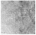
- FIG. 2 is a transmission electron microscope (TEM) photograph of the cathode active material prepared in Example 1.
- FIG. 2 is a transmission electron microscope (TEM) photograph of the cathode active material prepared in Example 1.
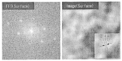
- FIG. 3 is a fast Fourier transform (FFT) pattern of the surface portion of the positive electrode active material prepared in Example 1, and the right view of FIG. 3 is a TEM photograph at a high magnification.
- FFT fast Fourier transform
- FIG. 4 is a FFT pattern of the center of the positive electrode active material prepared in Example 1, and the right view of FIG. 4 is a TEM image at a high magnification of the positive electrode active material.
- FIG. 5 is a scanning electron microscope (SEM) photograph at a low magnification of the cathode active material prepared in Comparative Example 1, and the right diagram of FIG. 5 is an SEM photograph at a high magnification of the cathode active material manufactured in Comparative Example 1.
- SEM scanning electron microscope
- FIG. 6 is a TEM photograph of the cathode active material prepared in Comparative Example 1.
- FIG. 7 is a fast Fourier transform (FFT) pattern of the surface portion of the positive electrode active material prepared in Comparative Example 1, and the right view of FIG. 7 is a TEM photograph at a high magnification of the positive electrode active material surface portion.
- FFT fast Fourier transform
- FIG. 8 is a FFT pattern of the center of the positive electrode active material manufactured in Comparative Example 1, and the right view of FIG. 8 is a TEM photograph at a high magnification of the center of the positive electrode active material.
- FIG. 9 is a graph showing capacity retention ratios of secondary batteries (monocells) manufactured in Example 1 and Comparative Example 1.
- FIG. 9 is a graph showing capacity retention ratios of secondary batteries (monocells) manufactured in Example 1 and Comparative Example 1.
- FIG. 10 is a graph showing capacity retention ratios of secondary batteries (full cells) prepared in Examples 1 to 3 and Comparative Examples 1 to 3.
- FIG. 10 is a graph showing capacity retention ratios of secondary batteries (full cells) prepared in Examples 1 to 3 and Comparative Examples 1 to 3.
- the positive electrode active material according to the present invention is a doping element M 2 (wherein M 2 is Al, Ti, Mg, Zr, W, Y, Sr, Co, F, Si, Na, Cu, Fe, Ca, S and B And at least one selected from the group consisting of lithium transition metal oxides containing at least 60 mol% nickel relative to the total moles of transition metals excluding lithium, wherein the lithium transition metal oxides exhibit a single particle form, A central portion having a layered structure and a surface portion having a rock salt structure.
- the doping element M 2 is included in the total weight of the positive electrode active material 3,580 ppm to 7,620 ppm.
- a lithium transition metal oxide doped with a doping element M 2 and containing nickel of 60 mol% or more with respect to the total moles of the transition metal excluding lithium may be used.
- the doping element M 2 is at least one selected from the group consisting of Al, Ti, Mg, Zr, W, Y, Sr, Co, F, Si, Na, Cu, Fe, Ca, S and B, preferably At least one selected from the group consisting of Sr, Ti, Mg and Zr.
- the doping element M 2 when the doping element M 2 is doped into a lithium transition metal oxide containing a high content of nickel, it exhibits a high capacity characteristic and also improves the structural stability of the lithium transition metal oxide at a high voltage, thereby improving its life characteristics at a high voltage. This can be improved.
- the positive electrode active material may include Sr as a doping element M 2 , and when the positive electrode active material includes Sr, growth of the positive electrode active material may be easily performed, thereby indicating a single particle shape.
- the cathode active material may include 3,580 ppm to 7,620 ppm, preferably 4,000 ppm to 7,000 ppm of doping element M 2 based on the total weight of the cathode active material.
- the doping element M 2 in the above range, the life characteristics, initial capacity and rate characteristics can be improved. For example, when the doping element M 2 is less than 3,580 ppm with respect to the total weight of the positive electrode active material, the lifespan may be reduced, and the doping element M 2 is greater than 7,620 ppm with respect to the total weight of the positive electrode active material. In this case, the initial dose and rate characteristics may be reduced.
- the lithium transition metal oxide may be represented by Formula 1 below:
- M 1 is at least one selected from the group consisting of Mn and Al
- M 2 Is at least one selected from the group consisting of Al, Ti, Mg, Zr, W, Y, Sr, Co, F, Si, Na, Cu, Fe, Ca, S and B.
- the average particle diameter (D 50 ) of the cathode active material may be 3.5 ⁇ m to 7 ⁇ m, preferably 4 ⁇ m to 6 ⁇ m.
- the average particle diameter (D 50 ) of the positive electrode active material satisfies the above range, it may be embodied to have a high energy density, has a good capacity, and may easily form a single particle of the positive electrode active material when under-fired.
- the average particle diameter D 50 may be defined as a particle size corresponding to 50% of the volume cumulative amount in the particle size distribution curve of the particles.
- the average particle diameter D 50 may be measured using, for example, a laser diffraction method.
- the laser diffraction method can measure the particle diameter of several mm from the submicron region, and high reproducibility and high resolution can be obtained.
- the cathode active material is in the form of a single particle, wherein the grain size of the cathode active material may be 180 nm to 300 nm, preferably 180 nm to 270 nm.
- the cathode active material may exhibit improved rate characteristics while having a single particle shape.
- the grain size of the positive electrode active material is 300 nm or more, the positive electrode active material exhibits a single particle shape, but the rate characteristic may decrease as the grain size increases, and when the grain size of the positive electrode active material is less than 180 nm
- primary particles may be aggregated rather than single particles.
- the grain size of the second cathode active material may be measured by using an XRD analyzer.
- the positive electrode active material includes a central portion having a layered structure and a surface portion having a rock salt structure.
- the layered structure refers to a structure in which atoms that are strongly bonded and densely arranged according to valence covalent bonds overlap in parallel by weak bonding forces such as van der Waals forces.
- weak bonding forces such as van der Waals forces.
- lithium ions, transition metal ions and oxygen ions are densely arranged, specifically, a metal oxide layer composed of transition metal and oxygen and an oxygen octahedral layer surrounding lithium are alternately arranged.
- Coulomb repulsive force acts between the metal oxide layers to allow insertion and desorption of lithium ions, and the ion conductivity is high because the lithium ions diffuse along a two-dimensional plane.
- the lithium ion in the particles can be quickly and smoothly moved to facilitate the insertion and desorption of lithium ions, thereby reducing the initial battery internal resistance and reducing the rate characteristics and initial capacity characteristics.
- the discharge capacity and lifespan characteristics can be further improved without concern.
- the rock salt structure refers to a structure having a face centered cubic structure coordinated by six oxygen atoms located in an octahedral shape around a metal atom. Compounds having such rock salt crystal structures have high structural stability, particularly at high temperatures.
- the cathode active material includes all of the surface portions having a rock salt structure on a central portion having a layered structure, structural stability and thermal stability of the cathode active material may be further improved.
- the surface portion represents a region located within 100 nm, preferably within 80 nm, and most preferably within 50 nm in the direction of the particle center on the surface of the positive electrode active material particles, such structural stability and thermal stability improvement effect is more effective. It can be remarkable, and when applied to the battery, the life characteristics of the secondary battery can be further improved.
- the positive electrode active material according to the present invention may optionally further include a coating element M 3 -containing coating layer formed on the surface of the lithium transition metal oxide optionally.
- M 3 may be at least one selected from the group consisting of Al, Ti, Mg, Zr, W, Y, Sr, Co, F, Si, Na, Cu, Fe, Ca, S and B, preferably It may be different from the doping element M 2 .
- the coating layer since the contact between the positive electrode active material and the electrolyte contained in the lithium secondary battery is blocked by the coating layer, side reactions are suppressed, so that the lifetime characteristics can be improved when applied to the battery, and the filling density of the positive electrode active material is also improved. Can be increased.
- the total content of the doping element M 2 and the coating element M 3 is 4,580 ppm to 9,120 ppm, preferably 5,000 ppm to 7,000 ppm, based on the total weight of the cathode active material. can do.
- the doping element of M 2 may comprise such that the 3,580 ppm to about 7,620 ppm, or doping element M 2 and the coating element doping elements the total content of M 3 so that the 4,580 ppm to 9,120 ppm M 2 and coating the element M It can contain all 3 's .
- the total content of the doping element M 2 and / or the coating element M 3 is 4,580 ppm to 9,120 ppm with respect to the total weight of the positive electrode active material, structural stability is improved, and the coating layer between the lithium transition metal oxide and the electrolyte solution. Side reactions are suppressed, and when applied to the battery, it is possible to improve the life characteristics of the battery at high voltage.
- the coating layer may be formed on the entire surface of the positive electrode active material, or may be partially formed. Specifically, when the coating layer is partially formed on the surface of the positive electrode active material, it may be formed in an area of less than 100% of more than 20% of the total surface area of the positive electrode active material.
- a transition metal precursor containing at least 60 mol% nickel, a lithium raw material and a doping element M 2 -containing raw material are mixed with respect to the total number of moles of the transition metal, and 800 ° C.
- a doped element M 2 -containing raw material comprising calcining at 1,000 ° C. to form a lithium transition metal oxide having a single particle form, wherein the doping element M 2 is 3,580 ppm to 7,620 ppm based on the total weight of the positive electrode active material. To mix the material.
- a transition metal precursor containing 60 mol% or more of nickel, a lithium raw material, and a doping element M 2 -containing raw material are prepared based on the total number of moles of the transition metal.
- the transition metal precursor may be a nickel content of 60 mol% or more with respect to the total number of moles of the transition metal, preferably Ni x Co y M 1 z (OH) 2 (where 0.6 ⁇ x1 ⁇ 1, 0 ⁇ y1 ⁇ 0.4, 0 ⁇ z1 ⁇ 0.4).
- the lithium raw material may be used without particular limitation as long as it is a compound containing a lithium source, preferably lithium carbonate (Li 2 CO 3 ), lithium hydroxide (LiOH), LiNO 3 , CH 3 COOLi and Li 2 (COO ) At least one selected from the group consisting of 2 can be used.
- a lithium source preferably lithium carbonate (Li 2 CO 3 ), lithium hydroxide (LiOH), LiNO 3 , CH 3 COOLi and Li 2 (COO ) At least one selected from the group consisting of 2 can be used.
- the doping element M 2 -containing raw material is a doping element M 2
- the M 2 is Al, Ti, Mg, Zr, W, Y, Sr, Co, F, Si, Na, Cu, Fe, Ca, S and At least one selected from the group consisting of B) -containing sulfates, nitrates, acetates, halides, hydroxides, or oxyhydroxides, and the like, and may be used without particular limitation, as long as it can be dissolved in the above-described solvents such as water. have.
- the positive electrode active material may include Sr as a doping element M 2 , and when the positive electrode active material includes Sr, the positive electrode active material grows by the Sr during firing, and thus may have a single particle shape.
- Sr is not included as the doping element M 2 , growth of the cathode active material becomes difficult even when the cathode active material is fired at a high temperature, and thus may not exhibit a single particle form.
- the transition metal precursor, the lithium raw material and the doping element M 2 -containing raw material are mixed and calcined at 800 ° C. to 1,000 ° C. to prepare a lithium transition metal oxide having a single particle form.
- the calcination may be performed at a temperature range such that the final grain size of the lithium transition metal oxide is 180 nm to 300 nm.
- the firing temperature may be appropriately adjusted according to the amount of nickel included in the transition metal precursor.
- the firing temperature is 1,000 ° C. as the content of nickel included in the transition metal precursor increases. It may be to lower to 800 °C.
- the firing temperature may be 900 ° C to 1,000 ° C, preferably 900 ° C to 950 ° C.
- the firing temperature may be more than 830 ° C and 900 ° C or less, preferably 850 ° C to 900 ° C.
- the firing temperature may be 800 ° C to 900 ° C, preferably 820 ° C to 900 ° C.
- the firing may be performed for 15 hours to 30 hours at 800 °C to 1,000 °C under oxygen or air atmosphere.
- the cathode active material may be recrystallized to form a single particle by performing overfiring at 800 ° C. to 1,000 ° C. for 15 hours to 30 hours, and the residue remaining on the surface of the cathode active material due to high temperature firing
- the amount of lithium can be reduced. Due to this reduction effect of residual lithium, gas generation due to side reactions between the residual lithium and the electrolyte solution can be prevented in advance.
- a surface of the under-resistance and the oxygen is desorbed from the surface of the lithium transition metal oxide having a layered structure because of the content of manganese, the positive electrode active material by Ni 2 + occurs can vary from rock salt structure.
- the cathode active material and the coating element M 3 -containing raw material prepared above may be formed to form a coating layer on the surface of the cathode active material.
- the cathode active material and the coating element M 3 -containing raw material prepared above (wherein M 3 is Al, Ti, Mg, Zr, W, Y, Sr, Co, F, Si, Na, Cu, Fe , At least one selected from the group consisting of Ca, S, and B) and a heat treatment may be performed to form a coating layer on the surface of the cathode active material.
- the heat treatment may be performed for 3 hours to 10 hours at 350 °C to 800 °C in an oxygen or air atmosphere, more preferably may be performed for 3 to 6 hours at 400 °C to 500 °C.
- the coating layer is easily formed on the surface of the lithium transition metal oxide, not only suppresses side reactions with the electrolyte solution, but also reduces residual lithium, due to the residual lithium present on the surface during charge and discharge. Gas generation can be significantly reduced.
- the positive electrode active material is a doping element M 2 -containing raw material and coating element M 3 -so that the total content of the doping element M 2 and the coating element M 3 with respect to the total weight of the positive electrode active material is 4,580 ppm to 9,120 ppm. It may be to mix the containing raw material.
- the doping element M 2 and coating the element M 3 doping element M 2 is the total amount of that is less than 4,580 ppm or 9,120 ppm over-case to mix containing raw material, it-containing raw materials and coating the element M 3 When applied to the battery, the initial capacity, rate characteristics and life characteristics may be degraded.
- the positive electrode for a secondary battery includes a positive electrode current collector and a positive electrode active material layer formed on the positive electrode current collector, and the positive electrode active material layer includes the positive electrode active material according to the present invention.
- the positive electrode current collector is not particularly limited as long as it has conductivity without causing chemical change in the battery.
- carbon, nickel, titanium on the surface of stainless steel, aluminum, nickel, titanium, calcined carbon, or aluminum or stainless steel Surface treated with silver, silver or the like can be used.
- the positive electrode current collector may have a thickness of about 3 to 500 ⁇ m, and may form fine irregularities on the surface of the current collector to increase the adhesion of the positive electrode active material.
- it can be used in various forms, such as a film, a sheet, a foil, a net, a porous body, a foam, a nonwoven body.
- the positive electrode active material layer may optionally include a conductive material and a binder as necessary, together with the positive electrode active material.
- the cathode active material may be included in an amount of 80 to 99 wt%, more specifically 85 to 98.5 wt%, based on the total weight of the cathode active material layer. When included in the above content range may exhibit excellent capacity characteristics.
- the conductive material is used to impart conductivity to the electrode, and in the battery constituted, any conductive material can be used without particular limitation as long as it has electronic conductivity without causing chemical change. Specific examples thereof include graphite such as natural graphite and artificial graphite; Carbon-based materials such as carbon black, acetylene black, ketjen black, channel black, furnace black, lamp black, summer black and carbon fiber; Metal powder or metal fibers such as copper, nickel, aluminum, and silver; Conductive whiskeys such as zinc oxide and potassium titanate; Conductive metal oxides such as titanium oxide; Or conductive polymers such as polyphenylene derivatives, and the like, or a mixture of two or more kinds thereof may be used.
- the conductive material may be included in an amount of 0.1 to 15% by weight based on the total weight of the positive electrode active material layer.
- the binder serves to improve adhesion between the positive electrode active material particles and the adhesion between the positive electrode active material and the current collector.
- Specific examples include polyvinylidene fluoride (PVDF), vinylidene fluoride-hexafluoropropylene copolymer (PVDF-co-HFP), polyvinyl alcohol, polyacrylonitrile, carboxymethyl cellulose (CMC).
- the binder may be included in an amount of 0.1 to 15% by weight based on the total weight of the positive electrode active material layer.
- the positive electrode may be manufactured according to a conventional positive electrode manufacturing method except for using the positive electrode active material described above. Specifically, the positive electrode active material and optionally, a composition for forming a positive electrode active material layer prepared by dissolving or dispersing a binder and a conductive material in a solvent may be applied onto a positive electrode current collector, followed by drying and rolling.
- the solvent may be a solvent generally used in the art, and may include dimethyl sulfoxide (DMSO), isopropyl alcohol, N-methylpyrrolidone (NMP), acetone or acetone. Water, and the like, one of these alone or a mixture of two or more thereof may be used.
- the amount of the solvent is sufficient to dissolve or disperse the positive electrode active material, the conductive material, and the binder in consideration of the coating thickness of the slurry and the production yield, and to have a viscosity that can exhibit excellent thickness uniformity during application for the production of the positive electrode. Do.
- the positive electrode may be prepared by casting the composition for forming the positive electrode active material layer on a separate support, and then laminating the film obtained by peeling from the support onto a positive electrode current collector.
- the present invention can manufacture an electrochemical device comprising the positive electrode.
- the electrochemical device may be specifically a battery, a capacitor, or the like, and more specifically, a lithium secondary battery.
- the lithium secondary battery includes a positive electrode, a negative electrode positioned to face the positive electrode, and a separator and an electrolyte interposed between the positive electrode and the negative electrode, and the positive electrode is the same as described above, and thus, a detailed description thereof will be omitted. Hereinafter, only the remaining configurations will be described in detail.
- the lithium secondary battery may further include a battery container for accommodating the electrode assembly of the positive electrode, the negative electrode, the separator, and a sealing member for sealing the battery container.
- the negative electrode includes a negative electrode current collector and a negative electrode active material layer positioned on the negative electrode current collector.
- the negative electrode current collector is not particularly limited as long as it has high conductivity without causing chemical change in the battery.
- the negative electrode current collector may be formed on a surface of copper, stainless steel, aluminum, nickel, titanium, calcined carbon, copper, or stainless steel. Surface-treated with carbon, nickel, titanium, silver, and the like, aluminum-cadmium alloy and the like can be used.
- the negative electrode current collector may have a thickness of 3 ⁇ m to 500 ⁇ m, and similarly to the positive electrode current collector, fine concavities and convexities may be formed on the surface of the current collector to enhance the bonding force of the negative electrode active material.
- it can be used in various forms, such as a film, a sheet, a foil, a net, a porous body, a foam, a nonwoven body.
- the negative electrode active material layer optionally includes a binder and a conductive material together with the negative electrode active material.
- a compound capable of reversible intercalation and deintercalation of lithium may be used.
- Specific examples include carbonaceous materials such as artificial graphite, natural graphite, graphitized carbon fibers, and amorphous carbon;
- Metallic compounds capable of alloying with lithium such as Si, Al, Sn, Pb, Zn, Bi, In, Mg, Ga, Cd, Si alloys, Sn alloys or Al alloys;
- Metal oxides capable of doping and undoping lithium such as SiO ⁇ (0 ⁇ ⁇ 2), SnO 2 , vanadium oxide, and lithium vanadium oxide;
- a composite including the metallic compound and the carbonaceous material such as a Si-C composite or a Sn-C composite, and any one or a mixture of two or more thereof may be used.
- a metal lithium thin film may be used as the anode active material.
- the carbon material both low crystalline carbon and high crystalline carbon can be used. Soft crystalline carbon and hard carbon are typical low crystalline carbon, and high crystalline carbon is amorphous, plate, scaly, spherical or fibrous natural graphite or artificial graphite, Kish graphite (Kish) graphite, pyrolytic carbon, mesophase pitch based carbon fiber, meso-carbon microbeads, mesophase pitches and petroleum or coal tar pitch High-temperature calcined carbon such as derived cokes is typical.
- the negative electrode active material may be included in an amount of 80 wt% to 99 wt% based on the total weight of the negative electrode active material layer.
- the binder is a component that assists the bonding between the conductive material, the active material and the current collector, and is typically added in an amount of 0.1 wt% to 10 wt% based on the total weight of the negative electrode active material layer.
- binders include polyvinylidene fluoride (PVDF), polyvinyl alcohol, carboxymethyl cellulose (CMC), starch, hydroxypropyl cellulose, regenerated cellulose, polyvinylpyrrolidone, tetrafluoro Low ethylene, polyethylene, polypropylene, ethylene-propylene-diene polymer (EPDM), sulfonated-EPDM, styrene-butadiene rubber, nitrile-butadiene rubber, fluorine rubber, various copolymers thereof and the like.
- PVDF polyvinylidene fluoride
- CMC carboxymethyl cellulose
- EPDM ethylene-propylene-diene polymer
- sulfonated-EPDM
- the conductive material is a component for further improving the conductivity of the negative electrode active material, and may be added in an amount of 10 wt% or less, preferably 5 wt% or less, based on the total weight of the negative electrode active material layer.
- a conductive material is not particularly limited as long as it has conductivity without causing chemical change in the battery, and examples thereof include graphite such as natural graphite and artificial graphite; Carbon blacks such as acetylene black, Ketjen black, channel black, furnace black, lamp black and thermal black; Conductive fibers such as carbon fibers and metal fibers; Metal powders such as carbon fluoride powder, aluminum powder and nickel powder; Conductive whiskeys such as zinc oxide and potassium titanate; Conductive metal oxides such as titanium oxide; Conductive materials such as polyphenylene derivatives and the like can be used.
- the negative electrode active material layer is prepared by applying and drying a negative electrode active material, and a composition for forming a negative electrode active material layer prepared by dissolving or dispersing a binder and a conductive material in a solvent, optionally on a negative electrode current collector, or the negative electrode
- the composition for forming the active material layer may be cast on a separate support, and then the film obtained by peeling from the support may be laminated on a negative electrode current collector.
- the negative electrode active material layer is, for example, coated with a negative electrode active material, and optionally a composition for forming a negative electrode active material layer prepared by dissolving or dispersing a binder and a conductive material in a solvent and dried, or for forming the negative electrode active material layer
- the composition may be prepared by casting the composition on a separate support, and then laminating the film obtained by peeling from the support onto a negative electrode current collector.
- the separator is to separate the negative electrode and the positive electrode and to provide a passage for the movement of lithium ions, if it is usually used as a separator in a lithium secondary battery can be used without particular limitation, in particular in the ion transfer of the electrolyte It is desirable to have a low resistance against the electrolyte and excellent electrolytic solution-moisture capability.
- a porous polymer film for example, a porous polymer film made of a polyolefin-based polymer such as ethylene homopolymer, propylene homopolymer, ethylene / butene copolymer, ethylene / hexene copolymer and ethylene / methacrylate copolymer, or the like Laminate structures of two or more layers may be used.
- a porous nonwoven fabrics such as nonwoven fabrics made of high melting point glass fibers, polyethylene terephthalate fibers and the like may be used.
- the separator may include a coating of a safety reinforced separator (SRS) prepared by coating ceramic particles and a binder polymer on a polyolefin-based or polyester-based resin separator substrate.
- SRS safety reinforced separator
- the ceramic particles can improve the thermal stability of the separator, thereby preventing the shrinkage of the separator at a high temperature.
- the binder polymer fixes the ceramic particles to the separator substrate.
- the SRS coating layer formed on the surface of the separator by the ceramic particles may be a pore structure formed on the surface. The pores formed on the surface of the SRS coating layer may smoothly move ions from the anode to the cathode even when the ceramic particles are coated on the separator.
- the binder polymer may stably maintain the ceramic particles in the separator, thereby improving the mechanical stability of the separator, and more stably adhering the separator to the electrode.
- an inorganic-inorganic composite separator further coated with an inorganic material may be used to secure heat resistance or mechanical strength, and may be optionally used as a single layer or a multilayer structure.
- the inorganic material may be used without particular limitation as long as it is a material capable of uniformly controlling pores of the organic-inorganic composite separator and improving heat resistance.
- the inorganic material may include, but is not limited to, SiO 2 , Al 2 O 3 , TiO 2 , BaTiO 3 , Li 2 O, LiF, LiOH, Li 3 N, BaO, Na 2 O, Li 2 CO 3 , CaCO 3 , At least one selected from the group consisting of LiAlO 2 , SrTiO 3 , SnO 2 , CeO 2 , MgO, NiO, CaO, ZnO, ZrO 2, SiC, and derivatives thereof and mixtures thereof.
- the average diameter of the inorganic material may be 0.001 ⁇ m to 10 ⁇ m, and more specifically 0.001 ⁇ m to 1 ⁇ m.
- the average diameter of the inorganic material is within the above range, dispersibility in the coating solution may be improved, and problems in the coating process may be minimized.
- the physical properties of the final separator can be uniform, and the inorganic particles can be uniformly distributed in the pores of the nonwoven fabric to improve the mechanical properties of the nonwoven fabric, and the size of the pores of the organic-inorganic composite separator can be easily adjusted. There is this.
- the average diameter of the pores of the organic-inorganic composite separator may be in the range of 0.001 ⁇ m to 10 ⁇ m, more specifically 0.001 ⁇ m to 1 ⁇ m. If the average diameter of the pores of the organic-inorganic composite membrane is within the above range, not only can control gas permeability and ionic conductivity to a desired range, but also when the battery is manufactured using the organic-inorganic composite membrane, the contact between the positive electrode and the negative electrode The possibility of internal short circuit of the battery can be eliminated.
- the porosity of the organic-inorganic composite membrane may be in the range of 30% by volume to 90% by volume. When the porosity is within the above range, ion conductivity may be increased and mechanical strength may be excellent.
- a conventional porous nonwoven fabric for example, a non-woven fabric of high melting point glass fiber, polyethylene terephthalate fiber, or the like may be used, but is not limited thereto.
- examples of the electrolyte used in the present invention include an organic liquid electrolyte, an inorganic liquid electrolyte, a solid polymer electrolyte, a gel polymer electrolyte, a solid inorganic electrolyte, a molten inorganic electrolyte, and the like, which can be used in manufacturing a lithium secondary battery. It doesn't happen.
- the electrolyte may include an organic solvent and a lithium salt.
- the organic solvent may be used without particular limitation as long as it can serve as a medium through which ions involved in the electrochemical reaction of the battery can move.
- the organic solvent methyl acetate, ethyl acetate, propyl acetate, methyl propionate, ethyl propionate, propyl propionate, butyl propionate, ⁇ -butyrolactone ester solvents such as ( ⁇ -butyrolactone) and ⁇ -caprolactone; Ether solvents such as dibutyl ether or tetrahydrofuran; Ketone solvents such as cyclohexanone; Aromatic hydrocarbon solvents such as benzene and fluorobenzene; Dimethylcarbonate (DMC), diethylcarbonate (DEC), methylethylcarbonate (MEC), ethylmethylcarbonate (EMC), ethylene carbonate (EC), propylene carbonate, Carbonate solvents such as PC); Alcohol solvents such as ethyl alcohol
- carbonate-based solvents are preferable, and cyclic carbonates having high ionic conductivity and high dielectric constant (for example, ethylene carbonate or propylene carbonate) that can improve the charge and discharge performance of a battery, and low viscosity linear carbonate compounds (for example, a mixture of ethyl methyl carbonate, dimethyl carbonate or diethyl carbonate and the like is more preferable.
- the cyclic carbonate and the chain carbonate may be mixed and used in a volume ratio of about 1: 1 to about 1: 9, so that the performance of the electrolyte may be excellent.
- the lithium salt may be used without particular limitation as long as it is a compound capable of providing lithium ions used in a lithium secondary battery.
- the lithium salt is LiPF 6 , LiClO 4 , LiAsF 6 , LiBF 4 , LiSbF 6 , LiAl0 4 , LiAlCl 4 , LiCF 3 SO 3 , LiC 4 F 9 SO 3 , LiN (C 2 F 5 SO 3 ) 2 , LiN (C 2 F 5 SO 2 ) 2 , LiN (CF 3 SO 2 ) 2 .
- LiCl, LiI, or LiB (C 2 O 4 ) 2 and the like can be used.
- the concentration of the lithium salt is preferably used within the range of 0.1 to 2.0M. When the concentration of the lithium salt is included in the above range, since the electrolyte has an appropriate conductivity and viscosity, it can exhibit excellent electrolyte performance, and lithium ions can move effectively.
- the electrolyte may further include an additive for the purpose of improving the life characteristics of the battery, suppressing the reduction of the battery capacity, and improving the discharge capacity of the battery.
- the additive is a haloalkylene carbonate-based compound such as difluoro ethylene carbonate, pyridine, triethyl phosphite, triethanolamine, cyclic ether, ethylene diamine, n-glyme, hexaphosphate triamide, Nitrobenzene derivative, sulfur, quinone imine dye, N-substituted oxazolidinone, N, N-substituted imidazolidine, ethylene glycol dialkyl ether, ammonium salt, pyrrole, 2-methoxy ethanol, aluminum trichloride, vinylene carbonate ( VC), propane sultone (PS), fluoro ethylene carbonate (FEC), and butane dinitrile (NA).
- the additive may be included in this case, the additive may be included in
- the additive when the additive includes at least one selected from the group consisting of vinylene carbonate (VC), propane sultone (PS), fluoro ethylene carbonate (FEC), and butanedinitryl (NA),
- VC vinylene carbonate
- PS propane sultone
- FEC fluoro ethylene carbonate
- NA butanedinitryl
- the additives can improve the output characteristics by forming a stable SEI film on the negative electrode together with the lithium salt, suppress the decomposition of the positive electrode surface and prevent the oxidation reaction of the electrolyte, consequently the output of the secondary battery when applied to high voltage of 4.3V or more Properties can be improved.
- the lithium secondary battery including the cathode active material according to the present invention stably exhibits excellent discharge capacity, output characteristics, and lifespan characteristics, portable devices such as mobile phones, laptop computers, digital cameras, and hybrid electric vehicles ( It is useful for electric vehicle fields such as hybrid electric vehicle (HEV).
- HEV hybrid electric vehicle
- a battery module including the lithium secondary battery as a unit cell and a battery pack including the same are provided.
- the battery module or the battery pack is a power tool (Power Tool); Electric vehicles including electric vehicles (EVs), hybrid electric vehicles, and plug-in hybrid electric vehicles (PHEVs); Or it can be used as a power source for any one or more of the system for power storage.
- Power Tool Electric vehicles including electric vehicles (EVs), hybrid electric vehicles, and plug-in hybrid electric vehicles (PHEVs); Or it can be used as a power source for any one or more of the system for power storage.
- the external shape of the lithium secondary battery of the present invention is not particularly limited, but may be cylindrical, square, pouch type, or coin type using a can.
- the lithium secondary battery according to the present invention may not only be used in a battery cell used as a power source for a small device, but also preferably used as a unit battery in a medium-large battery module including a plurality of battery cells.
- the positive electrode active material, the denka black conductive material, and the polyvinylidene fluoride (KF1100) binder prepared above were mixed in a weight ratio of 96: 2: 2, and mixed in an N-methylpyrrolidone (NMP) solvent to form a positive electrode.
- a composition for preparation was prepared.
- the positive electrode forming composition was applied to an Al current collector having a thickness of 20 ⁇ m, dried, and roll pressed to prepare a positive electrode.
- Mixing was carried out in a weight ratio of: 2.5: 1.15, which was added to an NMP solvent to prepare a composition for forming a negative electrode.
- the negative electrode forming composition was applied to a Cu current collector having a thickness of 20 ⁇ m, dried, and roll-pressed to prepare a negative electrode.
- a positive electrode and a positive electrode active material were prepared in the same manner as in Example 1, except that a positive electrode active material doped with 1,000 ppm of Sr, 3,500 ppm of Zr, 500 ppm of Mg, and 250 ppm of Ti was prepared.
- a secondary battery was prepared.
- a positive electrode active material In preparing the positive electrode active material, a positive electrode active material, a positive electrode, and a secondary battery including the same were manufactured using the same method as Example 1 except that the material was baked at 830-850 ° C. for 10 hours.
- a positive electrode active material In preparing the positive electrode active material, a positive electrode active material, a positive electrode, and a secondary battery including the same were manufactured using the same method as Example 2, except that the battery was baked at 810-830 ° C. for 10 hours.
- a positive electrode active material In preparing the positive electrode active material, a positive electrode active material, a positive electrode, and a secondary battery including the same were prepared using the same method as Example 3 except that the material was baked at 780-810 ° C. for 10 hours.
- a cathode active material having an average particle diameter (D 50 ) of 5 to 7 ⁇ m, doped with Sr of 1,000 ppm, Zr of 5,000 ppm, Mg of 2,500 pm, and Ti of 1,500 ppm based on the total weight of the cathode active material.
- the positive electrode active material prepared above, and Al 2 O 3 0.141711359g was mixed and calcined at 500 ° C. for 5 hours to prepare a cathode active material coated with 1,500 ppm of Al based on the total weight of the cathode active material, and the same method as in Example 4 except using the same. And a secondary battery comprising the same was prepared.
- the positive electrode active material prepared above, and Al 2 O 3 0.04723712g was mixed and calcined at 500 ° C. for 5 hours to prepare a cathode active material coated with 500 ppm of Al based on the total weight of the cathode active material, and the same method as in Example 4 except for using the same.
- a secondary battery including the same was prepared.
- the positive electrode active material particles prepared in Example 1 and Comparative Example 1 were cut to photograph a cross-section of the positive electrode active material using a transmission electron microscope (TEM), and the surface of the positive electrode active material was subjected to a Fast Fourier transform (FFT). And the crystal structure inside the particle was confirmed through a diffraction pattern.
- TEM transmission electron microscope
- FFT Fast Fourier transform
- FIGS. 1 to 4 are SEM images at low magnification (left) and high magnification (right) of the positive electrode active material prepared in Example 1, cross-sectional transmission electron microscope (TEM) image, FFT pattern (left) of the surface portion, and The TEM image (right), the FET pattern (left) and the TEM image (right) of the center are shown, and FIGS. 5 to 8 are SEMs at low magnification (left) and high magnification (right) of the positive electrode active material prepared in Comparative Example 1.
- the image, the cross-sectional TEM image, the FFT pattern (left) and the TEM image (right) of the surface portion, the FET pattern (left) and the TEM image (right) of the center portion are shown.
- the cathode active material prepared in Example 1 has a single particle shape, as shown in FIG. 1, and a region of up to 50 nm in the center direction and the center of the particle as shown in FIG. 2. It was confirmed that the crystal structure of was different. In order to confirm the crystal structure of the central portion and the surface portion, the FFT patterns of the inside and the surface portion (surface) shown in FIG. 2 were confirmed, which are shown in FIGS. 3 and 4.
- the positive electrode active material surface portion had a rock salt crystal structure
- the center of the positive electrode active material had a layered crystal structure
- the cathode active material prepared in Comparative Example 1 has a form of secondary particles formed by agglomeration of primary particles, and has the same crystal structure at the surface portion and the central portion of the particles. I could confirm it.
- Each of the secondary batteries (monocells) manufactured in Examples 1 to 4 and Comparative Examples 1 to 5 was charged to a temperature of 4.35V at 0.7C constant current at a high temperature (45 ° C). Then, discharge was performed until it became 3V by 0.5C constant current. After repeating this cycle 360 times with the charge and discharge behavior as one cycle, the life characteristics of the secondary batteries according to Examples 1 to 4 and Comparative Examples 1 to 5 were measured, which are shown in Tables 1 and 9 below. Indicated.
- Example 1 Example 2 83
- Example 3 Example 4 85 Comparative Example 1 60 Comparative Example 2 55 Comparative Example 3 20 Comparative Example 4 88 Comparative Example 5 62
- the secondary batteries (half cells) prepared in Examples 1, 2, and 4 and Comparative Examples 1 to 3 and 5 were charged to 4.4 V at a constant current of 0.7 C at room temperature (25 ° C.), respectively, and the charging capacity was measured ( If the Ni content of Example 3 and Comparative Example 3 includes a positive electrode active material of 80 mol%, it is charged to 4.25V at 0.7C constant current. Then, it discharged once until it became 3.0V by 0.5C constant current, and discharge capacity was measured.
- the charge capacity in the first cycle, the discharge capacity and the discharge efficiency in the first cycle are shown in Table 3, respectively.
- the discharge efficiency in the first cycle was calculated by dividing the discharge capacity in the first cycle by the charge capacity in the first cycle.
Abstract
The present invention relates to a cathode active material doped with a doping element, M2 (wherein M2 is at least one selected from the group consisting of Al, Ti, Mg, Zr, W, Y, Sr, Co, F, Si, Na, Cu, Fe, Ca, S, and B) and comprising a lithium transition metal oxide containing 60 mol% or more of nickel relative to the total number of moles of transition metals excluding lithium, wherein the lithium transition metal oxide has a single particle form, comprises a center portion having a layered structure and a surface portion having a rock salt structure, and contains 3,580-7,620 ppm of the doping element M2 relative to the total weight of the cathode active material, to a method for manufacturing the cathode active material, to a cathode comprising the cathode active material for a lithium secondary battery, and to a lithium secondary battery.
Description
관련출원과의 상호 인용Cross Citation with Related Applications
본 출원은 2018년 4월 6일자 한국특허출원 제10-2018-0040424에 기초한 우선권의 이익을 주장하며, 해당 한국특허출원의 문헌에 개시된 모든 내용은 본 명세서의 일부로서 포함된다.This application claims the benefit of priority based on Korean Patent Application No. 10-2018-0040424 dated April 6, 2018, and all the contents disclosed in the documents of the Korean patent application are included as part of this specification.
기술분야Technical Field
본 발명은 리튬 이차전지용 양극 활물질, 상기 양극 활물질의 제조 방법, 상기 양극 활물질을 포함하는 리튬 이차전지용 양극 및 리튬 이차전지에 관한 것이다. The present invention relates to a positive electrode active material for a lithium secondary battery, a manufacturing method of the positive electrode active material, a positive electrode for a lithium secondary battery and the lithium secondary battery containing the positive electrode active material.
모바일 기기에 대한 기술 개발과 수요가 증가함에 따라 에너지원으로서 이차전지의 수요가 급격히 증가하고 있다. 이러한 이차전지 중 높은 에너지 밀도와 전압을 가지며, 사이클 수명이 길고, 자기방전율이 낮은 리튬 이차전지가 상용화되어 널리 사용되고 있다.As technology development and demand for mobile devices increase, the demand for secondary batteries as a source of energy is rapidly increasing. Among such secondary batteries, lithium secondary batteries having high energy density and voltage, long cycle life, and low self discharge rate have been commercialized and widely used.
리튬 이차전지의 양극활물질로는 리튬 전이금속 복합 산화물이 이용되고 있으며, 이중에서도 작용전압이 높고 용량 특성이 우수한 LiCoO2 등의 리튬 코발트 복합금속 산화물이 주로 사용되고 있다. 그러나, LiCoO2는 탈리튬에 따른 결정 구조의 불안정화 때문에 열적 특성이 매우 열악하다. 또한, 상기 LiCoO2는 고가이기 때문에 전기 자동차 등과 같은 분야의 동력원으로서 대량 사용하기에는 한계가 있다. A lithium transition metal composite oxide is used as a cathode active material of a lithium secondary battery, and lithium cobalt composite metal oxides such as LiCoO 2 having a high operating voltage and excellent capacity characteristics are mainly used. However, LiCoO 2 has very poor thermal properties due to destabilization of the crystal structure due to thalithium. In addition, since the LiCoO 2 is expensive, there is a limit to mass use as a power source in fields such as electric vehicles.
상기 LiCoO2를 대체하기 위한 재료로서, 리튬 망간 복합금속 산화물(LiMnO2 또는 LiMn2O4 등), 리튬 인산철 화합물(LiFePO4 등) 또는 리튬 니켈 복합금속 산화물(LiNiO2 등) 등이 개발되었다. 이 중에서도 약 200 mAh/g의 높은 가역용량을 가져 대용량의 전지 구현이 용이한 리튬 니켈 복합금속 산화물에 대한 연구 개발이 보다 활발히 연구되고 있다. 그러나, 상기 LiNiO2는 LiCoO2와 비교하여 열안정성이 열위하고, 충전 상태에서 외부로부터의 압력 등에 의해 내부 단락이 생기면 양극 활물질 그 자체가 분해되어 전지의 파열 및 발화를 초래하는 문제가 있었다. 이에 따라 상기 LiNiO2의 우수한 가역용량은 유지하면서도 낮은 열안정성을 개선하기 위한 방법으로서, Ni의 일부를 Co 및 Mn 또는 Al로 치환한 리튬 니켈코발트금속 산화물이 개발되었다.As a material for replacing LiCoO 2 , lithium manganese composite metal oxides (such as LiMnO 2 or LiMn 2 O 4 ), lithium iron phosphate compounds (such as LiFePO 4 ), or lithium nickel composite metal oxides (such as LiNiO 2 ) have been developed. . Among them, research and development on lithium nickel composite metal oxides having a high reversible capacity of about 200 mAh / g, which is easy to implement a large-capacity battery, are being actively researched. However, LiNiO 2 is inferior in thermal stability to LiCoO 2, and when an internal short circuit occurs due to pressure from the outside in a charged state, the positive electrode active material itself decomposes, causing a battery to rupture and ignite. Accordingly, as a method for improving low thermal stability while maintaining the excellent reversible capacity of LiNiO 2 , lithium nickel cobalt metal oxides in which a part of Ni is substituted with Co and Mn or Al have been developed.
그러나, 상기 리튬 니켈코발트금속 산화물의 경우, 구조 안정성이 낮고 용량이 낮으며, 특히 용량 특성을 높이기 위해 니켈의 함량을 높일 경우, 충방전 공정이 진행됨에 따라 상기 니켈이 Ni2
+에서 Ni3
+ 또는 Ni4
+로 산화하고, 이에 따라 급격한 산소 탈리가 진행되어, 구조 안정성이 더욱 저하된다는 문제점이 있었다.However, in the case of the lithium nickel cobalt metal oxide, the structural stability is low and the capacity is low. In particular, when the nickel content is increased to increase the capacity characteristics, the nickel is Ni 2 + to Ni 3 + as the charge and discharge process proceeds. Or oxidized to Ni 4 + , there is a problem that rapid oxygen desorption proceeds, thereby further lowering the structural stability.
따라서, 고용량 특성을 나타내는 고함량의 Ni을 포함하는 리튬 니켈코발트금속 산화물을 포함하되, 이때 상기 리튬 니켈코발트금속 산화물의 구조 안정성이 우수하여, 고용량 및 고수명 전지를 제조할 수 있는 양극 활물질의 개발이 요구되고 있다.Therefore, the lithium nickel cobalt metal oxide containing a high content of Ni exhibiting a high capacity characteristics, wherein the lithium nickel cobalt metal oxide is excellent in the structural stability, the development of a cathode active material capable of manufacturing a high capacity and high life battery This is required.
상기와 같은 문제점을 해결하기 위하여, 본 발명의 제 1 기술적 과제는 단일 입자 형태를 가지고, 특정 함량으로 도핑원소가 도핑된 리튬 전이금속 산화물을 포함하는 양극 활물질을 제공하는 것이다.In order to solve the above problems, the first technical problem of the present invention is to provide a cathode active material including a lithium transition metal oxide having a single particle form, and doped with a specific content.
본 발명의 제 2 기술적 과제는 상기 양극 활물질의 제조 방법을 제공하는 것이다.The second technical problem of the present invention is to provide a method for producing the cathode active material.
본 발명의 제 3 기술적 과제는 상기 양극 활물질을 포함하는 리튬 이차전지용 양극을 제공하는 것이다.A third technical problem of the present invention is to provide a cathode for a lithium secondary battery including the cathode active material.
본 발명의 제 4 기술적 과제는 상기 리튬 이차전지용 양극을 포함하는 리튬 이차전지를 제공하는 것이다.The fourth technical problem of the present invention is to provide a lithium secondary battery including the positive electrode for a lithium secondary battery.
본 발명은 도핑원소 M2(이때, M2는 Al, Ti, Mg, Zr, W, Y, Sr, Co, F, Si, Na, Cu, Fe, Ca, S 및 B로 이루어진 군에서 선택되는 적어도 하나 이상임)로 도핑되고, 리튬을 제외한 전이금속 총 몰수에 대하여 60 몰% 이상의 니켈을 함유하는 리튬 전이금속 산화물을 포함하는 양극 활물질에 있어서, 상기 리튬 전이금속 산화물은 단일 입자 형태를 나타내고, 층상 구조를 가지는 중심부 및 암염 구조를 가지는 표면부를 포함하고, 상기 양극 활물질 총 중량에 대하여 도핑원소 M2를 3,580 ppm 내지 7,620 ppm으로 포함하는 양극 활물질을 제공한다.The present invention is a doping element M 2 (wherein M 2 is selected from the group consisting of Al, Ti, Mg, Zr, W, Y, Sr, Co, F, Si, Na, Cu, Fe, Ca, S and B) And a lithium transition metal oxide containing at least 60 mol% nickel based on the total moles of transition metals excluding lithium, wherein the lithium transition metal oxide has a single particle form and is layered. It provides a cathode active material comprising a central portion having a structure and a surface portion having a rock salt structure, and containing 3,580 ppm to 7,620 ppm of a doping element M 2 based on the total weight of the cathode active material.
또한, 본 발명은 전이금속 전체 몰수에 대하여 60몰% 이상의 니켈을 포함하는 전이금속 전구체, 리튬 원료 물질 및 도핑원소 M2-함유 원료물질을 혼합하고, 800℃ 내지 1,000℃에서 소성하여 단일 입자 형태를 가지는 리튬 전이금속 산화물을 제조하는 것을 포함하고, 양극 활물질 총 중량에 대하여 도핑원소 M2의 함량이 3,580 ppm 내지 7,620 ppm가 되도록 상기 도핑원소 M2-함유 원료물질을 혼합하는 것인, 양극 활물질의 제조 방법을 제공한다. In addition, the present invention is a single particle form by mixing a transition metal precursor, a lithium raw material and a doping element M 2 -containing raw material containing at least 60 mol% nickel with respect to the total number of moles of the transition metal, and calcined at 800 ℃ to 1,000 ℃ Comprising the production of a lithium transition metal oxide having a positive electrode active material, to mix the doping element M 2 -containing raw material so that the content of the doping element M 2 to 3,580 ppm to 7,620 ppm relative to the total weight of the positive electrode active material It provides a method for producing.
또한, 본 발명에 따른 양극 활물질을 포함하는, 리튬 이차전지용 양극을 제공한다.In addition, there is provided a cathode for a lithium secondary battery, including the cathode active material according to the present invention.
또한, 본 발명에 따른 양극을 포함하는, 리튬 이차전지를 제공한다.In addition, it provides a lithium secondary battery comprising a positive electrode according to the present invention.
본 발명에 따르면, 양극 활물질에 특정 도핑 원소를 도핑하되, 이때 도핑원소의 함량을 제어함으로써 이를 전지에 적용 시 고전압에서 수명 특성을 향상시킬 수 있다. According to the present invention, a specific doping element is doped into the positive electrode active material, and at this time, by controlling the content of the doping element it can improve the life characteristics at high voltage when applied to the battery.
본 발명에 따르면, 양극 활물질 제조 시 과소성을 수행함으로써 180 nm 내지 300 nm의 결정립 크기를 가지는 단일 입자 형태의 양극 활물질을 제조할 수 있다. 이를 이용하여 양극 제조 시, 양극 제조 과정에서 압연 등에 따른 양극 활물질의 크랙(crack)을 방지하여, 전지에 적용할 경우 전지의 수명 특성을 개선할 수 있다.According to the present invention, it is possible to prepare a cathode active material in the form of a single particle having a grain size of 180 nm to 300 nm by performing underfiring during the preparation of the cathode active material. By using this, when the positive electrode is manufactured, it is possible to prevent cracks of the positive electrode active material due to rolling in the positive electrode manufacturing process, and when applied to the battery can improve the life characteristics of the battery.
도 1의 좌측 도면은 실시예 1에서 제조한 양극 활물질의 저배율에서의 주사전자현미경(SEM) 사진이고, 도 1의 우측 도면은 실시예 1에서 제조한 양극 활물질의 고배율에서의 SEM 사진이다.1 is a scanning electron microscope (SEM) photograph at a low magnification of the cathode active material prepared in Example 1, and the right diagram of FIG. 1 is an SEM photograph at a high magnification of the cathode active material prepared in Example 1. FIG.
도 2는 실시예 1에서 제조한 양극 활물질의 투과전자현미경(TEM) 사진이다.2 is a transmission electron microscope (TEM) photograph of the cathode active material prepared in Example 1. FIG.
도 3의 좌측 도면은 실시예 1에서 제조한 양극 활물질의 표면부의 고속 푸리에 변환(fast Fourier transform, FFT) 패턴이고, 도 3의 우측 도면은 양극 활물질 표면부를 고배율로 확대한 TEM 사진이다.FIG. 3 is a fast Fourier transform (FFT) pattern of the surface portion of the positive electrode active material prepared in Example 1, and the right view of FIG. 3 is a TEM photograph at a high magnification.
도 4의 좌측 도면은 실시예 1에서 제조한 양극 활물질의 중심부의 FFT 패턴이고, 도 4의 우측 도면은 양극 활물질 중심부를 고배율로 확대한 TEM 사진이다.FIG. 4 is a FFT pattern of the center of the positive electrode active material prepared in Example 1, and the right view of FIG. 4 is a TEM image at a high magnification of the positive electrode active material.
도 5의 좌측 도면은 비교예 1에서 제조한 양극 활물질의 저배율에서의 주사전자현미경(SEM) 사진이고, 도 5의 우측 도면은 비교예 1에서 제조한 양극 활물질의 고배율에서의 SEM 사진이다.5 is a scanning electron microscope (SEM) photograph at a low magnification of the cathode active material prepared in Comparative Example 1, and the right diagram of FIG. 5 is an SEM photograph at a high magnification of the cathode active material manufactured in Comparative Example 1. FIG.
도 6은 비교예 1에서 제조한 양극 활물질의 TEM 사진이다.6 is a TEM photograph of the cathode active material prepared in Comparative Example 1. FIG.
도 7의 좌측 도면은 비교예 1에서 제조한 양극 활물질의 표면부의 고속 푸리에 변환(fast Fourier transform, FFT) 패턴이고, 도 7의 우측 도면은 양극 활물질 표면부를 고배율로 확대한 TEM 사진이다.7 is a fast Fourier transform (FFT) pattern of the surface portion of the positive electrode active material prepared in Comparative Example 1, and the right view of FIG. 7 is a TEM photograph at a high magnification of the positive electrode active material surface portion.
도 8의 좌측 도면은 비교예 1에서 제조한 양극 활물질의 중심부의 FFT 패턴이고, 도 8의 우측 도면은 양극 활물질 중심부를 고배율로 확대한 TEM 사진이다.8 is a FFT pattern of the center of the positive electrode active material manufactured in Comparative Example 1, and the right view of FIG. 8 is a TEM photograph at a high magnification of the center of the positive electrode active material.
도 9는 실시예 1 및 비교예 1에서 제조한 이차전지(모노 셀)의 용량 유지율을 나타낸 그래프이다.9 is a graph showing capacity retention ratios of secondary batteries (monocells) manufactured in Example 1 and Comparative Example 1. FIG.
도 10은 실시예 1~3 및 비교예 1~3에서 제조한 이차전지(풀 셀)의 용량 유지율을 나타낸 그래프이다. 10 is a graph showing capacity retention ratios of secondary batteries (full cells) prepared in Examples 1 to 3 and Comparative Examples 1 to 3. FIG.
이하, 본 발명을 더욱 상세하게 설명한다. Hereinafter, the present invention will be described in more detail.
본 명세서 및 청구범위에 사용된 용어나 단어는 통상적이거나 사전적인 의미로 한정해서 해석되어서는 아니 되며, 발명자는 그 자신의 발명을 가장 최선의 방법으로 설명하기 위해 용어의 개념을 적절하게 정의할 수 있다는 원칙에 입각하여 본 발명의 기술적 사상에 부합하는 의미와 개념으로 해석되어야만 한다.The terms or words used in this specification and claims are not to be construed as limiting in their usual or dictionary meanings, and the inventors may appropriately define the concept of terms in order to best explain their invention in the best way possible. It should be interpreted as meaning and concept corresponding to the technical idea of the present invention based on the principle that the present invention.
양극 활물질Positive electrode active material
본 발명에 따른 양극 활물질은, 도핑원소 M2(이때, M2는 Al, Ti, Mg, Zr, W, Y, Sr, Co, F, Si, Na, Cu, Fe, Ca, S 및 B로 이루어진 군에서 선택되는 적어도 하나 이상임)로 도핑되고, 리튬을 제외한 전이금속 총 몰수에 대하여 60 몰% 이상의 니켈을 함유하는 리튬 전이금속 산화물을 포함하며, 상기 리튬 전이금속 산화물은 단일 입자 형태를 나타내고, 층상 구조를 가지는 중심부 및 암염 구조를 가지는 표면부를 포함한다. 이때, 상기 양극 활물질 총 중량에 대하여 도핑원소 M2를 3,580 ppm 내지 7,620 ppm으로 포함하는 것이다. The positive electrode active material according to the present invention is a doping element M 2 (wherein M 2 is Al, Ti, Mg, Zr, W, Y, Sr, Co, F, Si, Na, Cu, Fe, Ca, S and B And at least one selected from the group consisting of lithium transition metal oxides containing at least 60 mol% nickel relative to the total moles of transition metals excluding lithium, wherein the lithium transition metal oxides exhibit a single particle form, A central portion having a layered structure and a surface portion having a rock salt structure. In this case, the doping element M 2 is included in the total weight of the positive electrode active material 3,580 ppm to 7,620 ppm.
구체적으로, 본원발명에 따른 양극 활물질로는 도핑원소 M2로 도핑되고, 리튬을 제외한 전이금속 총 몰수에 대하여 60 몰% 이상의 니켈을 함유하는 리튬 전이금속 산화물이 사용될 수 있다. 상기 도핑원소 M2는 Al, Ti, Mg, Zr, W, Y, Sr, Co, F, Si, Na, Cu, Fe, Ca, S 및 B로 이루어진 군에서 선택되는 적어도 하나 이상, 바람직하게는 Sr, Ti, Mg 및 Zr로 이루어진 군에서 선택되는 적어도 어느 하나일 수 있다. 상기와 같이, 고함량의 니켈을 포함하는 리튬 전이금속 산화물에 도핑원소 M2를 도핑할 경우, 고용량 특성을 나타내고, 또한 고전압에서의 리튬 전이금속 산화물의 구조 안정성이 향상되어, 고전압에서의 수명 특성이 향상될 수 있다.Specifically, as the cathode active material according to the present invention, a lithium transition metal oxide doped with a doping element M 2 and containing nickel of 60 mol% or more with respect to the total moles of the transition metal excluding lithium may be used. The doping element M 2 is at least one selected from the group consisting of Al, Ti, Mg, Zr, W, Y, Sr, Co, F, Si, Na, Cu, Fe, Ca, S and B, preferably At least one selected from the group consisting of Sr, Ti, Mg and Zr. As described above, when the doping element M 2 is doped into a lithium transition metal oxide containing a high content of nickel, it exhibits a high capacity characteristic and also improves the structural stability of the lithium transition metal oxide at a high voltage, thereby improving its life characteristics at a high voltage. This can be improved.
특히, 상기 양극 활물질은 도핑원소 M2로서 Sr을 포함하는 것일 수 있으며, 상기 양극 활물질이 Sr을 포함하는 경우, 상기 양극 활물질의 성장이 용이하여 단일 입자 형태를 나타내는 것일 수 있다. In particular, the positive electrode active material may include Sr as a doping element M 2 , and when the positive electrode active material includes Sr, growth of the positive electrode active material may be easily performed, thereby indicating a single particle shape.
상기 양극 활물질은, 양극 활물질 총 중량에 대하여 도핑원소 M2를 3,580 ppm 내지 7,620 ppm, 바람직하게는 4,000 ppm 내지 7,000 ppm으로 포함하는 것일 수 있다. 상기한 범위로 도핑원소 M2를 포함함으로써, 수명 특성, 초기 용량 및 율 특성이 향상될 수 있다. 예를 들면, 상기 양극 활물질 총 중량에 대하여 도핑원소 M2를 3,580 ppm 미만으로 포함할 경우, 수명 특성이 감소할 수 있고, 양극 활물질 총 중량에 대하여 도핑원소 M2를 7,620 ppm을 초과하여 포함할 경우, 초기용량 및 율 특성이 감소할 수 있다. The cathode active material may include 3,580 ppm to 7,620 ppm, preferably 4,000 ppm to 7,000 ppm of doping element M 2 based on the total weight of the cathode active material. By including the doping element M 2 in the above range, the life characteristics, initial capacity and rate characteristics can be improved. For example, when the doping element M 2 is less than 3,580 ppm with respect to the total weight of the positive electrode active material, the lifespan may be reduced, and the doping element M 2 is greater than 7,620 ppm with respect to the total weight of the positive electrode active material. In this case, the initial dose and rate characteristics may be reduced.
상기 리튬 전이금속 산화물은 하기 화학식 1로 표시되는 것일 수 있다:The lithium transition metal oxide may be represented by Formula 1 below:
[화학식 1][Formula 1]
Li1+a[NixCoyM1
zM2
w]1-aO2
Li 1 + a [Ni x Co y M 1 z M 2 w ] 1-a O 2
상기 화학식 1에서, 0≤a≤0.2, 0.6≤x<1, 0<y≤0.4, 0<z≤0.4, 0<w≤0.1이고, 바람직하게는 0.02≤a≤0.06, 0.6≤x≤0.8, 0.1≤y≤0.3, 0.1≤z≤0.3, 0<w≤0.1이고, x+y+z+w=1 이고, M1은 Mn 및 Al로 이루어진 군에서 선택되는 적어도 하나 이상이고, M2는 Al, Ti, Mg, Zr, W, Y, Sr, Co, F, Si, Na, Cu, Fe, Ca, S 및 B로 이루어진 군에서 선택되는 적어도 하나 이상임.In Formula 1, 0≤a≤0.2, 0.6≤x <1, 0 <y≤0.4, 0 <z≤0.4, 0 <w≤0.1, preferably 0.02≤a≤0.06, 0.6≤x≤0.8 , 0.1 ≦ y ≦ 0.3, 0.1 ≦ z ≦ 0.3, 0 <w ≦ 0.1, x + y + z + w = 1, M 1 is at least one selected from the group consisting of Mn and Al, M 2 Is at least one selected from the group consisting of Al, Ti, Mg, Zr, W, Y, Sr, Co, F, Si, Na, Cu, Fe, Ca, S and B.
상기 양극 활물질의 평균 입경(D50)은 3.5㎛ 내지 7㎛, 바람직하게는 4㎛ 내지 6㎛일 수 있다. 상기 양극 활물질의 평균 입경(D50)이 상기 범위를 만족하는 경우, 높은 에너지 밀도를 가질 구현할 수 있고, 용량이 우수하고, 과소성 시 양극 활물질의 단일 입자화가 용이할 수 있다.The average particle diameter (D 50 ) of the cathode active material may be 3.5 μm to 7 μm, preferably 4 μm to 6 μm. When the average particle diameter (D 50 ) of the positive electrode active material satisfies the above range, it may be embodied to have a high energy density, has a good capacity, and may easily form a single particle of the positive electrode active material when under-fired.
본 명세서에서 평균 입경(D50)은 입자의 입경 분포 곡선에 있어서, 체적 누적량의 50%에 해당하는 입경으로 정의할 수 있다. 상기 평균 입경(D50)은 예를 들어, 레이저 회절법(laser diffraction method)을 이용하여 측정할 수 있다. 상기 레이저 회절법은 일반적으로 서브미크론(submicron) 영역에서부터 수 mm 정도의 입경의 측정이 가능하며, 고 재현성 및 고 분해성의 결과를 얻을 수 있다.In the present specification, the average particle diameter D 50 may be defined as a particle size corresponding to 50% of the volume cumulative amount in the particle size distribution curve of the particles. The average particle diameter D 50 may be measured using, for example, a laser diffraction method. In general, the laser diffraction method can measure the particle diameter of several mm from the submicron region, and high reproducibility and high resolution can be obtained.
상기 양극 활물질은 단일 입자 형태를 가지는 것이며, 이때 상기 양극 활물질의 결정립 크기는 180 nm 내지 300 nm, 바람직하게는 180 nm 내지 270 nm일 수 있다. 예를 들면, 상기 양극 활물질의 결정립 크기가 180 nm 내지 300 nm로 형성될 경우, 상기 양극 활물질이 단일 입자 형태를 가지면서 개선된 율 특성을 나타낼 수 있다. 예를 들면, 상기 양극 활물질의 결정립 크기가 300 nm 이상일 경우 상기 양극 활물질은 단일 입자 형태를 나타내나, 결정립 크기 상승에 따라 율 특성이 저하될 수 있고, 상기 양극 활물질의 결정립 크기가 180 nm 미만일 경우, 단일 입자가 아닌 1차 입자가 응집된 형태일 수 있다. 상기 양극 활물질이 단일 입자 형태를 가짐으로써 입자의 강도가 증가하여, 이후 이를 포함하는 전지의 충방전 시 양극 활물질의 크랙 발생이 감소하고, 이에 따라 상기 양극 활물질과 전해액의 부반응 또한 감소하여 이를 전지에 적용 시 전지의 수명 특성이 개선될 수 있다. 상기 제2 양극 활물질의 결정립 크기는 XRD 분석기를 이용하여 측정하는 것일 수 있다.The cathode active material is in the form of a single particle, wherein the grain size of the cathode active material may be 180 nm to 300 nm, preferably 180 nm to 270 nm. For example, when the grain size of the cathode active material is formed to be 180 nm to 300 nm, the cathode active material may exhibit improved rate characteristics while having a single particle shape. For example, when the grain size of the positive electrode active material is 300 nm or more, the positive electrode active material exhibits a single particle shape, but the rate characteristic may decrease as the grain size increases, and when the grain size of the positive electrode active material is less than 180 nm For example, primary particles may be aggregated rather than single particles. Since the positive electrode active material has a single particle shape, the strength of the particles increases, and thereafter, the occurrence of cracking of the positive electrode active material is reduced during charging and discharging of the battery including the same. When applied, the life characteristics of the battery can be improved. The grain size of the second cathode active material may be measured by using an XRD analyzer.
또한, 상기 양극 활물질은 층상구조를 가지는 중심부 및 암염 구조를 가지는 표면부를 포함한다.In addition, the positive electrode active material includes a central portion having a layered structure and a surface portion having a rock salt structure.
상기 층상구조란, 원자가 공유결합 등에 따라 강하게 결합하여 조밀하게 배열한 면이 반데르발스 힘 등 약한 결합력에 의해 평행하게 중첩된 구조를 의미한다. 층상 구조를 갖는 리튬 전이금속 산화물은 리튬 이온, 전이금속 이온 및 산소 이온이 조밀하게 배열되며, 구체적으로 전이금속과 산소로 구성된 금속 산화물층과 리튬을 둘러싸고 있는 산소 팔면체층이 서로 교대로 배열하며, 금속 산화물층 사이에는 쿨롱 반발력이 작용하기 때문에 리튬 이온의 삽입 및 탈리가 가능하며, 상기 리튬 이온은 2차원 평면을 따라서 확산하기 때문에 이온 전도도가 높다. 따라서, 층상 구조를 갖는 양극 활물질의 경우, 입자 내 리튬 이온의 빠르고 원활한 이동이 가능하여 리튬 이온의 삽입과 탈리가 용이하기 때문에, 초기 전지 내부 저항을 감소시켜 율 특성 및 초기용량 특성의 저하에 대한 우려 없이 방전 용량 및 수명 특성을 더욱 향상시킬 수 있다.The layered structure refers to a structure in which atoms that are strongly bonded and densely arranged according to valence covalent bonds overlap in parallel by weak bonding forces such as van der Waals forces. In the lithium transition metal oxide having a layered structure, lithium ions, transition metal ions and oxygen ions are densely arranged, specifically, a metal oxide layer composed of transition metal and oxygen and an oxygen octahedral layer surrounding lithium are alternately arranged. Coulomb repulsive force acts between the metal oxide layers to allow insertion and desorption of lithium ions, and the ion conductivity is high because the lithium ions diffuse along a two-dimensional plane. Therefore, in the case of the positive electrode active material having a layered structure, the lithium ion in the particles can be quickly and smoothly moved to facilitate the insertion and desorption of lithium ions, thereby reducing the initial battery internal resistance and reducing the rate characteristics and initial capacity characteristics. The discharge capacity and lifespan characteristics can be further improved without concern.
상기 암염구조란, 금속 원자가 주위에 정팔면체형으로 위치한 6개의 산소 원자에 의해 배위된 면심입방구조(face centered cubic structure)를 구조를 의미한다. 이러한 암염 결정 구조를 가지는 화합물은, 구조적 안정성, 특히 고온에서의 구조적 안정성이 높다.The rock salt structure refers to a structure having a face centered cubic structure coordinated by six oxygen atoms located in an octahedral shape around a metal atom. Compounds having such rock salt crystal structures have high structural stability, particularly at high temperatures.
상기와 같이 양극 활물질이 층상 구조를 가지는 중심부 상에 암염 구조를 가지는 표면부를 모두 포함할 경우, 양극 활물질의 구조적 안정성 및 열 안정성이 더욱 개선될 수 있다. As described above, when the cathode active material includes all of the surface portions having a rock salt structure on a central portion having a layered structure, structural stability and thermal stability of the cathode active material may be further improved.
특히, 상기 표면부가 양극 활물질 입자의 표면에서 입자 중심 방향으로 100 nm 내, 바람직하게는 80 nm 내, 가장 바람직하게는 50 nm 내에 위치하는 영역을 나타낼 경우, 이러한 구조적 안정성 및 열 안정성 개선 효과가 더욱 현저해질 수 있고, 이를 전지에 적용 시 이차전지의 수명 특성이 더욱 개선될 수 있다. In particular, when the surface portion represents a region located within 100 nm, preferably within 80 nm, and most preferably within 50 nm in the direction of the particle center on the surface of the positive electrode active material particles, such structural stability and thermal stability improvement effect is more effective. It can be remarkable, and when applied to the battery, the life characteristics of the secondary battery can be further improved.
한편, 본 발명에 따른 양극 활물질은, 필요에 따라 선택적으로 상기 리튬 전이금속 산화물의 표면에 형성된 코팅원소 M3-함유 코팅층을 더 포함할 수 있다. 이때, 상기 M3는 Al, Ti, Mg, Zr, W, Y, Sr, Co, F, Si, Na, Cu, Fe, Ca, S 및 B로 이루어진 군에서 선택되는 적어도 하나 이상일 수 있으며, 바람직하게는 도핑원소 M2와는 상이한 것일 수 있다.On the other hand, the positive electrode active material according to the present invention may optionally further include a coating element M 3 -containing coating layer formed on the surface of the lithium transition metal oxide optionally. In this case, M 3 may be at least one selected from the group consisting of Al, Ti, Mg, Zr, W, Y, Sr, Co, F, Si, Na, Cu, Fe, Ca, S and B, preferably It may be different from the doping element M 2 .
예를 들면, 상기 코팅층에 의해 상기 양극 활물질과 리튬 이차전지에 포함되는 전해액과의 접촉이 차단되어 부반응 발생이 억제되므로, 전지에 적용시 수명 특성을 향상시킬 수 있고, 더불어 양극 활물질의 충진 밀도를 증가시킬 수 있다.For example, since the contact between the positive electrode active material and the electrolyte contained in the lithium secondary battery is blocked by the coating layer, side reactions are suppressed, so that the lifetime characteristics can be improved when applied to the battery, and the filling density of the positive electrode active material is also improved. Can be increased.
상기와 같이, 코팅 원소를 추가로 포함할 경우, 상기 양극 활물질 전체 중량에 대하여 도핑원소 M2 및 코팅원소 M3의 총함량이4,580 ppm 내지 9,120 ppm, 바람직하게는 5,000 ppm 내지 7,000 ppm이 되도록 포함할 수 있다. 예를 들면, 도핑원소 M2를 3,580 ppm 내지 7,620 ppm이 되도록 포함할 수 있고, 또는 도핑원소 M2 및 코팅원소 M3의 총 함량이 4,580 ppm 내지 9,120 ppm이 되도록 도핑원소 M2 및 코팅원소 M3를 모두 포함할 수 있다. 상기와 같이 양극 활물질 총 중량에 대하여 도핑원소 M2 및/또는 코팅원소 M3의 총 함량이 4,580 ppm 내지 9,120 ppm으로 포함될 경우, 구조 안정성이 향상되고, 상기 코팅층에 의해 리튬 전이금속 산화물과 전해액 간의 부반응이 억제되어, 이를 전지에 적용 시 고전압에서 전지의 수명 특성을 개선할 수 있다. As described above, when the coating element is further included, the total content of the doping element M 2 and the coating element M 3 is 4,580 ppm to 9,120 ppm, preferably 5,000 ppm to 7,000 ppm, based on the total weight of the cathode active material. can do. For example, the doping element of M 2 may comprise such that the 3,580 ppm to about 7,620 ppm, or doping element M 2 and the coating element doping elements the total content of M 3 so that the 4,580 ppm to 9,120 ppm M 2 and coating the element M It can contain all 3 's . As described above, when the total content of the doping element M 2 and / or the coating element M 3 is 4,580 ppm to 9,120 ppm with respect to the total weight of the positive electrode active material, structural stability is improved, and the coating layer between the lithium transition metal oxide and the electrolyte solution. Side reactions are suppressed, and when applied to the battery, it is possible to improve the life characteristics of the battery at high voltage.
상기 코팅층은 양극 활물질의 표면 전체에 형성될 수도 있고, 부분적으로 형성될 수도 있다. 구체적으로, 상기 양극 활물질의 표면에 상기 코팅층이 부분적으로 형성될 경우, 상기 양극 활물질의 전체 표면적 중 20% 이상 100% 미만의 면적으로 형성될 수 있다. The coating layer may be formed on the entire surface of the positive electrode active material, or may be partially formed. Specifically, when the coating layer is partially formed on the surface of the positive electrode active material, it may be formed in an area of less than 100% of more than 20% of the total surface area of the positive electrode active material.
양극 활물질의 제조 방법Manufacturing method of the positive electrode active material
다음으로, 본 발명에 따른 양극 활물질의 제조 방법에 대해 설명한다. Next, the manufacturing method of the positive electrode active material which concerns on this invention is demonstrated.
구체적으로, 본 발명에 따른 양극 활물질을 제조하기 위해서, 전이금속 전체 몰수에 대하여 60몰% 이상의 니켈을 포함하는 전이금속 전구체, 리튬 원료 물질 및 도핑원소 M2-함유 원료물질을 혼합하고, 800℃ 내지 1,000℃에서 소성하여 단일 입자 형태를 가지는 리튬 전이금속 산화물을 제조하는 것을 포함하고, 양극 활물질 총 중량에 대하여 도핑원소 M2의 함량이 3,580 ppm 내지 7,620 ppm가 되도록 상기 도핑원소 M2-함유 원료물질을 혼합하는 것이다. Specifically, in order to prepare the positive electrode active material according to the present invention, a transition metal precursor containing at least 60 mol% nickel, a lithium raw material and a doping element M 2 -containing raw material are mixed with respect to the total number of moles of the transition metal, and 800 ° C. To a doped element M 2 -containing raw material, comprising calcining at 1,000 ° C. to form a lithium transition metal oxide having a single particle form, wherein the doping element M 2 is 3,580 ppm to 7,620 ppm based on the total weight of the positive electrode active material. To mix the material.
이를 보다 자세하게 설명하면, 전이금속 전체 몰수에 대하여 60 몰% 이상의 니켈을 포함하는 전이금속 전구체와, 리튬 원료 물질 및 도핑원소 M2-함유 원료물질을 준비한다.In more detail, a transition metal precursor containing 60 mol% or more of nickel, a lithium raw material, and a doping element M 2 -containing raw material are prepared based on the total number of moles of the transition metal.
상기 전이금속 전구체는, 전이금속의 총 몰수에 대하여 니켈의 함량이 60 몰% 이상인 것일 수 있으며, 바람직하게는 NixCoyM1
z(OH)2(이때, 0.6≤x1<1, 0<y1≤0.4, 0<z1≤0.4임)로 표시될 수 있다. The transition metal precursor may be a nickel content of 60 mol% or more with respect to the total number of moles of the transition metal, preferably Ni x Co y M 1 z (OH) 2 (where 0.6≤x1 <1, 0 < y1 ≦ 0.4, 0 <z1 ≦ 0.4).
상기 리튬 원료 물질은, 리튬 소스를 포함하는 화합물이라면 특별히 제한되지 않고 사용할 수 있으며, 바람직하게는 탄산리튬(Li2CO3), 수산화리튬(LiOH), LiNO3, CH3COOLi 및 Li2(COO)2로 이루어진 군에서 선택되는 적어도 하나를 사용할 수 있다.The lithium raw material may be used without particular limitation as long as it is a compound containing a lithium source, preferably lithium carbonate (Li 2 CO 3 ), lithium hydroxide (LiOH), LiNO 3 , CH 3 COOLi and Li 2 (COO ) At least one selected from the group consisting of 2 can be used.
상기 도핑원소 M2-함유 원료물질은, 도핑원소 M2(상기 M2는 Al, Ti, Mg, Zr, W, Y, Sr, Co, F, Si, Na, Cu, Fe, Ca, S 및 B로 이루어진 군에서 선택되는 적어도 하나 이상임)-함유 황산염, 질산염, 아세트산염, 할라이드, 수산화물 또는 옥시수산화물 등이 사용될 수 있으며, 물 등 상기한 용매에 용해될 수 있는 것이라면, 특별히 제한되지 않고 사용될 수 있다.The doping element M 2 -containing raw material is a doping element M 2 (The M 2 is Al, Ti, Mg, Zr, W, Y, Sr, Co, F, Si, Na, Cu, Fe, Ca, S and At least one selected from the group consisting of B) -containing sulfates, nitrates, acetates, halides, hydroxides, or oxyhydroxides, and the like, and may be used without particular limitation, as long as it can be dissolved in the above-described solvents such as water. have.
특히, 상기 양극 활물질은 도핑원소 M2로서 Sr을 포함하는 것일 수 있으며, 상기 양극 활물질이 Sr을 포함하는 경우, 소성 시 상기 Sr에 의해 상기 양극 활물질이 성장하여, 단일 입자 형태를 가지는 것일 수 있다. 예를 들면, 도핑원소 M2로서 Sr을 포함하지 않는 경우, 양극 활물질을 고온에서 소성하더라도 양극 활물질의 성장이 어려워지며, 이에 따라 단일 입자 형태를 나타내지 않을 수 있다.In particular, the positive electrode active material may include Sr as a doping element M 2 , and when the positive electrode active material includes Sr, the positive electrode active material grows by the Sr during firing, and thus may have a single particle shape. . For example, when Sr is not included as the doping element M 2 , growth of the cathode active material becomes difficult even when the cathode active material is fired at a high temperature, and thus may not exhibit a single particle form.
이어서, 상기 전이금속 전구체와 리튬 원료 물질 및 도핑원소 M2-함유 원료물질을 혼합하고, 800℃ 내지 1,000℃에서 소성하여 단일 입자 형태를 가지는 리튬 전이금속 산화물을 제조한다. 구체적으로, 상기 소성은 최종 제조되는 리튬 전이금속 산화물의 결정립 크기가 180 nm 내지 300 nm가 되도록 하는 온도 범위에서 수행하는 것일 수 있다. 예를 들면, 상기 소성 온도는 상기 전이금속 전구체에 포함되는 니켈의 함량에 따라 적절하게 조절될 수 있으며, 예를 들면, 상기 전이금속 전구체에 포함되는 니켈의 함량이 증가할수록 상기 소성 온도는 1,000℃에서 800℃까지 낮아지는 것일 수 있다. 예를 들면, 상기 전이금속 전구체에 포함되는 니켈의 함량이 60 몰% 이상 70 몰% 미만인 경우, 소성 온도는 900℃ 내지 1,000℃, 바람직하게는 900℃ 내지 950℃일 수 있다. 예를 들면, 상기 전이금속 전구체에 포함되는 니켈의 함량이 70 몰% 이상 80 몰% 미만인 경우, 소성 온도는 830℃ 초과 900℃ 이하, 바람직하게는 850℃ 내지 900℃일 수 있다. 예를 들면, 상기 전이금속 전구체에 포함되는 니켈의 함량이 80 몰% 이상 90 몰% 미만인 경우, 소성 온도는 800℃ 내지 900℃, 바람직하게는 820℃ 내지 900℃일 수 있다.Subsequently, the transition metal precursor, the lithium raw material and the doping element M 2 -containing raw material are mixed and calcined at 800 ° C. to 1,000 ° C. to prepare a lithium transition metal oxide having a single particle form. Specifically, the calcination may be performed at a temperature range such that the final grain size of the lithium transition metal oxide is 180 nm to 300 nm. For example, the firing temperature may be appropriately adjusted according to the amount of nickel included in the transition metal precursor. For example, the firing temperature is 1,000 ° C. as the content of nickel included in the transition metal precursor increases. It may be to lower to 800 ℃. For example, when the content of nickel in the transition metal precursor is 60 mol% or more and less than 70 mol%, the firing temperature may be 900 ° C to 1,000 ° C, preferably 900 ° C to 950 ° C. For example, when the content of nickel contained in the transition metal precursor is 70 mol% or more and less than 80 mol%, the firing temperature may be more than 830 ° C and 900 ° C or less, preferably 850 ° C to 900 ° C. For example, when the content of nickel in the transition metal precursor is 80 mol% or more and less than 90 mol%, the firing temperature may be 800 ° C to 900 ° C, preferably 820 ° C to 900 ° C.
상기 소성은 산소 또는 공기 분위기 하, 800℃ 내지 1,000℃에서 15 시간 내지 30시간 동안 수행하는 것일 수 있다. 상기와 같이 800℃ 내지 1,000℃에서 15 시간 내지 30 시간 동안 과소성을 수행함으로써 상기 양극 활물질이 재결정화되어 단일 입자 형태로 형성되는 것일 수 있고, 고온 소성으로 인해 양극 활물질의 표면에 잔류하고 있는 잔류 리튬의 양이 감소할 수 있다. 이러한 잔류 리튬의 저감 효과로 인해, 잔류 리튬과 전해액 간의 부반응에 의한 가스 발생이 미연에 방지될 수 있다. 또한, 과소성 및 망간의 함유량으로 인해 층상구조를 가지는 리튬 전이금속 산화물의 표면에서 산소가 탈리되고, Ni2
+가 발생하여 양극 활물질의 표면이 암염 구조로 변할 수 있다. The firing may be performed for 15 hours to 30 hours at 800 ℃ to 1,000 ℃ under oxygen or air atmosphere. As described above, the cathode active material may be recrystallized to form a single particle by performing overfiring at 800 ° C. to 1,000 ° C. for 15 hours to 30 hours, and the residue remaining on the surface of the cathode active material due to high temperature firing The amount of lithium can be reduced. Due to this reduction effect of residual lithium, gas generation due to side reactions between the residual lithium and the electrolyte solution can be prevented in advance. In addition, a surface of the under-resistance and the oxygen is desorbed from the surface of the lithium transition metal oxide having a layered structure because of the content of manganese, the positive electrode active material by Ni 2 + occurs can vary from rock salt structure.
한편, 필요에 따라 선택적으로, 상기에서 제조한 양극 활물질의 표면에 코팅층을 형성하는 것을 더 포함할 수 있다. 예를 들면, 상기에서 제조한 양극 활물질과 코팅원소 M3-함유 원료 물질(이때, M3는 Al, Ti, Mg, Zr, W, Y, Sr, Co, F, Si, Na, Cu, Fe, Ca, S 및 B로 이루어진 군에서 선택되는 적어도 하나 이상임)을 혼합하고 열처리함으로써 상기 양극 활물질의 표면에 코팅층을 형성할 수 있다. On the other hand, optionally, further comprising forming a coating layer on the surface of the positive electrode active material prepared above. For example, the cathode active material and the coating element M 3 -containing raw material prepared above (wherein M 3 is Al, Ti, Mg, Zr, W, Y, Sr, Co, F, Si, Na, Cu, Fe , At least one selected from the group consisting of Ca, S, and B) and a heat treatment may be performed to form a coating layer on the surface of the cathode active material.
상기 열처리는 산소 또는 공기 분위기에서 350℃ 내지 800℃에서 3시간 내지 10시간 동안 수행하는 것일 수 있고, 더욱 바람직하게는 400℃ 내지 500℃에서 3 시간 내지 6 시간 동안 수행하는 것일 수 있다. 상기 범위에서 열처리를 수행할 경우, 리튬 전이금속 산화물의 표면에 코팅층이 용이하게 형성되어, 전해액과의 부반응을 억제시킬 뿐만 아니라, 잔류 리튬 또한 감소되어, 충방전시 표면에 존재하는 잔류 리튬에 의한 가스 발생이 현저히 감소할 수 있다. The heat treatment may be performed for 3 hours to 10 hours at 350 ℃ to 800 ℃ in an oxygen or air atmosphere, more preferably may be performed for 3 to 6 hours at 400 ℃ to 500 ℃. When the heat treatment is carried out in the above range, the coating layer is easily formed on the surface of the lithium transition metal oxide, not only suppresses side reactions with the electrolyte solution, but also reduces residual lithium, due to the residual lithium present on the surface during charge and discharge. Gas generation can be significantly reduced.
바람직하게는, 상기 양극 활물질은, 상기 양극 활물질 총 중량에 대하여 도핑원소 M2 및 코팅원소 M3의 총 함량이 4,580 ppm 내지 9,120 ppm가 되도록 도핑원소 M2-함유 원료물질 및 코팅원소 M3-함유 원료물질을 혼합하는 것일 수 있다. 예를 들면, 상기 도핑원소 M2 및 코팅원소 M3의 총 함량이 4,580 ppm 미만 또는 9,120 ppm 초과가 되도록 도핑원소 M2-함유 원료물질 및 코팅원소 M3-함유 원료물질을 혼합할 경우, 이를 전지에 적용 시 초기 용량, 율 특성 및 수명 특성이 저하될 수 있다.Preferably, the positive electrode active material is a doping element M 2 -containing raw material and coating element M 3 -so that the total content of the doping element M 2 and the coating element M 3 with respect to the total weight of the positive electrode active material is 4,580 ppm to 9,120 ppm. It may be to mix the containing raw material. For example, the doping element M 2 and coating the element M 3 doping element M 2 is the total amount of that is less than 4,580 ppm or 9,120 ppm over-case to mix containing raw material, it-containing raw materials and coating the element M 3 When applied to the battery, the initial capacity, rate characteristics and life characteristics may be degraded.
양극anode
다음으로, 본 발명에 따른 양극 활물질을 포함하는, 리튬 이차전지용 양극을 제공한다. Next, the positive electrode for a lithium secondary battery containing the positive electrode active material which concerns on this invention is provided.
구체적으로, 상기 이차전지용 양극은, 양극 집전체, 상기 양극 집전체 상에 형성된 양극 활물질층을 포함하며, 상기 양극 활물질층은 본 발명에 따른 양극 활물질을 포함하는, 리튬 이차전지용 양극을 제공한다. Specifically, the positive electrode for a secondary battery includes a positive electrode current collector and a positive electrode active material layer formed on the positive electrode current collector, and the positive electrode active material layer includes the positive electrode active material according to the present invention.
이때, 상기 양극 활물질은 상술한 바와 동일하므로, 구체적인 설명을 생략하고, 이하 나머지 구성에 대해서만 구체적으로 설명한다.In this case, since the cathode active material is the same as described above, a detailed description thereof will be omitted, and only the remaining configurations will be described below.
상기 양극 집전체는 전지에 화학적 변화를 유발하지 않으면서 도전성을 가진 것이라면 특별히 제한되는 것은 아니며, 예를 들어 스테인리스 스틸, 알루미늄, 니켈, 티탄, 소성 탄소 또는 알루미늄이나 스테인레스 스틸 표면에 탄소, 니켈, 티탄, 은 등으로 표면 처리한 것 등이 사용될 수 있다. 또, 상기 양극 집전체는 통상적으로 3 내지 500㎛의 두께를 가질 수 있으며, 상기 집전체 표면 상에 미세한 요철을 형성하여 양극 활물질의 접착력을 높일 수도 있다. 예를 들어 필름, 시트, 호일, 네트, 다공질체, 발포체, 부직포체 등 다양한 형태로 사용될 수 있다.The positive electrode current collector is not particularly limited as long as it has conductivity without causing chemical change in the battery. For example, carbon, nickel, titanium on the surface of stainless steel, aluminum, nickel, titanium, calcined carbon, or aluminum or stainless steel Surface treated with silver, silver or the like can be used. In addition, the positive electrode current collector may have a thickness of about 3 to 500 μm, and may form fine irregularities on the surface of the current collector to increase the adhesion of the positive electrode active material. For example, it can be used in various forms, such as a film, a sheet, a foil, a net, a porous body, a foam, a nonwoven body.
상기 양극 활물질층은 상기 양극 활물질과 함께, 도전재 및 필요에 따라 선택적으로 바인더를 포함할 수 있다. The positive electrode active material layer may optionally include a conductive material and a binder as necessary, together with the positive electrode active material.
이때 상기 양극 활물질은 양극 활물질층 총 중량에 대하여 80 내지 99중량%, 보다 구체적으로는 85 내지 98.5중량%의 함량으로 포함될 수 있다. 상기한 함량범위로 포함될 때 우수한 용량 특성을 나타낼 수 있다.In this case, the cathode active material may be included in an amount of 80 to 99 wt%, more specifically 85 to 98.5 wt%, based on the total weight of the cathode active material layer. When included in the above content range may exhibit excellent capacity characteristics.
상기 도전재는 전극에 도전성을 부여하기 위해 사용되는 것으로서, 구성되는 전지에 있어서, 화학변화를 야기하지 않고 전자 전도성을 갖는 것이면 특별한 제한 없이 사용 가능하다. 구체적인 예로는 천연 흑연이나 인조 흑연 등의 흑연; 카본 블랙, 아세틸렌블랙, 케첸블랙, 채널 블랙, 퍼네이스 블랙, 램프 블랙, 서머 블랙, 탄소섬유 등의 탄소계 물질; 구리, 니켈, 알루미늄, 은 등의 금속 분말 또는 금속 섬유; 산화아연, 티탄산 칼륨 등의 도전성 위스키; 산화 티탄 등의 도전성 금속 산화물; 또는 폴리페닐렌 유도체 등의 전도성 고분자 등을 들 수 있으며, 이들 중 1종 단독 또는 2종 이상의 혼합물이 사용될 수 있다. 상기 도전재는 양극 활물질층 총 중량에 대하여 0.1 내지 15 중량%로 포함될 수 있다.The conductive material is used to impart conductivity to the electrode, and in the battery constituted, any conductive material can be used without particular limitation as long as it has electronic conductivity without causing chemical change. Specific examples thereof include graphite such as natural graphite and artificial graphite; Carbon-based materials such as carbon black, acetylene black, ketjen black, channel black, furnace black, lamp black, summer black and carbon fiber; Metal powder or metal fibers such as copper, nickel, aluminum, and silver; Conductive whiskeys such as zinc oxide and potassium titanate; Conductive metal oxides such as titanium oxide; Or conductive polymers such as polyphenylene derivatives, and the like, or a mixture of two or more kinds thereof may be used. The conductive material may be included in an amount of 0.1 to 15% by weight based on the total weight of the positive electrode active material layer.
상기 바인더는 양극 활물질 입자들 간의 부착 및 양극 활물질과 집전체와의 접착력을 향상시키는 역할을 한다. 구체적인 예로는 폴리비닐리덴플로라이드(PVDF), 비닐리덴플루오라이드-헥사플루오로프로필렌 코폴리머(PVDF-co-HFP), 폴리비닐알코올, 폴리아크릴로니트릴(polyacrylonitrile), 카르복시메틸셀룰로우즈(CMC), 전분, 히드록시프로필셀룰로우즈, 재생 셀룰로우즈, 폴리비닐피롤리돈, 테트라플루오로에틸렌, 폴리에틸렌, 폴리프로필렌, 에틸렌-프로필렌-디엔 폴리머(EPDM), 술폰화-EPDM, 스티렌 부타디엔 고무(SBR), 불소 고무, 또는 이들의 다양한 공중합체 등을 들 수 있으며, 이들 중 1종 단독 또는 2종 이상의 혼합물이 사용될 수 있다. 상기 바인더는 양극 활물질층 총 중량에 대하여 0.1 내지 15 중량%로 포함될 수 있다.The binder serves to improve adhesion between the positive electrode active material particles and the adhesion between the positive electrode active material and the current collector. Specific examples include polyvinylidene fluoride (PVDF), vinylidene fluoride-hexafluoropropylene copolymer (PVDF-co-HFP), polyvinyl alcohol, polyacrylonitrile, carboxymethyl cellulose (CMC). ), Starch, hydroxypropyl cellulose, regenerated cellulose, polyvinylpyrrolidone, tetrafluoroethylene, polyethylene, polypropylene, ethylene-propylene-diene polymer (EPDM), sulfonated-EPDM, styrene butadiene rubber (SBR), fluororubbers, or various copolymers thereof, and the like, and one or a mixture of two or more thereof may be used. The binder may be included in an amount of 0.1 to 15% by weight based on the total weight of the positive electrode active material layer.
상기 양극은 상기한 양극 활물질을 이용하는 것을 제외하고는 통상의 양극 제조방법에 따라 제조될 수 있다. 구체적으로, 상기한 양극 활물질 및 선택적으로, 바인더 및 도전재를 용매 중에 용해 또는 분산시켜 제조한 양극 활물질층 형성용 조성물을 양극집전체 상에 도포한 후, 건조 및 압연함으로써 제조할 수 있다. The positive electrode may be manufactured according to a conventional positive electrode manufacturing method except for using the positive electrode active material described above. Specifically, the positive electrode active material and optionally, a composition for forming a positive electrode active material layer prepared by dissolving or dispersing a binder and a conductive material in a solvent may be applied onto a positive electrode current collector, followed by drying and rolling.
상기 용매로는 당해 기술분야에서 일반적으로 사용되는 용매일 수 있으며, 디메틸셀폭사이드(dimethyl sulfoxide,DMSO), 이소프로필 알코올(isopropyl alcohol), N-메틸피롤리돈(NMP), 아세톤(acetone) 또는 물 등을 들 수 있으며, 이들 중 1종 단독 또는 2종 이상의 혼합물이 사용될 수 있다. 상기 용매의 사용량은 슬러리의 도포 두께, 제조 수율을 고려하여 상기 양극 활물질, 도전재 및 바인더를 용해 또는 분산시키고, 이후 양극제조를 위한 도포시 우수한 두께 균일도를 나타낼 수 있는 점도를 갖도록 하는 정도면 충분하다.The solvent may be a solvent generally used in the art, and may include dimethyl sulfoxide (DMSO), isopropyl alcohol, N-methylpyrrolidone (NMP), acetone or acetone. Water, and the like, one of these alone or a mixture of two or more thereof may be used. The amount of the solvent is sufficient to dissolve or disperse the positive electrode active material, the conductive material, and the binder in consideration of the coating thickness of the slurry and the production yield, and to have a viscosity that can exhibit excellent thickness uniformity during application for the production of the positive electrode. Do.
또한, 다른 방법으로, 상기 양극은 상기 양극 활물질층 형성용 조성물을 별도의 지지체 상에 캐스팅한 다음, 이 지지체로부터 박리하여 얻은 필름을 양극 집전체 상에 라미네이션함으로써 제조될 수도 있다.Alternatively, the positive electrode may be prepared by casting the composition for forming the positive electrode active material layer on a separate support, and then laminating the film obtained by peeling from the support onto a positive electrode current collector.
이차전지Secondary battery
또한, 본 발명은 상기 양극을 포함하는 전기화학소자를 제조할 수 있다. 상기 전기화학소자는 구체적으로 전지, 커패시터 등일 수 있으며, 보다 구체적으로는 리튬 이차전지일 수 있다.In addition, the present invention can manufacture an electrochemical device comprising the positive electrode. The electrochemical device may be specifically a battery, a capacitor, or the like, and more specifically, a lithium secondary battery.
상기 리튬 이차전지는 구체적으로, 양극, 상기 양극과 대향하여 위치하는 음극, 및 상기 양극과 음극 사이에 개재되는 분리막 및 전해질을 포함하고, 상기 양극은 앞서 설명한 바와 동일하므로, 구체적인 설명을 생략하고, 이하 나머지 구성에 대해서만 구체적으로 설명한다. Specifically, the lithium secondary battery includes a positive electrode, a negative electrode positioned to face the positive electrode, and a separator and an electrolyte interposed between the positive electrode and the negative electrode, and the positive electrode is the same as described above, and thus, a detailed description thereof will be omitted. Hereinafter, only the remaining configurations will be described in detail.
또한, 상기 리튬 이차전지는 상기 양극, 음극, 분리막의 전극 조립체를 수납하는 전지용기, 및 상기 전지용기를 밀봉하는 밀봉 부재를 선택적으로 더 포함할 수 있다.In addition, the lithium secondary battery may further include a battery container for accommodating the electrode assembly of the positive electrode, the negative electrode, the separator, and a sealing member for sealing the battery container.
상기 리튬 이차전지에 있어서, 상기 음극은 음극 집전체 및 상기 음극 집전체 상에 위치하는 음극 활물질층을 포함한다.In the lithium secondary battery, the negative electrode includes a negative electrode current collector and a negative electrode active material layer positioned on the negative electrode current collector.
상기 음극 집전체는 전지에 화학적 변화를 유발하지 않으면서 높은 도전성을 가지는 것이라면 특별히 제한되는 것은 아니며, 예를 들어, 구리, 스테인레스 스틸, 알루미늄, 니켈, 티탄, 소성 탄소, 구리나 스테인레스 스틸의 표면에 탄소, 니켈, 티탄, 은 등으로 표면처리한 것, 알루미늄-카드뮴 합금 등이 사용될 수 있다. 또, 상기 음극 집전체는 통상적으로 3㎛ 내지 500㎛의 두께를 가질 수 있으며, 양극 집전체와 마찬가지로, 상기 집전체 표면에 미세한 요철을 형성하여 음극활물질의 결합력을 강화시킬 수도 있다. 예를 들어, 필름, 시트, 호일, 네트, 다공질체, 발포체, 부직포체 등 다양한 형태로 사용될 수 있다.The negative electrode current collector is not particularly limited as long as it has high conductivity without causing chemical change in the battery. For example, the negative electrode current collector may be formed on a surface of copper, stainless steel, aluminum, nickel, titanium, calcined carbon, copper, or stainless steel. Surface-treated with carbon, nickel, titanium, silver, and the like, aluminum-cadmium alloy and the like can be used. In addition, the negative electrode current collector may have a thickness of 3 μm to 500 μm, and similarly to the positive electrode current collector, fine concavities and convexities may be formed on the surface of the current collector to enhance the bonding force of the negative electrode active material. For example, it can be used in various forms, such as a film, a sheet, a foil, a net, a porous body, a foam, a nonwoven body.
상기 음극 활물질층은 음극 활물질과 함께 선택적으로 바인더 및 도전재를 포함한다.The negative electrode active material layer optionally includes a binder and a conductive material together with the negative electrode active material.
상기 음극 활물질로는 리튬의 가역적인 인터칼레이션 및 디인터칼레이션이 가능한 화합물이 사용될 수 있다. 구체적인 예로는 인조흑연, 천연흑연, 흑연화 탄소섬유, 비정질탄소 등의 탄소질 재료; Si, Al, Sn, Pb, Zn, Bi, In, Mg, Ga, Cd, Si합금, Sn합금 또는 Al합금 등 리튬과 합금화가 가능한 금속질 화합물; SiOβ(0<β<2), SnO2, 바나듐 산화물, 리튬 바나듐 산화물과 같이 리튬을 도프 및 탈도프할 수 있는 금속산화물; 또는 Si-C 복합체 또는 Sn-C 복합체과 같이 상기 금속질 화합물과 탄소질 재료를 포함하는 복합물 등을 들 수 있으며, 이들 중 어느 하나 또는 둘 이상의 혼합물이 사용될 수 있다. 또한, 상기 음극활물질로서 금속 리튬 박막이 사용될 수도 있다. 또, 탄소재료는 저결정 탄소 및 고결정성 탄소 등이 모두 사용될 수 있다. 저결정성 탄소로는 연화탄소 (soft carbon) 및 경화탄소 (hard carbon)가 대표적이며, 고결정성 탄소로는 무정형, 판상, 인편상, 구형 또는 섬유형의 천연 흑연 또는 인조 흑연, 키시흑연 (Kish graphite), 열분해 탄소 (pyrolytic carbon), 액정피치계 탄소섬유 (mesophase pitch based carbon fiber), 탄소 미소구체 (meso-carbon microbeads), 액정피치 (Mesophase pitches) 및 석유와 석탄계 코크스 (petroleum or coal tar pitch derived cokes) 등의 고온 소성탄소가 대표적이다.As the negative electrode active material, a compound capable of reversible intercalation and deintercalation of lithium may be used. Specific examples include carbonaceous materials such as artificial graphite, natural graphite, graphitized carbon fibers, and amorphous carbon; Metallic compounds capable of alloying with lithium such as Si, Al, Sn, Pb, Zn, Bi, In, Mg, Ga, Cd, Si alloys, Sn alloys or Al alloys; Metal oxides capable of doping and undoping lithium such as SiO β (0 <β <2), SnO 2 , vanadium oxide, and lithium vanadium oxide; Or a composite including the metallic compound and the carbonaceous material, such as a Si-C composite or a Sn-C composite, and any one or a mixture of two or more thereof may be used. In addition, a metal lithium thin film may be used as the anode active material. As the carbon material, both low crystalline carbon and high crystalline carbon can be used. Soft crystalline carbon and hard carbon are typical low crystalline carbon, and high crystalline carbon is amorphous, plate, scaly, spherical or fibrous natural graphite or artificial graphite, Kish graphite (Kish) graphite, pyrolytic carbon, mesophase pitch based carbon fiber, meso-carbon microbeads, mesophase pitches and petroleum or coal tar pitch High-temperature calcined carbon such as derived cokes is typical.
상기 음극활물질은 음극 활물질층의 전체 중량을 기준으로 80 중량% 내지 99중량%로 포함될 수 있다.The negative electrode active material may be included in an amount of 80 wt% to 99 wt% based on the total weight of the negative electrode active material layer.
상기 바인더는 도전재, 활물질 및 집전체 간의 결합에 조력하는 성분으로서, 통상적으로 음극 활물질층의 전체 중량을 기준으로 0.1 중량% 내지 10 중량%로 첨가된다. 이러한 바인더의 예로는, 폴리비닐리덴플루오라이드(PVDF), 폴리비닐알코올, 카르복시메틸셀룰로우즈(CMC), 전분, 히드록시프로필셀룰로우즈, 재생 셀룰로우즈, 폴리비닐피롤리돈, 테트라플루오로에틸렌, 폴리에틸렌, 폴리프로필렌, 에틸렌-프로필렌-디엔 폴리머(EPDM), 술폰화-EPDM, 스티렌-부타디엔 고무, 니트릴-부타디엔 고무, 불소 고무, 이들의 다양한 공중합체 등을 들 수 있다.The binder is a component that assists the bonding between the conductive material, the active material and the current collector, and is typically added in an amount of 0.1 wt% to 10 wt% based on the total weight of the negative electrode active material layer. Examples of such binders include polyvinylidene fluoride (PVDF), polyvinyl alcohol, carboxymethyl cellulose (CMC), starch, hydroxypropyl cellulose, regenerated cellulose, polyvinylpyrrolidone, tetrafluoro Low ethylene, polyethylene, polypropylene, ethylene-propylene-diene polymer (EPDM), sulfonated-EPDM, styrene-butadiene rubber, nitrile-butadiene rubber, fluorine rubber, various copolymers thereof and the like.
상기 도전재는 음극활물질의 도전성을 더욱 향상시키기 위한 성분으로서, 음극 활물질층의 전체 중량을 기준으로 10 중량% 이하, 바람직하게는 5 중량% 이하로 첨가될 수 있다. 이러한 도전재는 당해 전지에 화학적 변화를 유발하지 않으면서 도전성을 가진 것이라면 특별히 제한되는 것은 아니며, 예를 들어, 천연 흑연이나 인조 흑연 등의 흑연; 아세틸렌 블랙, 케첸 블랙, 채널 블랙, 퍼네이스 블랙, 램프 블랙, 서멀 블랙 등의 카본블랙; 탄소 섬유나 금속 섬유 등의 도전성 섬유; 불화 카본, 알루미늄, 니켈 분말 등의 금속 분말; 산화아연, 티탄산 칼륨 등의 도전성 위스키; 산화티탄 등의 도전성 금속 산화물; 폴리페닐렌 유도체 등의 도전성 소재 등이 사용될 수 있다.The conductive material is a component for further improving the conductivity of the negative electrode active material, and may be added in an amount of 10 wt% or less, preferably 5 wt% or less, based on the total weight of the negative electrode active material layer. Such a conductive material is not particularly limited as long as it has conductivity without causing chemical change in the battery, and examples thereof include graphite such as natural graphite and artificial graphite; Carbon blacks such as acetylene black, Ketjen black, channel black, furnace black, lamp black and thermal black; Conductive fibers such as carbon fibers and metal fibers; Metal powders such as carbon fluoride powder, aluminum powder and nickel powder; Conductive whiskeys such as zinc oxide and potassium titanate; Conductive metal oxides such as titanium oxide; Conductive materials such as polyphenylene derivatives and the like can be used.
예를 들면, 상기 음극 활물질층은 음극 집전체 상에 음극 활물질, 및 선택적으로 바인더 및 도전재를 용매 중에 용해 또는 분산시켜 제조한 음극 활물질층 형성용 조성물을 도포하고 건조함으로써 제조되거나, 또는 상기 음극 활물질층 형성용 조성물을 별도의 지지체 상에 캐스팅한 다음, 이 지지체로부터 박리하여 얻은 필름을 음극 집전체 상에 라미네이션함으로써 제조될 수 있다.For example, the negative electrode active material layer is prepared by applying and drying a negative electrode active material, and a composition for forming a negative electrode active material layer prepared by dissolving or dispersing a binder and a conductive material in a solvent, optionally on a negative electrode current collector, or the negative electrode The composition for forming the active material layer may be cast on a separate support, and then the film obtained by peeling from the support may be laminated on a negative electrode current collector.
상기 음극 활물질층은 일례로서 음극 집전체 상에 음극 활물질, 및 선택적으로 바인더 및 도전재를 용매 중에 용해 또는 분산시켜 제조한 음극 활물질층 형성용 조성물을 도포하고 건조하거나, 또는 상기 음극 활물질층 형성용 조성물을 별도의 지지체 상에 캐스팅한 다음, 이 지지체로부터 박리하여 얻은 필름을 음극 집전체 상에 라미네이션함으로써 제조될 수도 있다.The negative electrode active material layer is, for example, coated with a negative electrode active material, and optionally a composition for forming a negative electrode active material layer prepared by dissolving or dispersing a binder and a conductive material in a solvent and dried, or for forming the negative electrode active material layer The composition may be prepared by casting the composition on a separate support, and then laminating the film obtained by peeling from the support onto a negative electrode current collector.
한편, 상기 리튬 이차전지에 있어서, 분리막은 음극과 양극을 분리하고 리튬 이온의 이동 통로를 제공하는 것으로, 통상 리튬 이차전지에서 분리막으로 사용되는 것이라면 특별한 제한 없이 사용가능하며, 특히 전해질의 이온 이동에 대하여 저저항이면서 전해액 함습 능력이 우수한 것이 바람직하다. 구체적으로는 다공성 고분자 필름, 예를 들어 에틸렌 단독중합체, 프로필렌 단독중합체, 에틸렌/부텐 공중합체, 에틸렌/헥센 공중합체 및 에틸렌/메타크릴레이트 공중합체 등과 같은 폴리올레핀계 고분자로 제조한 다공성 고분자 필름 또는 이들의 2층 이상의 적층 구조체가 사용될 수 있다. 또 통상적인 다공성 부직포, 예를 들어 고융점의 유리 섬유, 폴리에틸렌테레프탈레이트 섬유 등으로 된 부직포가 사용될 수도 있다. 또한, 상기 분리막은 폴리올레핀계 또는 폴리에스터계 수지 분리막 기재 상에 세라믹 입자와 바인더 고분자를 도포하여 제조한 안정성 강화 분리막(safety reinforced separator, SRS)이 코팅된 것을 포함할 수 있다. 상기 세라믹 입자는 분리막의 열적 안정성을 향상시킬 수 있으며, 이에 따라 고온에서 분리막의 수축을 방지할 수 있다. 한편, 상기 바인더 고분자는 상기 세라믹 입자를 상기 분리막 기재에 고정시킨다. 상기 세라믹 입자에 의해 분리막 표면에 형성된 상기 SRS 코팅층은 표면에 기공 구조가 형성될 수 있다. 상기 SRS 코팅층 표면에 형성된 기공에 의해 세라믹 입자가 분리막에 코팅되어 있더라도 양극으로부터 음극으로 이온이 원활하게 이동할 수 있다. 또한, 상기 바인더 고분자는 상기 세라믹 입자를 분리막에 안정적으로 유지시켜, 분리막의 기계적 안정성 또한 향상시킬 수 있으며, 분리막을 전극에 보다 안정적으로 접착시킬 수 있다. On the other hand, in the lithium secondary battery, the separator is to separate the negative electrode and the positive electrode and to provide a passage for the movement of lithium ions, if it is usually used as a separator in a lithium secondary battery can be used without particular limitation, in particular in the ion transfer of the electrolyte It is desirable to have a low resistance against the electrolyte and excellent electrolytic solution-moisture capability. Specifically, a porous polymer film, for example, a porous polymer film made of a polyolefin-based polymer such as ethylene homopolymer, propylene homopolymer, ethylene / butene copolymer, ethylene / hexene copolymer and ethylene / methacrylate copolymer, or the like Laminate structures of two or more layers may be used. In addition, conventional porous nonwoven fabrics such as nonwoven fabrics made of high melting point glass fibers, polyethylene terephthalate fibers and the like may be used. In addition, the separator may include a coating of a safety reinforced separator (SRS) prepared by coating ceramic particles and a binder polymer on a polyolefin-based or polyester-based resin separator substrate. The ceramic particles can improve the thermal stability of the separator, thereby preventing the shrinkage of the separator at a high temperature. Meanwhile, the binder polymer fixes the ceramic particles to the separator substrate. The SRS coating layer formed on the surface of the separator by the ceramic particles may be a pore structure formed on the surface. The pores formed on the surface of the SRS coating layer may smoothly move ions from the anode to the cathode even when the ceramic particles are coated on the separator. In addition, the binder polymer may stably maintain the ceramic particles in the separator, thereby improving the mechanical stability of the separator, and more stably adhering the separator to the electrode.
이때, 내열성 또는 기계적 강도 확보를 위해 무기물이 추가로 코팅된 유무기 복합 분리막이 사용될 수도 있으며, 선택적으로 단층 또는 다층 구조로 사용될 수 있다.In this case, an inorganic-inorganic composite separator further coated with an inorganic material may be used to secure heat resistance or mechanical strength, and may be optionally used as a single layer or a multilayer structure.
상기 무기물은 유무기 복합 분리막의 기공을 균일하게 제어하고 내열성을 향상시키는 역할을 할 수 있는 물질이라면 특별히 한정되지 않고 사용될 수 있다. 예컨대, 상기 무기물은 비제한적인 예로는 SiO2, Al2O3, TiO2, BaTiO3, Li2O, LiF, LiOH, Li3N, BaO, Na2O, Li2CO3, CaCO3, LiAlO2, SrTiO3, SnO2, CeO2, MgO, NiO, CaO, ZnO, ZrO2, SiC, 및 이들의 유도체와 이들의 혼합물로 이루어진 군에서 선택된 적어도 하나를 들 수 있다.The inorganic material may be used without particular limitation as long as it is a material capable of uniformly controlling pores of the organic-inorganic composite separator and improving heat resistance. For example, the inorganic material may include, but is not limited to, SiO 2 , Al 2 O 3 , TiO 2 , BaTiO 3 , Li 2 O, LiF, LiOH, Li 3 N, BaO, Na 2 O, Li 2 CO 3 , CaCO 3 , At least one selected from the group consisting of LiAlO 2 , SrTiO 3 , SnO 2 , CeO 2 , MgO, NiO, CaO, ZnO, ZrO 2, SiC, and derivatives thereof and mixtures thereof.
상기 무기물의 평균 직경은 0.001 ㎛ 내지 10 ㎛일 수 있으며, 보다 구체적으로는 0.001 ㎛ 내지 1 ㎛일 수 있다. 무기물의 평균 직경이 상기 범위 이내이면 코팅 용액 내의 분산성이 향상되고, 코팅 공정에서의 문제 발생을 최소화할 수 있다. 또한, 최종 분리막의 물성을 균일하게 할 수 있을 뿐만 아니라, 무기입자가 부직포의 기공에 균일하게 분포되어 부직포의 기계적 물성을 향상시킬 수 있으며, 유무기 복합 분리막의 기공의 크기를 용이하게 조절 가능한 이점이 있다.The average diameter of the inorganic material may be 0.001 μm to 10 μm, and more specifically 0.001 μm to 1 μm. When the average diameter of the inorganic material is within the above range, dispersibility in the coating solution may be improved, and problems in the coating process may be minimized. In addition, the physical properties of the final separator can be uniform, and the inorganic particles can be uniformly distributed in the pores of the nonwoven fabric to improve the mechanical properties of the nonwoven fabric, and the size of the pores of the organic-inorganic composite separator can be easily adjusted. There is this.
상기 유무기 복합 분리막의 기공의 평균 직경은 0.001 ㎛ 내지 10 ㎛의 범위일 수 있으며, 보다 구체적으로는 0.001 ㎛ 내지 1 ㎛일 수 있다. 상기 유무기 복합 분리막의 기공의 평균 직경이 상기 범위 이내이면 기체 투과도 및 이온 전도도를 원하는 범위로 제어할 수 있을 뿐만 아니라, 상기 유무기 복합 분리막을 이용하여 전지를 제조 시, 양극과 음극의 접촉에 의한 전지의 내부 단락 가능성을 없앨 수 있다.The average diameter of the pores of the organic-inorganic composite separator may be in the range of 0.001 ㎛ to 10 ㎛, more specifically 0.001 ㎛ to 1 ㎛. If the average diameter of the pores of the organic-inorganic composite membrane is within the above range, not only can control gas permeability and ionic conductivity to a desired range, but also when the battery is manufactured using the organic-inorganic composite membrane, the contact between the positive electrode and the negative electrode The possibility of internal short circuit of the battery can be eliminated.
상기 유무기 복합 분리막의 기공도는 30 부피% 내지 90 부피%의 범위 내 일수 있다. 기공도가 상기 범위 내인 경우, 이온 전도성이 높아지며 기계적 강도가 우수해질 수 있다.The porosity of the organic-inorganic composite membrane may be in the range of 30% by volume to 90% by volume. When the porosity is within the above range, ion conductivity may be increased and mechanical strength may be excellent.
이 외에도 통상적인 다공성 부직포, 예를 들어 고융점의 유리 섬유, 폴리에틸렌테레프탈레이트 섬유 등으로 된 부직포를 사용할 수 있으나, 이에 한정되는 것은 아니다.In addition to this, a conventional porous nonwoven fabric, for example, a non-woven fabric of high melting point glass fiber, polyethylene terephthalate fiber, or the like may be used, but is not limited thereto.
또한, 본 발명에서 사용되는 전해질로는 리튬 이차전지 제조시 사용 가능한 유기계 액체 전해질, 무기계 액체 전해질, 고체 고분자 전해질, 겔형 고분자 전해질, 고체 무기 전해질, 용융형 무기 전해질 등을 들 수 있으며, 이들로 한정되는 것은 아니다. In addition, examples of the electrolyte used in the present invention include an organic liquid electrolyte, an inorganic liquid electrolyte, a solid polymer electrolyte, a gel polymer electrolyte, a solid inorganic electrolyte, a molten inorganic electrolyte, and the like, which can be used in manufacturing a lithium secondary battery. It doesn't happen.
구체적으로, 상기 전해질은 유기 용매 및 리튬염을 포함할 수 있다. Specifically, the electrolyte may include an organic solvent and a lithium salt.
상기 유기 용매로는 전지의 전기 화학적 반응에 관여하는 이온들이 이동할 수 있는 매질 역할을 할 수 있는 것이라면 특별한 제한 없이 사용될 수 있다. 구체적으로 상기 유기 용매로는, 메틸 아세테이트(methyl acetate), 에틸 아세테이트(ethyl acetate), 프로필 아세테이트, 메틸 프로피오네이트, 에틸 프로피오네이트, 프로필 프로피오네이트, 부틸 프로피오네이트, γ-부티로락톤(γ-butyrolactone), ε-카프로락톤(ε-caprolactone) 등의 에스테르계 용매; 디부틸 에테르(dibutyl ether) 또는 테트라히드로퓨란(tetrahydrofuran) 등의 에테르계 용매; 시클로헥사논(cyclohexanone) 등의 케톤계 용매; 벤젠(benzene), 플루오로벤젠(fluorobenzene) 등의 방향족 탄화수소계 용매; 디메틸카보네이트(dimethylcarbonate, DMC), 디에틸카보네이트(diethylcarbonate, DEC), 메틸에틸카보네이트(methylethylcarbonate, MEC), 에틸메틸카보네이트(ethylmethylcarbonate, EMC), 에틸렌카보네이트(ethylene carbonate, EC), 프로필렌카보네이트(propylene carbonate, PC) 등의 카보네이트계 용매; 에틸알코올, 이소프로필 알코올 등의 알코올계 용매; R-CN(R은 탄소수 2 내지 20의 직쇄상, 분지상 또는 환 구조의 탄화수소기이며, 이중결합 방향 환 또는 에테르 결합을 포함할 수 있다) 등의 니트릴류; 디메틸포름아미드 등의 아미드류; 1,3-디옥솔란 등의 디옥솔란류; 또는 설포란(sulfolane)류 등이 사용될 수 있다. 이중에서도 카보네이트계 용매가 바람직하고, 전지의 충방전 성능을 높일 수 있는 높은 이온전도도 및 고유전율을 갖는 환형 카보네이트(예를 들면, 에틸렌카보네이트 또는 프로필렌카보네이트 등)와, 저점도의 선형 카보네이트계 화합물(예를 들면, 에틸메틸카보네이트, 디메틸카보네이트 또는 디에틸카보네이트 등)의 혼합물이 보다 바람직하다. 이 경우 환형 카보네이트와 사슬형 카보네이트는 약 1:1 내지 약 1:9의 부피비로 혼합하여 사용하는 것이 전해액의 성능이 우수하게 나타날 수 있다. The organic solvent may be used without particular limitation as long as it can serve as a medium through which ions involved in the electrochemical reaction of the battery can move. Specifically, the organic solvent, methyl acetate, ethyl acetate, propyl acetate, methyl propionate, ethyl propionate, propyl propionate, butyl propionate, γ-butyrolactone ester solvents such as (γ-butyrolactone) and ε-caprolactone; Ether solvents such as dibutyl ether or tetrahydrofuran; Ketone solvents such as cyclohexanone; Aromatic hydrocarbon solvents such as benzene and fluorobenzene; Dimethylcarbonate (DMC), diethylcarbonate (DEC), methylethylcarbonate (MEC), ethylmethylcarbonate (EMC), ethylene carbonate (EC), propylene carbonate, Carbonate solvents such as PC); Alcohol solvents such as ethyl alcohol and isopropyl alcohol; Nitriles, such as R-CN (R is a C2-C20 linear, branched or cyclic hydrocarbon group, which may include a double bond aromatic ring or an ether bond); Amides such as dimethylformamide; Dioxolanes such as 1,3-dioxolane; Or sulfolanes may be used. Of these, carbonate-based solvents are preferable, and cyclic carbonates having high ionic conductivity and high dielectric constant (for example, ethylene carbonate or propylene carbonate) that can improve the charge and discharge performance of a battery, and low viscosity linear carbonate compounds ( For example, a mixture of ethyl methyl carbonate, dimethyl carbonate or diethyl carbonate and the like is more preferable. In this case, the cyclic carbonate and the chain carbonate may be mixed and used in a volume ratio of about 1: 1 to about 1: 9, so that the performance of the electrolyte may be excellent.
상기 리튬염은 리튬 이차전지에서 사용되는 리튬 이온을 제공할 수 있는 화합물이라면 특별한 제한 없이 사용될 수 있다. 구체적으로 상기 리튬염은, LiPF6, LiClO4, LiAsF6, LiBF4, LiSbF6, LiAl04, LiAlCl4, LiCF3SO3, LiC4F9SO3, LiN(C2F5SO3)2, LiN(C2F5SO2)2, LiN(CF3SO2)2
. LiCl, LiI, 또는 LiB(C2O4)2 등이 사용될 수 있다. 상기 리튬염의 농도는 0.1 내지 2.0M 범위 내에서 사용하는 것이 좋다. 리튬염의 농도가 상기 범위에 포함되면, 전해질이 적절한 전도도 및 점도를 가지므로 우수한 전해질 성능을 나타낼 수 있고, 리튬 이온이 효과적으로 이동할 수 있다.The lithium salt may be used without particular limitation as long as it is a compound capable of providing lithium ions used in a lithium secondary battery. Specifically, the lithium salt is LiPF 6 , LiClO 4 , LiAsF 6 , LiBF 4 , LiSbF 6 , LiAl0 4 , LiAlCl 4 , LiCF 3 SO 3 , LiC 4 F 9 SO 3 , LiN (C 2 F 5 SO 3 ) 2 , LiN (C 2 F 5 SO 2 ) 2 , LiN (CF 3 SO 2 ) 2 . LiCl, LiI, or LiB (C 2 O 4 ) 2 and the like can be used. The concentration of the lithium salt is preferably used within the range of 0.1 to 2.0M. When the concentration of the lithium salt is included in the above range, since the electrolyte has an appropriate conductivity and viscosity, it can exhibit excellent electrolyte performance, and lithium ions can move effectively.
상기 전해질에는 상기 전해질 구성 성분들 외에도 전지의 수명특성 향상, 전지 용량 감소 억제, 전지의 방전 용량 향상 등을 목적으로 첨가제를 더 포함할 수 있다. 예를 들어, 상기 첨가제는 디플루오로 에틸렌카보네이트 등과 같은 할로알킬렌카보네이트계 화합물, 피리딘, 트리에틸포스파이트, 트리에탄올아민, 환상 에테르, 에틸렌 디아민, n-글라임(glyme), 헥사인산 트리아미드, 니트로벤젠 유도체, 유황, 퀴논 이민 염료, N-치환 옥사졸리디논, N,N-치환 이미다졸리딘, 에틸렌 글리콜 디알킬 에테르, 암모늄염, 피롤, 2-메톡시 에탄올, 삼염화 알루미늄, 비닐렌 카보네이트(VC), 프로판 설톤(PS), 플루오로 에틸렌 카보네이트(FEC) 및 부탄디나이트릴(NA)로 이루어진 군에서 선택되는 적어도 하나 이상을 포함할 수 있다. 이때 상기 첨가제는 전해질 총 중량에 대하여 0.1 내지 5 중량%로 포함될 수 있다.In addition to the electrolyte components, the electrolyte may further include an additive for the purpose of improving the life characteristics of the battery, suppressing the reduction of the battery capacity, and improving the discharge capacity of the battery. For example, the additive is a haloalkylene carbonate-based compound such as difluoro ethylene carbonate, pyridine, triethyl phosphite, triethanolamine, cyclic ether, ethylene diamine, n-glyme, hexaphosphate triamide, Nitrobenzene derivative, sulfur, quinone imine dye, N-substituted oxazolidinone, N, N-substituted imidazolidine, ethylene glycol dialkyl ether, ammonium salt, pyrrole, 2-methoxy ethanol, aluminum trichloride, vinylene carbonate ( VC), propane sultone (PS), fluoro ethylene carbonate (FEC), and butane dinitrile (NA). In this case, the additive may be included in 0.1 to 5% by weight based on the total weight of the electrolyte.
예를 들면, 상기 첨가제로서 비닐렌 카보네이트(VC), 프로판 설톤(PS), 플루오로 에틸렌 카보네이트(FEC) 및 부탄디나이트릴(NA)로 이루어진 군에서 선택되는 적어도 하나 이상을 포함할 경우, 상기 첨가제가 상기 리튬염과 함께 음극에 안정한 SEI 막을 형성함으로써 출력 특성을 개선시킬 수 있고, 양극 표면의 분해를 억제하고 전해질의 산화 반응을 방지하여, 결과적으로 4.3V 이상 고전압에 적용시 이차 전지의 출력 특성을 향상시킬 수 있다.For example, when the additive includes at least one selected from the group consisting of vinylene carbonate (VC), propane sultone (PS), fluoro ethylene carbonate (FEC), and butanedinitryl (NA), The additives can improve the output characteristics by forming a stable SEI film on the negative electrode together with the lithium salt, suppress the decomposition of the positive electrode surface and prevent the oxidation reaction of the electrolyte, consequently the output of the secondary battery when applied to high voltage of 4.3V or more Properties can be improved.
상기와 같이 본 발명에 따른 양극 활물질을 포함하는 리튬 이차전지는 우수한 방전 용량, 출력 특성 및 수명 특성을 안정적으로 나타내기 때문에, 휴대전화, 노트북 컴퓨터, 디지털 카메라 등의 휴대용 기기, 및 하이브리드 전기자동차(hybrid electric vehicle, HEV) 등의 전기 자동차 분야 등에 유용하다.As described above, since the lithium secondary battery including the cathode active material according to the present invention stably exhibits excellent discharge capacity, output characteristics, and lifespan characteristics, portable devices such as mobile phones, laptop computers, digital cameras, and hybrid electric vehicles ( It is useful for electric vehicle fields such as hybrid electric vehicle (HEV).
이에 따라, 본 발명의 다른 일 구현예에 따르면, 상기 리튬 이차전지를 단위 셀로 포함하는 전지 모듈 및 이를 포함하는 전지팩이 제공된다. Accordingly, according to another embodiment of the present invention, a battery module including the lithium secondary battery as a unit cell and a battery pack including the same are provided.
상기 전지모듈 또는 전지팩은 파워 툴(Power Tool); 전기자동차(Electric Vehicle, EV), 하이브리드 전기자동차, 및 플러그인 하이브리드 전기자동차(Plug-in Hybrid Electric Vehicle, PHEV)를 포함하는 전기차; 또는 전력 저장용 시스템 중 어느 하나 이상의 중대형 디바이스 전원으로 이용될 수 있다.The battery module or the battery pack is a power tool (Power Tool); Electric vehicles including electric vehicles (EVs), hybrid electric vehicles, and plug-in hybrid electric vehicles (PHEVs); Or it can be used as a power source for any one or more of the system for power storage.
본 발명의 리튬 이차전지의 외형은 특별한 제한이 없으나, 캔을 사용한 원통형, 각형, 파우치(pouch)형 또는 코인(coin)형 등이 될 수 있다.The external shape of the lithium secondary battery of the present invention is not particularly limited, but may be cylindrical, square, pouch type, or coin type using a can.
본 발명에 따른 리튬 이차전지는 소형 디바이스의 전원으로 사용되는 전지셀에 사용될 수 있을 뿐만 아니라, 다수의 전지셀들을 포함하는 중대형 전지모듈에 단위전지로도 바람직하게 사용될 수 있다. The lithium secondary battery according to the present invention may not only be used in a battery cell used as a power source for a small device, but also preferably used as a unit battery in a medium-large battery module including a plurality of battery cells.
이하, 본 발명을 구체적으로 설명하기 위해 실시예를 들어 상세하게 설명한다. 그러나, 본 발명에 따른 실시예는 여러 가지 다른 형태로 변형될 수 있으며, 본 발명의 범위가 아래에서 상술하는 실시예에 한정되는 것으로 해석되어서는 안 된다. 본 발명의 실시예는 당업계에서 평균적인 지식을 가진 자에게 본 발명을 보다 완전하게 설명하기 위해서 제공되는 것이다.Hereinafter, the present invention will be described in detail with reference to Examples. However, embodiments according to the present invention can be modified in many different forms, the scope of the present invention should not be construed as limited to the embodiments described below. The embodiments of the present invention are provided to more completely explain the present invention to those skilled in the art.
실시예Example
실시예 1Example 1
(양극 활물질의 제조)(Manufacture of Anode Active Material)
Ni0
.
6Mn0
.
2Co0
.2(OH)2 92.092 g와 LiOH 37.32 g, SrCO3 0.1634g, ZrO2 0.4584g, MgO 0.1163g, 및 TiO2 0.0404g을 건식 혼합한 후, 920℃~950℃에서 과소성하여, 양극 활물질 총 중량에 대해, Sr이 1,000 ppm, Zr이 3,500 ppm, Mg가 500 ppm 및 Ti가 250 ppm으로 도핑된 양극활물질을 제조하였다.Ni 0 . 6 Mn 0 . 0 .2 Co 2 (OH) 2 and 92.092 g LiOH 37.32 g, SrCO 3 0.1634g, ZrO 2 0.4584g, MgO 0.1163g, and TiO 2 after the dry mixing 0.0404g, by under-castle 920 ℃ ~ 950 ℃ Based on the total weight of the positive electrode active material, a positive electrode active material doped with 1,000 ppm of Sr, 3,500 ppm of Zr, 500 ppm of Mg, and 250 ppm of Ti was prepared.
(양극의 제조)(Manufacture of Anode)
상기에서 제조한 양극 활물질, 덴카 블랙 도전재, 및 폴리비닐리덴 플루오라이드(KF1100) 바인더를 96:2:2의 중량비로 혼합하고, 이를 N-메틸피롤리돈(NMP) 용매 중에서 혼합하여 양극 형성용 조성물을 제조하였다. 상기 양극 형성용 조성물을 두께가 20㎛인 Al 집전체에 도포한 후, 건조하고, 롤 프레스를 실시하여 양극을 제조하였다.The positive electrode active material, the denka black conductive material, and the polyvinylidene fluoride (KF1100) binder prepared above were mixed in a weight ratio of 96: 2: 2, and mixed in an N-methylpyrrolidone (NMP) solvent to form a positive electrode. A composition for preparation was prepared. The positive electrode forming composition was applied to an Al current collector having a thickness of 20 μm, dried, and roll pressed to prepare a positive electrode.
(음극의 제조)(Production of a cathode)
음극 활물질로서 인조흑연(G1-C), 카본블랙 도전재(super C65), 바인더로서 스티렌 부타디엔 고무(BM-L301, Zeon 社) 및 카르복시메틸셀룰로우즈(Daice 12200, Daice 社)를 95.6:0.75:2.5:1.15의 중량비로 혼합하고, 이를 NMP 용매에 첨가하여 음극 형성용 조성물을 제조하였다. 상기 음극 형성용 조성물을 두께가 20㎛인 Cu 집전체에 도포하고, 건조한 후, 롤 프레스를 실시하여 음극을 제조하였다.Synthetic graphite (G1-C), carbon black conductive material (super C65) as a negative electrode active material, styrene butadiene rubber (BM-L301, Zeon) and carboxymethyl cellulose (Daice 12200, Daice) as binders 95.6: 0.75 Mixing was carried out in a weight ratio of: 2.5: 1.15, which was added to an NMP solvent to prepare a composition for forming a negative electrode. The negative electrode forming composition was applied to a Cu current collector having a thickness of 20 μm, dried, and roll-pressed to prepare a negative electrode.
(이차전지의 제조)(Manufacture of secondary battery)
상기에서 제조한 양극과 음극을 SRS 분리막과 함께 적층하여 전극 조립체를 제조한 다음, 이를 전지 케이스에 넣고 유기용매에 1M의 LiPF6를 용해시킨 전해액을 주입하여, 이차전지를 제조하였다.After preparing the electrode assembly by stacking the positive electrode and the negative electrode prepared together with the SRS separator, and then put it in a battery case and injecting an electrolyte solution in which 1M LiPF 6 dissolved in an organic solvent, a secondary battery was prepared.
상기 이차전지를 하프셀로 제조할 경우, 유기용매로서 에틸렌카보네이트:디메틸카보네이트:디에틸카보네이트를 1:2:1(부피%)로 혼합한 혼합 용액에, 혼합 용액 전체 함량을 기준으로, 비닐렌 카보네이트를 2중량% 첨가한 것을 사용하였다. When the secondary battery is manufactured in a half cell, vinylene is mixed with an ethylene carbonate: dimethyl carbonate: diethyl carbonate 1: 2: 1 (vol%) as an organic solvent based on the total content of the mixed solution. 2 weight% of carbonate was used.
한편, 상기 이차전지를 풀셀로 제조할 경우, 유기용매로서 에틸렌카보네이트:프로필프로피오네이트:디에틸카보네이트를 3:1:6(부피%)로 혼합한 혼합 용액에, 혼합 용액 전체 함량을 기준으로, 비닐렌 카보네이트 및 프로판 설톤을 각각 0.5 중량% 및 1 중량% 첨가한 것을 사용하였다.On the other hand, when the secondary battery is manufactured in a full cell, the mixed solution of ethylene carbonate: propyl propionate: diethyl carbonate 3: 3: 6 (vol%) as an organic solvent, based on the total content of the mixed solution 0.5 weight% and 1 weight% of vinylene carbonate and propane sultone were respectively added.
실시예 2 Example 2
Ni0
.
7Mn0
.
2Co0
.1(OH)2 92.092g와 LiOH 37.32g, SrCO3 0.1634g, ZrO2 0.4584g, MgO 0.1163g, TiO2 0.0404g을 건식 혼합한 후, 850~900℃에서 과소성하여 양극활물질 총 중량에 대해 Sr이 1,000 ppm, Zr이 3,500 ppm, Mg가 500 ppm, Ti가 250 ppm으로 도핑된 양극활물질을 제조하고, 이를 사용하는 것을 제외하고는 상기 실시예 1과 동일한 방법으로 양극 및 이를 포함하는 이차전지를 제조하였다.Ni 0 . 7 Mn 0 . 2 0 .1 Co (OH) 2 and 92.092g LiOH 37.32g, SrCO 3 0.1634g, ZrO 2 0.4584g, MgO 0.1163g, after dry mixing the TiO 2 0.0404g, positive electrode active material under the castle in 850 ~ 900 ℃ A positive electrode and a positive electrode active material were prepared in the same manner as in Example 1, except that a positive electrode active material doped with 1,000 ppm of Sr, 3,500 ppm of Zr, 500 ppm of Mg, and 250 ppm of Ti was prepared. A secondary battery was prepared.
실시예 3 Example 3
Ni0
.
8Mn0
.
1Co0
.1(OH)2와 92.092g, LiOH 37.32g, SrCO3 0.1634g, ZrO2 0.4584g, MgO 0.1163g, TiO2 0.0404g을 건식 혼합한 후, 820~900℃에서 10시간 동안 소성하여, 평균 입경(D50)이 6~7㎛이고 양극활물질 총 중량에 대해 Sr이 1,000 ppm, Zr이 3,500 ppm, Mg가 500 ppm, Ti가 250 ppm으로 도핑된 양극 활물질을 제조하고, 이를 사용하는 것을 제외하고는 상기 실시예 1과 동일한 방법으로 양극 및 이를 포함하는 이차전지를 제조하였다.Ni 0 . 8 Mn 0 . 1 0 .1 Co (OH) 2 and 92.092g, LiOH 37.32g, SrCO 3 0.1634g , ZrO 2 0.4584g, MgO 0.1163g, then dry mixing the TiO 2 0.0404g, calcined at 820 ~ 900 ℃ for 10 hours Thus, a cathode active material doped with an average particle diameter (D 50 ) of 6-7 μm and doped with Sr of 1,000 ppm, Zr of 3,500 ppm, Mg of 500 ppm, and Ti of 250 ppm with respect to the total weight of the positive electrode active material was used. Except for producing a positive electrode and a secondary battery comprising the same in the same manner as in Example 1.
실시예 4 Example 4
상기 실시예 1에서 제조한 Sr, Zr, Mg, Ti-도핑된 양극 활물질 100g과, Al2O3 0.141711359g을 혼합하고, 500℃에서 5시간 동안 소성하여, 평균 입경(D50)이 5~7㎛이고, 상기 양극 활물질의 전체 중량에 대하여 표면에 Al이 1,500 ppm 코팅된 양극 활물질을 제조하고, 이를 사용하는 것을 제외하고는 상기 실시예 1과 동일한 방법으로 양극 및 이를 포함하는 이차전지를 제조하였다.100 g of Sr, Zr, Mg, and Ti-doped positive electrode active material prepared in Example 1 and Al 2 O 3 0.141711359 g were mixed and calcined at 500 ° C. for 5 hours, whereby the average particle diameter (D 50 ) was 5˜. A positive electrode and a secondary battery including the same in the same manner as in Example 1 except for using a positive electrode active material having a thickness of 7㎛, Al 1,500 ppm coated on the surface with respect to the total weight of the positive electrode active material, and using the same It was.
비교예 1 Comparative Example 1
양극 활물질 제조 시, 830-850℃에서 10시간 동안 소성하는 것을 제외하고는 상기 실시예 1과 동일한 방법을 이용하여 양극 활물질, 양극 및 이를 포함하는 이차전지를 제조하였다. In preparing the positive electrode active material, a positive electrode active material, a positive electrode, and a secondary battery including the same were manufactured using the same method as Example 1 except that the material was baked at 830-850 ° C. for 10 hours.
비교예 2 Comparative Example 2
양극 활물질 제조 시, 810-830℃에서 10시간 동안 소성하는 것을 제외하고는 상기 실시예 2와 동일한 방법을 이용하여 양극 활물질, 양극 및 이를 포함하는 이차전지를 제조하였다. In preparing the positive electrode active material, a positive electrode active material, a positive electrode, and a secondary battery including the same were manufactured using the same method as Example 2, except that the battery was baked at 810-830 ° C. for 10 hours.
비교예 3 Comparative Example 3
양극 활물질 제조 시, 780-810℃에서 10시간 동안 소성하는 것을 제외하고는 상기 실시예 3과 동일한 방법을 이용하여 양극 활물질, 양극 및 이를 포함하는 이차전지를 제조하였다. In preparing the positive electrode active material, a positive electrode active material, a positive electrode, and a secondary battery including the same were prepared using the same method as Example 3 except that the material was baked at 780-810 ° C. for 10 hours.
비교예 4 Comparative Example 4
Ni0
.
6Mn0
.
2Co0
.2(OH)2 92.092g와 LiOH 37.32g, SrCO3 0.1634g, ZrO2 0.6548g, MgO 0.5816g 및 TiO2 0.2427g을 건식 혼합한 후, 920℃~950℃에서 10시간 동안 소성하여, 평균 입경(D50)이 5~7㎛이고, 양극 활물질 총 중량에 대해 Sr이 1,000 ppm, Zr이 5,000ppm, Mg가 2,500pm, Ti가 1,500ppm으로 도핑된 양극 활물질을 제조하였다. 상기에서 제조한 양극 활물질과, Al2O3
0.141711359g을 혼합하고, 500℃에서 5시간 동안 소성하여 양극 활물질 전체 중량에 대하여 표면에 Al이 1,500ppm 코팅된 양극 활물질을 제조하고, 이를 사용하는 것을 제외하고는 상기 실시예 4와 동일한 방법으로 양극 및 이를 포함하는 이차전지를 제조하였다.Ni 0 . 6 Mn 0 . 2 Co 0 .2 (OH) 2 92.092g with LiOH 37.32g, SrCO 3 0.1634g, ZrO 2 0.6548g, after dry mixing the MgO 0.5816g and 0.2427g TiO 2, calcined at 920 ℃ ~ 950 ℃ for 10 hours Thus, a cathode active material having an average particle diameter (D 50 ) of 5 to 7 μm, doped with Sr of 1,000 ppm, Zr of 5,000 ppm, Mg of 2,500 pm, and Ti of 1,500 ppm based on the total weight of the cathode active material. The positive electrode active material prepared above, and Al 2 O 3 0.141711359g was mixed and calcined at 500 ° C. for 5 hours to prepare a cathode active material coated with 1,500 ppm of Al based on the total weight of the cathode active material, and the same method as in Example 4 except using the same. And a secondary battery comprising the same was prepared.
비교예 5 Comparative Example 5
Ni0
.
6Mn0
.
2Co0
.2(OH)2 92.092g와 LiOH 37.32g, SrCO3 0.0817g, ZrO2 0.1310g, MgO 0.0582g 및 TiO2 0.0243g을 건식 혼합한 후, 920℃~950℃에서 10시간 동안 소성하여, 평균 입경(D50)이 5~7㎛이고, 양극 활물질 총 중량에 대해 Sr이 500 ppm, Zr이 1,000 ppm, Mg가 250 pm, Ti가 150 ppm으로 도핑된 LiNi0
.
6Co0
.
3Mn0
.
2O2 리튬 전이금속 산화물을 제조하였다. 상기에서 제조한 양극 활물질과, Al2O3
0.04723712g을 혼합하고, 500℃에서 5시간 동안 소성하여 양극 활물질 전체 중량에 대하여 표면에 Al이 500ppm 코팅된 양극 활물질을 제조하고, 이를 사용하는 것을 제외하고는 상기 실시예 4와 동일한 방법으로 양극 및 이를 포함하는 이차전지를 제조하였다.Ni 0 . 6 Mn 0 . 2 Co 0 .2 (OH) 2 92.092g with LiOH 37.32g, SrCO 3 0.0817g, ZrO 2 0.1310g, after dry mixing the MgO 0.0582g and 0.0243g TiO 2, calcined at 920 ℃ ~ 950 ℃ for 10 hours LiNi 0 doped with an average particle diameter (D 50 ) of 5 to 7 μm, doped with Sr of 500 ppm, Zr of 1,000 ppm, Mg of 250 pm, and Ti of 150 ppm with respect to the total weight of the positive electrode active material . 6 Co 0 . 3 Mn 0 . 2 O 2 lithium transition metal oxide was prepared. The positive electrode active material prepared above, and Al 2 O 3 0.04723712g was mixed and calcined at 500 ° C. for 5 hours to prepare a cathode active material coated with 500 ppm of Al based on the total weight of the cathode active material, and the same method as in Example 4 except for using the same. A secondary battery including the same was prepared.
실험예 1: 양극 활물질의 결정구조 확인Experimental Example 1: Checking the Crystal Structure of the Cathode Active Material
상기 실시예 1 및 비교예 1에서 제조한 양극 활물질 입자를 절단하여 투과전자현미경(TEM)을 이용하여 양극 활물질의 단면을 촬영하였고, 이를 고속 푸리에 변환(fast Fourier transform, FFT)하여 양극 활물질의 표면 및 입자 내부의 결정구조를 회절패턴을 통해 확인하였다.The positive electrode active material particles prepared in Example 1 and Comparative Example 1 were cut to photograph a cross-section of the positive electrode active material using a transmission electron microscope (TEM), and the surface of the positive electrode active material was subjected to a Fast Fourier transform (FFT). And the crystal structure inside the particle was confirmed through a diffraction pattern.
이와 관련하여, 도 1 내지 도 4는 실시예 1에서 제조한 양극 활물질의 저배율(좌) 및 고배율(우)에서의 SEM 이미지, 단면 투과전자현미경(TEM) 이미지, 표면부의 FFT 패턴(좌) 및 TEM 이미지(우), 중심부의 FET 패턴(좌) 및 TEM 이미지(우)를 나타낸 것이고, 도 5 내지 도 8은 비교예 1에서 제조한 양극 활물질의 저배율(좌) 및 고배율(우)에서의 SEM 이미지, 단면 TEM 이미지, 표면부의 FFT 패턴(좌) 및 TEM 이미지(우), 중심부의 FET 패턴(좌) 및 TEM 이미지(우)를 나타낸 것이다.In this regard, FIGS. 1 to 4 are SEM images at low magnification (left) and high magnification (right) of the positive electrode active material prepared in Example 1, cross-sectional transmission electron microscope (TEM) image, FFT pattern (left) of the surface portion, and The TEM image (right), the FET pattern (left) and the TEM image (right) of the center are shown, and FIGS. 5 to 8 are SEMs at low magnification (left) and high magnification (right) of the positive electrode active material prepared in Comparative Example 1. The image, the cross-sectional TEM image, the FFT pattern (left) and the TEM image (right) of the surface portion, the FET pattern (left) and the TEM image (right) of the center portion are shown.
보다 구체적으로, 실시예 1에서 제조한 양극 활물질은, 도 1에 나타난 바와 같이, 단일 입자 형태를 가지는 것이고, 도 2에 나타난 바와 같이 입자의 표면에서 중심방향으로 50 nm까지의 영역과 입자의 중심부의 결정 구조가 상이한 것을 확인할 수 있었다. 이러한 중심부 및 표면부의 결정 구조를 확인하기 위하여, 도 2에 표시한 중심부(inside) 및 표면부(surface)의 FFT 패턴을 확인하였고, 이를 도 3 및 도 4에 나타내었다.More specifically, the cathode active material prepared in Example 1 has a single particle shape, as shown in FIG. 1, and a region of up to 50 nm in the center direction and the center of the particle as shown in FIG. 2. It was confirmed that the crystal structure of was different. In order to confirm the crystal structure of the central portion and the surface portion, the FFT patterns of the inside and the surface portion (surface) shown in FIG. 2 were confirmed, which are shown in FIGS. 3 and 4.
도 3의 좌측 도면에 나타난 바와 같이, 양극 활물질 표면부는 암염 결정 구조를 가지는 것을 확인할 수 있었고, 도 4의 좌측 도면에 나타난 바와 같이 양극 활물질의 중심부는 층상 결정 구조를 가지는 것을 확인할 수 있었다. As shown in the left figure of FIG. 3, it was confirmed that the positive electrode active material surface portion had a rock salt crystal structure, and as shown in the left figure of FIG. 4, the center of the positive electrode active material had a layered crystal structure.
한편, 도 6 내지 도 9에 나타난 바와 같이, 비교예 1에서 제조한 양극 활물질은 1차 입자가 응집하여 이루어진 2차 입자의 형태를 가지는 것이며, 입자의 표면부 및 중심부에서 동일한 결정 구조를 가지는 것을 확인할 수 있었다. 6 to 9, the cathode active material prepared in Comparative Example 1 has a form of secondary particles formed by agglomeration of primary particles, and has the same crystal structure at the surface portion and the central portion of the particles. I could confirm it.
실험예 2: 이차전지(모노 셀)의 수명 특성Experimental Example 2: Life Characteristics of Secondary Battery (Mono Cell)
상기 실시예 1~4 및 비교예 1~5에서 제조한 이차전지(모노 셀) 각각에 대하여 고온(45℃)에서 0.7C 정전류로 4.35V가 될 때까지 충전을 실시하였다. 이후, 0.5C 정전류로 3V가 될 때까지 방전을 실시하였다. 상기 충전 및 방전 거동을 1 사이클로 하여, 이러한 사이클을 360회 반복 실시한 후, 상기 실시예 1~4 및 비교예 1~5에 따른 이차전지의 수명 특성을 측정하였고, 이를 하기 표 1 및 도 9에 나타냈다.Each of the secondary batteries (monocells) manufactured in Examples 1 to 4 and Comparative Examples 1 to 5 was charged to a temperature of 4.35V at 0.7C constant current at a high temperature (45 ° C). Then, discharge was performed until it became 3V by 0.5C constant current. After repeating this cycle 360 times with the charge and discharge behavior as one cycle, the life characteristics of the secondary batteries according to Examples 1 to 4 and Comparative Examples 1 to 5 were measured, which are shown in Tables 1 and 9 below. Indicated.
| 360 사이클째에서의 용량 유지율 (%)Capacity retention at 360 cycles (%) | |
| 실시예 1Example 1 | 8585 |
| 실시예 2Example 2 | 8383 |
| 실시예 3Example 3 | 8181 |
| 실시예 4Example 4 | 8585 |
| 비교예 1Comparative Example 1 | 6060 |
| 비교예 2Comparative Example 2 | 5555 |
| 비교예 3Comparative Example 3 | 2020 |
| 비교예 4Comparative Example 4 | 8888 |
| 비교예 5Comparative Example 5 | 6262 |
상기 표 1에 나타난 바와 같이, 양극 활물질 제조 시, 모든 조건을 동일하게 하되, 소성 조건만 다르게 제조한 실시예 1~3의 양극 활물질을 포함하는 이차전지(모노 셀)가 비교예 1~3의 이차전지(모노 셀)에 비해 360 사이클 째에서의 용량 유지율이 월등히 우수한 것을 확인할 수 있었다. 또한, 본원발명과 같이 코팅 원소 및 도핑 원소의 함량이 4,580 ppm 내지 9,120 ppm인 경우, 코팅 원소 및 도핑 원소의 총 함량이 상기 범위 미만인 비교예 5의 경우, 모노 셀에서의 용량 유지율이 현저히 저하된 것 또한 확인할 수 있었다.As shown in Table 1, when manufacturing the positive electrode active material, all the conditions are the same, but only the secondary battery (monocell) containing the positive electrode active material of Examples 1 to 3 manufactured only different firing conditions of Comparative Examples 1 to 3 It was confirmed that the capacity retention rate at the 360th cycle was much better than that of the secondary battery (mono cell). In addition, when the content of the coating element and the doping element is 4,580 ppm to 9,120 ppm as in the present invention, in Comparative Example 5 in which the total content of the coating element and the doping element is less than the above range, the capacity retention rate in the mono cell is significantly reduced. It could also be confirmed.
실험예Experimental Example
3: 이차전지(풀 셀)의 고온 수명 특성 3: high temperature life characteristics of secondary battery (full cell)
상기 실시예 1~4 및 비교예 1~5에서 제조한 이차전지(풀 셀) 각각에 대하여 고온(45℃)에서 0.7C 정전류로 4.35V가 될 때까지 충전을 실시하였다. 이후, 0.5C 정전류로 3V가 될 때까지 방전을 실시하였다. 상기 충전 및 방전 거동을 1 사이클로 하여, 이러한 사이클을 100회 반복 실시한 후, 상기 실시예 1~4 및 비교예 1~5에 따른 이차전지의 수명 특성을 측정하였고, 이를 하기 표 2 및 도 10에 나타냈다.Each of the secondary batteries (full cell) manufactured in Examples 1 to 4 and Comparative Examples 1 to 5 was charged until the temperature became 4.35V at 0.7C constant current at high temperature (45 ° C). Then, discharge was performed until it became 3V by 0.5C constant current. After repeating this cycle 100 times with the charge and discharge behavior as one cycle, the life characteristics of the secondary batteries according to Examples 1 to 4 and Comparative Examples 1 to 5 were measured, which are shown in Table 2 and FIG. 10. Indicated.
| 100 사이클 째에서의 용량 유지율 (%)Capacity retention at 100th cycle (%) | |
| 실시예 1Example 1 | 9292 |
| 실시예 2Example 2 | 9090 |
| 실시예 3Example 3 | 8585 |
| 실시예 4Example 4 | 9292 |
| 비교예 1Comparative Example 1 | 8282 |
| 비교예 2Comparative Example 2 | 7878 |
| 비교예 3Comparative Example 3 | 5050 |
| 비교예 4Comparative Example 4 | 8888 |
| 비교예 5Comparative Example 5 | 7070 |
상기 표 2 및 도 10에 나타난 바와 같이, 양극 활물질 제조 시, 모든 조건을 동일하게 하되, 소성 조건만 다르게 제조한 실시예 1~3의 양극 활물질을 포함하는 이차전지(풀 셀)가 비교예 1~3의 이차전지(풀 셀)에 비해 우수한 고온 수명 특성을 나타내는 것을 확인할 수 있었다. 또한, 본원발명과 같이 코팅 원소 및 도핑 원소의 함량이 4,580 ppm 내지 9.120 ppm인 경우, 코팅 원소 및 도핑 원소의 총 함량이 본원발명 범위 미만인 비교예 5의 경우, 풀 셀에서의 고온 수명 특성이 현저히 저하된 것을 확인할 수 있었다.As shown in Table 2 and FIG. 10, when manufacturing the positive electrode active material, all the conditions are the same, but only the secondary battery (full cell) including the positive electrode active materials of Examples 1 to 3 manufactured in different firing conditions is Comparative Example 1 It was confirmed that exhibited excellent high temperature life characteristics compared to the secondary battery (full cell) of ~ 3. In addition, when the content of the coating element and the doping element is 4,580 ppm to 9.120 ppm as in the present invention, in Comparative Example 5 in which the total content of the coating element and the doping element is less than the present invention, the high temperature life characteristics in the full cell are remarkably increased. It was confirmed that the degradation.
실험예 4: 이차전지의 용량 특성Experimental Example 4: Capacity Characteristics of Secondary Battery
상기 실시예 1, 2, 4 및 비교예 1~3, 5에서 제조한 이차전지(하프 셀)를 각각 상온(25℃)에서 0.7C의 정전류로 4.4V까지 충전을 하고 충전 용량을 측정하였다(실시예 3 및 비교예 3의 Ni 함량이 80몰%인 양극활물질을 포함하는 경우, 0.7C 정전류로 4.25V까지 충전함). 이후, 0.5C 정전류로 3.0V가 될 때까지 1회 방전하고, 방전 용량을 측정하였다.The secondary batteries (half cells) prepared in Examples 1, 2, and 4 and Comparative Examples 1 to 3 and 5 were charged to 4.4 V at a constant current of 0.7 C at room temperature (25 ° C.), respectively, and the charging capacity was measured ( If the Ni content of Example 3 and Comparative Example 3 includes a positive electrode active material of 80 mol%, it is charged to 4.25V at 0.7C constant current. Then, it discharged once until it became 3.0V by 0.5C constant current, and discharge capacity was measured.
첫번째 사이클에서의 충전 용량, 방전 용량 및 첫번째 사이클에서의 방전 효율을 각각 하기 표 3에 나타내었다. 이때, 첫번째 사이클에서의 방전 효율은 첫번째 사이클에서의 방전 용량을 첫번째 사이클에서의 충전 용량으로 나누어 계산하였다.The charge capacity in the first cycle, the discharge capacity and the discharge efficiency in the first cycle are shown in Table 3, respectively. At this time, the discharge efficiency in the first cycle was calculated by dividing the discharge capacity in the first cycle by the charge capacity in the first cycle.
| 충전용량(mAh/g)Charge capacity (mAh / g) | 방전용량(mAh/g)Discharge Capacity (mAh / g) | 효율(%)efficiency(%) | |
| 실시예 1Example 1 | 213.7213.7 | 187187 | 87.587.5 |
| 실시예 2Example 2 | 218218 | 194194 | 88.9988.99 |
| 실시예 3Example 3 | 226.8226.8 | 205205 | 90.390.3 |
| 실시예 4Example 4 | 213.7213.7 | 187187 | 87.587.5 |
| 비교예 1Comparative Example 1 | 216216 | 192192 | 88.888.8 |
| 비교예 2Comparative Example 2 | 218218 | 200200 | 91.791.7 |
| 비교예 3Comparative Example 3 | 226226 | 211211 | 93.1793.17 |
| 비교예 4Comparative Example 4 | 210210 | 165165 | 78.578.5 |
| 비교예 5Comparative Example 5 | 213.7213.7 | 187187 | 87.587.5 |
상기 표 3에 나타난 바와 같이, 양극 활물질 제조 시, 모든 조건을 동일하게 하되, 소성 조건만 다르게 제조한 실시예 1~3의 양극 활물질을 포함하는 이차전지(하프 셀)는 비교예 1~3의 이차전지(하프 셀)과 동등 수준의 충방전 효율을 나타내는 것을 확인할 수 있었다. 반면, 코팅 및 도핑 함량이 본원발명의 범위를 초과하는 비교예 4의 경우, 양극 활물질의 에너지 밀도 저하로 인해 본원발명의 실시예 3에 비해 충방전 효율이 현저히 저하된 것을 확인할 수 있었다.As shown in Table 3, the secondary battery (half cell) containing the positive electrode active material of Examples 1 to 3, all of the same conditions, but only different firing conditions when the positive electrode active material is manufactured, the Comparative Examples 1 to 3 It was confirmed that the same level of charge and discharge efficiency as that of the secondary battery (half cell) was shown. On the other hand, in the case of Comparative Example 4 in which the coating and doping content exceeds the range of the present invention, it was confirmed that the charge and discharge efficiency was significantly reduced compared to Example 3 of the present invention due to the decrease in the energy density of the positive electrode active material.
Claims (14)
- 도핑원소 M2(이때, M2는 Al, Ti, Mg, Zr, W, Y, Sr, Co, F, Si, Na, Cu, Fe, Ca, S 및 B로 이루어진 군에서 선택되는 적어도 하나 이상임)로 도핑되고, 리튬을 제외한 전이금속 총 몰수에 대하여 60 몰% 이상의 니켈을 함유하는 리튬 전이금속 산화물을 포함하는 양극 활물질에 있어서,Doping element M 2 (wherein M 2 is at least one selected from the group consisting of Al, Ti, Mg, Zr, W, Y, Sr, Co, F, Si, Na, Cu, Fe, Ca, S and B) In the positive electrode active material comprising a lithium transition metal oxide doped with a) and containing at least 60 mol% nickel relative to the total number of moles of the transition metal excluding lithium,상기 리튬 전이금속 산화물은 단일 입자 형태를 나타내고, 층상 구조를 가지는 중심부 및 암염 구조를 가지는 표면부를 포함하고, The lithium transition metal oxide has a single particle shape and includes a central portion having a layered structure and a surface portion having a rock salt structure,상기 양극 활물질 총 중량에 대하여 도핑원소 M2를 3,580 ppm 내지 7,620 ppm으로 포함하는, 양극 활물질.Doped element M 2 3,580 ppm to 7,620 ppm based on the total weight of the positive electrode active material, a positive electrode active material.
- 제1항에 있어서,The method of claim 1,상기 양극 활물질의 결정립 크기는 180 nm 내지 300 nm인, 양극 활물질.The grain size of the cathode active material is 180 nm to 300 nm, a cathode active material.
- 제1항에 있어서,The method of claim 1,상기 도핑원소 M2는 Sr을 포함하는 것인, 양극 활물질. The doping element M 2 is a positive electrode active material containing Sr.
- 제1항에 있어서,The method of claim 1,상기 표면부는 표면에서 입자 중심 방향으로 100 nm 내에 위치하는 영역인 것인, 양극 활물질.The surface portion is a positive electrode active material is a region located within 100 nm in the direction of the particle center from the surface.
- 제1항에 있어서,The method of claim 1,상기 리튬 전이금속 산화물은 하기 화학식 1로 표시되는 것인, 양극 활물질:The lithium transition metal oxide is represented by Formula 1, a positive electrode active material:[화학식 1][Formula 1]Li1+a[NixCoyM1 zM2 w]1-aO2 Li 1 + a [Ni x Co y M 1 z M 2 w ] 1-a O 2상기 화학식 1에서, In Chemical Formula 1,0≤a≤0.2, 0.6≤x<1, 0<y≤0.4, 0<z≤0.4, 0<w≤0.1, x+y+z+w=1 이고,0≤a≤0.2, 0.6≤x <1, 0 <y≤0.4, 0 <z≤0.4, 0 <w≤0.1, x + y + z + w = 1,M1은 Mn 및 Al로 이루어진 군에서 선택되는 적어도 하나 이상이고, M 1 is at least one selected from the group consisting of Mn and Al,M2는 Al, Ti, Mg, Zr, W, Y, Sr, Co, F, Si, Na, Cu, Fe, Ca, S 및 B로 이루어진 군에서 선택되는 적어도 하나 이상임.M 2 is at least one selected from the group consisting of Al, Ti, Mg, Zr, W, Y, Sr, Co, F, Si, Na, Cu, Fe, Ca, S and B.
- 제1항에 있어서,The method of claim 1,상기 리튬 전이금속 산화물의 표면에 형성된 코팅원소 M3-함유 코팅층(이때, M3는 Al, Ti, Mg, Zr, W, Y, Sr, Co, F, Si, Na, Cu, Fe, Ca, S 및 B로 이루어진 군에서 선택되는 적어도 하나 이상임)을 더 포함하는, 양극 활물질.Coating element M 3 -containing coating layer formed on the surface of the lithium transition metal oxide (wherein M 3 is Al, Ti, Mg, Zr, W, Y, Sr, Co, F, Si, Na, Cu, Fe, Ca, At least one selected from the group consisting of S and B).
- 제6항에 있어서,The method of claim 6,상기 양극 활물질 총 중량에 대하여 도핑원소 M2 및 코팅원소 M3의 총함량이 4,580 ppm 내지 9,120 ppm으로 포함하는, 양극 활물질. A total amount of the doping element M 2 and the coating element M 3 with respect to the total weight of the positive electrode active material comprises 4,580 ppm to 9,120 ppm, a positive electrode active material.
- 제1항에 있어서,The method of claim 1,상기 양극 활물질의 평균 입경은 3.5㎛ 내지 7㎛인, 양극 활물질.The average particle diameter of the positive electrode active material is 3.5 μm to 7 μm, the positive electrode active material.
- 전이금속 전체 몰수에 대하여 60몰% 이상의 니켈을 포함하는 전이금속 전구체, 리튬 원료 물질 및 도핑원소 M2-함유 원료물질(이때, M2는 Al, Ti, Mg, Zr, W, Y, Sr, Co, F, Si, Na, Cu, Fe, Ca, S 및 B로 이루어진 군에서 선택되는 적어도 하나 이상임)을 혼합하고, 800℃ 내지 1,000℃에서 소성하여 단일 입자 형태를 가지는 리튬 전이금속 산화물을 제조하는 것을 포함하고, Transition metal precursor, lithium raw material and doping element M 2 -containing raw material containing at least 60 mol% nickel relative to the total moles of the transition metal (wherein M 2 is Al, Ti, Mg, Zr, W, Y, Sr, At least one selected from the group consisting of Co, F, Si, Na, Cu, Fe, Ca, S, and B) and calcining at 800 ° C to 1,000 ° C to prepare a lithium transition metal oxide having a single particle form. Including doing it,양극 활물질 총 중량에 대하여 도핑원소 M2의 함량이 3,580 ppm 내지 7,620 ppm가 되도록 상기 도핑원소 M2-함유 원료물질을 혼합하는 것인, 양극 활물질의 제조 방법.The doping element M 2 -containing raw material is mixed so that the content of the doping element M 2 is 3,580 ppm to 7,620 ppm relative to the total weight of the positive electrode active material.
- 제9항에 있어서,The method of claim 9,상기 양극 활물질과 코팅원소 M3-함유 원료 물질(이때, M3는 Al, Ti, Mg, Zr, W, Y, Sr, Co, F, Si, Na, Cu, Fe, Ca, S 및 B로 이루어진 군에서 선택되는 적어도 하나 이상임)을 혼합하고 열처리하여 상기 양극 활물질의 표면에 코팅층을 형성하는 것을 더 포함하는, 양극 활물질의 제조 방법. The cathode active material and the coating element M 3 -containing raw material (wherein M 3 is Al, Ti, Mg, Zr, W, Y, Sr, Co, F, Si, Na, Cu, Fe, Ca, S and B At least one selected from the group consisting of: a mixture and heat treatment to form a coating layer on the surface of the cathode active material.
- 제10항에 있어서,The method of claim 10,상기 열처리는 350℃ 내지 800℃에서 수행하는 것인, 양극 활물질의 제조 방법.The heat treatment is carried out at 350 ° C to 800 ° C, a method for producing a positive electrode active material.
- 제10항에 있어서,The method of claim 10,상기 양극 활물질 총 중량에 대하여 도핑원소 M2 및 코팅원소 M3의 총 함량이 4,580 ppm 내지 9,120 ppm가 되도록 도핑원소 M2-함유 원료물질 및 코팅원소 M3-함유 원료물질을 혼합하는 것인, 양극 활물질의 제조 방법.Doping element M 2 -and the coating element M 3 -containing raw material to be mixed so that the total content of the doping element M 2 and the coating element M 3 to 4,580 ppm to 9,120 ppm relative to the total weight of the positive electrode active material, Method for producing a positive electrode active material.
- 제1항 내지 제8항 중 어느 한 항에 따른 양극 활물질을 포함하는, 리튬 이차전지용 양극. A cathode for a lithium secondary battery, comprising the cathode active material according to any one of claims 1 to 8.
- 제13항에 따른 양극을 포함하는, 리튬 이차전지.A lithium secondary battery comprising the positive electrode according to claim 13.
Priority Applications (6)
| Application Number | Priority Date | Filing Date | Title |
|---|---|---|---|
| CN202310379046.8A CN116364911A (en) | 2018-04-06 | 2019-04-01 | Positive electrode active material, positive electrode for lithium secondary battery comprising same, and lithium secondary battery |
| CN201980021816.3A CN111902978B (en) | 2018-04-06 | 2019-04-01 | Positive electrode active material for lithium secondary battery, method for producing same, positive electrode for lithium secondary battery comprising same, and lithium secondary battery |
| EP19781656.4A EP3761415A4 (en) | 2018-04-06 | 2019-04-01 | Cathode active material for lithium secondary battery, method for manufacturing same, cathode comprising same for lithium secondary battery, and lithium secondary battery |
| US17/041,233 US11799066B2 (en) | 2018-04-06 | 2019-04-01 | Positive electrode active material for lithium secondary battery, method of preparing the same, and positive electrode for lithium secondary battery and lithium secondary battery which include the positive electrode active material |
| EP23168024.0A EP4228032A1 (en) | 2018-04-06 | 2019-04-01 | Positive electrode active material for lithium secondary battery, method of preparing the same, and positive electrode for lithium secondary battery and lithium secondary battery which include the positive electrode active material |
| US18/195,089 US11876210B2 (en) | 2018-04-06 | 2023-05-09 | Positive electrode active material for lithium secondary battery, method of preparing the same, and positive electrode for lithium secondary battery and lithium secondary battery which include the positive electrode active material |
Applications Claiming Priority (2)
| Application Number | Priority Date | Filing Date | Title |
|---|---|---|---|
| KR10-2018-0040424 | 2018-04-06 | ||
| KR1020180040424A KR102398689B1 (en) | 2018-04-06 | 2018-04-06 | Positive electrode active material for lithium secondary battery, preparing method of the same, positive electrode and lithium secondary battery including the same |
Related Child Applications (2)
| Application Number | Title | Priority Date | Filing Date |
|---|---|---|---|
| US17/041,233 A-371-Of-International US11799066B2 (en) | 2018-04-06 | 2019-04-01 | Positive electrode active material for lithium secondary battery, method of preparing the same, and positive electrode for lithium secondary battery and lithium secondary battery which include the positive electrode active material |
| US18/195,089 Continuation US11876210B2 (en) | 2018-04-06 | 2023-05-09 | Positive electrode active material for lithium secondary battery, method of preparing the same, and positive electrode for lithium secondary battery and lithium secondary battery which include the positive electrode active material |
Publications (1)
| Publication Number | Publication Date |
|---|---|
| WO2019194510A1 true WO2019194510A1 (en) | 2019-10-10 |
Family
ID=68100852
Family Applications (1)
| Application Number | Title | Priority Date | Filing Date |
|---|---|---|---|
| PCT/KR2019/003820 WO2019194510A1 (en) | 2018-04-06 | 2019-04-01 | Cathode active material for lithium secondary battery, method for manufacturing same, cathode comprising same for lithium secondary battery, and lithium secondary battery |
Country Status (6)
| Country | Link |
|---|---|
| US (2) | US11799066B2 (en) |
| EP (2) | EP4228032A1 (en) |
| KR (1) | KR102398689B1 (en) |
| CN (2) | CN111902978B (en) |
| DE (1) | DE202019005948U1 (en) |
| WO (1) | WO2019194510A1 (en) |
Cited By (2)
| Publication number | Priority date | Publication date | Assignee | Title |
|---|---|---|---|---|
| CN113678288A (en) * | 2019-11-27 | 2021-11-19 | 株式会社Lg新能源 | Positive active material comprising lithium nickel-based oxide doped with doping element and secondary battery comprising same |
| EP3916859A4 (en) * | 2019-11-27 | 2022-06-08 | LG Energy Solution, Ltd. | Positive electrode active material comprising lithium nickel-based oxide doped with doping element, and secondary battery comprising same |
Families Citing this family (7)
| Publication number | Priority date | Publication date | Assignee | Title |
|---|---|---|---|---|
| KR102644823B1 (en) * | 2020-01-30 | 2024-03-08 | 주식회사 엘지에너지솔루션 | Positive electrode active material for lithium secondary battery, preparing method of the same |
| US20230197948A1 (en) * | 2020-05-29 | 2023-06-22 | Panasonic Intellectual Property Management Co., Ltd. | Positive electrode active material for nonaqueous electrolyte secondary batteries, and nonaqueous electrolyte secondary battery |
| KR102601015B1 (en) * | 2020-12-18 | 2023-11-10 | 포스코홀딩스 주식회사 | Positive active material for rechargeable lithium battery, method of preparing same, and rechargeable lithium battery including same |
| KR102649190B1 (en) * | 2020-12-21 | 2024-03-18 | 포스코홀딩스 주식회사 | Positive active material for rechargeable lithium battery, method of preparing the same, and rechargeable lithium battery including the same |
| CN116235317A (en) * | 2021-06-11 | 2023-06-06 | 三星Sdi株式会社 | Positive active material for rechargeable lithium battery, method of preparing the same, and rechargeable lithium battery including the same |
| CN113437288B (en) * | 2021-06-29 | 2022-06-10 | 贝特瑞(江苏)新材料科技有限公司 | Positive electrode active material, preparation method thereof and lithium ion battery |
| CN114094108B (en) * | 2022-01-18 | 2022-04-19 | 浙江帕瓦新能源股份有限公司 | Yttrium-copper double-modified high-nickel cathode material and preparation method thereof |
Citations (6)
| Publication number | Priority date | Publication date | Assignee | Title |
|---|---|---|---|---|
| KR20140081663A (en) * | 2012-12-13 | 2014-07-01 | 주식회사 에코프로 | Manufacuring method of cathode active material for lithium rechargeable battery, and cathode active material made by the same |
| KR20160045029A (en) * | 2014-10-15 | 2016-04-26 | 주식회사 포스코 | Positive electrode active material for rechargable lithium battery, and rechargable lithium battery including the same |
| KR20170075437A (en) * | 2015-12-23 | 2017-07-03 | 주식회사 포스코 | Positive active material for rechargeable lithium battery, method of preparing the same, and rechargeable lithium battery including the same |
| KR20170075596A (en) * | 2015-12-23 | 2017-07-03 | 주식회사 포스코 | Positive electrode active material for rechargeable lithium battery, method for menufacturing the same, and rechargeable lithium battery including the same |
| KR20170076348A (en) * | 2015-12-24 | 2017-07-04 | 주식회사 포스코 | Positive active material for rechargeable lithium battery, method of preparing the same, and rechargeable lithium battery including the same |
| KR20180004672A (en) * | 2016-07-04 | 2018-01-12 | 주식회사 엘지화학 | Preparation method of positive electrode active material for lithium secondary battery and positive electrode active material for lithium secondary battery prepared by using the same |
Family Cites Families (12)
| Publication number | Priority date | Publication date | Assignee | Title |
|---|---|---|---|---|
| KR101447840B1 (en) | 2010-08-17 | 2014-10-14 | 유미코르 | Alumina dry-coated cathode material precursors |
| KR101469436B1 (en) | 2012-01-17 | 2014-12-08 | 주식회사 엘지화학 | Cathode Active Material and Lithium Secondary Battery For Controlling Impurity or Swelling Comprising the Same and Method For Manufacturing Cathode Active Material Of Improved Productivity |
| WO2014157743A1 (en) | 2013-03-26 | 2014-10-02 | 주식회사 엘앤에프신소재 | Cathode active material for lithium secondary battery, and lithium secondary battery using same |
| KR102314045B1 (en) | 2014-12-18 | 2021-10-18 | 삼성에스디아이 주식회사 | Composit cathode active material, preparation method thereof, and cathode and lithium battery containing the composite cathode active material |
| CN113394392A (en) | 2014-12-23 | 2021-09-14 | 昆腾斯科普电池公司 | Lithium-rich nickel manganese cobalt oxide (LR-NMC) |
| CN105070907B (en) * | 2015-08-31 | 2018-06-05 | 宁波容百新能源科技股份有限公司 | A kind of nickelic positive electrode and preparation method thereof and lithium ion battery |
| KR101913897B1 (en) | 2015-09-30 | 2018-12-28 | 주식회사 엘지화학 | Positive electrode active material for secondary battery and secondary battery comprising the same |
| WO2018008952A1 (en) | 2016-07-04 | 2018-01-11 | 주식회사 엘지화학 | Method for manufacturing positive electrode active material for secondary battery and positive electrode active material for secondary battery, manufactured according to same |
| KR20230080489A (en) * | 2016-07-05 | 2023-06-07 | 가부시키가이샤 한도오따이 에네루기 켄큐쇼 | Positive electrode active material, method for manufacturing positive electrode active material, and secondary battery |
| KR101853078B1 (en) | 2016-10-12 | 2018-04-27 | (주)미봉하이텍 | leakage current detection device |
| CN115966677A (en) * | 2016-11-24 | 2023-04-14 | 株式会社半导体能源研究所 | Positive electrode active material particle and method for producing positive electrode active material particle |
| CN106505195B (en) | 2016-12-30 | 2019-12-31 | 宁波容百新能源科技股份有限公司 | High-nickel cathode material, preparation method thereof and lithium ion battery |
-
2018
- 2018-04-06 KR KR1020180040424A patent/KR102398689B1/en active IP Right Grant
-
2019
- 2019-04-01 CN CN201980021816.3A patent/CN111902978B/en active Active
- 2019-04-01 EP EP23168024.0A patent/EP4228032A1/en active Pending
- 2019-04-01 WO PCT/KR2019/003820 patent/WO2019194510A1/en unknown
- 2019-04-01 DE DE202019005948.2U patent/DE202019005948U1/en active Active
- 2019-04-01 EP EP19781656.4A patent/EP3761415A4/en active Pending
- 2019-04-01 US US17/041,233 patent/US11799066B2/en active Active
- 2019-04-01 CN CN202310379046.8A patent/CN116364911A/en active Pending
-
2023
- 2023-05-09 US US18/195,089 patent/US11876210B2/en active Active
Patent Citations (6)
| Publication number | Priority date | Publication date | Assignee | Title |
|---|---|---|---|---|
| KR20140081663A (en) * | 2012-12-13 | 2014-07-01 | 주식회사 에코프로 | Manufacuring method of cathode active material for lithium rechargeable battery, and cathode active material made by the same |
| KR20160045029A (en) * | 2014-10-15 | 2016-04-26 | 주식회사 포스코 | Positive electrode active material for rechargable lithium battery, and rechargable lithium battery including the same |
| KR20170075437A (en) * | 2015-12-23 | 2017-07-03 | 주식회사 포스코 | Positive active material for rechargeable lithium battery, method of preparing the same, and rechargeable lithium battery including the same |
| KR20170075596A (en) * | 2015-12-23 | 2017-07-03 | 주식회사 포스코 | Positive electrode active material for rechargeable lithium battery, method for menufacturing the same, and rechargeable lithium battery including the same |
| KR20170076348A (en) * | 2015-12-24 | 2017-07-04 | 주식회사 포스코 | Positive active material for rechargeable lithium battery, method of preparing the same, and rechargeable lithium battery including the same |
| KR20180004672A (en) * | 2016-07-04 | 2018-01-12 | 주식회사 엘지화학 | Preparation method of positive electrode active material for lithium secondary battery and positive electrode active material for lithium secondary battery prepared by using the same |
Cited By (3)
| Publication number | Priority date | Publication date | Assignee | Title |
|---|---|---|---|---|
| CN113678288A (en) * | 2019-11-27 | 2021-11-19 | 株式会社Lg新能源 | Positive active material comprising lithium nickel-based oxide doped with doping element and secondary battery comprising same |
| EP3916859A4 (en) * | 2019-11-27 | 2022-06-08 | LG Energy Solution, Ltd. | Positive electrode active material comprising lithium nickel-based oxide doped with doping element, and secondary battery comprising same |
| CN113678288B (en) * | 2019-11-27 | 2024-01-02 | 株式会社Lg新能源 | Positive electrode active material comprising lithium nickel-based oxide doped with doping element and secondary battery comprising same |
Also Published As
| Publication number | Publication date |
|---|---|
| KR20190117199A (en) | 2019-10-16 |
| CN111902978B (en) | 2023-08-15 |
| US20230275209A1 (en) | 2023-08-31 |
| CN116364911A (en) | 2023-06-30 |
| EP3761415A1 (en) | 2021-01-06 |
| KR102398689B1 (en) | 2022-05-17 |
| DE202019005948U1 (en) | 2023-09-01 |
| US20210020902A1 (en) | 2021-01-21 |
| US11799066B2 (en) | 2023-10-24 |
| US11876210B2 (en) | 2024-01-16 |
| EP4228032A1 (en) | 2023-08-16 |
| CN111902978A (en) | 2020-11-06 |
| EP3761415A4 (en) | 2021-06-02 |
Similar Documents
| Publication | Publication Date | Title |
|---|---|---|
| WO2019194510A1 (en) | Cathode active material for lithium secondary battery, method for manufacturing same, cathode comprising same for lithium secondary battery, and lithium secondary battery | |
| WO2019235885A1 (en) | Cathode active material for secondary battery, manufacturing method therefor, and lithium secondary battery comprising same | |
| WO2019221497A1 (en) | Cathode active material for secondary battery, manufacturing method therefor, and lithium secondary battery comprising same | |
| WO2019147017A1 (en) | Cathode active material for secondary battery, preparation method therefor, and lithium secondary battery comprising same | |
| WO2021029652A1 (en) | Positive electrode for lithium secondary battery, and lithium secondary battery comprising same | |
| WO2019050282A1 (en) | Lithium secondary battery cathode active material, preparation method therefor, lithium secondary battery cathode comprising same, and lithium secondary battery | |
| WO2020145639A1 (en) | Positive electrode active material, method for manufacturing positive electrode active material, and positive electrode and lithium secondary battery comprising positive electrode active material | |
| WO2019103363A1 (en) | Cathode active material for secondary battery, preparation method therefor, and lithium secondary battery comprising same | |
| WO2020116858A1 (en) | Positive electrode active material for rechargeable battery, production method therefor and rechargeable battery positive electrode comprising same | |
| WO2019074306A2 (en) | Positive electrode active material, method for preparing same, and lithium secondary battery comprising same | |
| WO2019083221A1 (en) | Cathode active material for secondary battery, preparation method therefor, and lithium secondary battery comprising same | |
| WO2020111543A1 (en) | Octahedral lithium manganese-based positive electrode active material, and positive electrode and lithium secondary battery including same | |
| WO2019059647A2 (en) | Positive electrode material for lithium secondary battery, method for manufacturing same, and positive electrode for lithium secondary battery and lithium secondary battery comprising same | |
| WO2017095081A1 (en) | Positive electrode active material for secondary battery, positive electrode, for secondary battery, comprising same, and secondary battery | |
| WO2021154021A1 (en) | Positive electrode active material precursor for secondary battery, positive electrode active material, and lithium secondary battery comprising same | |
| WO2021187907A1 (en) | Cathode material for lithium secondary battery, and cathode and lithium secondary battery each comprising same | |
| WO2021101281A1 (en) | Method for preparing cathode active material for lithium secondary battery, and cathode active material prepared by same method | |
| WO2021015511A1 (en) | Method for preparing cathode active material for lithium secondary battery, and cathode active material prepared by preparation method | |
| WO2020111545A1 (en) | Positive electrode active material, and positive electrode and lithium secondary battery comprising positive electrode active material | |
| WO2021049918A1 (en) | Positive electrode material for secondary battery and lithium secondary battery comprising same | |
| WO2020067830A1 (en) | Positive electrode active material for secondary battery, method for producing same, and lithium secondary battery comprising same | |
| WO2021066574A1 (en) | Positive electrode active material for lithium secondary battery and method for preparing positive electrode active material | |
| WO2020145638A1 (en) | Method for producing positive electrode active material for lithium secondary battery, and positive electrode active material produced thereby | |
| WO2020180160A1 (en) | Lithium secondary battery | |
| WO2017074109A1 (en) | Cathode for secondary battery, method for preparing same, and lithium secondary battery comprising same |
Legal Events
| Date | Code | Title | Description |
|---|---|---|---|
| 121 | Ep: the epo has been informed by wipo that ep was designated in this application |
Ref document number: 19781656 Country of ref document: EP Kind code of ref document: A1 |
|
| NENP | Non-entry into the national phase |
Ref country code: DE |
|
| ENP | Entry into the national phase |
Ref document number: 2019781656 Country of ref document: EP Effective date: 20200930 |