WO2019189451A1 - Pre-filled syringe - Google Patents
Pre-filled syringe Download PDFInfo
- Publication number
- WO2019189451A1 WO2019189451A1 PCT/JP2019/013336 JP2019013336W WO2019189451A1 WO 2019189451 A1 WO2019189451 A1 WO 2019189451A1 JP 2019013336 W JP2019013336 W JP 2019013336W WO 2019189451 A1 WO2019189451 A1 WO 2019189451A1
- Authority
- WO
- WIPO (PCT)
- Prior art keywords
- rfid tag
- mounting member
- gasket
- barrel
- mounting
- Prior art date
Links
Images


Classifications
-
- A—HUMAN NECESSITIES
- A61—MEDICAL OR VETERINARY SCIENCE; HYGIENE
- A61M—DEVICES FOR INTRODUCING MEDIA INTO, OR ONTO, THE BODY; DEVICES FOR TRANSDUCING BODY MEDIA OR FOR TAKING MEDIA FROM THE BODY; DEVICES FOR PRODUCING OR ENDING SLEEP OR STUPOR
- A61M5/00—Devices for bringing media into the body in a subcutaneous, intra-vascular or intramuscular way; Accessories therefor, e.g. filling or cleaning devices, arm-rests
- A61M5/14—Infusion devices, e.g. infusing by gravity; Blood infusion; Accessories therefor
- A61M5/142—Pressure infusion, e.g. using pumps
- A61M5/145—Pressure infusion, e.g. using pumps using pressurised reservoirs, e.g. pressurised by means of pistons
- A61M5/1452—Pressure infusion, e.g. using pumps using pressurised reservoirs, e.g. pressurised by means of pistons pressurised by means of pistons
- A61M5/1456—Pressure infusion, e.g. using pumps using pressurised reservoirs, e.g. pressurised by means of pistons pressurised by means of pistons with a replaceable reservoir comprising a piston rod to be moved into the reservoir, e.g. the piston rod is part of the removable reservoir
-
- A—HUMAN NECESSITIES
- A61—MEDICAL OR VETERINARY SCIENCE; HYGIENE
- A61M—DEVICES FOR INTRODUCING MEDIA INTO, OR ONTO, THE BODY; DEVICES FOR TRANSDUCING BODY MEDIA OR FOR TAKING MEDIA FROM THE BODY; DEVICES FOR PRODUCING OR ENDING SLEEP OR STUPOR
- A61M5/00—Devices for bringing media into the body in a subcutaneous, intra-vascular or intramuscular way; Accessories therefor, e.g. filling or cleaning devices, arm-rests
- A61M5/178—Syringes
- A61M5/31—Details
- A61M5/315—Pistons; Piston-rods; Guiding, blocking or restricting the movement of the rod or piston; Appliances on the rod for facilitating dosing ; Dosing mechanisms
- A61M5/31565—Administration mechanisms, i.e. constructional features, modes of administering a dose
- A61M5/31576—Constructional features or modes of drive mechanisms for piston rods
-
- A—HUMAN NECESSITIES
- A61—MEDICAL OR VETERINARY SCIENCE; HYGIENE
- A61M—DEVICES FOR INTRODUCING MEDIA INTO, OR ONTO, THE BODY; DEVICES FOR TRANSDUCING BODY MEDIA OR FOR TAKING MEDIA FROM THE BODY; DEVICES FOR PRODUCING OR ENDING SLEEP OR STUPOR
- A61M5/00—Devices for bringing media into the body in a subcutaneous, intra-vascular or intramuscular way; Accessories therefor, e.g. filling or cleaning devices, arm-rests
- A61M5/14—Infusion devices, e.g. infusing by gravity; Blood infusion; Accessories therefor
- A61M5/142—Pressure infusion, e.g. using pumps
-
- A—HUMAN NECESSITIES
- A61—MEDICAL OR VETERINARY SCIENCE; HYGIENE
- A61M—DEVICES FOR INTRODUCING MEDIA INTO, OR ONTO, THE BODY; DEVICES FOR TRANSDUCING BODY MEDIA OR FOR TAKING MEDIA FROM THE BODY; DEVICES FOR PRODUCING OR ENDING SLEEP OR STUPOR
- A61M5/00—Devices for bringing media into the body in a subcutaneous, intra-vascular or intramuscular way; Accessories therefor, e.g. filling or cleaning devices, arm-rests
- A61M5/178—Syringes
- A61M5/28—Syringe ampoules or carpules, i.e. ampoules or carpules provided with a needle
- A61M5/285—Syringe ampoules or carpules, i.e. ampoules or carpules provided with a needle with sealing means to be broken or opened
-
- A—HUMAN NECESSITIES
- A61—MEDICAL OR VETERINARY SCIENCE; HYGIENE
- A61M—DEVICES FOR INTRODUCING MEDIA INTO, OR ONTO, THE BODY; DEVICES FOR TRANSDUCING BODY MEDIA OR FOR TAKING MEDIA FROM THE BODY; DEVICES FOR PRODUCING OR ENDING SLEEP OR STUPOR
- A61M5/00—Devices for bringing media into the body in a subcutaneous, intra-vascular or intramuscular way; Accessories therefor, e.g. filling or cleaning devices, arm-rests
- A61M5/178—Syringes
- A61M5/31—Details
- A61M5/3129—Syringe barrels
- A61M5/3137—Specially designed finger grip means, e.g. for easy manipulation of the syringe rod
-
- A—HUMAN NECESSITIES
- A61—MEDICAL OR VETERINARY SCIENCE; HYGIENE
- A61M—DEVICES FOR INTRODUCING MEDIA INTO, OR ONTO, THE BODY; DEVICES FOR TRANSDUCING BODY MEDIA OR FOR TAKING MEDIA FROM THE BODY; DEVICES FOR PRODUCING OR ENDING SLEEP OR STUPOR
- A61M2205/00—General characteristics of the apparatus
- A61M2205/35—Communication
- A61M2205/3546—Range
- A61M2205/3569—Range sublocal, e.g. between console and disposable
-
- A—HUMAN NECESSITIES
- A61—MEDICAL OR VETERINARY SCIENCE; HYGIENE
- A61M—DEVICES FOR INTRODUCING MEDIA INTO, OR ONTO, THE BODY; DEVICES FOR TRANSDUCING BODY MEDIA OR FOR TAKING MEDIA FROM THE BODY; DEVICES FOR PRODUCING OR ENDING SLEEP OR STUPOR
- A61M2205/00—General characteristics of the apparatus
- A61M2205/35—Communication
- A61M2205/3576—Communication with non implanted data transmission devices, e.g. using external transmitter or receiver
- A61M2205/3592—Communication with non implanted data transmission devices, e.g. using external transmitter or receiver using telemetric means, e.g. radio or optical transmission
-
- A—HUMAN NECESSITIES
- A61—MEDICAL OR VETERINARY SCIENCE; HYGIENE
- A61M—DEVICES FOR INTRODUCING MEDIA INTO, OR ONTO, THE BODY; DEVICES FOR TRANSDUCING BODY MEDIA OR FOR TAKING MEDIA FROM THE BODY; DEVICES FOR PRODUCING OR ENDING SLEEP OR STUPOR
- A61M2205/00—General characteristics of the apparatus
- A61M2205/60—General characteristics of the apparatus with identification means
- A61M2205/6054—Magnetic identification systems
-
- A—HUMAN NECESSITIES
- A61—MEDICAL OR VETERINARY SCIENCE; HYGIENE
- A61M—DEVICES FOR INTRODUCING MEDIA INTO, OR ONTO, THE BODY; DEVICES FOR TRANSDUCING BODY MEDIA OR FOR TAKING MEDIA FROM THE BODY; DEVICES FOR PRODUCING OR ENDING SLEEP OR STUPOR
- A61M2207/00—Methods of manufacture, assembly or production
-
- A—HUMAN NECESSITIES
- A61—MEDICAL OR VETERINARY SCIENCE; HYGIENE
- A61M—DEVICES FOR INTRODUCING MEDIA INTO, OR ONTO, THE BODY; DEVICES FOR TRANSDUCING BODY MEDIA OR FOR TAKING MEDIA FROM THE BODY; DEVICES FOR PRODUCING OR ENDING SLEEP OR STUPOR
- A61M5/00—Devices for bringing media into the body in a subcutaneous, intra-vascular or intramuscular way; Accessories therefor, e.g. filling or cleaning devices, arm-rests
- A61M5/178—Syringes
- A61M5/31—Details
- A61M5/315—Pistons; Piston-rods; Guiding, blocking or restricting the movement of the rod or piston; Appliances on the rod for facilitating dosing ; Dosing mechanisms
- A61M5/31511—Piston or piston-rod constructions, e.g. connection of piston with piston-rod
- A61M5/31515—Connection of piston with piston rod
-
- G—PHYSICS
- G16—INFORMATION AND COMMUNICATION TECHNOLOGY [ICT] SPECIALLY ADAPTED FOR SPECIFIC APPLICATION FIELDS
- G16H—HEALTHCARE INFORMATICS, i.e. INFORMATION AND COMMUNICATION TECHNOLOGY [ICT] SPECIALLY ADAPTED FOR THE HANDLING OR PROCESSING OF MEDICAL OR HEALTHCARE DATA
- G16H20/00—ICT specially adapted for therapies or health-improving plans, e.g. for handling prescriptions, for steering therapy or for monitoring patient compliance
- G16H20/10—ICT specially adapted for therapies or health-improving plans, e.g. for handling prescriptions, for steering therapy or for monitoring patient compliance relating to drugs or medications, e.g. for ensuring correct administration to patients
- G16H20/17—ICT specially adapted for therapies or health-improving plans, e.g. for handling prescriptions, for steering therapy or for monitoring patient compliance relating to drugs or medications, e.g. for ensuring correct administration to patients delivered via infusion or injection
Definitions
- This disclosure relates to prefilled syringes.
- a drug such as intravenous anesthetic
- the flow rate of the drug to be delivered (hereinafter simply referred to as the patient's symptom)
- the patient's symptom the flow rate of the drug to be delivered
- a syringe pump capable of performing liquid feeding using a prefilled syringe in which a chemical liquid containing a medicine is contained in a barrel is used as an apparatus for accurately delivering a medicine for a long time with a set liquid feeding amount.
- a chemical solution administration device is known.
- Patent Document 1 discloses a chemical solution injection system as this type of chemical solution administration device.
- Patent Document 1 discloses a syringe attached to a chemical solution injection system, to which an RFID (Radio Frequency Identification) chip in which various data are recorded is attached.
- the chemical injection system described in Patent Document 1 has an RFID reader that acquires various recorded data from an RFID chip of a syringe.
- Patent Document 2 also discloses a syringe attached to a chemical liquid administration device, to which an RFID device is attached.
- the RFID chip since the RFID chip is mounted on the outer surface of the syringe barrel, the RFID chip may be damaged when the syringe is transported, for example. Moreover, when using the chemical
- This disclosure is intended to provide a prefilled syringe including an RFID tag that is not easily damaged.
- a prefilled syringe includes a chemical solution, a cylindrical barrel body that contains the chemical solution, and a nozzle portion that is provided on a distal end side of the barrel body portion and discharges the chemical solution.
- a barrel provided with a base end opening at the base end of the barrel body, a cap for sealing the tip opening provided at the tip of the nozzle part, and an inner peripheral surface of the barrel body
- a gasket that slides on the gasket, a syringe pusher that can be attached to the gasket and has an insertion portion that can be inserted into the barrel body, and a communication antenna and memory that are installed in the insertion portion of the syringe pusher
- an RFID tag having
- the syringe pusher includes a mounting member that can be mounted on the gasket, and a pressing member that can be mounted on the mounting member, and the insertion portion is provided on the mounting member. ing.
- the mounting member is formed with a recess that does not contact the gasket, the pressing member, and the barrel body, and the RFID tag is disposed in the recess. .
- the gasket has a mounting recess that opens toward a proximal end
- the mounting member includes a mounting insertion portion that is inserted into the mounting recess, and a proximal end of the mounting insertion portion.
- the RFID tag is installed on the outer surface of the main body.
- the main body portion of the mounting member includes a cylindrical body portion, a first protrusion that protrudes radially outward from the cylindrical body portion, and is capable of contacting the inner peripheral surface of the barrel body portion.
- the RFID tag is installed on the outer peripheral surface of the cylindrical body portion.
- the gasket is made of rubber or elastomer, the gasket has a mounting recess that opens toward a proximal end, and the mounting member is inserted into the mounting recess.
- the RFID tag is disposed on an outer peripheral surface of the mounting insertion portion, and is provided on an inner peripheral surface of the mounting recess of the gasket. Opposite.
- the RFID tag includes a tag main body having the antenna and the memory, a label portion that carries the tag main body and has an application surface that is attached to an outer surface of the mounting member. .
- the RFID tag includes a tag main body having the antenna and the memory, and a cover portion that covers the tag main body, and the RFID tag is accommodated in the mounting member. ing.
- the RFID tag is insert-molded in the mounting member.
- FIG. 1 It is a perspective view which shows the prefilled syringe as one Embodiment installed in the syringe pump. It is a perspective view which shows the prefilled syringe shown in FIG. It is sectional drawing of the prefilled syringe shown in FIG. It is a perspective view which shows the mounting member of the prefilled syringe shown in FIG. It is a block diagram which shows the RFID tag installed in the prefilled syringe shown in FIG. 2, and the reader
- FIG. 8A is a perspective view showing a second modified example of the mounting member of the prefilled syringe shown in FIG. 2, and FIG. 8B is a view of the mounting member of FIG. .
- It is a perspective view which shows the 3rd modification of the mounting member of the prefilled syringe shown in FIG.
- It is a side view which shows the 4th modification of the mounting member of the prefilled syringe shown in FIG.
- FIG. 11A is a view of a fifth modification of the mounting member of the prefilled syringe shown in FIG. 2 as viewed from the distal end side
- FIG. 11B is a side view of the mounting member shown in FIG. .
- FIG. 12A is a view of the sixth modification of the mounting member of the prefilled syringe shown in FIG. 2 as viewed from the distal end side
- FIG. 12B is a cross-sectional view taken along line II of FIG. .
- FIG. 14A is a side view showing a modification of the syringe pusher of the prefilled syringe shown in FIG. 2
- FIG. 14B is a cross-sectional view taken along the line II-II in FIG. It is a figure which shows other arrangement
- FIG. 1 is a perspective view showing a prefilled syringe 200 installed in a syringe pump 100 as one embodiment.
- FIG. 2 is a perspective view showing the prefilled syringe 200 shown in FIG.
- FIG. 3 is a cross-sectional view of the prefilled syringe 200 shown in FIG. More specifically, FIG. 3 is a cross-sectional view showing a cross section parallel to the axial direction of the prefilled syringe 200.
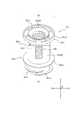
- FIG. 4 is a view showing the mounting member 251 of the prefilled syringe 200 shown in FIG.
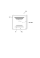
- FIG. 5 is a block diagram showing the RFID tag 260 installed in the prefilled syringe 200 and the reader 31 of the syringe pump 100.
- FIG. 1 is a perspective view showing a prefilled syringe 200 installed in a syringe pump 100 as one embodiment.
- FIG. 2 is a perspective view showing the prefilled syringe 200 shown in FIG.
- FIG. 6 is a view showing the RFID tag 260 installed in the prefilled syringe 200.
- FIG. 7 is a view showing a mounting member 651 as a first modification of the mounting member 251 of the prefilled syringe 200 shown in FIG.
- FIG. 8 is a view showing a mounting member 751 as a second modification of the mounting member 251 of the prefilled syringe 200 shown in FIG.
- FIG. 9 is a view showing a mounting member 851 as a third modification of the mounting member 251 of the prefilled syringe 200 shown in FIG.
- FIG. 10 is a view showing a mounting member 951 as a fourth modification of the mounting member 251 of the prefilled syringe 200 shown in FIG.
- FIG. 11 is a view showing a mounting member 1051 as a fifth modification of the mounting member of the prefilled syringe 200 shown in FIG.
- FIG. 12 is a view showing a mounting member 1151 as a sixth modification of the mounting member 251 of the prefilled syringe 200 shown in FIG.
- FIG. 13 is a diagram showing an RFID tag 360 as a modification of the RFID tag 260 installed in the prefilled syringe 200 shown in FIG.
- FIG. 14 is a view showing a syringe pusher 1150 as a modification of the syringe pusher 250 of the prefilled syringe 200 shown in FIG.
- FIG. 15 is a diagram showing another arrangement of the RFID tag 260 in the syringe pusher 1150 shown in FIG.
- prefilled syringe 200 As shown in FIG. 1, the prefilled syringe 200 of this embodiment can be installed in the syringe pump 100.
- the prefilled syringe 200 includes a chemical solution 210, a barrel 220, a cap 230, a gasket 240, a syringe pusher 250, and an RFID tag 260.
- the drug solution 210 is, for example, an anticancer agent, an anesthetic agent, a chemotherapeutic agent, a blood transfusion, a nutrient, or the like.
- the chemical liquid 210 is contained in the barrel 220. The chemical solution 210 is injected into the patient's body as will be described later.
- the barrel 220 includes a barrel body 220a, a nozzle portion 220b, and a flange portion 220c.
- the barrel 220 is provided with a proximal end opening 220d.
- the barrel body 220a has a cylindrical shape (for example, a cylindrical shape) and contains the chemical 210.
- the nozzle part 220b is provided on the tip side of the barrel body 220a.
- a tip opening 220b1 is provided at the tip of the nozzle portion 220b.
- the chemical liquid 210 is discharged from the tip opening 220b1.
- the nozzle portion 220b has a cylindrical shape, and a tube 270 (indicated by a two-dot chain line in FIGS. 1 and 2) can be connected to the nozzle portion 220b.
- the flange part 220c protrudes from the base end part of the barrel body part 220a toward the outside in the radial direction B of the barrel body part 220a.
- the base end opening 220d is provided at the base end of the barrel body 220a.
- An insertion portion 250i (described later) of the syringe pusher 250 is inserted through the proximal end opening 220d.
- the cap 230 can seal the tip opening 220b1 provided at the tip of the nozzle 220b.
- FIG. 2 shows a state in which the cap 230 is removed from the nozzle portion 220b and the tip opening 220b1 is opened.
- the gasket 240 is made of rubber or elastomer in this embodiment.
- the gasket 240 is slidable on the inner peripheral surface of the barrel body 220a.
- the gasket 240 according to the present embodiment is a cylindrical body having a distal end closed and a proximal end opened.
- the gasket 240 has a mounting recess 240a that opens toward the proximal end and extends along the axial direction A of the barrel body 220a.
- a mounting member engaging portion 240a2 is formed in the mounting recess 240a.
- a chemical solution storage portion 211 for storing the chemical solution 210 is formed in the barrel 220 by the gasket 240.
- the amount (milliliter) of the chemical solution to be stored is associated with the outer diameter D (millimeter) of the prefilled syringe 200, and is defined in, for example, ISO 11040-6 (Prefilled syringes-Part 6: ing.
- the outer diameter D is 14 millimeters.
- the amount of medicinal solution that can be stored is 10 milliliters
- the outer diameter D is 17 millimeters.
- the amount of chemicals that can be stored is 20 milliliters
- the outer diameter D is 22 millimeters.
- the amount of medicinal solution that can be stored is 50 milliliters, the outer diameter D is 33 millimeters.
- the syringe pusher 250 can be attached to the gasket 240.
- the syringe pusher 250 has an insertion portion 250i that can be inserted into the barrel body 220a.
- the syringe pusher 250 includes a mounting member 251 that can be mounted on the gasket 240 and a pressing member 252 that can be mounted on the mounting member 251.
- the entire mounting member 251 constitutes the insertion portion 250i.
- the RFID tag 260 is installed in the insertion portion 250i. Note that, in a modification example (see FIG. 7 or the like) of the mounting member, which will be described later, the entire mounting member constitutes the insertion portion 250i, and the RFID tag 260 is installed in the insertion portion 250i.
- the mounting member 251 includes a mounting insertion portion 251a that is inserted into the mounting recess 240a of the gasket 240, and a main body portion 251b that is positioned on the proximal end side of the mounting insertion portion 251a.
- the mounting insertion part 251a is a part protruding from the distal end side of the main body part 251b.
- a gasket engaging portion 251a1 is formed on the outer peripheral surface of the mounting insertion portion 251a of the mounting member 251.
- the gasket 240 and the mounting member 251 are engaged by a mounting member engaging portion 240 a 2 of the gasket 240 and a gasket engaging portion 251 a 1 of the mounting member 251.
- This engagement can be a screw joint.
- the male thread portion as the gasket engaging portion 251 a 1 of the mounting member 251 is the mounting member engaging portion of the gasket 240. It penetrates to the tip side from the female screw portion as 240a2.
- the main body 251b of the mounting member 251 extends along the axial direction A of the barrel body 220a.
- a pressing member 252 can be attached to the main body 251 b of the attachment member 251.
- the main body 251b has a cylindrical body 251b0, a first flange 251b1, and a second flange 251b2.
- the first flange portion 251b1 since the first flange portion 251b1 is in the radial direction from the cylindrical body portion 251b0 (in the state where the first flange portion 251b1 is inserted into the barrel body portion 220a, it is the same direction as the radial direction B of the barrel body portion 220a. , Described as “radial direction B”). Therefore, the outer diameter D1 of the first flange portion 251b1 is larger than the outer diameter D0 of the cylindrical body portion 251b0. In this embodiment, the 1st flange part 251b1 protrudes from the front-end
- first flange portion 251b1 can come into contact with the inner peripheral surface of the barrel body 220a.
- the outer diameter D1 of the first flange portion 251b1 is slightly smaller than or substantially equal to the inner diameter of the barrel body 220a.
- the second flange portion 251b2 protrudes outward in the radial direction B from the cylindrical body portion 251b0 on the proximal end side of the first flange portion 251b1 in the cylindrical body portion 251b0.
- the outer diameter D2 of the second flange portion 251b2 is larger than the outer diameter D0 of the cylindrical body portion 251b0.
- the 2nd flange part 251b2 protrudes from the base end part of the cylindrical trunk
- the 2nd flange part 251b2 can also contact
- the outer diameter D2 of the second flange portion 251b2 is slightly smaller than or substantially equal to the inner diameter of the barrel body 220a. Moreover, as shown in FIG. 4, the inner edge part 251b21 of the 2nd flange part 251b2 protrudes in the axial direction A rather than the other part of the 2nd flange part 251b2.
- the mounting member 251 is formed with a recess 251r that does not contact the gasket 240, the pressing member 252, and the barrel body 220a.
- the mounting member 251 can contact the gasket contact portion 251c that can contact the gasket 240, the pressing member contact portion 251d that can contact the pressing member 252, and the inner peripheral surface of the barrel body 220a.
- the recessed part 251r is formed in a different area
- the mounting member 251 on which the RFID tag 260 is disposed as shown in FIG. 2 can be fixed to the gasket 240 in the barrel 220 containing the drug solution 210.
- This also applies to a modification example (see FIG. 7 and the like) described later of the mounting member.
- the prefilled syringe 200 can be transported while the RFID tag 260 in which the information of the chemical liquid 210 is written is accommodated in the barrel 220 containing the chemical liquid 210.
- the pressing member 252 can be mounted on the mounting member 251.
- the pressing member 252 is movable in the axial direction A of the barrel body 220a.
- the pressing member 252 includes a main body portion 252a and a flange portion 252b.
- the front end of the main body 252a can be fixed to the mounting member 251.
- the pressing member 252 and the mounting member 251 can be fixed by screw joining.
- the mounting member 251 fixed to the gasket 240 in the barrel 220 and the pressing member 252 can be separated when the prefilled syringe 200 is shipped. Since the pressing member 252 is generally a long member, the total length in the axial direction is shortened by shipping the prefilled syringe 200 in a state where the mounting member 251 and the pressing member 252 are separated from each other as compared with a state where the pressing member 252 is not separated. In the state, the prefilled syringe 200 can be transported.
- the medical staff can fix the pressing member 252 to the mounting member 251 fixed to the gasket 240 in the barrel 220 at the site. This point is the same in a later-described modification of the mounting member (see FIG. 7 and the like).
- the flange portion 252b is a proximal end portion of the pressing member 252 and protrudes from the main body portion 252a toward the outside in the radial direction B.
- the syringe pusher 250 has an insertion portion 250i that can be inserted into the barrel body 220a.
- the RFID tag 260 is installed in the insertion portion 250i.
- the RFID tag 260 is installed in the recess 251r that does not contact the gasket 240, the pressing member 252 and the barrel body 220a.
- the RFID tag 260 has a rectangular shape.
- the RFID tag 260 is installed on the outer surface of the main body 251b of the mounting member 251. More specifically, as shown in FIG. 4, the RFID tag 260 is installed on the outer peripheral surface of the cylindrical body 251b0 of the main body 251b. Further, the RFID tag 260 of the present embodiment has the same axial direction as the axial direction A of the barrel body 220a in the state of being inserted into the barrel body 220a in the cylindrical body 251b0 of the main body 251b. Therefore, it is described along the axial direction A in the center portion of “axial direction A”.
- the size of the RFID tag 260 can be made sufficiently large.
- the reader 31 (see FIG. 5) of the syringe pump 100 can read the data of the RFID tag 260 more reliably.
- the reader 31 of the syringe pump 100 can read the data of the RFID tag 260 more reliably by making the RFID tag 260 face the reader 31 of the syringe pump 100. it can.
- the RFID tag 260 includes a communication antenna 261, a memory 62, and a control unit 263.
- the RFID tag 260 carries a tag body 260 a having an antenna 261 and a memory 262, and a tag body 260 a and affixed to a surface such as an outer surface of the mounting member 251.
- a label portion 260b having a surface 260b1 (the surface on the back side in FIG. 6).
- the tag body 260a can be a plastic substrate, for example.
- the antenna 261 of the RFID tag 260 is configured by an antenna wire wound in a rectangular shape.
- the antenna wire is not limited to a rectangular shape, and may be wound in a circular shape.
- the area on the insertion portion 251i where the RFID tag 260 can be installed is limited. Therefore, it is preferable to wind the antenna wire in a rectangular shape. In this way, it is easy to ensure a large loop area formed by the antenna wire, compared to a configuration in which the antenna wire is wound in a circular shape. Thereby, as shown in FIG.
- the RFID tag 260 of the prefilled syringe 200 and the reader 31 of the syringe pump 100 can communicate with each other even if they are not aligned with high accuracy.
- the antenna 261 of the RFID tag 260 communicates by wireless communication with a short reach, such as NFC (Near Field Communication).
- NFC Near Field Communication
- the control unit 263 of the RFID tag 260 can read data from the memory 262 and cause the antenna 261 to transmit the data.
- Wireless communication between the antenna 261 of the RFID tag 260 and the reader antenna 31a of the reader 31 of the syringe pump 100 has a short communicable distance (for example, within 35 mm). Therefore, when the RFID tag 260 of the prefilled syringe 200 is separated from the reader antenna 31a of the reader 31 by a predetermined distance or more, the reader antenna 31a of the reader 31 cannot communicate with the RFID tag 260 of the prefilled syringe 200.
- the memories 262 and 263 of the RFID tag 260 can be configured by an integrated circuit (IC chip) including a nonvolatile memory, for example.
- the antenna 261 of the RFID tag 260 receives electromagnetic waves transmitted from the reader antenna 31 a of the reader 31 of the syringe pump 100.
- the operating power of the RFID tag 260 can be obtained from this electromagnetic wave.
- the control unit 263 reads data in the memory 262 of the RFID tag 260, puts the data on an electromagnetic wave using the antenna 261, and returns (transmits) the data to the reader antenna 31 a of the reader 31.
- the reader antenna 31 a of the reader 31 receives electromagnetic waves from the antenna 261 of the RFID tag 260.
- control part 31c of the syringe pump 100 acquires the data memorize
- various data such as the name of the chemical liquid 210, identification data for each individual, dimension data of the barrel 220, dimension data of the stroke of the syringe pusher 250, and the like are stored for the prefilled syringe 200. ing.
- an information description label 300 is attached to the outer peripheral surface of the barrel body 220a.
- the information description label 300 is provided with two scales 301 along the axial direction A of the barrel body 220a. More specifically, the notches of the two scales 301 of the present embodiment are arranged along the axial direction A of the barrel body 220a.
- the scale 301 indicates the amount of the chemical solution 210 in the barrel body 220a.
- the two scales 301 are symmetric with respect to the central axis of the barrel body 220a. .
- the information description label 300 can be provided with an information area 302 in which the drug name or the amount of the drug solution is described.
- the syringe pump 100 is used in, for example, an intensive care unit. Moreover, the syringe pump 100 is used when a microinjection treatment of a liquid medicine such as an anticancer agent, an anesthetic agent, a chemotherapeutic agent, a blood transfusion, etc. is performed on the patient P with a high accuracy for a relatively long time. Can be used.
- a liquid medicine such as an anticancer agent, an anesthetic agent, a chemotherapeutic agent, a blood transfusion, etc.
- the syringe pump 100 of the present embodiment can be attached to and detached from a stand or the like, and can be used while being attached to the stand or the like.
- the prefilled syringe 200 is fixed to the syringe pump 100 so that the axial direction A of the barrel body 220a is horizontal.
- the syringe pump 100 includes a syringe pusher drive unit 2, a main body unit 3, a support unit 4, and a clamp unit 5.
- the syringe pusher drive unit 2 drives the syringe pusher 250 of the prefilled syringe 200 in the distal direction toward the distal end side of the barrel body 220a.
- the syringe pusher drive unit 2 can drive the syringe pusher 1150 shown in FIGS. 14 and 15 in the same manner.
- the syringe pusher drive unit 2 of the present embodiment includes a pressing unit 2a and a flange fixing unit 2b.
- the pressing portion 2a is disposed on the proximal end side in the axial direction A with respect to the flange portion 252b of the pressing member 252 as the flange portion 250b of the syringe presser 250 of the prefilled syringe 200 in the mounted state.
- the surface of the base end side of the axial direction A of the flange part 250b of the syringe pusher 250 can be pressed to the front end side of the axial direction A by moving the pressing part 2a to the front end side of the axial direction A. .
- the syringe pusher 250 can be moved relatively to the distal end side in the axial direction A with respect to the barrel 220 of the prefilled syringe 200 in the mounted state.
- the flange fixing part 2b fixes the flange part 250b of the syringe pusher 250 to the pressing part 2a.
- the flange fixing portion 2b of the present embodiment is located on the distal end side in the axial direction A of the pressing portion 2a and is attached to the pressing portion 2a.
- the flange portion 250b of the syringe pusher 250 is disposed between the pressing portion 2a and the flange fixing portion 2b. Accordingly, the syringe pusher 250 can move in the axial direction A following the movement of the syringe pusher drive unit 2 in the axial direction A.
- the flange portion 220 c of the barrel 220 is fitted in the flange receiving groove 7 of the main body portion 3.
- the main body 3 includes a reader 31 including a reader antenna 31a (see FIG. 5) that receives a data set stored in the memory 262 of the RFID tag 260 of the prefilled syringe 200, and a control unit 13 that controls the syringe pusher drive unit 2.
- the reader 31 and the control unit 13 of this embodiment are arranged inside the main body unit 3.
- the control part 13 of the syringe pump 100 and the control part 31c mentioned above can be made into a separate component. Further, the control unit 31c and the control unit 13 may be integrated into the same component.
- the reader antenna 31a of the reader 31 is composed of a reader antenna line.
- the outer edge of the reader antenna 31a composed of the reader antenna line is rectangular.
- the reader antenna 31a of the reader 31 can transmit electromagnetic waves in a state where the prefilled syringe 200 is received by the support unit 4 described later.
- the RFID tag 260 attached to the prefilled syringe 200 transmits data in response to the electromagnetic wave.
- the reader antenna 31a of the reader 31 can receive the data.
- the main body unit 3 of the present embodiment includes a display unit 32 and an operation panel unit 33.
- the support portion 4 of the present embodiment is formed on the front surface of the main body portion 3. Moreover, the support part 4 of this embodiment supports the outer peripheral surface of the barrel trunk
- the support portion 4 of the present embodiment is configured by a concave curved surface having a substantially semicircular cross section.
- the support part 4 of this embodiment can receive the barrel barrel part 220a of several types from which magnitude
- the clamp portion 5 faces the support portion 4 formed in the main body portion 3, and clamps the barrel body 220 a of the prefilled syringe 200 between the support portion 4.
- the prefilled syringe 200 operates in the following manner when attached to the syringe pump 100.
- the syringe pusher 250 is pressed toward the distal end side in the axial direction A by the syringe pump 100.
- the gasket 240 (refer FIG. 2 etc.) connected with the syringe pusher 250 slides in the barrel trunk
- the chemical solution 210 (see FIG. 2 and the like) in the barrel body 220a is compressed.
- the chemical liquid 210 is discharged through the nozzle part 220b of the barrel body part 220a by this compressive force.
- the tube 270 is connected to the tip opening 220b1 (see FIG. 2 and the like) of the nozzle portion 220b of the prefilled syringe 200.
- an indwelling needle 280 to be placed in the patient P is connected to the distal end of the tube 270. Therefore, the chemical liquid 210 in the barrel body 220a can be fed into the patient P through the tube 270 and the indwelling needle 280.
- FIG. 7 shows a mounting member 651 as a first modification of the mounting member 251 described above.
- the mounting member 651 can be mounted on the gasket 240 (see FIG. 3).
- the mounting member 651 is positioned on the mounting insertion portion 651a inserted into the mounting recess 240a (see FIG. 3 etc.) of the gasket 240 (see FIG. 3 etc.) and on the proximal end side of the mounting insertion portion 651a.
- Main body 651b As shown in FIG. 7, the mounting member 651 is positioned on the mounting insertion portion 651a inserted into the mounting recess 240a (see FIG. 3 etc.) of the gasket 240 (see FIG. 3 etc.) and on the proximal end side of the mounting insertion portion 651a.
- Main body 651b Main body 651b.
- a gasket engaging portion 651a1 is formed on the outer peripheral surface of the mounting insertion portion 651a of the mounting member 651.
- the gasket 240 and the mounting member 651 are engaged by the mounting member engaging portion 240a2 (see FIG. 3 and the like) of the gasket 240 and the gasket engaging portion 651a1 of the mounting member 651.
- This engagement can be a screw joint.
- the main body 651b of the mounting member 651 extends along the axial direction A of the barrel body 220a.
- a pressing member 252 (see FIG. 3) can be mounted on the main body 651b of the mounting member 651.
- the main body portion 651b includes a plate-shaped main body 651b0, a first flange portion 651b1, and a second flange portion 651b2.
- the plate-like main body 651b0 has four plate portions 651c1 to 651c4 extending radially from the central axis R of the mounting member 651.
- the four plate portions 651c1 to 651c4 are provided in a cross shape in a cross-sectional view of the plate-like main body 651b0 orthogonal to the central axis R of the mounting member 651.
- the RFID tag 260 is disposed on one surface of one plate portion 651c1.
- the first flange portion 651b1 in FIG. 7 is a disc-shaped portion that is disposed at the distal end portion of the main body portion 651b and that has the central axis R of the mounting member 651 as an axis.
- the outer peripheral surface constituting the outer diameter D1 of the first flange portion 651b1 is located at a position equal to or outside the outer end of the plate-like main body 651b0 in the radial direction with respect to the central axis R.
- the thickness along the axial direction A of the first flange portion 651b1 is larger than that of the first flange portion 251b1 of the mounting member 251 in FIG.
- the rigidity of the 1st flange part 651b1 can be made larger than the rigidity of the 1st flange part 251b1. Further, the first flange portion 651b1 can come into contact with the inner peripheral surface of the barrel body 220a.
- the second flange portion 651b2 in FIG. 7 is a disc-shaped portion that is disposed at the base end portion of the main body portion 651b and that has the central axis R of the mounting member 651 as an axis.
- the outer peripheral surface constituting the outer diameter D2 of the second flange portion 651b2 is located at a position equal to or outside the outer end of the plate-like main body 651b0 in the radial direction with respect to the central axis R.
- the thickness along the axial direction A of the second flange portion 651b2 is the same as that of the second flange portion 251b2 of the mounting member 251 of FIG. Further, the second flange portion 651b2 can contact the inner peripheral surface of the barrel body 220a.
- the mounting member 651 is formed with a recess 651r that does not contact the gasket 240 (see FIG. 2 and the like), the pressing member 252 (see FIG. 2 and the like), and the barrel body 220a (see FIG. 2 and the like). .
- the RFID tag 260 is installed in a recess 651r that does not contact the gasket 240, the pressing member 252, and the barrel body 220a.
- the RFID tag 260 has a rectangular shape.
- the RFID tag 260 is installed on the outer surface of the main body 651b of the mounting member 651. More specifically, the RFID tag 260 is disposed on one side of the single plate portion 651c1. By attaching the RFID tag 260 to almost the entire surface of at least one side surface of the plate portion 651c1, the RFID tag 260 is made sufficiently large so that the reader 31 (see FIG. 5) of the syringe pump 100 can easily read the data of the RFID tag 260. be able to. Further, since the RFID tag 260 of FIG. 7 is disposed on the flat plate portion 651c1, it does not deform like the RFID tag 260 disposed on the cylindrical surface shown in FIG. Therefore, the RFID tag 260 in FIG. 7 is less likely to be damaged than the RFID tag 260 in FIG.
- FIG. 8 shows a mounting member 751 as a second modification of the mounting member 251 described above.
- the mounting member 751 can be mounted on the gasket 240 (see FIG. 3).
- the mounting member 751 is positioned on the mounting insertion portion 751a inserted into the mounting recess 240a (see FIG. 3 etc.) of the gasket 240 (see FIG. 3 etc.) and on the proximal end side of the mounting insertion portion 751a.
- Main body 751b is positioned on the mounting insertion portion 751a inserted into the mounting recess 240a (see FIG. 3 etc.) of the gasket 240 (see FIG. 3 etc.) and on the proximal end side of the mounting insertion portion 751a.
- a gasket engaging portion 751a1 is formed on the outer peripheral surface of the mounting insertion portion 751a of the mounting member 751.
- the gasket 240 and the mounting member 751 are engaged by the mounting member engaging portion 240a2 (see FIG. 3 and the like) of the gasket 240 and the gasket engaging portion 751a1 of the mounting member 751.
- This engagement can be a screw joint.
- the mounting insertion portion 751a is cylindrical and has a hole 751a2.
- the main body 751b of the mounting member 751 extends along the axial direction A of the barrel body 220a.
- a pressing member 252 (see FIG. 3) can be mounted on the main body 751b of the mounting member 751.
- the main body 751b has a cylindrical body 751b0, a plate-like part 751b3, a first flange part 751b1, and a second flange part 751b2.
- the cylindrical body portion 751b0 is formed of a cylinder extending along the axial direction A and having an outer diameter D0.
- the plate-like portion 751b3 has four plates 751c1 to 751c4 projecting radially (cross-shaped) from the cylindrical body portion 751b0 in a cross-sectional view orthogonal to the central axis R of the mounting member 651.
- the first flange portion 751b1 protrudes radially outward from the cylindrical body portion 751b0, and the outer diameter D1 is larger than the outer diameter D0 of the cylindrical body portion 751b0.
- the first flange portion 751b1 protrudes from the distal end portion of the cylindrical body portion 751b0. Further, the first flange portion 751b1 can contact the inner peripheral surface of the barrel body 220a (see FIG. 2 and the like).
- the RFID tag 360 is installed in one of the four regions that are defined by the four plates 751c1 to 751c4 that exist on the proximal end side of the first flange portion 751b1.
- the second flange portion 751b2 protrudes radially outward from the cylindrical trunk portion 751b0 on the proximal end side of the first flange portion 751b1 in the cylindrical trunk portion 751b0, and the outer diameter D2 is the outer diameter of the cylindrical trunk portion 751b0. Greater than D0.
- the 2nd flange part 751b2 protrudes from the base end part of the cylindrical trunk
- the second flange portion 751b2 can also contact the inner peripheral surface of the barrel body 220a. Further, the inner edge portion 751b21 of the second flange portion 751b2 protrudes in the axial direction A from the other portion of the second flange portion 751b2.
- the mounting member 751 is formed with a recess 751r that does not contact the gasket 240 (see FIG. 2 and the like), the pressing member 252 (see FIG. 2 and the like), and the barrel body 220a (see FIG. 2 and the like).
- the recess 751r is an area defined by the outer surface of the cylindrical body 751b0 and both side surfaces of the four plates 751c1 to 751c4. The same applies to the recesses described later.
- the RFID tag 360 is installed in a recess 751r that does not contact the gasket 240, the pressing member 252, and the barrel body 220a.
- the RFID tag 360 has a curved strip shape. Thereby, the size of the RFID tag 360 is increased, and the reader of the syringe pump 100 can easily read the data of the RFID tag 360.
- the antenna of the RFID tag 360 can be formed by winding a conducting wire so that the outer edge has an arc shape.
- the other configuration of the RFID tag 360 is the same as the configuration of the RFID tag 260 described above.
- the RFID tag 360 is installed on the outer surface of the main body 751b of the mounting member 751. More specifically, the RFID tag 360 is installed in almost the entire area of the base end side surface of the first flange portion 751b1 in one of the four areas defined by the four plates 751c1 to 751c4. ing. Thereby, the RFID tag 360 can be made sufficiently large so that the reader of the syringe pump 100 can easily read the data of the RFID tag 360. In addition, by arranging the RFID tag 360 on the planar first flange portion 751b1, deformation of the RFID tag 360 can be suppressed, and damage to the RFID tag 360 can be suppressed.
- the RFID tag 360 can be installed on the second flange portion 751b2 instead of the first flange portion 751b1. More specifically, in one of the four regions defined by the four plates 751c1 to 751c4, almost the entire area of the surface on the tip side of the second flange portion 751b2 (for example, the RFID tag 260 in FIG. The RFID tag 360 can be installed in a region facing the disposed region.
- FIG. 9 shows a mounting member 851 as a third modification of the mounting member 251 described above.
- the mounting member 851 can be mounted on the gasket 240 (see FIG. 3).
- the mounting member 851 in FIG. 9 basically has the same configuration as the mounting member 751 in FIG. Therefore, the same members as those of the mounting member 751 in FIG. Hereinafter, a configuration different from the mounting member 751 of FIG. 8 will be mainly described.
- a second flange portion 751b2 is formed at the base end portion of the mounting member 851.
- the inner edge portion 751b21 of the second flange portion 751b2 protrudes in the axial direction A from the other portion of the second flange portion 751b2.
- the other portions are a gasket 240 (see FIG. 2 and the like), a pressing member 252 (see FIG. 2 and the like), and a recess 751r that does not contact the barrel body 220a (see FIG. 2 and the like).
- an annular groove may be formed on the base end side surface of the second flange portion 751b2, and this may be used as the recess 751r.
- the RFID tag 460 is installed in the recess 751r.
- the RFID tag 460 is installed on the outer surface of the main body 751b of the mounting member 851.
- the RFID tag 460 has a ring shape. Thereby, the size of the RFID tag 460 disposed on the annular second flange portion 751b2 is increased, and the reader 31 (see FIG. 5) of the syringe pump 100 can easily read the data of the RFID tag 460.
- the antenna of the RFID tag 460 can be formed by winding a conductive wire so that the outer edge has a ring shape.
- the other configuration of the RFID tag 460 is the same as the configuration of the RFID tag 260 described above.
- FIG. 10 shows a mounting member 951 as a fourth modification of the mounting member 251 described above.
- the mounting member 951 can be mounted on the gasket 240 (see FIG. 3).
- the mounting member 951 shown in FIG. 10 basically has the same configuration as the mounting member 751 shown in FIG. Therefore, the same reference numerals are attached to the mounting member 751 and the member in FIG. Hereinafter, a configuration different from the mounting member 751 of FIG. 8 will be mainly described.
- the RFID tag 260 attached to the mounting member 951 is rectangular.
- the RFID tag 260 is installed closer to the base end side than the gasket engaging portion 751a1 on the outer peripheral surface of the mounting insertion portion 751a.
- the mounting insertion portion 751a of the mounting member 951 in FIG. 10 is inserted into the mounting recess 240a of the gasket 240 made of rubber or elastomer. That is, the RFID tag 260 shown in FIG. 10 faces the inner peripheral surface of the mounting recess 240a of the gasket 240.
- the RFID tag 260 when the RFID tag 260 is opposed to the inner peripheral surface of the mounting recess 240a of the gasket 240 made of elastic rubber or elastomer, when the prefilled syringe 200 is subjected to an impact, the RFID tag 260 is provided. Can be prevented from being damaged.
- FIG. 11 shows a mounting member 1051 as a fifth modification of the mounting member 251 described above.
- the mounting member 1051 can be mounted on the gasket 240 (see FIG. 3).
- the mounting member 1051 in FIG. 11 basically has the same configuration as the mounting member 751 in FIG. Therefore, the same reference numerals are attached to the mounting member 751 and the member in FIG. Hereinafter, a configuration different from the mounting member 751 of FIG. 8 will be mainly described.
- the mounting insertion portion 751a of the mounting member 1051 is cylindrical and has a hole 751a2.
- the mounting member 1051 is formed with a recess 1051r that is a region that does not contact the gasket 240 (see FIG. 2 and the like), the pressing member 252 (see FIG. 2 and the like), and the barrel body 220a (see FIG. 2 and the like).
- a rectangular RFID tag 260 is disposed in the recess 1051r. More specifically, the RFID tag 260 is installed along the axial direction A on the inner peripheral surface of the hole 751a2.
- the RFID tag 260 can be protected by the mounting insertion portion 751a, and damage to the RFID tag 260 can be further suppressed.
- FIG. 12 shows a mounting member 1151 as a sixth modification of the mounting member 251 described above.
- the mounting member 1151 can be mounted on the gasket 240 (see FIG. 3).
- the mounting member 1151 in FIG. 12 basically has the same configuration as the mounting member 751 in FIG. Therefore, the same reference numerals are attached to the mounting member 751 and the member in FIG. Hereinafter, a configuration different from the mounting member 751 of FIG. 8 will be mainly described.
- the RFID tag 560 included in the mounting member 1151 will be described. As shown in FIG. 13, the RFID tag 560 includes a tag main body 260a having an antenna 261 and a memory 262, and a cover portion 564 that covers the tag main body 260a.
- the mounting insertion portion 751a of the mounting member 1151 is cylindrical and has a hole 751a2.
- the mounting member 1151 is formed with a recess 1151r that is a region that does not contact the gasket 240 (see FIG. 2 and the like), the pressing member 252 (see FIG. 2 and the like), and the barrel body 220a (see FIG. 2 and the like).
- An RFID tag 560 is installed in the recess 1151r. Specifically, by fitting the RFID tag 560 into the hole 751a2, the RFID tag 560 is accommodated and fixed in the hole 751a2.
- the cover portion 564 protects the tag main body 260a, and the RFID tag 560 is prevented from coming into contact with the gasket 240, the pressing member 252 or the barrel trunk portion 220a.
- the RFID tag 560 can be prevented from being damaged.
- the RFID tag 560 can be insert-molded in the mounting member 1151.
- the tag main body 260a is disposed in the cover portion 564 configured as a case, and the cover portion 564 is disposed in the mold for forming the mounting member 1151, and then the resin is injected into the mold. To do.
- the mounting member 1151 and the RFID tag 560 can be integrated.
- the tag main body 260 a having the antenna 261 and the memory 262 may be embedded in the mounting member 1151. In this manner, by integrating the mounting member 1151 and the RFID tag, the RFID tag can be protected by the mounting member 1151, and damage to the RFID tag can be further suppressed. Further, it is difficult to intentionally remove the RFID tag from the syringe.
- FIG. 14 shows a syringe pusher 1150 as a modified example of the syringe pusher 250 described above.
- the syringe pusher 1150 is a single member unlike the syringe pusher 250 having the separable mounting member 251 and the pressing member 252 shown in FIG.
- the syringe pusher 1150 has an insertion portion 1150i that can be inserted into the barrel body 220a at the distal end portion.
- the syringe pusher 1150 can be attached to the gasket 240. More specifically, a gasket engaging portion 1150a that engages with the mounting member engaging portion 240a2 of the gasket 240 shown in FIG. 3 is formed on the outer peripheral surface of the distal end portion of the syringe pusher 1150. This engagement can be a screw joint.
- the first flange portion 1150b1 and the second flange portion 1150b2 that protrude in the radial direction B and can come into contact with the inner peripheral surface of the barrel body portion 220a are formed in the insertion portion 1150i.
- a third flange portion 1150b3 protruding in the radial direction B is formed at the proximal end portion of the syringe pusher 1150.
- the RFID tag 260 is installed in the insertion portion 1150i. More specifically, referring to FIG. 14B, which is a cross-sectional view taken along line II-II in FIG. 14A, the RFID tag 260 is provided between the first flange portion 1150b1 and the second flange portion 1150b2. It is affixed on the inner peripheral surface of the syringe pusher 1150 located at the position. According to this configuration, when the RFID tag 260 is covered by the insertion portion 1150i of the syringe pusher 1150, the RFID tag 260 can be strongly protected and damage to the RFID tag 260 can be suppressed.
- the RFID tag 260 is attached to the outer peripheral surface 1150c of the syringe pusher 1150 located between the first flange portion 1150b1 and the second flange portion 1150b2. According to this configuration, when the prefilled syringe 200 is installed in the syringe pump 100, the reader of the syringe pump 100 can read the data of the RFID tag 260 more reliably. In addition, the RFID tag 260 can be prevented from being damaged by installing the RFID tag 260 on the outer peripheral surface 1150c, which is a region that does not contact the gasket 240, the pressing member 252, and the barrel body 220a.
- the syringe pusher 250 has the insertion portion 250i that can be inserted into the barrel body 220a, and the RFID tag 260 is installed in the insertion portion 250i of the syringe pusher 250.
- the RFID tag 260 is not exposed to the outer surface of the barrel 220, and the RFID tag can be prevented from being damaged when the prefilled syringe 200 is transported or installed. Further, since the RFID tag 260 is not incorporated into the gasket, the RFID tag is not damaged when the gasket is installed in the syringe.
- the syringe pusher 250 or 1150 includes a mounting member (251 or the like, hereinafter referred to as 251) that can be mounted on the gasket 240, and a pressing member 252 that can be mounted on the mounting member 251.
- the insertion portion 250i is provided on the mounting member 251.
- the RFID tag 260 in which the information about the chemical liquid 210 is written can be prevented from being separated from the barrel 220 containing the chemical liquid 210.
- the mounting member 251 fixed to the gasket 240 in the barrel 220 and the pressing member 252 can be separated. Since the pressing member 252 is generally a long member, the prefilled syringe 200 can be prevented from being bulky by separating the mounting member 251 and the pressing member 252.
- the medical staff can fix the pressing member 252 to the mounting member 251 fixed to the gasket 240 in the barrel 220 at the site.
- the mounting member 251 is formed with a recess 251r that does not contact the gasket 240, the pressing member 252, and the barrel body 220a, and the RFID tag 260 is in the recess 251r. Is arranged. Thereby, when the prefilled syringe 200 is transported or used, the RFID tag 260 can be prevented from coming into contact with the gasket 240, the pressing member 252 or the barrel body 220a and being damaged.
- the gasket 240 includes a mounting recess 240a that opens toward the proximal end, and the mounting member 251 includes a mounting insertion portion 251a that is inserted into the mounting recess 240a, and a mounting insertion.
- the RFID tag 260 is installed on the outer surface of the main body 251b. Therefore, since the gasket 240 does not contact the RFID tag 260, the RFID 260 tag can be prevented from being damaged when the gasket 240 is installed in the prefilled syringe 200.
- the main body portion 251b of the mounting member 251 protrudes radially outward from the cylindrical body portion 251b0 and the inner surface of the barrel body 220a.
- the first flange portion 251b1 that can be in contact with the inner peripheral surface of the barrel barrel portion 220a and projecting radially outward from the cylindrical barrel portion 251b0 on the proximal end side of the first flange portion 251b1 of the cylindrical barrel portion 251b0.
- the RFID tag 260 is installed on the outer peripheral surface of the cylindrical body 251b0. Thereby, it can suppress further that a RFID tag contacts with the internal peripheral surface of the barrel trunk part 220a, and can suppress that the RFID tag 260 is damaged.
- the gasket 240 is made of rubber or elastomer, the gasket 240 has a mounting recess 240a that opens toward the proximal end, and the mounting member 251 is in the mounting recess 240a.
- the RFID tag 260 is installed on the outer peripheral surface of the mounting insertion portion 251a, and the mounting recess of the gasket 240 is provided. It faces the inner peripheral surface of 240a.
- the RFID tag 260 when the RFID tag 260 is opposed to the inner peripheral surface of the mounting recess 240a of the gasket 240 made of elastic rubber or elastomer, when the prefilled syringe 200 is subjected to an impact, the RFID tag 260 is provided. Can be prevented from being damaged.
- the RFID tag 260 includes a tag main body 260a having an antenna 261 and a memory 262, and a sticking surface 260b1 that is attached to the outer surface of the mounting member 251 while carrying the tag main body 260a.
- the RFID tag 560 includes a tag main body 260a having the antenna 261 and the memory 262, and a cover portion 564 that covers the tag main body 260a, and the RFID tag 560 includes an attachment member. 251. Accordingly, the cover portion 564 protects the tag main body 260a, and the mounting member 251 protects the RFID tag 560, so that the RFID tag 560 can be prevented from being damaged.
- the RFID tag 560 is insert-molded in the mounting member 251. Thereby, damage to the RFID tag 560 can be further suppressed. Further, the RFID tag 560 can be prevented from being intentionally removed from the prefilled syringe 200.
- Syringe pump 13 Control unit 2: Syringe pusher drive unit 200: Prefilled syringe 210: Chemical solution 211: Chemical solution storage unit 220: Barrel 220a: Barrel barrel unit 220b: Nozzle unit 220b1: Tip opening 220c: Flange unit 220d: Base end opening 230: Cap 240: Gasket 240a: Mounting recess 240a2: Mounting member engaging portion 250: Syringe pusher 250b: Flange portion 250i: Inserting portion 251: Mounting member 251a: Mounting inserting portion 251a1: Gasket engaging portion 251b : Body 251b0: cylindrical body 251b1: first flange 251b2: second flange 251b21: inner edge 251c of the second flange: gasket contact 251d: pressing member contact 251e: barrel contact 251i : Insertion part 251r: Recess 252: Pressing part 252a: body 252b: flange 260
Abstract
Description
図1に示すように、本実施形態のプレフィルドシリンジ200は、シリンジポンプ100に設置可能である。 [Prefilled syringe 200]
As shown in FIG. 1, the
次に、図1を参照してシリンジポンプ100について説明する。 [Syringe pump 100]
Next, the
図7に、上述の装着部材251の第1変形例としての装着部材651を示す。装着部材651は、ガスケット240(図3参照)に装着可能である。 [Mounting member 651]
FIG. 7 shows a mounting
図8に、上述の装着部材251の第2変形例としての装着部材751を示す。装着部材751は、ガスケット240(図3参照)に装着可能である。 [Mounting member 751]
FIG. 8 shows a mounting
図9に、上述の装着部材251の第3変形例としての装着部材851を示す。装着部材851は、ガスケット240(図3参照)に装着可能である。 [Mounting member 851]
FIG. 9 shows a mounting
図10に、上述の装着部材251の第4変形例としての装着部材951を示す。装着部材951は、ガスケット240(図3参照)に装着可能である。 [Mounting member 951]
FIG. 10 shows a mounting
図11に、上述の装着部材251の第5変形例としての装着部材1051を示す。装着部材1051は、ガスケット240(図3参照)に装着可能である。 [Mounting member 1051]
FIG. 11 shows a mounting
図12に、上述の装着部材251の第6変形例としての装着部材1151を示す。装着部材1151は、ガスケット240(図3参照)に装着可能である。 [Mounting member 1151]
FIG. 12 shows a mounting
図14に、上述のシリンジ押子250の変形例としてのシリンジ押子1150を示す。 [Syringe pusher 1150]
FIG. 14 shows a
13:制御部
2:シリンジ押子駆動部
200:プレフィルドシリンジ
210:薬液
211:薬液収容部
220:バレル
220a:バレル胴部
220b:ノズル部
220b1:先端開口部
220c:フランジ部
220d:基端開口部
230:キャップ
240:ガスケット
240a:装着凹部
240a2:装着部材係合部
250:シリンジ押子
250b:フランジ部
250i:挿入部
251:装着部材
251a:装着挿入部
251a1:ガスケット係合部
251b:本体部
251b0:筒状胴部
251b1:第1フランジ部
251b2:第2フランジ部
251b21:第2フランジ部の内縁部
251c:ガスケット当接部
251d:押圧部材当接部
251e:バレル当接部
251i:挿入部
251r:凹部
252:押圧部材
252a:本体部
252b:フランジ部
260:RFIDタグ
260a:タグ本体
260b:ラベル部
260b1:貼付面
261:アンテナ
262:メモリ
263:制御部
270:チューブ
280:留置針
2a:押圧部
2b:フランジ固定部
3:本体部
300:情報記載ラベル
301:目盛
302:情報領域
31:リーダ
31a:リーダアンテナ
31b:記憶部
31c:制御部
32:表示部
33:操作パネル部
360:RFIDタグ
564:カバー部
4:支持部
460:RFIDタグ
5:クランプ部
560:RFIDタグ
564:カバー部
62:メモリ
651:装着部材
651a:装着挿入部
651a1:ガスケット係合部
651b:本体部
651b0:板状本体
651b1:第1フランジ部
651b2:第2フランジ部
651c1:板部
651r:凹部
7:溝
751:装着部材
751a:装着挿入部
751a1:ガスケット係合部
751a2:孔
751b:本体部
751b0:筒状胴部
751b1:第1フランジ部
751b2:第2フランジ部
751b21:第2フランジ部の内縁部
751b3:板状部
751c1:板
751r:凹部
851:装着部材
951:装着部材
1051:装着部材
1051r:凹部
1150:シリンジ押子
1150a:ガスケット係合部
1150b1:第1フランジ部
1150b2:第2フランジ部
1150b3:第3フランジ部
1150c:外周面
1150i:挿入部
1151r:凹部
1151:装着部材
A:バレル胴部の軸方向
B:バレル胴部の径方向
D:外径
D0:外径
D1:外径
D2:外径
P:患者
R:中心軸 100: Syringe pump 13: Control unit 2: Syringe pusher drive unit 200: Prefilled syringe 210: Chemical solution 211: Chemical solution storage unit 220: Barrel 220a: Barrel barrel unit 220b: Nozzle unit 220b1: Tip opening 220c: Flange unit 220d: Base end opening 230: Cap 240: Gasket 240a: Mounting recess 240a2: Mounting member engaging portion 250: Syringe pusher 250b: Flange portion 250i: Inserting portion 251: Mounting member 251a: Mounting inserting portion 251a1: Gasket engaging portion 251b : Body 251b0: cylindrical body 251b1: first flange 251b2: second flange 251b21: inner edge 251c of the second flange: gasket contact 251d: pressing member contact 251e: barrel contact 251i : Insertion part 251r: Recess 252: Pressing part 252a: body 252b: flange 260: RFID tag 260a: tag body 260b: label 260b1: affixing surface 261: antenna 262: memory 263: controller 270: tube 280: indwelling needle 2a: pressing part 2b: flange fixing part 3: Main unit 300: Information description label 301: Scale 302: Information area 31: Reader 31a: Reader antenna 31b: Storage unit 31c: Control unit 32: Display unit 33: Operation panel unit 360: RFID tag 564: Cover unit 4: Support portion 460: RFID tag 5: Clamp portion 560: RFID tag 564: Cover portion 62: Memory 651: Mounting member 651a: Mounting insertion portion 651a1: Gasket engaging portion 651b: Main body portion 651b0: Plate-shaped main body 651b1: First flange Portion 651b2: Second flange portion 651c1: Plate portion 51r: concave portion 7: groove 751: mounting member 751a: mounting insertion portion 751a1: gasket engaging portion 751a2: hole 751b: body portion 751b0: cylindrical body portion 751b1: first flange portion 751b2: second flange portion 751b21: second Inner edge 751b3 of the flange portion: plate-like portion 751c1: plate 751r: recessed portion 851: mounting member 951: mounting member 1051: mounting member 1051r: recessed portion 1150: syringe pusher 1150a: gasket engaging portion 1150b1: first flange portion 1150b2: Second flange portion 1150b3: Third flange portion 1150c: Outer peripheral surface 1150i: Insertion portion 1151r: Concave portion 1151: Mounting member A: Axial direction B of barrel barrel D: Diameter direction D of barrel barrel D: Outer diameter D0: Outer diameter D1 : Outer diameter D2: outer diameter P: patient R: central axis
Claims (9)
- 薬液と、
前記薬液を内包する筒状のバレル胴部と、前記バレル胴部の先端側に設けられ、前記薬液を排出するノズル部とを有し、前記バレル胴部の基端部に基端開口部が設けられたバレルと、
前記ノズル部の先端部に設けられた先端開口部を封止するキャップと、
前記バレル胴部の内周面を摺動するガスケットと、
前記ガスケットに装着可能であり、前記バレル胴部内に挿入可能な挿入部を有するシリンジ押子と、
前記シリンジ押子の前記挿入部に設置され、通信用のアンテナ及びメモリを有するRFIDタグと、
備えるプレフィルドシリンジ。 With chemicals,
It has a cylindrical barrel body containing the chemical liquid, and a nozzle part that is provided on the distal end side of the barrel body part and discharges the chemical liquid, and has a proximal end opening at the proximal end of the barrel body. A barrel provided,
A cap for sealing a tip opening provided at the tip of the nozzle portion;
A gasket sliding on the inner peripheral surface of the barrel body,
A syringe pusher that can be attached to the gasket and has an insertion portion that can be inserted into the barrel body,
An RFID tag installed in the insertion portion of the syringe pusher and having a communication antenna and memory;
Prefilled syringe with. - 前記シリンジ押子が、前記ガスケットに装着可能な装着部材と、前記装着部材に装着可能な押圧部材と、を備え、
前記挿入部は、前記装着部材に設けられている、請求項1に記載のプレフィルドシリンジ。 The syringe pusher comprises a mounting member that can be mounted on the gasket, and a pressing member that can be mounted on the mounting member.
The pre-filled syringe according to claim 1, wherein the insertion portion is provided in the mounting member. - 前記装着部材には、前記ガスケット、前記押圧部材及び前記バレル胴部に当接しない凹部が形成されており、
前記RFIDタグは、前記凹部内に配置されている、請求項2に記載のプレフィルドシリンジ。 The mounting member has a recess that does not contact the gasket, the pressing member, and the barrel body,
The prefilled syringe according to claim 2, wherein the RFID tag is disposed in the recess. - 前記ガスケットは、基端に向かって開口する装着凹部を有し、
前記装着部材は、前記装着凹部に挿入される装着挿入部と、前記装着挿入部の基端側に位置する本体部と、を備え、
前記RFIDタグは、前記本体部の外面に設置されている、請求項2又は3に記載のプレフィルドシリンジ。 The gasket has a mounting recess that opens toward the proximal end,
The mounting member includes a mounting insertion portion that is inserted into the mounting recess, and a main body portion that is located on a proximal end side of the mounting insertion portion,
The pre-filled syringe according to claim 2 or 3, wherein the RFID tag is installed on an outer surface of the main body. - 前記装着部材の前記本体部は、
筒状胴部と、
前記筒状胴部から径方向外側に突出し、前記バレル胴部の内周面と当接可能な第1フランジ部と、
前記筒状胴部のうち前記第1フランジ部よりも基端側で、前記筒状胴部から径方向外側に突出し、前記バレル胴部の内周面と当接可能な第2フランジ部と、を有し、
前記RFIDタグは、前記筒状胴部の外周面に設置されている、請求項4に記載のプレフィルドシリンジ。 The body portion of the mounting member is
A tubular body,
A first flange portion projecting radially outward from the cylindrical body portion and capable of contacting the inner peripheral surface of the barrel body portion;
A second flange portion that protrudes radially outward from the cylindrical barrel portion on the proximal side of the first flange portion of the cylindrical barrel portion and is capable of contacting the inner peripheral surface of the barrel barrel portion; Have
The pre-filled syringe according to claim 4, wherein the RFID tag is installed on an outer peripheral surface of the cylindrical body portion. - 前記ガスケットは、ゴム又はエラストマーで構成され、
前記ガスケットは、基端に向かって開口する装着凹部を有し、
前記装着部材は、前記装着凹部に挿入される装着挿入部と、前記装着挿入部の基端側に位置する本体部と、を備え、
前記RFIDタグは、前記装着挿入部の外周面上に設置され、前記ガスケットの前記装着凹部の内周面に対向している、請求項2に記載のプレフィルドシリンジ。 The gasket is made of rubber or elastomer,
The gasket has a mounting recess that opens toward the proximal end,
The mounting member includes a mounting insertion portion that is inserted into the mounting recess, and a main body portion that is located on a proximal end side of the mounting insertion portion,
The prefilled syringe according to claim 2, wherein the RFID tag is installed on an outer peripheral surface of the mounting insertion portion and faces an inner peripheral surface of the mounting recess of the gasket. - 前記RFIDタグは、
前記アンテナ及び前記メモリを有するタグ本体と、
前記タグ本体を担持するとともに、前記装着部材の外面に貼付されている貼付面を有するラベル部と、を備える、請求項2乃至6のいずれか1つに記載のプレフィルドシリンジ。 The RFID tag is
A tag body having the antenna and the memory;
The prefilled syringe according to any one of claims 2 to 6, further comprising a label portion that carries the tag body and has a pasting surface that is pasted on an outer surface of the mounting member. - 前記RFIDタグは、
前記アンテナ及び前記メモリを有するタグ本体と、
前記タグ本体をカバーするカバー部と、を備え、
前記RFIDタグは、前記装着部材内に収容されている、請求項2又は3に記載のプレフィルドシリンジ。 The RFID tag is
A tag body having the antenna and the memory;
A cover portion for covering the tag body,
The pre-filled syringe according to claim 2 or 3, wherein the RFID tag is accommodated in the mounting member. - 前記RFIDタグは、前記装着部材内にインサート成形されている、請求項8に記載のプレフィルドシリンジ。 The prefilled syringe according to claim 8, wherein the RFID tag is insert-molded in the mounting member.
Priority Applications (3)
| Application Number | Priority Date | Filing Date | Title |
|---|---|---|---|
| EP19774760.3A EP3777930A4 (en) | 2018-03-29 | 2019-03-27 | Pre-filled syringe |
| JP2020509246A JPWO2019189451A1 (en) | 2018-03-29 | 2019-03-27 | Prefilled syringe |
| US17/037,273 US20210008295A1 (en) | 2018-03-29 | 2020-09-29 | Prefilled syringe |
Applications Claiming Priority (2)
| Application Number | Priority Date | Filing Date | Title |
|---|---|---|---|
| JP2018066114 | 2018-03-29 | ||
| JP2018-066114 | 2018-03-29 |
Related Child Applications (1)
| Application Number | Title | Priority Date | Filing Date |
|---|---|---|---|
| US17/037,273 Continuation US20210008295A1 (en) | 2018-03-29 | 2020-09-29 | Prefilled syringe |
Publications (1)
| Publication Number | Publication Date |
|---|---|
| WO2019189451A1 true WO2019189451A1 (en) | 2019-10-03 |
Family
ID=68062152
Family Applications (1)
| Application Number | Title | Priority Date | Filing Date |
|---|---|---|---|
| PCT/JP2019/013336 WO2019189451A1 (en) | 2018-03-29 | 2019-03-27 | Pre-filled syringe |
Country Status (4)
| Country | Link |
|---|---|
| US (1) | US20210008295A1 (en) |
| EP (1) | EP3777930A4 (en) |
| JP (1) | JPWO2019189451A1 (en) |
| WO (1) | WO2019189451A1 (en) |
Cited By (2)
| Publication number | Priority date | Publication date | Assignee | Title |
|---|---|---|---|---|
| EP3971776A1 (en) * | 2020-09-18 | 2022-03-23 | Becton Dickinson France | Medical container comprising an rfid tag for remote identification |
| EP4142836A4 (en) * | 2020-11-02 | 2023-09-27 | Becton, Dickinson and Company | Radio frequency identification (rfid) inlays for use with medical injection devices |
Citations (6)
| Publication number | Priority date | Publication date | Assignee | Title |
|---|---|---|---|---|
| JPS582713B2 (en) | 1976-04-20 | 1983-01-18 | ブラザー工業株式会社 | Fully automatic washing machine |
| JP2002518108A (en) * | 1998-06-15 | 2002-06-25 | メドラッド インコーポレイテッド | Encoding syringe information |
| JP2004009267A (en) * | 2002-06-11 | 2004-01-15 | Hitachi Tool Engineering Ltd | Hard film coated high speed steel roughing end mill |
| US20070219503A1 (en) * | 2006-03-17 | 2007-09-20 | Robert Loop | RFID enabled plunger |
| JP2008535569A (en) * | 2005-04-06 | 2008-09-04 | マリンクロッド・インコーポレイテッド | System and method for managing information about medical fluids and their containers |
| US20150217059A1 (en) | 2012-08-17 | 2015-08-06 | Parker-Hannifin Corporation | Syringe having a piston with embedded rfid chip |
Family Cites Families (9)
| Publication number | Priority date | Publication date | Assignee | Title |
|---|---|---|---|---|
| US7264148B2 (en) * | 2001-09-12 | 2007-09-04 | Terumo Kabushiki Kaisha | Drug container and drug infusion device comprising the same |
| JP4133124B2 (en) * | 2002-08-29 | 2008-08-13 | テルモ株式会社 | Gasket for syringe, plunger with gasket, syringe and prefilled syringe |
| US20040186437A1 (en) * | 2003-03-20 | 2004-09-23 | Frenette Claude E. | Content-coded medical syringe, syringe set and syringe content identification method |
| JPWO2007116841A1 (en) * | 2006-04-04 | 2009-08-20 | 株式会社根本杏林堂 | Chemical injection system |
| US20080243088A1 (en) * | 2007-03-28 | 2008-10-02 | Docusys, Inc. | Radio frequency identification drug delivery device and monitoring system |
| US20080306443A1 (en) * | 2007-06-06 | 2008-12-11 | Mallinckrodt Inc. | Medical Fluid Injector Having Wireless Pressure Monitoring Feature |
| WO2009024562A1 (en) * | 2007-08-17 | 2009-02-26 | Novo Nordisk A/S | Medical device with value sensor |
| JP5567026B2 (en) * | 2009-09-30 | 2014-08-06 | テルモ株式会社 | Prefilled syringe |
| US10704944B2 (en) * | 2014-09-14 | 2020-07-07 | Becton, Dickinson And Company | System and method for capturing dose information |
-
2019
- 2019-03-27 EP EP19774760.3A patent/EP3777930A4/en not_active Withdrawn
- 2019-03-27 WO PCT/JP2019/013336 patent/WO2019189451A1/en active Application Filing
- 2019-03-27 JP JP2020509246A patent/JPWO2019189451A1/en active Pending
-
2020
- 2020-09-29 US US17/037,273 patent/US20210008295A1/en active Pending
Patent Citations (6)
| Publication number | Priority date | Publication date | Assignee | Title |
|---|---|---|---|---|
| JPS582713B2 (en) | 1976-04-20 | 1983-01-18 | ブラザー工業株式会社 | Fully automatic washing machine |
| JP2002518108A (en) * | 1998-06-15 | 2002-06-25 | メドラッド インコーポレイテッド | Encoding syringe information |
| JP2004009267A (en) * | 2002-06-11 | 2004-01-15 | Hitachi Tool Engineering Ltd | Hard film coated high speed steel roughing end mill |
| JP2008535569A (en) * | 2005-04-06 | 2008-09-04 | マリンクロッド・インコーポレイテッド | System and method for managing information about medical fluids and their containers |
| US20070219503A1 (en) * | 2006-03-17 | 2007-09-20 | Robert Loop | RFID enabled plunger |
| US20150217059A1 (en) | 2012-08-17 | 2015-08-06 | Parker-Hannifin Corporation | Syringe having a piston with embedded rfid chip |
Non-Patent Citations (1)
| Title |
|---|
| See also references of EP3777930A4 |
Cited By (3)
| Publication number | Priority date | Publication date | Assignee | Title |
|---|---|---|---|---|
| EP3971776A1 (en) * | 2020-09-18 | 2022-03-23 | Becton Dickinson France | Medical container comprising an rfid tag for remote identification |
| WO2022058394A1 (en) | 2020-09-18 | 2022-03-24 | Becton Dickinson France | Medical container comprising an rfid tag for remote identification |
| EP4142836A4 (en) * | 2020-11-02 | 2023-09-27 | Becton, Dickinson and Company | Radio frequency identification (rfid) inlays for use with medical injection devices |
Also Published As
| Publication number | Publication date |
|---|---|
| US20210008295A1 (en) | 2021-01-14 |
| EP3777930A1 (en) | 2021-02-17 |
| EP3777930A4 (en) | 2021-12-22 |
| JPWO2019189451A1 (en) | 2021-03-18 |
Similar Documents
| Publication | Publication Date | Title |
|---|---|---|
| AU2021215117B2 (en) | Smart connection interface | |
| JP7412330B2 (en) | syringe pump | |
| US11730431B2 (en) | Injectable vascular access port with discernable markers for identification | |
| CN103167888B (en) | Container holder assembly | |
| WO2019189451A1 (en) | Pre-filled syringe | |
| JP2023526093A (en) | Cover for medical injection device with RFID (radio frequency identification) tag | |
| KR102522480B1 (en) | Implantable Drug Infusion Device | |
| US10804971B2 (en) | Medicament delivery device | |
| CN218046055U (en) | Syringe component and syringe |
Legal Events
| Date | Code | Title | Description |
|---|---|---|---|
| 121 | Ep: the epo has been informed by wipo that ep was designated in this application |
Ref document number: 19774760 Country of ref document: EP Kind code of ref document: A1 |
|
| ENP | Entry into the national phase |
Ref document number: 2020509246 Country of ref document: JP Kind code of ref document: A |
|
| NENP | Non-entry into the national phase |
Ref country code: DE |
|
| WWE | Wipo information: entry into national phase |
Ref document number: 2019774760 Country of ref document: EP |
|
| ENP | Entry into the national phase |
Ref document number: 2019774760 Country of ref document: EP Effective date: 20201029 |