WO2019189316A1 - Molded article - Google Patents
Molded article Download PDFInfo
- Publication number
- WO2019189316A1 WO2019189316A1 PCT/JP2019/013103 JP2019013103W WO2019189316A1 WO 2019189316 A1 WO2019189316 A1 WO 2019189316A1 JP 2019013103 W JP2019013103 W JP 2019013103W WO 2019189316 A1 WO2019189316 A1 WO 2019189316A1
- Authority
- WO
- WIPO (PCT)
- Prior art keywords
- fluoropolymer
- tfe
- sample
- copolymer
- temperature
- Prior art date
Links
- 229920002313 fluoropolymer Polymers 0.000 claims abstract description 101
- 239000004811 fluoropolymer Substances 0.000 claims abstract description 101
- 229920001577 copolymer Polymers 0.000 claims abstract description 66
- BQCIDUSAKPWEOX-UHFFFAOYSA-N 1,1-Difluoroethene Chemical compound FC(F)=C BQCIDUSAKPWEOX-UHFFFAOYSA-N 0.000 claims abstract description 58
- BFKJFAAPBSQJPD-UHFFFAOYSA-N tetrafluoroethene Chemical group FC(F)=C(F)F BFKJFAAPBSQJPD-UHFFFAOYSA-N 0.000 claims abstract description 53
- 239000013078 crystal Substances 0.000 claims abstract description 40
- -1 polychlorotrifluoroethylene, ethylene Polymers 0.000 claims abstract description 34
- 229920002493 poly(chlorotrifluoroethylene) Polymers 0.000 description 47
- 239000005023 polychlorotrifluoroethylene (PCTFE) polymer Substances 0.000 description 47
- 238000002844 melting Methods 0.000 description 46
- 230000008018 melting Effects 0.000 description 46
- 238000000034 method Methods 0.000 description 44
- 239000000178 monomer Substances 0.000 description 31
- 238000001816 cooling Methods 0.000 description 28
- 238000002425 crystallisation Methods 0.000 description 28
- 230000008025 crystallization Effects 0.000 description 28
- 238000000235 small-angle X-ray scattering Methods 0.000 description 25
- 229920000642 polymer Polymers 0.000 description 21
- 238000004519 manufacturing process Methods 0.000 description 19
- UUAGAQFQZIEFAH-UHFFFAOYSA-N chlorotrifluoroethylene Chemical group FC(F)=C(F)Cl UUAGAQFQZIEFAH-UHFFFAOYSA-N 0.000 description 16
- HCDGVLDPFQMKDK-UHFFFAOYSA-N hexafluoropropylene Chemical group FC(F)=C(F)C(F)(F)F HCDGVLDPFQMKDK-UHFFFAOYSA-N 0.000 description 16
- 230000000052 comparative effect Effects 0.000 description 13
- 238000005259 measurement Methods 0.000 description 13
- 238000002441 X-ray diffraction Methods 0.000 description 12
- 238000012360 testing method Methods 0.000 description 12
- 238000010438 heat treatment Methods 0.000 description 11
- VGGSQFUCUMXWEO-UHFFFAOYSA-N Ethene Chemical compound C=C VGGSQFUCUMXWEO-UHFFFAOYSA-N 0.000 description 10
- 239000005977 Ethylene Substances 0.000 description 10
- 125000004432 carbon atom Chemical group C* 0.000 description 9
- 229910052731 fluorine Inorganic materials 0.000 description 9
- 230000010287 polarization Effects 0.000 description 9
- 238000006116 polymerization reaction Methods 0.000 description 9
- 229920001519 homopolymer Polymers 0.000 description 8
- 238000010586 diagram Methods 0.000 description 7
- 238000005096 rolling process Methods 0.000 description 7
- 238000001514 detection method Methods 0.000 description 6
- 125000001153 fluoro group Chemical group F* 0.000 description 6
- 125000005010 perfluoroalkyl group Chemical group 0.000 description 6
- 229920002554 vinyl polymer Polymers 0.000 description 6
- XLYOFNOQVPJJNP-UHFFFAOYSA-N water Chemical compound O XLYOFNOQVPJJNP-UHFFFAOYSA-N 0.000 description 6
- 238000004736 wide-angle X-ray diffraction Methods 0.000 description 6
- JAHNSTQSQJOJLO-UHFFFAOYSA-N 2-(3-fluorophenyl)-1h-imidazole Chemical compound FC1=CC=CC(C=2NC=CN=2)=C1 JAHNSTQSQJOJLO-UHFFFAOYSA-N 0.000 description 5
- LVHBHZANLOWSRM-UHFFFAOYSA-N methylenebutanedioic acid Natural products OC(=O)CC(=C)C(O)=O LVHBHZANLOWSRM-UHFFFAOYSA-N 0.000 description 5
- 230000003287 optical effect Effects 0.000 description 5
- 239000000126 substance Substances 0.000 description 5
- VZCYOOQTPOCHFL-UHFFFAOYSA-N trans-butenedioic acid Natural products OC(=O)C=CC(O)=O VZCYOOQTPOCHFL-UHFFFAOYSA-N 0.000 description 5
- 125000000391 vinyl group Chemical group [H]C([*])=C([H])[H] 0.000 description 5
- VZCYOOQTPOCHFL-OWOJBTEDSA-N Fumaric acid Chemical compound OC(=O)\C=C\C(O)=O VZCYOOQTPOCHFL-OWOJBTEDSA-N 0.000 description 4
- HNEGQIOMVPPMNR-IHWYPQMZSA-N citraconic acid Chemical compound OC(=O)C(/C)=C\C(O)=O HNEGQIOMVPPMNR-IHWYPQMZSA-N 0.000 description 4
- 229940018557 citraconic acid Drugs 0.000 description 4
- 125000004435 hydrogen atom Chemical group [H]* 0.000 description 4
- 239000000463 material Substances 0.000 description 4
- 239000000155 melt Substances 0.000 description 4
- 239000013081 microcrystal Substances 0.000 description 4
- 239000003505 polymerization initiator Substances 0.000 description 4
- 239000002904 solvent Substances 0.000 description 4
- RTZKZFJDLAIYFH-UHFFFAOYSA-N Diethyl ether Chemical compound CCOCC RTZKZFJDLAIYFH-UHFFFAOYSA-N 0.000 description 3
- XEKOWRVHYACXOJ-UHFFFAOYSA-N Ethyl acetate Chemical compound CCOC(C)=O XEKOWRVHYACXOJ-UHFFFAOYSA-N 0.000 description 3
- YCKRFDGAMUMZLT-UHFFFAOYSA-N Fluorine atom Chemical compound [F] YCKRFDGAMUMZLT-UHFFFAOYSA-N 0.000 description 3
- OFOBLEOULBTSOW-UHFFFAOYSA-N Propanedioic acid Natural products OC(=O)CC(O)=O OFOBLEOULBTSOW-UHFFFAOYSA-N 0.000 description 3
- YXFVVABEGXRONW-UHFFFAOYSA-N Toluene Chemical compound CC1=CC=CC=C1 YXFVVABEGXRONW-UHFFFAOYSA-N 0.000 description 3
- 239000002253 acid Substances 0.000 description 3
- 150000007513 acids Chemical class 0.000 description 3
- 125000001931 aliphatic group Chemical group 0.000 description 3
- 238000006243 chemical reaction Methods 0.000 description 3
- 229920000840 ethylene tetrafluoroethylene copolymer Polymers 0.000 description 3
- 238000002474 experimental method Methods 0.000 description 3
- 239000011737 fluorine Substances 0.000 description 3
- 238000003384 imaging method Methods 0.000 description 3
- VZCYOOQTPOCHFL-UPHRSURJSA-N maleic acid Chemical compound OC(=O)\C=C/C(O)=O VZCYOOQTPOCHFL-UPHRSURJSA-N 0.000 description 3
- 239000011976 maleic acid Substances 0.000 description 3
- 238000001000 micrograph Methods 0.000 description 3
- 239000000203 mixture Substances 0.000 description 3
- 150000002978 peroxides Chemical class 0.000 description 3
- 238000009864 tensile test Methods 0.000 description 3
- 239000001124 (E)-prop-1-ene-1,2,3-tricarboxylic acid Substances 0.000 description 2
- KHXKESCWFMPTFT-UHFFFAOYSA-N 1,1,1,2,2,3,3-heptafluoro-3-(1,2,2-trifluoroethenoxy)propane Chemical compound FC(F)=C(F)OC(F)(F)C(F)(F)C(F)(F)F KHXKESCWFMPTFT-UHFFFAOYSA-N 0.000 description 2
- BLTXWCKMNMYXEA-UHFFFAOYSA-N 1,1,2-trifluoro-2-(trifluoromethoxy)ethene Chemical compound FC(F)=C(F)OC(F)(F)F BLTXWCKMNMYXEA-UHFFFAOYSA-N 0.000 description 2
- UZKWTJUDCOPSNM-UHFFFAOYSA-N 1-ethenoxybutane Chemical compound CCCCOC=C UZKWTJUDCOPSNM-UHFFFAOYSA-N 0.000 description 2
- OZAIFHULBGXAKX-UHFFFAOYSA-N 2-(2-cyanopropan-2-yldiazenyl)-2-methylpropanenitrile Chemical compound N#CC(C)(C)N=NC(C)(C)C#N OZAIFHULBGXAKX-UHFFFAOYSA-N 0.000 description 2
- CSCPPACGZOOCGX-UHFFFAOYSA-N Acetone Chemical compound CC(C)=O CSCPPACGZOOCGX-UHFFFAOYSA-N 0.000 description 2
- LFQSCWFLJHTTHZ-UHFFFAOYSA-N Ethanol Chemical compound CCO LFQSCWFLJHTTHZ-UHFFFAOYSA-N 0.000 description 2
- LSDPWZHWYPCBBB-UHFFFAOYSA-N Methanethiol Chemical compound SC LSDPWZHWYPCBBB-UHFFFAOYSA-N 0.000 description 2
- 239000004696 Poly ether ether ketone Substances 0.000 description 2
- 238000000333 X-ray scattering Methods 0.000 description 2
- 150000008065 acid anhydrides Chemical class 0.000 description 2
- 229940091181 aconitic acid Drugs 0.000 description 2
- 230000008033 biological extinction Effects 0.000 description 2
- 239000004566 building material Substances 0.000 description 2
- 150000001735 carboxylic acids Chemical class 0.000 description 2
- 239000012986 chain transfer agent Substances 0.000 description 2
- 229910052801 chlorine Inorganic materials 0.000 description 2
- 125000001309 chloro group Chemical group Cl* 0.000 description 2
- GTZCVFVGUGFEME-IWQZZHSRSA-N cis-aconitic acid Chemical compound OC(=O)C\C(C(O)=O)=C\C(O)=O GTZCVFVGUGFEME-IWQZZHSRSA-N 0.000 description 2
- 150000001875 compounds Chemical class 0.000 description 2
- 238000012674 dispersion polymerization Methods 0.000 description 2
- 230000000694 effects Effects 0.000 description 2
- 238000010556 emulsion polymerization method Methods 0.000 description 2
- 238000005516 engineering process Methods 0.000 description 2
- FJKIXWOMBXYWOQ-UHFFFAOYSA-N ethenoxyethane Chemical compound CCOC=C FJKIXWOMBXYWOQ-UHFFFAOYSA-N 0.000 description 2
- 239000000835 fiber Substances 0.000 description 2
- 125000003709 fluoroalkyl group Chemical group 0.000 description 2
- 239000001530 fumaric acid Substances 0.000 description 2
- 230000004927 fusion Effects 0.000 description 2
- 238000005227 gel permeation chromatography Methods 0.000 description 2
- 229910052739 hydrogen Inorganic materials 0.000 description 2
- HNEGQIOMVPPMNR-NSCUHMNNSA-N mesaconic acid Chemical compound OC(=O)C(/C)=C/C(O)=O HNEGQIOMVPPMNR-NSCUHMNNSA-N 0.000 description 2
- HNEGQIOMVPPMNR-UHFFFAOYSA-N methylfumaric acid Natural products OC(=O)C(C)=CC(O)=O HNEGQIOMVPPMNR-UHFFFAOYSA-N 0.000 description 2
- 238000000465 moulding Methods 0.000 description 2
- VLKZOEOYAKHREP-UHFFFAOYSA-N n-Hexane Chemical compound CCCCCC VLKZOEOYAKHREP-UHFFFAOYSA-N 0.000 description 2
- 229920002530 polyetherether ketone Polymers 0.000 description 2
- 229920002981 polyvinylidene fluoride Polymers 0.000 description 2
- 238000002360 preparation method Methods 0.000 description 2
- 238000003825 pressing Methods 0.000 description 2
- 238000012545 processing Methods 0.000 description 2
- GTZCVFVGUGFEME-UHFFFAOYSA-N trans-aconitic acid Natural products OC(=O)CC(C(O)=O)=CC(O)=O GTZCVFVGUGFEME-UHFFFAOYSA-N 0.000 description 2
- 238000001797 two-dimensional small-angle X-ray scattering Methods 0.000 description 2
- 238000002424 x-ray crystallography Methods 0.000 description 2
- 0 **N=C1CCC1 Chemical compound **N=C1CCC1 0.000 description 1
- MIZLGWKEZAPEFJ-UHFFFAOYSA-N 1,1,2-trifluoroethene Chemical group FC=C(F)F MIZLGWKEZAPEFJ-UHFFFAOYSA-N 0.000 description 1
- AYMDJPGTQFHDSA-UHFFFAOYSA-N 1-(2-ethenoxyethoxy)-2-ethoxyethane Chemical compound CCOCCOCCOC=C AYMDJPGTQFHDSA-UHFFFAOYSA-N 0.000 description 1
- OEPOKWHJYJXUGD-UHFFFAOYSA-N 2-(3-phenylmethoxyphenyl)-1,3-thiazole-4-carbaldehyde Chemical compound O=CC1=CSC(C=2C=C(OCC=3C=CC=CC=3)C=CC=2)=N1 OEPOKWHJYJXUGD-UHFFFAOYSA-N 0.000 description 1
- OFNISBHGPNMTMS-UHFFFAOYSA-N 3-methylideneoxolane-2,5-dione Chemical compound C=C1CC(=O)OC1=O OFNISBHGPNMTMS-UHFFFAOYSA-N 0.000 description 1
- XDTMQSROBMDMFD-UHFFFAOYSA-N Cyclohexane Chemical compound C1CCCCC1 XDTMQSROBMDMFD-UHFFFAOYSA-N 0.000 description 1
- RWSOTUBLDIXVET-UHFFFAOYSA-N Dihydrogen sulfide Chemical class S RWSOTUBLDIXVET-UHFFFAOYSA-N 0.000 description 1
- 238000005033 Fourier transform infrared spectroscopy Methods 0.000 description 1
- UFHFLCQGNIYNRP-UHFFFAOYSA-N Hydrogen Chemical compound [H][H] UFHFLCQGNIYNRP-UHFFFAOYSA-N 0.000 description 1
- CERQOIWHTDAKMF-UHFFFAOYSA-N Methacrylic acid Chemical compound CC(=C)C(O)=O CERQOIWHTDAKMF-UHFFFAOYSA-N 0.000 description 1
- 238000005481 NMR spectroscopy Methods 0.000 description 1
- CTQNGGLPUBDAKN-UHFFFAOYSA-N O-Xylene Chemical compound CC1=CC=CC=C1C CTQNGGLPUBDAKN-UHFFFAOYSA-N 0.000 description 1
- 239000002033 PVDF binder Substances 0.000 description 1
- 239000004743 Polypropylene Substances 0.000 description 1
- XTXRWKRVRITETP-UHFFFAOYSA-N Vinyl acetate Chemical compound CC(=O)OC=C XTXRWKRVRITETP-UHFFFAOYSA-N 0.000 description 1
- BZHJMEDXRYGGRV-UHFFFAOYSA-N Vinyl chloride Chemical compound ClC=C BZHJMEDXRYGGRV-UHFFFAOYSA-N 0.000 description 1
- 150000001242 acetic acid derivatives Chemical class 0.000 description 1
- 150000001298 alcohols Chemical class 0.000 description 1
- 150000007933 aliphatic carboxylic acids Chemical class 0.000 description 1
- 125000000217 alkyl group Chemical group 0.000 description 1
- 150000008064 anhydrides Chemical class 0.000 description 1
- 125000004429 atom Chemical group 0.000 description 1
- 230000004888 barrier function Effects 0.000 description 1
- 239000011324 bead Substances 0.000 description 1
- HXTLWOZJMYIANK-UHFFFAOYSA-N butyl acetate;methanol Chemical compound OC.CCCCOC(C)=O HXTLWOZJMYIANK-UHFFFAOYSA-N 0.000 description 1
- 239000003990 capacitor Substances 0.000 description 1
- 150000001732 carboxylic acid derivatives Chemical class 0.000 description 1
- 238000000748 compression moulding Methods 0.000 description 1
- 239000002826 coolant Substances 0.000 description 1
- LDHQCZJRKDOVOX-NSCUHMNNSA-N crotonic acid Chemical compound C\C=C\C(O)=O LDHQCZJRKDOVOX-NSCUHMNNSA-N 0.000 description 1
- 238000011161 development Methods 0.000 description 1
- 239000003814 drug Substances 0.000 description 1
- 238000000921 elemental analysis Methods 0.000 description 1
- 238000011156 evaluation Methods 0.000 description 1
- 230000001747 exhibiting effect Effects 0.000 description 1
- 238000001125 extrusion Methods 0.000 description 1
- 230000005621 ferroelectricity Effects 0.000 description 1
- XUCNUKMRBVNAPB-UHFFFAOYSA-N fluoroethene Chemical group FC=C XUCNUKMRBVNAPB-UHFFFAOYSA-N 0.000 description 1
- 238000010528 free radical solution polymerization reaction Methods 0.000 description 1
- 239000007789 gas Substances 0.000 description 1
- 125000005843 halogen group Chemical group 0.000 description 1
- 229930195733 hydrocarbon Natural products 0.000 description 1
- 150000002430 hydrocarbons Chemical class 0.000 description 1
- 239000001257 hydrogen Substances 0.000 description 1
- 238000001746 injection moulding Methods 0.000 description 1
- 150000002576 ketones Chemical class 0.000 description 1
- 239000007788 liquid Substances 0.000 description 1
- 239000002184 metal Substances 0.000 description 1
- 239000002159 nanocrystal Substances 0.000 description 1
- 150000001451 organic peroxides Chemical class 0.000 description 1
- 239000012785 packaging film Substances 0.000 description 1
- 229920006280 packaging film Polymers 0.000 description 1
- 230000000704 physical effect Effects 0.000 description 1
- 229920003023 plastic Polymers 0.000 description 1
- 239000004033 plastic Substances 0.000 description 1
- 229920000728 polyester Polymers 0.000 description 1
- 239000002861 polymer material Substances 0.000 description 1
- 229920001155 polypropylene Polymers 0.000 description 1
- 238000010248 power generation Methods 0.000 description 1
- BWJUFXUULUEGMA-UHFFFAOYSA-N propan-2-yl propan-2-yloxycarbonyloxy carbonate Chemical compound CC(C)OC(=O)OOC(=O)OC(C)C BWJUFXUULUEGMA-UHFFFAOYSA-N 0.000 description 1
- 238000007789 sealing Methods 0.000 description 1
- 239000004065 semiconductor Substances 0.000 description 1
- 238000001464 small-angle X-ray scattering data Methods 0.000 description 1
- 230000000087 stabilizing effect Effects 0.000 description 1
- 229920006302 stretch film Polymers 0.000 description 1
- 238000010558 suspension polymerization method Methods 0.000 description 1
- 238000010557 suspension polymerization reaction Methods 0.000 description 1
- LDHQCZJRKDOVOX-UHFFFAOYSA-N trans-crotonic acid Natural products CC=CC(O)=O LDHQCZJRKDOVOX-UHFFFAOYSA-N 0.000 description 1
- 238000012546 transfer Methods 0.000 description 1
- 239000008096 xylene Substances 0.000 description 1
Images


Classifications
-
- C—CHEMISTRY; METALLURGY
- C08—ORGANIC MACROMOLECULAR COMPOUNDS; THEIR PREPARATION OR CHEMICAL WORKING-UP; COMPOSITIONS BASED THEREON
- C08J—WORKING-UP; GENERAL PROCESSES OF COMPOUNDING; AFTER-TREATMENT NOT COVERED BY SUBCLASSES C08B, C08C, C08F, C08G or C08H
- C08J5/00—Manufacture of articles or shaped materials containing macromolecular substances
- C08J5/18—Manufacture of films or sheets
-
- B—PERFORMING OPERATIONS; TRANSPORTING
- B29—WORKING OF PLASTICS; WORKING OF SUBSTANCES IN A PLASTIC STATE IN GENERAL
- B29C—SHAPING OR JOINING OF PLASTICS; SHAPING OF MATERIAL IN A PLASTIC STATE, NOT OTHERWISE PROVIDED FOR; AFTER-TREATMENT OF THE SHAPED PRODUCTS, e.g. REPAIRING
- B29C43/00—Compression moulding, i.e. applying external pressure to flow the moulding material; Apparatus therefor
- B29C43/003—Compression moulding, i.e. applying external pressure to flow the moulding material; Apparatus therefor characterised by the choice of material
-
- B—PERFORMING OPERATIONS; TRANSPORTING
- B29—WORKING OF PLASTICS; WORKING OF SUBSTANCES IN A PLASTIC STATE IN GENERAL
- B29C—SHAPING OR JOINING OF PLASTICS; SHAPING OF MATERIAL IN A PLASTIC STATE, NOT OTHERWISE PROVIDED FOR; AFTER-TREATMENT OF THE SHAPED PRODUCTS, e.g. REPAIRING
- B29C43/00—Compression moulding, i.e. applying external pressure to flow the moulding material; Apparatus therefor
- B29C43/32—Component parts, details or accessories; Auxiliary operations
- B29C43/52—Heating or cooling
-
- C—CHEMISTRY; METALLURGY
- C08—ORGANIC MACROMOLECULAR COMPOUNDS; THEIR PREPARATION OR CHEMICAL WORKING-UP; COMPOSITIONS BASED THEREON
- C08F—MACROMOLECULAR COMPOUNDS OBTAINED BY REACTIONS ONLY INVOLVING CARBON-TO-CARBON UNSATURATED BONDS
- C08F114/00—Homopolymers of compounds having one or more unsaturated aliphatic radicals, each having only one carbon-to-carbon double bond, and at least one being terminated by a halogen
- C08F114/18—Monomers containing fluorine
- C08F114/24—Trifluorochloroethene
-
- C—CHEMISTRY; METALLURGY
- C08—ORGANIC MACROMOLECULAR COMPOUNDS; THEIR PREPARATION OR CHEMICAL WORKING-UP; COMPOSITIONS BASED THEREON
- C08F—MACROMOLECULAR COMPOUNDS OBTAINED BY REACTIONS ONLY INVOLVING CARBON-TO-CARBON UNSATURATED BONDS
- C08F214/00—Copolymers of compounds having one or more unsaturated aliphatic radicals, each having only one carbon-to-carbon double bond, and at least one being terminated by a halogen
- C08F214/18—Monomers containing fluorine
- C08F214/22—Vinylidene fluoride
-
- C—CHEMISTRY; METALLURGY
- C08—ORGANIC MACROMOLECULAR COMPOUNDS; THEIR PREPARATION OR CHEMICAL WORKING-UP; COMPOSITIONS BASED THEREON
- C08F—MACROMOLECULAR COMPOUNDS OBTAINED BY REACTIONS ONLY INVOLVING CARBON-TO-CARBON UNSATURATED BONDS
- C08F214/00—Copolymers of compounds having one or more unsaturated aliphatic radicals, each having only one carbon-to-carbon double bond, and at least one being terminated by a halogen
- C08F214/18—Monomers containing fluorine
- C08F214/26—Tetrafluoroethene
- C08F214/262—Tetrafluoroethene with fluorinated vinyl ethers
-
- C—CHEMISTRY; METALLURGY
- C08—ORGANIC MACROMOLECULAR COMPOUNDS; THEIR PREPARATION OR CHEMICAL WORKING-UP; COMPOSITIONS BASED THEREON
- C08F—MACROMOLECULAR COMPOUNDS OBTAINED BY REACTIONS ONLY INVOLVING CARBON-TO-CARBON UNSATURATED BONDS
- C08F214/00—Copolymers of compounds having one or more unsaturated aliphatic radicals, each having only one carbon-to-carbon double bond, and at least one being terminated by a halogen
- C08F214/18—Monomers containing fluorine
- C08F214/26—Tetrafluoroethene
- C08F214/265—Tetrafluoroethene with non-fluorinated comonomers
-
- B—PERFORMING OPERATIONS; TRANSPORTING
- B29—WORKING OF PLASTICS; WORKING OF SUBSTANCES IN A PLASTIC STATE IN GENERAL
- B29K—INDEXING SCHEME ASSOCIATED WITH SUBCLASSES B29B, B29C OR B29D, RELATING TO MOULDING MATERIALS OR TO MATERIALS FOR MOULDS, REINFORCEMENTS, FILLERS OR PREFORMED PARTS, e.g. INSERTS
- B29K2027/00—Use of polyvinylhalogenides or derivatives thereof as moulding material
- B29K2027/12—Use of polyvinylhalogenides or derivatives thereof as moulding material containing fluorine
- B29K2027/18—PTFE, i.e. polytetrafluorethene, e.g. ePTFE, i.e. expanded polytetrafluorethene
-
- C—CHEMISTRY; METALLURGY
- C08—ORGANIC MACROMOLECULAR COMPOUNDS; THEIR PREPARATION OR CHEMICAL WORKING-UP; COMPOSITIONS BASED THEREON
- C08J—WORKING-UP; GENERAL PROCESSES OF COMPOUNDING; AFTER-TREATMENT NOT COVERED BY SUBCLASSES C08B, C08C, C08F, C08G or C08H
- C08J2323/00—Characterised by the use of homopolymers or copolymers of unsaturated aliphatic hydrocarbons having only one carbon-to-carbon double bond; Derivatives of such polymers
- C08J2323/02—Characterised by the use of homopolymers or copolymers of unsaturated aliphatic hydrocarbons having only one carbon-to-carbon double bond; Derivatives of such polymers not modified by chemical after treatment
- C08J2323/04—Homopolymers or copolymers of ethene
- C08J2323/08—Copolymers of ethene
-
- C—CHEMISTRY; METALLURGY
- C08—ORGANIC MACROMOLECULAR COMPOUNDS; THEIR PREPARATION OR CHEMICAL WORKING-UP; COMPOSITIONS BASED THEREON
- C08J—WORKING-UP; GENERAL PROCESSES OF COMPOUNDING; AFTER-TREATMENT NOT COVERED BY SUBCLASSES C08B, C08C, C08F, C08G or C08H
- C08J2327/00—Characterised by the use of homopolymers or copolymers of compounds having one or more unsaturated aliphatic radicals, each having only one carbon-to-carbon double bond, and at least one being terminated by a halogen; Derivatives of such polymers
- C08J2327/02—Characterised by the use of homopolymers or copolymers of compounds having one or more unsaturated aliphatic radicals, each having only one carbon-to-carbon double bond, and at least one being terminated by a halogen; Derivatives of such polymers not modified by chemical after-treatment
- C08J2327/04—Characterised by the use of homopolymers or copolymers of compounds having one or more unsaturated aliphatic radicals, each having only one carbon-to-carbon double bond, and at least one being terminated by a halogen; Derivatives of such polymers not modified by chemical after-treatment containing chlorine atoms
-
- C—CHEMISTRY; METALLURGY
- C08—ORGANIC MACROMOLECULAR COMPOUNDS; THEIR PREPARATION OR CHEMICAL WORKING-UP; COMPOSITIONS BASED THEREON
- C08J—WORKING-UP; GENERAL PROCESSES OF COMPOUNDING; AFTER-TREATMENT NOT COVERED BY SUBCLASSES C08B, C08C, C08F, C08G or C08H
- C08J2327/00—Characterised by the use of homopolymers or copolymers of compounds having one or more unsaturated aliphatic radicals, each having only one carbon-to-carbon double bond, and at least one being terminated by a halogen; Derivatives of such polymers
- C08J2327/02—Characterised by the use of homopolymers or copolymers of compounds having one or more unsaturated aliphatic radicals, each having only one carbon-to-carbon double bond, and at least one being terminated by a halogen; Derivatives of such polymers not modified by chemical after-treatment
- C08J2327/12—Characterised by the use of homopolymers or copolymers of compounds having one or more unsaturated aliphatic radicals, each having only one carbon-to-carbon double bond, and at least one being terminated by a halogen; Derivatives of such polymers not modified by chemical after-treatment containing fluorine atoms
- C08J2327/16—Homopolymers or copolymers of vinylidene fluoride
-
- C—CHEMISTRY; METALLURGY
- C08—ORGANIC MACROMOLECULAR COMPOUNDS; THEIR PREPARATION OR CHEMICAL WORKING-UP; COMPOSITIONS BASED THEREON
- C08J—WORKING-UP; GENERAL PROCESSES OF COMPOUNDING; AFTER-TREATMENT NOT COVERED BY SUBCLASSES C08B, C08C, C08F, C08G or C08H
- C08J2327/00—Characterised by the use of homopolymers or copolymers of compounds having one or more unsaturated aliphatic radicals, each having only one carbon-to-carbon double bond, and at least one being terminated by a halogen; Derivatives of such polymers
- C08J2327/02—Characterised by the use of homopolymers or copolymers of compounds having one or more unsaturated aliphatic radicals, each having only one carbon-to-carbon double bond, and at least one being terminated by a halogen; Derivatives of such polymers not modified by chemical after-treatment
- C08J2327/12—Characterised by the use of homopolymers or copolymers of compounds having one or more unsaturated aliphatic radicals, each having only one carbon-to-carbon double bond, and at least one being terminated by a halogen; Derivatives of such polymers not modified by chemical after-treatment containing fluorine atoms
- C08J2327/18—Homopolymers or copolymers of tetrafluoroethylene
-
- C—CHEMISTRY; METALLURGY
- C08—ORGANIC MACROMOLECULAR COMPOUNDS; THEIR PREPARATION OR CHEMICAL WORKING-UP; COMPOSITIONS BASED THEREON
- C08J—WORKING-UP; GENERAL PROCESSES OF COMPOUNDING; AFTER-TREATMENT NOT COVERED BY SUBCLASSES C08B, C08C, C08F, C08G or C08H
- C08J2327/00—Characterised by the use of homopolymers or copolymers of compounds having one or more unsaturated aliphatic radicals, each having only one carbon-to-carbon double bond, and at least one being terminated by a halogen; Derivatives of such polymers
- C08J2327/02—Characterised by the use of homopolymers or copolymers of compounds having one or more unsaturated aliphatic radicals, each having only one carbon-to-carbon double bond, and at least one being terminated by a halogen; Derivatives of such polymers not modified by chemical after-treatment
- C08J2327/12—Characterised by the use of homopolymers or copolymers of compounds having one or more unsaturated aliphatic radicals, each having only one carbon-to-carbon double bond, and at least one being terminated by a halogen; Derivatives of such polymers not modified by chemical after-treatment containing fluorine atoms
- C08J2327/20—Homopolymers or copolymers of hexafluoropropene
Definitions
- the present disclosure relates to a molded body.
- Fluoropolymers made of crystalline polymers such as vinylidene fluoride / tetrafluoroethylene copolymer and polychlorotrifluoroethylene have excellent non-adhesiveness, heat resistance, low friction, electrical properties, etc. Can be applied to various purposes. It is known that the properties of a crystalline polymer molded product depend on the degree of crystallinity and crystal structure of the polymer, and the molding technology has been studied.
- Patent Documents 1 to 6 and Non-Patent Documents 1 to 4 include isotactic polypropylene (i-PP), polyester, polyvinylidene fluoride, and a copolymer of vinylidene fluoride and trifluoroethylene. The technology is described.
- An object of this indication is to provide the molded object which is excellent in mechanical strength and heat resistance.
- the present disclosure relates to a molded article including a fluoropolymer crystal, wherein the fluoropolymer is a vinylidene fluoride / tetrafluoroethylene copolymer, a polychlorotrifluoroethylene, an ethylene / tetrafluoroethylene copolymer, or a tetrafluoroethylene.
- / Perfluoro (alkyl vinyl ether) copolymer and tetrafluoroethylene / hexafluoropropylene copolymer are at least one selected from the group consisting of a nano-oriented crystal having a size of 300 nm or less It relates to a molded body.
- the fluoropolymer is preferably highly crystalline.
- the molded body of the present disclosure is excellent in mechanical strength and heat resistance by having the above configuration.
- NTC nano orientation crystal
- FIG. 1 It is a schematic diagram which shows the structure of nano orientation crystal (NOC). It is a side surface schematic diagram of the press apparatus used for preparation of the molded object of this indication. It is a schematic diagram which shows the method of manufacturing the molded object of this indication using a roll apparatus (clamping roll). It is a schematic diagram which shows the method of manufacturing the molded object of this indication using a roll apparatus (clamping roll). It is a polarization microscope image (observation result from the through direction) of the sample concerning an Example. It is a small angle X-ray scattering image of the sample which concerns on an Example. It is a wide-angle X-ray-scattering image of the sample which concerns on an Example.
- NOC nano orientation crystal
- the molded body of the present disclosure will be described in detail.
- the molded body of the present disclosure is not limited to these descriptions, and other than the following exemplification, the molded body of the present disclosure is appropriately selected within a range that does not impair the purpose of the molded body of the present disclosure. Changes can be made.
- all the well-known literatures described in this specification are used as reference in this specification.
- a fluoropolymer having a polymerized unit based on vinylidene fluoride, tetrafluoroethylene, or chlorotrifluoroethylene has heat resistance, flame resistance, and resistance by having vinylidene fluoride, tetrafluoroethylene, or chlorotrifluoroethylene in the main chain. While exhibiting excellent properties such as chemical properties and weather resistance, the mechanical strength of the molded product remains only an order of magnitude smaller than other engineered plastics such as polyether ether ketone (PEEK). If the mechanical strength of the fluoropolymer having polymerized units based on vinylidene fluoride, tetrafluoroethylene, or chlorotrifluoroethylene is improved, the weight can be reduced by making the film thinner. Moreover, since the fluororesin simple film except PVdF is easy to produce a hole and a tear by the normal extending
- the inventors of the present invention succeeded in obtaining a molded product containing nano-oriented crystals of a very small fluoropolymer by subjecting the fluoropolymer melt to elongation crystallization at a rate equal to or higher than the critical elongation strain rate. And it discovered that the obtained molded object has the outstanding mechanical strength and heat resistance, and resulted in development of the molded object of this indication.
- the shaped body of the present disclosure includes a fluoropolymer nano-oriented crystal having a crystal size of 300 nm or less.
- the crystal size of the fluoropolymer contained in the molded article of the present disclosure is 300 nm or less. Since the mechanical strength and heat resistance of the molded body are more excellent, the crystal size is preferably 200 nm or less, more preferably 150 nm or less, still more preferably 100 nm or less, and 70 nm or less. Is particularly preferred.
- the lower limit of the crystal size is not particularly limited, but may be 3 nm, for example. From the viewpoint of further improving heat resistance, the crystal size is preferably 5 nm or more, more preferably 8 nm or more, and further preferably 10 nm or more.
- the size of the crystal can be determined by a known small angle X-ray scattering method (hereinafter referred to as “SAXS method”).
- the molded body of the present invention is preferably a highly crystalline fluoropolymer because the molded body is more excellent in mechanical strength and heat resistance.
- the fluoropolymer crystal constitutes a nano-oriented crystal (NOC).
- NOC is a fluoropolymer crystal (also referred to as nanocrystal, NC) having a crystal size of 300 nm or less and a polymer chain oriented in an extension direction (machine direction, MD). Is included.
- the NOC structure is understood to be a structure in which spherical crystals (NC) are connected in a bead shape along the extension direction (MD) as shown in FIG.
- the molded body of the present disclosure preferably contains a fluoropolymer NOC as a main component because more excellent mechanical strength, heat resistance, and transparency can be obtained.
- Whether the NC polymer chain included in the NOC constituting the molded body or the NC itself constituting the NOC is oriented is determined by observation with a polarizing microscope or by known X-ray diffraction (small angle X-ray scattering method, wide angle). X-ray scattering method). For specific methods of observation with a polarizing microscope and X-ray diffraction (small-angle X-ray scattering method, wide-angle X-ray scattering method), examples described later are appropriately referred to.
- the NC included in the NOC and the polymer chain included in the NC are approximately oriented in the MD direction of the molded body (for example, a sheet).
- the crystal size of the NC constituting the NOC may be measured by the MD size. For example, it can be said that the crystal size of NOC shown in FIG. 1 is about 61 nm.
- NC polymer chain contained in the NOC constituting the molded body and the NC itself constituting the NOC are oriented are determined by observation with a polarizing microscope or by known X-ray diffraction (small angle X-ray scattering (SAXS). Method), wide-angle X-ray scattering method (WAXS method)). It can be concluded from the fact that amorphous halo is hardly observed by WAXS that the molded body is highly crystalline.
- SAXS small angle X-ray scattering
- WAXS method wide-angle X-ray scattering method
- the melting point of the molded article of the present disclosure is preferably higher than the temperature 15 ° C. lower than the equilibrium melting point of the fluoropolymer stationary field.
- the melting point of the molded body is more preferably higher than the temperature 10 ° C. lower than the equilibrium melting point of the stationary field, and more preferably higher than the temperature 5 ° C. lower than the equilibrium melting point of the stationary field.
- the melting point of the molded article of the present invention is also preferably higher than the equilibrium melting point of the fluoropolymer stationary field.
- the fluoropolymer is usually melt processable.
- being melt processable means that the polymer can be melted and processed using conventional processing equipment such as an extruder and an injection molding machine. This includes heating and melting at a temperature equal to or higher than the melting point, and processing with a compression molding machine or the like.
- the above-mentioned fluoropolymers include vinylidene fluoride (VdF) / tetrafluoroethylene (TFE) copolymer, polychlorotrifluoroethylene (PCTFE), ethylene / TFE copolymer (ETFE), TFE / perfluoro (alkyl vinyl ether) ( PAVE) copolymer (PFA) and at least one selected from the group consisting of TFE / hexafluoropropylene (HFP) copolymer (FEP).
- VdF vinylidene fluoride
- TFE tetrafluoroethylene
- PCTFE polychlorotrifluoroethylene
- EFE ethylene / TFE copolymer
- PAVE perfluoro (alkyl vinyl ether) copolymer
- FEP hexafluoropropylene
- the fluoropolymer is more preferably at least one selected from the group consisting of PCTFE, VdF / TFE copolymer and ETFE from the viewpoint that mechanical strength and heat resistance are remarkably improved, and PCTFE is more preferable. .
- PCTFE is more preferable.
- VdF / TFE copolymer is a copolymer including polymerized units based on VdF (hereinafter also referred to as “VdF units”) and polymerized units based on TFE (hereinafter also referred to as “TFE units”). Since the VdF / TFE copolymer is more excellent in mechanical strength, heat resistance and transparency of the molded body, the VdF unit is 50 to 95 mol% with respect to 100 mol% in total of the VdF unit and the TFE unit. The TFE unit is preferably 5 to 50 mol%.
- the VdF unit is 60 to 95 mol%, the TFE unit is more preferably 5 to 40 mol%, the VdF unit is 70 to 90 mol%, and the TFE unit is 10 mol%. Particularly preferred is ⁇ 30 mol%.
- the VdF / TFE copolymer may be composed only of a VdF unit and a TFE unit, or a polymer unit based on a monomer copolymerizable with VdF and TFE (excluding VdF and TFE). May be included.
- the total of VdF units and TFE units is preferably 90 mol% or more, more preferably 95 mol% or more, and more preferably 98 mol% or more with respect to all polymerization units. More preferably.
- the content of the polymer unit based on the monomer copolymerizable with VdF and TFE is preferably 0 to 10 mol% because the mechanical strength, heat resistance and transparency of the molded body are more excellent. More preferably, the content is 0.01 to 5 mol%, and still more preferably 0.1 to 2 mol%.
- the weight average molecular weight of the VdF / TFE copolymer used in the present disclosure is preferably 10,000 or more, and more preferably 50,000 or more. 800,000 or less is preferable, 600,000 or less is more preferable, and 400,000 or less is more preferable.
- the weight average molecular weight is a value measured by gel permeation chromatography (GPC).
- the molded article of the present invention preferably has a tensile strength at break of 100 MPa or more.
- the tensile strength at break is more preferably 150 MPa or more, and further preferably 190 MPa or more.
- the molded article of the present disclosure preferably has an elastic modulus of 1.0 GPa or more.
- the elastic modulus is more preferably 1.2 GPa or more, further preferably 1.5 GPa or more, and particularly preferably 2.0 GPa or more.
- the tensile strength at break and elastic modulus are measured using a heat stretching stage for microscope (Linkam Tensile Testing System TST350, System Controllers T95-PE) and software (Linksystem 32 System Control and Image width width). The value measured with a distance between chucks of 2 mm using a test piece having a thickness of 0.01 to 0.3 mm. The tensile speed is 0.1 mm / s.
- the molded article of the present disclosure preferably has a heat resistant temperature of 90 ° C. or higher.
- the heat resistant temperature is more preferably 110 ° C. or higher, and further preferably 130 ° C. or higher.
- heat-resistant temperature means a heat-resistant temperature measured by a test piece size direct reading method using an optical microscope.
- the above-mentioned “test piece size direct reading method” includes an optical microscope (BX51 manufactured by Olympus Corporation), a heating stretching stage for a microscope (Linkam Tensile Testing System TST350, System Controllers T95-PE, Linksystem Control System Control System).
- the test piece is 0.6 mm long and 0.4 to 0.7 mm wide.
- the test piece is heated to 150 ° C. at a heating rate of 10 K / min, held at 150 ° C. for 30 minutes, and heated at 10 K / min.
- the temperature at which the test piece is strained (shrinkage or expansion) by 3% or more in the vertical direction (MD) or the transverse direction (TD) is defined as the heat resistant temperature.
- the melting point of the molded article of the present disclosure is preferably 130 ° C. or higher, more preferably 135 ° C. or higher, and further preferably 140 ° C. or higher. preferable.
- the melting point of the compact is a temperature corresponding to the maximum value in the heat of fusion curve when the temperature is raised at a rate of 10 K / min using a differential scanning calorimeter [DSC].
- PCTFE chlorotrifluoroethylene
- CTFE units polymerized units based on CTFE
- ⁇ polymerizable monomer
- PCTFE preferably has 90 to 100 mol% of CTFE units. From the viewpoint of better moisture resistance, the CTFE unit is more preferably 98 to 100 mol%, and the CTFE unit is more preferably 99 to 100 mol%.
- the monomer ( ⁇ ) is not particularly limited as long as it is a monomer copolymerizable with CTFE.
- CX 3 X 4 CX 1 (CF 2 ) n X 2 (I) (Wherein X 1 , X 3 and X 4 are the same or different and each represents a hydrogen atom or a fluorine atom, X 2 represents a hydrogen atom, a fluorine atom or a chlorine atom, and n is an integer of 1 to 10)
- a vinyl monomer represented by the following general formula (II): CF 2 CF—OCH 2 —Rf (II) (Wherein Rf is a perfluoroalkyl group having 1 to
- PAVE perfluoro (methyl vinyl ether) [PMVE], perfluoro (ethyl vinyl ether) [PEVE], perfluoro (propyl vinyl ether) [PPVE], and perfluoro (butyl vinyl ether).
- the vinyl monomer represented by the general formula (I) is not particularly limited.
- hexafluoropropylene (HFP), perfluoro (1,1,2-trihydro-1-hexene), perfluoro ( 1,1,5-trihydro-1-pentene) the following general formula (III): H 2 C ⁇ CX 5 Rf 5 (III) (Wherein, X 5 is H, F, or CF 3 , and Rf 5 is a perfluoroalkyl group having 1 to 10 carbon atoms).
- perfluoro (alkyl) ethylene perfluoro (butyl) ethylene is preferable.
- Rf is preferably a perfluoroalkyl group having 1 to 3 carbon atoms, and CF 2 ⁇ CF—OCH 2 —CF 2 CF 3 is more preferable. preferable.
- the monomer ( ⁇ ) polymerizable with CTFE is at least one selected from the group consisting of TFE, Et, VdF, PAVE, and the vinyl monomer represented by the general formula (I). It is preferable. Moreover, 1 type (s) or 2 or more types may be sufficient as the said monomer ((alpha)).
- unsaturated carboxylic acids copolymerizable with CTFE may also be used.
- the unsaturated carboxylic acids are not particularly limited, and examples thereof include unsaturated compounds having 3 to 6 carbon atoms such as (meth) acrylic acid, crotonic acid, maleic acid, fumaric acid, itaconic acid, citraconic acid, mesaconic acid, and aconitic acid. Examples thereof include aliphatic carboxylic acids, and may be unsaturated aliphatic polycarboxylic acids having 3 to 6 carbon atoms.
- the unsaturated aliphatic polycarboxylic acids are not particularly limited, and examples thereof include maleic acid, fumaric acid, itaconic acid, citraconic acid, mesaconic acid, aconitic acid and the like, and acids such as maleic acid, itaconic acid, citraconic acid and the like.
- an anhydride may be an acid anhydride.
- Two or more monomers ( ⁇ ) may be used, but when one of them is VdF, PAVE, or HFP, it may not be used in combination with itaconic acid, citraconic acid, and acid anhydrides thereof. Good.
- the flow value of PCTFE used in the present disclosure is preferably 1 ⁇ 10 ⁇ 5 (cc / s) or more, more preferably 1 ⁇ 10 ⁇ 4 (cc / s) or more, and 5 ⁇ 10 ⁇ 4. More preferably (cc / s) or more. Further, it is preferably 1 (cc / s) or less, more preferably 1 ⁇ 10 ⁇ 2 (cc / s) or less, and further preferably 5 ⁇ 10 ⁇ 3 (cc / s) or less.
- the flow value is a value measured by an elevated flow tester, and has a measurement temperature of 230 ° C., a load of 980 N, and a nozzle diameter of 1 mm ⁇ .
- the molded article of the present invention preferably has a tensile strength at break of 120 MPa or more.
- the tensile strength at break is more preferably 130 MPa or more, and further preferably 150 MPa or more.
- the molded article of the present invention preferably has an elastic modulus of 1.0 GPa or more.
- the elastic modulus is more preferably 1.2 GPa or more, further preferably 1.5 GPa or more, and particularly preferably 2.0 GPa or more.
- the molded article of the present invention preferably has a heat resistant temperature of 120 ° C. or higher.
- the heat resistant temperature is more preferably 150 ° C. or higher, and further preferably 170 ° C. or higher.
- the melting point of the molded article of the present disclosure is preferably 220 ° C. or higher, more preferably 225 ° C. or higher, and further preferably 230 ° C. or higher.
- the melting point of the molded body can be made higher than the equilibrium melting point of the stationary field of PCTFE.
- the equilibrium melting point of the stationary field of PCTFE measured by the method described above is 228 ° C. (M. Hikosaka et al. Polymer Preprints, Japan 1989, 38 (10), 3308-3310).
- ETFE is preferably a copolymer having a molar ratio of TFE units to ethylene units (TFE units / ethylene units) of 20/80 or more and 90/10 or less. A more preferable molar ratio is 37/63 or more and 85/15 or less, and a further preferable molar ratio is 38/62 or more and 80/20 or less.
- ETFE may be a copolymer composed of TFE, ethylene, and a monomer copolymerizable with TFE and ethylene.
- the monomer copolymerizable with TFE and ethylene may be an aliphatic unsaturated carboxylic acid such as itaconic acid or itaconic anhydride.
- the monomer copolymerizable with TFE and ethylene is preferably from 0.1 to 10 mol%, more preferably from 0.1 to 5 mol%, particularly preferably from 0.2 to 4 mol%, based on the fluoropolymer. preferable.
- the MFR of ETFE used in the present disclosure is preferably 0.1 g / 10 min or more, more preferably 0.5 g / 10 min or more, and further preferably 1 g / 10 min or more. Moreover, 120 g / 10min or less is preferable, 80 g / 10 min or less is more preferable, and 40 g / 10 min or less is more preferable.
- the MFR is a value measured according to ASTM D 3307.
- the molded article of the present invention preferably has a tensile strength at break of 100 MPa or more.
- the tensile strength at break is more preferably 120 MPa or more, and further preferably 130 MPa or more.
- the molded article of the present invention preferably has an elastic modulus of 1 GPa or more.
- the elastic modulus is more preferably 1.3 GPa or more, further preferably 1.5 GPa or more, and particularly preferably 1.6 GPa or more.
- the melting point of the molded article of the present disclosure is preferably 255 ° C. or higher.
- the PFA is not particularly limited, but a copolymer having a molar ratio of TFE units to PAVE units (TFE units / PAVE units) of 70 to 99/30 to 1 is preferable. A more preferred molar ratio is 80 to 98.5 / 20 to 1.5. A more preferred molar ratio is 97 to 98.5 / 3 to 1.5.
- monomer units derived from monomers copolymerizable with TFE and PAVE are 0.1 to 10 mol%, and TFE units and PAVE units are 90 to 99.9 mol% in total.
- a copolymer is also preferred.
- the molded article of the present invention preferably has a tensile strength at break of 30 MPa or more.
- the tensile strength at break is more preferably 40 MPa or more, and further preferably 45 MPa or more.
- the MFR of PFA used in the present disclosure is preferably 0.1 g / 10 min or more, more preferably 0.5 g / 10 min or more, and further preferably 1.0 g / 10 min or more. Moreover, 120 g / 10min or less is preferable, 80 g / 10 min or less is more preferable, and 40 g / 10 min or less is more preferable.
- the above MFR is a value measured by ASTM D 3307.
- the molded article of the present invention preferably has an elastic modulus of 0.4 GPa or more.
- the elastic modulus is more preferably 0.5 GPa or more, further preferably 0.7 GPa or more, and particularly preferably 0.8 GPa or more.
- the melting point of the molded article of the present disclosure is preferably 306 ° C. or higher, more preferably 310 ° C. or higher, and further preferably 312 ° C. or higher.
- the copolymer whose molar ratio (TFE unit / HFP unit) of a TFE unit and a HFP unit is 70/30 or more and less than 99/1 is preferable.
- a more preferable molar ratio is 75/25 or more and 98/2 or less, and a still more preferable molar ratio is 80/20 or more and 95/5 or less.
- the monomer units derived from monomers copolymerizable with TFE and HFP are 0.1 to 10 mol%, and the total of TFE units and HFP units is 90 to 99.9 mol%.
- a copolymer is also preferred.
- Examples of monomers copolymerizable with TFE and HFP include PAVE and alkyl perfluorovinyl ether derivatives.
- the MFR of FEP used in the present disclosure is preferably 0.1 g / 10 min or more, more preferably 0.5 g / 10 min or more, and further preferably 1 g / 10 min or more. Moreover, 100 g / 10min or less is preferable, 40 g / 10min or less is more preferable, and 30 or less is more preferable.
- the MFR is a value measured according to ASTM D 3307.
- the molded article of the present invention preferably has a tensile strength at break of 35 MPa or more.
- the tensile strength at break is more preferably 40 MPa or more, and further preferably 45 MPa or more.
- the molded article of the present invention preferably has an elastic modulus of 0.4 GPa or more.
- the elastic modulus is more preferably 0.5 GPa or more, further preferably 0.6 GPa or more, and particularly preferably 0.7 GPa or more.
- the melting point of the molded article of the present disclosure is preferably 258 ° C. or higher, more preferably 265 ° C. or higher, and further preferably 272 ° C. or higher.
- the content of each monomer unit in the copolymer can be calculated by appropriately combining NMR, FT-IR, elemental analysis, and fluorescent X-ray analysis depending on the type of monomer.
- the fluoropolymer can be obtained by a conventionally known solution polymerization method, suspension polymerization method (dispersion polymerization method), emulsion polymerization method or the like.
- the polymerization initiator to be used can be appropriately selected from those conventionally used according to the polymerization method.
- polymerization initiator examples include organic peroxides such as bis (chlorofluoroacyl) peroxide, bis (perfluoroacyl) peroxide, bis ( ⁇ -hydroperfluoroacyl) peroxide, t-butylperoxyisobutyrate, and diisopropylperoxydicarbonate.
- organic peroxides such as bis (chlorofluoroacyl) peroxide, bis (perfluoroacyl) peroxide, bis ( ⁇ -hydroperfluoroacyl) peroxide, t-butylperoxyisobutyrate, and diisopropylperoxydicarbonate.
- An azo compound such as azobisisobutyronitrile.
- the amount of the polymerization initiator used can be appropriately changed according to the type, polymerization reaction conditions, etc., but is usually 0.005 to 5% by weight, particularly 0.05 to 0.5% by weight, based on the whole monomer to be polymerized. %
- the polymerization reaction conditions a wide range of reaction conditions can be adopted without particular limitation.
- an optimum value for the polymerization reaction temperature can be selected depending on the kind of the polymerization initiator and the like.
- the reaction pressure can also be selected as appropriate, but usually 0.1 to 5 MPa, particularly about 0.5 to 3 MPa is employed.
- the fluoropolymer used in the present invention can be advantageously polymerized at the reaction pressure described above, but may be under a higher pressure or conversely under reduced pressure.
- any of a batch type, a continuous type, etc. can be employ
- a chain transfer agent can also be used for the purpose of adjusting the molecular weight of the fluoropolymer.
- Usable as the chain transfer agent are, for example, hydrocarbons such as n-hexane and cyclohexane; aromatics such as toluene and xylene; ketones such as acetone; acetate esters such as ethyl acetate and butyl acetate; methanol And alcohols such as ethanol; mercaptans such as methyl mercaptan.
- the amount added may vary depending on the size of the chain transfer constant of the compound used, but is usually used in the range of 0.01 wt% to 20 wt% with respect to the polymerization solvent.
- the polymerization solvent a conventionally used liquid solvent can be used according to the polymerization method.
- the fluoropolymer used in the present invention is preferably subjected to suspension polymerization (dispersion polymerization) in the presence of a fluorinated solvent from the viewpoint of excellent heat resistance of the obtained molded article.
- the fluoropolymer obtained by the emulsion polymerization method is preferably used by stabilizing the unstable terminal of the polymer to —CF 3 with a fluorine gas.
- the molded article of the present invention may be composed only of a fluoropolymer, or may contain components other than the fluoropolymer as long as the effects of the present invention are not hindered.
- the molded body of the present invention may be a sheet, a tube, a fiber or the like, but is preferably a sheet because it is relatively easy to produce.
- the thickness of the sheet is not particularly limited, and may be appropriately adjusted by the extrusion amount or the like according to the purpose of use.
- the specific thickness is preferably in the range of 1 ⁇ m to 10 mm, more preferably in the range of 2 ⁇ m to 5 mm, and particularly preferably in the range of 3 ⁇ m to 1 mm.
- the thickness of the sheet can be measured by using a micrometer.
- the molded body of the present disclosure has excellent mechanical strength and heat resistance by having the above configuration, it can be applied to various applications.
- the fluoropolymer is a VdF / TFE copolymer
- it has excellent electrical properties and ferroelectricity in addition to excellent mechanical strength and heat resistance.
- sensors high-speed switching elements, vibration power generation elements, image elements, wearable sensors, films for electrowetting devices, films for film capacitors, and the like.
- PCTFE it has an excellent water vapor barrier property in addition to excellent mechanical strength and heat resistance, and thus is suitable for a medicine packaging film or the like.
- ETFE in addition to excellent mechanical strength and heat resistance, it has excellent weather resistance, so release films, building material sheets such as greenhouses, roof materials for buildings, lining materials for chemical containers and tanks, chemicals Suitable for plug lining materials and the like.
- PFA in addition to excellent mechanical strength and heat resistance, it has excellent chemical resistance, so it can be used for fixing and pressure rolls, release films, lining materials for chemical containers and tanks, wrapping wires, flat cables, etc. Is preferred.
- FEP in addition to excellent mechanical strength and heat resistance, it has excellent low dielectric constant and low dielectric loss tangent, so it is suitable for release films, insulating films, wrapping electric wires, flat cables and the like.
- the molded body of the present disclosure can be suitably manufactured by the manufacturing method of the present disclosure described below.
- the production method of the present disclosure can produce a molded article made of a fluoropolymer having a crystal size of 300 nm or less by stretching and crystallizing the fluoropolymer.
- the molded body obtained by the production method of the present disclosure can improve the tensile strength at break as compared with the fluoropolymer before stretch crystallization. For example, it can be improved twice or more. The higher the tensile strength at break, the better, but the upper limit for improving the tensile strength at break is usually about 8 times.
- the shape of the fluoropolymer before stretch crystallization is not particularly limited, but is preferably a sheet or film because mechanical strength, melting point and heat resistance are easily improved.
- the elongation crystallization is A melting step of heating and melting the fluoropolymer to a maximum temperature (t1) equal to or higher than the melting point (t0) of the fluoropolymer before stretching crystallization; A cooling step of cooling the melted fluoropolymer to 100 ° C. at a cooling rate (r1); In the cooling step, when the fluoropolymer melt reaches the temperature (t2), the step of crystallizing the fluoropolymer melt at a predetermined elongation strain rate (R2); It is preferable to carry out by a method including a step of cooling a fluoropolymer cooled to 100 ° C. to room temperature.
- the molded product obtained by the above-described elongation crystallization usually has a sheet or film shape.
- the said maximum temperature (t1) will not be specifically limited if it is the temperature more than melting
- the maximum temperature (t1) is, for example, preferably 5 ° C or higher than the melting point of the fluoropolymer, more preferably 10 ° C or higher, and still more preferably 35 ° C or higher.
- the upper limit of the maximum temperature (t1) is not particularly limited as long as the temperature is such that the fluoropolymer does not deteriorate. For example, it may be a temperature 100 ° C. higher than the melting point of the fluoropolymer.
- the cooling rate (r1) is preferably from 0.1 K / min to 500 K / min, and more preferably from 1 K / min to 300 K / min. If the cooling rate (r1) is too small, the mechanical strength of the resulting molded article may not be improved, and if the cooling rate (r1) is too large, it may be difficult to control the elongation crystallization temperature.
- the temperature (t2) is a temperature at which the elongation crystallization of the fluoropolymer starts, and is less than [t0 + 35] ° C. and more than [t0-35] ° C. Since the tensile strength at break can be 2.0 times or more that of the fluoropolymer before stretch crystallization, it is more preferably less than [t0 + 15] ° C. and more than [t0-20] ° C. If the temperature (t2) is too high, the crystallinity and mechanical strength may not be improved. If the temperature (t2) is too low, elongation crystallization may be difficult.
- the elongation crystallization can be performed using a press device or a pinching roll.
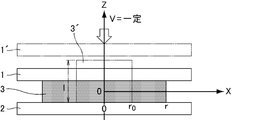
- a press apparatus that can be suitably used in the manufacturing method of the present disclosure, there are a pair of molds including a heating unit that heats the fluoropolymer, a cooling unit that cools the fluoropolymer, and a temperature detection unit that detects the temperature of the mold.
- the press apparatus installed so that it may oppose up and down is mentioned.
- the mold is preferably flat because it is easy to uniformly crush the fluoropolymer at a desired speed.
- the heating means is preferably a heater built in the mold, and the cooling means is preferably performed by circulating a coolant such as water or air through a tube built in the mold.
- the temperature of the mold detected by the temperature detecting means and the temperature (t) of the fluoropolymer can be made substantially the same temperature. it can.
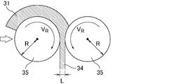
- a sandwiching roll that can be suitably used in the present invention, a pair of metal rolls provided with a heating means for heating the fluoropolymer, a cooling means for cooling the fluoropolymer, and a temperature detection means for detecting the roll temperature are vertically opposed to each other.
- the roll rolling apparatus installed in is mentioned.
- Elongation crystallization using the press device is, for example, Installing a fluoropolymer between a pair of upper and lower molds, A melting step in which the fluoropolymer is heated to a maximum temperature (t1) equal to or higher than the melting point (t0) of the fluoropolymer by a heating means; A cooling step of cooling the fluoropolymer melted by the cooling means to 100 ° C.
- the cooling step when the temperature of the mold detected by the temperature detecting means reaches the temperature (t2), the lower mold is driven toward the upper mold at the elongation strain rate (R2), and fluoro A step of stretching and crystallizing the polymer; Cooling the fluoropolymer cooled to 100 ° C. to room temperature; It can carry out by the method containing.
- the above method can be performed using, for example, an apparatus as shown in FIG.
- the elongation strain rate (R2) of elongation crystallization using the above pressing apparatus is preferably 40 s ⁇ 1 or more and 4000 s ⁇ 1 or less, and in this range, the tensile breaking strength is twice that of the fluoropolymer before crushing. This can be done. If the elongation strain rate (R2) is too small, the tensile strength at break of the resulting highly crystallized molded product tends to decrease. If the elongation strain rate (R2) is too large, the fluoropolymer is excessively impacted and destroyed. There is a risk of obtaining a molded product.
- the elongation strain rate (R2) can be adjusted, for example, by adjusting the sealing pressure of the accumulator that drives the lower mold of the press device described above.
- V (mm / s) is the crushing speed in the thickness direction
- l (mm) is the thickness of the sample before stretching crystallization
- r 0 (mm) is the distance from the center of the sample before stretching crystallization
- r (mm) is the distance from the center of the molded product after elongation crystallization (see FIG. 2).
- Elongation crystallization using the sandwiching roll is Installing a fluoropolymer on one of the opposing rolls; A melting step in which the fluoropolymer is heated to a maximum temperature (t1) equal to or higher than the melting point (t0) of the fluoropolymer by a heating means; A cooling step for cooling the roll temperature detected by the temperature detection means to the temperature (t2) of the fluoropolymer melted by the cooling means, and when the roll temperature reaches the temperature (t2), the pair of rolls are rotated at the roll rotation speed (V R ), and then extending the crystallization of the fluoropolymer at an elongation strain rate (R2) by narrowing the distance between the rolls, cooling the fluoropolymer to room temperature, It can carry out by the method containing.
- the above method can be performed using, for example, an apparatus as shown in FIGS.
- elongation crystallization using the above-described sandwiching rolls is performed by using a supercooled melt supply machine (an extruder that melts a fluoropolymer and supplies a melt of the fluoropolymer, and a melt from the extruder is cooled to a supercooled state.
- a cooling adapter that performs a continuous operation using an apparatus constituted by a sandwiching roll.
- a slit die is provided at the discharge port of the extruder, and the shape of the tip of the slit die is a square.
- the fluoropolymer melt discharged from the slit die is cooled until it reaches a supercooled state when passing through the cooling adapter (the melt in the cooled state is referred to as “supercooled melt”). It is discharged toward the pinching roll.
- the sandwiching roll is provided so that a pair of rotatable rolls face each other, sandwiching the supercooled melt supplied from the supercooled melt supply machine, extending in the rotation direction of the roll, and forming into a sheet shape Can be done.
- the elongation strain rate (R2) of elongation crystallization using the sandwiching roll is preferably 4 s -1 or more and 1000 s -1 or less, and if it is within this range, the tensile strength at break is twice that of the fluoropolymer before crushing This can be done. If the elongation strain rate (R2) is too small, the tensile strength at break of the resulting highly crystallized molded product tends to decrease. If the elongation strain rate (R2) is too large, the fluoropolymer is excessively impacted and destroyed. There is a risk of obtaining a molded product.
- the elongation strain rate (R2) can be adjusted by, for example, the roll rotation speed (V R ) of the roll rolling apparatus described above.
- R is the radius of the roll
- L is the thickness of the molded product after elongation crystallization (see FIG. 4).
- JSRI High Brightness Optical Science Research Center
- the imaging plate was read with a reader manufactured by Rigaku Corporation and reading software (manufactured by Rigaku Corporation, 2DP) to obtain a two-dimensional image.
- the WAXS method uses an X-ray diffractometer (manufactured by Rigaku, R-Axis VII).
- the camera length is 890 mm
- room temperature is 25 ° C.
- the exposure time was 10 minutes.
- the crystal size (d) of PCTFE was determined from a two-point image in the MD direction of a small-angle X-ray scattering image. From the scattering vector (q) in the MD direction of the small-angle X-ray scattering image, the crystal sizes (d) of ETFE, VdF / TFE copolymer and PFA were determined.
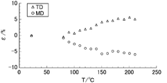
- Heat-resistant temperature The heat-resistant temperature of the sample which concerns on an Example and a comparative example was measured by the test piece size direct reading method using an optical microscope. More specifically, a heat stretching stage for a microscope (Linkam Tensile Testing System TST350, System Controllers T95-PE) and software (Linksys 32 System Control and Image Capture Software in 0.6 mm) were used. The test piece was heated to 150 ° C. at a heating rate of 10 K / min, held at 150 ° C. for 30 minutes, and heated at 10 K / min. At this time, observation and recording were performed with image analysis software (Linksys 32 System Control and Image Capture Software) that can quantify the size on the screen. Longitudinal direction of the test piece (MD) and transverse direction (TD) quantitatively measures the temperature of at the start of more than 3% shrinkage in the MD or TD (or expanded) to obtain a heat resistant temperature T H.
- MD Longitudinal direction of the test piece
- TD transverse direction
- Tensile modulus This is a value measured by a method based on JIS-7127.
- Production Example 1 9.8 g of an ethylene-tetrafluoroethylene copolymer (trade name EP546, manufactured by Daikin Industries, Ltd.) was weighed, sandwiched between upper and lower molds of ⁇ 60 mm, heated at 300 ° C. for 20 minutes, and then pressurized at 300 ° C. at 1 MPa. Depressurization was repeated 5 times to release air. Next, after pressurizing and holding at 300 ° C. and 3 MPa for 3 minutes, it was cooled with water at 3 MPa for 10 minutes. An ethylene-tetrafluoroethylene copolymer sheet having a thickness of 2.2 mm was obtained.
- an ethylene-tetrafluoroethylene copolymer (trade name EP546, manufactured by Daikin Industries, Ltd.) was weighed, sandwiched between upper and lower molds of ⁇ 60 mm, heated at 300 ° C. for 20 minutes, and then pressurized at 300 ° C. at 1 MPa. Depressurization was repeated 5 times to release air.
- VdF / TFE copolymer (1) 20 g was weighed, sandwiched between upper and lower ⁇ 120 mm molds, heated at 190 ° C. for 20 minutes, and then pressurized and depressurized at 190 ° C. and 2 MPa were repeated 5 times. . Next, after pressurizing and holding at 190 ° C. and 2 MPa for 1 minute, the mixture was water-cooled at 2 MPa for 10 minutes. A VdF / TFE copolymer sheet (1) having a thickness of 1.1 mm was obtained.
- VdF / TFE copolymer (2) 20 g was weighed, sandwiched between upper and lower ⁇ 120 mm molds, heated at 190 ° C. for 20 minutes, and then pressurized and depressurized at 190 ° C. and 2 MPa were repeated 5 times. . Next, after pressurizing and holding at 190 ° C. and 2 MPa for 1 minute, it was water-cooled at 2 MPa for 5 minutes. A VdF / TFE copolymer sheet (2) having a thickness of 1.1 mm was obtained.
- Production Example 4 4.8 g of polychlorotrifluoroethylene homopolymer (trade name: M300H, manufactured by Daikin Industries, Ltd.) was weighed, sandwiched between upper and lower molds of ⁇ 60 mm, heated at 280 ° C. for 20 minutes, and then added at 280 ° C. at 3 MPa. The pressure was released and the pressure was released 5 times. Next, pressurization and holding was performed at 280 ° C. and 3 MPa for 5 minutes, followed by water cooling at 3 MPa for 5 minutes. A polychlorotrifluoroethylene homopolymer sheet having a thickness of 0.78 mm was obtained.
- TFE / PPVE copolymer (trade name: AP230, manufactured by Daikin Industries, Ltd.) is weighed, sandwiched between upper and lower molds of 60 mm in diameter, heated at 360 ° C. for 20 minutes, and pressurized and depressurized at 360 ° C. at 3 MPa. Was repeatedly vented 5 times. Next, pressure was maintained at 360 ° C. and 3 MPa for 3 minutes, and then water cooling was performed at 3 MPa for 15 minutes. A 2.3 mm thick TFE / PPVE copolymer sheet was obtained.
- TFE / HFP copolymer (trade name: NP30, manufactured by Daikin Industries, Ltd.) was weighed, sandwiched between upper and lower molds of ⁇ 60 mm, heated at 330 ° C. for 20 minutes, and then pressurized at 330 ° C. at 3 MPa. Depressurization was repeated 5 times to release air. Next, pressure was maintained at 330 ° C. and 3 MPa for 3 minutes, and then water-cooled at 3 MPa for 15 minutes. A 1.3 mm thick TFE / HFP copolymer sheet was obtained.
- Example 1 Using a press apparatus shown in FIG. 2, ⁇ 10 mm, 2.2 mm thick ethylene-tetrafluoroethylene copolymer (trade name EP546, manufactured by Daikin Industries, Ltd.) was heated to 305 ° C. at 10 K / min and melted. After being held for 5 minutes, it was rolled at a crushing speed of 230 mm / s at 235 ° C. in the process of cooling to 100 ° C. at 208 K / min to obtain a stretch-crystallized film-like molded product. The elongation strain rate at the end of the molded product was 1366 s ⁇ 1 . Production conditions are shown in Table 1, and various measurement results of the molded products are shown in Table 2.
- Examples 2-7, 13, 14 The fluoropolymer and conditions shown in Table 1 were changed, and the sample thickness before pressing was 1.1 mm for VdF / TFE copolymer, 0.78 mm for polychlorotrifluoroethylene homopolymer, and TFE / PPVE copolymer for A film-like molded product stretched and crystallized was obtained in the same manner as in Example 1 except that 2.3 mm and the TFE / HFP copolymer were changed to 1.3 mm. Production conditions are shown in Table 1, and various measurement results of the molded products are shown in Table 2.
- Production Example 7 11 g of VdF / TFE copolymer (1) was weighed, sandwiched between upper and lower ⁇ 120 mm molds, heated at 190 ° C. for 20 minutes, and then pressurized and depressurized at 190 ° C. and 2 MPa were repeated 5 times. . Next, after pressurizing and holding at 190 ° C. and 2 MPa for 1 minute, the mixture was water-cooled at 2 MPa for 10 minutes. A sheet of VdF / TFE copolymer (1) having a thickness of 0.5 mm was obtained.
- Production Example 8 11 g of VdF / TFE copolymer (2) was weighed, sandwiched between upper and lower ⁇ 120 mm molds, heated at 190 ° C. for 20 minutes, and pressurized and depressurized at 190 ° C. and 2 MPa were repeated 5 times. . Next, after pressurizing and holding at 190 ° C. and 2 MPa for 1 minute, it was water-cooled at 2 MPa for 5 minutes. A sheet of VdF / TFE copolymer (2) having a thickness of 0.5 mm was obtained.
- Example 8 12 g of polychlorotrifluoroethylene homopolymer (trade name: M300H, manufactured by Daikin Industries, Ltd.) was weighed, sandwiched between upper and lower molds of 120 mm in diameter, heated at 280 ° C. for 20 minutes, and then pressurized at 280 ° C. at 3 MPa. Depressurization was repeated 5 times to release air. Next, pressurization and holding was performed at 280 ° C. and 3 MPa for 5 minutes, followed by water cooling at 3 MPa for 5 minutes. A polychlorotrifluoroethylene homopolymer sheet having a thickness of 0.5 mm was obtained.
- a PCTFE sheet having a length of 8 cm, a width of 3 cm, and a thickness of 0.5 mm is placed so that the longitudinal direction is the roll rotation direction, melted at 250 ° C., and held for 5 minutes. After that, it was cooled to 215 ° C. at 3 K / min, and roll-rolled at a roll rotation speed of 40 m / min to obtain a film-like molded product that was stretched and crystallized.
- the elongation strain rate at the end of the molded product was 326 s ⁇ 1 .
- the radius R of the roll is 100 mm
- V R is 40 m / min
- L is was 0.042 mm. Production conditions are shown in Table 3, and various measurement results of the molded product are shown in Table 4.
- FIG. 5 shows the result of the polarization microscope observation of the PCTFE sample obtained in Example 9.
- FIG. 5A is a polarization microscope image when the MD is placed in parallel to the sensitive color detection plate
- FIG. 5B is a polarization microscope image when the extinction angle is used.
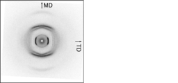
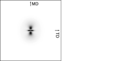
- FIG. 6 shows a SAXS image of the PCTFE sample obtained in Example 10 as a representative example observed using an X-ray diffractometer (manufactured by Rigaku, NANO Viewer).
- Examples 13, 1, 14, 3, 8, and 9 are shown in FIGS. 12, 13, 14, 15, 16, and 17 as representative examples observed using SPring-8 and the beam line BL40B2.
- 6 and 12 to 17 are observation results from the through direction.
- a two-point image strong against MD was observed. This is evidence that the crystal (NC) of the sample according to the example is oriented in MD. Therefore, it turns out that the sample which concerns on an Example forms NOC.
- FIG. 7 shows the observation result from the through direction.
- the fiber pattern indicates that the polymer chain (crystal c-axis) is highly oriented in MD. Therefore, it turns out that the sample which concerns on an Example forms NOC.
- the crystal size (d) of the sample according to the PCTFE example was determined from the two-point image in the MD direction in FIG.
- d of the PCTFE sample obtained in Example 10 was obtained and found to be 61 nm.
- the crystal sizes (d) of Examples 13, 1, 14, 3, 8, and 9 were determined from the two-point images of FIGS. 12, 13, 14, 15, 16, and 17.
- D of Example 13 is 56 nm
- d of Example 1 is 21 nm
- d of Example 14 is 42 nm
- d of Example 3 is 56 nm
- d of Example 8 is 55 nm
- d was 56 nm.
- the crystal size (d) was determined from the scattering vector q by one-dimensional small-angle scattering measurement of the samples of Examples 2, 4, 5, 6, 7, and 12.
- D of the sample of Example 2 is 29 nm
- d of the sample of Example 4 is 38 nm
- d of the sample of Example 5 is 44 nm
- d of the sample of Example 6 is 32 nm
- the d of the sample of 7 was 26 nm
- the d of the sample of Example 12 was 49 nm.
- the sample of Example 3 of the VdF / TFE copolymer (2) had a heat resistance temperature TH of 164 ° C. and had high heat resistance.
- the molded product of VdF / TFE copolymer (1) had high heat resistance with a heat resistant temperature TH of 135 ° C.
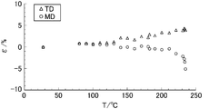
- the results of measuring the heat resistance of the sample of PCTFE Example 10 are shown in FIG.
- the result of measuring the heat resistance of Comparative Example 1 of PCTFE is shown in FIG.
- Heat resistance temperature T H when distorted sample of Example 10 is 3% or more was about 180 ° C..
- the heat resistance temperature T H of the sample of Comparative Example 1 of the PCTFE was about 110 ° C.. It turned out that the sample which concerns on an Example about heat-resistant temperature is what exceeds the sample which concerns on a comparative example greatly.
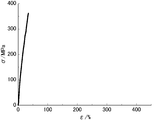
- FIG. 11 shows a diagram showing the results of measuring the tensile fracture stress ( ⁇ B ) and the tensile elastic modulus (E t ) for the sample of the comparative example of PCTFE.
- the molded product of ETFE, VdF / TFE copolymer and PCTFE had a tensile strength of 120 MPa or higher and a high tensile modulus of 1 GPa or higher.
- the molded product of PFA and FEP had high strength with a tensile fracture stress ( ⁇ B ) of 45 MPa or more and a tensile elastic modulus of 0.7 GPa or more.
- the molded article of the present invention has excellent mechanical strength and heat resistance as compared with a molded article made of a conventional fluoropolymer, the molded article containing crystals of a conventional fluoropolymer, for example, high temperature and In addition to being applicable to a moisture-proof film or the like in a certain place, it can be suitably used for a building material sheet.
Landscapes
- Chemical & Material Sciences (AREA)
- Health & Medical Sciences (AREA)
- Chemical Kinetics & Catalysis (AREA)
- Medicinal Chemistry (AREA)
- Polymers & Plastics (AREA)
- Organic Chemistry (AREA)
- Engineering & Computer Science (AREA)
- Manufacturing & Machinery (AREA)
- Materials Engineering (AREA)
- Mechanical Engineering (AREA)
- Manufacture Of Macromolecular Shaped Articles (AREA)
- Addition Polymer Or Copolymer, Post-Treatments, Or Chemical Modifications (AREA)
Abstract
Description
結晶性高分子の成形加工品の特性は、高分子の結晶化度及び結晶構造に依存することが知られており、その成形加工技術が検討されている。 Fluoropolymers made of crystalline polymers such as vinylidene fluoride / tetrafluoroethylene copolymer and polychlorotrifluoroethylene have excellent non-adhesiveness, heat resistance, low friction, electrical properties, etc. Can be applied to various purposes.
It is known that the properties of a crystalline polymer molded product depend on the degree of crystallinity and crystal structure of the polymer, and the molding technology has been studied.
上記フルオロポリマーは高結晶性であることが好ましい。 The present disclosure relates to a molded article including a fluoropolymer crystal, wherein the fluoropolymer is a vinylidene fluoride / tetrafluoroethylene copolymer, a polychlorotrifluoroethylene, an ethylene / tetrafluoroethylene copolymer, or a tetrafluoroethylene. / Perfluoro (alkyl vinyl ether) copolymer and tetrafluoroethylene / hexafluoropropylene copolymer are at least one selected from the group consisting of a nano-oriented crystal having a size of 300 nm or less It relates to a molded body.
The fluoropolymer is preferably highly crystalline.
また、PVdFを除くフッ素樹脂単体フィルムは、通常の延伸方法では孔や裂け目が生じやすく、膜厚を均一に延伸することが困難なことから、物性の改良の効果も低い。 A fluoropolymer having a polymerized unit based on vinylidene fluoride, tetrafluoroethylene, or chlorotrifluoroethylene has heat resistance, flame resistance, and resistance by having vinylidene fluoride, tetrafluoroethylene, or chlorotrifluoroethylene in the main chain. While exhibiting excellent properties such as chemical properties and weather resistance, the mechanical strength of the molded product remains only an order of magnitude smaller than other engineered plastics such as polyether ether ketone (PEEK). If the mechanical strength of the fluoropolymer having polymerized units based on vinylidene fluoride, tetrafluoroethylene, or chlorotrifluoroethylene is improved, the weight can be reduced by making the film thinner.
Moreover, since the fluororesin simple film except PVdF is easy to produce a hole and a tear by the normal extending | stretching method and it is difficult to extend | stretch film thickness uniformly, the effect of the improvement of a physical property is also low.
上記結晶サイズの下限は特に制限されないが、例えば3nmであってよい。耐熱性がより向上する点から、上記結晶サイズは、5nm以上であることが好ましく、8nm以上であることがより好ましく、10nm以上であることが更に好ましい。
上記結晶のサイズは、公知の小角X線散乱法(以下「SAXS法」という。)により求めることができる。
なお、SAXS法における、散乱ベクトル(q)-小角X線散乱強度(Ix)曲線の1次のピークは、平均サイズdの微結晶がランダムにお互いに詰まっている場合の微結晶間最近接距離(=結晶サイズd)に相当するため(参考文献:A.Guinier著、「X線結晶学の理論と実際」、理学電機(株)、p513、1967)、結晶サイズdは下記のBraggの式から求められる。
Braggの式: d=2π÷q The crystal size of the fluoropolymer contained in the molded article of the present disclosure is 300 nm or less. Since the mechanical strength and heat resistance of the molded body are more excellent, the crystal size is preferably 200 nm or less, more preferably 150 nm or less, still more preferably 100 nm or less, and 70 nm or less. Is particularly preferred.
The lower limit of the crystal size is not particularly limited, but may be 3 nm, for example. From the viewpoint of further improving heat resistance, the crystal size is preferably 5 nm or more, more preferably 8 nm or more, and further preferably 10 nm or more.
The size of the crystal can be determined by a known small angle X-ray scattering method (hereinafter referred to as “SAXS method”).
In the SAXS method, the first-order peak of the scattering vector (q) -small angle X-ray scattering intensity (I x ) curve is the closest distance between microcrystals when microcrystals of average size d are randomly packed together. Since it corresponds to the distance (= crystal size d) (reference: A. Guinier, “Theory and practice of X-ray crystallography”, Rigaku Denki Co., Ltd., p513, 1967), the crystal size d is the following Bragg's It is obtained from the formula.
Bragg's formula: d = 2π ÷ q
NOCを構成するNCの結晶サイズは、MDのサイズを測定すればよい。例えば、図1に示すNOCの結晶サイズは、約61nmであるといえる。 The NC included in the NOC and the polymer chain included in the NC are approximately oriented in the MD direction of the molded body (for example, a sheet).
The crystal size of the NC constituting the NOC may be measured by the MD size. For example, it can be said that the crystal size of NOC shown in FIG. 1 is about 61 nm.
なお、静置場の平衡融点(Tm 0)とは、高分子の分子鎖(以下、適宜「高分子鎖」ともいう。)が伸びきった状態で結晶化した巨視的サイズの完全結晶の融点を意味し、下記で算出される。
Tm 0=ΔHu÷ΔSu、ΔHu:融解エンタルピー、ΔSu:融解エントロピー
具体的には、偏光顕微鏡観察を用いた彦坂らの方法で上記静置場の平衡融点を決定する。
なお、上記融点は、単量体組成比が同じフルオロポリマーの平衡融点と対比する。 The melting point of the molded article of the present disclosure is preferably higher than the temperature 15 ° C. lower than the equilibrium melting point of the fluoropolymer stationary field. The melting point of the molded body is more preferably higher than the
The equilibrium melting point (T m 0 ) of the stationary field is the melting point of a macroscopically sized perfect crystal that is crystallized in a state in which a polymer molecular chain (hereinafter also referred to as “polymer chain”) is extended. And is calculated as follows.
T m 0 = ΔH u ÷ ΔS u , ΔH u : melting enthalpy, ΔS u : melting entropy Specifically, the equilibrium melting point of the stationary field is determined by the method of Hikosaka et al. Using polarization microscope observation.
In addition, the said melting | fusing point contrasts with the equilibrium melting | fusing point of a fluoropolymer with the same monomer composition ratio.
以下、各フルオロポリマーについて説明する。 The fluoropolymer is more preferably at least one selected from the group consisting of PCTFE, VdF / TFE copolymer and ETFE from the viewpoint that mechanical strength and heat resistance are remarkably improved, and PCTFE is more preferable. .
Hereinafter, each fluoropolymer will be described.
上記VdF/TFE系共重合体は、VdFに基づく重合単位(以下「VdF単位」ともいう)及びTFEに基づく重合単位(以下「TFE単位」ともいう)を含む共重合体である。
VdF/TFE系共重合体は、成形体の機械強度、耐熱性及び透明性がより優れることから、VdF単位とTFE単位との合計100モル%に対して、VdF単位が50~95モル%であり、TFE単位が5~50モル%であることが好ましい。VdF/TFE系共重合体は、VdF単位が60~95モル%であり、TFE単位が5~40モル%であることがより好ましく、VdF単位が70~90モル%であり、TFE単位が10~30モル%であることが特に好ましい。
上記VdF/TFE系共重合体は、VdF単位及びTFE単位のみからなるものであってもよいし、VdF及びTFEと共重合可能な単量体(但し、VdF及びTFEを除く)に基づく重合単位を含んでよい。上記VdF/TFE系共重合体は、全重合単位に対して、VdF単位及びTFE単位の合計が90モル%以上であることが好ましく、95モル%以上であることがより好ましく、98モル%以上であることが更に好ましい。
上記VdF及びTFEと共重合可能な単量体としては、ヘキサフルオロプロピレン(HFP)、エチレン、プロピレン、アルキルビニルエーテル、酢酸ビニル、塩化ビニル、塩化ビニリデン、CH2=CHCF3、CH2=CFCF3、CH2=CF(CF2)nH(n=3~7)、CH2=CH(CF2)nF(n=1~8)などが挙げられる。
中でも、HFP及びCH2=CFCF3からなる群より選択される少なくとも1種が好ましく、HFPがより好ましい。
上記VdF及びTFEと共重合可能な単量体に基づく重合単位の含有量としては、成形体の機械強度、耐熱性及び透明性がより優れることから、0~10モル%であることが好ましく、0.01~5モル%であることがより好ましく、0.1~2モル%であることが更に好ましい。 [VdF / TFE copolymer]
The VdF / TFE copolymer is a copolymer including polymerized units based on VdF (hereinafter also referred to as “VdF units”) and polymerized units based on TFE (hereinafter also referred to as “TFE units”).
Since the VdF / TFE copolymer is more excellent in mechanical strength, heat resistance and transparency of the molded body, the VdF unit is 50 to 95 mol% with respect to 100 mol% in total of the VdF unit and the TFE unit. The TFE unit is preferably 5 to 50 mol%. In the VdF / TFE copolymer, the VdF unit is 60 to 95 mol%, the TFE unit is more preferably 5 to 40 mol%, the VdF unit is 70 to 90 mol%, and the TFE unit is 10 mol%. Particularly preferred is ˜30 mol%.
The VdF / TFE copolymer may be composed only of a VdF unit and a TFE unit, or a polymer unit based on a monomer copolymerizable with VdF and TFE (excluding VdF and TFE). May be included. In the VdF / TFE copolymer, the total of VdF units and TFE units is preferably 90 mol% or more, more preferably 95 mol% or more, and more preferably 98 mol% or more with respect to all polymerization units. More preferably.
Monomers copolymerizable with VdF and TFE include hexafluoropropylene (HFP), ethylene, propylene, alkyl vinyl ether, vinyl acetate, vinyl chloride, vinylidene chloride, CH 2 = CHCF 3 , CH 2 = CFCF 3 , CH 2 ═CF (CF 2 ) n H (n = 3 to 7), CH 2 ═CH (CF 2 ) n F (n = 1 to 8), and the like.
Among them, is preferably at least one selected from the group consisting of HFP, and CH 2 = CFCF 3, HFP are more preferred.
The content of the polymer unit based on the monomer copolymerizable with VdF and TFE is preferably 0 to 10 mol% because the mechanical strength, heat resistance and transparency of the molded body are more excellent. More preferably, the content is 0.01 to 5 mol%, and still more preferably 0.1 to 2 mol%.
なお、本明細書において、引張破断強度および弾性率は、顕微鏡用加熱延伸ステージ(Linkam Tensile Testing System TST350、System Controllers T95-PE)とソフトウェア(Linksys 32 System Control and Image Capture Software)を用い、幅2mm、厚み0.01~0.3mmの試験片を用いて、チャック間距離2mmで測定した値である。引張速度は0.1mm/sである。 When the fluoropolymer is a VdF / TFE copolymer, the molded article of the present disclosure preferably has an elastic modulus of 1.0 GPa or more. The elastic modulus is more preferably 1.2 GPa or more, further preferably 1.5 GPa or more, and particularly preferably 2.0 GPa or more.
In this specification, the tensile strength at break and elastic modulus are measured using a heat stretching stage for microscope (Linkam Tensile Testing System TST350, System Controllers T95-PE) and software (Linksystem 32 System Control and Image width width). The value measured with a distance between chucks of 2 mm using a test piece having a thickness of 0.01 to 0.3 mm. The tensile speed is 0.1 mm / s.
なお、本明細書において、「耐熱温度」とは、光学顕微鏡を用いた試験片サイズ直読法により測定した耐熱温度を意味する。上記「試験片サイズ直読法」は、光学顕微鏡(オリンパス株式会社製BX51)と、顕微鏡用加熱延伸ステージ(Linkam Tensile Testing System TST350、System Controllers T95-PE 、Linksys 32 System Control and Image Capture Software)と、画面上のサイズを定量できる画像解析ソフトウェア(Linksys 32 System Control and Image Capture Software)を用いて実施される。試験片のサイズは、たて0.6mm、よこ0.4~0.7mmの試験片を用いる。試験片を昇温速度10K/minで150℃に加熱し、150℃で30分間保持し、10K/minで加熱する。その時、試験片がたて方向(MD)またはよこ方向(TD)に3%以上ひずみ(収縮または膨張)が生じたときの温度を耐熱温度とする。 When the fluoropolymer is a VdF / TFE copolymer, the molded article of the present disclosure preferably has a heat resistant temperature of 90 ° C. or higher. The heat resistant temperature is more preferably 110 ° C. or higher, and further preferably 130 ° C. or higher.
In the present specification, “heat-resistant temperature” means a heat-resistant temperature measured by a test piece size direct reading method using an optical microscope. The above-mentioned “test piece size direct reading method” includes an optical microscope (BX51 manufactured by Olympus Corporation), a heating stretching stage for a microscope (Linkam Tensile Testing System TST350, System Controllers T95-PE, Linksystem Control System Control System). It is implemented using image analysis software (Linksys 32 System Control and Image Capture Software) that can quantify the size on the screen. The test piece is 0.6 mm long and 0.4 to 0.7 mm wide. The test piece is heated to 150 ° C. at a heating rate of 10 K / min, held at 150 ° C. for 30 minutes, and heated at 10 K / min. At this time, the temperature at which the test piece is strained (shrinkage or expansion) by 3% or more in the vertical direction (MD) or the transverse direction (TD) is defined as the heat resistant temperature.
なお、本明細書において、成形体の融点は、示差走査熱量計〔DSC〕を用いて10K/minの速度で昇温したときの融解熱曲線における極大値に対応する温度である。 When the fluoropolymer is a VdF / TFE copolymer, the melting point of the molded article of the present disclosure is preferably 130 ° C. or higher, more preferably 135 ° C. or higher, and further preferably 140 ° C. or higher. preferable.
In the present specification, the melting point of the compact is a temperature corresponding to the maximum value in the heat of fusion curve when the temperature is raised at a rate of 10 K / min using a differential scanning calorimeter [DSC].
上記PCTFEとしては、クロロトリフルオロエチレン(CTFE)単独重合体、及び、CTFEに基づく重合単位(「CTFE単位」)とCTFEと重合可能な単量体(α)に基づく重合単位(「単量体(α)単位」)の共重合体が挙げられる。 [PCTFE]
Examples of the PCTFE include chlorotrifluoroethylene (CTFE) homopolymers, polymerized units based on CTFE (“CTFE units”), and polymerized units based on CTFE and a polymerizable monomer (α) (“monomer” (Α) units ”).
CX3X4=CX1(CF2)nX2 (I)
(式中、X1、X3及びX4は、同一若しくは異なって、水素原子又はフッ素原子を表し、X2は、水素原子、フッ素原子又は塩素原子を表し、nは、1~10の整数を表す。)で表されるビニル単量体、及び、下記一般式(II)
CF2=CF-OCH2-Rf (II)
(式中、Rfは、炭素数1~5のパーフルオロアルキル基)で表されるアルキルパーフルオロビニルエーテル誘導体等が挙げられる。 When PCTFE is a copolymer of a CTFE unit and a monomer (α) unit, the monomer (α) is not particularly limited as long as it is a monomer copolymerizable with CTFE. Fluoroethylene (TFE), ethylene (Et), vinylidene fluoride (VdF), perfluoro (alkyl vinyl) ether (PAVE), the following general formula (I):
CX 3 X 4 = CX 1 (CF 2 ) n X 2 (I)
(Wherein X 1 , X 3 and X 4 are the same or different and each represents a hydrogen atom or a fluorine atom, X 2 represents a hydrogen atom, a fluorine atom or a chlorine atom, and n is an integer of 1 to 10) And a vinyl monomer represented by the following general formula (II):
CF 2 = CF—OCH 2 —Rf (II)
(Wherein Rf is a perfluoroalkyl group having 1 to 5 carbon atoms) and the like.
H2C=CX5Rf5 (III)
(式中、X5は、H、F又はCF3であり、Rf5は、炭素数1~10のパーフルオロアルキル基である)で表されるパーフルオロ(アルキル)エチレン等が挙げられる。上記パーフルオロ(アルキル)エチレンとしては、パーフルオロ(ブチル)エチレンが好ましい。 The vinyl monomer represented by the general formula (I) is not particularly limited. For example, hexafluoropropylene (HFP), perfluoro (1,1,2-trihydro-1-hexene), perfluoro ( 1,1,5-trihydro-1-pentene), the following general formula (III):
H 2 C═CX 5 Rf 5 (III)
(Wherein, X 5 is H, F, or CF 3 , and Rf 5 is a perfluoroalkyl group having 1 to 10 carbon atoms). As the perfluoro (alkyl) ethylene, perfluoro (butyl) ethylene is preferable.
上記フロー値は、高架式フローテスターにより測定する値であり、測定温度230℃、荷重980N、ノズル径1mmφである。 The flow value of PCTFE used in the present disclosure is preferably 1 × 10 −5 (cc / s) or more, more preferably 1 × 10 −4 (cc / s) or more, and 5 × 10 −4. More preferably (cc / s) or more. Further, it is preferably 1 (cc / s) or less, more preferably 1 × 10 −2 (cc / s) or less, and further preferably 5 × 10 −3 (cc / s) or less.
The flow value is a value measured by an elevated flow tester, and has a measurement temperature of 230 ° C., a load of 980 N, and a nozzle diameter of 1 mmφ.
後述するような製造方法によって伸長結晶化を行うことによって、成形体の融点をPCTFEの静置場の平衡融点よりも高くすることもできる。CTFE単独重合体である場合、上述した方法で測定するPCTFEの静置場の平衡融点は228℃(M. Hikosaka et al. Polymer Preprints, Japan 1989, 38(10), 3308-3310)である。 When the fluoropolymer is PCTFE, the melting point of the molded article of the present disclosure is preferably 220 ° C. or higher, more preferably 225 ° C. or higher, and further preferably 230 ° C. or higher.
By performing extension crystallization by a production method as described later, the melting point of the molded body can be made higher than the equilibrium melting point of the stationary field of PCTFE. In the case of a CTFE homopolymer, the equilibrium melting point of the stationary field of PCTFE measured by the method described above is 228 ° C. (M. Hikosaka et al. Polymer Preprints, Japan 1989, 38 (10), 3308-3310).
上記ETFEとしては、TFE単位とエチレン単位とのモル比(TFE単位/エチレン単位)が20/80以上90/10以下である共重合体が好ましい。より好ましいモル比は37/63以上85/15以下であり、更に好ましいモル比は38/62以上80/20以下である。ETFEは、TFE、エチレン、並びに、TFE及びエチレンと共重合可能な単量体からなる共重合体であってもよい。共重合可能な単量体としては、下記式:
CH2=CX5Rf3、CF2=CFRf3、CF2=CFORf3、CH2=C(Rf3)2
(式中、X5は水素原子又はフッ素原子、Rf3はエーテル結合を含んでいてもよいフルオロアルキル基を表す。)で表される単量体が挙げられ、なかでも、CF2=CFRf3、CF2=CFORf3及びCH2=CX5Rf3で表される含フッ素ビニルモノマーが好ましく、HFP、CF2=CF-ORf4(式中、Rf4は炭素数1~5のパーフルオロアルキル基を表す。)で表されるパーフルオロ(アルキルビニルエーテル)及びRf3が炭素数1~8のフルオロアルキル基であるCH2=CX5Rf3で表される含フッ素ビニルモノマーがより好ましい。また、TFE及びエチレンと共重合可能な単量体は、イタコン酸、無水イタコン酸等の脂肪族不飽和カルボン酸であってもよい。TFE及びエチレンと共重合可能な単量体は、含フッ素重合体に対して0.1~10モル%が好ましく、0.1~5モル%がより好ましく、0.2~4モル%が特に好ましい。 [ETFE]
The ETFE is preferably a copolymer having a molar ratio of TFE units to ethylene units (TFE units / ethylene units) of 20/80 or more and 90/10 or less. A more preferable molar ratio is 37/63 or more and 85/15 or less, and a further preferable molar ratio is 38/62 or more and 80/20 or less. ETFE may be a copolymer composed of TFE, ethylene, and a monomer copolymerizable with TFE and ethylene. As a copolymerizable monomer, the following formula:
CH 2 = CX 5 Rf 3 , CF 2 = CFRf 3 , CF 2 = CFORf 3 , CH 2 = C (Rf 3 ) 2
(Wherein, X 5 represents a hydrogen atom or a fluorine atom, and Rf 3 represents a fluoroalkyl group which may contain an ether bond), among which CF 2 = CFRf 3 , A fluorine-containing vinyl monomer represented by CF 2 = CFORf 3 and CH 2 = CX 5 Rf 3 is preferred, and HFP, CF 2 = CF-ORf 4 (wherein Rf 4 is a perfluoroalkyl having 1 to 5 carbon atoms) represents a group.) perfluoro represented by (alkyl vinyl ether) and Rf 3 is more preferably a fluorine-containing vinyl monomer represented by CH 2 = CX 5 Rf 3 is a fluoroalkyl group having 1 to 8 carbon atoms. The monomer copolymerizable with TFE and ethylene may be an aliphatic unsaturated carboxylic acid such as itaconic acid or itaconic anhydride. The monomer copolymerizable with TFE and ethylene is preferably from 0.1 to 10 mol%, more preferably from 0.1 to 5 mol%, particularly preferably from 0.2 to 4 mol%, based on the fluoropolymer. preferable.
上記MFRは、ASTM D 3307により測定する値である。 The MFR of ETFE used in the present disclosure is preferably 0.1 g / 10 min or more, more preferably 0.5 g / 10 min or more, and further preferably 1 g / 10 min or more. Moreover, 120 g / 10min or less is preferable, 80 g / 10 min or less is more preferable, and 40 g / 10 min or less is more preferable.
The MFR is a value measured according to ASTM D 3307.
上記PFAとしては、特に限定されないが、TFE単位とPAVE単位とのモル比(TFE単位/PAVE単位)が70~99/30~1である共重合体が好ましい。より好ましいモル比は、80~98.5/20~1.5である。更に好ましいモル比は、97~98.5/3~1.5である。上記PFAは、TFE及びPAVEと共重合可能な単量体に由来する単量体単位が0.1~10モル%であり、TFE単位及びPAVE単位が合計で90~99.9モル%である共重合体であることも好ましい。TFE及びPAVEと共重合可能な単量体としては、HFP、CZ3Z4=CZ5(CF2)nZ6(式中、Z3、Z4及びZ5は、同一若しくは異なって、水素原子又はフッ素原子を表し、Z6は、水素原子、フッ素原子又は塩素原子を表し、nは2~10の整数を表す。)で表されるビニル単量体、及び、CF2=CF-O-Rf7(式中、Rf7は炭素数1~5のパーフルオロアルキル基を表す。)で表されるパーフルオロアルキルビニルエーテル誘導体、CF2=CF-OCH2-Rf7(式中、Rf7は炭素数1~5のパーフルオロアルキル基を表す。)で表されるアルキルパーフルオロビニルエーテル誘導体等が挙げられる。 [PFA]
The PFA is not particularly limited, but a copolymer having a molar ratio of TFE units to PAVE units (TFE units / PAVE units) of 70 to 99/30 to 1 is preferable. A more preferred molar ratio is 80 to 98.5 / 20 to 1.5. A more preferred molar ratio is 97 to 98.5 / 3 to 1.5. In the PFA, monomer units derived from monomers copolymerizable with TFE and PAVE are 0.1 to 10 mol%, and TFE units and PAVE units are 90 to 99.9 mol% in total. A copolymer is also preferred. Monomers copolymerizable with TFE and PAVE include HFP, CZ 3 Z 4 = CZ 5 (CF 2 ) n Z 6 (wherein Z 3 , Z 4 and Z 5 are the same or different and are hydrogen An atom or a fluorine atom, Z 6 represents a hydrogen atom, a fluorine atom or a chlorine atom, and n represents an integer of 2 to 10), and CF 2 ═CF—O —Rf 7 (wherein Rf 7 represents a perfluoroalkyl group having 1 to 5 carbon atoms), CF 2 ═CF—OCH 2 —Rf 7 (where Rf 7 Represents a perfluoroalkyl group having 1 to 5 carbon atoms.) And the like.
上記FEPとしては、特に限定されないが、TFE単位とHFP単位とのモル比(TFE単位/HFP単位)が70/30以上99/1未満である共重合体が好ましい。より好ましいモル比は、75/25以上98/2以下であり、更に好ましいモル比は、80/20以上95/5以下である。上記FEPは、TFE及びHFPと共重合可能な単量体に由来する単量体単位が0.1~10モル%であり、TFE単位及びHFP単位が合計で90~99.9モル%である共重合体であることも好ましい。TFE及びHFPと共重合可能な単量体としては、PAVE、アルキルパーフルオロビニルエーテル誘導体等が挙げられる。 [FEP]
Although it does not specifically limit as said FEP, The copolymer whose molar ratio (TFE unit / HFP unit) of a TFE unit and a HFP unit is 70/30 or more and less than 99/1 is preferable. A more preferable molar ratio is 75/25 or more and 98/2 or less, and a still more preferable molar ratio is 80/20 or more and 95/5 or less. In the FEP, the monomer units derived from monomers copolymerizable with TFE and HFP are 0.1 to 10 mol%, and the total of TFE units and HFP units is 90 to 99.9 mol%. A copolymer is also preferred. Examples of monomers copolymerizable with TFE and HFP include PAVE and alkyl perfluorovinyl ether derivatives.
上記MFRは、ASTM D 3307により測定する値である。 The MFR of FEP used in the present disclosure is preferably 0.1 g / 10 min or more, more preferably 0.5 g / 10 min or more, and further preferably 1 g / 10 min or more. Moreover, 100 g / 10min or less is preferable, 40 g / 10min or less is more preferable, and 30 or less is more preferable.
The MFR is a value measured according to ASTM D 3307.
乳化重合法によって得られるフルオロポリマーは、フッ素ガスによりポリマーの不安定末端を-CF3に安定化して使用することが好ましい。 As the polymerization solvent, a conventionally used liquid solvent can be used according to the polymerization method. However, the fluoropolymer used in the present invention is preferably subjected to suspension polymerization (dispersion polymerization) in the presence of a fluorinated solvent from the viewpoint of excellent heat resistance of the obtained molded article.
The fluoropolymer obtained by the emulsion polymerization method is preferably used by stabilizing the unstable terminal of the polymer to —CF 3 with a fluorine gas.
シートの厚みは特に制限されず、用いる目的に応じて適宜押出量などで調整すればよい。具体的な厚みは1μm~10mmの範囲、さらに2μm~5mm、特に3μm~1mmの範囲が好ましく挙げられる。
シートの厚みは、マイクロメーターを用いることによって測定され得る。 The molded body of the present invention may be a sheet, a tube, a fiber or the like, but is preferably a sheet because it is relatively easy to produce.
The thickness of the sheet is not particularly limited, and may be appropriately adjusted by the extrusion amount or the like according to the purpose of use. The specific thickness is preferably in the range of 1 μm to 10 mm, more preferably in the range of 2 μm to 5 mm, and particularly preferably in the range of 3 μm to 1 mm.
The thickness of the sheet can be measured by using a micrometer.
例えば、フルオロポリマーがVdF/TFE共重合体である場合、優れた機械強度及び耐熱性に加え、優れた電気特性、強誘電性を有することから、エレクトレットとしてマイク、スピーカー用の圧電フィルムや、圧電センサー類、高速スイッチング素子、振動発電素子、画像素子、ウェアラブルセンサー、エレクトロウエッティングデバイス用のフィルム、フィルムコンデンサ用のフィルム等にも好適である。また、焦電フィルム等にも好適である。
PCTFEである場合、優れた機械強度及び耐熱性に加え、優れた水蒸気バリア性を有することから、薬包フィルム等に好適である。
ETFEである場合、優れた機械強度及び耐熱性に加え、優れた耐候性を有することから、離形フィルム、ビニールハウス等の建材シート、建造物の屋根材、薬液容器やタンクのライニング材、薬栓のライニング材等に好適である。
PFAである場合、優れた機械強度及び耐熱性に加え、優れた耐薬品性を有することから、定着・加圧ロール、離形フィルム、薬液容器やタンクのライニング材、ラッピング電線、フラットケーブル等に好適である。
FEPである場合、優れた機械強度及び耐熱性に加え、優れた低誘電率・低誘電正接を有することから、離形フィルム、絶縁フィルム、ラッピング電線、フラットケーブル等に好適である。 Since the molded body of the present disclosure has excellent mechanical strength and heat resistance by having the above configuration, it can be applied to various applications.
For example, when the fluoropolymer is a VdF / TFE copolymer, it has excellent electrical properties and ferroelectricity in addition to excellent mechanical strength and heat resistance. It is also suitable for sensors, high-speed switching elements, vibration power generation elements, image elements, wearable sensors, films for electrowetting devices, films for film capacitors, and the like. It is also suitable for pyroelectric films and the like.
In the case of PCTFE, it has an excellent water vapor barrier property in addition to excellent mechanical strength and heat resistance, and thus is suitable for a medicine packaging film or the like.
In the case of ETFE, in addition to excellent mechanical strength and heat resistance, it has excellent weather resistance, so release films, building material sheets such as greenhouses, roof materials for buildings, lining materials for chemical containers and tanks, chemicals Suitable for plug lining materials and the like.
In the case of PFA, in addition to excellent mechanical strength and heat resistance, it has excellent chemical resistance, so it can be used for fixing and pressure rolls, release films, lining materials for chemical containers and tanks, wrapping wires, flat cables, etc. Is preferred.
In the case of FEP, in addition to excellent mechanical strength and heat resistance, it has excellent low dielectric constant and low dielectric loss tangent, so it is suitable for release films, insulating films, wrapping electric wires, flat cables and the like.
上記フルオロポリマーを、伸長結晶化前のフルオロポリマーの融点(t0)以上の最高温度(t1)に加熱して溶融させる溶融工程、
溶融させたフルオロポリマーを冷却速度(r1)で100℃まで冷却する冷却工程、
上記冷却工程において、フルオロポリマー融液が温度(t2)に到達した時にフルオロポリマー融液を所定の伸長歪み速度(R2)で伸長結晶化する工程、
100℃まで冷却されたフルオロポリマーを室温まで冷却する工程
を含む方法により実施することが好ましい。 The elongation crystallization is
A melting step of heating and melting the fluoropolymer to a maximum temperature (t1) equal to or higher than the melting point (t0) of the fluoropolymer before stretching crystallization;
A cooling step of cooling the melted fluoropolymer to 100 ° C. at a cooling rate (r1);
In the cooling step, when the fluoropolymer melt reaches the temperature (t2), the step of crystallizing the fluoropolymer melt at a predetermined elongation strain rate (R2);
It is preferable to carry out by a method including a step of cooling a fluoropolymer cooled to 100 ° C. to room temperature.
上記最高温度(t1)は、例えば、フルオロポリマーの融点より5℃以上高い温度であることが好ましく、10℃以上高い温度であることがより好ましく、35度以上高い温度であることが更に好ましい。
上記最高温度(t1)の上限はフルオロポリマーが劣化しない程度の温度であれば特に限定されるものではないが、例えば、フルオロポリマーの融点より100℃高い温度であってよい。 The said maximum temperature (t1) will not be specifically limited if it is the temperature more than melting | fusing point of a fluoropolymer, For example, temperature higher than the temperature (t2) mentioned later may be employ | adopted.
The maximum temperature (t1) is, for example, preferably 5 ° C or higher than the melting point of the fluoropolymer, more preferably 10 ° C or higher, and still more preferably 35 ° C or higher.
The upper limit of the maximum temperature (t1) is not particularly limited as long as the temperature is such that the fluoropolymer does not deteriorate. For example, it may be a
本発明で好適に使用できる挟持ロールとしては、フルオロポリマーを加熱する加熱手段、フルオロポリマーを冷却する冷却手段、及び、ロール温度を検出する温度検出手段を備える一対の金属ロールが上下に対向するように設置されているロール圧延装置が挙げられる。 The elongation crystallization can be performed using a press device or a pinching roll. As a press apparatus that can be suitably used in the manufacturing method of the present disclosure, there are a pair of molds including a heating unit that heats the fluoropolymer, a cooling unit that cools the fluoropolymer, and a temperature detection unit that detects the temperature of the mold. The press apparatus installed so that it may oppose up and down is mentioned. The mold is preferably flat because it is easy to uniformly crush the fluoropolymer at a desired speed. In the press apparatus, the heating means is preferably a heater built in the mold, and the cooling means is preferably performed by circulating a coolant such as water or air through a tube built in the mold. In the press apparatus, by incorporating the temperature detecting means near the press surface of the mold, the temperature of the mold detected by the temperature detecting means and the temperature (t) of the fluoropolymer can be made substantially the same temperature. it can.
As a sandwiching roll that can be suitably used in the present invention, a pair of metal rolls provided with a heating means for heating the fluoropolymer, a cooling means for cooling the fluoropolymer, and a temperature detection means for detecting the roll temperature are vertically opposed to each other. The roll rolling apparatus installed in is mentioned.
上下に対向する一対の金型の間にフルオロポリマーを設置する工程、
加熱手段によりフルオロポリマーをフルオロポリマーの融点(t0)以上の最高温度(t1)に加熱して溶融させる溶融工程、
冷却手段により溶融させたフルオロポリマーを冷却速度(r1)で100℃まで冷却する冷却工程、
前記冷却工程において、温度検出手段により検出された金型の温度が温度(t2)に到達した時に、下部の金型を伸長歪み速度(R2)で上部の金型に向かって駆動させて、フルオロポリマーを伸長結晶化する工程、
100℃まで冷却されたフルオロポリマーを室温まで冷却する工程、
を含む方法により行うことができる。
上記の方法は、例えば、図2に示すような装置を用いて行うことができる。 Elongation crystallization using the press device is, for example,
Installing a fluoropolymer between a pair of upper and lower molds,
A melting step in which the fluoropolymer is heated to a maximum temperature (t1) equal to or higher than the melting point (t0) of the fluoropolymer by a heating means;
A cooling step of cooling the fluoropolymer melted by the cooling means to 100 ° C. at a cooling rate (r1);
In the cooling step, when the temperature of the mold detected by the temperature detecting means reaches the temperature (t2), the lower mold is driven toward the upper mold at the elongation strain rate (R2), and fluoro A step of stretching and crystallizing the polymer;
Cooling the fluoropolymer cooled to 100 ° C. to room temperature;
It can carry out by the method containing.
The above method can be performed using, for example, an apparatus as shown in FIG.
伸長歪み速度(R2)が小さすぎると、得られる高結晶化成形品の引張破断強度が低下する傾向があり、伸長歪み速度(R2)が大きすぎると、フルオロポリマーに衝撃がかかり過ぎて破壊された成形品が得られるおそれがある。
伸長歪み速度(R2)は、例えば、上述したプレス装置の下部の金型を駆動させるアキュムレーターの封入圧力を調整することによって調整することができる。
上面及び底面が真円の円筒状のフルオロポリマー試料を用いた場合、伸長歪み速度(R2)は、R2=r2V/(r0 2l)により算出することができる。ここでV(mm/s)は厚さ方向の押し潰し速度、l(mm)は伸長結晶化前の試料の厚さ、r0(mm)は伸長結晶化前の試料の中心からの距離、r(mm)は伸長結晶化後の成形品の中心からの距離である(図2参照)。 The elongation strain rate (R2) of elongation crystallization using the above pressing apparatus is preferably 40 s −1 or more and 4000 s −1 or less, and in this range, the tensile breaking strength is twice that of the fluoropolymer before crushing. This can be done.
If the elongation strain rate (R2) is too small, the tensile strength at break of the resulting highly crystallized molded product tends to decrease. If the elongation strain rate (R2) is too large, the fluoropolymer is excessively impacted and destroyed. There is a risk of obtaining a molded product.
The elongation strain rate (R2) can be adjusted, for example, by adjusting the sealing pressure of the accumulator that drives the lower mold of the press device described above.
When a cylindrical fluoropolymer sample having a perfect upper surface and a bottom surface is used, the elongation strain rate (R2) can be calculated by R2 = r 2 V / (r 0 2 l). Where V (mm / s) is the crushing speed in the thickness direction, l (mm) is the thickness of the sample before stretching crystallization, r 0 (mm) is the distance from the center of the sample before stretching crystallization, r (mm) is the distance from the center of the molded product after elongation crystallization (see FIG. 2).
対向するロールの一方にフルオロポリマーを設置する工程、
加熱手段によりフルオロポリマーをフルオロポリマーの融点(t0)以上の最高温度(t1)に加熱して溶融させる溶融工程、
冷却手段により溶融させたフルオロポリマーを温度検出手段により検出されたロール温度を温度(t2)に冷却する冷却工程、ロール温度が温度(t2)に到達した時に、一対のロールをロール回転速度(VR)で駆動させて、その後ロール間距離を狭めることによりフルオロポリマーを伸長歪み速度(R2)で伸長結晶化する工程、フルオロポリマーを室温まで冷却する工程、
を含む方法により行うことができる。
上記の方法は、例えば、図3及び4に示すような装置を用いて行うことができる。 Elongation crystallization using the sandwiching roll is
Installing a fluoropolymer on one of the opposing rolls;
A melting step in which the fluoropolymer is heated to a maximum temperature (t1) equal to or higher than the melting point (t0) of the fluoropolymer by a heating means;
A cooling step for cooling the roll temperature detected by the temperature detection means to the temperature (t2) of the fluoropolymer melted by the cooling means, and when the roll temperature reaches the temperature (t2), the pair of rolls are rotated at the roll rotation speed (V R ), and then extending the crystallization of the fluoropolymer at an elongation strain rate (R2) by narrowing the distance between the rolls, cooling the fluoropolymer to room temperature,
It can carry out by the method containing.
The above method can be performed using, for example, an apparatus as shown in FIGS.
伸長歪み速度(R2)が小さすぎると、得られる高結晶化成形品の引張破断強度が低下する傾向があり、伸長歪み速度(R2)が大きすぎると、フルオロポリマーに衝撃がかかり過ぎて破壊された成形品が得られるおそれがある。
伸長歪み速度(R2)は、例えば、上述したロール圧延装置のロール回転速度(VR)によって調整することができる 。
伸長歪み速度(R2)は、R2=VR/(RL)1/2により算出することができる。ここでRはロールの半径、Lは伸長結晶化後の成形品の厚さである(図4参照)。 The elongation strain rate (R2) of elongation crystallization using the sandwiching roll is preferably 4 s -1 or more and 1000 s -1 or less, and if it is within this range, the tensile strength at break is twice that of the fluoropolymer before crushing This can be done.
If the elongation strain rate (R2) is too small, the tensile strength at break of the resulting highly crystallized molded product tends to decrease. If the elongation strain rate (R2) is too large, the fluoropolymer is excessively impacted and destroyed. There is a risk of obtaining a molded product.
The elongation strain rate (R2) can be adjusted by, for example, the roll rotation speed (V R ) of the roll rolling apparatus described above.
The elongation strain rate (R2) can be calculated by R2 = V R / (RL) 1/2 . Here, R is the radius of the roll, and L is the thickness of the molded product after elongation crystallization (see FIG. 4).
〔ETFE〕
エチレン/TFE共重合体、商品名 EP546、ダイキン工業(株)製
〔VdF/TFE共重合体(1)〕
VdF/TFE=80/20(mol比)
〔VdF/TFE共重合体(2)〕
VdF/TFE=93/7(mol比)
〔PCTFE〕
ポリクロロトリフルオロエチレン単独重合体、商品名 M300H、ダイキン工業(株)製、フロー値 1.5×10⁻³cc/s(230℃、980N、ノズル径1mmφ)
〔PFA〕
TFE/PPVE共重合体、商品名 AP230、ダイキン工業(株)製、MFR 2(g/10分)
〔FEP〕
TFE/HFP共重合体、商品名 NP30、ダイキン工業(株)製、MFR 3(g/10分)
上記MFRは、ASTM D 3307により測定する値である。PCTFEのフロー値は、高架式フローテスターにより測定した値である。 In the examples, the following fluoropolymers were used.
[ETFE]
Ethylene / TFE copolymer, trade name EP546, manufactured by Daikin Industries, Ltd. [VdF / TFE copolymer (1)]
VdF / TFE = 80/20 (mol ratio)
[VdF / TFE copolymer (2)]
VdF / TFE = 93/7 (mol ratio)
[PCTFE]
Polychlorotrifluoroethylene homopolymer, trade name M300H, manufactured by Daikin Industries, Ltd., flow value 1.5 × 10 −3 cc / s (230 ° C., 980 N,
[PFA]
TFE / PPVE copolymer, trade name AP230, manufactured by Daikin Industries, Ltd., MFR 2 (g / 10 min)
[FEP]
TFE / HFP copolymer, product name NP30, manufactured by Daikin Industries, Ltd., MFR 3 (g / 10 min)
The MFR is a value measured according to ASTM D 3307. The PCTFE flow value is a value measured by an elevated flow tester.
実施例で得られた各試料について、偏光顕微鏡観察を行った。偏光顕微鏡は、オリンパス(株)製BX51を用い、クロスニコルで観察を行った。レタデーション変化を定量的に測定するために、鋭敏色検板を偏光顕微鏡のポラライザーとアナライザー(偏光板)の間に挿入した(参考文献:高分子素材の偏光顕微鏡入門 粟屋 裕、アグネ技術センター、2001年、p.75-103)。偏光顕微鏡による観察は、室温25℃で行った。試料に対して、シート厚さ方向(ND、through方向)から、観察を行った。 (1) Polarization microscope observation About each sample obtained in the Example, the polarization microscope observation was performed. The polarizing microscope was observed with crossed Nicols using BX51 manufactured by Olympus Corporation. In order to quantitatively measure the retardation change, a sensitive color detection plate was inserted between the polarizer and analyzer (polarizing plate) of the polarizing microscope (Reference: Introduction to Polarizing Microscope of Polymer Materials Hiroshi Tsujiya, Agne Technical Center, 2001 Year, p.75-103). Observation with a polarizing microscope was performed at room temperature of 25 ° C. The sample was observed from the sheet thickness direction (ND, through direction).
各種試料を、SAXS法を用いて観察した。SAXS法は、「高分子X線回折 角戸 正夫 笠井 暢民、丸善株式会社、1968年」や「高分子X線回折 第3.3版 増子 徹、山形大学生協、1995年」の記載に準じて行われた。より具体的には、2次元小角X線散乱測定は、X線回折装置(Rigaku社製、NANO Viewer)を用いて、X線の波長λ=0.1542nm、カメラ長1mで、検出器に2次元半導体X線検出器を用いて、室温25℃で行った。MDとTDに垂直な方向(through)について観察した。X線の露出時間は10分で行った。
より高解像の2次元小角X線散乱測定は、(財)高輝度光科学研究センター(JASRI)SPring-8、ビームライン BL40B2において、X線の波長λ=0.15nm、カメラ長3mで、検出器にイメージングプレート(Imaging Plate)を用いて、室温25℃で行った。MDとTDに垂直な方向(through)について観察した。X線の露出時間は180secで行った。イメージングプレートを株式会社リガク製の読取装置と読込みソフトウェア(株式会社リガク製、2DP)とで読取り、2次元イメージを得た。
1次元小角散乱測定は、X線散乱測定装置(Rigaku社製、RINT-2500)を用いて、X線の波長λ=0.1542nm、カメラ長0.3mで、室温25℃で、MDとTDに垂直な方向(through)について測定した。 (2) X-ray diffraction (small angle X-ray scattering method)
Various samples were observed using the SAXS method. The SAXS method conforms to the description of “Polymer X-ray diffraction Masao Kadodo, Masami Kasai, Maruzen Co., Ltd., 1968” and “Polymer X-ray diffraction version 3.3 Toru Masuko, Yamagata University Co-op, 1995”. Was done. More specifically, the two-dimensional small-angle X-ray scattering measurement is performed using an X-ray diffractometer (manufactured by Rigaku, NANO Viewer) with an X-ray wavelength λ = 0.154 nm, a camera length of 1 m, and 2 detectors. The measurement was performed at room temperature of 25 ° C. using a three-dimensional semiconductor X-ray detector. Observation was made in the direction perpendicular to MD and TD. The X-ray exposure time was 10 minutes.
Higher-resolution two-dimensional small-angle X-ray scattering measurement is performed at the High Brightness Optical Science Research Center (JASRI) SPring-8, beamline BL40B2, with an X-ray wavelength λ = 0.15 nm and a camera length of 3 m. The detection was performed at room temperature of 25 ° C. using an imaging plate (Imaging Plate). Observation was made in the direction perpendicular to MD and TD. The X-ray exposure time was 180 seconds. The imaging plate was read with a reader manufactured by Rigaku Corporation and reading software (manufactured by Rigaku Corporation, 2DP) to obtain a two-dimensional image.
One-dimensional small-angle scattering measurement is performed using an X-ray scattering measurement apparatus (Rigaku, RINT-2500), an X-ray wavelength λ = 0.1542 nm, a camera length of 0.3 m, a room temperature of 25 ° C., MD and TD The measurement was made in the direction perpendicular to the line.
各種試料を、WAXS法を用いて観察した。WAXS法は、X線回折装置(Rigaku社製、R-Axis VII)を用いてX線の波長(λ)はλ=0.07107nm、カメラ長は890mm、室温25℃で、throughについて、X線の露出時間は10分で行った。 (3) X-ray diffraction (wide-angle X-ray scattering method)
Various samples were observed using the WAXS method. The WAXS method uses an X-ray diffractometer (manufactured by Rigaku, R-Axis VII). The wavelength (λ) of X-ray is λ = 0.07107 nm, the camera length is 890 mm, room temperature is 25 ° C. The exposure time was 10 minutes.
小角X線散乱イメージのMD方向の2点像から、PCTFEの結晶サイズ(d)を求めた。小角X線散乱イメージのMD方向の散乱ベクトル(q)から、ETFE、VdF/TFE系共重合体及びPFAの結晶サイズ(d)を求めた。SAXS法における、散乱ベクトル(q)-小角X線散乱強度(Ix)曲線の1次のピークは、平均サイズdの微結晶がランダムにお互いに詰まっている場合の微結晶間最近接距離(=結晶サイズd)に相当するため(参考文献:A.Guinier著、「X線結晶学の理論と実際」、理学電機(株)、p513、1967)、結晶サイズdはBraggの式から求められる。
Braggの式: d=2π÷q (4) Crystal size and NOC structure The crystal size (d) of PCTFE was determined from a two-point image in the MD direction of a small-angle X-ray scattering image. From the scattering vector (q) in the MD direction of the small-angle X-ray scattering image, the crystal sizes (d) of ETFE, VdF / TFE copolymer and PFA were determined. The first order peak of the scattering vector (q) -small angle X-ray scattering intensity (Ix) curve in the SAXS method is the closest distance between microcrystals when microcrystals of average size d are randomly packed together (= Since it corresponds to the crystal size d) (reference: A. Guinier, “Theory and practice of X-ray crystallography”, Rigaku Denki, p513, 1967), the crystal size d can be obtained from the Bragg equation.
Bragg's formula: d = 2π ÷ q
実施例及び比較例に係る試料の耐熱温度を、光学顕微鏡を用いた試験片サイズ直読法により測定した。具体的には、顕微鏡用加熱延伸ステージ(Linkam Tensile Testing System TST350、System Controllers T95-PE)とソフトウェア(Linksys 32 System Control and Image Capture Software)を用い、ホットステージ内に試験片(たて0.6mm、よこ0.4mmあるいは0.7mm)を置き、試験片を昇温速度10K/minで150℃に加熱し、150℃で30分間保持し、10K/minで加熱した。この時、画面上のサイズを定量できる画像解析ソフトウェア(Linksys 32 System Control and Image Capture Software)で観察と記録を行った。試験片のたて方向(MD)、およびよこ方向(TD)を定量的に計測し、MDまたはTDに3%以上収縮(又は膨張)を開始した時の温度を、耐熱温度THとした。 (5) Heat-resistant temperature The heat-resistant temperature of the sample which concerns on an Example and a comparative example was measured by the test piece size direct reading method using an optical microscope. More specifically, a heat stretching stage for a microscope (Linkam Tensile Testing System TST350, System Controllers T95-PE) and software (Linksys 32 System Control and Image Capture Software in 0.6 mm) were used. The test piece was heated to 150 ° C. at a heating rate of 10 K / min, held at 150 ° C. for 30 minutes, and heated at 10 K / min. At this time, observation and recording were performed with image analysis software (Linksys 32 System Control and Image Capture Software) that can quantify the size on the screen. Longitudinal direction of the test piece (MD) and transverse direction (TD) quantitatively measures the temperature of at the start of more than 3% shrinkage in the MD or TD (or expanded) to obtain a heat resistant temperature T H.
成形体の融点は、示差走査熱量計〔DSC〕を用いて10K/minの速度で昇温したときの融解熱曲線における極大値に対応する温度として求めた。 (6) Melting | fusing point of melting | fusing point molded object was calculated | required as temperature corresponding to the maximum value in the heat of fusion curve when it heated up at the speed | rate of 10 K / min using the differential scanning calorimeter [DSC].
JIS-7127に準じて測定する。 (7) Tensile fracture stress Measured according to JIS-7127.
JIS-7127に準拠した方法で測定した値である。 (8) Tensile modulus This is a value measured by a method based on JIS-7127.
作製例1
エチレン-テトラフルオロエチレン共重合体(商品名 EP546、ダイキン工業社製)を9.8g秤量し、上下φ60mmの金型で挟み、300℃で20分間加熱後、300℃で1MPaでの加圧と脱圧を5回繰り返しエア抜きを行った。次に300℃で3MPaで3分の加圧保持を行った後、3MPaで10分間水冷した。厚さ2.2mmのエチレン-テトラフルオロエチレン共重合体シートを得た。 [Preparation of melt press samples used for extension crystallization experiments by press]
Production Example 1
9.8 g of an ethylene-tetrafluoroethylene copolymer (trade name EP546, manufactured by Daikin Industries, Ltd.) was weighed, sandwiched between upper and lower molds of φ60 mm, heated at 300 ° C. for 20 minutes, and then pressurized at 300 ° C. at 1 MPa. Depressurization was repeated 5 times to release air. Next, after pressurizing and holding at 300 ° C. and 3 MPa for 3 minutes, it was cooled with water at 3 MPa for 10 minutes. An ethylene-tetrafluoroethylene copolymer sheet having a thickness of 2.2 mm was obtained.
VdF/TFE共重合体(1)を20g秤量し、上下φ120mmの金型で挟み、190℃で20分間加熱後、190℃で2MPaでの加圧と脱圧を5回繰り返しエア抜きを行った。次に190℃で2MPaで1分の加圧保持を行った後、2MPaで10分間水冷した。厚さ1.1mmのVdF/TFE共重合体シート(1)を得た。 Production Example 2
20 g of VdF / TFE copolymer (1) was weighed, sandwiched between upper and lower φ120 mm molds, heated at 190 ° C. for 20 minutes, and then pressurized and depressurized at 190 ° C. and 2 MPa were repeated 5 times. . Next, after pressurizing and holding at 190 ° C. and 2 MPa for 1 minute, the mixture was water-cooled at 2 MPa for 10 minutes. A VdF / TFE copolymer sheet (1) having a thickness of 1.1 mm was obtained.
VdF/TFE共重合体(2)を20g秤量し、上下φ120mmの金型で挟み、190℃で20分間加熱後、190℃で2MPaでの加圧と脱圧を5回繰り返しエア抜きを行った。次に190℃で2MPaで1分の加圧保持を行った後、2MPaで5分間水冷した。厚さ1.1mmのVdF/TFE共重合体シート(2)を得た。 Production Example 3
20 g of VdF / TFE copolymer (2) was weighed, sandwiched between upper and lower φ120 mm molds, heated at 190 ° C. for 20 minutes, and then pressurized and depressurized at 190 ° C. and 2 MPa were repeated 5 times. . Next, after pressurizing and holding at 190 ° C. and 2 MPa for 1 minute, it was water-cooled at 2 MPa for 5 minutes. A VdF / TFE copolymer sheet (2) having a thickness of 1.1 mm was obtained.
ポリクロロトリフルオロエチレン単独重合体(商品名 M300H、ダイキン工業(株)製)を4.8g秤量し、上下φ60mmの金型で挟み、280℃で20分間加熱後、280℃で3MPaでの加圧と脱圧を5回繰り返しエア抜きを行った。次に280℃で3MPaで5分の加圧保持を行った後、3MPaで5分間水冷した。厚さ0.78mmのポリクロロトリフルオロエチレン単独重合体シートを得た。 Production Example 4
4.8 g of polychlorotrifluoroethylene homopolymer (trade name: M300H, manufactured by Daikin Industries, Ltd.) was weighed, sandwiched between upper and lower molds of φ60 mm, heated at 280 ° C. for 20 minutes, and then added at 280 ° C. at 3 MPa. The pressure was released and the pressure was released 5 times. Next, pressurization and holding was performed at 280 ° C. and 3 MPa for 5 minutes, followed by water cooling at 3 MPa for 5 minutes. A polychlorotrifluoroethylene homopolymer sheet having a thickness of 0.78 mm was obtained.
TFE/PPVE共重合体(商品名 AP230、ダイキン工業(株)製)を14g秤量し、上下φ60mmの金型で挟み、360℃で20分間加熱後、360℃で3MPaでの加圧と脱圧を5回繰り返しエア抜きを行った。次に360℃で3MPaで3分の加圧保持を行った後、3MPaで15分間水冷した。厚さ2.3mmのTFE/PPVE共重合体シートを得た。 Production Example 5
14 g of a TFE / PPVE copolymer (trade name: AP230, manufactured by Daikin Industries, Ltd.) is weighed, sandwiched between upper and lower molds of 60 mm in diameter, heated at 360 ° C. for 20 minutes, and pressurized and depressurized at 360 ° C. at 3 MPa. Was repeatedly vented 5 times. Next, pressure was maintained at 360 ° C. and 3 MPa for 3 minutes, and then water cooling was performed at 3 MPa for 15 minutes. A 2.3 mm thick TFE / PPVE copolymer sheet was obtained.
TFE/HFP共重合体(商品名 NP30、ダイキン工業(株)製)を7.9g秤量し、上下φ60mmの金型で挟み、330℃で20分間加熱後、330℃で3MPaでの加圧と脱圧を5回繰り返しエア抜きを行った。次に330℃で3MPaで3分の加圧保持を行った後、3MPaで15分間水冷した。厚さ1.3mmのTFE/HFP共重合体シートを得た。 Production Example 6
7.9 g of TFE / HFP copolymer (trade name: NP30, manufactured by Daikin Industries, Ltd.) was weighed, sandwiched between upper and lower molds of φ60 mm, heated at 330 ° C. for 20 minutes, and then pressurized at 330 ° C. at 3 MPa. Depressurization was repeated 5 times to release air. Next, pressure was maintained at 330 ° C. and 3 MPa for 3 minutes, and then water-cooled at 3 MPa for 15 minutes. A 1.3 mm thick TFE / HFP copolymer sheet was obtained.
実施例1
図2に示すプレス装置を用い、φ10mm、2.2mm厚のエチレン-テトラフルオロエチレン共重合体(商品名 EP546、ダイキン工業社製)を、305℃まで10K/minで昇温して溶融させ、5分間保持した後、208K/minで100℃まで冷却する過程の235℃において、押潰速度230mm/sで圧延して、伸長結晶化されたフィルム状の成形物を得た。成形物端部の伸長ひずみ速度は1366s-1であった。
製造条件を表1に、成形物の各種測定結果を表2に示す。 [Elongation crystallization experiment by press]
Example 1
Using a press apparatus shown in FIG. 2, φ10 mm, 2.2 mm thick ethylene-tetrafluoroethylene copolymer (trade name EP546, manufactured by Daikin Industries, Ltd.) was heated to 305 ° C. at 10 K / min and melted. After being held for 5 minutes, it was rolled at a crushing speed of 230 mm / s at 235 ° C. in the process of cooling to 100 ° C. at 208 K / min to obtain a stretch-crystallized film-like molded product. The elongation strain rate at the end of the molded product was 1366 s −1 .
Production conditions are shown in Table 1, and various measurement results of the molded products are shown in Table 2.
表1に示すフルオロポリマー及び条件に変更し、プレス前の試料厚さをVdF/TFE共重合体は1.1mm、ポリクロロトリフルオロエチレン単独重合体は0.78mm、TFE/PPVE共重合体は2.3mm、TFE/HFP共重合体は1.3mmに変更したこと以外は実施例1と同様にして伸長結晶化されたフィルム状の成形物を得た。
製造条件を表1に、成形物の各種測定結果を表2に示す。 Examples 2-7, 13, 14
The fluoropolymer and conditions shown in Table 1 were changed, and the sample thickness before pressing was 1.1 mm for VdF / TFE copolymer, 0.78 mm for polychlorotrifluoroethylene homopolymer, and TFE / PPVE copolymer for A film-like molded product stretched and crystallized was obtained in the same manner as in Example 1 except that 2.3 mm and the TFE / HFP copolymer were changed to 1.3 mm.
Production conditions are shown in Table 1, and various measurement results of the molded products are shown in Table 2.
作製例7
VdF/TFE共重合体(1)を11g秤量し、上下φ120mmの金型で挟み、190℃で20分間加熱後、190℃で2MPaでの加圧と脱圧を5回繰り返しエア抜きを行った。次に190℃で2MPaで1分の加圧保持を行った後、2MPaで10分間水冷した。厚さ0.5mmのVdF/TFE共重合体(1)のシートを得た。 [Production of melt-pressed samples used for elongation crystallization experiments by roll rolling]
Production Example 7
11 g of VdF / TFE copolymer (1) was weighed, sandwiched between upper and lower φ120 mm molds, heated at 190 ° C. for 20 minutes, and then pressurized and depressurized at 190 ° C. and 2 MPa were repeated 5 times. . Next, after pressurizing and holding at 190 ° C. and 2 MPa for 1 minute, the mixture was water-cooled at 2 MPa for 10 minutes. A sheet of VdF / TFE copolymer (1) having a thickness of 0.5 mm was obtained.
VdF/TFE共重合体(2)を11g秤量し、上下φ120mmの金型で挟み、190℃で20分間加熱後、190℃で2MPaでの加圧と脱圧を5回繰り返しエア抜きを行った。次に190℃で2MPaで1分の加圧保持を行った後、2MPaで5分間水冷した。厚さ0.5mmのVdF/TFE共重合体(2)のシートを得た。 Production Example 8
11 g of VdF / TFE copolymer (2) was weighed, sandwiched between upper and lower φ120 mm molds, heated at 190 ° C. for 20 minutes, and pressurized and depressurized at 190 ° C. and 2 MPa were repeated 5 times. . Next, after pressurizing and holding at 190 ° C. and 2 MPa for 1 minute, it was water-cooled at 2 MPa for 5 minutes. A sheet of VdF / TFE copolymer (2) having a thickness of 0.5 mm was obtained.
ポリクロロトリフルオロエチレン単独重合体(商品名 M300H、ダイキン工業(株)製)を12g秤量し、上下φ120mmの金型で挟み、280℃で20分間加熱後、280℃で3MPaでの加圧と脱圧を5回繰り返しエア抜きを行った。次に280℃で3MPaで5分の加圧保持を行った後、3MPaで5分間水冷した。厚さ0.5mmのポリクロロトリフルオロエチレン単独重合体シートを得た。 Example 8
12 g of polychlorotrifluoroethylene homopolymer (trade name: M300H, manufactured by Daikin Industries, Ltd.) was weighed, sandwiched between upper and lower molds of 120 mm in diameter, heated at 280 ° C. for 20 minutes, and then pressurized at 280 ° C. at 3 MPa. Depressurization was repeated 5 times to release air. Next, pressurization and holding was performed at 280 ° C. and 3 MPa for 5 minutes, followed by water cooling at 3 MPa for 5 minutes. A polychlorotrifluoroethylene homopolymer sheet having a thickness of 0.5 mm was obtained.
ここで、ロールの半径Rは100mmであり、VRは40m/分であり、Lは0.042mmであった。
製造条件を表3に、成形物の各種測定結果を表4に示す。 Using a pinching roll device as shown in FIGS. 3 and 4, a PCTFE sheet having a length of 8 cm, a width of 3 cm, and a thickness of 0.5 mm is placed so that the longitudinal direction is the roll rotation direction, melted at 250 ° C., and held for 5 minutes. After that, it was cooled to 215 ° C. at 3 K / min, and roll-rolled at a roll rotation speed of 40 m / min to obtain a film-like molded product that was stretched and crystallized. The elongation strain rate at the end of the molded product was 326 s −1 .
Here, the radius R of the roll is 100 mm, V R is 40 m / min, L is was 0.042 mm.
Production conditions are shown in Table 3, and various measurement results of the molded product are shown in Table 4.
表3に示すフルオロポリマー及び条件に変更したこと以外は実施例8と同様にして伸長結晶化されたフィルム状の成形物を得た。 Examples 9-12
Except having changed into the fluoropolymer shown in Table 3, and conditions, it carried out similarly to Example 8, and obtained the film-form molded object which carried out the extension crystallization.
PCTFEのフィルム(商品名 DF-0025C1、ダイキン工業((株))製)を用いて各種測定を行った。 Comparative Example 1
Various measurements were performed using a PCTFE film (trade name: DF-0025C1, manufactured by Daikin Industries, Ltd.).

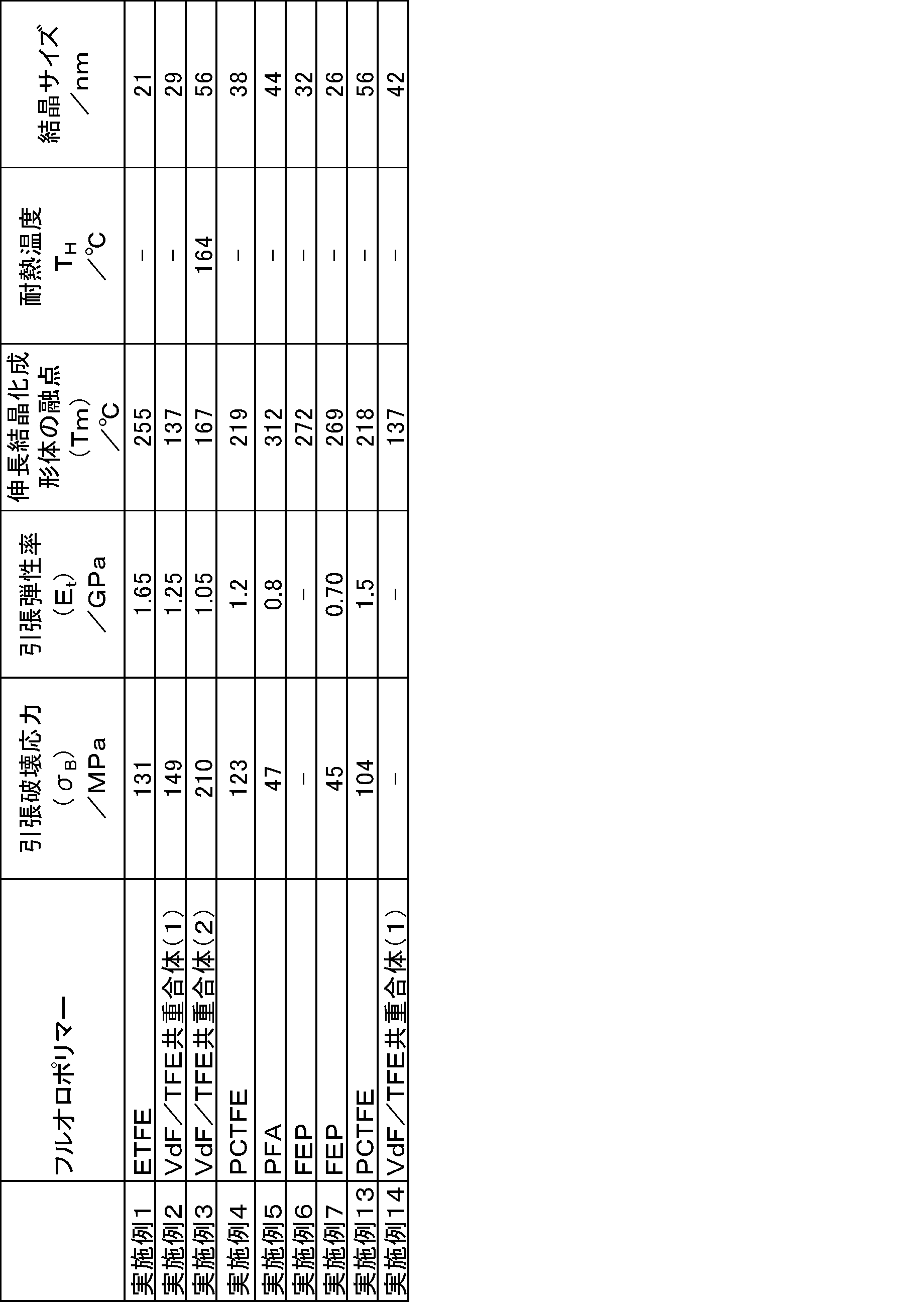
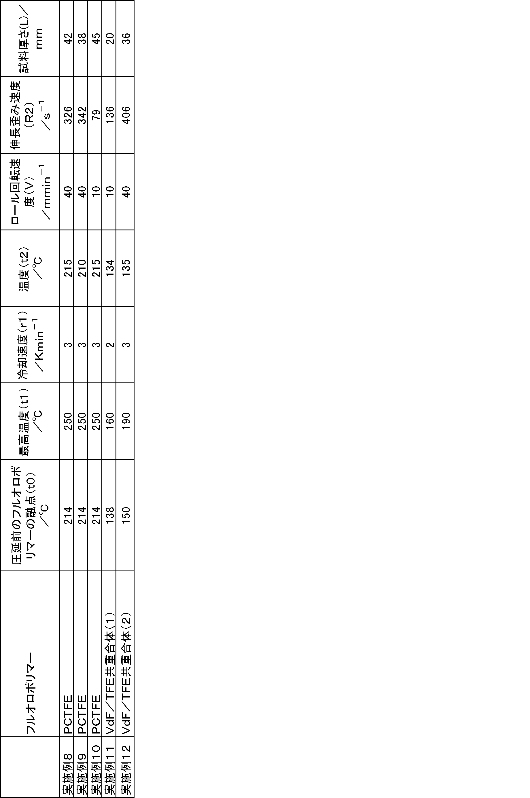
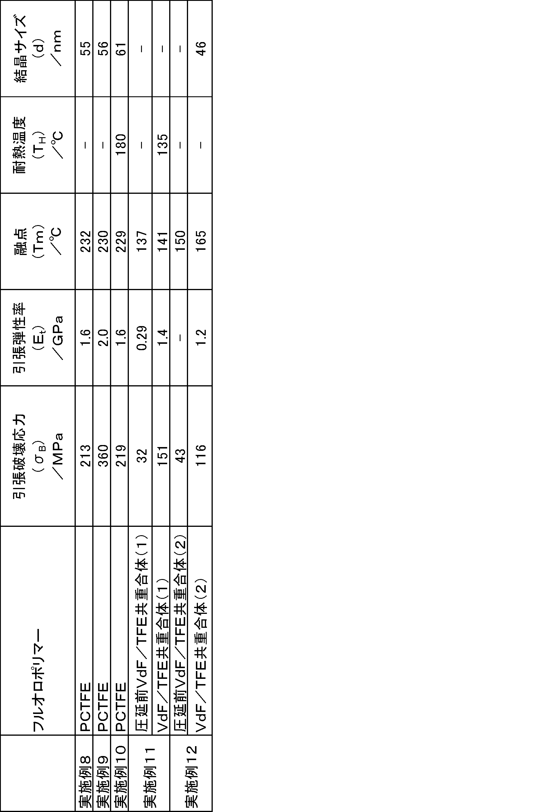
上記で得られた各試料について、試料に対して、シート厚さ方向(ND、through方向)から偏光顕微鏡観察を行った。実施例に係る試料の代表例として、実施例9で得られたPCTFEの試料について偏光顕微鏡観察を行った結果を図5に示す。図5(a)は、鋭敏色検板に対してMDを平行に置いた場合の偏光顕微鏡像であり、図5(b)は消光角の場合の偏光顕微鏡像である。 Polarization microscope observation About each sample obtained above, the polarization microscope observation was performed with respect to the sample from the sheet thickness direction (ND, through direction). As a representative example of the sample according to the example, FIG. 5 shows the result of the polarization microscope observation of the PCTFE sample obtained in Example 9. FIG. 5A is a polarization microscope image when the MD is placed in parallel to the sensitive color detection plate, and FIG. 5B is a polarization microscope image when the extinction angle is used.
実施例に係る試料を、SAXS法を用いて観察した。X線回折装置(Rigaku社製、NANO Viewer)を用いて観察した代表例として、実施例10で得られたPCTFEの試料のSAXSイメージを図6に示す。SPring-8、ビームライン BL40B2を用いて観察した代表例として実施例13、1、14、3、8、9を図12、13、14、15、16、17にそれぞれ示す。図6、12~17はthrough方向からの観察結果である。MDに強い2点像が見られた。これが、実施例に係る試料の結晶(NC)がMDに配向している証拠である。よって、実施例に係る試料はNOCを形成していることが分かる。 X-ray diffraction (small angle X-ray scattering method)
The sample according to the example was observed using the SAXS method. FIG. 6 shows a SAXS image of the PCTFE sample obtained in Example 10 as a representative example observed using an X-ray diffractometer (manufactured by Rigaku, NANO Viewer). Examples 13, 1, 14, 3, 8, and 9 are shown in FIGS. 12, 13, 14, 15, 16, and 17 as representative examples observed using SPring-8 and the beam line BL40B2. 6 and 12 to 17 are observation results from the through direction. A two-point image strong against MD was observed. This is evidence that the crystal (NC) of the sample according to the example is oriented in MD. Therefore, it turns out that the sample which concerns on an Example forms NOC.
実施例に係る試料を、WAXS法を用いて観察した。代表例として、実施例10で得られたPCTFEの試料のWAXSイメージを図7に示す。図7はthrough方向からの観察結果を示す。図7において、ファイバーパターンを示していることより高分子鎖(結晶のc軸)はMDに高配向していることを示している。よって、実施例に係る試料はNOCを形成していることが分かる。 X-ray diffraction (wide-angle X-ray scattering method)
The sample according to the example was observed using the WAXS method. As a representative example, a WAXS image of the PCTFE sample obtained in Example 10 is shown in FIG. FIG. 7 shows the observation result from the through direction. In FIG. 7, the fiber pattern indicates that the polymer chain (crystal c-axis) is highly oriented in MD. Therefore, it turns out that the sample which concerns on an Example forms NOC.
図6のMD方向の2点像から、PCTFEの実施例に係る試料の結晶サイズ(d)を求めた。PCTFEの実施例に係る試料の代表例として実施例10で得られたPCTFEの試料のdを求めた結果、61nmであるとわかった。同様に、図12、13、14、15、16,17の2点像から、実施例13、1、14、3、8、9の結晶サイズ(d)を求めた。実施例13のdは56nmであり、実施例1のdは21nmであり、実施例14のdは42nmであり、実施例3のdは56nmであり、実施例8のdは55nmであり、実施例9のdは56nmであった。
実施例2、4、5、6、7及び12の試料の1次元小角散乱測定により、散乱ベクトルqから結晶サイズ(d)を求めた。実施例2の試料のdは29nmであり、実施例4の試料のdは38nmであり、実施例5の試料のdは44nmであり、実施例6の試料のdは32nmであり、実施例7の試料のdは26nmであり、実施例12の試料のdは49nmであった。 Examination of crystal size and structure
The crystal size (d) of the sample according to the PCTFE example was determined from the two-point image in the MD direction in FIG. As a representative example of the sample according to the PCTFE example, d of the PCTFE sample obtained in Example 10 was obtained and found to be 61 nm. Similarly, the crystal sizes (d) of Examples 13, 1, 14, 3, 8, and 9 were determined from the two-point images of FIGS. 12, 13, 14, 15, 16, and 17. D of Example 13 is 56 nm, d of Example 1 is 21 nm, d of Example 14 is 42 nm, d of Example 3 is 56 nm, d of Example 8 is 55 nm, In Example 9, d was 56 nm.
The crystal size (d) was determined from the scattering vector q by one-dimensional small-angle scattering measurement of the samples of Examples 2, 4, 5, 6, 7, and 12. D of the sample of Example 2 is 29 nm, d of the sample of Example 4 is 38 nm, d of the sample of Example 5 is 44 nm, d of the sample of Example 6 is 32 nm, The d of the sample of 7 was 26 nm, and the d of the sample of Example 12 was 49 nm.
VdF/TFE共重合体(2)の実施例3の試料、VdF/TFE共重合体(1)の実施例11の試料、PCTFEの実施例10の試料およびPCTFEの比較例1の試料(商品名 DF-0025C1、ダイキン工業(株)製)の耐熱温度を、光学顕微鏡を用いた試験片サイズ直読法により測定した。試験片のたて方向(MD)、およびよこ方向(TD)を定量的に計測し、MDまたはTDに3%以上収縮(又は膨張)を開始した時の温度を、耐熱温度THとした。 Examination of heat-resistant temperature Sample of Example 3 of VdF / TFE copolymer (2), Sample of Example 11 of VdF / TFE copolymer (1), Sample of Example 10 of PCTFE and Comparative Example 1 of PCTFE The heat resistance temperature of a sample (trade name: DF-0025C1, manufactured by Daikin Industries, Ltd.) was measured by a test piece size direct reading method using an optical microscope. Longitudinal direction of the test piece (MD) and transverse direction (TD) quantitatively measures the temperature of at the start of more than 3% shrinkage in the MD or TD (or expanded) to obtain a heat resistant temperature T H.
PCTFEの実施例10の試料の耐熱性を測定した結果を図8に示す。PCTFEの比較例1の耐熱性を測定した結果を図9に示す。実施例10の試料が3%以上ひずんだ時の耐熱温度THは約180℃であった。一方、PCTFEの比較例1の試料の耐熱温度THは約110℃であった。耐熱温度について実施例に係る試料が、比較例に係る試料を大きく上回るものであるとわかった。 The sample of Example 3 of the VdF / TFE copolymer (2) had a heat resistance temperature TH of 164 ° C. and had high heat resistance. The molded product of VdF / TFE copolymer (1) had high heat resistance with a heat resistant temperature TH of 135 ° C.
The results of measuring the heat resistance of the sample of PCTFE Example 10 are shown in FIG. The result of measuring the heat resistance of Comparative Example 1 of PCTFE is shown in FIG. Heat resistance temperature T H when distorted sample of Example 10 is 3% or more was about 180 ° C.. On the other hand, the heat resistance temperature T H of the sample of Comparative Example 1 of the PCTFE was about 110 ° C.. It turned out that the sample which concerns on an Example about heat-resistant temperature is what exceeds the sample which concerns on a comparative example greatly.
実施例に係わる試料の融点Tmおよび伸長結晶化に使用したシートに係わる試料の融点t0を、示差走査熱量計〔DSC〕を用いて、10K/minの速度で昇温したときの融解熱曲線における極大値に対応する温度として求めた。結果を表2、4に示す。 Melting heat curve when melting point Tm of the sample relating to the melting point example and melting point t0 of the sample relating to the sheet used for the elongation crystallization were raised at a rate of 10 K / min using a differential scanning calorimeter [DSC]. The temperature was determined as the temperature corresponding to the maximum value at. The results are shown in Tables 2 and 4.
融点について実施例に係る試料が、伸長結晶化前のシートに係る試料よりも大きく上回るものであるとわかった。 PCTFE moldings have a Tm that is + 4 ° C. higher than the reported stationary equilibrium equilibrium melting point T m 0 = 228 ° C. (M. Hikosaka et al. Polymer Preprints, Japan 1989, 38 (10), 3308-3310.). Was.
It turned out that the sample which concerns on an Example is much larger than the sample which concerns on the sheet | seat before an elongation crystallization about melting | fusing point.
フルオロポリマーの実施例に係わる試料およびPCTFEの比較例の試料(商品名 DF-0025C1、ダイキン工業(株)製)の引張破壊応力、引張弾性率を測定した。結果を表2と表4に示す。実施例9の試料について引張破壊応力(σB)と引張弾性率(Et)を測定した結果を図10に示す。PCTFEの比較例の試料について引張破壊応力(σB)と引張弾性率(Et)を測定した結果を示す図を図11に示す。PCTFEの実施例9の試料と比較例1とを比較すると、引張破壊応力(σB)および引張弾性率(Et)について、実施例9に係る試料が、比較例1に係る試料を大きく上回るものであった。 Tensile Fracture Stress, Tensile Elastic Modulus Tensile fracture stress and tensile elastic modulus of samples related to Examples of fluoropolymer and a comparative example of PCTFE (trade name: DF-0025C1, manufactured by Daikin Industries, Ltd.) were measured. The results are shown in Tables 2 and 4. The results of measuring the tensile fracture stress (σ B ) and the tensile modulus (E t ) of the sample of Example 9 are shown in FIG. FIG. 11 shows a diagram showing the results of measuring the tensile fracture stress (σ B ) and the tensile elastic modulus (E t ) for the sample of the comparative example of PCTFE. When the sample of PCTFE Example 9 and Comparative Example 1 are compared, the sample according to Example 9 greatly exceeds the sample according to Comparative Example 1 in terms of tensile fracture stress (σ B ) and tensile elastic modulus (E t ). It was a thing.
PFA及びFEPの成形物は引張破壊応力(σB)が45MPa以上であり、引張弾性率が0.7GPa以上の高強度を有していた。 The molded product of ETFE, VdF / TFE copolymer and PCTFE had a tensile strength of 120 MPa or higher and a high tensile modulus of 1 GPa or higher.
The molded product of PFA and FEP had high strength with a tensile fracture stress (σ B ) of 45 MPa or more and a tensile elastic modulus of 0.7 GPa or more.
2:下部金型
3:圧延後の試料
3’:圧延前の試料
31:圧延前の試料
34:圧延後の試料
35:ロール 1, 1 ': Upper die 2: Lower die 3: Sample after rolling 3': Sample before rolling 31: Sample before rolling 34:
Claims (2)
- フルオロポリマーの結晶を含む成形体であって、
前記フルオロポリマーが、ビニリデンフルオライド/テトラフルオロエチレン共重合体、ポリクロロトリフルオロエチレン、エチレン/テトラフルオロエチレン共重合体、テトラフルオロエチレン/パーフルオロ(アルキルビニルエーテル)共重合体及びテトラフルオロエチレン/ヘキサフルオロプロピレン共重合体からなる群より選択される少なくとも1種であり、
前記結晶はサイズが300nm以下のナノ配向結晶である
ことを特徴とする成形体。 A molded body containing a fluoropolymer crystal,
The fluoropolymer is vinylidene fluoride / tetrafluoroethylene copolymer, polychlorotrifluoroethylene, ethylene / tetrafluoroethylene copolymer, tetrafluoroethylene / perfluoro (alkyl vinyl ether) copolymer, and tetrafluoroethylene / hexa At least one selected from the group consisting of fluoropropylene copolymers,
The shaped body is a nano-oriented crystal having a size of 300 nm or less. - 前記フルオロポリマーは高結晶性である請求項1記載の成形体。 The molded article according to claim 1, wherein the fluoropolymer is highly crystalline.
Priority Applications (6)
| Application Number | Priority Date | Filing Date | Title |
|---|---|---|---|
| KR1020207026703A KR20200123174A (en) | 2018-03-30 | 2019-03-27 | Molded body |
| CN201980023060.6A CN111936561A (en) | 2018-03-30 | 2019-03-27 | Shaped body |
| US17/043,582 US11773225B2 (en) | 2018-03-30 | 2019-03-27 | Molded article |
| KR1020237036471A KR20230152176A (en) | 2018-03-30 | 2019-03-27 | Molded article |
| JP2020509166A JP7321145B2 (en) | 2018-03-30 | 2019-03-27 | molding |
| EP19777426.8A EP3763772A4 (en) | 2018-03-30 | 2019-03-27 | Molded article |
Applications Claiming Priority (2)
| Application Number | Priority Date | Filing Date | Title |
|---|---|---|---|
| JP2018069585 | 2018-03-30 | ||
| JP2018-069585 | 2018-03-30 |
Publications (1)
| Publication Number | Publication Date |
|---|---|
| WO2019189316A1 true WO2019189316A1 (en) | 2019-10-03 |
Family
ID=68060069
Family Applications (1)
| Application Number | Title | Priority Date | Filing Date |
|---|---|---|---|
| PCT/JP2019/013103 WO2019189316A1 (en) | 2018-03-30 | 2019-03-27 | Molded article |
Country Status (6)
| Country | Link |
|---|---|
| US (1) | US11773225B2 (en) |
| EP (1) | EP3763772A4 (en) |
| JP (1) | JP7321145B2 (en) |
| KR (2) | KR20200123174A (en) |
| CN (1) | CN111936561A (en) |
| WO (1) | WO2019189316A1 (en) |
Cited By (1)
| Publication number | Priority date | Publication date | Assignee | Title |
|---|---|---|---|---|
| US20210206891A1 (en) * | 2019-12-31 | 2021-07-08 | Saint-Gobain Performance Plastics Corporation | Tube and method for making same |
Citations (12)
| Publication number | Priority date | Publication date | Assignee | Title |
|---|---|---|---|---|
| JP2002219750A (en) | 2000-11-10 | 2002-08-06 | Asahi Glass Co Ltd | Fluororesin film of high mechanical strength |
| WO2007026832A1 (en) | 2005-09-02 | 2007-03-08 | National University Of Corporation Hiroshima University | Process for producing polymer oriented crystal, polymer oriented crystal produced by said production process, and method for determining critical elongation strain rate of polymer melt |
| WO2008108251A1 (en) | 2007-03-02 | 2008-09-12 | Hiroshima University | Polymer crystal |
| JP2008248039A (en) | 2007-03-29 | 2008-10-16 | Hiroshima Univ | Polymer crystal and method for producing the same |
| WO2010084750A1 (en) * | 2009-01-23 | 2010-07-29 | 国立大学法人広島大学 | Polymer sheet and method for producing same |
| JP2010168485A (en) | 2009-01-23 | 2010-08-05 | Sunallomer Ltd | Method and system for producing crystalline resin film or sheet |
| JP2012149152A (en) * | 2011-01-18 | 2012-08-09 | Kureha Corp | Polyvinylidene fluoride resin composition, colored resin film, and backsheet for solar cell module |
| WO2012108463A1 (en) * | 2011-02-10 | 2012-08-16 | ダイキン工業株式会社 | Hydrophobic dielectric film for electrowetting |
| JP2014156581A (en) * | 2012-10-16 | 2014-08-28 | Daikin Ind Ltd | High dielectric film |
| WO2016035598A1 (en) | 2014-09-02 | 2016-03-10 | 国立大学法人広島大学 | Highly heat-resistant polyester sheet |
| JP2017043829A (en) * | 2015-08-28 | 2017-03-02 | 国立大学法人大阪大学 | Manufacturing method for dielectric base having metal containing film |
| JP2017155087A (en) * | 2016-02-29 | 2017-09-07 | デンカ株式会社 | Fluororesin sheet containing luminous phosphor, laminate therewith, luminous sheet, outdoor luminous indicator |
Family Cites Families (11)
| Publication number | Priority date | Publication date | Assignee | Title |
|---|---|---|---|---|
| US6146923A (en) * | 1993-04-09 | 2000-11-14 | Tadahiro Ohmi | Method of smoothing fluorine-containing resin molded article and smoothed molded article |
| US6476144B1 (en) * | 1998-05-29 | 2002-11-05 | Daikin Industries, Ltd. | Spherulite-micronizing agent for crystalline fluororesin crystalline fluororesin composition containing micronizing agent |
| CN100584863C (en) * | 2004-08-06 | 2010-01-27 | 大金工业株式会社 | Method for producing homopolymer of vinylidene fluoride having I type crystal structure |
| EP1798253B8 (en) * | 2004-08-11 | 2014-06-18 | Kaneka Corporation | Method for producing a vinylidene fluoride-based resin multilayered film |
| WO2008090947A1 (en) | 2007-01-26 | 2008-07-31 | Daikin Industries, Ltd. | High dielectric film having high withstand voltage |
| KR100930588B1 (en) | 2007-09-21 | 2009-12-09 | 경희대학교 산학협력단 | Method for producing polyvinylidene fluoride film having high content of β-crystal |
| JP2013237730A (en) | 2012-05-11 | 2013-11-28 | Tokyo Univ Of Agriculture & Technology | Method for producing fluororesin film |
| CN105283491B (en) | 2013-07-19 | 2018-10-16 | 三井化学株式会社 | Crystallize polymeric membrane and its manufacturing method |
| JP6455367B2 (en) | 2014-09-16 | 2019-01-23 | Agc株式会社 | Fluorine-containing resin composition, molded article, electric wire, and method for producing fluorine-containing resin composition |
| JP6504434B2 (en) | 2015-01-07 | 2019-04-24 | 三菱ケミカル株式会社 | Film made of vinylidene fluoride resin composition |
| US20210017375A1 (en) | 2018-03-30 | 2021-01-21 | Hiroshima University | Molded article |
-
2019
- 2019-03-27 JP JP2020509166A patent/JP7321145B2/en active Active
- 2019-03-27 CN CN201980023060.6A patent/CN111936561A/en active Pending
- 2019-03-27 WO PCT/JP2019/013103 patent/WO2019189316A1/en unknown
- 2019-03-27 KR KR1020207026703A patent/KR20200123174A/en active Application Filing
- 2019-03-27 US US17/043,582 patent/US11773225B2/en active Active
- 2019-03-27 EP EP19777426.8A patent/EP3763772A4/en active Pending
- 2019-03-27 KR KR1020237036471A patent/KR20230152176A/en not_active Application Discontinuation
Patent Citations (12)
| Publication number | Priority date | Publication date | Assignee | Title |
|---|---|---|---|---|
| JP2002219750A (en) | 2000-11-10 | 2002-08-06 | Asahi Glass Co Ltd | Fluororesin film of high mechanical strength |
| WO2007026832A1 (en) | 2005-09-02 | 2007-03-08 | National University Of Corporation Hiroshima University | Process for producing polymer oriented crystal, polymer oriented crystal produced by said production process, and method for determining critical elongation strain rate of polymer melt |
| WO2008108251A1 (en) | 2007-03-02 | 2008-09-12 | Hiroshima University | Polymer crystal |
| JP2008248039A (en) | 2007-03-29 | 2008-10-16 | Hiroshima Univ | Polymer crystal and method for producing the same |
| WO2010084750A1 (en) * | 2009-01-23 | 2010-07-29 | 国立大学法人広島大学 | Polymer sheet and method for producing same |
| JP2010168485A (en) | 2009-01-23 | 2010-08-05 | Sunallomer Ltd | Method and system for producing crystalline resin film or sheet |
| JP2012149152A (en) * | 2011-01-18 | 2012-08-09 | Kureha Corp | Polyvinylidene fluoride resin composition, colored resin film, and backsheet for solar cell module |
| WO2012108463A1 (en) * | 2011-02-10 | 2012-08-16 | ダイキン工業株式会社 | Hydrophobic dielectric film for electrowetting |
| JP2014156581A (en) * | 2012-10-16 | 2014-08-28 | Daikin Ind Ltd | High dielectric film |
| WO2016035598A1 (en) | 2014-09-02 | 2016-03-10 | 国立大学法人広島大学 | Highly heat-resistant polyester sheet |
| JP2017043829A (en) * | 2015-08-28 | 2017-03-02 | 国立大学法人大阪大学 | Manufacturing method for dielectric base having metal containing film |
| JP2017155087A (en) * | 2016-02-29 | 2017-09-07 | デンカ株式会社 | Fluororesin sheet containing luminous phosphor, laminate therewith, luminous sheet, outdoor luminous indicator |
Non-Patent Citations (9)
| Title |
|---|
| FUKUSHIMA, TOSHIYUKI ET AL.: "Undercooling dependence of nucleation rate of vinylidene fluoride/tetrafluoroethylene copolymer (P(VDF/TFE", POLYMER PREPRINTS, vol. 66, no. 1, 15 May 2017 (2017-05-15), Japan, pages 2C03, XP009523739 * |
| HIKOSAKA, M. ET AL., POLYMER PREPRINTS, JAPAN, vol. 64, no. 2, 2015, pages 1G11 |
| HIKOSAKA, MASAMICHI ET AL.: "High heat resistance and high strength of nano-oriented crystals (NOC) discovered by strain-induced crystallization of Polymer", POLYMER PREPRINTS, vol. 64, no. 2, 25 August 2015 (2015-08-25), Japan, pages 1G11, XP009523740 * |
| K. OKADAJ. WASHIYAMAK. WATANABES. SASAKIH. MASUNAGAM. HIKOSAKA, POLYMER J., vol. 42, 2010, pages 464 - 473 |
| M. HIKOSAKA ET AL., POLYMER PREPRINTS, JAPAN, vol. 38, no. 10, 1989, pages 3308 - 3310 |
| M. HIKOSAKAK. OKADA, POLYM. PREPR., JPN., vol. 60, no. 2, 2011, pages 3014 - 3015 |
| MASAO KAKUDONOBUTAMI KASAI: "Kobunshi Ekkusu-sen Kaisetsu (Polymer X-ray diffraction", 1995, MARUZEN PUBLISHING CO., LTD. |
| OKADA, KIYOKA ET AL.: "The universality of nano-oriented crystal formation in strain-induced crystallization and verification of nucleation rate-limiting", POLYMER PREPRINTS, vol. 63, no. 1, Japan * |
| YU AWAYA: "Introduction to polarization microscope for polymer material", 2001, AGNE GIJUTSU CENTER INC., pages: 75 - 103 |
Cited By (3)
| Publication number | Priority date | Publication date | Assignee | Title |
|---|---|---|---|---|
| US20210206891A1 (en) * | 2019-12-31 | 2021-07-08 | Saint-Gobain Performance Plastics Corporation | Tube and method for making same |
| CN114901981A (en) * | 2019-12-31 | 2022-08-12 | 美国圣戈班性能塑料公司 | Pipe and method for manufacturing same |
| JP2023509128A (en) * | 2019-12-31 | 2023-03-07 | サン-ゴバン パフォーマンス プラスティックス コーポレイション | Tubing and tube manufacturing method |
Also Published As
| Publication number | Publication date |
|---|---|
| US20210024709A1 (en) | 2021-01-28 |
| KR20230152176A (en) | 2023-11-02 |
| CN111936561A (en) | 2020-11-13 |
| JPWO2019189316A1 (en) | 2020-12-03 |
| EP3763772A4 (en) | 2021-11-24 |
| EP3763772A1 (en) | 2021-01-13 |
| JP7321145B2 (en) | 2023-08-04 |
| KR20200123174A (en) | 2020-10-28 |
| US11773225B2 (en) | 2023-10-03 |
| TW201942155A (en) | 2019-11-01 |
Similar Documents
| Publication | Publication Date | Title |
|---|---|---|
| CA2956703C (en) | Articles produced from vdf-co-(tfe or trfe) polymers | |
| CA2956705C (en) | Method for producing porous articles from alternating poly(ethylene tetrafluoroethylene) and articles produced therefrom | |
| KR102158634B1 (en) | Copolymers containing vinylidene fluoride and trifluoroethylene | |
| KR102035036B1 (en) | Dope composition for preparing optical film and optical film using thereof | |
| JP5930008B2 (en) | Modified polytetrafluoroethylene fine powder and uniaxially stretched porous body | |
| JP2011181748A (en) | Method of manufacturing polarized resin film | |
| JP6787335B2 (en) | Resin film and its manufacturing method | |
| WO2019189316A1 (en) | Molded article | |
| JP2005306033A (en) | Polytetrafluorethylene resin film and its manufacturing process | |
| WO2012026401A1 (en) | Process for manufacturing stretched polytetrafluoroethylene film, and stretched polytetrafluoroethylene film | |
| JP7101373B2 (en) | Mold | |
| TWI852925B (en) | Formed body | |
| KR102166417B1 (en) | Acrylic optical film and manufacturing method thereof | |
| Ito et al. | Structural and morphological changes at initial state under uniaxial elongation of rolled polytetrafluoroethylene | |
| KR102122723B1 (en) | Acrylic optical film and manufacturing method thereof | |
| KR102260108B1 (en) | Acrylic optical film and manufacturing method thereof | |
| JPH0468005A (en) | Production of fluorocopolymer |
Legal Events
| Date | Code | Title | Description |
|---|---|---|---|
| 121 | Ep: the epo has been informed by wipo that ep was designated in this application |
Ref document number: 19777426 Country of ref document: EP Kind code of ref document: A1 |
|
| ENP | Entry into the national phase |
Ref document number: 2020509166 Country of ref document: JP Kind code of ref document: A |
|
| ENP | Entry into the national phase |
Ref document number: 20207026703 Country of ref document: KR Kind code of ref document: A |
|
| ENP | Entry into the national phase |
Ref document number: 2019777426 Country of ref document: EP Effective date: 20201009 |