WO2019188828A1 - Heat exchanger and air-conditioning device - Google Patents
Heat exchanger and air-conditioning device Download PDFInfo
- Publication number
- WO2019188828A1 WO2019188828A1 PCT/JP2019/012199 JP2019012199W WO2019188828A1 WO 2019188828 A1 WO2019188828 A1 WO 2019188828A1 JP 2019012199 W JP2019012199 W JP 2019012199W WO 2019188828 A1 WO2019188828 A1 WO 2019188828A1
- Authority
- WO
- WIPO (PCT)
- Prior art keywords
- space
- header
- refrigerant
- heat transfer
- heat exchanger
- Prior art date
Links
Images


Classifications
-
- F—MECHANICAL ENGINEERING; LIGHTING; HEATING; WEAPONS; BLASTING
- F28—HEAT EXCHANGE IN GENERAL
- F28D—HEAT-EXCHANGE APPARATUS, NOT PROVIDED FOR IN ANOTHER SUBCLASS, IN WHICH THE HEAT-EXCHANGE MEDIA DO NOT COME INTO DIRECT CONTACT
- F28D1/00—Heat-exchange apparatus having stationary conduit assemblies for one heat-exchange medium only, the media being in contact with different sides of the conduit wall, in which the other heat-exchange medium is a large body of fluid, e.g. domestic or motor car radiators
- F28D1/02—Heat-exchange apparatus having stationary conduit assemblies for one heat-exchange medium only, the media being in contact with different sides of the conduit wall, in which the other heat-exchange medium is a large body of fluid, e.g. domestic or motor car radiators with heat-exchange conduits immersed in the body of fluid
- F28D1/04—Heat-exchange apparatus having stationary conduit assemblies for one heat-exchange medium only, the media being in contact with different sides of the conduit wall, in which the other heat-exchange medium is a large body of fluid, e.g. domestic or motor car radiators with heat-exchange conduits immersed in the body of fluid with tubular conduits
- F28D1/053—Heat-exchange apparatus having stationary conduit assemblies for one heat-exchange medium only, the media being in contact with different sides of the conduit wall, in which the other heat-exchange medium is a large body of fluid, e.g. domestic or motor car radiators with heat-exchange conduits immersed in the body of fluid with tubular conduits the conduits being straight
- F28D1/0535—Heat-exchange apparatus having stationary conduit assemblies for one heat-exchange medium only, the media being in contact with different sides of the conduit wall, in which the other heat-exchange medium is a large body of fluid, e.g. domestic or motor car radiators with heat-exchange conduits immersed in the body of fluid with tubular conduits the conduits being straight the conduits having a non-circular cross-section
- F28D1/05366—Assemblies of conduits connected to common headers, e.g. core type radiators
- F28D1/05391—Assemblies of conduits connected to common headers, e.g. core type radiators with multiple rows of conduits or with multi-channel conduits combined with a particular flow pattern, e.g. multi-row multi-stage radiators
-
- F—MECHANICAL ENGINEERING; LIGHTING; HEATING; WEAPONS; BLASTING
- F24—HEATING; RANGES; VENTILATING
- F24F—AIR-CONDITIONING; AIR-HUMIDIFICATION; VENTILATION; USE OF AIR CURRENTS FOR SCREENING
- F24F1/00—Room units for air-conditioning, e.g. separate or self-contained units or units receiving primary air from a central station
- F24F1/06—Separate outdoor units, e.g. outdoor unit to be linked to a separate room comprising a compressor and a heat exchanger
- F24F1/14—Heat exchangers specially adapted for separate outdoor units
- F24F1/18—Heat exchangers specially adapted for separate outdoor units characterised by their shape
-
- F—MECHANICAL ENGINEERING; LIGHTING; HEATING; WEAPONS; BLASTING
- F25—REFRIGERATION OR COOLING; COMBINED HEATING AND REFRIGERATION SYSTEMS; HEAT PUMP SYSTEMS; MANUFACTURE OR STORAGE OF ICE; LIQUEFACTION SOLIDIFICATION OF GASES
- F25B—REFRIGERATION MACHINES, PLANTS OR SYSTEMS; COMBINED HEATING AND REFRIGERATION SYSTEMS; HEAT PUMP SYSTEMS
- F25B39/00—Evaporators; Condensers
-
- F—MECHANICAL ENGINEERING; LIGHTING; HEATING; WEAPONS; BLASTING
- F28—HEAT EXCHANGE IN GENERAL
- F28D—HEAT-EXCHANGE APPARATUS, NOT PROVIDED FOR IN ANOTHER SUBCLASS, IN WHICH THE HEAT-EXCHANGE MEDIA DO NOT COME INTO DIRECT CONTACT
- F28D1/00—Heat-exchange apparatus having stationary conduit assemblies for one heat-exchange medium only, the media being in contact with different sides of the conduit wall, in which the other heat-exchange medium is a large body of fluid, e.g. domestic or motor car radiators
- F28D1/02—Heat-exchange apparatus having stationary conduit assemblies for one heat-exchange medium only, the media being in contact with different sides of the conduit wall, in which the other heat-exchange medium is a large body of fluid, e.g. domestic or motor car radiators with heat-exchange conduits immersed in the body of fluid
- F28D1/04—Heat-exchange apparatus having stationary conduit assemblies for one heat-exchange medium only, the media being in contact with different sides of the conduit wall, in which the other heat-exchange medium is a large body of fluid, e.g. domestic or motor car radiators with heat-exchange conduits immersed in the body of fluid with tubular conduits
- F28D1/053—Heat-exchange apparatus having stationary conduit assemblies for one heat-exchange medium only, the media being in contact with different sides of the conduit wall, in which the other heat-exchange medium is a large body of fluid, e.g. domestic or motor car radiators with heat-exchange conduits immersed in the body of fluid with tubular conduits the conduits being straight
-
- F—MECHANICAL ENGINEERING; LIGHTING; HEATING; WEAPONS; BLASTING
- F28—HEAT EXCHANGE IN GENERAL
- F28F—DETAILS OF HEAT-EXCHANGE AND HEAT-TRANSFER APPARATUS, OF GENERAL APPLICATION
- F28F9/00—Casings; Header boxes; Auxiliary supports for elements; Auxiliary members within casings
- F28F9/02—Header boxes; End plates
- F28F9/0202—Header boxes having their inner space divided by partitions
- F28F9/0204—Header boxes having their inner space divided by partitions for elongated header box, e.g. with transversal and longitudinal partitions
-
- F—MECHANICAL ENGINEERING; LIGHTING; HEATING; WEAPONS; BLASTING
- F28—HEAT EXCHANGE IN GENERAL
- F28D—HEAT-EXCHANGE APPARATUS, NOT PROVIDED FOR IN ANOTHER SUBCLASS, IN WHICH THE HEAT-EXCHANGE MEDIA DO NOT COME INTO DIRECT CONTACT
- F28D21/00—Heat-exchange apparatus not covered by any of the groups F28D1/00 - F28D20/00
- F28D2021/0019—Other heat exchangers for particular applications; Heat exchange systems not otherwise provided for
- F28D2021/0068—Other heat exchangers for particular applications; Heat exchange systems not otherwise provided for for refrigerant cycles
Definitions
- the present disclosure relates to a heat exchanger and an air conditioner.
- Patent Document 1 Japanese Patent Application Laid-Open No. 2015-068622
- the refrigerant can be diverted to the heat transfer tubes arranged in the vertical direction in any environment of a high circulation amount and a low circulation amount.
- coolant in the header is proposed.
- Patent Document 2 Japanese Patent Laid-Open No. 2017-044428 discloses a heat exchanger that is used in a posture in which the longitudinal direction of the header is horizontal and the heat transfer tubes extend in the vertical direction. The refrigerant is allowed to flow into each region from both ends in the longitudinal direction of the header while partitioning into a first region where one side portion of the heat transfer tube communicates with and a second region where the other side portion of each heat transfer tube communicates. There has been proposed a heat exchanger that employs a structure that allows refrigerant to be divided into the heat transfer tubes.
- the refrigerant is supplied to the plurality of heat transfer tubes in an upward direction so as to counteract its own weight in order to divert the refrigerant to flow. And it may be difficult to circulate the refrigerant sufficiently in the header. Further, even if the heat exchanger described in Patent Document 1 is used so that the longitudinal direction of the header is horizontal, if the refrigerant is circulated in the header, the refrigerant is opposed to its own weight. Therefore, it is difficult to circulate the refrigerant sufficiently in the header, and the refrigerant may drift.
- the liquid refrigerant collects in the vicinity of the center in the longitudinal direction of the header, which may cause refrigerant drift.
- This indication is made in view of the point mentioned above, and the subject of this indication is providing the heat exchanger and air harmony device which can control the drift of the refrigerant in a plurality of heat exchanger tubes.
- the heat exchanger includes a header and a plurality of heat transfer tubes.
- the header extends in the horizontal direction.
- the heat transfer tube extends in a direction intersecting the horizontal direction in which the header extends.
- the plurality of heat transfer tubes are arranged along the longitudinal direction of the header.
- the plurality of heat transfer tubes are connected to the header.
- the header has a first space, a second space, a circulation member, a first communication port, a second communication port, and an inflow port.
- the first space allows the coolant to flow in a first direction along the longitudinal direction of the header.
- the refrigerant flows in the second direction.
- the second space is provided so as to include a portion aligned in the horizontal direction with the first space.
- the second direction is a direction along the longitudinal direction of the header and is opposite to the first direction.
- the circulation member extends so as to divide the first space and the second space while extending along the longitudinal direction of the header.
- the first communication port communicates the first space and the second space in the header.
- the second communication port communicates the first space and the second space in the header at a position in the second direction as compared to the first communication port.
- the inlet allows the refrigerant to flow into the header.
- the first space and / or the second space is directly or indirectly connected to the heat transfer tube.
- the “horizontal direction”, which is the direction in which the header extends, is not limited to complete horizontal, but includes a tilt within a range of ⁇ 30 degrees with respect to the horizontal.
- the longitudinal direction of the circulating member in the longitudinal direction view of the header is not particularly limited, and may be within ⁇ 45 degrees with respect to the vertical direction, for example. Preferably, it is within a range of ⁇ 30 degrees.
- the height direction position of the lower end of the first space and the second space is different by inclining the longitudinal direction of the circulation member as viewed in the longitudinal direction of the header, the side to which the inflow port is connected It is preferable that the space is downward because it is easy to cause circulation of the refrigerant.
- the circulating member is not particularly limited, but for example, it is preferable that one end of the circulating member extends until it reaches the inner surface of the header opposite to the side to which the heat transfer tube is connected.
- heat transfer tube may extend upward from the header or may extend downward.
- the refrigerant that has flowed into the header via the inflow port is divided into a plurality of heat transfer tubes and flows, the first space, the first communication port, the second space, and the second communication port are arranged in this order. It becomes possible to circulate the refrigerant.
- the header extends in the horizontal direction, the refrigerant circulating in the header moves mainly in the horizontal direction and the degree of movement in the height direction is suppressed, so that the refrigerant in the header is affected by gravity. It can circulate in a difficult state. Thereby, it is possible to suppress the refrigerant from staying at a specific portion in the longitudinal direction of the header, and to equalize the distribution of the refrigerant to the plurality of heat transfer tubes positioned along the longitudinal direction of the header. become.
- the heat exchanger which concerns on a 2nd viewpoint is a heat exchanger which concerns on a 1st viewpoint, Comprising: As for several heat exchanger tubes, each edge part is connected to both the 1st space and 2nd space of a header. Connected to the header.
- one heat transfer tube connected to the header communicates with both the first space and the second space in the header, and one heat transfer tube has one flow path.
- the one flow path communicates with both the first space and the second space. Communicates with both the first space and the second space as a whole (a part of the plurality of channels mainly communicates with the first space, and the other part of the channels mainly communicates with the first space. You may communicate with two spaces).
- the heat exchanger according to the third aspect is a heat exchanger according to the first aspect, and the inlet is an opening through which the refrigerant flows into the first space of the header.
- the plurality of heat transfer tubes are connected to the header so that the respective end portions communicate with the first space of the header and do not communicate with the second space.
- the refrigerant passage area of the first space through which the refrigerant that has passed through the inflow port passes is larger than the internal space in the longitudinal view of the header because the internal space of the header is partitioned by the circulation member. Can be small. For this reason, it is possible to suppress a decrease in the flow rate of the refrigerant flowing through the first space. Therefore, even in an environment where the circulation amount of the refrigerant is relatively small, not only the heat transfer pipe connected to the vicinity of the inflow port in the first space, but the refrigerant supplied to the first space through the inflow port It is easy to reach the heat transfer tube connected to a position far from the inlet in the first space. Thereby, it becomes possible to suppress the drift of the refrigerant
- the heat exchanger according to the fourth aspect is the heat exchanger according to the first aspect, and the inflow port is an opening through which the refrigerant flows into the first space of the header.
- Each of the plurality of heat transfer tubes is connected to the header so that each end thereof communicates with the second space of the header and does not communicate with the first space.
- a heat exchanger is a heat exchanger according to any of the first to fourth aspects, wherein the header is a third space, a third space member, a third communication port, It has further.
- the third space is located between the first space and the second space, and the connection places between the plurality of heat transfer tubes and the header, or the first space and the connection places between the plurality of heat transfer tubes and the header. It is located between the second space and the connection points of the plurality of heat transfer tubes and the header.
- this heat exchanger is one of the following (1) to (5).
- the third space is located between the first space and the second space, and the connection locations of the plurality of heat transfer tubes and the header, and the first space and the third space are connected via the third communication port.
- the first space, the second space, and the third space are separated by a third space member so as to communicate with each other.
- the third space is located between the first space and the second space, and the connection points of the plurality of heat transfer tubes and the header, and the second space and the third space are connected via the third communication port.
- the first space, the second space, and the third space are separated by a third space member so as to communicate with each other.
- the third space is located between the first space and the second space, and the connection locations of the plurality of heat transfer tubes and the header, and the first space and the third space are connected via the third communication port.
- the first space, the second space, and the third space are separated by the third space member so that the second space and the third space communicate with each other via another third communication port. Yes.
- the third space is located between the first space and the connection points of the plurality of heat transfer tubes and the header, and the first space and the third space communicate with each other via the third communication port. In this way, the third space member is used.
- the third space is located between the second space and the connection points of the plurality of heat transfer tubes and the header, and the second space and the third space communicate with each other via the third communication port. In this way, the third space member is used.
- the refrigerant flowing in the first space or the second space passes through the third space through the third communication port formed in the third space member before being sent to the plurality of heat transfer tubes.
- the drift of the refrigerant between a plurality of heat exchanger tubes is controlled. It becomes possible.
- the heat exchanger according to the sixth aspect is a heat exchanger according to the fifth aspect, and the plurality of heat transfer tubes are arranged in a direction in which the first space and the second space are arranged.
- the plurality of heat transfer tubes are connected to the third space of the header.
- the plurality of heat transfer tubes are arranged in a matrix in the direction in which the first space and the second space are arranged while being arranged in the longitudinal direction of the header.
- a plurality of heat transfer tubes are arranged side by side in the direction in which the first space and the second space are arranged, and are arranged at different positions in the direction in which the first space and the second space are arranged. Since all the heat pipes are connected to the third space, which is the same space, the drift of the refrigerant between the heat transfer pipes arranged at different positions in the direction in which the first space and the second space are arranged is suppressed. It becomes possible.
- the heat exchanger according to the seventh aspect is a heat exchanger according to any one of the first to sixth aspects, and an inclination angle with respect to the vertical direction in which the plurality of heat transfer tubes extend is 45 degrees or less.
- the heat exchanger according to the eighth aspect is a heat exchanger according to any of the first to seventh aspects, and the heat transfer tube is a flat tube or a circular tube.
- the longitudinal direction of the cross section is the direction in which the first space and the second space are arranged.
- the circular tube has a circular cross section.
- the heat transfer tube when the heat transfer tube is a flat tube, a wide heat transfer area along the air flow direction is ensured when air is used in the direction in which the first space and the second space are aligned. Cheap. Further, when the heat transfer tube is a circular tube, it is easy to mix and flow the refrigerant supplied from both the first space and the second space.
- the air conditioner according to the ninth aspect includes a refrigerant circuit having the heat exchanger according to any one of the first to eighth aspects.
- This air conditioner can improve the performance when the refrigeration cycle is executed in the refrigerant circuit.
- FIG. 12 is a schematic cross-sectional view of a lower header in the vicinity of the lower header according to Modification C as viewed in the longitudinal direction.
- FIG. 10 is a schematic cross-sectional view of a lower header in the vicinity of the lower header according to Modification D as viewed in the longitudinal direction.
- FIG. 12 is a schematic cross-sectional view of a lower header in the vicinity of the lower header according to Modification E as viewed in the longitudinal direction.
- FIG. 10 is a schematic cross-sectional view of the lower header in the vicinity of the lower header according to Modification F as viewed in the longitudinal direction.
- 12 is a schematic cross-sectional view of a lower header in the vicinity of the lower header according to Modification G as viewed in the longitudinal direction.
- FIG. 10 is a schematic cross-sectional view of a lower header in the vicinity of the lower header according to Modification H as viewed in the longitudinal direction.
- FIG. 10 is a schematic cross-sectional view of the lower header in the vicinity of the lower header according to Modification I as viewed in the longitudinal direction.
- FIG. 10 is a schematic cross-sectional view of the lower header in the vicinity of the lower header according to Modification J as viewed in the longitudinal direction.
- 12 is a schematic cross-sectional view of the lower header in the vicinity of the lower header according to Modification K as viewed in the longitudinal direction.
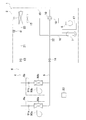
- FIG. 1 is a schematic configuration diagram of an air conditioner 1 in which an outdoor heat exchanger 11 as a heat exchanger according to an embodiment is employed.
- the air conditioner 1 is a device capable of cooling and heating a room such as a building by performing a vapor compression refrigeration cycle.
- the air conditioner 1 mainly includes an outdoor unit 2, indoor units 9a and 9b, a liquid refrigerant communication tube 4 and a gas refrigerant communication tube 5 that connect the outdoor unit 2 and the indoor units 9a and 9b, an outdoor unit 2 and And a control unit 23 that controls the constituent devices of the indoor units 9a and 3b.
- the vapor compression refrigerant circuit 6 of the air conditioner 1 is configured by connecting the outdoor unit 2 and the indoor units 9a and 9b via the refrigerant communication pipes 4 and 5, respectively.
- the outdoor unit 2 is installed outside the building (on the roof of the building, near the wall of the building, etc.) and constitutes a part of the refrigerant circuit 6.
- the outdoor unit 2 mainly includes an accumulator 7, a compressor 8, a four-way switching valve 10, an outdoor heat exchanger 11, an outdoor expansion valve 12 as an expansion mechanism, a liquid side shut-off valve 13, and a gas side shut-off valve. 14 and an outdoor fan 15.
- Each device and the valve are connected by refrigerant pipes 16-22.
- the indoor units 9a and 9b are installed in a room (such as a living room or a ceiling space) and constitute a part of the refrigerant circuit 6.
- the indoor unit 9a mainly includes an indoor expansion valve 91a, an indoor heat exchanger 92a, and an indoor fan 93a.
- the indoor unit 9b mainly includes an indoor expansion valve 91b as an expansion mechanism, an indoor heat exchanger 92b, and an indoor fan 93b.
- the refrigerant communication pipes 4 and 5 are refrigerant pipes that are constructed on site when the air conditioner 1 is installed at a place such as a building.
- One end of the liquid refrigerant communication tube 4 is connected to the liquid side closing valve 13 of the outdoor unit 2, and the other end of the liquid refrigerant communication tube 4 is connected to the liquid side ends of the indoor expansion valves 91a and 91b of the indoor units 9a and 9b.
- One end of the gas refrigerant communication pipe 5 is connected to the gas side shut-off valve 14 of the outdoor unit 2, and the other end of the gas refrigerant communication pipe 5 is connected to the gas side ends of the indoor heat exchangers 92a and 92b of the indoor units 9a and 9b. It is connected.
- the control unit 23 is configured by communication connection of control boards and the like (not shown) provided in the outdoor unit 2 and the indoor units 9a and 9b.
- the outdoor unit 2 and the indoor units 9a and 9b are illustrated at positions away from each other.
- the control unit 23 controls the components 8, 10, 12, 15, 91a, 91b, 93a, 93b of the air conditioner 1 (here, the outdoor unit 2 and the indoor units 9a, 9b), that is, the air conditioner 1
- the whole operation control is performed.
- the four-way switching valve 10 is switched to the outdoor heat radiation state (the state indicated by the solid line in FIG. 1).
- the low-pressure gas refrigerant in the refrigeration cycle is sucked into the compressor 8 and is compressed until it reaches the high pressure in the refrigeration cycle, and then discharged.
- the high-pressure gas refrigerant discharged from the compressor 8 is sent to the outdoor heat exchanger 11 through the four-way switching valve 10.
- the high-pressure gas refrigerant sent to the outdoor heat exchanger 11 is converted into outdoor air and heat supplied as a cooling source by the outdoor fan 15 during cooling operation in the outdoor heat exchanger 11 that functions as a refrigerant condenser or radiator.
- the outdoor fan 15 It exchanges and radiates heat (during the defrost operation, the outdoor fan 15 is in a stopped state but dissipates heat while melting frost), and becomes a high-pressure liquid refrigerant.
- the high-pressure liquid refrigerant radiated in the outdoor heat exchanger 11 is sent to the indoor expansion valves 91 a and 91 b through the outdoor expansion valve 12, the liquid side closing valve 13 and the liquid refrigerant communication pipe 4.
- the refrigerant sent to the indoor expansion valves 91a and 91b is decompressed to the low pressure of the refrigeration cycle by the indoor expansion valves 91a and 91b, and becomes a low-pressure gas-liquid two-phase refrigerant.
- the low-pressure gas-liquid two-phase refrigerant decompressed by the indoor expansion valves 91a and 91b is sent to the indoor heat exchangers 92a and 92b.
- the low-pressure gas-liquid two-phase refrigerant sent to the indoor heat exchangers 92a and 92b is indoor air supplied as a heating source by the indoor fans 93a and 93b during the cooling operation in the indoor heat exchangers 92a and 92b.
- the indoor fans 93a and 93b are not driven during the defrost operation but evaporate by exchanging heat with room air). Thereby, the indoor air is cooled, and then the indoor air is cooled (or the frost attached to the outdoor heat exchanger 11 is melted) by being supplied indoors.
- the low-pressure gas refrigerant evaporated in the indoor heat exchangers 92 a and 92 b is again sucked into the compressor 8 through the gas refrigerant communication pipe 5, the gas-side closing valve 14, the four-way switching valve 10, and the accumulator 7.
- the four-way selector valve 10 is switched to the outdoor evaporation state (the state indicated by the broken line in FIG. 1).
- the low-pressure gas refrigerant in the refrigeration cycle is sucked into the compressor 8 and is compressed until it reaches the high pressure in the refrigeration cycle, and then discharged.
- the high-pressure gas refrigerant discharged from the compressor 8 is sent to the indoor heat exchangers 92 a and 92 b through the four-way switching valve 10, the gas-side closing valve 14, and the gas refrigerant communication pipe 5.
- the high-pressure gas refrigerant sent to the indoor heat exchangers 92a and 92b dissipates heat by exchanging heat with indoor air supplied as cooling sources by the indoor fans 93a and 93b in the indoor heat exchangers 92a and 92b. Becomes a high-pressure liquid refrigerant. Thereby, indoor air is heated, and indoor heating is performed by being supplied indoors after that.
- the high-pressure liquid refrigerant radiated by the indoor heat exchangers 92 a and 92 b is sent to the outdoor expansion valve 12 through the indoor expansion valves 91 a and 91 b, the liquid refrigerant communication pipe 4 and the liquid-side closing valve 13.
- the refrigerant sent to the outdoor expansion valve 12 is decompressed to the low pressure of the refrigeration cycle by the outdoor expansion valve 12, and becomes a low-pressure gas-liquid two-phase refrigerant.
- the low-pressure gas-liquid two-phase refrigerant decompressed by the outdoor expansion valve 12 is sent to the outdoor heat exchanger 11.
- the low-pressure gas-liquid two-phase refrigerant sent to the outdoor heat exchanger 11 exchanges heat with outdoor air supplied as a heating source by the outdoor fan 15 in the outdoor heat exchanger 11 that functions as a refrigerant evaporator. Go and evaporate into a low-pressure gas refrigerant.
- the low-pressure refrigerant evaporated in the outdoor heat exchanger 11 is again sucked into the compressor 8 through the four-way switching valve 10 and the accumulator 7.
- the cooling operation and the heating operation are started by an input from a user via a remote controller (not shown), and the defrost operation is started when a predetermined defrost start condition is satisfied during the heating operation.
- the predetermined defrost start condition is not particularly limited.
- the outdoor air temperature detected by an outdoor temperature sensor (not shown) and / or the temperature of the outdoor heat exchanger 11 detected by the outdoor heat exchanger temperature sensor satisfy the predetermined temperature condition. It can be assumed that it is satisfied.
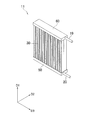
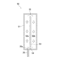
- FIG. 2 is an external perspective view of the outdoor heat exchanger 11.
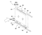
- FIG. 3 is an explanatory diagram for explaining the refrigerant flow in the outdoor heat exchanger 11 as an evaporator.
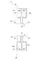
- FIG. 4 is a schematic configuration diagram of the lower header 50 in plan view.
- FIG. 5 is a schematic cross-sectional view of the upper header 60 and the lower header 50 as viewed in the longitudinal direction.
- the outdoor heat exchanger 11 is a heat exchanger that performs heat exchange between the refrigerant and the outdoor air, and mainly includes a lower header 50, an upper header 60, and a fin tube integrated member 30.
- Each member constituting the outdoor heat exchanger 11 is made of aluminum or an aluminum alloy, and is joined to each other by brazing or the like.
- the lower header 50 has a lower header body 51 and a lower circulation partition plate 53.
- the lower header body 51 is configured by a substantially rectangular parallelepiped housing whose longitudinal direction is horizontal (more specifically, the left-right direction).
- the rectangular bottom surface of the lower header body 51 extends horizontally, the wall portion is erected upward from the front, rear, left and right ends, and an upper surface having a shape corresponding to the bottom surface is provided.
- the refrigerant pipe 20 is connected to the front side portion of the right side surface of the lower header body 51, and the lower connection port 20a is formed at the connection location. In the vicinity of the lower connection port 20 a, the refrigerant pipe 20 extends in the longitudinal direction of the lower inflow space 52 a of the lower header 50.
- a plurality of fin tube integrated members 30 are connected to the upper surface of the lower header body 51.
- the lower circulation partition plate 53 is provided inside the lower header body 51, and the inner space 52A of the lower header body 51 is separated from the front lower inflow space 52a in which the lower connection port 20a is formed, and the rear side. (The names of the lower inflow space 52a and the lower return space 52b are based on the refrigerant flow when functioning as an evaporator).
- the lower circulation partition plate 53 extends upward from the bottom surface of the lower header body 51 and extends below the upper surface of the lower header body 51. That is, there is a gap in the vertical direction between the lower circulation partition plate 53 and the upper surface of the lower header body 51.
- the left end portion of the lower circulation partition plate 53 extends to the front of the left side surface of the lower header main body 51, and between the left end portion of the lower circulation partition plate 53 and the left side surface of the lower header main body 51, A lower return opening 55 is provided that communicates the lower inflow space 52a and the lower return space 52b in the front-rear direction.
- the right end of the lower circulation partition plate 53 extends to the front of the right side surface of the lower header body 51, and the right end portion of the lower circulation partition plate 53 and the right side surface of the lower header body 51
- a lower return opening 54 is provided between the lower inflow space 52a and the lower return space 52b in the front-rear direction.
- the upper header 60 has an upper header body 61 and an upper circulation partition plate 63, and is positioned directly above the lower header 50 via the plurality of fin tube integrated members 30.
- the upper header body 61 is configured by a substantially rectangular parallelepiped housing whose longitudinal direction is horizontal (more specifically, the left-right direction).
- the upper surface of the rectangle of the upper header body 61 extends horizontally, the wall portion is erected downward from the front, rear, left and right ends, and a bottom surface having a shape corresponding to the upper surface is provided.
- a refrigerant pipe 19 is connected to the rear portion of the right side surface of the upper header body 61, and an upper connection port 19a is formed at the connection location.
- a plurality of fin tube integrated members 30 are connected to the bottom surface of the upper header body 61.
- the upper circulation partition plate 63 is provided inside the upper header body 61, and the inner space 62A of the upper header body 61 is separated from the rear upper inflow space 62b in which the upper connection port 19a is formed, and the front side. (The names of the upper inflow space 62b and the upper return space 62a are based on the refrigerant flow when functioning as a condenser).
- the upper circulation partition plate 63 extends downward from the upper surface of the upper header body 61, and extends upward from the bottom surface of the upper header body 61. That is, there is a gap in the vertical direction between the upper circulation partition plate 63 and the bottom surface of the upper header body 61.
- the left end portion of the upper circulation partition plate 63 extends to the front of the left side surface of the upper header body 61, and between the left end portion of the upper circulation partition plate 63 and the left side surface of the upper header body 61, An upper return opening 65 is provided to communicate the upper inflow space 62b and the upper return space 62a in the front-rear direction.
- the right end of the upper circulation partition plate 63 extends to the front of the right side surface of the upper header body 61, and the right end portion of the upper circulation partition plate 63 and the right side surface of the upper header body 61
- An upper return opening 64 is provided between the upper inflow space 62b and the upper return space 62a in the front-rear direction.
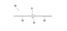
- the fin tube integrated member 30 is configured by integrating the heat transfer tubes 31 and the fins 33.
- the heat transfer tube 31 has a cylindrical shape extending in the vertical direction, and a flow path 32 is formed therein.
- the fin 33 extends in the front-rear direction and the upper-lower direction so as to extend in both the front-rear direction (both upstream and downstream in the air flow direction) with respect to the heat transfer tube 31.
- the lower end of the heat transfer tube 31 extends further below the lower end of the fin 33 and is connected to the vicinity of the center of the upper surface of the lower header body 51 in the front-rear direction.
- the upper end of the heat transfer tube 31 extends further upward than the upper end of the fin 33 and is connected to the vicinity of the center of the bottom surface of the upper header body 61 in the front-rear direction.
- each heat transfer tube 31 is disposed so as to overlap with the lower circulation partition plate 53 of the lower header 50 and the upper circulation partition plate 63 of the upper header 60 in a top view.
- the lower end of the heat transfer tube 31 extends to just before the upper end of the lower circulation partition plate 53 of the lower header 50, and they are not in contact with each other. For this reason, the lower end of the heat transfer tube 31 is in a state communicating with both the lower inflow space 52a and the lower return space 52b in the lower header 50.
- the upper end of the heat transfer tube 31 extends to just before the lower end of the upper circulation partition plate 63 of the upper header 60, and they are not in contact with each other, and the upper end of the heat transfer tube 31 flows into the upper header 60.
- the space 62b and the upper return space 62a are in communication with each other.
- the refrigerant that has flowed upward through the heat transfer tubes 31 and reached the upper header 60 flows toward the upper connection port 19a (right side) in both the upper return space 62a and the upper inflow space 62b. Then, it flows out of the outdoor heat exchanger 11 through the refrigerant pipe 19.
- the refrigerant flow is opposite to that described above, and the refrigerant circulates in the upper header 60 and flows downward through the heat transfer tubes 31.
- Both the lower inflow space 52a and the lower return space 52b of the header 50 flow toward the lower connection port 20a side (right side) and flow to the outside of the outdoor heat exchanger 11 through the refrigerant pipe 20. .
- the lower inflow space 52a, the lower return opening 55, the lower return space 52b, and the lower return opening 54 of the lower header 50 can be obtained. In either case, the refrigerant is unlikely to stay.
- the refrigerant flowing through both the lower inflow space 52 a and the lower return space 52 b in a state in which the stay is suppressed is a plurality of heat transfer tubes 31 positioned along the longitudinal direction of the lower header 50. Therefore, the refrigerant can be evenly distributed.
- the end portions of the flow paths 32 of the heat transfer tubes 31 are directly connected to both the lower inflow space 52a and the lower return space 52b. For this reason, the refrigerant flowing into the heat transfer tube 31 from the lower inflow space 52a and the refrigerant flowing into the same heat transfer tube 31 from the lower return space 52b are mixed with each other while passing through the flow path of the heat transfer tube 31. . For this reason, it is possible to sufficiently exchange heat between the refrigerant passing through the heat transfer tube 31 and the air around the outdoor heat exchanger 11.
- the refrigerant pipe 20 is connected to the lower inflow space 52a of the lower header 50 via the lower connection port 20a. In the vicinity of the lower connection port 20a, the refrigerant pipe 20 is connected to the lower inflow space 52a of the lower header 50. It extends in the longitudinal direction. For this reason, the refrigerant can be sufficiently circulated in the lower header 50 by utilizing the momentum of the refrigerant flow passing through the refrigerant pipe 20 in the vicinity of the lower connection port 20a.
- the refrigerant flowing into the lower header 50 through the refrigerant pipe 20 is provided with the lower circulation partition plate 53 so that the width in the front-rear direction is narrower than the inner space of the lower header 50. Therefore, the refrigerant passage area can be narrowed, and the flow rate of the refrigerant flowing through the lower inflow space 52a can be prevented from being reduced, so that the refrigerant can be easily circulated.
- the refrigerant circulates in the lower inflow space 52a and the lower return space 52b. It is possible to facilitate the circulation of the refrigerant without hindering the flow.
- the outdoor heat exchanger 11 of the present embodiment uses a fin tube integrated member 30 in which the heat transfer tubes 31 and the fins 33 are integrated, and the fins 33 spread in the air flow direction (front-rear direction) and the vertical direction.
- the heat transfer tube 31 extends in the vertical direction.
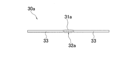
- the heat transfer tube is not limited to one having only one flow path 32, and, for example, as shown in FIG. 9, a flat multi-channel provided with a plurality of flow paths 32a arranged in the front-rear direction (air flow direction).
- the hole tube 31a may be used.
- the fins 33 may be formed so as to spread up and down before and after the flat multi-hole tube 31a (upstream and downstream in the air flow direction).
- the plurality of flow paths 32a in this case have a whole that is located immediately above the lower inflow space 52a, and a whole that is located directly above the lower return space 52b. May be.
- the bottom surfaces of the lower header 50 and the upper header 60 are spread so as to be inclined surfaces that are inclined from the horizontal.
- the outdoor heat exchanger 11a used in a posture in which the plate 53 and the heat transfer tube 31 extend at an inclination angle A from the vertical direction may be used.
- the lower end of the lower inflow space 52a provided with the lower connection port 20a is positioned below the lower end of the lower return space 52b.
- the posture is preferable in that it easily causes a circulation state of the refrigerant. That is, in the lower inflow space 52a in which the lower connection port 20a is provided, the refrigerant flows more vigorously than the lower return space 52b, and therefore the lower return opening 55 is formed in the lower inflow space 52a even though it slightly opposes its own weight.
- the refrigerant can flow from the side to the lower return space 52 b side, and the refrigerant is easily circulated in the lower header 50.
- the inclination angle A at which the downward circulation partition plate 53 and the heat transfer tube 31 are inclined from the vertical direction is preferably 45 degrees or less, and more preferably 30 degrees or less.
- the bottom surfaces of the lower header 50 and the upper header 60 are spread horizontally as in the above embodiment, and the lower circulation partition plate 53 is also in the above embodiment.
- the fin pipe integrated member 30b including the heat transfer pipe 31b may be inclined at an inclination angle B from the vertical direction.
- the inclination angle B in this case is also preferably 45 degrees or less, and more preferably 30 degrees or less.
- the flow path 32 of the heat transfer tube 31 of the finned tube integrated member 30 communicates directly only with the lower inflow space 52a, and the lower return space 52b has The structure which is not connected may be sufficient.
- the lower inflow space 52a to which the flow path 32 of the heat transfer tube 31 is connected is a space in which the lower connection port 20a is formed, and when the outdoor heat exchanger 11 functions as a refrigerant evaporator. Since the refrigerant first flows into the space, the refrigerant easily passes at a sufficient flow rate.
- the refrigerant passage area of the lower inflow space 52a can be made smaller than the inner space of the lower header 50 in the longitudinal direction since the inner space of the lower header 50 is partitioned by the lower circulation partition plate 53. Therefore, it is possible to suppress a decrease in the flow rate of the refrigerant flowing through the lower inflow space 52a.
- the refrigerant flowing into the lower inflow space 52a from the lower connection port 20a is not only the heat transfer pipe 31 connected in the vicinity of the lower connection port 20a but also the lower inflow space. 52a can be delivered to the heat transfer tube 31 connected to a position far from the lower connection port 20a. Thereby, it becomes possible to suppress the refrigerant
- the refrigerant passes through the vicinity of the lower connection port 20a at a relatively high flow rate in an environment where the refrigerant circulation amount is relatively large. Even if it exists, since the heat transfer tube is not connected to the lower inflow space 52a, the refrigerant is difficult to be supplied by passing through the heat transfer tube 31 quickly without flowing into the heat transfer tube 31 because the flow rate of the refrigerant is too fast. Can be suppressed.
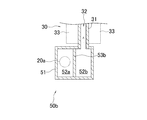
- the stirring chamber 59 is interposed between the lower end of the flow path 32 of the heat transfer tube 31 and the lower inflow space 52a of the lower header 50c.
- the lower lower inflow space 52a and the lower return space 52b and the upper stirring chamber 59 are spread horizontally in contact with the upper end of the lower circulation partition plate 53c in the lower header 50c. It is partitioned by a stirring partition plate 56 which is a plate-shaped member.
- the stirring partition plate 56 is not provided with an opening in a portion facing the lower return space 52b, but an inflow side communication port 57 penetrating in the vertical direction is formed in a portion facing the lower inflow space 52a.
- the inflow side communication port 57 is not particularly limited, and may be configured by a plurality of openings provided so as to be aligned in the longitudinal direction of the lower header 50, or by one opening that extends in the longitudinal direction of the lower header 50. It may be configured.
- the refrigerant flowing into the stirring chamber 59 from the lower inflow space 52a through the inflow side communication port 57 is divided into the heat transfer pipes 31 and flows into the heat transfer pipes 31.
- the liquid phase refrigerant can be agitated.
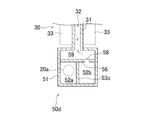
- the stirring chamber 59 is interposed between the lower end of the flow path 32 of the heat transfer tube 31 and the return space 52b of the lower header 50d.
- the lower lower inflow space 52a and the lower return space 52b and the upper stirring chamber 59 spread horizontally in contact with the upper end of the lower circulation partition plate 53c in the lower header 50d. It is partitioned by a stirring partition plate 56 which is a plate-shaped member.
- the stirring partition plate 56 is not provided with an opening in a portion facing the lower inflow space 52a, but a return side communication port 58 penetrating in the vertical direction is formed in a portion facing the lower return space 52b. Yes.
- the return side communication port 58 is not particularly limited, and may be constituted by a plurality of openings provided so as to be arranged in the longitudinal direction of the lower header 50, or by one opening that extends in the longitudinal direction of the lower header 50. It may be configured.
- the refrigerant flowing into the stirring chamber 59 from the lower return space 52b through the return side communication port 58 is divided into the heat transfer pipes 31 and then flows into the heat transfer pipes 31. And the liquid phase refrigerant can be agitated. Thereby, it is possible to more effectively suppress the drift of the refrigerant flowing through each heat transfer tube 31.
- the effect described in Modification E can also be obtained.
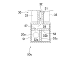
- the stirring chamber 59 is provided between the lower end of the flow path 32 of the heat transfer tube 31 and the lower inflow space 52a and the lower return space 52b of the lower header 50e. May be interposed.
- the lower lower inflow space 52a and the lower return space 52b and the upper stirring chamber 59 expand horizontally in contact with the upper end of the lower circulation partition plate 53c in the lower header 50e. It is partitioned by a stirring partition plate 56 which is a plate-shaped member.
- the stirring partition plate 56 is formed with an inflow side communication port 57 penetrating in the vertical direction in a portion facing the lower inflow space 52a, and a return side communication penetrating in the vertical direction in a portion facing the lower return space 52b.
- a mouth 58 is formed.
- the inflow side communication port 57 and the return side communication port 58 are not particularly limited, and may be configured by a plurality of openings provided so as to be aligned in the longitudinal direction of the lower header 50, or in the longitudinal direction of the lower header 50. You may be comprised by one extended opening.
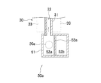
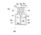
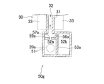
- a fin provided with a plurality of heat transfer tubes 31c each having one flow path 32c in the left-right direction (air flow direction) with respect to the stirring chamber 59 as in a lower header 50f shown in FIG.
- the tube integrated member 30c may be connected. Since the refrigerant after the gas-phase refrigerant and the liquid-phase refrigerant are sufficiently agitated in the agitating chamber 59 flows in each of the heat transfer tubes 31c, the refrigerant does not easily drift between them. Moreover, by providing the plurality of heat transfer tubes 31c in the air flow direction, it becomes easy to ensure a wide heat transfer area where heat exchange can be performed efficiently.
- the stirring chamber 59a may be interposed between the lower end of the flow path 32 of the heat transfer tube 31 and the lower inflow space 52a.
- the lower header 50g is divided into a lower inflow space 52a and a stirring chamber 59a on the left side (upstream side of the air flow) and a lower return space 52b on the right side (downstream side of the air flow) by the lower circulation partition plate 53a. It is partitioned.
- the stirring chamber 59a and the lower inflow space 52a are partitioned by the stirring partition plate 56a, and the stirring chamber 59a is positioned above the lower inflow space 52a in the vertical direction.
- the stirring partition plate 56a has an inflow side communication port 57a penetrating in the vertical direction.
- the inflow side communication port 57a is not particularly limited, and may be configured by a plurality of openings provided so as to be arranged in the longitudinal direction of the lower header 50, or by one opening that extends in the longitudinal direction of the lower header 50. It may be configured.
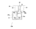
- the stirring chamber 59b may be interposed between the lower end of the flow path 32 of the heat transfer tube 31 and the lower return space 52b.
- the lower header 50h is divided into a lower inflow space 52a on the left side (upstream side of the air flow), a lower return space 52b on the right side (downstream side of the air flow), and a stirring chamber 59b by the partition plate 53a for lower circulation. It is partitioned.
- the stirring chamber 59b and the lower return space 52b are partitioned by the stirring partition plate 56b, and the stirring chamber 59b is positioned above the lower return space 52b in the vertical direction.
- the agitating partition plate 56b is formed with a return side communication port 58a penetrating in the vertical direction.
- the inflow side communication port 57b is not particularly limited, and may be configured by a plurality of openings provided so as to be aligned in the longitudinal direction of the lower header 50, or by one opening that extends in the longitudinal direction of the lower header 50. It may be configured.
- the refrigerant pipe 20 is connected to the lower header 50 as it is.
- the refrigerant pipe 20 has a nozzle shape by restricting the refrigerant passage area of the lower connection port 20a to be smaller than the flow path area of the refrigerant pipe 20.
- the upper connection port 19a may have a nozzle shape by narrowing the refrigerant passage area smaller than the flow passage area of the refrigerant pipe 19 in the same manner.
- Patent Document 1 Japanese Patent Laid-Open No. 2015-068622
- Patent Document 2 Japanese Patent Laid-Open No. 2017-044428
Abstract
Provided are a heat exchanger and an air-conditioning device such that it is possible to minimize unequal flow of refrigerant in a plurality of heat transfer pipes. An outdoor heat exchanger (11) is provided with a lower header (50) extending in a horizontal direction and a plurality of heat transfer pipes (31) which extend in a direction intersecting the horizontal direction, in which the lower header (50) extends, and which are connected to the lower header (50). The lower header (50) includes: a bottom inflow space (52a) which allows the refrigerant to flow in a first direction; a bottom return space (52b) which allows the refrigerant to flow in the reverse direction from the bottom inflow space (52a) and includes a portion disposed side by side with the bottom inflow space (52a) in the horizontal direction; a lower circulation partition board (53) extending so as to separate the bottom inflow space (52a) and the bottom return space (52b) from each other; a bottom flow reversal opening (55) providing communication between the bottom inflow space (52a) and the bottom return space (52b) in the lower header (50); a bottom return opening (54) providing communication between the bottom return space (52b) and the bottom inflow space (52a) on the opposite side from the bottom flow reversal opening (55); and a bottom connection port (20a) for allowing the refrigerant to flow into the lower header (50).
Description
本開示は、熱交換器および空気調和装置に関する。
The present disclosure relates to a heat exchanger and an air conditioner.
従来より、複数の伝熱管と、複数の伝熱管に接合されたフィンと、複数の伝熱管の端部に連結されたヘッダとを備え、伝熱管の内部を流れる冷媒を伝熱管の外部を流れる空気と熱交換させる熱交換器が知られている。
Conventionally, a plurality of heat transfer tubes, fins joined to the plurality of heat transfer tubes, and a header connected to end portions of the plurality of heat transfer tubes, the refrigerant flowing inside the heat transfer tubes flows outside the heat transfer tubes. Heat exchangers that exchange heat with air are known.
例えば、特許文献1(特開2015-068622号公報)では、高循環量と低循環量のいずれの環境下においても冷媒を上下方向に並んだ各伝熱管に対して分流可能となるように、ヘッダ内において冷媒を循環させる構造を採用した熱交換器を提案している。
For example, in Patent Document 1 (Japanese Patent Application Laid-Open No. 2015-068622), the refrigerant can be diverted to the heat transfer tubes arranged in the vertical direction in any environment of a high circulation amount and a low circulation amount. The heat exchanger which employ | adopted the structure which circulates a refrigerant | coolant in the header is proposed.
また、特許文献2(特開2017-044428号公報)では、ヘッダの長手方向が水平であり伝熱管が鉛直方向に延びる姿勢で用いられる熱交換器であって、ヘッダの内部空間を各伝熱管の一方側の部分が連通する第1領域と各伝熱管の他方側の部分が連通する第2領域とに仕切る仕切りつつ、ヘッダの長手方向の両端から各領域に冷媒を流入させることで、複数の伝熱管に対して冷媒を分流可能とする構造を採用した熱交換器が提案されている。
Patent Document 2 (Japanese Patent Laid-Open No. 2017-044428) discloses a heat exchanger that is used in a posture in which the longitudinal direction of the header is horizontal and the heat transfer tubes extend in the vertical direction. The refrigerant is allowed to flow into each region from both ends in the longitudinal direction of the header while partitioning into a first region where one side portion of the heat transfer tube communicates with and a second region where the other side portion of each heat transfer tube communicates. There has been proposed a heat exchanger that employs a structure that allows refrigerant to be divided into the heat transfer tubes.
上記特許文献1に示された熱交換器では、ヘッダの長手方向が鉛直方向であるため、複数の伝熱管に冷媒を分流させて流すために冷媒を自重に逆らうようにして上方に供給することが必要であり、ヘッダ内で十分に冷媒を循環させることが困難になる場合がある。また、仮に、特許文献1に記載の熱交換器を、ヘッダの長手方向が水平方向となるようにして用いたとしても、ヘッダ内で冷媒を循環させようとすると、冷媒を自重に逆らうようにして上方に移動させる箇所が必要になるため、ヘッダ内で十分に冷媒を循環させることが困難になり、冷媒の偏流が生じてしまう場合がある。
In the heat exchanger shown in Patent Document 1, since the longitudinal direction of the header is the vertical direction, the refrigerant is supplied to the plurality of heat transfer tubes in an upward direction so as to counteract its own weight in order to divert the refrigerant to flow. And it may be difficult to circulate the refrigerant sufficiently in the header. Further, even if the heat exchanger described in Patent Document 1 is used so that the longitudinal direction of the header is horizontal, if the refrigerant is circulated in the header, the refrigerant is opposed to its own weight. Therefore, it is difficult to circulate the refrigerant sufficiently in the header, and the refrigerant may drift.
また、上記特許文献2に示された熱交換器では、液冷媒がヘッダの長手方向における中央近傍に集まってしまい、冷媒の偏流が生じてしまう場合がある。
Further, in the heat exchanger disclosed in Patent Document 2, the liquid refrigerant collects in the vicinity of the center in the longitudinal direction of the header, which may cause refrigerant drift.
本開示は上述した点に鑑みてなされたものであり、本開示の課題は、複数の伝熱管における冷媒の偏流を抑制させることが可能な熱交換器および空気調和装置を提供することにある。
This indication is made in view of the point mentioned above, and the subject of this indication is providing the heat exchanger and air harmony device which can control the drift of the refrigerant in a plurality of heat exchanger tubes.
第1観点に係る熱交換器は、ヘッダと、複数の伝熱管と、を備えている。ヘッダは、水平方向に延びている。伝熱管は、ヘッダが延びている水平方向と交わる方向に延びている。複数の伝熱管は、ヘッダの長手方向に沿うように並んでいる。複数の伝熱管は、ヘッダに接続されている。ヘッダは、第1空間と、第2空間と、循環用部材と、第1連通口と、第2連通口と、流入口と、を有している。第1空間は、ヘッダの長手方向に沿った第1方向に冷媒を流す。第2空間は、第2方向に冷媒を流す。第2空間は、第1空間と水平方向に並ぶ部分を含むように設けられている。第2方向は、ヘッダの長手方向に沿った方向であって第1方向とは反対の方向である。循環用部材は、ヘッダの長手方向に沿うように延びつつ第1空間と第2空間とを区切るように広がっている。第1連通口は、ヘッダ内において第1空間と第2空間とを連通させる。第2連通口は、第1連通口よりも第2方向の位置においてヘッダ内で第1空間と第2空間とを連通させる。流入口は、ヘッダ内に冷媒を流入させる。第1空間および/または第2空間は、直接的または間接的に伝熱管に接続されている。
The heat exchanger according to the first aspect includes a header and a plurality of heat transfer tubes. The header extends in the horizontal direction. The heat transfer tube extends in a direction intersecting the horizontal direction in which the header extends. The plurality of heat transfer tubes are arranged along the longitudinal direction of the header. The plurality of heat transfer tubes are connected to the header. The header has a first space, a second space, a circulation member, a first communication port, a second communication port, and an inflow port. The first space allows the coolant to flow in a first direction along the longitudinal direction of the header. In the second space, the refrigerant flows in the second direction. The second space is provided so as to include a portion aligned in the horizontal direction with the first space. The second direction is a direction along the longitudinal direction of the header and is opposite to the first direction. The circulation member extends so as to divide the first space and the second space while extending along the longitudinal direction of the header. The first communication port communicates the first space and the second space in the header. The second communication port communicates the first space and the second space in the header at a position in the second direction as compared to the first communication port. The inlet allows the refrigerant to flow into the header. The first space and / or the second space is directly or indirectly connected to the heat transfer tube.
ここで、ヘッダが延びている方向である「水平方向」は、完全な水平に限られず、水平に対して±30度の範囲内の傾斜までを含む意味である。
Here, the “horizontal direction”, which is the direction in which the header extends, is not limited to complete horizontal, but includes a tilt within a range of ± 30 degrees with respect to the horizontal.
また、ヘッダの長手方向視(ヘッダ内の冷媒通過方向の断面視)における循環用部材の長手方向は、特に限定されるものではなく、例えば、鉛直方向に対して±45度以内であることが好ましく、±30度の範囲内であることがより好ましい。なお、ヘッダの長手方向視において循環用部材の長手方向を傾斜させることで、第1空間と第2空間との下端の高さ方向位置が相違する場合には、流入口が接続されている側の空間が下方となることが冷媒の循環を生じさせやすい点で好ましい。
Further, the longitudinal direction of the circulating member in the longitudinal direction view of the header (cross-sectional view in the refrigerant passage direction in the header) is not particularly limited, and may be within ± 45 degrees with respect to the vertical direction, for example. Preferably, it is within a range of ± 30 degrees. In addition, when the height direction position of the lower end of the first space and the second space is different by inclining the longitudinal direction of the circulation member as viewed in the longitudinal direction of the header, the side to which the inflow port is connected It is preferable that the space is downward because it is easy to cause circulation of the refrigerant.
循環用部材は、特に限定されないが、例えば、循環用部材の一端が、ヘッダの内部のうち伝熱管が接続されている側とは反対側の内面に達するまで延びていることが好ましい。
The circulating member is not particularly limited, but for example, it is preferable that one end of the circulating member extends until it reaches the inner surface of the header opposite to the side to which the heat transfer tube is connected.
なお、伝熱管は、ヘッダから上方に向けて延び出していてもよいし、下方に向けて延び出していてもよい。
Note that the heat transfer tube may extend upward from the header or may extend downward.
この熱交換器では、流入口を介してヘッダ内に流入した冷媒を、複数の伝熱管に分流して流す際に、第1空間、第1連通口、第2空間、第2連通口の順に冷媒を循環させることが可能になる。しかも、ヘッダが水平方向に延びているため、ヘッダ内で循環する冷媒は主として水平方向に移動し、高さ方向に移動する程度が抑えられているため、ヘッダ内の冷媒は重力の影響を受けにくい状態で循環することができる。これにより、ヘッダの長手方向における特定の箇所に冷媒が滞留してしまうことを抑制し、ヘッダの長手方向に沿うように位置している複数の伝熱管に対する冷媒の分配を均等化させることが可能になる。
In this heat exchanger, when the refrigerant that has flowed into the header via the inflow port is divided into a plurality of heat transfer tubes and flows, the first space, the first communication port, the second space, and the second communication port are arranged in this order. It becomes possible to circulate the refrigerant. In addition, since the header extends in the horizontal direction, the refrigerant circulating in the header moves mainly in the horizontal direction and the degree of movement in the height direction is suppressed, so that the refrigerant in the header is affected by gravity. It can circulate in a difficult state. Thereby, it is possible to suppress the refrigerant from staying at a specific portion in the longitudinal direction of the header, and to equalize the distribution of the refrigerant to the plurality of heat transfer tubes positioned along the longitudinal direction of the header. become.
第2観点に係る熱交換器は、第1観点に係る熱交換器であって、複数の伝熱管は、それぞれの端部が、ヘッダの第1空間と第2空間の両方に連通するように、ヘッダに接続されている。
The heat exchanger which concerns on a 2nd viewpoint is a heat exchanger which concerns on a 1st viewpoint, Comprising: As for several heat exchanger tubes, each edge part is connected to both the 1st space and 2nd space of a header. Connected to the header.
ここでは、1つの伝熱管のヘッダとの接続側の端部がヘッダ内の第1空間と第2空間の両方に連通していればよく、1つの伝熱管が1つの流路を有している場合には、当該1つの流路が第1空間と第2空間の両方に連通することとなり、1つの伝熱管が複数の流路を有している場合には、それらの複数の流路が全体として第1空間と第2空間の両方に連通することとなる(複数の流路のうちの一部の流路が主として第1空間と連通し、他の一部の流路が主として第2空間と連通してもよい)。
Here, it is only necessary that the end of one heat transfer tube connected to the header communicates with both the first space and the second space in the header, and one heat transfer tube has one flow path. In the case where the heat transfer tube has a plurality of flow paths, the one flow path communicates with both the first space and the second space. Communicates with both the first space and the second space as a whole (a part of the plurality of channels mainly communicates with the first space, and the other part of the channels mainly communicates with the first space. You may communicate with two spaces).
この熱交換器では、伝熱管に対して、第1流路を流れる冷媒と第2流路を流れる冷媒の両方の冷媒を供給することが可能となる。このため、例えば、第1流路内においてヘッダの長手方向における液冷媒の分布に偏りが生じていても、第2流路内においてヘッダの長手方向における液冷媒の分布に異なる偏りがある場合には、これらの各空間における液冷媒の偏りを相殺させることが可能になる。
In this heat exchanger, it is possible to supply both the refrigerant flowing through the first flow path and the refrigerant flowing through the second flow path to the heat transfer tube. For this reason, for example, even when the distribution of the liquid refrigerant in the longitudinal direction of the header is uneven in the first flow path, the distribution of the liquid refrigerant in the longitudinal direction of the header is different in the second flow path. Makes it possible to cancel out the bias of the liquid refrigerant in each of these spaces.
第3観点に係る熱交換器は、第1観点に係る熱交換器であって、流入口は、ヘッダの第1空間に冷媒を流入させる開口である。複数の伝熱管は、それぞれの端部が、ヘッダの第1空間に連通し、第2空間には連通しないように、ヘッダに接続されている。
The heat exchanger according to the third aspect is a heat exchanger according to the first aspect, and the inlet is an opening through which the refrigerant flows into the first space of the header. The plurality of heat transfer tubes are connected to the header so that the respective end portions communicate with the first space of the header and do not communicate with the second space.
この熱交換器では、流入口を通過した冷媒が通過する第1空間の冷媒通過面積は、ヘッダの内部空間が循環用部材によって区切られていることから、ヘッダの長手方向視における内部空間よりも小さくすることができる。このため、第1空間を流れる冷媒の流速の低下を抑制することが可能になっている。したがって、冷媒の循環量が比較的小さい環境下においても、流入口を通過して第1空間に供給された冷媒を、第1空間のうちの流入口近傍に接続されている伝熱管だけでなく、第1空間のうち流入口から遠く離れた位置に接続されている伝熱管にまで届けやすい。これにより、ヘッダの長手方向に沿うように並んで設けられている複数の伝熱管同士における冷媒の偏流を小さく抑制することが可能になる。
In this heat exchanger, the refrigerant passage area of the first space through which the refrigerant that has passed through the inflow port passes is larger than the internal space in the longitudinal view of the header because the internal space of the header is partitioned by the circulation member. Can be small. For this reason, it is possible to suppress a decrease in the flow rate of the refrigerant flowing through the first space. Therefore, even in an environment where the circulation amount of the refrigerant is relatively small, not only the heat transfer pipe connected to the vicinity of the inflow port in the first space, but the refrigerant supplied to the first space through the inflow port It is easy to reach the heat transfer tube connected to a position far from the inlet in the first space. Thereby, it becomes possible to suppress the drift of the refrigerant | coolant in the some heat exchanger tubes provided along with the longitudinal direction of the header small.
第4観点に係る熱交換器は、第1観点に係る熱交換器であって、流入口は、ヘッダの第1空間に冷媒を流入させる開口である。複数の伝熱管は、それぞれの端部が、ヘッダの第2空間に連通し、第1空間には連通しないように、ヘッダに接続されている。
The heat exchanger according to the fourth aspect is the heat exchanger according to the first aspect, and the inflow port is an opening through which the refrigerant flows into the first space of the header. Each of the plurality of heat transfer tubes is connected to the header so that each end thereof communicates with the second space of the header and does not communicate with the first space.
この熱交換器では、流入口を通過した冷媒が通過する第1空間には、伝熱管が接続されていない。このため、冷媒の循環量が比較的大きい環境下において、冷媒が流入口近傍を比較的速い流速で通過してしまう場合であっても、当該第1空間には伝熱管が接続されていないため、流速が早すぎることで伝熱管の入口を冷媒が素早く通過してしまうことで冷媒が伝熱管に供給されにくくなることを抑制することが可能になっている。そして、第1空間を比較的速い流速で通過して流入口から遠く離れた箇所に達した液冷媒は、第1連通口を介してより適切な流速に落とされて第2空間に供給されることで、当該第2空間に接続されている各伝熱管に適切に分流させることが可能になる。
In this heat exchanger, no heat transfer tube is connected to the first space through which the refrigerant that has passed through the inflow port passes. For this reason, even in a case where the refrigerant passes through the vicinity of the inlet at a relatively high flow rate in an environment where the circulation amount of the refrigerant is relatively large, the heat transfer tube is not connected to the first space. It is possible to prevent the refrigerant from becoming difficult to be supplied to the heat transfer tube because the refrigerant quickly passes through the inlet of the heat transfer tube because the flow velocity is too fast. Then, the liquid refrigerant that has passed through the first space at a relatively high flow rate and reached a location far from the inlet is dropped to a more appropriate flow rate through the first communication port and supplied to the second space. Thus, it is possible to appropriately divert each heat transfer tube connected to the second space.
第5観点に係る熱交換器は、第1観点から第4観点のいずれかに係る熱交換器であって、ヘッダは、第3空間と、第3空間用部材と、第3連通口と、をさらに有している。第3空間は、第1空間および第2空間と、複数の伝熱管とヘッダの接続箇所と、の間に位置しているか、第1空間と、複数の伝熱管とヘッダの接続箇所と、の間に位置しているか、第2空間と、複数の伝熱管とヘッダの接続箇所と、の間に位置している。ここで、この熱交換器は、以下の(1)~(5)のいずれかである。
A heat exchanger according to a fifth aspect is a heat exchanger according to any of the first to fourth aspects, wherein the header is a third space, a third space member, a third communication port, It has further. The third space is located between the first space and the second space, and the connection places between the plurality of heat transfer tubes and the header, or the first space and the connection places between the plurality of heat transfer tubes and the header. It is located between the second space and the connection points of the plurality of heat transfer tubes and the header. Here, this heat exchanger is one of the following (1) to (5).
(1)第1空間および第2空間と、複数の伝熱管とヘッダの接続箇所と、の間に第3空間が位置しており、第1空間と第3空間とが第3連通口を介して連通するように、第1空間および第2空間と、第3空間と、が第3空間用部材によって区切られている。
(1) The third space is located between the first space and the second space, and the connection locations of the plurality of heat transfer tubes and the header, and the first space and the third space are connected via the third communication port. The first space, the second space, and the third space are separated by a third space member so as to communicate with each other.
(2)第1空間および第2空間と、複数の伝熱管とヘッダの接続箇所と、の間に第3空間が位置しており、第2空間と第3空間とが第3連通口を介して連通するように、第1空間および第2空間と、第3空間と、が第3空間用部材によって区切られている。
(2) The third space is located between the first space and the second space, and the connection points of the plurality of heat transfer tubes and the header, and the second space and the third space are connected via the third communication port. The first space, the second space, and the third space are separated by a third space member so as to communicate with each other.
(3)第1空間および第2空間と、複数の伝熱管とヘッダの接続箇所と、の間に第3空間が位置しており、第1空間と第3空間とが第3連通口を介して連通し、第2空間と第3空間も別の第3連通口を介して連通するように、第1空間および第2空間と、第3空間と、が第3空間用部材によって区切られている。
(3) The third space is located between the first space and the second space, and the connection locations of the plurality of heat transfer tubes and the header, and the first space and the third space are connected via the third communication port. The first space, the second space, and the third space are separated by the third space member so that the second space and the third space communicate with each other via another third communication port. Yes.
(4)第1空間と、複数の伝熱管とヘッダの接続箇所と、の間に第3空間が位置しており、第1空間と第3空間とが、第3連通口を介して連通するように第3空間用部材によって区切られている。
(4) The third space is located between the first space and the connection points of the plurality of heat transfer tubes and the header, and the first space and the third space communicate with each other via the third communication port. In this way, the third space member is used.
(5)第2空間と、複数の伝熱管とヘッダの接続箇所と、の間に第3空間が位置しており、第2空間と第3空間とが、第3連通口を介して連通するように第3空間用部材によって区切られている。
(5) The third space is located between the second space and the connection points of the plurality of heat transfer tubes and the header, and the second space and the third space communicate with each other via the third communication port. In this way, the third space member is used.
この熱交換器では、第1空間または第2空間を流れた冷媒は、複数の伝熱管に送られる前に第3空間用部材に形成された第3連通口を通じて第3空間を通過することとなる。このため、第1空間または第2空間を流れた冷媒を、伝熱管に送る前に、第3空間において攪拌させることが可能になるため、複数の伝熱管同士の間における冷媒の偏流を抑制することが可能となる。
In this heat exchanger, the refrigerant flowing in the first space or the second space passes through the third space through the third communication port formed in the third space member before being sent to the plurality of heat transfer tubes. Become. For this reason, since it becomes possible to stir in the 3rd space before sending the refrigerant which flowed through the 1st space or the 2nd space to the heat exchanger tube, the drift of the refrigerant between a plurality of heat exchanger tubes is controlled. It becomes possible.
第6観点に係る熱交換器は、第5観点に係る熱交換器であって、複数の伝熱管は、第1空間と第2空間とが並ぶ方向に並んでいる。複数の伝熱管は、ヘッダの第3空間に接続されている。
The heat exchanger according to the sixth aspect is a heat exchanger according to the fifth aspect, and the plurality of heat transfer tubes are arranged in a direction in which the first space and the second space are arranged. The plurality of heat transfer tubes are connected to the third space of the header.
なお、ここでは、複数の伝熱管は、ヘッダの長手方向に並びつつ、第1空間と第2空間とが並ぶ方向にも並んで、行列をなしていることになる。
In addition, here, the plurality of heat transfer tubes are arranged in a matrix in the direction in which the first space and the second space are arranged while being arranged in the longitudinal direction of the header.
この熱交換器では、複数の伝熱管を、第1空間と第2空間とが並ぶ方向に並んで配置しつつ、第1空間と第2空間とが並ぶ方向において異なる位置に配置されている伝熱管がいずれも同じ空間である第3空間に接続されていることから、第1空間と第2空間とが並ぶ方向において異なる位置に配置されている伝熱管同士の間における冷媒の偏流を抑制することが可能になる。
In this heat exchanger, a plurality of heat transfer tubes are arranged side by side in the direction in which the first space and the second space are arranged, and are arranged at different positions in the direction in which the first space and the second space are arranged. Since all the heat pipes are connected to the third space, which is the same space, the drift of the refrigerant between the heat transfer pipes arranged at different positions in the direction in which the first space and the second space are arranged is suppressed. It becomes possible.
第7観点に係る熱交換器は、第1観点から第6観点のいずれかに係る熱交換器であって、複数の伝熱管が延びる方向の鉛直方向に対する傾斜角度は45度以下である。
The heat exchanger according to the seventh aspect is a heat exchanger according to any one of the first to sixth aspects, and an inclination angle with respect to the vertical direction in which the plurality of heat transfer tubes extend is 45 degrees or less.
この熱交換器では、複数の伝熱管が延びる方向の鉛直方向に対する傾斜角度は45度以下であるため、液冷媒が伝熱管の入口に到達した場合であっても、伝熱管内の流路内における下方に位置している部分に液冷媒が偏って流れることを抑制し、伝熱管内の流路の内周面の全体における冷媒分布を均一化させることが可能になる。
In this heat exchanger, since the inclination angle of the direction in which the plurality of heat transfer tubes extend with respect to the vertical direction is 45 degrees or less, even if the liquid refrigerant reaches the inlet of the heat transfer tubes, It is possible to suppress the liquid refrigerant from flowing unevenly in the portion located below in FIG. 5, and to uniformize the refrigerant distribution on the entire inner peripheral surface of the flow path in the heat transfer tube.
第8観点に係る熱交換器は、第1観点から第7観点のいずれかに係る熱交換器であって、伝熱管は、扁平管または円管である。扁平管は、その断面の長手方向が第1空間と第2空間とが並ぶ方向となっている。円管は、その断面が円形である。
The heat exchanger according to the eighth aspect is a heat exchanger according to any of the first to seventh aspects, and the heat transfer tube is a flat tube or a circular tube. In the flat tube, the longitudinal direction of the cross section is the direction in which the first space and the second space are arranged. The circular tube has a circular cross section.
この熱交換器では、伝熱管が扁平管である場合には、第1空間と第2空間とが並ぶ方向に空気を流して用いた場合に空気流れ方向に沿った伝熱面積を広く確保しやすい。また、伝熱管が円管である場合には、第1空間と第2空間の両方から供給される冷媒を混合して流しやすい。
In this heat exchanger, when the heat transfer tube is a flat tube, a wide heat transfer area along the air flow direction is ensured when air is used in the direction in which the first space and the second space are aligned. Cheap. Further, when the heat transfer tube is a circular tube, it is easy to mix and flow the refrigerant supplied from both the first space and the second space.
第9観点に係る空気調和装置は、第1観点から第8観点のいずれかに係る熱交換器を有する冷媒回路を備えている。
The air conditioner according to the ninth aspect includes a refrigerant circuit having the heat exchanger according to any one of the first to eighth aspects.
この空気調和装置では、冷媒回路において冷凍サイクルを実行させた場合の能力を向上させることが可能になる。
This air conditioner can improve the performance when the refrigeration cycle is executed in the refrigerant circuit.
以下、熱交換器および空気調和装置の一実施形態およびその変形例について、図面に基づいて説明する。
Hereinafter, an embodiment of a heat exchanger and an air conditioner and modifications thereof will be described with reference to the drawings.
(1)空気調和装置の構成
図1は、一実施形態に係る熱交換器としての室外熱交換器11が採用された空気調和装置1の概略構成図である。 (1) Configuration of Air Conditioner FIG. 1 is a schematic configuration diagram of anair conditioner 1 in which an outdoor heat exchanger 11 as a heat exchanger according to an embodiment is employed.
図1は、一実施形態に係る熱交換器としての室外熱交換器11が採用された空気調和装置1の概略構成図である。 (1) Configuration of Air Conditioner FIG. 1 is a schematic configuration diagram of an
空気調和装置1は、蒸気圧縮式の冷凍サイクルを行うことによって、建物等の室内の冷房および暖房を行うことが可能な装置である。空気調和装置1は、主として、室外ユニット2と、室内ユニット9a、9bと、室外ユニット2と室内ユニット9a、9bとを接続する液冷媒連絡管4およびガス冷媒連絡管5と、室外ユニット2および室内ユニット9a、3bの構成機器を制御する制御部23と、を有している。そして、空気調和装置1の蒸気圧縮式の冷媒回路6は、室外ユニット2と、室内ユニット9a、9bとが冷媒連絡管4、5を介して接続されることによって構成されている。
The air conditioner 1 is a device capable of cooling and heating a room such as a building by performing a vapor compression refrigeration cycle. The air conditioner 1 mainly includes an outdoor unit 2, indoor units 9a and 9b, a liquid refrigerant communication tube 4 and a gas refrigerant communication tube 5 that connect the outdoor unit 2 and the indoor units 9a and 9b, an outdoor unit 2 and And a control unit 23 that controls the constituent devices of the indoor units 9a and 3b. The vapor compression refrigerant circuit 6 of the air conditioner 1 is configured by connecting the outdoor unit 2 and the indoor units 9a and 9b via the refrigerant communication pipes 4 and 5, respectively.
室外ユニット2は、室外(建物の屋上や建物の壁面近傍等)に設置されており、冷媒回路6の一部を構成している。室外ユニット2は、主として、アキュムレータ7、圧縮機8と、四路切換弁10と、室外熱交換器11と、膨張機構としての室外膨張弁12と、液側閉鎖弁13と、ガス側閉鎖弁14と、室外ファン15と、を有している。各機器および弁間は、冷媒管16~22によって接続されている。
The outdoor unit 2 is installed outside the building (on the roof of the building, near the wall of the building, etc.) and constitutes a part of the refrigerant circuit 6. The outdoor unit 2 mainly includes an accumulator 7, a compressor 8, a four-way switching valve 10, an outdoor heat exchanger 11, an outdoor expansion valve 12 as an expansion mechanism, a liquid side shut-off valve 13, and a gas side shut-off valve. 14 and an outdoor fan 15. Each device and the valve are connected by refrigerant pipes 16-22.
室内ユニット9a、9bは、室内(居室や天井裏空間等)に設置されており、冷媒回路6の一部を構成している。室内ユニット9aは、主として、室内膨張弁91aと、室内熱交換器92aと、室内ファン93aと、を有している。室内ユニット9bは、主として、膨張機構としての室内膨張弁91bと、室内熱交換器92bと、室内ファン93bと、を有している。
The indoor units 9a and 9b are installed in a room (such as a living room or a ceiling space) and constitute a part of the refrigerant circuit 6. The indoor unit 9a mainly includes an indoor expansion valve 91a, an indoor heat exchanger 92a, and an indoor fan 93a. The indoor unit 9b mainly includes an indoor expansion valve 91b as an expansion mechanism, an indoor heat exchanger 92b, and an indoor fan 93b.
冷媒連絡管4、5は、空気調和装置1を建物等の設置場所に設置する際に、現地にて施工される冷媒管である。液冷媒連絡管4の一端は、室外ユニット2の液側閉鎖弁13に接続され、液冷媒連絡管4の他端は、室内ユニット9a、9bの室内膨張弁91a、91bの液側端に接続されている。ガス冷媒連絡管5の一端は、室外ユニット2のガス側閉鎖弁14に接続され、ガス冷媒連絡管5の他端は、室内ユニット9a、9bの室内熱交換器92a、92bのガス側端に接続されている。
The refrigerant communication pipes 4 and 5 are refrigerant pipes that are constructed on site when the air conditioner 1 is installed at a place such as a building. One end of the liquid refrigerant communication tube 4 is connected to the liquid side closing valve 13 of the outdoor unit 2, and the other end of the liquid refrigerant communication tube 4 is connected to the liquid side ends of the indoor expansion valves 91a and 91b of the indoor units 9a and 9b. Has been. One end of the gas refrigerant communication pipe 5 is connected to the gas side shut-off valve 14 of the outdoor unit 2, and the other end of the gas refrigerant communication pipe 5 is connected to the gas side ends of the indoor heat exchangers 92a and 92b of the indoor units 9a and 9b. It is connected.
制御部23は、室外ユニット2や室内ユニット9a、9bに設けられた制御基板等(図示せず)が通信接続されることによって構成されている。なお、図1においては、便宜上、室外ユニット2や室内ユニット9a、9bとは離れた位置に図示している。制御部23は、空気調和装置1(ここでは、室外ユニット2や室内ユニット9a、9b)の構成機器8、10、12、15、91a、91b、93a、93bの制御、すなわち、空気調和装置1全体の運転制御を行うようになっている。
The control unit 23 is configured by communication connection of control boards and the like (not shown) provided in the outdoor unit 2 and the indoor units 9a and 9b. In FIG. 1, for the sake of convenience, the outdoor unit 2 and the indoor units 9a and 9b are illustrated at positions away from each other. The control unit 23 controls the components 8, 10, 12, 15, 91a, 91b, 93a, 93b of the air conditioner 1 (here, the outdoor unit 2 and the indoor units 9a, 9b), that is, the air conditioner 1 The whole operation control is performed.
(2)空気調和装置の動作
次に、図1を用いて、空気調和装置1の動作について説明する。空気調和装置1では、圧縮機8、室外熱交換器11、室外膨張弁12および室内膨張弁91a、91b、室内熱交換器92a、92bの順に冷媒を流す冷房運転およびデフロスト運転と、圧縮機8、室内熱交換器92a、92b、室内膨張弁91a、91bおよび室外膨張弁12、室外熱交換器11の順に冷媒を流す暖房運転と、が行われる。なお、冷房運転、デフロスト運転および暖房運転は、制御部23によって行われる。 (2) Operation | movement of an air conditioning apparatus Next, operation | movement of theair conditioning apparatus 1 is demonstrated using FIG. In the air conditioner 1, in the compressor 8, the outdoor heat exchanger 11, the outdoor expansion valve 12, the indoor expansion valves 91a and 91b, and the indoor heat exchangers 92a and 92b, a cooling operation and a defrost operation in which the refrigerant flows, and the compressor 8 Then, the indoor heat exchangers 92 a and 92 b, the indoor expansion valves 91 a and 91 b, the outdoor expansion valve 12, and the outdoor heat exchanger 11 are sequentially heated in the heating operation. In addition, the cooling operation, the defrost operation, and the heating operation are performed by the control unit 23.
次に、図1を用いて、空気調和装置1の動作について説明する。空気調和装置1では、圧縮機8、室外熱交換器11、室外膨張弁12および室内膨張弁91a、91b、室内熱交換器92a、92bの順に冷媒を流す冷房運転およびデフロスト運転と、圧縮機8、室内熱交換器92a、92b、室内膨張弁91a、91bおよび室外膨張弁12、室外熱交換器11の順に冷媒を流す暖房運転と、が行われる。なお、冷房運転、デフロスト運転および暖房運転は、制御部23によって行われる。 (2) Operation | movement of an air conditioning apparatus Next, operation | movement of the
冷房運転時およびデフロスト運転時には、四路切換弁10が室外放熱状態(図1の実線で示される状態)に切り換えられる。冷媒回路6において、冷凍サイクルの低圧のガス冷媒は、圧縮機8に吸入され、冷凍サイクルの高圧になるまで圧縮された後に吐出される。圧縮機8から吐出された高圧のガス冷媒は、四路切換弁10を通じて、室外熱交換器11に送られる。室外熱交換器11に送られた高圧のガス冷媒は、冷媒の凝縮器または放熱器として機能する室外熱交換器11において、冷房運転時は室外ファン15によって冷却源として供給される室外空気と熱交換を行って放熱して(デフロスト運転時には室外ファン15は停止した状態であるが霜を融解させながら放熱して)、高圧の液冷媒になる。室外熱交換器11において放熱した高圧の液冷媒は、室外膨張弁12、液側閉鎖弁13および液冷媒連絡管4を通じて、室内膨張弁91a、91bに送られる。室内膨張弁91a、91bに送られた冷媒は、室内膨張弁91a、91bによって冷凍サイクルの低圧まで減圧されて、低圧の気液二相状態の冷媒になる。室内膨張弁91a、91bで減圧された低圧の気液二相状態の冷媒は、室内熱交換器92a、92bに送られる。室内熱交換器92a、92bに送られた低圧の気液二相状態の冷媒は、室内熱交換器92a、92bにおいて、冷房運転時については室内ファン93a、93bによって加熱源として供給される室内空気と熱交換を行って蒸発する(デフロスト運転時には室内ファン93a、93bは駆動が停止されているが室内空気と熱交換を行って蒸発する)。これにより、室内空気は冷却され、その後に、室内に供給されることで室内の冷房(または、室外熱交換器11に付着した霜の融解)が行われる。室内熱交換器92a、92bにおいて蒸発した低圧のガス冷媒は、ガス冷媒連絡管5、ガス側閉鎖弁14、四路切換弁10およびアキュムレータ7を通じて、再び、圧縮機8に吸入される。
During the cooling operation and the defrost operation, the four-way switching valve 10 is switched to the outdoor heat radiation state (the state indicated by the solid line in FIG. 1). In the refrigerant circuit 6, the low-pressure gas refrigerant in the refrigeration cycle is sucked into the compressor 8 and is compressed until it reaches the high pressure in the refrigeration cycle, and then discharged. The high-pressure gas refrigerant discharged from the compressor 8 is sent to the outdoor heat exchanger 11 through the four-way switching valve 10. The high-pressure gas refrigerant sent to the outdoor heat exchanger 11 is converted into outdoor air and heat supplied as a cooling source by the outdoor fan 15 during cooling operation in the outdoor heat exchanger 11 that functions as a refrigerant condenser or radiator. It exchanges and radiates heat (during the defrost operation, the outdoor fan 15 is in a stopped state but dissipates heat while melting frost), and becomes a high-pressure liquid refrigerant. The high-pressure liquid refrigerant radiated in the outdoor heat exchanger 11 is sent to the indoor expansion valves 91 a and 91 b through the outdoor expansion valve 12, the liquid side closing valve 13 and the liquid refrigerant communication pipe 4. The refrigerant sent to the indoor expansion valves 91a and 91b is decompressed to the low pressure of the refrigeration cycle by the indoor expansion valves 91a and 91b, and becomes a low-pressure gas-liquid two-phase refrigerant. The low-pressure gas-liquid two-phase refrigerant decompressed by the indoor expansion valves 91a and 91b is sent to the indoor heat exchangers 92a and 92b. The low-pressure gas-liquid two-phase refrigerant sent to the indoor heat exchangers 92a and 92b is indoor air supplied as a heating source by the indoor fans 93a and 93b during the cooling operation in the indoor heat exchangers 92a and 92b. (The indoor fans 93a and 93b are not driven during the defrost operation but evaporate by exchanging heat with room air). Thereby, the indoor air is cooled, and then the indoor air is cooled (or the frost attached to the outdoor heat exchanger 11 is melted) by being supplied indoors. The low-pressure gas refrigerant evaporated in the indoor heat exchangers 92 a and 92 b is again sucked into the compressor 8 through the gas refrigerant communication pipe 5, the gas-side closing valve 14, the four-way switching valve 10, and the accumulator 7.
暖房運転時には、四路切換弁10が室外蒸発状態(図1の破線で示される状態)に切り換えられる。冷媒回路6において、冷凍サイクルの低圧のガス冷媒は、圧縮機8に吸入され、冷凍サイクルの高圧になるまで圧縮された後に吐出される。圧縮機8から吐出された高圧のガス冷媒は、四路切換弁10、ガス側閉鎖弁14およびガス冷媒連絡管5を通じて、室内熱交換器92a、92bに送られる。室内熱交換器92a、92bに送られた高圧のガス冷媒は、室内熱交換器92a、92bにおいて、室内ファン93a、93bによって冷却源として供給される室内空気と熱交換を行って放熱して、高圧の液冷媒になる。これにより、室内空気は加熱され、その後に、室内に供給されることで室内の暖房が行われる。室内熱交換器92a、92bで放熱した高圧の液冷媒は、室内膨張弁91a、91b、液冷媒連絡管4および液側閉鎖弁13を通じて、室外膨張弁12に送られる。室外膨張弁12に送られた冷媒は、室外膨張弁12によって冷凍サイクルの低圧まで減圧されて、低圧の気液二相状態の冷媒になる。室外膨張弁12で減圧された低圧の気液二相状態の冷媒は、室外熱交換器11に送られる。室外熱交換器11に送られた低圧の気液二相状態の冷媒は、冷媒の蒸発器として機能する室外熱交換器11において、室外ファン15によって加熱源として供給される室外空気と熱交換を行って蒸発して、低圧のガス冷媒になる。室外熱交換器11で蒸発した低圧の冷媒は、四路切換弁10およびアキュムレータ7を通じて、再び、圧縮機8に吸入される。
During the heating operation, the four-way selector valve 10 is switched to the outdoor evaporation state (the state indicated by the broken line in FIG. 1). In the refrigerant circuit 6, the low-pressure gas refrigerant in the refrigeration cycle is sucked into the compressor 8 and is compressed until it reaches the high pressure in the refrigeration cycle, and then discharged. The high-pressure gas refrigerant discharged from the compressor 8 is sent to the indoor heat exchangers 92 a and 92 b through the four-way switching valve 10, the gas-side closing valve 14, and the gas refrigerant communication pipe 5. The high-pressure gas refrigerant sent to the indoor heat exchangers 92a and 92b dissipates heat by exchanging heat with indoor air supplied as cooling sources by the indoor fans 93a and 93b in the indoor heat exchangers 92a and 92b. Becomes a high-pressure liquid refrigerant. Thereby, indoor air is heated, and indoor heating is performed by being supplied indoors after that. The high-pressure liquid refrigerant radiated by the indoor heat exchangers 92 a and 92 b is sent to the outdoor expansion valve 12 through the indoor expansion valves 91 a and 91 b, the liquid refrigerant communication pipe 4 and the liquid-side closing valve 13. The refrigerant sent to the outdoor expansion valve 12 is decompressed to the low pressure of the refrigeration cycle by the outdoor expansion valve 12, and becomes a low-pressure gas-liquid two-phase refrigerant. The low-pressure gas-liquid two-phase refrigerant decompressed by the outdoor expansion valve 12 is sent to the outdoor heat exchanger 11. The low-pressure gas-liquid two-phase refrigerant sent to the outdoor heat exchanger 11 exchanges heat with outdoor air supplied as a heating source by the outdoor fan 15 in the outdoor heat exchanger 11 that functions as a refrigerant evaporator. Go and evaporate into a low-pressure gas refrigerant. The low-pressure refrigerant evaporated in the outdoor heat exchanger 11 is again sucked into the compressor 8 through the four-way switching valve 10 and the accumulator 7.
なお、特に限定されないが、冷房運転および暖房運転は、ユーザからの図示しないリモコンを介した入力により運転開始され、デフロスト運転は、暖房運転中に所定のデフロスト開始条件を満たした場合に開始される。所定のデフロスト開始条件としては、特に限定されず、例えば、図示しない室外温度センサによって検知される室外気温および/または室外熱交温度センサによって検知される室外熱交換器11の温度が所定温度条件を満たした場合とすることができる。
Although not particularly limited, the cooling operation and the heating operation are started by an input from a user via a remote controller (not shown), and the defrost operation is started when a predetermined defrost start condition is satisfied during the heating operation. . The predetermined defrost start condition is not particularly limited. For example, the outdoor air temperature detected by an outdoor temperature sensor (not shown) and / or the temperature of the outdoor heat exchanger 11 detected by the outdoor heat exchanger temperature sensor satisfy the predetermined temperature condition. It can be assumed that it is satisfied.
(3)室外熱交換器の構成
図2は、室外熱交換器11の外観斜視図である。図3は、蒸発器としての室外熱交換器11における冷媒流れを説明する説明図である。図4は、下方ヘッダ50の平面視概略構成図である.図5は、上方ヘッダ60および下方ヘッダ50の長手方向視の概略断面図である。 (3) Configuration of Outdoor Heat Exchanger FIG. 2 is an external perspective view of theoutdoor heat exchanger 11. FIG. 3 is an explanatory diagram for explaining the refrigerant flow in the outdoor heat exchanger 11 as an evaporator. FIG. 4 is a schematic configuration diagram of the lower header 50 in plan view. FIG. 5 is a schematic cross-sectional view of the upper header 60 and the lower header 50 as viewed in the longitudinal direction.
図2は、室外熱交換器11の外観斜視図である。図3は、蒸発器としての室外熱交換器11における冷媒流れを説明する説明図である。図4は、下方ヘッダ50の平面視概略構成図である.図5は、上方ヘッダ60および下方ヘッダ50の長手方向視の概略断面図である。 (3) Configuration of Outdoor Heat Exchanger FIG. 2 is an external perspective view of the
なお、以下の説明において、特に断りの無い限り、図2における矢印D1で示す方向を上、その反対を下とし、矢印D2で示す方向と後ろ、その反対を前とし、矢印D3で示す方向を右、その反対を左として、説明する。
In the following description, unless otherwise specified, the direction shown by the arrow D1 in FIG. 2 is up, the opposite is down, the direction shown by the arrow D2 is behind, the opposite is the front, and the direction shown by the arrow D3 is The explanation is given on the right and the opposite on the left.
なお、室外ファン15が駆動することで生じる空気流れは、図3において点線の矢印で示すように、室外熱交換器11を前から後ろに向けて(図2における矢印D2の向きに)通過する。
Note that the air flow generated when the outdoor fan 15 is driven passes through the outdoor heat exchanger 11 from the front to the rear (in the direction of arrow D2 in FIG. 2) as indicated by the dotted arrow in FIG. .
室外熱交換器11は、冷媒と室外空気との熱交換を行う熱交換器であり、主として、下方ヘッダ50と、上方ヘッダ60と、フィン管一体部材30と、を有している。なお、室外熱交換器11を構成する各部材は、アルミニウムまたはアルミニウム合金で形成されており、互いにロウ付け等によって接合されている。
The outdoor heat exchanger 11 is a heat exchanger that performs heat exchange between the refrigerant and the outdoor air, and mainly includes a lower header 50, an upper header 60, and a fin tube integrated member 30. Each member constituting the outdoor heat exchanger 11 is made of aluminum or an aluminum alloy, and is joined to each other by brazing or the like.
下方ヘッダ50は、下方ヘッダ本体51、下方循環用仕切板53を有している。下方ヘッダ本体51は、長手方向が水平(より具体的には左右方向)である略直方体の筐体によって構成されている。下方ヘッダ本体51の矩形の底面は水平に広がっており、前後左右の端部から壁部が上方に向けて立設し、底面と対応する形状の上面が設けられている。下方ヘッダ本体51の右側面のうち前側部分には、冷媒管20が接続されており、接続箇所には下接続口20aが形成されている。この下接続口20a近傍では、冷媒管20は、下方ヘッダ50の下流入空間52aの長手方向に延びている。下方ヘッダ本体51の上面には、複数のフィン管一体部材30が接続されている。下方循環用仕切板53は、下方ヘッダ本体51の内部に設けられており、下方ヘッダ本体51の内部空間52Aを、下接続口20aが形成されている前側の下流入空間52aと、後側の下戻し空間52bと、に区切っている(なお、下流入空間52a、下戻し空間52bの名前は蒸発器として機能する場合の冷媒流れに基づいている。)。下方循環用仕切板53は、下方ヘッダ本体51の底面から上方に向けて延び出しており、下方ヘッダ本体51の上面よりも下方まで延びている。すなわち、下方循環用仕切板53と下方ヘッダ本体51の上面との間には上下方向に隙間が生じている。下方循環用仕切板53の左側端部は、下方ヘッダ本体51の左側面の手前まで延びており、下方循環用仕切板53の左側端部と下方ヘッダ本体51の左側面との間には、下流入空間52aと下戻し空間52bとを前後方向に連通する下折返し開口55が設けられている。また、同様に、下方循環用仕切板53の右側端部は、下方ヘッダ本体51の右側面の手前まで延びており、下方循環用仕切板53の右側端部と下方ヘッダ本体51の右側面との間には、下流入空間52aと下戻し空間52bとを前後方向に連通する下戻し開口54が設けられている。
The lower header 50 has a lower header body 51 and a lower circulation partition plate 53. The lower header body 51 is configured by a substantially rectangular parallelepiped housing whose longitudinal direction is horizontal (more specifically, the left-right direction). The rectangular bottom surface of the lower header body 51 extends horizontally, the wall portion is erected upward from the front, rear, left and right ends, and an upper surface having a shape corresponding to the bottom surface is provided. The refrigerant pipe 20 is connected to the front side portion of the right side surface of the lower header body 51, and the lower connection port 20a is formed at the connection location. In the vicinity of the lower connection port 20 a, the refrigerant pipe 20 extends in the longitudinal direction of the lower inflow space 52 a of the lower header 50. A plurality of fin tube integrated members 30 are connected to the upper surface of the lower header body 51. The lower circulation partition plate 53 is provided inside the lower header body 51, and the inner space 52A of the lower header body 51 is separated from the front lower inflow space 52a in which the lower connection port 20a is formed, and the rear side. (The names of the lower inflow space 52a and the lower return space 52b are based on the refrigerant flow when functioning as an evaporator). The lower circulation partition plate 53 extends upward from the bottom surface of the lower header body 51 and extends below the upper surface of the lower header body 51. That is, there is a gap in the vertical direction between the lower circulation partition plate 53 and the upper surface of the lower header body 51. The left end portion of the lower circulation partition plate 53 extends to the front of the left side surface of the lower header main body 51, and between the left end portion of the lower circulation partition plate 53 and the left side surface of the lower header main body 51, A lower return opening 55 is provided that communicates the lower inflow space 52a and the lower return space 52b in the front-rear direction. Similarly, the right end of the lower circulation partition plate 53 extends to the front of the right side surface of the lower header body 51, and the right end portion of the lower circulation partition plate 53 and the right side surface of the lower header body 51 A lower return opening 54 is provided between the lower inflow space 52a and the lower return space 52b in the front-rear direction.
上方ヘッダ60は、上方ヘッダ本体61、上方循環用仕切板63を有しており、複数のフィン管一体部材30を介して、下方ヘッダ50の真上に位置している。上方ヘッダ本体61は、長手方向が水平(より具体的には左右方向)である略直方体の筐体によって構成されている。上方ヘッダ本体61の矩形の上面は水平に広がっており、前後左右の端部から壁部が下方に向けて立設し、上面と対応する形状の底面が設けられている。上方ヘッダ本体61の右側面のうち後側部分には、冷媒管19が接続されており、接続箇所には上接続口19aが形成されている。上方ヘッダ本体61の底面には、複数のフィン管一体部材30が接続されている。上方循環用仕切板63は、上方ヘッダ本体61の内部に設けられており、上方ヘッダ本体61の内部空間62Aを、上接続口19aが形成されている後側の上流入空間62bと、前側の上戻し空間62aと、に区切っている(なお、上流入空間62b、上戻し空間62aの名前は凝縮器として機能する場合の冷媒流れに基づいている。)。上方循環用仕切板63は、上方ヘッダ本体61の上面から下方に向けて延び出しており、上方ヘッダ本体61の底面よりも上方まで延びている。すなわち、上方循環用仕切板63と上方ヘッダ本体61の底面との間には上下方向に隙間が生じている。上方循環用仕切板63の左側端部は、上方ヘッダ本体61の左側面の手前まで延びており、上方循環用仕切板63の左側端部と上方ヘッダ本体61の左側面との間には、上流入空間62bと上戻し空間62aとを前後方向に連通する上折返し開口65が設けられている。また、同様に、上方循環用仕切板63の右側端部は、上方ヘッダ本体61の右側面の手前まで延びており、上方循環用仕切板63の右側端部と上方ヘッダ本体61の右側面との間には、上流入空間62bと上戻し空間62aとを前後方向に連通する上戻し開口64が設けられている。
The upper header 60 has an upper header body 61 and an upper circulation partition plate 63, and is positioned directly above the lower header 50 via the plurality of fin tube integrated members 30. The upper header body 61 is configured by a substantially rectangular parallelepiped housing whose longitudinal direction is horizontal (more specifically, the left-right direction). The upper surface of the rectangle of the upper header body 61 extends horizontally, the wall portion is erected downward from the front, rear, left and right ends, and a bottom surface having a shape corresponding to the upper surface is provided. A refrigerant pipe 19 is connected to the rear portion of the right side surface of the upper header body 61, and an upper connection port 19a is formed at the connection location. A plurality of fin tube integrated members 30 are connected to the bottom surface of the upper header body 61. The upper circulation partition plate 63 is provided inside the upper header body 61, and the inner space 62A of the upper header body 61 is separated from the rear upper inflow space 62b in which the upper connection port 19a is formed, and the front side. (The names of the upper inflow space 62b and the upper return space 62a are based on the refrigerant flow when functioning as a condenser). The upper circulation partition plate 63 extends downward from the upper surface of the upper header body 61, and extends upward from the bottom surface of the upper header body 61. That is, there is a gap in the vertical direction between the upper circulation partition plate 63 and the bottom surface of the upper header body 61. The left end portion of the upper circulation partition plate 63 extends to the front of the left side surface of the upper header body 61, and between the left end portion of the upper circulation partition plate 63 and the left side surface of the upper header body 61, An upper return opening 65 is provided to communicate the upper inflow space 62b and the upper return space 62a in the front-rear direction. Similarly, the right end of the upper circulation partition plate 63 extends to the front of the right side surface of the upper header body 61, and the right end portion of the upper circulation partition plate 63 and the right side surface of the upper header body 61 An upper return opening 64 is provided between the upper inflow space 62b and the upper return space 62a in the front-rear direction.
フィン管一体部材30は、図6の概略外観斜視図、図7の平面視概略図に示すように、伝熱管31とフィン33とが一体化されて構成されている。伝熱管31は、上下方向に延びた円筒形状であり、内部に流路32が形成されている。フィン33は、伝熱管31に対して前後方向の両方に(空気流れ方向の上流側と下流側の両方に)延び出すようにして、前後上下に広がっている。伝熱管31の下端は、フィン33の下端よりもさらに下方に延び出しており、下方ヘッダ本体51の上面の前後方向の中央近傍に接続される。伝熱管31の上端は、フィン33の上端よりもさらに上方に延び出しており、上方ヘッダ本体61の底面の前後方向の中央近傍に接続される。なお、上面視において、各伝熱管31は、下方ヘッダ50の下方循環用仕切板53および上方ヘッダ60の上方循環用仕切板63と重なるように配置されている。ここで、伝熱管31の下端は、下方ヘッダ50の下方循環用仕切板53の上端の手前まで延びており、両者は接していない。このため、伝熱管31の下端は、下方ヘッダ50内の下流入空間52aおよび下戻し空間52bのいずれに対しても連通した状態となっている。同様に、伝熱管31の上端は、上方ヘッダ60の上方循環用仕切板63の下端の手前まで延びており、両者は接しておらず、伝熱管31の上端は、上方ヘッダ60内の上流入空間62bおよび上戻し空間62aのいずれに対しても連通した状態となっている。
As shown in the schematic external perspective view of FIG. 6 and the schematic plan view of FIG. 7, the fin tube integrated member 30 is configured by integrating the heat transfer tubes 31 and the fins 33. The heat transfer tube 31 has a cylindrical shape extending in the vertical direction, and a flow path 32 is formed therein. The fin 33 extends in the front-rear direction and the upper-lower direction so as to extend in both the front-rear direction (both upstream and downstream in the air flow direction) with respect to the heat transfer tube 31. The lower end of the heat transfer tube 31 extends further below the lower end of the fin 33 and is connected to the vicinity of the center of the upper surface of the lower header body 51 in the front-rear direction. The upper end of the heat transfer tube 31 extends further upward than the upper end of the fin 33 and is connected to the vicinity of the center of the bottom surface of the upper header body 61 in the front-rear direction. In addition, each heat transfer tube 31 is disposed so as to overlap with the lower circulation partition plate 53 of the lower header 50 and the upper circulation partition plate 63 of the upper header 60 in a top view. Here, the lower end of the heat transfer tube 31 extends to just before the upper end of the lower circulation partition plate 53 of the lower header 50, and they are not in contact with each other. For this reason, the lower end of the heat transfer tube 31 is in a state communicating with both the lower inflow space 52a and the lower return space 52b in the lower header 50. Similarly, the upper end of the heat transfer tube 31 extends to just before the lower end of the upper circulation partition plate 63 of the upper header 60, and they are not in contact with each other, and the upper end of the heat transfer tube 31 flows into the upper header 60. The space 62b and the upper return space 62a are in communication with each other.
(4)室外熱交換器11が冷媒の蒸発器として機能する場合の冷媒流れ
室外熱交換器11が冷媒の蒸発器として機能する場合(空気調和装置1において暖房運転が行われる場合)には、室内熱交換器92a、92bにおいて凝縮し、液冷媒連絡管4を通過した後、気液二相冷媒の状態で冷媒管20を流れて室外熱交換器11に流入する。ここで、冷媒管20を介して下接続口20aから下方ヘッダ50に流入した冷媒は、図2、および、図8において実線の矢印で示すように、各伝熱管31に分流していきながら下流入空間52aを下接続口20aとは反対側(左側)に向けて流れ、下折返し開口55を通過して、下戻し空間52bに流入し、下戻し空間52bに到達した冷媒は各伝熱管31に分流していきながら下接続口20a側(右側)に向けて流れる。そして、下戻し開口54に到達した冷媒は、再度、下流入空間52aを下接続口20aとは反対側(左側)に向けて流れる。以上のようにして、下方ヘッダ50内において、各伝熱管31に冷媒を分流させながら、冷媒が循環することになる。 (4) Refrigerant flow when theoutdoor heat exchanger 11 functions as a refrigerant evaporator When the outdoor heat exchanger 11 functions as a refrigerant evaporator (when heating operation is performed in the air conditioner 1), After condensing in the indoor heat exchangers 92 a and 92 b and passing through the liquid refrigerant communication tube 4, the refrigerant flows through the refrigerant tube 20 in the state of gas-liquid two-phase refrigerant and flows into the outdoor heat exchanger 11. Here, the refrigerant that has flowed into the lower header 50 from the lower connection port 20a through the refrigerant pipe 20 is divided into the respective heat transfer pipes 31 as shown by solid arrows in FIGS. The refrigerant that flows in the inflow space 52a toward the side opposite to the lower connection port 20a (left side), passes through the lower folding opening 55, flows into the lower return space 52b, and reaches the lower return space 52b. It flows toward the lower connection port 20a side (right side). And the refrigerant | coolant which reached | attained the downward return opening 54 flows again in the lower inflow space 52a toward the opposite side (left side) from the lower connection port 20a. As described above, the refrigerant circulates in the lower header 50 while diverting the refrigerant to each heat transfer tube 31.
室外熱交換器11が冷媒の蒸発器として機能する場合(空気調和装置1において暖房運転が行われる場合)には、室内熱交換器92a、92bにおいて凝縮し、液冷媒連絡管4を通過した後、気液二相冷媒の状態で冷媒管20を流れて室外熱交換器11に流入する。ここで、冷媒管20を介して下接続口20aから下方ヘッダ50に流入した冷媒は、図2、および、図8において実線の矢印で示すように、各伝熱管31に分流していきながら下流入空間52aを下接続口20aとは反対側(左側)に向けて流れ、下折返し開口55を通過して、下戻し空間52bに流入し、下戻し空間52bに到達した冷媒は各伝熱管31に分流していきながら下接続口20a側(右側)に向けて流れる。そして、下戻し開口54に到達した冷媒は、再度、下流入空間52aを下接続口20aとは反対側(左側)に向けて流れる。以上のようにして、下方ヘッダ50内において、各伝熱管31に冷媒を分流させながら、冷媒が循環することになる。 (4) Refrigerant flow when the
ここで、各伝熱管31を上方に向けて流れ、上方ヘッダ60に到達した冷媒は、上戻し空間62aにおいても上流入空間62bにおいても、いずれも上接続口19a側(右側)に向けて流れ、冷媒管19を介して室外熱交換器11の外部に流出することになる。
Here, the refrigerant that has flowed upward through the heat transfer tubes 31 and reached the upper header 60 flows toward the upper connection port 19a (right side) in both the upper return space 62a and the upper inflow space 62b. Then, it flows out of the outdoor heat exchanger 11 through the refrigerant pipe 19.
なお、室外熱交換器11が冷媒の凝縮器として機能する場合には、上記とは反対の冷媒流れとなり、上方ヘッダ60内において冷媒が循環し、各伝熱管31を下方に流れた後、下方ヘッダ50の下流入空間52aと下戻し空間52bのいずれについても、下接続口20a側(右側)に向けて流れ、冷媒管20を介して室外熱交換器11の外部に流れていくことになる。
When the outdoor heat exchanger 11 functions as a refrigerant condenser, the refrigerant flow is opposite to that described above, and the refrigerant circulates in the upper header 60 and flows downward through the heat transfer tubes 31. Both the lower inflow space 52a and the lower return space 52b of the header 50 flow toward the lower connection port 20a side (right side) and flow to the outside of the outdoor heat exchanger 11 through the refrigerant pipe 20. .
(5)特徴
(5-1)
本実施形態の室外熱交換器11では、冷媒の蒸発器として機能する場合に、下接続口20aを介して下方ヘッダ50内に流入した冷媒を、複数の伝熱管31に分流して流す際に、下流入空間52a、下折返し開口55、下戻し空間52b、下戻し開口54の順に冷媒が循環する。この循環の際に、長手方向が水平方向であり底面が水平に広がっている下方ヘッダ50内で循環する冷媒は、水平方向に移動し、鉛直方向上方に向けて自重に逆らって移動することがない。このように、下方ヘッダ50内において、重力の影響を受けることなく冷媒を循環させることができるため、下方ヘッダ50の下流入空間52a、下折返し開口55、下戻し空間52b、下戻し開口54のいずれにおいても、冷媒の滞留が生じにくい。 (5) Features (5-1)
In theoutdoor heat exchanger 11 of the present embodiment, when functioning as a refrigerant evaporator, when the refrigerant flowing into the lower header 50 through the lower connection port 20a is diverted to the plurality of heat transfer tubes 31, it flows. The refrigerant circulates in the order of the lower inflow space 52a, the lower return opening 55, the lower return space 52b, and the lower return opening 54. During this circulation, the refrigerant circulating in the lower header 50 whose longitudinal direction is the horizontal direction and whose bottom surface extends horizontally can move in the horizontal direction and move against the dead weight upward in the vertical direction. Absent. In this way, since the refrigerant can be circulated in the lower header 50 without being affected by gravity, the lower inflow space 52a, the lower return opening 55, the lower return space 52b, and the lower return opening 54 of the lower header 50 can be obtained. In either case, the refrigerant is unlikely to stay.
(5-1)
本実施形態の室外熱交換器11では、冷媒の蒸発器として機能する場合に、下接続口20aを介して下方ヘッダ50内に流入した冷媒を、複数の伝熱管31に分流して流す際に、下流入空間52a、下折返し開口55、下戻し空間52b、下戻し開口54の順に冷媒が循環する。この循環の際に、長手方向が水平方向であり底面が水平に広がっている下方ヘッダ50内で循環する冷媒は、水平方向に移動し、鉛直方向上方に向けて自重に逆らって移動することがない。このように、下方ヘッダ50内において、重力の影響を受けることなく冷媒を循環させることができるため、下方ヘッダ50の下流入空間52a、下折返し開口55、下戻し空間52b、下戻し開口54のいずれにおいても、冷媒の滞留が生じにくい。 (5) Features (5-1)
In the
そして、このように、滞留が抑制された状態で下流入空間52aと下戻し空間52bの両方を流れている冷媒を、下方ヘッダ50の長手方向に沿うように位置している複数の伝熱管31に対して送ることができるため、冷媒を均等に分配することが可能になる。
In this way, the refrigerant flowing through both the lower inflow space 52 a and the lower return space 52 b in a state in which the stay is suppressed is a plurality of heat transfer tubes 31 positioned along the longitudinal direction of the lower header 50. Therefore, the refrigerant can be evenly distributed.
また、仮に、下流入空間52aと下戻し空間52bのそれぞれにおいて、下方ヘッダ50の長手方向における液冷媒の分布に偏りが生じていたとしても、下流入空間52aと下戻し空間52bにおける下方ヘッダ50の長手方向における液冷媒の分布の偏り方が逆の関係にある場合には、下流入空間52aと下戻し空間52bそれぞれからの冷媒が合流して流れる各伝熱管31には、下方ヘッダ50の長手方向における液冷媒の分布の偏りが多少相殺された状態で冷媒が流れる。これにより、下流入空間52aまたは下戻し空間52bにおいて液冷媒が偏在している場合であっても、各伝熱管31を流れる冷媒の偏流を抑制できる場合があることになる。
Even if the distribution of the liquid refrigerant in the longitudinal direction of the lower header 50 is uneven in each of the lower inflow space 52a and the lower return space 52b, the lower header 50 in the lower inflow space 52a and the lower return space 52b. When the distribution of the liquid refrigerant in the longitudinal direction is opposite, the refrigerant from the lower inflow space 52a and the lower return space 52b joins the heat transfer tubes 31 and flows into the heat transfer pipes 31. The refrigerant flows in a state where the uneven distribution of the liquid refrigerant in the longitudinal direction is somewhat offset. Thereby, even if the liquid refrigerant is unevenly distributed in the lower inflow space 52a or the lower return space 52b, the drift of the refrigerant flowing through each heat transfer tube 31 may be suppressed.
また、上記室外熱交換器11では、各伝熱管31の流路32の端部は、下流入空間52aと下戻し空間52bの両方の空間に対して直接端部が接続されている。このため、下流入空間52aから伝熱管31に流入する冷媒と、下戻し空間52bから同じ伝熱管31に流入する冷媒とは、当該伝熱管31の流路を通過しながら互いに混ぜられることになる。このため、当該伝熱管31を通過する冷媒を、室外熱交換器11の周囲の空気と十分に熱交換させることが可能になっている。
In the outdoor heat exchanger 11, the end portions of the flow paths 32 of the heat transfer tubes 31 are directly connected to both the lower inflow space 52a and the lower return space 52b. For this reason, the refrigerant flowing into the heat transfer tube 31 from the lower inflow space 52a and the refrigerant flowing into the same heat transfer tube 31 from the lower return space 52b are mixed with each other while passing through the flow path of the heat transfer tube 31. . For this reason, it is possible to sufficiently exchange heat between the refrigerant passing through the heat transfer tube 31 and the air around the outdoor heat exchanger 11.
また、下方ヘッダ50の下流入空間52aには、下接続口20aを介して冷媒管20が接続されており、この下接続口20a近傍では、冷媒管20は、下方ヘッダ50の下流入空間52aの長手方向に延びている。このため、冷媒管20のうち下接続口20a近傍を通過する冷媒流れの勢いを利用して、下方ヘッダ50内において冷媒を十分に循環させることが可能になっている。しかも、冷媒管20を介して下方ヘッダ50内に流入する冷媒は、下方循環用仕切板53が設けられることで前後方向の幅が下方ヘッダ50の内部空間よりも狭められている下流入空間52aを通過することになるため、冷媒通過面積を狭めることができており、下流入空間52aを流れる冷媒流速が低減してしまうことを抑制できることから、冷媒の循環を生じさせやすくすることができる。
The refrigerant pipe 20 is connected to the lower inflow space 52a of the lower header 50 via the lower connection port 20a. In the vicinity of the lower connection port 20a, the refrigerant pipe 20 is connected to the lower inflow space 52a of the lower header 50. It extends in the longitudinal direction. For this reason, the refrigerant can be sufficiently circulated in the lower header 50 by utilizing the momentum of the refrigerant flow passing through the refrigerant pipe 20 in the vicinity of the lower connection port 20a. In addition, the refrigerant flowing into the lower header 50 through the refrigerant pipe 20 is provided with the lower circulation partition plate 53 so that the width in the front-rear direction is narrower than the inner space of the lower header 50. Therefore, the refrigerant passage area can be narrowed, and the flow rate of the refrigerant flowing through the lower inflow space 52a can be prevented from being reduced, so that the refrigerant can be easily circulated.
また、下方ヘッダ50に対して接続されている伝熱管31の下端は、下方循環用仕切板53の上端よりも上方に位置しているため、下流入空間52aや下戻し空間52bにおいて循環する冷媒流れを阻害せず、冷媒の循環を生じさせやすくすることができる。
In addition, since the lower end of the heat transfer tube 31 connected to the lower header 50 is located above the upper end of the lower circulation partition plate 53, the refrigerant circulates in the lower inflow space 52a and the lower return space 52b. It is possible to facilitate the circulation of the refrigerant without hindering the flow.
(5-2)
本実施形態の室外熱交換器11は、伝熱管31とフィン33とが一体化されたフィン管一体部材30が用いられており、フィン33は空気流れ方向(前後方向)および上下方向に広がっており、伝熱管31は上下方向に延びている。このため、暖房運転時に室外熱交換器11が冷媒の蒸発器として機能することで室外熱交換器11の表面に霜が付着した際に、当該霜を融解させるデフロスト運転が行われた場合には、融解した霜は下方に落ちやすい。例えば、伝熱管が水平方向に延びる扁平管によって構成されているタイプの室外熱交換器と比べて、霜を落とすことが容易になっている。 (5-2)
Theoutdoor heat exchanger 11 of the present embodiment uses a fin tube integrated member 30 in which the heat transfer tubes 31 and the fins 33 are integrated, and the fins 33 spread in the air flow direction (front-rear direction) and the vertical direction. The heat transfer tube 31 extends in the vertical direction. For this reason, when the outdoor heat exchanger 11 functions as a refrigerant evaporator during the heating operation, and frost adheres to the surface of the outdoor heat exchanger 11, a defrost operation for melting the frost is performed. Melted frost tends to fall down. For example, it is easier to remove frost than an outdoor heat exchanger of a type in which a heat transfer tube is constituted by a flat tube extending in the horizontal direction.
本実施形態の室外熱交換器11は、伝熱管31とフィン33とが一体化されたフィン管一体部材30が用いられており、フィン33は空気流れ方向(前後方向)および上下方向に広がっており、伝熱管31は上下方向に延びている。このため、暖房運転時に室外熱交換器11が冷媒の蒸発器として機能することで室外熱交換器11の表面に霜が付着した際に、当該霜を融解させるデフロスト運転が行われた場合には、融解した霜は下方に落ちやすい。例えば、伝熱管が水平方向に延びる扁平管によって構成されているタイプの室外熱交換器と比べて、霜を落とすことが容易になっている。 (5-2)
The
(6)変形例
(6-1)変形例A
上記実施形態では、1つの伝熱管31について円筒形状の流路32が1つだけ設けられたフィン管一体部材30を例に挙げて説明した。 (6) Modification (6-1) Modification A
In the above embodiment, the fin tube integratedmember 30 provided with only one cylindrical flow path 32 for one heat transfer tube 31 has been described as an example.
(6-1)変形例A
上記実施形態では、1つの伝熱管31について円筒形状の流路32が1つだけ設けられたフィン管一体部材30を例に挙げて説明した。 (6) Modification (6-1) Modification A
In the above embodiment, the fin tube integrated
しかし、伝熱管としては、流路32が1つだけのものに限られず、例えば、図9に示すように、前後方向(空気流れ方向)に並んだ複数の流路32aが設けられた扁平多穴管31aを用いてもよい。この場合のフィン管一体部材30aにおいても、扁平多穴管31aの前後(空気流れ方向の上流側と下流側)において上下に広がるようにフィン33が形成されたものとすることができる。なお、この場合の複数の流路32aは、全体が下流入空間52aの真上に位置しているものを有し、全体が下戻し空間52bの真上に位置しているものを有していてもよい。
However, the heat transfer tube is not limited to one having only one flow path 32, and, for example, as shown in FIG. 9, a flat multi-channel provided with a plurality of flow paths 32a arranged in the front-rear direction (air flow direction). The hole tube 31a may be used. Also in the fin tube integrated member 30a in this case, the fins 33 may be formed so as to spread up and down before and after the flat multi-hole tube 31a (upstream and downstream in the air flow direction). Note that the plurality of flow paths 32a in this case have a whole that is located immediately above the lower inflow space 52a, and a whole that is located directly above the lower return space 52b. May be.
このように流路32aが空気流れ方向に並んで設けられる構造では、流路32aに近く伝熱しやすい部分を空気流れ方向において広く確保することができる。
In such a structure in which the flow paths 32a are provided side by side in the air flow direction, a portion that is close to the flow paths 32a and easily conducts heat can be secured widely in the air flow direction.
(6-2)変形例B
上記実施形態では、下方ヘッダ50の底面と上方ヘッダ60の底面がいずれも水平に広がっており、下方循環用仕切板53や伝熱管31が鉛直方向に延びた室外熱交換器11を例に挙げて説明した。 (6-2) Modification B
In the embodiment described above, theoutdoor heat exchanger 11 in which the bottom surface of the lower header 50 and the bottom surface of the upper header 60 are both horizontally spread and the lower circulation partition plate 53 and the heat transfer tube 31 extend in the vertical direction is taken as an example. Explained.
上記実施形態では、下方ヘッダ50の底面と上方ヘッダ60の底面がいずれも水平に広がっており、下方循環用仕切板53や伝熱管31が鉛直方向に延びた室外熱交換器11を例に挙げて説明した。 (6-2) Modification B
In the embodiment described above, the
しかし、例えば、図10に示すように、下方ヘッダ50の長手方向視において、下方ヘッダ50や上方ヘッダ60の底面がいずれも水平から傾斜した傾斜面となるように広がっており、下方循環用仕切板53や伝熱管31が鉛直方向から傾斜角度Aで傾斜して延びる姿勢で用いられる室外熱交換器11aであってもよい。
However, for example, as shown in FIG. 10, when the lower header 50 is viewed in the longitudinal direction, the bottom surfaces of the lower header 50 and the upper header 60 are spread so as to be inclined surfaces that are inclined from the horizontal. The outdoor heat exchanger 11a used in a posture in which the plate 53 and the heat transfer tube 31 extend at an inclination angle A from the vertical direction may be used.
このように室外熱交換器11aが傾斜した姿勢で用いられる場合には、下接続口20aが設けられている下流入空間52aの下端の方が、下戻し空間52bの下端よりも下方に位置する姿勢であることが、冷媒の循環状態を生じさせやすい点で好ましい。すなわち、下接続口20aが設けられている下流入空間52aでは、下戻し空間52bと比べて冷媒が勢いよく流れるため、少し自重に逆らいながらであっても、下折返し開口55を下流入空間52a側から下戻し空間52b側に冷媒を流すことができ、下方ヘッダ50において冷媒を循環させやすい。
As described above, when the outdoor heat exchanger 11a is used in an inclined posture, the lower end of the lower inflow space 52a provided with the lower connection port 20a is positioned below the lower end of the lower return space 52b. The posture is preferable in that it easily causes a circulation state of the refrigerant. That is, in the lower inflow space 52a in which the lower connection port 20a is provided, the refrigerant flows more vigorously than the lower return space 52b, and therefore the lower return opening 55 is formed in the lower inflow space 52a even though it slightly opposes its own weight. The refrigerant can flow from the side to the lower return space 52 b side, and the refrigerant is easily circulated in the lower header 50.
以上のような下方循環用仕切板53や伝熱管31が鉛直方向から傾斜する傾斜角度Aは、45度以下であることが好ましく、30度以下であることがより好ましい。
The inclination angle A at which the downward circulation partition plate 53 and the heat transfer tube 31 are inclined from the vertical direction is preferably 45 degrees or less, and more preferably 30 degrees or less.
(6-3)変形例C
上記変形例Bに係る室外熱交換器11aでは、上記実施形態と比べて、下方ヘッダ50、上方ヘッダ60、下方循環用仕切板53、伝熱管31の全てが傾斜した姿勢となっている場合を例に挙げて説明した。 (6-3) Modification C
In theoutdoor heat exchanger 11a according to the modified example B, the lower header 50, the upper header 60, the lower circulation partition plate 53, and the heat transfer pipe 31 are all inclined in comparison with the above embodiment. Explained with an example.
上記変形例Bに係る室外熱交換器11aでは、上記実施形態と比べて、下方ヘッダ50、上方ヘッダ60、下方循環用仕切板53、伝熱管31の全てが傾斜した姿勢となっている場合を例に挙げて説明した。 (6-3) Modification C
In the
これに対して、例えば、図11に示すように、下方ヘッダ50や上方ヘッダ60の底面についてはいずれも上記実施形態のように水平に広がっており、下方循環用仕切板53も上記実施形態のように鉛直方向に広がっており、伝熱管31bを含むフィン管一体部材30bが鉛直方向から傾斜角度Bで傾斜していてもよい。この場合の傾斜角度Bについても、45度以下であることが好ましく、30度以下であることがより好ましい。このように鉛直方向からの傾斜角度を小さく抑えることで、液冷媒が伝熱管の入口に到達した場合であっても、伝熱管31b内の流路32内の下方部分に沿うように液冷媒が偏って流れることを抑制し、伝熱管31b内の流路32の内周面の全体における冷媒分布を均一化させることが可能になる。
On the other hand, for example, as shown in FIG. 11, the bottom surfaces of the lower header 50 and the upper header 60 are spread horizontally as in the above embodiment, and the lower circulation partition plate 53 is also in the above embodiment. The fin pipe integrated member 30b including the heat transfer pipe 31b may be inclined at an inclination angle B from the vertical direction. The inclination angle B in this case is also preferably 45 degrees or less, and more preferably 30 degrees or less. By suppressing the inclination angle from the vertical direction in this way, even when the liquid refrigerant reaches the inlet of the heat transfer tube, the liquid refrigerant moves along the lower portion in the flow path 32 in the heat transfer tube 31b. It is possible to suppress the uneven flow and uniformize the refrigerant distribution on the entire inner peripheral surface of the flow path 32 in the heat transfer tube 31b.
(6-4)変形例D
上記実施形態では、フィン管一体部材30の伝熱管31の流路32が、下方ヘッダ50の下流入空間52aと下戻し空間52bとの両方に連通している場合を例に挙げて説明した。 (6-4) Modification D
In the above embodiment, the case where theflow path 32 of the heat transfer tube 31 of the fin tube integrated member 30 communicates with both the lower inflow space 52a and the lower return space 52b of the lower header 50 has been described as an example.
上記実施形態では、フィン管一体部材30の伝熱管31の流路32が、下方ヘッダ50の下流入空間52aと下戻し空間52bとの両方に連通している場合を例に挙げて説明した。 (6-4) Modification D
In the above embodiment, the case where the
これに対して、例えば、図12に示す下方ヘッダ50aのように、フィン管一体部材30の伝熱管31の流路32が下流入空間52aにのみ直接連通しており、下戻し空間52bには連通していない構成であってもよい。
On the other hand, for example, like the lower header 50a shown in FIG. 12, the flow path 32 of the heat transfer tube 31 of the finned tube integrated member 30 communicates directly only with the lower inflow space 52a, and the lower return space 52b has The structure which is not connected may be sufficient.
この構成によれば、伝熱管31の流路32が接続されている下流入空間52aは、下接続口20aが形成された空間であり、室外熱交換器11が冷媒の蒸発器として機能する際に冷媒が最初に流入する空間であるため、冷媒が十分な流速で通過しやすい。特に、下流入空間52aの冷媒通過面積は、下方ヘッダ50の内部空間が下方循環用仕切板53によって区切られていることから、下方ヘッダ50の長手方向視における内部空間よりも小さくすることができるため、下流入空間52aを流れる冷媒の流速の低下を抑制することが可能になっている。したがって、冷媒の循環量が比較的小さい環境下においても、下接続口20aから下流入空間52aに流入した冷媒は、下接続口20a近傍に接続されている伝熱管31だけでなく、下流入空間52aのうち下接続口20aから遠く離れた位置に接続されている伝熱管31にまで届けることができる。これにより、下方ヘッダ50の長手方向に沿うように並んで設けられている複数の伝熱管31同士における冷媒の偏流を小さく抑制することが可能になる。
According to this configuration, the lower inflow space 52a to which the flow path 32 of the heat transfer tube 31 is connected is a space in which the lower connection port 20a is formed, and when the outdoor heat exchanger 11 functions as a refrigerant evaporator. Since the refrigerant first flows into the space, the refrigerant easily passes at a sufficient flow rate. In particular, the refrigerant passage area of the lower inflow space 52a can be made smaller than the inner space of the lower header 50 in the longitudinal direction since the inner space of the lower header 50 is partitioned by the lower circulation partition plate 53. Therefore, it is possible to suppress a decrease in the flow rate of the refrigerant flowing through the lower inflow space 52a. Therefore, even in an environment where the circulation amount of the refrigerant is relatively small, the refrigerant flowing into the lower inflow space 52a from the lower connection port 20a is not only the heat transfer pipe 31 connected in the vicinity of the lower connection port 20a but also the lower inflow space. 52a can be delivered to the heat transfer tube 31 connected to a position far from the lower connection port 20a. Thereby, it becomes possible to suppress the refrigerant | coolant drift in the some heat exchanger tubes 31 provided along with the longitudinal direction of the lower header 50 small.
(6-5)変形例E
また、例えば、図13に示す下方ヘッダ50bのように、フィン管一体部材30の伝熱管31の流路32が下戻し空間52bにのみ直接連通しており、下流入空間52aには連通していない構成であってもよい。 (6-5) Modification E
For example, like thelower header 50b shown in FIG. 13, the flow path 32 of the heat transfer tube 31 of the finned tube integrated member 30 communicates directly only with the lower return space 52b and communicates with the lower inflow space 52a. There may be no configuration.
また、例えば、図13に示す下方ヘッダ50bのように、フィン管一体部材30の伝熱管31の流路32が下戻し空間52bにのみ直接連通しており、下流入空間52aには連通していない構成であってもよい。 (6-5) Modification E
For example, like the
この構成によれば、室外熱交換器11が冷媒の蒸発器として機能する場合において冷媒の循環量が比較的大きい環境下において、下接続口20a近傍を比較的速い流速で冷媒が通過する場合であっても、下流入空間52aには伝熱管が接続されていないため、冷媒の流速が早すぎることで伝熱管31に流入することなく素早く通過してしまうことで冷媒が供給されにくい伝熱管31が生じることを抑制できる。そして、冷媒が下流入空間52aを比較的速い流速で通過したとしても、下接続口20aから遠く離れた箇所に達した液冷媒は、下折返し開口55を介してより適切な流速に落とされて下戻し空間52bに供給されることになる。したがって、下戻し空間52bでは、冷媒が、適切な流速に落とされた状態で各伝熱管31に対して適切に分流させていくことが可能となる。
According to this configuration, when the outdoor heat exchanger 11 functions as a refrigerant evaporator, the refrigerant passes through the vicinity of the lower connection port 20a at a relatively high flow rate in an environment where the refrigerant circulation amount is relatively large. Even if it exists, since the heat transfer tube is not connected to the lower inflow space 52a, the refrigerant is difficult to be supplied by passing through the heat transfer tube 31 quickly without flowing into the heat transfer tube 31 because the flow rate of the refrigerant is too fast. Can be suppressed. Even if the refrigerant passes through the lower inflow space 52a at a relatively high flow rate, the liquid refrigerant that has reached a location far from the lower connection port 20a is dropped to a more appropriate flow rate through the lower return opening 55. It is supplied to the lower return space 52b. Therefore, in the downward return space 52b, the refrigerant can be appropriately diverted to each heat transfer tube 31 in a state where the refrigerant is dropped to an appropriate flow rate.
(6-6)変形例F
上記変形例Dでは、フィン管一体部材30の伝熱管31の流路32が、下流入空間52aにのみ直接接続され、下戻し空間52bには接続されていない下方ヘッダ50aを例に挙げて説明した。 (6-6) Modification F
In the modification D, theflow path 32 of the heat transfer tube 31 of the finned tube integrated member 30 is described as an example of the lower header 50a that is directly connected only to the lower inflow space 52a and not connected to the lower return space 52b. did.
上記変形例Dでは、フィン管一体部材30の伝熱管31の流路32が、下流入空間52aにのみ直接接続され、下戻し空間52bには接続されていない下方ヘッダ50aを例に挙げて説明した。 (6-6) Modification F
In the modification D, the
これに対して、例えば、図14に示す下方ヘッダ50cのように、伝熱管31の流路32の下端と、下方ヘッダ50cの下流入空間52aとの間に、攪拌室59が介在するものであってもよい。ここで、下方ヘッダ50c内では、下方の下流入空間52aおよび下戻し空間52bと、上方の攪拌室59と、が、下方ヘッダ50c内において下方循環用仕切板53cの上端と接しつつ水平に広がった板状部材である攪拌用仕切板56によって仕切られている。攪拌用仕切板56には、下戻し空間52bと面する部分には開口が設けられていないが、下流入空間52aと面する部分には上下方向に貫通した流入側連通口57が形成されている。流入側連通口57は、特に限定されず、下方ヘッダ50の長手方向に並ぶように設けられた複数の開口によって構成されていてもよいし、下方ヘッダ50の長手方向に広がった1つの開口によって構成されていてもよい。
On the other hand, for example, as in the lower header 50c shown in FIG. 14, the stirring chamber 59 is interposed between the lower end of the flow path 32 of the heat transfer tube 31 and the lower inflow space 52a of the lower header 50c. There may be. Here, in the lower header 50c, the lower lower inflow space 52a and the lower return space 52b and the upper stirring chamber 59 are spread horizontally in contact with the upper end of the lower circulation partition plate 53c in the lower header 50c. It is partitioned by a stirring partition plate 56 which is a plate-shaped member. The stirring partition plate 56 is not provided with an opening in a portion facing the lower return space 52b, but an inflow side communication port 57 penetrating in the vertical direction is formed in a portion facing the lower inflow space 52a. Yes. The inflow side communication port 57 is not particularly limited, and may be configured by a plurality of openings provided so as to be aligned in the longitudinal direction of the lower header 50, or by one opening that extends in the longitudinal direction of the lower header 50. It may be configured.
以上の構成によれば、下流入空間52aから流入側連通口57を介して攪拌室59に流入した冷媒が各伝熱管31に分流して流れていく前に、攪拌室59内で気相冷媒と液相冷媒とを攪拌させることが可能になる。これにより、各伝熱管31に流れる冷媒の偏流をさらに効果的に抑制することが可能となる。しかも、ここでは、変形例Dに記載の効果も得ることができる。
According to the above configuration, the refrigerant flowing into the stirring chamber 59 from the lower inflow space 52a through the inflow side communication port 57 is divided into the heat transfer pipes 31 and flows into the heat transfer pipes 31. And the liquid phase refrigerant can be agitated. Thereby, it is possible to more effectively suppress the drift of the refrigerant flowing through each heat transfer tube 31. In addition, the effects described in Modification D can also be obtained here.
(6-7)変形例G
上記変形例Eでは、フィン管一体部材30の伝熱管31の流路32が、下戻し空間52bにのみ直接接続され、下流入空間52aには接続されていない下方ヘッダ50bを例に挙げて説明した。 (6-7) Modification G
In the modification E, theflow path 32 of the heat transfer tube 31 of the finned tube integrated member 30 is directly connected only to the lower return space 52b, and the lower header 50b not connected to the lower inflow space 52a is described as an example. did.
上記変形例Eでは、フィン管一体部材30の伝熱管31の流路32が、下戻し空間52bにのみ直接接続され、下流入空間52aには接続されていない下方ヘッダ50bを例に挙げて説明した。 (6-7) Modification G
In the modification E, the
これに対して、例えば、図15に示す下方ヘッダ50dのように、伝熱管31の流路32の下端と、下方ヘッダ50dの下戻し空間52bとの間に、攪拌室59が介在するものであってもよい。ここで、下方ヘッダ50d内では、下方の下流入空間52aおよび下戻し空間52bと、上方の攪拌室59と、が、下方ヘッダ50d内において下方循環用仕切板53cの上端と接しつつ水平に広がった板状部材である攪拌用仕切板56によって仕切られている。攪拌用仕切板56には、下流入空間52aと面する部分には開口が設けられていないが、下戻し空間52bと面する部分には上下方向に貫通した戻し側連通口58が形成されている。戻し側連通口58は、特に限定されず、下方ヘッダ50の長手方向に並ぶように設けられた複数の開口によって構成されていてもよいし、下方ヘッダ50の長手方向に広がった1つの開口によって構成されていてもよい。
On the other hand, for example, like the lower header 50d shown in FIG. 15, the stirring chamber 59 is interposed between the lower end of the flow path 32 of the heat transfer tube 31 and the return space 52b of the lower header 50d. There may be. Here, in the lower header 50d, the lower lower inflow space 52a and the lower return space 52b and the upper stirring chamber 59 spread horizontally in contact with the upper end of the lower circulation partition plate 53c in the lower header 50d. It is partitioned by a stirring partition plate 56 which is a plate-shaped member. The stirring partition plate 56 is not provided with an opening in a portion facing the lower inflow space 52a, but a return side communication port 58 penetrating in the vertical direction is formed in a portion facing the lower return space 52b. Yes. The return side communication port 58 is not particularly limited, and may be constituted by a plurality of openings provided so as to be arranged in the longitudinal direction of the lower header 50, or by one opening that extends in the longitudinal direction of the lower header 50. It may be configured.
以上の構成によれば、下戻し空間52bから戻し側連通口58を介して攪拌室59に流入した冷媒が各伝熱管31に分流して流れていく前に、攪拌室59内で気相冷媒と液相冷媒とを攪拌させることが可能になる。これにより、各伝熱管31に流れる冷媒の偏流をさらに効果的に抑制することが可能となる。しかも、ここでは、変形例Eに記載の効果も得ることができる。
According to the above configuration, the refrigerant flowing into the stirring chamber 59 from the lower return space 52b through the return side communication port 58 is divided into the heat transfer pipes 31 and then flows into the heat transfer pipes 31. And the liquid phase refrigerant can be agitated. Thereby, it is possible to more effectively suppress the drift of the refrigerant flowing through each heat transfer tube 31. In addition, here, the effect described in Modification E can also be obtained.
(6-8)変形例H
上記実施形態では、フィン管一体部材30の伝熱管31の流路32が、下方ヘッダ50の下流入空間52aと下戻し空間52bとの両方に直接連通している場合を例に挙げて説明した。 (6-8) Modification H
In the above embodiment, the case where theflow path 32 of the heat transfer tube 31 of the finned tube integrated member 30 is directly communicated with both the lower inflow space 52a and the lower return space 52b of the lower header 50 has been described as an example. .
上記実施形態では、フィン管一体部材30の伝熱管31の流路32が、下方ヘッダ50の下流入空間52aと下戻し空間52bとの両方に直接連通している場合を例に挙げて説明した。 (6-8) Modification H
In the above embodiment, the case where the
これに対して、例えば、図16に示す下方ヘッダ50eのように、伝熱管31の流路32の下端と、下方ヘッダ50eの下流入空間52aおよび下戻し空間52bとの間に、攪拌室59が介在するものであってもよい。ここで、下方ヘッダ50e内では、下方の下流入空間52aおよび下戻し空間52bと、上方の攪拌室59と、が、下方ヘッダ50e内において下方循環用仕切板53cの上端と接しつつ水平に広がった板状部材である攪拌用仕切板56によって仕切られている。攪拌用仕切板56には、下流入空間52aと面する部分には上下方向に貫通した流入側連通口57が形成され、下戻し空間52bと面する部分には上下方向に貫通した戻し側連通口58が形成されている。流入側連通口57や戻し側連通口58は、特に限定されず、下方ヘッダ50の長手方向に並ぶように設けられた複数の開口によって構成されていてもよいし、下方ヘッダ50の長手方向に広がった1つの開口によって構成されていてもよい。
On the other hand, for example, like the lower header 50e shown in FIG. 16, the stirring chamber 59 is provided between the lower end of the flow path 32 of the heat transfer tube 31 and the lower inflow space 52a and the lower return space 52b of the lower header 50e. May be interposed. Here, in the lower header 50e, the lower lower inflow space 52a and the lower return space 52b and the upper stirring chamber 59 expand horizontally in contact with the upper end of the lower circulation partition plate 53c in the lower header 50e. It is partitioned by a stirring partition plate 56 which is a plate-shaped member. The stirring partition plate 56 is formed with an inflow side communication port 57 penetrating in the vertical direction in a portion facing the lower inflow space 52a, and a return side communication penetrating in the vertical direction in a portion facing the lower return space 52b. A mouth 58 is formed. The inflow side communication port 57 and the return side communication port 58 are not particularly limited, and may be configured by a plurality of openings provided so as to be aligned in the longitudinal direction of the lower header 50, or in the longitudinal direction of the lower header 50. You may be comprised by one extended opening.
以上の構成によれば、下流入空間52aから流入側連通口57を介して攪拌室59に流入した冷媒だけでなく、下戻し空間52bから戻し側連通口58を介して攪拌室59に流入した冷媒も合わせたこれらの冷媒全てについて、各伝熱管31に分流して流れていく前に、攪拌室59内で気相冷媒と液相冷媒とを攪拌させることが可能になる。これにより、各伝熱管31に流れる冷媒の偏流をさらに効果的に抑制することが可能となる。しかも、ここでは、上記実施形態に記載の効果も得ることができる。
According to the above configuration, not only the refrigerant that flows into the stirring chamber 59 from the lower inflow space 52a through the inflow side communication port 57, but also flows into the stirring chamber 59 from the lower return space 52b through the return side communication port 58. It is possible to stir the gas-phase refrigerant and the liquid-phase refrigerant in the agitating chamber 59 before all the refrigerants including the refrigerant are diverted to the heat transfer tubes 31 and flow. Thereby, it is possible to more effectively suppress the drift of the refrigerant flowing through each heat transfer tube 31. In addition, the effects described in the above embodiment can also be obtained.
(6-9)変形例I
上記変形例Hでは、攪拌室59に対して左右方向(空気流れ方向)に1つの流路32を有する1本の伝熱管31を備えたフィン管一体部材30が接続されている場合を例に挙げて説明した。 (6-9) Modification I
In the modified example H, a case where the finned tube integratedmember 30 including one heat transfer tube 31 having one flow path 32 in the left-right direction (air flow direction) is connected to the stirring chamber 59 is taken as an example. I gave it as an explanation.
上記変形例Hでは、攪拌室59に対して左右方向(空気流れ方向)に1つの流路32を有する1本の伝熱管31を備えたフィン管一体部材30が接続されている場合を例に挙げて説明した。 (6-9) Modification I
In the modified example H, a case where the finned tube integrated
これに対して、例えば、図17に示す下方ヘッダ50fのように、攪拌室59に対して左右方向(空気流れ方向)にそれぞれ1つの流路32cを有する複数本の伝熱管31cを備えたフィン管一体部材30cが接続してもよい。これらの各伝熱管31cには、攪拌室59において気相冷媒と液相冷媒とが十分に攪拌された後の冷媒が流れるため、これらの間の冷媒の偏流が生じにくい。しかも、空気流れ方向に複数の伝熱管31cを設けることにより、効率的に熱交換を行うことが可能な伝熱面積を広く確保しやすくなる。
On the other hand, for example, a fin provided with a plurality of heat transfer tubes 31c each having one flow path 32c in the left-right direction (air flow direction) with respect to the stirring chamber 59 as in a lower header 50f shown in FIG. The tube integrated member 30c may be connected. Since the refrigerant after the gas-phase refrigerant and the liquid-phase refrigerant are sufficiently agitated in the agitating chamber 59 flows in each of the heat transfer tubes 31c, the refrigerant does not easily drift between them. Moreover, by providing the plurality of heat transfer tubes 31c in the air flow direction, it becomes easy to ensure a wide heat transfer area where heat exchange can be performed efficiently.
(6-10)変形例J
上記変形例Dでは、フィン管一体部材30の伝熱管31の流路32が、下流入空間52aにのみ直接接続され、下戻し空間52bには接続されていない下方ヘッダ50aを例に挙げて説明した。 (6-10) Modification J
In the modification D, theflow path 32 of the heat transfer tube 31 of the finned tube integrated member 30 is described as an example of the lower header 50a that is directly connected only to the lower inflow space 52a and not connected to the lower return space 52b. did.
上記変形例Dでは、フィン管一体部材30の伝熱管31の流路32が、下流入空間52aにのみ直接接続され、下戻し空間52bには接続されていない下方ヘッダ50aを例に挙げて説明した。 (6-10) Modification J
In the modification D, the
これに対して、例えば、図18に示す下方ヘッダ50gのように、伝熱管31の流路32の下端と、下流入空間52aとの間に、攪拌室59aが介在するものであってもよい。ここで、下方ヘッダ50g内は、下方循環用仕切板53aによって、左側(空気流れ上流側)の下流入空間52aおよび攪拌室59aと、右側(空気流れ下流側)の下戻し空間52bと、に仕切られている。そして、攪拌室59aと下流入空間52aとは、攪拌用仕切板56aによって仕切られており、攪拌室59aは、下流入空間52aの鉛直方向上方に位置している。攪拌用仕切板56aには上下方向に貫通した流入側連通口57aが形成されている。流入側連通口57aは、特に限定されず、下方ヘッダ50の長手方向に並ぶように設けられた複数の開口によって構成されていてもよいし、下方ヘッダ50の長手方向に広がった1つの開口によって構成されていてもよい。
On the other hand, for example, like the lower header 50g shown in FIG. 18, the stirring chamber 59a may be interposed between the lower end of the flow path 32 of the heat transfer tube 31 and the lower inflow space 52a. . Here, the lower header 50g is divided into a lower inflow space 52a and a stirring chamber 59a on the left side (upstream side of the air flow) and a lower return space 52b on the right side (downstream side of the air flow) by the lower circulation partition plate 53a. It is partitioned. The stirring chamber 59a and the lower inflow space 52a are partitioned by the stirring partition plate 56a, and the stirring chamber 59a is positioned above the lower inflow space 52a in the vertical direction. The stirring partition plate 56a has an inflow side communication port 57a penetrating in the vertical direction. The inflow side communication port 57a is not particularly limited, and may be configured by a plurality of openings provided so as to be arranged in the longitudinal direction of the lower header 50, or by one opening that extends in the longitudinal direction of the lower header 50. It may be configured.
以上の構成によっても、変形例Dの構成による効果と共に、攪拌室59aを設けることによる偏流抑制効果が得られる。
Also with the above configuration, the effect of suppressing the drift by providing the stirring chamber 59a is obtained in addition to the effect of the configuration of the modified example D.
(6-11)変形例K
上記変形例Eでは、フィン管一体部材30の伝熱管31の流路32が、下戻し空間52bにのみ直接接続され、下流入空間52aには接続されていない下方ヘッダ50bを例に挙げて説明した。 (6-11) Modification K
In the modification E, theflow path 32 of the heat transfer tube 31 of the finned tube integrated member 30 is directly connected only to the lower return space 52b, and the lower header 50b not connected to the lower inflow space 52a is described as an example. did.
上記変形例Eでは、フィン管一体部材30の伝熱管31の流路32が、下戻し空間52bにのみ直接接続され、下流入空間52aには接続されていない下方ヘッダ50bを例に挙げて説明した。 (6-11) Modification K
In the modification E, the
これに対して、例えば、図19に示す下方ヘッダ50hのように、伝熱管31の流路32の下端と、下戻し空間52bとの間に、攪拌室59bが介在するものであってもよい。ここで、下方ヘッダ50h内は、下方循環用仕切板53aによって、左側(空気流れ上流側)の下流入空間52aと、右側(空気流れ下流側)の下戻し空間52bおよび攪拌室59bと、に仕切られている。そして、攪拌室59bと下戻し空間52bとは、攪拌用仕切板56bによって仕切られており、攪拌室59bは、下戻し空間52bの鉛直方向上方に位置している。攪拌用仕切板56bには上下方向に貫通した戻し側連通口58aが形成されている。流入側連通口57bは、特に限定されず、下方ヘッダ50の長手方向に並ぶように設けられた複数の開口によって構成されていてもよいし、下方ヘッダ50の長手方向に広がった1つの開口によって構成されていてもよい。
On the other hand, for example, like the lower header 50h shown in FIG. 19, the stirring chamber 59b may be interposed between the lower end of the flow path 32 of the heat transfer tube 31 and the lower return space 52b. . Here, the lower header 50h is divided into a lower inflow space 52a on the left side (upstream side of the air flow), a lower return space 52b on the right side (downstream side of the air flow), and a stirring chamber 59b by the partition plate 53a for lower circulation. It is partitioned. The stirring chamber 59b and the lower return space 52b are partitioned by the stirring partition plate 56b, and the stirring chamber 59b is positioned above the lower return space 52b in the vertical direction. The agitating partition plate 56b is formed with a return side communication port 58a penetrating in the vertical direction. The inflow side communication port 57b is not particularly limited, and may be configured by a plurality of openings provided so as to be aligned in the longitudinal direction of the lower header 50, or by one opening that extends in the longitudinal direction of the lower header 50. It may be configured.
以上の構成によっても、変形例Eの構成による効果と共に、攪拌室59bを設けることによる偏流抑制効果が得られる。
Also with the above configuration, the effect of suppressing the drift by providing the stirring chamber 59b is obtained in addition to the effect of the configuration of the modified example E.
(6-12)変形例L
上記実施形態では、冷媒管20は、下方ヘッダ50とそのまま接続されているが、例えば、下接続口20aの冷媒通過面積の大きさを冷媒管20の流路面積よりも小さく絞ることでノズル形状としてもよいし、上接続口19aについても同様に冷媒通過面積の大きさを冷媒管19の流路面積よりも小さく絞ることでノズル形状としてもよい。 (6-12) Modification L
In the above embodiment, therefrigerant pipe 20 is connected to the lower header 50 as it is. For example, the refrigerant pipe 20 has a nozzle shape by restricting the refrigerant passage area of the lower connection port 20a to be smaller than the flow path area of the refrigerant pipe 20. Alternatively, the upper connection port 19a may have a nozzle shape by narrowing the refrigerant passage area smaller than the flow passage area of the refrigerant pipe 19 in the same manner.
上記実施形態では、冷媒管20は、下方ヘッダ50とそのまま接続されているが、例えば、下接続口20aの冷媒通過面積の大きさを冷媒管20の流路面積よりも小さく絞ることでノズル形状としてもよいし、上接続口19aについても同様に冷媒通過面積の大きさを冷媒管19の流路面積よりも小さく絞ることでノズル形状としてもよい。 (6-12) Modification L
In the above embodiment, the
(6-13)変形例M
上記実施形態では、下方ヘッダ50の長手方向の一端にのみ冷媒管20が接続されている場合を例に挙げて説明したが、下方ヘッダ50の他端であって下戻し空間52b側の部分において当該冷媒管20から分岐した配管を接続するようにし、下方ヘッダ50の長手方向の両側から冷媒を流入させて、循環流れを生じさせてもよい。 (6-13) Modification M
In the above embodiment, the case where therefrigerant pipe 20 is connected to only one end in the longitudinal direction of the lower header 50 has been described as an example, but in the other end of the lower header 50 and on the lower return space 52b side. A pipe branched from the refrigerant pipe 20 may be connected, and the refrigerant may be introduced from both sides in the longitudinal direction of the lower header 50 to generate a circulating flow.
上記実施形態では、下方ヘッダ50の長手方向の一端にのみ冷媒管20が接続されている場合を例に挙げて説明したが、下方ヘッダ50の他端であって下戻し空間52b側の部分において当該冷媒管20から分岐した配管を接続するようにし、下方ヘッダ50の長手方向の両側から冷媒を流入させて、循環流れを生じさせてもよい。 (6-13) Modification M
In the above embodiment, the case where the
以上、本開示の実施形態を説明したが、特許請求の範囲に記載された本開示の趣旨及び範囲から逸脱することなく、形態や詳細の多様な変更が可能なことが理解されるであろう。
While the embodiments of the present disclosure have been described above, it will be understood that various changes in form and details can be made without departing from the spirit and scope of the present disclosure as set forth in the claims. .
1 空気調和装置
2 室外ユニット
9 室内ユニット
6 冷媒回路
11 室外熱交換器(熱交換器)
15 室外ファン
19 冷媒管
19a 上接続口(流入口)
20 冷媒管
20a 下接続口(流入口)
30 フィン管一体部材
31 伝熱管(円管)
31a~c 扁平管(伝熱管)
50 下方ヘッダ(ヘッダ)
51 下方ヘッダ本体
50a~h 下方ヘッダ(ヘッダ)
52a 下流入空間(第1空間)
52b 下戻し空間(第2空間)
53 下方循環用仕切板(循環用部材)
53a~c 下方循環用仕切板(循環用部材)
54 下戻し開口(第2連通口)
55 下折返し開口(第1連通口)
56 攪拌用仕切板(第3空間用部材)
56a 攪拌用仕切板(第3空間用部材)
56b 攪拌用仕切板(第3空間用部材)
57a 流入側連通口(第3連通口)
57b 流入側連通口(第3連通口)
57 流入側連通口(第3連通口)
58 戻し側連通口(第3連通口)
58a 戻し側連通口(第3連通口)
59 攪拌室(第3空間)
59a 攪拌室(第3空間)
59b 攪拌室(第3空間)
60 上方ヘッダ(ヘッダ)
61 上方ヘッダ本体
62a 上戻し空間(第2空間)
62b 上流入空間(第1空間)
63 上方循環用仕切板(循環用部材)
64 上戻し開口(第2連通口)
65 上折返し開口(第1連通口) DESCRIPTION OFSYMBOLS 1 Air conditioning apparatus 2 Outdoor unit 9 Indoor unit 6 Refrigerant circuit 11 Outdoor heat exchanger (heat exchanger)
15Outdoor fan 19 Refrigerant pipe 19a Upper connection port (inlet)
20Refrigerant pipe 20a Lower connection port (inlet)
30 Fin tube integratedmember 31 Heat transfer tube (circular tube)
31a-c Flat tube (heat transfer tube)
50 Lower header (header)
51Lower header body 50a-h Lower header (header)
52a Lower inflow space (first space)
52b Lower return space (second space)
53 Partition plate for downward circulation (circulation member)
53a-c Partition plate for downward circulation (circulation member)
54 Lower opening (second communication port)
55 Lower return opening (1st communication port)
56 Partitioning plate for stirring (third space member)
56a Stirring divider (third space member)
56b Partitioning plate for stirring (third space member)
57a Inlet side communication port (3rd communication port)
57b Inlet communication port (third communication port)
57 Inlet side communication port (3rd communication port)
58 Return side communication port (3rd communication port)
58a Return side communication port (3rd communication port)
59 Stirring chamber (third space)
59a Stirring chamber (third space)
59b Stirring chamber (third space)
60 Upper header (header)
61Upper header body 62a Upper return space (second space)
62b Upper inflow space (first space)
63 Upper circulation divider (circulation member)
64 Upper return opening (second communication port)
65 Upper folding opening (1st communication port)
2 室外ユニット
9 室内ユニット
6 冷媒回路
11 室外熱交換器(熱交換器)
15 室外ファン
19 冷媒管
19a 上接続口(流入口)
20 冷媒管
20a 下接続口(流入口)
30 フィン管一体部材
31 伝熱管(円管)
31a~c 扁平管(伝熱管)
50 下方ヘッダ(ヘッダ)
51 下方ヘッダ本体
50a~h 下方ヘッダ(ヘッダ)
52a 下流入空間(第1空間)
52b 下戻し空間(第2空間)
53 下方循環用仕切板(循環用部材)
53a~c 下方循環用仕切板(循環用部材)
54 下戻し開口(第2連通口)
55 下折返し開口(第1連通口)
56 攪拌用仕切板(第3空間用部材)
56a 攪拌用仕切板(第3空間用部材)
56b 攪拌用仕切板(第3空間用部材)
57a 流入側連通口(第3連通口)
57b 流入側連通口(第3連通口)
57 流入側連通口(第3連通口)
58 戻し側連通口(第3連通口)
58a 戻し側連通口(第3連通口)
59 攪拌室(第3空間)
59a 攪拌室(第3空間)
59b 攪拌室(第3空間)
60 上方ヘッダ(ヘッダ)
61 上方ヘッダ本体
62a 上戻し空間(第2空間)
62b 上流入空間(第1空間)
63 上方循環用仕切板(循環用部材)
64 上戻し開口(第2連通口)
65 上折返し開口(第1連通口) DESCRIPTION OF
15
20
30 Fin tube integrated
31a-c Flat tube (heat transfer tube)
50 Lower header (header)
51
52a Lower inflow space (first space)
52b Lower return space (second space)
53 Partition plate for downward circulation (circulation member)
53a-c Partition plate for downward circulation (circulation member)
54 Lower opening (second communication port)
55 Lower return opening (1st communication port)
56 Partitioning plate for stirring (third space member)
56a Stirring divider (third space member)
56b Partitioning plate for stirring (third space member)
57a Inlet side communication port (3rd communication port)
57b Inlet communication port (third communication port)
57 Inlet side communication port (3rd communication port)
58 Return side communication port (3rd communication port)
58a Return side communication port (3rd communication port)
59 Stirring chamber (third space)
59a Stirring chamber (third space)
59b Stirring chamber (third space)
60 Upper header (header)
61
62b Upper inflow space (first space)
63 Upper circulation divider (circulation member)
64 Upper return opening (second communication port)
65 Upper folding opening (1st communication port)
特許文献1:特開2015-068622号公報
特許文献2:特開2017-044428号公報 Patent Document 1: Japanese Patent Laid-Open No. 2015-068622 Patent Document 2: Japanese Patent Laid-Open No. 2017-044428
特許文献2:特開2017-044428号公報 Patent Document 1: Japanese Patent Laid-Open No. 2015-068622 Patent Document 2: Japanese Patent Laid-Open No. 2017-044428
Claims (9)
- 水平方向に延びたヘッダ(50、50a~h、60)と、
前記ヘッダが延びている水平方向と交わる方向に延びており、前記ヘッダの長手方向に沿うように並んでおり、前記ヘッダに接続された複数の伝熱管(31、31a~c)と、
を備え、
前記ヘッダは、
前記ヘッダの長手方向に沿った第1方向に冷媒を流す第1空間(52a、62b)と、
前記ヘッダの長手方向に沿った方向であって前記第1方向とは反対の方向である第2方向に冷媒を流し、前記第1空間と水平方向に並ぶ部分を含むように設けられ第2空間(52b、62a)と、
前記ヘッダの長手方向に沿うように延びつつ前記第1空間と前記第2空間とを区切るように広がった循環用部材(53、53a~c、63)と、
前記ヘッダ内において前記第1空間と前記第2空間とを連通させる第1連通口(55、65)と、
前記第1連通口よりも前記第2方向の位置において前記ヘッダ内で前記第1空間と前記第2空間とを連通させる第2連通口(54、64)と、
前記ヘッダ内に冷媒を流入させる流入口(20a、19a)と、
を有しており、
前記第1空間および/または前記第2空間は、直接的または間接的に前記伝熱管に接続されている、
熱交換器(11)。 A horizontally extending header (50, 50a-h, 60);
A plurality of heat transfer tubes (31, 31a-c) extending in a direction intersecting with the horizontal direction in which the header extends and arranged along the longitudinal direction of the header, and connected to the header;
With
The header is
A first space (52a, 62b) for flowing the refrigerant in a first direction along the longitudinal direction of the header;
The second space is provided so as to include a portion that flows in a second direction that is a direction along the longitudinal direction of the header and that is opposite to the first direction, and that is arranged in a horizontal direction with the first space. (52b, 62a),
A circulation member (53, 53a-c, 63) extending so as to divide the first space and the second space while extending along the longitudinal direction of the header;
A first communication port (55, 65) for communicating the first space and the second space in the header;
A second communication port (54, 64) for communicating the first space and the second space in the header at a position in the second direction from the first communication port;
Inlets (20a, 19a) for allowing refrigerant to flow into the header;
Have
The first space and / or the second space is directly or indirectly connected to the heat transfer tube,
Heat exchanger (11). - 複数の前記伝熱管は、それぞれの端部が、前記ヘッダの前記第1空間と前記第2空間の両方に連通するように、前記ヘッダに接続されている、
請求項1に記載の熱交換器。 The plurality of heat transfer tubes are connected to the header such that each end communicates with both the first space and the second space of the header.
The heat exchanger according to claim 1. - 前記流入口は、前記ヘッダの前記第1空間に冷媒を流入させる開口であり、
複数の前記伝熱管は、それぞれの端部が、前記ヘッダの前記第1空間に連通し、前記第2空間には連通しないように、前記ヘッダ(50a)に接続されている、
請求項1に記載の熱交換器。 The inflow port is an opening through which a refrigerant flows into the first space of the header;
The plurality of heat transfer tubes are connected to the header (50a) so that each end communicates with the first space of the header and does not communicate with the second space.
The heat exchanger according to claim 1. - 前記流入口は、前記ヘッダの前記第1空間に冷媒を流入させる開口であり、
複数の前記伝熱管は、それぞれの端部が、前記ヘッダの前記第2空間に連通し、前記第1空間には連通しないように、前記ヘッダ(50b)に接続されている、
請求項1に記載の熱交換器。 The inflow port is an opening through which a refrigerant flows into the first space of the header;
The plurality of heat transfer tubes are connected to the header (50b) so that each end communicates with the second space of the header and does not communicate with the first space.
The heat exchanger according to claim 1. - 前記ヘッダは、前記第1空間および/または前記第2空間と、複数の前記伝熱管と前記ヘッダの接続箇所と、の間に位置する第3空間(59、59a、59b)を有しており、
前記第1空間および前記第2空間と、複数の前記伝熱管と前記ヘッダの接続箇所と、の間に前記第3空間(59)が位置している場合に、前記第1空間と前記第3空間とが第3連通口(57)を介して連通するように前記第1空間および前記第2空間と前記第3空間とが第3空間用部材(56)によって区切られているか、前記第2空間と前記第3空間とが第3連通口(58)を介して連通するように前記第1空間および前記第2空間と前記第3空間とが第3空間用部材(56)によって区切られているか、前記第1空間と前記第3空間および前記第2空間と前記第3空間とがそれぞれ第3連通口(57、58)を介して連通するように前記第1空間および前記第2空間と前記第3空間とが第3空間用部材(56)によって区切られているか、
前記第1空間と、複数の前記伝熱管と前記ヘッダの接続箇所と、の間に前記第3空間(59a)が位置している場合に、前記第1空間と前記第3空間とが第3連通口(57a)を介して連通するように第3空間用部材(56a)によって区切られているか、
前記第2空間と、複数の前記伝熱管と前記ヘッダの接続箇所と、の間に前記第3空間(59b)が位置している場合に、前記第2空間と前記第3空間とが第3連通口(57b)を介して連通するように第3空間用部材(56b)によって区切られているか、
のいずれかである、
請求項1から4のいずれか1項に記載の熱交換器。 The header has a third space (59, 59a, 59b) located between the first space and / or the second space, and a plurality of the heat transfer tubes and connection portions of the header. ,
When the third space (59) is located between the first space and the second space, and a plurality of the heat transfer tubes and the connection portion of the header, the first space and the third space The first space, the second space, and the third space are separated by a third space member (56) so that the space communicates with the third communication port (57), or the second space The first space, the second space, and the third space are separated by a third space member (56) such that the space and the third space communicate with each other via a third communication port (58). The first space and the second space, and the second space and the third space communicate with each other via a third communication port (57, 58), respectively. Whether the third space is separated by the third space member (56)
When the third space (59a) is located between the first space and the connection locations of the plurality of heat transfer tubes and the header, the first space and the third space are third. Whether it is divided by the third space member (56a) so as to communicate via the communication port (57a);
When the third space (59b) is located between the second space and the connection locations of the plurality of heat transfer tubes and the header, the second space and the third space are third. Whether it is divided by the third space member (56b) so as to communicate via the communication port (57b);
One of the
The heat exchanger according to any one of claims 1 to 4. - 複数の前記伝熱管(31c)は、前記第1空間と前記第2空間とが並ぶ方向に並びつつ、前記ヘッダの前記第3空間に接続されている、
請求項5に記載の熱交換器。 The plurality of heat transfer tubes (31c) are connected to the third space of the header while being arranged in a direction in which the first space and the second space are arranged.
The heat exchanger according to claim 5. - 複数の前記伝熱管が延びる方向の鉛直方向に対する傾斜角度は45度以下である、
請求項1から6のいずれか1項に記載の熱交換器。 The inclination angle of the direction in which the plurality of heat transfer tubes extend with respect to the vertical direction is 45 degrees or less,
The heat exchanger according to any one of claims 1 to 6. - 前記伝熱管は、断面の長手方向が前記第1空間と前記第2空間とが並ぶ方向である扁平管(31a)であるか、断面が円形の円管(31)である、
請求項1から7のいずれか1項に記載の熱交換器。 The heat transfer tube is a flat tube (31a) in which the longitudinal direction of the cross section is a direction in which the first space and the second space are aligned, or is a circular tube (31) having a circular cross section.
The heat exchanger according to any one of claims 1 to 7. - 請求項1から8のいずれか1項に記載の熱交換器を含む冷媒回路(6)を備えた空気調和装置(1)。 An air conditioner (1) provided with a refrigerant circuit (6) including the heat exchanger according to any one of claims 1 to 8.
Priority Applications (3)
| Application Number | Priority Date | Filing Date | Title |
|---|---|---|---|
| CN201980022420.0A CN111919079A (en) | 2018-03-30 | 2019-03-22 | Heat exchanger and air conditioner |
| US17/043,125 US11603997B2 (en) | 2018-03-30 | 2019-03-22 | Heat exchanger and air conditioner |
| EP19776093.7A EP3767218B1 (en) | 2018-03-30 | 2019-03-22 | Heat exchanger and air-conditioning device |
Applications Claiming Priority (2)
| Application Number | Priority Date | Filing Date | Title |
|---|---|---|---|
| JP2018067324A JP7108177B2 (en) | 2018-03-30 | 2018-03-30 | heat exchangers and air conditioners |
| JP2018-067324 | 2018-03-30 |
Publications (1)
| Publication Number | Publication Date |
|---|---|
| WO2019188828A1 true WO2019188828A1 (en) | 2019-10-03 |
Family
ID=68061588
Family Applications (1)
| Application Number | Title | Priority Date | Filing Date |
|---|---|---|---|
| PCT/JP2019/012199 WO2019188828A1 (en) | 2018-03-30 | 2019-03-22 | Heat exchanger and air-conditioning device |
Country Status (5)
| Country | Link |
|---|---|
| US (1) | US11603997B2 (en) |
| EP (1) | EP3767218B1 (en) |
| JP (1) | JP7108177B2 (en) |
| CN (1) | CN111919079A (en) |
| WO (1) | WO2019188828A1 (en) |
Cited By (1)
| Publication number | Priority date | Publication date | Assignee | Title |
|---|---|---|---|---|
| WO2021149223A1 (en) * | 2020-01-23 | 2021-07-29 | 三菱電機株式会社 | Heat exchanger and refrigeration cycle apparatus |
Families Citing this family (4)
| Publication number | Priority date | Publication date | Assignee | Title |
|---|---|---|---|---|
| JP6693588B1 (en) * | 2019-03-29 | 2020-05-13 | 株式会社富士通ゼネラル | Heat exchanger |
| JP7310655B2 (en) | 2020-03-03 | 2023-07-19 | 株式会社富士通ゼネラル | Heat exchanger |
| JP7281059B2 (en) * | 2020-06-02 | 2023-05-25 | 三菱電機株式会社 | heat exchanger and heat pump equipment |
| JP7036166B2 (en) * | 2020-08-03 | 2022-03-15 | 株式会社富士通ゼネラル | Heat exchanger |
Citations (9)
| Publication number | Priority date | Publication date | Assignee | Title |
|---|---|---|---|---|
| US4922732A (en) * | 1989-11-20 | 1990-05-08 | Dyna-Manufacturing, Ltd. | Evaporator system for refrigeration systems |
| JP2002139295A (en) * | 2000-10-31 | 2002-05-17 | Toyo Radiator Co Ltd | Heat exchanger for air conditioning |
| JP2004177041A (en) * | 2002-11-28 | 2004-06-24 | Matsushita Electric Ind Co Ltd | Heat exchanger |
| WO2009022575A1 (en) * | 2007-08-10 | 2009-02-19 | Gac Corporation | Heat exchanger |
| JP2011085324A (en) * | 2009-10-15 | 2011-04-28 | Mitsubishi Electric Corp | Refrigerant distributor and heat pump device using the same |
| US20140123696A1 (en) * | 2012-11-02 | 2014-05-08 | Hongseong KIM | Air conditioner and evaporator inlet header distributor therefor |
| JP2015068622A (en) | 2013-09-30 | 2015-04-13 | ダイキン工業株式会社 | Heat exchanger and air conditioner |
| JP2017044428A (en) | 2015-08-27 | 2017-03-02 | 株式会社東芝 | Heat exchanger, split flow component and heat exchanging device |
| JP2019052784A (en) * | 2017-09-13 | 2019-04-04 | 三菱電機株式会社 | Heat exchanger and air conditioner |
Family Cites Families (13)
| Publication number | Priority date | Publication date | Assignee | Title |
|---|---|---|---|---|
| JPH02140569A (en) * | 1988-10-20 | 1990-05-30 | Matsushita Refrig Co Ltd | Refrigerant branch device |
| JP3204404B2 (en) * | 1991-04-22 | 2001-09-04 | 株式会社デンソー | Liquid receiver integrated condenser |
| JPH11337293A (en) * | 1998-05-26 | 1999-12-10 | Showa Alum Corp | Evaporator |
| JP2000346568A (en) * | 1999-05-31 | 2000-12-15 | Mitsubishi Heavy Ind Ltd | Heat exchanger |
| KR100638490B1 (en) | 2002-05-29 | 2006-10-25 | 한라공조주식회사 | Heat exchanger |
| CN101270944B (en) * | 2003-07-08 | 2010-06-16 | 昭和电工株式会社 | Heat exchanger |
| CN1875239B (en) * | 2003-10-29 | 2011-06-01 | 昭和电工株式会社 | Heat exchanger |
| KR20060021442A (en) * | 2004-09-03 | 2006-03-08 | 한국델파이주식회사 | Heat exchanger with straight type manifold holding structure for vehicle |
| CN100567876C (en) * | 2005-01-18 | 2009-12-09 | 昭和电工株式会社 | Heat exchanger |
| JP5957535B2 (en) * | 2012-10-31 | 2016-07-27 | 株式会社日立製作所 | Parallel flow heat exchanger and air conditioner using the same |
| JP5850118B1 (en) * | 2014-09-30 | 2016-02-03 | ダイキン工業株式会社 | Heat exchanger and air conditioner |
| KR20160131577A (en) * | 2015-05-08 | 2016-11-16 | 엘지전자 주식회사 | Heat exchanger for air conditioner |
| US10465996B2 (en) * | 2015-06-10 | 2019-11-05 | Mahle International Gmbh | Method of manufacturing a heat exchanger assembly having a sheet metal distributor/collector tube |
-
2018
- 2018-03-30 JP JP2018067324A patent/JP7108177B2/en active Active
-
2019
- 2019-03-22 US US17/043,125 patent/US11603997B2/en active Active
- 2019-03-22 CN CN201980022420.0A patent/CN111919079A/en active Pending
- 2019-03-22 WO PCT/JP2019/012199 patent/WO2019188828A1/en unknown
- 2019-03-22 EP EP19776093.7A patent/EP3767218B1/en active Active
Patent Citations (9)
| Publication number | Priority date | Publication date | Assignee | Title |
|---|---|---|---|---|
| US4922732A (en) * | 1989-11-20 | 1990-05-08 | Dyna-Manufacturing, Ltd. | Evaporator system for refrigeration systems |
| JP2002139295A (en) * | 2000-10-31 | 2002-05-17 | Toyo Radiator Co Ltd | Heat exchanger for air conditioning |
| JP2004177041A (en) * | 2002-11-28 | 2004-06-24 | Matsushita Electric Ind Co Ltd | Heat exchanger |
| WO2009022575A1 (en) * | 2007-08-10 | 2009-02-19 | Gac Corporation | Heat exchanger |
| JP2011085324A (en) * | 2009-10-15 | 2011-04-28 | Mitsubishi Electric Corp | Refrigerant distributor and heat pump device using the same |
| US20140123696A1 (en) * | 2012-11-02 | 2014-05-08 | Hongseong KIM | Air conditioner and evaporator inlet header distributor therefor |
| JP2015068622A (en) | 2013-09-30 | 2015-04-13 | ダイキン工業株式会社 | Heat exchanger and air conditioner |
| JP2017044428A (en) | 2015-08-27 | 2017-03-02 | 株式会社東芝 | Heat exchanger, split flow component and heat exchanging device |
| JP2019052784A (en) * | 2017-09-13 | 2019-04-04 | 三菱電機株式会社 | Heat exchanger and air conditioner |
Non-Patent Citations (1)
| Title |
|---|
| See also references of EP3767218A4 |
Cited By (2)
| Publication number | Priority date | Publication date | Assignee | Title |
|---|---|---|---|---|
| WO2021149223A1 (en) * | 2020-01-23 | 2021-07-29 | 三菱電機株式会社 | Heat exchanger and refrigeration cycle apparatus |
| TWI768340B (en) * | 2020-01-23 | 2022-06-21 | 日商三菱電機股份有限公司 | Heat Exchangers and Refrigeration Cycle Devices |
Also Published As
| Publication number | Publication date |
|---|---|
| CN111919079A (en) | 2020-11-10 |
| JP7108177B2 (en) | 2022-07-28 |
| EP3767218B1 (en) | 2023-05-10 |
| EP3767218A4 (en) | 2021-05-05 |
| US20210018190A1 (en) | 2021-01-21 |
| JP2019178804A (en) | 2019-10-17 |
| EP3767218A1 (en) | 2021-01-20 |
| US11603997B2 (en) | 2023-03-14 |
Similar Documents
| Publication | Publication Date | Title |
|---|---|---|
| WO2019188828A1 (en) | Heat exchanger and air-conditioning device | |
| EP2759785B1 (en) | Refrigeration device | |
| AU2018242788B2 (en) | Heat exchanger | |
| JP5747968B2 (en) | Heat recovery type refrigeration system | |
| JP2007192465A (en) | Evaporator unit and ejector type refrigerating cycle | |
| WO2018181338A1 (en) | Heat exchanger and air-conditioning device | |
| JPWO2018138770A1 (en) | Heat source side unit and refrigeration cycle apparatus | |
| JP2019128041A (en) | Heat exchanger and air conditioner | |
| JP6727398B2 (en) | Heat exchanger and air conditioner | |
| JP7137092B2 (en) | Heat exchanger | |
| JP2019132511A (en) | Refrigeration device | |
| US11732971B2 (en) | Heat exchanger and air conditioner having the same | |
| WO2021192192A1 (en) | Heat exchanger, heat exchanger unit, and refrigeration cycle device | |
| JP6840212B2 (en) | Distributor, heat exchanger, indoor unit, outdoor unit and air conditioner | |
| JP6817996B2 (en) | Header for heat exchanger, heat exchanger, outdoor unit and air conditioner | |
| US11181284B2 (en) | Heat exchanger or refrigeration apparatus | |
| JP2023072192A (en) | Heat exchanger and air conditioning device | |
| JP2023072193A (en) | Air conditioning device | |
| WO2019151115A1 (en) | Heat source unit for refrigeration device | |
| JP2019132582A (en) | Heat source unit of refrigeration device | |
| JP2019132513A (en) | Refrigeration device |
Legal Events
| Date | Code | Title | Description |
|---|---|---|---|
| 121 | Ep: the epo has been informed by wipo that ep was designated in this application |
Ref document number: 19776093 Country of ref document: EP Kind code of ref document: A1 |
|
| ENP | Entry into the national phase |
Ref document number: 2019776093 Country of ref document: EP Effective date: 20201015 |