WO2019188663A1 - Embolic material and method of manufacturing same - Google Patents
Embolic material and method of manufacturing same Download PDFInfo
- Publication number
- WO2019188663A1 WO2019188663A1 PCT/JP2019/011706 JP2019011706W WO2019188663A1 WO 2019188663 A1 WO2019188663 A1 WO 2019188663A1 JP 2019011706 W JP2019011706 W JP 2019011706W WO 2019188663 A1 WO2019188663 A1 WO 2019188663A1
- Authority
- WO
- WIPO (PCT)
- Prior art keywords
- side portion
- hydrogel
- embolic material
- embolic
- filler
- Prior art date
Links
Images


Classifications
-
- A—HUMAN NECESSITIES
- A61—MEDICAL OR VETERINARY SCIENCE; HYGIENE
- A61B—DIAGNOSIS; SURGERY; IDENTIFICATION
- A61B17/00—Surgical instruments, devices or methods, e.g. tourniquets
- A61B17/12—Surgical instruments, devices or methods, e.g. tourniquets for ligaturing or otherwise compressing tubular parts of the body, e.g. blood vessels, umbilical cord
- A61B17/12022—Occluding by internal devices, e.g. balloons or releasable wires
- A61B17/12099—Occluding by internal devices, e.g. balloons or releasable wires characterised by the location of the occluder
- A61B17/12109—Occluding by internal devices, e.g. balloons or releasable wires characterised by the location of the occluder in a blood vessel
-
- A—HUMAN NECESSITIES
- A61—MEDICAL OR VETERINARY SCIENCE; HYGIENE
- A61B—DIAGNOSIS; SURGERY; IDENTIFICATION
- A61B17/00—Surgical instruments, devices or methods, e.g. tourniquets
- A61B17/12—Surgical instruments, devices or methods, e.g. tourniquets for ligaturing or otherwise compressing tubular parts of the body, e.g. blood vessels, umbilical cord
- A61B17/12022—Occluding by internal devices, e.g. balloons or releasable wires
- A61B17/12131—Occluding by internal devices, e.g. balloons or releasable wires characterised by the type of occluding device
- A61B17/12181—Occluding by internal devices, e.g. balloons or releasable wires characterised by the type of occluding device formed by fluidized, gelatinous or cellular remodelable materials, e.g. embolic liquids, foams or extracellular matrices
- A61B17/12186—Occluding by internal devices, e.g. balloons or releasable wires characterised by the type of occluding device formed by fluidized, gelatinous or cellular remodelable materials, e.g. embolic liquids, foams or extracellular matrices liquid materials adapted to be injected
-
- A—HUMAN NECESSITIES
- A61—MEDICAL OR VETERINARY SCIENCE; HYGIENE
- A61B—DIAGNOSIS; SURGERY; IDENTIFICATION
- A61B17/00—Surgical instruments, devices or methods, e.g. tourniquets
- A61B17/00234—Surgical instruments, devices or methods, e.g. tourniquets for minimally invasive surgery
-
- A—HUMAN NECESSITIES
- A61—MEDICAL OR VETERINARY SCIENCE; HYGIENE
- A61B—DIAGNOSIS; SURGERY; IDENTIFICATION
- A61B17/00—Surgical instruments, devices or methods, e.g. tourniquets
- A61B17/12—Surgical instruments, devices or methods, e.g. tourniquets for ligaturing or otherwise compressing tubular parts of the body, e.g. blood vessels, umbilical cord
- A61B17/12022—Occluding by internal devices, e.g. balloons or releasable wires
- A61B17/12099—Occluding by internal devices, e.g. balloons or releasable wires characterised by the location of the occluder
- A61B17/12109—Occluding by internal devices, e.g. balloons or releasable wires characterised by the location of the occluder in a blood vessel
- A61B17/12113—Occluding by internal devices, e.g. balloons or releasable wires characterised by the location of the occluder in a blood vessel within an aneurysm
- A61B17/12118—Occluding by internal devices, e.g. balloons or releasable wires characterised by the location of the occluder in a blood vessel within an aneurysm for positioning in conjunction with a stent
-
- A—HUMAN NECESSITIES
- A61—MEDICAL OR VETERINARY SCIENCE; HYGIENE
- A61B—DIAGNOSIS; SURGERY; IDENTIFICATION
- A61B17/00—Surgical instruments, devices or methods, e.g. tourniquets
- A61B17/12—Surgical instruments, devices or methods, e.g. tourniquets for ligaturing or otherwise compressing tubular parts of the body, e.g. blood vessels, umbilical cord
- A61B17/12022—Occluding by internal devices, e.g. balloons or releasable wires
- A61B17/12131—Occluding by internal devices, e.g. balloons or releasable wires characterised by the type of occluding device
- A61B17/1214—Coils or wires
- A61B17/12145—Coils or wires having a pre-set deployed three-dimensional shape
-
- A—HUMAN NECESSITIES
- A61—MEDICAL OR VETERINARY SCIENCE; HYGIENE
- A61B—DIAGNOSIS; SURGERY; IDENTIFICATION
- A61B17/00—Surgical instruments, devices or methods, e.g. tourniquets
- A61B17/12—Surgical instruments, devices or methods, e.g. tourniquets for ligaturing or otherwise compressing tubular parts of the body, e.g. blood vessels, umbilical cord
- A61B17/12022—Occluding by internal devices, e.g. balloons or releasable wires
- A61B17/12131—Occluding by internal devices, e.g. balloons or releasable wires characterised by the type of occluding device
- A61B17/12181—Occluding by internal devices, e.g. balloons or releasable wires characterised by the type of occluding device formed by fluidized, gelatinous or cellular remodelable materials, e.g. embolic liquids, foams or extracellular matrices
- A61B17/1219—Occluding by internal devices, e.g. balloons or releasable wires characterised by the type of occluding device formed by fluidized, gelatinous or cellular remodelable materials, e.g. embolic liquids, foams or extracellular matrices expandable in contact with liquids
-
- A—HUMAN NECESSITIES
- A61—MEDICAL OR VETERINARY SCIENCE; HYGIENE
- A61L—METHODS OR APPARATUS FOR STERILISING MATERIALS OR OBJECTS IN GENERAL; DISINFECTION, STERILISATION OR DEODORISATION OF AIR; CHEMICAL ASPECTS OF BANDAGES, DRESSINGS, ABSORBENT PADS OR SURGICAL ARTICLES; MATERIALS FOR BANDAGES, DRESSINGS, ABSORBENT PADS OR SURGICAL ARTICLES
- A61L24/00—Surgical adhesives or cements; Adhesives for colostomy devices
- A61L24/001—Use of materials characterised by their function or physical properties
- A61L24/0031—Hydrogels or hydrocolloids
-
- A—HUMAN NECESSITIES
- A61—MEDICAL OR VETERINARY SCIENCE; HYGIENE
- A61L—METHODS OR APPARATUS FOR STERILISING MATERIALS OR OBJECTS IN GENERAL; DISINFECTION, STERILISATION OR DEODORISATION OF AIR; CHEMICAL ASPECTS OF BANDAGES, DRESSINGS, ABSORBENT PADS OR SURGICAL ARTICLES; MATERIALS FOR BANDAGES, DRESSINGS, ABSORBENT PADS OR SURGICAL ARTICLES
- A61L24/00—Surgical adhesives or cements; Adhesives for colostomy devices
- A61L24/001—Use of materials characterised by their function or physical properties
- A61L24/0036—Porous materials, e.g. foams or sponges
-
- A—HUMAN NECESSITIES
- A61—MEDICAL OR VETERINARY SCIENCE; HYGIENE
- A61L—METHODS OR APPARATUS FOR STERILISING MATERIALS OR OBJECTS IN GENERAL; DISINFECTION, STERILISATION OR DEODORISATION OF AIR; CHEMICAL ASPECTS OF BANDAGES, DRESSINGS, ABSORBENT PADS OR SURGICAL ARTICLES; MATERIALS FOR BANDAGES, DRESSINGS, ABSORBENT PADS OR SURGICAL ARTICLES
- A61L31/00—Materials for other surgical articles, e.g. stents, stent-grafts, shunts, surgical drapes, guide wires, materials for adhesion prevention, occluding devices, surgical gloves, tissue fixation devices
- A61L31/14—Materials characterised by their function or physical properties, e.g. injectable or lubricating compositions, shape-memory materials, surface modified materials
- A61L31/145—Hydrogels or hydrocolloids
-
- A—HUMAN NECESSITIES
- A61—MEDICAL OR VETERINARY SCIENCE; HYGIENE
- A61L—METHODS OR APPARATUS FOR STERILISING MATERIALS OR OBJECTS IN GENERAL; DISINFECTION, STERILISATION OR DEODORISATION OF AIR; CHEMICAL ASPECTS OF BANDAGES, DRESSINGS, ABSORBENT PADS OR SURGICAL ARTICLES; MATERIALS FOR BANDAGES, DRESSINGS, ABSORBENT PADS OR SURGICAL ARTICLES
- A61L31/00—Materials for other surgical articles, e.g. stents, stent-grafts, shunts, surgical drapes, guide wires, materials for adhesion prevention, occluding devices, surgical gloves, tissue fixation devices
- A61L31/14—Materials characterised by their function or physical properties, e.g. injectable or lubricating compositions, shape-memory materials, surface modified materials
- A61L31/146—Porous materials, e.g. foams or sponges
-
- A—HUMAN NECESSITIES
- A61—MEDICAL OR VETERINARY SCIENCE; HYGIENE
- A61B—DIAGNOSIS; SURGERY; IDENTIFICATION
- A61B17/00—Surgical instruments, devices or methods, e.g. tourniquets
- A61B17/00234—Surgical instruments, devices or methods, e.g. tourniquets for minimally invasive surgery
- A61B2017/00292—Surgical instruments, devices or methods, e.g. tourniquets for minimally invasive surgery mounted on or guided by flexible, e.g. catheter-like, means
-
- A—HUMAN NECESSITIES
- A61—MEDICAL OR VETERINARY SCIENCE; HYGIENE
- A61B—DIAGNOSIS; SURGERY; IDENTIFICATION
- A61B17/00—Surgical instruments, devices or methods, e.g. tourniquets
- A61B2017/00526—Methods of manufacturing
-
- A—HUMAN NECESSITIES
- A61—MEDICAL OR VETERINARY SCIENCE; HYGIENE
- A61B—DIAGNOSIS; SURGERY; IDENTIFICATION
- A61B17/00—Surgical instruments, devices or methods, e.g. tourniquets
- A61B2017/00831—Material properties
- A61B2017/00898—Material properties expandable upon contact with fluid
-
- A—HUMAN NECESSITIES
- A61—MEDICAL OR VETERINARY SCIENCE; HYGIENE
- A61B—DIAGNOSIS; SURGERY; IDENTIFICATION
- A61B17/00—Surgical instruments, devices or methods, e.g. tourniquets
- A61B2017/00831—Material properties
- A61B2017/00938—Material properties hydrophobic
-
- A—HUMAN NECESSITIES
- A61—MEDICAL OR VETERINARY SCIENCE; HYGIENE
- A61B—DIAGNOSIS; SURGERY; IDENTIFICATION
- A61B17/00—Surgical instruments, devices or methods, e.g. tourniquets
- A61B2017/00831—Material properties
- A61B2017/00942—Material properties hydrophilic
-
- A—HUMAN NECESSITIES
- A61—MEDICAL OR VETERINARY SCIENCE; HYGIENE
- A61B—DIAGNOSIS; SURGERY; IDENTIFICATION
- A61B17/00—Surgical instruments, devices or methods, e.g. tourniquets
- A61B17/12—Surgical instruments, devices or methods, e.g. tourniquets for ligaturing or otherwise compressing tubular parts of the body, e.g. blood vessels, umbilical cord
- A61B17/12022—Occluding by internal devices, e.g. balloons or releasable wires
- A61B2017/1205—Introduction devices
-
- A—HUMAN NECESSITIES
- A61—MEDICAL OR VETERINARY SCIENCE; HYGIENE
- A61L—METHODS OR APPARATUS FOR STERILISING MATERIALS OR OBJECTS IN GENERAL; DISINFECTION, STERILISATION OR DEODORISATION OF AIR; CHEMICAL ASPECTS OF BANDAGES, DRESSINGS, ABSORBENT PADS OR SURGICAL ARTICLES; MATERIALS FOR BANDAGES, DRESSINGS, ABSORBENT PADS OR SURGICAL ARTICLES
- A61L2430/00—Materials or treatment for tissue regeneration
- A61L2430/36—Materials or treatment for tissue regeneration for embolization or occlusion, e.g. vaso-occlusive compositions or devices
Definitions
- the present invention relates to an embolic material that is placed in a living body lumen and blocks the flow of biological fluid, and a method for manufacturing the embolizing material.
- a treatment for placing an embolic material in the biological lumen has been performed. Specifically, there are a method of injecting a liquid embolic material that solidifies when it comes into contact with a biological fluid into a living body lumen, and a method of placing an embolic material formed in a bead shape or a thread shape via a catheter or the like.
- JP-T 2002-539853, JP-T 2004-537353, JP-T 2011-507637, and JP-T 2013-505791 disclose a method for placing an embolic material.
- the embolus material before solidification flows in the flow of the biological fluid and moves from a desired position, thereby embedding an unintended place. May cause new complications.
- the embolic material formed into a bead shape or a thread shape may move from a desired position due to the flow of the biological fluid, like the liquid embolic material.
- An object of the present invention is to provide an embolic material that can prevent the flow of a biological fluid at a desired position without being moved by the flow of the biological fluid, and a manufacturing method thereof.
- an embolic material is an embolic material that blocks the flow of biological fluid by being placed in a biological lumen, and is in contact with the biological fluid. Then, it is provided with a long filler made of a material that swells, and the filler has a first side and a second side in the radial direction of the filler, and the first side and the side The second side is characterized by having a difference in swelling characteristics.
- the bent portion can be prevented from moving due to the flow of the biological fluid by being caught in the biological lumen. As a result, it stays at a desired position and swells to prevent the flow of biological fluid.
- the difference in swelling characteristics may be a difference in swelling speed.
- the first side portion and the second side portion in the process of swelling the filler, the first side portion and the second side portion A curved structure is formed with a difference in length therebetween. Thereby, the movement by the flow of the biological fluid of an embolic material can be prevented.
- the difference in swelling characteristics may be a difference in equilibrium swelling rate.
- the first side portion and the second side portion are in a state where the filling body is fully swollen. Since the difference in length is maintained, the curved state is maintained even after swelling. Thereby, the movement by the flow of the biological fluid of an embolic material can be prevented.
- the surface area of the first side portion may be larger than the surface area of the second side portion.
- the density of the porous density of the first side portion may be larger than the density of the second side portion.
- the swelling speed of the first side portion is faster than the swelling speed of the second side portion.
- a pore-forming agent that forms a porous material by leaching by contacting the biological fluid may be included on the first side of the filler.
- insoluble particles that do not dissolve in the biological fluid may be included on the second side of the filler.
- Such insoluble particles can slow the swelling rate of the second side by preventing moisture from entering the packing. That is, the swelling speed of the first side part is faster than the swelling speed of the second side part, and the embolic material can be curved.
- a thread-like structure made of a material having an equilibrium swelling rate lower than that of the filler may be included on the second side portion side of the filler.
- the second side portion including the thread-like structure is curved due to the reduced swelling rate of the filler.
- the second side portion may be covered with a waterproof film.
- the swelling speed of a 2nd side part can be made slow. That is, the swelling speed of the first side part is faster than the swelling speed of the second side part, and the embolic material can be curved.
- the ionic strength of the first side portion may be higher than the ionic strength of the second side portion.
- the portion with high ionic strength has a high water infiltration rate, so that the swelling rate of the first side can be made faster than the swelling rate of the second side.
- a method for manufacturing an embolic material according to another aspect of the present invention is a method for manufacturing an embolic material that is placed in a living body lumen to prevent the flow of a biological fluid, and has a plurality of compositions.
- the raw material solution may include particles having a surface potential as an additive, and the additive may be unevenly distributed by applying an electric field to the raw material solution.
- a porous portion may be formed in a part of the hydrogel by eluting the additive after the hydrogel is formed.
- the raw material solution may include a polymer electrolyte, and the polymer electrolyte may be unevenly distributed by applying an electric field to the raw material solution.
- the embolic material according to the above aspect can prevent the flow of biological fluid at a desired position without moving by the flow of biological fluid. Further, according to the embolic material manufacturing method of the present invention, an embolic material that can prevent the flow of biological fluid at a desired position without being moved by the flow of biological fluid is obtained.
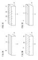
- FIG. 1A is a perspective view of an embolic material according to the first embodiment of the present invention
- FIG. 1B is a cross-sectional view taken along line IB-IB in FIG. 1A
- 2A, 2B, and 2C are perspective views showing a method of manufacturing the embolic material of FIG. 1A in the order of steps.
- 3A is a perspective view showing an example of making a cut in the longitudinal direction of the embolic material of FIG. 1A
- FIG. 3B is a perspective view showing an example of making a cut in the width direction
- FIG. 3C is a cut in a lattice shape.
- FIG. 3D is a perspective view showing an example in which a groove-shaped cut is made.
- FIG. 3A is a perspective view showing an example of making a cut in the longitudinal direction of the embolic material of FIG. 1A
- FIG. 3B is a perspective view showing an example of making a cut in the width direction
- FIG. 3C is a cut in
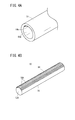
- FIG. 4A is an end perspective view showing a tube used in another method of manufacturing an embolic material according to the first embodiment
- FIG. 4B is a perspective view of the embolic material produced using the tube of FIG. 4A
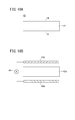
- FIG. 5A is a schematic diagram showing a process of moving the catheter to the indwelling position of the embolic material
- FIG. 5B is a schematic diagram showing a process of pushing out the embolic material from the catheter
- FIG. 5C is a flow of biological fluid through the embolic material.
- It is a schematic diagram which shows the blocked state.
- FIG. 7C are sectional views showing a method for manufacturing an embolic material according to the second embodiment in the order of steps.
- FIG. 8A is a cross-sectional view showing a method for manufacturing an embolic material according to the third embodiment
- FIG. 8B is a cross-sectional view of the embolic material according to the third embodiment. It is sectional drawing of the embolic material which concerns on 4th Embodiment.
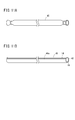
- FIG. 10A is a cross-sectional view of the embolic material according to the fifth embodiment
- FIG. 10B is a schematic diagram illustrating a method for manufacturing the embolic material according to the fifth embodiment.
- FIG. 11A is a perspective view of a tube used for manufacturing an embolic material according to Modification 1 of the fifth embodiment
- FIG. 11B is used for manufacturing an embolization material according to Modification 1 of the fifth embodiment. It is a perspective sectional view of a mask. It is a schematic diagram which shows the manufacturing method of the embolic material which concerns on the modification 2 of 5th Embodiment.
- 13A, 13B, and 13C are cross-sectional views illustrating a method for manufacturing an embolus material according to Modification 3 of the fifth embodiment in the order of steps.
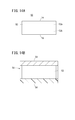
- FIG. 14A is a cross-sectional view of the embolic material according to the sixth embodiment
- FIG. 14B is a schematic view showing a method for manufacturing the embolic material according to the sixth embodiment.
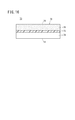
- FIG. 15A is a cross-sectional view of the embolic material according to the seventh embodiment
- FIG. 15B is a schematic view showing a method for manufacturing the embolic material according to the seventh embodiment. It is sectional drawing of the embolic material which concerns on 8th Embodiment.
- the embolic material 10 has a long filler 12 as shown in FIG. 1A.
- This filling body 12 is injected into a blood vessel of a living body via a catheter 90 (see FIGS. 5A to 5C), and in a state before being swelled (dry state), the width W of the filling body 12 is The inner diameter is smaller than 90.
- the width W is formed to be about 0.2 mm to 2 mm, for example.
- the length L of the filler 12 is formed to a length of 0.5 cm to 100 cm in the dry state.
- Such a filling body 12 is formed in a long shape in which the ratio of the length L to the width W (L / W) is at least 2 or more.
- the cross-sectional shape of the filler 12 is not limited to a rectangle as shown in the figure, and may be formed in a shape such as a circle, an ellipse, or a polygon.
- the filler 12 may be formed in a tubular shape having a hollow portion at the center.
- Such a filling body 12 is constituted by a hydrogel that expands by being in contact with moisture in the biological fluid.
- the hydrogel is a polymer material that swells by absorbing moisture, and has polymer chains that are crosslinked in a three-dimensional network. In the dry state, the polymer chains are intertwined. When water molecules diffuse into the polymer chain, the polymer chain is unwound and the network structure swells due to swelling including the water molecules.
- polyacrylic acid polymethacrylic acid, polyacrylamide, polyhydroxyethyl methacrylate and derivatives thereof, cross-linked polymers of polyols such as polyvinyl alcohol, polyvinyl pyrrolidone, and polyethylene glycol, or polysaccharide hydrogels as hydrogels. Can do.
- the filling body 12 has a difference in swelling characteristics between the first side portion 14 extending in the longitudinal direction of the filling body 12 and the second side portion 16 extending in parallel thereto. Is provided. In this embodiment, focusing on the swelling speed as one of the swelling characteristics of the hydrogel, the swelling speed of the hydrogel is changed between the vicinity of the first side portion 14 and the vicinity of the second side portion 16.
- the first side portion 14 is provided with a plurality of cuts having a predetermined depth so that the surface area of the first side portion 14 is larger than the surface area of the second side portion 16. Is formed. With this configuration, the moisture intrusion rate from the first side portion 14 is faster than the moisture intrusion rate from the second side portion 16. The swelling rate of the hydrogel increases as the moisture penetration rate increases. Therefore, in the process in which the filling body 12 swells, the first side portion 14 becomes transiently longer than the second side portion 16 to cause bending.
- Such an embolic material 10 is produced by the steps shown in FIGS. 2A to 2C.
- a thin plate-like hydrogel 12a is formed.
- the hydrogel 12a can be produced, for example, by crosslinking an ethylenically unsaturated monomer with radiation, heat, a redox agent, a nucleophile, or the like.
- the raw material solution may contain an ethylenically unsaturated monomer, a crosslinking agent that forms a crosslinked structure, and a suitable solvent. Such a raw material solution is poured into a mold.
- examples of the ethylenically unsaturated monomer include 2-hydroxyethyl methacrylate, hydroxybutyl acrylate, t-butylacrylamide, N, N′-methylenebisacrylamide, N-vinylpyrrolidinone, N-isopropylacrylamide, acrylic acid, and
- An ethylenically unsaturated carboxylic acid having a hydroxyl group, a sulfate group, a salt thereof, an amino group, and / or an ammonium group can be used.
- the cross-linking agent is a compound containing a branched molecule having at least two functional groups.
- an ester, carbonate, thioester, carbamate, oxalate, thioester, N, N′-methylenebisacrylamide, ethylene glycol dimethacrylate, or the like is used. be able to.
- Polymerization of ethylenically unsaturated monomers in the raw material solution forms a hydrogel by the stimulation of ionizing radiation, ultraviolet light, or heat, but initiates polymerization by disclosing free radicals as needed.
- An agent may be included.
- the polymerization initiator for example, azobisisobutyronitrile (AIBN) or a derivative thereof can be used.
- the above raw material solution may contain a visualizing agent in order to confirm the indwelling position 94a in the blood vessel 94 of the embolic material 10 and to confirm the state after the indwelling.
- a visualizing agent solid particles containing an element that hardly transmits radiation such as barium sulfate, bismuth, tantalum, platinum, and gold can be introduced by a method of dispersing in a hydrogel.
- an organic compound containing an atom having a large atomic number such as chlorine, bromine and iodine may be introduced by polymerizing the polymer.
- solvent for example, isopropyl alcohol, dichloromethane, acetone, water, ethanol, or a combination thereof can be used.
- the raw material solution is poured into a mold, the raw material solution is polymerized by a method of heating for several hours with a heat medium such as hot water (100 ° C.), a method of irradiating with ionizing radiation or ultraviolet rays, etc.
- a heat medium such as hot water (100 ° C.)
- ionizing radiation or ultraviolet rays etc.
- the illustrated lamellar hydrogel 12a is formed.
- a cut 18 is made in the surface of the thin plate-like hydrogel 12a.
- the cut 18 is formed by cutting a part of the surface side of the hydrogel 12a with a knife blade or laser light.
- the pattern of the notches 18, for example, as shown in FIG. 3A, notches 18 extending in the longitudinal direction of the filler 12 may be provided.
- the hydrogel 12a having the cut 18 formed therein is washed and dried, it is cut into a long and slender thread with a knife blade or a laser processing machine. As a result, the embolic material 10 having the long and narrow filler 12 is completed.
- the embolic material 10 may be formed by polymerizing the hydrogel in a tube having a predetermined cross-sectional shape.
- another method for manufacturing the embolic material 10 of the present embodiment will be described.
- the polymerization reaction of the hydrogel is performed using the tube 19 shown in FIG. 4A.
- the tube 19 has a plurality of convex portions 19b formed on a part of the inner peripheral portion 19a. These convex portions 19b extend along the axial direction of the tube 19 and are concentrated on a portion of the circumferential direction. A portion facing these convex portions 19b is formed by a smooth inner peripheral portion 19a.
- a tube 19 for example, a tube manufactured from HYTREL (registered trademark) manufactured by DuPont can be used. Such a tube 19 can be dissolved in a predetermined solvent, and the filling body 12 can be easily taken out from the tube 19.
- the tube 19 is filled with a hydrogel raw material solution. Thereafter, a polymerization reaction (crosslinking reaction) of the raw material solution is performed in the tube 19 to form a hydrogel.
- a polymerization reaction crosslinking reaction
- the raw material solution is polymerized by a method of heating the tube 19 with a heat medium such as hot water (100 ° C.) for several hours or a method of irradiating the tube 19 with ionizing radiation or ultraviolet rays.
- the tube 19 is removed by dissolving it in a predetermined solvent to obtain a filler 12A shown in FIG. 4B.
- This filling body 12 ⁇ / b> A has a plurality of grooves 18 ⁇ / b> A reflecting the convex portions 19 b of the tube 19 on one side portion (first side portion 14) in the longitudinal direction.
- the first side portion 14 in which these grooves 18A are formed has a larger surface area than the other side portion (second side portion 16) made of a smooth peripheral surface, and the swelling speed is increased accordingly.
- the embolizing material 10 of this embodiment is obtained by washing and drying the filling body 12.
- the embolic material 10 produced as described above operates as follows.
- the embolic material 10 in a dry state is inserted into the catheter 90.
- the catheter 90 is inserted into the blood vessel 94 as a living body lumen, for example.
- the distal end of the catheter 90 is advanced in the patient's blood vessel 94 until it reaches an indwelling position 94 a in the blood vessel 94.
- the embolic material 10 is pushed out by the pusher 92 as shown in FIG. 5B.
- the extruded embolic material 10 starts to swell when it comes into contact with blood.
- the filling body 12 of the embolic material 10 has a higher swelling speed of the first side portion 14 than that of the second side portion 16, the first side portion 14 side extends longer, and the second side The part 16 is in a shorter state, and bending is caused by the difference in length.
- the embolic material 10 pushed into the blood vessel 94 is curved to form an annular or coiled (spiral) three-dimensional structure. Since this three-dimensional structure is larger than the inner diameter of the blood vessel 94, the embolic material 10 is clogged in the indwelling position 94a of the blood vessel 94 without being pushed away by the flow of the biological fluid. Not only the example of illustration but embolization material 10 is detained in multiple numbers as needed.
- the embolization material 10 placed in the indwelling position 94a swells, so that the indwelling position 94a of the blood vessel 94 is filled without any gaps and the embolization is completed.
- the coiled (spiral) curve of the embolic material 10 as shown in the figure is not essential for preventing movement within the living body lumen (blood vessel).
- the embolic material 10 does not necessarily have to be curved in a coil shape (spiral shape), but only by contacting the inner wall of the blood vessel 94 while contacting the inner wall of the blood vessel 94 and exerting stress due to deformation, Demonstrate resistance to flow.
- the embolic material 10 moves through the blood vessel 94 without moving by the flow of biological fluid. Can be embolized.
- the embolic material 10 can be used not only for embolization of the blood vessel 94 but also for treatment of the aortic aneurysm 96 as shown in FIG.
- a stent graft treatment is performed that is less invasive to the patient and less burdensome.
- This stent graft treatment is a treatment for preventing blood from flowing into the aortic aneurysm 96 by installing an artificial blood vessel (stent graft 102) in the aortic aneurysm 96.
- Type 2 endoleak is caused when the blood flow that has been antegrade from the aortic aneurysm 96 toward the distal blood vessel (branching blood vessel 98) is placed in the aortic aneurysm 96 from the side of the branching blood vessel 98 by installing the stent graft 102.
- This is a complication in which blood accumulates in the aortic aneurysm 96. If this is left for a long period of time, the aortic aneurysm 96 may expand due to the backflowed blood.
- Such type 2 endoleak is considered to occur in about 20 to 30% of patients who have undergone stent graft treatment over a long period of time.
- the embolization material 10 of this embodiment is placed in the aortic aneurysm 96 to embolize the aortic aneurysm 96, so that type 2 endoleak can be treated.
- the catheter 100 is inserted into the aortic aneurysm 96 from the branch blood vessel 98 connected to the aortic aneurysm 96 or between the stent graft 102 and the iliac artery 97 (or the aorta 95), and the embolic material 10 is inserted through the catheter 100.
- the embolizing material 10 swells in the aortic aneurysm 96, thereby embolizing the aortic aneurysm 96 and preventing blood from flowing into the aortic aneurysm 96.
- the embolic material 10 is curved by the difference in swelling characteristics to form a coiled structure, and the embolic material 10 expands larger than the diameter of the branch blood vessel 98 connected to the aortic aneurysm 96. Therefore, the embolic material 10 does not enter the branch blood vessel 98 unlike the conventional liquid embolic material or bead-shaped embolic material. Therefore, according to the embolic material 10, the aortic aneurysm 96 can be safely embolized without causing complications due to the distal embolization via the branch blood vessel 98.
- the embolic material 10 of this embodiment is also suitable for the treatment of type 2 endoleak.
- the long filler 12 is bent due to the difference in swelling characteristics thereof, so that the bent portion is caught in the biological lumen, thereby causing the flow of the biological fluid. It can be prevented from moving. As a result, the blood stays in a desired position and swells to prevent blood flow.
- the embolic material 20 according to the second embodiment includes a porous filler 22 as shown in FIG. 7C.
- the porous density (pore density) of the filler 22 the porous density of the first side portion 14 is larger than the porous density of the second side portion 16.
- the surface area of the first side portion 14 is larger than that of the second side portion 16, and the swelling rate of the first side portion 14 is also larger.
- Such a filler 22 is produced as follows.
- a raw material solution 22a of the filler 22 is prepared and put in a mold.
- the raw material solution 22a of the present embodiment contains a pore forming agent 24.
- the ethylenically unsaturated monomer, the crosslinking agent, the polymerization initiator, and the solvent the same ones as in the first embodiment can be used.
- the pore-forming agent 24 is composed of a supersaturated substance that cannot be completely dissolved in the raw material solution 22a, or a substance that is insoluble in the raw material solution 22a and soluble in the cleaning liquid. Further, when water-soluble particles are used for the pore forming agent 24, an organic solvent is appropriately mixed in the raw material solution 22a to reduce the polarity of the solvent, thereby preventing dissolution of the pore forming agent 24. Good. Specifically, for example, sodium chloride, potassium chloride, ice, sucrose, sodium bicarbonate and the like can be used as the pore former 24.
- the pore forming agent 24 uses a substance having a specific gravity larger than that of the raw material solution 22a and precipitated in the raw material solution 22a, or a substance having a specific gravity smaller than that of the raw material solution 22a and floating in the raw material solution 22a.
- the pore forming agent 24 is dispersed as particles having a diameter of, for example, 500 ⁇ m or less in the raw material solution 22a.
- the raw material solution 22a containing the pore forming agent 24 is stirred and suspended uniformly, and then poured into a mold.
- the mold of this embodiment may be for forming a thin plate-like hydrogel, or may be a tube.
- a tube for example, a tube having a predetermined diameter manufactured from HYTREL (registered trademark) manufactured by DuPont can be used.
- the tube can be dissolved in a predetermined solvent, and the filling body 22 can be easily taken out from the tube.
- the raw material solution 22a is allowed to stand for a predetermined time.
- particles of the pore forming agent 24 having a specific gravity greater than that of the raw material solution 22a are precipitated, and the particles of the pore forming agent 24 gather near the bottom of the mold.
- the polymerization reaction is started to form the hydrogel 22b.
- the position of the pore forming agent 24 is fixed, and the hydrogel 22b containing a large amount of the pore forming agent 24 at the bottom is formed.
- the method of unevenly distributing the pore forming agent 24 in the raw material solution 22a can take various methods other than the method of precipitating the pore forming agent 24.
- particles having an electric charge can be used for the pore forming agent 24 and the pore forming agent 24 can be unevenly distributed by an electric field.
- negatively charged particles composed of polysaccharides such as alginic acid and agarose can be used.
- positively charged particles made of gelatin for example, may be used.
- These particles are dispersed in the hydrogel raw material solution 22a as a pore forming agent 24, and the pore forming agent 24 can be unevenly distributed in the raw material solution 22a by applying an electric field. Thereafter, the raw material solution 22a is polymerized to fix the position of the pore former 24.
- the thread-like hydrogel 22b is taken out by dissolving and removing the tube. Thereafter, as shown in FIG. 7C, the hydrogel 22b is washed with a washing liquid capable of dissolving the pore-forming agent 24. As a result, the pore former 24 is dissolved in the cleaning liquid and removed from the hydrogel 22b. By dissolving and removing the pore-forming agent 24 in this manner, pores 26 having the shape of pore-forming agent 24 particles are formed, and a porous hydrogel 22b is obtained.
- the holes 26 are concentrated on the bottom portion (first side portion 14) of the hydrogel 22b and are slightly present near the upper portion (second side portion 16).
- a bias occurs in the size of the porous density.
- a filler 22 having a high porous density at the first side portion 14 and a low porous density at the second side portion 16 is obtained.
- the hydrogel in FIG. 7C may be washed and dried, and then cut into pieces to form a thread.
- the embolic material 20 of the present embodiment is a method of bonding a hydrogel containing a pore-forming agent 24 and a hydrogel not containing the pore-forming agent 24 (see FIG. 12), or a pore-forming agent. It can also be formed by a method in which a hydrogel containing 24 and a hydrogel containing no pore-forming agent 24 are polymerized so as to be stacked (see FIGS. 13A to 13C).
- the embolic material 20 of this embodiment includes a filler 22 having a high porous density at the first side portion 14 and a low porous density at the second side portion 16.
- the first side portion 14 has a large number of holes 26, thereby increasing the surface area, and the moisture infiltration rate is higher than that of the second side portion 16.
- the swelling speed of the first side portion 14 becomes larger than the swelling speed of the second side portion 16, and bending can occur in the process of swelling. Therefore, the same effect as that of the embolic material 10 of the first embodiment can be obtained by the embolic material 20.
- the embolic material 20 of this embodiment is not limited to the above.
- a material that does not remove the pore-forming agent 24 from the hydrogel 22b containing the pore-forming agent 24 may be used as an embolization material.
- the embolizing material is obtained by washing with care so that the pore-forming agent 24 is not leached and then drying.
- a supersaturated solution containing the component of the pore-forming agent 24 can be used as the cleaning liquid.
- the embolizing material including such a pore-forming agent 24 is removed by dissolving the pore-forming agent 24 by contact with a biological fluid such as blood, and in the living body, as shown in FIG.
- the embolic material 20 having a large porosity is formed. Then, the first side portion 14 swells relatively quickly, so that the curvature can be generated.
- the pore-forming agent 24 for example, sugar particles such as glucose and sucrose, and electrolyte salt particles such as salt can be used.
- the pore-forming agent 24 that elutes inside the living body it is preferable to use a low molecular weight substance.
- the low molecular weight substance can diffuse through the inside of the network structure of the hydrogel 22b constituting the embolic material, it can be rapidly leached.
- an electrolyte is used as the pore-forming agent 24, the ionic strength of the surrounding hydrogel 22b is increased and the swelling speed is further increased, which is preferable.
- the embolic material 30 according to this embodiment has a structure in which insoluble particles 33 are unevenly distributed in the vicinity of the second side portion 16 of the filler 32 as shown in FIG. 8B.
- insoluble particles 33 are present on the second side portion 16
- moisture intrusion is hindered.
- the swelling speed of the second side portion 16 is slower than the swelling speed of the first side portion 14, and the embolic material 30 is curved when it comes into contact with moisture.
- the embolic material 30 of the present embodiment is curved by providing a structure that prevents moisture from entering the second side portion 16.
- insoluble particles 33 are dispersed in a hydrogel raw material solution 32a.
- the insoluble particles 33 for example, particles such as barium sulfate, bismuth, tantalum, platinum, gold, silica, and polystyrene can be used.
- the raw material solution 32a in which the insoluble particles 33 are dispersed is poured into a mold such as a tube, and the mold is horizontally disposed and left for a predetermined time.
- the insoluble particles 33 float or settle due to the difference in specific gravity between the raw material solution 32a and the insoluble particles 33, and the insoluble particles are placed on the side (upper or lower) of the horizontally arranged mold. 33 is unevenly distributed.
- the method of unevenly distributing the insoluble particles 33 may be performed by a method of applying an electric field.
- particles having a surface potential can be used as the insoluble particles 33.
- silica particles and polystyrene particles have a surface potential, and the insoluble particles 33 can be unevenly distributed by an electric field.
- the raw material solution 32 a is polymerized by heating, thereby forming the filler 32 in which the insoluble particles 33 are unevenly distributed on the second side portion 16.
- the embolic material 30 of this embodiment is obtained by removing the mold (for example, a tube), taking out the filler 32, washing and drying.
- the embolic material 30 of the present embodiment includes a method of bonding a hydrogel that does not include the insoluble particles 33 and a hydrogel that includes the insoluble particles 33 (see FIG. 12), or a hydrogel that does not include the insoluble particles 33 and the insoluble particles 33. It can also be formed by a method of polymerizing the hydrogel so as to be stacked (see FIGS. 13A to 13C).
- the insoluble particles 33 are unevenly distributed on the second side portion 16 of the filler 32 made of hydrogel.
- the water does not easily permeate, and thus the swelling speed becomes slow. That is, the swelling speed of the second side portion 16 of the filler 32 is relatively slower than the swelling speed of the first side portion 14, so that the embolic material 30 can be curved when it swells.
- the outflow by a biological fluid can be prevented in a biological lumen.
- a thread-like structure extending in the longitudinal direction of the embolic material 30 may be added to the hydrogel raw material solution instead of the insoluble particles 33.
- this thread-like structure one having an elongation swelling ratio (equilibrium swelling ratio) lower than that of the hydrogel can be used. By precipitating this thread-like structure in the raw material solution, it is unevenly distributed on the second side portion 16.
- the embolic material 30 including such a thread-like structure can be curved as the swelling rate of the second side portion 16 is lower than that of the first side portion 14.
- the embolic material 30A includes a filler 32A and a waterproof film 34 as shown in the cross-sectional view of FIG.
- the filling body 32A may be formed of a uniform hydrogel including the first side portion 14 which is a side extending in the longitudinal direction and the second side portion 16 extending in parallel therewith.
- the filling body 32 ⁇ / b> A has the second side portion 16 covered with the waterproof film 34.
- the waterproof film 34 may be made of a material that prevents water from entering, or a material that has a slower water ingress rate than the hydrogel constituting the filling body 32.
- a material that prevents water from entering or a material that has a slower water ingress rate than the hydrogel constituting the filling body 32.
- a film of cellulose or polylactic acid can be used.
- the waterproof film 34 is formed by applying or sticking the material constituting the waterproof film 34 to the hydrogel constituting the filler 32A. By cutting the hydrogel covered with the waterproof film 34 into a thread shape, a long and narrow filling body 32A is obtained.
- the filler 32A may be directly formed into a thread by polymerizing the hydrogel in the tube.
- the embolic material 30A of the present embodiment can be obtained by selectively applying the waterproof film 34 only to the second side portion 16 of the thread-like filler 32A.
- the second side portion 16 is covered with the waterproof film 34, so that moisture enters the filling body 32A from the second side portion 16. Is blocked.
- the first side portion 14 is swollen faster than the second side portion 16, and the filling body 32 can be curved during the swelling process.
- the effect similar to the embolic material 10 of 1st Embodiment can be acquired also by the embolic material 30A.
- the embolic material 40 includes a filler 42 in which the ionic strength of the hydrogel is different between the first side portion 14 and the second side portion 16.
- the polymer constituting the hydrogel constituting the filler 42 includes a basic substituent such as a hydroxyl group or an amine group, or an acidic substituent such as a carboxyl group or a sulfate group.
- a polymer having a basic substituent or an acidic substituent is also called a polymer electrolyte, and is bonded to various cations or anions.
- the concentration (ionic strength) of the ion active group bonded to the cation or the anion is high in the first side portion 14 in the packing body 42 and is inclined so that the ionic strength gradually decreases toward the second side portion 16. ing.
- a hydrogel containing more basic substituents or acidic substituents and having higher ionic strength has higher affinity with water, faster moisture penetration, and higher swelling speed. Therefore, in the filling body 42, the swelling speed of the first side part 14 having a high ionic strength is faster than the swelling speed of the second side part 16.
- the filler 42 performs a polymerization reaction while applying an electric field to the hydrogel raw material solution 42 a constituting the filler 42.
- a tube is disposed between the pair of electrodes 44a and 44b, and a voltage is applied between the electrodes 44a and 44b, while a heating medium such as hot water is used.
- the polymerization reaction is performed while heating the tube.
- the raw material solution 42a contains only an ion active group (substituent) bonded to either a cation or an anion.
- the embolizing material 40 of the present embodiment is obtained by appropriately cleaning and drying the filler 42.
- the hydrogel may be polymerized inside the plate-shaped mold without using a tube.
- the plate-like hydrogel obtained by the polymerization reaction is cut into thin yarns, whereby a long and long shaped filler 42 is obtained.
- the embolization material 40 (see FIG. 10A) has an ionic strength gradient depending on the concentration of the electrolyte impregnated in the filler 42, not the hydrogel itself constituting the filler 42. Also in the first modification, the electrolyte concentration (ionic strength) inside the filling body 42 is high in the first side portion 14 and the electrolyte concentration (ionic strength) in the second side portion 16 is low.
- electrolyte impregnated in the filler 42 for example, a salt of ions such as sodium, potassium, calcium, or magnesium and chlorine, acetic acid, citric acid, phosphoric acid, or the like can be used. Moreover, you may use the polymer electrolyte which has an acidic substituent or a basic substituent as electrolyte.
- the first side portion 14 having a high electrolyte concentration and the second side portion 16 having a low electrolyte concentration have a difference in osmotic pressure, and the first side portion has a high electrolyte concentration. 14 attracts more water. As a result, the swelling speed of the first side part 14 having a high electrolyte concentration becomes faster than the swelling speed of the second side part 16, and it is possible to generate a curve when swelling.
- the manufacturing method of the embolic material 40 of this embodiment forms a hydrogel with uniform ionic strength, and makes it by making the solution containing the monomer or polymer which has an ion active group in the one side (1st side part 14) contact. it can.
- a raw material solution of hydrogel is filled into a tube 45, and the tube 45 is heated for a predetermined time, whereby the raw material solution is polymerized to form a filler 42 made of a filamentous hydrogel.
- a mask 46 having an opening 46 a formed in the first side portion 14 is formed on the outer peripheral surface of the filler 42.
- the electrolyte is infiltrated into the first side portion 14 of the filler 42 by bringing the solution containing the electrolyte into contact with the first side portion 14 of the filler 42 exposed in the opening 46 a of the mask 46.
- the filling body 42 which has inclination in ionic strength between the 1st side part 14 and the 2nd side part 16 is obtained.
- the infiltrated polymer electrolyte may be polymerized with the hydrogel constituting the filler 42 by heating again, if necessary.
- the embolic material 40 is produced by chemical or physical joining of a plurality of hydrogels having different ionic strengths.
- first hydrogel 42b having a relatively high ionic strength and a second hydrogel 42c having a relatively low ionic strength are produced.
- each of the first hydrogel 42b and the second hydrogel 42c is formed as an elongated body having a semicircular cross section.
- These first and second hydrogels 42b and 42c can be produced by polymerizing a raw material solution having a predetermined composition to an appropriate hardness and then extruding it.
- the first hydrogel 42b and the second hydrogel 42c are bonded to each other and heated appropriately, so that the first hydrogel 42b and the second hydrogel 42c are joined by a polymerization reaction to form the filler 42.
- the embedding material 40 of this embodiment is completed by washing and drying the filler 42.
- the portion made of the first hydrogel 42b having a high ionic strength constitutes the first side portion 14
- the portion made of the second hydrogel 42c having a low ionic strength constitutes the second side portion 16. .
- the embolic material 40 that produces a curvature at the time of swelling is obtained.
- first hydrogel 42b and the second hydrogel 42c may be formed in a thin plate shape and joined, and then the filler 42 may be formed by thinly cutting into a thread shape.
- the filler 42 is formed by laminating hydrogels having different ionic strengths in layers by polymerizing the raw material solutions having different ionic strengths sequentially into the heated mold.
- the ionic strength gradient may be provided in the laminated hydrogel layer by gradually increasing or decreasing the ionic strength of the raw material solution.
- the modified example 3 can also be applied to a manufacturing method using a tube. As shown in FIG. 13A, a tube 45 is prepared, and about half of the raw material solution 42c1 is injected therein. Then, the second hydrogel 42c is formed by horizontally arranging the full length direction of the tube 45 and polymerizing the raw material solution 42c1 in the tube 45.
- the raw material solution 42b1 is injected into the remaining space in the tube 45 in which the second hydrogel 42c is formed.
- the raw material solution 42b1 contains more electrolyte than the second hydrogel 42c, and has high ionic strength. Thereafter, the raw material solution 42b1 is polymerized.
- a filling body 42 in which the first hydrogel 42b is laminated on the second hydrogel 42c is obtained.
- the embedding material 40 of this embodiment can be obtained by taking out the filling body 42 by dissolving and removing the tube 45 with a predetermined solvent, and washing and drying the filling body 42.
- the filler 42 is composed of a polymer gel hydrogel having an acidic ion-active group, and the second side 16 is brought into contact with the low ph solution, so that the vicinity of the second side 16 is increased.
- An inclination may be provided in the ionic strength by a method of reducing the ionic strength.
- the packing body 42 is composed of a polymer chain hydrogel having basic ion-active groups, and the second side portion 16 is brought into contact with a high ph solution, so that the ionic strength in the vicinity of the second side portion 16 is increased.
- the ionic strength may be inclined by a method of reducing the ionic strength.
- the modification 4 may be implemented using a tube.
- a mask 46 shown in FIG. 11B may be used. That is, a mask 46 having an opening 46 a on the second side portion 16 is formed on the outer peripheral portion of the filler 42. Then, the embolic material 40 of this embodiment can be formed by making the 2nd side part 16 exposed to the opening part 46a contact the solution of low ph or high ph, and reducing ionic strength.
- the ionic strength of the filler 42 differs depending on the location. That is, in the filling body 42, the swelling speed of the first side part 14 having a high ionic strength is faster than the swelling speed of the second side part 16. Thereby, a curve can be produced in the swelling process of the embolic material 40. Therefore, the same effect as that of the embolic material 10 of the first embodiment can be obtained by the embolic material 40.
- the embolic material 50 according to the present embodiment is provided with a highly hydrophilic region 52 a and a low hydrophilic region 52 b inside the filler 52.
- the highly hydrophilic region 52a includes many molecules having a hydrophilic functional group in the polymer chain constituting the hydrogel.
- many hydrophobic molecules are included in the polymer chain constituting the hydrogel.
- the hydrophilic functional group include a hydroxyl group, a sulfate group, an amino group, and a carboxyl group.
- the hydrophobic functional group include a methyl group and a benzene group.
- such an embolic material 50 was sandwiched between a hydrophilic substrate 58 and a hydrophobic (or oleophilic) substrate 56 when the hydrogel constituting the filler 52 was polymerized. It is produced by performing a polymerization reaction between the containers 54.
- a hydrophilic substrate 58 a substrate made of polyacrylamide, polyester, or the like can be used.
- a hydrophobic substrate for example, a substrate made of polyethylene, polystyrene, or the like can be used.
- the raw material solution 53 includes a hydrophilic polymer (for example, a charged polymer, polysaccharide, or polyol) or a hydrophilic monomer (for example, acrylamide, sugar, or a hydrophilic amino acid) and a hydrophobic polymer (for example, , Hydrophobic polyamino acids and polyesters) or those containing hydrophobic monomers (for example, hydrophobic amino acids).
- a hydrophilic polymer for example, a charged polymer, polysaccharide, or polyol
- a hydrophilic monomer for example, acrylamide, sugar, or a hydrophilic amino acid
- a hydrophobic polymer for example, Hydrophobic polyamino acids and polyesters
- hydrophobic monomers for example, hydrophobic amino acids
- the raw material solution 53 is heated and polymerized to form a hydrophilic region 52a and a hydrophobic region 52b in the hydrogel.
- the hydrogel thus produced is dried and cut to form a filler in which a hydrophilic region 52a is formed on the first side portion 14 and a hydrophobic region 52b is formed on the second side portion 16. 52 is obtained.
- the embolic material 50 of this embodiment is polymerized so that a hydrophilic hydrogel and a hydrophobic hydrogel are bonded together (see FIG. 12), or a hydrophilic hydrogel and a hydrophobic hydrogel are stacked. It can also be formed by a method (see FIGS. 13A to 13C).
- the hydrophilic region 52a is faster in moisture penetration than the hydrophobic region 52b.
- the first side portion 14 in which the hydrophilic region 52 a is formed swells faster than the second side portion 16, so that curvature can be generated in the swelling process.
- the embolic material 50 can acquire the effect similar to the embolic material 10 of 1st Embodiment.
- the first side portion 14 containing a lot of hydrophilic molecules can take in more water molecules in the polymer chain, the equilibrium swelling ratio is also increased. Therefore, in the embolic material 50, the first side portion 14 is larger than the second side portion 16 in the equilibrium swelling rate. Therefore, the embolic material 50 can maintain a curved state even in a completely swollen state.
- the embolic material 60 includes a filler 62 having an inclination in the cross-linking density.
- the filler 62 has a first region 64 with a low crosslink density and a second region 66 with a high crosslink density.
- the first side portion 14 is formed on the first region 64 side
- the second side portion 16 is formed on the second region 66 side.
- the network structure of the polymer chain constituting the hydrogel is fine, and moisture is hardly taken into the network structure and is difficult to swell.
- the network structure of the polymer chain is larger than that in the second region 66, and it is easy to swell.
- the swelling speed of the first region 64 having a low cross-linking density is higher and the speed of the second region 66 having a high cross-linking density is lower. That is, in the filling body 62, the swelling rate and the equilibrium swelling rate of the first side portion 14 are larger than the swelling rate and the equilibrium swelling rate of the second side portion 16.
- Such an embolic material 60 is produced by the method shown in FIG. 15B. That is, the raw material solution is polymerized in the mold 67 to form a uniform hydrogel 62a. Next, as shown in the figure, a solution 68 containing a cross-linking agent is brought into contact with one surface (the upper surface in the figure) of the hydrogel 62a. Thereby, a crosslinking agent infiltrates from the upper surface side of the hydrogel 62a. As a result, in the hydrogel 62a, a concentration distribution is generated such that the closer to the top surface, the higher the concentration of the crosslinking agent. Thereafter, the hydrogel 62a containing the crosslinking agent is heated to polymerize the crosslinking agent.
- the embolus 60 is obtained by cutting the hydrogel 62a into a thread and drying it.
- a tube for preparation of the embolic material 60 of this embodiment.
- a uniform thread-like hydrogel 62a is formed in the tube 45 using the tube 45 as shown in FIG. 11A.
- a side portion of the tube 45 is cut away to form a mask 46 having an opening 46a.
- the hydrogel 62a is heated again to polymerize the crosslinking agent.
- the embolus 60 is obtained by washing and drying the hydrogel 62a.
- the embolizing material 60 of the present embodiment is a method in which hydrogels 62a having different crosslink densities are bonded together (see FIG. 12), and a method in which raw material solutions having different components are sequentially polymerized so as to be stacked (FIGS. 13A to 13C). For example).
- the swelling speed of the first side portion 14 is made of the filler 62 that is larger than the swelling speed of the second side portion 16, so that the curve is generated during the swelling process. Can occur. Thereby, the effect similar to the embolic material 10 of 1st Embodiment is acquired. Further, since the embolization material 60 has a higher equilibrium swelling ratio of the first side portion 14 than that of the second side portion 16, the embolic material 60 can maintain a curved state even after being fully swollen. This is preferable because movement due to flow is less likely to occur.
- the embolic material 70 includes a filler 72 having different polymer concentrations therein.
- a low concentration region 74 and a high concentration region 76 are formed in the filler 72.
- the first side portion 14 is formed on the low concentration region 74 side
- the second side portion 16 is formed on the high concentration region 76 side.
- the concentration of the polymer constituting the hydrogel skeleton is relatively low
- the concentration of the polymer constituting the hydrogel skeleton is relatively high.
- the first side portion 14 of the low concentration region 74 of the filling body 72 has a higher swelling speed than the second side portion 16 of the high concentration region 76.
- Such a low concentration region 74 (first hydrogel layer) and a high concentration region 76 (second hydrogel layer) are obtained by adjusting the ratio of the solvent and the monomer in the raw material solution of the hydrogel constituting the filler 72.
- a hydrogel layer constituting the high concentration region 76 is formed by polymerizing a raw material solution containing a small amount of solvent and a high concentration of monomer.
- region 74 is formed by pouring the raw material solution in which a monomer is contained at low concentration, and polymerizing the raw material solution. Then, the 1st hydrogel layer and the 2nd hydrogel layer are stuck through the contact bonding layer 75, and the hydrogel by which the high concentration area
- stacked is obtained.
- the hydrogel in which the high-concentration region 76 and the low-concentration region 74 are laminated is cut into threads and dried, whereby the embolization material 70 of the present embodiment is completed.
- the embolic material 70 of the present embodiment is a method in which a hydrogel having a low polymer concentration and a hydrogel having a high polymer concentration are bonded together (see FIG. 12), or a hydrogel having a low polymer concentration and a hydrogel having a high polymer concentration are stacked. It can also be formed by a polymerization method (see FIGS. 13A to 13C).
- the embolizing material 70 since the swelling speed of the first side portion 14 of the filling body 72 is faster than the swelling speed of the second side portion 16, it is possible to cause bending in the swelling process. As a result, the same effect as that of the embolic material 10 of the first embodiment can be obtained by the embolic material 70.
- the embolizing material 70 in a region where the polymer density is high, more water can be taken in, so that the equilibrium swelling ratio increases. Therefore, when the embolic material 70 is brought into contact with moisture, the first side portion 14 first extends more quickly than the second side portion 16 to bend, but eventually the second side portion 16 is more The swelling rate becomes larger than that of the first side portion 14. As a result, when the embolic material 70 is fully swollen, the embolic material 70 is maintained in a curved state by the second side portion 16 extending longer.
- embolic material and the manufacturing method thereof according to the present invention are not limited to the above-described embodiments, and it is needless to say that various configurations can be adopted without departing from the gist of the present invention.
- Appendix 2 The embolization material according to appendix 1, wherein the difference in swelling property is a difference in swelling speed.
- Appendix 7 The embolization material according to appendix 2, wherein a pore-forming agent is formed on the first side portion side of the filler so as to be leached by contact with the biological fluid to form a porous material. Wood.
- Appendix 16 A method of manufacturing an embolic material that prevents the flow of biological fluid by being placed in a biological lumen, Preparing a hydrogel raw material solution; Polymerizing the raw material solution to form a hydrogel; Increasing or decreasing the swelling rate of a portion of the hydrogel; A method for producing an embolus material, comprising:
- Appendix 17 The method for manufacturing an embolization material according to appendix 16, wherein the step of increasing the swelling rate performs a process for increasing a surface area of a part of the hydrogel.
- Appendix 18 The method for producing an embolus material according to appendix 16, wherein the step of increasing the swelling rate causes a gradient in ionic strength by bringing a solution containing an electrolyte into contact with a part of the hydrogel. A method for producing an embolic material.
- Appendix 20 The method for producing an embolization material according to appendix 16, wherein the step of reducing the swelling rate causes a cross-linking density to be gradient by conducting a polymerization reaction after infiltrating a part of the hydrogel with a cross-linking agent.
- a method for producing an embolic material is
- Appendix 21 A method of manufacturing an embolic material that prevents the flow of biological fluid by being placed in a biological lumen, Preparing a hydrogel raw material solution comprising a plurality of compositions; A step of unevenly distributing a part of the composition in a part of the raw material solution; Polymerizing the raw material solution to form a hydrogel and fixing the uneven distribution of part of the composition; A method for producing an embolus material, comprising:
- Appendix 22 The embolization material manufacturing method according to appendix 21, wherein the raw material solution includes water-soluble particles or water-insoluble particles as additives, and the additives are unevenly distributed by precipitating the additives. A method for producing an embolic material.
- Appendix 23 The embolization material manufacturing method according to appendix 21, wherein the raw material solution includes particles having a surface potential as an additive, and the additive is unevenly distributed by applying an electric field to the raw material solution. A method for producing an embolus material.
- Appendix 24 A method for producing an embolus material according to appendix 22, wherein a porous portion is formed in a part of the hydrogel by eluting the additive after the hydrogel is formed.
- Appendix 25 The embolization material manufacturing method according to appendix 21, wherein the raw material solution includes a polymer electrolyte, and the polymer electrolyte is unevenly distributed by applying an electric field to the raw material solution. Method.
- Appendix 26 The method for producing an embolization material according to appendix 21, wherein the raw material solution includes a hydrophilic polymer or monomer and a hydrophobic polymer or monomer, and the raw material solution is brought into contact with the hydrophilic substrate and the hydrophobic substrate. In this way, the hydrophilic polymer or monomer and the hydrophobic polymer or monomer are unevenly distributed.
- Appendix 27 A method of manufacturing an embolic material that prevents the flow of biological fluid by being placed in a biological lumen, Preparing a hydrogel raw material solution; Creating a gradient in the concentration of ionic strength or hydrophilic polymer or hydrophilic monomer in the raw material solution; Polymerizing a raw material solution having a gradient in the concentration to form a hydrogel; A method for producing an embolus material, comprising:
- Appendix 28 28.
- Appendix 30 A method of manufacturing an embolic material that prevents the flow of biological fluid by being placed in a biological lumen, Forming a first hydrogel layer; Forming a second hydrogel layer having a swelling property different from that of the first hydrogel layer on the first hydrogel layer; A method for producing an embolus material, comprising:
- Appendix 31 A method of manufacturing an embolic material that prevents the flow of biological fluid by being placed in a biological lumen, Forming a first hydrogel; Forming a second hydrogel having different swelling properties than the first hydrogel; Bonding the second hydrogel to the first hydrogel; A method for producing an embolus material, comprising:
- a long filling body made of a material that swells when in contact with a biological fluid is provided, and the filling body has a first side portion and a second side portion in a radial direction of the filling body.
- An embolization method characterized in that the flow of biological fluid is blocked by placing an embolic material having a difference in swelling characteristics between a side portion and the second side portion in a living body lumen.
- Appendix 33 The embolization method according to appendix 32, wherein the embolization material is placed in the living body lumen using a catheter.
Abstract
An embolic material (10) which prevents flow of a biological fluid by being placed in a body lumen via a catheter (90), the embolic material (10) comprising a material that swells by contacting the biological fluid. The embolic material (10) includes a long filler (12) that is formed smaller than an inner diameter of the catheter (90). The filler (12) prevents the flow of the biological fluid by bending when brought into contact with the biological fluid due to the difference in swelling characteristics between a first side portion (14) and a second side portion (16) that extend in parallel in a longitudinal direction.
Description
本発明は、生体管腔内に留置されて生体液の流れを阻止する塞栓材及びその製造方法に関する。
The present invention relates to an embolic material that is placed in a living body lumen and blocks the flow of biological fluid, and a method for manufacturing the embolizing material.
従来より、生体管腔の生体液(例えば、血液)の流れを阻止するべく、生体管腔内に塞栓材を留置する処置が行われている。具体的には、生体液と接すると凝固する液体状の塞栓材を生体管腔内に注入する方法や、ビーズ状又は糸状に形成された塞栓材をカテーテル等を介して留置する方法がある。
Conventionally, in order to prevent the flow of biological fluid (for example, blood) in a biological lumen, a treatment for placing an embolic material in the biological lumen has been performed. Specifically, there are a method of injecting a liquid embolic material that solidifies when it comes into contact with a biological fluid into a living body lumen, and a method of placing an embolic material formed in a bead shape or a thread shape via a catheter or the like.
特表2002-539853号公報、特表2004-537353号公報、特表2011-507637号公報、及び特表2013-505791号公報は、塞栓材の留置方法を開示する。
JP-T 2002-539853, JP-T 2004-537353, JP-T 2011-507637, and JP-T 2013-505791 disclose a method for placing an embolic material.
また、”A Novel and Simple Technique for Embolization of Type 2 Endoleaks Through Direct Sac Access From the Distal Stent-graft Landing Zone”, G. Coppi et-al., European Journal of Vascular and Endovascular Surgery, Volume 47 Issue 4 p.394-401, April/2014には、液体塞栓材を注入する方法が記載されている。
Also, “A Novel and Simple Technique for Embolization of Type 2 Endoleaks Through Direct Sac Access From the Distal Stent-graft Landing Zone”, G. Coppi et-al., European Journal of Vocular 394-401, April / 2014 describes a method of injecting a liquid embolic material.
しかしながら、液体状の塞栓材を生体管腔内に留置する方法では、凝固する前の塞栓材が生体液の流れに流されて所望の位置から移動してしまい、意図しない場所を塞栓してしまうことにより、新たな合併症を生じるおそれがある。また、ビーズ状又は糸状に成形された塞栓材も液体塞栓材と同様に、生体液の流れによって所望の位置から移動してしまうおそれがある。
However, in the method in which the liquid embolus material is placed in the living body lumen, the embolus material before solidification flows in the flow of the biological fluid and moves from a desired position, thereby embedding an unintended place. May cause new complications. In addition, the embolic material formed into a bead shape or a thread shape may move from a desired position due to the flow of the biological fluid, like the liquid embolic material.
本発明は、生体液の流れによって移動することなく所望の位置で生体液の流れを阻止できる塞栓材及びその製造方法を提供することを目的とする。
An object of the present invention is to provide an embolic material that can prevent the flow of a biological fluid at a desired position without being moved by the flow of the biological fluid, and a manufacturing method thereof.
[1]前記の目的を達成するために、本発明の一観点に係る塞栓材は、生体管腔内に留置されることで生体液の流れを阻止する塞栓材であって、生体液に接すると膨潤する材料よりなる長尺な充填体を備え、前記充填体は、前記充填体の径方向において第1の側部と第2の側部とを有し、前記第1の側部と前記第2の側部は、膨潤特性に差を有することを特徴とする。
[1] In order to achieve the above object, an embolic material according to one aspect of the present invention is an embolic material that blocks the flow of biological fluid by being placed in a biological lumen, and is in contact with the biological fluid. Then, it is provided with a long filler made of a material that swells, and the filler has a first side and a second side in the radial direction of the filler, and the first side and the side The second side is characterized by having a difference in swelling characteristics.
上記の塞栓材によれば、長尺な充填体がその膨潤特性の差によって湾曲するため、湾曲した部分が生体管腔に引っ掛かることにより、生体液の流れによって移動するのを防止できる。その結果、所望の位置に留まって膨潤して生体液の流れを阻止できる。
According to the embolic material described above, since the long filler is bent due to the difference in its swelling characteristics, the bent portion can be prevented from moving due to the flow of the biological fluid by being caught in the biological lumen. As a result, it stays at a desired position and swells to prevent the flow of biological fluid.
[2]上記の塞栓材において、前記膨潤特性の差は、膨潤速度の差であってもよい。このように、第1の側部と第2の側部との間に膨潤速度の差がある場合には、充填体が膨潤する過程において、第1の側部と第2の側部との間に長さの差を生じて湾曲した構造が形成される。これにより、塞栓材の生体液の流れによる移動を防ぐことができる。
[2] In the embolization material, the difference in swelling characteristics may be a difference in swelling speed. Thus, when there is a difference in the swelling speed between the first side portion and the second side portion, in the process of swelling the filler, the first side portion and the second side portion A curved structure is formed with a difference in length therebetween. Thereby, the movement by the flow of the biological fluid of an embolic material can be prevented.
[3]上記の塞栓材において、前記膨潤特性の差は、平衡膨潤率の差であってもよい。このように、第1の側部と第2の側部との間に平衡膨潤率の差がある場合には、充填体が膨潤しきった状態において、第1の側部と第2の側部との間に長さの差が維持されるため、膨潤後も湾曲した状態が維持される。これにより、塞栓材の生体液の流れによる移動を防ぐことができる。
[3] In the embolizing material, the difference in swelling characteristics may be a difference in equilibrium swelling rate. Thus, when there is a difference in the equilibrium swelling rate between the first side portion and the second side portion, the first side portion and the second side portion are in a state where the filling body is fully swollen. Since the difference in length is maintained, the curved state is maintained even after swelling. Thereby, the movement by the flow of the biological fluid of an embolic material can be prevented.
[4]上記の塞栓材において、前記第1の側部の表面積を前記第2の側部の表面積よりも大きくしてもよい。これにより、第1の側部への水分の浸入速度が第2の側部への水分の浸入速度よりも速くなるため、第1の側部の膨潤速度が相対的に早くなる。その結果、塞栓材の膨潤過程において湾曲が形成され、塞栓材の生体液の流れによる移動を防ぐことができる。
[4] In the embolic material, the surface area of the first side portion may be larger than the surface area of the second side portion. Thereby, since the rate of moisture permeation into the first side portion is faster than the rate of moisture permeation into the second side portion, the swelling rate of the first side portion is relatively high. As a result, a curve is formed in the swelling process of the embolic material, and movement of the embolic material due to the flow of the biological fluid can be prevented.
[5]上記の塞栓材において、前記第1の側部の多孔密度の密度を前記第2の側部の多孔密度よりも大きくしてもよい。この場合には、第1の側部の表面積が大きくなるため、第1の側部の膨潤速度が第2の側部の膨潤速度よりも速くなる。
[5] In the embolization material described above, the density of the porous density of the first side portion may be larger than the density of the second side portion. In this case, since the surface area of the first side portion is increased, the swelling speed of the first side portion is faster than the swelling speed of the second side portion.
[6]この場合において、前記充填体の前記第1の側部側に前記生体液に接触することで溶脱して多孔質を形成する造孔剤が含まれていてもよい。
[6] In this case, a pore-forming agent that forms a porous material by leaching by contacting the biological fluid may be included on the first side of the filler.
[7]上記の塞栓材において、前記充填体の前記第2の側部側に前記生体液に溶解しない不溶性粒子が含まれていてもよい。このような不溶性粒子は、充填体への水分の浸入を妨げることにより、第2の側部の膨潤速度を遅くすることができる。すなわち、第1の側部の膨潤速度が第2の側部の膨潤速度よりも速くなり、塞栓材に湾曲を形成できる。
[7] In the embolic material, insoluble particles that do not dissolve in the biological fluid may be included on the second side of the filler. Such insoluble particles can slow the swelling rate of the second side by preventing moisture from entering the packing. That is, the swelling speed of the first side part is faster than the swelling speed of the second side part, and the embolic material can be curved.
[8]上記の塞栓材において、前記充填体の前記第2の側部側に前記充填体よりも平衡膨潤率の低い材料よりなる糸状の構造物が含まれていてもよい。糸状の構造物が含まれている第2の側部は、充填体の膨潤率が小さくなることで、湾曲を生じる。
[8] In the embolization material, a thread-like structure made of a material having an equilibrium swelling rate lower than that of the filler may be included on the second side portion side of the filler. The second side portion including the thread-like structure is curved due to the reduced swelling rate of the filler.
[9]上記の塞栓材において、第2の側部を防水膜で覆ってもよい。これにより、第2の側部が水と接する面積が減少するため、第2の側部の膨潤速度を遅くすることができる。すなわち、第1の側部の膨潤速度が第2の側部の膨潤速度よりも速くなり、塞栓材に湾曲を形成できる。
[9] In the embolizing material, the second side portion may be covered with a waterproof film. Thereby, since the area which a 2nd side part contacts with water reduces, the swelling speed of a 2nd side part can be made slow. That is, the swelling speed of the first side part is faster than the swelling speed of the second side part, and the embolic material can be curved.
[10]上記の塞栓材において、前記第1の側部のイオン強度を前記第2の側部のイオン強度よりも高くしてもよい。イオン強度が高い部分は水の浸入速度が速くなるため、第1の側部の膨潤速度を第2の側部の膨潤速度よりも速くすることができる。
[10] In the embolic material, the ionic strength of the first side portion may be higher than the ionic strength of the second side portion. The portion with high ionic strength has a high water infiltration rate, so that the swelling rate of the first side can be made faster than the swelling rate of the second side.
[11]また、本発明の別の一観点に係る塞栓材の製造方法は、生体管腔内に留置されることで生体液の流れを阻止する塞栓材の製造方法であって、複数の組成物を含むヒドロゲルの原料溶液を調製する工程と、前記原料溶液の一部に前記組成物の一部を偏在化させる工程と、前記原料溶液を重合させてヒドロゲルを形成して前記組成物の一部の偏在化を固定する工程と、を有することを特徴とする。
[11] A method for manufacturing an embolic material according to another aspect of the present invention is a method for manufacturing an embolic material that is placed in a living body lumen to prevent the flow of a biological fluid, and has a plurality of compositions. A step of preparing a raw material solution of a hydrogel containing a product, a step of unevenly distributing a part of the composition in a part of the raw material solution, and forming a hydrogel by polymerizing the raw material solution to form a hydrogel. And fixing the uneven distribution of the part.
[12]上記の塞栓材の製造方法であって、前記原料溶液は、添加剤として水溶性の粒子又は非水溶性の粒子を含み、前記添加剤を沈殿させることにより前記添加剤を偏在化させてもよい。
[12] The method for producing an embolizing material, wherein the raw material solution includes water-soluble particles or water-insoluble particles as an additive, and the additive is unevenly distributed by precipitating the additive. May be.
[13]上記の塞栓材の製造方法であって、前記原料溶液は、添加剤として表面電位を有する粒子を含み、前記原料溶液に電場を印加することにより前記添加剤を偏在化させてもよい。
[13] In the embolizing material manufacturing method, the raw material solution may include particles having a surface potential as an additive, and the additive may be unevenly distributed by applying an electric field to the raw material solution. .
[14]上記の塞栓材の製造方法において、前記ヒドロゲルの形成後に前記添加剤を溶出させることで、前記ヒドロゲルの一部に多孔質部分を形成してもよい。
[14] In the embolizing material manufacturing method, a porous portion may be formed in a part of the hydrogel by eluting the additive after the hydrogel is formed.
[15]上記の塞栓材の製造方法において、前記原料溶液は高分子電解質を含み、前記原料溶液に電場を印加することにより前記高分子電解質を偏在化させてもよい。
[15] In the above-described embolizing material manufacturing method, the raw material solution may include a polymer electrolyte, and the polymer electrolyte may be unevenly distributed by applying an electric field to the raw material solution.
上記観点に係る塞栓材によれば、生体液の流れによって移動することなく所望の位置で生体液の流れを阻止できる。また本発明に係る塞栓材の製造方法によれば、生体液の流れによって移動することなく所望の位置で生体液の流れを阻止できる塞栓材が得られる。
The embolic material according to the above aspect can prevent the flow of biological fluid at a desired position without moving by the flow of biological fluid. Further, according to the embolic material manufacturing method of the present invention, an embolic material that can prevent the flow of biological fluid at a desired position without being moved by the flow of biological fluid is obtained.
以下、本発明の好適な実施形態を挙げ、添付の図面を参照して詳細に説明する。
Hereinafter, preferred embodiments of the present invention will be given and described in detail with reference to the accompanying drawings.
(第1の実施形態)
本実施形態に係る塞栓材10は、図1Aに示すように、長尺な充填体12を有している。この充填体12は、カテーテル90(図5A~図5C参照)を介して生体の血管内に注入されるものであり、膨潤する前の状態(乾燥状態)において、その幅Wは、使用するカテーテル90の内径よりも小さく形成されている。幅Wは例えば、0.2mm~2mm程度に形成される。また、充填体12の長さLは、乾燥状態において0.5cm~100cmの長さに形成される。このような充填体12は、長さLと幅Wとの比率(L/W)が、少なくとも2以上の長尺状に形成される。充填体12の断面形状は図示のような矩形に限定されるものではなく、円形、楕円形又は多角形等の形状に形成してもよい。また、充填体12は、中心部に中空部が設けられた管状に形成されたものであってもよい。 (First embodiment)
Theembolic material 10 according to the present embodiment has a long filler 12 as shown in FIG. 1A. This filling body 12 is injected into a blood vessel of a living body via a catheter 90 (see FIGS. 5A to 5C), and in a state before being swelled (dry state), the width W of the filling body 12 is The inner diameter is smaller than 90. The width W is formed to be about 0.2 mm to 2 mm, for example. Further, the length L of the filler 12 is formed to a length of 0.5 cm to 100 cm in the dry state. Such a filling body 12 is formed in a long shape in which the ratio of the length L to the width W (L / W) is at least 2 or more. The cross-sectional shape of the filler 12 is not limited to a rectangle as shown in the figure, and may be formed in a shape such as a circle, an ellipse, or a polygon. The filler 12 may be formed in a tubular shape having a hollow portion at the center.
本実施形態に係る塞栓材10は、図1Aに示すように、長尺な充填体12を有している。この充填体12は、カテーテル90(図5A~図5C参照)を介して生体の血管内に注入されるものであり、膨潤する前の状態(乾燥状態)において、その幅Wは、使用するカテーテル90の内径よりも小さく形成されている。幅Wは例えば、0.2mm~2mm程度に形成される。また、充填体12の長さLは、乾燥状態において0.5cm~100cmの長さに形成される。このような充填体12は、長さLと幅Wとの比率(L/W)が、少なくとも2以上の長尺状に形成される。充填体12の断面形状は図示のような矩形に限定されるものではなく、円形、楕円形又は多角形等の形状に形成してもよい。また、充填体12は、中心部に中空部が設けられた管状に形成されたものであってもよい。 (First embodiment)
The
このような充填体12は、生体液中の水分と接することにより膨張するヒドロゲルによって構成される。ヒドロゲルは、水分を吸収することで膨潤するポリマー材料であり、立体的な網目状に架橋されたポリマー鎖を有する。乾燥状態において、ポリマー鎖は絡み合った状態となっている。このポリマー鎖に水分子が拡散すると、ポリマー鎖がほどけて網目構造が水分子を含んで膨らむことにより膨潤する。
Such a filling body 12 is constituted by a hydrogel that expands by being in contact with moisture in the biological fluid. The hydrogel is a polymer material that swells by absorbing moisture, and has polymer chains that are crosslinked in a three-dimensional network. In the dry state, the polymer chains are intertwined. When water molecules diffuse into the polymer chain, the polymer chain is unwound and the network structure swells due to swelling including the water molecules.
ヒドロゲルには、ポリアクリル酸、ポリメタクリル酸、ポリアクリルアミド、ポリヒドロキシエチルメタクリラート及びそれらの誘導体、ポリビニルアルコール、ポリビニルピロリドン、ポリエチレングリコール等のポリオールの架橋重合体、又は多糖系のヒドロゲル等を用いることができる。
Use polyacrylic acid, polymethacrylic acid, polyacrylamide, polyhydroxyethyl methacrylate and derivatives thereof, cross-linked polymers of polyols such as polyvinyl alcohol, polyvinyl pyrrolidone, and polyethylene glycol, or polysaccharide hydrogels as hydrogels. Can do.
この充填体12は、図1Bの断面図において、充填体12の長尺方向に伸びた第1の側部14と、これに平行に伸びる第2の側部16との間で膨潤特性に差異が設けられている。本実施形態においては、ヒドロゲルの膨潤特性の一つとして、膨潤速度に着目し、第1の側部14の付近と第2の側部16の付近とでヒドロゲルの膨潤速度を変えている。
In the cross-sectional view of FIG. 1B, the filling body 12 has a difference in swelling characteristics between the first side portion 14 extending in the longitudinal direction of the filling body 12 and the second side portion 16 extending in parallel thereto. Is provided. In this embodiment, focusing on the swelling speed as one of the swelling characteristics of the hydrogel, the swelling speed of the hydrogel is changed between the vicinity of the first side portion 14 and the vicinity of the second side portion 16.
具体的には、第1の側部14には所定の深さの切れ込みが複数設けられており、第1の側部14の表面積が、第2の側部16の表面積よりも大きくなるように形成されている。このように構成することにより、第1の側部14からの水分の浸入速度が、第2の側部16からの水分の浸入速度よりも速くなる。ヒドロゲルの膨潤速度は、水分の浸入速度が速くなるほど増加する。そのため、充填体12が膨潤する過程において、過渡的に第1の側部14が第2の側部16よりも長くなることで、湾曲を生じる。
Specifically, the first side portion 14 is provided with a plurality of cuts having a predetermined depth so that the surface area of the first side portion 14 is larger than the surface area of the second side portion 16. Is formed. With this configuration, the moisture intrusion rate from the first side portion 14 is faster than the moisture intrusion rate from the second side portion 16. The swelling rate of the hydrogel increases as the moisture penetration rate increases. Therefore, in the process in which the filling body 12 swells, the first side portion 14 becomes transiently longer than the second side portion 16 to cause bending.
このような塞栓材10は、図2A~図2Cに示す工程により作製される。まず、図2Aに示すように、薄板状のヒドロゲル12aを形成する。このヒドロゲル12aは、例えば、エチレン性不飽和モノマーを放射線、熱、酸化還元剤、又は求核試薬等により架橋結合させることで作製できる。その原料溶液には、エチレン性不飽和モノマーと、架橋構造を形成する架橋剤と、適当な溶媒が含まれていてよい。このような原料溶液を型に流し込む。
Such an embolic material 10 is produced by the steps shown in FIGS. 2A to 2C. First, as shown in FIG. 2A, a thin plate-like hydrogel 12a is formed. The hydrogel 12a can be produced, for example, by crosslinking an ethylenically unsaturated monomer with radiation, heat, a redox agent, a nucleophile, or the like. The raw material solution may contain an ethylenically unsaturated monomer, a crosslinking agent that forms a crosslinked structure, and a suitable solvent. Such a raw material solution is poured into a mold.
ここでは、エチレン性不飽和モノマーとして、例えば、2-ヒドロキシエチルメタクリレート、ヒドロキシブチルアクリレート、t-ブチルアクリルアミド、N、N‘-メチレンビスアクリルアミド、N-ビニルピロリジノン、N-イソプロピルアクリルアミド、アクリル酸、並びに、水酸基、硫酸基、その塩、アミノ基、又は/及びアンモニウム基を有するエチレン性不飽和カルボン酸等を用いることができる。
Here, examples of the ethylenically unsaturated monomer include 2-hydroxyethyl methacrylate, hydroxybutyl acrylate, t-butylacrylamide, N, N′-methylenebisacrylamide, N-vinylpyrrolidinone, N-isopropylacrylamide, acrylic acid, and An ethylenically unsaturated carboxylic acid having a hydroxyl group, a sulfate group, a salt thereof, an amino group, and / or an ammonium group can be used.
架橋剤は、少なくとも2つの官能基を有する分岐した分子を含む化合物であり、例えば、エステル、カーボネート、チオエステル、カルバメート、オキサレート、チオエステル、N,N‘-メチレンビスアクリルアミド及びエチレングリコールジメタクリレート等を用いることができる。
The cross-linking agent is a compound containing a branched molecule having at least two functional groups. For example, an ester, carbonate, thioester, carbamate, oxalate, thioester, N, N′-methylenebisacrylamide, ethylene glycol dimethacrylate, or the like is used. be able to.
原料溶液中のエチレン性不飽和モノマーの重合は、電離放射線、紫外光、又は熱などの刺激により重合してヒドロゲルを形成するが、必要に応じてフリーラジカルを発生させて反応を開示させる重合開始剤を含んでいていてもよい。重合開始剤としては、例えば、アゾビスイソブチロニトリル(AIBN)又はその誘導体等を用いることができる。
Polymerization of ethylenically unsaturated monomers in the raw material solution forms a hydrogel by the stimulation of ionizing radiation, ultraviolet light, or heat, but initiates polymerization by disclosing free radicals as needed. An agent may be included. As the polymerization initiator, for example, azobisisobutyronitrile (AIBN) or a derivative thereof can be used.
上記の原料溶液には、塞栓材10の血管94内での留置位置94aの確認や、留置後の状態を確認するために、可視化剤が含まれていてもよい。可視化剤としては、硫酸バリウム、ビスマス、タンタル、白金、金などの放射線を透過しにくい元素を含んだ固体粒子をヒドロゲル中に分散させる方法で導入することができる。また、塩素、臭素、及びヨウ素等の原子番号が大きな原子を含む有機化合物を、ポリマーに重合させる方法で導入してもよい。
The above raw material solution may contain a visualizing agent in order to confirm the indwelling position 94a in the blood vessel 94 of the embolic material 10 and to confirm the state after the indwelling. As a visualizing agent, solid particles containing an element that hardly transmits radiation such as barium sulfate, bismuth, tantalum, platinum, and gold can be introduced by a method of dispersing in a hydrogel. Alternatively, an organic compound containing an atom having a large atomic number such as chlorine, bromine and iodine may be introduced by polymerizing the polymer.
溶媒は、例えば、イソプロピルアルコール、ジクロロメタン、アセトン、水、エタノール等、若しくはこれらの組み合わせを用いることができる。
As the solvent, for example, isopropyl alcohol, dichloromethane, acetone, water, ethanol, or a combination thereof can be used.
原料溶液は、型に流し込まれた後、熱水(100℃)などの熱媒体により数時間加熱する方法、電離放射線又は紫外線を照射する方法などで、原料溶液を重合させることにより、図2Aに示す薄板状のヒドロゲル12aが形成される。
After the raw material solution is poured into a mold, the raw material solution is polymerized by a method of heating for several hours with a heat medium such as hot water (100 ° C.), a method of irradiating with ionizing radiation or ultraviolet rays, etc. The illustrated lamellar hydrogel 12a is formed.
次に、図2Bに示すように、薄板状のヒドロゲル12aの表面に切れ込み18を入れる。この切れ込み18は、ナイフ刃やレーザ光などでヒドロゲル12aの表面側の一部を切ることで形成される。この切れ込み18のパターンとしては、例えば図3Aに示すように充填体12の長尺方向に伸びた切れ込み18を入れてもよい。また、図3Bに示すように、充填体12の長尺方向と交差する向きの切れ込み18aを入れてもよい。或いは、図3Cに示すような格子状の切れ込み18、18aや、図3Dのような、充填体12の長尺方向に伸びる溝状の切れ込み17を入れてもよい。
Next, as shown in FIG. 2B, a cut 18 is made in the surface of the thin plate-like hydrogel 12a. The cut 18 is formed by cutting a part of the surface side of the hydrogel 12a with a knife blade or laser light. As the pattern of the notches 18, for example, as shown in FIG. 3A, notches 18 extending in the longitudinal direction of the filler 12 may be provided. Moreover, as shown to FIG. 3B, you may make the notch | incision 18a of the direction which cross | intersects the elongate direction of the filling body 12. FIG. Alternatively, lattice- like cuts 18 and 18a as shown in FIG. 3C and groove-like cuts 17 extending in the longitudinal direction of the filler 12 as shown in FIG. 3D may be provided.
次に、図2Cに示すように、切れ込み18が形成されたヒドロゲル12aを洗浄及び乾燥させた後、ナイフ刃又はレーザ加工機等で細長く糸状に切断する。これにより細長く長尺に成形された充填体12を有する塞栓材10が完成する。
Next, as shown in FIG. 2C, after the hydrogel 12a having the cut 18 formed therein is washed and dried, it is cut into a long and slender thread with a knife blade or a laser processing machine. As a result, the embolic material 10 having the long and narrow filler 12 is completed.
上記のような層状にヒドロゲルを形成した後切断して塞栓材10を作製する方法以外にも、所定の断面形状を有するチューブ内でヒドロゲルを重合させて塞栓材10を形成してもよい。以下、本実施形態の塞栓材10の別の製造方法について説明する。
In addition to the method of forming the embolic material 10 by forming the hydrogel in a layered manner as described above, the embolic material 10 may be formed by polymerizing the hydrogel in a tube having a predetermined cross-sectional shape. Hereinafter, another method for manufacturing the embolic material 10 of the present embodiment will be described.
この製造方法では、図4Aに示すチューブ19を用いてヒドロゲルの重合反応を行う。このチューブ19は、内周部19aの一部に複数の凸部19bが形成されている。これらの凸部19bは、チューブ19の軸方向に沿って伸びており、周方向の一部分に集中して形成されている。これらの凸部19bと対向する部分は、平滑な内周部19aで形成されている。このようなチューブ19としては、例えば、デュポン社製のHYTREL(登録商標)から製造されたチューブを用いることができる。このようなチューブ19は、所定の溶媒中で溶解させることができ、チューブ19からの充填体12の取り出しが容易になる。
In this manufacturing method, the polymerization reaction of the hydrogel is performed using the tube 19 shown in FIG. 4A. The tube 19 has a plurality of convex portions 19b formed on a part of the inner peripheral portion 19a. These convex portions 19b extend along the axial direction of the tube 19 and are concentrated on a portion of the circumferential direction. A portion facing these convex portions 19b is formed by a smooth inner peripheral portion 19a. As such a tube 19, for example, a tube manufactured from HYTREL (registered trademark) manufactured by DuPont can be used. Such a tube 19 can be dissolved in a predetermined solvent, and the filling body 12 can be easily taken out from the tube 19.
このチューブ19内にヒドロゲルの原料溶液を充填する。その後、チューブ19内で原料溶液の重合反応(架橋反応)を行わせてヒドロゲルを形成する。重合反応は、チューブ19を熱水(100℃)などの熱媒体により数時間加熱する方法、若しくは、電離放射線又は紫外線をチューブ19に照射する方法などで、原料溶液を重合させる。
The tube 19 is filled with a hydrogel raw material solution. Thereafter, a polymerization reaction (crosslinking reaction) of the raw material solution is performed in the tube 19 to form a hydrogel. In the polymerization reaction, the raw material solution is polymerized by a method of heating the tube 19 with a heat medium such as hot water (100 ° C.) for several hours or a method of irradiating the tube 19 with ionizing radiation or ultraviolet rays.
その後、チューブ19を所定の溶媒に溶解させることにより除去することにより、図4Bに示す充填体12Aを得る。この充填体12Aは、長手方向の一方の側部(第1の側部14)において、チューブ19の凸部19bを反映した複数の溝18Aを有している。これらの溝18Aが形成された第1の側部14は、平滑な周面よりなる他方の側部(第2の側部16)よりも表面積が大きく、その分膨潤速度が速くなっている。その後、充填体12を洗浄及び乾燥させることで、本実施形態の塞栓材10が得られる。以上のようにして作製された塞栓材10は、以下のように作用する。
Thereafter, the tube 19 is removed by dissolving it in a predetermined solvent to obtain a filler 12A shown in FIG. 4B. This filling body 12 </ b> A has a plurality of grooves 18 </ b> A reflecting the convex portions 19 b of the tube 19 on one side portion (first side portion 14) in the longitudinal direction. The first side portion 14 in which these grooves 18A are formed has a larger surface area than the other side portion (second side portion 16) made of a smooth peripheral surface, and the swelling speed is increased accordingly. Then, the embolizing material 10 of this embodiment is obtained by washing and drying the filling body 12. The embolic material 10 produced as described above operates as follows.
図5Aに示すように、乾燥状態の塞栓材10は、カテーテル90内に挿入される。カテーテル90は、生体管腔として例えば血管94に挿入される。そのカテーテル90の先端は、血管94内の留置位置94aに到達するまで患者の血管94内を進められる。カテーテル90が留置位置94aに到達すると、図5Bに示すように、塞栓材10がプッシャー92によって押し出される。押し出された塞栓材10は、血液と接触することによって、膨潤を開始する。
As shown in FIG. 5A, the embolic material 10 in a dry state is inserted into the catheter 90. The catheter 90 is inserted into the blood vessel 94 as a living body lumen, for example. The distal end of the catheter 90 is advanced in the patient's blood vessel 94 until it reaches an indwelling position 94 a in the blood vessel 94. When the catheter 90 reaches the indwelling position 94a, the embolic material 10 is pushed out by the pusher 92 as shown in FIG. 5B. The extruded embolic material 10 starts to swell when it comes into contact with blood.
塞栓材10の充填体12は、第1の側部14の膨潤速度が第2の側部16の膨潤速度よりも速いため、第1の側部14側の方が長く伸び、第2の側部16の方が短い状態となり、この長さの差によって湾曲を生じる。図5Cに示すように、血管94内に押し出された塞栓材10は湾曲して円環状又はコイル状(らせん状)の立体構造物を形成する。この立体構造物は、血管94の内径よりも大きいため、塞栓材10は、生体液の流れによって押し流されることなく、血管94の留置位置94aに詰まる。図示の例に限らず、塞栓材10は、必要に応じて複数本留置される。
Since the filling body 12 of the embolic material 10 has a higher swelling speed of the first side portion 14 than that of the second side portion 16, the first side portion 14 side extends longer, and the second side The part 16 is in a shorter state, and bending is caused by the difference in length. As shown in FIG. 5C, the embolic material 10 pushed into the blood vessel 94 is curved to form an annular or coiled (spiral) three-dimensional structure. Since this three-dimensional structure is larger than the inner diameter of the blood vessel 94, the embolic material 10 is clogged in the indwelling position 94a of the blood vessel 94 without being pushed away by the flow of the biological fluid. Not only the example of illustration but embolization material 10 is detained in multiple numbers as needed.
その後、留置位置94aに留置された塞栓材10が膨潤することにより、血管94の留置位置94aを隙間なく満たして塞栓が完了する。なお、図示のような塞栓材10のコイル状(らせん状)の湾曲は、生体管腔(血管)内の移動防止に対して必須のものではない。塞栓材10は、必ずしもコイル状(らせん状)に湾曲する必要はなく、血管94の内壁に湾曲した状態で接して、変形による応力を発揮しながら血管94の内壁に接するだけでも、生体液の流れに対する抵抗力を発揮する。すなわち、血管94の内径よりも塞栓材10の直径が僅かに小さく、円環状に湾曲できるスペースがない場合であっても、生体液の流れによって移動することなく、塞栓材10が血管94内を塞栓することができる。
Thereafter, the embolization material 10 placed in the indwelling position 94a swells, so that the indwelling position 94a of the blood vessel 94 is filled without any gaps and the embolization is completed. Note that the coiled (spiral) curve of the embolic material 10 as shown in the figure is not essential for preventing movement within the living body lumen (blood vessel). The embolic material 10 does not necessarily have to be curved in a coil shape (spiral shape), but only by contacting the inner wall of the blood vessel 94 while contacting the inner wall of the blood vessel 94 and exerting stress due to deformation, Demonstrate resistance to flow. That is, even when the diameter of the embolic material 10 is slightly smaller than the inner diameter of the blood vessel 94 and there is no space that can be curved in an annular shape, the embolic material 10 moves through the blood vessel 94 without moving by the flow of biological fluid. Can be embolized.
また、塞栓材10は、血管94の塞栓だけでなく、図6に示すように、大動脈瘤96の治療に用いることもできる。大動脈瘤96の治療には、患者への侵襲が少なく、負担が小さなステントグラフト治療が行われている。このステントグラフト治療は、大動脈瘤96に人工血管(ステントグラフト102)を設置することで、大動脈瘤96への血液の流入を阻止する治療である。
Further, the embolic material 10 can be used not only for embolization of the blood vessel 94 but also for treatment of the aortic aneurysm 96 as shown in FIG. For the treatment of the aortic aneurysm 96, a stent graft treatment is performed that is less invasive to the patient and less burdensome. This stent graft treatment is a treatment for preventing blood from flowing into the aortic aneurysm 96 by installing an artificial blood vessel (stent graft 102) in the aortic aneurysm 96.
ところが、ステントグラフト治療では、幾つかの合併症を起こすことが知られている。その一つとして、タイプ2エンドリーク(Type2 endoleaks)がある。タイプ2エンドリークは、大動脈瘤96から末端の血管(分枝血管98)に向けて順行性に抜けていた血流がステントグラフト102を設置することによって、分枝血管98側から大動脈瘤96内に逆行し、大動脈瘤96内に血液が溜まる合併症である。これを長期間放置すると、逆流した血液により大動脈瘤96が拡大してしまうこともある。このような、タイプ2エンドリークは、長期的な期間でみると、ステントグラフト治療を行った患者の2~3割程度に発生するとされる。
However, it is known that the stent graft treatment causes several complications. One of them is Type 2 endoleks. Type 2 endoleak is caused when the blood flow that has been antegrade from the aortic aneurysm 96 toward the distal blood vessel (branching blood vessel 98) is placed in the aortic aneurysm 96 from the side of the branching blood vessel 98 by installing the stent graft 102. This is a complication in which blood accumulates in the aortic aneurysm 96. If this is left for a long period of time, the aortic aneurysm 96 may expand due to the backflowed blood. Such type 2 endoleak is considered to occur in about 20 to 30% of patients who have undergone stent graft treatment over a long period of time.
そこで、図示のように、本実施形態の塞栓材10を大動脈瘤96に留置して大動脈瘤96を塞栓することで、タイプ2エンドリークを治療することができる。この場合には、大動脈瘤96につながる分枝血管98若しくは、ステントグラフト102と腸骨動脈97(又は大動脈95)との間からカテーテル100を大動脈瘤96内に挿入し、そのカテーテル100を通じて塞栓材10を大動脈瘤96内に留置する。この塞栓材10は、大動脈瘤96内で膨潤することで、大動脈瘤96を塞栓し、大動脈瘤96への血液の流入を阻止する。
Therefore, as shown in the figure, the embolization material 10 of this embodiment is placed in the aortic aneurysm 96 to embolize the aortic aneurysm 96, so that type 2 endoleak can be treated. In this case, the catheter 100 is inserted into the aortic aneurysm 96 from the branch blood vessel 98 connected to the aortic aneurysm 96 or between the stent graft 102 and the iliac artery 97 (or the aorta 95), and the embolic material 10 is inserted through the catheter 100. Is placed in the aortic aneurysm 96. The embolizing material 10 swells in the aortic aneurysm 96, thereby embolizing the aortic aneurysm 96 and preventing blood from flowing into the aortic aneurysm 96.
塞栓材10は、充填体12が膨潤特性の差によって湾曲してコイル状の構造物を形成し、大動脈瘤96につながる分枝血管98の直径よりも大きく広がる。そのため、塞栓材10は、従来の液体塞栓材やビーズ状の塞栓材とは異なり、分枝血管98に進入することはない。したがって、塞栓材10によれば、分枝血管98を介した遠位塞栓による合併症を起こすことなく、安全に大動脈瘤96を塞栓できる。このように、本実施形態の塞栓材10は、タイプ2エンドリークの治療にも好適である。
The embolic material 10 is curved by the difference in swelling characteristics to form a coiled structure, and the embolic material 10 expands larger than the diameter of the branch blood vessel 98 connected to the aortic aneurysm 96. Therefore, the embolic material 10 does not enter the branch blood vessel 98 unlike the conventional liquid embolic material or bead-shaped embolic material. Therefore, according to the embolic material 10, the aortic aneurysm 96 can be safely embolized without causing complications due to the distal embolization via the branch blood vessel 98. Thus, the embolic material 10 of this embodiment is also suitable for the treatment of type 2 endoleak.
以上のように、本実施形態の塞栓材10によれば、長尺な充填体12がその膨潤特性の差によって湾曲するため、湾曲した部分が生体管腔に引っ掛かることにより、生体液の流れによって移動するのを防止できる。その結果、所望の位置に留まって膨潤して血流を阻止できる。
As described above, according to the embolic material 10 of the present embodiment, the long filler 12 is bent due to the difference in swelling characteristics thereof, so that the bent portion is caught in the biological lumen, thereby causing the flow of the biological fluid. It can be prevented from moving. As a result, the blood stays in a desired position and swells to prevent blood flow.
(第2の実施形態)
第2実施形態に係る塞栓材20は、図7Cに示すように、多孔質の充填体22よりなる。その充填体22の多孔密度(孔の密度)は、第1の側部14の多孔密度の方が第2の側部16の多孔密度よりも多くなっている。これにより、第1の側部14の方が第2の側部16よりも表面積が大きくなっており、膨潤速度も第1の側部14の方が大きくなっている。このような充填体22は、以下のようにして作製される。 (Second Embodiment)
Theembolic material 20 according to the second embodiment includes a porous filler 22 as shown in FIG. 7C. As for the porous density (pore density) of the filler 22, the porous density of the first side portion 14 is larger than the porous density of the second side portion 16. Thereby, the surface area of the first side portion 14 is larger than that of the second side portion 16, and the swelling rate of the first side portion 14 is also larger. Such a filler 22 is produced as follows.
第2実施形態に係る塞栓材20は、図7Cに示すように、多孔質の充填体22よりなる。その充填体22の多孔密度(孔の密度)は、第1の側部14の多孔密度の方が第2の側部16の多孔密度よりも多くなっている。これにより、第1の側部14の方が第2の側部16よりも表面積が大きくなっており、膨潤速度も第1の側部14の方が大きくなっている。このような充填体22は、以下のようにして作製される。 (Second Embodiment)
The
まず、図7Aに示すように、充填体22の原料溶液22aを調製し、これを型の中に入れる。本実施形態の原料溶液22aには、エチレン性不飽和モノマーと、架橋剤と、重合開始剤と、溶媒とに加えて、造孔剤24が含まれている。エチレン性不飽和モノマー、架橋剤、重合開始剤及び溶媒については、第1の実施形態と同様のものを使用できる。
First, as shown in FIG. 7A, a raw material solution 22a of the filler 22 is prepared and put in a mold. In addition to the ethylenically unsaturated monomer, the crosslinking agent, the polymerization initiator, and the solvent, the raw material solution 22a of the present embodiment contains a pore forming agent 24. As for the ethylenically unsaturated monomer, the crosslinking agent, the polymerization initiator, and the solvent, the same ones as in the first embodiment can be used.
造孔剤24は、原料溶液22aに対して溶けきれない過飽和の状態とした可溶性の物質、又は原料溶液22aに対して不溶性であって洗浄液に対して可溶性の物質からなる。また、造孔剤24に水溶性の粒子を用いる場合には、原料溶液22aに適宜有機溶媒を混和させて溶媒の極性を落としておくことで、造孔剤24の溶解を防ぐようにしてもよい。造孔剤24は、具体的には、例えば塩化ナトリウム、塩化カリウム、氷、スクロース及び重炭酸ナトリウムなどを用いることができる。また、造孔剤24は、原料溶液22aよりも比重が大きく、原料溶液22a中に沈殿する物質、又は原料溶液22aよりも比重が小さくて原料溶液22a中で浮上する物質を用いることが好ましい。この造孔剤24は、原料溶液22a中で例えば500μm以下の径の粒子として分散している。
The pore-forming agent 24 is composed of a supersaturated substance that cannot be completely dissolved in the raw material solution 22a, or a substance that is insoluble in the raw material solution 22a and soluble in the cleaning liquid. Further, when water-soluble particles are used for the pore forming agent 24, an organic solvent is appropriately mixed in the raw material solution 22a to reduce the polarity of the solvent, thereby preventing dissolution of the pore forming agent 24. Good. Specifically, for example, sodium chloride, potassium chloride, ice, sucrose, sodium bicarbonate and the like can be used as the pore former 24. Moreover, it is preferable that the pore forming agent 24 uses a substance having a specific gravity larger than that of the raw material solution 22a and precipitated in the raw material solution 22a, or a substance having a specific gravity smaller than that of the raw material solution 22a and floating in the raw material solution 22a. The pore forming agent 24 is dispersed as particles having a diameter of, for example, 500 μm or less in the raw material solution 22a.
上記の造孔剤24を含んだ原料溶液22aは、撹拌して均一に懸濁させた後、型の中に流し込む。本実施形態の型は、薄板状のヒドロゲルを形成するためのものであってもよいし、チューブであってもよい。このようなチューブとしては、例えば、デュポン社製のHYTREL(登録商標)から製造された所定の径のチューブを用いることができる。このチューブは、所定の溶媒中で溶解させることができ、チューブからの充填体22の取り出しが容易になる。
The raw material solution 22a containing the pore forming agent 24 is stirred and suspended uniformly, and then poured into a mold. The mold of this embodiment may be for forming a thin plate-like hydrogel, or may be a tube. As such a tube, for example, a tube having a predetermined diameter manufactured from HYTREL (registered trademark) manufactured by DuPont can be used. The tube can be dissolved in a predetermined solvent, and the filling body 22 can be easily taken out from the tube.
次に、図7Bに示すように、所定の時間、原料溶液22aを静置する。これにより、原料溶液22aよりも比重が大きな造孔剤24の粒子が沈殿し、型の底部付近に造孔剤24の粒子が集まってくる。その後、造孔剤24が沈殿した原料溶液22aを加熱することにより、重合反応を開始させてヒドロゲル22bを形成する。これにより、造孔剤24の位置が固定され、底部に造孔剤24を多く含んだヒドロゲル22bが形成される。
Next, as shown in FIG. 7B, the raw material solution 22a is allowed to stand for a predetermined time. As a result, particles of the pore forming agent 24 having a specific gravity greater than that of the raw material solution 22a are precipitated, and the particles of the pore forming agent 24 gather near the bottom of the mold. Thereafter, by heating the raw material solution 22a on which the pore-forming agent 24 is precipitated, the polymerization reaction is started to form the hydrogel 22b. Thereby, the position of the pore forming agent 24 is fixed, and the hydrogel 22b containing a large amount of the pore forming agent 24 at the bottom is formed.
なお、造孔剤24を原料溶液22a中で偏在させる方法は、造孔剤24を沈殿させる方法以外にも種々の方法を採ることができる。例えば、造孔剤24に電荷を有する粒子を用い、電場により造孔剤24を偏在させることができる。この場合には、例えば、多糖であるアルギン酸やアガロースからなる負に帯電した粒子を用いることができる。また、例えばゼラチンからなる正に帯電した粒子を用いてもよい。これらの粒子を造孔剤24として、ヒドロゲルの原料溶液22aに分散させ、電場を印加することで、造孔剤24を原料溶液22aの中で偏在させることができる。その後、原料溶液22aを重合させて造孔剤24の位置を固定させればよい。
In addition, the method of unevenly distributing the pore forming agent 24 in the raw material solution 22a can take various methods other than the method of precipitating the pore forming agent 24. For example, particles having an electric charge can be used for the pore forming agent 24 and the pore forming agent 24 can be unevenly distributed by an electric field. In this case, for example, negatively charged particles composed of polysaccharides such as alginic acid and agarose can be used. Alternatively, positively charged particles made of gelatin, for example, may be used. These particles are dispersed in the hydrogel raw material solution 22a as a pore forming agent 24, and the pore forming agent 24 can be unevenly distributed in the raw material solution 22a by applying an electric field. Thereafter, the raw material solution 22a is polymerized to fix the position of the pore former 24.
造孔剤24の位置がヒドロゲル22b内で固定された後は、チューブを溶解して除去することにより糸状のヒドロゲル22bを取り出す。その後、図7Cに示すように、造孔剤24を溶解可能な洗浄液でヒドロゲル22bを洗浄する。これにより、造孔剤24が洗浄液に溶解してヒドロゲル22bから除去される。このようにして造孔剤24が溶解除去されることにより、造孔剤24の粒子の形を有する孔26が形成され、多孔質なヒドロゲル22bが得られる。この孔26は、ヒドロゲル22bの底部(第1の側部14)に集中し、上部(第2の側部16)付近には僅かしか存在しない。すなわち、多孔密度の大きさに偏りが生じる。この糸状のヒドロゲル22bを乾燥させることにより、第1の側部14において多孔密度が大きく、第2の側部16において多孔密度が小さな充填体22が得られる。なお、薄板状のヒドロゲルを形成する場合には、図7Cのヒドロゲルを洗浄及び乾燥させた後、細く切断することで糸状に成形すればよい。
After the position of the pore former 24 is fixed in the hydrogel 22b, the thread-like hydrogel 22b is taken out by dissolving and removing the tube. Thereafter, as shown in FIG. 7C, the hydrogel 22b is washed with a washing liquid capable of dissolving the pore-forming agent 24. As a result, the pore former 24 is dissolved in the cleaning liquid and removed from the hydrogel 22b. By dissolving and removing the pore-forming agent 24 in this manner, pores 26 having the shape of pore-forming agent 24 particles are formed, and a porous hydrogel 22b is obtained. The holes 26 are concentrated on the bottom portion (first side portion 14) of the hydrogel 22b and are slightly present near the upper portion (second side portion 16). That is, a bias occurs in the size of the porous density. By drying the thread-like hydrogel 22b, a filler 22 having a high porous density at the first side portion 14 and a low porous density at the second side portion 16 is obtained. In the case of forming a thin plate-like hydrogel, the hydrogel in FIG. 7C may be washed and dried, and then cut into pieces to form a thread.
また、本実施形態の塞栓材20は、後に詳細に説明するように、造孔剤24を含むヒドロゲルと造孔剤24を含まないヒドロゲルとを貼り合わせる方法(図12参照)や、造孔剤24を含むヒドロゲルと造孔剤24を含まないヒドロゲルとを積み重ねるように重合させてゆく方法(図13A~図13C参照)によっても形成できる。
In addition, as will be described in detail later, the embolic material 20 of the present embodiment is a method of bonding a hydrogel containing a pore-forming agent 24 and a hydrogel not containing the pore-forming agent 24 (see FIG. 12), or a pore-forming agent. It can also be formed by a method in which a hydrogel containing 24 and a hydrogel containing no pore-forming agent 24 are polymerized so as to be stacked (see FIGS. 13A to 13C).
本実施形態の塞栓材20は、第1の側部14において多孔密度が大きく、第2の側部16において多孔密度が小さな充填体22を備える。第1の側部14は、多数の孔26を有することにより、表面積が大きくなっており、水分の浸入速度が第2の側部16よりも大きくなっている。その結果、第1の側部14の膨潤速度が第2の側部16の膨潤速度よりも大きくなり、膨潤する過程において湾曲を生じることができる。したがって、塞栓材20によっても、第1の実施形態の塞栓材10と同様の効果を得ることができる。
The embolic material 20 of this embodiment includes a filler 22 having a high porous density at the first side portion 14 and a low porous density at the second side portion 16. The first side portion 14 has a large number of holes 26, thereby increasing the surface area, and the moisture infiltration rate is higher than that of the second side portion 16. As a result, the swelling speed of the first side portion 14 becomes larger than the swelling speed of the second side portion 16, and bending can occur in the process of swelling. Therefore, the same effect as that of the embolic material 10 of the first embodiment can be obtained by the embolic material 20.
なお、本実施形態の塞栓材20は上記に限定されるものではない。例えば、図7Bに示すように、造孔剤24を含んだままのヒドロゲル22bから造孔剤24を除去しないものを塞栓材として用いてもよい。この場合には造孔剤24を溶脱させないように注意しながら洗浄し、その後乾燥させることで塞栓材を得る。ヒドロゲル22bの洗浄には、造孔剤24の成分を含む過飽和の溶液を洗浄液に用いることができる。また、有機溶媒を混和して極性を落とすことで造孔剤24を溶脱しにくくした洗浄液を用いてヒドロゲル22bを洗浄してもよい。
In addition, the embolic material 20 of this embodiment is not limited to the above. For example, as shown in FIG. 7B, a material that does not remove the pore-forming agent 24 from the hydrogel 22b containing the pore-forming agent 24 may be used as an embolization material. In this case, the embolizing material is obtained by washing with care so that the pore-forming agent 24 is not leached and then drying. For cleaning the hydrogel 22b, a supersaturated solution containing the component of the pore-forming agent 24 can be used as the cleaning liquid. Moreover, you may wash | clean the hydrogel 22b using the washing | cleaning liquid which mixed the organic solvent and dropped polarity and made the pore-forming agent 24 hard to elute.
このような造孔剤24を含む塞栓材は、血液などの生体液と接することで造孔剤24が溶解して除去され、生体内において図7Cに示すように、第1の側部14で多孔密度が大きな塞栓材20を形成する。そして、第1の側部14が相対的に早く膨潤することにより、湾曲を生じさせることができる。この場合、造孔剤24としては、例えば、グルコースやスクロース等の糖の粒子や、食塩などの電解質の塩の粒子を用いることができる。生体内部に溶出する造孔剤24としては、低分子量の物質を用いることが好ましい。低分子量の物質は、塞栓材を構成するヒドロゲル22bの網目構造の内部を通って拡散できるため、素早く溶脱させることが可能である。造孔剤24として、電解質を用いると、その周辺のヒドロゲル22bのイオン強度が高くなり、膨潤速度が更に早くなって好適である。
The embolizing material including such a pore-forming agent 24 is removed by dissolving the pore-forming agent 24 by contact with a biological fluid such as blood, and in the living body, as shown in FIG. The embolic material 20 having a large porosity is formed. Then, the first side portion 14 swells relatively quickly, so that the curvature can be generated. In this case, as the pore-forming agent 24, for example, sugar particles such as glucose and sucrose, and electrolyte salt particles such as salt can be used. As the pore-forming agent 24 that elutes inside the living body, it is preferable to use a low molecular weight substance. Since the low molecular weight substance can diffuse through the inside of the network structure of the hydrogel 22b constituting the embolic material, it can be rapidly leached. When an electrolyte is used as the pore-forming agent 24, the ionic strength of the surrounding hydrogel 22b is increased and the swelling speed is further increased, which is preferable.
(第3の実施形態)
本実施形態に係る塞栓材30は、図8Bに示すように、充填体32の第2の側部16の付近に不溶性粒子33が偏在した構造を有している。このような塞栓材30では、第2の側部16に不溶性粒子33があるため、水分の浸入が阻害される。その結果、第2の側部16の膨潤速度が第1の側部14の膨潤速度よりも遅くなり、塞栓材30は、水分と接触した際に湾曲を生じる。すなわち、本実施形態の塞栓材30は、第2の側部16において水分の浸入を妨げる構造を設けることで、湾曲を生じさせている。 (Third embodiment)
Theembolic material 30 according to this embodiment has a structure in which insoluble particles 33 are unevenly distributed in the vicinity of the second side portion 16 of the filler 32 as shown in FIG. 8B. In such an embolizing material 30, since the insoluble particles 33 are present on the second side portion 16, moisture intrusion is hindered. As a result, the swelling speed of the second side portion 16 is slower than the swelling speed of the first side portion 14, and the embolic material 30 is curved when it comes into contact with moisture. In other words, the embolic material 30 of the present embodiment is curved by providing a structure that prevents moisture from entering the second side portion 16.
本実施形態に係る塞栓材30は、図8Bに示すように、充填体32の第2の側部16の付近に不溶性粒子33が偏在した構造を有している。このような塞栓材30では、第2の側部16に不溶性粒子33があるため、水分の浸入が阻害される。その結果、第2の側部16の膨潤速度が第1の側部14の膨潤速度よりも遅くなり、塞栓材30は、水分と接触した際に湾曲を生じる。すなわち、本実施形態の塞栓材30は、第2の側部16において水分の浸入を妨げる構造を設けることで、湾曲を生じさせている。 (Third embodiment)
The
上記の塞栓材30の製造方法を、図8A及び図8Bを参照しつつ説明する。まず、図8Aに示すように、ヒドロゲルの原料溶液32aに不溶性粒子33を分散させる。不溶性粒子33としては、例えば、硫酸バリウム、ビスマス、タンタル、白金、金、シリカ、ポリスチレン等の粒子を用いることができる。
A method for manufacturing the embolus material 30 will be described with reference to FIGS. 8A and 8B. First, as shown in FIG. 8A, insoluble particles 33 are dispersed in a hydrogel raw material solution 32a. As the insoluble particles 33, for example, particles such as barium sulfate, bismuth, tantalum, platinum, gold, silica, and polystyrene can be used.
その後、不溶性粒子33を分散させた原料溶液32aを、チューブ等の型に注入しその型を水平に配置して所定時間放置する。これにより、図8Bに示すように、原料溶液32aと不溶性粒子33との比重の差によって不溶性粒子33が浮上又は沈殿し、水平に配置された型の側部(上側又は下側)に不溶性粒子33が偏在する。
Thereafter, the raw material solution 32a in which the insoluble particles 33 are dispersed is poured into a mold such as a tube, and the mold is horizontally disposed and left for a predetermined time. As a result, as shown in FIG. 8B, the insoluble particles 33 float or settle due to the difference in specific gravity between the raw material solution 32a and the insoluble particles 33, and the insoluble particles are placed on the side (upper or lower) of the horizontally arranged mold. 33 is unevenly distributed.
なお、不溶性粒子33を偏在させる方法は、電場を印加する方法で行ってもよい。この場合、例えば不溶性粒子33には、表面電位を有する粒子を用いることができる。具体的は、例えば、シリカ粒子やポリスチレン粒子は表面電位を有しており、電場により不溶性粒子33を偏在させることができる。
In addition, the method of unevenly distributing the insoluble particles 33 may be performed by a method of applying an electric field. In this case, for example, particles having a surface potential can be used as the insoluble particles 33. Specifically, for example, silica particles and polystyrene particles have a surface potential, and the insoluble particles 33 can be unevenly distributed by an electric field.
次に、原料溶液32aを加熱することにより重合させることで、不溶性粒子33が第2の側部16に偏在した充填体32を形成する。その後、型(例えば、チューブ)を取り除いて充填体32を取り出し、洗浄及び乾燥させることで本実施形態の塞栓材30が得られる。
Next, the raw material solution 32 a is polymerized by heating, thereby forming the filler 32 in which the insoluble particles 33 are unevenly distributed on the second side portion 16. Then, the embolic material 30 of this embodiment is obtained by removing the mold (for example, a tube), taking out the filler 32, washing and drying.
また、本実施形態の塞栓材30は、不溶性粒子33を含まないヒドロゲルと不溶性粒子33を含むヒドロゲルとを貼り合わせる方法(図12参照)や、不溶性粒子33を含まないヒドロゲルと不溶性粒子33を含むヒドロゲルとを積み重ねるように重合させてゆく方法(図13A~図13C参照)によっても形成できる。
In addition, the embolic material 30 of the present embodiment includes a method of bonding a hydrogel that does not include the insoluble particles 33 and a hydrogel that includes the insoluble particles 33 (see FIG. 12), or a hydrogel that does not include the insoluble particles 33 and the insoluble particles 33. It can also be formed by a method of polymerizing the hydrogel so as to be stacked (see FIGS. 13A to 13C).
本実施形態の塞栓材30によれば、ヒドロゲルよりなる充填体32の第2の側部16に不溶性粒子33が偏在している。この不溶性粒子33が偏在した部分は、水分が浸透し難くなっているため、膨潤速度が遅くなる。すなわち、充填体32の第2の側部16の膨潤速度が第1の側部14の膨潤速度よりも相対的に遅くなることで、塞栓材30が膨潤する際に湾曲を生じることができる。これにより、塞栓材30によれば、生体管腔内において生体液による流出を防止できる。
According to the embolic material 30 of the present embodiment, the insoluble particles 33 are unevenly distributed on the second side portion 16 of the filler 32 made of hydrogel. In the portion where the insoluble particles 33 are unevenly distributed, the water does not easily permeate, and thus the swelling speed becomes slow. That is, the swelling speed of the second side portion 16 of the filler 32 is relatively slower than the swelling speed of the first side portion 14, so that the embolic material 30 can be curved when it swells. Thereby, according to the embolic material 30, the outflow by a biological fluid can be prevented in a biological lumen.
なお、不溶性粒子33に代えて、塞栓材30の長手方向に伸びる糸状の構造物をヒドロゲルの原料溶液に添加してもよい。この糸状の構造物はヒドロゲルよりも伸び膨潤率(平衡膨潤率)が低いものを用いることができる。この糸状の構造物を原料溶液中で沈殿させることで第2の側部16に偏在させる。このような糸状の構造物を含む塞栓材30は、第1の側部14よりも第2の側部16の膨潤率が低下することにより、湾曲を生ずることができる。
It should be noted that a thread-like structure extending in the longitudinal direction of the embolic material 30 may be added to the hydrogel raw material solution instead of the insoluble particles 33. As this thread-like structure, one having an elongation swelling ratio (equilibrium swelling ratio) lower than that of the hydrogel can be used. By precipitating this thread-like structure in the raw material solution, it is unevenly distributed on the second side portion 16. The embolic material 30 including such a thread-like structure can be curved as the swelling rate of the second side portion 16 is lower than that of the first side portion 14.
(第4の実施形態)
本実施形態に係る塞栓材30Aは、図9の断面図に示すように、充填体32Aと防水膜34とを備えている。充填体32Aは、長尺方向に伸びた側辺である第1の側部14とそれに平行して伸びる第2の側部16を含めて均一なヒドロゲルによって構成されていてよい。但し、充填体32Aは、第2の側部16が防水膜34によって覆われている。 (Fourth embodiment)
Theembolic material 30A according to the present embodiment includes a filler 32A and a waterproof film 34 as shown in the cross-sectional view of FIG. The filling body 32A may be formed of a uniform hydrogel including the first side portion 14 which is a side extending in the longitudinal direction and the second side portion 16 extending in parallel therewith. However, the filling body 32 </ b> A has the second side portion 16 covered with the waterproof film 34.
本実施形態に係る塞栓材30Aは、図9の断面図に示すように、充填体32Aと防水膜34とを備えている。充填体32Aは、長尺方向に伸びた側辺である第1の側部14とそれに平行して伸びる第2の側部16を含めて均一なヒドロゲルによって構成されていてよい。但し、充填体32Aは、第2の側部16が防水膜34によって覆われている。 (Fourth embodiment)
The
防水膜34は、水の浸入を阻止する材料又は、充填体32を構成するヒドロゲルよりも水の浸入速度が遅い材料を用いることができる。このような材料としては、例えば、セルロースやポリ乳酸等の膜を用いることができる。
The waterproof film 34 may be made of a material that prevents water from entering, or a material that has a slower water ingress rate than the hydrogel constituting the filling body 32. As such a material, for example, a film of cellulose or polylactic acid can be used.
この防水膜34は、充填体32Aを構成するヒドロゲルに防水膜34を構成する材料を塗布又は貼着して形成される。防水膜34で覆われたヒドロゲルを糸状に切断することにより、細長く長尺状に形成された充填体32Aが得られる。なお、充填体32Aは、チューブ内でヒドロゲルを重合させて直接、糸状に形成してもよい。この場合には、糸状の充填体32Aの第2の側部16にのみ選択的に防水膜34を塗布することで、本実施形態の塞栓材30Aを得られる。
The waterproof film 34 is formed by applying or sticking the material constituting the waterproof film 34 to the hydrogel constituting the filler 32A. By cutting the hydrogel covered with the waterproof film 34 into a thread shape, a long and narrow filling body 32A is obtained. The filler 32A may be directly formed into a thread by polymerizing the hydrogel in the tube. In this case, the embolic material 30A of the present embodiment can be obtained by selectively applying the waterproof film 34 only to the second side portion 16 of the thread-like filler 32A. *
以上のように構成された本実施形態に係る塞栓材30Aによれば、第2の側部16が防水膜34で覆われることにより、第2の側部16から充填体32Aへの水分の浸入が阻止される。その結果、第1の側部14の方が第2の側部16よりも膨潤速度が速くなり、膨潤過程において充填体32に湾曲を生じることができる。これにより、塞栓材30Aによっても、第1の実施形態の塞栓材10と同様の効果を得ることができる。
According to the embolus material 30A according to the present embodiment configured as described above, the second side portion 16 is covered with the waterproof film 34, so that moisture enters the filling body 32A from the second side portion 16. Is blocked. As a result, the first side portion 14 is swollen faster than the second side portion 16, and the filling body 32 can be curved during the swelling process. Thereby, the effect similar to the embolic material 10 of 1st Embodiment can be acquired also by the embolic material 30A.
(第5の実施形態)
本実施形態に係る塞栓材40は、図10Aに示すように、第1の側部14と第2の側部16との間でヒドロゲルのイオン強度が異なる充填体42を備えている。本実施形態においては、充填体42を構成するヒドロゲルを構成するポリマーには水酸基やアミン基等の塩基性置換基、又は、カルボキシル基や硫酸基等の酸性置換基が含まれる。このような塩基性置換基又は酸性置換基を有する高分子は、高分子電解質とも呼ばれ、各種カチオン又はアニオンと結合している。このカチオン又はアニオンと結合したイオン活性基の濃度(イオン強度)は、充填体42内において第1の側部14において高く、第2の側部16にかけて徐々にイオン強度が低下するように傾斜している。 (Fifth embodiment)
As shown in FIG. 10A, theembolic material 40 according to the present embodiment includes a filler 42 in which the ionic strength of the hydrogel is different between the first side portion 14 and the second side portion 16. In the present embodiment, the polymer constituting the hydrogel constituting the filler 42 includes a basic substituent such as a hydroxyl group or an amine group, or an acidic substituent such as a carboxyl group or a sulfate group. Such a polymer having a basic substituent or an acidic substituent is also called a polymer electrolyte, and is bonded to various cations or anions. The concentration (ionic strength) of the ion active group bonded to the cation or the anion is high in the first side portion 14 in the packing body 42 and is inclined so that the ionic strength gradually decreases toward the second side portion 16. ing.
本実施形態に係る塞栓材40は、図10Aに示すように、第1の側部14と第2の側部16との間でヒドロゲルのイオン強度が異なる充填体42を備えている。本実施形態においては、充填体42を構成するヒドロゲルを構成するポリマーには水酸基やアミン基等の塩基性置換基、又は、カルボキシル基や硫酸基等の酸性置換基が含まれる。このような塩基性置換基又は酸性置換基を有する高分子は、高分子電解質とも呼ばれ、各種カチオン又はアニオンと結合している。このカチオン又はアニオンと結合したイオン活性基の濃度(イオン強度)は、充填体42内において第1の側部14において高く、第2の側部16にかけて徐々にイオン強度が低下するように傾斜している。 (Fifth embodiment)
As shown in FIG. 10A, the
塩基性置換基又は酸性置換基を多く含み、イオン強度が高いヒドロゲルほど、水との親和性が高く、水分の浸入速度が速くなり、膨潤速度も速くなる。そのため、充填体42では、イオン強度の高い第1の側部14の膨潤速度が、第2の側部16の膨潤速度よりも速くなっている。
A hydrogel containing more basic substituents or acidic substituents and having higher ionic strength has higher affinity with water, faster moisture penetration, and higher swelling speed. Therefore, in the filling body 42, the swelling speed of the first side part 14 having a high ionic strength is faster than the swelling speed of the second side part 16.
上記の充填体42は、例えば図10Bに示すように、充填体42を構成するヒドロゲルの原料溶液42aに対して電場を印加しながら重合反応を行う。具体的には、例えばチューブ内に原料溶液42aを充填した状態で、一対の電極44a、44bの間にチューブを配置し、電極44a、44b間に電圧を印加しつつ、熱湯等の熱媒体でチューブを加熱しながら重合反応を行う。原料溶液42aには、カチオン及びアニオンのいずれか一方と結合したイオン活性基(置換基)のみが含まれている。それらの電極44a、44bに電源48から所定の電圧を印加すると、電場が発生し、原料溶液42a中に含まれるイオン活性基を含んだ高分子は、電場によって所定方向に引き寄せられる。その結果第1の側部14にイオン活性基を含んだ高分子が集まり、重合反応で得られたヒドロゲル内にはイオン強度の傾斜が形成される。
For example, as shown in FIG. 10B, the filler 42 performs a polymerization reaction while applying an electric field to the hydrogel raw material solution 42 a constituting the filler 42. Specifically, for example, in a state where the tube is filled with the raw material solution 42a, a tube is disposed between the pair of electrodes 44a and 44b, and a voltage is applied between the electrodes 44a and 44b, while a heating medium such as hot water is used. The polymerization reaction is performed while heating the tube. The raw material solution 42a contains only an ion active group (substituent) bonded to either a cation or an anion. When a predetermined voltage is applied to the electrodes 44a and 44b from the power supply 48, an electric field is generated, and the polymer containing ion active groups contained in the raw material solution 42a is attracted in a predetermined direction by the electric field. As a result, a polymer containing ion active groups gathers on the first side portion 14, and an ionic strength gradient is formed in the hydrogel obtained by the polymerization reaction.
その後、チューブからヒドロゲルを取り出すことにより、糸状の充填体42が得られる。この充填体42を適宜洗浄及び乾燥させることで、本実施形態の塞栓材40が得られる。
Thereafter, by removing the hydrogel from the tube, a thread-like filler 42 is obtained. The embolizing material 40 of the present embodiment is obtained by appropriately cleaning and drying the filler 42.
なお、本実施形態においても、チューブを用いずに板状の型の内部でヒドロゲルを重合させてもよい。この場合には、重合反応で得られた板状のヒドロゲルを細く糸状に切断することにより、細長く長尺状に整形された充填体42が得られる。
In this embodiment as well, the hydrogel may be polymerized inside the plate-shaped mold without using a tube. In this case, the plate-like hydrogel obtained by the polymerization reaction is cut into thin yarns, whereby a long and long shaped filler 42 is obtained.
(第5の実施形態の変形例1)
変形例1では、充填体42を構成するヒドロゲルそのものではなく、充填体42に含浸されている電解質の濃度によって、塞栓材40(図10A参照)にイオン強度の傾斜を持たせている。なお、変形例1においても、充填体42の内部の電解質の濃度(イオン強度)は、第1の側部14において高く、第2の側部16において電解質の濃度(イオン強度)が低い。 (Modification 1 of 5th Embodiment)
In the first modification, the embolization material 40 (see FIG. 10A) has an ionic strength gradient depending on the concentration of the electrolyte impregnated in thefiller 42, not the hydrogel itself constituting the filler 42. Also in the first modification, the electrolyte concentration (ionic strength) inside the filling body 42 is high in the first side portion 14 and the electrolyte concentration (ionic strength) in the second side portion 16 is low.
変形例1では、充填体42を構成するヒドロゲルそのものではなく、充填体42に含浸されている電解質の濃度によって、塞栓材40(図10A参照)にイオン強度の傾斜を持たせている。なお、変形例1においても、充填体42の内部の電解質の濃度(イオン強度)は、第1の側部14において高く、第2の側部16において電解質の濃度(イオン強度)が低い。 (Modification 1 of 5th Embodiment)
In the first modification, the embolization material 40 (see FIG. 10A) has an ionic strength gradient depending on the concentration of the electrolyte impregnated in the
充填体42に含浸させる電解質としては、例えば、ナトリウム、カリウム、カルシウム又はマグネシウム等のイオンと、塩素、酢酸、クエン酸、又はリン酸等との塩を用いることができる。また、電解質として、酸性置換基又は塩基性置換基を有する高分子電解質を用いてもよい。
As the electrolyte impregnated in the filler 42, for example, a salt of ions such as sodium, potassium, calcium, or magnesium and chlorine, acetic acid, citric acid, phosphoric acid, or the like can be used. Moreover, you may use the polymer electrolyte which has an acidic substituent or a basic substituent as electrolyte.
本変形例の塞栓材40において、電解質濃度が高い第1の側部14と、電解質濃度が低い第2の側部16とでは、浸透圧に差があり、電解質濃度が高い第1の側部14の方がより多くの水分が引き寄せられる。その結果、電解質濃度の高い第1の側部14の膨潤速度が、第2の側部16の膨潤速度よりも速くなり、膨潤する際に湾曲を生じさせることができる。
In the embolization material 40 of the present modification, the first side portion 14 having a high electrolyte concentration and the second side portion 16 having a low electrolyte concentration have a difference in osmotic pressure, and the first side portion has a high electrolyte concentration. 14 attracts more water. As a result, the swelling speed of the first side part 14 having a high electrolyte concentration becomes faster than the swelling speed of the second side part 16, and it is possible to generate a curve when swelling.
本実施形態の塞栓材40の製造方法は、イオン強度が均一なヒドロゲルを形成し、その片側(第1の側部14)にイオン活性基を有するモノマー又はポリマーを含む溶液を接触させることで作製できる。
The manufacturing method of the embolic material 40 of this embodiment forms a hydrogel with uniform ionic strength, and makes it by making the solution containing the monomer or polymer which has an ion active group in the one side (1st side part 14) contact. it can.
図11Aに示すように、チューブ45内にヒドロゲルの原料溶液を充填し、そのチューブ45を所定時間加熱することで、原料溶液を重合させて糸状のヒドロゲルよりなる充填体42を形成する。
As shown in FIG. 11A, a raw material solution of hydrogel is filled into a tube 45, and the tube 45 is heated for a predetermined time, whereby the raw material solution is polymerized to form a filler 42 made of a filamentous hydrogel.
その後、図11Bに示すように、充填体42の外周面に、第1の側部14の部分に開口部46aが形成されたマスク46を形成する。その後、マスク46の開口部46aに露出した充填体42の第1の側部14に、電解質を含んだ溶液を接触させることで、充填体42の第1の側部14に電解質を浸潤させる。これにより、第1の側部14と第2の側部16との間でイオン強度に傾斜を有する充填体42が得られる。なお、電解質が高分子電解質である場合には、必要に応じて、再度加熱するなどして、浸潤させた高分子電解質を、充填体42を構成するヒドロゲルと重合させてもよい。
Thereafter, as shown in FIG. 11B, a mask 46 having an opening 46 a formed in the first side portion 14 is formed on the outer peripheral surface of the filler 42. Thereafter, the electrolyte is infiltrated into the first side portion 14 of the filler 42 by bringing the solution containing the electrolyte into contact with the first side portion 14 of the filler 42 exposed in the opening 46 a of the mask 46. Thereby, the filling body 42 which has inclination in ionic strength between the 1st side part 14 and the 2nd side part 16 is obtained. In the case where the electrolyte is a polymer electrolyte, the infiltrated polymer electrolyte may be polymerized with the hydrogel constituting the filler 42 by heating again, if necessary.
(第5の実施形態の変形例2)
変形例2では、塞栓材40を、イオン強度が異なる複数のヒドロゲルの化学的又は物理的な接合により作製する。 (Modification 2 of the fifth embodiment)
In the modification 2, theembolic material 40 is produced by chemical or physical joining of a plurality of hydrogels having different ionic strengths.
変形例2では、塞栓材40を、イオン強度が異なる複数のヒドロゲルの化学的又は物理的な接合により作製する。 (Modification 2 of the fifth embodiment)
In the modification 2, the
図12に示すように、イオン強度が相対的に高い第1のヒドロゲル42bと、イオン強度が相対的に低い第2のヒドロゲル42cとをそれぞれ作製する。ここでは、第1のヒドロゲル42b及び第2のヒドロゲル42cは、それぞれ断面が半円形の長尺体として形成する。これら第1、第2のヒドロゲル42b、42cは、所定の組成の原料溶液を適度な硬さに重合させた上で押し出し成形することで作製できる。
As shown in FIG. 12, a first hydrogel 42b having a relatively high ionic strength and a second hydrogel 42c having a relatively low ionic strength are produced. Here, each of the first hydrogel 42b and the second hydrogel 42c is formed as an elongated body having a semicircular cross section. These first and second hydrogels 42b and 42c can be produced by polymerizing a raw material solution having a predetermined composition to an appropriate hardness and then extruding it.
その後、第1のヒドロゲル42bと、第2のヒドロゲル42cとを貼り合わせ、適宜加熱することで、第1のヒドロゲル42bと第2のヒドロゲル42cとを重合反応により接合して充填体42とする。その後、充填体42を洗浄及び乾燥させることで、本実施形態の塞栓材40が完成する。本変形例において、イオン強度が高い第1のヒドロゲル42bよりなる部分が第1の側部14を構成し、イオン強度が低い第2のヒドロゲル42cよりなる部分が第2の側部16を構成する。このようにして、膨潤時に湾曲を生じさせる塞栓材40が得られる。
Thereafter, the first hydrogel 42b and the second hydrogel 42c are bonded to each other and heated appropriately, so that the first hydrogel 42b and the second hydrogel 42c are joined by a polymerization reaction to form the filler 42. Thereafter, the embedding material 40 of this embodiment is completed by washing and drying the filler 42. In this modification, the portion made of the first hydrogel 42b having a high ionic strength constitutes the first side portion 14, and the portion made of the second hydrogel 42c having a low ionic strength constitutes the second side portion 16. . In this way, the embolic material 40 that produces a curvature at the time of swelling is obtained.
なお、本変形例では、第1のヒドロゲル42b及び第2のヒドロゲル42cを薄板状に形成して接合し、その後、細く糸状に切り分けることで充填体42を形成してもよい。
In this modification, the first hydrogel 42b and the second hydrogel 42c may be formed in a thin plate shape and joined, and then the filler 42 may be formed by thinly cutting into a thread shape.
(第5の実施形態の変形例3)
変形例3では、加熱した型の中にそれぞれイオン強度の異なる原料溶液を順次注ぎ込みながら重合反応させることでイオン強度が異なるヒドロゲルを層状に積層することで充填体42を形成する。この場合において、原料溶液のイオン強度を徐々に増加又は減少させることで、積層されるヒドロゲル層にイオン強度の傾斜を設けてもよい。このようにして形成されたヒドロゲルを糸状に切り分けることで、第1の側部14と第2の側部16との間でイオン強度が傾斜した充填体42を得ることができる。 (Modification 3 of the fifth embodiment)
In the modified example 3, thefiller 42 is formed by laminating hydrogels having different ionic strengths in layers by polymerizing the raw material solutions having different ionic strengths sequentially into the heated mold. In this case, the ionic strength gradient may be provided in the laminated hydrogel layer by gradually increasing or decreasing the ionic strength of the raw material solution. By cutting the hydrogel formed in this manner into a thread shape, it is possible to obtain the filler 42 in which the ionic strength is inclined between the first side portion 14 and the second side portion 16.
変形例3では、加熱した型の中にそれぞれイオン強度の異なる原料溶液を順次注ぎ込みながら重合反応させることでイオン強度が異なるヒドロゲルを層状に積層することで充填体42を形成する。この場合において、原料溶液のイオン強度を徐々に増加又は減少させることで、積層されるヒドロゲル層にイオン強度の傾斜を設けてもよい。このようにして形成されたヒドロゲルを糸状に切り分けることで、第1の側部14と第2の側部16との間でイオン強度が傾斜した充填体42を得ることができる。 (Modification 3 of the fifth embodiment)
In the modified example 3, the
また、変形例3は、チューブを用いた製造方法にも適用できる。図13Aに示すように、チューブ45を用意し、その中に半分ほどの量の原料溶液42c1を注入する。その後、チューブ45の全長方向を水平に配置し、チューブ45内で原料溶液42c1を重合させることで、第2のヒドロゲル42cを形成する。
Further, the modified example 3 can also be applied to a manufacturing method using a tube. As shown in FIG. 13A, a tube 45 is prepared, and about half of the raw material solution 42c1 is injected therein. Then, the second hydrogel 42c is formed by horizontally arranging the full length direction of the tube 45 and polymerizing the raw material solution 42c1 in the tube 45.
次に、図13Bに示すように、第2のヒドロゲル42cが形成されたチューブ45内の残りのスペースに、原料溶液42b1を注入する。この原料溶液42b1には、第2のヒドロゲル42cよりも多くの電解質が含まれており、イオン強度が高いものとなっている。その後、原料溶液42b1を重合させる。
Next, as shown in FIG. 13B, the raw material solution 42b1 is injected into the remaining space in the tube 45 in which the second hydrogel 42c is formed. The raw material solution 42b1 contains more electrolyte than the second hydrogel 42c, and has high ionic strength. Thereafter, the raw material solution 42b1 is polymerized.
これにより、図13Cに示すように、第2のヒドロゲル42cの上に第1のヒドロゲル42bが積層された充填体42が得られる。その後、チューブ45を所定の溶媒で溶解して除去することで充填体42を取り出し、その充填体42を洗浄及び乾燥させることで、本実施形態の塞栓材40を得ることができる。
Thereby, as shown in FIG. 13C, a filling body 42 in which the first hydrogel 42b is laminated on the second hydrogel 42c is obtained. Then, the embedding material 40 of this embodiment can be obtained by taking out the filling body 42 by dissolving and removing the tube 45 with a predetermined solvent, and washing and drying the filling body 42.
(第5の実施形態の変形例4)
変形例4では、充填体42を、酸性のイオン活性基を有するポリマー鎖のヒドロゲルで構成し、その第2の側部16を低ph溶液に接触させることで、第2の側部16付近のイオン強度を低下させる方法でイオン強度に傾斜を設けてもよい。さらに、充填体42を塩基性のイオン活性基を有するポリマー鎖のヒドロゲルで構成し、その第2の側部16を高phの溶液に接触させることで、第2の側部16付近のイオン強度を低下させる方法でイオン強度に傾斜を設けてもよい。 (Modification 4 of the fifth embodiment)
In the modified example 4, thefiller 42 is composed of a polymer gel hydrogel having an acidic ion-active group, and the second side 16 is brought into contact with the low ph solution, so that the vicinity of the second side 16 is increased. An inclination may be provided in the ionic strength by a method of reducing the ionic strength. Furthermore, the packing body 42 is composed of a polymer chain hydrogel having basic ion-active groups, and the second side portion 16 is brought into contact with a high ph solution, so that the ionic strength in the vicinity of the second side portion 16 is increased. The ionic strength may be inclined by a method of reducing the ionic strength.
変形例4では、充填体42を、酸性のイオン活性基を有するポリマー鎖のヒドロゲルで構成し、その第2の側部16を低ph溶液に接触させることで、第2の側部16付近のイオン強度を低下させる方法でイオン強度に傾斜を設けてもよい。さらに、充填体42を塩基性のイオン活性基を有するポリマー鎖のヒドロゲルで構成し、その第2の側部16を高phの溶液に接触させることで、第2の側部16付近のイオン強度を低下させる方法でイオン強度に傾斜を設けてもよい。 (Modification 4 of the fifth embodiment)
In the modified example 4, the
また、変形例4は、チューブを用いて実施してもよい。この場合には、図11Bに示すマスク46を用いればよい。すなわち、第2の側部16に開口部46aを設けたマスク46を充填体42の外周部に形成する。その後、開口部46aに露出した第2の側部16に低ph又は高phの溶液を接触させることで、イオン強度を低下させることで、本実施形態の塞栓材40を形成できる。
Moreover, the modification 4 may be implemented using a tube. In this case, a mask 46 shown in FIG. 11B may be used. That is, a mask 46 having an opening 46 a on the second side portion 16 is formed on the outer peripheral portion of the filler 42. Then, the embolic material 40 of this embodiment can be formed by making the 2nd side part 16 exposed to the opening part 46a contact the solution of low ph or high ph, and reducing ionic strength.
以上の変形例1~変形例4を含む方法で作製された本実施形態の塞栓材40によれば、充填体42のイオン強度が場所によって異なっている。すなわち、充填体42において、イオン強度の高い第1の側部14の膨潤速度が、第2の側部16の膨潤速度よりも速くなっている。これにより、塞栓材40の膨潤過程において湾曲を生じることができる。したがって、塞栓材40によっても、第1の実施形態の塞栓材10と同様の効果を得ることができる。
According to the embolizing material 40 of the present embodiment produced by the method including the first to fourth modifications, the ionic strength of the filler 42 differs depending on the location. That is, in the filling body 42, the swelling speed of the first side part 14 having a high ionic strength is faster than the swelling speed of the second side part 16. Thereby, a curve can be produced in the swelling process of the embolic material 40. Therefore, the same effect as that of the embolic material 10 of the first embodiment can be obtained by the embolic material 40.
(第6の実施形態)
本実施形態に係る塞栓材50は、図14Aに示すように、充填体52の内部に親水性の高い領域52aと親水性の低い領域52bとが設けられている。親水性の高い領域52aには、ヒドロゲルを構成するポリマー鎖の中に親水性の官能基を有する分子が多く含まれる。また、親水性の低い領域52bは、ヒドロゲルを構成するポリマー鎖の中に疎水的な分子が多くなっている。親水性の官能基としては、例えば、水酸基や硫酸基、アミノ基、カルボキシル基などがある。また疎水的な官能基としては、例えば、メチル基やベンゼン基などがある。 (Sixth embodiment)
As shown in FIG. 14A, theembolic material 50 according to the present embodiment is provided with a highly hydrophilic region 52 a and a low hydrophilic region 52 b inside the filler 52. The highly hydrophilic region 52a includes many molecules having a hydrophilic functional group in the polymer chain constituting the hydrogel. In addition, in the region 52b having low hydrophilicity, many hydrophobic molecules are included in the polymer chain constituting the hydrogel. Examples of the hydrophilic functional group include a hydroxyl group, a sulfate group, an amino group, and a carboxyl group. Examples of the hydrophobic functional group include a methyl group and a benzene group.
本実施形態に係る塞栓材50は、図14Aに示すように、充填体52の内部に親水性の高い領域52aと親水性の低い領域52bとが設けられている。親水性の高い領域52aには、ヒドロゲルを構成するポリマー鎖の中に親水性の官能基を有する分子が多く含まれる。また、親水性の低い領域52bは、ヒドロゲルを構成するポリマー鎖の中に疎水的な分子が多くなっている。親水性の官能基としては、例えば、水酸基や硫酸基、アミノ基、カルボキシル基などがある。また疎水的な官能基としては、例えば、メチル基やベンゼン基などがある。 (Sixth embodiment)
As shown in FIG. 14A, the
このような塞栓材50は、図14Bに示すように、充填体52を構成するヒドロゲルを重合させる際に、親水性の基板58と、疎水性(又は親油性)の基板56とで挟まれた容器54の間で重合反応を行うことで作製される。親水性の基板58としては、ポリアクリルアミドやポリエステル等よりなる基板を用いることができる。また疎水性の基板としては、例えば、ポリエチレンやポリスチレン等よりなる基板を用いることができる。
As shown in FIG. 14B, such an embolic material 50 was sandwiched between a hydrophilic substrate 58 and a hydrophobic (or oleophilic) substrate 56 when the hydrogel constituting the filler 52 was polymerized. It is produced by performing a polymerization reaction between the containers 54. As the hydrophilic substrate 58, a substrate made of polyacrylamide, polyester, or the like can be used. As the hydrophobic substrate, for example, a substrate made of polyethylene, polystyrene, or the like can be used.
原料溶液53には、親水性のポリマー(例えば、電荷を有するポリマーや多糖類又はポリオール類等)もしくは親水性のモノマー(例えば、アクリルアミドや糖又は親水性アミノ酸等)と、疎水的なポリマー(例えば、疎水性ポリアミノ酸やポリエステル等)もしくは疎水性のモノマー(例えば、疎水性アミノ酸等)が含まれているものを用いる。このような原料溶液53では容器54内で重合反応を行う際に、親水性のポリマー又はモノマーは、親水性の基板58側に集まり、疎水性のポリマー又はモノマーは疎水性の基板56側に集まる。
The raw material solution 53 includes a hydrophilic polymer (for example, a charged polymer, polysaccharide, or polyol) or a hydrophilic monomer (for example, acrylamide, sugar, or a hydrophilic amino acid) and a hydrophobic polymer (for example, , Hydrophobic polyamino acids and polyesters) or those containing hydrophobic monomers (for example, hydrophobic amino acids). In such a raw material solution 53, when the polymerization reaction is performed in the container 54, the hydrophilic polymer or monomer gathers on the hydrophilic substrate 58 side, and the hydrophobic polymer or monomer gathers on the hydrophobic substrate 56 side. .
その後、原料溶液53を加熱して重合させることにより、ヒドロゲル中に親水性の領域52aと疎水性の領域52bとが形成される。このようにして作製されたヒドロゲルを乾燥させて切り分けることにより、第1の側部14に親水性の領域52aが形成され、第2の側部16に疎水性の領域52bが形成された充填体52が得られる。
Thereafter, the raw material solution 53 is heated and polymerized to form a hydrophilic region 52a and a hydrophobic region 52b in the hydrogel. The hydrogel thus produced is dried and cut to form a filler in which a hydrophilic region 52a is formed on the first side portion 14 and a hydrophobic region 52b is formed on the second side portion 16. 52 is obtained.
また、本実施形態の塞栓材50は、親水性のヒドロゲルと疎水性のヒドロゲルとを貼り合わせる方法(図12参照)や、親水性のヒドロゲルと疎水性のヒドロゲルとを積み重ねるように重合させてゆく方法(図13A~図13C参照)によっても形成できる。
In addition, the embolic material 50 of this embodiment is polymerized so that a hydrophilic hydrogel and a hydrophobic hydrogel are bonded together (see FIG. 12), or a hydrophilic hydrogel and a hydrophobic hydrogel are stacked. It can also be formed by a method (see FIGS. 13A to 13C).
以上のようにして作製された塞栓材50は、親水性の領域52aの方が疎水性の領域52bよりも水分の浸入速度が速い。その結果、親水性の領域52aが形成された第1の側部14が第2の側部16よりも速く膨潤することにより、膨潤過程において湾曲を生じることができる。これにより、塞栓材50は第1の実施形態の塞栓材10と同様の効果を得ることができる。また、親水性の分子を多く含む第1の側部14は、ポリマー鎖の中により多くの水分子を取り込めるため、平衡膨潤率も増大する。そのため、塞栓材50においては、平衡膨潤率においても第1の側部14の方が第2の側部16よりも大きくなる。したがって、塞栓材50は、完全に膨潤した状態においても、湾曲した状態を保つことができる。
In the embolizing material 50 manufactured as described above, the hydrophilic region 52a is faster in moisture penetration than the hydrophobic region 52b. As a result, the first side portion 14 in which the hydrophilic region 52 a is formed swells faster than the second side portion 16, so that curvature can be generated in the swelling process. Thereby, the embolic material 50 can acquire the effect similar to the embolic material 10 of 1st Embodiment. In addition, since the first side portion 14 containing a lot of hydrophilic molecules can take in more water molecules in the polymer chain, the equilibrium swelling ratio is also increased. Therefore, in the embolic material 50, the first side portion 14 is larger than the second side portion 16 in the equilibrium swelling rate. Therefore, the embolic material 50 can maintain a curved state even in a completely swollen state.
(第7の実施形態)
本実施形態に係る塞栓材60は、図15Aに示すように、架橋結合密度に傾斜を有する充填体62を備えている。充填体62は、架橋結合密度が小さい第1の領域64と、架橋結合密度が大きい第2の領域66とを有している。充填体62において、第1の側部14は第1の領域64側に形成されており、第2の側部16は第2の領域66側に形成されている。 (Seventh embodiment)
As shown in FIG. 15A, theembolic material 60 according to this embodiment includes a filler 62 having an inclination in the cross-linking density. The filler 62 has a first region 64 with a low crosslink density and a second region 66 with a high crosslink density. In the filling body 62, the first side portion 14 is formed on the first region 64 side, and the second side portion 16 is formed on the second region 66 side.
本実施形態に係る塞栓材60は、図15Aに示すように、架橋結合密度に傾斜を有する充填体62を備えている。充填体62は、架橋結合密度が小さい第1の領域64と、架橋結合密度が大きい第2の領域66とを有している。充填体62において、第1の側部14は第1の領域64側に形成されており、第2の側部16は第2の領域66側に形成されている。 (Seventh embodiment)
As shown in FIG. 15A, the
架橋結合密度が大きい第2の領域66では、ヒドロゲルを構成するポリマー鎖の網目構造が細かくなっており、水分が網目構造の中に取り込まれにくくなっており、膨潤しにくくなっている。また、第1の領域64では、第2の領域66よりもポリマー鎖の網目構造が大きく、膨潤しやすくなっている。また、膨潤速度は、架橋結合密度が小さい第1の領域64の方が速く、架橋結合密度が大きい第2の領域66の方が遅くなる。すなわち、充填体62において第1の側部14の膨潤速度及び平衡膨潤率は、第2の側部16の膨潤速度及び平衡膨潤率よりも大きい。
In the second region 66 having a high cross-linking density, the network structure of the polymer chain constituting the hydrogel is fine, and moisture is hardly taken into the network structure and is difficult to swell. Further, in the first region 64, the network structure of the polymer chain is larger than that in the second region 66, and it is easy to swell. In addition, the swelling speed of the first region 64 having a low cross-linking density is higher and the speed of the second region 66 having a high cross-linking density is lower. That is, in the filling body 62, the swelling rate and the equilibrium swelling rate of the first side portion 14 are larger than the swelling rate and the equilibrium swelling rate of the second side portion 16.
このような塞栓材60は、図15Bに示す方法で作製される。すなわち、型67内で原料溶液を重合させて均一なヒドロゲル62aを形成する。次に、図示のようにヒドロゲル62aの片面(図の上面)に架橋剤を含んだ溶液68を接触させる。これにより、架橋剤がヒドロゲル62aの上面側から浸潤する。その結果、ヒドロゲル62a内において、上面に近いほど架橋剤の濃度が高くなるような濃度分布が生じる。その後、架橋剤を含んだヒドロゲル62aを加熱させて架橋剤を重合させる。架橋剤を多く含むほどポリマーが多く架橋するため、ヒドロゲル62aの上面付近と、底面付近とで、架橋結合密度に勾配を生ずることができる。その後、ヒドロゲル62aを糸状に切断し、乾燥させることにより、塞栓材60が得られる。
Such an embolic material 60 is produced by the method shown in FIG. 15B. That is, the raw material solution is polymerized in the mold 67 to form a uniform hydrogel 62a. Next, as shown in the figure, a solution 68 containing a cross-linking agent is brought into contact with one surface (the upper surface in the figure) of the hydrogel 62a. Thereby, a crosslinking agent infiltrates from the upper surface side of the hydrogel 62a. As a result, in the hydrogel 62a, a concentration distribution is generated such that the closer to the top surface, the higher the concentration of the crosslinking agent. Thereafter, the hydrogel 62a containing the crosslinking agent is heated to polymerize the crosslinking agent. The more the cross-linking agent is included, the more the polymer is cross-linked, so that a gradient can be generated in the cross-linking density between the vicinity of the top surface and the bottom surface of the hydrogel 62a. Thereafter, the embolus 60 is obtained by cutting the hydrogel 62a into a thread and drying it.
なお、本実施形態の塞栓材60の作製にチューブを用いてもよい。この場合には、図11Aに示すようなチューブ45を用いて、そのチューブ45内で、均一な糸状のヒドロゲル62aを形成する。その後、図11Bに示すように、チューブ45の側部を切り欠いて開口部46aを有するマスク46を形成する。次に、開口部46aに露出したヒドロゲル62aに架橋剤を浸潤させた後、再びヒドロゲル62aを加熱することで、架橋剤を重合させる。その後、マスク46を除去した後、ヒドロゲル62aを洗浄及び乾燥させることで、塞栓材60が得られる。
In addition, you may use a tube for preparation of the embolic material 60 of this embodiment. In this case, a uniform thread-like hydrogel 62a is formed in the tube 45 using the tube 45 as shown in FIG. 11A. Thereafter, as shown in FIG. 11B, a side portion of the tube 45 is cut away to form a mask 46 having an opening 46a. Next, after making the hydrogel 62a exposed to the opening 46a infiltrate the crosslinking agent, the hydrogel 62a is heated again to polymerize the crosslinking agent. Thereafter, after removing the mask 46, the embolus 60 is obtained by washing and drying the hydrogel 62a.
また、本実施形態の塞栓材60は、架橋結合密度が異なるヒドロゲル62aを貼り合わせる方法(図12参照)、異なる成分の原料溶液を順次、積み重ねるように重合させてゆく方法(図13A~図13C参照)によっても形成できる。
In addition, the embolizing material 60 of the present embodiment is a method in which hydrogels 62a having different crosslink densities are bonded together (see FIG. 12), and a method in which raw material solutions having different components are sequentially polymerized so as to be stacked (FIGS. 13A to 13C). For example).
以上のような本実施形態の塞栓材60によれば、第1の側部14の膨潤速度が、第2の側部16の膨潤速度よりも大きい充填体62よりなるため、膨潤過程において湾曲を生じることができる。これにより、第1の実施形態の塞栓材10と同様の効果が得られる。さらに、塞栓材60は、第1の側部14の平衡膨潤率が第2の側部16の平衡膨潤率よりも大きいため、膨潤しきった後も、湾曲した状態を維持できるため、生体液の流れによる移動が更に起こりにくくなり好適である。
According to the embolic material 60 of the present embodiment as described above, the swelling speed of the first side portion 14 is made of the filler 62 that is larger than the swelling speed of the second side portion 16, so that the curve is generated during the swelling process. Can occur. Thereby, the effect similar to the embolic material 10 of 1st Embodiment is acquired. Further, since the embolization material 60 has a higher equilibrium swelling ratio of the first side portion 14 than that of the second side portion 16, the embolic material 60 can maintain a curved state even after being fully swollen. This is preferable because movement due to flow is less likely to occur.
(第8の実施形態)
本実施形態に係る塞栓材70は、図16に示すように、内部でポリマーの濃度が異なる充填体72を備えている。充填体72には低濃度領域74と高濃度領域76とが形成されている。低濃度領域74側には第1の側部14が形成され、高濃度領域76側には第2の側部16が形成されている。低濃度領域74では、ヒドロゲルの骨格を構成するポリマーの濃度が相対的に低くなっており、高濃度領域76ではヒドロゲルの骨格を構成するポリマーの濃度が相対的に高くなっている。 (Eighth embodiment)
As shown in FIG. 16, theembolic material 70 according to the present embodiment includes a filler 72 having different polymer concentrations therein. A low concentration region 74 and a high concentration region 76 are formed in the filler 72. The first side portion 14 is formed on the low concentration region 74 side, and the second side portion 16 is formed on the high concentration region 76 side. In the low concentration region 74, the concentration of the polymer constituting the hydrogel skeleton is relatively low, and in the high concentration region 76, the concentration of the polymer constituting the hydrogel skeleton is relatively high.
本実施形態に係る塞栓材70は、図16に示すように、内部でポリマーの濃度が異なる充填体72を備えている。充填体72には低濃度領域74と高濃度領域76とが形成されている。低濃度領域74側には第1の側部14が形成され、高濃度領域76側には第2の側部16が形成されている。低濃度領域74では、ヒドロゲルの骨格を構成するポリマーの濃度が相対的に低くなっており、高濃度領域76ではヒドロゲルの骨格を構成するポリマーの濃度が相対的に高くなっている。 (Eighth embodiment)
As shown in FIG. 16, the
ポリマー濃度が高い領域では、水分の浸入速度が遅くなるため膨潤速度が遅くなる。一方、ポリマー濃度が低い領域では、水分の浸入速度が速くなるため膨潤速度が速くなる。したがって、充填体72の低濃度領域74の第1の側部14の方が、高濃度領域76の第2の側部16よりも膨潤速度が速い。
In the region where the polymer concentration is high, the water penetration rate is slow, so the swelling rate is slow. On the other hand, in the region where the polymer concentration is low, the water penetration rate is increased, so that the swelling rate is increased. Accordingly, the first side portion 14 of the low concentration region 74 of the filling body 72 has a higher swelling speed than the second side portion 16 of the high concentration region 76.
このような低濃度領域74(第1のヒドロゲル層)及び高濃度領域76(第2のヒドロゲル層)は、充填体72を構成するヒドロゲルの原料溶液中の溶媒及びモノマーの比率を調節することで作り分けることができる。すなわち、溶媒が少なくモノマーが高濃度で含まれる原料溶液を重合させることで、高濃度領域76を構成するヒドロゲル層を形成する。また、モノマーが低濃度で含まれる原料溶液を流し込み、その原料溶液を重合させることで、低濃度領域74を構成するヒドロゲル層を形成する。その後、接着層75を介して第1のヒドロゲル層及び第2のヒドロゲル層を貼着することで、高濃度領域76及び低濃度領域74が積層されたヒドロゲルが得られる。
Such a low concentration region 74 (first hydrogel layer) and a high concentration region 76 (second hydrogel layer) are obtained by adjusting the ratio of the solvent and the monomer in the raw material solution of the hydrogel constituting the filler 72. Can be made separately. That is, a hydrogel layer constituting the high concentration region 76 is formed by polymerizing a raw material solution containing a small amount of solvent and a high concentration of monomer. Moreover, the hydrogel layer which comprises the low concentration area | region 74 is formed by pouring the raw material solution in which a monomer is contained at low concentration, and polymerizing the raw material solution. Then, the 1st hydrogel layer and the 2nd hydrogel layer are stuck through the contact bonding layer 75, and the hydrogel by which the high concentration area | region 76 and the low concentration area | region 74 were laminated | stacked is obtained.
その後、高濃度領域76及び低濃度領域74が積層されたヒドロゲルを糸状に切り分けて乾燥させることにより、本実施形態の塞栓材70の作製が完了する。
Thereafter, the hydrogel in which the high-concentration region 76 and the low-concentration region 74 are laminated is cut into threads and dried, whereby the embolization material 70 of the present embodiment is completed.
また、本実施形態の塞栓材70は、ポリマー濃度の低いヒドロゲルとポリマー濃度の高いヒドロゲルとを貼り合わせる方法(図12参照)や、ポリマー濃度の低いヒドロゲルとポリマー濃度の高いヒドロゲルとを積み重ねるように重合させてゆく方法(図13A~図13C参照)によっても形成できる。
In addition, the embolic material 70 of the present embodiment is a method in which a hydrogel having a low polymer concentration and a hydrogel having a high polymer concentration are bonded together (see FIG. 12), or a hydrogel having a low polymer concentration and a hydrogel having a high polymer concentration are stacked. It can also be formed by a polymerization method (see FIGS. 13A to 13C).
以上のような塞栓材70によれば、充填体72の第1の側部14の膨潤速度が第2の側部16の膨潤速度よりも速いため、膨潤過程において湾曲を生じることができる。その結果、塞栓材70によっても第1の実施形態の塞栓材10と同様の効果が得られる。なお、塞栓材70において、ポリマー密度が高い領域では、より多くの水分を取り込めるため、平衡膨潤率は大きくなる。したがって、塞栓材70を水分に接触させると、初めに第1の側部14が第2の側部16よりも素早く伸びて湾曲を生じるが、最終的には第2の側部16の方が第1の側部14よりも膨潤率が大きくなる。その結果、塞栓材70が膨潤しきった状態では、第2の側部16の方が長く伸びることで塞栓材70が湾曲した状態に保たれる。
According to the embolizing material 70 as described above, since the swelling speed of the first side portion 14 of the filling body 72 is faster than the swelling speed of the second side portion 16, it is possible to cause bending in the swelling process. As a result, the same effect as that of the embolic material 10 of the first embodiment can be obtained by the embolic material 70. In the embolizing material 70, in a region where the polymer density is high, more water can be taken in, so that the equilibrium swelling ratio increases. Therefore, when the embolic material 70 is brought into contact with moisture, the first side portion 14 first extends more quickly than the second side portion 16 to bend, but eventually the second side portion 16 is more The swelling rate becomes larger than that of the first side portion 14. As a result, when the embolic material 70 is fully swollen, the embolic material 70 is maintained in a curved state by the second side portion 16 extending longer.
なお、本発明に係る塞栓材及びその製造方法は、上述の実施の形態に限らず、本発明の要旨を逸脱することなく、種々の構成を採り得ることはもちろんである。
In addition, the embolic material and the manufacturing method thereof according to the present invention are not limited to the above-described embodiments, and it is needless to say that various configurations can be adopted without departing from the gist of the present invention.
以上まとめると付記のようになる。
The above is summarized as an appendix.
(付記1)
生体管腔内に留置されることで生体液の流れを阻止する塞栓材であって、
生体液に接すると膨潤する材料よりなる長尺な充填体を備え、
前記充填体は、前記充填体の径方向において第1の側部と第2の側部とを有し、前記第1の側部と前記第2の側部は、膨潤特性に差を有することを特徴とする塞栓材。 (Appendix 1)
An embolic material that blocks the flow of biological fluid by being placed in a biological lumen,
Equipped with a long filler made of a material that swells when in contact with biological fluids,
The filler has a first side and a second side in the radial direction of the filler, and the first side and the second side have a difference in swelling characteristics. An embolic material characterized by
(付記2)
付記1記載の塞栓材において、前記膨潤特性の差は、膨潤速度の差であることを特徴とする塞栓材。 (Appendix 2)
The embolization material according to appendix 1, wherein the difference in swelling property is a difference in swelling speed.
付記1記載の塞栓材において、前記膨潤特性の差は、膨潤速度の差であることを特徴とする塞栓材。 (Appendix 2)
The embolization material according to appendix 1, wherein the difference in swelling property is a difference in swelling speed.
(付記3)
付記1記載の塞栓材において、前記膨潤特性の差は平衡膨潤率の差であることを特徴とする塞栓材。 (Appendix 3)
The embolization material according to appendix 1, wherein the difference in swelling characteristics is a difference in equilibrium swelling rate.
付記1記載の塞栓材において、前記膨潤特性の差は平衡膨潤率の差であることを特徴とする塞栓材。 (Appendix 3)
The embolization material according to appendix 1, wherein the difference in swelling characteristics is a difference in equilibrium swelling rate.
(付記4)
付記2記載の塞栓材において、前記第1の側部の表面積が前記第2の側部の表面積よりも大きいことを特徴とする塞栓材。 (Appendix 4)
The embolic material according to claim 2, wherein the surface area of the first side portion is larger than the surface area of the second side portion.
付記2記載の塞栓材において、前記第1の側部の表面積が前記第2の側部の表面積よりも大きいことを特徴とする塞栓材。 (Appendix 4)
The embolic material according to claim 2, wherein the surface area of the first side portion is larger than the surface area of the second side portion.
(付記5)
付記2記載の塞栓材において、前記第1の側部に切れ込みが形成されていることを特徴とする塞栓材。 (Appendix 5)
The embolic material according to claim 2, wherein a cut is formed in the first side portion.
付記2記載の塞栓材において、前記第1の側部に切れ込みが形成されていることを特徴とする塞栓材。 (Appendix 5)
The embolic material according to claim 2, wherein a cut is formed in the first side portion.
(付記6)
付記2記載の塞栓材において、前記第1の側部の多孔密度の密度が前記第2の側部の多孔密度よりも大きいことを特徴とする塞栓材。 (Appendix 6)
The embolic material according to claim 2, wherein the density of the porous density of the first side portion is larger than the porous density of the second side portion.
付記2記載の塞栓材において、前記第1の側部の多孔密度の密度が前記第2の側部の多孔密度よりも大きいことを特徴とする塞栓材。 (Appendix 6)
The embolic material according to claim 2, wherein the density of the porous density of the first side portion is larger than the porous density of the second side portion.
(付記7)
付記2記載の塞栓材において、前記充填体の前記第1の側部側に前記生体液に接触することで溶脱して多孔質を形成する造孔剤が含まれていることを特徴とする塞栓材。 (Appendix 7)
The embolization material according to appendix 2, wherein a pore-forming agent is formed on the first side portion side of the filler so as to be leached by contact with the biological fluid to form a porous material. Wood.
(付記8)
付記2記載の塞栓材において、前記充填体の前記第2の側部側に前記生体液に溶解しない不溶性粒子が含まれていることを特徴とする塞栓材。 (Appendix 8)
The embolization material according to appendix 2, wherein insoluble particles that do not dissolve in the biological fluid are contained on the second side portion side of the filler.
付記2記載の塞栓材において、前記充填体の前記第2の側部側に前記生体液に溶解しない不溶性粒子が含まれていることを特徴とする塞栓材。 (Appendix 8)
The embolization material according to appendix 2, wherein insoluble particles that do not dissolve in the biological fluid are contained on the second side portion side of the filler.
(付記9)
付記2又は3記載の塞栓材において、前記充填体の前記第2の側部側に前記充填体よりも平衡膨潤率の低い材料よりなる糸状の構造物が含まれていることを特徴とする塞栓材。 (Appendix 9)
The embolization material according to appendix 2 or 3, wherein the filler includes a thread-like structure made of a material having an equilibrium swelling rate lower than that of the filler on the second side portion side. Wood.
(付記10)
付記2記載の塞栓材において、前記第2の側部が防水膜で覆われていることを特徴とする塞栓材。 (Appendix 10)
The embolization material according to appendix 2, wherein the second side portion is covered with a waterproof film.
付記2記載の塞栓材において、前記第2の側部が防水膜で覆われていることを特徴とする塞栓材。 (Appendix 10)
The embolization material according to appendix 2, wherein the second side portion is covered with a waterproof film.
(付記11)
付記2記載の塞栓材において、前記第1の側部のイオン強度が前記第2の側部のイオン強度よりも高いことを特徴とする塞栓材。 (Appendix 11)
The embolic material according to claim 2, wherein the ionic strength of the first side portion is higher than the ionic strength of the second side portion.
付記2記載の塞栓材において、前記第1の側部のイオン強度が前記第2の側部のイオン強度よりも高いことを特徴とする塞栓材。 (Appendix 11)
The embolic material according to claim 2, wherein the ionic strength of the first side portion is higher than the ionic strength of the second side portion.
(付記12)
付記2又は3記載の塞栓材において、前記第1の側部が前記第2の側部よりも親水性のポリマーを多く含むことを特徴とする塞栓材。 (Appendix 12)
The embolization material according to appendix 2 or 3, wherein the first side portion contains more hydrophilic polymer than the second side portion.
付記2又は3記載の塞栓材において、前記第1の側部が前記第2の側部よりも親水性のポリマーを多く含むことを特徴とする塞栓材。 (Appendix 12)
The embolization material according to appendix 2 or 3, wherein the first side portion contains more hydrophilic polymer than the second side portion.
(付記13)
付記2又は3記載の塞栓材において、前記第2の側部のポリマーの濃度が前記第1の側部のポリマーの濃度よりも高いことを特徴とする塞栓材。 (Appendix 13)
The embolic material according to claim 2 or 3, wherein the concentration of the polymer on the second side is higher than the concentration of the polymer on the first side.
付記2又は3記載の塞栓材において、前記第2の側部のポリマーの濃度が前記第1の側部のポリマーの濃度よりも高いことを特徴とする塞栓材。 (Appendix 13)
The embolic material according to claim 2 or 3, wherein the concentration of the polymer on the second side is higher than the concentration of the polymer on the first side.
(付記14)
付記3記載の塞栓材において、前記第2の側部の架橋結合密度が前記第1の側部の架橋結合密度よりも高いことを特徴とする塞栓材。 (Appendix 14)
The embolic material according to claim 3, wherein the cross-linking density of the second side portion is higher than the cross-linking density of the first side portion.
付記3記載の塞栓材において、前記第2の側部の架橋結合密度が前記第1の側部の架橋結合密度よりも高いことを特徴とする塞栓材。 (Appendix 14)
The embolic material according to claim 3, wherein the cross-linking density of the second side portion is higher than the cross-linking density of the first side portion.
(付記15)
付記1~14に記載の塞栓材において、前記充填体はカテーテルを介して血管の瘤部に留置されることを特徴とする塞栓材。 (Appendix 15)
15. The embolic material according to any one of appendices 1 to 14, wherein the filler is placed in a blood vessel aneurysm through a catheter.
付記1~14に記載の塞栓材において、前記充填体はカテーテルを介して血管の瘤部に留置されることを特徴とする塞栓材。 (Appendix 15)
15. The embolic material according to any one of appendices 1 to 14, wherein the filler is placed in a blood vessel aneurysm through a catheter.
(付記16)
生体管腔内に留置されることで生体液の流れを阻止する塞栓材の製造方法であって、
ヒドロゲルの原料溶液を調製する工程と、
前記原料溶液を重合させてヒドロゲルを形成する工程と、
前記ヒドロゲルの一部の膨潤速度を増加又は減少させる工程と、
を有することを特徴とする塞栓材の製造方法。 (Appendix 16)
A method of manufacturing an embolic material that prevents the flow of biological fluid by being placed in a biological lumen,
Preparing a hydrogel raw material solution;
Polymerizing the raw material solution to form a hydrogel;
Increasing or decreasing the swelling rate of a portion of the hydrogel;
A method for producing an embolus material, comprising:
(付記17)
付記16記載の塞栓材の製造方法であって、前記膨潤速度を増加させる工程は、前記ヒドロゲルの一部に表面積を増加させる加工を施すことを特徴とする塞栓材の製造方法。 (Appendix 17)
The method for manufacturing an embolization material according toappendix 16, wherein the step of increasing the swelling rate performs a process for increasing a surface area of a part of the hydrogel.
付記16記載の塞栓材の製造方法であって、前記膨潤速度を増加させる工程は、前記ヒドロゲルの一部に表面積を増加させる加工を施すことを特徴とする塞栓材の製造方法。 (Appendix 17)
The method for manufacturing an embolization material according to
(付記18)
付記16記載の塞栓材の製造方法であって、前記膨潤速度を増加させる工程は、前記ヒドロゲルの一部に電解質を含んだ溶液を接触させることによりイオン強度に勾配を生じさせることを特徴とする塞栓材の製造方法。 (Appendix 18)
The method for producing an embolus material according toappendix 16, wherein the step of increasing the swelling rate causes a gradient in ionic strength by bringing a solution containing an electrolyte into contact with a part of the hydrogel. A method for producing an embolic material.
付記16記載の塞栓材の製造方法であって、前記膨潤速度を増加させる工程は、前記ヒドロゲルの一部に電解質を含んだ溶液を接触させることによりイオン強度に勾配を生じさせることを特徴とする塞栓材の製造方法。 (Appendix 18)
The method for producing an embolus material according to
(付記19)
付記16記載の塞栓材の製造方法であって、前記膨潤速度を減少させる工程は、前記ヒドロゲルの一部を防水膜で覆うことで水分の浸透速度に差異を持たせることを特徴とする塞栓材の製造方法。 (Appendix 19)
The embolization material manufacturing method according toappendix 16, wherein the step of reducing the swelling rate provides a difference in moisture permeation rate by covering a part of the hydrogel with a waterproof film. Manufacturing method.
付記16記載の塞栓材の製造方法であって、前記膨潤速度を減少させる工程は、前記ヒドロゲルの一部を防水膜で覆うことで水分の浸透速度に差異を持たせることを特徴とする塞栓材の製造方法。 (Appendix 19)
The embolization material manufacturing method according to
(付記20)
付記16記載の塞栓材の製造方法であって、前記膨潤速度を低下させる工程は、前記ヒドロゲルの一部に架橋剤を浸潤させた後、重合反応を行うことで架橋結合密度に勾配を生じさせることを特徴とする塞栓材の製造方法。 (Appendix 20)
The method for producing an embolization material according toappendix 16, wherein the step of reducing the swelling rate causes a cross-linking density to be gradient by conducting a polymerization reaction after infiltrating a part of the hydrogel with a cross-linking agent. A method for producing an embolic material.
付記16記載の塞栓材の製造方法であって、前記膨潤速度を低下させる工程は、前記ヒドロゲルの一部に架橋剤を浸潤させた後、重合反応を行うことで架橋結合密度に勾配を生じさせることを特徴とする塞栓材の製造方法。 (Appendix 20)
The method for producing an embolization material according to
(付記21)
生体管腔内に留置されることで生体液の流れを阻止する塞栓材の製造方法であって、
複数の組成物を含むヒドロゲルの原料溶液を調製する工程と、
前記原料溶液の一部に前記組成物の一部を偏在化させる工程と、
前記原料溶液を重合させてヒドロゲルを形成して前記組成物の一部の偏在化を固定する工程と、
を有することを特徴とする塞栓材の製造方法。 (Appendix 21)
A method of manufacturing an embolic material that prevents the flow of biological fluid by being placed in a biological lumen,
Preparing a hydrogel raw material solution comprising a plurality of compositions;
A step of unevenly distributing a part of the composition in a part of the raw material solution;
Polymerizing the raw material solution to form a hydrogel and fixing the uneven distribution of part of the composition;
A method for producing an embolus material, comprising:
(付記22)
付記21記載の塞栓材の製造方法であって、前記原料溶液は、添加剤として水溶性の粒子又は非水溶性の粒子を含み、前記添加剤を沈殿させることにより前記添加剤を偏在化させることを特徴とする塞栓材の製造方法。 (Appendix 22)
The embolization material manufacturing method according to appendix 21, wherein the raw material solution includes water-soluble particles or water-insoluble particles as additives, and the additives are unevenly distributed by precipitating the additives. A method for producing an embolic material.
(付記23)
付記21記載の塞栓材の製造方法であって、前記原料溶液は、添加剤として表面電位を有する粒子を含み、前記原料溶液に電場を印加することにより前記添加剤を偏在化させることを特徴とする塞栓材の製造方法。 (Appendix 23)
The embolization material manufacturing method according to appendix 21, wherein the raw material solution includes particles having a surface potential as an additive, and the additive is unevenly distributed by applying an electric field to the raw material solution. A method for producing an embolus material.
(付記24)
付記22記載の塞栓材の製造方法であって、前記ヒドロゲルの形成後に前記添加剤を溶出させることで、前記ヒドロゲルの一部に多孔質部分を形成することを特徴とする塞栓材の製造方法。 (Appendix 24)
23. A method for producing an embolus material according toappendix 22, wherein a porous portion is formed in a part of the hydrogel by eluting the additive after the hydrogel is formed.
付記22記載の塞栓材の製造方法であって、前記ヒドロゲルの形成後に前記添加剤を溶出させることで、前記ヒドロゲルの一部に多孔質部分を形成することを特徴とする塞栓材の製造方法。 (Appendix 24)
23. A method for producing an embolus material according to
(付記25)
付記21記載の塞栓材の製造方法であって、前記原料溶液は高分子電解質を含み、前記原料溶液に電場を印加することにより前記高分子電解質を偏在化させることを特徴とする塞栓材の製造方法。 (Appendix 25)
The embolization material manufacturing method according to appendix 21, wherein the raw material solution includes a polymer electrolyte, and the polymer electrolyte is unevenly distributed by applying an electric field to the raw material solution. Method.
(付記26)
付記21記載の塞栓材の製造方法であって、前記原料溶液は、親水性のポリマー又はモノマーと疎水性のポリマー又はモノマーとを含み、前記原料溶液を親水性基板及び疎水性基板とに接触させることにより、前記親水性のポリマー又はモノマーと疎水性ポリマー又はモノマーとを偏在化させることを特徴とする塞栓材の製造方法。 (Appendix 26)
The method for producing an embolization material according to appendix 21, wherein the raw material solution includes a hydrophilic polymer or monomer and a hydrophobic polymer or monomer, and the raw material solution is brought into contact with the hydrophilic substrate and the hydrophobic substrate. In this way, the hydrophilic polymer or monomer and the hydrophobic polymer or monomer are unevenly distributed.
(付記27)
生体管腔内に留置されることで生体液の流れを阻止する塞栓材の製造方法であって、
ヒドロゲルの原料溶液を調製する工程と、
前記原料溶液にイオン強度若しくは親水性のポリマー又は親水性のモノマーの濃度に勾配を生じさせる工程と、
前記濃度に勾配が生じた原料溶液を重合させてヒドロゲルを形成する工程と、
を有することを特徴とする塞栓材の製造方法。 (Appendix 27)
A method of manufacturing an embolic material that prevents the flow of biological fluid by being placed in a biological lumen,
Preparing a hydrogel raw material solution;
Creating a gradient in the concentration of ionic strength or hydrophilic polymer or hydrophilic monomer in the raw material solution;
Polymerizing a raw material solution having a gradient in the concentration to form a hydrogel;
A method for producing an embolus material, comprising:
(付記28)
付記27記載の塞栓材の製造方法であって、前記原料溶液のイオン強度に勾配を生じさせる工程は、前記原料溶液に電場を印加することを特徴とする塞栓材の製造方法。 (Appendix 28)
28. The method of manufacturing an embolus material according to appendix 27, wherein the step of generating a gradient in the ionic strength of the raw material solution applies an electric field to the raw material solution.
(付記29)
付記27記載の塞栓材の製造方法であって、前記原料溶液に親水性のポリマー又は親水性のモノマーの濃度の勾配を生じさせる工程は、対向して配置された疎水性の基板と親水性の基板とに前記原料溶液を接触させることを特徴とする塞栓材の製造方法。 (Appendix 29)
The embolization material manufacturing method according to appendix 27, wherein the step of generating a gradient of the concentration of a hydrophilic polymer or hydrophilic monomer in the raw material solution includes a hydrophobic substrate and a hydrophilic substrate disposed opposite to each other. A method for producing an embolus material, comprising bringing the raw material solution into contact with a substrate.
(付記30)
生体管腔内に留置されることで生体液の流れを阻止する塞栓材の製造方法であって、
第1のヒドロゲル層を形成する工程と、
前記第1のヒドロゲル層の上に前記第1のヒドロゲル層と異なる膨潤特性を有する第2のヒドロゲル層を形成する工程と、
を有することを特徴とする塞栓材の製造方法。 (Appendix 30)
A method of manufacturing an embolic material that prevents the flow of biological fluid by being placed in a biological lumen,
Forming a first hydrogel layer;
Forming a second hydrogel layer having a swelling property different from that of the first hydrogel layer on the first hydrogel layer;
A method for producing an embolus material, comprising:
(付記31)
生体管腔内に留置されることで生体液の流れを阻止する塞栓材の製造方法であって、
第1のヒドロゲルを形成する工程と、
前記第1のヒドロゲルと異なる膨潤特性を有する第2のヒドロゲルを形成する工程と、
前記第1のヒドロゲルに、前記第2のヒドロゲルを接合させる工程と、
を有することを特徴とする塞栓材の製造方法。 (Appendix 31)
A method of manufacturing an embolic material that prevents the flow of biological fluid by being placed in a biological lumen,
Forming a first hydrogel;
Forming a second hydrogel having different swelling properties than the first hydrogel;
Bonding the second hydrogel to the first hydrogel;
A method for producing an embolus material, comprising:
(付記32)
生体液に接すると膨潤する材料よりなる長尺な充填体を備え、前記充填体は、前記充填体の径方向において第1の側部と第2の側部とを有し、前記第1の側部と前記第2の側部は膨潤特性に差を有する塞栓材を、生体管腔内に留置することで生体液の流れを阻止することを特徴とする塞栓方法。 (Appendix 32)
A long filling body made of a material that swells when in contact with a biological fluid is provided, and the filling body has a first side portion and a second side portion in a radial direction of the filling body. An embolization method characterized in that the flow of biological fluid is blocked by placing an embolic material having a difference in swelling characteristics between a side portion and the second side portion in a living body lumen.
(付記33)
付記32記載の塞栓方法において、前記塞栓材は、カテーテルを用いて前記生体管腔内に留置することを特徴とする塞栓方法。 (Appendix 33)
The embolization method according toappendix 32, wherein the embolization material is placed in the living body lumen using a catheter.
付記32記載の塞栓方法において、前記塞栓材は、カテーテルを用いて前記生体管腔内に留置することを特徴とする塞栓方法。 (Appendix 33)
The embolization method according to
Claims (15)
- 生体管腔内に留置されることで生体液の流れを阻止する塞栓材であって、
生体液に接すると膨潤する材料よりなる長尺な充填体(12、12A、22、32、32A、42、52、62、72)を備え、
前記充填体(12、12A、22、32、32A、42、52、62、72)は、前記充填体(12、12A、22、32、32A、42、52、62、72)の径方向において第1の側部(14)と第2の側部(16)とを有し、前記第1の側部(14)と前記第2の側部(16)は、膨潤特性に差を有することを特徴とする塞栓材。 An embolic material that blocks the flow of biological fluid by being placed in a biological lumen,
Elongated fillers (12, 12A, 22, 32, 32A, 42, 52, 62, 72) made of a material that swells when in contact with biological fluids,
The filler (12, 12A, 22, 32, 32A, 42, 52, 62, 72) is in the radial direction of the filler (12, 12A, 22, 32, 32A, 42, 52, 62, 72). It has a first side (14) and a second side (16), and the first side (14) and the second side (16) have a difference in swelling characteristics. An embolic material characterized by - 請求項1記載の塞栓材において、前記膨潤特性の差は、膨潤速度の差であることを特徴とする塞栓材。 2. The embolic material according to claim 1, wherein the difference in swelling property is a difference in swelling speed.
- 請求項1記載の塞栓材において、前記膨潤特性の差は平衡膨潤率の差であることを特徴とする塞栓材。 2. The embolic material according to claim 1, wherein the difference in swelling property is a difference in equilibrium swelling rate.
- 請求項2記載の塞栓材において、前記第1の側部(14)の表面積が前記第2の側部(16)の表面積よりも大きいことを特徴とする塞栓材。 3. The embolic material according to claim 2, wherein a surface area of the first side portion (14) is larger than a surface area of the second side portion (16).
- 請求項2記載の塞栓材において、前記第1の側部(14)の多孔密度の密度が前記第2の側部(16)の多孔密度よりも大きいことを特徴とする塞栓材。 3. The embolic material according to claim 2, wherein the density of the porous density of the first side portion (14) is larger than the porous density of the second side portion (16).
- 請求項2記載の塞栓材において、前記充填体(22)の前記第1の側部(14)側に前記生体液に接触することで溶脱して多孔質を形成する造孔剤(24)が含まれていることを特徴とする塞栓材。 3. The embolic material according to claim 2, wherein a pore-forming agent (24) is formed on the first side (14) side of the filling body (22) by leaching by contact with the biological fluid to form a porous material. An embolic material characterized by being included.
- 請求項2記載の塞栓材において、前記充填体(32)の前記第2の側部(16)側に前記生体液に溶解しない不溶性粒子(33)が含まれていることを特徴とする塞栓材。 3. The embolic material according to claim 2, wherein insoluble particles (33) that do not dissolve in the biological fluid are contained on the second side portion (16) side of the filler (32). .
- 請求項2又は3記載の塞栓材において、前記充填体(52、62、72)の前記第2の側部(16)側に前記充填体(52、62、72)よりも平衡膨潤率の低い材料よりなる糸状の構造物が含まれていることを特徴とする塞栓材。 The embolic material according to claim 2 or 3, wherein the equilibrium swelling rate is lower on the second side portion (16) side of the filler (52, 62, 72) than on the filler (52, 62, 72). An embolic material comprising a thread-like structure made of a material.
- 請求項2記載の塞栓材において、前記第2の側部(16)が防水膜(34)で覆われていることを特徴とする塞栓材。 3. The embolic material according to claim 2, wherein the second side portion (16) is covered with a waterproof film (34).
- 請求項2記載の塞栓材において、前記第1の側部(14)のイオン強度が前記第2の側部(16)のイオン強度よりも高いことを特徴とする塞栓材。 3. The embolic material according to claim 2, wherein the ionic strength of the first side portion (14) is higher than the ionic strength of the second side portion (16).
- 生体管腔内に留置されることで生体液の流れを阻止する塞栓材の製造方法であって、
複数の組成物を含むヒドロゲル(22b)の原料溶液(22a、32a)を調製する工程と、
前記原料溶液(22a、32a)の一部に前記組成物の一部を偏在化させる工程と、
前記原料溶液(22a、32a)を重合させてヒドロゲル(22b、32)を形成して前記組成物の一部の偏在化を固定する工程と、
を有することを特徴とする塞栓材の製造方法。 A method of manufacturing an embolic material that prevents the flow of biological fluid by being placed in a biological lumen,
Preparing a raw solution (22a, 32a) of a hydrogel (22b) comprising a plurality of compositions;
A step of unevenly distributing a part of the composition in a part of the raw material solution (22a, 32a);
Polymerizing the raw material solutions (22a, 32a) to form a hydrogel (22b, 32) to fix the uneven distribution of a part of the composition;
A method for producing an embolus material, comprising: - 請求項11記載の塞栓材の製造方法であって、前記原料溶液(22a、32a)は、添加剤として水溶性の粒子又は非水溶性の粒子を含み、前記添加剤を沈殿させることにより前記添加剤を偏在化させることを特徴とする塞栓材の製造方法。 It is a manufacturing method of the embolus material of Claim 11, Comprising: The said raw material solution (22a, 32a) contains the water-soluble particle | grains or water-insoluble particle | grains as an additive, The said addition is carried out by precipitating the said additive. A method for producing an embolic material, characterized in that the agent is unevenly distributed.
- 請求項11記載の塞栓材の製造方法であって、前記原料溶液(22a、32a)は、添加剤として表面電位を有する粒子を含み、前記原料溶液(22a、32a)に電場を印加することにより前記添加剤を偏在化させることを特徴とする塞栓材の製造方法。 It is a manufacturing method of the embolus material of Claim 11, Comprising: The said raw material solution (22a, 32a) contains the particle | grains which have a surface potential as an additive, By applying an electric field to the said raw material solution (22a, 32a) A method for producing an embolic material, characterized in that the additive is unevenly distributed.
- 請求項12記載の塞栓材の製造方法であって、前記ヒドロゲル(22b)の形成後に前記添加剤を溶出させることで、前記ヒドロゲル(22b)の一部に多孔質部分を形成することを特徴とする塞栓材の製造方法。 13. The method for producing an embolus material according to claim 12, wherein a porous portion is formed in a part of the hydrogel (22b) by eluting the additive after the formation of the hydrogel (22b). A method for producing an embolus material.
- 請求項11記載の塞栓材の製造方法であって、前記原料溶液(22a、32a)は高分子電解質を含み、前記原料溶液(22a、32a)に電場を印加することにより前記高分子電解質を偏在化させることを特徴とする塞栓材の製造方法。 The embolic material manufacturing method according to claim 11, wherein the raw material solution (22a, 32a) contains a polymer electrolyte, and the polymer electrolyte is unevenly distributed by applying an electric field to the raw material solution (22a, 32a). A method for producing an embolus material characterized by comprising:
Priority Applications (3)
| Application Number | Priority Date | Filing Date | Title |
|---|---|---|---|
| JP2020510783A JP7248654B2 (en) | 2018-03-29 | 2019-03-20 | embolization material |
| EP19775299.1A EP3766436A4 (en) | 2018-03-29 | 2019-03-20 | Embolic material and method of manufacturing same |
| US17/036,081 US11559312B2 (en) | 2018-03-29 | 2020-09-29 | Embolus material and method of manufacturing the same |
Applications Claiming Priority (2)
| Application Number | Priority Date | Filing Date | Title |
|---|---|---|---|
| JP2018-063998 | 2018-03-29 | ||
| JP2018063998 | 2018-03-29 |
Related Child Applications (1)
| Application Number | Title | Priority Date | Filing Date |
|---|---|---|---|
| US17/036,081 Continuation US11559312B2 (en) | 2018-03-29 | 2020-09-29 | Embolus material and method of manufacturing the same |
Publications (1)
| Publication Number | Publication Date |
|---|---|
| WO2019188663A1 true WO2019188663A1 (en) | 2019-10-03 |
Family
ID=68059911
Family Applications (1)
| Application Number | Title | Priority Date | Filing Date |
|---|---|---|---|
| PCT/JP2019/011706 WO2019188663A1 (en) | 2018-03-29 | 2019-03-20 | Embolic material and method of manufacturing same |
Country Status (4)
| Country | Link |
|---|---|
| US (1) | US11559312B2 (en) |
| EP (1) | EP3766436A4 (en) |
| JP (1) | JP7248654B2 (en) |
| WO (1) | WO2019188663A1 (en) |
Cited By (4)
| Publication number | Priority date | Publication date | Assignee | Title |
|---|---|---|---|---|
| WO2020226157A1 (en) * | 2019-05-09 | 2020-11-12 | 国立大学法人横浜国立大学 | Pva hydrogel and method for manufacturing same |
| WO2022209620A1 (en) * | 2021-03-31 | 2022-10-06 | テルモ株式会社 | Embolus material and embolus material production method |
| WO2023037677A1 (en) * | 2021-09-07 | 2023-03-16 | テルモ株式会社 | Embolic coil |
| JP7463407B2 (en) | 2019-05-30 | 2024-04-08 | デビコー・メディカル・プロダクツ・インコーポレイテッド | Biopsy site marker for limited mobility |
Citations (8)
| Publication number | Priority date | Publication date | Assignee | Title |
|---|---|---|---|---|
| JP2002539853A (en) | 1999-03-19 | 2002-11-26 | マイクロ・セラピューティクス・インコーポレーテッド | Methods to prevent the formation of endoleaks associated with endovascular repair of celiac aortic aneurysms |
| JP2004537353A (en) | 2001-07-16 | 2004-12-16 | マイクロ ベンション インコーポレイテッド | Methods, materials and devices for preventing or preventing endoleakage following implantation of an endovascular graft |
| WO2009122971A1 (en) * | 2008-03-31 | 2009-10-08 | テルモ株式会社 | Closing device for medical use |
| JP2010500917A (en) * | 2006-06-15 | 2010-01-14 | マイクロベンション, インコーポレイテッド | Embolization device composed of expandable polymer |
| JP2011507637A (en) | 2007-12-21 | 2011-03-10 | マイクロベンション, インコーポレイテッド | Hydrogel filament for biomedical use |
| US20120101519A1 (en) * | 2010-10-25 | 2012-04-26 | Boston Scientific Scimed, Inc. | Porous vascular closure plug with starch powder |
| JP2013505791A (en) | 2009-09-24 | 2013-02-21 | マイクロベンション インコーポレイテッド | Injectable hydrogel fiber for medical use |
| US20140135812A1 (en) * | 2012-11-13 | 2014-05-15 | Covidien Lp | Occlusive devices |
Family Cites Families (14)
| Publication number | Priority date | Publication date | Assignee | Title |
|---|---|---|---|---|
| US4890612A (en) * | 1987-02-17 | 1990-01-02 | Kensey Nash Corporation | Device for sealing percutaneous puncture in a vessel |
| US7335220B2 (en) * | 2004-11-05 | 2008-02-26 | Access Closure, Inc. | Apparatus and methods for sealing a vascular puncture |
| US8465516B2 (en) * | 2001-07-26 | 2013-06-18 | Oregon Health Science University | Bodily lumen closure apparatus and method |
| US7131997B2 (en) * | 2002-03-29 | 2006-11-07 | Scimed Life Systems, Inc. | Tissue treatment |
| EP1827525A2 (en) | 2004-12-20 | 2007-09-05 | Carbgraft AB | Chitosan compositions |
| US20060178696A1 (en) | 2005-02-04 | 2006-08-10 | Porter Stephen C | Macroporous materials for use in aneurysms |
| US8585753B2 (en) * | 2006-03-04 | 2013-11-19 | John James Scanlon | Fibrillated biodegradable prosthesis |
| US9492596B2 (en) * | 2006-11-06 | 2016-11-15 | Atrium Medical Corporation | Barrier layer with underlying medical device and one or more reinforcing support structures |
| JP2010162063A (en) * | 2009-01-13 | 2010-07-29 | Japan Health Science Foundation | Embolus material |
| US8292918B2 (en) * | 2009-02-20 | 2012-10-23 | Boston Scientific Scimed, Inc. | Composite plug for arteriotomy closure and method of use |
| CA2977830C (en) * | 2009-05-04 | 2019-09-17 | Incept, Llc | Biomaterials for track and puncture closure |
| US8858592B2 (en) * | 2009-11-24 | 2014-10-14 | Covidien Lp | Wound plugs |
| EP4032563A1 (en) | 2014-05-29 | 2022-07-27 | Access Closure, Inc. | Chitosan and polyethylene glycol copolymers and methods and devices for using same for sealing a vascular puncture |
| CN107427304A (en) * | 2015-03-26 | 2017-12-01 | 波士顿科学国际有限公司 | Inflatable plugging device based on biology |
-
2019
- 2019-03-20 EP EP19775299.1A patent/EP3766436A4/en active Pending
- 2019-03-20 WO PCT/JP2019/011706 patent/WO2019188663A1/en unknown
- 2019-03-20 JP JP2020510783A patent/JP7248654B2/en active Active
-
2020
- 2020-09-29 US US17/036,081 patent/US11559312B2/en active Active
Patent Citations (8)
| Publication number | Priority date | Publication date | Assignee | Title |
|---|---|---|---|---|
| JP2002539853A (en) | 1999-03-19 | 2002-11-26 | マイクロ・セラピューティクス・インコーポレーテッド | Methods to prevent the formation of endoleaks associated with endovascular repair of celiac aortic aneurysms |
| JP2004537353A (en) | 2001-07-16 | 2004-12-16 | マイクロ ベンション インコーポレイテッド | Methods, materials and devices for preventing or preventing endoleakage following implantation of an endovascular graft |
| JP2010500917A (en) * | 2006-06-15 | 2010-01-14 | マイクロベンション, インコーポレイテッド | Embolization device composed of expandable polymer |
| JP2011507637A (en) | 2007-12-21 | 2011-03-10 | マイクロベンション, インコーポレイテッド | Hydrogel filament for biomedical use |
| WO2009122971A1 (en) * | 2008-03-31 | 2009-10-08 | テルモ株式会社 | Closing device for medical use |
| JP2013505791A (en) | 2009-09-24 | 2013-02-21 | マイクロベンション インコーポレイテッド | Injectable hydrogel fiber for medical use |
| US20120101519A1 (en) * | 2010-10-25 | 2012-04-26 | Boston Scientific Scimed, Inc. | Porous vascular closure plug with starch powder |
| US20140135812A1 (en) * | 2012-11-13 | 2014-05-15 | Covidien Lp | Occlusive devices |
Non-Patent Citations (2)
| Title |
|---|
| G. COPPI ET AL.: "A Novel and Simple Technique for Embolization of Type 2 Endoleaks Through Direct Sac Access From the Distal Stent-graft Landing Zone", EUROPEAN JOURNAL OF VASCULAR AND ENDOVASCULAR SURGERY, vol. 47, April 2014 (2014-04-01), pages 394 - 401, XP028636890, DOI: 10.1016/j.ejvs.2014.01.013 |
| See also references of EP3766436A4 |
Cited By (4)
| Publication number | Priority date | Publication date | Assignee | Title |
|---|---|---|---|---|
| WO2020226157A1 (en) * | 2019-05-09 | 2020-11-12 | 国立大学法人横浜国立大学 | Pva hydrogel and method for manufacturing same |
| JP7463407B2 (en) | 2019-05-30 | 2024-04-08 | デビコー・メディカル・プロダクツ・インコーポレイテッド | Biopsy site marker for limited mobility |
| WO2022209620A1 (en) * | 2021-03-31 | 2022-10-06 | テルモ株式会社 | Embolus material and embolus material production method |
| WO2023037677A1 (en) * | 2021-09-07 | 2023-03-16 | テルモ株式会社 | Embolic coil |
Also Published As
| Publication number | Publication date |
|---|---|
| US11559312B2 (en) | 2023-01-24 |
| US20210015492A1 (en) | 2021-01-21 |
| JP7248654B2 (en) | 2023-03-29 |
| EP3766436A4 (en) | 2021-03-31 |
| JPWO2019188663A1 (en) | 2021-04-15 |
| EP3766436A1 (en) | 2021-01-20 |
Similar Documents
| Publication | Publication Date | Title |
|---|---|---|
| WO2019188663A1 (en) | Embolic material and method of manufacturing same | |
| JP4416151B2 (en) | Hydrogels whose volume swells in response to environmental changes and methods for their production and use | |
| EP1401338B1 (en) | Method of manufacturing expansile filamentous embolization devices | |
| US6602261B2 (en) | Filamentous embolic device with expansile elements | |
| US20050004660A1 (en) | Methods, materials and apparatus for deterring or preventing endoleaks following endovascular graft implantation | |
| US20080140002A1 (en) | System for delivery of biologically active substances with actuating three dimensional surface | |
| AU2002344223A1 (en) | Method of Manufacturing Expansile Filamentous Embolization Devices | |
| JPH06503984A (en) | drug delivery system | |
| AU2002306605A1 (en) | Hydrogels that undergo volumetric expansion in response to changes in their environment and their methods of manufacture and use | |
| US20100185146A1 (en) | Drug delivery systems | |
| CN101978934B (en) | Multi-layer coaxial vaso-occlusive device | |
| US20210228327A1 (en) | Three-dimensional printed scaffold for capturing toxins and releasing agents | |
| AU2014200734A1 (en) | Hydrogels that undergo volumetric expansion in response to changes in their environment and their methods of manufacture and use | |
| JPS62172960A (en) | Medical material having anti-thrombotic property |
Legal Events
| Date | Code | Title | Description |
|---|---|---|---|
| 121 | Ep: the epo has been informed by wipo that ep was designated in this application |
Ref document number: 19775299 Country of ref document: EP Kind code of ref document: A1 |
|
| ENP | Entry into the national phase |
Ref document number: 2020510783 Country of ref document: JP Kind code of ref document: A |
|
| NENP | Non-entry into the national phase |
Ref country code: DE |
|
| ENP | Entry into the national phase |
Ref document number: 2019775299 Country of ref document: EP Effective date: 20201014 |