WO2019188420A1 - Audio device - Google Patents
Audio device Download PDFInfo
- Publication number
- WO2019188420A1 WO2019188420A1 PCT/JP2019/010865 JP2019010865W WO2019188420A1 WO 2019188420 A1 WO2019188420 A1 WO 2019188420A1 JP 2019010865 W JP2019010865 W JP 2019010865W WO 2019188420 A1 WO2019188420 A1 WO 2019188420A1
- Authority
- WO
- WIPO (PCT)
- Prior art keywords
- slit
- housing
- front wall
- acoustic device
- fire
- Prior art date
Links
Images


Classifications
-
- G—PHYSICS
- G08—SIGNALLING
- G08B—SIGNALLING OR CALLING SYSTEMS; ORDER TELEGRAPHS; ALARM SYSTEMS
- G08B7/00—Signalling systems according to more than one of groups G08B3/00 - G08B6/00; Personal calling systems according to more than one of groups G08B3/00 - G08B6/00
- G08B7/06—Signalling systems according to more than one of groups G08B3/00 - G08B6/00; Personal calling systems according to more than one of groups G08B3/00 - G08B6/00 using electric transmission, e.g. involving audible and visible signalling through the use of sound and light sources
-
- G—PHYSICS
- G08—SIGNALLING
- G08B—SIGNALLING OR CALLING SYSTEMS; ORDER TELEGRAPHS; ALARM SYSTEMS
- G08B17/00—Fire alarms; Alarms responsive to explosion
- G08B17/10—Actuation by presence of smoke or gases, e.g. automatic alarm devices for analysing flowing fluid materials by the use of optical means
- G08B17/11—Actuation by presence of smoke or gases, e.g. automatic alarm devices for analysing flowing fluid materials by the use of optical means using an ionisation chamber for detecting smoke or gas
- G08B17/113—Constructional details
-
- H—ELECTRICITY
- H04—ELECTRIC COMMUNICATION TECHNIQUE
- H04R—LOUDSPEAKERS, MICROPHONES, GRAMOPHONE PICK-UPS OR LIKE ACOUSTIC ELECTROMECHANICAL TRANSDUCERS; DEAF-AID SETS; PUBLIC ADDRESS SYSTEMS
- H04R1/00—Details of transducers, loudspeakers or microphones
- H04R1/02—Casings; Cabinets ; Supports therefor; Mountings therein
-
- G—PHYSICS
- G08—SIGNALLING
- G08B—SIGNALLING OR CALLING SYSTEMS; ORDER TELEGRAPHS; ALARM SYSTEMS
- G08B7/00—Signalling systems according to more than one of groups G08B3/00 - G08B6/00; Personal calling systems according to more than one of groups G08B3/00 - G08B6/00
- G08B7/06—Signalling systems according to more than one of groups G08B3/00 - G08B6/00; Personal calling systems according to more than one of groups G08B3/00 - G08B6/00 using electric transmission, e.g. involving audible and visible signalling through the use of sound and light sources
- G08B7/062—Signalling systems according to more than one of groups G08B3/00 - G08B6/00; Personal calling systems according to more than one of groups G08B3/00 - G08B6/00 using electric transmission, e.g. involving audible and visible signalling through the use of sound and light sources indicating emergency exits
Definitions
- the present disclosure relates generally to an audio device, and more particularly to an audio device that notifies that an external event such as a fire has occurred.
- a residential alarm device described in Patent Document 1 is illustrated.
- a smoke detector having a smoke inlet is opened at the center of the cover, and a fire is detected when smoke from the fire reaches a predetermined concentration.
- the house alarm has an acoustic hole on the lower left side of the smoke detection part in the cover, and a speaker is built in behind it to output an alarm sound and a voice message.
- the home alarm is installed on, for example, a wall surface of a living room or a bedroom of a house, and in the event of a fire, the fire is detected and an alarm is started.
- a residence guard (acoustic device) that can shorten the evacuation time of residents is desired.
- another notification function in addition to the alarm sound, and perform both the output of the alarm sound and the execution of the notification function when a specific event occurs.
- another notification function is newly provided in the home alarm, the appearance (aesthetic appearance) of the home alarm may be impaired.
- the present disclosure has been made in view of the above-described reasons, and an object thereof is to provide an audio device capable of shortening the evacuation time while suppressing the appearance from being impaired.
- the acoustic device is installed in a structure.
- the acoustic device includes a control unit, a first output unit, a second output unit, and a housing.
- the control unit receives information on the specific event and determines whether the specific event has occurred.
- the first output unit outputs a sound so as to notify the occurrence of the specific event when the control unit determines that the specific event has occurred.
- the second output unit outputs illumination light that illuminates a surrounding area according to the information.
- the housing houses the control unit, the first output unit, and the second output unit.
- the housing includes a base portion fixed to the structure and a front wall portion located on the front side of the base portion.
- the front wall portion has a slit recessed in a direction approaching the base portion on the front surface thereof.
- the slit has an acoustic hole that guides the sound to the outside of the housing in a first region on the inner surface, and a window hole that guides the illumination light to the outside of the housing on a second region of the inner surface.
- FIG. 1 is an external view of an audio device according to an embodiment.
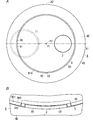
- FIG. 2A is a front view of the above-described acoustic device
- FIG. 2B is a front view of a main part of the above-described acoustic device.
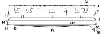
- FIG. 3 is a side view of the above acoustic device.
- FIG. 4 is a perspective view of a second output unit and a light guide member in the above-described acoustic device.
- FIG. 5 is a block configuration diagram of the above-described acoustic device.
- FIG. 6 is a diagram showing a state of the bedroom in which the above-described acoustic device is installed.
- FIG. 7 is a front view of a modification of the above-described acoustic device.
- the acoustic device 1 of the present embodiment is installed on a structure C1 (a construction material such as a ceiling or a wall).
- the acoustic device 1 includes a control unit 10, a first output unit 11, a second output unit 12, and a housing 4.
- the control unit 10 receives information on the specific event and determines whether the specific event has occurred.
- the acoustic device 1 is, for example, a fire alarm device that outputs a sound such as an alarm sound when a fire occurs.
- the specific event is not limited to a fire as long as it is an alarm sound issue target, and may be a gas leak, a tsunami, an earthquake, a suspicious person intrusion, or the like.
- the acoustic device 1 of the present embodiment further includes a photoelectric sensor (detector 2) that detects smoke inside, but the detector 2 is a constant temperature that detects heat. It may be a sensor of the type.
- the detection unit 2 may be a separate body from the acoustic device 1.
- the control unit 10 of the audio device 1 may receive information on fire through communication with another audio device (fire alarm device) provided with a detection unit.
- the acoustic device 1 is installed on one surface (ceiling surface or wall surface) of the structure C1 such as a room, bedroom, stairs, and corridor in a house.
- the house may be a detached house or an apartment house (apartment).
- the acoustic device 1 may be installed not only in a house but also in a non-residential structure C1 (ceiling surface or wall surface).
- Non-residential examples include office buildings, theaters, cinemas, public halls, amusement halls, complex facilities, restaurants, department stores, schools, hotels, inns, hospitals, nursing homes, kindergartens, libraries, museums, museums, underground malls, stations Including airports.
- the first output unit 11 outputs an alarm sound so as to notify the occurrence of a fire when the control unit 10 determines that a fire that is a specific event has occurred.
- the 2nd output part 12 outputs the light which illuminates surrounding field R1 (refer to Drawing 6) according to the information about a fire.
- the “surrounding region R1” referred to here is a region (for example, a floor surface) facing the ceiling surface when the acoustic device 1 is installed on the ceiling surface, but when the acoustic device 1 is installed on the wall surface, It is a region (for example, a wall surface) facing the wall surface.
- the housing 4 accommodates the control unit 10, the first output unit 11, and the second output unit 12.
- the housing 4 has a base 4A (see FIG. 3) fixed to the structure C1, and a front wall 4B located on the front side of the base 4A.
- the front wall portion 4B has a slit 9 that is recessed in the front surface 40 in a direction approaching the base portion 4A.
- the slit 9 guides an audible sound to the first region 91 of the inner surface 90 to the outside of the housing 4, and guides the illumination light to the second region 92 of the inner surface 90 to the outside of the housing 4.
- a window hole H2 a window hole
- the acoustic device 1 is a battery-type fire alarm as an example.
- the acoustic device 1 is a fire alarm device that is electrically connected to an external power source (for example, a commercial power system), and is driven by converting AC power (for example, an effective value of 100 V) supplied from the external power source into a DC current. There may be.
- the acoustic device 1 is installed on the ceiling surface of the bedroom (one surface of the structure C1) in the residence of the resident 100 as an example.
- the vertical and horizontal directions of the acoustic device 1 will be described with reference to the vertical and horizontal arrows shown in FIG. These arrows are described only for the purpose of assisting the explanation, and are not accompanied by an entity. Further, these directions are not intended to limit the use direction of the acoustic device 1.
- the acoustic device 1 includes a control unit 10, a first output unit (sound output unit) 11, a second output unit (light output unit) 12, a detection unit 2, and a housing 4.
- the battery 13, the operation unit 3, and the operation lamp 15 are further provided.
- the acoustic device 1 is a single-type fire alarm and does not have a communication function for communicating with other fire alarms.
- (2.2) Case The case 4 includes the control unit 10, the first output unit 11, the second output unit 12, the battery 13, the detection unit 2, and the circuit components constituting the control unit 10 and various circuits.
- a circuit board B1 (see FIG. 4) to be mounted is accommodated therein.
- the various circuits referred to here are, for example, an acoustic circuit, a first lighting circuit, a second lighting circuit, and a power circuit, which will be described later.
- the housing 4 is made of a synthetic resin, for example, a flame retardant ABS resin.
- the housing 4 is formed in a flat cylindrical shape as a whole. As shown in FIG. 3, the housing 4 includes a case 4 ⁇ / b> H whose upper end is opened and a base 4 ⁇ / b> A.
- the base 4A is assembled so as to close the open upper end of the case 4H.
- the case 4H includes a front wall portion 4B (a lower wall portion in FIG. 1) and a side wall portion 4C.
- the base 4A has a disk shape.
- the base 4A has a fixing portion, and is fixed to one surface (installation surface) of the structure C1 by the fixing portion.
- the base portion 4A has, for example, a plurality of through holes (fixing portions) that can be inserted through the thickness direction and into which mounting screws can be inserted, and the base portion 4A is fixed to the ceiling surface with the mounting screws. It is possible.
- the base 4A and the case 4H are assembled by fitting the base 4A into the upper end of the case 4H while the base 4A is fixed to the ceiling surface.
- the front wall portion 4B has a disc shape and is located on the front side (lower side in FIG. 1) of the base portion 4A. As shown in FIGS. 1 and 2A, the front wall portion 4B has a slit 9 that is recessed in a direction (upward direction) approaching the base portion 4A on the front surface 40 (lower surface in FIG. 1). As shown in FIG. 2A, the slit 9 has a shape along the outer periphery of the housing 4 when viewed from the front of the front wall portion 4B.
- the slit 9 when viewed from the front of the front wall portion 4B, the slit 9 has an annular shape (closed shape) in which one end and the other end of the slit 9 in the circumferential direction of the outer periphery of the housing 4 are connected to each other. ing.
- a region R10 (see FIG. 2A) surrounded by the slit 9 exists on the front surface 40 of the front wall portion 4B.
- the center P1 of the region R10 coincides with the center of the outer periphery of the housing 4 when viewed from the front of the front wall portion 4B.
- the term “match” here does not have to be exact match, but also includes what can be said to be coincidence by human visual recognition.
- the slit 9 is formed in an annular shape having a predetermined groove width when viewed from the front of the front wall portion 4B (downward in FIG. 1). That is, the outer appearance of the slit 9 is also annular in accordance with the circular outer periphery of the housing 4 when viewed from the front.
- the slit 9 has an acoustic hole H1 and a window hole H2 in the first region 91 and the second region 92 of the inner surface 90, respectively.
- the acoustic hole H ⁇ b> 1 is a hole for leading the alarm sound of the first output unit 11 to the outside of the housing 4, and faces the first output unit 11 in the housing 4.
- the window hole H ⁇ b> 2 is a hole for leading the illumination light of the second output unit 12 to the outside of the housing 4, and faces the second output unit 12 in the housing 4.
- the acoustic hole H1 and the window hole H2 in the slit 9 will be described in detail in the later section “(2.8) Acoustic hole and window hole”.
- the side wall part 4C protrudes from the peripheral edge E1 of the front wall part 4B toward the base part 4A.
- the surface of the side wall portion 4C is not straight along the vertical direction, but is slightly inclined so that the diameter of the case 4H becomes smaller as it approaches the base portion 4A (upward) (see FIG. 3).
- the diameter on the lower end side of the case 4H is slightly larger than the diameter on the upper end side of the case 4H.
- the side wall 4C has an opening 41 through which fire smoke flows into the labyrinth (the detection space of the detection unit 2) provided in the housing 4.
- the opening 41 is composed of a plurality of through holes arranged along the circumferential direction of the housing 4.
- casing 4 has a partition wall which partitions the internal space into two upper and lower sides.
- the labyrinth and detection unit 2 is in the upper first space, and the control unit 10, the first output unit 11, the second output unit 12, the circuit board B1, and the like are in the lower second space.
- the casing 4 supports the operation section 3 so that the lower surface of the operation section 3 is exposed to the outside of the casing 4 at the front wall section 4B.
- the operation unit 3 receives an operation input from the outside.
- the operation unit 3 can be pushed upward by a pressing operation with a user's finger or the like.
- the operation unit 3 is a disk-shaped member having translucency.
- the operation unit 3 is disposed to face the operating lamp 15 accommodated in the housing 4.
- the operation unit 3 is configured to push a push button switch (not shown) housed in the housing 4 by a push operation.
- the operation unit 3 is disposed in a region R10 surrounded by the slit 9 on the front surface 40 of the front wall 4B when viewed from the front of the front wall 4B.
- the operation unit 3 is arranged on the right side of the center P1 of the region R10.
- the first output unit 11 outputs sound (sound wave). When the control unit 10 determines that a fire has occurred, the first output unit 11 outputs an alarm sound so as to notify the occurrence of the fire.
- the 1st output part 11 is constituted by a speaker which converts an electric signal into sound.
- the speaker has a diaphragm and emits an alarm sound by mechanically vibrating the diaphragm in accordance with an electrical signal.
- the speaker is formed in a circular shape when viewed from the front and has a disk shape.
- the first output unit 11 outputs an alarm sound (for example, “beep” sound) under the control of the control unit 10. It is preferable that the 1st output part 11 outputs a warning sound by changing the magnitude
- the alarm sound may include, for example, a sweep sound that is swept from a low tone to a high tone.
- the alarm sound may include a voice message such as “fire. Fire”.
- the alarm sound is composed of a sweep sound and a voice message continuous with the sweep sound.
- circuit components constituting an acoustic circuit are mounted on the circuit board B1.
- the acoustic circuit includes a low-pass filter and an amplifier.
- PWM Pulse Width Modulation
- the acoustic circuit receives a PWM (Pulse Width Modulation) signal corresponding to the alarm sound generated by the control unit 10 in the event of a fire, it converts it into a sinusoidal sound signal with a low-pass filter and amplifies it with an amplifier. To be output from the first output unit 11.
- PWM Pulse Width Modulation
- the first output unit 11 outputs an alarm sound as a test even during operation check.
- the first output unit 11 outputs a voice message such as “normal” or “abnormal” according to the state of the audio device 1.
- the operation check can be executed by operating the operation unit 3 or pulling a drawstring (not shown) led out from the housing 4.
- the first output unit 11 may output a voice message notifying that effect.
- the battery 13 is a lithium battery, for example.
- the second output unit 12 outputs illumination light.
- the second output unit 12 outputs illumination light that illuminates the surrounding region R ⁇ b> 1 in accordance with information related to fire under the control of the control unit 10.
- the second output unit 12 has one or more illumination white LEDs (Light Emitting Diodes) 12A mounted on the circuit board B1 as a light source (see FIG. 4: here two LEDs 12A).
- the second output unit 12 is turned off during normal times (when monitoring a fire), and starts turning on (outputs illumination light) when the control unit 10 determines that a fire has occurred.
- Each LED 12A is configured as a package type LED in which at least one LED chip is mounted at the center of the mounting surface of the flat mounting substrate.
- the LED chip is preferably a blue light emitting diode that emits blue light from the light emitting surface, for example.
- the mounting surface of the substrate including the LED chip is covered with a sealing resin mixed with a fluorescent material that converts the wavelength of blue light emitted from the LED chip.
- the LED 12A is configured to emit white illumination light from the light emitting surface when a DC voltage is applied between the anode electrode and the cathode electrode.
- the color of the illumination light is not limited to white, and other light colors may be used. However, it is desirable not to cover the light color of the operating lamp 15.
- Circuit parts constituting the first lighting circuit for lighting the LED 12A of the second output unit 12 are mounted on the circuit board B1.
- the first lighting circuit lights the LED 12 ⁇ / b> A using DC power discharged from the battery 13 under the control of the control unit 10.
- the first lighting circuit converts the AC power supplied from the power system into a DC current to light the LED 12A.
- the light (illumination light) emitted from the second output unit 12 is led out of the housing 4 through the light guide member 8 (see FIG. 4).
- the light guide member 8 is formed of, for example, a transparent acrylic resin.
- the light guide member 8 has a bridge shape and is mounted on the circuit board B1.
- the exposed portion 80 at the lower end of the light guide member 8 faces the two LEDs 12A.
- the exposed portion 80 is inserted into the window hole H2 from the circuit board B1 side and exposed from the window hole H2 (see FIG. 2B).
- the light emitted from the LED 12A is led out of the window hole H2 through the exposed portion 80 of the light guide member 8, and the surrounding area R1 (here, the floor surface of the bedroom, the bed, etc.) is illuminated.
- the second output unit 12 is lit on a trial basis during operation check. Similar to the first output unit 11, the operation check of the second output unit 12 can be performed by pressing the operation unit 3 or pulling the pull string.
- the operation lamp 15 has red LED15A (refer FIG. 5) mounted in circuit board B1 as a light source.
- the operation lamp 15 is turned off during normal times (when monitoring a fire), and starts blinking (or turned on) when the control unit 10 determines that a fire has occurred.
- the operation lamp 15 stops blinking under the control of the control unit 10 when the alarm sound is stopped.
- Circuit parts constituting a second lighting circuit for blinking the LED 15A of the operation lamp 15 are mounted on the circuit board B1.
- the second lighting circuit blinks the LED 15 ⁇ / b> A using DC power discharged from the battery 13 under the control of the control unit 10.
- the second lighting circuit converts AC power supplied from the power system into DC current, and causes the LED 15A to blink.
- the light emitted from the operation lamp 15 is led out of the housing 4 through the operation unit 3 having translucency.
- the resident 100 can know that the acoustic device 1 is operating (detecting a fire) by visually recognizing the operation unit 3 blinking in red.
- the operating lamp 15 blinks even during operation check.
- the operation check of the operation lamp 15 can be executed by pushing the operation unit 3 or pulling the pull string.
- the operation lamp 15 also blinks when the replacement time of the battery 13 is approaching or a failure occurs.
- the first output unit 11 outputs a voice message notifying that the replacement time is approaching or that a failure has occurred.
- the detection part 2 is a photoelectric sensor (smoke detection part) which detects smoke as an example.
- the detection unit 2 includes a light emitting unit 21 such as an LED and a light receiving unit 22 such as a photodiode.
- the light emitting unit 21 and the light receiving unit 22 are arranged in the labyrinth of the housing 4 so that the light receiving surface of the light receiving unit 22 deviates from the optical axis of the irradiation light of the light emitting unit 21.
- smoke can be introduced into the labyrinth through the opening 41 in the side wall 4C of the housing 4.
- the detection unit 2 receives the irradiation light of the light emitting unit 21 scattered by the smoke by the light receiving unit 22.
- the detection unit 2 is electrically connected to the control unit 10.
- the detection unit 2 transmits an electric signal (detection signal) indicating a voltage level corresponding to the amount of light received by the light receiving unit 22 to the control unit 10.
- the control unit 10 converts the light amount of the detection signal received from the detection unit 2 into a smoke concentration (event level) and determines fire.
- the detection unit 2 may transmit a detection signal indicating a voltage level corresponding to the smoke density to the control unit 10 after converting the amount of light received by the light receiving unit 22 into a smoke density.
- the detection unit 2 may determine the occurrence of fire (smoke) from the amount of light received by the light receiving unit 22 and transmit a detection signal including information that a fire has occurred to the control unit 10.
- the control unit 10 is composed of, for example, a microcomputer having a CPU (Central Processing Unit) and a memory as main components.
- the control unit 10 is realized by a computer having a CPU and a memory, and the computer functions as the control unit 10 when the CPU executes a program stored in the memory.
- the program is recorded in advance in the memory here, but may be provided by being recorded through a telecommunication line such as the Internet or in a non-temporary recording medium such as a memory card.
- the control unit 10 controls the first output unit 11, the acoustic circuit, the second output unit 12, the operation lamp 15, the first lighting circuit, the second lighting circuit, the detection unit 2, and the like.
- the control unit 10 also controls a power supply circuit that generates operating power for various circuits from the DC power of the battery 13.
- the control unit 10 is configured to receive information on a fire that is a specific event and determine whether or not a fire has occurred. Specifically, the control unit 10 monitors a detection signal (information) received from the detection unit 2 and determines whether or not the event level included in the detection signal exceeds a threshold value. As described above, the event level is the smoke density after conversion as an example. However, the event level may be a light amount.
- the control unit 10 stores a threshold value in its own memory.
- the control unit 10 may determine, for example, whether or not the smoke density periodically exceeds a threshold at a predetermined time interval, and may determine that a fire has occurred once the smoke density exceeds the threshold.
- the predetermined time interval is, for example, a 5-second interval.
- the control unit 10 may count the number of times that the smoke concentration has continuously exceeded the threshold, and may determine that a fire has occurred when the number of times reaches a specified number.
- the control part 10 receives the detection signal containing the information that the fire broke out from the detection part 2, you may determine that the fire broke out directly.
- the control unit 10 determines that a fire has occurred based on the smoke concentration, the control unit 10 starts to output an alarm sound from the first output unit 11. Specifically, the control unit 10 generates a PWM signal corresponding to a sweep sound whose frequency changes linearly with the passage of time, and outputs the PWM signal to the acoustic circuit.
- the PWM signal is converted into an audio signal by an acoustic circuit, and a sweep sound (alarm sound) is output from the first output unit 11.
- the control part 10 produces
- the PWM signal is converted into an audio signal by an acoustic circuit, and an audio message (alarm sound) is output from the first output unit 11.
- the control unit 10 determines that a fire has occurred, the control signal for lighting the second output unit 12 is sent to the first lighting circuit, and the control signal for blinking the operating lamp 15 is sent to the second lighting circuit. Send each one.
- the first lighting circuit lights the second output unit 12 with a certain brightness.
- the second lighting circuit causes the operation lamp 15 to start operation blinking.
- the control unit 10 determines the smoke concentration even during an alarm (while an alarm sound is being issued). If the smoke concentration falls below the reference value during the alarm, the control unit 10 stops generating the PWM signal, stops the output of the alarm sound by the first output unit 11, and sends the stop signal to the first lighting circuit and The light is transmitted to the second lighting circuit, and the light output from the second output unit 12 and the operation lamp 15 is also stopped. That is, when the control unit 10 determines that the fire (smoke) has disappeared, the control unit 10 automatically stops the output of the alarm sound, the output of the illumination light, and the blinking of the operation lamp 15.
- control unit 10 stops the output of the alarm sound when the push button switch in the housing 4 is turned on by pressing the operation unit 3 during the alarm. If the resident 100 determines that the alarm of the audio device 1 is a false alarm, the alarm sound can be stopped by pressing the operation unit 3. The alarm sound can be stopped by pulling the drawstring.
- the control unit 10 executes a predetermined operation test for operation check.
- the operation test includes a sound output test of the first output unit 11, a light output test of the second output unit 12, a blinking test of the operation lamp 15, and the like.
- the operation test can also be performed by pulling the drawstring.
- the resident 100 sleeping in the bedroom of the house wakes up from the bed in a state close to darkness after hearing an alarm sound and goes from the bed to the hallway. It may be difficult to instantaneously grasp the route and direction to the connected door.
- the resident 100 may go to the wall switch by searching in the dark and try to turn on the light in the bedroom. The action until the wall switch is turned on can lead to a delay in evacuation.
- the resident 100 is a hearing impaired person, for example, there is a possibility that the occurrence of a fire may not be noticed only by an alarm sound (sound).
- the acoustic device 1 since the acoustic device 1 outputs not only the alarm sound but also the illumination light of the second output unit 12, the resident 100 instantaneously takes a route (evacuation route) from the bed to the door connected to the hallway. And the possibility of saving time to turn on the lighting in the bedroom increases. Moreover, even if the resident 100 is a hearing impaired person, the possibility that a fire will be noticed by the illumination light of the second output unit 12 is increased. In short, since the acoustic device 1 outputs not only the alarm sound but also the illumination light, the evacuation time can be shortened.
- the acoustic hole H1 and the window hole H2 are respectively disposed in the first region 91 and the second region 92 of the inner surface 90 of the annular slit 9 having a predetermined groove width.
- the slit 9 of the present embodiment has a rectangular cross section cut along the radial direction of the front wall portion 4 ⁇ / b> B, and the first region 91 and the second region 92 have a bottom surface 900 ( FIG. 2B) is a partial region. Accordingly, when viewed from the front of the front wall portion 4B, the acoustic hole H1 and the window hole H2 can be seen.
- first region 91 and the second region 92 may be a partial region of the first inner side surface 901 (see FIG. 2B) on the center P1 side of the region R10 in the inner surface 90, or the peripheral edge It may be a partial region of the second inner side surface 902 (see FIG. 2B) on the E1 side.
- at least one of the first region 91 and the second region 92 is a region extending over both the bottom surface 900 and the first inner side surface 901 (or the second inner side surface 902), or the bottom surface 900 and the first inner side surface 901. It may be a region extending over the entire area with the second inner surface 902.
- the cross section of the slit 9 is not limited to being recessed in a rectangular shape, and may be recessed, for example, in a V shape.
- Each of the acoustic hole H1 and the window hole H2 is provided on the bottom surface 900 of the slit 9 as described above, and the width dimension of these holes is the same as the width dimension of the slit 9.
- each of the acoustic hole H1 and the window hole H2 is also curved in an arc shape with the center P1 of the region R10 as the center of the circle in accordance with the shape of the bottom surface 900 of the slit 9.
- the acoustic hole H1 and the window hole H2 have opening areas having the same shape and size.
- the length in the circumferential direction of each of the acoustic hole H1 and the window hole H2 is substantially equal to the diameter of the operation portion 3 when viewed from the front of the front wall portion 4B.
- the length in the circumferential direction of each of the acoustic hole H1 and the window hole H2 may be, for example, about one third of the length in the circumferential direction of the slit 9, or one quarter.
- the acoustic hole H1 is provided so that the acoustic hole H1, the center P1, and the operation part 3 are arranged in a line when viewed from the front of the front wall portion 4B (see FIG. 2A).
- Virtual line A1 the window hole H2 is provided on a virtual line A2 that is perpendicular to the virtual line A1 and passes through the center P1 when viewed from the front of the front wall portion 4B.
- the window hole H2 is located behind the center P1, but may be located closer to the front than the center P1.
- the relative positional relationship among the acoustic hole H1, the window hole H2, the center P1, and the operation unit 3 in the illustrated example is also an example.
- the position of the acoustic hole H1 and the position of the window hole H2 may be interchanged.
- the window hole H2 may also be provided on the right side of the operation unit 3 on the virtual line A1.
- the acoustic hole H1 and the window hole H2 are provided in the inner surface 90 of the slit 9, so that these holes are not easily noticeable. It has a structure. That is, when the acoustic device 1 is installed on the structure C1 such as the ceiling of a house, for example, it is possible to make it difficult to give an impression that the acoustic hole H1 and the window hole H2 are emphasized to the structure C1. Therefore, the evacuation time can be shortened while suppressing the appearance of the acoustic device 1 from being deteriorated.
- the window hole H2 from which the illumination light is radiated is in the slit 9, the glare given to the resident 100 can be suppressed.
- the acoustic device 1 may be installed on a wall surface other than the ceiling surface, for example. In this case, since the acoustic hole H1 and the window hole H2 are provided in the inner surface 90 of the slit 9, it is possible to suppress the possibility that foreign matters such as dust enter the housing 4 from these holes.
- the slit 9 has a shape along the outer periphery of the housing 4, the slit 9 having a sense of unity with the housing 4 can be provided, and the acoustic hole H ⁇ b> 1 and the window hole H ⁇ b> 2 have a less noticeable structure. . Further, the center P1 of the region R10 surrounded by the slit 9 coincides with the center of the outer periphery of the housing 4 when viewed from the front of the front wall portion 4B. 9 can be provided.
- the operation unit 3 is disposed in the region R10 surrounded by the slit 9 when viewed from the front of the front wall 4B, the slit 9 having a sense of unity with the housing 4 and the operation unit 3 is provided.
- the acoustic hole H1 and the window hole H2 are more inconspicuous.
- the slit 9 is annular, the slit 9 having a sense of unity with the housing 4 can be provided.
- the outer periphery of the housing 4 has a circular shape and the slit 9 has an annular shape that is concentric with the outer periphery of the housing 4, it is possible to provide the slit 9 with a more integrated feeling.
- the slit 9 is not provided in the front wall portion 4B, the positional relationship and the dimensional relationship in which the acoustic hole and the hole for the optical window are as inconspicuous as possible with respect to the front surface 40 of the front wall portion 4B are considered. This may limit the degree of design freedom. However, since the slit 9 is provided as in the present embodiment, if the inner surface 90 of the slit 9 is provided, the positional limitation on the first region 91 and the second region 92 and the limitation on the length in the circumferential direction are performed. The degree of freedom in designing the acoustic hole H1 and the window hole H2 can be increased.
- the exposed portion 80 of the light guide member 8 is inserted into the window hole H2 from the circuit board B1 side as described above. Further, as shown in FIG. 2B, the exposed portion 80 is curved in an arc shape with substantially the same shape as the opening region of the window hole H2 when viewed from the front of the front wall portion 4B, and the opening of the window hole H2 It has dimensions slightly smaller than the area.
- the surface (lower surface) of the exposed portion 80 is substantially flush with the bottom surface 900 of the slit 9. Therefore, the light emitted from the second output portion 12 can be efficiently derived through the exposed portion 80 of the light guide member 8 inserted into the window hole H2.
- the front surface 40 of the front wall portion 4B of the present embodiment is inclined so as to approach the base portion 4A as it goes from the center P2 toward the peripheral edge E1. Specifically, the front surface 40 has a gently curved shape with the center P2 as a vertex when the housing 4 is viewed from the side.
- the “center P2” of the front surface 40 referred to here coincides with the center P1 of the region R10 surrounded by the slit 9.
- the front wall portion 4B has such a front surface 40, when the entire casing 4 is viewed, the vertical dimension of the casing 4 in the vicinity of the peripheral edge E1 appears thin, and the overall thickness is thin.
- the housing 4 can be provided. By having such a thin housing 4, the acoustic device 1 becomes less conspicuous with respect to the structure C ⁇ b> 1.
- the opening 41 of the side wall 4C of the present embodiment has a tapered surface T1 that guides the inflow of fire smoke at the opening edge.
- the opening edge includes a first edge 411 on the base portion 4A side and a second edge 412 on the front wall portion 4B side.
- the tapered surface T ⁇ b> 1 is at least at the second edge 412 of the first edge 411 and the second edge 412.
- the tapered surface T ⁇ b> 1 is on both the first edge 411 and the second edge 412.
- the lower tapered surface T1 is an inclined surface that is inclined so as to approach the detection space (labyrinth) in the housing 4 as it approaches the base 4A.
- the upper tapered surface T1 is an inclined surface that is inclined so as to approach the detection space (labyrinth) of the housing 4 as the distance from the base 4A increases. Note that the lower tapered surface T1 has a larger area and a longer vertical length than the upper tapered surface T1.
- the side wall portion 4C has such a tapered surface T1
- fire smoke is more likely to flow into the detection space in the housing 4, and the fire detection performance can be improved.
- the tapered surface T1 on both the first edge 411 and the second edge 412 makes the side wall portion 4C look narrow, and the appearance of the acoustic device 1 is also improved.
- the portion D1 from the lower end of the lower tapered surface T1 to the peripheral edge E1 in the side wall portion 4C becomes thinner due to the presence of the tapered surface T1. Therefore, while improving the detection performance of fire smoke, a thin appearance is obtained from the peripheral edge E1 of the front wall portion 4B to the second edge 412, and the appearance is improved.
- the slit 9 of the basic example has an annular shape when viewed from the front of the front wall portion 4B.
- the slit 9 may be a polygonal annular shape in addition to the annular shape.
- the appearance of the slit 9 is also a regular hexagonal or regular octagonal shape in accordance with the outer peripheral shape. May be.
- the slit 9 of the basic example has a shape that matches the outer peripheral shape of the housing 4. However, it is not essential to match the shape of the slit 9 to the outer peripheral shape of the housing 4.
- the slit 9 may be a regular octagonal ring with respect to the casing 4 having a circular outer peripheral shape.
- the number of each of the acoustic holes H1 and the window holes H2 is one, but may be two or more.
- the two acoustic holes H ⁇ b> 1 may be arranged along the circumferential direction of the slit 9.
- two window holes H2 may be provided on both left and right ends of the slit 9 so as to sandwich the center P1 therebetween.
- the number of acoustic holes H1 and the number of window holes H2 may be different from each other.
- the slit 9 in the basic example is one closed ring.
- the slit 9 may not be a closed ring.
- the slit 9 may have a partially opened shape, or may have a C shape, for example, when viewed from the front of the front wall portion 4B.
- the slit 9 may be composed of a plurality of small slits 9X (two in the example of FIG. 7).
- the two small slits 9X are arranged along the outer periphery of the housing 4 when viewed from the front of the front wall portion 4B.
- the acoustic hole H1 and the window hole H2 are inconspicuous.
- both the acoustic hole H1 and the window hole H2 are provided in one C-shaped small slit 9X, but one of these holes may be provided in the other small slit 9X. .
- one or a plurality of dummy slits may be provided separately from the slit 9.
- the dummy slit may have an annular shape concentric with the slit 9 and may have a smaller diameter (or larger diameter) than the slit 9.
- the dummy slit is disposed inside the slit 9.
- the acoustic device 1 of the basic example was a single type fire alarm. That is, the acoustic device 1 of the basic example does not have a communication function for communicating with other fire alarms. However, the acoustic device 1 may be an interlocking fire alarm having a communication function for communicating with other fire alarms. Communication may be performed wirelessly or may be performed by wire.
- the audio device 1 may be configured to be able to communicate with devices other than the fire alarm.
- Devices other than the fire alarm are, for example, a portable terminal (for example, a smartphone) carried by the resident 100, a security monitoring device installed in a house, and the like.
- the acoustic device (1, 1A) is installed in the structure (C1).
- the acoustic device (1, 1A) includes a control unit (10), a first output unit (11), a second output unit (12), and a housing (4).
- the control unit (10) receives information on the specific event and determines whether the specific event has occurred.
- the first output unit (11) outputs a sound so as to notify the occurrence of the specific event when the control unit (10) determines that the specific event has occurred.
- a 2nd output part (12) outputs the illumination light which illuminates the surrounding area
- casing (4) accommodates a control part (10), a 1st output part (11), and a 2nd output part (12).
- the housing (4) has a base (4A) fixed to the structure (C1) and a front wall (4B) located on the front side of the base (4A).
- the front wall (4B) has a slit (9) that is recessed in a direction approaching the base (4A) on the front surface (40).
- the slit (9) has an acoustic hole (H1) for guiding the sound to the outside of the housing (4) in the first region (91) of the inner surface (90), and a second region (92) of the inner surface (90).
- the acoustic hole (H1) and the window hole (H2) are provided on the inner surface (90) of the slit (9). Therefore, these holes are inconspicuous. Therefore, it is possible to shorten the evacuation time while suppressing the appearance from being deteriorated.
- the slit (9) extends along the outer periphery of the housing (4) when viewed from the front of the front wall (4B). It is preferable that the shape is different.
- casing (4) can be provided, and an acoustic hole (H1) and a window hole (H2) become a structure which is not conspicuous.
- the slit (9) in the circumferential direction of the outer periphery is It is preferable that one end and the other end have an annular shape connected to each other. According to the third aspect, it is possible to provide the slit (9) having a sense of unity with the housing (4). Moreover, the design freedom of the acoustic hole (H1) and the window hole (H2) in the slit (9) can be increased.
- the slit (9) is preferably composed of a plurality of small slits (9X).
- the plurality of small slits (9X) are preferably arranged along the outer periphery when viewed from the front of the front wall portion (4B).
- the acoustic hole (H1) and the window hole (H2) are less noticeable.
- the center (P1) of the region (R10) surrounded by the slit (9) is the front wall.
- the slit (9) having a sense of unity with the housing (4).
- the acoustic device (1, 1A) in any one of the second to fifth aspects, it is preferable that the acoustic device (1, 1A) further includes an operation unit (3) that receives an operation input from the outside.
- the operation portion (3) When viewed from the front of the front wall portion (4B), the operation portion (3) is disposed in a region (R10) surrounded by the slit (9) on the front surface (40) of the front wall portion (4B). It is preferable.
- the slit (9) having a sense of unity with the housing (4) and the operation unit (3) can be provided, and the acoustic hole (H1) and the window hole (H2) are less noticeable. Become.
- the front surface (40) of the front wall portion (4B) has a peripheral edge ( It is preferable to incline so that it may approach a base part (4A), so that it goes to E1).
- casing (4) can be provided as a whole, and an acoustic apparatus (1, 1A) becomes difficult to stand out with respect to a structure (C1).
- the specific event is preferably a fire. It is preferable that the acoustic device (1, 1A) further includes a detection unit (2) that is housed in the housing (4) and detects a fire.
- the control unit (10) preferably receives the detection result from the detection unit (2) as the information and determines whether or not a fire has occurred.
- the acoustic apparatus (1, 1A) with a detection part (2) which can aim at shortening of an evacuation time can be provided, suppressing that the external appearance looks impaired.
- the detection unit (2) is preferably a smoke detection unit.
- the housing (4) preferably further includes a side wall portion (4C) protruding from the peripheral edge (E1) of the front wall portion (4B) toward the base portion (4A).
- the side wall (4C) preferably has an opening (41) that allows fire smoke to flow into the detection space of the smoke detector (detector 2) in the housing (4).
- the opening (41) preferably has a tapered surface (T1) for guiding the inflow of fire smoke at the opening edge. According to the ninth aspect, the fire smoke detection performance can be improved by the tapered surface (T1).
- the opening edge includes a first edge (411) on the base part (4A) side and a front wall part (4B) side.
- the tapered surface (T1) is preferably at least on the second edge (412) of the first edge (411) and the second edge (412).
- the tapered surface (T1) improves the fire smoke detection performance, and has a thin appearance from the peripheral edge (E1) of the front wall portion (4B) to the second edge (412). The appearance can also be improved.
- the configurations according to the second to tenth aspects are not essential to the acoustic device (1, 1A) and can be omitted as appropriate.
Landscapes
- Physics & Mathematics (AREA)
- General Physics & Mathematics (AREA)
- Chemical & Material Sciences (AREA)
- Analytical Chemistry (AREA)
- Business, Economics & Management (AREA)
- Emergency Management (AREA)
- Engineering & Computer Science (AREA)
- Acoustics & Sound (AREA)
- Signal Processing (AREA)
- Fire Alarms (AREA)
- Fire-Detection Mechanisms (AREA)
- Alarm Systems (AREA)
Abstract
An objective of the present disclosure is, while avoiding impairment of outward appearances, to effect a reduction in evacuation times. Provided is an audio device comprising a control part, a first output part (11), a second output part, and a casing (4). The control part receives information relating to a specified event and determines whether the specified event has occurred. The first output part (11) outputs a sound as a notification of the occurrence of the specified event. The second output part outputs illumination light. The casing (4) comprises a base part which is anchored to a structure body (C1), and a front wall part (4B) which is positioned forward of the base part. The front wall part (4B) comprises a slit (9) in a front surface (40) thereof, said slit (9) being hollowed in a direction approaching the base part. The slit (9) comprises: an audio hole (H1) in a first region (91) in an inner surface (90) thereof, said audio hole (H1) being for guiding the sound externally to the casing (4); and a viewport (H2) in a second region (92) of the inner surface (90), said viewport (H2) being for guiding the illumination light externally to the casing (4).
Description
本開示は、一般に、音響装置に関し、より詳細には、火災等の外的事象が発生したことを報知する音響装置に関する。
The present disclosure relates generally to an audio device, and more particularly to an audio device that notifies that an external event such as a fire has occurred.
従来例として、特許文献1に記載の住警器を例示する。この住警器は、そのカバーの中央に、煙流入口を開口した検煙部を配置し、火災による煙が所定濃度に達したときに火災を検出する。また住警器は、カバーにおける検煙部の左下側に音響孔を有し、その背後にスピーカを内蔵し、警報音及び音声メッセージを出力する。住警器は、住宅の居間及び寝室等の例えば壁面に設置され、万一、火災が発生した場合には、火災を検出して警報を開始する。
As a conventional example, a residential alarm device described in Patent Document 1 is illustrated. In this residential alarm, a smoke detector having a smoke inlet is opened at the center of the cover, and a fire is detected when smoke from the fire reaches a predetermined concentration. In addition, the house alarm has an acoustic hole on the lower left side of the smoke detection part in the cover, and a speaker is built in behind it to output an alarm sound and a voice message. The home alarm is installed on, for example, a wall surface of a living room or a bedroom of a house, and in the event of a fire, the fire is detected and an alarm is started.
ところで、住人の避難時間をより短縮できる住警器(音響装置)が望まれる。例えば警報音に加えて別の報知機能を付加し、特定事象の発生時に警報音の出力とその報知機能の実行の両方を行うことが考えられる。しかし、別の報知機能を新たに住警器に設けようとすると、住警器の外観上の見栄え(美観)を損ねる可能性がある。
By the way, a residence guard (acoustic device) that can shorten the evacuation time of residents is desired. For example, it is conceivable to add another notification function in addition to the alarm sound, and perform both the output of the alarm sound and the execution of the notification function when a specific event occurs. However, if another notification function is newly provided in the home alarm, the appearance (aesthetic appearance) of the home alarm may be impaired.
本開示は上記事由に鑑みてなされ、外観上の見栄えが損なわれることを抑制しつつ、避難時間の短縮を図ることができる音響装置を提供することを目的とする。
The present disclosure has been made in view of the above-described reasons, and an object thereof is to provide an audio device capable of shortening the evacuation time while suppressing the appearance from being impaired.
本開示の一態様に係る音響装置は、構造体に設置される。前記音響装置は、制御部と、第1出力部と、第2出力部と、筐体と、を備える。前記制御部は、特定事象に関する情報を受けて前記特定事象が発生したか否かを判定する。前記第1出力部は、前記制御部にて前記特定事象が発生したと判定したときに、前記特定事象の発生を報知するように音を出力する。前記第2出力部は、前記情報に応じて周囲の領域を照らす照明光を出力する。前記筐体は、前記制御部、前記第1出力部及び前記第2出力部を収容する。前記筐体は、前記構造体に固定される基部と、前記基部の前側に位置する前壁部と、有する。前記前壁部は、その前面において、前記基部に近づく方向に凹んだスリットを有する。前記スリットは、その内面の第1領域に、前記音を前記筐体の外部に導出する音響孔と、前記内面の第2領域に、前記照明光を前記筐体の外部に導出する窓孔と、を有する。
The acoustic device according to one embodiment of the present disclosure is installed in a structure. The acoustic device includes a control unit, a first output unit, a second output unit, and a housing. The control unit receives information on the specific event and determines whether the specific event has occurred. The first output unit outputs a sound so as to notify the occurrence of the specific event when the control unit determines that the specific event has occurred. The second output unit outputs illumination light that illuminates a surrounding area according to the information. The housing houses the control unit, the first output unit, and the second output unit. The housing includes a base portion fixed to the structure and a front wall portion located on the front side of the base portion. The front wall portion has a slit recessed in a direction approaching the base portion on the front surface thereof. The slit has an acoustic hole that guides the sound to the outside of the housing in a first region on the inner surface, and a window hole that guides the illumination light to the outside of the housing on a second region of the inner surface. Have.
(1)概要
以下の実施形態は、本開示の様々な実施形態の一つに過ぎない。以下の実施形態は、本開示の目的を達成できれば、設計等に応じて種々の変更が可能である。また、以下の実施形態において説明する各図は、模式的な図であり、各図中の各構成要素の大きさ及び厚さそれぞれの比が、必ずしも実際の寸法比を反映しているとは限らない。 (1) Outline The following embodiment is only one of various embodiments of the present disclosure. The following embodiments can be variously modified according to the design or the like as long as the object of the present disclosure can be achieved. Each figure described in the following embodiments is a schematic diagram, and the ratio of the size and thickness of each component in each figure does not necessarily reflect the actual dimensional ratio. Not exclusively.
以下の実施形態は、本開示の様々な実施形態の一つに過ぎない。以下の実施形態は、本開示の目的を達成できれば、設計等に応じて種々の変更が可能である。また、以下の実施形態において説明する各図は、模式的な図であり、各図中の各構成要素の大きさ及び厚さそれぞれの比が、必ずしも実際の寸法比を反映しているとは限らない。 (1) Outline The following embodiment is only one of various embodiments of the present disclosure. The following embodiments can be variously modified according to the design or the like as long as the object of the present disclosure can be achieved. Each figure described in the following embodiments is a schematic diagram, and the ratio of the size and thickness of each component in each figure does not necessarily reflect the actual dimensional ratio. Not exclusively.
本実施形態の音響装置1は、図6に示すように、構造体C1(天井又は壁等の造営材)に設置される。音響装置1は、図5に示すように、制御部10と、第1出力部11と、第2出力部12と、筐体4とを備える。制御部10は、特定事象に関する情報を受けて特定事象が発生したか否かを判定する。
As shown in FIG. 6, the acoustic device 1 of the present embodiment is installed on a structure C1 (a construction material such as a ceiling or a wall). As shown in FIG. 5, the acoustic device 1 includes a control unit 10, a first output unit 11, a second output unit 12, and a housing 4. The control unit 10 receives information on the specific event and determines whether the specific event has occurred.
ここでは「特定事象」とは、一例として火災であることを想定する。したがって、音響装置1は、一例として、火災の発生時に警報音等の音を出力する火災警報器である。しかし、特定事象は、警報音の発報対象であれば、火災に限定されず、ガス漏れ、津波、地震、不審者の侵入等であってもよい。
Suppose here that "specific event" is a fire as an example. Therefore, the acoustic device 1 is, for example, a fire alarm device that outputs a sound such as an alarm sound when a fire occurs. However, the specific event is not limited to a fire as long as it is an alarm sound issue target, and may be a gas leak, a tsunami, an earthquake, a suspicious person intrusion, or the like.
本実施形態の音響装置1は、図5に示すように、その内部に煙を検知する光電式のセンサ(検知部2)を、更に備えているが、検知部2は、熱を検知する定温式のセンサでもよい。また、検知部2は、音響装置1と別体であってもよい。音響装置1の制御部10は、検知部を備えた別の音響装置(火災警報器)との通信により、火災に関する情報を受けてもよい。
As shown in FIG. 5, the acoustic device 1 of the present embodiment further includes a photoelectric sensor (detector 2) that detects smoke inside, but the detector 2 is a constant temperature that detects heat. It may be a sensor of the type. The detection unit 2 may be a separate body from the acoustic device 1. The control unit 10 of the audio device 1 may receive information on fire through communication with another audio device (fire alarm device) provided with a detection unit.
音響装置1は、住宅内の居室、寝室、階段、廊下等の構造体C1の一面(天井面又は壁面)に設置される。住宅は、戸建住宅、又は集合住宅(マンション)でもよい。更に、音響装置1は、住宅だけでなく非住宅の構造体C1(天井面又は壁面等)に設置されてもよい。非住宅の例としては、オフィスビル、劇場、映画館、公会堂、遊技場、複合施設、飲食店、百貨店、学校、ホテル、旅館、病院、老人ホーム、幼稚園、図書館、博物館、美術館、地下街、駅、空港等を含む。
The acoustic device 1 is installed on one surface (ceiling surface or wall surface) of the structure C1 such as a room, bedroom, stairs, and corridor in a house. The house may be a detached house or an apartment house (apartment). Furthermore, the acoustic device 1 may be installed not only in a house but also in a non-residential structure C1 (ceiling surface or wall surface). Non-residential examples include office buildings, theaters, cinemas, public halls, amusement halls, complex facilities, restaurants, department stores, schools, hotels, inns, hospitals, nursing homes, kindergartens, libraries, museums, museums, underground malls, stations Including airports.
第1出力部11は、制御部10にて特定事象である火災が発生したと判定したときに、火災の発生を報知するように警報音を出力する。第2出力部12は、火災に関する情報に応じて、周囲の領域R1(図6参照)を照らす光を出力する。なお、第2出力部12の光を「照明光」と呼ぶこともあるが、第2出力部12の光は、一般的な照明器具が出力する照明光に比べて明るさの弱い、避難経路を照らす程度の光である。ここで言う「周囲の領域R1」は、音響装置1が天井面に設置される場合、天井面と対向する領域(例えば床面)であるが、音響装置1が壁面に設置される場合、当該壁面と対向する領域(例えば壁面)である。
The first output unit 11 outputs an alarm sound so as to notify the occurrence of a fire when the control unit 10 determines that a fire that is a specific event has occurred. The 2nd output part 12 outputs the light which illuminates surrounding field R1 (refer to Drawing 6) according to the information about a fire. In addition, although the light of the 2nd output part 12 may be called "illumination light", the light of the 2nd output part 12 is weakness compared with the illumination light which a general lighting fixture outputs, and the evacuation route Is enough to illuminate The “surrounding region R1” referred to here is a region (for example, a floor surface) facing the ceiling surface when the acoustic device 1 is installed on the ceiling surface, but when the acoustic device 1 is installed on the wall surface, It is a region (for example, a wall surface) facing the wall surface.
筐体4は、制御部10、第1出力部11及び第2出力部12を収容する。筐体4は、構造体C1に固定される基部4A(図3参照)と、基部4Aの前側に位置する前壁部4Bと、有している。前壁部4Bは、図1及び図2Aに示すように、その前面40において、基部4Aに近づく方向に凹んだスリット9を有している。スリット9は、その内面90の第1領域91に、警報音を筐体4の外部に導出する音響孔H1と、内面90の第2領域92に、照明光を筐体4の外部に導出する窓孔H2と、を有している。
The housing 4 accommodates the control unit 10, the first output unit 11, and the second output unit 12. The housing 4 has a base 4A (see FIG. 3) fixed to the structure C1, and a front wall 4B located on the front side of the base 4A. As shown in FIGS. 1 and 2A, the front wall portion 4B has a slit 9 that is recessed in the front surface 40 in a direction approaching the base portion 4A. The slit 9 guides an audible sound to the first region 91 of the inner surface 90 to the outside of the housing 4, and guides the illumination light to the second region 92 of the inner surface 90 to the outside of the housing 4. And a window hole H2.
この構成によれば、警報音の出力だけでなく照明光の出力も行う。そのため、避難時間の短縮を図ることができる。また、音響孔H1と窓孔H2とがスリット9の内面90に設けられているため、これらの孔が目立ち難い構造となっている。したがって、外観上の見栄えが損なわれることを抑制しつつ、避難時間の短縮を図ることができる。
こ の According to this configuration, not only alarm sound but also illumination light is output. Therefore, the evacuation time can be shortened. Moreover, since the acoustic hole H1 and the window hole H2 are provided in the inner surface 90 of the slit 9, these holes have a structure which is not conspicuous. Therefore, it is possible to shorten the evacuation time while suppressing the appearance from being deteriorated.
(2)詳細
(2.1)全体構成
以下、本実施形態の音響装置1の全体構成について詳しく説明する。ここでは、音響装置1は、一例として電池式の火災警報器である。ただし、音響装置1は、外部電源(例えば商用の電力系統)に電気的に接続され、外部電源から供給される交流電力(例えば実効値100V)を直流電流に変換して駆動する火災警報器であってもよい。 (2) Details (2.1) Overall Configuration Hereinafter, the overall configuration of theacoustic device 1 of the present embodiment will be described in detail. Here, the acoustic device 1 is a battery-type fire alarm as an example. However, the acoustic device 1 is a fire alarm device that is electrically connected to an external power source (for example, a commercial power system), and is driven by converting AC power (for example, an effective value of 100 V) supplied from the external power source into a DC current. There may be.
(2.1)全体構成
以下、本実施形態の音響装置1の全体構成について詳しく説明する。ここでは、音響装置1は、一例として電池式の火災警報器である。ただし、音響装置1は、外部電源(例えば商用の電力系統)に電気的に接続され、外部電源から供給される交流電力(例えば実効値100V)を直流電流に変換して駆動する火災警報器であってもよい。 (2) Details (2.1) Overall Configuration Hereinafter, the overall configuration of the
以下では、図6に示すように、音響装置1が、一例として、住人100の住宅における寝室の天井面(構造体C1の一面)に設置されることを想定する。これにより、音響装置1の上下、左右の方向を、図1に図示されている上下、左右の矢印を用いて規定して説明する。これらの矢印は、単に説明を補助する目的で記載しているに過ぎず、実体を伴わない。またこれらの方向は、音響装置1の使用方向を限定する趣旨ではない。
Hereinafter, as illustrated in FIG. 6, it is assumed that the acoustic device 1 is installed on the ceiling surface of the bedroom (one surface of the structure C1) in the residence of the resident 100 as an example. Thus, the vertical and horizontal directions of the acoustic device 1 will be described with reference to the vertical and horizontal arrows shown in FIG. These arrows are described only for the purpose of assisting the explanation, and are not accompanied by an entity. Further, these directions are not intended to limit the use direction of the acoustic device 1.
音響装置1は、図5に示すように、制御部10、第1出力部(音出力部)11、第2出力部(光出力部)12、検知部2、及び筐体4の他に、例えば、バッテリー13と、操作部3と、作動灯15と、を更に備えている。ここでは、音響装置1は、一例として、単独型の火災警報器であり、他の火災警報器と通信する通信機能を有していないものと想定する。
As shown in FIG. 5, the acoustic device 1 includes a control unit 10, a first output unit (sound output unit) 11, a second output unit (light output unit) 12, a detection unit 2, and a housing 4. For example, the battery 13, the operation unit 3, and the operation lamp 15 are further provided. Here, as an example, it is assumed that the acoustic device 1 is a single-type fire alarm and does not have a communication function for communicating with other fire alarms.
(2.2)筐体
筐体4は、制御部10、第1出力部11、第2出力部12、バッテリー13、検知部2、並びに、制御部10及び各種の回路を構成する回路部品が実装される回路基板B1(図4参照)等を内部に収容する。図示は省略するが、ここで言う各種の回路とは、例えば後述する音響回路、第1点灯回路、第2点灯回路、及び電源回路等である。 (2.2) Case Thecase 4 includes the control unit 10, the first output unit 11, the second output unit 12, the battery 13, the detection unit 2, and the circuit components constituting the control unit 10 and various circuits. A circuit board B1 (see FIG. 4) to be mounted is accommodated therein. Although illustration is omitted, the various circuits referred to here are, for example, an acoustic circuit, a first lighting circuit, a second lighting circuit, and a power circuit, which will be described later.
筐体4は、制御部10、第1出力部11、第2出力部12、バッテリー13、検知部2、並びに、制御部10及び各種の回路を構成する回路部品が実装される回路基板B1(図4参照)等を内部に収容する。図示は省略するが、ここで言う各種の回路とは、例えば後述する音響回路、第1点灯回路、第2点灯回路、及び電源回路等である。 (2.2) Case The
筐体4は、合成樹脂製であり、例えば難燃性ABS樹脂製である。筐体4は、全体としてへん平な円筒状に形成されている。筐体4は、図3に示すように、上端部が開放されたケース4Hと、基部4Aとから構成されている。基部4Aがケース4Hの開放された上端部を塞ぐように組み付けられる。ケース4Hは、前壁部4B(図1では下側の壁部)及び側壁部4Cからなる。
The housing 4 is made of a synthetic resin, for example, a flame retardant ABS resin. The housing 4 is formed in a flat cylindrical shape as a whole. As shown in FIG. 3, the housing 4 includes a case 4 </ b> H whose upper end is opened and a base 4 </ b> A. The base 4A is assembled so as to close the open upper end of the case 4H. The case 4H includes a front wall portion 4B (a lower wall portion in FIG. 1) and a side wall portion 4C.
基部4Aは、円板形状となっている。基部4Aは、固定部を有しており、当該固定部によって構造体C1の一面(設置面)に固定される。具体的には、基部4Aは、例えば、厚み方向に貫通して、取付ねじを挿入可能な複数の貫通孔(固定部)を有しており、取付ねじで天井面に基部4Aをねじ止め固定可能となっている。基部4Aが天井面に固定された状態で、基部4Aをケース4Hの上端部に嵌め込むことで、基部4Aとケース4Hとが組み付けられる。
The base 4A has a disk shape. The base 4A has a fixing portion, and is fixed to one surface (installation surface) of the structure C1 by the fixing portion. Specifically, the base portion 4A has, for example, a plurality of through holes (fixing portions) that can be inserted through the thickness direction and into which mounting screws can be inserted, and the base portion 4A is fixed to the ceiling surface with the mounting screws. It is possible. The base 4A and the case 4H are assembled by fitting the base 4A into the upper end of the case 4H while the base 4A is fixed to the ceiling surface.
前壁部4Bは、円板形状となっていて、基部4Aの前側(図1では下側)に位置する。前壁部4Bは、図1及び図2Aに示すように、その前面40(図1では下面)において、基部4Aに近づく方向(上方向)に凹んだスリット9を有している。スリット9は、図2Aに示すように、前壁部4Bの前方から見たときに、筐体4の外周に沿った形状となっている。スリット9は、一例として、前壁部4Bの前方から見たときに、筐体4の外周の周方向におけるスリット9の一端と他端とが互いに繋がった環状の形状(閉じた形状)となっている。前壁部4Bの前面40には、スリット9によって囲まれた領域R10(図2A参照)が存在する。領域R10の中心P1は、前壁部4Bの前方から見たときに、筐体4の外周の中心と一致している。なお、ここで言う「一致」とは、厳密な一致でなくてもよく、人の視認で一致と言えるものも含む。
The front wall portion 4B has a disc shape and is located on the front side (lower side in FIG. 1) of the base portion 4A. As shown in FIGS. 1 and 2A, the front wall portion 4B has a slit 9 that is recessed in a direction (upward direction) approaching the base portion 4A on the front surface 40 (lower surface in FIG. 1). As shown in FIG. 2A, the slit 9 has a shape along the outer periphery of the housing 4 when viewed from the front of the front wall portion 4B. For example, when viewed from the front of the front wall portion 4B, the slit 9 has an annular shape (closed shape) in which one end and the other end of the slit 9 in the circumferential direction of the outer periphery of the housing 4 are connected to each other. ing. A region R10 (see FIG. 2A) surrounded by the slit 9 exists on the front surface 40 of the front wall portion 4B. The center P1 of the region R10 coincides with the center of the outer periphery of the housing 4 when viewed from the front of the front wall portion 4B. Note that the term “match” here does not have to be exact match, but also includes what can be said to be coincidence by human visual recognition.
特に本実施形態では、スリット9は、前壁部4Bの前方(図1では下方)から見たときに、所定の溝幅を有した円環状に形成されている。すなわち、正面から見たときの筐体4の円形状の外周に合わせて、スリット9の外観も円環状となっている。
Particularly in this embodiment, the slit 9 is formed in an annular shape having a predetermined groove width when viewed from the front of the front wall portion 4B (downward in FIG. 1). That is, the outer appearance of the slit 9 is also annular in accordance with the circular outer periphery of the housing 4 when viewed from the front.
そして、スリット9は、その内面90の第1領域91と、第2領域92とに、それぞれ、音響孔H1と、窓孔H2とを有している。音響孔H1は、第1出力部11の警報音を筐体4の外部に導出するための孔であり、筐体4内の第1出力部11と対向している。また、窓孔H2は、第2出力部12の照明光を筐体4の外部に導出するための孔であり、筐体4内の第2出力部12と対向している。なお、スリット9内の音響孔H1及び窓孔H2については、後の「(2.8)音響孔及び窓孔」の欄で詳しく説明する。
The slit 9 has an acoustic hole H1 and a window hole H2 in the first region 91 and the second region 92 of the inner surface 90, respectively. The acoustic hole H <b> 1 is a hole for leading the alarm sound of the first output unit 11 to the outside of the housing 4, and faces the first output unit 11 in the housing 4. Further, the window hole H <b> 2 is a hole for leading the illumination light of the second output unit 12 to the outside of the housing 4, and faces the second output unit 12 in the housing 4. The acoustic hole H1 and the window hole H2 in the slit 9 will be described in detail in the later section “(2.8) Acoustic hole and window hole”.
側壁部4Cは、図3に示すように、前壁部4Bの周縁E1から基部4Aに向かって突出する。なお、側壁部4Cの表面は、上下方向に沿って真っ直ぐではなく、基部4Aに近づくほど(上方に行くほど)、ケース4Hの径が小さくなるようにやや傾斜している(図3参照)。要するに、ケース4Hの下端側の径の方が、ケース4Hの上端側の径よりも僅かに大きい。
As shown in FIG. 3, the side wall part 4C protrudes from the peripheral edge E1 of the front wall part 4B toward the base part 4A. Note that the surface of the side wall portion 4C is not straight along the vertical direction, but is slightly inclined so that the diameter of the case 4H becomes smaller as it approaches the base portion 4A (upward) (see FIG. 3). In short, the diameter on the lower end side of the case 4H is slightly larger than the diameter on the upper end side of the case 4H.
側壁部4Cは、筐体4内に設けられているラビリンス(検知部2の検知空間)に火災煙を流入させる開口部41を有している。開口部41は、筐体4の周方向に沿って並ぶ複数の貫通孔から構成されている。筐体4は、その内部空間を上下2つに仕切る仕切壁を有している。ラビリンス及び検知部2は、上側の第1空間にあり、制御部10、第1出力部11、第2出力部12、及び回路基板B1等は、下側の第2空間にある。
The side wall 4C has an opening 41 through which fire smoke flows into the labyrinth (the detection space of the detection unit 2) provided in the housing 4. The opening 41 is composed of a plurality of through holes arranged along the circumferential direction of the housing 4. The housing | casing 4 has a partition wall which partitions the internal space into two upper and lower sides. The labyrinth and detection unit 2 is in the upper first space, and the control unit 10, the first output unit 11, the second output unit 12, the circuit board B1, and the like are in the lower second space.
更に筐体4は、前壁部4Bにおいて、操作部3の下面が筐体4の外部に露出するように、操作部3を支持している。操作部3は、外部からの操作入力を受け付ける。操作部3は、ユーザの指等による押し操作により上方へ押し込み可能となっている。操作部3は、透光性を有した円板状の部材である。操作部3は、筐体4内に収容されている作動灯15と対向して配置されている。また、操作部3は、押し操作により、筐体4内に収容されている押し釦スイッチ(不図示)を押すように構成されている。
Further, the casing 4 supports the operation section 3 so that the lower surface of the operation section 3 is exposed to the outside of the casing 4 at the front wall section 4B. The operation unit 3 receives an operation input from the outside. The operation unit 3 can be pushed upward by a pressing operation with a user's finger or the like. The operation unit 3 is a disk-shaped member having translucency. The operation unit 3 is disposed to face the operating lamp 15 accommodated in the housing 4. The operation unit 3 is configured to push a push button switch (not shown) housed in the housing 4 by a push operation.
本実施形態では、操作部3は、前壁部4Bの前方から見たときに、前壁部4Bの前面40において、スリット9に囲まれた領域R10内に配置されている。ここでは、一例として、操作部3は、領域R10の中心P1の右横に配置されている。
In the present embodiment, the operation unit 3 is disposed in a region R10 surrounded by the slit 9 on the front surface 40 of the front wall 4B when viewed from the front of the front wall 4B. Here, as an example, the operation unit 3 is arranged on the right side of the center P1 of the region R10.
(2.3)第1出力部
第1出力部11は、音(音波)を出力する。第1出力部11は、制御部10にて火災が発生したと判定したときに、火災の発生を報知するように警報音を出力する。 (2.3) First Output Unit Thefirst output unit 11 outputs sound (sound wave). When the control unit 10 determines that a fire has occurred, the first output unit 11 outputs an alarm sound so as to notify the occurrence of the fire.
第1出力部11は、音(音波)を出力する。第1出力部11は、制御部10にて火災が発生したと判定したときに、火災の発生を報知するように警報音を出力する。 (2.3) First Output Unit The
第1出力部11は、電気信号を音に変換するスピーカにより構成される。スピーカは、振動板を有し、電気信号に従って振動板を機械的に振動させることにより警報音を発する。スピーカは、正面視円形状に形成されており、円板状である。第1出力部11は、制御部10による制御下で、警報音(例えば「ピー」音)を出力する。第1出力部11は、警報音の大きさ(音圧レベル)を変化させて警報音を出力することが好ましい。警報音は、例えば、低音から高音にスイープさせたスイープ音を含んでもよい。警報音は、例えば「火事です。火事です。」といった音声メッセージを含んでもよい。ここでは、警報音は、スイープ音と、スイープ音に連続する音声メッセージとから構成されることを想定する。
The 1st output part 11 is constituted by a speaker which converts an electric signal into sound. The speaker has a diaphragm and emits an alarm sound by mechanically vibrating the diaphragm in accordance with an electrical signal. The speaker is formed in a circular shape when viewed from the front and has a disk shape. The first output unit 11 outputs an alarm sound (for example, “beep” sound) under the control of the control unit 10. It is preferable that the 1st output part 11 outputs a warning sound by changing the magnitude | size (sound pressure level) of a warning sound. The alarm sound may include, for example, a sweep sound that is swept from a low tone to a high tone. The alarm sound may include a voice message such as “fire. Fire”. Here, it is assumed that the alarm sound is composed of a sweep sound and a voice message continuous with the sweep sound.
回路基板B1には、例えば音響回路を構成する回路部品が実装されている。音響回路は、ローパスフィルタ、及び増幅器等を有する。音響回路は、火災発生時に制御部10にて生成された警報音に対応するPWM(Pulse Width Modulation)信号を受け取ると、ローパスフィルタで正弦波形の音声信号に変換し増幅器で増幅して、警報音として第1出力部11から出力させる。
For example, circuit components constituting an acoustic circuit are mounted on the circuit board B1. The acoustic circuit includes a low-pass filter and an amplifier. When the acoustic circuit receives a PWM (Pulse Width Modulation) signal corresponding to the alarm sound generated by the control unit 10 in the event of a fire, it converts it into a sinusoidal sound signal with a low-pass filter and amplifies it with an amplifier. To be output from the first output unit 11.
第1出力部11は、動作点検時においても、試験的に警報音を出力する。第1出力部11は、音響装置1の状態に応じて「正常です。」又は「異常です。」等といった音声メッセージを出力する。動作点検は、操作部3が操作されるか、又は筐体4から導出されている引き紐(不図示)が引っ張られることで実行可能となっている。第1出力部11は、バッテリー13の交換時期が近づいてきたときに、その旨を報知する音声メッセージを出力してもよい。バッテリー13は、例えばリチウム電池である。
The first output unit 11 outputs an alarm sound as a test even during operation check. The first output unit 11 outputs a voice message such as “normal” or “abnormal” according to the state of the audio device 1. The operation check can be executed by operating the operation unit 3 or pulling a drawstring (not shown) led out from the housing 4. When the replacement time of the battery 13 is approaching, the first output unit 11 may output a voice message notifying that effect. The battery 13 is a lithium battery, for example.
(2.4)第2出力部
第2出力部12は、照明光を出力する。第2出力部12は、制御部10の制御の下、火災に関する情報に応じて、周囲の領域R1を照らす照明光を出力する。 (2.4) Second Output Unit Thesecond output unit 12 outputs illumination light. The second output unit 12 outputs illumination light that illuminates the surrounding region R <b> 1 in accordance with information related to fire under the control of the control unit 10.
第2出力部12は、照明光を出力する。第2出力部12は、制御部10の制御の下、火災に関する情報に応じて、周囲の領域R1を照らす照明光を出力する。 (2.4) Second Output Unit The
第2出力部12は、光源として回路基板B1に実装された1又は複数の照明用白色LED(Light Emitting Diode)12Aを有している(図4参照:ここでは2つのLED12A)。第2出力部12は、通常時(火災の監視時)には消灯しており、制御部10にて火災が発生したと判定したときに点灯(照明光の出力)を開始する。
The second output unit 12 has one or more illumination white LEDs (Light Emitting Diodes) 12A mounted on the circuit board B1 as a light source (see FIG. 4: here two LEDs 12A). The second output unit 12 is turned off during normal times (when monitoring a fire), and starts turning on (outputs illumination light) when the control unit 10 determines that a fire has occurred.
各LED12Aは、平板状の実装基板の実装面の中央に少なくとも1個のLEDチップが実装された、パッケージ型のLEDとして構成される。LEDチップは、例えば、発光面から青色光を放射する青色発光ダイオードであることが好ましい。また、LEDチップを含む基板の実装面は、LEDチップから放射される青色光を波長変換する蛍光物質が混入された封止樹脂で被われている。LED12Aは、そのアノード電極とカソード電極との間に直流電圧が印加されることにより、白色の照明光を発光面から放射するように構成されている。照明光の色は、白色に限定されず、他の光色でもよい。ただし、作動灯15の光色と被らないことが望ましい。
Each LED 12A is configured as a package type LED in which at least one LED chip is mounted at the center of the mounting surface of the flat mounting substrate. The LED chip is preferably a blue light emitting diode that emits blue light from the light emitting surface, for example. The mounting surface of the substrate including the LED chip is covered with a sealing resin mixed with a fluorescent material that converts the wavelength of blue light emitted from the LED chip. The LED 12A is configured to emit white illumination light from the light emitting surface when a DC voltage is applied between the anode electrode and the cathode electrode. The color of the illumination light is not limited to white, and other light colors may be used. However, it is desirable not to cover the light color of the operating lamp 15.
回路基板B1には、第2出力部12のLED12Aを点灯させるための第1点灯回路を構成する回路部品が実装されている。第1点灯回路は、制御部10による制御下で、バッテリー13から放電される直流電力を用いて、LED12Aを点灯させる。音響装置1が、商用の電力系統に電気的に接続されている場合には、第1点灯回路は、電力系統から供給される交流電力を直流電流に変換して、LED12Aを点灯させる。
Circuit parts constituting the first lighting circuit for lighting the LED 12A of the second output unit 12 are mounted on the circuit board B1. The first lighting circuit lights the LED 12 </ b> A using DC power discharged from the battery 13 under the control of the control unit 10. When the acoustic device 1 is electrically connected to a commercial power system, the first lighting circuit converts the AC power supplied from the power system into a DC current to light the LED 12A.
第2出力部12から出射された光(照明光)は、導光部材8(図4参照)を介して筐体4の外部に導出される。導光部材8は、例えば透明なアクリル樹脂等により形成されている。導光部材8は、ブリッジ形状となっていて、回路基板B1に実装されている。導光部材8の下端にある露出部80は、2つのLED12Aと対向している。露出部80は、回路基板B1の側から窓孔H2に差し込まれて、窓孔H2から露出する(図2B参照)。LED12Aから放射された光は、導光部材8の露出部80を介して、窓孔H2の外に導出されて、周囲の領域R1(ここでは、寝室の床面及びベッド等)が照らされる。
The light (illumination light) emitted from the second output unit 12 is led out of the housing 4 through the light guide member 8 (see FIG. 4). The light guide member 8 is formed of, for example, a transparent acrylic resin. The light guide member 8 has a bridge shape and is mounted on the circuit board B1. The exposed portion 80 at the lower end of the light guide member 8 faces the two LEDs 12A. The exposed portion 80 is inserted into the window hole H2 from the circuit board B1 side and exposed from the window hole H2 (see FIG. 2B). The light emitted from the LED 12A is led out of the window hole H2 through the exposed portion 80 of the light guide member 8, and the surrounding area R1 (here, the floor surface of the bedroom, the bed, etc.) is illuminated.
第2出力部12は、動作点検時においても試験的に点灯する。第2出力部12の動作点検は、第1出力部11と同様に、操作部3が押し操作されるか、又は引き紐が引き操作されることで実行可能となっている。
The second output unit 12 is lit on a trial basis during operation check. Similar to the first output unit 11, the operation check of the second output unit 12 can be performed by pressing the operation unit 3 or pulling the pull string.
(2.5)作動灯
作動灯15は、光源として回路基板B1に実装された赤色LED15A(図5参照)を有している。作動灯15は、通常時(火災の監視時)には消灯しており、制御部10にて火災が発生したと判定したときに点滅(又は点灯)を開始する。作動灯15は、警報音の発報が停止すると、制御部10の制御の下、点滅を停止する。 (2.5) Operation lamp Theoperation lamp 15 has red LED15A (refer FIG. 5) mounted in circuit board B1 as a light source. The operation lamp 15 is turned off during normal times (when monitoring a fire), and starts blinking (or turned on) when the control unit 10 determines that a fire has occurred. The operation lamp 15 stops blinking under the control of the control unit 10 when the alarm sound is stopped.
作動灯15は、光源として回路基板B1に実装された赤色LED15A(図5参照)を有している。作動灯15は、通常時(火災の監視時)には消灯しており、制御部10にて火災が発生したと判定したときに点滅(又は点灯)を開始する。作動灯15は、警報音の発報が停止すると、制御部10の制御の下、点滅を停止する。 (2.5) Operation lamp The
回路基板B1には、作動灯15のLED15Aを点滅させるための第2点灯回路を構成する回路部品が実装されている。第2点灯回路は、制御部10による制御下で、バッテリー13から放電される直流電力を用いて、LED15Aを点滅させる。音響装置1が、商用の電力系統に電気的に接続されている場合には、第2点灯回路は、電力系統から供給される交流電力を直流電流に変換して、LED15Aを点滅させる。
Circuit parts constituting a second lighting circuit for blinking the LED 15A of the operation lamp 15 are mounted on the circuit board B1. The second lighting circuit blinks the LED 15 </ b> A using DC power discharged from the battery 13 under the control of the control unit 10. When the acoustic device 1 is electrically connected to a commercial power system, the second lighting circuit converts AC power supplied from the power system into DC current, and causes the LED 15A to blink.
作動灯15から出射された光は、透光性を有した操作部3を介して、筐体4の外部に導出される。住人100は、赤色に点滅する操作部3を視認することで、音響装置1が作動中(火災を検知中)であることを知ることができる。作動灯15は、動作点検時においても点滅する。作動灯15の動作点検は、第1出力部11と同様に、操作部3が押し操作されるか、又は引き紐が引き操作されることで実行可能となっている。また、作動灯15は、バッテリー13の交換時期が近づいてきたり、故障が発生したりしたときにも点滅する。点滅中に操作部3が操作されると、第1出力部11は、交換時期が近づいてきた旨又は故障が発生した旨を伝える音声メッセージを出力する。
The light emitted from the operation lamp 15 is led out of the housing 4 through the operation unit 3 having translucency. The resident 100 can know that the acoustic device 1 is operating (detecting a fire) by visually recognizing the operation unit 3 blinking in red. The operating lamp 15 blinks even during operation check. As with the first output unit 11, the operation check of the operation lamp 15 can be executed by pushing the operation unit 3 or pulling the pull string. The operation lamp 15 also blinks when the replacement time of the battery 13 is approaching or a failure occurs. When the operation unit 3 is operated while blinking, the first output unit 11 outputs a voice message notifying that the replacement time is approaching or that a failure has occurred.
(2.6)検知部
検知部2は、特定事象である火災を検知する。ここでは、検知部2は、一例として、煙を検知する光電式のセンサ(煙検知部)である。検知部2は、図5に示すように、例えば、LED等の発光部21と、フォトダイオード等の受光部22とを備えている。発光部21及び受光部22は、筐体4のラビリンス内において、受光部22の受光面が、発光部21の照射光の光軸上から外れるように配置されている。火災の発生時には、煙が筐体4の側壁部4Cにある開口部41を通じて、ラビリンス内に導入され得る。 (2.6) Detector Thedetector 2 detects a fire that is a specific event. Here, the detection part 2 is a photoelectric sensor (smoke detection part) which detects smoke as an example. As shown in FIG. 5, the detection unit 2 includes a light emitting unit 21 such as an LED and a light receiving unit 22 such as a photodiode. The light emitting unit 21 and the light receiving unit 22 are arranged in the labyrinth of the housing 4 so that the light receiving surface of the light receiving unit 22 deviates from the optical axis of the irradiation light of the light emitting unit 21. When a fire occurs, smoke can be introduced into the labyrinth through the opening 41 in the side wall 4C of the housing 4.
検知部2は、特定事象である火災を検知する。ここでは、検知部2は、一例として、煙を検知する光電式のセンサ(煙検知部)である。検知部2は、図5に示すように、例えば、LED等の発光部21と、フォトダイオード等の受光部22とを備えている。発光部21及び受光部22は、筐体4のラビリンス内において、受光部22の受光面が、発光部21の照射光の光軸上から外れるように配置されている。火災の発生時には、煙が筐体4の側壁部4Cにある開口部41を通じて、ラビリンス内に導入され得る。 (2.6) Detector The
筐体4のラビリンス内に煙が存在しない場合、発光部21の照射光は、受光部22の受光面にほとんど到達しない。一方、筐体4のラビリンス内に煙が存在する場合、発光部21の照射光が煙によって散乱し、散乱した光の一部が受光部22の受光面に到達する。つまり、検知部2は、煙によって散乱された発光部21の照射光を受光部22で受光する。
When there is no smoke in the labyrinth of the housing 4, the light emitted from the light emitting unit 21 hardly reaches the light receiving surface of the light receiving unit 22. On the other hand, when smoke is present in the labyrinth of the housing 4, the irradiation light of the light emitting unit 21 is scattered by the smoke, and a part of the scattered light reaches the light receiving surface of the light receiving unit 22. That is, the detection unit 2 receives the irradiation light of the light emitting unit 21 scattered by the smoke by the light receiving unit 22.
検知部2は、制御部10と電気的に接続されている。検知部2は、受光部22で受光された光量に応じた電圧レベルを示す電気信号(検知信号)を制御部10に送信する。制御部10は、検知部2から受け取った検知信号の光量を煙濃度(事象レベル)に換算して火災の判定を行う。なお、検知部2は、受光部22で受光された光量を煙濃度に換算してから煙濃度に応じた電圧レベルを示す検知信号を制御部10に送信してもよい。あるいは、検知部2は、受光部22で受光された光量から火災(煙)の発生を判定し、火災が発生したという情報を含む検知信号を制御部10に送信してもよい。
The detection unit 2 is electrically connected to the control unit 10. The detection unit 2 transmits an electric signal (detection signal) indicating a voltage level corresponding to the amount of light received by the light receiving unit 22 to the control unit 10. The control unit 10 converts the light amount of the detection signal received from the detection unit 2 into a smoke concentration (event level) and determines fire. The detection unit 2 may transmit a detection signal indicating a voltage level corresponding to the smoke density to the control unit 10 after converting the amount of light received by the light receiving unit 22 into a smoke density. Alternatively, the detection unit 2 may determine the occurrence of fire (smoke) from the amount of light received by the light receiving unit 22 and transmit a detection signal including information that a fire has occurred to the control unit 10.
(2.7)制御部
制御部10は、例えば、CPU(Central Processing Unit)及びメモリを主構成とするマイクロコンピュータにて構成されている。言い換えれば、制御部10は、CPU及びメモリを有するコンピュータにて実現されており、CPUがメモリに格納されているプログラムを実行することにより、コンピュータが制御部10として機能する。プログラムは、ここではメモリに予め記録されているが、インターネット等の電気通信回線を通じて、又はメモリカード等の非一時的な記録媒体に記録されて提供されてもよい。 (2.7) Control Unit The control unit 10 is composed of, for example, a microcomputer having a CPU (Central Processing Unit) and a memory as main components. In other words, the control unit 10 is realized by a computer having a CPU and a memory, and the computer functions as the control unit 10 when the CPU executes a program stored in the memory. The program is recorded in advance in the memory here, but may be provided by being recorded through a telecommunication line such as the Internet or in a non-temporary recording medium such as a memory card.
制御部10は、例えば、CPU(Central Processing Unit)及びメモリを主構成とするマイクロコンピュータにて構成されている。言い換えれば、制御部10は、CPU及びメモリを有するコンピュータにて実現されており、CPUがメモリに格納されているプログラムを実行することにより、コンピュータが制御部10として機能する。プログラムは、ここではメモリに予め記録されているが、インターネット等の電気通信回線を通じて、又はメモリカード等の非一時的な記録媒体に記録されて提供されてもよい。 (2.7) Control Unit The control unit 10 is composed of, for example, a microcomputer having a CPU (Central Processing Unit) and a memory as main components. In other words, the control unit 10 is realized by a computer having a CPU and a memory, and the computer functions as the control unit 10 when the CPU executes a program stored in the memory. The program is recorded in advance in the memory here, but may be provided by being recorded through a telecommunication line such as the Internet or in a non-temporary recording medium such as a memory card.
制御部10は、第1出力部11、音響回路、第2出力部12、作動灯15、第1点灯回路、第2点灯回路、及び検知部2等を制御する。また、制御部10は、バッテリー13の直流電力から各種の回路の動作電力を生成する電源回路を制御する。
The control unit 10 controls the first output unit 11, the acoustic circuit, the second output unit 12, the operation lamp 15, the first lighting circuit, the second lighting circuit, the detection unit 2, and the like. The control unit 10 also controls a power supply circuit that generates operating power for various circuits from the DC power of the battery 13.
制御部10は、特定事象である火災に関する情報を受けて、火災が発生したか否かを判定するように構成されている。具体的には、制御部10は、検知部2から受信する検知信号(情報)を監視し、検知信号に含まれている事象レベルが閾値を超えたか否かを判定する。事象レベルは、上述の通り、一例として変換後の煙濃度である。ただし、事象レベルは、光量でもよい。
The control unit 10 is configured to receive information on a fire that is a specific event and determine whether or not a fire has occurred. Specifically, the control unit 10 monitors a detection signal (information) received from the detection unit 2 and determines whether or not the event level included in the detection signal exceeds a threshold value. As described above, the event level is the smoke density after conversion as an example. However, the event level may be a light amount.
制御部10は、自身のメモリ内に閾値を記憶している。制御部10は、例えば、所定の時間間隔で、周期的に煙濃度が閾値を超えたか否かを判定し、一度でも煙濃度が閾値を超えれば、火災が発生したと決定してもよい。所定の時間間隔は、例えば5秒間隔である。あるいは、制御部10は、煙濃度が連続して閾値を超えた回数をカウントし、その回数が規定回数に到達したときに、火災が発生したと決定してもよい。もちろん、制御部10は、検知部2から火災が発生したという情報を含む検知信号を受信すれば、直接的に火災が発生したと決定してもよい。
The control unit 10 stores a threshold value in its own memory. The control unit 10 may determine, for example, whether or not the smoke density periodically exceeds a threshold at a predetermined time interval, and may determine that a fire has occurred once the smoke density exceeds the threshold. The predetermined time interval is, for example, a 5-second interval. Alternatively, the control unit 10 may count the number of times that the smoke concentration has continuously exceeded the threshold, and may determine that a fire has occurred when the number of times reaches a specified number. Of course, if the control part 10 receives the detection signal containing the information that the fire broke out from the detection part 2, you may determine that the fire broke out directly.
制御部10は、煙濃度に基づいて火災が発生したと判定すると、第1出力部11から警報音の出力を開始させる。具体的には、制御部10は、時間の経過に伴って周波数が直線的に変化するスイープ音に対応したPWM信号を生成し、音響回路に出力する。上記PWM信号は、音響回路にて音声信号に変換されて、スイープ音(警報音)が第1出力部11から出力される。また、制御部10は、自身のメモリ内に記憶されているメッセージデータに基づいて、音声メッセージに対応したPWM信号を生成し、音響回路に出力する。上記PWM信号は、音響回路にて音声信号に変換されて、音声メッセージ(警報音)が第1出力部11から出力される。
When the control unit 10 determines that a fire has occurred based on the smoke concentration, the control unit 10 starts to output an alarm sound from the first output unit 11. Specifically, the control unit 10 generates a PWM signal corresponding to a sweep sound whose frequency changes linearly with the passage of time, and outputs the PWM signal to the acoustic circuit. The PWM signal is converted into an audio signal by an acoustic circuit, and a sweep sound (alarm sound) is output from the first output unit 11. Moreover, the control part 10 produces | generates the PWM signal corresponding to an audio | voice message based on the message data memorize | stored in own memory, and outputs it to an acoustic circuit. The PWM signal is converted into an audio signal by an acoustic circuit, and an audio message (alarm sound) is output from the first output unit 11.
また制御部10は、火災が発生したと判定すると、第2出力部12を点灯させるための制御信号を第1点灯回路へ、作動灯15を点滅させるための制御信号を第2点灯回路へ、それぞれ送信する。第1点灯回路は、制御部10から制御信号を受信すると、第2出力部12を一定の明るさで点灯させる。第2点灯回路は、制御部10から制御信号を受信すると、作動灯15に作動点滅を開始させる。
When the control unit 10 determines that a fire has occurred, the control signal for lighting the second output unit 12 is sent to the first lighting circuit, and the control signal for blinking the operating lamp 15 is sent to the second lighting circuit. Send each one. When receiving the control signal from the control unit 10, the first lighting circuit lights the second output unit 12 with a certain brightness. When receiving the control signal from the control unit 10, the second lighting circuit causes the operation lamp 15 to start operation blinking.
制御部10は、警報中(警報音を発報中)も煙濃度の判定を行なっている。制御部10は、もし警報中に煙濃度が、基準値以下になれば、PWM信号の生成を止めて第1出力部11による警報音の出力を停止し、また停止信号を第1点灯回路及び第2点灯回路にそれぞれ送信して、第2出力部12及び作動灯15からの光出力も停止する。つまり、制御部10は、火災(煙)が無くなったと判断すると、自動的に警報音の出力、照明光の出力、及び作動灯15の点滅を停止する。
The control unit 10 determines the smoke concentration even during an alarm (while an alarm sound is being issued). If the smoke concentration falls below the reference value during the alarm, the control unit 10 stops generating the PWM signal, stops the output of the alarm sound by the first output unit 11, and sends the stop signal to the first lighting circuit and The light is transmitted to the second lighting circuit, and the light output from the second output unit 12 and the operation lamp 15 is also stopped. That is, when the control unit 10 determines that the fire (smoke) has disappeared, the control unit 10 automatically stops the output of the alarm sound, the output of the illumination light, and the blinking of the operation lamp 15.
また制御部10は、警報中に、操作部3への押し操作により筐体4内の押し釦スイッチがオンされると、警報音の出力を停止する。もし住人100が、音響装置1の警報が誤報であると判断すれば、操作部3を押すことで、警報音の発報を停止することができる。警報音の発報の停止は、引き紐の引っ張りでも可能である。
Further, the control unit 10 stops the output of the alarm sound when the push button switch in the housing 4 is turned on by pressing the operation unit 3 during the alarm. If the resident 100 determines that the alarm of the audio device 1 is a false alarm, the alarm sound can be stopped by pressing the operation unit 3. The alarm sound can be stopped by pulling the drawstring.
一方、制御部10は、非警報中に、操作部3への押し操作により筐体4内の押し釦スイッチがオンされると、動作点検用の所定の動作試験を実行する。動作試験は、第1出力部11の音出力試験、第2出力部12の光出力試験、作動灯15の点滅試験等を含む。動作試験は、引き紐の引き操作でも可能である。
On the other hand, when the push button switch in the housing 4 is turned on by a push operation to the operation unit 3 during a non-alarm, the control unit 10 executes a predetermined operation test for operation check. The operation test includes a sound output test of the first output unit 11, a light output test of the second output unit 12, a blinking test of the operation lamp 15, and the like. The operation test can also be performed by pulling the drawstring.
ここで、例えば、深夜の時間帯に住宅で火災が発生した場合、住宅の寝室で就寝中の住人100は、警報音を聞いた後、暗闇に近い状態でベッドから起きて、ベッドから廊下に繋がるドアまでの経路及び方向を、瞬間的に把握しにくい可能性がある。また住人100は、例えば、暗闇の中手探りで壁スイッチまで行き、寝室の照明を点けようとする可能性があり、壁スイッチをオンするまでの行動が、避難の遅れに繋がり得る。また、住人100が、例えば聴覚障害者であれば、警報音(音)だけでは、火災の発生に気づかない可能性もある。これに対して、音響装置1は、警報音だけでなく、第2出力部12の照明光を出力するため、住人100は、ベッドから廊下に繋がるドアまでの経路(避難経路)を、瞬間的に把握することができ、寝室の照明を点けようとする時間が省かれる可能性が高くなる。また、住人100が聴覚障害者であっても、第2出力部12の照明光により、火災の発生に気づく可能性が高くなる。要するに、音響装置1は、警報音の出力だけでなく照明光の出力も行うため、避難時間の短縮を図ることができる。
Here, for example, when a fire occurs in a house at midnight, the resident 100 sleeping in the bedroom of the house wakes up from the bed in a state close to darkness after hearing an alarm sound and goes from the bed to the hallway. It may be difficult to instantaneously grasp the route and direction to the connected door. In addition, the resident 100 may go to the wall switch by searching in the dark and try to turn on the light in the bedroom. The action until the wall switch is turned on can lead to a delay in evacuation. In addition, if the resident 100 is a hearing impaired person, for example, there is a possibility that the occurrence of a fire may not be noticed only by an alarm sound (sound). On the other hand, since the acoustic device 1 outputs not only the alarm sound but also the illumination light of the second output unit 12, the resident 100 instantaneously takes a route (evacuation route) from the bed to the door connected to the hallway. And the possibility of saving time to turn on the lighting in the bedroom increases. Moreover, even if the resident 100 is a hearing impaired person, the possibility that a fire will be noticed by the illumination light of the second output unit 12 is increased. In short, since the acoustic device 1 outputs not only the alarm sound but also the illumination light, the evacuation time can be shortened.
(2.8)音響孔及び窓孔
以下、音響孔H1及び窓孔H2について、図2A及び図2Bを参照しながら詳しく説明する。 (2.8) Acoustic hole and window hole Hereinafter, the acoustic hole H1 and the window hole H2 will be described in detail with reference to FIGS. 2A and 2B.
以下、音響孔H1及び窓孔H2について、図2A及び図2Bを参照しながら詳しく説明する。 (2.8) Acoustic hole and window hole Hereinafter, the acoustic hole H1 and the window hole H2 will be described in detail with reference to FIGS. 2A and 2B.
音響孔H1及び窓孔H2は、上述の通り、所定の溝幅を有した円環状のスリット9における、内面90の第1領域91及び第2領域92に、それぞれ配置されている。本実施形態のスリット9は、一例として、前壁部4Bの径方向に沿って切った断面が矩形状に凹んでいて、第1領域91及び第2領域92は、内面90のうち底面900(図2B参照)の一部の領域である。したがって、前壁部4Bの前方から見たときに、音響孔H1及び窓孔H2が見える位置にある。
As described above, the acoustic hole H1 and the window hole H2 are respectively disposed in the first region 91 and the second region 92 of the inner surface 90 of the annular slit 9 having a predetermined groove width. As an example, the slit 9 of the present embodiment has a rectangular cross section cut along the radial direction of the front wall portion 4 </ b> B, and the first region 91 and the second region 92 have a bottom surface 900 ( FIG. 2B) is a partial region. Accordingly, when viewed from the front of the front wall portion 4B, the acoustic hole H1 and the window hole H2 can be seen.
ただし、第1領域91及び第2領域92の少なくともいずれか一方は、内面90のうち領域R10の中心P1の側の第1内側面901(図2B参照)の一部の領域でもよいし、周縁E1の側の第2内側面902(図2B参照)の一部の領域でもよい。また、第1領域91及び第2領域92の少なくともいずれか一方は、底面900と第1内側面901(又は第2内側面902)との両方にわたる領域、又は底面900と第1内側面901と第2内側面902との全てにわたる領域でもよい。またスリット9の断面は、矩形状に凹んでいることに限定されず、例えばV字形状に凹んでいてもよい。
However, at least one of the first region 91 and the second region 92 may be a partial region of the first inner side surface 901 (see FIG. 2B) on the center P1 side of the region R10 in the inner surface 90, or the peripheral edge It may be a partial region of the second inner side surface 902 (see FIG. 2B) on the E1 side. Further, at least one of the first region 91 and the second region 92 is a region extending over both the bottom surface 900 and the first inner side surface 901 (or the second inner side surface 902), or the bottom surface 900 and the first inner side surface 901. It may be a region extending over the entire area with the second inner surface 902. The cross section of the slit 9 is not limited to being recessed in a rectangular shape, and may be recessed, for example, in a V shape.
音響孔H1及び窓孔H2の各々は、上述の通り、スリット9の底面900に設けられており、これらの孔の幅寸法は、スリット9の幅寸法と同じである。特に、音響孔H1及び窓孔H2の各々も、スリット9の底面900の形状に合わせて、領域R10の中心P1を円の中心とする円弧状に湾曲している。音響孔H1及び窓孔H2は、互いに同じ形状及び寸法の開口領域を有している。ここでは、一例として、音響孔H1及び窓孔H2の各々の周方向における長さは、前壁部4Bの前方から見たときに、操作部3の径寸法に略等しい。ただし、音響孔H1及び窓孔H2の各々の周方向における長さは、例えば、スリット9の周方向における長さの約三分の一、又は四分の一等でもよい。
Each of the acoustic hole H1 and the window hole H2 is provided on the bottom surface 900 of the slit 9 as described above, and the width dimension of these holes is the same as the width dimension of the slit 9. In particular, each of the acoustic hole H1 and the window hole H2 is also curved in an arc shape with the center P1 of the region R10 as the center of the circle in accordance with the shape of the bottom surface 900 of the slit 9. The acoustic hole H1 and the window hole H2 have opening areas having the same shape and size. Here, as an example, the length in the circumferential direction of each of the acoustic hole H1 and the window hole H2 is substantially equal to the diameter of the operation portion 3 when viewed from the front of the front wall portion 4B. However, the length in the circumferential direction of each of the acoustic hole H1 and the window hole H2 may be, for example, about one third of the length in the circumferential direction of the slit 9, or one quarter.
音響孔H1は、図2Aに示すように、前壁部4Bの前方から見たときに、音響孔H1と中心P1と操作部3とが概ね一列に並ぶように設けられている(図2Aの仮想線A1参照)。一方、窓孔H2は、前壁部4Bの前方から見たときに、仮想線A1に対して垂直で、かつ中心P1を通る仮想線A2上に設けられている。なお、図示例では、窓孔H2は、中心P1より後ろ側にあるが、中心P1より手前側にあってもよい。また、図示例の音響孔H1、窓孔H2、中心P1、及び操作部3の相対的な位置関係も、一例である。例えば、音響孔H1の位置と窓孔H2の位置とが互いに入れ替わってもよい。また、窓孔H2も、仮想線A1上で操作部3の右横に設けられていてもよい。
As shown in FIG. 2A, the acoustic hole H1 is provided so that the acoustic hole H1, the center P1, and the operation part 3 are arranged in a line when viewed from the front of the front wall portion 4B (see FIG. 2A). Virtual line A1). On the other hand, the window hole H2 is provided on a virtual line A2 that is perpendicular to the virtual line A1 and passes through the center P1 when viewed from the front of the front wall portion 4B. In the illustrated example, the window hole H2 is located behind the center P1, but may be located closer to the front than the center P1. Further, the relative positional relationship among the acoustic hole H1, the window hole H2, the center P1, and the operation unit 3 in the illustrated example is also an example. For example, the position of the acoustic hole H1 and the position of the window hole H2 may be interchanged. Further, the window hole H2 may also be provided on the right side of the operation unit 3 on the virtual line A1.
このように本実施形態では、警報音の出力だけでなく照明光の出力も行い、また音響孔H1と窓孔H2とがスリット9の内面90に設けられているため、これらの孔が目立ち難い構造となっている。つまり、音響装置1が例えば住宅の天井等の構造体C1に設置されたときに、構造体C1に対して音響孔H1と窓孔H2とが強調された印象を与え難くすることができる。したがって、音響装置1の外観上の見栄えが損なわれることを抑制しつつ、避難時間の短縮を図ることができる。
As described above, in this embodiment, not only the alarm sound but also the illumination light is output, and the acoustic hole H1 and the window hole H2 are provided in the inner surface 90 of the slit 9, so that these holes are not easily noticeable. It has a structure. That is, when the acoustic device 1 is installed on the structure C1 such as the ceiling of a house, for example, it is possible to make it difficult to give an impression that the acoustic hole H1 and the window hole H2 are emphasized to the structure C1. Therefore, the evacuation time can be shortened while suppressing the appearance of the acoustic device 1 from being deteriorated.
また、照明光が放射される窓孔H2がスリット9内にあることで、住人100に与える眩しさ(グレア)を抑制できる。なお、音響装置1は、天井面以外にも例えば壁面に設置される場合もある。この場合、音響孔H1と窓孔H2とがスリット9の内面90に設けられていることで、埃等の異物がこれらの孔から筐体4内に入り込む可能性を抑制できる。
Further, since the window hole H2 from which the illumination light is radiated is in the slit 9, the glare given to the resident 100 can be suppressed. The acoustic device 1 may be installed on a wall surface other than the ceiling surface, for example. In this case, since the acoustic hole H1 and the window hole H2 are provided in the inner surface 90 of the slit 9, it is possible to suppress the possibility that foreign matters such as dust enter the housing 4 from these holes.
また、スリット9が、筐体4の外周に沿った形状となっているため、筐体4と一体感のあるスリット9を提供でき、音響孔H1及び窓孔H2が、より目立ち難い構造となる。更にスリット9に囲まれた領域R10の中心P1が、前壁部4Bの前方から見たときに、筐体4の外周の中心と一致しているため、筐体4と更に一体感のあるスリット9を提供できる。
Moreover, since the slit 9 has a shape along the outer periphery of the housing 4, the slit 9 having a sense of unity with the housing 4 can be provided, and the acoustic hole H <b> 1 and the window hole H <b> 2 have a less noticeable structure. . Further, the center P1 of the region R10 surrounded by the slit 9 coincides with the center of the outer periphery of the housing 4 when viewed from the front of the front wall portion 4B. 9 can be provided.
また操作部3が、前壁部4Bの前方から見たときに、スリット9に囲まれた領域R10内に配置されているため、筐体4及び操作部3と一体感のあるスリット9を提供でき、音響孔H1及び窓孔H2がより更に目立ち難い構造となる。
Further, since the operation unit 3 is disposed in the region R10 surrounded by the slit 9 when viewed from the front of the front wall 4B, the slit 9 having a sense of unity with the housing 4 and the operation unit 3 is provided. In other words, the acoustic hole H1 and the window hole H2 are more inconspicuous.
また、スリット9が環状であることから、筐体4と更に一体感のあるスリット9を提供できる。特に、筐体4の外周が円形状で、スリット9が筐体4の外周と同心円となる円環状であることから、更に一体感のあるスリット9を提供できる。
Further, since the slit 9 is annular, the slit 9 having a sense of unity with the housing 4 can be provided. In particular, since the outer periphery of the housing 4 has a circular shape and the slit 9 has an annular shape that is concentric with the outer periphery of the housing 4, it is possible to provide the slit 9 with a more integrated feeling.
仮にスリット9が前壁部4Bに設けられていなければ、前壁部4Bの前面40に対して、音響用の孔と光窓用の孔とが可能な限り目立たない位置関係及び寸法関係を考慮する必要があり、設計自由度が制限される可能性がある。しかし、本実施形態のようにスリット9が設けられていることで、スリット9の内面90であれば、第1領域91及び第2領域92に対する位置的な制限、及び周方向の長さの制限を受け難く、音響孔H1及び窓孔H2の設計自由度を高めることができる。
If the slit 9 is not provided in the front wall portion 4B, the positional relationship and the dimensional relationship in which the acoustic hole and the hole for the optical window are as inconspicuous as possible with respect to the front surface 40 of the front wall portion 4B are considered. This may limit the degree of design freedom. However, since the slit 9 is provided as in the present embodiment, if the inner surface 90 of the slit 9 is provided, the positional limitation on the first region 91 and the second region 92 and the limitation on the length in the circumferential direction are performed. The degree of freedom in designing the acoustic hole H1 and the window hole H2 can be increased.
ところで、導光部材8の露出部80は、上述の通り、回路基板B1の側から窓孔H2に挿入されている。また、露出部80は、図2Bに示すように、前壁部4Bの前方から見たときに窓孔H2の開口領域と略同形で円弧状に湾曲していて、かつ、窓孔H2の開口領域より僅かに小さい寸法を有している。露出部80の表面(下面)は、スリット9の底面900と略面一である。したがって、第2出力部12から出射された光は、窓孔H2に挿入された導光部材8の露出部80を介して効率良く導出され得る。
Incidentally, the exposed portion 80 of the light guide member 8 is inserted into the window hole H2 from the circuit board B1 side as described above. Further, as shown in FIG. 2B, the exposed portion 80 is curved in an arc shape with substantially the same shape as the opening region of the window hole H2 when viewed from the front of the front wall portion 4B, and the opening of the window hole H2 It has dimensions slightly smaller than the area. The surface (lower surface) of the exposed portion 80 is substantially flush with the bottom surface 900 of the slit 9. Therefore, the light emitted from the second output portion 12 can be efficiently derived through the exposed portion 80 of the light guide member 8 inserted into the window hole H2.
(2.9)筐体の外側の構造
以下、筐体4の外側の構造について、図3を参照しながら詳しく説明する。 (2.9) Structure on the Outside of the Case Hereinafter, the structure on the outside of thecase 4 will be described in detail with reference to FIG.
以下、筐体4の外側の構造について、図3を参照しながら詳しく説明する。 (2.9) Structure on the Outside of the Case Hereinafter, the structure on the outside of the
本実施形態の前壁部4Bの前面40は、その中心P2から周縁E1に向かうほど、基部4Aに近づくように傾斜している。具体的には、前面40は、筐体4を側方から見て、中心P2を頂点とした緩やかな曲面形状となっている。なお、ここで言う前面40の「中心P2」は、スリット9に囲まれた領域R10の中心P1と一致する。
The front surface 40 of the front wall portion 4B of the present embodiment is inclined so as to approach the base portion 4A as it goes from the center P2 toward the peripheral edge E1. Specifically, the front surface 40 has a gently curved shape with the center P2 as a vertex when the housing 4 is viewed from the side. The “center P2” of the front surface 40 referred to here coincides with the center P1 of the region R10 surrounded by the slit 9.
前壁部4Bが、このような前面40を有していることで、筐体4全体を見たときに、周縁E1近傍における、筐体4の上下方向の寸法が薄く見え、全体として薄型の筐体4を提供できる。このような薄型の筐体4を有していることで、構造体C1に対して音響装置1が目立ち難くなる。
Since the front wall portion 4B has such a front surface 40, when the entire casing 4 is viewed, the vertical dimension of the casing 4 in the vicinity of the peripheral edge E1 appears thin, and the overall thickness is thin. The housing 4 can be provided. By having such a thin housing 4, the acoustic device 1 becomes less conspicuous with respect to the structure C <b> 1.
また、本実施形態の側壁部4Cの開口部41は、その開口縁に、火災煙の流入をガイドするテーパ状の面T1を有している。上記開口縁は、基部4Aの側の第1縁411と、前壁部4Bの側の第2縁412と、を含む。テーパ状の面T1は、第1縁411及び第2縁412のうち、少なくとも第2縁412にある。図示例では、一例として、テーパ状の面T1は、第1縁411及び第2縁412の両方にある。下側のテーパ状の面T1は、基部4Aに近づくほど筐体4内の検知空間(ラビリンス)に近づくように傾斜している傾斜面である。上側のテーパ状の面T1は、基部4Aから離れるほど筐体4の検知空間(ラビリンス)に近づくように傾斜している傾斜面である。なお、下側のテーパ状の面T1の方が、上側のテーパ状の面T1より、面積が大きく、上下方向の長さも大きい。
Moreover, the opening 41 of the side wall 4C of the present embodiment has a tapered surface T1 that guides the inflow of fire smoke at the opening edge. The opening edge includes a first edge 411 on the base portion 4A side and a second edge 412 on the front wall portion 4B side. The tapered surface T <b> 1 is at least at the second edge 412 of the first edge 411 and the second edge 412. In the illustrated example, as an example, the tapered surface T <b> 1 is on both the first edge 411 and the second edge 412. The lower tapered surface T1 is an inclined surface that is inclined so as to approach the detection space (labyrinth) in the housing 4 as it approaches the base 4A. The upper tapered surface T1 is an inclined surface that is inclined so as to approach the detection space (labyrinth) of the housing 4 as the distance from the base 4A increases. Note that the lower tapered surface T1 has a larger area and a longer vertical length than the upper tapered surface T1.
側壁部4Cが、このようなテーパ状の面T1を有していることで、火災煙がより筐体4内の検知空間に流入され易くなり、火災の検知性能を向上することができる。また、第1縁411及び第2縁412の両方にあるテーパ状の面T1により、側壁部4Cがくびれた形状に見え、音響装置1の外観上の見栄えもよくなる。
Since the side wall portion 4C has such a tapered surface T1, fire smoke is more likely to flow into the detection space in the housing 4, and the fire detection performance can be improved. Further, the tapered surface T1 on both the first edge 411 and the second edge 412 makes the side wall portion 4C look narrow, and the appearance of the acoustic device 1 is also improved.
特に、側壁部4Cにおける下側のテーパ状の面T1の下端から周縁E1までの部位D1が、当該テーパ状の面T1の存在により、薄く見えるようになる。したがって、火災煙の検知性能を向上しつつ、前壁部4Bの周縁E1から第2縁412にわたって薄型の外観となり、外観上の見栄えもよくなる。
Particularly, the portion D1 from the lower end of the lower tapered surface T1 to the peripheral edge E1 in the side wall portion 4C becomes thinner due to the presence of the tapered surface T1. Therefore, while improving the detection performance of fire smoke, a thin appearance is obtained from the peripheral edge E1 of the front wall portion 4B to the second edge 412, and the appearance is improved.
(3)変形例
以下に、いくつかの変形例について列記する。以下では上述した実施形態を「基本例」と呼ぶ。以下に説明する変形例の各々は、上述した基本例及び/又は他の変形例と適宜組み合わせて適用可能である。 (3) Modified Examples Below, several modified examples are listed. Hereinafter, the above-described embodiment is referred to as a “basic example”. Each of the modifications described below can be applied in appropriate combination with the basic example and / or other modifications described above.
以下に、いくつかの変形例について列記する。以下では上述した実施形態を「基本例」と呼ぶ。以下に説明する変形例の各々は、上述した基本例及び/又は他の変形例と適宜組み合わせて適用可能である。 (3) Modified Examples Below, several modified examples are listed. Hereinafter, the above-described embodiment is referred to as a “basic example”. Each of the modifications described below can be applied in appropriate combination with the basic example and / or other modifications described above.
基本例のスリット9は、前壁部4Bの前方から見たときに、円環状である。しかし、スリット9は、円環状以外に、多角形の環状でもよい。例えば、正面から見たときの筐体4の外周形状が正六角形状又は正八角形状であれば、その外周形状に合わせてスリット9の外観も、正六角形の環状、又は正八角形の環状であってもよい。
The slit 9 of the basic example has an annular shape when viewed from the front of the front wall portion 4B. However, the slit 9 may be a polygonal annular shape in addition to the annular shape. For example, when the outer peripheral shape of the housing 4 when viewed from the front is a regular hexagonal shape or a regular octagonal shape, the appearance of the slit 9 is also a regular hexagonal or regular octagonal shape in accordance with the outer peripheral shape. May be.
基本例のスリット9は、筐体4の外周形状に合わせた形状である。しかし、スリット9の形状を、筐体4の外周形状に合わせることは必須ではない。例えば、外周形状が円形の筐体4に対して、スリット9は、正八角形の環状であってもよい。
The slit 9 of the basic example has a shape that matches the outer peripheral shape of the housing 4. However, it is not essential to match the shape of the slit 9 to the outer peripheral shape of the housing 4. For example, the slit 9 may be a regular octagonal ring with respect to the casing 4 having a circular outer peripheral shape.
基本例では、音響孔H1及び窓孔H2の各々の数は、1つであるが、2つ以上であってもよい。例えば、2つの音響孔H1が、スリット9の周方向に沿って並んでいてもよい。例えば、2つの窓孔H2が、中心P1を間に挟むように、スリット9の左右両端に、それぞれ設けられてもよい。また、音響孔H1の数と窓孔H2の数は互いに異なってもよい。
In the basic example, the number of each of the acoustic holes H1 and the window holes H2 is one, but may be two or more. For example, the two acoustic holes H <b> 1 may be arranged along the circumferential direction of the slit 9. For example, two window holes H2 may be provided on both left and right ends of the slit 9 so as to sandwich the center P1 therebetween. Further, the number of acoustic holes H1 and the number of window holes H2 may be different from each other.
基本例のスリット9は、1つの閉じた環状である。しかし、スリット9は、閉じた環状でなくてもよい。例えば、スリット9は、部分的に開放された形状であってもよく、前壁部4Bの前方から見たときに、例えばC字形状でもよい。
The slit 9 in the basic example is one closed ring. However, the slit 9 may not be a closed ring. For example, the slit 9 may have a partially opened shape, or may have a C shape, for example, when viewed from the front of the front wall portion 4B.
また、図7に示す変形例の音響装置1Aのように、スリット9は、複数の小スリット9X(図7の例では2つ)から構成されてもよい。この場合、2つの小スリット9Xは、前壁部4Bの前方から見たときに、筐体4の外周に沿って並んでいる。この図7の変形例においても、音響孔H1及び窓孔H2が目立ち難い構造となる。なお、ここでは、音響孔H1及び窓孔H2の両方が、一方のC字状の小スリット9Xに設けられているが、これらの孔の一方が、他方の小スリット9Xに設けられてもよい。
Further, as in the acoustic device 1A of the modification shown in FIG. 7, the slit 9 may be composed of a plurality of small slits 9X (two in the example of FIG. 7). In this case, the two small slits 9X are arranged along the outer periphery of the housing 4 when viewed from the front of the front wall portion 4B. Also in the modified example of FIG. 7, the acoustic hole H1 and the window hole H2 are inconspicuous. Here, both the acoustic hole H1 and the window hole H2 are provided in one C-shaped small slit 9X, but one of these holes may be provided in the other small slit 9X. .
あるいは、スリット9とは別に、1又は複数のダミースリットが設けられてもよい。ダミースリットは、例えば、スリット9と同心円の円環状であり、かつスリット9より小径(又は大径)でもよい。この場合、ダミースリットは、スリット9の内側に配置される。このようにダミースリットを設けることで、(メインの)スリット9に、音響孔H1及び窓孔H2が設けられているという印象を与え難くなる。
Alternatively, one or a plurality of dummy slits may be provided separately from the slit 9. For example, the dummy slit may have an annular shape concentric with the slit 9 and may have a smaller diameter (or larger diameter) than the slit 9. In this case, the dummy slit is disposed inside the slit 9. By providing the dummy slit in this way, it is difficult to give an impression that the (main) slit 9 is provided with the acoustic hole H1 and the window hole H2.
基本例の音響装置1は、単独型の火災警報器であった。すなわち、基本例の音響装置1は、他の火災警報器と通信する通信機能を有していない。しかし、音響装置1は、他の火災警報器と通信する通信機能を有した、連動型の火災警報器であってもよい。通信は、無線で行われてもよいし、有線で行われてもよい。
The acoustic device 1 of the basic example was a single type fire alarm. That is, the acoustic device 1 of the basic example does not have a communication function for communicating with other fire alarms. However, the acoustic device 1 may be an interlocking fire alarm having a communication function for communicating with other fire alarms. Communication may be performed wirelessly or may be performed by wire.
また音響装置1は、火災警報器以外の機器と通信可能に構成されてもよい。火災警報器以外の機器とは、例えば、住人100が携帯する携帯端末(例えばスマートフォン)、及び住宅内に設置されているセキュリティ監視機器等である。
Also, the audio device 1 may be configured to be able to communicate with devices other than the fire alarm. Devices other than the fire alarm are, for example, a portable terminal (for example, a smartphone) carried by the resident 100, a security monitoring device installed in a house, and the like.
(4)利点
以上説明したように、第1の態様に係る音響装置(1、1A)は、構造体(C1)に設置される。音響装置(1、1A)は、制御部(10)と、第1出力部(11)と、第2出力部(12)と、筐体(4)と、を備える。制御部(10)は、特定事象に関する情報を受けて特定事象が発生したか否かを判定する。第1出力部(11)は、制御部(10)にて特定事象が発生したと判定したときに、特定事象の発生を報知するように音を出力する。第2出力部(12)は、上記情報に応じて周囲の領域(R1)を照らす照明光を出力する。筐体(4)は、制御部(10)、第1出力部(11)及び第2出力部(12)を収容する。筐体(4)は、構造体(C1)に固定される基部(4A)と、基部(4A)の前側に位置する前壁部(4B)と、有する。前壁部(4B)は、その前面(40)において、基部(4A)に近づく方向に凹んだスリット(9)を有する。スリット(9)は、その内面(90)の第1領域(91)に、上記音を筐体(4)の外部に導出する音響孔(H1)と、内面(90)の第2領域(92)に、上記照明光を筐体(4)の外部に導出する窓孔(H2)と、を有する。第1の態様によれば、音(警報音)の出力だけでなく照明光の出力も行い、また音響孔(H1)と窓孔(H2)とがスリット(9)の内面(90)に設けられているため、これらの孔が目立ち難い構造となっている。したがって、外観上の見栄えが損なわれることを抑制しつつ、避難時間の短縮を図ることができる。 (4) Advantages As described above, the acoustic device (1, 1A) according to the first aspect is installed in the structure (C1). The acoustic device (1, 1A) includes a control unit (10), a first output unit (11), a second output unit (12), and a housing (4). The control unit (10) receives information on the specific event and determines whether the specific event has occurred. The first output unit (11) outputs a sound so as to notify the occurrence of the specific event when the control unit (10) determines that the specific event has occurred. A 2nd output part (12) outputs the illumination light which illuminates the surrounding area | region (R1) according to the said information. A housing | casing (4) accommodates a control part (10), a 1st output part (11), and a 2nd output part (12). The housing (4) has a base (4A) fixed to the structure (C1) and a front wall (4B) located on the front side of the base (4A). The front wall (4B) has a slit (9) that is recessed in a direction approaching the base (4A) on the front surface (40). The slit (9) has an acoustic hole (H1) for guiding the sound to the outside of the housing (4) in the first region (91) of the inner surface (90), and a second region (92) of the inner surface (90). ) Has a window hole (H2) for guiding the illumination light to the outside of the housing (4). According to the first aspect, not only the sound (alarm sound) is output but also the illumination light is output, and the acoustic hole (H1) and the window hole (H2) are provided on the inner surface (90) of the slit (9). Therefore, these holes are inconspicuous. Therefore, it is possible to shorten the evacuation time while suppressing the appearance from being deteriorated.
以上説明したように、第1の態様に係る音響装置(1、1A)は、構造体(C1)に設置される。音響装置(1、1A)は、制御部(10)と、第1出力部(11)と、第2出力部(12)と、筐体(4)と、を備える。制御部(10)は、特定事象に関する情報を受けて特定事象が発生したか否かを判定する。第1出力部(11)は、制御部(10)にて特定事象が発生したと判定したときに、特定事象の発生を報知するように音を出力する。第2出力部(12)は、上記情報に応じて周囲の領域(R1)を照らす照明光を出力する。筐体(4)は、制御部(10)、第1出力部(11)及び第2出力部(12)を収容する。筐体(4)は、構造体(C1)に固定される基部(4A)と、基部(4A)の前側に位置する前壁部(4B)と、有する。前壁部(4B)は、その前面(40)において、基部(4A)に近づく方向に凹んだスリット(9)を有する。スリット(9)は、その内面(90)の第1領域(91)に、上記音を筐体(4)の外部に導出する音響孔(H1)と、内面(90)の第2領域(92)に、上記照明光を筐体(4)の外部に導出する窓孔(H2)と、を有する。第1の態様によれば、音(警報音)の出力だけでなく照明光の出力も行い、また音響孔(H1)と窓孔(H2)とがスリット(9)の内面(90)に設けられているため、これらの孔が目立ち難い構造となっている。したがって、外観上の見栄えが損なわれることを抑制しつつ、避難時間の短縮を図ることができる。 (4) Advantages As described above, the acoustic device (1, 1A) according to the first aspect is installed in the structure (C1). The acoustic device (1, 1A) includes a control unit (10), a first output unit (11), a second output unit (12), and a housing (4). The control unit (10) receives information on the specific event and determines whether the specific event has occurred. The first output unit (11) outputs a sound so as to notify the occurrence of the specific event when the control unit (10) determines that the specific event has occurred. A 2nd output part (12) outputs the illumination light which illuminates the surrounding area | region (R1) according to the said information. A housing | casing (4) accommodates a control part (10), a 1st output part (11), and a 2nd output part (12). The housing (4) has a base (4A) fixed to the structure (C1) and a front wall (4B) located on the front side of the base (4A). The front wall (4B) has a slit (9) that is recessed in a direction approaching the base (4A) on the front surface (40). The slit (9) has an acoustic hole (H1) for guiding the sound to the outside of the housing (4) in the first region (91) of the inner surface (90), and a second region (92) of the inner surface (90). ) Has a window hole (H2) for guiding the illumination light to the outside of the housing (4). According to the first aspect, not only the sound (alarm sound) is output but also the illumination light is output, and the acoustic hole (H1) and the window hole (H2) are provided on the inner surface (90) of the slit (9). Therefore, these holes are inconspicuous. Therefore, it is possible to shorten the evacuation time while suppressing the appearance from being deteriorated.
第2の態様に係る音響装置(1、1A)に関して、第1の態様において、スリット(9)は、前壁部(4B)の前方から見たときに、筐体(4)の外周に沿った形状となっていることが好ましい。第2の態様によれば、筐体(4)と一体感のあるスリット(9)を提供でき、音響孔(H1)及び窓孔(H2)が、より目立ち難い構造となる。
Regarding the acoustic device (1, 1A) according to the second aspect, in the first aspect, the slit (9) extends along the outer periphery of the housing (4) when viewed from the front of the front wall (4B). It is preferable that the shape is different. According to the 2nd aspect, the slit (9) with a sense of unity with a housing | casing (4) can be provided, and an acoustic hole (H1) and a window hole (H2) become a structure which is not conspicuous.
第3の態様に係る音響装置(1)に関して、第2の態様において、スリット(9)は、前壁部(4B)の前方から見たときに、上記外周の周方向におけるスリット(9)の一端と他端とが互いに繋がった環状の形状となっていることが好ましい。第3の態様によれば、筐体(4)と更に一体感のあるスリット(9)を提供できる。また、スリット(9)内における音響孔(H1)及び窓孔(H2)の設計自由度を高めることができる。
Regarding the acoustic device (1) according to the third aspect, in the second aspect, when the slit (9) is viewed from the front of the front wall (4B), the slit (9) in the circumferential direction of the outer periphery is It is preferable that one end and the other end have an annular shape connected to each other. According to the third aspect, it is possible to provide the slit (9) having a sense of unity with the housing (4). Moreover, the design freedom of the acoustic hole (H1) and the window hole (H2) in the slit (9) can be increased.
第4の態様に係る音響装置(1A)は、第2の態様において、スリット(9)は、複数の小スリット(9X)から構成されることが好ましい。複数の小スリット(9X)は、前壁部(4B)の前方から見たときに、上記外周に沿って並んでいることが好ましい。第4の態様によれば、音響孔(H1)及び窓孔(H2)が、より目立ち難い構造となる。
In the acoustic device (1A) according to the fourth aspect, in the second aspect, the slit (9) is preferably composed of a plurality of small slits (9X). The plurality of small slits (9X) are preferably arranged along the outer periphery when viewed from the front of the front wall portion (4B). According to the fourth aspect, the acoustic hole (H1) and the window hole (H2) are less noticeable.
第5の態様に係る音響装置(1、1A)は、第2~第4の態様のいずれか1つにおいて、スリット(9)に囲まれた領域(R10)の中心(P1)は、前壁部(4B)の前方から見たときに、上記外周の中心と一致していることが好ましい。第5の態様によれば、筐体(4)と更に一体感のあるスリット(9)を提供できる。
In the acoustic device (1, 1A) according to the fifth aspect, in any one of the second to fourth aspects, the center (P1) of the region (R10) surrounded by the slit (9) is the front wall. When viewed from the front of the portion (4B), it is preferable to coincide with the center of the outer periphery. According to the fifth aspect, it is possible to provide the slit (9) having a sense of unity with the housing (4).
第6の態様に係る音響装置(1、1A)は、第2~第5の態様のいずれか1つにおいて、外部からの操作入力を受け付ける操作部(3)を、更に備えることが好ましい。操作部(3)は、前壁部(4B)の前方から見たときに、前壁部(4B)の前面(40)において、スリット(9)に囲まれた領域(R10)内に配置されていることが好ましい。第6の態様によれば、筐体(4)及び操作部(3)と一体感のあるスリット(9)を提供でき、音響孔(H1)及び窓孔(H2)が、より目立ち難い構造となる。
In the acoustic device (1, 1A) according to the sixth aspect, in any one of the second to fifth aspects, it is preferable that the acoustic device (1, 1A) further includes an operation unit (3) that receives an operation input from the outside. When viewed from the front of the front wall portion (4B), the operation portion (3) is disposed in a region (R10) surrounded by the slit (9) on the front surface (40) of the front wall portion (4B). It is preferable. According to the sixth aspect, the slit (9) having a sense of unity with the housing (4) and the operation unit (3) can be provided, and the acoustic hole (H1) and the window hole (H2) are less noticeable. Become.
第7の態様に係る音響装置(1、1A)に関して、第1~第6の態様のいずれか1つにおいて、前壁部(4B)の前面(40)は、その中心(P2)から周縁(E1)に向かうほど、基部(4A)に近づくように傾斜していることが好ましい。第7の態様によれば、全体として薄型の筐体(4)を提供でき、構造体(C1)に対して音響装置(1、1A)が目立ち難くなる。
With regard to the acoustic device (1, 1A) according to the seventh aspect, in any one of the first to sixth aspects, the front surface (40) of the front wall portion (4B) has a peripheral edge ( It is preferable to incline so that it may approach a base part (4A), so that it goes to E1). According to the 7th aspect, a thin housing | casing (4) can be provided as a whole, and an acoustic apparatus (1, 1A) becomes difficult to stand out with respect to a structure (C1).
第8の態様に係る音響装置(1、1A)に関して、第1~第7の態様のいずれか1つにおいて、特定事象とは、火災であることが好ましい。音響装置(1、1A)は、筐体(4)内に収容され、かつ火災を検知する検知部(2)を、更に備えることが好ましい。制御部(10)は、検知部(2)からの検知結果を上記情報として受けて火災が発生したか否かを判定することが好ましい。第8の態様によれば、外観上の見栄えが損なわれることを抑制しつつ、避難時間の短縮を図ることができる、検知部(2)付きの音響装置(1、1A)を提供できる。
Regarding the acoustic device (1, 1A) according to the eighth aspect, in any one of the first to seventh aspects, the specific event is preferably a fire. It is preferable that the acoustic device (1, 1A) further includes a detection unit (2) that is housed in the housing (4) and detects a fire. The control unit (10) preferably receives the detection result from the detection unit (2) as the information and determines whether or not a fire has occurred. According to the 8th aspect, the acoustic apparatus (1, 1A) with a detection part (2) which can aim at shortening of an evacuation time can be provided, suppressing that the external appearance looks impaired.
第9の態様に係る音響装置(1、1A)に関して、第8の態様において、検知部(2)は、煙検知部であることが好ましい。筐体(4)は、前壁部(4B)の周縁(E1)から基部(4A)に向かって突出する側壁部(4C)を更に有することが好ましい。側壁部(4C)は、火災煙を筐体(4)内における煙検知部(検知部2)の検知空間に流入させる開口部(41)を、有することが好ましい。開口部(41)は、その開口縁に、火災煙の流入をガイドするテーパ状の面(T1)を有することが好ましい。第9の態様によれば、テーパ状の面(T1)により、火災煙の検知性能を向上することができる。
Regarding the acoustic device (1, 1A) according to the ninth aspect, in the eighth aspect, the detection unit (2) is preferably a smoke detection unit. The housing (4) preferably further includes a side wall portion (4C) protruding from the peripheral edge (E1) of the front wall portion (4B) toward the base portion (4A). The side wall (4C) preferably has an opening (41) that allows fire smoke to flow into the detection space of the smoke detector (detector 2) in the housing (4). The opening (41) preferably has a tapered surface (T1) for guiding the inflow of fire smoke at the opening edge. According to the ninth aspect, the fire smoke detection performance can be improved by the tapered surface (T1).
第10の態様に係る音響装置(1、1A)に関して、第9の態様において、上記開口縁は、基部(4A)の側の第1縁(411)と、前壁部(4B)の側の第2縁(412)と、を含むことが好ましい。テーパ状の面(T1)は、第1縁(411)及び第2縁(412)のうち、少なくとも第2縁(412)にあることが好ましい。第10の態様によれば、テーパ状の面(T1)により、火災煙の検知性能を向上しつつ、前壁部(4B)の周縁(E1)から第2縁(412)にわたって薄型の外観となり、外観上の見栄えもよくすることができる。
Regarding the acoustic device (1, 1A) according to the tenth aspect, in the ninth aspect, the opening edge includes a first edge (411) on the base part (4A) side and a front wall part (4B) side. A second edge (412). The tapered surface (T1) is preferably at least on the second edge (412) of the first edge (411) and the second edge (412). According to the tenth aspect, the tapered surface (T1) improves the fire smoke detection performance, and has a thin appearance from the peripheral edge (E1) of the front wall portion (4B) to the second edge (412). The appearance can also be improved.
第2~第10の態様に係る構成については、音響装置(1、1A)に必須の構成ではなく、適宜省略可能である。
The configurations according to the second to tenth aspects are not essential to the acoustic device (1, 1A) and can be omitted as appropriate.
1、1A 音響装置
10 制御部
11 第1出力部
12 第2出力部
2 検知部
3 操作部
4 筐体
4A 基部
4B 前壁部
4C 側壁部
40 前面
41 開口部
411 第1縁
412 第2縁
9 スリット
90 内面
91 第1領域
92 第2領域
9X 小スリット
C1 構造体
E1 前壁部の周縁
H1 音響孔
H2 窓孔
P1 中心
P2 中心
R1 周囲の領域
R10 領域
T1 テーパ状の面 DESCRIPTION OF SYMBOLS 1, 1A sound apparatus 10 Control part 11 1st output part 12 2nd output part 2 Detection part 3 Operation part 4 Case 4A Base part 4B Front wall part 4C Side wall part 40 Front surface 41 Opening part 411 1st edge 412 2nd edge 9 Slit 90 Inner surface 91 First region 92 Second region 9X Small slit C1 Structure E1 Front wall edge H1 Acoustic hole H2 Window hole P1 Center P2 Center R1 Surrounding region R10 Region T1 Tapered surface
10 制御部
11 第1出力部
12 第2出力部
2 検知部
3 操作部
4 筐体
4A 基部
4B 前壁部
4C 側壁部
40 前面
41 開口部
411 第1縁
412 第2縁
9 スリット
90 内面
91 第1領域
92 第2領域
9X 小スリット
C1 構造体
E1 前壁部の周縁
H1 音響孔
H2 窓孔
P1 中心
P2 中心
R1 周囲の領域
R10 領域
T1 テーパ状の面 DESCRIPTION OF
Claims (10)
- 構造体に設置される音響装置であって、
特定事象に関する情報を受けて前記特定事象が発生したか否かを判定する制御部と、
前記制御部にて前記特定事象が発生したと判定したときに、前記特定事象の発生を報知するように音を出力する第1出力部と、
前記情報に応じて周囲の領域を照らす照明光を出力する第2出力部と、
前記制御部、前記第1出力部及び前記第2出力部を収容する筐体と、
を備え、
前記筐体は、前記構造体に固定される基部と、前記基部の前側に位置する前壁部とを有し、
前記前壁部は、その前面において、前記基部に近づく方向に凹んだスリットを有し、
前記スリットは、
その内面の第1領域に、前記音を前記筐体の外部に導出する音響孔と、
前記内面の第2領域に、前記照明光を前記筐体の外部に導出する窓孔と、
を有する、
音響装置。 An acoustic device installed in a structure,
A control unit that receives information on a specific event and determines whether the specific event has occurred;
A first output unit that outputs a sound so as to notify the occurrence of the specific event when the control unit determines that the specific event has occurred;
A second output unit that outputs illumination light that illuminates a surrounding area according to the information;
A housing that houses the control unit, the first output unit, and the second output unit;
With
The housing includes a base fixed to the structure, and a front wall located on the front side of the base,
The front wall portion has a slit recessed in a direction approaching the base portion on the front surface thereof,
The slit is
An acoustic hole for guiding the sound to the outside of the housing in a first region of the inner surface;
A window hole for guiding the illumination light to the outside of the housing in the second region of the inner surface;
Having
Acoustic device. - 前記スリットは、前記前壁部の前方から見たときに、前記筐体の外周に沿った形状となっている、
請求項1に記載の音響装置。 The slit has a shape along the outer periphery of the housing when viewed from the front of the front wall.
The acoustic device according to claim 1. - 前記スリットは、前記前壁部の前方から見たときに、前記外周の周方向における当該スリットの一端と他端とが互いに繋がった環状の形状となっている、
請求項2に記載の音響装置。 The slit has an annular shape in which one end and the other end of the slit in the circumferential direction of the outer periphery are connected to each other when viewed from the front of the front wall portion.
The acoustic device according to claim 2. - 前記スリットは、複数の小スリットから構成され、
前記複数の小スリットは、前記前壁部の前方から見たときに、前記外周に沿って並んでいる、
請求項2に記載の音響装置。 The slit is composed of a plurality of small slits,
The plurality of small slits are arranged along the outer periphery when viewed from the front of the front wall portion.
The acoustic device according to claim 2. - 前記スリットに囲まれた領域の中心は、前記前壁部の前方から見たときに、前記外周の中心と一致している、
請求項2~4のいずれか1項に記載の音響装置。 The center of the region surrounded by the slit coincides with the center of the outer periphery when viewed from the front of the front wall.
The acoustic device according to any one of claims 2 to 4. - 外部からの操作入力を受け付ける操作部を、更に備え、
前記操作部は、前記前壁部の前方から見たときに、前記前壁部の前記前面において、前記スリットに囲まれた領域内に配置されている、
請求項2~5のいずれか1項に記載の音響装置。 An operation unit for receiving an operation input from the outside is further provided,
When viewed from the front of the front wall portion, the operation portion is disposed in a region surrounded by the slit on the front surface of the front wall portion.
The acoustic device according to any one of claims 2 to 5. - 前記前壁部の前記前面は、その中心から周縁に向かうほど、前記基部に近づくように傾斜している、
請求項1~6のいずれか1項に記載の音響装置。 The front surface of the front wall portion is inclined so as to approach the base portion from the center toward the periphery.
The acoustic device according to any one of claims 1 to 6. - 前記特定事象とは、火災であり、
前記筐体内に収容され、かつ前記火災を検知する検知部を、更に備え、
前記制御部は、前記検知部からの検知結果を前記情報として受けて前記火災が発生したか否かを判定する、
請求項1~7のいずれか1項に記載の音響装置。 The specific event is a fire,
A detector that is housed in the housing and detects the fire;
The control unit receives a detection result from the detection unit as the information and determines whether or not the fire has occurred.
The acoustic device according to any one of claims 1 to 7. - 前記検知部は、煙検知部であり、
前記筐体は、前記前壁部の周縁から前記基部に向かって突出する側壁部を更に有し、
前記側壁部は、火災煙を前記筐体内における前記煙検知部の検知空間に流入させる開口部を、有し、
前記開口部は、その開口縁に、前記火災煙の流入をガイドするテーパ状の面を有する、
請求項8に記載の音響装置。 The detection unit is a smoke detection unit,
The housing further includes a side wall portion projecting from a peripheral edge of the front wall portion toward the base portion,
The side wall has an opening that allows fire smoke to flow into the detection space of the smoke detector in the housing,
The opening has a tapered surface that guides the inflow of the fire smoke at the opening edge thereof,
The acoustic device according to claim 8. - 前記開口縁は、前記基部の側の第1縁と、前記前壁部の側の第2縁と、を含み、
前記テーパ状の面は、前記第1縁及び前記第2縁のうち、少なくとも前記第2縁にある、
請求項9に記載の音響装置。 The opening edge includes a first edge on the base side and a second edge on the front wall side,
The tapered surface is at least at the second edge of the first edge and the second edge.
The acoustic device according to claim 9.
Priority Applications (2)
| Application Number | Priority Date | Filing Date | Title |
|---|---|---|---|
| EP19777224.7A EP3779907B1 (en) | 2018-03-29 | 2019-03-15 | Audio device |
| EP22175814.7A EP4089656A1 (en) | 2018-03-29 | 2019-03-15 | Audio device |
Applications Claiming Priority (2)
| Application Number | Priority Date | Filing Date | Title |
|---|---|---|---|
| JP2018066190A JP7002006B2 (en) | 2018-03-29 | 2018-03-29 | Audio equipment |
| JP2018-066190 | 2018-03-29 |
Publications (1)
| Publication Number | Publication Date |
|---|---|
| WO2019188420A1 true WO2019188420A1 (en) | 2019-10-03 |
Family
ID=68061503
Family Applications (1)
| Application Number | Title | Priority Date | Filing Date |
|---|---|---|---|
| PCT/JP2019/010865 WO2019188420A1 (en) | 2018-03-29 | 2019-03-15 | Audio device |
Country Status (4)
| Country | Link |
|---|---|
| EP (2) | EP4089656A1 (en) |
| JP (1) | JP7002006B2 (en) |
| TW (1) | TWI712996B (en) |
| WO (1) | WO2019188420A1 (en) |
Citations (4)
| Publication number | Priority date | Publication date | Assignee | Title |
|---|---|---|---|---|
| JPH0730991A (en) * | 1993-07-13 | 1995-01-31 | Fujitsu Ltd | Mounting structure of speaker |
| JP2008276429A (en) * | 2007-04-27 | 2008-11-13 | Dx Antenna Co Ltd | Push button structure in electronic equipment |
| JP2010049604A (en) | 2008-08-25 | 2010-03-04 | Hochiki Corp | Alarm |
| JP2017084023A (en) * | 2015-10-27 | 2017-05-18 | ホーチキ株式会社 | Indicator lamp device |
Family Cites Families (6)
| Publication number | Priority date | Publication date | Assignee | Title |
|---|---|---|---|---|
| US20100073172A1 (en) * | 2008-09-25 | 2010-03-25 | L.I.F.E. Support Technologies, Llc | Dual condition fire/smoke detector with adjustable led cannon |
| US8933811B2 (en) * | 2009-10-05 | 2015-01-13 | Cavius Aps | Smoke alarm |
| US9007222B2 (en) * | 2012-09-21 | 2015-04-14 | Google Inc. | Detector unit and sensing chamber therefor |
| TWM505665U (en) * | 2015-03-13 | 2015-07-21 | Yun Yang Fire Safety Equipment Co Ltd | Fire alarm device |
| WO2017081663A1 (en) * | 2015-11-13 | 2017-05-18 | Huizhou Light Engine Limited | Light emitting diode strobe lighting system |
| US9842479B1 (en) * | 2016-06-10 | 2017-12-12 | Dathan O. Black | Systems including a smart device for receiving a prerecorded message and transmitting the prerecorded message to a detector |
-
2018
- 2018-03-29 JP JP2018066190A patent/JP7002006B2/en active Active
-
2019
- 2019-03-15 EP EP22175814.7A patent/EP4089656A1/en active Pending
- 2019-03-15 EP EP19777224.7A patent/EP3779907B1/en active Active
- 2019-03-15 WO PCT/JP2019/010865 patent/WO2019188420A1/en active Application Filing
- 2019-03-22 TW TW108109971A patent/TWI712996B/en active
Patent Citations (4)
| Publication number | Priority date | Publication date | Assignee | Title |
|---|---|---|---|---|
| JPH0730991A (en) * | 1993-07-13 | 1995-01-31 | Fujitsu Ltd | Mounting structure of speaker |
| JP2008276429A (en) * | 2007-04-27 | 2008-11-13 | Dx Antenna Co Ltd | Push button structure in electronic equipment |
| JP2010049604A (en) | 2008-08-25 | 2010-03-04 | Hochiki Corp | Alarm |
| JP2017084023A (en) * | 2015-10-27 | 2017-05-18 | ホーチキ株式会社 | Indicator lamp device |
Non-Patent Citations (1)
| Title |
|---|
| See also references of EP3779907A4 |
Also Published As
| Publication number | Publication date |
|---|---|
| EP3779907A4 (en) | 2021-05-19 |
| TWI712996B (en) | 2020-12-11 |
| JP7002006B2 (en) | 2022-01-20 |
| EP3779907B1 (en) | 2022-07-06 |
| EP4089656A1 (en) | 2022-11-16 |
| EP3779907A1 (en) | 2021-02-17 |
| TW201942880A (en) | 2019-11-01 |
| JP2019175395A (en) | 2019-10-10 |
Similar Documents
| Publication | Publication Date | Title |
|---|---|---|
| JP2024026674A (en) | Alarm, control method, and program | |
| KR100845546B1 (en) | Emergency exit guide and guidance broadcast speaker | |
| WO2019188421A1 (en) | Audio device, control method, and program | |
| JP7213473B2 (en) | sound equipment | |
| WO2019188420A1 (en) | Audio device | |
| JP7511190B2 (en) | device | |
| JP7228758B2 (en) | Disaster prevention equipment, control method, and program | |
| EP3779906B1 (en) | Alarm, control method, and program | |
| TWI702573B (en) | Acoustic device, control method of acoustic device, and control program of acoustic device | |
| JP2020021262A (en) | Alarm system, alarm, control method, and program | |
| JP7555055B2 (en) | Alarm device, control method, and program | |
| JP7122705B2 (en) | Disaster prevention equipment, disaster prevention system, control method, and program | |
| KR200266079Y1 (en) | Exit Indicator | |
| AU2011203307B2 (en) | Sounder |
Legal Events
| Date | Code | Title | Description |
|---|---|---|---|
| 121 | Ep: the epo has been informed by wipo that ep was designated in this application |
Ref document number: 19777224 Country of ref document: EP Kind code of ref document: A1 |
|
| NENP | Non-entry into the national phase |
Ref country code: DE |
|
| WWE | Wipo information: entry into national phase |
Ref document number: 2019777224 Country of ref document: EP |
|
| ENP | Entry into the national phase |
Ref document number: 2019777224 Country of ref document: EP Effective date: 20201029 |