WO2019187964A1 - Sealing head for manufacturing glass panel unit and method for sealing in-process item of glass panel unit - Google Patents
Sealing head for manufacturing glass panel unit and method for sealing in-process item of glass panel unit Download PDFInfo
- Publication number
- WO2019187964A1 WO2019187964A1 PCT/JP2019/007921 JP2019007921W WO2019187964A1 WO 2019187964 A1 WO2019187964 A1 WO 2019187964A1 JP 2019007921 W JP2019007921 W JP 2019007921W WO 2019187964 A1 WO2019187964 A1 WO 2019187964A1
- Authority
- WO
- WIPO (PCT)
- Prior art keywords
- frame
- substrate
- glass panel
- sealing head
- panel unit
- Prior art date
Links
Images


Classifications
-
- C—CHEMISTRY; METALLURGY
- C03—GLASS; MINERAL OR SLAG WOOL
- C03C—CHEMICAL COMPOSITION OF GLASSES, GLAZES OR VITREOUS ENAMELS; SURFACE TREATMENT OF GLASS; SURFACE TREATMENT OF FIBRES OR FILAMENTS MADE FROM GLASS, MINERALS OR SLAGS; JOINING GLASS TO GLASS OR OTHER MATERIALS
- C03C27/00—Joining pieces of glass to pieces of other inorganic material; Joining glass to glass other than by fusing
- C03C27/06—Joining glass to glass by processes other than fusing
- C03C27/10—Joining glass to glass by processes other than fusing with the aid of adhesive specially adapted for that purpose
-
- C—CHEMISTRY; METALLURGY
- C03—GLASS; MINERAL OR SLAG WOOL
- C03C—CHEMICAL COMPOSITION OF GLASSES, GLAZES OR VITREOUS ENAMELS; SURFACE TREATMENT OF GLASS; SURFACE TREATMENT OF FIBRES OR FILAMENTS MADE FROM GLASS, MINERALS OR SLAGS; JOINING GLASS TO GLASS OR OTHER MATERIALS
- C03C27/00—Joining pieces of glass to pieces of other inorganic material; Joining glass to glass other than by fusing
- C03C27/06—Joining glass to glass by processes other than fusing
-
- E—FIXED CONSTRUCTIONS
- E06—DOORS, WINDOWS, SHUTTERS, OR ROLLER BLINDS IN GENERAL; LADDERS
- E06B—FIXED OR MOVABLE CLOSURES FOR OPENINGS IN BUILDINGS, VEHICLES, FENCES OR LIKE ENCLOSURES IN GENERAL, e.g. DOORS, WINDOWS, BLINDS, GATES
- E06B3/00—Window sashes, door leaves, or like elements for closing wall or like openings; Layout of fixed or moving closures, e.g. windows in wall or like openings; Features of rigidly-mounted outer frames relating to the mounting of wing frames
- E06B3/66—Units comprising two or more parallel glass or like panes permanently secured together
- E06B3/6612—Evacuated glazing units
-
- E—FIXED CONSTRUCTIONS
- E06—DOORS, WINDOWS, SHUTTERS, OR ROLLER BLINDS IN GENERAL; LADDERS
- E06B—FIXED OR MOVABLE CLOSURES FOR OPENINGS IN BUILDINGS, VEHICLES, FENCES OR LIKE ENCLOSURES IN GENERAL, e.g. DOORS, WINDOWS, BLINDS, GATES
- E06B3/00—Window sashes, door leaves, or like elements for closing wall or like openings; Layout of fixed or moving closures, e.g. windows in wall or like openings; Features of rigidly-mounted outer frames relating to the mounting of wing frames
- E06B3/66—Units comprising two or more parallel glass or like panes permanently secured together
- E06B3/677—Evacuating or filling the gap between the panes ; Equilibration of inside and outside pressure; Preventing condensation in the gap between the panes; Cleaning the gap between the panes
- E06B3/6775—Evacuating or filling the gap during assembly
-
- E—FIXED CONSTRUCTIONS
- E06—DOORS, WINDOWS, SHUTTERS, OR ROLLER BLINDS IN GENERAL; LADDERS
- E06B—FIXED OR MOVABLE CLOSURES FOR OPENINGS IN BUILDINGS, VEHICLES, FENCES OR LIKE ENCLOSURES IN GENERAL, e.g. DOORS, WINDOWS, BLINDS, GATES
- E06B3/00—Window sashes, door leaves, or like elements for closing wall or like openings; Layout of fixed or moving closures, e.g. windows in wall or like openings; Features of rigidly-mounted outer frames relating to the mounting of wing frames
- E06B3/66—Units comprising two or more parallel glass or like panes permanently secured together
- E06B3/673—Assembling the units
- E06B3/67339—Working the edges of already assembled units
- E06B3/6736—Heat treatment
-
- Y—GENERAL TAGGING OF NEW TECHNOLOGICAL DEVELOPMENTS; GENERAL TAGGING OF CROSS-SECTIONAL TECHNOLOGIES SPANNING OVER SEVERAL SECTIONS OF THE IPC; TECHNICAL SUBJECTS COVERED BY FORMER USPC CROSS-REFERENCE ART COLLECTIONS [XRACs] AND DIGESTS
- Y02—TECHNOLOGIES OR APPLICATIONS FOR MITIGATION OR ADAPTATION AGAINST CLIMATE CHANGE
- Y02A—TECHNOLOGIES FOR ADAPTATION TO CLIMATE CHANGE
- Y02A30/00—Adapting or protecting infrastructure or their operation
- Y02A30/24—Structural elements or technologies for improving thermal insulation
- Y02A30/249—Glazing, e.g. vacuum glazing
-
- Y—GENERAL TAGGING OF NEW TECHNOLOGICAL DEVELOPMENTS; GENERAL TAGGING OF CROSS-SECTIONAL TECHNOLOGIES SPANNING OVER SEVERAL SECTIONS OF THE IPC; TECHNICAL SUBJECTS COVERED BY FORMER USPC CROSS-REFERENCE ART COLLECTIONS [XRACs] AND DIGESTS
- Y02—TECHNOLOGIES OR APPLICATIONS FOR MITIGATION OR ADAPTATION AGAINST CLIMATE CHANGE
- Y02B—CLIMATE CHANGE MITIGATION TECHNOLOGIES RELATED TO BUILDINGS, e.g. HOUSING, HOUSE APPLIANCES OR RELATED END-USER APPLICATIONS
- Y02B80/00—Architectural or constructional elements improving the thermal performance of buildings
- Y02B80/22—Glazing, e.g. vaccum glazing
Definitions
- the present disclosure relates to a sealing head for manufacturing a glass panel unit and a method for sealing a work in progress of the glass panel unit.
- a heat-insulating glass panel unit can be manufactured by reducing the internal space between a pair of substrates positioned facing each other and sealing the internal space in a reduced pressure state.
- Patent Document 1 discloses a technique in which a glass exhaust pipe is connected to an exhaust hole of one of a pair of substrates, and the internal space is decompressed through the exhaust pipe, and then the exhaust pipe is heated and cut. Are listed.
- the trace of the cut exhaust pipe remains on the glass panel unit formed by this technique in a state of protruding from the outer surface of the glass panel unit.
- This disclosure is intended to manufacture a glass panel unit having a decompressed internal space by a technique that does not leave a trace of an exhaust pipe.
- a sealing head for manufacturing a glass panel unit includes a frame that is detachably attached to a work in progress of the glass panel unit, an air intake portion that is supported by the frame, and a frame that is supported by the frame.
- the work-in-process includes a first substrate including a glass panel and an exhaust hole formed therein, a second substrate including the glass panel, and the first substrate and the second substrate positioned opposite to each other in an airtight manner.
- the intake portion is configured to suck air in the internal space through the exhaust hole, and the pressing pin is formed of a hot-melt sealing material inserted into the exhaust hole to seal the exhaust hole.
- the non-contact heater is configured to locally heat the sealing material through the second substrate in a non-contact manner, the suction portion, the pressing pin, and the second substrate.
- the non-contact heater is detachably attached to the work in progress integrally with the frame.
- a method for sealing a work in progress of a glass panel unit uses the sealing head, and the internal space is configured by detachably mounting the sealing head on a corner portion of the work in progress. And the exhaust hole is sealed.
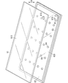
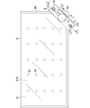
- FIG. 1 is a perspective view explaining the arrangement process for manufacturing the glass panel unit of one embodiment.
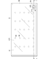
- FIG. 2 is a plan view for explaining an arrangement process and a bonding process for manufacturing the glass panel unit.
- 3 is a schematic cross-sectional view taken along line AA in FIG.
- FIG. 4 is a plan view for explaining a decompression step for manufacturing the glass panel unit same as above.
- FIG. 5 is a schematic sectional view taken along line BB in FIG.
- FIG. 6 is a schematic cross-sectional view taken along the line CC of FIG.
- FIG. 7: is a schematic sectional drawing explaining the sealing process for manufacturing the glass panel unit same as the above.
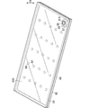
- FIG. 8 is a perspective view of a glass panel unit manufactured through the same sealing process.
- FIG. 8 is a perspective view of a glass panel unit manufactured through the same sealing process.
- FIG. 9A is a cross-sectional view of a main part for explaining a pressure reduction process using the first modification of the sealing head described above
- FIG. 9B illustrates a sealing process using the first modification of the sealing head described above. It is principal part sectional drawing.
- FIG. 10 is a schematic cross-sectional view for explaining a pressure reduction process using the second modification of the sealing head.
- a method for manufacturing a glass panel unit includes an arrangement process, a bonding process, a decompression process, and a sealing process.
- the work-in-process 8 is formed through the placement process and the joining process.
- the work-in-progress 8 is an article in the middle of manufacturing the glass panel unit.
- a heat-insulating glass panel unit is formed by performing a decompression process and a sealing process on the work-in-process 8 using a sealing head 9 for manufacturing a glass panel unit.
- the first substrate 81, the second substrate 82, the bonding material 83, the plurality of pillars 84, and the dam portion 87 are arranged at predetermined positions, respectively.
- the bonding material 83, the weir portion 87, and the plurality of pillars 84 are disposed on one surface (that is, the upper surface) of the second substrate 82.
- a first substrate 81 is disposed above the second substrate 82 so as to face it.
- the first substrate 81 includes a glass panel 810 having translucency.
- the second substrate 82 includes a glass panel 820 having translucency.
- the glass panel 810 included in the first substrate 81 is referred to as a first glass panel 810
- the glass panel 820 included in the second substrate 82 is referred to as a second glass panel 820.
- a low radiation film 812 is overlaid on one surface (lower surface) of the first glass panel 810 (see FIG. 3). Most of the surface of the first substrate 81 facing the second substrate 82 is constituted by the surface of the low radiation film 812. The surface of the second substrate 82 that faces the first substrate 81 is constituted by the surface of the second glass panel 820.
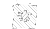
- An exhaust hole 815 is formed through the first substrate 81.
- the exhaust hole 815 penetrates the first glass panel 810 in the thickness direction D1.
- the low radiation film 812 is not overlapped so as to cover the entire surface of the first glass panel 810, and the peripheral edge of the entire surface of the first glass panel 810 and the exhaust hole in the surface of the first glass panel 810. A peripheral portion of 815 is not covered with the low emission film 812.
- the bonding material 83 is disposed on the second substrate 82 (that is, the second glass panel 820) using a coating device such as a dispenser. As shown in FIG. 1, the bonding material 83 is arranged in a frame shape along the outer peripheral edge of one surface (that is, the upper surface) of the second substrate 82.
- the dam portion 87 is disposed on the second substrate 82 (that is, the second glass panel 820) using a coating device such as a dispenser.
- the dam portion 87 is arranged at a predetermined position on one surface of the second substrate 82 so as to have an annular shape having a notch 875.
- the material of the bonding material 83 and the material of the weir portion 87 are preferably the same material (for example, glass frit).
- the dam portion 87 has a C-shape having a notch 875, but the shape of the dam portion 87 is not limited to this.
- the plurality of pillars 84 are regularly distributed in a region surrounded by the bonding material 83 on one surface of the second substrate 82.
- the dimension shape, number and arrangement of the plurality of pillars 84 are not particularly limited.
- the first substrate 81 and the second substrate 82 that are opposed to each other in the arrangement step are bonded in an airtight manner via the bonding material 83.
- the first substrate 81 and the second substrate 82 arranged to face each other with the joining material 83, the weir portion 87, and the plurality of pillars 84 sandwiched therebetween are placed in a joining furnace such as a hot air circulating furnace. It is heated and the bonding material 83 is once melted and then cured. As a result, the bonding material 83 becomes a frame-shaped bonding portion 86 that bonds the peripheral portions of the first substrate 81 and the second substrate 82 in an airtight manner.
- an internal space 85 is formed between the first substrate 81 and the second substrate 82 (see FIG. 3 and the like).
- the internal space 85 is a space surrounded by the first substrate 81, the second substrate 82, and the joint portion 86, and communicates with the external space only through the exhaust hole 815.
- the work-in-progress 8 is formed through the above arrangement process and joining process.
- the exhaust hole 815 of the first substrate 81 is located surrounded by the dam portion 87 (see FIG. 2).
- the thickness direction D1 is the thickness direction of the first substrate 81, the thickness direction of the second substrate 82, and the overall thickness direction of the work-in-progress 8.
- the first substrate 81 including the first glass panel 810 and the exhaust hole 815 formed, and the second substrate 82 including the second glass panel 820 are connected via the frame-shaped joint portion 86. Airtightly joined.
- An internal space 85 is formed between the first substrate 81 and the second substrate 82 so as to be surrounded by the joint 86.
- a weir portion 87 having a notch 875 is disposed in the internal space 85 so as to surround the opening of the exhaust hole 815.
- the work-in-process 8 has a rectangular outer shape when viewed from the thickness direction D1.
- the first substrate 81 and the second substrate 82 have a rectangular outer shape.
- the exhaust hole 815 and the weir part 87 are located in the corner part 8a when the work-in-process 8 is viewed from the thickness direction D1.
- the dam portion 87 is bonded to the first substrate 81 by being cured once heated and melted in the bonding step, but the dam portion 87 may be bonded to the second substrate 82.
- the notches 875 are formed only at one location of the dam portion 87, but may be formed at a plurality of locations spaced in the circumferential direction of the dam portion 87.
- the notch 875 is formed so as to divide the dam portion 87, but is not limited thereto.
- a part of the weir part 87 in the circumferential direction may be formed one step lower than the remaining part, and this part (that is, a part recessed from the remaining part) may be a notch.
- the heat-insulating glass panel unit can be manufactured by performing an operation for sealing the exhaust hole 815 while maintaining the internal space 85 in a reduced pressure state for the work-in-process 8. That is, a heat-insulating glass panel unit can be manufactured by further performing a decompression process and a sealing process on the work-in-process 8.
- the decompression step and the sealing step are performed in this order using the sealing head 9 shown in FIGS.
- the sealing head 9 is detachably attached to a right-angled corner portion 8a of the work-in-process 8.
- the structure of the sealing head 9 will be described below.
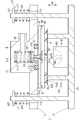
- the sealing head 9 includes a decompression mechanism capable of decompressing the internal space 85 of the work-in-progress 8, a sealing mechanism capable of sealing the internal space 85 in a decompressed state,
- the frame 1 that supports these mechanisms is integrally provided.
- the decompression mechanism is a mechanism including an air intake unit 2 described later.
- the sealing mechanism is a mechanism including a pressing pin 3 and a non-contact heater 4 which will be described later.
- the intake portion 2, the pressing pin 3, and the non-contact heater 4 are detachably attached to the corner portion 8a.
- the frame 1 includes a first frame 11 pressed against the corner portion of the first substrate 81 from above and a second frame 12 pressed against the corner portion of the second substrate 82 from below.
- the first frame 11 integrally supports a cylindrical intake portion 2 having an intake passage 22 therein.
- the intake portion 2 has a function of sucking air in the internal space 85 through the exhaust hole 815 of the work-in-progress 8.
- the intake section 2 is configured to depressurize the internal space 85 through the exhaust hole 815 and maintain the internal space 85 in a depressurized state.
- the air intake section 2 includes a bottomed cylindrical hollow body 21 having a bottom 212 on the upper side and an opening 214 on the lower side, and a pipe-shaped connection section 28 extending laterally from the hollow body 21.
- the internal space of the hollow body 21 constitutes the intake passage 22.
- the hollow body 21 only needs to have the intake passage 22 and the opening 214, and the shape thereof is not particularly limited.
- the internal flow path of the connection part 28 is connected to an intake device (not shown).
- the intake passage 22 has a series of a first intake passage 221 located on the upper side (that is, the side closer to the bottom 212) and a second intake passage 222 located on the lower side (that is, the side closer to the opening 214).
- the first intake path 221 communicates with the internal flow path of the connection portion 28.
- the second intake path 222 communicates with the opening 214 of the hollow body 21.
- the second intake path 222 has a smaller cross-sectional area than the first intake path 221, and a step is formed at the boundary between the first intake path 221 and the second intake path 222.
- the pressing pin 3 is movably disposed in the intake passage 22.
- the pressing pin 3 integrally includes a plate-like base portion 31 and a columnar pin body 35 protruding downward from a part of the base portion 31.
- the base 31 is located in the first intake passage 221.
- a part of the pin body 35 is located in the second intake passage 222.
- the pressing pin 3 is guided by the inner peripheral surface 2220 of the second intake passage 222 and is movable up and down (that is, in a direction approaching and separating from the second substrate 82).
- the rotation of the pressing pin 3 with respect to the first frame 11 is regulated by a rotation preventing structure 7 shown in FIG.
- the anti-rotation structure 7 is formed by the outer peripheral surface 30 of the pressing pin 3 and the inner peripheral surface 220 of the intake passage 22.
- the outer peripheral surface 30 of the pressing pin 3 that constitutes a part of the detent structure 7 is an outer peripheral surface 350 having a non-circular cross section of the pin body 35.
- An inner peripheral surface 220 of the intake passage 22 constituting another part of the rotation stopper structure 7 is an inner peripheral surface 2220 having a non-circular cross section of the second intake passage 222.
- a plurality (two in this embodiment) of protrusions are provided on the outer peripheral surface 350 of the pin body 35, and the plurality of protrusions are provided on the inner peripheral surface 2220 of the second intake passage 222.
- Plural (two in this embodiment) grooves are provided in which the strips can be moved up and down.
- the shapes of the pin main body 35 and the second intake passage 222 are not limited to this, and other shapes may be used as long as they fit in such a manner that they cannot be relatively rotated.
- a compressed spring member 51 is further accommodated in the first intake passage 221 shown in FIG.
- the spring member 51 presses against the bottom 212 of the hollow body 21 and presses against the base 31 of the pressing pin 3, thereby constantly applying a downward biasing force to the base 31.
- the pin body 35 is pushed downward (that is, in a direction approaching the second substrate 82) through the opening 214 of the hollow body 21 by the biasing force applied to the base 31 by the spring member 51.
- the spring member 51 is supported by the first frame 11. In the sealing head 9 of the present embodiment, the spring member 51 forms the pin spring mechanism 5 that pushes the pressing pin 3 toward the second substrate 82.
- An annular groove 215 is formed in a portion surrounding the opening 214 on the lower surface of the hollow body 21.
- An O-ring 27 having elasticity is arranged in the groove 215. With the O-ring 27 partially fitted in the groove 215, the remaining portion protrudes downward.
- the second frame 12 includes a base 121 that supports the non-contact heater 4 from below, a pressing portion 123 that presses against the second substrate 82 from below, and a plurality of connecting rods 125 that protrude upward from the base 121. Have one.
- the non-contact heater 4 is an electromagnetic wave irradiator 40 configured to irradiate an electromagnetic wave for local heating.
- the electromagnetic wave irradiated by the electromagnetic wave irradiator 40 is infrared.
- the electromagnetic wave irradiator 40 irradiates infrared rays through the second substrate 82 (that is, the second glass panel 820) having translucency with respect to the heat-meltable sealing material 89 inserted into the exhaust hole 815 as will be described later.
- the sealing material 89 is configured to be heated locally.
- the electromagnetic wave irradiator 40 includes a heat source unit 401 that can emit infrared rays, and a condensing unit 402 that collects infrared rays emitted from the heat source unit 401 at a target location.
- the heat source unit 401 is preferably a halogen lamp that emits near infrared rays. If the infrared ray irradiated from the electromagnetic wave irradiator 40 is a near infrared ray having a short wavelength, there is an advantage that the near infrared ray is hardly absorbed when passing through the second substrate 82.
- the sealing material 89 When irradiating near-infrared rays from the electromagnetic wave irradiator 40, the sealing material 89 may be formed using a black material having a high near-infrared absorptivity so that the near-infrared absorptivity of the sealing material 89 is 30% or more. preferable.
- the pressing part 123 is in a position surrounding the electromagnetic wave irradiator 40 when the second frame 12 is viewed from the thickness direction D1.
- the pressing portion 123 includes a column 1231 that protrudes upward from the base 121, and a contact portion 1233 that is supported above the base 121 by the column 1231.
- the contact portion 1233 is a portion that hits the second substrate 82 from below, and preferably has elasticity.
- the second frame 12 supports the shielding plate 6.
- the shielding plate 6 is a plate material that can block electromagnetic waves, that is, infrared rays, and a through hole 60 that allows infrared rays to pass toward the sealing material 89 is provided in the central portion thereof.
- the shielding plate 6 is a plate material for passing the portion irradiated toward the sealing material 89 and blocking at least a part of the remaining portion of the infrared rays irradiated by the electromagnetic wave irradiator 40.
- the shielding plate 6 is shielded by the shielding plate 6, so that the deterioration of the O-ring 27 may proceed due to the influence of infrared rays. It can be suppressed.
- the plurality of rods 125 included in the second frame 12 are inserted into the plurality of connecting holes 115 formed in the first frame 11 on a one-to-one basis. Thereby, the first frame 11 and the second frame 12 are connected so as to be relatively displaceable in the direction in which the first substrate 81 and the second substrate 82 face each other (that is, the thickness direction D1).
- the plurality of connecting holes 115 are located at positions surrounding the hollow body 21 when the first frame 11 is viewed from the thickness direction D1.
- a retaining portion 127 is provided at the tip of each of the plurality of rods 125.
- the retaining portion 127 has a larger diameter than the connection hole 115.
- the retaining portion 127 is located above the first frame 11.
- a compressed spring member 171 is interposed between the retaining portion 127 and the first frame 11.
- the plurality of spring members 171 assembled to the plurality of rods 125 give a biasing force that biases the first frame 11 and the second frame 12 toward each other.
- the plurality of spring members 171 form a frame spring mechanism 17 that urges the first frame 11 and the second frame 12 toward each other.
- the work-in-process 8 When mounting the sealing head 9, the work-in-process 8 is set so that the first substrate 81 is positioned above the second substrate 82.
- the intake portion 2 supported by the first frame 11 is set so as to be positioned above the exhaust hole 815 with the opening 214 facing downward.
- the pressing pin 3 is located above the exhaust hole 815.
- a sealing material 89 and a plate 88 are inserted in advance into the exhaust hole 815 of the work-in-process 8.
- the sealing material 89 is a solid sealing material formed using, for example, glass frit.
- the plate 88 is a disk-shaped plate formed using, for example, metal.
- Both the sealing material 89 and the plate 88 have an outer diameter smaller than that of the exhaust hole 815.
- the plate 88 has an outer diameter larger than that of the sealing material 89.
- the plate 88 disposed in the exhaust hole 815 is located on the opposite side of the second substrate 82 with the sealing material 89 interposed therebetween.
- the exhaust hole 815 of the first substrate 81 and the intake passage 22 of the hollow body 21 communicate with each other in an airtight manner.
- the pin spring mechanism 5 functions as a holding mechanism that holds the sealing material 89 in the exhaust hole 815.
- the depressurization step when air is sucked through the connection portion 28 in this state (see the white arrow in FIG. 5), the internal space 85 is depressurized until the degree of vacuum is, for example, 0.1 Pa or less.
- a sealing material 89 and a plate 88 are inserted into the exhaust hole 815, but there is a gap between the inner peripheral surface of the exhaust hole 815 and the sealing material 89, and there is a gap between the exhaust hole 815 and the plate 88. There is a gap between the two gaps. Accordingly, the air in the internal space 85 is smoothly sucked through the exhaust holes 815 of the first substrate 81 and the notches 875 in the dam portions 87 disposed in the internal space 85.
- the non-contact heater 4 supported by the second frame 12 seals the internal space 85 with the pressure reduced.
- the non-contact heater 4 is configured to heat the sealing material 89 inserted into the exhaust hole 815 locally and in a non-contact manner while the internal space 85 remains in a decompressed state.
- the locally heated sealing material 89 melts and softens when it reaches a predetermined temperature.
- the softened sealing material 89 is pushed and deformed toward the second substrate 82 by the urging force (spring force) exerted by the spring member 51 via the plate 88.
- the sealing material 89 is expanded in a direction orthogonal to the thickness direction D1 and is deformed until it hits the inner peripheral surface of the weir portion 87 in the internal space 85. When the sealing material 89 hits the weir portion 87, further expansion is suppressed.
- the notch 875 of the weir part 87 is sealed by a sealing material 89 that is expanded until it hits the weir part 87.
- the exhaust hole 815 is sealed with the sealing material 89, and the internal space 85 is hermetically sealed in a reduced pressure state.
- the sealing material 89 is bonded to both the first substrate 81 and the second substrate 82 in the internal space 85.
- the trace of the exhaust pipe as described in the prior art does not remain. Therefore, the trace of the exhaust pipe does not cause damage to the glass panel unit.
- the plate 88 remains in the exhaust hole 815, but the plate 88 is sealed after the exhaust hole 815 is sealed. It is also possible to remove.
- the intake portion 2, the pressing pin 3, and the non-contact heater 4 are all attached to the corner portion 8a of the work in process 8 where the exhaust holes 815 are formed. And can be detachably attached integrally. Therefore, the internal space 85 of the work-in-process 8 can be depressurized and sealed in a depressurized state with a simple operation of attaching and detaching the frame 1 to and from the corner portion 8a. It does not remain.
- the frame 1 places the pressing pin 3 and the non-contact heater 4 at positions opposite to each other across the second substrate 82 of the work in process 8.
- the non-contact heater 4 locally heats the sealing material 89 through the second substrate 82 in a non-contact manner. Therefore, the sealing material 89 can be heated and melted by infrared rays irradiated from the opposite side to the pressing pin 3 while applying a load to the sealing material 89 with the pressing pin 3, and the sealing work of the internal space 85 is efficiently performed. Can be done.
- the first frame 11 that supports the intake portion 2 and the pressing pin 3 and the second frame 12 that supports the non-contact heater 4 are mutually connected by the frame spring mechanism 17. It is energized in the approaching direction. Therefore, the frame 1 including the first frame 11 and the second frame 12 can be easily set in a form in which the work-in-process 8 is sandwiched from both sides in the thickness direction D1. Moreover, when the dimension of the work-in-process 8 in the thickness direction D1 changes due to the decompression of the internal space 85, the distance between the first frame 11 and the second frame 12 naturally changes accordingly.
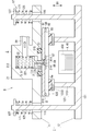
- the hollow body 21 further has a protruding portion 25 inserted into the exhaust hole 815.
- the protruding portion 25 is an annular protrusion formed so as to surround the opening 214 on the lower surface of the hollow body 21.
- An air-permeable space is formed between the annular protruding portion 25 and the columnar pin body 35.
- the protruding portion 25 is formed continuously in the circumferential direction, but may be formed intermittently.
- the projecting portion 25 inserted into the exhaust hole 815 functions to suppress the wraparound of the seal material 89. To do. Therefore, in the first modification, the heat-melted sealing material 89 is suppressed from adhering to the pressing pin 3.
- the operator grasps the first frame 11 and focuses on the axis of the pressing pin 3.
- the first frame 11 may be rotated. Since the relative rotation between the pressing pin 3 and the first frame 11 is restricted by the detent structure 7 shown in FIG. 6, when the first frame 11 is rotated, the pressing pin 3 rotates integrally with the first frame 11. To do. As a result, the portion of the sealing material 89 attached to the pressing pin 3 is peeled off from the pressing pin 3.
- FIG. 10 shows a second modification of the sealing head 9.
- the non-contact heater 4 supported by the base 121 of the second frame 12 is a magnetic field generator 45 including a coil 450 that generates a magnetic field for induction heating.
- the work-in-process 8 can be decompressed and sealed without the trace of the exhaust pipe remaining as in the prior art.
- infrared rays are emitted from the electromagnetic wave irradiator 40.
- the sealing material 89 can be locally heated through the second substrate 82, it is possible to irradiate electromagnetic waves of a different type from infrared rays. is there.
- the shielding board 6 should just have the property which can interrupt
- the pressing pin 3 is pressed against the sealing material 89 via the plate 88, but the plate 88 is not essential, and the pressing pin 3 can also be pressed directly against the sealing material 89.
- the dam portion 87 is provided in the internal space 85 of the work-in-process 8, but the dam portion 87 is not essential. It is also possible to seal the exhaust hole 815 by crushing the sealing material 89 with the pressing pin 3 without providing the dam portion 87 in the internal space 85.
- the exhaust holes 815 are provided in one corner portion among the four corner portions of the first substrate 81 of the work-in-progress 8, but the exhaust holes 815 are provided in a plurality of corner portions. It may be provided.
- the internal space 85 can be depressurized and sealed by using a plurality of sealing heads 9 and mounting the sealing heads 9 at the corners at each location.
- the internal space 85 is depressurized until the degree of vacuum is 0.1 Pa or less, but the degree of depressurization of the internal space 85 is not limited to this.
- the sealing head (9) of the first aspect includes a frame (1), an intake portion (2), a pressing pin (3), and a non-contact heater. (4) is provided.
- the frame (1) is detachably attached to the work piece (8) of the glass panel unit.
- the intake part (2), the pressing pin (3), and the non-contact heater (4) are supported by the frame (1).
- the work-in-process (8) has a first substrate (81), a second substrate (82), a joint (86), and an internal space (85).
- the first substrate (81) includes a glass panel (810) and an exhaust hole (815) is formed.
- the second substrate (82) includes a glass panel (820).
- the joining portion (86) joins the first substrate (81) and the second substrate (82) that face each other in an airtight manner.
- the internal space (85) is formed surrounded by the first substrate (81), the second substrate (82), and the joint (86), and communicates with the exhaust hole (815).
- the intake part (2) is configured to suck air in the internal space (85) through the exhaust hole (815).
- the pressing pin (3) pushes the hot-melt sealing material (89) inserted into the exhaust hole (815) toward the second substrate (82) to seal the exhaust hole (815). It is configured.
- the non-contact heater (4) is configured to locally heat the sealing material (89) through the second substrate (82) in a non-contact manner.
- the air intake (2), the pressing pin (3), and the non-contact heater (4) are detachably attached to the work in process (8) integrally with the frame (1).
- the sealing head (9) of the first aspect the internal space (85) of the work-in-process (8) is decompressed and the exhaust hole (815) is sealed using the sealing head (9).
- the exhaust pipe trace as in the prior art does not remain.
- the frame (1) may be attached to the work-in-process (8), and after completion of sealing, the frame (1) may be removed from the work-in-process (8), and complicated work is not required. is there.
- the sealing head (9) of the second aspect is realized by a combination with the first aspect.
- the sealing head (9) of the second aspect in the state where the frame (1) is mounted on the work-in-progress (8), the pressing pin (3) and the non-contact heater (4) are the second substrate (82). ) On opposite sides of each other.
- the sealing material (89) is attached to the second substrate (82) by the pressing pin (3) in a state where the frame (1) is mounted on the work-in-process (8).
- the sealing material (89) can be locally heated through the second substrate (82) by pressing.
- the sealing head (9) of the third aspect is realized by a combination with the first or second aspect.
- the frame (1) includes a first frame (11), a second frame (12), and a frame spring mechanism (17).
- the first frame (11) supports the intake portion (2) and the pressing pin (3).
- the second frame (12) supports the non-contact heater (4).
- the frame spring mechanism (17) biases the first frame (11) and the second frame (12) toward each other.
- the sealing head (9) of the third aspect for example, even if the thickness of the work-in-process (8) changes in the decompression step, the first frame (11) and the second frame (12) follow this. The distance is automatically changed.
- the sealing head (9) of the fourth aspect is realized by a combination with the first or second aspect.
- the sealing head (9) according to the fourth aspect further includes a pin spring mechanism (5).
- the pin spring mechanism (5) is supported by the frame (1), and is configured to push the pressing pin (3) toward the second substrate (82).
- the pressing pin (3) approaches the second substrate (82) following the crushing of the sealing material (89) in the sealing step.
- the pressing pin (3) can stably apply a load to the sealing material (89).
- the sealing head (9) of the fifth aspect is realized by a combination with the third aspect.
- the sealing head (9) of the fifth aspect further includes a pin spring mechanism (5).
- the pin spring mechanism (5) is supported by the first frame (11) and configured to push the pressing pin (3) toward the second substrate (82).
- the pressing pin (3) approaches the second substrate (82) following the fact that the sealing material (89) is crushed.
- the pressing pin (3) can stably apply a load to the sealing material (89).
- the sealing head (9) of the sixth aspect is realized by a combination with any one of the first, second, and fourth aspects.
- the sealing head (9) of the sixth aspect further includes a shielding plate (6) supported by the frame (1).
- the non-contact heater (4) is an electromagnetic wave irradiator (40).
- the shielding plate (6) is configured to pass a portion of the electromagnetic wave emitted by the electromagnetic wave irradiator (40) toward the sealing material (89) and shield at least a part of the remaining portion.
- the electromagnetic wave irradiated by the electromagnetic wave irradiator (40) is prevented from being irradiated to members other than the sealing material (89). Deterioration of the sealing head (9) can be suppressed.
- the sealing head (9) of the seventh aspect is realized by a combination with the third or fifth aspect.
- the sealing head (9) of the seventh aspect further includes a shielding plate (6) supported by the second frame (12).
- the non-contact heater (4) is an electromagnetic wave irradiator (40).
- the shielding plate (6) is configured to pass a portion of the electromagnetic wave emitted by the electromagnetic wave irradiator (40) toward the sealing material (89) and shield at least a part of the remaining portion.
- the electromagnetic wave irradiated by the electromagnetic wave irradiator (40) is prevented from being irradiated to members other than the sealing material (89), and thereby, due to the influence of the electromagnetic wave. Deterioration of the sealing head (9) can be suppressed.
- the sealing head (9) of the eighth aspect is realized by a combination with the sixth or seventh aspect.
- the air intake portion (2) includes a hollow body (21) having an air intake passage (22) and an opening (214) communicating with the air intake path (22), and the hollow body (21).
- An O-ring (27) provided at a position surrounding the opening (214) is included.
- the intake portion (2) is configured such that the intake passage (22) and the exhaust hole (815) communicate with each other in an airtight manner through the O-ring (27) in a state where the O-ring (27) is in contact with the first substrate (81). It is configured.
- a shielding board (6) is comprised so that the part which goes to an O-ring (27) among electromagnetic waves may be shielded.
- the electromagnetic wave irradiated by the electromagnetic wave irradiator (40) is suppressed from being applied to the O-ring (27), and the deterioration of the O-ring (27) is suppressed. Can do.
- the sealing head (9) of the ninth aspect is realized by a combination with any of the sixth to eighth aspects.
- the electromagnetic wave is infrared.
- the sealing material (89) can be locally heated by irradiating the sealing material (89) with infrared rays through the second substrate (82).
- the sealing head (9) of the tenth aspect is realized by a combination with any one of the first to seventh aspects.
- the intake section (2) includes a hollow body (21) having an intake path (22) and an opening (214) communicating with the intake path (22).
- the pressing pin (3) is accommodated in the intake passage (22) so that the tip end portion projects outward through the opening (214).
- the sealing head (9) of the tenth aspect the pressing pin (20) protruding from the opening (214) while keeping the internal space (85) of the work-in-process (8) in a reduced pressure state by the air intake (2).
- the sealing material (89) can be crushed at the tip of 3) to seal the exhaust hole (815).
- the sealing head (9) of the eleventh aspect is realized by a combination with the tenth aspect.
- the hollow body (21) further includes a protruding portion (25) configured to be inserted into the exhaust hole (815).
- the protruding portion (25) inserted into the exhaust hole (815) has the heat-melted sealing material (89) attached to the pressing pin (3). It works to suppress.
- the sealing head (9) of the twelfth aspect is realized by a combination with any one of the first to eleventh aspects.
- the sealing head (9) of the twelfth aspect further includes a detent structure (7) for restricting relative rotation of the pressing pin (3) and the frame (1).
- the sealing head (9) of the twelfth aspect when the heat-melted sealing material (89) adheres to the pressing pin (3), after the sealing process is completed, for example, the operator What is necessary is just to grasp (1) and rotate. Since the frame (1) and the pressing pin (3) rotate integrally, the portion of the sealing material (89) attached to the pressing pin (3) is peeled off from the pressing pin (3).
- the sealing head (9) of the thirteenth aspect is realized by a combination with the tenth aspect.
- the sealing head (9) of the thirteenth aspect further includes a detent structure (7) that restricts relative rotation of the pressing pin (3) and the frame (1).
- the detent structure (7) is formed by the outer peripheral surface (30) of the pressing pin (3) and the inner peripheral surface (220) of the intake passage (22).
- the sealing head (9) of the thirteenth aspect when the heat-melted sealing material (89) adheres to the pressing pin (3), after the sealing process is completed, for example, the operator What is necessary is just to grasp (1) and rotate. Since the frame (1) and the pressing pin (3) rotate integrally, the portion of the sealing material (89) attached to the pressing pin (3) is peeled off from the pressing pin (3).
- the method for sealing the work in progress of the glass panel unit according to the first aspect uses the sealing head (9) according to any one of the first to thirteenth aspects, and the sealing head (9) of the work in process (8) is used.
- the internal space (85) is decompressed and the exhaust hole (815) is sealed by being detachably attached to the corner portion (8a).
- the frame (1) when decompressing and sealing, the frame (1) is attached to the corner portion (8a), and after the sealing is completed, the corner portion (8a ) To remove the frame (1), and no complicated work is required. Moreover, no trace of the exhaust pipe as in the prior art remains.
Landscapes
- Engineering & Computer Science (AREA)
- Chemical & Material Sciences (AREA)
- Civil Engineering (AREA)
- Structural Engineering (AREA)
- Chemical Kinetics & Catalysis (AREA)
- Life Sciences & Earth Sciences (AREA)
- Ceramic Engineering (AREA)
- General Chemical & Material Sciences (AREA)
- Geochemistry & Mineralogy (AREA)
- Materials Engineering (AREA)
- Organic Chemistry (AREA)
- Joining Of Glass To Other Materials (AREA)
- Securing Of Glass Panes Or The Like (AREA)
Abstract
The purpose of the present invention is to provide a glass panel unit having a depressurized internal space with a structure without a mark of an exhaust pipe left. A sealing head (9) comprises a frame (1), an intake unit (2), a pushing pin (3), and a non-contact heater (4). The frame (1) is detachably fitted to an in-process item (8) of the glass panel unit. The intake unit (2), the pushing pin (3), and the non-contact heater (4) are supported by the frame (1). The in-process item (8) has a first substrate (81), a second substrate (82), a joint unit (86), and an interior space (85). The first substrate (81) has an exhaust hole (815). The joint unit (86) joints the first substrate (81) with the second substrate (82). The interior space (85) is formed so as to be surrounded by the first substrate (81), the second substrate (82), and the joint unit (86), and communicates with the exhaust hole (815). The pushing pin (3) pushes a thermofusible sealing material (89) inserted in the exhaust hole (815) into the second substrate (82). The non-contact heater (4) locally heats the sealing material (89) in a non-contact state via the second substrate (82).
Description
本開示は、ガラスパネルユニット製造用の封止ヘッド及びガラスパネルユニットの仕掛品の封止方法に関する。
The present disclosure relates to a sealing head for manufacturing a glass panel unit and a method for sealing a work in progress of the glass panel unit.
互いに対向して位置する一対の基板の間の内部空間を減圧し、該内部空間を減圧状態のまま封止することで、断熱性のガラスパネルユニットを製造することができる。
A heat-insulating glass panel unit can be manufactured by reducing the internal space between a pair of substrates positioned facing each other and sealing the internal space in a reduced pressure state.
特許文献1には、一対の基板のうち一方の基板が有する排気孔に、ガラス製の排気管を接続し、この排気管を通じて内部空間を減圧した後に、排気管を加熱して切断する技術が記載されている。
Patent Document 1 discloses a technique in which a glass exhaust pipe is connected to an exhaust hole of one of a pair of substrates, and the internal space is decompressed through the exhaust pipe, and then the exhaust pipe is heated and cut. Are listed.
この技術で形成されたガラスパネルユニットには、切断された排気管の跡が、ガラスパネルユニットの外面から突出した状態で、残存する。
The trace of the cut exhaust pipe remains on the glass panel unit formed by this technique in a state of protruding from the outer surface of the glass panel unit.
本開示は、減圧された内部空間を有するガラスパネルユニットを、排気管の跡が残存することのない手法で製造することを、目的とする。
This disclosure is intended to manufacture a glass panel unit having a decompressed internal space by a technique that does not leave a trace of an exhaust pipe.
本開示の一態様に係るガラスパネルユニット製造用の封止ヘッドは、ガラスパネルユニットの仕掛品に着脱自在に装着されるフレームと、前記フレームに支持された吸気部と、前記フレームに支持された押圧ピンと、前記フレームに支持された非接触加熱器と、を備える。
A sealing head for manufacturing a glass panel unit according to an aspect of the present disclosure includes a frame that is detachably attached to a work in progress of the glass panel unit, an air intake portion that is supported by the frame, and a frame that is supported by the frame. A pressing pin; and a non-contact heater supported by the frame.
前記仕掛品は、ガラスパネルを含みかつ排気孔が形成された第一基板と、ガラスパネルを含む第二基板と、互いに対向して位置する前記第一基板と前記第二基板を、気密に接合する枠状の接合部と、前記第一基板と前記第二基板と前記接合部に囲まれて形成され、前記排気孔に連通する内部空間と、を有する。
The work-in-process includes a first substrate including a glass panel and an exhaust hole formed therein, a second substrate including the glass panel, and the first substrate and the second substrate positioned opposite to each other in an airtight manner. A frame-shaped joint portion, and the first substrate, the second substrate, and an internal space that is surrounded by the joint portion and communicates with the exhaust hole.
前記吸気部は、前記排気孔を通じて前記内部空間の空気を吸引するように構成され、前記押圧ピンは、前記排気孔を封止するために前記排気孔に挿入された熱溶融性のシール材を、前記第二基板に向けて押し込むように構成され、前記非接触加熱器は、前記第二基板を通じて、前記シール材を非接触で局所加熱するように構成され、前記吸気部、前記押圧ピン及び前記非接触加熱器は、前記フレームと一体的に、前記仕掛品に着脱自在に装着される。
The intake portion is configured to suck air in the internal space through the exhaust hole, and the pressing pin is formed of a hot-melt sealing material inserted into the exhaust hole to seal the exhaust hole. And the non-contact heater is configured to locally heat the sealing material through the second substrate in a non-contact manner, the suction portion, the pressing pin, and the second substrate. The non-contact heater is detachably attached to the work in progress integrally with the frame.
本開示の一態様に係るガラスパネルユニットの仕掛品の封止方法は、前記封止ヘッドを用い、前記封止ヘッドを、前記仕掛品のコーナー部分に着脱自在に装着することで、前記内部空間の減圧と、前記排気孔の封止を行う。
A method for sealing a work in progress of a glass panel unit according to an aspect of the present disclosure uses the sealing head, and the internal space is configured by detachably mounting the sealing head on a corner portion of the work in progress. And the exhaust hole is sealed.
(一実施形態)
一実施形態の封止ヘッドを用いてガラスパネルユニットを製造する方法について、添付図面に基づいて説明する。 (One embodiment)
A method for manufacturing a glass panel unit using the sealing head of one embodiment will be described with reference to the accompanying drawings.
一実施形態の封止ヘッドを用いてガラスパネルユニットを製造する方法について、添付図面に基づいて説明する。 (One embodiment)
A method for manufacturing a glass panel unit using the sealing head of one embodiment will be described with reference to the accompanying drawings.
一実施形態のガラスパネルユニットを製造する方法は、配置工程、接合工程、減圧工程及び封止工程を含む。
A method for manufacturing a glass panel unit according to an embodiment includes an arrangement process, a bonding process, a decompression process, and a sealing process.
本実施形態のガラスパネルユニットを製造する方法では、配置工程と接合工程を経ることで、仕掛品8が形成される。仕掛品8は、ガラスパネルユニットを製造する途中の物品である。仕掛品8に対して、ガラスパネルユニット製造用の封止ヘッド9を用いて減圧工程と封止工程を実行することで、断熱性のガラスパネルユニットが形成される。
In the method of manufacturing the glass panel unit of the present embodiment, the work-in-process 8 is formed through the placement process and the joining process. The work-in-progress 8 is an article in the middle of manufacturing the glass panel unit. A heat-insulating glass panel unit is formed by performing a decompression process and a sealing process on the work-in-process 8 using a sealing head 9 for manufacturing a glass panel unit.
まず、配置工程について説明する。
First, the arrangement process will be described.
図1等に示すように、配置工程では、第一基板81、第二基板82、接合材83、複数のピラー84、及び堰部分87がそれぞれ所定箇所に配置される。具体的には、第二基板82の一面(つまり上面)に、接合材83と、堰部分87と、複数のピラー84が配置される。第二基板82の上方に、第一基板81が対向配置される。
As shown in FIG. 1 and the like, in the arranging step, the first substrate 81, the second substrate 82, the bonding material 83, the plurality of pillars 84, and the dam portion 87 are arranged at predetermined positions, respectively. Specifically, the bonding material 83, the weir portion 87, and the plurality of pillars 84 are disposed on one surface (that is, the upper surface) of the second substrate 82. A first substrate 81 is disposed above the second substrate 82 so as to face it.
第一基板81は、透光性を有するガラスパネル810を含む。第二基板82は、透光性を有するガラスパネル820を含む。以下においては、第一基板81に含まれるガラスパネル810を、第一ガラスパネル810と称し、第二基板82に含まれるガラスパネル820を、第二ガラスパネル820と称する。
The first substrate 81 includes a glass panel 810 having translucency. The second substrate 82 includes a glass panel 820 having translucency. Hereinafter, the glass panel 810 included in the first substrate 81 is referred to as a first glass panel 810, and the glass panel 820 included in the second substrate 82 is referred to as a second glass panel 820.
第一ガラスパネル810の一面(下面)には、低放射膜812が重ねられている(図3参照)。第一基板81のうち第二基板82に対向する面の大部分は、低放射膜812の表面で構成されている。第二基板82のうち第一基板81に対向する面は、第二ガラスパネル820の表面で構成されている。
A low radiation film 812 is overlaid on one surface (lower surface) of the first glass panel 810 (see FIG. 3). Most of the surface of the first substrate 81 facing the second substrate 82 is constituted by the surface of the low radiation film 812. The surface of the second substrate 82 that faces the first substrate 81 is constituted by the surface of the second glass panel 820.
第一基板81には、排気孔815が貫通形成されている。排気孔815は、第一ガラスパネル810をその厚み方向D1に貫通している。
An exhaust hole 815 is formed through the first substrate 81. The exhaust hole 815 penetrates the first glass panel 810 in the thickness direction D1.
低放射膜812は、第一ガラスパネル810の一面の全てを覆うようには重ねられておらず、第一ガラスパネル810の一面全体の周縁部分と、第一ガラスパネル810の一面のうち排気孔815の周縁部分は、低放射膜812に覆われていない。
The low radiation film 812 is not overlapped so as to cover the entire surface of the first glass panel 810, and the peripheral edge of the entire surface of the first glass panel 810 and the exhaust hole in the surface of the first glass panel 810. A peripheral portion of 815 is not covered with the low emission film 812.
接合材83は、ディスペンサー等の塗布装置を用いて、第二基板82(すなわち第二ガラスパネル820)に配される。図1に示すように、接合材83は、第二基板82の一面(つまり上面)の外周縁に沿って、枠状の形態となるように配される。
The bonding material 83 is disposed on the second substrate 82 (that is, the second glass panel 820) using a coating device such as a dispenser. As shown in FIG. 1, the bonding material 83 is arranged in a frame shape along the outer peripheral edge of one surface (that is, the upper surface) of the second substrate 82.
堰部分87は、同じくディスペンサー等の塗布装置を用いて、第二基板82(すなわち第二ガラスパネル820)に配される。堰部分87は、第二基板82の一面の所定箇所に、切欠き875を有する環状の形態となるように配される。接合材83の材料と、堰部分87の材料は、同一の材料(たとえばガラスフリット)であることが好ましい。堰部分87は、切欠き875を有するC字状の形状を有するが、堰部分87の形状はこれに限定されない。
The dam portion 87 is disposed on the second substrate 82 (that is, the second glass panel 820) using a coating device such as a dispenser. The dam portion 87 is arranged at a predetermined position on one surface of the second substrate 82 so as to have an annular shape having a notch 875. The material of the bonding material 83 and the material of the weir portion 87 are preferably the same material (for example, glass frit). The dam portion 87 has a C-shape having a notch 875, but the shape of the dam portion 87 is not limited to this.
複数のピラー84は、第二基板82の一面のうちの接合材83に囲まれる領域に、規則的に分散配置される。複数のピラー84の寸法形状、数及び配置は特に限定されない。
The plurality of pillars 84 are regularly distributed in a region surrounded by the bonding material 83 on one surface of the second substrate 82. The dimension shape, number and arrangement of the plurality of pillars 84 are not particularly limited.
次に、接合工程について説明する。
Next, the joining process will be described.
接合工程では、配置工程において対向配置された第一基板81と第二基板82が、接合材83を介して気密に接合される。
In the bonding step, the first substrate 81 and the second substrate 82 that are opposed to each other in the arrangement step are bonded in an airtight manner via the bonding material 83.
具体的には、配置工程において、接合材83と堰部分87と複数のピラー84を挟み込んだ状態で対向配置された第一基板81と第二基板82が、熱風循環炉等の接合炉内で加熱され、接合材83がいったん溶融した後に硬化する。これにより、接合材83が、第一基板81と第二基板82の互いの周縁部を気密に接合する枠状の接合部86となる。
Specifically, in the arranging step, the first substrate 81 and the second substrate 82 arranged to face each other with the joining material 83, the weir portion 87, and the plurality of pillars 84 sandwiched therebetween are placed in a joining furnace such as a hot air circulating furnace. It is heated and the bonding material 83 is once melted and then cured. As a result, the bonding material 83 becomes a frame-shaped bonding portion 86 that bonds the peripheral portions of the first substrate 81 and the second substrate 82 in an airtight manner.
接合工程を経ることで、第一基板81と第二基板82の間に、内部空間85が形成される(図3等参照)。内部空間85は、第一基板81と第二基板82と接合部86で囲まれた空間であり、排気孔815のみを通じて外部空間に連通する。
Through the bonding process, an internal space 85 is formed between the first substrate 81 and the second substrate 82 (see FIG. 3 and the like). The internal space 85 is a space surrounded by the first substrate 81, the second substrate 82, and the joint portion 86, and communicates with the external space only through the exhaust hole 815.
上記の配置工程と接合工程を経ることで、仕掛品8が形成される。
The work-in-progress 8 is formed through the above arrangement process and joining process.
仕掛品8を厚み方向D1から視たときに、第一基板81の排気孔815は、堰部分87に囲まれて位置する(図2参照)。
When the work-in-progress 8 is viewed from the thickness direction D1, the exhaust hole 815 of the first substrate 81 is located surrounded by the dam portion 87 (see FIG. 2).
仕掛品8において、厚み方向D1は、第一基板81の厚み方向であるとともに、第二基板82の厚み方向であり、かつ仕掛品8の全体の厚み方向である。
In the work-in-progress 8, the thickness direction D1 is the thickness direction of the first substrate 81, the thickness direction of the second substrate 82, and the overall thickness direction of the work-in-progress 8.
仕掛品8においては、第一ガラスパネル810を含みかつ排気孔815が形成された第一基板81と、第二ガラスパネル820を含む第二基板82とが、枠状の接合部86を介して気密に接合されている。第一基板81と第二基板82の間には、内部空間85が接合部86に囲まれて形成されている。内部空間85には、切欠き875を有する堰部分87が、排気孔815の開口を囲むように配置されている。
In the work-in-process 8, the first substrate 81 including the first glass panel 810 and the exhaust hole 815 formed, and the second substrate 82 including the second glass panel 820 are connected via the frame-shaped joint portion 86. Airtightly joined. An internal space 85 is formed between the first substrate 81 and the second substrate 82 so as to be surrounded by the joint 86. A weir portion 87 having a notch 875 is disposed in the internal space 85 so as to surround the opening of the exhaust hole 815.
仕掛品8は、厚み方向D1から視たときに矩形状の外形を有する。仕掛品8を厚み方向D1から視たとき、第一基板81と第二基板82は矩形状の外形を有する。排気孔815と堰部分87は、仕掛品8を厚み方向D1から視たときのコーナー部分8aに位置する。
The work-in-process 8 has a rectangular outer shape when viewed from the thickness direction D1. When the work-in-process 8 is viewed from the thickness direction D1, the first substrate 81 and the second substrate 82 have a rectangular outer shape. The exhaust hole 815 and the weir part 87 are located in the corner part 8a when the work-in-process 8 is viewed from the thickness direction D1.
堰部分87は、接合工程において、いったん加熱溶融した後に硬化したことで、第一基板81に接合されているが、堰部分87が第二基板82に接合されてもよい。
The dam portion 87 is bonded to the first substrate 81 by being cured once heated and melted in the bonding step, but the dam portion 87 may be bonded to the second substrate 82.
本実施形態では、切欠き875は、堰部分87の一箇所にだけ形成されているが、堰部分87の周方向に距離をあけた複数個所に形成されてもよい。本実施形態では、切欠き875は、堰部分87を分断するように形成されているが、これに限定されない。たとえば、堰部分87の周方向の一部を残りの部分よりも一段低く形成し、この一部(つまり、残りの部分よりも凹んだ部分)を切欠きとすることも可能である。
In this embodiment, the notches 875 are formed only at one location of the dam portion 87, but may be formed at a plurality of locations spaced in the circumferential direction of the dam portion 87. In the present embodiment, the notch 875 is formed so as to divide the dam portion 87, but is not limited thereto. For example, a part of the weir part 87 in the circumferential direction may be formed one step lower than the remaining part, and this part (that is, a part recessed from the remaining part) may be a notch.
この仕掛品8に対して、内部空間85を減圧状態に維持しながら排気孔815を封止する作業を行うことで、断熱性のガラスパネルユニットを製造することができる。つまり、仕掛品8に対して、更に減圧工程と封止工程を実行することで、断熱性のガラスパネルユニットを製造することができる。
The heat-insulating glass panel unit can be manufactured by performing an operation for sealing the exhaust hole 815 while maintaining the internal space 85 in a reduced pressure state for the work-in-process 8. That is, a heat-insulating glass panel unit can be manufactured by further performing a decompression process and a sealing process on the work-in-process 8.
減圧工程と封止工程は、図4から図7に示す封止ヘッド9を用いて、この順に実行される。封止ヘッド9は、仕掛品8が有する直角なコーナー部分8aに対して、着脱自在に装着される。
The decompression step and the sealing step are performed in this order using the sealing head 9 shown in FIGS. The sealing head 9 is detachably attached to a right-angled corner portion 8a of the work-in-process 8.
封止ヘッド9の構造について、以下に説明する。
The structure of the sealing head 9 will be described below.
図5等に示すように、封止ヘッド9は、仕掛品8の内部空間85を減圧することのできる減圧機構と、内部空間85を減圧状態のまま封止することのできる封止機構と、これらの機構を支持するフレーム1を、一体に備えている。減圧機構は、後述の吸気部2を含む機構である。封止機構は、後述の押圧ピン3と非接触加熱器4を含む機構である。
As shown in FIG. 5 and the like, the sealing head 9 includes a decompression mechanism capable of decompressing the internal space 85 of the work-in-progress 8, a sealing mechanism capable of sealing the internal space 85 in a decompressed state, The frame 1 that supports these mechanisms is integrally provided. The decompression mechanism is a mechanism including an air intake unit 2 described later. The sealing mechanism is a mechanism including a pressing pin 3 and a non-contact heater 4 which will be described later.
フレーム1がコーナー部分8aに着脱自在に装着されることで、吸気部2、押圧ピン3及び非接触加熱器4が、コーナー部分8aに着脱自在に装着される。
When the frame 1 is detachably attached to the corner portion 8a, the intake portion 2, the pressing pin 3, and the non-contact heater 4 are detachably attached to the corner portion 8a.
フレーム1は、第一基板81のコーナー部分に上方から押し付けられる第一フレーム11と、第二基板82のコーナー部分に下方から押し付けられる第二フレーム12を含む。
The frame 1 includes a first frame 11 pressed against the corner portion of the first substrate 81 from above and a second frame 12 pressed against the corner portion of the second substrate 82 from below.
第一フレーム11は、吸気路22を内部に有する筒状の吸気部2を、一体的に支持する。吸気部2は、仕掛品8の排気孔815を通じて内部空間85の空気を吸引する機能を有する。吸気部2は、排気孔815を通じて内部空間85を減圧し、かつ内部空間85を減圧状態で維持するように構成されている。
The first frame 11 integrally supports a cylindrical intake portion 2 having an intake passage 22 therein. The intake portion 2 has a function of sucking air in the internal space 85 through the exhaust hole 815 of the work-in-progress 8. The intake section 2 is configured to depressurize the internal space 85 through the exhaust hole 815 and maintain the internal space 85 in a depressurized state.
吸気部2は、上側に底212を有しかつ下側に開口214を有する有底筒型の中空体21と、中空体21から側方に延長されるパイプ状の接続部28を備える。中空体21の内部空間が、吸気路22を構成している。中空体21は吸気路22と開口214を有していればよく、その形状は特に限定されない。接続部28の内部流路は、図示略の吸気装置に接続される。
The air intake section 2 includes a bottomed cylindrical hollow body 21 having a bottom 212 on the upper side and an opening 214 on the lower side, and a pipe-shaped connection section 28 extending laterally from the hollow body 21. The internal space of the hollow body 21 constitutes the intake passage 22. The hollow body 21 only needs to have the intake passage 22 and the opening 214, and the shape thereof is not particularly limited. The internal flow path of the connection part 28 is connected to an intake device (not shown).
吸気路22は、上側(つまり底212に近い側)に位置する第一吸気路221と、下側(つまり開口214に近い側)に位置する第二吸気路222を、一連に有する。第一吸気路221は、接続部28の内部流路に連通している。第二吸気路222は、中空体21の開口214に連通している。第二吸気路222は、第一吸気路221よりも断面積が小さく、第一吸気路221と第二吸気路222の境界には、段差が形成されている。
The intake passage 22 has a series of a first intake passage 221 located on the upper side (that is, the side closer to the bottom 212) and a second intake passage 222 located on the lower side (that is, the side closer to the opening 214). The first intake path 221 communicates with the internal flow path of the connection portion 28. The second intake path 222 communicates with the opening 214 of the hollow body 21. The second intake path 222 has a smaller cross-sectional area than the first intake path 221, and a step is formed at the boundary between the first intake path 221 and the second intake path 222.
吸気路22には、押圧ピン3が移動自在に配されている。押圧ピン3は、板状の基部31と、基部31の一部から下方に突出する円柱状のピン本体35を、一体に有する。
The pressing pin 3 is movably disposed in the intake passage 22. The pressing pin 3 integrally includes a plate-like base portion 31 and a columnar pin body 35 protruding downward from a part of the base portion 31.
基部31は第一吸気路221に位置する。第一吸気路221において、基部31の周囲には通気可能な隙間が存在する。ピン本体35の一部は、第二吸気路222に位置する。第二吸気路222において、ピン本体35の周囲には通気可能な隙間が存在する。
The base 31 is located in the first intake passage 221. In the first intake path 221, there is a gap that allows ventilation around the base 31. A part of the pin body 35 is located in the second intake passage 222. In the second air intake path 222, there is an air permeable gap around the pin body 35.
押圧ピン3は、第二吸気路222の内周面2220にガイドされて、上下に(つまり第二基板82に近接離間する方向に)移動自在である。押圧ピン3の第一フレーム11に対する回転は、図6に示す回り止め構造7によって規制されている。
The pressing pin 3 is guided by the inner peripheral surface 2220 of the second intake passage 222 and is movable up and down (that is, in a direction approaching and separating from the second substrate 82). The rotation of the pressing pin 3 with respect to the first frame 11 is regulated by a rotation preventing structure 7 shown in FIG.
回り止め構造7は、押圧ピン3の外周面30と、吸気路22の内周面220とで形成されている。回り止め構造7の一部を構成する押圧ピン3の外周面30は、ピン本体35の断面非円形な外周面350である。回り止め構造7の別の一部を構成する吸気路22の内周面220は、第二吸気路222の断面非円形な内周面2220である。
The anti-rotation structure 7 is formed by the outer peripheral surface 30 of the pressing pin 3 and the inner peripheral surface 220 of the intake passage 22. The outer peripheral surface 30 of the pressing pin 3 that constitutes a part of the detent structure 7 is an outer peripheral surface 350 having a non-circular cross section of the pin body 35. An inner peripheral surface 220 of the intake passage 22 constituting another part of the rotation stopper structure 7 is an inner peripheral surface 2220 having a non-circular cross section of the second intake passage 222.
本実施形態の封止ヘッド9では、ピン本体35の外周面350に複数(本実施形態では二つ)の突条が設けられ、第二吸気路222の内周面2220に、これら複数の突条が上下動自在に嵌る複数(本実施形態では二つ)の溝が設けられている。ピン本体35と第二吸気路222の形状はこれに限定されず、相対回転不能に嵌り合う形状であれば、別の形状でも構わない。
In the sealing head 9 of this embodiment, a plurality (two in this embodiment) of protrusions are provided on the outer peripheral surface 350 of the pin body 35, and the plurality of protrusions are provided on the inner peripheral surface 2220 of the second intake passage 222. Plural (two in this embodiment) grooves are provided in which the strips can be moved up and down. The shapes of the pin main body 35 and the second intake passage 222 are not limited to this, and other shapes may be used as long as they fit in such a manner that they cannot be relatively rotated.
図5に示す第一吸気路221には、圧縮状態のばね部材51が、更に収容されている。ばね部材51は、中空体21の底212に押し当たり、かつ押圧ピン3の基部31に押し当たることで、基部31に対して下方への付勢力を常に与えている。ばね部材51が基部31に与える付勢力により、中空体21の開口214を通じてピン本体35が下方に(つまり第二基板82に近づく方向に)押し出される。
A compressed spring member 51 is further accommodated in the first intake passage 221 shown in FIG. The spring member 51 presses against the bottom 212 of the hollow body 21 and presses against the base 31 of the pressing pin 3, thereby constantly applying a downward biasing force to the base 31. The pin body 35 is pushed downward (that is, in a direction approaching the second substrate 82) through the opening 214 of the hollow body 21 by the biasing force applied to the base 31 by the spring member 51.
ばね部材51は、第一フレーム11に支持されている。本実施形態の封止ヘッド9では、ばね部材51が、押圧ピン3を第二基板82に向けて押し込むピン用ばね機構5を形成している。
The spring member 51 is supported by the first frame 11. In the sealing head 9 of the present embodiment, the spring member 51 forms the pin spring mechanism 5 that pushes the pressing pin 3 toward the second substrate 82.
中空体21の下面のうち開口214を囲む部分には、環状の溝215が形成されている。溝215には、弾性を有するOリング27が配されている。Oリング27は、その一部が溝215に嵌められた状態で、残りの部分が下方に突出する。
An annular groove 215 is formed in a portion surrounding the opening 214 on the lower surface of the hollow body 21. An O-ring 27 having elasticity is arranged in the groove 215. With the O-ring 27 partially fitted in the groove 215, the remaining portion protrudes downward.
第二フレーム12は、非接触加熱器4を下方から支持するベース121と、第二基板82に下方から押し当たる押圧部123と、ベース121から上方に突出する複数の連結用のロッド125を、一体に有する。
The second frame 12 includes a base 121 that supports the non-contact heater 4 from below, a pressing portion 123 that presses against the second substrate 82 from below, and a plurality of connecting rods 125 that protrude upward from the base 121. Have one.
非接触加熱器4は、局所加熱用の電磁波を照射するように構成された電磁波照射器40である。本実施形態の封止ヘッド9において、電磁波照射器40が照射する電磁波は、赤外線である。電磁波照射器40は、後述するように排気孔815に挿入した熱溶融性のシール材89に対して、透光性を有する第二基板82(つまり第二ガラスパネル820)を通じて赤外線を照射し、シール材89を局所的に加熱するように構成されている。
The non-contact heater 4 is an electromagnetic wave irradiator 40 configured to irradiate an electromagnetic wave for local heating. In the sealing head 9 of this embodiment, the electromagnetic wave irradiated by the electromagnetic wave irradiator 40 is infrared. The electromagnetic wave irradiator 40 irradiates infrared rays through the second substrate 82 (that is, the second glass panel 820) having translucency with respect to the heat-meltable sealing material 89 inserted into the exhaust hole 815 as will be described later. The sealing material 89 is configured to be heated locally.
電磁波照射器40は、赤外線を放出することのできる熱源部401と、熱源部401から放出された赤外線を狙いの箇所に集光させる集光部402を備える。熱源部401は、近赤外線を放出するハロゲンランプであることが好ましい。電磁波照射器40から照射する赤外線が、波長の短い近赤外線であると、近赤外線が第二基板82を通過するときに吸収されにくいという利点がある。電磁波照射器40から近赤外線を照射する場合、シール材89の近赤外線の吸収率が30%以上となるように、近赤外線の吸収率が高い黒色材料を用いてシール材89を形成することが好ましい。
The electromagnetic wave irradiator 40 includes a heat source unit 401 that can emit infrared rays, and a condensing unit 402 that collects infrared rays emitted from the heat source unit 401 at a target location. The heat source unit 401 is preferably a halogen lamp that emits near infrared rays. If the infrared ray irradiated from the electromagnetic wave irradiator 40 is a near infrared ray having a short wavelength, there is an advantage that the near infrared ray is hardly absorbed when passing through the second substrate 82. When irradiating near-infrared rays from the electromagnetic wave irradiator 40, the sealing material 89 may be formed using a black material having a high near-infrared absorptivity so that the near-infrared absorptivity of the sealing material 89 is 30% or more. preferable.
押圧部123は、第二フレーム12を厚み方向D1から視たときに、電磁波照射器40を囲む位置にある。押圧部123は、ベース121から上方に突出する支柱1231と、支柱1231によってベース121の上方に支持される当接部分1233を含む。当接部分1233は、第二基板82に下方から当たる部分であり、弾性を有することが好ましい。
The pressing part 123 is in a position surrounding the electromagnetic wave irradiator 40 when the second frame 12 is viewed from the thickness direction D1. The pressing portion 123 includes a column 1231 that protrudes upward from the base 121, and a contact portion 1233 that is supported above the base 121 by the column 1231. The contact portion 1233 is a portion that hits the second substrate 82 from below, and preferably has elasticity.
更に、第二フレーム12は、遮蔽板6を支持している。遮蔽板6は、電磁波つまり赤外線を遮断することができる板材であり、その中央部分には、赤外線をシール材89に向けて通過させる貫通孔60が、設けられている。
Furthermore, the second frame 12 supports the shielding plate 6. The shielding plate 6 is a plate material that can block electromagnetic waves, that is, infrared rays, and a through hole 60 that allows infrared rays to pass toward the sealing material 89 is provided in the central portion thereof.
言い換えれば、遮蔽板6は、電磁波照射器40が照射する赤外線のうち、シール材89に向けて照射された部分を通過させ、残りの部分の少なくとも一部を遮蔽するための板材である。電磁波照射器40から照射された赤外線のうち、Oリング27に向けて照射された部分の少なくとも一部が遮蔽板6で遮蔽されるので、赤外線の影響でOリング27の劣化が進行することが抑えられる。
In other words, the shielding plate 6 is a plate material for passing the portion irradiated toward the sealing material 89 and blocking at least a part of the remaining portion of the infrared rays irradiated by the electromagnetic wave irradiator 40. Of the infrared rays emitted from the electromagnetic wave irradiator 40, at least a part of the portion irradiated toward the O-ring 27 is shielded by the shielding plate 6, so that the deterioration of the O-ring 27 may proceed due to the influence of infrared rays. It can be suppressed.
第二フレーム12が有する複数のロッド125は、第一フレーム11に形成された複数の連結孔115に、一対一で挿通されている。これにより、第一フレーム11と第二フレーム12は、第一基板81と第二基板82が対向する方向(つまり厚み方向D1)において、相対変位可能に連結されている。複数の連結孔115は、第一フレーム11を厚み方向D1から視たときに、中空体21を囲む位置にある。
The plurality of rods 125 included in the second frame 12 are inserted into the plurality of connecting holes 115 formed in the first frame 11 on a one-to-one basis. Thereby, the first frame 11 and the second frame 12 are connected so as to be relatively displaceable in the direction in which the first substrate 81 and the second substrate 82 face each other (that is, the thickness direction D1). The plurality of connecting holes 115 are located at positions surrounding the hollow body 21 when the first frame 11 is viewed from the thickness direction D1.
複数のロッド125のそれぞれの先端部分には、抜け止め部127が設けられている。抜け止め部127は、連結孔115よりも大きな径を有する。抜け止め部127は、第一フレーム11よりも上方に位置する。抜け止め部127と第一フレーム11の間には、圧縮状態のばね部材171が介在している。
A retaining portion 127 is provided at the tip of each of the plurality of rods 125. The retaining portion 127 has a larger diameter than the connection hole 115. The retaining portion 127 is located above the first frame 11. A compressed spring member 171 is interposed between the retaining portion 127 and the first frame 11.
複数のロッド125に組み付けられた複数のばね部材171は、第一フレーム11と第二フレーム12に対して、互いに近づく方向に付勢する付勢力を与える。これら複数のばね部材171が、第一フレーム11と第二フレーム12を互いに近づく方向に付勢するフレーム用ばね機構17を形成する。
The plurality of spring members 171 assembled to the plurality of rods 125 give a biasing force that biases the first frame 11 and the second frame 12 toward each other. The plurality of spring members 171 form a frame spring mechanism 17 that urges the first frame 11 and the second frame 12 toward each other.
上記の構造を備える封止ヘッド9を、仕掛品8のコーナー部分8aに装着した状態で、減圧工程と封止工程は、以下のようにして行われる。
In the state where the sealing head 9 having the above structure is attached to the corner portion 8a of the work-in-progress 8, the decompression process and the sealing process are performed as follows.
封止ヘッド9を装着するにあたって、仕掛品8は、第一基板81が第二基板82の上方に位置するようにセットされる。第一フレーム11に支持される吸気部2は、開口214を下方に向けた姿勢で、排気孔815の上方に位置するようにセットされる。排気孔815の上方には、押圧ピン3が位置する。
When mounting the sealing head 9, the work-in-process 8 is set so that the first substrate 81 is positioned above the second substrate 82. The intake portion 2 supported by the first frame 11 is set so as to be positioned above the exhaust hole 815 with the opening 214 facing downward. The pressing pin 3 is located above the exhaust hole 815.
このとき、仕掛品8の排気孔815には、シール材89とプレート88を予め挿入しておく。シール材89は、たとえばガラスフリットを用いて形成された固形のシール材である。プレート88は、たとえば金属を用いて形成された円板状のプレートである。
At this time, a sealing material 89 and a plate 88 are inserted in advance into the exhaust hole 815 of the work-in-process 8. The sealing material 89 is a solid sealing material formed using, for example, glass frit. The plate 88 is a disk-shaped plate formed using, for example, metal.
シール材89とプレート88は共に、排気孔815よりも小さな外径を有する。プレート88は、シール材89よりも大きな外径を有する。排気孔815に配されたプレート88は、シール材89を挟んで第二基板82とは反対側に位置する。
Both the sealing material 89 and the plate 88 have an outer diameter smaller than that of the exhaust hole 815. The plate 88 has an outer diameter larger than that of the sealing material 89. The plate 88 disposed in the exhaust hole 815 is located on the opposite side of the second substrate 82 with the sealing material 89 interposed therebetween.
図5に示すように、封止ヘッド9がコーナー部分8aに装着された状態において、中空体21の開口214から下方に突出したピン本体35の先端部は、ばね部材51の付勢力を伴って、プレート88の上面に押し当たる。吸気部2の下面に嵌め込まれたOリング27は、第一基板81の上面のうち、排気孔815を全周に亘って囲む部分に、気密に押し当たる。
As shown in FIG. 5, in a state where the sealing head 9 is mounted on the corner portion 8 a, the tip portion of the pin body 35 protruding downward from the opening 214 of the hollow body 21 is accompanied by the urging force of the spring member 51. , Against the upper surface of the plate 88. The O-ring 27 fitted into the lower surface of the air intake unit 2 presses against the portion of the upper surface of the first substrate 81 that surrounds the exhaust hole 815 over the entire circumference.
第一基板81と中空体21の間に、第一基板81に中空体21が押し当たる力(言い換えれば、複数のばね部材171が与える付勢力)で弾性変形したОリング27が介在することで、第一基板81の排気孔815と、中空体21の吸気路22が、気密に連通する。
Between the first substrate 81 and the hollow body 21, there is an O-ring 27 that is elastically deformed by the force with which the hollow body 21 presses against the first substrate 81 (in other words, the urging force provided by the plurality of spring members 171). The exhaust hole 815 of the first substrate 81 and the intake passage 22 of the hollow body 21 communicate with each other in an airtight manner.
このとき、シール材89とこの上に載せられたプレート88は、第二基板82と押圧ピン3の間で、ばね部材51が与える付勢力によって上下に挟み込まれる。減圧工程において、ピン用ばね機構5は、シール材89を排気孔815に保持する保持機構として、機能する。
At this time, the sealing material 89 and the plate 88 placed thereon are sandwiched between the second substrate 82 and the pressing pin 3 by the urging force applied by the spring member 51. In the decompression step, the pin spring mechanism 5 functions as a holding mechanism that holds the sealing material 89 in the exhaust hole 815.
減圧工程において、この状態で接続部28を通じて空気を吸引すると(図5中の白抜き矢印参照)、内部空間85が、たとえば0.1Pa以下の真空度に至るまで減圧される。
In the depressurization step, when air is sucked through the connection portion 28 in this state (see the white arrow in FIG. 5), the internal space 85 is depressurized until the degree of vacuum is, for example, 0.1 Pa or less.
排気孔815には、シール材89とプレート88が挿入されているが、排気孔815の内周面とシール材89の間には隙間が存在し、排気孔815とプレート88の間には隙間が存在し、両隙間は連通している。したがって、第一基板81が有する排気孔815と、内部空間85に配された堰部分87の切欠き875を通じて、内部空間85の空気は円滑に吸引される。
A sealing material 89 and a plate 88 are inserted into the exhaust hole 815, but there is a gap between the inner peripheral surface of the exhaust hole 815 and the sealing material 89, and there is a gap between the exhaust hole 815 and the plate 88. There is a gap between the two gaps. Accordingly, the air in the internal space 85 is smoothly sucked through the exhaust holes 815 of the first substrate 81 and the notches 875 in the dam portions 87 disposed in the internal space 85.
封止工程では、第二フレーム12に支持された非接触加熱器4が、内部空間85を減圧状態のままで封止する。
In the sealing step, the non-contact heater 4 supported by the second frame 12 seals the internal space 85 with the pressure reduced.
非接触加熱器4は、内部空間85が減圧された状態のままで、排気孔815に挿入されたシール材89を、非接触でかつ局所的に加熱するように構成されている。
The non-contact heater 4 is configured to heat the sealing material 89 inserted into the exhaust hole 815 locally and in a non-contact manner while the internal space 85 remains in a decompressed state.
局所的に加熱されたシール材89は、所定の温度に到達すると溶融し、軟化する。軟化したシール材89は、ばね部材51がプレート88を介して及ぼす付勢力(ばね力)によって、第二基板82に向けて押し込まれて変形する。
The locally heated sealing material 89 melts and softens when it reaches a predetermined temperature. The softened sealing material 89 is pushed and deformed toward the second substrate 82 by the urging force (spring force) exerted by the spring member 51 via the plate 88.
シール材89は、厚み方向D1と直交する方向に向けて押し拡げられ、内部空間85において、堰部分87の内周面に当たるまで変形する。シール材89は、堰部分87に当たることで、それ以上の拡がりが抑制される。堰部分87の切欠き875は、堰部分87に当たるまで押し拡げられたシール材89によって、封止される。
The sealing material 89 is expanded in a direction orthogonal to the thickness direction D1 and is deformed until it hits the inner peripheral surface of the weir portion 87 in the internal space 85. When the sealing material 89 hits the weir portion 87, further expansion is suppressed. The notch 875 of the weir part 87 is sealed by a sealing material 89 that is expanded until it hits the weir part 87.
この段階で、排気孔815はシール材89によって封止され、内部空間85は、減圧状態のまま気密に封止される。図7に示すように、シール材89は、内部空間85において第一基板81と第二基板82の両方に接合される。
At this stage, the exhaust hole 815 is sealed with the sealing material 89, and the internal space 85 is hermetically sealed in a reduced pressure state. As shown in FIG. 7, the sealing material 89 is bonded to both the first substrate 81 and the second substrate 82 in the internal space 85.
本実施形態の封止ヘッド9を用いて内部空間85が減圧及び封止されたガラスパネルユニットには、従来技術で述べたような排気管の跡が残存しない。そのため、排気管の跡がガラスパネルユニットの破損の原因になることがない。
In the glass panel unit in which the internal space 85 is decompressed and sealed using the sealing head 9 of the present embodiment, the trace of the exhaust pipe as described in the prior art does not remain. Therefore, the trace of the exhaust pipe does not cause damage to the glass panel unit.
図8に示すように、本実施形態の封止ヘッド9を用いて製造されたガラスパネルユニットでは、排気孔815内にプレート88が残存しているが、排気孔815を封止した後にプレート88を除去することも可能である。
As shown in FIG. 8, in the glass panel unit manufactured using the sealing head 9 of this embodiment, the plate 88 remains in the exhaust hole 815, but the plate 88 is sealed after the exhaust hole 815 is sealed. It is also possible to remove.
以上、本実施形態の封止ヘッド9と、これを用いてガラスパネルユニットを製造する方法について説明した。
In the above, the sealing head 9 of this embodiment and the method of manufacturing a glass panel unit using this were described.
本実施形態の封止ヘッド9によれば、吸気部2、押圧ピン3及び非接触加熱器4の全てを、仕掛品8のうち排気孔815が形成されたコーナー部分8aに対して、フレーム1と一体的に着脱自在に装着することができる。そのため、フレーム1をコーナー部分8aに着脱するシンプルな作業で、仕掛品8の内部空間85を減圧し、かつ減圧状態のまま封止することができ、しかも従来技術のような排気管の跡が残存することがない。
According to the sealing head 9 of the present embodiment, the intake portion 2, the pressing pin 3, and the non-contact heater 4 are all attached to the corner portion 8a of the work in process 8 where the exhaust holes 815 are formed. And can be detachably attached integrally. Therefore, the internal space 85 of the work-in-process 8 can be depressurized and sealed in a depressurized state with a simple operation of attaching and detaching the frame 1 to and from the corner portion 8a. It does not remain.
図7等に示すように、本実施形態の封止ヘッド9において、フレーム1は、押圧ピン3と非接触加熱器4を、仕掛品8の第二基板82を挟んで互いに反対側の位置に支持する。非接触加熱器4は、第二基板82を通じてシール材89を非接触で局所加熱する。そのため、シール材89に対して押圧ピン3で負荷を加えつつ、押圧ピン3とは反対側から照射した赤外線でシール材89を加熱溶融させることができ、内部空間85の封止作業を効率的に行うことができる。
As shown in FIG. 7 and the like, in the sealing head 9 of the present embodiment, the frame 1 places the pressing pin 3 and the non-contact heater 4 at positions opposite to each other across the second substrate 82 of the work in process 8. To support. The non-contact heater 4 locally heats the sealing material 89 through the second substrate 82 in a non-contact manner. Therefore, the sealing material 89 can be heated and melted by infrared rays irradiated from the opposite side to the pressing pin 3 while applying a load to the sealing material 89 with the pressing pin 3, and the sealing work of the internal space 85 is efficiently performed. Can be done.
加えて、本実施形態の封止ヘッド9では、吸気部2と押圧ピン3を支持する第一フレーム11と、非接触加熱器4を支持する第二フレーム12が、フレーム用ばね機構17によって互いに近づく方向に付勢されている。そのため、第一フレーム11と第二フレーム12を含むフレーム1を、仕掛品8を厚み方向D1の両側から挟み込む形態で簡単にセットすることができる。しかも、内部空間85の減圧によって仕掛品8の厚み方向D1の寸法が変化したときには、これに追従して、第一フレーム11と第二フレーム12の間の距離が自ずと変化する。
In addition, in the sealing head 9 of the present embodiment, the first frame 11 that supports the intake portion 2 and the pressing pin 3 and the second frame 12 that supports the non-contact heater 4 are mutually connected by the frame spring mechanism 17. It is energized in the approaching direction. Therefore, the frame 1 including the first frame 11 and the second frame 12 can be easily set in a form in which the work-in-process 8 is sandwiched from both sides in the thickness direction D1. Moreover, when the dimension of the work-in-process 8 in the thickness direction D1 changes due to the decompression of the internal space 85, the distance between the first frame 11 and the second frame 12 naturally changes accordingly.
(変形例)
次に、封止ヘッド9の各種の変形例について説明する。以下の変形例の説明において、上記の実施形態で既に説明した構成については、同一符号を付して詳しい説明を省略する。 (Modification)
Next, various modifications of the sealinghead 9 will be described. In the following description of the modified examples, the same reference numerals are given to the configurations that have already been described in the above embodiment, and detailed descriptions thereof are omitted.
次に、封止ヘッド9の各種の変形例について説明する。以下の変形例の説明において、上記の実施形態で既に説明した構成については、同一符号を付して詳しい説明を省略する。 (Modification)
Next, various modifications of the sealing
図9A、図9Bには、封止ヘッド9の変形例1の要部を示している。変形例1では、中空体21が、排気孔815に挿入される突出部分25を更に有している。突出部分25は、中空体21の下面において開口214を囲むように形成された環状の突起である。環状である突出部分25と、柱状であるピン本体35との間には、通気可能な空間が形成される。突出部分25は、周方向において連続的に形成されているが、断続的に形成されてもよい。
9A and 9B show the main part of Modification 1 of the sealing head 9. In the first modification, the hollow body 21 further has a protruding portion 25 inserted into the exhaust hole 815. The protruding portion 25 is an annular protrusion formed so as to surround the opening 214 on the lower surface of the hollow body 21. An air-permeable space is formed between the annular protruding portion 25 and the columnar pin body 35. The protruding portion 25 is formed continuously in the circumferential direction, but may be formed intermittently.
吸気部2が第一基板81に押し当たった状態(具体的にはOリング27が第一基板81に押し当たった状態)において、突出部分25の少なくとも先端側の一部が、排気孔815内に挿入される。
In a state where the intake portion 2 is pressed against the first substrate 81 (specifically, a state where the O-ring 27 is pressed against the first substrate 81), at least a part of the projecting portion 25 on the tip side is inside the exhaust hole 815. Inserted into.
この状態で、吸気部2を用いて内部空間85を減圧し、内部空間85の減圧状態を維持しながらシール材89を局所加熱すると、シール材89は押圧ピン3の先端に押し潰されて変形し、変形後のシール材89が排気孔815を封止する(図9B参照)。
In this state, when the internal space 85 is decompressed using the intake portion 2 and the sealing material 89 is locally heated while maintaining the decompressed state of the internal space 85, the sealing material 89 is crushed and deformed by the tip of the pressing pin 3. Then, the deformed sealing material 89 seals the exhaust hole 815 (see FIG. 9B).
ここで、押し潰されたシール材89がプレート88の上方にまで回り込んできても、変形例1では、排気孔815に挿入された突出部分25が、シール材89の回り込みを抑えるように機能する。したがって、変形例1では、加熱溶融されたシール材89が押圧ピン3に付着することが抑えられる。
Here, even if the squeezed seal material 89 has reached the upper side of the plate 88, in the first modification, the projecting portion 25 inserted into the exhaust hole 815 functions to suppress the wraparound of the seal material 89. To do. Therefore, in the first modification, the heat-melted sealing material 89 is suppressed from adhering to the pressing pin 3.
封止工程において、加熱溶融されたシール材89が押圧ピン3に付着した場合には、封止工程が終了した後に、作業者が第一フレーム11を掴んで、押圧ピン3の軸を中心として第一フレーム11を回転させればよい。図6に示す回り止め構造7により、押圧ピン3と第一フレーム11の相対回転は規制されているので、第一フレーム11を回転させると、押圧ピン3は第一フレーム11と一体的に回転する。これにより、シール材89のうち押圧ピン3に付着していた部分は、押圧ピン3から剥がれる。
In the sealing process, when the heat-melted sealing material 89 adheres to the pressing pin 3, after the sealing process is finished, the operator grasps the first frame 11 and focuses on the axis of the pressing pin 3. The first frame 11 may be rotated. Since the relative rotation between the pressing pin 3 and the first frame 11 is restricted by the detent structure 7 shown in FIG. 6, when the first frame 11 is rotated, the pressing pin 3 rotates integrally with the first frame 11. To do. As a result, the portion of the sealing material 89 attached to the pressing pin 3 is peeled off from the pressing pin 3.
中空体21が突出部分25を有さない場合でも、加熱溶融されたシール材89が押圧ピン3に付着した場合には、同様の作業を行うことで、シール材89を押圧ピン3から剥がすことは可能である。
Even when the hollow body 21 does not have the protruding portion 25, when the sealing material 89 heated and melted adheres to the pressing pin 3, the sealing material 89 is peeled off from the pressing pin 3 by performing the same operation. Is possible.
図10には、封止ヘッド9の変形例2を示している。
FIG. 10 shows a second modification of the sealing head 9.
変形例2では、第二フレーム12のベース121に支持される非接触加熱器4が、誘導加熱のための磁界を発生させるコイル450を含んだ磁界発生器45である。
In the second modification, the non-contact heater 4 supported by the base 121 of the second frame 12 is a magnetic field generator 45 including a coil 450 that generates a magnetic field for induction heating.
変形例2では、磁界発生器45のコイル450に交流電力を供給する。これにより、導電体を含む(つまり導電性を有する)プレート88に過電流が発生し、プレート88は、誘導加熱によって所定温度まで加熱される。排気孔815に挿入されたシール材89は、誘導加熱により発熱したプレート88を介して、局所的に加熱される。
In the second modification, AC power is supplied to the coil 450 of the magnetic field generator 45. As a result, an overcurrent is generated in the plate 88 including a conductor (that is, having conductivity), and the plate 88 is heated to a predetermined temperature by induction heating. The sealing material 89 inserted into the exhaust hole 815 is locally heated through the plate 88 that generates heat by induction heating.
変形例2においても、従来技術のような排気管の跡が残存することなく仕掛品8を減圧及び封止することができる。
Also in the modified example 2, the work-in-process 8 can be decompressed and sealed without the trace of the exhaust pipe remaining as in the prior art.
封止ヘッド9の他の構成においても、適宜に設計変更を行うことが可能である。
Also in other configurations of the sealing head 9, the design can be changed as appropriate.
たとえば、上記した実施形態では、電磁波照射器40から赤外線を照射しているが、第二基板82を通じてシール材89を局所加熱できる限りにおいて、赤外線とは別種類の電磁波を照射することも可能である。遮蔽板6は、この別種類の電磁波を遮断することができる性質を有していればよい。
For example, in the above-described embodiment, infrared rays are emitted from the electromagnetic wave irradiator 40. However, as long as the sealing material 89 can be locally heated through the second substrate 82, it is possible to irradiate electromagnetic waves of a different type from infrared rays. is there. The shielding board 6 should just have the property which can interrupt | block this different kind of electromagnetic waves.
上記した実施形態では、押圧ピン3を、プレート88を介してシール材89に押し付けているが、プレート88は必須でなく、押圧ピン3をシール材89に直接押し付けることも可能である。
In the above-described embodiment, the pressing pin 3 is pressed against the sealing material 89 via the plate 88, but the plate 88 is not essential, and the pressing pin 3 can also be pressed directly against the sealing material 89.
上記した実施形態では、仕掛品8の内部空間85に堰部分87を設けているが、堰部分87は必須ではない。内部空間85に堰部分87を設けることなく、押圧ピン3でシール材89を押し潰して排気孔815を封止することも可能である。
In the above-described embodiment, the dam portion 87 is provided in the internal space 85 of the work-in-process 8, but the dam portion 87 is not essential. It is also possible to seal the exhaust hole 815 by crushing the sealing material 89 with the pressing pin 3 without providing the dam portion 87 in the internal space 85.
上記した実施形態では、仕掛品8の第一基板81が有する四箇所のコーナー部分のうち、一箇所のコーナー部分に排気孔815が設けられているが、複数箇所のコーナー部分に排気孔815が設けられてもよい。この場合には、封止ヘッド9を複数用い、各個所のコーナー部分に封止ヘッド9を装着することで、内部空間85を減圧及び封止することができる。
In the above-described embodiment, the exhaust holes 815 are provided in one corner portion among the four corner portions of the first substrate 81 of the work-in-progress 8, but the exhaust holes 815 are provided in a plurality of corner portions. It may be provided. In this case, the internal space 85 can be depressurized and sealed by using a plurality of sealing heads 9 and mounting the sealing heads 9 at the corners at each location.
仕掛品8の内部空間85に複数のピラー84が配置されているが、これらのピラー84は必須ではない。上記した実施形態では、内部空間85を0.1Pa以下の真空度に至るまで減圧しているが、内部空間85の減圧の程度はこれに限定されない。
Although a plurality of pillars 84 are arranged in the internal space 85 of the work-in-progress 8, these pillars 84 are not essential. In the above-described embodiment, the internal space 85 is depressurized until the degree of vacuum is 0.1 Pa or less, but the degree of depressurization of the internal space 85 is not limited to this.
(態様)
上述した実施形態及び各変形例の説明から明らかなように、第1の態様の封止ヘッド(9)は、フレーム(1)と吸気部(2)と押圧ピン(3)と非接触加熱器(4)を備える。フレーム(1)は、ガラスパネルユニットの仕掛品(8)に着脱自在に装着される。吸気部(2)と押圧ピン(3)と非接触加熱器(4)は、フレーム(1)に支持されている。 (Aspect)
As is clear from the description of the above-described embodiments and modifications, the sealing head (9) of the first aspect includes a frame (1), an intake portion (2), a pressing pin (3), and a non-contact heater. (4) is provided. The frame (1) is detachably attached to the work piece (8) of the glass panel unit. The intake part (2), the pressing pin (3), and the non-contact heater (4) are supported by the frame (1).
仕掛品(8)は、第一基板(81)と第二基板(82)と接合部(86)と内部空間(85)を有する。第一基板(81)は、ガラスパネル(810)を含み、かつ排気孔(815)が形成されている。第二基板(82)は、ガラスパネル(820)を含む。接合部(86)は、互いに対向して位置する第一基板(81)と第二基板(82)を、気密に接合する。内部空間(85)は、第一基板(81)と第二基板(82)と接合部(86)に囲まれて形成され、排気孔(815)に連通する。
The work-in-process (8) has a first substrate (81), a second substrate (82), a joint (86), and an internal space (85). The first substrate (81) includes a glass panel (810) and an exhaust hole (815) is formed. The second substrate (82) includes a glass panel (820). The joining portion (86) joins the first substrate (81) and the second substrate (82) that face each other in an airtight manner. The internal space (85) is formed surrounded by the first substrate (81), the second substrate (82), and the joint (86), and communicates with the exhaust hole (815).
吸気部(2)は、排気孔(815)を通じて内部空間(85)の空気を吸引するように構成されている。押圧ピン(3)は、排気孔(815)を封止するために排気孔(815)に挿入された熱溶融性のシール材(89)を、第二基板(82)に向けて押し込むように構成されている。非接触加熱器(4)は、第二基板(82)を通じて、シール材(89)を非接触で局所加熱するように構成されている。吸気部(2)、押圧ピン(3)及び非接触加熱器(4)は、フレーム(1)と一体的に、仕掛品(8)に着脱自在に装着される。
The intake part (2) is configured to suck air in the internal space (85) through the exhaust hole (815). The pressing pin (3) pushes the hot-melt sealing material (89) inserted into the exhaust hole (815) toward the second substrate (82) to seal the exhaust hole (815). It is configured. The non-contact heater (4) is configured to locally heat the sealing material (89) through the second substrate (82) in a non-contact manner. The air intake (2), the pressing pin (3), and the non-contact heater (4) are detachably attached to the work in process (8) integrally with the frame (1).
第1の態様の封止ヘッド(9)によれば、この封止ヘッド(9)を用いて仕掛品(8)の内部空間(85)を減圧し、かつ排気孔(815)を封止することができ、しかも、従来技術のような排気管の跡が残存することがない。減圧及び封止を行うときには、仕掛品(8)にフレーム(1)を装着すればよく、封止完了後は仕掛品(8)からフレーム(1)を外せばよく、複雑な作業が不要である。
According to the sealing head (9) of the first aspect, the internal space (85) of the work-in-process (8) is decompressed and the exhaust hole (815) is sealed using the sealing head (9). In addition, the exhaust pipe trace as in the prior art does not remain. When decompression and sealing are performed, the frame (1) may be attached to the work-in-process (8), and after completion of sealing, the frame (1) may be removed from the work-in-process (8), and complicated work is not required. is there.
第2の態様の封止ヘッド(9)は、第1の態様との組み合わせにより実現される。第2の態様の封止ヘッド(9)では、フレーム(1)が仕掛品(8)に装着された状態において、押圧ピン(3)と非接触加熱器(4)は、第二基板(82)を挟んで互いに反対側に位置する。
The sealing head (9) of the second aspect is realized by a combination with the first aspect. In the sealing head (9) of the second aspect, in the state where the frame (1) is mounted on the work-in-progress (8), the pressing pin (3) and the non-contact heater (4) are the second substrate (82). ) On opposite sides of each other.
第2の態様の封止ヘッド(9)によれば、フレーム(1)を仕掛品(8)に装着した状態で、押圧ピン(3)によりシール材(89)を第二基板(82)に押し付け、かつ第二基板(82)を通じてシール材(89)を局所加熱することができる。
According to the sealing head (9) of the second aspect, the sealing material (89) is attached to the second substrate (82) by the pressing pin (3) in a state where the frame (1) is mounted on the work-in-process (8). The sealing material (89) can be locally heated through the second substrate (82) by pressing.
第3の態様の封止ヘッド(9)は、第1又は第2の態様との組み合わせにより実現される。第3の態様の封止ヘッド(9)では、フレーム(1)は、第一フレーム(11)と第二フレーム(12)とフレーム用ばね機構(17)を含む。第一フレーム(11)は、吸気部(2)と押圧ピン(3)を支持する。第二フレーム(12)は、非接触加熱器(4)を支持する。フレーム用ばね機構(17)は、第一フレーム(11)と第二フレーム(12)を、互いに近づく方向に付勢する。
The sealing head (9) of the third aspect is realized by a combination with the first or second aspect. In the sealing head (9) of the third aspect, the frame (1) includes a first frame (11), a second frame (12), and a frame spring mechanism (17). The first frame (11) supports the intake portion (2) and the pressing pin (3). The second frame (12) supports the non-contact heater (4). The frame spring mechanism (17) biases the first frame (11) and the second frame (12) toward each other.
第3の態様の封止ヘッド(9)によれば、たとえば減圧工程において仕掛品(8)の厚みが変化しても、これに追従して第一フレーム(11)と第二フレーム(12)の距離が自ずと変更される。
According to the sealing head (9) of the third aspect, for example, even if the thickness of the work-in-process (8) changes in the decompression step, the first frame (11) and the second frame (12) follow this. The distance is automatically changed.
第4の態様の封止ヘッド(9)は、第1の又は第2の態様との組み合わせにより実現される。第4の態様の封止ヘッド(9)は、ピン用ばね機構(5)を更に備える。ピン用ばね機構(5)は、フレーム(1)に支持され、押圧ピン(3)を第二基板(82)に向けて押し込むように構成されている。
The sealing head (9) of the fourth aspect is realized by a combination with the first or second aspect. The sealing head (9) according to the fourth aspect further includes a pin spring mechanism (5). The pin spring mechanism (5) is supported by the frame (1), and is configured to push the pressing pin (3) toward the second substrate (82).
第4の態様の封止ヘッド(9)によれば、封止工程において、シール材(89)が押し潰されることに追従して押圧ピン(3)が第二基板(82)に近づくので、押圧ピン(3)はシール材(89)に対して安定的に負荷を加えることができる。
According to the sealing head (9) of the fourth aspect, the pressing pin (3) approaches the second substrate (82) following the crushing of the sealing material (89) in the sealing step. The pressing pin (3) can stably apply a load to the sealing material (89).
第5の態様の封止ヘッド(9)は、第3の態様との組み合わせにより実現される。第5の態様の封止ヘッド(9)は、ピン用ばね機構(5)を更に備える。ピン用ばね機構(5)は、第一フレーム(11)に支持され、押圧ピン(3)を第二基板(82)に向けて押し込むように構成されている。
The sealing head (9) of the fifth aspect is realized by a combination with the third aspect. The sealing head (9) of the fifth aspect further includes a pin spring mechanism (5). The pin spring mechanism (5) is supported by the first frame (11) and configured to push the pressing pin (3) toward the second substrate (82).
第5の態様の封止ヘッド(9)によれば、封止工程において、シール材(89)が押し潰されることに追従して押圧ピン(3)が第二基板(82)に近づくので、押圧ピン(3)はシール材(89)に対して安定的に負荷を加えることができる。
According to the sealing head (9) of the fifth aspect, in the sealing step, the pressing pin (3) approaches the second substrate (82) following the fact that the sealing material (89) is crushed. The pressing pin (3) can stably apply a load to the sealing material (89).
第6の態様の封止ヘッド(9)は、第1,第2,第4のいずれかの態様との組み合わせにより実現される。第6の態様の封止ヘッド(9)は、フレーム(1)に支持された遮蔽板(6)を、更に備える。非接触加熱器(4)は、電磁波照射器(40)である。遮蔽板(6)は、電磁波照射器(40)が照射する電磁波のうち、シール材(89)に向かう部分を通過させ、残りの部分の少なくとも一部を遮蔽するように構成されている。
The sealing head (9) of the sixth aspect is realized by a combination with any one of the first, second, and fourth aspects. The sealing head (9) of the sixth aspect further includes a shielding plate (6) supported by the frame (1). The non-contact heater (4) is an electromagnetic wave irradiator (40). The shielding plate (6) is configured to pass a portion of the electromagnetic wave emitted by the electromagnetic wave irradiator (40) toward the sealing material (89) and shield at least a part of the remaining portion.
第6の態様の封止ヘッド(9)によれば、電磁波照射器(40)が照射する電磁波が、シール材(89)以外の部材に照射されることを抑え、これにより、電磁波の影響で封止ヘッド(9)が劣化することを抑制することができる。
According to the sealing head (9) of the sixth aspect, the electromagnetic wave irradiated by the electromagnetic wave irradiator (40) is prevented from being irradiated to members other than the sealing material (89). Deterioration of the sealing head (9) can be suppressed.
第7の態様の封止ヘッド(9)は、第3又は第5の態様との組み合わせにより実現される。第7の態様の封止ヘッド(9)は、第二フレーム(12)に支持された遮蔽板(6)を、更に備える。非接触加熱器(4)は、電磁波照射器(40)である。遮蔽板(6)は、電磁波照射器(40)が照射する電磁波のうち、シール材(89)に向かう部分を通過させ、残りの部分の少なくとも一部を遮蔽するように構成されている。
The sealing head (9) of the seventh aspect is realized by a combination with the third or fifth aspect. The sealing head (9) of the seventh aspect further includes a shielding plate (6) supported by the second frame (12). The non-contact heater (4) is an electromagnetic wave irradiator (40). The shielding plate (6) is configured to pass a portion of the electromagnetic wave emitted by the electromagnetic wave irradiator (40) toward the sealing material (89) and shield at least a part of the remaining portion.
第7の態様の封止ヘッド(9)によれば、電磁波照射器(40)が照射する電磁波が、シール材(89)以外の部材に照射されることを抑え、これにより、電磁波の影響で封止ヘッド(9)が劣化することを抑制することができる。
According to the sealing head (9) of the seventh aspect, the electromagnetic wave irradiated by the electromagnetic wave irradiator (40) is prevented from being irradiated to members other than the sealing material (89), and thereby, due to the influence of the electromagnetic wave. Deterioration of the sealing head (9) can be suppressed.
第8の態様の封止ヘッド(9)は、第6又は第7の態様との組み合わせにより実現される。第8の態様の封止ヘッド(9)では、吸気部(2)は、吸気路(22)とこれに連通する開口(214)を有する中空体(21)と、中空体(21)のうち開口(214)を囲む位置に設けられたOリング(27)を含む。吸気部(2)は、Oリング(27)が第一基板(81)に当たった状態で、Oリング(27)を介して吸気路(22)と排気孔(815)が気密に連通するように構成されている。遮蔽板(6)は、電磁波のうちOリング(27)に向かう部分を遮蔽するように構成されている。
The sealing head (9) of the eighth aspect is realized by a combination with the sixth or seventh aspect. In the sealing head (9) of the eighth aspect, the air intake portion (2) includes a hollow body (21) having an air intake passage (22) and an opening (214) communicating with the air intake path (22), and the hollow body (21). An O-ring (27) provided at a position surrounding the opening (214) is included. The intake portion (2) is configured such that the intake passage (22) and the exhaust hole (815) communicate with each other in an airtight manner through the O-ring (27) in a state where the O-ring (27) is in contact with the first substrate (81). It is configured. A shielding board (6) is comprised so that the part which goes to an O-ring (27) among electromagnetic waves may be shielded.
第8の態様の封止ヘッド(9)によれば、電磁波照射器(40)が照射する電磁波が、Oリング(27)に照射されることを抑え、Oリング(27)の劣化を抑えることができる。
According to the sealing head (9) of the eighth aspect, the electromagnetic wave irradiated by the electromagnetic wave irradiator (40) is suppressed from being applied to the O-ring (27), and the deterioration of the O-ring (27) is suppressed. Can do.
第9の態様の封止ヘッド(9)は、第6から第8のいずれかの態様との組み合わせにより実現される。第9の態様の封止ヘッド(9)では、電磁波は赤外線である。
The sealing head (9) of the ninth aspect is realized by a combination with any of the sixth to eighth aspects. In the sealing head (9) of the ninth aspect, the electromagnetic wave is infrared.
第9の態様の封止ヘッド(9)によれば、第二基板(82)を通じてシール材(89)に赤外線を照射し、シール材(89)を局所加熱することができる。
According to the sealing head (9) of the ninth aspect, the sealing material (89) can be locally heated by irradiating the sealing material (89) with infrared rays through the second substrate (82).
第10の態様の封止ヘッド(9)は、第1から第7のいずれかの態様との組み合わせにより実現される。第9の態様の封止ヘッド(9)では、吸気部(2)は、吸気路(22)とこれに連通する開口(214)を有する中空体(21)を含む。押圧ピン(3)は、その先端部が開口(214)を通じて外側に突出するように吸気路(22)に収容されている。
The sealing head (9) of the tenth aspect is realized by a combination with any one of the first to seventh aspects. In the sealing head (9) of the ninth aspect, the intake section (2) includes a hollow body (21) having an intake path (22) and an opening (214) communicating with the intake path (22). The pressing pin (3) is accommodated in the intake passage (22) so that the tip end portion projects outward through the opening (214).
第10の態様の封止ヘッド(9)によれば、仕掛品(8)の内部空間(85)を吸気部(2)で減圧状態に保ちながら、開口部(214)から突出する押圧ピン(3)の先端部でシール材(89)を押し潰し、排気孔(815)を封止することができる。
According to the sealing head (9) of the tenth aspect, the pressing pin (20) protruding from the opening (214) while keeping the internal space (85) of the work-in-process (8) in a reduced pressure state by the air intake (2). The sealing material (89) can be crushed at the tip of 3) to seal the exhaust hole (815).
第11の態様の封止ヘッド(9)は、第10の態様との組み合わせにより実現される。第11の態様の封止ヘッド(9)では、中空体(21)は、排気孔(815)に挿入されるように構成された突出部分(25)を、更に有する。
The sealing head (9) of the eleventh aspect is realized by a combination with the tenth aspect. In the sealing head (9) of the eleventh aspect, the hollow body (21) further includes a protruding portion (25) configured to be inserted into the exhaust hole (815).
第11の態様の封止ヘッド(9)によれば、排気孔(815)に挿入された突出部分(25)が、加熱溶融されたシール材(89)が押圧ピン(3)に付着することを抑えるように機能する。
According to the sealing head (9) of the eleventh aspect, the protruding portion (25) inserted into the exhaust hole (815) has the heat-melted sealing material (89) attached to the pressing pin (3). It works to suppress.
第12の態様の封止ヘッド(9)は、第1から第11のいずれかの態様との組み合わせにより実現される。第12の態様の封止ヘッド(9)は、押圧ピン(3)とフレーム(1)の相対回転を規制する回り止め構造(7)を、更に備える。
The sealing head (9) of the twelfth aspect is realized by a combination with any one of the first to eleventh aspects. The sealing head (9) of the twelfth aspect further includes a detent structure (7) for restricting relative rotation of the pressing pin (3) and the frame (1).
第12の態様の封止ヘッド(9)によれば、加熱溶融されたシール材(89)が押圧ピン(3)に付着した場合には、封止工程が終了した後に、たとえば作業者がフレーム(1)を掴んで回転させればよい。フレーム(1)と押圧ピン(3)は一体的に回転するので、シール材(89)のうち押圧ピン(3)に付着していた部分は、押圧ピン(3)から剥がれる。
According to the sealing head (9) of the twelfth aspect, when the heat-melted sealing material (89) adheres to the pressing pin (3), after the sealing process is completed, for example, the operator What is necessary is just to grasp (1) and rotate. Since the frame (1) and the pressing pin (3) rotate integrally, the portion of the sealing material (89) attached to the pressing pin (3) is peeled off from the pressing pin (3).
第13の態様の封止ヘッド(9)は、第10の態様との組み合わせにより実現される。第13の態様の封止ヘッド(9)は、押圧ピン(3)とフレーム(1)の相対回転を規制する回り止め構造(7)を、更に備える。回り止め構造(7)は、押圧ピン(3)の外周面(30)と、吸気路(22)の内周面(220)で形成されている。
The sealing head (9) of the thirteenth aspect is realized by a combination with the tenth aspect. The sealing head (9) of the thirteenth aspect further includes a detent structure (7) that restricts relative rotation of the pressing pin (3) and the frame (1). The detent structure (7) is formed by the outer peripheral surface (30) of the pressing pin (3) and the inner peripheral surface (220) of the intake passage (22).
第13の態様の封止ヘッド(9)によれば、加熱溶融されたシール材(89)が押圧ピン(3)に付着した場合には、封止工程が終了した後に、たとえば作業者がフレーム(1)を掴んで回転させればよい。フレーム(1)と押圧ピン(3)は一体的に回転するので、シール材(89)のうち押圧ピン(3)に付着していた部分は、押圧ピン(3)から剥がれる。
According to the sealing head (9) of the thirteenth aspect, when the heat-melted sealing material (89) adheres to the pressing pin (3), after the sealing process is completed, for example, the operator What is necessary is just to grasp (1) and rotate. Since the frame (1) and the pressing pin (3) rotate integrally, the portion of the sealing material (89) attached to the pressing pin (3) is peeled off from the pressing pin (3).
第1の態様のガラスパネルユニットの仕掛品の封止方法は、第1から第13のいずれかの態様の封止ヘッド(9)を用い、封止ヘッド(9)を仕掛品(8)のコーナー部分(8a)に着脱自在に装着することで内部空間(85)の減圧と排気孔(815)の封止を行う。
The method for sealing the work in progress of the glass panel unit according to the first aspect uses the sealing head (9) according to any one of the first to thirteenth aspects, and the sealing head (9) of the work in process (8) is used. The internal space (85) is decompressed and the exhaust hole (815) is sealed by being detachably attached to the corner portion (8a).
第1の態様のガラスパネルユニットの仕掛品の封止方法によれば、減圧及び封止を行うときには、コーナー部分(8a)にフレーム(1)を装着し、封止完了後はコーナー部分(8a)からフレーム(1)を外せばよく、複雑な作業が不要である。しかも、従来技術のような排気管の跡が残存することがない。
According to the work piece sealing method of the glass panel unit of the first aspect, when decompressing and sealing, the frame (1) is attached to the corner portion (8a), and after the sealing is completed, the corner portion (8a ) To remove the frame (1), and no complicated work is required. Moreover, no trace of the exhaust pipe as in the prior art remains.
1 フレーム
11 第一フレーム
12 第二フレーム
17 フレーム用ばね機構
2 吸気部
21 中空体
214 開口
22 吸気路
220 内周面
25 突出部分
27 Oリング
3 押圧ピン
30 外周面
4 非接触加熱器
40 電磁波照射器
5 ピン用ばね機構
6 遮蔽板
7 回り止め構造
8 仕掛品
8a コーナー部分
81 第一基板
810 ガラスパネル
815 排気孔
82 第二基板
820 ガラスパネル
85 内部空間
86 接合部
89 シール材
9 封止ヘッド DESCRIPTION OFSYMBOLS 1 Frame 11 1st frame 12 2nd frame 17 Frame spring mechanism 2 Intake part 21 Hollow body 214 Opening 22 Intake path 220 Inner peripheral surface 25 Protruding part 27 O-ring 3 Pressing pin 30 Outer peripheral surface 4 Non-contact heater 40 Electromagnetic wave irradiation 5 Pin spring mechanism 6 Shield plate 7 Anti-rotation structure 8 Work in progress 8a Corner portion 81 First substrate 810 Glass panel 815 Exhaust hole 82 Second substrate 820 Glass panel 85 Internal space 86 Joining portion 89 Sealing material 9 Sealing head
11 第一フレーム
12 第二フレーム
17 フレーム用ばね機構
2 吸気部
21 中空体
214 開口
22 吸気路
220 内周面
25 突出部分
27 Oリング
3 押圧ピン
30 外周面
4 非接触加熱器
40 電磁波照射器
5 ピン用ばね機構
6 遮蔽板
7 回り止め構造
8 仕掛品
8a コーナー部分
81 第一基板
810 ガラスパネル
815 排気孔
82 第二基板
820 ガラスパネル
85 内部空間
86 接合部
89 シール材
9 封止ヘッド DESCRIPTION OF
Claims (14)
- ガラスパネルユニットの仕掛品に着脱自在に装着されるフレームと、
前記フレームに支持された吸気部と、
前記フレームに支持された押圧ピンと、
前記フレームに支持された非接触加熱器と、を備え、
前記仕掛品は、
ガラスパネルを含みかつ排気孔が形成された第一基板と、
ガラスパネルを含む第二基板と、
互いに対向して位置する前記第一基板と前記第二基板を、気密に接合する枠状の接合部と、
前記第一基板と前記第二基板と前記接合部に囲まれて形成され、前記排気孔に連通する内部空間と、を有し、
前記吸気部は、前記排気孔を通じて前記内部空間の空気を吸引するように構成され、
前記押圧ピンは、前記排気孔を封止するために前記排気孔に挿入された熱溶融性のシール材を、前記第二基板に向けて押し込むように構成され、
前記非接触加熱器は、前記第二基板を通じて、前記シール材を非接触で局所加熱するように構成され、
前記吸気部、前記押圧ピン及び前記非接触加熱器は、前記フレームと一体的に、前記仕掛品に着脱自在に装着される、
ガラスパネルユニット製造用の封止ヘッド。 A frame that is detachably attached to the work in progress of the glass panel unit;
An air intake supported by the frame;
A pressing pin supported by the frame;
A non-contact heater supported by the frame,
The work in process is
A first substrate including a glass panel and formed with exhaust holes;
A second substrate including a glass panel;
A frame-like joint that hermetically joins the first substrate and the second substrate positioned opposite to each other;
An inner space formed by being surrounded by the first substrate, the second substrate, and the joint, and communicating with the exhaust hole,
The intake portion is configured to suck air in the internal space through the exhaust hole,
The pressing pin is configured to push a heat-meltable sealing material inserted into the exhaust hole toward the second substrate in order to seal the exhaust hole,
The non-contact heater is configured to locally heat the sealant in a non-contact manner through the second substrate.
The intake portion, the pressing pin, and the non-contact heater are detachably attached to the work in progress integrally with the frame.
Sealing head for manufacturing glass panel units. - 前記フレームが前記仕掛品に装着された状態において、前記押圧ピンと前記非接触加熱器は、前記第二基板を挟んで互いに反対側に位置する、
請求項1のガラスパネルユニット製造用の封止ヘッド。 In a state where the frame is mounted on the work in process, the pressing pin and the non-contact heater are located on opposite sides of the second substrate,
The sealing head for glass panel unit manufacture of Claim 1. - 前記フレームは、
前記吸気部と前記押圧ピンを支持する第一フレームと、
前記非接触加熱器を支持する第二フレームと、
前記第一フレームと前記第二フレームを、互いに近づく方向に付勢するフレーム用ばね機構を含む、
請求項1又は2のガラスパネルユニット製造用の封止ヘッド。 The frame is
A first frame that supports the suction portion and the pressing pin;
A second frame that supports the non-contact heater;
Including a frame spring mechanism for biasing the first frame and the second frame toward each other;
A sealing head for producing the glass panel unit according to claim 1. - 前記フレームに支持され、前記押圧ピンを前記第二基板に向けて押し込むように構成されたピン用ばね機構を、更に備える
請求項1又は2のガラスパネルユニット製造用の封止ヘッド。 The sealing head for manufacturing a glass panel unit according to claim 1, further comprising a pin spring mechanism supported by the frame and configured to push the pressing pin toward the second substrate. - 前記第一フレームに支持され、前記押圧ピンを前記第二基板に向けて押し込むように構成されたピン用ばね機構を、更に備える、
請求項3のガラスパネルユニット製造用の封止ヘッド。 A pin spring mechanism supported by the first frame and configured to push the pressing pin toward the second substrate;
A sealing head for producing the glass panel unit according to claim 3. - 前記フレームに支持された遮蔽板を、更に備え、
前記非接触加熱器は、電磁波照射器であり、
前記遮蔽板は、前記電磁波照射器が照射する電磁波のうち、前記シール材に向かう部分を通過させ、残りの部分の少なくとも一部を遮蔽するように構成されている、
請求項1,2,4のいずれかのガラスパネルユニット製造用の封止ヘッド。 A shielding plate supported by the frame;
The non-contact heater is an electromagnetic wave irradiator.
The shielding plate is configured to pass a part toward the sealing material and shield at least a part of the remaining part of the electromagnetic wave irradiated by the electromagnetic wave irradiator.
A sealing head for producing the glass panel unit according to claim 1. - 前記第二フレームに支持された遮蔽板を、更に備え、
前記非接触加熱器は、電磁波照射器であり、
前記遮蔽板は、前記電磁波照射器が照射する電磁波のうち、前記シール材に向かう部分を通過させ、残りの部分の少なくとも一部を遮蔽するように構成されている、
請求項3又は5のガラスパネルユニット製造用の封止ヘッド。 A shielding plate supported by the second frame;
The non-contact heater is an electromagnetic wave irradiator.
The shielding plate is configured to pass a part toward the sealing material and shield at least a part of the remaining part of the electromagnetic wave irradiated by the electromagnetic wave irradiator.
A sealing head for manufacturing a glass panel unit according to claim 3 or 5. - 前記吸気部は、
吸気路とこれに連通する開口を有する中空体と、
前記中空体のうち前記開口を囲む位置に設けられたOリングを含み、
前記Oリングが前記第一基板に当たった状態で、前記Oリングを介して前記吸気路と前記排気孔が気密に連通するように構成され、
前記遮蔽板は、前記電磁波のうち前記Oリングに向かう部分を遮蔽するように構成されている、
請求項6又は7のガラスパネルユニット製造用の封止ヘッド。 The intake section is
A hollow body having an intake passage and an opening communicating with the intake passage;
Including an O-ring provided at a position surrounding the opening in the hollow body;
In a state where the O-ring is in contact with the first substrate, the intake passage and the exhaust hole are configured to communicate in an airtight manner via the O-ring.
The shielding plate is configured to shield a portion of the electromagnetic wave toward the O-ring,
A sealing head for producing a glass panel unit according to claim 6 or 7. - 前記電磁波は、赤外線である、
請求項6から8のいずれかのガラスパネルユニット製造用の封止ヘッド。 The electromagnetic wave is infrared.
A sealing head for producing the glass panel unit according to claim 6. - 前記吸気部は、
吸気路とこれに連通する開口を有する中空体を含み、
前記押圧ピンは、その先端部が前記開口を通じて外側に突出するように前記吸気路に収容されている、
請求項1から7のいずれかのガラスパネルユニット製造用の封止ヘッド。 The intake section is
Including a hollow body having an intake passage and an opening communicating with the intake passage;
The pressing pin is accommodated in the intake passage such that the tip portion protrudes outward through the opening,
A sealing head for producing the glass panel unit according to claim 1. - 前記中空体は、前記排気孔に挿入されるように構成された突出部分を、更に有する、
請求項10のガラスパネルユニット製造用の封止ヘッド。 The hollow body further has a protruding portion configured to be inserted into the exhaust hole,
The sealing head for glass panel unit manufacture of Claim 10. - 前記押圧ピンと前記フレームの相対回転を規制する回り止め構造を、更に備える、
請求項1から11のいずれかのガラスパネルユニット製造用の封止ヘッド。 A detent structure for restricting relative rotation between the pressing pin and the frame;
A sealing head for producing a glass panel unit according to claim 1. - 前記押圧ピンと前記フレームの相対回転を規制する回り止め構造を、更に備え、
前記回り止め構造は、前記押圧ピンの外周面と、前記吸気路の内周面で形成されている
請求項10のガラスパネルユニット製造用の封止ヘッド。 A detent structure for restricting relative rotation between the pressing pin and the frame;
The sealing head for manufacturing a glass panel unit according to claim 10, wherein the rotation preventing structure is formed by an outer peripheral surface of the pressing pin and an inner peripheral surface of the intake passage. - 請求項1から13のいずれかの封止ヘッドを用い、
前記封止ヘッドを、前記仕掛品のコーナー部分に着脱自在に装着することで、前記内部空間の減圧と、前記排気孔の封止を行う、
ガラスパネルユニットの仕掛品の封止方法。 Using the sealing head according to any one of claims 1 to 13,
The sealing head is detachably attached to a corner portion of the work-in-process so as to reduce the internal space and seal the exhaust hole.
Method for sealing work-in-process of glass panel unit.
Priority Applications (3)
| Application Number | Priority Date | Filing Date | Title |
|---|---|---|---|
| JP2020510490A JP7012283B2 (en) | 2018-03-30 | 2019-02-28 | Sealing head for manufacturing glass panel unit and sealing method of work in process of glass panel unit |
| EP19775944.2A EP3778510A4 (en) | 2018-03-30 | 2019-02-28 | Sealing head for manufacturing glass panel unit and method for sealing in-process item of glass panel unit |
| US17/044,233 US12091359B2 (en) | 2018-03-30 | 2019-02-28 | Sealing head for manufacturing glass panel unit and method for sealing work in progress of glass panel unit |
Applications Claiming Priority (2)
| Application Number | Priority Date | Filing Date | Title |
|---|---|---|---|
| JP2018-069720 | 2018-03-30 | ||
| JP2018069720 | 2018-03-30 |
Publications (1)
| Publication Number | Publication Date |
|---|---|
| WO2019187964A1 true WO2019187964A1 (en) | 2019-10-03 |
Family
ID=68061430
Family Applications (1)
| Application Number | Title | Priority Date | Filing Date |
|---|---|---|---|
| PCT/JP2019/007921 WO2019187964A1 (en) | 2018-03-30 | 2019-02-28 | Sealing head for manufacturing glass panel unit and method for sealing in-process item of glass panel unit |
Country Status (4)
| Country | Link |
|---|---|
| US (1) | US12091359B2 (en) |
| EP (1) | EP3778510A4 (en) |
| JP (1) | JP7012283B2 (en) |
| WO (1) | WO2019187964A1 (en) |
Cited By (1)
| Publication number | Priority date | Publication date | Assignee | Title |
|---|---|---|---|---|
| CN114687648A (en) * | 2022-04-05 | 2022-07-01 | 江苏煌朝真空玻璃科技有限公司 | Portable vacuum glass assembly device |
Citations (3)
| Publication number | Priority date | Publication date | Assignee | Title |
|---|---|---|---|---|
| JP2001354456A (en) | 2000-06-09 | 2001-12-25 | Central Glass Co Ltd | Low pressure sealed double-glazed unit |
| JP2017141136A (en) * | 2016-02-12 | 2017-08-17 | パナソニックIpマネジメント株式会社 | Production method of glass panel unit and glass panel unit |
| WO2017170378A1 (en) * | 2016-03-31 | 2017-10-05 | パナソニックIpマネジメント株式会社 | Glass panel unit production method, fitting production method, glass panel unit production device, and glass panel unit |
Family Cites Families (3)
| Publication number | Priority date | Publication date | Assignee | Title |
|---|---|---|---|---|
| US5797780A (en) | 1996-02-23 | 1998-08-25 | Industrial Technology Research Institute | Hybrid tubeless sealing process for flat panel displays |
| KR101902058B1 (en) * | 2016-05-12 | 2018-09-27 | 박재일 | Method for producing vacuum insulation glass panel and supporting device of sealing cap |
| KR101963247B1 (en) * | 2016-06-27 | 2019-03-29 | 주식회사 에피온 | Vacuum sealing device apparatus of fabricating vacuum glass module using the same |
-
2019
- 2019-02-28 US US17/044,233 patent/US12091359B2/en active Active
- 2019-02-28 EP EP19775944.2A patent/EP3778510A4/en active Pending
- 2019-02-28 JP JP2020510490A patent/JP7012283B2/en active Active
- 2019-02-28 WO PCT/JP2019/007921 patent/WO2019187964A1/en active Application Filing
Patent Citations (3)
| Publication number | Priority date | Publication date | Assignee | Title |
|---|---|---|---|---|
| JP2001354456A (en) | 2000-06-09 | 2001-12-25 | Central Glass Co Ltd | Low pressure sealed double-glazed unit |
| JP2017141136A (en) * | 2016-02-12 | 2017-08-17 | パナソニックIpマネジメント株式会社 | Production method of glass panel unit and glass panel unit |
| WO2017170378A1 (en) * | 2016-03-31 | 2017-10-05 | パナソニックIpマネジメント株式会社 | Glass panel unit production method, fitting production method, glass panel unit production device, and glass panel unit |
Non-Patent Citations (1)
| Title |
|---|
| See also references of EP3778510A4 |
Cited By (2)
| Publication number | Priority date | Publication date | Assignee | Title |
|---|---|---|---|---|
| CN114687648A (en) * | 2022-04-05 | 2022-07-01 | 江苏煌朝真空玻璃科技有限公司 | Portable vacuum glass assembly device |
| CN114687648B (en) * | 2022-04-05 | 2023-01-31 | 江苏煌朝真空玻璃科技有限公司 | Portable vacuum glass assembly device |
Also Published As
| Publication number | Publication date |
|---|---|
| JPWO2019187964A1 (en) | 2021-03-18 |
| US20210017074A1 (en) | 2021-01-21 |
| EP3778510A1 (en) | 2021-02-17 |
| EP3778510A4 (en) | 2021-05-19 |
| US12091359B2 (en) | 2024-09-17 |
| JP7012283B2 (en) | 2022-02-14 |
Similar Documents
| Publication | Publication Date | Title |
|---|---|---|
| JP6757912B2 (en) | Glass panel unit manufacturing method, fitting manufacturing method, glass panel unit manufacturing equipment, and glass panel unit | |
| US20120248950A1 (en) | Hermetically sealed container, image display apparatus, and their manufacturing methods | |
| WO2019187964A1 (en) | Sealing head for manufacturing glass panel unit and method for sealing in-process item of glass panel unit | |
| WO2009023225A1 (en) | Method and apparatus for sealing a glass package | |
| JP6890278B2 (en) | Manufacturing method of glass panel unit | |
| JP7018588B2 (en) | Manufacturing method of glass panel unit | |
| US11767705B2 (en) | Glass panel unit manufacturing method | |
| JP2013203629A (en) | Glass welding method, glass welding apparatus, and glass welding body | |
| CN112927984A (en) | Electrical product and method of manufacturing an electrical product |
Legal Events
| Date | Code | Title | Description |
|---|---|---|---|
| 121 | Ep: the epo has been informed by wipo that ep was designated in this application |
Ref document number: 19775944 Country of ref document: EP Kind code of ref document: A1 |
|
| ENP | Entry into the national phase |
Ref document number: 2020510490 Country of ref document: JP Kind code of ref document: A |
|
| WWE | Wipo information: entry into national phase |
Ref document number: 2019775944 Country of ref document: EP |