WO2019186641A1 - 物体検出装置、車両、物体検出方法および物体検出プログラム - Google Patents
物体検出装置、車両、物体検出方法および物体検出プログラム Download PDFInfo
- Publication number
- WO2019186641A1 WO2019186641A1 PCT/JP2018/012107 JP2018012107W WO2019186641A1 WO 2019186641 A1 WO2019186641 A1 WO 2019186641A1 JP 2018012107 W JP2018012107 W JP 2018012107W WO 2019186641 A1 WO2019186641 A1 WO 2019186641A1
- Authority
- WO
- WIPO (PCT)
- Prior art keywords
- data
- area
- distance
- region
- object detection
- Prior art date
- Legal status (The legal status is an assumption and is not a legal conclusion. Google has not performed a legal analysis and makes no representation as to the accuracy of the status listed.)
- Ceased
Links
Images






Classifications
-
- G—PHYSICS
- G01—MEASURING; TESTING
- G01S—RADIO DIRECTION-FINDING; RADIO NAVIGATION; DETERMINING DISTANCE OR VELOCITY BY USE OF RADIO WAVES; LOCATING OR PRESENCE-DETECTING BY USE OF THE REFLECTION OR RERADIATION OF RADIO WAVES; ANALOGOUS ARRANGEMENTS USING OTHER WAVES
- G01S7/00—Details of systems according to groups G01S13/00, G01S15/00, G01S17/00
- G01S7/48—Details of systems according to groups G01S13/00, G01S15/00, G01S17/00 of systems according to group G01S17/00
- G01S7/4802—Details of systems according to groups G01S13/00, G01S15/00, G01S17/00 of systems according to group G01S17/00 using analysis of echo signal for target characterisation; Target signature; Target cross-section
-
- G—PHYSICS
- G01—MEASURING; TESTING
- G01S—RADIO DIRECTION-FINDING; RADIO NAVIGATION; DETERMINING DISTANCE OR VELOCITY BY USE OF RADIO WAVES; LOCATING OR PRESENCE-DETECTING BY USE OF THE REFLECTION OR RERADIATION OF RADIO WAVES; ANALOGOUS ARRANGEMENTS USING OTHER WAVES
- G01S17/00—Systems using the reflection or reradiation of electromagnetic waves other than radio waves, e.g. lidar systems
- G01S17/02—Systems using the reflection of electromagnetic waves other than radio waves
- G01S17/06—Systems determining position data of a target
- G01S17/42—Simultaneous measurement of distance and other co-ordinates
-
- G—PHYSICS
- G01—MEASURING; TESTING
- G01S—RADIO DIRECTION-FINDING; RADIO NAVIGATION; DETERMINING DISTANCE OR VELOCITY BY USE OF RADIO WAVES; LOCATING OR PRESENCE-DETECTING BY USE OF THE REFLECTION OR RERADIATION OF RADIO WAVES; ANALOGOUS ARRANGEMENTS USING OTHER WAVES
- G01S7/00—Details of systems according to groups G01S13/00, G01S15/00, G01S17/00
- G01S7/48—Details of systems according to groups G01S13/00, G01S15/00, G01S17/00 of systems according to group G01S17/00
- G01S7/4808—Evaluating distance, position or velocity data
-
- G—PHYSICS
- G01—MEASURING; TESTING
- G01S—RADIO DIRECTION-FINDING; RADIO NAVIGATION; DETERMINING DISTANCE OR VELOCITY BY USE OF RADIO WAVES; LOCATING OR PRESENCE-DETECTING BY USE OF THE REFLECTION OR RERADIATION OF RADIO WAVES; ANALOGOUS ARRANGEMENTS USING OTHER WAVES
- G01S17/00—Systems using the reflection or reradiation of electromagnetic waves other than radio waves, e.g. lidar systems
- G01S17/88—Lidar systems specially adapted for specific applications
- G01S17/93—Lidar systems specially adapted for specific applications for anti-collision purposes
- G01S17/931—Lidar systems specially adapted for specific applications for anti-collision purposes of land vehicles
Definitions
- the present invention relates to an object detection device, a vehicle, an object detection method, and an object detection program.
- Patent Document 1 discloses a technique for recognizing that the same object is detected even if a spot that is not detected as a detection point on the object even when the exploration wave is irradiated.
- LiDAR When using a sensor such as LiDAR that measures the scattered light in response to laser irradiation that emits pulses and analyzes the distance to the object at a long distance and the properties of the object, the characteristics of the object or surface of the object Depending on the direction of light, there is a case where light does not return in the sensor direction even when light is actually irradiated.
- LiDAR is an abbreviation for Laser Imaging Detection and Ranging.
- the present invention aims to improve the detection accuracy of an object.
- An object detection device includes: Data indicating the distance measurement result for each signal is obtained from a sensor that measures the distance by observing the reflected waves of multiple signals emitted toward different areas, and the distance is measured from the acquired data.
- a classification unit for classifying into first data indicating that there was no data, second data indicating a distance to one or more obstacles, and third data indicating a distance to the ground;
- a determination unit that refers to the third data and determines whether or not the ground exists in a first region that is an irradiation destination region of a signal corresponding to the first data; When the determination unit determines that the ground exists in the first area, and the first area is adjacent to a second area that is an irradiation destination area of a signal corresponding to the second data,
- An estimation unit that estimates that one obstacle exists across the first region and the second region.
- the obstacle when it is determined that the ground exists in the first area where the distance is not measured, and the first area is adjacent to the second area where the distance to the obstacle is measured, the obstacle It is estimated that an object exists across the first region and the second region. Therefore, when a surrounding object is detected by a sensor, even if there is an object including a portion that is actually difficult to reflect light, the object is not detected separately. Therefore, according to the present invention, the object detection accuracy is improved.
- FIG. 1 is a block diagram illustrating a configuration of an object detection device according to Embodiment 1.
- FIG. 4 is a diagram illustrating an example of acquired data in the sensor according to the first embodiment.
- 5 is a flowchart showing the operation of the object detection apparatus according to the first embodiment. The figure which shows the example of the measurement direction with respect to the ground from the sensor which concerns on Embodiment 1, and a measurement distance.
- FIG. 4 is a diagram illustrating an example of a measurement data separation method by the object detection apparatus according to the first embodiment. The figure which shows the example of a classification
- FIG. 4 is a diagram illustrating an example of a method for defining a non-reflective region by the object detection device according to the first embodiment.
- FIG. 5 is a diagram illustrating an example of a method for combining object shape data by the object detection device according to the first embodiment.
- FIG. 6 is a block diagram showing a configuration of an object detection device according to a modification of the first embodiment.
- FIG. 4 is a block diagram illustrating a configuration of an object detection device according to a second embodiment. 10 is a flowchart showing the operation of the object detection apparatus according to the second embodiment.
- Embodiment 1 FIG. This embodiment will be described with reference to FIGS.
- the object detection device 10 is a computer.
- the object detection apparatus 10 is an in-vehicle computer in the present embodiment, but may be a server computer installed in a remote place such as a cloud server.
- the vehicle on which the object detection device 10 is mounted is also mounted with a sensor 51 such as LiDAR.
- the object detection device 10 is connected to the sensor 51 by wire or wirelessly.
- the object detection apparatus 10 includes a processor 11 and other hardware such as a memory 12 and an input / output interface 13.
- the processor 11 is connected to other hardware via the signal line 14 and controls these other hardware.
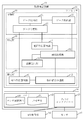
- the object detection apparatus 10 includes a classification unit 20, a determination unit 30, and an estimation unit 40 as functional elements.
- the classification unit 20 includes a data acquisition unit 21, a data classification unit 22, and a data storage unit 23.
- the determination unit 30 includes a ground shape calculation unit 31 and an area determination unit 32.
- the estimation unit 40 includes an object shape calculation unit 41 and an object combination processing unit 42.
- the functions of the classification unit 20, the determination unit 30, and the estimation unit 40 are realized by software. Specifically, the functions of the classification unit 20, the determination unit 30, and the estimation unit 40 are realized by an object detection program.
- the object detection program is a program that causes a computer to execute processes performed by the classification unit 20, the determination unit 30, and the estimation unit 40 as classification processing, determination processing, and estimation processing, respectively.
- the object detection program may be provided by being recorded on a computer-readable medium, may be provided by being stored in a recording medium, or may be provided as a program product.
- the processor 11 is a device that executes an object detection program.
- the processor 11 is a CPU, for example.
- CPU is an abbreviation for Central Processing Unit.
- the memory 12 is a device that stores an object detection program in advance or temporarily.
- the memory 12 is, for example, a RAM, a flash memory, or a combination thereof.
- RAM is an abbreviation for Random Access Memory.
- the input / output interface 13 includes a receiver that receives data input to the object detection program and a transmitter that transmits data output from the object detection program.
- the input / output interface 13 is a circuit that acquires data from the sensor 51 in accordance with an instruction from the processor 11.
- the input / output interface 13 is, for example, a communication chip or a NIC. “NIC” is an abbreviation for Network Interface Card.
- the object detection apparatus 10 may further include an input device and a display as hardware.
- the input device is a device operated by the user to input data to the object detection program.
- the input device is, for example, a mouse, a keyboard, a touch panel, or some or all of these.
- the display is a device that displays data output from the object detection program on the screen.
- the display is, for example, an LCD.
- LCD is an abbreviation for Liquid Crystal Display.
- the object detection program is read from the memory 12 into the processor 11 and executed by the processor 11.
- the memory 12 stores not only the object detection program but also the OS. “OS” is an abbreviation for Operating System.
- the processor 11 executes the object detection program while executing the OS. Part or all of the object detection program may be incorporated in the OS.
- the object detection program and the OS may be stored in the auxiliary storage device.
- the auxiliary storage device is, for example, an HDD, a flash memory, or a combination thereof. “HDD” is an abbreviation for Hard Disk Drive.
- the object detection apparatus 10 may include a plurality of processors that replace the processor 11.
- the plurality of processors share execution of the object detection program.
- Each processor is, for example, a CPU.
- Data, information, signal values and variable values used, processed or output by the object detection program are stored in the memory 12, the auxiliary storage device, or a register or cache memory in the processor 11.
- data that can be acquired by the input / output interface 13, a calculation result of the object detection program, and sensor installation information 24 are stored in the memory 12.
- the sensor installation information 24 includes position information and posture information of the sensor 51.
- Data and information stored in the memory 12 are input / output in response to a request from the processor 11.
- the object detection apparatus 10 may be configured by a single computer or may be configured by a plurality of computers. When the object detection apparatus 10 is configured by a plurality of computers, the functions of the classification unit 20, the determination unit 30, and the estimation unit 40 may be distributed and realized in each computer.
- Sensor 51 emits a plurality of signals. These multiple signals are emitted toward different areas.
- the sensor 51 measures the distance by observing reflected waves of a plurality of irradiated signals. Specifically, as shown in FIG. 2, the sensor 51 measures the distance m to the obstacle at each angle ( ⁇ , ⁇ ) with the sensor 51 as the center.
- the sensor 51 generates data indicating the measurement result of the distance for each irradiated signal.
- the sensor 51 transmits the generated data to the object detection device 10.
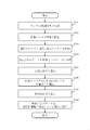
- FIG. 3 shows the operation of the object detection apparatus 10.
- step S ⁇ b> 101 the classification unit 20 acquires data indicating the measurement result of the distance for each signal emitted from the sensor 51 from the sensor 51.
- step S101 the data acquisition unit 21 acquires distance information to the object for each direction acquired by the sensor 51 via the input / output interface 13.
- the data to be acquired is the distance m from the sensor 51 to the obstacle at each angle ( ⁇ , ⁇ ).
- step S102 to step S104 the classification unit 20 uses the data acquired in step S101 as the first data indicating that the distance has not been measured, the second data indicating the distance to one or more obstacles, It classify
- step S102 the data acquisition unit 21 investigates the presence or absence of distance data for the acquired data. Depending on the investigation result, data with distance data is sent to the data classification unit 22, and data without distance data is sent to the data storage unit 23.
- the data storage unit 23 extracts a direction in which the distance data could not be acquired, and stores information indicating the extracted direction in the memory 12.
- the data classification unit 22 determines whether the data acquired by the data acquisition unit 21 is a part of the ground or not for the data that has acquired the distance to the object. More specifically, the data classification unit 22 determines whether the received data is the ground or an object. The determination of whether the object is the ground or the object may be performed by any method, but in the present embodiment, as shown in FIG. 4, when it is assumed that the periphery of the sensor 51 is a plane, the measurement direction Is known, the distance m to the ground is obtained. With respect to the difference between the obtained distance data and the actual measurement data, it can be determined that the data is within the threshold value and that it is the ground.
- a plane that minimizes the sum of the square distances to the point cloud may be obtained from the acquired data, and the distance of the data with respect to the obtained plane may be obtained to perform determination based on the threshold value.
- the determination of the plane using the data of adjacent points may be repeated a plurality of times.
- the object shape calculation unit 41 stores the data determined by the data classification unit 22 as not being the ground in the memory 12, and further performs a process of dividing the set of point groups as individual objects. More specifically, the object shape calculation unit 41 classifies the received data into data for each object, and obtains a position where each object is located.
- a grid is defined on a two-dimensional plane, and data is stored in an adjacent grid. If it exists, a method of recognizing the data as one object is used.
- step S105 to step S107 may be performed before the processing of step S104.
- step S105 to step S107 the determination unit 30 refers to the third data to determine whether or not the ground exists in the first area that is the irradiation destination area of the signal corresponding to the first data.
- the determination unit 30 uses the third data to calculate the shape of the ground in the entire area to which the plurality of signals irradiated by the sensor 51 are irradiated. The determination unit 30 determines whether the ground exists in the first region from the calculation result of the shape of the ground.
- the ground shape calculation unit 31 stores the data determined as the ground by the data classification unit 22 in the memory 12, and calculates the ground shape. More specifically, the ground shape calculation unit 31 calculates the shape of the ground using the received data. The ground shape calculation unit 31 uses the data determined to be ground data and calculates the shape of the ground, so that the position of the ground can be determined based on the surrounding measurement data even in an area where the ground is not measured. Is estimated.
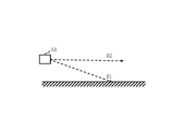
- step S ⁇ b> 106 the area determination unit 32 intersects the ground calculated by the ground shape calculation unit 31 with respect to the direction information stored in the memory 12 by the data storage unit 23 for which distance data could not be acquired. Judge whether to do. More specifically, the area determination unit 32 uses the ground shape data obtained by the ground shape calculation unit 31 and the position information of the sensor 51 included in the sensor installation information 24 for the data without distance information, from the sensor 51 to the ground. Data for which there was no distance data is extracted for measurement toward the direction. As shown in FIG. 6, if the sensing direction of the extracted data is the direction D1 of the ground, the fact that light is not reflected on the ground can be considered that there is an object that reflects light low.
- the ground in the direction D1 of the ground, at least the ground exists in a region near the measurable distance of LiDAR. Therefore, when there is no measurement value, it can be determined that there is an object but the light is not reflected and returned.
- the sensing direction of the extracted data is the direction D2 other than the ground, there may be no reflecting object. That is, there may be no object in an area closer to the measurable distance in the direction D2 other than the ground.
- step S107 the area determination unit 32 does not reflect light in the direction intersecting the ground with respect to the direction information stored in the memory 12 by the data storage unit 23 in which the distance data could not be acquired. It is determined that there is an object, and an area where there is a possibility of the object is calculated. More specifically, the region determination unit 32 estimates a non-reflective region using the data extracted in step S106 and the ground data.
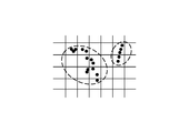
- the non-reflective region can be defined as a region surrounded by detection points from which distance data can be acquired as shown in FIG. 7 with respect to the direction extracted in step S106.
- step S108 the estimation unit 40 determines that the ground exists in the first region by the determination unit 30, and the first region and the second region that is the irradiation destination region of the signal corresponding to the second data are adjacent to each other. If it is, it is estimated that one obstacle X exists across the first area and the second area.
- the estimation unit 40 includes two or more signals corresponding to the second data among a plurality of signals emitted by the sensor 51, and a pair of second regions are both sides of the first region as the second region. It is estimated that the obstacle X exists over the first region and the pair of second regions.
- the estimation unit 40 calculates the shape of the obstacle X in the pair of second regions using the second data.
- the estimation unit 40 estimates the shape of the obstacle X in the first region from the calculation result of the shape of the obstacle X.
- the estimation unit 40 combines the calculation result of the shape of the obstacle X and the estimation result.
- the non-reflective region calculated by the region determination unit 32 is adjacent to the region where the object obtained by the object shape calculation unit 41 in the object combination processing unit 42 is in step S104. If it is adjacent, the area where the object exists is expanded and the separated objects are combined. More specifically, the object combination processing unit 42 connects the object shapes when the non-reflective regions obtained by the region determining unit 32 are adjacent to the object shape data obtained by the object shape calculating unit 41. Match. As shown in FIG. 8, when the shape data Fa and the shape data Fb exist, and there is a non-reflective region adjacent to them, the object combination processing unit 42 combines the shape data Fa and the shape data Fb into one. Detect as an object.
- the distance is not detected in the detection direction of the ground direction from the ground information obtained by calculating the shape of the ground from all the information for one frame acquired by the sensor 51 and the installation information of the sensor 51.
- an undetected area is defined.
- the shape of the object is obtained from the detection data even when detecting an object having a portion that is difficult to reflect light by combining the undetected area with the object detection area. It is possible to prevent the results from separating.
- the distance is not detected with respect to the light ray direction other than the ground direction, the undetected area is not defined, and the object detection area can be prevented from being excessively widened. That is, it is possible to prevent the results calculated as objects from being combined more than necessary, and to reduce erroneous detection.
- the object detection device 10 detects an object from information output from the sensor 51.
- the ground shape calculation unit 31 calculates the ground shape from the distance information from the sensor 51 to the obstacle in each direction and the sensor installation information 24.
- the region determination unit 32 extracts a direction obtained from the ground shape calculated by the ground shape calculation unit 31 from the light ray directions that could not be detected, and determines a non-reflective region. If the non-reflective region calculated by the region determination unit 32 is adjacent to the region calculated by the object combination processing unit 42 as a lump for each object from the data determined as the object data, the object data is Combine.
- the area determination unit 32 measures the direction in which distance data could not be acquired from the ground shape obtained from the acquired distance data and the installation information of the sensor 51 in spite of the presence of an object.
- the non-reflective region where there is a possibility that an object with low reflection characteristics may exist is identified by using the fact that the image cannot be generated.
- the object combination processing unit 42 joins the object shapes. , Prevent the object from being detected separately.
- the result of obtaining the shape of the object from the detection data is prevented from being separated, and the result calculated as the object is more than necessary. It is possible to prevent coupling and reduce false detections.
- the functions of the classification unit 20, the determination unit 30, and the estimation unit 40 are realized by software.
- the functions of the classification unit 20, the determination unit 30, and the estimation unit 40 are realized by hardware. May be. About this modification, the difference with this Embodiment is mainly demonstrated.
- the object detection apparatus 10 includes hardware such as an electronic circuit 19 and an input / output interface 13.
- the electronic circuit 19 is dedicated hardware for realizing the functions of the classification unit 20, the determination unit 30, and the estimation unit 40.
- the electronic circuit 19 is, for example, a single circuit, a composite circuit, a programmed processor, a parallel programmed processor, a logic IC, a GA, an FPGA, an ASIC, or some or all of these.
- IC is an abbreviation for Integrated Circuit.
- GA is an abbreviation for Gate Array.
- FPGA is an abbreviation for Field-Programmable Gate Array.
- ASIC is an abbreviation for Application Specific Integrated Circuit.
- the sensor installation information 24 is stored in advance in the data storage unit 23 of the classification unit 20.
- the function of the data storage unit 23 is realized by a built-in memory of the electronic circuit 19.
- the object detection apparatus 10 may include a plurality of electronic circuits that replace the electronic circuit 19.
- the plurality of electronic circuits implement the functions of the classification unit 20, the determination unit 30, and the estimation unit 40 as a whole.
- Each electronic circuit is, for example, a single circuit, a composite circuit, a programmed processor, a parallel programmed processor, a logic IC, a GA, an FPGA, an ASIC, or some or all of these combinations .
- the functions of the classification unit 20, the determination unit 30, and the estimation unit 40 may be realized by a combination of software and hardware. That is, some of the functions of the classification unit 20, the determination unit 30, and the estimation unit 40 may be realized by dedicated hardware, and the rest may be realized by software.
- Both the processor 11 and the electronic circuit 19 are processing circuits. That is, regardless of the configuration of the object detection device 10 shown in FIGS. 1 and 9, the operations of the classification unit 20, the determination unit 30, and the estimation unit 40 are performed by the processing circuit.
- Embodiment 2 FIG. In the present embodiment, differences from the first embodiment will be mainly described with reference to FIGS. 10 and 11.
- the vehicle on which the object detection device 10 is mounted includes a GPS receiver 52 in addition to the sensor 51.
- GPS is an abbreviation for Global Positioning System.
- the object detection device 10 is connected to the GPS receiver 52 by wire or wirelessly.
- the determination unit 30 includes a position calculation unit 33 in addition to the ground shape calculation unit 31 and the region determination unit 32 as functional elements.
- the map information 34 is stored in the memory 12.
- the map information 34 includes position information of surrounding structures.
- the non-reflective area is obtained using the ground data obtained from the data having a distance.
- the non-reflective region even when there is a surrounding structure in addition to the ground data, using the vehicle position information obtained from GPS and the map information 34 including the position information of the surrounding structure. Is calculated.
- FIG. 11 shows the operation of the object detection apparatus 10.
- step S201 to step S205 Since the processing from step S201 to step S205 is the same as the processing from step S101 to step 105 in the first embodiment, description thereof will be omitted.
- step S206 and step S207 the determination unit 30 acquires the position information of the surrounding structures included in the map information 34 stored in the memory 12 from the memory 12.
- the determination unit 30 determines whether there is a structure in the first region based on the acquired position information and the position information of the sensor 51 included in the sensor installation information 24.
- the first area is an irradiation destination area of a signal corresponding to the first data.
- the first data is data obtained from the sensor 51 and indicating that the distance has not been measured.
- the position calculation unit 33 uses the position information obtained from the GPS receiver 52 and the map information 34, and the position data of surrounding structures centered on the vehicle on which the sensor 51 is mounted. Is stored in the memory 12.
- the area determination unit 32 uses the ground shape data obtained by the ground shape calculation unit 31 and the sensor installation information 24 for the data without distance information stored in the memory 12 by the data storage unit 23. From the position information of the included sensor 51, data for which there is no distance data is extracted for the measurement from the sensor 51 toward the ground.
- the area determination unit 32 uses the position data of the structure stored in the memory 12 by the position calculation unit 33 and the position information of the sensor 51 included in the sensor installation information 24 for the data without the distance information from Data for which there was no distance data is extracted for measurement in the direction of the structure.
- step S207 the region determination unit 32 estimates a non-reflective region using the data extracted in step S206 and the ground data.
- the non-reflective region can be defined as a region surrounded by detection points from which distance data can be acquired as shown in FIG. 7 with respect to the direction extracted in step S206.
- step S208 the estimation unit 40 determines that the ground is present in the first region by the determination unit 30 and the first region and the second region are adjacent to each other, as in the first embodiment. It is estimated that the obstacle X exists over the first area and the second area. In the present embodiment, the estimation unit 40 determines that there is a structure in the first region by the determination unit 30 and the obstacle X is the first even when the first region and the second region are adjacent to each other. It is estimated that it exists over 1 area
- the second area is an irradiation destination area of a signal corresponding to the second data. The second data is data indicating the distance to one or more obstacles acquired from the sensor 51.
- the non-reflective region can be defined not only for the ground direction but also for the direction in which the structure exists, and the result of obtaining the shape of the object from the detection data Can be prevented from separating, and the result calculated as an object can be prevented from being combined more than necessary, thereby reducing false detection.
- 10 object detection device 11 processor, 12 memory, 13 input / output interface, 14 signal lines, 19 electronic circuit, 20 classification unit, 21 data acquisition unit, 22 data classification unit, 23 data storage unit, 24 sensor installation information, 30 determination Unit, 31 ground shape calculation unit, 32 area determination unit, 33 position calculation unit, 34 map information, 40 estimation unit, 41 object shape calculation unit, 42 object combination processing unit, 51 sensor, 52 GPS receiver.
Landscapes
- Engineering & Computer Science (AREA)
- Physics & Mathematics (AREA)
- Computer Networks & Wireless Communication (AREA)
- General Physics & Mathematics (AREA)
- Radar, Positioning & Navigation (AREA)
- Remote Sensing (AREA)
- Electromagnetism (AREA)
- Optical Radar Systems And Details Thereof (AREA)
- Radar Systems Or Details Thereof (AREA)
Abstract
物体検出装置(10)において、分類部(20)は、センサ(51)から、センサ(51)が照射した信号ごとの距離の計測結果を示すデータを取得する。分類部(20)は、取得したデータを、距離が計測されなかったことを示す第1データと、1つ以上の障害物までの距離を示す第2データと、地面までの距離を示す第3データとに分類する。判定部(30)は、第3データを参照して、第1データに対応する信号の照射先の領域である第1領域に地面が存在するかどうかを判定する。推定部(40)は、判定部(30)により第1領域に地面が存在すると判定され、かつ、第1領域と第2データに対応する信号の照射先の領域である第2領域とが隣接している場合、1つの障害物が第1領域と第2領域とに跨って存在すると推定する。
Description
本発明は、物体検出装置、車両、物体検出方法および物体検出プログラムに関するものである。
特許文献1には、探査波を照射しても検出点として検出されない箇所が物体上にあっても、同じ物体であると認識する技術が開示されている。
パルス状に発光するレーザー照射に対する散乱光を測定し、遠距離にある対象までの距離およびその対象の性質を分析するLiDARのようなセンサを用いたとき、対象となる物体の特性または物体の面の向きによっては、実際に光を照射してもセンサ方向に光が返ってこない場合がある。「LiDAR」は、Laser Imaging Detection and Rangingの略語である。
上記のようなセンサで周囲の物体を検出する場合、実際に光を反射しにくい部分を含む物体があると、物体が分離して検出されてしまい、物体認識精度が低下してしまう。特許文献1に記載の技術では、今回の検出結果において検出点が検出された検出方向に隣接する隣接方向に検出点が検出されず、隣接方向に検出点が存在すると判定された場合、検出方向に今回検出された検出点が示す物体の検出点が隣接方向に存在するものとして物体を認識する。しかしながら、特許文献1に記載の技術では、未検出点において隣接点の情報を利用し、物体が存在するものとして認識するため、実際に物体がなくて未検出点となった箇所も隣接方向に物体がある場合にはその物体の情報で必要以上に埋めてしまい、複数の物体がある場合にも1つの大きな物体が存在すると誤認識してしまう。
本発明は、物体の検出精度の向上を目的とする。
本発明の一態様に係る物体検出装置は、
互いに異なる領域に向かって照射された複数の信号の反射波を観測することで距離を計測するセンサから、信号ごとの距離の計測結果を示すデータを取得し、取得したデータを、距離が計測されなかったことを示す第1データと、1つ以上の障害物までの距離を示す第2データと、地面までの距離を示す第3データとに分類する分類部と、
前記第3データを参照して、前記第1データに対応する信号の照射先の領域である第1領域に前記地面が存在するかどうかを判定する判定部と、
前記判定部により前記第1領域に前記地面が存在すると判定され、かつ、前記第1領域と前記第2データに対応する信号の照射先の領域である第2領域とが隣接している場合、1つの障害物が前記第1領域と前記第2領域とに跨って存在すると推定する推定部と
を備える。
互いに異なる領域に向かって照射された複数の信号の反射波を観測することで距離を計測するセンサから、信号ごとの距離の計測結果を示すデータを取得し、取得したデータを、距離が計測されなかったことを示す第1データと、1つ以上の障害物までの距離を示す第2データと、地面までの距離を示す第3データとに分類する分類部と、
前記第3データを参照して、前記第1データに対応する信号の照射先の領域である第1領域に前記地面が存在するかどうかを判定する判定部と、
前記判定部により前記第1領域に前記地面が存在すると判定され、かつ、前記第1領域と前記第2データに対応する信号の照射先の領域である第2領域とが隣接している場合、1つの障害物が前記第1領域と前記第2領域とに跨って存在すると推定する推定部と
を備える。
本発明では、距離が計測されなかった第1領域に地面が存在すると判定され、かつ、第1領域と障害物までの距離が計測された第2領域とが隣接している場合に、その障害物が第1領域と第2領域とに跨って存在すると推定される。そのため、センサで周囲の物体を検出する場合、実際に光を反射しにくい部分を含む物体があっても、物体が分離して検出されない。よって、本発明によれば、物体の検出精度が向上する。
以下、本発明の実施の形態について、図を用いて説明する。各図中、同一または相当する部分には、同一符号を付している。実施の形態の説明において、同一または相当する部分については、説明を適宜省略または簡略化する。なお、本発明は、以下に説明する実施の形態に限定されるものではなく、必要に応じて種々の変更が可能である。例えば、以下に説明する実施の形態のうち、2つ以上の実施の形態が組み合わせられて実施されても構わない。あるいは、以下に説明する実施の形態のうち、1つの実施の形態または2つ以上の実施の形態の組み合わせが部分的に実施されても構わない。
実施の形態1.
本実施の形態について、図1から図8を用いて説明する。
本実施の形態について、図1から図8を用いて説明する。
***構成の説明***
図1を参照して、本実施の形態に係る物体検出装置10の構成を説明する。
図1を参照して、本実施の形態に係る物体検出装置10の構成を説明する。
物体検出装置10は、コンピュータである。物体検出装置10は、本実施の形態では車載コンピュータであるが、クラウドサーバ等、遠隔地に設置されたサーバコンピュータでもよい。物体検出装置10が搭載されている車両には、LiDAR等のセンサ51も搭載されている。物体検出装置10は、センサ51と有線または無線で接続されている。
物体検出装置10は、プロセッサ11を備えるとともに、メモリ12および入出力インタフェース13といった他のハードウェアを備える。プロセッサ11は、信号線14を介して他のハードウェアと接続され、これら他のハードウェアを制御する。
物体検出装置10は、機能要素として、分類部20と、判定部30と、推定部40とを備える。分類部20は、データ取得部21と、データ分類部22と、データ格納部23とを備える。判定部30は、地面形状算出部31と、領域判定部32とを備える。推定部40は、物体形状算出部41と、物体結合処理部42とを備える。分類部20、判定部30および推定部40の機能は、ソフトウェアにより実現される。具体的には、分類部20、判定部30および推定部40の機能は、物体検出プログラムにより実現される。物体検出プログラムは、分類部20、判定部30および推定部40により行われる処理をそれぞれ分類処理、判定処理および推定処理としてコンピュータに実行させるプログラムである。物体検出プログラムは、コンピュータ読取可能な媒体に記録されて提供されてもよいし、記録媒体に格納されて提供されてもよいし、プログラムプロダクトとして提供されてもよい。
プロセッサ11は、物体検出プログラムを実行する装置である。プロセッサ11は、例えば、CPUである。「CPU」は、Central Processing Unitの略語である。
メモリ12は、物体検出プログラムをあらかじめまたは一時的に記憶する装置である。メモリ12は、例えば、RAM、フラッシュメモリまたはこれらの組み合わせである。「RAM」は、Random Access Memoryの略語である。
入出力インタフェース13は、物体検出プログラムに入力されるデータを受信するレシーバと、物体検出プログラムから出力されるデータを送信するトランスミッタとを備える。入出力インタフェース13は、プロセッサ11からの指示に従ってセンサ51よりデータを取得する回路である。入出力インタフェース13は、例えば、通信チップまたはNICである。「NIC」は、Network Interface Cardの略語である。
物体検出装置10は、ハードウェアとして、入力機器と、ディスプレイとをさらに備えてもよい。
入力機器は、物体検出プログラムへのデータの入力のためにユーザにより操作される機器である。入力機器は、例えば、マウス、キーボード、タッチパネル、または、これらのうちいくつか、もしくは、すべての組み合わせである。
ディスプレイは、物体検出プログラムから出力されるデータを画面に表示する機器である。ディスプレイは、例えば、LCDである。「LCD」は、Liquid Crystal Displayの略語である。
物体検出プログラムは、メモリ12からプロセッサ11に読み込まれ、プロセッサ11によって実行される。メモリ12には、物体検出プログラムだけでなく、OSも記憶されている。「OS」は、Operating Systemの略語である。プロセッサ11は、OSを実行しながら、物体検出プログラムを実行する。なお、物体検出プログラムの一部または全部がOSに組み込まれていてもよい。
物体検出プログラムおよびOSは、補助記憶装置に記憶されていてもよい。補助記憶装置は、例えば、HDD、フラッシュメモリまたはこれらの組み合わせである。「HDD」は、Hard Disk Driveの略語である。物体検出プログラムおよびOSは、補助記憶装置に記憶されている場合、メモリ12にロードされ、プロセッサ11によって実行される。
物体検出装置10は、プロセッサ11を代替する複数のプロセッサを備えていてもよい。これら複数のプロセッサは、物体検出プログラムの実行を分担する。それぞれのプロセッサは、例えば、CPUである。
物体検出プログラムにより利用、処理または出力されるデータ、情報、信号値および変数値は、メモリ12、補助記憶装置、または、プロセッサ11内のレジスタまたはキャッシュメモリに記憶される。特に、入出力インタフェース13で取得できるデータ、物体検出プログラムの算出結果、および、センサ設置情報24は、メモリ12に記憶される。センサ設置情報24には、センサ51の位置情報と姿勢情報とが含まれている。メモリ12に記憶されたデータおよび情報は、プロセッサ11からの要求に応じて入出力される。
物体検出装置10は、1台のコンピュータで構成されていてもよいし、複数台のコンピュータで構成されていてもよい。物体検出装置10が複数台のコンピュータで構成されている場合は、分類部20、判定部30および推定部40の機能が、各コンピュータに分散されて実現されてもよい。
***動作の説明***
図1から図8を参照して、本実施の形態に係る物体検出装置10およびセンサ51の動作を説明する。物体検出装置10の動作とセンサ51の動作とを組み合わせることで、本実施の形態に係る物体検出方法が実現される。
図1から図8を参照して、本実施の形態に係る物体検出装置10およびセンサ51の動作を説明する。物体検出装置10の動作とセンサ51の動作とを組み合わせることで、本実施の形態に係る物体検出方法が実現される。
センサ51は、複数の信号を照射する。これら複数の信号は、互いに異なる領域に向かって照射される。センサ51は、照射した複数の信号の反射波を観測することで距離を計測する。具体的には、センサ51は、図2に示すように、センサ51を中心として各角度(θ,ω)の障害物までの距離mを計測する。
センサ51は、照射した信号ごとの距離の計測結果を示すデータを生成する。センサ51は、生成したデータを物体検出装置10に送信する。
図3は、物体検出装置10の動作を示している。
ステップS101において、分類部20は、センサ51から、センサ51が照射した信号ごとの距離の計測結果を示すデータを取得する。
具体的には、ステップS101において、データ取得部21が、入出力インタフェース13を介して、センサ51で取得した各方向に対する物体までの距離情報を取得する。取得するデータは、図2に示すように、センサ51を中心として各角度(θ,ω)の障害物までの距離mである。
ステップS102からステップS104において、分類部20は、ステップS101で取得したデータを、距離が計測されなかったことを示す第1データと、1つ以上の障害物までの距離を示す第2データと、地面までの距離を示す第3データとに分類する。
具体的には、ステップS102において、データ取得部21が、取得したデータについて、距離データの有無を調査する。調査結果により、距離データがあるデータはデータ分類部22に送られ、距離データがないデータはデータ格納部23に送られる。データ格納部23は、距離データを取得できなかった方向を抽出し、抽出した方向を示す情報をメモリ12に格納する。
そして、ステップS103において、データ分類部22が、データ取得部21で取得したデータのうち、物体までの距離が取得できたデータについて、地面の一部であるか、そうでないか判別する。より具体的には、データ分類部22が、受け取ったデータが地面であるか物体であるかを判定する。地面であるか物体であるかの判定は、任意の方法で行われてよいが、本実施の形態では、図4に示すように、センサ51の周囲が平面であったと仮定したとき、計測方向が分かっていれば、地面までの距離mを求めることで行われる。求められた距離データと実際の計測データとの差分に対して、閾値以内であったデータに対して、地面であると判定することができる。取得データから、点群との2乗距離の合計を最小にする平面を求め、求めた平面に対するデータの距離を求めて閾値による判定を行ってもよい。斜面に対応するために、隣接した点のデータで平面を求めることを複数回繰り返してもよい。
そして、ステップS104において、物体形状算出部41が、データ分類部22において、地面ではないと判別されたデータをメモリ12に格納し、さらに点群の集合を個々の物体として切り分ける処理を行う。より具体的には、物体形状算出部41が、受け取ったデータを物体ごとのデータに分類し、各物体がある位置を求める。物体ごとにデータを分類する方法としては、任意の方法を用いてよいが、本実施の形態では、図5に示すように、2次元平面上に格子を定義し、隣接する格子内にデータが存在する場合に、そのデータを1つの物体として認識する方法が用いられる。
なお、ステップS104の処理の前に、ステップS105からステップS107の一部または全部の処理が行われてもよい。
ステップS105からステップS107において、判定部30は、第3データを参照して、第1データに対応する信号の照射先の領域である第1領域に地面が存在するかどうかを判定する。
本実施の形態では、判定部30は、第3データを利用して、センサ51が照射した複数の信号の照射先の領域全体における地面の形状を算出する。判定部30は、地面の形状の算出結果から、第1領域に地面が存在するかどうかを判定する。
具体的には、ステップS105において、地面形状算出部31が、データ分類部22で地面として判定されたデータをメモリ12に格納し、地面形状を算出する。より具体的には、地面形状算出部31が、受け取ったデータを利用して、地面の形状を算出する。地面形状算出部31は、地面のデータであると判定されたデータを利用し、地面の形状を算出することで、地面を計測していない領域についても周囲の計測データをもとに地面の位置を推定する。
そして、ステップS106において、領域判定部32が、データ格納部23によりメモリ12に格納された、距離データを取得できなかった方向の情報に対して、地面形状算出部31で算出された地面と交差するかを判定する。より具体的には、領域判定部32が、距離情報のないデータについて、地面形状算出部31で求めた地面形状データとセンサ設置情報24に含まれるセンサ51の位置情報とから、センサ51から地面方向に向かう計測に対して、距離データがなかったデータを抽出する。図6に示すように、抽出したデータのセンシング方向が地面の方向D1であれば、地面に光が反射していないということは、光を低反射する物体があったと考えることができる。すなわち、地面の方向D1には、LiDARの計測可能距離より近い領域に少なくとも地面が存在するから、計測値がない場合は、物体はあるが、光が反射して返ってこなかったと判定できる。一方で、抽出したデータのセンシング方向が地面以外の方向D2であれば、反射する物体が何もない場合がある。すなわち、地面以外の方向D2には、計測可能距離より近い領域に物体がない場合がある。
そして、ステップS107において、領域判定部32が、データ格納部23によりメモリ12に格納された、距離データを取得できなかった方向の情報に対して、地面と交差する方向については、光を反射しない物体があると判定し、物体がある可能性がある領域を算出する。より具体的には、領域判定部32が、ステップS106で抽出したデータと地面データとを利用して、非反射領域を推定する。非反射領域は、ステップS106で抽出した方向に対して、図7に示すように、距離データを取得できた検出点に囲まれる領域として定義できる。
ステップS108において、推定部40は、判定部30により第1領域に地面が存在すると判定され、かつ、第1領域と第2データに対応する信号の照射先の領域である第2領域とが隣接している場合、1つの障害物Xが第1領域と第2領域とに跨って存在すると推定する。
特に、推定部40は、センサ51が照射した複数の信号の中に、第2データに対応する2つ以上の信号があり、第2領域として、1対の第2領域が第1領域の両側に隣接している場合、障害物Xが第1領域と1対の第2領域とに跨って存在すると推定する。
本実施の形態では、推定部40は、第2データを利用して、1対の第2領域における障害物Xの形状を算出する。推定部40は、障害物Xの形状の算出結果から、第1領域における障害物Xの形状を推定する。推定部40は、障害物Xの形状の算出結果と推定結果とを結合する。
具体的には、ステップS108において、物体結合処理部42が、ステップS104で物体形状算出部41が求めた物体が存在する領域に対して、領域判定部32で算出された非反射領域が隣接するかどうかを確認し、隣接している場合は物体が存在している領域を広げ、分離している物体を結合させる。より具体的には、物体結合処理部42が、物体形状算出部41で求めた物体の形状データに関して、領域判定部32で求めた非反射領域が隣接している場合に、物体の形状をつなぎ合わせる。図8に示すように、形状データFaと形状データFbとが存在し、それらに隣接して非反射領域が存在する場合、物体結合処理部42は、形状データFaと形状データFbとを1つの物体として検出する。
***実施の形態の効果の説明***
本実施の形態では、距離が計測されなかった第1領域に地面が存在すると判定され、かつ、第1領域と障害物Xまでの距離が計測された第2領域とが隣接している場合に、その障害物Xが第1領域と第2領域とに跨って存在すると推定される。そのため、センサ51で周囲の物体を検出する場合、実際に光を反射しにくい部分を含む物体があっても、物体が分離して検出されない。よって、本実施の形態によれば、物体の検出精度が向上する。
本実施の形態では、距離が計測されなかった第1領域に地面が存在すると判定され、かつ、第1領域と障害物Xまでの距離が計測された第2領域とが隣接している場合に、その障害物Xが第1領域と第2領域とに跨って存在すると推定される。そのため、センサ51で周囲の物体を検出する場合、実際に光を反射しにくい部分を含む物体があっても、物体が分離して検出されない。よって、本実施の形態によれば、物体の検出精度が向上する。
本実施の形態では、センサ51で取得した1フレーム分の全情報から地面の形状を算出した地面情報とセンサ51の設置情報とから、地面方向の検出方向に対して距離が未検出であった場合について、未検出領域が定義される。周囲に物体が検出されている場合には、未検出領域を物体検出領域に結合させることにより、光を反射しにくい部分を持つ物体を検出する場合においても、検出データより物体の形状を求めた結果が分離することを防ぐことができる。地面方向ではない光線方向に対して距離が未検出であった場合には、未検出領域が定義されず、過剰に物体の検出領域を広げてしまうことを防ぐことができる。すなわち、物体として算出した結果が必要以上に結合されることを防ぎ、誤検出を減らすことができるようになる。
本実施の形態では、物体検出装置10が、センサ51が出力する情報から物体を検出する。具体的には、地面形状算出部31が、センサ51から各方向に対する障害物までの距離情報とセンサ設置情報24とから地面形状を算出する。領域判定部32が、検出できなかった光線方向のうち、地面形状算出部31で算出された地面形状から求まった方向を抽出し、非反射領域を判定する。物体結合処理部42が、物体のデータとして判別されたデータから物体ごとに塊として算出した領域に対して、領域判定部32で算出された非反射領域が隣接している場合に、物体データを結合させる。
領域判定部32は、距離データを取得することができなかった方向に対して、周囲の取得できた距離データより求めた地面形状とセンサ51の設置情報とから、物体があるにも関わらず計測ができなかったことを利用して、反射特性の低い物体が存在する可能性がある非反射領域を特定する。
物体結合処理部42は、距離データを取得することができたデータから求めた物体の形状データと、領域判定部32で求めた非反射領域が隣接している場合、物体の形状をつなぎ合わせて、物体が分離して検出されることを防ぐ。
上記手法を用いることにより、光を反射しにくい部分を持つ物体を検出する場合においても、検出データより物体の形状を求めた結果が分離することを防ぐとともに、物体として算出した結果が必要以上に結合することを防ぎ、誤検出を減らすことができるようになる。
***他の構成***
本実施の形態では、分類部20、判定部30および推定部40の機能がソフトウェアにより実現されるが、変形例として、分類部20、判定部30および推定部40の機能がハードウェアにより実現されてもよい。この変形例について、主に本実施の形態との差異を説明する。
本実施の形態では、分類部20、判定部30および推定部40の機能がソフトウェアにより実現されるが、変形例として、分類部20、判定部30および推定部40の機能がハードウェアにより実現されてもよい。この変形例について、主に本実施の形態との差異を説明する。
図9を参照して、本実施の形態の変形例に係る物体検出装置10の構成を説明する。
物体検出装置10は、電子回路19および入出力インタフェース13といったハードウェアを備える。
電子回路19は、分類部20、判定部30および推定部40の機能を実現する専用のハードウェアである。電子回路19は、例えば、単一回路、複合回路、プログラム化したプロセッサ、並列プログラム化したプロセッサ、ロジックIC、GA、FPGA、ASIC、または、これらのうちいくつか、もしくは、すべての組み合わせである。「IC」は、Integrated Circuitの略語である。「GA」は、Gate Arrayの略語である。「FPGA」は、Field-Programmable Gate Arrayの略語である。「ASIC」は、Application Specific Integrated Circuitの略語である。
図示していないが、センサ設置情報24は、分類部20のデータ格納部23にあらかじめ記憶されている。データ格納部23の機能は、電子回路19の内蔵メモリによって実現される。
物体検出装置10は、電子回路19を代替する複数の電子回路を備えていてもよい。これら複数の電子回路は、全体として分類部20、判定部30および推定部40の機能を実現する。それぞれの電子回路は、例えば、単一回路、複合回路、プログラム化したプロセッサ、並列プログラム化したプロセッサ、ロジックIC、GA、FPGA、ASIC、または、これらのうちいくつか、もしくは、すべての組み合わせである。
別の変形例として、分類部20、判定部30および推定部40の機能がソフトウェアとハードウェアとの組み合わせにより実現されてもよい。すなわち、分類部20、判定部30および推定部40の機能の一部が専用のハードウェアにより実現され、残りがソフトウェアにより実現されてもよい。
プロセッサ11および電子回路19は、いずれも処理回路である。すなわち、物体検出装置10の構成が図1および図9のいずれに示した構成であっても、分類部20、判定部30および推定部40の動作は、処理回路により行われる。
実施の形態2.
本実施の形態について、主に実施の形態1との差異を、図10および図11を用いて説明する。
本実施の形態について、主に実施の形態1との差異を、図10および図11を用いて説明する。
***構成の説明***
図10を参照して、本実施の形態に係る物体検出装置10の構成を説明する。
図10を参照して、本実施の形態に係る物体検出装置10の構成を説明する。
本実施の形態では、物体検出装置10が搭載されている車両には、センサ51のほかに、GPS受信機52も搭載されている。「GPS」は、Global Positioning Systemの略語である。物体検出装置10は、GPS受信機52と有線または無線で接続されている。
判定部30は、機能要素として、地面形状算出部31と、領域判定部32とのほかに、位置算出部33を備える。
地図情報34は、メモリ12に記憶される。地図情報34には、周辺の構造物の位置情報が含まれている。
***動作の説明***
図10および図11を参照して、本実施の形態に係る物体検出装置10の動作を説明する。センサ51の動作については、実施の形態1のものと同じであるため、説明を省略する。物体検出装置10の動作とセンサ51の動作とを組み合わせることで、本実施の形態に係る物体検出方法が実現される。
図10および図11を参照して、本実施の形態に係る物体検出装置10の動作を説明する。センサ51の動作については、実施の形態1のものと同じであるため、説明を省略する。物体検出装置10の動作とセンサ51の動作とを組み合わせることで、本実施の形態に係る物体検出方法が実現される。
実施の形態1では、距離があるデータから求めた地面データを利用して、非反射領域が求められる。本実施の形態では、GPSより得られる車両の位置情報と、周囲の構造物の位置情報を含む地図情報34とを用いて、地面データ以外に、周囲の構造物がある場合についても非反射領域が算出される。
図11は、物体検出装置10の動作を示している。
ステップS201からステップS205の処理については、実施の形態1におけるステップS101からステップ105の処理と同じであるため、説明を省略する。
ステップS206およびステップS207において、判定部30は、メモリ12から、メモリ12に記憶された地図情報34に含まれる、周辺の構造物の位置情報を取得する。判定部30は、取得した位置情報と、センサ設置情報24に含まれる、センサ51の位置情報とに基づいて、第1領域に構造物が存在するかどうかを判定する。前述したように、第1領域は、第1データに対応する信号の照射先の領域である。第1データは、センサ51から取得された、距離が計測されなかったことを示すデータである。
具体的には、ステップS206において、位置算出部33が、GPS受信機52より得られた位置情報と地図情報34とから、センサ51が搭載された車両を中心とした周囲の構造物の位置データを作成し、メモリ12に格納する。実施の形態1と同様に、領域判定部32が、データ格納部23によりメモリ12に格納された、距離情報のないデータについて、地面形状算出部31で求めた地面形状データとセンサ設置情報24に含まれるセンサ51の位置情報とから、センサ51から地面方向に向かう計測に対して、距離データがなかったデータを抽出する。同時に、領域判定部32が、距離情報のないデータについて、位置算出部33によりメモリ12に格納された構造物の位置データとセンサ設置情報24に含まれるセンサ51の位置情報とから、センサ51から構造物方向に向かう計測に対して、距離データがなかったデータを抽出する。
そして、ステップS207において、領域判定部32が、ステップS206で抽出したデータと地面データとを利用して、非反射領域を推定する。非反射領域は、ステップS206で抽出した方向に対して、図7に示すように、距離データを取得できた検出点に囲まれる領域として定義できる。
ステップS208において、推定部40は、実施の形態1と同じように、判定部30により第1領域に地面が存在すると判定され、かつ、第1領域と第2領域とが隣接している場合、障害物Xが第1領域と第2領域とに跨って存在すると推定する。推定部40は、本実施の形態では、判定部30により第1領域に構造物が存在すると判定され、かつ、第1領域と第2領域とが隣接している場合も、障害物Xが第1領域と第2領域とに跨って存在すると推定する。前述したように、第2領域は、第2データに対応する信号の照射先の領域である。第2データは、センサ51から取得された、1つ以上の障害物までの距離を示すデータである。
***実施の形態の効果の説明***
本実施の形態によれば、構造物データを利用することにより、地面方向だけでなく、構造物がある方向についても非反射領域を定義することができ、検出データより物体の形状を求めた結果が分離することを防ぐとともに、物体として算出した結果が必要以上に結合することを防ぎ、誤検出を減らすことができるようになる。
本実施の形態によれば、構造物データを利用することにより、地面方向だけでなく、構造物がある方向についても非反射領域を定義することができ、検出データより物体の形状を求めた結果が分離することを防ぐとともに、物体として算出した結果が必要以上に結合することを防ぎ、誤検出を減らすことができるようになる。
10 物体検出装置、11 プロセッサ、12 メモリ、13 入出力インタフェース、14 信号線、19 電子回路、20 分類部、21 データ取得部、22 データ分類部、23 データ格納部、24 センサ設置情報、30 判定部、31 地面形状算出部、32 領域判定部、33 位置算出部、34 地図情報、40 推定部、41 物体形状算出部、42 物体結合処理部、51 センサ、52 GPS受信機。
Claims (8)
- 互いに異なる領域に向かって照射された複数の信号の反射波を観測することで距離を計測するセンサから、信号ごとの距離の計測結果を示すデータを取得し、取得したデータを、距離が計測されなかったことを示す第1データと、1つ以上の障害物までの距離を示す第2データと、地面までの距離を示す第3データとに分類する分類部と、
前記第3データを参照して、前記第1データに対応する信号の照射先の領域である第1領域に前記地面が存在するかどうかを判定する判定部と、
前記判定部により前記第1領域に前記地面が存在すると判定され、かつ、前記第1領域と前記第2データに対応する信号の照射先の領域である第2領域とが隣接している場合、1つの障害物が前記第1領域と前記第2領域とに跨って存在すると推定する推定部と
を備える物体検出装置。 - 前記推定部は、前記複数の信号の中に、前記第2データに対応する2つ以上の信号があり、前記第2領域として、1対の第2領域が前記第1領域の両側に隣接している場合、前記1つの障害物が前記第1領域と前記1対の第2領域とに跨って存在すると推定する請求項1に記載の物体検出装置。
- 前記推定部は、前記第2データを利用して、前記1対の第2領域における前記1つの障害物の形状を算出し、前記1つの障害物の形状の算出結果から、前記第1領域における前記1つの障害物の形状を推定し、前記1つの障害物の形状の算出結果と推定結果とを結合する請求項2に記載の物体検出装置。
- 前記判定部は、前記第3データを利用して、前記複数の信号の照射先の領域全体における前記地面の形状を算出し、前記地面の形状の算出結果から、前記第1領域に前記地面が存在するかどうかを判定する請求項1から3のいずれか1項に記載の物体検出装置。
- 前記判定部は、周辺の構造物の位置情報を含む地図情報を記憶するメモリから、前記構造物の位置情報を取得し、取得した位置情報と前記センサの位置情報とに基づいて、前記第1領域に前記構造物が存在するかどうかを判定し、
前記推定部は、前記判定部により前記第1領域に前記構造物が存在すると判定され、かつ、前記第1領域と前記第2領域とが隣接している場合も、前記1つの障害物が前記第1領域と前記第2領域とに跨って存在すると推定する請求項1から4のいずれか1項に記載の物体検出装置。 - 前記センサと、
請求項1から5のいずれか1項に記載の物体検出装置と
を備える車両。 - センサが、互いに異なる領域に向かって照射された複数の信号の反射波を観測することで距離を計測し、
コンピュータが、前記センサから、信号ごとの距離の計測結果を示すデータを取得し、取得したデータを、距離が計測されなかったことを示す第1データと、1つ以上の障害物までの距離を示す第2データと、地面までの距離を示す第3データとに分類し、
前記コンピュータが、前記第3データを参照して、前記第1データに対応する信号の照射先の領域である第1領域に前記地面が存在するかどうかを判定し、
前記コンピュータが、前記第1領域に前記地面が存在すると判定され、かつ、前記第1領域と前記第2データに対応する信号の照射先の領域である第2領域とが隣接している場合、1つの障害物が前記第1領域と前記第2領域とに跨って存在すると推定する物体検出方法。 - コンピュータに、
互いに異なる領域に向かって照射された複数の信号の反射波を観測することで距離を計測するセンサから、信号ごとの距離の計測結果を示すデータを取得し、取得したデータを、距離が計測されなかったことを示す第1データと、1つ以上の障害物までの距離を示す第2データと、地面までの距離を示す第3データとに分類する分類処理と、
前記第3データを参照して、前記第1データに対応する信号の照射先の領域である第1領域に前記地面が存在するかどうかを判定する判定処理と、
前記判定処理により前記第1領域に前記地面が存在すると判定され、かつ、前記第1領域と前記第2データに対応する信号の照射先の領域である第2領域とが隣接している場合、1つの障害物が前記第1領域と前記第2領域とに跨って存在すると推定する推定処理と
を実行させる物体検出プログラム。
Priority Applications (5)
| Application Number | Priority Date | Filing Date | Title |
|---|---|---|---|
| JP2020510139A JP6704556B2 (ja) | 2018-03-26 | 2018-03-26 | 物体検出装置、車両、物体検出方法および物体検出プログラム |
| US16/967,388 US11609307B2 (en) | 2018-03-26 | 2018-03-26 | Object detection apparatus, vehicle, object detection method, and computer readable medium |
| PCT/JP2018/012107 WO2019186641A1 (ja) | 2018-03-26 | 2018-03-26 | 物体検出装置、車両、物体検出方法および物体検出プログラム |
| CN201880091454.0A CN111868562B (zh) | 2018-03-26 | 2018-03-26 | 物体检测装置、车辆、物体检测方法和计算机能读取的记录介质 |
| DE112018007135.9T DE112018007135B4 (de) | 2018-03-26 | 2018-03-26 | Objekterkennungsvorrichtung, fahrzeug, objekterkennungsverfahren und objekterkennungsprogramm |
Applications Claiming Priority (1)
| Application Number | Priority Date | Filing Date | Title |
|---|---|---|---|
| PCT/JP2018/012107 WO2019186641A1 (ja) | 2018-03-26 | 2018-03-26 | 物体検出装置、車両、物体検出方法および物体検出プログラム |
Publications (1)
| Publication Number | Publication Date |
|---|---|
| WO2019186641A1 true WO2019186641A1 (ja) | 2019-10-03 |
Family
ID=68059384
Family Applications (1)
| Application Number | Title | Priority Date | Filing Date |
|---|---|---|---|
| PCT/JP2018/012107 Ceased WO2019186641A1 (ja) | 2018-03-26 | 2018-03-26 | 物体検出装置、車両、物体検出方法および物体検出プログラム |
Country Status (5)
| Country | Link |
|---|---|
| US (1) | US11609307B2 (ja) |
| JP (1) | JP6704556B2 (ja) |
| CN (1) | CN111868562B (ja) |
| DE (1) | DE112018007135B4 (ja) |
| WO (1) | WO2019186641A1 (ja) |
Cited By (1)
| Publication number | Priority date | Publication date | Assignee | Title |
|---|---|---|---|---|
| JP2021185345A (ja) * | 2020-05-25 | 2021-12-09 | 三菱電機株式会社 | 路面領域検出装置、路面領域検出システム、車両および路面領域検出方法 |
Families Citing this family (2)
| Publication number | Priority date | Publication date | Assignee | Title |
|---|---|---|---|---|
| JP7461838B2 (ja) * | 2020-09-04 | 2024-04-04 | 株式会社日立製作所 | 道路管理システム、サーバー計算機および道路管理方法 |
| EP4309856A4 (en) | 2021-09-07 | 2024-09-04 | Samsung Electronics Co., Ltd. | ROBOTS AND METHODS FOR CONTROLLING THEM |
Citations (4)
| Publication number | Priority date | Publication date | Assignee | Title |
|---|---|---|---|---|
| JP2012225806A (ja) * | 2011-04-20 | 2012-11-15 | Toyota Central R&D Labs Inc | 道路勾配推定装置及びプログラム |
| JP2014025804A (ja) * | 2012-07-26 | 2014-02-06 | Sanyo Electric Co Ltd | 情報取得装置および物体検出装置 |
| JP2016065842A (ja) * | 2014-09-26 | 2016-04-28 | シャープ株式会社 | 障害物判定装置および障害物判定方法 |
| US20160131762A1 (en) * | 2014-11-07 | 2016-05-12 | Hyundai Mobis Co., Ltd. | Apparatus and method for determining available driving space |
Family Cites Families (13)
| Publication number | Priority date | Publication date | Assignee | Title |
|---|---|---|---|---|
| JP4791147B2 (ja) | 2005-11-04 | 2011-10-12 | 東海旅客鉄道株式会社 | 物体検出ユニット、物体検出装置、横断路の移動物体検知装置及びプログラム |
| JP5152840B2 (ja) | 2007-11-07 | 2013-02-27 | オムロンオートモーティブエレクトロニクス株式会社 | 車載用レーダ装置 |
| JP2010271166A (ja) | 2009-05-21 | 2010-12-02 | Toyota Motor Corp | 障害物検出装置 |
| JP5278283B2 (ja) * | 2009-11-02 | 2013-09-04 | トヨタ自動車株式会社 | 自律移動装置及びその制御方法 |
| WO2011145141A1 (ja) * | 2010-05-19 | 2011-11-24 | 三菱電機株式会社 | 車両後方監視装置 |
| JP5630249B2 (ja) | 2010-12-06 | 2014-11-26 | 株式会社デンソー | 物体認識装置 |
| JP5580233B2 (ja) | 2011-03-22 | 2014-08-27 | 富士重工業株式会社 | 車外監視装置および車外監視方法 |
| KR20140019501A (ko) | 2012-08-06 | 2014-02-17 | 현대자동차주식회사 | 장애물 인식을 위한 분류기의 생성방법 |
| DE112013006385B4 (de) * | 2013-01-09 | 2018-09-06 | Mitsubishi Electric Corporation | Fahrzeugperipherie-Anzeigevorrichtung |
| JP2017032329A (ja) * | 2015-07-30 | 2017-02-09 | シャープ株式会社 | 障害物判定装置、移動体、及び障害物判定方法 |
| KR101778558B1 (ko) * | 2015-08-28 | 2017-09-26 | 현대자동차주식회사 | 물체 인식 장치, 그를 가지는 차량 및 그 제어 방법 |
| JP6569504B2 (ja) | 2015-12-09 | 2019-09-04 | 株式会社デンソー | 物体認識装置 |
| JP6756124B2 (ja) * | 2016-03-16 | 2020-09-16 | 株式会社デンソー | 物体検出装置および物体検出プログラム |
-
2018
- 2018-03-26 DE DE112018007135.9T patent/DE112018007135B4/de active Active
- 2018-03-26 US US16/967,388 patent/US11609307B2/en active Active
- 2018-03-26 WO PCT/JP2018/012107 patent/WO2019186641A1/ja not_active Ceased
- 2018-03-26 CN CN201880091454.0A patent/CN111868562B/zh active Active
- 2018-03-26 JP JP2020510139A patent/JP6704556B2/ja active Active
Patent Citations (4)
| Publication number | Priority date | Publication date | Assignee | Title |
|---|---|---|---|---|
| JP2012225806A (ja) * | 2011-04-20 | 2012-11-15 | Toyota Central R&D Labs Inc | 道路勾配推定装置及びプログラム |
| JP2014025804A (ja) * | 2012-07-26 | 2014-02-06 | Sanyo Electric Co Ltd | 情報取得装置および物体検出装置 |
| JP2016065842A (ja) * | 2014-09-26 | 2016-04-28 | シャープ株式会社 | 障害物判定装置および障害物判定方法 |
| US20160131762A1 (en) * | 2014-11-07 | 2016-05-12 | Hyundai Mobis Co., Ltd. | Apparatus and method for determining available driving space |
Cited By (1)
| Publication number | Priority date | Publication date | Assignee | Title |
|---|---|---|---|---|
| JP2021185345A (ja) * | 2020-05-25 | 2021-12-09 | 三菱電機株式会社 | 路面領域検出装置、路面領域検出システム、車両および路面領域検出方法 |
Also Published As
| Publication number | Publication date |
|---|---|
| DE112018007135B4 (de) | 2022-02-17 |
| US11609307B2 (en) | 2023-03-21 |
| CN111868562A (zh) | 2020-10-30 |
| US20210215797A1 (en) | 2021-07-15 |
| DE112018007135T5 (de) | 2020-11-05 |
| JP6704556B2 (ja) | 2020-06-03 |
| JPWO2019186641A1 (ja) | 2020-05-28 |
| CN111868562B (zh) | 2024-06-14 |
Similar Documents
| Publication | Publication Date | Title |
|---|---|---|
| CN112014845B (zh) | 一种车辆障碍物定位方法、装置、设备及存储介质 | |
| CN108140323B (zh) | 用于机动车中的环境检测时改进的数据融合的方法和设备 | |
| CN103348259B (zh) | 物体检测装置以及导航装置 | |
| US11954918B2 (en) | Object detection device, object detection method, and storage medium | |
| JP5316572B2 (ja) | 物体認識装置 | |
| JP7401273B2 (ja) | 移動体の制御装置及び方法 | |
| JP6704556B2 (ja) | 物体検出装置、車両、物体検出方法および物体検出プログラム | |
| CN117269967A (zh) | 用于求取动态对象的接近的对象位置的方法、设备和车辆 | |
| US20240242432A1 (en) | Method and device for determining concealed objects in a 3d point cloud representing an environment | |
| US11982745B2 (en) | Object recognizing device | |
| US11933884B2 (en) | Radar image processing device, radar image processing method, and storage medium | |
| US12105198B2 (en) | Sensor control apparatus, vehicle, sensing method, and computer readable medium | |
| US20210364280A1 (en) | Road surface area detection device, road surface area detection system, vehicle, and road surface area detection method | |
| US11113833B2 (en) | Object detection system | |
| CN113631948A (zh) | 物体检测装置 | |
| JP2020008310A (ja) | 物体検出装置 | |
| US20230168378A1 (en) | Object detection device | |
| CN110133624B (zh) | 无人驾驶异常检测方法、装置、设备和介质 | |
| US12487354B2 (en) | Content capture of an environment of a vehicle using a priori confidence levels | |
| CN119310528B (zh) | 角反射器部署方案的确定方法、设备和可读存储介质 | |
| KR102475760B1 (ko) | 다채널 레이더를 이용한 특정물체 판별방법 및 장치 | |
| CN121008256A (zh) | 用于确定车辆的周围环境中的对象的方法和装置 | |
| US20250004138A1 (en) | Information processing device, control method, program, and storage medium | |
| WO2021131260A1 (ja) | 遮蔽検出装置および遮蔽検出プログラム | |
| CN119199868A (zh) | 机动车障碍物高度检测方法、装置及计算机可读存储介质 |
Legal Events
| Date | Code | Title | Description |
|---|---|---|---|
| 121 | Ep: the epo has been informed by wipo that ep was designated in this application |
Ref document number: 18912643 Country of ref document: EP Kind code of ref document: A1 |
|
| ENP | Entry into the national phase |
Ref document number: 2020510139 Country of ref document: JP Kind code of ref document: A |
|
| 122 | Ep: pct application non-entry in european phase |
Ref document number: 18912643 Country of ref document: EP Kind code of ref document: A1 |