WO2019176580A1 - 通信装置、通信方法、プログラム、および、通信システム - Google Patents
通信装置、通信方法、プログラム、および、通信システム Download PDFInfo
- Publication number
- WO2019176580A1 WO2019176580A1 PCT/JP2019/008004 JP2019008004W WO2019176580A1 WO 2019176580 A1 WO2019176580 A1 WO 2019176580A1 JP 2019008004 W JP2019008004 W JP 2019008004W WO 2019176580 A1 WO2019176580 A1 WO 2019176580A1
- Authority
- WO
- WIPO (PCT)
- Prior art keywords
- mode
- communication
- data signal
- multilane
- lane
- Prior art date
Links
Images


Classifications
-
- G—PHYSICS
- G06—COMPUTING; CALCULATING OR COUNTING
- G06F—ELECTRIC DIGITAL DATA PROCESSING
- G06F13/00—Interconnection of, or transfer of information or other signals between, memories, input/output devices or central processing units
-
- G—PHYSICS
- G06—COMPUTING; CALCULATING OR COUNTING
- G06F—ELECTRIC DIGITAL DATA PROCESSING
- G06F13/00—Interconnection of, or transfer of information or other signals between, memories, input/output devices or central processing units
- G06F13/14—Handling requests for interconnection or transfer
- G06F13/36—Handling requests for interconnection or transfer for access to common bus or bus system
-
- G—PHYSICS
- G06—COMPUTING; CALCULATING OR COUNTING
- G06F—ELECTRIC DIGITAL DATA PROCESSING
- G06F13/00—Interconnection of, or transfer of information or other signals between, memories, input/output devices or central processing units
- G06F13/38—Information transfer, e.g. on bus
-
- G—PHYSICS
- G06—COMPUTING; CALCULATING OR COUNTING
- G06F—ELECTRIC DIGITAL DATA PROCESSING
- G06F13/00—Interconnection of, or transfer of information or other signals between, memories, input/output devices or central processing units
- G06F13/38—Information transfer, e.g. on bus
- G06F13/42—Bus transfer protocol, e.g. handshake; Synchronisation
-
- H—ELECTRICITY
- H04—ELECTRIC COMMUNICATION TECHNIQUE
- H04L—TRANSMISSION OF DIGITAL INFORMATION, e.g. TELEGRAPHIC COMMUNICATION
- H04L12/00—Data switching networks
- H04L12/28—Data switching networks characterised by path configuration, e.g. LAN [Local Area Networks] or WAN [Wide Area Networks]
- H04L12/40—Bus networks
Definitions
- the present disclosure relates to a communication device, a communication method, a program, and a communication system, and in particular, a communication device, a communication method, a program, and a communication device that can reliably perform communication using a plurality of data signal lines.
- the present invention relates to a communication system.
- CCI Chip Control Interface
- I2C Inter-Integrated Circuit
- I2C and I3C are configured to be able to communicate with slaves connected to the bus IF according to control by a master having the initiative of communication via the bus IF.
- a function that maintains compatibility so that communication with an I2C device can be performed a function called hot join that enables a slave to participate in the bus IF, and multiple masters A function to transfer master authority between each other is provided.
- Patent Document 1 in a communication method compliant with the I3C standard, the master detects a parity error by setting one of the two bits of parity included in the data as even parity and the other as odd parity.
- a communication method is disclosed.
- the present disclosure has been made in view of such a situation, and makes it possible to reliably perform communication using a plurality of data signal lines.
- a communication device includes a single lane mode which is a communication mode in which communication is performed using one clock signal line and one data signal line, and one clock signal line and two A transmission / reception unit that transmits and receives signals to and from other communication devices in any one of the multi-lane modes, which is a communication mode in which communication is performed using a predetermined number or more of the data signal lines, A multilane setting command that is a command for instructing the setting of the multilane mode is transmitted from the transmission / reception unit, and a multilane confirmation command that is a command for confirming the current setting of the multilane mode is transmitted from the transmission / reception unit, A multi-lane mode transition processing unit that performs processing for transitioning communication from the single-lane mode to the multi-lane mode, The multi-lane mode transition processing unit receives an acknowledgment transmitted following the broadcast address used when transmitting the command all at once on all the data signal lines used by the other communication devices.
- a communication method includes a single lane mode, which is a communication mode in which communication is performed using one clock signal line and one data signal line, and one clock signal line and 2
- a transmission / reception unit that transmits and receives signals to and from other communication devices in any one of the multi-lane modes, which is a communication mode in which communication is performed using a predetermined number or more of the data signal lines
- a multilane setting command that is a command for instructing the setting of the multilane mode is transmitted from the transmission / reception unit
- a multilane confirmation command that is a command for confirming the current setting of the multilane mode is transmitted from the transmission / reception unit
- a communication comprising a multilane mode transition processing unit for performing a process of transitioning communication from the single lane mode to the multilane mode And receiving an acknowledgment transmitted following the broadcast address used when transmitting the command all at once on all the data signal lines in use by the other communication device.
- a program includes a single lane mode which is a communication mode in which communication is performed using one clock signal line and one data signal line, and one clock signal line and two data lines.
- a transmission / reception unit that transmits / receives a signal to / from another communication device in any one of the multi-lane modes, which is a communication mode in which communication is performed using the predetermined number of the data signal lines, and
- a multilane setting command that is a command for instructing setting of a multilane mode is transmitted from the transmission / reception unit, and a multilane confirmation command that is a command for confirming the current setting of the multilane mode is transmitted from the transmission / reception unit
- a multi-lane mode transition processing unit that performs processing for transitioning communication from the single-lane mode to the multi-lane mode.
- a communication system includes a first communication device having a control initiative in a bus, and a second communication device that performs communication according to control by the first communication device.
- the communication apparatus uses a single lane mode, which is a communication mode in which communication is performed using one clock signal line and one data signal line, and a predetermined number of two or more clock signal lines and one of the clock signal lines.
- a transmission / reception unit that transmits / receives a signal to / from the second communication device in any one of the multi-lane modes, which is a communication mode in which communication is performed using the data signal line, and the multi-lane mode.
- a multilane setting command which is a command for confirming the current setting of the multilane mode, is transmitted from the transmission / reception unit.
- a multi-lane mode transition processing unit that performs a process of transitioning communication from the single-lane mode to the multi-lane mode. Confirming reception of an acknowledgment transmitted following a broadcast address used when transmitting the command all at once on all the data signal lines in use by the communication device; and the second communication Confirmation of at least one of confirmation of receipt of acknowledgment sent following individual address designating each of said second communication devices on all said data signal lines in use by the device And confirming that one of the acknowledgments has been received, it is recognized that the communication transition from the single lane mode to the multi lane mode has succeeded. That.
- an affirmative message is transmitted following a broadcast address used when commands are transmitted all at once on all data signal lines in use by other communication devices (second communication devices). Confirming the reception of the response and assigning each individual communication device (second communication device) to an individual address on all data signal lines in use by the other communication device (second communication device) Communication from single lane mode to multi lane mode is confirmed when at least one of confirmation of receipt of acknowledgment sent subsequently is confirmed and reception of one acknowledgment is confirmed. It is recognized that the transition was successful.
- communication using a plurality of data signal lines can be reliably performed.
- FIG. 18 is a block diagram illustrating a configuration example of an embodiment of a computer to which the present technology is applied.
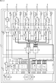
- FIG. 1 is a block diagram illustrating a configuration example of an embodiment of a bus IF to which the present technology is applied.
- the bus IF 11 is configured to include one master 12 and three slaves 13a to 13c.
- the bus IF 11 is not limited to the configuration example shown in FIG. 1.
- the slave 13 is added or reduced, or the slave 13 to which the master authority is transferred from the master 12 operates as a master. be able to.
- one clock signal line 14 and four data signal lines 15-0 to 15-3 are connected to the master 12.
- the slave 13a is connected to the master 12 via the clock signal line 14 and the data signal line 15-0
- the slave 13b is connected via the clock signal line 14 and the data signal lines 15-0 and 15-1.
- the slave 13c is connected to the master 12 via the clock signal line 14 and the data signal lines 15-0 to 15-3.
- the master 12 has the initiative of communication in the bus IF 11, and controls communication with the slaves 13a to 13c via the clock signal line 14 and the data signal lines 15-0 to 15-3. Further, the master 12 can change the communication mode for communicating with the slaves 13a to 13c to either the single-lane mode or the multi-lane mode, and can perform communication in each communication mode. In the single lane mode, communication is performed using one clock signal line 14 and one data signal line 15-0, and in the multi lane mode, one clock signal line 14 and two or more predetermined signals are used. Communication is performed using the number of data signal lines 15.
- the slaves 13a to 13c can communicate according to control by the master 12.
- the slave 13a can perform communication only in the single lane mode.
- the slave 13b can perform communication in a single lane mode and a multi-lane mode using one clock signal line 14 and two data signal lines 15-0 and 15-1.
- the slave 13c has a single lane mode, a multi-lane mode using one clock signal line 14 and two data signal lines 15-0 and 15-1, and a single clock signal line 14 and four data signal lines 14. Communication can be performed in a multilane mode using the data signal lines 15-0 to 15-3.
- the clock signal line 14 and the data signal lines 15-0 to 15-3 are used for transmitting signals between the master 12 and the slave 13.
- a serial clock (SCL: Serial) Clock) having a predetermined frequency is transmitted via the clock signal line 14, and sequentially one bit at a time via the data signal lines 15-0 to 15-3.
- Serial data (SDA: Serial Data) is transmitted.
- the master 12 transmits / receives signals via the clock signal line 14 and the data signal lines 15-0 to 15-3, signals received by the transmitter / receiver 21 and instructions from a host system (not shown).
- the control part 22 which performs control according to this is comprised.
- the transmission / reception unit 21 includes at least a clock transmission / reception unit 31 and data transmission / reception units 32-0 to 32-3, and the control unit 22 includes at least an ML transition processing unit 33.
- a detailed configuration example of the master 12 will be described later with reference to FIG.
- the clock transmission / reception unit 31 transmits / receives a serial clock SCL transmitted via the clock signal line 14.
- the clock transmission / reception unit 31 may be configured to only transmit the serial clock SCL.
- the data transmission / reception units 32-0 through 32-3 are serial data transmitted through the data signal lines 15-0 through 15-3, respectively, based on the timing of the serial clock SCL transmitted through the clock transmission / reception unit 31. SDA [0] to SDA [3] are transmitted and received.
- the ML transition processing unit 33 performs multi-lane mode transition processing for transitioning from the single-lane mode to the multi-lane mode for communication with the slaves 13b and 13c that can perform communication in the multi-lane mode (the flowchart of FIG. 17 described later). See).
- the slaves 13a to 13c perform control according to transmission / reception units 41a to 41c that transmit and receive signals to and from the master 12, and signals received by the transmission / reception units 41a to 41c and instructions from a higher-level system (not shown).
- Each of the control units 42a to 42c is provided. A detailed configuration example of the slaves 13a to 13c will be described later with reference to FIG.
- the slave 13a can perform communication only in the single lane mode
- the transmission / reception unit 41a has a clock transmission / reception unit 51a and a data transmission / reception unit 52a-0
- the control unit 42a has an ML transition processing unit. It has a configuration that does not.
- the slave 13b can perform communication in both the single lane mode and the multilane mode, and the transmission / reception unit 41b includes the clock transmission / reception unit 51b and the data transmission / reception units 52b-0 and 52b-1,
- the unit 42b has an ML transition processing unit 53b.
- the slave 13c can perform communication in both the single lane mode and the multilane mode, and the transmission / reception unit 41c includes a clock transmission / reception unit 51c and data transmission / reception units 52c-0 to 52c-3, and a control unit 42c is configured to include an ML transition processing unit 53c.
- the clock transmission / reception units 51 a to 51 c perform transmission / reception of the serial clock SCL transmitted via the clock signal line 14.
- the clock transmission / reception units 51a to 51c only receive the serial clock SCL. You may comprise.
- the data transmission / reception units 52a-0 to 52c-0 store the serial data SDA [0] transmitted through the data signal line 15-0. Send and receive.
- the data transmitter / receivers 52b-1 and 52c-1 transmit / receive serial data SDA [1] transmitted through the data signal line 15-1.
- the data transmitter / receiver 52c-2 transmits / receives serial data SDA [2] transmitted via the data signal line 15-2, and the data transmitter / receiver 52c-3 transmits via the data signal line 15-3. Transmit / receive serial data SDA [3] to be transmitted.
- ML transition processing units 53b and 53c perform multilane mode transition processing (see the flowchart of FIG. 18 described later) for transitioning communication with the master 12 from the single lane mode to the multilane mode.
- the bus IF 11 is configured in this way, and the master 12 can speed up communication not only by performing communication in the single lane mode but also by performing communication in the multi lane mode.
- the ML transition processing unit 33 when transitioning from the single lane mode to the multi lane mode, the ML transition processing unit 33 performs the multi lane mode transition processing, and the ML transition processing units 53b and 53c perform the corresponding multi lane mode transition processing. By doing so, communication in the multi-lane mode can be performed more reliably.
- a plurality of transmission methods with different communication speeds are defined according to the I3C standard, and the master 12 can switch between these transmission methods.
- an SDR (Single Data Rate) mode in which data communication is performed at a normal transfer rate according to a data transfer rate
- an HDR (High Data Data Rate) mode is defined.
- the HDR mode three modes are defined in the standard: a DDR (Double Data Rate) mode, a TSP (Ternary Symbol Symbol Pure-Bus) mode, and a TSL (Ternary Symbol Symbol Legacy-inclusive-Bus) mode.
- the bus IF 11 stipulates that communication is performed in the SDR mode when communication is started.
- the bus IF 11 it is essential that the slave 13a that performs communication only in the single lane mode and the slaves 13b and 13c that can perform communication also in the multi-lane mode coexist. Therefore, in the bus IF 11, all of the I3C protocols (for example, Start, STOP, device address, ACK / NACK, CCC, etc.) are transmitted in the single lane mode via the clock signal line 14 and the data signal line 15-0.
- I3C protocols for example, Start, STOP, device address, ACK / NACK, CCC, etc.
- serial data SDA [1] transmitted via the data signal line 15-1 is set as an inverted value of the serial data SDA [0] transmitted via the data signal line 15-0.
- the bus IF 11 performs only data transmission in the multilane mode (no transmission of the I3C protocol), and the multilane mode can be used for communication in the SDR mode and the HDR-DDR mode.
- the SDR mode in multi-lane mode communication will be described as SDR / ML and the HDR-DDR mode in multi-lane mode communication will be described as DDR / ML as appropriate.
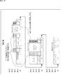
- FIG. 2 shows a detailed configuration example of the master 12.
- the master 12 includes a transmission / reception unit 21 and a control unit 22.
- the transmission / reception unit 21 includes a lane distribution unit (Lane Distribution) 61 and a lane merge unit (Lane Merge) 62 in addition to the clock transmission / reception unit 31 and the data transmission / reception units 32-0 to 32-3 illustrated in FIG. Is done.
- the clock transmission / reception unit 31 includes an output amplifier 71, an input amplifier 72, and an SCL control unit 73.
- the data transmitting / receiving unit 32-0 includes an output amplifier 71-0, an input amplifier 72-0, an H level maintaining unit 74-0, a serial conversion unit 75-0, a parallel conversion unit 76-0, and a parity calculation unit 77-0. It is comprised. Further, the data transmitting / receiving units 32-1 to 32-3 are configured in the same manner as the data transmitting / receiving unit 32-0. Accordingly, the data transmitting / receiving units 32-0 to 32-3 are configured to calculate and add parity by the parity calculating units 77-0 to 77-3 for each of the serial data SDA [0] to SDA [3], respectively. Is done.
- the lane distribution unit 61 supplies the parallel data supplied from the FSM 84 to the data transmission / reception unit 32-0 in the single lane mode.
- the lane distribution unit 61 distributes and supplies the parallel data supplied from the FSM 84 to the data transmission / reception units 32-0 to 32-3.
- data can be transmitted in parallel using the data signal lines 15-0 to 15-3, that is, the speed can be increased as compared with the single lane mode.
- the lane merging unit 62 supplies the parallel data supplied from the data transmitting / receiving unit 32-0 to the FSM 84 in the single lane mode.
- the lane distribution unit 61 merges the parallel data supplied from the data transmission / reception units 32-0 to 32-3 and supplies the merged data to the FSM 84.
- data can be received in parallel using the data signal lines 15-0 to 15-3, that is, the speed can be increased as compared with the single lane mode.
- the control unit 22 includes an ML control unit 81, a serial error detection unit 82, a parallel error detection unit 83, and an FSM (Finite State Machine) 84.
- ML control unit 81 a serial error detection unit 82
- parallel error detection unit 83 a parallel error detection unit 83
- FSM Finite State Machine
- the ML control unit 81 performs the SCL control unit 73 of the clock transmission / reception unit 31 and the data transmission / reception units 32-0 to 32-0. 32-3, the lane distributing unit 61, the lane merging unit 62, and the serial error detecting unit 82 are controlled so as to be driven in the multi-lane mode.
- the serial error detection unit 82 receives the serial data (is0, is1, is2, is3) received by the data transmission / reception units 32-0 to 32-3, and the serial data transmitted by the data transmission / reception units 32-0 to 32-3 ( Detect errors that occur in op0, op1, op2, and op3).
- the serial error detection unit 82 includes a CRC error detector 91 that detects an error based on CRC (Cyclic Redundancy Check), a bit inversion error detector 92 that detects a bit inversion error, and a conflict error.
- a conflict error detector 93 is detected.
- the CRC error detector 91, the bit inversion error detector 92, and the conflict error detector 93 each detect an error to be detected, the CRC error detector 91, the bit inversion error detector 92, and the conflict error detector 93 supply a detection result indicating that an error has been detected to the FSM 84.
- the parallel error detection unit 83 detects an error that occurs in the parallel data obtained by converting the serial data received by the data transmission / reception units 32-0 to 32-3 into parallel data.
- the parallel error detector 83 includes a preamble error detector 94 that detects an error that occurs in the preamble, and a parity that detects an error that occurs in the parity for each of the data signal lines 15-0 to 15-3.
- An error detector 95 and an ACK / NACK detector 96 for detecting ACK / NACK are provided.
- the preamble error detector 94, the parity error detector 95, and the ACK / NACK detector 96 each detect an error to be detected, they supply a detection result indicating that the error has been detected to the FSM 84.
- the FSM 84 is a digital circuit designed so that the process transitions according to the state, and is configured to include the return processing unit 101 and the disconnection detection processing unit 102 in addition to the ML transition processing unit 33 illustrated in FIG. .
- the ML transition processing unit 33 performs a multilane mode transition process (refer to a flowchart of FIG. 17 described later) for transitioning from the single lane mode to the multilane mode.
- the return processing unit 101 performs a recovery process for returning the slave 13 when the ACK from the communication target slave 13 cannot be received. As will be described later, the return processing unit 101 determines whether the data signal line 15 in which the disconnection of the data signal lines 15-0 to 15-3 is detected or the error is frequently detected. The return process can be performed according to 15.
- the disconnection detection processing unit 102 performs disconnection detection processing (see flowcharts of FIGS. 21 and 22 described later) for detecting disconnection of the clock signal line 14 and the data signal lines 15-0 to 15-3. For example, the disconnection detection processing unit 102 transmits data signal lines 15-0 to 15-0 based on ACK / NACK transmitted from the slave 13c via the data signal lines 15-0 to 15-3 to at least the slave address. A disconnection of 15-3 can be detected. Further, in addition to the slave address, the disconnection detection processing unit 102 transmits ACK / NACK transmitted from the slave 13c to all locations where ACK / NACK should be transmitted via the data signal lines 15-0 to 15-3. Based on NACK, disconnection of the data signal lines 15-0 to 15-3 may be detected.
- FIG. 3 shows a detailed configuration example of the slave 13.
- the slave 13 includes a transmission / reception unit 41 and a control unit 42.
- communication can be performed in the multilane mode using the four data signal lines 15-0 to 15-3, and when the master authority is transferred from the master 12, it operates as a master.
- a configuration example of the slave 13 having a secondary master function that can be used is shown. Therefore, in the following description, the configuration of the slave 13 that is different from the master 12 will be described, and the description of the configuration that is common to the master 12 will be omitted.
- the transmission / reception unit 41 includes the lane distribution unit 61 and the lane merge unit 62 in the same manner as the transmission / reception unit 21 of the master 12 in addition to the clock transmission / reception unit 31 and the data transmission / reception units 32-0 to 32-3 illustrated in FIG. It is configured.
- the control unit 42 includes an ML control unit 81, a serial error detection unit 82, a parallel error detection unit 83S, and an FSM 84.
- the parallel error detector 83S of the controller 42 has an I3C standard error detector in addition to the preamble error detector 94, the parity error detector 95, and the ACK / NACK detector 96.
- the configuration differs from that of the master 12 in that 97 is provided.
- the I3C standard error detector 97 detects that a specific error detected on the slave 13 side based on the I3C standard (for example, the first word transmitted following the start or restart of communication is a prohibited address). S0 error to be detected, S4 error to detect receiving address header other than 7E / R in CCC (ENTDAA) instructing dynamic address assignment, transaction to send common command code (GETBCR CCC) has been confirmed S5 error) is detected to detect that an error has occurred in the data transmitted later.
- ENTDAA receiving address header other than 7E / R in CCC
- GETBCR CCC transaction to send common command code
- the slave 13a that performs communication only in the single lane mode includes the clock transmission / reception unit 31, the data transmission / reception unit 32-0, the serial error detection unit 82, the parallel error detection unit 83, and the FSM 84 in the configuration example illustrated in FIG. It is configured with.
- the FSM 84 of the slave 13a is configured to include only a processing unit required for single-lane mode communication without including the ML transition processing unit 33, the return processing unit 101, and the disconnection detection processing unit 102.
- the transmission / reception unit 21 and the control unit 22 constituting the master 12 and the transmission / reception unit 41 and the control unit 42 constituting the slave 13 are constituted by semiconductor circuits, and a part or all of the control unit 22 and the control unit 42 are configured. It may be realized by software.
- the master 12 and the slave 13 are not limited to the structure which consists of a functional block shown in FIG. 2 and FIG.
- the master 12 when the master authority is transferred, the master 12 can function as the slave 13 and the slave 13 can function as the master 12, so that the master 12 and the slave 13 have both functional blocks. be able to.
- FIG. 4 shows an example of a data format in which error countermeasures are adopted by the bus IF 11 in the SDR mode in multilane mode communication.
- FIG. 5 shows the SDR mode in multilane mode communication. An example of another data format to be considered is shown.
- the slave 13b using the two data signal lines 15-0 and 15-1 receives an ACK to the unused data signal lines 15-2 and 15-3. Will not return. Further, the slave 13b calculates and assigns the parity on each of the data signal lines 15-0 and 15-1. Note that the 9-bit final bit of serial data SDA [0] is the T bit at the time of Read, as in the existing standard, while the parity is at the time of Write, and the 9-bit final bit of the serial data SDA [1] is the Read and Write It is always parity.
- the slave 13c using the four data signal lines 15-0 to 15-3 returns ACK to the data signal lines 15-2 and 15-3 to be used. That is, the slave 13c performs not only data transmission using the data signal lines 15-2 and 15-3 but also ACK / NACK transfer using the data signal lines 15-2 and 15-3. Configured as follows. Further, the slave 13c calculates and assigns parity for each of the data signal lines 15-0 to 15-3.
- a format as shown in FIG. 5 is also considered for SDR mode in multilane communication. That is, in communication with the slave 13b using the two data signal lines 15-0 and 15-1, the unused data signal lines 15-2 and 15-3 are set in an idle state (always H or L). Then, the parity at the time of writing is calculated and added to the serial data SDA [0] transmitted via the data signal line 15-0, and the serial data SDA [1] transmitted via the data signal line 15-1 is provided. The parity at the time of reading is calculated and added in.
- the 9-bit final bit of serial data SDA [0] is the T bit when reading, as in the existing standard, while the parity is used when writing, and the 9-bit final bit of serial data SDA [1] is the parity when reading. , Optional when writing (undefined).
- the data signal lines 15-2 and 15-3 are used for data transmission (from the master 12 to the slave 13c at the time of writing). Only the slave 13c to the master 12 is performed at the time of reading, and the state returns to the idle state after data transmission.
- the bus IF 11 adopts a format error countermeasure as shown in FIG. 4 to detect disconnection, error frequency for each data signal line 15 and the like as will be described later. Therefore, communication can be performed more reliably than the format shown in FIG.
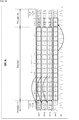
- FIG. 6 shows an example of a data format in which error countermeasures are adopted by the bus IF 11 in the DDR mode (when reading) in multi-lane mode communication
- FIG. 7 shows multi-lane mode communication.
- An example of another data format to be considered for the DDR mode (when reading) is shown.
- the bus IF 11 uses the data signal lines 15-2 and 15-3 to perform not only data transmission but also ACK / NACK transfer and calculates the parity for each data signal line 15. And grant.
- the format shown in Fig. 7 is also considered for DDR mode (when reading) in multi-lane mode communication. That is, it is considered that only data is transferred in multilane, and that a parity of 2 bits is added every 16 bits across the data signal lines 15-0 to 15-3.
- the serial data SDA [1] transmitted through the data signal line 15-1 is an inverted signal of the serial data SDA [0] transmitted through the data signal line 15-0.
- the bus IF 11 adopts the format error countermeasure as shown in FIG. 6 to detect disconnection, error frequency for each data signal line 15 and the like as will be described later. Therefore, communication can be performed more reliably than the format shown in FIG.
- FIG. 8 shows an example of a data format in which error countermeasures are adopted by the bus IF 11 in the DDR mode (when writing) in multi-lane mode communication.
- FIG. 9 shows multi-lane mode communication. An example of another data format considered for the DDR mode (during writing) is shown.
- the bus IF 11 has a format in which parity is placed after the data in the same manner as in the DDR mode (when reading) so that the parity can be transmitted for each data signal line 15. Further, parity is calculated and assigned for each data signal line 15.
- a format as shown in FIG. 9 is also considered for DDR mode (when reading) in multi-lane mode communication. That is, the parity is 2 bits every 16 bits across the data signal line 15, and unlike the case of Read, the parity is transmitted before the transmission data. Data signal lines 15-2 and 15-3 are used only for data transmission.
- the bus IF 11 adopts the error countermeasure of the format shown in FIG. 8 to detect disconnection, error frequency for each data signal line 15 and the like as will be described later. Therefore, communication can be performed more reliably than the format shown in FIG.
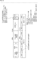
- FIG. 10 shows an example of a multilane setting command (SETML)
- FIG. 11 shows an example of a multilane confirmation command (GETML).
- a broadcast address (7'h7E) and a bit (W) indicating writing are transmitted from the master 12, and an ACK corresponding thereto is transmitted to the slave 13 Is returned from At this time, the slave 13 that has received the broadcast address returns ACK on the lane (data signal line 15) that is being used among the four data signal lines 15-0 to 15-3.
- a multilane setting command (SETMLSETCCC) indicating that a multilane is set by a common command code (CCC: CommonCCCommand Code) and a 1-bit parity (T) are transmitted from the master 12 Is done.
- CCC CommonCCCommand Code
- T 1-bit parity
- the multilane setting byte (SETMLSETByte) that stores the multilane number (Number of ML) that specifies the lane to be used in the multilane mode and the 1-bit parity (T) are the master. 12 is transmitted.
- FIG. 10 shows an example of the multilane number stored in the 0th bit and the 1st bit of the multilane setting byte.
- the broadcast address (7'h7E) following the restart (Sr) or the end of the multilane setting command (P) is transmitted from the master 12.
- the master 12 finishes transmitting the multilane setting byte for each individual slave 13 sequentially to all the slaves 13 corresponding to the multilane mode
- the master 12 transmits an end (P).
- the slave 13 can shift to the multi-lane mode using the lane designated by the multi-lane number at the timing when the multi-lane setting command is normally received and the next restart or stop is received.
- the broadcast address (7′h7E) and the bit (W) indicating writing are transmitted from the master 12, and the ACK corresponding thereto is transmitted to the slave 13 Is returned from At this time, the slave 13 that has received the broadcast address returns ACK on the lane (data signal line 15) that is being used among the four data signal lines 15-0 to 15-3.
- a multilane confirmation command (GETML CCC) indicating that the multilane is confirmed by the common command code and a 1-bit parity (T) are transmitted from the master 12.
- GETML CCC multilane confirmation command
- T 1-bit parity
- the multilane confirmation byte (GETML Byte) that stores the multilane number (Number of ML) that confirms the lane used in the multilane mode and the 1-bit parity (T) are slaves. 13 is transmitted. That is, the slave 13 confirms the setting by transmitting the multilane number set by the multilane setting command to the slave 13 by the multilane confirmation command.
- FIG. 11 shows an example of the multilane number stored in the 0th and 1st bits of the multilane confirmation byte, as in FIG.
- the broadcast address (7'h7E) following the restart (Sr) or the end of the multilane confirmation command (P) is transmitted from the master 12. For example, when the master 12 finishes receiving the multilane confirmation byte for each individual slave 13 sequentially from all the slaves 13 corresponding to the multilane mode, the master 12 transmits an end (P).
- FIG. 12 shows an example of a data format in which error countermeasures are adopted by the bus IF 11 in the SDR mode in multilane mode communication.
- FIG. 13 shows the SDR mode in multilane mode communication. An example of yet another data format to be considered is shown.
- data signal lines 15-2 and 15-3 are used to perform not only data transmission but also ACK / NACK transfer, and parity is calculated and assigned for each data signal line 15. Yes.
- a format as shown in FIG. 13 is also considered for the SDR mode in the multi-lane mode communication.
- the bus IF 11 adopts the error countermeasure of the format shown in FIG. 12 to detect the disconnection, the error frequency for each data signal line 15 and the like as will be described later. Therefore, communication can be performed more reliably than the format shown in FIG.
- FIG. 14 shows an example of a data format in which error countermeasures are adopted by the bus IF 11 in the DDR mode in the multi-lane mode communication.
- FIG. 15 shows the DDR mode in the multi-lane mode communication. An example of yet another data format to be considered is shown.
- parity is calculated and assigned for each data signal line 15, and in the data signal line 15-0, the parity is arranged after the data, and the data signal lines 15-1 to 15-3 are arranged. In this case, parity is arranged before data.
- a format as shown in FIG. 15 is also considered for the DDR mode in the multi-lane mode communication. That is, it is considered that a parity of 2 bits is provided every 16 bits across the data signal lines 15-0 to 15-3.
- the bus IF 11 adopts the format error countermeasure as shown in FIG. 14 to detect disconnection, the error frequency for each data signal line 15 and the like as will be described later. Therefore, communication can be performed more reliably than the format shown in FIG.
- the slaves 13a to 13c receive an ACK via the data signal line 15 in use among the data signal lines 15-0 to 15-3 when reading or writing the slave address in the SDR mode. It is required to return.
- the broadcast address (0x7E)
- the disconnection detection processing unit 102 of the master 12 can detect the disconnection because the ACK by the serial data SDA [1] is not returned by the read or write designating the slave address to the slave 13b.
- an ACK by the serial data SDA [1] is returned by the read or write designating the slave address to the slave 13c, so that the data signal line 15-1 between the master 12 and the slave 13c is disconnected. It can be estimated that it has not. That is, in this case, as shown in FIG. 16, it can be estimated that no disconnection has occurred in the common part before the bus branch.
- the disconnection detection processing unit 102 of the master 12 uses the data signal line before branching to each slave 13. It can be estimated that a disconnection has occurred at 15-1. In this case, there is a possibility that the disconnection occurred simultaneously in the vicinity of the SDA [1] output terminals of all the slaves 13.
- the slaves 13a to 13c return ACK via the data signal line 15 in use among the data signal lines 15-0 to 15-3. Is needed. If the disconnection detection processing unit 102 of the master 12 cannot receive the ACK for the DDR read command, it can be estimated that there is a possibility of disconnection, and detects a disconnection error. Note that the disconnection detection processing unit 102 of the master 12 may detect a disconnection error when the ACK cannot be received continuously for a predetermined set value or more.
- the return processing unit 101 of the master 12 responds to the lane (data signal line 15) from which no ACK is returned. Thus, it is estimated which lane is disconnected, and a return process as described below is performed.
- the return processing unit 101 when ACK is not returned in any of the serial data SDA [1] to SDA [3], the return processing unit 101 is the data that has not returned ACK among the data signal lines 15-1 to 15-3. The use of the signal line 15 is stopped.
- the restoration processing unit 101 may perform LaneSWAP to replace lanes if necessary. For example, if it is estimated that the data signal line 15-1 is disconnected near the master 12 (the common part before the bus branch shown in FIG. 16), the return processing unit 101 determines the single lane mode for the slave 13b. Re-set to, and continue communication.
- the return processing unit 101 switches the data signal line 15-1 and the data signal line 15-2 (LaneSWAP), and sets the data signal line 15-0 and the data signal line 15-2. Re-set to multi-lane mode using and continue communication.
- the serial error detection unit 82 and the parallel error detection unit 83 detect a lane (data signal line 15) having a high error frequency, thereby avoiding use of the lane.
- the master 12 gives a parity for each lane when writing in the SDR mode. Also, when reading in the SDR mode, the serial data SDA [1] to SDA [3] give parity to each lane, and the error frequency of the serial data SDA [0] is measured only at the time of writing.
- the master 12 when writing in the DDR mode, arranges the parity after the data in combination with the format when reading in the DDR mode, and gives 2 bits (even / odd) parity for each lane.
- 2 bits (even / odd) parity is assigned to each lane.
- the return processing unit 101 of the master 12 can perform the same return operation as the existing parity error detection.
- the slave 13 includes a register that holds which lane error.
- the master 12 confirms the error by using a command (GET STATUS) for obtaining the status, and then confirms in which lane the error has occurred, and detects the occurrence of the error continuously for a predetermined set value or more. Therefore, it can be determined that the lane has a high error frequency.
- GET STATUS GET STATUS
- the master 12 uses the lane with the high error frequency as described above by the return processing by the return processing unit 101. Can be canceled.
- bus IF 11 can improve error resistance in the multi-lane mode using two or more lanes.
- the serial data SDA [1] transmitted via the data signal line 15-1 basically includes the data signal line 15- except for read data or write data.
- the inverted bit of serial data SDA [0] transmitted via 0 is transmitted.
- the reliability can be improved by setting an error.
- This error is applied to 0x7E: S0 Error, CCC: S1 Error, Illegal CCC format: S5 Error in SDR, for example. Also, this error is applied to, for example, CRC5 error in DDR.
- the master 12 can detect which one of the data signal lines 15-1 to 15-3 is disconnected by the disconnection detection processing unit 102. Further, when the ACK is not returned on all of the data signal lines 15-0 to 15-3 by the disconnection detection processing unit 102, the master 12 disconnects one of the clock signal line 14 and the data signal line 15-0. It is possible to detect whether or not a disconnection has occurred in all of them. Further, the master 12 can detect the data signal line 15 having a high error frequency among the data signal lines 15-0 to 15-3 by the serial error detection unit 82 and the parallel error detection unit 83, and the data The use of the signal line 15 is stopped.
- the bus IF 11 detects the data signal line 15 having a high error frequency among the data signal lines 15-0 to 15-3, and stops using the data signal line 15 in an uncertain state. It is possible to avoid continuing communication.
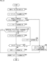
- FIG. 17 is a flowchart for explaining the multilane mode transition process executed on the master 12 side.
- processing is started when an upper system (not shown) instructs the master 12 to transition to the multi-lane mode.
- the ML transition processing unit 33 uses a common command code that is transmitted to all the slaves 13 connected to the bus IF 11 at the same time to check a capability confirmation command (GETCAP CCC) ) Is transmitted from the transmission / reception unit 21.
- GETCAP CCC capability confirmation command
- communication is performed in the single lane mode, and the transmission / reception unit 21 transmits a capability confirmation command using the clock transmission / reception unit 31 and the data transmission / reception unit 32-0.
- step S12 the data transmitting / receiving unit 32-0 sequentially transmits the capability confirmation command transmitted in step S11 from all the slaves 13 connected to the bus IF 11 using the data signal line 15-0. Receive incoming response. Then, the ML transition processing unit 33 confirms the capabilities of all the slaves 13 connected to the bus IF 11 based on the response to the capability confirmation command received by the data transmitting / receiving unit 32-0.
- step S13 the ML transition processing unit 33 determines whether there is a slave 13 compatible with the multilane mode as a result of the confirmation in step S12. In step S13, if the ML transition processing unit 33 determines that there is a slave 13 that supports the multilane mode, the process proceeds to step S14.
- step S14 the ML transition processing unit 33 sends a multilane setting command (SETML CCC) to the slave 13 corresponding to the multilane mode (hereinafter described as the slave 13c in FIG. 1) using a common command code. ) Is transmitted from the transmission / reception unit 21. Thereby, in the slave 13c, the multi-lane mode using the lane designated by the multi-lane number as described with reference to FIG. 10 is validated.
- SETML CCC multilane setting command
- step S15 the ML transition processing unit 33 causes the transmission / reception unit 21 to transmit a multilane confirmation command (GETML CCC) using a common command code in order to confirm the current setting of the multilane mode of the slave 13c.
- GETML CCC multilane confirmation command
- the slave 13c transmits ACK via the data signal lines 15-0 to 15-3 used in the multilane mode (steps S37 and S38 in FIG. 18 described later).
- step S16 the ML transition processing unit 33 performs ACK following the broadcast address on all the data signal lines 15-0 to 15-3 being used by the slave 13c to be communicated according to the detection result by the ACK / NACK detector 96. Is received. If the ML transition processing unit 33 determines in step S16 that the ACK following the broadcast address has been received by all the data signal lines 15-0 to 15-3 being used by the slave 13c to be communicated, Proceed to S17.
- step S17 the ML transition processing unit 33 determines whether or not the ACK following the slave address has been received on all the data signal lines 15-0 to 15-3 being used by the slave 13c to be communicated. If the ML transition processing unit 33 determines in step S16 that the ACK following the slave address has been received on all the data signal lines 15-0 to 15-3 being used by the slave 13c to be communicated, Proceed to S18.
- step S18 the ML transition processing unit 33 checks whether the bit value of the multilane number transmitted from the slave 13c (in step S39 in FIG. 18 described later) in accordance with the multilane confirmation command transmitted in step S15 is correct. Determine whether or not. That is, it is determined whether or not the same bit value as the bit value of the multilane number stored in the multilane setting byte of the multilane setting command transmitted in step S14 is stored in the multilane setting byte of the multilane confirmation command. Is done.
- step S18 when the ML transition processing unit 33 determines that the bit value of the multilane number is incorrect (incorrect), the process proceeds to step S19.
- the ML transition processing unit 33 determines in step S16 that the ACK following the broadcast address has not been received on all the data signal lines 15-0 to 15-3 being used by the slave 13c to be communicated. However, the process proceeds to step S19.
- step S17 the ML transition processing unit 33 determines that the ACK following the slave address has not been received by all the data signal lines 15-0 to 15-3 being used by the communication target slave 13c. In this case, the process proceeds to step S19.
- the ML transition processing unit 33 recognizes that the setting of the multilane mode has failed, and performs the process again from the transmission of the multilane setting command (step S14).
- step S19 the ML transition processing unit 33 determines whether or not the processing has been restarted from the transmission of the multi-lane setting command continuously over a preset value set as the number of restarts.
- step S19 when the ML transition processing unit 33 determines that the process has not been repeated since the transmission of the multilane setting command for a set value or more, that is, when the number of consecutive process repeats is less than the set value, The process returns to step S14. Then, the processing is restarted from the transmission of the multilane setting command.
- step S19 when the ML transition processing unit 33 determines in step S19 that the processing has been repeated from the transmission of the multilane setting command for more than the set value, the process proceeds to step S20.
- step S20 an error detection process by the serial error detection unit 82 and the parallel error detection unit 83, and a return process by the return processing unit 101 are performed. That is, as described above, according to the error detection results by the serial error detection unit 82 and the parallel error detection unit 83, a lane (data signal line 15) with a high error frequency is detected, and the return processing unit 101 detects which lane is disconnected. A return process is performed according to whether or not it has been performed.
- step S21 the ML transition processing unit 33 determines whether or not the return processing in step S20 has been performed continuously for the set value or more.
- step S21 when the ML transition processing unit 33 determines that the return process in step S20 has not been performed continuously for a set value or more, that is, the number of times the return process has been performed continuously is less than the set value. If so, the process returns to step S14. Then, the processing is restarted from the transmission of the multilane setting command.
- step S21 determines in step S21 that the return process in step S20 has been performed continuously for a set value or more, the process proceeds to step S22.
- step S22 the disconnection detection processing unit 102 performs disconnection detection processing (processing of flowcharts of FIGS. 21 and 22 described later) for detecting disconnection of the clock signal line 14 and the data signal lines 15-0 to 15-3. Then, after the disconnection detection process in step S22, the process returns to step S14, and the process is repeated from the transmission of the multilane setting command.
- step S13 determines in step S13 that there is no slave 13 compatible with the multi-lane mode
- the process is terminated.
- step S18 determines that the bit value of the multilane number is correct
- the ML transition processing unit 33 recognizes that the setting of the multilane mode is successful, and after this processing is completed, the data in the multilane mode is obtained. Is started (the process of the flowchart of FIG. 19).
- FIG. 18 is a flowchart for explaining the multi-lane mode transition process executed on the slave 13 side.
- the multilane mode transition process in the slave 13c of FIG. 1 corresponding to the multilane mode will be described.
- step S31 the transmission / reception unit 41c receives the capability confirmation command and supplies it to the ML transition processing unit 53c.
- step S32 the ML transition processing unit 53c transmits a response from the transmission / reception unit 41c so as to respond to the capability of the slave 13c itself.
- step S33 the transmission / reception unit 41c starts receiving the multilane setting command transmitted from the master 12 in step S14 of FIG.
- step S34 when the transmission / reception unit 41c acquires the multilane number (see FIG. 10) stored in the multilane setting command, the transmission / reception unit 41c supplies the multilane number to the ML transition processing unit 53c.
- step S35 after the transmission / reception unit 41c completes reception of the multilane setting command, the ML transition processing unit 53c sets the multilane in which the data signal line 15 used for communication is set according to the multilane number acquired in step S34. Performs processing to transition to mode.
- step S36 the transmission / reception unit 41c receives the multi-lane confirmation command transmitted from the master 12 in step S15 of FIG. 17, and supplies it to the ML transition processing unit 53c.
- step S37 the ML transition processing unit 53c transmits an ACK following the broadcast address on all the data signal lines 15 in use. For example, when the use of four data signal lines 15-0 to 15-3 according to the multilane number is set (2'b11), the four data signal lines 15-0 to 15-3 are set. In all of the above, ACK is transmitted following the broadcast address. Thereby, for example, if no disconnection has occurred, the master 12 receives an ACK following the broadcast address on all the data signal lines 15 in use.
- step S38 the ML transition processing unit 53c transmits an ACK following the slave address on all the data signal lines 15 in use. For example, when the use of four data signal lines 15-0 to 15-3 according to the multilane number is set (2'b11), the four data signal lines 15-0 to 15-3 are set. In all of the above, ACK is transmitted following the slave address. Thereby, for example, if no disconnection has occurred, the master 12 receives an ACK following the slave address on all the data signal lines 15 in use.
- step S39 the ML transition processing unit 53c transmits the multi-lane number set in step S35 to the master 12, and the process ends.
- FIG. 19 is a flowchart for explaining data reception processing after transition to the multi-lane mode executed on the master 12 side.
- the multi-lane mode communication is set using the slave 13c and the four data signal lines 15-0 to 15-3.
- step S41 the control unit 22 causes the transmission / reception unit 21 to start transmission of a common command code or data transfer (Read / Write) with the slave 13c to be communicated.
- a common command code or data transfer Read / Write
- the multi-lane setting command SETML is excluded from the common command code transmitted at this time.
- step S42 the control unit 22 follows the broadcast address (0x7E) on all the data signal lines 15-0 to 15-3 being used by the slave 13c to be communicated according to the detection result by the ACK / NACK detector 96. It is determined whether or not an ACK has been received.
- the control unit 22 determines in step S42 that the ACK following the broadcast address (0x7E) has been received by all the data signal lines 15-0 to 15-3 being used by the slave 13c to be communicated, Proceed to step S43.
- step S43 according to the detection result by the ACK / NACK detector 96, the control unit 22 designates the slave 13c in the data signal lines 15-0 to 15-3 being used by the slave 13c to be communicated. It is determined whether or not an ACK following the address has been received.
- step S43 the control unit 22 determines that all of the data signal lines 15-0 to 15-3 being used by the communication target slave 13c have not received an ACK following the slave address designating the slave 13c. If so, the process proceeds to step S44.
- step S42 it is determined that the control unit 22 has not received an ACK following the broadcast address (0x7E) on all the data signal lines 15-0 to 15-3 being used by the slave 13c to be communicated. If this happens, the process proceeds to step S44.
- steps S44 to S46 an error detection process and a return process are performed as in steps S20 to S22 of FIG. 17 described above, and a disconnection detection process is performed when the return process is performed continuously for a set value or more. Then, when it is determined in step S45 that the return process has not been performed continuously for a set value or more, or after the disconnection detection process is performed in step S46, the process returns to step S41. Repeated.
- step S43 the control unit 22 determines that the ACK following the slave address designating the slave 13c has been received by all the data signal lines 15-0 to 15-3 being used by the slave 13c to be communicated. If so, the process proceeds to step S47.
- step S47 after the transmission of the common command code started in step S41 or the data transfer with the slave 13c to be communicated is terminated, the process is terminated.
- the multi-lane setting command (SETML) is excluded from the common command code transmitted in step S41. Therefore, in response to the multilane setting command, the control unit 22 confirms reception of ACK on all the data signal lines 15-0 to 15-3 being used by the slave 13c to be communicated (step S42 or S43). What is done is avoided.
- control unit 22 avoids an infinite loop by confirming reception of ACK only with the serial data SDA [0] transmitted via the data signal line 15-0. can do.
- the master 12 detects the disconnection of the data signal line 15-1 and returns to the single lane mode, as shown in FIG. 10, using the multi lane setting command (SETML), the multi lane number (2'b00 ).
- the master 12 cannot receive the ACK via the data signal line 15-1 because the lane that the slave 13c is currently using is the data signal lines 15-0 to 15-3. Disconnection detection is performed again, and the multilane setting command cannot be terminated, resulting in an infinite loop.
- control unit 22 confirms only the serial data SDA [0] only for the ACK for the multi-lane setting command, and prohibits the confirmation of the ACK in the other lanes, thereby preventing the control unit 22 from exiting the infinite loop. It can be avoided.
- FIG. 20 is a flowchart for explaining data reception processing after transition to the multi-lane mode executed on the slave 13 side.
- FIG. 18 the data reception process in the slave 13c in FIG. 1 will be described.
- step S41 when the transmission of the common command code from the master 12 or the data transfer with the slave 13c to be communicated is started (step S41 in FIG. 19), the process is started.
- step S51 when a common command code is transmitted from the master 12, the transmission / reception unit 41c starts receiving the common command code and performs data transfer (Read / Write) with the master 12. Starts the data transfer.
- step S52 the transmission / reception unit 41c receives, for example, a broadcast address transmitted when the master 12 transmits a common command code, and supplies the broadcast address to the control unit 42c.
- step S52 the transmission / reception unit 41c returns an ACK in all of the lanes (data signal lines) in use among the four data signal lines 15-0 to 15-3 according to the control by the control unit 42c.
- steps S52 and S53 are performed only when a broadcast address is transmitted from the master 12, and the processes in steps S52 and S53 are skipped when a slave address is transmitted from the master 12.
- step S54 the transmission / reception unit 41c receives the slave address of the slave 13c and supplies it to the control unit 42c.
- step S55 the transmission / reception unit 41c returns an ACK on all of the lanes (data signal lines) in use among the four data signal lines 15-0 to 15-3 in accordance with the control by the control unit 42c.
- step S56 if the transmission / reception unit 41c has received the common command code, the transmission / reception unit 41c ends the reception of the common command code. If the data transfer has been performed with the master 12, the transmission / reception unit 41c ends the data transfer. To do. Thereafter, the process is terminated.
- 21 and 22 are flowcharts for explaining the disconnection detection processing executed by the disconnection detection processing unit 102 of the master 12 in step S22 of FIG. 17 or step S46 of FIG.
- step S61 the disconnection detection processing unit 102 sets the broadcast address on the data signal line 15-0 (that is, the data signal line used in the single lane mode among the data signal lines 15-0 to 15-3). It is determined whether the subsequent ACK is not received.
- step S61 when the disconnection detection processing unit 102 determines that the ACK following the broadcast address cannot be received on the data signal line 15-0, the process proceeds to step S62.
- step S62 the disconnection detection processing unit 102 estimates that the clock signal line 14 or the data signal line 15-0 is disconnected (see FIG. 16) at the common part before the bus branch.
- step S63 the return processing unit 101 stops the use of the entire bus IF 11, notifies the host system to that effect, and then the process ends.
- step S61 determines in step S61 that the ACK following the broadcast address is not received on the data signal line 15-0 (ACK can be received). the process proceeds to step S64.
- step S64 the disconnection detection processing unit 102 receives an ACK following the broadcast address on the data signal lines 15-1 to 15-3 (other than the data signal line 15-0 confirmed in step S61) being used in the multilane mode. It is determined whether or not reception is possible.
- step S64 when the disconnection detection processing unit 102 determines that the ACK following the broadcast address cannot be received on the data signal lines 15-1 to 15-3 being used in the multilane mode, the process proceeds to step S65. .
- step S65 the disconnection detection processing unit 102 disconnects the data signal line 15 that has not received ACK among the data signal lines 15-1 to 15-3 at the common part before the bus branch (see FIG. 16). It is estimated that
- step S66 the return processing unit 101 changes the communication mode according to the data signal line 15 that has not received ACK. For example, when it is estimated that the data signal line 15-1 is disconnected, the return processing unit 101 causes all the slaves 13 to transition to the single lane mode. The return processing unit 101 uses, for example, the four data signal lines 15-0 to 15-3 to determine whether the data signal line 15-2 or 15-3 is disconnected. The slave 13 communicating in the mode is shifted to the multi-lane mode using the data signal lines 15-0 and 15-2. Thereafter, the process is terminated.
- step S64 the disconnection detection processing unit 102 determines that the ACK following the broadcast address cannot be received (ACK can be received) on the data signal lines 15-1 to 15-3 being used in the multilane mode. If so, the process proceeds to step S67.
- step S67 the disconnection detection processing unit 102 sets the slave address on the data signal line 15-0 (that is, the data signal line of the data signal lines 15-0 to 15-3 that is also used in the single lane mode). It is determined whether the subsequent ACK is not received.
- step S67 if the disconnection detection processing unit 102 determines that the ACK following the slave address cannot be received on the data signal line 15-0, the process proceeds to step S68.
- step S68 the disconnection detection processing unit 102 estimates that the clock signal line 14 or the data signal line 15-0 is disconnected between the bus branch and the slave terminal (see FIG. 16).
- step S69 the return processing unit 101 stops the use of the target slave 13 that is estimated to be disconnected between the bus branch and the slave terminals, and the processing is terminated.
- step S67 if the disconnection detection processing unit 102 determines in step S67 that the data signal line 15-0 cannot receive the ACK following the slave address (ACK can be received), the process proceeds to step S70.
- step S70 the disconnection detection processing unit 102 receives an ACK following the slave address on the data signal lines 15-1 to 15-3 (other than the data signal line 15-0 confirmed in step S67) being used in the multilane mode. It is determined whether or not reception is possible.
- step S70 If the disconnection detection processing unit 102 determines in step S70 that the ACK following the slave address cannot be received on the data signal lines 15-1 to 15-3 being used in the multilane mode, the process proceeds to step S71. move on.
- step S71 the disconnection detection processing unit 102 estimates that the data signal line 15 that has not received ACK is disconnected (see FIG. 16) between the bus branch and the slave terminal.
- step S72 the return processing unit 101 changes the communication mode according to the data signal line 15 that has not received ACK. For example, when it is estimated that the data signal line 15-1 is disconnected, the return processing unit 101 shifts only the slave 13 to the single lane mode. The return processing unit 101 uses, for example, the four data signal lines 15-0 to 15-3 to determine whether the data signal line 15-2 or 15-3 is disconnected. The slave 13 communicating in the mode is shifted to the multi-lane mode using the data signal lines 15-0 and 15-2. Thereafter, the process is terminated.
- step S70 the disconnection detection processing unit 102 determines that the ACK following the slave address cannot be received (ACK can be received) on the data signal lines 15-1 to 15-3 being used in the multilane mode. If it is determined, the process proceeds to step S73.
- step S73 the disconnection detection processing unit 102 performs a parity error or the like on the data signal line 15-0 (that is, the data signal line used in the single lane mode among the data signal lines 15-0 to 15-3). It is determined whether or not an error is detected.
- step S73 when the disconnection detection processing unit 102 determines that an error such as a parity error has been detected in the data signal line 15-0, the process proceeds to step S74.
- step S74 the disconnection detection processing unit 102 indicates that the data signal line 15-0 (that is, the data signal line used in the single lane mode among the data signal lines 15-0 to 15-3) is just before the disconnection. Or it is estimated that it is continuously affected by noise.
- the process proceeds to step S69, and as described above, the use of the slave 13 is stopped and the process is terminated.
- step S73 determines in step S73 that an error such as a parity error is not detected on the data signal line 15-0. If the disconnection detection processing unit 102 determines in step S73 that an error such as a parity error is not detected on the data signal line 15-0, the process proceeds to step S75.
- step S75 the disconnection detection processing unit 102 detects an error such as a parity error on the data signal lines 15-1 to 15-3 (other than the data signal line 15-0 confirmed in step S73) being used in the multilane mode. It is determined whether or not it has been detected.
- an error such as a parity error on the data signal lines 15-1 to 15-3 (other than the data signal line 15-0 confirmed in step S73) being used in the multilane mode. It is determined whether or not it has been detected.
- step S75 when the disconnection detection processing unit 102 determines that an error such as a parity error has been detected in the data signal lines 15-1 to 15-3 being used in the multilane mode, the process proceeds to step S76.
- step S76 the disconnection detection processing unit 102 estimates that the data signal line 15 in which the error is detected is about to be disconnected or is continuously affected by noise. After the process of step S76, the process proceeds to step S72, and as described above, the communication mode is changed according to the data signal line 15 that has not received ACK.
- step S75 If the disconnection detection processing unit 102 determines in step S75 that no error such as a parity error has been detected on the data signal lines 15-1 to 15-3 being used in the multi-lane mode, the processing ends. Is done.
- FIG. 23 is a flowchart for explaining a communication process (DDR Read) in which the master 12 reads data from the slave 13 in the DDR mode which is one of the HDR modes.
- This communication process (DDR Read) is first executed after the above-described multi-lane mode transition process is performed using the common command code in the SDR mode to transition to the multi-lane mode.
- ENTHDR CCC (0x20 )
- step S82 the transmission / reception unit 21 of the master 12 drives the clock signal line 14 and the data signal line 15-0 to transmit a read command.
- step S83 the control unit 22 detects the value of the second bit of the preamble after transmitting the read command according to the detection result by the ACK / NACK detector 96, and which of ACK and NACK is transmitted from the slave 13? Determine. That is, the control unit 22 determines that ACK has been transmitted from the slave 13 when detecting that the second bit of the preamble after transmitting the read command is 0. On the other hand, when the control unit 22 detects that the second bit of the preamble after transmitting the read command is 1, it determines that the NACK has been transmitted from the slave 13.
- step S83 if the control unit 22 determines that ACK has been transmitted from the slave 13, the process proceeds to step S84.
- step S84 the transmitting / receiving unit 21 receives the read data transmitted from the slave 13.
- step S85 the control unit 22 determines whether a parity error has occurred in any of the data signal lines 15 in use according to the detection result by the parity error detector 95.
- the parity bit P1 is 0 when the logical sum of the odd-numbered bits of the data is even, and the parity bit P1 is the even-numbered data. 0 is taken when the logical sum of the bits is odd.
- step S85 when the control unit 22 determines that no parity error has occurred in all the data signal lines 15 being used, that is, the data is normal, the process proceeds to step S86.
- step S86 the transmission / reception unit 21 receives a preamble transmitted following the data.
- step S87 the control unit 22 determines which of the data and the CRC word is designated to be transmitted next by the preamble received in step S86.
- step S87 if the control unit 22 determines that the next data to be transmitted is data, the process proceeds to step S88. After the transmission / reception unit 21 receives the read data, the process returns to step S85. Thereafter, the same processing is repeated.
- step S87 determines in step S87 that the next transmission is a CRC word
- the process proceeds to step S89, and the transmission / reception unit 21 receives the CRC word.
- step S89 the process proceeds to step S91.
- step S85 if it is determined in step S85 that there is a parity error, the process proceeds to step S91. If it is determined in step S83 that NACK has been transmitted, the process proceeds to step S91, and after a predetermined number of conflict prevention clock periods have elapsed, a clock signal is transmitted, and the process proceeds to step S91.
- step S91 the transmission / reception unit 21 transmits an HDR end command, whereby the communication process (DDR Read) in which the master 12 reads data from the slave 13 in the DDR mode is ended.
- DDR Read the communication process in which the master 12 reads data from the slave 13 in the DDR mode is ended.
- the control unit 22 can detect that the received data is not correct according to the detection result by the parity error detector 95. As a result, the master 12 accurately determines whether the received data is correct or is due to a state in which the data signal lines 15-0 to 15-3 are not driven, thereby enabling more reliable communication. It can be performed.
- the parity error detection method in the bus IF 11 of the present embodiment is performed, for example, in the same manner as the method shown in FIG. 4 or FIG.
- the configuration is the same as that of FIG. 5 or FIG.
- unused bits are filled with 0 and output as DATA [15: 0].
- serial data SDA needs to be transmitted with only 4 bits per lane, and the parity needs to be calculated with 4 bits. For this reason, transmission data is set only for D0 to D3, and the parity is calculated with 0 padding for others.
- the above-described series of processing can be executed by hardware or can be executed by software.
- a program constituting the software executes various functions by installing a computer incorporated in dedicated hardware or various programs.
- the program is installed in a general-purpose personal computer from a program recording medium on which the program is recorded.
- FIG. 24 is a block diagram showing an example of the hardware configuration of a computer that executes the above-described series of processing by a program.
- a CPU Central Processing Unit
- ROM Read Only Memory
- RAM Random Access Memory
- EEPROM Electrically Erasable Memory and Programmable Read Only Memory
- the CPU 201 loads, for example, a program stored in the ROM 202 and the EEPROM 204 to the RAM 203 via the bus 205 and executes the program, thereby performing the above-described series of processing.
- the program executed by the computer can be installed in the EEPROM 204 or updated from the outside via the input / output interface 206, in addition to being written in the ROM 202 in advance.
- a system represents the whole apparatus comprised by a some apparatus.
- this technique can also take the following structures.
- Single lane mode which is a communication mode in which communication is performed using one clock signal line and one data signal line, and one clock signal line and two or more predetermined number of data signal lines
- a transmission / reception unit that transmits / receives a signal to / from another communication device in any one of the multi-lane modes, which is a communication mode in which communication is performed using
- a multilane setting command that is a command for instructing the setting of the multilane mode is transmitted from the transmission / reception unit, and a multilane confirmation command that is a command for confirming the current setting of the multilane mode is transmitted from the transmission / reception unit
- a multi-lane mode transition processing unit that performs processing for transitioning communication from the single-lane mode to the multi-lane mode,
- the multi-lane mode transition processing unit Confirming reception of an acknowledgment transmitted following a broadcast address used when transmitting the command simultaneously on all the data signal lines used by the other communication devices; Confirming reception of an acknowledgment transmitted following an
- the multi-lane mode transition processing unit Confirming receipt of an acknowledgment sent following the broadcast address; Confirming the receipt of an acknowledgment sent following the individual address, and receiving both acknowledgments, the transition from the single-lane mode to the multi-lane mode
- the communication device according to (1) wherein the communication device is recognized as successful.
- (3) Acknowledgment or negative response transmitted to at least the individual address from the other communication device supporting communication in the multilane mode via the data signal line used in the multilane mode
- the communication apparatus according to (1) or (2), wherein the disconnection detecting unit detects a disconnection of the data signal line used in the multilane mode based on the above.
- the disconnection detection unit is transmitted to the broadcast address from the other communication device that supports communication in the multilane mode via the data signal line used in the multilane mode.
- the communication device according to (3), wherein a disconnection of the data signal line used in the multilane mode is detected based on an affirmative response or a negative response.
- the disconnection detection unit is configured to receive an acknowledgment or a negative response from the other communication device corresponding to the communication in the multilane mode via the data signal line used in the multilane mode.
- the communication device according to (3) or (4), wherein a disconnection of the data signal line used in the multilane mode is detected based on an acknowledgment or a negative response transmitted with respect to.
- the multilane mode transition processing unit confirms an acknowledgment transmitted in response to the multilane setting command only by the data signal line used in the single lane mode.
- the communication apparatus according to any of the above.
- the error detection unit is a communication using the one clock signal line and the two data signal lines in the multi-lane mode, and the bit inverted between the two data signal lines is not transmitted. If the error occurs, the communication device according to (6) is detected.
- Single lane mode which is a communication mode in which communication is performed using one clock signal line and one data signal line, and one clock signal line and two or more predetermined number of data signal lines
- a transmission / reception unit that transmits / receives a signal to / from another communication device in any one of the multi-lane modes, which is a communication mode in which communication is performed using
- a multilane setting command that is a command for instructing the setting of the multilane mode is transmitted from the transmission / reception unit, and a multilane confirmation command that is a command for confirming the current setting of the multilane mode is transmitted from the transmission / reception unit
- a communication method of a communication device comprising: a multilane mode transition processing unit that performs a process of transitioning communication from the single lane mode to the multilane mode, Confirming reception of an acknowledgment transmitted following a broadcast address used when transmitting the command simultaneously on all the data signal lines used by the other communication devices; Confirming reception of an acknowledgment transmitted following an individual address designating each of the other communication devices on all the
- Single lane mode which is a communication mode in which communication is performed using one clock signal line and one data signal line, and one clock signal line and two or more predetermined number of data signal lines
- a transmission / reception unit that transmits / receives a signal to / from another communication device in any one of the multi-lane modes, which is a communication mode in which communication is performed using
- a multilane setting command that is a command for instructing the setting of the multilane mode is transmitted from the transmission / reception unit
- a multilane confirmation command that is a command for confirming the current setting of the multilane mode is transmitted from the transmission / reception unit
- a computer of a communication device comprising: a multilane mode transition processing unit that performs processing for transitioning communication from the single lane mode to the multilane mode.
- a program for executing a communication process including recognizing that a transition of communication from the single lane mode to the multi lane mode is successful when one of the confirmations is confirmed and reception of the one acknowledgment is confirmed.
- a multilane setting command that is a command for instructing the setting of the multilane mode is transmitted from the transmission / reception unit, and a multilane confirmation command that is a command for confirming the current setting of the multilane mode is transmitted from the transmission / reception unit,
- a multi-lane mode transition processing unit that performs processing for transitioning communication from the single-lane mode to the multi-lane mode, The multi-lane mode transition processing unit Confirming receipt of an acknowledgment transmitted following a broadcast address used when transmitting the command all at once on all the data signal lines
Landscapes
- Engineering & Computer Science (AREA)
- Theoretical Computer Science (AREA)
- Physics & Mathematics (AREA)
- General Engineering & Computer Science (AREA)
- General Physics & Mathematics (AREA)
- Computer Networks & Wireless Communication (AREA)
- Signal Processing (AREA)
- Information Transfer Systems (AREA)
Abstract
本開示は、複数本のデータ信号線を使用した通信を確実に行うことができるようにする通信装置、通信方法、プログラム、および、通信システムに関する。 マスタでは、スレーブとの通信で使用される全てのデータ信号線を介して、一斉にコマンドを送信する際に使用するブロードキャストアドレスに続いて送信されてくるACKを受信したことの確認と、スレーブが使用中の全てのデータ信号線で、各個のスレーブを指定するスレーブアドレスに続いて送信されてくるACKを受信したことの確認が行われ、それらのACKを受信した場合、シングルレーンモードからマルチレーンモードへの通信の遷移に成功したと認識される。本技術は、例えば、I3Cバスに適用できる。
Description
本開示は、通信装置、通信方法、プログラム、および、通信システムに関し、特に、複数本のデータ信号線を使用した通信を確実に行うことができるようにした通信装置、通信方法、プログラム、および、通信システムに関する。
従来、各種のデバイスにおけるレジスタを制御するためのバスIF(Interface)としてCCI(Camera Control Interface)が広く使用されており、CCIでは、物理層にI2C(Inter-Integrated Circuit)規格が採用されている。また、近年、I2Cの高速化を実現することが求められており、次世代の規格としてI3C(Improved Inter Integrated Circuit)の規定が策定され、その改定が進められている。
例えば、I2CおよびI3Cは、バスIFを介した通信の主導権を有するマスタによる制御に従って、バスIFに接続されているスレーブと通信を行うことができるように構成される。さらに、I3Cでは、I2Cのデバイスと通信を行うことができるように互換性を維持する機能や、バスIFに途中からスレーブが参加することを可能とするホットジョインと称される機能、複数のマスタどうしでマスタ権限を譲渡する機能などが提供される。
例えば、特許文献1には、I3Cの規格に準拠した通信方法において、マスタが、データに含まれている2ビットのパリティのうち、一方を偶数パリティとし、他方を奇数パリティとしてパリティエラーを検出する通信方法が開示されている。
ところで、I3Cにおいて、転送データレートのさらなる向上が求められており、例えば、複数本のデータ信号線を使用して通信を行う新たな仕様が検討されているが、その為には、より確実に通信を行えるようにすることが必要となる。
本開示は、このような状況に鑑みてなされたものであり、複数本のデータ信号線を使用した通信を確実に行うことができるようにするものである。
本開示の一側面の通信装置は、1本のクロック信号線と1本のデータ信号線とを使用して通信を行う通信モードであるシングルレーンモード、および、1本の前記クロック信号線と2本以上の所定本数の前記データ信号線とを使用して通信を行う通信モードであるマルチレーンモードのうちの、いずれかの通信モードで、他の通信装置と信号の送受信を行う送受信部と、前記マルチレーンモードの設定を指示するコマンドであるマルチレーン設定コマンドを前記送受信部から送信し、前記マルチレーンモードの現状設定を確認するコマンドであるマルチレーン確認コマンドを前記送受信部から送信して、前記シングルレーンモードから前記マルチレーンモードへの通信を遷移させる処理を行うマルチレーンモード遷移処理部とを備え、前記マルチレーンモード遷移処理部は、前記他の通信装置が使用中の全ての前記データ信号線で、一斉に前記コマンドを送信する際に使用するブロードキャストアドレスに続いて送信されてくる肯定応答の受信を確認することと、前記他の通信装置が使用中の全ての前記データ信号線で、各個の前記他の通信装置を指定する個別アドレスに続いて送信されてくる肯定応答の受信を確認することとのうちの、少なくとも一方の確認を行い、その一方の肯定応答の受信を確認した場合、前記シングルレーンモードから前記マルチレーンモードへの通信の遷移に成功したと認識する。
本開示の一側面の通信方法は、1本のクロック信号線と1本のデータ信号線とを使用して通信を行う通信モードであるシングルレーンモード、および、1本の前記クロック信号線と2本以上の所定本数の前記データ信号線とを使用して通信を行う通信モードであるマルチレーンモードのうちの、いずれかの通信モードで、他の通信装置と信号の送受信を行う送受信部と、前記マルチレーンモードの設定を指示するコマンドであるマルチレーン設定コマンドを前記送受信部から送信し、前記マルチレーンモードの現状設定を確認するコマンドであるマルチレーン確認コマンドを前記送受信部から送信して、前記シングルレーンモードから前記マルチレーンモードへの通信を遷移させる処理を行うマルチレーンモード遷移処理部とを備える通信装置の通信方法であって、前記他の通信装置が使用中の全ての前記データ信号線で、一斉に前記コマンドを送信する際に使用するブロードキャストアドレスに続いて送信されてくる肯定応答の受信を確認することと、前記他の通信装置が使用中の全ての前記データ信号線で、各個の前記他の通信装置を指定する個別アドレスに続いて送信されてくる肯定応答の受信を確認することとのうちの、少なくとも一方の確認を行い、その一方の肯定応答の受信を確認した場合、前記シングルレーンモードから前記マルチレーンモードへの通信の遷移に成功したと認識することを含む。
本開示の一側面のプログラムは、1本のクロック信号線と1本のデータ信号線とを使用して通信を行う通信モードであるシングルレーンモード、および、1本の前記クロック信号線と2本以上の所定本数の前記データ信号線とを使用して通信を行う通信モードであるマルチレーンモードのうちの、いずれかの通信モードで、他の通信装置と信号の送受信を行う送受信部と、前記マルチレーンモードの設定を指示するコマンドであるマルチレーン設定コマンドを前記送受信部から送信し、前記マルチレーンモードの現状設定を確認するコマンドであるマルチレーン確認コマンドを前記送受信部から送信して、前記シングルレーンモードから前記マルチレーンモードへの通信を遷移させる処理を行うマルチレーンモード遷移処理部とを備える通信装置のコンピュータに、前記他の通信装置が使用中の全ての前記データ信号線で、一斉に前記コマンドを送信する際に使用するブロードキャストアドレスに続いて送信されてくる肯定応答の受信を確認することと、前記他の通信装置が使用中の全ての前記データ信号線で、各個の前記他の通信装置を指定する個別アドレスに続いて送信されてくる肯定応答の受信を確認することとのうちの、少なくとも一方の確認を行い、その一方の肯定応答の受信を確認した場合、前記シングルレーンモードから前記マルチレーンモードへの通信の遷移に成功したと認識することを含む通信処理を実行させる。
本開示の一側面の通信システムは、バスにおける制御の主導権を有する第1の通信装置と、前記第1の通信装置による制御に従って通信を行う第2の通信装置とを備え、前記第1の通信装置が、1本のクロック信号線と1本のデータ信号線とを使用して通信を行う通信モードであるシングルレーンモード、および、1本の前記クロック信号線と2本以上の所定本数の前記データ信号線とを使用して通信を行う通信モードであるマルチレーンモードのうちの、いずれかの通信モードで、前記第2の通信装置と信号の送受信を行う送受信部と、前記マルチレーンモードの設定を指示するコマンドであるマルチレーン設定コマンドを前記送受信部から送信し、前記マルチレーンモードの現状設定を確認するコマンドであるマルチレーン確認コマンドを前記送受信部から送信して、前記シングルレーンモードから前記マルチレーンモードへの通信を遷移させる処理を行うマルチレーンモード遷移処理部とを有し、前記マルチレーンモード遷移処理部は、前記第2の通信装置が使用中の全ての前記データ信号線で、一斉に前記コマンドを送信する際に使用するブロードキャストアドレスに続いて送信されてくる肯定応答の受信を確認することと、前記第2の通信装置が使用中の全ての前記データ信号線で、各個の前記第2の通信装置を指定する個別アドレスに続いて送信されてくる肯定応答の受信を確認することとのうちの、少なくとも一方の確認を行い、その一方の肯定応答の受信を確認した場合、前記シングルレーンモードから前記マルチレーンモードへの通信の遷移に成功したと認識する。
本開示の一側面においては、他の通信装置(第2の通信装置)が使用中の全てのデータ信号線で、一斉にコマンドを送信する際に使用するブロードキャストアドレスに続いて送信されてくる肯定応答の受信を確認することと、他の通信装置(第2の通信装置)が使用中の全てのデータ信号線で、各個の他の通信装置(第2の通信装置)を指定する個別アドレスに続いて送信されてくる肯定応答の受信を確認することとのうちの、少なくとも一方の確認が行われ、その一方の肯定応答の受信が確認された場合、シングルレーンモードからマルチレーンモードへの通信の遷移に成功したと認識される。
本開示の一側面によれば、複数本のデータ信号線を使用した通信を確実に行うことができる。
なお、ここに記載された効果は必ずしも限定されるものではなく、本開示中に記載されたいずれかの効果であってもよい。
以下、本技術を適用した具体的な実施の形態について、図面を参照しながら詳細に説明する。
<バスIFの第1の構成例>
図1は、本技術を適用したバスIFの一実施の形態の構成例を示すブロック図である。
図1は、本技術を適用したバスIFの一実施の形態の構成例を示すブロック図である。
図1に示す構成例では、バスIF11は、1台のマスタ12と、3台のスレーブ13a乃至13cとを備えて構成されている。なお、バスIF11は、図1に示すような構成例に限定されることなく、例えば、スレーブ13を追加または削減したり、マスタ12からマスタ権限が譲渡されたスレーブ13がマスタとして動作したりすることができる。
また、バスIF11では、1本のクロック信号線14と、4本のデータ信号線15-0乃至15-3とがマスタ12に接続されている。そして、スレーブ13aは、クロック信号線14およびデータ信号線15-0を介してマスタ12に接続されており、スレーブ13bは、クロック信号線14並びにデータ信号線15-0および15-1を介してマスタ12に接続されている。また、スレーブ13cは、クロック信号線14およびデータ信号線15-0乃至15-3を介してマスタ12に接続されている。
マスタ12は、バスIF11における通信の主導権を有しており、クロック信号線14およびデータ信号線15-0乃至15-3を介して、スレーブ13a乃至13cとの通信を制御する。また、マスタ12は、スレーブ13a乃至13cと通信を行う通信モードをシングルレーンモードおよびマルチレーンモードのいずれかに遷移して、それぞれの通信モードで通信を行うことができる。シングルレーンモードでは、1本のクロック信号線14と1本のデータ信号線15-0とを使用して通信が行われ、マルチレーンモードでは、1本のクロック信号線14と2本以上の所定本数のデータ信号線15とを使用して通信が行われる。
スレーブ13a乃至13cは、マスタ12による制御に従って通信を行うことができる。図1に示す構成例では、スレーブ13aは、シングルレーンモードのみで通信を行うことができる。また、スレーブ13bは、シングルレーンモード、並びに、1本のクロック信号線14と2本のデータ信号線15-0および15-1とを使用するマルチレーンモードで通信を行うことができる。スレーブ13cは、シングルレーンモード、1本のクロック信号線14と2本のデータ信号線15-0および15-1とを使用するマルチレーンモード、並びに、1本のクロック信号線14と4本のデータ信号線15-0乃至15-3とを使用するマルチレーンモードで通信を行うことができる。
クロック信号線14およびデータ信号線15-0乃至15-3は、マスタ12およびスレーブ13の間で信号を伝送するのに用いられる。例えば、バスIF11では、クロック信号線14を介して、所定の周波数のシリアルクロック(SCL:Serial Clock)が伝送され、データ信号線15-0乃至15-3を介して、1ビットずつ逐次的にシリアルデータ(SDA:Serial Data)が伝送される。
マスタ12は、クロック信号線14およびデータ信号線15-0乃至15-3を介した信号の送受信を行う送受信部21、および、送受信部21が受信した信号や図示しない上位のシステムからの指示などに従った制御を行う制御部22を備えて構成される。例えば、送受信部21は、少なくともクロック送受信部31およびデータ送受信部32-0乃至32-3を有しており、制御部22は、少なくともML遷移処理部33を有している。なお、マスタ12の詳細な構成例は、図2を参照して後述する。
クロック送受信部31は、クロック信号線14を介して伝送されるシリアルクロックSCLの送受信を行う。なお、マスタ12が、例えば、他のマスタ12による制御に従った通信を行う機能を備えていない場合、クロック送受信部31はシリアルクロックSCLの送信のみを行うように構成してもよい。
データ送受信部32-0乃至32-3は、クロック送受信部31を介して伝送されるシリアルクロックSCLのタイミングに基づいて、それぞれデータ信号線15-0乃至15-3を介して伝送されるシリアルデータSDA[0]乃至SDA[3]の送受信を行う。
ML遷移処理部33は、マルチレーンモードで通信を行うことができるスレーブ13bおよび13cとの通信を、シングルレーンモードからマルチレーンモードへ遷移するためのマルチレーンモード遷移処理(後述する図17のフローチャート参照)を行う。
スレーブ13a乃至13cは、マスタ12との間で信号の送受信を行う送受信部41a乃至41c、および、送受信部41a乃至41cが受信した信号や図示しない上位のシステムからの指示などに従った制御を行う制御部42a乃至42cを、それぞれ備えて構成される。なお、スレーブ13a乃至13cの詳細な構成例は、図3を参照して後述する。
ここで、スレーブ13aは、シングルレーンモードのみで通信を行うことができ、送受信部41aが、クロック送受信部51aおよびデータ送受信部52a-0を有し、制御部42aが、ML遷移処理部を有さない構成となっている。
これに対し、スレーブ13bは、シングルレーンモードおよびマルチレーンモードの両方で通信を行うことができ、送受信部41bが、クロック送受信部51b並びにデータ送受信部52b-0および52b-1を有し、制御部42bが、ML遷移処理部53bを有する構成となっている。同様に、スレーブ13cは、シングルレーンモードおよびマルチレーンモードの両方で通信を行うことができ、送受信部41cが、クロック送受信部51cおよびデータ送受信部52c-0乃至52c-3を有し、制御部42cが、ML遷移処理部53cを有する構成となっている。
クロック送受信部51a乃至51cは、クロック信号線14を介して伝送されるシリアルクロックSCLの送受信を行う。なお、スレーブ13a乃至13cが、例えば、マスタ12による制御に従った通信のみを行う(セカンダリマスタとしての機能を備えていない)場合、クロック送受信部51a乃至51cはシリアルクロックSCLの受信のみを行うように構成してもよい。
データ送受信部52a-0乃至52c-0は、クロック送受信部31を介して伝送されるシリアルクロックSCLのタイミングに基づいて、データ信号線15-0を介して伝送されるシリアルデータSDA[0]の送受信を行う。同様に、データ送受信部52b-1および52c-1は、データ信号線15-1を介して伝送されるシリアルデータSDA[1]の送受信を行う。また、データ送受信部52c-2は、データ信号線15-2を介して伝送されるシリアルデータSDA[2]の送受信を行い、データ送受信部52c-3は、データ信号線15-3を介して伝送されるシリアルデータSDA[3]の送受信を行う。
ML遷移処理部53bおよび53cは、マスタ12との通信を、シングルレーンモードからマルチレーンモードへ遷移するためのマルチレーンモード遷移処理(後述する図18のフローチャート参照)を行う。
このようにバスIF11は構成されており、マスタ12は、シングルレーンモードで通信を行うだけでなく、マルチレーンモードで通信を行うことによって、通信の高速化を図ることができる。そして、バスIF11では、シングルレーンモードからマルチレーンモードへ遷移する際に、ML遷移処理部33がマルチレーンモード遷移処理を行い、それに応じたマルチレーンモード遷移処理をML遷移処理部53bおよび53cが行うことで、より確実に、マルチレーンモードでの通信を行うことができる。
また、バスIF11では、I3Cの規格に準じて、通信速度が異なる複数の伝送方式が規定されており、マスタ12は、それらの伝送方式を切り替えることができる。例えば、バスIF11では、データの転送レートに応じて、通常の転送レートでデータ通信を行うSDR(Single Data Rate)モード、および、SDRモードよりも高い転送レートでデータ通信を行うHDR(High Data Rate)モードが規定されている。また、HDRモードでは、DDR(Double Data Rate)モード、TSP(Ternary Symbol Pure-Bus)モード、および、TSL(Ternary Symbol Legacy-inclusive-Bus)モードの3つのモードが規格で定義されている。なお、バスIF11では、通信を開始するときにはSDRモードで通信を行うことが規定されている。
ここで、バスIF11では、シングルレーンモードのみで通信を行うスレーブ13aと、マルチレーンモードでも通信を行うことができるスレーブ13bおよび13cとが共存することが必須である。このため、バスIF11では、I3Cプロトコル(例えば、Start, STOP, デバイスアドレス, ACK/NACK, CCCなど)の全ては、クロック信号線14およびデータ信号線15-0を介したシングルレーンモードで伝送される。
また、バスIF11では、データ信号線15-1を介して伝送されるシリアルデータSDA[1]を、データ信号線15-0を介して伝送されるシリアルデータSDA[0]の反転値とすることで、エラー耐性の向上を図ることができる。さらに、バスIF11では、マルチレーンモードにおいてデータ伝送のみが行われ(I3Cプロトコルの伝送は行われず)、マルチレーンモードは、SDRモードおよびHDR-DDRモードでの通信で用いることができる。以下、適宜、マルチレーンモードの通信におけるSDRモードをSDR/MLとし、マルチレーンモードの通信におけるHDR-DDRモードをDDR/MLとして説明を行う。
図2には、マスタ12の詳細な構成例が示されている。
図1を参照して説明したようにマスタ12は、送受信部21および制御部22を備えて構成されている。
送受信部21は、図1に示したクロック送受信部31およびデータ送受信部32-0乃至32-3の他、レーン分配部(Lane Distribution)61およびレーン併合部(Lane Merge)62を有して構成される。
クロック送受信部31は、出力アンプ71、入力アンプ72、およびSCL制御部73を有して構成される。
データ送受信部32-0は、出力アンプ71-0、入力アンプ72-0、Hレベル維持部74-0、シリアル変換部75-0、パラレル変換部76-0、および、パリティ計算部77-0を有して構成される。また、データ送受信部32-1乃至32-3は、データ送受信部32-0と同様に構成される。従って、データ送受信部32-0乃至32-3は、それぞれシリアルデータSDA[0]乃至SDA[3]ごとに、パリティ計算部77-0乃至77-3によってパリティを計算して付与するように構成される。
レーン分配部61は、シングルレーンモードのときは、FSM84から供給されるパラレルデータをデータ送受信部32-0に供給する。一方、レーン分配部61は、マルチレーンモードのときは、FSM84から供給されるパラレルデータをデータ送受信部32-0乃至32-3に分配して供給する。これにより、マルチレーンモードでは、データ信号線15-0乃至15-3を利用して並列的にデータを送信すること、即ち、シングルレーンモードよりも高速化を図ることができる。
レーン併合部62は、シングルレーンモードのときは、データ送受信部32-0から供給されるパラレルデータをFSM84に供給する。一方、レーン分配部61は、マルチレーンモードのときは、データ送受信部32-0乃至32-3から供給されるパラレルデータを併合してFSM84に供給する。これにより、マルチレーンモードでは、データ信号線15-0乃至15-3を利用して並列的にデータを受信すること、即ち、シングルレーンモードよりも高速化を図ることができる。
制御部22は、ML制御部81、シリアルエラー検出部82、パラレルエラー検出部83、およびFSM(Finite State Machine)84を備えて構成される。
ML制御部81は、ML遷移処理部33がマルチレーンモード遷移処理を行ってマルチレーンモードへの通信の遷移に成功した場合、クロック送受信部31のSCL制御部73、データ送受信部32-0乃至32-3、レーン分配部61、レーン併合部62、およびシリアルエラー検出部82に対し、マルチレーンモードで駆動するように制御を行う。
シリアルエラー検出部82は、データ送受信部32-0乃至32-3が受信したシリアルデータ(is0,is1,is2,is3)、および、データ送受信部32-0乃至32-3が送信するシリアルデータ(op0,op1,op2,op3)に発生するエラーを検出する。
図2に示す構成例では、シリアルエラー検出部82は、CRC(Cyclic Redundancy Check)に基づくエラーを検出するCRCエラー検出器91、bit反転エラーを検出するbit反転エラー検出器92、および、コンフリクトエラーを検出するコンフリクトエラー検出器93を有する。CRCエラー検出器91、bit反転エラー検出器92、およびコンフリクトエラー検出器93は、それぞれ検出対象のエラーを検出すると、エラーを検出したことを示す検出結果をFSM84に供給する。
パラレルエラー検出部83は、データ送受信部32-0乃至32-3が受信したシリアルデータをパラレル変換したパラレルデータに発生するエラーを検出する。
図2に示す構成例では、パラレルエラー検出部83は、プリアンブルに発生するエラーを検出するプリアンブルエラー検出器94、データ信号線15-0乃至15-3ごとにパリティに発生するエラーを検出するパリティエラー検出器95、および、ACK/NACKを検出するACK/NACK検出器96を有する。プリアンブルエラー検出器94、パリティエラー検出器95、およびACK/NACK検出器96は、それぞれ検出対象のエラーを検出すると、エラーを検出したことを示す検出結果をFSM84に供給する。
FSM84は、状態に応じて処理が遷移するように設計されたデジタル回路であり、図1に示したML遷移処理部33の他、復帰処理部101および断線検出処理部102を備えて構成される。
ML遷移処理部33は、上述したように、シングルレーンモードからマルチレーンモードへ遷移するためのマルチレーンモード遷移処理(後述する図17のフローチャート参照)を行う。
復帰処理部101は、例えば、ML遷移処理部33によるマルチレーンモード遷移処理において、通信対象のスレーブ13からのACKを受信することができなかった場合、そのスレーブ13を復帰させる復帰処理を行う。後述するように、復帰処理部101は、データ信号線15-0乃至15-3のうちの断線が検出されたデータ信号線15に応じて、または、エラーが高頻度で検出されたデータ信号線15に応じて、復帰処理を行うことができる。
断線検出処理部102は、クロック信号線14およびデータ信号線15-0乃至15-3の断線を検出するための断線検出処理(後述する図21および図22のフローチャート参照)を行う。例えば、断線検出処理部102は、スレーブ13cからデータ信号線15-0乃至15-3を介して、少なくともスレーブアドレスに対して送信されてくるACK/NACKに基づいて、データ信号線15-0乃至15-3の断線を検出することができる。さらに、スレーブアドレスの他、断線検出処理部102は、スレーブ13cからデータ信号線15-0乃至15-3を介して、ACK/NACKを送信すべき全ての箇所に対して送信されてくるACK/NACKに基づいて、データ信号線15-0乃至15-3の断線を検出してもよい。
図3には、スレーブ13の詳細な構成例が示されている。
図1を参照して説明したようにスレーブ13は、送受信部41および制御部42を備えて構成されている。
ここで、図3には、4本のデータ信号線15-0乃至15-3を使用したマルチレーンモードで通信を行うことができるとともに、マスタ12からマスタ権限が譲渡されるとマスタとして動作することができるセカンダリマスタ機能を有しているスレーブ13の構成例が示されている。従って、以下では、スレーブ13の構成のうち、マスタ12と異なる構成に関する説明を行い、マスタ12と共通する構成に関する説明は省略する。
即ち、送受信部41は、図1に示したクロック送受信部31およびデータ送受信部32-0乃至32-3の他、マスタ12の送受信部21と同様に、レーン分配部61およびレーン併合部62を有して構成される。制御部42は、マスタ12の制御部22と同様に、ML制御部81、シリアルエラー検出部82、パラレルエラー検出部83S、およびFSM84を有して構成される。
図3に示すように、スレーブ13は、制御部42のパラレルエラー検出部83Sが、プリアンブルエラー検出器94、パリティエラー検出器95、およびACK/NACK検出器96に加えて、I3C規格エラー検出器97を備えている点で、マスタ12と異なる構成となっている。
I3C規格エラー検出器97は、スレーブ13側においてI3Cの規格に基づいて検出される特定のエラー(例えば、通信のスタートまたはリスタートに続いて送信されてくる1ワード目が禁止アドレスであることを検出するS0エラー、ダイナミックアドレスの割り当てを指示するCCC(ENTDAA)のうちの7E/R以外のアドレスヘッダを受信したことを検出するS4エラー、コモンコマンドコード(GETBCR CCC)を送信するトランザクションが確定した後に送信されてくるデータにエラーが発生していることを検出するS5エラー)の検出を行う。
ここで、シングルレーンモードのみで通信を行うスレーブ13aは、図3に示す構成例のうち、クロック送受信部31、データ送受信部32-0、シリアルエラー検出部82、パラレルエラー検出部83、およびFSM84を備えて構成される。そして、スレーブ13aのFSM84は、ML遷移処理部33、復帰処理部101、および断線検出処理部102を備えずに、シングルレーンモードの通信で必要な処理部のみを備えて構成される。
なお、マスタ12を構成する送受信部21および制御部22、並びに、スレーブ13を構成する送受信部41および制御部42は、半導体回路によって構成され、制御部22および制御部42の一部または全部を、ソフトウエアによって実現してもよい。また、マスタ12およびスレーブ13は、図2および図3に示した機能ブロックからなる構成に限定されることはない。例えば、マスタ権限を譲渡することにより、マスタ12がスレーブ13として機能し、スレーブ13がマスタ12として機能することができることより、マスタ12およびスレーブ13は、それぞれ両方の機能ブロックを備えた構成とすることができる。
<マルチレーンモードの通信におけるエラー対策>
図4乃至図9を参照して、マルチレーンモードの通信においてバスIF11が採用するエラー対策が施されたデータフォーマットについて、検討される他のデータフォーマットと比較して説明する。
図4乃至図9を参照して、マルチレーンモードの通信においてバスIF11が採用するエラー対策が施されたデータフォーマットについて、検討される他のデータフォーマットと比較して説明する。
図4には、マルチレーンモードの通信におけるSDRモードにおいて、バスIF11が採用するエラー対策が施されたデータフォーマットの一例が示されており、図5には、マルチレーンモードの通信におけるSDRモードについて検討される他のデータフォーマットの一例が示されている。
図4に示すように、バスIF11では、例えば、2本のデータ信号線15-0および15-1を使用するスレーブ13bは、未使用のデータ信号線15-2および15-3に対してACKは返さない。また、スレーブ13bは、データ信号線15-0および15-1それぞれで、パリティを計算して付与する。なお、シリアルデータSDA[0]の9bitの最終ビットは、既存規格と同様にRead時にはTビットとする一方、Write時にはパリティとし、シリアルデータSDA[1]の9bitの最終ビットは、Read時およびWrite時ともパリティとする。
また、図4に示すように、4本のデータ信号線15-0乃至15-3を使用するスレーブ13cは、使用するデータ信号線15-2および15-3に対してACKを返す。即ち、スレーブ13cは、データ信号線15-2および15-3を使用してデータ伝送だけを行うのではなく、データ信号線15-2および15-3を使用してACK/NACKの転送も行うように構成される。また、スレーブ13cは、データ信号線15-0乃至15-3ごとに、パリティを計算して付与する。
これに対し、マルチレーンモードの通信におけるSDRモードについて、図5に示すようなフォーマットも検討される。即ち、2本のデータ信号線15-0および15-1を使用するスレーブ13bとの通信において、未使用のデータ信号線15-2および15-3はアイドル状態(常にHまたはL)とする。そして、データ信号線15-0を介して伝送されるシリアルデータSDA[0]においてWrite時のパリティを計算して付与し、データ信号線15-1を介して伝送されるシリアルデータSDA[1]においてRead時のパリティを計算して付与する。また、シリアルデータSDA[0]の9bitの最終ビットは、既存規格と同様にRead時にはTビットとする一方、Write時にはパリティとし、シリアルデータSDA[1]の9bitの最終ビットは、Read時にはパリティとし、Write時にはOptional(未定義)とする。
さらに、4本のデータ信号線15-0乃至15-3を使用するスレーブ13cとの通信において、データ信号線15-2および15-3は、データの伝送(Write時にはマスタ12からスレーブ13cへ、Read時にはスレーブ13cからマスタ12へ)のみが行われ、データの伝送後にはアイドル状態に戻る。
図4および図5を比較して分かるように、図4に示すようなフォーマットのエラー対策をバスIF11が採用することにより、後述するように断線やデータ信号線15ごとのエラー頻度などを検出することができるため、図5に示すようなフォーマットよりも、より確実に通信を行うことができる。
図6には、マルチレーンモードの通信におけるDDRモード(Read時)において、バスIF11が採用するエラー対策が施されたデータフォーマットの一例が示されており、図7には、マルチレーンモードの通信におけるDDRモード(Read時)について検討される他のデータフォーマットの一例が示されている。
図6に示すように、バスIF11では、データ信号線15-2および15-3を使用してデータ伝送だけでなく、ACK/NACKの転送を行い、かつ、データ信号線15ごとにパリティを計算し付与している。
これに対し、マルチレーンモードの通信におけるDDRモード(Read時)について、図7に示すようなフォーマットも検討される。即ち、データのみをマルチレーンで転送すること、データ信号線15-0乃至15-3にまたがって16bitごとに2bitのパリティを付けることが検討される。なお、データ信号線15-1で伝送されるシリアルデータSDA[1]は、データ信号線15-0で伝送されるシリアルデータSDA[0]の反転した信号とされる。
図6および図7を比較して分かるように、図6に示すようなフォーマットのエラー対策をバスIF11が採用することにより、後述するように断線やデータ信号線15ごとのエラー頻度などを検出することができるため、図7に示すようなフォーマットよりも、より確実に通信を行うことができる。
図8には、マルチレーンモードの通信におけるDDRモード(Write時)において、バスIF11が採用するエラー対策が施されたデータフォーマットの一例が示されており、図9には、マルチレーンモードの通信におけるDDRモード(Write時)について検討される他のデータフォーマットの一例が示されている。
図8に示すように、バスIF11では、データ信号線15ごとにパリティを伝送できるように、DDRモード(Read時)と同様に、データの後ろにパリティを置くフォーマットとなっている。さらに、データ信号線15ごとにパリティを計算し付与している。
これに対し、マルチレーンモードの通信におけるDDRモード(Read時)ついて、図9示すようなフォーマットも検討される。即ち、パリティは、データ信号線15にまたがって16bitごとに2bit付け、Read時と異なって、パリティが送信データの前に伝送されている。また、データ信号線15-2および15-3は、データの伝送にのみ用いられている。
図8および図9を比較して分かるように、図8に示すようなフォーマットのエラー対策をバスIF11が採用することにより、後述するように断線やデータ信号線15ごとのエラー頻度などを検出することができるため、図9に示すようなフォーマットよりも、より確実に通信を行うことができる。
<マルチレーン設定コマンドおよびマルチレーン確認コマンド>
図10には、マルチレーン設定コマンド(SETML)の一例が示されており、図11には、マルチレーン確認コマンド(GETML)の一例が示されている。
図10には、マルチレーン設定コマンド(SETML)の一例が示されており、図11には、マルチレーン確認コマンド(GETML)の一例が示されている。
図10に示すように、マルチレーン設定コマンドでは、スタート(S)に続いて、ブロードキャストアドレス(7'h7E)と書き込みを示すビット(W)とがマスタ12から送信され、それに対するACKがスレーブ13から返される。このとき、ブロードキャストアドレスを受信したスレーブ13は、4本のデータ信号線15-0乃至15-3のうち、自身が使用中のレーン(データ信号線15)でACKを返す。
そして、マルチレーン設定コマンドでは、コモンコマンドコード(CCC:Common Command Code)によってマルチレーンを設定することを示すマルチレーン設定コマンド(SETML CCC)と、1ビットのパリティ(T)とがマスタ12から送信される。
その後、マルチレーン設定コマンドでは、リスタート(Sr)に続いて、ACKを返してきた各個のスレーブ13を指定するスレーブアドレスと書き込みを示すビット(W)とがマスタ12から送信され、そのスレーブアドレスで指定されたスレーブ13からACKが返される。このとき、スレーブ13は、4本のデータ信号線15-0乃至15-3のうち、自身が使用中のレーン(データ信号線15)でACKを返す。
さらに、マルチレーン設定コマンドでは、マルチレーンモードで使用するレーンを指定するマルチレーンナンバー(Number of ML)が格納されたマルチレーン設定バイト(SETML Byte)と、1ビットのパリティ(T)とがマスタ12から送信される。図10には、マルチレーン設定バイトの0ビット目および1ビット目に格納されるマルチレーンナンバーの一例が示されている。
そして、リスタート(Sr)に続くブロードキャストアドレス(7'h7E)、または、マルチレーン設定コマンドの終了(P)がマスタ12から送信される。例えば、マスタ12は、マルチレーンモードに対応する全てのスレーブ13に対して順次、個別のスレーブ13ごとにマルチレーン設定バイトを送信し終わると、終了(P)を送信する。スレーブ13は、マルチレーン設定コマンドを正常に受信し、次のリスタートまたはストップを受信したタイミングで、マルチレーンナンバーで指定されたレーンを使用するマルチレーンモードに移行することができる。
図11に示すように、マルチレーン確認コマンドでは、スタート(S)に続いて、ブロードキャストアドレス(7'h7E)と書き込みを示すビット(W)とがマスタ12から送信され、それに対するACKがスレーブ13から返される。このとき、ブロードキャストアドレスを受信したスレーブ13は、4本のデータ信号線15-0乃至15-3のうち、自身が使用中のレーン(データ信号線15)でACKを返す。
そして、マルチレーン確認コマンドでは、コモンコマンドコードによってマルチレーンを確認することを示すマルチレーン確認コマンド(GETML CCC)と、1ビットのパリティ(T)とがマスタ12から送信される。
その後、マルチレーン確認コマンドでは、リスタート(Sr)に続いて、ACKを返してきた各個のスレーブ13を指定するスレーブアドレスと読み出しを示すビット(R)とがマスタ12から送信され、そのスレーブアドレスで指定されたスレーブ13からACKが返される。このとき、スレーブ13は、4本のデータ信号線15-0乃至15-3のうち、自身が使用中のレーン(データ信号線15)でACKを返す。
さらに、マルチレーン確認コマンドでは、マルチレーンモードで使用するレーンを確認するマルチレーンナンバー(Number of ML)が格納されたマルチレーン確認バイト(GETML Byte)と、1ビットのパリティ(T)とがスレーブ13から送信される。即ち、スレーブ13は、マルチレーン設定コマンドで設定されたマルチレーンナンバーを、マルチレーン確認コマンドでスレーブ13に送信することで、その設定の確認が行われる。図11には、図10と同様に、マルチレーン確認バイトの0および1ビット目に格納されるマルチレーンナンバーの一例が示されている。
そして、リスタート(Sr)に続くブロードキャストアドレス(7'h7E)、または、マルチレーン確認コマンドの終了(P)がマスタ12から送信される。例えば、マスタ12は、マルチレーンモードに対応する全てのスレーブ13から順次、個別のスレーブ13ごとにマルチレーン確認バイトを受信し終わると、終了(P)を送信する。
<マルチレーンモードの通信におけるエラー対策>
図12乃至図15を参照して、マルチレーンモードの通信においてバスIF11が採用するエラー対策が施されたデータフォーマットについて検討される、さらに他のデータフォーマットと比較して説明する。
図12乃至図15を参照して、マルチレーンモードの通信においてバスIF11が採用するエラー対策が施されたデータフォーマットについて検討される、さらに他のデータフォーマットと比較して説明する。
図12には、マルチレーンモードの通信におけるSDRモードにおいて、バスIF11が採用するエラー対策が施されたデータフォーマットの一例が示されており、図13には、マルチレーンモードの通信におけるSDRモードについて検討される、さらに他のデータフォーマットの一例が示されている。
図12に示すように、データ信号線15-2および15-3を使用して、データ伝送だけでなくACK/NACKの転送を行い、かつ、データ信号線15ごとにパリティを計算し付与している。
これに対し、マルチレーンモードの通信におけるSDRモードについて、図13に示すようなフォーマットも検討される。
図12および図13を比較して分かるように、図12に示すようなフォーマットのエラー対策をバスIF11が採用することにより、後述するように断線やデータ信号線15ごとのエラー頻度などを検出することができるため、図13に示すようなフォーマットよりも、より確実に通信を行うことができる。
図14には、マルチレーンモードの通信におけるDDRモードにおいて、バスIF11が採用するエラー対策が施されたデータフォーマットの一例が示されており、図15には、マルチレーンモードの通信におけるDDRモードについて検討される、さらに他のデータフォーマットの一例が示されている。
図14に示すように、データ信号線15ごとにパリティを計算し付与しており、データ信号線15-0ではデータの後ろにパリティが配置されており、データ信号線15-1乃至15-3ではデータの前にパリティが配置されている。
これに対し、マルチレーンモードの通信におけるDDRモードについて、図15に示すようなフォーマットも検討される。即ち、データ信号線15-0乃至15-3にまたがって16bitごとに2bitのパリティを付けることが検討される。
図14および図15を比較して分かるように、図14に示すようなフォーマットのエラー対策をバスIF11が採用することにより、後述するように断線やデータ信号線15ごとのエラー頻度などを検出することができるため、図15に示すようなフォーマットよりも、より確実に通信を行うことができる。
<断線箇所の推定>
図16を参照して、断線検出処理部102によりデータ信号線に断線が発生したと推定される箇所について説明する。
図16を参照して、断線検出処理部102によりデータ信号線に断線が発生したと推定される箇所について説明する。
バスIF11では、最低限、スレーブ13a乃至13cは、SDRモードにおけるスレーブアドレスのリードまたはライトでは、データ信号線15-0乃至15-3のうちの、使用中のデータ信号線15を介してACKを返すことが必要とされる。また、データ信号線15-0乃至15-3は、マスタ12の端子近傍で断線が発生したのか、または、特定のスレーブ13の端子近傍で断線したのかを判別するため、ブロードキャストアドレス(0x7E)やスレーブアドレスに対しても、データ信号線15-0乃至15-3のうちの、使用中のデータ信号線15を介してACKを返すことが望ましい。
例えば、スレーブ13bのSDA[1]出力端子の近傍で断線が発生した場合、即ち、図16に示すように、バス分岐後からスレーブの端子までの間で断線が発生した場合について説明する。
この場合、マスタ12の断線検出処理部102は、スレーブ13bに対してスレーブアドレスを指定したリードまたはライトで、シリアルデータSDA[1]によるACKが返ってこないので断線を検出することができる。また、スレーブ13cに対してスレーブアドレスを指定したリードまたはライトで、シリアルデータSDA[1]によるACKが返ってくるので、マスタ12およびスレーブ13cの間のデータ信号線15-1には断線が発生していないと推定することができる。即ち、この場合、図16に示すように、バス分岐前の共通部分で断線が発生していないと推定することができる。
一方、マスタ12のSDA[1]端子の近傍で断線が発生した場合、即ち、図16に示すように、バス分岐前の共通部分で断線が発生した場合について説明する。
例えば、この場合、ブロードキャストアドレス(0x7E)などに対しても、シリアルデータSDA[1]による応答がないので、マスタ12の断線検出処理部102は、それぞれのスレーブ13に分岐する前でデータ信号線15-1に断線が発生したと推定することができる。なお、この場合、全てのスレーブ13のSDA[1]出力端子の近傍で同時に断線が発生した可能性もある。
また、その他、バスIF11では、DDRのリードコマンドの後は、スレーブ13a乃至13cは、データ信号線15-0乃至15-3のうちの、使用中のデータ信号線15を介してACKを返すことが必要とされる。マスタ12の断線検出処理部102は、DDRのリードコマンドに対するACKを受信することができなかった場合、断線の可能性があると推定することができ、断線エラーを検出する。なお、マスタ12の断線検出処理部102は、予め設定された設定値以上連続で、ACKを受信することができなかった場合に、断線エラーを検出するようにしてもよい。
そして、バスIF11では、予め設定された設定値以上連続で、ACKを受信することができなかった場合、マスタ12の復帰処理部101は、ACKが返ってこないレーン(データ信号線15)に応じて、どのレーンが断線したかを推定して、以下で説明するような復帰処理を行う。
例えば、シリアルデータSDA[0]でACKが返ってこない場合、クロック信号線14およびデータ信号線15-0の一方、または、それらの2本を含む全てのデータ信号線15が断線したと推定される。従って、この場合、復帰処理部101は、断線に備え予備系統のデータ信号線15が用意されていれば、その予備のデータ信号線15に切替えて通信を継続する。
また、シリアルデータSDA[1]~SDA[3]のいずれかでACKが返ってこない場合、復帰処理部101は、データ信号線15-1乃至15-3のうち、ACKが返ってこなかったデータ信号線15の使用を停止する。また、復帰処理部101は、必要であれば、LaneSWAPを行ってレーンの入れ替えを行ってもよい。例えば、復帰処理部101は、データ信号線15-1がマスタ12の近傍(図16に示すバス分岐前の共通部分)で断線が発生したと推定される場合、スレーブ13bに対してシングルレーンモードに再設定して通信を継続する。また、復帰処理部101は、スレーブ13cに対しては、データ信号線15-1とデータ信号線15-2とを入れ替えて(LaneSWAP)、データ信号線15-0とデータ信号線15-2とを使用するマルチレーンモードに再設定して通信を継続する。
さらに、バスIF11では、シリアルエラー検出部82およびパラレルエラー検出部83によりエラー頻度の高いレーン(データ信号線15)を検出することで、そのレーンの使用を回避することができる。
例えば、マスタ12は、SDRモードのwrite時には、レーンごとにパリティを付与する。また、SDRモードのread時には、シリアルデータSDA[1]乃至SDA[3]は、レーンごとにパリティを付与し、シリアルデータSDA[0]のエラー頻度はwrite時にのみ測定する
また、マスタ12は、DDRモードのwrite時には、DDRモードのRead時とフォーマットを合わせてパリティはデータの後に配置し、レーンごとに2bit(偶奇)parityを付与する。DDRモードのRead時には、レーンごとに2bit(偶奇)parityを付与する。
そして、マスタ12の復帰処理部101は、既存のparity error検出と同じ復帰動作を行うことができる。このとき、スレーブ13は、どのレーンのエラーかを保持するレジスタを備える。また、マスタ12は、ステータスを取得するコマンド(GET STATUS)などでエラーを確認した後、どのレーンにエラーが発生したかを確認し、予め設定された設定値以上連続でエラーの発生を検出すると、そのレーンをエラー頻度が高いと判断することができる。
従って、マスタ12は、シリアルエラー検出部82およびパラレルエラー検出部83によりエラー頻度の高いレーンが検出された後、復帰処理部101による復帰処理により上述したように、エラー頻度の高いレーンの使用を中止することができる。
また、バスIF11では、2レーン以上を使用するマルチレーンモードにおけるエラー耐性の向上を図ることができる。
即ち、2レーン以上を使用するマルチレーンモードでは、データ信号線15-1を介して伝送されるシリアルデータSDA[1]には、リードデータまたはライトデータ以外は基本的に、データ信号線15-0を介して伝送されるシリアルデータSDA[0]の反転bitが伝送される。ここで、何らかのエラーで、シリアルデータSDA[1]において、シリアルデータSDA[0]の反転bitが伝送されていない場合には、エラーとすることで信頼性を向上させることができる。
このエラーは、SDRでは、例えば、0x7E:S0 Error、CCC:S1 Error、Illegal CCC format: S5 Errorに適用される。また、このエラーは、DDRでは、例えば、CRC5 errorに適用される。
このように、マスタ12は、断線検出処理部102により、データ信号線15-1乃至15-3のうちの、いずれで断線が発生したかを検出することができる。また、マスタ12は、断線検出処理部102により、データ信号線15-0乃至15-3の全てでACKが返ってこない場合、クロック信号線14およびデータ信号線15-0のいずれか一方で断線が発生したか、または、それらを含む全てで断線が発生したことを検出することができる。さらに、マスタ12は、シリアルエラー検出部82およびパラレルエラー検出部83により、データ信号線15-0乃至15-3のうちの、エラー頻度の高いデータ信号線15を検出することができ、そのデータ信号線15の使用を停止する。
従って、バスIF11では、データ信号線15-0乃至15-3のうちの、エラー頻度の高いデータ信号線15を検出し、そのデータ信号線15の使用を停止することで、不確実な状態で通信が継続されることを回避することができる。
<バスIFにおける通信処理>
図17乃至図23を参照して、バスIF11において実行される通信処理について説明する。
図17乃至図23を参照して、バスIF11において実行される通信処理について説明する。
図17は、マスタ12側で実行されるマルチレーンモード遷移処理を説明するフローチャートである。
例えば、図示しない上位のシステムからマスタ12に対して、マルチレーンモードへ遷移することが指示されると処理が開始される。ステップS11において、ML遷移処理部33は、バスIF11に接続されている全てのスレーブ13に対して一斉に送信するコモンコマンドコードによって、それらのスレーブ13が備える能力を確認する能力確認コマンド(GETCAP CCC)を、送受信部21より送信させる。このとき、シングルレーンモードで通信が行われており、送受信部21では、クロック送受信部31およびデータ送受信部32-0を使用して、能力確認コマンドが送信される。
ステップS12において、データ送受信部32-0は、ステップS11で送信された能力確認コマンドに対し、バスIF11に接続されている全てのスレーブ13からデータ信号線15-0を使用して順次送信されてくる応答を受信する。そして、ML遷移処理部33は、データ送受信部32-0が受信した能力確認コマンドに対する応答に基づいて、バスIF11に接続されている全てのスレーブ13の能力を確認する。
ステップS13において、ML遷移処理部33は、ステップS12における確認の結果、マルチレーンモードに対応しているスレーブ13があるか否かを判定する。ステップS13において、ML遷移処理部33が、マルチレーンモードに対応しているスレーブ13があると判定した場合、処理はステップS14に進む。
ステップS14において、ML遷移処理部33は、マルチレーンモードに対応しているスレーブ13(以下では、図1のスレーブ13cとして説明を行う)に対して、コモンコマンドコードによってマルチレーン設定コマンド(SETML CCC)を、送受信部21より送信させる。これにより、スレーブ13cでは、図10を参照して説明したようなマルチレーンナンバーで指定されたレーンを使用するマルチレーンモードが有効化される。
ステップS15において、ML遷移処理部33は、スレーブ13cのマルチレーンモードの現状設定を確認するために、コモンコマンドコードによってマルチレーン確認コマンド(GETML CCC)を、送受信部21より送信させる。このマルチレーン確認コマンドに対し、スレーブ13cは、マルチレーンモードで使用するデータ信号線15-0乃至15-3を介してACKを送信(後述する図18のステップS37およびS38)する。
ステップS16において、ML遷移処理部33は、ACK/NACK検出器96による検出結果に従って、通信対象のスレーブ13cによって使用中のデータ信号線15-0乃至15-3の全てで、ブロードキャストアドレスに続くACKを受信したか否かを判定する。ステップS16において、ML遷移処理部33が、通信対象のスレーブ13cによって使用中のデータ信号線15-0乃至15-3の全てで、ブロードキャストアドレスに続くACKを受信したと判定した場合、処理はステップS17に進む。
ステップS17において、ML遷移処理部33は、通信対象のスレーブ13cによって使用中のデータ信号線15-0乃至15-3の全てで、スレーブアドレスに続くACKを受信したか否かを判定する。ステップS16において、ML遷移処理部33が、通信対象のスレーブ13cによって使用中のデータ信号線15-0乃至15-3の全てで、スレーブアドレスに続くACKを受信したと判定した場合、処理はステップS18に進む。
ステップS18において、ML遷移処理部33は、ステップS15で送信されたマルチレーン確認コマンドに応じてスレーブ13cから(後述する図18のステップS39で)送信されてくるマルチレーンナンバーのビット値が正しいか否かを判定する。即ち、ステップS14で送信したマルチレーン設定コマンドのマルチレーン設定バイトに格納したマルチレーンナンバーのビット値と同一のビット値が、マルチレーン確認コマンドのマルチレーン設定バイトに格納されているか否かが判定される。
ステップS18において、ML遷移処理部33が、マルチレーンナンバーのビット値が正しくない(間違っている)と判定した場合、処理はステップS19に進む。また、ステップS16において、ML遷移処理部33が、通信対象のスレーブ13cによって使用中のデータ信号線15-0乃至15-3の全てで、ブロードキャストアドレスに続くACKを受信していないと判定した場合も、処理はステップS19に進む。同様に、ステップS17において、ML遷移処理部33が、通信対象のスレーブ13cによって使用中のデータ信号線15-0乃至15-3の全てで、スレーブアドレスに続くACKを受信していないと判定した場合も、処理はステップS19に進む。
即ち、この場合、ML遷移処理部33は、マルチレーンモードの設定に失敗したと認識し、マルチレーン設定コマンドの送信(ステップS14)から処理のやり直しを行う。
ステップS19において、ML遷移処理部33は、やり直し回数として予め設定された設定値以上連続で、マルチレーン設定コマンドの送信から処理をやり直したか否かを判定する。
ステップS19において、ML遷移処理部33が、設定値以上連続で、マルチレーン設定コマンドの送信から処理をやり直していないと判定した場合、即ち、連続した処理のやり直し回数が設定値未満である場合、処理はステップS14に戻る。そして、マルチレーン設定コマンドの送信から処理がやり直される。
一方、ステップS19において、ML遷移処理部33が、設定値以上連続で、マルチレーン設定コマンドの送信から処理をやり直したと判定した場合、処理はステップS20に進む。
ステップS20において、シリアルエラー検出部82およびパラレルエラー検出部83によるエラー検出処理、並びに、復帰処理部101による復帰処理が行われる。即ち、上述したように、シリアルエラー検出部82およびパラレルエラー検出部83によるエラーの検出結果に従って、エラー頻度の高いレーン(データ信号線15)を検出し、復帰処理部101により、どのレーンが断線したかに応じた復帰処理が行われる。
ステップS21において、ML遷移処理部33は、上述した設定値以上連続で、ステップS20における復帰処理が行われたか否かを判定する。
ステップS21において、ML遷移処理部33が、設定値以上連続で、ステップS20における復帰処理が行われていないと判定した場合、即ち、連続して復帰処理が行われた回数が設定値未満である場合、処理はステップS14に戻る。そして、マルチレーン設定コマンドの送信から処理がやり直される。
一方、ステップS21において、ML遷移処理部33が、設定値以上連続で、ステップS20における復帰処理が行われたと判定した場合、処理はステップS22に進む。
ステップS22において、断線検出処理部102は、クロック信号線14およびデータ信号線15-0乃至15-3の断線を検出する断線検出処理(後述する図21および図22のフローチャートの処理)を行う。そして、ステップS22の断線検出処理の処理後、処理はステップS14に戻り、マルチレーン設定コマンドの送信から処理がやり直される。
一方、ML遷移処理部33が、ステップS13において、マルチレーンモードに対応しているスレーブ13がないと判定した場合、処理は終了される。または、ステップS18において、マルチレーンナンバーのビット値が正しいと判定した場合、ML遷移処理部33は、マルチレーンモードの設定に成功したと認識し、この処理が終了した後、マルチレーンモードによるデータの転送(図19のフローチャートの処理)が開始される。
図18は、スレーブ13側で実行されるマルチレーンモード遷移処理を説明するフローチャートである。なお、ここでは、マルチレーンモードに対応している図1のスレーブ13cにおけるマルチレーンモード遷移処理について説明する。
例えば、マスタ12から能力確認コマンドが送信(図17のステップS11)されると処理が開始され、ステップS31において、送受信部41cは能力確認コマンドを受信してML遷移処理部53cに供給する。
ステップS32において、ML遷移処理部53cは、スレーブ13c自身が備える能力を応答するように、送受信部41cから応答を送信させる。
ステップS33において、送受信部41cは、図17のステップS14においてマスタ12から送信されてくるマルチレーン設定コマンドの受信を開始する。そして、ステップS34において、送受信部41cは、マルチレーン設定コマンドに格納されているマルチレーンナンバー(図10参照)を取得すると、ML遷移処理部53cに供給する。
ステップS35において、送受信部41cがマルチレーン設定コマンドの受信を完了した後、ML遷移処理部53cは、ステップS34で取得したマルチレーンナンバーに従って、通信に使用するデータ信号線15が設定されたマルチレーンモードへ遷移する処理を行う。
ステップS36において、送受信部41cは、図17のステップS15においてマスタ12から送信されてくるマルチレーン確認コマンドを受信して、ML遷移処理部53cに供給する。
ステップS37において、ML遷移処理部53cは、使用中のデータ信号線15の全てで、ブロードキャストアドレスに続けてACKを送信する。例えば、マルチレーンナンバーに従って4本のデータ信号線15-0乃至15-3を使用することが設定(2'b11)されている場合には、4本のデータ信号線15-0乃至15-3の全てでブロードキャストアドレスに続けてACKが送信される。これにより、例えば、断線が発生していなければ、マスタ12では、使用中のデータ信号線15の全てでブロードキャストアドレスに続くACKが受信される。
ステップS38において、ML遷移処理部53cは、使用中のデータ信号線15の全てで、スレーブアドレスに続けてACKを送信する。例えば、マルチレーンナンバーに従って4本のデータ信号線15-0乃至15-3を使用することが設定(2'b11)されている場合には、4本のデータ信号線15-0乃至15-3の全てでスレーブアドレスに続けてACKが送信される。これにより、例えば、断線が発生していなければ、マスタ12では、使用中のデータ信号線15の全てでスレーブアドレスに続くACKが受信される。
ステップS39において、ML遷移処理部53cは、ステップS35で設定されたマルチレーンナンバーをマスタ12へ送信し、処理は終了される。
図19は、マスタ12側で実行されるマルチレーンモードに遷移後のデータ受信処理を説明するフローチャートである。なお、ここでは、スレーブ13cと4本のデータ信号線15-0乃至15-3を使用してマルチレーンモードの通信を行うように設定されたものとして説明を行う。
ステップS41において、制御部22は、送受信部21により、コモンコマンドコードの送信、または、通信対象のスレーブ13cとのデータ転送(Read/Write)を開始させる。なお、このとき送信されるコモンコマンドコードからは、マルチレーン設定コマンド(SETML)は除かれたものとする。
ステップS42において、制御部22は、ACK/NACK検出器96による検出結果に従って、通信対象のスレーブ13cによって使用中のデータ信号線15-0乃至15-3の全てで、ブロードキャストアドレス(0x7E)に続くACKを受信したか否かを判定する。ステップS42において、制御部22が、通信対象のスレーブ13cによって使用中のデータ信号線15-0乃至15-3の全てで、ブロードキャストアドレス(0x7E)に続くACKを受信したと判定した場合、処理はステップS43に進む。
ステップS43において、制御部22は、ACK/NACK検出器96による検出結果に従って、通信対象のスレーブ13cによって使用中のデータ信号線15-0乃至15-3の全てで、そのスレーブ13cを指定するスレーブアドレスに続くACKを受信したか否かを判定する。
ステップS43において、制御部22が、通信対象のスレーブ13cによって使用中のデータ信号線15-0乃至15-3の全てで、そのスレーブ13cを指定するスレーブアドレスに続くACKを受信していないと判定された場合、処理はステップS44に進む。また、ステップS42において、制御部22が、通信対象のスレーブ13cによって使用中のデータ信号線15-0乃至15-3の全てで、ブロードキャストアドレス(0x7E)に続くACKを受信していないと判定された場合も、処理はステップS44に進む。
ステップS44乃至S46において、上述した図17のステップS20乃至S22と同様に、エラー検出処理および復帰処理が行われ、設定値以上連続で復帰処理が行われた場合には断線検出処理が行われる。そして、ステップS45において設定値以上連続で復帰処理が行われていないと判定された場合、または、ステップS46において断線検出処理が行われた後、処理はステップS41に戻り、以下、同様の処理が繰り返される。
一方、ステップS43において、制御部22が、通信対象のスレーブ13cによって使用中のデータ信号線15-0乃至15-3の全てで、そのスレーブ13cを指定するスレーブアドレスに続くACKを受信したと判定された場合、処理はステップS47に進む。
ステップS47において、ステップS41で開始した、コモンコマンドコードの送信、または、通信対象のスレーブ13cとのデータ転送が終了された後、処理は終了される。
ここで、上述したように、ステップS41で送信されるコモンコマンドコードからは、マルチレーン設定コマンド(SETML)は除かれる。従って、制御部22が、マルチレーン設定コマンドに対しては、通信対象のスレーブ13cによって使用中のデータ信号線15-0乃至15-3の全てでACKの受信の確認(ステップS42またはS43)が行われることは回避される。
即ち、制御部22は、マルチレーン設定コマンドに対しては、データ信号線15-0を介して伝送されるシリアルデータSDA[0]のみでACKの受信の確認を行うことで、無限ループを回避することができる。
例えば、スレーブ13cが、4本のデータ信号線15-0乃至15-3を使用するマルチレーンモードで稼働しているときに、データ信号線15-1に断線が発生したとする。このとき、マスタ12は、データ信号線15-1の断線を検出し、シングルレーンモードに戻すために、図10に示したように、マルチレーン設定コマンド(SETML)でマルチレーンナンバー(2'b00)を送信する。この場合、マスタ12は、スレーブ13cが使用中のレーンは現時点では、データ信号線15-0乃至15-3であるため、データ信号線15-1を介してACKを受信することができず、再度、断線検出を行ってしまい、マルチレーン設定コマンドを終了させることができずに、無限ループとなる。
従って、制御部22は、マルチレーン設定コマンドに対するACKだけは、シリアルデータSDA[0]のみを確認し、それ以外のレーンでのACKの確認を禁止することにより、無限ループから出られなくなることを回避することができる。
図20は、スレーブ13側で実行されるマルチレーンモードに遷移後のデータ受信処理を説明するフローチャートである。なお、ここでは、図18と同様に、図1のスレーブ13cにおけるデータ受信処理について説明する。
例えば、マスタ12からコモンコマンドコードの送信、または、通信対象のスレーブ13cとのデータ転送が開始(図19のステップS41)されると処理が開始される。ステップS51において、送受信部41cは、マスタ12からコモンコマンドコードが送信されてくる場合には、そのコモンコマンドコードの受信を開始し、マスタ12とのデータ転送(Read/Write)が行われる場合には、そのデータ転送を開始する。
ステップS52において、送受信部41cは、例えば、マスタ12がコモンコマンドコードを送信する際に送られてくるブロードキャストアドレスを受信して、制御部42cへ供給する。
ステップS52において、送受信部41cは、制御部42cによる制御に従って、4本のデータ信号線15-0乃至15-3のうち、自身が使用中のレーン(データ信号線)の全てでACKを返す。
なお、ステップS52およびS53の処理は、マスタ12からブロードキャストアドレスが送信されてくるときのみ行われ、マスタ12からスレーブアドレスが送信されてくるときには、ステップS52およびS53の処理はスキップされる。
ステップS54において、送受信部41cは、スレーブ13cのスレーブアドレスを受信して、制御部42cへ供給する。
ステップS55において、送受信部41cは、制御部42cによる制御に従って、4本のデータ信号線15-0乃至15-3のうち、自身が使用中のレーン(データ信号線)の全てでACKを返す。
ステップS56において、送受信部41cは、コモンコマンドコードの受信を行っていた場合には、そのコモンコマンドコードの受信を終了し、マスタ12とデータ転送を行っていた場合には、そのデータ転送を終了する。その後、処理は終了される。
図21および図22は、図17のステップS22または図19のステップS46において、マスタ12の断線検出処理部102が実行する断線検出処理を説明するフローチャートである。
ステップS61において、断線検出処理部102は、データ信号線15-0(即ち、データ信号線15-0乃至15-3のうちの、シングルレーンモードでも使用されるデータ信号線)で、ブロードキャストアドレスに続くACKが受信不可であるか否かを判定する。
ステップS61において、断線検出処理部102が、データ信号線15-0でブロードキャストアドレスに続くACKが受信不可であると判定した場合、処理はステップS62に進む。
ステップS62において、断線検出処理部102は、クロック信号線14またはデータ信号線15-0が、バス分岐前の共通部分で断線(図16参照)していると推定する。
従って、この場合、ステップS63において、復帰処理部101は、バスIF11全体の使用を停止し、その旨を上位のシステムに通知した後、処理は終了される。
一方、ステップS61において、断線検出処理部102が、データ信号線15-0でブロードキャストアドレスに続くACKが受信不可でない(ACKが受信可能である)と判定した場合、処理はステップS64に進む。
ステップS64において、断線検出処理部102は、マルチレーンモードで使用中のデータ信号線15-1乃至15-3(ステップS61で確認したデータ信号線15-0以外)で、ブロードキャストアドレスに続くACKが受信不可であるか否かを判定する。
ステップS64において、断線検出処理部102が、マルチレーンモードで使用中のデータ信号線15-1乃至15-3でブロードキャストアドレスに続くACKが受信不可であると判定した場合、処理はステップS65に進む。
ステップS65において、断線検出処理部102は、データ信号線15-1乃至15-3のうちの、ACKを未受信のデータ信号線15が、バス分岐前の共通部分で断線(図16参照)していると推定する。
従って、この場合、ステップS66において、復帰処理部101は、ACKを未受信のデータ信号線15に応じて通信モードを遷移させる。例えば、復帰処理部101は、データ信号線15-1が断線していると推定されるとき、全てのスレーブ13に対してシングルレーンモードへ遷移させる。また、復帰処理部101は、例えば、データ信号線15-2または15-3が断線していると推定されるとき、4本のデータ信号線15-0乃至15-3を使用してマルチレーンモードで通信しているスレーブ13に対して、データ信号線15-0および15-2を使用したマルチレーンモードへ遷移させる。その後、処理は終了される。
一方、ステップS64において、断線検出処理部102が、マルチレーンモードで使用中のデータ信号線15-1乃至15-3でブロードキャストアドレスに続くACKが受信不可でない(ACKが受信可能である)と判定した場合、処理はステップS67に進む。
ステップS67において、断線検出処理部102は、データ信号線15-0(即ち、データ信号線15-0乃至15-3のうちの、シングルレーンモードでも使用されるデータ信号線)で、スレーブアドレスに続くACKが受信不可であるか否かを判定する。
ステップS67において、断線検出処理部102が、データ信号線15-0で、スレーブアドレスに続くACKが受信不可であると判定した場合、処理はステップS68に進む。
ステップS68において、断線検出処理部102は、クロック信号線14またはデータ信号線15-0が、バス分岐後からスレーブ端子までの間で断線(図16参照)していると推定する。
ステップS69において、復帰処理部101は、バス分岐後からスレーブ端子までの間で断線していると推定された対象のスレーブ13の使用を停止し、処理は終了される。
一方、ステップS67において、断線検出処理部102が、データ信号線15-0で、スレーブアドレスに続くACKが受信不可でない(ACKが受信可能である)と判定した場合、処理はステップS70に進む。
ステップS70において、断線検出処理部102は、マルチレーンモードで使用中のデータ信号線15-1乃至15-3(ステップS67で確認したデータ信号線15-0以外)で、スレーブアドレスに続くACKが受信不可であるか否かを判定する。
ステップS70において、断線検出処理部102が、マルチレーンモードで使用中のデータ信号線15-1乃至15-3で、スレーブアドレスに続くACKが受信不可であると判定した場合、処理はステップS71に進む。
ステップS71において、断線検出処理部102は、ACKを未受信のデータ信号線15が、バス分岐後からスレーブ端子までの間で断線(図16参照)していると推定する。
ステップS72において、復帰処理部101は、ACKを未受信のデータ信号線15に応じて通信モードを遷移させる。例えば、復帰処理部101は、データ信号線15-1が断線していると推定されるとき、そのスレーブ13のみに対してシングルレーンモードへ遷移させる。また、復帰処理部101は、例えば、データ信号線15-2または15-3が断線していると推定されるとき、4本のデータ信号線15-0乃至15-3を使用してマルチレーンモードで通信しているスレーブ13に対して、データ信号線15-0および15-2を使用したマルチレーンモードへ遷移させる。その後、処理は終了される。
一方、ステップS70において、断線検出処理部102が、マルチレーンモードで使用中のデータ信号線15-1乃至15-3で、スレーブアドレスに続くACKが受信不可でない(ACKが受信可能である)と判定した場合、処理はステップS73に進む。
ステップS73において、断線検出処理部102は、データ信号線15-0(即ち、データ信号線15-0乃至15-3のうちの、シングルレーンモードでも使用されるデータ信号線)で、パリティエラーなどのエラーが検出されたか否かを判定する。
ステップS73において、断線検出処理部102が、データ信号線15-0で、パリティエラーなどのエラーが検出されたと判定した場合、処理はステップS74に進む。
ステップS74において、断線検出処理部102は、データ信号線15-0(即ち、データ信号線15-0乃至15-3のうちの、シングルレーンモードでも使用されるデータ信号線)が断線寸前であるか、ノイズの影響を連続的に受けていると推定する。ステップS74の処理後、処理はステップS69に進み、上述したように、そのスレーブ13の使用を停止し、処理は終了される。
一方、ステップS73において、断線検出処理部102が、データ信号線15-0で、パリティエラーなどのエラーが検出されないと判定した場合、処理はステップS75に進む。
ステップS75において、断線検出処理部102は、マルチレーンモードで使用中のデータ信号線15-1乃至15-3(ステップS73で確認したデータ信号線15-0以外)で、パリティエラーなどのエラーが検出されたか否かを判定する。
ステップS75において、断線検出処理部102が、マルチレーンモードで使用中のデータ信号線15-1乃至15-3で、パリティエラーなどのエラーが検出されたと判定した場合、処理はステップS76に進む。
ステップS76において、断線検出処理部102は、エラーが検出されたデータ信号線15が断線寸前であるか、ノイズの影響を連続的に受けていると推定する。ステップS76の処理後、処理はステップS72に進み、上述したように、ACKを未受信のデータ信号線15に応じて通信モードを遷移させる。
そして、ステップS75において、断線検出処理部102が、マルチレーンモードで使用中のデータ信号線15-1乃至15-3で、パリティエラーなどのエラーが検出されていないと判定した場合、処理は終了される。
<パリティチェックを正常に行う通信方法>
図23は、マスタ12が、HDRモードのひとつであるDDRモードでスレーブ13からデータを読み出す通信処理(DDR Read)を説明するフローチャートである。この通信処理(DDR Read)は、まずSDRモードにおいてコモンコマンドコードを使用して、上述のマルチレーンモード遷移処理が行われてマルチレーンモードに遷移した後に実行される。
図23は、マスタ12が、HDRモードのひとつであるDDRモードでスレーブ13からデータを読み出す通信処理(DDR Read)を説明するフローチャートである。この通信処理(DDR Read)は、まずSDRモードにおいてコモンコマンドコードを使用して、上述のマルチレーンモード遷移処理が行われてマルチレーンモードに遷移した後に実行される。
ステップS81において、マスタ12は、通信をSDRモードからHDRモードに切り替える処理を行う。具体的には、マスタ12では、送受信部21が、クロック信号線14およびデータ信号線15-0を駆動して、SDRモードにおいて、バスIF11を構成する全てのスレーブ13を対象として一斉にコマンドを送信することを通知するブロードキャストコマンド(0x7E+R/W=0)を送信する。その後、マスタ12では、ブロードキャストコマンドの受信が成功したことを確認するためにスレーブ13から送信されてくるACKを受信すると、送受信部21が、HDRモードに入るためのコモンコマンドコード(ENTHDR CCC(0x20))を送信する。
ステップS82において、マスタ12の送受信部21は、クロック信号線14およびデータ信号線15-0を駆動して、リードコマンドを送信する。
ステップS83において、制御部22は、ACK/NACK検出器96による検出結果に従って、リードコマンドを送信した後のプリアンブルの2ビット目の値を検出し、スレーブ13からACKおよびNACKのどちらが送信されてきかを判定する。即ち、制御部22は、リードコマンドを送信した後のプリアンブルの2ビット目が0であることを検出した場合、スレーブ13からACKが送信されてきたと判定する。一方、制御部22は、リードコマンドを送信した後のプリアンブルの2ビット目が1であることを検出した場合、スレーブ13からNACKが送信されてきたと判定する。
ステップS83において、制御部22が、スレーブ13からACKが送信されてきたと判定した場合、処理はステップS84に進む。
ステップS84において、送受信部21は、スレーブ13から送信されてくるリードデータを受信する。
ステップS85において、制御部22は、パリティエラー検出器95による検出結果に従って、使用中のいずれかのデータ信号線15でパリティエラーが発生しているか否かを判定する。このとき、上述の特許文献1の図4に示したように、バリティビットP1は、データの奇数番目のビットの論理和が偶数のとき0を取り、バリティビットP1は、データの偶数番目のビットの論理和が奇数のとき0を取る。
ステップS85において、制御部22が、使用中の全てのデータ信号線15でパリティエラーが発生していない、即ち、データが正常であると判定した場合、処理はステップS86に進む。ステップS86において、送受信部21は、データに続いて送信されてくるプリアンブルを受信する。
ステップS87において、制御部22は、ステップS86で受信したプリアンブルにより次に送信されることが指定されているのは、データおよびCRCワードのどちらであるかを判定する。
ステップS87において、制御部22が、次に送信されてくるのはデータであると判定した場合、処理はステップS88に進み、送受信部21はリードデータを受信した後、処理はステップS85に戻って、以下、同様の処理が繰り返される。
一方、ステップS87において、制御部22が、次に送信されてくるのはCRCワードであると判定した場合、処理はステップS89に進み、送受信部21はCRCワードを受信する。
ステップS89の処理後、処理はステップS91に進む。または、ステップS85でパリティエラーがあったと判定された場合、処理はステップS91に進む。また、ステップS83でNACKが送信されてきたと判定された場合、処理はステップS91に進み、所定のビット数のコンフリクト防止クロック期間の経過後、クロック信号を送信して、処理はステップS91に進む。
ステップS91において、送受信部21はHDR終了コマンドを送信し、これにより、マスタ12がDDRモードでスレーブ13からデータを読み出す通信処理(DDR Read)は終了される。
以上のように、バスIF11では、例えば、マスタ12がACKを受信したと判定したとき、そのACKがNACKの1ビットエラーであってデータ信号線15-0乃至15-3に対する駆動が行われない状態が発生したとしても、制御部22がパリティエラー検出器95による検出結果に従って、受信したデータが正しいものではないことを検出することができる。これにより、マスタ12は、受信したデータが正しいものであるのか、データ信号線15-0乃至15-3に対する駆動が行われない状態によるものであるのかを正確に判断して、より確実に通信を行うことができる。
ここで、本実施の形態のバスIF11におけるパリティエラーの検出方法は、例えば、上述の特許文献1の図4または図7に示した方法と同様に行われ、パリティエラー検出器95は、上述の特許文献1の図5または図8と同様に構成される。このとき、例えば、使わないbitは0で埋めてDATA[15:0]で出力される。これは、例えば、16bitで送ると仮定すると、4レーンモードのときには、シリアルデータSDAは、1レーンあたり、4bitしか送信せず、パリティも4bitで計算することが必要となる。このため、D0~D3だけ送信データを設定し、その他は0埋めでパリティが計算される。
<コンピュータの構成例>
なお、上述のフローチャートを参照して説明した各処理は、必ずしもフローチャートとして記載された順序に沿って時系列に処理する必要はなく、並列的あるいは個別に実行される処理(例えば、並列処理あるいはオブジェクトによる処理)も含むものである。また、プログラムは、1のCPUにより処理されるものであっても良いし、複数のCPUによって分散処理されるものであっても良い。
なお、上述のフローチャートを参照して説明した各処理は、必ずしもフローチャートとして記載された順序に沿って時系列に処理する必要はなく、並列的あるいは個別に実行される処理(例えば、並列処理あるいはオブジェクトによる処理)も含むものである。また、プログラムは、1のCPUにより処理されるものであっても良いし、複数のCPUによって分散処理されるものであっても良い。
また、上述した一連の処理(通信方法)は、ハードウエアにより実行することもできるし、ソフトウエアにより実行することもできる。一連の処理をソフトウエアにより実行する場合には、そのソフトウエアを構成するプログラムが、専用のハードウエアに組み込まれているコンピュータ、または、各種のプログラムをインストールすることで、各種の機能を実行することが可能な、例えば汎用のパーソナルコンピュータなどに、プログラムが記録されたプログラム記録媒体からインストールされる。
図24は、上述した一連の処理をプログラムにより実行するコンピュータのハードウエアの構成例を示すブロック図である。
コンピュータにおいて、CPU(Central Processing Unit)201,ROM(Read Only Memory)202,RAM(Random Access Memory)203、およびEEPROM(Electronically Erasable and Programmable Read Only Memory)204は、バス205により相互に接続されている。バス205には、さらに、入出力インタフェース206が接続されており、入出力インタフェース206が外部に接続される。
以上のように構成されるコンピュータでは、CPU201が、例えば、ROM202およびEEPROM204に記憶されているプログラムを、バス205を介してRAM203にロードして実行することにより、上述した一連の処理が行われる。また、コンピュータ(CPU201)が実行するプログラムは、ROM202に予め書き込んでおく他、入出力インタフェース206を介して外部からEEPROM204にインストールしたり、更新したりすることができる。
なお、本明細書において、システムとは、複数の装置により構成される装置全体を表すものである。
<構成の組み合わせ例>
なお、本技術は以下のような構成も取ることができる。
(1)
1本のクロック信号線と1本のデータ信号線とを使用して通信を行う通信モードであるシングルレーンモード、および、1本の前記クロック信号線と2本以上の所定本数の前記データ信号線とを使用して通信を行う通信モードであるマルチレーンモードのうちの、いずれかの通信モードで、他の通信装置と信号の送受信を行う送受信部と、
前記マルチレーンモードの設定を指示するコマンドであるマルチレーン設定コマンドを前記送受信部から送信し、前記マルチレーンモードの現状設定を確認するコマンドであるマルチレーン確認コマンドを前記送受信部から送信して、前記シングルレーンモードから前記マルチレーンモードへの通信を遷移させる処理を行うマルチレーンモード遷移処理部と
を備え、
前記マルチレーンモード遷移処理部は、
前記他の通信装置が使用中の全ての前記データ信号線で、一斉に前記コマンドを送信する際に使用するブロードキャストアドレスに続いて送信されてくる肯定応答の受信を確認することと、
前記他の通信装置が使用中の全ての前記データ信号線で、各個の前記他の通信装置を指定する個別アドレスに続いて送信されてくる肯定応答の受信を確認することと
のうちの、少なくとも一方の確認を行い、その一方の肯定応答の受信を確認した場合、前記シングルレーンモードから前記マルチレーンモードへの通信の遷移に成功したと認識する
通信装置。
(2)
前記マルチレーンモード遷移処理部は、
前記ブロードキャストアドレスに続いて送信されてくる肯定応答の受信を確認することと、
前記個別アドレスに続いて送信されてくる肯定応答の受信を確認することと
の両方を行い、それらの両方の肯定応答を受信した場合、前記シングルレーンモードから前記マルチレーンモードへの通信の遷移に成功したと認識する
上記(1)に記載の通信装置。
(3)
前記マルチレーンモードでの通信に対応している前記他の通信装置から前記マルチレーンモードにおいて使用される前記データ信号線を介して、少なくとも前記個別アドレスに対して送信されてくる肯定応答または否定応答に基づいて、前記マルチレーンモードにおいて使用される前記データ信号線の断線を検出する断線検出部
上記(1)または(2)に記載の通信装置。
(4)
前記断線検出部は、前記マルチレーンモードでの通信に対応している前記他の通信装置から前記マルチレーンモードにおいて使用される前記データ信号線を介して、前記ブロードキャストアドレスに対して送信されてくる肯定応答または否定応答に基づいて、前記マルチレーンモードにおいて使用される前記データ信号線の断線を検出する
上記(3)に記載の通信装置。
(5)
前記断線検出部は、前記マルチレーンモードでの通信に対応している前記他の通信装置から前記マルチレーンモードにおいて使用される前記データ信号線を介して、肯定応答または否定応答すべき全ての箇所に対して送信されてくる肯定応答または否定応答に基づいて、前記マルチレーンモードにおいて使用される前記データ信号線の断線を検出する
上記(3)または(4)に記載の通信装置。
(6)
所定本数の前記データ信号線ごとに、それぞれの前記データ信号線を介して伝送されるデータのパリティを計算して付与することで、前記データ信号線ごとのデータに発生したエラーを検出するエラー検出部
をさらに備える上記(3)から(5)までのいずれかに記載の通信装置。
(7)
前記断線検出部により断線が検出され、または、前記エラー検出部によりエラーが高頻度で検出された場合、通信中の前記他の通信装置との通信を復帰させる処理を行う復帰処理部
をさらに備える上記(6)に記載の通信装置。
(8)
前記断線検出部は、前記他の通信装置からの肯定応答または否定応答に基づいて、前記データ信号線に断線が発生した断線箇所を推定する
上記(7)に記載の通信装置。
(9)
前記マルチレーンモード遷移処理部は、前記マルチレーン設定コマンドに対して送信されてくる肯定応答の確認を、前記シングルレーンモードで使用される前記データ信号線のみで行う
上記(1)から(8)までのいずれかに記載の通信装置。
(10)
前記エラー検出部は、前記マルチレーンモードにおける1本の前記クロック信号線と2本の前記データ信号線とを使用した通信で、2本の前記データ信号線どうしで反転したビットが伝送されていない場合、エラーが発生したことを検出する
上記(6)に記載の通信装置。
(11)
1本のクロック信号線と1本のデータ信号線とを使用して通信を行う通信モードであるシングルレーンモード、および、1本の前記クロック信号線と2本以上の所定本数の前記データ信号線とを使用して通信を行う通信モードであるマルチレーンモードのうちの、いずれかの通信モードで、他の通信装置と信号の送受信を行う送受信部と、
前記マルチレーンモードの設定を指示するコマンドであるマルチレーン設定コマンドを前記送受信部から送信し、前記マルチレーンモードの現状設定を確認するコマンドであるマルチレーン確認コマンドを前記送受信部から送信して、前記シングルレーンモードから前記マルチレーンモードへの通信を遷移させる処理を行うマルチレーンモード遷移処理部と
を備える通信装置の通信方法であって、
前記他の通信装置が使用中の全ての前記データ信号線で、一斉に前記コマンドを送信する際に使用するブロードキャストアドレスに続いて送信されてくる肯定応答の受信を確認することと、
前記他の通信装置が使用中の全ての前記データ信号線で、各個の前記他の通信装置を指定する個別アドレスに続いて送信されてくる肯定応答の受信を確認することと
のうちの、少なくとも一方の確認を行い、その一方の肯定応答の受信を確認した場合、前記シングルレーンモードから前記マルチレーンモードへの通信の遷移に成功したと認識する
ことを含む通信方法。
(12)
1本のクロック信号線と1本のデータ信号線とを使用して通信を行う通信モードであるシングルレーンモード、および、1本の前記クロック信号線と2本以上の所定本数の前記データ信号線とを使用して通信を行う通信モードであるマルチレーンモードのうちの、いずれかの通信モードで、他の通信装置と信号の送受信を行う送受信部と、
前記マルチレーンモードの設定を指示するコマンドであるマルチレーン設定コマンドを前記送受信部から送信し、前記マルチレーンモードの現状設定を確認するコマンドであるマルチレーン確認コマンドを前記送受信部から送信して、前記シングルレーンモードから前記マルチレーンモードへの通信を遷移させる処理を行うマルチレーンモード遷移処理部と
を備える通信装置のコンピュータに、
前記他の通信装置が使用中の全ての前記データ信号線で、一斉に前記コマンドを送信する際に使用するブロードキャストアドレスに続いて送信されてくる肯定応答の受信を確認することと、
前記他の通信装置が使用中の全ての前記データ信号線で、各個の前記他の通信装置を指定する個別アドレスに続いて送信されてくる肯定応答の受信を確認することと
のうちの、少なくとも一方の確認を行い、その一方の肯定応答の受信を確認した場合、前記シングルレーンモードから前記マルチレーンモードへの通信の遷移に成功したと認識する
ことを含む通信処理を実行させるためのプログラム。
(13)
バスにおける制御の主導権を有する第1の通信装置と、
前記第1の通信装置による制御に従って通信を行う第2の通信装置と
を備え、
前記第1の通信装置が、
1本のクロック信号線と1本のデータ信号線とを使用して通信を行う通信モードであるシングルレーンモード、および、1本の前記クロック信号線と2本以上の所定本数の前記データ信号線とを使用して通信を行う通信モードであるマルチレーンモードのうちの、いずれかの通信モードで、前記第2の通信装置と信号の送受信を行う送受信部と、
前記マルチレーンモードの設定を指示するコマンドであるマルチレーン設定コマンドを前記送受信部から送信し、前記マルチレーンモードの現状設定を確認するコマンドであるマルチレーン確認コマンドを前記送受信部から送信して、前記シングルレーンモードから前記マルチレーンモードへの通信を遷移させる処理を行うマルチレーンモード遷移処理部と
を有し、
前記マルチレーンモード遷移処理部は、
前記第2の通信装置が使用中の全ての前記データ信号線で、一斉に前記コマンドを送信する際に使用するブロードキャストアドレスに続いて送信されてくる肯定応答の受信を確認することと、
前記第2の通信装置が使用中の全ての前記データ信号線で、各個の前記第2の通信装置を指定する個別アドレスに続いて送信されてくる肯定応答の受信を確認することと
のうちの、少なくとも一方の確認を行い、その一方の肯定応答の受信を確認した場合、前記シングルレーンモードから前記マルチレーンモードへの通信の遷移に成功したと認識する
通信システム。
なお、本実施の形態は、上述した実施の形態に限定されるものではなく、本開示の要旨を逸脱しない範囲において種々の変更が可能である。また、本明細書に記載された効果はあくまで例示であって限定されるものではなく、他の効果があってもよい。
11 バスIF, 12 マスタ, 13 スレーブ, 14 クロック信号線, 15 データ信号線, 21 送受信部, 22 制御部, 31 クロック送受信部, 32 データ送受信部, 33 ML遷移処理部, 41 送受信部, 42 制御部, 51 クロック送受信部, 52 データ送受信部, 53 ML遷移処理部, 61 レーン分配部, 62 レーン併合部, 71 出力アンプ, 72 入力アンプ, 73 SCL制御部, 74 Hレベル維持部, 75 シリアル変換部, 76 パラレル変換部, 77 パリティ計算部, 81 ML制御部, 82 シリアルエラー検出部, 83 パラレルエラー検出部, 84 FSM, 91 CRCエラー検出器, 92 bit反転エラー検出器, 93 コンフリクトエラー検出器, 94 プリアンブルエラー検出器, 95 パリティエラー検出器, 96 ACK/NACK検出器, 97 I3C規格エラー検出器, 101 復帰処理部, 102 断線検出処理部
Claims (13)
- 1本のクロック信号線と1本のデータ信号線とを使用して通信を行う通信モードであるシングルレーンモード、および、1本の前記クロック信号線と2本以上の所定本数の前記データ信号線とを使用して通信を行う通信モードであるマルチレーンモードのうちの、いずれかの通信モードで、他の通信装置と信号の送受信を行う送受信部と、
前記マルチレーンモードの設定を指示するコマンドであるマルチレーン設定コマンドを前記送受信部から送信し、前記マルチレーンモードの現状設定を確認するコマンドであるマルチレーン確認コマンドを前記送受信部から送信して、前記シングルレーンモードから前記マルチレーンモードへの通信を遷移させる処理を行うマルチレーンモード遷移処理部と
を備え、
前記マルチレーンモード遷移処理部は、
前記他の通信装置が使用中の全ての前記データ信号線で、一斉に前記コマンドを送信する際に使用するブロードキャストアドレスに続いて送信されてくる肯定応答の受信を確認することと、
前記他の通信装置が使用中の全ての前記データ信号線で、各個の前記他の通信装置を指定する個別アドレスに続いて送信されてくる肯定応答の受信を確認することと
のうちの、少なくとも一方の確認を行い、その一方の肯定応答の受信を確認した場合、前記シングルレーンモードから前記マルチレーンモードへの通信の遷移に成功したと認識する
通信装置。 - 前記マルチレーンモード遷移処理部は、
前記ブロードキャストアドレスに続いて送信されてくる肯定応答の受信を確認することと、
前記個別アドレスに続いて送信されてくる肯定応答の受信を確認することと
の両方を行い、それらの両方の肯定応答を受信した場合、前記シングルレーンモードから前記マルチレーンモードへの通信の遷移に成功したと認識する
請求項1に記載の通信装置。 - 前記マルチレーンモードでの通信に対応している前記他の通信装置から前記マルチレーンモードにおいて使用される前記データ信号線を介して、少なくとも前記個別アドレスに対して送信されてくる肯定応答または否定応答に基づいて、前記マルチレーンモードにおいて使用される前記データ信号線の断線を検出する断線検出部
をさらに備える請求項1に記載の通信装置。 - 前記断線検出部は、前記マルチレーンモードでの通信に対応している前記他の通信装置から前記マルチレーンモードにおいて使用される前記データ信号線を介して、前記ブロードキャストアドレスに対して送信されてくる肯定応答または否定応答に基づいて、前記マルチレーンモードにおいて使用される前記データ信号線の断線を検出する
請求項3に記載の通信装置。 - 前記断線検出部は、前記マルチレーンモードでの通信に対応している前記他の通信装置から前記マルチレーンモードにおいて使用される前記データ信号線を介して、肯定応答または否定応答すべき全ての箇所に対して送信されてくる肯定応答または否定応答に基づいて、前記マルチレーンモードにおいて使用される前記データ信号線の断線を検出する
請求項3に記載の通信装置。 - 所定本数の前記データ信号線ごとに、それぞれの前記データ信号線を介して伝送されるデータのパリティを計算して付与することで、前記データ信号線ごとのデータに発生したエラーを検出するエラー検出部
をさらに備える請求項3に記載の通信装置。 - 前記断線検出部により断線が検出され、または、前記エラー検出部によりエラーが高頻度で検出された場合、通信中の前記他の通信装置との通信を復帰させる処理を行う復帰処理部
をさらに備える請求項6に記載の通信装置。 - 前記断線検出部は、前記他の通信装置からの肯定応答または否定応答に基づいて、前記データ信号線に断線が発生した断線箇所を推定する
請求項7に記載の通信装置。 - 前記マルチレーンモード遷移処理部は、前記マルチレーン設定コマンドに対して送信されてくる肯定応答の確認を、前記シングルレーンモードで使用される前記データ信号線のみで行う
請求項1に記載の通信装置。 - 前記エラー検出部は、前記マルチレーンモードにおける1本の前記クロック信号線と2本の前記データ信号線とを使用した通信で、2本の前記データ信号線どうしで反転したビットが伝送されていない場合、エラーが発生したことを検出する
請求項6に記載の通信装置。 - 1本のクロック信号線と1本のデータ信号線とを使用して通信を行う通信モードであるシングルレーンモード、および、1本の前記クロック信号線と2本以上の所定本数の前記データ信号線とを使用して通信を行う通信モードであるマルチレーンモードのうちの、いずれかの通信モードで、他の通信装置と信号の送受信を行う送受信部と、
前記マルチレーンモードの設定を指示するコマンドであるマルチレーン設定コマンドを前記送受信部から送信し、前記マルチレーンモードの現状設定を確認するコマンドであるマルチレーン確認コマンドを前記送受信部から送信して、前記シングルレーンモードから前記マルチレーンモードへの通信を遷移させる処理を行うマルチレーンモード遷移処理部と
を備える通信装置の通信方法であって、
前記他の通信装置が使用中の全ての前記データ信号線で、一斉に前記コマンドを送信する際に使用するブロードキャストアドレスに続いて送信されてくる肯定応答の受信を確認することと、
前記他の通信装置が使用中の全ての前記データ信号線で、各個の前記他の通信装置を指定する個別アドレスに続いて送信されてくる肯定応答の受信を確認することと
のうちの、少なくとも一方の確認を行い、その一方の肯定応答の受信を確認した場合、前記シングルレーンモードから前記マルチレーンモードへの通信の遷移に成功したと認識する
ことを含む通信方法。 - 1本のクロック信号線と1本のデータ信号線とを使用して通信を行う通信モードであるシングルレーンモード、および、1本の前記クロック信号線と2本以上の所定本数の前記データ信号線とを使用して通信を行う通信モードであるマルチレーンモードのうちの、いずれかの通信モードで、他の通信装置と信号の送受信を行う送受信部と、
前記マルチレーンモードの設定を指示するコマンドであるマルチレーン設定コマンドを前記送受信部から送信し、前記マルチレーンモードの現状設定を確認するコマンドであるマルチレーン確認コマンドを前記送受信部から送信して、前記シングルレーンモードから前記マルチレーンモードへの通信を遷移させる処理を行うマルチレーンモード遷移処理部と
を備える通信装置のコンピュータに、
前記他の通信装置が使用中の全ての前記データ信号線で、一斉に前記コマンドを送信する際に使用するブロードキャストアドレスに続いて送信されてくる肯定応答の受信を確認することと、
前記他の通信装置が使用中の全ての前記データ信号線で、各個の前記他の通信装置を指定する個別アドレスに続いて送信されてくる肯定応答の受信を確認することと
のうちの、少なくとも一方の確認を行い、その一方の肯定応答の受信を確認した場合、前記シングルレーンモードから前記マルチレーンモードへの通信の遷移に成功したと認識する
ことを含む通信処理を実行させるためのプログラム。 - バスにおける制御の主導権を有する第1の通信装置と、
前記第1の通信装置による制御に従って通信を行う第2の通信装置と
を備え、
前記第1の通信装置が、
1本のクロック信号線と1本のデータ信号線とを使用して通信を行う通信モードであるシングルレーンモード、および、1本の前記クロック信号線と2本以上の所定本数の前記データ信号線とを使用して通信を行う通信モードであるマルチレーンモードのうちの、いずれかの通信モードで、前記第2の通信装置と信号の送受信を行う送受信部と、
前記マルチレーンモードの設定を指示するコマンドであるマルチレーン設定コマンドを前記送受信部から送信し、前記マルチレーンモードの現状設定を確認するコマンドであるマルチレーン確認コマンドを前記送受信部から送信して、前記シングルレーンモードから前記マルチレーンモードへの通信を遷移させる処理を行うマルチレーンモード遷移処理部と
を有し、
前記マルチレーンモード遷移処理部は、
前記第2の通信装置が使用中の全ての前記データ信号線で、一斉に前記コマンドを送信する際に使用するブロードキャストアドレスに続いて送信されてくる肯定応答の受信を確認することと、
前記第2の通信装置が使用中の全ての前記データ信号線で、各個の前記第2の通信装置を指定する個別アドレスに続いて送信されてくる肯定応答の受信を確認することと
のうちの、少なくとも一方の確認を行い、その一方の肯定応答の受信を確認した場合、前記シングルレーンモードから前記マルチレーンモードへの通信の遷移に成功したと認識する
通信システム。
Applications Claiming Priority (2)
| Application Number | Priority Date | Filing Date | Title |
|---|---|---|---|
| JP2018046981 | 2018-03-14 | ||
| JP2018-046981 | 2018-03-14 |
Publications (1)
| Publication Number | Publication Date |
|---|---|
| WO2019176580A1 true WO2019176580A1 (ja) | 2019-09-19 |
Family
ID=67908195
Family Applications (1)
| Application Number | Title | Priority Date | Filing Date |
|---|---|---|---|
| PCT/JP2019/008004 WO2019176580A1 (ja) | 2018-03-14 | 2019-03-01 | 通信装置、通信方法、プログラム、および、通信システム |
Country Status (1)
| Country | Link |
|---|---|
| WO (1) | WO2019176580A1 (ja) |
Citations (2)
| Publication number | Priority date | Publication date | Assignee | Title |
|---|---|---|---|---|
| JP2005332356A (ja) * | 2004-05-21 | 2005-12-02 | Intel Corp | リンク幅の動的調整 |
| JP2017208712A (ja) * | 2016-05-18 | 2017-11-24 | ソニー株式会社 | 通信装置、通信方法、プログラム、および、通信システム |
-
2019
- 2019-03-01 WO PCT/JP2019/008004 patent/WO2019176580A1/ja active Application Filing
Patent Citations (2)
| Publication number | Priority date | Publication date | Assignee | Title |
|---|---|---|---|---|
| JP2005332356A (ja) * | 2004-05-21 | 2005-12-02 | Intel Corp | リンク幅の動的調整 |
| JP2017208712A (ja) * | 2016-05-18 | 2017-11-24 | ソニー株式会社 | 通信装置、通信方法、プログラム、および、通信システム |
Similar Documents
| Publication | Publication Date | Title |
|---|---|---|
| US7821919B2 (en) | Data processing apparatus and data processing method | |
| US20150012774A1 (en) | Information processing apparatus and method for controlling information processing apparatus | |
| JP6971538B2 (ja) | 通信装置、通信方法、プログラム、および、通信システム | |
| US20060277339A1 (en) | Communication apparatus, switching method, and switching program | |
| RU2740163C2 (ru) | Устройство связи, способ связи, программа и система связи | |
| WO2017183482A1 (en) | Communication device, communication method, program, and communication system | |
| WO2019176580A1 (ja) | 通信装置、通信方法、プログラム、および、通信システム | |
| WO2017022463A1 (ja) | データ伝送装置およびデータ伝送方法、受信装置および受信方法、プログラム、並びにデータ伝送システム | |
| JP6903645B2 (ja) | 通信装置、通信方法、プログラム、および、通信システム | |
| EP3459189B1 (en) | Communication apparatus, communication method, program, and communication system | |
| RU2741484C2 (ru) | Устройство связи, способ связи, программа и система связи | |
| JP6739983B2 (ja) | 通信装置、通信方法、プログラム、および、通信システム | |
| JPH0991100A (ja) | データ伝送制御装置 | |
| JP2000201195A (ja) | シリアル通信装置、シリアル通信制御方法及び記憶媒体 |
Legal Events
| Date | Code | Title | Description |
|---|---|---|---|
| 121 | Ep: the epo has been informed by wipo that ep was designated in this application |
Ref document number: 19767250 Country of ref document: EP Kind code of ref document: A1 |
|
| NENP | Non-entry into the national phase |
Ref country code: DE |
|
| 122 | Ep: pct application non-entry in european phase |
Ref document number: 19767250 Country of ref document: EP Kind code of ref document: A1 |
|
| NENP | Non-entry into the national phase |
Ref country code: JP |