WO2019176499A1 - Pulse wave propagation time measuring device and blood pressure measuring device - Google Patents
Pulse wave propagation time measuring device and blood pressure measuring device Download PDFInfo
- Publication number
- WO2019176499A1 WO2019176499A1 PCT/JP2019/006710 JP2019006710W WO2019176499A1 WO 2019176499 A1 WO2019176499 A1 WO 2019176499A1 JP 2019006710 W JP2019006710 W JP 2019006710W WO 2019176499 A1 WO2019176499 A1 WO 2019176499A1
- Authority
- WO
- WIPO (PCT)
- Prior art keywords
- blood pressure
- pulse wave
- unit
- propagation time
- wave propagation
- Prior art date
Links
Images


Classifications
-
- A—HUMAN NECESSITIES
- A61—MEDICAL OR VETERINARY SCIENCE; HYGIENE
- A61B—DIAGNOSIS; SURGERY; IDENTIFICATION
- A61B5/00—Measuring for diagnostic purposes; Identification of persons
- A61B5/02—Detecting, measuring or recording pulse, heart rate, blood pressure or blood flow; Combined pulse/heart-rate/blood pressure determination; Evaluating a cardiovascular condition not otherwise provided for, e.g. using combinations of techniques provided for in this group with electrocardiography or electroauscultation; Heart catheters for measuring blood pressure
- A61B5/021—Measuring pressure in heart or blood vessels
- A61B5/02108—Measuring pressure in heart or blood vessels from analysis of pulse wave characteristics
- A61B5/02125—Measuring pressure in heart or blood vessels from analysis of pulse wave characteristics of pulse wave propagation time
-
- A—HUMAN NECESSITIES
- A61—MEDICAL OR VETERINARY SCIENCE; HYGIENE
- A61B—DIAGNOSIS; SURGERY; IDENTIFICATION
- A61B5/00—Measuring for diagnostic purposes; Identification of persons
- A61B5/02—Detecting, measuring or recording pulse, heart rate, blood pressure or blood flow; Combined pulse/heart-rate/blood pressure determination; Evaluating a cardiovascular condition not otherwise provided for, e.g. using combinations of techniques provided for in this group with electrocardiography or electroauscultation; Heart catheters for measuring blood pressure
- A61B5/021—Measuring pressure in heart or blood vessels
- A61B5/02141—Details of apparatus construction, e.g. pump units or housings therefor, cuff pressurising systems, arrangements of fluid conduits or circuits
-
- A—HUMAN NECESSITIES
- A61—MEDICAL OR VETERINARY SCIENCE; HYGIENE
- A61B—DIAGNOSIS; SURGERY; IDENTIFICATION
- A61B5/00—Measuring for diagnostic purposes; Identification of persons
- A61B5/02—Detecting, measuring or recording pulse, heart rate, blood pressure or blood flow; Combined pulse/heart-rate/blood pressure determination; Evaluating a cardiovascular condition not otherwise provided for, e.g. using combinations of techniques provided for in this group with electrocardiography or electroauscultation; Heart catheters for measuring blood pressure
- A61B5/021—Measuring pressure in heart or blood vessels
- A61B5/0215—Measuring pressure in heart or blood vessels by means inserted into the body
- A61B5/02156—Calibration means
-
- A—HUMAN NECESSITIES
- A61—MEDICAL OR VETERINARY SCIENCE; HYGIENE
- A61B—DIAGNOSIS; SURGERY; IDENTIFICATION
- A61B5/00—Measuring for diagnostic purposes; Identification of persons
- A61B5/02—Detecting, measuring or recording pulse, heart rate, blood pressure or blood flow; Combined pulse/heart-rate/blood pressure determination; Evaluating a cardiovascular condition not otherwise provided for, e.g. using combinations of techniques provided for in this group with electrocardiography or electroauscultation; Heart catheters for measuring blood pressure
- A61B5/021—Measuring pressure in heart or blood vessels
- A61B5/022—Measuring pressure in heart or blood vessels by applying pressure to close blood vessels, e.g. against the skin; Ophthalmodynamometers
- A61B5/02225—Measuring pressure in heart or blood vessels by applying pressure to close blood vessels, e.g. against the skin; Ophthalmodynamometers using the oscillometric method
-
- A—HUMAN NECESSITIES
- A61—MEDICAL OR VETERINARY SCIENCE; HYGIENE
- A61B—DIAGNOSIS; SURGERY; IDENTIFICATION
- A61B5/00—Measuring for diagnostic purposes; Identification of persons
- A61B5/24—Detecting, measuring or recording bioelectric or biomagnetic signals of the body or parts thereof
- A61B5/25—Bioelectric electrodes therefor
-
- A—HUMAN NECESSITIES
- A61—MEDICAL OR VETERINARY SCIENCE; HYGIENE
- A61B—DIAGNOSIS; SURGERY; IDENTIFICATION
- A61B5/00—Measuring for diagnostic purposes; Identification of persons
- A61B5/24—Detecting, measuring or recording bioelectric or biomagnetic signals of the body or parts thereof
- A61B5/316—Modalities, i.e. specific diagnostic methods
- A61B5/318—Heart-related electrical modalities, e.g. electrocardiography [ECG]
- A61B5/346—Analysis of electrocardiograms
- A61B5/349—Detecting specific parameters of the electrocardiograph cycle
- A61B5/352—Detecting R peaks, e.g. for synchronising diagnostic apparatus; Estimating R-R interval
-
- A—HUMAN NECESSITIES
- A61—MEDICAL OR VETERINARY SCIENCE; HYGIENE
- A61B—DIAGNOSIS; SURGERY; IDENTIFICATION
- A61B5/00—Measuring for diagnostic purposes; Identification of persons
- A61B5/68—Arrangements of detecting, measuring or recording means, e.g. sensors, in relation to patient
- A61B5/6801—Arrangements of detecting, measuring or recording means, e.g. sensors, in relation to patient specially adapted to be attached to or worn on the body surface
- A61B5/6813—Specially adapted to be attached to a specific body part
- A61B5/6824—Arm or wrist
-
- A—HUMAN NECESSITIES
- A61—MEDICAL OR VETERINARY SCIENCE; HYGIENE
- A61B—DIAGNOSIS; SURGERY; IDENTIFICATION
- A61B5/00—Measuring for diagnostic purposes; Identification of persons
- A61B5/68—Arrangements of detecting, measuring or recording means, e.g. sensors, in relation to patient
- A61B5/6801—Arrangements of detecting, measuring or recording means, e.g. sensors, in relation to patient specially adapted to be attached to or worn on the body surface
- A61B5/683—Means for maintaining contact with the body
-
- A—HUMAN NECESSITIES
- A61—MEDICAL OR VETERINARY SCIENCE; HYGIENE
- A61B—DIAGNOSIS; SURGERY; IDENTIFICATION
- A61B2560/00—Constructional details of operational features of apparatus; Accessories for medical measuring apparatus
- A61B2560/02—Operational features
- A61B2560/0223—Operational features of calibration, e.g. protocols for calibrating sensors
- A61B2560/0238—Means for recording calibration data
-
- A—HUMAN NECESSITIES
- A61—MEDICAL OR VETERINARY SCIENCE; HYGIENE
- A61B—DIAGNOSIS; SURGERY; IDENTIFICATION
- A61B2562/00—Details of sensors; Constructional details of sensor housings or probes; Accessories for sensors
- A61B2562/02—Details of sensors specially adapted for in-vivo measurements
- A61B2562/0247—Pressure sensors
-
- A—HUMAN NECESSITIES
- A61—MEDICAL OR VETERINARY SCIENCE; HYGIENE
- A61B—DIAGNOSIS; SURGERY; IDENTIFICATION
- A61B5/00—Measuring for diagnostic purposes; Identification of persons
- A61B5/02—Detecting, measuring or recording pulse, heart rate, blood pressure or blood flow; Combined pulse/heart-rate/blood pressure determination; Evaluating a cardiovascular condition not otherwise provided for, e.g. using combinations of techniques provided for in this group with electrocardiography or electroauscultation; Heart catheters for measuring blood pressure
- A61B5/021—Measuring pressure in heart or blood vessels
- A61B5/02108—Measuring pressure in heart or blood vessels from analysis of pulse wave characteristics
-
- A—HUMAN NECESSITIES
- A61—MEDICAL OR VETERINARY SCIENCE; HYGIENE
- A61B—DIAGNOSIS; SURGERY; IDENTIFICATION
- A61B5/00—Measuring for diagnostic purposes; Identification of persons
- A61B5/02—Detecting, measuring or recording pulse, heart rate, blood pressure or blood flow; Combined pulse/heart-rate/blood pressure determination; Evaluating a cardiovascular condition not otherwise provided for, e.g. using combinations of techniques provided for in this group with electrocardiography or electroauscultation; Heart catheters for measuring blood pressure
- A61B5/021—Measuring pressure in heart or blood vessels
- A61B5/022—Measuring pressure in heart or blood vessels by applying pressure to close blood vessels, e.g. against the skin; Ophthalmodynamometers
- A61B5/0235—Valves specially adapted therefor
-
- A—HUMAN NECESSITIES
- A61—MEDICAL OR VETERINARY SCIENCE; HYGIENE
- A61B—DIAGNOSIS; SURGERY; IDENTIFICATION
- A61B5/00—Measuring for diagnostic purposes; Identification of persons
- A61B5/68—Arrangements of detecting, measuring or recording means, e.g. sensors, in relation to patient
- A61B5/6801—Arrangements of detecting, measuring or recording means, e.g. sensors, in relation to patient specially adapted to be attached to or worn on the body surface
- A61B5/683—Means for maintaining contact with the body
- A61B5/6831—Straps, bands or harnesses
-
- A—HUMAN NECESSITIES
- A61—MEDICAL OR VETERINARY SCIENCE; HYGIENE
- A61B—DIAGNOSIS; SURGERY; IDENTIFICATION
- A61B5/00—Measuring for diagnostic purposes; Identification of persons
- A61B5/74—Details of notification to user or communication with user or patient ; user input means
- A61B5/742—Details of notification to user or communication with user or patient ; user input means using visual displays
Definitions
- the present invention relates to a pulse wave propagation time measurement device that non-invasively measures a pulse wave propagation time, and a blood pressure measurement device using the pulse wave propagation time measurement device.
- PTT Pulse Transit Time
- Patent Document 1 discloses a blood pressure measurement device that measures blood pressure using the above correlation.
- This blood pressure measurement device calculates a pulse wave propagation time based on the output of an ECG (ElectroCardioGraphic) sensor and the output of a PPG (PhotoPlethysmoGraphic) sensor, and calculates the calculated pulse wave propagation time and a relational expression representing the above correlation To calculate the blood pressure value.
- the ECG sensor is attached to the user's torso
- the PPG sensor is attached to the user's ear.
- the present invention has been made paying attention to the above circumstances, and an object of the present invention is to provide a pulse wave transit time measurement device and a blood pressure measurement device that can be easily attached to a user.
- the present invention adopts the following configuration in order to solve the above problems.
- a pulse wave transit time measuring apparatus includes a belt unit wound around a measurement site of a user and a plurality of electrodes provided on the belt unit, and the electrocardiogram of the user is obtained using the plurality of electrodes
- a pulse wave propagation time calculation unit that calculates a pulse wave propagation time based on a time difference between the feature point and the waveform feature point of the pulse wave signal.
- both the electrode and the pulse wave sensor are provided on the belt portion.
- an electrode and a pulse wave sensor can be attached to a user by winding a belt part around a user. For this reason, it is easy to attach to the user.
- the pulse wave propagation time is calculated based on the time difference between the waveform feature point of the electrocardiogram and the waveform feature point of the pulse wave signal relating to the measurement site.
- the pulse wave propagation time corresponds to the time required for the pulse wave to travel a long distance from the heart to the measurement site, and the pulse wave propagation time between two points in the measurement site is measured. It becomes a large value compared with the case. In other words, a long pulse wave propagation distance is secured. For this reason, the influence on the pulse wave propagation time of the error that occurs when calculating the time difference between the waveform feature point of the electrocardiogram and the waveform feature point of the pulse wave signal is reduced, and the pulse wave propagation time is accurately measured. Can do.
- the pulse wave sensor may be disposed in a portion of the belt portion that is located on a distal side in a state where the belt portion is wound around the measurement site of the user.
- the plurality of electrodes may be arranged in a portion of the belt portion that is located on a central side in a state where the belt portion is wound around the measurement site of the user.
- a signal representing the electrical activity of the heart can be acquired with a higher signal-to-noise ratio (S / N ratio), and the time of the waveform feature point can be detected more accurately in the electrocardiogram.
- S / N ratio signal-to-noise ratio
- the plurality of electrodes may be at least four electrodes
- the electrocardiogram acquisition unit acquires a first potential difference between two first electrodes of the plurality of electrodes, Of the plurality of electrodes, a second potential difference between two second electrodes different from the two first electrodes is obtained, and a difference between the first potential difference and the second potential difference is calculated as a third potential difference. It may be acquired as a potential difference, and the electrocardiogram may be generated based on the third potential difference.
- body motion noise caused by the user's body motion may be included in the first potential difference. Since body motion noise of the same level is also present in the second potential difference, it is possible to remove or reduce body motion noise by calculating the difference between the first potential difference and the second potential difference. An electrocardiogram from which body motion noise is removed or reduced can be acquired, and the time of waveform feature points can be detected more accurately in the electrocardiogram. As a result, the pulse wave propagation time can be measured more accurately.
- the pulse wave transit time measuring device includes: a determination unit that determines whether or not a condition recommended to measure the blood pressure of the user is satisfied based on the calculated pulse wave transit time; And an instruction unit that outputs information instructing execution of blood pressure measurement in response to the determination unit determining that the condition is satisfied.
- the measurement site may be the upper arm. In this configuration, it is possible to wear the pulse wave transit time measuring device under clothes, and to make it less noticeable that the pulse wave transit time measuring device is worn.
- a blood pressure measurement device includes the above-described pulse wave propagation time measurement device and a blood pressure value calculation unit that calculates a blood pressure value based on the calculated pulse wave propagation time.
- blood pressure measurement based on the pulse wave propagation time can be performed with one device.
- a blood pressure measurement device includes a first blood pressure value calculation that calculates a first blood pressure value based on the pulse wave propagation time measurement device described above, and the calculated pulse wave propagation time and blood pressure calculation formula.
- a pressure cuff provided on the belt cuff, a fluid supply unit that supplies fluid to the pressure cuff, a pressure sensor that detects pressure in the pressure cuff, and an output signal of the pressure sensor.
- a second blood pressure value calculating unit that calculates a second blood pressure value, a pulse wave propagation time obtained by the pulse wave propagation time measuring device, and a second blood pressure value calculated by the second blood pressure value calculating unit And a calibration unit that calibrates the blood pressure calculation formula.
- blood pressure measurement based on pulse wave propagation time cuff blood pressure measurement capable of more accurate measurement
- blood pressure calculation expression calibration can be performed with one device.
- the present invention it is possible to provide a pulse wave transit time measuring device and a blood pressure measuring device that can be easily attached to a user.
- FIG. 1 is a diagram illustrating a blood pressure measurement device according to an embodiment.
- FIG. 2 is a diagram illustrating the appearance of the blood pressure measurement device shown in FIG.
- FIG. 3 is a diagram illustrating an appearance of the blood pressure measurement device illustrated in FIG. 1.
- FIG. 4 is a diagram illustrating a cross section of the blood pressure measurement device illustrated in FIG. 1.
- FIG. 5 is a block diagram illustrating a hardware configuration of a control system of the blood pressure measurement device shown in FIG.
- FIG. 6 is a block diagram illustrating a software configuration of the blood pressure measurement device shown in FIG.
- FIG. 7 is a diagram for explaining a method in which the pulse wave propagation time calculation unit shown in FIG. 6 calculates the pulse wave propagation time.
- FIG. 1 is a diagram illustrating a blood pressure measurement device according to an embodiment.
- FIG. 2 is a diagram illustrating the appearance of the blood pressure measurement device shown in FIG.
- FIG. 3 is a diagram illustrating an appearance of the blood pressure measurement device illustrated in
- FIG. 8 is a flowchart illustrating an operation in which the blood pressure measurement device shown in FIG. 1 performs blood pressure measurement based on the pulse wave propagation time.
- FIG. 9 is a flowchart illustrating an operation in which the blood pressure measurement device illustrated in FIG. 1 instructs execution of blood pressure measurement by the oscillometric method.
- FIG. 10 is a flowchart illustrating the operation of the blood pressure measurement device shown in FIG. 1 performing blood pressure measurement by the oscillometric method.
- FIG. 11 is a diagram showing changes in the cuff pressure and the pulse wave signal in blood pressure measurement by the oscillometric method.
- FIG. 12 is a block diagram illustrating a hardware configuration of an electrocardiogram acquisition unit according to an embodiment.
- FIG. 1 illustrates a blood pressure measurement device 10 according to one embodiment.
- the blood pressure measurement device 10 is a wearable device and is worn on the upper arm as a measurement site of a user.
- the blood pressure measurement device 10 includes a belt unit 20, a first blood pressure measurement unit 30, a second blood pressure measurement unit 40, a determination unit 50, and an instruction unit 60.
- the belt unit 20 includes a belt 21 and a main body 22.
- the belt 21 refers to a belt-like member that is worn around the upper arm, and may be called another name such as a band or a cuff.
- the belt 21 has an inner peripheral surface and an outer peripheral surface.
- the inner peripheral surface is a surface in contact with the user's upper arm in a state in which the user wears the blood pressure measurement device 10 (hereinafter simply referred to as “wearing state”), and the outer peripheral surface is a surface opposite to the inner peripheral surface. is there.
- the main body 22 is attached to the belt 21.
- the main body 22 houses components such as a control unit 501 (shown in FIG. 5) described later, along with the operation unit 221 and the display unit 222.
- the operation unit 221 is an input device that allows a user to input an instruction to the blood pressure measurement device 10.
- the operation unit 221 includes a plurality of push buttons.
- the display unit 222 is a display device that displays information such as a message urging execution of blood pressure measurement and a blood pressure measurement result.
- a liquid crystal display device (LCD) or an OLED (Organic Light Emitting Diode) display can be used.
- a touch screen that doubles as a display device and an input device may be used.
- the main body 22 may be provided with a sounding body such as a speaker or a piezoelectric sounder.
- the main body 22 may be provided with a microphone so that the user can input instructions by voice.
- the first blood pressure measurement unit 30 noninvasively measures the pulse wave propagation time of the user, and calculates a blood pressure value based on the measured pulse wave propagation time.
- the first blood pressure measurement unit 30 can perform continuous blood pressure measurement to obtain a blood pressure value for each heartbeat.
- the second blood pressure measurement unit 40 performs blood pressure measurement by a method different from that of the first blood pressure measurement unit 30.
- the second blood pressure measurement unit 40 is based on, for example, the oscillometric method or the Korotkoff method, and performs blood pressure measurement at a specific timing, for example, in response to an operation by the user.
- the second blood pressure measurement unit 40 cannot measure continuous blood pressure, but can measure blood pressure more accurately than the first blood pressure measurement unit 30.
- the first blood pressure measurement unit 30 includes an electrocardiogram acquisition unit 31, a pulse wave signal acquisition unit 32, a pulse wave propagation time calculation unit 33, and a blood pressure value calculation unit 34.
- the electrocardiogram acquisition unit 31 includes a plurality of electrodes, and acquires an electrocardiogram (ECG: ElectroCardioGram) of the user using these electrodes.
- ECG ElectroCardioGram
- An electrocardiogram represents the electrical activity of the heart.
- the electrode is provided on the belt portion 20.
- the electrode is disposed on the inner peripheral surface of the belt 21 so that the electrode contacts the skin of the upper arm of the user in the worn state.
- the pulse wave signal acquisition unit 32 includes a pulse wave sensor, and acquires a pulse wave signal representing the user's pulse wave using the pulse wave sensor.
- the pulse wave sensor is provided on the belt portion 20.
- the pulse wave sensor is arranged on the inner peripheral surface of the belt 21, so that the pulse wave sensor comes into contact with the skin of the upper arm of the user in the worn state.
- Some types of pulse wave sensors such as a pulse wave sensor based on the radio wave method described later, do not need to be in contact with the skin of the user's upper arm when worn.
- the pulse wave propagation time calculation unit 33 calculates a pulse wave based on the time difference between the waveform feature point of the electrocardiogram acquired by the electrocardiogram acquisition unit 31 and the waveform feature point of the pulse wave signal acquired by the pulse wave signal acquisition unit 32. Calculate the propagation time. For example, the pulse wave propagation time calculation unit 33 calculates a time difference between the waveform feature point of the electrocardiogram and the waveform feature point of the pulse wave signal, and outputs the calculated time difference as the pulse wave propagation time.
- the pulse wave propagation time corresponds to the time required for the pulse wave to propagate through the artery from the heart to the upper arm (specifically, the position where the pulse wave sensor is disposed).
- the blood pressure value calculation unit 34 calculates a blood pressure value based on the pulse wave propagation time calculated by the pulse wave propagation time calculation unit 33 and the blood pressure calculation formula.
- the blood pressure calculation formula is a relational expression representing a correlation between the pulse wave propagation time and the blood pressure.
- An example of a blood pressure calculation formula is shown below.
- SBP A 1 / PTT 2 + A 2 (1)
- SBP represents systolic blood pressure
- PTT represents pulse wave propagation time
- a 1 and A 2 are parameters.
- the above correlation is different for each individual. For this reason, it is necessary to calibrate the blood pressure calculation formula for the user. Calibration of the blood pressure calculation formula (specifically, determination of the parameters A 1 and A 2 ) is performed based on the blood pressure value obtained by the second blood pressure measurement unit 40. The calibration of the blood pressure calculation formula will be described later.
- the pulse wave propagation time calculation unit 33 can calculate the pulse wave propagation time for each heartbeat, and thus the blood pressure value calculation unit 34 can calculate the blood pressure value for each heartbeat.
- the determination unit 50 monitors the blood pressure value continuously obtained by the first blood pressure measurement unit 30, and determines whether or not a condition recommended for measuring the user's blood pressure is satisfied. For example, when a rapid increase in blood pressure occurs, it is desired that the second blood pressure measurement unit 40 perform accurate blood pressure measurement. For this reason, conditions are prescribed
- the instruction unit 60 outputs information instructing execution of blood pressure measurement by the second blood pressure measurement unit 40 in response to the determination unit 50 determining that the condition is satisfied. For example, the instruction unit 60 outputs a notification sound (for example, a melody) through a sounding body and causes the display unit 222 to display a message “Please execute blood pressure measurement”. When the user presses a predetermined button in response to an instruction from the instruction unit 60, blood pressure measurement by the second blood pressure measurement unit 40 is executed. The blood pressure measurement by the second blood pressure measurement unit 40 will be described later.
- the plurality of electrodes used for acquiring an electrocardiogram and a pulse wave sensor used for acquiring a pulse wave signal are both provided in the belt unit 20.
- the belt unit 20 it becomes possible to attach an electrode and a pulse wave sensor to a user simply by winding the belt part 20 around an upper arm. For this reason, it is easy for the user to wear, and the user's refusal to wear the blood pressure measurement device 10 can be reduced.
- the time difference between the waveform feature point of the electrocardiogram and the waveform feature point of the pulse wave signal related to the upper arm is calculated as the pulse wave propagation time.
- the pulse wave propagation time obtained by the blood pressure measurement device 10 is a larger value compared to the case where the pulse wave propagation time is measured between two points in the upper arm. In other words, a longer pulse wave propagation distance is ensured. For this reason, the influence on the pulse wave propagation time of the error generated when calculating the time difference between the waveform feature point of the electrocardiogram and the pulse wave signal is small, and the pulse wave propagation time is accurately measured. be able to. As a result, the reliability of the blood pressure value obtained by blood pressure measurement based on the pulse wave propagation time is improved.
- FIGS. 2 and 3 are plan views illustrating the external appearance of the blood pressure measurement device 10.
- FIG. 2 shows the blood pressure measurement device 10 viewed from the outer peripheral surface 211 side of the belt 21 with the belt 21 deployed
- FIG. 3 shows the inner peripheral surface of the belt 21 with the belt 21 deployed.
- the blood pressure measurement device 10 as viewed from the 212 side is shown.
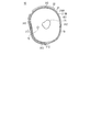
- FIG. 4 shows a cross section of the blood pressure measurement device 10 in the mounted state.
- the belt 21 includes a mounting member that allows the belt 21 to be attached to and detached from the upper arm.
- the mounting member is a hook and loop fastener having a loop surface 213 having a number of loops and a hook surface 214 having a plurality of hooks.
- the loop surface 213 is disposed on the outer peripheral surface 211 of the belt 21 and at the end 215 ⁇ / b> A in the longitudinal direction of the belt 21.
- the longitudinal direction corresponds to the circumferential direction of the upper arm in the mounted state.
- the hook surface 214 is disposed on the inner peripheral surface 212 of the belt 21 and at an end 215 ⁇ / b> B in the longitudinal direction of the belt 21.
- the end 215 ⁇ / b> B faces the end 215 ⁇ / b> A in the longitudinal direction of the belt 21.
- the loop surface 213 and the hook surface 214 are pressed together, the loop surface 213 and the hook surface 214 are coupled. Further, the loop surface 213 and the hook surface 214 are separated by pulling the loop surface 213 and the hook surface 214 away from each other.
- an electrode group 311 for measuring an electrocardiogram is arranged on the inner peripheral surface 212 of the belt 21.
- the electrode group 311 includes six electrodes 312 that are aligned at regular intervals in the longitudinal direction of the belt 21.
- the interval between the electrodes 312 is set to, for example, a quarter of the upper arm circumference of the assumed user with the narrowest arm.
- four of the six electrodes 312 are in contact with the upper arm 70 in the wearing state and are positioned at equal intervals on the circumference of the upper arm, and the rest
- the two electrodes 312 are in contact with the outer peripheral surface of the belt 111.
- the humerus 71 and the brachial artery 72 are shown.
- all six electrodes 312 are in contact with the upper arm 70 in the worn state.
- the number of electrodes 312 is not limited to six and may be 2 to 5 or 7 or more.
- the electrocardiogram may not be measured well depending on the wearing state.
- the electrode 312 is disposed on the central portion 217A of the belt 21 as shown in FIG.
- the central portion 217A is a portion located on the central side (shoulder side) with respect to the center line 216 in the mounted state. More preferably, the electrode 312 is disposed at the central end 218 ⁇ / b> A of the belt 21.
- the central end 218A is an end located on the central side in the mounted state, and the width of the central end 218A is, for example, one third of the entire width of the belt 21.
- a sensor portion 322 of a pulse wave sensor 321 for measuring a pulse wave is further arranged on the inner peripheral surface 212 of the belt 21.
- the sensor unit 322 includes a pair of electrodes 323A and 323D for energizing the upper arm and a pair of electrodes 323B and 323C for detecting a voltage.
- the electrodes 323A, 323B, 323C, and 323D are arranged in the width direction of the belt 111 in this order.
- the width direction of the belt 111 is a direction along the brachial artery 72 in a worn state.
- the farther the sensor unit 322 is located from the heart in the wearing state the longer the pulse wave propagation distance and the larger the measured value of the pulse wave propagation time. For this reason, the error generated when calculating the time difference between the waveform feature point of the electrocardiogram and the waveform feature point of the pulse wave signal becomes relatively small with respect to the pulse wave propagation time, and the pulse wave propagation time is accurately determined. It becomes possible to measure.
- the sensor unit 322 is disposed on the distal portion 217B of the belt 21.
- the distal portion 217B is a portion located on the distal side (elbow side) of the center line 216 in the mounted state.
- the sensor unit 322 is disposed at the distal end 218 ⁇ / b> C of the belt 21.
- the distal end 218C is an end located on the distal side in the mounted state, and the width of the distal end 218C is, for example, one third of the entire width of the belt 21.
- a portion 218B between the central end 218A and the distal end 218C is referred to as an intermediate portion.
- the belt 21 includes an inner cloth 210A, an outer cloth 210B, and a pressing cuff 401 provided between the inner cloth 210A and the outer cloth 210B.
- the press cuff 401 is a belt-like body that is long in the longitudinal direction of the belt 21 so as to surround the upper arm.
- the press cuff 401 is configured as a fluid bag by causing two polyurethane sheets that can be expanded and contracted to face each other in the thickness direction and welding their peripheral portions.
- the electrode group 311 and the sensor unit 322 are provided on the inner cloth 210 ⁇ / b> A so as to be positioned between the pressing cuff 401 and the upper arm 70 in the mounted state.
- FIG. 5 illustrates an example of a hardware configuration of a control system of the blood pressure measurement device 10 according to the present embodiment.
- the main body 22 includes a control unit 501, a storage unit 505, a battery 506, a switch circuit 313, a subtraction circuit 314, and an analog front end (AFE) 315 in addition to the operation unit 221 and the display unit 222 described above.
- a pressure sensor 402, a pump 403, a valve 404, an oscillation circuit 405, and a pump drive circuit 406 are mounted.
- the pulse wave sensor 321 includes an energization and voltage detection circuit 324 in addition to the sensor unit 322 described above. In this example, the energization and voltage detection circuit 324 is mounted on the belt 21.
- the control unit 501 includes a CPU (Central Processing Unit) 502, a RAM (Random Access Memory) 503, a ROM (Read Only Memory) 504, and the like, and controls each component according to information processing.
- the storage unit 505 is an auxiliary storage device such as a hard disk drive (HDD) or a semiconductor memory (for example, a flash memory), and includes programs executed by the control unit 501 (for example, a pulse wave propagation time measurement program and a blood pressure measurement program). ), Setting data necessary for executing the program, blood pressure measurement results, and the like are stored in a nonvolatile manner.
- the storage medium included in the storage unit 505 can store information such as a program, electrical, magnetic, optical, mechanical, or chemical so that the computer and other devices, machines, and the like can read information such as programs recorded therein. It is a medium that accumulates due to mechanical action. Part or all of the program may be stored in the ROM 504.
- the battery 506 supplies power to components such as the control unit 501.
- the battery 506 is a rechargeable battery, for example.
- Each electrode 312 included in the electrode group 311 is connected to an input terminal of the switch circuit 313.
- the two output terminals of the switch circuit 313 are connected to the two input terminals of the subtraction circuit 314, respectively.
- the switch circuit 313 receives the switch signal from the control unit 501 and connects the two electrodes 312 specified by the switch signal to the subtraction circuit 314.
- the subtraction circuit 314 subtracts the potential input from the other input terminal from the potential input from one input terminal.
- the subtraction circuit 314 outputs a potential difference signal representing a potential difference between the two connected electrodes 312 to the AFE 135.
- the subtraction circuit 314 is, for example, an instrumentation amplifier.
- the AFE 135 includes, for example, a low-pass filter (LPF), an amplifier, and an analog-digital converter.
- the potential difference signal is filtered by an LPF, amplified by an amplifier, and converted into a digital signal by an analog-digital converter.
- the potential difference signal converted into the digital signal is given to the control unit 501.
- the control unit 501 acquires a potential difference signal output in time series from the AFE 315 as an electrocardiogram.
- the energization and voltage detection circuit 324 allows a high frequency constant current to flow between the electrodes 323A and 323D.
- the frequency of the current is 50 kHz, and the current value is 1 mA.
- the energization and voltage detection circuit 324 detects the voltage between the electrodes 323B and 323C and generates a detection signal while energizing between the electrodes 323A and 323D.
- the detection signal represents a change in electrical impedance due to a pulse wave propagating through the portion of the artery facing the electrodes 323B and 323C.
- the energization and voltage detection circuit 324 performs signal processing including rectification, amplification, filtering, and analog-digital conversion on the detection signal, and gives the detection signal to the control unit 501.
- the control unit 501 acquires a detection signal output in time series from the energization and voltage detection circuit 324 as a pulse wave signal.
- the pressure sensor 402 is connected to the pressing cuff 401 via a pipe 407, and the pump 403 and the valve 404 are connected to the pressing cuff 401 via a pipe 408.
- the pipes 407 and 408 may be one common pipe.
- the pump 403 is, for example, a piezoelectric pump, and supplies air as a fluid to the pressing cuff 401 through the pipe 408 in order to increase the pressure in the pressing cuff 401.
- the valve 404 is mounted on the pump 403 and is configured to be opened and closed in accordance with the operation state (ON / OFF) of the pump 403. Specifically, when the pump 403 is turned on, the valve 404 is closed, and when the pump 403 is turned off, the valve 404 is opened.
- the valve 404 When the valve 404 is in the open state, the pressing cuff 401 communicates with the atmosphere, and the air in the pressing cuff 401 is discharged into the atmosphere.
- the valve 404 has a check valve function, and air does not flow backward.
- the pump drive circuit 406 drives the pump 403 based on a control signal received from the control unit 501.
- the pressure sensor 402 detects the pressure (also referred to as cuff pressure) in the pressing cuff 401 and generates an electric signal representing the cuff pressure.
- the cuff pressure is, for example, a pressure based on atmospheric pressure.
- the pressure sensor 402 is, for example, a piezoresistive pressure sensor.
- the oscillation circuit 405 oscillates based on the electrical signal from the pressure sensor 402 and outputs a frequency signal having a frequency corresponding to the electrical signal to the control unit 501.
- the output of the pressure sensor 402 is used to control the pressure of the pressure cuff 401 and to calculate blood pressure values (including systolic blood pressure and diastolic blood pressure) by the oscillometric method.
- the pressing cuff 401 may be used for adjusting the contact state between the electrode 312 or the sensor unit 322 of the pulse wave sensor 321 and the upper arm. For example, when the blood pressure measurement based on the pulse wave propagation time is executed, the pressure cuff 401 is kept in a state where a certain amount of air is accommodated. As a result, the electrode 312 and the sensor portion 322 of the pulse wave sensor 321 come into reliable contact with the upper arm.
- the electrode group 311, the switch circuit 313, the subtraction circuit 314, and the AFE 315 correspond to the electrocardiogram acquisition unit 31 of the first blood pressure measurement unit 30 shown in FIG. 321 (the electrode 323 and the energization and voltage detection circuit 324) corresponds to the pulse wave signal acquisition unit 32 of the first blood pressure measurement unit 30.
- the pressure cuff 401, the pressure sensor 402, the pump 403, the valve 404, the oscillation circuit 405, the pump drive circuit 406, and the pipes 407 and 408 correspond to the second blood pressure measurement unit 40.
- the control unit 501 may include a plurality of processors.
- the blood pressure measurement device 10 may include a communication unit 507 for communicating with an external device such as a user's mobile terminal (for example, a smartphone).
- the communication unit 507 includes a wired communication module and / or a wireless communication module.
- a wireless communication system for example, Bluetooth (registered trademark), BLE (Bluetooth Low Energy), or the like can be adopted.
- FIG. 6 illustrates an example of the software configuration of the blood pressure measurement device 10 according to the present embodiment.
- the blood pressure measurement device 10 includes an electrocardiogram measurement control unit 601, an electrocardiogram storage unit 602, a pulse wave measurement control unit 603, a pulse wave signal storage unit 604, a pulse wave propagation time calculation unit 605, and a blood pressure value calculation unit 606.
- the calibration part 614 performs the following process, when the control part 501 of the blood-pressure measuring apparatus 10 runs the program memorize
- FIG. When the control unit 501 executes a program, the control unit 501 expands the program in the RAM 503. Then, the control unit 501 interprets and executes the program expanded in the RAM 503 by the CPU 502 and controls each component.
- the electrocardiogram storage unit 602, the pulse wave signal storage unit 604, the blood pressure value storage unit 607, and the blood pressure value storage unit 611 are realized by the storage unit 505.
- the electrocardiogram measurement control unit 601 controls the switch circuit 313 in order to acquire an electrocardiogram. Specifically, the electrocardiogram measurement control unit 601 generates a switch signal for selecting two of the six electrodes 312 and supplies the switch signal to the switch circuit 313. The electrocardiogram measurement control unit 601 acquires a potential difference signal obtained by using the selected two electrodes 312 and stores time series data of the acquired potential difference signal in the electrocardiogram storage unit 602 as an electrocardiogram.
- the electrocardiogram measurement control unit 601 determines an optimal electrode pair for acquiring the electrocardiogram. For example, the electrocardiogram measurement control unit 601 acquires an electrocardiogram for each of all electrode pairs, and determines an electrode pair that provides an electrocardiogram having the largest R-wave amplitude as an optimal electrode pair. Thereafter, the electrocardiogram measurement control unit 601 measures the electrocardiogram using an optimal electrode pair.
- the pulse wave measurement control unit 603 controls the energization and voltage detection circuit 324 in order to acquire a pulse wave signal. Specifically, the pulse wave measurement control unit 603 instructs the energization and voltage detection circuit 324 to flow a current between the electrodes 323A and D, and the electrode 323B detected in a state where a current flows between the electrodes 323A and D. A detection signal indicating a voltage between 323C is acquired. The pulse wave measurement control unit 603 stores the time series data of the detection signal in the pulse wave signal storage unit 604 as a pulse wave signal.
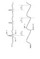
- the pulse wave propagation time calculation unit 605 reads the electrocardiogram from the electrocardiogram storage unit 602, reads the pulse wave signal from the pulse wave signal storage unit 604, and calculates the time difference between the waveform feature point of the electrocardiogram and the waveform feature point of the pulse wave signal. Based on this, the pulse wave propagation time is calculated. For example, as shown in FIG. 7, the pulse wave propagation time calculation unit 605 detects the peak point time (time) corresponding to the R wave from the electrocardiogram, and detects the rise point time (time) from the pulse wave signal. The difference obtained by subtracting the peak point time from the rising point time is calculated as the pulse wave propagation time.
- the pulse wave propagation time calculation unit 605 may correct the time difference based on the precursor ejection period (PEP: PreEjection Period) and output the corrected time difference as the pulse wave propagation time.
- PEP PreEjection Period
- the pulse wave propagation time calculation unit 605 may calculate the pulse wave propagation time by subtracting a predetermined value from the above time difference, assuming that the precursor ejection period is constant.
- the peak point corresponding to the R wave is an example of a waveform feature point of the electrocardiogram.
- the waveform feature point of the electrocardiogram may be a peak point corresponding to the Q wave or a peak point corresponding to the S wave. Since the R wave appears as a clear peak compared to the Q wave or S wave, the time of the R wave peak point can be specified more accurately. For this reason, the R wave peak point is preferably used as a waveform feature point of the electrocardiogram.
- the rising point is an example of a waveform feature point of the pulse wave signal.
- the waveform feature point of the pulse wave signal may be a peak point. Since the pulse wave signal gradually changes with time, an error is likely to occur when specifying the time of the waveform feature point in the pulse wave signal.
- the blood pressure value calculation unit 606 calculates the blood pressure value based on the pulse wave propagation time calculated by the pulse wave propagation time calculation unit 605 and the blood pressure calculation formula.
- the blood pressure value calculation unit 606 uses, for example, the above formula (1) as a blood pressure calculation formula.
- the blood pressure value calculation unit 606 stores the calculated blood pressure value in the blood pressure value storage unit 607 in association with the time information.
- the blood pressure calculation formula is not limited to the above formula (1).
- the blood pressure calculation formula may be, for example, the following formula.
- SBP B 1 / PTT 2 + B 2 / PTT + B 3 ⁇ PTT + B 4 (2)
- B 1 , B 2 , B 3 , B 4 are parameters.
- the determination unit 608 corresponds to the determination unit 50 shown in FIG.
- the determination unit 608 determines, based on the pulse wave propagation time calculated by the pulse wave propagation time calculation unit 605, whether or not a condition recommended for measuring the user's blood pressure is satisfied. In one example, the determination unit 608 determines whether the blood pressure change rate exceeds a threshold value.
- the blood pressure change rate is, for example, the amount of change in blood pressure value per unit time. Specifically, the determination unit 608 determines whether or not the difference obtained by subtracting the blood pressure value before unit time from the latest blood pressure value exceeds a threshold value.
- the determination unit 608 satisfies the conditional expression of SBP 0 ⁇ SBP 1 > V th. It is determined whether or not.
- the unit time is, for example, 30 seconds
- the threshold value is, for example, 20 [mmHg].
- the latest pulse wave propagation time value is PTT 0 and the pulse wave propagation time value before unit time is PTT 1
- the above conditional expression can be transformed using Equation (1) to A 1 (1 / PTT 0 2 ⁇ 1 / PTT 1 2 )> V th .
- the determination unit 608 may use the pulse wave propagation time itself, or may use a blood pressure value calculated based on the pulse wave propagation time. Note that the determination unit 608 may determine whether the difference obtained by subtracting the blood pressure value before a predetermined heart rate (for example, 30 beats before) from the latest blood pressure value exceeds a threshold value. In another example, the determination unit 608 determines whether or not the latest systolic blood pressure value exceeds a threshold (for example, 150 [mmHg]). This threshold value may be fixed or variable. For example, the threshold is set to a higher value as the average blood pressure of the user is higher.
- the instruction unit 609 corresponds to the instruction unit 60 shown in FIG.
- the instruction unit 609 outputs information that instructs execution of blood pressure measurement.
- the instruction unit 609 gives an instruction signal to the display control unit 612 so that a message prompting execution of blood pressure measurement is displayed on the display unit 222.
- the instruction unit 609 outputs a control signal for controlling a drive circuit that drives the sounding body in order to generate a notification sound.
- the instruction unit 609 may transmit an instruction signal to the user's mobile terminal via the communication unit 507, thereby prompting the user to perform blood pressure measurement through the mobile terminal.
- the instruction input unit 613 receives an instruction input from the user using the operation unit 221. For example, when an operation for instructing execution of blood pressure measurement is performed, the instruction input unit 613 provides the blood pressure measurement control unit 610 with an instruction to start blood pressure measurement.
- the blood pressure measurement control unit 610 controls the pump drive circuit 406 in order to perform blood pressure measurement.
- the blood pressure measurement control unit 610 drives the pump 403 via the pump drive circuit 406.
- the pressure cuff 401 expands, thereby compressing the user's upper arm.
- the blood pressure measurement control unit 610 monitors the cuff pressure using the pressure sensor 402.
- the blood pressure measurement control unit 610 calculates a blood pressure value by an oscillometric method based on a pressure signal output from the pressure sensor 402 in a pressurizing process of supplying air to the pressing cuff 401.
- Blood pressure values include, but are not limited to, systolic blood pressure (SBP) and diastolic blood pressure (DBP).
- SBP systolic blood pressure
- DBP diastolic blood pressure
- the blood pressure measurement control unit 610 stores the calculated blood pressure value in the blood pressure value storage unit 611 in association with the time information.
- the blood pressure measurement control unit 610 can calculate the pulse rate simultaneously with the blood pressure value.
- the blood pressure measurement control unit 610 stops the pump 403 via the pump drive circuit 406 when the calculation of the blood pressure value is completed. Thereby, air is exhausted from the pressing cuff 401 through the valve 404.
- the display control unit 612 controls the display unit 222.
- the display control unit 612 receives an instruction signal from the instruction unit 609 and causes the display unit 222 to display a message included in the instruction signal.
- the display control unit 612 displays the blood pressure measurement result on the display unit 222 after the blood pressure measurement by the blood pressure measurement control unit 610 is completed.
- the calibration unit 614 calibrates the blood pressure calculation formula based on the pulse wave propagation time obtained by the pulse wave propagation time calculation unit 605 and the blood pressure value obtained by the blood pressure measurement control unit 610.
- the correlation between the pulse wave propagation time and the blood pressure value is different for each individual.
- the correlation changes according to the state in which the blood pressure measurement device 10 is worn on the user's upper arm. For example, even for the same user, the correlation changes between when the blood pressure measurement device 10 is placed on the shoulder side and when the blood pressure measurement device 10 is placed on the elbow side. In order to reflect such a change in correlation, the blood pressure calculation formula is calibrated. Calibration of the blood pressure calculation formula is executed, for example, when the user wears the blood pressure measurement device 10.
- the calibration unit 614 obtains a plurality of combinations of the measurement result of the pulse wave propagation time and the measurement result of the blood pressure, and sets the parameter A 1 based on the plurality of combinations of the measurement result of the pulse wave propagation time and the measurement result of the blood pressure. , A 2 is determined.
- the calibration unit 614 uses, for example, a fitting method such as a least square method or a maximum likelihood method in order to determine the parameters A 1 and A 2 .
- Electrode group 311 includes four electrodes 312, and these four electrodes 312 are referred to as electrodes 312-1, 312-2, 312-3, and 312-4.
- the control unit 501 provides a switch signal for selecting the electrodes 312-1 and 312-2 to the switch circuit 313, and obtains an electrocardiogram using the pair of electrodes 312-1 and 312-2.
- the control unit 501 gives a switch signal for selecting the electrodes 312-1 and 312-3 to the switch circuit 313, and obtains an electrocardiogram using the pair of the electrodes 312-1 and 312-3.
- the control unit 501 includes a pair of electrodes 312-1 and 312-4, a pair of electrodes 312-2 and 312-3, a pair of electrodes 312-2 and 312-4, and an electrode 312-3 and 312-.
- An electrocardiogram is obtained using 4 pairs.
- the control unit 501 determines an electrode pair from which an electrocardiogram having the largest R wave amplitude is obtained as an electrode pair used to obtain an electrocardiogram.
- the blood pressure calculation formula is calibrated.
- the control unit 501 operates as the calibration unit 614. If the number of parameters included in the blood pressure calculation formula is N, N or more sets of measured values of pulse wave propagation time and measured values of blood pressure are required.
- the blood pressure calculation formula (1) has two parameters A 1 and A 2 . In this case, for example, when the user is at rest, the control unit 501 obtains a combination of the measurement value of the pulse wave propagation time and the measurement value of the blood pressure, and subsequently causes the user to perform exercise. A set of measurement values and blood pressure measurement values is acquired.
- the control unit 501 determines the parameters A 1 and A 2 based on the two sets of the acquired measured value of the pulse wave propagation time and the measured value of the blood pressure. After the calibration is completed, blood pressure measurement based on the pulse wave propagation time can be executed.
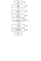
- FIG. 8 shows an operation flow when the blood pressure measurement device 10 performs blood pressure measurement based on the pulse wave propagation time.
- step S11 of FIG. 8 the control unit 501 starts blood pressure measurement based on the pulse wave propagation time.
- the control unit 501 receives an operation signal indicating that the user has instructed the start of blood pressure measurement based on the pulse wave propagation time from the operation unit 221, and starts blood pressure measurement in response thereto.
- the control unit 501 may start blood pressure measurement based on the pulse wave propagation time in response to the completion of calibration of the blood pressure calculation formula.
- step S12 the control unit 501 operates as the electrocardiogram measurement control unit 601, and acquires an electrocardiogram using the two electrodes 312 determined in the above-described processing.
- step S ⁇ b> 13 the control unit 501 operates as the pulse wave measurement control unit 603 and acquires a pulse wave signal using the pulse wave sensor 321.
- the process of step S11 and the process of step S12 are executed in parallel.
- step S14 the control unit 501 operates as the pulse wave propagation time calculation unit 605, and calculates the time difference between the R wave peak point of the electrocardiogram and the rising point of the pulse wave signal as the pulse wave propagation time.
- step S15 the control unit 501 operates as the blood pressure value calculation unit 606, and calculates the blood pressure value from the pulse wave propagation time calculated in step S14 using the above-described blood pressure calculation formula (1).
- the control unit 501 records the calculated blood pressure value in the storage unit 505 in association with the time information.
- step S16 the control unit 501 determines whether or not an operation signal indicating that the user has instructed the end of blood pressure measurement based on the pulse wave propagation time is received from the operation unit 221. Until the control unit 501 receives the operation signal, the processes in steps S12 to S15 are repeated. Thereby, the blood pressure value for each heartbeat is recorded. When receiving the operation signal, the control unit 501 ends the blood pressure measurement based on the pulse wave propagation time.
- the blood pressure can be continuously measured over a long period of time with a light physical burden on the user.
- FIG. 9 shows an operation flow when instructing the blood pressure measurement device 10 to execute blood pressure measurement by the oscillometric method.
- the process shown in FIG. 9 is executed during a period in which blood pressure measurement based on the pulse wave propagation time is being executed.
- control unit 501 acquires a blood pressure measurement value by blood pressure measurement based on the pulse wave propagation time described with reference to FIG. 8.
- step S ⁇ b> 22 the control unit 501 operates as the determination unit 608, and determines whether or not a condition recommended to measure the user's blood pressure is satisfied based on the latest measurement value acquired in step S ⁇ b> 21. To do. For example, the control unit 501 determines whether or not the blood pressure value difference obtained by subtracting the blood pressure value of unit time ago from the latest blood pressure value exceeds a threshold value. When the blood pressure value difference is equal to or smaller than the threshold value, the process returns to step S21, and the control unit 501 acquires the next measurement value. When the blood pressure value difference exceeds the threshold value, the process proceeds to step S23.
- step S23 the control unit 501 operates as the instruction unit 609, and instructs execution of blood pressure measurement.
- the control unit 501 generates a notification sound through the sound generator and causes the display unit 222 to display a message prompting execution of blood pressure measurement.
- control unit 501 instructs the user to perform blood pressure measurement by the oscillometric method when a situation in which accurate blood pressure measurement is recommended occurs.
- FIG. 10 shows an operation flow when the blood pressure measurement device 10 performs blood pressure measurement by the oscillometric method.
- the pressure cuff 401 is gradually pressurized and then depressurized.
- the pulse wave propagation time cannot be measured correctly.
- blood pressure measurement based on the pulse wave propagation time shown in FIG. 8 may be temporarily stopped.
- step S31 of FIG. 10 the control unit 501 starts blood pressure measurement by the oscillometric method.
- the control unit 501 receives an operation signal indicating that the user has instructed execution of blood pressure measurement by the oscillometric method from the operation unit 221, and starts blood pressure measurement in response thereto.
- step S32 the control unit 501 operates as the blood pressure measurement control unit 610 and performs initialization for blood pressure measurement. For example, the control unit 501 initializes the processing memory area. Then, the control unit 501 stops the pump 403 via the pump drive circuit 406. Along with this, the valve 404 is opened, and the air in the pressing cuff 401 is discharged. The control unit 501 sets the current output value of the pressure sensor 402 as a reference value.
- step S ⁇ b> 33 the control unit 501 operates as the blood pressure measurement control unit 610 and performs control to pressurize the press cuff 401.
- the control unit 501 drives the pump 403 via the pump drive circuit 406.
- the valve 404 is closed and air is supplied to the pressing cuff 401.
- the press cuff 401 expands and the cuff pressure Pc gradually increases as shown in FIG.
- the control unit 501 monitors the cuff pressure Pc using the pressure sensor 402 and acquires a pulse wave signal Pm representing a fluctuation component of the arterial volume.
- step S34 the control unit 501 operates as the blood pressure measurement control unit 610, and tries to calculate a blood pressure value (including SBP and DBP) based on the pulse wave signal Pm acquired at this time. If the blood pressure value cannot be calculated yet because of insufficient data at this time (No in step S35), the processes in steps S33 and S34 are repeated unless the cuff pressure Pc reaches the upper limit pressure.
- the upper limit pressure is determined in advance from the viewpoint of safety.
- the upper limit pressure is, for example, 300 mmHg.
- step S35 If the blood pressure value has been calculated (Yes in step S35), the process proceeds to step S36.
- step S ⁇ b> 36 the control unit 501 operates as the blood pressure measurement control unit 610 and stops the pump 403 by the pump drive circuit 406. Along with this, the valve 404 is opened, and the air in the pressing cuff 401 is discharged.
- step S37 the control unit 501 displays the blood pressure measurement result on the display unit 222 and records it in the storage unit 505.
- the processing procedure shown in FIG. 8, FIG. 9, or FIG. 10 is an example, and the processing order or the contents of each processing can be changed as appropriate.
- the calculation of the blood pressure value may be executed in a decompression process in which air is discharged from the pressure cuff 401.
- the electrode group 311 and the sensor unit 322 of the pulse wave sensor 321 are both provided on the belt 21. For this reason, both the electrode group 311 and the pulse wave sensor 321 are attached to the user by simply winding the belt 21 around the upper arm. Therefore, the user can easily wear the blood pressure measurement device 10. Since the user only needs to wear one device, the user's feeling of refusal to wear the blood pressure measurement device 10 is reduced.
- the pulse wave propagation time is calculated based on the electrocardiogram and the pulse wave signal obtained for the upper arm, the pulse wave propagation time can be obtained for a long distance from the heart to the upper arm. This improves the robustness against errors that occur when calculating the time difference between the waveform feature points of the electrocardiogram and the waveform feature points of the pulse wave signal.
- the electrode group 311 is disposed on the central portion 217 ⁇ / b> A of the belt 21, and the sensor portion 322 of the pulse wave sensor 321 is disposed on the distal portion 217 ⁇ / b> B of the belt 21. With this arrangement, a longer pulse wave propagation distance is ensured and an electrocardiogram with a high S / N ratio is acquired. Thereby, the robustness is further improved. As a result, the pulse wave propagation time can be accurately measured, and the reliability of the blood pressure value calculated based on the pulse wave propagation time is improved.
- the blood pressure calculation formula used in the first blood pressure measurement unit 30 is calibrated based on the blood pressure value obtained by the second blood pressure measurement unit 40. It is necessary to calibrate based on a blood pressure value obtained by a measurement system different from the first blood pressure measurement unit 30.
- the second blood pressure measurement unit 40 is integrated with the first blood pressure measurement unit 30, and the blood pressure calculation formula is calibrated based on the blood pressure value obtained by the second blood pressure measurement unit 40. . Thereby, the blood pressure calculation formula can be calibrated by the blood pressure measurement device 10 alone. For this reason, the blood pressure calculation formula can be easily calibrated.
- the first blood pressure measurement unit 30 determines whether or not a condition recommended to measure the user's blood pressure is satisfied, and if the condition is satisfied, the second The user is notified that the blood pressure measurement by the blood pressure measurement unit 40 should be performed. For this reason, it is possible to cause the user to perform accurate blood pressure measurement under a situation where blood pressure measurement is recommended.
- the blood pressure measurement based on the pulse wave propagation time and the blood pressure measurement by the oscillometric method can be performed with one device, it is highly convenient for the user.
- the blood pressure measuring device 10 Since the blood pressure measuring device 10 is attached to the upper arm, blood pressure is measured at substantially the same height as the heart. Thereby, it is not necessary to perform height correction on the acquired blood pressure measurement result. Moreover, when the blood pressure measuring device 10 is an upper arm type, the blood pressure measuring device 10 can be hidden by the sleeve of clothes, and it can be made inconspicuous that the blood pressure measuring device 10 is worn.
- the electrode group for measuring the electrocardiogram has four or more electrodes, in order to remove or reduce body movement noise from the electrocardiogram, the electrode other than the two electrodes used to measure the optimal electrocardiogram Two may be used.
- Body motion noise is noise generated due to the user's body motion. It is difficult to effectively reduce body movement noise with a filter such as a low-pass filter.
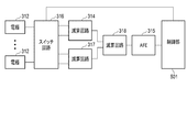
- FIG. 12 illustrates an example of a hardware configuration of an electrocardiogram acquisition unit in the blood pressure measurement device according to one embodiment.
- the same components as those shown in FIG. 5 are denoted by the same reference numerals, and description of these components will be omitted.
- the electrodes 312 are connected to the input terminals of the switch circuit 316, respectively.
- the switch circuit 316 is controlled by the control unit 501.
- the control unit 501 includes a first switch signal for selecting two electrodes used for electrocardiogram measurement and a second switch signal for selecting two electrodes used for body motion noise reduction. 316.
- the first and second output terminals of the switch circuit 316 are connected to the subtraction circuit 314, and the subtraction circuit 314 represents a first potential difference signal representing a potential difference between the two electrodes designated by the first switch signal. Is output to the subtraction circuit 318.
- the third and fourth output terminals of the switch circuit 316 are connected to the subtraction circuit 317, and the subtraction circuit 317 represents a second potential difference signal representing the potential difference between the two electrodes designated by the second switch signal. Is output to the subtraction circuit 318.
- the subtraction circuit 318 generates a third potential difference signal by subtracting the second potential difference signal from the first potential difference signal, and outputs the third potential difference signal to the AFE 135. Since the same level of body motion noise is included in each of the first potential difference signal and the second potential difference signal, the body motion noise can be removed or reduced.
- the pulse wave sensor employs an impedance method for detecting a change in impedance accompanying a change in arterial volume.
- the pulse wave sensor may employ another measurement method such as a photoelectric method, a piezoelectric method, or a radio wave method.
- the pulse wave sensor includes a light emitting element that irradiates light toward an artery passing through a measurement site, and a photodetector that detects reflected light or transmitted light of the light, Changes in light intensity associated with arterial volume changes are detected.
- the pulse wave sensor includes a piezoelectric element provided on the belt so as to be in contact with the measurement site, and detects a change in pressure due to a change in the volume of the artery.
- the blood pressure measurement device 10 includes a pressure cuff for adjusting the contact state between the electrode 312 and the upper arm, a pump that supplies air to the pressure cuff, a pump drive circuit that drives the pump, and the pressure in the pressure cuff. And a pressure sensor for detection.
- the pressing cuff is provided at the central end 218A of the belt 21.
- the pressing cuff 401 is provided, for example, at the intermediate portion 218B of the belt 21.
- the blood pressure measurement device 10 includes a pressure cuff for adjusting the contact state between the sensor unit 322 of the pulse wave sensor 321 and the upper arm, a pump that supplies air to the pressure cuff, a pump drive circuit that drives the pump, And a pressure sensor for detecting the pressure in the pressing cuff.
- This pressing cuff is provided at the distal end 218 ⁇ / b> C of the belt 21.
- the pressing cuff 401 is provided, for example, at the intermediate portion 218B of the belt 21.
- a pulse wave propagation time measurement device including a belt unit 20, an electrocardiogram acquisition unit 31, a pulse wave signal acquisition unit 32, and a pulse wave propagation time calculation unit 33 is provided.
- This pulse wave propagation time measuring device may further include a determination unit 50 and an instruction unit 60.
- the pulse wave propagation time measurement device may further include a pressure cuff, a pump, and a pump drive circuit in order to press the electrode 312 and the pulse wave sensor 321 against the upper arm.
- the blood pressure measurement device 10 may not include the second blood pressure measurement unit 40.
- a blood pressure value obtained by measuring with another blood pressure monitor is input to the blood pressure measurement device 10 in order to calibrate the blood pressure calculation formula. There is a need to.
- the part to be measured is not limited to the upper arm, but may be another part such as a wrist, a thigh, or an ankle.
- the present invention is not limited to the above-described embodiment as it is, and can be embodied by modifying the constituent elements without departing from the scope of the invention in the implementation stage. Further, various inventions can be formed by appropriately combining a plurality of constituent elements disclosed in the embodiment. For example, some components may be deleted from all the components shown in the embodiment. Furthermore, you may combine suitably the component covering different embodiment.
- Electrode 324 Energization and voltage detection circuit 401 ... Pressure cuff 402 ... Pressure sensor 403 ... Pump 404 ... Valve 405 ... Oscillation circuit 406 ... Pump drive circuit 407, 408 ... piping 501 ... control unit 502 ... CPU 503 ... RAM 504 ... ROM 505 ... Storage unit 506 ... Battery 507 ... Communication unit 601 ... ECG measurement control unit 602 ... ECG storage unit 603 ... Pulse wave measurement control unit 604 ... Pulse wave signal storage unit 605 ... Pulse wave propagation time calculation unit 606 ... Blood pressure value calculation unit 607 ... Blood pressure value storage unit 608 ... Determination unit 609 ... Instruction unit 610 ... Blood pressure measurement control unit 611 ... Blood pressure value storage unit 612 ... Display control unit 613 ... Instruction input unit 614 ... Calibration unit
Abstract
Provided is a pulse wave propagation time measuring device which is easily worn by a user. A pulse wave propagation time measuring device according to an aspect is provided with: a belt unit wound on a part to be measured of a user; an electrocardiogram acquisition unit which includes a plurality of electrodes provided in the belt unit, and acquire an electrocardiogram of the user by using the plurality of electrodes; a pulse wave signal acquisition unit which includes a pulse wave sensor provided in the belt unit, and acquires a pulse wave signal representing the pulse wave of the user by using the pulse wave sensor; and a pulse wave propagation time calculating unit which calculates a pulse wave propagation time on the basis of the time difference between a waveform feature point of the electrocardiogram and a waveform feature point of the pulse wave signal.
Description
本発明は、脈波伝播時間を非侵襲的に測定する脈波伝播時間測定装置、及び脈波伝播時間測定装置を用いた血圧測定装置に関する。
The present invention relates to a pulse wave propagation time measurement device that non-invasively measures a pulse wave propagation time, and a blood pressure measurement device using the pulse wave propagation time measurement device.
脈波が動脈上の2点間を伝播するのに要する時間である脈波伝播時間(PTT:Pulse Transit Time)と血圧との間に相関関係があることが知られている。
It is known that there is a correlation between the pulse wave propagation time (PTT: Pulse Transit Time), which is the time required for the pulse wave to propagate between two points on the artery, and the blood pressure.
特許文献1には、上記の相関関係を利用して血圧を測定する血圧測定装置が開示されている。この血圧測定装置は、ECG(ElectroCardioGraphic)センサの出力とPPG(PhotoPlethysmoGraphic)センサの出力とに基づいて脈波伝播時間を算出し、算出した脈波伝播時間と上記の相関関係を表す関係式とを用いて血圧値を算出する。ECGセンサはユーザの胴体に装着され、PPGセンサはユーザの耳に装着される。
Patent Document 1 discloses a blood pressure measurement device that measures blood pressure using the above correlation. This blood pressure measurement device calculates a pulse wave propagation time based on the output of an ECG (ElectroCardioGraphic) sensor and the output of a PPG (PhotoPlethysmoGraphic) sensor, and calculates the calculated pulse wave propagation time and a relational expression representing the above correlation To calculate the blood pressure value. The ECG sensor is attached to the user's torso, and the PPG sensor is attached to the user's ear.
特許文献1に開示された血圧測定装置においては、2つのデバイスをユーザに装着する必要があり、ユーザにとって装着が面倒である。
In the blood pressure measurement device disclosed in Patent Document 1, it is necessary to wear two devices on the user, which is troublesome for the user.
本発明は、上記の事情に着目してなされたものであり、その目的は、ユーザへの装着が容易な脈波伝播時間測定装置及び血圧測定装置を提供することである。
The present invention has been made paying attention to the above circumstances, and an object of the present invention is to provide a pulse wave transit time measurement device and a blood pressure measurement device that can be easily attached to a user.
本発明は、上記課題を解決するために、以下の構成を採用する。
The present invention adopts the following configuration in order to solve the above problems.
一態様に係る脈波伝播時間測定装置は、ユーザの被測定部位に巻き付けられるベルト部と、前記ベルト部に設けられた複数の電極を含み、前記複数の電極を用いて前記ユーザの心電図を取得する心電図取得部と、前記ベルト部に設けられた脈波センサを含み、前記脈波センサを用いて前記ユーザの脈波を表す脈波信号を取得する脈波信号取得部と、前記心電図の波形特徴点と前記脈波信号の波形特徴点との間の時間差に基づいて脈波伝播時間を算出する脈波伝播時間算出部と、を備える。
A pulse wave transit time measuring apparatus according to an aspect includes a belt unit wound around a measurement site of a user and a plurality of electrodes provided on the belt unit, and the electrocardiogram of the user is obtained using the plurality of electrodes An electrocardiogram acquisition unit, a pulse wave sensor provided on the belt unit, and a pulse wave signal acquisition unit for acquiring a pulse wave signal representing the pulse wave of the user using the pulse wave sensor, and a waveform of the electrocardiogram A pulse wave propagation time calculation unit that calculates a pulse wave propagation time based on a time difference between the feature point and the waveform feature point of the pulse wave signal.
上記の構成では、電極及び脈波センサがともにベルト部に設けられている。これにより、ベルト部をユーザに巻き付けることで電極及び脈波センサをユーザに取り付けることができる。このため、ユーザへの装着が容易である。さらに、心電図の波形特徴点と被測定部位に関する脈波信号の波形特徴点との時間差に基づいて脈波伝播時間が算出される。この場合、脈波伝播時間は、脈波が心臓から被測定部位までの長い距離を伝播するのに要した時間に相当し、被測定部位中の2点間での脈波伝播時間を測定する場合と比較して大きい値になる。言い換えると、長い脈波伝播距離が確保される。このため、心電図の波形特徴点と脈波信号の波形特徴点との間の時間差を算出する際に生じる誤差の脈波伝播時間への影響が小さくなり、脈波伝播時間を正確に測定することができる。
In the above configuration, both the electrode and the pulse wave sensor are provided on the belt portion. Thereby, an electrode and a pulse wave sensor can be attached to a user by winding a belt part around a user. For this reason, it is easy to attach to the user. Further, the pulse wave propagation time is calculated based on the time difference between the waveform feature point of the electrocardiogram and the waveform feature point of the pulse wave signal relating to the measurement site. In this case, the pulse wave propagation time corresponds to the time required for the pulse wave to travel a long distance from the heart to the measurement site, and the pulse wave propagation time between two points in the measurement site is measured. It becomes a large value compared with the case. In other words, a long pulse wave propagation distance is secured. For this reason, the influence on the pulse wave propagation time of the error that occurs when calculating the time difference between the waveform feature point of the electrocardiogram and the waveform feature point of the pulse wave signal is reduced, and the pulse wave propagation time is accurately measured. Can do.
一態様では、前記脈波センサは、前記ベルト部のうち、前記ベルト部が前記ユーザの前記被測定部位に巻き付けられた状態で末梢側に位置する部分に配置されてもよい。当該構成では、より長い脈波伝播距離が確保され、脈波伝播時間をより正確に測定することができる。
In one aspect, the pulse wave sensor may be disposed in a portion of the belt portion that is located on a distal side in a state where the belt portion is wound around the measurement site of the user. With this configuration, a longer pulse wave propagation distance is ensured, and the pulse wave propagation time can be measured more accurately.
一態様では、前記複数の電極は、前記ベルト部のうち、前記ベルト部が前記ユーザの前記被測定部位に巻き付けられた状態で中枢側に位置する部分に配置されてもよい。当該構成では、より高い信号対雑音比(SN比)で心臓の電気的活動を表す信号を取得することができ、心電図において波形特徴点の時間をより正確に検出することができるようになる。その結果、脈波伝播時間をより正確に測定することができる。
In one aspect, the plurality of electrodes may be arranged in a portion of the belt portion that is located on a central side in a state where the belt portion is wound around the measurement site of the user. In this configuration, a signal representing the electrical activity of the heart can be acquired with a higher signal-to-noise ratio (S / N ratio), and the time of the waveform feature point can be detected more accurately in the electrocardiogram. As a result, the pulse wave propagation time can be measured more accurately.
一態様では、前記複数の電極は、少なくとも4つの電極であってもよく、前記心電図取得部は、前記複数の電極のうちの2つの第1の電極間の第1の電位差を取得し、前記複数の電極のうち、前記2つの第1の電極とは異なる2つの第2の電極間の第2の電位差を取得し、前記第1の電位差と前記第2の電位差との差を第3の電位差として取得し、前記第3の電位差に基づいて前記心電図を生成してもよい。
In one aspect, the plurality of electrodes may be at least four electrodes, and the electrocardiogram acquisition unit acquires a first potential difference between two first electrodes of the plurality of electrodes, Of the plurality of electrodes, a second potential difference between two second electrodes different from the two first electrodes is obtained, and a difference between the first potential difference and the second potential difference is calculated as a third potential difference. It may be acquired as a potential difference, and the electrocardiogram may be generated based on the third potential difference.
上記の構成では、第1の電位差には、ユーザの体動に起因して生じる体動ノイズが載ることがある。第2の電位差にも同程度の体動ノイズが載るため、前記第1の電位差と前記第2の電位差との差を算出することで体動ノイズを除去又は低減することが可能である。体動ノイズが除去又は低減された心電図を取得することができ、心電図において波形特徴点の時間をより正確に検出することができるようになる。その結果、脈波伝播時間をより正確に測定することができる。
In the above configuration, body motion noise caused by the user's body motion may be included in the first potential difference. Since body motion noise of the same level is also present in the second potential difference, it is possible to remove or reduce body motion noise by calculating the difference between the first potential difference and the second potential difference. An electrocardiogram from which body motion noise is removed or reduced can be acquired, and the time of waveform feature points can be detected more accurately in the electrocardiogram. As a result, the pulse wave propagation time can be measured more accurately.
一態様では、上記脈波伝播時間測定装置は、前記算出された脈波伝播時間に基づいて、前記ユーザの血圧を測定することが推奨される条件が満たされたか否かを判定する判定部と、前記条件が満たされたと前記判定部が判定したことに応答して、血圧測定の実行を指示する情報を出力する指示部と、をさらに備えてもよい。
In one aspect, the pulse wave transit time measuring device includes: a determination unit that determines whether or not a condition recommended to measure the blood pressure of the user is satisfied based on the calculated pulse wave transit time; And an instruction unit that outputs information instructing execution of blood pressure measurement in response to the determination unit determining that the condition is satisfied.
上記の構成では、条件が満たされる場合に、例えば、血圧測定の実行を促すメッセージがユーザに提示される。このため、血圧が急上昇したときなどの血圧測定が推奨される状況下で血圧測定が実行されるようになる。
In the above configuration, when the condition is satisfied, for example, a message prompting execution of blood pressure measurement is presented to the user. For this reason, blood pressure measurement comes to be performed under the situation where blood pressure measurement is recommended, such as when blood pressure suddenly rises.
一態様では、前記被測定部位は上腕であってよい。当該構成では、脈波伝播時間測定装置を服の下に装着することが可能であり、脈波伝播時間測定装置を装着していることを目立たなくすることができる。
In one aspect, the measurement site may be the upper arm. In this configuration, it is possible to wear the pulse wave transit time measuring device under clothes, and to make it less noticeable that the pulse wave transit time measuring device is worn.
一態様に係る血圧測定装置は、上記の脈波伝播時間測定装置と、前記算出された脈波伝播時間に基づいて、血圧値を算出する血圧値算出部と、を備える。
A blood pressure measurement device according to an aspect includes the above-described pulse wave propagation time measurement device and a blood pressure value calculation unit that calculates a blood pressure value based on the calculated pulse wave propagation time.
上記の構成によれば、脈波伝播時間に基づく血圧測定(一心拍ごとの血圧値を得る連続血圧測定)を1つのデバイスで行うことができる。
According to the above configuration, blood pressure measurement based on the pulse wave propagation time (continuous blood pressure measurement for obtaining a blood pressure value for each heartbeat) can be performed with one device.
一態様に係る血圧測定装置は、上記の脈波伝播時間測定装置と、前記算出された脈波伝播時間と血圧算出式とに基づいて、第1の血圧値を算出する第1の血圧値算出部と、前記ベルト部に設けられた押圧カフと、前記押圧カフに流体を供給する流体供給部と、前記押圧カフ内の圧力を検出する圧力センサと、前記圧力センサの出力信号に基づいて第2の血圧値を算出する第2の血圧値算出部と、前記脈波伝播時間測定装置により得られた脈波伝播時間と前記第2の血圧値算出部により算出された第2の血圧値とに基づいて、前記血圧算出式の較正を行う較正部と、を備える。
A blood pressure measurement device according to an aspect includes a first blood pressure value calculation that calculates a first blood pressure value based on the pulse wave propagation time measurement device described above, and the calculated pulse wave propagation time and blood pressure calculation formula. A pressure cuff provided on the belt cuff, a fluid supply unit that supplies fluid to the pressure cuff, a pressure sensor that detects pressure in the pressure cuff, and an output signal of the pressure sensor. A second blood pressure value calculating unit that calculates a second blood pressure value, a pulse wave propagation time obtained by the pulse wave propagation time measuring device, and a second blood pressure value calculated by the second blood pressure value calculating unit And a calibration unit that calibrates the blood pressure calculation formula.
上記の構成では、脈波伝播時間に基づく血圧測定、より正確な測定が可能なカフ式の血圧測定、及び血圧算出式の較正を1つのデバイスで行うことができる。
In the above configuration, blood pressure measurement based on pulse wave propagation time, cuff blood pressure measurement capable of more accurate measurement, and blood pressure calculation expression calibration can be performed with one device.
本発明によれば、ユーザへの装着が容易な脈波伝播時間測定装置及び血圧測定装置を提供することができる。
According to the present invention, it is possible to provide a pulse wave transit time measuring device and a blood pressure measuring device that can be easily attached to a user.
以下、図面を参照しながら本発明の実施形態を説明する。
Hereinafter, embodiments of the present invention will be described with reference to the drawings.
[適用例]
図1を参照して、本発明が適用される場面の一例について説明する。図1は、一実施形態に係る血圧測定装置10を例示する。血圧測定装置10は、ウェアラブルデバイスであり、ユーザの被測定部位としての上腕に装着される。血圧測定装置10は、ベルト部20、第1の血圧測定部30、第2の血圧測定部40、判定部50、及び指示部60を備える。 [Application example]
An example of a scene to which the present invention is applied will be described with reference to FIG. FIG. 1 illustrates a bloodpressure measurement device 10 according to one embodiment. The blood pressure measurement device 10 is a wearable device and is worn on the upper arm as a measurement site of a user. The blood pressure measurement device 10 includes a belt unit 20, a first blood pressure measurement unit 30, a second blood pressure measurement unit 40, a determination unit 50, and an instruction unit 60.
図1を参照して、本発明が適用される場面の一例について説明する。図1は、一実施形態に係る血圧測定装置10を例示する。血圧測定装置10は、ウェアラブルデバイスであり、ユーザの被測定部位としての上腕に装着される。血圧測定装置10は、ベルト部20、第1の血圧測定部30、第2の血圧測定部40、判定部50、及び指示部60を備える。 [Application example]
An example of a scene to which the present invention is applied will be described with reference to FIG. FIG. 1 illustrates a blood
ベルト部20は、ベルト21及び本体22を備える。ベルト21は、上腕を取り巻いて装着される帯状の部材を指し、バンド又はカフなどの別の名称で呼ばれることもある。ベルト21は、内周面及び外周面を有する。内周面は、ユーザが血圧測定装置10を装着した状態(以下では、単に「装着状態」と称する)でユーザの上腕に接する表面であり、外周面は、内周面の反対側の表面である。
The belt unit 20 includes a belt 21 and a main body 22. The belt 21 refers to a belt-like member that is worn around the upper arm, and may be called another name such as a band or a cuff. The belt 21 has an inner peripheral surface and an outer peripheral surface. The inner peripheral surface is a surface in contact with the user's upper arm in a state in which the user wears the blood pressure measurement device 10 (hereinafter simply referred to as “wearing state”), and the outer peripheral surface is a surface opposite to the inner peripheral surface. is there.
本体22は、ベルト21に取り付けられている。本体22は、操作部221及び表示部222とともに、後述する制御部501(図5に示される)などの構成要素を収容する。操作部221は、ユーザが血圧測定装置10に対する指示を入力することを可能にする入力装置である。図1の例では、操作部221は複数のプッシュ式ボタンを含む。表示部222は、血圧測定の実行を促すメッセージや血圧測定結果などの情報を表示する表示装置である。表示装置としては、例えば、液晶表示装置(LCD)又はOLED(Organic Light Emitting Diode)ディスプレイを使用することができる。表示装置及び入力装置を兼ねたタッチスクリーンが使用されてもよい。本体22には、スピーカ又は圧電サウンダなどの発音体が設けられていてもよい。本体22には、ユーザが音声で指示を入力することができるように、マイクロフォンが設けられていてもよい。
The main body 22 is attached to the belt 21. The main body 22 houses components such as a control unit 501 (shown in FIG. 5) described later, along with the operation unit 221 and the display unit 222. The operation unit 221 is an input device that allows a user to input an instruction to the blood pressure measurement device 10. In the example of FIG. 1, the operation unit 221 includes a plurality of push buttons. The display unit 222 is a display device that displays information such as a message urging execution of blood pressure measurement and a blood pressure measurement result. As the display device, for example, a liquid crystal display device (LCD) or an OLED (Organic Light Emitting Diode) display can be used. A touch screen that doubles as a display device and an input device may be used. The main body 22 may be provided with a sounding body such as a speaker or a piezoelectric sounder. The main body 22 may be provided with a microphone so that the user can input instructions by voice.
第1の血圧測定部30は、ユーザの脈波伝播時間を非侵襲的に測定し、測定した脈波伝播時間に基づいて血圧値を算出する。第1の血圧測定部30は、一心拍ごとの血圧値を得る連続血圧測定を行うことができる。第2の血圧測定部40は、第1の血圧測定部30とは異なる方式で血圧測定を行う。第2の血圧測定部40は、例えばオシロメトリック法又はコロトコフ法に基づいており、特定のタイミングで、例えばユーザによる操作に応答して、血圧測定を行う。第2の血圧測定部40は、連続血圧測定を行うことはできないが、第1の血圧測定部30よりも正確に血圧を測定することができる。
The first blood pressure measurement unit 30 noninvasively measures the pulse wave propagation time of the user, and calculates a blood pressure value based on the measured pulse wave propagation time. The first blood pressure measurement unit 30 can perform continuous blood pressure measurement to obtain a blood pressure value for each heartbeat. The second blood pressure measurement unit 40 performs blood pressure measurement by a method different from that of the first blood pressure measurement unit 30. The second blood pressure measurement unit 40 is based on, for example, the oscillometric method or the Korotkoff method, and performs blood pressure measurement at a specific timing, for example, in response to an operation by the user. The second blood pressure measurement unit 40 cannot measure continuous blood pressure, but can measure blood pressure more accurately than the first blood pressure measurement unit 30.
第1の血圧測定部30は、心電図取得部31、脈波信号取得部32、脈波伝播時間算出部33、及び血圧値算出部34を備える。
The first blood pressure measurement unit 30 includes an electrocardiogram acquisition unit 31, a pulse wave signal acquisition unit 32, a pulse wave propagation time calculation unit 33, and a blood pressure value calculation unit 34.
心電図取得部31は、複数の電極を備え、これらの電極を用いてユーザの心電図(ECG:ElectroCardioGram)を取得する。心電図は、心臓の電気的活動を表す。電極はベルト部20に設けられている。例えば、電極はベルト21の内周面に配置されており、それにより、装着状態で電極がユーザの上腕の皮膚に接するようになっている。
The electrocardiogram acquisition unit 31 includes a plurality of electrodes, and acquires an electrocardiogram (ECG: ElectroCardioGram) of the user using these electrodes. An electrocardiogram represents the electrical activity of the heart. The electrode is provided on the belt portion 20. For example, the electrode is disposed on the inner peripheral surface of the belt 21 so that the electrode contacts the skin of the upper arm of the user in the worn state.
脈波信号取得部32は、脈波センサを備え、脈波センサを用いてユーザの脈波を表す脈波信号を取得する。脈波センサはベルト部20に設けられている。例えば、脈波センサはベルト21の内周面に配置されており、それにより、装着状態で脈波センサがユーザの上腕の皮膚に接するようになっている。なお、後述する電波法に基づく脈波センサなどのいくつかのタイプの脈波センサでは、装着状態でユーザの上腕の皮膚に接する必要はない。
The pulse wave signal acquisition unit 32 includes a pulse wave sensor, and acquires a pulse wave signal representing the user's pulse wave using the pulse wave sensor. The pulse wave sensor is provided on the belt portion 20. For example, the pulse wave sensor is arranged on the inner peripheral surface of the belt 21, so that the pulse wave sensor comes into contact with the skin of the upper arm of the user in the worn state. Some types of pulse wave sensors, such as a pulse wave sensor based on the radio wave method described later, do not need to be in contact with the skin of the user's upper arm when worn.
脈波伝播時間算出部33は、心電図取得部31により取得された心電図の波形特徴点と脈波信号取得部32により取得された脈波信号の波形特徴点との間の時間差に基づいて脈波伝播時間を算出する。例えば、脈波伝播時間算出部33は、心電図の波形特徴点と脈波信号の波形特徴点との間の時間差を算出し、算出した時間差を脈波伝播時間として出力する。本実施形態では、脈波伝播時間は、心臓から上腕(具体的には脈波センサが配置される位置)まで脈波が動脈を伝播するのに要した時間に相当する。
The pulse wave propagation time calculation unit 33 calculates a pulse wave based on the time difference between the waveform feature point of the electrocardiogram acquired by the electrocardiogram acquisition unit 31 and the waveform feature point of the pulse wave signal acquired by the pulse wave signal acquisition unit 32. Calculate the propagation time. For example, the pulse wave propagation time calculation unit 33 calculates a time difference between the waveform feature point of the electrocardiogram and the waveform feature point of the pulse wave signal, and outputs the calculated time difference as the pulse wave propagation time. In the present embodiment, the pulse wave propagation time corresponds to the time required for the pulse wave to propagate through the artery from the heart to the upper arm (specifically, the position where the pulse wave sensor is disposed).
血圧値算出部34は、脈波伝播時間算出部33により算出された脈波伝播時間と血圧算出式とに基づいて血圧値を算出する。血圧算出式は、脈波伝播時間と血圧との間の相関関係を表す関係式である。血圧算出式の一例を下記に示す。
SBP=A1/PTT2+A2 ・・・(1)
ここで、SBPは収縮期血圧を表し、PTTは脈波伝播時間を表し、A1、A2はパラメータである。上記の相関関係は、個人ごとに異なる。このため、ユーザに関して血圧算出式の較正を行う必要がある。血圧算出式の較正(具体的には、パラメータA1、A2の決定)は、第2の血圧測定部40により得られた血圧値に基づいて行われる。血圧算出式の較正については後述する。 The blood pressurevalue calculation unit 34 calculates a blood pressure value based on the pulse wave propagation time calculated by the pulse wave propagation time calculation unit 33 and the blood pressure calculation formula. The blood pressure calculation formula is a relational expression representing a correlation between the pulse wave propagation time and the blood pressure. An example of a blood pressure calculation formula is shown below.
SBP = A 1 / PTT 2 + A 2 (1)
Here, SBP represents systolic blood pressure, PTT represents pulse wave propagation time, and A 1 and A 2 are parameters. The above correlation is different for each individual. For this reason, it is necessary to calibrate the blood pressure calculation formula for the user. Calibration of the blood pressure calculation formula (specifically, determination of the parameters A 1 and A 2 ) is performed based on the blood pressure value obtained by the second bloodpressure measurement unit 40. The calibration of the blood pressure calculation formula will be described later.
SBP=A1/PTT2+A2 ・・・(1)
ここで、SBPは収縮期血圧を表し、PTTは脈波伝播時間を表し、A1、A2はパラメータである。上記の相関関係は、個人ごとに異なる。このため、ユーザに関して血圧算出式の較正を行う必要がある。血圧算出式の較正(具体的には、パラメータA1、A2の決定)は、第2の血圧測定部40により得られた血圧値に基づいて行われる。血圧算出式の較正については後述する。 The blood pressure
SBP = A 1 / PTT 2 + A 2 (1)
Here, SBP represents systolic blood pressure, PTT represents pulse wave propagation time, and A 1 and A 2 are parameters. The above correlation is different for each individual. For this reason, it is necessary to calibrate the blood pressure calculation formula for the user. Calibration of the blood pressure calculation formula (specifically, determination of the parameters A 1 and A 2 ) is performed based on the blood pressure value obtained by the second blood
脈波伝播時間算出部33は一心拍ごとの脈波伝播時間を算出することができ、したがって、血圧値算出部34は一心拍ごとの血圧値を算出することができる。
The pulse wave propagation time calculation unit 33 can calculate the pulse wave propagation time for each heartbeat, and thus the blood pressure value calculation unit 34 can calculate the blood pressure value for each heartbeat.
判定部50は、第1の血圧測定部30により連続的に得られる血圧値をモニタし、ユーザの血圧を測定することが推奨される条件が満たされたか否かを判定する。例えば、急激な血圧上昇が発生したときに、第2の血圧測定部40による正確な血圧測定の実行が望まれる。このため、条件は、例えば、急激な血圧上昇が発生したことを検出するために規定される。
The determination unit 50 monitors the blood pressure value continuously obtained by the first blood pressure measurement unit 30, and determines whether or not a condition recommended for measuring the user's blood pressure is satisfied. For example, when a rapid increase in blood pressure occurs, it is desired that the second blood pressure measurement unit 40 perform accurate blood pressure measurement. For this reason, conditions are prescribed | regulated, for example in order to detect that the rapid blood pressure rise occurred.
指示部60は、条件が満たされたと判定部50が判定したことに応答して、第2の血圧測定部40による血圧測定の実行を指示する情報を出力する。例えば、指示部60は、発音体を通じて通知音(例えばメロディ)を出力するとともに、「血圧測定を実行してください」というメッセージを表示部222に表示させる。ユーザが指示部60からの指示に応答して所定のボタンを押すと、第2の血圧測定部40による血圧測定が実行される。第2の血圧測定部40による血圧測定については後述する。
The instruction unit 60 outputs information instructing execution of blood pressure measurement by the second blood pressure measurement unit 40 in response to the determination unit 50 determining that the condition is satisfied. For example, the instruction unit 60 outputs a notification sound (for example, a melody) through a sounding body and causes the display unit 222 to display a message “Please execute blood pressure measurement”. When the user presses a predetermined button in response to an instruction from the instruction unit 60, blood pressure measurement by the second blood pressure measurement unit 40 is executed. The blood pressure measurement by the second blood pressure measurement unit 40 will be described later.
以上のように、血圧測定装置10では、心電図を取得するために使用される複数の電極及び脈波信号を取得するために使用される脈波センサがともにベルト部20に設けられている。これにより、単にベルト部20を上腕に巻き付けることで、電極及び脈波センサをユーザに取り付けることが可能になる。このため、ユーザへの装着が容易であり、血圧測定装置10の装着に対するユーザの拒否感を低減することができる。
As described above, in the blood pressure measurement device 10, the plurality of electrodes used for acquiring an electrocardiogram and a pulse wave sensor used for acquiring a pulse wave signal are both provided in the belt unit 20. Thereby, it becomes possible to attach an electrode and a pulse wave sensor to a user simply by winding the belt part 20 around an upper arm. For this reason, it is easy for the user to wear, and the user's refusal to wear the blood pressure measurement device 10 can be reduced.
さらに、心電図の波形特徴点と上腕に関する脈波信号の波形特徴点との間の時間差が脈波伝播時間として算出される。血圧測定装置10で得られる脈波伝播時間は、上腕中の2点間に関して脈波伝播時間を測定する場合と比較して大きい値になる。言い換えると、より長い脈波伝播距離が確保される。このため、心電図の波形特徴点と脈波信号の波形特徴点との間の時間差を算出する際に生じた誤差の脈波伝播時間への影響が小さくなり、脈波伝播時間を正確に測定することができる。その結果、脈波伝播時間に基づく血圧測定により得られる血圧値の信頼性が向上する。
Furthermore, the time difference between the waveform feature point of the electrocardiogram and the waveform feature point of the pulse wave signal related to the upper arm is calculated as the pulse wave propagation time. The pulse wave propagation time obtained by the blood pressure measurement device 10 is a larger value compared to the case where the pulse wave propagation time is measured between two points in the upper arm. In other words, a longer pulse wave propagation distance is ensured. For this reason, the influence on the pulse wave propagation time of the error generated when calculating the time difference between the waveform feature point of the electrocardiogram and the pulse wave signal is small, and the pulse wave propagation time is accurately measured. be able to. As a result, the reliability of the blood pressure value obtained by blood pressure measurement based on the pulse wave propagation time is improved.
以下に、血圧測定装置10をより具体的に説明する。
[構成例]
(ハードウェア構成)
図2から図6を参照して、本実施形態に係る血圧測定装置10のハードウェア構成の一例を説明する。
図2及び図3は、血圧測定装置10の外観を例示する平面図である。具体的には、図2は、ベルト21を展開した状態でベルト21の外周面211側から見た血圧測定装置10を示し、図3は、ベルト21を展開した状態でベルト21の内周面212側から見た血圧測定装置10を示している。図4は、装着状態での血圧測定装置10の断面を示している。 Hereinafter, the bloodpressure measurement device 10 will be described more specifically.
[Configuration example]
(Hardware configuration)
An example of a hardware configuration of the bloodpressure measurement device 10 according to the present embodiment will be described with reference to FIGS.
2 and 3 are plan views illustrating the external appearance of the bloodpressure measurement device 10. Specifically, FIG. 2 shows the blood pressure measurement device 10 viewed from the outer peripheral surface 211 side of the belt 21 with the belt 21 deployed, and FIG. 3 shows the inner peripheral surface of the belt 21 with the belt 21 deployed. The blood pressure measurement device 10 as viewed from the 212 side is shown. FIG. 4 shows a cross section of the blood pressure measurement device 10 in the mounted state.
[構成例]
(ハードウェア構成)
図2から図6を参照して、本実施形態に係る血圧測定装置10のハードウェア構成の一例を説明する。
図2及び図3は、血圧測定装置10の外観を例示する平面図である。具体的には、図2は、ベルト21を展開した状態でベルト21の外周面211側から見た血圧測定装置10を示し、図3は、ベルト21を展開した状態でベルト21の内周面212側から見た血圧測定装置10を示している。図4は、装着状態での血圧測定装置10の断面を示している。 Hereinafter, the blood
[Configuration example]
(Hardware configuration)
An example of a hardware configuration of the blood
2 and 3 are plan views illustrating the external appearance of the blood
ベルト21は、ベルト21を上腕に着脱可能にする装着部材を備える。図2及び図3に示される例では、装着部材は、多数のループを有するループ面213と複数のフックを有するフック面214とを有する面ファスナである。ループ面213は、ベルト21の外周面211上であってベルト21の長手方向の端部215Aに配置されている。長手方向は、装着状態で上腕の周方向に対応する。フック面214は、ベルト21の内周面212上であってベルト21の長手方向の端部215Bに配置されている。端部215Bは、ベルト21の長手方向において端部215Aと対向する。ループ面213及びフック面214を互いに押し付けると、ループ面213及びフック面214が結合する。また、ループ面213及びフック面214を互いに離れるように引っ張ることで、ループ面213及びフック面214が分離する。
The belt 21 includes a mounting member that allows the belt 21 to be attached to and detached from the upper arm. In the example shown in FIGS. 2 and 3, the mounting member is a hook and loop fastener having a loop surface 213 having a number of loops and a hook surface 214 having a plurality of hooks. The loop surface 213 is disposed on the outer peripheral surface 211 of the belt 21 and at the end 215 </ b> A in the longitudinal direction of the belt 21. The longitudinal direction corresponds to the circumferential direction of the upper arm in the mounted state. The hook surface 214 is disposed on the inner peripheral surface 212 of the belt 21 and at an end 215 </ b> B in the longitudinal direction of the belt 21. The end 215 </ b> B faces the end 215 </ b> A in the longitudinal direction of the belt 21. When the loop surface 213 and the hook surface 214 are pressed together, the loop surface 213 and the hook surface 214 are coupled. Further, the loop surface 213 and the hook surface 214 are separated by pulling the loop surface 213 and the hook surface 214 away from each other.
図3に示されるように、ベルト21の内周面212には、心電図を測定するための電極群311が配置されている。図3の例では、電極群311は、ベルト21の長手方向に一定間隔で整列した6つの電極312を有する。電極312間の間隔は、例えば、想定する最も腕の細いユーザの上腕周長の四分の一に設定される。この配置では、図4に示されるように、想定する最も腕の細いユーザについて、装着状態で6つの電極312のうちの4つが上腕70に接し、上腕の周上において等間隔に位置し、残り2つの電極312はベルト111の外周面に接する。図4において、上腕骨71及び上腕動脈72が示されている。想定する最も腕の太いユーザについては、装着状態で6つすべての電極312が上腕70に接する。
As shown in FIG. 3, an electrode group 311 for measuring an electrocardiogram is arranged on the inner peripheral surface 212 of the belt 21. In the example of FIG. 3, the electrode group 311 includes six electrodes 312 that are aligned at regular intervals in the longitudinal direction of the belt 21. The interval between the electrodes 312 is set to, for example, a quarter of the upper arm circumference of the assumed user with the narrowest arm. In this arrangement, as shown in FIG. 4, for the assumed thinest user, four of the six electrodes 312 are in contact with the upper arm 70 in the wearing state and are positioned at equal intervals on the circumference of the upper arm, and the rest The two electrodes 312 are in contact with the outer peripheral surface of the belt 111. In FIG. 4, the humerus 71 and the brachial artery 72 are shown. For the assumed thickest user, all six electrodes 312 are in contact with the upper arm 70 in the worn state.
なお、電極312の数は、6つに限らず、2~5又は7以上であってよい。2つ又は3つの電極312が上腕に接する場合には、装着状態によっては心電図をうまく測定できないことがある。心電図をうまく測定できない場合には、表示部222にメッセージを表示するなどして、ユーザに血圧測定装置10を装着し直してもらう必要がある。心電図を測定できない事態を回避するために、装着状態で少なくとも4つの電極312が上腕に接することが望まれる。
Note that the number of electrodes 312 is not limited to six and may be 2 to 5 or 7 or more. When two or three electrodes 312 are in contact with the upper arm, the electrocardiogram may not be measured well depending on the wearing state. When the electrocardiogram cannot be measured well, it is necessary to display a message on the display unit 222 and have the user put on the blood pressure measurement device 10 again. In order to avoid a situation in which an electrocardiogram cannot be measured, it is desirable that at least four electrodes 312 are in contact with the upper arm in a worn state.
装着状態で電極312が心臓の近くに位置するほど、電極312を用いて得られる、心臓の電気的活動を表す信号が大きくなり、すなわち、信号対雑音比(SN比)が高くなる。好ましくは、図3に示されるように、電極312はベルト21の中枢側部分217Aに配置される。中枢側部分217Aは、装着状態で中心線216よりも中枢側(肩側)に位置する部分である。より好ましくは、電極312はベルト21の中枢側端部218Aに配置される。中枢側端部218Aは、装着状態で中枢側に位置する端部であり、中枢側端部218Aの幅は、例えば、ベルト21の全幅の3分の1である。
As the electrode 312 is positioned closer to the heart in the mounted state, the signal representing the electrical activity of the heart obtained using the electrode 312 increases, that is, the signal-to-noise ratio (SN ratio) increases. Preferably, the electrode 312 is disposed on the central portion 217A of the belt 21 as shown in FIG. The central portion 217A is a portion located on the central side (shoulder side) with respect to the center line 216 in the mounted state. More preferably, the electrode 312 is disposed at the central end 218 </ b> A of the belt 21. The central end 218A is an end located on the central side in the mounted state, and the width of the central end 218A is, for example, one third of the entire width of the belt 21.
ベルト21の内周面212には、脈波を測定するための脈波センサ321のセンサ部322がさらに配置されている。図3の例では、センサ部322は、上腕に通電するための1対の電極323A、323Dと、電圧を検出するための1対の電極323B、323Cと、を含む。電極323A、323B、323C、323Dは、この順番にベルト111の幅方向に配列されている。ベルト111の幅方向は、装着状態で上腕動脈72に沿う方向である。
A sensor portion 322 of a pulse wave sensor 321 for measuring a pulse wave is further arranged on the inner peripheral surface 212 of the belt 21. In the example of FIG. 3, the sensor unit 322 includes a pair of electrodes 323A and 323D for energizing the upper arm and a pair of electrodes 323B and 323C for detecting a voltage. The electrodes 323A, 323B, 323C, and 323D are arranged in the width direction of the belt 111 in this order. The width direction of the belt 111 is a direction along the brachial artery 72 in a worn state.
また、装着状態でセンサ部322が心臓から遠くに位置するほど、脈波伝播距離が長くなり、脈波伝播時間の測定値が大きくなる。このため、心電図の波形特徴点と脈波信号の波形特徴点との間の時間差を算出する際に生じた誤差が脈波伝播時間に対して相対的に小さくなり、脈波伝播時間を正確に測定できるようになる。好ましくは、センサ部322はベルト21の末梢側部分217Bに配置される。末梢側部分217Bは、装着状態で中心線216よりも末梢側(肘側)に位置する部分である。より好ましくは、センサ部322はベルト21の末梢側端部218Cに配置される。末梢側端部218Cは、装着状態で末梢側に位置する端部であり、末梢側端部218Cの幅は、例えば、ベルト21の全幅の3分の1である。中枢側端部218Aと末梢側端部218Cとの間の部分218Bは中間部と称する。
Also, the farther the sensor unit 322 is located from the heart in the wearing state, the longer the pulse wave propagation distance and the larger the measured value of the pulse wave propagation time. For this reason, the error generated when calculating the time difference between the waveform feature point of the electrocardiogram and the waveform feature point of the pulse wave signal becomes relatively small with respect to the pulse wave propagation time, and the pulse wave propagation time is accurately determined. It becomes possible to measure. Preferably, the sensor unit 322 is disposed on the distal portion 217B of the belt 21. The distal portion 217B is a portion located on the distal side (elbow side) of the center line 216 in the mounted state. More preferably, the sensor unit 322 is disposed at the distal end 218 </ b> C of the belt 21. The distal end 218C is an end located on the distal side in the mounted state, and the width of the distal end 218C is, for example, one third of the entire width of the belt 21. A portion 218B between the central end 218A and the distal end 218C is referred to as an intermediate portion.
図4に示されるように、ベルト21は、内布210A、外布210B、及び内布210Aと外布210Bとの間に設けられた押圧カフ401を含む。押圧カフ401は、上腕を取り囲むことができるように、ベルト21の長手方向に長い帯状体である。例えば、押圧カフ401は、伸縮可能な2枚のポリウレタンシートを厚さ方向に対向させ、それらの周縁部を溶着して、流体袋として構成されている。電極群311及びセンサ部322は、装着状態で押圧カフ401と上腕70との間に位置するように内布210Aに設けられている。
As shown in FIG. 4, the belt 21 includes an inner cloth 210A, an outer cloth 210B, and a pressing cuff 401 provided between the inner cloth 210A and the outer cloth 210B. The press cuff 401 is a belt-like body that is long in the longitudinal direction of the belt 21 so as to surround the upper arm. For example, the press cuff 401 is configured as a fluid bag by causing two polyurethane sheets that can be expanded and contracted to face each other in the thickness direction and welding their peripheral portions. The electrode group 311 and the sensor unit 322 are provided on the inner cloth 210 </ b> A so as to be positioned between the pressing cuff 401 and the upper arm 70 in the mounted state.
図5は、本実施形態に係る血圧測定装置10の制御系のハードウェア構成の一例を例示する。図5の例では、本体22には、上述した操作部221及び表示部222に加えて、制御部501、記憶部505、電池506、スイッチ回路313、減算回路314、アナログフロントエンド(AFE)315、圧力センサ402、ポンプ403、弁404、発振回路405、及びポンプ駆動回路406が搭載されている。脈波センサ321は、上述したセンサ部322に加えて、通電及び電圧検出回路324を備える。この例では、通電及び電圧検出回路324は、ベルト21に搭載されている。
FIG. 5 illustrates an example of a hardware configuration of a control system of the blood pressure measurement device 10 according to the present embodiment. In the example of FIG. 5, the main body 22 includes a control unit 501, a storage unit 505, a battery 506, a switch circuit 313, a subtraction circuit 314, and an analog front end (AFE) 315 in addition to the operation unit 221 and the display unit 222 described above. A pressure sensor 402, a pump 403, a valve 404, an oscillation circuit 405, and a pump drive circuit 406 are mounted. The pulse wave sensor 321 includes an energization and voltage detection circuit 324 in addition to the sensor unit 322 described above. In this example, the energization and voltage detection circuit 324 is mounted on the belt 21.
制御部501は、CPU(Central Processing Unit)502、RAM(Random Access Memory)503、ROM(Read Only Memory)504などを含み、情報処理に応じて各構成要素の制御を行う。記憶部505は、例えば、ハードディスクドライブ(HDD)、半導体メモリ(例えばフラッシュメモリ)などの補助記憶装置であり、制御部501で実行されるプログラム(例えば脈波伝播時間測定プログラム及び血圧測定プログラムを含む)、プログラムを実行するために必要な設定データ、血圧測定結果などを不揮発的に記憶する。記憶部505が備える記憶媒体は、コンピュータその他装置、機械等が記録されたプログラムなどの情報を読み取り可能なように、当該プログラムなどの情報を、電気的、磁気的、光学的、機械的又は化学的作用によって蓄積する媒体である。なお、プログラムの一部又は全部は、ROM504に記憶されていてもよい。
The control unit 501 includes a CPU (Central Processing Unit) 502, a RAM (Random Access Memory) 503, a ROM (Read Only Memory) 504, and the like, and controls each component according to information processing. The storage unit 505 is an auxiliary storage device such as a hard disk drive (HDD) or a semiconductor memory (for example, a flash memory), and includes programs executed by the control unit 501 (for example, a pulse wave propagation time measurement program and a blood pressure measurement program). ), Setting data necessary for executing the program, blood pressure measurement results, and the like are stored in a nonvolatile manner. The storage medium included in the storage unit 505 can store information such as a program, electrical, magnetic, optical, mechanical, or chemical so that the computer and other devices, machines, and the like can read information such as programs recorded therein. It is a medium that accumulates due to mechanical action. Part or all of the program may be stored in the ROM 504.
電池506は、制御部501などの構成要素に電力を供給する。電池506は、例えば、充電可能なバッテリである。
The battery 506 supplies power to components such as the control unit 501. The battery 506 is a rechargeable battery, for example.
電極群311に含まれる電極312はそれぞれ、スイッチ回路313の入力端子に接続されている。スイッチ回路313の2つの出力端子はそれぞれ、減算回路314の2つの入力端子に接続されている。スイッチ回路313は、制御部501からスイッチ信号を受け取り、スイッチ信号により指定される2つの電極312を減算回路314に接続する。減算回路314は、一方の入力端子から入力された電位から他方の入力端子から入力された電位を減算する。減算回路314は、接続された2つの電極312間の電位差を表す電位差信号をAFE135へ出力する。減算回路314は、例えば計装アンプである。AFE135は、例えば、ローパスフィルタ(LPF)、増幅器、及びアナログデジタル変換器を含む。電位差信号は、LPFで濾波され、増幅器で増幅され、アナログデジタル変換器でデジタル信号に変換される。デジタル信号に変換された電位差信号は、制御部501へ与えられる。制御部501は、AFE315から時系列で出力される電位差信号を心電図として取得する。
Each electrode 312 included in the electrode group 311 is connected to an input terminal of the switch circuit 313. The two output terminals of the switch circuit 313 are connected to the two input terminals of the subtraction circuit 314, respectively. The switch circuit 313 receives the switch signal from the control unit 501 and connects the two electrodes 312 specified by the switch signal to the subtraction circuit 314. The subtraction circuit 314 subtracts the potential input from the other input terminal from the potential input from one input terminal. The subtraction circuit 314 outputs a potential difference signal representing a potential difference between the two connected electrodes 312 to the AFE 135. The subtraction circuit 314 is, for example, an instrumentation amplifier. The AFE 135 includes, for example, a low-pass filter (LPF), an amplifier, and an analog-digital converter. The potential difference signal is filtered by an LPF, amplified by an amplifier, and converted into a digital signal by an analog-digital converter. The potential difference signal converted into the digital signal is given to the control unit 501. The control unit 501 acquires a potential difference signal output in time series from the AFE 315 as an electrocardiogram.
通電及び電圧検出回路324は、電極323A、323D間に高周波定電流を流す。例えば、電流の周波数は50kHzであり、電流値は1mAである。通電及び電圧検出回路324は、電極323A、323D間に通電した状態で、電極323B、323C間の電圧を検出し、検出信号を生成する。検出信号は、電極323B、323Cが対向する動脈の部分を伝播する脈波による電気インピーダンスの変化を表す。通電及び電圧検出回路324は、検出信号に対して整流、増幅、濾波及びアナログデジタル変換を含む信号処理を施し、検出信号を制御部501に与える。制御部501は、通電及び電圧検出回路324から時系列で出力される検出信号を脈波信号として取得する。
The energization and voltage detection circuit 324 allows a high frequency constant current to flow between the electrodes 323A and 323D. For example, the frequency of the current is 50 kHz, and the current value is 1 mA. The energization and voltage detection circuit 324 detects the voltage between the electrodes 323B and 323C and generates a detection signal while energizing between the electrodes 323A and 323D. The detection signal represents a change in electrical impedance due to a pulse wave propagating through the portion of the artery facing the electrodes 323B and 323C. The energization and voltage detection circuit 324 performs signal processing including rectification, amplification, filtering, and analog-digital conversion on the detection signal, and gives the detection signal to the control unit 501. The control unit 501 acquires a detection signal output in time series from the energization and voltage detection circuit 324 as a pulse wave signal.
圧力センサ402は配管407を介して押圧カフ401に接続され、ポンプ403及び弁404は配管408を介して押圧カフ401に接続されている。配管407、408は共通の1つの配管であってもよい。ポンプ403は、例えば圧電ポンプであり、押圧カフ401内の圧力を高めるために、配管408を通して押圧カフ401に流体としての空気を供給する。弁404は、ポンプ403に搭載され、ポンプ403の動作状態(オン/オフ)に伴って開閉が制御される構成となっている。具体的には、ポンプ403がオンされると弁404は閉状態となり、ポンプ403がオフされると弁404は開状態となる。弁404が開状態であるときには、押圧カフ401は大気と連通し、押圧カフ401内の空気が大気中へ排出される。なお、弁404は、逆止弁の機能を有し、空気が逆流することがない。ポンプ駆動回路406は、制御部501から受け取る制御信号に基づいてポンプ403を駆動する。
The pressure sensor 402 is connected to the pressing cuff 401 via a pipe 407, and the pump 403 and the valve 404 are connected to the pressing cuff 401 via a pipe 408. The pipes 407 and 408 may be one common pipe. The pump 403 is, for example, a piezoelectric pump, and supplies air as a fluid to the pressing cuff 401 through the pipe 408 in order to increase the pressure in the pressing cuff 401. The valve 404 is mounted on the pump 403 and is configured to be opened and closed in accordance with the operation state (ON / OFF) of the pump 403. Specifically, when the pump 403 is turned on, the valve 404 is closed, and when the pump 403 is turned off, the valve 404 is opened. When the valve 404 is in the open state, the pressing cuff 401 communicates with the atmosphere, and the air in the pressing cuff 401 is discharged into the atmosphere. The valve 404 has a check valve function, and air does not flow backward. The pump drive circuit 406 drives the pump 403 based on a control signal received from the control unit 501.
圧力センサ402は、押圧カフ401内の圧力(カフ圧とも称する)を検出し、カフ圧を表す電気信号を生成する。カフ圧は、例えば、大気圧を基準とした圧力である。圧力センサ402は、例えばピエゾ抵抗式圧力センサである。発振回路405は、圧力センサ402からの電気信号に基づいて発振して、電気信号に応じた周波数を有する周波数信号を制御部501に出力する。この例では、圧力センサ402の出力は、押圧カフ401の圧力を制御するために、及び、オシロメトリック法によって血圧値(収縮期血圧及び拡張期血圧を含む)を算出するために用いられる。
The pressure sensor 402 detects the pressure (also referred to as cuff pressure) in the pressing cuff 401 and generates an electric signal representing the cuff pressure. The cuff pressure is, for example, a pressure based on atmospheric pressure. The pressure sensor 402 is, for example, a piezoresistive pressure sensor. The oscillation circuit 405 oscillates based on the electrical signal from the pressure sensor 402 and outputs a frequency signal having a frequency corresponding to the electrical signal to the control unit 501. In this example, the output of the pressure sensor 402 is used to control the pressure of the pressure cuff 401 and to calculate blood pressure values (including systolic blood pressure and diastolic blood pressure) by the oscillometric method.
押圧カフ401は、電極312又は脈波センサ321のセンサ部322と上腕との接触状態を調整するために使用されてもよい。例えば、脈波伝播時間に基づく血圧測定の実行時には、押圧カフ401はある程度の空気が収容された状態に保たれる。これにより、電極312及び脈波センサ321のセンサ部322が上腕に確実に接触するようになる。
The pressing cuff 401 may be used for adjusting the contact state between the electrode 312 or the sensor unit 322 of the pulse wave sensor 321 and the upper arm. For example, when the blood pressure measurement based on the pulse wave propagation time is executed, the pressure cuff 401 is kept in a state where a certain amount of air is accommodated. As a result, the electrode 312 and the sensor portion 322 of the pulse wave sensor 321 come into reliable contact with the upper arm.
図2から図5に示される例では、電極群311、スイッチ回路313、減算回路314、及びAFE315が図1に示した第1の血圧測定部30の心電図取得部31に相当し、脈波センサ321(電極323並びに通電及び電圧検出回路324)が第1の血圧測定部30の脈波信号取得部32に相当する。また、押圧カフ401、圧力センサ402、ポンプ403、弁404、発振回路405、ポンプ駆動回路406、及び配管407、408が第2の血圧測定部40に相当する。
In the example shown in FIGS. 2 to 5, the electrode group 311, the switch circuit 313, the subtraction circuit 314, and the AFE 315 correspond to the electrocardiogram acquisition unit 31 of the first blood pressure measurement unit 30 shown in FIG. 321 (the electrode 323 and the energization and voltage detection circuit 324) corresponds to the pulse wave signal acquisition unit 32 of the first blood pressure measurement unit 30. Further, the pressure cuff 401, the pressure sensor 402, the pump 403, the valve 404, the oscillation circuit 405, the pump drive circuit 406, and the pipes 407 and 408 correspond to the second blood pressure measurement unit 40.
なお、血圧測定装置10の具体的なハードウェア構成に関して、実施形態に応じて、適宜、構成要素の省略、置換及び追加が可能である。例えば、制御部501は、複数のプロセッサを含んでいてもよい。血圧測定装置10は、ユーザの携帯端末(例えばスマートフォン)などの外部装置と通信するための通信部507を備えていてもよい。通信部507は、有線通信モジュール及び/又は無線通信モジュールを含む。無線通信方式として、例えば、Bluetooth(登録商標)、BLE(Bluetooth Low Energy)などを採用することができる。
It should be noted that regarding the specific hardware configuration of the blood pressure measurement device 10, the components can be omitted, replaced, and added as appropriate according to the embodiment. For example, the control unit 501 may include a plurality of processors. The blood pressure measurement device 10 may include a communication unit 507 for communicating with an external device such as a user's mobile terminal (for example, a smartphone). The communication unit 507 includes a wired communication module and / or a wireless communication module. As a wireless communication system, for example, Bluetooth (registered trademark), BLE (Bluetooth Low Energy), or the like can be adopted.
(ソフトウェア構成)
図6を参照して、本実施形態に係る血圧測定装置10のソフトウェア構成の一例を説明する。図6は、本実施形態に係る血圧測定装置10のソフトウェア構成の一例を例示する。図6の例では、血圧測定装置10は、心電図測定制御部601、心電図記憶部602、脈波測定制御部603、脈波信号記憶部604、脈波伝播時間算出部605、血圧値算出部606、血圧値記憶部607、判定部608、指示部609、血圧測定制御部610、血圧値記憶部611、表示制御部612、指示入力部613、及び較正部614を備える。心電図測定制御部601、脈波測定制御部603、脈波伝播時間算出部605、血圧値算出部606、判定部608、指示部609、血圧測定制御部610、表示制御部612、指示入力部613、及び較正部614は、血圧測定装置10の制御部501が記憶部505に記憶されたプログラムを実行することによって下記の処理を実行する。制御部501がプログラムを実行する際は、制御部501は、プログラムをRAM503に展開する。そして、制御部501は、RAM503に展開されたプログラムをCPU502により解釈及び実行して、各構成要素を制御する。心電図記憶部602、脈波信号記憶部604、血圧値記憶部607、及び血圧値記憶部611は、記憶部505により実現される。 (Software configuration)
An example of the software configuration of the bloodpressure measurement device 10 according to the present embodiment will be described with reference to FIG. FIG. 6 illustrates an example of the software configuration of the blood pressure measurement device 10 according to the present embodiment. In the example of FIG. 6, the blood pressure measurement device 10 includes an electrocardiogram measurement control unit 601, an electrocardiogram storage unit 602, a pulse wave measurement control unit 603, a pulse wave signal storage unit 604, a pulse wave propagation time calculation unit 605, and a blood pressure value calculation unit 606. A blood pressure value storage unit 607, a determination unit 608, an instruction unit 609, a blood pressure measurement control unit 610, a blood pressure value storage unit 611, a display control unit 612, an instruction input unit 613, and a calibration unit 614. Electrocardiogram measurement control unit 601, pulse wave measurement control unit 603, pulse wave propagation time calculation unit 605, blood pressure value calculation unit 606, determination unit 608, instruction unit 609, blood pressure measurement control unit 610, display control unit 612, instruction input unit 613 And the calibration part 614 performs the following process, when the control part 501 of the blood-pressure measuring apparatus 10 runs the program memorize | stored in the memory | storage part 505. FIG. When the control unit 501 executes a program, the control unit 501 expands the program in the RAM 503. Then, the control unit 501 interprets and executes the program expanded in the RAM 503 by the CPU 502 and controls each component. The electrocardiogram storage unit 602, the pulse wave signal storage unit 604, the blood pressure value storage unit 607, and the blood pressure value storage unit 611 are realized by the storage unit 505.
図6を参照して、本実施形態に係る血圧測定装置10のソフトウェア構成の一例を説明する。図6は、本実施形態に係る血圧測定装置10のソフトウェア構成の一例を例示する。図6の例では、血圧測定装置10は、心電図測定制御部601、心電図記憶部602、脈波測定制御部603、脈波信号記憶部604、脈波伝播時間算出部605、血圧値算出部606、血圧値記憶部607、判定部608、指示部609、血圧測定制御部610、血圧値記憶部611、表示制御部612、指示入力部613、及び較正部614を備える。心電図測定制御部601、脈波測定制御部603、脈波伝播時間算出部605、血圧値算出部606、判定部608、指示部609、血圧測定制御部610、表示制御部612、指示入力部613、及び較正部614は、血圧測定装置10の制御部501が記憶部505に記憶されたプログラムを実行することによって下記の処理を実行する。制御部501がプログラムを実行する際は、制御部501は、プログラムをRAM503に展開する。そして、制御部501は、RAM503に展開されたプログラムをCPU502により解釈及び実行して、各構成要素を制御する。心電図記憶部602、脈波信号記憶部604、血圧値記憶部607、及び血圧値記憶部611は、記憶部505により実現される。 (Software configuration)
An example of the software configuration of the blood
心電図測定制御部601は、心電図を取得するためにスイッチ回路313を制御する。具体的には、心電図測定制御部601は、6つの電極312のうちの2つの電極312を選択するためのスイッチ信号を生成し、このスイッチ信号をスイッチ回路313に与える。心電図測定制御部601は、選択した2つの電極312を用いて得られた電位差信号を取得し、取得された電位差信号の時系列データを心電図として心電図記憶部602に記憶させる。
The electrocardiogram measurement control unit 601 controls the switch circuit 313 in order to acquire an electrocardiogram. Specifically, the electrocardiogram measurement control unit 601 generates a switch signal for selecting two of the six electrodes 312 and supplies the switch signal to the switch circuit 313. The electrocardiogram measurement control unit 601 acquires a potential difference signal obtained by using the selected two electrodes 312 and stores time series data of the acquired potential difference signal in the electrocardiogram storage unit 602 as an electrocardiogram.
ユーザが血圧測定装置10を上腕に装着した際には、心電図測定制御部601は、心電図を取得するのに最適な電極対を決定する。例えば、心電図測定制御部601は、全ての電極対それぞれについて心電図を取得し、R波の振幅が最も大きい心電図を提供する電極対を最適な電極対として決定する。その後は、心電図測定制御部601は、最適な電極対を用いて心電図を測定する。
When the user wears the blood pressure measurement device 10 on the upper arm, the electrocardiogram measurement control unit 601 determines an optimal electrode pair for acquiring the electrocardiogram. For example, the electrocardiogram measurement control unit 601 acquires an electrocardiogram for each of all electrode pairs, and determines an electrode pair that provides an electrocardiogram having the largest R-wave amplitude as an optimal electrode pair. Thereafter, the electrocardiogram measurement control unit 601 measures the electrocardiogram using an optimal electrode pair.
脈波測定制御部603は、脈波信号を取得するために通電及び電圧検出回路324を制御する。具体的には、脈波測定制御部603は、電極323A、D間に電流を流すよう通電及び電圧検出回路324に指示し、電極323A、D間に電流を流した状態で検出された電極323B、323C間の電圧を示す検出信号を取得する。脈波測定制御部603は、検出信号の時系列データを脈波信号として脈波信号記憶部604に記憶させる。
The pulse wave measurement control unit 603 controls the energization and voltage detection circuit 324 in order to acquire a pulse wave signal. Specifically, the pulse wave measurement control unit 603 instructs the energization and voltage detection circuit 324 to flow a current between the electrodes 323A and D, and the electrode 323B detected in a state where a current flows between the electrodes 323A and D. A detection signal indicating a voltage between 323C is acquired. The pulse wave measurement control unit 603 stores the time series data of the detection signal in the pulse wave signal storage unit 604 as a pulse wave signal.
脈波伝播時間算出部605は、心電図記憶部602から心電図を読み出し、脈波信号記憶部604から脈波信号を読み出し、心電図の波形特徴点と脈波信号の波形特徴点との間の時間差に基づいて脈波伝播時間を算出する。例えば、脈波伝播時間算出部605は、図7に示されるように、心電図からR波に対応するピーク点の時間(時刻)を検出し、脈波信号から立ち上がり点の時間(時刻)を検出し、立ち上がり点の時間からピーク点の時間を引いた差を脈波伝播時間として算出する。
The pulse wave propagation time calculation unit 605 reads the electrocardiogram from the electrocardiogram storage unit 602, reads the pulse wave signal from the pulse wave signal storage unit 604, and calculates the time difference between the waveform feature point of the electrocardiogram and the waveform feature point of the pulse wave signal. Based on this, the pulse wave propagation time is calculated. For example, as shown in FIG. 7, the pulse wave propagation time calculation unit 605 detects the peak point time (time) corresponding to the R wave from the electrocardiogram, and detects the rise point time (time) from the pulse wave signal. The difference obtained by subtracting the peak point time from the rising point time is calculated as the pulse wave propagation time.
なお、脈波伝播時間算出部605は、前駆出期(PEP:PreEjection Period)に基づいて上記の時間差を補正し、補正後の時間差を脈波伝播時間として出力してもよい。例えば、前駆出期が一定であるとみなし、脈波伝播時間算出部605は、上記の時間差から所定値を引くことで脈波伝播時間を算出してもよい。
Note that the pulse wave propagation time calculation unit 605 may correct the time difference based on the precursor ejection period (PEP: PreEjection Period) and output the corrected time difference as the pulse wave propagation time. For example, the pulse wave propagation time calculation unit 605 may calculate the pulse wave propagation time by subtracting a predetermined value from the above time difference, assuming that the precursor ejection period is constant.
R波に対応するピーク点は、心電図の波形特徴点の一例である。心電図の波形特徴点は、Q波に対応するピーク点であってもよく、S波に対応するピーク点であってもよい。R波はQ波又はS波と比べてはっきりとしたピークとして現れるので、R波ピーク点の時間はより正確に特定することができる。このため、好ましくは、R波ピーク点が心電図の波形特徴点として使用される。また、立ち上がり点は、脈波信号の波形特徴点の一例である。脈波信号の波形特徴点は、ピーク点であってもよい。脈波信号は緩やかに時間変化するため、脈波信号において波形特徴点の時間を特定する際に誤差が生じやすい。
The peak point corresponding to the R wave is an example of a waveform feature point of the electrocardiogram. The waveform feature point of the electrocardiogram may be a peak point corresponding to the Q wave or a peak point corresponding to the S wave. Since the R wave appears as a clear peak compared to the Q wave or S wave, the time of the R wave peak point can be specified more accurately. For this reason, the R wave peak point is preferably used as a waveform feature point of the electrocardiogram. The rising point is an example of a waveform feature point of the pulse wave signal. The waveform feature point of the pulse wave signal may be a peak point. Since the pulse wave signal gradually changes with time, an error is likely to occur when specifying the time of the waveform feature point in the pulse wave signal.
図6を参照すると、血圧値算出部606は、脈波伝播時間算出部605により算出された脈波伝播時間と血圧算出式とに基づいて血圧値を算出する。血圧値算出部606は、例えば上記の式(1)を血圧算出式として使用する。血圧値算出部606は、算出した血圧値を時間情報に関連付けて血圧値記憶部607に記憶させる。
Referring to FIG. 6, the blood pressure value calculation unit 606 calculates the blood pressure value based on the pulse wave propagation time calculated by the pulse wave propagation time calculation unit 605 and the blood pressure calculation formula. The blood pressure value calculation unit 606 uses, for example, the above formula (1) as a blood pressure calculation formula. The blood pressure value calculation unit 606 stores the calculated blood pressure value in the blood pressure value storage unit 607 in association with the time information.
なお、血圧算出式は上記の式(1)に限らない。血圧算出式は、例えば、下記の式であってもよい。
SBP=B1/PTT2+B2/PTT+B3×PTT+B4 ・・・(2)
ここで、B1、B2、B3、B4はパラメータである。 The blood pressure calculation formula is not limited to the above formula (1). The blood pressure calculation formula may be, for example, the following formula.
SBP = B 1 / PTT 2 + B 2 / PTT + B 3 × PTT + B 4 (2)
Here, B 1 , B 2 , B 3 , B 4 are parameters.
判定部608は、図1に示した判定部50に相当するものである。判定部608は、脈波伝播時間算出部605により算出された脈波伝播時間に基づいて、ユーザの血圧を測定することが推奨される条件が満たされたか否かを判定する。一例では、判定部608は、血圧変化率が閾値を超えたか否かを判定する。血圧変化率は、例えば、単位時間における血圧値の変化量である。具体的には、判定部608は、最新の血圧値から単位時間前の血圧値を引いた差が閾値を超えたか否かを判定する。最新の収縮期血圧の値をSBP0、単位時間前の収縮期血圧の値をSBP1、閾値をVthとすると、判定部608は、SBP0-SBP1>Vthの条件式が満たされるか否かを判定する。単位時間は例えば30秒であり、閾値は例えば20[mmHg]である。最新の脈波伝播時間の値をPTT0、単位時間前の脈波伝播時間の値をPTT1とすると、上記の条件式は、式(1)を用いて変形すると、A1(1/PTT0
2-1/PTT1
2)>Vthとなる。すなわち、判定部608は、脈波伝播時間そのものを使用してもよく、脈波伝播時間に基づいて算出された血圧値を使用してもよい。なお、判定部608は、最新の血圧値から所定心拍数前(例えば30拍前)の血圧値を引いた差が閾値を超えたか否かを判定してもよい。他の例では、判定部608は、最新の収縮期血圧の値が閾値(例えば150[mmHg])を超えたか否かを判定する。この閾値は、固定であってもよく、可変であってもよい。例えば、ユーザの平均血圧が高いほど、閾値は高い値に設定される。
The determination unit 608 corresponds to the determination unit 50 shown in FIG. The determination unit 608 determines, based on the pulse wave propagation time calculated by the pulse wave propagation time calculation unit 605, whether or not a condition recommended for measuring the user's blood pressure is satisfied. In one example, the determination unit 608 determines whether the blood pressure change rate exceeds a threshold value. The blood pressure change rate is, for example, the amount of change in blood pressure value per unit time. Specifically, the determination unit 608 determines whether or not the difference obtained by subtracting the blood pressure value before unit time from the latest blood pressure value exceeds a threshold value. Assuming that the latest systolic blood pressure value is SBP 0 , the systolic blood pressure value before unit time is SBP 1 , and the threshold value is V th , the determination unit 608 satisfies the conditional expression of SBP 0 −SBP 1 > V th. It is determined whether or not. The unit time is, for example, 30 seconds, and the threshold value is, for example, 20 [mmHg]. Assuming that the latest pulse wave propagation time value is PTT 0 and the pulse wave propagation time value before unit time is PTT 1 , the above conditional expression can be transformed using Equation (1) to A 1 (1 / PTT 0 2 −1 / PTT 1 2 )> V th . That is, the determination unit 608 may use the pulse wave propagation time itself, or may use a blood pressure value calculated based on the pulse wave propagation time. Note that the determination unit 608 may determine whether the difference obtained by subtracting the blood pressure value before a predetermined heart rate (for example, 30 beats before) from the latest blood pressure value exceeds a threshold value. In another example, the determination unit 608 determines whether or not the latest systolic blood pressure value exceeds a threshold (for example, 150 [mmHg]). This threshold value may be fixed or variable. For example, the threshold is set to a higher value as the average blood pressure of the user is higher.
指示部609は、図1に示した指示部60に相当するものである。指示部609は、条件が満たされたと判定部608が判定したことに応答して、血圧測定の実行を指示する情報を出力する。例えば、指示部609は、血圧測定の実行を促すメッセージを表示部222に表示させるよう表示制御部612に指示信号を与える。さらに、指示部609は、通知音を発生させるために、発音体を駆動する駆動回路を制御する制御信号を出力する。なお、指示部609は、通信部507を介してユーザの携帯端末に指示信号を送信し、それにより、携帯端末を通じて血圧測定の実行をユーザに促すようにしてもよい。
The instruction unit 609 corresponds to the instruction unit 60 shown in FIG. In response to the determination by the determination unit 608 that the condition is satisfied, the instruction unit 609 outputs information that instructs execution of blood pressure measurement. For example, the instruction unit 609 gives an instruction signal to the display control unit 612 so that a message prompting execution of blood pressure measurement is displayed on the display unit 222. Further, the instruction unit 609 outputs a control signal for controlling a drive circuit that drives the sounding body in order to generate a notification sound. Note that the instruction unit 609 may transmit an instruction signal to the user's mobile terminal via the communication unit 507, thereby prompting the user to perform blood pressure measurement through the mobile terminal.
指示入力部613は、操作部221を用いてユーザから入力された指示を受け付ける。例えば、血圧測定の実行を指示する操作がなされると、指示入力部613は、血圧測定の開始指示を血圧測定制御部610に与える。
The instruction input unit 613 receives an instruction input from the user using the operation unit 221. For example, when an operation for instructing execution of blood pressure measurement is performed, the instruction input unit 613 provides the blood pressure measurement control unit 610 with an instruction to start blood pressure measurement.
血圧測定制御部610は、血圧測定を実行するためにポンプ駆動回路406を制御する。血圧測定制御部610は、指示入力部613からの血圧測定の開始指示を受けると、ポンプ駆動回路406を介してポンプ403を駆動する。それにより、押圧カフ401への空気の供給が開始される。押圧カフ401が膨張し、それによりユーザの上腕が圧迫される。血圧測定制御部610は、圧力センサ402を用いてカフ圧をモニタする。血圧測定制御部610は、押圧カフ401に空気を供給する加圧過程において、圧力センサ402から出力される圧力信号に基づいて、オシロメトリック法により血圧値を算出する。血圧値は、収縮期血圧(SBP)及び拡張期血圧(DBP)を含むが、これに限定されない。血圧測定制御部610は、算出した血圧値を時間情報に関連付けて血圧値記憶部611に記憶させる。血圧測定制御部610は、血圧値と同時に脈拍数を算出することができる。血圧測定制御部610は、血圧値の算出が完了すると、ポンプ駆動回路406を介してポンプ403を停止する。それにより、押圧カフ401から弁404を通じて空気が排気される。
The blood pressure measurement control unit 610 controls the pump drive circuit 406 in order to perform blood pressure measurement. When receiving a blood pressure measurement start instruction from the instruction input unit 613, the blood pressure measurement control unit 610 drives the pump 403 via the pump drive circuit 406. Thereby, the supply of air to the press cuff 401 is started. The pressure cuff 401 expands, thereby compressing the user's upper arm. The blood pressure measurement control unit 610 monitors the cuff pressure using the pressure sensor 402. The blood pressure measurement control unit 610 calculates a blood pressure value by an oscillometric method based on a pressure signal output from the pressure sensor 402 in a pressurizing process of supplying air to the pressing cuff 401. Blood pressure values include, but are not limited to, systolic blood pressure (SBP) and diastolic blood pressure (DBP). The blood pressure measurement control unit 610 stores the calculated blood pressure value in the blood pressure value storage unit 611 in association with the time information. The blood pressure measurement control unit 610 can calculate the pulse rate simultaneously with the blood pressure value. The blood pressure measurement control unit 610 stops the pump 403 via the pump drive circuit 406 when the calculation of the blood pressure value is completed. Thereby, air is exhausted from the pressing cuff 401 through the valve 404.
表示制御部612は、表示部222を制御する。例えば、表示制御部612は、指示部609からの指示信号を受け取り、指示信号に含まれるメッセージを表示部222に表示させる。また、表示制御部612は、血圧測定制御部610による血圧測定が完了した後に血圧測定結果を表示部222に表示させる。
The display control unit 612 controls the display unit 222. For example, the display control unit 612 receives an instruction signal from the instruction unit 609 and causes the display unit 222 to display a message included in the instruction signal. In addition, the display control unit 612 displays the blood pressure measurement result on the display unit 222 after the blood pressure measurement by the blood pressure measurement control unit 610 is completed.
較正部614は、脈波伝播時間算出部605により得られた脈波伝播時間と血圧測定制御部610により得られた血圧値とに基づいて、血圧算出式の較正を行う。脈波伝播時間と血圧値との間の相関関係は、個人ごとに異なる。また、相関関係は、血圧測定装置10がユーザの上腕に装着された状態に応じて変化する。例えば、同じユーザであっても、血圧測定装置10がより肩側に配置されたときと血圧測定装置10がより肘側に配置されたときとで相関関係は変化する。このような相関関係の変化を反映するために、血圧算出式の較正が行われる。血圧算出式の較正は、例えば、ユーザが血圧測定装置10を装着したときに実行される。較正部614は、例えば、脈波伝播時間の測定結果と血圧の測定結果との組みを複数得て、脈波伝播時間の測定結果と血圧の測定結果との複数の組みに基づいてパラメータA1、A2を決定する。較正部614は、パラメータA1、A2を決定するために、例えば、最小二乗法又は最尤法といったフィッティング法を使用する。
The calibration unit 614 calibrates the blood pressure calculation formula based on the pulse wave propagation time obtained by the pulse wave propagation time calculation unit 605 and the blood pressure value obtained by the blood pressure measurement control unit 610. The correlation between the pulse wave propagation time and the blood pressure value is different for each individual. The correlation changes according to the state in which the blood pressure measurement device 10 is worn on the user's upper arm. For example, even for the same user, the correlation changes between when the blood pressure measurement device 10 is placed on the shoulder side and when the blood pressure measurement device 10 is placed on the elbow side. In order to reflect such a change in correlation, the blood pressure calculation formula is calibrated. Calibration of the blood pressure calculation formula is executed, for example, when the user wears the blood pressure measurement device 10. For example, the calibration unit 614 obtains a plurality of combinations of the measurement result of the pulse wave propagation time and the measurement result of the blood pressure, and sets the parameter A 1 based on the plurality of combinations of the measurement result of the pulse wave propagation time and the measurement result of the blood pressure. , A 2 is determined. The calibration unit 614 uses, for example, a fitting method such as a least square method or a maximum likelihood method in order to determine the parameters A 1 and A 2 .
なお、本実施形態では、血圧測定装置10の機能がいずれも汎用のプロセッサによって実現される例について説明している。しかしながら、機能の一部又は全部が1又は複数の専用のプロセッサにより実現されてもよい。
In the present embodiment, an example is described in which all the functions of the blood pressure measurement device 10 are realized by a general-purpose processor. However, some or all of the functions may be realized by one or more dedicated processors.
[動作例]
(心電図を取得するために使用する電極対の選択)
ユーザが血圧測定装置10を装着すると、まず、心電図を取得するために使用する電極対を選択する処理が実行される。この処理では、制御部501は、脈波測定制御部603として動作する。ここでは、電極群311が4つの電極312を有するものとし、これらの4つの電極312を区別するために電極312-1、312-2、312-3、312-4と表記することとする。制御部501は、電極312-1、312-2を選択するためのスイッチ信号をスイッチ回路313に与え、電極312-1、312-2の対を用いて心電図を得る。次に、制御部501は、電極312-1、312-3を選択するためのスイッチ信号をスイッチ回路313に与え、電極312-1、312-3の対を用いて心電図を得る。同様にして、制御部501は、電極312-1、312-4の対、電極312-2、312-3の対、電極312-2、312-4の対、及び電極312-3、312-4の対を用いて、心電図を得る。制御部501は、R波の振幅が最も大きい心電図が得られる電極対を、心電図を得るために使用する電極対として決定する。 [Operation example]
(Selection of electrode pair to be used for acquiring ECG)
When the user wears the bloodpressure measurement device 10, first, processing for selecting an electrode pair to be used for acquiring an electrocardiogram is executed. In this process, the control unit 501 operates as the pulse wave measurement control unit 603. Here, it is assumed that the electrode group 311 includes four electrodes 312, and these four electrodes 312 are referred to as electrodes 312-1, 312-2, 312-3, and 312-4. The control unit 501 provides a switch signal for selecting the electrodes 312-1 and 312-2 to the switch circuit 313, and obtains an electrocardiogram using the pair of electrodes 312-1 and 312-2. Next, the control unit 501 gives a switch signal for selecting the electrodes 312-1 and 312-3 to the switch circuit 313, and obtains an electrocardiogram using the pair of the electrodes 312-1 and 312-3. Similarly, the control unit 501 includes a pair of electrodes 312-1 and 312-4, a pair of electrodes 312-2 and 312-3, a pair of electrodes 312-2 and 312-4, and an electrode 312-3 and 312-. An electrocardiogram is obtained using 4 pairs. The control unit 501 determines an electrode pair from which an electrocardiogram having the largest R wave amplitude is obtained as an electrode pair used to obtain an electrocardiogram.
(心電図を取得するために使用する電極対の選択)
ユーザが血圧測定装置10を装着すると、まず、心電図を取得するために使用する電極対を選択する処理が実行される。この処理では、制御部501は、脈波測定制御部603として動作する。ここでは、電極群311が4つの電極312を有するものとし、これらの4つの電極312を区別するために電極312-1、312-2、312-3、312-4と表記することとする。制御部501は、電極312-1、312-2を選択するためのスイッチ信号をスイッチ回路313に与え、電極312-1、312-2の対を用いて心電図を得る。次に、制御部501は、電極312-1、312-3を選択するためのスイッチ信号をスイッチ回路313に与え、電極312-1、312-3の対を用いて心電図を得る。同様にして、制御部501は、電極312-1、312-4の対、電極312-2、312-3の対、電極312-2、312-4の対、及び電極312-3、312-4の対を用いて、心電図を得る。制御部501は、R波の振幅が最も大きい心電図が得られる電極対を、心電図を得るために使用する電極対として決定する。 [Operation example]
(Selection of electrode pair to be used for acquiring ECG)
When the user wears the blood
(脈波伝播時間に基づく血圧測定に使用される血圧算出式の較正)
次に、血圧算出式の較正が実行される。この処理では、制御部501は、較正部614として動作する。血圧算出式に含まれるパラメータの数をNとすると、脈波伝播時間の測定値と血圧の測定値との組みがN組み以上必要となる。上記の血圧算出式(1)は2つのパラメータA1、A2を有する。この場合、例えば、制御部501は、ユーザの安静時に、脈波伝播時間の測定値及び血圧の測定値の組みを取得し、続いて、ユーザに運動を行わせ、運動後に脈波伝播時間の測定値及び血圧の測定値の組みを取得する。これにより、脈波伝播時間の測定値と血圧の測定値との組みが2組み取得される。制御部501は、取得された脈波伝播時間の測定値と血圧の測定値との2つの組みに基づいてパラメータA1、A2を決定する。較正が終了した後に、脈波伝播時間に基づく血圧測定が実行可能となる。 (Calibration of blood pressure calculation formula used for blood pressure measurement based on pulse wave propagation time)
Next, the blood pressure calculation formula is calibrated. In this process, thecontrol unit 501 operates as the calibration unit 614. If the number of parameters included in the blood pressure calculation formula is N, N or more sets of measured values of pulse wave propagation time and measured values of blood pressure are required. The blood pressure calculation formula (1) has two parameters A 1 and A 2 . In this case, for example, when the user is at rest, the control unit 501 obtains a combination of the measurement value of the pulse wave propagation time and the measurement value of the blood pressure, and subsequently causes the user to perform exercise. A set of measurement values and blood pressure measurement values is acquired. Thereby, two sets of the measured value of the pulse wave propagation time and the measured value of the blood pressure are acquired. The control unit 501 determines the parameters A 1 and A 2 based on the two sets of the acquired measured value of the pulse wave propagation time and the measured value of the blood pressure. After the calibration is completed, blood pressure measurement based on the pulse wave propagation time can be executed.
次に、血圧算出式の較正が実行される。この処理では、制御部501は、較正部614として動作する。血圧算出式に含まれるパラメータの数をNとすると、脈波伝播時間の測定値と血圧の測定値との組みがN組み以上必要となる。上記の血圧算出式(1)は2つのパラメータA1、A2を有する。この場合、例えば、制御部501は、ユーザの安静時に、脈波伝播時間の測定値及び血圧の測定値の組みを取得し、続いて、ユーザに運動を行わせ、運動後に脈波伝播時間の測定値及び血圧の測定値の組みを取得する。これにより、脈波伝播時間の測定値と血圧の測定値との組みが2組み取得される。制御部501は、取得された脈波伝播時間の測定値と血圧の測定値との2つの組みに基づいてパラメータA1、A2を決定する。較正が終了した後に、脈波伝播時間に基づく血圧測定が実行可能となる。 (Calibration of blood pressure calculation formula used for blood pressure measurement based on pulse wave propagation time)
Next, the blood pressure calculation formula is calibrated. In this process, the
(脈波伝播時間に基づく血圧測定)
図8は、血圧測定装置10が脈波伝播時間に基づく血圧測定を行う際の動作フローを示している。 (Measure blood pressure based on pulse wave propagation time)
FIG. 8 shows an operation flow when the bloodpressure measurement device 10 performs blood pressure measurement based on the pulse wave propagation time.
図8は、血圧測定装置10が脈波伝播時間に基づく血圧測定を行う際の動作フローを示している。 (Measure blood pressure based on pulse wave propagation time)
FIG. 8 shows an operation flow when the blood
図8のステップS11では、制御部501は、脈波伝播時間に基づく血圧測定を開始する。例えば、制御部501は、操作部221からユーザが脈波伝播時間に基づく血圧測定の開始を指示したことを表す操作信号を受け取り、それに応答して血圧測定を開始する。また、制御部501は、血圧算出式の較正が完了したことに応答して脈波伝播時間に基づく血圧測定を開始してもよい。
In step S11 of FIG. 8, the control unit 501 starts blood pressure measurement based on the pulse wave propagation time. For example, the control unit 501 receives an operation signal indicating that the user has instructed the start of blood pressure measurement based on the pulse wave propagation time from the operation unit 221, and starts blood pressure measurement in response thereto. In addition, the control unit 501 may start blood pressure measurement based on the pulse wave propagation time in response to the completion of calibration of the blood pressure calculation formula.
ステップS12では、制御部501は、心電図測定制御部601として動作し、上述した処理において決定された2つの電極312を用いて心電図を取得する。ステップS13では、制御部501は、脈波測定制御部603として動作し、脈波センサ321を用いて脈波信号を取得する。ステップS11の処理とステップS12の処理は並行して実行される。
In step S12, the control unit 501 operates as the electrocardiogram measurement control unit 601, and acquires an electrocardiogram using the two electrodes 312 determined in the above-described processing. In step S <b> 13, the control unit 501 operates as the pulse wave measurement control unit 603 and acquires a pulse wave signal using the pulse wave sensor 321. The process of step S11 and the process of step S12 are executed in parallel.
ステップS14では、制御部501は、脈波伝播時間算出部605として動作し、心電図のR波ピーク点と脈波信号の立ち上がり点との間の時間差を脈波伝播時間として算出する。ステップS15では、制御部501は、血圧値算出部606として動作し、上述した血圧算出式(1)を使用して、ステップS14で算出した脈波伝播時間から血圧値を算出する。制御部501は、算出した血圧値を時刻情報に関連付けて記憶部505に記録する。
In step S14, the control unit 501 operates as the pulse wave propagation time calculation unit 605, and calculates the time difference between the R wave peak point of the electrocardiogram and the rising point of the pulse wave signal as the pulse wave propagation time. In step S15, the control unit 501 operates as the blood pressure value calculation unit 606, and calculates the blood pressure value from the pulse wave propagation time calculated in step S14 using the above-described blood pressure calculation formula (1). The control unit 501 records the calculated blood pressure value in the storage unit 505 in association with the time information.
ステップS16では、制御部501は、操作部221からユーザが脈波伝播時間に基づく血圧測定の終了を指示したことを表す操作信号を受け取ったか否かを判定する。制御部501が操作信号を受け取るまで、ステップS12~S15の処理が繰り返される。それにより、一心拍ごとの血圧値が記録される。制御部501は、操作信号を受け取ると、脈波伝播時間に基づく血圧測定を終了する。
In step S16, the control unit 501 determines whether or not an operation signal indicating that the user has instructed the end of blood pressure measurement based on the pulse wave propagation time is received from the operation unit 221. Until the control unit 501 receives the operation signal, the processes in steps S12 to S15 are repeated. Thereby, the blood pressure value for each heartbeat is recorded. When receiving the operation signal, the control unit 501 ends the blood pressure measurement based on the pulse wave propagation time.
脈波伝播時間に基づく血圧測定によれば、ユーザの身体的負担が軽い状態で、血圧を長期間にわたって連続的に測定することができる。
According to the blood pressure measurement based on the pulse wave propagation time, the blood pressure can be continuously measured over a long period of time with a light physical burden on the user.
(オシロメトリック法による血圧測定の実行の指示)
図9は、血圧測定装置10がオシロメトリック法による血圧測定を実行することを指示する際の動作フローを示している。図9に示される処理は、脈波伝播時間に基づく血圧測定が実行されている期間中に実行される。 (Instruction to perform blood pressure measurement by oscillometric method)
FIG. 9 shows an operation flow when instructing the bloodpressure measurement device 10 to execute blood pressure measurement by the oscillometric method. The process shown in FIG. 9 is executed during a period in which blood pressure measurement based on the pulse wave propagation time is being executed.
図9は、血圧測定装置10がオシロメトリック法による血圧測定を実行することを指示する際の動作フローを示している。図9に示される処理は、脈波伝播時間に基づく血圧測定が実行されている期間中に実行される。 (Instruction to perform blood pressure measurement by oscillometric method)
FIG. 9 shows an operation flow when instructing the blood
図9のステップS21では、制御部501は、図8に関連して説明した脈波伝播時間に基づく血圧測定により血圧の測定値を取得する。
9, the control unit 501 acquires a blood pressure measurement value by blood pressure measurement based on the pulse wave propagation time described with reference to FIG. 8.
ステップS22では、制御部501は、判定部608として動作し、ステップS21で取得された最新の測定値に基づいて、ユーザの血圧を測定することが推奨される条件が満たされたか否かを判定する。例えば、制御部501は、最新の血圧値から単位時間前の血圧値を引いた血圧値差が閾値を超えたか否かを判定する。血圧値差が閾値以下である場合、ステップS21に戻り、制御部501は、次の測定値を取得する。血圧値差が閾値を超えた場合、ステップS23に進む。
In step S <b> 22, the control unit 501 operates as the determination unit 608, and determines whether or not a condition recommended to measure the user's blood pressure is satisfied based on the latest measurement value acquired in step S <b> 21. To do. For example, the control unit 501 determines whether or not the blood pressure value difference obtained by subtracting the blood pressure value of unit time ago from the latest blood pressure value exceeds a threshold value. When the blood pressure value difference is equal to or smaller than the threshold value, the process returns to step S21, and the control unit 501 acquires the next measurement value. When the blood pressure value difference exceeds the threshold value, the process proceeds to step S23.
ステップS23では、制御部501は、指示部609として動作し、血圧測定の実行を指示する。例えば、制御部501は、発音体を通じて通知音を発生させるとともに、血圧測定の実行を促すメッセージを表示部222に表示させる。
In step S23, the control unit 501 operates as the instruction unit 609, and instructs execution of blood pressure measurement. For example, the control unit 501 generates a notification sound through the sound generator and causes the display unit 222 to display a message prompting execution of blood pressure measurement.
このようにして、制御部501は、正確な血圧測定が推奨される状況が生じたときにオシロメトリック法による血圧測定の実行をユーザに指示する。
In this way, the control unit 501 instructs the user to perform blood pressure measurement by the oscillometric method when a situation in which accurate blood pressure measurement is recommended occurs.
(オシロメトリック法による血圧測定)
図10は、血圧測定装置10がオシロメトリック法による血圧測定を行う際の動作フローを示している。オシロメトリック法による血圧測定では、押圧カフ401が徐々に加圧され、その後に減圧される。このような加圧又は減圧過程では、脈波伝播時間を正しく測定することができない。このため、オシロメトリック法による血圧測定の実行中は、図8に示した脈波伝播時間に基づく血圧測定は一時的に停止されてもよい。 (Measure blood pressure by oscillometric method)
FIG. 10 shows an operation flow when the bloodpressure measurement device 10 performs blood pressure measurement by the oscillometric method. In blood pressure measurement by the oscillometric method, the pressure cuff 401 is gradually pressurized and then depressurized. In such a pressurization or decompression process, the pulse wave propagation time cannot be measured correctly. For this reason, during execution of blood pressure measurement by the oscillometric method, blood pressure measurement based on the pulse wave propagation time shown in FIG. 8 may be temporarily stopped.
図10は、血圧測定装置10がオシロメトリック法による血圧測定を行う際の動作フローを示している。オシロメトリック法による血圧測定では、押圧カフ401が徐々に加圧され、その後に減圧される。このような加圧又は減圧過程では、脈波伝播時間を正しく測定することができない。このため、オシロメトリック法による血圧測定の実行中は、図8に示した脈波伝播時間に基づく血圧測定は一時的に停止されてもよい。 (Measure blood pressure by oscillometric method)
FIG. 10 shows an operation flow when the blood
図10のステップS31では、制御部501は、オシロメトリック法による血圧測定を開始する。例えば、制御部501は、操作部221からユーザがオシロメトリック法による血圧測定の実行を指示したことを表す操作信号を受け取り、それに応答して血圧測定を開始する。
In step S31 of FIG. 10, the control unit 501 starts blood pressure measurement by the oscillometric method. For example, the control unit 501 receives an operation signal indicating that the user has instructed execution of blood pressure measurement by the oscillometric method from the operation unit 221, and starts blood pressure measurement in response thereto.
ステップS32では、制御部501は、血圧測定制御部610として動作し、血圧測定のための初期化を行う。例えば、制御部501は、処理用メモリ領域を初期化する。そして、制御部501は、ポンプ駆動回路406を介してポンプ403を停止する。これに伴い弁404が開き、押圧カフ401内の空気が排出される。制御部501は、圧力センサ402の現時点の出力値を基準値として設定する。
In step S32, the control unit 501 operates as the blood pressure measurement control unit 610 and performs initialization for blood pressure measurement. For example, the control unit 501 initializes the processing memory area. Then, the control unit 501 stops the pump 403 via the pump drive circuit 406. Along with this, the valve 404 is opened, and the air in the pressing cuff 401 is discharged. The control unit 501 sets the current output value of the pressure sensor 402 as a reference value.
ステップS33では、制御部501は、血圧測定制御部610として動作し、押圧カフ401に加圧する制御を行う。例えば、制御部501は、ポンプ駆動回路406を介してポンプ403を駆動する。これに伴い弁404が閉じ、空気が押圧カフ401に供給される。それにより、押圧カフ401が膨張するとともに、図11に示すようにカフ圧Pcが徐々に高まる。制御部501は、圧力センサ402を用いてカフ圧Pcをモニタし、動脈容積の変動成分を表す脈波信号Pmを取得する。
In step S <b> 33, the control unit 501 operates as the blood pressure measurement control unit 610 and performs control to pressurize the press cuff 401. For example, the control unit 501 drives the pump 403 via the pump drive circuit 406. Along with this, the valve 404 is closed and air is supplied to the pressing cuff 401. As a result, the press cuff 401 expands and the cuff pressure Pc gradually increases as shown in FIG. The control unit 501 monitors the cuff pressure Pc using the pressure sensor 402 and acquires a pulse wave signal Pm representing a fluctuation component of the arterial volume.
ステップS34では、制御部501は、血圧測定制御部610として動作し、この時点で取得されている脈波信号Pmに基づいて血圧値(SBP及びDBPを含む)の算出を試みる。この時点でデータ不足のために、未だ血圧値を算出できない場合は(ステップS35においてNo)、カフ圧Pcが上限圧力に達していない限り、ステップS33、S34の処理が繰り返される。上限圧力は、安全性の観点から予め定められる。上限圧力は、例えば300mmHgである。
In step S34, the control unit 501 operates as the blood pressure measurement control unit 610, and tries to calculate a blood pressure value (including SBP and DBP) based on the pulse wave signal Pm acquired at this time. If the blood pressure value cannot be calculated yet because of insufficient data at this time (No in step S35), the processes in steps S33 and S34 are repeated unless the cuff pressure Pc reaches the upper limit pressure. The upper limit pressure is determined in advance from the viewpoint of safety. The upper limit pressure is, for example, 300 mmHg.
血圧値の算出ができた場合(ステップS35においてYes)、ステップS36に進む。ステップS36では、制御部501は、血圧測定制御部610として動作し、ポンプ駆動回路406によってポンプ403を停止する。これに伴い弁404が開き、押圧カフ401内の空気が排出される。
If the blood pressure value has been calculated (Yes in step S35), the process proceeds to step S36. In step S <b> 36, the control unit 501 operates as the blood pressure measurement control unit 610 and stops the pump 403 by the pump drive circuit 406. Along with this, the valve 404 is opened, and the air in the pressing cuff 401 is discharged.
ステップS37では、制御部501は、血圧測定結果を表示部222に表示させるとともに、記憶部505に記録する。
In step S37, the control unit 501 displays the blood pressure measurement result on the display unit 222 and records it in the storage unit 505.
なお、図8、図9、又は図10に示した処理手順は例示であり、処理順序又は各処理の内容を適宜変更することが可能である。例えば、オシロメトリック法による血圧測定において、血圧値の算出は、押圧カフ401から空気が排出される減圧過程で実行されてもよい。
Note that the processing procedure shown in FIG. 8, FIG. 9, or FIG. 10 is an example, and the processing order or the contents of each processing can be changed as appropriate. For example, in the blood pressure measurement by the oscillometric method, the calculation of the blood pressure value may be executed in a decompression process in which air is discharged from the pressure cuff 401.
[効果]
以上のように、本実施形態に係る血圧測定装置10では、電極群311及び脈波センサ321のセンサ部322がともにベルト21に設けられている。このため、単にベルト21を上腕に巻き付けることで、電極群311及び脈波センサ321の両方がユーザに取り付けられる。したがって、ユーザは血圧測定装置10を容易に装着することができる。ユーザはひとつのデバイスを装着するだけでよいため、血圧測定装置10の装着に対するユーザの拒否感が減る。 [effect]
As described above, in the bloodpressure measurement device 10 according to the present embodiment, the electrode group 311 and the sensor unit 322 of the pulse wave sensor 321 are both provided on the belt 21. For this reason, both the electrode group 311 and the pulse wave sensor 321 are attached to the user by simply winding the belt 21 around the upper arm. Therefore, the user can easily wear the blood pressure measurement device 10. Since the user only needs to wear one device, the user's feeling of refusal to wear the blood pressure measurement device 10 is reduced.
以上のように、本実施形態に係る血圧測定装置10では、電極群311及び脈波センサ321のセンサ部322がともにベルト21に設けられている。このため、単にベルト21を上腕に巻き付けることで、電極群311及び脈波センサ321の両方がユーザに取り付けられる。したがって、ユーザは血圧測定装置10を容易に装着することができる。ユーザはひとつのデバイスを装着するだけでよいため、血圧測定装置10の装着に対するユーザの拒否感が減る。 [effect]
As described above, in the blood
さらに、心電図と上腕に関して得られた脈波信号とに基づいて脈波伝播時間が算出されるので、心臓から上腕までという長い距離に関して脈波伝播時間が得られる。これにより、心電図の波形特徴点と脈波信号の波形特徴点との間の時間差を算出する際に生じた誤差に対するロバスト性が向上する。さらに、電極群311がベルト21の中枢側部分217Aに配置され、脈波センサ321のセンサ部322がベルト21の末梢側部分217Bに配置される。この配置では、より長い脈波伝播距離が確保されるとともに、高いSN比の心電図が取得される。それにより、ロバスト性がより向上する。その結果、脈波伝播時間を正確に測定することが可能になり、脈波伝播時間に基づいて算出される血圧値の信頼性が向上する。
Furthermore, since the pulse wave propagation time is calculated based on the electrocardiogram and the pulse wave signal obtained for the upper arm, the pulse wave propagation time can be obtained for a long distance from the heart to the upper arm. This improves the robustness against errors that occur when calculating the time difference between the waveform feature points of the electrocardiogram and the waveform feature points of the pulse wave signal. Furthermore, the electrode group 311 is disposed on the central portion 217 </ b> A of the belt 21, and the sensor portion 322 of the pulse wave sensor 321 is disposed on the distal portion 217 </ b> B of the belt 21. With this arrangement, a longer pulse wave propagation distance is ensured and an electrocardiogram with a high S / N ratio is acquired. Thereby, the robustness is further improved. As a result, the pulse wave propagation time can be accurately measured, and the reliability of the blood pressure value calculated based on the pulse wave propagation time is improved.
第1の血圧測定部30において使用される血圧算出式は、第2の血圧測定部40により得られた血圧値に基づいて較正される。第1の血圧測定部30とは別の測定系で得られた血圧値に基づいて較正する必要がある。本実施形態では、第2の血圧測定部40が第1の血圧測定部30と一体化されており、第2の血圧測定部40により得られた血圧値に基づいて血圧算出式が較正される。これにより、血圧測定装置10単独で血圧算出式の較正を行うことができる。このため、血圧算出式の較正を容易に行うことができる。
The blood pressure calculation formula used in the first blood pressure measurement unit 30 is calibrated based on the blood pressure value obtained by the second blood pressure measurement unit 40. It is necessary to calibrate based on a blood pressure value obtained by a measurement system different from the first blood pressure measurement unit 30. In the present embodiment, the second blood pressure measurement unit 40 is integrated with the first blood pressure measurement unit 30, and the blood pressure calculation formula is calibrated based on the blood pressure value obtained by the second blood pressure measurement unit 40. . Thereby, the blood pressure calculation formula can be calibrated by the blood pressure measurement device 10 alone. For this reason, the blood pressure calculation formula can be easily calibrated.
また、第1の血圧測定部30による連続血圧測定の結果に基づいてユーザの血圧を測定することが推奨される条件が満たされたか否かが判定され、条件が満たされた場合に、第2の血圧測定部40による血圧測定を実行すべき旨がユーザに報知される。このため、血圧測定が推奨される状況下で正確な血圧測定をユーザに実行させることができる。
Further, based on the result of continuous blood pressure measurement by the first blood pressure measurement unit 30, it is determined whether or not a condition recommended to measure the user's blood pressure is satisfied, and if the condition is satisfied, the second The user is notified that the blood pressure measurement by the blood pressure measurement unit 40 should be performed. For this reason, it is possible to cause the user to perform accurate blood pressure measurement under a situation where blood pressure measurement is recommended.
脈波伝播時間に基づく血圧測定とオシロメトリック法による血圧測定とを1つのデバイスで行うことができるので、ユーザにとって利便性が高い。
Since the blood pressure measurement based on the pulse wave propagation time and the blood pressure measurement by the oscillometric method can be performed with one device, it is highly convenient for the user.
血圧測定装置10は上腕に装着されるので、心臓と略同じ高さで血圧測定が行なわれる。これにより、取得された血圧測定結果に対する高さ補正を行う必要がない。また、血圧測定装置10が上腕式である場合、血圧測定装置10を服の袖で隠すことができ、血圧測定装置10を装着していることを目立たなくすることができる。
Since the blood pressure measuring device 10 is attached to the upper arm, blood pressure is measured at substantially the same height as the heart. Thereby, it is not necessary to perform height correction on the acquired blood pressure measurement result. Moreover, when the blood pressure measuring device 10 is an upper arm type, the blood pressure measuring device 10 can be hidden by the sleeve of clothes, and it can be made inconspicuous that the blood pressure measuring device 10 is worn.
(変形例)
心電図を測定するための電極群が4つ以上の電極を有する場合、心電図から体動ノイズを除去又は低減するために、最適な心電図を測定するために使用する2つの電極以外の電極のうちの2つを使用してもよい。体動ノイズは、ユーザの体動に起因して生じるノイズである。体動ノイズは、ローパスフィルタなどのフィルタで効果的に低減することは難しい。 (Modification)
If the electrode group for measuring the electrocardiogram has four or more electrodes, in order to remove or reduce body movement noise from the electrocardiogram, the electrode other than the two electrodes used to measure the optimal electrocardiogram Two may be used. Body motion noise is noise generated due to the user's body motion. It is difficult to effectively reduce body movement noise with a filter such as a low-pass filter.
図12は、一実施形態に係る血圧測定装置内の心電図取得部のハードウェア構成の一例を例示する。図12において、図5に示したものと同じ構成要素に同じ参照符号を付し、これらの構成要素についての説明を省略する。図12の例では、電極312がスイッチ回路316の入力端子にそれぞれ接続されている。スイッチ回路316は、制御部501によって制御される。制御部501は、心電図測定に使用する2つの電極を選択するための第1のスイッチ信号と、体動ノイズ低減に使用する2つの電極を選択するための第2のスイッチ信号と、をスイッチ回路316に与える。スイッチ回路316の第1及び第2の出力端子は、減算回路314に接続されており、減算回路314は、第1のスイッチ信号により指定された2つの電極間の電位差を表す第1の電位差信号を減算回路318へ出力する。スイッチ回路316の第3及び第4の出力端子は、減算回路317に接続されており、減算回路317は、第2のスイッチ信号により指定された2つの電極間の電位差を表す第2の電位差信号を減算回路318へ出力する。減算回路318は、第1の電位差信号から第2の電位差信号を減算することで第3の電位差信号を生成し、第3の電位差信号をAFE135へ出力する。第1の電位差信号及び第2の電位差信号それぞれには同程度の体動ノイズが載っているので、体動ノイズを除去又は低減することができる。
FIG. 12 illustrates an example of a hardware configuration of an electrocardiogram acquisition unit in the blood pressure measurement device according to one embodiment. In FIG. 12, the same components as those shown in FIG. 5 are denoted by the same reference numerals, and description of these components will be omitted. In the example of FIG. 12, the electrodes 312 are connected to the input terminals of the switch circuit 316, respectively. The switch circuit 316 is controlled by the control unit 501. The control unit 501 includes a first switch signal for selecting two electrodes used for electrocardiogram measurement and a second switch signal for selecting two electrodes used for body motion noise reduction. 316. The first and second output terminals of the switch circuit 316 are connected to the subtraction circuit 314, and the subtraction circuit 314 represents a first potential difference signal representing a potential difference between the two electrodes designated by the first switch signal. Is output to the subtraction circuit 318. The third and fourth output terminals of the switch circuit 316 are connected to the subtraction circuit 317, and the subtraction circuit 317 represents a second potential difference signal representing the potential difference between the two electrodes designated by the second switch signal. Is output to the subtraction circuit 318. The subtraction circuit 318 generates a third potential difference signal by subtracting the second potential difference signal from the first potential difference signal, and outputs the third potential difference signal to the AFE 135. Since the same level of body motion noise is included in each of the first potential difference signal and the second potential difference signal, the body motion noise can be removed or reduced.
上述した実施形態では、脈波センサは、動脈の容積変化に伴うインピーダンスの変化を検出するインピーダンス法を採用している。なお、脈波センサは、光電法、圧電法又は電波法などの他の測定法を採用してもよい。光電法を採用する実施形態では、脈波センサは、被測定部位を通る動脈に向けて光を照射する発光素子と、その光の反射光又は透過光を検出する光検出器と、を備え、動脈の容積変化に伴う光強度の変化を検出する。圧電法を採用する実施形態では、脈波センサは、被測定部位に接するようにベルトに設けられた圧電素子を備え、動脈の容積変化に伴う圧力の変化を検出する。電波法を採用する実施形態では、被測定部位を通る動脈に向けて電波を送信する送信素子と、その電波の反射波を受信する受信素子と、を備え、動脈の容積変化に伴う送信波と反射波との間の位相ずれを検出する。
In the above-described embodiment, the pulse wave sensor employs an impedance method for detecting a change in impedance accompanying a change in arterial volume. The pulse wave sensor may employ another measurement method such as a photoelectric method, a piezoelectric method, or a radio wave method. In the embodiment employing the photoelectric method, the pulse wave sensor includes a light emitting element that irradiates light toward an artery passing through a measurement site, and a photodetector that detects reflected light or transmitted light of the light, Changes in light intensity associated with arterial volume changes are detected. In the embodiment employing the piezoelectric method, the pulse wave sensor includes a piezoelectric element provided on the belt so as to be in contact with the measurement site, and detects a change in pressure due to a change in the volume of the artery. In an embodiment employing the radio wave method, a transmission element that transmits a radio wave toward an artery passing through a measurement site, and a reception element that receives a reflected wave of the radio wave, the transmission wave accompanying a change in the volume of the artery, A phase shift from the reflected wave is detected.
血圧測定装置10は、電極312と上腕との接触状態を調整するための押圧カフと、この押圧カフに空気を供給するポンプと、このポンプを駆動するポンプ駆動回路、この押圧カフ内の圧力を検出する圧力センサと、をさらに備えていてもよい。この押圧カフは、ベルト21の中枢側端部218Aに設けられる。この場合、押圧カフ401は、例えば、ベルト21の中間部218Bに設けられる。
The blood pressure measurement device 10 includes a pressure cuff for adjusting the contact state between the electrode 312 and the upper arm, a pump that supplies air to the pressure cuff, a pump drive circuit that drives the pump, and the pressure in the pressure cuff. And a pressure sensor for detection. The pressing cuff is provided at the central end 218A of the belt 21. In this case, the pressing cuff 401 is provided, for example, at the intermediate portion 218B of the belt 21.
血圧測定装置10は、脈波センサ321のセンサ部322と上腕との接触状態を調整するための押圧カフと、この押圧カフに空気を供給するポンプと、このポンプを駆動するポンプ駆動回路、この押圧カフ内の圧力を検出する圧力センサと、をさらに備えていてもよい。この押圧カフは、ベルト21の末梢側端部218Cに設けられる。この場合、押圧カフ401は、例えば、ベルト21の中間部218Bに設けられる。
The blood pressure measurement device 10 includes a pressure cuff for adjusting the contact state between the sensor unit 322 of the pulse wave sensor 321 and the upper arm, a pump that supplies air to the pressure cuff, a pump drive circuit that drives the pump, And a pressure sensor for detecting the pressure in the pressing cuff. This pressing cuff is provided at the distal end 218 </ b> C of the belt 21. In this case, the pressing cuff 401 is provided, for example, at the intermediate portion 218B of the belt 21.
脈波伝播時間の測定に関与する部分が単独の装置として実現されてもよい。一実施形態では、ベルト部20、心電図取得部31、脈波信号取得部32、及び脈波伝播時間算出部33を備える脈波伝播時間測定装置が提供される。この脈波伝播時間測定装置は、判定部50及び指示部60をさらに備えてよい。脈波伝播時間測定装置は、電極312と脈波センサ321とを上腕に押し付けるために、押圧カフ、ポンプ、及びポンプ駆動回路をさらに備えていてもよい。
The part related to the measurement of the pulse wave propagation time may be realized as a single device. In one embodiment, a pulse wave propagation time measurement device including a belt unit 20, an electrocardiogram acquisition unit 31, a pulse wave signal acquisition unit 32, and a pulse wave propagation time calculation unit 33 is provided. This pulse wave propagation time measuring device may further include a determination unit 50 and an instruction unit 60. The pulse wave propagation time measurement device may further include a pressure cuff, a pump, and a pump drive circuit in order to press the electrode 312 and the pulse wave sensor 321 against the upper arm.
血圧測定装置10は、第2の血圧測定部40を備えていなくてもよい。血圧測定装置10が第2の血圧測定部40を備えない実施形態では、血圧算出式の較正を行うために、他の血圧計で測定することで得られた血圧値を血圧測定装置10に入力する必要がある。
The blood pressure measurement device 10 may not include the second blood pressure measurement unit 40. In an embodiment in which the blood pressure measurement device 10 does not include the second blood pressure measurement unit 40, a blood pressure value obtained by measuring with another blood pressure monitor is input to the blood pressure measurement device 10 in order to calibrate the blood pressure calculation formula. There is a need to.
被測定部位は、上腕に限らず、手首、大腿、足首などの他の部位であってもよい。
The part to be measured is not limited to the upper arm, but may be another part such as a wrist, a thigh, or an ankle.
本発明は、上記実施形態そのままに限定されるものではなく、実施段階ではその要旨を逸脱しない範囲で構成要素を変形して具体化できる。また、上記実施形態に開示されている複数の構成要素の適宜な組み合せにより種々の発明を形成できる。例えば、実施形態に示される全構成要素から幾つかの構成要素を削除してもよい。さらに、異なる実施形態に亘る構成要素を適宜組み合せてもよい。
The present invention is not limited to the above-described embodiment as it is, and can be embodied by modifying the constituent elements without departing from the scope of the invention in the implementation stage. Further, various inventions can be formed by appropriately combining a plurality of constituent elements disclosed in the embodiment. For example, some components may be deleted from all the components shown in the embodiment. Furthermore, you may combine suitably the component covering different embodiment.
10…血圧測定装置
20…ベルト部
21…ベルト
22…本体
30…第1の血圧測定部
31…心電図取得部
32…脈波信号取得部
33…脈波伝播時間算出部
34…血圧値算出部
40…第2の血圧測定部
50…判定部
60…指示部
210A…内布
210B…外布
213…ループ面
214…フック面
221…操作部
222…表示部
311…電極群
312…電極
313…スイッチ回路
314…減算回路
315…アナログフロントエンド
321…脈波センサ
322…センサ部
323A~323D…電極
324…通電及び電圧検出回路
401…押圧カフ
402…圧力センサ
403…ポンプ
404…弁
405…発振回路
406…ポンプ駆動回路
407,408…配管
501…制御部
502…CPU
503…RAM
504…ROM
505…記憶部
506…電池
507…通信部
601…心電図測定制御部
602…心電図記憶部
603…脈波測定制御部
604…脈波信号記憶部
605…脈波伝播時間算出部
606…血圧値算出部
607…血圧値記憶部
608…判定部
609…指示部
610…血圧測定制御部
611…血圧値記憶部
612…表示制御部
613…指示入力部
614…較正部 DESCRIPTION OFSYMBOLS 10 ... Blood pressure measuring device 20 ... Belt part 21 ... Belt 22 ... Main body 30 ... First blood pressure measuring part 31 ... Electrocardiogram acquisition part 32 ... Pulse wave signal acquisition part 33 ... Pulse wave propagation time calculation part 34 ... Blood pressure value calculation part 40 ... second blood pressure measurement unit 50 ... determination unit 60 ... instruction unit 210A ... inner cloth 210B ... outer cloth 213 ... loop surface 214 ... hook surface 221 ... operation unit 222 ... display unit 311 ... electrode group 312 ... electrode 313 ... switch circuit 314: Subtraction circuit 315: Analog front end 321 ... Pulse wave sensor 322 ... Sensor unit 323A to 323D ... Electrode 324 ... Energization and voltage detection circuit 401 ... Pressure cuff 402 ... Pressure sensor 403 ... Pump 404 ... Valve 405 ... Oscillation circuit 406 ... Pump drive circuit 407, 408 ... piping 501 ... control unit 502 ... CPU
503 ... RAM
504 ... ROM
505 ...Storage unit 506 ... Battery 507 ... Communication unit 601 ... ECG measurement control unit 602 ... ECG storage unit 603 ... Pulse wave measurement control unit 604 ... Pulse wave signal storage unit 605 ... Pulse wave propagation time calculation unit 606 ... Blood pressure value calculation unit 607 ... Blood pressure value storage unit 608 ... Determination unit 609 ... Instruction unit 610 ... Blood pressure measurement control unit 611 ... Blood pressure value storage unit 612 ... Display control unit 613 ... Instruction input unit 614 ... Calibration unit
20…ベルト部
21…ベルト
22…本体
30…第1の血圧測定部
31…心電図取得部
32…脈波信号取得部
33…脈波伝播時間算出部
34…血圧値算出部
40…第2の血圧測定部
50…判定部
60…指示部
210A…内布
210B…外布
213…ループ面
214…フック面
221…操作部
222…表示部
311…電極群
312…電極
313…スイッチ回路
314…減算回路
315…アナログフロントエンド
321…脈波センサ
322…センサ部
323A~323D…電極
324…通電及び電圧検出回路
401…押圧カフ
402…圧力センサ
403…ポンプ
404…弁
405…発振回路
406…ポンプ駆動回路
407,408…配管
501…制御部
502…CPU
503…RAM
504…ROM
505…記憶部
506…電池
507…通信部
601…心電図測定制御部
602…心電図記憶部
603…脈波測定制御部
604…脈波信号記憶部
605…脈波伝播時間算出部
606…血圧値算出部
607…血圧値記憶部
608…判定部
609…指示部
610…血圧測定制御部
611…血圧値記憶部
612…表示制御部
613…指示入力部
614…較正部 DESCRIPTION OF
503 ... RAM
504 ... ROM
505 ...
Claims (8)
- ユーザの被測定部位に巻き付けられるベルト部と、
前記ベルト部に設けられた複数の電極を含み、前記複数の電極を用いて前記ユーザの心電図を取得する心電図取得部と、
前記ベルト部に設けられた脈波センサを含み、前記脈波センサを用いて前記ユーザの脈波を表す脈波信号を取得する脈波信号取得部と、
前記心電図の波形特徴点と前記脈波信号の波形特徴点との間の時間差に基づいて脈波伝播時間を算出する脈波伝播時間算出部と、
を備える脈波伝播時間測定装置。 A belt portion wound around a user's measurement site;
An electrocardiogram acquisition unit that includes a plurality of electrodes provided on the belt portion and acquires the electrocardiogram of the user using the plurality of electrodes;
A pulse wave signal acquisition unit that includes a pulse wave sensor provided in the belt unit, and acquires a pulse wave signal representing the pulse wave of the user using the pulse wave sensor;
A pulse wave propagation time calculation unit for calculating a pulse wave propagation time based on a time difference between the waveform feature point of the electrocardiogram and the waveform feature point of the pulse wave signal;
A device for measuring pulse wave propagation time. - 前記脈波センサは、前記ベルト部のうち、前記ベルト部が前記ユーザの前記被測定部位に巻き付けられた状態で末梢側に位置する部分に配置されている、請求項1に記載の脈波伝播時間測定装置。 2. The pulse wave propagation according to claim 1, wherein the pulse wave sensor is disposed in a portion of the belt portion that is positioned on a distal side in a state where the belt portion is wound around the measurement site of the user. Time measuring device.
- 前記複数の電極は、前記ベルト部のうち、前記ベルト部が前記ユーザの前記被測定部位に巻き付けられた状態で中枢側に位置する部分に配置されている、請求項1又は2に記載の脈波伝播時間測定装置。 3. The pulse according to claim 1, wherein the plurality of electrodes are arranged in a portion of the belt portion that is located on a central side in a state where the belt portion is wound around the measurement site of the user. Wave propagation time measurement device.
- 前記複数の電極は、少なくとも4つの電極であり、
前記心電図取得部は、前記複数の電極のうちの2つの第1の電極間の第1の電位差を取得し、前記複数の電極のうち、前記2つの第1の電極とは異なる2つの第2の電極間の第2の電位差を取得し、前記第1の電位差と前記第2の電位差との差を第3の電位差として取得し、前記第3の電位差に基づいて前記心電図を生成する、請求項1乃至3のいずれか1項に記載の脈波伝播時間測定装置。 The plurality of electrodes is at least four electrodes;
The electrocardiogram acquisition unit acquires a first potential difference between two first electrodes of the plurality of electrodes, and two second different from the two first electrodes among the plurality of electrodes. A second potential difference between the electrodes is obtained, a difference between the first potential difference and the second potential difference is obtained as a third potential difference, and the electrocardiogram is generated based on the third potential difference. Item 4. The pulse wave transit time measuring device according to any one of Items 1 to 3. - 前記脈波伝播時間に基づいて、前記ユーザの血圧を測定することが推奨される条件が満たされたか否かを判定する判定部と、
前記条件が満たされたと前記判定部が判定したことに応答して、血圧測定の実行を指示する情報を出力する指示部と、
をさらに備える、請求項1乃至4のいずれか1項に記載の脈波伝播時間測定装置。 A determination unit that determines whether or not a condition recommended to measure the blood pressure of the user is satisfied based on the pulse wave propagation time;
In response to the determination unit determining that the condition is satisfied, an instruction unit that outputs information instructing execution of blood pressure measurement;
The pulse wave transit time measuring device according to any one of claims 1 to 4, further comprising: - 前記被測定部位は上腕である、請求項1乃至5のいずれか1項に記載の脈波伝播時間測定装置。 The pulse wave transit time measuring device according to any one of claims 1 to 5, wherein the measurement site is an upper arm.
- 請求項1乃至6のいずれか1項に記載の脈波伝播時間測定装置と、
前記算出された脈波伝播時間に基づいて、血圧値を算出する血圧値算出部と、
を備える血圧測定装置。 The pulse wave transit time measuring device according to any one of claims 1 to 6,
A blood pressure value calculation unit for calculating a blood pressure value based on the calculated pulse wave propagation time;
A blood pressure measurement device comprising: - 請求項1乃至6のいずれか1項に記載の脈波伝播時間測定装置と、
前記算出された脈波伝播時間と血圧算出式とに基づいて、第1の血圧値を算出する第1の血圧値算出部と、
前記ベルト部に設けられた押圧カフと、
前記押圧カフに流体を供給する流体供給部と、
前記押圧カフ内の圧力を検出する圧力センサと、
前記圧力センサの出力信号に基づいて第2の血圧値を算出する第2の血圧値算出部と、
前記脈波伝播時間測定装置により得られた脈波伝播時間と前記第2の血圧値算出部により算出された第2の血圧値とに基づいて、前記血圧算出式の較正を行う較正部と、
を備える血圧測定装置。 The pulse wave transit time measuring device according to any one of claims 1 to 6,
A first blood pressure value calculating unit that calculates a first blood pressure value based on the calculated pulse wave propagation time and a blood pressure calculation formula;
A pressing cuff provided on the belt portion;
A fluid supply for supplying fluid to the pressing cuff;
A pressure sensor for detecting the pressure in the pressing cuff;
A second blood pressure value calculating unit for calculating a second blood pressure value based on an output signal of the pressure sensor;
A calibration unit that calibrates the blood pressure calculation formula based on the pulse wave propagation time obtained by the pulse wave propagation time measurement device and the second blood pressure value calculated by the second blood pressure value calculation unit;
A blood pressure measurement device comprising:
Priority Applications (3)
| Application Number | Priority Date | Filing Date | Title |
|---|---|---|---|
| CN201980017139.8A CN111818843B (en) | 2018-03-14 | 2019-02-22 | Pulse wave propagation time measuring device and blood pressure measuring device |
| DE112019001282.7T DE112019001282T5 (en) | 2018-03-14 | 2019-02-22 | PULSE TRANSIT TIME MONITOR AND BLOOD PRESSURE MONITOR |
| US17/009,424 US20200397318A1 (en) | 2018-03-14 | 2020-09-01 | Pulse transit time measuring apparatus and blood pressure measuring apparatus |
Applications Claiming Priority (2)
| Application Number | Priority Date | Filing Date | Title |
|---|---|---|---|
| JP2018047031A JP7023752B2 (en) | 2018-03-14 | 2018-03-14 | Pulse wave velocity measuring device and blood pressure measuring device |
| JP2018-047031 | 2018-03-14 |
Related Child Applications (1)
| Application Number | Title | Priority Date | Filing Date |
|---|---|---|---|
| US17/009,424 Continuation US20200397318A1 (en) | 2018-03-14 | 2020-09-01 | Pulse transit time measuring apparatus and blood pressure measuring apparatus |
Publications (1)
| Publication Number | Publication Date |
|---|---|
| WO2019176499A1 true WO2019176499A1 (en) | 2019-09-19 |
Family
ID=67907629
Family Applications (1)
| Application Number | Title | Priority Date | Filing Date |
|---|---|---|---|
| PCT/JP2019/006710 WO2019176499A1 (en) | 2018-03-14 | 2019-02-22 | Pulse wave propagation time measuring device and blood pressure measuring device |
Country Status (5)
| Country | Link |
|---|---|
| US (1) | US20200397318A1 (en) |
| JP (1) | JP7023752B2 (en) |
| CN (1) | CN111818843B (en) |
| DE (1) | DE112019001282T5 (en) |
| WO (1) | WO2019176499A1 (en) |
Families Citing this family (1)
| Publication number | Priority date | Publication date | Assignee | Title |
|---|---|---|---|---|
| JP2023023136A (en) * | 2021-08-04 | 2023-02-16 | オムロンヘルスケア株式会社 | Biological information measurement device and biological information processing system |
Citations (8)
| Publication number | Priority date | Publication date | Assignee | Title |
|---|---|---|---|---|
| JPH07136136A (en) * | 1993-11-15 | 1995-05-30 | Omron Corp | Continuous blood pressure monitoring system |
| JPH07313472A (en) * | 1994-03-30 | 1995-12-05 | Nippon Koden Corp | Blood pressure monitor device |
| JPH11188012A (en) * | 1997-12-26 | 1999-07-13 | Nippon Colin Co Ltd | Biological data measuring apparatus for exercise loading device |
| JP2001161650A (en) * | 1999-12-13 | 2001-06-19 | Nippon Colin Co Ltd | Device for measuring velocity of transmission of pulse wave |
| JP2014200270A (en) * | 2013-04-01 | 2014-10-27 | 株式会社東芝 | Apparatus, method, and program for electrocardiographic measurement |
| WO2016040264A1 (en) * | 2014-09-08 | 2016-03-17 | Braintree Analytics Llc | Electrical coupling of pulse transit time (ptt) measurement system to heart for blood pressure measurment |
| JP6202510B1 (en) * | 2017-01-31 | 2017-09-27 | 株式会社Arblet | Blood pressure information measurement system, blood pressure information measurement method, blood pressure information measurement program, blood pressure information measurement device, server device, calculation method, and calculation program |
| WO2018043692A1 (en) * | 2016-09-05 | 2018-03-08 | 日本電気株式会社 | Blood pressure measuring device, blood pressure measuring method and recording medium having blood pressure measuring program recorded therein |
Family Cites Families (8)
| Publication number | Priority date | Publication date | Assignee | Title |
|---|---|---|---|---|
| GB2367621A (en) | 2000-06-05 | 2002-04-10 | Seven Of Nine Ltd | Mounting arrangements for bloodflow parameter monitoring devices |
| JP2007195690A (en) * | 2006-01-25 | 2007-08-09 | Matsushita Electric Works Ltd | Portable electrocardiographic device |
| US8475370B2 (en) * | 2009-05-20 | 2013-07-02 | Sotera Wireless, Inc. | Method for measuring patient motion, activity level, and posture along with PTT-based blood pressure |
| KR101843083B1 (en) | 2011-01-26 | 2018-03-29 | 삼성전자주식회사 | Apparatus and method for measuring biological including multiple unit measurer |
| JP5587524B2 (en) * | 2012-07-06 | 2014-09-10 | パナソニック株式会社 | Biological signal measuring device and biological signal measuring method |
| JP6628074B2 (en) * | 2014-06-30 | 2020-01-08 | パナソニックIpマネジメント株式会社 | Cardiac potential measuring device and cardiac potential measuring method |
| JP6758327B2 (en) * | 2015-06-22 | 2020-09-23 | ディ ハート ソチエタ レスポンサビリタ リミタータD−Heart S.R.L. | Electronic system to control the acquisition of electrocardiogram |
| US11213212B2 (en) * | 2015-12-07 | 2022-01-04 | Samsung Electronics Co., Ltd. | Apparatus for measuring blood pressure, and method for measuring blood pressure by using same |
-
2018
- 2018-03-14 JP JP2018047031A patent/JP7023752B2/en active Active
-
2019
- 2019-02-22 CN CN201980017139.8A patent/CN111818843B/en active Active
- 2019-02-22 WO PCT/JP2019/006710 patent/WO2019176499A1/en active Application Filing
- 2019-02-22 DE DE112019001282.7T patent/DE112019001282T5/en active Pending
-
2020
- 2020-09-01 US US17/009,424 patent/US20200397318A1/en active Pending
Patent Citations (8)
| Publication number | Priority date | Publication date | Assignee | Title |
|---|---|---|---|---|
| JPH07136136A (en) * | 1993-11-15 | 1995-05-30 | Omron Corp | Continuous blood pressure monitoring system |
| JPH07313472A (en) * | 1994-03-30 | 1995-12-05 | Nippon Koden Corp | Blood pressure monitor device |
| JPH11188012A (en) * | 1997-12-26 | 1999-07-13 | Nippon Colin Co Ltd | Biological data measuring apparatus for exercise loading device |
| JP2001161650A (en) * | 1999-12-13 | 2001-06-19 | Nippon Colin Co Ltd | Device for measuring velocity of transmission of pulse wave |
| JP2014200270A (en) * | 2013-04-01 | 2014-10-27 | 株式会社東芝 | Apparatus, method, and program for electrocardiographic measurement |
| WO2016040264A1 (en) * | 2014-09-08 | 2016-03-17 | Braintree Analytics Llc | Electrical coupling of pulse transit time (ptt) measurement system to heart for blood pressure measurment |
| WO2018043692A1 (en) * | 2016-09-05 | 2018-03-08 | 日本電気株式会社 | Blood pressure measuring device, blood pressure measuring method and recording medium having blood pressure measuring program recorded therein |
| JP6202510B1 (en) * | 2017-01-31 | 2017-09-27 | 株式会社Arblet | Blood pressure information measurement system, blood pressure information measurement method, blood pressure information measurement program, blood pressure information measurement device, server device, calculation method, and calculation program |
Also Published As
| Publication number | Publication date |
|---|---|
| DE112019001282T5 (en) | 2020-12-03 |
| CN111818843B (en) | 2023-02-21 |
| JP2019154864A (en) | 2019-09-19 |
| JP7023752B2 (en) | 2022-02-22 |
| US20200397318A1 (en) | 2020-12-24 |
| CN111818843A (en) | 2020-10-23 |
Similar Documents
| Publication | Publication Date | Title |
|---|---|---|
| JP7427733B2 (en) | Electrocardiogram signal measurement device | |
| CN107865647B (en) | Blood pressure detection device and method for calibrating blood pressure detection device | |
| JP2018501016A (en) | Wearable hemodynamic sensor | |
| WO2020013006A1 (en) | Pulse wave propagation time measurement device and blood pressure measurement device | |
| KR102017067B1 (en) | Wrist wearable blood pressure monitor | |
| JP7124552B2 (en) | measuring device | |
| KR101945960B1 (en) | Wrist wearable blood pressure monitor | |
| JPWO2018043638A1 (en) | Blood pressure estimation device | |
| US11369276B2 (en) | Blood pressure measurement device | |
| WO2019176499A1 (en) | Pulse wave propagation time measuring device and blood pressure measuring device | |
| TWI268773B (en) | Method for detecting continuous blood pressure waveform | |
| WO2023106295A1 (en) | Blood-pressure-measuring device and blood-pressure-measuring system | |
| CN110960205A (en) | Blood pressure measuring method, monitoring device and storage medium | |
| JP2007014567A (en) | Blood pressure measurement apparatus and blood pressure management apparatus | |
| WO2023013720A1 (en) | Biological information measuring apparatus and biological information processing system | |
| TWI832029B (en) | Non-pressure continuous blood pressure measuring device and method | |
| JP2014068824A (en) | Electronic sphygmomanometer and control method for the same | |
| TW202224626A (en) | Non-pressure continuous blood pressure measuring device and method | |
| JP3754177B2 (en) | Blood pressure measuring device and method | |
| JP2006102249A (en) | Blood pressure index measuring device, blood pressure index measuring method, control program and computer-readable storage medium | |
| JP2014014555A (en) | Electronic sphygmomanometer and sphygmomanometry method |
Legal Events
| Date | Code | Title | Description |
|---|---|---|---|
| 121 | Ep: the epo has been informed by wipo that ep was designated in this application |
Ref document number: 19768076 Country of ref document: EP Kind code of ref document: A1 |
|
| 122 | Ep: pct application non-entry in european phase |
Ref document number: 19768076 Country of ref document: EP Kind code of ref document: A1 |