WO2019176335A1 - Control system, controller, and control method - Google Patents
Control system, controller, and control method Download PDFInfo
- Publication number
- WO2019176335A1 WO2019176335A1 PCT/JP2019/002733 JP2019002733W WO2019176335A1 WO 2019176335 A1 WO2019176335 A1 WO 2019176335A1 JP 2019002733 W JP2019002733 W JP 2019002733W WO 2019176335 A1 WO2019176335 A1 WO 2019176335A1
- Authority
- WO
- WIPO (PCT)
- Prior art keywords
- controller
- address
- controllers
- network
- control program
- Prior art date
Links
Images


Classifications
-
- G—PHYSICS
- G05—CONTROLLING; REGULATING
- G05B—CONTROL OR REGULATING SYSTEMS IN GENERAL; FUNCTIONAL ELEMENTS OF SUCH SYSTEMS; MONITORING OR TESTING ARRANGEMENTS FOR SUCH SYSTEMS OR ELEMENTS
- G05B19/00—Programme-control systems
- G05B19/02—Programme-control systems electric
- G05B19/04—Programme control other than numerical control, i.e. in sequence controllers or logic controllers
- G05B19/05—Programmable logic controllers, e.g. simulating logic interconnections of signals according to ladder diagrams or function charts
- G05B19/054—Input/output
-
- G—PHYSICS
- G16—INFORMATION AND COMMUNICATION TECHNOLOGY [ICT] SPECIALLY ADAPTED FOR SPECIFIC APPLICATION FIELDS
- G16Y—INFORMATION AND COMMUNICATION TECHNOLOGY SPECIALLY ADAPTED FOR THE INTERNET OF THINGS [IoT]
- G16Y40/00—IoT characterised by the purpose of the information processing
- G16Y40/30—Control
-
- H—ELECTRICITY
- H04—ELECTRIC COMMUNICATION TECHNIQUE
- H04L—TRANSMISSION OF DIGITAL INFORMATION, e.g. TELEGRAPHIC COMMUNICATION
- H04L61/00—Network arrangements, protocols or services for addressing or naming
- H04L61/09—Mapping addresses
- H04L61/10—Mapping addresses of different types
- H04L61/103—Mapping addresses of different types across network layers, e.g. resolution of network layer into physical layer addresses or address resolution protocol [ARP]
-
- H—ELECTRICITY
- H04—ELECTRIC COMMUNICATION TECHNIQUE
- H04L—TRANSMISSION OF DIGITAL INFORMATION, e.g. TELEGRAPHIC COMMUNICATION
- H04L61/00—Network arrangements, protocols or services for addressing or naming
- H04L61/50—Address allocation
- H04L61/5007—Internet protocol [IP] addresses
-
- H—ELECTRICITY
- H04—ELECTRIC COMMUNICATION TECHNIQUE
- H04L—TRANSMISSION OF DIGITAL INFORMATION, e.g. TELEGRAPHIC COMMUNICATION
- H04L61/00—Network arrangements, protocols or services for addressing or naming
- H04L61/50—Address allocation
- H04L61/5038—Address allocation for local use, e.g. in LAN or USB networks, or in a controller area network [CAN]
-
- H—ELECTRICITY
- H04—ELECTRIC COMMUNICATION TECHNIQUE
- H04L—TRANSMISSION OF DIGITAL INFORMATION, e.g. TELEGRAPHIC COMMUNICATION
- H04L61/00—Network arrangements, protocols or services for addressing or naming
- H04L61/50—Address allocation
- H04L61/5046—Resolving address allocation conflicts; Testing of addresses
-
- H—ELECTRICITY
- H04—ELECTRIC COMMUNICATION TECHNIQUE
- H04L—TRANSMISSION OF DIGITAL INFORMATION, e.g. TELEGRAPHIC COMMUNICATION
- H04L2101/00—Indexing scheme associated with group H04L61/00
- H04L2101/60—Types of network addresses
- H04L2101/618—Details of network addresses
- H04L2101/622—Layer-2 addresses, e.g. medium access control [MAC] addresses
Definitions
- This disclosure relates to a technique for automatically setting an IP (Internet Protocol) address in a control device.
- IP Internet Protocol
- controllers such as PLCs (Programmable Logic Controllers) and robot controllers have been introduced.
- the controller controls various industrial drive devices to automate the production process.
- controllers may be connected to the same network. These controllers are configured to be able to communicate with a host information processing apparatus.
- the host information processing apparatus can collect information on driving devices controlled by each controller and information on each controller by communicating with each controller. In order for the information processing apparatus to communicate with each controller, it is necessary to perform network settings (for example, an IP address) for each controller.
- Patent Document 1 Japanese Patent Application Laid-Open No. 2013-242629
- Patent Document 2 Japanese Patent Application Laid-Open No. 2008-152799
- Patent Document 3 Japanese Patent Application Laid-Open No. 2017-151934
- Patent Document 4 JP-A-2002-328706
- control program of the drive device downloaded to the controller is also used by other controllers.
- control program controls the drive device depending on the IP address of the controller
- IP address will be duplicated and the control program will not operate normally.
- network settings are duplicated, and the higher-level information processing apparatus cannot communicate with each controller.
- it is necessary to manually change the network settings and the description of the control program.
- such a change becomes more troublesome as the scale of the facility increases.
- the present disclosure has been made in order to solve the above-described problems, and an object in one aspect is to provide a technology that enables communication even when the same control program is used between controllers. Is to provide.
- the control system includes a plurality of controllers each for controlling a drive device to be controlled, and an information processing apparatus connected to the same network as the plurality of controllers.
- Each of the plurality of controllers stores a network setting including a correspondence relationship between an IP (Internet Protocol) address of the own controller and an identifier replacing the IP address, and a control program for controlling the drive device to be controlled.
- a storage device is provided.
- the control program includes a control command for controlling the drive device to be controlled with the identifier shown in the network setting of the controller as an input.
- Each of the plurality of controllers further generates an IP address of its own controller so that it is different from the IP addresses of other controllers, and uses the generated IP address to change the IP address indicated in the network setting of the own controller.
- a generation module for rewriting and a communication module for communicating with the information processing apparatus according to the IP address indicated in the network setting of the own controller are provided.
- control system can make the information processing apparatus and each controller communicable even when the same control program is used between the controllers.
- the generation module generates an IP address of the own controller based on identification information that can uniquely identify the own controller.
- the controller can reliably generate an IP address that does not overlap with the IP addresses of other controllers.
- each of the plurality of controllers is configured to be connectable to an external storage medium.
- the external storage medium stores a setting value related to the IP address.
- the generation module reads the setting value stored in the external storage medium, and generates an IP address of the own controller according to the setting value.
- the user can change the IP address of the controller simply by rewriting the setting value stored in the external storage medium.
- the generation module inquires of the other controller whether or not the generated IP address is already used by the other controller, and when there is no other controller that responds to the inquiry, The IP address indicated in the network setting of the controller is rewritten with the generated IP address.
- the controller can reliably generate an IP address that does not overlap with the IP addresses of other controllers.
- the generation module regenerates an IP address different from the previously generated IP address when there is another controller that responds to the inquiry.
- the controller can avoid the IP address of its own controller from overlapping with the IP address of another controller.
- the generation module when the generation module inquires whether the IP address of the other controller is already set in the local controller, the generation module does not automatically overlap with the IP address. Generate the IP address of the controller.
- the controller can generate a unique IP address more reliably than a random IP address.
- control program stored in the own controller is a duplicate of the control program stored in another controller.
- control system can make the information processing apparatus and each controller communicable.
- the controller for controlling the driving device includes a network setting including a correspondence relationship between the IP address of the controller and an identifier replacing the IP address, and a control program for controlling the driving device.
- the control program includes a control command for controlling the drive device with the identifier indicated in the network setting as an input.
- the controller further generates an IP address of the controller so as to be different from the IP addresses of other controllers connected to the same network as the controller, and the IP indicated in the network setting is generated by the generated IP address.
- control system can make the information processing apparatus and each controller communicable even when the same control program is used between the controllers.
- a controller control method for controlling a driving device controls a network setting including a correspondence relationship between an IP address of the controller and an identifier instead of the IP address, and the driving device.
- the control program includes a control command for controlling the drive device with the identifier indicated in the network setting as an input.
- the control method further generates an IP address of the controller different from the IP addresses of other controllers connected to the same network as the controller, and is indicated in the network setting by the generated IP address. Rewriting the IP address, and communicating with an information processing apparatus connected to the same network as the controller according to the IP address indicated in the network setting.
- control system can make the information processing apparatus and each controller communicable even when the same control program is used between the controllers.
- FIG. 1 It is a sequence diagram which shows the flow of the collection function of an IP address by a polling system. It is a figure which shows the modification of the function block shown by FIG. It is a figure which shows the modification of the management table shown by FIG. It is a block diagram which shows the hardware structural example of the controller according to embodiment. It is a schematic diagram which shows the hardware constitutions of the information processing apparatus according to an embodiment.
- FIG. 1 is a diagram showing an outline of the control system 1.
- the control system 1 is an FA (Factory Automation) system for controlling the controlled objects such as equipment and devices and automating the production process.
- the control system 1 includes a plurality of controllers, one or a plurality of information processing devices 200, and a plurality of driving devices.
- FIG. 1 two controllers 100A and 100B are shown as examples of a plurality of controllers.
- two drive devices 300 are shown as examples of a plurality of drive devices.
- the controllers 100A and 100B each include a storage device 105, a generation module 152, and a communication module 154.
- a plurality of controllers (for example, controllers 100A and 100B) are collectively referred to as controller 100.
- the controller 100 can be connected to a plurality of networks.
- the controller 100 is connected to a network N1 and a network N2.
- EtherNET registered trademark
- the network N1 is not limited to EtherNET, and any communication means can be adopted.
- an information processing apparatus 200 is connected to the network N1.
- the information processing apparatus 200 includes, for example, a PC (Personal Computer), a tablet terminal, a smartphone, a display (for example, HMI (Human Machine Interface)), and the like.
- the network N2 is a lower network than the network N1.
- EtherNet / IP registered trademark
- a driving device 300 is connected to the network N2.
- the drive device 300 includes various industrial devices for automating the production process.
- the driving device 300 includes an arm robot, a robot controller for controlling the arm robot, an image sensor for photographing a workpiece conveyed in the production process, and other devices used in the production process. Including.
- the storage device 105 stores a network setting 108 of the controller 100 and a control program 110 for controlling the driving device 300.
- the network setting 108 includes a correspondence relationship between the IP address of the controller 100 and an identifier replacing the IP address.
- the identifier may be a program variable defined by the control program 110, a system variable managed by the controller 100, or a physical address indicating a storage location of each variable. .
- the control program 110 is a user program implemented by a designer according to the driving device 300.
- the development tool for the control program 110 is installed in the information processing apparatus 200 as a PC, for example.
- the designer can design the control program 110 in accordance with the configuration of the drive device 300 by arbitrarily combining a plurality of types of predetermined commands on the development tool.
- the control program 110 compiled on the development tool is installed in the controller 100.
- control program 110 includes a control command for controlling the drive device 300 to be controlled with an identifier indicated in the network setting 108 of the controller 100 as an input.
- the identifier is common between the controllers 100A and 100B. As described above, the identifier replaces the IP addresses of the controllers 100A and 100B.
- the identifier is a fixed value that is not linked to the IP addresses of the controllers 100A and 100B. By interpreting the IP address using such an identifier as an input, even when the IP address changes, the user does not need to rewrite the control program 110.
- the generation module 152 generates the IP address of its own controller so that it is different from the IP addresses of other controllers. That is, the generation module 152 generates the IP address of its own controller so that the IP addresses do not overlap between the controllers 100A and 100B. Details of the method of generating IP addresses so as not to overlap will be described later.
- the generation module 152 rewrites the IP address indicated in the network setting 108 of its own controller with the generated IP address.
- the communication module 154 communicates with the information processing apparatus 200 according to the IP address indicated in the network setting 108 of its own controller. Since the IP address indicated in the network setting 108 is determined so as not to overlap with other controllers, the information processing apparatus 200 can communicate with the controllers 100A and 100B.
- control command depending on the IP address included in the control program 110 controls the drive device 300 to be controlled according to the identifier instead of the IP address. Therefore, it is not necessary to change the description of the control program 110 even when the IP address changes. As a result, the currently used control program can be used for other controllers.
- each of the controllers 100A and 100B has a function of generating an IP address so as not to overlap with other controllers. Therefore, even when the number of controllers connected to the network N1 increases, the information processing apparatus 200 can continue communication with each controller. As a result, even when a control program in a certain controller is used in another controller connected to the same network, communication can be performed. This eliminates the need to manually change the settings related to the IP address and the description of the control program when copying the current equipment. Such advantages become more prominent as the scale of the facility increases.
- FIG. 2 is a diagram showing a system configuration of control system 1 according to the present embodiment.
- control system 1 includes a plurality of controllers 100, one or a plurality of information processing devices 200, and a plurality of driving devices 300.
- the controller 100 can be connected to a plurality of networks.
- the controller 100 is connected to the upper network N1 and the lower network N2.
- the information processing apparatus 200 is connected to the upper network N1.
- the information processing apparatus 200 is a communication device that can be connected to the network N1.
- the information processing device 200 includes at least one of one or more support devices 200A, one or more server devices 200B, and one or more displays 200C.
- the support device 200A provides a designer with a development environment for designing the control program 110.
- the support device 200A is, for example, a notebook PC, a desktop PC, a tablet terminal, or a smartphone.
- the designer can design the control program 110 on the support device 200A and download the control program 110 to the controller 100 via the network N1.
- the server device 200B is assumed to be a database system, a manufacturing execution system (MES: Manufacturing Execution System), or the like.
- the manufacturing execution system acquires information from a manufacturing apparatus or facility to be controlled, monitors and manages the entire production, and can handle order information, quality information, shipping information, and the like.
- the present invention is not limited thereto, and an apparatus that provides an information system service (a process of acquiring various types of information from a control target and performing macroscopic or microscopic analysis) may be connected to the network N1.
- the server device 200B collects data related to the operation states of the controller 100 and the driving device 300 from the controller 100, and writes the collected data in the database.
- the display device 200C receives a user operation and outputs a command or the like corresponding to the user operation to the controller 100.
- the display device 200C graphically displays the calculation result in the controller 100 and the like.
- the driving device 300 is connected to the lower network N2.
- the driving device 300 is a set of devices for performing a predetermined work on the workpiece W directly or indirectly.
- FIG. 2 shows an arm robot 325 that is an example of the driving device 300.
- the equipment of the controller 100A and the arm robot 325 and the equipment of the controller 100B and the arm robot 325 are the same.
- the controller 100 has a plurality of physical communication ports. Different networks can be connected to each communication port. In the example of FIG. 2, the controller 100 has two communication ports P1 and P2. The network N1 is separated by a hub 150 and is connected to each communication port P1 of the controllers 100A and 100B. A network N2 is connected to the communication port P2. As the network N2, it is preferable to employ a field network that performs fixed-cycle communication that guarantees the arrival time of data. EtherCAT, CompoNet, etc. are known as a field network for performing such periodic communication. The controller 100 generates a control command for the arm robot 325 at regular intervals according to the control program 110 (see FIG. 1), and transmits the control command to the arm robot 325.
- each of the controllers 100 generates its own IP address so as not to overlap with other controllers.
- Various methods can be adopted for such an IP address generation function. A specific example of the IP address automatic generation function will be described below.
- FIG. 3 is a diagram showing a function block FB0 having an IP address automatic generation function.
- the function block FB0 is an example of the generation module 152 (see FIG. 1) described above.
- the function for automatically generating an IP address may be defined by another programming language.
- the IP address automatic generation function may be defined by a ladder diagram (LD), an instruction list (IL), a structured text (ST), and a sequential function. It may be defined by any one of charts (SFC: Sequential Function Chart) or a combination thereof. Further, it may be defined by a general-purpose programming language such as JavaScript (registered trademark) or C language.
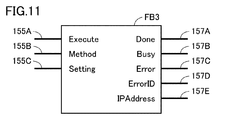
- the function block FB0 includes input units 155A and 155B that accept settings related to the IP address automatic generation function, and output units 157A to 157E for outputting the execution result of the IP address automatic generation function. including.
- the input unit 155A indicated as “Execute” accepts a setting for designating whether or not to execute the automatic IP address generation function.
- the input unit 155A receives an input of “True” or “False”. As long as “False” is input to the input unit 155A, the IP address automatic generation function is not executed. On the other hand, when “True” is input to the input unit 155A, an IP address automatic generation function is executed.
- the input unit 155B indicated as “Method” accepts the setting of the IP address automatic generation method. That is, the function block FB0 switches the method of the IP address automatic generation function according to the value input to the input unit 155B. As an example, the input unit 155B accepts inputs “1” to “3”.
- the function block FB0 When “1” is input to the input unit 155B, the function block FB0 generates an IP address based on a predetermined setting value stored in an external storage device such as a memory card. Typically, a setting file is written in advance in the external storage device. In the setting file, a setting value related to the IP address is defined. The set value may be the IP address itself or identification information unique to the controller (for example, MAC (Media Access Control) or serial number). The function block FB0 reads the setting value from the setting file stored in the external storage device based on the input of “True” to the input unit 155A indicated as “Execute”. Next, the function block FB0 generates the IP address of the controller 100 based on the set value. By providing such an IP address generation method, the user does not need to rewrite the existing control program 110.
- the function block FB0 When “2” is input to the input unit 155B, the function block FB0 generates an IP address of the own controller based on identification information that can uniquely identify the own controller.
- the identification information is, for example, a MAC (Media Access Control) address of the controller 100. By generating the controller based on such identification information, the IP address of the controller can be uniquely determined.
- the function block FB0 When “3” is input to the input unit 155B, the function block FB0 generates an IP address of the own controller based on identification information that can uniquely identify the own controller.
- the identification information is, for example, the serial number of the controller 100. By generating the controller based on such identification information, the IP address of the controller can be uniquely determined.
- a signal indicating normal termination is output from the output unit 157A indicated as “Done”.
- a signal indicating that the generation process is in progress is output from the output unit 157B indicated as “Busy”.
- a signal indicating abnormal termination is output from the output unit 157C indicated as “Error”.
- an error ID for identifying the content of the error is further output from the output unit 157D indicated as “Error ID”.
- the generated IP address is output from the output unit 157C indicated as “IPAddress”.
- the function block FB0 may be provided with various input units and output units.
- IP address automatic generation function (C2. Specific example 2 of IP address automatic generation function) Next, a specific example 2 of the IP address automatic generation function will be described with reference to FIG.
- the IP address automatic generation function is not provided as a function block but as a basic function of the controller 100.
- the basic function is an example of the generation module 152 (see FIG. 1) described above.
- FIG. 4 is a diagram showing a process in which each controller generates its own IP address.
- FIG. 4 shows three controllers 100A to 100C.
- the controllers 100A to 100C are connected to the same network NW1 via the hub 150. As an initial state, it is assumed that no IP address is set in the controllers 100A to 100C.
- the generation module 152 of the controller 100A has generated the IP address of its own controller.
- the controller 100A generates the IP address of the controller based on identification information that can uniquely identify the controller, for example.
- the identification information includes, for example, at least one of a MAC address and a serial number. By generating the controller based on such identification information, the IP address of the controller can be uniquely generated. In the example of FIG. 4, “192.168.250.1” is generated as the IP address of the controller 100A.
- step S1 the controller 100A broadcasts the generated IP address to the other controllers 100B and 100C.
- the generated IP address is transmitted in, for example, an ARP (Address Resolution Protocol) packet.
- ARP is a mechanism for obtaining Ethernet MAC address information from an IP address.
- a response to the ARP packet indicates that the IP address included in the ARP packet is already used.
- the generation module 152 of the controller 100A inquires of the other controller whether or not the generated IP address is already used by the other controller. That is, the generation module 152 of the controller 100A writes the generated IP address in the ARP packet, and transmits the ARP packet to the other controllers 100B and 100C by broadcasting.
- step S2 it is assumed that the other controllers 100B and 100C have received an inquiry by the ARP packet from the controller 100A.
- the controllers 100B and 100C store the IP address included in the ARP packet.
- the controllers 100B and 100C determine whether or not the IP address included in the ARP packet matches its own IP address.
- the controller 100B or 100C transmits its own MAC address to the transmission source controller 100A. Otherwise, the controllers 100B and 100C do not transmit anything to the transmission source controller 100A.
- step S3 when there is no other controller that responds to the inquiry by the ARP packet, the generation module 152 of the controller 100B rewrites the network setting 108 (see FIG. 1) of the own controller with the generated IP address. As a result, the controller 100A can reliably generate a unique IP address.
- the generation module 152 of the controller 100A regenerates an IP address different from the previously generated IP address.
- the controller 100A can avoid duplication of IP addresses with other controllers.
- the controller 100A repeats the regeneration of the IP address and the inquiry using the ARP packet until no response to the inquiry using the ARP packet is obtained.
- the generation module 152 of the controller 100B generates the IP address of its own controller.
- the generation module 152 of the controller 100B generates the IP address of the own controller so as not to overlap with the IP address included in the inquiry. Thereby, the controller 100B can generate a unique IP address more reliably than randomly generating an IP address.
- the controller 100B adds a predetermined value (for example, 1) to the IP address, and adopts the addition result as the IP address of the own controller.
- a predetermined value for example, 1
- “192.168.250.2” is generated as the IP address of the controller 100B.
- the controller 100B writes the generated IP address in the ARP packet, and transmits the ARP packet to the other controllers 100A and 100C by broadcasting.
- step S5 it is assumed that the other controllers 100A and 100C have received an inquiry using an ARP packet from the controller 100B.
- the controllers 100A and 100C store the IP address included in the ARP packet.
- the controllers 100A and 100C determine whether or not the IP address included in the ARP packet matches its own IP address.
- the controller 100A or 100C transmits its own MAC address to the transmission source controller 100B. Otherwise, the controllers 100A and 100C do not transmit anything to the transmission source controller 100B.
- step S6 when there is no other controller responding to the inquiry by the ARP packet, the generation module 152 of the controller 100B rewrites the network setting 108 (see FIG. 1) of the own controller with the generated IP address.
- the generation module 152 of the controller 100B regenerates an IP address different from the previously generated IP address. Thereby, the controller 100B can avoid duplication of IP addresses with other controllers.
- the controller 100B repeats the regeneration of the IP address and the inquiry by the ARP packet until the response to the inquiry by the ARP packet is not obtained.
- the generation module 152 of the controller 100C generates the IP address of its own controller.
- the generation module 152 of the controller 100C generates the IP address of the own controller so as not to overlap with the IP address included in the inquiry.
- the controller 100C adds a predetermined value (for example, 1) to the IP address, and adopts the addition result as the IP address of the own controller.
- a predetermined value for example, 1
- “192.168.250.3” is generated as the IP address of the controller 100C.
- the generation module 152 of the controller 100C writes the generated IP address in the ARP packet, and transmits the ARP packet to the other controllers 100A and 100B by broadcasting.
- step S8 it is assumed that the other controllers 100A and 100B have received an inquiry using an ARP packet from the controller 100C.
- the controllers 100A and 100B determine whether or not the IP address included in the ARP packet matches its own IP address.
- the controller 100A, 100B determines that the IP address included in the ARP packet matches its own IP address, the controller 100A, 100B transmits its own MAC address to the transmission source controller 100C. Otherwise, the controllers 100A and 100B do not transmit anything to the transmission source controller 100C.
- step S9 when there is no other controller that responds to the inquiry by the ARP packet, the generation module 152 of the controller 100C rewrites the network setting 108 (see FIG. 1) of the own controller with the generated IP address.
- the generation module 152 of the controller 100C regenerates an IP address different from the previously generated IP address.
- the controller 100A can avoid duplication of IP addresses with other controllers.
- the controller 100C repeats the regeneration of the IP address and the inquiry using the ARP packet until no response to the inquiry using the ARP packet is obtained.
- each of the controllers 100 determines whether or not the generated IP address is used by another controller based on the inquiry result of the ARP packet.
- the controller 100 When the controller 100 has received an inquiry from an ARP packet even once from another controller, the controller 100 generates an IP address so as not to overlap with the IP address included in the ARP packet received from the other controller. This prevents IP address duplication between controllers.
- the interval at which the ARP packet is transmitted is shifted for each controller.
- Each controller for example, generates a random number and determines the timing for transmitting an ARP packet based on the random number. As described above, the timing for transmitting the ARP packet is shifted for each controller, thereby preventing the ARP packet from being transmitted simultaneously.
- FIG. 5 is a diagram showing an example of a control program incorporating the function block FB0 shown in FIG. 3 .
- control program 110 is defined by a ladder program.
- the control program 110 includes processing for generating the IP address of the controller 100, processing for setting the generated IP address in the controller 100, and the like. Note that the control program 110 shown in FIG. 5 does not show the entire processing in the controller 100 but shows a part of the processing.
- control program 110 includes input elements IN0 and IN1, function blocks FB0 and FB1, and output elements OUT0 and OUT1.
- the values of the input elements IN0 and IN1 change according to the assigned variable. More specifically, the variable “AutoSetting” is assigned to the input element IN0.
- the variable “ChangeTrigger” is assigned to the input element IN1.
- the variable “Done 0” is assigned to the input element IN2.
- the variable “Done0” is associated with the output “Done” of the function block FB0.
- a signal indicating normal end is output from the output unit “Done” of the function block FB1.
- a signal indicating that the setting process is being performed is output from the output unit “Busy” of the function block FB1.
- a signal indicating abnormal termination is output from the output unit “Error” of the function block FB1.
- an error ID for identifying the content of the error is further output from the output unit “ErrorID” of the function block FB1.
- the output element OUT1 is assigned the variable “Done1” and is associated with the output unit “Done” of the function block FB1. As a result, the value of the output element OUT1 changes according to the value of the output “Done” of the function block FB1.
- FIG. 6 is a diagram illustrating an example of a screen for setting an IP address setting mode.
- the IP address setting mode can be set, for example, on the setting screen 30 displayed on the above-described support device 200A (see FIG. 2).
- the setting screen 30 includes radio buttons R1 to R4 that accept selection of a setting mode, an OK button 31, and a cancel button 32.
- the IP address setting mode includes, for example, a first setting mode to a fourth setting mode.
- the IP address setting mode is set to the first setting mode.
- the user can specify an IP address to be set in the controller 100, a subnet mask, and an IP address of a default gateway.
- the IP address setting mode is set to the second setting mode.
- the controller 100 In the second setting mode, the controller 100 is set to acquire an IP address from the server in accordance with a BOOTP (BOOTstrap Protocol) protocol. In the second setting mode, the controller 100 dynamically sets the IP address every time it is activated.
- BOOTP BOOTstrap Protocol
- the IP address setting mode is set to the third setting mode.
- the controller 100 is set to acquire an IP address from the server according to the BOOTP protocol.
- the controller 100 statically sets the IP address.
- the IP address setting mode is set to the fourth setting mode.
- the controller 100 automatically generates an IP address and applies the IP address to itself. Since the IP address automatic generation function is as described with reference to FIGS. 3 and 4, the description thereof will not be repeated.
- the support device 200A stores the selected setting mode.
- the support device 200A transmits the selected setting mode to the designated controller 100 based on the reception of the setting mode download command.
- the controller 100 sets the IP address according to the selected setting mode.
- the support device 200A closes the setting screen 30 without saving the selected setting mode.
- control program 110 includes a control command that depends on the IP address of its own controller.
- FIG. 7 is a diagram showing a function block FB2 that depends on the IP address of its own controller.
- control instruction may include those defined by ladder diagrams, instruction lists, structured text, and sequential function charts, or combinations thereof.
- control instruction may include those defined in a general-purpose programming language such as JavaScript or C language.
- the function block FB2 is a program for transmitting designated data to a designated device.
- the function block FB2 includes input units 158A to 158D that accept settings related to the data transmission function, and output units 159A to 159D for outputting the execution result of the data transmission function.
- the input unit 158A indicated as “Execute” accepts a setting for designating whether to execute the data transmission function.
- the input unit 158A receives an input of “True” or “False”. As long as “False” is input to the input unit 158A, the data transmission function is not executed. On the other hand, when “True” is input to the input unit 158A, the data transmission function is executed.
- the input unit 158B indicated as “Socket” accepts network information related to the transmission destination and the transmission source.
- the network information includes the IP address of the information processing apparatus 200 that is the transmission destination, the IP address of the controller 100 that is the transmission source, and the like.
- the function block FB2 depends on the IP address of the controller 100.
- the control program 110 is designed so that the above-described identifier (see FIG. 1) instead of the IP address is written in the network information input to the input unit 158B, and then the network information is input to the input unit 158B.
- the input unit 158C indicated as “SendDat” accepts transmission target data as an input.
- the input unit 158D indicated as “Size” receives the size of data to be transmitted as an input.
- a signal indicating normal termination is output from the output unit 159A indicated as “Done”.
- a signal indicating that transmission processing is in progress is output from the output unit 159B indicated as “Busy”.
- a signal indicating abnormal termination is output from the output unit 159C indicated as “Error”.
- an error ID for identifying the content of the error is further output from the output unit 159D indicated as “Error ID”.
- the information processing apparatus 200 collects the IP addresses generated by the above-described automatic generation function from each lower controller. With this collection function, the user can easily grasp the IP address set in each controller.
- the IP address collection method employs either a notification method from the controller 100 or a polling method by the information processing apparatus 200.
- the notification method and the polling method will be described in order with reference to FIGS.
- FIG. 8 is a sequence diagram showing the flow of the IP address collection function based on the notification method.
- each controller transmits itself to the host information processing apparatus 200 at the timing when the automatically generated IP address is set.
- step S10 the controller 100 downloads various settings from the support device 200A described above.
- the various settings include a control program 110 designed by the support device 200A, a setting mode set on the setting screen 30 (see FIG. 6), and the like.
- step S12 the controller 100 executes automatic IP address generation processing. Since the IP address automatic generation process is as described with reference to FIGS. 3 and 4, the description thereof will not be repeated. The controller 100 sets the generated IP address as its own IP address.
- step S20 the controller 100 transmits the IP address generated in step S12 to the information processing apparatus 200.
- other controllers also transmit the IP address to the information processing apparatus 200 at the timing when the automatically generated IP address is set.
- step S22 the information processing apparatus 200 updates the IP address management table based on the reception of the IP address from the controller 100.
- FIG. 9 is a diagram illustrating an example of an IP address management table.
- FIG. 9 shows a management table 35 as an example of an IP address management table.
- the management table 35 is managed by, for example, a storage device 210 (see FIG. 14) described later of the information processing device 200.
- controller identification information an IP address, a serial number, and a model are associated with each other.
- the identification information of the controller is indicated by the controller name and ID (Identification) such that the controller can be uniquely identified.
- the information processing apparatus 200 identifies the transmission source controller identification information, the IP address of the transmission source controller, and the transmission.
- the serial number of the original controller and the model of the transmission source controller are added to the management table 35.
- the IP address, serial number, and model associated with the identification information of the transmission source controller are received. Update the IP address, serial number, and model.
- the user can display the management table 35 on the display of the information processing apparatus 200 as necessary. Thereby, the user can easily grasp the IP address set in each controller. Further, the serial number, model, and the like are displayed side by side, so that the user can easily distinguish between the controllers and can easily understand what IP address is set for which controller.
- the information processing apparatus 200 periodically collects IP addresses automatically generated from each controller.
- step S50 the information processing apparatus 200 transmits an IP address transmission command to each of the controllers 100.
- the transmission command is periodically transmitted from the information processing apparatus 200 to the controller 100.
- the IP address of the controller 100 is not set at the time of step S50.
- the controller 100 does not respond to the transmission command received from the information processing apparatus 200.
- step S54 it is assumed that the controller 100 has downloaded various settings from the support device 200A described above.
- the various settings include a control program 110 designed by the support device 200A, a setting mode set on the setting screen 30 (see FIG. 6), and the like.
- step S60 the information processing apparatus 200 transmits an IP address transmission command to each of the controllers 100. Similar to step S50, since the IP address of the information processing apparatus 200 is not set at this point, the controller 100 does not respond to the transmission command received in step S60.
- step S64 the controller 100 executes an IP address automatic generation process. Since the IP address automatic generation process is as described with reference to FIGS. 3 and 4, the description thereof will not be repeated. The controller 100 sets the generated IP address as its own IP address.
- step S70 the information processing apparatus 200 transmits an IP address transmission command to each of the controllers 100.
- the controller 100 transmits its own IP address to the information processing apparatus 200 in step S72.
- step S80 the information processing apparatus 200 updates the IP address management table 35 (see FIG. 9) based on the reception of the IP address from the controller 100. Since the updating method of the management table 35 is as described in FIG. 9, the description thereof will not be repeated.
- control system 1 is configured to accept whether the IP address of the controller 100 has been provisionally determined or has been determined. Since such a determination state can be set, the user can easily grasp whether the IP address of each controller is temporarily set or set to true.
- the user when the user constructs the network environment of the control system 1, the user sets the IP address of the controller 100 to the provisional determination state.
- a provisionally determined state may be employed when the control system 1 is in a communicable state for the time being.
- the user After constructing the network environment of the control system 1, the user sets the IP address of the controller 100 to be true and sets the IP address to the final determination state.
- FIG. 11 is a diagram showing a modification of the function block FB0 shown in FIG.
- FIG. 11 shows a function block FB3 as a modification of the function block FB0.
- the function block FB3 shown in FIG. 11 is different from the function block FB0 shown in FIG. 3 in that it further includes an input unit 155C. Since other points are as described above, their description will not be repeated.
- the input unit 155C indicated as “Setting” accepts the setting of the IP address determination state. As an example, the input unit 155C receives an input of “0” or “1”.
- the determination state of the IP address is switched according to, for example, an IP address automatic generation method.
- an IP address automatic generation method As an example, when a method for generating an IP address from identification information (for example, a MAC address) of the controller 100 is set for the input unit 155B, “0” indicating a provisionally determined state is set in the input unit 155C. Entered.
- the input unit 155C indicates this determination state. 1 "is input.
- the management table 35A is managed by, for example, a storage device 210 (see FIG. 14) described later of the information processing device 200.
- controller identification information an IP address, and an IP address determination state are associated with each other.
- the identification information of the controller is indicated by the controller name, ID, etc. that can uniquely identify the controller.
- FIG. 13 is a block diagram illustrating a hardware configuration example of the controller 100.
- the controller 100 includes a processor 102, a chip set 104, a storage device 105, a main memory 106, a USB (Universal Serial Bus) interface 112, a memory card interface 114, and a network interface 118.
- the processor 102 includes a CPU (Central Processing Unit), an MPU (Micro Processing Unit), a GPU (Graphics Processing Unit), and the like. As the processor 102, a configuration having a plurality of cores may be adopted, or a plurality of processors 102 may be arranged. Thus, the controller 100 includes one or more processors 102 and / or a processor 102 having one or more cores.
- the chip set 104 realizes processing as the entire controller 100 by controlling the processor 102 and peripheral elements.
- the main memory 106 includes a volatile storage device such as DRAM (Dynamic Random Access Memory) and SRAM (Static Random Access Memory).
- the storage device 105 is configured by, for example, a nonvolatile storage device such as a flash memory.
- the processor 102 reads out various programs stored in the storage device 105, develops them in the main memory 106, and executes them, thereby realizing control according to the control target.
- the storage device 105 stores the above-described network setting 108 and the control program 110 of the controller 100.
- the control program 110 includes a user program 110A created according to the manufacturing apparatus and equipment to be controlled, in addition to the system program 111B for realizing basic processing.
- the USB interface 112 mediates data communication with an external device (for example, a support device that develops a user program) via a USB connection.
- an external device for example, a support device that develops a user program
- the memory card interface 114 is configured so that the memory card 116 can be attached and detached, and can write data to the memory card 116 and read various data (such as user programs and trace data) from the memory card 116. ing.
- the network interface 118 can mediate data communication via the network N1.
- the internal bus controller 120 mediates data communication with the functional units attached to the controller 100.
- the field network controller 130 mediates data communication with other units via the network N2.
- FIG. 13 illustrates a configuration example in which necessary processing is realized by the processor 102 executing a program. However, part or all of the provided processing is performed by a dedicated hardware circuit (for example, an ASIC). (Application Specific Integrated Circuit) or FPGA (Field Programmable Gate Array)) may be used.
- ASIC Application Specific Integrated Circuit
- FPGA Field Programmable Gate Array
- FIG. 14 is a schematic diagram illustrating a hardware configuration of the information processing apparatus 200.
- the information processing apparatus 200 includes, for example, a computer configured according to a general-purpose computer architecture.
- the information processing apparatus 200 includes a control device 201, a main memory 202, a communication interface 203, an operation interface 205, a display interface 206, an optical drive 207, and a storage device 210. These components are communicably connected to each other via an internal bus 219.
- the control device 201 is configured by at least one integrated circuit, for example.
- the integrated circuit includes, for example, at least one CPU, at least one ASIC, at least one FPGA, or a combination thereof.
- the control device 201 implements various processes such as the above-described collection function of the IP address by developing and executing the program in the main memory 202.
- the main memory 202 is composed of a volatile memory and functions as a work memory necessary for program execution by the control device 201.
- the communication interface 203 exchanges data with an external device via a network.
- the external device includes, for example, the controller 100, a server, and other communication devices.
- the information processing apparatus 200 may be configured to download the information processing program 213 via the communication interface 203.
- the information processing program 213 is a program for providing an integrated development environment for the control program 110 described above.
- the operation interface 205 is connected to the operation unit 222 and takes in a signal indicating a user operation from the operation unit 222.
- the operation unit 222 typically includes a keyboard, a mouse, a touch panel, a touch pad, and the like, and accepts an operation from the user.
- the display interface 206 is connected to the display unit 220 and sends an image signal for displaying an image to the display unit 220 in accordance with a command from the control device 201 or the like.
- the display unit 220 includes a display, an indicator, and the like, and presents various information to the user.
- the optical drive 207 reads various programs stored in the optical disk 207A or the like and installs them in the storage device 210.
- FIG. 14 shows a configuration example in which a necessary program is installed in the information processing apparatus 200 via the optical drive 207.
- the program may be downloaded from a server apparatus on the network. Also good.
- the program on the information processing apparatus 200 may be rewritten by a program written in a storage medium such as a USB (Universal Serial Bus) memory, an SD (Secure Digital) card, or a CF (Compact Flash). Good.
- a USB Universal Serial Bus
- SD Secure Digital
- CF Compact Flash
- the storage device 210 is, for example, a hard disk or an external storage medium.
- the storage device 210 stores the management tables 35 and 35A and the information processing program 213 described above.
- the management tables 35 and 35A are not necessarily stored in the storage device 210, and may be stored in other storage devices.
- the management tables 35 and 35A may be stored in the main memory 202 or an external storage medium (for example, a memory card or a server).
- the control program 110 includes a control command that depends on the IP address.
- the control command controls the drive device 300 to be controlled with the identifier indicated in the network setting 108 of the controller 100 as an input.
- the identifier replaces the IP address of the controller and is common to the controllers.
- the controller 100 generates the IP address of its own controller so that it is different from the IP addresses of other controllers.
- the user can easily construct an environment where communication is possible even when the facility is expanded.
- the present embodiment includes the following disclosure.
- IP Internet Protocol
- the control program (110) includes a control command for controlling the drive device (300) to be controlled by using the identifier shown in the network setting (108) of the own controller as an input,
- Each of the plurality of controllers (100A, 100B, 100C) further includes A generating module (152 for generating the IP address of the own controller different from the IP address of the other controller and rewriting the IP address indicated in the network setting (108) of the own controller with the generated IP address.
- a control system comprising: a communication module (154) for communicating with the information processing device (200) according to an IP address indicated in the network setting (108) of its own controller.
- Each of the plurality of controllers (100A, 100B, 100C) is configured to be connectable to an external storage medium,
- the external storage medium stores setting values related to IP addresses,
- the control system according to Configuration 1 or 2, wherein the generation module (152) reads the setting value stored in the external storage medium and generates an IP address of the own controller according to the setting value.
- the generation module (152) Queries the other controller whether the generated IP address is already used by the other controller, 4.
- the control system according to any one of configurations 1 to 3, wherein when there is no other controller that responds to the inquiry, the IP address indicated in the network setting (108) of the own controller is rewritten with the generated IP address. .
- the control program (110) includes a control command for controlling the driving device (300) with the identifier shown in the network setting (108) as an input, and An IP address of the controller (100A) is generated so as to be different from the IP addresses of other controllers (100B, 100C) connected to the same network as the controller (100A), and the network is generated using the generated IP address.
- a controller comprising: a communication module (154) for communicating with an information processing device (200) connected to the same network as the controller (100A) according to an IP address indicated in the network setting (108).
- a control method of the controller (100A) for controlling the driving device (300), A network setting (108) including a correspondence relationship between the IP address of the controller (100A) and an identifier replacing the IP address, and a control program (110) for controlling the driving device (300) are transmitted to the controller (100A).
- the control program (110) includes a control command for controlling the driving device (300) with the identifier shown in the network setting (108) as an input, and An IP address of the controller (100A) is generated so as to be different from the IP addresses of other controllers (100B, 100C) connected to the same network as the controller (100A), and the network is generated using the generated IP address.
- control system 30 setting screen, 31 OK button, 32 cancel button, 35, 35A management table, 100, 100A, 100B, 100C controller, 102 processor, 104 chipset, 105, 210 storage device, 106, 202 main memory, 108 network setting, 110 control program, 110A user program, 111B system program, 112 USB interface, 114 memory card interface, 116 memory card, 118 network interface, 120 internal bus controller, 130 field network controller, 150 hub, 152 generation module, 154 communication module, 155A, 155B, 155C, 158A, 58B, 158C, 158D input unit, 157A, 157B, 157C, 157D, 157E, 159A, 159B, 159C, 159D output unit, 200 information processing device, 200A support device, 200B server device, 200C display device, 201 control device, 203 Communication interface, 205 operation interface, 206 display interface, 207 optical drive, 207A optical disk, 213 information processing program, 219 internal bus,
Abstract
Provided is a technology for realizing a communicable state even when the same control program (110) is used among controllers (100A, 100B, 100C). The controllers (100A, 100B, 100C) are each provided with a storage device (105) that stores: network setting (108) that includes a correspondence relationship between an IP address and an identifier; and the control program (110) for controlling a drive device. The control program (110) includes a control command for controlling the drive device by using the identifier as an input. The controllers (100A, 100B, 100C) are each provided with: a generation module (152) that generates an IP address so as to be different from IP addresses of other controllers (100A, 100B, 100C) on the same network and that rewrites the IP address of the network setting (108); and a communication module (154) that communicates with an information processing apparatus on the same network in accordance with the IP address of the network setting (108).
Description
本開示は、IP(Internet Protocol)アドレスを制御装置に自動設定するための技術に関する。
This disclosure relates to a technique for automatically setting an IP (Internet Protocol) address in a control device.
様々な生産現場において、PLC(Programmable Logic Controller)やロボットコントローラなどの産業用の制御装置(以下、「コントローラ」ともいう。)が導入されている。コントローラが種々の産業用の駆動機器を制御することで、生産工程が自動化される。
In various production sites, industrial control devices (hereinafter also referred to as “controllers”) such as PLCs (Programmable Logic Controllers) and robot controllers have been introduced. The controller controls various industrial drive devices to automate the production process.
複数のコントローラが同一のネットワークに接続されることがある。これらのコントローラは、上位の情報処理装置と通信可能に構成されている。上位の情報処理装置は、各コントローラと通信することで、各コントローラが制御する駆動機器の情報や各コントローラの情報を収集することができる。情報処理装置が各コントローラと通信するためには、各コントローラに対してネットワーク設定(たとえば、IPアドレスなど)を行う必要がある。
* Multiple controllers may be connected to the same network. These controllers are configured to be able to communicate with a host information processing apparatus. The host information processing apparatus can collect information on driving devices controlled by each controller and information on each controller by communicating with each controller. In order for the information processing apparatus to communicate with each controller, it is necessary to perform network settings (for example, an IP address) for each controller.
コントローラのネットワーク設定に関する文献として、たとえば、特開2013-242629号公報(特許文献1)と、特開2008-152799号公報(特許文献2)と、特開2017-151934号公報(特許文献3)と、特開2002-328706号公報(特許文献4)とがある。
As documents relating to the network setting of the controller, for example, Japanese Patent Application Laid-Open No. 2013-242629 (Patent Document 1), Japanese Patent Application Laid-Open No. 2008-152799 (Patent Document 2), and Japanese Patent Application Laid-Open No. 2017-151934 (Patent Document 3). And JP-A-2002-328706 (Patent Document 4).
生産現場における設備を拡大するときに、現在の設備と同じ設備を複製したいというケースがある。この場合、コントローラにダウンロードされている駆動機器の制御プログラムが他のコントローラでも利用される。
When expanding equipment on the production site, there is a case where you want to duplicate the same equipment as the current equipment. In this case, the control program of the drive device downloaded to the controller is also used by other controllers.
制御プログラムがコントローラのIPアドレスに依存して駆動機器を制御する場合、制御プログラムが複製されると、IPアドレスが重複してしまい、制御プログラムは、正常に動作しない。また、ネットワーク設定が重複してしまい、上位の情報処理装置は、各コントローラと通信できなくなる。これらの問題を解決するためには、ネットワーク設定や制御プログラムの記述を手動で変更する必要がある。しかしながら、このような変更は、設備の規模が大きくなるほど手間となる。
When the control program controls the drive device depending on the IP address of the controller, if the control program is duplicated, the IP address will be duplicated and the control program will not operate normally. Further, the network settings are duplicated, and the higher-level information processing apparatus cannot communicate with each controller. In order to solve these problems, it is necessary to manually change the network settings and the description of the control program. However, such a change becomes more troublesome as the scale of the facility increases.
本開示は上述のような問題点を解決するためになされたものであって、ある局面における目的は、コントローラ間で同一の制御プログラムを利用する場合であっても通信可能な状態にできる技術を提供することである。
The present disclosure has been made in order to solve the above-described problems, and an object in one aspect is to provide a technology that enables communication even when the same control program is used between controllers. Is to provide.
本開示の一例では、制御システムは、それぞれが制御対象の駆動機器を制御するための複数のコントローラと、上記複数のコントローラと同一のネットワークに接続される情報処理装置とを備える。上記複数のコントローラのそれぞれは、自コントローラのIP(Internet Protocol)アドレスと当該IPアドレスに代わる識別子との対応関係を含むネットワーク設定と、制御対象の駆動機器を制御するための制御プログラムとを格納する記憶装置を備える。上記制御プログラムは、自コントローラの上記ネットワーク設定に示される上記識別子を入力として制御対象の駆動機器を制御する制御命令を含む。上記複数のコントローラのそれぞれは、さらに、他のコントローラのIPアドレスとは異なるように自コントローラのIPアドレスを生成し、当該生成したIPアドレスで、当該自コントローラの上記ネットワーク設定に示されるIPアドレスを書き換えるための生成モジュールと、自コントローラの上記ネットワーク設定に示されるIPアドレスに従って上記情報処理装置と通信するための通信モジュールとを備える。
In an example of the present disclosure, the control system includes a plurality of controllers each for controlling a drive device to be controlled, and an information processing apparatus connected to the same network as the plurality of controllers. Each of the plurality of controllers stores a network setting including a correspondence relationship between an IP (Internet Protocol) address of the own controller and an identifier replacing the IP address, and a control program for controlling the drive device to be controlled. A storage device is provided. The control program includes a control command for controlling the drive device to be controlled with the identifier shown in the network setting of the controller as an input. Each of the plurality of controllers further generates an IP address of its own controller so that it is different from the IP addresses of other controllers, and uses the generated IP address to change the IP address indicated in the network setting of the own controller. A generation module for rewriting and a communication module for communicating with the information processing apparatus according to the IP address indicated in the network setting of the own controller are provided.
この開示によれば、制御システムは、コントローラ間で同一の制御プログラムを利用する場合であっても情報処理装置と各コントローラとを通信可能な状態にできる。
According to this disclosure, the control system can make the information processing apparatus and each controller communicable even when the same control program is used between the controllers.
本開示の一例では、上記生成モジュールは、自コントローラを一意に識別可能な識別情報に基づいて、当該自コントローラのIPアドレスを生成する。
In an example of the present disclosure, the generation module generates an IP address of the own controller based on identification information that can uniquely identify the own controller.
この開示によれば、コントローラは、他のコントローラのIPアドレスとは重複しないIPアドレスを確実に生成することができる。
According to this disclosure, the controller can reliably generate an IP address that does not overlap with the IP addresses of other controllers.
本開示の一例では、上記複数のコントローラのそれぞれは、外部記憶媒体に接続可能に構成されている。上記外部記憶媒体は、IPアドレスに関する設定値を格納している。上記生成モジュールは、上記外部記憶媒体に格納されている上記設定値を読み取り、当該設定値に従って自コントローラのIPアドレスを生成する。
In an example of the present disclosure, each of the plurality of controllers is configured to be connectable to an external storage medium. The external storage medium stores a setting value related to the IP address. The generation module reads the setting value stored in the external storage medium, and generates an IP address of the own controller according to the setting value.
この開示によれば、ユーザは、外部記憶媒体に格納されている設定値を書き換えるだけでコントローラのIPアドレスを変えることができる。
According to this disclosure, the user can change the IP address of the controller simply by rewriting the setting value stored in the external storage medium.
本開示の一例では、上記生成モジュールは、生成したIPアドレスが上記他のコントローラで既に使用されているか否かを当該他のコントローラに問い合わせ、当該問い合わせに応答する他のコントローラが存在しない場合、当該生成したIPアドレスで自コントローラの上記ネットワーク設定に示されるIPアドレスを書き換える。
In an example of the present disclosure, the generation module inquires of the other controller whether or not the generated IP address is already used by the other controller, and when there is no other controller that responds to the inquiry, The IP address indicated in the network setting of the controller is rewritten with the generated IP address.
この開示によれば、コントローラは、他のコントローラのIPアドレスとは重複しないIPアドレスを確実に生成することができる。
According to this disclosure, the controller can reliably generate an IP address that does not overlap with the IP addresses of other controllers.
本開示の一例では、上記生成モジュールは、上記問い合わせに応答する他のコントローラが存在する場合、先に生成したIPアドレスとは異なるIPアドレスを再生成する。
In one example of the present disclosure, the generation module regenerates an IP address different from the previously generated IP address when there is another controller that responds to the inquiry.
この開示によれば、コントローラは、自コントローラのIPアドレスが他のコントローラのIPアドレスと重複することを回避することができる。
According to this disclosure, the controller can avoid the IP address of its own controller from overlapping with the IP address of another controller.
本開示の一例では、上記生成モジュールは、上記他のコントローラのIPアドレスが自コントローラに既に設定されているか否かを当該他のコントローラから問い合わされた場合、当該IPアドレスとは重複しないように自コントローラのIPアドレスを生成する。
In an example of the present disclosure, when the generation module inquires whether the IP address of the other controller is already set in the local controller, the generation module does not automatically overlap with the IP address. Generate the IP address of the controller.
この開示によれば、コントローラは、ランダムにIPアドレスを生成するよりも確実に一意のIPアドレスを生成することができる。
According to this disclosure, the controller can generate a unique IP address more reliably than a random IP address.
本開示の一例では、自コントローラに格納される制御プログラムは、他のコントローラに格納される制御プログラムを複製したものである。
In an example of the present disclosure, the control program stored in the own controller is a duplicate of the control program stored in another controller.
この開示によれば、他のコントローラにおける制御プログラムが自コントローラにおける制御プログラムを複製した場合であっても、制御システムは、情報処理装置と各コントローラとを通信可能な状態にできる。
According to this disclosure, even when a control program in another controller duplicates a control program in its own controller, the control system can make the information processing apparatus and each controller communicable.
本開示の他の例では、駆動機器を制御するためのコントローラは、上記コントローラのIPアドレスと当該IPアドレスに代わる識別子との対応関係を含むネットワーク設定と、上記駆動機器を制御するための制御プログラムを格納する記憶装置を備える。上記制御プログラムは、上記ネットワーク設定に示される上記識別子を入力として上記駆動機器を制御する制御命令を含む。上記コントローラは、さらに、上記コントローラと同一のネットワークに接続される他のコントローラのIPアドレスとは異なるように上記コントローラのIPアドレスを生成し、当該生成したIPアドレスで、上記ネットワーク設定に示されるIPアドレスを書き換えるための生成モジュールと、上記ネットワーク設定に示されるIPアドレスに従って上記コントローラと同一のネットワークに接続される情報処理装置と通信するための通信モジュールとを備える。
In another example of the present disclosure, the controller for controlling the driving device includes a network setting including a correspondence relationship between the IP address of the controller and an identifier replacing the IP address, and a control program for controlling the driving device. Is provided. The control program includes a control command for controlling the drive device with the identifier indicated in the network setting as an input. The controller further generates an IP address of the controller so as to be different from the IP addresses of other controllers connected to the same network as the controller, and the IP indicated in the network setting is generated by the generated IP address. A generation module for rewriting an address and a communication module for communicating with an information processing apparatus connected to the same network as the controller according to the IP address indicated in the network setting.
この開示によれば、制御システムは、コントローラ間で同一の制御プログラムを利用する場合であっても情報処理装置と各コントローラとを通信可能な状態にできる。
According to this disclosure, the control system can make the information processing apparatus and each controller communicable even when the same control program is used between the controllers.
本開示の他の例では、駆動機器を制御するためのコントローラの制御方法は、上記コントローラのIPアドレスと、当該IPアドレスに代わる識別子との対応関係を含むネットワーク設定と、上記駆動機器を制御するための制御プログラムを上記コントローラの記憶装置から取得するステップを備える。上記制御プログラムは、上記ネットワーク設定に示される上記識別子を入力として上記駆動機器を制御する制御命令を含む。上記制御方法は、さらに、上記コントローラと同一のネットワークに接続される他のコントローラのIPアドレスとは異なるように上記コントローラのIPアドレスを生成し、当該生成したIPアドレスで、上記ネットワーク設定に示されるIPアドレスを書き換えるステップと、上記ネットワーク設定に示されるIPアドレスに従って上記コントローラと同一のネットワークに接続される情報処理装置と通信するステップとを備える。
In another example of the present disclosure, a controller control method for controlling a driving device controls a network setting including a correspondence relationship between an IP address of the controller and an identifier instead of the IP address, and the driving device. For obtaining a control program for storing the program from the storage device of the controller. The control program includes a control command for controlling the drive device with the identifier indicated in the network setting as an input. The control method further generates an IP address of the controller different from the IP addresses of other controllers connected to the same network as the controller, and is indicated in the network setting by the generated IP address. Rewriting the IP address, and communicating with an information processing apparatus connected to the same network as the controller according to the IP address indicated in the network setting.
この開示によれば、制御システムは、コントローラ間で同一の制御プログラムを利用する場合であっても情報処理装置と各コントローラとを通信可能な状態にできる。
According to this disclosure, the control system can make the information processing apparatus and each controller communicable even when the same control program is used between the controllers.
以下、図面を参照しつつ、本発明に従う各実施の形態について説明する。以下の説明では、同一の部品および構成要素には同一の符号を付してある。それらの名称および機能も同じである。したがって、これらについての詳細な説明は繰り返さない。
Embodiments according to the present invention will be described below with reference to the drawings. In the following description, the same parts and components are denoted by the same reference numerals. Their names and functions are also the same. Therefore, detailed description thereof will not be repeated.
<A.適用例>
図1を参照して、本発明の適用例について説明する。図1は、制御システム1の概略を示す図である。 <A. Application example>
An application example of the present invention will be described with reference to FIG. FIG. 1 is a diagram showing an outline of thecontrol system 1.
図1を参照して、本発明の適用例について説明する。図1は、制御システム1の概略を示す図である。 <A. Application example>
An application example of the present invention will be described with reference to FIG. FIG. 1 is a diagram showing an outline of the
制御システム1は、設備および装置などの制御対象を制御し、生産工程を自動化するためのFA(Factory Automation)システムである。制御システム1は、複数のコントローラと、1または複数の情報処理装置200と、複数の駆動機器とを含む。図1には、複数のコントローラの例として、2つのコントローラ100A,100Bが示されている。また、複数の駆動機器の例として、2つの駆動機器300が示されている。
The control system 1 is an FA (Factory Automation) system for controlling the controlled objects such as equipment and devices and automating the production process. The control system 1 includes a plurality of controllers, one or a plurality of information processing devices 200, and a plurality of driving devices. In FIG. 1, two controllers 100A and 100B are shown as examples of a plurality of controllers. Further, two drive devices 300 are shown as examples of a plurality of drive devices.
コントローラ100A、100Bは、それぞれ、記憶装置105と、生成モジュール152と、通信モジュール154とを含む。以下では、複数のコントローラ(たとえば、コントローラ100A、100B)を総称してコントローラ100ともいう。
The controllers 100A and 100B each include a storage device 105, a generation module 152, and a communication module 154. Hereinafter, a plurality of controllers (for example, controllers 100A and 100B) are collectively referred to as controller 100.
コントローラ100は、複数のネットワークに接続され得る。図1の例では、コントローラ100は、ネットワークN1とネットワークN2とに接続されている。
The controller 100 can be connected to a plurality of networks. In the example of FIG. 1, the controller 100 is connected to a network N1 and a network N2.
ネットワークN1には、たとえば、EtherNET(登録商標)が採用される。但し、ネットワークN1は、EtherNETに限定されず、任意の通信手段が採用され得る。図1の例では、ネットワークN1に情報処理装置200が接続されている。情報処理装置200は、たとえば、PC(Personal Computer)、タブレット端末、スマートフォン、表示器(たとえば、HMI(Human Machine Interface))などを含む。
For example, EtherNET (registered trademark) is adopted as the network N1. However, the network N1 is not limited to EtherNET, and any communication means can be adopted. In the example of FIG. 1, an information processing apparatus 200 is connected to the network N1. The information processing apparatus 200 includes, for example, a PC (Personal Computer), a tablet terminal, a smartphone, a display (for example, HMI (Human Machine Interface)), and the like.
ネットワークN2は、ネットワークN1よりも下位のネットワークである。ネットワークN2には、たとえば、EtherNet/IP(登録商標)などが採用される。図1の例では、ネットワークN2に駆動機器300が接続されている。駆動機器300は、生産工程を自動化するための種々の産業用機器を含む。一例として、駆動機器300は、アームロボットや、アームロボットを制御するためのロボットコントローラや、生産工程を搬送されるワークを撮影するための画像センサや、生産工程で利用されるその他の機器などを含む。
The network N2 is a lower network than the network N1. For example, EtherNet / IP (registered trademark) is used for the network N2. In the example of FIG. 1, a driving device 300 is connected to the network N2. The drive device 300 includes various industrial devices for automating the production process. As an example, the driving device 300 includes an arm robot, a robot controller for controlling the arm robot, an image sensor for photographing a workpiece conveyed in the production process, and other devices used in the production process. Including.
記憶装置105は、コントローラ100のネットワーク設定108と、駆動機器300を制御するための制御プログラム110とを格納する。
The storage device 105 stores a network setting 108 of the controller 100 and a control program 110 for controlling the driving device 300.
ネットワーク設定108は、コントローラ100のIPアドレスと、当該IPアドレスに代わる識別子との対応関係を含む。当該識別子は、制御プログラム110で規定されているプログラム変数であってもよいし、コントローラ100で管理されるシステム変数であってもよいし、各変数の記憶場所を示す物理アドレスであってもよい。
The network setting 108 includes a correspondence relationship between the IP address of the controller 100 and an identifier replacing the IP address. The identifier may be a program variable defined by the control program 110, a system variable managed by the controller 100, or a physical address indicating a storage location of each variable. .
制御プログラム110は、駆動機器300に応じて設計者によって実装されたユーザプログラムである。制御プログラム110の開発ツールは、たとえば、PCとしての情報処理装置200にインストールされている。設計者は、予め規定されている複数種類の命令を開発ツール上で任意に組み合わせることで、駆動機器300の構成に合わせた制御プログラム110を設計することができる。開発ツール上でコンパイルされた制御プログラム110は、コントローラ100にインストールされる。
The control program 110 is a user program implemented by a designer according to the driving device 300. The development tool for the control program 110 is installed in the information processing apparatus 200 as a PC, for example. The designer can design the control program 110 in accordance with the configuration of the drive device 300 by arbitrarily combining a plurality of types of predetermined commands on the development tool. The control program 110 compiled on the development tool is installed in the controller 100.
典型的には、コントローラ100Aの制御プログラム110は、コントローラ100Bの制御プログラム110を複製したものである。本実施の形態に従う制御システム1は、制御プログラムが複製された場合でも、制御プログラムの記述やIPアドレスに関する設定を変更することなしにコントローラ100が動作するような環境を提供する。
Typically, the control program 110 of the controller 100A is a copy of the control program 110 of the controller 100B. The control system 1 according to the present embodiment provides an environment in which the controller 100 can operate without changing the description of the control program and the setting related to the IP address even when the control program is duplicated.
より具体的には、制御プログラム110は、コントローラ100のネットワーク設定108に示される識別子を入力として制御対象の駆動機器300を制御する制御命令を含む。当該識別子は、コントローラ100A,100B間で共通している。上述したように、当該識別子は、コントローラの100A,100BのIPアドレスに代わるものである。当該識別子は、コントローラの100A,100BのIPアドレスには連動しない固定値である。このような識別子を入力としてIPアドレスが解釈されることで、IPアドレスが変わった場合でも、ユーザは、制御プログラム110を書き換える必要がなくなる。
More specifically, the control program 110 includes a control command for controlling the drive device 300 to be controlled with an identifier indicated in the network setting 108 of the controller 100 as an input. The identifier is common between the controllers 100A and 100B. As described above, the identifier replaces the IP addresses of the controllers 100A and 100B. The identifier is a fixed value that is not linked to the IP addresses of the controllers 100A and 100B. By interpreting the IP address using such an identifier as an input, even when the IP address changes, the user does not need to rewrite the control program 110.
生成モジュール152は、他のコントローラのIPアドレスとは異なるように自コントローラのIPアドレスを生成する。すなわち、生成モジュール152は、コントローラ100A,100B間でIPアドレスが重複しないように自コントローラのIPアドレスを生成する。重複しないようにIPアドレスを生成する方法の詳細については後述する。生成モジュール152は、自コントローラのネットワーク設定108に示されるIPアドレスを、生成したIPアドレスで書き換える。
The generation module 152 generates the IP address of its own controller so that it is different from the IP addresses of other controllers. That is, the generation module 152 generates the IP address of its own controller so that the IP addresses do not overlap between the controllers 100A and 100B. Details of the method of generating IP addresses so as not to overlap will be described later. The generation module 152 rewrites the IP address indicated in the network setting 108 of its own controller with the generated IP address.
通信モジュール154は、自コントローラのネットワーク設定108に示されるIPアドレスに従って情報処理装置200と通信する。ネットワーク設定108に示されるIPアドレスは、他のコントローラと重複しないように決定されたものであるので、情報処理装置200は、コントローラ100A,100Bと通信することができる。
The communication module 154 communicates with the information processing apparatus 200 according to the IP address indicated in the network setting 108 of its own controller. Since the IP address indicated in the network setting 108 is determined so as not to overlap with other controllers, the information processing apparatus 200 can communicate with the controllers 100A and 100B.
以上のように、制御プログラム110に含まれる、IPアドレスに依存する制御命令は、IPアドレスに代わる識別子に従って制御対象の駆動機器300を制御する。そのため、IPアドレスが変わった場合であっても、制御プログラム110の記述を変える必要がない。その結果、現在使用されている制御プログラムを他のコントローラに流用することが可能になる。
As described above, the control command depending on the IP address included in the control program 110 controls the drive device 300 to be controlled according to the identifier instead of the IP address. Therefore, it is not necessary to change the description of the control program 110 even when the IP address changes. As a result, the currently used control program can be used for other controllers.
また、コントローラ100A,100Bは、それぞれ、他のコントローラと重複しないようにIPアドレスを生成する機能を有する。そのため、ネットワークN1に接続されるコントローラが増えた場合であっても、情報処理装置200は、各コントローラと通信を継続することができる。その結果、あるコントローラにおける制御プログラムを同一のネットワークに接続される他のコントローラで利用する場合であっても通信可能な状態にできる。これにより、現在の設備を複製する場合に、IPアドレスに関する設定や制御プログラムの記述を手動で変更する必要が無くなる。このような利点は、設備の規模が大きくなるほど顕著となる。
In addition, each of the controllers 100A and 100B has a function of generating an IP address so as not to overlap with other controllers. Therefore, even when the number of controllers connected to the network N1 increases, the information processing apparatus 200 can continue communication with each controller. As a result, even when a control program in a certain controller is used in another controller connected to the same network, communication can be performed. This eliminates the need to manually change the settings related to the IP address and the description of the control program when copying the current equipment. Such advantages become more prominent as the scale of the facility increases.
<B.制御システム1の装置構成>
次に、本実施の形態に従う制御システム1の全体構成について説明する。図2は、本実施の形態に従う制御システム1のシステム構成を示す図である。 <B. Device configuration ofcontrol system 1>
Next, the overall configuration ofcontrol system 1 according to the present embodiment will be described. FIG. 2 is a diagram showing a system configuration of control system 1 according to the present embodiment.
次に、本実施の形態に従う制御システム1の全体構成について説明する。図2は、本実施の形態に従う制御システム1のシステム構成を示す図である。 <B. Device configuration of
Next, the overall configuration of
図2に示されるように、制御システム1は、複数のコントローラ100と、1または複数の情報処理装置200と、複数の駆動機器300とを含む。
As shown in FIG. 2, the control system 1 includes a plurality of controllers 100, one or a plurality of information processing devices 200, and a plurality of driving devices 300.
コントローラ100は、複数のネットワークに接続され得る。図2の例では、コントローラ100は、上位のネットワークN1と、下位のネットワークN2に接続されている。
The controller 100 can be connected to a plurality of networks. In the example of FIG. 2, the controller 100 is connected to the upper network N1 and the lower network N2.
上位のネットワークN1には、情報処理装置200が接続されている。情報処理装置200は、ネットワークN1に接続され得る通信機器である。図2に示されるように、情報処理装置200は、1または複数のサポート装置200Aと、1または複数のサーバ装置200Bと、1または複数の表示器200Cとの少なくとも1つで構成される。
The information processing apparatus 200 is connected to the upper network N1. The information processing apparatus 200 is a communication device that can be connected to the network N1. As illustrated in FIG. 2, the information processing device 200 includes at least one of one or more support devices 200A, one or more server devices 200B, and one or more displays 200C.
サポート装置200Aは、制御プログラム110を設計するための開発環境を設計者に提供する。サポート装置200Aは、たとえば、ノート型PC、デスクトップ型PC、タブレット端末、または、スマートフォンなどである。設計者は、サポート装置200A上で制御プログラム110を設計し、当該制御プログラム110をネットワークN1を介してコントローラ100にダウンロードすることができる。
The support device 200A provides a designer with a development environment for designing the control program 110. The support device 200A is, for example, a notebook PC, a desktop PC, a tablet terminal, or a smartphone. The designer can design the control program 110 on the support device 200A and download the control program 110 to the controller 100 via the network N1.
サーバ装置200Bは、データベースシステム、製造実行システム(MES:Manufacturing Execution System)などが想定される。製造実行システムは、制御対象の製造装置や設備からの情報を取得して、生産全体を監視および管理するものであり、オーダ情報、品質情報、出荷情報などを扱うこともできる。これらに限らず、情報系サービス(制御対象から各種情報を取得して、マクロ的またはミクロ的な分析などを行う処理)を提供する装置をネットワークN1に接続するようにしてもよい。また、サーバ装置200Bは、コントローラ100や駆動機器300の動作状態に関するデータをコントローラ100から収集し、当該収集したデータをデーターベースに書き込む。
The server device 200B is assumed to be a database system, a manufacturing execution system (MES: Manufacturing Execution System), or the like. The manufacturing execution system acquires information from a manufacturing apparatus or facility to be controlled, monitors and manages the entire production, and can handle order information, quality information, shipping information, and the like. However, the present invention is not limited thereto, and an apparatus that provides an information system service (a process of acquiring various types of information from a control target and performing macroscopic or microscopic analysis) may be connected to the network N1. Further, the server device 200B collects data related to the operation states of the controller 100 and the driving device 300 from the controller 100, and writes the collected data in the database.
表示器200Cは、ユーザからの操作を受けて、コントローラ100に対してユーザ操作に応じたコマンドなどを出力する。表示器200Cは、コントローラ100での演算結果などをグラフィカルに表示する。
The display device 200C receives a user operation and outputs a command or the like corresponding to the user operation to the controller 100. The display device 200C graphically displays the calculation result in the controller 100 and the like.
下位のネットワークN2には、駆動機器300が接続されている。駆動機器300は、直接的または間接的にワークWに対して所定の作業を行うための機器の集合である。図2には、駆動機器300の一例であるアームロボット325が示されている。コントローラ100Aおよびアームロボット325の設備と、コントローラ100Bおよびアームロボット325の設備とは、同じである。
The driving device 300 is connected to the lower network N2. The driving device 300 is a set of devices for performing a predetermined work on the workpiece W directly or indirectly. FIG. 2 shows an arm robot 325 that is an example of the driving device 300. The equipment of the controller 100A and the arm robot 325 and the equipment of the controller 100B and the arm robot 325 are the same.
コントローラ100は、複数の物理的な通信ポートを有する。それぞれの通信ポートに異なるネットワークが接続され得る。図2の例では、コントローラ100は、2つの通信ポートP1,P2を有する。ネットワークN1は、ハブ150で分離されており、コントローラ100A,100Bの各々の通信ポートP1に接続されている。通信ポートP2には、ネットワークN2が接続されている。ネットワークN2には、データの到達時間が保証される、定周期通信を行うフィールドネットワークを採用することが好ましい。このような定周期通信を行うフィールドネットワークとしては、EtherCAT、CompoNetなどが知られている。コントローラ100は、制御プログラム110(図1参照)に従ってアームロボット325に対する制御指令を定周期ごとに生成し、当該制御指令をアームロボット325に送信する。
The controller 100 has a plurality of physical communication ports. Different networks can be connected to each communication port. In the example of FIG. 2, the controller 100 has two communication ports P1 and P2. The network N1 is separated by a hub 150 and is connected to each communication port P1 of the controllers 100A and 100B. A network N2 is connected to the communication port P2. As the network N2, it is preferable to employ a field network that performs fixed-cycle communication that guarantees the arrival time of data. EtherCAT, CompoNet, etc. are known as a field network for performing such periodic communication. The controller 100 generates a control command for the arm robot 325 at regular intervals according to the control program 110 (see FIG. 1), and transmits the control command to the arm robot 325.
<C.IPアドレスの自動生成機能>
上述のように、コントローラ100の各々は、他のコントローラと重複しないように自身のIPアドレスを生成する。このようなIPアドレスの生成機能には、様々な方法が採用され得る。以下では、IPアドレスの自動生成機能の具体例について説明する。 <C. Automatic IP address generation function>
As described above, each of thecontrollers 100 generates its own IP address so as not to overlap with other controllers. Various methods can be adopted for such an IP address generation function. A specific example of the IP address automatic generation function will be described below.
上述のように、コントローラ100の各々は、他のコントローラと重複しないように自身のIPアドレスを生成する。このようなIPアドレスの生成機能には、様々な方法が採用され得る。以下では、IPアドレスの自動生成機能の具体例について説明する。 <C. Automatic IP address generation function>
As described above, each of the
(C1.IPアドレスの自動生成機能の具体例1)
まず、図3を参照して、IPアドレスの自動生成機能の具体例1について説明する。本具体例では、IPアドレスの自動生成機能がファンクションブロックで提供される。このようなファンクションブロックが上述の制御プログラム110(図1参照)に組み込まれることで、ユーザは、IPアドレスを設定する必要が無くなる。図3は、IPアドレスの自動生成機能を有するファンクションブロックFB0を示す図である。ファンクションブロックFB0は、上述の生成モジュール152(図1参照)の一例である。 (C1. Specific example 1 of the IP address automatic generation function)
First, a specific example 1 of the IP address automatic generation function will be described with reference to FIG. In this specific example, an IP address automatic generation function is provided as a function block. By incorporating such a function block in the above-described control program 110 (see FIG. 1), the user does not need to set an IP address. FIG. 3 is a diagram showing a function block FB0 having an IP address automatic generation function. The function block FB0 is an example of the generation module 152 (see FIG. 1) described above.
以下では、IPアドレスの自動生成機能がファンクションブロックで規定されている前提で説明を行うが、IPアドレスの自動生成機能は、他のプログラム言語で規定されてもよい。一例として、IPアドレスの自動生成機能は、ラダーダイアグラム(LD:Ladder Diagram)で規定されてもよいし、命令リスト(IL:Instruction List)、構造化テキスト(ST:Structured Text)、および、シーケンシャルファンクションチャート(SFC:Sequential Function Chart)のいずれか、あるいは、これらの組み合わせで規定されてもよい。また、JavaScript(登録商標)やC言語のような汎用的なプログラミング言語で規定されていてもよい。
In the following, description will be made on the assumption that the function for automatically generating an IP address is defined by a function block, but the function for automatically generating an IP address may be defined by another programming language. As an example, the IP address automatic generation function may be defined by a ladder diagram (LD), an instruction list (IL), a structured text (ST), and a sequential function. It may be defined by any one of charts (SFC: Sequential Function Chart) or a combination thereof. Further, it may be defined by a general-purpose programming language such as JavaScript (registered trademark) or C language.
図3に示されるように、ファンクションブロックFB0は、IPアドレスの自動生成機能に関する設定を受け付ける入力部155A,155Bと、IPアドレスの自動生成機能の実行結果を出力するための出力部157A~157Eとを含む。
As shown in FIG. 3, the function block FB0 includes input units 155A and 155B that accept settings related to the IP address automatic generation function, and output units 157A to 157E for outputting the execution result of the IP address automatic generation function. including.
「Execute」として示される入力部155Aは、IPアドレスの自動生成機能を実行するか否かを指定するための設定を受け付ける。一例として、入力部155Aは、「True」または「False」の入力を受け付ける。入力部155Aに「False」が入力されている限り、IPアドレスの自動生成機能は、実行されない。一方で、入力部155Aに「True」が入力された場合には、IPアドレスの自動生成機能が実行される。
The input unit 155A indicated as “Execute” accepts a setting for designating whether or not to execute the automatic IP address generation function. As an example, the input unit 155A receives an input of “True” or “False”. As long as “False” is input to the input unit 155A, the IP address automatic generation function is not executed. On the other hand, when “True” is input to the input unit 155A, an IP address automatic generation function is executed.
「Method」として示される入力部155Bは、IPアドレスの自動生成方法の設定を受け付ける。すなわち、ファンクションブロックFB0は、入力部155Bに入力される値に応じてIPアドレスの自動生成機能の方法を切り替える。一例として、入力部155Bは、「1」~「3」の入力を受け付ける。
The input unit 155B indicated as “Method” accepts the setting of the IP address automatic generation method. That is, the function block FB0 switches the method of the IP address automatic generation function according to the value input to the input unit 155B. As an example, the input unit 155B accepts inputs “1” to “3”.
入力部155Bに「1」が入力された場合、ファンクションブロックFB0は、メモリカードなどの外部記憶装置に格納されている所定の設定値に基づいて、IPアドレスを生成する。典型的には、外部記憶装置には、設定ファイルが予め書き込まれている。当該設定ファイルには、IPアドレスに関する設定値が規定されている。当該設定値は、IPアドレス自体であってもよいし、コントローラ固有の識別情報(たとえば、MAC(Media Access Control)やシリアルナンバーなど)であってもよい。ファンクションブロックFB0は、「Execute」として示される入力部155Aに「True」が入力されたことに基づいて、当該外部記憶装置に格納されている設定ファイルから設定値を読み込む。次に、ファンクションブロックFB0は、当該設定値に基づいて、コントローラ100のIPアドレスを生成する。このようなIPアドレスの生成方法が提供されることで、ユーザは、既存の制御プログラム110を書き換える必要が無くなる。
When “1” is input to the input unit 155B, the function block FB0 generates an IP address based on a predetermined setting value stored in an external storage device such as a memory card. Typically, a setting file is written in advance in the external storage device. In the setting file, a setting value related to the IP address is defined. The set value may be the IP address itself or identification information unique to the controller (for example, MAC (Media Access Control) or serial number). The function block FB0 reads the setting value from the setting file stored in the external storage device based on the input of “True” to the input unit 155A indicated as “Execute”. Next, the function block FB0 generates the IP address of the controller 100 based on the set value. By providing such an IP address generation method, the user does not need to rewrite the existing control program 110.
入力部155Bに「2」が入力された場合、ファンクションブロックFB0は、自コントローラを一意に識別可能な識別情報に基づいて、当該自コントローラのIPアドレスを生成する。当該識別情報は、たとえば、コントローラ100のMAC(Media Access Control)アドレスである。このような識別情報に基づいてコントローラが生成されることで、コントローラのIPアドレスが一意に決定され得る。
When “2” is input to the input unit 155B, the function block FB0 generates an IP address of the own controller based on identification information that can uniquely identify the own controller. The identification information is, for example, a MAC (Media Access Control) address of the controller 100. By generating the controller based on such identification information, the IP address of the controller can be uniquely determined.
入力部155Bに「3」が入力された場合、ファンクションブロックFB0は、自コントローラを一意に識別可能な識別情報に基づいて、当該自コントローラのIPアドレスを生成する。当該識別情報は、たとえば、コントローラ100のシリアルナンバーである。このような識別情報に基づいてコントローラが生成されることで、コントローラのIPアドレスが一意に決定され得る。
When “3” is input to the input unit 155B, the function block FB0 generates an IP address of the own controller based on identification information that can uniquely identify the own controller. The identification information is, for example, the serial number of the controller 100. By generating the controller based on such identification information, the IP address of the controller can be uniquely determined.
IPアドレスが正常に生成された場合には、正常終了を示す信号が、「Done」として示される出力部157Aから出力される。IPアドレスの生成中には、生成処理中を示す信号が、「Busy」として示される出力部157Bから出力される。IPアドレスが正常に生成されなかった場合には、異常終了を示す信号が、「Error」として示される出力部157Cから出力される。この場合には、さらに、エラーの内容を識別するためのエラーIDが、「ErrorID」として示される出力部157Dから出力される。IPアドレスが正常に生成された場合には、「IPAddress」として示される出力部157Cから、生成されたIPアドレスが出力される。
When the IP address is normally generated, a signal indicating normal termination is output from the output unit 157A indicated as “Done”. During the generation of the IP address, a signal indicating that the generation process is in progress is output from the output unit 157B indicated as “Busy”. When the IP address is not normally generated, a signal indicating abnormal termination is output from the output unit 157C indicated as “Error”. In this case, an error ID for identifying the content of the error is further output from the output unit 157D indicated as “Error ID”. When the IP address is normally generated, the generated IP address is output from the output unit 157C indicated as “IPAddress”.
なお、ファンクションブロックFB0には、入力部155A,155Bおよび出力部157A~157Eの他にも様々な入力部および出力部が設けられてもよい。
In addition to the input units 155A and 155B and the output units 157A to 157E, the function block FB0 may be provided with various input units and output units.
(C2.IPアドレスの自動生成機能の具体例2)
次に、図4を参照して、IPアドレスの自動生成機能の具体例2について説明する。本具体例では、IPアドレスの自動生成機能がファンクションブロックとしては提供されずコントローラ100の基本機能として提供される。当該基本機能は、上述の生成モジュール152(図1参照)の一例である。 (C2. Specific example 2 of IP address automatic generation function)
Next, a specific example 2 of the IP address automatic generation function will be described with reference to FIG. In this specific example, the IP address automatic generation function is not provided as a function block but as a basic function of thecontroller 100. The basic function is an example of the generation module 152 (see FIG. 1) described above.
次に、図4を参照して、IPアドレスの自動生成機能の具体例2について説明する。本具体例では、IPアドレスの自動生成機能がファンクションブロックとしては提供されずコントローラ100の基本機能として提供される。当該基本機能は、上述の生成モジュール152(図1参照)の一例である。 (C2. Specific example 2 of IP address automatic generation function)
Next, a specific example 2 of the IP address automatic generation function will be described with reference to FIG. In this specific example, the IP address automatic generation function is not provided as a function block but as a basic function of the
図4は、各コントローラが自身のIPアドレスを生成する過程を示す図である。図4には、3つのコントローラ100A~100Cが示されている。コントローラ100A~100Cは、ハブ150を介して、同一のネットワークNW1に接続されている。初期状態として、コントローラ100A~100Cには、IPアドレスが設定されていない状態であるとする。
FIG. 4 is a diagram showing a process in which each controller generates its own IP address. FIG. 4 shows three controllers 100A to 100C. The controllers 100A to 100C are connected to the same network NW1 via the hub 150. As an initial state, it is assumed that no IP address is set in the controllers 100A to 100C.
まず、コントローラ100Aの生成モジュール152が、自コントローラのIPアドレスを生成したとする。コントローラ100A~100CのIPアドレスが未設定である現段階では、コントローラ100Aは、たとえば、自コントローラを一意に識別可能な識別情報に基づいて、当該自コントローラのIPアドレスを生成する。当該識別情報は、たとえば、MACアドレスおよびシリアルナンバーの少なくとも一方を含む。このような識別情報に基づいてコントローラが生成されることで、コントローラのIPアドレスが一意に生成され得る。図4の例では、コントローラ100AのIPアドレスとして「192.168.250.1」が生成されている。
First, it is assumed that the generation module 152 of the controller 100A has generated the IP address of its own controller. At the present stage where the IP addresses of the controllers 100A to 100C are not set, the controller 100A generates the IP address of the controller based on identification information that can uniquely identify the controller, for example. The identification information includes, for example, at least one of a MAC address and a serial number. By generating the controller based on such identification information, the IP address of the controller can be uniquely generated. In the example of FIG. 4, “192.168.250.1” is generated as the IP address of the controller 100A.
ステップS1において、コントローラ100Aは、生成したIPアドレスを他のコントローラ100B,100Cにブロードキャストで送信する。生成されたIPアドレスは、たとえば、ARP(Address Resolution Protocol)パケットで送信される。ARPは、IPアドレスからEthernetのMACアドレスの情報を得るための仕組みである。ARPパケットに対する応答があることは、当該ARPパケットに含まれるIPアドレスが既に利用されていることを示す。
In step S1, the controller 100A broadcasts the generated IP address to the other controllers 100B and 100C. The generated IP address is transmitted in, for example, an ARP (Address Resolution Protocol) packet. ARP is a mechanism for obtaining Ethernet MAC address information from an IP address. A response to the ARP packet indicates that the IP address included in the ARP packet is already used.
この仕組みを利用して、コントローラ100Aの生成モジュール152は、生成したIPアドレスが他のコントローラで既に使用されているか否かを他のコントローラに問い合わせる。すなわち、コントローラ100Aの生成モジュール152は、生成したIPアドレスをARPパケットに書き込み、当該ARPパケットをブロードキャストで他のコントローラ100B,100Cに送信する。
Using this mechanism, the generation module 152 of the controller 100A inquires of the other controller whether or not the generated IP address is already used by the other controller. That is, the generation module 152 of the controller 100A writes the generated IP address in the ARP packet, and transmits the ARP packet to the other controllers 100B and 100C by broadcasting.
ステップS2において、他のコントローラ100B,100Cは、ARPパケットによる問い合わせをコントローラ100Aから受信したとする。このとき、コントローラ100B,100Cは、ARPパケットに含まれるIPアドレスを記憶しておく。コントローラ100B,100Cは、ARPパケットに含まれるIPアドレスが自身のIPアドレスに一致するか否かを判断する。コントローラ100B,100Cは、ARPパケットに含まれるIPアドレスが自身のIPアドレスに一致すると判断した場合、自身のMACアドレスを送信元のコントローラ100Aに送信する。そうでない場合には、コントローラ100B,100Cは、送信元のコントローラ100Aに対して何も送信しない。
In step S2, it is assumed that the other controllers 100B and 100C have received an inquiry by the ARP packet from the controller 100A. At this time, the controllers 100B and 100C store the IP address included in the ARP packet. The controllers 100B and 100C determine whether or not the IP address included in the ARP packet matches its own IP address. When the controller 100B or 100C determines that the IP address included in the ARP packet matches its own IP address, the controller 100B or 100C transmits its own MAC address to the transmission source controller 100A. Otherwise, the controllers 100B and 100C do not transmit anything to the transmission source controller 100A.
ステップS3において、ARPパケットによる問い合わせに応答する他のコントローラが存在しない場合、コントローラ100Bの生成モジュール152は、生成したIPアドレスで自コントローラのネットワーク設定108(図1参照)を書き換える。これにより、コントローラ100Aは、一意のIPアドレスを確実に生成することができる。
In step S3, when there is no other controller that responds to the inquiry by the ARP packet, the generation module 152 of the controller 100B rewrites the network setting 108 (see FIG. 1) of the own controller with the generated IP address. As a result, the controller 100A can reliably generate a unique IP address.
一方で、コントローラ100Aの生成モジュール152は、ARPパケットによる問い合わせに応答する他のコントローラが存在する場合、先に生成したIPアドレスとは異なるIPアドレスを再生成する。これにより、コントローラ100Aは、他のコントローラとIPアドレスが重複することを回避することができる。ARPパケットによる問い合わせに対する応答を得なくなるまで、コントローラ100Aは、IPアドレスの再生成とARPパケットによる問い合わせとを繰り返す。
On the other hand, when there is another controller that responds to the inquiry by the ARP packet, the generation module 152 of the controller 100A regenerates an IP address different from the previously generated IP address. As a result, the controller 100A can avoid duplication of IP addresses with other controllers. The controller 100A repeats the regeneration of the IP address and the inquiry using the ARP packet until no response to the inquiry using the ARP packet is obtained.
次に、コントローラ100Bの生成モジュール152は、自コントローラのIPアドレスを生成する。ARPパケットによる問い合わせを他のコントローラ100Aから受信している現段階では、コントローラ100Bの生成モジュール152は、当該問い合わせに含まれるIPアドレスとは重複しないように自コントローラのIPアドレスを生成する。これにより、コントローラ100Bは、ランダムにIPアドレスを生成するよりも確実に一意のIPアドレスを生成することができる。
Next, the generation module 152 of the controller 100B generates the IP address of its own controller. At the present stage when the inquiry by the ARP packet is received from the other controller 100A, the generation module 152 of the controller 100B generates the IP address of the own controller so as not to overlap with the IP address included in the inquiry. Thereby, the controller 100B can generate a unique IP address more reliably than randomly generating an IP address.
一例として、コントローラ100Bは、当該IPアドレスに所定値(たとえば、1)を加算し、当該加算結果を自コントローラのIPアドレスとして採用する。図4の例では、コントローラ100BのIPアドレスとして「192.168.250.2」が生成されている。ステップS4において、コントローラ100Bは、生成したIPアドレスをARPパケットに書き込み、当該ARPパケットをブロードキャストで他のコントローラ100A,100Cに送信する。
As an example, the controller 100B adds a predetermined value (for example, 1) to the IP address, and adopts the addition result as the IP address of the own controller. In the example of FIG. 4, “192.168.250.2” is generated as the IP address of the controller 100B. In step S4, the controller 100B writes the generated IP address in the ARP packet, and transmits the ARP packet to the other controllers 100A and 100C by broadcasting.
ステップS5において、他のコントローラ100A,100Cは、ARPパケットによる問い合わせをコントローラ100Bから受信したとする。このとき、コントローラ100A,100Cは、ARPパケットに含まれるIPアドレスを記憶しておく。コントローラ100A,100Cは、ARPパケットに含まれるIPアドレスが自身のIPアドレスに一致するか否かを判断する。コントローラ100A,100Cは、ARPパケットに含まれるIPアドレスが自身のIPアドレスに一致すると判断した場合、自身のMACアドレスを送信元のコントローラ100Bに送信する。そうでない場合には、コントローラ100A,100Cは、送信元のコントローラ100Bに対して何も送信しない。
In step S5, it is assumed that the other controllers 100A and 100C have received an inquiry using an ARP packet from the controller 100B. At this time, the controllers 100A and 100C store the IP address included in the ARP packet. The controllers 100A and 100C determine whether or not the IP address included in the ARP packet matches its own IP address. When the controller 100A or 100C determines that the IP address included in the ARP packet matches its own IP address, the controller 100A or 100C transmits its own MAC address to the transmission source controller 100B. Otherwise, the controllers 100A and 100C do not transmit anything to the transmission source controller 100B.
ステップS6において、ARPパケットによる問い合わせに応答する他のコントローラが存在しない場合、コントローラ100Bの生成モジュール152は、生成したIPアドレスで自コントローラのネットワーク設定108(図1参照)を書き換える。
In step S6, when there is no other controller responding to the inquiry by the ARP packet, the generation module 152 of the controller 100B rewrites the network setting 108 (see FIG. 1) of the own controller with the generated IP address.
一方で、コントローラ100Bの生成モジュール152は、ARPパケットによる問い合わせに応答する他のコントローラが存在する場合、先に生成したIPアドレスとは異なるIPアドレスを再生成する。これにより、コントローラ100Bは、他のコントローラとIPアドレスが重複することを回避することができる。ARPパケットによる問い合わせに対する応答を得なくなるまで、コントローラ100Bは、IPアドレスの再生成とARPパケットによる問い合わせとを繰り返す。
On the other hand, when there is another controller that responds to the inquiry by the ARP packet, the generation module 152 of the controller 100B regenerates an IP address different from the previously generated IP address. Thereby, the controller 100B can avoid duplication of IP addresses with other controllers. The controller 100B repeats the regeneration of the IP address and the inquiry by the ARP packet until the response to the inquiry by the ARP packet is not obtained.
次に、コントローラ100Cの生成モジュール152は、自コントローラのIPアドレスを生成する。ARPパケットによる問い合わせを他のコントローラ100A,100Bから受信している現段階では、コントローラ100Cの生成モジュール152は、当該問い合わせに含まれるIPアドレスとは重複しないように自コントローラのIPアドレスを生成する。
Next, the generation module 152 of the controller 100C generates the IP address of its own controller. At the present stage when the inquiry by the ARP packet is received from the other controllers 100A and 100B, the generation module 152 of the controller 100C generates the IP address of the own controller so as not to overlap with the IP address included in the inquiry.
一例として、コントローラ100Cは、当該IPアドレスに所定値(たとえば、1)を加算し、当該加算結果を自コントローラのIPアドレスとして採用する。図4の例では、コントローラ100CのIPアドレスとして「192.168.250.3」が生成されている。ステップS7において、コントローラ100Cの生成モジュール152は、生成したIPアドレスをARPパケットに書き込み、当該ARPパケットをブロードキャストで他のコントローラ100A,100Bに送信する。
As an example, the controller 100C adds a predetermined value (for example, 1) to the IP address, and adopts the addition result as the IP address of the own controller. In the example of FIG. 4, “192.168.250.3” is generated as the IP address of the controller 100C. In step S7, the generation module 152 of the controller 100C writes the generated IP address in the ARP packet, and transmits the ARP packet to the other controllers 100A and 100B by broadcasting.
ステップS8において、他のコントローラ100A,100Bは、ARPパケットによる問い合わせをコントローラ100Cから受信したとする。コントローラ100A,100Bは、ARPパケットに含まれるIPアドレスが自身のIPアドレスに一致するか否かを判断する。コントローラ100A,100Bは、ARPパケットに含まれるIPアドレスが自身のIPアドレスに一致すると判断した場合、自身のMACアドレスを送信元のコントローラ100Cに送信する。そうでない場合には、コントローラ100A,100Bは、送信元のコントローラ100Cに対して何も送信しない。
In step S8, it is assumed that the other controllers 100A and 100B have received an inquiry using an ARP packet from the controller 100C. The controllers 100A and 100B determine whether or not the IP address included in the ARP packet matches its own IP address. When the controller 100A, 100B determines that the IP address included in the ARP packet matches its own IP address, the controller 100A, 100B transmits its own MAC address to the transmission source controller 100C. Otherwise, the controllers 100A and 100B do not transmit anything to the transmission source controller 100C.
ステップS9において、ARPパケットによる問い合わせに応答する他のコントローラが存在しない場合、コントローラ100Cの生成モジュール152は、生成したIPアドレスで自コントローラのネットワーク設定108(図1参照)を書き換える。
In step S9, when there is no other controller that responds to the inquiry by the ARP packet, the generation module 152 of the controller 100C rewrites the network setting 108 (see FIG. 1) of the own controller with the generated IP address.
一方で、コントローラ100Cの生成モジュール152は、ARPパケットによる問い合わせに応答する他のコントローラが存在する場合、先に生成したIPアドレスとは異なるIPアドレスを再生成する。これにより、コントローラ100Aは、他のコントローラとIPアドレスが重複することを回避することができる。ARPパケットによる問い合わせに対する応答を得なくなるまで、コントローラ100Cは、IPアドレスの再生成とARPパケットによる問い合わせとを繰り返す。
On the other hand, when there is another controller that responds to the inquiry by the ARP packet, the generation module 152 of the controller 100C regenerates an IP address different from the previously generated IP address. As a result, the controller 100A can avoid duplication of IP addresses with other controllers. The controller 100C repeats the regeneration of the IP address and the inquiry using the ARP packet until no response to the inquiry using the ARP packet is obtained.
以上のようにして、本具体例では、コントローラ100の各々は、生成したIPアドレスが他のコントローラで使用されているか否かをARPパケットによる問い合わせ結果に基づいて判断する。コントローラ100は、ARPパケットによる問い合わせを他のコントローラから一度でも受信した段階では、他のコントローラから受信したARPパケットに含まれるIPアドレスと重複しないようにIPアドレスを生成する。これにより、コントローラ間のIPアドレスの重複が防止される。
As described above, in this specific example, each of the controllers 100 determines whether or not the generated IP address is used by another controller based on the inquiry result of the ARP packet. When the controller 100 has received an inquiry from an ARP packet even once from another controller, the controller 100 generates an IP address so as not to overlap with the IP address included in the ARP packet received from the other controller. This prevents IP address duplication between controllers.
好ましくは、ARPパケットが送信される間隔は、コントローラごとにずらされる。各コントローラは、たとえば、乱数を発生させ、当該乱数に基づいて、ARPパケットを送信するタイミングを決定する。このように、ARPパケットを送信するタイミングがコントローラごとにずらされることで、ARPパケットが同時に送信されることが防止される。
Preferably, the interval at which the ARP packet is transmitted is shifted for each controller. Each controller, for example, generates a random number and determines the timing for transmitting an ARP packet based on the random number. As described above, the timing for transmitting the ARP packet is shifted for each controller, thereby preventing the ARP packet from being transmitted simultaneously.
<D.プログラム例>
図5を参照して、図3で説明したファンクションブロックFB0の使用例について説明する。図5は、図3に示されるファンクションブロックFB0を組み込んだ制御プログラムの例を示す図である。 <D. Program example>
With reference to FIG. 5, a usage example of the function block FB0 described in FIG. 3 will be described. FIG. 5 is a diagram showing an example of a control program incorporating the function block FB0 shown in FIG.
図5の例では、制御プログラム110は、ラダープログラムで規定されている。当該制御プログラム110は、コントローラ100のIPアドレスを生成する処理、および、生成されたIPアドレスをコントローラ100に設定する処理などを含む。なお、図5に示される制御プログラム110は、コントローラ100における全処理を示しているわけではなく、一部の処理を示している。
In the example of FIG. 5, the control program 110 is defined by a ladder program. The control program 110 includes processing for generating the IP address of the controller 100, processing for setting the generated IP address in the controller 100, and the like. Note that the control program 110 shown in FIG. 5 does not show the entire processing in the controller 100 but shows a part of the processing.
図5の例では、制御プログラム110は、入力要素IN0,IN1と、ファンクションブロックFB0,FB1と、出力要素OUT0,OUT1とを含む。
In the example of FIG. 5, the control program 110 includes input elements IN0 and IN1, function blocks FB0 and FB1, and output elements OUT0 and OUT1.
入力要素IN0,IN1の値は、割付けられている変数に応じて変化する。より具体的には、入力要素IN0には、変数「AutoSetting」が割り当てられている。変数「AutoSetting」は、BOOL型であり、初期値は、「False」(=OFF)である。図5には示されていないが、変数「AutoSetting」の値は、たとえば、IPアドレスの自動設定モードがONに設定されたことに基づいて、「True」(=ON)に変化する。IPアドレスの設定モードの説明については後述する(図6参照)。IPアドレスの自動設定モードがOFFに設定されている場合、変数「AutoSetting」の値は、「False」(=OFF)となる。
The values of the input elements IN0 and IN1 change according to the assigned variable. More specifically, the variable “AutoSetting” is assigned to the input element IN0. The variable “AutoSetting” is a Boolean type, and the initial value is “False” (= OFF). Although not shown in FIG. 5, the value of the variable “AutoSetting” changes to “True” (= ON), for example, based on the fact that the IP address automatic setting mode is set to ON. The IP address setting mode will be described later (see FIG. 6). When the IP address automatic setting mode is set to OFF, the value of the variable “AutoSetting” is “False” (= OFF).
入力要素IN1には、変数「ChangeTrigger」が割り当てられている。変数「ChangeTrigger」は、BOOL型であり、初期値は、「False」(=OFF)である。図5には示されていないが、変数「ChangeTrigger」の値は、たとえば、コントローラ100が起動されたことに基づいて、「True」(=ON)に変化する。その他の場合、変数「ChangeTrigger」の値は、「False」(=OFF)となる。
The variable “ChangeTrigger” is assigned to the input element IN1. The variable “ChangeTrigger” is of the BOOT type, and the initial value is “False” (= OFF). Although not shown in FIG. 5, the value of the variable “ChangeTrigger” changes to “True” (= ON) based on the activation of the controller 100, for example. In other cases, the value of the variable “ChangeTrigger” is “False” (= OFF).
入力要素IN2には、変数「Done0」が割り当てられている。変数「Done0」は、BOOL型であり、初期値は、「False」(=OFF)である。また、変数「Done0」は、ファンクションブロックFB0の出力「Done」に関連付けられている。上述したように、IPアドレスの生成処理が正常に変更された場合には、ファンクションブロックFB0の出力「Done」からは、正常終了を示す信号「True」(=ON)が出力される。ファンクションブロックFB0の出力「Done」が「True」(=ON)となると、入力要素IN2の値は、「True」(=ON)となる。一方で、ファンクションブロックFB0の出力「Done」が「False」(=OFF)となると、入力要素IN2の値は、「False」(=OFF)となる。
The variable “Done 0” is assigned to the input element IN2. The variable “Done 0” is a Boolean type, and the initial value is “False” (= OFF). The variable “Done0” is associated with the output “Done” of the function block FB0. As described above, when the IP address generation process is changed normally, the signal “True” (= ON) indicating normal end is output from the output “Done” of the function block FB0. When the output “Done” of the function block FB0 becomes “True” (= ON), the value of the input element IN2 becomes “True” (= ON). On the other hand, when the output “Done” of the function block FB0 becomes “False” (= OFF), the value of the input element IN2 becomes “False” (= OFF).
ファンクションブロックFB0は、IPアドレスを生成するためのプログラムである。変数「AutoSetting」が「True」(=ON)になり、かつ、変数「ChangeTrigger」が「True」(=ON)になったことに基づいて、有効を示す信号「True」(=ON)がファンクションブロックFB0の入力部「Execute」に入力される。このことに基づいて、ファンクションブロックFB0は、入力部「Method」に入力される変数「Method0」に従ってIPアドレスの生成処理を実行する。IPアドレスの生成処理の詳細については図3で説明した通りであるので、その説明については繰り返さない。
The function block FB0 is a program for generating an IP address. Based on the fact that the variable “AutoSetting” is “True” (= ON) and the variable “ChangeTrigger” is “True” (= ON), the valid signal “True” (= ON) is a function. It is input to the input section “Execute” of the block FB0. Based on this, the function block FB0 executes an IP address generation process according to the variable “Method0” input to the input unit “Method”. The details of the IP address generation process are as described with reference to FIG. 3, and therefore the description thereof will not be repeated.
ファンクションブロックFB1は、コントローラ100にIPアドレスを設定するためのプログラムである。変数「Done」が「True」(=ON)になったことに基づいて、有効を示す信号「True」(=ON)がファンクションブロックFB1の入力部「Execute」に入力される。このことに基づいて、ファンクションブロックFB1は、入力部「IPAddress」に入力される変数「IPAddress0」の値に従ってIPアドレスの設定処理を実行する。変数「IPAddress0」は、ファンクションブロックFB0の出力「IPAddress」に関連付けられているので、ファンクションブロックFB0によって生成されたIPアドレスがファンクションブロックFB1によって設定される。より具体的には、ファンクションブロックFB1は、コントローラ100のネットワーク設定108(図1参照)に規定されるIPアドレスや、システム変数で管理されるIPアドレスを、変数「IPAddress0」の値で書き換える。
The function block FB1 is a program for setting an IP address in the controller 100. Based on the fact that the variable “Done” has become “True” (= ON), the signal “True” (= ON) indicating the validity is input to the input unit “Execute” of the function block FB1. Based on this, the function block FB1 executes IP address setting processing according to the value of the variable “IPAddress0” input to the input unit “IPAddress”. Since the variable “IPAddress0” is associated with the output “IPAddress” of the function block FB0, the IP address generated by the function block FB0 is set by the function block FB1. More specifically, the function block FB1 rewrites the IP address defined in the network setting 108 (see FIG. 1) of the controller 100 and the IP address managed by the system variable with the value of the variable “IPAddress0”.
IPアドレスが正常に設定された場合には、正常終了を示す信号が、ファンクションブロックFB1の出力部「Done」から出力される。IPアドレスの設定中には、設定処理中を示す信号が、ファンクションブロックFB1の出力部「Busy」から出力される。IPアドレスが正常に設定されなかった場合には、異常終了を示す信号が、ファンクションブロックFB1の出力部「Error」から出力される。この場合には、さらに、エラーの内容を識別するためのエラーIDが、ファンクションブロックFB1の出力部「ErrorID」から出力される。
When the IP address is normally set, a signal indicating normal end is output from the output unit “Done” of the function block FB1. During the setting of the IP address, a signal indicating that the setting process is being performed is output from the output unit “Busy” of the function block FB1. If the IP address is not set normally, a signal indicating abnormal termination is output from the output unit “Error” of the function block FB1. In this case, an error ID for identifying the content of the error is further output from the output unit “ErrorID” of the function block FB1.
出力要素OUT1には、変数「Done1」が割付けられており、ファンクションブロックFB1の出力部「Done」に関連付けられている。その結果、出力要素OUT1の値は、ファンクションブロックFB1の出力「Done」の値に応じて変化する。
The output element OUT1 is assigned the variable “Done1” and is associated with the output unit “Done” of the function block FB1. As a result, the value of the output element OUT1 changes according to the value of the output “Done” of the function block FB1.
<E.IPアドレスの設定モード>
図6を参照して、IPアドレスの設定モードについて説明する。図6は、IPアドレスの設定モードを設定するための画面の一例を示す図である。 <E. IP address setting mode>
The IP address setting mode will be described with reference to FIG. FIG. 6 is a diagram illustrating an example of a screen for setting an IP address setting mode.
図6を参照して、IPアドレスの設定モードについて説明する。図6は、IPアドレスの設定モードを設定するための画面の一例を示す図である。 <E. IP address setting mode>
The IP address setting mode will be described with reference to FIG. FIG. 6 is a diagram illustrating an example of a screen for setting an IP address setting mode.
IPアドレスの設定モードは、たとえば、上述のサポート装置200A(図2参照)に表示される設定画面30上で設定され得る。設定画面30は、設定モードの選択を受け付けるラジオボタンR1~R4と、OKボタン31と、キャンセルボタン32とを含む。IPアドレスの設定モードは、たとえば、第1設定モード~第4設定モードを含む。
The IP address setting mode can be set, for example, on the setting screen 30 displayed on the above-described support device 200A (see FIG. 2). The setting screen 30 includes radio buttons R1 to R4 that accept selection of a setting mode, an OK button 31, and a cancel button 32. The IP address setting mode includes, for example, a first setting mode to a fourth setting mode.
ラジオボタンR1が選択された場合、IPアドレスの設定モードは、第1設定モードに設定される。第1設定モードでは、ユーザは、コントローラ100に設定するIPアドレスと、サブネットマスクと、デフォルトゲートウェイのIPアドレスとを指定することができる。
When the radio button R1 is selected, the IP address setting mode is set to the first setting mode. In the first setting mode, the user can specify an IP address to be set in the controller 100, a subnet mask, and an IP address of a default gateway.
ラジオボタンR2が選択された場合、IPアドレスの設定モードは、第2設定モードに設定される。第2設定モードにおいては、コントローラ100は、BOOTP(BOOTstrap Protocol)プロトコルに従ってサーバからIPアドレスを取得するように設定される。第2設定モードにおいては、コントローラ100は、起動される度にIPアドレスを動的に設定する。
When the radio button R2 is selected, the IP address setting mode is set to the second setting mode. In the second setting mode, the controller 100 is set to acquire an IP address from the server in accordance with a BOOTP (BOOTstrap Protocol) protocol. In the second setting mode, the controller 100 dynamically sets the IP address every time it is activated.
ラジオボタンR3が選択された場合、IPアドレスの設定モードは、第3設定モードに設定される。第3設定モードにおいては、コントローラ100は、BOOTPプロトコルに従ってサーバからIPアドレスを取得するように設定される。第2設定モードにおいては、コントローラ100は、IPアドレスを静的に設定する。
When the radio button R3 is selected, the IP address setting mode is set to the third setting mode. In the third setting mode, the controller 100 is set to acquire an IP address from the server according to the BOOTP protocol. In the second setting mode, the controller 100 statically sets the IP address.
ラジオボタンR4が選択された場合、IPアドレスの設定モードは、第4設定モードに設定される。第4設定モードにおいては、コントローラ100は、IPアドレスを自動生成し、当該IPアドレスを自身に適用する。IPアドレスの自動生成機能については図3や図4で説明した通りであるので、その説明については繰り返さない。
When the radio button R4 is selected, the IP address setting mode is set to the fourth setting mode. In the fourth setting mode, the controller 100 automatically generates an IP address and applies the IP address to itself. Since the IP address automatic generation function is as described with reference to FIGS. 3 and 4, the description thereof will not be repeated.
OKボタン31が押下されると、サポート装置200Aは、選択された設定モードを保存する。サポート装置200Aは、設定モードのダウンロード命令を受け付けたことに基づいて、選択された設定モードを、指定されたコントローラ100に送信する。コントローラ100は、選択された設定モードに従ってIPアドレスを設定する。
When the OK button 31 is pressed, the support device 200A stores the selected setting mode. The support device 200A transmits the selected setting mode to the designated controller 100 based on the reception of the setting mode download command. The controller 100 sets the IP address according to the selected setting mode.
キャンセルボタン32が押下されると、サポート装置200Aは、選択された設定モードを保存せずに、設定画面30を閉じる。
When the cancel button 32 is pressed, the support device 200A closes the setting screen 30 without saving the selected setting mode.
<F.IPアドレスの設定に依存する制御命令>
上述のように、制御プログラム110(図1参照)は、自コントローラのIPアドレスに依存する制御命令を含む。以下では、図7を参照して、自コントローラのIPアドレスに依存する制御命令の一例について説明する。図7は、自コントローラのIPアドレスに依存するファンクションブロックFB2を示す図である。 <F. Control instructions depending on IP address settings>
As described above, the control program 110 (see FIG. 1) includes a control command that depends on the IP address of its own controller. Hereinafter, an example of a control command depending on the IP address of the own controller will be described with reference to FIG. FIG. 7 is a diagram showing a function block FB2 that depends on the IP address of its own controller.
以下では、自コントローラのIPアドレスに依存する制御命令の例として、ファンクションブロックFB2を例に挙げて説明を行うが、当該制御命令は、ファンクションブロックFB2に限定されない。たとえば、当該制御命令は、ラダーダイアグラムで規定されるもの、命令リスト、構造化テキスト、および、シーケンシャルファンクションチャートのいずれか、あるいは、これらの組み合わせで規定されるものも含み得る。また、当該制御命令は、JavaScriptやC言語のような汎用的なプログラミング言語で規定されるものも含み得る。
Hereinafter, the function block FB2 will be described as an example of a control instruction depending on the IP address of the own controller, but the control instruction is not limited to the function block FB2. For example, the control instructions may include those defined by ladder diagrams, instruction lists, structured text, and sequential function charts, or combinations thereof. In addition, the control instruction may include those defined in a general-purpose programming language such as JavaScript or C language.
ファンクションブロックFB2は、指定されたデータを指定された装置に送信するためのプログラムである。ファンクションブロックFB2は、データ送信機能に関する設定を受け付ける入力部158A~158Dと、データ送信機能の実行結果を出力するための出力部159A~159Dとを含む。
The function block FB2 is a program for transmitting designated data to a designated device. The function block FB2 includes input units 158A to 158D that accept settings related to the data transmission function, and output units 159A to 159D for outputting the execution result of the data transmission function.
「Execute」として示される入力部158Aは、データ送信機能を実行するか否かを指定するための設定を受け付ける。一例として、入力部158Aは、「True」または「False」の入力を受け付ける。入力部158Aに「False」が入力されている限り、データ送信機能は、実行されない。一方で、入力部158Aに「True」が入力された場合には、データ送信機能が実行される。
The input unit 158A indicated as “Execute” accepts a setting for designating whether to execute the data transmission function. As an example, the input unit 158A receives an input of “True” or “False”. As long as “False” is input to the input unit 158A, the data transmission function is not executed. On the other hand, when “True” is input to the input unit 158A, the data transmission function is executed.
「Soket」として示される入力部158Bは、送信先や送信元に関するネットワーク情報を受け付ける。一例として、当該ネットワーク情報は、送信先の情報処理装置200のIPアドレスや、送信元のコントローラ100のIPアドレスなどを含む。このように、ファンクションブロックFB2は、コントローラ100のIPアドレスに依存する。IPアドレスの代わりとなる上述の識別子(図1参照)が入力部158Bに入力されるネットワーク情報に書き込まれた上で、当該ネットワーク情報が入力部158Bに入力されるように制御プログラム110が設計される。
The input unit 158B indicated as “Socket” accepts network information related to the transmission destination and the transmission source. As an example, the network information includes the IP address of the information processing apparatus 200 that is the transmission destination, the IP address of the controller 100 that is the transmission source, and the like. In this way, the function block FB2 depends on the IP address of the controller 100. The control program 110 is designed so that the above-described identifier (see FIG. 1) instead of the IP address is written in the network information input to the input unit 158B, and then the network information is input to the input unit 158B. The
「SendDat」として示される入力部158Cは、送信対象のデータを入力として受け付ける。「Size」として示される入力部158Dは、送信対象のデータのサイズを入力として受け付ける。
The input unit 158C indicated as “SendDat” accepts transmission target data as an input. The input unit 158D indicated as “Size” receives the size of data to be transmitted as an input.
送信対象のデータが正常に送信された場合には、正常終了を示す信号が、「Done」として示される出力部159Aから出力される。送信対象のデータの送信中には、送信処理中を示す信号が、「Busy」として示される出力部159Bから出力される。送信対象のデータが正常に生成されなかった場合には、異常終了を示す信号が、「Error」として示される出力部159Cから出力される。この場合には、さらに、エラーの内容を識別するためのエラーIDが、「ErrorID」として示される出力部159Dから出力される。
When the transmission target data is normally transmitted, a signal indicating normal termination is output from the output unit 159A indicated as “Done”. During transmission of data to be transmitted, a signal indicating that transmission processing is in progress is output from the output unit 159B indicated as “Busy”. When the transmission target data is not normally generated, a signal indicating abnormal termination is output from the output unit 159C indicated as “Error”. In this case, an error ID for identifying the content of the error is further output from the output unit 159D indicated as “Error ID”.
<G.IPアドレスの収集機能>
情報処理装置200(図1参照)は、上述の自動生成機能により生成されたIPアドレスを下位の各コントローラから収集する。この収集機能により、ユーザは、各コントローラに設定されたIPアドレスを容易に把握することができる。 <G. IP address collection function>
The information processing apparatus 200 (see FIG. 1) collects the IP addresses generated by the above-described automatic generation function from each lower controller. With this collection function, the user can easily grasp the IP address set in each controller.
IPアドレスの収集方法には、様々な収取方式が採用され得る。一例として、IPアドレスの収集方法には、コントローラ100からの通知方式、および情報処理装置200によるポーリング方式のいずれかが採用される。以下では、図8~図10を参照して、当該通知方式および当該ポーリング方式について順に説明する。
Various collection methods can be adopted as a method for collecting IP addresses. As an example, the IP address collection method employs either a notification method from the controller 100 or a polling method by the information processing apparatus 200. Hereinafter, the notification method and the polling method will be described in order with reference to FIGS.
(G1.通知方式によるIPアドレスの収集機能)
まず、図8を参照して、通知方式によるIPアドレスの収集機能について説明する。図8は、通知方式によるIPアドレスの収集機能の流れを示すシーケンス図である。 (G1. IP address collection function by notification method)
First, referring to FIG. 8, the IP address collection function based on the notification method will be described. FIG. 8 is a sequence diagram showing the flow of the IP address collection function based on the notification method.
本方式におけるデータ収集機能においては、各コントローラは、自動生成したIPアドレスを設定したタイミングで上位の情報処理装置200に自ら送信する。
In the data collection function in this method, each controller transmits itself to the host information processing apparatus 200 at the timing when the automatically generated IP address is set.
より具体的には、ステップS10において、コントローラ100が起動されたとする。または、ステップS10において、コントローラ100は、上述のサポート装置200Aなどから各種設定をダウンロードしたとする。当該各種設定は、サポート装置200Aで設計された制御プログラム110や、上述の設定画面30(図6参照)で設定された設定モードなどを含む。
More specifically, it is assumed that the controller 100 is activated in step S10. Alternatively, in step S10, the controller 100 downloads various settings from the support device 200A described above. The various settings include a control program 110 designed by the support device 200A, a setting mode set on the setting screen 30 (see FIG. 6), and the like.
ステップS12において、コントローラ100は、IPアドレスの自動生成処理を実行する。IPアドレスの自動生成処理については図3および図4で説明した通りであるので、その説明については繰り返さない。コントローラ100は、生成したIPアドレスを自IPアドレスとして設定する。
In step S12, the controller 100 executes automatic IP address generation processing. Since the IP address automatic generation process is as described with reference to FIGS. 3 and 4, the description thereof will not be repeated. The controller 100 sets the generated IP address as its own IP address.
ステップS20において、コントローラ100は、ステップS12で生成したIPアドレスを情報処理装置200に送信する。他のコントローラも同様に、自動生成されたIPアドレスを設定したタイミングで当該IPアドレスを情報処理装置200に送信する。
In step S20, the controller 100 transmits the IP address generated in step S12 to the information processing apparatus 200. Similarly, other controllers also transmit the IP address to the information processing apparatus 200 at the timing when the automatically generated IP address is set.
ステップS22において、情報処理装置200は、コントローラ100からIPアドレスを受信したことに基づいて、IPアドレスの管理テーブルを更新する。図9は、IPアドレスの管理テーブルの一例を示す図である。図9には、IPアドレスの管理テーブルの一例として、管理テーブル35が示されている。
In step S22, the information processing apparatus 200 updates the IP address management table based on the reception of the IP address from the controller 100. FIG. 9 is a diagram illustrating an example of an IP address management table. FIG. 9 shows a management table 35 as an example of an IP address management table.
管理テーブル35は、たとえば、情報処理装置200の後述の記憶装置210(図14参照)で管理される。管理テーブル35において、コントローラの識別情報と、IPアドレスと、シリアルナンバーと、型式とが対応付けられている。コントローラの識別情報は、コントローラ名やID(Identification)などコントローラを一意に識別可能によって示される。
The management table 35 is managed by, for example, a storage device 210 (see FIG. 14) described later of the information processing device 200. In the management table 35, controller identification information, an IP address, a serial number, and a model are associated with each other. The identification information of the controller is indicated by the controller name and ID (Identification) such that the controller can be uniquely identified.
IPアドレスの送信元のコントローラに関する情報が管理テーブル35に規定されていない場合には、情報処理装置200は、当該送信元のコントローラの識別情報と、当該送信元のコントローラのIPアドレスと、当該送信元のコントローラのシリアルナンバーと、当該送信元のコントローラの型式とを管理テーブル35に追加する。一方で、IPアドレスの送信元のコントローラに関する情報が管理テーブル35に既に規定されている場合には、当該送信元のコントローラの識別情報に対応付けられているIPアドレス、シリアルナンバー、型式を、受信したIPアドレス、シリアルナンバー、型式で更新する。
If the information regarding the IP address transmission source controller is not defined in the management table 35, the information processing apparatus 200 identifies the transmission source controller identification information, the IP address of the transmission source controller, and the transmission. The serial number of the original controller and the model of the transmission source controller are added to the management table 35. On the other hand, if information related to the controller of the IP address transmission source is already defined in the management table 35, the IP address, serial number, and model associated with the identification information of the transmission source controller are received. Update the IP address, serial number, and model.
ユーザは、管理テーブル35を必要に応じて情報処理装置200のディスプレイに表示することができる。これにより、ユーザは、各コントローラに設定されたIPアドレスを容易に把握することができる。また、シリアルナンバーや型式などが並べて表示されることで、ユーザは、コントローラを区別しやすくなり、どのコントローラにどのようなIPアドレスが設定されたのかを容易に把握することができる。
The user can display the management table 35 on the display of the information processing apparatus 200 as necessary. Thereby, the user can easily grasp the IP address set in each controller. Further, the serial number, model, and the like are displayed side by side, so that the user can easily distinguish between the controllers and can easily understand what IP address is set for which controller.
(G2.ポーリング方式によるIPアドレスの収集機能)
次に、図10を参照して、ポーリング方式によるIPアドレスの収集機能について説明する。図10は、ポーリング方式によるIPアドレスの収集機能の流れを示すシーケンス図である。 (G2. IP address collection function by polling method)
Next, referring to FIG. 10, the IP address collection function by the polling method will be described. FIG. 10 is a sequence diagram showing the flow of the IP address collection function by the polling method.
本方式におけるデータ収集機能においては、情報処理装置200が各コントローラから自動生成されたIPアドレスを定期的に収集する。
In the data collection function in this method, the information processing apparatus 200 periodically collects IP addresses automatically generated from each controller.
より具体的には、ステップS50において、情報処理装置200は、コントローラ100の各々にIPアドレスの送信命令を送信する。当該送信命令は、情報処理装置200からコントローラ100に定期的に送信される。
More specifically, in step S50, the information processing apparatus 200 transmits an IP address transmission command to each of the controllers 100. The transmission command is periodically transmitted from the information processing apparatus 200 to the controller 100.
ステップS50の時点では、コントローラ100のIPアドレスが未設定であるとする。IPアドレスが未設定の状態である場合、コントローラ100は、情報処理装置200から受信した送信命令に対して何も応答しない。
Suppose that the IP address of the controller 100 is not set at the time of step S50. When the IP address is not set, the controller 100 does not respond to the transmission command received from the information processing apparatus 200.
ステップS54において、コントローラ100が起動されたとする。または、ステップS54において、コントローラ100は、上述のサポート装置200Aなどから各種設定をダウンロードしたとする。当該各種設定は、サポート装置200Aで設計された制御プログラム110や、上述の設定画面30(図6参照)で設定された設定モードなどを含む。
Suppose that the controller 100 is activated in step S54. Alternatively, in step S54, it is assumed that the controller 100 has downloaded various settings from the support device 200A described above. The various settings include a control program 110 designed by the support device 200A, a setting mode set on the setting screen 30 (see FIG. 6), and the like.
ステップS60において、情報処理装置200は、コントローラ100の各々にIPアドレスの送信命令を送信する。ステップS50と同様に、この時点では、情報処理装置200のIPアドレスが未設定であるため、コントローラ100は、ステップS60で受信した送信命令に対して何も応答しない。
In step S60, the information processing apparatus 200 transmits an IP address transmission command to each of the controllers 100. Similar to step S50, since the IP address of the information processing apparatus 200 is not set at this point, the controller 100 does not respond to the transmission command received in step S60.
ステップS64において、コントローラ100は、IPアドレスの自動生成処理を実行する。IPアドレスの自動生成処理については図3および図4で説明した通りであるので、その説明については繰り返さない。コントローラ100は、生成したIPアドレスを自IPアドレスとして設定する。
In step S64, the controller 100 executes an IP address automatic generation process. Since the IP address automatic generation process is as described with reference to FIGS. 3 and 4, the description thereof will not be repeated. The controller 100 sets the generated IP address as its own IP address.
ステップS70において、情報処理装置200は、コントローラ100の各々にIPアドレスの送信命令を送信する。この時点では、情報処理装置200のIPアドレスが設定されているので、ステップS72において、コントローラ100は、自身のIPアドレスを情報処理装置200に送信する。
In step S70, the information processing apparatus 200 transmits an IP address transmission command to each of the controllers 100. At this time, since the IP address of the information processing apparatus 200 is set, the controller 100 transmits its own IP address to the information processing apparatus 200 in step S72.
ステップS80において、情報処理装置200は、コントローラ100からIPアドレスを受信したことに基づいて、IPアドレスの管理テーブル35(図9参照)を更新する。管理テーブル35の更新方法については図9で説明した通りであるので、その説明については繰り返さない。
In step S80, the information processing apparatus 200 updates the IP address management table 35 (see FIG. 9) based on the reception of the IP address from the controller 100. Since the updating method of the management table 35 is as described in FIG. 9, the description thereof will not be repeated.
<H.IPアドレスの決定状態>
好ましくは、制御システム1は、コントローラ100のIPアドレスが仮決定されている状態か本決定されている状態かを受け付けるように構成される。このような決定状態が設定され得ることで、ユーザは、各コントローラのIPアドレスが仮に設定されている状態か真に設定されている状態かを容易に把握することができる。 <H. IP address decision status>
Preferably, thecontrol system 1 is configured to accept whether the IP address of the controller 100 has been provisionally determined or has been determined. Since such a determination state can be set, the user can easily grasp whether the IP address of each controller is temporarily set or set to true.
好ましくは、制御システム1は、コントローラ100のIPアドレスが仮決定されている状態か本決定されている状態かを受け付けるように構成される。このような決定状態が設定され得ることで、ユーザは、各コントローラのIPアドレスが仮に設定されている状態か真に設定されている状態かを容易に把握することができる。 <H. IP address decision status>
Preferably, the
一例として、ユーザは、制御システム1のネットワーク環境を構築するときにはコントローラ100のIPアドレスを仮決定状態とする。このような仮決定状態は、とりあえず制御システム1を通信可能な状態にするときなどに採用され得る。ユーザは、制御システム1のネットワーク環境を構築後にはコントローラ100のIPアドレスを真に設定し、当該IPアドレスを本決定状態とする。
As an example, when the user constructs the network environment of the control system 1, the user sets the IP address of the controller 100 to the provisional determination state. Such a provisionally determined state may be employed when the control system 1 is in a communicable state for the time being. After constructing the network environment of the control system 1, the user sets the IP address of the controller 100 to be true and sets the IP address to the final determination state.
以下では、図11を参照して、IPアドレスの決定状態を設定する方法について説明する。図11は、図3に示されるファンクションブロックFB0の変形例を示す図である。図11には、ファンクションブロックFB0の変形例として、ファンクションブロックFB3が示されている。
Hereinafter, a method for setting the IP address determination state will be described with reference to FIG. FIG. 11 is a diagram showing a modification of the function block FB0 shown in FIG. FIG. 11 shows a function block FB3 as a modification of the function block FB0.
図11に示されるファンクションブロックFB3は、入力部155Cをさらに有する点で、図3に示されるファンクションブロックFB0と異なる。その他の点については上述の通りであるので、それらの説明については繰り返さない。
The function block FB3 shown in FIG. 11 is different from the function block FB0 shown in FIG. 3 in that it further includes an input unit 155C. Since other points are as described above, their description will not be repeated.
「Setting」として示される入力部155Cは、IPアドレスの決定状態の設定を受け付ける。一例として、入力部155Cは、「0」または「1」の入力を受け付ける。
The input unit 155C indicated as “Setting” accepts the setting of the IP address determination state. As an example, the input unit 155C receives an input of “0” or “1”.
入力部155Cに「0」が入力された場合、ファンクションブロックFB3により生成されるIPアドレスは、仮決定状態として設定される。入力部155Cに「1」が入力された場合、ファンクションブロックFB3により生成されるIPアドレスは、本決定状態として設定される。
When “0” is input to the input unit 155C, the IP address generated by the function block FB3 is set as a provisionally determined state. When “1” is input to the input unit 155C, the IP address generated by the function block FB3 is set as the final determination state.
IPアドレスの決定状態は、たとえば、IPアドレスの自動生成方法に応じて切り替えられる。一例として、コントローラ100の識別情報(たとえば、MACアドレスなど)からIPアドレスを生成する方法が入力部155Bに対して設定された場合には、入力部155Cには仮決定状態を示す「0」が入力される。また、メモリカードなどの外部記憶装置に格納されている設定値に基づいてIPアドレスを生成する方法が入力部155Bに対して設定された場合には、入力部155Cには本決定状態を示す「1」が入力される。
The determination state of the IP address is switched according to, for example, an IP address automatic generation method. As an example, when a method for generating an IP address from identification information (for example, a MAC address) of the controller 100 is set for the input unit 155B, “0” indicating a provisionally determined state is set in the input unit 155C. Entered. In addition, when a method for generating an IP address based on a setting value stored in an external storage device such as a memory card is set for the input unit 155B, the input unit 155C indicates this determination state. 1 "is input.
図12は、図9に示される管理テーブル35の変形例を示す図である。図12には、変形例として、管理テーブル35Aが示されている。
FIG. 12 is a diagram showing a modification of the management table 35 shown in FIG. FIG. 12 shows a management table 35A as a modification.
管理テーブル35Aは、たとえば、情報処理装置200の後述の記憶装置210(図14参照)で管理される。管理テーブル35Aにおいて、コントローラの識別情報と、IPアドレスと、IPアドレスの決定状態とが対応付けられている。コントローラの識別情報は、コントローラ名やIDなどコントローラを一意に識別可能によって示される。
The management table 35A is managed by, for example, a storage device 210 (see FIG. 14) described later of the information processing device 200. In the management table 35A, controller identification information, an IP address, and an IP address determination state are associated with each other. The identification information of the controller is indicated by the controller name, ID, etc. that can uniquely identify the controller.
ユーザは、管理テーブル35Aを必要に応じて情報処理装置200のディスプレイに表示することができる。これにより、ユーザは、各コントローラに設定されたIPアドレスの決定状態を容易に把握することができる。
The user can display the management table 35A on the display of the information processing apparatus 200 as necessary. Thereby, the user can easily grasp the determined state of the IP address set in each controller.
<I.コントローラ100のハードウェア構成>
図13は、コントローラ100のハードウェア構成例を示すブロック図である。図13を参照して、コントローラ100は、プロセッサ102と、チップセット104と、記憶装置105と、主メモリ106と、USB(Universal Serial Bus)インターフェイス112と、メモリカードインターフェイス114と、ネットワークインターフェイス118と、内部バスコントローラ120と、フィールドネットワークコントローラ130とを含む。 <I. Hardware configuration ofcontroller 100>
FIG. 13 is a block diagram illustrating a hardware configuration example of thecontroller 100. Referring to FIG. 13, the controller 100 includes a processor 102, a chip set 104, a storage device 105, a main memory 106, a USB (Universal Serial Bus) interface 112, a memory card interface 114, and a network interface 118. An internal bus controller 120 and a field network controller 130.
図13は、コントローラ100のハードウェア構成例を示すブロック図である。図13を参照して、コントローラ100は、プロセッサ102と、チップセット104と、記憶装置105と、主メモリ106と、USB(Universal Serial Bus)インターフェイス112と、メモリカードインターフェイス114と、ネットワークインターフェイス118と、内部バスコントローラ120と、フィールドネットワークコントローラ130とを含む。 <I. Hardware configuration of
FIG. 13 is a block diagram illustrating a hardware configuration example of the
プロセッサ102は、CPU(Central Processing Unit)、MPU(Micro Processing Unit)、GPU(Graphics Processing Unit)などで構成される。プロセッサ102としては、複数のコアを有する構成を採用してもよいし、プロセッサ102を複数配置してもよい。このように、コントローラ100は、1または複数のプロセッサ102、および/または、1または複数のコアを有するプロセッサ102を有している。チップセット104は、プロセッサ102および周辺エレメントを制御することで、コントローラ100全体としての処理を実現する。主メモリ106は、DRAM(Dynamic Random Access Memory)やSRAM(Static Random Access Memory)などの揮発性記憶装置などで構成される。記憶装置105は、たとえば、フラッシュメモリなどの不揮発性記憶装置などで構成される。
The processor 102 includes a CPU (Central Processing Unit), an MPU (Micro Processing Unit), a GPU (Graphics Processing Unit), and the like. As the processor 102, a configuration having a plurality of cores may be adopted, or a plurality of processors 102 may be arranged. Thus, the controller 100 includes one or more processors 102 and / or a processor 102 having one or more cores. The chip set 104 realizes processing as the entire controller 100 by controlling the processor 102 and peripheral elements. The main memory 106 includes a volatile storage device such as DRAM (Dynamic Random Access Memory) and SRAM (Static Random Access Memory). The storage device 105 is configured by, for example, a nonvolatile storage device such as a flash memory.
プロセッサ102は、記憶装置105に格納された各種プログラムを読出して、主メモリ106に展開して実行することで、制御対象に応じた制御を実現する。記憶装置105には、上述のネットワーク設定108やコントローラ100の制御プログラム110が格納されている。制御プログラム110は、基本的な処理を実現するためのシステムプログラム111Bに加えて、制御対象の製造装置や設備に応じて作成されたユーザプログラム110Aを含む。
The processor 102 reads out various programs stored in the storage device 105, develops them in the main memory 106, and executes them, thereby realizing control according to the control target. The storage device 105 stores the above-described network setting 108 and the control program 110 of the controller 100. The control program 110 includes a user program 110A created according to the manufacturing apparatus and equipment to be controlled, in addition to the system program 111B for realizing basic processing.
USBインターフェイス112は、USB接続を介した外部装置(たとえば、ユーザプログラムの開発などを行うサポート装置)との間のデータ通信を仲介する。
The USB interface 112 mediates data communication with an external device (for example, a support device that develops a user program) via a USB connection.
メモリカードインターフェイス114は、メモリカード116が着脱可能に構成されており、メモリカード116に対してデータを書き込み、メモリカード116から各種データ(ユーザプログラムやトレースデータなど)を読出すことが可能になっている。
The memory card interface 114 is configured so that the memory card 116 can be attached and detached, and can write data to the memory card 116 and read various data (such as user programs and trace data) from the memory card 116. ing.
ネットワークインターフェイス118は、ネットワークN1を介したデータ通信の仲介が可能になっている。
The network interface 118 can mediate data communication via the network N1.
内部バスコントローラ120は、コントローラ100に装着される機能ユニットとの間のデータ通信を仲介する。フィールドネットワークコントローラ130は、ネットワークN2を介した他のユニットとの間のデータ通信を仲介する。
The internal bus controller 120 mediates data communication with the functional units attached to the controller 100. The field network controller 130 mediates data communication with other units via the network N2.
図13には、プロセッサ102がプログラムを実行することで必要な処理が実現される構成例を示したが、これらの提供される処理の一部または全部を、専用のハードウェア回路(たとえば、ASIC(Application Specific Integrated Circuit)またはFPGA(Field Programmable Gate Array)など)を用いて実装してもよい。
FIG. 13 illustrates a configuration example in which necessary processing is realized by the processor 102 executing a program. However, part or all of the provided processing is performed by a dedicated hardware circuit (for example, an ASIC). (Application Specific Integrated Circuit) or FPGA (Field Programmable Gate Array)) may be used.
<J.情報処理装置200のハードウェア構成>
図14を参照して、情報処理装置200のハードウェア構成について説明する。図14は、情報処理装置200のハードウェア構成を示す模式図である。 <J. Hardware configuration ofinformation processing apparatus 200>
The hardware configuration of theinformation processing apparatus 200 will be described with reference to FIG. FIG. 14 is a schematic diagram illustrating a hardware configuration of the information processing apparatus 200.
図14を参照して、情報処理装置200のハードウェア構成について説明する。図14は、情報処理装置200のハードウェア構成を示す模式図である。 <J. Hardware configuration of
The hardware configuration of the
情報処理装置200は、一例として、汎用的なコンピュータアーキテクチャに準じて構成されるコンピュータからなる。情報処理装置200は、制御装置201と、主メモリ202と、通信インターフェイス203と、操作インターフェイス205と、表示インターフェイス206と、光学ドライブ207と、記憶装置210とを含む。これらのコンポーネントは、内部バス219を介して互いに通信可能に接続されている。
The information processing apparatus 200 includes, for example, a computer configured according to a general-purpose computer architecture. The information processing apparatus 200 includes a control device 201, a main memory 202, a communication interface 203, an operation interface 205, a display interface 206, an optical drive 207, and a storage device 210. These components are communicably connected to each other via an internal bus 219.
制御装置201は、たとえば、少なくとも1つの集積回路によって構成される。集積回路は、たとえば、少なくとも1つのCPU、少なくとも1つのASIC、少なくとも1つのFPGA、またはそれらの組み合わせなどによって構成される。制御装置201は、プログラムを主メモリ202に展開して実行することで、IPアドレスの上述の収集機能など各種処理を実現する。主メモリ202は、揮発性メモリにより構成され、制御装置201によるプログラム実行に必要なワークメモリとして機能する。
The control device 201 is configured by at least one integrated circuit, for example. The integrated circuit includes, for example, at least one CPU, at least one ASIC, at least one FPGA, or a combination thereof. The control device 201 implements various processes such as the above-described collection function of the IP address by developing and executing the program in the main memory 202. The main memory 202 is composed of a volatile memory and functions as a work memory necessary for program execution by the control device 201.
通信インターフェイス203は、外部機器との間でネットワークを介してデータを遣り取りする。当該外部機器は、たとえば、コントローラ100、サーバ、その他の通信機器などを含む。情報処理装置200は、通信インターフェイス203を介して、情報処理プログラム213をダウンロードできるように構成されてもよい。情報処理プログラム213は、上述の制御プログラム110の統合開発環境を提供するためのプログラムである。
The communication interface 203 exchanges data with an external device via a network. The external device includes, for example, the controller 100, a server, and other communication devices. The information processing apparatus 200 may be configured to download the information processing program 213 via the communication interface 203. The information processing program 213 is a program for providing an integrated development environment for the control program 110 described above.
操作インターフェイス205は、操作部222に接続され、操作部222からのユーザ操作を示す信号を取り込む。操作部222は、典型的には、キーボード、マウス、タッチパネル、タッチパッドなどからなり、ユーザからの操作を受け付ける。
The operation interface 205 is connected to the operation unit 222 and takes in a signal indicating a user operation from the operation unit 222. The operation unit 222 typically includes a keyboard, a mouse, a touch panel, a touch pad, and the like, and accepts an operation from the user.
表示インターフェイス206は、表示部220と接続され、制御装置201などからの指令に従って、表示部220に対して、画像を表示するための画像信号を送出する。表示部220は、ディスプレイ、インジケータなどからなり、ユーザに対して各種情報を提示する。
The display interface 206 is connected to the display unit 220 and sends an image signal for displaying an image to the display unit 220 in accordance with a command from the control device 201 or the like. The display unit 220 includes a display, an indicator, and the like, and presents various information to the user.
光学ドライブ207は、光学ディスク207Aなどから、その中に格納されている各種プログラムを読み出して、記憶装置210にインストールする。
The optical drive 207 reads various programs stored in the optical disk 207A or the like and installs them in the storage device 210.
図14には、光学ドライブ207を介して必要なプログラムを情報処理装置200にインストールする構成例が示されているが、これに限られることなく、ネットワーク上のサーバ装置などからダウンロードするようにしてもよい。あるいは、情報処理装置200上のプログラムは、USB(Universal Serial Bus)メモリ、SD(Secure Digital)カード、CF(Compact Flash)などの記憶媒体に書き込まれているプログラムによって書き換えられるように構成されてもよい。
FIG. 14 shows a configuration example in which a necessary program is installed in the information processing apparatus 200 via the optical drive 207. However, the present invention is not limited to this, and the program may be downloaded from a server apparatus on the network. Also good. Alternatively, the program on the information processing apparatus 200 may be rewritten by a program written in a storage medium such as a USB (Universal Serial Bus) memory, an SD (Secure Digital) card, or a CF (Compact Flash). Good.
記憶装置210は、たとえば、ハードディスクや外付けの記憶媒体である。一例として、記憶装置210は、上述の管理テーブル35,35Aと、情報処理プログラム213とを格納する。なお、管理テーブル35,35Aは、必ずしも記憶装置210に格納される必要はなく、その他の記憶装置に格納されてもよい。一例として、管理テーブル35,35Aは、主メモリ202や外部記憶媒体(たとえば、メモリカードやサーバなど)に格納されてもよい。
The storage device 210 is, for example, a hard disk or an external storage medium. As an example, the storage device 210 stores the management tables 35 and 35A and the information processing program 213 described above. The management tables 35 and 35A are not necessarily stored in the storage device 210, and may be stored in other storage devices. As an example, the management tables 35 and 35A may be stored in the main memory 202 or an external storage medium (for example, a memory card or a server).
<K.まとめ>
以上のようにして、制御プログラム110は、IPアドレスに依存する制御命令を含む。当該制御命令は、コントローラ100のネットワーク設定108に示される識別子を入力として制御対象の駆動機器300を制御する。当該識別子は、コントローラのIPアドレスに代わるものであり、各コントローラで共通している。このような識別子を入力とすることで、IPアドレスが変わった場合でも、ユーザは、制御プログラム110を書き換える必要がなくなる。そのため、現在使用されている制御プログラムを他のコントローラに流用することが可能になり、設備の拡大が容易となる。 <K. Summary>
As described above, thecontrol program 110 includes a control command that depends on the IP address. The control command controls the drive device 300 to be controlled with the identifier indicated in the network setting 108 of the controller 100 as an input. The identifier replaces the IP address of the controller and is common to the controllers. By using such an identifier as an input, even when the IP address changes, the user does not need to rewrite the control program 110. Therefore, it becomes possible to divert the control program currently used to other controllers, and the facility can be easily expanded.
以上のようにして、制御プログラム110は、IPアドレスに依存する制御命令を含む。当該制御命令は、コントローラ100のネットワーク設定108に示される識別子を入力として制御対象の駆動機器300を制御する。当該識別子は、コントローラのIPアドレスに代わるものであり、各コントローラで共通している。このような識別子を入力とすることで、IPアドレスが変わった場合でも、ユーザは、制御プログラム110を書き換える必要がなくなる。そのため、現在使用されている制御プログラムを他のコントローラに流用することが可能になり、設備の拡大が容易となる。 <K. Summary>
As described above, the
また、コントローラ100は、他のコントローラのIPアドレスとは異なるように自コントローラのIPアドレスを生成する。これにより、ユーザは、設備を拡大する場合であっても通信可能な環境を容易に構築することができる。
In addition, the controller 100 generates the IP address of its own controller so that it is different from the IP addresses of other controllers. Thus, the user can easily construct an environment where communication is possible even when the facility is expanded.
<L.付記>
以上のように、本実施形態は以下のような開示を含む。 <L. Addendum>
As described above, the present embodiment includes the following disclosure.
以上のように、本実施形態は以下のような開示を含む。 <L. Addendum>
As described above, the present embodiment includes the following disclosure.
[構成1]
それぞれが制御対象の駆動機器(300)を制御するための複数のコントローラ(100A,100B,100C)と、
前記複数のコントローラ(100A,100B,100C)と同一のネットワークに接続される情報処理装置(200)とを備え、
前記複数のコントローラ(100A,100B,100C)のそれぞれは、
自コントローラのIP(Internet Protocol)アドレスと当該IPアドレスに代わる識別子との対応関係を含むネットワーク設定(108)と、制御対象の駆動機器(300)を制御するための制御プログラム(110)とを格納する記憶装置(105)を備え、
前記制御プログラム(110)は、自コントローラの前記ネットワーク設定(108)に示される前記識別子を入力として制御対象の駆動機器(300)を制御する制御命令を含み、
前記複数のコントローラ(100A,100B,100C)のそれぞれは、さらに、
他のコントローラのIPアドレスとは異なるように自コントローラのIPアドレスを生成し、当該生成したIPアドレスで、当該自コントローラの前記ネットワーク設定(108)に示されるIPアドレスを書き換えるための生成モジュール(152)と、
自コントローラの前記ネットワーク設定(108)に示されるIPアドレスに従って前記情報処理装置(200)と通信するための通信モジュール(154)とを備える、制御システム。 [Configuration 1]
A plurality of controllers (100A, 100B, 100C) each for controlling the drive device (300) to be controlled;
An information processing device (200) connected to the same network as the plurality of controllers (100A, 100B, 100C),
Each of the plurality of controllers (100A, 100B, 100C)
Stores a network setting (108) including a correspondence relationship between an IP (Internet Protocol) address of its own controller and an identifier replacing the IP address, and a control program (110) for controlling the drive device (300) to be controlled. A storage device (105)
The control program (110) includes a control command for controlling the drive device (300) to be controlled by using the identifier shown in the network setting (108) of the own controller as an input,
Each of the plurality of controllers (100A, 100B, 100C) further includes
A generating module (152 for generating the IP address of the own controller different from the IP address of the other controller and rewriting the IP address indicated in the network setting (108) of the own controller with the generated IP address. )When,
A control system comprising: a communication module (154) for communicating with the information processing device (200) according to an IP address indicated in the network setting (108) of its own controller.
[構成2]
前記生成モジュール(152)は、自コントローラを一意に識別可能な識別情報に基づいて、当該自コントローラのIPアドレスを生成する、構成1に記載の制御システム。 [Configuration 2]
The control system according toConfiguration 1, wherein the generation module (152) generates an IP address of the controller based on identification information that can uniquely identify the controller.
前記生成モジュール(152)は、自コントローラを一意に識別可能な識別情報に基づいて、当該自コントローラのIPアドレスを生成する、構成1に記載の制御システム。 [Configuration 2]
The control system according to
[構成3]
前記複数のコントローラ(100A,100B,100C)のそれぞれは、外部記憶媒体に接続可能に構成されており、
前記外部記憶媒体は、IPアドレスに関する設定値を格納しており、
前記生成モジュール(152)は、前記外部記憶媒体に格納されている前記設定値を読み取り、当該設定値に従って自コントローラのIPアドレスを生成する、構成1または2に記載の制御システム。 [Configuration 3]
Each of the plurality of controllers (100A, 100B, 100C) is configured to be connectable to an external storage medium,
The external storage medium stores setting values related to IP addresses,
The control system according toConfiguration 1 or 2, wherein the generation module (152) reads the setting value stored in the external storage medium and generates an IP address of the own controller according to the setting value.
前記複数のコントローラ(100A,100B,100C)のそれぞれは、外部記憶媒体に接続可能に構成されており、
前記外部記憶媒体は、IPアドレスに関する設定値を格納しており、
前記生成モジュール(152)は、前記外部記憶媒体に格納されている前記設定値を読み取り、当該設定値に従って自コントローラのIPアドレスを生成する、構成1または2に記載の制御システム。 [Configuration 3]
Each of the plurality of controllers (100A, 100B, 100C) is configured to be connectable to an external storage medium,
The external storage medium stores setting values related to IP addresses,
The control system according to
[構成4]
前記生成モジュール(152)は、
生成したIPアドレスが前記他のコントローラで既に使用されているか否かを当該他のコントローラに問い合わせ、
当該問い合わせに応答する他のコントローラが存在しない場合、当該生成したIPアドレスで自コントローラの前記ネットワーク設定(108)に示されるIPアドレスを書き換える、構成1~3のいずれか1項に記載の制御システム。 [Configuration 4]
The generation module (152)
Queries the other controller whether the generated IP address is already used by the other controller,
4. The control system according to any one ofconfigurations 1 to 3, wherein when there is no other controller that responds to the inquiry, the IP address indicated in the network setting (108) of the own controller is rewritten with the generated IP address. .
前記生成モジュール(152)は、
生成したIPアドレスが前記他のコントローラで既に使用されているか否かを当該他のコントローラに問い合わせ、
当該問い合わせに応答する他のコントローラが存在しない場合、当該生成したIPアドレスで自コントローラの前記ネットワーク設定(108)に示されるIPアドレスを書き換える、構成1~3のいずれか1項に記載の制御システム。 [Configuration 4]
The generation module (152)
Queries the other controller whether the generated IP address is already used by the other controller,
4. The control system according to any one of
[構成5]
前記生成モジュール(152)は、前記問い合わせに応答する他のコントローラが存在する場合、先に生成したIPアドレスとは異なるIPアドレスを再生成する、構成4に記載の制御システム。 [Configuration 5]
The control system according to Configuration 4, wherein the generation module (152) regenerates an IP address different from the previously generated IP address when there is another controller that responds to the inquiry.
[構成6]
前記生成モジュール(152)は、前記他のコントローラのIPアドレスが自コントローラに既に設定されているか否かを当該他のコントローラから問い合わされた場合、当該IPアドレスとは重複しないように自コントローラのIPアドレスを生成する、構成4または5に記載の制御システム。 [Configuration 6]
When the other controller inquires whether the IP address of the other controller has already been set in the own controller, the generation module (152) determines that the IP address of the own controller does not overlap with the IP address. 6. The control system according to configuration 4 or 5, which generates an address.
[構成7]
自コントローラに格納される制御プログラム(110)は、他のコントローラに格納される制御プログラム(110)を複製したものである、構成1~6のいずれか1項に記載の制御システム。 [Configuration 7]
The control system according to any one ofconfigurations 1 to 6, wherein the control program (110) stored in the own controller is a copy of the control program (110) stored in another controller.
自コントローラに格納される制御プログラム(110)は、他のコントローラに格納される制御プログラム(110)を複製したものである、構成1~6のいずれか1項に記載の制御システム。 [Configuration 7]
The control system according to any one of
[構成8]
駆動機器(300)を制御するためのコントローラ(100A)であって、
前記コントローラ(100A)のIPアドレスと当該IPアドレスに代わる識別子との対応関係を含むネットワーク設定(108)と、前記駆動機器(300)を制御するための制御プログラム(110)を格納する記憶装置(105)を備え、
前記制御プログラム(110)は、前記ネットワーク設定(108)に示される前記識別子を入力として前記駆動機器(300)を制御する制御命令を含み、さらに、
前記コントローラ(100A)と同一のネットワークに接続される他のコントローラ(100B,100C)のIPアドレスとは異なるように前記コントローラ(100A)のIPアドレスを生成し、当該生成したIPアドレスで、前記ネットワーク設定(108)に示されるIPアドレスを書き換えるための生成モジュール(152)と、
前記ネットワーク設定(108)に示されるIPアドレスに従って前記コントローラ(100A)と同一のネットワークに接続される情報処理装置(200)と通信するための通信モジュール(154)とを備える、コントローラ。 [Configuration 8]
A controller (100A) for controlling the driving device (300),
A storage device (108) for storing a network setting (108) including a correspondence relationship between an IP address of the controller (100A) and an identifier replacing the IP address, and a control program (110) for controlling the driving device (300). 105)
The control program (110) includes a control command for controlling the driving device (300) with the identifier shown in the network setting (108) as an input, and
An IP address of the controller (100A) is generated so as to be different from the IP addresses of other controllers (100B, 100C) connected to the same network as the controller (100A), and the network is generated using the generated IP address. A generation module (152) for rewriting the IP address indicated in the setting (108);
A controller comprising: a communication module (154) for communicating with an information processing device (200) connected to the same network as the controller (100A) according to an IP address indicated in the network setting (108).
[構成9]
駆動機器(300)を制御するためのコントローラ(100A)の制御方法であって、
前記コントローラ(100A)のIPアドレスと、当該IPアドレスに代わる識別子との対応関係を含むネットワーク設定(108)と、前記駆動機器(300)を制御するための制御プログラム(110)を前記コントローラ(100A)の記憶装置から取得するステップを備え、
前記制御プログラム(110)は、前記ネットワーク設定(108)に示される前記識別子を入力として前記駆動機器(300)を制御する制御命令を含み、さらに、
前記コントローラ(100A)と同一のネットワークに接続される他のコントローラ(100B,100C)のIPアドレスとは異なるように前記コントローラ(100A)のIPアドレスを生成し、当該生成したIPアドレスで、前記ネットワーク設定(108)に示されるIPアドレスを書き換えるステップと、
前記ネットワーク設定(108)に示されるIPアドレスに従って前記コントローラ(100A)と同一のネットワークに接続される情報処理装置(200)と通信するステップとを備える、制御方法。 [Configuration 9]
A control method of the controller (100A) for controlling the driving device (300),
A network setting (108) including a correspondence relationship between the IP address of the controller (100A) and an identifier replacing the IP address, and a control program (110) for controlling the driving device (300) are transmitted to the controller (100A). A step of obtaining from the storage device)
The control program (110) includes a control command for controlling the driving device (300) with the identifier shown in the network setting (108) as an input, and
An IP address of the controller (100A) is generated so as to be different from the IP addresses of other controllers (100B, 100C) connected to the same network as the controller (100A), and the network is generated using the generated IP address. Rewriting the IP address indicated in the setting (108);
And a step of communicating with an information processing apparatus (200) connected to the same network as the controller (100A) according to the IP address indicated in the network setting (108).
今回開示された実施の形態は全ての点で例示であって制限的なものではないと考えられるべきである。本発明の範囲は上記した説明ではなくて請求の範囲によって示され、請求の範囲と均等の意味および範囲内での全ての変更が含まれることが意図される。
The embodiment disclosed this time should be considered as illustrative in all points and not restrictive. The scope of the present invention is defined by the terms of the claims, rather than the description above, and is intended to include any modifications within the scope and meaning equivalent to the terms of the claims.
1 制御システム、30 設定画面、31 OKボタン、32 キャンセルボタン、35,35A 管理テーブル、100,100A,100B,100C コントローラ、102 プロセッサ、104 チップセット、105,210 記憶装置、106,202 主メモリ、108 ネットワーク設定、110 制御プログラム、110A ユーザプログラム、111B システムプログラム、112 USBインターフェイス、114 メモリカードインターフェイス、116 メモリカード、118 ネットワークインターフェイス、120 内部バスコントローラ、130 フィールドネットワークコントローラ、150 ハブ、152 生成モジュール、154 通信モジュール、155A,155B,155C,158A,158B,158C,158D 入力部、157A,157B,157C,157D,157E,159A,159B,159C,159D 出力部、200 情報処理装置、200A サポート装置、200B サーバ装置、200C 表示器、201 制御装置、203 通信インターフェイス、205 操作インターフェイス、206 表示インターフェイス、207 光学ドライブ、207A 光学ディスク、213 情報処理プログラム、219 内部バス、220 表示部、222 操作部、300 駆動機器、325 アームロボット。
1 control system, 30 setting screen, 31 OK button, 32 cancel button, 35, 35A management table, 100, 100A, 100B, 100C controller, 102 processor, 104 chipset, 105, 210 storage device, 106, 202 main memory, 108 network setting, 110 control program, 110A user program, 111B system program, 112 USB interface, 114 memory card interface, 116 memory card, 118 network interface, 120 internal bus controller, 130 field network controller, 150 hub, 152 generation module, 154 communication module, 155A, 155B, 155C, 158A, 58B, 158C, 158D input unit, 157A, 157B, 157C, 157D, 157E, 159A, 159B, 159C, 159D output unit, 200 information processing device, 200A support device, 200B server device, 200C display device, 201 control device, 203 Communication interface, 205 operation interface, 206 display interface, 207 optical drive, 207A optical disk, 213 information processing program, 219 internal bus, 220 display unit, 222 operation unit, 300 drive device, 325 arm robot.
Claims (9)
- それぞれが制御対象の駆動機器を制御するための複数のコントローラと、
前記複数のコントローラと同一のネットワークに接続される情報処理装置とを備え、
前記複数のコントローラのそれぞれは、
自コントローラのIP(Internet Protocol)アドレスと当該IPアドレスに代わる識別子との対応関係を含むネットワーク設定と、制御対象の駆動機器を制御するための制御プログラムとを格納する記憶装置を備え、
前記制御プログラムは、自コントローラの前記ネットワーク設定に示される前記識別子を入力として制御対象の駆動機器を制御する制御命令を含み、
前記複数のコントローラのそれぞれは、さらに、
他のコントローラのIPアドレスとは異なるように自コントローラのIPアドレスを生成し、当該生成したIPアドレスで、当該自コントローラの前記ネットワーク設定に示されるIPアドレスを書き換えるための生成モジュールと、
自コントローラの前記ネットワーク設定に示されるIPアドレスに従って前記情報処理装置と通信するための通信モジュールとを備える、制御システム。 A plurality of controllers each for controlling the drive device to be controlled;
An information processing device connected to the same network as the plurality of controllers,
Each of the plurality of controllers is
A storage device for storing a network setting including a correspondence relationship between an IP (Internet Protocol) address of the own controller and an identifier instead of the IP address, and a control program for controlling a drive device to be controlled;
The control program includes a control command for controlling the drive device to be controlled with the identifier indicated in the network setting of the controller as an input,
Each of the plurality of controllers further includes:
A generating module for generating an IP address of the own controller different from the IP addresses of other controllers, and rewriting the IP address indicated in the network setting of the own controller with the generated IP address;
A control system comprising: a communication module for communicating with the information processing apparatus according to an IP address indicated in the network setting of its own controller. - 前記生成モジュールは、自コントローラを一意に識別可能な識別情報に基づいて、当該自コントローラのIPアドレスを生成する、請求項1に記載の制御システム。 The control system according to claim 1, wherein the generation module generates an IP address of the own controller based on identification information capable of uniquely identifying the own controller.
- 前記複数のコントローラのそれぞれは、外部記憶媒体に接続可能に構成されており、
前記外部記憶媒体は、IPアドレスに関する設定値を格納しており、
前記生成モジュールは、前記外部記憶媒体に格納されている前記設定値を読み取り、当該設定値に従って自コントローラのIPアドレスを生成する、請求項1または2に記載の制御システム。 Each of the plurality of controllers is configured to be connectable to an external storage medium,
The external storage medium stores setting values related to IP addresses,
The control system according to claim 1, wherein the generation module reads the setting value stored in the external storage medium and generates an IP address of the own controller according to the setting value. - 前記生成モジュールは、
生成したIPアドレスが前記他のコントローラで既に使用されているか否かを当該他のコントローラに問い合わせ、
当該問い合わせに応答する他のコントローラが存在しない場合、当該生成したIPアドレスで自コントローラの前記ネットワーク設定に示されるIPアドレスを書き換える、請求項1~3のいずれか1項に記載の制御システム。 The generation module includes:
Queries the other controller whether the generated IP address is already used by the other controller,
The control system according to any one of claims 1 to 3, wherein when there is no other controller that responds to the inquiry, the IP address indicated in the network setting of the own controller is rewritten with the generated IP address. - 前記生成モジュールは、前記問い合わせに応答する他のコントローラが存在する場合、先に生成したIPアドレスとは異なるIPアドレスを再生成する、請求項4に記載の制御システム。 The control system according to claim 4, wherein the generation module regenerates an IP address different from the previously generated IP address when there is another controller that responds to the inquiry.
- 前記生成モジュールは、前記他のコントローラのIPアドレスが自コントローラに既に設定されているか否かを当該他のコントローラから問い合わされた場合、当該IPアドレスとは重複しないように自コントローラのIPアドレスを生成する、請求項4または5に記載の制御システム。 The generation module generates an IP address of the own controller so that it does not overlap with the IP address when inquired from the other controller whether the IP address of the other controller is already set in the own controller. The control system according to claim 4 or 5.
- 自コントローラに格納される制御プログラムは、他のコントローラに格納される制御プログラムを複製したものである、請求項1~6のいずれか1項に記載の制御システム。 The control system according to any one of claims 1 to 6, wherein the control program stored in the own controller is a copy of the control program stored in another controller.
- 駆動機器を制御するためのコントローラであって、
前記コントローラのIPアドレスと当該IPアドレスに代わる識別子との対応関係を含むネットワーク設定と、前記駆動機器を制御するための制御プログラムを格納する記憶装置を備え、
前記制御プログラムは、前記ネットワーク設定に示される前記識別子を入力として前記駆動機器を制御する制御命令を含み、さらに、
前記コントローラと同一のネットワークに接続される他のコントローラのIPアドレスとは異なるように前記コントローラのIPアドレスを生成し、当該生成したIPアドレスで、前記ネットワーク設定に示されるIPアドレスを書き換えるための生成モジュールと、
前記ネットワーク設定に示されるIPアドレスに従って前記コントローラと同一のネットワークに接続される情報処理装置と通信するための通信モジュールとを備える、コントローラ。 A controller for controlling a drive device,
A network setting including a correspondence relationship between an IP address of the controller and an identifier instead of the IP address, and a storage device for storing a control program for controlling the driving device;
The control program includes a control command for controlling the drive device with the identifier indicated in the network setting as an input, and
Generate an IP address of the controller so that it is different from the IP addresses of other controllers connected to the same network as the controller, and rewrite the IP address indicated in the network settings with the generated IP address Module,
A controller comprising: a communication module for communicating with an information processing apparatus connected to the same network as the controller according to an IP address indicated in the network setting. - 駆動機器を制御するためのコントローラの制御方法であって、
前記コントローラのIPアドレスと、当該IPアドレスに代わる識別子との対応関係を含むネットワーク設定と、前記駆動機器を制御するための制御プログラムを前記コントローラの記憶装置から取得するステップを備え、
前記制御プログラムは、前記ネットワーク設定に示される前記識別子を入力として前記駆動機器を制御する制御命令を含み、さらに、
前記コントローラと同一のネットワークに接続される他のコントローラのIPアドレスとは異なるように前記コントローラのIPアドレスを生成し、当該生成したIPアドレスで、前記ネットワーク設定に示されるIPアドレスを書き換えるステップと、
前記ネットワーク設定に示されるIPアドレスに従って前記コントローラと同一のネットワークに接続される情報処理装置と通信するステップとを備える、制御方法。 A controller control method for controlling a drive device,
Obtaining a network setting including a correspondence relationship between an IP address of the controller and an identifier instead of the IP address, and a control program for controlling the driving device from the storage device of the controller;
The control program includes a control command for controlling the drive device with the identifier indicated in the network setting as an input, and
Generating an IP address of the controller different from an IP address of another controller connected to the same network as the controller, and rewriting the IP address indicated in the network setting with the generated IP address;
Communicating with an information processing apparatus connected to the same network as the controller according to the IP address indicated in the network setting.
Priority Applications (3)
| Application Number | Priority Date | Filing Date | Title |
|---|---|---|---|
| CN201980004100.2A CN111052009B (en) | 2018-03-12 | 2019-01-28 | Control system, controller and control method |
| EP19767451.8A EP3767410A4 (en) | 2018-03-12 | 2019-01-28 | Control system, controller, and control method |
| US16/643,843 US11165745B2 (en) | 2018-03-12 | 2019-01-28 | Control system, controller, and control method |
Applications Claiming Priority (2)
| Application Number | Priority Date | Filing Date | Title |
|---|---|---|---|
| JP2018-043839 | 2018-03-12 | ||
| JP2018043839A JP6954190B2 (en) | 2018-03-12 | 2018-03-12 | Control system, controller, and control method |
Publications (1)
| Publication Number | Publication Date |
|---|---|
| WO2019176335A1 true WO2019176335A1 (en) | 2019-09-19 |
Family
ID=67907722
Family Applications (1)
| Application Number | Title | Priority Date | Filing Date |
|---|---|---|---|
| PCT/JP2019/002733 WO2019176335A1 (en) | 2018-03-12 | 2019-01-28 | Control system, controller, and control method |
Country Status (5)
| Country | Link |
|---|---|
| US (1) | US11165745B2 (en) |
| EP (1) | EP3767410A4 (en) |
| JP (1) | JP6954190B2 (en) |
| CN (1) | CN111052009B (en) |
| WO (1) | WO2019176335A1 (en) |
Families Citing this family (3)
| Publication number | Priority date | Publication date | Assignee | Title |
|---|---|---|---|---|
| JP6950772B2 (en) * | 2020-03-13 | 2021-10-13 | 株式会社安川電機 | Production systems, control methods, and programs |
| US11741284B2 (en) * | 2021-09-28 | 2023-08-29 | GBT Technologies, Inc. | Systems and methods of automatic generation of integrated circuit IP blocks |
| SE2230242A1 (en) * | 2022-07-18 | 2023-06-07 | Atlas Copco Ind Technique Ab | Method of a network device for connecting a group of industrial tools to a plurality of controllers using shared single virtual ip addresses and identifiers, and network device |
Citations (7)
| Publication number | Priority date | Publication date | Assignee | Title |
|---|---|---|---|---|
| JP2000137508A (en) * | 1998-10-30 | 2000-05-16 | Digital Electronics Corp | Controller |
| JP2002108731A (en) * | 2000-09-27 | 2002-04-12 | Digital Electronics Corp | Network setting method for computer, recording medium recorded with program thereof, and computer capable of performing network setting by the method |
| JP2002328706A (en) | 2001-04-27 | 2002-11-15 | Omron Corp | Programmable controller system |
| JP2004302735A (en) * | 2003-03-31 | 2004-10-28 | Mitsubishi Electric Corp | Device for managing apparatus configuration |
| JP2008152799A (en) | 2004-04-13 | 2008-07-03 | Omron Corp | Control system setting device |
| JP2013242629A (en) | 2012-05-18 | 2013-12-05 | Omron Corp | Control device, control method and instruction set |
| JP2017151934A (en) | 2016-02-26 | 2017-08-31 | オムロン株式会社 | Programmable controller, control method of programmable controller, and control program for programmable controller |
Family Cites Families (8)
| Publication number | Priority date | Publication date | Assignee | Title |
|---|---|---|---|---|
| US7120139B1 (en) * | 1999-12-30 | 2006-10-10 | At&T Corp. | Broadband cable telephony network architecture IP ITN network architecture reference model |
| CA2325670C (en) * | 1999-12-30 | 2003-12-30 | At&T Corp. | Method for performing roaming amongst multiple ip networks |
| US8477771B2 (en) * | 2007-03-01 | 2013-07-02 | Meraki Networks, Inc. | System and method for remote monitoring and control of network devices |
| US9319300B2 (en) * | 2008-12-09 | 2016-04-19 | Glue Networks, Inc. | Systems and methods for determining endpoint configurations for endpoints of a virtual private network (VPN) and deploying the configurations to the endpoints |
| CN102859973B (en) * | 2011-04-19 | 2015-04-15 | 华为技术有限公司 | Method, apparatus and system for address resolution |
| US8738756B2 (en) * | 2011-12-01 | 2014-05-27 | International Business Machines Corporation | Enabling co-existence of hosts or virtual machines with identical addresses |
| KR20160070471A (en) * | 2014-12-10 | 2016-06-20 | 한국전자통신연구원 | Method and apparatus for allocating ip address for direct communication mobile station |
| FR3063855B1 (en) * | 2017-03-08 | 2019-04-12 | Areva Np | PROGRAMMABLE LOGIC CIRCUIT FOR CONTROLLING AN ELECTRICAL INSTALLATION, IN PARTICULAR A NUCLEAR INSTALLATION, DEVICE AND CONTROL METHOD THEREOF |
-
2018
- 2018-03-12 JP JP2018043839A patent/JP6954190B2/en active Active
-
2019
- 2019-01-28 EP EP19767451.8A patent/EP3767410A4/en active Pending
- 2019-01-28 CN CN201980004100.2A patent/CN111052009B/en active Active
- 2019-01-28 WO PCT/JP2019/002733 patent/WO2019176335A1/en unknown
- 2019-01-28 US US16/643,843 patent/US11165745B2/en active Active
Patent Citations (7)
| Publication number | Priority date | Publication date | Assignee | Title |
|---|---|---|---|---|
| JP2000137508A (en) * | 1998-10-30 | 2000-05-16 | Digital Electronics Corp | Controller |
| JP2002108731A (en) * | 2000-09-27 | 2002-04-12 | Digital Electronics Corp | Network setting method for computer, recording medium recorded with program thereof, and computer capable of performing network setting by the method |
| JP2002328706A (en) | 2001-04-27 | 2002-11-15 | Omron Corp | Programmable controller system |
| JP2004302735A (en) * | 2003-03-31 | 2004-10-28 | Mitsubishi Electric Corp | Device for managing apparatus configuration |
| JP2008152799A (en) | 2004-04-13 | 2008-07-03 | Omron Corp | Control system setting device |
| JP2013242629A (en) | 2012-05-18 | 2013-12-05 | Omron Corp | Control device, control method and instruction set |
| JP2017151934A (en) | 2016-02-26 | 2017-08-31 | オムロン株式会社 | Programmable controller, control method of programmable controller, and control program for programmable controller |
Non-Patent Citations (1)
| Title |
|---|
| See also references of EP3767410A4 |
Also Published As
| Publication number | Publication date |
|---|---|
| CN111052009B (en) | 2023-04-11 |
| EP3767410A1 (en) | 2021-01-20 |
| JP6954190B2 (en) | 2021-10-27 |
| US11165745B2 (en) | 2021-11-02 |
| CN111052009A (en) | 2020-04-21 |
| EP3767410A4 (en) | 2021-11-17 |
| JP2019159631A (en) | 2019-09-19 |
| US20210067483A1 (en) | 2021-03-04 |
Similar Documents
| Publication | Publication Date | Title |
|---|---|---|
| US7987305B2 (en) | Remote virtual placeholder configuration for distributed input/output modules | |
| KR100397760B1 (en) | Control system, display device, control-use host computer, and data transmission method | |
| WO2019176335A1 (en) | Control system, controller, and control method | |
| US7904205B2 (en) | Network opening method in manufacturing robots to a second network from a first network | |
| JP2002268707A (en) | Controller and tool, and system constituted of the same | |
| JP6514252B2 (en) | Robot data setting system, data setting method and program | |
| JP6816554B2 (en) | Control systems, controllers and control programs | |
| JP7230677B2 (en) | Control device | |
| WO2019167512A1 (en) | Display device, screen generation method, and screen generation program | |
| JP6135247B2 (en) | Information processing apparatus and information processing program | |
| JP2019179476A (en) | Support apparatus, support program, and setting method | |
| WO2019176336A1 (en) | Control system, development assistance device, and development assistance program | |
| JP2011186607A (en) | Field device, setting method for the same, field device management method and program | |
| JP2007011936A (en) | Programmable display unit | |
| JP2011158928A (en) | Field apparatus | |
| JP7107262B2 (en) | Control system and controller | |
| JP2004126817A (en) | Setting tool device and program product | |
| WO2019167246A1 (en) | Data management system, control device, data management device, data management method, and data management program | |
| JP2003273875A (en) | Data server | |
| JP7163657B2 (en) | Support device, setting method and setting program | |
| JP2007172128A (en) | I/o simulator device | |
| CN103518164A (en) | Method for operating an automation system | |
| JP2000315104A (en) | Management system for nc machine tool and its management program | |
| WO2022254953A1 (en) | Control system and control method | |
| JP6915583B2 (en) | Safety control system and control method in safety control system |
Legal Events
| Date | Code | Title | Description |
|---|---|---|---|
| 121 | Ep: the epo has been informed by wipo that ep was designated in this application |
Ref document number: 19767451 Country of ref document: EP Kind code of ref document: A1 |
|
| NENP | Non-entry into the national phase |
Ref country code: DE |
|
| ENP | Entry into the national phase |
Ref document number: 2019767451 Country of ref document: EP Effective date: 20201012 |