WO2019176275A1 - Cell evaluation device and cell evaluation system - Google Patents
Cell evaluation device and cell evaluation system Download PDFInfo
- Publication number
- WO2019176275A1 WO2019176275A1 PCT/JP2019/001252 JP2019001252W WO2019176275A1 WO 2019176275 A1 WO2019176275 A1 WO 2019176275A1 JP 2019001252 W JP2019001252 W JP 2019001252W WO 2019176275 A1 WO2019176275 A1 WO 2019176275A1
- Authority
- WO
- WIPO (PCT)
- Prior art keywords
- cell
- unit
- capturing
- cell evaluation
- substance
- Prior art date
Links
Images


Classifications
-
- C—CHEMISTRY; METALLURGY
- C12—BIOCHEMISTRY; BEER; SPIRITS; WINE; VINEGAR; MICROBIOLOGY; ENZYMOLOGY; MUTATION OR GENETIC ENGINEERING
- C12M—APPARATUS FOR ENZYMOLOGY OR MICROBIOLOGY; APPARATUS FOR CULTURING MICROORGANISMS FOR PRODUCING BIOMASS, FOR GROWING CELLS OR FOR OBTAINING FERMENTATION OR METABOLIC PRODUCTS, i.e. BIOREACTORS OR FERMENTERS
- C12M1/00—Apparatus for enzymology or microbiology
- C12M1/34—Measuring or testing with condition measuring or sensing means, e.g. colony counters
-
- C—CHEMISTRY; METALLURGY
- C12—BIOCHEMISTRY; BEER; SPIRITS; WINE; VINEGAR; MICROBIOLOGY; ENZYMOLOGY; MUTATION OR GENETIC ENGINEERING
- C12M—APPARATUS FOR ENZYMOLOGY OR MICROBIOLOGY; APPARATUS FOR CULTURING MICROORGANISMS FOR PRODUCING BIOMASS, FOR GROWING CELLS OR FOR OBTAINING FERMENTATION OR METABOLIC PRODUCTS, i.e. BIOREACTORS OR FERMENTERS
- C12M41/00—Means for regulation, monitoring, measurement or control, e.g. flow regulation
- C12M41/30—Means for regulation, monitoring, measurement or control, e.g. flow regulation of concentration
- C12M41/36—Means for regulation, monitoring, measurement or control, e.g. flow regulation of concentration of biomass, e.g. colony counters or by turbidity measurements
-
- C—CHEMISTRY; METALLURGY
- C12—BIOCHEMISTRY; BEER; SPIRITS; WINE; VINEGAR; MICROBIOLOGY; ENZYMOLOGY; MUTATION OR GENETIC ENGINEERING
- C12M—APPARATUS FOR ENZYMOLOGY OR MICROBIOLOGY; APPARATUS FOR CULTURING MICROORGANISMS FOR PRODUCING BIOMASS, FOR GROWING CELLS OR FOR OBTAINING FERMENTATION OR METABOLIC PRODUCTS, i.e. BIOREACTORS OR FERMENTERS
- C12M41/00—Means for regulation, monitoring, measurement or control, e.g. flow regulation
- C12M41/46—Means for regulation, monitoring, measurement or control, e.g. flow regulation of cellular or enzymatic activity or functionality, e.g. cell viability
-
- G—PHYSICS
- G01—MEASURING; TESTING
- G01N—INVESTIGATING OR ANALYSING MATERIALS BY DETERMINING THEIR CHEMICAL OR PHYSICAL PROPERTIES
- G01N21/00—Investigating or analysing materials by the use of optical means, i.e. using sub-millimetre waves, infrared, visible or ultraviolet light
- G01N21/75—Systems in which material is subjected to a chemical reaction, the progress or the result of the reaction being investigated
- G01N21/76—Chemiluminescence; Bioluminescence
-
- G—PHYSICS
- G01—MEASURING; TESTING
- G01N—INVESTIGATING OR ANALYSING MATERIALS BY DETERMINING THEIR CHEMICAL OR PHYSICAL PROPERTIES
- G01N33/00—Investigating or analysing materials by specific methods not covered by groups G01N1/00 - G01N31/00
- G01N33/48—Biological material, e.g. blood, urine; Haemocytometers
- G01N33/50—Chemical analysis of biological material, e.g. blood, urine; Testing involving biospecific ligand binding methods; Immunological testing
- G01N33/53—Immunoassay; Biospecific binding assay; Materials therefor
Definitions
- This technology relates to a cell evaluation device and a cell evaluation system.
- CMOS Complementary Metal Oxide Semiconductor
- the present technology has been made in view of such a situation, and a main object thereof is to provide a cell evaluation apparatus that can accurately and accurately evaluate cells and secretory substances emitted from the cells. To do.
- the present inventor has surprisingly succeeded in accurately and accurately evaluating cells and secretory substances emitted from the cells.
- the technology has been completed.
- a first capturing unit that captures a secretory substance secreted by a cell
- An image acquisition unit for acquiring an image obtained by imaging the light emitted from the luminescent substance combined with the observation light of the cell and the secretory substance,
- the image acquisition unit and the first capturing unit are arranged in this order,
- a cell evaluation device is provided in which the image acquisition unit acquires positional information of the cell and the secretory substance.
- the image acquisition unit may be a CMOS image sensor.
- the image acquisition unit can acquire an image obtained by imaging chemiluminescence generated by the reaction of the luminescent substance, which is an enzyme, with a substrate.
- the first capturing unit may include a molecule that binds non-specifically or specifically to the secretory substance.
- a protection unit may be disposed in a region that does not include the molecule in which the first capturing unit binds nonspecifically or specifically to the secretory substance.
- the molecule that nonspecifically or specifically binds to the secretory substance may be at least one selected from the group consisting of a first antibody, a first aptamer, and a molecular imprint polymer, and there are a plurality of the first antibodies.
- a first antibody a first aptamer, and a molecular imprint polymer, and there are a plurality of the first antibodies.
- OK is OK.
- the cell evaluation device further includes a second capturing unit that captures the cells.
- the image acquisition unit and the second capturing unit are arranged in this order. May be.
- the first capturing unit may be arranged around the second capturing unit.
- the second capturing unit may include a molecule that binds nonspecifically or specifically to the cell.
- a protection unit may be disposed in a region that does not include the molecule in which the second capturing unit binds nonspecifically or specifically to the cell.
- the molecule that nonspecifically or specifically binds to the cell may be at least one selected from the group consisting of a second antibody, a second aptamer, a supramolecule, and oleylamine, and the second antibody may be a plurality of types. Good.
- a photodegradable linker may be included between the second capturing unit and the image acquiring unit.
- a first capturing unit that captures a secretory substance secreted by the cell
- An image acquisition unit for acquiring an image obtained by imaging the light emitted from a light-emitting substance combined with the observation light of the cell and the secretory substance
- An analysis unit for analyzing the obtained image
- the image acquisition unit and the first capturing unit are arranged in this order,
- a cell evaluation device is provided in which the image acquisition unit acquires positional information of the cell and the secretory substance.
- the analysis unit can perform the quantification of the secretory substance based on the intensity of the light emitted from the luminescent substance combined with the secretory substance.
- the analysis unit can analyze the cell based on luminance information of light emitted from a light-emitting substance combined with the observation light and / or secretory substance of the cell.
- the cell evaluation apparatus may further include an irradiation unit that projects the cells.
- the cell evaluation apparatus may further include a display unit that displays the image.
- a display unit that displays the image.
- Well image display based on a cell image obtained by imaging the observation light of the cell and a chemiluminescence image obtained by imaging light emitted from a luminescent substance combined with the secretory substance
- an analysis data display unit and an analysis plot display unit based on the analysis of the analysis unit.
- a first capturing unit that captures a secretory substance secreted by a cell
- An image acquisition unit for acquiring an image obtained by imaging the light emitted from a light-emitting substance combined with the observation light of the cell and the secretory substance
- An analysis unit for analyzing the obtained image
- the image acquisition unit and the first capturing unit are arranged in this order,
- a cell evaluation system is provided in which the image acquisition unit acquires positional information of the cell and the secretory substance.
- the CMOS image sensor provides a cell evaluation apparatus that acquires positional information between the cell and the secretory substance, A first antibody that captures secretory material secreted by the cell; A second antibody that captures cells; A CMOS image sensor for obtaining an image obtained by imaging the light emitted from a light-emitting substance combined with the observation light of the cell and the secretory substance; An analysis unit for analyzing the acquired image, The CMOS image sensor, the first antibody and the second antibody are arranged in this order, The first antibody is disposed around the second antibody;
- cells and secretory substances emitted from the cells can be accurately evaluated with high accuracy.
- the effects described here are not necessarily limited, and may be any of the effects described in the present disclosure.
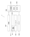
- FIG. 1 is a block diagram illustrating a configuration example of the cell evaluation device according to the first embodiment to which the present technology is applied.
- FIG. 2 is a diagram illustrating a configuration example of the cell evaluation device according to the first embodiment to which the present technology is applied.
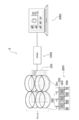
- FIG. 3 is a diagram illustrating a configuration example of the cell evaluation device according to the first embodiment to which the present technology is applied.
- FIG. 4 is a cross-sectional view illustrating a configuration example of a CMOS image sensor (solid-state imaging device) including an antibody layer.
- FIG. 5 is a diagram illustrating a configuration example of the analysis unit.
- FIG. 6 is a diagram illustrating a configuration example of the display unit.
- FIG. 1 is a block diagram illustrating a configuration example of the cell evaluation device according to the first embodiment to which the present technology is applied.
- FIG. 2 is a diagram illustrating a configuration example of the cell evaluation device according to the first embodiment to which the present technology is applied.
- FIG. 3 is a diagram
- FIG. 7 is a block diagram illustrating a configuration example of the cell evaluation device according to the second embodiment to which the present technology is applied.
- FIG. 8 is a diagram illustrating an example of patterning of the first capturing unit and the second capturing unit.
- FIG. 9 is a diagram illustrating an example of patterning of the first capturing unit and the second capturing unit.
- FIG. 10 is a diagram illustrating an example of patterning of the first capturing unit and the second capturing unit.
- the ELISPOT method cultivates a large amount of cells in a well, captures the secretory substance of the cell with a membrane placed at the bottom of the well, removes the cell, reacts with the secretory substance attached to the membrane, and colors the The number of secreted cells can be calculated by counting the number by microscopic observation.
- a method of measuring in a small well for each single cell has been proposed, but since individual cells are divided into wells, it is not possible to observe the interaction in the coexistence of multiple cells.
- the ELISPOT method needs to remove cells before measurement as described above, it is impossible to take out specific cells after ELISPOT and perform post-analysis (eg, gene analysis).
- This technology has been made in view of the above situation, and it is possible to know which cell has secreted what amount in an environment where a plurality of cells coexist. Eventually, it becomes possible to grasp the interaction occurring between different cells such as cancer cells and immune cells, which have been difficult as applications.
- Examples of cells observed by the cell evaluation apparatus according to the present technology include cancer cells, immune cells, and the like.
- immune cells include T cells, NK cells, macrophages, and the like.
- cells include tissues in which single or multiple cells are assembled with a certain function.
- cell secretions observed by the cell evaluation apparatus according to the present technology include IFN- ⁇ , interleukin, chemokine and the like.
- this technique can add at least quantification of secreted substances and cell imaging for each cell to the function of ELISPOT (counting secretory cells), it is possible to specify the cell type and state of the secreted substance. . For example, in co-culture of cancer cells and immune cells, it is currently unknown whether IFN ⁇ was produced, or only the live cells that produced IFN ⁇ were counted, but IFN ⁇ was also produced during apoptosis. can do. Since this technique has a technique based on at least the ELISPOT method and the ELISA method, a necessary blood sample can be reduced. Since cells can be collected in principle, it is possible to reanalyze only those cells that have released secretory substances. It is possible to evaluate which cell has secreted how much in an environment where a plurality of cells coexist. That is, as described above, it is possible to grasp the interaction occurring between different cells such as cancer cells and immune cells, which has been difficult until now.
- Example 1 the first embodiment
- the second embodiment Cell evaluation device
- Example 2 the third embodiment (example of cell evaluation system)
- the cell evaluation apparatus includes a first capturing unit that captures a secretory substance secreted by a cell, light emitted from the observation light of the cell and the secretory substance
- An image acquisition unit that acquires an image obtained by imaging light emitted from a substance, wherein the image acquisition unit and the first capture unit are arranged in this order, and the image acquisition unit is secreted from the cell
- It is a cell evaluation apparatus which acquires positional information with a substance.
- the image acquisition unit and the first acquisition unit are arranged in this order, the image acquisition unit and the first acquisition unit may be arranged continuously, or the image acquisition unit and the first acquisition unit It means that the capturing part may be arranged via an optional material layer (which may be a material film, the same applies hereinafter) or a material part. And that the image acquisition unit and the first acquisition unit are continuously arranged means that the first acquisition unit is arranged immediately above the image acquisition unit.
- the fact that the first capturing unit is disposed immediately above the image acquiring unit means that the first capturing unit is disposed at a distance within 150 ⁇ m, preferably within 10 ⁇ m, from the image acquiring unit, for example. To do.
- the cell evaluation device may further include at least one of an analysis unit, an irradiation unit, and a display unit. That is, the cell evaluation apparatus according to the first embodiment of the present technology can further include an analysis unit, an irradiation unit, a display unit, and an analysis unit and irradiation. A display section, an analysis section and a display section, an irradiation section and a display section, and an analysis section, an irradiation section and a display section. it can.
- FIG. 1 is a block diagram illustrating an example of the cell evaluation apparatus according to the first embodiment of the present technology.
- FIG.2 and FIG.3 is a block diagram which shows an example of the cell evaluation apparatus of 1st Embodiment which concerns on this technique.
- the cell evaluation apparatus 1 includes at least an upper part 101 of an image sensor including a first capturing unit 101, an image sensor 1001 (for example, a CMOS image sensor) that is an image acquisition unit, and an analysis unit 1005.
- the cell evaluation apparatus 1 further includes a driver 1002, an irradiation control unit 1004, a display unit 1006, and an irradiation unit 1007.
- the irradiation control unit 1004, the analysis unit 1005, and the display unit 1006 may be formed as one device 1003.
- the upper part 101 of the image sensor may include a protective part in addition to the first capturing part 101.
- the irradiation control unit 1004 can control the wavelength selectivity (selectivity of light color) of light emitted by the irradiation unit 1007 and the light exposure time.
- the first capturing unit 101-1 (for example, the capturing unit including the first antibody for supplementing secretory substance) is disposed on the image sensor 1001 in a desired positional relationship.
- the cell can be identified by taking a cell image using the cell observation light or the irradiation unit 1007 and analyzing the cell size and cell shape. It is possible to accurately grasp the cell type and cell state (cell viability, etc.).
- Digital ⁇ Mirror Device (DMD) or the like is included in the irradiation unit, and the irradiation position can be controlled.
- DMD Digital ⁇ Mirror Device
- the secretory substance emitted from the cells is captured by the first capturing unit 101-1 (for example, the capturing unit including the first antibody for capturing the secretory substance). Furthermore, by making it react with a chemiluminescent substance etc., weak light can be generated and the light can be acquired with the image sensor 1001 directly under.
- the chemiluminescent substance is, for example, an enzyme, and chemiluminescence is emitted by the reaction of the enzyme with the substrate.
- the position where the secretory substance is obtained on the image sensor 1001 can be mapped. Since the positional relationship between the first capture unit 101-1 (for example, the capture unit including the first antibody for capturing the secretory substance) and the cell can be designated in advance, the cell that has released the secretory substance is also specified. Is possible.
- the analysis unit 1005 can also quantify the secretory substance by utilizing the fact that the luminance changes depending on the concentration of the secretory substance. An image obtained from the image sensor 1001 is displayed on the display unit 1006 (for example, a monitor) through the analysis unit 1005.
- the density of the first antibody for capturing the secretory substance contained in the first capturing unit 101-1 is increased, or the image sensor 1001 and the first capturing unit 101-1 (for example, the antibody)
- There are measures such as making the distance to the layer as short as possible (arranging it directly above the image sensor 1001), increasing the exposure time, and separating the background noise portion and the signal portion by image processing.
- Cell image acquisition and secretory substance detection can also be performed in real time on the image sensor 1001.
- the cell evaluation apparatus 2 includes an antibody layer (first capture unit) 201 including an antibody (first antibody) 200, a CMOS image sensor 2001 that is an image acquisition unit, a driver (driver) 2002, an analysis unit, and a display And a device 2003 including a unit.
- the CMOS image sensor 2001 shows three pixels.
- the CMOS image sensor 2001 includes a protective layer 202, a semiconductor substrate 203, and a wiring layer 204 in order from the light incident side.
- a photodiode (PD) (three photodiodes (PD) in FIG. 2) is formed on the semiconductor substrate 203.
- An antibody layer 201 is disposed immediately above the protective layer 202 (in the upward direction of the protective layer in FIG. 2).
- the antibody layer 201 is disposed immediately above the protective layer 202, so that the light emitted by the luminescent substance combined with the secreted substance captured by the antibody 200 contained in the antibody layer 201 and the observation light of the cell can be converted into a CMOS image.
- the sensor 2001 can receive light efficiently.
- the cell observation light means light obtained by, for example, projecting natural light or room light onto a cell.
- FIG. 2 four wells (two in the horizontal direction and two in the vertical direction in FIG. 2) are shown. However, in the cell evaluation apparatus 2, one well has one well. It means to be disposed immediately above the CMOS image sensor 2001 (the protective layer 205 included in the CMOS image sensor 2001). In the well, for example, an antibody 200 that captures a secreted substance is immobilized in a collagen (Collagen) coat (protection part), traps the pretreated cells, gives the cells stimulation, and is cultured. The secretory substance is emitted from the cell, and the secretory substance is captured by the antibody 200.
- a collagen Collagen
- the cell evaluation apparatus 3 includes an antibody layer (first capturing unit) 301 including an antibody 300, a CMOS image sensor 3001 that is an image acquisition unit, a driver (driver) 3002, an analysis unit, and a display unit. And an irradiation unit 3004.
- the CMOS image sensor 3001 shows three pixels.
- the CMOS image sensor 3001 includes a protective layer 302, a semiconductor substrate 303, and a wiring layer 304 in order from the light incident side.
- a photodiode (PD) (three photodiodes (PD) in FIG. 3) is formed on the semiconductor substrate 303.
- An antibody layer 301 is disposed immediately above the protective layer 302 (upward of the protective layer in FIG. 3). By disposing the antibody layer 301 immediately above the protective layer 302, the light emitted by the luminescent substance combined with the secreted substance captured by the antibody 300 contained in the antibody layer 301 and the irradiation unit 3004 project onto the cell.
- the CMOS image sensor 3001 can efficiently receive the light obtained by this.
- CMOS complementary metal-oxide-semiconductor
- the image sensor 3001 is disposed directly above the protective layer 305. That is, in the cell evaluation device 3, at least four CMOS image sensors 3001 are required.
- an antibody 300 that captures a secretory substance is immobilized on a collagen (Collagen) coat (protection part), traps the pretreated cells, gives the cells stimulation, and is cultured. Secreted substances are emitted from the cells, and the secreted substances are captured by the antibody 300.
- the cell evaluation device includes a first capturing unit.
- the first capturing unit captures secretory substances secreted by the cells.
- the first capture portion can include a molecule that binds non-specifically or specifically to the secretory substance.
- the molecule that nonspecifically or specifically binds to the secretory substance may be at least one selected from the group of the first antibody, the first aptamer, and the imprint polymer, and the first antibody may be plural types.
- a protective part can be arranged in a region where the first capturing part does not contain a molecule that nonspecifically or specifically binds to the secretory substance.
- the protection unit may be formed of, for example, a collagen (Collagen) coat.
- the protective part may be formed of at least one hydrophilic polymer that can suppress the adsorption of the biopolymer.
- the hydrophilic polymer include polyethylene glycol, a polymer having a phosphorylcholine group in the side chain, a polysaccharide, and a polypeptide.
- the cell evaluation device includes an image acquisition unit.
- the image acquisition unit include an image sensor, and examples of the image sensor include a solid-state imaging device such as a CMOS (Complementary Metal Oxide Semiconductor) image sensor and a CCD (Charge Coupled Device).
- CMOS Complementary Metal Oxide Semiconductor
- CCD Charge Coupled Device
- FIG. 4 is a cross-sectional view illustrating a configuration example of one pixel 20 of the backside illumination type solid-state imaging device 10.
- the pixel 20 includes a single organic photoelectric conversion element 41 stacked in the depth direction, a photodiode 36 having a pn junction, and a photodiode 37 in one pixel.
- a protective layer 44 is formed on the organic photoelectric conversion element 41 on the back side of the semiconductor substrate 35 (upper side in FIG. 4), and an antibody layer 50 including the antibody 51 is formed immediately above the protective layer 44.
- the protective layer 44 and the antibody layer 50 are continuously arranged.
- the thickness of the protective layer 44 may be a thin layer of 100 nm, for example.
- the protective layer 44 disposed continuously with the antibody layer 50 preferably has transparency in order to efficiently take light into the organic photoelectric conversion element 41, the photodiode 36 and the photodiode 37.
- the protective layer 44 is preferably made of, for example, SiO 2 .
- the pixel 20 includes a semiconductor substrate (silicon substrate) 35 on which a photodiode 36 and a photodiode 37 are formed, and light reception is performed such that light is incident on the back side of the semiconductor substrate 35 (upper side of the semiconductor substrate 35 in FIG. 4). A surface is formed, and a circuit including a readout circuit and the like is formed on the surface side of the semiconductor substrate 35.
- the pixel 20 has a light receiving surface on the back surface side of the substrate 35 and a circuit forming surface formed on the substrate surface side opposite to the light receiving surface.
- the semiconductor substrate 35 may be formed of a first conductivity type, for example, an n-type semiconductor substrate.
- an inorganic photoelectric conversion part having two pn junctions that is, a first photodiode 36 and a second photodiode 37 are formed so as to be stacked in the depth direction from the back side.
- the first photodiode 36 is formed and the second photodiode 37 is formed from the reverse side to the depth direction (downward in the figure).
- the first photodiode 36 is for blue (B)
- the second photodiode 37 is for red (R).
- a first electrode (lower electrode) 33, a first buffer layer 47, a photoelectric conversion layer 32, and a second buffer layer are formed on the back surface of the semiconductor substrate 35 in the region where the first photodiode 36 and the second photodiode 37 are formed.
- An organic photoelectric conversion element 41 for the first color in which 46 and the second electrode (upper electrode) 31 are stacked in this order is disposed.
- the organic photoelectric conversion device 41 is for green (G).
- the second electrode (upper electrode) 31 and the first electrode (lower electrode) 33 may be formed of a transparent conductive film such as an indium tin oxide film or an indium zinc oxide film.
- the organic photoelectric conversion element 41 is green, the first photodiode 36 is blue, and the second photodiode 37 is red. Any combination of colors is possible.
- the organic photoelectric conversion element 41 can be set to red or blue, and the first photodiode 36 and the second photodiode 37 can be set to other corresponding colors. In this case, the position in the depth direction of the first photodiode 36 and the second photodiode 37 is set according to the color.
- an organic photoelectric conversion element 41B for blue an organic photoelectric conversion element 41G for green
- an organic photoelectric conversion for red is used.
- the element 41R may be applied to the solid-state imaging device (backside illumination type solid-state imaging device and front-side illumination type solid-state imaging device) of the second embodiment according to the present technology.
- an organic photoelectric conversion element 41B that performs photoelectric conversion with blue wavelength light an organic photoelectric conversion material containing a coumarin dye, tris-8-hydroxyquinoline A1 (A1q3), a melocyanine dye, or the like can be used.
- the photoelectric conversion element 41G that performs photoelectric conversion with green wavelength light for example, an organic photoelectric conversion material containing a rhodamine dye, a melocyanine dye, quinacridone, or the like can be used.
- an organic photoelectric conversion material containing a phthalocyanine dye can be used.
- the organic photoelectric conversion element 41UV for ultraviolet light and / or the organic for infrared light is used.
- the photoelectric conversion element 41IR may be applied to the solid-state imaging device (back-illuminated solid-state imaging device and front-illuminated solid-state imaging device) according to the second embodiment of the present technology.
- the light emitted by the luminescent material in combination with the secretory substance captured by the antibody 51 (first antibody) contained in the antibody layer 50, the observation light of the cell, and the projection light that projects the cell by the light of the irradiation part It may be light having an arbitrary wavelength band, and is imaged using at least one of the organic photoelectric conversion element 41, the first photodiode 36, and the second photodiode 37 in accordance with the color (wavelength band) of the light. It's okay.
- the solid-state imaging device 10 if the light emitted from the luminescent substance by combining with the secretory substance is green light, it can be imaged using the organic photoelectric conversion element 41, and the luminescent substance is combined with the secretory substance. If the light emitted by the light source is blue light, it can be imaged using the first photodiode 36, and if the light emitted by the luminescent material in combination with the secretory material is red light, the first photodiode 37 can be used for imaging.
- the first Imaging can be performed using all of the photodiode 36 and the second photodiode 37.
- a first electrode (lower electrode) 33 is formed, and an insulating film 34 for insulating and isolating the first electrode (lower electrode) 33 is shown in the figure of the first electrode (lower electrode) 33. Formed at the bottom.
- a wiring 39 connected to the first electrode (lower electrode) 33 and a wiring (not shown) connected to the second electrode (upper electrode) 31 are formed.
- the wiring 39 becomes a p-type semiconductor layer when formed by a semiconductor layer by ion implantation.
- the wiring connected to the second electrode (upper electrode) 31 can use an n-type semiconductor layer because the second electrode (upper electrode) 31 extracts electrons.
- an n-type region 38 for charge accumulation is formed on the surface side of the semiconductor substrate 35.
- This n-type region 38 functions as a floating diffusion portion of the photoelectric conversion element 41.
- a film having a negative fixed charge can be used as the insulating film 34 on the back surface of the semiconductor substrate 35.
- a film having a negative fixed charge for example, a hafnium oxide film can be used. That is, the insulating film 34 may be formed to have a three-layer structure in which a silicon oxide film, a hafnium oxide film, and a silicon oxide film are sequentially formed from the back surface.
- a wiring layer 45 is formed on the surface side of the semiconductor substrate 35 (the lower side in FIG. 4).
- the back-illuminated solid-state imaging device 10 may be formed with a color filter, a transparent filter, an ND filter, a white filter, a gray filter, or the like, or an on-chip lens. May be.
- the CMOS image sensor may be a front-illuminated solid-state image sensor as well as the back-illuminated solid-state image sensor described above.
- a surface irradiation type solid-state imaging device will be described.
- the wiring layer 92 formed below the semiconductor substrate 35 is different from the back-illuminated solid-state image sensor 10 described above in that the organic photoelectric conversion element 41, the semiconductor substrate 35, and the like. The only difference is that the wiring layer 92 is formed between the two.
- Other points may be the same as those of the back-illuminated solid-state imaging device 10 described above, and a description thereof is omitted here.
- the cell evaluation device can include an analysis unit.
- the analysis unit can perform quantification of the secretory substance based on the intensity of light emitted from the luminescent substance combined with the secretory substance.
- the analysis unit can analyze the cell based on the light (luminance information) obtained by projecting the cell with the observation light of the cell or the irradiation unit.
- the projected image of the cell may be converted into a higher resolution image by a hologram technique or a super-resolution technique to analyze the cell.
- FIG. 5 shows a configuration example of the analysis unit. Specifically, FIG. 5A shows antibody arrangement information 70a, FIG. 5B shows a chemiluminescence image, and FIG. 5C shows a cell image. .
- antibody arrangement information 70a includes antibodies 71a to 76a.
- Each of the antibodies 71a to 76a includes, for example, a first antibody that captures a secretory substance.
- each of the antibodies 71a to 76a includes, for example, a first antibody that captures a secreted substance and a second antibody that captures a cell. It is.
- individual chemiluminescent images 71b to 76b are obtained in the chemiluminescent image 70b.
- Each of the chemiluminescent images 71b to 76b corresponds to each of the antibody 71a to the antibody 76a.
- the chemiluminescence intensity can be calculated to further calculate the amount of secretion.
- the secretory substance is quantified by obtaining the intensity of chemiluminescence from the luminance information for each pixel obtained from the image sensor, and determining the secretory substance from the intensity and the information of the calibration curve taken as data in advance. Calculate the concentration.
- the cell image 70c shows individual cell images 71c to 76c.
- the cell images 71c to 76c are cell images that are 1 ⁇ (equal magnification) with respect to the cells, but may be enlarged or reduced as necessary. It may be a cell image. Since each of the cell images 71c to 76c corresponds to each of the antibody 71a to antibody 76a and the chemiluminescent images 71b to 76b, the concentration of the secretory substance for each of the cell images 71c to 76c can be uniquely determined. it can.
- each cell in the cell images 71c to 76c is a cell captured by the second antibody, so It becomes clearer.
- the cell evaluation device can include an irradiation unit.
- the irradiation unit is one means for confirming the cell image.
- the irradiation control unit is used to select the wavelength selectivity (light color selectivity) of light emitted from the irradiation unit and the light exposure. Since the time can be controlled, a clearer cell image can be obtained by using the irradiation unit.
- the photodegradable linker can be cleaved using only the specific wavelength irradiated to release only specific cells.
- the cell evaluation device may include a display unit.
- the display unit emits light emitted from a luminescent substance combined with a cell image and a secretory substance obtained by imaging a cell observation light or light (luminance information) obtained by projecting a cell with an irradiation part.
- a well image display unit based on the chemiluminescence image obtained by imaging, and an analysis data display unit and an analysis plot display unit based on the analysis of the analysis unit can be provided.
- FIG. 6 shows a configuration example of the display unit. Specifically, FIG. 6B shows a well image display unit based on the chemiluminescence image 80a-1 and the cell image 80a-2 shown in FIG. 6A.
- FIG. 6C shows the analysis data display unit, and FIG. 6C shows the analysis plot display unit.
- each of the chemiluminescent images 81a-1 to 86a-1 of the chemiluminescent image 80a-1 is associated with each of the cell images 81a-2 to 86a-2.
- the combined image is shown in the well display portion 80b.
- FIG. 6 (b) information relating to the cells contained in the well 1A among the total of six wells 1A to 3A and 2A to 3B is shown. Referring to FIG.
- the chemiluminescence image 81b-1 and the cell image 81b-2 correspond, the chemiluminescence image 82b-1 and the cell image 82b-2 correspond, and the chemiluminescence image 83b-1 and The cell image 83b-2 corresponds, the chemiluminescence image 84b-1 and the cell image 84b-2 correspond, the chemiluminescence image 85b-1 and the cell image 85b-2 correspond, and the chemiluminescence image 86b -1 and cell image 86b-2 correspond to each other.
- the cell in the cell image 81a-2 (cell image 81b-2) whose cell size is the arrow P8 is the largest among the six cells shown in FIG. The light emission is the largest.
- the chemiluminescence image is shown in white in FIGS.
- the cells in the cell image 83a-2 have the smallest cell size and the amount of chemiluminescence is almost zero, not shown.
- the chemiluminescence image is shown in black.
- the analysis data display section 80c the cell diameter of the well (Well) total number of 1A cells have been shown to be 10 4, individual cells (cell No.) ( ⁇ m), secretion amount (pg) and the like are shown.
- the analysis plot display unit 80d shows a graph in which the vertical axis represents the secretion amount (pg) and the horizontal axis represents the cell size (cell diameter) ( ⁇ m).
- secretion and (pg) it is determined from the correlation between the cell size (cell diameter) ([mu] m), the number of cells to be evaluated, 10 four of 100 It can be determined that it is an individual.
- the cells indicated by black circles out of 100 cells correspond to, for example, the cells in the cell image 81a-2 (cell image 81b-2) described above.
- the cell evaluation device includes a first capturing unit that captures a secretory substance secreted by a cell, a second capturing unit that captures the cell, An image acquisition unit that acquires an image obtained by imaging light emitted from a luminescent substance combined with observation light of the cell and a secretory substance, and the image acquisition unit and the first capturing unit are in this order.
- the image acquisition unit and the second capturing unit are arranged in this order, and the image acquisition unit acquires positional information between the cells and the secretory substance.
- the cell evaluation device according to the second embodiment (Example 2 of the cell evaluation device) according to the present technology is the second cell evaluation device according to the first embodiment (Example 1 of the cell evaluation device) according to the present technology.
- the configuration of the cell evaluation apparatus according to the second embodiment (Example 2 of the cell evaluation apparatus) according to the present technology is the same as the configuration according to the present technology except for the configuration of the second capture section.
- the configuration may be the same as that of the cell evaluation device according to the first embodiment (Example 1 of the cell evaluation device).
- the image acquisition unit and the first acquisition unit are arranged in this order, the image acquisition unit and the first acquisition unit may be arranged continuously, or the image acquisition unit and the first acquisition unit It means that the capturing part may be arranged via an optional material layer (material film) or material part. And that the image acquisition unit and the first acquisition unit are continuously arranged means that the first acquisition unit is arranged immediately above the image acquisition unit.
- the phrase “the first capturing unit is disposed immediately above the image acquiring unit” means, for example, that the first capturing unit is disposed at a distance within 150 ⁇ m from the image acquiring unit, preferably within a distance within 10 ⁇ m.
- the image acquisition unit and the second acquisition unit are arranged in this order.
- the image acquisition unit and the second acquisition unit may be arranged in succession, or the image acquisition unit and the second acquisition unit. Means that it may be arranged via an optional material layer (material film) or material part. And that the image acquisition unit and the second acquisition unit are continuously arranged means that the second acquisition unit is arranged immediately above the image acquisition unit.
- the phrase “the second capturing unit is disposed immediately above the image acquiring unit” means, for example, that the second capturing unit is disposed at a distance within 150 ⁇ m from the image acquiring unit, preferably within a distance within 10 ⁇ m.
- the cell evaluation device may further include at least one of an analysis unit, an irradiation unit, and a display unit. That is, the cell evaluation device according to the second embodiment of the present technology can further include an analysis unit, an irradiation unit, a display unit, and an analysis unit and irradiation.
- the cell evaluation apparatus 7 includes an upper part 101 of an image sensor including a first capturing unit 101-1 and a second capturing unit 101-2, an image sensor 1001 (for example, a CMOS image sensor) that is an image acquiring unit, and an analyzing unit. 1005 at least.
- the cell evaluation apparatus 1 further includes a driver 1002, an irradiation control unit 1004, a display unit 1006, and an irradiation unit 1007.
- the irradiation control unit 1004, the analysis unit 1005, and the display unit 1006 may be formed as one device 1003.
- the upper part 101 of the image sensor may include a protective part in addition to the first capturing part 101-1 and the second capturing part 101-2.
- a first capturing unit 101-1 for example, a capturing unit including a first antibody for capturing a secretory substance
- a second capturing unit 101-2 for example, The capturing part containing the second antibody for cell capture
- the cell captured by the second capturing unit 101-2 can be identified by taking a cell image using the cell observation light or the irradiation unit 1007 and analyzing the cell size and cell shape. It is possible to accurately grasp the cell type and cell state (cell viability, etc.).
- the cells are captured by the second capture unit 101-2, after culturing the cells, for example, only a specific capture antibody (second antibody) that has reacted to the secretory substance is cleaved by an optical linker technique or the like, It is also possible to collect cells.
- a photodegradable linker is included between the second capturing unit 101-2 and the image sensor 1001. By including a photodegradable linker, only specific cells can be released. That is, in the cell evaluation apparatus 7, it becomes possible to perform post-analysis (such as gene analysis) by analyzing the cells and then cutting off the capture of the cells by applying light, taking out only the desired cells.
- the cells are cultured on the image sensor 1001, and the secretory substance emitted from the cells is captured by the first capturing unit 101-1 (for example, the capturing unit including the first antibody for capturing the secreted substance), Thereafter, a weak light is generated by further reacting with a chemiluminescent substance or the like, and the light can be acquired by the image sensor 1001 directly below.
- a chemiluminescent substance is an enzyme, for example, and chemiluminescence is emitted by reaction of an enzyme with a substrate.
- a first capture unit 101-1 eg, a capture unit containing a first antibody for capturing secretory material
- a second capture unit 101-2 eg, a capture containing a second antibody for capturing cells
- the analysis unit 1005 can also quantify the secretory substance by utilizing the fact that the luminance changes depending on the concentration of the secretory substance.
- An image obtained from the image sensor 1001 is displayed on the display unit 1006 (for example, a monitor) through the analysis unit 1005.
- the density of the first antibody for capturing the secretory substance contained in the first capturing unit 101-1 is increased, or the image sensor 1001 and the first capturing unit 101-1 (for example, the antibody)
- There are measures such as making the distance to the layer as short as possible (arranging the image sensor 1001 directly above), increasing the exposure time, and separating the background noise portion and the signal portion by image processing.
- Cell image acquisition and secretory substance detection can also be performed in real time on the image sensor 1001.
- the cell evaluation device includes a first capturing unit and a second capturing unit.
- the first capturing unit captures secretory substances secreted by the cells. Since the 1st capture part is as having explained in the column of the cell evaluation device of a 1st embodiment (example 1 of a cell evaluation device) concerning this art, detailed explanation is omitted here.
- the second capturing unit captures cells.
- the second capture portion can include a molecule that binds non-specifically or specifically to the cell.
- the molecule that nonspecifically or specifically binds to the cell may be at least one selected from the group consisting of the second antibody, the second aptamer, the supramolecule, and oleylamine, and the second antibody may be a plurality of types.
- a protective part can be arranged in a region where the second capturing part does not contain a molecule that nonspecifically or specifically binds to a cell.
- the protection part may be formed of, for example, a collagen (Collagen) coat.
- the protective part may be formed of at least one hydrophilic polymer that can suppress the adsorption of the biopolymer. Examples of the hydrophilic polymer include polyethylene glycol, a polymer having a phosphorylcholine group in the side chain, a polysaccharide, and a polypeptide.
- FIG. 8A shows the patterning of one first capturing portion and second capturing portion shown in FIG. 8A for 16 pieces.
- the second capturing unit 401a shown in FIG. 8A corresponds to the second capturing unit 401b shown in FIG. 8B
- the first capturing unit 402a shown in FIG. 8B corresponds to the second capture unit 402b shown in FIG. 8B
- the protection unit 403a shown in FIG. 8A corresponds to the second protection unit 403b shown in FIG. 8B.
- the place of the 2nd capture part 401a is 1st.
- a capturing unit 402a is arranged.
- first capturing parts 502a to 505a are arranged around the second capturing part 501a, and the first capturing parts 502a to 505a and the second capturing part
- a protection unit 506a is disposed between the unit 501a and each of the first capturing units 502a to 505a.
- the first capturing parts 502a and 503a include the same material (for example, the first antibody), and the first capturing parts 503a and 504a include the same material (for example, the first aptamer), Two types of materials are used.
- the first capturing portions 502a to 505a are the vertical rectangular shapes of the first capturing portions 502a and 503a (the longitudinal direction is the vertical direction in FIG. 9A) in FIG.
- the first capturing portions 504a and 505a have a rectangular shape (the longitudinal direction is the left-right direction in FIG. 9A), and the first capturing portions including different materials are adjacent to each other.
- FIG. 9B the patterning of one first capturing portion and the second capturing portion shown in FIG. 9A is shown for 16 pieces.
- the second capturing unit 501a shown in FIG. 9A corresponds to the second capturing unit 501b shown in FIG. 9B
- the first capturing unit 502a shown in FIG. 9B corresponds to the second capturing unit 502b shown in FIG. 9B
- the first capturing unit 503a shown in FIG. 9A corresponds to the second capturing unit 503b shown in FIG. 9B
- 9A corresponds to the second capturing unit 504b illustrated in FIG. 9B
- the first capturing unit 505a illustrated in FIG. 9A is illustrated in FIG. It corresponds to the second capturing part 505b shown in b)
- the protective part 506a shown in FIG. 9A corresponds to the protective part 506b shown in FIG. 9B.
- the place of the 2nd capture part 501a is 1st.
- the capturing units 502a to 505a at least one first capturing unit is arranged.
- the first capturing units 602a to 609a are arranged around the second capturing unit 601a, and the first capturing units 602a to 609a and the second capturing unit are arranged.
- a protective unit 610a is disposed between the first capturing unit 602a and the first capturing units 602a to 609a.
- Each of the first capturing parts 602a to 609a includes different materials (for example, eight kinds of first antibodies or eight kinds of first aptamers), and eight kinds of materials are used.
- the first capturing parts 602a to 609a are arranged in the form of eight squares in FIG. 10 (a).
- FIG. 10B the patterning of one first capturing portion and the second capturing portion shown in FIG. 10A is shown for 16 pieces.
- the second capturing unit 601a shown in FIG. 10A corresponds to the second capturing unit 601 (b) shown in FIG. 10B, and the first capturing unit 602a shown in FIG. 10A.
- the first capturing portion 603a shown in FIG. 10A corresponds to the second capturing portion 603b shown in FIG.
- the first capturing unit 604a shown in FIG. 10 (a) corresponds to the second capturing unit 604b shown in FIG. 10 (b)
- the first capturing unit 605a shown in FIG. 10 corresponds to the second capturing unit 605b shown in FIG. 10B, and the first capturing unit 606a shown in FIG.
- FIG. 10A corresponds to the second capturing unit 606b shown in FIG.
- the first capturing unit 607a shown in (a) is in phase with the second capturing unit 607b shown in FIG. 10 (b).
- the first capturing unit 608a shown in FIG. 10A corresponds to the second capturing unit 608b shown in FIG. 10B
- the first capturing unit 609a shown in FIG. 9B corresponds to the second capturing unit 609b shown in FIG. 9B
- the protection unit 610a shown in FIG. 10A corresponds to the protection unit 610b shown in FIG. 9B.
- the place of the 2nd capture part 601a is the 1st capture.
- the parts 602a to 609a at least one first capturing part is arranged.
- the image acquisition unit provided in the cell evaluation device according to the second embodiment (Example 2 of the cell evaluation device) according to the present technology is the same as the cell evaluation device according to the first embodiment (Example 1 of the cell evaluation device) according to the present technology. Since it is as having demonstrated in the column, detailed description is abbreviate
- the analysis unit, the irradiation unit, and the display unit that can be included in the cell evaluation device of the second embodiment (Example 2 of the cell evaluation device) according to the present technology are also included in the first embodiment (cells) according to the present technology. Since it is as having demonstrated in the column of the cell evaluation apparatus of the example 1) of an evaluation apparatus, detailed description is abbreviate
- a cell evaluation system includes a first capturing unit that captures a secretory substance secreted by a cell, cell observation light, and light emission combined with the secretory substance.
- An image acquisition unit that acquires an image obtained by imaging light emitted from a substance, and an analysis unit that analyzes the obtained image.
- the image acquisition unit and the first capture unit are in this order.
- the cell evaluation system in which the image acquisition unit acquires positional information between the cells and the secretory substance.
- the cell evaluation system of the third embodiment includes a first capturing unit that captures a secretory substance secreted by a cell, a cell observation light, and the secretory substance.
- An image acquisition unit that acquires an image obtained by imaging light emitted from the luminescent material, and an analysis unit that analyzes the obtained image.
- the image acquisition unit and the first capturing unit include: A cell evaluation system may be used in which the image acquisition unit is arranged in this order and the image acquisition unit acquires positional information of the cells and the secretory substances.
- the cell evaluation system according to the third embodiment of the present technology may further include at least one of an irradiation unit and a display unit. That is, the cell evaluation system of the third embodiment according to the present technology can further include an irradiation unit, a display unit, and an irradiation unit and a display unit.
- the contents of the cell evaluation device according to the first embodiment and the second embodiment of the present technology (of the cell evaluation device) except for the contents described above.
- the contents described in the columns of Example 1 and Example 2) can be directly applied to the cell evaluation system of the third embodiment according to the present technology.
- the image acquisition unit and the analysis unit included in the cell evaluation system of the third embodiment (cell evaluation system) according to the present technology are the same as those of the cell evaluation device of the first embodiment (Example 1 of the cell evaluation device) according to the present technology. Since it is as having demonstrated in the column, detailed description is abbreviate
- the irradiation unit and the display unit that can be included in the cell evaluation system of the third embodiment (cell evaluation system) according to the present technology are the same as those of the first embodiment (Example 1 of the cell evaluation device) according to the present technology.
- the second capturing unit that can be provided in the cell evaluation system of the third embodiment (cell evaluation system) according to the present technology is the same as that of the second embodiment (Example 2 of the cell evaluation device) according to the present technology. Since it is as having demonstrated in the column of the cell evaluation apparatus, detailed description is abbreviate
- the present technology may take the following configurations [1] to [68].
- a first capturing part for capturing a secretory substance secreted by a cell;
- An image acquisition unit for acquiring an image obtained by imaging the light emitted from the luminescent substance combined with the observation light of the cell and the secretory substance,
- the image acquisition unit and the first capturing unit are arranged in this order,
- the cell evaluation apparatus wherein the image acquisition unit acquires positional information between the cells and the secretory substance.
- [3] The cell evaluation apparatus according to [1] or [2], wherein the image acquisition unit acquires an image obtained by imaging chemiluminescence generated by the reaction of the luminescent substance that is an enzyme with a substrate.
- the first capturing unit includes a molecule that nonspecifically or specifically binds to the secretory substance.
- a protective part is arranged in a region not including the molecule in which the first capturing part binds nonspecifically or specifically to the secretory substance.
- the molecule that nonspecifically or specifically binds to the secretory substance is at least one selected from the group consisting of a first antibody, a first aptamer, and a molecular imprint polymer, [4] or [5] The cell evaluation apparatus according to 1. [7] The cell evaluation apparatus according to [6], wherein the first antibody is a plurality of types.
- a second capturing part for capturing the cells The cell evaluation device according to any one of [1] to [7], wherein the image acquisition unit and the second capturing unit are arranged in this order. [9] The cell evaluation device according to [8], wherein the first capturing unit is arranged around the second capturing unit. [10] The cell evaluation device according to [8] or [9], wherein a photodegradable linker is included between the second capture unit and the image acquisition unit. [11] The cell evaluation device according to any one of [8] to [10], wherein the second capturing unit includes a molecule that nonspecifically or specifically binds to the cell.
- a first capturing part for capturing a secretory substance secreted by a cell An image acquisition unit for acquiring an image obtained by imaging the light emitted from a light-emitting substance combined with the observation light of the cell and the secretory substance; An analysis unit for analyzing the obtained image, The image acquisition unit and the first capturing unit are arranged in this order, The cell evaluation apparatus, wherein the image acquisition unit acquires positional information between the cells and the secretory substance.
- the analysis unit quantifies the secretory substance based on the intensity of the light emitted from the luminescent substance combined with the secretory substance.
- the first capture unit includes a molecule that nonspecifically or specifically binds to the secretory substance [1 The cell evaluation device according to any one of [5] to [19]. [21] The cell evaluation apparatus according to [20], wherein a protective part is arranged in a region not including the molecule in which the first capturing part binds nonspecifically or specifically to the secretory substance. [22] The molecule that nonspecifically or specifically binds to the secretory substance is at least one selected from the group consisting of a first antibody, a first aptamer, and a molecular imprint polymer [20] or [21] The cell evaluation apparatus according to 1. [23] The cell evaluation apparatus according to [22], wherein the first antibody is a plurality of types.
- a second capturing part for capturing the cells The cell evaluation device according to any one of [15] to [23], wherein the image acquisition unit and the second capturing unit are arranged in this order. [25] The cell evaluation apparatus according to [24], wherein the first capturing unit is arranged around the second capturing unit. [26] The cell evaluation device according to [24] or [25], wherein a photodegradable linker is included between the second capture unit and the image acquisition unit. [27] The cell evaluation device according to any one of [24] to [26], wherein the second capture unit includes a molecule that nonspecifically or specifically binds to the cell.
- the cell evaluation apparatus according to any one of [1] to [30], further comprising an irradiation unit that projects the cells.
- the cell evaluation apparatus according to any one of [1] to [31], further comprising a display unit that displays the image.
- Well image display based on a cell image obtained by imaging the observation light of the cell and a chemiluminescence image obtained by imaging light emitted from a luminescent substance combined with the secretory substance
- the analysis data display unit and the analysis plot display unit based on the analysis of the analysis unit, the cell evaluation device according to [32].
- a first capturing part for capturing a secretory substance secreted by a cell An image acquisition unit for acquiring an image obtained by imaging the light emitted from the luminescent substance combined with the observation light of the cell and the secretory substance, The image acquisition unit and the first capturing unit are arranged in this order, The cell evaluation system in which the image acquisition unit acquires positional information between the cells and the secretory substance.
- the cell evaluation system according to [34] wherein the image acquisition unit is a CMOS image sensor.
- the image acquisition unit acquires an image obtained by imaging chemiluminescence generated by a reaction of the luminescent substance that is an enzyme with a substrate.
- the cell evaluation system according to any one of [34] to [36], wherein the first capture unit includes a molecule that nonspecifically or specifically binds to the secretory substance.
- a protective part is arranged in a region not including the molecule in which the first capturing part binds nonspecifically or specifically to the secretory substance.
- the molecule that non-specifically or specifically binds to the secretory substance is at least one selected from the group consisting of a first antibody, a first aptamer, and a molecular imprint polymer [37] or [38] The cell evaluation system described in 1.
- the cell evaluation system according to [39], wherein the first antibody is a plurality of types.
- a second capturing part for capturing the cells The cell evaluation system according to any one of [34] to [40], wherein the image acquisition unit and the second capturing unit are arranged in this order.
- a first capturing part for capturing a secretory substance secreted by a cell An image acquisition unit for acquiring an image obtained by imaging the light emitted from a light-emitting substance combined with the observation light of the cell and the secretory substance; An analysis unit for analyzing the obtained image, The image acquisition unit and the first capturing unit are arranged in this order, The cell evaluation system in which the image acquisition unit acquires positional information between the cells and the secretory substance.
- the cell evaluation system according to [48] wherein the analysis unit quantifies the secretory substance based on the intensity of the light emitted from the luminescent substance combined with the secretory substance.
- [50] The cell according to [48] or [49], wherein the analysis unit analyzes the cell based on luminance information of light emitted from a light-emitting substance combined with the observation light and / or secretory substance of the cell. Evaluation system.
- the cell evaluation system according to any one of [48] to [52], wherein the first capture unit includes a molecule that nonspecifically or specifically binds to the secretory substance.
- the first capture unit includes a molecule that nonspecifically or specifically binds to the secretory substance.
- a protective part is arranged in a region not including the molecule in which the first capturing part binds nonspecifically or specifically to the secretory substance.
- the molecule that nonspecifically or specifically binds to the secretory substance is at least one selected from the group consisting of a first antibody, a first aptamer, and a molecular imprint polymer.
- the cell evaluation system according to [55] wherein the first antibody is a plurality of types.
- [57] A second capturing part for capturing the cells; The cell evaluation system according to any one of [48] to [56], wherein the image acquisition unit and the second capturing unit are arranged in this order. [58] The cell evaluation system according to [57], wherein the first capturing unit is arranged around the second capturing unit. [59] The cell evaluation system according to [57] or [58], wherein a photodegradable linker is included between the second capturing unit and the image acquiring unit. [60] The cell evaluation system according to any one of [57] to [59], wherein the second capture unit includes a molecule that nonspecifically or specifically binds to the cell.
- a cell evaluation system according to [65] comprising an analysis data display unit and an analysis plot display unit based on the analysis of the analysis unit.
- a first antibody that captures secretory material secreted by the cell A second antibody that captures cells; A CMOS image sensor that obtains an image obtained by imaging the light emitted from the luminescent substance combined with the observation light of the cell and the secretory substance, and The CMOS image sensor, the first antibody and the second antibody are arranged in this order, The first antibody is disposed around the second antibody; The cell evaluation apparatus, wherein the CMOS image sensor acquires positional information between the cell and the secretory substance.
- a first antibody that captures secretory material secreted by the cell A second antibody that captures cells; A CMOS image sensor that acquires an image obtained by imaging light emitted from the observation light of the cell and the secretory substance, and light emitted from the SO An analysis unit for analyzing the acquired image, The CMOS image sensor, the first antibody and the second antibody are arranged in this order, The first antibody is disposed around the second antibody; The cell evaluation apparatus, wherein the CMOS image sensor acquires positional information between the cell and the secretory substance.
- a first antibody that captures secretory material secreted by the cell A second antibody that captures cells; A CMOS image sensor that obtains an image obtained by imaging the light emitted from the luminescent substance combined with the observation light of the cell and the secretory substance, and The CMOS image sensor, the first antibody and the second antibody are arranged in this order, The first antibody is disposed around the second antibody; A cell evaluation system in which the CMOS image sensor acquires positional information between the cell and the secretory substance.
- a first antibody that captures secretory material secreted by the cell A second antibody that captures cells;
- a CMOS image sensor for obtaining an image obtained by imaging the light emitted from a light-emitting substance combined with the observation light of the cell and the secretory substance;
- An analysis unit for analyzing the acquired image,
- the CMOS image sensor, the first antibody and the second antibody are arranged in this order, The first antibody is disposed around the second antibody;
Abstract
Provided is a cell evaluation device capable of highly accurate and exact evaluation of a cell and a substance secreted by the cell. This cell evaluation device comprises a first capturing unit for capturing a secreted substance secreted by a cell and an image acquisition unit for acquiring an image obtained by imaging cell observation light and light emitted from a luminescent substance joined to the secreted substance. The image acquisition unit and first capturing unit are arranged in order with the image acquisition unit followed by the first capturing unit. The image acquisition unit acquires position information for the cell and the secreted substance.
Description
本技術は細胞評価装置及び細胞評価システムに関する。
This technology relates to a cell evaluation device and a cell evaluation system.
近年、細胞や細胞から発せられる分泌物質を評価するシステムは進化し続け、様々な技術が提案されている。
In recent years, systems for evaluating cells and secreted substances emitted from cells continue to evolve, and various technologies have been proposed.
例えば、CMOS(Complementary Metal Oxide Semiconductor)バイオセンサシステムに関する技術が提案されている(特許文献1を参照)。
For example, a technology related to a CMOS (Complementary Metal Oxide Semiconductor) biosensor system has been proposed (see Patent Document 1).
しかしながら、特許文献1で提案された技術では、細胞や細胞から発せられる分泌物質を、高精度で的確に評価することができないおそれがある。
However, with the technique proposed in Patent Document 1, there is a possibility that cells and secretory substances emitted from the cells cannot be accurately evaluated with high accuracy.
そこで、本技術は、このような状況に鑑みてなされたものであり、細胞や細胞から発せられる分泌物質を、高精度で的確に評価することができる細胞評価装置を提供することを主目的とする。
Therefore, the present technology has been made in view of such a situation, and a main object thereof is to provide a cell evaluation apparatus that can accurately and accurately evaluate cells and secretory substances emitted from the cells. To do.
本発明者は、上述の目的を解決するために鋭意研究を行った結果、驚くべきことに、細胞や細胞から発せられる分泌物質を、高精度で的確に評価することができることに成功し、本技術を完成するに至った。
As a result of diligent research to solve the above-mentioned object, the present inventor has surprisingly succeeded in accurately and accurately evaluating cells and secretory substances emitted from the cells. The technology has been completed.
すなわち、本技術では、まず、細胞が分泌する分泌物質を捕捉する第1の捕捉部と、
前記細胞の観察光及び前記分泌物質と結合した発光物質より発せられた光を撮像して得られた画像を取得する画像取得部と、を備え、
前記画像取得部と、前記第1の捕捉部とがこの順で配され、
前記画像取得部が、前記細胞と前記分泌物質との位置情報を取得する、細胞評価装置を提供する。 That is, in the present technology, first, a first capturing unit that captures a secretory substance secreted by a cell;
An image acquisition unit for acquiring an image obtained by imaging the light emitted from the luminescent substance combined with the observation light of the cell and the secretory substance,
The image acquisition unit and the first capturing unit are arranged in this order,
A cell evaluation device is provided in which the image acquisition unit acquires positional information of the cell and the secretory substance.
本技術に係る細胞評価装置において、前記画像取得部がCMOSイメージセンサでよい。
本技術に係る細胞評価装置において、前記画像取得部が、酵素である前記発光物質が基質との反応により発せられた化学発光を撮像して得られた画像を取得することができる。 In the cell evaluation device according to the present technology, the image acquisition unit may be a CMOS image sensor.
In the cell evaluation apparatus according to the present technology, the image acquisition unit can acquire an image obtained by imaging chemiluminescence generated by the reaction of the luminescent substance, which is an enzyme, with a substrate.
本技術に係る細胞評価装置において、前記第1の捕捉部が、前記分泌物質と非特異的又は特異的に結合する分子を含んでよい。
本技術に係る細胞評価装置において、前記第1の捕捉部が前記分泌物質と非特異的又は特異的に結合する前記分子を含まない領域に保護部が配されてよい。 In the cell evaluation apparatus according to the present technology, the first capturing unit may include a molecule that binds non-specifically or specifically to the secretory substance.
In the cell evaluation apparatus according to the present technology, a protection unit may be disposed in a region that does not include the molecule in which the first capturing unit binds nonspecifically or specifically to the secretory substance.
前記分泌物質と非特異的又は特異的に結合する前記分子が、第1の抗体、第1のアプタマー、及び分子インプリントポリマーの群から選ばれる少なくとも1種でよく、前記第1の抗体が複数種類でよい。
The molecule that nonspecifically or specifically binds to the secretory substance may be at least one selected from the group consisting of a first antibody, a first aptamer, and a molecular imprint polymer, and there are a plurality of the first antibodies. Kind is OK.
本技術に係る細胞評価装置が、前記細胞を捕捉する第2の捕捉部を更に備え、本技術に係る細胞評価装置において、前記画像取得部と、前記第2の捕捉部とがこの順で配されてよい。
The cell evaluation device according to the present technology further includes a second capturing unit that captures the cells. In the cell evaluation device according to the present technology, the image acquisition unit and the second capturing unit are arranged in this order. May be.
本技術に係る細胞評価装置において、前記第1の捕捉部が前記第2の捕捉部の周囲に配されてよい。
In the cell evaluation apparatus according to the present technology, the first capturing unit may be arranged around the second capturing unit.
本技術に係る細胞評価装置において、前記第2の捕捉部が、前記細胞と非特異的又は特異的に結合する分子を含んでよい。
本技術に係る細胞評価装置において、前記第2の捕捉部が前記細胞と非特異的又は特異的に結合する前記分子を含まない領域に保護部が配されてよい。
前記細胞と非特異的又は特異的に結合する前記分子が、第2の抗体、第2のアプタマー、超分子及びオレイルアミンの群から選ばれる少なくとも1種でよく、前記第2の抗体が複数種類でよい。
本技術に係る細胞評価装置において、前記第2の捕捉部と前記画像取得部との間には光分解性リンカーが含まれていてもよい。 In the cell evaluation apparatus according to the present technology, the second capturing unit may include a molecule that binds nonspecifically or specifically to the cell.
In the cell evaluation device according to the present technology, a protection unit may be disposed in a region that does not include the molecule in which the second capturing unit binds nonspecifically or specifically to the cell.
The molecule that nonspecifically or specifically binds to the cell may be at least one selected from the group consisting of a second antibody, a second aptamer, a supramolecule, and oleylamine, and the second antibody may be a plurality of types. Good.
In the cell evaluation device according to the present technology, a photodegradable linker may be included between the second capturing unit and the image acquiring unit.
また、本技術では、細胞が分泌する分泌物質を捕捉する第1の捕捉部と、
前記細胞の観察光及び前記分泌物質と結合した発光物質より発せられた光を撮像して得られた画像を取得する画像取得部と、
前記得られた画像を解析する解析部と、を備え、
前記画像取得部と、前記第1の捕捉部とがこの順で配され、
前記画像取得部が、前記細胞と前記分泌物質との位置情報を取得する、細胞評価装置を提供する。 In the present technology, a first capturing unit that captures a secretory substance secreted by the cell;
An image acquisition unit for acquiring an image obtained by imaging the light emitted from a light-emitting substance combined with the observation light of the cell and the secretory substance;
An analysis unit for analyzing the obtained image,
The image acquisition unit and the first capturing unit are arranged in this order,
A cell evaluation device is provided in which the image acquisition unit acquires positional information of the cell and the secretory substance.
本技術に係る細胞評価装置において、前記解析部が、前記分泌物質と結合した前記発光物質より発せられた前記光の強度に基づいて前記分泌物質の定量を行うことができる。
前記解析部が、前記細胞の前記観察光及び/又は分泌物質と結合した発光物質より発せられた光の輝度情報に基づいて前記細胞の分析を行うことができる。 In the cell evaluation device according to the present technology, the analysis unit can perform the quantification of the secretory substance based on the intensity of the light emitted from the luminescent substance combined with the secretory substance.
The analysis unit can analyze the cell based on luminance information of light emitted from a light-emitting substance combined with the observation light and / or secretory substance of the cell.
本技術に係る細胞評価装置が、前記細胞を投影する照射部を更に備えてよい。
The cell evaluation apparatus according to the present technology may further include an irradiation unit that projects the cells.
本技術に係る細胞評価装置が、前記画像を表示する表示部を更に備えてよい。
前記表示部が、前記細胞の観察光を撮像して得られた細胞像画像及び前記分泌物質と結合した発光物質より発せられた光を撮像して得られた化学発光画像に基づいたウェル画像表示部、並びに、前記解析部の解析に基づいた解析データ表示部及び解析プロット表示部を備えてよい。 The cell evaluation apparatus according to the present technology may further include a display unit that displays the image.
Well image display based on a cell image obtained by imaging the observation light of the cell and a chemiluminescence image obtained by imaging light emitted from a luminescent substance combined with the secretory substance And an analysis data display unit and an analysis plot display unit based on the analysis of the analysis unit.
さらに、本技術では、細胞が分泌する分泌物質を捕捉する第1の捕捉部と、
前記細胞の観察光及び前記分泌物質と結合した発光物質より発せられた光を撮像して得られた画像を取得する画像取得部と、
前記得られた画像を解析する解析部と、を備え、
前記画像取得部と、前記第1の捕捉部とがこの順で配され、
前記画像取得部が、前記細胞と前記分泌物質との位置情報を取得する、細胞評価システムを提供する。 Furthermore, in the present technology, a first capturing unit that captures a secretory substance secreted by a cell;
An image acquisition unit for acquiring an image obtained by imaging the light emitted from a light-emitting substance combined with the observation light of the cell and the secretory substance;
An analysis unit for analyzing the obtained image,
The image acquisition unit and the first capturing unit are arranged in this order,
A cell evaluation system is provided in which the image acquisition unit acquires positional information of the cell and the secretory substance.
さらにまた、本技術では、
細胞が分泌する分泌物質を捕捉する第1の抗体と、
細胞を捕捉する第2の抗体と、
前記細胞の観察光及び前記分泌物質と結合した発光物質より発せられた光を撮像して得られた画像を取得するCMOSイメージセンサと、を備え、
前記CMOSイメージセンサと、前記第1の抗体及び前記第2の抗体とがこの順で配され、
前記第1の抗体が前記第2の抗体の周囲に配され、
前記CMOSイメージセンサが、前記細胞と前記分泌物質との位置情報を取得する、細胞評価装置を提供し、
細胞が分泌する分泌物質を捕捉する第1の抗体と、
細胞を捕捉する第2の抗体と、
前記細胞の観察光及び前記分泌物質と結合した発光物質より発せられた光を撮像して得られた画像を取得するCMOSイメージセンサと、
取得された前記画像を解析する解析部と、を備え、
前記CMOSイメージセンサと、前記第1の抗体及び前記第2の抗体とがこの順で配され、
前記第1の抗体が、前記第2の抗体の周囲に配され、
前記CMOSイメージセンサが、前記細胞と前記分泌物質との位置情報を取得する、細胞評価装置を提供する。 Furthermore, in this technology,
A first antibody that captures secretory material secreted by the cell;
A second antibody that captures cells;
A CMOS image sensor that obtains an image obtained by imaging the light emitted from the luminescent substance combined with the observation light of the cell and the secretory substance, and
The CMOS image sensor, the first antibody and the second antibody are arranged in this order,
The first antibody is disposed around the second antibody;
The CMOS image sensor provides a cell evaluation apparatus that acquires positional information between the cell and the secretory substance,
A first antibody that captures secretory material secreted by the cell;
A second antibody that captures cells;
A CMOS image sensor for obtaining an image obtained by imaging the light emitted from a light-emitting substance combined with the observation light of the cell and the secretory substance;
An analysis unit for analyzing the acquired image,
The CMOS image sensor, the first antibody and the second antibody are arranged in this order,
The first antibody is disposed around the second antibody;
There is provided a cell evaluation apparatus in which the CMOS image sensor acquires positional information between the cells and the secretory substance.
細胞が分泌する分泌物質を捕捉する第1の抗体と、
細胞を捕捉する第2の抗体と、
前記細胞の観察光及び前記分泌物質と結合した発光物質より発せられた光を撮像して得られた画像を取得するCMOSイメージセンサと、を備え、
前記CMOSイメージセンサと、前記第1の抗体及び前記第2の抗体とがこの順で配され、
前記第1の抗体が前記第2の抗体の周囲に配され、
前記CMOSイメージセンサが、前記細胞と前記分泌物質との位置情報を取得する、細胞評価装置を提供し、
細胞が分泌する分泌物質を捕捉する第1の抗体と、
細胞を捕捉する第2の抗体と、
前記細胞の観察光及び前記分泌物質と結合した発光物質より発せられた光を撮像して得られた画像を取得するCMOSイメージセンサと、
取得された前記画像を解析する解析部と、を備え、
前記CMOSイメージセンサと、前記第1の抗体及び前記第2の抗体とがこの順で配され、
前記第1の抗体が、前記第2の抗体の周囲に配され、
前記CMOSイメージセンサが、前記細胞と前記分泌物質との位置情報を取得する、細胞評価装置を提供する。 Furthermore, in this technology,
A first antibody that captures secretory material secreted by the cell;
A second antibody that captures cells;
A CMOS image sensor that obtains an image obtained by imaging the light emitted from the luminescent substance combined with the observation light of the cell and the secretory substance, and
The CMOS image sensor, the first antibody and the second antibody are arranged in this order,
The first antibody is disposed around the second antibody;
The CMOS image sensor provides a cell evaluation apparatus that acquires positional information between the cell and the secretory substance,
A first antibody that captures secretory material secreted by the cell;
A second antibody that captures cells;
A CMOS image sensor for obtaining an image obtained by imaging the light emitted from a light-emitting substance combined with the observation light of the cell and the secretory substance;
An analysis unit for analyzing the acquired image,
The CMOS image sensor, the first antibody and the second antibody are arranged in this order,
The first antibody is disposed around the second antibody;
There is provided a cell evaluation apparatus in which the CMOS image sensor acquires positional information between the cells and the secretory substance.
本技術によれば、細胞や細胞から発せられる分泌物質を、高精度で的確に評価することができる。なお、ここに記載された効果は、必ずしも限定されるものではなく、本開示中に記載されたいずれかの効果であってもよい。
According to the present technology, cells and secretory substances emitted from the cells can be accurately evaluated with high accuracy. Note that the effects described here are not necessarily limited, and may be any of the effects described in the present disclosure.
以下、本技術を実施するための好適な形態について説明する。以下に説明する実施形態は、本技術の代表的な実施形態の一例を示したものであり、これにより本技術の範囲が狭く解釈されることはない。
Hereinafter, preferred embodiments for implementing the present technology will be described. The embodiment described below shows an example of a typical embodiment of the present technology, and the scope of the present technology is not interpreted narrowly.
なお、説明は以下の順序で行う。
1.本技術に係る細胞評価装置の概要
2.第1の実施形態(細胞評価装置の例1)
2-1.細胞評価装置
2-2.第1の捕捉部
2-3.画像取得部
2-4.解析部
2-5.照射部
2-6.表示部
3.第2の実施形態(細胞評価装置の例2)
3-1.細胞評価装置
3-2.第1の捕捉部及び第2の捕捉部、並びに第1の捕捉部と第2の捕捉部とのパターニング
3-3.画像取得部、解析部、照射部及び表示部
4.第3の実施形態(細胞評価システムの例)
4-1.細胞評価システム
4-2.第1の捕捉部、第2の捕捉部、画像取得部、解析部、照射部及び表示部 The description will be given in the following order.
1. 1. Outline of cell evaluation apparatus according to the present technology 1st Embodiment (Example 1 of a cell evaluation apparatus)
2-1. Cell evaluation device 2-2. First capturing unit 2-3. Image acquisition unit 2-4. Analysis unit 2-5. Irradiation unit 2-6. 3. Display unit Second embodiment (Example 2 of cell evaluation apparatus)
3-1. Cell evaluation device 3-2. Patterning of the first capturing unit and the second capturing unit, and the first capturing unit and the second capturing unit 3-3. 3. Image acquisition unit, analysis unit, irradiation unit, and display unit Third Embodiment (Example of Cell Evaluation System)
4-1. Cell evaluation system 4-2. First capture unit, second capture unit, image acquisition unit, analysis unit, irradiation unit, and display unit
<1.本技術に係る細胞評価装置の概要>
本技術に係る細胞評価装置の概要について説明をする。
細胞の分泌物質を取得する方法にはELISA法、ELISPOT法と呼ばれる方法や特化したシステム(例えば、フローサイトメトリを用いた細胞内サイトカイン測定システム等)が既に広く使われている。 <1. Overview of cell evaluation apparatus according to the present technology>
An outline of the cell evaluation apparatus according to the present technology will be described.
As a method for obtaining a secreted substance of a cell, a method called ELISA method or ELISPOT method or a specialized system (for example, an intracellular cytokine measurement system using flow cytometry) has already been widely used.
ELISA法はウェル内で大量の細胞を培養し、細胞を取り除いた後に分泌物質だけを集めてその分泌量を計測する。この場合、細胞の何割が分泌物質を分泌したかを知ることはできない。このため、個々の細胞に注目したい目的において、細胞をより小さなウェルに1~数個単位で培養し、個々の細胞が出した分泌量を算出する研究開発が行われている。
In the ELISA method, a large amount of cells are cultured in a well, and after removing the cells, only secretory substances are collected and the amount of secretion is measured. In this case, it is impossible to know what percentage of the cells secreted secretory substances. Therefore, for the purpose of paying attention to individual cells, research and development has been performed in which cells are cultured in smaller wells in units of 1 to several, and the amount of secretion produced by individual cells is calculated.
一方で、ELISPOT法はウェル内で大量の細胞を培養し、細胞の分泌物質をウェル底に配置した膜で捕獲し、細胞を取り除いた後に膜に付着した分泌物質と反応させて色をつけ、顕微鏡観察によりその数を数えることで分泌した細胞の数を算出することができる。ただし、いずれの方法もどの細胞が分泌物を出したかを知ることは難しいことや、複数の細胞が共存する中での細胞毎の分類ができないことがある。その後、シングルセル毎に小さなウェルに入れて計測する手法も提案されてきているが、個細胞をウェルに分けてしまうので複数細胞の共存における相互作用などを観測することはできない。また、ELISPOT法は、前述したように測定前に細胞を除去する必要があるので、ELISPOT後に特定の細胞だけを取り出して、ポストアナリシス(遺伝子解析など)することが不可能である。
On the other hand, the ELISPOT method cultivates a large amount of cells in a well, captures the secretory substance of the cell with a membrane placed at the bottom of the well, removes the cell, reacts with the secretory substance attached to the membrane, and colors the The number of secreted cells can be calculated by counting the number by microscopic observation. However, in either method, it is difficult to know which cells have produced secretions, and it may not be possible to classify each cell in the presence of a plurality of cells. After that, a method of measuring in a small well for each single cell has been proposed, but since individual cells are divided into wells, it is not possible to observe the interaction in the coexistence of multiple cells. In addition, since the ELISPOT method needs to remove cells before measurement as described above, it is impossible to take out specific cells after ELISPOT and perform post-analysis (eg, gene analysis).
本技術は、上記の状況に鑑みてなされたものであり、複数の細胞が共存する環境下でもどの細胞がどの程度の量を分泌したのかを知ることができる。ひいては、アプリケーションとしてこれまで困難であったようながん細胞と免疫細胞となどの異なる細胞間で発生している相互作用を把握することが可能となる。
This technology has been made in view of the above situation, and it is possible to know which cell has secreted what amount in an environment where a plurality of cells coexist. Eventually, it becomes possible to grasp the interaction occurring between different cells such as cancer cells and immune cells, which have been difficult as applications.
本技術に係る細胞評価装置が観察する細胞としては、例えば、がん細胞、免疫細胞などが挙げられ、特に免疫細胞はT細胞、NK細胞、マクロファージなどを含む。また、細胞には単一ないし複数細胞が一定の機能をもって集合した組織も含まれる。さらに、本技術に係る細胞評価装置が観察する細胞の分泌物としては、IFN-γ、インターロイキン、ケモカインなどが挙げられる。
Examples of cells observed by the cell evaluation apparatus according to the present technology include cancer cells, immune cells, and the like. In particular, immune cells include T cells, NK cells, macrophages, and the like. In addition, cells include tissues in which single or multiple cells are assembled with a certain function. Further, cell secretions observed by the cell evaluation apparatus according to the present technology include IFN-γ, interleukin, chemokine and the like.
本技術は、ELISPOTの機能(分泌細胞のカウント)に、細胞毎の分泌物質の定量化及び細胞のイメージング化を少なくとも付加できるので、分泌物質を出した細胞種やその状態を特定することができる。例えば、がん細胞と免疫細胞での共培養において、現状ではどちらがIFNγを出したかわからないことや、IFNγを出した生細胞のみ数えたいが、アポトーシスの際にもIFNγを出してしまうこと等を解決することができる。本技術は、少なくとも、ELISPOT法及びELISA法に基づく技術を有するため、必要な血液サンプルを減らすことができる。原理的に細胞回収が可能なので、分泌物質を出した細胞だけを再解析することが可能である。複数の細胞が共存する環境下でもどの細胞がどの程度の量を分泌したのかを評価をすることができる。すなわち、上述したように、これまで困難であったがん細胞と免疫細胞となどの異なる細胞間で発生している相互作用を把握することが可能である。
Since this technique can add at least quantification of secreted substances and cell imaging for each cell to the function of ELISPOT (counting secretory cells), it is possible to specify the cell type and state of the secreted substance. . For example, in co-culture of cancer cells and immune cells, it is currently unknown whether IFNγ was produced, or only the live cells that produced IFNγ were counted, but IFNγ was also produced during apoptosis. can do. Since this technique has a technique based on at least the ELISPOT method and the ELISA method, a necessary blood sample can be reduced. Since cells can be collected in principle, it is possible to reanalyze only those cells that have released secretory substances. It is possible to evaluate which cell has secreted how much in an environment where a plurality of cells coexist. That is, as described above, it is possible to grasp the interaction occurring between different cells such as cancer cells and immune cells, which has been difficult until now.
以下に、本技術に係る細胞評価装置及び細胞評価システムを具体的に説明するために、本技術に係る第1の実施形態(細胞評価装置の例1)、第2の実施形態(細胞評価装置の例2)、及び第3の実施形態(細胞評価システムの例)について述べる。
Hereinafter, in order to specifically describe the cell evaluation device and the cell evaluation system according to the present technology, the first embodiment (Example 1 of the cell evaluation device) and the second embodiment (Cell evaluation device) according to the present technology. Example 2) and the third embodiment (example of cell evaluation system) will be described.
<2.第1の実施形態(細胞評価装置の例1)>
[2-1.細胞評価装置]
本技術に係る第1の実施形態(細胞評価装置の例1)の細胞評価装置は、細胞が分泌する分泌物質を捕捉する第1の捕捉部と、細胞の観察光及び分泌物質と結合した発光物質より発せられた光を撮像して得られた画像を取得する画像取得部と、を備え、画像取得部と、第1の捕捉部とがこの順で配され、画像取得部が細胞と分泌物質との位置情報を取得する、細胞評価装置である。 <2. First Embodiment (Example 1 of Cell Evaluation Apparatus)>
[2-1. Cell evaluation device]
The cell evaluation apparatus according to the first embodiment (Example 1 of the cell evaluation apparatus) according to the present technology includes a first capturing unit that captures a secretory substance secreted by a cell, light emitted from the observation light of the cell and the secretory substance An image acquisition unit that acquires an image obtained by imaging light emitted from a substance, wherein the image acquisition unit and the first capture unit are arranged in this order, and the image acquisition unit is secreted from the cell It is a cell evaluation apparatus which acquires positional information with a substance.
ここで、画像取得部と第1の捕捉部とがこの順で配されるとは、画像取得部と第1の捕捉部とが連続で配されてもよいし、画像取得部と第1の捕捉部とが、随意の材料層(材料膜でもよい。以下、同じ。)又は材料部を介して配されてよいことを意味する。そして、画像取得部と第1の捕捉部とが連続で配されることとは、画像取得部の直上に第1の捕捉部が配されることを意味する。また、画像取得部の直上に第1の捕捉部が配されるとは、例えば、第1の捕捉部が画像取得部から150μm以内の距離、好ましくは10μm以内の距離に配されることを意味する。
Here, the image acquisition unit and the first acquisition unit are arranged in this order, the image acquisition unit and the first acquisition unit may be arranged continuously, or the image acquisition unit and the first acquisition unit It means that the capturing part may be arranged via an optional material layer (which may be a material film, the same applies hereinafter) or a material part. And that the image acquisition unit and the first acquisition unit are continuously arranged means that the first acquisition unit is arranged immediately above the image acquisition unit. In addition, the fact that the first capturing unit is disposed immediately above the image acquiring unit means that the first capturing unit is disposed at a distance within 150 μm, preferably within 10 μm, from the image acquiring unit, for example. To do.
本技術に係る第1の実施形態の細胞評価装置は、更に、解析部、照射部及び表示部のうち、少なくとも1つを備えることができる。すなわち、本技術に係る第1の実施形態の細胞評価装置は、更に、解析部を備えることができるし、照射部を備えることができるし、表示部を備えることができるし、解析部と照射部とを備えることはできるし、解析部と表示部とを備えることができるし、照射部と表示部とを備えることができるし、解析部と、照射部と、表示部とを備えることができる。
The cell evaluation device according to the first embodiment of the present technology may further include at least one of an analysis unit, an irradiation unit, and a display unit. That is, the cell evaluation apparatus according to the first embodiment of the present technology can further include an analysis unit, an irradiation unit, a display unit, and an analysis unit and irradiation. A display section, an analysis section and a display section, an irradiation section and a display section, and an analysis section, an irradiation section and a display section. it can.
図1~3を用いて、本技術に係る第1の実施形態の細胞評価装置の具体例を説明する。図1は、本技術に係る第1の実施形態の細胞評価装置の一例を示すブロック図である。図2及び図3は、本技術に係る第1の実施形態の細胞評価装置の一例を示す構成図である。
A specific example of the cell evaluation apparatus according to the first embodiment of the present technology will be described with reference to FIGS. FIG. 1 is a block diagram illustrating an example of the cell evaluation apparatus according to the first embodiment of the present technology. FIG.2 and FIG.3 is a block diagram which shows an example of the cell evaluation apparatus of 1st Embodiment which concerns on this technique.
まず、図1を参照する。細胞評価装置1は、第1の捕捉部101を含むイメージセンサの上部101と、画像取得部であるイメージセンサ1001(例えばCMOSイメージセンサ)と、解析部1005とを少なくとも備える。そして、細胞評価装置1においては、ドライバ1002と、照射制御部1004と、表示部1006と、照射部1007とが更に備えられている。図1に示されるように、照射制御部1004と、解析部1005と、表示部1006とが1つの装置1003として形成されてもよい。図1に図示はされていないが、イメージセンサの上部101には、第1の捕捉部101の他に保護部が含まれてもよい。照射制御部1004は、照射部1007が発する光の波長選択性(光の色の選択性)及び光の露光時間を制御するこができる。
First, refer to FIG. The cell evaluation apparatus 1 includes at least an upper part 101 of an image sensor including a first capturing unit 101, an image sensor 1001 (for example, a CMOS image sensor) that is an image acquisition unit, and an analysis unit 1005. The cell evaluation apparatus 1 further includes a driver 1002, an irradiation control unit 1004, a display unit 1006, and an irradiation unit 1007. As illustrated in FIG. 1, the irradiation control unit 1004, the analysis unit 1005, and the display unit 1006 may be formed as one device 1003. Although not shown in FIG. 1, the upper part 101 of the image sensor may include a protective part in addition to the first capturing part 101. The irradiation control unit 1004 can control the wavelength selectivity (selectivity of light color) of light emitted by the irradiation unit 1007 and the light exposure time.
細胞評価装置1においては、イメージセンサ1001上に、第1の捕捉部101-1(例えば、分泌物質補足用の第1の抗体を含む捕捉部)を所望の位置関係で配置する。細胞の特定は細胞の観察光又は照射部1007を用いて細胞像を撮影し、細胞サイズや細胞形状を画像解析することができる。細胞種や細胞状態(細胞の生死など)を正確に把握することができる。また、照射部にDigital Mirror Device(DMD)等が含まれ、照射する位置を制御することもできる。
In the cell evaluation apparatus 1, the first capturing unit 101-1 (for example, the capturing unit including the first antibody for supplementing secretory substance) is disposed on the image sensor 1001 in a desired positional relationship. The cell can be identified by taking a cell image using the cell observation light or the irradiation unit 1007 and analyzing the cell size and cell shape. It is possible to accurately grasp the cell type and cell state (cell viability, etc.). In addition, Digital 部 Mirror Device (DMD) or the like is included in the irradiation unit, and the irradiation position can be controlled.
そして、イメージセンサ1001上で細胞を培養し、細胞から発せられた分泌物質を第1の捕捉部101-1(例えば、分泌物質の捕捉用の第1の抗体を含む捕捉部)で捕捉した後、更に化学発光物質などと反応させることにより、微弱光を発生させ、直下のイメージセンサ1001でその光を取得することができる。化学発光物質は、例えば酵素であり、酵素が基質との反応により化学発光が発せられる。
Then, after the cells are cultured on the image sensor 1001, the secretory substance emitted from the cells is captured by the first capturing unit 101-1 (for example, the capturing unit including the first antibody for capturing the secretory substance). Furthermore, by making it react with a chemiluminescent substance etc., weak light can be generated and the light can be acquired with the image sensor 1001 directly under. The chemiluminescent substance is, for example, an enzyme, and chemiluminescence is emitted by the reaction of the enzyme with the substrate.
微弱光がドライバ1002で電気信号へ光電変換され、分泌物質が捕捉されたセンサ部のみの輝度が高くなるので、イメージセンサ1001上で分泌物質を得た位置のマッピングが可能となる。第1の捕捉部101-1(例えば、分泌物質の捕捉用の第1の抗体を含む捕捉部)と細胞の位置関係を予め指定しておくことができることから、分泌物質を出した細胞も特定が可能である。また、分泌物質の濃度に依存して輝度が変わることを利用して、解析部1005では分泌物質の定量化も可能である。イメージセンサ1001から得られた画像は解析部1005を通じて表示部1006(例えば、モニタ)に表示される。
Since the weak light is photoelectrically converted into an electric signal by the driver 1002 and the luminance of only the sensor portion where the secretory substance is captured is increased, the position where the secretory substance is obtained on the image sensor 1001 can be mapped. Since the positional relationship between the first capture unit 101-1 (for example, the capture unit including the first antibody for capturing the secretory substance) and the cell can be designated in advance, the cell that has released the secretory substance is also specified. Is possible. The analysis unit 1005 can also quantify the secretory substance by utilizing the fact that the luminance changes depending on the concentration of the secretory substance. An image obtained from the image sensor 1001 is displayed on the display unit 1006 (for example, a monitor) through the analysis unit 1005.
感度を高めるためには、第1の捕捉部101-1に含まれる、分泌物質捕捉用の第1の抗体の密度を高めることや、イメージセンサ1001と第1の捕捉部101-1(例えば抗体層)との距離をできるだけ短くすることや(イメージセンサ1001の直上に配すること。)や、露光時間を上げることや、画像処理で背景ノイズ部と信号部を切り分けること等の方策がある。そして、細胞画像の取得及び分泌物質の検出はイメージセンサ1001上でリアルタイムに行うこともできる。
In order to increase the sensitivity, the density of the first antibody for capturing the secretory substance contained in the first capturing unit 101-1 is increased, or the image sensor 1001 and the first capturing unit 101-1 (for example, the antibody) There are measures such as making the distance to the layer as short as possible (arranging it directly above the image sensor 1001), increasing the exposure time, and separating the background noise portion and the signal portion by image processing. Cell image acquisition and secretory substance detection can also be performed in real time on the image sensor 1001.
次に、図2を参照する。細胞評価装置2は、抗体(第1の抗体)200を含む抗体層(第1の捕捉部)201と、画像取得部であるCMOSイメージセンサ2001と、driver(ドライバ)2002と、解析部及び表示部を備えた装置2003とを備えている。なお、図2中では、CMOSイメージセンサ2001は、3画素分が図示されている。
Next, refer to FIG. The cell evaluation apparatus 2 includes an antibody layer (first capture unit) 201 including an antibody (first antibody) 200, a CMOS image sensor 2001 that is an image acquisition unit, a driver (driver) 2002, an analysis unit, and a display And a device 2003 including a unit. In FIG. 2, the CMOS image sensor 2001 shows three pixels.
CMOSイメージセンサ2001は、光入射側から順に、保護層202と半導体基板203と、配線層204とから構成されている。半導体基板203にはフォトダイオード(PD)(図2中では3つのフォトダイオード(PD))が形成されている。保護層202の直上(図2中では保護層の上方向)には、抗体層201が配されている。保護層202の直上に抗体層201が配されることで、抗体層201に含まれる抗体200に捕捉された分泌物質と結合した発光物質によって発せられた光を、及び細胞の観察光をCMOSイメージセンサ2001は効率良く受光することができる。細胞の観察光は、例えば自然光又は室内光を細胞に投影することによって得られた光を意味する。
The CMOS image sensor 2001 includes a protective layer 202, a semiconductor substrate 203, and a wiring layer 204 in order from the light incident side. A photodiode (PD) (three photodiodes (PD) in FIG. 2) is formed on the semiconductor substrate 203. An antibody layer 201 is disposed immediately above the protective layer 202 (in the upward direction of the protective layer in FIG. 2). The antibody layer 201 is disposed immediately above the protective layer 202, so that the light emitted by the luminescent substance combined with the secreted substance captured by the antibody 200 contained in the antibody layer 201 and the observation light of the cell can be converted into a CMOS image. The sensor 2001 can receive light efficiently. The cell observation light means light obtained by, for example, projecting natural light or room light onto a cell.
図2中では、ウェルが、4個分(図2中の左右方向に2個、上下方向に2個)で図示されているが、細胞評価装置2においては、4個のウェルが、1つのCMOSイメージセンサ2001(CMOSイメージセンサ2001が備える保護層205)の直上に配置されることを意味する。ウェル内では、例えば、コラーゲン(Collagen)コート(保護部)に分泌物質を捕捉する抗体200が固定化されて、前処理された細胞をトラップして、細胞に刺激が与えられて、培養されて、細胞から分泌物質が発せられて、分泌物質が抗体200に捕捉される。
In FIG. 2, four wells (two in the horizontal direction and two in the vertical direction in FIG. 2) are shown. However, in the cell evaluation apparatus 2, one well has one well. It means to be disposed immediately above the CMOS image sensor 2001 (the protective layer 205 included in the CMOS image sensor 2001). In the well, for example, an antibody 200 that captures a secreted substance is immobilized in a collagen (Collagen) coat (protection part), traps the pretreated cells, gives the cells stimulation, and is cultured. The secretory substance is emitted from the cell, and the secretory substance is captured by the antibody 200.
さらに、図3を参照する。細胞評価装置3は、抗体300を含む抗体層(第1の捕捉部)301と、画像取得部であるCMOSイメージセンサ3001と、driver(ドライバ)3002と、解析部及び表示部を備えた装置3003と、照射部3004とを備えている。なお、図3中では、CMOSイメージセンサ3001は、3画素分が図示されている。
Furthermore, refer to FIG. The cell evaluation apparatus 3 includes an antibody layer (first capturing unit) 301 including an antibody 300, a CMOS image sensor 3001 that is an image acquisition unit, a driver (driver) 3002, an analysis unit, and a display unit. And an irradiation unit 3004. In FIG. 3, the CMOS image sensor 3001 shows three pixels.
CMOSイメージセンサ3001は、光入射側から順に、保護層302と半導体基板303と、配線層304とから構成されている。半導体基板303にはフォトダイオード(PD)(図3中では3つのフォトダイオード(PD))が形成されている。保護層302の直上(図3中では保護層の上方向)には、抗体層301が配されている。保護層302の直上に抗体層301が配されることで、抗体層301に含まれる抗体300に捕捉された分泌物質と結合した発光物質によって発せられた光、及び照射部3004が細胞に投影することによって得られた光を、CMOSイメージセンサ3001は効率良く受光することができる。
The CMOS image sensor 3001 includes a protective layer 302, a semiconductor substrate 303, and a wiring layer 304 in order from the light incident side. A photodiode (PD) (three photodiodes (PD) in FIG. 3) is formed on the semiconductor substrate 303. An antibody layer 301 is disposed immediately above the protective layer 302 (upward of the protective layer in FIG. 3). By disposing the antibody layer 301 immediately above the protective layer 302, the light emitted by the luminescent substance combined with the secreted substance captured by the antibody 300 contained in the antibody layer 301 and the irradiation unit 3004 project onto the cell. The CMOS image sensor 3001 can efficiently receive the light obtained by this.
図3中では、ウェルが、4個分(図3中では上下方向に4個)で図示されているが、細胞評価装置3においては、1個のウェルが、1つのCMOSイメージセンサ3001(CMOSイメージセンサ3001が備える保護層305)の直上に配置されることを意味する。すなわち、細胞評価装置3においては、少なくとも、4つのCMOSイメージセンサ3001が必要となる。ウェル内では、例えば、コラーゲン(Collagen)コート(保護部)に分泌物質を捕捉する抗体300が固定化されて、前処理された細胞をトラップして、細胞に刺激が与えられて培養されて、細胞から分泌物質が発せられて、分泌物質が抗体300に捕捉される。
In FIG. 3, four wells are shown (four in the vertical direction in FIG. 3), but in the cell evaluation apparatus 3, one well has one CMOS image sensor 3001 (CMOS This means that the image sensor 3001 is disposed directly above the protective layer 305). That is, in the cell evaluation device 3, at least four CMOS image sensors 3001 are required. In the well, for example, an antibody 300 that captures a secretory substance is immobilized on a collagen (Collagen) coat (protection part), traps the pretreated cells, gives the cells stimulation, and is cultured. Secreted substances are emitted from the cells, and the secreted substances are captured by the antibody 300.
[2-2.第1の捕捉部]
本技術に係る第1の実施形態の細胞評価装置は第1の捕捉部を備える。上述したように、第1の捕捉部は、細胞が分泌する分泌物質を捕捉する。第1の捕捉部は、分泌物質と非特異的又は特異的に結合する分子を含むことができる。分泌物質と非特異的又は特異的に結合する分子は、第1の抗体、第1のアプタマー及びインプリントポリマーの群から選ばれる少なくとも1種でよく、また、第1の抗体は複数種類でよい。第1の捕捉部が分泌物質と非特異的又は特異的に結合する分子を含まない領域には保護部を配することができる。保護部は、上述したように、例えば、コラーゲン(Collagen)コートから形成されてよい。また、保護部は、生体高分子の吸着を抑制することができる、少なくとも1種の親水性高分子から形成されてもよい。親水性高分子は、例えば、ポリエチレングリコール、ホスホリルコリン基を側鎖に有する高分子、多糖類、ポリペプチド等が挙げられる。 [2-2. First capture unit]
The cell evaluation device according to the first embodiment of the present technology includes a first capturing unit. As described above, the first capturing unit captures secretory substances secreted by the cells. The first capture portion can include a molecule that binds non-specifically or specifically to the secretory substance. The molecule that nonspecifically or specifically binds to the secretory substance may be at least one selected from the group of the first antibody, the first aptamer, and the imprint polymer, and the first antibody may be plural types. . A protective part can be arranged in a region where the first capturing part does not contain a molecule that nonspecifically or specifically binds to the secretory substance. As described above, the protection unit may be formed of, for example, a collagen (Collagen) coat. The protective part may be formed of at least one hydrophilic polymer that can suppress the adsorption of the biopolymer. Examples of the hydrophilic polymer include polyethylene glycol, a polymer having a phosphorylcholine group in the side chain, a polysaccharide, and a polypeptide.
[2-3.画像取得部]
本技術に係る第1の実施形態の細胞評価装置は画像取得部を備える。画像取得部は、例えば、イメージセンサが挙げられ、イメージセンサは、例えば、CMOS(Complementary Metal Oxide Semiconductor)イメージセンサやCCD(Charge Coupled Device)などの固体撮像素子が挙げられる。以下に、CMOSイメージセンサの例である裏面照射型の固体撮像素子及び表面照射型の固体撮像素子について、詳細に述べる。 [2-3. Image acquisition unit]
The cell evaluation device according to the first embodiment of the present technology includes an image acquisition unit. Examples of the image acquisition unit include an image sensor, and examples of the image sensor include a solid-state imaging device such as a CMOS (Complementary Metal Oxide Semiconductor) image sensor and a CCD (Charge Coupled Device). Hereinafter, a back-illuminated solid-state image sensor and a front-illuminated solid-state image sensor, which are examples of CMOS image sensors, will be described in detail.
(裏面照射型の固体撮像素子)
CMOSイメージセンサの一例である裏面照射型の固体撮像素子を、図4を用いて説明をする。図4は、裏面照射型の固体撮像素子10の1つの画素20の構成例を示す断面図である。 (Back-illuminated solid-state image sensor)
A back-illuminated solid-state imaging device as an example of a CMOS image sensor will be described with reference to FIG. FIG. 4 is a cross-sectional view illustrating a configuration example of onepixel 20 of the backside illumination type solid-state imaging device 10.
CMOSイメージセンサの一例である裏面照射型の固体撮像素子を、図4を用いて説明をする。図4は、裏面照射型の固体撮像素子10の1つの画素20の構成例を示す断面図である。 (Back-illuminated solid-state image sensor)
A back-illuminated solid-state imaging device as an example of a CMOS image sensor will be described with reference to FIG. FIG. 4 is a cross-sectional view illustrating a configuration example of one
画素20は、1つの画素内に、深さ方向に積層した、1つの有機光電変換素子41と、pn接合を有するフォトダイオード36及びフォトダイオード37とを有して構成される。そして、半導体基板35の裏面側(図4中の上側)であって、有機光電変換素子41上には保護層44が形成され、保護層44の直上には抗体51を含む抗体層50が形成されている。すなわち、保護層44と抗体層50とが連続して配されている。この場合、保護層44の厚みは、例えば、100nmの薄層でよい。抗体層50と連続して配される保護層44は、有機光電変換素子41、フォトダイオード36及びフォトダイオード37に、光を効率的に取り込むために、透明性を有することが好ましい。保護層44は例えばSiO2から構成されることが好ましい。画素20は、フォトダイオード36及びフォトダイオード37が形成される半導体基板(シリコン基板)35を有し、半導体基板35の裏面側(図4中の半導体基板35の上側)に光が入射される受光面が形成され、半導体基板35の表面側に読み出し回路等を含む回路が形成される。すなわち画素20では、基板35の裏面側の受光面と、受光面とは反対側の基板表面側に形成された回路形成面とを有する。半導体基板35は、第1導電型、例えばn型の半導体基板で構成されてよい。
The pixel 20 includes a single organic photoelectric conversion element 41 stacked in the depth direction, a photodiode 36 having a pn junction, and a photodiode 37 in one pixel. A protective layer 44 is formed on the organic photoelectric conversion element 41 on the back side of the semiconductor substrate 35 (upper side in FIG. 4), and an antibody layer 50 including the antibody 51 is formed immediately above the protective layer 44. Has been. That is, the protective layer 44 and the antibody layer 50 are continuously arranged. In this case, the thickness of the protective layer 44 may be a thin layer of 100 nm, for example. The protective layer 44 disposed continuously with the antibody layer 50 preferably has transparency in order to efficiently take light into the organic photoelectric conversion element 41, the photodiode 36 and the photodiode 37. The protective layer 44 is preferably made of, for example, SiO 2 . The pixel 20 includes a semiconductor substrate (silicon substrate) 35 on which a photodiode 36 and a photodiode 37 are formed, and light reception is performed such that light is incident on the back side of the semiconductor substrate 35 (upper side of the semiconductor substrate 35 in FIG. 4). A surface is formed, and a circuit including a readout circuit and the like is formed on the surface side of the semiconductor substrate 35. That is, the pixel 20 has a light receiving surface on the back surface side of the substrate 35 and a circuit forming surface formed on the substrate surface side opposite to the light receiving surface. The semiconductor substrate 35 may be formed of a first conductivity type, for example, an n-type semiconductor substrate.
半導体基板35内には、裏面側から深さ方向に積層されるように、2つのpn接合を有する無機光電変換部、すなわち第1フォトダイオード36と第2フォトダイオード37が形成される。半導体基板35内では、裏面倒から深さ方向(図中、下方向)に向かって、第1フォトダイオード36が形成され、第2フォトダイオード37が形成される。図4においては、第1フォトダイオード36が青色(B)用となり、第2フォトダイオード37が赤色(R)用となる。
In the semiconductor substrate 35, an inorganic photoelectric conversion part having two pn junctions, that is, a first photodiode 36 and a second photodiode 37 are formed so as to be stacked in the depth direction from the back side. In the semiconductor substrate 35, the first photodiode 36 is formed and the second photodiode 37 is formed from the reverse side to the depth direction (downward in the figure). In FIG. 4, the first photodiode 36 is for blue (B), and the second photodiode 37 is for red (R).
第1フォトダイオード36及び第2フォトダイオード37が形成された領域の半導体基板35裏面の上部には、第1電極(下部電極)33と第1バッファ層47と光電変換層32と第2バッファ層46と第2電極(上部電極)31とがこの順で積層された第1色用の有機光電変換素子41が配される。図4に示される裏面照射型の固体撮像素子10の例では有機光電変換素子41が緑色(G)用となる。第2電極(上部電極)31及び第1電極(下部電極)33は、例えば、酸化インジウム錫膜、酸化インジウム亜鉛膜等の透明導電膜で形成されてよい。
A first electrode (lower electrode) 33, a first buffer layer 47, a photoelectric conversion layer 32, and a second buffer layer are formed on the back surface of the semiconductor substrate 35 in the region where the first photodiode 36 and the second photodiode 37 are formed. An organic photoelectric conversion element 41 for the first color in which 46 and the second electrode (upper electrode) 31 are stacked in this order is disposed. In the example of the backside illumination type solid-state imaging device 10 shown in FIG. 4, the organic photoelectric conversion device 41 is for green (G). For example, the second electrode (upper electrode) 31 and the first electrode (lower electrode) 33 may be formed of a transparent conductive film such as an indium tin oxide film or an indium zinc oxide film.
色の組み合わせとして、図4に示される裏面照射型の固体撮像素子10の例では、有機光電変換素子41を緑色、第1フォトダイオード36を青色、第2フォトダイオード37を赤色としたが、その他の色の組み合わせも可能である。例えば、有機光電変換素子41を赤色又は青色とし、第1フォトダイオード36及び第2フォトダイオード37を、その他の対応する色に設定することができる。この場合、色に応じて第1フォトダイオード36及び第2フォトダイオード37の深さ方向の位置が設定される。
In the example of the back-illuminated solid-state imaging device 10 shown in FIG. 4, the organic photoelectric conversion element 41 is green, the first photodiode 36 is blue, and the second photodiode 37 is red. Any combination of colors is possible. For example, the organic photoelectric conversion element 41 can be set to red or blue, and the first photodiode 36 and the second photodiode 37 can be set to other corresponding colors. In this case, the position in the depth direction of the first photodiode 36 and the second photodiode 37 is set according to the color.
また、第1フォトダイオード36及び第2フォトダイオード37を用いないで、3つの光電変換素子、すなわち、青色用の有機光電変換素子41B、緑色用の有機光電変換素子41G及び赤色用の有機光電変換素子41Rを、本技術に係る第2の実施形態の固体撮像素子(裏面照射型の固体撮像素子及び表面照射型の固体撮像素子)に適用してもよい。青の波長光で光電変換する有機光電変換素子41Bとしては、クマリン系色素、トリス-8-ヒドリキシキノリンA1(A1q3)、メラシアニン系色素等を含む有機光電変換材料を用いることができる。緑の波長光で光電変換する光電変換素子41Gとしては、例えばローダーミン系色素、メラシアニン系色素、キナクリドン等を含む有機光電変換材料を用いることができる。赤の波長光で光電変換する光電変換素子41Rとしては、フタロシアニン系色素を含む有機光電変換材料を用いることができる。
Further, without using the first photodiode 36 and the second photodiode 37, three photoelectric conversion elements, that is, an organic photoelectric conversion element 41B for blue, an organic photoelectric conversion element 41G for green, and an organic photoelectric conversion for red are used. The element 41R may be applied to the solid-state imaging device (backside illumination type solid-state imaging device and front-side illumination type solid-state imaging device) of the second embodiment according to the present technology. As the organic photoelectric conversion element 41B that performs photoelectric conversion with blue wavelength light, an organic photoelectric conversion material containing a coumarin dye, tris-8-hydroxyquinoline A1 (A1q3), a melocyanine dye, or the like can be used. As the photoelectric conversion element 41G that performs photoelectric conversion with green wavelength light, for example, an organic photoelectric conversion material containing a rhodamine dye, a melocyanine dye, quinacridone, or the like can be used. As the photoelectric conversion element 41R that performs photoelectric conversion with red wavelength light, an organic photoelectric conversion material containing a phthalocyanine dye can be used.
さらに、青色用の有機光電変換素子41B、緑色用の有機光電変換素子41G及び赤色用の有機光電変換素子41Rに加えて、紫外光用の有機光電変換素子41UV及び/又は赤外光用の有機光電変換素子41IRを、本技術に係る第2の実施形態の固体撮像素子(裏面照射型の固体撮像素子及び表面照射型の固体撮像素子)に適用してもよい。紫外光用の光電変換素子41UV及び/又は赤外光用の光電変換素子41IRを設けることで、可視光領域以外の波長の光を検出することが可能となる。
Further, in addition to the organic photoelectric conversion element 41B for blue, the organic photoelectric conversion element 41G for green, and the organic photoelectric conversion element 41R for red, the organic photoelectric conversion element 41UV for ultraviolet light and / or the organic for infrared light is used. The photoelectric conversion element 41IR may be applied to the solid-state imaging device (back-illuminated solid-state imaging device and front-illuminated solid-state imaging device) according to the second embodiment of the present technology. By providing the photoelectric conversion element 41UV for ultraviolet light and / or the photoelectric conversion element 41IR for infrared light, it becomes possible to detect light having a wavelength other than the visible light region.
抗体層50に含まれる抗体51(第1の抗体)に捕捉された分泌物質と結合して発光物質によって発せられた光、細胞の観察光、照射部の光による細胞を投影した投影光は、任意の波長帯を有する光でよく、これらの光が有する色(波長帯)に応じて、有機光電変換素子41、第1フォトダイオード36及び第2フォトダイオード37の少なくとも1つを用いて撮像されてよい。例えば、固体撮像素子10において、分泌物質と結合して発光物質によって発せられた光が緑色光であれば、有機光電変換素子41を用いて撮像することができ、分泌物質と結合して発光物質によって発せられた光が青色光であれば、第1フォトダイオード36を用いて撮像することができ、分泌物質と結合して発光物質によって発せられた光が赤色光であれば、第1フォトダイオード37を用いて撮像することができる。また、例えば、細胞の観察光又は照射部による細胞を投影することによって得られた光が、無彩色系の光(例えば白色光、グレー光等)であれば、有機光電変換素子41、第1フォトダイオード36及び第2フォトダイオード37の全てを用いて撮像することができる。
The light emitted by the luminescent material in combination with the secretory substance captured by the antibody 51 (first antibody) contained in the antibody layer 50, the observation light of the cell, and the projection light that projects the cell by the light of the irradiation part, It may be light having an arbitrary wavelength band, and is imaged using at least one of the organic photoelectric conversion element 41, the first photodiode 36, and the second photodiode 37 in accordance with the color (wavelength band) of the light. It's okay. For example, in the solid-state imaging device 10, if the light emitted from the luminescent substance by combining with the secretory substance is green light, it can be imaged using the organic photoelectric conversion element 41, and the luminescent substance is combined with the secretory substance. If the light emitted by the light source is blue light, it can be imaged using the first photodiode 36, and if the light emitted by the luminescent material in combination with the secretory material is red light, the first photodiode 37 can be used for imaging. Further, for example, if the light obtained by projecting the cell observation light or the cell by the irradiation unit is achromatic light (for example, white light, gray light, etc.), the organic photoelectric conversion element 41, the first Imaging can be performed using all of the photodiode 36 and the second photodiode 37.
有機光電変換素子41では、第1電極(下部電極)33が形成され、第1電極(下部電極)33を絶縁分離するための絶縁膜34が、第1電極(下部電極)33の図中の下部に形成される。
In the organic photoelectric conversion element 41, a first electrode (lower electrode) 33 is formed, and an insulating film 34 for insulating and isolating the first electrode (lower electrode) 33 is shown in the figure of the first electrode (lower electrode) 33. Formed at the bottom.
1つの画素20内には、第1電極(下部電極)33に接続される配線39と第2電極(上部電極)31に接続される配線(不図示)が形成される。配線39と第2電極(上部電極)31に接続される配線としては、例えば、Siとの短絡を抑制するために、SiO2又はSiN絶縁層を周辺に有するタングステン(W)プラグ、あるいは、イオン注入による半導体層等により形成することができる。図2に示される裏面照射型の固体撮像素子の例では、信号電荷を正孔(ホール)としているので、配線39は、イオン注入による半導体層で形成する場合、p型半導体層となる。第2電極(上部電極)31に接続される配線は、第2電極(上部電極)31が電子を引き抜くのでn型半導体層を用いることができる。
In one pixel 20, a wiring 39 connected to the first electrode (lower electrode) 33 and a wiring (not shown) connected to the second electrode (upper electrode) 31 are formed. As the wiring connected to the wiring 39 and the second electrode (upper electrode) 31, for example, a tungsten (W) plug having an SiO 2 or SiN insulating layer in the periphery or ion implantation to suppress a short circuit with Si. It can be formed by a semiconductor layer or the like. In the example of the back-illuminated solid-state imaging device shown in FIG. 2, since the signal charges are holes, the wiring 39 becomes a p-type semiconductor layer when formed by a semiconductor layer by ion implantation. The wiring connected to the second electrode (upper electrode) 31 can use an n-type semiconductor layer because the second electrode (upper electrode) 31 extracts electrons.
本例では、半導体基板35の表面側に電荷蓄積用のn型領域38が形成される。このn型領域38は、光電変換素子41のフローティングディフージョン部として機能する。
In this example, an n-type region 38 for charge accumulation is formed on the surface side of the semiconductor substrate 35. This n-type region 38 functions as a floating diffusion portion of the photoelectric conversion element 41.
半導体基板35の裏面上の絶縁膜34としては、負の固定電荷を有する膜を用いることができる。負の固定電荷を有する膜としては、例えば、ハフニウム酸化膜を用いることができる。すなわち、この絶縁膜34は、裏面より順次、シリコン酸化膜、ハフニウム酸化膜及びシリコン酸化膜を成膜した3層構造となるように形成されてもよい。
As the insulating film 34 on the back surface of the semiconductor substrate 35, a film having a negative fixed charge can be used. As a film having a negative fixed charge, for example, a hafnium oxide film can be used. That is, the insulating film 34 may be formed to have a three-layer structure in which a silicon oxide film, a hafnium oxide film, and a silicon oxide film are sequentially formed from the back surface.
半導体基板35の表面側(図4中の下側)には配線層45が形成されている。なお、図示はされていないが、裏面照射型の固体撮像素子10には、カラーフィルタ、透明フィルタ、NDフィルタ、白色フィルタ、グレーフィルタ等が形成されてもよいし、オンチップレンズが形成されていてもよい。
A wiring layer 45 is formed on the surface side of the semiconductor substrate 35 (the lower side in FIG. 4). Although not shown, the back-illuminated solid-state imaging device 10 may be formed with a color filter, a transparent filter, an ND filter, a white filter, a gray filter, or the like, or an on-chip lens. May be.
(表面照射型の固体撮像素子)
CMOSイメージセンサは、上述した裏面照射型の固体撮像素子だけではなく、表面照射型の固体撮像素子でもよい。表面照射型の固体撮像素子ついて説明をする。 (Surface irradiation type solid-state imaging device)
The CMOS image sensor may be a front-illuminated solid-state image sensor as well as the back-illuminated solid-state image sensor described above. A surface irradiation type solid-state imaging device will be described.
表面照射型の固体撮像素子の例は、上述した裏面照射型の固体撮像素子10に対して、半導体基板35の下部に形成されていた配線層92が、有機光電変換素子41と半導体基板35との間に配線層92が形成されるという点で異なるだけである。その他の点は上述した裏面照射型の固体撮像素子10と同様にしてよく、ここでは説明を省略する。
In the example of the front-illuminated solid-state image sensor, the wiring layer 92 formed below the semiconductor substrate 35 is different from the back-illuminated solid-state image sensor 10 described above in that the organic photoelectric conversion element 41, the semiconductor substrate 35, and the like. The only difference is that the wiring layer 92 is formed between the two. Other points may be the same as those of the back-illuminated solid-state imaging device 10 described above, and a description thereof is omitted here.
[2-4.解析部]
上述したように、本技術に係る第1の実施形態の細胞評価装置は解析部を備えることができる。解析部は、分泌物質と結合した発光物質より発せられた光の強度に基づいて分泌物質の定量を行うことができる。また、解析部は、細胞の観察光や照射部により細胞を投影することによって得られた光(輝度情報)に基づいて細胞の分析を行うことができる。解析部において、細胞の投影画像をホログラム技術や超解像技術などにより、より高解像な画像に変換して、細胞の分析をしてもよい。 [2-4. Analysis Department]
As described above, the cell evaluation device according to the first embodiment of the present technology can include an analysis unit. The analysis unit can perform quantification of the secretory substance based on the intensity of light emitted from the luminescent substance combined with the secretory substance. The analysis unit can analyze the cell based on the light (luminance information) obtained by projecting the cell with the observation light of the cell or the irradiation unit. In the analysis unit, the projected image of the cell may be converted into a higher resolution image by a hologram technique or a super-resolution technique to analyze the cell.
図5を用いて、解析部の具体的な構成を説明する。図5は解析部の構成例を示し、詳しくは、図5(a)は、抗体配置情報70aを示し、図5(b)は化学発光画像を示し、図5(c)は細胞画像を示す。
The specific configuration of the analysis unit will be described with reference to FIG. FIG. 5 shows a configuration example of the analysis unit. Specifically, FIG. 5A shows antibody arrangement information 70a, FIG. 5B shows a chemiluminescence image, and FIG. 5C shows a cell image. .
図5(a)を参照すると、抗体配置情報70aには、抗体71a~抗体76aが示されている。抗体71a~抗体76aのそれぞれは、例えば、分泌物質を捕捉した第1の抗体が含まれている。後述する本技術に係る第1の実施形態の細胞評価装置の場合は、抗体71a~抗体76aのそれぞれは、例えば、分泌物質を捕捉した第1の抗体及び細胞を捕捉した第2の抗体が含まれている。
Referring to FIG. 5 (a), antibody arrangement information 70a includes antibodies 71a to 76a. Each of the antibodies 71a to 76a includes, for example, a first antibody that captures a secretory substance. In the case of the cell evaluation device according to the first embodiment of the present technology to be described later, each of the antibodies 71a to 76a includes, for example, a first antibody that captures a secreted substance and a second antibody that captures a cell. It is.
図5(b)を参照すると、化学発光画像70bには、個々の化学発光画像71b~76bが得られている。化学発光画像71b~76bのそれぞれは、抗体71a~抗体76aのそれぞれに対応している。化学発光画像71b~76bのそれぞれの抗体配置エリアにおける輝度情報から、化学発光強度を計算して、更に分泌物量を計算することができる。具体的には、分泌物質の定量は、イメージセンサから得られた画素毎の輝度情報から、化学発光の強度を取得し、その強度と、予めデータとして取られた検量線の情報から分泌物質の濃度を計算する。
Referring to FIG. 5B, individual chemiluminescent images 71b to 76b are obtained in the chemiluminescent image 70b. Each of the chemiluminescent images 71b to 76b corresponds to each of the antibody 71a to the antibody 76a. From the luminance information in each antibody arrangement area of the chemiluminescent images 71b to 76b, the chemiluminescence intensity can be calculated to further calculate the amount of secretion. Specifically, the secretory substance is quantified by obtaining the intensity of chemiluminescence from the luminance information for each pixel obtained from the image sensor, and determining the secretory substance from the intensity and the information of the calibration curve taken as data in advance. Calculate the concentration.
図5(c)を参照すると、細胞画像70cには、個々の細胞画像71c~76cが示されている。図5(c)では、細胞画像71c~76cは、細胞に対して1倍(等倍)の細胞像であるが、必要に応じて、細胞に対して、拡大した細胞像でもよいし、縮小した細胞像でもよい。細胞画像71c~76cのそれぞれは、抗体71a~抗体76a及び化学発光画像71b~76bのそれぞれに対応しているので、個々の細胞画像71c~76cごとの分泌物質の濃度を一意に決定することができる。そして、細胞の観察光又は照射部により、イメージセンサに造影された細胞画像71c~76cの輝度情報から、物体セグメンテーションを実施し、細胞画像71c~76cのそれぞれのサイズ、位置及び形状を分析することができ、細胞内のダイナミックレンジなどから細胞の内部状態を分析することができ、さらに、1つのウェル内に含まれる細胞の全体数を算出することができる。例えば、細胞画像71cとして示される細胞のサイズは、矢印P7に相当する。なお、後述する本技術に係る第2の実施形態の細胞評価装置の場合は、細胞画像71c~76cのそれぞれの細胞は、第2の抗体に捕捉された細胞であるので、細胞の位置情報がより明確となる。
Referring to FIG. 5 (c), the cell image 70c shows individual cell images 71c to 76c. In FIG. 5 (c), the cell images 71c to 76c are cell images that are 1 × (equal magnification) with respect to the cells, but may be enlarged or reduced as necessary. It may be a cell image. Since each of the cell images 71c to 76c corresponds to each of the antibody 71a to antibody 76a and the chemiluminescent images 71b to 76b, the concentration of the secretory substance for each of the cell images 71c to 76c can be uniquely determined. it can. Then, object segmentation is performed from the luminance information of the cell images 71c to 76c imaged on the image sensor by the cell observation light or irradiation unit, and the size, position and shape of each of the cell images 71c to 76c are analyzed. The internal state of the cell can be analyzed from the dynamic range in the cell, and the total number of cells contained in one well can be calculated. For example, the size of the cell shown as the cell image 71c corresponds to the arrow P7. Note that in the case of the cell evaluation device according to the second embodiment of the present technology described later, each cell in the cell images 71c to 76c is a cell captured by the second antibody, so It becomes clearer.
[2-5.照射部]
上述したように、本技術に係る第1の実施形態の細胞評価装置は照射部を備えることができる。照射部は、細胞画像を確認するための1つの手段であり、上述したように、照射制御部を用いて、照射部が発する光の波長選択性(光の色の選択性)及び光の露光時間を制御するこができるので、照射部を用いると、より鮮明な細胞画像を得ることができる。また、照射された特定波長を利用して、光分解性リンカーを切断し、特定の細胞のみを遊離することもできる。 [2-5. Irradiation part]
As described above, the cell evaluation device according to the first embodiment of the present technology can include an irradiation unit. The irradiation unit is one means for confirming the cell image. As described above, the irradiation control unit is used to select the wavelength selectivity (light color selectivity) of light emitted from the irradiation unit and the light exposure. Since the time can be controlled, a clearer cell image can be obtained by using the irradiation unit. In addition, the photodegradable linker can be cleaved using only the specific wavelength irradiated to release only specific cells.
[2-6.表示部]
本技術に係る第1の実施形態の細胞評価装置は表示部を備えることができる。表示部は、細胞の観察光又は照射部により細胞を投影することによって得られた光(輝度情報)を撮像して得られた細胞像画像及び分泌物質と結合した発光物質より発せられた光を撮像して得られた化学発光画像に基づいたウェル画像表示部、並びに、解析部の解析に基づいた解析データ表示部及び解析プロット表示部を備えることができる。 [2-6. Display section]
The cell evaluation device according to the first embodiment of the present technology may include a display unit. The display unit emits light emitted from a luminescent substance combined with a cell image and a secretory substance obtained by imaging a cell observation light or light (luminance information) obtained by projecting a cell with an irradiation part. A well image display unit based on the chemiluminescence image obtained by imaging, and an analysis data display unit and an analysis plot display unit based on the analysis of the analysis unit can be provided.
図6を用いて、表示部の具体的な構成を説明する。図6は表示部の構成例を示し、詳しくは、図6(b)は、図6(a)に示される化学発光画像80a―1及び細胞像画像80a-2に基づいた、ウェル画像表示部を示し、図6(c)は解析データ表示部を示し、図6(c)は解析プロット表示部を示す。
A specific configuration of the display unit will be described with reference to FIG. FIG. 6 shows a configuration example of the display unit. Specifically, FIG. 6B shows a well image display unit based on the chemiluminescence image 80a-1 and the cell image 80a-2 shown in FIG. 6A. FIG. 6C shows the analysis data display unit, and FIG. 6C shows the analysis plot display unit.
図6(a)及び(b)を参照すると、化学発光画像80a―1の個々の化学発光画像81a―1~86a―1のそれぞれと、細胞画像81a―2~86a―2のそれぞれを対応させて合成した画像がウェル表示部80bに示されている。図6(b)では、ウェル1A~3A及び2A~3Bの計6個のウェルのうち、ウェル1Aに含まれる細胞に関する情報が示されている。図6(b)を参照すると、化学発光画像81b―1と細胞画像81b―2とが対応し、化学発光画像82b―1と細胞画像82b―2とが対応し、化学発光画像83b―1と細胞画像83b―2とが対応し、化学発光画像84b―1と細胞画像84b―2とが対応し、化学発光画像85b―1と細胞画像85b―2とが対応し、そして、化学発光画像86b―1と細胞画像86b―2とが対応している。そのうち、細胞サイズが矢印P8である細胞画像81a-2(細胞画像81b―2)の細胞は、図6(b)に図示されている6個の細胞のうち、細胞サイズとして一番大きく、化学発光量が一番多い。この場合、図6(a)及び(b)中では化学発光画像として白色で示されている。反対に、細胞画像83a-2(細胞画像83b―2)の細胞は図示されないほど細胞サイズが一番小さく、化学発光量がほとんどゼロに近い。この場合、図6(a)及び(b)中では化学発光画像として黒色で示されている。
Referring to FIGS. 6A and 6B, each of the chemiluminescent images 81a-1 to 86a-1 of the chemiluminescent image 80a-1 is associated with each of the cell images 81a-2 to 86a-2. The combined image is shown in the well display portion 80b. In FIG. 6 (b), information relating to the cells contained in the well 1A among the total of six wells 1A to 3A and 2A to 3B is shown. Referring to FIG. 6B, the chemiluminescence image 81b-1 and the cell image 81b-2 correspond, the chemiluminescence image 82b-1 and the cell image 82b-2 correspond, and the chemiluminescence image 83b-1 and The cell image 83b-2 corresponds, the chemiluminescence image 84b-1 and the cell image 84b-2 correspond, the chemiluminescence image 85b-1 and the cell image 85b-2 correspond, and the chemiluminescence image 86b -1 and cell image 86b-2 correspond to each other. Among them, the cell in the cell image 81a-2 (cell image 81b-2) whose cell size is the arrow P8 is the largest among the six cells shown in FIG. The light emission is the largest. In this case, the chemiluminescence image is shown in white in FIGS. On the other hand, the cells in the cell image 83a-2 (cell image 83b-2) have the smallest cell size and the amount of chemiluminescence is almost zero, not shown. In this case, in FIGS. 6A and 6B, the chemiluminescence image is shown in black.
図6(c)を参照すると、解析データ表示部80cには、ウェル(Well)1Aの細胞の全体数は104個であることが示されて、個々の細胞(細胞No.)の細胞径(μm)、分泌量(pg)等が示されている。
Referring to FIG. 6 (c), the analysis data display section 80c, the cell diameter of the well (Well) total number of 1A cells have been shown to be 10 4, individual cells (cell No.) (Μm), secretion amount (pg) and the like are shown.
図6(d)を参照すると、解析プロット表示部80dでは、縦軸が分泌量(pg)であり、横軸が細胞サイズ(細胞径)(μm)であるグラフが示されている。図6(d)に示されるグラフを参照すると、分泌量(pg)と、細胞サイズ(細胞径)(μm)との相関から判断して、評価対象の細胞数は、104個のうち100個であることが判断することできる。図6(d)中で、細胞数100個のうち黒丸で示されている細胞は、例えば、上記で説明をした細胞画像81a-2(細胞画像81b―2)の細胞に相当する。
Referring to FIG. 6D, the analysis plot display unit 80d shows a graph in which the vertical axis represents the secretion amount (pg) and the horizontal axis represents the cell size (cell diameter) (μm). Referring to the graph shown in FIG. 6 (d), secretion and (pg), it is determined from the correlation between the cell size (cell diameter) ([mu] m), the number of cells to be evaluated, 10 four of 100 It can be determined that it is an individual. In FIG. 6D, the cells indicated by black circles out of 100 cells correspond to, for example, the cells in the cell image 81a-2 (cell image 81b-2) described above.
<3.第2の実施形態(細胞評価装置の例2)>
[3-1.細胞評価装置]
本技術に係る第2の実施形態(細胞評価装置の例2)の細胞評価装置は、細胞が分泌する分泌物質を捕捉する第1の捕捉部と、細胞を捕捉する第2の捕捉部と、細胞の観察光及び分泌物質と結合した発光物質より発せられた光を撮像して得られた画像を取得する画像取得部と、を備え、画像取得部と、第1の捕捉部とがこの順で配され、さらに、画像取得部と、第2の捕捉部とがこの順で配され、画像取得部が細胞と分泌物質との位置情報を取得する、細胞評価装置である。すなわち、本技術に係る第2の実施形態(細胞評価装置の例2)の細胞評価装置は、本技術に係る第1の実施形態(細胞評価装置の例1)の細胞評価装置に第2の捕捉部が加わった構成であり、第2の捕捉部の構成を除けば、本技術に係る第2の実施形態(細胞評価装置の例2)の細胞評価装置の構成は、本技術に係る第1の実施形態(細胞評価装置の例1)の細胞評価装置の構成と同じでよい。ここで、画像取得部と第1の捕捉部とがこの順で配されるとは、画像取得部と第1の捕捉部とが連続で配されてもよいし、画像取得部と第1の捕捉部とが、随意の材料層(材料膜)又は材料部を介して配されてよいことを意味する。そして、画像取得部と第1の捕捉部とが連続で配されることとは、画像取得部の直上に第1の捕捉部が配されることを意味する。画像取得部の直上に第1の捕捉部が配されるとは、例えば、第1の捕捉部が画像取得部から150μm以内の距離、好ましくは10μm以内の距離に配されることを意味する。 <3. Second Embodiment (Example 2 of Cell Evaluation Device)>
[3-1. Cell evaluation device]
The cell evaluation device according to the second embodiment (Example 2 of the cell evaluation device) according to the present technology includes a first capturing unit that captures a secretory substance secreted by a cell, a second capturing unit that captures the cell, An image acquisition unit that acquires an image obtained by imaging light emitted from a luminescent substance combined with observation light of the cell and a secretory substance, and the image acquisition unit and the first capturing unit are in this order. In addition, the image acquisition unit and the second capturing unit are arranged in this order, and the image acquisition unit acquires positional information between the cells and the secretory substance. That is, the cell evaluation device according to the second embodiment (Example 2 of the cell evaluation device) according to the present technology is the second cell evaluation device according to the first embodiment (Example 1 of the cell evaluation device) according to the present technology. The configuration of the cell evaluation apparatus according to the second embodiment (Example 2 of the cell evaluation apparatus) according to the present technology is the same as the configuration according to the present technology except for the configuration of the second capture section. The configuration may be the same as that of the cell evaluation device according to the first embodiment (Example 1 of the cell evaluation device). Here, the image acquisition unit and the first acquisition unit are arranged in this order, the image acquisition unit and the first acquisition unit may be arranged continuously, or the image acquisition unit and the first acquisition unit It means that the capturing part may be arranged via an optional material layer (material film) or material part. And that the image acquisition unit and the first acquisition unit are continuously arranged means that the first acquisition unit is arranged immediately above the image acquisition unit. The phrase “the first capturing unit is disposed immediately above the image acquiring unit” means, for example, that the first capturing unit is disposed at a distance within 150 μm from the image acquiring unit, preferably within a distance within 10 μm.
また、画像取得部と第2の捕捉部とがこの順で配されるとは、画像取得部と第2の捕捉部とが連続で配されてもよいし、画像取得部と第2の捕捉部とが、随意の材料層(材料膜)又は材料部を介して配されてよいことを意味する。そして、画像取得部と第2の捕捉部とが連続で配されることとは、画像取得部の直上に第2の捕捉部が配されることを意味する。画像取得部の直上に第2の捕捉部が配されるとは、例えば、第2の捕捉部が画像取得部から150μm以内の距離、好ましくは10μm以内の距離に配されることを意味する。
In addition, the image acquisition unit and the second acquisition unit are arranged in this order. The image acquisition unit and the second acquisition unit may be arranged in succession, or the image acquisition unit and the second acquisition unit. Means that it may be arranged via an optional material layer (material film) or material part. And that the image acquisition unit and the second acquisition unit are continuously arranged means that the second acquisition unit is arranged immediately above the image acquisition unit. The phrase “the second capturing unit is disposed immediately above the image acquiring unit” means, for example, that the second capturing unit is disposed at a distance within 150 μm from the image acquiring unit, preferably within a distance within 10 μm.
本技術に係る第2の実施形態の細胞評価装置は、更に、解析部、照射部及び表示部のうち、少なくとも1つを備えることができる。すなわち、本技術に係る第2の実施形態の細胞評価装置は、更に、解析部を備えることができるし、照射部を備えることができるし、表示部を備えることができるし、解析部と照射部とを備えることはできるし、解析部と表示部とを備えることができるし、照射部と表示部とを備えることができるし、解析部と、照射部と、表示部とを備えることができる。
The cell evaluation device according to the second embodiment of the present technology may further include at least one of an analysis unit, an irradiation unit, and a display unit. That is, the cell evaluation device according to the second embodiment of the present technology can further include an analysis unit, an irradiation unit, a display unit, and an analysis unit and irradiation. A display section, an analysis section and a display section, an irradiation section and a display section, and an analysis section, an irradiation section and a display section. it can.
図7を参照する。細胞評価装置7は、第1の捕捉部101-1及び第2の捕捉部101-2を含むイメージセンサの上部101と、画像取得部であるイメージセンサ1001(例えばCMOSイメージセンサ)と、解析部1005とを少なくとも備える。そして、細胞評価装置1においては、ドライバ1002と、照射制御部1004と、表示部1006と、照射部1007とが更に備えられている。図1に示されるように、照射制御部1004と、解析部1005と、表示部1006とが1つの装置1003として形成されてもよい。図7には図示はされていないが、イメージセンサの上部101には、第1の捕捉部101-1及び第2の捕捉部101-2の他に保護部が含まれてもよい。
Refer to FIG. The cell evaluation apparatus 7 includes an upper part 101 of an image sensor including a first capturing unit 101-1 and a second capturing unit 101-2, an image sensor 1001 (for example, a CMOS image sensor) that is an image acquiring unit, and an analyzing unit. 1005 at least. The cell evaluation apparatus 1 further includes a driver 1002, an irradiation control unit 1004, a display unit 1006, and an irradiation unit 1007. As illustrated in FIG. 1, the irradiation control unit 1004, the analysis unit 1005, and the display unit 1006 may be formed as one device 1003. Although not shown in FIG. 7, the upper part 101 of the image sensor may include a protective part in addition to the first capturing part 101-1 and the second capturing part 101-2.
細胞評価装置7においては、イメージセンサ1001上に、第1の捕捉部101-1(例えば、分泌物質捕捉用の第1の抗体を含む捕捉部)及び第2の捕捉部101-2(例えば、細胞補足用の第2の抗体を含む捕捉部)を所望の位置関係で配置する。第2の捕捉部101-2に捕捉された細胞の特定は、細胞の観察光又は照射部1007を用いて細胞像を撮影し、細胞サイズや細胞形状を画像解析することができる。細胞種や細胞状態(細胞の生死など)を正確に把握することができる。細胞は第2の捕捉部101-2に捕捉されているので、細胞の培養後に、例えば分泌物質に反応があった特定の捕捉抗体(第2の抗体)のみを光リンカー技術などにより切断し、細胞回収することも可能になる。この場合、第2の捕捉部101-2とイメージセンサ1001との間には光分解性リンカーが含まれていることが好ましい。光分解性リンカーが含まれていることにより、特定の細胞だけをリリースすることができる。すなわち、細胞評価装置7では、細胞を解析した後に、光を当てることにより細胞の捕捉を切り、所望の細胞のみを取り出し、ポストアナリシス(遺伝子解析など)をすることが可能となる。
In the cell evaluation apparatus 7, on the image sensor 1001, a first capturing unit 101-1 (for example, a capturing unit including a first antibody for capturing a secretory substance) and a second capturing unit 101-2 (for example, The capturing part containing the second antibody for cell capture) is arranged in a desired positional relationship. The cell captured by the second capturing unit 101-2 can be identified by taking a cell image using the cell observation light or the irradiation unit 1007 and analyzing the cell size and cell shape. It is possible to accurately grasp the cell type and cell state (cell viability, etc.). Since the cells are captured by the second capture unit 101-2, after culturing the cells, for example, only a specific capture antibody (second antibody) that has reacted to the secretory substance is cleaved by an optical linker technique or the like, It is also possible to collect cells. In this case, it is preferable that a photodegradable linker is included between the second capturing unit 101-2 and the image sensor 1001. By including a photodegradable linker, only specific cells can be released. That is, in the cell evaluation apparatus 7, it becomes possible to perform post-analysis (such as gene analysis) by analyzing the cells and then cutting off the capture of the cells by applying light, taking out only the desired cells.
そして、イメージセンサ1001上で細胞を培養し、細胞から発せられた分泌物質を第1の捕捉部101-1(例えば、分泌物質の捕捉用の第1の抗体を含む捕捉部)で捕捉し、後、更に化学発光物質などと反応させることにより、微弱光を発生させ、直下のイメージセンサ1001でその光を取得することができる。化学発光物質は、例えば酵素であり、酵素が基質との反応により化学発光が発せられる。
Then, the cells are cultured on the image sensor 1001, and the secretory substance emitted from the cells is captured by the first capturing unit 101-1 (for example, the capturing unit including the first antibody for capturing the secreted substance), Thereafter, a weak light is generated by further reacting with a chemiluminescent substance or the like, and the light can be acquired by the image sensor 1001 directly below. A chemiluminescent substance is an enzyme, for example, and chemiluminescence is emitted by reaction of an enzyme with a substrate.
微弱光がドライバ1002で電気信号へ光電変換され、分泌物質が捕捉されたセンサ部のみの輝度が高くなるので、イメージセンサ1001上で分泌物質を得た位置のマッピングが可能となる。第1の捕捉部101-1(例えば、分泌物質の捕捉用の第1の抗体を含む捕捉部)と第2の捕捉部101-2(例えば、細胞の捕捉用の第2の抗体を含む捕捉部)との位置関係を予め指定しておくことができることから、分泌物質を出した細胞も特定が可能である。また、分泌物質の濃度に依存して輝度が変わることを利用して、解析部1005では分泌物質の定量化も可能である。イメージセンサ1001から得られた画像は解析部1005を通じて表示部1006(例えば、モニタ)に表示される。
Since the weak light is photoelectrically converted into an electric signal by the driver 1002 and the luminance of only the sensor portion where the secretory substance is captured is increased, the position where the secretory substance is obtained on the image sensor 1001 can be mapped. A first capture unit 101-1 (eg, a capture unit containing a first antibody for capturing secretory material) and a second capture unit 101-2 (eg, a capture containing a second antibody for capturing cells) Since the positional relationship with (part) can be specified in advance, it is also possible to specify the cell that has released the secretory substance. The analysis unit 1005 can also quantify the secretory substance by utilizing the fact that the luminance changes depending on the concentration of the secretory substance. An image obtained from the image sensor 1001 is displayed on the display unit 1006 (for example, a monitor) through the analysis unit 1005.
感度を高めるためには、第1の捕捉部101-1に含まれる、分泌物質捕捉用の第1の抗体の密度を高めることや、イメージセンサ1001と第1の捕捉部101-1(例えば抗体層)との距離をできるだけ短くすること(イメージセンサ1001に直上に配すること。)や、露光時間を上げることや、画像処理で背景ノイズ部と信号部を切り分けること等の方策がある。そして、細胞画像の取得及び分泌物質の検出はイメージセンサ1001上でリアルタイムに行うこともできる。
In order to increase the sensitivity, the density of the first antibody for capturing the secretory substance contained in the first capturing unit 101-1 is increased, or the image sensor 1001 and the first capturing unit 101-1 (for example, the antibody) There are measures such as making the distance to the layer as short as possible (arranging the image sensor 1001 directly above), increasing the exposure time, and separating the background noise portion and the signal portion by image processing. Cell image acquisition and secretory substance detection can also be performed in real time on the image sensor 1001.
[3-2.第1の捕捉部及び第2の捕捉部、並びに第1の捕捉部と第2の捕捉部とのパターニング]
本技術に係る第2の実施形態の細胞評価装置は第1の捕捉部及び第2の捕捉部を備える。上述したように、第1の捕捉部は、細胞が分泌する分泌物質を捕捉する。第1の捕捉部は、本技術に係る第1の実施形態(細胞評価装置の例1)の細胞評価装置の欄で説明したとおりなので、ここでは詳細な説明は省略する。 [3-2. First Capture Unit and Second Capture Unit, and Patterning of First Capture Unit and Second Capture Unit]
The cell evaluation device according to the second embodiment of the present technology includes a first capturing unit and a second capturing unit. As described above, the first capturing unit captures secretory substances secreted by the cells. Since the 1st capture part is as having explained in the column of the cell evaluation device of a 1st embodiment (example 1 of a cell evaluation device) concerning this art, detailed explanation is omitted here.
第2の捕捉部は、細胞を捕捉する。第2の捕捉部は、細胞と非特異的又は特異的に結合する分子を含むことができる。細胞と非特異的又は特異的に結合する分子は、第2の抗体、第2のアプタマー、超分子及びオレイルアミンの群から選ばれる少なくとも1種でよく、また、第2の抗体は複数種類でよい。第2の捕捉部が細胞と非特異的又は特異的に結合する分子を含まない領域には保護部を配することができる。保護部は、例えば、コラーゲン(Collagen)コートから形成されてよい。また、保護部は、生体高分子の吸着を抑制することができる、少なくとも1種の親水性高分子から形成されてもよい。親水性高分子は、例えば、ポリエチレングリコール、ホスホリルコリン基を側鎖に有する高分子、多糖類、ポリペプチド等が挙げられる。
The second capturing unit captures cells. The second capture portion can include a molecule that binds non-specifically or specifically to the cell. The molecule that nonspecifically or specifically binds to the cell may be at least one selected from the group consisting of the second antibody, the second aptamer, the supramolecule, and oleylamine, and the second antibody may be a plurality of types. . A protective part can be arranged in a region where the second capturing part does not contain a molecule that nonspecifically or specifically binds to a cell. The protection part may be formed of, for example, a collagen (Collagen) coat. The protective part may be formed of at least one hydrophilic polymer that can suppress the adsorption of the biopolymer. Examples of the hydrophilic polymer include polyethylene glycol, a polymer having a phosphorylcholine group in the side chain, a polysaccharide, and a polypeptide.
第1の捕捉部と第2の捕捉部とのパターニングについて、図8~図10を用いて説明をする。図8(a)を参照すると、サイズ50μmにおいて、第1の捕捉部402aが、第2の捕捉部401aの周囲に配されて、第1の捕捉部402aと、第2の捕捉部401aとの間には保護部403aが配されている。図8(b)には、図8(a)に示される1個の第1の捕捉部と第2の捕捉部とのパターニングが、16個分で示されている。図8(a)に示される第2の捕捉部401aは図8(b)に示される第2の捕捉部401bに相当し、図8(a)に示される第1の捕捉部402aは図8(b)に示される第2の捕捉部402bに相当し、図8(a)に示される保護部403aは図8(b)に示される第2の保護部403bに相当する。
The patterning of the first capturing part and the second capturing part will be described with reference to FIGS. Referring to FIG. 8A, at a size of 50 μm, the first capturing unit 402a is arranged around the second capturing unit 401a, and the first capturing unit 402a and the second capturing unit 401a A protection unit 403a is disposed between them. FIG. 8B shows the patterning of one first capturing portion and second capturing portion shown in FIG. 8A for 16 pieces. The second capturing unit 401a shown in FIG. 8A corresponds to the second capturing unit 401b shown in FIG. 8B, and the first capturing unit 402a shown in FIG. 8B corresponds to the second capture unit 402b shown in FIG. 8B, and the protection unit 403a shown in FIG. 8A corresponds to the second protection unit 403b shown in FIG. 8B.
なお、本技術に係る第1の実施形態(細胞評価装置の例1)の細胞評価装置は、第2の捕捉部401aを備えていないので、第2の捕捉部401aのところは、第1の捕捉部402aが配される。
In addition, since the cell evaluation apparatus of 1st Embodiment (Example 1 of a cell evaluation apparatus) which concerns on this technique is not provided with the 2nd capture part 401a, the place of the 2nd capture part 401a is 1st. A capturing unit 402a is arranged.
図9(a)を参照すると、サイズ50μmにおいて、第1の捕捉部502a~505aが、第2の捕捉部501aの周囲に配されて、第1の捕捉部502a~505aと、第2の捕捉部501aとの間及び第1の捕捉部502a~505aのそれぞれの間には保護部506aが配されている。第1の捕捉部502a及び503aには同一の材料(例えば第1の抗体)が含まれて、第1の捕捉部503a及び504aには同一の材料(例えば第1のアプタマー)が含まれて、2種の材料が用いられている。第1の捕捉部502a~505aは、図9(a)中で、第1の捕捉部502a及び503aの縦の矩形状(長手方向が図9(a)中の上下方向)であって、第1の捕捉部504a及び505aは横の矩形状(長手方向が図9(a)中の左右方向)、異なる材料を含む第1の捕捉部同士が隣接するようになっている。図9(b)には、図9(a)に示される1個の第1の捕捉部と第2の捕捉部とのパターニングが、16個分で示されている。
Referring to FIG. 9 (a), at a size of 50 μm, first capturing parts 502a to 505a are arranged around the second capturing part 501a, and the first capturing parts 502a to 505a and the second capturing part A protection unit 506a is disposed between the unit 501a and each of the first capturing units 502a to 505a. The first capturing parts 502a and 503a include the same material (for example, the first antibody), and the first capturing parts 503a and 504a include the same material (for example, the first aptamer), Two types of materials are used. The first capturing portions 502a to 505a are the vertical rectangular shapes of the first capturing portions 502a and 503a (the longitudinal direction is the vertical direction in FIG. 9A) in FIG. The first capturing portions 504a and 505a have a rectangular shape (the longitudinal direction is the left-right direction in FIG. 9A), and the first capturing portions including different materials are adjacent to each other. In FIG. 9B, the patterning of one first capturing portion and the second capturing portion shown in FIG. 9A is shown for 16 pieces.
図9(a)に示される第2の捕捉部501aは図9(b)に示される第2の捕捉部501bに相当し、図9(a)に示される第1の捕捉部502aは図9(b)に示される第2の捕捉部502bに相当し、図9(a)に示される第1の捕捉部503aは図9(b)に示される第2の捕捉部503bに相当し、図9(a)に示される第1の捕捉部504aは図9(b)に示される第2の捕捉部504bに相当し、図9(a)に示される第1の捕捉部505aは図9(b)に示される第2の捕捉部505bに相当し、図9(a)に示される保護部506aは図9(b)に示される保護部506bに相当する。
The second capturing unit 501a shown in FIG. 9A corresponds to the second capturing unit 501b shown in FIG. 9B, and the first capturing unit 502a shown in FIG. 9B corresponds to the second capturing unit 502b shown in FIG. 9B, and the first capturing unit 503a shown in FIG. 9A corresponds to the second capturing unit 503b shown in FIG. 9B. 9A corresponds to the second capturing unit 504b illustrated in FIG. 9B, and the first capturing unit 505a illustrated in FIG. 9A is illustrated in FIG. It corresponds to the second capturing part 505b shown in b), and the protective part 506a shown in FIG. 9A corresponds to the protective part 506b shown in FIG. 9B.
なお、本技術に係る第1の実施形態(細胞評価装置の例1)の細胞評価装置は、第2の捕捉部501aを備えていないので、第2の捕捉部501aのところは、第1の捕捉部502a~505aのうち、少なくとも1つの第1の捕捉部が配される。
In addition, since the cell evaluation apparatus of 1st Embodiment (Example 1 of a cell evaluation apparatus) which concerns on this technique is not provided with the 2nd capture part 501a, the place of the 2nd capture part 501a is 1st. Among the capturing units 502a to 505a, at least one first capturing unit is arranged.
図10(a)を参照すると、サイズ50μmにおいて、第1の捕捉部602a~609aが、第2の捕捉部601aの周囲に配されて、第1の捕捉部602a~609aと第2の捕捉部601aとの間、及び第1の捕捉部602a~609aのそれぞれの間には保護部610aが配されている。第1の捕捉部602a~609aのそれぞれは互いに異なる材料(例えば第1の抗体の8種又は第1のアプタマーの8種)が含まれて、8種の材料が用いられている。第1の捕捉部602a~609aは、図10(a)中では正方形状のものが8個で配されている。図10(b)には、図10(a)に示される1個の第1の捕捉部と第2の捕捉部とのパターニングが、16個分で示されている。
Referring to FIG. 10 (a), when the size is 50 μm, the first capturing units 602a to 609a are arranged around the second capturing unit 601a, and the first capturing units 602a to 609a and the second capturing unit are arranged. A protective unit 610a is disposed between the first capturing unit 602a and the first capturing units 602a to 609a. Each of the first capturing parts 602a to 609a includes different materials (for example, eight kinds of first antibodies or eight kinds of first aptamers), and eight kinds of materials are used. The first capturing parts 602a to 609a are arranged in the form of eight squares in FIG. 10 (a). In FIG. 10B, the patterning of one first capturing portion and the second capturing portion shown in FIG. 10A is shown for 16 pieces.
図10(a)に示される第2の捕捉部601aは図10(b)に示される第2の捕捉部601(b)に相当し、図10(a)に示される第1の捕捉部602aは図10(b)に示される第2の捕捉部602bに相当し、図10(a)に示される第1の捕捉部603aは図10bに示される第2の捕捉部603bに相当し、図10(a)に示される第1の捕捉部604aは図10(b)に示される第2の捕捉部604bに相当し、図10(a)に示される第1の捕捉部605aは図9(b)に示される第2の捕捉部605bに相当し、図10(a)に示される第1の捕捉部606aは図10(b)に示される第2の捕捉部606bに相当し、図10(a)に示される第1の捕捉部607aは図10(b)に示される第2の捕捉部607bに相当し、図10(a)に示される第1の捕捉部608aは図10(b)に示される第2の捕捉部608bに相当し、図10(a)に示される第1の捕捉部609aは図9(b)に示される第2の捕捉部609bに相当し、図10(a)に示される保護部610aは図9(b)に示される保護部610bに相当する。なお、本技術に係る第1の実施形態(細胞評価装置の例1)の細胞評価装置は、第2の捕捉部601aを備えないので、第2の捕捉部601aのところは、第1の捕捉部602a~609aのうち、少なくとも1つの第1の捕捉部が配される。
The second capturing unit 601a shown in FIG. 10A corresponds to the second capturing unit 601 (b) shown in FIG. 10B, and the first capturing unit 602a shown in FIG. 10A. Corresponds to the second capturing portion 602b shown in FIG. 10B, and the first capturing portion 603a shown in FIG. 10A corresponds to the second capturing portion 603b shown in FIG. The first capturing unit 604a shown in FIG. 10 (a) corresponds to the second capturing unit 604b shown in FIG. 10 (b), and the first capturing unit 605a shown in FIG. 10 corresponds to the second capturing unit 605b shown in FIG. 10B, and the first capturing unit 606a shown in FIG. 10A corresponds to the second capturing unit 606b shown in FIG. The first capturing unit 607a shown in (a) is in phase with the second capturing unit 607b shown in FIG. 10 (b). The first capturing unit 608a shown in FIG. 10A corresponds to the second capturing unit 608b shown in FIG. 10B, and the first capturing unit 609a shown in FIG. 9B corresponds to the second capturing unit 609b shown in FIG. 9B, and the protection unit 610a shown in FIG. 10A corresponds to the protection unit 610b shown in FIG. 9B. In addition, since the cell evaluation apparatus of 1st Embodiment (Example 1 of a cell evaluation apparatus) which concerns on this technique is not provided with the 2nd capture part 601a, the place of the 2nd capture part 601a is the 1st capture. Among the parts 602a to 609a, at least one first capturing part is arranged.
[3-3.画像取得部、解析部、照射部及び表示部]
本技術に係る第2の実施形態(細胞評価装置の例2)の細胞評価装置が備える画像取得部は、本技術に係る第1の実施形態(細胞評価装置の例1)の細胞評価装置の欄で説明したとおりなので、ここでは詳細な説明は省略する。また、本技術に係る第2の実施形態(細胞評価装置の例2)の細胞評価装置が備えることができる、解析部、照射部及び表示部も、本技術に係る第1の実施形態(細胞評価装置の例1)の細胞評価装置の欄で説明したとおりなので、ここでは詳細な説明は省略する。 [3-3. Image acquisition unit, analysis unit, irradiation unit and display unit]
The image acquisition unit provided in the cell evaluation device according to the second embodiment (Example 2 of the cell evaluation device) according to the present technology is the same as the cell evaluation device according to the first embodiment (Example 1 of the cell evaluation device) according to the present technology. Since it is as having demonstrated in the column, detailed description is abbreviate | omitted here. In addition, the analysis unit, the irradiation unit, and the display unit that can be included in the cell evaluation device of the second embodiment (Example 2 of the cell evaluation device) according to the present technology are also included in the first embodiment (cells) according to the present technology. Since it is as having demonstrated in the column of the cell evaluation apparatus of the example 1) of an evaluation apparatus, detailed description is abbreviate | omitted here.
<4.第3の実施形態(細胞評価システムの例)>
[4-1.細胞評価システム]
本技術に係る第3の実施形態(細胞評価システムの例)の細胞評価システムは、細胞が分泌する分泌物質を捕捉する第1の捕捉部と、細胞の観察光及び前記分泌物質と結合した発光物質より発せられた光を撮像して得られた画像を取得する画像取得部と、得られた画像を解析する解析部と、を備え、画像取得部と、第1の捕捉部とがこの順で配され、画像取得部が、細胞と分泌物質との位置情報を取得する、細胞評価システムである。 <4. Third Embodiment (Example of Cell Evaluation System)>
[4-1. Cell evaluation system]
A cell evaluation system according to a third embodiment (an example of a cell evaluation system) according to the present technology includes a first capturing unit that captures a secretory substance secreted by a cell, cell observation light, and light emission combined with the secretory substance. An image acquisition unit that acquires an image obtained by imaging light emitted from a substance, and an analysis unit that analyzes the obtained image. The image acquisition unit and the first capture unit are in this order. The cell evaluation system in which the image acquisition unit acquires positional information between the cells and the secretory substance.
また、本技術に係る第3の実施形態(細胞評価システムの例)の細胞評価システムは、細胞が分泌する分泌物質を捕捉する第1の捕捉部と、細胞の観察光及び前記分泌物質と結合した発光物質より発せられた光を撮像して得られた画像を取得する画像取得部と、得られた画像を解析する解析部と、を備え、画像取得部と、第1の捕捉部とがこの順で配され、画像取得部が、細胞と分泌物質との位置情報を取得する、細胞評価システムでもよい。
In addition, the cell evaluation system of the third embodiment (example of cell evaluation system) according to the present technology includes a first capturing unit that captures a secretory substance secreted by a cell, a cell observation light, and the secretory substance. An image acquisition unit that acquires an image obtained by imaging light emitted from the luminescent material, and an analysis unit that analyzes the obtained image. The image acquisition unit and the first capturing unit include: A cell evaluation system may be used in which the image acquisition unit is arranged in this order and the image acquisition unit acquires positional information of the cells and the secretory substances.
本技術に係る第3の実施形態の細胞評価システムは、更に、照射部及び表示部のうち、少なくとも1つを備えることができる。すなわち、本技術に係る第3の実施形態の細胞評価システムは、更に、照射部を備えることができるし、表示部を備えることができるし、照射部と表示部とを備えることができる。
The cell evaluation system according to the third embodiment of the present technology may further include at least one of an irradiation unit and a display unit. That is, the cell evaluation system of the third embodiment according to the present technology can further include an irradiation unit, a display unit, and an irradiation unit and a display unit.
なお、本技術に係る第3の実施形態の細胞評価システムに関して、以上のとおり述べた内容以外は、本技術に係る第1の実施形態及び第2の実施形態の細胞評価装置(細胞評価装置の例1及び例2)の欄で述べた内容が、本技術に係る第3の実施形態の細胞評価システムにそのまま適用することができる。
In addition, regarding the cell evaluation system of the third embodiment according to the present technology, the contents of the cell evaluation device according to the first embodiment and the second embodiment of the present technology (of the cell evaluation device) except for the contents described above. The contents described in the columns of Example 1 and Example 2) can be directly applied to the cell evaluation system of the third embodiment according to the present technology.
[4-2.第1の捕捉部、第2の捕捉部、画像取得部、解析部、照射部及び表示部]
本技術に係る第3の実施形態(細胞評価システム)の細胞評価システムが備える画像取得部及び解析部は、本技術に係る第1の実施形態(細胞評価装置の例1)の細胞評価装置の欄で説明したとおりなので、ここでは詳細な説明は省略する。また、本技術に係る第3の実施形態(細胞評価システム)の細胞評価システムが備えることができる照射部及び表示部も、本技術に係る第1の実施形態(細胞評価装置の例1)の細胞評価装置の欄で説明したとおりなので、ここでは詳細な説明は省略する。さらに、本技術に係る第3の実施形態(細胞評価システム)の細胞評価システムが備えることができる第2の捕捉部は、本技術に係る第2の実施形態(細胞評価装置の例2)の細胞評価装置の欄で説明したとおりなので、ここでは詳細な説明は省略する。 [4-2. First capture unit, second capture unit, image acquisition unit, analysis unit, irradiation unit, and display unit]
The image acquisition unit and the analysis unit included in the cell evaluation system of the third embodiment (cell evaluation system) according to the present technology are the same as those of the cell evaluation device of the first embodiment (Example 1 of the cell evaluation device) according to the present technology. Since it is as having demonstrated in the column, detailed description is abbreviate | omitted here. In addition, the irradiation unit and the display unit that can be included in the cell evaluation system of the third embodiment (cell evaluation system) according to the present technology are the same as those of the first embodiment (Example 1 of the cell evaluation device) according to the present technology. Since it is as having demonstrated in the column of the cell evaluation apparatus, detailed description is abbreviate | omitted here. Furthermore, the second capturing unit that can be provided in the cell evaluation system of the third embodiment (cell evaluation system) according to the present technology is the same as that of the second embodiment (Example 2 of the cell evaluation device) according to the present technology. Since it is as having demonstrated in the column of the cell evaluation apparatus, detailed description is abbreviate | omitted here.
なお、本技術に係る実施形態は、上述した実施形態に限定されるものではなく、本技術の要旨を逸脱しない範囲において種々の変更が可能である。
Note that the embodiments according to the present technology are not limited to the above-described embodiments, and various modifications can be made without departing from the gist of the present technology.
また、本開示中に記載された効果はあくまでも例示であって限定されるものではなく、また他の効果があってもよい。
Also, the effects described in the present disclosure are merely examples and are not limited, and there may be other effects.
また、本技術は、以下の[1]~[68]の構成を取ることもできる。
[1]
細胞が分泌する分泌物質を捕捉する第1の捕捉部と、
前記細胞の観察光及び前記分泌物質と結合した発光物質より発せられた光を撮像して得られた画像を取得する画像取得部と、を備え、
前記画像取得部と、前記第1の捕捉部とがこの順で配され、
前記画像取得部が、前記細胞と前記分泌物質との位置情報を取得する、細胞評価装置。
[2]
前記画像取得部がCMOSイメージセンサである、[1]に記載の細胞評価装置。
[3]
前記画像取得部が、酵素である前記発光物質が基質との反応により発せられた化学発光を撮像して得られた画像を取得する、[1]又は[2]に記載の細胞評価装置。
[4]
前記第1の捕捉部が、前記分泌物質と非特異的又は特異的に結合する分子を含む、[1]から[3]のいずれか1つに記載の細胞評価装置。
[5]
前記第1の捕捉部が前記分泌物質と非特異的又は特異的に結合する前記分子を含まない領域に保護部が配される、[4]に記載の細胞評価装置。
[6]
前記分泌物質と非特異的又は特異的に結合する前記分子が、第1の抗体、第1のアプタマー、及び分子インプリントポリマーの群から選ばれる少なくとも1種である、[4]又は[5]に記載の細胞評価装置。
[7]
前記第1の抗体が複数種類である、[6]に記載の細胞評価装置。 In addition, the present technology may take the following configurations [1] to [68].
[1]
A first capturing part for capturing a secretory substance secreted by a cell;
An image acquisition unit for acquiring an image obtained by imaging the light emitted from the luminescent substance combined with the observation light of the cell and the secretory substance,
The image acquisition unit and the first capturing unit are arranged in this order,
The cell evaluation apparatus, wherein the image acquisition unit acquires positional information between the cells and the secretory substance.
[2]
The cell evaluation apparatus according to [1], wherein the image acquisition unit is a CMOS image sensor.
[3]
The cell evaluation apparatus according to [1] or [2], wherein the image acquisition unit acquires an image obtained by imaging chemiluminescence generated by the reaction of the luminescent substance that is an enzyme with a substrate.
[4]
The cell evaluation apparatus according to any one of [1] to [3], wherein the first capturing unit includes a molecule that nonspecifically or specifically binds to the secretory substance.
[5]
The cell evaluation apparatus according to [4], wherein a protective part is arranged in a region not including the molecule in which the first capturing part binds nonspecifically or specifically to the secretory substance.
[6]
The molecule that nonspecifically or specifically binds to the secretory substance is at least one selected from the group consisting of a first antibody, a first aptamer, and a molecular imprint polymer, [4] or [5] The cell evaluation apparatus according to 1.
[7]
The cell evaluation apparatus according to [6], wherein the first antibody is a plurality of types.
[1]
細胞が分泌する分泌物質を捕捉する第1の捕捉部と、
前記細胞の観察光及び前記分泌物質と結合した発光物質より発せられた光を撮像して得られた画像を取得する画像取得部と、を備え、
前記画像取得部と、前記第1の捕捉部とがこの順で配され、
前記画像取得部が、前記細胞と前記分泌物質との位置情報を取得する、細胞評価装置。
[2]
前記画像取得部がCMOSイメージセンサである、[1]に記載の細胞評価装置。
[3]
前記画像取得部が、酵素である前記発光物質が基質との反応により発せられた化学発光を撮像して得られた画像を取得する、[1]又は[2]に記載の細胞評価装置。
[4]
前記第1の捕捉部が、前記分泌物質と非特異的又は特異的に結合する分子を含む、[1]から[3]のいずれか1つに記載の細胞評価装置。
[5]
前記第1の捕捉部が前記分泌物質と非特異的又は特異的に結合する前記分子を含まない領域に保護部が配される、[4]に記載の細胞評価装置。
[6]
前記分泌物質と非特異的又は特異的に結合する前記分子が、第1の抗体、第1のアプタマー、及び分子インプリントポリマーの群から選ばれる少なくとも1種である、[4]又は[5]に記載の細胞評価装置。
[7]
前記第1の抗体が複数種類である、[6]に記載の細胞評価装置。 In addition, the present technology may take the following configurations [1] to [68].
[1]
A first capturing part for capturing a secretory substance secreted by a cell;
An image acquisition unit for acquiring an image obtained by imaging the light emitted from the luminescent substance combined with the observation light of the cell and the secretory substance,
The image acquisition unit and the first capturing unit are arranged in this order,
The cell evaluation apparatus, wherein the image acquisition unit acquires positional information between the cells and the secretory substance.
[2]
The cell evaluation apparatus according to [1], wherein the image acquisition unit is a CMOS image sensor.
[3]
The cell evaluation apparatus according to [1] or [2], wherein the image acquisition unit acquires an image obtained by imaging chemiluminescence generated by the reaction of the luminescent substance that is an enzyme with a substrate.
[4]
The cell evaluation apparatus according to any one of [1] to [3], wherein the first capturing unit includes a molecule that nonspecifically or specifically binds to the secretory substance.
[5]
The cell evaluation apparatus according to [4], wherein a protective part is arranged in a region not including the molecule in which the first capturing part binds nonspecifically or specifically to the secretory substance.
[6]
The molecule that nonspecifically or specifically binds to the secretory substance is at least one selected from the group consisting of a first antibody, a first aptamer, and a molecular imprint polymer, [4] or [5] The cell evaluation apparatus according to 1.
[7]
The cell evaluation apparatus according to [6], wherein the first antibody is a plurality of types.
[8]
前記細胞を捕捉する第2の捕捉部を更に備え、
前記画像取得部と、前記第2の捕捉部とがこの順で配される、[1]から[7]のいずれか1つに記載の細胞評価装置。
[9]
前記第1の捕捉部が前記第2の捕捉部の周囲に配される、[8]に記載の細胞評価装置。
[10]
前記第2の捕捉部と前記画像取得部との間には光分解性リンカーが含まれる、[8]又は[9]に記載の細胞評価装置。
[11]
前記第2の捕捉部が、前記細胞と非特異的又は特異的に結合する分子を含む、[8]から[10]のいずれか1つに記載の細胞評価装置。
[12]
前記第2の捕捉部が前記細胞と非特異的又は特異的に結合する前記分子を含まない領域に保護部が配される、[11]に記載の細胞評価装置。
[13]
前記細胞と非特異的又は特異的に結合する前記分子が、第2の抗体、第2のアプタマー、超分子及びオレイルアミンの群から選ばれる少なくとも1種である、[11]又は[12]に記載の細胞評価装置。
[14]
前記第2の抗体が複数種類である、[13]に記載の細胞評価装置。 [8]
A second capturing part for capturing the cells;
The cell evaluation device according to any one of [1] to [7], wherein the image acquisition unit and the second capturing unit are arranged in this order.
[9]
The cell evaluation device according to [8], wherein the first capturing unit is arranged around the second capturing unit.
[10]
The cell evaluation device according to [8] or [9], wherein a photodegradable linker is included between the second capture unit and the image acquisition unit.
[11]
The cell evaluation device according to any one of [8] to [10], wherein the second capturing unit includes a molecule that nonspecifically or specifically binds to the cell.
[12]
The cell evaluation apparatus according to [11], wherein a protective part is arranged in a region not including the molecule in which the second capturing part binds nonspecifically or specifically to the cell.
[13]
[11] or [12], wherein the molecule that nonspecifically or specifically binds to the cell is at least one selected from the group consisting of a second antibody, a second aptamer, a supramolecule, and oleylamine. Cell evaluation device.
[14]
The cell evaluation device according to [13], wherein the second antibody is of a plurality of types.
[15]
細胞が分泌する分泌物質を捕捉する第1の捕捉部と、
前記細胞の観察光及び前記分泌物質と結合した発光物質より発せられた光を撮像して得られた画像を取得する画像取得部と、
前記得られた画像を解析する解析部と、を備え、
前記画像取得部と、前記第1の捕捉部とがこの順で配され、
前記画像取得部が、前記細胞と前記分泌物質との位置情報を取得する、細胞評価装置。
[16]
前記解析部が、前記分泌物質と結合した前記発光物質より発せられた前記光の強度に基づいて前記分泌物質の定量を行う、[15]に記載の細胞評価装置。
[17]
前記解析部が、前記細胞の前記観察光及び/又は分泌物質と結合した発光物質より発せられた光の輝度情報に基づいて前記細胞の分析を行う、[15]又は[16]に記載の細胞評価装置。
[18]
前記画像取得部がCMOSイメージセンサである、[15]から[17]のいずれか1つに記載の細胞評価装置。
[19]
前記画像取得部が、酵素である前記発光物質が基質との反応により発せられた化学発光を撮像して得られた画像を取得する、[15]から[18]のいずれか1つに記載の細胞評価装置。
[20]
前記第1の捕捉部が、前記分泌物質と非特異的又は特異的に結合する分子を含む、[1
5]から[19]のいずれか1つに記載の細胞評価装置。
[21]
前記第1の捕捉部が前記分泌物質と非特異的又は特異的に結合する前記分子を含まない領域に保護部が配される、[20]に記載の細胞評価装置。
[22]
前記分泌物質と非特異的又は特異的に結合する前記分子が、第1の抗体、第1のアプタマー、及び分子インプリントポリマーの群から選ばれる少なくとも1種である、[20]又は[21]に記載の細胞評価装置。
[23]
前記第1の抗体が複数種類である、[22]に記載の細胞評価装置。 [15]
A first capturing part for capturing a secretory substance secreted by a cell;
An image acquisition unit for acquiring an image obtained by imaging the light emitted from a light-emitting substance combined with the observation light of the cell and the secretory substance;
An analysis unit for analyzing the obtained image,
The image acquisition unit and the first capturing unit are arranged in this order,
The cell evaluation apparatus, wherein the image acquisition unit acquires positional information between the cells and the secretory substance.
[16]
The cell evaluation apparatus according to [15], wherein the analysis unit quantifies the secretory substance based on the intensity of the light emitted from the luminescent substance combined with the secretory substance.
[17]
The cell according to [15] or [16], wherein the analysis unit analyzes the cell based on luminance information of light emitted from a light emitting substance combined with the observation light and / or secretory substance of the cell. Evaluation device.
[18]
The cell evaluation device according to any one of [15] to [17], wherein the image acquisition unit is a CMOS image sensor.
[19]
The image acquisition unit according to any one of [15] to [18], wherein the image acquisition unit acquires an image obtained by imaging chemiluminescence generated by the reaction of the luminescent substance that is an enzyme with a substrate. Cell evaluation device.
[20]
The first capture unit includes a molecule that nonspecifically or specifically binds to the secretory substance [1
The cell evaluation device according to any one of [5] to [19].
[21]
The cell evaluation apparatus according to [20], wherein a protective part is arranged in a region not including the molecule in which the first capturing part binds nonspecifically or specifically to the secretory substance.
[22]
The molecule that nonspecifically or specifically binds to the secretory substance is at least one selected from the group consisting of a first antibody, a first aptamer, and a molecular imprint polymer [20] or [21] The cell evaluation apparatus according to 1.
[23]
The cell evaluation apparatus according to [22], wherein the first antibody is a plurality of types.
[24]
前記細胞を捕捉する第2の捕捉部を更に備え、
前記画像取得部と、前記第2の捕捉部とがこの順で配される、[15]から[23]のいずれか1つに記載の細胞評価装置。
[25]
前記第1の捕捉部が前記第2の捕捉部の周囲に配される、[24]に記載の細胞評価装置。
[26]
前記第2の捕捉部と前記画像取得部との間には光分解性リンカーが含まれる、[24]又は[25]に記載の細胞評価装置。
[27]
前記第2の捕捉部が、前記細胞と非特異的又は特異的に結合する分子を含む、[24]から[26]のいずれか1つに記載の細胞評価装置。
[28]
前記第2の捕捉部が前記細胞と非特異的又は特異的に結合する前記分子を含まない領域に保護部が配される、[27]に記載の細胞評価装置。
[29]
前記細胞と非特異的又は特異的に結合する前記分子が、第2の抗体、第2のアプタマー、超分子及びオレイルアミンの群から選ばれる少なくとも1種である、[27]又は[28]に記載の細胞評価装置。
[30]
前記第2の抗体が複数種類である、[29]に記載の細胞評価装置。 [24]
A second capturing part for capturing the cells;
The cell evaluation device according to any one of [15] to [23], wherein the image acquisition unit and the second capturing unit are arranged in this order.
[25]
The cell evaluation apparatus according to [24], wherein the first capturing unit is arranged around the second capturing unit.
[26]
The cell evaluation device according to [24] or [25], wherein a photodegradable linker is included between the second capture unit and the image acquisition unit.
[27]
The cell evaluation device according to any one of [24] to [26], wherein the second capture unit includes a molecule that nonspecifically or specifically binds to the cell.
[28]
The cell evaluation apparatus according to [27], wherein a protective part is arranged in a region not including the molecule in which the second capturing part binds nonspecifically or specifically to the cell.
[29]
[27] or [28], wherein the molecule that nonspecifically or specifically binds to the cell is at least one selected from the group consisting of a second antibody, a second aptamer, a supramolecule, and oleylamine. Cell evaluation device.
[30]
The cell evaluation device according to [29], wherein the second antibody is of a plurality of types.
[31]
前記細胞を投影する照射部を更に備える、[1]から[30]のいずれか1つに記載の細胞評価装置。
[32]
前記画像を表示する表示部を更に備える、[1]から[31]のいずれか1つに記載の細胞評価装置。
[33]
前記表示部が、前記細胞の観察光を撮像して得られた細胞像画像及び前記分泌物質と結合した発光物質より発せられた光を撮像して得られた化学発光画像に基づいたウェル画像表示部、並びに、前記解析部の解析に基づいた解析データ表示部及び解析プロット表示部を備える、[32]に記載の細胞評価装置。 [31]
The cell evaluation apparatus according to any one of [1] to [30], further comprising an irradiation unit that projects the cells.
[32]
The cell evaluation apparatus according to any one of [1] to [31], further comprising a display unit that displays the image.
[33]
Well image display based on a cell image obtained by imaging the observation light of the cell and a chemiluminescence image obtained by imaging light emitted from a luminescent substance combined with the secretory substance And the analysis data display unit and the analysis plot display unit based on the analysis of the analysis unit, the cell evaluation device according to [32].
[34]
細胞が分泌する分泌物質を捕捉する第1の捕捉部と、
前記細胞の観察光及び前記分泌物質と結合した発光物質より発せられた光を撮像して得られた画像を取得する画像取得部と、を備え、
前記画像取得部と、前記第1の捕捉部とがこの順で配され、
前記画像取得部が、前記細胞と前記分泌物質との位置情報を取得する、細胞評価システム。
[35]
前記画像取得部がCMOSイメージセンサである、[34]に記載の細胞評価システム。
[36]
前記画像取得部が、酵素である前記発光物質が基質との反応により発せられた化学発光を撮像して得られた画像を取得する、[34]又は[35]に記載の細胞評価システム。
[37]
前記第1の捕捉部が、前記分泌物質と非特異的又は特異的に結合する分子を含む、[34]から[36]のいずれか1つに記載の細胞評価システム。
[38]
前記第1の捕捉部が前記分泌物質と非特異的又は特異的に結合する前記分子を含まない領域に保護部が配される、[37]に記載の細胞評価システム。
[39]
前記分泌物質と非特異的又は特異的に結合する前記分子が、第1の抗体、第1のアプタマー、及び分子インプリントポリマーの群から選ばれる少なくとも1種である、[37]又は[38]に記載の細胞評価システム。
[40]
前記第1の抗体が複数種類である、[39]に記載の細胞評価システム。 [34]
A first capturing part for capturing a secretory substance secreted by a cell;
An image acquisition unit for acquiring an image obtained by imaging the light emitted from the luminescent substance combined with the observation light of the cell and the secretory substance,
The image acquisition unit and the first capturing unit are arranged in this order,
The cell evaluation system in which the image acquisition unit acquires positional information between the cells and the secretory substance.
[35]
The cell evaluation system according to [34], wherein the image acquisition unit is a CMOS image sensor.
[36]
The cell evaluation system according to [34] or [35], wherein the image acquisition unit acquires an image obtained by imaging chemiluminescence generated by a reaction of the luminescent substance that is an enzyme with a substrate.
[37]
The cell evaluation system according to any one of [34] to [36], wherein the first capture unit includes a molecule that nonspecifically or specifically binds to the secretory substance.
[38]
The cell evaluation system according to [37], wherein a protective part is arranged in a region not including the molecule in which the first capturing part binds nonspecifically or specifically to the secretory substance.
[39]
The molecule that non-specifically or specifically binds to the secretory substance is at least one selected from the group consisting of a first antibody, a first aptamer, and a molecular imprint polymer [37] or [38] The cell evaluation system described in 1.
[40]
The cell evaluation system according to [39], wherein the first antibody is a plurality of types.
[41]
前記細胞を捕捉する第2の捕捉部を更に備え、
前記画像取得部と、前記第2の捕捉部とがこの順で配される、[34]から[40]のいずれか1つに記載の細胞評価システム。
[42]
前記第1の捕捉部が前記第2の捕捉部の周囲に配される、[41]に記載の細胞評価システム。
[43]
前記第2の捕捉部と前記画像取得部との間には光分解性リンカーが含まれる、[41]又は[42]に記載の細胞評価システム。
[44]
前記第2の捕捉部が、前記細胞と非特異的又は特異的に結合する分子を含む、[41]から[43]のいずれか1つに記載の細胞評価システム。
[45]
前記第2の捕捉部が前記細胞と非特異的又は特異的に結合する前記分子を含まない領域に保護部が配される、[44]に記載の細胞評価システム。
[46]
前記細胞と非特異的又は特異的に結合する前記分子が、第2の抗体、第2のアプタマー、超分子及びオレイルアミンの群から選ばれる少なくとも1種である、[44]又は[45]に記載の細胞評価システム。
[47]
前記第2の抗体が複数種類である、[46]に記載の細胞評価システム。 [41]
A second capturing part for capturing the cells;
The cell evaluation system according to any one of [34] to [40], wherein the image acquisition unit and the second capturing unit are arranged in this order.
[42]
The cell evaluation system according to [41], wherein the first capturing unit is arranged around the second capturing unit.
[43]
The cell evaluation system according to [41] or [42], wherein a photodegradable linker is included between the second capturing unit and the image acquiring unit.
[44]
The cell evaluation system according to any one of [41] to [43], wherein the second capture unit includes a molecule that nonspecifically or specifically binds to the cell.
[45]
The cell evaluation system according to [44], wherein a protective part is arranged in a region not including the molecule in which the second capturing part binds nonspecifically or specifically to the cell.
[46]
[44] or [45], wherein the molecule that nonspecifically or specifically binds to the cell is at least one member selected from the group consisting of a second antibody, a second aptamer, a supramolecule, and oleylamine. Cell evaluation system.
[47]
The cell evaluation system according to [46], wherein the second antibody is of a plurality of types.
[48]
細胞が分泌する分泌物質を捕捉する第1の捕捉部と、
前記細胞の観察光及び前記分泌物質と結合した発光物質より発せられた光を撮像して得られた画像を取得する画像取得部と、
前記得られた画像を解析する解析部と、を備え、
前記画像取得部と、前記第1の捕捉部とがこの順で配され、
前記画像取得部が、前記細胞と前記分泌物質との位置情報を取得する、細胞評価システム。
[49]
前記解析部が、前記分泌物質と結合した前記発光物質より発せられた前記光の強度に基づいて前記分泌物質の定量を行う、[48]に記載の細胞評価システム。
[50]
前記解析部が、前記細胞の前記観察光及び/又は分泌物質と結合した発光物質より発せられた光の輝度情報に基づいて前記細胞の分析を行う、[48]又は[49]に記載の細胞評価システム。
[51]
前記画像取得部がCMOSイメージセンサである、[48]から[50]のいずれか1つに記載の細胞評価システム。
[52]
前記画像取得部が、酵素である前記発光物質が基質との反応により発せられた化学発光を撮像して得られた画像を取得する、[48]から[51]のいずれか1つに記載の細胞評価システム。
[53]
前記第1の捕捉部が、前記分泌物質と非特異的又は特異的に結合する分子を含む、[48]から[52]のいずれか1つに記載の細胞評価システム。
[54]
前記第1の捕捉部が前記分泌物質と非特異的又は特異的に結合する前記分子を含まない領域に保護部が配される、[53]に記載の細胞評価システム。
[55]
前記分泌物質と非特異的又は特異的に結合する前記分子が、第1の抗体、第1のアプタマー、及び分子インプリントポリマーの群から選ばれる少なくとも1種である、[53]又は[54]に記載の細胞評価システム。
[56]
前記第1の抗体が複数種類である、[55]に記載の細胞評価システム。 [48]
A first capturing part for capturing a secretory substance secreted by a cell;
An image acquisition unit for acquiring an image obtained by imaging the light emitted from a light-emitting substance combined with the observation light of the cell and the secretory substance;
An analysis unit for analyzing the obtained image,
The image acquisition unit and the first capturing unit are arranged in this order,
The cell evaluation system in which the image acquisition unit acquires positional information between the cells and the secretory substance.
[49]
The cell evaluation system according to [48], wherein the analysis unit quantifies the secretory substance based on the intensity of the light emitted from the luminescent substance combined with the secretory substance.
[50]
The cell according to [48] or [49], wherein the analysis unit analyzes the cell based on luminance information of light emitted from a light-emitting substance combined with the observation light and / or secretory substance of the cell. Evaluation system.
[51]
The cell evaluation system according to any one of [48] to [50], wherein the image acquisition unit is a CMOS image sensor.
[52]
The image acquisition unit according to any one of [48] to [51], wherein the image acquisition unit acquires an image obtained by imaging chemiluminescence generated by the reaction of the luminescent substance that is an enzyme with a substrate. Cell evaluation system.
[53]
The cell evaluation system according to any one of [48] to [52], wherein the first capture unit includes a molecule that nonspecifically or specifically binds to the secretory substance.
[54]
The cell evaluation system according to [53], wherein a protective part is arranged in a region not including the molecule in which the first capturing part binds nonspecifically or specifically to the secretory substance.
[55]
[53] or [54] The molecule that nonspecifically or specifically binds to the secretory substance is at least one selected from the group consisting of a first antibody, a first aptamer, and a molecular imprint polymer. The cell evaluation system described in 1.
[56]
The cell evaluation system according to [55], wherein the first antibody is a plurality of types.
[57]
前記細胞を捕捉する第2の捕捉部を更に備え、
前記画像取得部と、前記第2の捕捉部とがこの順で配される、[48]から[56]のいずれか1つに記載の細胞評価システム。
[58]
前記第1の捕捉部が前記第2の捕捉部の周囲に配される、[57]に記載の細胞評価システム。
[59]
前記第2の捕捉部と前記画像取得部との間には光分解性リンカーが含まれる、[57]又は[58]に記載の細胞評価システム。
[60]
前記第2の捕捉部が、前記細胞と非特異的又は特異的に結合する分子を含む、[57]から[59]のいずれか1つに記載の細胞評価システム。
[61]
前記第2の捕捉部が前記細胞と非特異的又は特異的に結合する前記分子を含まない領域に保護部が配される、[60]に記載の細胞評価システム。
[62]
前記細胞と非特異的又は特異的に結合する前記分子が、第2の抗体、第2のアプタマー、超分子及びオレイルアミンの群から選ばれる少なくとも1種である、[60]又は[61]に記載の細胞評価システム。
[63]
前記第2の抗体が複数種類である、[62]に記載の細胞評価システム。 [57]
A second capturing part for capturing the cells;
The cell evaluation system according to any one of [48] to [56], wherein the image acquisition unit and the second capturing unit are arranged in this order.
[58]
The cell evaluation system according to [57], wherein the first capturing unit is arranged around the second capturing unit.
[59]
The cell evaluation system according to [57] or [58], wherein a photodegradable linker is included between the second capturing unit and the image acquiring unit.
[60]
The cell evaluation system according to any one of [57] to [59], wherein the second capture unit includes a molecule that nonspecifically or specifically binds to the cell.
[61]
The cell evaluation system according to [60], wherein a protective part is arranged in a region not containing the molecule in which the second capturing part binds nonspecifically or specifically to the cell.
[62]
[60] or [61], wherein the molecule that nonspecifically or specifically binds to the cell is at least one selected from the group consisting of a second antibody, a second aptamer, a supramolecule, and oleylamine. Cell evaluation system.
[63]
The cell evaluation system according to [62], wherein the second antibody is a plurality of types.
[64]
前記細胞を投影する照射部を更に備える、[34]から[63]のいずれか1つに記載の細胞評価システム。
[65]
前記画像を表示する表示部を更に備える、[34]から[64]のいずれか1つに記載の細胞評価システム。
[66]
前記表示部が、前記細胞の観察光を撮像して得られた細胞像画像及び前記分泌物質と結合した発光物質より発せられた光を撮像して得られた化学発光画像に基づいたウェル画像表示部、並びに、前記解析部の解析に基づいた解析データ表示部及び解析プロット表示部を備える、[65]に記載の細胞評価システム。 [64]
The cell evaluation system according to any one of [34] to [63], further comprising an irradiation unit that projects the cells.
[65]
The cell evaluation system according to any one of [34] to [64], further comprising a display unit that displays the image.
[66]
Well image display based on a cell image obtained by imaging the observation light of the cell and a chemiluminescence image obtained by imaging light emitted from a luminescent substance combined with the secretory substance And a cell evaluation system according to [65], comprising an analysis data display unit and an analysis plot display unit based on the analysis of the analysis unit.
[67]
細胞が分泌する分泌物質を捕捉する第1の抗体と、
細胞を捕捉する第2の抗体と、
前記細胞の観察光及び前記分泌物質と結合した発光物質より発せられた光を撮像して得られた画像を取得するCMOSイメージセンサと、を備え、
前記CMOSイメージセンサと、前記第1の抗体及び前記第2の抗体とがこの順で配され、
前記第1の抗体が前記第2の抗体の周囲に配され、
前記CMOSイメージセンサが、前記細胞と前記分泌物質との位置情報を取得する、細胞評価装置。 [67]
A first antibody that captures secretory material secreted by the cell;
A second antibody that captures cells;
A CMOS image sensor that obtains an image obtained by imaging the light emitted from the luminescent substance combined with the observation light of the cell and the secretory substance, and
The CMOS image sensor, the first antibody and the second antibody are arranged in this order,
The first antibody is disposed around the second antibody;
The cell evaluation apparatus, wherein the CMOS image sensor acquires positional information between the cell and the secretory substance.
[68]
細胞が分泌する分泌物質を捕捉する第1の抗体と、
細胞を捕捉する第2の抗体と、
前記細胞の観察光及び前記分泌物質と結合した発光物・BR>ソより発せられた光を撮像して得られた画像を取得するCMOSイメージセンサと、
取得された前記画像を解析する解析部と、を備え、
前記CMOSイメージセンサと、前記第1の抗体及び前記第2の抗体とがこの順で配され、
前記第1の抗体が、前記第2の抗体の周囲に配され、
前記CMOSイメージセンサが、前記細胞と前記分泌物質との位置情報を取得する、細胞評価装置。 [68]
A first antibody that captures secretory material secreted by the cell;
A second antibody that captures cells;
A CMOS image sensor that acquires an image obtained by imaging light emitted from the observation light of the cell and the secretory substance, and light emitted from the SO
An analysis unit for analyzing the acquired image,
The CMOS image sensor, the first antibody and the second antibody are arranged in this order,
The first antibody is disposed around the second antibody;
The cell evaluation apparatus, wherein the CMOS image sensor acquires positional information between the cell and the secretory substance.
[69]
細胞が分泌する分泌物質を捕捉する第1の抗体と、
細胞を捕捉する第2の抗体と、
前記細胞の観察光及び前記分泌物質と結合した発光物質より発せられた光を撮像して得られた画像を取得するCMOSイメージセンサと、を備え、
前記CMOSイメージセンサと、前記第1の抗体及び前記第2の抗体とがこの順で配され、
前記第1の抗体が前記第2の抗体の周囲に配され、
前記CMOSイメージセンサが、前記細胞と前記分泌物質との位置情報を取得する、細胞評価システム。 [69]
A first antibody that captures secretory material secreted by the cell;
A second antibody that captures cells;
A CMOS image sensor that obtains an image obtained by imaging the light emitted from the luminescent substance combined with the observation light of the cell and the secretory substance, and
The CMOS image sensor, the first antibody and the second antibody are arranged in this order,
The first antibody is disposed around the second antibody;
A cell evaluation system in which the CMOS image sensor acquires positional information between the cell and the secretory substance.
[70]
細胞が分泌する分泌物質を捕捉する第1の抗体と、
細胞を捕捉する第2の抗体と、
前記細胞の観察光及び前記分泌物質と結合した発光物質より発せられた光を撮像して得られた画像を取得するCMOSイメージセンサと、
取得された前記画像を解析する解析部と、を備え、
前記CMOSイメージセンサと、前記第1の抗体及び前記第2の抗体とがこの順で配され、
前記第1の抗体が、前記第2の抗体の周囲に配され、
前記CMOSイメージセンサが、前記細胞と前記分泌物質との位置情報を取得する、細胞評価システム。 [70]
A first antibody that captures secretory material secreted by the cell;
A second antibody that captures cells;
A CMOS image sensor for obtaining an image obtained by imaging the light emitted from a light-emitting substance combined with the observation light of the cell and the secretory substance;
An analysis unit for analyzing the acquired image,
The CMOS image sensor, the first antibody and the second antibody are arranged in this order,
The first antibody is disposed around the second antibody;
A cell evaluation system in which the CMOS image sensor acquires positional information between the cell and the secretory substance.
1…細胞評価装置、101-1…第1の捕捉部、101-2…第2の捕捉部、1001…画像取得部(イメージセンサ)、1005…解析部、1006…表示部。
DESCRIPTION OF SYMBOLS 1 ... Cell evaluation apparatus, 101-1 ... 1st capture | acquisition part, 101-2 ... 2nd capture | acquisition part, 1001 ... Image acquisition part (image sensor), 1005 ... Analysis part, 1006 ... Display part.
Claims (20)
- 細胞が分泌する分泌物質を捕捉する第1の捕捉部と、
前記細胞の観察光及び前記分泌物質と結合した発光物質より発せられた光を撮像して得られた画像を取得する画像取得部と、を備え、
前記画像取得部と、前記第1の捕捉部とがこの順で配され、
前記画像取得部が、前記細胞と前記分泌物質との位置情報を取得する、細胞評価装置。 A first capturing part for capturing a secretory substance secreted by a cell;
An image acquisition unit for acquiring an image obtained by imaging the light emitted from the luminescent substance combined with the observation light of the cell and the secretory substance,
The image acquisition unit and the first capturing unit are arranged in this order,
The cell evaluation apparatus, wherein the image acquisition unit acquires positional information between the cells and the secretory substance. - 前記画像取得部がCMOSイメージセンサである、請求項1に記載の細胞評価装置。 The cell evaluation device according to claim 1, wherein the image acquisition unit is a CMOS image sensor.
- 前記画像取得部が、酵素である前記発光物質が基質との反応により発せられた化学発光を撮像して得られた画像を取得する、請求項1に記載の細胞評価装置。 The cell evaluation apparatus according to claim 1, wherein the image acquisition unit acquires an image obtained by imaging chemiluminescence generated by a reaction of the luminescent substance, which is an enzyme, with a substrate.
- 前記第1の捕捉部が、前記分泌物質と非特異的又は特異的に結合する分子を含む、請求項1に記載の細胞評価装置。 The cell evaluation apparatus according to claim 1, wherein the first capturing unit includes a molecule that nonspecifically or specifically binds to the secretory substance.
- 前記第1の捕捉部が前記分泌物質と非特異的又は特異的に結合する前記分子を含まない領域に保護部が配される、請求項4に記載の細胞評価装置。 The cell evaluation apparatus according to claim 4, wherein a protective part is arranged in a region not including the molecule in which the first capturing part is non-specifically or specifically bound to the secretory substance.
- 前記分泌物質と非特異的又は特異的に結合する前記分子が、第1の抗体、第1のアプタマー、及び分子インプリントポリマーの群から選ばれる少なくとも1種である、請求項4に記載の細胞評価装置。 The cell according to claim 4, wherein the molecule that nonspecifically or specifically binds to the secretory substance is at least one selected from the group consisting of a first antibody, a first aptamer, and a molecular imprint polymer. Evaluation device.
- 前記第1の抗体が複数種類である、請求項6に記載の細胞評価装置。 The cell evaluation apparatus according to claim 6, wherein the first antibody is of a plurality of types.
- 前記細胞を捕捉する第2の捕捉部を更に備え、
前記画像取得部と、前記第2の捕捉部とがこの順で配される、請求項1に記載の細胞評価装置。 A second capturing part for capturing the cells;
The cell evaluation apparatus according to claim 1, wherein the image acquisition unit and the second capturing unit are arranged in this order. - 前記第1の捕捉部が前記第2の捕捉部の周囲に配される、請求項8に記載の細胞評価装置。 The cell evaluation apparatus according to claim 8, wherein the first capturing unit is arranged around the second capturing unit.
- 前記第2の捕捉部が、前記細胞と非特異的又は特異的に結合する分子を含む、請求項8に記載の細胞評価装置。 The cell evaluation apparatus according to claim 8, wherein the second capturing unit includes a molecule that nonspecifically or specifically binds to the cell.
- 前記第2の捕捉部が前記細胞と非特異的又は特異的に結合する前記分子を含まない領域に保護部が配される、請求項10に記載の細胞評価装置。 The cell evaluation apparatus according to claim 10, wherein a protective part is arranged in a region not including the molecule in which the second capturing part binds nonspecifically or specifically to the cell.
- 前記細胞と非特異的又は特異的に結合する前記分子が、第2の抗体、第2のアプタマー、超分子及びオレイルアミンの群から選ばれる少なくとも1種である、請求項10に記載の細胞評価装置。 The cell evaluation apparatus according to claim 10, wherein the molecule that nonspecifically or specifically binds to the cell is at least one selected from the group consisting of a second antibody, a second aptamer, a supramolecule, and oleylamine. .
- 前記第2の抗体が複数種類である、請求項12に記載の細胞評価装置。 The cell evaluation apparatus according to claim 12, wherein the second antibody is of a plurality of types.
- 細胞が分泌する分泌物質を捕捉する第1の捕捉部と、
前記細胞の観察光及び前記分泌物質と結合した発光物質より発せられた光を撮像して得られた画像を取得する画像取得部と、
前記得られた画像を解析する解析部と、を備え、
前記画像取得部と、前記第1の捕捉部とがこの順で配され、
前記画像取得部が、前記細胞と前記分泌物質との位置情報を取得する、細胞評価装置。 A first capturing part for capturing a secretory substance secreted by a cell;
An image acquisition unit for acquiring an image obtained by imaging the light emitted from a light-emitting substance combined with the observation light of the cell and the secretory substance;
An analysis unit for analyzing the obtained image,
The image acquisition unit and the first capturing unit are arranged in this order,
The cell evaluation apparatus, wherein the image acquisition unit acquires positional information between the cells and the secretory substance. - 前記解析部が、前記分泌物質と結合した前記発光物質より発せられた前記光の強度に基づいて前記分泌物質の定量を行う、請求項14に記載の細胞評価装置。 The cell evaluation apparatus according to claim 14, wherein the analysis unit quantifies the secretory substance based on the intensity of the light emitted from the luminescent substance combined with the secretory substance.
- 前記解析部が、前記細胞の前記観察光及び/又は分泌物質と結合した発光物質より発せられた光の輝度情報に基づいて前記細胞の分析を行う、請求項14に記載の細胞評価装置。 The cell evaluation apparatus according to claim 14, wherein the analysis unit analyzes the cell based on luminance information of light emitted from a light-emitting substance combined with the observation light and / or secretory substance of the cell.
- 前記細胞を投影する照射部を更に備える、請求項14に記載の細胞評価装置。 The cell evaluation apparatus according to claim 14, further comprising an irradiation unit that projects the cells.
- 前記画像を表示する表示部を更に備える、請求項14に記載の細胞評価装置。 The cell evaluation apparatus according to claim 14, further comprising a display unit for displaying the image.
- 前記表示部が、前記細胞の観察光を撮像して得られた細胞像画像及び前記分泌物質と結合した発光物質より発せられた光を撮像して得られた化学発光画像に基づいたウェル画像表示部、並びに、前記解析部の解析に基づいた解析データ表示部及び解析プロット表示部を備える、請求項18に記載の細胞評価装置。 Well image display based on a cell image obtained by imaging the observation light of the cell and a chemiluminescence image obtained by imaging light emitted from a luminescent substance combined with the secretory substance The cell evaluation apparatus according to claim 18, further comprising: an analysis data display unit and an analysis plot display unit based on the analysis of the analysis unit.
- 細胞が分泌する分泌物質を捕捉する第1の捕捉部と、
前記細胞の観察光及び前記分泌物質と結合した発光物質より発せられた光を撮像して得られた画像を取得する画像取得部と、
前記得られた画像を解析する解析部と、を備え、
前記画像取得部と、前記第1の捕捉部とがこの順で配され、
前記画像取得部が、前記細胞と前記分泌物質との位置情報を取得する、細胞評価システム。 A first capturing part for capturing a secretory substance secreted by a cell;
An image acquisition unit for acquiring an image obtained by imaging the light emitted from a light-emitting substance combined with the observation light of the cell and the secretory substance;
An analysis unit for analyzing the obtained image,
The image acquisition unit and the first capturing unit are arranged in this order,
The cell evaluation system in which the image acquisition unit acquires positional information between the cells and the secretory substance.
Priority Applications (4)
| Application Number | Priority Date | Filing Date | Title |
|---|---|---|---|
| CN201980016144.7A CN111788483A (en) | 2018-03-12 | 2019-01-17 | Cell evaluation apparatus and cell evaluation system |
| JP2020505622A JP7351290B2 (en) | 2018-03-12 | 2019-01-17 | Cell evaluation device and cell evaluation system |
| US16/978,153 US20210040426A1 (en) | 2018-03-12 | 2019-01-17 | Cell evaluation device and cell evaluation system |
| JP2023148642A JP2023171794A (en) | 2018-03-12 | 2023-09-13 | Cell evaluation device and cell evaluation system |
Applications Claiming Priority (2)
| Application Number | Priority Date | Filing Date | Title |
|---|---|---|---|
| JP2018-044776 | 2018-03-12 | ||
| JP2018044776 | 2018-03-12 |
Publications (1)
| Publication Number | Publication Date |
|---|---|
| WO2019176275A1 true WO2019176275A1 (en) | 2019-09-19 |
Family
ID=67906961
Family Applications (1)
| Application Number | Title | Priority Date | Filing Date |
|---|---|---|---|
| PCT/JP2019/001252 WO2019176275A1 (en) | 2018-03-12 | 2019-01-17 | Cell evaluation device and cell evaluation system |
Country Status (4)
| Country | Link |
|---|---|
| US (1) | US20210040426A1 (en) |
| JP (2) | JP7351290B2 (en) |
| CN (1) | CN111788483A (en) |
| WO (1) | WO2019176275A1 (en) |
Cited By (1)
| Publication number | Priority date | Publication date | Assignee | Title |
|---|---|---|---|---|
| WO2021166598A1 (en) * | 2020-02-19 | 2021-08-26 | ソニーセミコンダクタソリューションズ株式会社 | Chip for detecting living body-derived material, device for detecting living body-derived material and system for detecting living body-derived material |
Citations (6)
| Publication number | Priority date | Publication date | Assignee | Title |
|---|---|---|---|---|
| JP2007263701A (en) * | 2006-03-28 | 2007-10-11 | Casio Comput Co Ltd | Imaging apparatus, bio-polymer analyzing chip, development analyzing method of gene and antigen detection method |
| JP2011521644A (en) * | 2008-05-30 | 2011-07-28 | マサチューセッツ インスティテュート オブ テクノロジー | Compositions and methods for spatial separation and screening of cells |
| JP2015527588A (en) * | 2012-08-24 | 2015-09-17 | イェール ユニバーシティーYale University | High-throughput multiplex detection system, apparatus and method |
| WO2016154620A1 (en) * | 2015-03-26 | 2016-09-29 | University Of Houston System | Integrated functional and molecular profiling of cells |
| WO2017048871A1 (en) * | 2015-09-14 | 2017-03-23 | Essenlix Corp. | Device and system for analyzing a sample, particularly blood, as well as methods of using the same |
| JP2017063716A (en) * | 2015-09-30 | 2017-04-06 | ソニー株式会社 | Cell analysis method, cell analysis chip, cell analysis reagent, cell analysis kit, and cell analysis apparatus |
Family Cites Families (2)
| Publication number | Priority date | Publication date | Assignee | Title |
|---|---|---|---|---|
| US20070166741A1 (en) * | 1998-12-14 | 2007-07-19 | Somalogic, Incorporated | Multiplexed analyses of test samples |
| EP3430158A4 (en) * | 2016-03-17 | 2019-10-23 | The University Of British Columbia | Devices and methods for cellular secretion analysis |
-
2019
- 2019-01-17 JP JP2020505622A patent/JP7351290B2/en active Active
- 2019-01-17 CN CN201980016144.7A patent/CN111788483A/en active Pending
- 2019-01-17 WO PCT/JP2019/001252 patent/WO2019176275A1/en active Application Filing
- 2019-01-17 US US16/978,153 patent/US20210040426A1/en active Pending
-
2023
- 2023-09-13 JP JP2023148642A patent/JP2023171794A/en active Pending
Patent Citations (6)
| Publication number | Priority date | Publication date | Assignee | Title |
|---|---|---|---|---|
| JP2007263701A (en) * | 2006-03-28 | 2007-10-11 | Casio Comput Co Ltd | Imaging apparatus, bio-polymer analyzing chip, development analyzing method of gene and antigen detection method |
| JP2011521644A (en) * | 2008-05-30 | 2011-07-28 | マサチューセッツ インスティテュート オブ テクノロジー | Compositions and methods for spatial separation and screening of cells |
| JP2015527588A (en) * | 2012-08-24 | 2015-09-17 | イェール ユニバーシティーYale University | High-throughput multiplex detection system, apparatus and method |
| WO2016154620A1 (en) * | 2015-03-26 | 2016-09-29 | University Of Houston System | Integrated functional and molecular profiling of cells |
| WO2017048871A1 (en) * | 2015-09-14 | 2017-03-23 | Essenlix Corp. | Device and system for analyzing a sample, particularly blood, as well as methods of using the same |
| JP2017063716A (en) * | 2015-09-30 | 2017-04-06 | ソニー株式会社 | Cell analysis method, cell analysis chip, cell analysis reagent, cell analysis kit, and cell analysis apparatus |
Cited By (1)
| Publication number | Priority date | Publication date | Assignee | Title |
|---|---|---|---|---|
| WO2021166598A1 (en) * | 2020-02-19 | 2021-08-26 | ソニーセミコンダクタソリューションズ株式会社 | Chip for detecting living body-derived material, device for detecting living body-derived material and system for detecting living body-derived material |
Also Published As
| Publication number | Publication date |
|---|---|
| US20210040426A1 (en) | 2021-02-11 |
| JPWO2019176275A1 (en) | 2021-04-08 |
| JP7351290B2 (en) | 2023-09-27 |
| JP2023171794A (en) | 2023-12-05 |
| CN111788483A (en) | 2020-10-16 |
Similar Documents
| Publication | Publication Date | Title |
|---|---|---|
| US9683938B2 (en) | Fluorescent imaging using a flatbed scanner | |
| CN103808409B (en) | The multispectral starring array sensor of mixing material | |
| AU2012352965B2 (en) | Luminescence imaging scanner | |
| CN104854476B (en) | Photographic device, electronic equipment and image capture method | |
| US9285303B2 (en) | Optical biosensor with a plurality of sensor regions and a detector having a detector plane wherein at least one primary image is mapped onto the whole detector plane | |
| US10670526B2 (en) | DNA sequencing system with stacked BSI global shutter image sensor | |
| Michalet et al. | Silicon photon-counting avalanche diodes for single-molecule fluorescence spectroscopy | |
| CN103733341B (en) | Imaging sensor, its manufacture method and check device | |
| WO2007133465A2 (en) | A laser illumination system in fluorescent microscopy | |
| US10346972B2 (en) | Image cytometer for characterization and quantification of particulate samples | |
| KR100783335B1 (en) | Measuring method of incident light and sensor having spectroscopic mechanism employing it | |
| JP2023171794A (en) | Cell evaluation device and cell evaluation system | |
| US20110017915A1 (en) | Drift scanner for rare cell detection | |
| US9436866B2 (en) | High sensitivity flat panel microbiology detection and enumeration system | |
| CN104034282A (en) | High-precision surface acquiring method in in-situ liquid shaping manufacturing of an optical micro lens | |
| CA3035109A1 (en) | Scanning microscope using a mosaic scan filter | |
| Hardy et al. | Intra-pixel response of infrared detector arrays for JWST | |
| JP2017021020A (en) | Tissue sample analyzer and tissue sample analysis system | |
| CN107830939B (en) | A kind of colorful number silicon photoelectric multiplier pixel unit | |
| CN102660456A (en) | Device and method for detecting and counting blood cells by lensless shadow imaging | |
| CN108627511A (en) | A kind of microoptic imaging detection method and device | |
| WO2023248561A1 (en) | Biological sample analysis system and biological sample analysis method | |
| TW202326102A (en) | Biomolecular image sensor and method thereof for detecting biological molecules | |
| AU2014265018B2 (en) | Luminescence imaging scanner | |
| CN117881955A (en) | Particle analysis system, particle analysis method, and flow cytometer system |
Legal Events
| Date | Code | Title | Description |
|---|---|---|---|
| 121 | Ep: the epo has been informed by wipo that ep was designated in this application |
Ref document number: 19768134 Country of ref document: EP Kind code of ref document: A1 |
|
| ENP | Entry into the national phase |
Ref document number: 2020505622 Country of ref document: JP Kind code of ref document: A |
|
| NENP | Non-entry into the national phase |
Ref country code: DE |
|
| 122 | Ep: pct application non-entry in european phase |
Ref document number: 19768134 Country of ref document: EP Kind code of ref document: A1 |