WO2019172444A1 - Optical fiber ribbon and optical fiber cable - Google Patents
Optical fiber ribbon and optical fiber cable Download PDFInfo
- Publication number
- WO2019172444A1 WO2019172444A1 PCT/JP2019/009482 JP2019009482W WO2019172444A1 WO 2019172444 A1 WO2019172444 A1 WO 2019172444A1 JP 2019009482 W JP2019009482 W JP 2019009482W WO 2019172444 A1 WO2019172444 A1 WO 2019172444A1
- Authority
- WO
- WIPO (PCT)
- Prior art keywords
- optical fiber
- intermittent connection
- core wire
- colored
- fiber ribbon
- Prior art date
Links
- 239000013307 optical fiber Substances 0.000 title claims abstract description 321
- 239000000463 material Substances 0.000 claims abstract description 74
- 239000001913 cellulose Substances 0.000 claims abstract description 58
- 229920002678 cellulose Polymers 0.000 claims abstract description 57
- 229920005862 polyol Polymers 0.000 claims abstract description 49
- 150000003077 polyols Chemical class 0.000 claims abstract description 49
- 239000002121 nanofiber Substances 0.000 claims abstract description 47
- 239000011248 coating agent Substances 0.000 claims abstract description 25
- 238000000576 coating method Methods 0.000 claims abstract description 25
- 239000011247 coating layer Substances 0.000 claims description 69
- 239000010410 layer Substances 0.000 claims description 57
- 238000000034 method Methods 0.000 claims description 24
- 239000000853 adhesive Substances 0.000 claims description 22
- 230000001070 adhesive effect Effects 0.000 claims description 22
- 239000000835 fiber Substances 0.000 claims description 16
- 239000000126 substance Substances 0.000 claims description 14
- 239000002994 raw material Substances 0.000 claims description 10
- 238000004040 coloring Methods 0.000 claims description 9
- 239000002655 kraft paper Substances 0.000 claims description 4
- XLYOFNOQVPJJNP-UHFFFAOYSA-N water Substances O XLYOFNOQVPJJNP-UHFFFAOYSA-N 0.000 claims description 4
- 238000004519 manufacturing process Methods 0.000 abstract description 39
- 230000001629 suppression Effects 0.000 abstract description 3
- 230000010485 coping Effects 0.000 abstract 1
- 235000010980 cellulose Nutrition 0.000 description 52
- 239000000178 monomer Substances 0.000 description 47
- 229920005989 resin Polymers 0.000 description 38
- 239000011347 resin Substances 0.000 description 38
- 229920001451 polypropylene glycol Polymers 0.000 description 33
- 230000000694 effects Effects 0.000 description 20
- -1 polytetramethylene Polymers 0.000 description 16
- 230000001588 bifunctional effect Effects 0.000 description 13
- 239000000203 mixture Substances 0.000 description 13
- IISBACLAFKSPIT-UHFFFAOYSA-N bisphenol A Chemical compound C=1C=C(O)C=CC=1C(C)(C)C1=CC=C(O)C=C1 IISBACLAFKSPIT-UHFFFAOYSA-N 0.000 description 12
- 239000011342 resin composition Substances 0.000 description 11
- OMIGHNLMNHATMP-UHFFFAOYSA-N 2-hydroxyethyl prop-2-enoate Chemical compound OCCOC(=O)C=C OMIGHNLMNHATMP-UHFFFAOYSA-N 0.000 description 10
- 239000002585 base Substances 0.000 description 9
- 230000000052 comparative effect Effects 0.000 description 9
- 239000011521 glass Substances 0.000 description 9
- 229920001296 polysiloxane Polymers 0.000 description 9
- 239000000654 additive Substances 0.000 description 8
- VFHVQBAGLAREND-UHFFFAOYSA-N diphenylphosphoryl-(2,4,6-trimethylphenyl)methanone Chemical compound CC1=CC(C)=CC(C)=C1C(=O)P(=O)(C=1C=CC=CC=1)C1=CC=CC=C1 VFHVQBAGLAREND-UHFFFAOYSA-N 0.000 description 7
- KCTAWXVAICEBSD-UHFFFAOYSA-N prop-2-enoyloxy prop-2-eneperoxoate Chemical compound C=CC(=O)OOOC(=O)C=C KCTAWXVAICEBSD-UHFFFAOYSA-N 0.000 description 7
- 241000196324 Embryophyta Species 0.000 description 6
- LYCAIKOWRPUZTN-UHFFFAOYSA-N Ethylene glycol Chemical compound OCCO LYCAIKOWRPUZTN-UHFFFAOYSA-N 0.000 description 6
- 229910000831 Steel Inorganic materials 0.000 description 6
- 239000000470 constituent Substances 0.000 description 6
- 230000008878 coupling Effects 0.000 description 6
- 238000010168 coupling process Methods 0.000 description 6
- 238000005859 coupling reaction Methods 0.000 description 6
- 238000010790 dilution Methods 0.000 description 6
- 239000012895 dilution Substances 0.000 description 6
- 239000012948 isocyanate Substances 0.000 description 6
- 239000000049 pigment Substances 0.000 description 6
- 239000010959 steel Substances 0.000 description 6
- DVKJHBMWWAPEIU-UHFFFAOYSA-N toluene 2,4-diisocyanate Chemical compound CC1=CC=C(N=C=O)C=C1N=C=O DVKJHBMWWAPEIU-UHFFFAOYSA-N 0.000 description 6
- NIXOWILDQLNWCW-UHFFFAOYSA-M Acrylate Chemical compound [O-]C(=O)C=C NIXOWILDQLNWCW-UHFFFAOYSA-M 0.000 description 5
- 239000002202 Polyethylene glycol Substances 0.000 description 5
- VYPSYNLAJGMNEJ-UHFFFAOYSA-N Silicium dioxide Chemical compound O=[Si]=O VYPSYNLAJGMNEJ-UHFFFAOYSA-N 0.000 description 5
- UHESRSKEBRADOO-UHFFFAOYSA-N ethyl carbamate;prop-2-enoic acid Chemical compound OC(=O)C=C.CCOC(N)=O UHESRSKEBRADOO-UHFFFAOYSA-N 0.000 description 5
- 229920001223 polyethylene glycol Polymers 0.000 description 5
- 239000012956 1-hydroxycyclohexylphenyl-ketone Substances 0.000 description 4
- UFHFLCQGNIYNRP-UHFFFAOYSA-N Hydrogen Chemical compound [H][H] UFHFLCQGNIYNRP-UHFFFAOYSA-N 0.000 description 4
- MQDJYUACMFCOFT-UHFFFAOYSA-N bis[2-(1-hydroxycyclohexyl)phenyl]methanone Chemical compound C=1C=CC=C(C(=O)C=2C(=CC=CC=2)C2(O)CCCCC2)C=1C1(O)CCCCC1 MQDJYUACMFCOFT-UHFFFAOYSA-N 0.000 description 4
- 238000012790 confirmation Methods 0.000 description 4
- 238000002425 crystallisation Methods 0.000 description 4
- 230000008025 crystallization Effects 0.000 description 4
- JBKVHLHDHHXQEQ-UHFFFAOYSA-N epsilon-caprolactam Chemical compound O=C1CCCCCN1 JBKVHLHDHHXQEQ-UHFFFAOYSA-N 0.000 description 4
- 125000002887 hydroxy group Chemical group [H]O* 0.000 description 4
- 239000003999 initiator Substances 0.000 description 4
- 239000004611 light stabiliser Substances 0.000 description 4
- 210000001724 microfibril Anatomy 0.000 description 4
- 239000002023 wood Substances 0.000 description 4
- PJAKWOZHTFWTNF-UHFFFAOYSA-N (2-nonylphenyl) prop-2-enoate Chemical class CCCCCCCCCC1=CC=CC=C1OC(=O)C=C PJAKWOZHTFWTNF-UHFFFAOYSA-N 0.000 description 3
- PSGCQDPCAWOCSH-UHFFFAOYSA-N (4,7,7-trimethyl-3-bicyclo[2.2.1]heptanyl) prop-2-enoate Chemical compound C1CC2(C)C(OC(=O)C=C)CC1C2(C)C PSGCQDPCAWOCSH-UHFFFAOYSA-N 0.000 description 3
- BTJPUDCSZVCXFQ-UHFFFAOYSA-N 2,4-diethylthioxanthen-9-one Chemical compound C1=CC=C2C(=O)C3=CC(CC)=CC(CC)=C3SC2=C1 BTJPUDCSZVCXFQ-UHFFFAOYSA-N 0.000 description 3
- LWRBVKNFOYUCNP-UHFFFAOYSA-N 2-methyl-1-(4-methylsulfanylphenyl)-2-morpholin-4-ylpropan-1-one Chemical compound C1=CC(SC)=CC=C1C(=O)C(C)(C)N1CCOCC1 LWRBVKNFOYUCNP-UHFFFAOYSA-N 0.000 description 3
- FIHBHSQYSYVZQE-UHFFFAOYSA-N 6-prop-2-enoyloxyhexyl prop-2-enoate Chemical compound C=CC(=O)OCCCCCCOC(=O)C=C FIHBHSQYSYVZQE-UHFFFAOYSA-N 0.000 description 3
- 229920003043 Cellulose fiber Polymers 0.000 description 3
- IAYPIBMASNFSPL-UHFFFAOYSA-N Ethylene oxide Chemical compound C1CO1 IAYPIBMASNFSPL-UHFFFAOYSA-N 0.000 description 3
- 239000006087 Silane Coupling Agent Substances 0.000 description 3
- HEMHJVSKTPXQMS-UHFFFAOYSA-M Sodium hydroxide Chemical compound [OH-].[Na+] HEMHJVSKTPXQMS-UHFFFAOYSA-M 0.000 description 3
- 239000003086 colorant Substances 0.000 description 3
- 238000010586 diagram Methods 0.000 description 3
- 239000001257 hydrogen Substances 0.000 description 3
- 229910052739 hydrogen Inorganic materials 0.000 description 3
- 230000002209 hydrophobic effect Effects 0.000 description 3
- WGCNASOHLSPBMP-UHFFFAOYSA-N hydroxyacetaldehyde Natural products OCC=O WGCNASOHLSPBMP-UHFFFAOYSA-N 0.000 description 3
- ZZXXBDPXXIDUBP-UHFFFAOYSA-N hydroxymethyl prop-2-enoate Chemical compound C(C=C)(=O)OCO.C(C=C)(=O)OCO ZZXXBDPXXIDUBP-UHFFFAOYSA-N 0.000 description 3
- 238000005259 measurement Methods 0.000 description 3
- 238000000926 separation method Methods 0.000 description 3
- 235000020354 squash Nutrition 0.000 description 3
- 229920005992 thermoplastic resin Polymers 0.000 description 3
- 238000012546 transfer Methods 0.000 description 3
- ZDQNWDNMNKSMHI-UHFFFAOYSA-N 1-[2-(2-prop-2-enoyloxypropoxy)propoxy]propan-2-yl prop-2-enoate Chemical compound C=CC(=O)OC(C)COC(C)COCC(C)OC(=O)C=C ZDQNWDNMNKSMHI-UHFFFAOYSA-N 0.000 description 2
- IFSLSXUHNIVHPB-UHFFFAOYSA-N 2,2-dimethylpropane-1,3-diol;3-hydroxy-2,2-dimethylpropanoic acid;prop-2-enoic acid Chemical compound OC(=O)C=C.OCC(C)(C)CO.OCC(C)(C)C(O)=O IFSLSXUHNIVHPB-UHFFFAOYSA-N 0.000 description 2
- GOXQRTZXKQZDDN-UHFFFAOYSA-N 2-Ethylhexyl acrylate Chemical compound CCCCC(CC)COC(=O)C=C GOXQRTZXKQZDDN-UHFFFAOYSA-N 0.000 description 2
- CUXGDKOCSSIRKK-UHFFFAOYSA-N 7-methyloctyl prop-2-enoate Chemical compound CC(C)CCCCCCOC(=O)C=C CUXGDKOCSSIRKK-UHFFFAOYSA-N 0.000 description 2
- LVGFPWDANALGOY-UHFFFAOYSA-N 8-methylnonyl prop-2-enoate Chemical compound CC(C)CCCCCCCOC(=O)C=C LVGFPWDANALGOY-UHFFFAOYSA-N 0.000 description 2
- WHNWPMSKXPGLAX-UHFFFAOYSA-N N-Vinyl-2-pyrrolidone Chemical compound C=CN1CCCC1=O WHNWPMSKXPGLAX-UHFFFAOYSA-N 0.000 description 2
- 239000006096 absorbing agent Substances 0.000 description 2
- NIXOWILDQLNWCW-UHFFFAOYSA-N acrylic acid group Chemical group C(C=C)(=O)O NIXOWILDQLNWCW-UHFFFAOYSA-N 0.000 description 2
- 230000000996 additive effect Effects 0.000 description 2
- 150000001412 amines Chemical class 0.000 description 2
- QVGXLLKOCUKJST-UHFFFAOYSA-N atomic oxygen Chemical compound [O] QVGXLLKOCUKJST-UHFFFAOYSA-N 0.000 description 2
- 239000003795 chemical substances by application Substances 0.000 description 2
- 238000004891 communication Methods 0.000 description 2
- 238000004132 cross linking Methods 0.000 description 2
- 230000007423 decrease Effects 0.000 description 2
- 238000009826 distribution Methods 0.000 description 2
- 238000001125 extrusion Methods 0.000 description 2
- 238000010438 heat treatment Methods 0.000 description 2
- 239000003112 inhibitor Substances 0.000 description 2
- NIMLQBUJDJZYEJ-UHFFFAOYSA-N isophorone diisocyanate Chemical compound CC1(C)CC(N=C=O)CC(C)(CN=C=O)C1 NIMLQBUJDJZYEJ-UHFFFAOYSA-N 0.000 description 2
- 239000000314 lubricant Substances 0.000 description 2
- 230000007246 mechanism Effects 0.000 description 2
- GDOPTJXRTPNYNR-UHFFFAOYSA-N methyl-cyclopentane Natural products CC1CCCC1 GDOPTJXRTPNYNR-UHFFFAOYSA-N 0.000 description 2
- 238000002156 mixing Methods 0.000 description 2
- 230000004048 modification Effects 0.000 description 2
- 238000012986 modification Methods 0.000 description 2
- 230000003647 oxidation Effects 0.000 description 2
- 238000007254 oxidation reaction Methods 0.000 description 2
- 229910052760 oxygen Inorganic materials 0.000 description 2
- 239000001301 oxygen Substances 0.000 description 2
- 239000000123 paper Substances 0.000 description 2
- 238000010298 pulverizing process Methods 0.000 description 2
- 230000009467 reduction Effects 0.000 description 2
- 239000004575 stone Substances 0.000 description 2
- 229920002554 vinyl polymer Polymers 0.000 description 2
- QNODIIQQMGDSEF-UHFFFAOYSA-N (1-hydroxycyclohexyl)-phenylmethanone Chemical compound C=1C=CC=CC=1C(=O)C1(O)CCCCC1 QNODIIQQMGDSEF-UHFFFAOYSA-N 0.000 description 1
- RYHBNJHYFVUHQT-UHFFFAOYSA-N 1,4-Dioxane Chemical compound C1COCCO1 RYHBNJHYFVUHQT-UHFFFAOYSA-N 0.000 description 1
- VOBUAPTXJKMNCT-UHFFFAOYSA-N 1-prop-2-enoyloxyhexyl prop-2-enoate Chemical compound CCCCCC(OC(=O)C=C)OC(=O)C=C VOBUAPTXJKMNCT-UHFFFAOYSA-N 0.000 description 1
- XMLYCEVDHLAQEL-UHFFFAOYSA-N 2-hydroxy-2-methyl-1-phenylpropan-1-one Chemical compound CC(C)(O)C(=O)C1=CC=CC=C1 XMLYCEVDHLAQEL-UHFFFAOYSA-N 0.000 description 1
- CAAMSDWKXXPUJR-UHFFFAOYSA-N 3,5-dihydro-4H-imidazol-4-one Chemical compound O=C1CNC=N1 CAAMSDWKXXPUJR-UHFFFAOYSA-N 0.000 description 1
- 235000017166 Bambusa arundinacea Nutrition 0.000 description 1
- 235000017491 Bambusa tulda Nutrition 0.000 description 1
- 244000025254 Cannabis sativa Species 0.000 description 1
- 235000012766 Cannabis sativa ssp. sativa var. sativa Nutrition 0.000 description 1
- 235000012765 Cannabis sativa ssp. sativa var. spontanea Nutrition 0.000 description 1
- 240000000491 Corchorus aestuans Species 0.000 description 1
- 235000011777 Corchorus aestuans Nutrition 0.000 description 1
- 235000010862 Corchorus capsularis Nutrition 0.000 description 1
- 229920000742 Cotton Polymers 0.000 description 1
- LFQSCWFLJHTTHZ-UHFFFAOYSA-N Ethanol Chemical compound CCO LFQSCWFLJHTTHZ-UHFFFAOYSA-N 0.000 description 1
- 229920002488 Hemicellulose Polymers 0.000 description 1
- 240000000797 Hibiscus cannabinus Species 0.000 description 1
- 240000007594 Oryza sativa Species 0.000 description 1
- 235000007164 Oryza sativa Nutrition 0.000 description 1
- 229910019142 PO4 Inorganic materials 0.000 description 1
- 244000082204 Phyllostachys viridis Species 0.000 description 1
- 235000015334 Phyllostachys viridis Nutrition 0.000 description 1
- 239000004721 Polyphenylene oxide Substances 0.000 description 1
- NRCMAYZCPIVABH-UHFFFAOYSA-N Quinacridone Chemical compound N1C2=CC=CC=C2C(=O)C2=C1C=C1C(=O)C3=CC=CC=C3NC1=C2 NRCMAYZCPIVABH-UHFFFAOYSA-N 0.000 description 1
- 240000000111 Saccharum officinarum Species 0.000 description 1
- 235000007201 Saccharum officinarum Nutrition 0.000 description 1
- GWEVSGVZZGPLCZ-UHFFFAOYSA-N Titan oxide Chemical compound O=[Ti]=O GWEVSGVZZGPLCZ-UHFFFAOYSA-N 0.000 description 1
- 241000209140 Triticum Species 0.000 description 1
- 235000021307 Triticum Nutrition 0.000 description 1
- 240000008042 Zea mays Species 0.000 description 1
- 235000005824 Zea mays ssp. parviglumis Nutrition 0.000 description 1
- 235000002017 Zea mays subsp mays Nutrition 0.000 description 1
- FHLPGTXWCFQMIU-UHFFFAOYSA-N [4-[2-(4-prop-2-enoyloxyphenyl)propan-2-yl]phenyl] prop-2-enoate Chemical class C=1C=C(OC(=O)C=C)C=CC=1C(C)(C)C1=CC=C(OC(=O)C=C)C=C1 FHLPGTXWCFQMIU-UHFFFAOYSA-N 0.000 description 1
- GUCYFKSBFREPBC-UHFFFAOYSA-N [phenyl-(2,4,6-trimethylbenzoyl)phosphoryl]-(2,4,6-trimethylphenyl)methanone Chemical compound CC1=CC(C)=CC(C)=C1C(=O)P(=O)(C=1C=CC=CC=1)C(=O)C1=C(C)C=C(C)C=C1C GUCYFKSBFREPBC-UHFFFAOYSA-N 0.000 description 1
- 238000012644 addition polymerization Methods 0.000 description 1
- 230000002411 adverse Effects 0.000 description 1
- 239000003513 alkali Substances 0.000 description 1
- 239000003963 antioxidant agent Substances 0.000 description 1
- 239000011425 bamboo Substances 0.000 description 1
- 238000005452 bending Methods 0.000 description 1
- 239000012965 benzophenone Substances 0.000 description 1
- 150000008366 benzophenones Chemical class 0.000 description 1
- 230000005540 biological transmission Effects 0.000 description 1
- 230000015572 biosynthetic process Effects 0.000 description 1
- 235000009120 camo Nutrition 0.000 description 1
- 239000006229 carbon black Substances 0.000 description 1
- 239000003054 catalyst Substances 0.000 description 1
- 230000003197 catalytic effect Effects 0.000 description 1
- 230000008859 change Effects 0.000 description 1
- 235000005607 chanvre indien Nutrition 0.000 description 1
- 238000006243 chemical reaction Methods 0.000 description 1
- 239000006103 coloring component Substances 0.000 description 1
- 235000005822 corn Nutrition 0.000 description 1
- 238000005336 cracking Methods 0.000 description 1
- 239000013078 crystal Substances 0.000 description 1
- 230000006866 deterioration Effects 0.000 description 1
- 238000007599 discharging Methods 0.000 description 1
- 239000006185 dispersion Substances 0.000 description 1
- 230000032050 esterification Effects 0.000 description 1
- 238000005886 esterification reaction Methods 0.000 description 1
- 238000011156 evaluation Methods 0.000 description 1
- 239000004744 fabric Substances 0.000 description 1
- 239000002657 fibrous material Substances 0.000 description 1
- 239000000945 filler Substances 0.000 description 1
- 125000000524 functional group Chemical group 0.000 description 1
- 230000009477 glass transition Effects 0.000 description 1
- 150000004676 glycans Chemical class 0.000 description 1
- 238000000227 grinding Methods 0.000 description 1
- 230000012447 hatching Effects 0.000 description 1
- 239000011487 hemp Substances 0.000 description 1
- 150000002440 hydroxy compounds Chemical class 0.000 description 1
- 239000001023 inorganic pigment Substances 0.000 description 1
- 238000010409 ironing Methods 0.000 description 1
- PBOSTUDLECTMNL-UHFFFAOYSA-N lauryl acrylate Chemical compound CCCCCCCCCCCCOC(=O)C=C PBOSTUDLECTMNL-UHFFFAOYSA-N 0.000 description 1
- 229920005610 lignin Polymers 0.000 description 1
- 239000007788 liquid Substances 0.000 description 1
- 238000000691 measurement method Methods 0.000 description 1
- 230000005012 migration Effects 0.000 description 1
- 238000013508 migration Methods 0.000 description 1
- 239000002086 nanomaterial Substances 0.000 description 1
- 239000002105 nanoparticle Substances 0.000 description 1
- 239000004745 nonwoven fabric Substances 0.000 description 1
- 239000012860 organic pigment Substances 0.000 description 1
- 239000010893 paper waste Substances 0.000 description 1
- 239000002245 particle Substances 0.000 description 1
- NBIIXXVUZAFLBC-UHFFFAOYSA-K phosphate Chemical compound [O-]P([O-])([O-])=O NBIIXXVUZAFLBC-UHFFFAOYSA-K 0.000 description 1
- 239000010452 phosphate Substances 0.000 description 1
- IEQIEDJGQAUEQZ-UHFFFAOYSA-N phthalocyanine Chemical compound N1C(N=C2C3=CC=CC=C3C(N=C3C4=CC=CC=C4C(=N4)N3)=N2)=C(C=CC=C2)C2=C1N=C1C2=CC=CC=C2C4=N1 IEQIEDJGQAUEQZ-UHFFFAOYSA-N 0.000 description 1
- 239000010908 plant waste Substances 0.000 description 1
- 239000004014 plasticizer Substances 0.000 description 1
- 229920000728 polyester Polymers 0.000 description 1
- 229920000570 polyether Polymers 0.000 description 1
- 229920001282 polysaccharide Polymers 0.000 description 1
- 239000005017 polysaccharide Substances 0.000 description 1
- 229920003124 powdered cellulose Polymers 0.000 description 1
- 235000019814 powdered cellulose Nutrition 0.000 description 1
- 230000008569 process Effects 0.000 description 1
- 239000011253 protective coating Substances 0.000 description 1
- 235000009566 rice Nutrition 0.000 description 1
- 235000011121 sodium hydroxide Nutrition 0.000 description 1
- 239000010902 straw Substances 0.000 description 1
- 230000001360 synchronised effect Effects 0.000 description 1
- 238000012719 thermal polymerization Methods 0.000 description 1
- YRHRIQCWCFGUEQ-UHFFFAOYSA-N thioxanthen-9-one Chemical compound C1=CC=C2C(=O)C3=CC=CC=C3SC2=C1 YRHRIQCWCFGUEQ-UHFFFAOYSA-N 0.000 description 1
- OGIDPMRJRNCKJF-UHFFFAOYSA-N titanium oxide Inorganic materials [Ti]=O OGIDPMRJRNCKJF-UHFFFAOYSA-N 0.000 description 1
- 238000009281 ultraviolet germicidal irradiation Methods 0.000 description 1
Images


Classifications
-
- G—PHYSICS
- G02—OPTICS
- G02B—OPTICAL ELEMENTS, SYSTEMS OR APPARATUS
- G02B6/00—Light guides; Structural details of arrangements comprising light guides and other optical elements, e.g. couplings
- G02B6/44—Mechanical structures for providing tensile strength and external protection for fibres, e.g. optical transmission cables
- G02B6/4479—Manufacturing methods of optical cables
- G02B6/4482—Code or colour marking
-
- G—PHYSICS
- G02—OPTICS
- G02B—OPTICAL ELEMENTS, SYSTEMS OR APPARATUS
- G02B6/00—Light guides; Structural details of arrangements comprising light guides and other optical elements, e.g. couplings
- G02B6/44—Mechanical structures for providing tensile strength and external protection for fibres, e.g. optical transmission cables
- G02B6/4401—Optical cables
- G02B6/4403—Optical cables with ribbon structure
-
- G—PHYSICS
- G02—OPTICS
- G02B—OPTICAL ELEMENTS, SYSTEMS OR APPARATUS
- G02B6/00—Light guides; Structural details of arrangements comprising light guides and other optical elements, e.g. couplings
- G02B6/44—Mechanical structures for providing tensile strength and external protection for fibres, e.g. optical transmission cables
- G02B6/4401—Optical cables
- G02B6/4405—Optical cables with longitudinally spaced waveguide clamping
-
- G—PHYSICS
- G02—OPTICS
- G02B—OPTICAL ELEMENTS, SYSTEMS OR APPARATUS
- G02B6/00—Light guides; Structural details of arrangements comprising light guides and other optical elements, e.g. couplings
- G02B6/44—Mechanical structures for providing tensile strength and external protection for fibres, e.g. optical transmission cables
- G02B6/4401—Optical cables
- G02B6/4429—Means specially adapted for strengthening or protecting the cables
- G02B6/443—Protective covering
-
- G—PHYSICS
- G02—OPTICS
- G02B—OPTICAL ELEMENTS, SYSTEMS OR APPARATUS
- G02B6/00—Light guides; Structural details of arrangements comprising light guides and other optical elements, e.g. couplings
- G02B6/44—Mechanical structures for providing tensile strength and external protection for fibres, e.g. optical transmission cables
- G02B6/4479—Manufacturing methods of optical cables
- G02B6/448—Ribbon cables
Definitions
- the present invention relates to an optical fiber ribbon and an optical fiber cable. More specifically, the optical fiber ribbon and the optical fiber ribbon are formed by intermittently adhering and connecting adjacent optical fiber colored cores to each other in the longitudinal direction and the tape width direction by an intermittent connection portion. Relates to optical fiber cables.
- optical fiber cables are also required to have a smaller diameter and higher density.
- optical fiber ribbons have been proposed in order to realize a reduction in the diameter and density of the optical fiber cable.
- the adjacent optical fibers are intermittently connected in the longitudinal direction to obtain a tape width.
- optical fiber ribbon that is alternately arranged so that connecting portions adjacent in the direction do not overlap (see, for example, Patent Document 1).
- the optical fiber tape core wire is made of an ultraviolet curable resin or the like, in which a plurality of optical fiber core wires (optical fiber colored core wires) obtained by applying a protective coating to the optical fiber with an ultraviolet curable resin or the like are arranged in a planar shape. It is connected and integrated at the connecting portion.
- Japanese Patent No. 5117519 JP 2001-264604 A Japanese Patent No. 5149230 Japanese Patent No. 6169060
- an operation of applying a resin between the optical fiber colored core wires and the optical fiber colored core wires Must be synchronized. Therefore, in order to manufacture an optical fiber ribbon with a high linear velocity (for example, a linear velocity of 200 m / min or more as the linear velocity of an optical fiber colored core), the viscosity at the time of applying a resin, The ease of resin wear is greatly affected.
- the present invention has been made in view of the above-described problems, and is an intermittently connected optical fiber tape core formed by adhering and connecting adjacent optical fiber colored cores with an intermittently connected portion at a high speed.
- An object of the present invention is to provide an optical fiber ribbon and an optical fiber cable that can be manufactured.
- an optical fiber ribbon according to the present invention has at least two coating layers covering the optical fiber formed around the optical fiber, and the outermost layer of the coating layers is colored.
- the optical fiber colored cores configured in parallel are arranged in parallel, and the adjacent optical fiber colored cores are optical fiber tape cores connected in the length direction by intermittent connection parts, and the intermittent connection parts
- it is characterized by containing a polyol having a weight average molecular weight of 2500 to 4000 and containing cellulose nanofibers in an amount of 0.01 to 10.0% by mass with respect to the whole intermittently connected portion.
- the optical fiber ribbon according to the present invention is characterized in that, in the above-described present invention, the intermittent connection portion contains 4 to 30% by mass of the polyol with respect to the entire intermittent connection portion.
- the optical fiber ribbon according to the present invention is characterized in that, in the above-described present invention, the cellulose nanofiber is contained in an amount of 0.1 to 5.0% by mass with respect to the entire intermittent connection portion.
- the material forming the intermittent connection portion has a viscosity at a shear rate of 10 1 1 / s obtained from dynamic viscoelasticity at 25 ° C. of 2. 0 to 8.2 Pa ⁇ s.
- the optical fiber ribbon according to the present invention is the optical fiber tape according to the present invention, wherein the cellulose nanofiber is selected from the group consisting of a chemical defibrating method, a mechanical defibrating method, and a water collision defibrating method. It is characterized by being defibrated by.
- the optical fiber ribbon according to the present invention is characterized in that, in the above-described present invention, the cellulose nanofiber is made from kraft pulp as a fiber raw material.
- the optical fiber ribbon according to the present invention is characterized in that an adhesive strength between the optical fiber colored core and the intermittent connection portion is 0.1 N or more.
- An optical fiber cable according to the present invention includes the above-described optical fiber tape core wire of the present invention.
- the optical fiber tape core of the present invention is not limited to cellulose nanofibers. It is set as the structure contained in the range. With this configuration, scattering of the material can be suppressed by centrifugal force generated with rotation of an application roll or the like that applies the material during manufacturing, and the amount of application to the optical fiber colored core can be stabilized. And it becomes an optical fiber cable provided with the optical fiber tape core wire and the said optical fiber colored core wire which can maintain suppression of this scattering etc. also at high-speed manufacture.
- the optical fiber ribbon 2 according to the present invention, at least two coating layers that cover the optical fiber 10 are formed around the optical fiber 10, and the outermost layer of the coating layers is colored.
- the colored core wires 1 are arranged in parallel, and the adjacent optical fiber colored core wires 1 are intermittently connected in the length direction by the intermittent connecting portion 3.
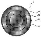
- FIG. 1 is a cross-sectional view showing an example of the structure of the optical fiber colored core wire 1.
- FIG. 2 is a cross-sectional view showing another example of the structure of the optical fiber colored core wire 1.
- 1 and 2 1 is an optical fiber colored core wire, 10 is an optical fiber, 11 is a primary coating layer, 12 is a secondary coating layer, 12a is a colored secondary coating layer (FIG. 2 only), 13 is Colored layers (FIG. 1 only) are shown respectively.
- a primary coating layer 11 (primary layer) around an optical fiber 10 such as a glass optical fiber
- a secondary coating layer 12 (secondary layer) around the primary coating layer 11, and a secondary coating layer.
- a colored layer 13 colored around 12 is formed in this order, and constitutes the optical fiber colored core wire 1.
- the colored layer 13 is the outermost layer of the optical fiber colored core wire 1.
- a primary coating layer 11 and a secondary coating layer 12a colored around the primary coating layer 11 are formed around the optical fiber 10 in this order.
- the colored secondary coating layer 12 a is the outermost layer of the optical fiber colored core wire 1.
- the colored layer 13 that is the outermost layer of the optical fiber colored core wire 1 and the colored secondary coating layer 12a may be combined to form the colored layer 13 or the like.
- FIG. 3 is a front view showing an aspect of the optical fiber ribbon 2.
- 4 and 5 are diagrams showing the connection state of the optical fiber ribbon 2 (FIG. 4 is a cross-sectional view taken along the line AA in FIG. 3 including the intermittent connection portion 31, and FIG. Is a cross-sectional view taken along the line BB of FIG. 3 to 5 show an optical fiber ribbon 2 composed of 12 optical fiber colored cores 1 for convenience.
- the intermittently connected optical fiber tape core 2 is an optical fiber colored core wire 1 arranged in parallel. It is also called intermittent connection in the length direction.
- the connecting portion intermittent connecting portion 3
- the optical fiber colored core wires 1 can be connected and integrated.
- a pair of optical fiber colored cores t1 composed of the optical fiber colored core 1a and the optical fiber colored core 1b is lengthened by the intermittent connecting portion 31. (See FIG. 3).
- adjacent intermittent connection portions 31 can be provided at equal intervals, and the lengths of the intermittent connection portions 31 can also be made equal.
- optical fiber colored core wire pair t3 consisting of optical fiber colored core wire 1c and optical fiber colored core wire 1d
- optical fiber colored core wire pair t5 consisting of optical fiber colored core wire 1e and optical fiber colored core wire 1f
- An optical fiber colored core pair t7 composed of an optical fiber colored core 1g and an optical fiber colored core 1h
- an optical fiber colored core t9 composed of an optical fiber colored core 1i and an optical fiber colored core 1j
- an optical fiber colored core is the same applies to the optical fiber colored core pair t11 including the line 1k and the optical fiber colored core 1l.
- intermittent coupling portions 31 are provided so that the arrangement in the tape width direction is the same (see FIG. 3). ). Therefore, the non-connected portion (single-core portion where the intermittently connected portion 3 is not formed) of the six pairs of optical fiber colored core wires t1, t3, t5, t7, t9, and t11 is shown in FIG.
- the portion surrounded by the dotted line.) 33 is also a common position when viewed from the tape width direction.
- the optical fiber colored core wire pair t2 composed of the optical fiber colored core wire 1b and the optical fiber colored core wire 1c is intermittently connected in the length direction by the intermittent connecting portion 32.
- the adjacent intermittent connection parts 32 can be provided at equal intervals, and the lengths of the intermittent connection parts 32 can also be made equal.
- optical fiber colored core wire pair t6 consisting of optical fiber colored core wire 1d and optical fiber colored core wire 1e
- optical fiber colored core wire pair t6 consisting of optical fiber colored core wire 1f and optical fiber colored core wire 1g
- optical fiber colored core wire t8 composed of the optical fiber colored core wire 1h and the optical fiber colored core wire 1i
- optical fiber colored core wire pair t10 composed of the optical fiber colored core wire 1j and the optical fiber colored core wire 1k.
- intermittent coupling portions 32 are provided so that the arrangement in the tape width direction is the same. Therefore, the unconnected portions 33 of the five pairs of optical fiber colored cores t2, t4, t6, t8, and t10 are also in a common position when viewed from the tape width direction.
- the intermittently connected optical fiber ribbon 2 is not separated from the intermittently connected portions 31 and 32 in the length direction and the tape width direction with respect to the adjacent two (two) optical fiber colored cores 1.
- the connecting portions 33 are formed so as to be alternately arranged with a predetermined length, and the adjacent optical fiber colored core wires 1 are intermittently connected in the length direction by the intermittent connecting portion 3 (for example, FIG. 3).
- An optical fiber colored core wire t1 composed of the optical fiber colored core wire 1a and the optical fiber colored core wire 1b, an optical fiber colored core wire pair t2 composed of the optical fiber colored core wire 1b and the optical fiber colored core wire 1c, etc. reference.).
- intermittent pairs of optical fiber colored core pairs t1 to t11 composed of two adjacent cores (two) formed with intermittent coupling portions 31 and 32 are formed. Both sides (outside) in the tape width direction of the portion where the connecting portion 3 is formed are not connected (for example, from the optical fiber colored core 1c and the optical fiber colored core 1d shown in FIG. 4).
- the optical fiber colored core pair t3 is formed with an intermittent coupling portion 31 that couples the two optical fiber colored core wires 1c and 1d, while a portion in which the intermittent coupling portion 3 is formed in the tape width direction. Both sides (outside) are not connected.
- the length L1 of the intermittent connection portions 31 and 32 in the optical fiber ribbon 2 is preferably about 5 to 35 mm, and the length of the non-connection portion 33 is The length L2 is preferably about 5 to 15 mm.
- the pitch P in the optical fiber ribbon 2 indicates the length of the intermittent connection part 31 to the intermittent connection part 31 (or the intermittent connection part 32 to the intermittent connection part 32) adjacent in the length direction.
- the portion 31 to the intermittently connected portion 31) is preferably 100 mm or less, and generally preferably 20 to 90 mm, but is not particularly limited to this range.
- the non-connecting portion refers to a single core portion (single core portion) where the intermittent connecting portion 3 is not formed.
- X shown in FIG. 3 is also a non-connecting portion (non-connecting portion X having a length LX).
- LX of the pair of optical fiber colored core wires is LX.
- the thickness is preferably 15 to 55 mm, but is not particularly limited to this range.
- the intermittently connecting portion 3 shown in FIG. 3 and the like can be formed by curing the following components, for example.
- the component constituting the intermittent connection portion 3 includes a polyol having a weight average molecular weight (M w ) of 2500 to 4000.
- the polyol having such a weight average molecular weight (hereinafter sometimes simply referred to as “molecular weight”) can exist without reacting with the network of the ultraviolet curable resin constituting the intermittent connection portion 3.
- the intermittent connection part 3 is that the polyol is swollen in the dense network structure of the ultraviolet curable resin, and plays a role of a plasticizer for the ultraviolet curable resin.
- the Young's modulus of the intermittent connection part 3 moderate, flexibility and elongation can be provided to the intermittent connection part 3 also under low temperature conditions. Further, the polyol can bleed on the surface of the intermittent connection portion 3 to suppress friction between the optical fiber units 21.
- the weight average molecular weight of the polyol is in the above-described range, it is considered that the molecular weight of the colored layer 13 of the optical fiber colored core wire 1 is larger, so that the colored layer 13 does not pass through the mesh and does not move.
- the molecular weight of the polyol is as large as 2500 to 4000, it is possible to control the Young's modulus of the intermittent connection portion 3 by increasing the polyol content. As described above, the presence of the polyol in the intermittent connection portion 3 can impart flexibility and elongation to the intermittent connection portion 3 even under a low temperature condition, and the polyol bleeds on the surface of the intermittent connection portion 3. The friction between the optical fiber units 21 can be suppressed.
- polyol examples include polypropylene glycol, polyethylene glycol, and polytetramethylene glycol.
- those having no branched structure such as polyethylene glycol and polytetramethylene glycol are crystallized at low temperatures. There is a case where bending due to crystals occurs at the interface between the colored layer 13 and the intermittent coupling portion 3 and causes an increase in loss.
- polypropylene glycol having a branched structure does not crystallize even at a low temperature of ⁇ 60 ° C., and the above-described effects of the polyol can be reliably obtained. Therefore, it is preferable to use polypropylene glycol as the polyol.
- Polypropylene glycol is produced by addition polymerization of polypropylene oxide (PO) to polyfunctional alcohol using an alkali catalyst, but ethylene oxide (EO) may be added and used to enhance the reaction, but ethylene oxide is added. Then, since hydrophilicity becomes high, it is preferable to use only polypropylene oxide (PO) as an additional substance.
- PO polypropylene oxide
- EO ethylene oxide
- the weight average molecular weight of the polyol contained in the intermittent connection part 3 is 2500 to 4000.
- the weight average molecular weight of the polyol is smaller than 2500, the polyol may migrate through the colored layer 13 in contact with the intermittent connection portion 3.
- it when it is set as the optical fiber cable 4, it may transfer to the buffer layer and coating layer (sheath) of the optical fiber cable which touches the intermittent connection part 3. Due to such a migration of polyol, the above-described effects may not be achieved.
- the viscosity increases when mixed with the ultraviolet curable resin, so that the coating amount when applying the intermittent connection part 3 at the time of manufacture is lowered, resulting in poor adhesion.
- the viscosity can be lowered by increasing the heating temperature or the like.
- the heating temperature is increased, the amount of resin at the time of application tends to increase, and the thickness of the intermittent connection portion 3 increases. It may be a factor.
- stringing may occur between the intermittently connected portion and the roll portion, which may be a factor that contaminates the surroundings.
- the content of the polyol contained in the intermittent connection part 3 is preferably 4 to 30% by mass with respect to the entire intermittent connection part 3 (the whole components constituting the intermittent connection part 3).
- the content of polyol relative to the entire intermittent connection portion 3 is less than 4% by mass, the flexibility and elongation when unitized are insufficient, and the risk of cracking of the intermittent connection portion 3 is increased when ironing is applied. There is.
- the content exceeds 30% by mass, the viscosity decreases, which may cause application failure or cause scattering from the roll.
- the polyol content is preferably 4 to 30% by mass with respect to the entire intermittently connected portion 3.
- UV curable resin that coats the optical fiber and components generally used as an additive component thereof can be used.
- oligomers, dilutions, and the like can be used.
- Monomers, photoinitiators, silane coupling agents, sensitizers, pigments, fillers, and other various additives can be used.
- the oligomer for example, polyether urethane acrylate, epoxy acrylate, polyester acrylate, silicone acrylate and the like can be used. These may be used alone or in combination of two or more.
- the Young's modulus and the glass transition temperature (Tg) of the intermittently connected portion 3 as a whole can be adjusted by the skeleton structure and molecular weight of the oligomer, and the type and added amount of the diluted monomer described later. As will be described later, the Young's modulus can be adjusted by reducing the molecular weight of the oligomer or increasing the functional group of the monomer.
- polyether-type urethane acrylate as an oligomer
- a polyol such as polypropylene glycol, polyethylene glycol, or polytetramethylene glycol
- a polypropylene glycol having a branched structure can be used.
- Hydroxy compound having an unsaturated double bond that is reactive to ultraviolet rays via an aromatic diisocyanate at the hydroxyl groups at both ends as a skeletal component preferably using such polypropylene glycol as an intermediate block It is preferable to use an oligomer in which is bound.
- polypropylene glycol as a polyol and using an oligomer having polypropylene glycol as an intermediate block as an oligomer, crystallization at a low temperature of ⁇ 60 ° C. does not cause crystallization, so that crystallization at a low temperature can be efficiently prevented.
- the oligomer to be used those having a weight average molecular weight of 500 to 2000 are preferred, and those having a weight average molecular weight of 1000 to 2000 are particularly preferred.
- aromatic diisocyanates such as tolylene diisocyanate (TDI) and isophorone diisocyanate (IPDI) can be used.
- TDI tolylene diisocyanate
- IPDI isophorone diisocyanate
- a hydroxy type compound such as hydroxyethyl acrylate (HEA) etc. can be used, for example.
- a dilution monomer can be blended mainly for viscosity adjustment within a range that does not interfere with the purpose and effect of addition of cellulose nanofiber described later.
- a dilution monomer a monofunctional monomer, a bifunctional monomer, a polyfunctional monomer, etc. can be used, for example.
- dilutable monomers for example, PO-modified nonylphenol acrylate, isobornyl acrylate, 2-ethylhexyl acrylate, isononyl acrylate, isodecyl acrylate, polyethylene glycol acrylate, N-vinyl pyrrolidone, N-vinyl Examples include caprolactam and lauryl acrylate.
- Bifunctional and polyfunctional monomers include 1,6-hexanediol diacrylate, bisphenol A epoxy acrylate, tripropylene glycol diacrylate, tricyclodecane dimethylol diacrylate, EO-modified bisphenol A diacrylate, and hexanediol diacrylate.
- An acrylate etc. are mentioned. One of these may be used alone, or two or more thereof may be used in combination. Note that the monofunctional monomer has a greater effect of lowering the Young's modulus than the bifunctional monomer and the polyfunctional monomer. This is because the monofunctional monomer has a greater effect of reducing the crosslinking points in the molecular structure than the bifunctional monomer and the polyfunctional monomer.
- the photoinitiator is radicalized by absorbing ultraviolet rays, and can continuously polymerize the unsaturated double bond of the reactive oligomer and reactive monomer.
- the photoinitiator include alkylphenone photopolymerization initiators and acylphosphine oxide photopolymerization initiators such as 1-hydroxy-cyclohexyl-phenyl-ketone and 2-hydroxy-2-methyl-1-phenyl-propane- 1-one, 2,4,6-trimethylbenzoyl-diphenyl-phosphine oxide, bis (2,4,6-trimethylbenzoyl) -phenylphosphine oxide, and the like can be used. These may be used individually by 1 type, or can be used in combination of 2 or more type.
- triplet sensitizers such as thioxanthones and benzophenones are suitable, and in particular, thioxanthone has a long effect in the triplet state and can be used in combination.
- cellulose nanofibers are added as constituent components.
- Cellulose nanofibers are fine fibrous cellulose (cellulose fine fibers), have mechanical properties comparable to steel, etc., and have a nanostructure with a diameter in the range of several nanometers to several hundred nanometers. It is attracting attention as an additive to materials.
- Such a cellulose nanofiber has an effect of making the viscosity relatively high in a low shear rate region by adding to the material constituting the intermittent connection part 3 (referring to an ultraviolet curable resin composition). Furthermore, there is an effect of reducing the inclination with respect to the temperature dependence.
- Cellulose nanofibers added to and dispersed in the material (ultraviolet curable resin composition) constituting the intermittent connection portion 3 can be obtained, for example, by dispersing cellulose fibers that are aggregates of cellulose fine fibers that are microfibrils. .
- cellulose nanofibers are bundled into multiple bundles to take a higher order structure, and the strong cohesion between microfibrils is weakened by treatment such as high-pressure dispersion, and is dispersed and refined to nano-sized fibers It is.
- Cellulose nanofibers in the state of cellulose fibers that are aggregates, are bound together by hydrogen bonds, and in order to take out the fine fibers (cellulose nanofibers), the microfibrils are separated by breaking the hydrogen bonds. (Defibration) needs to be done.
- a method of fibrillating cellulose nanofibers (cellulose fine fibers) for separating (defibrating) such microfibrils for example, mechanical defibrating methods with intense physical force, phosphate esterification methods
- the fiber can be defibrated by a chemical defibrating method such as a TEMPO oxidation method (TEMPO catalytic oxidation method), a water collision method such as a water jet method, an underwater counter collision method (ACC method), or the like.
- TEMPO catalytic oxidation method TEMPO catalytic oxidation method
- ACC method underwater counter collision method
- cellulose nanofibers obtained as a mechanical defibrating method for example, fiber raw materials (pulp, cellulose powder, etc., hereinafter may be simply referred to as “pulp etc.”) are homogenizers (high pressure homogenizer, high pressure homogenizer).
- homogenizers high pressure homogenizer, high pressure homogenizer.
- Cellulose nanofibers obtained by microfibrillation with a pulverization device fiber raw materials (pulp, etc.), cellulose nanofibers, fiber raw materials (pulp, etc.) obtained by microfibrillation with a stone mill type friction machine (grinder, grinding machine, etc.)
- a refiner conical refiner, disc refiner, etc.
- the size (number average major axis diameter) of cellulose nanofibers obtained by pulverizing cellulose fiber materials as described above to nanosize by using a homogenizer, a grinder, or a stone mill type pulverizer is approximately 0. 0.005 ⁇ m to 10 ⁇ m is preferable, 0.007 ⁇ m to 1 ⁇ m is more preferable, and 0.010 ⁇ m to 0.1 ⁇ m is more preferable.
- plant-derived fibrous cellulose is preferable, and fine plant-derived fibrous cellulose (powdered pulp) is particularly preferable.
- Pulp which is a raw material for fibers, is also a raw material for paper, and is mainly composed of a temporary canal extracted from plants. From a chemical point of view, the main component is a polysaccharide and the main component is cellulose.
- the plant-derived fibrous cellulose is not particularly limited.
- wood, bamboo, hemp, jute, kenaf, crop residue for example, straw such as wheat and rice, corn, stems such as cotton, Sugarcane, etc.
- cloth, recycled pulp and those derived from plants such as waste paper, but wood or wood-derived ones are preferred, and kraft pulp is particularly preferred.
- Kraft pulp is a general term for pulp obtained by removing lignin / hemicellulose from wood or plant raw materials by chemical treatment such as caustic soda, and taking out nearly pure cellulose.
- the fiber raw material of a cellulose nanofiber may be used individually by 1 type, and can be used in combination of 2 or more type.
- the content of the cellulose nanofiber is set to 0.01 to 10.0% by mass with respect to the entire intermittent connection portion 3 (the entire components constituting the intermittent connection portion 3).
- the content of the cellulose nanofiber is smaller than 0.01% by mass, the above effect may not be stably imparted.
- the content exceeds 10.0% by mass the curing behavior of the ultraviolet curable resin, etc. May have an adverse effect on the various characteristics of the material, and the scattering of the material during production may not be suppressed.
- the content of the cellulose nanofiber is 0.01 to 10.0% by mass with respect to the entire intermittent connection portion 3, and more preferably 0.1 to 5.0% by mass. Furthermore, 0.1 to 2.0% by mass is particularly preferable.
- cellulose nanofibers may be hydrophobic or hydrophilic, it is preferable to use hydrophobic cellulose nanofibers.
- hydrophobic cellulose nanofibers when added to the ultraviolet curable resin composition constituting the intermittent connection portion 3, the mixing property becomes good and the material is evenly dispersed.
- the viscosity at a shear rate of 10 1 1 / s determined from dynamic viscoelasticity at 25 ° C. which is generally considered to be a low shear rate region, is preferably in the range of 2.0 to 8.2 Pa ⁇ s. If the viscosity is within the range, scattering of the material at the time of production can be suppressed, and the amount of application to the optical fiber colored core can be stabilized. Further, such scattering and the like can be stably maintained even at high speed manufacturing.
- the viscosity of the material which comprises the above-mentioned intermittent connection part 3 can be measured using the commercially available viscosity measuring apparatus (rheometer), for example, using rheometer MCR301 (made by Anton Paar) etc. it can.
- the adhesive strength between the optical fiber colored core wire 1 and the intermittent connection portion 3 is preferably 0.1 N or more. As long as the adhesive strength is within a range, the above-described effects are efficiently exhibited, and the optical fiber colored core wire 1 and the intermittent connection portion 3 are appropriately bonded (adhered).
- the adhesive strength is more preferably 0.1 to 0.25N, and particularly preferably 0.1 to 0.23N. As long as the adhesive strength is within the range, the optical fiber colored core wire 1 and the intermittent connection portion 3 are appropriately bonded (contacted), and the separation (working) property of the optical fiber colored core wire 1 can be maintained. .
- the amount of resin applied to the intermittent connection portion 3 is controlled by the resin pressure at the time of manufacture (the same as the application pressure; the same shall apply hereinafter), and adhesion is performed as the resin amount of the intermittent connection portion 3 decreases (adhesion surface becomes smaller).
- the strength is reduced, if the resin is applied so as to be higher than the colored optical fiber 1, the optical fiber adjacent to the optical fiber 2 is folded when the optical fiber ribbon 2 is folded and densified into a cable. There may be a problem that the tape core wire 2 hits to cause macrobending (increase in transmission loss) or the intermittent connection portion 3 is broken.
- the adhesive strength is excessively high, separation (working) property cannot be ensured, so that the resin constituting the intermittent connection portion 3 is applied to the extent that the height between the two optical fiber colored cores 1 is not exceeded. This is preferable because macrobending can be suppressed.
- Bond strength and separability (working) are often influenced by the length of the interface (length of the bonded portion) where one optical fiber colored core wire 1 and the intermittently connected portion 3 are in contact.
- the length of the bonded portion is appropriately determined depending on the material constituting the intermittent connecting portion 3, the shape of the intermittent connecting portion 3, and the like, but is preferably about 5 to 35 mm, and the length of the bonded portion is within such a range. As a result, both good adhesive strength and separation (working) properties are secured.
- the type or the like of the material is appropriately selected by using the materials described above or later as the intermittent connection portion 3. Then, it is carried out by adjusting the resin pressure of the resin, the length of the bonded portion, the ultraviolet curing conditions such as the irradiation amount, and the like.
- the adhesive strength between the optical fiber colored core wire 1 and the intermittent connection portion can be measured, for example, as follows.
- the two optical fiber colored cores 1 formed with the intermittent connection part 3 are taken out, and the optical fiber colored cores 1 are fixed to the upper part of the tensile tester, and ⁇ 0 is placed between the two optical fiber colored cores 1.
- the resin material (ultraviolet curable resin composition) constituting the intermittent connection portion 3 includes the following additives, for example, light stabilizers such as antioxidants, ultraviolet absorbers, hindered amine light stabilizers, Deterioration inhibitors such as thermal polymerization inhibitors, silane coupling agents, leveling agents, hydrogen absorbers, chain transfer agents, silicones, lubricants, etc. may be added as necessary within the range that does not interfere with the purpose and effect of the present invention. it can.
- light stabilizers such as antioxidants, ultraviolet absorbers, hindered amine light stabilizers
- Deterioration inhibitors such as thermal polymerization inhibitors, silane coupling agents, leveling agents, hydrogen absorbers, chain transfer agents, silicones, lubricants, etc. may be added as necessary within the range that does not interfere with the purpose and effect of the present invention. it can.
- the intermittent connection part 3 may be colored.
- the pigment that is added when coloring the intermittent connection portion 3 include organic pigments such as phthalocyanine, quinacridone, dioxan, and Bensui imidazolone, and inorganic pigments such as carbon black and titanium oxide.
- the content of the colorant may be appropriately determined depending on the material constituting the intermittent connection part 3, the content of the pigment contained in the colorant, the type of other components such as an ultraviolet curable resin, and the like.
- the content is preferably 0.5 to 3.0% by mass, particularly preferably 1.5 to 2.5% by mass with respect to the whole.
- adhesion confirmation of the intermittent connection part 3 and the optical fiber tape core 2 can be performed continuously in a production line. .
- the material include the ultraviolet curable resin and its additives listed as the components constituting the intermittent connection part 3 described above, for example, oligomer, dilution monomer, photoinitiator, silane coupling agent, sensitizer, pigment (and Components such as the above-mentioned various additives such as a coloring material obtained by mixing a pigment and an ultraviolet curable resin, a lubricant, and the like can be preferably used.
- the oligomer for example, as the primary coating layer 11 and the secondary coating layer 12, aromatic isocyanate and hydroxyethyl acrylate are added to a polyol using polypropylene glycol, which is the same as that constituting the intermittent connection portion 3 described above. It is preferable to use the above oligomer, and the Young's modulus can be adjusted by changing the molecular weight of the polyol (polypropylene glycol) in the intermediate block.
- the weight average molecular weight of the oligomer used is preferably 1000 to 4000 when used as the primary coating layer 11, and 500 to 2000 when used as the secondary coating layer 12. It is preferable to use 500 to 2000 when used as the colored layer 13, and 500 to 2000 when used as the colored secondary coating layer 12a. Is preferred.
- the primary coating layer 11 and the secondary coating layer 12 are not crystallized even at a low temperature of ⁇ 60 ° C. by using polypropylene glycol as a polyol and an oligomer having polypropylene glycol as an intermediate block as an oligomer. Therefore, crystallization at low temperatures can be efficiently prevented.
- aromatic isocyanate for example, aromatic diisocyanates such as tolylene diisocyanate (TDI) and isophorone diisocyanate (IPDI) can be used.
- TDI tolylene diisocyanate
- IPDI isophorone diisocyanate
- HOA hydroxyethyl acrylate
- a dilution monomer can be blended mainly for viscosity adjustment.
- a monofunctional monomer for example, PO-modified nonylphenol acrylate, isobornyl acrylate, 2-ethylhexyl acrylate, isononyl acrylate, isodecyl acrylate, polyethylene glycol acrylate, N-vinyl pyrrolidone, N-vinyl Examples include caprolactam.
- bifunctional monomer and polyfunctional monomer examples include 1,6-hexanediol diacrylate, bisphenol A epoxy acrylate, tripropylene glycol diacrylate, tricyclodecane dimethylol diacrylate, and the like. One of these may be used alone, or two or more thereof may be used in combination.
- the monofunctional monomer has a greater effect of lowering the Young's modulus than the bifunctional monomer and the polyfunctional monomer. This is because the monofunctional monomer has a greater effect of reducing the crosslinking points in the molecular structure than the bifunctional monomer and the polyfunctional monomer.
- the photoinitiator absorbs ultraviolet rays, the photoinitiator is radicalized, and the unsaturated double bond of the reactive oligomer and the reactive monomer can be continuously polymerized.
- the photoinitiator for example, an alkylphenone photopolymerization initiator or an acyl phosphine oxide photopolymerization initiator can be used. These may be used individually by 1 type, or can be used in combination of 2 or more type.
- the oligomer which comprises the colored layer 13 the oligomer which added the aromatic isocyanate and hydroxyethyl acrylate to the polyol which uses polypropylene glycol similarly to the above-mentioned primary coating layer 11 and the secondary coating layer 12 is used. It is preferable that the Young's modulus can be adjusted by changing the molecular weight of the polyol (polypropylene glycol) in the intermediate block, or by using a bifunctional monomer or a polyfunctional monomer.
- urethane acrylate or hydroxypivalic acid neopentyl glycol acrylic acid adduct can be used as the resin constituting the colored layer 13, and in addition, bisphenol A epoxy acrylate or the like can be added to make the resin strong. Can raise the sex.
- the colored secondary coating layer 12a also serves as the colored layer 13
- the colored secondary coating layer 12a may be used as these components.
- the oligomer it is preferable to use an oligomer obtained by adding aromatic isocyanate and hydroxyethyl acrylate to a polyol using polypropylene glycol, and changing the molecular weight of the middle block polyol (polypropylene glycol)
- the Young's modulus can be adjusted by using a bifunctional monomer or a polyfunctional monomer.
- a bifunctional monomer or a polyfunctional monomer for example, by adding bisphenol A epoxy acrylate or the like as an oligomer, toughness can be increased, and further, urethane acrylate or hydroxypivalate neopentyl glycol acrylic acid adduct can be used.
- a both-end-type acrylic-modified silicone, one-end-type acrylic-modified silicone, a side-chain-end acrylic-modified silicone, or the like can be used.
- the photoinitiator include 2-methyl-1- (4-methylthiophenyl) -2-morpholinopropan-1-one, 2-benzyl-2-dimethylamino-1- (4-morpholinophenyl)- Butanone-1,2,4-diethylthioxanthone, 2,4,6-trimethylbenzoyl-diphenyl-phosphine oxide, 1-hydroxy-cyclohexyl-phenyl-ketone and the like can be used.
- each layer in the optical fiber colored core wire 1 is generally 80 ⁇ m to 125 ⁇ m and the outer diameter of the primary coating layer 11 in order to maintain the characteristics as an optical fiber (see below). Is preferably 120 ⁇ m to 200 ⁇ m, the outer diameter of the secondary coating layer 12 is 160 ⁇ m to 242 ⁇ m, and the outer diameter of the colored layer 13 is preferably 173 ⁇ m to 255 ⁇ m. As shown in FIG. 2, when the secondary coating layer 12 also serves as the colored layer 13, the colored secondary coating layer 12a preferably has an outer diameter in the range of 160 ⁇ m to 255 ⁇ m. .
- (V) Manufacturing method of optical fiber ribbon 2 An example of the manufacturing method of the optical fiber ribbon 2 according to the present invention will be described.
- the glass optical fiber 10 will be described as an example of the optical fiber 10
- an optical fiber made of quartz glass (glass optical fiber 10) coated with the primary coating layer 11 and the secondary coating layer 12 will be described as an optical fiber. It is called a strand.
- the optical fiber colored core wire 1 In order to manufacture the optical fiber colored core wire 1, for example, first, a preform mainly composed of quartz glass is heated and melted in a drawing furnace to obtain a quartz glass optical fiber (glass optical fiber 10). Next, a component containing a liquid ultraviolet curable resin is applied to the glass optical fiber 10 using a coating die, and then ultraviolet rays are applied to the component containing the ultraviolet curable resin applied by the ultraviolet irradiation device (UV irradiation device). Irradiate to cure such components. In this way, an optical fiber strand in which the glass optical fiber 10 is coated with the primary coating layer 11 and the secondary coating layer 12 is manufactured. Immediately after drawing, the outer periphery of the glass optical fiber 10 is immediately coated with a component containing an ultraviolet curable resin to form the primary coating layer 11 and the secondary coating layer 12, thereby preventing a reduction in strength of the obtained optical fiber. Can do.
- UV irradiation device ultraviolet irradiation device
- the optical fiber colored core wire 1 is manufactured by covering the outer periphery of the obtained optical fiber with the colored layer 13.
- the secondary coating layer 12 may be colored to form the optical fiber colored core wire 1 as the secondary coating layer 12a in which the outermost layer is colored.
- the optical fiber colored cores 1 obtained are arranged in a desired number, the material constituting the intermittent connection part 3 is applied in a predetermined pattern, and cured under predetermined conditions to form the intermittent connection part 3.
- the optical fiber ribbon 2 can be obtained.
- the optical fiber ribbon 2 can be manufactured, for example, by aligning a plurality of optical fiber colored cores 1 in parallel and by intermittently applying the constituent material of the intermittent connection portion 3 to a part of the outer periphery. It can be carried out using a production apparatus provided with a coating roll 6 (see FIG. 6 and the like to be described later). For example, it can be carried out using a production apparatus and a production method disclosed in Japanese Patent No. 6169060. it can.
- a plurality of optical fiber colored cores 1 are brought into contact with the respective application rolls, and the constituent material of the intermittent connection portion 3 is intermittently applied to the side surfaces of the optical fiber colored cores 1, while the alignment means By aligning the side surfaces of the optical fiber colored core wire 1 coated with the material constituting the intermittent connection portion 3 on the side surfaces so as to contact each other, and curing the above-described constituent materials by ultraviolet irradiation or the like, the intermittent connection portion 3 What is necessary is just to connect the optical fiber colored core wires 1 intermittently and to obtain the optical fiber tape core wire 2.
- FIG. 6 is a view showing an example of the application roll 6.
- the application roll 6 shown in FIG. 6 employs a configuration in which the application roll 6 is sandwiched between a pair of V-groove rolls 7 in which V-grooves 71 are formed. 1 will come into contact.
- FIG. 7 is a perspective view showing another example of the application roll 6, and FIG. 8 is an enlarged view of the application hole 61 formed in the application roll 6 of FIG.
- the coating roll 6 shown in FIG. 7 is provided with the coating hole 61 shown in FIG. 8, and the coating hole 61 is not a single continuous long hole, but a plurality of small holes 62 arranged in a line. Composed. That is, the coating hole 61 is formed by continuously arranging a plurality of small holes 62 with a predetermined width and a predetermined length.
- the coating hole 61 having such a configuration By using the coating hole 61 having such a configuration, the extrusion amount of the material (ultraviolet curable resin) R constituting the intermittent connection portion is stabilized. Since each small hole 62 is independent in the application hole 61, a substantially constant material R is extruded from each small hole 62. Therefore, since a substantially constant amount of material R can be pushed out to the coating hole 61 (the range where the small holes 62 are formed), the amount of the material R applied to the optical fiber colored core wire 1 is stabilized. .
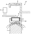
- FIG. 9 is a cross-sectional view showing the device D in the vicinity of the coating roll 6.
- the apparatus D shown in FIG. 9 employs a configuration in which the die 9 is pressed with a predetermined load in the vicinity of the coating roll 6 in the extrusion direction of the material R, and air is used as a member for holding the die 9.
- a cylinder 8 is provided.
- the die 9 is pressed by the air cylinder 8 with a constant load toward the application side of the material R to the optical fiber colored core wire 1 that is in contact with the V groove 71 of the V groove roll 7.
- the material R is applied from the application hole 61.
- an elastic member such as a spring may be provided.
- the optical fiber ribbon 2 according to the present invention described above contains a polyol having a weight average molecular weight of 2500 to 4000 with respect to the material (ultraviolet curable resin composition) constituting the intermittent connection portion 3, It is set as the structure containing a cellulose nanofiber in the specific range.
- the scattering of the material can be suppressed by the centrifugal force generated with the rotation of the coating roll 6 or the like that applies the material at the time of manufacture, and the coating amount on the optical fiber colored core wire 1 can be stabilized. And it becomes the optical fiber tape core wire 2 which can maintain suppression of this scattering etc. even in the manufacture which made the linear velocity high.
- optical fiber cable 4 provided with the optical fiber ribbon 2 according to the present invention enjoys the effect of the optical fiber ribbon 2 described above. That is, the scattering of the material by the coating roll 6 etc. at the time of manufacture of the intermittent connection part 3 can be suppressed, the coating amount to the optical fiber colored core wire 1 can be stabilized, and the line speed can be increased to suppress such scattering.
- An optical fiber cable 4 having an optical fiber ribbon 2 that can be maintained even during manufacture is provided.
- FIG. 10 is a diagram illustrating an aspect of the optical fiber cable 4.
- a predetermined number (25 in FIG. 10) of optical fiber units 21 obtained by twisting or bundling a predetermined number (8 in FIG. 10) of optical fiber tape cores 2 having a predetermined number of cores are twisted or bundled.
- the cable core 41 is configured.
- a buffer layer 42 made of, for example, a non-woven presser tape or the like is formed around the cable core 41.
- two steel wires (tension members) 43 and two tear strings 44 are formed around the buffer layer 42.
- a covering layer (sheath) 46 made of a thermoplastic resin or the like is formed.
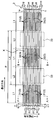
- FIG. 11 is a diagram showing another aspect of the optical fiber cable 4.
- the optical fiber cable 4 in FIG. 11 has a predetermined number of optical fiber units 21 formed by twisting or bundling a predetermined number of optical fiber ribbons 2 (not shown in FIG. 11) with a predetermined number of cores.
- the loose tube 5 is incorporated in a twisted or bundled state, and the optical fiber unit 21 and the loose tube 5 incorporating the optical fiber unit 21 are arranged around a steel wire (tension member) 43 in a predetermined number. (8 in FIG. 11) Twist together.
- a buffer layer 42 made of, for example, a non-woven presser tape or the like is formed around the periphery, and a predetermined number (15 in FIG. 11) of optical fiber units 21 and loose tubes 5 containing the optical fiber units 21 are further provided around the buffer layer 42. ) Arrange and twist.
- a buffer layer 42 made of, for example, a non-woven presser tape and a coating layer (sheath) 46 made of a thermoplastic resin are formed around the periphery.
- FIGS. 10 and 11 For convenience, the hatching of the optical fiber ribbon 2 in FIG. 10 and the optical fiber unit 21 in FIG. 11 is omitted in FIGS. 10 and 11. Moreover, about the code
- the optical fiber cable 4 may be an optical fiber cable such as a center tube type, a loose tube type, or a slot type, and is not particularly limited as long as the optical fiber cable accommodates the optical fiber ribbon 2.
- the coating layer 46 can be, for example, 2.0 to 3.0 mm, but is not particularly limited to this range.
- the configuration of the 12 fibers shown in FIGS. 3 to 5 has been described as an example of the optical fiber ribbon 2, but the number of cores in the optical fiber ribbon 2 (optical fiber coloring) is described.
- the number of cores 1) can be arbitrarily determined in addition to 12 cores, such as 4 cores, 8 cores, and 24 cores.
- the cross-sectional shape of the intermittent connection part 3 although the 2 sides which contact
- the structure shown in FIGS. 10 and 11 has been described as an example of the optical fiber cable 4 including the optical fiber ribbon 2, but the structure of the optical fiber cable 4 is described above.
- the type and thickness of the coating layer 46, the number and size of the optical fiber colored core wire 1 and the optical fiber tape core wire 2, the number and size of the optical fiber units 21, and the optical fiber The number of optical fiber ribbons 2 in the unit 21, the type, number and size of steel wires (tension members) 43, the type and thickness of the buffer layer 42, and the number of layers can be freely selected. .
- the outer diameter, cross-sectional shape, etc. of the optical fiber cable 4 can be freely selected.
- the specific structure, shape, and the like in the implementation of the present invention may be other structures as long as the object of the present invention can be achieved.
- optical fiber colored core wires shown in FIGS. 1 and 2 were provided by the methods shown in (1) and (2) below, as shown in FIGS.
- An optical fiber ribbon having the configuration shown in FIG. 5 was manufactured.
- the molecular weight refers to “weight average molecular weight”.
- the following component was used about the primary coating layer, the secondary coating layer, the colored layer, and the intermittent connection part.
- optical fiber colored core Around an optical fiber made of quartz glass and having an outer diameter of 125 ⁇ m, the outer diameter of the primary coating layer (primary layer) is 195 ⁇ m and the outer diameter of the secondary coating layer (secondary layer) is 242 ⁇ m. The layer was coated into an optical fiber. The obtained optical fiber is coated with a colored layer (the component that becomes the colored layer is component a) around the secondary coating layer in a separate process. An optical fiber colored core wire having a diameter of 255 ⁇ m was obtained.
- optical fiber colored core Around a glass optical fiber made of quartz glass having an outer diameter of 125 ⁇ m, which is an optical fiber, an outer diameter of the primary coating layer (primary layer) is 185 ⁇ m, and a colored secondary coating layer (with a colored secondary coating layer and The component is component b.) The outer diameter was 255 ⁇ m and each layer was coated to obtain an optical fiber colored core wire having an outer diameter of 255 ⁇ m having the configuration shown in FIG.
- the primary coating layer and the secondary coating layer are made of an oligomer using polypropylene glycol as an ultraviolet curable resin (polypropylene glycol as an intermediate block, and skeleton component having hydroxyethyl acrylate as a skeleton component via tolylene diisocyanate. Oligomer)), dilutable monomer, photoinitiator, and additives were mixed and used in appropriate amounts.
- Component a optical fiber colored core wire as shown in FIG. 1:
- the UV curable resin constituting component a (colorant component a) to be a colored layer uses urethane acrylate or bisphenol A epoxy acrylate as an oligomer, and a Young's modulus by adding a bifunctional monomer or a polyfunctional monomer as a monomer. Adjusted. Moreover, 3 mass% of both terminal type acrylic modified silicone was contained with respect to the whole colored layer.
- Photoinitiators are 2-methyl-1- (4-methylthiophenyl) -2-morpholinopropan-1-one (Irgacure 907), 2,4,6-trimethylbenzoyl-diphenyl-phosphine oxide (lucillin TPO), 2,4-Diethylthioxanthone (Kayacure DETX-S) was added.
- the oxygen concentration in the production was adjusted to 3 to 5%, and the ultraviolet irradiation amount was 80 mJ / cm 2 or less.
- Component b optical fiber colored core wire as shown in FIG. 2:
- the ultraviolet curable resin constituting component b (coloring material component b) to be a colored secondary coating layer (colored layer) is obtained by adding aromatic isocyanate and hydroxyethyl acrylate to a polyol using polypropylene glycol as an oligomer.
- the Young's modulus was adjusted by changing the molecular weight of the middle block polyol (polypropylene glycol) or by using a bifunctional monomer or a polyfunctional monomer.
- the material (ultraviolet curable resin composition) constituting the intermittent connection portion as the following material, 600 m / min as follows: (The speed at which the colored optical fiber is advanced; the same shall apply hereinafter) and a predetermined pattern (length of intermittently connected portion: 30 mm, length of non-connected portion: 10 mm, pitch length) was applied while adjusting the resin pressure (application pressure) to be 80 mm) and cured to form intermittently connected portions (and non-connected portions), thereby forming an optical fiber ribbon.
- the viscosity of the material constituting the intermittent connection portion was confirmed by the following method, and the presence or absence of material scattering in the application of the material constituting the intermittent connection portion was confirmed. . Furthermore, the adhesive strength between the optical fiber colored core wire and the intermittent connection portion was also measured.
- Base material used as a component of intermittent connection Oligomer as an ultraviolet curable resin (an oligomer in which a polypropylene glycol having a weight average molecular weight of 2000 is used as an intermediate block and hydroxyethyl acrylate is bonded to hydroxyl groups at both ends as a skeleton component via tolylene diisocyanate). Isobornyl acrylate and PO-modified nonylphenol acrylate were used as monofunctional monomers, and tricyclodecane dimethylol diacrylate and 1,6-hexanediol diacrylate were used as bifunctional monomers.
- photoinitiators 1-hydroxy-cyclohexyl-phenyl-ketone, 2,4,6-trimethylbenzoyl-diphenyl-phosphine oxide was used. Further, a suitable amount of hindered amine light stabilizer and silicone (weight average molecular weight: about 10,000) as light stabilizers were mixed as additives. A material composed of these components is used as a base material, and a polyol (cellulose curable resin composition) that constitutes an intermittently connected portion by adding the following polyols and cellulose nanofibers at a predetermined content (note that In Comparative Example 1, no cellulose nanofiber was added.)
- Example 1 Polypropylene glycol having a weight average molecular weight of 3000 as a polyol (PP3000: manufactured by Sanyo Chemical Industries, Ltd.) is used as the base material, and an ultraviolet curable resin composition (a material constituting the intermittent connection portion). In some cases.) 23 mass% of the total was added. Further, cellulose powder (KC Flock W-200: manufactured by Nippon Paper Chemicals Co., Ltd., powdered cellulose having an average particle diameter of about 32 ⁇ m) is defibrated with a homogenizer, and the size (number average major axis diameter) is 0.007 to 1 ⁇ m. (7 to 1000 nm) was used as cellulose nanofiber (hereinafter the same as in Examples 2 to 5 and Comparative Example 2), and the cellulose nanofiber was 0.01% by mass relative to the entire composition. Added.
- cellulose powder KC Flock W-200: manufactured by Nippon Paper Chemicals Co., Ltd., powdered cellulose having an average particle diameter of about 32
- Example 2 Polypropylene glycol having a weight average molecular weight of 3000 (PP3000: manufactured by Sanyo Chemical Industries, Ltd.) as a polyol was added to the base material in an amount of 23% by mass based on the entire composition. Moreover, 0.1 mass% of cellulose nanofiber was added with respect to the whole composition.
- PP3000 weight average molecular weight of 3000
- Example 3 Polypropylene glycol having a weight average molecular weight of 3000 (PP3000: manufactured by Sanyo Chemical Industries, Ltd.) as a polyol was added to the base material in an amount of 23% by mass based on the entire composition. Moreover, 1.0 mass% of cellulose nanofiber was added with respect to the whole composition.
- PP3000 weight average molecular weight of 3000
- Example 4 Polypropylene glycol having a weight average molecular weight of 3000 (PP3000: manufactured by Sanyo Chemical Industries, Ltd.) as a polyol was added to the base material in an amount of 23% by mass based on the entire composition. Moreover, the cellulose nanofiber was added 5.0 mass% with respect to the whole composition.
- PP3000 weight average molecular weight of 3000
- cellulose nanofiber was added 5.0 mass% with respect to the whole composition.
- Example 5 Polypropylene glycol having a weight average molecular weight of 3000 (PP3000: manufactured by Sanyo Chemical Industries, Ltd.) as a polyol was added to the base material in an amount of 23% by mass based on the entire composition. Moreover, 10.0 mass% of cellulose nanofibers were added with respect to the whole composition.
- PP3000 weight average molecular weight of 3000
- the viscosity was measured using a rheometer (MCR301: Anton Paar). The viscosity at a shear rate of 10 1 1 / s (viscosity 25 ° C. 10 ⁇ 1 1 / s) determined from dynamic viscoelasticity at 25 ⁇ parallel plate, gap 0.5 mm, 25 ° C. was determined.
- Table 1 shows the evaluation results. Examples 1 to 5 in which the intermittent connection part contains a polyol having a weight average molecular weight of 2500 to 4000 and the cellulose nanofiber is 0.01 to 10.0% by mass with respect to the entire intermittent connection part.
- material scattering confirmation even when the material scattering confirmation was performed at a linear speed of 600 m / min, it could be determined that the coating amount was stable, and the overall judgment was “ ⁇ ”.
- the material constituting the intermittent connection portion results of viscosity measured in (ultraviolet curable resin composition applied), the viscosity of the shear rate 10 1 1 / s to both determined from a dynamic viscoelasticity at 25 ° C. 2 It was within the range of 0.0 to 8.2 Pa ⁇ s.
- Comparative Example 1 that does not contain cellulose nanofibers in the entire intermittent connection part
- Comparative Example 2 that contains cellulose nanofibers in excess of 10.0% by mass with respect to the entire intermittent connection part
- the measurement results of the adhesive strength are also shown in Table 1.
- Examples 1 to 5 as a result of measuring the adhesive strength of the material constituting the intermittently connected portion of the optical fiber colored core wire (the UV curable resin composition to be applied), production of a high linear velocity (600 m / min) was performed. However, a high adhesive strength of 0.1 N or more was obtained.
- Comparative Example 1 shows a result of low adhesive strength (lower than 0.1N), and Comparative Example 2 does not follow the linear velocity, so that a satisfactory optical fiber ribbon cannot be produced, and adhesive strength is obtained.
- Comparative Example 1 shows a result of low adhesive strength (lower than 0.1N)
- Comparative Example 2 does not follow the linear velocity, so that a satisfactory optical fiber ribbon cannot be produced, and adhesive strength is obtained.
- adhesive strength is obtained.
- optical fiber cable 18 (or 36) optical fiber units in which 8 pieces of 12 optical fiber ribbons were twisted were twisted to form a cable core, and a nonwoven fabric holding tape was wound around it as a buffer layer. Furthermore, a coating layer was formed on the outer periphery of the buffer layer together with FRP of ⁇ 4 mm, two steel wires, and two tear strings. Regarding cable formation, a thermoplastic resin was coated as a coating layer (sheath) to form a cable.
- the optical fiber ribbon of the present invention could be cabled in the same manner as a conventional optical fiber ribbon and could be suitably used as an optical fiber cable.
- the present invention can be effectively used as a means for providing an optical fiber ribbon and an optical fiber cable that can prevent scattering of the material constituting the intermittent connection portion during manufacturing, and has high industrial applicability.
- Optical fiber colored core wire 10 ...
- Optical fiber (glass optical fiber) 11 Primary coating layer (primary layer) 12 ; Secondary coating layer (secondary layer) 12a: Colored secondary coating layer 13: Colored layer 2:
- Optical fiber tape core wire 21 Optical fiber unit 3: Intermittent connection part 31, 32: Intermittent connection part 33, X: Non-connection Part (single core) 4 ...
Abstract
Description
まず、光ファイバテープ心線2を構成する光ファイバ着色心線1の一態様を説明する。図1は、光ファイバ着色心線1の構造の一例を示した断面図である。また、図2は、光ファイバ着色心線1の構造の他の例を示した断面図である。図1及び図2中、1は光ファイバ着色心線、10は光ファイバ、11は一次被覆層、12は二次被覆層、12aは着色された二次被覆層(図2のみ)、13は着色層(図1のみ)、をそれぞれ示す。 (I) Structure of optical fiber colored core wire 1:
First, an aspect of the optical fiber colored
図3は、光ファイバテープ心線2の一態様を示した正面図である。図4及び図5は、光ファイバテープ心線2の連結状態を示した図(図4は間欠連結部31を含む図3のA-A断面図、図5は間欠連結部32を含む図3のB-B断面図である。)である。なお、図3ないし図5では、便宜的に、12心の光ファイバ着色心線1から構成される光ファイバテープ心線2を示している。 (II) Structure of the optical fiber ribbon 2:
FIG. 3 is a front view showing an aspect of the
前記した図3等に示した間欠連結部3は、例えば、下記の成分を硬化させて形成することができる。本発明において、間欠連結部3を構成する成分としては、重量平均分子量(Mw)が2500~4000のポリオールを含有する。かかる重量平均分子量(以下、単に「分子量」とすることもある。)のポリオールは、間欠連結部3を構成する紫外線硬化樹脂の網目に反応しないで存在することができる。間欠連結部3は、紫外線硬化樹脂の稠密な網目構造にポリオールが膨潤していることになり、紫外線硬化樹脂に対して可塑剤的な役割を果たす。これにより、間欠連結部3のヤング率を適度にさせるとともに、低温条件下でも間欠連結部3にしなやかさ及び伸びを付与することができる。また、ポリオールは、間欠連結部3の表面にブリードして、光ファイバユニット21同士の摩擦を抑えることができる。 (III) Intermittent connection part 3:
The intermittently connecting
本発明に係る光ファイバ着色心線1の一次被覆層11(プライマリ層)及び二次被覆層12(セカンダリ層)の構成材料となる樹脂材料や、光ファイバ着色心線1の着色層13の構成材料としては、前記した間欠連結部3を構成する成分として挙げた紫外線硬化樹脂及びその添加剤である、例えば、オリゴマー、希釈モノマー、光開始剤、シランカップリング剤、増感剤、顔料(及び顔料と紫外線硬化樹脂等を混合した着色材)、滑剤等、前記した各種の添加剤等の成分を好ましく使用することができる。 (IV)
The resin material used as the constituent material of the primary coating layer 11 (primary layer) and the secondary coating layer 12 (secondary layer) of the optical fiber
本発明に係る光ファイバテープ心線2の製造方法の一例を説明する。なお、以下において、光ファイバ10としてガラス光ファイバ10を例に挙げて説明し、一次被覆層11と二次被覆層12とが被覆された石英ガラス製光ファイバ(ガラス光ファイバ10)を光ファイバ素線とよんでいる。 (V) Manufacturing method of optical fiber ribbon 2:
An example of the manufacturing method of the
以上説明した本発明に係る光ファイバテープ心線2は、間欠連結部3を構成する材料(紫外線硬化樹脂組成物)に対して、重量平均分子量が2500~4000のポリオールを含有することに加え、セルロースナノファイバを特定の範囲で含有する構成としている。かかる構成により、製造時に当該材料を塗布する塗布ロール6等の回転に伴い生ずる遠心力により材料の飛散を抑え、光ファイバ着色心線1への塗布量を安定させることができる。かつ、かかる飛散の抑制等を、線速を高速とした製造でも維持することができる光ファイバテープ心線2となる。 (VI) Effects of the invention:
The
なお、以上説明した態様は、本発明の一態様を示したものであって、本発明は、前記した実施形態に限定されるものではなく、本発明の構成を備え、目的及び効果を達成できる範囲内での変形や改良が、本発明の内容に含まれるものであることはいうまでもない。また、本発明を実施する際における具体的な構造及び形状等は、本発明の目的及び効果を達成できる範囲内において、他の構造や形状等としても問題はない。本発明は前記した各実施形態に限定されるものではなく、本発明の目的を達成できる範囲での変形や改良は、本発明に含まれるものである。 (VII) Variation of embodiment:
The aspect described above shows one aspect of the present invention, and the present invention is not limited to the above-described embodiment, and has the configuration of the present invention and can achieve the objects and effects. It goes without saying that modifications and improvements within the scope are included in the content of the present invention. Further, the specific structure, shape, and the like in carrying out the present invention are not problematic as other structures, shapes, and the like as long as the objects and effects of the present invention can be achieved. The present invention is not limited to the above-described embodiments, and modifications and improvements within the scope that can achieve the object of the present invention are included in the present invention.
その他、本発明の実施の際の具体的な構造及び形状等は、本発明の目的を達成できる範囲で他の構造等としてもよい。 In the above-described embodiment, the structure shown in FIGS. 10 and 11 has been described as an example of the
In addition, the specific structure, shape, and the like in the implementation of the present invention may be other structures as long as the object of the present invention can be achieved.
表1に示した内容及び下記に示した成分を用いて、下記(1)、(2)に示した方法により、図1及び図2に示した光ファイバ着色心線を備えた、図3ないし図5に示した構成の光ファイバテープ心線を製造した。なお、下記の内容において、分子量とは「重量平均分子量」を指す。なお、一次被覆層、二次被覆層、着色層及び間欠連結部については、下記の成分を使用した。 Manufacture of optical fiber ribbons:
Using the contents shown in Table 1 and the components shown below, the optical fiber colored core wires shown in FIGS. 1 and 2 were provided by the methods shown in (1) and (2) below, as shown in FIGS. An optical fiber ribbon having the configuration shown in FIG. 5 was manufactured. In the following contents, the molecular weight refers to “weight average molecular weight”. In addition, the following component was used about the primary coating layer, the secondary coating layer, the colored layer, and the intermittent connection part.
光ファイバである、石英ガラスからなる外径が125μmのガラス光ファイバの周囲に、一次被覆層(プライマリ層)の外径を195μm、二次被覆層(セカンダリ層)の外径を242μmとしてそれぞれの層を被覆して光ファイバ素線とした。得られた光ファイバ素線に対して、別工程にて二次被覆層の周囲に着色層(着色層となる成分は成分aとした。)を被覆して、図1に示した構成の外径255μmの光ファイバ着色心線を得た。 (1) Production of optical fiber colored core:
Around an optical fiber made of quartz glass and having an outer diameter of 125 μm, the outer diameter of the primary coating layer (primary layer) is 195 μm and the outer diameter of the secondary coating layer (secondary layer) is 242 μm. The layer was coated into an optical fiber. The obtained optical fiber is coated with a colored layer (the component that becomes the colored layer is component a) around the secondary coating layer in a separate process. An optical fiber colored core wire having a diameter of 255 μm was obtained.
光ファイバである、石英ガラスからなる外径が125μmのガラス光ファイバの周囲に、一次被覆層(プライマリ層)の外径を185μm、着色された二次被覆層(着色された二次被覆層となる成分は成分bとした。)の外径を255μmとしてそれぞれの層を被覆して、図2に示した構成の外径255μmの光ファイバ着色心線を得た。 (2) Production of optical fiber colored core:
Around a glass optical fiber made of quartz glass having an outer diameter of 125 μm, which is an optical fiber, an outer diameter of the primary coating layer (primary layer) is 185 μm, and a colored secondary coating layer (with a colored secondary coating layer and The component is component b.) The outer diameter was 255 μm and each layer was coated to obtain an optical fiber colored core wire having an outer diameter of 255 μm having the configuration shown in FIG.
一次被覆層及び二次被覆層は、紫外線硬化樹脂としてポリプロピレングリコールを使用したオリゴマー(ポリプロピレングリコールを中間ブロックとし、骨格成分として、その両末端の水酸基に、トリレンジイソシアネートを介して、ヒドロキシエチルアクリレートを結合させたオリゴマーのこと。)、希釈性モノマー、光開始剤、添加剤を適当量混合して使用した。 (Components of primary coating layer and secondary coating layer)
The primary coating layer and the secondary coating layer are made of an oligomer using polypropylene glycol as an ultraviolet curable resin (polypropylene glycol as an intermediate block, and skeleton component having hydroxyethyl acrylate as a skeleton component via tolylene diisocyanate. Oligomer)), dilutable monomer, photoinitiator, and additives were mixed and used in appropriate amounts.
着色層となる成分a(着色材成分a)を構成する紫外線硬化樹脂は、オリゴマーとしてはウレタンアクリレートやビスフェノールAエポキシアクリレートを使用し、モノマーとして二官能モノマーや多官能モノマーを添加することでヤング率を調整した。また、両末端型アクリル変性シリコーンを着色層全体に対して3質量%含有させた。光開始剤は、2-メチル-1-(4-メチルチオフェニル)-2-モルフォリノプロパン-1-オン(Irgacure907)、2,4,6-トリメチルベンゾイル-ジフェニル-フォスフィンオキサイド(ルシリンTPO)、2,4-ジエチルチオキサントン(カヤキュアーDETX-S)を添加した。製造における酸素濃度は3~5%で調整し、紫外線照射量は80mJ/cm2以下とした。 (A) Component a (optical fiber colored core wire as shown in FIG. 1):
The UV curable resin constituting component a (colorant component a) to be a colored layer uses urethane acrylate or bisphenol A epoxy acrylate as an oligomer, and a Young's modulus by adding a bifunctional monomer or a polyfunctional monomer as a monomer. Adjusted. Moreover, 3 mass% of both terminal type acrylic modified silicone was contained with respect to the whole colored layer. Photoinitiators are 2-methyl-1- (4-methylthiophenyl) -2-morpholinopropan-1-one (Irgacure 907), 2,4,6-trimethylbenzoyl-diphenyl-phosphine oxide (lucillin TPO), 2,4-Diethylthioxanthone (Kayacure DETX-S) was added. The oxygen concentration in the production was adjusted to 3 to 5%, and the ultraviolet irradiation amount was 80 mJ / cm 2 or less.
着色された二次被覆層(着色層)となる成分b(着色材成分b)を構成する紫外線硬化樹脂は、オリゴマーとして、ポリプロピレングリコールを使用したポリオールに芳香族系イソシアネートとヒドロキシエチルアクリレートを付加したオリゴマーを使用し、中間ブロックのポリオール(ポリプロピレングリコール)の分子量を変化させることや、二官能モノマーや多官能モノマーを使用することでヤング率を調整した。また、強靱性の向上のため、ビスフェノールAエポキシアクリレートを添加し、また、側鎖端アクリル変性シリコーンを着色層全体に対して2質量%含有させた。光開始剤は、1-ヒドロキシ-シクロヘキシル-フェニル-ケトン(Irgacure184)、2,4,6-トリメチルベンゾイル-ジフェニルーフォスフィンオキサイド(ルシリンTPO)を添加した。製造における酸素濃度は0.01%~22%で調整し、紫外線照射量は80mJ/cm2以下とした。 (B) Component b (optical fiber colored core wire as shown in FIG. 2):
The ultraviolet curable resin constituting component b (coloring material component b) to be a colored secondary coating layer (colored layer) is obtained by adding aromatic isocyanate and hydroxyethyl acrylate to a polyol using polypropylene glycol as an oligomer. Using an oligomer, the Young's modulus was adjusted by changing the molecular weight of the middle block polyol (polypropylene glycol) or by using a bifunctional monomer or a polyfunctional monomer. Moreover, in order to improve toughness, bisphenol A epoxy acrylate was added, and side chain end acrylic-modified silicone was contained in an amount of 2% by mass with respect to the entire colored layer. As photoinitiators, 1-hydroxy-cyclohexyl-phenyl-ketone (Irgacure 184) and 2,4,6-trimethylbenzoyl-diphenyl-phosphine oxide (lucillin TPO) were added. The oxygen concentration in the production was adjusted from 0.01% to 22%, and the ultraviolet irradiation amount was 80 mJ / cm 2 or less.
前記のようにして得られた光ファイバ着色心線を12本並列に並べて、図3ないし図5に示すような構造となるように、特許第6169060号に示される製造装置及び製造方法により、塗布ロールとして図6及び図7、塗布ロール近傍の装置として図9に示したものを用い、間欠連結部を構成する材料(紫外線硬化樹脂組成物)を下記の材料として、下記のように600m/分の線速(光ファイバ着色心線を進行させる速度のこと。以下同じ。)を用いて、所定のパターン(間欠連結部の長さ:30mm、非連結部の長さ:10mm、ピッチの長さ:80mm)となるように樹脂圧(塗布圧)を調整しながら塗布し、硬化させることにより間欠連結部(及び非連結部)を形成し、光ファイバテープ心線とした。 (3) Manufacture of optical fiber ribbons:
The 12 optical fiber colored cores obtained as described above are arranged in parallel, and are coated by the manufacturing apparatus and manufacturing method shown in Japanese Patent No. 6169060 so that the structure shown in FIGS. 6 and 7 as the roll, and the apparatus shown in FIG. 9 as the apparatus in the vicinity of the coating roll, and the material (ultraviolet curable resin composition) constituting the intermittent connection portion as the following material, 600 m / min as follows: (The speed at which the colored optical fiber is advanced; the same shall apply hereinafter) and a predetermined pattern (length of intermittently connected portion: 30 mm, length of non-connected portion: 10 mm, pitch length) Was applied while adjusting the resin pressure (application pressure) to be 80 mm) and cured to form intermittently connected portions (and non-connected portions), thereby forming an optical fiber ribbon.
紫外線硬化樹脂としてのオリゴマー(重量平均分子量2000のポリプロピレングリコールを中間ブロックとし、骨格成分として、その両末端の水酸基に、トリレンジイソシアネートを介して、ヒドロキシエチルアクリレートを結合させたオリゴマーのこと。)、単官能モノマーとしてイソボルニルアクリレート、PO変性ノニルフェノールアクリレート、二官能モノマーとしてトリシクロデカンジメチロールジアクリレート、1,6-ヘキサンジオールジアクリレートを使用した。光開始剤として、1-ヒドロキシ-シクロヘキシル-フェニル-ケトン、2,4,6-トリメチルベンゾイル-ジフェニル-フォスフィンオキサイドを使用した。また、光安定剤としてヒンダードアミン光安定剤、シリコーン(重量平均分子量:約10000)を添加剤として適当量混合した。これらの成分で構成される材料をベース材料とし、下記に示すポリオールやセルロースナノファイバをそれぞれ所定の含有量で添加して間欠連結部を構成する材料(紫外線硬化樹脂組成物)とした(なお、比較例1ではセルロースナノファイバは添加しなかった。)。 Base material used as a component of intermittent connection:
Oligomer as an ultraviolet curable resin (an oligomer in which a polypropylene glycol having a weight average molecular weight of 2000 is used as an intermediate block and hydroxyethyl acrylate is bonded to hydroxyl groups at both ends as a skeleton component via tolylene diisocyanate). Isobornyl acrylate and PO-modified nonylphenol acrylate were used as monofunctional monomers, and tricyclodecane dimethylol diacrylate and 1,6-hexanediol diacrylate were used as bifunctional monomers. As photoinitiators, 1-hydroxy-cyclohexyl-phenyl-ketone, 2,4,6-trimethylbenzoyl-diphenyl-phosphine oxide was used. Further, a suitable amount of hindered amine light stabilizer and silicone (weight average molecular weight: about 10,000) as light stabilizers were mixed as additives. A material composed of these components is used as a base material, and a polyol (cellulose curable resin composition) that constitutes an intermittently connected portion by adding the following polyols and cellulose nanofibers at a predetermined content (note that In Comparative Example 1, no cellulose nanofiber was added.)
前記ベース材料に、ポリオールとして重量平均分子量が3000のポリプロピレングリコール(PP3000:三洋化成工業(株)製)を、紫外線硬化樹脂組成物(間欠連結部を構成する材料であり、以下、単に「組成物」とする場合もある。)全体に対して23質量%添加した。また、セルロース粉末(KCフロックW-200:日本製紙ケミカル(株)製、平均粒径約32μmの粉末状セルロース)をホモジナイザーで解繊し、サイズ(数平均長軸径)を0.007~1μm(7~1000nm)としたものをセルロースナノファイバとして使用し(以下、実施例2~実施例5、比較例2について同様。)、かかるセルロースナノファイバを組成物全体に対して0.01質量%添加した。 Example 1
Polypropylene glycol having a weight average molecular weight of 3000 as a polyol (PP3000: manufactured by Sanyo Chemical Industries, Ltd.) is used as the base material, and an ultraviolet curable resin composition (a material constituting the intermittent connection portion). In some cases.) 23 mass% of the total was added. Further, cellulose powder (KC Flock W-200: manufactured by Nippon Paper Chemicals Co., Ltd., powdered cellulose having an average particle diameter of about 32 μm) is defibrated with a homogenizer, and the size (number average major axis diameter) is 0.007 to 1 μm. (7 to 1000 nm) was used as cellulose nanofiber (hereinafter the same as in Examples 2 to 5 and Comparative Example 2), and the cellulose nanofiber was 0.01% by mass relative to the entire composition. Added.
前記ベース材料に、ポリオールとして重量平均分子量が3000のポリプロピレングリコール(PP3000:三洋化成工業(株)製)を、組成物全体に対して23質量%添加した。また、セルロースナノファイバを組成物全体に対して0.1質量%添加した。 (Example 2)
Polypropylene glycol having a weight average molecular weight of 3000 (PP3000: manufactured by Sanyo Chemical Industries, Ltd.) as a polyol was added to the base material in an amount of 23% by mass based on the entire composition. Moreover, 0.1 mass% of cellulose nanofiber was added with respect to the whole composition.
前記ベース材料に、ポリオールとして重量平均分子量が3000のポリプロピレングリコール(PP3000:三洋化成工業(株)製)を、組成物全体に対して23質量%添加した。また、セルロースナノファイバを組成物全体に対して1.0質量%添加した。 (Example 3)
Polypropylene glycol having a weight average molecular weight of 3000 (PP3000: manufactured by Sanyo Chemical Industries, Ltd.) as a polyol was added to the base material in an amount of 23% by mass based on the entire composition. Moreover, 1.0 mass% of cellulose nanofiber was added with respect to the whole composition.
前記ベース材料に、ポリオールとして重量平均分子量が3000のポリプロピレングリコール(PP3000:三洋化成工業(株)製)を、組成物全体に対して23質量%添加した。また、セルロースナノファイバを組成物全体に対して5.0質量%添加した。 Example 4
Polypropylene glycol having a weight average molecular weight of 3000 (PP3000: manufactured by Sanyo Chemical Industries, Ltd.) as a polyol was added to the base material in an amount of 23% by mass based on the entire composition. Moreover, the cellulose nanofiber was added 5.0 mass% with respect to the whole composition.
前記ベース材料に、ポリオールとして重量平均分子量が3000のポリプロピレングリコール(PP3000:三洋化成工業(株)製)を、組成物全体に対して23質量%添加した。また、セルロースナノファイバを組成物全体に対して10.0質量%添加した。 (Example 5)
Polypropylene glycol having a weight average molecular weight of 3000 (PP3000: manufactured by Sanyo Chemical Industries, Ltd.) as a polyol was added to the base material in an amount of 23% by mass based on the entire composition. Moreover, 10.0 mass% of cellulose nanofibers were added with respect to the whole composition.
前記ベース材料に、ポリオールとして重量平均分子量が3000のポリプロピレングリコール(PP3000:三洋化成工業(株)製)を、組成物全体に対して23質量%添加した。また、セルロースナノファイバは添加しなかった。 (Comparative Example 1)
Polypropylene glycol having a weight average molecular weight of 3000 (PP3000: manufactured by Sanyo Chemical Industries, Ltd.) as a polyol was added to the base material in an amount of 23% by mass based on the entire composition. Moreover, the cellulose nanofiber was not added.
前記ベース材料に、ポリオールとして重量平均分子量が3000のポリプロピレングリコール(PP3000:三洋化成工業(株)製)を、組成物全体に対し23質量%添加した。また、セルロースナノファイバを組成物全体に対して15.0質量%添加した。 (Comparative Example 2)
Polypropylene glycol having a weight average molecular weight of 3000 (PP3000: manufactured by Sanyo Chemical Industries, Ltd.) as a polyol was added to the base material in an amount of 23% by mass based on the entire composition. Moreover, 15.0 mass% of cellulose nanofiber was added with respect to the whole composition.
レオメータ(MCR301: Anton Paar社)を使用して、粘度を測定した。25φパラレルプレート、ギャップ 0.5mm、25℃での動的粘弾性から求めたせん断速度101 1/s(粘度 25℃ 10^1 1/s)の粘度を求めた。 (Measurement method of viscosity)
The viscosity was measured using a rheometer (MCR301: Anton Paar). The viscosity at a shear rate of 10 1 1 / s (viscosity 25 ° C. 10 ^ 1 1 / s) determined from dynamic viscoelasticity at 25φ parallel plate, gap 0.5 mm, 25 ° C. was determined.
前記した装置を使用して間欠連結部の形成の際に間欠連結部を構成する材料を2本の光ファイバ着色心線の間に塗布する際の材料のロールからの飛散の有無を、線速を600m/分の1種類として、長さ50kmの飛散をアクリルケースで覆い確認した。ロール部分及びその他パスラインを汚染しないで50km塗布でき、安定した塗布量であったと判断できる場合を「○」、飛散が多く確認され、光ファイバ着色心線に垂れる状態やロール部分及びその他パスラインを汚染し、50km塗布しきれなかった場合を「×」として判定した。 (Confirmation of material scattering)
Whether or not the material constituting the intermittent connection portion is applied between the two optical fiber colored core wires when the intermittent connection portion is formed using the above-described apparatus is determined based on whether or not the material is scattered from the roll. Was confirmed to be covered with an acrylic case with a length of 50 km. When it can be judged that the coating amount can be 50 km without contaminating the roll part and other pass lines, and it can be judged that the coating amount is stable, a lot of scattering is confirmed and the state where the roll part and other pass lines hang down on the optical fiber colored core. Was determined to be “x”.
間欠連結部が形成された2本の光ファイバ着色心線を取り出し、かかる光ファイバ着色心線を引張試験機の上部に固定し、2本の光ファイバ着色心線の間にφ0.5mmの針金を通し、針金を下方向に100mm/分の速度で引っ張って間欠連結部から光ファイバ着色心線を剥離させるために必要な強度(N)を計測して、光ファイバ着色心線と間欠連結部との間の接着強度とした。なお、測定ができなかった場合は、表1に「-」と示した。 (Measurement of adhesive strength)
Take out the two optical fiber colored cores with intermittent connection parts, fix the optical fiber colored cores to the top of the tensile tester, and wire φ0.5mm between the two optical fiber colored cores , And measure the strength (N) required to peel the optical fiber colored core wire from the intermittently connected portion by pulling the wire downward at a speed of 100 mm / min. It was set as the adhesive strength between. When measurement could not be performed, “-” is shown in Table 1.

実施例1の光ファイバテープ心線を用いて、光ファイバケーブルを下記のようにして製造した。 (Manufacture of optical fiber cables)
Using the optical fiber ribbon of Example 1, an optical fiber cable was manufactured as follows.
12心の光ファイバテープ心線を8本撚り合わせた光ファイバユニットを18本(または36本)撚り合わせてケーブルコアとし、その周囲に緩衝層として不織布押さえ巻テープを巻き付けた。さらに、緩衝層の外周に、φ4mmのFRP及び鋼線2本と、引き裂き紐2本とともに、被覆層を形成した。ケーブル化については、被覆層(シース)として熱可塑性樹脂を被覆しケーブルとした。 (4) Manufacture of optical fiber cable:
18 (or 36) optical fiber units in which 8 pieces of 12 optical fiber ribbons were twisted were twisted to form a cable core, and a nonwoven fabric holding tape was wound around it as a buffer layer. Furthermore, a coating layer was formed on the outer periphery of the buffer layer together with FRP of φ4 mm, two steel wires, and two tear strings. Regarding cable formation, a thermoplastic resin was coated as a coating layer (sheath) to form a cable.
1a~1l …… 光ファイバ着色心線
10 …… 光ファイバ(ガラス光ファイバ)
11 …… 一次被覆層(プライマリ層)
12 …… 二次被覆層(セカンダリ層)
12a …… 着色された二次被覆層
13 …… 着色層
2 …… 光ファイバテープ心線
21 …… 光ファイバユニット
3 …… 間欠連結部
31,32 …… 間欠連結部
33,X …… 非連結部(単心部)
4 …… 光ファイバケーブル
41 …… ケーブルコア
42 …… 緩衝層
43 …… 鋼線(テンションメンバ)
44 …… 引き裂き紐
46 …… 被覆層(シース)
5 …… ルースチューブ
6 …… 塗布ロール
61 …… 塗布孔
62 …… 小孔
7 …… V溝ロール
71 …… V溝
8 …… エアシリンダ
9 …… ダイス
D …… 装置
R …… 間欠連結部を構成する材料
t1~t11 …… 光ファイバ着色心線対 1 ... Optical fiber colored
11 …… Primary coating layer (primary layer)
12 …… Secondary coating layer (secondary layer)
12a: Colored secondary coating layer 13: Colored layer 2: Optical fiber tape core wire 21: Optical fiber unit 3:
4 ...
44 …… Tear
5 ...
Claims (8)
- 光ファイバの周囲に当該光ファイバを被覆する少なくとも2つの被覆層が形成され、当該被覆層のうち最外層が着色されて構成される光ファイバ着色心線を並列に配置し、隣接する前記光ファイバ着色心線が、間欠連結部によって長さ方向に連結されてなる光ファイバテープ心線であって、
前記間欠連結部が、重量平均分子量が2500~4000のポリオールを含有し、かつ、
セルロースナノファイバを前記間欠連結部全体に対して0.01~10.0質量%含有したことを特徴とする光ファイバテープ心線。 At least two coating layers for coating the optical fiber are formed around the optical fiber, and optical fiber colored cores configured by coloring the outermost layer of the coating layers are arranged in parallel, and the adjacent optical fibers The colored core wire is an optical fiber tape core wire connected in the length direction by the intermittent connection portion,
The intermittently connected portion contains a polyol having a weight average molecular weight of 2500 to 4000, and
An optical fiber ribbon comprising 0.01 to 10.0% by mass of cellulose nanofibers with respect to the entire intermittently connected portion. - 前記間欠連結部が、前記ポリオールを前記間欠連結部全体に対して4~30質量%含有することを特徴とする請求項1に記載の光ファイバテープ心線。 2. The optical fiber ribbon according to claim 1, wherein the intermittently connected portion contains 4 to 30% by mass of the polyol with respect to the entire intermittently connected portion.
- 前記セルロースナノファイバが、前記間欠連結部全体に対して0.1~5.0質量%含有されていることを特徴とする請求項1または請求項2に記載の光ファイバテープ心線。 3. The optical fiber ribbon according to claim 1, wherein the cellulose nanofiber is contained in an amount of 0.1 to 5.0% by mass with respect to the entire intermittently connected portion.
- 前記間欠連結部を形成する材料の、25℃での動的粘弾性から求めたせん断速度101 1/sの粘度が2.0~8.2Pa・sであることを特徴とする請求項1ないし請求項3のいずれかに記載の光ファイバテープ心線。 2. The material of which the intermittently connected portion is formed has a viscosity at a shear rate of 10 1 1 / s determined from dynamic viscoelasticity at 25 ° C. of 2.0 to 8.2 Pa · s. The optical fiber ribbon according to any one of claims 3 to 4.
- 前記セルロースナノファイバが、化学的解繊法、機械的解繊法及び水衝突解繊法よりなる群より選ばれるうちの1つにより解繊されたものであることを特徴とする請求項1ないし請求項4のいずれかに記載の光ファイバテープ心線。 The cellulose nanofiber is fibrillated by one selected from the group consisting of a chemical defibrating method, a mechanical defibrating method, and a water collision defibrating method. The optical fiber ribbon according to claim 4.
- 前記セルロースナノファイバがクラフトパルプを繊維原料とするものであることを特徴とする請求項1ないし請求項5のいずれかに記載の光ファイバテープ心線。 The optical fiber tape core wire according to any one of claims 1 to 5, wherein the cellulose nanofiber is made of kraft pulp as a fiber raw material.
- 前記光ファイバ着色心線と前記間欠連結部との間の接着強度が0.1N以上であることを特徴とする請求項1ないし請求項6のいずれかに記載の光ファイバテープ心線。 The optical fiber ribbon according to any one of claims 1 to 6, wherein an adhesive strength between the optical fiber colored core and the intermittent connection portion is 0.1 N or more.
- 請求項1ないし請求項7のいずれかに記載の光ファイバテープ心線を備えたことを特徴とする光ファイバケーブル。
An optical fiber cable comprising the optical fiber ribbon according to any one of claims 1 to 7.
Priority Applications (4)
| Application Number | Priority Date | Filing Date | Title |
|---|---|---|---|
| CN201980017959.7A CN111868592A (en) | 2018-03-08 | 2019-03-08 | Optical fiber ribbon and optical fiber cable |
| EP19764993.2A EP3764142A4 (en) | 2018-03-08 | 2019-03-08 | Optical fiber ribbon and optical fiber cable |
| JP2020504069A JPWO2019172444A1 (en) | 2018-03-08 | 2019-03-08 | Optical fiber tape core wire and optical fiber cable |
| US17/014,892 US20200400904A1 (en) | 2018-03-08 | 2020-09-08 | Optical fiber ribbon and optical fiber cable |
Applications Claiming Priority (2)
| Application Number | Priority Date | Filing Date | Title |
|---|---|---|---|
| JP2018-041423 | 2018-03-08 | ||
| JP2018041423 | 2018-03-08 |
Related Child Applications (1)
| Application Number | Title | Priority Date | Filing Date |
|---|---|---|---|
| US17/014,892 Continuation US20200400904A1 (en) | 2018-03-08 | 2020-09-08 | Optical fiber ribbon and optical fiber cable |
Publications (1)
| Publication Number | Publication Date |
|---|---|
| WO2019172444A1 true WO2019172444A1 (en) | 2019-09-12 |
Family
ID=67846719
Family Applications (1)
| Application Number | Title | Priority Date | Filing Date |
|---|---|---|---|
| PCT/JP2019/009482 WO2019172444A1 (en) | 2018-03-08 | 2019-03-08 | Optical fiber ribbon and optical fiber cable |
Country Status (5)
| Country | Link |
|---|---|
| US (1) | US20200400904A1 (en) |
| EP (1) | EP3764142A4 (en) |
| JP (1) | JPWO2019172444A1 (en) |
| CN (1) | CN111868592A (en) |
| WO (1) | WO2019172444A1 (en) |
Cited By (2)
| Publication number | Priority date | Publication date | Assignee | Title |
|---|---|---|---|---|
| WO2022065485A1 (en) * | 2020-09-28 | 2022-03-31 | 住友電気工業株式会社 | Optical fiber cable and cable with connector |
| JP2022108476A (en) * | 2021-01-13 | 2022-07-26 | 古河電気工業株式会社 | Optical fiber ribbon and optical fiber cable |
Families Citing this family (2)
| Publication number | Priority date | Publication date | Assignee | Title |
|---|---|---|---|---|
| CN112876099B (en) * | 2021-02-01 | 2024-02-20 | 山东鹰联光电科技股份有限公司 | Centralized optical fiber coloring V-shaped line concentration die and coloring process thereof |
| CN114217397B (en) * | 2021-12-20 | 2023-03-21 | 长飞光纤光缆股份有限公司 | Forming method of optical fiber ribbon and special dispensing equipment for implementing forming method |
Citations (15)
| Publication number | Priority date | Publication date | Assignee | Title |
|---|---|---|---|---|
| JPS5117519B1 (en) | 1975-02-28 | 1976-06-02 | ||
| JPS5149230B2 (en) | 1971-09-27 | 1976-12-25 | ||
| JP2001264604A (en) | 2000-03-21 | 2001-09-26 | Fujikura Ltd | Apparatus for manufacturing coated optical fiber ribbon |
| WO2011126038A1 (en) * | 2010-04-06 | 2011-10-13 | ユニチカ株式会社 | Polyamide resin composition and method for producing polyamide resin composition |
| JP2014142631A (en) * | 2012-12-28 | 2014-08-07 | Daicel Corp | Method of manufacturing polymer optical fiber, and polymer optical fiber manufactured by the same |
| JP2015000934A (en) * | 2013-06-14 | 2015-01-05 | 花王株式会社 | Resin composition and manufacturing method thereof |
| JP2016133606A (en) * | 2015-01-19 | 2016-07-25 | 古河電気工業株式会社 | Optical fiber ribbon and method of splitting the same |
| US20160245990A1 (en) * | 2015-02-20 | 2016-08-25 | Elwha Llc | Biodegradable optical fibers and methods of use thereof |
| WO2017094560A1 (en) * | 2015-12-01 | 2017-06-08 | 古河電気工業株式会社 | Optical fiber ribbon core-wire and optical fiber cable |
| JP6169060B2 (en) | 2014-10-16 | 2017-07-26 | 古河電気工業株式会社 | Optical fiber ribbon manufacturing method and optical fiber ribbon manufacturing apparatus |
| JP2017156558A (en) * | 2016-03-02 | 2017-09-07 | 古河電気工業株式会社 | Manufacturing method for optical fiber cable, and manufacturing method for optical fiber tape ribbon |
| JP6211160B1 (en) * | 2016-09-30 | 2017-10-11 | 大王製紙株式会社 | Water disintegratable sheet |
| JP2017204931A (en) * | 2016-05-11 | 2017-11-16 | 住友電装株式会社 | Exterior sheet for wire bundle, protective tube for wire bundle, and wire harness |
| WO2018012643A1 (en) * | 2016-07-15 | 2018-01-18 | スターライト工業株式会社 | Resin composition and method for producing same |
| JP2018098064A (en) * | 2016-12-14 | 2018-06-21 | 住友電気工業株式会社 | Insulated wire |
Family Cites Families (2)
| Publication number | Priority date | Publication date | Assignee | Title |
|---|---|---|---|---|
| TW420757B (en) * | 1996-11-18 | 2001-02-01 | Sumitomo Electric Industries | Divided type optical fiber tape core wires |
| US10989888B2 (en) * | 2016-02-02 | 2021-04-27 | Ofs Fitel, Llc | Flexible ribbon structure and method for making |
-
2019
- 2019-03-08 JP JP2020504069A patent/JPWO2019172444A1/en active Pending
- 2019-03-08 EP EP19764993.2A patent/EP3764142A4/en not_active Withdrawn
- 2019-03-08 WO PCT/JP2019/009482 patent/WO2019172444A1/en active Application Filing
- 2019-03-08 CN CN201980017959.7A patent/CN111868592A/en active Pending
-
2020
- 2020-09-08 US US17/014,892 patent/US20200400904A1/en not_active Abandoned
Patent Citations (15)
| Publication number | Priority date | Publication date | Assignee | Title |
|---|---|---|---|---|
| JPS5149230B2 (en) | 1971-09-27 | 1976-12-25 | ||
| JPS5117519B1 (en) | 1975-02-28 | 1976-06-02 | ||
| JP2001264604A (en) | 2000-03-21 | 2001-09-26 | Fujikura Ltd | Apparatus for manufacturing coated optical fiber ribbon |
| WO2011126038A1 (en) * | 2010-04-06 | 2011-10-13 | ユニチカ株式会社 | Polyamide resin composition and method for producing polyamide resin composition |
| JP2014142631A (en) * | 2012-12-28 | 2014-08-07 | Daicel Corp | Method of manufacturing polymer optical fiber, and polymer optical fiber manufactured by the same |
| JP2015000934A (en) * | 2013-06-14 | 2015-01-05 | 花王株式会社 | Resin composition and manufacturing method thereof |
| JP6169060B2 (en) | 2014-10-16 | 2017-07-26 | 古河電気工業株式会社 | Optical fiber ribbon manufacturing method and optical fiber ribbon manufacturing apparatus |
| JP2016133606A (en) * | 2015-01-19 | 2016-07-25 | 古河電気工業株式会社 | Optical fiber ribbon and method of splitting the same |
| US20160245990A1 (en) * | 2015-02-20 | 2016-08-25 | Elwha Llc | Biodegradable optical fibers and methods of use thereof |
| WO2017094560A1 (en) * | 2015-12-01 | 2017-06-08 | 古河電気工業株式会社 | Optical fiber ribbon core-wire and optical fiber cable |
| JP2017156558A (en) * | 2016-03-02 | 2017-09-07 | 古河電気工業株式会社 | Manufacturing method for optical fiber cable, and manufacturing method for optical fiber tape ribbon |
| JP2017204931A (en) * | 2016-05-11 | 2017-11-16 | 住友電装株式会社 | Exterior sheet for wire bundle, protective tube for wire bundle, and wire harness |
| WO2018012643A1 (en) * | 2016-07-15 | 2018-01-18 | スターライト工業株式会社 | Resin composition and method for producing same |
| JP6211160B1 (en) * | 2016-09-30 | 2017-10-11 | 大王製紙株式会社 | Water disintegratable sheet |
| JP2018098064A (en) * | 2016-12-14 | 2018-06-21 | 住友電気工業株式会社 | Insulated wire |
Non-Patent Citations (2)
| Title |
|---|
| "Research and development of highly functional green members for automobiles by cellulose nanofiber reinforcement", FY 1990-FY 2004 ACHIEVEMENT REPORT, 22 February 2013 (2013-02-22), JP, pages 1 - 84, XP009523566 * |
| See also references of EP3764142A4 |
Cited By (3)
| Publication number | Priority date | Publication date | Assignee | Title |
|---|---|---|---|---|
| WO2022065485A1 (en) * | 2020-09-28 | 2022-03-31 | 住友電気工業株式会社 | Optical fiber cable and cable with connector |
| JP2022108476A (en) * | 2021-01-13 | 2022-07-26 | 古河電気工業株式会社 | Optical fiber ribbon and optical fiber cable |
| JP7335903B2 (en) | 2021-01-13 | 2023-08-30 | 古河電気工業株式会社 | Optical fiber ribbon and optical fiber cable |
Also Published As
| Publication number | Publication date |
|---|---|
| JPWO2019172444A1 (en) | 2021-03-11 |
| EP3764142A1 (en) | 2021-01-13 |
| EP3764142A4 (en) | 2021-11-17 |
| CN111868592A (en) | 2020-10-30 |
| US20200400904A1 (en) | 2020-12-24 |
Similar Documents
| Publication | Publication Date | Title |
|---|---|---|
| WO2019172444A1 (en) | Optical fiber ribbon and optical fiber cable | |
| JP7288429B2 (en) | Optical fiber ribbon and optical fiber cable | |
| JP6490805B2 (en) | Optical fiber ribbon and optical fiber cable | |
| CN104470999B (en) | Primary optical fiber coating composition containing non-radiation curable component | |
| US9488774B2 (en) | Primary optical fiber coating composition containing non-radiation curable component | |
| JP2005503593A (en) | Optical fiber coating with pressure sensitive adhesive properties | |
| DE3239818A1 (en) | COATED OPTICAL FIBER AND METHOD FOR PRODUCING THE SAME | |
| JP2014219550A (en) | Coated optical fiber | |
| CN114845968B (en) | Resin composition, optical fiber, and method for producing optical fiber | |
| DE60032944T2 (en) | SECONDARY COATING FOR LIGHT FILTERS | |
| JP6046021B2 (en) | Overcoat core wire and optical fiber cable provided with the overcoat core wire | |
| DE60101774T2 (en) | Optical fiber coating to increase the micro bending strength | |
| US4909597A (en) | Flexible optical waveguide containing a thermoplastic aliphatic segmented polyurethane core | |
| JP5787927B2 (en) | Overcoat core wire and optical fiber cable provided with the overcoat core wire | |
| JP7335903B2 (en) | Optical fiber ribbon and optical fiber cable | |
| DE10333941A1 (en) | Sizing for the treatment of glass fibers and glass fibers equipped with these sizes | |
| JP5871435B2 (en) | Overcoat core wire and optical fiber cable provided with the overcoat core wire | |
| CN117046221B (en) | Method for preparing filter element from degradable composite fiber | |
| JP2011033931A (en) | Coated optical fiber |
Legal Events
| Date | Code | Title | Description |
|---|---|---|---|
| 121 | Ep: the epo has been informed by wipo that ep was designated in this application |
Ref document number: 19764993 Country of ref document: EP Kind code of ref document: A1 |
|
| ENP | Entry into the national phase |
Ref document number: 2020504069 Country of ref document: JP Kind code of ref document: A |
|
| NENP | Non-entry into the national phase |
Ref country code: DE |
|
| WWE | Wipo information: entry into national phase |
Ref document number: 2019764993 Country of ref document: EP |
|
| ENP | Entry into the national phase |
Ref document number: 2019764993 Country of ref document: EP Effective date: 20201008 |