WO2019163879A1 - Pressure reducing valve - Google Patents
Pressure reducing valve Download PDFInfo
- Publication number
- WO2019163879A1 WO2019163879A1 PCT/JP2019/006508 JP2019006508W WO2019163879A1 WO 2019163879 A1 WO2019163879 A1 WO 2019163879A1 JP 2019006508 W JP2019006508 W JP 2019006508W WO 2019163879 A1 WO2019163879 A1 WO 2019163879A1
- Authority
- WO
- WIPO (PCT)
- Prior art keywords
- elastic member
- valve body
- valve
- relief valve
- pressure reducing
- Prior art date
Links
Images


Classifications
-
- F—MECHANICAL ENGINEERING; LIGHTING; HEATING; WEAPONS; BLASTING
- F16—ENGINEERING ELEMENTS AND UNITS; GENERAL MEASURES FOR PRODUCING AND MAINTAINING EFFECTIVE FUNCTIONING OF MACHINES OR INSTALLATIONS; THERMAL INSULATION IN GENERAL
- F16K—VALVES; TAPS; COCKS; ACTUATING-FLOATS; DEVICES FOR VENTING OR AERATING
- F16K31/00—Actuating devices; Operating means; Releasing devices
- F16K31/12—Actuating devices; Operating means; Releasing devices actuated by fluid
- F16K31/126—Actuating devices; Operating means; Releasing devices actuated by fluid the fluid acting on a diaphragm, bellows, or the like
- F16K31/128—Actuating devices; Operating means; Releasing devices actuated by fluid the fluid acting on a diaphragm, bellows, or the like servo actuated
-
- G—PHYSICS
- G05—CONTROLLING; REGULATING
- G05D—SYSTEMS FOR CONTROLLING OR REGULATING NON-ELECTRIC VARIABLES
- G05D16/00—Control of fluid pressure
- G05D16/04—Control of fluid pressure without auxiliary power
- G05D16/06—Control of fluid pressure without auxiliary power the sensing element being a flexible membrane, yielding to pressure, e.g. diaphragm, bellows, capsule
Definitions
- the present invention relates to a pressure reducing valve.
- the pressure reducing valve is provided in a flow path connecting the fluid inlet and outlet, and has a valve seat and a valve body, and a spring that urges the valve body in a direction away from the valve seat to open the valve,
- An auxiliary spring that closes the valve by urging the valve body in a direction to contact the valve seat with a smaller urging force than the spring, and when the fluid pressure on the outflow side increases, it deforms by the fluid pressure and compresses the spring
- Patent Document 1 discloses a pressure reducing valve in which a spring for biasing a valve shaft provided in a valve body and an auxiliary spring are fixed to an upper part and a lower part of a housing.
- This invention was made in order to solve said subject, and it aims at providing the pressure-reduction valve which can adjust the pressure value which a valve body operate
- a pressure reducing valve includes a housing in which a flow path connecting an inflow port into which a fluid flows in and an outflow port from which the fluid flows out, a valve seat formed in the flow path, and a valve seat.
- a contactable valve body a first elastic member that urges the valve body in a direction to contact the valve seat;
- a second elastic member having a second elastic member disposed between the second elastic member and the valve body, wherein one surface is in contact with the second elastic member to receive a biasing force of the second elastic member, and the other surface is the flow path.
- a diaphragm that receives a fluid pressure of the fluid in contact with a portion closer to the outlet than the valve seat.
- the pressure reducing valve includes an adjustment member that is held by the housing so as to be movable in a direction in which the second elastic member is compressed or extended, and adjusts the magnitude of the urging force of the second elastic member.
- the adjusting member that adjusts the magnitude of the urging force of the second elastic member since the adjusting member that adjusts the magnitude of the urging force of the second elastic member is provided, the diaphragm is deformed to the second elastic member side, and the valve body is moved to the valve seat by the first elastic member. The abutting fluid pressure can be changed. As a result, a pressure reducing valve capable of adjusting the pressure value at which the valve element operates can be provided.
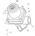
- FIG. 1 is a perspective view of a pressure reducing valve according to Embodiment 1 of the present invention.
- 1 is a perspective view of the pressure reducing valve shown in FIG. 1 cut along the XZ plane.
- Sectional drawing of the pressure reducing valve which concerns on Embodiment 1 of this invention 1 is an exploded view of a pressure reducing valve according to Embodiment 1 of the present invention.
- Cross-sectional view of the pressure reducing valve when the fluid pressure rises and the valve body contacts the valve seat and the valve closes Cross section of the pressure reducing valve when the fluid pressure further increases and the relief valve opens A perspective view of a pressure reducing valve according to Embodiment 2 of the present invention.
- FIG. 8 A perspective view of the pressure reducing valve shown in FIG. 8 cut along the XZ plane.
- Sectional drawing of the pressure reducing valve which concerns on Embodiment 2 of this invention Exploded view of a pressure reducing valve according to Embodiment 2 of the present invention
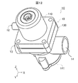
- a perspective view of a pressure reducing valve according to Embodiment 3 of the present invention. 12 is a perspective view of the pressure reducing valve shown in FIG. 12 cut along the XZ plane. Sectional drawing of the pressure reducing valve which concerns on Embodiment 3 of this invention. Exploded view of a pressure reducing valve according to Embodiment 3 of the present invention
- the pressure reducing valve according to Embodiment 1 is a pressure reducing valve that includes an adjusting member that adjusts the urging force of a spring that opens and closes the valve body.
- the pressure reducing valve further includes a relief valve.
- the pressure reducing valve includes a separation member that can adjust the position at which the valve body separates from the valve seat in order to adjust the opening and closing of the valve body of the relief valve.
- FIG. 1 is a perspective view of a pressure reducing valve 1A according to Embodiment 1 of the present invention.
- FIG. 2 is a perspective view of the pressure reducing valve 1A shown in FIG. 1 cut along the XZ plane.
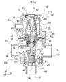
- FIG. 3 is a cross-sectional view of the pressure reducing valve 1A.
- FIG. 4 is an exploded view of the pressure reducing valve 1A. As shown in FIGS.
- the pressure reducing valve 1A includes a casing 10 in which an inlet 13 and an outlet 14 are formed, a valve body 20 disposed in the casing 10, and a valve body 20 A contactable valve seat 30; an auxiliary spring 40 that urges the valve body 20 in a direction to contact the valve seat 30; a spring 50 that urges the valve body 20 in a direction away from the valve seat 30;
- the diaphragm 60 that is deformed by receiving the fluid pressure of the fluid and compresses or extends the spring 50, the relief valve 70 provided in the diaphragm 60, and the adjustment provided to adjust the compression amount of the spring 50 provided in the housing 10.
- a member 80 and a relief valve adjusting member 90 for adjusting the relief valve 70 are configured.
- the casing 10 is formed with a flow path 15 through which a fluid flows, and a member that accommodates members such as the valve body 20, the auxiliary spring 40, the spring 50, and the diaphragm 60 disposed in the vicinity of the flow path 15. It is.
- the housing 10 includes an upper lid 110, a lower lid 120, and a valve housing 130.
- the upper lid 110 is formed in a shape in which a cylindrical portion 111 and a rectangular parallelepiped portion 112 arranged on the ⁇ Z side of the cylindrical portion 111 are combined.
- a hollow is formed inside the cylindrical portion 111 and the spring 50 is accommodated.
- An opening for inserting the adjustment member 80 is formed on the + Z side of the cylindrical portion 111 in order to adjust the compression amount of the spring 50.
- a relief valve adjusting member 90 is inserted into this opening.
- the ⁇ Z side of the cavity of the cylindrical part 111 is continuous with the cavity formed inside the rectangular parallelepiped part 112.
- the rectangular parallelepiped portion 112 has a cavity formed therein, like the cylindrical portion 111.
- the ⁇ Z end of the rectangular parallelepiped portion 112 is open.
- the diaphragm 60 is fixed to the ⁇ Z end of the rectangular parallelepiped portion 112 with the diaphragm 60 oriented parallel to the XY plane.
- the rectangular parallelepiped portion 112 covers a rectangular parallelepiped portion 131 (to be described later) of the valve casing 130 and closes the + Z side opening of the valve casing 130.
- the relief valve 70 is provided in the diaphragm 60 in the cavity of the rectangular parallelepiped part 112 and the cavity of the cylindrical part 111 continuous with the cavity, a fluid flows when the relief valve 70 is opened.
- the cylindrical portion 111 is provided with a discharge port 12.
- the lower lid 120 is formed in a cylindrical shape as shown in FIG.
- a recess 122 for accommodating the auxiliary spring 40 is formed on the + Z side of the lower lid 120.
- the auxiliary spring 40 is placed in the recess 122.
- An O-ring 121 that is a hermetic seal is provided on the outer periphery of the lower lid 120 to prevent fluid leakage.
- the lower lid 120 is fitted into the opening on the ⁇ Z side of the valve housing 130 to close the opening.
- the valve housing 130 includes a rectangular parallelepiped portion 131 that covers the upper lid 110, and a cylindrical portion that is disposed on the ⁇ Z side of the rectangular parallelepiped portion 131 and in which a flow path 15 for flowing fluid and a valve seat 30 are formed.
- 132 and a cylindrical portion 133 disposed on the ⁇ Z side of the cylindrical portion 132 and having the lower lid 120 fitted in the opening of the cylindrical portion.
- the rectangular parallelepiped portion 131 is formed with a cavity in order to supply a fluid to the diaphragm 60 provided on the upper lid 110.
- the + Z end of the rectangular parallelepiped portion 131 is open.
- a rectangular parallelepiped portion 112 of the upper lid 110 is covered with the opening.
- the diaphragm 60 faces the cavity of the rectangular parallelepiped portion 131 to which the fluid is supplied. Thereby, the fluid pressure of the fluid is applied to the surface of the diaphragm 60 on the side of the rectangular parallelepiped portion 131, that is, the surface on the ⁇ Z side.
- the cylindrical portion 132 has a cylindrical axis directed in the X direction. And both ends of the cylinder in the X direction are open. Specifically, the ⁇ X end of the cylindrical portion 132 is opened to function as the inflow port 13 into which the fluid flows. The + X end of the cylindrical portion 132 is opened in order to function as the outlet 14 through which the fluid that has flowed in flows out. Thereby, the internal space of the cylindrical portion 132 functions as the flow path 15 through which the fluid flowing in from the inflow port 13 flows.
- the cylindrical portion 132 is provided with a partition wall 151 that obliquely crosses the cylindrical axis and partitions the internal space of the cylindrical portion 132. Further, an internal cylinder 152 is provided in which the + Z end is located on the + Z side of the cylindrical portion 132, that is, located in the cavity of the rectangular parallelepiped portion 131, and the -Z end is located in the center of the cylindrical portion 132 in the Z direction. Yes.
- the + Z end and the ⁇ Z end of the inner cylinder 152 are open.
- a valve shaft 22 (described later) of the valve body 20 is inserted into the inner cylinder 152.
- the valve seat 30 is formed at the ⁇ Z end of the inner cylinder 152, and the valve body 20 is disposed on the ⁇ Z side of the inner cylinder 152.
- An opening 153 is formed in the cylindrical wall of the inner cylinder 152, and a partition wall 151 is connected to the opening 153.
- a flow path 15 is formed in which fluid flows from the inlet 13 to the outlet 14 via the valve body 20 of the inner cylinder 152.
- the internal space of the cylindrical portion 132 is connected to the cavity of the rectangular parallelepiped portion 131 described above on the + X side of the internal cylinder 152, that is, on the outlet 14 side.
- the fluid on the outlet 14 side is supplied to the cavity of the rectangular parallelepiped portion 131.
- the fluid pressure of the fluid is applied to the diaphragm 60.
- the + Z end of the cylindrical portion 133 with the cylindrical axis directed in the Z direction is connected to the wall portion of the cylindrical portion 132 on the ⁇ Z side with respect to the inner cylinder 152.
- the -Z end of the cylindrical part 133 is open.
- a lower lid 120 is fitted into the opening.
- the auxiliary spring 40 is placed on the lower lid 120.
- the auxiliary spring 40 is positioned on the ⁇ Z side of the inner cylinder 152 by fitting the lower lid 120.
- the auxiliary spring 40 is disposed on the ⁇ Z side of the valve body 20 on the ⁇ Z side of the inner cylinder 152.
- the valve body 20 is formed in a disk shape as shown in FIG. As shown in FIGS. 2 and 3, the outer diameter of the valve body 20 is larger than the inner diameter of the inner cylinder 152 in order to contact the valve seat 30 and close the ⁇ Z end of the inner cylinder 152.
- the valve body 20 is disposed on the + Z side with respect to the auxiliary spring 40. As shown in FIG. 3, the valve body 20 is urged toward the + Z side, that is, in a direction in contact with the valve seat 30 of the inner cylinder 152 by a compressed auxiliary spring 40 described later. Thereby, the valve body 20 can contact the valve seat 30 formed in the inner cylinder 152 to close the flow path 15.
- An annular sealing material 21 is provided on the + Z surface of the valve body 20 in order to close the flow path 15 in close contact with the valve seat 30.
- valve body 20 opens the flow path 15 away from the valve seat 30, the valve shaft 22 pushed in the ⁇ Z direction by the diaphragm 60 and the inner wall of the inner cylinder 152 when the valve shaft 22 is pushed. And a cylindrical close portion 24 that closely prevents fluid leakage.
- the valve shaft 22 extends from the valve body 20 in the + Z direction and to the ⁇ Z side of the diaphragm 60. As described above, the valve shaft 22 is inserted through the inner cylinder 152. When the diaphragm 60 is deformed in the ⁇ Z direction by a spring 50, which will be described later, the + Z end of the valve shaft 22 is pressed by the diaphragm 60 in the direction of the cylindrical axis of the inner cylinder 152 and in the ⁇ Z side, and moved in that direction. . As a result, the valve body 20 is separated from the valve seat 30 of the inner cylinder 152. As a result, the valve body 20 opens the flow path 15.
- An O-ring 23 that is a hermetic seal is wound around the outer periphery of the close contact portion 24.
- the close contact portion 24 prevents fluid from leaking from between the inner cylinder 152 when the valve shaft 22 is pressed by the diaphragm 60 and moves inside the inner cylinder 152.
- valve seat 30 is formed at the ⁇ Z end of the inner cylinder 152 as described above.
- the valve seat 30 is formed in an annular shape.
- the outer diameter of the valve seat 30 is smaller than the outer diameter of the valve body 20 so that the valve body 20 can come into contact therewith.
- the inner diameter of the valve seat 30 is larger than the outer diameter of the valve shaft 22 so that the valve body 20 can be moved in the Z direction. The valve body 20 is pressed against the valve seat 30 by the auxiliary spring 40 as described above.
- the auxiliary spring 40 is configured by a coil spring whose natural length is smaller than the distance from the + Z surface of the recess 122 of the lower lid 120 to the ⁇ Z surface of the valve seat 30.
- the auxiliary spring 40 is sandwiched between the + Z surface of the recess 122 of the lower lid 120 and the ⁇ Z surface of the valve body 20 and is compressed. Thereby, the auxiliary spring 40 always urges the valve body 20 in the + Z direction, that is, toward the valve seat 30 side of the inner cylinder 152.
- the spring 50 is configured by a coil spring placed on the + Z surface of the diaphragm 60 and having a natural length smaller than a distance from a later-described washer 61 to a cylindrical portion 111 cavity + Z end of the upper lid 110.
- the ⁇ Z end of the spring 50 is in contact with the washer 61.
- the + Z end of the spring 50 is in contact with an adjustment member 80 provided on the cylindrical portion 111 of the upper lid 110.
- the spring 50 is compressed by being sandwiched between the washer 61 and the adjustment member 80. Thereby, the spring 50 always urges the diaphragm 60 in the ⁇ Z direction.
- the diaphragm 60 is formed in an annular shape as shown in FIG. Then, as shown in FIG. 3, a cylindrical portion of a relief valve seat 72, which will be described later, of the relief valve 70 is fitted into the annular hole.
- the flange portion at the ⁇ Z end of the relief valve seat 72 is located on the ⁇ Z side of the diaphragm 60.
- a washer 61 having an inner diameter equal to the inner diameter of the diaphragm 60 is placed on the + Z surface of the diaphragm 60.
- the ⁇ Z end of the spring 50 is in contact with the washer 61.
- the washer 61 is biased in the ⁇ Z direction by the spring 50.
- the diaphragm 60 is urged in the ⁇ Z direction via the washer 61.
- a flange portion of the relief valve seat 72 is disposed on the ⁇ Z surface of the diaphragm 60.
- the relief valve element 71 and the + Z end of the valve shaft 22 are positioned in this order on the ⁇ Z side of the relief valve seat 72.
- the diaphragm 60 When the urging force of the spring 50 is smaller than the fluid pressure, the diaphragm 60 is pushed by the urging force of the spring 50 and deforms in a convex shape in the ⁇ Z direction. Accordingly, the diaphragm 60 moves the relief valve body 71 in the ⁇ Z direction and presses the + Z end of the valve shaft 22 in the ⁇ Z direction. As a result, the diaphragm 60 moves the valve body 20 in the ⁇ Z direction to open the flow path 15 of the inner cylinder 152.
- the diaphragm 60 when the urging force of the spring 50 is larger than the fluid pressure, the diaphragm 60 is deformed into a concave shape in the + Z direction by the fluid pressure. Thereby, the diaphragm 60 moves the relief valve body 71 in the + Z direction to separate the relief valve body 71 from the + Z end of the valve shaft 22. As a result, the diaphragm 60 enables the valve shaft 22 and the valve body 20 to move in the + Z direction. Since the valve body 20 is always urged in the + Z direction by the auxiliary spring 40, the valve body 20 moves in the + Z direction and closes the flow path 15 of the inner cylinder 152.
- the relief valve 70 is a member that opens the valve and lowers the fluid pressure when the fluid pressure increases with the valve body 20 closing the flow path 15 of the inner cylinder 152. As shown in FIG. 4, the relief valve 70 urges the relief valve body 71, the relief valve seat 72 on which the relief valve body 71 can come into contact, and the relief valve body 71 toward the relief valve seat 72. And a relief valve spring 73.
- the relief valve element 71 is formed in a shape in which the valve shaft 710 extends in the + Z direction from the center of the disc. Further, as shown in FIGS. 2 and 3, a sealing material 711 for closely contacting the relief valve seat 72 is provided on the + Z surface of the disc of the relief valve body 71.
- the relief valve seat 72 is formed in a shape in which an annular flange is provided at the ⁇ Z end of the cylindrical portion, as shown in FIG.
- the cylindrical portion of the relief valve seat 72 is inserted into the hole of the diaphragm 60, and the flange portion of the relief valve seat 72 is in contact with the ⁇ Z surface of the diaphragm 60.
- the relief valve seat 72 is fixed to the diaphragm 60 in this state.
- the cylindrical portion of the relief valve seat 72 accommodates a relief valve spring 73 into which the valve shaft 710 is inserted.
- the valve shaft 710 is provided with a spring clamp 712 that clamps the + Z end of the relief valve spring 73.
- the relief valve spring 73 is constituted by a coil spring.
- the relief valve spring 73 is sandwiched between the spring clamp 712 and the -Z end disk of the relief valve seat 72 in a compressed state. Thereby, the valve shaft 710 is biased in the + Z direction. As a result, the state where the relief valve body 71 abuts on the relief valve seat 72, that is, the state where the valve is closed is maintained.
- the diaphragm 60 is deformed into a concave shape in the + Z direction in order to change the valve from the closed state at the relief valve seat 72 to the open state.
- a relief valve adjusting member 90 is provided that contacts the valve shaft 710 and separates the relief valve body 71 from the relief valve seat 72 when the relief valve body 71 moves in the + Z direction.
- the relief valve adjusting member 90 is formed in the shape of a pin extending in the Z direction.
- a cylindrical head 91 is provided at the + Z end of the relief valve adjusting member 90.
- An O-ring 92 that is a hermetic seal is provided on the outer periphery of the head 91.
- a male screw (not shown) is formed.
- the adjusting member 80 is formed with a screw hole into which the relief valve adjusting member 90 is inserted.
- a female screw into which the male screw of the head 91 is screwed is formed in the screw hole.
- the relief valve adjusting member 90 is inserted into the screw hole of the adjusting member 80, and the male screw of the head 91 is screwed into the female screw of the screw hole of the adjusting member 80.
- a groove 93 for turning the relief valve adjusting member 90 with a tool driver is formed at the + Z end of the head 91.
- the relief valve adjusting member 90 is moved in the Z direction along the female screw of the screw hole of the adjusting member 80 when the groove 93 is rotated by a driver.
- the relief valve adjusting member 90 can adjust the position where the relief valve body 71 contacts the valve shaft 710, and the position where the relief valve body 71 moves away from the relief valve seat 72 and the valve opens.
- the adjusting member 80 is a member that adjusts the compression amount of the spring 50 by changing the position where the + Z end of the spring 50 is pressed.
- the adjustment member 80 is formed in a cylindrical shape having an outer diameter larger than that of the coil of the spring 50 in order to hold down the + Z end of the spring 50.
- the cylindrical hole of the adjusting member 80 is processed into a screw hole in which the above-described female screw is formed on the inner wall.
- the relief valve adjusting member 90 is inserted, and the female screw of the relief valve adjusting member 90 is screwed into the screw hole of the adjusting member 80 as described above.
- the relief valve adjusting member 90 is fixed to the adjusting member 80.
- On the ⁇ Z side of the adjustment member 80 a small cylindrical portion 81 having an outer diameter smaller than that of the adjustment member 80 and the same inner diameter is formed to guide the relief valve adjustment member 90.
- an O-ring 82 is provided on the outer periphery of the adjustment member 80 as a hermetic seal. Furthermore, a male screw (not shown) is formed. The adjustment member 80 is inserted into the opening of the upper lid 110, and the male screw of the adjustment member 80 is screwed into the female screw formed on the inner wall of the opening of the upper lid 110. Thereby, the adjusting member 80 is fixed to the upper lid 110.
- the cylinder of the adjustment member 80 is formed with a protrusion into which a wrench and a spanner as tools are fitted.
- the adjustment member 80 is movable in the Z direction by being rotated by a tool. Thereby, the adjustment member 80 is moved in the Z direction, and the position where the + Z end of the spring 50 is pressed is adjusted. As a result, the amount of compression of the spring 50 is adjusted, and the urging force of the spring 50 is adjusted.
- the operation of the pressure reducing valve 1A will be described with reference to FIGS.
- FIG. 5 is a cross-sectional view of the pressure reducing valve 1A when the fluid is supplied and the valve body 20 is separated from the valve seat 30 and the valve is opened.
- FIG. 6 is a cross-sectional view of the pressure reducing valve 1A when the fluid pressure of the fluid increases and the valve body 20 contacts the valve seat 30 and the valve is closed.
- FIG. 7 is a cross-sectional view of the pressure reducing valve 1A when the fluid pressure is further increased and the relief valve 70 is opened.
- the adjustment member 80 compresses the spring 50 so that the force applied from the diaphragm 60 to the spring 50 and the urging force of the spring 50 become the same magnitude. Assume that the amount is adjusted.
- the ⁇ Z end of the relief valve adjusting member 90 abuts on the + Z end of the valve shaft 710 of the relief valve body 71 and the + Z end of the valve shaft 710 is ⁇ It is assumed that the position has been adjusted to be pushed down by a certain amount in the Z direction.
- the fluid pressure Ps is higher than the fluid pressure Pc.
- the convex shape on the ⁇ Z side of the diaphragm 60 does not protrude toward the ⁇ Z side as compared with the state shown in FIG. It becomes a shape. In other words, the amount of protrusion of the diaphragm 60 toward the ⁇ Z side is small.
- the relief valve element 71 provided in the diaphragm 60 is biased in the + Z direction by the relief valve spring 73, and thereby maintains a state of contacting the relief valve seat 72. For this reason, the relief valve body 71 moves together with the diaphragm 60 to the + Z side from the position shown in FIG.
- the valve body 20 Since the valve body 20 is always urged in the + Z direction by the auxiliary spring 40, the valve body 20 moves in the + Z direction together with the valve shaft 22 from the position shown in FIG. Thereby, the valve body 20 contacts the valve seat 30. That is, the valve of the pressure reducing valve 1A is closed. As a result, the fluid does not flow from the inlet 13 to the outlet 14, and the fluid pressure on the outlet 14 side is reduced.
- the diaphragm 60 When the fluid pressure of the fluid exceeds the fluid pressure Pc and reaches the fluid pressure Ps, the diaphragm 60 is deformed into a concave shape on the + Z side by the fluid pressure, as shown in FIG. Thereby, the relief valve seat 72 of the relief valve 70 provided in the diaphragm 60 moves in the + Z direction together with the relief valve body 71 from the state shown in FIG. Then, the + Z end of the valve shaft 710 of the relief valve body 71 contacts the ⁇ Z end of the relief valve adjusting member 90, and the valve shaft 710 is pushed down by a certain amount in the ⁇ Z direction.
- the relief valve body 71 is pushed down in the ⁇ Z direction, the relief valve body 71 moves away from the relief valve seat 72, and the relief valve 70 opens. Thereby, the fluid is discharged from the discharge port 12. As a result, the fluid pressure of the fluid is prevented from exceeding the fluid pressure Ps.
- the pressure reducing valve 1A includes the adjusting member 80 that adjusts the magnitude of the urging force of the spring 50. Therefore, the fluid pressure at which the diaphragm 60 is deformed to the + Z side, that is, the spring 50 side and the valve body 20 contacts the valve seat 30 can be changed. As a result, the fluid pressure to be reduced by closing the valve body 20 of the pressure reducing valve 1A can be adjusted. In the pressure reducing valve 1A, even if the biasing force of the spring 50 varies from a desired biasing force during assembly, the fluid pressure to be reduced can be adjusted by the adjusting member 80.
- the adjustment member 80 is formed with a male screw that is screwed into a female screw formed on the upper lid 110 of the housing 10. For this reason, the position of the adjusting member 80 can be easily adjusted by moving the male screw of the adjusting member 80 along the female screw of the upper lid 110. As a result, in the pressure reducing valve 1A, the fluid pressure to be reduced by closing the valve body 20 can be adjusted.
- the pressure reducing valve 1A is provided with a relief valve adjusting member 90 that contacts the valve shaft 710 of the relief valve body 71 and separates the relief valve body 71 from the relief valve seat 72.
- the relief valve adjusting member 90 is provided with a head 91 that adjusts the position where the relief valve adjusting member 90 abuts. For this reason, the fluid pressure to be reduced by closing the relief valve 70 can be adjusted.
- the relief valve adjusting member 90 is formed with a male screw that is screwed into the female screw formed on the adjusting member 80. For this reason, the position of the relief valve adjusting member 90 can be easily adjusted by moving the male screw of the relief valve adjusting member 90 along the female screw of the adjusting member 80. Further, since the relief valve adjusting member 90 and the adjusting member 80 are coaxial, the operation of adjusting the positions of the relief valve adjusting member 90 and the adjusting member 80 is easy.
- Embodiment 2 The pressure reducing valve 1B according to Embodiment 2 has two outlets.
- the pressure reducing valve 1B according to the second embodiment will be described below with reference to FIGS. In the second embodiment, a configuration different from that of the first embodiment will be described.
- FIG. 8 is a perspective view of a pressure reducing valve 1B according to Embodiment 2 of the present invention.
- FIG. 9 is a perspective view of the pressure reducing valve 1B shown in FIG. 8 taken along the XZ plane.
- FIG. 10 is a cross-sectional view of the pressure reducing valve 1B.
- FIG. 11 is an exploded view of the pressure reducing valve 1B.
- the pressure reducing valve 1 ⁇ / b> B has a second outlet 16 formed in the lower lid 140.
- the lower lid 140 is formed in a cylindrical shape as shown in FIGS.
- the cylinder of the lower lid 140 is oriented in the Z direction, and is open on the Z side and the ⁇ Z side. Thereby, the internal space of the lower lid 140 forms a flow path that branches from the internal space of the valve housing 130 to the Z side. Then, the fluid flows from the internal space of the valve housing 130, whereby the opening on the ⁇ Z side of the lower lid 140 functions as the second outlet 16.
- a protrusion 142 is formed on the inner wall of the lower lid 140 to support the + Z end of the auxiliary spring 40.
- the protrusion 142 is disposed at a position where the distance to the valve body 20 located on the + Z side is smaller than the natural length of the auxiliary spring 40.
- the auxiliary spring 40 is sandwiched between the + Z surface of the protrusion 142 and the ⁇ Z surface of the valve body 20 to compress the auxiliary spring 40. As a result, the auxiliary spring 40 biases the valve body 20 in the + Z direction, that is, in the direction of the valve seat 30.
- the pressure reducing valve 1B according to the second embodiment has the same configuration as the pressure reducing valve 1A according to the first embodiment, except that the second outlet 16 is formed. Therefore, the operation of the pressure reducing valve 1B is the same as that of the pressure reducing valve 1A according to Embodiment 1 except that the fluid flows out to the second outlet 16 in addition to the outlet 14. For this reason, in Embodiment 2, description of operation
- the second outflow port 16 is formed in the lower lid 140 in the pressure reducing valve 1B according to the second embodiment.
- the pressure reducing valve 1B also includes an adjustment member 80 and a relief valve adjustment member 90, as in the first embodiment. Therefore, even in the pressure reducing valve 1B having the outlet 14 and the second outlet 16, the fluid pressure to be reduced by closing the valve body 20 of the pressure reducing valve 1A, and the relief valve 70 should be reduced by closing the relief valve body 71. The fluid pressure can be adjusted.
- the pressure reducing valve 1 ⁇ / b> C according to the third embodiment includes an auxiliary spring adjusting member 41 that adjusts the biasing force of the auxiliary spring 40.
- the pressure reducing valve 1C according to the third embodiment will be described below with reference to FIGS. In the third embodiment, a configuration different from the first and second embodiments will be described.
- FIG. 12 is a perspective view of a pressure reducing valve 1C according to Embodiment 3 of the present invention.
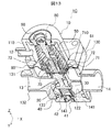
- 13 is a perspective view of the pressure reducing valve 1C shown in FIG. 12, taken along the XZ plane.
- FIG. 14 is a cross-sectional view of the pressure reducing valve 1C.
- FIG. 15 is an exploded view of the pressure reducing valve 1C. As shown in FIG. 15, the lower lid 141 has a through-hole 143 extending in the Z direction and having an internal thread formed on the inner wall.
- the through-hole 143 has a cylindrical pin that can be inserted into the through-hole 143 and a disk-shaped pin head that is provided on the ⁇ Z side of the pin and has a larger outer diameter than the cylinder.
- An auxiliary spring adjusting member 41 having a shape connected to the portion is inserted.
- a male screw that can be screwed into a female screw on the inner wall of the through hole 143 is formed on the outer periphery of the pin head of the auxiliary spring adjusting member 41.
- the auxiliary spring adjusting member 41 is fixed to the lower lid 141 by screwing the male screw on the pin head of the auxiliary spring adjusting member 41 into the female screw on the inner wall of the through hole 143.
- the + Z end of the auxiliary spring adjustment member 41 is located on the + Z side with respect to the recess in the lower lid 141.
- a support plate 42 that supports the ⁇ Z end of the auxiliary spring 40 is disposed at the + Z end of the auxiliary spring adjusting member 41.
- the auxiliary spring adjustment member 41 supports the ⁇ Z end of the auxiliary spring 40 via the support plate 42.
- the auxiliary spring adjusting member 41 rotates, the male screw on the pin head of the auxiliary spring adjusting member 41 moves along the female screw on the inner wall of the through hole 143, and the auxiliary spring adjusting member 41 moves in the Z direction.
- the auxiliary spring adjusting member 41 can adjust the position of the support plate 42 in the Z direction to adjust the position of the ⁇ Z end of the auxiliary spring 40.
- the urging force of the auxiliary spring 40 can be adjusted.
- the pressure reducing valve 1C according to the third embodiment has the same configuration as the pressure reducing valve 1A according to the first embodiment, except that the auxiliary spring adjusting member 41 is provided. For this reason, the operation of the pressure reducing valve 1C after the urging force of the auxiliary spring 40 is adjusted by the auxiliary spring adjusting member 41 is the same as the operation of the pressure reducing valve 1A according to the first embodiment. For this reason, in Embodiment 3, description of operation
- the pressure reducing valve 1C includes the auxiliary spring adjusting member 41, so that the biasing force of the auxiliary spring 40 can be adjusted.
- the biasing force of the auxiliary spring 40 can be adjusted using the auxiliary spring adjusting member 41.
- the adjusting member 80 and the relief valve adjusting member 90 are formed with male threads.
- the present invention is not limited to this.
- the adjustment member 80 only needs to be held in the housing 10 so as to be movable in a direction in which the spring 50 is compressed or extended, and the magnitude of the urging force of the spring 50 can be adjusted.
- the relief valve adjusting member 90 only needs to be held by the housing 10 so as to be movable from the spring 50 side to the relief valve body 71 side or in the opposite direction. For this reason, even if the adjusting member 80 and the relief valve adjusting member 90 are held by the housing 10 by forming the female screw on the adjusting member 80 and the relief valve adjusting member 90 and forming the male screw on the housing 10. Good.
- the adjusting member 80 and the relief valve adjusting member 90 are arranged coaxially.
- the adjusting member 80 and the relief valve adjusting member 90 do not have to be arranged coaxially, and the X direction Alternatively, they may be arranged in the Y direction.
- the member that contacts the relief valve body 71 from the spring 50 side and separates the relief valve body 71 from the relief valve seat 72 is referred to as the relief valve adjusting member 90. Since it is a member that separates the valve body 71 and the relief valve seat 72, it may be referred to as a separation member.
- the springs included in the pressure reducing valve 1A-1C are referred to as the auxiliary spring 40, the spring 50, and the relief valve spring 73.
- these members may be elastic members that are elastically deformed. For this reason, these members may be formed of rubber.
- the auxiliary spring 40, the spring 50, and the relief valve spring 73 may be referred to as a first elastic member, a second elastic member, and a third elastic member.
- the opening of the upper lid 110 of the housing 10 is formed as a female screw on the inner wall, and may be referred to as a screw hole.
- the adjustment member 80 is formed with a screw hole into which the relief valve adjustment member 90 is screwed.
- the screw hole into which the relief valve adjusting member 90 is screwed may be formed in the housing 10.
- the screw hole formed in the housing 10 may be referred to as a second screw hole because the screw hole is also formed in the upper lid 110 of the housing 10.
- the screw hole formed in the adjustment member 80 described in Embodiment 1-3 may be referred to as a third screw hole.
- Embodiment 1-3 it is described that a fluid flows through the pressure reducing valve 1A-1C.
- the fluid is, for example, water used in a water heater or a refrigerant used in an air conditioner.
- the pressure reducing valve 1A-1C can be applied to a water heater, an air conditioner, and the like.
- 1A-1C Pressure reducing valve 10 housing, 12 outlet, 13 inlet, 14 outlet, 15 flow path, 16 second outlet, 20 valve body, 21 sealing material, 22 valve stem, 23 O-ring, 24 closely Part, 30 valve seat, 40 auxiliary spring, 41 auxiliary spring adjusting member, 42 support plate, 50 spring, 60 diaphragm, 61 washer, 70 relief valve, 71 relief valve body, 72 relief valve seat, 73 relief valve spring, 80 Adjusting member, 81 small cylindrical part, 82 O-ring, 90 relief valve adjusting member, 91 head, 92 O-ring, 93 groove, 110 upper lid, 111 cylindrical part, 112 rectangular parallelepiped part, 120 lower lid, 121 O-ring, 122 dent , 130 valve housing, 131 cuboid part, 132, 133 cylindrical part, 140 lower lid, 141 lower lid, 142 protrusions, 143 Through-holes, 151 partition wall, 152 inner cylinder, 153 opening, 710 valve shaft, 711 sealing material, 712 a spring clasp.
Abstract
A pressure reducing valve (1A) is provided with: a housing (10) in which a flow passage (15) is formed; a valve seat (30) formed in the flow passage (15); a valve body (20) capable of coming into contact with the valve seat; an auxiliary spring (40) for urging the valve body (20) in the direction in which the valve body (20) comes into contact with the valve seat (30); a spring (50) for urging the valve body (20) in the direction in which the valve body (20) is separated from the valve seat (30); a diaphragm (60) disposed between the spring (50) and the valve body (20), one surface of the diaphragm (60) being in contact with the spring (50) and being subjected to the urging force of the spring (50), the other surface of the diaphragm (60) being in contact with the portion of the flow passage (15), which is located closer to an outlet (14) than the valve seat (30), and being subjected to the pressure of fluid, the diaphragm (60) being deformed toward the valve body (20) when the urging force of the spring (50) is greater than a force caused by the fluid pressure, thereby separating the valve body (20) from the valve seat (30); and a regulation member (80) held by the housing (10) so as to be movable in the direction in which the spring (50) is compressed or allowed to extend, and regulating the magnitude of the urging force of the spring (50).
Description
本発明は減圧弁に関する。
The present invention relates to a pressure reducing valve.
減圧弁には、流体の流入口と流出口とをつなぐ流路に設けられ、弁座及び弁体を有する弁と、弁座から離れる方向に弁体を付勢して弁を開けるバネと、そのバネよりも小さい付勢力で弁座に当接する方向に弁体を付勢して弁を閉じる補助バネと、流出口側の流体圧が高まった場合に、流体圧によって変形してバネを圧縮し、バネの付勢力を小さくして、補助バネで弁を閉じるダイヤフラムと、を備えるものがある。
The pressure reducing valve is provided in a flow path connecting the fluid inlet and outlet, and has a valve seat and a valve body, and a spring that urges the valve body in a direction away from the valve seat to open the valve, An auxiliary spring that closes the valve by urging the valve body in a direction to contact the valve seat with a smaller urging force than the spring, and when the fluid pressure on the outflow side increases, it deforms by the fluid pressure and compresses the spring Some of them include a diaphragm that reduces the biasing force of the spring and closes the valve with an auxiliary spring.
例えば、特許文献1には、弁体に備えられる弁軸を付勢するバネと補助バネが筐体の上部と下部に固定された減圧弁が開示されている。
For example, Patent Document 1 discloses a pressure reducing valve in which a spring for biasing a valve shaft provided in a valve body and an auxiliary spring are fixed to an upper part and a lower part of a housing.
特許文献1に記載の減圧弁では、バネが固定されているため、バネの付勢力を調整することができない。その結果、バネの組立のばらつきによって、弁体が閉じる流体圧の値、すなわち、弁体が動作する圧力値がばらついてしまうことがある。
In the pressure reducing valve described in Patent Document 1, since the spring is fixed, the urging force of the spring cannot be adjusted. As a result, the value of fluid pressure at which the valve body closes, that is, the pressure value at which the valve body operates may vary due to variations in the assembly of the spring.
本発明は上記の課題を解決するためになされたもので、弁体が動作する圧力値を調整できる減圧弁を提供することを目的とする。
This invention was made in order to solve said subject, and it aims at providing the pressure-reduction valve which can adjust the pressure value which a valve body operate | moves.
上記の目的を達成するため、減圧弁は、流体が流入する流入口と流体が流出する流出口をつなぐ流路が形成された筐体と、流路に形成された弁座と、弁座に当接可能な弁体と、弁座に当接する方向に弁体を付勢する第1弾性部材と、弁座から離れる方向に弁体を付勢し、第1弾性部材よりも大きい付勢力を有する第2弾性部材と、第2弾性部材と弁体の間に配置され、一方の面が第2弾性部材に当接して第2弾性部材の付勢力を受けると共に、他方の面が流路の、弁座よりも流出口の側の部分に接して流体の流体圧を受けるダイヤフラムと、を備える。ダイヤフラムは、第2弾性部材の付勢力が流体圧による力よりも大きい場合に弁体の側に変形して弁体を弁座から離し、第2弾性部材の付勢力が流体圧による力よりも小さい場合に第2弾性部材の側に変形し、第1弾性部材によって弁体を弁座に当接させる。さらに、減圧弁は、第2弾性部材を圧縮又は伸長させる方向へ移動可能に筐体に保持され、第2弾性部材の付勢力の大きさを調整する調整部材を備える。
In order to achieve the above object, a pressure reducing valve includes a housing in which a flow path connecting an inflow port into which a fluid flows in and an outflow port from which the fluid flows out, a valve seat formed in the flow path, and a valve seat. A contactable valve body, a first elastic member that urges the valve body in a direction to contact the valve seat; A second elastic member having a second elastic member disposed between the second elastic member and the valve body, wherein one surface is in contact with the second elastic member to receive a biasing force of the second elastic member, and the other surface is the flow path. And a diaphragm that receives a fluid pressure of the fluid in contact with a portion closer to the outlet than the valve seat. When the urging force of the second elastic member is larger than the force due to the fluid pressure, the diaphragm deforms toward the valve body and separates the valve body from the valve seat, and the urging force of the second elastic member is larger than the force due to the fluid pressure. When it is small, it is deformed toward the second elastic member, and the valve body is brought into contact with the valve seat by the first elastic member. Furthermore, the pressure reducing valve includes an adjustment member that is held by the housing so as to be movable in a direction in which the second elastic member is compressed or extended, and adjusts the magnitude of the urging force of the second elastic member.
本発明の構成によれば、第2弾性部材の付勢力の大きさを調整する調整部材を備えるため、ダイヤフラムが第2弾性部材の側に変形して第1弾性部材によって弁体が弁座に当接する流体圧を変更できる。その結果、弁体が動作する圧力値を調整できる減圧弁を提供することができる。
According to the configuration of the present invention, since the adjusting member that adjusts the magnitude of the urging force of the second elastic member is provided, the diaphragm is deformed to the second elastic member side, and the valve body is moved to the valve seat by the first elastic member. The abutting fluid pressure can be changed. As a result, a pressure reducing valve capable of adjusting the pressure value at which the valve element operates can be provided.
以下、本発明の実施の形態に係る減圧弁について図面を参照して詳細に説明する。なお、図中、同一又は同等の部分には同一の符号を付す。図に示す直交座標系XYZにおいて、流体が流入する流入口を左に配置した場合の、左右方向がX軸、上下方向がZ軸、X軸とZ軸とに直交する方向がY軸である。以下、適宜、この座標系を引用して説明する。
Hereinafter, a pressure reducing valve according to an embodiment of the present invention will be described in detail with reference to the drawings. In addition, the same code | symbol is attached | subjected to the same or equivalent part in a figure. In the Cartesian coordinate system XYZ shown in the figure, when the inflow port into which the fluid flows is arranged on the left, the horizontal direction is the X axis, the vertical direction is the Z axis, and the direction perpendicular to the X axis and the Z axis is the Y axis. . Hereinafter, this coordinate system will be described as appropriate.
(実施の形態1)
実施の形態1に係る減圧弁は、弁体を開閉するバネの付勢力を調整する調整部材を備える減圧弁である。この減圧弁は、さらに逃し弁を備える。また、この減圧弁は、逃し弁の弁体の開閉を調整するため、弁体が弁座から離れる位置を調整できる離間部材を備えている。以下、図1-図4を参照して減圧弁の構成について説明する。 (Embodiment 1)
The pressure reducing valve according toEmbodiment 1 is a pressure reducing valve that includes an adjusting member that adjusts the urging force of a spring that opens and closes the valve body. The pressure reducing valve further includes a relief valve. In addition, the pressure reducing valve includes a separation member that can adjust the position at which the valve body separates from the valve seat in order to adjust the opening and closing of the valve body of the relief valve. Hereinafter, the configuration of the pressure reducing valve will be described with reference to FIGS.
実施の形態1に係る減圧弁は、弁体を開閉するバネの付勢力を調整する調整部材を備える減圧弁である。この減圧弁は、さらに逃し弁を備える。また、この減圧弁は、逃し弁の弁体の開閉を調整するため、弁体が弁座から離れる位置を調整できる離間部材を備えている。以下、図1-図4を参照して減圧弁の構成について説明する。 (Embodiment 1)
The pressure reducing valve according to
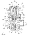
図1は、本発明の実施の形態1に係る減圧弁1Aの斜視図である。図2は、XZ平面で切断した、図1に示す減圧弁1Aの斜視図である。図3は、減圧弁1Aの断面図である。図4は、減圧弁1Aの分解図である。
減圧弁1Aは、図1-図4に示すように、流入口13と流出口14とが形成された筐体10と、筐体10内に配置された弁体20と、弁体20が当接可能な弁座30と、弁体20を弁座30に当接する方向に付勢する補助バネ40と、弁体20を弁座30から離す方向に付勢するバネ50と、筐体10内で流体の流体圧を受けて変形して、バネ50を圧縮又は伸長させるダイヤフラム60と、ダイヤフラム60に設けられた逃し弁70と、筐体10に設けられ、バネ50の圧縮量を調整する調整部材80と、逃し弁70を調整する逃し弁調整部材90と、で構成されている。 FIG. 1 is a perspective view of apressure reducing valve 1A according to Embodiment 1 of the present invention. FIG. 2 is a perspective view of the pressure reducing valve 1A shown in FIG. 1 cut along the XZ plane. FIG. 3 is a cross-sectional view of the pressure reducing valve 1A. FIG. 4 is an exploded view of the pressure reducing valve 1A.
As shown in FIGS. 1 to 4, thepressure reducing valve 1A includes a casing 10 in which an inlet 13 and an outlet 14 are formed, a valve body 20 disposed in the casing 10, and a valve body 20 A contactable valve seat 30; an auxiliary spring 40 that urges the valve body 20 in a direction to contact the valve seat 30; a spring 50 that urges the valve body 20 in a direction away from the valve seat 30; The diaphragm 60 that is deformed by receiving the fluid pressure of the fluid and compresses or extends the spring 50, the relief valve 70 provided in the diaphragm 60, and the adjustment provided to adjust the compression amount of the spring 50 provided in the housing 10. A member 80 and a relief valve adjusting member 90 for adjusting the relief valve 70 are configured.
減圧弁1Aは、図1-図4に示すように、流入口13と流出口14とが形成された筐体10と、筐体10内に配置された弁体20と、弁体20が当接可能な弁座30と、弁体20を弁座30に当接する方向に付勢する補助バネ40と、弁体20を弁座30から離す方向に付勢するバネ50と、筐体10内で流体の流体圧を受けて変形して、バネ50を圧縮又は伸長させるダイヤフラム60と、ダイヤフラム60に設けられた逃し弁70と、筐体10に設けられ、バネ50の圧縮量を調整する調整部材80と、逃し弁70を調整する逃し弁調整部材90と、で構成されている。 FIG. 1 is a perspective view of a
As shown in FIGS. 1 to 4, the
筐体10は、流体を流す流路15が形成されると共に、流路15と流路15の近傍に配置された弁体20、補助バネ40、バネ50、ダイヤフラム60等の部材を収容する部材である。筐体10は、図3及び図4に示すように、上蓋110、下蓋120及び、弁筐体130で構成されている。
The casing 10 is formed with a flow path 15 through which a fluid flows, and a member that accommodates members such as the valve body 20, the auxiliary spring 40, the spring 50, and the diaphragm 60 disposed in the vicinity of the flow path 15. It is. As shown in FIGS. 3 and 4, the housing 10 includes an upper lid 110, a lower lid 120, and a valve housing 130.
上蓋110は、図4に示すように、円筒部111と、円筒部111の-Z側に配置された直方体部112と、が結合された形状に形成されている。
As shown in FIG. 4, the upper lid 110 is formed in a shape in which a cylindrical portion 111 and a rectangular parallelepiped portion 112 arranged on the −Z side of the cylindrical portion 111 are combined.
円筒部111の内部には、図3に示すように、空洞が形成され、バネ50を収容されている。そして、円筒部111の+Z側には、バネ50の圧縮量を調整するため、調整部材80を挿入する開口が形成されている。また、この開口には、逃し弁調整部材90が挿入されている。一方、円筒部111の空洞の-Z側は、直方体部112の内部に形成された空洞と連続している。
As shown in FIG. 3, a hollow is formed inside the cylindrical portion 111 and the spring 50 is accommodated. An opening for inserting the adjustment member 80 is formed on the + Z side of the cylindrical portion 111 in order to adjust the compression amount of the spring 50. A relief valve adjusting member 90 is inserted into this opening. On the other hand, the −Z side of the cavity of the cylindrical part 111 is continuous with the cavity formed inside the rectangular parallelepiped part 112.
直方体部112は、円筒部111と同様に、内部に空洞が形成されている。そして、直方体部112の-Z端は、開口している。この開口を塞いでバネ50を圧縮するため、直方体部112の-Z端には、ダイヤフラム60がXY平面に平行に向けられた状態で、固定されている。直方体部112は、弁筐体130が有する、後述する直方体部131に覆って、弁筐体130の+Z側の開口を塞いでいる。
The rectangular parallelepiped portion 112 has a cavity formed therein, like the cylindrical portion 111. The −Z end of the rectangular parallelepiped portion 112 is open. In order to close the opening and compress the spring 50, the diaphragm 60 is fixed to the −Z end of the rectangular parallelepiped portion 112 with the diaphragm 60 oriented parallel to the XY plane. The rectangular parallelepiped portion 112 covers a rectangular parallelepiped portion 131 (to be described later) of the valve casing 130 and closes the + Z side opening of the valve casing 130.
直方体部112の空洞と、その空洞に連続する円筒部111の空洞とには、ダイヤフラム60に逃し弁70が設けられているため、逃し弁70が開いたときに流体が流入する。この流体を排出するため、円筒部111には、排出口12が設けられている。
Since the relief valve 70 is provided in the diaphragm 60 in the cavity of the rectangular parallelepiped part 112 and the cavity of the cylindrical part 111 continuous with the cavity, a fluid flows when the relief valve 70 is opened. In order to discharge this fluid, the cylindrical portion 111 is provided with a discharge port 12.
これに対して、下蓋120は、図4に示すように、円柱状に形成されている。そして、下蓋120の+Z側には、補助バネ40を収容するための凹み122が形成されている。凹み122には、図3に示すように、補助バネ40が載置されている。そして、下蓋120の外周には、流体の漏れを防止するため、密閉シールであるOリング121が設けられている。下蓋120は、弁筐体130の-Z側の開口に嵌め込まれて、その開口を塞いでいる。
On the other hand, the lower lid 120 is formed in a cylindrical shape as shown in FIG. A recess 122 for accommodating the auxiliary spring 40 is formed on the + Z side of the lower lid 120. As shown in FIG. 3, the auxiliary spring 40 is placed in the recess 122. An O-ring 121 that is a hermetic seal is provided on the outer periphery of the lower lid 120 to prevent fluid leakage. The lower lid 120 is fitted into the opening on the −Z side of the valve housing 130 to close the opening.
弁筐体130は、図4に示すように、上蓋110が被せられる直方体部131と、直方体部131の-Z側に配置され、流体を流す流路15と弁座30が形成された円筒部132と、円筒部132の-Z側に配置され、円筒の開口に下蓋120が嵌め込まれた円筒部133と、で構成されている。
As shown in FIG. 4, the valve housing 130 includes a rectangular parallelepiped portion 131 that covers the upper lid 110, and a cylindrical portion that is disposed on the −Z side of the rectangular parallelepiped portion 131 and in which a flow path 15 for flowing fluid and a valve seat 30 are formed. 132 and a cylindrical portion 133 disposed on the −Z side of the cylindrical portion 132 and having the lower lid 120 fitted in the opening of the cylindrical portion.
直方体部131は、上蓋110に設けられたダイヤフラム60に流体を供給するため、空洞が形成されている。直方体部131の+Z端は開口している。その開口には、図3に示すように、上蓋110の直方体部112が被されている。そして、直方体部131の、流体が供給される空洞には、ダイヤフラム60が面している。これにより、ダイヤフラム60の、直方体部131側の面、すなわち、-Z側の面には、流体の流体圧が加えられる。
The rectangular parallelepiped portion 131 is formed with a cavity in order to supply a fluid to the diaphragm 60 provided on the upper lid 110. The + Z end of the rectangular parallelepiped portion 131 is open. As shown in FIG. 3, a rectangular parallelepiped portion 112 of the upper lid 110 is covered with the opening. The diaphragm 60 faces the cavity of the rectangular parallelepiped portion 131 to which the fluid is supplied. Thereby, the fluid pressure of the fluid is applied to the surface of the diaphragm 60 on the side of the rectangular parallelepiped portion 131, that is, the surface on the −Z side.
一方、円筒部132には、図2及び図3に示すように、円筒軸がX方向に向けられている。そして、X方向の円筒両端が開口している。詳細には、円筒部132の-X端は、流体が流入する流入口13として機能させるため、開口している。円筒部132の+X端は、流入した流体を流出させる流出口14として機能させるため、開口している。これにより、円筒部132の内部空間が、流入口13から流入した流体が流れる流路15として機能している。
On the other hand, as shown in FIGS. 2 and 3, the cylindrical portion 132 has a cylindrical axis directed in the X direction. And both ends of the cylinder in the X direction are open. Specifically, the −X end of the cylindrical portion 132 is opened to function as the inflow port 13 into which the fluid flows. The + X end of the cylindrical portion 132 is opened in order to function as the outlet 14 through which the fluid that has flowed in flows out. Thereby, the internal space of the cylindrical portion 132 functions as the flow path 15 through which the fluid flowing in from the inflow port 13 flows.
円筒部132には、円筒軸を斜めに横切り、円筒部132の内部空間を仕切る隔壁151が設けられている。また、+Z端が円筒部132よりも+Z側に位置し、すなわち、直方体部131の空洞に位置し、かつ-Z端が円筒部132内のZ方向中央に位置する内部円筒152が設けられている。内部円筒152の+Z端と-Z端は開口している。
The cylindrical portion 132 is provided with a partition wall 151 that obliquely crosses the cylindrical axis and partitions the internal space of the cylindrical portion 132. Further, an internal cylinder 152 is provided in which the + Z end is located on the + Z side of the cylindrical portion 132, that is, located in the cavity of the rectangular parallelepiped portion 131, and the -Z end is located in the center of the cylindrical portion 132 in the Z direction. Yes. The + Z end and the −Z end of the inner cylinder 152 are open.
内部円筒152には、弁体20の後述する弁軸22が挿通されている。そして、内部円筒152の-Z端には、弁座30が形成され、内部円筒152よりも-Z側には弁体20が配置されている。内部円筒152の円筒壁には、開口153が形成され、その開口153に隔壁151がつなげられている。これにより、流体が流入口13から内部円筒152の弁体20を経て流出口14へ流れる流路15が形成されている。
A valve shaft 22 (described later) of the valve body 20 is inserted into the inner cylinder 152. The valve seat 30 is formed at the −Z end of the inner cylinder 152, and the valve body 20 is disposed on the −Z side of the inner cylinder 152. An opening 153 is formed in the cylindrical wall of the inner cylinder 152, and a partition wall 151 is connected to the opening 153. Thus, a flow path 15 is formed in which fluid flows from the inlet 13 to the outlet 14 via the valve body 20 of the inner cylinder 152.
円筒部132の内部空間は、内部円筒152よりも+X側、すなわち、流出口14側で、上述した直方体部131の空洞につながっている。これにより、流出口14側の流体が直方体部131の空洞に供給される。その結果、ダイヤフラム60に流体の流体圧が加圧される。また、内部円筒152よりも-Z側の円筒部132の壁部には、円筒軸をZ方向に向けた円筒部133の+Z端がつなげられている。
The internal space of the cylindrical portion 132 is connected to the cavity of the rectangular parallelepiped portion 131 described above on the + X side of the internal cylinder 152, that is, on the outlet 14 side. As a result, the fluid on the outlet 14 side is supplied to the cavity of the rectangular parallelepiped portion 131. As a result, the fluid pressure of the fluid is applied to the diaphragm 60. Further, the + Z end of the cylindrical portion 133 with the cylindrical axis directed in the Z direction is connected to the wall portion of the cylindrical portion 132 on the −Z side with respect to the inner cylinder 152.
円筒部133の-Z端は、開口している。その開口には、下蓋120が嵌め込まれている。下蓋120には、上述したように、補助バネ40が載置されている。円筒部133では、下蓋120が嵌め込まれることで、補助バネ40が内部円筒152の-Z側に位置する。これにより、補助バネ40が、内部円筒152の-Z側にある弁体20の-Z側に配置させる。
The -Z end of the cylindrical part 133 is open. A lower lid 120 is fitted into the opening. As described above, the auxiliary spring 40 is placed on the lower lid 120. In the cylindrical portion 133, the auxiliary spring 40 is positioned on the −Z side of the inner cylinder 152 by fitting the lower lid 120. As a result, the auxiliary spring 40 is disposed on the −Z side of the valve body 20 on the −Z side of the inner cylinder 152.
弁体20は、図4に示すように、円板状に形成されている。弁体20の外径は、図2及び図3に示すように、弁座30に当接して内部円筒152の-Z端を閉鎖可能とするため、内部円筒152の内径よりも大きい。そして、弁体20は、補助バネ40よりも+Z側に配置されている。弁体20は、図3に示すように、後述する圧縮された補助バネ40によって、+Z側に向かって、すなわち内部円筒152の弁座30に当接する方向に向かって、付勢されている。これにより、弁体20は、内部円筒152に形成された弁座30に当接して流路15を閉じることが可能である。弁体20の+Z面には、弁座30に密接して流路15を完全に閉じるため、円環状のシール材21が設けられている。
The valve body 20 is formed in a disk shape as shown in FIG. As shown in FIGS. 2 and 3, the outer diameter of the valve body 20 is larger than the inner diameter of the inner cylinder 152 in order to contact the valve seat 30 and close the −Z end of the inner cylinder 152. The valve body 20 is disposed on the + Z side with respect to the auxiliary spring 40. As shown in FIG. 3, the valve body 20 is urged toward the + Z side, that is, in a direction in contact with the valve seat 30 of the inner cylinder 152 by a compressed auxiliary spring 40 described later. Thereby, the valve body 20 can contact the valve seat 30 formed in the inner cylinder 152 to close the flow path 15. An annular sealing material 21 is provided on the + Z surface of the valve body 20 in order to close the flow path 15 in close contact with the valve seat 30.
また、弁体20は、弁座30から離れて流路15を開けるため、ダイヤフラム60によって-Z方向に押される弁軸22と、弁軸22が押されたときに、内部円筒152の内壁に密接して流体の漏れを防ぐ円柱状の密接部24と、を有している。
Further, since the valve body 20 opens the flow path 15 away from the valve seat 30, the valve shaft 22 pushed in the −Z direction by the diaphragm 60 and the inner wall of the inner cylinder 152 when the valve shaft 22 is pushed. And a cylindrical close portion 24 that closely prevents fluid leakage.
弁軸22は、弁体20から+Z方向かつ、ダイヤフラム60の-Z側まで延在している。上述したように、弁軸22は、内部円筒152に挿通されている。弁軸22の+Z端は、後述する、ダイヤフラム60がバネ50によって-Z方向に変形したときに、ダイヤフラム60によって内部円筒152の円筒軸方向かつ-Z側に押圧され、その方向に移動される。これにより、内部円筒152の弁座30から弁体20が離れる。その結果、弁体20が流路15を開ける。
The valve shaft 22 extends from the valve body 20 in the + Z direction and to the −Z side of the diaphragm 60. As described above, the valve shaft 22 is inserted through the inner cylinder 152. When the diaphragm 60 is deformed in the −Z direction by a spring 50, which will be described later, the + Z end of the valve shaft 22 is pressed by the diaphragm 60 in the direction of the cylindrical axis of the inner cylinder 152 and in the −Z side, and moved in that direction. . As a result, the valve body 20 is separated from the valve seat 30 of the inner cylinder 152. As a result, the valve body 20 opens the flow path 15.
密接部24の外周には、密閉シールであるOリング23が巻き付けられている。これにより、密接部24は、弁軸22がダイヤフラム60に押圧されて内部円筒152の内部を移動するときに、内部円筒152との間から流体が漏れることを防いでいる。
An O-ring 23 that is a hermetic seal is wound around the outer periphery of the close contact portion 24. As a result, the close contact portion 24 prevents fluid from leaking from between the inner cylinder 152 when the valve shaft 22 is pressed by the diaphragm 60 and moves inside the inner cylinder 152.
一方、弁座30は、上述したように、内部円筒152の-Z端に形成されている。弁座30は、図示しないが円環状に形成されている。弁座30の外径は、弁体20が当接可能とするため、弁体20の外径よりも小さい。また、弁座30の内径は、弁体20をZ方向に移動可能とするため、弁軸22の外径よりも大きい。そして、弁座30には、上述したように、弁体20が補助バネ40によって押し付けられる。
On the other hand, the valve seat 30 is formed at the −Z end of the inner cylinder 152 as described above. Although not shown, the valve seat 30 is formed in an annular shape. The outer diameter of the valve seat 30 is smaller than the outer diameter of the valve body 20 so that the valve body 20 can come into contact therewith. Further, the inner diameter of the valve seat 30 is larger than the outer diameter of the valve shaft 22 so that the valve body 20 can be moved in the Z direction. The valve body 20 is pressed against the valve seat 30 by the auxiliary spring 40 as described above.
補助バネ40は、自然長が下蓋120の凹み122の+Z面から弁座30の-Z面までの距離よりも小さいコイルバネで構成されている。補助バネ40は、下蓋120の凹み122の+Z面と弁体20の-Z面との間に挟みこまれて圧縮されている。これにより、補助バネ40は、常時、弁体20を+Z方向に、すなわち、内部円筒152の弁座30側に、弁体20を付勢している。
The auxiliary spring 40 is configured by a coil spring whose natural length is smaller than the distance from the + Z surface of the recess 122 of the lower lid 120 to the −Z surface of the valve seat 30. The auxiliary spring 40 is sandwiched between the + Z surface of the recess 122 of the lower lid 120 and the −Z surface of the valve body 20 and is compressed. Thereby, the auxiliary spring 40 always urges the valve body 20 in the + Z direction, that is, toward the valve seat 30 side of the inner cylinder 152.
これに対して、バネ50は、ダイヤフラム60の+Z面に載置された、後述するワッシャー61から上蓋110の円筒部111空洞+Z端までの距離よりも自然長が小さいコイルバネで構成されている。そして、バネ50の-Z端は、ワッシャー61に当接している。バネ50の+Z端は、上蓋110の円筒部111に設けられた調整部材80に当接している。そして、バネ50は、ワッシャー61と調整部材80の間に挟み込まれて圧縮されている。これにより、バネ50は、常時、ダイヤフラム60を-Z方向に付勢している。
On the other hand, the spring 50 is configured by a coil spring placed on the + Z surface of the diaphragm 60 and having a natural length smaller than a distance from a later-described washer 61 to a cylindrical portion 111 cavity + Z end of the upper lid 110. The −Z end of the spring 50 is in contact with the washer 61. The + Z end of the spring 50 is in contact with an adjustment member 80 provided on the cylindrical portion 111 of the upper lid 110. The spring 50 is compressed by being sandwiched between the washer 61 and the adjustment member 80. Thereby, the spring 50 always urges the diaphragm 60 in the −Z direction.
ダイヤフラム60は、図4に示すように、円環状に形成されている。そして、その円環の孔には、図3に示すように、逃し弁70の、後述する、逃し弁座72の円筒部が嵌め込まれている。そして、逃し弁座72の-Z端にある鍔部がダイヤフラム60の-Z側に位置している。
The diaphragm 60 is formed in an annular shape as shown in FIG. Then, as shown in FIG. 3, a cylindrical portion of a relief valve seat 72, which will be described later, of the relief valve 70 is fitted into the annular hole. The flange portion at the −Z end of the relief valve seat 72 is located on the −Z side of the diaphragm 60.
ダイヤフラム60の+Z面には、図2及び図3に示すように、ダイヤフラム60の内径と同径の内径を有するワッシャー61が載置されている。ワッシャー61には、上述したように、バネ50の-Z端が当接している。これにより、ワッシャー61は、バネ50によって-Z方向に付勢されている。その結果、ダイヤフラム60は、ワッシャー61を介して、-Z方向に付勢されている。
As shown in FIGS. 2 and 3, a washer 61 having an inner diameter equal to the inner diameter of the diaphragm 60 is placed on the + Z surface of the diaphragm 60. As described above, the −Z end of the spring 50 is in contact with the washer 61. As a result, the washer 61 is biased in the −Z direction by the spring 50. As a result, the diaphragm 60 is urged in the −Z direction via the washer 61.
一方、ダイヤフラム60の-Z面には、逃し弁座72の鍔部が配置されている。そして、逃し弁座72よりも-Z側には、逃し弁体71と、弁軸22の+Z端と、がこの順序で位置している。ダイヤフラム60の-Z面には、流入口13から流体が流入し、かつ流出口14側に流体が流入すると、弁筐体130の直方体部131の空洞が流体で満たされることにより、流体が接触する。その結果、ダイヤフラム60には、流体の流体圧が加圧される。
On the other hand, a flange portion of the relief valve seat 72 is disposed on the −Z surface of the diaphragm 60. The relief valve element 71 and the + Z end of the valve shaft 22 are positioned in this order on the −Z side of the relief valve seat 72. When fluid flows into the −Z surface of the diaphragm 60 from the inflow port 13 and flows into the outflow port 14 side, the cavity of the rectangular parallelepiped portion 131 of the valve housing 130 is filled with the fluid, so that the fluid contacts. To do. As a result, the diaphragm 60 is pressurized with fluid pressure.
ダイヤフラム60は、バネ50の付勢力が流体圧よりも小さい場合に、バネ50の付勢力に押されて-Z方向に凸状に変形する。これにより、ダイヤフラム60は、逃し弁体71を-Z方向に移動させて弁軸22の+Z端を-Z方向に押圧する。その結果、ダイヤフラム60は、弁体20を-Z方向に移動させて内部円筒152の流路15を開ける。
When the urging force of the spring 50 is smaller than the fluid pressure, the diaphragm 60 is pushed by the urging force of the spring 50 and deforms in a convex shape in the −Z direction. Accordingly, the diaphragm 60 moves the relief valve body 71 in the −Z direction and presses the + Z end of the valve shaft 22 in the −Z direction. As a result, the diaphragm 60 moves the valve body 20 in the −Z direction to open the flow path 15 of the inner cylinder 152.
一方、ダイヤフラム60は、バネ50の付勢力が流体圧よりも大きい場合に、流体圧によって+Z方向に凹状に変形する。これにより、ダイヤフラム60は、逃し弁体71を+Z方向に移動させて逃し弁体71を弁軸22の+Z端から離す。その結果、ダイヤフラム60は、弁軸22と弁体20を+Z方向に移動可能にする。弁体20は、補助バネ40によって常時+Z方向に付勢されているため、+Z方向に移動して、内部円筒152の流路15を閉じる。
On the other hand, when the urging force of the spring 50 is larger than the fluid pressure, the diaphragm 60 is deformed into a concave shape in the + Z direction by the fluid pressure. Thereby, the diaphragm 60 moves the relief valve body 71 in the + Z direction to separate the relief valve body 71 from the + Z end of the valve shaft 22. As a result, the diaphragm 60 enables the valve shaft 22 and the valve body 20 to move in the + Z direction. Since the valve body 20 is always urged in the + Z direction by the auxiliary spring 40, the valve body 20 moves in the + Z direction and closes the flow path 15 of the inner cylinder 152.
逃し弁70は、弁体20によって内部円筒152の流路15を閉じられた状態で、流体圧が高まったときに、弁を開けて流体圧を低下させる部材である。逃し弁70は、図4に示すように、上述した逃し弁体71と、逃し弁体71が当接可能な逃し弁座72と、逃し弁体71を逃し弁座72に向かって付勢する逃し弁用バネ73と、で構成されている。
The relief valve 70 is a member that opens the valve and lowers the fluid pressure when the fluid pressure increases with the valve body 20 closing the flow path 15 of the inner cylinder 152. As shown in FIG. 4, the relief valve 70 urges the relief valve body 71, the relief valve seat 72 on which the relief valve body 71 can come into contact, and the relief valve body 71 toward the relief valve seat 72. And a relief valve spring 73.
逃し弁体71は、円板の中心から弁軸710が+Z方向に延在する形状に形成されている。そして、逃し弁体71の円板の+Z面には、図2及び図3に示すように、逃し弁座72に密接するためのシール材711が設けられている。
The relief valve element 71 is formed in a shape in which the valve shaft 710 extends in the + Z direction from the center of the disc. Further, as shown in FIGS. 2 and 3, a sealing material 711 for closely contacting the relief valve seat 72 is provided on the + Z surface of the disc of the relief valve body 71.
これに対して、逃し弁座72は、図4に示すように、円筒部の-Z端に円環状の鍔部が設けられた形状に形成されている。逃し弁座72の円筒部は、図2及び図3に示すように、ダイヤフラム60の孔に挿通され、逃し弁座72の鍔部は、ダイヤフラム60の-Z面に当接している。そして、逃し弁座72は、この状態で、ダイヤフラム60に固定されている。そして、逃し弁座72の円筒部には、弁軸710が挿通された、逃し弁用バネ73が収容されている。弁軸710には、逃し弁用バネ73の+Z端を留めるバネ留め712が設けられている。
On the other hand, the relief valve seat 72 is formed in a shape in which an annular flange is provided at the −Z end of the cylindrical portion, as shown in FIG. As shown in FIGS. 2 and 3, the cylindrical portion of the relief valve seat 72 is inserted into the hole of the diaphragm 60, and the flange portion of the relief valve seat 72 is in contact with the −Z surface of the diaphragm 60. The relief valve seat 72 is fixed to the diaphragm 60 in this state. The cylindrical portion of the relief valve seat 72 accommodates a relief valve spring 73 into which the valve shaft 710 is inserted. The valve shaft 710 is provided with a spring clamp 712 that clamps the + Z end of the relief valve spring 73.
逃し弁用バネ73は、コイルバネで構成されている。そして、逃し弁用バネ73は、圧縮された状態で、バネ留め712と、逃し弁座72の-Z端の円板と、に挟み込まれている。これにより、弁軸710は+Z方向に付勢されている。その結果、逃し弁体71が、逃し弁座72に当接する状態、すなわち、弁が閉じた状態が維持されている。
The relief valve spring 73 is constituted by a coil spring. The relief valve spring 73 is sandwiched between the spring clamp 712 and the -Z end disk of the relief valve seat 72 in a compressed state. Thereby, the valve shaft 710 is biased in the + Z direction. As a result, the state where the relief valve body 71 abuts on the relief valve seat 72, that is, the state where the valve is closed is maintained.
一方、逃し弁体71の弁軸710よりも+Z方向には、逃し弁座72で弁が閉じた状態から弁を開いた状態にするため、ダイヤフラム60が+Z方向に凹状に変形することによって、逃し弁体71が+Z方向に移動したときに、弁軸710に当接して、逃し弁体71を逃し弁座72から離す、逃し弁調整部材90が設けられている。
On the other hand, in the + Z direction with respect to the valve shaft 710 of the relief valve body 71, the diaphragm 60 is deformed into a concave shape in the + Z direction in order to change the valve from the closed state at the relief valve seat 72 to the open state. A relief valve adjusting member 90 is provided that contacts the valve shaft 710 and separates the relief valve body 71 from the relief valve seat 72 when the relief valve body 71 moves in the + Z direction.
逃し弁調整部材90は、図4に示すように、Z方向に延在するピンの形状に形成されている。逃し弁調整部材90の+Z端には、図2及び図3に示すように、円筒状の頭部91が設けられている。頭部91の外周には、密閉シールであるOリング92が設けられている。さらに図示しない雄ネジが形成されている。調整部材80には、逃し弁調整部材90が挿入されるネジ孔が形成されている。そのネジ孔には、頭部91の雄ネジが螺合する雌ネジが形成されている。逃し弁調整部材90は、調整部材80のネジ孔に挿入され、頭部91の雄ネジが調整部材80のネジ孔の雌ネジに螺合している。
As shown in FIG. 4, the relief valve adjusting member 90 is formed in the shape of a pin extending in the Z direction. As shown in FIGS. 2 and 3, a cylindrical head 91 is provided at the + Z end of the relief valve adjusting member 90. An O-ring 92 that is a hermetic seal is provided on the outer periphery of the head 91. Furthermore, a male screw (not shown) is formed. The adjusting member 80 is formed with a screw hole into which the relief valve adjusting member 90 is inserted. A female screw into which the male screw of the head 91 is screwed is formed in the screw hole. The relief valve adjusting member 90 is inserted into the screw hole of the adjusting member 80, and the male screw of the head 91 is screwed into the female screw of the screw hole of the adjusting member 80.
頭部91の+Z端には、工具のドライバーで逃し弁調整部材90を回動させるための溝93が形成されている。逃し弁調整部材90は、溝93がドライバーで回動されることで、調整部材80のネジ孔の雌ネジに沿ってZ方向に移動される。これにより、逃し弁調整部材90は、弁軸710に当接する位置を調整して、逃し弁体71が逃し弁座72から離れて弁が開く位置を調整可能である。
At the + Z end of the head 91, a groove 93 for turning the relief valve adjusting member 90 with a tool driver is formed. The relief valve adjusting member 90 is moved in the Z direction along the female screw of the screw hole of the adjusting member 80 when the groove 93 is rotated by a driver. As a result, the relief valve adjusting member 90 can adjust the position where the relief valve body 71 contacts the valve shaft 710, and the position where the relief valve body 71 moves away from the relief valve seat 72 and the valve opens.
調整部材80は、バネ50の+Z端を押さえる位置を変えてバネ50の圧縮量を調整する部材である。調整部材80は、バネ50の+Z端を押さえるため、バネ50のコイルよりも大きい外径を有する円筒の形状に形成されている。調整部材80の円筒孔は、内壁に上述した雌ネジが形成されたネジ孔に加工されている。そして、逃し弁調整部材90が挿入され、上述したように、調整部材80のネジ孔に逃し弁調整部材90の雌ネジが螺合している。これにより、調整部材80に、逃し弁調整部材90が固定されている。調整部材80の-Z側には、逃し弁調整部材90を案内するため、調整部材80よりも外径が小さく、内径が同径の小円筒部81が形成されている。
The adjusting member 80 is a member that adjusts the compression amount of the spring 50 by changing the position where the + Z end of the spring 50 is pressed. The adjustment member 80 is formed in a cylindrical shape having an outer diameter larger than that of the coil of the spring 50 in order to hold down the + Z end of the spring 50. The cylindrical hole of the adjusting member 80 is processed into a screw hole in which the above-described female screw is formed on the inner wall. Then, the relief valve adjusting member 90 is inserted, and the female screw of the relief valve adjusting member 90 is screwed into the screw hole of the adjusting member 80 as described above. As a result, the relief valve adjusting member 90 is fixed to the adjusting member 80. On the −Z side of the adjustment member 80, a small cylindrical portion 81 having an outer diameter smaller than that of the adjustment member 80 and the same inner diameter is formed to guide the relief valve adjustment member 90.
また、調整部材80の外周には、密閉シールとしてOリング82が設けられている。さらに、図示しない雄ネジが形成されている。調整部材80は、上蓋110の開口に挿入され、調整部材80の雄ネジが上蓋110の開口の内壁に形成された雌ネジに螺合している。これにより、調整部材80が上蓋110に固定されている。
Further, an O-ring 82 is provided on the outer periphery of the adjustment member 80 as a hermetic seal. Furthermore, a male screw (not shown) is formed. The adjustment member 80 is inserted into the opening of the upper lid 110, and the male screw of the adjustment member 80 is screwed into the female screw formed on the inner wall of the opening of the upper lid 110. Thereby, the adjusting member 80 is fixed to the upper lid 110.
図示しないが、調整部材80の円筒には、工具であるレンチ、スパナが嵌合する突起が形成されている。調整部材80は、工具によって回動されることで、Z方向に移動可能である。これにより、調整部材80は、Z方向に移動されてバネ50の+Z端を押さえる位置が調整される。その結果、バネ50は、圧縮量が調整されてバネ50の付勢力が調整される。
次に、図5-図7を参照して、減圧弁1Aの動作について説明する。 Although not shown, the cylinder of theadjustment member 80 is formed with a protrusion into which a wrench and a spanner as tools are fitted. The adjustment member 80 is movable in the Z direction by being rotated by a tool. Thereby, the adjustment member 80 is moved in the Z direction, and the position where the + Z end of the spring 50 is pressed is adjusted. As a result, the amount of compression of the spring 50 is adjusted, and the urging force of the spring 50 is adjusted.
Next, the operation of thepressure reducing valve 1A will be described with reference to FIGS.
次に、図5-図7を参照して、減圧弁1Aの動作について説明する。 Although not shown, the cylinder of the
Next, the operation of the
図5は、流体が供給され、弁体20が弁座30から離れて弁が開いたときの減圧弁1Aの断面図である。図6は、流体の流体圧が高まり、弁体20が弁座30に当接して弁が閉じたときの減圧弁1Aの断面図である。図7は、さらに流体の流体圧が高まり、逃し弁70が開いたときの減圧弁1Aの断面図である。
以下の説明では、ダイヤフラム60が流体圧Pcで変形したときに、ダイヤフラム60からバネ50に加えられる力とバネ50の付勢力とが同じ大きさになる状態に、調整部材80によってバネ50の圧縮量が調整されているものとする。また、ダイヤフラム60が流体圧Psで変形したときに、逃し弁調整部材90は、その-Z端が、逃し弁体71の弁軸710の+Z端に当接して弁軸710の+Z端を-Z方向に一定量だけ、押し下げる位置に、調整されているものとする。また、流体圧Psは、流体圧Pcよりも高い圧力であるものとする。 FIG. 5 is a cross-sectional view of thepressure reducing valve 1A when the fluid is supplied and the valve body 20 is separated from the valve seat 30 and the valve is opened. FIG. 6 is a cross-sectional view of the pressure reducing valve 1A when the fluid pressure of the fluid increases and the valve body 20 contacts the valve seat 30 and the valve is closed. FIG. 7 is a cross-sectional view of the pressure reducing valve 1A when the fluid pressure is further increased and the relief valve 70 is opened.
In the following description, when thediaphragm 60 is deformed by the fluid pressure Pc, the adjustment member 80 compresses the spring 50 so that the force applied from the diaphragm 60 to the spring 50 and the urging force of the spring 50 become the same magnitude. Assume that the amount is adjusted. Further, when the diaphragm 60 is deformed by the fluid pressure Ps, the −Z end of the relief valve adjusting member 90 abuts on the + Z end of the valve shaft 710 of the relief valve body 71 and the + Z end of the valve shaft 710 is − It is assumed that the position has been adjusted to be pushed down by a certain amount in the Z direction. The fluid pressure Ps is higher than the fluid pressure Pc.
以下の説明では、ダイヤフラム60が流体圧Pcで変形したときに、ダイヤフラム60からバネ50に加えられる力とバネ50の付勢力とが同じ大きさになる状態に、調整部材80によってバネ50の圧縮量が調整されているものとする。また、ダイヤフラム60が流体圧Psで変形したときに、逃し弁調整部材90は、その-Z端が、逃し弁体71の弁軸710の+Z端に当接して弁軸710の+Z端を-Z方向に一定量だけ、押し下げる位置に、調整されているものとする。また、流体圧Psは、流体圧Pcよりも高い圧力であるものとする。 FIG. 5 is a cross-sectional view of the
In the following description, when the
図5に示すように、流体の流体圧が流体圧Pcよりも低い場合、ダイヤフラム60は、バネ50の付勢力によって-Z側に押圧され、その結果、ダイヤフラム60は、-Z側に凸状に変形している。これにより、ダイヤフラム60は、逃し弁体71を弁軸22の+Z端に押し付け、さらに-Z方向に押し込んでいる。その結果、弁軸22の-Z端にある弁体20は、弁座30から離されている。換言すると、減圧弁1Aの弁が開かれている。このため、流体の流体圧が流体圧Pcよりも低い場合、減圧弁1Aでは、流体が流入口13から流出口14へ流れる。
As shown in FIG. 5, when the fluid pressure of the fluid is lower than the fluid pressure Pc, the diaphragm 60 is pressed to the −Z side by the urging force of the spring 50. As a result, the diaphragm 60 is convex to the −Z side. Is deformed. As a result, the diaphragm 60 presses the relief valve element 71 against the + Z end of the valve shaft 22 and further in the −Z direction. As a result, the valve body 20 at the −Z end of the valve shaft 22 is separated from the valve seat 30. In other words, the valve of the pressure reducing valve 1A is opened. For this reason, when the fluid pressure of the fluid is lower than the fluid pressure Pc, the fluid flows from the inlet 13 to the outlet 14 in the pressure reducing valve 1A.
流体が流体圧Pcと同じ流体圧になると、図6に示すように、その流体圧によって、ダイヤフラム60の-Z側に凸状の形状が、図5に示す状態よりも-Z側へ突出しない形状となる。換言すると、ダイヤフラム60の-Z側への突出量は小さくなる。一方、ダイヤフラム60に設けられた逃し弁体71は、逃し弁用バネ73によって+Z方向に付勢され、これにより、逃し弁座72に当接した状態を維持している。このため、逃し弁体71は、ダイヤフラム60と共に、図5に示す位置よりも+Z側に移動する。その結果、逃し弁体71を介して、ダイヤフラム60が弁軸22の+Z端を押し込む量が小さくなり、弁軸22が+Z方向に移動可能な状態となる。弁体20は、補助バネ40によって常時+Z方向に付勢されているため、弁体20は、図5に示す位置よりも、弁軸22と共に+Z方向に移動する。これにより、弁体20は、弁座30に当接する。すなわち、減圧弁1Aの弁が閉じられる。その結果、流体が流入口13から流出口14へ流れなくなり、流出口14側の流体圧が減圧される。
When the fluid has the same fluid pressure as the fluid pressure Pc, as shown in FIG. 6, due to the fluid pressure, the convex shape on the −Z side of the diaphragm 60 does not protrude toward the −Z side as compared with the state shown in FIG. It becomes a shape. In other words, the amount of protrusion of the diaphragm 60 toward the −Z side is small. On the other hand, the relief valve element 71 provided in the diaphragm 60 is biased in the + Z direction by the relief valve spring 73, and thereby maintains a state of contacting the relief valve seat 72. For this reason, the relief valve body 71 moves together with the diaphragm 60 to the + Z side from the position shown in FIG. As a result, the amount by which the diaphragm 60 pushes the + Z end of the valve shaft 22 through the relief valve body 71 is reduced, and the valve shaft 22 is movable in the + Z direction. Since the valve body 20 is always urged in the + Z direction by the auxiliary spring 40, the valve body 20 moves in the + Z direction together with the valve shaft 22 from the position shown in FIG. Thereby, the valve body 20 contacts the valve seat 30. That is, the valve of the pressure reducing valve 1A is closed. As a result, the fluid does not flow from the inlet 13 to the outlet 14, and the fluid pressure on the outlet 14 side is reduced.
流体の流体圧が流体圧Pcを超えて、流体圧Psまで達すると、図7に示すように、ダイヤフラム60は、その流体圧によって、+Z側に凹んだ形状に変形する。これにより、ダイヤフラム60に設けられた逃し弁70の逃し弁座72が、逃し弁体71と共に、図6に示す状態よりも+Z方向に移動する。そして、逃し弁体71の弁軸710の+Z端が逃し弁調整部材90の-Z端に当接して、弁軸710が-Z方向に一定量、押し下げられる。その結果、逃し弁体71が-Z方向に押し下げられて、逃し弁体71が、逃し弁座72から離れて逃し弁70が開く。これにより、流体が排出口12から排出される。その結果、流体の流体圧が流体圧Psを超えることが防止される。
When the fluid pressure of the fluid exceeds the fluid pressure Pc and reaches the fluid pressure Ps, the diaphragm 60 is deformed into a concave shape on the + Z side by the fluid pressure, as shown in FIG. Thereby, the relief valve seat 72 of the relief valve 70 provided in the diaphragm 60 moves in the + Z direction together with the relief valve body 71 from the state shown in FIG. Then, the + Z end of the valve shaft 710 of the relief valve body 71 contacts the −Z end of the relief valve adjusting member 90, and the valve shaft 710 is pushed down by a certain amount in the −Z direction. As a result, the relief valve body 71 is pushed down in the −Z direction, the relief valve body 71 moves away from the relief valve seat 72, and the relief valve 70 opens. Thereby, the fluid is discharged from the discharge port 12. As a result, the fluid pressure of the fluid is prevented from exceeding the fluid pressure Ps.
以上のように、実施の形態1に係る減圧弁1Aは、バネ50の付勢力の大きさを調整する調整部材80を備えている。このため、ダイヤフラム60が+Z側に、すなわち、バネ50の側に変形して弁体20が弁座30に当接する流体圧を変更することができる。その結果、減圧弁1Aの弁体20が閉じて減圧すべき流体圧を調整することができる。減圧弁1Aでは、組立でバネ50の付勢力が所望の付勢力からばらついたとしても、調整部材80で減圧すべき流体圧を調整することができる。
As described above, the pressure reducing valve 1A according to the first embodiment includes the adjusting member 80 that adjusts the magnitude of the urging force of the spring 50. Therefore, the fluid pressure at which the diaphragm 60 is deformed to the + Z side, that is, the spring 50 side and the valve body 20 contacts the valve seat 30 can be changed. As a result, the fluid pressure to be reduced by closing the valve body 20 of the pressure reducing valve 1A can be adjusted. In the pressure reducing valve 1A, even if the biasing force of the spring 50 varies from a desired biasing force during assembly, the fluid pressure to be reduced can be adjusted by the adjusting member 80.
調整部材80には、筐体10の上蓋110に形成された雌ネジに螺合する雄ネジが形成されている。このため、調整部材80の雄ネジを上蓋110の雌ネジに沿って移動させることで、容易に調整部材80の位置を調整することができる。その結果、減圧弁1Aでは、弁体20が閉じて減圧すべき流体圧を調整することができる。
The adjustment member 80 is formed with a male screw that is screwed into a female screw formed on the upper lid 110 of the housing 10. For this reason, the position of the adjusting member 80 can be easily adjusted by moving the male screw of the adjusting member 80 along the female screw of the upper lid 110. As a result, in the pressure reducing valve 1A, the fluid pressure to be reduced by closing the valve body 20 can be adjusted.
また、減圧弁1Aは、逃し弁体71の弁軸710に当接して、逃し弁体71を逃し弁座72から離す、逃し弁調整部材90を備えている。そして、逃し弁調整部材90には、逃し弁調整部材90が当接する位置を調整する頭部91が設けられている。このため、逃し弁70が閉じて減圧すべき流体圧を調整することができる。
Further, the pressure reducing valve 1A is provided with a relief valve adjusting member 90 that contacts the valve shaft 710 of the relief valve body 71 and separates the relief valve body 71 from the relief valve seat 72. The relief valve adjusting member 90 is provided with a head 91 that adjusts the position where the relief valve adjusting member 90 abuts. For this reason, the fluid pressure to be reduced by closing the relief valve 70 can be adjusted.
逃し弁調整部材90には、調整部材80に形成された雌ネジに螺合する雄ネジが形成されている。このため、逃し弁調整部材90の雄ネジを調整部材80の雌ネジに沿って移動させることで、容易に逃し弁調整部材90の位置を調整することができる。さらに、逃し弁調整部材90と調整部材80は、同軸であるため、逃し弁調整部材90と調整部材80の位置の調整の作業が容易である。
The relief valve adjusting member 90 is formed with a male screw that is screwed into the female screw formed on the adjusting member 80. For this reason, the position of the relief valve adjusting member 90 can be easily adjusted by moving the male screw of the relief valve adjusting member 90 along the female screw of the adjusting member 80. Further, since the relief valve adjusting member 90 and the adjusting member 80 are coaxial, the operation of adjusting the positions of the relief valve adjusting member 90 and the adjusting member 80 is easy.
(実施の形態2)
実施の形態2に係る減圧弁1Bは、2つの流出口を有している。以下に、図8-図11を参照して実施の形態2に係る減圧弁1Bを説明する。実施の形態2では、実施の形態1と異なる構成について説明する。 (Embodiment 2)
Thepressure reducing valve 1B according to Embodiment 2 has two outlets. The pressure reducing valve 1B according to the second embodiment will be described below with reference to FIGS. In the second embodiment, a configuration different from that of the first embodiment will be described.
実施の形態2に係る減圧弁1Bは、2つの流出口を有している。以下に、図8-図11を参照して実施の形態2に係る減圧弁1Bを説明する。実施の形態2では、実施の形態1と異なる構成について説明する。 (Embodiment 2)
The
図8は、本発明の実施の形態2に係る減圧弁1Bの斜視図である。図9は、XZ平面で切断した、図8に示す減圧弁1Bの斜視図である。図10は、減圧弁1Bの断面図である。図11は、減圧弁1Bの分解図である。
図8に示すように、減圧弁1Bは、下蓋140に、第2流出口16が形成されている。 FIG. 8 is a perspective view of apressure reducing valve 1B according to Embodiment 2 of the present invention. FIG. 9 is a perspective view of the pressure reducing valve 1B shown in FIG. 8 taken along the XZ plane. FIG. 10 is a cross-sectional view of the pressure reducing valve 1B. FIG. 11 is an exploded view of the pressure reducing valve 1B.
As shown in FIG. 8, thepressure reducing valve 1 </ b> B has a second outlet 16 formed in the lower lid 140.
図8に示すように、減圧弁1Bは、下蓋140に、第2流出口16が形成されている。 FIG. 8 is a perspective view of a
As shown in FIG. 8, the
下蓋140は、図9-図11に示すように、円筒の形状に形成されている。下蓋140の円筒は、Z方向に向けられ、かつ、Z側と-Z側が開口している。これにより、下蓋140の内部空間は、弁筐体130の内部空間からZ側に分岐する流路を形成している。そして、弁筐体130の内部空間から流体が流れこむことで、下蓋140の-Z側の開口が、第2流出口16として機能する。
The lower lid 140 is formed in a cylindrical shape as shown in FIGS. The cylinder of the lower lid 140 is oriented in the Z direction, and is open on the Z side and the −Z side. Thereby, the internal space of the lower lid 140 forms a flow path that branches from the internal space of the valve housing 130 to the Z side. Then, the fluid flows from the internal space of the valve housing 130, whereby the opening on the −Z side of the lower lid 140 functions as the second outlet 16.
下蓋140の内壁には、補助バネ40の+Z端を支持するため、突起142が形成されている。突起142は、+Z側に位置する弁体20までの距離が補助バネ40の自然長よりも小さい位置に配置されている。突起142の+Z面と弁体20の-Z面との間には、補助バネ40が挟み込まれて、補助バネ40が圧縮されている。これにより、補助バネ40が弁体20を+Z方向に、すなわち、弁座30の方向に、付勢している。
A protrusion 142 is formed on the inner wall of the lower lid 140 to support the + Z end of the auxiliary spring 40. The protrusion 142 is disposed at a position where the distance to the valve body 20 located on the + Z side is smaller than the natural length of the auxiliary spring 40. The auxiliary spring 40 is sandwiched between the + Z surface of the protrusion 142 and the −Z surface of the valve body 20 to compress the auxiliary spring 40. As a result, the auxiliary spring 40 biases the valve body 20 in the + Z direction, that is, in the direction of the valve seat 30.
実施の形態2に係る減圧弁1Bは、第2流出口16が形成されていることを除いて、実施の形態1に係る減圧弁1Aと構成が同じである。このため、減圧弁1Bは、流体が流出口14のほか、第2流出口16に流出することを除いて、実施の形態1に係る減圧弁1Aと動作は同じである。このため、実施の形態2では、減圧弁1Bの動作の説明を省略する。
The pressure reducing valve 1B according to the second embodiment has the same configuration as the pressure reducing valve 1A according to the first embodiment, except that the second outlet 16 is formed. Therefore, the operation of the pressure reducing valve 1B is the same as that of the pressure reducing valve 1A according to Embodiment 1 except that the fluid flows out to the second outlet 16 in addition to the outlet 14. For this reason, in Embodiment 2, description of operation | movement of the pressure reducing valve 1B is abbreviate | omitted.
以上のように、実施の形態2に係る減圧弁1Bには、弁筐体130に形成された流出口14に加えて、下蓋140に第2流出口16が形成されている。そして、減圧弁1Bも、実施の形態1と同様に、調整部材80と、逃し弁調整部材90と、を備える。このため、流出口14と第2流出口16を備える減圧弁1Bでも、減圧弁1Aの弁体20が閉じて減圧すべき流体圧と、逃し弁体71が閉じて逃し弁70が減圧すべき流体圧と、を調整することができる。
As described above, in addition to the outflow port 14 formed in the valve housing 130, the second outflow port 16 is formed in the lower lid 140 in the pressure reducing valve 1B according to the second embodiment. The pressure reducing valve 1B also includes an adjustment member 80 and a relief valve adjustment member 90, as in the first embodiment. Therefore, even in the pressure reducing valve 1B having the outlet 14 and the second outlet 16, the fluid pressure to be reduced by closing the valve body 20 of the pressure reducing valve 1A, and the relief valve 70 should be reduced by closing the relief valve body 71. The fluid pressure can be adjusted.
(実施の形態3)
実施の形態3に係る減圧弁1Cは、補助バネ40の付勢力を調整する補助バネ調整部材41を備えている。以下に、図12-図15を参照して実施の形態3に係る減圧弁1Cを説明する。実施の形態3では、実施の形態1及び2と異なる構成について説明する。 (Embodiment 3)
Thepressure reducing valve 1 </ b> C according to the third embodiment includes an auxiliary spring adjusting member 41 that adjusts the biasing force of the auxiliary spring 40. The pressure reducing valve 1C according to the third embodiment will be described below with reference to FIGS. In the third embodiment, a configuration different from the first and second embodiments will be described.
実施の形態3に係る減圧弁1Cは、補助バネ40の付勢力を調整する補助バネ調整部材41を備えている。以下に、図12-図15を参照して実施の形態3に係る減圧弁1Cを説明する。実施の形態3では、実施の形態1及び2と異なる構成について説明する。 (Embodiment 3)
The
図12は、本発明の実施の形態3に係る減圧弁1Cの斜視図である。図13は、XZ平面で切断した、図12に示す減圧弁1Cの斜視図である。図14は、減圧弁1Cの断面図である。図15は、減圧弁1Cの分解図である。
図15に示すように、下蓋141には、Z方向に延在し、内壁に雌ネジが形成された貫通孔143が形成されている。 FIG. 12 is a perspective view of apressure reducing valve 1C according to Embodiment 3 of the present invention. 13 is a perspective view of the pressure reducing valve 1C shown in FIG. 12, taken along the XZ plane. FIG. 14 is a cross-sectional view of the pressure reducing valve 1C. FIG. 15 is an exploded view of the pressure reducing valve 1C.
As shown in FIG. 15, thelower lid 141 has a through-hole 143 extending in the Z direction and having an internal thread formed on the inner wall.
図15に示すように、下蓋141には、Z方向に延在し、内壁に雌ネジが形成された貫通孔143が形成されている。 FIG. 12 is a perspective view of a
As shown in FIG. 15, the
貫通孔143には、図13及び図14に示すように、貫通孔143に挿通可能な円柱状のピンと、ピンの-Z側に設けられ、円柱よりも外径が大きい円板状のピン頭部と、が連結した形状を有する補助バネ調整部材41が挿入されている。そして、補助バネ調整部材41のピン頭部の外周には、貫通孔143の内壁の雌ネジに螺合可能な雄ネジが形成されている。補助バネ調整部材41は、貫通孔143の内壁の雌ネジに補助バネ調整部材41のピン頭部の雄ネジが螺合することで、下蓋141に固定されている。
As shown in FIGS. 13 and 14, the through-hole 143 has a cylindrical pin that can be inserted into the through-hole 143 and a disk-shaped pin head that is provided on the −Z side of the pin and has a larger outer diameter than the cylinder. An auxiliary spring adjusting member 41 having a shape connected to the portion is inserted. A male screw that can be screwed into a female screw on the inner wall of the through hole 143 is formed on the outer periphery of the pin head of the auxiliary spring adjusting member 41. The auxiliary spring adjusting member 41 is fixed to the lower lid 141 by screwing the male screw on the pin head of the auxiliary spring adjusting member 41 into the female screw on the inner wall of the through hole 143.
補助バネ調整部材41の+Z端は、下蓋141内の凹部よりも+Z側に位置している。そして、補助バネ調整部材41の+Z端には、補助バネ40の-Z端を支持する支持板42が配置されている。これにより、補助バネ調整部材41は、支持板42を介して、補助バネ40の-Z端を支持している。補助バネ調整部材41が回動することで、補助バネ調整部材41のピン頭部の雄ネジが貫通孔143の内壁の雌ネジに沿って移動して、補助バネ調整部材41がZ方向に移動する。これにより、補助バネ調整部材41は、支持板42のZ方向の位置を調整して、補助バネ40の-Z端の位置を調整することができる。その結果、補助バネ40の付勢力を調整することができる。
The + Z end of the auxiliary spring adjustment member 41 is located on the + Z side with respect to the recess in the lower lid 141. A support plate 42 that supports the −Z end of the auxiliary spring 40 is disposed at the + Z end of the auxiliary spring adjusting member 41. Thus, the auxiliary spring adjustment member 41 supports the −Z end of the auxiliary spring 40 via the support plate 42. As the auxiliary spring adjusting member 41 rotates, the male screw on the pin head of the auxiliary spring adjusting member 41 moves along the female screw on the inner wall of the through hole 143, and the auxiliary spring adjusting member 41 moves in the Z direction. To do. As a result, the auxiliary spring adjusting member 41 can adjust the position of the support plate 42 in the Z direction to adjust the position of the −Z end of the auxiliary spring 40. As a result, the urging force of the auxiliary spring 40 can be adjusted.
実施の形態3に係る減圧弁1Cは、補助バネ調整部材41を備えることを除いて、実施の形態1に係る減圧弁1Aと構成が同じである。このため、補助バネ調整部材41で補助バネ40の付勢力が調整された後の減圧弁1Cの動作は、実施の形態1に係る減圧弁1Aと動作は同じである。このため、実施の形態3では、減圧弁1Cの動作の説明を省略する。
The pressure reducing valve 1C according to the third embodiment has the same configuration as the pressure reducing valve 1A according to the first embodiment, except that the auxiliary spring adjusting member 41 is provided. For this reason, the operation of the pressure reducing valve 1C after the urging force of the auxiliary spring 40 is adjusted by the auxiliary spring adjusting member 41 is the same as the operation of the pressure reducing valve 1A according to the first embodiment. For this reason, in Embodiment 3, description of operation | movement of the pressure reducing valve 1C is abbreviate | omitted.
以上のように、実施の形態3に係る減圧弁1Cは、補助バネ調整部材41を備えているので、補助バネ40の付勢力を調整することができる。減圧弁1Cでは、組立で、所望の、補助バネ40のバネ50に対する相対的な付勢力が得られない場合、補助バネ調整部材41を用いて、補助バネ40の付勢力を調整することができる。
As described above, the pressure reducing valve 1C according to the third embodiment includes the auxiliary spring adjusting member 41, so that the biasing force of the auxiliary spring 40 can be adjusted. In the pressure reducing valve 1 </ b> C, when the desired relative biasing force of the auxiliary spring 40 to the spring 50 cannot be obtained by assembly, the biasing force of the auxiliary spring 40 can be adjusted using the auxiliary spring adjusting member 41. .
以上、本発明の実施の形態を説明したが、本発明は上記の実施の形態に限定されるものではない。例えば、実施の形態1-3では、調整部材80と逃し弁調整部材90に雄ネジが形成されている。しかし、本発明はこれに限定されない。本発明では、調整部材80は、筐体10にバネ50を圧縮又は伸長させる方向へ移動可能に保持され、バネ50の付勢力の大きさを調整可能であればよい。また、逃し弁調整部材90は、筐体10にバネ50の側から逃し弁体71の側の方向又はその反対方向に移動可能に保持されていればよい。このため、調整部材80と逃し弁調整部材90に雌ネジが形成され、筐体10に雄ネジが形成されることで、調整部材80と逃し弁調整部材90が筐体10に保持されてもよい。
As mentioned above, although embodiment of this invention was described, this invention is not limited to said embodiment. For example, in Embodiment 1-3, the adjusting member 80 and the relief valve adjusting member 90 are formed with male threads. However, the present invention is not limited to this. In the present invention, the adjustment member 80 only needs to be held in the housing 10 so as to be movable in a direction in which the spring 50 is compressed or extended, and the magnitude of the urging force of the spring 50 can be adjusted. Further, the relief valve adjusting member 90 only needs to be held by the housing 10 so as to be movable from the spring 50 side to the relief valve body 71 side or in the opposite direction. For this reason, even if the adjusting member 80 and the relief valve adjusting member 90 are held by the housing 10 by forming the female screw on the adjusting member 80 and the relief valve adjusting member 90 and forming the male screw on the housing 10. Good.
また、実施の形態1-3では、調整部材80と逃し弁調整部材90が同軸に配置されているが、調整部材80と逃し弁調整部材90が同軸に配置されていなくてもよく、X方向又はY方向に並べられて配置されてもよい。
In Embodiment 1-3, the adjusting member 80 and the relief valve adjusting member 90 are arranged coaxially. However, the adjusting member 80 and the relief valve adjusting member 90 do not have to be arranged coaxially, and the X direction Alternatively, they may be arranged in the Y direction.
なお、実施の形態1-3では、バネ50の側から逃し弁体71に当接して逃し弁体71を逃し弁座72から離す部材が、逃し弁調整部材90と称されているが、逃し弁体71と逃し弁座72とを離間する部材であることから、離間部材と称されてもよい。
In Embodiment 1-3, the member that contacts the relief valve body 71 from the spring 50 side and separates the relief valve body 71 from the relief valve seat 72 is referred to as the relief valve adjusting member 90. Since it is a member that separates the valve body 71 and the relief valve seat 72, it may be referred to as a separation member.
また、実施の形態1-3では、減圧弁1A-1Cが備えるバネを、補助バネ40、バネ50及び、逃し弁用バネ73と称している。しかし、本発明では、これらの部材は、弾性変形する弾性部材であればよい。このため、これらの部材がゴムで形成されてもよい。そして、例えば、補助バネ40、バネ50及び、逃し弁用バネ73が、第1弾性部材、第2弾性部材及び、第3弾性部材と称されてもよい。
In Embodiment 1-3, the springs included in the pressure reducing valve 1A-1C are referred to as the auxiliary spring 40, the spring 50, and the relief valve spring 73. However, in the present invention, these members may be elastic members that are elastically deformed. For this reason, these members may be formed of rubber. For example, the auxiliary spring 40, the spring 50, and the relief valve spring 73 may be referred to as a first elastic member, a second elastic member, and a third elastic member.
実施の形態1-3の、筐体10の上蓋110の開口は、内壁に雌ネジに形成されていることから、ネジ孔と称されもよい。
In Embodiment 1-3, the opening of the upper lid 110 of the housing 10 is formed as a female screw on the inner wall, and may be referred to as a screw hole.
また、実施の形態1-3では、逃し弁調整部材90が螺合するネジ孔が、調整部材80に形成されている。しかし、上述したように、本発明では、逃し弁調整部材90が螺合するネジ孔は、筐体10に形成されてもよい。この場合、筐体10に形成されたネジ孔は、筐体10の上蓋110にもネジ孔が形成されているため、第2ネジ孔と称されもよい。実施の形態1-3で説明する、調整部材80に形成されたネジ孔は、第3ネジ孔と称されもよい。
In Embodiment 1-3, the adjustment member 80 is formed with a screw hole into which the relief valve adjustment member 90 is screwed. However, as described above, in the present invention, the screw hole into which the relief valve adjusting member 90 is screwed may be formed in the housing 10. In this case, the screw hole formed in the housing 10 may be referred to as a second screw hole because the screw hole is also formed in the upper lid 110 of the housing 10. The screw hole formed in the adjustment member 80 described in Embodiment 1-3 may be referred to as a third screw hole.
実施の形態1-3では、減圧弁1A-1Cに流体が流れると説明しているが、流体は、例えば、給湯器に使用される水、空気調和装置に使用される冷媒である。このように、減圧弁1A-1Cは、給湯器、空気調和装置などに適用することができる。
In Embodiment 1-3, it is described that a fluid flows through the pressure reducing valve 1A-1C. However, the fluid is, for example, water used in a water heater or a refrigerant used in an air conditioner. In this way, the pressure reducing valve 1A-1C can be applied to a water heater, an air conditioner, and the like.
本発明は、本発明の広義の精神と範囲を逸脱することなく、様々な実施形態及び変形が可能とされるものである。また、上述した実施形態は、本発明を説明するためのものであり、本発明の範囲を限定するものではない。つまり、本発明の範囲は、実施形態ではなく、請求の範囲によって示される。そして、請求の範囲内及びそれと同等の発明の意義の範囲内で施される様々な変形が、本発明の範囲内とみなされる。
The present invention is capable of various embodiments and modifications without departing from the broad spirit and scope of the present invention. Further, the above-described embodiment is for explaining the present invention, and does not limit the scope of the present invention. That is, the scope of the present invention is shown not by the embodiments but by the claims. Various modifications within the scope of the claims and within the scope of the equivalent invention are considered to be within the scope of the present invention.
本出願は、2018年2月22日に出願された、日本国特許出願特願2018-29475号に基づく。本明細書中に日本国特許出願特願2018-29475号の明細書、特許請求の範囲、図面全体を参照として取り込むものとする。
This application is based on Japanese Patent Application No. 2018-29475 filed on Feb. 22, 2018. The specification, claims, and entire drawings of Japanese Patent Application No. 2018-29475 are incorporated herein by reference.
1A-1C 減圧弁、10 筐体、12 排出口、13 流入口、14 流出口、15 流路、16 第2流出口、20 弁体、21 シール材、22 弁軸、23 Oリング、24 密接部、30 弁座、40 補助バネ、41 補助バネ調整部材、42 支持板、50 バネ、60 ダイヤフラム、61 ワッシャー、70 逃し弁、71 逃し弁体、72 逃し弁座、73 逃し弁用バネ、80 調整部材、81 小円筒部、82 Oリング、90 逃し弁調整部材、91 頭部、92 Oリング、93 溝、110 上蓋、111 円筒部、112 直方体部、120 下蓋、121 Oリング、122 凹み、130 弁筐体、131 直方体部、132、133 円筒部、140 下蓋、141 下蓋、142 突起、143 貫通孔、151 隔壁、152 内部円筒、153 開口、710 弁軸、711 シール材、712 バネ留め。
1A-1C Pressure reducing valve, 10 housing, 12 outlet, 13 inlet, 14 outlet, 15 flow path, 16 second outlet, 20 valve body, 21 sealing material, 22 valve stem, 23 O-ring, 24 closely Part, 30 valve seat, 40 auxiliary spring, 41 auxiliary spring adjusting member, 42 support plate, 50 spring, 60 diaphragm, 61 washer, 70 relief valve, 71 relief valve body, 72 relief valve seat, 73 relief valve spring, 80 Adjusting member, 81 small cylindrical part, 82 O-ring, 90 relief valve adjusting member, 91 head, 92 O-ring, 93 groove, 110 upper lid, 111 cylindrical part, 112 rectangular parallelepiped part, 120 lower lid, 121 O-ring, 122 dent , 130 valve housing, 131 cuboid part, 132, 133 cylindrical part, 140 lower lid, 141 lower lid, 142 protrusions, 143 Through-holes, 151 partition wall, 152 inner cylinder, 153 opening, 710 valve shaft, 711 sealing material, 712 a spring clasp.
Claims (7)
- 流体が流入する流入口と前記流体が流出する流出口をつなぐ流路が形成された筐体と、
前記流路に形成された弁座と、
前記弁座に当接可能な弁体と、
前記弁座に当接する方向に前記弁体を付勢する第1弾性部材と、
前記弁座から離れる方向に前記弁体を付勢し、前記第1弾性部材よりも大きい付勢力を有する第2弾性部材と、
前記第2弾性部材と前記弁体の間に配置され、一方の面が前記第2弾性部材に当接して前記第2弾性部材の付勢力を受けると共に、他方の面が前記流路の、前記弁座よりも前記流出口の側の部分に接して前記流体の流体圧を受け、前記第2弾性部材の付勢力が前記流体圧による力よりも大きい場合に前記弁体の側に変形して前記弁体を前記弁座から離し、前記第2弾性部材の付勢力が前記流体圧による力よりも小さい場合に前記第2弾性部材の側に変形し、前記第1弾性部材によって前記弁体を前記弁座に当接させるダイヤフラムと、
前記第2弾性部材を圧縮又は伸長させる方向へ移動可能に前記筐体に保持され、前記第2弾性部材の付勢力の大きさを調整する調整部材と、
を備える、減圧弁。 A housing in which a flow path connecting the inlet into which the fluid flows in and the outlet through which the fluid flows out is formed;
A valve seat formed in the flow path;
A valve body capable of contacting the valve seat;
A first elastic member for urging the valve body in a direction in contact with the valve seat;
A second elastic member that urges the valve body in a direction away from the valve seat and has a larger urging force than the first elastic member;
The first elastic member is disposed between the second elastic member and the valve body, and one surface abuts on the second elastic member to receive the urging force of the second elastic member, and the other surface is the flow path. When the urging force of the second elastic member is larger than the force due to the fluid pressure, it is deformed to the valve body side when it receives the fluid pressure of the fluid in contact with the portion on the outlet side of the valve seat. The valve body is separated from the valve seat, and when the urging force of the second elastic member is smaller than the force due to the fluid pressure, the valve body is deformed to the second elastic member side, and the valve body is deformed by the first elastic member. A diaphragm to contact the valve seat;
An adjustment member that is held by the housing so as to be movable in a direction in which the second elastic member is compressed or extended, and adjusts the magnitude of the urging force of the second elastic member;
A pressure reducing valve. - 前記調整部材は、前記第2弾性部材が圧縮する方向へ前記筐体を貫通するネジ孔に螺合し、前記ネジ孔に沿って回動されることで、前記第2弾性部材を圧縮又は伸長させる方向へ移動可能である、
請求項1に記載の減圧弁。 The adjusting member is screwed into a screw hole penetrating the housing in a direction in which the second elastic member compresses, and is rotated along the screw hole to compress or extend the second elastic member. Is movable in the direction of
The pressure reducing valve according to claim 1. - 前記ダイヤフラムを貫通する貫通孔に設けられた逃し弁座及び、前記ダイヤフラムの、前記弁体の側から前記逃し弁座に当接可能な逃し弁体を有する逃し弁と、
前記逃し弁座に当接する方向に前記逃し弁体を付勢する第3弾性部材と、
前記ダイヤフラムが前記第2弾性部材の付勢力よりも大きい前記流体の流体圧を受けて前記第2弾性部材の側に変形した場合に、前記ダイヤフラムの、前記第2弾性部材の側から前記逃し弁体に当接して前記逃し弁体を前記逃し弁座から離す離間部材と、
を備え、
前記離間部材は、前記筐体に、前記第2弾性部材の側から前記逃し弁体の側の方向又はその反対方向に移動可能に保持されている、
請求項1又は2に記載の減圧弁。 A relief valve seat provided in a through-hole penetrating the diaphragm, and a relief valve having a relief valve body capable of contacting the relief valve seat from the valve body side of the diaphragm;
A third elastic member for urging the relief valve body in a direction in contact with the relief valve seat;
When the diaphragm receives a fluid pressure of the fluid larger than the biasing force of the second elastic member and deforms to the second elastic member side, the relief valve from the second elastic member side of the diaphragm A spacing member that contacts the body and separates the relief valve body from the relief valve seat;
With
The spacing member is held in the housing so as to be movable from the second elastic member side to the relief valve body side or in the opposite direction.
The pressure reducing valve according to claim 1 or 2. - 前記離間部材は、前記第2弾性部材の側から前記逃し弁体の側の方向へ前記筐体を貫通する第2ネジ孔に螺合し、前記第2ネジ孔に沿って回動されることで、前記第2弾性部材の側から前記逃し弁体の側の方向又はその反対方向へ移動可能である、
請求項3に記載の減圧弁。 The spacing member is screwed into a second screw hole penetrating the housing in the direction from the second elastic member side to the relief valve body side, and is rotated along the second screw hole. Then, it is movable from the side of the second elastic member to the direction of the relief valve body or the opposite direction.
The pressure reducing valve according to claim 3. - 前記第2弾性部材の側から前記逃し弁体の側の方向は、前記第2弾性部材が圧縮する方向であり、
前記調整部材は、前記第2弾性部材が圧縮する方向へ前記筐体を貫通するネジ孔に螺合し、前記ネジ孔に沿って回動されることで、前記第2弾性部材を圧縮又は伸長させる方向へ移動可能であり、
前記離間部材は、前記第2弾性部材を圧縮させる方向へ前記調整部材を貫通する第3ネジ孔に螺合し、前記第3ネジ孔に沿って回動されることで、前記第2弾性部材が圧縮又は伸長する方向へ移動可能である、
請求項3に記載の減圧弁。 The direction from the second elastic member side to the relief valve body side is a direction in which the second elastic member compresses,
The adjusting member is screwed into a screw hole penetrating the housing in a direction in which the second elastic member compresses, and is rotated along the screw hole to compress or extend the second elastic member. Can be moved in the direction
The separation member is screwed into a third screw hole that penetrates the adjustment member in a direction in which the second elastic member is compressed, and is rotated along the third screw hole, whereby the second elastic member Is movable in the direction of compression or expansion,
The pressure reducing valve according to claim 3. - 前記調整部材と前記離間部材は、同一方向に回動することで、前記第2弾性部材が圧縮又は伸長する方向へ移動可能である、
請求項5に記載の減圧弁。 The adjustment member and the separation member are movable in a direction in which the second elastic member is compressed or extended by rotating in the same direction.
The pressure reducing valve according to claim 5. - 前記調整部材は、密閉シールを挟んで前記筐体に保持されている、
請求項1から6のいずれか1項に記載の減圧弁。 The adjustment member is held by the casing with a hermetic seal interposed therebetween,
The pressure reducing valve according to any one of claims 1 to 6.
Priority Applications (1)
| Application Number | Priority Date | Filing Date | Title |
|---|---|---|---|
| JP2020501028A JPWO2019163879A1 (en) | 2018-02-22 | 2019-02-21 | Pressure reducing valve |
Applications Claiming Priority (2)
| Application Number | Priority Date | Filing Date | Title |
|---|---|---|---|
| JP2018-029475 | 2018-02-22 | ||
| JP2018029475 | 2018-02-22 |
Publications (1)
| Publication Number | Publication Date |
|---|---|
| WO2019163879A1 true WO2019163879A1 (en) | 2019-08-29 |
Family
ID=67688514
Family Applications (1)
| Application Number | Title | Priority Date | Filing Date |
|---|---|---|---|
| PCT/JP2019/006508 WO2019163879A1 (en) | 2018-02-22 | 2019-02-21 | Pressure reducing valve |
Country Status (2)
| Country | Link |
|---|---|
| JP (1) | JPWO2019163879A1 (en) |
| WO (1) | WO2019163879A1 (en) |
Citations (3)
| Publication number | Priority date | Publication date | Assignee | Title |
|---|---|---|---|---|
| JPH01314316A (en) * | 1988-06-14 | 1989-12-19 | Tlv Co Ltd | Relief mechanism for pressure reducing valve |
| JP2008052381A (en) * | 2006-08-23 | 2008-03-06 | Shuichi Kobayashi | Pressure reducing valve for low flow rate and very low pressure |
| JP2008299700A (en) * | 2007-06-01 | 2008-12-11 | Tabuchi Corp | Pressure reducing valve |
-
2019
- 2019-02-21 WO PCT/JP2019/006508 patent/WO2019163879A1/en active Application Filing
- 2019-02-21 JP JP2020501028A patent/JPWO2019163879A1/en active Pending
Patent Citations (3)
| Publication number | Priority date | Publication date | Assignee | Title |
|---|---|---|---|---|
| JPH01314316A (en) * | 1988-06-14 | 1989-12-19 | Tlv Co Ltd | Relief mechanism for pressure reducing valve |
| JP2008052381A (en) * | 2006-08-23 | 2008-03-06 | Shuichi Kobayashi | Pressure reducing valve for low flow rate and very low pressure |
| JP2008299700A (en) * | 2007-06-01 | 2008-12-11 | Tabuchi Corp | Pressure reducing valve |
Also Published As
| Publication number | Publication date |
|---|---|
| JPWO2019163879A1 (en) | 2020-12-10 |
Similar Documents
| Publication | Publication Date | Title |
|---|---|---|
| CN102985730B (en) | For valve rod and the valve plug apparatus of fluid conditioner | |
| US6708712B2 (en) | Pressure regulator utilizing a disc spring | |
| KR101232436B1 (en) | Adjustment valve | |
| US2057150A (en) | Two-stage pressure regulator | |
| JP3802753B2 (en) | Vehicle fuel gas supply device | |
| US4776562A (en) | Dual piston pneumatically operated valve | |
| EP3631284B1 (en) | Compact gas cylinder valve with residual pressure function | |
| JP2008309255A (en) | Relief valve | |
| JP6349324B2 (en) | Vacuum valve | |
| US20020179152A1 (en) | Regulator with improved seat | |
| US20160305562A1 (en) | Non-return valve mechanism and one-way valve device | |
| US20180348800A1 (en) | Pressure regulator and high pressure source assembly with the same | |
| US7487792B2 (en) | Constant flow valve | |
| JP5892543B2 (en) | Pressure reducing valve | |
| JP5384303B2 (en) | Pressure reducing valve | |
| WO2019163879A1 (en) | Pressure reducing valve | |
| US20050139273A1 (en) | Electromechanically controlled proportional valve | |
| GB2298026A (en) | Pressure reducing valve | |
| US3407841A (en) | Fluid pressure regulators | |
| JP3837285B2 (en) | Gas pressure reducing valve | |
| US2817356A (en) | Compressor governor | |
| US8448662B1 (en) | High inlet pressure three-stage pressure regulator | |
| JP2006046196A (en) | Regulator for fluid | |
| CN218494291U (en) | Control mechanism for gas pressure regulating valve | |
| CN217713780U (en) | Back pressure valve |
Legal Events
| Date | Code | Title | Description |
|---|---|---|---|
| 121 | Ep: the epo has been informed by wipo that ep was designated in this application |
Ref document number: 19757263 Country of ref document: EP Kind code of ref document: A1 |
|
| ENP | Entry into the national phase |
Ref document number: 2020501028 Country of ref document: JP Kind code of ref document: A |
|
| NENP | Non-entry into the national phase |
Ref country code: DE |
|
| 122 | Ep: pct application non-entry in european phase |
Ref document number: 19757263 Country of ref document: EP Kind code of ref document: A1 |