WO2019159239A1 - 画像処理装置、表示画像生成方法、およびフォントのデータ構造 - Google Patents
画像処理装置、表示画像生成方法、およびフォントのデータ構造 Download PDFInfo
- Publication number
- WO2019159239A1 WO2019159239A1 PCT/JP2018/004930 JP2018004930W WO2019159239A1 WO 2019159239 A1 WO2019159239 A1 WO 2019159239A1 JP 2018004930 W JP2018004930 W JP 2018004930W WO 2019159239 A1 WO2019159239 A1 WO 2019159239A1
- Authority
- WO
- WIPO (PCT)
- Prior art keywords
- image
- display image
- displacement
- character
- display
- Prior art date
- Legal status (The legal status is an assumption and is not a legal conclusion. Google has not performed a legal analysis and makes no representation as to the accuracy of the status listed.)
- Ceased
Links
Images







Classifications
-
- G—PHYSICS
- G09—EDUCATION; CRYPTOGRAPHY; DISPLAY; ADVERTISING; SEALS
- G09G—ARRANGEMENTS OR CIRCUITS FOR CONTROL OF INDICATING DEVICES USING STATIC MEANS TO PRESENT VARIABLE INFORMATION
- G09G5/00—Control arrangements or circuits for visual indicators common to cathode-ray tube indicators and other visual indicators
- G09G5/22—Control arrangements or circuits for visual indicators common to cathode-ray tube indicators and other visual indicators characterised by the display of characters or indicia using display control signals derived from coded signals representing the characters or indicia, e.g. with a character-code memory
- G09G5/222—Control of the character-code memory
-
- G—PHYSICS
- G06—COMPUTING OR CALCULATING; COUNTING
- G06T—IMAGE DATA PROCESSING OR GENERATION, IN GENERAL
- G06T11/00—Two-dimensional [2D] image generation
- G06T11/60—Creating or editing images; Combining images with text
-
- G—PHYSICS
- G09—EDUCATION; CRYPTOGRAPHY; DISPLAY; ADVERTISING; SEALS
- G09G—ARRANGEMENTS OR CIRCUITS FOR CONTROL OF INDICATING DEVICES USING STATIC MEANS TO PRESENT VARIABLE INFORMATION
- G09G5/00—Control arrangements or circuits for visual indicators common to cathode-ray tube indicators and other visual indicators
- G09G5/22—Control arrangements or circuits for visual indicators common to cathode-ray tube indicators and other visual indicators characterised by the display of characters or indicia using display control signals derived from coded signals representing the characters or indicia, e.g. with a character-code memory
- G09G5/32—Control arrangements or circuits for visual indicators common to cathode-ray tube indicators and other visual indicators characterised by the display of characters or indicia using display control signals derived from coded signals representing the characters or indicia, e.g. with a character-code memory with means for controlling the display position
-
- G—PHYSICS
- G09—EDUCATION; CRYPTOGRAPHY; DISPLAY; ADVERTISING; SEALS
- G09G—ARRANGEMENTS OR CIRCUITS FOR CONTROL OF INDICATING DEVICES USING STATIC MEANS TO PRESENT VARIABLE INFORMATION
- G09G2320/00—Control of display operating conditions
- G09G2320/02—Improving the quality of display appearance
- G09G2320/0261—Improving the quality of display appearance in the context of movement of objects on the screen or movement of the observer relative to the screen
-
- G—PHYSICS
- G09—EDUCATION; CRYPTOGRAPHY; DISPLAY; ADVERTISING; SEALS
- G09G—ARRANGEMENTS OR CIRCUITS FOR CONTROL OF INDICATING DEVICES USING STATIC MEANS TO PRESENT VARIABLE INFORMATION
- G09G2340/00—Aspects of display data processing
- G09G2340/04—Changes in size, position or resolution of an image
- G09G2340/0457—Improvement of perceived resolution by subpixel rendering
-
- G—PHYSICS
- G09—EDUCATION; CRYPTOGRAPHY; DISPLAY; ADVERTISING; SEALS
- G09G—ARRANGEMENTS OR CIRCUITS FOR CONTROL OF INDICATING DEVICES USING STATIC MEANS TO PRESENT VARIABLE INFORMATION
- G09G2340/00—Aspects of display data processing
- G09G2340/04—Changes in size, position or resolution of an image
- G09G2340/0464—Positioning
-
- G—PHYSICS
- G09—EDUCATION; CRYPTOGRAPHY; DISPLAY; ADVERTISING; SEALS
- G09G—ARRANGEMENTS OR CIRCUITS FOR CONTROL OF INDICATING DEVICES USING STATIC MEANS TO PRESENT VARIABLE INFORMATION
- G09G2354/00—Aspects of interface with display user
-
- G—PHYSICS
- G09—EDUCATION; CRYPTOGRAPHY; DISPLAY; ADVERTISING; SEALS
- G09G—ARRANGEMENTS OR CIRCUITS FOR CONTROL OF INDICATING DEVICES USING STATIC MEANS TO PRESENT VARIABLE INFORMATION
- G09G5/00—Control arrangements or circuits for visual indicators common to cathode-ray tube indicators and other visual indicators
- G09G5/22—Control arrangements or circuits for visual indicators common to cathode-ray tube indicators and other visual indicators characterised by the display of characters or indicia using display control signals derived from coded signals representing the characters or indicia, e.g. with a character-code memory
- G09G5/24—Generation of individual character patterns
- G09G5/28—Generation of individual character patterns for enhancement of character form, e.g. smoothing
Definitions
- the present invention relates to an image processing apparatus for displaying a content image, a display image generation method, and a font data structure used for the image processing apparatus.
- image display technology has been evolving, and using mobile terminals, tablets, TV sets, personal computers, wearable displays, etc., information can be confirmed in various forms and situations, and content such as games and videos can be viewed. It has become possible to have fun.
- display devices have high resolution, and display with high-definition images is familiar.
- a technique has been proposed in which an image is perceived at a resolution higher than that of the display by sequentially displaying images with thinned pixels when the image moves using the time integration function of human visual stimulation. (For example, refer to cited document 1 and non-patent document 1).
- the same source image is appropriately displayed according to the situation as the display device and the scene using the display device diversify.
- the characters can be reduced or less information can be displayed at a time.
- the visibility deteriorates anyway.
- the character becomes smaller, the number of pixels on the display screen to represent it decreases, so that the lines that make up the character appear to be connected, so-called character collapse occurs, or jaggy whose outline looks jagged is conspicuous, In addition, reading difficulty increases.
- the present invention has been made in view of these problems, and an object of the present invention is to provide a technique capable of ensuring visibility even when the resolution of a display device or the size of an image to be displayed changes.
- An aspect of the present invention relates to an image processing apparatus.
- the image processing apparatus includes a storage unit that stores data in which a source image data represented in a display image is associated with a displacement rule of the source image that is created in advance with respect to the display image plane, and a source image that is in accordance with the displacement rule. Based on the positional relationship between the source image and the display image plane, the displacement control unit that determines the pixel value of the display image, and the output unit that outputs the data of the display image from which the pixel value has been determined. It is characterized by having.
- the display image generation method includes a step of reading data used for generating a display image from a memory that stores data in which source image data is associated with a displacement rule of the source image with respect to the display image plane, which is created in advance. , Displacing the source image according to the displacement rule, determining the pixel value of the display image based on the positional relationship between the source image and the display image plane, and outputting the display image data for which the pixel value is determined And a step.
- Still another aspect of the present invention relates to a font data structure.
- the data structure of this font associates, for each character, data representing the shape of the character and a displacement rule that is referred to in order to displace the character on the display image plane when the image processing apparatus represents the character on the display image. It is characterized by that.
- FIG. 1 It is a figure which illustrates the aspect of the image display which can apply this Embodiment. It is a figure which shows typically the relationship between the font data displayed in this Embodiment, and the pixel of a display apparatus. In this Embodiment, it is a figure which shows typically a mode that a character is displaced on a display image plane. It is a figure for demonstrating the perceptual effect by displacing a character in this Embodiment. In this Embodiment, it is a figure for demonstrating the mode of a human perception when the state which is chasing the character to be displaced with the eyes is considered. It is a figure which shows the internal circuit structure of the image processing apparatus of this Embodiment.
- this Embodiment it is a figure which shows the structure of the functional block of a character displacement control part in the case of displacing a character only in the area
- this Embodiment it is a figure which shows the example of the screen in the case of displacing the character of a target area
- It is a flowchart which shows the process sequence which the image processing apparatus of this Embodiment produces
- FIG. 1 exemplifies a mode of image display to which the present embodiment can be applied.
- the illustrated example shows a portable terminal 8 that is integrally provided with an image processing device 10 and a display device 16.
- the upper surface of the screen of the display device 16 includes a transparent touchpad that accepts a user's touch operation on the displayed image as the input device 14.
- the forms of the image processing apparatus 10, the input apparatus 14, and the display apparatus 16 in the present embodiment are not limited to those illustrated.
- these devices may be individual devices connected by wire or wirelessly. Alternatively, two of these devices may be integrated into one device.
- the display device 16 may be a head-mounted display (hereinafter referred to as “HMD”) that displays an image in front of the user when the user wears the head, and the image processing device 10 may be built in the HMD.
- HMD head-mounted display
- the input device 14 may be realized by any one of general input devices such as a game controller, a keyboard, a mouse, and a joystick, or a combination thereof, in addition to the illustrated touch pad.
- the input device 14 may be a microphone that inputs sound or an imaging device that captures the state of real space.
- the input device 14 is operated by the user to accept requests for processing start and end, selection of functions and contents, input of various commands, and the like, and supplies them to the image processing device 10 as electrical signals.
- the display device 16 is a general device that outputs an image generated by the image processing device 10.
- it may be a display of a portable terminal or a tablet terminal as shown, or may be a liquid crystal television, an organic EL television, a plasma television, a PC monitor, or the like.
- An HMD or a projector may be used.
- a motion sensor provided inside the HMD may be used as the input device 14 and the head movement may be a user operation.
- the image processing apparatus 10 generates display image data in response to a user operation via the input device 14 and outputs the display image data to the display device 16.
- the type of information shown as the display image is not particularly limited, and may be determined as appropriate depending on the function required by the user, the content, and the like.
- an image 6 representing a website page is a display target.
- the image processing apparatus 10 establishes communication with the management server of the website and acquires page data and image data expressed in a markup language such as HTML.
- the image 6 or A part of the image is generated.
- it is possible to maintain a certain degree of readability by adjusting characters and component images to an appropriate size depending on the size of the screen, and adjusting their arrangement and position of text wrapping. .
- the screen resolution becomes lower and the screen size becomes smaller, it is conceivable that the visibility deteriorates due to text collapse and jaggy even by such adjustment.
- the outline of the character can be clearly seen on human perception, and the deterioration of visibility is reduced.
- the font can be individually displaced. Therefore, the number and position of characters to be displaced are not particularly limited from one character to all characters shown in the image 6.
- the object to be displaced need not be a character unit.
- the entire image 6 or a part of the image 6 may be displaced by a minute amount. That is, the object to be displaced is not limited to characters, but may be a picture, a figure, a mark, a combination thereof, or an image formed by combining them. That is, the type of the image is not limited as long as the image can control displacement and stop with respect to the display image plane, such as a texture in the texture mapping technique. Further, the type of display image represented using such a source image and the purpose of display are not particularly limited. Hereinafter, such display objects are collectively referred to as “content”. As a representative example, a method for generating a display image of content using a character font as a source image will be described.
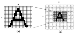
- FIG. 2 schematically shows the relationship between the font data displayed in the present embodiment and the pixels of the display device 16.
- FIG. 5A shows font data representing the character “A”.
- (B) shows a state in which the font data is displayed on the screen of the display device 16. This example assumes a “bitmap point”, and as shown in (a), among the pixels of a two-dimensional array defined by (u, v) coordinates, It has a data structure in which pixel values different from the pixels are given.
- the image processing apparatus 10 uses the font data to represent characters on an image plane corresponding to the resolution of the display device 16.
- FIG. 3 schematically shows how characters are displaced on the display image plane.
- the area 90 is an area representing the character “A” in the display image, and other characters and figures may be displayed around the area 90.
- the image processing apparatus 10 displaces the font image of the character “A” associated with the region 90 in a predetermined direction at a predetermined speed with respect to the display image plane.
- the movement of the character “A” to the upper left in three consecutive frames is represented by three “A”.
- the three “A” s in the figure have different luminances for the purpose of indicating that they are displayed at different times, but in reality the form of the characters themselves is the same.
- the moving amount of the font image to be associated is exaggerated, but the actual moving amount is a minute amount of less than one pixel per frame.
- the displacement of several pixels from the lower right to the upper left and the displacement of several pixels from the upper left to the lower right in the region 90 are performed over a plurality of frames. By repeating the vibration, it is possible to prevent the configuration of the entire page from being affected.
- the direction of displacement may be any of vertical, horizontal, and diagonal, or may be a random direction combining them.
- the entire character “A” is displaced, but only a part of the character line may be displaced.
- only lines that have high density and are likely to be crushed may be displaced.
- the outline can be clearly seen in the direction of displacement, and the displacement direction may be determined by the direction of the selected line. Or even if it is a case where all the lines which constitute a character are displaced, the direction to be displaced by the lines may be varied.
- FIG. 4 is a diagram for explaining a perceptual effect caused by displacing characters.
- (A) in the upper part of the figure shows a temporal change in the positional relationship between the font image representing the character and the display image plane. That is, it is assumed that the font images 92a, 92b, and 92c as shown in FIG. 2A are moved in this order with respect to the regions 94a, 94b, and 94c on the 4 ⁇ 4 pixel display image.
- the font images 92a, 92b, and 92c show a part of the character, for example, a part of an oblique line that forms the character “A” shown in FIG.
- the image processing apparatus 10 determines the pixel value of the display image with reference to the pixel value on the font data by obtaining the uv coordinate on the corresponding font image for each of the 4 ⁇ 4 pixels on the display image.
- (B) in the middle of the figure shows how pixel values are given to the regions 94a, 94b, and 94c with respect to the time change shown in (a).
- the movement of the diagonal line moving to the upper left also appears on the display image.
- the line is thicker than the original font data. Therefore, when each frame is viewed as a still image, character collapse that is not the original font data may occur or jaggy may be noticeable.
- FIG. 5 shows the state of an image perceived by a person who has seen the display image as a result of a change in the display image as shown in (b).
- the region 94a to the region 94b in (b) there are four patterns of pixels: a pixel that changes from white to black, a pixel that changes from black to white, a pixel that remains black, and a pixel that remains white. .
- these four patterns of pixels exist.
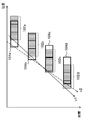
- FIG. 5 is a diagram for explaining the state of human perception when the state of following the moving character with eyes is taken into consideration.
- the horizontal axis is the horizontal position on the display image plane, and a part of the characters as shown in FIG. 4, specifically, the three-pixel areas 102a, 102b, 102c, and 102d representing the line width are represented as time.
- a state in which the display image plane is moved leftward with respect to the progress is shown.
- a region that is mainly viewed moves like gaze regions 104a, 104b, 104c, and 104d.
- the center of the gaze area 104a, 104b, 104c, 104d tends to appear in the same color as the character (gray in the example in the figure) constantly.
- the left end or the right end tends to include a background color (white in the example in the figure).
- the speed of the line of sight is constant, but there are actually variations, and even in this case, the same tendency occurs.
- the color distribution of such gaze areas 104a, 104b, 104c, and 104d is perceived by time integration, the original color of the character is recognized at the center of the line width, and the color blended with the background color is recognized at the periphery.
- the width of the line that can be seen in the original color of the character is determined regardless of the boundary of the pixel area representing it, that is, two boundaries between three pixels in the illustrated example. As a result, it is possible to perceive a line with a resolution higher than that of the display device.
- FIG. 6 shows the internal circuit configuration of the image processing apparatus 10.
- the image processing apparatus 10 includes a CPU (Central Processing Unit) 22, a GPU (Graphics Processing Unit) 24, and a main memory 26. These units are connected to each other via a bus 30.
- An input / output interface 28 is further connected to the bus 30.
- the input / output interface 28 outputs data to a peripheral device interface such as USB or IEEE1394, a communication unit 32 including a wired or wireless LAN network interface, a storage unit 34 such as a hard disk drive or a nonvolatile memory, and the display device 16.
- An output unit 36, an input unit 38 for inputting data from the input device 14, and a recording medium driving unit 40 for driving a removable recording medium such as a magnetic disk, an optical disk or a semiconductor memory are connected.
- the CPU 22 controls the entire image processing apparatus 10 by executing the operating system stored in the storage unit 34.
- the CPU 22 also executes various programs read from the removable recording medium and loaded into the main memory 26 or downloaded via the communication unit 32.
- the GPU 24 has a function of a geometry engine and a function of a rendering processor, performs drawing processing according to a drawing command from the CPU 22, and stores a display image in a frame buffer (not shown).
- the display image stored in the frame buffer is converted into a video signal and output to the output unit 36.
- the main memory 26 is composed of RAM (Random Access Memory) and stores programs and data necessary for processing.
- FIG. 7 shows a functional block configuration of the image processing apparatus 10 in the present embodiment.
- Each functional block shown in the figure can be realized in hardware by the configuration of the CPU 22, GPU 24, main memory 26, output unit 36, input unit 38, etc. shown in FIG. Is loaded into the main memory 26 and realized by a program that exhibits various functions such as a data input function, a data holding function, an arithmetic function, an image processing function, and a communication function. Therefore, it is understood by those skilled in the art that these functional blocks can be realized in various forms by hardware only, software only, or a combination thereof, and is not limited to any one.
- the image processing apparatus 10 includes an input information acquisition unit 72 that acquires input information from the input device 14, a display content acquisition unit 74 that acquires data of content to be displayed, and a display image generation that generates display image data representing the content.
- a font data storage unit 78 that stores font data used for the display image, a character displacement control unit 80 that draws characters while controlling the displacement, and an output unit 84 that outputs display image data.
- the input information acquisition unit 72 is realized by the input unit 38, the CPU 22, and the like of FIG. 6 and acquires the contents of the user operation from the input device 14.
- the user operation may be performed by general information processing such as details of information processing to be executed, selection of content to be displayed, start / end of processing, and command input for information processing being executed.
- the input information acquisition unit 72 may appropriately acquire information related to the user's gaze point, a measurement value of a motion sensor built in the HMD, and the like as will be described later.
- the input information acquisition unit 72 supplies the acquired information to the display content acquisition unit 74 and the character displacement control unit 80 as appropriate.
- the display content acquisition unit 74 is realized by the CPU 22, the main memory 26, the communication unit 32, and the like in FIG. 6, and acquires data of content to be displayed. For example, when the display target is a website page, the display content acquisition unit 74 acquires the data of the page from the management server via a network (not shown). Or the display content acquisition part 74 may read the data of the content stored in the image processing apparatus 10, and may read the program for producing
- the display image generation unit 82 is realized by the CPU 22, the GPU 24, the main memory 26, and the like in FIG. 6, and performs basic processing for generating a content image.
- the display image generation unit 82 represents the entire structure of the display image in the buffer memory that represents the plane of the display image, and performs a drawing process or maps a component image on an area that does not use a font.
- the character displacement control unit 80 is requested to perform drawing processing by designating the region and the character.
- the character displacement control unit 80 is implemented by the CPU 22, the GPU 24, the main memory 26, and the like in FIG. 6 and draws characters using the font data stored in the font data storage unit 78 for the area specified by the display image generation unit 82. .
- various character fonts and their displacement rules are stored in advance in association with each other. Font data may be acquired from a server via a network (not shown).
- the character displacement control unit 80 controls the displacement of characters according to the rules set for the read font.
- the character displacement control unit 80 displaces a character by a minute amount for each frame in accordance with a rule set as font data for a character to be displaced.
- the font image is gradually reflected in the pixel value of the display image by shifting the font image at the sub-pixel level with respect to the display image plane.
- Characters that are not subject to displacement may be drawn by a general method.
- the display image generation unit 82 sequentially outputs the generated display image data including the characters drawn by the character displacement control unit 80 to the output unit 84.
- the output unit 84 is realized by the CPU 22, the GPU 24, the main memory 26, the output unit 36, and the like in FIG. 6, and sequentially outputs the display image data generated by the display image generation unit 82 to the display device 16 at appropriate timing.
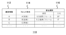
- FIG. 8 shows an example of the structure of font data stored in the font data storage unit 78.
- the font data 110 is data in which the identification information 112, the font shape 114, and the displacement rule 116 are associated with each character.
- the identification information 112 represents character identification information.
- the identification information 112 is a character itself such as “A”, “B”, and “C”, but may be any conventional identification information such as a character code.
- the font shape 114 represents the shape of the character body. In the example shown in the figure, “A (image)”, “B (image)”, “C (image)”, etc. are used, but in actuality, an address indicating a data storage area or character image data itself is used. is there.
- the correspondence between the identification information 112 and the font shape 114 may be the same as that of conventional font data. Further, the font shape may be expressed in a bitmap format or an outline format as described above.
- the displacement rule 116 specifically represents a character displacement rule such as a displacement speed and a displacement direction. In the example shown in the figure, the letter “A” specifies that 0.5 pixel is displaced for each frame by 30 ° from the x-axis of the image plane. By setting the displacement rule for each character in this way, it is possible to set an appropriate displacement direction and speed according to the line density and direction.
- a displacement rule that is common to all characters is set separately and held inside the character displacement control unit 80.
- the displacement rule is not set for the letter “C”.
- the processing load can be reduced by omitting the displacement processing.
- the data structure of the displacement rule is not limited to that shown in the figure. For example, as described above, for each line constituting the character, whether to displace, the displacement direction, and the displacement speed may be set.
- displacing or vibrating one character in one direction it may be displaced in another direction in units of one frame or several frames such as vertical, horizontal, and diagonal. For example, a random number may be generated for each frame and displaced to an angle corresponding thereto.
- the items set as the displacement rule may be the maximum amplitude or frequency when vibrating, in addition to the speed and angle.
- the shape of the font is not limited to the existing shape, but may be generated separately on the premise that it is displaced. For example, assuming that characters are visible with high resolution in the direction of displacement and that the line width looks narrower than the actual display, the line on the font may be thickened or the balance with other lines may be adjusted. Conceivable. In setting the displacement rule including such a case, it is desirable to derive the conditions with the best visibility by actually displacing characters with various resolutions and character sizes.
- the influence on the visibility when the resolution of the display device or the character size is small can be suppressed by displacing the character at least on the display image.
- the font data to be used may be either a bitmap font or an outline font.
- the outline of the character can be shown more clearly by devising the distribution of sampling points. .
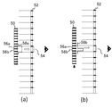
- FIG. 9 is a diagram for explaining an example of a method for determining a pixel value of a display image using bitmap font data.
- FIGS. 5A and 5B schematically show a state where the font image 50 and the display image 52 are viewed from the side, and bold lines shown at equal intervals on each surface indicate pixel boundaries. ing.
- a plurality of pixels of the font image 50 correspond to one pixel of the display image 52.
- two pixels 56 a and 56 b of the font image 50 correspond to one pixel 54 of the display image 52.
- the pixel value C of the pixel 54 of the display image 52 can be determined as follows.
- C (p1 + p2) / 2
- the pixel value C as follows considering the surrounding pixel in a font image.
- C p0 / 4 + p1 / 2 + p2 / 4
- p0 is a pixel adjacent to the pixel 56a of the font image.
- the font value is referred to in two dimensions including the depth direction in the figure and used to determine the pixel value. That is, the pixel value of the display image can be determined by performing a convolution operation on one pixel of the display image using a pixel value included in a predetermined range centered on the position on the corresponding font image.
- a pixel value obtained by blending the character color and the background color is obtained for the pixels near the outline of the character.
- the outline of the character is blurred and the jaggy is not noticeable.
- it is desirable that the outline of the character in each frame stands out from the background in order to make it easier to see the line by displacing the character by the method described above. Therefore, during the period in which the characters are displaced, the reference range of the font image is narrowed as shown in FIG. For example, referring to only the pixel 56b out of the two pixels 56a and 56b of the font image 50 corresponding to the pixel 54 of the display image 52, the pixel value C is determined as follows. C p2
- the reference range is narrowed in the moving direction, and the direction perpendicular thereto is the same as the reference range when the character is stopped as in (a).
- the window functions 58a and 58b that define the reference range and weight may be switched according to the stop / displacement of the character, and the convolution calculation of the pixel value of the font image may be performed.
- FIG. 10 schematically shows a change example of the reference range of the font image with respect to the displacement of the character in the two-dimensional direction.
- This figure assumes a situation in which one pixel of the display image corresponds to 4 ⁇ 4 pixel blocks of the font image, and the reference range when the character is displaced by the velocity vector indicated by the arrow is shown for each pixel block.
- the inner circle or ellipse is shown.
- the circle and ellipse represent the concept of the reference range of the font image used for determining the pixel value, and in practice, discrete sampling points as indicated by black circles are determined according to the range.
- the velocity vector (Vx, Vy) When the character is displaced obliquely with respect to the display image, that is, when the velocity vector (Vx, Vy), the velocity (Vx 2 + Vy 2 ) 1 as indicated by the ellipse in the pixel blocks 250f, 250g, 250h, 250i.
- the reference range of the font image is changed depending on the character speed, blending with the background color can be prioritized at low speed, and clarity of the outline can be prioritized at high speed, and it can be adapted to human visual characteristics according to the speed. .
- the optimum value of the character speed may be determined by the positional relationship with other characters. Further, the reference range may be narrowed by a predetermined ratio in the moving direction whenever the reference range is not adjusted according to the speed and is displaced.
- the pixel value of the display image is determined for each frame by determining one or more sampling points on the font image and taking the weighted average of the pixel values.
- FIG. 11 schematically shows a sampling state in a mode in which the distribution of sampling points is separated in the time direction.
- Each of the three rectangles shown in the figure indicates a region on the font image corresponding to one pixel of the display image at each of the times t0, t1, and t2, and each of the rectangles is configured by a block of 2 ⁇ 2 pixels, for example.
- the boundary between the pixels of the font image and the display image may be shifted.
- sampling points at equal distances from the center of the pixel block 290a are set equally.
- four points of midpoints A, B, C, and D between the center and four vertices of the pixel block 290a are set as sampling points.
- sampling points are 4 points in this way, 4 frames of the display image are set as 1 unit, and 4 sampled pixel values appear in order in 1 unit display time. That is, the pixel value at the sampling point A in the first frame of the unit, and the pixel values at the sampling points B, C, and D in the second, third, and fourth frames respectively appear as pixel values in the display image. To do. Then, the user who sees the corresponding pixel in the frame for one unit appears that the colors of the sampling points A, B, C, and D are blended by the time integration function of the visual stimulus. As long as the characters are stopped, the pixel values at the same sampling point are read out and displayed.
- the reference range is reduced in the direction of the velocity vector, as shown in FIG.
- the distribution of the sampling points is adjusted so that the reference range becomes narrower as the speed V increases.
- the pixel values of the four sampling points are sequentially read over four frames and displayed individually for each frame, so that when the frame for one unit is viewed, To be blended.
- the same effect as when the pixel values in the reference range corresponding to the speed are averaged on the display image of one frame can be obtained. Further, since it is sufficient to read one pixel value of the font image per pixel of one frame, the processing load can be suppressed as compared with reading and calculating a plurality of pixel values simultaneously. Furthermore, regardless of whether the character is stopped or not, it is unified in that the color change expressed in a short time is perceived by time integration, so perceptual discontinuity by switching between the stopped state and the displaced state Disappears.
- the number of sampling points of the font image is four per pixel of the display image, but the present embodiment is not limited thereto.
- N sampling points per pixel are used, N frames are one unit.
- a plurality of pixel values of the font image read at one time may be averaged, and the pixel values of one frame may be averaged.
- the pixel value of the display image is determined using two pixel values of the font image, the values of the sampled N pixels may be represented by N / 2 frames.
- FIG. 12 shows a functional block configuration of the character displacement control unit 80 in a mode in which characters are displaced only in the region of the display image that the user is gazing at.
- the character displacement control unit 80 includes a gazing point detection unit 120, a target area determination unit 124, and a character drawing unit 126.
- the gaze point detection unit 120 acquires, from a gaze point detector (not shown) connected to the image processing apparatus 10, information indicating where on the display screen the user is gazing at a predetermined rate.
- a gazing point detector is a general device that detects a point at which a person is gazing out of an object viewed by a person, for example, by detecting reflection of infrared rays applied to an eyeball.
- the display device 16 is an HMD
- the center of a display image is about a gaze point.
- the function of the gazing point detection unit 120 can be omitted.
- the display device 16 is not limited to the HMD, and the point of interest can be specified in various forms.
- the target area determination unit 124 determines a predetermined range from the gazing point in the display image as a target area for displacing characters. For example, a circle or a rectangular area having a predetermined size centered on the gazing point on the screen is set as the target area. Alternatively, based on the displayed content, an article or item including a gazing point may be the target area.
- the character drawing unit 126 draws each character in a state where the characters in the target area are displaced according to the setting and the other areas are stopped. By limiting the area where the character is displaced in this way, the character is clearly perceived for the part the user is looking at, while the number of times of drawing is reduced for areas that are not affected by the user's recognition. The load can be reduced.
- FIG. 13 shows an example of a screen in a mode of displacing characters in the target area in the display image.
- the display screen 130 has a configuration representing a news article in each of a plurality of regions 132a, 132b, and 132c surrounded by a line.
- the characters in the area 132b are displaced.
- the display positions of the characters are actually shifted by a minute amount for each frame as described above, and this does not mean that the shifted characters are displayed at the same time.
- This mode is an example of determining the target area according to the display content.
- an area selected by the user via the input device 14 may be set as the target area. As shown in the figure, if the area is clearly divided in the display image, the selection by the pointing device may be accepted.
- the characters in the target area may be displaced independently according to the setting of the font data, or the entire area 132b may be displaced. In this case, a displacement rule as set for each character in the font data shown in FIG. 8 may be set for the area 132b in the content data.
- the displacement of the character may be a minute vibration that is not noticed by the user, or may be a large movement that is naturally recognized. In the latter case, for example, it may be a large displacement such that the region 132b located at the right end of the screen moves to the left end. It is possible to intentionally create a situation in which large movements are not unnatural, and to achieve such enjoyment and ease of reading characters at the same time.
- the display screen 130 may represent a vehicle that moves the region 132b, and the region 132b may be displaced by moving the vehicle left and right.
- the example shown in the figure is the display of character information called a news article.
- an object representing a character string may be moved for the sake of readability on a game screen or a virtual world display.
- FIG. 14 is a flowchart illustrating a processing procedure in which the image processing apparatus 10 according to the present embodiment generates and outputs a display image while displacing characters as necessary.
- the display content acquisition unit 74 of the image processing apparatus 10 acquires data of content to be displayed based on a user operation on the input device 14 (S10).
- the display image generation unit 82 interprets and processes the content of the display target content, and determines the overall configuration of the display image (S12). And about the area
- the character displacement control unit 80 determines a target region for displacing the character among the regions requested to be drawn based on a predetermined reference (S14).
- the target area may be the entire display image, or may be a partial area corresponding to the point of gaze or user operation.
- the character displacement control unit 80 may determine whether or not to apply the character displacement process based on a predetermined criterion.
- the readability is maintained even in a situation where the character is crushed or jaggy depending on the resolution of the display device or the size of the character to be displayed.
- the displacement process itself can be omitted in situations where readability is originally secured, such as when displaying on a large screen or when the screen is small and the number of characters is limited and reduction of characters can be suppressed.
- the necessity / unnecessity of the displacement process can also be determined according to the user's visual acuity and the situation of viewing the display device.
- the following is illustrated as a criterion for applying the displacement process.
- the resolution of the display device 16 is a predetermined value or less.
- the size of the display target character on the screen is below a predetermined value.
- the number of pixels representing the display target character is equal to or less than a predetermined value.
- the distance from the user to the screen is a predetermined value or more.
- the user's visual acuity is below a predetermined value. Screen speed is greater than 0
- the distance 4 may be estimated in real time from the size of the user's image taken by providing an imaging device in the vicinity of the screen of the display device 16, or the value in the normal state is pre-registered by the user. May be.
- the user also pre-registers the visual acuity 5.
- the above 6 assumes that it is difficult to see characters in a situation where the screen itself is shaking, such as when the user is looking at the mobile terminal in the car.
- the character displacement control unit 80 may specify the screen speed by acquiring the detection value of the motion sensor inside the terminal.
- the above criteria may be applied alone, or two or more may be combined to evaluate the difficulty of viewing in multiple ways. For example, a score corresponding to an actual situation may be assigned to a plurality of criteria, and it may be determined whether or not to perform character displacement processing based on the total score. As described above, the application of the displacement process as necessary eliminates a sense of discomfort to the user because the object having sufficient visibility is displaced. In addition, the drawing processing load can be reduced, and power consumption can be saved.
- the character displacement control unit 80 reads the data of the character to be drawn from the font data storage unit 78 and draws the character in the drawing destination area on the display image plane.
- the character is drawn in the position representing the displacement in the area representing the character (S18). For example, when a character is simply vibrated, the character is drawn at a position that is a starting point such as the center.
- a character is drawn at a reference position such as the center of the drawing destination area (S20). Note that the character to be displaced may be drawn at the same reference position as the character that is not displaced in the initial drawing.
- the character displacement control unit 80 repeats the processing from S16 to S20 until drawing of all the characters to be drawn using the font in the display image (N in S22).
- the display image generation unit 82 When all the characters have been drawn (Y in S22), the display image generation unit 82 performs drawing appropriately for other regions to complete the display image, and the data is displayed on the display device via the output unit 84. 16 (S24). During a period when it is not necessary to end the display due to a user operation or the like (N in S26), the processes in S12 to S24 are repeated, and all the processes are terminated at the display end timing (Y in S26). In the state where the display image is stationary except for the character to be displaced, the processing of S12, S14, and S20 is omitted as appropriate, and only the region of the character to be displaced needs to be updated in S18.
- an image such as a character in a display image is displaced or vibrated by a minute amount smaller than a pixel area per frame, thereby making a line using a time integration function of visual stimulation.
- a rule for displacing the entire character or a part of a character is associated with a character font.
- the pixel value of the display image is determined by adjusting the sampling range of the font image according to the presence / absence of displacement and the displacement speed.
- the object to be displaced is limited to an area determined based on a predetermined standard such as an area including a gazing point.
- whether or not to apply character displacement processing is at least a standard that affects the difficulty of viewing, such as the resolution of the display device, the size of the characters on the screen, the user's visual acuity, the distance to the screen, and the shaking of the screen. Decide based on either. As a result, it is possible to prevent waste caused by performing displacement processing in an area or situation that does not affect reading difficulty, and avoid an increase in processing load.
- 8 mobile terminal 10 image processing device, 14 input device, 16 display device, 72 input information acquisition unit, 74 display content acquisition unit, 78 font data storage unit, 80 character displacement control unit, 82 display image generation unit, 84 output unit , 120 gaze point detection unit, 124 target area determination unit, 126 character drawing unit.
- the present invention can be used for various information processing devices such as an image display device, an image playback device, a game device, a personal computer, and a mobile terminal, and an information processing system including any one of them.
Landscapes
- Engineering & Computer Science (AREA)
- Physics & Mathematics (AREA)
- General Physics & Mathematics (AREA)
- Theoretical Computer Science (AREA)
- Computer Hardware Design (AREA)
- Controls And Circuits For Display Device (AREA)
Abstract
ユーザ操作に従い表示対象のコンテンツデータを取得し、表示画像の構成を決定する(S10、S12)。表示画像においてフォントを用いて描画する領域のうち、文字を微小量ずつ変位させる領域を決定する(S14)。変位対象の文字については設定された変位規則に従い、時間経過とともに変位させながら描画し(S16のY、S18)、対象外の文字については基準位置に描画する(S16のN、S20)。全文字を描画したら表示画像を完成させ出力する(S22、S24)。表示終了までS12からS24の処理を繰り返す(S26のN)。
Description
本発明は、コンテンツの画像を表示するための画像処理装置、表示画像生成方法、およびそれに用いられるフォントのデータ構造に関する。
近年、画像表示技術は進化の一途を辿り、携帯端末、タブレット、テレビ受像器、パーソナルコンピュータ、ウェアラブルディスプレイなどを用いて、様々な形態や状況で情報を確認したり、ゲームや動画などのコンテンツを楽しんだりできるようになってきた。特に表示装置は高解像度化が実現され、高精細な画像による表示が身近なものになっている。また人の視覚刺激の時間積分機能を利用して、像が移動する場合に、画素を間引いた画像を順に表示させることにより、ディスプレイの解像度より高い解像度で画像を知覚させる技術が提案されている(例えば引用文献1、非特許文献1参照)。
増井俊之、 PixelDoubler、 Interaction'99 講演論文集、 情報処理学会、 March 1999
表示装置やそれを用いるシーンが多様化することにより、同じソース画像をそれらの状況に応じて適切に表示させることが望まれている。例えば大画面の表示装置に表示させることで高い視認性を得ていた文字情報を、腕時計型のウェアラブル端末や携帯電話機に表示させる場合、文字を縮小したり、一度に表示させる情報を少なくしたりする対応が考えられるが、いずれにしても視認性が悪化する。文字が小さくなると、それを表すための表示画面の画素の数が少なくなり、文字を構成する線同士がつながって見える、いわゆる文字つぶれが生じたり、輪郭がギザギザに見えるジャギーが目立ったりして、さらに読みづらさが増す。
本発明はこうした課題に鑑みてなされたものであり、その目的は、表示装置の解像度や表示対象の像の大きさが変化しても、視認性を確保できる技術を提供することにある。
本発明のある態様は画像処理装置に関する。この画像処理装置は、表示画像に表すソース画像のデータと、あらかじめ作成された、表示画像平面に対する前記ソース画像の変位規則とを対応づけたデータを格納する記憶部と、変位規則に従いソース画像を変位させたうえ、当該ソース画像と表示画像平面との位置関係に基づき、表示画像の画素値を決定する変位制御部と、画素値が決定された表示画像のデータを出力する出力部と、を備えたことを特徴とする。
本発明の別の態様は表示画像生成方法に関する。この表示画像生成方法は、ソース画像のデータと、あらかじめ作成された、表示画像平面に対するソース画像の変位規則とを対応づけたデータを格納するメモリから、表示画像の生成に用いるデータを読み出すステップと、変位規則に従いソース画像を変位させたうえ、当該ソース画像と表示画像平面との位置関係に基づき、表示画像の画素値を決定するステップと、画素値が決定された表示画像のデータを出力するステップと、を含むことを特徴とする。
本発明のさらに別の態様はフォントのデータ構造に関する。このフォントのデータ構造は、文字の形状を表すデータと、画像処理装置が表示画像に文字を表す際、表示画像平面で当該文字を変位させるために参照する変位規則と、を文字ごとに対応づけたことを特徴とする。
なお、以上の構成要素の任意の組合せ、本発明の表現を方法、装置などの間で変換したものもまた、本発明の態様として有効である。
本発明によると、表示装置の解像度や表示対象の像の大きさが変化しても、視認性を確保できる。
図1は、本実施の形態を適用できる画像表示の態様を例示している。図示する例は、画像処理装置10と表示装置16を一体的に備えた携帯端末8を示している。表示装置16の画面の上面は、表示された画像に対するユーザのタッチ操作を受け付ける透明なタッチパッドを入力装置14として備える。ただし本実施の形態における画像処理装置10、入力装置14、および表示装置16の形態は図示するものに限らない。例えばそれらの装置を有線あるいは無線で接続した個別の装置としてもよい。あるいはこれらのうち2つの装置を、一体的に備えた1つの装置としてもよい。例えば表示装置16を、ユーザが頭部に装着することにより眼前に画像を表示するヘッドマウントディスプレイ(以下、「HMD」と表記する)とし、画像処理装置10をHMDに内蔵させてもよい。
入力装置14は、図示するタッチパッドのほか、ゲームコントローラ、キーボード、マウス、ジョイスティックなど、一般的な入力装置のいずれか、またはそれらの組み合わせによって実現してよい。あるいは入力装置14は、音声を入力するマイクロフォンや実空間の様子を撮影する撮像装置であってもよい。入力装置14は、ユーザが操作することにより、処理の開始、終了、機能やコンテンツの選択、各種コマンド入力などの要求を受け付け、画像処理装置10に電気信号として供給する。
表示装置16は、画像処理装置10が生成した画像を出力する一般的な装置である。例えば図示するような携帯端末やタブレット端末のディスプレイでもよいし、液晶テレビ、有機ELテレビ、プラズマテレビ、PCモニターなどでもよい。HMDやプロジェクタなどでもよい。なお表示装置16をHMDとする場合、HMDの内部に設けたモーションセンサを入力装置14とし、頭部の動きをユーザ操作としてもよい。
画像処理装置10は、入力装置14を介したユーザ操作などに応じて表示画像のデータを生成し、表示装置16に出力する。ここで表示画像として示される情報の種類は特に限定されず、ユーザが求める機能やコンテンツの内容などによって適宜決定してよい。図の例では、ウェブサイトのページを表す画像6が表示対象であることを模式的に示している。この場合、画像処理装置10は、当該ウェブサイトの管理サーバと通信を確立してHTMLなどマークアップ言語で表されたページのデータや画像のデータを取得する。
そして取得したデータに従い、内部で保持するフォントのデータ、あるいは必要に応じてサーバから取得したフォントのデータを用いて文字情報を描画したうえ、その他の部品画像を配置することにより、画像6、あるいはその一部の画像を生成する。このような手法によれば、画面の大きさによって文字や部品画像を適切なサイズに調整したり、それらの配置や文章の折り返し位置を調整したりすることにより、ある程度の読みやすさを維持できる。一方、画面の解像度が低くなるほど、また画面のサイズが小さくなるほど、そのような調整によっても文字つぶれやジャギーにより視認性が悪化することが考えられる。
そこで本実施の形態では、表示画像において表される文字を微小量変位させつづける、あるいは振動させることにより、人間の知覚上で文字の輪郭が明瞭に見えるようにし、視認性の悪化を軽減させる。なお上述したウェブサイトのページのように、フォントを用いて表示画像を生成する場合には、フォントを個別に変位させることができる。したがって画像6に表される1文字から全ての文字まで、変位対象の文字の数や位置は特に限定されない。
一方、変位させる対象は文字単位でなくてもよい。例えば画像6全体、あるいはその一部の領域を微小量、変位させるようにしてもよい。つまり変位させる対象は文字に限らず、絵、図形、マークでもよいし、それらの組み合わせ、あるいはそれらを組み合わせてなる画像などでもよい。すなわちテクスチャマッピング技術におけるテクスチャのように、表示画像平面に対し変位や停止を制御できる画像であればその種類は限定されない。また、そのようなソース画像を用いて表す表示画像の種類や表示の目的も特に限定されない。以後、そのような表示対象を総じて「コンテンツ」と呼ぶ。また代表的な例として、文字フォントをソース画像とし、コンテンツの表示画像を生成する手法について説明する。
図2は、本実施の形態で表示させるフォントデータと表示装置16の画素の関係を模式的に示している。同図(a)は文字「A」を表すフォントデータを示している。(b)は当該フォントデータを表示装置16の画面に表示させた状態を示している。この例は「ビットマップォント」を想定しており、(a)に示すように、(u,v)座標で定義される2次元配列の画素のうち、字の線として表す画素に、他の画素と異なる画素値を与えたデータ構造を有する。画像処理装置10は当該フォントデータを用いて、表示装置16の解像度に対応する画像平面に文字を表す。
すなわち(b)に示す、(x、y)座標で定義される表示画像平面の各画素に対応するuv座標を求め、(a)に示すフォント画像における当該位置座標の画素値をサンプリングすることにより、表示画像の画素値を決定する。この処理は、コンピュータグラフィクスにおけるテクスチャマッピングに相当する。なおフォントデータとしては、線の端点や曲線の基準点など輪郭における特徴点の位置で文字を表現する「アウトラインフォント」も一般的である。アウトラインフォントを用いる場合、表示画像平面に仮想的に表した輪郭との内外判定により各画素の値を決定するラスタライズがなされる。この場合も文字を変位させることによる効果は同様となる。
図3は、表示画像平面において文字を変位させる様子を模式的に示している。領域90は、表示画像において文字「A」を表す領域であり、周囲にはその他の文字や図形が表示されていてよい。画像処理装置10は、領域90に対応づける文字「A」のフォント画像を、表示画像平面に対し所定速度で所定方向に変位させる。図の例では連続する3フレームにおいて、文字「A」を左上に移動させることを、3つの「A」で表している。なお図における3つの「A」は、互いに異なる時刻に表示されることを示す目的で輝度を異ならせているが、実際には文字自体の態様は同じである。
また図では、対応づけるフォント画像の移動量を誇張して示しているが、実際の移動量は1フレームあたり1画素未満の微小量とする。ウェブサイトのページのように通常は静止している文字の場合、領域90において右下から左上への数画素分の変位と左上から右下への数画素分の変位を、複数フレームに渡って繰り返すように振動させることにより、ページ全体の構成には影響を与えないようにできる。なお変位の方向は縦、横、斜めのいずれでもよいし、それらを組み合わせたランダムな方向としてもよい。
また同図では文字「A」全体を変位させたが、文字の一部の線のみを変位させてもよい。例えば密度が高く文字つぶれが生じやすい線のみを変位させてもよい。定性的には変位させる方向において輪郭を明瞭に見せることができるため、選択した線の方向によって変位方向を決定してもよい。または文字を構成する線の全てを変位させる場合であっても、線によって変位させる方向を異ならせてもよい。
図4は、文字を変位させることによる知覚上の効果を説明するための図である。同図上段の(a)は、文字を表すフォント画像と表示画像平面の位置関係の時間変化を示している。すなわち4×4画素の表示画像上の領域94a、94b、94cに対し、図2の(a)で示したようなフォント画像92a、92b、92cがこの順で移動しているとする。フォント画像92a、92b、92cは、文字の一部を示しており、例えば図3で示した文字「A」を構成する斜め線の一部などである。
画像処理装置10は、表示画像上の4×4の画素のそれぞれについて、対応するフォント画像上のuv座標を求めることにより、フォントデータ上の画素値を参照して、表示画像の画素値を決定する。同図中段の(b)は、(a)に示した時間変化に対し、領域94a、94b、94cに画素値が与えられた様子を示している。図示するように、斜め線が左上に移動する動きが表示画像上でも表れる。ただし表示装置の解像度によっては、元のフォントデータより太い線となる。そのため、各フレームを静止画として見た場合は、元のフォントデータではなかった文字つぶれが発生したりジャギーが目立ったりすることがある。
同図(c)は、(b)のように表示画像が変化した結果、それを見た人が知覚する画像の様子を示している。(b)における領域94aから領域94bへの変化では、白から黒に変化する画素、黒から白に変化する画素、黒のままの画素、白のままの画素、という4パターンの画素が存在する。領域94bから領域94cへの変化でも同様に、それらの4パターンの画素が存在する。
人は短時間の視覚的刺激を時間積分で感じる特性を有するため、白から黒に変化する画素、黒から白に変化する画素は、原理的には灰色として認識される。黒のままの画素、白のままの画素は当然、黒あるいは白として認識されるため、人の知覚上では(c)に示すように、線の中心では文字本来の色(図の例では黒)、周縁では背景色(図の例では白)とブレンドされた色となる。つまりこのような文字の変位により、線の中心軸近傍の色が強調される結果、文字つぶれやジャギーによる視認のしづらさを軽減させることができる。
図5は、変位する文字を目で追っている状態を考慮したときの、人の知覚の様子を説明するための図である。同図は横軸を表示画像平面における横方向の位置とし、図4で示したような文字の一部、具体的には線幅を表す3画素の領域102a、102b、102c、102dが、時間経過に対し表示画像平面を左方向に移動していく様子を示している。人がその動きを目で追うとき、主に見ている領域が、注視領域104a、104b、104c、104dのように動くとする。
つまり視線の速度v2が文字の速度v1からずれているとき、注視領域104a、104b、104c、104dの中央付近は定常的に文字と同じ色(図の例では灰色)が表れやすいのに対し、左端あるいは右端は背景色(図の例では白)が含まれやすい。図示する例は視線の速度を一定としているが、実際にはばらつきがあり、その場合でも同様の傾向となる。そのような注視領域104a、104b、104c、104dの色分布を時間積分して知覚した場合、線幅の中央部分は文字本来の色、周縁では背景色とブレンドされた色が認識される。また、文字本来の色で見える線の幅は、それを表す画素領域の境界、図示する例では3画素の間の2つの境界と関わりなく決まる。結果として知覚上、表示装置の解像度より高い解像度で線を認識させることができる。
図6は画像処理装置10の内部回路構成を示している。画像処理装置10は、CPU(Central Processing Unit)22、GPU(Graphics Processing Unit)24、メインメモリ26を含む。これらの各部は、バス30を介して相互に接続されている。バス30にはさらに入出力インターフェース28が接続されている。入出力インターフェース28には、USBやIEEE1394などの周辺機器インターフェースや、有線又は無線LANのネットワークインターフェースからなる通信部32、ハードディスクドライブや不揮発性メモリなどの記憶部34、表示装置16へデータを出力する出力部36、入力装置14からデータを入力する入力部38、磁気ディスク、光ディスクまたは半導体メモリなどのリムーバブル記録媒体を駆動する記録媒体駆動部40が接続される。
CPU22は、記憶部34に記憶されているオペレーティングシステムを実行することにより画像処理装置10の全体を制御する。CPU22はまた、リムーバブル記録媒体から読み出されてメインメモリ26にロードされた、あるいは通信部32を介してダウンロードされた各種プログラムを実行する。GPU24は、ジオメトリエンジンの機能とレンダリングプロセッサの機能とを有し、CPU22からの描画命令に従って描画処理を行い、表示画像を図示しないフレームバッファに格納する。そしてフレームバッファに格納された表示画像をビデオ信号に変換して出力部36に出力する。メインメモリ26はRAM(Random Access Memory)により構成され、処理に必要なプログラムやデータを記憶する。
図7は、本実施の形態における画像処理装置10の機能ブロックの構成を示している。同図に示す各機能ブロックは、ハードウェア的には、図6に示したCPU22、GPU24、メインメモリ26、出力部36、入力部38などの構成で実現でき、ソフトウェア的には、記録媒体などからメインメモリ26にロードした、データ入力機能、データ保持機能、演算機能、画像処理機能、通信機能などの諸機能を発揮するプログラムで実現される。したがって、これらの機能ブロックがハードウェアのみ、ソフトウェアのみ、またはそれらの組合せによっていろいろな形で実現できることは当業者には理解されるところであり、いずれかに限定されるものではない。
画像処理装置10は、入力装置14から入力情報を取得する入力情報取得部72、表示対象のコンテンツのデータを取得する表示コンテンツ取得部74、コンテンツを表した表示画像のデータを生成する表示画像生成部82、表示画像に用いるフォントのデータを格納したフォントデータ記憶部78、変位を制御しつつ文字を描画する文字変位制御部80、および表示画像のデータを出力する出力部84を含む。
入力情報取得部72は図6の入力部38、CPU22などで実現され、ユーザ操作の内容を入力装置14から取得する。ここでユーザ操作とは、実行する情報処理の内容や表示対象のコンテンツの選択、処理の開始/終了、実行している情報処理に対するコマンド入力など、一般的な情報処理でなされるものでよい。また入力情報取得部72は、後述するようにユーザの注視点に係る情報や、HMDに内蔵されたモーションセンサの計測値などを適宜取得してよい。入力情報取得部72は取得した情報を、表示コンテンツ取得部74および文字変位制御部80に適宜供給する。
表示コンテンツ取得部74は図6のCPU22、メインメモリ26、通信部32などで実現され、表示対象のコンテンツのデータを取得する。例えば表示対象をウェブサイトのページとした場合、表示コンテンツ取得部74は図示しないネットワークを介して管理サーバから当該ページのデータを取得する。あるいは表示コンテンツ取得部74は、画像処理装置10内部に格納されたコンテンツのデータを読み出してもよいし、表示画像を生成するためのプログラムを読み出してもよい。
表示画像生成部82は図6のCPU22、GPU24、メインメモリ26などで実現され、コンテンツの画像を生成する基本的な処理を実施する。すなわち表示画像生成部82は、表示画像の平面を表したバッファメモリに、表示画像の全体構造を表し、フォントを用いない領域について、描画処理を実施したり部品画像をマッピングしたりする。またフォントを用いて文字を描画すべき領域については、文字変位制御部80に、当該領域と文字を指定して描画処理を要求する。
文字変位制御部80は図6のCPU22、GPU24、メインメモリ26などで実現され、表示画像生成部82が指定した領域について、フォントデータ記憶部78に格納されたフォントデータを用いて文字を描画する。フォントデータ記憶部78にはあらかじめ、各種の文字フォントと、その変位規則を対応づけて格納しておく。なおフォントデータは、図示しないネットワークを介してサーバから取得してもよい。文字変位制御部80は、読み出したフォントに対し設定されている規則に従い文字の変位を制御する。
この際、コンテンツにおいて設定されている規則に従い、表示画像の全ての文字を変位させるか、特定の領域のみ変位させるか、特定の文字あるいは字体のみ変位させるか、などを決定してもよい。また大画面での表示など、元々良好な視認性が保証されている状況では、変位処理自体を省略してもよい。文字変位制御部80は、変位対象の文字については、フォントデータとして設定されている規則に従い、フレームごとに文字を微小量変位させる。
厳密には、表示画像平面に対しフォントの画像をサブピクセルレベルでずらしていくことで表示画像の画素値に徐々に反映させる。変位対象でない文字については、一般的な手法で描画すればよい。表示画像生成部82は、文字変位制御部80が描画した文字を含め、生成した表示画像のデータを順次、出力部84に出力する。出力部84は図6のCPU22、GPU24、メインメモリ26、出力部36などで実現され、表示画像生成部82が生成した表示画像のデータを適切なタイミングで順次、表示装置16に出力する。
図8は、フォントデータ記憶部78に格納するフォントデータの構造例を示している。フォントデータ110は、識別情報112、フォント形状114、および変位規則116を、文字ごとに対応づけたデータである。識別情報112は、文字の識別情報を表し、図示する例では「A」、「B」、「C」など文字そのものとしているが、文字コードなど従来ある識別情報のいずれでもよい。フォント形状114は、文字本体の形状を表す。図示する例では「A(画像)」、「B(画像」、「C(画像)」などと表記しているが、実際にはデータの記憶領域を示すアドレスや、文字の画像データそのものなどである。
識別情報112とフォント形状114の対応づけは、従来のフォントデータと同様でよい。またフォント形状は上述のとおりビットマップ形式で表されてもアウトライン形式で表されてもよい。変位規則116は、変位速度、変位方向など文字の変位規則を具体的に表す。図示する例では「A」の文字は、フレームごとに0.5画素分、画像平面のx軸から30°をなす方向に変位させることを指定している。このように文字ごとに変位規則を設定することにより、線の密度や方向に応じて適切な変位方向や速度を設定できる。
一方、全ての文字に共通とする変位規則については、別途設定し、文字変位制御部80内部で保持しておく。また図示する例では「C」の文字は変位規則を設定していない。このように文字形状が比較的単純で、解像度や文字サイズによって視認性が変化しにくい文字については、変位処理を省略することにより処理の負荷を軽減できる。なお変位規則のデータ構造は図示するものに限らない。例えば上述のとおり、文字を構成する線ごとに、変位させるか否か、変位方向、変位速度を設定してもよい。
また1文字を一方向に変位あるいは振動させるのみならず、縦、横、斜めなど1フレームあるいは数フレーム単位で別の方向へ変位させてもよい。例えばフレームごとに乱数を発生させ、それに対応する角度に変位させるようにしてもよい。さらに変位規則として設定する項目は、速度や角度のほか、振動させる場合の最大振幅や周波数などでもよい。図示するような構造のデータを、様々なフォントに対して設けることにより、同じ文字でも文字つぶれの生じやすさなどに応じて適切な変位を実現できる。
ここでフォントの形状は既存のものに限らず、変位させることを前提として別途生成しておいてもよい。例えば変位させる方向において高い分解能で文字が視認され、実際の表示より線幅が狭く見えることを想定し、フォント上での線を太くしたり、他の線とのバランスを調整したりすることが考えられる。このような場合を含め変位規則の設定に当たっては、様々な解像度や文字サイズで実際に文字を変位させて、最も視認性がよい条件を導出しておくことが望ましい。
これまで述べたように本実施の形態では、少なくとも表示画像上で文字を変位させることにより、表示装置の解像度や文字のサイズが小さい場合の視認性への影響を抑えることができる。その観点において、用いるフォントデータは、ビットマップフォントとアウトラインフォントのいずれでもよいが、特にビットマップフォントを用いた場合、サンプリング点の分布を工夫することにより、文字の輪郭をさらにはっきり見せることができる。
図9は、ビットマップのフォントデータを用いて表示画像の画素値を決定する手法の例を説明するための図である。同図(a)、(b)はどちらも、フォント画像50と表示画像52を側面から見た状態を模式的に示しており、各面において等間隔で示された太線が画素の境界を示している。フォント画像50の画素が表示画像52の画素より細かい場合、表示画像52の1画素に、フォント画像50の複数の画素が対応する。図示する例では、フォント画像50の2つの画素56a、56bが、表示画像52の1つの画素54に対応している。
ここでフォント画像50の画素56a、56bの値をp1およびp2とすると、表示画像52の画素54の画素値Cを次のように決定できる。
C=(p1+p2)/2
ただし上記は1次元での画素の対応のみを考慮している。図の奥行き方向を含めた2次元を考慮し、フォント画像50の2×2=4個の画素が、表示画像52の画素54に対応する場合、当該4つの画素値の平均値を、画素54の画素値Cとする。
C=(p1+p2)/2
ただし上記は1次元での画素の対応のみを考慮している。図の奥行き方向を含めた2次元を考慮し、フォント画像50の2×2=4個の画素が、表示画像52の画素54に対応する場合、当該4つの画素値の平均値を、画素54の画素値Cとする。
あるいはフォント画像における周囲の画素を加味して、画素値Cを次のように求めてもよい。
C=p0/4+p1/2+p2/4
ここでp0は、フォント画像の画素56aに隣接する画素である。ただしこの場合も、実際には図の奥行き方向を含めた2次元でフォント画像を参照し画素値の決定に用いる。すなわち表示画像の1つの画素に対し、それに対応するフォント画像上の位置を中心とした所定範囲に含まれる画素値を用いて畳み込み演算を行うことにより、表示画像の画素値を決定できる。
C=p0/4+p1/2+p2/4
ここでp0は、フォント画像の画素56aに隣接する画素である。ただしこの場合も、実際には図の奥行き方向を含めた2次元でフォント画像を参照し画素値の決定に用いる。すなわち表示画像の1つの画素に対し、それに対応するフォント画像上の位置を中心とした所定範囲に含まれる画素値を用いて畳み込み演算を行うことにより、表示画像の画素値を決定できる。
このような手法によれば、文字の輪郭近傍の画素については、文字の色と背景色がブレンドされた画素値が得られる。結果として文字の輪郭がぼやけ、ジャギーを目立たせないようにできる。一方、上述した手法により文字を変位させて線を見やすくするためには、各フレームにおける文字の輪郭が背景に対し際立っていることが望ましい。そのため文字を変位させている期間は、同図(b)に示すように、フォント画像の参照範囲を狭める。例えば、表示画像52の画素54に対応するフォント画像50の2つの画素56a、56bのうち、画素56bのみを参照し次のように画素値Cを決定する。
C=p2
C=p2
ただし上述した効果は文字の移動方向のみに作用するため、当該移動方向において参照範囲を狭め、それと垂直な方向については、(a)のように文字が停止しているときと同様の参照範囲とする。なお図示する例では表示画像の1つの画素に、フォント画像のちょうど2つの画素が対応していたが、画素の対応関係は特に限定されない。すなわちフォントの縮小率にかかわらず、参照範囲と重みを規定した窓関数58a、58bを、文字の停止/変位によって切り替えたうえ、フォント画像の画素値の畳み込み演算を行えばよい。
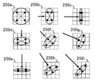
図10は、2次元方向の文字の変位に対するフォント画像の参照範囲の変化例を模式的に示している。同図は表示画像の1画素に、フォント画像の4×4個の画素ブロックが対応する状況を想定しており、矢印で示す速度ベクトルで文字を変位させたときの参照範囲を、各画素ブロック内の円形または楕円形で示している。ただし当該円形、楕円形は、画素値の決定に用いるフォント画像の参照範囲を概念として表象するものであり、実際には黒丸で示すような離散的なサンプリング点を範囲に応じて決定する。
まず文字を停止させているとき、画素ブロック250aに円形で示すように、画素ブロックの中心から均等な範囲を参照する。これにより、表示画像上で文字の輪郭近傍に存在する画素は、文字の色と背景の色がブレンドされた色となる。表示画像に対し文字を横方向に変位させる場合、すなわち速度ベクトル(Vx,0)のときは、画素ブロック250b、250cに楕円形で示すように、速度Vxが大きいほど横方向の参照範囲がより狭まるようにする。表示画像に対し文字を縦方向に変位させる場合、すなわち速度ベクトル(0,Vy)のときは、画素ブロック250d、250eに楕円形で示すように、速度Vyが大きいほど縦方向の参照範囲がより狭まるようにする。
表示画像に対し文字を斜め方向に変位させる場合、すなわち速度ベクトル(Vx,Vy)のときは、画素ブロック250f、250g、250h、250iに楕円形で示すように、速度(Vx2+Vy2)1/2が大きいほど速度ベクトルと同方向の参照範囲がより狭まるようにする。なお移動速度の増加に対し参照範囲が小さくなれば、両者の具体的な関係は特に限定されず、例えば反比例でもよいし1次関数や指数関数などでもよい。
このように文字の速度によってフォント画像の参照範囲を変化させると、低速時には背景色とのブレンドを、高速時には輪郭の明確性を優先でき、速度に応じた人の視覚特性に適合させることができる。なお文字の速度は文字自体の形状やサイズ以外に、他の文字との位置関係などによって最適値を決定してよい。また速度に応じて参照範囲を調整せず、変位させているときは常に、移動方向に所定割合だけ参照範囲を狭めるようにしてもよい。
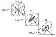
これまで述べた態様では、フォント画像上で1つまたは複数のサンプリング点を決定し、その画素値の加重平均をとることで、フレームごとに表示画像の画素値を決定した。一方、サンプリング点の分布を、連続したフレームに対し時間方向に分離することにより、文字を停止させている状態においても、視覚刺激の時間積分機能を利用して認識上でブレンドさせることが考えられる。図11は、サンプリング点の分布を時間方向に分離する態様におけるサンプリングの様子を模式的に示している。
図に示す3つの矩形はそれぞれ、各時刻t0、t1、t2において表示画像の1画素に対応するフォント画像上の領域を示しており、例えばいずれも2×2個の画素からなるブロックで構成される。ただしフォント画像と表示画像の画素の境界がずれていても構わない。まず文字を停止させているとき(V=0)、画素ブロック290aの中心から等しい距離のサンプリング点を均等に設定する。図示する例では、画素ブロック290aの中心と4頂点との中点A、B、C、Dの4点をサンプリング点としている。
このようにサンプリング点を4点とした場合、表示画像の4フレームを1単位とし、1単位の表示時間で、サンプリングした4つの画素値が順に表れるようにする。すなわち当該単位の最初のフレームにおいてサンプリング点Aの画素値が、2番目、3番目、4番目のフレームにおいて、サンプリング点B、C、Dの画素値が、それぞれ表示画像の画素値として表れるようにする。すると1単位分のフレームの該当画素を見たユーザには、視覚刺激の時間積分機能によって、サンプリング点A、B、C、Dの色がブレンドされて見える。文字が停止している限りは、同じサンプリング点の画素値を循環して読み出し、表示する。
文字を変位させている場合は、図10で示したのと同様、速度ベクトルの方向に参照範囲を縮小する。このとき画素ブロック290b、290cに示すように、速度Vが大きいほど参照範囲がより狭まるようにサンプリング点の分布を調整する。そして停止させている場合と同様、4つのサンプリング点の画素値を、4フレームに渡って順に読み出し、フレームごとに個別に表示させることにより、1単位分のフレームを見たときに、認識上でブレンドされるようにする。
この場合も、1フレームの表示画像上で、速度に応じた参照範囲の画素値を平均したときと同様の効果が得られる。また1フレームの1画素あたり、フォント画像の1つの画素値を読み出せばよいため、複数の画素値を同時に読み出し、演算するのと比較して処理の負荷を抑えることができる。さらに文字が停止しているか否かに関わらず、短時間に表された色の変化を時間積分して知覚する点で統一されるため、停止状態と変位状態の切り替えによる知覚的な不連続性がなくなる。
なお図示する例では、フォント画像のサンプリング点を、表示画像の1画素当たり4つとしているが、本実施の形態をそれに限る趣旨ではない。1画素当たりのサンプリング点をN個とした場合、Nフレームが1単位となる。また、一度に読み出すフォント画像の画素値を複数とし、それらを平均して1フレームの画素値としてもよい。例えばフォント画像の2つの画素値を用いて表示画像の画素値を決定する場合、サンプリングしたN個の画素の値をN/2フレームで表せばよい。
上述のように文字を変位させる対象は、表示画像全体としてもよいし一部の領域としてもよい。図12は、表示画像のうちユーザが注視している領域に限定して文字を変位させる態様における、文字変位制御部80の機能ブロックの構成を示している。この態様において文字変位制御部80は、注視点検出部120、対象領域決定部124、および文字描画部126を備える。注視点検出部120は、画像処理装置10と接続した図示しない注視点検出器から、ユーザが表示画面のどこを注視しているかを示す情報を所定のレートで取得する。
注視点検出器は、眼球に照射した赤外線の反射を検出するなどして、人が見ている対象物のうち注視しているポイントを検出する一般的な装置である。例えば表示装置16をHMDとする場合、HMDの内部に注視点検出器を設けることが考えられる。またHMDを装着したユーザの視線に応じた視野で画像を表示する態様においては、表示画像の中心がおよそ注視点であると推定できる。この場合、注視点検出部120の機能を省略できる。ただし表示装置16をHMDに限る趣旨ではなく、様々な形態で注視点を特定できることは、当業者には理解されるところである。
対象領域決定部124は、表示画像において注視点から所定の範囲を、文字を変位させる対象領域として決定する。例えば画面上で注視点を中心とする所定サイズの円や矩形状の領域を対象領域とする。あるいは表示されている内容を踏まえ、注視点を含む記事や項目などを対象領域としてもよい。文字描画部126は、対象領域内の文字について設定に従う変位をさせ、その他の領域については停止させた状態で、各文字を描画する。このように文字を変位させる領域を限定的とすることで、ユーザが見ている部分については文字を明確に知覚させる一方、ユーザの認識上、影響のない領域については描画の回数を減らし、処理負荷を軽減させることができる。
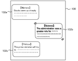
図13は、表示画像のうち対象領域の文字を変位させる態様における画面の例を示している。表示画面130は、線で囲まれた複数の領域132a、132b、132cのそれぞれに、ニュースの記事を表した構成を有する。これらの領域のうち領域132b内にユーザの注視点があった場合、領域132b内の文字を変位させる。なお図ではずれた字を重ねて表しているが、実際には上述のとおりフレームごとに微小量ずつ文字の表示位置をずらしていくのであり、ずれた字を同時に表示する趣旨ではない。
この態様は表示の内容によって対象領域を決定する例である。なお注視点を検出する代わりに、入力装置14を介してユーザが選択した領域を対象領域としてもよい。図示するように表示画像において領域が明確に分かれている場合は、ポインティングデバイスによる選択を受け付ければよい。なお対象領域内の文字は、フォントデータの設定に従いそれぞれ独立して変位させてもよいし、領域132b全体を変位させてもよい。この場合、図8で示したフォントデータにおいて文字ごとに設定したような変位規則を、コンテンツデータにおいて、領域132bに対し設定しておけばよい。
また文字の変位は、ユーザが気づかない程度の微小な振動でもよいし、当然認識されるような大きな動きとしてもよい。後者の場合、例えば画面の右端にあった領域132bが左端まで移動するような大きな変位としてもよい。大きな動きが不自然でない状況を意図的に作りだし、そのような演出の楽しさと文字の読みやすさを同時に達成するようにしてもよい。例えば表示画面130に、領域132bを動かす乗り物を表し、当該乗り物が左右に動くことにより領域132bが変位するようにしてもよい。図示する例はニュースの記事という、文字情報の表示であったが、ゲーム画面や仮想世界の表示において、文字列を表したオブジェクトを、読みやすさを意図して動かすようにしてもよい。
次に、これまで述べた構成によって実現できる画像処理装置の動作について説明する。図14は、本実施の形態の画像処理装置10が、必要に応じて文字を変位させつつ表示画像を生成、出力する処理手順を示すフローチャートである。まず画像処理装置10の表示コンテンツ取得部74は、入力装置14に対するユーザ操作に基づき、表示するコンテンツのデータを取得する(S10)。
次に表示画像生成部82は、表示対象のコンテンツの内容を解釈したり処理したりして、表示画像の全体的な構成を決定する(S12)。そしてフォントを用いて描画する領域については、文字変位制御部80にその描画を要求する。文字変位制御部80は、描画を要求された領域のうち、文字を変位させる対象領域を所定の基準により決定する(S14)。対象領域は表示画像全体としてもよいし、注視点やユーザ操作などに応じた一部の領域でもよい。またS14の前処理として文字変位制御部80は、文字の変位処理を適用するか否かを、所定の基準により判定してもよい。
本実施の形態では文字を変位させることにより、表示装置の解像度や表示させる文字のサイズなどによって文字つぶれやジャギーが発生するような状況でも読みやすさを維持する。換言すれば、大画面での表示や、画面が小さくても文字数が限定的で文字の縮小を抑えられる場合など、元々読みやすさが確保されている状況では、変位処理自体を省くことができる。またユーザの視力や、表示装置を見ている状況によっても、変位処理の必要/不必要を決定できる。
変位処理を適用する判定基準として次のものが例示される。
1.表示装置16の解像度が所定値以下
2.表示対象の文字の画面でのサイズが所定値以下
3.表示対象の文字を表す画素の数が所定値以下
4.ユーザから画面までの距離が所定値以上
5.ユーザの視力が所定値以下
6.画面の速度が0より大きい
1.表示装置16の解像度が所定値以下
2.表示対象の文字の画面でのサイズが所定値以下
3.表示対象の文字を表す画素の数が所定値以下
4.ユーザから画面までの距離が所定値以上
5.ユーザの視力が所定値以下
6.画面の速度が0より大きい
上記4の距離については、表示装置16の画面近傍に撮像装置を設け、それで撮影したユーザの像の大きさなどからリアルタイムで推定してもよいし、通常状態での値をユーザが事前登録してもよい。5の視力についてもユーザが事前登録しておく。上記6は、ユーザが車中で携帯端末を見ているなど、画面自体が揺れている状況における文字の見にくさを想定している。この場合、文字変位制御部80は端末内部のモーションセンサの検出値を取得することにより画面の速度を特定すればよい。
上記基準は単独で適用してもよいし、2つ以上を組み合わせて、見づらさを多角的に評価してもよい。例えば複数の基準について実際の状況に応じたスコアをつけ、その合計スコアに基づき、文字の変位処理を実施するか否かを決定してもよい。このように必要に応じた変位処理の適用により、十分な視認性が得られているものが変位していることによって、却ってユーザに違和感を与えるようなことがなくなる。また描画処理の負荷を抑えられ、消費電力も節約できる。
次に文字変位制御部80は、フォントデータ記憶部78から描画すべき文字のデータを読み出し、表示画像平面における描画先の領域に文字を描画する。ここで描画先が変位対象領域に含まれている場合は(S16のY)、当該文字を表す領域のうち変位を前提とした位置に文字を描画する(S18)。例えば文字を単振動させる場合、その中心など始点となる位置に文字を描画する。描画先が変位対象領域に含まれていない場合は(S16のN)、当該描画先の領域の中央など基準位置に文字を描画する(S20)。なお変位対象の文字も、初回の描画については変位させない文字と同様の基準位置に描画してもよい。文字変位制御部80は、表示画像中、フォントを用いて描画する文字を全て描画し終えるまでS16からS20の処理を繰り返す(S22のN)。
全ての文字を描画し終えたら(S22のY)、表示画像生成部82は、それ以外の領域について適宜描画を実施して表示画像を完成させ、そのデータを、出力部84を介して表示装置16に出力する(S24)。ユーザ操作などにより表示を終了させる必要がない期間は(S26のN)、S12~S24の処理を繰り返し、表示終了のタイミングで全処理を終了させる(S26のY)。なお変位させる文字を除き表示画像が静止している状態においては、S12、S14、S20の処理は適宜省略し、S18において変位対象の文字の領域のみ、データを更新すればよい。
以上述べた本実施の形態によれば、表示画像において文字などの像を、フレームあたり画素領域より小さい微小量だけ変位させたり振動させたりすることにより、視覚刺激の時間積分機能を利用して線を見やすくする。例えば文字フォントに対し、文字全体または一部の線を変位させる規則を対応づけておく。これにより、フォントを用いたフレキシブルな表示を実現できると同時に、解像度や文字サイズの低下による見づらさ、読みづらさを軽減できる。
また変位の有無や変位速度によって、フォント画像のサンプリングの範囲を調整して、表示画像の画素値を決定する。これにより変位させない文字については輪郭が背景とブレンドされ、変位させる場合は時間積分により輪郭がはっきり視認されるような表示を実現できる。さらに文字を変位させる対象を、注視点を含む領域など所定の基準で決定した領域に限定する。加えて文字の変位処理を適用するか否かを、表示装置の解像度、画面上での文字のサイズ、ユーザの視力、画面までの距離、画面の揺れなど、見づらさに影響を与える基準の少なくともいずれかに基づき決定する。これらのことにより、読みづらさに影響しない領域や状況で変位処理を実施することによる無駄を防ぎ、処理負荷の増大を回避できる。
以上、本発明を実施の形態をもとに説明した。上記実施の形態は例示であり、それらの各構成要素や各処理プロセスの組合せにいろいろな変形例が可能なこと、またそうした変形例も本発明の範囲にあることは当業者に理解されるところである。
8 携帯端末、 10 画像処理装置、 14 入力装置、 16 表示装置、 72 入力情報取得部、 74 表示コンテンツ取得部、 78 フォントデータ記憶部、 80 文字変位制御部、 82 表示画像生成部、 84 出力部、 120 注視点検出部、 124 対象領域決定部、 126 文字描画部。
以上のように本発明は、画像表示装置、画像再生装置、ゲーム装置、パーソナルコンピュータ、携帯端末など各種情報処理装置や、それらのいずれかを含む情報処理システムなどに利用可能である。
Claims (13)
- 表示画像に表すソース画像のデータと、あらかじめ作成された、表示画像平面に対する前記ソース画像の変位規則とを対応づけたデータを格納する記憶部と、
前記変位規則に従い前記ソース画像を変位させたうえ、当該ソース画像と表示画像平面との位置関係に基づき、表示画像の画素値を決定する変位制御部と、
画素値が決定された表示画像のデータを出力する出力部と、
を備えたことを特徴とする画像処理装置。 - 前記記憶部は、前記変位規則として、表示画像の1フレームに対し1画素の領域より小さい変位を生じさせる規則を格納することを特徴とする請求項1に記載の画像処理装置。
- 前記記憶部は、前記ソース画像のデータとして文字のフォントを表すデータを、前記変位規則と対応づけて格納し、
前記変位制御部は、前記変位規則に従い、表示画像における文字を個別に変位させることを特徴とする請求項1または2に記載の画像処理装置。 - 前記記憶部は、前記文字のフォントのうち、当該文字を構成する線ごとに前記変位規則を対応づけたデータを格納し、
前記変位制御部は、前記変位規則に従い、前記線を個別に変位させることを特徴とする請求項3に記載の画像処理装置。 - 前記記憶部は、前記変位規則として、表示画像平面に対する振動の規則を、前記ソース画像のデータと対応づけて格納し、
前記変位制御部は、前記変位規則に従い、表示画像平面に対し前記ソース画像を振動させることを特徴とする請求項1から4のいずれかに記載の画像処理装置。 - 前記変位制御部は、表示画像のうち所定の基準で選択した領域内で、前記変位規則に従った変位を実現させることを特徴とする請求項1から5のいずれかに記載の画像処理装置。
- 前記変位制御部は、表示画像に対するユーザの注視点に係る情報を取得し、当該注視点を含む所定範囲の領域内で、前記変位規則に従った変位を実現させることを特徴とする請求項1から6のいずれかに記載の画像処理装置
- 前記変位制御部は、表示画像を出力する表示装置の解像度、表示画像平面に対する前記ソース画像のサイズ、前記表示装置の画面とユーザとの距離、ユーザの視力、および前記表示装置の速度、の少なくともいずれかに基づき、前記変位規則に従った変位を実現させるか否かを判定することを特徴とする請求項1から7のいずれかに記載の画像処理装置。
- 前記変位制御部は、表示画像の各画素値を決定するために参照する前記ソース画像上の範囲の形状を、当該ソース画像の変位の有無によって異ならせることを特徴とする請求項1から8のいずれかに記載の画像処理装置。
- 前記変位制御部は、表示画像の各画素値を決定するために参照する前記ソース画像上の範囲を、当該ソース画像を変位させる方向において狭めることを特徴とする請求項1から9のいずれかに記載の画像処理装置。
- ソース画像のデータと、あらかじめ作成された、表示画像平面に対する前記ソース画像の変位規則とを対応づけたデータを格納するメモリから、表示画像の生成に用いるデータを読み出すステップと、
前記変位規則に従い前記ソース画像を変位させたうえ、当該ソース画像と表示画像平面との位置関係に基づき、表示画像の画素値を決定するステップと、
画素値が決定された表示画像のデータを出力するステップと、
を含むことを特徴とする画像処理装置による表示画像生成方法。 - ソース画像のデータと、あらかじめ作成された、表示画像平面に対する前記ソース画像の変位規則とを対応づけたデータを格納するメモリから、表示画像の生成に用いるデータを読み出す機能と、
前記変位規則に従い前記ソース画像を変位させたうえ、当該ソース画像と表示画像平面との位置関係に基づき、表示画像の画素値を決定する機能と、
画素値が決定された表示画像のデータを出力する機能と、
をコンピュータに実現させることを特徴とするコンピュータプログラム。 - 画像処理装置が表示画像に文字を描画するために参照するフォントのデータ構造であって、
表示画像平面に配置され、表示画像の各画素値を決定するために対応する位置の画素値が参照される、文字の形状を表す画像のデータと、前記画像処理装置が、前記配置を変位させるための規則を表した変位規則とを、文字ごとに対応づけたことを特徴とするフォントのデータ構造。
Priority Applications (3)
| Application Number | Priority Date | Filing Date | Title |
|---|---|---|---|
| PCT/JP2018/004930 WO2019159239A1 (ja) | 2018-02-13 | 2018-02-13 | 画像処理装置、表示画像生成方法、およびフォントのデータ構造 |
| US16/966,076 US11769469B2 (en) | 2018-02-13 | 2018-02-13 | Image processing apparatus, display image generating method, and font data structure |
| JP2019571844A JP6965374B2 (ja) | 2018-02-13 | 2018-02-13 | 画像処理装置および表示画像生成方法 |
Applications Claiming Priority (1)
| Application Number | Priority Date | Filing Date | Title |
|---|---|---|---|
| PCT/JP2018/004930 WO2019159239A1 (ja) | 2018-02-13 | 2018-02-13 | 画像処理装置、表示画像生成方法、およびフォントのデータ構造 |
Publications (1)
| Publication Number | Publication Date |
|---|---|
| WO2019159239A1 true WO2019159239A1 (ja) | 2019-08-22 |
Family
ID=67618915
Family Applications (1)
| Application Number | Title | Priority Date | Filing Date |
|---|---|---|---|
| PCT/JP2018/004930 Ceased WO2019159239A1 (ja) | 2018-02-13 | 2018-02-13 | 画像処理装置、表示画像生成方法、およびフォントのデータ構造 |
Country Status (3)
| Country | Link |
|---|---|
| US (1) | US11769469B2 (ja) |
| JP (1) | JP6965374B2 (ja) |
| WO (1) | WO2019159239A1 (ja) |
Cited By (2)
| Publication number | Priority date | Publication date | Assignee | Title |
|---|---|---|---|---|
| JP2021113845A (ja) * | 2020-01-16 | 2021-08-05 | アルパイン株式会社 | 表示制御装置および表示制御方法 |
| JP2022094585A (ja) * | 2020-12-15 | 2022-06-27 | 株式会社Jvcケンウッド | 表示装置及びその制御方法 |
Citations (5)
| Publication number | Priority date | Publication date | Assignee | Title |
|---|---|---|---|---|
| JP2002268616A (ja) * | 2001-03-12 | 2002-09-20 | Canon Inc | 表示制御方法及び装置と表示装置 |
| JP2004177720A (ja) * | 2002-11-28 | 2004-06-24 | Nippon Seiki Co Ltd | 表示装置の表示方法および表示装置 |
| JP2010008598A (ja) * | 2008-06-25 | 2010-01-14 | Funai Electric Co Ltd | 映像表示装置 |
| JP2015158524A (ja) * | 2012-06-12 | 2015-09-03 | パナソニック株式会社 | 画像表示装置の駆動方法、画像表示装置および画像表示システム |
| JP2017227716A (ja) * | 2016-06-21 | 2017-12-28 | 株式会社リコー | 画像投写装置 |
Family Cites Families (8)
| Publication number | Priority date | Publication date | Assignee | Title |
|---|---|---|---|---|
| US7365738B2 (en) * | 2003-12-02 | 2008-04-29 | International Business Machines Corporation | Guides and indicators for eye movement monitoring systems |
| JP2006330112A (ja) * | 2005-05-23 | 2006-12-07 | Pioneer Electronic Corp | 情報生成装置、その方法、そのプログラム、および、そのプログラムを記録した記録媒体 |
| JP2006337771A (ja) | 2005-06-02 | 2006-12-14 | Sony Corp | 画像処理装置、その方法、そのプログラムおよび記録媒体 |
| US20120096344A1 (en) * | 2010-10-19 | 2012-04-19 | Google Inc. | Rendering or resizing of text and images for display on mobile / small screen devices |
| US20120311436A1 (en) * | 2011-06-03 | 2012-12-06 | Research In Motion Limited | Dynamic display of content using an electronic device |
| JP5929034B2 (ja) | 2011-08-09 | 2016-06-01 | ソニー株式会社 | 情報処理装置、情報処理方法、及びプログラム |
| US20180018305A1 (en) * | 2015-02-05 | 2018-01-18 | Hewlett-Packard Development Company, L.P. | Character spacing adjustment of text columns |
| JP6567461B2 (ja) | 2016-04-25 | 2019-08-28 | 日本電信電話株式会社 | 認識装置、映像コンテンツ提示システム、プログラム |
-
2018
- 2018-02-13 US US16/966,076 patent/US11769469B2/en active Active
- 2018-02-13 JP JP2019571844A patent/JP6965374B2/ja active Active
- 2018-02-13 WO PCT/JP2018/004930 patent/WO2019159239A1/ja not_active Ceased
Patent Citations (5)
| Publication number | Priority date | Publication date | Assignee | Title |
|---|---|---|---|---|
| JP2002268616A (ja) * | 2001-03-12 | 2002-09-20 | Canon Inc | 表示制御方法及び装置と表示装置 |
| JP2004177720A (ja) * | 2002-11-28 | 2004-06-24 | Nippon Seiki Co Ltd | 表示装置の表示方法および表示装置 |
| JP2010008598A (ja) * | 2008-06-25 | 2010-01-14 | Funai Electric Co Ltd | 映像表示装置 |
| JP2015158524A (ja) * | 2012-06-12 | 2015-09-03 | パナソニック株式会社 | 画像表示装置の駆動方法、画像表示装置および画像表示システム |
| JP2017227716A (ja) * | 2016-06-21 | 2017-12-28 | 株式会社リコー | 画像投写装置 |
Cited By (3)
| Publication number | Priority date | Publication date | Assignee | Title |
|---|---|---|---|---|
| JP2021113845A (ja) * | 2020-01-16 | 2021-08-05 | アルパイン株式会社 | 表示制御装置および表示制御方法 |
| JP7433703B2 (ja) | 2020-01-16 | 2024-02-20 | アルパイン株式会社 | 表示制御装置および表示制御方法 |
| JP2022094585A (ja) * | 2020-12-15 | 2022-06-27 | 株式会社Jvcケンウッド | 表示装置及びその制御方法 |
Also Published As
| Publication number | Publication date |
|---|---|
| JPWO2019159239A1 (ja) | 2021-01-14 |
| US11769469B2 (en) | 2023-09-26 |
| US20210035530A1 (en) | 2021-02-04 |
| JP6965374B2 (ja) | 2021-11-10 |
Similar Documents
| Publication | Publication Date | Title |
|---|---|---|
| US10643307B2 (en) | Super-resolution based foveated rendering | |
| KR102641272B1 (ko) | 재투영된 프레임을 위한 모션 스무딩 | |
| CN110869884B (zh) | 用于注视点渲染系统的时间超级采样 | |
| CN111292236B (zh) | 一种减少中央凹注视渲染中的混叠伪像的方法和计算系统 | |
| KR102227506B1 (ko) | 실감형 콘텐츠 제공 장치 및 방법 | |
| US10853918B2 (en) | Foveal adaptation of temporal anti-aliasing | |
| US11294535B2 (en) | Virtual reality VR interface generation method and apparatus | |
| CN110300994B (zh) | 图像处理装置、图像处理方法以及图像系统 | |
| US11308685B2 (en) | Rendering computer-generated reality text | |
| CN115220572A (zh) | 视点渲染 | |
| JPWO2017037952A1 (ja) | プログラム、記録媒体、コンテンツ提供装置及び制御方法 | |
| JP6849826B2 (ja) | 画像処理装置および表示画像生成方法 | |
| US20240119557A1 (en) | Image display system and image display method | |
| JP6121496B2 (ja) | ヘッドマウントディスプレイシステムを制御するプログラム | |
| JP6965374B2 (ja) | 画像処理装置および表示画像生成方法 | |
| EP3236306A1 (en) | A method for rendering a 3d virtual reality and a virtual reality equipment for implementing the method | |
| US10540826B2 (en) | Method of playing virtual reality image and program using the same | |
| CN120047649A (zh) | 图像显示方法、装置、存储介质、设备及程序产品 | |
| US20180144722A1 (en) | Display Control Method and Display Control Apparatus | |
| US20230412792A1 (en) | Rendering format selection based on virtual distance | |
| US12633048B2 (en) | Information processing apparatus, information processing method, and non-transitory computer readable medium | |
| US20240257450A1 (en) | Information processing apparatus, information processing method, and non-transitory computer readable medium | |
| EP4550798A1 (en) | Image transmission device and image transmission method |
Legal Events
| Date | Code | Title | Description |
|---|---|---|---|
| 121 | Ep: the epo has been informed by wipo that ep was designated in this application |
Ref document number: 18905970 Country of ref document: EP Kind code of ref document: A1 |
|
| ENP | Entry into the national phase |
Ref document number: 2019571844 Country of ref document: JP Kind code of ref document: A |
|
| NENP | Non-entry into the national phase |
Ref country code: DE |
|
| 122 | Ep: pct application non-entry in european phase |
Ref document number: 18905970 Country of ref document: EP Kind code of ref document: A1 |