WO2019156201A1 - 薬液注入装置 - Google Patents
薬液注入装置 Download PDFInfo
- Publication number
- WO2019156201A1 WO2019156201A1 PCT/JP2019/004556 JP2019004556W WO2019156201A1 WO 2019156201 A1 WO2019156201 A1 WO 2019156201A1 JP 2019004556 W JP2019004556 W JP 2019004556W WO 2019156201 A1 WO2019156201 A1 WO 2019156201A1
- Authority
- WO
- WIPO (PCT)
- Prior art keywords
- main body
- pusher member
- end side
- apparatus main
- needle tip
- Prior art date
- Legal status (The legal status is an assumption and is not a legal conclusion. Google has not performed a legal analysis and makes no representation as to the accuracy of the status listed.)
- Ceased
Links
Images













Classifications
-
- A—HUMAN NECESSITIES
- A61—MEDICAL OR VETERINARY SCIENCE; HYGIENE
- A61M—DEVICES FOR INTRODUCING MEDIA INTO, OR ONTO, THE BODY; DEVICES FOR TRANSDUCING BODY MEDIA OR FOR TAKING MEDIA FROM THE BODY; DEVICES FOR PRODUCING OR ENDING SLEEP OR STUPOR
- A61M5/00—Devices for bringing media into the body in a subcutaneous, intra-vascular or intramuscular way; Accessories therefor, e.g. filling or cleaning devices, arm-rests
- A61M5/178—Syringes
- A61M5/28—Syringe ampoules or carpules, i.e. ampoules or carpules provided with a needle
-
- A—HUMAN NECESSITIES
- A61—MEDICAL OR VETERINARY SCIENCE; HYGIENE
- A61M—DEVICES FOR INTRODUCING MEDIA INTO, OR ONTO, THE BODY; DEVICES FOR TRANSDUCING BODY MEDIA OR FOR TAKING MEDIA FROM THE BODY; DEVICES FOR PRODUCING OR ENDING SLEEP OR STUPOR
- A61M5/00—Devices for bringing media into the body in a subcutaneous, intra-vascular or intramuscular way; Accessories therefor, e.g. filling or cleaning devices, arm-rests
- A61M5/178—Syringes
- A61M5/31—Details
- A61M5/32—Needles; Details of needles pertaining to their connection with syringe or hub; Accessories for bringing the needle into, or holding the needle on, the body; Devices for protection of needles
-
- A—HUMAN NECESSITIES
- A61—MEDICAL OR VETERINARY SCIENCE; HYGIENE
- A61M—DEVICES FOR INTRODUCING MEDIA INTO, OR ONTO, THE BODY; DEVICES FOR TRANSDUCING BODY MEDIA OR FOR TAKING MEDIA FROM THE BODY; DEVICES FOR PRODUCING OR ENDING SLEEP OR STUPOR
- A61M5/00—Devices for bringing media into the body in a subcutaneous, intra-vascular or intramuscular way; Accessories therefor, e.g. filling or cleaning devices, arm-rests
- A61M5/50—Devices for bringing media into the body in a subcutaneous, intra-vascular or intramuscular way; Accessories therefor, e.g. filling or cleaning devices, arm-rests having means for preventing re-use, or for indicating if defective, used, tampered with or unsterile
Definitions
- the present invention relates to a chemical solution injector that injects a chemical solution into a patient's body by pressing a pusher member.
- Patent Document 1 JP-T-2007-506498
- a chemical liquid injector provided with a needle tip cover that covers the needle tip after use. That is, in the chemical injection device described in Patent Document 1, a syringe (injection device 4) including a hollow needle (needle 7) is accommodated with respect to a device main body (main body 3) including a needle tip cover (protective sleeve 6). It has come to be. Then, the hollow needle is punctured into the skin and the pusher member (plunger) is pressed (push-in operation), whereby the medical solution stored in the syringe is injected into the patient's body and the hollow needle is removed from the skin. By pulling out, the needle tip cover protrudes from the apparatus main body to the distal end side, so that the needle tip of the hollow needle is protected.
- the needle tip cover is only held by the spring (spring 26) in a state where the needle tip of the hollow needle is protected.
- the needle tip may be unintentionally reexposed.
- Patent Document 2 discloses a needle tip cover at a position for protecting the needle tip of a hollow needle on the device body.
- a fixing means for fixing the needle tip is disclosed, and the problem of re-exposure of the needle tip as described above is solved.
- the chemical injection device described in Patent Document 2 since the fixing means for the needle tip cover is provided between the needle tip cover and the apparatus main body, the structure of the apparatus main body is likely to be complicated.
- a syringe is employed as an internal reservoir for storing the chemical liquid, and the chemical liquid in the syringe is poured out of the apparatus by pushing the plunger of the syringe. It was. Therefore, in use, it is necessary to suck the drug solution sealed in a vial or the like into a syringe, and the operation is troublesome.
- the problem to be solved by the invention described in claims 10 and 11 is to provide a chemical solution injection device having a novel structure that does not require injection of a chemical solution during use and is easy to operate.
- the drug solution stored in the internal reservoir is dispensed through the hollow needle by pushing the pusher member from the proximal end side to the apparatus main body having the hollow needle on the distal end side.
- the pusher member is positioned at the pushing position into the device main body.
- a positioning mechanism is provided between the pusher member to be directly pushed and the apparatus main body, and the needle tip cover is brought into contact with the pusher member positioned at the pushing position by the positioning mechanism. The movement to the base end side is restricted.
- the chemical injection device structured according to this aspect the re-exposure of the needle tip due to the movement of the needle tip cover toward the proximal end is prevented by the abutting action on the pusher member that has been pushed in. Therefore, complication of the apparatus main body for restricting the movement of the needle tip cover toward the proximal end side is avoided.
- the pusher member since the pusher member is pushed directly, it can be moved reliably to the push-in position, and positioning by the positioning mechanism and thus movement regulation to the proximal end side of the needle tip cover can be realized more stably. It becomes.
- a vial including a bottle and a stopper is adopted as the internal reservoir.
- a prefilled syringe is employed as the internal reservoir in the chemical liquid injector according to the first aspect.
- the chemical solution storage unit can be simplified.
- employing a prefilled syringe as the internal reservoir eliminates the need for complicated operations such as storing the chemical liquid in the syringe each time.
- the positioning mechanism in the chemical injection device according to any one of the first to third aspects, the positioning of the pusher member to the pushing position of the device body is a release operation means.
- a reuse prevention mechanism is configured.
- the release of the positioning of the pusher member pushed into the distal end side with respect to the device main body is virtually impossible, so the provider of the chemical injection device is not assumed. Intentional or unintended reuse by the user is prevented.
- the pusher member is pushed into the device body between the pusher member and the device body.
- a lock fixing mechanism that disables the operation is provided.
- the pusher member is prevented from being unintentionally pushed under the situation before use.
- the fixing by the lock fixing mechanism is released by relatively rotating the pusher member and the device main body in the circumferential direction. A pushing operation of the pusher member with respect to the apparatus main body is allowed.
- the pusher member cannot be fixed unless the pusher member is operated in the rotational direction orthogonal to the pushing direction which is the normal operation direction. Therefore, an unintended pushing operation of the pusher member is prevented.
- the proximal end portion of the needle tip cover is provided with a flexible portion that can be bent and deformed.
- the pusher member which has been directly pushed, gets over the flexible part so that the pusher member reaches the push-in position.
- the flexible portion that can be bent and deformed is provided at the proximal end portion of the needle tip cover, the flexible portion is pushed and deformed.
- the overpass operation of the proximal end portion of the needle tip cover by the distal end portion of the child member can be stably realized.
- a flexible piece is provided at a distal end portion of the pusher member so as to be deformable.
- the pusher member reaches the push-in position when the flexible piece of the pusher member that is directly pushed over the base end of the needle tip cover.
- the operation of passing over the base end portion of the needle tip cover by the distal end portion of the pusher member can be stably realized by the bending of the flexible piece.
- a mutual interference portion is provided between a distal end portion of the pusher member and a proximal end portion of the needle tip cover.
- the mutual interference portions overlap each other so that the pusher member While the movement toward the distal end side with respect to the apparatus main body is allowed, the needle tip cover protrudes from the apparatus main body toward the distal end side in a state where the pusher member is positioned at the pushing position with respect to the apparatus main body.
- the mutual interference portion is canceled, and the movement of the needle tip cover toward the proximal end side is restricted by the mutual abutting action of the mutual interference portion.
- the mutual movement due to the overlap of the needle tip cover and the pusher member is allowed in one direction, so that the pushing operation of the pusher member and the tip side of the needle tip cover And the movement of the protruding needle tip cover to the proximal end side is restricted.
- the drug solution stored in the internal reservoir is dispensed through the hollow needle by pushing the pusher member from the base end side into the apparatus body having the hollow needle on the distal end side.
- a vial having a bottle and a stopper is adopted as the internal reservoir, the stopper is positioned with respect to the apparatus main body, and the bottle is accompanied by a pushing operation of the pusher member.
- the drug solution in the vial is poured out through the hollow needle penetrated through the stopper.
- the chemical solution injection device structured according to this aspect it is possible to attach a vial containing a chemical solution, and the operability can be greatly improved as compared with, for example, a syringe having a conventional structure.
- the eleventh aspect of the present invention is assembled so that it can move in the axial direction from the base end side of the apparatus main body having a hollow needle on the distal end side, and is stored in the internal reservoir by being pushed into the apparatus main body.
- the pusher member for the chemical solution injection device structured according to this aspect, since the vial containing the chemical solution is mounted, the pusher member is assembled and used in the device main body, thereby containing the chemical solution. Work becomes unnecessary. It is also possible to prepare a plurality of vials containing different types of chemical solutions, or to prepare a plurality of types of pusher members on which various types of vials are mounted in advance, and provide them to the user as appropriate.
- the proximal end of the needle tip cover that protects the needle tip of the hollow needle by contact with the pusher member pushed into the distal end side
- a chemical injection device having a novel structure can be provided in which re-exposure of the needle tip due to lateral movement is prevented.
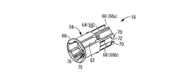
- FIG. 2 is a perspective view showing a needle tip cover constituting the chemical liquid injector shown in FIG. 1 in a single product state before being assembled to the apparatus main body.
- hook tip cover shown by FIG. The front view which expands and shows the needle
- FIG. 2 is a longitudinal sectional view showing a state in which the pusher member can be rotated around a central axis with respect to the apparatus main body to enable a pushing operation in the chemical liquid injector shown in FIG. 1.
- the longitudinal cross-sectional view which shows the state which presses against skin and punctures a hollow needle in the chemical
- the longitudinal cross-sectional view which shows the state in the middle of pushing operation of a pusher member in the chemical
- the longitudinal cross-sectional view which shows the state which further pushed in the pusher member in the chemical
- the longitudinal cross-sectional view which shows the state which rotated the chemical
- the top view which shows the state which the needle-tip cover has moved to the front end side and protected the needle-point of a hollow needle in the chemical injection device shown in FIG. XXI-XXI sectional view in FIG. XXII-XXII sectional drawing in FIG.
- FIG. 23 It is a longitudinal cross-sectional view which shows the chemical
- the front view of the chemical injection device shown in FIG. The perspective view shown in the state which punctured the hollow needle and pushed in the pusher member in the chemical
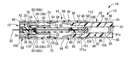
- FIGS. 1 to 3 show a drug solution injection device 10 as a first embodiment of the present invention in a state before puncture with a cap 114 (see FIG. 14) described later removed.
- the chemical injection device 10 includes an apparatus main body 14 to which the hollow needle 12 is fixed, a needle tip cover 16 provided on the distal end side of the apparatus main body 14, and a pusher member 18 provided on the proximal end side of the apparatus main body 14. It is comprised including.
- a vial 20 as an internal reservoir is attached to the pusher member 18, and the vial 20 is obtained by puncturing the hollow needle 12 into the skin and pushing the pusher member 18 from the proximal end side.
- the medical solution stored inside is injected into the body through the hollow needle 12 (poured out of the vial 20), and the hollow needle 12 is removed from the skin, so that the distal needle as the needle tip of the hollow needle 12 after puncture
- the tip 22 is protected by a needle tip cover 16 that protrudes from the apparatus main body 14 toward the distal end side.
- the axial direction refers to the left-right direction in FIG. 1 that is the central axial direction of each member constituting the chemical liquid injector 10.
- the distal end side refers to the left side in FIG. 1 that is the side that is punctured into the skin in the liquid injector 10
- the proximal end refers to the side that performs the pushing operation of the pusher member 18 in the liquid injector 10.
- the hollow needle 12 of the present embodiment is a double-ended needle, and has a sharp tip end needle tip 22 and a base end needle tip 24 at both axial ends.
- a generally cylindrical needle hub 26 is externally attached to the axially intermediate portion of the hollow needle 12 and is fixed with an adhesive or the like as necessary.
- a male screw portion 28 is formed on the outer peripheral surface of the proximal end side of the needle hub 26.
- the needle hub 26 to which the hollow needle 12 is fixed is assembled to the apparatus main body 14 that has a substantially cylindrical shape as a whole.
- the apparatus main body 14 has a substantially double cylindrical structure extending in the axial direction, and includes an inner peripheral wall portion 30 and an outer peripheral wall portion 32 that are positioned in an internal / external insertion state.
- the inner peripheral wall portion 30 and the outer peripheral wall portion 32 both extend substantially straight in the axial direction.
- the outer peripheral wall portion 32 has a larger axial dimension than the inner peripheral wall portion 30, and both axial sides of the outer peripheral wall portion 32 protrude outward in the axial direction from the inner peripheral wall portion 30.
- the inner peripheral wall portion 30 and the outer peripheral wall portion 32 are connected to each other by a connecting plate portion 34 extending in the direction perpendicular to the axis at the respective intermediate portions in the axial direction.
- a connecting plate portion 34 extending in the direction perpendicular to the axis at the respective intermediate portions in the axial direction.
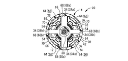
- four such connecting plate portions 34 are provided at substantially equal intervals in the circumferential direction, and the pair of connecting plate portions 34a, 34a are on both sides in one radial direction (both sides in the vertical direction in FIG. 3).
- another pair of connecting plate portions 34b, 34b are provided on both sides in the direction perpendicular to the connecting plate portions 34a, 34a (both sides in the left-right direction in FIG. 3).
- the circumferential width dimension of the pair of connecting plate portions 34a, 34a is larger than the circumferential width dimension of the other pair of connecting plate portions 34b, 34b.
- the distal end side from the connecting plate portion 34 is a mounting tube portion 36 that is thicker than the connecting plate portion 34 in the base end side.
- a female screw portion 38 is formed on the inner peripheral surface of the mounting cylinder portion 36.
- a fixed cylinder portion 40 having a small inner diameter is provided at the proximal end portion of the inner peripheral wall portion 30.
- the inner diameter dimension of the fixed cylinder portion 40 is substantially equal to or slightly larger than the outer diameter dimension of the hollow needle 12.
- the proximal end portion of the needle hub 26 is inserted into the attachment tube portion 36 on the distal end side of the inner peripheral wall portion 30, and the male screw portion 28 and the female screw portion 38 are screwed together. It is indirectly fixed to the apparatus main body 14 via the hub 26.
- the hollow needle 12 may be directly fixed to the apparatus main body 14 without using the needle hub 26.
- the hollow needle 12 is inserted into the inner peripheral wall portion 30, and the tip side needle tip 22 of the hollow needle 12 protrudes to the tip side from the inner peripheral wall portion 30 and the outer peripheral wall portion 32.
- the proximal end needle tip 24 protrudes to the proximal end side from the inner peripheral wall portion 30 and protrudes with a length that does not reach the proximal end of the outer peripheral wall portion 32.
- the distal needle tip 22 of the hollow needle 12 protrudes axially outward from the distal end of the apparatus main body 14, and the proximal needle tip 24 is positioned inside the apparatus main body 14.
- the outer peripheral surface of the proximal end portion of the hollow needle 12 may be fixed to the inner peripheral surface of the proximal end portion (fixed cylinder portion 40) of the inner peripheral wall portion 30 with an adhesive or the like.
- an annular cap engaging portion 42 to which a cap 114 described later is engaged is continuously provided over the entire circumference in the circumferential direction. Is provided. Further, on the inner peripheral surface of the outer peripheral wall portion 32, a tip end side claw portion 44 (see FIG. 19) that protrudes to the inner periphery side is provided at the tip end portion. In the present embodiment, four tip side claw portions 44 are formed at substantially equal intervals in the circumferential direction.
- a through window 46 that penetrates the outer peripheral wall portion 32 in the thickness direction, and an elastic piece that can be elastically deformed in the thickness direction with respect to the outer peripheral wall portion 32.
- four through windows 46 and four elastic pieces 48 are formed at substantially equal intervals (approximately every 90 degrees) in the circumferential direction.
- the through windows 46 and the elastic pieces 48 are elastic.
- the pieces 48 are alternately formed at intervals of 45 degrees in the circumferential direction.
- the through window 46 has a substantially rectangular shape in which the axial dimension is larger than the circumferential width dimension.
- a substantially rectangular opening window 50 in which the circumferential width dimension and the axial dimension are substantially equal or the circumferential width dimension is slightly larger. Is formed.
- An elastic piece 48 protrudes from the inner surface on the distal end side of the opening window 50 toward the proximal end side, and the elastic piece 48 is separated from three sides except for the distal end side on the inner surface of the opening window 50. Thereby, the elastic piece 48 can be elastically deformed in the thickness direction of the outer peripheral wall portion 32.
- a proximal end claw portion 52 that protrudes toward the inner peripheral side is formed at the protruding distal end (axially proximal end).
- an overpass projection 54 that protrudes to the inner peripheral side is formed in the axially intermediate portion, specifically, on the base end side of the connecting plate portion 34.
- four overpass projections 54 are provided on the circumference, and these four overpass projections 54 are provided at substantially equal intervals (approximately every 90 degrees) in the circumferential direction.
- These overpass projections 54 are provided at positions substantially corresponding to restriction projections 70 and 70 in the needle tip cover 16 described later, and in this embodiment, a pair of left and right directions in FIG.
- the overpass projections 54, 54 oppose each other at a predetermined distance in the circumferential direction.
- the distance between the circumferential direction of the overpass protrusions 54 and 54 which oppose in the circumferential direction in one side of the left-right direction in FIG. 3 is made larger than the circumferential width dimension of the connection plate parts 34b and 34b in the apparatus main body 14.
- the inner peripheral surface of the overpass protrusion 54 is a tapered surface 56 that is inclined in a direction in which the protruding dimension of the overpass protrusion 54 decreases toward the base end side.
- a needle tip cover 16 as shown in FIGS. 4 to 8 is assembled to the distal end side of the apparatus main body 14 having such a structure so as to be movable in the axial direction.
- the needle tip cover 16 has a substantially cylindrical shape as a whole and includes a peripheral wall 58 extending in the circumferential direction.
- the outer diameter of the peripheral wall 58 is substantially equal to or slightly smaller than the inner diameter of the outer peripheral wall portion 32 of the apparatus main body 14.
- the contact protrusion 60 which protrudes to the outer peripheral side is formed in the front-end
- an engagement groove 62 having a predetermined axial dimension is formed on the outer peripheral surface at the tip portion of the peripheral wall 58 so as to open to the outer peripheral side.
- the engagement grooves 62 are formed at positions corresponding to the front end side claw portions 44 of the apparatus main body 14 on the circumference, and in the present embodiment, the four engagement grooves 62 are arranged at substantially equal intervals (substantially about the circumference). Formed every 90 degrees). These engagement grooves 62 extend to the substantially axial center portion of the peripheral wall 58.
- an engagement claw 64 protruding to the outer peripheral side is provided at the proximal end of the engagement groove 62.
- the base end side surface of the engagement claw 64 is an inclined surface 66 in which the projecting dimension of the engagement claw 64 gradually decreases toward the base end side, and the engagement groove 62 including the engagement claw 64 is formed.
- the base end portion can be elastically deformed in the thickness direction of the peripheral wall 58. Thereby, the assembly of the needle tip cover 16 to the apparatus main body 14 is facilitated.
- a notch 68 that opens to the base end side and penetrates in the thickness direction of the peripheral wall 58 is formed at the base end of the peripheral wall 58 with a predetermined axial dimension. In the present embodiment, it extends from the base end of the peripheral wall 58 to the substantially central portion in the axial direction. Further, in the present embodiment, four notches 68 are formed in the circumferential direction at substantially equal intervals (approximately every 90 degrees) in the circumferential direction, and correspond to the connecting plate portion 34 in the apparatus main body 14 on the circumference. .
- these notches 68 are provided at positions away from the engaging grooves 62 in the circumferential direction, and the notches 68 and the engaging grooves 62 are formed when the needle tip cover 16 is viewed in the axial direction. They are provided alternately at intervals of approximately 45 degrees in the circumferential direction. That is, a pair of notches 68a and 68a are formed to face each other in the vertical direction in FIG. 3, and another pair of notches 68b and 68b are formed to face each other in the left and right direction in FIG. Has been.
- the circumferential width dimension of the notch 68b is larger than the circumferential width dimension of the notch 68a.
- the circumferential width dimension of the notch 68a is substantially equal to or slightly larger than the circumferential width dimension of the connecting plate portion 34a provided at a corresponding position in the apparatus main body 14.
- a pair of regulating protrusions 70 as mutual interference parts protruding inward of the notch 68b are provided facing each other in the circumferential direction.
- These regulating projections 70 and 70 are opposed to each other with a predetermined circumferential separation distance without contacting each other, and the circumferential separation distance of the regulating projections 70 and 70 is at a corresponding position in the apparatus main body 14. It is made larger than the circumferential width dimension of the provided connecting plate part 34b.
- the inner peripheral surfaces of the restricting protrusions 70 are inclined surfaces 72 that are inclined in the direction in which the thickness dimension of the restricting protrusions 70 gradually increases toward the base end side.
- the end surface on the end side is a vertical surface 73 extending in the direction perpendicular to the axis.
- annular holding wall portion 74 that protrudes toward the inner peripheral side is provided on the inner peripheral surface of the axially intermediate portion of the peripheral wall 58, and a proximal end is provided on the inner peripheral edge portion of the holding wall portion 74.
- An insertion tube portion 76 protruding to the side is provided.
- the inner diameter dimension of the holding wall portion 74 is larger than the outer diameter dimension of the needle hub 26 attached to the tip of the apparatus main body 14.
- the reinforcing rib 78 is provided on the inner peripheral surface of the peripheral wall 58 from the tip of the peripheral wall 58 to the holding wall portion 74.
- four reinforcing ribs 78 are provided on the periphery, and the deformation rigidity of the peripheral wall 58 is increased.
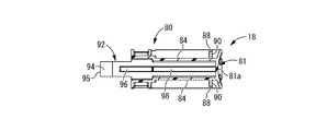
- a pusher member 18 as shown in FIGS. 9 to 13 is assembled so as to be movable in the axial direction.
- the pusher member 18 has a generally bottomed cylindrical shape as a whole, and includes a peripheral wall 80 extending in the circumferential direction and a substantially circular bottom wall portion 81 that closes the proximal end side opening of the peripheral wall 80. .
- the outer diameter of the peripheral wall 80 is substantially equal to or slightly smaller than the inner diameter of the outer peripheral wall 32 of the apparatus main body 14.
- the base end side end surface 81a of the bottom wall portion 81 is a curved surface in which the central portion is positioned on the front end side with respect to the outer peripheral portion, and the user (for example, a medical worker or the patient himself) is the base end side end surface. It is easy to place the finger on 81a and push the pusher member 18 toward the distal end.
- a circumferential groove 82 extending in the circumferential direction with a predetermined circumferential dimension is provided on the outer circumferential surface of the distal end portion of the circumferential wall 80 so as to open to the outer circumferential side, and one circumferential end of the circumferential groove 82 is provided. From the section, an axial groove 84 extending toward the base end side with a predetermined axial dimension is provided on the outer peripheral side.
- the circumferential grooves 82 are formed around the circumferential wall 80 with a circumferential dimension of approximately 45 degrees, and the four circumferential grooves 82 are substantially equidistant on the circumference (approximately every 90 degrees). Is provided. That is, as will be described later, the proximal claw portion 52 positioned in the circumferential groove 82 rotates the pusher member 18 about the central axis by 45 degrees with respect to the apparatus main body 14, so that the axial groove 84 To move to.
- the circumferential groove 82 is provided with an insertion groove 85 extending in the axial direction from the distal end of the peripheral wall 80.
- the apparatus main body 14 and the pusher member 18 are assembled, the apparatus main body is inserted through the insertion groove 85.
- 14 base end side claw portions 52 can be inserted into the circumferential groove 82.
- a retaining protrusion 85a is provided between the insertion groove 85 and the circumferential groove 82, specifically, at the proximal end of the insertion groove 85, protruding from the groove bottom surface to the outer peripheral side.
- the base end side claw portion 52 can move into the circumferential groove 82 by getting over the retaining protrusion 85a.
- the distal end surface of the retaining protrusion 85a is an inclined surface 85b whose projecting dimension gradually decreases toward the distal end side, so that the operation of passing the retaining protrusion 85a by the proximal end claw portion 52 is easy. To be realized.
- a locking projection 86 that protrudes from the groove bottom surface to the outer peripheral side is provided between the circumferential groove 82 and the axial groove 84, specifically, at one circumferential end of the circumferential groove 82. ing. As a result, unless the external force accompanying the rotation operation is exerted on the pusher member 18, the proximal claw portion 52 does not get over the locking projection 86, and the pusher member 18 on the distal end side with respect to the apparatus main body 14. Movement (push-in operation) to is prevented.
- the positioning protrusion 88 protrudes from the groove bottom surface to the outer peripheral side at a position separated from the base end side wall portion of the axial groove 84 toward the front end side by a predetermined axial dimension. ing.
- a substantially rectangular positioning recess 90 surrounded by the peripheral wall constituting the axial groove 84 and the positioning projection 88 is formed at the base end of the axial groove 84.
- the base end side claw portion 52 moved to the base end side through the directional groove 84 gets over the positioning protrusion 88 and enters the positioning recess 90.
- the proximal end claw portion 52 that has entered the positioning recess 90 abuts against the proximal end wall portion of the axial groove 84 and the positioning projection 88, thereby preventing its axial movement. Unintentional relative movement between the apparatus main body 14 and the pusher member 18 is prevented in a state where the proximal end side claw portion 52 enters the recess 90.
- an arm portion 92 as a mutual interference portion projecting toward the tip side is provided at the tip of the peripheral wall 80 in the pusher member 18.
- the arm portions 92 have a curved plate shape that is substantially rectangular when viewed from the front as a whole, and a pair of arms 92 are provided to face each other on both sides in one radial direction (right and left sides in FIG. 11). Further, each of these arm portions 92 is sufficiently thin to be able to bend and deform in the radial direction (opposing direction). In this embodiment, these arm portions 92 can be elastically deformed. It has become. That is, in the present embodiment, a flexible piece that can be bent and deformed at the distal end portion of the pusher member 18 is constituted by the arm portion 92.
- an inclined portion 94 that is inclined toward the outer peripheral side is provided at the distal end portion of the arm portion 92, and an external force is applied to the inclined portion 94 from the distal end side.
- the elastic deformation in the radial direction can be easily generated.
- the maximum separation distance on the outer surfaces of the arm portions 92, 92 may be substantially equal to or slightly smaller than the inner diameter dimension of the outer peripheral wall portion 32 in the apparatus main body 14, or may be slightly increased to increase the pusher member.
- the arm 92 may be slightly elastically deformed to the inner peripheral side when the 18 is assembled to the apparatus main body 14.
- the end surface on the tip side of the inclined portion 94 is a vertical surface 95 that extends in the direction perpendicular to the axis.
- a reinforcing rib 96 extending in the axial direction is provided so as to protrude toward the inner peripheral side from the axially intermediate portion of each arm portion 92 to the proximal end of the peripheral wall 80.
- the reinforcing ribs 96 are provided so as to face each other in the radial direction (the left-right direction in FIG. 11) that is the opposing direction of the arm portions 92, 92.
- a holding projection 98 that holds the vial 20 described later protrudes toward the inner peripheral side.
- the holding projection 98 protrudes from the inner peripheral surface of each reinforcing rib 96 toward the inner peripheral side and faces in the radial direction (left-right direction in FIG. 11), and on the inner peripheral surface of the peripheral wall 80.
- the holding protrusions 98 are also provided on both sides of the direction perpendicular to the opposing direction of the holding protrusions 98, 98 (the vertical direction in FIG. 11). That is, in this embodiment, the four holding protrusions 98 are provided at substantially equal intervals (approximately every 90 degrees) in the circumferential direction.
- the distance between the opposing surfaces of the opposing holding projections 98, 98 is substantially equal to or slightly larger than the outer diameter of the vial 20 described later, and the vial 20 is mounted without being inclined with respect to the pusher member 18. It has come to be.
- a positioning piece 100 protruding to the outer peripheral side is provided at the proximal end portion of the peripheral wall 80.
- the distal end side surface of the positioning piece 100 is an inclined surface 102 in which the protruding dimension of the positioning piece 100 gradually decreases toward the distal end side, and the positioning piece 100 has a substantially right-angled triangular longitudinal section.
- the four positioning pieces 100 are formed at substantially equal intervals (approximately every 90 degrees) in the circumferential direction, and the positioning pieces 100 are positioned between the circumferential directions of the axial grooves 84. Yes.
- the circumferential groove 82 and the insertion groove 85 are located on the distal end side of the positioning piece 100 on the outer circumferential surface of the pusher member 18, and the shaft is disposed on the distal end side of the axial groove 84.
- the arm portion 92 is located across the tip side wall portion 101 of the directional groove 84. That is, a gap 101 a that opens to the outer peripheral side is formed between the tip side wall portion 101 and the inclined portion 94 that is inclined to the outer peripheral side at the tip of the arm portion 92.
- these positioning pieces 100 are not connected to the peripheral wall 80 or the bottom wall portion 81 on the three sides (base end side and both sides in the circumferential direction), that is, are connected to the peripheral wall 80 only at the distal end side. Elastic deformation is possible in the thickness direction (radial direction) of 80.
- the needle hub 26, the apparatus main body 14, the needle tip cover 16, and the pusher member 18 as described above are preferably formed of, for example, hard synthetic resin.
- the hollow needle 12 is preferably formed of a metal such as stainless steel.
- the vial 20 for storing a chemical solution is mounted as an internal reservoir.
- the vial 20 includes a substantially bottomed cylindrical bottle body 104 that opens to the distal end side, and a plug body 106 that closes the distal end side opening of the bottle body 104.
- the material of the bottle body 104 is not limited at all, and for example, glass, hard synthetic resin, or the like can be suitably used.
- the plug body 106 is suitable for the plug body 106 to be comprised with elastic bodies, such as rubber
- a slit 108 penetrating in the axial direction is formed at the center of the plug body 106, and the plug body 106 is inserted and attached to the opening on the distal end side of the bottle body 104.
- the slit 108 is closed by being compressed from the side, so that the chemical liquid sealed in the vial 20 does not leak out.
- the slit 108 is not essential.
- medical solution stored inside the vial 20 is not limited at all, and a desired chemical
- the vial body 104 of the vial 20 is held by the pusher member 18 while the portion constituting the peripheral wall and the bottom wall portion 81 of the pusher member 18 are substantially in contact with each other. It is held by the protrusion 98 without being inclined substantially in the axial direction.
- the needle body cover 16 is assembled to the distal end side so as to be movable in the axial direction with respect to the apparatus main body 14 to which the hollow needle 12 is fixed as described above, and the vial 20 is placed in the proximal end side so as to be movable in the axial direction.
- the pusher member 18 provided is assembled.
- the needle tip cover 16 is assembled to the device main body 14 by being inserted from the distal end side opening 109, and the engagement groove 62 provided on the outer peripheral surface of the needle tip cover 16 is inserted into the engagement groove 62 of the device main body 14.
- the front end side claw portion 44 is inserted and positioned in the circumferential direction.
- the connecting plate portions 34a and 34b of the apparatus main body 14 and the notches 68a and 68b of the needle tip cover 16 are aligned with each other in the circumferential direction, and the needle tip cover 16 is aligned with the apparatus main body 14.
- the connecting plate portions 34a and 34a can move in the notches 68a and 68a in the axial direction when moved to the base end side, and the connecting plate portions 34b and 34b are notched. 68b, 68b can be moved in the axial direction. Since the base end portion of the engagement groove 62 including the engagement claw 64 can be elastically deformed in the radial direction when the distal claw portion 44 is inserted into the engagement groove 62, the engagement groove 62 The engagement claw 64 can be easily inserted into the.
- the tip claw 44 moves in the engagement groove 62 in the axial direction, so that the needle tip cover 16 can move without rotating or tilting with respect to the apparatus main body 14.
- the movement of the needle tip cover 16 in the axial direction is caused by the end of the tip end of the apparatus main body 14 and the contact protrusion 60 of the needle tip cover 16 abutting each other, the connecting plate portion 34 a of the apparatus main body 14,
- the movement of the needle tip cover 16 toward the proximal end side is prevented by contacting the inner surface of the tip end side of the notches 68 a and 68 b in the needle tip cover 16, and the distal end side of the apparatus main body 14.
- the claw portion 44 and the engagement claw 64 of the needle tip cover 16 are in contact with each other, so that the movement of the needle tip cover 16 toward the distal end side is prevented.
- a coil spring 110 serving as an elastic member is interposed between the apparatus main body 14 and the needle tip cover 16 in the axial direction. Specifically, the distal end portion of the coil spring 110 is externally inserted into the insertion tube portion 76 of the needle tip cover 16 and abuts against the holding wall portion 74 and is fixed with an adhesive or the like as necessary. Yes. On the other hand, the base end portion of the coil spring 110 is extrapolated to the mounting cylinder portion 36 of the apparatus main body 14, abuts against the connecting plate portion 34, and is fixed with an adhesive or the like as necessary. In the state before the puncture shown in FIGS.
- the coil spring 110 has a substantially natural length or is slightly compressed in the axial direction and is disposed with respect to the needle tip cover 16. An urging force in the direction of the tip may be exerted. In the state before puncturing, the tip side needle tip 22 of the hollow needle 12 protruding from the apparatus main body 14 is covered and protected by the needle tip cover 16.
- the vial 20 filled with a chemical solution in advance is inserted and attached through the distal end side opening of the pusher member 18, and the pusher member 18 attached with the vial 20 is attached to the proximal end side of the apparatus main body 14.
- the proximal end side claw portion 52 provided in the proximal end portion of the apparatus main body 14 is inserted into the circumferential groove 82 through the insertion groove 85 provided in the outer peripheral surface of the pusher member 18.
- the child member 18 and the apparatus main body 14 are positioned with respect to each other in the circumferential direction. In the state before puncturing shown in FIGS.
- 111 is prevented from moving in the axial direction of the pusher member 18 with respect to the apparatus main body 14 (for example, pushing operation of the pusher member 18), and the circumferential direction of the proximal claw portion 52 and the circumferential groove 82 is prevented. Unintentional relative rotation between the apparatus main body 14 and the pusher member 18 is prevented by abutment with a locking projection 86 provided at one end.
- the lock fixing mechanism 112 that disables the pushing operation of the pusher member 18 with respect to the apparatus main body 14 is arranged between the base end side claw portion 52 and the circumferential direction between the apparatus main body 14 and the pusher member 18.
- the base end side wall 111 of the groove 82 is included.
- the pusher member 18 is inserted from the proximal end side opening 113 of the apparatus main body 14, the proximal end portion of the pusher member 18 protrudes from the proximal end of the apparatus main body 14, and the apparatus main body.
- the proximal end portion (fixed cylinder portion 40) of the inner peripheral wall portion 14 of 14 is inserted into the distal end portion of the peripheral wall 80 of the pusher member 18.
- the proximal end needle tip 24 of the hollow needle 12 is positioned on the distal end side of the stopper body 106 in the vial 20, but the proximal end needle tip 24 is the slit 108 of the stopper body 106.
- the plug body 106 may be positioned at an intermediate portion in the axial direction or may penetrate the plug body 106.
- FIG. 14 shows a state before using the chemical injection device 10, that is, a state where it is sold and actually available to the user.
- the cap 114 is externally attached to the distal end portion of the chemical liquid injector 10, that is, the distal end portion of the needle tip cover 16 and the apparatus main body 14.
- the specific shape of this cap 114 is not limited at all, in this embodiment, it is made into the substantially bottomed cylindrical shape opened to a base end side.
- the cap 114 includes a substantially circular distal end wall portion 115a and a cylindrical wall portion 115b protruding from the outer peripheral end portion of the distal end wall portion 115a toward the proximal end side. Further, on the inner peripheral side of the cylindrical wall portion 115b, an abutting cylindrical portion 115c protruding from the distal end wall portion 115a to the proximal end side is provided, and the needle tip cover 16 and the distal end portion of the apparatus main body 14 are disposed.
- the tip portion of the outer peripheral wall portion 32 of the needle tip cover 16 and the apparatus main body 14 is inserted between the radial direction of the cylindrical wall portion 115b and the contact cylindrical portion 115c, and The outer peripheral side of the distal end side needle tip 22 of the hollow needle 12 is covered with a contact cylinder portion 115c.
- the cap locking portion 42 provided at the tip of the outer peripheral wall portion 32 contacts the inner peripheral surface of the cylindrical wall portion 115b and the protruding tip of the abutting cylindrical portion 115c. (Axial direction proximal end) is in contact with the distal end of the needle hub 26, thereby preventing the cap 114 from moving toward the proximal end side with respect to the apparatus main body 14.
- the needle tip cover 16 is not in contact with the cap 114 or is zero-touched so that an external force from the cap 114 is not exerted on the needle tip cover 16. That is, the needle tip cover 16 is prevented from unintentionally moving to the proximal end side with respect to the apparatus main body 14 in a state before the chemical liquid injector 10 is used.
- the cap 114 is prevented from moving toward the base end side with respect to the apparatus main body 14 because the cap locking portion 42 of the outer peripheral wall portion 32 contacts the inner peripheral surface of the cylindrical wall portion 115b of the cap 114, and It may be achieved by any one of the projecting tip of the contact cylindrical portion 115c contacting the needle hub 26. That is, for example, in the cap 114, the contact cylinder portion 115c may not be provided. Further, for example, the inner peripheral surface of the cap 114 (the inner peripheral surface of the cylindrical wall portion 115 b) may be provided with a convex portion protruding toward the inner peripheral side, and the convex portion is provided at the tip of the outer peripheral wall portion 32. The cap 114 may be prevented from being unintentionally detached from the chemical liquid injector 10 by engaging with the cap locking portion 42 provided.
- FIG. 15 shows a state in which the pusher member 18 is rotated by a predetermined angle around the central axis with respect to the apparatus main body 14 from such a state. That is, by rotating the pusher member 18 by a predetermined angle around the central axis with respect to the apparatus main body 14, the base end side claw portion 52 of the apparatus main body 14 located in the circumferential groove 82 is engaged with the locking protrusion. 86 is moved over into the axial groove 84.
- the push fixing member 18 cannot be pushed into the device main body 14 by the lock fixing mechanism 112, but the device main body 14 and the pusher member 18 are moved in the circumferential direction ( By the relative rotation (around the central axis), the lock by the lock fixing mechanism 112 is released, and the pushing operation of the pusher member 18 with respect to the apparatus main body 14 is allowed.
- the proximal end side claw portion 52 moves from the circumferential groove 82 to the axial groove 84, and the pusher is moved.
- the member 18 can move in the axial direction with respect to the apparatus main body 14.
- the pusher member 18 is rotated by a predetermined angle (45 degrees in the present embodiment) about the central axis with respect to the apparatus main body 14 in this way, so that the ride-over collision provided on the outer peripheral wall portion 32 in the apparatus main body 14
- the portion 54 and the arm portion 92 provided on the pusher member 18 are aligned with each other in the circumferential direction (that is, the overpass projection 54 is located on the distal end side of the arm portion 92).
- the through window 46 in the apparatus main body 14 and the positioning piece 100 in the pusher member 18 are aligned with each other in the circumferential direction (that is, the through window 46 is located on the distal end side of the positioning piece 100).
- the needle tip cover 16 is pushed into the inside of the apparatus main body 14, that is, the proximal end side against the urging force of the coil spring 110, and protrudes from the tip of the needle tip cover 16.
- the exposed tip 22 of the hollow needle 12 is punctured into the patient's skin.
- the movement of the needle tip cover 16 toward the proximal end with respect to the apparatus main body 14 is guided by the movement of the connecting plate portions 34a and 34b of the apparatus main body 14 in the notches 68a and 68b of the needle tip cover 16. It has become.
- the movement of the needle tip cover 16 toward the base end side with respect to the apparatus main body 14 is such that the connecting plate portions 34a and 34b come into contact with the front end surface of the inner surfaces of the notches 68a and 68b, or Can be regulated by contacting the contact protrusion 60 of the needle tip cover 16.
- the base of the needle tip cover 16 is set.
- the restricting protrusion 70 provided at the end and the overpass protrusion 54 provided on the inner peripheral surface of the axially intermediate portion of the apparatus main body 14 are substantially adjacent to each other in the axial direction.
- the inclined surface 72 that is the peripheral surface and the tapered surface 56 that is the inner peripheral surface of the overpass projection 54 are substantially continuous in the axial direction.
- the coil spring 110 is compressed by moving the needle tip cover 16 toward the base end side with respect to the apparatus main body 14, in this state, the elastic force of the coil spring 110 with respect to the needle tip cover 16. A biasing force toward the distal end side of the apparatus main body 14 is exerted along with the restoring action.
- the pusher member 18 is pushed directly into the distal end side with respect to the apparatus main body 14 as shown in FIG. (For example, a finger is pressed against the proximal end surface 81a of the pusher member 18 to perform a direct pushing operation), whereby the bottle body 104 and the stopper body 106 both move to the distal end side, and the distal end portion of the vial 20
- the proximal end needle tip 24 of the hollow needle 12 is inserted into the slit 108 of the plug body 106 provided on the plug body 106 and penetrated.
- the plug body 106 abuts on the proximal end portion (fixed cylinder portion 40) of the inner peripheral wall portion 30 and cannot be moved further to the distal end side, that is, the plug body 106 is not allowed to move to the inner peripheral wall portion 30. It is positioned in the axial direction with respect to (device main body 14). Further, by pushing the pusher member 18 further toward the distal end side with respect to the apparatus main body 14 from such a state, the bottle body 104 moves toward the distal end side with respect to the stopper body 106, in other words, the inside of the bottle body 104. Since the stopper 106 moves toward the proximal end, the volume in the vial 20 is reduced, and the drug solution stored in the vial 20 is injected into the patient's blood vessel through the hollow needle 12 (poured out of the vial 20). ).
- the arm portion 92 provided at the front end of the pusher member 18 contacts the overpass projection 54 provided in the apparatus main body 14.
- the arm portion 92 is elastically deformed to the inner peripheral side in accordance with the guiding action of the tapered surface 56 which is the inner peripheral surface of the ride-over protrusion 54.
- the elastic deformation is easily caused by making the arm portion 92 sufficiently thin.
- the base end side moves to the base end side in the axial groove 84.
- the claw portion 52 gets over the positioning protrusion 88 and is positioned in the positioning recess 90.
- the base end side claw portion 52 is provided at the protruding tip of the elastic piece 48, the overpass operation of the positioning protrusion 88 by the base end side claw portion 52 is more easily realized. Yes. In this state, the positioning piece 100 of the pusher member 18 enters the through window 46 of the apparatus main body 14.
- the inclined surface 102 of the positioning piece 100 and the peripheral edge portion of the proximal end side opening 113 of the apparatus main body 14 are brought into contact with each other.
- the positioning piece 100 is elastically deformed to the inner peripheral side, and the positioning piece 100 gets over the peripheral wall (outer peripheral wall portion 32) on the proximal end side of the through window 46, whereby the positioning piece 100 is elastically deformed. It is restored and deformed to enter the through window 46.
- the proximal end of the pusher member 18 with respect to the apparatus main body 14 by the mutual contact between the proximal end claw portion 52 and the positioning projection 88 and the mutual contact between the positioning piece 100 and the proximal end inner surface of the through window 46. Is prevented from moving to the side (the direction opposite to the pushing direction), and the pusher member 18 is brought into contact with the inclined surface 102 of the positioning piece 100 and the inner peripheral side end of the inner surface on the front end side of the through window 46. Thus, movement toward the tip side (in the pushing direction) with respect to the apparatus main body 14 is prevented. Thereby, the pusher member 18 can be positioned in the axial direction with respect to the apparatus main body 14.
- the positioning mechanism 116 that positions the pusher member 18 at the position where the pusher member 18 is pushed into the apparatus main body 14 includes the proximal claw 52 and the positioning protrusion between the pusher member 18 and the apparatus main body 14. 88 and the fitting of the positioning piece 100 to the through-window 46.
- the engagement between the base end side claw portion 52 and the positioning projection 88 and the fitting of the positioning piece 100 to the through window 46 are both realized in the apparatus main body 14.
- Such a positioning mechanism 116 cannot be released from the outside, and has a structure that does not include release operation means.
- the pusher member 18 that has been pushed into the push-in position and moved to the proximal end side cannot be reused again, and the positioning mechanism 116 of the present embodiment can be reused.
- the prevention mechanism 118 is included.
- the proximal end of the pusher member 18 is substantially the same axial position as the proximal end opening 113 of the apparatus main body 14 or slightly inward in the axial direction. For example, an operation such as grasping the pusher member 18 and forcibly pulling it out to the proximal end side is impossible.
- the arm portion 92 of the pusher member 18 gets over the overpass projection 54 of the apparatus main body 14 and the regulation projection 70 of the needle tip cover 16 from the inner peripheral side. After getting over, the arm portion 92 is elastically restored and deformed so as to be positioned in the notch 68b of the needle tip cover 16. That is, in other words, in the state where the pusher member 18 is in the pushed-in position, the ride-over protrusion 54 and the restriction protrusion 70 are positioned in the gap 101 a on the outer peripheral side of the arm portion 92.
- the overpassing operation of the overpass projection 54 and the regulation projection 70 of the arm 92 can be easily realized because the inner peripheral surfaces thereof are the tapered surface 56 and the inclined surface 72, respectively. Then, the tip of the inclined portion 94 of the arm portion 92 elastically deformed to the outer peripheral side in the notch 68b of the needle tip cover 16 abuts on the inner peripheral surface of the outer peripheral wall portion 32 of the apparatus main body 14 or slightly. Separated. In this state, as shown in FIG. 19 in particular, the portions other than the formation position of the arm portion 92 in the peripheral wall 80 of the pusher member 18 are the formation positions of the notches 68a and 68b in the peripheral wall 58 of the needle tip cover 16. It is made to substantially contact with the other parts.
- the needle tip 22 of the hollow needle 12 is punctured into the skin, the pusher member 18 is pushed to the push-in position to inject the chemical solution, and then the hollow needle 12 is removed from the skin.
- the needle tip cover 16 moves so as to protrude from the apparatus main body 14 toward the distal end side according to the urging force of the coil spring 110, and the distal tip side needle tip 22 of the hollow needle 12 is moved by the needle tip cover 16. Covered and protected.
- the needle tip cover 16 moves to the distal end side with respect to the apparatus main body 14 from the state where the arm portion 92 of the pusher member 18 enters the notch 68b of the needle tip cover 16, so that the needle tip cover 16 is pushed. It is located on the tip side from the member 18.
- the needle tip cover 16 moves toward the distal end side from the state where the regulation projection 70 of the needle tip cover 16 is positioned in the gap 101a on the outer peripheral side of the arm portion 92, and thus along the inclined surface 72 of the regulation projection 70.
- the arm portion 92 is elastically deformed to the inner peripheral side, and the restriction protrusion 70 can be detached from the gap 101a.
- the arm portion 92 After the arm portion 92 has passed over the restricting projection 70, the arm portion 92 is elastically restored and deformed to the outer peripheral side, and the tip of the inclined portion 94 of the arm portion 92 is the outer peripheral wall portion 32 of the apparatus main body 14. It contacts with the inner peripheral surface of or is slightly separated.
- the restricting protrusion 70 of the needle tip cover 16 is substantially adjacent to the inclined portion 94 of the arm portion 92 in the axial direction, and the restricting protrusion 70 and the inclined portion 94 come into contact with each other.
- the movement of the needle tip cover 16 toward the base end side with respect to the apparatus main body 14 is restricted or prevented.
- the base end side end surface of the restricting protrusion 70 and the tip end side end surface of the inclined portion 94 are both vertical surfaces 73 and 95 extending in the direction perpendicular to the axis. The effect of preventing movement to the base end side is stably exhibited.
- the movement of the needle tip cover 16 toward the distal end side with respect to the apparatus main body 14 is prevented by the mutual contact between the engaging claw 64 of the needle tip cover 16 and the front end claw portion 44 of the apparatus main body 14.
- the needle tip cover 16 can be prevented from coming off from 14.
- the restricting protrusion 70 of the needle tip cover 16 moved to the proximal end side when the hollow needle 12 is punctured and the pusher moved to the distal end side during the pushing operation and positioned at the pushing position.
- the arm portions 92 of the child member 18 overlap each other, and the needle tip cover 16 is moved to the distal end side when the hollow needle 12 is removed, so that the overlap between the restricting protrusions 70 and the arm portions 92 is eliminated.
- the tip end cover 16 protects the tip side needle tip 22 of the hollow needle 12 by contacting the pusher member 18 positioned at the pushing position by the positioning mechanism 116. Since the movement of the needle tip cover 16 in the state to the proximal end side is restricted or blocked, the unintended movement of the needle tip cover 16 to the proximal end side, i.e., the intention, has a simple structure. The re-exposure of the tip side needle tip 22 of the hollow needle 12 that is not performed can be prevented.
- the positioning mechanism 116 that positions the pusher member 18 at the pushed-in position engages the proximal claw 52 and the positioning projection 88 and fits the positioning piece 100 to the through window 46. Therefore, the positioning mechanism 116 is provided inside the chemical liquid injector 10. Therefore, for example, it is substantially impossible to cancel the positioning of the pusher member 18 and the apparatus main body 14, and the positioning state of the pusher member 18 and the apparatus main body 14, and consequently the hollow by the needle tip cover 16. The protection state of the tip side needle tip 22 of the needle 12 can be stably maintained.
- the mutual interference portions (the restriction protrusion 70 and the inclined portion 94 of the arm portion 92 in particular) are provided. Since they are overlapped with each other, it is possible to avoid an increase in the axial dimension of the apparatus main body 14 and consequently the chemical liquid injector 10.
- the arm portion 92 is elastically deformable, the overpassing operation of the restricting protrusion 70 by the arm portion 92 can be realized stably.
- the vial 20 is employed as an internal reservoir for storing a chemical solution
- the internal reservoir can be provided in the chemical injection device 10 only by attaching the vial 20 to the pusher member 18.
- the leakage of the chemical liquid can be effectively avoided, and the ease of assembling the internal reservoir to the chemical liquid injection apparatus 10 and thus the manufacturing efficiency of the chemical liquid injection apparatus 10 can be improved.
- by preparing a plurality of vials 20 with different types of stored chemical solutions it is possible to easily manufacture a plurality of chemical solution injection devices 10 that can inject different chemical solutions.
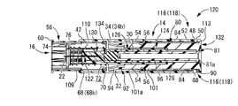
- FIG. 23 shows a drug solution injection device 120 as a second embodiment of the present invention before the hollow needle 122 is punctured.
- FIG. 24 shows the drug solution injector 120 with the hollow needle 122 punctured
- FIG. 25 shows the state after the hollow needle 122 has been punctured.
- a prefilled syringe 124 is employed as an internal reservoir.
- the prefilled syringe 124 of the present embodiment is configured to include a syringe barrel 126 that substantially stores a chemical solution and a plunger 128 that is inserted from the proximal end side opening of the syringe barrel 126.
- a needle hub 130 to which the hollow needle 122 is fixed is integrally formed at the distal end portion of the syringe barrel 126, and the proximal end portion of the hollow needle 122 having only the distal needle tip 22 is fixed to the needle hub 130.
- the syringe barrel 126 is inserted and fixed to the inner peripheral wall portion 30 of the apparatus main body 14, and the distal end needle tip 22 of the hollow needle 122 protrudes from the distal end of the apparatus main body 14 to the distal end side.
- the plunger 128 constituting the prefilled syringe 124 is formed integrally with the pusher member 132. That is, the pusher member 132 of the present embodiment is shaped like a double cylinder having a plunger 128 on the inner peripheral side of the peripheral wall 80, and the base end side opening of the peripheral wall 80 has a substantially annular bottom wall portion. A substantially cylindrical plunger 128 extends from the inner peripheral edge of the bottom wall 81 toward the distal end side. A rubber stopper 134 is fixed to the distal end of the plunger 128, and the rubber stopper 134 is compressed in the radial direction by inserting the rubber stopper 134 from the proximal end opening of the syringe barrel 126.
- the rubber stopper 134 may not be fixed to the plunger 128, and the rubber stopper 134 and the tip of the plunger 128 are axially separated from each other in the state before puncturing shown in FIG. Also good.
- a syringe barrel 126 including the hollow needle 122 is inserted and positioned in the inner peripheral wall portion 30 of the apparatus main body 14, and a pusher member 132 integrally including a plunger 128 is axially provided on the proximal end side of the apparatus main body 14.
- the chemical solution injection device 120 of this embodiment is configured.
- the distal end portions of the rubber stopper 134 and the plunger 128 are inserted from the proximal end side opening portion of the syringe barrel 126, and the proximal end side opening portion of the syringe barrel 126 is inserted. Is liquid-tightly closed.
- the method for containing the chemical in the prefilled syringe 124 is not limited in any way.
- the hollow needle 122 is inserted in a state where the plunger 128 (pushing member 132) is pushed to the deepest part with respect to the syringe barrel 126.
- the medical solution can be stored in the prefilled syringe 124 by puncturing the rubber stopper of the vial in which the chemical solution is sealed and withdrawing the plunger 128 from this state.
- the prefilled syringe 124 and the pusher member 132 in which the medicinal solution is stored are inserted from the proximal end side opening 113 of the apparatus main body 14, the syringe barrel 126 is inserted into the inner peripheral wall 30 of the apparatus main body 14, and the push
- the chemical injection device 120 of the present embodiment can be manufactured by assembling the child member 132 to the apparatus main body 14.
- the chemical injection device 120 having such a structure is also used in the same manner as in the first embodiment, and the pusher member 132 is centered with respect to the device main body 14 from the state before the puncture shown in FIG. By pushing a predetermined angle (45 degrees in this embodiment) around the axis, the pushing operation of the pusher member 132 to the apparatus main body 14 is allowed.
- the hollow needle 122 is punctured into the skin as shown in FIG. 24, and the pusher member 132 is further pushed into the device main body 14, whereby a prefilled syringe
- the medicinal solution contained in 124 is injected into the blood vessel of the patient.
- the pusher member 132 When the pusher member 132 is pushed into the deepest part, the pusher member 132 is positioned at the push-in position by the positioning mechanism 116, and almost all of the chemical solution in the prefilled syringe 124 is injected into the blood vessel. After the injection of the drug solution, the hollow needle 122 is removed from the skin, so that the needle tip cover 16 is moved to the distal end side by the apparatus main body 14 by the elastic restoring action of the coil spring 110 as shown in FIG. Thus, the tip side needle tip 22 of the hollow needle 122 can be protected by the needle tip cover 16.
- the needle tip cover 16 is prevented from moving to the proximal end side by contacting the pusher member 132 positioned at the pushing position.
- the same effects as those of the first embodiment can be exhibited.
- FIGS. 26 and 27 show a chemical liquid injector 140 as a third embodiment of the present invention.
- the shapes of the needle tip cover and the pusher member are not limited to those described in the above embodiment, and the needle tip cover 142 and the pusher member 144 constituting the chemical solution injector 140 of the present embodiment are not limited. It may be a shape.
- the illustration of the apparatus main body (14) is omitted.
- the vial (20) is mounted as an internal reservoir inside the pusher member 144.
- the internal reservoir A prefilled syringe (124) may be attached.
- the peripheral wall 58 of the needle tip cover 142 is provided with a plurality (four in this embodiment) of supporting arm portions 146 projecting toward the proximal end, and the projecting tip portions of the supporting arm portions 146 are provided.
- a pair of elastic pieces 148 and 148 project from the both ends in the circumferential direction at the axial base end portion, and face each other in the circumferential direction. These elastic pieces 148 have a sufficiently small circumferential dimension, and can be elastically deformed in the circumferential direction.
- a regulation projecting portion 150 is provided as a mutual interference portion projecting in a direction approaching each other. That is, the circumferential separation distance of the elastic pieces 148 and 148 is reduced at the base end portion of the elastic piece 148 where the restricting protrusion 150 is formed, and the support arm 146, the elastic pieces 148 and 148, and the restricting protrusion.
- a region surrounded by the portions 150 and 150 is a storage region 152 extending in the axial direction.
- the circumferential separation distance between the restricting protrusions 150 and 150 is smaller than the width dimension of the vertical surface 160 of the positioning protrusion 158 described later.
- the end surface on the front end side of the restricting projection 150 is an inclined surface 154 that is inclined in a direction in which the projecting dimension gradually decreases toward the front end side.
- the peripheral wall 80 of the pusher member 144 is provided with a plurality of arms (156 in the present embodiment) projecting to the tip side on the periphery, and on the outer peripheral surface of the tip of each arm 156, Positioning protrusions 158 are provided as mutual interference portions protruding to the outer peripheral side.
- the positioning projection 158 of the present embodiment has a substantially triangular shape, and the distal end side end surface of the positioning projection 158 is a vertical surface 160 extending in the direction perpendicular to the axis, and the base end side is the restriction projection 150,
- the inclined surfaces 162 and 162 are inclined in the direction corresponding to the 150 inclined surfaces 154 and 154.
- the positioning projection 158 of the pusher member 144 enters the accommodating region 152 of the needle tip cover 142.
- the positioning projection 158 is located at the base end of the accommodating region 152, and the inclined surfaces 154 and 154 of the restricting projection 150, which is a mutual interference portion, and the inclined surfaces 162 and 162 of the positioning projection 158 are circumferential. Abutting and overlapping in direction. However, these inclined surfaces 154 and 162 may be separated from each other.
- the needle tip cover 142 moves to the proximal end side with respect to the apparatus main body (14) as shown in FIG.
- the member 144 toward the distal end side with respect to the apparatus main body (14) By pushing the member 144 toward the distal end side with respect to the apparatus main body (14), the hollow needle 12 is punctured into the patient's skin, and the drug solution is injected into the blood vessel of the patient.
- the positioning projection 158 of the pusher member 144 is moved to the distal end side within the accommodation region 152. Then, as shown in FIG.
- the storage region 152 is moved to the end on the front end side.
- the pusher member 144 is positioned with respect to the apparatus main body (14).
- a positioning mechanism for positioning the pusher member 144 and the apparatus main body (14) is not shown, but for example, a positioning mechanism (116) similar to that in the above-described embodiment may be employed.
- the needle tip cover 142 is moved to the front end side with respect to the apparatus main body (14) by the elastic restoring action of the coil spring 110 by removing the hollow needle 12 from the skin, and it is hollow.
- the tip side needle tip 22 of the needle 12 can be protected by the needle tip cover 142.
- the needle tip cover 142 is positioned on the distal end side with respect to the pusher member 144, and the pusher member 144 is placed against the restricting protrusions 150 and 150 of the needle tip cover 142.
- the positioning projection 158 abuts from the proximal end side, so that the movement of the needle tip cover 142 toward the proximal end side is prevented.
- the needle tip cover 142 moves to the front end side with respect to the pusher member 144 by the elastic restoring action of the coil spring 110 after the needle removal.
- the positioning projection 158 located at the end on the distal end side of the storage area 152 is moved to the base end side in the storage area 152.
- the needle tip cover 142 is moved further to the distal end side than the state before puncturing shown in FIGS. 26 and 27, and the positioning projection 158 is moved to the proximal end of the accommodation region 152.
- the restricting protrusions 150 and 150 By abutting against the restricting protrusions 150 and 150 provided in the side openings, the restricting protrusions 150 and 150 (elastic pieces 148 and 148) are elastically deformed in the circumferential direction outside, that is, in a direction away from each other. As a result, the positioning protrusion 158 can pass between the expanded restricting protrusions 150 and 150, and the restricting protrusions 150 and 150 get over the positioning protrusion 158, as shown in FIG. 150 and 150 (elastic pieces 148 and 148) are elastically restored and deformed to the initial positions so that the base end side end surface of the restricting protrusion 150 is in contact with the vertical surface 160 of the positioning protrusion 158.
- the distal end side surface of the restriction projection 150 and the proximal end side surface of the positioning projection 158 that contacts the distal end side surface are the inclined surface 154 and the inclined surface 162, respectively.
- the elastic deformation of 150, 150 (elastic pieces 148, 148) outward in the circumferential direction can be facilitated.
- the pusher member 144 positioned at the push-in position comes into contact with the needle tip cover 142 from the proximal end side, so that the needle tip protection state is achieved. Since the movement of the needle tip cover 142 to the proximal end side is prevented, the same effect as in the first embodiment can be exhibited.
- the positioning mechanism 116 is configured to include the engagement between the proximal end claw portion 52 and the positioning projection 88 and the fitting of the positioning piece 100 to the through window 46. Either may be sufficient.
- the specific structure of the positioning mechanism for positioning the pusher member with respect to the apparatus main body is not limited in any way.
- the uneven structure as described above is provided opposite to the apparatus main body and the pusher member.
- the portion into which the positioning piece 100 is fitted is the through window 46 that penetrates the outer peripheral wall 32 of the apparatus main body 14 in the thickness direction. With the bottom hole shape, it may be more difficult to release the positioning of the apparatus main body 14 and the pusher member 18 by the positioning mechanism 116 from the outside.
- the base end side claw portion 52, the positioning protrusion 88, the positioning piece 100, and the through window 46 constituting the positioning mechanism 116 are all provided at the base end portions of the apparatus main body 14 and the pusher member 18.
- the positioning mechanism 116 is provided at the proximal end portion of the chemical liquid injectors 10, 120, 140.
- the pusher member is in the push-in position. In a state, you may provide in the axial direction intermediate part and front-end
- the positioning mechanism 116 includes the engagement between the proximal end claw portion 52 and the positioning projection 88 and the fitting of the positioning piece 100 to the through window 46.
- these axial positions may be different from each other, for example, either one is between the tip portion or the axial middle portion of the apparatus main body and the tip portion or the axial middle portion of the pusher member. It may be provided.
- the proximal end of the pusher member 18 in a state where the pusher member 18 is in the push-in position, is substantially at the same axial position as the proximal end side opening 113 of the apparatus main body 14 or slightly in the axial direction. Although it was located inward in the direction, the proximal end of the pusher member may be located axially outward from the proximal end side opening of the apparatus main body. Furthermore, in a state where the pusher member is in the push-in position, the pusher member may be movable in the axial direction (for example, the base end side) by a predetermined distance.
- the needle tip cover can also move to the base end side, but with a movement amount that does not expose the needle tip of the hollow needle. If so, the protection state of the needle tip by the needle tip cover can be maintained.
- the lock fixing mechanism 112 that makes the pushing operation of the pusher member 18 into the apparatus main body 14 impossible before the pusher member 18 is punctured is not essential.
- the circumferential groove 82 is not essential, and only an axial groove may be provided.
- a locking projection that disables the pushing operation of the pusher member is provided at the axially intermediate portion of the axial groove, and the proximal claw portion gets over the locking projection so that the pusher The pushing operation of the member may be allowed.
- the lock by the lock fixing mechanism 112 is released by rotating the pusher member 18 by 45 degrees in the circumferential direction with respect to the apparatus main body 14. The rotation angle is not limited at all.
- the coil spring 110 is employed as an elastic member that exerts an urging force toward the distal end side on the needle tip cover 16, but it may be a cylindrical member made of a rubber elastic body, a magnetic force, etc.
- the urging force may be exerted on the needle tip cover by using.
- such an elastic member or the like is not essential, and the needle tip cover that has moved to the proximal side when the hollow needle is punctured may be manually moved to the distal side when the hollow needle is removed.
- the distal end portions (arm portions 92, 156) of the pusher members 18, 132, 144 positioned at the push-in positions directly contact the proximal end portions of the needle tip covers 16, 142, and the needle tips.
- an intermediate member may be provided between the needle tip cover and the pusher member, and the intermediate member is interposed therebetween. The needle tip cover and the pusher member may be brought into contact with each other to prevent the needle tip cover from moving toward the proximal end side.
- the vial 20 is mounted inside the pusher member 18, but the pusher member may be formed by the vial itself.
- the pusher member may be constituted by a bottle constituting the vial. In such a case, for example, the pusher member is pushed between the inner circumferential surface of the outer circumferential wall portion and the outer circumferential surface of the bottle body.
- a positioning mechanism for positioning the child member (bottle body) at the push-in position may be provided.
- the plunger 128 is integrally formed inside the pusher member 132.
- the pusher member and the plunger may be separated. That is, the syringe barrel may be assembled to the apparatus main body and the plunger may be assembled to the pusher member, and the apparatus main body and the pusher member may be assembled to each other. In such a case, a commercially available syringe can be used. is there.
- the internal reservoir is a syringe type as described above, it is not limited to the mode of assembling a prefilled syringe in which a chemical solution is stored in advance as in the second embodiment, and a chemical solution injection device is manufactured.
- the drug solution may be accommodated in the syringe barrel through the tip of the hollow needle.
- the chemical injection device is manufactured in a state where it is advanced to a position immediately before the pusher member is positioned with respect to the device main body, and in this state, the needle tip of the hollow needle is immersed in the chemical, If a member is moved to the base end side, a chemical
- the syringe barrel 126 is not indispensable, and an internal reservoir can be constituted by the inner peripheral wall portion.
- the needle tip cover at the position for protecting the needle tip of the hollow needle is in contact with the pusher member positioned at the push-in position to prevent the movement toward the proximal end side. It is not a thing. That is, the needle tip cover as in the above embodiment is not essential, and for example, a mechanism for protecting the needle tip of the hollow needle after use may be provided separately, or the needle tip of the hollow needle after use is not necessarily protected. It does not have to be done.
- the stopper body 106 is pushed into the bottle body 104 of the vial 20 to the deepest part (until the stopper body 106 comes into contact with the bottom wall portion on the proximal end side of the bottle body 104).
- the position is the pushing position of the pusher member 18 with respect to the apparatus main body 14, it is not limited to this mode. That is, for example, the position where the stopper is pushed to the middle portion in the axial direction of the bottle may be set as the pushing position and positioned by the positioning mechanism.
- the position where the plunger was pushed in to the axial direction intermediate part of the syringe barrel may be made into the pushing position, for example.
- the arm portion 92 gets over the restricting protrusion 70 by elastically deforming the arm portion 92 toward the inner peripheral side with respect to the restricting protrusion 70.
- the restricting projection that can be flexibly deformed or elastically deformed elastically deforms toward the outer peripheral side with respect to the arm portion, so that the arm portion may get over the restricting projection.
- the flexible portion that can be bent and deformed at the proximal end portion of the needle tip cover can be constituted by the restricting protrusion.
- the vial 20 and the prefilled syringe 124 are employed as the internal reservoir.
- the internal reservoir for example, the distal end side and the proximal end side are sealed with a plug or the like, and the internal reservoir You may employ
- the proximal end needle tip of the hollow needle that is a double-ended needle can be punctured with respect to the distal end side plug body, and the proximal end side plug body becomes a cartridge along with the pushing operation of the pusher member. It is possible to move to the tip side inside.
- the proximal end of the hollow needle is punctured into the plug on the distal end so that the chemical solution inside the cartridge does not leak from the hollow needle, and the inside and outside of the cartridge are communicated.
- the operation is performed when the cartridge is pushed to the front end side with respect to the apparatus main body in accordance with the pushing operation of the pusher member, when the pusher member to which the cartridge is fixed is attached to the apparatus main body, or when the pusher member is attached to the apparatus It may be configured to be achieved when the cartridge is attached to the apparatus main body before being attached to the main body.
- the cartridge is moved to the distal end side by the pushing operation of the pusher member, and the proximal end needle tip of the hollow needle is punctured into the distal end side stopper body. Further, when the pusher member is pushed, the plug on the proximal end side moves to the distal end side inside the cartridge, and the medical solution inside the cartridge is configured to be administered to the patient.
Landscapes
- Health & Medical Sciences (AREA)
- Vascular Medicine (AREA)
- Engineering & Computer Science (AREA)
- Anesthesiology (AREA)
- Biomedical Technology (AREA)
- Heart & Thoracic Surgery (AREA)
- Hematology (AREA)
- Life Sciences & Earth Sciences (AREA)
- Animal Behavior & Ethology (AREA)
- General Health & Medical Sciences (AREA)
- Public Health (AREA)
- Veterinary Medicine (AREA)
- Infusion, Injection, And Reservoir Apparatuses (AREA)
Abstract
中空針の再露出を防止することができる、新規な構造の薬液注入装置を提供する。 先端側に中空針12を備えた装置本体14に対して基端側から押し子部材18を押込操作することで内部リザーバ20に貯留された薬液が中空針12を通じて注出されると共に、中空針12の針先22を保護する針先カバー16が装置本体14に対して軸方向で移動可能に組み付けられた薬液注入装置10において、押し子部材18を装置本体14への押込位置へ位置決めする位置決め機構116が直接押込操作される押し子部材18と装置本体14との間に設けられており、位置決め機構116で押込位置へ位置決めされた押し子部材18への当接作用によって、針先カバー16の基端側への移動が規制される。
Description
本発明は、押し子部材を押込操作することで患者の体内に薬液を注入する薬液注入装置に関するものである。
従来から、医療分野において患者に薬液などを注入する際に用いられる医療器具として、中空針を備えた薬液注入装置が知られている。
ところで、薬液の注入後に抜去した針先が露出したままになっていると、医師や看護師、廃棄業者などが露出した針先で指などを誤って刺す誤穿刺事故の発生のおそれがある。誤穿刺事故が発生した場合、針先に付着した血液による感染症を引き起こしたり、針先に付着した薬液を意図せず摂取してしまう危険がある。
そこで、例えば特表2007-506498号公報(特許文献1)に記載されているように、使用後の針先を覆う針先カバーを設けた薬液注入装置が提案されている。すなわち、上記特許文献1に記載の薬液注入装置では、針先カバー(保護スリーブ6)を備える装置本体(本体3)に対して、中空針(針7)を備える注射器(注入装置4)が収容されるようになっている。そして、かかる中空針を皮膚に穿刺して押し子部材(プランジャ)を押圧操作(押込操作)することで、注射器中に収容された薬液が患者の体内に注入されるとともに、中空針を皮膚から抜去することで針先カバーが装置本体から先端側に突出して中空針の針先が保護されるようになっている。
ところが、上記特許文献1に記載の薬液注入装置では、針先カバーが、中空針の針先を保護した状態で、ばね(ばね26)により保持されるのみであることから、針先カバーに対して装置本体へ収容される方向への外力が及ぼされると、意図せず針先が再露出してしまうおそれがあった。
なお、上記特許文献1に記載の薬液注入装置の改良として、特表2011-510731号公報(特許文献2)には、中空針の針先を保護する位置にある針先カバーを、装置本体に対して固定する固定手段が開示されており、上記の如き針先の再露出という問題が解消されている。ところが、上記特許文献2に記載の薬液注入装置では、かかる針先カバーの固定手段が、針先カバーと装置本体との間に設けられることから、装置本体などの構造が複雑になり易かった。
また、上記特許文献1,2に記載の薬液注入装置では、薬液を貯留する内部リザーバとして注射器が採用されており、注射器のプランジャを押し込むことでシリンジ内の薬液が装置から注出されるようになっていた。そのために、使用に際しては、バイアル瓶などに封入された薬液を注射器に吸引する必要があり、操作が面倒であった。
本発明は、上述の事情を背景に為されたものであって、請求項1~9に記載の発明の解決課題は、中空針の再露出を防止することができる、新規な構造の薬液注入装置を提供することにある。
また、請求項10,11に記載の発明の解決課題は、使用に際しての薬液の注入が不要で操作が容易とされた、新規な構造の薬液注入装置を提供することにある。
本発明の第1の態様は、先端側に中空針を備えた装置本体に対して基端側から押し子部材を押込操作することで内部リザーバに貯留された薬液が該中空針を通じて注出されると共に、該中空針の針先を保護する針先カバーが該装置本体に対して軸方向で移動可能に組み付けられた薬液注入装置において、前記押し子部材を前記装置本体への押込位置へ位置決めする位置決め機構が直接押込操作される該押し子部材と該装置本体との間に設けられており、該位置決め機構で押込位置へ位置決めされた該押し子部材への当接作用によって、前記針先カバーの基端側への移動が規制されることを特徴とするものである。
本態様に従う構造とされた薬液注入装置によれば、針先カバーの基端側への移動による針先の再露出が、押込操作された押し子部材への当接作用で防止される。それ故、針先カバーの基端側への移動を規制するための装置本体の複雑化が回避される。また、押し子部材は、直接に押込操作されることから、押込位置へ確実に移動させることができ、位置決め機構による位置決めひいては針先カバーの基端側への移動規制がより安定して実現可能となる。
なお、薬液を貯留する内部リザーバとしては、以下の第2又は第3の態様が好適に採用され得る。
本発明の第2の態様は、前記第1の態様に係る薬液注入装置において、前記内部リザーバとして、瓶体と栓体を備えたバイアルが採用されるものである。
本発明の第3の態様は、前記第1の態様に係る薬液注入装置において、前記内部リザーバとして、プレフィルドシリンジが採用されるものである。
特に、前記第2の態様に従って、内部リザーバとしてバイアルを採用することにより、薬液収容部の簡略化が図られ得る。また、前記第3の態様に従って、内部リザーバとしてプレフィルドシリンジを採用することにより、シリンジに薬液を都度収容するなどの煩雑な操作が不要となる。
本発明の第4の態様は、前記第1~3の何れかの態様に係る薬液注入装置において、前記位置決め機構において、前記押し子部材の前記装置本体への押込位置への位置決めが解除操作手段を備えない構造とされることで、再使用防止機構が構成されているものである。
本態様に従う構造とされた薬液注入装置によれば、先端側へ押し込まれた押し子部材の装置本体に対する位置決めの解除が事実上で不能とされることから、薬液注入装置の提供者が想定しない、使用者による意図的な或いは意図しない再使用が防止される。
本発明の第5の態様は、前記第1~4の何れかの態様に係る薬液注入装置において、前記押し子部材と前記装置本体との間には、該装置本体に対する該押し子部材の押込操作を不能とするロック固定機構が設けられているものである。
本態様に従う構造とされた薬液注入装置によれば、使用前の状況下において意図せず押し子部材が押し込まれることが防止される。
本発明の第6の態様は、前記第5の態様に係る薬液注入装置において、前記押し子部材と前記装置本体とを周方向に相対回転させることで前記ロック固定機構による固定が解除されて、該装置本体に対する該押し子部材の押込操作が許容されるようになっているものである。
本態様に従う構造とされた薬液注入装置によれば、押し子部材に対して、通常の操作方向である押込方向とは直交する回転方向の操作を加えないと押し子部材の固定が解除されないことから、押し子部材の意図しない押込操作が防止される。
本発明の第7の態様は、前記第1~6の何れかの態様に係る薬液注入装置において、前記針先カバーの基端部には撓み変形可能とされた可撓部が設けられており、直接押込操作された前記押し子部材の先端部が該可撓部を乗り越えることで該押し子部材が前記押込位置に至るようになっているものである。
本態様に従う構造とされた薬液注入装置によれば、針先カバーの基端部に撓み変形可能とされた可撓部が設けられていることから、当該可撓部が撓み変形することで押し子部材の先端部による針先カバーの基端部の乗越作動が安定して実現され得る。
本発明の第8の態様は、前記第1~7の何れかの態様に係る薬液注入装置において、前記押し子部材の先端部には撓み変形可能とされた可撓片が設けられており、直接押込操作された該押し子部材の該可撓片が前記針先カバーの基端部を乗り越えることで該押し子部材が前記押込位置に至るようになっているものである。
本態様に従う構造とされた薬液注入装置によれば、可撓片が撓み変形することで押し子部材の先端部による針先カバーの基端部の乗越作動が安定して実現され得る。
本発明の第9の態様は、前記第1~8の何れかの態様に係る薬液注入装置において、前記押し子部材の先端部分と前記針先カバーの基端部分との間に相互干渉部が設けられており、前記針先カバーが前記装置本体に対して基端側へ移動して前記中空針の針先が露出された状態で、該相互干渉部が互いに重なり合うことで該押し子部材の該装置本体に対する先端側への移動が許容される一方、該押し子部材が該装置本体に対して前記押込位置へ位置決めされた状態で、該針先カバーが該装置本体から先端側へ突出することで該相互干渉部における互いの重なりが解消されて、該相互干渉部の互いの軸方向の当接作用によって、該針先カバーの基端側への移動が規制されるものである。
本態様に従う構造とされた薬液注入装置によれば、針先カバーと押し子部材との重なり合いによる相互移動が一方向に許容されることで、押し子部材の押込操作と針先カバーの先端側への突出作動とが許容されると共に、突出した針先カバーの基端側への移動の規制が実現される。
本発明の第10の態様は、先端側に中空針を備えた装置本体に対して基端側から押し子部材を押込操作することで内部リザーバに貯留された薬液が該中空針を通じて注出される薬液注入装置において、前記内部リザーバとして瓶体と栓体を備えたバイアルが採用され、該栓体が前記装置本体に対して位置決めされると共に、該瓶体が前記押し子部材の押込操作に伴って先端側へ移動して、該バイアル内の前記薬液が該栓体に穿通された前記中空針を通じて注出されることを特徴とするものである。
本態様に従う構造とされた薬液注入装置によれば、薬液を収容せしめたバイアルを装着することが可能となり、例えば従来構造の注射器を用いる場合に比して操作性が大幅に向上され得る。
本発明の第11の態様は、先端側に中空針を備えた装置本体の基端側から軸方向で移動可能に組み付けられて、該装置本体に対して押込操作されることにより内部リザーバに貯留された薬液を該中空針を通じて注出せしめる薬液注入装置用の押し子部材であって、前記内部リザーバを構成するバイアルが装着されており、該バイアルの瓶体を保持せしめて前記装置本体に対して先端側へ移動させることで、該装置本体によって位置決めされる該バイアルの栓体に対して該瓶体を移動させることを特徴とするものである。
本態様に従う構造とされた薬液注入装置用の押し子部材によれば、薬液が収容されたバイアルが装着されていることから、かかる押し子部材を装置本体に組み付けて用いることで、薬液の収容作業などが不要になる。また、異なる種類の薬液が収容されたバイアルを複数準備したり、各種のバイアルが予め装着された複数種類の押し子部材を準備して、適宜に使用者に提供することも可能になる。
請求項1~9に記載の発明に従う構造とされた薬液注入装置によれば、先端側に押し込まれた押し子部材への当接により、中空針の針先を保護する針先カバーの基端側への移動による針先の再露出が防止される、新規な構造の薬液注入装置が提供され得る。
また、請求項10,11に記載の発明に従う構造とされた薬液注入装置によれば、内部リザーバとしてバイアルを採用することで、例えば従来の注射器を採用する場合に比して、薬液注入装置における薬液の収容から注出に至る使用に際しての操作性の向上が図られ得る。
以下、本発明を更に具体的に明らかにするために、本発明の実施形態について、図面を参照しつつ、詳細に説明する。
先ず、図1~3には、本発明の第1の実施形態としての薬液注入装置10が、後述するキャップ114(図14参照)を取り外した、穿刺前の状態で示されている。この薬液注入装置10は、中空針12が固定される装置本体14と、当該装置本体14の先端側に設けられる針先カバー16と、当該装置本体14の基端側に設けられる押し子部材18とを含んで構成されている。本実施形態では、当該押し子部材18に対して内部リザーバとしてのバイアル20が装着されており、中空針12を皮膚に穿刺して基端側から押し子部材18を押込操作することでバイアル20内に貯留された薬液が中空針12を通じて体内に注入(バイアル20外に注出)されるとともに、中空針12を皮膚から抜去することで穿刺後の中空針12の針先としての先端側針先22が、装置本体14から先端側に突出する針先カバー16で保護されるようになっている。なお、以下の説明において、軸方向とは薬液注入装置10を構成する各部材の中心軸方向となる図1中の左右方向をいう。また、先端側とは、薬液注入装置10において皮膚に穿刺される側である図1中の左側をいう一方、基端側とは、薬液注入装置10において押し子部材18の押込操作を行う側である図1中の右側をいう。
より詳細には、本実施形態の中空針12は、両頭針とされており、軸方向両端部において先鋭上の先端側針先22と基端側針先24を有している。かかる中空針12の軸方向中間部分には、全体として略筒状の針ハブ26が外挿装着されており、必要に応じて、接着剤などで固着されている。なお、かかる針ハブ26の基端側の外周面には、雄ねじ部28が形成されている。
そして、かかる中空針12が固定された針ハブ26が、全体として略筒状とされた装置本体14に組み付けられている。本実施形態では、当該装置本体14が、軸方向に延びる略二重筒構造とされており、相互に内外挿状態で位置する内周壁部30と外周壁部32とを備えている。なお、これら内周壁部30と外周壁部32とは、何れも軸方向に対して略ストレートに延びている。また、外周壁部32は、内周壁部30よりも大きな軸方向寸法を有しており、外周壁部32の軸方向両側が、内周壁部30よりも軸方向外方まで突出している。
さらに、これら内周壁部30と外周壁部32とが、それぞれの軸方向中間部分において、軸直角方向に延びる連結板部34で相互に連結されている。本実施形態では、かかる連結板部34が、周方向で略等間隔に4つ設けられており、一対の連結板部34a,34aが径方向1方向の両側(図3中の上下方向両側)に設けられているとともに、もう一対の連結板部34b,34bが、連結板部34a,34aと直交する方向の両側(図3中の左右方向両側)に設けられている。特に、本実施形態では、一対の連結板部34a,34aの周方向幅寸法が、もう一対の連結板部34b,34bの周方向幅寸法よりも大きくされている。
更にまた、かかる内周壁部30において、連結板部34より先端側は、連結板部34より基端側に比して、厚肉の筒状とされた取付筒部36とされており、当該取付筒部36の内周面には雌ねじ部38が形成されている。一方、内周壁部30の基端部分には、内径寸法が小さくされた固定筒部40が設けられている。かかる固定筒部40の内径寸法は、中空針12の外径寸法と略等しいか、僅かに大きくされている。
そして、内周壁部30の先端側の取付筒部36に対して針ハブ26の基端部分が挿入されて、雄ねじ部28と雌ねじ部38とが螺合することにより、中空針12が、針ハブ26を介して装置本体14に対して間接的に固定されている。なお、中空針12は、針ハブ26を介さず、装置本体14に対して直接的に固定されてもよい。かかる中空針12は、内周壁部30に挿通されており、中空針12の先端側針先22が、内周壁部30および外周壁部32よりも先端側まで突出している一方、中空針12の基端側針先24が、内周壁部30よりも基端側まで突出しているともに、外周壁部32の基端には至らない長さで突出している。すなわち、中空針12の先端側針先22が装置本体14の先端から軸方向外方に突出しているとともに、基端側針先24が装置本体14の内部に位置している。なお、中空針12の基端部分の外周面は、内周壁部30の基端部分(固定筒部40)の内周面に対して、接着剤などで固着されていてもよい。
一方、装置本体14の外周壁部32の外周面において、先端側端部には、後述するキャップ114が係止される環状のキャップ係止部42が、周方向の全周に亘って連続して設けられている。さらに、かかる外周壁部32の内周面において、先端側端部には、内周側に突出する先端側爪部44(図19参照)が設けられている。本実施形態では、周方向で略等間隔に4つの先端側爪部44が形成されている。
また、外周壁部32の基端側端部には、当該外周壁部32を厚さ方向で貫通する貫通窓46と、当該外周壁部32に対して厚さ方向で弾性変形可能な弾性片48とを備えている。本実施形態では、これら貫通窓46と弾性片48とが、それぞれ周方向で略等間隔(略90度毎)に4つずつ形成されており、特に本実施形態では、これら貫通窓46と弾性片48とが、周方向で45度ずつの間隔をもって交互に形成されている。
かかる貫通窓46は、周方向幅寸法に比して軸方向寸法が大きくされた略矩形状とされている。一方、外周壁部32における弾性片48の形成位置には、周方向幅寸法と軸方向寸法が略等しくされた、或いは周方向幅寸法の方が僅かに大きくされた略矩形状の開口窓50が形成されている。そして、かかる開口窓50の先端側の内面から基端側に弾性片48が突出しており、当該弾性片48が、開口窓50の内面における先端側を除く三方に対して離隔している。これにより、弾性片48が、外周壁部32の厚さ方向で弾性変形可能とされている。かかる弾性片48において、突出先端(軸方向基端)には、内周側に突出する基端側爪部52が形成されている。
また、外周壁部32の内周面において、軸方向中間部分、具体的には連結板部34よりも基端側には、内周側に突出する乗越突部54が形成されている。本実施形態では、周上で4つの乗越突部54が設けられており、これら4つの乗越突部54が、周方向で略等間隔(略90度毎)に設けられている。これら乗越突部54は、後述する針先カバー16における規制突部70,70と周上の略対応する位置に設けられており、本実施形態では、図3中の左右方向両側において、一対の乗越突部54,54が周方向で所定の距離を隔てて相互に対向している。なお、図3中の左右方向一方において周方向で対向する乗越突部54,54の周方向間距離は、装置本体14における連結板部34b,34bの周方向幅寸法よりも大きくされている。さらに、かかる乗越突部54の内周面は、基端側に向かって乗越突部54の突出寸法が小さくなる方向に傾斜するテーパ面56とされている。
かかる構造とされた装置本体14の先端側には、図4~8に示される如き針先カバー16が、軸方向で移動可能に組み付けられている。この針先カバー16は、全体として略筒状とされており、周方向に延びる周壁58を備えている。当該周壁58の外径寸法は、装置本体14の外周壁部32における内径寸法と略等しいか、僅かに小さくされている。そして、かかる周壁58の先端には、外周側に突出する当接突部60が、周方向の略全周に亘って形成されている。
また、周壁58の先端部分における外周面には、所定の軸方向寸法を有する係合溝62が、外周側に開口して形成されている。この係合溝62は、装置本体14の先端側爪部44と周上で対応する位置に形成されており、本実施形態では、4つの係合溝62が、周上で略等間隔(略90度毎)に形成されている。そして、これら係合溝62が、周壁58の略軸方向中央部分まで延びている。さらに、当該係合溝62における基端には、外周側に突出する係合爪64が設けられている。なお、当該係合爪64の基端側面は、基端側に向かって係合爪64の突出寸法が次第に小さくなる傾斜面66とされているとともに、係合爪64を含む係合溝62の基端部分が、周壁58の厚さ方向で弾性変形可能とされている。これにより、針先カバー16の装置本体14への組付けが容易とされている。
さらに、周壁58の基端には、基端側に開口するとともに、周壁58の厚さ方向で貫通する切欠き68が、所定の軸方向寸法をもって形成されている。本実施形態では、周壁58の基端から軸方向略中央部分にまで延びている。また、本実施形態では、周上で4つの切欠き68が周方向で略等間隔(略90度毎)に形成されており、装置本体14における連結板部34と周上で対応している。特に、本実施形態では、これら切欠き68は、係合溝62を周方向で外れた位置に設けられており、針先カバー16の軸方向視において、切欠き68と係合溝62とが周方向で略45度の間隔をもって交互に設けられている。すなわち、一対の切欠き68a,68aが図3中の上下方向で相互に対向して形成されているとともに、もう一対の切欠き68b,68bが図3中の左右方向で相互に対向して形成されている。特に、本実施形態では、切欠き68bにおける周方向幅寸法が、切欠き68aにおける周方向幅寸法よりも大きくされている。具体的には、切欠き68aにおける周方向幅寸法が、装置本体14において対応する位置に設けられた連結板部34aの周方向幅寸法と略等しいか、僅かに大きくされている。
ここにおいて、切欠き68bの基端側開口部における周壁58からは、切欠き68bの内方に突出する相互干渉部としての規制突部70が、周方向で対向して一対設けられている。これら規制突部70,70は、相互に当接することなく、所定の周方向離隔距離をもって対向しており、かかる規制突部70,70の周方向離隔距離が、装置本体14において対応する位置に設けられた連結板部34bの周方向幅寸法より大きくされている。そして、これら規制突部70の内周面が、基端側に向かって規制突部70の厚さ寸法が次第に大きくなる方向に傾斜する傾斜面72とされているとともに、規制突部70の基端側端面が軸直角方向に広がる垂直面73とされている。
また、かかる周壁58の軸方向中間部分の内周面には、内周側に突出する環状の保持壁部74が設けられているとともに、当該保持壁部74の内周縁部には、基端側に突出する挿入筒部76が設けられている。本実施形態では、かかる保持壁部74の内径寸法が、装置本体14の先端に取り付けられる針ハブ26の外径寸法よりも大きくされている。また、本実施形態では、周壁58の内周面において、周壁58の先端から保持壁部74にかけて、補強リブ78が設けられている。特に、本実施形態では、周上で4つの補強リブ78が設けられて周壁58の変形剛性が大きくされている。
一方、装置本体14の基端側には、図9~13に示される如き押し子部材18が、軸方向で移動可能に組み付けられている。この押し子部材18は、全体として略有底の筒状とされており、周方向に延びる周壁80と当該周壁80の基端側開口部を閉塞する略円形の底壁部81を備えている。当該周壁80の外径寸法は、装置本体14の外周壁部32における内径寸法と略等しいか、僅かに小さくされている。なお、かかる底壁部81の基端側端面81aは、中央部分が外周部分よりも先端側に位置する湾曲面とされており、使用者(例えば医療従事者や患者自身)が基端側端面81aに手指を置いて押し子部材18を先端側に押し込む操作が容易とされている。
この周壁80の先端部分の外周面には、所定の周方向寸法をもって周方向に延びる周方向溝82が外周側に開口して設けられているとともに、当該周方向溝82の周方向一方の端部からは、所定の軸方向寸法をもって基端側に延びる軸方向溝84が外周側に開口して設けられている。本実施形態では、かかる周方向溝82が、周壁80の回りに略45度の周方向寸法をもって形成されているとともに、4つの周方向溝82が周上で略等間隔(略90度毎)に設けられている。すなわち、後述するように、周方向溝82内に位置する基端側爪部52が、装置本体14に対して押し子部材18を中心軸回りに45度回転させることで、軸方向溝84内に移動するようになっている。
なお、かかる周方向溝82には、周壁80の先端から軸方向に延びる差入溝85が設けられており、装置本体14と押し子部材18との組み付けに際して、かかる差入溝85を通じて装置本体14の基端側爪部52を周方向溝82に差し入れられるようになっている。特に、かかる差入溝85と周方向溝82との間、具体的には差入溝85の基端側の端部には、溝底面から外周側に突出する抜止突部85aが設けられており、基端側爪部52が当該抜止突部85aを乗り越えることで周方向溝82内に移動することが可能となっている。本実施形態では、かかる抜止突部85aの先端面が先端側に向かって突出寸法が次第に小さくなる傾斜面85bとされることで、基端側爪部52による抜止突部85aの乗越作動が容易に実現されるようになっている。
また、これら周方向溝82と軸方向溝84との間、具体的には周方向溝82の周方向一方の端部には、溝底面から外周側に突出する係止突部86が設けられている。これにより、押し子部材18に対して回転動作に伴う外力を及ぼさない限りは、基端側爪部52が係止突部86を乗り越えることがなく、押し子部材18の装置本体14に対する先端側への移動(押込操作)が防止されている。
さらに、軸方向溝84の基端部分において、軸方向溝84の基端側の壁部から所定の軸方向寸法だけ先端側に離隔した位置では、位置決め突部88が溝底面から外周側に突出している。これにより、軸方向溝84の基端には、軸方向溝84を構成する周壁と位置決め突部88とで囲まれた略矩形状の位置決め凹部90が形成されており、後述するように、軸方向溝84を基端側に移動した基端側爪部52が位置決め突部88を乗り越えて位置決め凹部90内に入り込むようになっている。すなわち、位置決め凹部90内に入り込んだ基端側爪部52は、軸方向溝84の基端側の壁部と位置決め突部88に当接することで、その軸方向移動が防止されており、位置決め凹部90内に基端側爪部52が入り込んだ状態で装置本体14と押し子部材18との意図しない相対移動が防止されている。
また、押し子部材18における周壁80の先端には、先端側に突出する相互干渉部としての腕部92が設けられている。この腕部92は、全体として正面視において略矩形状とされた湾曲板形状とされており、径方向1方向両側(図11中の左右方向両側)で対向して一対設けられている。さらに、これら腕部92は、それぞれ十分に薄肉とされて径方向(対向方向)での撓み変形が可能とされており、本実施形態では、これら腕部92が弾性的に変形し得るようになっている。すなわち、本実施形態では、押し子部材18の先端部において撓み変形可能とされた可撓片が、腕部92により構成されている。特に、本実施形態では、これら腕部92の先端部分に、外周側に傾斜する傾斜部94が設けられており、傾斜部94に対して先端側から外力が及ぼされることで、腕部92の径方向の弾性変形が容易に生ぜしめられるようになっている。なお、かかる腕部92,92の外面における最大離隔距離は、装置本体14における外周壁部32の内径寸法と略等しいか僅かに小さくされていてもよいし、僅かに大きくされて、押し子部材18が装置本体14に組み付けられた際に腕部92が僅かに内周側に弾性変形せしめられるようになっていてもよい。また、本実施形態では、傾斜部94の先端側端面が軸直角方向に広がる垂直面95とされている。
更にまた、周壁80の内周面において、それぞれの腕部92の軸方向中間部分から周壁80の基端にかけては、軸方向に延びる補強リブ96が内周側に突出して設けられている。すなわち、これら補強リブ96,96は、腕部92,92の対向方向となる径方向(図11中の左右方向)で相互に対向して設けられている。一方、これら補強リブ96,96の内周面を含む周壁80の内周面からは、後述するバイアル20を保持する保持突部98が内周側に突出している。本実施形態では、それぞれの補強リブ96の内周面から保持突部98が内周側に突出して径方向(図11中の左右方向)で対向しているとともに、周壁80の内周面において、上記保持突部98,98の対向方向と直交する方向(図11中の上下方向)の両側にも、保持突部98が設けられている。すなわち、本実施形態では、4つの保持突部98が、周方向で略等間隔(略90度毎)に設けられている。これら対向する保持突部98,98の対向面間距離は、後述するバイアル20の外径寸法と略等しいか僅かに大きくされており、押し子部材18に対してバイアル20が略傾くことなく装着されるようになっている。
一方、押し子部材18の外周面において、周壁80の基端部分には、外周側に突出する位置決め片100が設けられている。本実施形態では、当該位置決め片100の先端側面が、先端側に向かって位置決め片100の突出寸法が次第に小さくなる傾斜面102とされており、かかる位置決め片100が、略直角三角形状の縦断面を有している。また、本実施形態では、4つの位置決め片100が、周方向で略等間隔(略90度毎)に形成されており、各位置決め片100が、軸方向溝84の周方向間に位置している。したがって、本実施形態では、押し子部材18の外周面において、位置決め片100の先端側に、周方向溝82および差入溝85が位置しているとともに、軸方向溝84の先端側に、軸方向溝84の先端側壁部101を挟んで腕部92が位置している。すなわち、当該先端側壁部101と腕部92先端において外周側に傾斜する傾斜部94との軸方向間には、外周側に開口する隙間101aが形成されている。また、これら位置決め片100は、周囲の三方(基端側および周方向両側)が周壁80や底壁部81に連結されておらず、即ち先端側のみで周壁80に連結しており、それぞれ周壁80の厚さ方向(径方向)で弾性変形が可能とされている。
なお、以上の如き針ハブ26、装置本体14、針先カバー16、押し子部材18は、例えば硬質の合成樹脂により好適に形成される。また、中空針12は、例えばステンレス鋼などの金属により好適に形成される。
以上の如き構造とされた押し子部材18の内部には、内部リザーバとして薬液を貯留するバイアル20が装着されている。当該バイアル20は、先端側に開口する略有底筒状の瓶体104と当該瓶体104の先端側開口部を閉塞する栓体106とを含んで構成されている。かかる瓶体104の材質としては何等限定されるものではなく、例えばガラスや硬質の合成樹脂などが好適に採用され得る。また、栓体106は、ゴムなどの弾性体により構成されることが好適である。当該栓体106の中央には、軸方向で貫通するスリット108が形成されており、栓体106が瓶体104の先端側開口部に内挿されて装着されることで、栓体106が外周側から圧縮されてスリット108が閉塞して、バイアル20の内部に封入された薬液が漏出しないようになっている。なお、かかるスリット108は必須なものではない。また、バイアル20の内部に貯留される薬液は何等限定されるものではなく、所望の薬液が適宜に採用され得る。
そして、かかるバイアル20の瓶体104は、基端側壁部を構成する部分と押し子部材18の底壁部81とが略当接した状態で、周壁を構成する部分が押し子部材18における保持突部98により軸方向で略傾くことなく保持されている。
以上の如き中空針12が固定された装置本体14に対して、先端側に軸方向で移動可能に針先カバー16が組み付けられるとともに、基端側に軸方向で移動可能に内部にバイアル20を備える押し子部材18が組み付けられている。
すなわち、装置本体14に対して針先カバー16が先端側開口部109から挿入されることで組み付けられており、針先カバー16の外周面に設けられた係合溝62に、装置本体14の先端側爪部44が差し入れられて周方向で位置決めされている。また、かかる周方向位置決め状態では、装置本体14の連結板部34a,34bと針先カバー16の切欠き68a,68bが相互に周方向で位置合わせされており、針先カバー16が装置本体14に対して基端側に移動した際に、連結板部34a,34aが切欠き68a,68a内を軸方向で移動することができるようになっているとともに、連結板部34b,34bが切欠き68b,68b内を軸方向で移動することができるようになっている。なお、係合溝62に先端側爪部44を差し入れる際に、係合爪64を含む係合溝62の基端部分が径方向で弾性変形可能とされていることから、係合溝62への係合爪64の差し入れが容易となっている。
そして、係合溝62内を先端側爪部44が軸方向で移動することで針先カバー16が装置本体14に対して回転したり傾いたりすることなく移動することが可能となっている。かかる針先カバー16の軸方向への移動は、装置本体14の先端側端部と針先カバー16の当接突部60とが相互に当接することや、装置本体14の連結板部34a,34bが針先カバー16における切欠き68a,68bの先端側の内面に当接することで針先カバー16の基端側への移動が防止されるようになっているとともに、装置本体14の先端側爪部44と針先カバー16の係合爪64とが相互に当接することで針先カバー16の先端側への移動が防止されるようになっている。
本実施形態では、これら装置本体14と針先カバー16との軸方向間に弾性部材としてのコイルスプリング110が介装されている。具体的には、コイルスプリング110の先端部分が、針先カバー16の挿入筒部76に外挿されるとともに、保持壁部74に対して当接して、必要に応じて接着剤などで固着されている。一方、コイルスプリング110の基端部分が、装置本体14の取付筒部36に外挿されるとともに、連結板部34に対して当接して、必要に応じて接着剤などで固着されている。なお、図1~3に示される穿刺前の状態では、コイルスプリング110が略自然長とされているか、僅かに軸方向で圧縮された状態で配置されて針先カバー16に対して装置本体14の先端方向への付勢力が及ぼされるようになっていてもよい。かかる穿刺前の状態では、装置本体14から突出する中空針12の先端側針先22が、針先カバー16に覆われて保護されている。
一方、予め薬液が封入されたバイアル20が押し子部材18の先端側開口部から挿入されて装着されるとともに、当該バイアル20が装着された押し子部材18が装置本体14の基端側に対して組み付けられている。すなわち、押し子部材18の外周面に設けられた差入溝85を通じて周方向溝82に装置本体14の基端部分に設けられた基端側爪部52が差し入れられており、これにより、押し子部材18と装置本体14とは周方向で相互に位置決めされている。なお、図1~3に示される穿刺前の状態では、基端側爪部52と、差入溝85の基端に設けられた抜止突部85aおよび周方向溝82を構成する基端側壁部111とが当接することで装置本体14に対する押し子部材18の軸方向移動(例えば、押し子部材18の押込操作)が防止されるとともに、基端側爪部52と周方向溝82の周方向一方の端部に設けられた係止突部86とが当接することで装置本体14と押し子部材18との意図しない相対回転が防止されている。すなわち、本実施形態では、装置本体14に対する押し子部材18の押込操作を不能とするロック固定機構112が、装置本体14と押し子部材18との間において、基端側爪部52と周方向溝82の基端側壁部111とを含んで構成されている。
かかる穿刺前の状態では、押し子部材18が装置本体14の基端側開口部113から挿入されて、押し子部材18の基端部分が装置本体14の基端から突出しているとともに、装置本体14の内周壁部30における基端部分(固定筒部40)が、押し子部材18の周壁80の先端部分に差し入れられている。かかる状態において、本実施形態では、中空針12の基端側針先24がバイアル20における栓体106よりも先端側に位置しているが、基端側針先24が栓体106のスリット108に差し入れられて、例えば栓体106の軸方向中間部分に位置していてもよいし、栓体106を貫通していてもよい。
以上の如き薬液注入装置10の使用方法を、以下の図14~22を示して説明する。
先ず、図14には、薬液注入装置10の使用前の状態、即ち販売されて使用者が実際に入手し得る状態が示されている。かかる状態では、薬液注入装置10の先端部分、即ち針先カバー16および装置本体14の先端部分に対してキャップ114が外挿装着されている。このキャップ114の具体的な形状は何等限定されるものではないが、本実施形態では、基端側に開口する略有底筒形状とされている。
すなわち、キャップ114は、略円形の先端壁部115aと、当該先端壁部115aの外周端部から基端側に突出する筒状壁部115bとを備えている。また、この筒状壁部115bの内周側には、先端壁部115aから基端側に突出する当接筒部115cが設けられており、針先カバー16および装置本体14の先端部分に対してキャップ114が外挿装着されることで、針先カバー16および装置本体14における外周壁部32の先端部分が筒状壁部115bと当接筒部115cとの径方向間に差し入れられるとともに、中空針12の先端側針先22の外周側が当接筒部115cで覆われるようになっている。特に、本実施形態では、かかる装着状態において、外周壁部32の先端に設けられたキャップ係止部42が筒状壁部115bの内周面に接触するとともに、当接筒部115cの突出先端(軸方向基端)が針ハブ26の先端に当接しており、これにより、キャップ114が装置本体14に対して基端側に移動することが防止されている。
かかる状態では、針先カバー16はキャップ114に対して当接していないかゼロタッチであり、キャップ114からの外力が針先カバー16に及ぼされないようになっている。すなわち、薬液注入装置10の使用前の状態において、針先カバー16が、意図せず装置本体14に対する基端側へ移動することが防止されている。
なお、キャップ114の装置本体14に対する基端側への移動阻止は、外周壁部32のキャップ係止部42がキャップ114における筒状壁部115bの内周面に接触することと、キャップ114における当接筒部115cの突出先端が針ハブ26に当接することの何れか一方により達成されてもよい。すなわち、例えばキャップ114において、当接筒部115cは設けられなくてもよい。また、例えばキャップ114の内周面(筒状壁部115bの内周面)には、内周側に突出する凸部が設けられてもよく、かかる凸部が、外周壁部32の先端に設けられたキャップ係止部42に係合することで、キャップ114が薬液注入装置10から意図せず外れないようになっていてもよい。
そして、かかる状態からキャップ114を取り外すことで、薬液注入装置10は、図1~3に示される穿刺前の状態とされる。さらに、かかる状態から、押し子部材18を装置本体14に対して中心軸回りに所定角度だけ回転させた状態が図15に示されている。すなわち、押し子部材18を装置本体14に対して中心軸回りに所定角度だけ回転させることで、周方向溝82内に位置していた装置本体14の基端側爪部52が係止突部86を乗り越えて軸方向溝84内に移動するようになっている。これにより、周方向溝82の先端側の壁部(抜止突部85a)および基端側壁部111に当接することで装置本体14に対して軸方向移動不能とされていた押し子部材18が、装置本体14に対して先端側に移動可能とされる。要するに、図1~3に示される状態では、ロック固定機構112により装置本体14に対する押し子部材18の押込操作が不能とされていたが、装置本体14と押し子部材18とを周方向に(中心軸回りに)相対回転させることでロック固定機構112によるロックが解除されて、装置本体14に対する押し子部材18の押込操作が許容されるようになっている。
本実施形態では、装置本体14に対して押し子部材18を中心軸回りに45度回転させることで、基端側爪部52が周方向溝82から軸方向溝84に移動して、押し子部材18が装置本体14に対して軸方向移動可能となるようにされている。そして、このように押し子部材18を装置本体14に対して中心軸回りに所定角度(本実施形態では45度)だけ回転させることで、装置本体14における外周壁部32に設けられた乗越突部54と押し子部材18に設けられた腕部92とが、相互に周方向で位置合わせされる(即ち、腕部92の先端側に乗越突部54が位置する)ようになっている。また、かかる状態では、装置本体14における貫通窓46と押し子部材18における位置決め片100とが、相互に周方向で位置合わせされる(即ち、位置決め片100の先端側に貫通窓46が位置する)ようになっている。
さらに、かかる状態の薬液注入装置10の先端側を患者の皮膚に押し付ける。これにより、図16に示されるように、針先カバー16がコイルスプリング110の付勢力に抗して装置本体14の内部、即ち基端側に押し込まれるとともに、針先カバー16の先端から突出して露出された中空針12の先端側針先22が患者の皮膚に穿刺される。かかる針先カバー16の装置本体14に対する基端側への移動は、針先カバー16の切欠き68a,68b内を装置本体14の連結板部34a,34bが移動することで案内されるようになっている。なお、針先カバー16の装置本体14に対する基端側への移動は、これら連結板部34a,34bが切欠き68a,68bの内面における先端側の面に当接することや、装置本体14の先端が針先カバー16の当接突部60に当接することによって規制され得る。そして、このように針先カバー16が装置本体14に対して最も収容された状態(針先カバー16のそれ以上の基端側への移動が規制された状態)では、針先カバー16の基端に設けられた規制突部70と装置本体14の軸方向中間部分の内周面に設けられた乗越突部54とが軸方向で略隣接するようになっており、規制突部70の内周面である傾斜面72と乗越突部54の内周面であるテーパ面56とが軸方向で略連続するようになっている。また、針先カバー16が装置本体14に対して基端側に移動することでコイルスプリング110が圧縮せしめられることから、かかる状態では、針先カバー16に対して、コイルスプリング110の弾性的な復元作用に伴って装置本体14の先端側への付勢力が及ぼされている。
そして、上記のように中空針12の先端側針先22が患者の皮膚に穿刺された状態から、図17に示されるように、押し子部材18を装置本体14に対して直接先端側に押し込む(例えば、押し子部材18の基端側端面81aに手指を押し当てて直接押込操作を行う)ことにより、瓶体104と栓体106とが共に先端側に移動して、バイアル20の先端部分に設けられた栓体106のスリット108に対して中空針12の基端側針先24が挿入されて穿通せしめられる。これにより、バイアル20の内部と患者の血管内とが中空針12を介して連通される。かかる状態では、栓体106が内周壁部30の基端部分(固定筒部40)に当接してそれ以上の先端側への移動が不能とされており、即ち栓体106が内周壁部30(装置本体14)に対して軸方向で位置決めされている。そして、かかる状態から更に押し子部材18を装置本体14に対して先端側に押し込むことで、栓体106に対して瓶体104が先端側に移動する、換言すれば、瓶体104の内部を栓体106が基端側に移動することから、バイアル20内の容積が減少せしめられて、バイアル20内に貯留された薬液が中空針12を通じて患者の血管内に注入(バイアル20外へ注出)されるようになっている。
また、このように押し子部材18を装置本体14に対して先端側に押し込むことで、押し子部材18の先端に設けられた腕部92が装置本体14に設けられた乗越突部54に当接して、乗越突部54の内周面であるテーパ面56の案内作用に従って、腕部92が内周側に弾性変形せしめられるようになっている。本実施形態では、腕部92が十分に薄肉とされることで、かかる弾性変形が容易に惹起されるようになっている。
そして、図18,19に示されるように、押し子部材18を装置本体14に対して最深部(押込位置)まで押し込んだ状態では、軸方向溝84内を基端側に移動する基端側爪部52が、位置決め突部88を乗り越えて位置決め凹部90内に位置するようになっている。特に、かかる基端側爪部52が、弾性片48の突出先端に設けられていることから、基端側爪部52による位置決め突部88の乗越作動がより容易に実現されるようになっている。また、かかる状態では、押し子部材18の位置決め片100が装置本体14の貫通窓46に入り込んでいる。すなわち、押し子部材18を装置本体14に対して先端側に押し込むことで、位置決め片100の傾斜面102と装置本体14の基端側開口部113の周縁部とが相互に当接して、当該傾斜面102に従って、位置決め片100が内周側に弾性変形させられるとともに、位置決め片100が貫通窓46の基端側の周壁(外周壁部32)を乗り越えることで、位置決め片100が弾性的に復元変形して貫通窓46内に入り込むようになっている。したがって、基端側爪部52と位置決め突部88との相互の当接および位置決め片100と貫通窓46の基端側内面との相互の当接により押し子部材18の装置本体14に対する基端側(押込方向と反対の方向)への移動が防止されるとともに、位置決め片100の傾斜面102と貫通窓46の先端側内面における内周側端部との相互の当接により押し子部材18の装置本体14に対する先端側(押込方向)への移動が防止されるようになっている。これにより、押し子部材18が装置本体14に対して軸方向で位置決めされ得る。
したがって、本実施形態では、押し子部材18を装置本体14への押込位置で位置決めする位置決め機構116が、押し子部材18と装置本体14との間において、基端側爪部52と位置決め突部88との係合および位置決め片100の貫通窓46への嵌合を含んで構成されている。そして、これら基端側爪部52と位置決め突部88との係合と、位置決め片100の貫通窓46への嵌合とは、何れも装置本体14の内部において実現されるものであることから、かかる位置決め機構116は、外部から解除不能とされており、解除操作手段を備えない構造とされている。それ故、本実施形態では、押込位置まで押し込んで位置決めした押し子部材18を再び基端側に移動させて再使用することが不能とされており、本実施形態の位置決め機構116は、再使用防止機構118を含んで構成されている。特に、本実施形態では、かかる押込位置において、押し子部材18の基端が、装置本体14の基端側開口部113と略同じ軸方向位置にあるか僅かに軸方向内方に位置しており、例えば押し子部材18を把持して無理に基端側に引き抜くなどの操作も不能とされている。
また、かかる押し子部材18が押込位置に至る過程では、押し子部材18の腕部92が、装置本体14の乗越突部54および針先カバー16の規制突部70を内周側から乗り越えるとともに、乗り越えた後は腕部92が弾性的に復元変形して、針先カバー16の切欠き68b内に位置するようになっている。すなわち、換言すれば、押し子部材18が押込位置にある状態では、乗越突部54および規制突部70が、腕部92の外周側の隙間101a内に位置するようになっている。かかる腕部92の乗越突部54および規制突部70の乗越作動は、これらの内周面がそれぞれテーパ面56および傾斜面72とされていることから、容易に実現され得る。そして、針先カバー16の切欠き68b内で外周側に復元的に弾性変形した腕部92における傾斜部94の先端が、装置本体14の外周壁部32における内周面に当接するか僅かに離隔している。なお、かかる状態では、特に図19に示されるように、押し子部材18の周壁80における腕部92の形成位置以外の部分が、針先カバー16の周壁58における切欠き68a,68bの形成位置以外の部分に、略当接するようになっている。
このように中空針12の先端側針先22を皮膚に穿刺するとともに押し子部材18を押込位置まで先端側に押し込んで薬液を注入した後、中空針12を皮膚から抜去することで、図20~22に示されるように、コイルスプリング110の付勢力に従って針先カバー16が装置本体14から先端側に突出するように移動して、中空針12の先端側針先22が針先カバー16で覆われて保護されるようになっている。
すなわち、押し子部材18の腕部92が針先カバー16の切欠き68bに入り込んだ状態から針先カバー16が装置本体14に対して先端側に移動することで、針先カバー16が押し子部材18よりも先端側に位置するようになっている。要するに、腕部92の外周側の隙間101aに針先カバー16の規制突部70が位置する状態から針先カバー16が先端側に移動することで、規制突部70の傾斜面72に沿って腕部92が内周側に弾性変形させられて、当該規制突部70が隙間101aから離脱され得る。そして、腕部92が規制突部70を乗り越えた後は腕部92が外周側に弾性的に復元変形せしめられて、腕部92の傾斜部94における先端が、装置本体14の外周壁部32における内周面と当接するか僅かに離隔するようになっている。
かかる状態では、針先カバー16の規制突部70が、腕部92の傾斜部94と軸方向で略隣接するようになっており、これら規制突部70と傾斜部94とが相互に当接することで、針先カバー16の装置本体14に対する基端側への移動が規制または阻止されるようになっている。特に、本実施形態では、規制突部70の基端側端面および傾斜部94の先端側端面が何れも軸直角方向に広がる垂直面73,95とされていることから、上記針先カバー16の基端側への移動防止効果が安定して発揮されるようになっている。一方、針先カバー16の装置本体14に対する先端側への移動は、針先カバー16の係合爪64と装置本体14の先端側爪部44との相互の当接により阻止されて、装置本体14からの針先カバー16の脱落が防止され得る。要するに、本実施形態では、中空針12の穿刺時において基端側に移動せしめられた針先カバー16の規制突部70と押込操作時において先端側に移動せしめられて押込位置で位置決めされた押し子部材18の腕部92とが互いに重なり合うとともに、中空針12の抜去時において針先カバー16が先端側に移動せしめられることで、これら規制突部70と腕部92との重なり合いが解消されるようになっている。そして、針先カバー16の規制突部70と上記押込位置で位置決めされた押し子部材18の腕部92の特に傾斜部94とが軸方向で相互に当接することで針先カバー16の基端側への移動が規制または阻止されるようになっており、押し子部材18の先端部分と針先カバー16の基端部分に設けられる相互干渉部が、それぞれ腕部92の特に傾斜部94と規制突部70により構成されている。
すなわち、本実施形態の薬液注入装置10では、針先カバー16が、位置決め機構116により押込位置に位置決めされた押し子部材18に当接することによって、中空針12の先端側針先22を保護する状態とされた針先カバー16の基端側への移動が規制または阻止されるようになっていることから、簡単な構造をもって、意図しない針先カバー16の基端側への移動、即ち意図しない中空針12の先端側針先22の再露出が防止され得る。
特に、本実施形態では、かかる押し子部材18を押込位置に位置決めする位置決め機構116が、基端側爪部52と位置決め突部88との係合および位置決め片100の貫通窓46への嵌合を含んで構成されていることから、当該位置決め機構116が薬液注入装置10の内部に設けられている。それ故、例えば押し子部材18と装置本体14との位置決めを解除することが実質的に不可能とされており、押し子部材18と装置本体14との位置決め状態、ひいては針先カバー16による中空針12の先端側針先22の保護状態が安定して維持され得る。
また、本実施形態では、針先カバー16と押し子部材18が何れも装置本体14に収納される状態において、それぞれの相互干渉部(規制突部70と腕部92の特に傾斜部94)が相互に重なるようにされていることから、装置本体14、ひいては薬液注入装置10の軸方向寸法が大きくなることが回避される。特に、本実施形態では、腕部92が弾性変形可能とされていることから、腕部92による規制突部70の乗越作動が安定して実現され得る。
さらに、本実施形態では、薬液を貯留する内部リザーバとしてバイアル20が採用されていることから、バイアル20を押し子部材18に装着することのみで内部リザーバを薬液注入装置10に設けることができて、薬液の漏出を効果的に回避することができるとともに、内部リザーバの薬液注入装置10への組付容易性、ひいては薬液注入装置10の製造効率が向上され得る。また、貯留された薬液の種類を異ならせたバイアル20を複数準備することで、異なる薬液を注入することのできる複数の薬液注入装置10を容易に製造することができる。
次に、図23には、本発明の第2の実施形態としての薬液注入装置120が、中空針122の穿刺前の状態で示されている。また、図24には、当該薬液注入装置120が、中空針122の穿刺状態で示されているとともに、図25には、中空針122の穿刺後の状態が示されている。本実施形態における薬液注入装置120では、内部リザーバとして、プレフィルドシリンジ124が採用されている。なお、以下の説明において、前記第1の実施形態と実質的に同一の部材および部位には、図中に、前記第1の実施形態と同一の符号を付すことにより詳細な説明を省略する。
すなわち、本実施形態のプレフィルドシリンジ124は、実質的に薬液が貯留されるシリンジバレル126と、当該シリンジバレル126の基端側開口部から挿入されるプランジャ128を含んで構成されている。かかるシリンジバレル126の先端部分には、中空針122が固定される針ハブ130が一体的に形成されており、先端側針先22のみを有する中空針122の基端部分が針ハブ130に固定されている。そして、かかるシリンジバレル126が装置本体14の内周壁部30に内挿固定されており、装置本体14の先端から中空針122の先端側針先22が先端側に突出している。
一方、プレフィルドシリンジ124を構成するプランジャ128は、押し子部材132に一体的に形成されている。すなわち、本実施形態の押し子部材132は、周壁80の内周側にプランジャ128を備える二重筒の如き形状とされており、周壁80の基端側開口部が略円環状の底壁部81で閉塞されているとともに、当該底壁部81の内周縁部から先端側に向かって略筒状のプランジャ128が延び出している。なお、当該プランジャ128の先端にはゴム栓134が固着されており、当該ゴム栓134がシリンジバレル126の基端側開口部から挿入されることで、ゴム栓134が径方向で圧縮されてシリンジバレル126の周壁に密着するようになっている。尤も、かかるゴム栓134はプランジャ128に対して非固着であってもよく、図23に示される穿刺前の状態において、ゴム栓134とプランジャ128の先端とは軸方向で相互に離隔していてもよい。
かかる中空針122を備えるシリンジバレル126が装置本体14の内周壁部30に挿入されて位置決めされているとともに、プランジャ128を一体的に備える押し子部材132が装置本体14の基端側に軸方向で移動可能に組み付けられており、これにより、本実施形態の薬液注入装置120が構成されている。本実施形態では、図23に示される穿刺前の状態において、ゴム栓134およびプランジャ128の先端部分がシリンジバレル126の基端側開口部から挿入されており、シリンジバレル126の基端側開口部が液密的に閉塞されている。
なお、プレフィルドシリンジ124に薬液を収容する方法としては何等限定されるものではないが、例えばシリンジバレル126に対して最深部までプランジャ128(押し子部材132)を押し込んだ状態で中空針122を、薬液が封入されたバイアルのゴム栓に穿刺して、かかる状態からプランジャ128を引き抜くことでプレフィルドシリンジ124内に薬液が収容され得る。そして、当該薬液が収容されたプレフィルドシリンジ124および押し子部材132を装置本体14の基端側開口部113から挿入して、装置本体14の内周壁部30にシリンジバレル126を挿入するとともに、押し子部材132を装置本体14に対して組み付けることで、本実施形態の薬液注入装置120が製造され得る。
かかる構造とされた薬液注入装置120も、使用方法としては前記第1の実施形態と同様であり、図23に示された穿刺前の状態から、押し子部材132を装置本体14に対して中心軸回りに所定角度(本実施形態においても45度)回転させることで、押し子部材132の装置本体14に対する押込操作が許容される。かかる状態の薬液注入装置120を皮膚に押し付けることで、図24に示されるように中空針122が皮膚に穿刺されるとともに、更に押し子部材132を装置本体14に対して押し込むことで、プレフィルドシリンジ124内に収容された薬液が患者の血管内に注入される。
そして、押し子部材132を最深部まで押し込むと、当該押し子部材132が位置決め機構116により押込位置で位置決めされるとともに、プレフィルドシリンジ124内の薬液が略全て血管内に注入される。かかる薬液の注入後に、中空針122を皮膚から抜去することで、図25に示されるように、コイルスプリング110の弾性的な復元作用により針先カバー16が装置本体14に先端側に移動せしめられて、中空針122の先端側針先22が針先カバー16により保護され得る。
上記の如き構造とされた本実施形態の薬液注入装置120においても、押込位置で位置決めされた押し子部材132に当接することで針先カバー16の基端側への移動が防止されることから、前記第1の実施形態と同様の効果が発揮され得る。
次に、図26,27には、本発明の第3の実施形態としての薬液注入装置140が示されている。すなわち、針先カバーや押し子部材の形状は、前記実施形態において記載のものに限定されるものではなく、本実施形態の薬液注入装置140を構成する針先カバー142や押し子部材144の如き形状であってもよい。なお、本実施形態では、装置本体(14)の図示を省略する。また、本実施形態においては、前記第1の実施形態と同様に、押し子部材144の内部に内部リザーバとしてバイアル(20)が装着されているが、前記第2の実施形態のように内部リザーバとしてプレフィルドシリンジ(124)が装着されてもよい。
すなわち、針先カバー142の周壁58には、基端側に突出する支持腕部146が周上で複数(本実施形態では4つ)設けられているとともに、各支持腕部146の突出先端部分(軸方向基端部分)において周方向両端部から、一対の弾性片148,148が基端側に突出して周方向で相互に対向している。これら弾性片148は、周方向寸法が十分に小さくされて、周方向での弾性変形が可能となっている。
そして、これら弾性片148の突出先端には、相互に接近する方向に突出する相互干渉部としての規制突部150が設けられている。すなわち、弾性片148,148の周方向離隔距離が、規制突部150の形成位置である弾性片148の基端部分において小さくされており、これら支持腕部146と弾性片148,148と規制突部150,150とで囲まれた領域が、軸方向に延びる収容領域152とされている。特に、かかる規制突部150,150の周方向離隔距離は、後述する位置決め突起158における垂直面160における幅寸法より小さくされている。なお、本実施形態では、かかる規制突部150の先端側端面が、先端側に向かって次第に突出寸法が小さくなる方向に傾斜する傾斜面154とされている。
また、押し子部材144の周壁80には、先端側に突出する腕部156が周上で複数(本実施形態では4つ)設けられており、各腕部156における先端の外周面には、外周側に突出する相互干渉部としての位置決め突起158が設けられている。特に、本実施形態の位置決め突起158は、略三角形状とされており、位置決め突起158の先端側端面が軸直角方向に広がる垂直面160とされているとともに、基端側が、規制突部150,150の傾斜面154,154と対応する方向に傾斜する傾斜面162,162とされている。
そして、本実施形態における薬液注入装置140において、穿刺前の状態では、図26,27に示されるように、針先カバー142の収容領域152内に押し子部材144の位置決め突起158が入り込んでいる。具体的には、収容領域152の基端に位置決め突起158が位置しており、相互干渉部とされた規制突部150の傾斜面154,154と位置決め突起158の傾斜面162,162とが周方向で当接して重なり合っている。尤も、これら傾斜面154,162は、相互に離隔していてもよい。かかる状態の薬液注入装置140の先端を患者の皮膚に押し付けることで、図28に示されるように、針先カバー142が装置本体(14)に対して基端側に移動するとともに、更に押し子部材144を装置本体(14)に対して先端側に押し込むことで、中空針12が患者の皮膚に穿刺されて、患者の血管内に薬液が注入される。その際(即ち、針先カバー142の基端側への移動および押し子部材144の先端側への移動の際)、押し子部材144の位置決め突起158は、収容領域152内を先端側に移動して、図28に示されるように、収容領域152の先端側端部まで移動せしめられる。かかる位置で押し子部材144は、装置本体(14)に対して位置決めされる。なお、本実施形態において、押し子部材144と装置本体(14)とを位置決めする位置決め機構は図示されていないが、例えば前記実施形態と同様の位置決め機構(116)が採用され得る。
そして、薬液の注入後、皮膚から中空針12を抜去することで、コイルスプリング110の弾性的な復元作用により針先カバー142が装置本体(14)に対して先端側に移動せしめられて、中空針12の先端側針先22が針先カバー142により保護され得る。また、かかる針先カバー142による保護状態では、押し子部材144よりも先端側に針先カバー142が位置せしめられて、針先カバー142の規制突部150,150に対して押し子部材144の位置決め突起158が基端側から当接することで、針先カバー142の基端側への移動が防止されるようになっている。
すなわち、本実施形態では、抜針後、コイルスプリング110の弾性的な復元作用により針先カバー142が押し子部材144に対して先端側に移動する。要するに、収容領域152の先端側端部に位置していた位置決め突起158が収容領域152内を基端側に移動せしめられる。その際、コイルスプリング110の反発力により、針先カバー142が、図26,27に示される穿刺前の状態よりも更に先端側に移動せしめられて、位置決め突起158が、収容領域152の基端側開口部に設けられた規制突部150,150に当接することで、規制突部150,150(弾性片148,148)を周方向外側、即ち相互に離隔する方向に弾性変形させる。これにより、位置決め突起158が、拡開された規制突部150,150間を通過可能となり、規制突部150,150が位置決め突起158を乗り越えることで、図29に示されるように、規制突部150,150(弾性片148,148)が初期位置に弾性的に復元変形して、規制突部150の基端側端面が位置決め突起158の垂直面160に当接するようになっている。特に、本実施形態では、規制突部150の先端側端面および当該先端側端面に当接する位置決め突起158の基端側面が、それぞれ傾斜面154および傾斜面162とされていることから、規制突部150,150(弾性片148,148)の周方向外側への弾性変形が容易とされ得る。
以上の如き構造とされた本実施形態の薬液注入装置140においても、押込位置で位置決めされた押し子部材144が針先カバー142に対して基端側から当接することで、針先保護状態とされた針先カバー142の基端側への移動が防止されることから、前記第1の実施形態と同様の効果が発揮され得る。
以上、本発明の実施形態について説明してきたが、本発明はかかる実施形態における具体的な記載によって限定的に解釈されるものでなく、当業者の知識に基づいて種々なる変更、修正、改良などを加えた態様で実施可能である。
たとえば、前記実施形態では、位置決め機構116が、基端側爪部52と位置決め突部88との係合、および位置決め片100の貫通窓46への嵌合を含んで構成されていたが、何れか一方であってもよい。尤も、装置本体に対して押し子部材を位置決めする位置決め機構の具体的な構造は何等限定されるものではなく、例えば上記の如き凹凸形状を、装置本体と押し子部材に対して反対に設けてもよい。また、前記実施形態では、位置決め片100が嵌合される部分が、装置本体14の外周壁部32を厚さ方向に貫通する貫通窓46とされていたが、例えば内周側に開口する有底穴形状とすることで、位置決め機構116による装置本体14と押し子部材18との位置決めを外部から解除することが一層困難とされ得る。
さらに、前記実施形態では、位置決め機構116を構成する基端側爪部52、位置決め突部88、位置決め片100および貫通窓46が、何れも装置本体14および押し子部材18の基端部分に設けられて、押し子部材18が押込位置にある状態において、位置決め機構116が薬液注入装置10,120,140の基端部分に設けられていたが、位置決め機構は、押し子部材が押込位置にある状態において、薬液注入装置の軸方向中間部分や先端部分に設けられてもよい。更にまた、前記実施形態のように、位置決め機構116が、基端側爪部52と位置決め突部88との係合、および位置決め片100の貫通窓46への嵌合を含んで構成される場合には、これらの軸方向位置を相互に異ならせてもよく、例えば何れか一方は、装置本体の先端部分や軸方向中間部分と、押し子部材の先端部分や軸方向中間部分との間に設けられてもよい。
また、前記実施形態では、押し子部材18が押込位置にある状態において、押し子部材18の基端が、装置本体14の基端側開口部113と略同じ軸方向位置にあるか僅かに軸方向内方に位置していたが、押し子部材の基端は装置本体の基端側開口部よりも軸方向外方に位置していてもよい。さらに、押し子部材が押込位置にある状態において、押し子部材は所定距離だけ軸方向(例えば基端側)に移動可能とされてもよい。すなわち、押し子部材が基端側(即ち、押込方向と反対方向)に移動することで、針先カバーも基端側に移動し得るが、中空針の針先が露出しない程度の移動量であれば、針先カバーによる針先の保護状態が維持され得る。
また、本発明では、押し子部材18の穿刺前の状態において装置本体14に対する押し子部材18の押込操作を不能とするロック固定機構112は必須なものではない。また、ロック固定機構が設けられる場合であっても、周方向溝82は必須なものではなく、軸方向溝が設けられるだけであってもよい。かかる場合には、軸方向溝の軸方向中間部分に押し子部材の押込操作を不能とする係止突部が設けられて、基端側爪部が当該係止突部を乗り越えることで押し子部材の押込操作が許容されるようになっていてもよい。なお、前記実施形態では、装置本体14に対して押し子部材18を周方向で45度回転させることでロック固定機構112によるロックが解除されるようになっていたが、ロックを解除するための回転角度は、何等限定されるものではない。
さらに、前記実施形態では、針先カバー16に先端側への付勢力を及ぼす弾性部材としてコイルスプリング110が採用されていたが、ゴム弾性体からなる筒状部材であってもよいし、磁力などを利用して針先カバーに付勢力を及ぼすようにしてもよい。尤も、かかる弾性部材などは必須なものではなく、中空針の穿刺時に基端側に移動した針先カバーを、中空針の抜去時に手動により先端側に移動させてもよい。
更にまた、前記実施形態では、押込位置に位置決めされた押し子部材18,132,144の先端部分(腕部92,156)が直接針先カバー16,142の基端部分に当接して針先カバー16,142の基端側への移動が防止されるようになっていたが、これら針先カバーと押し子部材との間には中間部材が設けられてもよく、当該中間部材を介して針先カバーと押し子部材とが当接することで、針先カバーの基端側への移動が防止されるようになっていてもよい。
また、前記第1の実施形態では、押し子部材18の内部にバイアル20が装着されていたが、押し子部材は、バイアル自体によって構成されてもよい。具体的には、バイアルを構成する瓶体によって押し子部材が構成されてもよく、かかる場合には、例えば装置本体における外周壁部の内周面と瓶体の外周面との間に、押し子部材(瓶体)を押込位置で位置決めする位置決め機構が設けられ得る。
また、前記第2の実施形態では、押し子部材132の内部にプランジャ128が一体的に形成されていたが、押し子部材とプランジャとは別体とされてもよい。すなわち、シリンジバレルを装置本体に組み付けると共にプランジャを押し子部材に組み付けて、かかる装置本体と押し子部材とを相互に組み付けてもよく、かかる場合には、市販のシリンジを利用することも可能である。なお、このように内部リザーバがシリンジタイプとされる場合には、前記第2の実施形態のように予め薬液が収容されたプレフィルドシリンジを組み付ける態様に限定されるものではなく、薬液注入装置を製造した後に中空針の針先を通じてシリンジバレル内に薬液を収容してもよい。具体的には、薬液注入装置を、装置本体に対して押し子部材が位置決めされる直前の位置まで前進させた状態で製造して、かかる状態で中空針の針先を薬液に浸し、押し子部材を基端側に移動させればシリンジバレル内に薬液が収容され得る。なお、前記第2の実施形態において、シリンジバレル126は必須なものではなく、内周壁部によって内部リザーバを構成することも可能である。
さらに、本発明において、中空針の針先を保護する位置にある針先カバーが押込位置で位置決めされた押し子部材に当接することで基端側への移動が防止されるという構成は必須なものではない。すなわち、前記実施形態の如き針先カバーは必須なものではなく、例えば使用後の中空針の針先を保護する機構が別途設けられてもよいし、使用後の中空針の針先は必ずしも保護されなくてもよい。
なお、前記第1の実施形態では、バイアル20の瓶体104に対して栓体106が最深部まで(栓体106が瓶体104の基端側の底壁部に当接するまで)押し込まれた位置が、装置本体14に対する押し子部材18の押込位置とされていたが、かかる態様に限定されるものではない。すなわち、例えば栓体が瓶体の軸方向中間部分まで押し込まれた位置が押込位置とされて位置決め機構により位置決めされてもよい。同様に、前記第2の実施形態では、例えばプランジャがシリンジバレルの軸方向中間部分まで押し込まれた位置が押込位置とされてもよい。
また、前記第1や第2の実施形態では、規制突部70に対して腕部92が内周側に弾性変形することで腕部92が規制突部70を乗り越えるようになっているが、撓み変形または弾性変形可能とされた規制突部が腕部に対して外周側に弾性変形することで腕部が規制突部を乗り越えるようになっていてもよい。かかる場合には、針先カバーの基端部において撓み変形可能とされた可撓部が、規制突部によって構成され得る。
さらに、前記第1や第2の実施形態では、内部リザーバとしてバイアル20やプレフィルドシリンジ124が採用されていたが、内部リザーバとして、例えば先端側および基端側が栓体などで封止されて内部に薬液が貯留されているカートリッジを採用してもよい。この場合、例えば先端側の栓体に対して両頭針とされた中空針の基端側針先が穿刺可能とされるとともに、基端側の栓体が、押し子部材の押込操作に伴いカートリッジの内部を先端側に移動可能とされる。また、かかるカートリッジが採用される場合には、カートリッジ内部の薬液が中空針から漏出しないように、先端側の栓体に対して中空針の基端側針先を穿刺してカートリッジの内外を連通する操作は、押し子部材の押込操作に伴いカートリッジが装置本体に対して先端側に押し込まれる際や、予めカートリッジが固定された押し子部材を装置本体に装着する際、或いは押し子部材を装置本体に装着する前においてカートリッジを装置本体に装着する際に達成されるように構成されてもよい。かかる構造とされた薬液注入装置では、例えば押し子部材の押込操作によりカートリッジが先端側に移動せしめられて先端側の栓体に中空針の基端側針先が穿刺されるとともに、かかる状態から更に押し子部材が押し込まれることで、基端側の栓体がカートリッジ内部を先端側に移動してカートリッジ内部の薬液が患者に投与されるように構成される。
10,120,140:薬液注入装置、12,122:中空針、14:装置本体、16,142:針先カバー、18,132,144:押し子部材、20:バイアル(内部リザーバ)、22:先端側針先(針先)、70:規制突部(相互干渉部)、92:腕部(相互干渉部、可撓片)、94:傾斜部(相互干渉部)、104:瓶体、106:栓体、112:ロック固定機構、116:位置決め機構、118:再使用防止機構、124:プレフィルドシリンジ(内部リザーバ)、150:規制突部(相互干渉部)、158:位置決め突起(相互干渉部)
Claims (11)
- 先端側に中空針を備えた装置本体に対して基端側から押し子部材を押込操作することで内部リザーバに貯留された薬液が該中空針を通じて注出されると共に、該中空針の針先を保護する針先カバーが該装置本体に対して軸方向で移動可能に組み付けられた薬液注入装置において、
前記押し子部材を前記装置本体への押込位置へ位置決めする位置決め機構が直接押込操作される該押し子部材と該装置本体との間に設けられており、該位置決め機構で押込位置へ位置決めされた該押し子部材への当接作用によって、前記針先カバーの基端側への移動が規制されることを特徴とする薬液注入装置。 - 前記内部リザーバとして、瓶体と栓体を備えたバイアルが採用される請求項1に記載の薬液注入装置。
- 前記内部リザーバとして、プレフィルドシリンジが採用される請求項1に記載の薬液注入装置。
- 前記位置決め機構において、前記押し子部材の前記装置本体への押込位置への位置決めが解除操作手段を備えない構造とされることで、再使用防止機構が構成されている請求項1~3の何れか1項に記載の薬液注入装置。
- 前記押し子部材と前記装置本体との間には、該装置本体に対する該押し子部材の押込操作を不能とするロック固定機構が設けられている請求項1~4の何れか1項に記載の薬液注入装置。
- 前記押し子部材と前記装置本体とを周方向に相対回転させることで前記ロック固定機構による固定が解除されて、該装置本体に対する該押し子部材の押込操作が許容されるようになっている請求項5に記載の薬液注入装置。
- 前記針先カバーの基端部には撓み変形可能とされた可撓部が設けられており、直接押込操作された前記押し子部材の先端部が該可撓部を乗り越えることで該押し子部材が前記押込位置に至るようになっている請求項1~6の何れか1項に記載の薬液注入装置。
- 前記押し子部材の先端部には撓み変形可能とされた可撓片が設けられており、直接押込操作された該押し子部材の該可撓片が前記針先カバーの基端部を乗り越えることで該押し子部材が前記押込位置に至るようになっている請求項1~7の何れか1項に記載の薬液注入装置。
- 前記押し子部材の先端部分と前記針先カバーの基端部分との間に相互干渉部が設けられており、
前記針先カバーが前記装置本体に対して基端側へ移動して前記中空針の針先が露出された状態で、該相互干渉部が互いに重なり合うことで該押し子部材の該装置本体に対する先端側への移動が許容される一方、
該押し子部材が該装置本体に対して前記押込位置へ位置決めされた状態で、該針先カバーが該装置本体から先端側へ突出することで該相互干渉部における互いの重なりが解消されて、該相互干渉部の互いの軸方向の当接作用によって、該針先カバーの基端側への移動が規制される請求項1~8の何れか1項に記載の薬液注入装置。 - 先端側に中空針を備えた装置本体に対して基端側から押し子部材を押込操作することで内部リザーバに貯留された薬液が該中空針を通じて注出される薬液注入装置において、
前記内部リザーバとして瓶体と栓体を備えたバイアルが採用され、該栓体が前記装置本体に対して位置決めされると共に、該瓶体が前記押し子部材の押込操作に伴って先端側へ移動して、該バイアル内の前記薬液が該栓体に穿通された前記中空針を通じて注出されることを特徴とする薬液注入装置。 - 先端側に中空針を備えた装置本体の基端側から軸方向で移動可能に組み付けられて、該装置本体に対して押込操作されることにより内部リザーバに貯留された薬液を該中空針を通じて注出せしめる薬液注入装置用の押し子部材であって、
前記内部リザーバを構成するバイアルが装着されており、該バイアルの瓶体を保持せしめて前記装置本体に対して先端側へ移動させることで、該装置本体によって位置決めされる該バイアルの栓体に対して該瓶体を移動させることを特徴とする押し子部材。
Applications Claiming Priority (2)
| Application Number | Priority Date | Filing Date | Title |
|---|---|---|---|
| JP2018022120A JP7458140B2 (ja) | 2018-02-09 | 2018-02-09 | 薬液注入装置 |
| JP2018-022120 | 2018-02-09 |
Publications (1)
| Publication Number | Publication Date |
|---|---|
| WO2019156201A1 true WO2019156201A1 (ja) | 2019-08-15 |
Family
ID=67548291
Family Applications (1)
| Application Number | Title | Priority Date | Filing Date |
|---|---|---|---|
| PCT/JP2019/004556 Ceased WO2019156201A1 (ja) | 2018-02-09 | 2019-02-08 | 薬液注入装置 |
Country Status (2)
| Country | Link |
|---|---|
| JP (1) | JP7458140B2 (ja) |
| WO (1) | WO2019156201A1 (ja) |
Cited By (3)
| Publication number | Priority date | Publication date | Assignee | Title |
|---|---|---|---|---|
| US11483682B2 (en) | 2017-09-20 | 2022-10-25 | JRD Communication (Shenzhen) Ltd. | Method, base station and user equipment for multicasting and device with a storage capability |
| WO2023157524A1 (ja) * | 2022-02-15 | 2023-08-24 | テルモ株式会社 | 薬液投与装置 |
| WO2023176275A1 (ja) * | 2022-03-14 | 2023-09-21 | テルモ株式会社 | 薬液投与装置 |
Citations (5)
| Publication number | Priority date | Publication date | Assignee | Title |
|---|---|---|---|---|
| JP2004526520A (ja) * | 2001-04-13 | 2004-09-02 | ベクトン・ディキンソン・アンド・カンパニー | 事前充墳可能な皮内注射器 |
| JP2010535564A (ja) * | 2007-08-10 | 2010-11-25 | オーウェン マンフォード リミテッド | 注射装置 |
| JP2014516688A (ja) * | 2011-05-18 | 2014-07-17 | ベクトン・ディキンソン・アンド・カンパニー | 注射装置 |
| JP2014516687A (ja) * | 2011-05-18 | 2014-07-17 | ベクトン・ディキンソン・アンド・カンパニー | 低コストの単回使用注射器 |
| WO2017046556A1 (en) * | 2015-09-14 | 2017-03-23 | Consort Medical Plc | Injection device |
Family Cites Families (1)
| Publication number | Priority date | Publication date | Assignee | Title |
|---|---|---|---|---|
| JP5256200B2 (ja) | 2007-07-23 | 2013-08-07 | テルモ株式会社 | 薬液注入器具 |
-
2018
- 2018-02-09 JP JP2018022120A patent/JP7458140B2/ja active Active
-
2019
- 2019-02-08 WO PCT/JP2019/004556 patent/WO2019156201A1/ja not_active Ceased
Patent Citations (5)
| Publication number | Priority date | Publication date | Assignee | Title |
|---|---|---|---|---|
| JP2004526520A (ja) * | 2001-04-13 | 2004-09-02 | ベクトン・ディキンソン・アンド・カンパニー | 事前充墳可能な皮内注射器 |
| JP2010535564A (ja) * | 2007-08-10 | 2010-11-25 | オーウェン マンフォード リミテッド | 注射装置 |
| JP2014516688A (ja) * | 2011-05-18 | 2014-07-17 | ベクトン・ディキンソン・アンド・カンパニー | 注射装置 |
| JP2014516687A (ja) * | 2011-05-18 | 2014-07-17 | ベクトン・ディキンソン・アンド・カンパニー | 低コストの単回使用注射器 |
| WO2017046556A1 (en) * | 2015-09-14 | 2017-03-23 | Consort Medical Plc | Injection device |
Cited By (4)
| Publication number | Priority date | Publication date | Assignee | Title |
|---|---|---|---|---|
| US11483682B2 (en) | 2017-09-20 | 2022-10-25 | JRD Communication (Shenzhen) Ltd. | Method, base station and user equipment for multicasting and device with a storage capability |
| WO2023157524A1 (ja) * | 2022-02-15 | 2023-08-24 | テルモ株式会社 | 薬液投与装置 |
| EP4458387A4 (en) * | 2022-02-15 | 2025-04-16 | Terumo Kabushiki Kaisha | Device for administering a medicinal solution |
| WO2023176275A1 (ja) * | 2022-03-14 | 2023-09-21 | テルモ株式会社 | 薬液投与装置 |
Also Published As
| Publication number | Publication date |
|---|---|
| JP7458140B2 (ja) | 2024-03-29 |
| JP2019136293A (ja) | 2019-08-22 |
Similar Documents
| Publication | Publication Date | Title |
|---|---|---|
| ES3013919T3 (en) | Automatic drug delivery device | |
| KR102110292B1 (ko) | 자동 주사기 장치 | |
| JP5058425B2 (ja) | ペン針および安全シールドシステム | |
| JP5030593B2 (ja) | プレフィルド注射器用の安全シールドシステム | |
| JP4738422B2 (ja) | 注射器用安全シールドシステム | |
| US7976499B2 (en) | Automatic injection device | |
| EP3322462B1 (en) | Medicament packaging | |
| JP6013483B2 (ja) | 注射装置用の補充モジュール | |
| JP5256200B2 (ja) | 薬液注入器具 | |
| PL234202B1 (pl) | Urządzenie igły bezpiecznej | |
| EP1477196A2 (en) | Injection device comprising a syringe and a disposable self-shielding syringe guard | |
| JP4961355B2 (ja) | 受動的に保護され中が満たされた注射器 | |
| JP6211790B2 (ja) | 注射器 | |
| EP3681570B1 (en) | Safety assembly and medical device with safety assembly | |
| CN102341140B (zh) | 穿刺器组装体及药液注入器 | |
| JP7458140B2 (ja) | 薬液注入装置 | |
| US11097068B2 (en) | Safety needle with deformable cannula for injector pen | |
| WO1997029798A1 (en) | Device |
Legal Events
| Date | Code | Title | Description |
|---|---|---|---|
| 121 | Ep: the epo has been informed by wipo that ep was designated in this application |
Ref document number: 19751549 Country of ref document: EP Kind code of ref document: A1 |
|
| NENP | Non-entry into the national phase |
Ref country code: DE |
|
| 122 | Ep: pct application non-entry in european phase |
Ref document number: 19751549 Country of ref document: EP Kind code of ref document: A1 |