WO2019155682A1 - 通信システム及び通信方法 - Google Patents
通信システム及び通信方法 Download PDFInfo
- Publication number
- WO2019155682A1 WO2019155682A1 PCT/JP2018/037692 JP2018037692W WO2019155682A1 WO 2019155682 A1 WO2019155682 A1 WO 2019155682A1 JP 2018037692 W JP2018037692 W JP 2018037692W WO 2019155682 A1 WO2019155682 A1 WO 2019155682A1
- Authority
- WO
- WIPO (PCT)
- Prior art keywords
- unit
- processing unit
- communication
- huffman
- vehicle
- Prior art date
- Legal status (The legal status is an assumption and is not a legal conclusion. Google has not performed a legal analysis and makes no representation as to the accuracy of the status listed.)
- Ceased
Links
Images





Classifications
-
- H—ELECTRICITY
- H03—ELECTRONIC CIRCUITRY
- H03M—CODING; DECODING; CODE CONVERSION IN GENERAL
- H03M7/00—Conversion of a code where information is represented by a given sequence or number of digits to a code where the same, similar or subset of information is represented by a different sequence or number of digits
- H03M7/30—Compression; Expansion; Suppression of unnecessary data, e.g. redundancy reduction
- H03M7/40—Conversion to or from variable length codes, e.g. Shannon-Fano code, Huffman code, Morse code
-
- H—ELECTRICITY
- H04—ELECTRIC COMMUNICATION TECHNIQUE
- H04L—TRANSMISSION OF DIGITAL INFORMATION, e.g. TELEGRAPHIC COMMUNICATION
- H04L12/00—Data switching networks
- H04L12/28—Data switching networks characterised by path configuration, e.g. LAN [Local Area Networks] or WAN [Wide Area Networks]
Definitions
- the present invention relates to a communication system and a communication method. This application claims priority on February 9, 2018 based on Japanese Patent Application No. 2018-22555 for which it applied to Japan, and uses the content here.
- a data compression technique for compressing data to be transmitted when transmitting data flowing in a communication network mounted on a vehicle such as an automobile in real time to a monitoring device such as a server or storage outside the vehicle is, for example, non-patent It is disclosed in Document 1.
- an identifier (ID) of a frame flowing in a CAN (Controller Area Network) is an encoding target, and a short bit string is assigned to a frequently appearing ID, whereas a long ID is not long. Huffman encoding for assigning bit strings is performed.
- the data compression technique of Non-Patent Document 1 uses the payload of a frame flowing in the CAN as an encoding target, and performs run-length encoding of differential data of the payload between consecutive frames for each identifier (ID).
- Non-Patent Document 1 depending on the configuration of a communication network or computer system mounted on the vehicle, data flowing in the communication network mounted on the vehicle is transmitted in real time to a device outside the vehicle. In a communication system, there are cases where real-time characteristics and reduction of communication data amount are not sufficient.
- the present invention has been made in consideration of such circumstances, and its object is to provide real-time characteristics in a communication system that transmits data flowing in a communication network mounted on a vehicle to a device outside the vehicle in real time.
- the purpose is to improve the amount of communication data.
- a communication system is a communication system that transmits data flowing in a communication network mounted on a vehicle to a device outside the vehicle in real time.
- the vehicle transmits and receives a frame via the communication network.
- the first arithmetic processing unit includes a Huffman encoding unit that encodes encoding target data included in the frame with a Huffman code, and the Huffman encoded data encoded by the Huffman encoding unit is stored in the communication path. Is transmitted to the second arithmetic processing unit.
- the second arithmetic processing unit includes a Huffman code decoding unit that decodes the Huffman encoded data, and a range encoding unit that encodes a decoding result of the Huffman code decoding unit using a range code, and the range encoding unit
- the range encoded data encoded by is transmitted to a device outside the vehicle by the communication unit.
- the first arithmetic processing unit includes a hash conversion unit that converts the identifier of the frame into a hash value
- the Huffman encoding unit converts the hash value of the identifier of the frame into a Huffman
- the range encoding unit may encode the hash value of the identifier of the frame obtained by decoding by the Huffman code decoding unit using a range code.
- a communication method for transmitting data flowing in a communication network mounted on a vehicle in real time to a device outside the vehicle wherein a communication network interface provided in the vehicle is connected via the communication network. Transmitting and receiving frames, a step in which the first arithmetic processing unit provided in the vehicle executes control processing of the communication network, and a step in which the communication unit provided in the vehicle communicates with a device outside the vehicle. And a second arithmetic processing unit provided in the vehicle generates communication data to be transmitted to a device outside the vehicle.
- the first arithmetic processing unit encodes data to be encoded included in the frame by a Huffman code, and the Huffman encoded data encoded by the Huffman code is transmitted to the second arithmetic process by a communication path provided in the vehicle. Transmitted to the part.
- the second arithmetic processing unit decodes the Huffman encoded data, encodes the decoding result with a range code, and the range encoded data encoded with the range code is transmitted to the outside of the vehicle by the communication unit. Sent to other devices.
- the first calculation processing unit may convert the identifier of the frame into a hash value, encode the hash value of the identifier of the frame with a Huffman code, and perform the second calculation.
- the processing unit may encode the hash value of the identifier of the frame obtained by decoding the Huffman encoded data with a range code.
- FIG. 1 is a block diagram illustrating a configuration example of a communication system according to the present embodiment.
- the communication system according to the present embodiment is a communication system for transmitting data flowing in a communication network to a server device outside the vehicle in real time.
- the communication network is mounted on a vehicle such as an automobile.
- an automobile is taken as an example of a vehicle.
- a communication system 1 shown in FIG. 1 includes an automobile 3 and a server device 7.
- the automobile 3 includes a gateway device 5 (CGW: Central Gateway) and a TCU (Telematics Communication Unit) 6.
- the gateway device 5 and the TCU 6 are connected by a CAN-FD (CAN with Flexible Data rate) standard communication network (hereinafter referred to as CAN-FD) mounted in the automobile 3.
- the gateway device 5 is connected to a plurality (n) of CAN standard communication networks (hereinafter referred to as CAN_sub-bus_1 to n) mounted on the automobile 3.
- a communication node such as an ECU (Electronic Control Unit) mounted on the automobile 3 is connected to each CAN_sub-bus_1 to n.
- the communication node transmits and receives a CAN standard frame (hereinafter simply referred to as a frame) via CAN_sub-bus_1 to n to which the communication node is connected.
- the communication node performs communication using a frame.
- the gateway device 5 includes a CAN_sub-bus interface 50, a CAN-FD interface 51, and a CAN control processing unit 52.
- the CAN control processing unit 52 corresponds to the first arithmetic processing unit.
- the CAN_sub-bus interface 50 transmits / receives a frame via each CAN_sub-bus_1 to n.
- the CAN_sub-bus interface 50 acquires a frame flowing through each CAN_sub-bus_1 to n, and outputs the acquired frame to the CAN control processing unit 52.
- the CAN control processing unit 52 executes control processing of CAN_sub-bus_1 to n. In addition, the CAN control processing unit 52 performs encoding for each CAN_sub-bus_1 to n from which frames are acquired, with the frame input from the CAN_sub-bus interface 50 as an encoding target. The CAN control processing unit 52 outputs frame encoded data, which is a frame encoding result, to the CAN-FD interface 51.
- the CAN control processing unit 52 includes a head shift method encoding unit 53 and a Huffman encoding unit 54.
- the leading move method encoding unit 53 encodes the frame identifier (ID) input from the CAN_sub-bus interface 50 to the CAN control processing unit 52 by using the move to front (MTF) method. I do.
- the leading movement method encoding unit 53 outputs data (the leading movement method encoded data) obtained by encoding the ID by the leading movement method to the Huffman encoding unit 54.
- the Huffman encoding unit 54 encodes the first moving method encoded data input from the first moving method encoding unit 53 with the Huffman code as an encoding target. Further, the Huffman encoding unit 54 encodes the encoding target other than the ID included in the frame input from the CAN_sub-bus interface 50 to the CAN control processing unit 52 using the Huffman code. In the encoding by the Huffman code, the code content such as the code length assigned to the information may be determined according to the frequency of the information to be encoded that appears in one block with a certain number of frames as one block.
- the Huffman encoding unit 54 outputs each data (Huffman encoded data) as a result of Huffman encoding each encoding target.
- the CAN control processing unit 52 outputs the Huffman encoded data output from the Huffman encoding unit 54 to the CAN-FD interface 51 as frame encoded data.
- the CAN-FD interface 51 transmits / receives data to / from the TCU 6 via the CAN-FD.
- the CAN-FD interface 51 transmits the frame encoded data input from the CAN control processing unit 52 to the TCU 6 via the CAN-FD.
- the TCU 6 is a communication device.
- the TCU 6 includes a communication unit 60, a CAN-FD interface 61, and a communication control processing unit 62.
- the communication control processing unit 62 corresponds to the second arithmetic processing unit.
- the communication unit 60 communicates with a device outside the automobile 3.
- the communication unit 60 may perform wireless communication or wired communication. As an example according to the present embodiment, the communication unit 60 performs wireless communication using a wireless communication network.
- the communication unit 60 communicates with the server device 7.
- the CAN-FD interface 61 transmits / receives data to / from the gateway device 5 via the CAN-FD.
- the CAN-FD interface 61 outputs the frame encoded data received from the gateway device 5 to the communication control processing unit 62.
- the CAN-FD interface 51, the CAN-FD, and the CAN-FD interface 61 perform data transmission between the CAN control processing unit 52 (first arithmetic processing unit) and the communication control processing unit 62 (second arithmetic processing unit). Corresponds to the communication path.
- the communication control processing unit 62 executes control processing for communication with an external device of the automobile 3 by the communication unit 60. In addition, the communication control processing unit 62 generates communication data to be transmitted to the server device 7.
- the communication control processing unit 62 decodes the Huffman encoded data included in the frame encoded data input from the CAN-FD interface 61, and encodes the decoding result using a range code.
- the communication control processing unit 62 outputs the range encoded data encoded by the range code to the communication unit 60.
- the communication unit 60 transmits the range encoded data input from the communication control processing unit 62 to the server device 7.
- the communication control processing unit 62 includes a Huffman code decoding unit 63 and a range encoding unit 64.
- the Huffman code decoding unit 63 decodes the Huffman encoded data included in the frame encoded data input from the CAN-FD interface 61.
- the Huffman code decoding unit 63 outputs the decoding result of the Huffman encoded data to the range encoding unit 64.
- the range encoding unit 64 encodes the decoding result of the Huffman encoded data input from the Huffman code decoding unit 63 using a range code.
- the range encoding unit 64 outputs data resulting from the range encoding (range encoded data).
- the communication control processing unit 62 outputs the range encoded data output from the range encoding unit 64 to the communication unit 60.
- the server device 7 includes a communication unit 70, a range code decoding unit 71, a head movement method code decoding unit 72, and a recording unit 73.
- the communication unit 70 communicates with a device external to the server device 7.
- the communication unit 70 communicates with the automobile 3.
- the communication unit 70 of the server device 7 communicates with the communication unit 60 of the TCU 6 of the automobile 3.
- the server device 7 receives range encoded data from the automobile 3 through the communication unit 70.
- the range code decoding unit 71 decodes the range encoded data received from the automobile 3.
- the range code decoding unit 71 outputs the head movement method encoded data obtained by decoding the range encoded data to the head movement method code decoding unit 72. Further, the range code decoding unit 71 outputs a decoding result other than the ID obtained by decoding the range encoded data (a portion to be encoded other than the ID included in the frame) to the recording unit 73.
- the head movement method code decoding unit 72 decodes the head movement method encoded data input from the range code decoding unit 71.
- the decoding method of the leading movement method code decoding unit 72 corresponds to the encoding method of the leading movement method encoding unit 53.
- the leading movement method code decoding unit 72 outputs the ID obtained by decoding the leading movement method encoded data to the recording unit 73.
- the recording unit 73 records the decoding result of the ID input from the head movement method code decoding unit 72 and the decoding result other than the ID input from the range code decoding unit 71.
- FIG. 2 is an explanatory diagram showing an example of a frame encoding method according to the present embodiment.
- the example of FIG. 2 shows a case where a frame flowing in one CAN (any one of CAN_sub-bus_1 to n in FIG. 1) is acquired and the frame is encoded.
- a frame 100 shown in FIG. 2 shows an outline of a CAN data frame.
- the CAN data frame includes an 11-bit identifier (ID), a 4-bit DLC (Data Length Code), and data having a maximum 64-bit length (DATA).
- ID 11-bit identifier
- DLC Data Length Code
- the ID, DLC, and DATA are the encoding target data. If the DLC is fixed for each ID, that is, if the DLC is determined uniformly if the ID is determined, the server device 7 can determine the DLC from the ID. For this reason, when the DLC is fixed for each ID, the DLC does not need to be transmitted from the automobile 3 to the server device 7, and therefore, the DLC does not need to be encoded.
- the CAN control processing unit 52 performs frame encoding processing by the frame encoding method shown in FIG. 2 for each CAN_sub-bus_1 to n.
- the CAN control processing unit 52 receives frames acquired from the CAN_sub-bus_1 to n from the CAN_sub-bus interface 50.
- the CAN control processing unit 52 includes a buffer (not shown) that holds the DLC and DATA of the most recently input frame for each ID for each CAN_sub-bus_1 to n.
- the leading movement method encoding unit 53 of the CAN control processing unit 52 encodes the ID by the leading movement method.
- the Huffman coding unit 54 performs Huffman coding separately for ID, DLC, and DATA.
- the frame 100 is acquired from the CAN_sub-bus_1 by the CAN_sub-bus interface 50 and input to the CAN control processing unit 52.
- the procedure of the frame encoding method of FIG. 2 is started.
- the time when the frame 100 is input to the CAN control processing unit 52 is t
- the input time of the CAN_sub-bus_1 frame input to the CAN control processing unit 52 immediately before the frame 100 is “t”. ⁇ 1 ”.
- the DLC and DATA of the frame at the input time “t ⁇ 1” are already held in the buffer of the CAN control processing unit 52.
- Step S ⁇ b> 10 The CAN control processing unit 52 acquires an ID from the frame 100.
- Step S11 The leading movement method encoding unit 53 encodes the ID by the leading movement method.
- head movement method encoded data MTF (ID) is generated.
- Step S12 The Huffman encoder 54 encodes the head movement method encoded data MTF (ID) with the Huffman code. By this encoding, Huffman encoded data of the head shift encoded data MTF (ID) is generated.
- Step S ⁇ b> 13 The CAN control processing unit 52 acquires a DLC from the frame 100. Further, the CAN control processing unit 52 acquires the DLC held in the buffer corresponding to the ID of the frame 100 from the buffer. The CAN control processing unit 52 calculates a difference dDLC between the DLC acquired from the frame 100 and the DLC acquired from the buffer.
- Step S14 The Huffman encoder 54 encodes the difference dDLC with a Huffman code. By this encoding, Huffman encoded data of the difference dDLC is generated.
- Step S15 The CAN control processing unit 52 acquires DATA from the frame 100. Further, the CAN control processing unit 52 acquires DATA held in the buffer corresponding to the ID of the frame 100 from the buffer. The CAN control processing unit 52 calculates a difference dDATA between the DATA acquired from the frame 100 and the DATA acquired from the buffer.
- Step S16 The Huffman encoder 54 encodes the difference dDATA with a Huffman code. By this encoding, Huffman encoded data of the difference dDATA is generated.
- Step S ⁇ b> 17 The CAN control processing unit 52, as the encoded data of the frame 100, “the Huffman encoded data of the head moving method encoded data MTF (ID)”, “the Huffman encoded data of the difference dDLC”, and “the difference dDATA”. Huffman encoded data "is output.
- Step S ⁇ b> 18 The CAN control processing unit 52 rewrites the content held in the buffer corresponding to the ID of the frame 100 to the DLC and DATA of the frame 100. As a result, the DLC and DATA of the frame 100 are held in the buffer corresponding to the ID of the frame 100.
- the leading movement method encoding unit 53 (transmission side) and the leading movement method code decoding unit 72 (reception side) each include a prediction buffer.
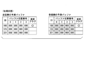
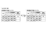
- the prediction buffer includes a plurality of storage areas for each identifier (ID) of a frame. In the example from FIG. 3 to FIG. 10, for convenience of explanation, there are three IDs “100”, “123”, and “321”. For each ID, four storage areas with buffer position numbers 0 to 3 are provided.
- Buffer position number “0” indicates the first storage area
- buffer position number “1” indicates the second storage area
- buffer position number “2” indicates the third storage area
- buffer position number “3” indicates the last storage area.
- FIG. 3 shows each prediction buffer in the initial state on the transmission side and the reception side.
- values indicating an empty state are stored in all the storage areas of the prediction buffer.
- a value indicating an empty state a value “000” that is not used for the ID is used.
- the immediately preceding flag is set in common on the transmission side and the reception side.
- the immediately preceding flag indicates an ID input immediately before the ID input this time. Therefore, the ID for which the immediately preceding flag is set is the ID that was input most recently in the past.
- the immediately preceding flag is initially set to ID “100” in common on the transmission side and the reception side.
- An ID for which the immediately preceding flag is set is referred to as “immediately preceding ID”.
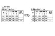
- FIG. 4 shows each prediction buffer on the transmission side and the reception side as a result of processing the input ID “123”. Since the input ID “123” does not exist in the storage area of the immediately preceding ID “100” (see FIG. 3) of the prediction buffer on the transmission side, the head movement encoding unit 53 (transmission side) sets the input ID “123” to Store in the first storage area (buffer position number “0”) of the immediately preceding ID “100”. The leading movement method encoding unit 53 (transmission side) outputs a predetermined code (compression code) indicating the input ID “123”. The code indicating this input ID “123” is sent to the receiving side. The leading movement method encoding unit 53 (transmission side) changes the setting of the immediately preceding flag to the input ID “123”.
- the head movement method code decoding unit 72 receives the code indicating the ID “123”, the received code is not the code indicating the buffer position number, and therefore the ID “123” indicated by the received code is received. Is stored in the first storage area (buffer position number “0”) of the previous prediction buffer ID “100” (see FIG. 3).
- the head movement method code decoding unit 72 outputs the ID “123” indicated by the received code as a decoding result.
- the leading movement method code decoding unit 72 (reception side) changes the setting of the immediately preceding flag to ID “123”. Thereby, as shown in FIG. 4, the states of the prediction buffers on both the transmission side and the reception side match.
- FIG. 5 shows each prediction buffer on the transmission side and reception side as a result of processing the input ID “321”. Since the input ID “321” does not exist in the storage area of the immediately preceding ID “123” (see FIG. 4) of the prediction buffer on the transmission side, the head movement encoding unit 53 (transmission side) sets the input ID “321” to Store in the first storage area (buffer position number “0”) of the immediately preceding ID “123”. The leading movement method encoding unit 53 (transmission side) outputs a predetermined code (compression code) indicating the input ID “321”. The code indicating this input ID “321” is sent to the receiving side. The leading movement method encoding unit 53 (transmission side) changes the setting of the immediately preceding flag to the input ID “321”.
- the head movement code decoding unit 72 (reception side) receives the code indicating the ID “321”, the received code is not the code indicating the buffer position number, and therefore the ID “321” indicated by the received code is received. Is stored in the first storage area (buffer position number “0”) of the previous prediction buffer ID “123” (see FIG. 4).
- the head movement method code decoding unit 72 (reception side) outputs the ID “321” indicated by the received code as a decoding result.
- the leading movement method code decoding unit 72 (reception side) changes the setting of the immediately preceding flag to ID “321”. Thereby, as shown in FIG. 5, the states of the prediction buffers on both the transmission side and the reception side match.
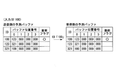
- FIG. 6 shows each prediction buffer on the transmission side and reception side as a result of processing the input ID “100”. Since the input ID “100” does not exist in the storage area of the immediately preceding ID “321” (see FIG. 5) of the prediction buffer on the transmission side, the head movement encoding unit 53 (transmission side) sets the input ID “100” to Store in the first storage area (buffer position number “0”) of the immediately preceding ID “321”. The leading movement method encoding unit 53 (transmission side) outputs a predetermined code (compression code) indicating the input ID “100”. The code indicating this input ID “100” is sent to the receiving side. The leading movement method encoding unit 53 (transmission side) changes the setting of the immediately preceding flag to the input ID “100”.
- the head movement method code decoding unit 72 (reception side) receives the code indicating the ID “100”, the received code is not the code indicating the buffer position number, and therefore the ID “100” indicated by the received code is received. Is stored in the first storage area (buffer position number “0”) of the previous prediction buffer ID “321” (see FIG. 5).
- the leading movement method code decoding unit 72 (receiving side) outputs the ID “100” indicated by the received code as a decoding result.
- the leading movement method code decoding unit 72 (reception side) changes the setting of the immediately preceding flag to ID “100”. Thereby, as shown in FIG. 6, the states of the prediction buffers on both the transmission side and the reception side match.
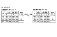
- FIG. 7 shows prediction buffers on the transmission side and the reception side as a result of processing the input ID “123”.
- the input ID “123” exists in the first storage area (buffer position number “0”) of the immediately preceding ID “100” (see FIG. 6) of the prediction buffer on the transmission side. Therefore, the stored state is maintained as it is.
- the leading movement encoding unit 53 (transmission side) outputs a predetermined code (compression code) indicating the buffer position number “0” of the storage area in which the input ID “123” has already been stored. The code indicating this buffer position number “0” is sent to the receiving side.
- the leading movement method encoding unit 53 (transmission side) changes the setting of the immediately preceding flag to the input ID “123”.
- the head movement code decoding unit 72 receives the code indicating the buffer position number “0”, the received code is a code indicating the buffer position number. "(See FIG. 6), the ID" 123 "is acquired from the storage area of the buffer position number” 0 "indicated by the received code.
- the leading movement code decoding unit 72 outputs the acquired ID “123” as a decoding result.
- the leading movement method code decoding unit 72 changes the setting of the immediately preceding flag to ID “123”.
- FIG. 7 the states of the prediction buffers on both the transmission side and the reception side match.
- the ID “123” is input to the transmission side in the state of the prediction buffer shown in FIG. 6, the buffer position number “0” is transmitted by the head movement encoding unit 53 (transmission side).
- the ID “123” can be decoded by the head movement method code decoding unit 72 (receiving side).
- FIG. 8 shows each prediction buffer on the transmission side and the reception side as a result of processing the input ID “100”. Since the input ID “100” does not exist in the storage area of the immediately preceding ID “123” (see FIG. 7) of the prediction buffer on the transmission side, the head movement encoding unit 53 (transmission side) sets the input ID “100” to Store in the first storage area (buffer position number “0”) of the immediately preceding ID “321”. At this time, the head shift encoding unit 53 (transmission side) replaces the ID “321” that already exists in the storage area of the buffer position number “0” of the ID “123” with the ID “123” next to the ID “123”.
- the leading movement method encoding unit 53 (transmission side) outputs a predetermined code (compression code) indicating the input ID “100”. The code indicating this input ID “100” is sent to the receiving side. The leading movement method encoding unit 53 (transmission side) changes the setting of the immediately preceding flag to the input ID “100”.
- the head movement method code decoding unit 72 (reception side) receives the code indicating the ID “100”, the received code is not the code indicating the buffer position number, and therefore the ID “100” indicated by the received code is received. Is stored in the first storage area (buffer position number “0”) of the previous prediction buffer ID “123” (see FIG. 7). At this time, the head movement method code decoding unit 72 (reception side) uses the ID “321” already existing in the storage area of the buffer position number “0” of the ID “123” as in the transmission side. Move to the storage area of the buffer position number “1” next to “123”. The leading movement method code decoding unit 72 (receiving side) outputs the ID “100” indicated by the received code as a decoding result.
- the leading movement method code decoding unit 72 (reception side) changes the setting of the immediately preceding flag to ID “100”. Thereby, as shown in FIG. 8, the states of the prediction buffers on both the transmission side and the reception side match. When both the transmitting side and the receiving side move the ID storage area to the storage area of the next buffer position number, the ID already existing in the storage area of the buffer position number “3” is deleted.
- FIG. 9 shows each prediction buffer on the transmission side and the reception side as a result of processing the input ID “123”.
- the input ID “123” exists in the first storage area (buffer position number “0”) of the immediately preceding ID “100” (see FIG. 8) of the prediction buffer on the transmission side. Therefore, the stored state is maintained as it is.
- the leading movement encoding unit 53 (transmission side) outputs a predetermined code (compression code) indicating the buffer position number “0” of the storage area in which the input ID “123” has already been stored. The code indicating this buffer position number “0” is sent to the receiving side.
- the leading movement method encoding unit 53 (transmission side) changes the setting of the immediately preceding flag to the input ID “123”.
- the head movement code decoding unit 72 (reception side) receives the code indicating the buffer position number “0”, the received code is a code indicating the buffer position number. ”(See FIG. 8), the ID“ 123 ”is acquired from the storage area of the buffer position number“ 0 ”indicated by the received code.
- the leading movement code decoding unit 72 (reception side) outputs the acquired ID “123” as a decoding result.
- the leading movement method code decoding unit 72 (reception side) changes the setting of the immediately preceding flag to ID “123”.
- the states of the prediction buffers on both the transmission side and the reception side match. In this way, when the ID “123” is input to the transmission side in the state of the prediction buffer shown in FIG. 8, the buffer position number “0” is transmitted by the head movement encoding unit 53 (transmission side). As a result, the ID “123” can be decoded by the head movement method code decoding unit 72 (receiving side).
- FIG. 10 shows each prediction buffer on the transmission side and the reception side as a result of processing the input ID “321”.
- the leading movement encoding unit 53 (transmission side) stores the input ID “321” in the second storage area (buffer position number “1”) of the immediately preceding ID “123” (see FIG. 9) of the prediction buffer on the transmission side. Since it exists, the ID “321” is moved to the top storage area (buffer position number “0”). At this time, the head shift encoding unit 53 (transmission side) replaces the ID “100” already existing in the storage area of the buffer position number “0” of the ID “123” with the ID “123” next to the ID “123”.
- the leading movement encoding unit 53 (transmission side) outputs a predetermined code (compression code) indicating the buffer position number “1” of the storage area in which the input ID “321” has already been stored.
- the code indicating this buffer position number “1” is sent to the receiving side.
- the leading movement method encoding unit 53 (transmission side) changes the setting of the immediately preceding flag to the input ID “321”.
- the head movement code decoding unit 72 receives the code indicating the buffer position number “1”, the received code is a code indicating the buffer position number. "(See FIG. 9), ID" 321 "is acquired from the storage area of buffer position number” 1 "indicated by the received code.
- the leading movement method code decoding unit 72 outputs the acquired ID “321” as a decoding result.
- the leading movement method code decoding unit 72 changes the setting of the immediately preceding flag to ID “321”.
- the states of the prediction buffers on both the transmission side and the reception side match.
- the ID “321” is input to the transmission side in the state of the prediction buffer shown in FIG. 9, the buffer position number “1” is transmitted by the head movement encoding unit 53 (transmission side).
- the ID “321” can be decoded by the head movement method code decoding unit 72 (receiving side).
- head movement method encoding method data is biased in the ID encoding result (head movement method encoded data).
- the Huffman coding is further applied to the biased data (first moving method encoded data).
- An identifier (ID) of a CAN (controller area network) frame mounted on a vehicle such as an automobile has a bias in appearance frequency depending on the ID (see, for example, Non-Patent Document 1). Therefore, by applying the head movement method encoding method according to the present embodiment to the ID of the frame acquired from the CAN mounted on the vehicle, an effect of improving the ID data compression rate can be obtained.
- FIG. 11 is an explanatory diagram showing a modification of the ID encoding method according to the present embodiment.
- the CAN control processing unit 52 includes a hash conversion unit that converts an ID into a hash value.
- Step S31 The CAN control processing unit 52 converts the ID into a hash value hash (ID) by the hash conversion unit.
- the CAN control processing unit 52 inputs the hash value hash (ID) to the Huffman encoding unit 54.
- Step S32 The Huffman encoding unit 54 encodes the hash value hash (ID) with the Huffman code. Huffman encoded data obtained as a result of Huffman encoding the hash value hash (ID) is transmitted from the gateway device 5 to the TCU 6 and input to the communication control processing unit 62 of the TCU 6.
- Step S33 The Huffman code decoding unit 63 of the communication control processing unit 62 decodes the Huffman encoded data input to the communication control processing unit 62.
- the Huffman code decoding unit 63 outputs the hash value hash (ID) obtained by the decoding to the range encoding unit 64.
- the range encoding unit 64 encodes the hash value hash (ID) input from the Huffman code decoding unit 63 with a range code. Range encoded data resulting from the range encoding of the hash value hash (ID) is input from the communication control processing unit 62 to the communication unit 60 and transmitted to the server device 7 by the communication unit 60.
- An ID-hash value correspondence table showing the correspondence between ID and hash value hash (ID) is provided in the server device 7 in advance.
- the server device 7 uses the range code decoding unit 71 to decode the range encoded data of the hash value hash (ID) received from the automobile 3.
- the server device 7 acquires an ID corresponding to the hash value hash (ID) obtained by the decryption from the ID-hash value correspondence table.
- the table search target space in the ID encoding can be reduced by converting the ID into a hash value.
- the hash value hash (ID) obtained by decoding the Huffman code is returned to the ID in the process from the decoding of the Huffman code to the range encoding in the communication control processing unit 62.
- the table search process and the process of converting the ID into the hash value hash (ID) in the ID range encoding can be omitted.
- the CAN_sub ⁇ A CAN control processing unit 52 (first arithmetic processing unit) that executes control processing of bus_1 to n includes a Huffman encoding unit that encodes data to be encoded included in a frame flowing through CAN_sub-bus_1 to n using a Huffman code.
- a communication control processing unit 62 (second arithmetic processing unit) that generates communication data to be transmitted to the server device 7 and a Huffman code decoding unit that decodes the Huffman encoded data transmitted from the CAN control processing unit 52;
- a range encoding unit that encodes the decoding result of the Huffman code decoding unit with a range code, Coded range encoded data is transmitted to the server 7 by Nji coder.
- Huffman coding is a coding method having higher real-time characteristics than, for example, range coding.
- range encoding is an encoding method having a higher data compression rate than, for example, Huffman encoding.
- the CAN control processing unit 52 executes the control processing of CAN_sub-bus_1 to n, it is required to execute the processing at high speed. For example, if reading and writing of a transmission / reception buffer that temporarily holds frames transmitted / received to / from CAN_sub-bus_1 to n takes a certain time or more, a frame that cannot be processed may be discarded. According to the present embodiment, the CAN control processing unit 52 can contribute to the high-speed processing of the CAN control processing unit 52 by applying Huffman coding having a relatively high real-time property.
- the amount of communication data transmitted from the automobile 3 to the server device 7 outside the vehicle is as small as possible.
- the wireless communication cost is reduced or the influence of data delay due to fluctuations in the wireless communication speed (speed reduction) is reduced.
- the amount of communication data is preferably as small as possible. According to the present embodiment, by applying range coding with a relatively high data compression rate to the communication control processing unit 62, it is possible to contribute to a reduction in the amount of communication data transmitted to the server device 7. .
- an automobile is used as an example of a vehicle.
- a computer program for realizing the functions of each device described above may be recorded on a computer-readable recording medium, and the program recorded on the recording medium may be read into a computer system and executed.
- the “computer system” may include an OS and hardware such as peripheral devices.
- “Computer-readable recording medium” refers to a flexible disk, a magneto-optical disk, a ROM, a writable nonvolatile memory such as a flash memory, a portable medium such as a DVD (Digital Versatile Disc), and a built-in computer system.
- a storage device such as a hard disk.
- the “computer-readable recording medium” means a volatile memory (for example, DRAM (Dynamic DRAM) in a computer system that becomes a server or a client when a program is transmitted through a network such as the Internet or a communication line such as a telephone line. Random Access Memory)), etc., which hold programs for a certain period of time.
- the program may be transmitted from a computer system storing the program in a storage device or the like to another computer system via a transmission medium or by a transmission wave in the transmission medium.
- the “transmission medium” for transmitting the program refers to a medium having a function of transmitting information, such as a network (communication network) such as the Internet or a communication line (communication line) such as a telephone line.
- the program may be for realizing a part of the functions described above. Furthermore, what can implement
- Communication System 3 Car 5 Gateway Device 6 TCU 7 Server device 50 CAN_sub-bus interface 51, 61 CAN-FD interface 52 CAN control processing unit (first arithmetic processing unit) 53 Head Movement Encoding Unit 54 Huffman Encoding Unit 60, 70 Communication Unit 62 Communication Control Processing Unit (Second Arithmetic Processing Unit) 63 Huffman code decoding unit 64 Range encoding unit 71 Range code decoding unit 72 First moving method code decoding unit 73 Recording unit CAN_sub-bus_1 to n Communication network
Landscapes
- Engineering & Computer Science (AREA)
- Computer Networks & Wireless Communication (AREA)
- Signal Processing (AREA)
- Theoretical Computer Science (AREA)
- Compression, Expansion, Code Conversion, And Decoders (AREA)
Abstract
車両は、車両に搭載された通信ネットワークの制御処理を実行する第1演算処理部と、車両の外部の装置へ送信される通信データを生成する第2演算処理部とを備え、第1演算処理部は、車両に搭載された通信ネットワークのフレームに含まれる符号化対象データをハフマン符号により符号化するハフマン符号化部を備え、第2演算処理部は、ハフマン符号化データを復号するハフマン符号復号部と、当該復号結果をレンジ符号により符号化するレンジ符号化部と、を備え、レンジ符号化部により符号化されたレンジ符号化データは車両の外部の装置へ送信される。
Description
本発明は、通信システム及び通信方法に関する。
本願は、2018年2月9日に、日本に出願された特願2018-22555号に基づき優先権を主張し、その内容をここに援用する。
本願は、2018年2月9日に、日本に出願された特願2018-22555号に基づき優先権を主張し、その内容をここに援用する。
従来、自動車等の車両に搭載された通信ネットワークに流れるデータを車両の外部のサーバやストレージ等の監視装置へリアルタイムに送信する際に、送信されるデータを圧縮するデータ圧縮技術が、例えば非特許文献1に開示されている。非特許文献1のデータ圧縮技術は、CAN(Controller Area Network)に流れるフレームの識別子(ID)を符号化対象にして、よく出現するIDには短いビット列を割り当てる一方、あまり出現しないIDには長いビット列を割り当てるハフマン(Huffman)符号化を行う。また、非特許文献1のデータ圧縮技術は、CANに流れるフレームのペイロードを符号化対象にして、識別子(ID)毎に、連続するフレーム間のペイロードの差分データをランレングス符号化する。
大平修慈、金森健人、井上博之、石田賢治、「車載LAN トラフィック監視システム向けのリアルタイムデータ圧縮方式」、情報処理学会、コンピュータセキュリティシンポジウム 2017、2017年10月、pp.1469-1474
しかし、上述した非特許文献1のデータ圧縮技術では、車両に搭載された通信ネットワークやコンピュータシステムの構成によっては、車両に搭載された通信ネットワークに流れるデータを車両の外部の装置へリアルタイムに送信する通信システムにおいて、リアルタイム性と通信データ量の低減とが十分ではない場合があった。
本発明は、このような事情を考慮してなされたものであり、その目的は、車両に搭載された通信ネットワークに流れるデータを車両の外部の装置へリアルタイムに送信する通信システムにおいて、リアルタイム性と通信データ量の低減との向上を図ることにある。
本発明の一態様の通信システムは、車両に搭載された通信ネットワークに流れるデータを前記車両の外部の装置へリアルタイムに送信する通信システムにおいて、前記車両は、前記通信ネットワークを介してフレームを送受する通信ネットワークインタフェースと、前記通信ネットワークの制御処理を実行する第1演算処理部と、前記車両の外部の装置と通信を行う通信部と、前記車両の外部の装置へ送信される通信データを生成する第2演算処理部と、前記第1演算処理部と前記第2演算処理部との間のデータ伝送を行う通信路とを備える。前記第1演算処理部は、前記フレームに含まれる符号化対象データをハフマン符号により符号化するハフマン符号化部を備え、前記ハフマン符号化部により符号化されたハフマン符号化データは、前記通信路により前記第2演算処理部へ伝送される。前記第2演算処理部は、前記ハフマン符号化データを復号するハフマン符号復号部と、前記ハフマン符号復号部の復号結果をレンジ符号により符号化するレンジ符号化部とを備え、前記レンジ符号化部により符号化されたレンジ符号化データは、前記通信部により前記車両の外部の装置へ送信される。
本発明の一態様の通信システムにおいて、前記第1演算処理部は、前記フレームの識別子をハッシュ値に変換するハッシュ変換部を備え、前記ハフマン符号化部は、前記フレームの識別子のハッシュ値をハフマン符号により符号化し、前記レンジ符号化部は、前記ハフマン符号復号部の復号により得られた前記フレームの識別子のハッシュ値をレンジ符号により符号化するようにしてもよい。
本発明の一態様の通信システムにおいて、前記第1演算処理部は、前記フレームの識別子をハッシュ値に変換するハッシュ変換部を備え、前記ハフマン符号化部は、前記フレームの識別子のハッシュ値をハフマン符号により符号化し、前記レンジ符号化部は、前記ハフマン符号復号部の復号により得られた前記フレームの識別子のハッシュ値をレンジ符号により符号化するようにしてもよい。
本発明の一態様の通信方法は、車両に搭載された通信ネットワークに流れるデータを前記車両の外部の装置へリアルタイムに送信する通信方法において、前記車両に備わる通信ネットワークインタフェースが、前記通信ネットワークを介してフレームを送受するステップと、前記車両に備わる第1演算処理部が、前記通信ネットワークの制御処理を実行するステップと、前記車両に備わる通信部が、前記車両の外部の装置と通信を行うステップと、前記車両に備わる第2演算処理部が、前記車両の外部の装置へ送信される通信データを生成するステップとを含む。前記第1演算処理部は、前記フレームに含まれる符号化対象データをハフマン符号により符号化し、前記ハフマン符号により符号化されたハフマン符号化データは、前記車両に備わる通信路により前記第2演算処理部へ伝送される。前記第2演算処理部は、前記ハフマン符号化データを復号し、当該復号の結果をレンジ符号により符号化し、前記レンジ符号により符号化されたレンジ符号化データは、前記通信部により前記車両の外部の装置へ送信される。
本発明の一態様の通信方法において、前記第1演算処理部は、前記フレームの識別子をハッシュ値に変換し、前記フレームの識別子のハッシュ値をハフマン符号により符号化してもよく、前記第2演算処理部は、前記ハフマン符号化データの復号により得られた前記フレームの識別子のハッシュ値をレンジ符号により符号化してもよい。
本発明の一態様の通信方法において、前記第1演算処理部は、前記フレームの識別子をハッシュ値に変換し、前記フレームの識別子のハッシュ値をハフマン符号により符号化してもよく、前記第2演算処理部は、前記ハフマン符号化データの復号により得られた前記フレームの識別子のハッシュ値をレンジ符号により符号化してもよい。
本発明によれば、車両に搭載された通信ネットワークに流れるデータを車両の外部の装置へリアルタイムに送信する通信システムにおいて、リアルタイム性と通信データ量の低減との向上を図ることができるという効果が得られる。
以下、図面を参照し、本発明の実施形態について説明する。
図1は、本実施形態に係る通信システムの構成例を示すブロック図である。本実施形態に係る通信システムは、通信ネットワークに流れるデータを車両の外部のサーバ装置へリアルタイムに送信するための通信システムである。本実施形態において、通信ネットワークは、自動車等の車両に搭載される。図1の通信システム1では、車両として自動車を例に挙げている。図1に示される通信システム1は、自動車3とサーバ装置7とを備える。
自動車3は、ゲートウェイ装置5(CGW:Central Gateway)とTCU(Telematics Communication Unit)6とを備える。ゲートウェイ装置5とTCU6とは、自動車3に搭載されたCAN-FD(CAN with Flexible Data rate)規格の通信ネットワーク(以下、CAN-FDと称する)で接続されている。ゲートウェイ装置5には、自動車3に搭載されたCAN規格の複数(n個)の通信ネットワーク(以下、CAN_sub-bus_1~nと称する)が接続されている。各CAN_sub-bus_1~nには、自動車3に搭載されたECU(Electronic Control Unit:電子制御装置)等の通信ノード(図示せず)が接続されている。通信ノードは、自己が接続するCAN_sub-bus_1~nを介して、CAN規格のフレーム(以下、単にフレームと称する)を送受する。通信ノードは、フレームを使用して通信を行う。
ゲートウェイ装置5は、CAN_sub-busインタフェース50とCAN-FDインタフェース51とCAN制御処理部52とを備える。CAN制御処理部52は第1演算処理部に対応する。
CAN_sub-busインタフェース50は、各CAN_sub-bus_1~nを介してフレームを送受する。CAN_sub-busインタフェース50は、各CAN_sub-bus_1~nを流れるフレームを取得し、取得したフレームをCAN制御処理部52へ出力する。
CAN_sub-busインタフェース50は、各CAN_sub-bus_1~nを介してフレームを送受する。CAN_sub-busインタフェース50は、各CAN_sub-bus_1~nを流れるフレームを取得し、取得したフレームをCAN制御処理部52へ出力する。
CAN制御処理部52は、CAN_sub-bus_1~nの制御処理を実行する。また、CAN制御処理部52は、CAN_sub-busインタフェース50から入力されたフレームを符号化対象にして、フレームの取得元のCAN_sub-bus_1~n毎に符号化を行う。CAN制御処理部52は、フレームの符号化結果であるフレーム符号化データをCAN-FDインタフェース51へ出力する。
CAN制御処理部52は、先頭移動法符号化部53とハフマン符号化部54とを備える。
先頭移動法符号化部53は、CAN_sub-busインタフェース50からCAN制御処理部52に入力されたフレームの識別子(ID)を符号化対象にして、先頭移動法(Move to Front:MTF)により符号化を行う。先頭移動法符号化部53は、IDを先頭移動法により符号化した結果のデータ(先頭移動法符号化データ)を、ハフマン符号化部54へ出力する。
先頭移動法符号化部53は、CAN_sub-busインタフェース50からCAN制御処理部52に入力されたフレームの識別子(ID)を符号化対象にして、先頭移動法(Move to Front:MTF)により符号化を行う。先頭移動法符号化部53は、IDを先頭移動法により符号化した結果のデータ(先頭移動法符号化データ)を、ハフマン符号化部54へ出力する。
ハフマン符号化部54は、先頭移動法符号化部53から入力された先頭移動法符号化データを符号化対象にして、ハフマン符号により符号化を行う。また、ハフマン符号化部54は、CAN_sub-busインタフェース50からCAN制御処理部52に入力されたフレームに含まれるID以外の符号化対象について、ハフマン符号により符号化する。
ハフマン符号による符号化では、一定のフレーム数を1ブロックとして、1ブロック内に出現する符号化対象の情報の頻度に応じて当該情報に割り当てる符号長等の符号内容を決定してもよい。
ハフマン符号による符号化では、一定のフレーム数を1ブロックとして、1ブロック内に出現する符号化対象の情報の頻度に応じて当該情報に割り当てる符号長等の符号内容を決定してもよい。
ハフマン符号化部54は、各符号化対象をハフマン符号化した結果の各データ(ハフマン符号化データ)を出力する。CAN制御処理部52は、ハフマン符号化部54から出力されたハフマン符号化データをフレーム符号化データとしてCAN-FDインタフェース51へ出力する。
CAN-FDインタフェース51は、CAN-FDを介して、TCU6とデータを送受する。CAN-FDインタフェース51は、CAN制御処理部52から入力されたフレーム符号化データを、CAN-FDを介してTCU6へ送信する。
TCU6は通信装置である。TCU6は、通信部60とCAN-FDインタフェース61と通信制御処理部62とを備える。通信制御処理部62は、第2演算処理部に対応する。
通信部60は、自動車3の外部の装置と通信を行う。通信部60は、無線通信を行ってもよく、又は、有線通信を行ってもよい。本実施形態に係る一例として、通信部60は、無線通信ネットワークを利用して無線通信を行う。通信部60は、サーバ装置7と通信を行う。
通信部60は、自動車3の外部の装置と通信を行う。通信部60は、無線通信を行ってもよく、又は、有線通信を行ってもよい。本実施形態に係る一例として、通信部60は、無線通信ネットワークを利用して無線通信を行う。通信部60は、サーバ装置7と通信を行う。
CAN-FDインタフェース61は、CAN-FDを介して、ゲートウェイ装置5とデータを送受する。CAN-FDインタフェース61は、ゲートウェイ装置5から受信したフレーム符号化データを、通信制御処理部62へ出力する。
CAN-FDインタフェース51、CAN-FD及びCAN-FDインタフェース61は、CAN制御処理部52(第1演算処理部)と通信制御処理部62(第2演算処理部)との間のデータ伝送を行う通信路に対応する。
CAN-FDインタフェース51、CAN-FD及びCAN-FDインタフェース61は、CAN制御処理部52(第1演算処理部)と通信制御処理部62(第2演算処理部)との間のデータ伝送を行う通信路に対応する。
通信制御処理部62は、通信部60による自動車3の外部の装置との通信の制御処理を実行する。また、通信制御処理部62は、サーバ装置7へ送信される通信データを生成する。通信制御処理部62は、CAN-FDインタフェース61から入力されたフレーム符号化データに含まれるハフマン符号化データを復号し、当該復号の結果をレンジ符号により符号化する。通信制御処理部62は、レンジ符号により符号化されたレンジ符号化データを通信部60へ出力する。通信部60は、通信制御処理部62から入力されたレンジ符号化データをサーバ装置7へ送信する。
通信制御処理部62は、ハフマン符号復号部63とレンジ符号化部64とを備える。ハフマン符号復号部63は、CAN-FDインタフェース61から入力されたフレーム符号化データに含まれるハフマン符号化データを復号する。ハフマン符号復号部63は、ハフマン符号化データの復号結果をレンジ符号化部64へ出力する。レンジ符号化部64は、ハフマン符号復号部63から入力されたハフマン符号化データの復号結果をレンジ符号により符号化する。レンジ符号化部64は、レンジ符号化した結果のデータ(レンジ符号化データ)を出力する。通信制御処理部62は、レンジ符号化部64から出力されたレンジ符号化データを通信部60へ出力する。
サーバ装置7は、通信部70とレンジ符号復号部71と先頭移動法符号復号部72と記録部73とを備える。
通信部70は、サーバ装置7の外部の装置と通信を行う。通信部70は、自動車3と通信を行う。具体的には、サーバ装置7の通信部70と自動車3のTCU6の通信部60とが通信を行う。サーバ装置7は、通信部70により、自動車3からレンジ符号化データを受信する。
通信部70は、サーバ装置7の外部の装置と通信を行う。通信部70は、自動車3と通信を行う。具体的には、サーバ装置7の通信部70と自動車3のTCU6の通信部60とが通信を行う。サーバ装置7は、通信部70により、自動車3からレンジ符号化データを受信する。
レンジ符号復号部71は、自動車3から受信したレンジ符号化データを復号する。レンジ符号復号部71は、レンジ符号化データの復号により得られた先頭移動法符号化データを先頭移動法符号復号部72へ出力する。また、レンジ符号復号部71は、レンジ符号化データの復号により得られたID以外の復号結果(フレームに含まれるID以外の符号化対象の部分)を記録部73へ出力する。
先頭移動法符号復号部72は、レンジ符号復号部71から入力された先頭移動法符号化データを復号する。先頭移動法符号復号部72の復号方法は、先頭移動法符号化部53の符号化方法に対応するものである。先頭移動法符号復号部72は、先頭移動法符号化データの復号により得られたIDを記録部73へ出力する。
記録部73は、先頭移動法符号復号部72から入力されたIDの復号結果と、レンジ符号復号部71から入力されたID以外の復号結果とを記録する。
次に図2を参照して、図1に示すCAN制御処理部52に係るフレーム符号化処理を説明する。図2は、本実施形態に係るフレーム符号化方法の例を示す説明図である。図2の例は、一つのCAN(図1中のCAN_sub-bus_1~nのいずれか一つ)に流れるフレームを取得し、当該フレームを符号化する場合を示す。図2中に示されるフレーム100は、CANのデータフレームの概要を示すものである。CANのデータフレームは、フレーム100に示されるように、11ビット長の識別子(ID)と、4ビット長のDLC(Data Length Code)と、最大64ビット長のデータ(DATA)とを含む。図2の例では、それらIDとDLCとDATAとが符号化対象データである。
なお、DLCがID毎に固定されている場合、つまり、IDが決まればDLCが一律に決まる場合には、サーバ装置7はIDからDLCを決定できる。このため、DLCがID毎に固定されている場合には、自動車3からサーバ装置7へDLCを送信しなくてもよいので、DLCを符号化対象にしなくてもよい。
なお、DLCがID毎に固定されている場合、つまり、IDが決まればDLCが一律に決まる場合には、サーバ装置7はIDからDLCを決定できる。このため、DLCがID毎に固定されている場合には、自動車3からサーバ装置7へDLCを送信しなくてもよいので、DLCを符号化対象にしなくてもよい。
CAN制御処理部52は、CAN_sub-bus_1~n毎に、図2に示すフレーム符号化方法によりフレーム符号化処理を行う。CAN制御処理部52には、CAN_sub-busインタフェース50から、各CAN_sub-bus_1~nから取得されたフレームが入力される。CAN制御処理部52は、各CAN_sub-bus_1~nに対して、ID毎に、過去の直近に入力されたフレームのDLC及びDATAを保持するバッファ(図示せず)を備える。
CAN制御処理部52の先頭移動法符号化部53は、先頭移動法によりIDを符号化する。ハフマン符号化部54は、IDとDLCとDATAについて、それぞれ別個にハフマン符号化を行う。
以下、CAN_sub-bus_1~nのうちの一つ、例えばCAN_sub-bus_1から取得されたフレームについてのフレーム符号化処理を説明する。フレーム100は、CAN_sub-busインタフェース50により、CAN_sub-bus_1から取得されてCAN制御処理部52に入力される。フレーム100がCAN制御処理部52に入力されると、図2のフレーム符号化方法の手順が開始される。図2の以降の説明では、フレーム100がCAN制御処理部52に入力された時刻をtとし、フレーム100の直前にCAN制御処理部52に入力されたCAN_sub-bus_1のフレームの入力時刻を「t-1」とする。フレーム100がCAN制御処理部52に入力された時刻tにおいて、CAN制御処理部52のバッファには入力時刻「t-1」のフレームのDLC及びDATAが既に保持されている。
(ステップS10) CAN制御処理部52は、フレーム100からIDを取得する。
(ステップS11) 先頭移動法符号化部53は、IDを先頭移動法により符号化する。
この符号化により先頭移動法符号化データMTF(ID)が生成される。
この符号化により先頭移動法符号化データMTF(ID)が生成される。
(ステップS12) ハフマン符号化部54は、先頭移動法符号化データMTF(ID)をハフマン符号により符号化する。この符号化により、先頭移動法符号化データMTF(ID)のハフマン符号化データが生成される。
(ステップS13) CAN制御処理部52は、フレーム100からDLCを取得する。
また、CAN制御処理部52は、フレーム100のIDに対応するバッファに保持されているDLCを当該バッファから取得する。CAN制御処理部52は、フレーム100から取得したDLCとバッファから取得したDLCとの差dDLCを計算する。
また、CAN制御処理部52は、フレーム100のIDに対応するバッファに保持されているDLCを当該バッファから取得する。CAN制御処理部52は、フレーム100から取得したDLCとバッファから取得したDLCとの差dDLCを計算する。
(ステップS14) ハフマン符号化部54は、差dDLCをハフマン符号により符号化する。この符号化により、差dDLCのハフマン符号化データが生成される。
(ステップS15) CAN制御処理部52は、フレーム100からDATAを取得する。また、CAN制御処理部52は、フレーム100のIDに対応するバッファに保持されているDATAを当該バッファから取得する。CAN制御処理部52は、フレーム100から取得したDATAとバッファから取得したDATAとの差dDATAを計算する。
(ステップS16) ハフマン符号化部54は、差dDATAをハフマン符号により符号化する。この符号化により、差dDATAのハフマン符号化データが生成される。
(ステップS17) CAN制御処理部52は、フレーム100の符号化データとして、「先頭移動法符号化データMTF(ID)のハフマン符号化データ」と「差dDLCのハフマン符号化データ」と「差dDATAのハフマン符号化データ」とを出力する。
(ステップS18) CAN制御処理部52は、フレーム100のIDに対応するバッファの保持内容を、フレーム100のDLC及びDATAに書き換える。これにより、フレーム100のIDに対応するバッファに、フレーム100のDLC及びDATAが保持される。
[先頭移動法符号化方法]
次に図3~図10を参照して、本実施形態に係る先頭移動法符号化方法を説明する。図3~図10は、本実施形態に係る先頭移動法符号化方法に用いられる予測バッファの具体的な設定内容を示す表である。
先頭移動法符号化部53(送信側)及び先頭移動法符号復号部72(受信側)は、それぞれに、予測バッファを備える。予測バッファは、フレームの識別子(ID)毎に、複数の格納領域を備える。図3から図10までの例では、説明の便宜上、IDは「100」、「123」及び「321」の3個である。各IDに対して、バッファ位置番号が0から3までの4個の格納領域が設けられる。バッファ位置番号「0」が先頭の格納領域を示し、次いでバッファ位置番号「1」が2番目の格納領域を示し、次いでバッファ位置番号「2」が3番目の格納領域を示し、次いでバッファ位置番号「3」が最後尾の格納領域を示す。
以下、図3~図10の例を参照して本実施形態に係る先頭移動法符号化方法を具体的に説明する。
次に図3~図10を参照して、本実施形態に係る先頭移動法符号化方法を説明する。図3~図10は、本実施形態に係る先頭移動法符号化方法に用いられる予測バッファの具体的な設定内容を示す表である。
先頭移動法符号化部53(送信側)及び先頭移動法符号復号部72(受信側)は、それぞれに、予測バッファを備える。予測バッファは、フレームの識別子(ID)毎に、複数の格納領域を備える。図3から図10までの例では、説明の便宜上、IDは「100」、「123」及び「321」の3個である。各IDに対して、バッファ位置番号が0から3までの4個の格納領域が設けられる。バッファ位置番号「0」が先頭の格納領域を示し、次いでバッファ位置番号「1」が2番目の格納領域を示し、次いでバッファ位置番号「2」が3番目の格納領域を示し、次いでバッファ位置番号「3」が最後尾の格納領域を示す。
以下、図3~図10の例を参照して本実施形態に係る先頭移動法符号化方法を具体的に説明する。
図3には、送信側及び受信側の初期状態の各予測バッファが示される。初期状態では、予測バッファの全ての格納領域に空の状態を示す値が格納される。ここでは、空の状態を示す値の一例として、IDに使用されない値「000」が使用されている。
また、送信側及び受信側で共通に直前フラグが設定される。直前フラグは、今回入力されたIDの直前に入力されたIDを示す。したがって、直前フラグが設定されているIDは、過去の直近に入力されたIDである。ここでは、直前フラグは、送信側及び受信側で共通に、ID「100」に初期設定されている。直前フラグが設定されているIDを「直前ID」と称する。
また、送信側及び受信側で共通に直前フラグが設定される。直前フラグは、今回入力されたIDの直前に入力されたIDを示す。したがって、直前フラグが設定されているIDは、過去の直近に入力されたIDである。ここでは、直前フラグは、送信側及び受信側で共通に、ID「100」に初期設定されている。直前フラグが設定されているIDを「直前ID」と称する。
次いで、送信側にID「123」が入力される。図4には、入力ID「123」が処理された結果の送信側及び受信側の各予測バッファが示される。先頭移動法符号化部53(送信側)は、入力ID「123」が送信側の予測バッファの直前ID「100」(図3参照)の格納領域に存在しないので、入力ID「123」を、直前ID「100」の先頭の格納領域(バッファ位置番号「0」)に格納する。先頭移動法符号化部53(送信側)は、入力ID「123」を示す所定の符号(圧縮符号)を出力する。この入力ID「123」を示す符号は受信側へ送られる。先頭移動法符号化部53(送信側)は、直前フラグを入力ID「123」に設定変更する。
先頭移動法符号復号部72(受信側)は、ID「123」を示す符号を受信すると、受信した符号がバッファ位置番号を示す符号ではないので、受信した符号が示すID「123」を、受信側の予測バッファの直前ID「100」(図3参照)の先頭の格納領域(バッファ位置番号「0」)に格納する。先頭移動法符号復号部72(受信側)は、該受信した符号が示すID「123」を復号結果として出力する。先頭移動法符号復号部72(受信側)は、直前フラグをID「123」に設定変更する。これにより、図4に示されるように、送信側及び受信側の両方の予測バッファの状態が一致する。
次いで、送信側にID「321」が入力される。図5には、入力ID「321」が処理された結果の送信側及び受信側の各予測バッファが示される。先頭移動法符号化部53(送信側)は、入力ID「321」が送信側の予測バッファの直前ID「123」(図4参照)の格納領域に存在しないので、入力ID「321」を、直前ID「123」の先頭の格納領域(バッファ位置番号「0」)に格納する。先頭移動法符号化部53(送信側)は、入力ID「321」を示す所定の符号(圧縮符号)を出力する。この入力ID「321」を示す符号は受信側へ送られる。先頭移動法符号化部53(送信側)は、直前フラグを入力ID「321」に設定変更する。
先頭移動法符号復号部72(受信側)は、ID「321」を示す符号を受信すると、受信した符号がバッファ位置番号を示す符号ではないので、受信した符号が示すID「321」を、受信側の予測バッファの直前ID「123」(図4参照)の先頭の格納領域(バッファ位置番号「0」)に格納する。先頭移動法符号復号部72(受信側)は、該受信した符号が示すID「321」を復号結果として出力する。先頭移動法符号復号部72(受信側)は、直前フラグをID「321」に設定変更する。これにより、図5に示されるように、送信側及び受信側の両方の予測バッファの状態が一致する。
次いで、送信側にID「100」が入力される。図6には、入力ID「100」が処理された結果の送信側及び受信側の各予測バッファが示される。先頭移動法符号化部53(送信側)は、入力ID「100」が送信側の予測バッファの直前ID「321」(図5参照)の格納領域に存在しないので、入力ID「100」を、直前ID「321」の先頭の格納領域(バッファ位置番号「0」)に格納する。先頭移動法符号化部53(送信側)は、入力ID「100」を示す所定の符号(圧縮符号)を出力する。この入力ID「100」を示す符号は受信側へ送られる。先頭移動法符号化部53(送信側)は、直前フラグを入力ID「100」に設定変更する。
先頭移動法符号復号部72(受信側)は、ID「100」を示す符号を受信すると、受信した符号がバッファ位置番号を示す符号ではないので、受信した符号が示すID「100」を、受信側の予測バッファの直前ID「321」(図5参照)の先頭の格納領域(バッファ位置番号「0」)に格納する。先頭移動法符号復号部72(受信側)は、該受信した符号が示すID「100」を復号結果として出力する。先頭移動法符号復号部72(受信側)は、直前フラグをID「100」に設定変更する。これにより、図6に示されるように、送信側及び受信側の両方の予測バッファの状態が一致する。
次いで、送信側にID「123」が入力される。図7には、入力ID「123」が処理された結果の送信側及び受信側の各予測バッファが示される。先頭移動法符号化部53(送信側)は、入力ID「123」が送信側の予測バッファの直前ID「100」(図6参照)の先頭の格納領域(バッファ位置番号「0」)に存在するので、そのままの格納状態を維持する。先頭移動法符号化部53(送信側)は、入力ID「123」が既に格納されていた格納領域のバッファ位置番号「0」を示す所定の符号(圧縮符号)を出力する。このバッファ位置番号「0」を示す符号は受信側へ送られる。先頭移動法符号化部53(送信側)は、直前フラグを入力ID「123」に設定変更する。
先頭移動法符号復号部72(受信側)は、バッファ位置番号「0」を示す符号を受信すると、受信した符号がバッファ位置番号を示す符号であるので、受信側の予測バッファの直前ID「100」(図6参照)の当該受信した符号が示すバッファ位置番号「0」の格納領域からID「123」を取得する。先頭移動法符号復号部72(受信側)は、該取得したID「123」を復号結果として出力する。先頭移動法符号復号部72(受信側)は、直前フラグをID「123」に設定変更する。これにより、図7に示されるように、送信側及び受信側の両方の予測バッファの状態が一致する。
このように、図6に示された予測バッファの状態で、送信側にID「123」が入力されたときには、先頭移動法符号化部53(送信側)でバッファ位置番号「0」を送信することによって、先頭移動法符号復号部72(受信側)ではID「123」を復号することができる。
このように、図6に示された予測バッファの状態で、送信側にID「123」が入力されたときには、先頭移動法符号化部53(送信側)でバッファ位置番号「0」を送信することによって、先頭移動法符号復号部72(受信側)ではID「123」を復号することができる。
次いで、送信側にID「100」が入力される。図8には、入力ID「100」が処理された結果の送信側及び受信側の各予測バッファが示される。先頭移動法符号化部53(送信側)は、入力ID「100」が送信側の予測バッファの直前ID「123」(図7参照)の格納領域に存在しないので、入力ID「100」を、直前ID「321」の先頭の格納領域(バッファ位置番号「0」)に格納する。このとき、先頭移動法符号化部53(送信側)は、ID「123」のバッファ位置番号「0」の格納領域に既に存在していたID「321」を、当該ID「123」の次のバッファ位置番号「1」の格納領域に移す。先頭移動法符号化部53(送信側)は、入力ID「100」を示す所定の符号(圧縮符号)を出力する。この入力ID「100」を示す符号は受信側へ送られる。先頭移動法符号化部53(送信側)は、直前フラグを入力ID「100」に設定変更する。
先頭移動法符号復号部72(受信側)は、ID「100」を示す符号を受信すると、受信した符号がバッファ位置番号を示す符号ではないので、受信した符号が示すID「100」を、受信側の予測バッファの直前ID「123」(図7参照)の先頭の格納領域(バッファ位置番号「0」)に格納する。このとき、先頭移動法符号復号部72(受信側)は、送信側と同様に、ID「123」のバッファ位置番号「0」の格納領域に既に存在していたID「321」を、当該ID「123」の次のバッファ位置番号「1」の格納領域に移す。先頭移動法符号復号部72(受信側)は、該受信した符号が示すID「100」を復号結果として出力する。先頭移動法符号復号部72(受信側)は、直前フラグをID「100」に設定変更する。これにより、図8に示されるように、送信側及び受信側の両方の予測バッファの状態が一致する。
なお、送信側及び受信側共に、IDの格納領域を次のバッファ位置番号の格納領域に移す場合に、バッファ位置番号「3」の格納領域に既に存在したIDについては削除する。
なお、送信側及び受信側共に、IDの格納領域を次のバッファ位置番号の格納領域に移す場合に、バッファ位置番号「3」の格納領域に既に存在したIDについては削除する。
次いで、送信側にID「123」が入力される。図9には、入力ID「123」が処理された結果の送信側及び受信側の各予測バッファが示される。先頭移動法符号化部53(送信側)は、入力ID「123」が送信側の予測バッファの直前ID「100」(図8参照)の先頭の格納領域(バッファ位置番号「0」)に存在するので、そのままの格納状態を維持する。先頭移動法符号化部53(送信側)は、入力ID「123」が既に格納されていた格納領域のバッファ位置番号「0」を示す所定の符号(圧縮符号)を出力する。このバッファ位置番号「0」を示す符号は受信側へ送られる。先頭移動法符号化部53(送信側)は、直前フラグを入力ID「123」に設定変更する。
先頭移動法符号復号部72(受信側)は、バッファ位置番号「0」を示す符号を受信すると、受信した符号がバッファ位置番号を示す符号であるので、受信側の予測バッファの直前ID「100」(図8参照)の当該受信した符号が示すバッファ位置番号「0」の格納領域からID「123」を取得する。先頭移動法符号復号部72(受信側)は、該取得したID「123」を復号結果として出力する。先頭移動法符号復号部72(受信側)は、直前フラグをID「123」に設定変更する。これにより、図9に示されるように、送信側及び受信側の両方の予測バッファの状態が一致する。
このように、図8に示された予測バッファの状態で、送信側にID「123」が入力されたときには、先頭移動法符号化部53(送信側)でバッファ位置番号「0」を送信することによって、先頭移動法符号復号部72(受信側)ではID「123」を復号することができる。
このように、図8に示された予測バッファの状態で、送信側にID「123」が入力されたときには、先頭移動法符号化部53(送信側)でバッファ位置番号「0」を送信することによって、先頭移動法符号復号部72(受信側)ではID「123」を復号することができる。
次いで、送信側にID「321」が入力される。図10には、入力ID「321」が処理された結果の送信側及び受信側の各予測バッファが示される。先頭移動法符号化部53(送信側)は、入力ID「321」が送信側の予測バッファの直前ID「123」(図9参照)の2番目の格納領域(バッファ位置番号「1」)に存在するので、ID「321」を先頭の格納領域(バッファ位置番号「0」)に移す。このとき、先頭移動法符号化部53(送信側)は、ID「123」のバッファ位置番号「0」の格納領域に既に存在していたID「100」を、当該ID「123」の次のバッファ位置番号「1」の格納領域に移す。先頭移動法符号化部53(送信側)は、入力ID「321」が既に格納されていた格納領域のバッファ位置番号「1」を示す所定の符号(圧縮符号)を出力する。このバッファ位置番号「1」を示す符号は受信側へ送られる。先頭移動法符号化部53(送信側)は、直前フラグを入力ID「321」に設定変更する。
先頭移動法符号復号部72(受信側)は、バッファ位置番号「1」を示す符号を受信すると、受信した符号がバッファ位置番号を示す符号であるので、受信側の予測バッファの直前ID「123」(図9参照)の当該受信した符号が示すバッファ位置番号「1」の格納領域からID「321」を取得する。先頭移動法符号復号部72(受信側)は、該取得したID「321」を復号結果として出力する。先頭移動法符号復号部72(受信側)は、直前フラグをID「321」に設定変更する。これにより、図10に示されるように、送信側及び受信側の両方の予測バッファの状態が一致する。
このように、図9に示された予測バッファの状態で、送信側にID「321」が入力されたときには、先頭移動法符号化部53(送信側)でバッファ位置番号「1」を送信することによって、先頭移動法符号復号部72(受信側)ではID「321」を復号することができる。
このように、図9に示された予測バッファの状態で、送信側にID「321」が入力されたときには、先頭移動法符号化部53(送信側)でバッファ位置番号「1」を送信することによって、先頭移動法符号復号部72(受信側)ではID「321」を復号することができる。
上述した先頭移動法符号化方法によれば、IDの符号化結果(先頭移動法符号化データ)において、データに偏りが生じる。本実施形態では、その偏りがあるデータ(先頭移動法符号化データ)に対してさらにハフマン符号化を施す。これにより、IDに対してそのままハフマン符号化を施すよりも、高いデータ圧縮率が得られる。このデータ圧縮率の向上の効果は、IDの出現頻度の偏りが大きいほど顕著になる。
自動車等の車両に搭載されたCAN(コントローラエリアネットワーク)のフレームの識別子(ID)には、IDによって出現頻度に偏りがある(例えば非特許文献1参照)。したがって、車両に搭載されたCANから取得されたフレームのIDに対して、本実施形態に係る先頭移動法符号化方法を適用することにより、IDのデータ圧縮率が向上する効果が得られる。
[変形例]
次に図11を参照して、本実施形態に係るID符号化方法の変形例を説明する。図11は、本実施形態に係るID符号化方法の変形例を示す説明図である。図11において、CAN制御処理部52は、IDをハッシュ(hash)値に変換するハッシュ変換部を備える。
次に図11を参照して、本実施形態に係るID符号化方法の変形例を説明する。図11は、本実施形態に係るID符号化方法の変形例を示す説明図である。図11において、CAN制御処理部52は、IDをハッシュ(hash)値に変換するハッシュ変換部を備える。
(ステップS31) CAN制御処理部52は、ハッシュ変換部によりIDをハッシュ値hash(ID)に変換する。CAN制御処理部52は、ハッシュ値hash(ID)をハフマン符号化部54へ入力する。
(ステップS32) ハフマン符号化部54は、ハッシュ値hash(ID)をハフマン符号により符号化する。ハッシュ値hash(ID)をハフマン符号化した結果のハフマン符号化データは、ゲートウェイ装置5からTCU6へ送信され、TCU6の通信制御処理部62に入力される。
(ステップS33) 通信制御処理部62のハフマン符号復号部63は、通信制御処理部62に入力されたハフマン符号化データを復号する。ハフマン符号復号部63は、当該復号により得られたハッシュ値hash(ID)をレンジ符号化部64へ出力する。
(ステップS34) レンジ符号化部64は、ハフマン符号復号部63から入力されたハッシュ値hash(ID)をレンジ符号により符号化する。ハッシュ値hash(ID)をレンジ符号化した結果のレンジ符号化データは、通信制御処理部62から通信部60に入力されて、通信部60によりサーバ装置7へ送信される。
IDとハッシュ値hash(ID)との対応関係を示すID-ハッシュ値対応テーブルは、予め、サーバ装置7に備えられる。サーバ装置7は、自動車3から受信したハッシュ値hash(ID)のレンジ符号化データを、レンジ符号復号部71により復号する。サーバ装置7は、当該復号により得られたハッシュ値hash(ID)に対応するIDをID-ハッシュ値対応テーブルから取得する。
IDにはスパース性があるので、IDをハッシュ値に変換することにより、IDの符号化におけるテーブル探索対象空間を小さくすることができる。図11に示されるID符号化方法によれば、通信制御処理部62におけるハフマン符号の復号からレンジ符号化までの過程において、ハフマン符号の復号により得られたハッシュ値hash(ID)をIDに戻すテーブル探索処理と、IDのレンジ符号化においてIDをハッシュ値hash(ID)に変換する処理とを省略することができる。
上述した実施形態によれば、自動車3(車両)に搭載されたCAN_sub-bus_1~n(通信ネットワーク)に流れるデータを自動車3の外部のサーバ装置7へリアルタイムに送信する通信システム1において、CAN_sub-bus_1~nの制御処理を実行するCAN制御処理部52(第1演算処理部)が、CAN_sub-bus_1~nを流れるフレームに含まれる符号化対象データをハフマン符号により符号化するハフマン符号化部を備え、サーバ装置7へ送信される通信データを生成する通信制御処理部62(第2演算処理部)が、CAN制御処理部52から送信されたハフマン符号化データを復号するハフマン符号復号部と、ハフマン符号復号部の復号結果をレンジ符号により符号化するレンジ符号化部と、を備え、レンジ符号化部により符号化されたレンジ符号化データがサーバ装置7へ送信される。
ハフマン符号化は、例えばレンジ符号化に比してリアルタイム性が高い符号化方法である。一方、レンジ符号化は、例えばハフマン符号化に比してデータ圧縮率が高い符号化方法である。
ハフマン符号化は、例えばレンジ符号化に比してリアルタイム性が高い符号化方法である。一方、レンジ符号化は、例えばハフマン符号化に比してデータ圧縮率が高い符号化方法である。
CAN制御処理部52は、CAN_sub-bus_1~nの制御処理を実行することから、高速に処理を実行することが要求される。例えば、CAN_sub-bus_1~nとの間で送受するフレームを一時的に保持する送受バッファの読み出し及び書き込みに一定以上の時間がかかると、処理しきれないフレームが廃棄される事態が発生し得る。本実施形態によれば、CAN制御処理部52に対しては比較的リアルタイム性が高いハフマン符号化を適用することにより、CAN制御処理部52の高速な処理の実行に寄与することができる。
一方、自動車3から車外のサーバ装置7へ送信される通信データ量は、できる限り少ないことが好ましい。例えば、無線通信ネットワークを利用して自動車3からサーバ装置7へデータを送信する場合には、無線通信コストの低減や無線通信速度の変動(速度低下)によるデータ遅延の影響の低減などのために、通信データ量はできる限り少ない方が好ましい。本実施形態によれば、通信制御処理部62に対しては比較的データ圧縮率が高いレンジ符号化を適用することにより、サーバ装置7へ送信される通信データ量の低減に寄与することができる。
上述したように本実施形態によれば、車両に搭載された通信ネットワークに流れるデータを車両の外部の装置へリアルタイムに送信する通信システムにおいて、リアルタイム性と通信データ量の低減との向上を図ることができるという効果が得られる。
以上、本発明の実施形態について図面を参照して詳述してきたが、具体的な構成はこの実施形態に限られるものではなく、本発明の要旨を逸脱しない範囲の設計変更等も含まれる。
上述した図1の通信システム1では、車両として自動車を例に挙げたが、原動機付自転車や鉄道車両等の自動車以外の他の車両にも適用可能である。
また、上述した各装置の機能を実現するためのコンピュータプログラムをコンピュータ読み取り可能な記録媒体に記録して、この記録媒体に記録されたプログラムをコンピュータシステムに読み込ませ、実行するようにしてもよい。なお、ここでいう「コンピュータシステム」とは、OSや周辺機器等のハードウェアを含むものであってもよい。
また、「コンピュータ読み取り可能な記録媒体」とは、フレキシブルディスク、光磁気ディスク、ROM、フラッシュメモリ等の書き込み可能な不揮発性メモリ、DVD(Digital Versatile Disc)等の可搬媒体、コンピュータシステムに内蔵されるハードディスク等の記憶装置のことをいう。
また、「コンピュータ読み取り可能な記録媒体」とは、フレキシブルディスク、光磁気ディスク、ROM、フラッシュメモリ等の書き込み可能な不揮発性メモリ、DVD(Digital Versatile Disc)等の可搬媒体、コンピュータシステムに内蔵されるハードディスク等の記憶装置のことをいう。
さらに「コンピュータ読み取り可能な記録媒体」とは、インターネット等のネットワークや電話回線等の通信回線を介してプログラムが送信された場合のサーバやクライアントとなるコンピュータシステム内部の揮発性メモリ(例えばDRAM(Dynamic Random Access Memory))のように、一定時間プログラムを保持しているものも含むものとする。
また、上記プログラムは、このプログラムを記憶装置等に格納したコンピュータシステムから、伝送媒体を介して、あるいは、伝送媒体中の伝送波により他のコンピュータシステムに伝送されてもよい。ここで、プログラムを伝送する「伝送媒体」は、インターネット等のネットワーク(通信網)や電話回線等の通信回線(通信線)のように情報を伝送する機能を有する媒体のことをいう。
また、上記プログラムは、前述した機能の一部を実現するためのものであっても良い。さらに、前述した機能をコンピュータシステムにすでに記録されているプログラムとの組み合わせで実現できるもの、いわゆる差分ファイル(差分プログラム)であっても良い。
また、上記プログラムは、このプログラムを記憶装置等に格納したコンピュータシステムから、伝送媒体を介して、あるいは、伝送媒体中の伝送波により他のコンピュータシステムに伝送されてもよい。ここで、プログラムを伝送する「伝送媒体」は、インターネット等のネットワーク(通信網)や電話回線等の通信回線(通信線)のように情報を伝送する機能を有する媒体のことをいう。
また、上記プログラムは、前述した機能の一部を実現するためのものであっても良い。さらに、前述した機能をコンピュータシステムにすでに記録されているプログラムとの組み合わせで実現できるもの、いわゆる差分ファイル(差分プログラム)であっても良い。
1 通信システム
3 自動車
5 ゲートウェイ装置
6 TCU
7 サーバ装置
50 CAN_sub-busインタフェース
51,61 CAN-FDインタフェース
52 CAN制御処理部(第1演算処理部)
53 先頭移動法符号化部
54 ハフマン符号化部
60,70 通信部
62 通信制御処理部(第2演算処理部)
63 ハフマン符号復号部
64 レンジ符号化部
71 レンジ符号復号部
72 先頭移動法符号復号部
73 記録部
CAN_sub-bus_1~n 通信ネットワーク
3 自動車
5 ゲートウェイ装置
6 TCU
7 サーバ装置
50 CAN_sub-busインタフェース
51,61 CAN-FDインタフェース
52 CAN制御処理部(第1演算処理部)
53 先頭移動法符号化部
54 ハフマン符号化部
60,70 通信部
62 通信制御処理部(第2演算処理部)
63 ハフマン符号復号部
64 レンジ符号化部
71 レンジ符号復号部
72 先頭移動法符号復号部
73 記録部
CAN_sub-bus_1~n 通信ネットワーク
Claims (4)
- 車両に搭載された通信ネットワークに流れるデータを前記車両の外部の装置へリアルタイムに送信する通信システムにおいて、
前記車両は、
前記通信ネットワークを介してフレームを送受する通信ネットワークインタフェースと、
前記通信ネットワークの制御処理を実行する第1演算処理部と、
前記車両の外部の装置と通信を行う通信部と、
前記車両の外部の装置へ送信される通信データを生成する第2演算処理部と、
前記第1演算処理部と前記第2演算処理部との間のデータ伝送を行う通信路と、を備え、
前記第1演算処理部は、前記フレームに含まれる符号化対象データをハフマン符号により符号化するハフマン符号化部を備え、
前記ハフマン符号化部により符号化されたハフマン符号化データは、前記通信路により前記第2演算処理部へ伝送され、
前記第2演算処理部は、
前記ハフマン符号化データを復号するハフマン符号復号部と、
前記ハフマン符号復号部の復号結果をレンジ符号により符号化するレンジ符号化部と、を備え、
前記レンジ符号化部により符号化されたレンジ符号化データは、前記通信部により前記車両の外部の装置へ送信される、
通信システム。 - 前記第1演算処理部は、前記フレームの識別子をハッシュ値に変換するハッシュ変換部を備え、
前記ハフマン符号化部は、前記フレームの識別子のハッシュ値をハフマン符号により符号化し、
前記レンジ符号化部は、前記ハフマン符号復号部の復号により得られた前記フレームの識別子のハッシュ値をレンジ符号により符号化する、
請求項1に記載の通信システム。 - 車両に搭載された通信ネットワークに流れるデータを前記車両の外部の装置へリアルタイムに送信する通信方法において、
前記車両に備わる通信ネットワークインタフェースが、前記通信ネットワークを介してフレームを送受するステップと、
前記車両に備わる第1演算処理部が、前記通信ネットワークの制御処理を実行するステップと、
前記車両に備わる通信部が、前記車両の外部の装置と通信を行うステップと、
前記車両に備わる第2演算処理部が、前記車両の外部の装置へ送信される通信データを生成するステップと、を含み、
前記第1演算処理部は、前記フレームに含まれる符号化対象データをハフマン符号により符号化し、
前記ハフマン符号により符号化されたハフマン符号化データは、前記車両に備わる通信路により前記第2演算処理部へ伝送され、
前記第2演算処理部は、前記ハフマン符号化データを復号し、当該復号の結果をレンジ符号により符号化し、
前記レンジ符号により符号化されたレンジ符号化データは、前記通信部により前記車両の外部の装置へ送信される、
通信方法。 - 前記第1演算処理部は、前記フレームの識別子をハッシュ値に変換し、前記フレームの識別子のハッシュ値をハフマン符号により符号化し、
前記第2演算処理部は、前記ハフマン符号化データの復号により得られた前記フレームの識別子のハッシュ値をレンジ符号により符号化する、
請求項3に記載の通信方法。
Applications Claiming Priority (2)
| Application Number | Priority Date | Filing Date | Title |
|---|---|---|---|
| JP2018-022555 | 2018-02-09 | ||
| JP2018022555A JP6948961B2 (ja) | 2018-02-09 | 2018-02-09 | 通信システム及び通信方法 |
Publications (1)
| Publication Number | Publication Date |
|---|---|
| WO2019155682A1 true WO2019155682A1 (ja) | 2019-08-15 |
Family
ID=67549380
Family Applications (1)
| Application Number | Title | Priority Date | Filing Date |
|---|---|---|---|
| PCT/JP2018/037692 Ceased WO2019155682A1 (ja) | 2018-02-09 | 2018-10-10 | 通信システム及び通信方法 |
Country Status (2)
| Country | Link |
|---|---|
| JP (1) | JP6948961B2 (ja) |
| WO (1) | WO2019155682A1 (ja) |
Cited By (1)
| Publication number | Priority date | Publication date | Assignee | Title |
|---|---|---|---|---|
| WO2026018625A1 (ja) * | 2024-07-19 | 2026-01-22 | トヨタ自動車株式会社 | 方法、システム、及び、プログラム |
Families Citing this family (1)
| Publication number | Priority date | Publication date | Assignee | Title |
|---|---|---|---|---|
| CN116192969B (zh) * | 2023-03-01 | 2026-03-06 | 西华大学 | 液压平板挂车主纵梁安全融合信源编码方法及其装置 |
Citations (3)
| Publication number | Priority date | Publication date | Assignee | Title |
|---|---|---|---|---|
| JP2005223662A (ja) * | 2004-02-06 | 2005-08-18 | Hitachi Ltd | 地上―車上間の情報伝送ネットワークシステム |
| JP2010212744A (ja) * | 2009-03-06 | 2010-09-24 | Nec Corp | データ圧縮方法、装置、およびプログラム |
| JP2017060031A (ja) * | 2015-09-17 | 2017-03-23 | Kddi株式会社 | 車載制御システム、車両、管理装置、車載コンピュータ、データ共有方法、及びコンピュータプログラム |
-
2018
- 2018-02-09 JP JP2018022555A patent/JP6948961B2/ja active Active
- 2018-10-10 WO PCT/JP2018/037692 patent/WO2019155682A1/ja not_active Ceased
Patent Citations (3)
| Publication number | Priority date | Publication date | Assignee | Title |
|---|---|---|---|---|
| JP2005223662A (ja) * | 2004-02-06 | 2005-08-18 | Hitachi Ltd | 地上―車上間の情報伝送ネットワークシステム |
| JP2010212744A (ja) * | 2009-03-06 | 2010-09-24 | Nec Corp | データ圧縮方法、装置、およびプログラム |
| JP2017060031A (ja) * | 2015-09-17 | 2017-03-23 | Kddi株式会社 | 車載制御システム、車両、管理装置、車載コンピュータ、データ共有方法、及びコンピュータプログラム |
Non-Patent Citations (1)
| Title |
|---|
| OOHIRA, SHUJI ET AL.: "Real-Time Data Compression Method for the In-Vehicle LAN Traffic Monitoring System", PROCEEDINGS OF COMPUTER SECURITY SYMPOSIUM 2017, SYMPOSIUM SERIES OF INFORMATION PROCESSING SOCIETY OF JAPAN, vol. 2017, no. 2, 16 October 2017 (2017-10-16), pages 1469 - 1474 * |
Cited By (1)
| Publication number | Priority date | Publication date | Assignee | Title |
|---|---|---|---|---|
| WO2026018625A1 (ja) * | 2024-07-19 | 2026-01-22 | トヨタ自動車株式会社 | 方法、システム、及び、プログラム |
Also Published As
| Publication number | Publication date |
|---|---|
| JP6948961B2 (ja) | 2021-10-13 |
| JP2019140545A (ja) | 2019-08-22 |
Similar Documents
| Publication | Publication Date | Title |
|---|---|---|
| KR102156030B1 (ko) | 이미지의 복호화 및 부호화 방법, 복호화 및 부호화 장치, 디코더 및 인코더 | |
| JP4532098B2 (ja) | パックし圧縮したバッファを使用してクライアント−サーバ間の通信を向上させるシステムおよび方法 | |
| JP2022528062A5 (ja) | ||
| TR201809427T4 (tr) | Di̇nami̇k aralik kontrolünde etki̇n edi̇ni̇m koduna sahi̇p olan ses kodlama ci̇hazi ve bi̇r ses dekoderi̇ | |
| JP7603741B2 (ja) | キー情報を画像に埋め込む方法及び装置 | |
| WO2008048605B1 (en) | Method for using a network abstract layer unit to signal an instantaneous decoding refresh during a video operation | |
| US20150358302A1 (en) | Apparatus and method for secure transmission avoiding duplicate data | |
| WO2019155682A1 (ja) | 通信システム及び通信方法 | |
| US10070174B2 (en) | Movie package file format to persist HLS onto disk | |
| US20170070244A1 (en) | Storage control device, storage system, and storage control method | |
| USRE44777E1 (en) | System and method for encoding data transmitted on a bus | |
| US7609722B2 (en) | Method and apparatus for transmitting and receiving compressed frame of data over a wireless channel | |
| CN113744744A (zh) | 一种音频编码方法、装置、电子设备及存储介质 | |
| WO2016003130A1 (ko) | 제한된 캐리 연산에 의한 산술 코딩을 수행하기 위한 방법 및 장치 | |
| CN116134732B (zh) | 用于事务层分组的压缩寻址 | |
| WO2019155681A1 (ja) | フレーム識別子符号化装置、フレーム識別子復号装置、フレーム識別子の通信方法及びコンピュータプログラム | |
| US10742783B2 (en) | Data transmitting apparatus, data receiving apparatus and method thereof having encoding or decoding functionalities | |
| WO2019242180A1 (zh) | 解码方法、设备及可读存储介质 | |
| US10585626B2 (en) | Management of non-universal and universal encoders | |
| KR102718140B1 (ko) | 2진/3진 영상 데이터 상호 변환 장치 및 방법 | |
| US20030138104A1 (en) | Method for transmission of data including compressed fax and image data | |
| CN105915935A (zh) | 视频传输控制方法及装置 | |
| JP6273223B2 (ja) | 暗号化システム、暗号化装置、復号装置、暗号化方法、暗号化プログラム、復号プログラム | |
| JP6280266B2 (ja) | 復号装置、及び復号方法 | |
| CN118230743A (zh) | 音频处理方法、装置及设备 |
Legal Events
| Date | Code | Title | Description |
|---|---|---|---|
| 121 | Ep: the epo has been informed by wipo that ep was designated in this application |
Ref document number: 18905316 Country of ref document: EP Kind code of ref document: A1 |
|
| NENP | Non-entry into the national phase |
Ref country code: DE |
|
| 122 | Ep: pct application non-entry in european phase |
Ref document number: 18905316 Country of ref document: EP Kind code of ref document: A1 |