WO2019151268A1 - Encoding device, decoding device, encoding method, and decoding method - Google Patents
Encoding device, decoding device, encoding method, and decoding method Download PDFInfo
- Publication number
- WO2019151268A1 WO2019151268A1 PCT/JP2019/003039 JP2019003039W WO2019151268A1 WO 2019151268 A1 WO2019151268 A1 WO 2019151268A1 JP 2019003039 W JP2019003039 W JP 2019003039W WO 2019151268 A1 WO2019151268 A1 WO 2019151268A1
- Authority
- WO
- WIPO (PCT)
- Prior art keywords
- block
- division
- candidates
- encoding
- block division
- Prior art date
Links
Images


Classifications
-
- H—ELECTRICITY
- H04—ELECTRIC COMMUNICATION TECHNIQUE
- H04N—PICTORIAL COMMUNICATION, e.g. TELEVISION
- H04N19/00—Methods or arrangements for coding, decoding, compressing or decompressing digital video signals
- H04N19/90—Methods or arrangements for coding, decoding, compressing or decompressing digital video signals using coding techniques not provided for in groups H04N19/10-H04N19/85, e.g. fractals
- H04N19/96—Tree coding, e.g. quad-tree coding
-
- H—ELECTRICITY
- H04—ELECTRIC COMMUNICATION TECHNIQUE
- H04N—PICTORIAL COMMUNICATION, e.g. TELEVISION
- H04N19/00—Methods or arrangements for coding, decoding, compressing or decompressing digital video signals
- H04N19/10—Methods or arrangements for coding, decoding, compressing or decompressing digital video signals using adaptive coding
- H04N19/102—Methods or arrangements for coding, decoding, compressing or decompressing digital video signals using adaptive coding characterised by the element, parameter or selection affected or controlled by the adaptive coding
- H04N19/119—Adaptive subdivision aspects, e.g. subdivision of a picture into rectangular or non-rectangular coding blocks
-
- H—ELECTRICITY
- H04—ELECTRIC COMMUNICATION TECHNIQUE
- H04N—PICTORIAL COMMUNICATION, e.g. TELEVISION
- H04N19/00—Methods or arrangements for coding, decoding, compressing or decompressing digital video signals
- H04N19/10—Methods or arrangements for coding, decoding, compressing or decompressing digital video signals using adaptive coding
- H04N19/169—Methods or arrangements for coding, decoding, compressing or decompressing digital video signals using adaptive coding characterised by the coding unit, i.e. the structural portion or semantic portion of the video signal being the object or the subject of the adaptive coding
- H04N19/17—Methods or arrangements for coding, decoding, compressing or decompressing digital video signals using adaptive coding characterised by the coding unit, i.e. the structural portion or semantic portion of the video signal being the object or the subject of the adaptive coding the unit being an image region, e.g. an object
- H04N19/176—Methods or arrangements for coding, decoding, compressing or decompressing digital video signals using adaptive coding characterised by the coding unit, i.e. the structural portion or semantic portion of the video signal being the object or the subject of the adaptive coding the unit being an image region, e.g. an object the region being a block, e.g. a macroblock
-
- H—ELECTRICITY
- H04—ELECTRIC COMMUNICATION TECHNIQUE
- H04N—PICTORIAL COMMUNICATION, e.g. TELEVISION
- H04N19/00—Methods or arrangements for coding, decoding, compressing or decompressing digital video signals
- H04N19/46—Embedding additional information in the video signal during the compression process
- H04N19/463—Embedding additional information in the video signal during the compression process by compressing encoding parameters before transmission
Definitions
- the present disclosure relates to an encoding device that encodes a moving image including a plurality of pictures.
- H.C. also called HEVC (High-Efficiency Video Coding).
- H.265 exists (for example, refer nonpatent literature 1).
- the block division method to be performed must be selected from among a large number of block division shape candidates.
- the present disclosure provides an apparatus or the like that can select a block division method to be performed from among candidate block division methods that have been reduced through selection in the process of determining the block division method in the block division unit.
- An encoding apparatus includes a circuit and a memory, and the circuit determines whether or not the shape of a block to be divided of an image satisfies a first condition using the memory.
- the circuit determines whether or not the shape of a block to be divided of an image satisfies a first condition using the memory.
- the division target block satisfies the first condition
- one or more predetermined candidates are deleted from the plurality of first candidates of the block division method to generate one or more second candidates
- the block division method is selected from the one or more second candidates, and the division target block is divided according to the selected block division method.
- the encoding apparatus and the like can select a block division method to be performed more efficiently than before in the process of determining the block division method in the block division unit.
- FIG. 1 is a block diagram showing a functional configuration of the encoding apparatus according to Embodiment 1.
- FIG. 2 is a diagram illustrating an example of block division in the first embodiment.
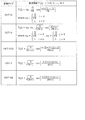
- FIG. 3 is a table showing conversion basis functions corresponding to each conversion type.
- FIG. 4A is a diagram illustrating an example of the shape of a filter used in ALF.
- FIG. 4B is a diagram illustrating another example of the shape of a filter used in ALF.
- FIG. 4C is a diagram illustrating another example of the shape of a filter used in ALF.
- FIG. 5A is a diagram illustrating 67 intra prediction modes in intra prediction.
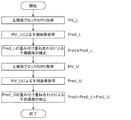
- FIG. 5B is a flowchart for explaining the outline of the predicted image correction process by the OBMC process.
- FIG. 5A is a diagram illustrating 67 intra prediction modes in intra prediction.
- FIG. 5B is a flowchart for explaining the outline of the predicted image correction process by the OBMC process.
- FIG. 5A is a
- FIG. 5C is a conceptual diagram for explaining the outline of the predicted image correction process by the OBMC process.
- FIG. 5D is a diagram illustrating an example of FRUC.
- FIG. 6 is a diagram for explaining pattern matching (bilateral matching) between two blocks along the motion trajectory.
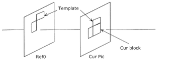
- FIG. 7 is a diagram for explaining pattern matching (template matching) between a template in the current picture and a block in the reference picture.
- FIG. 8 is a diagram for explaining a model assuming constant velocity linear motion.
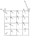
- FIG. 9A is a diagram for explaining derivation of a motion vector in units of sub-blocks based on motion vectors of a plurality of adjacent blocks.
- FIG. 9B is a diagram for explaining the outline of the motion vector deriving process in the merge mode.
- FIG. 9A is a diagram for explaining derivation of a motion vector in units of sub-blocks based on motion vectors of a plurality of adjacent blocks.
- FIG. 9B is a diagram for explaining the outline of
- FIG. 9C is a conceptual diagram for explaining an outline of DMVR processing.
- FIG. 9D is a diagram for describing an overview of a predicted image generation method using luminance correction processing by LIC processing.
- FIG. 10 is a block diagram showing a functional configuration of the decoding apparatus according to the first embodiment.
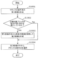
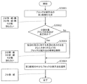
- FIG. 11 is a flowchart of a process of selecting a block division method candidate in the block division unit of the encoding device according to the first aspect.
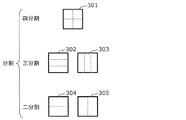
- FIG. 12 is a diagram illustrating an example of a block division method.
- FIG. 13 is a diagram illustrating an example of a syntax tree of information on a block division method.
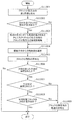
- FIG. 14 is a flowchart of processing for selecting a block division method candidate in the block division unit of the encoding device according to the first specific example of the first aspect.
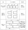
- FIG. 15 is a table showing the block division method and the constraint conditions at the time of division in the first specific example of the first mode.
- FIG. 16 is a flowchart of processing for selecting a block division method candidate when the division target block is a horizontally long rectangle in the first specific example of the first mode.
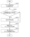
- FIG. 17 is a flowchart of a process of selecting a block division method candidate in the block division unit of the encoding device according to the first aspect.
- FIG. 18 is a table showing the block division method and the constraint conditions at the time of division in the specific example 2 of the first mode.
- FIG. 19 is a flowchart of a process of selecting a block division method candidate in the block division unit of the encoding device according to Specific Example 3 of the first aspect.
- FIG. 20 is a table showing the block division method and the constraint conditions at the time of division in the specific example 3 of the first mode.
- FIG. 21 is a flowchart of a block division method candidate selection process in the block division unit of the encoding device according to the fourth specific example of the first aspect.
- FIG. 22 is a table showing the block division method and the restriction condition at the time of division in the specific example 4 of the first mode.
- FIG. 23 is a flowchart of a process of selecting a block division method candidate in the block division unit of the encoding device in Specific Example 5 of the first aspect.
- FIG. 20 is a table showing the block division method and the constraint conditions at the time of division in the specific example 3 of the first mode.
- FIG. 21 is a flowchart of a block division method candidate selection process in the block division unit of
- FIG. 24 is a table showing the block division method and the restriction condition at the time of division in the specific example 5 of the first mode.
- FIG. 25 is a flowchart of a process of selecting a block division method candidate in the block division unit of the encoding device according to the second aspect.
- FIG. 26 is a flowchart of a process of selecting a block division method candidate in the block division unit of the encoding device according to the first specific example of the second mode.
- FIG. 27 is a flowchart of a process of selecting a block division method candidate in the block division unit of the encoding device according to the second specific example of the second mode.
- FIG. 25 is a flowchart of a process of selecting a block division method candidate in the block division unit of the encoding device according to the second aspect.
- FIG. 28 is a flowchart of a process of selecting a block division method candidate in the block division unit of the encoding device according to the third specific example of the second mode.
- FIG. 29 is a flowchart of block division information reference and block division implementation processing of the decoding device according to the second mode.
- FIG. 30 is a flowchart illustrating processing of referring to block division information and performing block division in the decoding device according to the first specific example of the second mode.
- FIG. 31 is a flowchart illustrating block division information reference processing and block division implementation processing performed by the decoding apparatus according to the second specific example of the second mode.
- FIG. 32 is a flowchart of the block division information reference and block division implementation processing performed by the decoding apparatus according to the third specific example of the second mode.
- FIG. 33 is a block diagram illustrating an implementation example of the encoding device 100.
- FIG. 34 is a flowchart showing an operation example of the encoding apparatus 100.
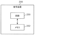
- FIG. 35 is a block diagram illustrating an implementation example of the decoding device 200.
- FIG. 36 is a flowchart illustrating an operation example of the decoding device 200.
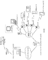
- FIG. 37 is an overall configuration diagram of a content supply system that implements a content distribution service.
- FIG. 38 is a diagram illustrating an example of an encoding structure at the time of scalable encoding.
- FIG. 39 is a diagram illustrating an example of a coding structure at the time of scalable coding.
- FIG. 40 shows an example of a web page display screen.
- FIG. 41 is a diagram illustrating a display screen example of a web page.
- FIG. 42 is a diagram illustrating an example of a smartphone.
- FIG. 43 is a block diagram illustrating a configuration example of a smartphone.
- a block division unit converts each of the plurality of pictures into a CTU (Coding Tree Unit) and a CU obtained by recursively dividing the CTU ( (Coding Unit, coding unit).
- the picture is divided into fixed-size CTUs that are processed by raster scanning from the upper left to the lower right.
- the size of the CTU can be set to any number of pixels of 16 ⁇ 16, 32 ⁇ 32, or 64 ⁇ 64 using any value of 16, 32, or 64 that is a multiple of 16.
- the CTU is divided into variable-size CUs based on recursive quadtree block division.
- a quadtree is a tree structure in which each board is branched into four branches.
- the CTU becomes the CU as it is, and the size of the CTU becomes the maximum size of the CU.
- the size of the CU can be set to any number of pixels of 8 ⁇ 8, 16 ⁇ 16, 32 ⁇ 32, and 64 ⁇ 64.
- an encoding apparatus includes a circuit and a memory, and the circuit uses the memory to determine whether the shape of an image division target block satisfies a first condition. If the block to be divided satisfies the first condition, one or more second candidates are deleted by deleting one or more predetermined candidates from the plurality of first candidates of the block division method. And the block division method is selected from the one or more second candidates, and the division target block is divided according to the selected block division method.
- the encoding apparatus generates a new candidate by reducing the number of candidates from a large number of candidates for the block division method under a certain condition, and selects a candidate from the generated candidates. It can be divided into shapes corresponding to the block division method. Therefore, under certain conditions, the encoding apparatus can divide the division target block by the efficiently selected block division method. Also, the encoding apparatus can prohibit the appearance of a block having a shape corresponding to the deleted block division method candidate. Therefore, when determining an encoding mode using an optimization method such as RD (Rate-Distortion) optimization, the number of variations for trial calculation is reduced, and encoding processing is performed while suppressing deterioration in encoding efficiency. We can expect to reduce the amount.
- RD Red-Distortion
- the encoding device intentionally biases the occurrence frequency of information regarding the block division direction, the accuracy of probability estimation in arithmetic encoding processing using contexts such as CABAC (Context Adaptive Binary Arithmetic Coding) is increased, and An improvement in conversion performance can be expected.
- CABAC Context Adaptive Binary Arithmetic Coding
- the first condition is that the division target block is rectangular.
- the encoding device when the block to be divided is rectangular, the encoding device generates a new candidate by reducing the number of candidates from a large number of candidates for the block division method, and the block selected from the generated candidates
- the division target block can be divided into shapes corresponding to the division method. Therefore, when the division target block is rectangular, the encoding apparatus can divide the division target block by the block division method selected efficiently.
- the first condition is that the ratio of the length of the long side to the length of the short side of the block to be divided is larger than the first value.
- the encoding apparatus can select a block division method selected from candidates generated by reducing the number of candidates from a large number of candidates of the block division method when the division target block is a rectangle that is longer and narrower than a predetermined shape. Can be divided into shapes corresponding to. Therefore, when the division target block is a rectangle that is longer and narrower than a predetermined shape, the encoding apparatus can divide the division target block by the efficiently selected block division method.
- the first value is 2.
- the encoding device is generated by reducing the number of candidates from a large number of candidates for the block division method when the division target block is a rectangle whose long side is twice the length of the short side. It can be divided into shapes corresponding to the block division method selected from the candidates. Therefore, when the block to be divided is a rectangle whose long side is twice the length of the short side, the encoding device converts the block to be divided into a shape corresponding to the efficiently selected block dividing method. Can be divided.
- the first value is 4.
- the encoding device is generated by reducing the number of candidates from a large number of candidates for the block division method when the division target block is a rectangle whose long side is four times the length of the short side. It can be divided into shapes corresponding to the block division method selected from the candidates. Therefore, when the block to be divided is a rectangle whose long side is four times the length of the short side, the encoding device converts the block to be divided into a shape corresponding to the efficiently selected block dividing method. Can be divided.
- the first condition is that the division target block is a rectangle and the length of the short side is smaller than the second value.
- the encoding apparatus can calculate the number of candidates from a large number of candidates for the block division method when the division target block is a rectangle whose short side is smaller than a predetermined value, that is, when the division target block is long and thin. It can be divided into shapes corresponding to the block division method selected from the candidates generated by reduction. Therefore, when the block to be divided is a rectangle whose short side is smaller than a predetermined value, that is, when the block to be divided is long and thin, the encoding device has a shape corresponding to the block division method selected efficiently. It is possible to divide the division target block.
- the second value is 64 pixels.
- the encoding apparatus is selected from candidates generated by reducing the number of candidates from a large number of candidates for the block division shape when the block to be divided is a rectangle having a short side length of less than 64 pixels. It can be divided into block division shapes. Therefore, when the division target block is a rectangle having a shorter side length of less than 64 pixels, the encoding apparatus can divide the division target block into the block division shape selected efficiently.
- the first condition is that the ratio of the length of the long side to the length of the short side of the division target block after the division is larger than a third value.
- the encoding device selects from the candidates generated by reducing the number of candidates from a large number of candidates for the block division method when the division target block becomes a rectangle that is longer than a predetermined shape after being divided. It can be divided into shapes corresponding to the block division method. Therefore, when the division target block is divided into a rectangle that is longer and narrower than a predetermined shape, the encoding device may efficiently divide the division target block into a shape corresponding to the selected block division method. I can do it.
- the third value is 4.
- the encoding apparatus reduces the number of candidates from a large number of candidates for the block division method when the division target block is divided into a rectangle whose long side is four times the length of the short side. Then, it can be divided into shapes corresponding to the block division method selected from the candidates generated in this way. Therefore, when the block to be divided is divided into a rectangle whose long side is four times the length of the short side after being divided, the encoding apparatus corresponds to the block division method selected efficiently.
- the division target block can be divided into shapes.
- the third value is 8.
- the encoding apparatus reduces the number of candidates from a large number of candidates for the block division method when the division target block is divided into a rectangle whose long side is eight times the short side. Then, it can be divided into shapes corresponding to the block division method selected from the candidates generated in this way. Therefore, after the block to be divided is divided, when the long side becomes a rectangle whose length is eight times the length of the short side, the encoding apparatus corresponds to the efficiently selected block division method.
- the division target block can be divided into shapes.
- the one or more predetermined candidates include candidates for dividing a block whose one side is longer than the other side so that the ratio of the length of the one side to the length of the other side is further increased.
- the encoding apparatus can delete a block division method candidate that makes the block even longer after the division target block is divided. Therefore, the encoding device can inhibit the appearance of extremely long and thin blocks that are unlikely to appear during the block division process. Therefore, when determining an encoding mode using an optimization method such as RD optimization, the number of variations for trial calculation is reduced, and the amount of encoding processing is reduced while suppressing deterioration in encoding efficiency. I can expect that. Also, the encoding device intentionally biases the occurrence frequency of information regarding the block division direction. As a result, the accuracy of probability estimation in arithmetic coding processing using a context such as CABAC is increased, and an improvement in coding performance can be expected. In addition, since the encoding device can limit the appearance of extremely long and thin blocks, the subjective image quality can be further improved.
- the one or more predetermined candidates include candidates for dividing a block having one side longer than the other side into two so that the ratio of the length of the one side to the length of the other side is further increased.
- the encoding apparatus can delete a block division method candidate in which the block is further divided into two after being divided after the division target block is divided. Therefore, the encoding device can inhibit the appearance of extremely long and thin blocks that are unlikely to appear during the block division process. Therefore, when determining an encoding mode using an optimization method such as RD optimization, the number of variations for trial calculation is reduced, and the amount of encoding processing is reduced while suppressing deterioration in encoding efficiency. I can expect that. Also, the encoding device intentionally biases the occurrence frequency of information regarding the block division direction. As a result, the accuracy of probability estimation in arithmetic coding processing using a context such as CABAC is increased, and an improvement in coding performance can be expected. In addition, since the encoding device can limit the appearance of extremely long and thin blocks, the subjective image quality can be further improved.
- the one or more predetermined candidates include candidates for dividing a block having one side longer than the other side into three so that a ratio of the length of the one side to the length of the other side is further increased. .
- the encoding apparatus can delete a block division method candidate in which the block is further divided into three after being divided after the division target block is divided. Therefore, the encoding device can inhibit the appearance of extremely long and thin blocks that are unlikely to appear during the block division process. Therefore, when determining an encoding mode using an optimization method such as RD optimization, the number of variations for trial calculation is reduced, and the amount of encoding processing is reduced while suppressing deterioration in encoding efficiency. I can expect that. Also, the encoding device intentionally biases the occurrence frequency of information regarding the block division direction. As a result, the accuracy of probability estimation in arithmetic coding processing using a context such as CABAC is increased, and an improvement in coding performance can be expected. In addition, since the encoding device can limit the appearance of extremely long and thin blocks, the subjective image quality can be further improved.
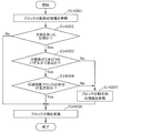
- the circuit when the second condition is not satisfied, the circuit performs encoding of block division information that is information related to the block division method obtained by dividing the division target block, and when the second condition is satisfied, The circuit skips the encoding of the block division information.
- the encoding apparatus can reduce the code amount by skipping the encoding of the block division information and the writing to the syntax of the bitstream accompanying the encoding. Therefore, the encoding apparatus can improve encoding efficiency.
- the block division information is information including at least one of the number of block divisions and the block division direction.
- the encoding apparatus can include information that can uniquely determine the block division shape in the block division information.
- the second condition is that the block division method has a division direction and the division target block is rectangular.
- the encoding apparatus can skip the encoding of the block division information when the block division method has a direction and the division target block is a rectangle. Therefore, the encoding apparatus can improve encoding efficiency.
- the second condition is that the block division method is divided into two and the division target block is rectangular.
- the encoding apparatus can skip the encoding of the block division information when the block division method is bisection and the division target block is a rectangle. Therefore, the encoding apparatus can improve encoding efficiency.
- the second condition is that the block division method is divided into two and the ratio of the length of the long side to the length of the short side of the block to be divided is larger than a predetermined value.
- the encoding apparatus encodes the block division information when the block division method is divided into two and the ratio of the long side length to the short side length of the division target block is larger than a predetermined value. Can be skipped. Therefore, the encoding apparatus can improve encoding efficiency.
- the second condition is that the block division method is three divisions and the division target block is rectangular.
- the encoding apparatus can skip the encoding of the block division information when the block division method is three divisions and the division target block is a rectangle. Therefore, the encoding apparatus can improve encoding efficiency.
- the second condition is that the block division method is three divisions, and the ratio of the long side length to the short side length of the division target block is larger than a predetermined value.
- the encoding apparatus encodes block division information when the block division method is three divisions and the ratio of the long side length to the short side length of the division target block is larger than a predetermined value. Can be skipped. Therefore, the encoding apparatus can improve encoding efficiency.
- the circuit writes the first condition in the syntax of the sequence layer, the picture layer, and the slice layer.
- the encoding apparatus can send information on the candidate of the block division method to be deleted to the decoding apparatus. Therefore, the decoding device can improve decoding efficiency.
- the circuit writes the first condition in an SPS (Sequence Parameter Set).
- the encoding apparatus can send information on the candidate of the block division method to be deleted to the decoding apparatus. Therefore, the decoding device can improve decoding efficiency.
- a decoding device includes a circuit and a memory, and the circuit uses a block from which the image is encoded using a bit stream obtained by encoding the image.
- Block division information related to the block division method is divided, and the division target block is divided based on the decoded block division information.
- the block division information indicates that the division target block of the image satisfies a first condition.
- generating one or more second candidates by deleting one or more predetermined candidates from the plurality of first candidates of the block division method, and the block from among the one or more second candidates Generated by selecting a division method.
- the decoding apparatus divides the division target block into a shape corresponding to the block division method selected from the candidates generated by reducing the number of candidates from a large number of candidates of the block division method under a certain condition. it can. Therefore, under certain conditions, the decoding apparatus can divide the division target block into a shape corresponding to the efficiently selected block division method. Further, the decoding apparatus can prohibit the appearance of a block having a shape corresponding to the deleted block division method candidate. Therefore, when determining the decoding mode using an optimization method such as RD optimization, the number of variations for trial calculation is reduced, and it is expected to reduce the amount of decoding processing while suppressing deterioration in decoding efficiency. it can. Also, the decoding device intentionally biases the occurrence frequency of information regarding the block division direction. As a result, the accuracy of probability estimation in arithmetic decoding processing using a context such as CABAC is increased, and an improvement in decoding performance can be expected.
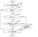
- the circuit decodes block division information that is information related to the block division method for dividing the division target block and performs division processing by dividing the division target block
- the circuit performs the decoding process by dividing the block to be divided without decoding the block division information that is information relating to the block division method.
- the decoding apparatus can reduce the decoding amount by not decoding the coding and the bit stream accompanying the coding written in the syntax of the block division information. Therefore, the decoding device can improve decoding efficiency.
- the block division information is information related to at least one of the number of block divisions and the block division direction.
- the decoding apparatus can include information that can uniquely determine the block division method in the block division information.
- the second condition is that the block division method is uniquely determined from the shape of the division target block.
- the decoding apparatus selects the block division method selected from the candidates generated by reducing the number of candidates from a large number of candidates of the block division method Can be divided into shapes corresponding to. Therefore, when the block division method is uniquely determined from the shape of the division target block, the decoding apparatus can divide the division target block into a shape corresponding to the block division method selected efficiently.
- the first condition is that the shape of the division target block is a rectangle.
- the decoding apparatus can divide into shapes corresponding to the block division method selected from the candidates generated by reducing the number of candidates from a large number of candidates for the block division method. . Therefore, when the division target block is rectangular, the decoding apparatus can divide the division target block into a shape corresponding to the efficiently selected block division method.
- the first condition is that the ratio of the length of the long side to the length of the short side of the block to be divided is larger than the first value.
- the decoding apparatus uses a block division method selected from candidates generated by reducing the number of candidates from a large number of candidates of the block division method when the division target block is a rectangle that is longer and narrower than a predetermined shape. Can be divided into corresponding shapes. Therefore, when the division target block is a rectangle that is longer and narrower than a predetermined shape, the decoding apparatus can divide the division target block into a shape corresponding to the block division method selected efficiently.
- the first value is 2.
- the decoding apparatus reduces the number of candidates from a large number of candidates corresponding to the block division method when the division target block is a rectangle whose long side is twice the length of the short side. It can be divided into shapes corresponding to the block division method selected from the generated candidates. Therefore, when the block to be divided is a rectangle whose long side is twice the length of the short side, the decoding apparatus divides the block to be divided into shapes corresponding to the block division method selected efficiently. I can do it.
- the first value is 4.
- the decoding apparatus reduces the number of candidates from a large number of candidates for the block division method when the division target block becomes a rectangle whose long side is four times the length of the short side after being divided. Then, it can be divided into shapes corresponding to the block division method selected from the candidates generated in this way. Therefore, after the block to be divided is divided, the decoding device has a shape corresponding to the efficiently selected block division method when the long side becomes a rectangle whose length is four times the length of the short side. It is possible to divide the division target block.
- the first condition is that the shape of the division target block is a rectangle, and the length of the short side of the rectangle is smaller than a second value.
- the decoding apparatus reduces the number of candidates from a large number of candidates for the block division method when the division target block is a rectangle whose short side length is smaller than a predetermined value, that is, when the division target block is long and thin. Then, it can be divided into shapes corresponding to the block division method selected from the candidates generated in this way. Therefore, when the division target block is a rectangle whose short side length is smaller than a predetermined value, that is, when the division target block is long and thin, the decoding device has a shape corresponding to the block division method selected efficiently.
- the division target block can be divided.
- the second value is 64 pixels.
- the decoding device is selected from candidates generated by reducing the number of candidates from a large number of candidates for the block division method when the block to be divided is a rectangle having a short side length of less than 64 pixels. Can be divided into shapes corresponding to the block division method. Therefore, when the division target block is a rectangle whose short side is smaller than 64 pixels, the decoding apparatus can divide the division target block into a shape corresponding to the block division method selected efficiently.
- the first condition is that the ratio of the length of the long side to the length of the short side of the block to be divided after the division is larger than a third value.
- the decoding device is selected from candidates generated by reducing the number of candidates from a large number of candidates for the block division shape when the division target block becomes a rectangle that is longer than the predetermined shape after being divided. It can be divided into block division shapes. Therefore, after the division target block is divided, the decoding apparatus can efficiently divide the division target block into a block division shape that is efficiently selected when the rectangle becomes a longer and narrower rectangle than the predetermined shape.
- the third value is 4.
- the decoding apparatus reduces the number of candidates from a large number of candidates for the block division method when the division target block is divided into a rectangle whose long side is four times the length of the short side. Can be divided into shapes corresponding to the block division method selected from the candidates generated in this way. Therefore, after the block to be divided is divided, the decoding device has a shape corresponding to the efficiently selected block division method when the long side becomes a rectangle whose length is four times the length of the short side. It is possible to divide the division target block.
- the third value is 8.
- the decoding device reduces the number of candidates from a large number of candidates for the block division method when the division target block is divided into a rectangle whose long side is eight times the length of the short side. Can be divided into block division shapes selected from the candidates generated in this way. Therefore, after the division target block is divided, when the long side becomes a rectangle whose length is eight times the length of the short side, the decoding device has a shape corresponding to the efficiently selected block division method. It is possible to divide the division target block.
- the one or more predetermined candidates include candidates for dividing a block whose one side is longer than the other side so that the ratio of the length of the one side to the length of the other side is further increased.
- the decoding device can delete a block division method candidate in which the block is further divided into three parts after the division target block is divided. Therefore, the decoding apparatus can prohibit the appearance of extremely thin blocks that are unlikely to appear in the process of block division. Therefore, when determining the decoding mode using an optimization method such as RD optimization, it is expected that the number of trial variations will be reduced, and the amount of encoding processing will be reduced while suppressing deterioration in decoding efficiency. it can. Also, the decoding device intentionally biases the occurrence frequency of information regarding the block division direction. As a result, the accuracy of probability estimation in arithmetic coding processing using a context such as CABAC is increased, and an improvement in decoding performance can be expected. Also, since the decoding device can limit the appearance of extremely long and thin blocks, the subjective image quality can be further improved.
- the one or more predetermined candidates include candidates for dividing a block having one side longer than the other side into two so that the ratio of the length of the one side to the length of the other side is further increased.
- the decoding apparatus can delete a block division method candidate in which the block is further divided into two after the division target block is divided. Therefore, the decoding apparatus can prohibit the appearance of extremely thin blocks that are unlikely to appear in the process of block division. Therefore, when determining a decoding mode using an optimization method such as RD optimization, the number of variations for trial calculation is reduced, and it is expected to reduce the amount of decoding processing while suppressing deterioration in decoding efficiency. it can. Also, the decoding device intentionally biases the occurrence frequency of information regarding the block division direction. As a result, the accuracy of probability estimation in arithmetic coding processing using a context such as CABAC is increased, and an improvement in decoding performance can be expected. Also, since the decoding device can limit the appearance of extremely long and thin blocks, the subjective image quality can be further improved.
- the one or more predetermined candidates include candidates for dividing a block having one side longer than the other side into three so that a ratio of the length of the one side to the length of the other side is further increased. .
- the decoding device can delete a block division method candidate in which the block is further divided into three parts after the division target block is divided. Therefore, the decoding apparatus can prohibit the appearance of extremely thin blocks that are unlikely to appear in the process of block division. Therefore, when determining a decoding mode using an optimization method such as RD optimization, the number of variations for trial calculation is reduced, and it is expected to reduce the amount of decoding processing while suppressing deterioration in decoding efficiency. it can. Also, the decoding device intentionally biases the occurrence frequency of information regarding the block division direction. As a result, the accuracy of probability estimation in arithmetic coding processing using a context such as CABAC is increased, and an improvement in decoding performance can be expected. Also, since the decoding device can limit the appearance of extremely long and thin blocks, the subjective image quality can be further improved.
- the encoding method it is determined whether or not the shape of the division target block of the image satisfies the first condition, and the division target block satisfies the first condition. Then, one or more predetermined candidates are deleted from a plurality of first candidates of the block division method to generate one or more second candidates, and the block division method is selected from the one or more second candidates. And the division target block is divided according to the selected block division method.
- the coding method allows the division target block to have a shape corresponding to the block division method selected from the candidates generated by reducing the number of candidates from a large number of candidates of the block division method under a certain condition. Can be divided. Therefore, under certain conditions, the encoding method can divide the division target block into a shape corresponding to the efficiently selected block division method. Also, the encoding apparatus can prohibit the appearance of a block having a shape corresponding to the deleted block division method candidate. Therefore, when determining the encoding mode using an optimization method such as RD optimization, the number of variations for trial calculation is reduced, and the amount of encoding processing is reduced while suppressing deterioration in encoding efficiency. I can expect that. Further, the frequency of occurrence of information regarding the block division direction is intentionally biased. As a result, the accuracy of probability estimation in arithmetic coding processing using a context such as CABAC is increased, and an improvement in coding performance can be expected.
- the decoding method decodes block division information related to a block division method in which a division target block included in an image is divided from a bitstream obtained by encoding the image, and the decoded block division The division target block is divided based on information, and the block division information includes, when the division target block of the image satisfies a first condition, from one or more first candidates of a block division method, The predetermined candidate is deleted to generate one or more second candidates, and the block division method is selected from the one or more second candidates.
- the decoding method divides the block to be divided into shapes corresponding to the block division method selected from the candidates generated by reducing the number of candidates from a large number of candidates of the block division method under certain conditions. it can. Therefore, under certain conditions, the decoding method can divide the block to be divided into shapes corresponding to the efficiently selected block division method.
- the decoding method can inhibit the appearance of a block having a shape corresponding to the deleted block division method candidate. Therefore, when determining the decoding mode using an optimization method such as RD optimization, the number of variations for trial calculation is reduced, and it is expected to reduce the amount of decoding processing while suppressing deterioration in decoding efficiency. it can. Further, the frequency of occurrence of information regarding the block division direction is intentionally biased. As a result, the accuracy of probability estimation in arithmetic decoding processing using a context such as CABAC is increased, and an improvement in decoding performance can be expected.
- an encoding device includes a dividing unit, an intra prediction unit, an inter prediction unit, a loop filter unit, a conversion unit, a quantization unit, and an entropy encoding unit. You may prepare.
- the dividing unit may divide a picture into a plurality of blocks.
- the intra prediction unit may perform intra prediction on blocks included in the plurality of blocks.
- the inter prediction unit may perform inter prediction on the block.
- the conversion unit may generate a conversion coefficient by converting a prediction error between a predicted image obtained by the intra prediction or the inter prediction and an original image.
- the quantization unit may quantize the transform coefficient to generate a quantization coefficient.
- the entropy encoding unit may generate an encoded bitstream by encoding the quantization coefficient.
- the loop filter unit may apply a filter to the reconstructed image of the block.
- the encoding device may be an encoding device that encodes a moving image including a plurality of pictures.
- the dividing unit includes a circuit and a memory, and the circuit uses the memory to determine whether or not the shape of an image division target block satisfies a first condition, and the division target When a block satisfies the first condition, one or more predetermined candidates are deleted from a plurality of first candidates of the block division method to generate one or more second candidates, and the one or more candidates
- the block division method may be selected from second candidates, and the division target block may be divided according to the selected block division method.
- the decoding device may include an entropy decoding unit, an inverse quantization unit, an inverse transform unit, an intra prediction unit, an inter prediction unit, and a loop filter unit. .
- the entropy decoding unit may decode the quantization coefficient of the block in the picture from the encoded bit stream.
- the inverse quantization unit may obtain the transform coefficient by inverse quantization of the quantization coefficient.
- the inverse transform unit may inversely transform the transform coefficient to obtain a prediction error.
- the intra prediction unit may perform intra prediction on the block.
- the inter prediction unit may perform inter prediction on the block.
- the filter unit may apply a filter to a reconstructed image generated using a prediction image obtained by the intra prediction or the inter prediction and the prediction error.
- the decoding device may be a decoding device that decodes a moving image including a plurality of pictures.
- the decoding apparatus may further include a dividing unit that divides the picture into a plurality of blocks.
- the division unit includes a circuit and a memory, and the circuit uses the memory to block a block division method in which a division target block included in an image is divided from a bitstream obtained by encoding the image.
- the division information is decoded, and the division target block is divided based on the decoded block division information.
- the block division information One or more predetermined candidates are deleted from a plurality of first candidates to generate one or more second candidates, and the block division method is selected from the one or more second candidates. May be.
- non-transitory recording medium such as a system, apparatus, method, integrated circuit, computer program, or computer-readable CD-ROM.
- the present invention may be realized by any combination of an apparatus, a method, an integrated circuit, a computer program, and a recording medium.
- an outline of the first embodiment will be described as an example of an encoding device and a decoding device to which the processing and / or configuration described in each aspect of the present disclosure described below can be applied.
- the first embodiment is merely an example of an encoding device and a decoding device to which the processing and / or configuration described in each aspect of the present disclosure can be applied, and the processing and / or processing described in each aspect of the present disclosure.
- the configuration can also be implemented in an encoding device and a decoding device different from those in the first embodiment.
- the encoding apparatus or decoding apparatus according to the first embodiment corresponds to the constituent elements described in each aspect of the present disclosure among a plurality of constituent elements constituting the encoding apparatus or decoding apparatus. Replacing the constituent elements with constituent elements described in each aspect of the present disclosure (2) A plurality of constituent elements constituting the encoding apparatus or decoding apparatus with respect to the encoding apparatus or decoding apparatus of the first embodiment The constituent elements corresponding to the constituent elements described in each aspect of the present disclosure are added to the present disclosure after arbitrary changes such as addition, replacement, and deletion of functions or processes to be performed on some constituent elements among the constituent elements.
- a component that performs a part of processing performed by a component is a component that is described in each aspect of the present disclosure, a component that includes a part of a function included in a component described in each aspect of the present disclosure, or a book (6)
- a method performed by the encoding device or the decoding device according to Embodiment 1 is performed in combination with a component that performs a part of processing performed by the component described in each aspect of the disclosure.
- the process corresponding to the process described in each aspect of the present disclosure is replaced with the process described in each aspect of the present disclosure.
- the encoding apparatus according to the first embodiment or A part of the plurality of processes included in the method performed by the decoding device is performed in combination with the processes described in each aspect of the present disclosure
- the processes and / or configurations described in each aspect of the present disclosure are not limited to the above examples.
- the present invention may be implemented in an apparatus used for a different purpose from the moving picture / picture encoding apparatus or moving picture / picture decoding apparatus disclosed in the first embodiment, and the processing and / or described in each aspect.
- the configuration may be implemented alone.
- you may implement combining the process and / or structure which were demonstrated in the different aspect.
- FIG. 1 is a block diagram showing a functional configuration of encoding apparatus 100 according to Embodiment 1.
- the encoding device 100 is a moving image / image encoding device that encodes moving images / images in units of blocks.
- an encoding apparatus 100 is an apparatus that encodes an image in units of blocks, and includes a dividing unit 102, a subtracting unit 104, a transforming unit 106, a quantizing unit 108, and entropy encoding.
- Unit 110 inverse quantization unit 112, inverse transform unit 114, addition unit 116, block memory 118, loop filter unit 120, frame memory 122, intra prediction unit 124, inter prediction unit 126, A prediction control unit 128.
- the encoding device 100 is realized by, for example, a general-purpose processor and a memory.
- the processor when the software program stored in the memory is executed by the processor, the processor performs the division unit 102, the subtraction unit 104, the conversion unit 106, the quantization unit 108, the entropy encoding unit 110, and the inverse quantization unit 112.
- the encoding apparatus 100 includes a dividing unit 102, a subtracting unit 104, a transforming unit 106, a quantizing unit 108, an entropy coding unit 110, an inverse quantizing unit 112, an inverse transforming unit 114, an adding unit 116, and a loop filter unit 120.
- the intra prediction unit 124, the inter prediction unit 126, and the prediction control unit 128 may be implemented as one or more dedicated electronic circuits.
- the dividing unit 102 divides each picture included in the input moving image into a plurality of blocks, and outputs each block to the subtracting unit 104.
- the dividing unit 102 first divides a picture into blocks of a fixed size (for example, 128 ⁇ 128).
- This fixed size block may be referred to as a coding tree unit (CTU).
- the dividing unit 102 divides each fixed-size block into blocks of variable size (for example, 64 ⁇ 64 or less) based on recursive quadtree and / or binary tree block division.
- This variable size block may be referred to as a coding unit (CU), a prediction unit (PU) or a transform unit (TU).
- CU, PU, and TU do not need to be distinguished, and some or all blocks in a picture may be processing units of CU, PU, and TU.
- FIG. 2 is a diagram showing an example of block division in the first embodiment.
- a solid line represents a block boundary by quadtree block division
- a broken line represents a block boundary by binary tree block division.
- the block 10 is a 128 ⁇ 128 pixel square block (128 ⁇ 128 block).
- the 128 ⁇ 128 block 10 is first divided into four square 64 ⁇ 64 blocks (quadtree block division).
- the upper left 64 ⁇ 64 block is further divided vertically into two rectangular 32 ⁇ 64 blocks, and the left 32 ⁇ 64 block is further divided vertically into two rectangular 16 ⁇ 64 blocks (binary tree block division). As a result, the upper left 64 ⁇ 64 block is divided into two 16 ⁇ 64 blocks 11 and 12 and a 32 ⁇ 64 block 13.
- the upper right 64 ⁇ 64 block is horizontally divided into two rectangular 64 ⁇ 32 blocks 14 and 15 (binary tree block division).
- the lower left 64x64 block is divided into four square 32x32 blocks (quadrant block division). Of the four 32 ⁇ 32 blocks, the upper left block and the lower right block are further divided.
- the upper left 32 ⁇ 32 block is vertically divided into two rectangular 16 ⁇ 32 blocks, and the right 16 ⁇ 32 block is further divided horizontally into two 16 ⁇ 16 blocks (binary tree block division).
- the lower right 32 ⁇ 32 block is horizontally divided into two 32 ⁇ 16 blocks (binary tree block division).
- the lower left 64 ⁇ 64 block is divided into a 16 ⁇ 32 block 16, two 16 ⁇ 16 blocks 17 and 18, two 32 ⁇ 32 blocks 19 and 20, and two 32 ⁇ 16 blocks 21 and 22.
- the lower right 64x64 block 23 is not divided.
- the block 10 is divided into 13 variable-size blocks 11 to 23 based on the recursive quadtree and binary tree block division.
- Such division may be called QTBT (quad-tree plus binary tree) division.
- one block is divided into four or two blocks (quadrature tree or binary tree block division), but the division is not limited to this.
- one block may be divided into three blocks (triple tree block division).
- Such a division including a tri-tree block division may be called an MBT (multi type tree) division.
- the subtraction unit 104 subtracts the prediction signal (prediction sample) from the original signal (original sample) in units of blocks divided by the division unit 102. That is, the subtraction unit 104 calculates a prediction error (also referred to as a residual) of a coding target block (hereinafter referred to as a current block). Then, the subtraction unit 104 outputs the calculated prediction error to the conversion unit 106.
- a prediction error also referred to as a residual of a coding target block (hereinafter referred to as a current block).
- the original signal is an input signal of the encoding device 100, and is a signal (for example, a luminance (luma) signal and two color difference (chroma) signals) representing an image of each picture constituting the moving image.
- a signal representing an image may be referred to as a sample.
- the transform unit 106 transforms the prediction error in the spatial domain into a transform factor in the frequency domain, and outputs the transform coefficient to the quantization unit 108. Specifically, the transform unit 106 performs, for example, a predetermined discrete cosine transform (DCT) or discrete sine transform (DST) on a prediction error in the spatial domain.
- DCT discrete cosine transform
- DST discrete sine transform
- the conversion unit 106 adaptively selects a conversion type from a plurality of conversion types, and converts a prediction error into a conversion coefficient using a conversion basis function corresponding to the selected conversion type. May be. Such a conversion may be referred to as EMT (explicit multiple core transform) or AMT (adaptive multiple transform).
- the plurality of conversion types include, for example, DCT-II, DCT-V, DCT-VIII, DST-I and DST-VII.
- FIG. 3 is a table showing conversion basis functions corresponding to each conversion type. In FIG. 3, N indicates the number of input pixels. Selection of a conversion type from among these multiple conversion types may depend on, for example, the type of prediction (intra prediction and inter prediction), or may depend on an intra prediction mode.
- Information indicating whether or not to apply such EMT or AMT (for example, called an AMT flag) and information indicating the selected conversion type are signaled at the CU level.
- the signalization of these pieces of information need not be limited to the CU level, but may be another level (for example, a sequence level, a picture level, a slice level, a tile level, or a CTU level).
- the conversion unit 106 may reconvert the conversion coefficient (conversion result). Such a re-conversion is sometimes called AST (adaptive secondary transform) or NSST (non-separable secondary transform). For example, the conversion unit 106 performs re-conversion for each sub-block (for example, 4 ⁇ 4 sub-block) included in the block of the conversion coefficient corresponding to the intra prediction error. Information indicating whether or not NSST is applied and information related to the transformation matrix used for NSST are signaled at the CU level. Note that the signalization of these pieces of information need not be limited to the CU level, but may be another level (for example, a sequence level, a picture level, a slice level, a tile level, or a CTU level).
- the separable conversion is a method of performing the conversion a plurality of times by separating the number of dimensions of the input for each direction, and the non-separable conversion is two or more when the input is multidimensional.
- the dimensions are collectively regarded as one dimension, and conversion is performed collectively.
- non-separable conversion if an input is a 4 ⁇ 4 block, it is regarded as one array having 16 elements, and 16 ⁇ 16 conversion is performed on the array. The thing which performs the conversion process with a matrix is mentioned.
- a 4 ⁇ 4 input block is regarded as a single array having 16 elements, and then the Givens rotation is performed multiple times on the array (Hypercube Givens Transform) is also a non-separable. It is an example of conversion.
- the quantization unit 108 quantizes the transform coefficient output from the transform unit 106. Specifically, the quantization unit 108 scans the transform coefficients of the current block in a predetermined scanning order, and quantizes the transform coefficients based on the quantization parameter (QP) corresponding to the scanned transform coefficients. Then, the quantization unit 108 outputs the quantized transform coefficient (hereinafter referred to as a quantization coefficient) of the current block to the entropy encoding unit 110 and the inverse quantization unit 112.
- QP quantization parameter
- the predetermined order is an order for quantization / inverse quantization of transform coefficients.
- the predetermined scanning order is defined in ascending order of frequency (order from low frequency to high frequency) or descending order (order from high frequency to low frequency).
- the quantization parameter is a parameter that defines a quantization step (quantization width). For example, if the value of the quantization parameter increases, the quantization step also increases. That is, if the value of the quantization parameter increases, the quantization error increases.
- the entropy encoding unit 110 generates an encoded signal (encoded bit stream) by performing variable length encoding on the quantization coefficient that is input from the quantization unit 108. Specifically, the entropy encoding unit 110 binarizes the quantization coefficient, for example, and arithmetically encodes the binary signal.
- the inverse quantization unit 112 inversely quantizes the quantization coefficient that is an input from the quantization unit 108. Specifically, the inverse quantization unit 112 inversely quantizes the quantization coefficient of the current block in a predetermined scanning order. Then, the inverse quantization unit 112 outputs the inverse-quantized transform coefficient of the current block to the inverse transform unit 114.
- the inverse transform unit 114 restores the prediction error by inverse transforming the transform coefficient that is an input from the inverse quantization unit 112. Specifically, the inverse transform unit 114 restores the prediction error of the current block by performing an inverse transform corresponding to the transform by the transform unit 106 on the transform coefficient. Then, the inverse transformation unit 114 outputs the restored prediction error to the addition unit 116.
- the restored prediction error does not match the prediction error calculated by the subtraction unit 104 because information is lost due to quantization. That is, the restored prediction error includes a quantization error.
- the adder 116 reconstructs the current block by adding the prediction error input from the inverse transform unit 114 and the prediction sample input from the prediction control unit 128. Then, the adding unit 116 outputs the reconfigured block to the block memory 118 and the loop filter unit 120.
- the reconstructed block is sometimes referred to as a local decoding block.
- the block memory 118 is a storage unit for storing blocks in an encoding target picture (hereinafter referred to as current picture) that are referred to in intra prediction. Specifically, the block memory 118 stores the reconstructed block output from the adding unit 116.
- the loop filter unit 120 applies a loop filter to the block reconstructed by the adding unit 116 and outputs the filtered reconstructed block to the frame memory 122.
- the loop filter is a filter (in-loop filter) used in the encoding loop, and includes, for example, a deblocking filter (DF), a sample adaptive offset (SAO), an adaptive loop filter (ALF), and the like.
- a least square error filter is applied to remove coding distortion. For example, for each 2 ⁇ 2 sub-block in the current block, a plurality of multiples based on the direction of the local gradient and the activity are provided. One filter selected from the filters is applied.
- sub-blocks for example, 2 ⁇ 2 sub-blocks
- a plurality of classes for example, 15 or 25 classes.
- the direction value D of the gradient is derived, for example, by comparing gradients in a plurality of directions (for example, horizontal, vertical, and two diagonal directions).
- the gradient activation value A is derived, for example, by adding gradients in a plurality of directions and quantizing the addition result.
- a filter for a sub-block is determined from among a plurality of filters.
- FIG. 4A to 4C are diagrams showing a plurality of examples of filter shapes used in ALF.
- 4A shows a 5 ⁇ 5 diamond shape filter
- FIG. 4B shows a 7 ⁇ 7 diamond shape filter
- FIG. 4C shows a 9 ⁇ 9 diamond shape filter.
- Information indicating the shape of the filter is signalized at the picture level. It should be noted that the signalization of the information indicating the filter shape need not be limited to the picture level, but may be another level (for example, a sequence level, a slice level, a tile level, a CTU level, or a CU level).
- ALF on / off is determined, for example, at the picture level or the CU level. For example, for luminance, it is determined whether to apply ALF at the CU level, and for color difference, it is determined whether to apply ALF at the picture level.
- Information indicating ALF on / off is signaled at the picture level or the CU level. Signaling of information indicating ALF on / off need not be limited to the picture level or CU level, and may be performed at other levels (for example, sequence level, slice level, tile level, or CTU level). Good.
- a coefficient set of a plurality of selectable filters (for example, filters up to 15 or 25) is signalized at the picture level.
- the signalization of the coefficient set need not be limited to the picture level, but may be another level (for example, sequence level, slice level, tile level, CTU level, CU level, or sub-block level).
- the frame memory 122 is a storage unit for storing a reference picture used for inter prediction, and is sometimes called a frame buffer. Specifically, the frame memory 122 stores the reconstructed block filtered by the loop filter unit 120.
- the intra prediction unit 124 generates a prediction signal (intra prediction signal) by referring to the block in the current picture stored in the block memory 118 and performing intra prediction (also referred to as intra-screen prediction) of the current block. Specifically, the intra prediction unit 124 generates an intra prediction signal by performing intra prediction with reference to a sample (for example, luminance value and color difference value) of a block adjacent to the current block, and performs prediction control on the intra prediction signal. To the unit 128.
- the intra prediction unit 124 performs intra prediction using one of a plurality of predefined intra prediction modes.
- the plurality of intra prediction modes include one or more non-directional prediction modes and a plurality of directional prediction modes.
- One or more non-directional prediction modes are for example H.264. It includes Planar prediction mode and DC prediction mode defined by H.265 / HEVC (High-Efficiency Video Coding) standard (Non-patent Document 1).
- the multiple directionality prediction modes are for example H.264. It includes 33-direction prediction modes defined in the H.265 / HEVC standard. In addition to the 33 directions, the plurality of directionality prediction modes may further include 32 direction prediction modes (a total of 65 directionality prediction modes).
- FIG. 5A is a diagram illustrating 67 intra prediction modes (two non-directional prediction modes and 65 directional prediction modes) in intra prediction. The solid line arrows The 33 directions defined in the H.265 / HEVC standard are represented, and the dashed arrow represents the added 32 directions.
- the luminance block may be referred to in the intra prediction of the color difference block. That is, the color difference component of the current block may be predicted based on the luminance component of the current block.
- Such intra prediction is sometimes called CCLM (cross-component linear model) prediction.
- the intra prediction mode (for example, called CCLM mode) of the color difference block which refers to such a luminance block may be added as one of the intra prediction modes of the color difference block.
- the intra prediction unit 124 may correct the pixel value after intra prediction based on the gradient of the reference pixel in the horizontal / vertical direction. Intra prediction with such correction may be called PDPC (position dependent intra prediction combination). Information indicating whether or not PDPC is applied (for example, referred to as a PDPC flag) is signaled, for example, at the CU level.
- the signalization of this information need not be limited to the CU level, but may be another level (for example, a sequence level, a picture level, a slice level, a tile level, or a CTU level).
- the inter prediction unit 126 refers to a reference picture stored in the frame memory 122 and is different from the current picture, and performs inter prediction (also referred to as inter-screen prediction) of the current block, thereby generating a prediction signal (inter prediction signal). Prediction signal). Inter prediction is performed in units of a current block or a sub-block (for example, 4 ⁇ 4 block) in the current block. For example, the inter prediction unit 126 performs motion estimation in the reference picture for the current block or sub-block. Then, the inter prediction unit 126 generates an inter prediction signal of the current block or sub-block by performing motion compensation using motion information (for example, motion vector) obtained by motion search. Then, the inter prediction unit 126 outputs the generated inter prediction signal to the prediction control unit 128.
- inter prediction also referred to as inter-screen prediction
- a motion vector predictor may be used for signalizing the motion vector. That is, the difference between the motion vector and the predicted motion vector may be signaled.
- an inter prediction signal may be generated using not only the motion information of the current block obtained by motion search but also the motion information of adjacent blocks. Specifically, the inter prediction signal is generated in units of sub-blocks in the current block by weighted addition of the prediction signal based on the motion information obtained by motion search and the prediction signal based on the motion information of adjacent blocks. May be.
- Such inter prediction motion compensation
- OBMC overlapped block motion compensation
- OBMC block size information indicating the size of a sub-block for OBMC (for example, called OBMC block size) is signaled at the sequence level. Also, information indicating whether or not to apply the OBMC mode (for example, referred to as an OBMC flag) is signaled at the CU level. Note that the level of signalization of these pieces of information need not be limited to the sequence level and the CU level, and may be other levels (for example, a picture level, a slice level, a tile level, a CTU level, or a sub-block level). Good.
- FIG. 5B and FIG. 5C are a flowchart and a conceptual diagram for explaining the outline of the predicted image correction process by the OBMC process.
- a prediction image (Pred) by normal motion compensation is acquired using a motion vector (MV) assigned to an encoding target block.
- MV motion vector
- a prediction image (Pred_L) is obtained by applying the motion vector (MV_L) of the encoded left adjacent block to the encoding target block, and prediction is performed by superimposing the prediction image and Pred_L with weights. Perform the first correction of the image.
- the motion vector (MV_U) of the encoded upper adjacent block is applied to the block to be encoded to obtain a prediction image (Pred_U), and the prediction image and Pred_U that have been subjected to the first correction are weighted. Then, the second correction of the predicted image is performed by superimposing and making it the final predicted image.
- the two-step correction method using the left adjacent block and the upper adjacent block has been described here, the correction may be performed more times than the two steps using the right adjacent block and the lower adjacent block. Is possible.
- the area to be overlapped may not be the pixel area of the entire block, but only a part of the area near the block boundary.
- the processing target block may be a prediction block unit or a sub-block unit obtained by further dividing the prediction block.
- obmc_flag is a signal indicating whether or not to apply the OBMC process.
- the encoding apparatus it is determined whether or not the encoding target block belongs to a complex motion region, and if it belongs to a complex motion region, a value 1 is set as obmc_flag. Encoding is performed by applying the OBMC process, and if it does not belong to a complex region of motion, the value 0 is set as obmc_flag and the encoding is performed without applying the OBMC process.
- the decoding device decodes obj_flag described in the stream, and performs decoding by switching whether to apply the OBMC processing according to the value.
- the motion information may be derived on the decoding device side without being converted into a signal.
- H.M. A merge mode defined in the H.265 / HEVC standard may be used.
- the motion information may be derived by performing motion search on the decoding device side. In this case, motion search is performed without using the pixel value of the current block.
- the mode in which the motion search is performed on the decoding device side is sometimes called a PMMVD (patterned motion vector derivation) mode or an FRUC (frame rate up-conversion) mode.
- PMMVD patterned motion vector derivation
- FRUC frame rate up-conversion
- FIG. 5D An example of FRUC processing is shown in FIG. 5D.
- a list of a plurality of candidates each having a predicted motion vector (may be common with the merge list) is generated Is done.
- the best candidate MV is selected from a plurality of candidate MVs registered in the candidate list. For example, the evaluation value of each candidate included in the candidate list is calculated, and one candidate is selected based on the evaluation value.
- a motion vector for the current block is derived based on the selected candidate motion vector.
- the selected candidate motion vector (best candidate MV) is directly derived as a motion vector for the current block.
- the motion vector for the current block may be derived by performing pattern matching in the peripheral region at the position in the reference picture corresponding to the selected candidate motion vector. That is, the same method is used to search the area around the best candidate MV, and if there is an MV with a good evaluation value, the best candidate MV is updated to the MV, and the current block is updated. The final MV may be used. It is also possible to adopt a configuration in which the processing is not performed.
- the same processing may be performed when processing is performed in units of sub-blocks.
- the evaluation value is calculated by obtaining a difference value of the reconstructed image by pattern matching between a region in the reference picture corresponding to the motion vector and a predetermined region. Note that the evaluation value may be calculated using information other than the difference value.
- the first pattern matching or the second pattern matching is used as the pattern matching.
- the first pattern matching and the second pattern matching may be referred to as bilateral matching and template matching, respectively.
- pattern matching is performed between two blocks in two different reference pictures that follow the motion trajectory of the current block. Therefore, in the first pattern matching, a region in another reference picture along the motion trajectory of the current block is used as the predetermined region for calculating the candidate evaluation value described above.
- FIG. 6 is a diagram for explaining an example of pattern matching (bilateral matching) between two blocks along a motion trajectory.
- first pattern matching two blocks along the motion trajectory of the current block (Cur block) and two blocks in two different reference pictures (Ref0, Ref1) are used.
- two motion vectors MV0, MV1 are derived.
- MV0, MV1 a reconstructed image at a designated position in the first encoded reference picture (Ref0) designated by the candidate MV, and a symmetric MV obtained by scaling the candidate MV at a display time interval.
- the difference from the reconstructed image at the designated position in the second encoded reference picture (Ref1) designated in (2) is derived, and the evaluation value is calculated using the obtained difference value.
- the candidate MV having the best evaluation value among the plurality of candidate MVs may be selected as the final MV.
- the motion vectors (MV0, MV1) pointing to the two reference blocks are temporal distances between the current picture (Cur Pic) and the two reference pictures (Ref0, Ref1). It is proportional to (TD0, TD1).
- the first pattern matching uses a mirror-symmetric bi-directional motion vector Is derived.
- pattern matching is performed between a template in the current picture (a block adjacent to the current block in the current picture (for example, an upper and / or left adjacent block)) and a block in the reference picture. Therefore, in the second pattern matching, a block adjacent to the current block in the current picture is used as the predetermined region for calculating the candidate evaluation value described above.
- FIG. 7 is a diagram for explaining an example of pattern matching (template matching) between a template in the current picture and a block in the reference picture.
- the current block is searched by searching the reference picture (Ref0) for the block that most closely matches the block adjacent to the current block (Cur block) in the current picture (Cur Pic).
- Ref0 the reference picture
- the reconstructed image of the encoded region of the left adjacent area and / or the upper adjacent area, and the equivalent in the encoded reference picture (Ref0) designated by the candidate MV When a difference from the reconstructed image at the position is derived, an evaluation value is calculated using the obtained difference value, and a candidate MV having the best evaluation value among a plurality of candidate MVs is selected as the best candidate MV. Good.
- FRUC flag Information indicating whether or not to apply such FRUC mode (for example, called FRUC flag) is signaled at the CU level. Further, when the FRUC mode is applied (for example, when the FRUC flag is true), information indicating the pattern matching method (first pattern matching or second pattern matching) (for example, called the FRUC mode flag) is signaled at the CU level. It becomes. Note that the signalization of these pieces of information need not be limited to the CU level, but may be other levels (for example, sequence level, picture level, slice level, tile level, CTU level, or sub-block level). .
- BIO bi-directional optical flow
- FIG. 8 is a diagram for explaining a model assuming constant velocity linear motion.
- (v x , v y ) indicates a velocity vector
- ⁇ 0 and ⁇ 1 are the time between the current picture (Cur Pic) and two reference pictures (Ref 0 , Ref 1 ), respectively.
- the distance. (MVx 0 , MVy 0 ) indicates a motion vector corresponding to the reference picture Ref 0
- (MVx 1 , MVy 1 ) indicates a motion vector corresponding to the reference picture Ref 1 .
- This optical flow equation consists of (i) the product of the time derivative of the luminance value, (ii) the horizontal component of the horizontal velocity and the spatial gradient of the reference image, and (iii) the vertical velocity and the spatial gradient of the reference image. Indicates that the sum of the products of the vertical components of is equal to zero. Based on a combination of this optical flow equation and Hermite interpolation, a block-based motion vector obtained from a merge list or the like is corrected in pixel units.
- the motion vector may be derived on the decoding device side by a method different from the derivation of the motion vector based on the model assuming constant velocity linear motion.
- a motion vector may be derived for each subblock based on the motion vectors of a plurality of adjacent blocks.
- This mode may be referred to as an affine motion compensation prediction mode.
- FIG. 9A is a diagram for explaining derivation of a motion vector in units of sub-blocks based on motion vectors of a plurality of adjacent blocks.
- the current block includes 16 4 ⁇ 4 sub-blocks.
- the motion vector v 0 of the upper left corner control point of the current block is derived based on the motion vector of the adjacent block
- the motion vector v 1 of the upper right corner control point of the current block is derived based on the motion vector of the adjacent sub block. Is done.
- the motion vector (v x , v y ) of each sub-block in the current block is derived by the following equation (2).
- x and y indicate the horizontal position and vertical position of the sub-block, respectively, and w indicates a predetermined weight coefficient.
- Such an affine motion compensation prediction mode may include several modes in which the motion vector derivation methods of the upper left and upper right corner control points are different.
- Information indicating such an affine motion compensation prediction mode (for example, called an affine flag) is signaled at the CU level.
- the signalization of the information indicating the affine motion compensation prediction mode does not need to be limited to the CU level, but other levels (for example, sequence level, picture level, slice level, tile level, CTU level, or sub-block level) ).
- the prediction control unit 128 selects either the intra prediction signal or the inter prediction signal, and outputs the selected signal to the subtraction unit 104 and the addition unit 116 as a prediction signal.
- FIG. 9B is a diagram for explaining the outline of the motion vector deriving process in the merge mode.
- a prediction MV list in which prediction MV candidates are registered is generated.
- prediction MV candidates spatial adjacent prediction MVs that are MVs of a plurality of encoded blocks located spatially around the encoding target block, and the position of the encoding target block in the encoded reference picture are projected.
- Temporal adjacent prediction MV that is MV of neighboring blocks combined prediction MV that is MV generated by combining MV values of spatial adjacent prediction MV and temporal adjacent prediction MV, zero prediction MV that is MV having a value of zero, and the like There is.
- variable length encoding unit describes and encodes merge_idx which is a signal indicating which prediction MV is selected in the stream.
- the prediction MV registered in the prediction MV list described with reference to FIG. 9B is an example, and the number of prediction MVs may be different from the number in the figure, or may not include some types of prediction MVs in the figure. It may be the composition which added prediction MV other than the kind of prediction MV in a figure.
- the final MV may be determined by performing DMVR processing, which will be described later, using the MV of the encoding target block derived by the merge mode.
- FIG. 9C is a conceptual diagram for explaining an outline of DMVR processing.
- the optimal MVP set in the processing target block is set as a candidate MV, and reference pixels from a first reference picture that is a processed picture in the L0 direction and a second reference picture that is a processed picture in the L1 direction are set according to the candidate MV. Are obtained, and a template is generated by taking the average of each reference pixel.
- the peripheral areas of the candidate MVs of the first reference picture and the second reference picture are searched, respectively, and the MV with the lowest cost is determined as the final MV.
- the cost value is calculated using a difference value between each pixel value of the template and each pixel value of the search area, an MV value, and the like.
- FIG. 9D is a diagram for explaining an outline of a predicted image generation method using luminance correction processing by LIC processing.
- an MV for obtaining a reference image corresponding to a block to be encoded is derived from a reference picture that is an encoded picture.
- the predicted image for the encoding target block is generated by performing the brightness correction process using the brightness correction parameter for the reference image in the reference picture specified by MV.
- the shape of the peripheral reference region in FIG. 9D is an example, and other shapes may be used.
- the process of generating a predicted image from one reference picture has been described, but the same applies to the case of generating a predicted image from a plurality of reference pictures, and the same applies to reference images acquired from each reference picture.
- the predicted image is generated after performing the luminance correction processing by the method.
- lic_flag is a signal indicating whether to apply LIC processing.
- the encoding device it is determined whether or not the encoding target block belongs to an area where the luminance change occurs, and if it belongs to the area where the luminance change occurs, lic_flag is set. Encode by applying LIC processing with a value of 1 set, and if not belonging to an area where a luminance change has occurred, set 0 as lic_flag and perform encoding without applying the LIC processing .
- the decoding apparatus decodes lic_flag described in the stream, thereby switching whether to apply the LIC processing according to the value, and performing decoding.
- a method for determining whether or not to apply LIC processing for example, there is a method for determining whether or not LIC processing has been applied to peripheral blocks.
- the encoding target block is in the merge mode
- whether or not the surrounding encoded blocks selected in the derivation of the MV in the merge mode processing are encoded by applying the LIC processing. Judgment is performed, and encoding is performed by switching whether to apply the LIC processing according to the result.
- the decoding process is exactly the same.
- FIG. 10 is a block diagram showing a functional configuration of decoding apparatus 200 according to Embodiment 1.
- the decoding device 200 is a moving image / image decoding device that decodes moving images / images in units of blocks.
- the decoding device 200 includes an entropy decoding unit 202, an inverse quantization unit 204, an inverse transformation unit 206, an addition unit 208, a block memory 210, a loop filter unit 212, and a frame memory 214. And an intra prediction unit 216, an inter prediction unit 218, and a prediction control unit 220.
- the decoding device 200 is realized by, for example, a general-purpose processor and a memory.
- the processor executes the entropy decoding unit 202, the inverse quantization unit 204, the inverse transformation unit 206, the addition unit 208, the loop filter unit 212, and the intra prediction unit. 216, the inter prediction unit 218, and the prediction control unit 220.
- the decoding apparatus 200 is dedicated to the entropy decoding unit 202, the inverse quantization unit 204, the inverse transformation unit 206, the addition unit 208, the loop filter unit 212, the intra prediction unit 216, the inter prediction unit 218, and the prediction control unit 220. It may be realized as one or more electronic circuits.
- the entropy decoding unit 202 performs entropy decoding on the encoded bit stream. Specifically, the entropy decoding unit 202 performs arithmetic decoding from a coded bitstream to a binary signal, for example. Then, the entropy decoding unit 202 debinarizes the binary signal. As a result, the entropy decoding unit 202 outputs the quantized coefficient to the inverse quantization unit 204 in units of blocks.
- the inverse quantization unit 204 inversely quantizes the quantization coefficient of a decoding target block (hereinafter referred to as a current block) that is an input from the entropy decoding unit 202. Specifically, the inverse quantization unit 204 inversely quantizes each quantization coefficient of the current block based on the quantization parameter corresponding to the quantization coefficient. Then, the inverse quantization unit 204 outputs the quantization coefficient (that is, the transform coefficient) obtained by inverse quantization of the current block to the inverse transform unit 206.
- a decoding target block hereinafter referred to as a current block
- the inverse quantization unit 204 inversely quantizes each quantization coefficient of the current block based on the quantization parameter corresponding to the quantization coefficient. Then, the inverse quantization unit 204 outputs the quantization coefficient (that is, the transform coefficient) obtained by inverse quantization of the current block to the inverse transform unit 206.
- the inverse transform unit 206 restores the prediction error by inverse transforming the transform coefficient that is an input from the inverse quantization unit 204.
- the inverse conversion unit 206 determines the current block based on the information indicating the read conversion type. Inversely transform the conversion coefficient of.
- the inverse transform unit 206 applies inverse retransformation to the transform coefficient.
- the adder 208 reconstructs the current block by adding the prediction error input from the inverse converter 206 and the prediction sample input from the prediction controller 220. Then, the adding unit 208 outputs the reconfigured block to the block memory 210 and the loop filter unit 212.
- the block memory 210 is a storage unit for storing a block that is referred to in intra prediction and that is within a decoding target picture (hereinafter referred to as a current picture). Specifically, the block memory 210 stores the reconstructed block output from the adding unit 208.
- the loop filter unit 212 applies a loop filter to the block reconstructed by the adding unit 208, and outputs the filtered reconstructed block to the frame memory 214, the display device, and the like.
- one filter is selected from the plurality of filters based on the local gradient direction and activity, The selected filter is applied to the reconstruction block.
- the frame memory 214 is a storage unit for storing a reference picture used for inter prediction, and is sometimes called a frame buffer. Specifically, the frame memory 214 stores the reconstructed block filtered by the loop filter unit 212.
- the intra prediction unit 216 performs intra prediction with reference to the block in the current picture stored in the block memory 210 based on the intra prediction mode read from the encoded bitstream, so that a prediction signal (intra prediction Signal). Specifically, the intra prediction unit 216 generates an intra prediction signal by performing intra prediction with reference to a sample (for example, luminance value and color difference value) of a block adjacent to the current block, and performs prediction control on the intra prediction signal. Output to the unit 220.
- a prediction signal for example, luminance value and color difference value
- the intra prediction unit 216 may predict the color difference component of the current block based on the luminance component of the current block.
- the intra prediction unit 216 corrects the pixel value after intra prediction based on the gradient of the reference pixel in the horizontal / vertical direction.
- the inter prediction unit 218 refers to the reference picture stored in the frame memory 214 and predicts the current block. Prediction is performed in units of a current block or a sub-block (for example, 4 ⁇ 4 block) in the current block. For example, the inter prediction unit 218 generates an inter prediction signal of the current block or sub-block by performing motion compensation using motion information (for example, a motion vector) read from the encoded bitstream, and generates the inter prediction signal. The result is output to the prediction control unit 220.
- motion information for example, a motion vector
- the inter prediction unit 218 When the information read from the encoded bitstream indicates that the OBMC mode is to be applied, the inter prediction unit 218 includes not only the motion information of the current block obtained by motion search but also the motion information of adjacent blocks. To generate an inter prediction signal.
- the inter prediction unit 218 When the information read from the encoded bitstream indicates that the FRUC mode is applied, the inter prediction unit 218 follows the pattern matching method (bilateral matching or template matching) read from the encoded stream. Motion information is derived by performing motion search. Then, the inter prediction unit 218 performs motion compensation using the derived motion information.
- the pattern matching method bilateral matching or template matching
- the inter prediction unit 218 derives a motion vector based on a model assuming constant velocity linear motion. Also, when the information read from the encoded bitstream indicates that the affine motion compensated prediction mode is applied, the inter prediction unit 218 determines the motion vector in units of subblocks based on the motion vectors of a plurality of adjacent blocks. Is derived.
- the prediction control unit 220 selects either the intra prediction signal or the inter prediction signal, and outputs the selected signal to the adding unit 208 as a prediction signal.
- This aspect may be implemented in combination with at least a part of other aspects in the present disclosure.
- a part of the processing, a part of the configuration of the apparatus, a part of the syntax, and the like described in the flowchart of this aspect may be implemented in combination with another aspect.
- FIG. 11 is a flowchart of a process of selecting a block division method candidate in the block division unit of the encoding device according to the first aspect.
- the encoding apparatus 100 generates a first candidate for the block division method (S1001).
- the block division method is a method in which the coding apparatus 100 divides a division target block in the division unit 102.
- the division target block is a block of an image to be divided by the dividing unit 102 when encoding is performed by the encoding apparatus 100.
- the first candidate for the block division method includes, for example, a method of dividing the block to be divided into two vertical divisions, a method of dividing into two horizontal divisions, a method of dividing into three vertical divisions, a method of dividing into four divisions, and a division Methods that do not perform may be included. Note that the block division methods included in the first candidate are not limited to those listed here.
- the encoding apparatus 100 determines whether or not the shape of the division target block satisfies the first condition (S1002).
- the first condition may be, for example, whether or not the value of the ratio of the long side length to the short side length of the division target block is greater than a predetermined value.
- the encoding apparatus 100 determines whether one or more predetermined block division methods are selected from the first candidate including a plurality of block division method candidates.
- the candidate is deleted (S1003).
- the candidate deleted from the first candidate is, for example, relative to the length of the short side of the block generated by the division of the division target block, rather than the value of the ratio of the long side length to the short side length of the division target block.
- a candidate corresponding to a block division method in which the value of the ratio of the lengths of the long sides is large may be used.
- the encoding apparatus 100 may delete the two vertical divisions performed on the vertical division target block and the three vertical divisions performed on the vertical division target block. Note that specific examples of candidates to be deleted from the first candidate are not limited to those listed here.
- the encoding apparatus 100 may generate a second candidate including one or more block division method candidates.
- the encoding apparatus 100 deletes the block division method candidate from the first candidate including a plurality of block division method candidates. do not do.
- a candidate generated by the encoding apparatus 100 without deleting the block division method candidate from the first candidate may be set as the second candidate.
- the encoding apparatus 100 selects a block division method from the second candidates (S1004).
- the encoding apparatus 100 may select one block division method from the second candidates.
- RD optimization refers to a block division method having the best cost evaluation, in which the coding apparatus 100 tries a plurality of block division method candidates and evaluates the cost of each candidate. A method for selecting candidates is assumed.
- the encoding apparatus 100 divides the division target block according to the block division method selected in step S1004.
- the block division method candidates may be reduced regardless of the block division method of the block to be divided and the number of block divisions in the block division method.
- a block division method candidate to be reduced from the first candidate may be determined according to the type of picture such as an I picture, a P picture, or a B picture, and an intra prediction mode or an inter prediction mode may be used.
- determination of a block division method candidate to be reduced from the first candidate may be performed.
- the block division method candidates to be reduced from the first candidate may be determined using either the block division method of the division target block or the number of block divisions in the block division method.
- FIG. 11 may be applied in block division of a prediction unit (PU: Prediction Unit) or a transform unit (TU: Transform Unit).
- PU Prediction Unit
- TU Transform Unit
- FIG. 12 is a diagram illustrating an example of a block division method.
- the block division method includes, for example, four divisions for dividing the division target block into symmetrical rectangles, three divisions for dividing the division target block in the same direction at a ratio of 1: 2 to 1, and one-to-one division target blocks. There may be two divisions, etc., that are divided by the ratio.
- the four divisions 301 for dividing the division target block into symmetrical rectangles are expressed as having no direction regarding block division because the blocks generated by the division of the division target block are left-right symmetric and vertical symmetric.
- the shape of the block generated by the division of the division target block changes depending on which direction, such as vertical and horizontal, the division target block is divided.
- the division target block is divided.
- the shape of the block generated by the division of the division target block changes depending on which direction, such as vertical and horizontal, the division target block is divided. For example, there are two divisions 304 for dividing the division target block into two in the horizontal direction and two divisions 305 for dividing the division target block into two in the vertical direction. Therefore, the two divisions are expressed as having a direction relating to block division.
- the shape of the division target block is not limited to a square.
- the shape of the division target block may be a rectangle or the like.
- the encoding apparatus 100 may hold information on the direction related to block division when the division target block is divided into two or three. Note that the case where the encoding apparatus 100 holds information about the direction related to block division is not limited to two divisions or three divisions. When the encoding apparatus 100 holds information about the direction related to block division, all cases where the shape of the block generated by the division of the division target block changes depending on the direction in which the division target block is divided are included. May be.
- FIG. 13 is a diagram illustrating an example of a syntax tree of block division method information.
- FIG. 13 shows a syntax tree of block division method information having options of division into two, three, four, and no division as candidates for the block division method.
- the encoding apparatus 100 first divides the division target block into four symmetric rectangles. Thereafter, the blocks generated by the division of the division target blocks are further divided into four symmetric rectangles. That is, the encoding apparatus 100 recursively divides the division target block into four symmetrical rectangles twice. Thereafter, the encoding apparatus 100 may perform division into two blocks in the horizontal direction with respect to a block obtained by performing the above-described division.
- FIG. 14 is a flowchart of processing for selecting a block division method candidate in the block division unit of the encoding device according to the first specific example of the first aspect.
- the encoding apparatus 100 generates a first candidate for the block division method (S2001).
- the block division method is a method in which the coding apparatus 100 divides a division target block in the division unit 102.
- the division target block is a block of an image to be divided by the dividing unit 102 when encoding is performed by the encoding apparatus 100.
- the first candidate of the block division method includes, for example, a method of dividing into vertical two divisions, a method of dividing into horizontal two divisions, a method of dividing into vertical three divisions, a method of dividing into four divisions, and a method not performing division. It may be. Note that the block division methods included in the first candidate are not limited to those listed here.
- the encoding apparatus 100 determines whether or not the shape of the division target block is a rectangle (S2002).
- the rectangle may be a vertically long rectangle or a horizontally long rectangle.
- a vertically long rectangle means a rectangle whose length in the vertical direction is longer than the length in the horizontal direction.
- the horizontally long rectangle means a rectangle in which the length of the side in the horizontal direction is longer than the length of the side in the vertical direction.
- the determination condition for the shape of the division target block may be whether the division target block is square or not.
- the encoding apparatus 100 determines the length corresponding to the length of the short side of the division target block from among the first candidates composed of a plurality of candidates for the block division method.
- three divisions 302 for dividing the division target block into three in the horizontal direction three divisions 303 for dividing the division target block into three in the vertical direction, two divisions 304 for dividing the division target block into two in the horizontal direction, and a division target block
- a block division method candidate having a direction related to block division such as a two-division 305 that divides a frame into two vertically, a division method that further shortens a short side of a vertically long block, or a short side of a horizontally long block Candidates corresponding to each of the division methods that further shorten the length may be deleted.
- the encoding apparatus 100 may generate a second candidate including one or more block division method candidates.
- the encoding apparatus 100 does not delete the block division method candidate from the first candidate composed of a plurality of block division method candidates. At this time, the encoding apparatus 100 may use the candidate generated without deleting the block division method candidate from the first candidate as the second candidate.
- the encoding apparatus 100 selects a block division method candidate from the second block division method candidates (S2004). At this time, the encoding apparatus 100 may select one block division method candidate from the second block division method candidates.
- RD optimization refers to a block division method having the best cost evaluation, in which the coding apparatus 100 tries a plurality of block division method candidates and evaluates the cost of each candidate. A method for selecting candidates is assumed.
- the encoding apparatus 100 divides the division target block according to the block division method selected in step S2004.
- FIG. 15 is a table showing the block division method and the constraint condition at the time of division in the specific example 1 of the first mode.
- the division target block is a square
- the division target block can be divided in the vertical direction and the horizontal direction.
- the division target block is divided into three divisions 306, the division target block is divided into three divisions 307 in the vertical direction, the division target block is divided into two divisions 308 in the horizontal direction, and the division target block is divided into vertical divisions.
- the bisection 309 that bisects in the direction is not prohibited by the encoding apparatus 100 and is not deleted from the candidates for the block division method.
- the encoding apparatus 100 further selects a division method that further shortens the short side of the vertically long block or the short side of the horizontally long block from the first candidates for the block division method. Candidates corresponding to each of the division methods to be shortened may be deleted.
- the encoding apparatus 100 prohibits a three-part 310 that further shortens the side in the vertical direction in a horizontally long rectangle.
- the encoding apparatus 100 does not prohibit the three-part 311 that further shortens the side in the horizontal direction in the horizontally long rectangle.
- the encoding apparatus 100 deletes the three division 310 from the first candidates for the block division method. Also, the encoding apparatus 100 does not delete the three-division 311 from the first candidates for the block division method.
- two-division 312 that further shortens the vertical side is prohibited.
- the encoding apparatus 100 does not prohibit the bisection 313 that further shortens the side in the horizontal direction in the horizontally long rectangle.
- the encoding apparatus 100 deletes the bisection 312 from the first candidates for the block division method. Also, the encoding apparatus 100 does not delete the bisection 313 from the first candidates for the block division method.
- FIG. 16 is a flowchart of processing for selecting a block division method candidate when the division target block is a horizontally long rectangle in the first specific example of the first mode.
- the encoding apparatus 100 generates a block division method candidate for the division target block (S3001).
- the first candidate of the block division method includes, for example, a method of dividing into vertical two divisions, a method of dividing into horizontal two divisions, a method of dividing into vertical three divisions, a method of dividing into four divisions, and a method not performing division. It may be. Note that the block division methods included in the first candidate are not limited to those listed here.
- the encoding apparatus 100 determines whether or not the shape of the division target block is a rectangle (S3002).
- the encoding apparatus 100 determines the length corresponding to the length of the short side of the division target block from among the first candidates that are a plurality of candidates for the block division method.
- One block division method candidate in which the value of the ratio of the length of the long side to the length of the short side of the block formed by dividing the block to be divided is larger than the value of the ratio of the side lengths. This is deleted (S3003). For example, a division method for dividing a horizontally long rectangle into two in the horizontal direction and a division method for dividing a horizontally long rectangle into three in the horizontal direction are deleted.
- the encoding apparatus 100 may generate a second candidate including one or more block division method candidates.
- the encoding apparatus 100 may use the candidate generated without deleting the block division method candidate from the first candidate as the second candidate.
- the encoding apparatus 100 selects a block division method candidate from the second block division method candidates (S3004).
- a method of dividing the division target block into two parts in the vertical direction is selected.
- FIG. 17 is a flowchart of a process of selecting a block division method candidate in the block division unit of the encoding device according to the first aspect.
- the encoding apparatus 100 generates a first candidate for the block division method (S4001).
- the block division method is a method in which the coding apparatus 100 divides a division target block in the division unit 102.
- the division target block is a block of an image to be divided by the dividing unit 102 when encoding is performed by the encoding apparatus 100.
- the first candidate of the block division method includes, for example, a method of dividing into vertical two divisions, a method of dividing into horizontal two divisions, a method of dividing into vertical three divisions, a method of dividing into four divisions, and a method not performing division. It may be. Note that the block division methods included in the first candidate are not limited to those listed here.
- the encoding apparatus 100 determines whether or not the shape of the division target block is a rectangle (S4002). Note that the determination condition for the shape of the division target block may be whether the division target block is square or not.
- the encoding apparatus 100 determines the length corresponding to the length of the short side of the division target block from among the first candidates made up of a plurality of candidates for the block division method.
- Candidate block division method that divides the block into three so that the value of the ratio of the length of the long side to the length of the short side of the block formed by dividing the block to be divided becomes larger than the value of the ratio of the side length Is deleted (S4003).
- a dividing method of dividing a vertically long rectangle into three in the vertical direction and a dividing method of dividing a horizontally long rectangle into three in the horizontal direction may be deleted.
- the block division method candidates for dividing the block to be divided into two may not be deleted.
- a block division method candidate that divides the division target block into two is deleted from the first candidate, and a block division method candidate that divides the division target block into three is not deleted from the first candidate. It is good as well.
- the encoding apparatus 100 may generate a second candidate including one or more block division method candidates.
- the encoding apparatus 100 may use the candidate generated without deleting the block division method candidate from the first candidate as the second candidate.
- the encoding apparatus 100 selects a block division method candidate from the second block division method candidates (S4004). At this time, the encoding apparatus 100 may select one block division method candidate from the second block division method candidates.
- RD optimization refers to a block division method having the best cost evaluation, in which the coding apparatus 100 tries a plurality of block division method candidates and evaluates the cost of each candidate. A method for selecting candidates is assumed.
- the encoding apparatus 100 divides the division target block according to the block division method selected in step S4004.
- step S4003 the encoding apparatus 100 determines the length of the short side of the block formed by dividing the division target block from the value of the ratio of the length of the long side to the length of the short side of the division target block.
- FIG. 18 is a table showing the block division method and the constraint conditions at the time of division in the specific example 2 of the first mode.
- the division target block is a square
- the division target block can be divided in the vertical direction and the horizontal direction.
- the division target block is divided into three divisions 306, the division target block is divided into three divisions 307 in the vertical direction, the division target block is divided into two divisions 308 in the horizontal direction, and the division target block is divided into vertical divisions.
- the bisection 309 that bisects in the direction is not prohibited by the encoding apparatus 100 and is not deleted from the candidates for the block division method.
- the encoding apparatus 100 When the division target block is a rectangle, the encoding apparatus 100 performs a division method that performs three divisions such that the short side of the vertically long block is further shortened from among the first candidates for the block division method, or a horizontally long block. You may delete the candidate corresponding to each of the division
- the encoding apparatus 100 prohibits a three-part 310 that further shortens the side in the vertical direction in a horizontally long rectangle.
- the encoding apparatus 100 does not prohibit the three-part 311 that further shortens the side in the horizontal direction in the horizontally long rectangle.
- the encoding apparatus 100 deletes the three division 310 from the first candidates for the block division method. Also, the encoding apparatus 100 does not delete the three-division 311 from the first candidates for the block division method.
- the bisection 312 that further shortens the side in the vertical direction is not prohibited. Also, the encoding device 100 does not prohibit the bisection 313 that further shortens the side in the horizontal rectangle.
- the encoding apparatus 100 does not delete the bisection 312 from the first candidates for the block division method. Also, the encoding apparatus 100 does not delete the bisection 313 from the first candidates for the block division method.
- FIG. 19 is a flowchart of a process of selecting a block division method candidate in the block division unit of the encoding device according to Specific Example 3 of the first aspect.
- the encoding apparatus 100 generates a first candidate for the block division method (S5001).
- the block division method indicates a method in which the encoding apparatus 100 divides a division target block in the division unit 102.
- the division target block is a block of an image to be divided by the dividing unit 102 when encoding is performed by the encoding apparatus 100.
- the first candidate of the block division method includes, for example, a method of dividing into vertical two divisions, a method of dividing into horizontal two divisions, a method of dividing into vertical three divisions, a method of dividing into four divisions, and a method not performing division. It may be. Note that the block division methods included in the first candidate are not limited to those listed here.
- the encoding apparatus 100 determines whether the value of the ratio of the long side length to the short side length of the division target block is greater than 2 (S5002).
- the encoding apparatus 100 selects the division target from the first candidates for the block division method.
- the ratio of the length of the long side to the length of the short side of the block formed by dividing the block to be divided is larger than the ratio of the length of the long side to the length of the short side of the block.
- Candidates corresponding to the division method are deleted (S5003).
- the encoding apparatus 100 may generate a second candidate including one or more block division method candidates.
- the ratio of the length of the long side to the length of the short side of the block to be divided is larger than 2, the case where the division with the direction related to the block division, ie, the division into two or three is performed will be described.
- a candidate for a division method that performs division that further shortens the side in the vertical direction in the horizontally long rectangle and division that further shortens the side in the horizontal direction in the vertically long rectangle is represented by the block division method.
- the first candidate may be deleted.
- the block is selected from the first candidates made up of a plurality of candidates for the block dividing method.
- the candidate for the division method is not deleted.
- the encoding apparatus 100 may use the candidate generated without deleting the block division method candidate from the first candidate as the second candidate.
- the encoding apparatus 100 selects a block division method candidate from the second block division method candidates (S5004). At this time, the encoding apparatus 100 may select one block division method candidate from the second block division method candidates.
- RD optimization refers to a block division method having the best cost evaluation, in which the coding apparatus 100 tries a plurality of block division method candidates and evaluates the cost of each candidate. A method for selecting candidates is assumed.
- the encoding apparatus 100 divides the division target block according to the block division method selected in step S5004.
- step S5002 the encoding apparatus 100 determines whether or not the value of the ratio of the long side length to the short side length of the division target block is greater than 2.
- the value used is not limited to 2.
- the encoding apparatus 100 may determine whether the value of the ratio of the length of the long side to the length of the short side of the division target block is greater than 4.
- the value of the ratio of the length of the long side to the length of the short side of the division target block used by the encoding apparatus 100 for the determination in step S5002 may be an arbitrary natural number.
- FIG. 20 is a table showing the block division method and the constraint conditions at the time of division in the specific example 3 of the first mode.
- the division target block When the division target block is a square, the division target block can be divided in the vertical direction and the horizontal direction.
- the three divisions 306, the three divisions 307, the two divisions 308, and the two divisions 309 are not prohibited by the encoding device 100.
- the encoding apparatus 100 does not delete the block division method candidates corresponding to the three divisions 306, the three divisions 307, the two divisions 308, and the two divisions 309 from the first block division method candidates.
- both the vertical block dividing method and the horizontal block dividing method are not prohibited.
- a three-part 314 that further shortens the side in the vertical direction in a horizontally long rectangle, a three-part 315 that further shortens the side in the horizontal and vertical direction;
- Neither the two divisions 316 to be further shortened nor the two divisions 317 to further shorten the horizontal sides in the horizontally long rectangle are prohibited.
- the encoding apparatus 100 does not delete the block division method candidates corresponding to the three divisions 314, the three divisions 315, the two divisions 316, and the two divisions 317 from the first block division method candidates.
- a dividing method that further shortens the side in the vertical direction in a horizontally long rectangle is prohibited.
- a dividing method that further shortens the side in the horizontal direction is prohibited.
- a three-part 318 that further shortens the side in the vertical direction is prohibited.
- a three-part 319 that further shortens the side in the horizontal direction is not prohibited.
- the bisection 320 that further shortens the side in the vertical direction is prohibited.
- the bisection 321 that further shortens the side in the horizontal rectangle is not prohibited.
- the encoding apparatus 100 deletes block division method candidates corresponding to the three divisions 318 and the two divisions 320 from the first block division method candidates. Also, the encoding apparatus 100 does not delete block division method candidates corresponding to the three divisions 319 and the two divisions 321 from the first block division method candidates.
- FIG. 21 is a flowchart of a block division method candidate selection process in the block division unit of the encoding device according to the fourth specific example of the first aspect.
- the encoding apparatus 100 generates a first candidate for the block division method (S6001).
- the block division method indicates a method in which the encoding apparatus 100 divides a division target block in the division unit 102.
- the division target block is a block of an image to be divided by the dividing unit 102 when encoding is performed by the encoding apparatus 100.
- the first candidate of the block division method includes, for example, a method of dividing into vertical two divisions, a method of dividing into horizontal two divisions, a method of dividing into vertical three divisions, a method of dividing into four divisions, and a method not performing division. It may be. Note that the block division methods included in the first candidate are not limited to those listed here.
- the encoding apparatus 100 determines whether or not the shape of the division target block is a rectangle and the length of the short side of the division target block is smaller than 32 pixels (S6002).
- the encoding device 100 uses the long side for the length of the short side of the division target block.
- a block division method candidate is determined such that the value of the ratio of the length of the long side to the length of the short side of the block generated by the division of the block to be divided is larger than the value of the ratio of the length of the block.
- the encoding apparatus 100 may generate a second candidate including one or more block division method candidates.
- the division target block is not square and the length of the short side is smaller than 32 pixels, in the horizontally long rectangle.
- the candidate for the division method that performs the division that further shortens the side in the direction and the division that further shortens the side in the horizontal direction in the vertically long rectangle is deleted from the first candidates for the block division method. May be.
- the first candidate consisting of a plurality of candidates for the block division method is selected.
- the block division method candidates are not deleted.
- the encoding apparatus 100 may use the candidate generated without deleting the block division method candidate from the first candidate as the second candidate.
- the encoding apparatus 100 selects a block division method candidate from the second block division method candidates (S6004). At this time, the encoding apparatus 100 may select one block division method candidate from the second block division method candidates.
- RD optimization refers to a block division method having the best cost evaluation, in which the coding apparatus 100 tries a plurality of block division method candidates and evaluates the cost of each candidate. A method for selecting candidates is assumed.
- the encoding apparatus 100 divides the division target block according to the block division method selected in step S6004.
- step S6002 the encoding apparatus 100 determines whether the length of the short side of the block to be divided is smaller than 32 pixels, but the length of the short side used for the determination is not limited to 32 pixels. For example, the encoding apparatus 100 may determine whether the length of the short side of the division target block is smaller than 64 pixels. Further, the length of the short side used for the determination may be determined depending on the picture size. The numerical value indicating the length of the short side used by the encoding apparatus 100 for determination in step S6002 may be an arbitrary natural number.
- FIG. 22 is a table showing the block division method and the constraint conditions at the time of division in the specific example 4 of the first aspect.
- the division target block is a square
- the division target block can be divided in the vertical direction and the horizontal direction.
- the three divisions 306, the three divisions 307, the two divisions 308, and the two divisions 309 are not prohibited by the encoding apparatus 100.
- the encoding apparatus 100 does not delete the block division method candidates corresponding to the three divisions 306, the three divisions 307, the two divisions 308, and the two divisions 309 from the first block division method candidates.
- both the vertical block dividing method and the horizontal block dividing method are not prohibited.
- a three-part 322 that further shortens the side in the vertical direction a three-part 323 that further shortens the side in the horizontally long vertical direction, and in a horizontally long rectangle, the side in the vertical direction
- any two divisions 327 that further shorten the side in the horizontal direction are not prohibited.
- the encoding apparatus 100 does not delete the block division method candidates corresponding to the three divisions 322, three divisions 323, two divisions 324, two divisions 325, two divisions 326, and two divisions 327, respectively.
- a dividing method that further shortens the side in the vertical direction in the horizontally long rectangle is prohibited.
- a dividing method that further shortens the side in the horizontal direction is prohibited.
- a three-part 328 that further shortens the side in the vertical direction is prohibited.
- a three-part 329 that further shortens the side in the horizontal direction is not prohibited.
- the bisection 330 that further shortens the side in the vertical direction is prohibited.
- Bi-division 331 that further shortens the side in the horizontal rectangle is not prohibited.
- the encoding apparatus 100 deletes block division method candidates corresponding to the three divisions 328 and the two divisions 330 from the first block division method candidates. Also, the encoding apparatus 100 does not delete the block division method candidates corresponding to the three divisions 329 and the two divisions 331 from the first block division method candidates.
- FIG. 23 is a flowchart of a process of selecting a block division method candidate in the block division unit of the encoding device in Specific Example 5 of the first aspect.
- the encoding apparatus 100 generates a first candidate for the block division method (S7001).
- the block division method is a method in which the encoding apparatus 100 divides a division target block in the division unit 102.
- the division target block is a block of an image to be divided by the dividing unit 102 when encoding is performed by the encoding apparatus 100.
- the first candidate of the block division method includes, for example, a method of dividing into vertical two divisions, a method of dividing into horizontal two divisions, a method of dividing into vertical three divisions, a method of dividing into four divisions, and a method not performing division. It may be. Note that the block division methods included in the first candidate are not limited to those listed here.
- the encoding apparatus 100 determines whether or not the value of the ratio of the long side length to the short side length of the block generated by the division of the division target block is larger than the third value (S7002). ).
- the third value may be 4 or 8.
- the third value may be an arbitrary natural number.
- the encoding apparatus 100 selects the division target block. Candidates corresponding to the block division method in which the value of the ratio of the long side length to the short side length of the divided block is larger than the third value are deleted from the first candidates for the block division method. (S7003).
- the encoding apparatus 100 may generate a second candidate including one or more block division method candidates.
- the encoding apparatus 100 may use the candidate generated without deleting the block division method candidate from the first candidate as the second candidate.
- the encoding apparatus 100 selects a block division method candidate from the second block division method candidates (S7004). At this time, the encoding apparatus 100 may select one block division method candidate from the second block division method candidates.
- RD optimization refers to a block division method having the best cost evaluation, in which the coding apparatus 100 tries a plurality of block division method candidates and evaluates the cost of each candidate. A method for selecting candidates is assumed.
- the encoding apparatus 100 divides the division target block according to the block division method selected in step S7004.
- FIG. 24 is a flowchart of a process of selecting a block division method candidate in the block division unit of the encoding device according to the fifth specific example of the first aspect.
- the division target block can be divided in the vertical direction and the horizontal direction.
- the division target block is divided into two parts 332 in the horizontal direction, the division target block is divided into two parts 333 in the vertical direction, the division target block is divided into three parts 334 in the horizontal direction, and the division target block is divided into the vertical parts.
- the three divisions 335 that are divided into three in the direction are not prohibited by the encoding apparatus 100.
- the encoding apparatus 100 does not delete the block division method candidates corresponding to the two divisions 332, the two divisions 333, the three divisions 334, and the three divisions 335 from the first block division method candidates.
- the horizontally divided side 336 is further shortened, In the rectangle, three divisions 337 that further shorten the side in the horizontal direction and two divisions 338 that further shorten the side in the vertical direction in the horizontally long rectangle are not prohibited.
- a three-part 339 that further shortens the side in the vertical direction is prohibited.
- the three divisions 339 may be three divisions in which the ratio of the lengths of the short sides to be divided is 1: 2: 1.
- the encoding apparatus 100 does not delete the block division method candidates corresponding to the two divisions 36, the three divisions 37, and the two divisions 38 from the first block division method candidates. On the other hand, the encoding apparatus 100 deletes a block division method candidate corresponding to the three division 339 from the first block division method candidates.
- the horizontally divided rectangle 340 that further shortens the side in the horizontal direction, and the horizontally long rectangle 3 is not prohibited by the encoding apparatus 100.
- the encoding apparatus 100 prohibits two divisions 342 that further shorten the vertical sides in the horizontally long rectangle and three divisions 343 that further shorten the vertical sides in the horizontally long rectangle. Is done.
- the encoding apparatus 100 does not delete the block division method candidates corresponding to the two divisions 340 and the three divisions 341 from the first block division method candidates. On the other hand, the encoding apparatus 100 deletes block division method candidates corresponding to the two divisions 342 and the three divisions 343 from the first block division method candidates.
- the arithmetic coding process using the context is, for example, CABAC. Therefore, performing the processing shown in the present disclosure may improve the encoding performance.
- each determination condition in the first aspect may be the same content as the specific example of the first aspect, or may be a combination of the specific examples of the first aspect.
- each determination condition in the first aspect may be obtained by changing the numerical value of the specific example of the first aspect.
- the subjective image quality may be improved by suppressing the appearance of extremely thin blocks by the encoding apparatus 100.
- the term “long and thin” in the present disclosure may mean that the ratio of the length of the long side to the length of the short side is larger than a predetermined value in the block, or the length of the long side and the length of the short side
- the difference in length may be a predetermined value or more.
- “long and thin” may mean that the ratio of the length of the long side to the length of the short side is a predetermined value or more.
- the predetermined value may be 2, 4, or 8.
- “A long and thin block becomes even longer by dividing” means that dividing the block may increase the ratio of the length of the long side to the length of the short side, or the length of the long side. And the difference between the length of the short side and the length of the short side may be increased.
- the block in this indication is not limited to a rectangular block.
- FIG. 25 is a flowchart of a process of selecting a block division method candidate in the block division unit of the encoding device according to the second aspect.
- the encoding apparatus 100 generates a first candidate for the block division method (S8001).
- the block division method is a method in which the coding apparatus 100 divides a division target block in the division unit 102.
- the division target block is a block of an image to be divided by the dividing unit 102 when encoding is performed by the encoding apparatus 100.
- the first candidate of the block division method includes, for example, a method of dividing into vertical two divisions, a method of dividing into horizontal two divisions, a method of dividing into vertical three divisions, a method of dividing into four divisions, and a method not performing division. It may be. Note that the block division methods included in the first candidate are not limited to those listed here.
- the encoding apparatus 100 determines whether or not the shape of the division target block satisfies a predetermined condition (S8002).
- the encoding apparatus 100 deletes a predetermined block division method candidate from the first block division method candidate (S8003).
- the encoding apparatus 100 may generate a second candidate including one or more block division method candidates.
- the block division method candidates are not deleted from the first candidates composed of a plurality of block division method candidates.
- a candidate generated by the encoding apparatus 100 without deleting the block division method candidate from the first candidate may be set as the second candidate.
- the encoding apparatus 100 selects a block division method candidate from the second block division method candidates (S8004). At this time, the encoding apparatus 100 may select one block division method candidate from the second block division method candidates.
- RD optimization refers to a block division method having the best cost evaluation, in which the coding apparatus 100 tries a plurality of block division method candidates and evaluates the cost of each candidate. A method for selecting candidates is assumed.
- the encoding apparatus 100 divides the division target block according to the block division method selected in step S8004.
- the encoding apparatus 100 encodes block division information that is not uniquely determined (S8005).
- the encoding performed by the encoding apparatus includes an encoding process and writing of the encoded information into the bit stream.
- step S8005 is performed when the block division information is not uniquely determined from the shape of the division target block, and may be prohibited in other cases. For example, in the case where only division that reduces the value of the ratio of the length of the long side to the length of the short side is performed on the rectangular division target block, in step S8005, the division target block is processed. Processing may not be performed. Further, the block division information may include either or both of the direction related to block division and the number of block divisions in the block division method.
- the block division method candidates may be reduced regardless of the block division method of the block to be divided and the number of block divisions in the block division method.
- a block division method candidate to be reduced from the first candidate may be determined depending on the type of picture such as an I picture, a P picture, or a B picture, or an intra prediction mode or an inter prediction mode.
- the block division method candidates to be reduced from the first candidate may be determined.
- the block division method candidates to be reduced from the first candidate may be determined using either the block division method of the division target block or the number of block divisions in the block division method.
- FIG. 25 may be applied in block division of a prediction unit (PU: Prediction Unit) or a conversion unit (TU: Transform Unit).
- PU Prediction Unit
- TU Transform Unit
- the encoding apparatus 100 may write the conditions used for the determination in step S8002 in the respective syntaxes of the sequence layer, the picture layer, and the slice layer. Also, the encoding apparatus 100 may write the conditions used for the determination in step S8002 in an SPS (Sequence Parameter Set).
- SPS Sequence Parameter Set
- FIG. 26 is a flowchart of a process of selecting a block division method candidate in the block division unit of the encoding device according to the first specific example of the second mode.
- the encoding apparatus 100 generates a first candidate for the block division method (S9001).
- the block division method is a method in which the coding apparatus 100 divides a division target block in the division unit 102.
- the division target block is a block of an image to be divided by the dividing unit 102 when encoding is performed by the encoding apparatus 100.
- the first candidate of the block division method includes, for example, a method of dividing into vertical two divisions, a method of dividing into horizontal two divisions, a method of dividing into vertical three divisions, a method of dividing into four divisions, and a method not performing division. It may be. Note that the block division methods included in the first candidate are not limited to those listed here.
- the encoding apparatus 100 determines whether or not the shape of the division target block satisfies a predetermined condition (S9002).
- the encoding apparatus 100 deletes a predetermined block division method candidate from the first block division method candidate (S9003).
- the encoding apparatus 100 may generate a second candidate including one or more block division method candidates.
- the block division method candidates are not deleted from the first candidates composed of a plurality of block division method candidates.
- a candidate generated by the encoding apparatus 100 without deleting the block division method candidate from the first candidate may be set as the second candidate.
- the encoding apparatus 100 selects a block division method candidate from the second block division method candidates (S9004). At this time, the encoding apparatus 100 may select one block division method candidate from the second block division method candidates.
- RD optimization refers to a block division method having the best cost evaluation, in which the coding apparatus 100 tries a plurality of block division method candidates and evaluates the cost of each candidate. A method for selecting candidates is assumed.
- the encoding apparatus 100 divides the division target block according to the block division method selected in step S9004.
- the encoding apparatus 100 encodes the number of block divisions (S9005).
- the encoding performed by the encoding apparatus 100 includes encoding processing and writing of the encoded information to the bit stream.
- the encoding apparatus 100 determines whether the selected block division method candidate is a block division method candidate having a direction related to block division (S9006).
- the block division method having a direction related to block division may be, for example, two divisions or three divisions.
- the encoding apparatus 100 ends the process.
- the encoding apparatus 100 determines that the division number of the block division method satisfies a predetermined condition. It is determined whether or not it is satisfied (S9007).
- the predetermined condition may be, for example, that the number of divisions of the block division method is the same as the number of divisions of candidates deleted from the block division method candidates.
- step S9009 Details of the processing in step S9009 will be described later.
- the encoding apparatus 100 determines whether the shape of the division target block satisfies the predetermined condition (S9008).
- the predetermined condition may be the same as the condition used when determining whether or not to delete a candidate for the block division method in step S9003.
- the encoding apparatus 100 encodes information in the direction related to block division (S9009).
- the encoding may include encoding and writing of the encoded information to the bit stream. Thereafter, the encoding device 100 ends the process.
- the encoding apparatus 100 ends the process without encoding the information on the direction related to the block division.
- the determination conditions regarding the block shape in this aspect and specific examples of candidates for the block division method to be deleted may be the same as those in the first aspect.
- the processing by the encoding apparatus 100 in this aspect may reverse the order of processing. That is, the encoding apparatus 100 may change the order of processing to be performed according to the shape of the syntax tree representing the order of processing. For example, if the syntax for the direction related to block division is positioned higher on the syntax tree than the syntax for the number of divisions in the block division method, the order of the processes in steps S9006 and S9007 may be changed. Good.
- FIG. 27 is a flowchart of a process of selecting a block division method candidate in the block division unit of the encoding device according to the second specific example of the second mode.
- the encoding apparatus 100 generates a first candidate for the block division method (S10001).
- the block division method is a method in which the coding apparatus 100 divides a division target block in the division unit 102.
- the division target block is a block of an image to be divided by the dividing unit 102 when encoding is performed by the encoding apparatus 100.
- the first candidate of the block division method includes, for example, a method of dividing into vertical two divisions, a method of dividing into horizontal two divisions, a method of dividing into vertical three divisions, a method of dividing into four divisions, and a method not performing division. It may be. Note that the block division methods included in the first candidate are not limited to those listed here.
- the encoding apparatus 100 determines whether or not the shape of the division target block is a rectangle (S10002).
- the encoding apparatus 100 is a candidate for a block division method that further increases the value of the ratio of the length of the long side to the length of the short side. Are deleted from the first candidate for the block division method (S10003).
- the encoding apparatus 100 may generate a second candidate including one or more block division method candidates.
- the block division method candidates are not deleted from the first candidates including a plurality of block division method candidates.
- a candidate generated by the encoding apparatus 100 without deleting the block division method candidate from the first candidate may be set as the second candidate.
- the encoding apparatus 100 selects a block division method candidate from the second block division method candidates (S10004). At this time, the encoding apparatus 100 may select one block division method candidate from the second block division method candidates.
- RD optimization refers to a block division method having the best cost evaluation, in which the coding apparatus 100 tries a plurality of block division method candidates and evaluates the cost of each candidate. A method for selecting candidates is assumed.
- the encoding apparatus 100 divides the division target block according to the block division method selected in step S10004.
- the encoding apparatus 100 encodes the number of block divisions (S10005).
- the encoding performed by the encoding device includes encoding processing and writing of the encoded information to the bit stream.
- the encoding apparatus 100 determines whether the selected block division method candidate is a block division method candidate having a direction related to block division (S10006).
- the block division method having a direction related to block division may be, for example, two divisions or three divisions.
- the encoding apparatus 100 ends the process.
- the encoding apparatus 100 may divide the block division method into two pieces, or It is determined whether the image is divided into three (S10007).
- step S10009 Details of the processing in step S10009 will be described later.
- the encoding apparatus 100 determines whether the shape of the division target block is a rectangle (S10008).
- the encoding apparatus 100 encodes direction information regarding block division (S10009).
- the encoding may include encoding and writing of the encoded information to the bit stream.
- the second division 305 for dividing the division target block into two in the vertical direction is selected from the second candidates.
- a three-division 302 that divides the division target block into three in the horizontal direction is selected from the second candidates.
- the encoding apparatus 100 ends the process without encoding the direction information regarding the block division.
- FIG. 28 is a flowchart of a process of selecting a block division method candidate in the block division unit of the encoding device according to the third specific example of the second mode.
- the encoding apparatus 100 generates a first candidate for the block division method (S11001).
- the block division method is a method in which the coding apparatus 100 divides a division target block in the division unit 102.
- the division target block is a block of an image to be divided by the dividing unit 102 when encoding is performed by the encoding apparatus 100.
- the first candidate of the block division method includes, for example, a method of dividing into vertical two divisions, a method of dividing into horizontal two divisions, a method of dividing into vertical three divisions, a method of dividing into four divisions, and a method not performing division. It may be. Note that the block division methods included in the first candidate are not limited to those listed here.
- the encoding apparatus 100 determines whether or not the shape of the division target block is a rectangle (S11002).
- the encoding apparatus 100 When the shape of the division target block is a rectangle (Yes in S11002), the encoding apparatus 100 performs block division of three divisions that further increases the value of the ratio of the length of the long side to the length of the short side.
- the method candidate is deleted from the first candidate for the block division method (S11003).
- the encoding apparatus 100 may generate a second candidate including one or more block division method candidates.
- the encoding apparatus 100 may use the candidate generated without deleting the block division method candidate from the first candidate as the second candidate.
- the encoding apparatus 100 selects a block division method candidate from the second block division method candidates (S11004). At this time, the encoding apparatus 100 may select one block division method candidate from the second block division method candidates.
- RD optimization refers to a block division method having the best cost evaluation, in which the coding apparatus 100 tries a plurality of block division method candidates and evaluates the cost of each candidate. A method for selecting candidates is assumed.
- the encoding apparatus 100 divides the division target block according to the block division method selected in step S11004.
- the encoding apparatus 100 encodes the number of block divisions (S11005).
- the encoding performed by the encoding apparatus includes an encoding process and writing of the encoded information into the bit stream.
- the encoding apparatus 100 determines whether the selected block division method candidate is a block division method candidate having a direction related to block division (S11006).
- the block division method having a direction related to block division may be, for example, two divisions or three divisions.
- the encoding apparatus 100 ends the process.
- the encoding apparatus 100 determines whether the number of divisions of the block division method is three. It is determined whether or not (S11007).
- step S11009 Details of the processing in step S11009 will be described later.
- the encoding apparatus 100 determines whether or not the shape of the division target block is a rectangle (S11008).
- the encoding apparatus 100 encodes information on the direction related to block division (S11009).
- the encoding may include encoding and writing the encoded information to the bit stream.
- the second division 305 in which the division target block is divided into two in the vertical direction is selected from the second candidates.
- a three-division 302 that divides the division target block into three in the horizontal direction is selected from the second candidates.
- the encoding apparatus 100 ends the process without encoding the information on the direction related to the block division.
- step S11007 the encoding apparatus 100 determines whether or not the division number of the block division method is three. However, the encoding apparatus 100 determines whether or not the division number of the block division method is two. You may judge.
- step S11008 the encoding apparatus 100 determines whether or not the shape of the division target block is a rectangle, but the encoding apparatus 100 determines the length of the long side with respect to the length of the short side of the division target block. It may be determined whether the ratio value is greater than a predetermined value.
- FIG. 29 is a flowchart of block division information reference and block division implementation processing of the decoding device according to the second mode.
- the decoding device 200 refers to the shape of the division target block (S12001).
- the division target block is a block to be divided by the decoding device.
- the decoding apparatus 200 may calculate the shape of the division target block.
- the decoding device 200 does not refer to the block division information or the like.
- the decoding device 200 refers to the block division information (S12003). That is, the decoding apparatus 200 reads the shape of the block to be divided or the block division information encoded by the encoding apparatus 100 and written in the bitstream.
- the decoding apparatus 200 performs block division by a predetermined block division method (S12004).
- the predetermined block division method may be the block division method indicated in the block division information referenced in step S12003.
- the predetermined block division method may be the block division method when the block division method is uniquely determined in step S12002.
- the decryption apparatus 200 ends the process.
- block division method candidates may be reduced based on a determination condition using a shape other than the shape of the division target block.
- a block division method candidate to be reduced from the first candidate may be determined according to the type of picture such as an I picture, a P picture, or a B picture, or an intra prediction mode or an inter prediction.
- a block division method candidate to be reduced from the first candidate may be determined depending on the type of prediction mode such as a mode.
- the block division method candidates to be reduced from the first candidate may be determined using either the block division method of the division target block or the number of block divisions in the block division method.
- FIG. 30 is a flowchart illustrating processing of referring to block division information and performing block division in the decoding device according to the first specific example of the second mode.
- the decoding apparatus 200 refers to information on the number of block divisions in the block division method performed at the time of encoding (S13001). At this time, the decoding apparatus 200 may refer to information on the number of block divisions by decoding the bitstream transmitted from the encoding apparatus 100. That is, the decoding apparatus 200 reads the shape of the block to be divided or the block division information encoded by the encoding apparatus 100 and written in the bitstream.
- the information referred to here may be, for example, TT-Flag, QT-Flag or S-Flag in the syntax tree shown in FIG.
- the decoding apparatus 200 determines whether or not the block division method is a candidate for a block division method corresponding to a division having a direction related to block division (S13002).
- the decoding apparatus 200 When the block division method is not a candidate for a block division method corresponding to a division having a direction related to block division (No in S13002), the decoding apparatus 200 does not refer to the block division information. For example, the case where the block division information is uniquely determined from the shape of the division target block is included. This is because it is not necessary for the decoding apparatus 200 to refer to information about the direction related to block division. Thereafter, the decoding device 200 divides the division target block (S13006).
- the block division method is a candidate for a block division method corresponding to a division having a direction related to block division (Yes in S13002)
- the decoding apparatus 200 refers to information on the direction related to block division (S13005). Thereafter, the decoding device 200 divides the division target block (S13006).
- the decoding apparatus 200 determines whether or not the shape of the division target block satisfies a predetermined condition (S13004).
- the predetermined condition regarding the shape of the division target block is, for example, whether or not the shape of the division target block is rectangular.
- the decoding device 200 performs division of the division target block (S13006).
- the division target block may be divided in a predetermined direction. For example, when the division target block is vertically long, block division in the horizontal direction may be performed, and when the division target block is horizontally long, block division in the vertical direction may be performed.
- the decoding device 200 refers to the block division information (S13005). After that, the decoding device 200 divides the division target block based on the referenced information (S13006).
- the decoding apparatus may divide the division target block without decoding the block division information.
- the block division information may include either or both of the direction related to block division and the number of block divisions in the block division method.
- FIG. 31 is a flowchart illustrating block division information reference processing and block division implementation processing performed by the decoding apparatus according to the second specific example of the second mode.
- the decoding apparatus 200 refers to information regarding the number of block divisions in the block division method performed at the time of encoding (S14001). At this time, the decoding apparatus 200 may refer to information on the number of block divisions by decoding the bitstream transmitted from the encoding apparatus 100. That is, the decoding apparatus 200 reads the shape of the block to be divided or the block division information encoded by the encoding apparatus 100 and written in the bitstream.
- the information referred to here may be, for example, TT-Flag, QT-Flag or S-Flag in the syntax tree shown in FIG.
- the decoding apparatus 200 determines whether or not the block division method is a candidate for a block division method corresponding to a division having a direction related to block division (S14002).
- the decoding apparatus 200 When the block division method is not a candidate for a block division method corresponding to a division having a direction related to block division (No in S14002), the decoding apparatus 200 does not refer to the block division information. This is because it is not necessary for the decoding apparatus 200 to refer to information about the direction related to block division. Thereafter, the decoding apparatus 200 divides the division target block (S14006).
- the block division method is a candidate for a block division method corresponding to a division having a direction related to block division (Yes in S14002), it is determined whether the number of block divisions is 2 or 3 (S14003). ).
- the decoding apparatus 200 refers to information on the direction related to block division (S14005). Thereafter, the decoding apparatus 200 divides the division target block (S14006).
- the decoding apparatus 200 determines whether or not the shape of the division target block is a rectangle (S14004).
- the decoding device 200 divides the division target block (S14006). At this time, the decoding apparatus 200 performs the division without referring to the information on the block division direction. For example, when the number of block divisions of the referenced block division method is 2 or 3, the vertical blocks may be divided in the horizontal direction, or the horizontal blocks may be divided in the vertical direction. Division may be performed.
- the decoding device 200 refers to the block division information (S14005). After that, the decoding device 200 divides the division target block based on the referenced information (S14006).
- step S14004 the decoding apparatus 200 determines whether or not the shape of the division target block is a rectangle. However, the decoding apparatus 200 determines that the length of the long side with respect to the length of the short side of the division target block is longer. It may be determined whether the ratio is greater than the first value. At this time, the first value may be 2 or 4. The first value may be an arbitrary natural number.
- the decoding apparatus 200 determines whether or not the shape of the division target block is a rectangle. However, the decoding apparatus 200 has a rectangular shape and a short side of the rectangle. It may be determined whether the length is smaller than the second value.
- the second value may be 64 pixels, for example. The second value may be an arbitrary number of pixels in a range handled by the encoding apparatus 100.
- step S14004 the decoding apparatus 200 determines whether or not the shape of the division target block is a rectangle, but the decoding apparatus 200 determines the length of the short side of the block generated by dividing the division target block. It may be determined whether the ratio of the length of the long side to is greater than the third value.
- the third value may be 4 or 8.
- the third value may be an arbitrary natural number.
- FIG. 32 is a flowchart illustrating processing of referring to block division information and performing block division in the decoding device according to the third specific example of the second mode.
- the decoding apparatus 200 refers to information regarding the number of blocks divided in the block division method (S15001). At this time, the decoding apparatus 200 may refer to information on the number of block divisions by decoding the bitstream transmitted from the encoding apparatus 100.
- the information referred to here may be, for example, TT-Flag, QT-Flag or S-Flag in the syntax tree shown in FIG.
- the decoding apparatus 200 determines whether or not the referenced block division method is a candidate for a block division method having a direction related to block division (S15002).
- the decoding apparatus 200 When the block division method of the block division method referred to by the decoding apparatus 200 is not a candidate for a division method having a direction related to block division (No in S15002), the decoding apparatus 200 does not refer to the block division information. This is because it is not necessary for the decoding apparatus 200 to refer to information about the direction related to block division. After that, the decoding device 200 performs division of the division target block (S15006).
- the block division method of the block division method referred to by the decoding apparatus 200 is a candidate for a division method having a direction related to block division (Yes in S15002), whether or not the number of block divisions is 3 is determined. Determination is made (S15003).
- the decoding device 200 refers to the information on the block division direction (S15005). After that, the decoding device 200 performs division of the division target block (S15006).
- the decoding apparatus 200 determines whether the shape of the division target block is a rectangle (S15004).
- the decoding device 200 divides the division target block (S15006). At this time, the decoding apparatus 200 performs the division without referring to the direction information regarding the block division. For example, when the number of block divisions of the referenced block division method is three divisions, the vertical blocks may be divided in the horizontal direction, or the horizontal blocks may be divided in the vertical direction. You may go.
- the decoding apparatus 200 refers to the block division information (S15005). After that, the decoding device 200 divides the division target block based on the referenced information (S15006).
- the division is performed without referring to the direction information regarding the block division.
- the target block may be divided into three in the vertical direction.
- the block division is performed with reference to the direction information regarding the block division.
- the division target block may be divided into two in the horizontal direction.
- the arithmetic coding process using the context is, for example, CABAC. Therefore, performing the processing shown in the present disclosure may improve the encoding performance.
- subjective image quality may be improved by suppressing the appearance of extremely thin blocks.
- each determination condition in the second mode may be the same as the specific example of the second mode, or may be a combination of the specific example of the second mode.
- each determination condition in the second aspect may be obtained by changing the numerical value of the specific example of the second aspect.
- the encoding apparatus 100 or the decoding apparatus 200 may determine whether to execute the process included in the content of the present disclosure in units of slices.
- the encoding device 100 or the decoding device 200 may determine whether to execute the process included in the content of the present disclosure on a tile basis.
- the encoding apparatus 100 or the decoding apparatus 200 may determine whether to execute the process included in the content of the present disclosure according to the slice type.
- the slice type is, for example, an I slice, a P slice, or a B slice.
- the three divisions performed on the division target block by the encoding device 100 or the decoding device 200 may not divide the block equally. For example, the length of a certain side of the block may be divided into 1 to 2 to 1.
- the encoding device 100 or the decoding device 200 may determine whether to execute the process included in the content of the present disclosure according to the prediction mode.
- a flag indicating that the process included in the content of the present disclosure is performed may be written in syntax such as a sequence layer, a picture layer, and a slice layer in the bitstream. Good.
- the encoding apparatus 100 may write information on determination conditions used for processing included in the content of the present disclosure into syntax such as a sequence layer, a picture layer, and a slice layer in a bitstream.
- the information about the determination condition includes the ratio of the length of the long side to the length of the short side of the block to be divided, the length of the long side to the length of the short side of the block generated by dividing the block to be divided The ratio value, the absolute value of the length of the short side of the block to be divided, information on the candidate of the block division method to be deleted, and the like.
- the encoding device 100 or the decoding device 200 encodes or decodes information regarding the number of block divisions in the block division method. May be skipped. For example, a case where it is determined that a division target block having an 8 ⁇ 8 size is not divided will be described. In this case, the encoding device 100 and the decoding device 200 do not have to perform encoding and decoding of information regarding the number of block divisions in the block division method used for the 8 ⁇ 8 block.
- determination conditions used for the processing included in the content of the present disclosure are not limited to those described here. Moreover, the determination used for the process included in the content of the present disclosure may be different from the specific example described here in the number of processes.
- FIG. 33 is a block diagram illustrating an implementation example of the encoding device 100.
- the encoding device 100 includes a circuit 150 and a memory 152.
- a plurality of components of the encoding device 100 illustrated in FIG. 1 are implemented by the circuit 150 and the memory 152 illustrated in FIG.
- the circuit 150 is an electronic circuit that can access the memory 152 and performs information processing.
- the circuit 150 is a dedicated or general-purpose electronic circuit that encodes a moving image using the memory 152.
- the circuit 150 may be a processor such as a CPU.
- the circuit 150 may be an aggregate of a plurality of electronic circuits.
- the circuit 150 may serve as a plurality of constituent elements excluding a constituent element for storing information among a plurality of constituent elements of the encoding device 100 illustrated in FIG. That is, the circuit 150 may perform the operation described above as the operation of these components.
- the memory 152 is a dedicated or general-purpose memory in which information for the circuit 150 to encode a moving image is stored.
- the memory 152 may be an electronic circuit, may be connected to the circuit 150, or may be included in the circuit 150.
- the memory 152 may be an aggregate of a plurality of electronic circuits or may be configured by a plurality of sub memories.
- the memory 152 may be a magnetic disk or an optical disk, or may be expressed as a storage or a recording medium.
- the memory 152 may be a non-volatile memory or a volatile memory.
- the memory 152 may serve as a component for storing information among a plurality of components of the encoding device 100 illustrated in FIG.
- the memory 152 may store a moving image to be encoded, or may store a bit string corresponding to the encoded moving image.
- the memory 152 may store a program for the circuit 150 to encode a moving image.
- not all of the plurality of components shown in FIG. 1 may be mounted, or all of the plurality of processes described above may not be performed. Some of the plurality of components shown in FIG. 1 may be included in another device, and some of the plurality of processes described above may be executed by another device. Then, in the encoding device 100, a part of the plurality of components shown in FIG. 1 is mounted, and a part of the plurality of processes described above is performed, so that it relates to the encoding of the moving image. Information can be set appropriately.
- FIG. 34 is a flowchart showing an operation example of the encoding apparatus 100.
- the encoding apparatus 100 shown in FIG. 33 performs the operation shown in FIG. 34 when the dividing unit 102 divides the division target block.
- the circuit 150 performs the following operation using the memory 152.
- the encoding apparatus 100 determines whether the shape of the division target block satisfies the first condition (S16001).
- the encoding apparatus 100 When the shape of the division target block satisfies the first condition (Yes in S16001), the encoding apparatus 100 performs one or more predetermined block division methods from the first candidate including a plurality of block division method candidates. Are deleted, and a second candidate composed of a plurality of candidates for the block division method is generated (S16002).
- the candidates deleted in step S 16002 may include candidates for dividing a block having one side longer than the other side so that the ratio of the length of the one side to the other side is further increased.
- the candidates deleted in step S 16002 may include a candidate for dividing a block having one side longer than the other side into two so that the ratio of the length of the one side to the length of the other side is further increased.
- the candidates to be deleted in step S 16002 may include a candidate for dividing a block having one side longer than the other side into three so that the ratio of the length of the one side to the length of the other side is further increased.
- the encoding apparatus 100 selects a block division method candidate from the second block division method candidates (S16003).
- the encoding apparatus 100 divides the division target block according to the block division method selected in step S16003 (S16005). Then, the encoding device 100 ends the process.
- the encoding apparatus 100 selects a block division method candidate from the first candidates including a plurality of block division method candidates. (S16004).
- the encoding apparatus 100 divides the division target block according to the block division method selected in step S16004 (S16005). Then, the encoding device 100 ends the process.
- FIG. 35 is a block diagram illustrating an implementation example of the decoding device 200.
- the decoding device 200 includes a circuit 250 and a memory 252.
- a plurality of components of the decoding device 200 illustrated in FIG. 10 are implemented by the circuit 250 and the memory 252 illustrated in FIG.
- the circuit 250 is an electronic circuit that can access the memory 252 and performs information processing.
- the circuit 250 is a dedicated or general-purpose electronic circuit that decodes a moving image using the memory 252.
- the circuit 250 may be a processor such as a CPU.
- the circuit 250 may be an assembly of a plurality of electronic circuits.
- the circuit 250 may serve as a plurality of constituent elements excluding a constituent element for storing information among a plurality of constituent elements of the decoding device 200 illustrated in FIG. That is, the circuit 250 may perform the operation described above as the operation of these components.
- the memory 252 is a dedicated or general-purpose memory in which information for the circuit 250 to decode a moving image is stored.
- the memory 252 may be an electronic circuit, may be connected to the circuit 250, or may be included in the circuit 250.
- the memory 252 may be an aggregate of a plurality of electronic circuits or may be configured by a plurality of sub memories.
- the memory 252 may be a magnetic disk or an optical disk, or may be expressed as a storage or a recording medium.
- the memory 252 may be a nonvolatile memory or a volatile memory.
- the memory 252 may serve as a component for storing information among a plurality of components of the decoding device 200 illustrated in FIG.
- the memory 252 may store a bit string corresponding to the decoded moving image, or may store the decoded moving image.
- the memory 252 may store a program for the circuit 250 to decode a moving image.
- all of the plurality of components shown in FIG. 10 may not be implemented, and all of the plurality of processes described above may not be performed. Some of the plurality of components illustrated in FIG. 10 may be included in another device, and some of the plurality of processes described above may be performed by another device. Then, in the decoding device 200, a part of the plurality of components shown in FIG. 10 is implemented, and a part of the plurality of processes described above is performed, so that information related to the decoding of the moving image is obtained. It can be set appropriately.
- FIG. 36 is a flowchart showing an operation example of the decoding apparatus 200.
- the decoding device 200 shown in FIG. 35 performs the operation shown in FIG. 36 when dividing the block to be divided.
- the circuit 250 performs the following operation using the memory 252.
- the decoding apparatus 200 deletes one or more predetermined block division method candidates from a first candidate including a plurality of block division method candidates, and obtains a second candidate including a plurality of block division method candidates. Generate (S 17001).
- the decoding apparatus 200 selects a block division method candidate from the second block division method candidates (S17002).
- the decoding apparatus 200 divides the division target block according to the block division method selected in step S17002 (S17003). Then, the decoding device 200 ends the process.
- the encoding device 100 and the decoding device 200 in the present embodiment may be used as an image encoding device and an image decoding device, respectively, or may be used as a moving image encoding device and a moving image decoding device, respectively.
- each component may be configured by dedicated hardware or may be realized by executing a software program suitable for each component.
- Each component may be realized by a program execution unit such as a CPU or a processor reading and executing a software program recorded on a recording medium such as a hard disk or a semiconductor memory.
- each of the encoding device 100 and the decoding device 200 includes a processing circuit (Processing Circuit) and a storage device (Storage) electrically connected to the processing circuit and accessible from the processing circuit. You may have.
- the processing circuit corresponds to the circuit 150 or 250
- the storage device corresponds to the memory 152 or 252.
- the processing circuit includes at least one of dedicated hardware and a program execution unit, and executes processing using a storage device. Further, when the processing circuit includes a program execution unit, the storage device stores a software program executed by the program execution unit.
- the software that realizes the encoding apparatus 100 or the decoding apparatus 200 according to the present embodiment is the following program.
- the program determines whether or not the shape of the block to be divided of the image satisfies the first condition, and when the block to be divided satisfies the first condition, One or more predetermined candidates are deleted from the first candidate to generate one or more second candidates, the block division method is selected from the one or more second candidates, and the selected The division target block may be divided according to a block division method.
- the program decodes block division information related to a block division method in which a block to be divided included in an image is divided from a bit stream obtained by encoding the image, and performs the division based on the decoded block division information.
- the target block may be divided.
- the block division information is one obtained by deleting one or more predetermined candidates from a plurality of first candidates of the block division method when the division target block of the image satisfies the first condition.
- the second candidate may be generated, and the block division method may be selected from the one or more second candidates.
- Each component may be a circuit as described above. These circuits may constitute one circuit as a whole, or may be separate circuits. Each component may be realized by a general-purpose processor or a dedicated processor.
- the encoding / decoding device may include the encoding device 100 and the decoding device 200.
- ordinal numbers such as the first and second used in the description may be appropriately replaced.
- an ordinal number may be newly given to a component or the like, or may be removed.
- the aspect of the encoding apparatus 100 and the decoding apparatus 200 was demonstrated based on embodiment, the aspect of the encoding apparatus 100 and decoding apparatus 200 is not limited to this embodiment. As long as it does not deviate from the gist of the present disclosure, the encoding device 100 and the decoding device 200 may be configured in which various modifications conceived by those skilled in the art have been made in the present embodiment, or in a form constructed by combining components in different embodiments. It may be included within the scope of the embodiment.
- This aspect may be implemented in combination with at least a part of other aspects in the present disclosure.
- a part of the processing, a part of the configuration of the apparatus, a part of the syntax, and the like described in the flowchart of this aspect may be implemented in combination with another aspect.
- each of the functional blocks can usually be realized by an MPU, a memory, and the like. Further, the processing by each functional block is usually realized by a program execution unit such as a processor reading and executing software (program) recorded on a recording medium such as a ROM. The software may be distributed by downloading or the like, or may be distributed by being recorded on a recording medium such as a semiconductor memory. Naturally, each functional block can be realized by hardware (dedicated circuit).
- each embodiment may be realized by performing centralized processing using a single device (system), or may be realized by performing distributed processing using a plurality of devices. Good.
- the number of processors that execute the program may be one or more. That is, centralized processing may be performed, or distributed processing may be performed.
- the system includes an image encoding device using an image encoding method, an image decoding device using an image decoding method, and an image encoding / decoding device including both.
- Other configurations in the system can be appropriately changed according to circumstances.
- FIG. 37 is a diagram showing an overall configuration of a content supply system ex100 that implements a content distribution service.
- the communication service providing area is divided into desired sizes, and base stations ex106, ex107, ex108, ex109, and ex110, which are fixed wireless stations, are installed in each cell.
- devices such as a computer ex111, a game machine ex112, a camera ex113, a home appliance ex114, and a smartphone ex115 via the Internet ex101, the Internet service provider ex102 or the communication network ex104, and the base stations ex106 to ex110.
- the content supply system ex100 may be connected by combining any of the above elements.
- Each device may be directly or indirectly connected to each other via a telephone network or a short-range wireless communication without using the base stations ex106 to ex110 which are fixed wireless stations.
- the streaming server ex103 is connected to each device such as a computer ex111, a game machine ex112, a camera ex113, a home appliance ex114, and a smartphone ex115 via the Internet ex101.
- the streaming server ex103 is connected to a terminal in a hot spot in the airplane ex117 via the satellite ex116.
- the streaming server ex103 may be directly connected to the communication network ex104 without going through the Internet ex101 or the Internet service provider ex102, or may be directly connected to the airplane ex117 without going through the satellite ex116.
- the camera ex113 is a device that can shoot still images and moving images such as a digital camera.
- the smartphone ex115 is a smartphone, a mobile phone, or a PHS (Personal Handyphone System) that is compatible with a mobile communication system generally called 2G, 3G, 3.9G, 4G, and 5G in the future.
- PHS Personal Handyphone System
- Home appliance ex118 is a refrigerator or a device included in a household fuel cell cogeneration system.
- a terminal having a photographing function is connected to the streaming server ex103 through the base station ex106 or the like, thereby enabling live distribution or the like.
- the terminal (computer ex111, game machine ex112, camera ex113, home appliance ex114, smartphone ex115, terminal in airplane ex117, etc.) is used for the above-described still image or video content captured by the user using the terminal.
- the encoding process described in each embodiment is performed, and the video data obtained by the encoding and the sound data obtained by encoding the sound corresponding to the video are multiplexed, and the obtained data is transmitted to the streaming server ex103. That is, each terminal functions as an image encoding device according to an aspect of the present disclosure.
- the streaming server ex103 streams the content data transmitted to the requested client.
- the client is a computer ex111, a game machine ex112, a camera ex113, a home appliance ex114, a smartphone ex115, a terminal in the airplane ex117, or the like that can decode the encoded data.
- Each device that has received the distributed data decrypts and reproduces the received data. That is, each device functions as an image decoding device according to an aspect of the present disclosure.
- the streaming server ex103 may be a plurality of servers or a plurality of computers, and may process, record, and distribute data in a distributed manner.
- the streaming server ex103 may be realized by a CDN (Contents Delivery Network), and content distribution may be realized by a network connecting a large number of edge servers and edge servers distributed all over the world.
- CDN Contents Delivery Network
- edge servers that are physically close to each other are dynamically allocated according to clients. Then, the content can be cached and distributed to the edge server, thereby reducing the delay.
- the processing is distributed among multiple edge servers, the distribution subject is switched to another edge server, or the part of the network where the failure occurs Since detouring can be continued, high-speed and stable distribution can be realized.
- the captured data may be encoded at each terminal, may be performed on the server side, or may be shared with each other.
- a processing loop is performed twice.
- the first loop the complexity of the image or the code amount in units of frames or scenes is detected.
- the second loop processing for maintaining the image quality and improving the coding efficiency is performed.
- the terminal performs the first encoding process
- the server receiving the content performs the second encoding process, thereby improving the quality and efficiency of the content while reducing the processing load on each terminal. it can.
- the encoded data of the first time performed by the terminal can be received and reproduced by another terminal, enabling more flexible real-time distribution.
- the camera ex113 or the like extracts a feature amount from an image, compresses data relating to the feature amount as metadata, and transmits the metadata to the server.
- the server performs compression according to the meaning of the image, for example, by determining the importance of the object from the feature amount and switching the quantization accuracy.
- the feature data is particularly effective for improving the accuracy and efficiency of motion vector prediction at the time of re-compression on the server.
- simple coding such as VLC (variable length coding) may be performed at the terminal, and coding with a large processing load such as CABAC (context adaptive binary arithmetic coding) may be performed at the server.
- a plurality of video data in which almost the same scene is captured by a plurality of terminals.
- using a plurality of terminals that have taken pictures and other terminals and servers that have not taken pictures as necessary for example, GOP (Group of Picture) units, picture units, or tiles obtained by dividing a picture Distributed processing is performed by assigning encoding processing in units or the like. Thereby, delay can be reduced and real-time property can be realized.
- GOP Group of Picture
- the server may manage and / or instruct the video data captured by each terminal to refer to each other.
- the encoded data from each terminal may be received by the server and the reference relationship may be changed among a plurality of data, or the picture itself may be corrected or replaced to be encoded again. This makes it possible to generate a stream with improved quality and efficiency of each piece of data.
- the server may distribute the video data after performing transcoding to change the encoding method of the video data.
- the server may convert the MPEG encoding system to the VP encoding. 264. It may be converted into H.265.
- the encoding process can be performed by a terminal or one or more servers. Therefore, in the following, description such as “server” or “terminal” is used as the subject performing processing, but part or all of processing performed by the server may be performed by the terminal, or processing performed by the terminal may be performed. Some or all may be performed on the server. The same applies to the decoding process.
- the server not only encodes a two-dimensional moving image, but also encodes a still image automatically based on a scene analysis of the moving image or at a time specified by the user, and transmits it to the receiving terminal. Also good.
- the server can acquire the relative positional relationship between the photographing terminals, the server obtains the three-dimensional shape of the scene based on not only the two-dimensional moving image but also the video obtained by photographing the same scene from different angles. Can be generated.
- the server may separately encode the three-dimensional data generated by the point cloud or the like, and the video to be transmitted to the receiving terminal based on the result of recognizing or tracking the person or the object using the three-dimensional data. Alternatively, it may be generated by selecting or reconstructing videos taken by a plurality of terminals.
- the user can arbitrarily select each video corresponding to each photographing terminal and enjoy a scene, or can display a video of an arbitrary viewpoint from three-dimensional data reconstructed using a plurality of images or videos. You can also enjoy the clipped content.
- sound is collected from a plurality of different angles, and the server may multiplex and transmit sound from a specific angle or space according to the video.
- the server may generate viewpoint images for the right eye and the left eye, respectively, and perform encoding that allows reference between each viewpoint video by Multi-View Coding (MVC) or the like. You may encode as another stream, without referring. When decoding another stream, it is preferable to reproduce the streams in synchronization with each other so that a virtual three-dimensional space is reproduced according to the viewpoint of the user.
- MVC Multi-View Coding
- the server superimposes virtual object information in the virtual space on the camera information in the real space based on the three-dimensional position or the movement of the user's viewpoint.
- the decoding apparatus may acquire or hold virtual object information and three-dimensional data, generate a two-dimensional image according to the movement of the user's viewpoint, and generate superimposition data by connecting them smoothly.
- the decoding device transmits the movement of the user's viewpoint to the server in addition to the request for the virtual object information, and the server generates superimposition data according to the movement of the viewpoint received from the three-dimensional data held in the server,
- the superimposed data may be encoded and distributed to the decoding device.
- the superimposition data has an ⁇ value indicating transparency in addition to RGB
- the server sets the ⁇ value of the portion other than the object generated from the three-dimensional data to 0 or the like, and the portion is transparent. May be encoded.
- the server may generate data in which a RGB value of a predetermined value is set as the background, such as a chroma key, and the portion other than the object is set to the background color.
- the decryption processing of the distributed data may be performed at each terminal as a client, may be performed on the server side, or may be performed in a shared manner.
- a terminal may once send a reception request to the server, receive content corresponding to the request at another terminal, perform a decoding process, and transmit a decoded signal to a device having a display.
- a part of a region such as a tile in which a picture is divided may be decoded and displayed on a viewer's personal terminal while receiving large-size image data on a TV or the like. Thereby, it is possible to confirm at hand the area to be confirmed or the area to be confirmed in more detail while sharing the whole image.
- access to encoded data on the network such as when the encoded data is cached in a server that can be accessed from the receiving terminal in a short time, or copied to the edge server in the content delivery service. It is also possible to switch the bit rate of received data based on ease.
- the content switching will be described using a scalable stream that is compression-encoded by applying the moving picture encoding method shown in each of the above embodiments shown in FIG.
- the server may have a plurality of streams of the same content and different quality as individual streams, but the temporal / spatial scalable implementation realized by dividing into layers as shown in the figure.
- the configuration may be such that the content is switched by utilizing the characteristics of the stream.
- the decoding side decides which layer to decode according to internal factors such as performance and external factors such as the state of communication bandwidth, so that the decoding side can combine low-resolution content and high-resolution content. You can switch freely and decrypt. For example, when the user wants to continue watching the video that was viewed on the smartphone ex115 while moving on a device such as an Internet TV after returning home, the device only has to decode the same stream to a different layer, so the load on the server side Can be reduced.
- the enhancement layer includes meta information based on image statistical information, etc., in addition to the configuration in which the picture is encoded for each layer and the enhancement layer exists above the base layer.
- the decoding side may generate content with high image quality by super-resolution of the base layer picture based on the meta information.
- Super-resolution may be either improvement of the SN ratio at the same resolution or enlargement of the resolution.
- the meta information includes information for specifying a linear or non-linear filter coefficient used for super-resolution processing, or information for specifying a parameter value in filter processing, machine learning, or least square calculation used for super-resolution processing. .
- the picture may be divided into tiles or the like according to the meaning of the object in the image, and the decoding side may select only a part of the region by selecting the tile to be decoded.
- the decoding side can determine the position of the desired object based on the meta information. Can be identified and the tile containing the object can be determined.
- the meta information is stored using a data storage structure different from the pixel data such as the SEI message in HEVC. This meta information indicates, for example, the position, size, or color of the main object.
- meta information may be stored in units composed of a plurality of pictures, such as streams, sequences, or random access units.
- the decoding side can acquire the time when the specific person appears in the video, etc., and can match the picture in which the object exists and the position of the object in the picture by combining with the information in units of pictures.
- FIG. 40 is a diagram showing an example of a web page display screen on the computer ex111 or the like.
- FIG. 41 is a diagram illustrating a display screen example of a web page on the smartphone ex115 or the like.
- the web page may include a plurality of link images that are links to image contents, and the appearance differs depending on the browsing device.
- the display device when a plurality of link images are visible on the screen, the display device until the user explicitly selects the link image, or until the link image approaches the center of the screen or the entire link image enters the screen.
- the (decoding device) displays a still image or I picture included in each content as a link image, displays a video like a gif animation with a plurality of still images or I pictures, or receives only a base layer and receives a video Are decoded and displayed.
- the display device When the link image is selected by the user, the display device decodes the base layer with the highest priority. If there is information indicating that the HTML constituting the web page is scalable content, the display device may decode up to the enhancement layer. Also, in order to ensure real-time properties, the display device only decodes forward reference pictures (I picture, P picture, forward reference only B picture) before being selected or when the communication bandwidth is very strict. In addition, the delay between the decoding time of the first picture and the display time (delay from the start of content decoding to the start of display) can be reduced by displaying. Further, the display device may intentionally ignore the reference relationship of pictures and roughly decode all B pictures and P pictures with forward reference, and perform normal decoding as the number of received pictures increases over time.
- forward reference pictures I picture, P picture, forward reference only B picture
- the receiving terminal when transmitting or receiving still images or video data such as two-dimensional or three-dimensional map information for automatic driving or driving support of a car, the receiving terminal adds meta data to image data belonging to one or more layers. Weather or construction information may also be received and decoded in association with each other. The meta information may belong to a layer or may be simply multiplexed with image data.
- the receiving terminal since a vehicle, drone, airplane, or the like including the receiving terminal moves, the receiving terminal transmits the position information of the receiving terminal when receiving the request, thereby performing seamless reception and switching while switching the base stations ex106 to ex110. Decoding can be realized.
- the receiving terminal can dynamically switch how much meta information is received or how much map information is updated according to the user's selection, the user's situation, or the communication band state. become.
- the encoded information transmitted by the user can be received, decoded and reproduced in real time by the client.
- the content supply system ex100 can perform not only high-quality and long-time content by a video distributor but also unicast or multicast distribution of low-quality and short-time content by an individual. Moreover, such personal contents are expected to increase in the future.
- the server may perform the encoding process after performing the editing process. This can be realized, for example, with the following configuration.
- the server After shooting, the server performs recognition processing such as shooting error, scene search, semantic analysis, and object detection from the original image or encoded data. The server then manually or automatically corrects out-of-focus or camera shake based on the recognition result, or creates a less important scene such as a scene that is lighter or less focused than other pictures. Edit such as deleting, emphasizing the edge of an object, and changing the hue. The server encodes the edited data based on the editing result. It is also known that the audience rating decreases when the shooting time is too long, and the server moves not only the less important scene as described above but also the content within a specific time range according to the shooting time. A scene with few images may be automatically clipped based on the image processing result. Alternatively, the server may generate and encode a digest based on the result of the semantic analysis of the scene.
- recognition processing such as shooting error, scene search, semantic analysis, and object detection from the original image or encoded data.
- the server then manually or automatically corrects out-of-focus or camera shake based on the recognition
- the server may change and encode a person's face in the periphery of the screen or the inside of the house into an image that is not in focus.
- the server recognizes whether or not a face of a person different from the person registered in advance is shown in the encoding target image, and if so, performs processing such as applying a mosaic to the face part. May be.
- the user specifies a person or background area that the user wants to process an image from the viewpoint of copyright, etc., and the server replaces the specified area with another video or defocuses it. It is also possible to perform such processing. If it is a person, the face image can be replaced while tracking the person in the moving image.
- the decoding device first receives the base layer with the highest priority and performs decoding and reproduction, depending on the bandwidth.
- the decoding device may receive the enhancement layer during this time, and may play back high-quality video including the enhancement layer when played back twice or more, such as when playback is looped.
- a stream that is scalable in this way can provide an experience in which the video is rough when it is not selected or at the beginning of viewing, but the stream gradually becomes smarter and the image is improved.
- the same experience can be provided even if the coarse stream played back the first time and the second stream coded with reference to the first video are configured as one stream. .
- these encoding or decoding processes are generally processed in the LSI ex500 that each terminal has.
- the LSI ex500 may be configured as a single chip or a plurality of chips.
- moving image encoding or decoding software is incorporated into some recording medium (CD-ROM, flexible disk, hard disk, or the like) that can be read by the computer ex111 or the like, and encoding or decoding processing is performed using the software. Also good.
- moving image data acquired by the camera may be transmitted. The moving image data at this time is data encoded by the LSI ex500 included in the smartphone ex115.
- the LSI ex500 may be configured to download and activate application software.
- the terminal first determines whether the terminal is compatible with the content encoding method or has a specific service execution capability. If the terminal does not support the content encoding method or does not have the ability to execute a specific service, the terminal downloads a codec or application software, and then acquires and reproduces the content.
- the digital broadcasting system includes at least the moving image encoding device (image encoding device) or the moving image decoding device (image decoding device) of each of the above embodiments. Any of these can be incorporated.
- the unicasting of the content supply system ex100 is suitable for multicasting because it uses a satellite or the like to transmit and receive multiplexed data in which video and sound are multiplexed on broadcasting radio waves.
- the same application is possible for the encoding process and the decoding process.
- FIG. 42 is a diagram illustrating the smartphone ex115.
- FIG. 43 is a diagram illustrating a configuration example of the smartphone ex115.
- the smartphone ex115 receives the antenna ex450 for transmitting and receiving radio waves to and from the base station ex110, the camera unit ex465 capable of taking video and still images, the video captured by the camera unit ex465, and the antenna ex450.
- a display unit ex458 for displaying data obtained by decoding the video or the like.
- the smartphone ex115 further includes an operation unit ex466 that is a touch panel or the like, a voice output unit ex457 that is a speaker or the like for outputting voice or sound, a voice input unit ex456 that is a microphone or the like for inputting voice, and photographing.
- Memory unit ex467 that can store encoded video or still image, recorded audio, received video or still image, encoded data such as mail, or decoded data, and a user, and network
- An external memory may be used instead of the memory unit ex467.
- a main control unit ex460 that comprehensively controls the display unit ex458, the operation unit ex466, and the like, a power supply circuit unit ex461, an operation input control unit ex462, a video signal processing unit ex455, a camera interface unit ex463, a display control unit ex459, a modulation / Demodulation unit ex452, multiplexing / demultiplexing unit ex453, audio signal processing unit ex454, slot unit ex464, and memory unit ex467 are connected via bus ex470.
- the power supply circuit unit ex461 starts up the smartphone ex115 in an operable state by supplying power from the battery pack to each unit.
- the smartphone ex115 performs processing such as calling and data communication based on the control of the main control unit ex460 having a CPU, a ROM, a RAM, and the like.
- the audio signal picked up by the audio input unit ex456 is converted into a digital audio signal by the audio signal processing unit ex454, this is subjected to spread spectrum processing by the modulation / demodulation unit ex452, and digital / analog conversion is performed by the transmission / reception unit ex451
- the data is transmitted via the antenna ex450.
- the received data is amplified and subjected to frequency conversion processing and analog-digital conversion processing, spectrum despreading processing is performed by the modulation / demodulation unit ex452, and converted to analog audio signal by the audio signal processing unit ex454, and then this is output to the audio output unit ex457.
- text, still image, or video data is sent to the main control unit ex460 via the operation input control unit ex462 by the operation of the operation unit ex466 of the main body unit, and transmission / reception processing is performed similarly.
- the video signal processing unit ex455 uses the video signal stored in the memory unit ex467 or the video signal input from the camera unit ex465 as described above.
- the video data is compressed and encoded by the moving image encoding method shown in the form, and the encoded video data is sent to the multiplexing / demultiplexing unit ex453.
- the audio signal processing unit ex454 encodes the audio signal picked up by the audio input unit ex456 while the camera unit ex465 captures a video or a still image, and sends the encoded audio data to the multiplexing / separating unit ex453.
- the multiplexing / demultiplexing unit ex453 multiplexes the encoded video data and the encoded audio data by a predetermined method, and the modulation / demodulation unit (modulation / demodulation circuit unit) ex452 and the modulation / demodulation unit ex451 perform modulation processing and conversion.
- the data is processed and transmitted via the antenna ex450.
- the multiplexing / demultiplexing unit ex453 When receiving video attached to an e-mail or chat, or video linked to a web page or the like, the multiplexing / demultiplexing unit ex453 performs multiplexing to decode multiplexed data received via the antenna ex450. By separating the data, the multiplexed data is divided into a bit stream of video data and a bit stream of audio data, and the encoded video data is supplied to the video signal processing unit ex455 via the synchronization bus ex470. The converted audio data is supplied to the audio signal processing unit ex454. The video signal processing unit ex455 decodes the video signal by the video decoding method corresponding to the video encoding method shown in each of the above embodiments, and is linked from the display unit ex458 via the display control unit ex459.
- the video or still image included in the moving image file is displayed.
- the audio signal processing unit ex454 decodes the audio signal, and the audio is output from the audio output unit ex457. Since real-time streaming is widespread, depending on the user's situation, there may be occasions where audio playback is not socially appropriate. Therefore, it is desirable that the initial value is a configuration in which only the video data is reproduced without reproducing the audio signal. Audio may be synchronized and played back only when the user performs an operation such as clicking on video data.
- the smartphone ex115 has been described here as an example, in addition to a transmission / reception terminal having both an encoder and a decoder as a terminal, a transmission terminal having only an encoder and a reception having only a decoder There are three possible mounting formats: terminals.
- terminals In the digital broadcasting system, it has been described that multiplexed data in which audio data or the like is multiplexed with video data is received or transmitted. However, multiplexed data includes character data related to video in addition to audio data. The video data itself may be received or transmitted instead of the multiplexed data.
- the terminal often includes a GPU. Therefore, a configuration may be adopted in which a wide area is processed in a lump by utilizing the performance of the GPU by using a memory shared by the CPU and the GPU or a memory whose addresses are managed so as to be used in common. As a result, the encoding time can be shortened, real-time performance can be ensured, and low delay can be realized. In particular, it is efficient to perform motion search, deblocking filter, SAO (Sample Adaptive Offset), and transformation / quantization processing in batches in units of pictures or the like instead of the CPU.
- SAO Sample Adaptive Offset
- This aspect may be implemented in combination with at least a part of other aspects in the present disclosure.
- a part of the processing, a part of the configuration of the apparatus, a part of the syntax, and the like described in the flowchart of this aspect may be implemented in combination with another aspect.
- the present disclosure can be used for, for example, a television receiver, a digital video recorder, a car navigation system, a mobile phone, a digital camera, a digital video camera, a video conference system, or an electronic mirror.
Abstract
This encoding device (100) comprises a circuit (150) and memory (152). The circuit (150) uses the memory (152) to assess whether or not the morphology of a block to be divided satisfies a first condition. If the block to be divided satisfies the first condition, one or more prescribed candidates are deleted from a plurality of first candidate block division methods to generate one or more second candidates, the block division method is selected from among the one or more second candidates, and the block to be divided is divided according to the selected block division method.
Description
本開示は、複数のピクチャを含む動画像を符号化する符号化装置等に関する。
The present disclosure relates to an encoding device that encodes a moving image including a plurality of pictures.
従来、動画像を符号化するための規格として、HEVC(High-Efficiency Video Coding)とも呼ばれるH.265が存在する(例えば、非特許文献1参照)。
Conventionally, as a standard for encoding moving images, H.C. also called HEVC (High-Efficiency Video Coding). H.265 exists (for example, refer nonpatent literature 1).
しかしながら、ブロック分割部におけるブロック分割方法を決定する処理に際して、膨大なブロック分割形状の候補の中から、実施されるブロック分割方法を選択しなければならない。
However, in the process of determining the block division method in the block division unit, the block division method to be performed must be selected from among a large number of block division shape candidates.
そこで、本開示は、ブロック分割部におけるブロック分割方法を決定する処理に際して、選別を経て削減されたブロック分割方法の候補の中から、実施されるブロック分割方法を選択できる装置等を提供する。
Therefore, the present disclosure provides an apparatus or the like that can select a block division method to be performed from among candidate block division methods that have been reduced through selection in the process of determining the block division method in the block division unit.
本開示の一態様に係る符号化装置は、回路と、メモリと、を備え、前記回路は、前記メモリを用いて、画像の分割対象ブロックの形状が第1条件を満たしているか否かを判定し、前記分割対象ブロックが前記第1条件を満たしているとき、ブロック分割方法の複数の第1候補から、1つ以上の所定の候補を削除して1つ以上の第2候補を生成し、前記1つ以上の第2候補の中から前記ブロック分割方法を選択し、選択した前記ブロック分割方法に従って、前記分割対象ブロックを分割する。
An encoding apparatus according to an aspect of the present disclosure includes a circuit and a memory, and the circuit determines whether or not the shape of a block to be divided of an image satisfies a first condition using the memory. When the division target block satisfies the first condition, one or more predetermined candidates are deleted from the plurality of first candidates of the block division method to generate one or more second candidates, The block division method is selected from the one or more second candidates, and the division target block is divided according to the selected block division method.
なお、これらの包括的または具体的な態様は、システム、装置、方法、集積回路、コンピュータプログラム、または、コンピュータ読み取り可能なCD-ROMなどの非一時的な記録媒体で実現されてもよく、システム、装置、方法、集積回路、コンピュータプログラム、及び、記録媒体の任意な組み合わせで実現されてもよい。
Note that these comprehensive or specific aspects may be realized by a system, apparatus, method, integrated circuit, computer program, or non-transitory recording medium such as a computer-readable CD-ROM. The present invention may be realized by any combination of an apparatus, a method, an integrated circuit, a computer program, and a recording medium.
本開示の一態様に係る符号化装置等は、ブロック分割部におけるブロック分割方法を決定する処理に際して、従来よりも効率的に、実施されるブロック分割方法を選択することが出来る。
The encoding apparatus and the like according to an aspect of the present disclosure can select a block division method to be performed more efficiently than before in the process of determining the block division method in the block division unit.
(本開示の基礎となった知見)
複数のピクチャを含む動画像を符号化する符号化装置は、ブロック分割部において、複数のピクチャのそれぞれを、CTU(Coding Tree Unit、符号化ツリーユニット)と、CTUを再帰的に分割したCU(Coding Unit、符号化ユニット)などに分割する。 (Knowledge that became the basis of this disclosure)
In an encoding apparatus that encodes a moving image including a plurality of pictures, a block division unit converts each of the plurality of pictures into a CTU (Coding Tree Unit) and a CU obtained by recursively dividing the CTU ( (Coding Unit, coding unit).
ピクチャをCTUに分割する処理では、ピクチャは、左上から右下に向かって、ラスタ・スキャンで処理される固定サイズのCTUに分割される。CTUのサイズは、16の倍数である16、32、または64のいずれかの値を用いて、16×16、32×32、64×64のいずれかの画素数に設定されうる。
In the process of dividing a picture into CTUs, the picture is divided into fixed-size CTUs that are processed by raster scanning from the upper left to the lower right. The size of the CTU can be set to any number of pixels of 16 × 16, 32 × 32, or 64 × 64 using any value of 16, 32, or 64 that is a multiple of 16.
CTUをCUに分割する処理では、CTUは、再帰的な四分木ブロック分割に基づいて可変サイズのCUに分割される。四分木とは、各ボードが4つの枝に分岐されたツリー構造のことである。CTUを分割しない場合は、CTUがそのままCUとなり、CTUのサイズがCUの最大サイズとなる。CUのサイズは、8×8、16×16、32×32、64×64のいずれかの画素数に設定されうる。
In the process of dividing a CTU into CUs, the CTU is divided into variable-size CUs based on recursive quadtree block division. A quadtree is a tree structure in which each board is branched into four branches. When the CTU is not divided, the CTU becomes the CU as it is, and the size of the CTU becomes the maximum size of the CU. The size of the CU can be set to any number of pixels of 8 × 8, 16 × 16, 32 × 32, and 64 × 64.
そこで、例えば、本開示の一態様に係る符号化装置は、回路と、メモリと、を備え、前記回路は、前記メモリを用いて、画像の分割対象ブロックの形状が第1条件を満たしているか否かを判定し、前記分割対象ブロックが前記第1条件を満たしているとき、ブロック分割方法の複数の第1候補から、1つ以上の所定の候補を削除して1つ以上の第2候補を生成し、前記1つ以上の第2候補の中から前記ブロック分割方法を選択し、選択した前記ブロック分割方法に従って、前記分割対象ブロックを分割する。
Thus, for example, an encoding apparatus according to an aspect of the present disclosure includes a circuit and a memory, and the circuit uses the memory to determine whether the shape of an image division target block satisfies a first condition. If the block to be divided satisfies the first condition, one or more second candidates are deleted by deleting one or more predetermined candidates from the plurality of first candidates of the block division method. And the block division method is selected from the one or more second candidates, and the division target block is divided according to the selected block division method.
これにより、符号化装置は、分割対象ブロックを、ある条件下において、ブロック分割方法の多数の候補から、候補数を削減して新たな候補を生成し、生成された候補の中から、選択されたブロック分割方法に対応する形状に分割できる。よって、ある条件下において、符号化装置は、効率的に選択されたブロック分割方法によって分割対象ブロックを分割することが出来る。また、符号化装置は、削除されたブロック分割方法の候補に対応する形状のブロックの出現を禁止することが出来る。そのため、R-D(Rate-Distortion)最適化などの最適化手法を用いて符号化モードを決定する際に、試算を行うバリエーション数が減少し、符号化効率の劣化を抑えながら符号化の処理量の削減を行うことが期待できる。また、符号化装置がブロック分割方向に関する情報の発生頻度を意図的に偏らせることにより、CABAC(Context Adaptive Binary Arithmetic Coding)などのコンテクストを用いた算術符号化処理における確率推定の精度が高まり、符号化性能の向上が期待できる。
Thus, the encoding apparatus generates a new candidate by reducing the number of candidates from a large number of candidates for the block division method under a certain condition, and selects a candidate from the generated candidates. It can be divided into shapes corresponding to the block division method. Therefore, under certain conditions, the encoding apparatus can divide the division target block by the efficiently selected block division method. Also, the encoding apparatus can prohibit the appearance of a block having a shape corresponding to the deleted block division method candidate. Therefore, when determining an encoding mode using an optimization method such as RD (Rate-Distortion) optimization, the number of variations for trial calculation is reduced, and encoding processing is performed while suppressing deterioration in encoding efficiency. We can expect to reduce the amount. In addition, since the encoding device intentionally biases the occurrence frequency of information regarding the block division direction, the accuracy of probability estimation in arithmetic encoding processing using contexts such as CABAC (Context Adaptive Binary Arithmetic Coding) is increased, and An improvement in conversion performance can be expected.
また、例えば、前記第1条件は、前記分割対象ブロックが長方形であることである。
Also, for example, the first condition is that the division target block is rectangular.
これにより、符号化装置は、分割対象ブロックが長方形のときに、ブロック分割方法の多数の候補から、候補数を削減して新たな候補を生成し、生成された候補の中から選択されたブロック分割方法に対応する形状に分割対象ブロックを分割できる。よって、分割対象ブロックが長方形のときに、符号化装置は、効率的に選択されたブロック分割方法で分割対象ブロックを分割することが出来る。
As a result, when the block to be divided is rectangular, the encoding device generates a new candidate by reducing the number of candidates from a large number of candidates for the block division method, and the block selected from the generated candidates The division target block can be divided into shapes corresponding to the division method. Therefore, when the division target block is rectangular, the encoding apparatus can divide the division target block by the block division method selected efficiently.
また、例えば、前記第1条件は、前記分割対象ブロックの短辺の長さに対する長辺の長さの比が第1の値より大きいことである。
For example, the first condition is that the ratio of the length of the long side to the length of the short side of the block to be divided is larger than the first value.
これにより、符号化装置は、分割対象ブロックが所定の形状より長細い長方形のときに、ブロック分割方法の多数の候補から候補数を削減して生成された候補の中から選択されたブロック分割方法に対応する形状に分割できる。よって、分割対象ブロックが所定の形状より長細い長方形のときに、符号化装置は、効率的に選択されたブロック分割方法に分割対象ブロックを分割することが出来る。
As a result, the encoding apparatus can select a block division method selected from candidates generated by reducing the number of candidates from a large number of candidates of the block division method when the division target block is a rectangle that is longer and narrower than a predetermined shape. Can be divided into shapes corresponding to. Therefore, when the division target block is a rectangle that is longer and narrower than a predetermined shape, the encoding apparatus can divide the division target block by the efficiently selected block division method.
また、例えば、前記第1の値は、2である。
Also, for example, the first value is 2.
これにより、符号化装置は、分割対象ブロックが長辺の長さが短辺の長さの2倍である長方形のときに、ブロック分割方法の多数の候補から候補数を削減して生成された候補の中から選択されたブロック分割方法に対応する形状に分割できる。よって、分割対象ブロックが長辺の長さが短辺の長さの2倍である長方形のときに、符号化装置は、効率的に選択されたブロック分割方法に対応する形状に分割対象ブロックを分割することが出来る。
Thus, the encoding device is generated by reducing the number of candidates from a large number of candidates for the block division method when the division target block is a rectangle whose long side is twice the length of the short side. It can be divided into shapes corresponding to the block division method selected from the candidates. Therefore, when the block to be divided is a rectangle whose long side is twice the length of the short side, the encoding device converts the block to be divided into a shape corresponding to the efficiently selected block dividing method. Can be divided.
また、例えば、前記第1の値は、4である。
Also, for example, the first value is 4.
これにより、符号化装置は、分割対象ブロックが長辺の長さが短辺の長さの4倍である長方形のときに、ブロック分割方法の多数の候補から候補数を削減して生成された候補の中から選択されたブロック分割方法に対応する形状に分割できる。よって、分割対象ブロックが長辺の長さが短辺の長さの4倍である長方形のときに、符号化装置は、効率的に選択されたブロック分割方法に対応する形状に分割対象ブロックを分割することが出来る。
Accordingly, the encoding device is generated by reducing the number of candidates from a large number of candidates for the block division method when the division target block is a rectangle whose long side is four times the length of the short side. It can be divided into shapes corresponding to the block division method selected from the candidates. Therefore, when the block to be divided is a rectangle whose long side is four times the length of the short side, the encoding device converts the block to be divided into a shape corresponding to the efficiently selected block dividing method. Can be divided.
また、例えば、前記第1条件は、前記分割対象ブロックが長方形であり、かつ短辺の長さが第2の値より小さいことである。
Also, for example, the first condition is that the division target block is a rectangle and the length of the short side is smaller than the second value.
これにより、符号化装置は、分割対象ブロックが、短辺の長さが所定の値より小さい長方形のとき、つまり、分割対象ブロックが長細いときに、ブロック分割方法の多数の候補から候補数を削減して生成された候補の中から選択されたブロック分割方法に対応する形状に分割できる。よって、分割対象ブロックが、短辺の長さが所定の値より小さい長方形のとき、つまり、分割対象ブロックが長細いとき、符号化装置は、効率的に選択されたブロック分割方法に対応する形状に分割対象ブロックを分割することが出来る。
Thus, the encoding apparatus can calculate the number of candidates from a large number of candidates for the block division method when the division target block is a rectangle whose short side is smaller than a predetermined value, that is, when the division target block is long and thin. It can be divided into shapes corresponding to the block division method selected from the candidates generated by reduction. Therefore, when the block to be divided is a rectangle whose short side is smaller than a predetermined value, that is, when the block to be divided is long and thin, the encoding device has a shape corresponding to the block division method selected efficiently. It is possible to divide the division target block.
また、例えば、前記第2の値は、64画素である。
Also, for example, the second value is 64 pixels.
これにより、符号化装置は、分割対象ブロックが短辺の長さが64画素より小さい長方形のときに、ブロック分割形状の多数の候補から候補数を削減して生成された候補の中から選択されたブロック分割形状に分割できる。よって、分割対象ブロックが短辺の長さが64画素より小さい長方形のときに、符号化装置は、効率的に選択されたブロック分割形状に分割対象ブロックを分割することが出来る。
As a result, the encoding apparatus is selected from candidates generated by reducing the number of candidates from a large number of candidates for the block division shape when the block to be divided is a rectangle having a short side length of less than 64 pixels. It can be divided into block division shapes. Therefore, when the division target block is a rectangle having a shorter side length of less than 64 pixels, the encoding apparatus can divide the division target block into the block division shape selected efficiently.
また、例えば、前記第1条件は、分割後の前記分割対象ブロックの短辺の長さに対する長辺の長さの比が第3の値より大きいことである。
For example, the first condition is that the ratio of the length of the long side to the length of the short side of the division target block after the division is larger than a third value.
これにより、符号化装置は、分割対象ブロックが分割された後に所定の形状より長細い長方形になるときに、ブロック分割方法の多数の候補から候補数を削減して生成された候補の中から選択されたブロック分割方法に対応する形状に分割できる。よって、分割対象ブロックが分割された後に、所定の形状より長細い長方形になるときに、符号化装置は、効率的に選択されたブロック分割方法に対応する形状に分割対象ブロックを分割することが出来る。
As a result, the encoding device selects from the candidates generated by reducing the number of candidates from a large number of candidates for the block division method when the division target block becomes a rectangle that is longer than a predetermined shape after being divided. It can be divided into shapes corresponding to the block division method. Therefore, when the division target block is divided into a rectangle that is longer and narrower than a predetermined shape, the encoding device may efficiently divide the division target block into a shape corresponding to the selected block division method. I can do it.
また、例えば、前記第3の値は、4である。
Also, for example, the third value is 4.
これにより、符号化装置は、分割対象ブロックが分割された後に長辺の長さが短辺の長さの4倍である長方形になるときに、ブロック分割方法の多数の候補から候補数を削減して生成された候補の中から選択されたブロック分割方法に対応する形状に分割できる。よって、分割対象ブロックが分割された後に、長辺の長さが短辺の長さの4倍である長方形になるときに、符号化装置は、効率的に選択されたブロック分割方法に対応する形状に分割対象ブロックを分割することが出来る。
As a result, the encoding apparatus reduces the number of candidates from a large number of candidates for the block division method when the division target block is divided into a rectangle whose long side is four times the length of the short side. Then, it can be divided into shapes corresponding to the block division method selected from the candidates generated in this way. Therefore, when the block to be divided is divided into a rectangle whose long side is four times the length of the short side after being divided, the encoding apparatus corresponds to the block division method selected efficiently. The division target block can be divided into shapes.
また、例えば、前記第3の値は、8である。
Also, for example, the third value is 8.
これにより、符号化装置は、分割対象ブロックが分割された後に長辺の長さが短辺の長さの8倍である長方形になるときに、ブロック分割方法の多数の候補から候補数を削減して生成された候補の中から選択されたブロック分割方法に対応する形状に分割できる。よって、分割対象ブロックが分割された後に、長辺の長さが短辺の長さの8倍である長方形になるときに、符号化装置は、効率的に選択されたブロック分割方法に対応する形状に分割対象ブロックを分割することが出来る。
As a result, the encoding apparatus reduces the number of candidates from a large number of candidates for the block division method when the division target block is divided into a rectangle whose long side is eight times the short side. Then, it can be divided into shapes corresponding to the block division method selected from the candidates generated in this way. Therefore, after the block to be divided is divided, when the long side becomes a rectangle whose length is eight times the length of the short side, the encoding apparatus corresponds to the efficiently selected block division method. The division target block can be divided into shapes.
また、例えば、前記1つ以上の所定の候補は、一辺が他の一辺より長いブロックを前記一辺の長さの前記他の一辺の長さに対する比率をさらに大きくするように分割する候補を含む。
Also, for example, the one or more predetermined candidates include candidates for dividing a block whose one side is longer than the other side so that the ratio of the length of the one side to the length of the other side is further increased.
これにより、符号化装置は、分割対象ブロックが分割された後にブロックがさらに長細くなるようなブロック分割方法の候補を、削除することが出来る。そのため、符号化装置は、ブロック分割の過程で出現しにくいと予想される極端に長細いブロックの出現を禁止できる。よって、R-D最適化などの最適化手法を用いて符号化モードを決定する際に、試算を行うバリエーション数が減少し、符号化効率の劣化を抑えながら符号化の処理量の削減を行うことが期待できる。また、符号化装置は、ブロック分割方向に関する情報の発生頻度を意図的に偏らせる。このことにより、CABACなどのコンテクストを用いた算術符号化処理における確率推定の精度が高まり、符号化性能の向上が期待できる。また、符号化装置は、極端に長細いブロックの出現を制限することが出来るため、主観画質をより向上させることが出来る。
Thereby, the encoding apparatus can delete a block division method candidate that makes the block even longer after the division target block is divided. Therefore, the encoding device can inhibit the appearance of extremely long and thin blocks that are unlikely to appear during the block division process. Therefore, when determining an encoding mode using an optimization method such as RD optimization, the number of variations for trial calculation is reduced, and the amount of encoding processing is reduced while suppressing deterioration in encoding efficiency. I can expect that. Also, the encoding device intentionally biases the occurrence frequency of information regarding the block division direction. As a result, the accuracy of probability estimation in arithmetic coding processing using a context such as CABAC is increased, and an improvement in coding performance can be expected. In addition, since the encoding device can limit the appearance of extremely long and thin blocks, the subjective image quality can be further improved.
また、例えば、前記1つ以上の所定の候補は、一辺が他の一辺より長いブロックを前記一辺の長さの前記他の一辺の長さに対する比率をさらに大きくするように二分割する候補を含む。
Further, for example, the one or more predetermined candidates include candidates for dividing a block having one side longer than the other side into two so that the ratio of the length of the one side to the length of the other side is further increased. .
これにより、符号化装置は、分割対象ブロックが分割された後にブロックがさらに長細く二分割されるブロック分割方法の候補を、削除することが出来る。そのため、符号化装置は、ブロック分割の過程で出現しにくいと予想される極端に長細いブロックの出現を禁止できる。よって、R-D最適化などの最適化手法を用いて符号化モードを決定する際に、試算を行うバリエーション数が減少し、符号化効率の劣化を抑えながら符号化の処理量の削減を行うことが期待できる。また、符号化装置は、ブロック分割方向に関する情報の発生頻度を意図的に偏らせる。このことにより、CABACなどのコンテクストを用いた算術符号化処理における確率推定の精度が高まり、符号化性能の向上が期待できる。また、符号化装置は、極端に長細いブロックの出現を制限することが出来るため、主観画質をより向上させることが出来る。
Thereby, the encoding apparatus can delete a block division method candidate in which the block is further divided into two after being divided after the division target block is divided. Therefore, the encoding device can inhibit the appearance of extremely long and thin blocks that are unlikely to appear during the block division process. Therefore, when determining an encoding mode using an optimization method such as RD optimization, the number of variations for trial calculation is reduced, and the amount of encoding processing is reduced while suppressing deterioration in encoding efficiency. I can expect that. Also, the encoding device intentionally biases the occurrence frequency of information regarding the block division direction. As a result, the accuracy of probability estimation in arithmetic coding processing using a context such as CABAC is increased, and an improvement in coding performance can be expected. In addition, since the encoding device can limit the appearance of extremely long and thin blocks, the subjective image quality can be further improved.
また、例えば、前記1つ以上の所定の候補は、一辺が他の一辺より長いブロックを前記一辺の長さの前記他の一辺の長さに対する比率をさらに大きくするように三分割する候補を含む。
Further, for example, the one or more predetermined candidates include candidates for dividing a block having one side longer than the other side into three so that a ratio of the length of the one side to the length of the other side is further increased. .
これにより、符号化装置は、分割対象ブロックが分割された後にブロックがさらに長細く三分割されるブロック分割方法の候補を、削除することが出来る。そのため、符号化装置は、ブロック分割の過程で出現しにくいと予想される極端に長細いブロックの出現を禁止できる。よって、R-D最適化などの最適化手法を用いて符号化モードを決定する際に、試算を行うバリエーション数が減少し、符号化効率の劣化を抑えながら符号化の処理量の削減を行うことが期待できる。また、符号化装置は、ブロック分割方向に関する情報の発生頻度を意図的に偏らせる。このことにより、CABACなどのコンテクストを用いた算術符号化処理における確率推定の精度が高まり、符号化性能の向上が期待できる。また、符号化装置は、極端に長細いブロックの出現を制限することが出来るため、主観画質をより向上させることが出来る。
Thereby, the encoding apparatus can delete a block division method candidate in which the block is further divided into three after being divided after the division target block is divided. Therefore, the encoding device can inhibit the appearance of extremely long and thin blocks that are unlikely to appear during the block division process. Therefore, when determining an encoding mode using an optimization method such as RD optimization, the number of variations for trial calculation is reduced, and the amount of encoding processing is reduced while suppressing deterioration in encoding efficiency. I can expect that. Also, the encoding device intentionally biases the occurrence frequency of information regarding the block division direction. As a result, the accuracy of probability estimation in arithmetic coding processing using a context such as CABAC is increased, and an improvement in coding performance can be expected. In addition, since the encoding device can limit the appearance of extremely long and thin blocks, the subjective image quality can be further improved.
また、例えば、第2条件が満たされないとき、前記回路は、前記分割対象ブロックを分割した前記ブロック分割方法に関する情報であるブロック分割情報の符号化を行い、前記第2条件が満たされるとき、前記回路は、前記ブロック分割情報の符号化をスキップする。
Further, for example, when the second condition is not satisfied, the circuit performs encoding of block division information that is information related to the block division method obtained by dividing the division target block, and when the second condition is satisfied, The circuit skips the encoding of the block division information.
これにより、符号化装置は、ブロック分割情報の符号化と符号化に伴うビットストリームのシンタックスへの書き込みをスキップすることにより、符号量を削減することが出来る。よって、符号化装置は、符号化効率を向上させることが出来る。
Thereby, the encoding apparatus can reduce the code amount by skipping the encoding of the block division information and the writing to the syntax of the bitstream accompanying the encoding. Therefore, the encoding apparatus can improve encoding efficiency.
また、例えば、前記ブロック分割情報は、ブロック分割数及びブロック分割方向の少なくとも一つを含む情報である。
For example, the block division information is information including at least one of the number of block divisions and the block division direction.
これにより、符号化装置は、ブロック分割形状を一意に定めることができる情報をブロック分割情報に含めることが出来る。
Thereby, the encoding apparatus can include information that can uniquely determine the block division shape in the block division information.
また、例えば、前記第2条件は、前記ブロック分割方法に分割の方向があり、かつ、前記分割対象ブロックが長方形であることである。
Also, for example, the second condition is that the block division method has a division direction and the division target block is rectangular.
これにより、符号化装置は、ブロック分割方法が方向をもっており、かつ分割対象ブロックが長方形であるときに、ブロック分割情報の符号化をスキップすることが出来る。よって、符号化装置は、符号化効率を向上させることが出来る。
Thereby, the encoding apparatus can skip the encoding of the block division information when the block division method has a direction and the division target block is a rectangle. Therefore, the encoding apparatus can improve encoding efficiency.
また、例えば、前記第2条件は、前記ブロック分割方法が二分割であり、かつ、前記分割対象ブロックが長方形であることである。
Also, for example, the second condition is that the block division method is divided into two and the division target block is rectangular.
これにより、符号化装置は、ブロック分割方法が二分割であり、かつ分割対象ブロックが長方形であるときに、ブロック分割情報の符号化をスキップすることが出来る。よって、符号化装置は、符号化効率を向上させることが出来る。
Thereby, the encoding apparatus can skip the encoding of the block division information when the block division method is bisection and the division target block is a rectangle. Therefore, the encoding apparatus can improve encoding efficiency.
また、例えば、前記第2条件は、前記ブロック分割方法が二分割であり、前記分割対象ブロックの短辺の長さに対する長辺の長さの比が所定の値より大きいことである。
Further, for example, the second condition is that the block division method is divided into two and the ratio of the length of the long side to the length of the short side of the block to be divided is larger than a predetermined value.
これにより、符号化装置は、ブロック分割方法が二分割であり、かつ分割対象ブロックの短辺の長さに対する長辺の長さの比が所定の値より大きいときに、ブロック分割情報の符号化をスキップすることが出来る。よって、符号化装置は、符号化効率を向上させることが出来る。
Thereby, the encoding apparatus encodes the block division information when the block division method is divided into two and the ratio of the long side length to the short side length of the division target block is larger than a predetermined value. Can be skipped. Therefore, the encoding apparatus can improve encoding efficiency.
また、例えば、前記第2条件は、前記ブロック分割方法が三分割であり、前記分割対象ブロックが長方形であることである。
Also, for example, the second condition is that the block division method is three divisions and the division target block is rectangular.
これにより、符号化装置は、ブロック分割方法が三分割であり、かつ分割対象ブロックが長方形であるときに、ブロック分割情報の符号化をスキップすることが出来る。よって、符号化装置は、符号化効率を向上させることが出来る。
Thereby, the encoding apparatus can skip the encoding of the block division information when the block division method is three divisions and the division target block is a rectangle. Therefore, the encoding apparatus can improve encoding efficiency.
また、例えば、前記第2条件は、前記ブロック分割方法が三分割であり、前記分割対象ブロックの短辺の長さに対する長辺の長さの比が所定の値より大きいことである。
Further, for example, the second condition is that the block division method is three divisions, and the ratio of the long side length to the short side length of the division target block is larger than a predetermined value.
これにより、符号化装置は、ブロック分割方法が三分割であり、かつ分割対象ブロックの短辺の長さに対する長辺の長さの比が所定の値より大きいときに、ブロック分割情報の符号化をスキップすることが出来る。よって、符号化装置は、符号化効率を向上させることが出来る。
Accordingly, the encoding apparatus encodes block division information when the block division method is three divisions and the ratio of the long side length to the short side length of the division target block is larger than a predetermined value. Can be skipped. Therefore, the encoding apparatus can improve encoding efficiency.
また、例えば、前記回路は、前記第1条件を、シーケンス層、ピクチャ層、スライス層のシンタックスに書きこむ。
For example, the circuit writes the first condition in the syntax of the sequence layer, the picture layer, and the slice layer.
これにより、符号化装置は、復号装置に、削除するブロック分割方法の候補に関する情報を送ることが出来る。よって、復号装置は、復号効率を向上させることが出来る。
Thereby, the encoding apparatus can send information on the candidate of the block division method to be deleted to the decoding apparatus. Therefore, the decoding device can improve decoding efficiency.
また、例えば、本開示の一態様に係る符号化装置においては、前記回路は、前記第1条件を、SPS(Sequence Parameter Set)に書きこむ。
For example, in the encoding device according to an aspect of the present disclosure, the circuit writes the first condition in an SPS (Sequence Parameter Set).
これにより、符号化装置は、復号装置に、削除するブロック分割方法の候補に関する情報を送ることが出来る。よって、復号装置は、復号効率を向上させることが出来る。
Thereby, the encoding apparatus can send information on the candidate of the block division method to be deleted to the decoding apparatus. Therefore, the decoding device can improve decoding efficiency.
また、例えば、本開示の一態様に係る復号装置は、回路と、メモリと、を備え、前記回路は、前記メモリを用いて、画像を符号化したビットストリームから、画像に含まれる分割対象ブロックを分割したブロック分割方法に関するブロック分割情報を復号し、復号した前記ブロック分割情報に基づいて前記分割対象ブロックを分割し、前記ブロック分割情報は、前記画像の前記分割対象ブロックが第1条件を満たしているとき、ブロック分割方法の複数の第1候補から、1つ以上の所定の候補を削除して1つ以上の第2候補を生成し、前記1つ以上の第2候補の中から前記ブロック分割方法を選択することによって生成される。
Further, for example, a decoding device according to an aspect of the present disclosure includes a circuit and a memory, and the circuit uses a block from which the image is encoded using a bit stream obtained by encoding the image. Block division information related to the block division method is divided, and the division target block is divided based on the decoded block division information. The block division information indicates that the division target block of the image satisfies a first condition. And generating one or more second candidates by deleting one or more predetermined candidates from the plurality of first candidates of the block division method, and the block from among the one or more second candidates Generated by selecting a division method.
これにより、復号装置は、分割対象ブロックを、ある条件下において、ブロック分割方法の多数の候補から候補数を削減して生成された候補の中から選択されたブロック分割方法に対応する形状に分割できる。よって、ある条件下において、復号装置は、効率的に選択されたブロック分割方法に対応する形状に分割対象ブロックを分割することが出来る。また、復号装置は、削除されたブロック分割方法の候補に対応する形状のブロックの出現を禁止することが出来る。そのため、R-D最適化などの最適化手法を用いて復号モードを決定する際に、試算を行うバリエーション数が減少し、復号効率の劣化を抑えながら復号の処理量の削減を行うことが期待できる。また、復号装置は、ブロック分割方向に関する情報の発生頻度を意図的に偏らせる。このことにより、CABACなどのコンテクストを用いた算術復号処理における確率推定の精度が高まり、復号性能の向上が期待できる。
Thereby, the decoding apparatus divides the division target block into a shape corresponding to the block division method selected from the candidates generated by reducing the number of candidates from a large number of candidates of the block division method under a certain condition. it can. Therefore, under certain conditions, the decoding apparatus can divide the division target block into a shape corresponding to the efficiently selected block division method. Further, the decoding apparatus can prohibit the appearance of a block having a shape corresponding to the deleted block division method candidate. Therefore, when determining the decoding mode using an optimization method such as RD optimization, the number of variations for trial calculation is reduced, and it is expected to reduce the amount of decoding processing while suppressing deterioration in decoding efficiency. it can. Also, the decoding device intentionally biases the occurrence frequency of information regarding the block division direction. As a result, the accuracy of probability estimation in arithmetic decoding processing using a context such as CABAC is increased, and an improvement in decoding performance can be expected.
また、例えば、第2条件を満たさないとき、前記回路は、前記分割対象ブロックを分割した前記ブロック分割方法に関する情報であるブロック分割情報を復号して前記分割対象ブロックの分割を行うことによって復号処理を行い、前記第2条件を満たすとき、前記回路は、前記ブロック分割方法に関する情報であるブロック分割情報を復号せずに前記分割対象ブロックの分割を行うことによって復号処理を行う。
Also, for example, when the second condition is not satisfied, the circuit decodes block division information that is information related to the block division method for dividing the division target block and performs division processing by dividing the division target block When the second condition is satisfied, the circuit performs the decoding process by dividing the block to be divided without decoding the block division information that is information relating to the block division method.
これにより、復号装置は、ブロック分割情報のシンタックスに書き込まれた符号化と符号化に伴うビットストリームを復号しないことにより、復号量を削減することが出来る。よって、復号装置は、復号効率を向上させることが出来る。
Thereby, the decoding apparatus can reduce the decoding amount by not decoding the coding and the bit stream accompanying the coding written in the syntax of the block division information. Therefore, the decoding device can improve decoding efficiency.
また、例えば、前記ブロック分割情報は、ブロック分割数及びブロック分割方向の少なくとも一つに関する情報である。
For example, the block division information is information related to at least one of the number of block divisions and the block division direction.
これにより、復号装置は、ブロック分割方法を一意に定めることができる情報をブロック分割情報に含めることが出来る。
Thereby, the decoding apparatus can include information that can uniquely determine the block division method in the block division information.
また、例えば、前記第2条件は、前記分割対象ブロックの形状から前記ブロック分割方法が一意に決定されることである。
For example, the second condition is that the block division method is uniquely determined from the shape of the division target block.
これにより、復号装置は、分割対象ブロックの形状からブロック分割方法が一意に定まるときに、ブロック分割方法の多数の候補から候補数を削減して生成された候補の中から選択されたブロック分割方法に対応する形状に分割できる。よって、分割対象ブロックの形状からブロック分割方法が一意に定まるときに、復号装置は、効率的に選択されたブロック分割方法に対応する形状に分割対象ブロックを分割することが出来る。
Thus, when the block division method is uniquely determined from the shape of the division target block, the decoding apparatus selects the block division method selected from the candidates generated by reducing the number of candidates from a large number of candidates of the block division method Can be divided into shapes corresponding to. Therefore, when the block division method is uniquely determined from the shape of the division target block, the decoding apparatus can divide the division target block into a shape corresponding to the block division method selected efficiently.
また、例えば、前記第1条件は、前記分割対象ブロックの形状が長方形であることである。
For example, the first condition is that the shape of the division target block is a rectangle.
これにより、復号装置は、分割対象ブロックが長方形のときに、ブロック分割方法の多数の候補から候補数を削減して生成された候補の中から選択されたブロック分割方法に対応する形状に分割できる。よって、分割対象ブロックが長方形のときに、復号装置は、効率的に選択されたブロック分割方法に対応する形状に分割対象ブロックを分割することが出来る。
Accordingly, when the division target block is a rectangle, the decoding apparatus can divide into shapes corresponding to the block division method selected from the candidates generated by reducing the number of candidates from a large number of candidates for the block division method. . Therefore, when the division target block is rectangular, the decoding apparatus can divide the division target block into a shape corresponding to the efficiently selected block division method.
また、例えば、前記第1条件は、前記分割対象ブロックの短辺の長さに対する長辺の長さの比が第1の値より大きいことである。
For example, the first condition is that the ratio of the length of the long side to the length of the short side of the block to be divided is larger than the first value.
これにより、復号装置は、分割対象ブロックが所定の形状より長細い長方形のときに、ブロック分割方法の多数の候補から候補数を削減して生成された候補の中から選択されたブロック分割方法に対応する形状に分割できる。よって、分割対象ブロックが所定の形状より長細い長方形のときに、復号装置は、効率的に選択されたブロック分割方法に対応する形状に分割対象ブロックを分割することが出来る。
As a result, the decoding apparatus uses a block division method selected from candidates generated by reducing the number of candidates from a large number of candidates of the block division method when the division target block is a rectangle that is longer and narrower than a predetermined shape. Can be divided into corresponding shapes. Therefore, when the division target block is a rectangle that is longer and narrower than a predetermined shape, the decoding apparatus can divide the division target block into a shape corresponding to the block division method selected efficiently.
また、例えば、前記第1の値は、2である。
Also, for example, the first value is 2.
これにより、復号装置は、分割対象ブロックが長辺の長さが短辺の長さの2倍である長方形のときに、ブロック分割方法に対応する形状の多数の候補から候補数を削減して生成された候補の中から選択されたブロック分割方法に対応する形状に分割できる。よって、分割対象ブロックが長辺の長さが短辺の長さの2倍である長方形のときに、復号装置は、効率的に選択されたブロック分割方法に対応する形状に分割対象ブロックを分割することが出来る。
Thus, the decoding apparatus reduces the number of candidates from a large number of candidates corresponding to the block division method when the division target block is a rectangle whose long side is twice the length of the short side. It can be divided into shapes corresponding to the block division method selected from the generated candidates. Therefore, when the block to be divided is a rectangle whose long side is twice the length of the short side, the decoding apparatus divides the block to be divided into shapes corresponding to the block division method selected efficiently. I can do it.
また、例えば、前記第1の値は、4である。
Also, for example, the first value is 4.
これにより、復号装置は、分割対象ブロックが、分割された後に長辺の長さが短辺の長さの4倍である長方形になるときに、ブロック分割方法の多数の候補から候補数を削減して生成された候補の中から選択されたブロック分割方法に対応する形状に分割できる。よって、分割対象ブロックが分割された後に、長辺の長さが短辺の長さの4倍である長方形になるときに、復号装置は、効率的に選択されたブロック分割方法に対応する形状に分割対象ブロックを分割することが出来る。
Thereby, the decoding apparatus reduces the number of candidates from a large number of candidates for the block division method when the division target block becomes a rectangle whose long side is four times the length of the short side after being divided. Then, it can be divided into shapes corresponding to the block division method selected from the candidates generated in this way. Therefore, after the block to be divided is divided, the decoding device has a shape corresponding to the efficiently selected block division method when the long side becomes a rectangle whose length is four times the length of the short side. It is possible to divide the division target block.
また、例えば、前記第1条件は、前記分割対象ブロックの形状が長方形であり、かつ前記長方形の短辺の長さが第2の値より小さいことである。
For example, the first condition is that the shape of the division target block is a rectangle, and the length of the short side of the rectangle is smaller than a second value.
これにより、復号装置は、分割対象ブロックが、短辺の長さが所定の値より小さい長方形のとき、つまり、分割対象ブロックが長細いときに、ブロック分割方法の多数の候補から候補数を削減して生成された候補の中から選択されたブロック分割方法に対応する形状に分割できる。よって、分割対象ブロックが、短辺の長さが所定の値より小さい長方形のとき、つまり、分割対象ブロックが長細いとき、復号装置は、効率的に選択されたブロック分割方法に対応する形状に分割対象ブロックを分割することが出来る。
Thereby, the decoding apparatus reduces the number of candidates from a large number of candidates for the block division method when the division target block is a rectangle whose short side length is smaller than a predetermined value, that is, when the division target block is long and thin. Then, it can be divided into shapes corresponding to the block division method selected from the candidates generated in this way. Therefore, when the division target block is a rectangle whose short side length is smaller than a predetermined value, that is, when the division target block is long and thin, the decoding device has a shape corresponding to the block division method selected efficiently. The division target block can be divided.
また、例えば、前記第2の値は、64画素である。
Also, for example, the second value is 64 pixels.
これにより、復号装置は、分割対象ブロックが短辺の長さが64画素より小さい長方形のときに、ブロック分割方法の多数の候補から候補数を削減して生成された候補の中から選択されたブロック分割方法に対応した形状に分割できる。よって、分割対象ブロックが短辺の長さが64画素より小さい長方形のときに、復号装置は、効率的に選択されたブロック分割方法に対応した形状に分割対象ブロックを分割することが出来る。
Thus, the decoding device is selected from candidates generated by reducing the number of candidates from a large number of candidates for the block division method when the block to be divided is a rectangle having a short side length of less than 64 pixels. Can be divided into shapes corresponding to the block division method. Therefore, when the division target block is a rectangle whose short side is smaller than 64 pixels, the decoding apparatus can divide the division target block into a shape corresponding to the block division method selected efficiently.
また、例えば、前記第1条件は、分割後の前記分割対象ブロックの短辺の長さに対する長辺の長さの比が、第3の値より大きいことである。
For example, the first condition is that the ratio of the length of the long side to the length of the short side of the block to be divided after the division is larger than a third value.
これにより、復号装置は、分割対象ブロックが分割された後に所定の形状より長細い長方形になるときに、ブロック分割形状の多数の候補から候補数を削減して生成された候補の中から選択されたブロック分割形状に分割できる。よって、分割対象ブロックが分割された後に、所定の形状より長細い長方形になるときに、復号装置は、効率的に選択されたブロック分割形状に分割対象ブロックを分割することが出来る。
As a result, the decoding device is selected from candidates generated by reducing the number of candidates from a large number of candidates for the block division shape when the division target block becomes a rectangle that is longer than the predetermined shape after being divided. It can be divided into block division shapes. Therefore, after the division target block is divided, the decoding apparatus can efficiently divide the division target block into a block division shape that is efficiently selected when the rectangle becomes a longer and narrower rectangle than the predetermined shape.
また、例えば、前記第3の値は、4である。
Also, for example, the third value is 4.
これにより、復号装置は、分割対象ブロックが分割された後に長辺の長さが短辺の長さの4倍である長方形になるときに、ブロック分割方法の多数の候補から候補数を削減して生成された候補の中から選択されたブロック分割方法に対応する形状に分割できる。よって、分割対象ブロックが分割された後に、長辺の長さが短辺の長さの4倍である長方形になるときに、復号装置は、効率的に選択されたブロック分割方法に対応する形状に分割対象ブロックを分割することが出来る。
Accordingly, the decoding apparatus reduces the number of candidates from a large number of candidates for the block division method when the division target block is divided into a rectangle whose long side is four times the length of the short side. Can be divided into shapes corresponding to the block division method selected from the candidates generated in this way. Therefore, after the block to be divided is divided, the decoding device has a shape corresponding to the efficiently selected block division method when the long side becomes a rectangle whose length is four times the length of the short side. It is possible to divide the division target block.
また、例えば、前記第3の値は、8である。
Also, for example, the third value is 8.
これにより、復号装置は、分割対象ブロックが分割された後に長辺の長さが短辺の長さの8倍である長方形になるときに、ブロック分割方法の多数の候補から候補数を削減して生成された候補の中から選択されたブロック分割形状に分割できる。よって、分割対象ブロックが分割された後に、長辺の長さが短辺の長さの8倍である長方形になるときに、復号装置は、効率的に選択されたブロック分割方法に対応する形状に分割対象ブロックを分割することが出来る。
As a result, the decoding device reduces the number of candidates from a large number of candidates for the block division method when the division target block is divided into a rectangle whose long side is eight times the length of the short side. Can be divided into block division shapes selected from the candidates generated in this way. Therefore, after the division target block is divided, when the long side becomes a rectangle whose length is eight times the length of the short side, the decoding device has a shape corresponding to the efficiently selected block division method. It is possible to divide the division target block.
また、例えば、前記1つ以上の所定の候補は、一辺が他の一辺より長いブロックを前記一辺の長さの前記他の一辺の長さに対する比率をさらに大きくするように分割する候補を含む。
Also, for example, the one or more predetermined candidates include candidates for dividing a block whose one side is longer than the other side so that the ratio of the length of the one side to the length of the other side is further increased.
これにより、復号装置は、分割対象ブロックが分割された後にブロックがさらに長細く三分割されるブロック分割方法の候補を、削除することが出来る。そのため、復号装置は、ブロック分割の過程で出現しにくいと予想される極端に長細いブロックの出現を禁止できる。よって、R-D最適化などの最適化手法を用いて復号モードを決定する際に、試算を行うバリエーション数が減少し復号効率の劣化を抑えながら符号化の処理量の削減を行うことが期待できる。また、復号装置は、ブロック分割方向に関する情報の発生頻度を意図的に偏らせる。このことにより、CABACなどのコンテクストを用いた算術符号化処理における確率推定の精度が高まり、復号性能の向上が期待できる。また、復号装置は、極端に長細いブロックの出現を制限することが出来るため、主観画質をより向上させることが出来る。
Thereby, the decoding device can delete a block division method candidate in which the block is further divided into three parts after the division target block is divided. Therefore, the decoding apparatus can prohibit the appearance of extremely thin blocks that are unlikely to appear in the process of block division. Therefore, when determining the decoding mode using an optimization method such as RD optimization, it is expected that the number of trial variations will be reduced, and the amount of encoding processing will be reduced while suppressing deterioration in decoding efficiency. it can. Also, the decoding device intentionally biases the occurrence frequency of information regarding the block division direction. As a result, the accuracy of probability estimation in arithmetic coding processing using a context such as CABAC is increased, and an improvement in decoding performance can be expected. Also, since the decoding device can limit the appearance of extremely long and thin blocks, the subjective image quality can be further improved.
また、例えば、前記1つ以上の所定の候補は、一辺が他の一辺より長いブロックを前記一辺の長さの前記他の一辺の長さに対する比率をさらに大きくするように二分割する候補を含む。
Further, for example, the one or more predetermined candidates include candidates for dividing a block having one side longer than the other side into two so that the ratio of the length of the one side to the length of the other side is further increased. .
これにより、復号装置は、分割対象ブロックが分割された後にブロックがさらに長細く二分割するブロック分割方法の候補を、削除することが出来る。そのため、復号装置は、ブロック分割の過程で出現しにくいと予想される極端に長細いブロックの出現を禁止できる。よって、R-D最適化などの最適化手法を用いて復号モードを決定する際に、試算を行うバリエーション数が減少し、復号効率の劣化を抑えながら復号の処理量の削減を行うことが期待できる。また、復号装置は、ブロック分割方向に関する情報の発生頻度を意図的に偏らせる。このことにより、CABACなどのコンテクストを用いた算術符号化処理における確率推定の精度が高まり、復号性能の向上が期待できる。また、復号装置は、極端に長細いブロックの出現を制限することが出来るため、主観画質をより向上させることが出来る。
Thereby, the decoding apparatus can delete a block division method candidate in which the block is further divided into two after the division target block is divided. Therefore, the decoding apparatus can prohibit the appearance of extremely thin blocks that are unlikely to appear in the process of block division. Therefore, when determining a decoding mode using an optimization method such as RD optimization, the number of variations for trial calculation is reduced, and it is expected to reduce the amount of decoding processing while suppressing deterioration in decoding efficiency. it can. Also, the decoding device intentionally biases the occurrence frequency of information regarding the block division direction. As a result, the accuracy of probability estimation in arithmetic coding processing using a context such as CABAC is increased, and an improvement in decoding performance can be expected. Also, since the decoding device can limit the appearance of extremely long and thin blocks, the subjective image quality can be further improved.
また、例えば、前記1つ以上の所定の候補は、一辺が他の一辺より長いブロックを前記一辺の長さの前記他の一辺の長さに対する比率をさらに大きくするように三分割する候補を含む。
Further, for example, the one or more predetermined candidates include candidates for dividing a block having one side longer than the other side into three so that a ratio of the length of the one side to the length of the other side is further increased. .
これにより、復号装置は、分割対象ブロックが分割された後にブロックがさらに長細く三分割されるブロック分割方法の候補を、削除することが出来る。そのため、復号装置は、ブロック分割の過程で出現しにくいと予想される極端に長細いブロックの出現を禁止できる。よって、R-D最適化などの最適化手法を用いて復号モードを決定する際に、試算を行うバリエーション数が減少し、復号効率の劣化を抑えながら復号の処理量の削減を行うことが期待できる。また、復号装置は、ブロック分割方向に関する情報の発生頻度を意図的に偏らせる。このことにより、CABACなどのコンテクストを用いた算術符号化処理における確率推定の精度が高まり、復号性能の向上が期待できる。また、復号装置は、極端に長細いブロックの出現を制限することが出来るため、主観画質をより向上させることが出来る。
Thereby, the decoding device can delete a block division method candidate in which the block is further divided into three parts after the division target block is divided. Therefore, the decoding apparatus can prohibit the appearance of extremely thin blocks that are unlikely to appear in the process of block division. Therefore, when determining a decoding mode using an optimization method such as RD optimization, the number of variations for trial calculation is reduced, and it is expected to reduce the amount of decoding processing while suppressing deterioration in decoding efficiency. it can. Also, the decoding device intentionally biases the occurrence frequency of information regarding the block division direction. As a result, the accuracy of probability estimation in arithmetic coding processing using a context such as CABAC is increased, and an improvement in decoding performance can be expected. Also, since the decoding device can limit the appearance of extremely long and thin blocks, the subjective image quality can be further improved.
また、例えば、本開示の一態様に係る符号化方法は、画像の分割対象ブロックの形状が第1条件を満たしているか否かを判定し、前記分割対象ブロックが前記第1条件を満たしているとき、ブロック分割方法の複数の第1候補から、1つ以上の所定の候補を削除して1つ以上の第2候補を生成し、前記1つ以上の第2候補の中から前記ブロック分割方法を選択し、選択した前記ブロック分割方法に従って、前記分割対象ブロックを分割する。
In addition, for example, in the encoding method according to an aspect of the present disclosure, it is determined whether or not the shape of the division target block of the image satisfies the first condition, and the division target block satisfies the first condition. Then, one or more predetermined candidates are deleted from a plurality of first candidates of the block division method to generate one or more second candidates, and the block division method is selected from the one or more second candidates. And the division target block is divided according to the selected block division method.
これにより、符号化方法は、分割対象ブロックを、ある条件下において、ブロック分割方法の多数の候補から候補数を削減して生成された候補の中から選択されたブロック分割方法に対応する形状に分割できる。よって、ある条件下において、符号化方法は、効率的に選択されたブロック分割方法に対応する形状に分割対象ブロックを分割することが出来る。また、符号化装置は、削除されたブロック分割方法の候補に対応する形状のブロックの出現を禁止することが出来る。そのため、R-D最適化などの最適化手法を用いて符号化モードを決定する際に、試算を行うバリエーション数が減少し、符号化効率の劣化を抑えながら符号化の処理量の削減を行うことが期待できる。また、ブロック分割方向に関する情報の発生頻度を意図的に偏らせる。このことにより、CABACなどのコンテクストを用いた算術符号化処理における確率推定の精度が高まり、符号化性能の向上が期待できる。
As a result, the coding method allows the division target block to have a shape corresponding to the block division method selected from the candidates generated by reducing the number of candidates from a large number of candidates of the block division method under a certain condition. Can be divided. Therefore, under certain conditions, the encoding method can divide the division target block into a shape corresponding to the efficiently selected block division method. Also, the encoding apparatus can prohibit the appearance of a block having a shape corresponding to the deleted block division method candidate. Therefore, when determining the encoding mode using an optimization method such as RD optimization, the number of variations for trial calculation is reduced, and the amount of encoding processing is reduced while suppressing deterioration in encoding efficiency. I can expect that. Further, the frequency of occurrence of information regarding the block division direction is intentionally biased. As a result, the accuracy of probability estimation in arithmetic coding processing using a context such as CABAC is increased, and an improvement in coding performance can be expected.
また、例えば、本開示の一態様に係る復号方法は、画像を符号化したビットストリームから、画像に含まれる分割対象ブロックを分割したブロック分割方法に関するブロック分割情報を復号し、復号した前記ブロック分割情報に基づいて前記分割対象ブロックを分割し、前記ブロック分割情報は、前記画像の前記分割対象ブロックが第1条件を満たしているとき、ブロック分割方法の複数の第1候補から、1つ以上の所定の候補を削除して1つ以上の第2候補を生成し、前記1つ以上の第2候補の中から前記ブロック分割方法を選択することによって生成される。
In addition, for example, the decoding method according to one aspect of the present disclosure decodes block division information related to a block division method in which a division target block included in an image is divided from a bitstream obtained by encoding the image, and the decoded block division The division target block is divided based on information, and the block division information includes, when the division target block of the image satisfies a first condition, from one or more first candidates of a block division method, The predetermined candidate is deleted to generate one or more second candidates, and the block division method is selected from the one or more second candidates.
これにより、復号方法は、分割対象ブロックを、ある条件下において、ブロック分割方法の多数の候補から候補数を削減して生成された候補の中から選択されたブロック分割方法に対応する形状に分割できる。よって、ある条件下において、復号方法は、効率的に選択されたブロック分割方法に対応する形状に分割対象ブロックを分割することが出来る。また、復号方法は、削除されたブロック分割方法の候補に対応する形状のブロックの出現を禁止することが出来る。そのため、R-D最適化などの最適化手法を用いて復号モードを決定する際に、試算を行うバリエーション数が減少し、復号効率の劣化を抑えながら復号の処理量の削減を行うことが期待できる。また、ブロック分割方向に関する情報の発生頻度を意図的に偏らせる。このことにより、CABACなどのコンテクストを用いた算術復号処理における確率推定の精度が高まり、復号性能の向上が期待できる。
As a result, the decoding method divides the block to be divided into shapes corresponding to the block division method selected from the candidates generated by reducing the number of candidates from a large number of candidates of the block division method under certain conditions. it can. Therefore, under certain conditions, the decoding method can divide the block to be divided into shapes corresponding to the efficiently selected block division method. In addition, the decoding method can inhibit the appearance of a block having a shape corresponding to the deleted block division method candidate. Therefore, when determining the decoding mode using an optimization method such as RD optimization, the number of variations for trial calculation is reduced, and it is expected to reduce the amount of decoding processing while suppressing deterioration in decoding efficiency. it can. Further, the frequency of occurrence of information regarding the block division direction is intentionally biased. As a result, the accuracy of probability estimation in arithmetic decoding processing using a context such as CABAC is increased, and an improvement in decoding performance can be expected.
また、例えば、本開示の一態様に係る符号化装置は、分割部と、イントラ予測部と、インター予測部と、ループフィルタ部と、変換部と、量子化部と、エントロピー符号化部とを備えてもよい。
In addition, for example, an encoding device according to an aspect of the present disclosure includes a dividing unit, an intra prediction unit, an inter prediction unit, a loop filter unit, a conversion unit, a quantization unit, and an entropy encoding unit. You may prepare.
前記分割部は、ピクチャを複数のブロックに分割してもよい。前記イントラ予測部は、前記複数のブロックに含まれるブロックに対してイントラ予測を行ってもよい。前記インター予測部は、前記ブロックに対してインター予測を行ってもよい。前記変換部は、前記イントラ予測または前記インター予測によって得られる予測画像と、原画像との予測誤差を変換して、変換係数を生成してもよい。前記量子化部は、前記変換係数を量子化して量子化係数を生成してもよい。前記エントロピー符号化部は、前記量子化係数を符号化して符号化ビットストリームを生成してもよい。前記ループフィルタ部は、前記ブロックの再構成画像にフィルタを適用してもよい。
The dividing unit may divide a picture into a plurality of blocks. The intra prediction unit may perform intra prediction on blocks included in the plurality of blocks. The inter prediction unit may perform inter prediction on the block. The conversion unit may generate a conversion coefficient by converting a prediction error between a predicted image obtained by the intra prediction or the inter prediction and an original image. The quantization unit may quantize the transform coefficient to generate a quantization coefficient. The entropy encoding unit may generate an encoded bitstream by encoding the quantization coefficient. The loop filter unit may apply a filter to the reconstructed image of the block.
また、例えば、前記符号化装置は、複数のピクチャを含む動画像を符号化する符号化装置であってもよい。
Further, for example, the encoding device may be an encoding device that encodes a moving image including a plurality of pictures.
そして、前記分割部は、回路と、メモリと、を備え、前記回路は、前記メモリを用いて、画像の分割対象ブロックの形状が第1条件を満たしているか否かを判定し、前記分割対象ブロックが前記第1条件を満たしているとき、ブロック分割方法の複数の第1候補から、1つ以上の所定の候補を削除して1つ以上の第2候補を生成し、前記1つ以上の第2候補の中から前記ブロック分割方法を選択し、選択した前記ブロック分割方法に従って、前記分割対象ブロックの分割を行ってもよい。
The dividing unit includes a circuit and a memory, and the circuit uses the memory to determine whether or not the shape of an image division target block satisfies a first condition, and the division target When a block satisfies the first condition, one or more predetermined candidates are deleted from a plurality of first candidates of the block division method to generate one or more second candidates, and the one or more candidates The block division method may be selected from second candidates, and the division target block may be divided according to the selected block division method.
また、例えば、本開示の一態様に係る復号装置は、エントロピー復号部と、逆量子化部と、逆変換部と、イントラ予測部と、インター予測部と、ループフィルタ部とを備えてもよい。
For example, the decoding device according to an aspect of the present disclosure may include an entropy decoding unit, an inverse quantization unit, an inverse transform unit, an intra prediction unit, an inter prediction unit, and a loop filter unit. .
前記エントロピー復号部は、符号化ビットストリームからピクチャ内のブロックの量子化係数を復号してもよい。前記逆量子化部は、前記量子化係数を逆量子化して変換係数を取得してもよい。前記逆変換部は、前記変換係数を逆変換して予測誤差を取得してもよい。前記イントラ予測部は、前記ブロックに対してイントラ予測を行ってもよい。前記インター予測部は、前記ブロックに対してインター予測を行ってもよい。前記フィルタ部は、前記イントラ予測または前記インター予測によって得られる予測画像と前記予測誤差とを用いて生成される再構成画像にフィルタを適用してもよい。
The entropy decoding unit may decode the quantization coefficient of the block in the picture from the encoded bit stream. The inverse quantization unit may obtain the transform coefficient by inverse quantization of the quantization coefficient. The inverse transform unit may inversely transform the transform coefficient to obtain a prediction error. The intra prediction unit may perform intra prediction on the block. The inter prediction unit may perform inter prediction on the block. The filter unit may apply a filter to a reconstructed image generated using a prediction image obtained by the intra prediction or the inter prediction and the prediction error.
また、例えば、前記復号装置は、複数のピクチャを含む動画像を復号する復号装置であってもよい。
For example, the decoding device may be a decoding device that decodes a moving image including a plurality of pictures.
前記復号装置は、さらに、ピクチャを複数のブロックに分割する分割部を備えてもよい。
The decoding apparatus may further include a dividing unit that divides the picture into a plurality of blocks.
そして、前記分割部は、回路と、メモリと、を備え、前記回路は、前記メモリを用いて、画像を符号化したビットストリームから、画像に含まれる分割対象ブロックを分割したブロック分割方法に関するブロック分割情報を復号し、復号した前記ブロック分割情報に基づいて前記分割対象ブロックを分割し、前記ブロック分割情報は、前記画像の前記分割対象ブロックが第1条件を満たしているとき、ブロック分割方法の複数の第1候補から、1つ以上の所定の候補を削除して1つ以上の第2候補を生成し、前記1つ以上の第2候補の中から前記ブロック分割方法を選択することによって生成されてもよい。
The division unit includes a circuit and a memory, and the circuit uses the memory to block a block division method in which a division target block included in an image is divided from a bitstream obtained by encoding the image. The division information is decoded, and the division target block is divided based on the decoded block division information. When the division target block of the image satisfies the first condition, the block division information One or more predetermined candidates are deleted from a plurality of first candidates to generate one or more second candidates, and the block division method is selected from the one or more second candidates. May be.
さらに、これらの包括的または具体的な態様は、システム、装置、方法、集積回路、コンピュータプログラム、または、コンピュータ読み取り可能なCD-ROMなどの非一時的な記録媒体で実現されてもよく、システム、装置、方法、集積回路、コンピュータプログラム、及び、記録媒体の任意な組み合わせで実現されてもよい。
Furthermore, these comprehensive or specific aspects may be realized by a non-transitory recording medium such as a system, apparatus, method, integrated circuit, computer program, or computer-readable CD-ROM. The present invention may be realized by any combination of an apparatus, a method, an integrated circuit, a computer program, and a recording medium.
以下、実施の形態について図面を参照しながら具体的に説明する。
Hereinafter, embodiments will be specifically described with reference to the drawings.
なお、以下で説明する実施の形態は、いずれも包括的または具体的な例を示すものである。以下の実施の形態で示される数値、形状、材料、構成要素、構成要素の配置位置及び接続形態、ステップ、ステップの順序などは、一例であり、請求の範囲を限定する主旨ではない。また、以下の実施の形態における構成要素のうち、最上位概念を示す独立請求項に記載されていない構成要素については、任意の構成要素として説明される。
It should be noted that each of the embodiments described below shows a comprehensive or specific example. Numerical values, shapes, materials, components, arrangement positions and connection forms of components, steps, order of steps, and the like shown in the following embodiments are merely examples, and are not intended to limit the scope of the claims. In addition, among the constituent elements in the following embodiments, constituent elements that are not described in the independent claims indicating the highest concept are described as optional constituent elements.
(実施の形態1)
まず、後述する本開示の各態様で説明する処理および/または構成を適用可能な符号化装置および復号化装置の一例として、実施の形態1の概要を説明する。ただし、実施の形態1は、本開示の各態様で説明する処理および/または構成を適用可能な符号化装置および復号化装置の一例にすぎず、本開示の各態様で説明する処理および/または構成は、実施の形態1とは異なる符号化装置および復号化装置においても実施可能である。 (Embodiment 1)
First, an outline of the first embodiment will be described as an example of an encoding device and a decoding device to which the processing and / or configuration described in each aspect of the present disclosure described below can be applied. However, the first embodiment is merely an example of an encoding device and a decoding device to which the processing and / or configuration described in each aspect of the present disclosure can be applied, and the processing and / or processing described in each aspect of the present disclosure. The configuration can also be implemented in an encoding device and a decoding device different from those in the first embodiment.
実施の形態1に対して本開示の各態様で説明する処理および/または構成を適用する場合、例えば以下のいずれかを行ってもよい。
When applying the processing and / or configuration described in each aspect of the present disclosure to Embodiment 1, for example, one of the following may be performed.
(1)実施の形態1の符号化装置または復号化装置に対して、当該符号化装置または復号化装置を構成する複数の構成要素のうち、本開示の各態様で説明する構成要素に対応する構成要素を、本開示の各態様で説明する構成要素に置き換えること
(2)実施の形態1の符号化装置または復号化装置に対して、当該符号化装置または復号化装置を構成する複数の構成要素のうち一部の構成要素について機能または実施する処理の追加、置き換え、削除などの任意の変更を施した上で、本開示の各態様で説明する構成要素に対応する構成要素を、本開示の各態様で説明する構成要素に置き換えること
(3)実施の形態1の符号化装置または復号化装置が実施する方法に対して、処理の追加、および/または当該方法に含まれる複数の処理のうちの一部の処理について置き換え、削除などの任意の変更を施した上で、本開示の各態様で説明する処理に対応する処理を、本開示の各態様で説明する処理に置き換えること
(4)実施の形態1の符号化装置または復号化装置を構成する複数の構成要素のうちの一部の構成要素を、本開示の各態様で説明する構成要素、本開示の各態様で説明する構成要素が備える機能の一部を備える構成要素、または本開示の各態様で説明する構成要素が実施する処理の一部を実施する構成要素と組み合わせて実施すること
(5)実施の形態1の符号化装置または復号化装置を構成する複数の構成要素のうちの一部の構成要素が備える機能の一部を備える構成要素、または実施の形態1の符号化装置または復号化装置を構成する複数の構成要素のうちの一部の構成要素が実施する処理の一部を実施する構成要素を、本開示の各態様で説明する構成要素、本開示の各態様で説明する構成要素が備える機能の一部を備える構成要素、または本開示の各態様で説明する構成要素が実施する処理の一部を実施する構成要素と組み合わせて実施すること
(6)実施の形態1の符号化装置または復号化装置が実施する方法に対して、当該方法に含まれる複数の処理のうち、本開示の各態様で説明する処理に対応する処理を、本開示の各態様で説明する処理に置き換えること
(7)実施の形態1の符号化装置または復号化装置が実施する方法に含まれる複数の処理のうちの一部の処理を、本開示の各態様で説明する処理と組み合わせて実施すること (1) The encoding apparatus or decoding apparatus according to the first embodiment corresponds to the constituent elements described in each aspect of the present disclosure among a plurality of constituent elements constituting the encoding apparatus or decoding apparatus. Replacing the constituent elements with constituent elements described in each aspect of the present disclosure (2) A plurality of constituent elements constituting the encoding apparatus or decoding apparatus with respect to the encoding apparatus or decoding apparatus of the first embodiment The constituent elements corresponding to the constituent elements described in each aspect of the present disclosure are added to the present disclosure after arbitrary changes such as addition, replacement, and deletion of functions or processes to be performed on some constituent elements among the constituent elements. (3) Addition of processes and / or a plurality of processes included in the method to the method performed by the encoding apparatus or decoding apparatus of the first embodiment home Replace any processing corresponding to the processing described in each aspect of the present disclosure with the processing described in each aspect of the present disclosure after performing arbitrary changes such as replacement and deletion of a part of the processing (4) Implementation The constituent elements described in each aspect of the present disclosure, the constituent elements described in the respective aspects of the present disclosure are part of the plurality of constituent elements constituting the encoding device or the decoding device of the first embodiment (5) Encoding device according toEmbodiment 1 that is implemented in combination with a component that includes a part of the functions provided, or a component that performs a part of processing performed by a component described in each aspect of the present disclosure Alternatively, a component provided with a part of the functions provided by some of the components included in the decoding device, or a plurality of components included in the encoding device or the decoding device according to the first embodiment. Some of A component that performs a part of processing performed by a component is a component that is described in each aspect of the present disclosure, a component that includes a part of a function included in a component described in each aspect of the present disclosure, or a book (6) A method performed by the encoding device or the decoding device according to Embodiment 1 is performed in combination with a component that performs a part of processing performed by the component described in each aspect of the disclosure. Of the plurality of processes included in the method, the process corresponding to the process described in each aspect of the present disclosure is replaced with the process described in each aspect of the present disclosure. (7) The encoding apparatus according to the first embodiment or A part of the plurality of processes included in the method performed by the decoding device is performed in combination with the processes described in each aspect of the present disclosure
(2)実施の形態1の符号化装置または復号化装置に対して、当該符号化装置または復号化装置を構成する複数の構成要素のうち一部の構成要素について機能または実施する処理の追加、置き換え、削除などの任意の変更を施した上で、本開示の各態様で説明する構成要素に対応する構成要素を、本開示の各態様で説明する構成要素に置き換えること
(3)実施の形態1の符号化装置または復号化装置が実施する方法に対して、処理の追加、および/または当該方法に含まれる複数の処理のうちの一部の処理について置き換え、削除などの任意の変更を施した上で、本開示の各態様で説明する処理に対応する処理を、本開示の各態様で説明する処理に置き換えること
(4)実施の形態1の符号化装置または復号化装置を構成する複数の構成要素のうちの一部の構成要素を、本開示の各態様で説明する構成要素、本開示の各態様で説明する構成要素が備える機能の一部を備える構成要素、または本開示の各態様で説明する構成要素が実施する処理の一部を実施する構成要素と組み合わせて実施すること
(5)実施の形態1の符号化装置または復号化装置を構成する複数の構成要素のうちの一部の構成要素が備える機能の一部を備える構成要素、または実施の形態1の符号化装置または復号化装置を構成する複数の構成要素のうちの一部の構成要素が実施する処理の一部を実施する構成要素を、本開示の各態様で説明する構成要素、本開示の各態様で説明する構成要素が備える機能の一部を備える構成要素、または本開示の各態様で説明する構成要素が実施する処理の一部を実施する構成要素と組み合わせて実施すること
(6)実施の形態1の符号化装置または復号化装置が実施する方法に対して、当該方法に含まれる複数の処理のうち、本開示の各態様で説明する処理に対応する処理を、本開示の各態様で説明する処理に置き換えること
(7)実施の形態1の符号化装置または復号化装置が実施する方法に含まれる複数の処理のうちの一部の処理を、本開示の各態様で説明する処理と組み合わせて実施すること (1) The encoding apparatus or decoding apparatus according to the first embodiment corresponds to the constituent elements described in each aspect of the present disclosure among a plurality of constituent elements constituting the encoding apparatus or decoding apparatus. Replacing the constituent elements with constituent elements described in each aspect of the present disclosure (2) A plurality of constituent elements constituting the encoding apparatus or decoding apparatus with respect to the encoding apparatus or decoding apparatus of the first embodiment The constituent elements corresponding to the constituent elements described in each aspect of the present disclosure are added to the present disclosure after arbitrary changes such as addition, replacement, and deletion of functions or processes to be performed on some constituent elements among the constituent elements. (3) Addition of processes and / or a plurality of processes included in the method to the method performed by the encoding apparatus or decoding apparatus of the first embodiment home Replace any processing corresponding to the processing described in each aspect of the present disclosure with the processing described in each aspect of the present disclosure after performing arbitrary changes such as replacement and deletion of a part of the processing (4) Implementation The constituent elements described in each aspect of the present disclosure, the constituent elements described in the respective aspects of the present disclosure are part of the plurality of constituent elements constituting the encoding device or the decoding device of the first embodiment (5) Encoding device according to
なお、本開示の各態様で説明する処理および/または構成の実施の仕方は、上記の例に限定されるものではない。例えば、実施の形態1において開示する動画像/画像符号化装置または動画像/画像復号化装置とは異なる目的で利用される装置において実施されてもよいし、各態様において説明した処理および/または構成を単独で実施してもよい。また、異なる態様において説明した処理および/または構成を組み合わせて実施してもよい。
Note that the processes and / or configurations described in each aspect of the present disclosure are not limited to the above examples. For example, the present invention may be implemented in an apparatus used for a different purpose from the moving picture / picture encoding apparatus or moving picture / picture decoding apparatus disclosed in the first embodiment, and the processing and / or described in each aspect. The configuration may be implemented alone. Moreover, you may implement combining the process and / or structure which were demonstrated in the different aspect.
[符号化装置の概要]
まず、実施の形態1に係る符号化装置の概要を説明する。図1は、実施の形態1に係る符号化装置100の機能構成を示すブロック図である。符号化装置100は、動画像/画像をブロック単位で符号化する動画像/画像符号化装置である。 [Outline of encoding device]
First, the outline | summary of the encoding apparatus which concerns onEmbodiment 1 is demonstrated. FIG. 1 is a block diagram showing a functional configuration of encoding apparatus 100 according to Embodiment 1. The encoding device 100 is a moving image / image encoding device that encodes moving images / images in units of blocks.
まず、実施の形態1に係る符号化装置の概要を説明する。図1は、実施の形態1に係る符号化装置100の機能構成を示すブロック図である。符号化装置100は、動画像/画像をブロック単位で符号化する動画像/画像符号化装置である。 [Outline of encoding device]
First, the outline | summary of the encoding apparatus which concerns on
図1に示すように、符号化装置100は、画像をブロック単位で符号化する装置であって、分割部102と、減算部104と、変換部106と、量子化部108と、エントロピー符号化部110と、逆量子化部112と、逆変換部114と、加算部116と、ブロックメモリ118と、ループフィルタ部120と、フレームメモリ122と、イントラ予測部124と、インター予測部126と、予測制御部128と、を備える。
As shown in FIG. 1, an encoding apparatus 100 is an apparatus that encodes an image in units of blocks, and includes a dividing unit 102, a subtracting unit 104, a transforming unit 106, a quantizing unit 108, and entropy encoding. Unit 110, inverse quantization unit 112, inverse transform unit 114, addition unit 116, block memory 118, loop filter unit 120, frame memory 122, intra prediction unit 124, inter prediction unit 126, A prediction control unit 128.
符号化装置100は、例えば、汎用プロセッサ及びメモリにより実現される。この場合、メモリに格納されたソフトウェアプログラムがプロセッサにより実行されたときに、プロセッサは、分割部102、減算部104、変換部106、量子化部108、エントロピー符号化部110、逆量子化部112、逆変換部114、加算部116、ループフィルタ部120、イントラ予測部124、インター予測部126及び予測制御部128として機能する。また、符号化装置100は、分割部102、減算部104、変換部106、量子化部108、エントロピー符号化部110、逆量子化部112、逆変換部114、加算部116、ループフィルタ部120、イントラ予測部124、インター予測部126及び予測制御部128に対応する専用の1以上の電子回路として実現されてもよい。
The encoding device 100 is realized by, for example, a general-purpose processor and a memory. In this case, when the software program stored in the memory is executed by the processor, the processor performs the division unit 102, the subtraction unit 104, the conversion unit 106, the quantization unit 108, the entropy encoding unit 110, and the inverse quantization unit 112. , An inverse transform unit 114, an addition unit 116, a loop filter unit 120, an intra prediction unit 124, an inter prediction unit 126, and a prediction control unit 128. The encoding apparatus 100 includes a dividing unit 102, a subtracting unit 104, a transforming unit 106, a quantizing unit 108, an entropy coding unit 110, an inverse quantizing unit 112, an inverse transforming unit 114, an adding unit 116, and a loop filter unit 120. The intra prediction unit 124, the inter prediction unit 126, and the prediction control unit 128 may be implemented as one or more dedicated electronic circuits.
以下に、符号化装置100に含まれる各構成要素について説明する。
Hereinafter, each component included in the encoding device 100 will be described.
[分割部]
分割部102は、入力動画像に含まれる各ピクチャを複数のブロックに分割し、各ブロックを減算部104に出力する。例えば、分割部102は、まず、ピクチャを固定サイズ(例えば128x128)のブロックに分割する。この固定サイズのブロックは、符号化ツリーユニット(CTU)と呼ばれることがある。そして、分割部102は、再帰的な四分木(quadtree)及び/または二分木(binary tree)ブロック分割に基づいて、固定サイズのブロックの各々を可変サイズ(例えば64x64以下)のブロックに分割する。この可変サイズのブロックは、符号化ユニット(CU)、予測ユニット(PU)あるいは変換ユニット(TU)と呼ばれることがある。なお、本実施の形態では、CU、PU及びTUは区別される必要はなく、ピクチャ内の一部またはすべてのブロックがCU、PU、TUの処理単位となってもよい。 [Division part]
The dividingunit 102 divides each picture included in the input moving image into a plurality of blocks, and outputs each block to the subtracting unit 104. For example, the dividing unit 102 first divides a picture into blocks of a fixed size (for example, 128 × 128). This fixed size block may be referred to as a coding tree unit (CTU). Then, the dividing unit 102 divides each fixed-size block into blocks of variable size (for example, 64 × 64 or less) based on recursive quadtree and / or binary tree block division. . This variable size block may be referred to as a coding unit (CU), a prediction unit (PU) or a transform unit (TU). In the present embodiment, CU, PU, and TU do not need to be distinguished, and some or all blocks in a picture may be processing units of CU, PU, and TU.
分割部102は、入力動画像に含まれる各ピクチャを複数のブロックに分割し、各ブロックを減算部104に出力する。例えば、分割部102は、まず、ピクチャを固定サイズ(例えば128x128)のブロックに分割する。この固定サイズのブロックは、符号化ツリーユニット(CTU)と呼ばれることがある。そして、分割部102は、再帰的な四分木(quadtree)及び/または二分木(binary tree)ブロック分割に基づいて、固定サイズのブロックの各々を可変サイズ(例えば64x64以下)のブロックに分割する。この可変サイズのブロックは、符号化ユニット(CU)、予測ユニット(PU)あるいは変換ユニット(TU)と呼ばれることがある。なお、本実施の形態では、CU、PU及びTUは区別される必要はなく、ピクチャ内の一部またはすべてのブロックがCU、PU、TUの処理単位となってもよい。 [Division part]
The dividing
図2は、実施の形態1におけるブロック分割の一例を示す図である。図2において、実線は四分木ブロック分割によるブロック境界を表し、破線は二分木ブロック分割によるブロック境界を表す。
FIG. 2 is a diagram showing an example of block division in the first embodiment. In FIG. 2, a solid line represents a block boundary by quadtree block division, and a broken line represents a block boundary by binary tree block division.
ここでは、ブロック10は、128x128画素の正方形ブロック(128x128ブロック)である。この128x128ブロック10は、まず、4つの正方形の64x64ブロックに分割される(四分木ブロック分割)。
Here, the block 10 is a 128 × 128 pixel square block (128 × 128 block). The 128 × 128 block 10 is first divided into four square 64 × 64 blocks (quadtree block division).
左上の64x64ブロックは、さらに2つの矩形の32x64ブロックに垂直に分割され、左の32x64ブロックはさらに2つの矩形の16x64ブロックに垂直に分割される(二分木ブロック分割)。その結果、左上の64x64ブロックは、2つの16x64ブロック11、12と、32x64ブロック13とに分割される。
The upper left 64 × 64 block is further divided vertically into two rectangular 32 × 64 blocks, and the left 32 × 64 block is further divided vertically into two rectangular 16 × 64 blocks (binary tree block division). As a result, the upper left 64 × 64 block is divided into two 16 × 64 blocks 11 and 12 and a 32 × 64 block 13.
右上の64x64ブロックは、2つの矩形の64x32ブロック14、15に水平に分割される(二分木ブロック分割)。
The upper right 64 × 64 block is horizontally divided into two rectangular 64 × 32 blocks 14 and 15 (binary tree block division).
左下の64x64ブロックは、4つの正方形の32x32ブロックに分割される(四分木ブロック分割)。4つの32x32ブロックのうち左上のブロック及び右下のブロックはさらに分割される。左上の32x32ブロックは、2つの矩形の16x32ブロックに垂直に分割され、右の16x32ブロックはさらに2つの16x16ブロックに水平に分割される(二分木ブロック分割)。右下の32x32ブロックは、2つの32x16ブロックに水平に分割される(二分木ブロック分割)。その結果、左下の64x64ブロックは、16x32ブロック16と、2つの16x16ブロック17、18と、2つの32x32ブロック19、20と、2つの32x16ブロック21、22とに分割される。
The lower left 64x64 block is divided into four square 32x32 blocks (quadrant block division). Of the four 32 × 32 blocks, the upper left block and the lower right block are further divided. The upper left 32 × 32 block is vertically divided into two rectangular 16 × 32 blocks, and the right 16 × 32 block is further divided horizontally into two 16 × 16 blocks (binary tree block division). The lower right 32 × 32 block is horizontally divided into two 32 × 16 blocks (binary tree block division). As a result, the lower left 64 × 64 block is divided into a 16 × 32 block 16, two 16 × 16 blocks 17 and 18, two 32 × 32 blocks 19 and 20, and two 32 × 16 blocks 21 and 22.
右下の64x64ブロック23は分割されない。
The lower right 64x64 block 23 is not divided.
以上のように、図2では、ブロック10は、再帰的な四分木及び二分木ブロック分割に基づいて、13個の可変サイズのブロック11~23に分割される。このような分割は、QTBT(quad-tree plus binary tree)分割と呼ばれることがある。
As described above, in FIG. 2, the block 10 is divided into 13 variable-size blocks 11 to 23 based on the recursive quadtree and binary tree block division. Such division may be called QTBT (quad-tree plus binary tree) division.
なお、図2では、1つのブロックが4つまたは2つのブロックに分割されていたが(四分木または二分木ブロック分割)、分割はこれに限定されない。例えば、1つのブロックが3つのブロックに分割されてもよい(三分木ブロック分割)。このような三分木ブロック分割を含む分割は、MBT(multi type tree)分割と呼ばれることがある。
In FIG. 2, one block is divided into four or two blocks (quadrature tree or binary tree block division), but the division is not limited to this. For example, one block may be divided into three blocks (triple tree block division). Such a division including a tri-tree block division may be called an MBT (multi type tree) division.
[減算部]
減算部104は、分割部102によって分割されたブロック単位で原信号(原サンプル)から予測信号(予測サンプル)を減算する。つまり、減算部104は、符号化対象ブロック(以下、カレントブロックという)の予測誤差(残差ともいう)を算出する。そして、減算部104は、算出された予測誤差を変換部106に出力する。 [Subtraction section]
Thesubtraction unit 104 subtracts the prediction signal (prediction sample) from the original signal (original sample) in units of blocks divided by the division unit 102. That is, the subtraction unit 104 calculates a prediction error (also referred to as a residual) of a coding target block (hereinafter referred to as a current block). Then, the subtraction unit 104 outputs the calculated prediction error to the conversion unit 106.
減算部104は、分割部102によって分割されたブロック単位で原信号(原サンプル)から予測信号(予測サンプル)を減算する。つまり、減算部104は、符号化対象ブロック(以下、カレントブロックという)の予測誤差(残差ともいう)を算出する。そして、減算部104は、算出された予測誤差を変換部106に出力する。 [Subtraction section]
The
原信号は、符号化装置100の入力信号であり、動画像を構成する各ピクチャの画像を表す信号(例えば輝度(luma)信号及び2つの色差(chroma)信号)である。以下において、画像を表す信号をサンプルともいうこともある。
The original signal is an input signal of the encoding device 100, and is a signal (for example, a luminance (luma) signal and two color difference (chroma) signals) representing an image of each picture constituting the moving image. Hereinafter, a signal representing an image may be referred to as a sample.
[変換部]
変換部106は、空間領域の予測誤差を周波数領域の変換係数に変換し、変換係数を量子化部108に出力する。具体的には、変換部106は、例えば空間領域の予測誤差に対して予め定められた離散コサイン変換(DCT)または離散サイン変換(DST)を行う。 [Conversion section]
Thetransform unit 106 transforms the prediction error in the spatial domain into a transform factor in the frequency domain, and outputs the transform coefficient to the quantization unit 108. Specifically, the transform unit 106 performs, for example, a predetermined discrete cosine transform (DCT) or discrete sine transform (DST) on a prediction error in the spatial domain.
変換部106は、空間領域の予測誤差を周波数領域の変換係数に変換し、変換係数を量子化部108に出力する。具体的には、変換部106は、例えば空間領域の予測誤差に対して予め定められた離散コサイン変換(DCT)または離散サイン変換(DST)を行う。 [Conversion section]
The
なお、変換部106は、複数の変換タイプの中から適応的に変換タイプを選択し、選択された変換タイプに対応する変換基底関数(transform basis function)を用いて、予測誤差を変換係数に変換してもよい。このような変換は、EMT(explicit multiple core transform)またはAMT(adaptive multiple transform)と呼ばれることがある。
Note that the conversion unit 106 adaptively selects a conversion type from a plurality of conversion types, and converts a prediction error into a conversion coefficient using a conversion basis function corresponding to the selected conversion type. May be. Such a conversion may be referred to as EMT (explicit multiple core transform) or AMT (adaptive multiple transform).
複数の変換タイプは、例えば、DCT-II、DCT-V、DCT-VIII、DST-I及びDST-VIIを含む。図3は、各変換タイプに対応する変換基底関数を示す表である。図3においてNは入力画素の数を示す。これらの複数の変換タイプの中からの変換タイプの選択は、例えば、予測の種類(イントラ予測及びインター予測)に依存してもよいし、イントラ予測モードに依存してもよい。
The plurality of conversion types include, for example, DCT-II, DCT-V, DCT-VIII, DST-I and DST-VII. FIG. 3 is a table showing conversion basis functions corresponding to each conversion type. In FIG. 3, N indicates the number of input pixels. Selection of a conversion type from among these multiple conversion types may depend on, for example, the type of prediction (intra prediction and inter prediction), or may depend on an intra prediction mode.
このようなEMTまたはAMTを適用するか否かを示す情報(例えばAMTフラグと呼ばれる)及び選択された変換タイプを示す情報は、CUレベルで信号化される。なお、これらの情報の信号化は、CUレベルに限定される必要はなく、他のレベル(例えば、シーケンスレベル、ピクチャレベル、スライスレベル、タイルレベルまたはCTUレベル)であってもよい。
Information indicating whether or not to apply such EMT or AMT (for example, called an AMT flag) and information indicating the selected conversion type are signaled at the CU level. Note that the signalization of these pieces of information need not be limited to the CU level, but may be another level (for example, a sequence level, a picture level, a slice level, a tile level, or a CTU level).
また、変換部106は、変換係数(変換結果)を再変換してもよい。このような再変換は、AST(adaptive secondary transform)またはNSST(non-separable secondary transform)と呼ばれることがある。例えば、変換部106は、イントラ予測誤差に対応する変換係数のブロックに含まれるサブブロック(例えば4x4サブブロック)ごとに再変換を行う。NSSTを適用するか否かを示す情報及びNSSTに用いられる変換行列に関する情報は、CUレベルで信号化される。なお、これらの情報の信号化は、CUレベルに限定される必要はなく、他のレベル(例えば、シーケンスレベル、ピクチャレベル、スライスレベル、タイルレベルまたはCTUレベル)であってもよい。
Further, the conversion unit 106 may reconvert the conversion coefficient (conversion result). Such a re-conversion is sometimes called AST (adaptive secondary transform) or NSST (non-separable secondary transform). For example, the conversion unit 106 performs re-conversion for each sub-block (for example, 4 × 4 sub-block) included in the block of the conversion coefficient corresponding to the intra prediction error. Information indicating whether or not NSST is applied and information related to the transformation matrix used for NSST are signaled at the CU level. Note that the signalization of these pieces of information need not be limited to the CU level, but may be another level (for example, a sequence level, a picture level, a slice level, a tile level, or a CTU level).
ここで、Separableな変換とは、入力の次元の数だけ方向ごとに分離して複数回変換を行う方式であり、Non-Separableな変換とは、入力が多次元であった際に2つ以上の次元をまとめて1次元とみなして、まとめて変換を行う方式である。
Here, the separable conversion is a method of performing the conversion a plurality of times by separating the number of dimensions of the input for each direction, and the non-separable conversion is two or more when the input is multidimensional. In this method, the dimensions are collectively regarded as one dimension, and conversion is performed collectively.
例えば、Non-Separableな変換の1例として、入力が4×4のブロックであった場合にはそれを16個の要素を持ったひとつの配列とみなし、その配列に対して16×16の変換行列で変換処理を行うようなものが挙げられる。
For example, as an example of non-separable conversion, if an input is a 4 × 4 block, it is regarded as one array having 16 elements, and 16 × 16 conversion is performed on the array. The thing which performs the conversion process with a matrix is mentioned.
また、同様に4×4の入力ブロックを16個の要素を持ったひとつの配列とみなした後に、その配列に対してGivens回転を複数回行うようなもの(Hypercube Givens Transform)もNon-Separableな変換の例である。
Similarly, a 4 × 4 input block is regarded as a single array having 16 elements, and then the Givens rotation is performed multiple times on the array (Hypercube Givens Transform) is also a non-separable. It is an example of conversion.
[量子化部]
量子化部108は、変換部106から出力された変換係数を量子化する。具体的には、量子化部108は、カレントブロックの変換係数を所定の走査順序で走査し、走査された変換係数に対応する量子化パラメータ(QP)に基づいて当該変換係数を量子化する。そして、量子化部108は、カレントブロックの量子化された変換係数(以下、量子化係数という)をエントロピー符号化部110及び逆量子化部112に出力する。 [Quantization unit]
Thequantization unit 108 quantizes the transform coefficient output from the transform unit 106. Specifically, the quantization unit 108 scans the transform coefficients of the current block in a predetermined scanning order, and quantizes the transform coefficients based on the quantization parameter (QP) corresponding to the scanned transform coefficients. Then, the quantization unit 108 outputs the quantized transform coefficient (hereinafter referred to as a quantization coefficient) of the current block to the entropy encoding unit 110 and the inverse quantization unit 112.
量子化部108は、変換部106から出力された変換係数を量子化する。具体的には、量子化部108は、カレントブロックの変換係数を所定の走査順序で走査し、走査された変換係数に対応する量子化パラメータ(QP)に基づいて当該変換係数を量子化する。そして、量子化部108は、カレントブロックの量子化された変換係数(以下、量子化係数という)をエントロピー符号化部110及び逆量子化部112に出力する。 [Quantization unit]
The
所定の順序は、変換係数の量子化/逆量子化のための順序である。例えば、所定の走査順序は、周波数の昇順(低周波から高周波の順)または降順(高周波から低周波の順)で定義される。
The predetermined order is an order for quantization / inverse quantization of transform coefficients. For example, the predetermined scanning order is defined in ascending order of frequency (order from low frequency to high frequency) or descending order (order from high frequency to low frequency).
量子化パラメータとは、量子化ステップ(量子化幅)を定義するパラメータである。例えば、量子化パラメータの値が増加すれば量子化ステップも増加する。つまり、量子化パラメータの値が増加すれば量子化誤差が増大する。
The quantization parameter is a parameter that defines a quantization step (quantization width). For example, if the value of the quantization parameter increases, the quantization step also increases. That is, if the value of the quantization parameter increases, the quantization error increases.
[エントロピー符号化部]
エントロピー符号化部110は、量子化部108から入力である量子化係数を可変長符号化することにより符号化信号(符号化ビットストリーム)を生成する。具体的には、エントロピー符号化部110は、例えば、量子化係数を二値化し、二値信号を算術符号化する。 [Entropy encoding unit]
Theentropy encoding unit 110 generates an encoded signal (encoded bit stream) by performing variable length encoding on the quantization coefficient that is input from the quantization unit 108. Specifically, the entropy encoding unit 110 binarizes the quantization coefficient, for example, and arithmetically encodes the binary signal.
エントロピー符号化部110は、量子化部108から入力である量子化係数を可変長符号化することにより符号化信号(符号化ビットストリーム)を生成する。具体的には、エントロピー符号化部110は、例えば、量子化係数を二値化し、二値信号を算術符号化する。 [Entropy encoding unit]
The
[逆量子化部]
逆量子化部112は、量子化部108からの入力である量子化係数を逆量子化する。具体的には、逆量子化部112は、カレントブロックの量子化係数を所定の走査順序で逆量子化する。そして、逆量子化部112は、カレントブロックの逆量子化された変換係数を逆変換部114に出力する。 [Inverse quantization unit]
Theinverse quantization unit 112 inversely quantizes the quantization coefficient that is an input from the quantization unit 108. Specifically, the inverse quantization unit 112 inversely quantizes the quantization coefficient of the current block in a predetermined scanning order. Then, the inverse quantization unit 112 outputs the inverse-quantized transform coefficient of the current block to the inverse transform unit 114.
逆量子化部112は、量子化部108からの入力である量子化係数を逆量子化する。具体的には、逆量子化部112は、カレントブロックの量子化係数を所定の走査順序で逆量子化する。そして、逆量子化部112は、カレントブロックの逆量子化された変換係数を逆変換部114に出力する。 [Inverse quantization unit]
The
[逆変換部]
逆変換部114は、逆量子化部112からの入力である変換係数を逆変換することにより予測誤差を復元する。具体的には、逆変換部114は、変換係数に対して、変換部106による変換に対応する逆変換を行うことにより、カレントブロックの予測誤差を復元する。そして、逆変換部114は、復元された予測誤差を加算部116に出力する。 [Inverse conversion part]
Theinverse transform unit 114 restores the prediction error by inverse transforming the transform coefficient that is an input from the inverse quantization unit 112. Specifically, the inverse transform unit 114 restores the prediction error of the current block by performing an inverse transform corresponding to the transform by the transform unit 106 on the transform coefficient. Then, the inverse transformation unit 114 outputs the restored prediction error to the addition unit 116.
逆変換部114は、逆量子化部112からの入力である変換係数を逆変換することにより予測誤差を復元する。具体的には、逆変換部114は、変換係数に対して、変換部106による変換に対応する逆変換を行うことにより、カレントブロックの予測誤差を復元する。そして、逆変換部114は、復元された予測誤差を加算部116に出力する。 [Inverse conversion part]
The
なお、復元された予測誤差は、量子化により情報が失われているので、減算部104が算出した予測誤差と一致しない。すなわち、復元された予測誤差には、量子化誤差が含まれている。
Note that the restored prediction error does not match the prediction error calculated by the subtraction unit 104 because information is lost due to quantization. That is, the restored prediction error includes a quantization error.
[加算部]
加算部116は、逆変換部114からの入力である予測誤差と予測制御部128からの入力である予測サンプルとを加算することによりカレントブロックを再構成する。そして、加算部116は、再構成されたブロックをブロックメモリ118及びループフィルタ部120に出力する。再構成ブロックは、ローカル復号ブロックと呼ばれることもある。 [Addition part]
Theadder 116 reconstructs the current block by adding the prediction error input from the inverse transform unit 114 and the prediction sample input from the prediction control unit 128. Then, the adding unit 116 outputs the reconfigured block to the block memory 118 and the loop filter unit 120. The reconstructed block is sometimes referred to as a local decoding block.
加算部116は、逆変換部114からの入力である予測誤差と予測制御部128からの入力である予測サンプルとを加算することによりカレントブロックを再構成する。そして、加算部116は、再構成されたブロックをブロックメモリ118及びループフィルタ部120に出力する。再構成ブロックは、ローカル復号ブロックと呼ばれることもある。 [Addition part]
The
[ブロックメモリ]
ブロックメモリ118は、イントラ予測で参照されるブロックであって符号化対象ピクチャ(以下、カレントピクチャという)内のブロックを格納するための記憶部である。具体的には、ブロックメモリ118は、加算部116から出力された再構成ブロックを格納する。 [Block memory]
Theblock memory 118 is a storage unit for storing blocks in an encoding target picture (hereinafter referred to as current picture) that are referred to in intra prediction. Specifically, the block memory 118 stores the reconstructed block output from the adding unit 116.
ブロックメモリ118は、イントラ予測で参照されるブロックであって符号化対象ピクチャ(以下、カレントピクチャという)内のブロックを格納するための記憶部である。具体的には、ブロックメモリ118は、加算部116から出力された再構成ブロックを格納する。 [Block memory]
The
[ループフィルタ部]
ループフィルタ部120は、加算部116によって再構成されたブロックにループフィルタを施し、フィルタされた再構成ブロックをフレームメモリ122に出力する。ループフィルタとは、符号化ループ内で用いられるフィルタ(インループフィルタ)であり、例えば、デブロッキング・フィルタ(DF)、サンプルアダプティブオフセット(SAO)及びアダプティブループフィルタ(ALF)などを含む。 [Loop filter section]
Theloop filter unit 120 applies a loop filter to the block reconstructed by the adding unit 116 and outputs the filtered reconstructed block to the frame memory 122. The loop filter is a filter (in-loop filter) used in the encoding loop, and includes, for example, a deblocking filter (DF), a sample adaptive offset (SAO), an adaptive loop filter (ALF), and the like.
ループフィルタ部120は、加算部116によって再構成されたブロックにループフィルタを施し、フィルタされた再構成ブロックをフレームメモリ122に出力する。ループフィルタとは、符号化ループ内で用いられるフィルタ(インループフィルタ)であり、例えば、デブロッキング・フィルタ(DF)、サンプルアダプティブオフセット(SAO)及びアダプティブループフィルタ(ALF)などを含む。 [Loop filter section]
The
ALFでは、符号化歪みを除去するための最小二乗誤差フィルタが適用され、例えばカレントブロック内の2x2サブブロックごとに、局所的な勾配(gradient)の方向及び活性度(activity)に基づいて複数のフィルタの中から選択された1つのフィルタが適用される。
In ALF, a least square error filter is applied to remove coding distortion. For example, for each 2 × 2 sub-block in the current block, a plurality of multiples based on the direction of the local gradient and the activity are provided. One filter selected from the filters is applied.
具体的には、まず、サブブロック(例えば2x2サブブロック)が複数のクラス(例えば15または25クラス)に分類される。サブブロックの分類は、勾配の方向及び活性度に基づいて行われる。例えば、勾配の方向値D(例えば0~2または0~4)と勾配の活性値A(例えば0~4)とを用いて分類値C(例えばC=5D+A)が算出される。そして、分類値Cに基づいて、サブブロックが複数のクラス(例えば15または25クラス)に分類される。
Specifically, first, sub-blocks (for example, 2 × 2 sub-blocks) are classified into a plurality of classes (for example, 15 or 25 classes). Sub-block classification is performed based on gradient direction and activity. For example, the classification value C (for example, C = 5D + A) is calculated using the gradient direction value D (for example, 0 to 2 or 0 to 4) and the gradient activity value A (for example, 0 to 4). Then, based on the classification value C, the sub-blocks are classified into a plurality of classes (for example, 15 or 25 classes).
勾配の方向値Dは、例えば、複数の方向(例えば水平、垂直及び2つの対角方向)の勾配を比較することにより導出される。また、勾配の活性値Aは、例えば、複数の方向の勾配を加算し、加算結果を量子化することにより導出される。
The direction value D of the gradient is derived, for example, by comparing gradients in a plurality of directions (for example, horizontal, vertical, and two diagonal directions). The gradient activation value A is derived, for example, by adding gradients in a plurality of directions and quantizing the addition result.
このような分類の結果に基づいて、複数のフィルタの中からサブブロックのためのフィルタが決定される。
-Based on the result of such classification, a filter for a sub-block is determined from among a plurality of filters.
ALFで用いられるフィルタの形状としては例えば円対称形状が利用される。図4A~図4Cは、ALFで用いられるフィルタの形状の複数の例を示す図である。図4Aは、5x5ダイヤモンド形状フィルタを示し、図4Bは、7x7ダイヤモンド形状フィルタを示し、図4Cは、9x9ダイヤモンド形状フィルタを示す。フィルタの形状を示す情報は、ピクチャレベルで信号化される。なお、フィルタの形状を示す情報の信号化は、ピクチャレベルに限定される必要はなく、他のレベル(例えば、シーケンスレベル、スライスレベル、タイルレベル、CTUレベルまたはCUレベル)であってもよい。
As the shape of the filter used in ALF, for example, a circularly symmetric shape is used. 4A to 4C are diagrams showing a plurality of examples of filter shapes used in ALF. 4A shows a 5 × 5 diamond shape filter, FIG. 4B shows a 7 × 7 diamond shape filter, and FIG. 4C shows a 9 × 9 diamond shape filter. Information indicating the shape of the filter is signalized at the picture level. It should be noted that the signalization of the information indicating the filter shape need not be limited to the picture level, but may be another level (for example, a sequence level, a slice level, a tile level, a CTU level, or a CU level).
ALFのオン/オフは、例えば、ピクチャレベルまたはCUレベルで決定される。例えば、輝度についてはCUレベルでALFを適用するか否かが決定され、色差についてはピクチャレベルでALFを適用するか否かが決定される。ALFのオン/オフを示す情報は、ピクチャレベルまたはCUレベルで信号化される。なお、ALFのオン/オフを示す情報の信号化は、ピクチャレベルまたはCUレベルに限定される必要はなく、他のレベル(例えば、シーケンスレベル、スライスレベル、タイルレベルまたはCTUレベル)であってもよい。
ALF on / off is determined, for example, at the picture level or the CU level. For example, for luminance, it is determined whether to apply ALF at the CU level, and for color difference, it is determined whether to apply ALF at the picture level. Information indicating ALF on / off is signaled at the picture level or the CU level. Signaling of information indicating ALF on / off need not be limited to the picture level or CU level, and may be performed at other levels (for example, sequence level, slice level, tile level, or CTU level). Good.
選択可能な複数のフィルタ(例えば15または25までのフィルタ)の係数セットは、ピクチャレベルで信号化される。なお、係数セットの信号化は、ピクチャレベルに限定される必要はなく、他のレベル(例えば、シーケンスレベル、スライスレベル、タイルレベル、CTUレベル、CUレベルまたはサブブロックレベル)であってもよい。
A coefficient set of a plurality of selectable filters (for example, filters up to 15 or 25) is signalized at the picture level. The signalization of the coefficient set need not be limited to the picture level, but may be another level (for example, sequence level, slice level, tile level, CTU level, CU level, or sub-block level).
[フレームメモリ]
フレームメモリ122は、インター予測に用いられる参照ピクチャを格納するための記憶部であり、フレームバッファと呼ばれることもある。具体的には、フレームメモリ122は、ループフィルタ部120によってフィルタされた再構成ブロックを格納する。 [Frame memory]
Theframe memory 122 is a storage unit for storing a reference picture used for inter prediction, and is sometimes called a frame buffer. Specifically, the frame memory 122 stores the reconstructed block filtered by the loop filter unit 120.
フレームメモリ122は、インター予測に用いられる参照ピクチャを格納するための記憶部であり、フレームバッファと呼ばれることもある。具体的には、フレームメモリ122は、ループフィルタ部120によってフィルタされた再構成ブロックを格納する。 [Frame memory]
The
[イントラ予測部]
イントラ予測部124は、ブロックメモリ118に格納されたカレントピクチャ内のブロックを参照してカレントブロックのイントラ予測(画面内予測ともいう)を行うことで、予測信号(イントラ予測信号)を生成する。具体的には、イントラ予測部124は、カレントブロックに隣接するブロックのサンプル(例えば輝度値、色差値)を参照してイントラ予測を行うことでイントラ予測信号を生成し、イントラ予測信号を予測制御部128に出力する。 [Intra prediction section]
Theintra prediction unit 124 generates a prediction signal (intra prediction signal) by referring to the block in the current picture stored in the block memory 118 and performing intra prediction (also referred to as intra-screen prediction) of the current block. Specifically, the intra prediction unit 124 generates an intra prediction signal by performing intra prediction with reference to a sample (for example, luminance value and color difference value) of a block adjacent to the current block, and performs prediction control on the intra prediction signal. To the unit 128.
イントラ予測部124は、ブロックメモリ118に格納されたカレントピクチャ内のブロックを参照してカレントブロックのイントラ予測(画面内予測ともいう)を行うことで、予測信号(イントラ予測信号)を生成する。具体的には、イントラ予測部124は、カレントブロックに隣接するブロックのサンプル(例えば輝度値、色差値)を参照してイントラ予測を行うことでイントラ予測信号を生成し、イントラ予測信号を予測制御部128に出力する。 [Intra prediction section]
The
例えば、イントラ予測部124は、予め規定された複数のイントラ予測モードのうちの1つを用いてイントラ予測を行う。複数のイントラ予測モードは、1以上の非方向性予測モードと、複数の方向性予測モードと、を含む。
For example, the intra prediction unit 124 performs intra prediction using one of a plurality of predefined intra prediction modes. The plurality of intra prediction modes include one or more non-directional prediction modes and a plurality of directional prediction modes.
1以上の非方向性予測モードは、例えばH.265/HEVC(High-Efficiency Video Coding)規格(非特許文献1)で規定されたPlanar予測モード及びDC予測モードを含む。
One or more non-directional prediction modes are for example H.264. It includes Planar prediction mode and DC prediction mode defined by H.265 / HEVC (High-Efficiency Video Coding) standard (Non-patent Document 1).
複数の方向性予測モードは、例えばH.265/HEVC規格で規定された33方向の予測モードを含む。なお、複数の方向性予測モードは、33方向に加えてさらに32方向の予測モード(合計で65個の方向性予測モード)を含んでもよい。図5Aは、イントラ予測における67個のイントラ予測モード(2個の非方向性予測モード及び65個の方向性予測モード)を示す図である。実線矢印は、H.265/HEVC規格で規定された33方向を表し、破線矢印は、追加された32方向を表す。
The multiple directionality prediction modes are for example H.264. It includes 33-direction prediction modes defined in the H.265 / HEVC standard. In addition to the 33 directions, the plurality of directionality prediction modes may further include 32 direction prediction modes (a total of 65 directionality prediction modes). FIG. 5A is a diagram illustrating 67 intra prediction modes (two non-directional prediction modes and 65 directional prediction modes) in intra prediction. The solid line arrows The 33 directions defined in the H.265 / HEVC standard are represented, and the dashed arrow represents the added 32 directions.
なお、色差ブロックのイントラ予測において、輝度ブロックが参照されてもよい。つまり、カレントブロックの輝度成分に基づいて、カレントブロックの色差成分が予測されてもよい。このようなイントラ予測は、CCLM(cross-component linear model)予測と呼ばれることがある。このような輝度ブロックを参照する色差ブロックのイントラ予測モード(例えばCCLMモードと呼ばれる)は、色差ブロックのイントラ予測モードの1つとして加えられてもよい。
Note that the luminance block may be referred to in the intra prediction of the color difference block. That is, the color difference component of the current block may be predicted based on the luminance component of the current block. Such intra prediction is sometimes called CCLM (cross-component linear model) prediction. The intra prediction mode (for example, called CCLM mode) of the color difference block which refers to such a luminance block may be added as one of the intra prediction modes of the color difference block.
イントラ予測部124は、水平/垂直方向の参照画素の勾配に基づいてイントラ予測後の画素値を補正してもよい。このような補正をともなうイントラ予測は、PDPC(position dependent intra prediction combination)と呼ばれることがある。PDPCの適用の有無を示す情報(例えばPDPCフラグと呼ばれる)は、例えばCUレベルで信号化される。なお、この情報の信号化は、CUレベルに限定される必要はなく、他のレベル(例えば、シーケンスレベル、ピクチャレベル、スライスレベル、タイルレベルまたはCTUレベル)であってもよい。
The intra prediction unit 124 may correct the pixel value after intra prediction based on the gradient of the reference pixel in the horizontal / vertical direction. Intra prediction with such correction may be called PDPC (position dependent intra prediction combination). Information indicating whether or not PDPC is applied (for example, referred to as a PDPC flag) is signaled, for example, at the CU level. The signalization of this information need not be limited to the CU level, but may be another level (for example, a sequence level, a picture level, a slice level, a tile level, or a CTU level).
[インター予測部]
インター予測部126は、フレームメモリ122に格納された参照ピクチャであってカレントピクチャとは異なる参照ピクチャを参照してカレントブロックのインター予測(画面間予測ともいう)を行うことで、予測信号(インター予測信号)を生成する。インター予測は、カレントブロックまたはカレントブロック内のサブブロック(例えば4x4ブロック)の単位で行われる。例えば、インター予測部126は、カレントブロックまたはサブブロックについて参照ピクチャ内で動き探索(motion estimation)を行う。そして、インター予測部126は、動き探索により得られた動き情報(例えば動きベクトル)を用いて動き補償を行うことでカレントブロックまたはサブブロックのインター予測信号を生成する。そして、インター予測部126は、生成されたインター予測信号を予測制御部128に出力する。 [Inter prediction section]
Theinter prediction unit 126 refers to a reference picture stored in the frame memory 122 and is different from the current picture, and performs inter prediction (also referred to as inter-screen prediction) of the current block, thereby generating a prediction signal (inter prediction signal). Prediction signal). Inter prediction is performed in units of a current block or a sub-block (for example, 4 × 4 block) in the current block. For example, the inter prediction unit 126 performs motion estimation in the reference picture for the current block or sub-block. Then, the inter prediction unit 126 generates an inter prediction signal of the current block or sub-block by performing motion compensation using motion information (for example, motion vector) obtained by motion search. Then, the inter prediction unit 126 outputs the generated inter prediction signal to the prediction control unit 128.
インター予測部126は、フレームメモリ122に格納された参照ピクチャであってカレントピクチャとは異なる参照ピクチャを参照してカレントブロックのインター予測(画面間予測ともいう)を行うことで、予測信号(インター予測信号)を生成する。インター予測は、カレントブロックまたはカレントブロック内のサブブロック(例えば4x4ブロック)の単位で行われる。例えば、インター予測部126は、カレントブロックまたはサブブロックについて参照ピクチャ内で動き探索(motion estimation)を行う。そして、インター予測部126は、動き探索により得られた動き情報(例えば動きベクトル)を用いて動き補償を行うことでカレントブロックまたはサブブロックのインター予測信号を生成する。そして、インター予測部126は、生成されたインター予測信号を予測制御部128に出力する。 [Inter prediction section]
The
動き補償に用いられた動き情報は信号化される。動きベクトルの信号化には、予測動きベクトル(motion vector predictor)が用いられてもよい。つまり、動きベクトルと予測動きベクトルとの間の差分が信号化されてもよい。
The motion information used for motion compensation is signaled. A motion vector predictor may be used for signalizing the motion vector. That is, the difference between the motion vector and the predicted motion vector may be signaled.
なお、動き探索により得られたカレントブロックの動き情報だけでなく、隣接ブロックの動き情報も用いて、インター予測信号が生成されてもよい。具体的には、動き探索により得られた動き情報に基づく予測信号と、隣接ブロックの動き情報に基づく予測信号と、を重み付け加算することにより、カレントブロック内のサブブロック単位でインター予測信号が生成されてもよい。このようなインター予測(動き補償)は、OBMC(overlapped block motion compensation)と呼ばれることがある。
Note that an inter prediction signal may be generated using not only the motion information of the current block obtained by motion search but also the motion information of adjacent blocks. Specifically, the inter prediction signal is generated in units of sub-blocks in the current block by weighted addition of the prediction signal based on the motion information obtained by motion search and the prediction signal based on the motion information of adjacent blocks. May be. Such inter prediction (motion compensation) is sometimes called OBMC (overlapped block motion compensation).
このようなOBMCモードでは、OBMCのためのサブブロックのサイズを示す情報(例えばOBMCブロックサイズと呼ばれる)は、シーケンスレベルで信号化される。また、OBMCモードを適用するか否かを示す情報(例えばOBMCフラグと呼ばれる)は、CUレベルで信号化される。なお、これらの情報の信号化のレベルは、シーケンスレベル及びCUレベルに限定される必要はなく、他のレベル(例えばピクチャレベル、スライスレベル、タイルレベル、CTUレベルまたはサブブロックレベル)であってもよい。
In such an OBMC mode, information indicating the size of a sub-block for OBMC (for example, called OBMC block size) is signaled at the sequence level. Also, information indicating whether or not to apply the OBMC mode (for example, referred to as an OBMC flag) is signaled at the CU level. Note that the level of signalization of these pieces of information need not be limited to the sequence level and the CU level, and may be other levels (for example, a picture level, a slice level, a tile level, a CTU level, or a sub-block level). Good.
OBMCモードについて、より具体的に説明する。図5B及び図5Cは、OBMC処理による予測画像補正処理の概要を説明するためのフローチャート及び概念図である。
The OBMC mode will be described more specifically. FIG. 5B and FIG. 5C are a flowchart and a conceptual diagram for explaining the outline of the predicted image correction process by the OBMC process.
まず、符号化対象ブロックに割り当てられた動きベクトル(MV)を用いて通常の動き補償による予測画像(Pred)を取得する。
First, a prediction image (Pred) by normal motion compensation is acquired using a motion vector (MV) assigned to an encoding target block.
次に、符号化済みの左隣接ブロックの動きベクトル(MV_L)を符号化対象ブロックに適用して予測画像(Pred_L)を取得し、前記予測画像とPred_Lとを重みを付けて重ね合わせることで予測画像の1回目の補正を行う。
Next, a prediction image (Pred_L) is obtained by applying the motion vector (MV_L) of the encoded left adjacent block to the encoding target block, and prediction is performed by superimposing the prediction image and Pred_L with weights. Perform the first correction of the image.
同様に、符号化済みの上隣接ブロックの動きベクトル(MV_U)を符号化対象ブロックに適用して予測画像(Pred_U)を取得し、前記1回目の補正を行った予測画像とPred_Uとを重みを付けて重ね合わせることで予測画像の2回目の補正を行い、それを最終的な予測画像とする。
Similarly, the motion vector (MV_U) of the encoded upper adjacent block is applied to the block to be encoded to obtain a prediction image (Pred_U), and the prediction image and Pred_U that have been subjected to the first correction are weighted. Then, the second correction of the predicted image is performed by superimposing and making it the final predicted image.
なお、ここでは左隣接ブロックと上隣接ブロックを用いた2段階の補正の方法を説明したが、右隣接ブロックや下隣接ブロックを用いて2段階よりも多い回数の補正を行う構成とすることも可能である。
Although the two-step correction method using the left adjacent block and the upper adjacent block has been described here, the correction may be performed more times than the two steps using the right adjacent block and the lower adjacent block. Is possible.
なお、重ね合わせを行う領域はブロック全体の画素領域ではなく、ブロック境界近傍の一部の領域のみであってもよい。
Note that the area to be overlapped may not be the pixel area of the entire block, but only a part of the area near the block boundary.
なお、ここでは1枚の参照ピクチャからの予測画像補正処理について説明したが、複数枚の参照ピクチャから予測画像を補正する場合も同様であり、各々の参照ピクチャから補正した予測画像を取得した後に、得られた予測画像をさらに重ね合わせることで最終的な予測画像とする。
Note that here, the predicted image correction processing from one reference picture has been described, but the same applies to the case where a predicted image is corrected from a plurality of reference pictures, and after obtaining a corrected predicted image from each reference picture. Then, the obtained predicted image is further superimposed to obtain a final predicted image.
なお、前記処理対象ブロックは、予測ブロック単位であっても、予測ブロックをさらに分割したサブブロック単位であってもよい。
The processing target block may be a prediction block unit or a sub-block unit obtained by further dividing the prediction block.
OBMC処理を適用するかどうかの判定の方法として、例えば、OBMC処理を適用するかどうかを示す信号であるobmc_flagを用いる方法がある。具体的な一例としては、符号化装置において、符号化対象ブロックが動きの複雑な領域に属しているかどうかを判定し、動きの複雑な領域に属している場合はobmc_flagとして値1を設定してOBMC処理を適用して符号化を行い、動きの複雑な領域に属していない場合はobmc_flagとして値0を設定してOBMC処理を適用せずに符号化を行う。一方、復号化装置では、ストリームに記述されたobmc_flagを復号化することで、その値に応じてOBMC処理を適用するかどうかを切替えて復号化を行う。
As a method for determining whether or not to apply the OBMC process, for example, there is a method of using obmc_flag which is a signal indicating whether or not to apply the OBMC process. As a specific example, in the encoding apparatus, it is determined whether or not the encoding target block belongs to a complex motion region, and if it belongs to a complex motion region, a value 1 is set as obmc_flag. Encoding is performed by applying the OBMC process, and if it does not belong to a complex region of motion, the value 0 is set as obmc_flag and the encoding is performed without applying the OBMC process. On the other hand, the decoding device decodes obj_flag described in the stream, and performs decoding by switching whether to apply the OBMC processing according to the value.
なお、動き情報は信号化されずに、復号装置側で導出されてもよい。例えば、H.265/HEVC規格で規定されたマージモードが用いられてもよい。また例えば、復号装置側で動き探索を行うことにより動き情報が導出されてもよい。この場合、カレントブロックの画素値を用いずに動き探索が行われる。
Note that the motion information may be derived on the decoding device side without being converted into a signal. For example, H.M. A merge mode defined in the H.265 / HEVC standard may be used. Further, for example, the motion information may be derived by performing motion search on the decoding device side. In this case, motion search is performed without using the pixel value of the current block.
ここで、復号装置側で動き探索を行うモードについて説明する。この復号装置側で動き探索を行うモードは、PMMVD(pattern matched motion vector derivation)モードまたはFRUC(frame rate up-conversion)モードと呼ばれることがある。
Here, a mode in which motion search is performed on the decoding device side will be described. The mode in which the motion search is performed on the decoding device side is sometimes called a PMMVD (patterned motion vector derivation) mode or an FRUC (frame rate up-conversion) mode.
FRUC処理の一例を図5Dに示す。まず、カレントブロックに空間的または時間的に隣接する符号化済みブロックの動きベクトルを参照して、各々が予測動きベクトルを有する複数の候補のリスト(マージリストと共通であってもよい)が生成される。次に、候補リストに登録されている複数の候補MVの中からベスト候補MVを選択する。例えば、候補リストに含まれる各候補の評価値が算出され、評価値に基づいて1つの候補が選択される。
An example of FRUC processing is shown in FIG. 5D. First, referring to the motion vector of an encoded block spatially or temporally adjacent to the current block, a list of a plurality of candidates each having a predicted motion vector (may be common with the merge list) is generated Is done. Next, the best candidate MV is selected from a plurality of candidate MVs registered in the candidate list. For example, the evaluation value of each candidate included in the candidate list is calculated, and one candidate is selected based on the evaluation value.
そして、選択された候補の動きベクトルに基づいて、カレントブロックのための動きベクトルが導出される。具体的には、例えば、選択された候補の動きベクトル(ベスト候補MV)がそのままカレントブロックのための動きベクトルとして導出される。また例えば、選択された候補の動きベクトルに対応する参照ピクチャ内の位置の周辺領域において、パターンマッチングを行うことにより、カレントブロックのための動きベクトルが導出されてもよい。すなわち、ベスト候補MVの周辺の領域に対して同様の方法で探索を行い、さらに評価値が良い値となるMVがあった場合は、ベスト候補MVを前記MVに更新して、それをカレントブロックの最終的なMVとしてもよい。なお、当該処理を実施しない構成とすることも可能である。
Then, a motion vector for the current block is derived based on the selected candidate motion vector. Specifically, for example, the selected candidate motion vector (best candidate MV) is directly derived as a motion vector for the current block. Further, for example, the motion vector for the current block may be derived by performing pattern matching in the peripheral region at the position in the reference picture corresponding to the selected candidate motion vector. That is, the same method is used to search the area around the best candidate MV, and if there is an MV with a good evaluation value, the best candidate MV is updated to the MV, and the current block is updated. The final MV may be used. It is also possible to adopt a configuration in which the processing is not performed.
サブブロック単位で処理を行う場合も全く同様の処理としてもよい。
The same processing may be performed when processing is performed in units of sub-blocks.
なお、評価値は、動きベクトルに対応する参照ピクチャ内の領域と、所定の領域との間のパターンマッチングによって再構成画像の差分値を求めることにより算出される。なお、差分値に加えてそれ以外の情報を用いて評価値を算出してもよい。
Note that the evaluation value is calculated by obtaining a difference value of the reconstructed image by pattern matching between a region in the reference picture corresponding to the motion vector and a predetermined region. Note that the evaluation value may be calculated using information other than the difference value.
パターンマッチングとしては、第1パターンマッチングまたは第2パターンマッチングが用いられる。第1パターンマッチング及び第2パターンマッチングは、それぞれ、バイラテラルマッチング(bilateral matching)及びテンプレートマッチング(template matching)と呼ばれることがある。
The first pattern matching or the second pattern matching is used as the pattern matching. The first pattern matching and the second pattern matching may be referred to as bilateral matching and template matching, respectively.
第1パターンマッチングでは、異なる2つの参照ピクチャ内の2つのブロックであってカレントブロックの動き軌道(motion trajectory)に沿う2つのブロックの間でパターンマッチングが行われる。したがって、第1パターンマッチングでは、上述した候補の評価値の算出のための所定の領域として、カレントブロックの動き軌道に沿う他の参照ピクチャ内の領域が用いられる。
In the first pattern matching, pattern matching is performed between two blocks in two different reference pictures that follow the motion trajectory of the current block. Therefore, in the first pattern matching, a region in another reference picture along the motion trajectory of the current block is used as the predetermined region for calculating the candidate evaluation value described above.
図6は、動き軌道に沿う2つのブロック間でのパターンマッチング(バイラテラルマッチング)の一例を説明するための図である。図6に示すように、第1パターンマッチングでは、カレントブロック(Cur block)の動き軌道に沿う2つのブロックであって異なる2つの参照ピクチャ(Ref0、Ref1)内の2つのブロックのペアの中で最もマッチするペアを探索することにより2つの動きベクトル(MV0、MV1)が導出される。具体的には、カレントブロックに対して、候補MVで指定された第1の符号化済み参照ピクチャ(Ref0)内の指定位置における再構成画像と、前記候補MVを表示時間間隔でスケーリングした対称MVで指定された第2の符号化済み参照ピクチャ(Ref1)内の指定位置における再構成画像との差分を導出し、得られた差分値を用いて評価値を算出する。複数の候補MVの中で最も評価値が良い値となる候補MVを最終MVとして選択するとよい。
FIG. 6 is a diagram for explaining an example of pattern matching (bilateral matching) between two blocks along a motion trajectory. As shown in FIG. 6, in the first pattern matching, two blocks along the motion trajectory of the current block (Cur block) and two blocks in two different reference pictures (Ref0, Ref1) are used. By searching for the best matching pair, two motion vectors (MV0, MV1) are derived. Specifically, for the current block, a reconstructed image at a designated position in the first encoded reference picture (Ref0) designated by the candidate MV, and a symmetric MV obtained by scaling the candidate MV at a display time interval. The difference from the reconstructed image at the designated position in the second encoded reference picture (Ref1) designated in (2) is derived, and the evaluation value is calculated using the obtained difference value. The candidate MV having the best evaluation value among the plurality of candidate MVs may be selected as the final MV.
連続的な動き軌道の仮定の下では、2つの参照ブロックを指し示す動きベクトル(MV0、MV1)は、カレントピクチャ(Cur Pic)と2つの参照ピクチャ(Ref0、Ref1)との間の時間的な距離(TD0、TD1)に対して比例する。例えば、カレントピクチャが時間的に2つの参照ピクチャの間に位置し、カレントピクチャから2つの参照ピクチャへの時間的な距離が等しい場合、第1パターンマッチングでは、鏡映対称な双方向の動きベクトルが導出される。
Under the assumption of continuous motion trajectory, the motion vectors (MV0, MV1) pointing to the two reference blocks are temporal distances between the current picture (Cur Pic) and the two reference pictures (Ref0, Ref1). It is proportional to (TD0, TD1). For example, when the current picture is temporally located between two reference pictures and the temporal distances from the current picture to the two reference pictures are equal, the first pattern matching uses a mirror-symmetric bi-directional motion vector Is derived.
第2パターンマッチングでは、カレントピクチャ内のテンプレート(カレントピクチャ内でカレントブロックに隣接するブロック(例えば上及び/または左隣接ブロック))と参照ピクチャ内のブロックとの間でパターンマッチングが行われる。したがって、第2パターンマッチングでは、上述した候補の評価値の算出のための所定の領域として、カレントピクチャ内のカレントブロックに隣接するブロックが用いられる。
In the second pattern matching, pattern matching is performed between a template in the current picture (a block adjacent to the current block in the current picture (for example, an upper and / or left adjacent block)) and a block in the reference picture. Therefore, in the second pattern matching, a block adjacent to the current block in the current picture is used as the predetermined region for calculating the candidate evaluation value described above.
図7は、カレントピクチャ内のテンプレートと参照ピクチャ内のブロックとの間でのパターンマッチング(テンプレートマッチング)の一例を説明するための図である。図7に示すように、第2パターンマッチングでは、カレントピクチャ(Cur Pic)内でカレントブロック(Cur block)に隣接するブロックと最もマッチするブロックを参照ピクチャ(Ref0)内で探索することによりカレントブロックの動きベクトルが導出される。具体的には、カレントブロックに対して、左隣接および上隣接の両方もしくはどちらか一方の符号化済み領域の再構成画像と、候補MVで指定された符号化済み参照ピクチャ(Ref0)内の同等位置における再構成画像との差分を導出し、得られた差分値を用いて評価値を算出し、複数の候補MVの中で最も評価値が良い値となる候補MVをベスト候補MVとして選択するとよい。
FIG. 7 is a diagram for explaining an example of pattern matching (template matching) between a template in the current picture and a block in the reference picture. As shown in FIG. 7, in the second pattern matching, the current block is searched by searching the reference picture (Ref0) for the block that most closely matches the block adjacent to the current block (Cur block) in the current picture (Cur Pic). Of motion vectors are derived. Specifically, with respect to the current block, the reconstructed image of the encoded region of the left adjacent area and / or the upper adjacent area, and the equivalent in the encoded reference picture (Ref0) designated by the candidate MV When a difference from the reconstructed image at the position is derived, an evaluation value is calculated using the obtained difference value, and a candidate MV having the best evaluation value among a plurality of candidate MVs is selected as the best candidate MV. Good.
このようなFRUCモードを適用するか否かを示す情報(例えばFRUCフラグと呼ばれる)は、CUレベルで信号化される。また、FRUCモードが適用される場合(例えばFRUCフラグが真の場合)、パターンマッチングの方法(第1パターンマッチングまたは第2パターンマッチング)を示す情報(例えばFRUCモードフラグと呼ばれる)がCUレベルで信号化される。なお、これらの情報の信号化は、CUレベルに限定される必要はなく、他のレベル(例えば、シーケンスレベル、ピクチャレベル、スライスレベル、タイルレベル、CTUレベルまたはサブブロックレベル)であってもよい。
Information indicating whether or not to apply such FRUC mode (for example, called FRUC flag) is signaled at the CU level. Further, when the FRUC mode is applied (for example, when the FRUC flag is true), information indicating the pattern matching method (first pattern matching or second pattern matching) (for example, called the FRUC mode flag) is signaled at the CU level. It becomes. Note that the signalization of these pieces of information need not be limited to the CU level, but may be other levels (for example, sequence level, picture level, slice level, tile level, CTU level, or sub-block level). .
ここで、等速直線運動を仮定したモデルに基づいて動きベクトルを導出するモードについて説明する。このモードは、BIO(bi-directional optical flow)モードと呼ばれることがある。
Here, a mode for deriving a motion vector based on a model assuming constant velocity linear motion will be described. This mode may be referred to as a BIO (bi-directional optical flow) mode.
図8は、等速直線運動を仮定したモデルを説明するための図である。図8において、(vx,vy)は、速度ベクトルを示し、τ0、τ1は、それぞれ、カレントピクチャ(Cur Pic)と2つの参照ピクチャ(Ref0,Ref1)との間の時間的な距離を示す。(MVx0,MVy0)は、参照ピクチャRef0に対応する動きベクトルを示し、(MVx1、MVy1)は、参照ピクチャRef1に対応する動きベクトルを示す。
FIG. 8 is a diagram for explaining a model assuming constant velocity linear motion. In FIG. 8, (v x , v y ) indicates a velocity vector, and τ 0 and τ 1 are the time between the current picture (Cur Pic) and two reference pictures (Ref 0 , Ref 1 ), respectively. The distance. (MVx 0 , MVy 0 ) indicates a motion vector corresponding to the reference picture Ref 0 , and (MVx 1 , MVy 1 ) indicates a motion vector corresponding to the reference picture Ref 1 .
このとき速度ベクトル(vx,vy)の等速直線運動の仮定の下では、(MVx0,MVy0)及び(MVx1,MVy1)は、それぞれ、(vxτ0,vyτ0)及び(-vxτ1,-vyτ1)と表され、以下のオプティカルフロー等式(1)が成り立つ。
At this time, under the assumption of constant velocity linear motion of the velocity vector (v x , v y ), (MVx 0 , MVy 0 ) and (MVx 1 , MVy 1 ) are (v x τ 0 , v y τ), respectively. 0 ) and (−v x τ 1 , −v y τ 1 ), and the following optical flow equation (1) holds.
ここで、I(k)は、動き補償後の参照画像k(k=0,1)の輝度値を示す。このオプティカルフロー等式は、(i)輝度値の時間微分と、(ii)水平方向の速度及び参照画像の空間勾配の水平成分の積と、(iii)垂直方向の速度及び参照画像の空間勾配の垂直成分の積と、の和が、ゼロと等しいことを示す。このオプティカルフロー等式とエルミート補間(Hermite interpolation)との組み合わせに基づいて、マージリスト等から得られるブロック単位の動きベクトルが画素単位で補正される。
Here, I (k) represents the luminance value of the reference image k (k = 0, 1) after motion compensation. This optical flow equation consists of (i) the product of the time derivative of the luminance value, (ii) the horizontal component of the horizontal velocity and the spatial gradient of the reference image, and (iii) the vertical velocity and the spatial gradient of the reference image. Indicates that the sum of the products of the vertical components of is equal to zero. Based on a combination of this optical flow equation and Hermite interpolation, a block-based motion vector obtained from a merge list or the like is corrected in pixel units.
なお、等速直線運動を仮定したモデルに基づく動きベクトルの導出とは異なる方法で、復号装置側で動きベクトルが導出されてもよい。例えば、複数の隣接ブロックの動きベクトルに基づいてサブブロック単位で動きベクトルが導出されてもよい。
Note that the motion vector may be derived on the decoding device side by a method different from the derivation of the motion vector based on the model assuming constant velocity linear motion. For example, a motion vector may be derived for each subblock based on the motion vectors of a plurality of adjacent blocks.
ここで、複数の隣接ブロックの動きベクトルに基づいてサブブロック単位で動きベクトルを導出するモードについて説明する。このモードは、アフィン動き補償予測(affine motion compensation prediction)モードと呼ばれることがある。
Here, a mode for deriving a motion vector for each sub-block based on the motion vectors of a plurality of adjacent blocks will be described. This mode may be referred to as an affine motion compensation prediction mode.
図9Aは、複数の隣接ブロックの動きベクトルに基づくサブブロック単位の動きベクトルの導出を説明するための図である。図9Aにおいて、カレントブロックは、16の4x4サブブロックを含む。ここでは、隣接ブロックの動きベクトルに基づいてカレントブロックの左上角制御ポイントの動きベクトルv0が導出され、隣接サブブロックの動きベクトルに基づいてカレントブロックの右上角制御ポイントの動きベクトルv1が導出される。そして、2つの動きベクトルv0及びv1を用いて、以下の式(2)により、カレントブロック内の各サブブロックの動きベクトル(vx,vy)が導出される。
FIG. 9A is a diagram for explaining derivation of a motion vector in units of sub-blocks based on motion vectors of a plurality of adjacent blocks. In FIG. 9A, the current block includes 16 4 × 4 sub-blocks. Here, the motion vector v 0 of the upper left corner control point of the current block is derived based on the motion vector of the adjacent block, and the motion vector v 1 of the upper right corner control point of the current block is derived based on the motion vector of the adjacent sub block. Is done. Then, using the two motion vectors v 0 and v 1 , the motion vector (v x , v y ) of each sub-block in the current block is derived by the following equation (2).

ここで、x及びyは、それぞれ、サブブロックの水平位置及び垂直位置を示し、wは、予め定められた重み係数を示す。
Here, x and y indicate the horizontal position and vertical position of the sub-block, respectively, and w indicates a predetermined weight coefficient.
このようなアフィン動き補償予測モードでは、左上及び右上角制御ポイントの動きベクトルの導出方法が異なるいくつかのモードを含んでもよい。このようなアフィン動き補償予測モードを示す情報(例えばアフィンフラグと呼ばれる)は、CUレベルで信号化される。なお、このアフィン動き補償予測モードを示す情報の信号化は、CUレベルに限定される必要はなく、他のレベル(例えば、シーケンスレベル、ピクチャレベル、スライスレベル、タイルレベル、CTUレベルまたはサブブロックレベル)であってもよい。
Such an affine motion compensation prediction mode may include several modes in which the motion vector derivation methods of the upper left and upper right corner control points are different. Information indicating such an affine motion compensation prediction mode (for example, called an affine flag) is signaled at the CU level. The signalization of the information indicating the affine motion compensation prediction mode does not need to be limited to the CU level, but other levels (for example, sequence level, picture level, slice level, tile level, CTU level, or sub-block level) ).
[予測制御部]
予測制御部128は、イントラ予測信号及びインター予測信号のいずれかを選択し、選択した信号を予測信号として減算部104及び加算部116に出力する。 [Prediction control unit]
Theprediction control unit 128 selects either the intra prediction signal or the inter prediction signal, and outputs the selected signal to the subtraction unit 104 and the addition unit 116 as a prediction signal.
予測制御部128は、イントラ予測信号及びインター予測信号のいずれかを選択し、選択した信号を予測信号として減算部104及び加算部116に出力する。 [Prediction control unit]
The
ここで、マージモードにより符号化対象ピクチャの動きベクトルを導出する例を説明する。図9Bは、マージモードによる動きベクトル導出処理の概要を説明するための図である。
Here, an example of deriving the motion vector of the encoding target picture by the merge mode will be described. FIG. 9B is a diagram for explaining the outline of the motion vector deriving process in the merge mode.
まず、予測MVの候補を登録した予測MVリストを生成する。予測MVの候補としては、符号化対象ブロックの空間的に周辺に位置する複数の符号化済みブロックが持つMVである空間隣接予測MV、符号化済み参照ピクチャにおける符号化対象ブロックの位置を投影した近辺のブロックが持つMVである時間隣接予測MV、空間隣接予測MVと時間隣接予測MVのMV値を組合わせて生成したMVである結合予測MV、および値がゼロのMVであるゼロ予測MV等がある。
First, a prediction MV list in which prediction MV candidates are registered is generated. As prediction MV candidates, spatial adjacent prediction MVs that are MVs of a plurality of encoded blocks located spatially around the encoding target block, and the position of the encoding target block in the encoded reference picture are projected. Temporal adjacent prediction MV that is MV of neighboring blocks, combined prediction MV that is MV generated by combining MV values of spatial adjacent prediction MV and temporal adjacent prediction MV, zero prediction MV that is MV having a value of zero, and the like There is.
次に、予測MVリストに登録されている複数の予測MVの中から1つの予測MVを選択することで、符号化対象ブロックのMVとして決定する。
Next, by selecting one prediction MV from a plurality of prediction MVs registered in the prediction MV list, it is determined as the MV of the block to be encoded.
さらに可変長符号化部では、どの予測MVを選択したかを示す信号であるmerge_idxをストリームに記述して符号化する。
Further, the variable length encoding unit describes and encodes merge_idx which is a signal indicating which prediction MV is selected in the stream.
なお、図9Bで説明した予測MVリストに登録する予測MVは一例であり、図中の個数とは異なる個数であったり、図中の予測MVの一部の種類を含まない構成であったり、図中の予測MVの種類以外の予測MVを追加した構成であったりしてもよい。
Note that the prediction MV registered in the prediction MV list described with reference to FIG. 9B is an example, and the number of prediction MVs may be different from the number in the figure, or may not include some types of prediction MVs in the figure. It may be the composition which added prediction MV other than the kind of prediction MV in a figure.
なお、マージモードにより導出した符号化対象ブロックのMVを用いて、後述するDMVR処理を行うことによって最終的なMVを決定してもよい。
It should be noted that the final MV may be determined by performing DMVR processing, which will be described later, using the MV of the encoding target block derived by the merge mode.
ここで、DMVR処理を用いてMVを決定する例について説明する。
Here, an example in which MV is determined using DMVR processing will be described.
図9Cは、DMVR処理の概要を説明するための概念図である。
FIG. 9C is a conceptual diagram for explaining an outline of DMVR processing.
まず、処理対象ブロックに設定された最適MVPを候補MVとして、前記候補MVに従って、L0方向の処理済みピクチャである第1参照ピクチャ、およびL1方向の処理済みピクチャである第2参照ピクチャから参照画素をそれぞれ取得し、各参照画素の平均をとることでテンプレートを生成する。
First, the optimal MVP set in the processing target block is set as a candidate MV, and reference pixels from a first reference picture that is a processed picture in the L0 direction and a second reference picture that is a processed picture in the L1 direction are set according to the candidate MV. Are obtained, and a template is generated by taking the average of each reference pixel.
次に、前記テンプレートを用いて、第1参照ピクチャおよび第2参照ピクチャの候補MVの周辺領域をそれぞれ探索し、最もコストが最小となるMVを最終的なMVとして決定する。なお、コスト値はテンプレートの各画素値と探索領域の各画素値との差分値およびMV値等を用いて算出する。
Next, using the template, the peripheral areas of the candidate MVs of the first reference picture and the second reference picture are searched, respectively, and the MV with the lowest cost is determined as the final MV. The cost value is calculated using a difference value between each pixel value of the template and each pixel value of the search area, an MV value, and the like.
なお、符号化装置および復号化装置では、ここで説明した処理の概要は基本的に共通である。
Note that the outline of the processing described here is basically the same in the encoding device and the decoding device.
なお、ここで説明した処理そのものでなくても、候補MVの周辺を探索して最終的なMVを導出することができる処理であれば、他の処理を用いてもよい。
Note that other processes may be used as long as they are processes that can search the vicinity of the candidate MV and derive the final MV, instead of the process described here.
ここで、LIC処理を用いて予測画像を生成するモードについて説明する。
Here, a mode for generating a predicted image using LIC processing will be described.
図9Dは、LIC処理による輝度補正処理を用いた予測画像生成方法の概要を説明するための図である。
FIG. 9D is a diagram for explaining an outline of a predicted image generation method using luminance correction processing by LIC processing.
まず、符号化済みピクチャである参照ピクチャから符号化対象ブロックに対応する参照画像を取得するためのMVを導出する。
First, an MV for obtaining a reference image corresponding to a block to be encoded is derived from a reference picture that is an encoded picture.
次に、符号化対象ブロックに対して、左隣接および上隣接の符号化済み周辺参照領域の輝度画素値と、MVで指定された参照ピクチャ内の同等位置における輝度画素値とを用いて、参照ピクチャと符号化対象ピクチャとで輝度値がどのように変化したかを示す情報を抽出して輝度補正パラメータを算出する。
Next, for the encoding target block, reference is made using the luminance pixel values of the left and upper adjacent encoded peripheral reference regions and the luminance pixel value at the equivalent position in the reference picture specified by MV. Information indicating how the luminance value has changed between the picture and the picture to be encoded is extracted to calculate a luminance correction parameter.
MVで指定された参照ピクチャ内の参照画像に対して前記輝度補正パラメータを用いて輝度補正処理を行うことで、符号化対象ブロックに対する予測画像を生成する。
The predicted image for the encoding target block is generated by performing the brightness correction process using the brightness correction parameter for the reference image in the reference picture specified by MV.
なお、図9Dにおける前記周辺参照領域の形状は一例であり、これ以外の形状を用いてもよい。
Note that the shape of the peripheral reference region in FIG. 9D is an example, and other shapes may be used.
また、ここでは1枚の参照ピクチャから予測画像を生成する処理について説明したが、複数枚の参照ピクチャから予測画像を生成する場合も同様であり、各々の参照ピクチャから取得した参照画像に同様の方法で輝度補正処理を行ってから予測画像を生成する。
Further, here, the process of generating a predicted image from one reference picture has been described, but the same applies to the case of generating a predicted image from a plurality of reference pictures, and the same applies to reference images acquired from each reference picture. The predicted image is generated after performing the luminance correction processing by the method.
LIC処理を適用するかどうかの判定の方法として、例えば、LIC処理を適用するかどうかを示す信号であるlic_flagを用いる方法がある。具体的な一例としては、符号化装置において、符号化対象ブロックが輝度変化が発生している領域に属しているかどうかを判定し、輝度変化が発生している領域に属している場合はlic_flagとして値1を設定してLIC処理を適用して符号化を行い、輝度変化が発生している領域に属していない場合はlic_flagとして値0を設定してLIC処理を適用せずに符号化を行う。一方、復号化装置では、ストリームに記述されたlic_flagを復号化することで、その値に応じてLIC処理を適用するかどうかを切替えて復号化を行う。
As a method for determining whether to apply LIC processing, for example, there is a method of using lic_flag, which is a signal indicating whether to apply LIC processing. As a specific example, in the encoding device, it is determined whether or not the encoding target block belongs to an area where the luminance change occurs, and if it belongs to the area where the luminance change occurs, lic_flag is set. Encode by applying LIC processing with a value of 1 set, and if not belonging to an area where a luminance change has occurred, set 0 as lic_flag and perform encoding without applying the LIC processing . On the other hand, the decoding apparatus decodes lic_flag described in the stream, thereby switching whether to apply the LIC processing according to the value, and performing decoding.
LIC処理を適用するかどうかの判定の別の方法として、例えば、周辺ブロックでLIC処理を適用したかどうかに従って判定する方法もある。具体的な一例としては、符号化対象ブロックがマージモードであった場合、マージモード処理におけるMVの導出の際に選択した周辺の符号化済みブロックがLIC処理を適用して符号化したかどうかを判定し、その結果に応じてLIC処理を適用するかどうかを切替えて符号化を行う。なお、この例の場合、復号化における処理も全く同様となる。
As another method for determining whether or not to apply LIC processing, for example, there is a method for determining whether or not LIC processing has been applied to peripheral blocks. As a specific example, when the encoding target block is in the merge mode, whether or not the surrounding encoded blocks selected in the derivation of the MV in the merge mode processing are encoded by applying the LIC processing. Judgment is performed, and encoding is performed by switching whether to apply the LIC processing according to the result. In this example, the decoding process is exactly the same.
[復号装置の概要]
次に、上記の符号化装置100から出力された符号化信号(符号化ビットストリーム)を復号可能な復号装置の概要について説明する。図10は、実施の形態1に係る復号装置200の機能構成を示すブロック図である。復号装置200は、動画像/画像をブロック単位で復号する動画像/画像復号装置である。 [Outline of Decoding Device]
Next, an outline of a decoding apparatus capable of decoding the encoded signal (encoded bit stream) output from theencoding apparatus 100 will be described. FIG. 10 is a block diagram showing a functional configuration of decoding apparatus 200 according to Embodiment 1. The decoding device 200 is a moving image / image decoding device that decodes moving images / images in units of blocks.
次に、上記の符号化装置100から出力された符号化信号(符号化ビットストリーム)を復号可能な復号装置の概要について説明する。図10は、実施の形態1に係る復号装置200の機能構成を示すブロック図である。復号装置200は、動画像/画像をブロック単位で復号する動画像/画像復号装置である。 [Outline of Decoding Device]
Next, an outline of a decoding apparatus capable of decoding the encoded signal (encoded bit stream) output from the
図10に示すように、復号装置200は、エントロピー復号部202と、逆量子化部204と、逆変換部206と、加算部208と、ブロックメモリ210と、ループフィルタ部212と、フレームメモリ214と、イントラ予測部216と、インター予測部218と、予測制御部220と、を備える。
As illustrated in FIG. 10, the decoding device 200 includes an entropy decoding unit 202, an inverse quantization unit 204, an inverse transformation unit 206, an addition unit 208, a block memory 210, a loop filter unit 212, and a frame memory 214. And an intra prediction unit 216, an inter prediction unit 218, and a prediction control unit 220.
復号装置200は、例えば、汎用プロセッサ及びメモリにより実現される。この場合、メモリに格納されたソフトウェアプログラムがプロセッサにより実行されたときに、プロセッサは、エントロピー復号部202、逆量子化部204、逆変換部206、加算部208、ループフィルタ部212、イントラ予測部216、インター予測部218及び予測制御部220として機能する。また、復号装置200は、エントロピー復号部202、逆量子化部204、逆変換部206、加算部208、ループフィルタ部212、イントラ予測部216、インター予測部218及び予測制御部220に対応する専用の1以上の電子回路として実現されてもよい。
The decoding device 200 is realized by, for example, a general-purpose processor and a memory. In this case, when the software program stored in the memory is executed by the processor, the processor executes the entropy decoding unit 202, the inverse quantization unit 204, the inverse transformation unit 206, the addition unit 208, the loop filter unit 212, and the intra prediction unit. 216, the inter prediction unit 218, and the prediction control unit 220. Also, the decoding apparatus 200 is dedicated to the entropy decoding unit 202, the inverse quantization unit 204, the inverse transformation unit 206, the addition unit 208, the loop filter unit 212, the intra prediction unit 216, the inter prediction unit 218, and the prediction control unit 220. It may be realized as one or more electronic circuits.
以下に、復号装置200に含まれる各構成要素について説明する。
Hereinafter, each component included in the decoding device 200 will be described.
[エントロピー復号部]
エントロピー復号部202は、符号化ビットストリームをエントロピー復号する。具体的には、エントロピー復号部202は、例えば、符号化ビットストリームから二値信号に算術復号する。そして、エントロピー復号部202は、二値信号を多値化(debinarize)する。これにより、エントロピー復号部202は、ブロック単位で量子化係数を逆量子化部204に出力する。 [Entropy decoding unit]
Theentropy decoding unit 202 performs entropy decoding on the encoded bit stream. Specifically, the entropy decoding unit 202 performs arithmetic decoding from a coded bitstream to a binary signal, for example. Then, the entropy decoding unit 202 debinarizes the binary signal. As a result, the entropy decoding unit 202 outputs the quantized coefficient to the inverse quantization unit 204 in units of blocks.
エントロピー復号部202は、符号化ビットストリームをエントロピー復号する。具体的には、エントロピー復号部202は、例えば、符号化ビットストリームから二値信号に算術復号する。そして、エントロピー復号部202は、二値信号を多値化(debinarize)する。これにより、エントロピー復号部202は、ブロック単位で量子化係数を逆量子化部204に出力する。 [Entropy decoding unit]
The
[逆量子化部]
逆量子化部204は、エントロピー復号部202からの入力である復号対象ブロック(以下、カレントブロックという)の量子化係数を逆量子化する。具体的には、逆量子化部204は、カレントブロックの量子化係数の各々について、当該量子化係数に対応する量子化パラメータに基づいて当該量子化係数を逆量子化する。そして、逆量子化部204は、カレントブロックの逆量子化された量子化係数(つまり変換係数)を逆変換部206に出力する。 [Inverse quantization unit]
Theinverse quantization unit 204 inversely quantizes the quantization coefficient of a decoding target block (hereinafter referred to as a current block) that is an input from the entropy decoding unit 202. Specifically, the inverse quantization unit 204 inversely quantizes each quantization coefficient of the current block based on the quantization parameter corresponding to the quantization coefficient. Then, the inverse quantization unit 204 outputs the quantization coefficient (that is, the transform coefficient) obtained by inverse quantization of the current block to the inverse transform unit 206.
逆量子化部204は、エントロピー復号部202からの入力である復号対象ブロック(以下、カレントブロックという)の量子化係数を逆量子化する。具体的には、逆量子化部204は、カレントブロックの量子化係数の各々について、当該量子化係数に対応する量子化パラメータに基づいて当該量子化係数を逆量子化する。そして、逆量子化部204は、カレントブロックの逆量子化された量子化係数(つまり変換係数)を逆変換部206に出力する。 [Inverse quantization unit]
The
[逆変換部]
逆変換部206は、逆量子化部204からの入力である変換係数を逆変換することにより予測誤差を復元する。 [Inverse conversion part]
Theinverse transform unit 206 restores the prediction error by inverse transforming the transform coefficient that is an input from the inverse quantization unit 204.
逆変換部206は、逆量子化部204からの入力である変換係数を逆変換することにより予測誤差を復元する。 [Inverse conversion part]
The
例えば符号化ビットストリームから読み解かれた情報がEMTまたはAMTを適用することを示す場合(例えばAMTフラグが真)、逆変換部206は、読み解かれた変換タイプを示す情報に基づいてカレントブロックの変換係数を逆変換する。
For example, when the information read from the encoded bit stream indicates that EMT or AMT is applied (for example, the AMT flag is true), the inverse conversion unit 206 determines the current block based on the information indicating the read conversion type. Inversely transform the conversion coefficient of.
また例えば、符号化ビットストリームから読み解かれた情報がNSSTを適用することを示す場合、逆変換部206は、変換係数に逆再変換を適用する。
Also, for example, when the information read from the encoded bitstream indicates that NSST is applied, the inverse transform unit 206 applies inverse retransformation to the transform coefficient.
[加算部]
加算部208は、逆変換部206からの入力である予測誤差と予測制御部220からの入力である予測サンプルとを加算することによりカレントブロックを再構成する。そして、加算部208は、再構成されたブロックをブロックメモリ210及びループフィルタ部212に出力する。 [Addition part]
Theadder 208 reconstructs the current block by adding the prediction error input from the inverse converter 206 and the prediction sample input from the prediction controller 220. Then, the adding unit 208 outputs the reconfigured block to the block memory 210 and the loop filter unit 212.
加算部208は、逆変換部206からの入力である予測誤差と予測制御部220からの入力である予測サンプルとを加算することによりカレントブロックを再構成する。そして、加算部208は、再構成されたブロックをブロックメモリ210及びループフィルタ部212に出力する。 [Addition part]
The
[ブロックメモリ]
ブロックメモリ210は、イントラ予測で参照されるブロックであって復号対象ピクチャ(以下、カレントピクチャという)内のブロックを格納するための記憶部である。具体的には、ブロックメモリ210は、加算部208から出力された再構成ブロックを格納する。 [Block memory]
Theblock memory 210 is a storage unit for storing a block that is referred to in intra prediction and that is within a decoding target picture (hereinafter referred to as a current picture). Specifically, the block memory 210 stores the reconstructed block output from the adding unit 208.
ブロックメモリ210は、イントラ予測で参照されるブロックであって復号対象ピクチャ(以下、カレントピクチャという)内のブロックを格納するための記憶部である。具体的には、ブロックメモリ210は、加算部208から出力された再構成ブロックを格納する。 [Block memory]
The
[ループフィルタ部]
ループフィルタ部212は、加算部208によって再構成されたブロックにループフィルタを施し、フィルタされた再構成ブロックをフレームメモリ214及び表示装置等に出力する。 [Loop filter section]
Theloop filter unit 212 applies a loop filter to the block reconstructed by the adding unit 208, and outputs the filtered reconstructed block to the frame memory 214, the display device, and the like.
ループフィルタ部212は、加算部208によって再構成されたブロックにループフィルタを施し、フィルタされた再構成ブロックをフレームメモリ214及び表示装置等に出力する。 [Loop filter section]
The
符号化ビットストリームから読み解かれたALFのオン/オフを示す情報がALFのオンを示す場合、局所的な勾配の方向及び活性度に基づいて複数のフィルタの中から1つのフィルタが選択され、選択されたフィルタが再構成ブロックに適用される。
If the ALF on / off information read from the encoded bitstream indicates ALF on, one filter is selected from the plurality of filters based on the local gradient direction and activity, The selected filter is applied to the reconstruction block.
[フレームメモリ]
フレームメモリ214は、インター予測に用いられる参照ピクチャを格納するための記憶部であり、フレームバッファと呼ばれることもある。具体的には、フレームメモリ214は、ループフィルタ部212によってフィルタされた再構成ブロックを格納する。 [Frame memory]
Theframe memory 214 is a storage unit for storing a reference picture used for inter prediction, and is sometimes called a frame buffer. Specifically, the frame memory 214 stores the reconstructed block filtered by the loop filter unit 212.
フレームメモリ214は、インター予測に用いられる参照ピクチャを格納するための記憶部であり、フレームバッファと呼ばれることもある。具体的には、フレームメモリ214は、ループフィルタ部212によってフィルタされた再構成ブロックを格納する。 [Frame memory]
The
[イントラ予測部]
イントラ予測部216は、符号化ビットストリームから読み解かれたイントラ予測モードに基づいて、ブロックメモリ210に格納されたカレントピクチャ内のブロックを参照してイントラ予測を行うことで、予測信号(イントラ予測信号)を生成する。具体的には、イントラ予測部216は、カレントブロックに隣接するブロックのサンプル(例えば輝度値、色差値)を参照してイントラ予測を行うことでイントラ予測信号を生成し、イントラ予測信号を予測制御部220に出力する。 [Intra prediction section]
Theintra prediction unit 216 performs intra prediction with reference to the block in the current picture stored in the block memory 210 based on the intra prediction mode read from the encoded bitstream, so that a prediction signal (intra prediction Signal). Specifically, the intra prediction unit 216 generates an intra prediction signal by performing intra prediction with reference to a sample (for example, luminance value and color difference value) of a block adjacent to the current block, and performs prediction control on the intra prediction signal. Output to the unit 220.
イントラ予測部216は、符号化ビットストリームから読み解かれたイントラ予測モードに基づいて、ブロックメモリ210に格納されたカレントピクチャ内のブロックを参照してイントラ予測を行うことで、予測信号(イントラ予測信号)を生成する。具体的には、イントラ予測部216は、カレントブロックに隣接するブロックのサンプル(例えば輝度値、色差値)を参照してイントラ予測を行うことでイントラ予測信号を生成し、イントラ予測信号を予測制御部220に出力する。 [Intra prediction section]
The
なお、色差ブロックのイントラ予測において輝度ブロックを参照するイントラ予測モードが選択されている場合は、イントラ予測部216は、カレントブロックの輝度成分に基づいて、カレントブロックの色差成分を予測してもよい。
In addition, when the intra prediction mode that refers to the luminance block is selected in the intra prediction of the color difference block, the intra prediction unit 216 may predict the color difference component of the current block based on the luminance component of the current block. .
また、符号化ビットストリームから読み解かれた情報がPDPCの適用を示す場合、イントラ予測部216は、水平/垂直方向の参照画素の勾配に基づいてイントラ予測後の画素値を補正する。
In addition, when the information read from the encoded bitstream indicates application of PDPC, the intra prediction unit 216 corrects the pixel value after intra prediction based on the gradient of the reference pixel in the horizontal / vertical direction.
[インター予測部]
インター予測部218は、フレームメモリ214に格納された参照ピクチャを参照して、カレントブロックを予測する。予測は、カレントブロックまたはカレントブロック内のサブブロック(例えば4x4ブロック)の単位で行われる。例えば、インター予測部218は、符号化ビットストリームから読み解かれた動き情報(例えば動きベクトル)を用いて動き補償を行うことでカレントブロックまたはサブブロックのインター予測信号を生成し、インター予測信号を予測制御部220に出力する。 [Inter prediction section]
Theinter prediction unit 218 refers to the reference picture stored in the frame memory 214 and predicts the current block. Prediction is performed in units of a current block or a sub-block (for example, 4 × 4 block) in the current block. For example, the inter prediction unit 218 generates an inter prediction signal of the current block or sub-block by performing motion compensation using motion information (for example, a motion vector) read from the encoded bitstream, and generates the inter prediction signal. The result is output to the prediction control unit 220.
インター予測部218は、フレームメモリ214に格納された参照ピクチャを参照して、カレントブロックを予測する。予測は、カレントブロックまたはカレントブロック内のサブブロック(例えば4x4ブロック)の単位で行われる。例えば、インター予測部218は、符号化ビットストリームから読み解かれた動き情報(例えば動きベクトル)を用いて動き補償を行うことでカレントブロックまたはサブブロックのインター予測信号を生成し、インター予測信号を予測制御部220に出力する。 [Inter prediction section]
The
なお、符号化ビットストリームから読み解かれた情報がOBMCモードを適用することを示す場合、インター予測部218は、動き探索により得られたカレントブロックの動き情報だけでなく、隣接ブロックの動き情報も用いて、インター予測信号を生成する。
When the information read from the encoded bitstream indicates that the OBMC mode is to be applied, the inter prediction unit 218 includes not only the motion information of the current block obtained by motion search but also the motion information of adjacent blocks. To generate an inter prediction signal.
また、符号化ビットストリームから読み解かれた情報がFRUCモードを適用することを示す場合、インター予測部218は、符号化ストリームから読み解かれたパターンマッチングの方法(バイラテラルマッチングまたはテンプレートマッチング)に従って動き探索を行うことにより動き情報を導出する。そして、インター予測部218は、導出された動き情報を用いて動き補償を行う。
When the information read from the encoded bitstream indicates that the FRUC mode is applied, the inter prediction unit 218 follows the pattern matching method (bilateral matching or template matching) read from the encoded stream. Motion information is derived by performing motion search. Then, the inter prediction unit 218 performs motion compensation using the derived motion information.
また、インター予測部218は、BIOモードが適用される場合に、等速直線運動を仮定したモデルに基づいて動きベクトルを導出する。また、符号化ビットストリームから読み解かれた情報がアフィン動き補償予測モードを適用することを示す場合には、インター予測部218は、複数の隣接ブロックの動きベクトルに基づいてサブブロック単位で動きベクトルを導出する。
In addition, when the BIO mode is applied, the inter prediction unit 218 derives a motion vector based on a model assuming constant velocity linear motion. Also, when the information read from the encoded bitstream indicates that the affine motion compensated prediction mode is applied, the inter prediction unit 218 determines the motion vector in units of subblocks based on the motion vectors of a plurality of adjacent blocks. Is derived.
[予測制御部]
予測制御部220は、イントラ予測信号及びインター予測信号のいずれかを選択し、選択した信号を予測信号として加算部208に出力する。 [Prediction control unit]
Theprediction control unit 220 selects either the intra prediction signal or the inter prediction signal, and outputs the selected signal to the adding unit 208 as a prediction signal.
予測制御部220は、イントラ予測信号及びインター予測信号のいずれかを選択し、選択した信号を予測信号として加算部208に出力する。 [Prediction control unit]
The
本態様を本開示における他の態様の少なくとも一部と組み合わせて実施してもよい。また、本態様のフローチャートに記載の一部の処理、装置の一部の構成、シンタックスの一部などを他の態様と組み合わせて実施してもよい。
This aspect may be implemented in combination with at least a part of other aspects in the present disclosure. In addition, a part of the processing, a part of the configuration of the apparatus, a part of the syntax, and the like described in the flowchart of this aspect may be implemented in combination with another aspect.
[第1態様における符号化装置のブロック分割部の内部構成]
図11は、第1態様における符号化装置のブロック分割部におけるブロック分割方法の候補の選択の処理のフローチャートである。 [Internal configuration of block division unit of encoding apparatus in first aspect]
FIG. 11 is a flowchart of a process of selecting a block division method candidate in the block division unit of the encoding device according to the first aspect.
まず、符号化装置100は、ブロック分割方法の第1候補を生成する(S1001)。ブロック分割方法とは、符号化装置100が分割部102において、分割対象ブロックを、分割する方法である。分割対象ブロックとは、符号化装置100が行う符号化の際に、分割部102において分割される対象となる画像のブロックのことである。ブロック分割方法の第1候補には、例えば、分割対象ブロックを縦二分割に分割する方法、横二分割に分割する方法、縦三分割に分割する方法、四分割に分割する方法、及び、分割を行わない方法が含まれていてもよい。なお、第1候補に含まれるブロック分割方法は、ここに挙げたものに限らない。
First, the encoding apparatus 100 generates a first candidate for the block division method (S1001). The block division method is a method in which the coding apparatus 100 divides a division target block in the division unit 102. The division target block is a block of an image to be divided by the dividing unit 102 when encoding is performed by the encoding apparatus 100. The first candidate for the block division method includes, for example, a method of dividing the block to be divided into two vertical divisions, a method of dividing into two horizontal divisions, a method of dividing into three vertical divisions, a method of dividing into four divisions, and a division Methods that do not perform may be included. Note that the block division methods included in the first candidate are not limited to those listed here.
次に、符号化装置100は、分割対象ブロックの形状が第1条件を満たしているか否かを判断する(S1002)。第1条件とは、例えば、分割対象ブロックの短辺の長さに対する長辺の長さの比の値が、所定の値より大きいか否かであってもよい。
Next, the encoding apparatus 100 determines whether or not the shape of the division target block satisfies the first condition (S1002). The first condition may be, for example, whether or not the value of the ratio of the long side length to the short side length of the division target block is greater than a predetermined value.
分割対象ブロックの形状が第1条件を満たしていた場合(S1002でYes)、符号化装置100は、ブロック分割方法の複数の候補からなる第1候補から、1つ以上の所定のブロック分割方法の候補を削除する(S1003)。第1候補から削除される候補は、例えば、分割対象ブロックの短辺の長さに対する長辺の長さの比の値よりも、分割対象ブロックの分割によって生じたブロックの短辺の長さに対する長辺の長さの比の値が、大きくなるようなブロック分割方法に対応する候補であってもよい。具体的には、符号化装置100は、縦長の分割対象ブロックに対して行う縦方向の二分割、及び、縦長の分割対象ブロックに対して行う縦方向の三分割を削除してもよい。なお、第1候補から削除される候補の具体例は、ここに挙げたものに限らない。
When the shape of the block to be divided satisfies the first condition (Yes in S1002), the encoding apparatus 100 determines whether one or more predetermined block division methods are selected from the first candidate including a plurality of block division method candidates. The candidate is deleted (S1003). The candidate deleted from the first candidate is, for example, relative to the length of the short side of the block generated by the division of the division target block, rather than the value of the ratio of the long side length to the short side length of the division target block. A candidate corresponding to a block division method in which the value of the ratio of the lengths of the long sides is large may be used. Specifically, the encoding apparatus 100 may delete the two vertical divisions performed on the vertical division target block and the three vertical divisions performed on the vertical division target block. Note that specific examples of candidates to be deleted from the first candidate are not limited to those listed here.
このように、当該ブロック分割方法を削除することにより、符号化装置100は、1つ以上のブロック分割方法の候補からなる第2候補を生成してもよい。
Thus, by deleting the block division method, the encoding apparatus 100 may generate a second candidate including one or more block division method candidates.
一方、分割対象ブロックの形状が第1条件を満たしていなかった場合(S1002でNo)、符号化装置100は、ブロック分割方法の複数の候補からなる第1候補から、ブロック分割方法の候補を削除しない。このとき、符号化装置100が、第1候補からブロック分割方法の候補を削除せずに生成した候補を、第2候補としてもよい。
On the other hand, when the shape of the division target block does not satisfy the first condition (No in S1002), the encoding apparatus 100 deletes the block division method candidate from the first candidate including a plurality of block division method candidates. do not do. At this time, a candidate generated by the encoding apparatus 100 without deleting the block division method candidate from the first candidate may be set as the second candidate.
次に、符号化装置100は、第2候補の中から、ブロック分割方法を選択する(S1004)。符号化装置100は、第2候補の中から、ブロック分割方法を一つ選択してもよい。ブロック分割方法を選択するための手法としては、R-D最適化等が利用されてもよい。ここで、R-D最適化とは、符号化装置100が、複数のブロックの分割方法の候補を一通り試して、それぞれの候補のコストを評価し、コスト評価の最も良かったブロック分割方法の候補を選択する手法が想定される。
Next, the encoding apparatus 100 selects a block division method from the second candidates (S1004). The encoding apparatus 100 may select one block division method from the second candidates. As a method for selecting a block division method, RD optimization or the like may be used. Here, RD optimization refers to a block division method having the best cost evaluation, in which the coding apparatus 100 tries a plurality of block division method candidates and evaluates the cost of each candidate. A method for selecting candidates is assumed.
そして、符号化装置100は、ステップS1004で選択されたブロック分割方法に従って、分割対象ブロックを分割する。
Then, the encoding apparatus 100 divides the division target block according to the block division method selected in step S1004.
なお、ステップS1003に示される処理において、分割対象ブロックのブロック分割方法、及び、ブロック分割方法におけるブロックの分割数に依らずに、ブロック分割方法の候補の削減が行われてもよい。例えば、Iピクチャ、Pピクチャ、または、Bピクチャ等のピクチャの種類によって、第1候補から削減されるブロック分割方法の候補の決定が行われてもよいし、イントラ予測モードまたはインター予測モードなどの予測モードの種類によって、第1候補から削減されるブロック分割方法の候補の決定が行われてもよい。また、分割対象ブロックのブロック分割方法、及び、ブロック分割方法におけるブロックの分割数のいずれか一方を用いて、第1候補から削減されるブロック分割方法の候補の決定が行われてもよい。
In the process shown in step S1003, the block division method candidates may be reduced regardless of the block division method of the block to be divided and the number of block divisions in the block division method. For example, a block division method candidate to be reduced from the first candidate may be determined according to the type of picture such as an I picture, a P picture, or a B picture, and an intra prediction mode or an inter prediction mode may be used. Depending on the type of prediction mode, determination of a block division method candidate to be reduced from the first candidate may be performed. Further, the block division method candidates to be reduced from the first candidate may be determined using either the block division method of the division target block or the number of block divisions in the block division method.
また、図11において説明された処理は、予測ユニット(PU:Prediction Unit)、または、変換ユニット(TU:Transform Unit)のブロック分割において適用されてもよい。
Further, the processing described in FIG. 11 may be applied in block division of a prediction unit (PU: Prediction Unit) or a transform unit (TU: Transform Unit).
[ブロック分割方法の例]
図12は、ブロック分割方法の例を示す図である。ブロック分割方法には、例えば、分割対象ブロックを対称な矩形に分割する四分割、分割対象ブロックを1対2対1の比率で同じ方向に向かって分割する三分割、分割対象ブロックを1対1の比率で分割する二分割等があってもよい。 [Example of block division method]
FIG. 12 is a diagram illustrating an example of a block division method. The block division method includes, for example, four divisions for dividing the division target block into symmetrical rectangles, three divisions for dividing the division target block in the same direction at a ratio of 1: 2 to 1, and one-to-one division target blocks. There may be two divisions, etc., that are divided by the ratio.
分割対象ブロックを対称な矩形に分割する四分割301は、分割対象ブロックの分割により生じたブロック同士が、左右対称、及び、上下対称となるため、ブロック分割に関する方向を持たないと表現する。
The four divisions 301 for dividing the division target block into symmetrical rectangles are expressed as having no direction regarding block division because the blocks generated by the division of the division target block are left-right symmetric and vertical symmetric.
分割対象ブロックの三分割は、分割対象ブロックに対して、縦と横等のどの方向に向かって分割を行うかで、分割対象ブロックの分割により生じたブロックの形状が変わる。例えば、分割対象ブロックを横方向に三分割する三分割302と、分割対象ブロックを縦方向に三分割する三分割303とである。よって、三分割に関しては、ブロック分割に関する方向を持つと表現する。
In the three divisions of the division target block, the shape of the block generated by the division of the division target block changes depending on which direction, such as vertical and horizontal, the division target block is divided. For example, there are three divisions 302 for dividing the division target block into three in the horizontal direction and three divisions 303 for dividing the division target block into three in the vertical direction. Therefore, the three divisions are expressed as having a direction concerning block division.
分割対象ブロックを二分割する場合は、分割対象ブロックに対して、縦と横等のどの方向に向かって分割を行うかで、分割対象ブロックの分割により生じたブロックの形状が変わる。例えば、分割対象ブロックを横方向に二分割する二分割304と、分割対象ブロックを縦方向に二分割する二分割305とである。よって、二分割に関しては、ブロック分割に関する方向を持つと表現する。
When dividing the division target block into two, the shape of the block generated by the division of the division target block changes depending on which direction, such as vertical and horizontal, the division target block is divided. For example, there are two divisions 304 for dividing the division target block into two in the horizontal direction and two divisions 305 for dividing the division target block into two in the vertical direction. Therefore, the two divisions are expressed as having a direction relating to block division.
なお、二分割と三分割以外の分割方法に関しても、縦と横等のどの方向に向かって分割を行うかで、分割対象ブロックの分割により生じたブロックの形状が変わる場合は、ブロック分割に関する方向を持つと表現する。
In addition, regarding the division method other than the division into two and three divisions, if the shape of the block generated by the division of the division target block changes depending on the direction in which the division is performed, such as vertical and horizontal, the direction related to block division We express that we have.
なお、分割対象ブロックの形状は、正方形に限らない。分割対象ブロックの形状は、長方形等であってもよい。
Note that the shape of the division target block is not limited to a square. The shape of the division target block may be a rectangle or the like.
また、符号化装置100は、分割対象ブロックを二分割または三分割にするときに、ブロック分割に関する方向についての情報を保持してもよい。なお、符号化装置100がブロック分割に関する方向についての情報を保持する場合は、二分割または三分割に限られない。符号化装置100が、ブロック分割に関する方向についての情報を保持する場合は、分割対象ブロックをどの方向に向かって分割するかによって、分割対象ブロックの分割によって生じるブロックの形状が変わる場合がすべて含まれてもよい。
Also, the encoding apparatus 100 may hold information on the direction related to block division when the division target block is divided into two or three. Note that the case where the encoding apparatus 100 holds information about the direction related to block division is not limited to two divisions or three divisions. When the encoding apparatus 100 holds information about the direction related to block division, all cases where the shape of the block generated by the division of the division target block changes depending on the direction in which the division target block is divided are included. May be.
図13は、ブロック分割方法の情報のシンタックスツリーの例を示す図である。図13は、二分割、三分割、四分割及び分割しないという選択肢を、ブロック分割方法の候補として持つ、ブロック分割方法の情報のシンタックスツリーを表している。
FIG. 13 is a diagram illustrating an example of a syntax tree of block division method information. FIG. 13 shows a syntax tree of block division method information having options of division into two, three, four, and no division as candidates for the block division method.
まず、初めに、分割を行うか否かを示す情報であるSが存在する。次に、四分割を行うか否かを示す情報であるQTが存在する。その次に、三分割を行うか否かを示す情報であるTTが存在する。最後に、分割方向を示す情報であるVerが存在する。なお、QTを行うように情報が設定された場合には、再度QTを行うように情報が設定されてもよい。この場合、シンタックスツリーにおいて、QTからQTに再帰的に戻ってもよい。
First, there is S which is information indicating whether or not to perform division. Next, there is QT which is information indicating whether or not quartering is performed. Next, there is TT which is information indicating whether or not to divide into three. Finally, there is Ver, which is information indicating the division direction. Note that when information is set to perform QT, the information may be set to perform QT again. In this case, the syntax tree may recursively return from QT to QT.
例えば、S=1が存在し、QT=1が2つ存在し、TT=0が存在し、かつ、Ver=0が存在する場合について説明する。符号化装置100は、まず、分割対象ブロックを対称な矩形に四分割する。その後、分割対象ブロックの分割により生じたブロックを、それぞれさらに、対称な矩形に四分割する。つまり、符号化装置100は、分割対象ブロックに対して、対称な矩形に四分割する分割を再帰的に2回行う。その後、符号化装置100は、上記の分割を施されて出来たブロックに対して、横方向に二分割にする分割を行ってもよい。
For example, a case where S = 1 exists, two QT = 1 exist, TT = 0 exists, and Ver = 0 exists will be described. The encoding apparatus 100 first divides the division target block into four symmetric rectangles. Thereafter, the blocks generated by the division of the division target blocks are further divided into four symmetric rectangles. That is, the encoding apparatus 100 recursively divides the division target block into four symmetrical rectangles twice. Thereafter, the encoding apparatus 100 may perform division into two blocks in the horizontal direction with respect to a block obtained by performing the above-described division.
[第1態様の符号化処理の具体例1]
図14は、第1態様の具体例1における符号化装置のブロック分割部におけるブロック分割方法の候補の選択の処理のフローチャートである。 [Specific Example 1 of Encoding Process of First Mode]
FIG. 14 is a flowchart of processing for selecting a block division method candidate in the block division unit of the encoding device according to the first specific example of the first aspect.
まず、符号化装置100は、ブロック分割方法の第1候補を生成する(S2001)。ブロック分割方法とは、符号化装置100が分割部102において、分割対象ブロックを、分割する方法である。分割対象ブロックとは、符号化装置100が行う符号化の際に、分割部102において分割される対象となる画像のブロックのことである。ブロック分割方法の第1候補には、例えば、縦二分割に分割する方法、横二分割に分割する方法、縦三分割に分割する方法、四分割に分割する方法及び分割を行わない方法が含まれていてもよい。なお、第1候補に含まれるブロック分割方法は、ここに挙げたものに限らない。
First, the encoding apparatus 100 generates a first candidate for the block division method (S2001). The block division method is a method in which the coding apparatus 100 divides a division target block in the division unit 102. The division target block is a block of an image to be divided by the dividing unit 102 when encoding is performed by the encoding apparatus 100. The first candidate of the block division method includes, for example, a method of dividing into vertical two divisions, a method of dividing into horizontal two divisions, a method of dividing into vertical three divisions, a method of dividing into four divisions, and a method not performing division. It may be. Note that the block division methods included in the first candidate are not limited to those listed here.
次に、符号化装置100は、分割対象ブロックの形状が長方形であるか否かを判定する(S2002)。長方形は、縦長の形状の長方形であってもよいし、横長の形状の長方形であってもよい。縦長の長方形とは、縦方向の辺の長さが横方向の辺の長さよりも長い長方形のことを意味する。また、横長の長方形とは、横方向の辺の長さが縦方向の辺の長さよりも長い長方形のことを意味する。なお、分割対象ブロックの形状の判定条件を、分割対象ブロックが正方形か否かとしてもよい。
Next, the encoding apparatus 100 determines whether or not the shape of the division target block is a rectangle (S2002). The rectangle may be a vertically long rectangle or a horizontally long rectangle. A vertically long rectangle means a rectangle whose length in the vertical direction is longer than the length in the horizontal direction. Further, the horizontally long rectangle means a rectangle in which the length of the side in the horizontal direction is longer than the length of the side in the vertical direction. Note that the determination condition for the shape of the division target block may be whether the division target block is square or not.
分割対象ブロックの形状が長方形であった場合(S2002でYes)、符号化装置100は、ブロック分割方法の複数の候補からなる第1候補の中から、分割対象ブロックの短辺の長さに対する長辺の長さの比の値より、分割対象ブロックの分割により生じたブロックの短辺の長さに対する長辺の長さの比の値が大きくなるような、ブロック分割方法の候補を1つ以上削除する(S2003)。
When the shape of the division target block is a rectangle (Yes in S2002), the encoding apparatus 100 determines the length corresponding to the length of the short side of the division target block from among the first candidates composed of a plurality of candidates for the block division method. One or more candidate block division methods in which the value of the ratio of the length of the long side to the length of the short side of the block generated by the division of the division target block is larger than the value of the ratio of the side lengths It is deleted (S2003).
例えば、分割対象ブロックを横方向に三分割する三分割302と、分割対象ブロックを縦方向に三分割する三分割303と、分割対象ブロックを横方向に二分割する二分割304と、分割対象ブロックを縦方向に二分割する二分割305とのような、ブロック分割に関する方向を持つブロック分割方法の候補に関して、縦長のブロックの短辺をさらに短くするような分割方法、または横長のブロックの短辺をさらに短くするような分割方法のそれぞれに対応する候補を削除してもよい。
For example, three divisions 302 for dividing the division target block into three in the horizontal direction, three divisions 303 for dividing the division target block into three in the vertical direction, two divisions 304 for dividing the division target block into two in the horizontal direction, and a division target block For a block division method candidate having a direction related to block division, such as a two-division 305 that divides a frame into two vertically, a division method that further shortens a short side of a vertically long block, or a short side of a horizontally long block Candidates corresponding to each of the division methods that further shorten the length may be deleted.
このように、当該ブロック分割方法を削除することにより、符号化装置100は、1つ以上のブロック分割方法の候補からなる第2候補を生成してもよい。
Thus, by deleting the block division method, the encoding apparatus 100 may generate a second candidate including one or more block division method candidates.
一方、分割対象ブロックの形状が長方形でなかった場合(S2002でNo)、符号化装置100は、ブロック分割方法の複数の候補からなる第1候補から、ブロック分割方法の候補を削除しない。このとき、符号化装置100が、第1候補からブロック分割方法の候補を削除せずに生成した候補を第2候補としてもよい。
On the other hand, when the shape of the block to be divided is not a rectangle (No in S2002), the encoding apparatus 100 does not delete the block division method candidate from the first candidate composed of a plurality of block division method candidates. At this time, the encoding apparatus 100 may use the candidate generated without deleting the block division method candidate from the first candidate as the second candidate.
次に、符号化装置100は、ブロック分割方法の第2候補の中から、ブロック分割方法の候補を選択する(S2004)。このとき、符号化装置100は、ブロック分割方法の第2候補の中から、ブロック分割方法の候補を一つ選択してもよい。ブロック分割方法を選択するための手法としては、R-D最適化等が利用されてもよい。ここで、R-D最適化とは、符号化装置100が、複数のブロックの分割方法の候補を一通り試して、それぞれの候補のコストを評価し、コスト評価の最も良かったブロック分割方法の候補を選択する手法が想定される。
Next, the encoding apparatus 100 selects a block division method candidate from the second block division method candidates (S2004). At this time, the encoding apparatus 100 may select one block division method candidate from the second block division method candidates. As a method for selecting a block division method, RD optimization or the like may be used. Here, RD optimization refers to a block division method having the best cost evaluation, in which the coding apparatus 100 tries a plurality of block division method candidates and evaluates the cost of each candidate. A method for selecting candidates is assumed.
そして、符号化装置100は、ステップS2004で選択されたブロック分割方法に従って、分割対象ブロックを分割する。
Then, the encoding apparatus 100 divides the division target block according to the block division method selected in step S2004.
図15は、第1態様の具体例1におけるブロック分割方法と分割の際の制約条件を表した表である。分割対象ブロックが正方形である場合、分割対象ブロックは縦方向及び横方向に分割可能である。分割対象ブロックを横方向に三分割する三分割306と、分割対象ブロックを縦方向に三分割する三分割307と、分割対象ブロックを横方向に二分割する二分割308と、分割対象ブロックを縦方向に二分割する二分割309とは、符号化装置100によって禁止されず、ブロック分割方法の候補から削除されない。
FIG. 15 is a table showing the block division method and the constraint condition at the time of division in the specific example 1 of the first mode. When the division target block is a square, the division target block can be divided in the vertical direction and the horizontal direction. The division target block is divided into three divisions 306, the division target block is divided into three divisions 307 in the vertical direction, the division target block is divided into two divisions 308 in the horizontal direction, and the division target block is divided into vertical divisions. The bisection 309 that bisects in the direction is not prohibited by the encoding apparatus 100 and is not deleted from the candidates for the block division method.
分割対象ブロックが長方形である場合、符号化装置100は、ブロック分割方法の第1候補の中から、縦長のブロックの短辺をさらに短くするような分割方法、または横長のブロックの短辺をさらに短くするような分割方法のそれぞれに対応する候補を削除してもよい。
When the division target block is a rectangle, the encoding apparatus 100 further selects a division method that further shortens the short side of the vertically long block or the short side of the horizontally long block from the first candidates for the block division method. Candidates corresponding to each of the division methods to be shortened may be deleted.
例えば、符号化装置100は、横長の長方形において、縦方向の辺をさらに短くするような三分割310は禁止する。反対に、符号化装置100は、横長の長方形において横方向の辺をさらに短くするような三分割311は禁止しない。
For example, the encoding apparatus 100 prohibits a three-part 310 that further shortens the side in the vertical direction in a horizontally long rectangle. On the other hand, the encoding apparatus 100 does not prohibit the three-part 311 that further shortens the side in the horizontal direction in the horizontally long rectangle.
つまり、符号化装置100は、三分割310を、ブロック分割方法の第1候補の中から削除する。また、符号化装置100は、三分割311を、ブロック分割方法の第1候補の中から削除しない。
That is, the encoding apparatus 100 deletes the three division 310 from the first candidates for the block division method. Also, the encoding apparatus 100 does not delete the three-division 311 from the first candidates for the block division method.
また、例えば、横長の長方形において、縦方向の辺をさらに短くするような二分割312は禁止する。反対に、符号化装置100は、横長の長方形において横方向の辺をさらに短くするような二分割313は禁止しない。
Also, for example, in a horizontally long rectangle, two-division 312 that further shortens the vertical side is prohibited. On the contrary, the encoding apparatus 100 does not prohibit the bisection 313 that further shortens the side in the horizontal direction in the horizontally long rectangle.
つまり、符号化装置100は、二分割312を、ブロック分割方法の第1候補の中から削除する。また、符号化装置100は、二分割313を、ブロック分割方法の第1候補の中から削除しない。
That is, the encoding apparatus 100 deletes the bisection 312 from the first candidates for the block division method. Also, the encoding apparatus 100 does not delete the bisection 313 from the first candidates for the block division method.
[第1態様の符号化処理の具体例1におけるブロック分割方向の候補の変遷]
図16は、第1態様の具体例1における、分割対象ブロックが横長の長方形のときの、ブロック分割方法の候補の選択の処理のフローチャートである。 [Transition of candidates in block division direction in specific example 1 of encoding process of first aspect]
FIG. 16 is a flowchart of processing for selecting a block division method candidate when the division target block is a horizontally long rectangle in the first specific example of the first mode.
まず、符号化装置100は、分割対象ブロックに対するブロック分割方法の候補を生成する(S3001)。ブロック分割方法の第1候補には、例えば、縦二分割に分割する方法、横二分割に分割する方法、縦三分割に分割する方法、四分割に分割する方法及び分割を行わない方法が含まれていてもよい。なお、第1候補に含まれるブロック分割方法は、ここに挙げたものに限らない。
First, the encoding apparatus 100 generates a block division method candidate for the division target block (S3001). The first candidate of the block division method includes, for example, a method of dividing into vertical two divisions, a method of dividing into horizontal two divisions, a method of dividing into vertical three divisions, a method of dividing into four divisions, and a method not performing division. It may be. Note that the block division methods included in the first candidate are not limited to those listed here.
次に、符号化装置100は、分割対象ブロックの形状が長方形であるか否かを判定する(S3002)。
Next, the encoding apparatus 100 determines whether or not the shape of the division target block is a rectangle (S3002).
分割対象ブロックの形状が長方形であった場合(S3002でYes)、符号化装置100は、ブロック分割方法の複数の候補からなる第1候補の中から、分割対象ブロックの短辺の長さに対する長辺の長さの比の値より、分割対象ブロックを分割してできたブロックの短辺の長さに対する長辺の長さの比の値が大きくなるような、ブロック分割方法の候補を1つ以上削除する(S3003)。例えば、横長の長方形を横方向に二分割する分割方法と、横長の長方形を横方向に三分割する分割方法と、が削除される。
When the shape of the division target block is a rectangle (Yes in S3002), the encoding apparatus 100 determines the length corresponding to the length of the short side of the division target block from among the first candidates that are a plurality of candidates for the block division method. One block division method candidate in which the value of the ratio of the length of the long side to the length of the short side of the block formed by dividing the block to be divided is larger than the value of the ratio of the side lengths. This is deleted (S3003). For example, a division method for dividing a horizontally long rectangle into two in the horizontal direction and a division method for dividing a horizontally long rectangle into three in the horizontal direction are deleted.
このように、当該ブロック分割方法を削除することにより、符号化装置100は、1つ以上のブロック分割方法の候補からなる第2候補を生成してもよい。
Thus, by deleting the block division method, the encoding apparatus 100 may generate a second candidate including one or more block division method candidates.
一方、分割対象ブロックの形状が長方形でなかった場合(S3002でNo)、ブロック分割方法の複数の候補からなる第1候補の中から、ブロック分割方法の候補は削除されない。このとき、符号化装置100が、第1候補からブロック分割方法の候補を削除せずに生成した候補を第2候補としてもよい。
On the other hand, if the shape of the division target block is not rectangular (No in S3002), the block division method candidates are not deleted from the first candidates composed of a plurality of block division method candidates. At this time, the encoding apparatus 100 may use the candidate generated without deleting the block division method candidate from the first candidate as the second candidate.
次に、符号化装置100は、ブロック分割方法の第2候補の中から、ブロック分割方法の候補を選択する(S3004)。ここで、例えば、分割対象ブロックを縦方向に二分割に分割する方法が選択される。
Next, the encoding apparatus 100 selects a block division method candidate from the second block division method candidates (S3004). Here, for example, a method of dividing the division target block into two parts in the vertical direction is selected.
以上のように、分割対象ブロックに対するブロック分割方法の候補の削除及び選択のいずれかまたは両方が、実施される。
As described above, either or both of deletion and selection of block division method candidates for the division target block are performed.
[第1態様の符号化処理の具体例2]
図17は、第1態様における符号化装置のブロック分割部におけるブロック分割方法の候補の選択の処理のフローチャートである。 [Specific Example 2 of Encoding Processing of First Mode]
FIG. 17 is a flowchart of a process of selecting a block division method candidate in the block division unit of the encoding device according to the first aspect.
図17は、第1態様における符号化装置のブロック分割部におけるブロック分割方法の候補の選択の処理のフローチャートである。 [Specific Example 2 of Encoding Processing of First Mode]
FIG. 17 is a flowchart of a process of selecting a block division method candidate in the block division unit of the encoding device according to the first aspect.
まず、符号化装置100は、ブロック分割方法の第1候補を生成する(S4001)。ブロック分割方法とは、符号化装置100が分割部102において、分割対象ブロックを、分割する方法である。分割対象ブロックとは、符号化装置100が行う符号化の際に、分割部102において分割される対象となる画像のブロックのことである。ブロック分割方法の第1候補には、例えば、縦二分割に分割する方法、横二分割に分割する方法、縦三分割に分割する方法、四分割に分割する方法及び分割を行わない方法が含まれていてもよい。なお、第1候補に含まれるブロック分割方法は、ここに挙げたものに限らない。
First, the encoding apparatus 100 generates a first candidate for the block division method (S4001). The block division method is a method in which the coding apparatus 100 divides a division target block in the division unit 102. The division target block is a block of an image to be divided by the dividing unit 102 when encoding is performed by the encoding apparatus 100. The first candidate of the block division method includes, for example, a method of dividing into vertical two divisions, a method of dividing into horizontal two divisions, a method of dividing into vertical three divisions, a method of dividing into four divisions, and a method not performing division. It may be. Note that the block division methods included in the first candidate are not limited to those listed here.
次に、符号化装置100は、分割対象ブロックの形状が長方形であるか否かを判断する(S4002)。なお、分割対象ブロックの形状の判定条件を、分割対象ブロックが正方形か否かとしてもよい。
Next, the encoding apparatus 100 determines whether or not the shape of the division target block is a rectangle (S4002). Note that the determination condition for the shape of the division target block may be whether the division target block is square or not.
分割対象ブロックの形状が長方形であった場合(S4002でYes)、符号化装置100は、ブロック分割方法の複数の候補からなる第1候補の中から、分割対象ブロックの短辺の長さに対する長辺の長さの比の値より、分割対象ブロックを分割してできたブロックの短辺の長さに対する長辺の長さの比の値が大きくなるような三分割を行うブロック分割方法の候補を削除する(S4003)。
When the shape of the division target block is a rectangle (Yes in S4002), the encoding apparatus 100 determines the length corresponding to the length of the short side of the division target block from among the first candidates made up of a plurality of candidates for the block division method. Candidate block division method that divides the block into three so that the value of the ratio of the length of the long side to the length of the short side of the block formed by dividing the block to be divided becomes larger than the value of the ratio of the side length Is deleted (S4003).
例えば、縦長の長方形を縦方向に三分割する分割方法と、横長の長方形を横方向に三分割する分割方法とを削除してもよい。このとき、分割対象ブロックを二分割にするブロック分割方法の候補については削除しないこととしてもよい。
For example, a dividing method of dividing a vertically long rectangle into three in the vertical direction and a dividing method of dividing a horizontally long rectangle into three in the horizontal direction may be deleted. At this time, the block division method candidates for dividing the block to be divided into two may not be deleted.
また、分割対象ブロックを二分割にするブロック分割方法の候補について、第1候補からの削除を行い、分割対象ブロックを三分割にするブロック分割方法の候補について、第1候補からの削除を行わないこととしてもよい。
In addition, a block division method candidate that divides the division target block into two is deleted from the first candidate, and a block division method candidate that divides the division target block into three is not deleted from the first candidate. It is good as well.
このように、当該ブロック分割方法を削除することにより、符号化装置100は、1つ以上のブロック分割方法の候補からなる第2候補を生成してもよい。
Thus, by deleting the block division method, the encoding apparatus 100 may generate a second candidate including one or more block division method candidates.
一方、分割対象ブロックの形状が長方形でなかった場合(S4002でNo)、ブロック分割方法の複数の候補からなる第1候補の中から、ブロック分割方法の候補は削除されない。このとき、符号化装置100が、第1候補からブロック分割方法の候補を削除せずに生成した候補を第2候補としてもよい。
On the other hand, when the shape of the division target block is not rectangular (No in S4002), the block division method candidates are not deleted from the first candidates including a plurality of block division method candidates. At this time, the encoding apparatus 100 may use the candidate generated without deleting the block division method candidate from the first candidate as the second candidate.
次に、符号化装置100は、ブロック分割方法の第2候補の中から、ブロック分割方法の候補を選択する(S4004)。このとき、符号化装置100は、ブロック分割方法の第2候補の中から、ブロック分割方法の候補を一つ選択してもよい。ブロック分割方法を選択するための手法としては、R-D最適化等が利用されてもよい。ここで、R-D最適化とは、符号化装置100が、複数のブロックの分割方法の候補を一通り試して、それぞれの候補のコストを評価し、コスト評価の最も良かったブロック分割方法の候補を選択する手法が想定される。
Next, the encoding apparatus 100 selects a block division method candidate from the second block division method candidates (S4004). At this time, the encoding apparatus 100 may select one block division method candidate from the second block division method candidates. As a method for selecting a block division method, RD optimization or the like may be used. Here, RD optimization refers to a block division method having the best cost evaluation, in which the coding apparatus 100 tries a plurality of block division method candidates and evaluates the cost of each candidate. A method for selecting candidates is assumed.
そして、符号化装置100は、ステップS4004で選択されたブロック分割方法に従って、分割対象ブロックを分割する。
Then, the encoding apparatus 100 divides the division target block according to the block division method selected in step S4004.
なお、ステップS4003で、符号化装置100は、分割対象ブロックの短辺の長さに対する長辺の長さの比の値より、分割対象ブロックを分割してできたブロックの短辺の長さに対する長辺の長さの比の値が大きくなるような三分割を行うブロック分割方法の候補を削除するとしたが、分割対象ブロックの短辺の長さに対する長辺の長さの比の値より、分割対象ブロックを分割してできたブロックの短辺の長さに対する長辺の長さの比の値が大きくなるような二分割を行うブロック分割方法の候補を削除してもよい。
In step S4003, the encoding apparatus 100 determines the length of the short side of the block formed by dividing the division target block from the value of the ratio of the length of the long side to the length of the short side of the division target block. Although we decided to delete the block division method candidate that performs three divisions so that the ratio of the long side length becomes larger, than the ratio of the long side length to the short side length of the division target block, You may delete the candidate of the block division | segmentation method which divides into two so that the value of the ratio of the length of the long side with respect to the length of the short side of the block formed by dividing | segmenting a division | segmentation object block may become large.
図18は、第1態様の具体例2におけるブロック分割方法と分割の際の制約条件を表した表である。分割対象ブロックが正方形である場合、分割対象ブロックは縦方向及び横方向に分割可能である。分割対象ブロックを横方向に三分割する三分割306と、分割対象ブロックを縦方向に三分割する三分割307と、分割対象ブロックを横方向に二分割する二分割308と、分割対象ブロックを縦方向に二分割する二分割309とは、符号化装置100によって禁止されず、ブロック分割方法の候補から削除されない。
FIG. 18 is a table showing the block division method and the constraint conditions at the time of division in the specific example 2 of the first mode. When the division target block is a square, the division target block can be divided in the vertical direction and the horizontal direction. The division target block is divided into three divisions 306, the division target block is divided into three divisions 307 in the vertical direction, the division target block is divided into two divisions 308 in the horizontal direction, and the division target block is divided into vertical divisions. The bisection 309 that bisects in the direction is not prohibited by the encoding apparatus 100 and is not deleted from the candidates for the block division method.
分割対象ブロックが長方形である場合、符号化装置100は、ブロック分割方法の第1候補の中から、縦長のブロックの短辺をさらに短くするような三分割を行う分割方法、または横長のブロックの短辺をさらに短くするような三分割を行う分割方法のそれぞれに対応する候補を削除してもよい。
When the division target block is a rectangle, the encoding apparatus 100 performs a division method that performs three divisions such that the short side of the vertically long block is further shortened from among the first candidates for the block division method, or a horizontally long block. You may delete the candidate corresponding to each of the division | segmentation methods which perform 3 division | segmentation which makes a short side still shorter.
例えば、符号化装置100は、横長の長方形において、縦方向の辺をさらに短くするような三分割310は禁止する。反対に、符号化装置100は、横長の長方形において横方向の辺をさらに短くするような三分割311は、禁止しない。
For example, the encoding apparatus 100 prohibits a three-part 310 that further shortens the side in the vertical direction in a horizontally long rectangle. On the contrary, the encoding apparatus 100 does not prohibit the three-part 311 that further shortens the side in the horizontal direction in the horizontally long rectangle.
つまり、符号化装置100は、三分割310を、ブロック分割方法の第1候補の中から削除する。また、符号化装置100は、三分割311を、ブロック分割方法の第1候補の中から削除しない。
That is, the encoding apparatus 100 deletes the three division 310 from the first candidates for the block division method. Also, the encoding apparatus 100 does not delete the three-division 311 from the first candidates for the block division method.
また、例えば、横長の長方形において、縦方向の辺をさらに短くするような二分割312は禁止しない。また、符号化装置100は、横長の長方形において横方向の辺をさらに短くするような二分割313は禁止しない。
Also, for example, in a horizontally long rectangle, the bisection 312 that further shortens the side in the vertical direction is not prohibited. Also, the encoding device 100 does not prohibit the bisection 313 that further shortens the side in the horizontal rectangle.
つまり、符号化装置100は、二分割312を、ブロック分割方法の第1候補の中から削除しない。また、符号化装置100は、二分割313を、ブロック分割方法の第1候補の中から削除しない。
That is, the encoding apparatus 100 does not delete the bisection 312 from the first candidates for the block division method. Also, the encoding apparatus 100 does not delete the bisection 313 from the first candidates for the block division method.
[第1態様の符号化処理の具体例3]
図19は、第1態様の具体例3における符号化装置のブロック分割部におけるブロック分割方法の候補の選択の処理のフローチャートである。 [Specific Example 3 of Encoding Processing of First Mode]
FIG. 19 is a flowchart of a process of selecting a block division method candidate in the block division unit of the encoding device according to Specific Example 3 of the first aspect.
まず、符号化装置100は、ブロック分割方法の第1候補を生成する(S5001)。ブロック分割方法とは、符号化装置100が分割部102において、分割対象ブロックを、分割する方法を示している。分割対象ブロックとは、符号化装置100が行う符号化の際に、分割部102において分割される対象となる画像のブロックのことである。ブロック分割方法の第1候補には、例えば、縦二分割に分割する方法、横二分割に分割する方法、縦三分割に分割する方法、四分割に分割する方法及び分割を行わない方法が含まれていてもよい。なお、第1候補に含まれるブロック分割方法は、ここに挙げたものに限らない。
First, the encoding apparatus 100 generates a first candidate for the block division method (S5001). The block division method indicates a method in which the encoding apparatus 100 divides a division target block in the division unit 102. The division target block is a block of an image to be divided by the dividing unit 102 when encoding is performed by the encoding apparatus 100. The first candidate of the block division method includes, for example, a method of dividing into vertical two divisions, a method of dividing into horizontal two divisions, a method of dividing into vertical three divisions, a method of dividing into four divisions, and a method not performing division. It may be. Note that the block division methods included in the first candidate are not limited to those listed here.
次に、符号化装置100は、分割対象ブロックの短辺の長さに対する長辺の長さの比の値が、2より大きいか否かを判定する(S5002)。
Next, the encoding apparatus 100 determines whether the value of the ratio of the long side length to the short side length of the division target block is greater than 2 (S5002).
分割対象ブロックの短辺の長さに対する長辺の長さの比の値が、2より大きい場合(S5002でYes)、符号化装置100は、ブロック分割方法の第1候補の中から、分割対象ブロックの短辺の長さに対する長辺の長さの比の値より、分割対象ブロックを分割してできたブロックの短辺の長さに対する長辺の長さの比の値が大きくなるような分割方法に対応する候補を削除する(S5003)。
If the value of the ratio of the length of the long side to the length of the short side of the block to be divided is larger than 2 (Yes in S5002), the encoding apparatus 100 selects the division target from the first candidates for the block division method. The ratio of the length of the long side to the length of the short side of the block formed by dividing the block to be divided is larger than the ratio of the length of the long side to the length of the short side of the block. Candidates corresponding to the division method are deleted (S5003).
このように、当該ブロック分割方法を削除することにより、符号化装置100は、1つ以上のブロック分割方法の候補からなる第2候補を生成してもよい。
Thus, by deleting the block division method, the encoding apparatus 100 may generate a second candidate including one or more block division method candidates.
例えば、分割対象ブロックの短辺の長さに対する長辺の長さの比が、2より大きい場合において、ブロック分割に関する方向を持つ分割である二分割や三分割を行うときについて述べる。このとき、横長の長方形において、縦方向の辺をさらに短くするような分割と、縦長の長方形において、横方向の辺をさらに短くするような分割を行うような分割方法の候補を、ブロック分割方法の第1候補の中から削除してもよい。
For example, when the ratio of the length of the long side to the length of the short side of the block to be divided is larger than 2, the case where the division with the direction related to the block division, ie, the division into two or three is performed will be described. At this time, a candidate for a division method that performs division that further shortens the side in the vertical direction in the horizontally long rectangle and division that further shortens the side in the horizontal direction in the vertically long rectangle is represented by the block division method. The first candidate may be deleted.
一方、分割対象ブロックの短辺の長さに対する長辺の長さの比の値が、2以下の場合(S5002でNo)、ブロック分割方法の複数の候補からなる第1候補の中から、ブロック分割方法の候補は削除されない。このとき、符号化装置100が、第1候補からブロック分割方法の候補を削除せずに生成した候補を第2候補としてもよい。
On the other hand, if the ratio of the length of the long side to the length of the short side of the block to be divided is 2 or less (No in S5002), the block is selected from the first candidates made up of a plurality of candidates for the block dividing method. The candidate for the division method is not deleted. At this time, the encoding apparatus 100 may use the candidate generated without deleting the block division method candidate from the first candidate as the second candidate.
次に、符号化装置100は、ブロック分割方法の第2候補の中から、ブロック分割方法の候補を選択する(S5004)。このとき、符号化装置100は、ブロック分割方法の第2候補の中から、ブロック分割方法の候補を一つ選択してもよい。ブロック分割方法を選択するための手法としては、R-D最適化等が利用されてもよい。ここで、R-D最適化とは、符号化装置100が、複数のブロックの分割方法の候補を一通り試して、それぞれの候補のコストを評価し、コスト評価の最も良かったブロック分割方法の候補を選択する手法が想定される。
Next, the encoding apparatus 100 selects a block division method candidate from the second block division method candidates (S5004). At this time, the encoding apparatus 100 may select one block division method candidate from the second block division method candidates. As a method for selecting a block division method, RD optimization or the like may be used. Here, RD optimization refers to a block division method having the best cost evaluation, in which the coding apparatus 100 tries a plurality of block division method candidates and evaluates the cost of each candidate. A method for selecting candidates is assumed.
そして、符号化装置100は、ステップS5004で選択されたブロック分割方法に従って、分割対象ブロックを分割する。
Then, the encoding apparatus 100 divides the division target block according to the block division method selected in step S5004.
なお、ステップS5002で、符号化装置100は、分割対象ブロックの短辺の長さに対する長辺の長さの比の値が2より大きいか否かを判定するとしたが、符号化装置が判定に用いる値は2に限らない。例えば、符号化装置100は、分割対象ブロックの短辺の長さに対する長辺の長さの比の値が4より大きいか否かを判定してもよい。また、符号化装置100が、ステップS5002での判定に用いる、分割対象ブロックの短辺の長さに対する長辺の長さの比の値は、任意の自然数でよい。
In step S5002, the encoding apparatus 100 determines whether or not the value of the ratio of the long side length to the short side length of the division target block is greater than 2. The value used is not limited to 2. For example, the encoding apparatus 100 may determine whether the value of the ratio of the length of the long side to the length of the short side of the division target block is greater than 4. Further, the value of the ratio of the length of the long side to the length of the short side of the division target block used by the encoding apparatus 100 for the determination in step S5002 may be an arbitrary natural number.
図20は、第1態様の具体例3におけるブロック分割方法と分割の際の制約条件を表した表である。
FIG. 20 is a table showing the block division method and the constraint conditions at the time of division in the specific example 3 of the first mode.
分割対象ブロックが正方形である場合、分割対象ブロックは縦方向及び横方向に分割可能である。三分割306と、三分割307と、二分割308と、二分割309とは、符号化装置100によって禁止されない。
When the division target block is a square, the division target block can be divided in the vertical direction and the horizontal direction. The three divisions 306, the three divisions 307, the two divisions 308, and the two divisions 309 are not prohibited by the encoding device 100.
つまり、符号化装置100は、ブロック分割方法の第1候補から、三分割306と、三分割307と、二分割308と、二分割309とに対応するブロック分割方法の候補を、削除しない。
That is, the encoding apparatus 100 does not delete the block division method candidates corresponding to the three divisions 306, the three divisions 307, the two divisions 308, and the two divisions 309 from the first block division method candidates.
分割対象ブロックの短辺の長さに対する長辺の長さの比の値が2以下の場合、縦方向のブロック分割方法及び横方向のブロック分割方法は、ともに禁止されない。例えば、横長の長方形において、縦方向の辺をさらに短くするような三分割314、横長の長方形において横縦方向の辺をさらに短くするような三分割315、横長の長方形において、縦方向の辺をさらに短くするような二分割316及び横長の長方形において横方向の辺をさらに短くするような二分割317は、いずれも禁止されない。
When the ratio of the length of the long side to the length of the short side of the block to be divided is 2 or less, both the vertical block dividing method and the horizontal block dividing method are not prohibited. For example, in a horizontally long rectangle, a three-part 314 that further shortens the side in the vertical direction; in a horizontally long rectangle, a three-part 315 that further shortens the side in the horizontal and vertical direction; Neither the two divisions 316 to be further shortened nor the two divisions 317 to further shorten the horizontal sides in the horizontally long rectangle are prohibited.
つまり、符号化装置100は、ブロック分割方法の第1候補から、三分割314、三分割315、二分割316及び二分割317の、それぞれに対応するブロック分割方法の候補を、削除しない。
That is, the encoding apparatus 100 does not delete the block division method candidates corresponding to the three divisions 314, the three divisions 315, the two divisions 316, and the two divisions 317 from the first block division method candidates.
分割対象ブロックの短辺の長さに対する長辺の長さの比の値が2より大きい場合、横長の長方形において、縦方向の辺をさらに短くするような分割方法は禁止される。また、縦長の長方形において、横方向の辺をさらに短くするような分割方法は禁止される。例えば、横長の長方形において、縦方向の辺をさらに短くするような三分割318は禁止される。横長の長方形において、横方向の辺をさらに短くするような三分割319は禁止されない。横長の長方形において、縦方向の辺をさらに短くするような二分割320は禁止される。横長の長方形において横方向の辺をさらに短くするような二分割321は、禁止されない。
When the ratio of the length of the long side to the length of the short side of the block to be divided is greater than 2, a dividing method that further shortens the side in the vertical direction in a horizontally long rectangle is prohibited. In addition, in a vertically long rectangle, a dividing method that further shortens the side in the horizontal direction is prohibited. For example, in a horizontally long rectangle, a three-part 318 that further shortens the side in the vertical direction is prohibited. In a horizontally long rectangle, a three-part 319 that further shortens the side in the horizontal direction is not prohibited. In a horizontally long rectangle, the bisection 320 that further shortens the side in the vertical direction is prohibited. The bisection 321 that further shortens the side in the horizontal rectangle is not prohibited.
つまり、符号化装置100は、ブロック分割方法の第1候補から、三分割318と、二分割320とに対応するブロック分割方法の候補を削除する。また、符号化装置100は、ブロック分割方法の第1候補から、三分割319と、二分割321とに対応するブロック分割方法の候補を削除しない。
That is, the encoding apparatus 100 deletes block division method candidates corresponding to the three divisions 318 and the two divisions 320 from the first block division method candidates. Also, the encoding apparatus 100 does not delete block division method candidates corresponding to the three divisions 319 and the two divisions 321 from the first block division method candidates.
[第1態様の符号化処理の具体例4]
図21は、第1態様の具体例4における符号化装置のブロック分割部におけるブロック分割方法の候補の選択の処理のフローチャートである。 [Specific Example 4 of Encoding Processing of First Mode]
FIG. 21 is a flowchart of a block division method candidate selection process in the block division unit of the encoding device according to the fourth specific example of the first aspect.
まず、符号化装置100は、ブロック分割方法の第1候補を生成する(S6001)。ブロック分割方法とは、符号化装置100が分割部102において、分割対象ブロックを、分割する方法を示している。分割対象ブロックとは、符号化装置100が行う符号化の際に、分割部102において分割される対象となる画像のブロックのことである。ブロック分割方法の第1候補には、例えば、縦二分割に分割する方法、横二分割に分割する方法、縦三分割に分割する方法、四分割に分割する方法及び分割を行わない方法が含まれていてもよい。なお、第1候補に含まれるブロック分割方法は、ここに挙げたものに限らない。
First, the encoding apparatus 100 generates a first candidate for the block division method (S6001). The block division method indicates a method in which the encoding apparatus 100 divides a division target block in the division unit 102. The division target block is a block of an image to be divided by the dividing unit 102 when encoding is performed by the encoding apparatus 100. The first candidate of the block division method includes, for example, a method of dividing into vertical two divisions, a method of dividing into horizontal two divisions, a method of dividing into vertical three divisions, a method of dividing into four divisions, and a method not performing division. It may be. Note that the block division methods included in the first candidate are not limited to those listed here.
次に、符号化装置100は、分割対象ブロックの形状が長方形であり、かつ、分割対象ブロックの短辺の長さが32画素より小さいか否かを判定する(S6002)。
Next, the encoding apparatus 100 determines whether or not the shape of the division target block is a rectangle and the length of the short side of the division target block is smaller than 32 pixels (S6002).
分割対象ブロックの形状が長方形であり、かつ、分割対象ブロックの短辺の長さが32画素より小さい場合(S6002でYes)、符号化装置100は、分割対象ブロック短辺の長さに対する長辺の長さの比の値より、分割対象ブロックの分割により生じたブロックの短辺の長さに対する長辺の長さの比の値が大きくなるような、ブロック分割方法の候補を、ブロック分割方法の第1候補から削除する(S6003)。
When the shape of the division target block is a rectangle and the length of the short side of the division target block is smaller than 32 pixels (Yes in S6002), the encoding device 100 uses the long side for the length of the short side of the division target block. A block division method candidate is determined such that the value of the ratio of the length of the long side to the length of the short side of the block generated by the division of the block to be divided is larger than the value of the ratio of the length of the block. Are deleted from the first candidate (S6003).
このように、当該ブロック分割方法を削除することにより、符号化装置100は、1つ以上のブロック分割方法の候補からなる第2候補を生成してもよい。
Thus, by deleting the block division method, the encoding apparatus 100 may generate a second candidate including one or more block division method candidates.
例えば、ブロック分割に関する方向を持つ分割である二分割や三分割を行うとき、分割対象ブロックが正方形でなく、かつ短辺の長さが32画素よりも小さい場合には、横長の長方形において、縦方向の辺をさらに短くするような分割と、縦長の長方形において、横方向の辺をさらに短くするような分割を行うような分割方法の候補を、ブロック分割方法の第1候補の中から削除してもよい。
For example, when performing division into two or three, which is a division having a direction related to block division, if the division target block is not square and the length of the short side is smaller than 32 pixels, in the horizontally long rectangle, The candidate for the division method that performs the division that further shortens the side in the direction and the division that further shortens the side in the horizontal direction in the vertically long rectangle is deleted from the first candidates for the block division method. May be.
一方、分割対象ブロックの形状が長方形でなく、または、分割対象ブロックの短辺の長さが32画素以上の場合(S6002でNo)、ブロック分割方法の複数の候補からなる第1候補の中から、ブロック分割方法の候補は削除されない。このとき、符号化装置100が、第1候補からブロック分割方法の候補を削除せずに生成した候補を第2候補としてもよい。
On the other hand, when the shape of the division target block is not rectangular or the length of the short side of the division target block is 32 pixels or more (No in S6002), the first candidate consisting of a plurality of candidates for the block division method is selected. The block division method candidates are not deleted. At this time, the encoding apparatus 100 may use the candidate generated without deleting the block division method candidate from the first candidate as the second candidate.
次に、符号化装置100は、ブロック分割方法の第2候補の中から、ブロック分割方法の候補を選択する(S6004)。このとき、符号化装置100は、ブロック分割方法の第2候補の中から、ブロック分割方法の候補を一つ選択してもよい。ブロック分割方法を選択するための手法としては、R-D最適化等が利用されてもよい。ここで、R-D最適化とは、符号化装置100が、複数のブロックの分割方法の候補を一通り試して、それぞれの候補のコストを評価し、コスト評価の最も良かったブロック分割方法の候補を選択する手法が想定される。
Next, the encoding apparatus 100 selects a block division method candidate from the second block division method candidates (S6004). At this time, the encoding apparatus 100 may select one block division method candidate from the second block division method candidates. As a method for selecting a block division method, RD optimization or the like may be used. Here, RD optimization refers to a block division method having the best cost evaluation, in which the coding apparatus 100 tries a plurality of block division method candidates and evaluates the cost of each candidate. A method for selecting candidates is assumed.
そして、符号化装置100は、ステップS6004で選択されたブロック分割方法に従って、分割対象ブロックを分割する。
Then, the encoding apparatus 100 divides the division target block according to the block division method selected in step S6004.
なお、ステップS6002では、符号化装置100は、分割対象ブロックの短辺の長さが32画素より小さいか否かを判定したが、判定に用いられる短辺の長さは32画素に限らない。例えば、符号化装置100は、分割対象ブロックの短辺の長さが64画素より小さいか否かを判定してもよい。また、判定に用いられる短辺の長さは、ピクチャサイズに依って決定されてもよい。符号化装置100が、ステップS6002で判定に用いる短辺の長さを表す数値は、任意の自然数であってよい。
In step S6002, the encoding apparatus 100 determines whether the length of the short side of the block to be divided is smaller than 32 pixels, but the length of the short side used for the determination is not limited to 32 pixels. For example, the encoding apparatus 100 may determine whether the length of the short side of the division target block is smaller than 64 pixels. Further, the length of the short side used for the determination may be determined depending on the picture size. The numerical value indicating the length of the short side used by the encoding apparatus 100 for determination in step S6002 may be an arbitrary natural number.
図22は、第1態様の具体例4におけるブロック分割方法と分割の際の制約条件を表した表である。分割対象ブロックが正方形である場合、分割対象ブロックは縦方向及び横方向に分割可能である。三分割306と、三分割307、二分割308と、二分割309とは、符号化装置100によって禁止されない。
FIG. 22 is a table showing the block division method and the constraint conditions at the time of division in the specific example 4 of the first aspect. When the division target block is a square, the division target block can be divided in the vertical direction and the horizontal direction. The three divisions 306, the three divisions 307, the two divisions 308, and the two divisions 309 are not prohibited by the encoding apparatus 100.
つまり、符号化装置100は、ブロック分割方法の第1候補から、三分割306と、三分割307と、二分割308と、二分割309とに対応するブロック分割方法の候補を、削除しない。
That is, the encoding apparatus 100 does not delete the block division method candidates corresponding to the three divisions 306, the three divisions 307, the two divisions 308, and the two divisions 309 from the first block division method candidates.
分割対象ブロックの形状が正方形でなく、かつ、短辺の長さが32画素以上の場合、縦方向のブロック分割方法及び横方向のブロック分割方法は、ともに禁止されない。例えば、横長の長方形において、縦方向の辺をさらに短くするような三分割322、横長の長方形において横縦方向の辺をさらに短くするような三分割323、横長の長方形において、縦方向の辺をさらに短くするような二分割324、横長の長方形において横方向の辺をさらに短くするような二分割325、横長の長方形において長さが32画素である横方向の辺をさらに短くするような二分割326、及び、縦長の長方形において、横方向の辺をさらに短くするような二分割327は、いずれも禁止されない。
When the shape of the block to be divided is not square and the length of the short side is 32 pixels or more, both the vertical block dividing method and the horizontal block dividing method are not prohibited. For example, in a horizontally long rectangle, a three-part 322 that further shortens the side in the vertical direction, a three-part 323 that further shortens the side in the horizontally long vertical direction, and in a horizontally long rectangle, the side in the vertical direction Two divisions 324 for further shortening, two divisions 325 for further shortening the horizontal sides in a horizontally long rectangle, and two divisions for further shortening a horizontal side having a length of 32 pixels in a horizontally long rectangle In 326 and a vertically long rectangle, any two divisions 327 that further shorten the side in the horizontal direction are not prohibited.
つまり、符号化装置100は、三分割322、三分割323、二分割324、二分割325、二分割326、及び、二分割327の、それぞれに対応するブロック分割方法の候補を、削除しない。
That is, the encoding apparatus 100 does not delete the block division method candidates corresponding to the three divisions 322, three divisions 323, two divisions 324, two divisions 325, two divisions 326, and two divisions 327, respectively.
分割対象ブロックの形状が正方形でなく、かつ、短辺の長さが32画素より小さい場合、横長の長方形において、縦方向の辺をさらに短くするような分割方法は禁止される。また、縦長の長方形において、横方向の辺をさらに短くするような分割方法は禁止される。例えば、横長の長方形において、縦方向の辺をさらに短くするような三分割328は禁止される。横長の長方形において、横方向の辺をさらに短くするような三分割329は禁止されない。横長の長方形において、縦方向の辺をさらに短くするような二分割330は禁止される。横長の長方形において横方向の辺をさらに短くするような二分割331は、禁止されない。
When the shape of the block to be divided is not square and the length of the short side is smaller than 32 pixels, a dividing method that further shortens the side in the vertical direction in the horizontally long rectangle is prohibited. In addition, in a vertically long rectangle, a dividing method that further shortens the side in the horizontal direction is prohibited. For example, in a horizontally long rectangle, a three-part 328 that further shortens the side in the vertical direction is prohibited. In a horizontally long rectangle, a three-part 329 that further shortens the side in the horizontal direction is not prohibited. In the horizontally long rectangle, the bisection 330 that further shortens the side in the vertical direction is prohibited. Bi-division 331 that further shortens the side in the horizontal rectangle is not prohibited.
つまり、符号化装置100は、ブロック分割方法の第1候補から、三分割328と、二分割330とに対応するブロック分割方法の候補を削除する。また、符号化装置100は、ブロック分割方法の第1候補から、三分割329と、二分割331とに対応するブロック分割方法の候補を削除しない。
That is, the encoding apparatus 100 deletes block division method candidates corresponding to the three divisions 328 and the two divisions 330 from the first block division method candidates. Also, the encoding apparatus 100 does not delete the block division method candidates corresponding to the three divisions 329 and the two divisions 331 from the first block division method candidates.
[第1態様の符号化処理の具体例5]
図23は、第1態様の具体例5における符号化装置のブロック分割部におけるブロック分割方法の候補の選択の処理のフローチャートである。 [Specific example 5 of encoding process of first aspect]
FIG. 23 is a flowchart of a process of selecting a block division method candidate in the block division unit of the encoding device in Specific Example 5 of the first aspect.
図23は、第1態様の具体例5における符号化装置のブロック分割部におけるブロック分割方法の候補の選択の処理のフローチャートである。 [Specific example 5 of encoding process of first aspect]
FIG. 23 is a flowchart of a process of selecting a block division method candidate in the block division unit of the encoding device in Specific Example 5 of the first aspect.
まず、符号化装置100は、ブロック分割方法の第1候補を生成する(S7001)。ブロック分割方法とは、符号化装置100が分割部102において、分割対象ブロックを、分割する方法をである。分割対象ブロックとは、符号化装置100が行う符号化の際に、分割部102において分割される対象となる画像のブロックのことである。ブロック分割方法の第1候補には、例えば、縦二分割に分割する方法、横二分割に分割する方法、縦三分割に分割する方法、四分割に分割する方法及び分割を行わない方法が含まれていてもよい。なお、第1候補に含まれるブロック分割方法は、ここに挙げたものに限らない。
First, the encoding apparatus 100 generates a first candidate for the block division method (S7001). The block division method is a method in which the encoding apparatus 100 divides a division target block in the division unit 102. The division target block is a block of an image to be divided by the dividing unit 102 when encoding is performed by the encoding apparatus 100. The first candidate of the block division method includes, for example, a method of dividing into vertical two divisions, a method of dividing into horizontal two divisions, a method of dividing into vertical three divisions, a method of dividing into four divisions, and a method not performing division. It may be. Note that the block division methods included in the first candidate are not limited to those listed here.
次に、符号化装置100は、分割対象ブロックの分割によって生じたブロックの短辺の長さに対する長辺の長さの比の値が、第3の値より大きいか否かを判定する(S7002)。第3の値は、例えば、4でもよいし、8でもよい。第3の値は、任意の自然数であってもよい。
Next, the encoding apparatus 100 determines whether or not the value of the ratio of the long side length to the short side length of the block generated by the division of the division target block is larger than the third value (S7002). ). For example, the third value may be 4 or 8. The third value may be an arbitrary natural number.
分割対象ブロックの分割によって生じたブロックの短辺の長さに対する長辺の長さの比の値が、第3の値より大きい場合(S7002でYes)、符号化装置100は、分割対象ブロックを分割してできたブロックの短辺の長さに対する長辺の長さの比の値が第3の値より大きくなるブロック分割方法に対応する候補を、ブロック分割方法の第1候補の中から削除する(S7003)。
When the value of the ratio of the long side length to the short side length of the block generated by the division of the division target block is larger than the third value (Yes in S7002), the encoding apparatus 100 selects the division target block. Candidates corresponding to the block division method in which the value of the ratio of the long side length to the short side length of the divided block is larger than the third value are deleted from the first candidates for the block division method. (S7003).
このように、当該ブロック分割方法を削除することにより、符号化装置100は、1つ以上のブロック分割方法の候補からなる第2候補を生成してもよい。
Thus, by deleting the block division method, the encoding apparatus 100 may generate a second candidate including one or more block division method candidates.
一方、分割対象ブロックを分割してできたブロックの短辺の長さに対する長辺の長さの比の値が、第3の値以下の場合(S7002でNo)、ブロック分割方法の複数の候補からなる第1候補の中から、ブロック分割方法の候補は削除されない。このとき、符号化装置100が、第1候補からブロック分割方法の候補を削除せずに生成した候補を第2候補としてもよい。
On the other hand, if the value of the ratio of the length of the long side to the length of the short side of the block formed by dividing the block to be divided is equal to or smaller than the third value (No in S7002), a plurality of candidates for the block division method The candidate for the block division method is not deleted from the first candidates consisting of At this time, the encoding apparatus 100 may use the candidate generated without deleting the block division method candidate from the first candidate as the second candidate.
次に、符号化装置100は、ブロック分割方法の第2候補の中から、ブロック分割方法の候補を選択する(S7004)。このとき、符号化装置100は、ブロック分割方法の第2候補の中から、ブロック分割方法の候補を一つ選択してもよい。ブロック分割方法を選択するための手法としては、R-D最適化等が利用されてもよい。ここで、R-D最適化とは、符号化装置100が、複数のブロックの分割方法の候補を一通り試して、それぞれの候補のコストを評価し、コスト評価の最も良かったブロック分割方法の候補を選択する手法が想定される。
Next, the encoding apparatus 100 selects a block division method candidate from the second block division method candidates (S7004). At this time, the encoding apparatus 100 may select one block division method candidate from the second block division method candidates. As a method for selecting a block division method, RD optimization or the like may be used. Here, RD optimization refers to a block division method having the best cost evaluation, in which the coding apparatus 100 tries a plurality of block division method candidates and evaluates the cost of each candidate. A method for selecting candidates is assumed.
そして、符号化装置100は、ステップS7004で選択されたブロック分割方法に従って、分割対象ブロックを分割する。
Then, the encoding apparatus 100 divides the division target block according to the block division method selected in step S7004.
図24は、第1態様の具体例5における符号化装置のブロック分割部におけるブロック分割方法の候補の選択の処理のフローチャートである。分割対象ブロック短辺の長さに対する長辺の長さ比の値が、2未満である場合、分割対象ブロックは縦方向、及び、横方向に分割可能である。分割対象ブロックを横方向に二分割する二分割332と、分割対象ブロックを縦方向に二分割する二分割333と、分割対象ブロックを横方向に三分割する三分割334と、分割対象ブロックを縦方向に三分割する三分割335とは、符号化装置100によって禁止されない。
FIG. 24 is a flowchart of a process of selecting a block division method candidate in the block division unit of the encoding device according to the fifth specific example of the first aspect. When the value of the ratio of the length of the long side to the length of the short side of the division target block is less than 2, the division target block can be divided in the vertical direction and the horizontal direction. The division target block is divided into two parts 332 in the horizontal direction, the division target block is divided into two parts 333 in the vertical direction, the division target block is divided into three parts 334 in the horizontal direction, and the division target block is divided into the vertical parts. The three divisions 335 that are divided into three in the direction are not prohibited by the encoding apparatus 100.
つまり、符号化装置100は、ブロック分割方法の第1候補から、二分割332と、二分割333と、三分割334と、三分割335とに対応するブロック分割方法の候補を、削除しない。
That is, the encoding apparatus 100 does not delete the block division method candidates corresponding to the two divisions 332, the two divisions 333, the three divisions 334, and the three divisions 335 from the first block division method candidates.
分割対象ブロックの短辺の長さに対する長辺の長さの比の値が、2以上4未満であるとき、横長の長方形において、横方向の辺をさらに短くするような二分割336、横長の長方形において、横方向の辺をさらに短くするような三分割337、及び、横長の長方形において、縦方向の辺をさらに短くするような二分割338は禁止されない。一方、横長の長方形において、縦方向の辺をさらに短くするような三分割339は禁止される。三分割339は、分割される短辺の長さの比率が、1対2対1での三分割でもよい。
When the ratio of the length of the long side to the length of the short side of the block to be divided is 2 or more and less than 4, in the horizontally long rectangle, the horizontally divided side 336 is further shortened, In the rectangle, three divisions 337 that further shorten the side in the horizontal direction and two divisions 338 that further shorten the side in the vertical direction in the horizontally long rectangle are not prohibited. On the other hand, in a horizontally long rectangle, a three-part 339 that further shortens the side in the vertical direction is prohibited. The three divisions 339 may be three divisions in which the ratio of the lengths of the short sides to be divided is 1: 2: 1.
つまり、符号化装置100は、ブロック分割方法の第1候補から、二分割36と、三分割37と、二分割38とのそれぞれに対応するブロック分割方法の候補を削除しない。一方、符号化装置100は、ブロック分割方法の第1候補から、三分割339に対応するブロック分割方法の候補を、削除する。
That is, the encoding apparatus 100 does not delete the block division method candidates corresponding to the two divisions 36, the three divisions 37, and the two divisions 38 from the first block division method candidates. On the other hand, the encoding apparatus 100 deletes a block division method candidate corresponding to the three division 339 from the first block division method candidates.
分割対象ブロックの短辺の長さに対する長辺の長さの比の値が4以上であるとき、横長の長方形において、横方向の辺をさらに短くするような二分割340、及び、横長の長方形において、横方向の辺をさらに短くするような三分割341は、符号化装置100によって禁止されない。一方、横長の長方形において、縦方向の辺をさらに短くするような二分割342、及び、横長の長方形において、縦方向の辺をさらに短くするような三分割343は、符号化装置100によって、禁止される。
When the value of the ratio of the length of the long side to the length of the short side of the block to be divided is 4 or more, the horizontally divided rectangle 340 that further shortens the side in the horizontal direction, and the horizontally long rectangle 3 is not prohibited by the encoding apparatus 100. In FIG. On the other hand, the encoding apparatus 100 prohibits two divisions 342 that further shorten the vertical sides in the horizontally long rectangle and three divisions 343 that further shorten the vertical sides in the horizontally long rectangle. Is done.
つまり、符号化装置100は、ブロック分割方法の第1候補から、二分割340と、三分割341とのそれぞれに対応するブロック分割方法の候補を削除しない。一方、符号化装置100は、ブロック分割方法の第1候補から、二分割342と、三分割343とのそれぞれに対応するブロック分割方法の候補を、削除する。
That is, the encoding apparatus 100 does not delete the block division method candidates corresponding to the two divisions 340 and the three divisions 341 from the first block division method candidates. On the other hand, the encoding apparatus 100 deletes block division method candidates corresponding to the two divisions 342 and the three divisions 343 from the first block division method candidates.
[第1態様の効果]
第1態様の構成によれば、符号化装置100の分割部102による分割対象ブロックの分割において、極端に長細いブロックが生成されにくいことが予想される。よって、生成される確率の低い形状を生成するブロック分割方法をあらかじめ禁止することで、本処理において選択されるブロック分割方法の数を少なくすることが出来る。よって、符号化装置100が、R-D最適化等の最適化手法を用いて符号化モードを決定する際に、計算対象とするブロック分割方法の数を抑えられる。このため、符号化装置100は、符号化効率の劣化を抑えながら、符号化にかかる処理量を削減できる。 [Effect of the first aspect]
According to the configuration of the first aspect, it is expected that an extremely long block is hardly generated in the division of the division target block by thedivision unit 102 of the encoding device 100. Therefore, the number of block division methods selected in this processing can be reduced by prohibiting in advance the block division method that generates a shape with a low probability of being generated. Therefore, when the encoding apparatus 100 determines an encoding mode using an optimization method such as RD optimization, the number of block division methods to be calculated can be reduced. For this reason, the encoding apparatus 100 can reduce the processing amount concerning encoding, suppressing the deterioration of encoding efficiency.
第1態様の構成によれば、符号化装置100の分割部102による分割対象ブロックの分割において、極端に長細いブロックが生成されにくいことが予想される。よって、生成される確率の低い形状を生成するブロック分割方法をあらかじめ禁止することで、本処理において選択されるブロック分割方法の数を少なくすることが出来る。よって、符号化装置100が、R-D最適化等の最適化手法を用いて符号化モードを決定する際に、計算対象とするブロック分割方法の数を抑えられる。このため、符号化装置100は、符号化効率の劣化を抑えながら、符号化にかかる処理量を削減できる。 [Effect of the first aspect]
According to the configuration of the first aspect, it is expected that an extremely long block is hardly generated in the division of the division target block by the
また、ブロック分割に関する方向についての情報それぞれの発生頻度を、意図的に偏らせることで、コンテクストを用いた算術符号化処理における確率推定の精度が高まる。コンテクストを用いた算術符号化処理とは、例えば、CABAC等である。よって、本開示に示された処理を行うことにより、符号化性能が向上する可能性がある。
Also, by deliberately deviating the occurrence frequency of each piece of information about the direction related to block division, the accuracy of probability estimation in arithmetic coding processing using the context increases. The arithmetic coding process using the context is, for example, CABAC. Therefore, performing the processing shown in the present disclosure may improve the encoding performance.
なお、本開示に示される符号化装置、復号装置、符号化方法および復号方法は、第1態様に記載したすべての構成要素を常に備えていなければならないわけではなく、第1態様の一部の構成要素のみを備えていてもよい。また、第1態様における各判定条件は、第1態様の具体例と同一の内容であってもよいし、第1態様の具体例の組み合わせであってもよい。また、第1態様における各判定条件は、第1態様の具体例の数値を変更したものであってもよい。
Note that the encoding device, the decoding device, the encoding method, and the decoding method shown in the present disclosure do not always have to include all the constituent elements described in the first aspect. You may provide only the component. In addition, each determination condition in the first aspect may be the same content as the specific example of the first aspect, or may be a combination of the specific examples of the first aspect. In addition, each determination condition in the first aspect may be obtained by changing the numerical value of the specific example of the first aspect.
また、符号化装置100が極端に長細いブロックの出現を抑制することにより、主観画質が向上する可能性がある。
Also, the subjective image quality may be improved by suppressing the appearance of extremely thin blocks by the encoding apparatus 100.
なお、本開示における「長細い」とは、ブロックにおいて、短辺の長さに対する長辺の長さの比率が所定値以上に大きいことであってもよいし、長辺の長さと短辺の長さの差分が所定値以上であることであってもよい。また、例えば、長細いとは、短辺の長さに対する長辺の長さの比率が所定値以上であることであってもよい。所定値は、2でもよいし、4でもよいし、8でもよい。「長細いブロックが分割によってさらに長細くなる」とは、ブロックを分割することによって、短辺の長さに対する長辺の長さの比率が増加することであってもよいし、長辺の長さと短辺の長さとの差分が増加することであってもよい。また、本開示におけるブロックは、矩形のブロックに限定されない。
The term “long and thin” in the present disclosure may mean that the ratio of the length of the long side to the length of the short side is larger than a predetermined value in the block, or the length of the long side and the length of the short side The difference in length may be a predetermined value or more. Further, for example, “long and thin” may mean that the ratio of the length of the long side to the length of the short side is a predetermined value or more. The predetermined value may be 2, 4, or 8. “A long and thin block becomes even longer by dividing” means that dividing the block may increase the ratio of the length of the long side to the length of the short side, or the length of the long side. And the difference between the length of the short side and the length of the short side may be increased. Moreover, the block in this indication is not limited to a rectangular block.
[第2態様における符号化装置のブロック分割部の内部構成]
図25は、第2態様における符号化装置のブロック分割部におけるブロック分割方法の候補の選択の処理のフローチャートである。 [Internal Configuration of Block Division Unit of Encoding Device in Second Aspect]
FIG. 25 is a flowchart of a process of selecting a block division method candidate in the block division unit of the encoding device according to the second aspect.
まず、符号化装置100は、ブロック分割方法の第1候補を生成する(S8001)。ブロック分割方法とは、符号化装置100が分割部102において、分割対象ブロックを、分割する方法である。分割対象ブロックとは、符号化装置100が行う符号化の際に、分割部102において分割される対象となる画像のブロックのことである。ブロック分割方法の第1候補には、例えば、縦二分割に分割する方法、横二分割に分割する方法、縦三分割に分割する方法、四分割に分割する方法及び分割を行わない方法が含まれていてもよい。なお、第1候補に含まれるブロック分割方法は、ここに挙げたものに限らない。
First, the encoding apparatus 100 generates a first candidate for the block division method (S8001). The block division method is a method in which the coding apparatus 100 divides a division target block in the division unit 102. The division target block is a block of an image to be divided by the dividing unit 102 when encoding is performed by the encoding apparatus 100. The first candidate of the block division method includes, for example, a method of dividing into vertical two divisions, a method of dividing into horizontal two divisions, a method of dividing into vertical three divisions, a method of dividing into four divisions, and a method not performing division. It may be. Note that the block division methods included in the first candidate are not limited to those listed here.
次に、符号化装置100は、分割対象ブロックの形状が、所定の条件を満たしているか否かを判定する(S8002)。
Next, the encoding apparatus 100 determines whether or not the shape of the division target block satisfies a predetermined condition (S8002).
分割対象ブロックの形状が、所定の条件を満たしている場合(S8002でYes)、符号化装置100は、所定のブロック分割方法の候補を、ブロック分割方法の第1候補から削除する(S8003)。
When the shape of the division target block satisfies a predetermined condition (Yes in S8002), the encoding apparatus 100 deletes a predetermined block division method candidate from the first block division method candidate (S8003).
このように、当該ブロック分割方法を削除することにより、符号化装置100は、1つ以上のブロック分割方法の候補からなる第2候補を生成してもよい。
Thus, by deleting the block division method, the encoding apparatus 100 may generate a second candidate including one or more block division method candidates.
一方、分割対象ブロックの形状が、所定の条件を満たしていない場合(S8002でNo)、ブロック分割方法の複数の候補からなる第1候補の中から、ブロック分割方法の候補は削除されない。このとき、符号化装置100が、第1候補からブロック分割方法の候補を削除せずに生成した候補を、第2候補としてもよい。
On the other hand, when the shape of the division target block does not satisfy the predetermined condition (No in S8002), the block division method candidates are not deleted from the first candidates composed of a plurality of block division method candidates. At this time, a candidate generated by the encoding apparatus 100 without deleting the block division method candidate from the first candidate may be set as the second candidate.
次に、符号化装置100は、ブロック分割方法の第2候補の中から、ブロック分割方法の候補を選択する(S8004)。このとき、符号化装置100は、ブロック分割方法の第2候補の中から、ブロック分割方法の候補を一つ選択してもよい。ブロック分割方法を選択するための手法としては、R-D最適化等が利用されてもよい。ここで、R-D最適化とは、符号化装置100が、複数のブロックの分割方法の候補を一通り試して、それぞれの候補のコストを評価し、コスト評価の最も良かったブロック分割方法の候補を選択する手法が想定される。
Next, the encoding apparatus 100 selects a block division method candidate from the second block division method candidates (S8004). At this time, the encoding apparatus 100 may select one block division method candidate from the second block division method candidates. As a method for selecting a block division method, RD optimization or the like may be used. Here, RD optimization refers to a block division method having the best cost evaluation, in which the coding apparatus 100 tries a plurality of block division method candidates and evaluates the cost of each candidate. A method for selecting candidates is assumed.
そして、符号化装置100は、ステップS8004で選択されたブロック分割方法に従って、分割対象ブロックを分割する。
Then, the encoding apparatus 100 divides the division target block according to the block division method selected in step S8004.
次に、符号化装置100は、一意に定まらないブロック分割情報の符号化を行う(S8005)。ここで、符号化装置が行う符号化とは、符号化処理、及び、符号化処理された情報のビットストリームへの書き込みを含む。
Next, the encoding apparatus 100 encodes block division information that is not uniquely determined (S8005). Here, the encoding performed by the encoding apparatus includes an encoding process and writing of the encoded information into the bit stream.
ステップS8005で行われる処理は、分割対象ブロックの形状からブロック分割情報が一意に定まらないときに行われ、それ以外の場合には禁止されてもよい。例えば、長方形の分割対象ブロックに対して、短辺の長さに対する長辺の長さの比の値を小さくするような分割しか行われない場合は、当該分割対象ブロックに対して、ステップS8005の処理は行われなくてもよい。また、ブロック分割情報とは、ブロック分割に関する方向、及び、ブロック分割方法におけるブロックの分割数のいずれかまたは両方を含んでいてもよい。
The processing performed in step S8005 is performed when the block division information is not uniquely determined from the shape of the division target block, and may be prohibited in other cases. For example, in the case where only division that reduces the value of the ratio of the length of the long side to the length of the short side is performed on the rectangular division target block, in step S8005, the division target block is processed. Processing may not be performed. Further, the block division information may include either or both of the direction related to block division and the number of block divisions in the block division method.
なお、ステップS8003に示される処理において、分割対象ブロックのブロック分割方法、及び、ブロック分割方法におけるブロックの分割数に依らずに、ブロック分割方法の候補の削減が行われてもよい。例えば、Iピクチャ、Pピクチャ、または、Bピクチャ等のピクチャの種類によって、第1候補から削減されるブロック分割方法の候補の決定が行われてもよいし、イントラ予測モード、または、インター予測モードなどの、予測モードの種類によって、第1候補から削減されるブロック分割方法の候補の決定が行われてもよい。また、分割対象ブロックのブロック分割方法、及び、ブロック分割方法におけるブロックの分割数の、いずれか一方を用いて、第1候補から削減されるブロック分割方法の候補の決定が行われてもよい。
In the process shown in step S8003, the block division method candidates may be reduced regardless of the block division method of the block to be divided and the number of block divisions in the block division method. For example, a block division method candidate to be reduced from the first candidate may be determined depending on the type of picture such as an I picture, a P picture, or a B picture, or an intra prediction mode or an inter prediction mode. Depending on the type of prediction mode, the block division method candidates to be reduced from the first candidate may be determined. Further, the block division method candidates to be reduced from the first candidate may be determined using either the block division method of the division target block or the number of block divisions in the block division method.
また、図25において説明された処理は、予測ユニット(PU:Prediction Unit)、または、変換ユニット(TU:Transform Unit)のブロック分割において適用されてもよい。
Further, the processing described in FIG. 25 may be applied in block division of a prediction unit (PU: Prediction Unit) or a conversion unit (TU: Transform Unit).
また、符号化装置100は、ステップS8002で判定に用いられた条件を、シーケンス層、ピクチャ層及びスライス層のそれぞれのシンタックスに書き込んでもよい。また、符号化装置100は、ステップS8002で判定に用いられた条件を、SPS(Sequence Parameter Set)に書き込んでもよい。
Also, the encoding apparatus 100 may write the conditions used for the determination in step S8002 in the respective syntaxes of the sequence layer, the picture layer, and the slice layer. Also, the encoding apparatus 100 may write the conditions used for the determination in step S8002 in an SPS (Sequence Parameter Set).
[第2態様の符号化処理の具体例1]
図26は、第2態様の具体例1における符号化装置のブロック分割部におけるブロック分割方法の候補の選択の処理のフローチャートである。 [Specific Example 1 of Encoding Processing of Second Aspect]
FIG. 26 is a flowchart of a process of selecting a block division method candidate in the block division unit of the encoding device according to the first specific example of the second mode.
まず、符号化装置100は、ブロック分割方法の第1候補を生成する(S9001)。ブロック分割方法とは、符号化装置100が分割部102において、分割対象ブロックを、分割する方法である。分割対象ブロックとは、符号化装置100が行う符号化の際に、分割部102において分割される対象となる画像のブロックのことである。ブロック分割方法の第1候補には、例えば、縦二分割に分割する方法、横二分割に分割する方法、縦三分割に分割する方法、四分割に分割する方法及び分割を行わない方法が含まれていてもよい。なお、第1候補に含まれるブロック分割方法は、ここに挙げたものに限らない。
First, the encoding apparatus 100 generates a first candidate for the block division method (S9001). The block division method is a method in which the coding apparatus 100 divides a division target block in the division unit 102. The division target block is a block of an image to be divided by the dividing unit 102 when encoding is performed by the encoding apparatus 100. The first candidate of the block division method includes, for example, a method of dividing into vertical two divisions, a method of dividing into horizontal two divisions, a method of dividing into vertical three divisions, a method of dividing into four divisions, and a method not performing division. It may be. Note that the block division methods included in the first candidate are not limited to those listed here.
次に、符号化装置100は、分割対象ブロックの形状が、所定の条件を満たしているか否かを判定する(S9002)。
Next, the encoding apparatus 100 determines whether or not the shape of the division target block satisfies a predetermined condition (S9002).
分割対象ブロックの形状が、所定の条件を満たしている場合(S9002でYes)、符号化装置100は、所定のブロック分割方法の候補を、ブロック分割方法の第1候補から削除する(S9003)。
When the shape of the division target block satisfies a predetermined condition (Yes in S9002), the encoding apparatus 100 deletes a predetermined block division method candidate from the first block division method candidate (S9003).
このように、当該ブロック分割方法を削除することにより、符号化装置100は、1つ以上のブロック分割方法の候補からなる第2候補を生成してもよい。
Thus, by deleting the block division method, the encoding apparatus 100 may generate a second candidate including one or more block division method candidates.
一方、分割対象ブロックの形状が、所定の条件を満たしていない場合(S9002でNo)、ブロック分割方法の複数の候補からなる第1候補の中から、ブロック分割方法の候補は削除されない。このとき、符号化装置100が、第1候補からブロック分割方法の候補を削除せずに生成した候補を、第2候補としてもよい。
On the other hand, if the shape of the division target block does not satisfy the predetermined condition (No in S9002), the block division method candidates are not deleted from the first candidates composed of a plurality of block division method candidates. At this time, a candidate generated by the encoding apparatus 100 without deleting the block division method candidate from the first candidate may be set as the second candidate.
次に、符号化装置100は、ブロック分割方法の第2候補の中から、ブロック分割方法の候補を選択する(S9004)。このとき、符号化装置100は、ブロック分割方法の第2候補の中から、ブロック分割方法の候補を一つ選択してもよい。ブロック分割方法を選択するための手法としては、R-D最適化等が利用されてもよい。ここで、R-D最適化とは、符号化装置100が、複数のブロックの分割方法の候補を一通り試して、それぞれの候補のコストを評価し、コスト評価の最も良かったブロック分割方法の候補を選択する手法が想定される。
Next, the encoding apparatus 100 selects a block division method candidate from the second block division method candidates (S9004). At this time, the encoding apparatus 100 may select one block division method candidate from the second block division method candidates. As a method for selecting a block division method, RD optimization or the like may be used. Here, RD optimization refers to a block division method having the best cost evaluation, in which the coding apparatus 100 tries a plurality of block division method candidates and evaluates the cost of each candidate. A method for selecting candidates is assumed.
そして、符号化装置100は、ステップS9004で選択されたブロック分割方法に従って、分割対象ブロックを分割する。
Then, the encoding apparatus 100 divides the division target block according to the block division method selected in step S9004.
次に、符号化装置100は、ブロック分割数の符号化を行う(S9005)。ここで、符号化装置100が行う符号化は、符号化処理及び符号化処理された情報のビットストリームへの書き込みを含む。
Next, the encoding apparatus 100 encodes the number of block divisions (S9005). Here, the encoding performed by the encoding apparatus 100 includes encoding processing and writing of the encoded information to the bit stream.
続いて、符号化装置100は、選択されたブロック分割方法の候補が、ブロック分割に関する方向を持つブロック分割方法の候補であるか否かを判断する(S9006)。ブロック分割に関する方向を持つブロック分割方法とは、例えば、二分割、または、三分割であってもよい。
Subsequently, the encoding apparatus 100 determines whether the selected block division method candidate is a block division method candidate having a direction related to block division (S9006). The block division method having a direction related to block division may be, for example, two divisions or three divisions.
選択されたブロック分割方法の候補が、ブロック分割に関する方向を持つブロック分割方法の候補でない場合(S9006でNo)、符号化装置100は、処理を終了する。
If the selected block division method candidate is not a candidate for a block division method having a direction related to block division (No in S9006), the encoding apparatus 100 ends the process.
一方、選択されたブロック分割方法の候補が、ブロック分割に関する方向を持つブロック分割方法の候補である場合(S9006でYes)、符号化装置100は、ブロック分割方法の分割数が、所定の条件を満たすか否かを判断する(S9007)。ここで、所定の条件とは、例えば、ブロック分割方法の分割数が、ブロック分割方法の候補から削除された候補の分割数と同一であることであってもよい。
On the other hand, when the selected block division method candidate is a block division method candidate having a direction related to block division (Yes in S9006), the encoding apparatus 100 determines that the division number of the block division method satisfies a predetermined condition. It is determined whether or not it is satisfied (S9007). Here, the predetermined condition may be, for example, that the number of divisions of the block division method is the same as the number of divisions of candidates deleted from the block division method candidates.
ブロック分割方法の分割数が所定の条件を満たさない場合(S9007でNo)、符号化装置100は、ステップS9009の処理を行う。ステップS9009の処理の内容については、後述する。
When the division number of the block division method does not satisfy the predetermined condition (No in S9007), the encoding device 100 performs the process of step S9009. Details of the processing in step S9009 will be described later.
一方、ブロック分割方法の分割数が所定の条件を満たす場合(S9007でYes)、符号化装置100は、分割対象ブロックの形状が所定の条件を満たしているかを判断する(S9008)。ここで、所定の条件とは、ステップS9003で、ブロック分割方法の候補を削除するか否かを判定する際に用いられた条件と同一であってもよい。
On the other hand, when the division number of the block division method satisfies the predetermined condition (Yes in S9007), the encoding apparatus 100 determines whether the shape of the division target block satisfies the predetermined condition (S9008). Here, the predetermined condition may be the same as the condition used when determining whether or not to delete a candidate for the block division method in step S9003.
分割対象ブロックの形状が所定の条件を満たしていない場合(S9008でNo)、符号化装置100は、ブロック分割に関する方向の情報の符号化を行う(S9009)。ここで符号化は、符号化、及び、符号化された情報のビットストリームへの書き込みを含んでいてもよい。その後、符号化装置100は、処理を終了する。
When the shape of the division target block does not satisfy the predetermined condition (No in S9008), the encoding apparatus 100 encodes information in the direction related to block division (S9009). Here, the encoding may include encoding and writing of the encoded information to the bit stream. Thereafter, the encoding device 100 ends the process.
一方、分割対象ブロックの形状が所定の条件を満たす場合(S9008でYes)、符号化装置100は、ブロック分割に関する方向の情報の符号化を行なわず、処理を終了する。
On the other hand, when the shape of the division target block satisfies the predetermined condition (Yes in S9008), the encoding apparatus 100 ends the process without encoding the information on the direction related to the block division.
なお、本態様におけるブロック形状に関する判定条件、及び、削除されるブロック分割方法の候補の具体例は、第1態様のものと同一であってもよい。なお、本態様における符号化装置100による処理は、処理の順番を逆転させてもよい。つまり、符号化装置100は、処理の順序を表すシンタックスツリーの形状に応じて、行う処理の順序を入れ替えてもよい。例えば、ブロック分割に関する方向についてのシンタックスが、ブロック分割方法の分割数に関するシンタックスよりも、シンタックスツリー上で上位に位置する場合には、ステップS9006とステップS9007の処理の順序を入れ替えてもよい。
Note that the determination conditions regarding the block shape in this aspect and specific examples of candidates for the block division method to be deleted may be the same as those in the first aspect. Note that the processing by the encoding apparatus 100 in this aspect may reverse the order of processing. That is, the encoding apparatus 100 may change the order of processing to be performed according to the shape of the syntax tree representing the order of processing. For example, if the syntax for the direction related to block division is positioned higher on the syntax tree than the syntax for the number of divisions in the block division method, the order of the processes in steps S9006 and S9007 may be changed. Good.
図27は、第2態様の具体例2における符号化装置のブロック分割部におけるブロック分割方法の候補の選択の処理のフローチャートである。
FIG. 27 is a flowchart of a process of selecting a block division method candidate in the block division unit of the encoding device according to the second specific example of the second mode.
まず、符号化装置100は、ブロック分割方法の第1候補を生成する(S10001)。ブロック分割方法とは、符号化装置100が分割部102において、分割対象ブロックを、分割する方法である。分割対象ブロックとは、符号化装置100が行う符号化の際に、分割部102において分割される対象となる画像のブロックのことである。ブロック分割方法の第1候補には、例えば、縦二分割に分割する方法、横二分割に分割する方法、縦三分割に分割する方法、四分割に分割する方法及び分割を行わない方法が含まれていてもよい。なお、第1候補に含まれるブロック分割方法は、ここに挙げたものに限らない。
First, the encoding apparatus 100 generates a first candidate for the block division method (S10001). The block division method is a method in which the coding apparatus 100 divides a division target block in the division unit 102. The division target block is a block of an image to be divided by the dividing unit 102 when encoding is performed by the encoding apparatus 100. The first candidate of the block division method includes, for example, a method of dividing into vertical two divisions, a method of dividing into horizontal two divisions, a method of dividing into vertical three divisions, a method of dividing into four divisions, and a method not performing division. It may be. Note that the block division methods included in the first candidate are not limited to those listed here.
次に、符号化装置100は、分割対象ブロックの形状が、長方形であるか否かを判定する(S10002)。
Next, the encoding apparatus 100 determines whether or not the shape of the division target block is a rectangle (S10002).
分割対象ブロックの形状が、長方形である場合(S10002でYes)、符号化装置100は、短辺の長さに対する長辺の長さの比の値を、さらに大きくするようなブロック分割方法の候補を、ブロック分割方法の第1候補から削除する(S10003)。
If the shape of the division target block is a rectangle (Yes in S10002), the encoding apparatus 100 is a candidate for a block division method that further increases the value of the ratio of the length of the long side to the length of the short side. Are deleted from the first candidate for the block division method (S10003).
このように、当該ブロック分割方法を削除することにより、符号化装置100は、1つ以上のブロック分割方法の候補からなる第2候補を生成してもよい。
Thus, by deleting the block division method, the encoding apparatus 100 may generate a second candidate including one or more block division method candidates.
一方、分割対象ブロックの形状が、長方形でない場合(S10002でNo)、ブロック分割方法の複数の候補からなる第1候補の中から、ブロック分割方法の候補は削除されない。このとき、符号化装置100が、第1候補からブロック分割方法の候補を削除せずに生成した候補を、第2候補としてもよい。
On the other hand, when the shape of the division target block is not rectangular (No in S10002), the block division method candidates are not deleted from the first candidates including a plurality of block division method candidates. At this time, a candidate generated by the encoding apparatus 100 without deleting the block division method candidate from the first candidate may be set as the second candidate.
次に、符号化装置100は、ブロック分割方法の第2候補の中から、ブロック分割方法の候補を選択する(S10004)。このとき、符号化装置100は、ブロック分割方法の第2候補の中から、ブロック分割方法の候補を一つ選択してもよい。ブロック分割方法を選択するための手法としては、R-D最適化等が利用されてもよい。ここで、R-D最適化とは、符号化装置100が、複数のブロックの分割方法の候補を一通り試して、それぞれの候補のコストを評価し、コスト評価の最も良かったブロック分割方法の候補を選択する手法が想定される。
Next, the encoding apparatus 100 selects a block division method candidate from the second block division method candidates (S10004). At this time, the encoding apparatus 100 may select one block division method candidate from the second block division method candidates. As a method for selecting a block division method, RD optimization or the like may be used. Here, RD optimization refers to a block division method having the best cost evaluation, in which the coding apparatus 100 tries a plurality of block division method candidates and evaluates the cost of each candidate. A method for selecting candidates is assumed.
そして、符号化装置100は、ステップS10004で選択されたブロック分割方法に従って、分割対象ブロックを分割する。
Then, the encoding apparatus 100 divides the division target block according to the block division method selected in step S10004.
次に、符号化装置100は、ブロック分割数の符号化を行う(S10005)。ここで、符号化装置が行う符号化とは、符号化処理及び符号化処理された情報のビットストリームへの書き込みを含む。
Next, the encoding apparatus 100 encodes the number of block divisions (S10005). Here, the encoding performed by the encoding device includes encoding processing and writing of the encoded information to the bit stream.
続いて、符号化装置100は、選択されたブロック分割方法の候補が、ブロック分割に関する方向を持つブロック分割方法の候補であるか否かを判断する(S10006)。ブロック分割に関する方向を持つブロック分割方法とは、例えば、二分割、または、三分割であってもよい。
Subsequently, the encoding apparatus 100 determines whether the selected block division method candidate is a block division method candidate having a direction related to block division (S10006). The block division method having a direction related to block division may be, for example, two divisions or three divisions.
選択されたブロック分割方法の候補が、ブロック分割に関する方向を持つブロック分割方法の候補でない場合(S10006でNo)、符号化装置100は処理を終了する。
When the selected block division method candidate is not a candidate for the block division method having a direction related to block division (No in S10006), the encoding apparatus 100 ends the process.
一方、選択されたブロック分割方法の候補が、ブロック分割に関する方向を持つブロック分割方法の候補である場合(S10006でYes)、符号化装置100は、ブロック分割方法の分割数が二分割、または、三分割であるか否か判断する(S10007)。
On the other hand, if the selected block division method candidate is a block division method candidate having a direction related to block division (Yes in S10006), the encoding apparatus 100 may divide the block division method into two pieces, or It is determined whether the image is divided into three (S10007).
ブロック分割方法の分割数が二分割、または、三分割でない場合(S10007でNo)、符号化装置100は、ステップS10009の処理を行う。ステップS10009の処理の内容については、後述する。
When the block division method is not divided into two or three (No in S10007), the encoding apparatus 100 performs the process of step S10009. Details of the processing in step S10009 will be described later.
一方、ブロック分割方法の分割数が二分割、または、三分割である場合(S10007でYes)、符号化装置100は、分割対象ブロックの形状が長方形であるか否かを判断する(S10008)。
On the other hand, when the division number of the block division method is two divisions or three divisions (Yes in S10007), the encoding apparatus 100 determines whether the shape of the division target block is a rectangle (S10008).
分割対象ブロックの形状が長方形でない場合(S10008でNo)、符号化装置100は、ブロック分割に関する方向の情報の符号化を行う(S10009)。ここで符号化は、符号化、及び、符号化された情報のビットストリームへの書き込みを含んでいてもよい。例えば、第2候補から、分割対象ブロックを縦方向に二分割する二分割305が選択される。そして、分割対象ブロックが、横長の長方形の形状をしている場合には、図3で示されるようなシンタックスツリーに、S=0、QT=0及びTT=0とし、Verを使用せずに、シンタックスをビットストリームに書き込む。また、例えば、第2候補から、分割対象ブロックを横方向に三分割する三分割302が選択される。そして、分割対象ブロックが縦長の長方形の形状をしている場合には、図3で示されるようなシンタックスツリーに、S=0、QT=0及びTT=1とし、Verを使用せずにシンタックスをビットストリームに書き込む。
If the shape of the division target block is not a rectangle (No in S10008), the encoding apparatus 100 encodes direction information regarding block division (S10009). Here, the encoding may include encoding and writing of the encoded information to the bit stream. For example, the second division 305 for dividing the division target block into two in the vertical direction is selected from the second candidates. If the block to be divided has a horizontally long rectangular shape, S = 0, QT = 0 and TT = 0 are set in the syntax tree as shown in FIG. 3, and Ver is not used. Write the syntax to the bitstream. Further, for example, a three-division 302 that divides the division target block into three in the horizontal direction is selected from the second candidates. If the block to be divided has a vertically long rectangular shape, S = 0, QT = 0 and TT = 1 are set in the syntax tree as shown in FIG. 3, and Ver is not used. Write the syntax to the bitstream.
一方、分割対象ブロックの形状が長方形である場合(S10008でYes)、符号化装置100は、ブロック分割に関する方向の情報の符号化を行なわず、処理を終了する。
On the other hand, if the shape of the division target block is a rectangle (Yes in S10008), the encoding apparatus 100 ends the process without encoding the direction information regarding the block division.
図28は、第2態様の具体例3における符号化装置のブロック分割部におけるブロック分割方法の候補の選択の処理のフローチャートである。
FIG. 28 is a flowchart of a process of selecting a block division method candidate in the block division unit of the encoding device according to the third specific example of the second mode.
まず、符号化装置100は、ブロック分割方法の第1候補を生成する(S11001)。ブロック分割方法とは、符号化装置100が分割部102において、分割対象ブロックを、分割する方法である。分割対象ブロックとは、符号化装置100が行う符号化の際に、分割部102において分割される対象となる画像のブロックのことである。ブロック分割方法の第1候補には、例えば、縦二分割に分割する方法、横二分割に分割する方法、縦三分割に分割する方法、四分割に分割する方法及び分割を行わない方法が含まれていてもよい。なお、第1候補に含まれるブロック分割方法は、ここに挙げたものに限らない。
First, the encoding apparatus 100 generates a first candidate for the block division method (S11001). The block division method is a method in which the coding apparatus 100 divides a division target block in the division unit 102. The division target block is a block of an image to be divided by the dividing unit 102 when encoding is performed by the encoding apparatus 100. The first candidate of the block division method includes, for example, a method of dividing into vertical two divisions, a method of dividing into horizontal two divisions, a method of dividing into vertical three divisions, a method of dividing into four divisions, and a method not performing division. It may be. Note that the block division methods included in the first candidate are not limited to those listed here.
次に、符号化装置100は、分割対象ブロックの形状が、長方形であるか否かを判定する(S11002)。
Next, the encoding apparatus 100 determines whether or not the shape of the division target block is a rectangle (S11002).
分割対象ブロックの形状が、長方形である場合(S11002でYes)、符号化装置100は、短辺の長さに対する長辺の長さの比の値を、さらに大きくするような三分割のブロック分割方法の候補を、ブロック分割方法の第1候補から削除する(S11003)。
When the shape of the division target block is a rectangle (Yes in S11002), the encoding apparatus 100 performs block division of three divisions that further increases the value of the ratio of the length of the long side to the length of the short side. The method candidate is deleted from the first candidate for the block division method (S11003).
このように、当該ブロック分割方法を削除することにより、符号化装置100は、1つ以上のブロック分割方法の候補からなる第2候補を生成してもよい。
Thus, by deleting the block division method, the encoding apparatus 100 may generate a second candidate including one or more block division method candidates.
一方、分割対象ブロックの形状が、長方形でない場合(S11002でNo)、ブロック分割方法の複数の候補からなる第1候補の中から、ブロック分割方法の候補は削除されない。このとき、符号化装置100が、第1候補からブロック分割方法の候補を削除せずに生成した候補を第2候補としてもよい。
On the other hand, when the shape of the division target block is not a rectangle (No in S11002), the block division method candidates are not deleted from the first candidates composed of a plurality of block division method candidates. At this time, the encoding apparatus 100 may use the candidate generated without deleting the block division method candidate from the first candidate as the second candidate.
次に、符号化装置100は、ブロック分割方法の第2候補の中から、ブロック分割方法の候補を選択する(S11004)。このとき、符号化装置100は、ブロック分割方法の第2候補の中から、ブロック分割方法の候補を一つ選択してもよい。ブロック分割方法を選択するための手法としては、R-D最適化等が利用されてもよい。ここで、R-D最適化とは、符号化装置100が、複数のブロックの分割方法の候補を一通り試して、それぞれの候補のコストを評価し、コスト評価の最も良かったブロック分割方法の候補を選択する手法が想定される。
Next, the encoding apparatus 100 selects a block division method candidate from the second block division method candidates (S11004). At this time, the encoding apparatus 100 may select one block division method candidate from the second block division method candidates. As a method for selecting a block division method, RD optimization or the like may be used. Here, RD optimization refers to a block division method having the best cost evaluation, in which the coding apparatus 100 tries a plurality of block division method candidates and evaluates the cost of each candidate. A method for selecting candidates is assumed.
そして、符号化装置100は、ステップS11004で選択されたブロック分割方法に従って、分割対象ブロックを分割する。
Then, the encoding apparatus 100 divides the division target block according to the block division method selected in step S11004.
次に、符号化装置100は、ブロック分割数の符号化を行う(S11005)。ここで、符号化装置が行う符号化とは、符号化処理、及び、符号化処理された情報のビットストリームへの書き込みを含む。
Next, the encoding apparatus 100 encodes the number of block divisions (S11005). Here, the encoding performed by the encoding apparatus includes an encoding process and writing of the encoded information into the bit stream.
続いて、符号化装置100は、選択されたブロック分割方法の候補が、ブロック分割に関する方向を持つブロック分割方法の候補であるか否かを判断する(S11006)。ブロック分割に関する方向を持つブロック分割方法とは、例えば、二分割、または、三分割であってもよい。
Subsequently, the encoding apparatus 100 determines whether the selected block division method candidate is a block division method candidate having a direction related to block division (S11006). The block division method having a direction related to block division may be, for example, two divisions or three divisions.
選択されたブロック分割方法の候補が、ブロック分割に関する方向を持つブロック分割方法の候補でない場合(S11006でNo)、符号化装置100は、処理を終了する。
If the selected block division method candidate is not a candidate for a block division method having a direction related to block division (No in S11006), the encoding apparatus 100 ends the process.
一方、選択されたブロック分割方法の候補が、ブロック分割に関する方向を持つブロック分割方法の候補である場合(S11006でYes)、符号化装置100は、ブロック分割方法の分割数が三分割であるか否か判断する(S11007)。
On the other hand, when the selected block division method candidate is a block division method candidate having a direction related to block division (Yes in S11006), the encoding apparatus 100 determines whether the number of divisions of the block division method is three. It is determined whether or not (S11007).
ブロック分割方法の分割数が三分割でない場合(S11007でNo)、符号化装置100は、ステップS11009の処理を行う。ステップS11009の処理の内容については、後述する。
When the division number of the block division method is not three divisions (No in S11007), the encoding device 100 performs the process of step S11009. Details of the processing in step S11009 will be described later.
一方、ブロック分割方法の分割数が三分割である場合(S11007でYes)、符号化装置100は、分割対象ブロックの形状が長方形であるか否かを判断する(S11008)。
On the other hand, when the number of divisions of the block division method is three divisions (Yes in S11007), the encoding apparatus 100 determines whether or not the shape of the division target block is a rectangle (S11008).
分割対象ブロックの形状が長方形でない場合(S11008でNo)、符号化装置100は、ブロック分割に関する方向の情報の符号化を行う(S11009)。ここで符号化とは、符号化、及び、符号化された情報のビットストリームへの書き込みを含んでいてもよい。例えば、第2候補から、分割対象ブロックが縦方向に二分割する二分割305が選択される。そして、分割対象ブロックが、横長の長方形の形状をしている場合には、図3で示されるようなシンタックスツリーに、S=0、QT=0、TT=0及びVer=1として、シンタックスをビットストリームに書き込む。また、例えば、第2候補から、分割対象ブロックを横方向に三分割する三分割302が選択される。そして、分割対象ブロックが縦長の長方形の形状をしている場合には、図3で示されるようなシンタックスツリーに、S=0、QT=0及びTT=1とし、Verを使用せずにシンタックスをビットストリームに書き込む。
If the shape of the division target block is not rectangular (No in S11008), the encoding apparatus 100 encodes information on the direction related to block division (S11009). Here, the encoding may include encoding and writing the encoded information to the bit stream. For example, the second division 305 in which the division target block is divided into two in the vertical direction is selected from the second candidates. If the block to be divided has a horizontally long rectangular shape, the syntax tree as shown in FIG. 3 is set to S = 0, QT = 0, TT = 0, and Ver = 1. Write the tax to the bitstream. Further, for example, a three-division 302 that divides the division target block into three in the horizontal direction is selected from the second candidates. If the block to be divided has a vertically long rectangular shape, S = 0, QT = 0 and TT = 1 are set in the syntax tree as shown in FIG. 3, and Ver is not used. Write the syntax to the bitstream.
一方、分割対象ブロックの形状が長方形である場合(S11008でYes)、符号化装置100は、ブロック分割に関する方向の情報の符号化を行なわず、処理を終了する。
On the other hand, when the shape of the division target block is a rectangle (Yes in S11008), the encoding apparatus 100 ends the process without encoding the information on the direction related to the block division.
なお、ステップS11007で、符号化装置100は、ブロック分割方法の分割数が三分割であるか否か判断したが、符号化装置100は、ブロック分割方法の分割数が二分割であるか否か判断してもよい。
In step S11007, the encoding apparatus 100 determines whether or not the division number of the block division method is three. However, the encoding apparatus 100 determines whether or not the division number of the block division method is two. You may judge.
また、ステップS11008で、符号化装置100は、分割対象ブロックの形状が長方形であるか否かを判断したが、符号化装置100は、分割対象ブロックの短辺の長さに対する長辺の長さの比の値が所定の値より大きいか否かを判断してもよい。
In step S11008, the encoding apparatus 100 determines whether or not the shape of the division target block is a rectangle, but the encoding apparatus 100 determines the length of the long side with respect to the length of the short side of the division target block. It may be determined whether the ratio value is greater than a predetermined value.
[第2態様における復号装置のブロック分割部の内部構成]
図29は、第2態様における復号装置のブロック分割情報の参照及びブロック分割の実施の処理のフローチャートである。 [Internal configuration of block division unit of decoding apparatus in second aspect]
FIG. 29 is a flowchart of block division information reference and block division implementation processing of the decoding device according to the second mode.
まず、復号装置200は、分割対象ブロックの形状を参照する(S12001)。分割対象ブロックとは、復号装置によって分割される対象のブロックのことである。このとき、復号装置200は、分割対象ブロックの形状を算出してもよい。
First, the decoding device 200 refers to the shape of the division target block (S12001). The division target block is a block to be divided by the decoding device. At this time, the decoding apparatus 200 may calculate the shape of the division target block.
次に、分割対象ブロックの形状から、ブロック分割方法が一意に決まるか否かを判定する(S12002)。
Next, it is determined whether the block division method is uniquely determined from the shape of the division target block (S12002).
分割対象ブロックの形状から、ブロック分割方法が一意に決まる場合(S12002でYes)、復号装置200は、ブロック分割情報等を参照しない。
When the block division method is uniquely determined from the shape of the division target block (Yes in S12002), the decoding device 200 does not refer to the block division information or the like.
一方、分割対象ブロックの形状から、ブロック分割方法が一意に決まらない場合(S12002でNo)、復号装置200は、ブロック分割情報を参照する(S12003)。つまり、復号装置200は、符号化装置100によって、符号化されビットストリームに書き込まれた、分割対象ブロックの形状、または、ブロック分割情報を読み出す。
On the other hand, when the block division method is not uniquely determined from the shape of the division target block (No in S12002), the decoding device 200 refers to the block division information (S12003). That is, the decoding apparatus 200 reads the shape of the block to be divided or the block division information encoded by the encoding apparatus 100 and written in the bitstream.
次に、復号装置200は、所定のブロック分割方法でブロックの分割を実施する(S12004)。ここで、所定のブロック分割方法は、ステップS12003で参照されたブロック分割情報に示されるブロック分割方法でもよい。また、所定のブロック分割方法とは、ステップS12002で、ブロック分割方法が一意に決まる場合、当該ブロック分割方法でもよい。
Next, the decoding apparatus 200 performs block division by a predetermined block division method (S12004). Here, the predetermined block division method may be the block division method indicated in the block division information referenced in step S12003. The predetermined block division method may be the block division method when the block division method is uniquely determined in step S12002.
ここで、復号装置200は処理を終了する。
Here, the decryption apparatus 200 ends the process.
なお、図29で説明された処理において、分割対象ブロックの形状以外を用いた判定条件に基づいて、ブロック分割方法の候補の削減が行われてもよい。例えば、Iピクチャ、Pピクチャ、または、Bピクチャ等の、ピクチャの種類によって、第1候補から削減されるブロック分割方法の候補の決定が行われてもよいし、イントラ予測モード、または、インター予測モードなどの、予測モードの種類によって、第1候補から削減されるブロック分割方法の候補の決定が行われてもよい。また、分割対象ブロックのブロック分割方法、及び、ブロック分割方法におけるブロックの分割数のいずれか一方を用いて、第1候補から削減されるブロック分割方法の候補の決定が行われてもよい。
Note that in the process described with reference to FIG. 29, block division method candidates may be reduced based on a determination condition using a shape other than the shape of the division target block. For example, a block division method candidate to be reduced from the first candidate may be determined according to the type of picture such as an I picture, a P picture, or a B picture, or an intra prediction mode or an inter prediction. A block division method candidate to be reduced from the first candidate may be determined depending on the type of prediction mode such as a mode. Further, the block division method candidates to be reduced from the first candidate may be determined using either the block division method of the division target block or the number of block divisions in the block division method.
[第2態様の復号処理の具体例1]
図30は、第2態様の具体例1における復号装置のブロック分割情報の参照及びブロック分割の実施の処理を示すフローチャートである。 [Specific Example 1 of Decoding Process of Second Mode]
FIG. 30 is a flowchart illustrating processing of referring to block division information and performing block division in the decoding device according to the first specific example of the second mode.
まず、復号装置200は、符号化の際に行われたブロック分割方法の、ブロックの分割数に関する情報を参照する(S13001)。このとき、復号装置200は、ブロックの分割数に関する情報を、符号化装置100から送信されたビットストリームを復号することによって、参照してもよい。つまり、復号装置200は、符号化装置100によって、符号化されビットストリームに書き込まれた、分割対象ブロックの形状、または、ブロック分割情報を読み出す。ここで参照する情報は、例えば、図13に示されるシンタックスツリーの中の、TT-Flag、QT-FlagまたはS-Flagであってもよい。
First, the decoding apparatus 200 refers to information on the number of block divisions in the block division method performed at the time of encoding (S13001). At this time, the decoding apparatus 200 may refer to information on the number of block divisions by decoding the bitstream transmitted from the encoding apparatus 100. That is, the decoding apparatus 200 reads the shape of the block to be divided or the block division information encoded by the encoding apparatus 100 and written in the bitstream. The information referred to here may be, for example, TT-Flag, QT-Flag or S-Flag in the syntax tree shown in FIG.
次に、復号装置200は、ブロック分割方法が、ブロック分割に関する方向を持つ分割に対応したブロック分割方法の候補であるか否かを判断する(S13002)。
Next, the decoding apparatus 200 determines whether or not the block division method is a candidate for a block division method corresponding to a division having a direction related to block division (S13002).
ブロックの分割方法が、ブロック分割に関する方向を持つ分割に対応したブロック分割方法の候補でない場合(S13002でNo)、復号装置200は、ブロック分割情報を参照しない。例えば、分割対象ブロックの形状からブロック分割情報が一意に決定される場合も含まれる。復号装置200が、ブロック分割に関する方向についての情報を参照する必要がないためである。その後、復号装置200は、分割対象ブロックの分割を実施する(S13006)。
When the block division method is not a candidate for a block division method corresponding to a division having a direction related to block division (No in S13002), the decoding apparatus 200 does not refer to the block division information. For example, the case where the block division information is uniquely determined from the shape of the division target block is included. This is because it is not necessary for the decoding apparatus 200 to refer to information about the direction related to block division. Thereafter, the decoding device 200 divides the division target block (S13006).
一方、ブロックの分割方法が、ブロック分割に関する方向を持つ分割に対応したブロック分割方法の候補である場合(S13002でYes)、ブロックの分割数が所定の分割数であるか否かを判断する(S13003)。例えば、ブロックの分割数が、三分割であるか否かを判定してもよい。
On the other hand, when the block division method is a candidate for a block division method corresponding to a division having a direction related to block division (Yes in S13002), it is determined whether or not the block division number is a predetermined division number ( S13003). For example, it may be determined whether the number of block divisions is three.
ブロックの分割数が所定のものでなかった場合(S13003でNo)、復号装置200は、ブロック分割に関する方向の情報を参照する(S13005)。その後、復号装置200は、分割対象ブロックの分割を実施する(S13006)。
If the number of block divisions is not a predetermined number (No in S13003), the decoding apparatus 200 refers to information on the direction related to block division (S13005). Thereafter, the decoding device 200 divides the division target block (S13006).
一方、ブロックの分割数が所定の分割数であった場合(S13003でYes)、復号装置200は、分割対象ブロックの形状が、所定の条件を満たしているか否かを判断する(S13004)。ここで、分割対象ブロックの形状に関する所定の条件は、例えば、分割対象ブロックの形状が長方形か否か等である。
On the other hand, when the number of block divisions is the predetermined number of divisions (Yes in S13003), the decoding apparatus 200 determines whether or not the shape of the division target block satisfies a predetermined condition (S13004). Here, the predetermined condition regarding the shape of the division target block is, for example, whether or not the shape of the division target block is rectangular.
分割対象ブロックの形状が所定の条件を満たしている場合(S13004でYes)、復号装置200は、分割対象ブロックの分割を実施する(S13006)。このとき、分割対象ブロックの分割は、所定の方向へ行われてもよい。例えば、分割対象ブロックが縦長の場合には横方向へのブロック分割を行ってもよいし、分割対象ブロックが横長の場合には、縦方向へのブロック分割を行ってもよい。
If the shape of the division target block satisfies a predetermined condition (Yes in S13004), the decoding device 200 performs division of the division target block (S13006). At this time, the division target block may be divided in a predetermined direction. For example, when the division target block is vertically long, block division in the horizontal direction may be performed, and when the division target block is horizontally long, block division in the vertical direction may be performed.
一方、分割対象ブロックの形状が所定の条件を満たしていない場合(S13004でNo)、復号装置200は、ブロック分割情報を参照する(S13005)。その後、復号装置200は、参照した情報に基づいて分割対象ブロックを分割する(S13006)。
On the other hand, when the shape of the division target block does not satisfy the predetermined condition (No in S13004), the decoding device 200 refers to the block division information (S13005). After that, the decoding device 200 divides the division target block based on the referenced information (S13006).
このように、ステップS13006で、復号装置は、分割対象ブロックの形状が所定の条件を満たしている場合、ブロック分割情報を復号せずに分割対象ブロックの分割を行ってもよい。
As described above, in step S13006, when the shape of the division target block satisfies a predetermined condition, the decoding apparatus may divide the division target block without decoding the block division information.
また、ブロック分割情報とは、ブロック分割に関する方向、及び、ブロック分割方法におけるブロックの分割数のいずれかまたは両方を含んでいてもよい。
Also, the block division information may include either or both of the direction related to block division and the number of block divisions in the block division method.
[第2態様の復号処理の具体例2]
図31は、第2態様の具体例2における復号装置のブロック分割情報の参照及びブロック分割の実施の処理を示すフローチャートである。 [Specific Example 2 of Decoding Process of Second Mode]
FIG. 31 is a flowchart illustrating block division information reference processing and block division implementation processing performed by the decoding apparatus according to the second specific example of the second mode.
まず、復号装置200は、符号化の際に行われたブロック分割方法の、ブロックの分割数に関する情報を参照する(S14001)。このとき、復号装置200は、ブロックの分割数に関する情報を、符号化装置100から送信されたビットストリームを復号することによって参照してもよい。つまり、復号装置200は、符号化装置100によって、符号化されビットストリームに書き込まれた、分割対象ブロックの形状、または、ブロック分割情報を読み出す。ここで参照する情報は、例えば、図13に示されるシンタックスツリーの中の、TT-Flag、QT-FlagまたはS-Flagであってもよい。
First, the decoding apparatus 200 refers to information regarding the number of block divisions in the block division method performed at the time of encoding (S14001). At this time, the decoding apparatus 200 may refer to information on the number of block divisions by decoding the bitstream transmitted from the encoding apparatus 100. That is, the decoding apparatus 200 reads the shape of the block to be divided or the block division information encoded by the encoding apparatus 100 and written in the bitstream. The information referred to here may be, for example, TT-Flag, QT-Flag or S-Flag in the syntax tree shown in FIG.
次に、復号装置200は、ブロック分割方法が、ブロック分割に関する方向を持つ分割に対応するブロック分割方法の候補であるか否かを判断する(S14002)。
Next, the decoding apparatus 200 determines whether or not the block division method is a candidate for a block division method corresponding to a division having a direction related to block division (S14002).
ブロック分割方法が、ブロック分割に関する方向を持つ分割に対応するブロック分割方法の候補でない場合(S14002でNo)、復号装置200は、ブロック分割情報を参照しない。復号装置200が、ブロック分割に関する方向についての情報を参照する必要がないためである。その後、復号装置200は、分割対象ブロックの分割を実施する(S14006)。
When the block division method is not a candidate for a block division method corresponding to a division having a direction related to block division (No in S14002), the decoding apparatus 200 does not refer to the block division information. This is because it is not necessary for the decoding apparatus 200 to refer to information about the direction related to block division. Thereafter, the decoding apparatus 200 divides the division target block (S14006).
一方、ブロック分割方法が、ブロック分割に関する方向を持つ分割に対応するブロック分割方法の候補である場合(S14002でYes)、ブロックの分割数が、2または3であるか否かを判断する(S14003)。
On the other hand, if the block division method is a candidate for a block division method corresponding to a division having a direction related to block division (Yes in S14002), it is determined whether the number of block divisions is 2 or 3 (S14003). ).
ブロックの分割数が、2または3でない場合(S14003でNo)、復号装置200は、ブロック分割に関する方向の情報を参照する(S14005)。その後、復号装置200は、分割対象ブロックの分割を実施する(S14006)。
If the number of block divisions is not 2 or 3 (No in S14003), the decoding apparatus 200 refers to information on the direction related to block division (S14005). Thereafter, the decoding apparatus 200 divides the division target block (S14006).
一方、ブロックの分割数が、2または3である場合(S14003でYes)、復号装置200は、分割対象ブロックの形状が長方形であるか否かを判断する(S14004)。
On the other hand, when the number of block divisions is 2 or 3 (Yes in S14003), the decoding apparatus 200 determines whether or not the shape of the division target block is a rectangle (S14004).
分割対象ブロックの形状が長方形である場合(S14004でYes)、復号装置200は、分割対象ブロックの分割を実施する(S14006)。このとき、復号装置200は、ブロック分割方向の情報を参照せずに、分割を行う。例えば、参照されたブロック分割方法のブロックの分割数が、2または3であった場合、縦長のブロックに対して横方向への分割を行ってもよいし、横長のブロックに対して縦方向の分割を行ってもよい。
When the shape of the division target block is a rectangle (Yes in S14004), the decoding device 200 divides the division target block (S14006). At this time, the decoding apparatus 200 performs the division without referring to the information on the block division direction. For example, when the number of block divisions of the referenced block division method is 2 or 3, the vertical blocks may be divided in the horizontal direction, or the horizontal blocks may be divided in the vertical direction. Division may be performed.
一方、分割対象ブロックの形状が長方形でない場合(S14004でNo)、復号装置200は、ブロック分割情報を参照する(S14005)。その後、復号装置200は、参照した情報に基づいて、分割対象ブロックを分割する(S14006)。
On the other hand, when the shape of the division target block is not rectangular (No in S14004), the decoding device 200 refers to the block division information (S14005). After that, the decoding device 200 divides the division target block based on the referenced information (S14006).
なお、ステップS14004で、復号装置200は、分割対象ブロックの形状が長方形であるか否かを判断するとしたが、復号装置200は、分割対象ブロックの短辺の長さに対する長辺の長さの比が、第1の値より大きいか否かを判断してもよい。このとき、第1の値は、2であってもよいし、4であってもよい。また、第1の値は、任意の自然数であってもよい。
In step S14004, the decoding apparatus 200 determines whether or not the shape of the division target block is a rectangle. However, the decoding apparatus 200 determines that the length of the long side with respect to the length of the short side of the division target block is longer. It may be determined whether the ratio is greater than the first value. At this time, the first value may be 2 or 4. The first value may be an arbitrary natural number.
また、ステップS14004で、復号装置200は、分割対象ブロックの形状が長方形であるか否かを判断するとしたが、復号装置200は、分割対象ブロックの形状が長方形であり、かつ長方形の短辺の長さが第2の値より小さいか否かを判断してもよい。なお、第2の値は、例えば、64画素であってもよい。第2の値は、符号化装置100が取り扱う範囲の任意の画素数であってもよい。
In step S14004, the decoding apparatus 200 determines whether or not the shape of the division target block is a rectangle. However, the decoding apparatus 200 has a rectangular shape and a short side of the rectangle. It may be determined whether the length is smaller than the second value. The second value may be 64 pixels, for example. The second value may be an arbitrary number of pixels in a range handled by the encoding apparatus 100.
また、ステップS14004で、復号装置200は、分割対象ブロックの形状が長方形であるか否かを判断するとしたが、復号装置200は、分割対象ブロックが分割されて生じたブロックの短辺の長さに対する長辺の長さの比が、第3の値より大きいか否かを判断してもよい。なお、第3の値は、4であってもよいし、8であってもよい。第3の値は、任意の自然数であってもよい。
In step S14004, the decoding apparatus 200 determines whether or not the shape of the division target block is a rectangle, but the decoding apparatus 200 determines the length of the short side of the block generated by dividing the division target block. It may be determined whether the ratio of the length of the long side to is greater than the third value. Note that the third value may be 4 or 8. The third value may be an arbitrary natural number.
[第2態様の復号処理の具体例3]
図32は、第2態様の具体例3における復号装置のブロック分割情報の参照及びブロック分割の実施の処理を示すフローチャートである。 [Specific Example 3 of Decoding Process of Second Mode]
FIG. 32 is a flowchart illustrating processing of referring to block division information and performing block division in the decoding device according to the third specific example of the second mode.
まず、復号装置200は、ブロック分割方法のブロックの分割数に関する情報を参照する(S15001)。このとき、復号装置200は、ブロックの分割数に関する情報を、符号化装置100から送信されたビットストリームを復号することによって、参照してもよい。ここで参照する情報は、例えば、図13に示されるシンタックスツリーの中の、TT-Flag、QT-FlagまたはS-Flagであってもよい。
First, the decoding apparatus 200 refers to information regarding the number of blocks divided in the block division method (S15001). At this time, the decoding apparatus 200 may refer to information on the number of block divisions by decoding the bitstream transmitted from the encoding apparatus 100. The information referred to here may be, for example, TT-Flag, QT-Flag or S-Flag in the syntax tree shown in FIG.
次に、復号装置200は、参照されたブロック分割方法が、ブロック分割に関する方向を持つブロック分割方法の候補であるか否かを判断する(S15002)。
Next, the decoding apparatus 200 determines whether or not the referenced block division method is a candidate for a block division method having a direction related to block division (S15002).
復号装置200によって参照されたブロック分割方法のブロックの分割方法が、ブロック分割に関する方向を持つ分割方法の候補でない場合(S15002でNo)、復号装置200は、ブロック分割情報を参照しない。復号装置200が、ブロック分割に関する方向についての情報を参照する必要がないためである。その後、復号装置200は、分割対象ブロックの分割を実施する(S15006)。
When the block division method of the block division method referred to by the decoding apparatus 200 is not a candidate for a division method having a direction related to block division (No in S15002), the decoding apparatus 200 does not refer to the block division information. This is because it is not necessary for the decoding apparatus 200 to refer to information about the direction related to block division. After that, the decoding device 200 performs division of the division target block (S15006).
一方、復号装置200によって参照されたブロック分割方法のブロックの分割方法が、ブロック分割に関する方向を持つ分割方法の候補である場合(S15002でYes)、ブロックの分割数が3であるか否かを判断する(S15003)。
On the other hand, if the block division method of the block division method referred to by the decoding apparatus 200 is a candidate for a division method having a direction related to block division (Yes in S15002), whether or not the number of block divisions is 3 is determined. Determination is made (S15003).
ブロックの分割数が3でなかった場合(S15003でNo)、復号装置200は、ブロック分割方向の情報を参照する(S15005)。その後、復号装置200は、分割対象ブロックの分割を実施する(S15006)。
When the number of block divisions is not 3 (No in S15003), the decoding device 200 refers to the information on the block division direction (S15005). After that, the decoding device 200 performs division of the division target block (S15006).
一方、ブロックの分割数が3であった場合(S15003でYes)、復号装置200は、分割対象ブロックの形状が長方形であるか否かを判断する(S15004)。
On the other hand, when the number of block divisions is 3 (Yes in S15003), the decoding apparatus 200 determines whether the shape of the division target block is a rectangle (S15004).
分割対象ブロックの形状が長方形である場合(S15004でYes)、復号装置200は、分割対象ブロックの分割を実施する(S15006)。このとき、復号装置200は、ブロック分割に関する方向の情報を参照せずに、分割を行う。例えば、参照されたブロック分割方法のブロックの分割数が三分割であった場合、縦長のブロックに対して横方向への分割を行ってもよいし、横長のブロックに対して縦方向の分割を行ってもよい。
When the shape of the division target block is a rectangle (Yes in S15004), the decoding device 200 divides the division target block (S15006). At this time, the decoding apparatus 200 performs the division without referring to the direction information regarding the block division. For example, when the number of block divisions of the referenced block division method is three divisions, the vertical blocks may be divided in the horizontal direction, or the horizontal blocks may be divided in the vertical direction. You may go.
一方、分割対象ブロックの形状が長方形でない場合(S15004でNo)、復号装置200は、ブロック分割情報を参照する(S15005)。その後、復号装置200は、参照した情報に基づいて分割対象ブロックを分割する(S15006)。
On the other hand, when the shape of the division target block is not a rectangle (No in S15004), the decoding apparatus 200 refers to the block division information (S15005). After that, the decoding device 200 divides the division target block based on the referenced information (S15006).
図32で説明された処理においては、例えば、横長のブロックに対して、三分割を行うことを示す情報がビットストリームに書かれていた場合、ブロック分割に関する方向の情報を参照せずに、分割対象ブロックに対して縦方向に三分割を実施してもよい。また、例えば、横長のブロックに対して、二分割を行うことを示す情報がビットストリームに書かれていた場合、ブロック分割に関する方向の情報を参照して、ブロック分割を行う。このとき、参照したブロック分割に関する方向の情報が横方向への分割を行うことを示していた場合は、分割対象ブロックに対して横方向に二分割を実施してもよい。
In the processing described in FIG. 32, for example, when information indicating that a horizontal block is to be divided into three is written in the bitstream, the division is performed without referring to the direction information regarding the block division. The target block may be divided into three in the vertical direction. Further, for example, when information indicating that a horizontally long block is to be divided into two is written in the bitstream, the block division is performed with reference to the direction information regarding the block division. At this time, when the information on the direction regarding the block division referred to indicates that the division is performed in the horizontal direction, the division target block may be divided into two in the horizontal direction.
[第2態様の効果]
第2態様の構成によれば、符号化装置100の分割部102による、分割対象ブロックの分割において、極端に長細いブロックが生成されにくいことが予想される。よって、生成される確率の低い形状を生成するブロック分割方法をあらかじめ禁止することで、本処理において選択されるブロック分割方法の数を少なくすることが出来る。よって、符号化装置100が、R-D最適化等の最適化手法を用いて符号化モードを決定する際に、計算対象とするブロック分割方法の数を抑えられる。このため、符号化効率の劣化を抑えながら、符号化にかかる処理量を削減できる。その上で、ビットストリームへのシンタックスの書き込みをスキップすることにより、さらに、符号化にかかる処理量が削減される。 [Effect of the second aspect]
According to the configuration of the second aspect, it is expected that extremely thin blocks are hardly generated in the division of the division target block by thedivision unit 102 of the encoding device 100. Therefore, the number of block division methods selected in this processing can be reduced by prohibiting in advance the block division method that generates a shape with a low probability of being generated. Therefore, when the encoding apparatus 100 determines an encoding mode using an optimization method such as RD optimization, the number of block division methods to be calculated can be reduced. For this reason, the processing amount concerning encoding can be reduced, suppressing deterioration of encoding efficiency. In addition, by skipping the writing of syntax to the bitstream, the processing amount for encoding is further reduced.
第2態様の構成によれば、符号化装置100の分割部102による、分割対象ブロックの分割において、極端に長細いブロックが生成されにくいことが予想される。よって、生成される確率の低い形状を生成するブロック分割方法をあらかじめ禁止することで、本処理において選択されるブロック分割方法の数を少なくすることが出来る。よって、符号化装置100が、R-D最適化等の最適化手法を用いて符号化モードを決定する際に、計算対象とするブロック分割方法の数を抑えられる。このため、符号化効率の劣化を抑えながら、符号化にかかる処理量を削減できる。その上で、ビットストリームへのシンタックスの書き込みをスキップすることにより、さらに、符号化にかかる処理量が削減される。 [Effect of the second aspect]
According to the configuration of the second aspect, it is expected that extremely thin blocks are hardly generated in the division of the division target block by the
また、ブロック分割に関する方向についての情報それぞれの発生頻度を、意図的に偏らせることで、コンテクストを用いた算術符号化処理における確率推定の精度が高まる。コンテクストを用いた算術符号化処理とは、例えば、CABAC等である。よって、本開示に示された処理を行うことにより、符号化性能が向上する可能性がある。
Also, by deliberately deviating the occurrence frequency of each piece of information about the direction related to block division, the accuracy of probability estimation in arithmetic coding processing using the context increases. The arithmetic coding process using the context is, for example, CABAC. Therefore, performing the processing shown in the present disclosure may improve the encoding performance.
また、極端に長細いブロックの出現を抑制することにより、主観画質が向上する可能性がある。
Also, subjective image quality may be improved by suppressing the appearance of extremely thin blocks.
なお、本開示に示される符号化装置、復号装置、符号化方法および復号方法は、第2態様に記載したすべての構成要素を常に備えていなければならないわけではなく、第2態様の一部の構成要素のみを備えていてもよい。また、第2態様における各判定条件は、第2態様の具体例と同一の内容であってもよいし、第2態様の具体例の組み合わせであってもよい。また、第2態様における各判定条件は、第2態様の具体例の数値を変更したものであってもよい。
Note that the encoding device, the decoding device, the encoding method, and the decoding method described in the present disclosure do not always have to include all the constituent elements described in the second aspect. You may provide only the component. Each determination condition in the second mode may be the same as the specific example of the second mode, or may be a combination of the specific example of the second mode. In addition, each determination condition in the second aspect may be obtained by changing the numerical value of the specific example of the second aspect.
[変形例]
符号化装置100または復号装置200で行われる、分割対象ブロックの分割の処理において、ブロックの構造が、色差信号と輝度信号とで異なって設定されていた場合には、符号化装置100は、本開示の内容を、輝度信号、及び、色差信号の、いずれか一方に用いてもよい。 [Modification]
In the process of dividing the block to be divided performed by theencoding apparatus 100 or the decoding apparatus 200, if the block structure is set differently for the color difference signal and the luminance signal, the encoding apparatus 100 performs the present process. You may use the content of an indication for any one of a luminance signal and a color difference signal.
符号化装置100または復号装置200で行われる、分割対象ブロックの分割の処理において、ブロックの構造が、色差信号と輝度信号とで異なって設定されていた場合には、符号化装置100は、本開示の内容を、輝度信号、及び、色差信号の、いずれか一方に用いてもよい。 [Modification]
In the process of dividing the block to be divided performed by the
符号化装置100、または、復号装置200は、スライス単位で、本開示の内容に含まれる処理を実行するか否かを決定してもよい。
The encoding apparatus 100 or the decoding apparatus 200 may determine whether to execute the process included in the content of the present disclosure in units of slices.
符号化装置100、または、復号装置200は、タイル単位で、本開示の内容に含まれる処理を実行するか否かを決定してもよい。
The encoding device 100 or the decoding device 200 may determine whether to execute the process included in the content of the present disclosure on a tile basis.
符号化装置100、または、復号装置200は、スライス種に応じて、本開示の内容に含まれる処理を実行するか否かを決定してもよい。スライス種とは、例えば、Iスライス、Pスライス、Bスライス等である。
The encoding apparatus 100 or the decoding apparatus 200 may determine whether to execute the process included in the content of the present disclosure according to the slice type. The slice type is, for example, an I slice, a P slice, or a B slice.
符号化装置100、または、復号装置200が、分割対象ブロックに対して行う三分割は、ブロックを均等に分割するものでなくてもよい。例えば、ブロックのある辺の長さを、1対2対1に分割するものであってもよい。
The three divisions performed on the division target block by the encoding device 100 or the decoding device 200 may not divide the block equally. For example, the length of a certain side of the block may be divided into 1 to 2 to 1.
符号化装置100、または、復号装置200は、予測モードに応じて、本開示の内容に含まれる処理を実行するか否かを決定してもよい。
The encoding device 100 or the decoding device 200 may determine whether to execute the process included in the content of the present disclosure according to the prediction mode.
符号化装置100が行う処理において、本開示の内容に含まれる処理を行っていることを示すフラグを、ビットストリームのうちの、シーケンス層、ピクチャ層、及び、スライス層等のシンタックスに書き込んでもよい。
In the process performed by the encoding apparatus 100, a flag indicating that the process included in the content of the present disclosure is performed may be written in syntax such as a sequence layer, a picture layer, and a slice layer in the bitstream. Good.
符号化装置100は、本開示の内容に含まれる処理に用いられる判定条件に関する情報を、ビットストリームのうちの、シーケンス層、ピクチャ層、及び、スライス層等のシンタックスに書き込んでもよい。例えば、判定条件に関する情報としては、分割対象ブロックの短辺の長さに対する長辺の長さの比の値、分割対象ブロックの分割により生じたブロックの短辺の長さに対する長辺の長さの比の値、分割対象ブロックの短辺の長さの絶対値、及び、削除されるブロック分割方法の候補についての情報、等が挙げられる。
The encoding apparatus 100 may write information on determination conditions used for processing included in the content of the present disclosure into syntax such as a sequence layer, a picture layer, and a slice layer in a bitstream. For example, the information about the determination condition includes the ratio of the length of the long side to the length of the short side of the block to be divided, the length of the long side to the length of the short side of the block generated by dividing the block to be divided The ratio value, the absolute value of the length of the short side of the block to be divided, information on the candidate of the block division method to be deleted, and the like.
分割対象ブロックの形状から、ブロック分割方法におけるブロックの分割数が一意に定まる場合、符号化装置100、または、復号装置200は、ブロック分割方法におけるブロックの分割数に関する情報の符号化、または、復号を、スキップしてもよい。例えば、8×8の大きさの分割対象ブロックに対して、分割を行わないと定められている場合について述べる。この場合、符号化装置100、及び、復号装置200は、8×8のブロックに対して用いられるブロック分割方法におけるブロックの分割数に関する情報の、符号化、及び、復号は行わなくてもよい。
When the number of block divisions in the block division method is uniquely determined from the shape of the division target block, the encoding device 100 or the decoding device 200 encodes or decodes information regarding the number of block divisions in the block division method. May be skipped. For example, a case where it is determined that a division target block having an 8 × 8 size is not divided will be described. In this case, the encoding device 100 and the decoding device 200 do not have to perform encoding and decoding of information regarding the number of block divisions in the block division method used for the 8 × 8 block.
本開示の内容に含まれる処理に用いられる判定条件の具体例は、ここに記載されているものに限られない。また、本開示の内容に含まれる処理に用いられる判定は、ここに記載されている具体例と、処理の回数が異なってもよい。
The specific examples of the determination conditions used for the processing included in the content of the present disclosure are not limited to those described here. Moreover, the determination used for the process included in the content of the present disclosure may be different from the specific example described here in the number of processes.
[実装]
図33は、符号化装置100の実装例を示すブロック図である。符号化装置100は、回路150及びメモリ152を備える。例えば、図1に示された符号化装置100の複数の構成要素は、図33に示された回路150及びメモリ152によって実装される。 [Implementation]
FIG. 33 is a block diagram illustrating an implementation example of theencoding device 100. The encoding device 100 includes a circuit 150 and a memory 152. For example, a plurality of components of the encoding device 100 illustrated in FIG. 1 are implemented by the circuit 150 and the memory 152 illustrated in FIG.
図33は、符号化装置100の実装例を示すブロック図である。符号化装置100は、回路150及びメモリ152を備える。例えば、図1に示された符号化装置100の複数の構成要素は、図33に示された回路150及びメモリ152によって実装される。 [Implementation]
FIG. 33 is a block diagram illustrating an implementation example of the
回路150は、メモリ152にアクセス可能な電子回路であって、情報処理を行う。例えば、回路150は、メモリ152を用いて動画像を符号化する専用または汎用の電子回路である。回路150は、CPUのようなプロセッサであってもよい。また、回路150は、複数の電子回路の集合体であってもよい。
The circuit 150 is an electronic circuit that can access the memory 152 and performs information processing. For example, the circuit 150 is a dedicated or general-purpose electronic circuit that encodes a moving image using the memory 152. The circuit 150 may be a processor such as a CPU. The circuit 150 may be an aggregate of a plurality of electronic circuits.
また、例えば、回路150は、図1に示された符号化装置100の複数の構成要素のうち、情報を記憶するための構成要素を除く、複数の構成要素の役割を果たしてもよい。すなわち、回路150は、これらの構成要素の動作として上述された動作を行ってもよい。
Further, for example, the circuit 150 may serve as a plurality of constituent elements excluding a constituent element for storing information among a plurality of constituent elements of the encoding device 100 illustrated in FIG. That is, the circuit 150 may perform the operation described above as the operation of these components.
メモリ152は、回路150が動画像を符号化するための情報が記憶される専用または汎用のメモリである。メモリ152は、電子回路であってもよく、回路150に接続されていてもよいし、回路150に含まれていてもよい。
The memory 152 is a dedicated or general-purpose memory in which information for the circuit 150 to encode a moving image is stored. The memory 152 may be an electronic circuit, may be connected to the circuit 150, or may be included in the circuit 150.
また、メモリ152は、複数の電子回路の集合体であってもよいし、複数のサブメモリで構成されていてもよい。また、メモリ152は、磁気ディスクまたは光ディスク等であってもよいし、ストレージまたは記録媒体等と表現されてもよい。また、メモリ152は、不揮発性メモリでもよいし、揮発性メモリでもよい。
Further, the memory 152 may be an aggregate of a plurality of electronic circuits or may be configured by a plurality of sub memories. The memory 152 may be a magnetic disk or an optical disk, or may be expressed as a storage or a recording medium. The memory 152 may be a non-volatile memory or a volatile memory.
例えば、メモリ152は、図1に示された符号化装置100の複数の構成要素のうち、情報を記憶するための構成要素の役割を果たしてもよい。
For example, the memory 152 may serve as a component for storing information among a plurality of components of the encoding device 100 illustrated in FIG.
また、メモリ152には、符号化される動画像が記憶されてもよいし、符号化された動画像に対応するビット列が記憶されてもよい。また、メモリ152には、回路150が動画像を符号化するためのプログラムが記憶されていてもよい。
The memory 152 may store a moving image to be encoded, or may store a bit string corresponding to the encoded moving image. The memory 152 may store a program for the circuit 150 to encode a moving image.
なお、符号化装置100において、図1に示された複数の構成要素の全てが実装されなくてもよいし、上述された複数の処理の全てが行われなくてもよい。図1に示された複数の構成要素の一部は、他の装置に含まれていてもよいし、上述された複数の処理の一部は、他の装置によって実行されてもよい。そして、符号化装置100において、図1に示された複数の構成要素のうちの一部が実装され、上述された複数の処理の一部が行われることによって、動画像の符号化に関連する情報が適切に設定され得る。
Note that in the encoding device 100, not all of the plurality of components shown in FIG. 1 may be mounted, or all of the plurality of processes described above may not be performed. Some of the plurality of components shown in FIG. 1 may be included in another device, and some of the plurality of processes described above may be executed by another device. Then, in the encoding device 100, a part of the plurality of components shown in FIG. 1 is mounted, and a part of the plurality of processes described above is performed, so that it relates to the encoding of the moving image. Information can be set appropriately.
図34は、符号化装置100の動作例を示すフローチャートである。例えば、図33に示された符号化装置100は、分割部102において分割対象ブロックの分割を行う際に、図34に示された動作を行う。具体的には、回路150は、メモリ152を用いて、以下の動作を行う。
FIG. 34 is a flowchart showing an operation example of the encoding apparatus 100. For example, the encoding apparatus 100 shown in FIG. 33 performs the operation shown in FIG. 34 when the dividing unit 102 divides the division target block. Specifically, the circuit 150 performs the following operation using the memory 152.
まず、符号化装置100は、分割対象ブロックの形状が、第1条件を満たしているか否かを判定する(S16001)。
First, the encoding apparatus 100 determines whether the shape of the division target block satisfies the first condition (S16001).
分割対象ブロックの形状が、第1条件を満たしているとき(S16001でYes)、符号化装置100は、ブロック分割方法の複数の候補からなる第1候補から、1つ以上の所定のブロック分割方法の候補を削除して、ブロック分割方法の複数の候補からなる第2候補を生成する(S16002)。
When the shape of the division target block satisfies the first condition (Yes in S16001), the encoding apparatus 100 performs one or more predetermined block division methods from the first candidate including a plurality of block division method candidates. Are deleted, and a second candidate composed of a plurality of candidates for the block division method is generated (S16002).
なお、ステップS16002で削除される候補は、一辺が他の一辺より長いブロックを、当該一辺の長さの他の辺に対する比率をさらに大きくするように分割する候補を含んでもよい。また、ステップS16002で削除される候補は、一辺が他の一辺より長いブロックを、当該一辺の長さの他の一辺の長さに対する比率をさらに大きくするように二分割する候補を含んでもよい。また、ステップS16002で削除される候補は、一辺が他の一辺より長いブロックを、当該一辺の長さの他の一辺の長さに対する比率をさらに大きくするように三分割する候補を含んでもよい。
Note that the candidates deleted in step S 16002 may include candidates for dividing a block having one side longer than the other side so that the ratio of the length of the one side to the other side is further increased. The candidates deleted in step S 16002 may include a candidate for dividing a block having one side longer than the other side into two so that the ratio of the length of the one side to the length of the other side is further increased. The candidates to be deleted in step S 16002 may include a candidate for dividing a block having one side longer than the other side into three so that the ratio of the length of the one side to the length of the other side is further increased.
符号化装置100は、ブロック分割方法の第2候補の中から、ブロック分割方法の候補を選択する(S16003)。
The encoding apparatus 100 selects a block division method candidate from the second block division method candidates (S16003).
次に、符号化装置100は、ステップS16003で選択されたブロック分割方法に従って、分割対象ブロックを分割する(S16005)。そして、符号化装置100は、処理を終了する。
Next, the encoding apparatus 100 divides the division target block according to the block division method selected in step S16003 (S16005). Then, the encoding device 100 ends the process.
一方、分割対象ブロックの形状が、第1条件を満たしていないとき(S16001でNo)、符号化装置100は、ブロック分割方法の複数の候補からなる第1候補から、ブロック分割方法の候補を選択する(S16004)。
On the other hand, when the shape of the block to be divided does not satisfy the first condition (No in S16001), the encoding apparatus 100 selects a block division method candidate from the first candidates including a plurality of block division method candidates. (S16004).
次に、符号化装置100は、ステップS16004で選択されたブロック分割方法に従って、分割対象ブロックを分割する(S16005)。そして、符号化装置100は、処理を終了する。
Next, the encoding apparatus 100 divides the division target block according to the block division method selected in step S16004 (S16005). Then, the encoding device 100 ends the process.
図35は、復号装置200の実装例を示すブロック図である。復号装置200は、回路250及びメモリ252を備える。例えば、図10に示された復号装置200の複数の構成要素は、図35に示された回路250及びメモリ252によって実装される。
FIG. 35 is a block diagram illustrating an implementation example of the decoding device 200. The decoding device 200 includes a circuit 250 and a memory 252. For example, a plurality of components of the decoding device 200 illustrated in FIG. 10 are implemented by the circuit 250 and the memory 252 illustrated in FIG.
回路250は、メモリ252にアクセス可能な電子回路であって、情報処理を行う。例えば、回路250は、メモリ252を用いて動画像を復号する専用または汎用の電子回路である。回路250は、CPUのようなプロセッサであってもよい。また、回路250は、複数の電子回路の集合体であってもよい。
The circuit 250 is an electronic circuit that can access the memory 252 and performs information processing. For example, the circuit 250 is a dedicated or general-purpose electronic circuit that decodes a moving image using the memory 252. The circuit 250 may be a processor such as a CPU. The circuit 250 may be an assembly of a plurality of electronic circuits.
また、例えば、回路250は、図10に示された復号装置200の複数の構成要素のうち、情報を記憶するための構成要素を除く、複数の構成要素の役割を果たしてもよい。すなわち、回路250は、これらの構成要素の動作として上述された動作を行ってもよい。
Further, for example, the circuit 250 may serve as a plurality of constituent elements excluding a constituent element for storing information among a plurality of constituent elements of the decoding device 200 illustrated in FIG. That is, the circuit 250 may perform the operation described above as the operation of these components.
メモリ252は、回路250が動画像を復号するための情報が記憶される専用または汎用のメモリである。メモリ252は、電子回路であってもよく、回路250に接続されていてもよいし、回路250に含まれていてもよい。
The memory 252 is a dedicated or general-purpose memory in which information for the circuit 250 to decode a moving image is stored. The memory 252 may be an electronic circuit, may be connected to the circuit 250, or may be included in the circuit 250.
また、メモリ252は、複数の電子回路の集合体であってもよいし、複数のサブメモリで構成されていてもよい。また、メモリ252は、磁気ディスクまたは光ディスク等であってもよいし、ストレージまたは記録媒体等と表現されてもよい。また、メモリ252は、不揮発性メモリでもよいし、揮発性メモリでもよい。
Further, the memory 252 may be an aggregate of a plurality of electronic circuits or may be configured by a plurality of sub memories. The memory 252 may be a magnetic disk or an optical disk, or may be expressed as a storage or a recording medium. The memory 252 may be a nonvolatile memory or a volatile memory.
例えば、メモリ252は、図35に示された復号装置200の複数の構成要素のうち、情報を記憶するための構成要素の役割を果たしてもよい。
For example, the memory 252 may serve as a component for storing information among a plurality of components of the decoding device 200 illustrated in FIG.
また、メモリ252には、復号された動画像に対応するビット列が記憶されてもよいし、復号された動画像が記憶されてもよい。また、メモリ252には、回路250が動画像を復号するためのプログラムが記憶されていてもよい。
Further, the memory 252 may store a bit string corresponding to the decoded moving image, or may store the decoded moving image. The memory 252 may store a program for the circuit 250 to decode a moving image.
なお、復号装置200において、図10に示された複数の構成要素の全てが実装されなくてもよいし、上述された複数の処理の全てが行われなくてもよい。図10に示された複数の構成要素の一部は、他の装置に含まれていてもよいし、上述された複数の処理の一部は、他の装置によって実行されてもよい。そして、復号装置200において、図10に示された複数の構成要素のうちの一部が実装され、上述された複数の処理の一部が行われることによって、動画像の復号に関連する情報が適切に設定され得る。
Note that in the decoding device 200, all of the plurality of components shown in FIG. 10 may not be implemented, and all of the plurality of processes described above may not be performed. Some of the plurality of components illustrated in FIG. 10 may be included in another device, and some of the plurality of processes described above may be performed by another device. Then, in the decoding device 200, a part of the plurality of components shown in FIG. 10 is implemented, and a part of the plurality of processes described above is performed, so that information related to the decoding of the moving image is obtained. It can be set appropriately.
図36は、復号装置200の動作例を示すフローチャートである。例えば、図35に示された復号装置200は、分割対象ブロックの分割を行う際に、図36に示された動作を行う。具体的には、回路250は、メモリ252を用いて、以下の動作を行う。
FIG. 36 is a flowchart showing an operation example of the decoding apparatus 200. For example, the decoding device 200 shown in FIG. 35 performs the operation shown in FIG. 36 when dividing the block to be divided. Specifically, the circuit 250 performs the following operation using the memory 252.
まず、復号装置200は、ブロック分割方法の複数の候補からなる第1候補から、1つ以上の所定のブロック分割方法の候補を削除して、ブロック分割方法の複数の候補からなる第2候補を生成する(S17001)。
First, the decoding apparatus 200 deletes one or more predetermined block division method candidates from a first candidate including a plurality of block division method candidates, and obtains a second candidate including a plurality of block division method candidates. Generate (S 17001).
復号装置200は、ブロック分割方法の第2候補の中から、ブロック分割方法の候補を選択する(S17002)。
The decoding apparatus 200 selects a block division method candidate from the second block division method candidates (S17002).
次に、復号装置200は、ステップS17002で選択されたブロック分割方法に従って、分割対象ブロックを分割する(S17003)。そして、復号装置200は、処理を終了する。
Next, the decoding apparatus 200 divides the division target block according to the block division method selected in step S17002 (S17003). Then, the decoding device 200 ends the process.
[補足]
本実施の形態における符号化装置100及び復号装置200は、それぞれ、画像符号化装置及び画像復号装置として利用されてもよいし、動画像符号化装置及び動画像復号装置として利用されてもよい。 [Supplement]
Theencoding device 100 and the decoding device 200 in the present embodiment may be used as an image encoding device and an image decoding device, respectively, or may be used as a moving image encoding device and a moving image decoding device, respectively.
本実施の形態における符号化装置100及び復号装置200は、それぞれ、画像符号化装置及び画像復号装置として利用されてもよいし、動画像符号化装置及び動画像復号装置として利用されてもよい。 [Supplement]
The
また、本実施の形態において、各構成要素は、専用のハードウェアで構成されるか、各構成要素に適したソフトウェアプログラムを実行することによって実現されてもよい。各構成要素は、CPUまたはプロセッサなどのプログラム実行部が、ハードディスクまたは半導体メモリなどの記録媒体に記録されたソフトウェアプログラムを読み出して実行することによって実現されてもよい。
In the present embodiment, each component may be configured by dedicated hardware or may be realized by executing a software program suitable for each component. Each component may be realized by a program execution unit such as a CPU or a processor reading and executing a software program recorded on a recording medium such as a hard disk or a semiconductor memory.
具体的には、符号化装置100及び復号装置200のそれぞれは、処理回路(Processing Circuitry)と、当該処理回路に電気的に接続された、当該処理回路からアクセス可能な記憶装置(Storage)とを備えていてもよい。例えば、処理回路は回路150または250に対応し、記憶装置はメモリ152または252に対応する。
Specifically, each of the encoding device 100 and the decoding device 200 includes a processing circuit (Processing Circuit) and a storage device (Storage) electrically connected to the processing circuit and accessible from the processing circuit. You may have. For example, the processing circuit corresponds to the circuit 150 or 250, and the storage device corresponds to the memory 152 or 252.
処理回路は、専用のハードウェア及びプログラム実行部の少なくとも一方を含み、記憶装置を用いて処理を実行する。また、記憶装置は、処理回路がプログラム実行部を含む場合には、当該プログラム実行部により実行されるソフトウェアプログラムを記憶する。
The processing circuit includes at least one of dedicated hardware and a program execution unit, and executes processing using a storage device. Further, when the processing circuit includes a program execution unit, the storage device stores a software program executed by the program execution unit.
ここで、本実施の形態の符号化装置100または復号装置200などを実現するソフトウェアは、次のようなプログラムである。
Here, the software that realizes the encoding apparatus 100 or the decoding apparatus 200 according to the present embodiment is the following program.
すなわち、このプログラムは、コンピュータに、画像の分割対象ブロックの形状が第1条件を満たしているか否かを判定し、前記分割対象ブロックが前記第1条件を満たしているとき、ブロック分割方法の複数の第1候補から、1つ以上の所定の候補を削除して1つ以上の第2候補を生成し、前記1つ以上の第2候補の中から前記ブロック分割方法を選択し、選択した前記ブロック分割方法に従って、前記分割対象ブロックの分割を実行させてもよい。
That is, the program determines whether or not the shape of the block to be divided of the image satisfies the first condition, and when the block to be divided satisfies the first condition, One or more predetermined candidates are deleted from the first candidate to generate one or more second candidates, the block division method is selected from the one or more second candidates, and the selected The division target block may be divided according to a block division method.
あるいは、このプログラムは、コンピュータに、画像を符号化したビットストリームから、画像に含まれる分割対象ブロックを分割したブロック分割方法に関するブロック分割情報を復号し、復号した前記ブロック分割情報に基づいて前記分割対象ブロックを分割してもよい。ここで、前記ブロック分割情報は、前記画像の前記分割対象ブロックが第1条件を満たしているとき、ブロック分割方法の複数の第1候補から、1つ以上の所定の候補を削除して1つ以上の第2候補を生成し、前記1つ以上の第2候補の中から前記ブロック分割方法を選択することによって生成されてもよい。
Alternatively, the program decodes block division information related to a block division method in which a block to be divided included in an image is divided from a bit stream obtained by encoding the image, and performs the division based on the decoded block division information. The target block may be divided. Here, the block division information is one obtained by deleting one or more predetermined candidates from a plurality of first candidates of the block division method when the division target block of the image satisfies the first condition. The second candidate may be generated, and the block division method may be selected from the one or more second candidates.
また、各構成要素は、上述の通り、回路であってもよい。これらの回路は、全体として1つの回路を構成してもよいし、それぞれ別々の回路であってもよい。また、各構成要素は、汎用的なプロセッサで実現されてもよいし、専用のプロセッサで実現されてもよい。
Each component may be a circuit as described above. These circuits may constitute one circuit as a whole, or may be separate circuits. Each component may be realized by a general-purpose processor or a dedicated processor.
また、特定の構成要素が実行する処理を別の構成要素が実行してもよい。また、処理を実行する順番が変更されてもよいし、複数の処理が並行して実行されてもよい。また、符号化復号装置が、符号化装置100及び復号装置200を備えていてもよい。
Also, another component may execute the process executed by a specific component. In addition, the order in which the processes are executed may be changed, or a plurality of processes may be executed in parallel. Further, the encoding / decoding device may include the encoding device 100 and the decoding device 200.
また、説明に用いられた第1及び第2等の序数は、適宜、付け替えられてもよい。また、構成要素などに対して、序数が新たに与えられてもよいし、取り除かれてもよい。
In addition, the ordinal numbers such as the first and second used in the description may be appropriately replaced. In addition, an ordinal number may be newly given to a component or the like, or may be removed.
以上、符号化装置100及び復号装置200の態様について、実施の形態に基づいて説明したが、符号化装置100及び復号装置200の態様は、この実施の形態に限定されるものではない。本開示の趣旨を逸脱しない限り、当業者が思いつく各種変形を本実施の形態に施したものや、異なる実施の形態における構成要素を組み合わせて構築される形態も、符号化装置100及び復号装置200の態様の範囲内に含まれてもよい。
As mentioned above, although the aspect of the encoding apparatus 100 and the decoding apparatus 200 was demonstrated based on embodiment, the aspect of the encoding apparatus 100 and decoding apparatus 200 is not limited to this embodiment. As long as it does not deviate from the gist of the present disclosure, the encoding device 100 and the decoding device 200 may be configured in which various modifications conceived by those skilled in the art have been made in the present embodiment, or in a form constructed by combining components in different embodiments. It may be included within the scope of the embodiment.
本態様を本開示における他の態様の少なくとも一部と組み合わせて実施してもよい。また、本態様のフローチャートに記載の一部の処理、装置の一部の構成、シンタックスの一部などを他の態様と組み合わせて実施してもよい。
This aspect may be implemented in combination with at least a part of other aspects in the present disclosure. In addition, a part of the processing, a part of the configuration of the apparatus, a part of the syntax, and the like described in the flowchart of this aspect may be implemented in combination with another aspect.
(実施の形態2)
以上の各実施の形態において、機能ブロックの各々は、通常、MPU及びメモリ等によって実現可能である。また、機能ブロックの各々による処理は、通常、プロセッサなどのプログラム実行部が、ROM等の記録媒体に記録されたソフトウェア(プログラム)を読み出して実行することで実現される。当該ソフトウェアはダウンロード等により配布されてもよいし、半導体メモリなどの記録媒体に記録して配布されてもよい。なお、各機能ブロックをハードウェア(専用回路)によって実現することも、当然、可能である。 (Embodiment 2)
In each of the above embodiments, each of the functional blocks can usually be realized by an MPU, a memory, and the like. Further, the processing by each functional block is usually realized by a program execution unit such as a processor reading and executing software (program) recorded on a recording medium such as a ROM. The software may be distributed by downloading or the like, or may be distributed by being recorded on a recording medium such as a semiconductor memory. Naturally, each functional block can be realized by hardware (dedicated circuit).
また、各実施の形態において説明した処理は、単一の装置(システム)を用いて集中処理することによって実現してもよく、または、複数の装置を用いて分散処理することによって実現してもよい。また、上記プログラムを実行するプロセッサは、単数であってもよく、複数であってもよい。すなわち、集中処理を行ってもよく、または分散処理を行ってもよい。
The processing described in each embodiment may be realized by performing centralized processing using a single device (system), or may be realized by performing distributed processing using a plurality of devices. Good. The number of processors that execute the program may be one or more. That is, centralized processing may be performed, or distributed processing may be performed.
本開示の態様は、以上の実施例に限定されることなく、種々の変更が可能であり、それらも本開示の態様の範囲内に包含される。
The aspects of the present disclosure are not limited to the above embodiments, and various modifications are possible, and these are also included within the scope of the aspects of the present disclosure.
さらにここで、上記各実施の形態で示した動画像符号化方法(画像符号化方法)または動画像復号化方法(画像復号方法)の応用例とそれを用いたシステムを説明する。当該システムは、画像符号化方法を用いた画像符号化装置、画像復号方法を用いた画像復号装置、及び両方を備える画像符号化復号装置を有することを特徴とする。システムにおける他の構成について、場合に応じて適切に変更することができる。
Furthermore, application examples of the moving picture coding method (picture coding method) or the moving picture decoding method (picture decoding method) shown in the above embodiments and a system using the same will be described. The system includes an image encoding device using an image encoding method, an image decoding device using an image decoding method, and an image encoding / decoding device including both. Other configurations in the system can be appropriately changed according to circumstances.
[使用例]
図37は、コンテンツ配信サービスを実現するコンテンツ供給システムex100の全体構成を示す図である。通信サービスの提供エリアを所望の大きさに分割し、各セル内にそれぞれ固定無線局である基地局ex106、ex107、ex108、ex109、ex110が設置されている。 [Example of use]
FIG. 37 is a diagram showing an overall configuration of a content supply system ex100 that implements a content distribution service. The communication service providing area is divided into desired sizes, and base stations ex106, ex107, ex108, ex109, and ex110, which are fixed wireless stations, are installed in each cell.
このコンテンツ供給システムex100では、インターネットex101に、インターネットサービスプロバイダex102または通信網ex104、及び基地局ex106~ex110を介して、コンピュータex111、ゲーム機ex112、カメラex113、家電ex114、及びスマートフォンex115などの各機器が接続される。当該コンテンツ供給システムex100は、上記のいずれかの要素を組合せて接続するようにしてもよい。固定無線局である基地局ex106~ex110を介さずに、各機器が電話網または近距離無線等を介して直接的または間接的に相互に接続されていてもよい。また、ストリーミングサーバex103は、インターネットex101等を介して、コンピュータex111、ゲーム機ex112、カメラex113、家電ex114、及びスマートフォンex115などの各機器と接続される。また、ストリーミングサーバex103は、衛星ex116を介して、飛行機ex117内のホットスポット内の端末等と接続される。
In this content supply system ex100, devices such as a computer ex111, a game machine ex112, a camera ex113, a home appliance ex114, and a smartphone ex115 via the Internet ex101, the Internet service provider ex102 or the communication network ex104, and the base stations ex106 to ex110. Is connected. The content supply system ex100 may be connected by combining any of the above elements. Each device may be directly or indirectly connected to each other via a telephone network or a short-range wireless communication without using the base stations ex106 to ex110 which are fixed wireless stations. The streaming server ex103 is connected to each device such as a computer ex111, a game machine ex112, a camera ex113, a home appliance ex114, and a smartphone ex115 via the Internet ex101. The streaming server ex103 is connected to a terminal in a hot spot in the airplane ex117 via the satellite ex116.
なお、基地局ex106~ex110の代わりに、無線アクセスポイントまたはホットスポット等が用いられてもよい。また、ストリーミングサーバex103は、インターネットex101またはインターネットサービスプロバイダex102を介さずに直接通信網ex104と接続されてもよいし、衛星ex116を介さず直接飛行機ex117と接続されてもよい。
Note that a wireless access point or a hot spot may be used instead of the base stations ex106 to ex110. Further, the streaming server ex103 may be directly connected to the communication network ex104 without going through the Internet ex101 or the Internet service provider ex102, or may be directly connected to the airplane ex117 without going through the satellite ex116.
カメラex113はデジタルカメラ等の静止画撮影、及び動画撮影が可能な機器である。また、スマートフォンex115は、一般に2G、3G、3.9G、4G、そして今後は5Gと呼ばれる移動通信システムの方式に対応したスマートフォン機、携帯電話機、またはPHS(Personal Handyphone System)等である。
The camera ex113 is a device that can shoot still images and moving images such as a digital camera. The smartphone ex115 is a smartphone, a mobile phone, or a PHS (Personal Handyphone System) that is compatible with a mobile communication system generally called 2G, 3G, 3.9G, 4G, and 5G in the future.
家電ex118は、冷蔵庫、または家庭用燃料電池コージェネレーションシステムに含まれる機器等である。
Home appliance ex118 is a refrigerator or a device included in a household fuel cell cogeneration system.
コンテンツ供給システムex100では、撮影機能を有する端末が基地局ex106等を通じてストリーミングサーバex103に接続されることで、ライブ配信等が可能になる。ライブ配信では、端末(コンピュータex111、ゲーム機ex112、カメラex113、家電ex114、スマートフォンex115、及び飛行機ex117内の端末等)は、ユーザが当該端末を用いて撮影した静止画または動画コンテンツに対して上記各実施の形態で説明した符号化処理を行い、符号化により得られた映像データと、映像に対応する音を符号化した音データと多重化し、得られたデータをストリーミングサーバex103に送信する。即ち、各端末は、本開示の一態様に係る画像符号化装置として機能する。
In the content supply system ex100, a terminal having a photographing function is connected to the streaming server ex103 through the base station ex106 or the like, thereby enabling live distribution or the like. In live distribution, the terminal (computer ex111, game machine ex112, camera ex113, home appliance ex114, smartphone ex115, terminal in airplane ex117, etc.) is used for the above-described still image or video content captured by the user using the terminal. The encoding process described in each embodiment is performed, and the video data obtained by the encoding and the sound data obtained by encoding the sound corresponding to the video are multiplexed, and the obtained data is transmitted to the streaming server ex103. That is, each terminal functions as an image encoding device according to an aspect of the present disclosure.
一方、ストリーミングサーバex103は要求のあったクライアントに対して送信されたコンテンツデータをストリーム配信する。クライアントは、上記符号化処理されたデータを復号化することが可能な、コンピュータex111、ゲーム機ex112、カメラex113、家電ex114、スマートフォンex115、または飛行機ex117内の端末等である。配信されたデータを受信した各機器は、受信したデータを復号化処理して再生する。即ち、各機器は、本開示の一態様に係る画像復号装置として機能する。
On the other hand, the streaming server ex103 streams the content data transmitted to the requested client. The client is a computer ex111, a game machine ex112, a camera ex113, a home appliance ex114, a smartphone ex115, a terminal in the airplane ex117, or the like that can decode the encoded data. Each device that has received the distributed data decrypts and reproduces the received data. That is, each device functions as an image decoding device according to an aspect of the present disclosure.
[分散処理]
また、ストリーミングサーバex103は複数のサーバまたは複数のコンピュータであって、データを分散して処理したり記録したり配信するものであってもよい。例えば、ストリーミングサーバex103は、CDN(Contents Delivery Network)により実現され、世界中に分散された多数のエッジサーバとエッジサーバ間をつなぐネットワークによりコンテンツ配信が実現されていてもよい。CDNでは、クライアントに応じて物理的に近いエッジサーバが動的に割り当てられる。そして、当該エッジサーバにコンテンツがキャッシュ及び配信されることで遅延を減らすことができる。また、何らかのエラーが発生した場合またはトラフィックの増加などにより通信状態が変わる場合に複数のエッジサーバで処理を分散したり、他のエッジサーバに配信主体を切り替えたり、障害が生じたネットワークの部分を迂回して配信を続けることができるので、高速かつ安定した配信が実現できる。 [Distributed processing]
The streaming server ex103 may be a plurality of servers or a plurality of computers, and may process, record, and distribute data in a distributed manner. For example, the streaming server ex103 may be realized by a CDN (Contents Delivery Network), and content distribution may be realized by a network connecting a large number of edge servers and edge servers distributed all over the world. In CDN, edge servers that are physically close to each other are dynamically allocated according to clients. Then, the content can be cached and distributed to the edge server, thereby reducing the delay. Also, when some error occurs or the communication status changes due to an increase in traffic, the processing is distributed among multiple edge servers, the distribution subject is switched to another edge server, or the part of the network where the failure occurs Since detouring can be continued, high-speed and stable distribution can be realized.
また、配信自体の分散処理にとどまらず、撮影したデータの符号化処理を各端末で行ってもよいし、サーバ側で行ってもよいし、互いに分担して行ってもよい。一例として、一般に符号化処理では、処理ループが2度行われる。1度目のループでフレームまたはシーン単位での画像の複雑さ、または、符号量が検出される。また、2度目のループでは画質を維持して符号化効率を向上させる処理が行われる。例えば、端末が1度目の符号化処理を行い、コンテンツを受け取ったサーバ側が2度目の符号化処理を行うことで、各端末での処理負荷を減らしつつもコンテンツの質と効率を向上させることができる。この場合、ほぼリアルタイムで受信して復号する要求があれば、端末が行った一度目の符号化済みデータを他の端末で受信して再生することもできるので、より柔軟なリアルタイム配信も可能になる。
In addition to the distributed processing of the distribution itself, the captured data may be encoded at each terminal, may be performed on the server side, or may be shared with each other. As an example, in general, in an encoding process, a processing loop is performed twice. In the first loop, the complexity of the image or the code amount in units of frames or scenes is detected. In the second loop, processing for maintaining the image quality and improving the coding efficiency is performed. For example, the terminal performs the first encoding process, and the server receiving the content performs the second encoding process, thereby improving the quality and efficiency of the content while reducing the processing load on each terminal. it can. In this case, if there is a request to receive and decode in almost real time, the encoded data of the first time performed by the terminal can be received and reproduced by another terminal, enabling more flexible real-time distribution. Become.
他の例として、カメラex113等は、画像から特徴量抽出を行い、特徴量に関するデータをメタデータとして圧縮してサーバに送信する。サーバは、例えば特徴量からオブジェクトの重要性を判断して量子化精度を切り替えるなど、画像の意味に応じた圧縮を行う。特徴量データはサーバでの再度の圧縮時の動きベクトル予測の精度及び効率向上に特に有効である。また、端末でVLC(可変長符号化)などの簡易的な符号化を行い、サーバでCABAC(コンテキスト適応型二値算術符号化方式)など処理負荷の大きな符号化を行ってもよい。
As another example, the camera ex113 or the like extracts a feature amount from an image, compresses data relating to the feature amount as metadata, and transmits the metadata to the server. The server performs compression according to the meaning of the image, for example, by determining the importance of the object from the feature amount and switching the quantization accuracy. The feature data is particularly effective for improving the accuracy and efficiency of motion vector prediction at the time of re-compression on the server. Also, simple coding such as VLC (variable length coding) may be performed at the terminal, and coding with a large processing load such as CABAC (context adaptive binary arithmetic coding) may be performed at the server.
さらに他の例として、スタジアム、ショッピングモール、または工場などにおいては、複数の端末によりほぼ同一のシーンが撮影された複数の映像データが存在する場合がある。この場合には、撮影を行った複数の端末と、必要に応じて撮影をしていない他の端末及びサーバを用いて、例えばGOP(Group of Picture)単位、ピクチャ単位、またはピクチャを分割したタイル単位などで符号化処理をそれぞれ割り当てて分散処理を行う。これにより、遅延を減らし、よりリアルタイム性を実現できる。
As yet another example, in a stadium, a shopping mall, a factory, or the like, there may be a plurality of video data in which almost the same scene is captured by a plurality of terminals. In this case, using a plurality of terminals that have taken pictures and other terminals and servers that have not taken pictures as necessary, for example, GOP (Group of Picture) units, picture units, or tiles obtained by dividing a picture Distributed processing is performed by assigning encoding processing in units or the like. Thereby, delay can be reduced and real-time property can be realized.
また、複数の映像データはほぼ同一シーンであるため、各端末で撮影された映像データを互いに参照し合えるように、サーバで管理及び/または指示をしてもよい。または、各端末からの符号化済みデータを、サーバが受信し複数のデータ間で参照関係を変更、またはピクチャ自体を補正或いは差し替えて符号化しなおしてもよい。これにより、一つ一つのデータの質と効率を高めたストリームを生成できる。
In addition, since the plurality of video data are almost the same scene, the server may manage and / or instruct the video data captured by each terminal to refer to each other. Alternatively, the encoded data from each terminal may be received by the server and the reference relationship may be changed among a plurality of data, or the picture itself may be corrected or replaced to be encoded again. This makes it possible to generate a stream with improved quality and efficiency of each piece of data.
また、サーバは、映像データの符号化方式を変更するトランスコードを行ったうえで映像データを配信してもよい。例えば、サーバは、MPEG系の符号化方式をVP系に変換してもよいし、H.264をH.265に変換してもよい。
Also, the server may distribute the video data after performing transcoding to change the encoding method of the video data. For example, the server may convert the MPEG encoding system to the VP encoding. 264. It may be converted into H.265.
このように、符号化処理は、端末、または1以上のサーバにより行うことが可能である。よって、以下では、処理を行う主体として「サーバ」または「端末」等の記載を用いるが、サーバで行われる処理の一部または全てが端末で行われてもよいし、端末で行われる処理の一部または全てがサーバで行われてもよい。また、これらに関しては、復号処理についても同様である。
Thus, the encoding process can be performed by a terminal or one or more servers. Therefore, in the following, description such as “server” or “terminal” is used as the subject performing processing, but part or all of processing performed by the server may be performed by the terminal, or processing performed by the terminal may be performed. Some or all may be performed on the server. The same applies to the decoding process.
[3D、マルチアングル]
近年では、互いにほぼ同期した複数のカメラex113及び/またはスマートフォンex115などの端末により撮影された異なるシーン、または、同一シーンを異なるアングルから撮影した画像或いは映像を統合して利用することも増えてきている。各端末で撮影した映像は、別途取得した端末間の相対的な位置関係、または、映像に含まれる特徴点が一致する領域などに基づいて統合される。 [3D, multi-angle]
In recent years, different scenes photographed by terminals such as a plurality of cameras ex113 and / or smartphones ex115 that are substantially synchronized with each other, or images or videos obtained by photographing the same scene from different angles have been increasingly used. Yes. The video shot by each terminal is integrated based on the relative positional relationship between the terminals acquired separately or the region where the feature points included in the video match.
サーバは、2次元の動画像を符号化するだけでなく、動画像のシーン解析などに基づいて自動的に、または、ユーザが指定した時刻において、静止画を符号化し、受信端末に送信してもよい。サーバは、さらに、撮影端末間の相対的な位置関係を取得できる場合には、2次元の動画像だけでなく、同一シーンが異なるアングルから撮影された映像に基づき、当該シーンの3次元形状を生成できる。なお、サーバは、ポイントクラウドなどにより生成した3次元のデータを別途符号化してもよいし、3次元データを用いて人物またはオブジェクトを認識或いは追跡した結果に基づいて、受信端末に送信する映像を、複数の端末で撮影した映像から選択、または、再構成して生成してもよい。
The server not only encodes a two-dimensional moving image, but also encodes a still image automatically based on a scene analysis of the moving image or at a time specified by the user, and transmits it to the receiving terminal. Also good. In addition, when the server can acquire the relative positional relationship between the photographing terminals, the server obtains the three-dimensional shape of the scene based on not only the two-dimensional moving image but also the video obtained by photographing the same scene from different angles. Can be generated. The server may separately encode the three-dimensional data generated by the point cloud or the like, and the video to be transmitted to the receiving terminal based on the result of recognizing or tracking the person or the object using the three-dimensional data. Alternatively, it may be generated by selecting or reconstructing videos taken by a plurality of terminals.
このようにして、ユーザは、各撮影端末に対応する各映像を任意に選択してシーンを楽しむこともできるし、複数画像または映像を用いて再構成された3次元データから任意視点の映像を切り出したコンテンツを楽しむこともできる。さらに、映像と同様に音も複数の相異なるアングルから収音され、サーバは、映像に合わせて特定のアングルまたは空間からの音を映像と多重化して送信してもよい。
In this way, the user can arbitrarily select each video corresponding to each photographing terminal and enjoy a scene, or can display a video of an arbitrary viewpoint from three-dimensional data reconstructed using a plurality of images or videos. You can also enjoy the clipped content. Furthermore, as with video, sound is collected from a plurality of different angles, and the server may multiplex and transmit sound from a specific angle or space according to the video.
また、近年ではVirtual Reality(VR)及びAugmented Reality(AR)など、現実世界と仮想世界とを対応付けたコンテンツも普及してきている。VRの画像の場合、サーバは、右目用及び左目用の視点画像をそれぞれ生成し、Multi-View Coding(MVC)などにより各視点映像間で参照を許容する符号化を行ってもよいし、互いに参照せずに別ストリームとして符号化してもよい。別ストリームの復号ときには、ユーザの視点に応じて仮想的な3次元空間が再現されるように互いに同期させて再生するとよい。
Also, in recent years, content that associates the real world with the virtual world, such as Virtual Reality (VR) and Augmented Reality (AR), has become widespread. In the case of a VR image, the server may generate viewpoint images for the right eye and the left eye, respectively, and perform encoding that allows reference between each viewpoint video by Multi-View Coding (MVC) or the like. You may encode as another stream, without referring. When decoding another stream, it is preferable to reproduce the streams in synchronization with each other so that a virtual three-dimensional space is reproduced according to the viewpoint of the user.
ARの画像の場合には、サーバは、現実空間のカメラ情報に、仮想空間上の仮想物体情報を、3次元的位置またはユーザの視点の動きに基づいて重畳する。復号装置は、仮想物体情報及び3次元データを取得または保持し、ユーザの視点の動きに応じて2次元画像を生成し、スムーズにつなげることで重畳データを生成してもよい。または、復号装置は仮想物体情報の依頼に加えてユーザの視点の動きをサーバに送信し、サーバは、サーバに保持される3次元データから受信した視点の動きに合わせて重畳データを生成し、重畳データを符号化して復号装置に配信してもよい。なお、重畳データは、RGB以外に透過度を示すα値を有し、サーバは、3次元データから生成されたオブジェクト以外の部分のα値が0などに設定し、当該部分が透過する状態で、符号化してもよい。もしくは、サーバは、クロマキーのように所定の値のRGB値を背景に設定し、オブジェクト以外の部分は背景色にしたデータを生成してもよい。
In the case of an AR image, the server superimposes virtual object information in the virtual space on the camera information in the real space based on the three-dimensional position or the movement of the user's viewpoint. The decoding apparatus may acquire or hold virtual object information and three-dimensional data, generate a two-dimensional image according to the movement of the user's viewpoint, and generate superimposition data by connecting them smoothly. Alternatively, the decoding device transmits the movement of the user's viewpoint to the server in addition to the request for the virtual object information, and the server generates superimposition data according to the movement of the viewpoint received from the three-dimensional data held in the server, The superimposed data may be encoded and distributed to the decoding device. Note that the superimposition data has an α value indicating transparency in addition to RGB, and the server sets the α value of the portion other than the object generated from the three-dimensional data to 0 or the like, and the portion is transparent. May be encoded. Alternatively, the server may generate data in which a RGB value of a predetermined value is set as the background, such as a chroma key, and the portion other than the object is set to the background color.
同様に配信されたデータの復号処理はクライアントである各端末で行っても、サーバ側で行ってもよいし、互いに分担して行ってもよい。一例として、ある端末が、一旦サーバに受信リクエストを送り、そのリクエストに応じたコンテンツを他の端末で受信し復号処理を行い、ディスプレイを有する装置に復号済みの信号が送信されてもよい。通信可能な端末自体の性能によらず処理を分散して適切なコンテンツを選択することで画質のよいデータを再生することができる。また、他の例として大きなサイズの画像データをTV等で受信しつつ、鑑賞者の個人端末にピクチャが分割されたタイルなど一部の領域が復号されて表示されてもよい。これにより、全体像を共有化しつつ、自身の担当分野またはより詳細に確認したい領域を手元で確認することができる。
Similarly, the decryption processing of the distributed data may be performed at each terminal as a client, may be performed on the server side, or may be performed in a shared manner. As an example, a terminal may once send a reception request to the server, receive content corresponding to the request at another terminal, perform a decoding process, and transmit a decoded signal to a device having a display. Regardless of the performance of the communicable terminal itself, it is possible to reproduce data with good image quality by distributing processing and selecting appropriate content. As another example, a part of a region such as a tile in which a picture is divided may be decoded and displayed on a viewer's personal terminal while receiving large-size image data on a TV or the like. Thereby, it is possible to confirm at hand the area to be confirmed or the area to be confirmed in more detail while sharing the whole image.
また今後は、屋内外にかかわらず近距離、中距離、または長距離の無線通信が複数使用可能な状況下で、MPEG-DASHなどの配信システム規格を利用して、接続中の通信に対して適切なデータを切り替えながらシームレスにコンテンツを受信することが予想される。これにより、ユーザは、自身の端末のみならず屋内外に設置されたディスプレイなどの復号装置または表示装置を自由に選択しながらリアルタイムで切り替えられる。また、自身の位置情報などに基づいて、復号する端末及び表示する端末を切り替えながら復号を行うことができる。これにより、目的地への移動中に、表示可能なデバイスが埋め込まれた隣の建物の壁面または地面の一部に地図情報を表示させながら移動することも可能になる。また、符号化データが受信端末から短時間でアクセスできるサーバにキャッシュされている、または、コンテンツ・デリバリー・サービスにおけるエッジサーバにコピーされている、などの、ネットワーク上での符号化データへのアクセス容易性に基づいて、受信データのビットレートを切り替えることも可能である。
In the future, in the situation where multiple short-distance, medium-distance, or long-distance wireless communications can be used regardless of whether indoors or outdoors, using a distribution system standard such as MPEG-DASH, It is expected that content is received seamlessly while switching appropriate data. Thereby, the user can switch in real time while freely selecting a decoding device or a display device such as a display installed indoors or outdoors as well as his / her own terminal. Also, decoding can be performed while switching between a terminal to be decoded and a terminal to be displayed based on its own position information. This makes it possible to move while displaying the map information on the wall surface of a neighboring building or a part of the ground in which a displayable device is embedded while moving to the destination. Also, access to encoded data on the network, such as when the encoded data is cached in a server that can be accessed from the receiving terminal in a short time, or copied to the edge server in the content delivery service. It is also possible to switch the bit rate of received data based on ease.
[スケーラブル符号化]
コンテンツの切り替えに関して、図38に示す、上記各実施の形態で示した動画像符号化方法を応用して圧縮符号化されたスケーラブルなストリームを用いて説明する。サーバは、個別のストリームとして内容は同じで質の異なるストリームを複数有していても構わないが、図示するようにレイヤに分けて符号化を行うことで実現される時間的/空間的スケーラブルなストリームの特徴を活かして、コンテンツを切り替える構成であってもよい。つまり、復号側が性能という内的要因と通信帯域の状態などの外的要因とに応じてどのレイヤまで復号するかを決定することで、復号側は、低解像度のコンテンツと高解像度のコンテンツとを自由に切り替えて復号できる。例えば移動中にスマートフォンex115で視聴していた映像の続きを、帰宅後にインターネットTV等の機器で視聴したい場合には、当該機器は、同じストリームを異なるレイヤまで復号すればよいので、サーバ側の負担を軽減できる。 [Scalable coding]
The content switching will be described using a scalable stream that is compression-encoded by applying the moving picture encoding method shown in each of the above embodiments shown in FIG. The server may have a plurality of streams of the same content and different quality as individual streams, but the temporal / spatial scalable implementation realized by dividing into layers as shown in the figure. The configuration may be such that the content is switched by utilizing the characteristics of the stream. In other words, the decoding side decides which layer to decode according to internal factors such as performance and external factors such as the state of communication bandwidth, so that the decoding side can combine low-resolution content and high-resolution content. You can switch freely and decrypt. For example, when the user wants to continue watching the video that was viewed on the smartphone ex115 while moving on a device such as an Internet TV after returning home, the device only has to decode the same stream to a different layer, so the load on the server side Can be reduced.
さらに、上記のように、レイヤ毎にピクチャが符号化されており、ベースレイヤの上位にエンハンスメントレイヤが存在するスケーラビリティを実現する構成以外に、エンハンスメントレイヤが画像の統計情報などに基づくメタ情報を含み、復号側が、メタ情報に基づきベースレイヤのピクチャを超解像することで高画質化したコンテンツを生成してもよい。超解像とは、同一解像度におけるSN比の向上、及び、解像度の拡大のいずれであってもよい。メタ情報は、超解像処理に用いる線形或いは非線形のフィルタ係数を特定するため情報、または、超解像処理に用いるフィルタ処理、機械学習或いは最小2乗演算におけるパラメータ値を特定する情報などを含む。
Further, as described above, the enhancement layer includes meta information based on image statistical information, etc., in addition to the configuration in which the picture is encoded for each layer and the enhancement layer exists above the base layer. The decoding side may generate content with high image quality by super-resolution of the base layer picture based on the meta information. Super-resolution may be either improvement of the SN ratio at the same resolution or enlargement of the resolution. The meta information includes information for specifying a linear or non-linear filter coefficient used for super-resolution processing, or information for specifying a parameter value in filter processing, machine learning, or least square calculation used for super-resolution processing. .
または、画像内のオブジェクトなどの意味合いに応じてピクチャがタイル等に分割されており、復号側が、復号するタイルを選択することで一部の領域だけを復号する構成であってもよい。また、オブジェクトの属性(人物、車、ボールなど)と映像内の位置(同一画像における座標位置など)とをメタ情報として格納することで、復号側は、メタ情報に基づいて所望のオブジェクトの位置を特定し、そのオブジェクトを含むタイルを決定できる。例えば、図39に示すように、メタ情報は、HEVCにおけるSEIメッセージなど画素データとは異なるデータ格納構造を用いて格納される。このメタ情報は、例えば、メインオブジェクトの位置、サイズ、または色彩などを示す。
Alternatively, the picture may be divided into tiles or the like according to the meaning of the object in the image, and the decoding side may select only a part of the region by selecting the tile to be decoded. Also, by storing the object attributes (person, car, ball, etc.) and the position in the video (coordinate position in the same image, etc.) as meta information, the decoding side can determine the position of the desired object based on the meta information. Can be identified and the tile containing the object can be determined. For example, as shown in FIG. 39, the meta information is stored using a data storage structure different from the pixel data such as the SEI message in HEVC. This meta information indicates, for example, the position, size, or color of the main object.
また、ストリーム、シーケンスまたはランダムアクセス単位など、複数のピクチャから構成される単位でメタ情報が格納されてもよい。これにより、復号側は、特定人物が映像内に出現する時刻などが取得でき、ピクチャ単位の情報と合わせることで、オブジェクトが存在するピクチャ、及び、ピクチャ内でのオブジェクトの位置を特定できる。
Also, meta information may be stored in units composed of a plurality of pictures, such as streams, sequences, or random access units. Thereby, the decoding side can acquire the time when the specific person appears in the video, etc., and can match the picture in which the object exists and the position of the object in the picture by combining with the information in units of pictures.
[Webページの最適化]
図40は、コンピュータex111等におけるwebページの表示画面例を示す図である。図41は、スマートフォンex115等におけるwebページの表示画面例を示す図である。図40及び図41に示すようにwebページが、画像コンテンツへのリンクであるリンク画像を複数含む場合があり、閲覧するデバイスによってその見え方は異なる。画面上に複数のリンク画像が見える場合には、ユーザが明示的にリンク画像を選択するまで、または画面の中央付近にリンク画像が近付く或いはリンク画像の全体が画面内に入るまでは、表示装置(復号装置)は、リンク画像として各コンテンツが有する静止画またはIピクチャを表示したり、複数の静止画またはIピクチャ等でgifアニメのような映像を表示したり、ベースレイヤのみ受信して映像を復号及び表示したりする。 [Web page optimization]
FIG. 40 is a diagram showing an example of a web page display screen on the computer ex111 or the like. FIG. 41 is a diagram illustrating a display screen example of a web page on the smartphone ex115 or the like. As shown in FIGS. 40 and 41, the web page may include a plurality of link images that are links to image contents, and the appearance differs depending on the browsing device. When a plurality of link images are visible on the screen, the display device until the user explicitly selects the link image, or until the link image approaches the center of the screen or the entire link image enters the screen. The (decoding device) displays a still image or I picture included in each content as a link image, displays a video like a gif animation with a plurality of still images or I pictures, or receives only a base layer and receives a video Are decoded and displayed.
ユーザによりリンク画像が選択された場合、表示装置は、ベースレイヤを最優先にして復号する。なお、webページを構成するHTMLにスケーラブルなコンテンツであることを示す情報があれば、表示装置は、エンハンスメントレイヤまで復号してもよい。また、リアルタイム性を担保するために、選択される前または通信帯域が非常に厳しい場合には、表示装置は、前方参照のピクチャ(Iピクチャ、Pピクチャ、前方参照のみのBピクチャ)のみを復号及び表示することで、先頭ピクチャの復号時刻と表示時刻との間の遅延(コンテンツの復号開始から表示開始までの遅延)を低減できる。また、表示装置は、ピクチャの参照関係を敢えて無視して全てのBピクチャ及びPピクチャを前方参照にして粗く復号し、時間が経ち受信したピクチャが増えるにつれて正常の復号を行ってもよい。
When the link image is selected by the user, the display device decodes the base layer with the highest priority. If there is information indicating that the HTML constituting the web page is scalable content, the display device may decode up to the enhancement layer. Also, in order to ensure real-time properties, the display device only decodes forward reference pictures (I picture, P picture, forward reference only B picture) before being selected or when the communication bandwidth is very strict. In addition, the delay between the decoding time of the first picture and the display time (delay from the start of content decoding to the start of display) can be reduced by displaying. Further, the display device may intentionally ignore the reference relationship of pictures and roughly decode all B pictures and P pictures with forward reference, and perform normal decoding as the number of received pictures increases over time.
[自動走行]
また、車の自動走行または走行支援のため2次元または3次元の地図情報などの静止画または映像データを送受信する場合、受信端末は、1以上のレイヤに属する画像データに加えて、メタ情報として天候または工事の情報なども受信し、これらを対応付けて復号してもよい。なお、メタ情報は、レイヤに属してもよいし、単に画像データと多重化されてもよい。 [Automatic driving]
In addition, when transmitting or receiving still images or video data such as two-dimensional or three-dimensional map information for automatic driving or driving support of a car, the receiving terminal adds meta data to image data belonging to one or more layers. Weather or construction information may also be received and decoded in association with each other. The meta information may belong to a layer or may be simply multiplexed with image data.
この場合、受信端末を含む車、ドローンまたは飛行機などが移動するため、受信端末は、当該受信端末の位置情報を受信要求ときに送信することで、基地局ex106~ex110を切り替えながらシームレスな受信及び復号を実現できる。また、受信端末は、ユーザの選択、ユーザの状況または通信帯域の状態に応じて、メタ情報をどの程度受信するか、または地図情報をどの程度更新していくかを動的に切り替えることが可能になる。
In this case, since a vehicle, drone, airplane, or the like including the receiving terminal moves, the receiving terminal transmits the position information of the receiving terminal when receiving the request, thereby performing seamless reception and switching while switching the base stations ex106 to ex110. Decoding can be realized. In addition, the receiving terminal can dynamically switch how much meta information is received or how much map information is updated according to the user's selection, the user's situation, or the communication band state. become.
以上のようにして、コンテンツ供給システムex100では、ユーザが送信した符号化された情報をリアルタイムでクライアントが受信して復号し、再生することができる。
As described above, in the content supply system ex100, the encoded information transmitted by the user can be received, decoded and reproduced in real time by the client.
[個人コンテンツの配信]
また、コンテンツ供給システムex100では、映像配信業者による高画質で長時間のコンテンツのみならず、個人による低画質で短時間のコンテンツのユニキャスト、またはマルチキャスト配信が可能である。また、このような個人のコンテンツは今後も増加していくと考えられる。個人コンテンツをより優れたコンテンツにするために、サーバは、編集処理を行ってから符号化処理を行ってもよい。これは例えば、以下のような構成で実現できる。 [Distribution of personal contents]
In addition, the content supply system ex100 can perform not only high-quality and long-time content by a video distributor but also unicast or multicast distribution of low-quality and short-time content by an individual. Moreover, such personal contents are expected to increase in the future. In order to make personal content superior, the server may perform the encoding process after performing the editing process. This can be realized, for example, with the following configuration.
撮影時にリアルタイムまたは蓄積して撮影後に、サーバは、原画または符号化済みデータから撮影エラー、シーン探索、意味の解析、及びオブジェクト検出などの認識処理を行う。そして、サーバは、認識結果に基いて手動または自動で、ピントずれまたは手ブレなどを補正したり、明度が他のピクチャに比べて低いまたは焦点が合っていないシーンなどの重要性の低いシーンを削除したり、オブジェクトのエッジを強調したり、色合いを変化させるなどの編集を行う。サーバは、編集結果に基いて編集後のデータを符号化する。また撮影時間が長すぎると視聴率が下がることも知られており、サーバは、撮影時間に応じて特定の時間範囲内のコンテンツになるように上記のように重要性が低いシーンのみならず動きが少ないシーンなどを、画像処理結果に基き自動でクリップしてもよい。または、サーバは、シーンの意味解析の結果に基づいてダイジェストを生成して符号化してもよい。
After shooting, the server performs recognition processing such as shooting error, scene search, semantic analysis, and object detection from the original image or encoded data. The server then manually or automatically corrects out-of-focus or camera shake based on the recognition result, or creates a less important scene such as a scene that is lighter or less focused than other pictures. Edit such as deleting, emphasizing the edge of an object, and changing the hue. The server encodes the edited data based on the editing result. It is also known that the audience rating decreases when the shooting time is too long, and the server moves not only the less important scene as described above but also the content within a specific time range according to the shooting time. A scene with few images may be automatically clipped based on the image processing result. Alternatively, the server may generate and encode a digest based on the result of the semantic analysis of the scene.
なお、個人コンテンツには、そのままでは著作権、著作者人格権、または肖像権等の侵害となるものが写り込んでいるケースもあり、共有する範囲が意図した範囲を超えてしまうなど個人にとって不都合な場合もある。よって、例えば、サーバは、画面の周辺部の人の顔、または家の中などを敢えて焦点が合わない画像に変更して符号化してもよい。また、サーバは、符号化対象画像内に、予め登録した人物とは異なる人物の顔が映っているかどうかを認識し、映っている場合には、顔の部分にモザイクをかけるなどの処理を行ってもよい。または、符号化の前処理または後処理として、著作権などの観点からユーザが画像を加工したい人物または背景領域を指定し、サーバは、指定された領域を別の映像に置き換える、または焦点をぼかすなどの処理を行うことも可能である。人物であれば、動画像において人物をトラッキングしながら、顔の部分の映像を置き換えることができる。
In some cases, personal content may include infringements such as copyright, author's moral rights, or portrait rights, etc., and this may be inconvenient for individuals, such as exceeding the intended scope of sharing. In some cases. Therefore, for example, the server may change and encode a person's face in the periphery of the screen or the inside of the house into an image that is not in focus. In addition, the server recognizes whether or not a face of a person different from the person registered in advance is shown in the encoding target image, and if so, performs processing such as applying a mosaic to the face part. May be. Or, as a pre-processing or post-processing of encoding, the user specifies a person or background area that the user wants to process an image from the viewpoint of copyright, etc., and the server replaces the specified area with another video or defocuses it. It is also possible to perform such processing. If it is a person, the face image can be replaced while tracking the person in the moving image.
また、データ量の小さい個人コンテンツの視聴はリアルタイム性の要求が強いため、帯域幅にもよるが、復号装置は、まずベースレイヤを最優先で受信して復号及び再生を行う。復号装置は、この間にエンハンスメントレイヤを受信し、再生がループされる場合など2回以上再生される場合に、エンハンスメントレイヤも含めて高画質の映像を再生してもよい。このようにスケーラブルな符号化が行われているストリームであれば、未選択時または見始めた段階では粗い動画だが、徐々にストリームがスマートになり画像がよくなるような体験を提供することができる。スケーラブル符号化以外にも、1回目に再生される粗いストリームと、1回目の動画を参照して符号化される2回目のストリームとが1つのストリームとして構成されていても同様の体験を提供できる。
In addition, since viewing of personal content with a small amount of data is strongly demanded for real-time performance, the decoding device first receives the base layer with the highest priority and performs decoding and reproduction, depending on the bandwidth. The decoding device may receive the enhancement layer during this time, and may play back high-quality video including the enhancement layer when played back twice or more, such as when playback is looped. A stream that is scalable in this way can provide an experience in which the video is rough when it is not selected or at the beginning of viewing, but the stream gradually becomes smarter and the image is improved. In addition to scalable coding, the same experience can be provided even if the coarse stream played back the first time and the second stream coded with reference to the first video are configured as one stream. .
[その他の使用例]
また、これらの符号化または復号処理は、一般的に各端末が有するLSIex500において処理される。LSIex500は、ワンチップであっても複数チップからなる構成であってもよい。なお、動画像符号化または復号用のソフトウェアをコンピュータex111等で読み取り可能な何らかの記録メディア(CD-ROM、フレキシブルディスク、またはハードディスクなど)に組み込み、そのソフトウェアを用いて符号化または復号処理を行ってもよい。さらに、スマートフォンex115がカメラ付きである場合には、そのカメラで取得した動画データを送信してもよい。このときの動画データはスマートフォンex115が有するLSIex500で符号化処理されたデータである。 [Other usage examples]
Also, these encoding or decoding processes are generally processed in the LSI ex500 that each terminal has. The LSI ex500 may be configured as a single chip or a plurality of chips. Note that moving image encoding or decoding software is incorporated into some recording medium (CD-ROM, flexible disk, hard disk, or the like) that can be read by the computer ex111 or the like, and encoding or decoding processing is performed using the software. Also good. Furthermore, when the smartphone ex115 has a camera, moving image data acquired by the camera may be transmitted. The moving image data at this time is data encoded by the LSI ex500 included in the smartphone ex115.
なお、LSIex500は、アプリケーションソフトをダウンロードしてアクティベートする構成であってもよい。この場合、端末は、まず、当該端末がコンテンツの符号化方式に対応しているか、または、特定サービスの実行能力を有するかを判定する。端末がコンテンツの符号化方式に対応していない場合、または、特定サービスの実行能力を有さない場合、端末は、コーデックまたはアプリケーションソフトをダウンロードし、その後、コンテンツ取得及び再生する。
Note that the LSI ex500 may be configured to download and activate application software. In this case, the terminal first determines whether the terminal is compatible with the content encoding method or has a specific service execution capability. If the terminal does not support the content encoding method or does not have the ability to execute a specific service, the terminal downloads a codec or application software, and then acquires and reproduces the content.
また、インターネットex101を介したコンテンツ供給システムex100に限らず、デジタル放送用システムにも上記各実施の形態の少なくとも動画像符号化装置(画像符号化装置)または動画像復号化装置(画像復号装置)のいずれかを組み込むことができる。衛星などを利用して放送用の電波に映像と音が多重化された多重化データを載せて送受信するため、コンテンツ供給システムex100のユニキャストがし易い構成に対してマルチキャスト向きであるという違いがあるが符号化処理及び復号処理に関しては同様の応用が可能である。
In addition to the content supply system ex100 via the Internet ex101, the digital broadcasting system includes at least the moving image encoding device (image encoding device) or the moving image decoding device (image decoding device) of each of the above embodiments. Any of these can be incorporated. The difference is that the unicasting of the content supply system ex100 is suitable for multicasting because it uses a satellite or the like to transmit and receive multiplexed data in which video and sound are multiplexed on broadcasting radio waves. However, the same application is possible for the encoding process and the decoding process.
[ハードウェア構成]
図42は、スマートフォンex115を示す図である。また、図43は、スマートフォンex115の構成例を示す図である。スマートフォンex115は、基地局ex110との間で電波を送受信するためのアンテナex450と、映像及び静止画を撮ることが可能なカメラ部ex465と、カメラ部ex465で撮像した映像、及びアンテナex450で受信した映像等が復号されたデータを表示する表示部ex458とを備える。スマートフォンex115は、さらに、タッチパネル等である操作部ex466と、音声または音響を出力するためのスピーカ等である音声出力部ex457と、音声を入力するためのマイク等である音声入力部ex456と、撮影した映像或いは静止画、録音した音声、受信した映像或いは静止画、メール等の符号化されたデータ、または、復号化されたデータを保存可能なメモリ部ex467と、ユーザを特定し、ネットワークをはじめ各種データへのアクセスの認証をするためのSIMex468とのインタフェース部であるスロット部ex464とを備える。なお、メモリ部ex467の代わりに外付けメモリが用いられてもよい。 [Hardware configuration]
FIG. 42 is a diagram illustrating the smartphone ex115. FIG. 43 is a diagram illustrating a configuration example of the smartphone ex115. The smartphone ex115 receives the antenna ex450 for transmitting and receiving radio waves to and from the base station ex110, the camera unit ex465 capable of taking video and still images, the video captured by the camera unit ex465, and the antenna ex450. A display unit ex458 for displaying data obtained by decoding the video or the like. The smartphone ex115 further includes an operation unit ex466 that is a touch panel or the like, a voice output unit ex457 that is a speaker or the like for outputting voice or sound, a voice input unit ex456 that is a microphone or the like for inputting voice, and photographing. Memory unit ex467 that can store encoded video or still image, recorded audio, received video or still image, encoded data such as mail, or decoded data, and a user, and network A slot part ex464, which is an interface part with the SIMex 468 for authenticating access to various data. An external memory may be used instead of the memory unit ex467.
また、表示部ex458及び操作部ex466等を統括的に制御する主制御部ex460と、電源回路部ex461、操作入力制御部ex462、映像信号処理部ex455、カメラインタフェース部ex463、ディスプレイ制御部ex459、変調/復調部ex452、多重/分離部ex453、音声信号処理部ex454、スロット部ex464、及びメモリ部ex467とがバスex470を介して接続されている。
In addition, a main control unit ex460 that comprehensively controls the display unit ex458, the operation unit ex466, and the like, a power supply circuit unit ex461, an operation input control unit ex462, a video signal processing unit ex455, a camera interface unit ex463, a display control unit ex459, a modulation / Demodulation unit ex452, multiplexing / demultiplexing unit ex453, audio signal processing unit ex454, slot unit ex464, and memory unit ex467 are connected via bus ex470.
電源回路部ex461は、ユーザの操作により電源キーがオン状態にされると、バッテリパックから各部に対して電力を供給することによりスマートフォンex115を動作可能な状態に起動する。
When the power key is turned on by a user operation, the power supply circuit unit ex461 starts up the smartphone ex115 in an operable state by supplying power from the battery pack to each unit.
スマートフォンex115は、CPU、ROM及びRAM等を有する主制御部ex460の制御に基づいて、通話及データ通信等の処理を行う。通話ときは、音声入力部ex456で収音した音声信号を音声信号処理部ex454でデジタル音声信号に変換し、これを変調/復調部ex452でスペクトラム拡散処理し、送信/受信部ex451でデジタルアナログ変換処理及び周波数変換処理を施した後にアンテナex450を介して送信する。また受信データを増幅して周波数変換処理及びアナログデジタル変換処理を施し、変調/復調部ex452でスペクトラム逆拡散処理し、音声信号処理部ex454でアナログ音声信号に変換した後、これを音声出力部ex457から出力する。データ通信モード時は、本体部の操作部ex466等の操作によってテキスト、静止画、または映像データが操作入力制御部ex462を介して主制御部ex460に送出され、同様に送受信処理が行われる。データ通信モード時に映像、静止画、または映像と音声を送信する場合、映像信号処理部ex455は、メモリ部ex467に保存されている映像信号またはカメラ部ex465から入力された映像信号を上記各実施の形態で示した動画像符号化方法によって圧縮符号化し、符号化された映像データを多重/分離部ex453に送出する。また、音声信号処理部ex454は、映像または静止画等をカメラ部ex465で撮像中に音声入力部ex456で収音した音声信号を符号化し、符号化された音声データを多重/分離部ex453に送出する。多重/分離部ex453は、符号化済み映像データと符号化済み音声データを所定の方式で多重化し、変調/復調部(変調/復調回路部)ex452、及び送信/受信部ex451で変調処理及び変換処理を施してアンテナex450を介して送信する。
The smartphone ex115 performs processing such as calling and data communication based on the control of the main control unit ex460 having a CPU, a ROM, a RAM, and the like. During a call, the audio signal picked up by the audio input unit ex456 is converted into a digital audio signal by the audio signal processing unit ex454, this is subjected to spread spectrum processing by the modulation / demodulation unit ex452, and digital / analog conversion is performed by the transmission / reception unit ex451 After performing the processing and the frequency conversion processing, the data is transmitted via the antenna ex450. Further, the received data is amplified and subjected to frequency conversion processing and analog-digital conversion processing, spectrum despreading processing is performed by the modulation / demodulation unit ex452, and converted to analog audio signal by the audio signal processing unit ex454, and then this is output to the audio output unit ex457. Output from. In the data communication mode, text, still image, or video data is sent to the main control unit ex460 via the operation input control unit ex462 by the operation of the operation unit ex466 of the main body unit, and transmission / reception processing is performed similarly. When transmitting video, still image, or video and audio in the data communication mode, the video signal processing unit ex455 uses the video signal stored in the memory unit ex467 or the video signal input from the camera unit ex465 as described above. The video data is compressed and encoded by the moving image encoding method shown in the form, and the encoded video data is sent to the multiplexing / demultiplexing unit ex453. In addition, the audio signal processing unit ex454 encodes the audio signal picked up by the audio input unit ex456 while the camera unit ex465 captures a video or a still image, and sends the encoded audio data to the multiplexing / separating unit ex453. To do. The multiplexing / demultiplexing unit ex453 multiplexes the encoded video data and the encoded audio data by a predetermined method, and the modulation / demodulation unit (modulation / demodulation circuit unit) ex452 and the modulation / demodulation unit ex451 perform modulation processing and conversion. The data is processed and transmitted via the antenna ex450.
電子メールまたはチャットに添付された映像、またはウェブページ等にリンクされた映像を受信した場合、アンテナex450を介して受信された多重化データを復号するために、多重/分離部ex453は、多重化データを分離することにより、多重化データを映像データのビットストリームと音声データのビットストリームとに分け、同期バスex470を介して符号化された映像データを映像信号処理部ex455に供給するとともに、符号化された音声データを音声信号処理部ex454に供給する。映像信号処理部ex455は、上記各実施の形態で示した動画像符号化方法に対応した動画像復号化方法によって映像信号を復号し、ディスプレイ制御部ex459を介して表示部ex458から、リンクされた動画像ファイルに含まれる映像または静止画が表示される。また音声信号処理部ex454は、音声信号を復号し、音声出力部ex457から音声が出力される。なおリアルタイムストリーミングが普及しているため、ユーザの状況によっては音声の再生が社会的にふさわしくない場も起こりえる。そのため、初期値としては、音声信号は再生せず映像データのみを再生する構成の方が望ましい。ユーザが映像データをクリックするなど操作を行った場合にのみ音声を同期して再生してもよい。
When receiving video attached to an e-mail or chat, or video linked to a web page or the like, the multiplexing / demultiplexing unit ex453 performs multiplexing to decode multiplexed data received via the antenna ex450. By separating the data, the multiplexed data is divided into a bit stream of video data and a bit stream of audio data, and the encoded video data is supplied to the video signal processing unit ex455 via the synchronization bus ex470. The converted audio data is supplied to the audio signal processing unit ex454. The video signal processing unit ex455 decodes the video signal by the video decoding method corresponding to the video encoding method shown in each of the above embodiments, and is linked from the display unit ex458 via the display control unit ex459. The video or still image included in the moving image file is displayed. The audio signal processing unit ex454 decodes the audio signal, and the audio is output from the audio output unit ex457. Since real-time streaming is widespread, depending on the user's situation, there may be occasions where audio playback is not socially appropriate. Therefore, it is desirable that the initial value is a configuration in which only the video data is reproduced without reproducing the audio signal. Audio may be synchronized and played back only when the user performs an operation such as clicking on video data.
またここではスマートフォンex115を例に説明したが、端末としては符号化器及び復号化器を両方持つ送受信型端末の他に、符号化器のみを有する送信端末、及び、復号化器のみを有する受信端末という3通りの実装形式が考えられる。さらに、デジタル放送用システムにおいて、映像データに音声データなどが多重化された多重化データを受信または送信するとして説明したが、多重化データには、音声データ以外に映像に関連する文字データなどが多重化されてもよいし、多重化データではなく映像データ自体が受信または送信されてもよい。
In addition, although the smartphone ex115 has been described here as an example, in addition to a transmission / reception terminal having both an encoder and a decoder as a terminal, a transmission terminal having only an encoder and a reception having only a decoder There are three possible mounting formats: terminals. Furthermore, in the digital broadcasting system, it has been described that multiplexed data in which audio data or the like is multiplexed with video data is received or transmitted. However, multiplexed data includes character data related to video in addition to audio data. The video data itself may be received or transmitted instead of the multiplexed data.
なお、CPUを含む主制御部ex460が符号化または復号処理を制御するとして説明したが、端末はGPUを備えることも多い。よって、CPUとGPUで共通化されたメモリ、または共通に使用できるようにアドレスが管理されているメモリにより、GPUの性能を活かして広い領域を一括して処理する構成でもよい。これにより符号化時間を短縮でき、リアルタイム性を確保し、低遅延を実現できる。特に動き探索、デブロックフィルタ、SAO(Sample Adaptive Offset)、及び変換・量子化の処理を、CPUではなく、GPUでピクチャなどの単位で一括して行うと効率的である。
In addition, although the main control unit ex460 including the CPU has been described as controlling the encoding or decoding process, the terminal often includes a GPU. Therefore, a configuration may be adopted in which a wide area is processed in a lump by utilizing the performance of the GPU by using a memory shared by the CPU and the GPU or a memory whose addresses are managed so as to be used in common. As a result, the encoding time can be shortened, real-time performance can be ensured, and low delay can be realized. In particular, it is efficient to perform motion search, deblocking filter, SAO (Sample Adaptive Offset), and transformation / quantization processing in batches in units of pictures or the like instead of the CPU.
本態様を本開示における他の態様の少なくとも一部と組み合わせて実施してもよい。また、本態様のフローチャートに記載の一部の処理、装置の一部の構成、シンタックスの一部などを他の態様と組み合わせて実施してもよい。
This aspect may be implemented in combination with at least a part of other aspects in the present disclosure. In addition, a part of the processing, a part of the configuration of the apparatus, a part of the syntax, and the like described in the flowchart of this aspect may be implemented in combination with another aspect.
本開示は、例えば、テレビジョン受像機、デジタルビデオレコーダー、カーナビゲーション、携帯電話、デジタルカメラ、デジタルビデオカメラ、テレビ会議システム、または、電子ミラー等に利用可能である。
The present disclosure can be used for, for example, a television receiver, a digital video recorder, a car navigation system, a mobile phone, a digital camera, a digital video camera, a video conference system, or an electronic mirror.
301 四分割
302、303、306、307、310、311、314、315、318、319、322、323、328、329、334、335、337、339、341、343 三分割
304、305、308、309、312、313,316,317、320、321、324、325、326、327、330、331、332、333、336、338、340、342 二分割
100 符号化装置
102 分割部
104 減算部
106 変換部
108 量子化部
110 エントロピー符号化部
112、204 逆量子化部
114、206 逆変換部
116、208 加算部
118、210 ブロックメモリ
120、212 ループフィルタ部
122、214 フレームメモリ
124、216 イントラ予測部
126、218 インター予測部
128、220 予測制御部
150、250 回路
152、252 メモリ
200 復号装置
202 エントロピー復号部 301 Quadrant 302, 303, 306, 307, 310, 311, 314, 315, 318, 319, 322, 323, 328, 329, 334, 335, 337, 339, 341, 343 Tripartite 304, 305, 308, 309, 312, 313, 316, 317, 320, 321, 324, 325, 326, 327, 330, 331, 332, 333, 336, 338, 340, 342 Divided 100 Encoding device 102 Dividing unit 104 Subtracting unit 106 Transformer 108 Quantizer 110 Entropy encoder 112, 204 Inverse quantizer 114, 206 Inverse transformer 116, 208 Adder 118, 210 Block memory 120, 212 Loop filter unit 122, 214 Frame memory 124, 216 Intra prediction Part 126, 218 A Prediction unit 128, 220 prediction control unit 150, 250 circuit 152, 252 memory 200 decoding device 202 entropy decoding unit
302、303、306、307、310、311、314、315、318、319、322、323、328、329、334、335、337、339、341、343 三分割
304、305、308、309、312、313,316,317、320、321、324、325、326、327、330、331、332、333、336、338、340、342 二分割
100 符号化装置
102 分割部
104 減算部
106 変換部
108 量子化部
110 エントロピー符号化部
112、204 逆量子化部
114、206 逆変換部
116、208 加算部
118、210 ブロックメモリ
120、212 ループフィルタ部
122、214 フレームメモリ
124、216 イントラ予測部
126、218 インター予測部
128、220 予測制御部
150、250 回路
152、252 メモリ
200 復号装置
202 エントロピー復号部 301
Claims (40)
- 回路と、
メモリと、を備え、
前記回路は、前記メモリを用いて、
画像の分割対象ブロックの形状が第1条件を満たしているか否かを判定し、
前記分割対象ブロックが前記第1条件を満たしているとき、ブロック分割方法の複数の第1候補から、1つ以上の所定の候補を削除して1つ以上の第2候補を生成し、
前記1つ以上の第2候補の中から前記ブロック分割方法を選択し、
選択した前記ブロック分割方法に従って、前記分割対象ブロックを分割する、
符号化装置。 Circuit,
And a memory,
The circuit uses the memory,
Determine whether the shape of the block to be divided of the image satisfies the first condition,
When the division target block satisfies the first condition, one or more predetermined candidates are deleted from a plurality of first candidates of the block division method to generate one or more second candidates,
Selecting the block division method from the one or more second candidates;
Dividing the division target block according to the selected block dividing method;
Encoding device. - 前記第1条件は、前記分割対象ブロックが長方形であることである、
請求項1に記載の符号化装置。 The first condition is that the division target block is rectangular.
The encoding device according to claim 1. - 前記第1条件は、前記分割対象ブロックの短辺の長さに対する長辺の長さの比が第1の値より大きいことである、
請求項2に記載の符号化装置。 The first condition is that a ratio of a long side length to a short side length of the division target block is larger than a first value.
The encoding device according to claim 2. - 前記第1の値は、2である、
請求項3に記載の符号化装置。 The first value is 2.
The encoding device according to claim 3. - 前記第1の値は、4である、
請求項3に記載の符号化装置。 The first value is 4.
The encoding device according to claim 3. - 前記第1条件は、前記分割対象ブロックが長方形であり、かつ短辺の長さが第2の値より小さいことである、
請求項2に記載の符号化装置。 The first condition is that the division target block is a rectangle and the length of the short side is smaller than a second value.
The encoding device according to claim 2. - 前記第2の値は、64画素である、
請求項6に記載の符号化装置。 The second value is 64 pixels;
The encoding device according to claim 6. - 前記第1条件は、分割後の前記分割対象ブロックの短辺の長さに対する長辺の長さの比が第3の値より大きいことである、
請求項1に記載の符号化装置。 The first condition is that the ratio of the length of the long side to the length of the short side of the division target block after the division is larger than a third value.
The encoding device according to claim 1. - 前記第3の値は、4である、
請求項8に記載の符号化装置。 The third value is 4.
The encoding device according to claim 8. - 前記第3の値は、8である、
請求項8に記載の符号化装置。 The third value is 8.
The encoding device according to claim 8. - 前記1つ以上の所定の候補は、一辺が他の一辺より長いブロックを前記一辺の長さの前記他の一辺の長さに対する比率をさらに大きくするように分割する候補を含む、
請求項1に記載の符号化装置。 The one or more predetermined candidates include candidates for dividing a block having one side longer than the other side so that a ratio of the length of the one side to the length of the other side is further increased.
The encoding device according to claim 1. - 前記1つ以上の所定の候補は、一辺が他の一辺より長いブロックを前記一辺の長さの前記他の一辺の長さに対する比率をさらに大きくするように二分割する候補を含む、
請求項11に記載の符号化装置。 The one or more predetermined candidates include candidates for dividing a block having one side longer than the other side into two so that a ratio of the length of the one side to the length of the other side is further increased.
The encoding device according to claim 11. - 前記1つ以上の所定の候補は、一辺が他の一辺より長いブロックを前記一辺の長さの前記他の一辺の長さに対する比率をさらに大きくするように三分割する候補を含む、
請求項11に記載の符号化装置。 The one or more predetermined candidates include candidates for dividing a block whose one side is longer than the other side into three so that a ratio of the length of the one side to the length of the other side is further increased.
The encoding device according to claim 11. - 第2条件が満たされないとき、前記回路は、前記分割対象ブロックを分割した前記ブロック分割方法に関する情報であるブロック分割情報の符号化を行い、
前記第2条件が満たされるとき、前記回路は、前記ブロック分割情報の符号化をスキップする、
請求項1に記載の符号化装置。 When the second condition is not satisfied, the circuit encodes block division information that is information related to the block division method obtained by dividing the division target block,
When the second condition is satisfied, the circuit skips the encoding of the block division information;
The encoding device according to claim 1. - 前記ブロック分割情報は、ブロック分割数及びブロック分割方向の少なくとも一つを含む情報である、
請求項14に記載の符号化装置。 The block division information is information including at least one of the number of block divisions and the block division direction.
The encoding device according to claim 14. - 前記第2条件は、前記ブロック分割方法に分割の方向があり、かつ、前記分割対象ブロックが長方形であることである、
請求項14に記載の符号化装置。 The second condition is that the block division method has a division direction, and the division target block is rectangular.
The encoding device according to claim 14. - 前記第2条件は、前記ブロック分割方法が二分割であり、かつ、前記分割対象ブロックが長方形であることである、
請求項16に記載の符号化装置。 The second condition is that the block division method is divided into two and the division target block is rectangular.
The encoding device according to claim 16. - 前記第2条件は、前記ブロック分割方法が二分割であり、前記分割対象ブロックの短辺の長さに対する長辺の長さの比が所定の値より大きいことである、
請求項17に記載の符号化装置。 The second condition is that the block dividing method is divided into two, and the ratio of the length of the long side to the length of the short side of the block to be divided is larger than a predetermined value.
The encoding device according to claim 17. - 前記第2条件は、前記ブロック分割方法が三分割であり、前記分割対象ブロックが長方形であることである、
請求項16に記載の符号化装置。 The second condition is that the block division method is three divisions and the division target block is rectangular.
The encoding device according to claim 16. - 前記第2条件は、前記ブロック分割方法が三分割であり、前記分割対象ブロックの短辺の長さに対する長辺の長さの比が所定の値より大きいことである、
請求項19に記載の符号化装置。 The second condition is that the block division method is divided into three, and the ratio of the length of the long side to the length of the short side of the block to be divided is larger than a predetermined value.
The encoding device according to claim 19. - 前記回路は、前記第1条件を、シーケンス層、ピクチャ層、スライス層のシンタックスに書きこむ、
請求項1に記載の符号化装置。 The circuit writes the first condition in a sequence layer, picture layer, slice layer syntax;
The encoding device according to claim 1. - 前記回路は、前記第1条件を、SPS(Sequence Parameter Set)に書きこむ、
請求項1に記載の符号化装置。 The circuit writes the first condition in an SPS (Sequence Parameter Set).
The encoding device according to claim 1. - 回路と、
メモリと、を備え、
前記回路は、前記メモリを用いて、
画像を符号化したビットストリームから、画像に含まれる分割対象ブロックを分割したブロック分割方法に関するブロック分割情報を復号し、
復号した前記ブロック分割情報に基づいて前記分割対象ブロックを分割し、
前記ブロック分割情報は、
前記画像の前記分割対象ブロックが第1条件を満たしているとき、ブロック分割方法の複数の第1候補から、1つ以上の所定の候補を削除して1つ以上の第2候補を生成し、
前記1つ以上の第2候補の中から前記ブロック分割方法を選択することによって生成される、
復号装置。 Circuit,
And a memory,
The circuit uses the memory,
Decoding block division information related to a block division method for dividing a division target block included in an image from a bitstream obtained by encoding an image;
Dividing the division target block based on the decoded block division information;
The block division information is
When the division target block of the image satisfies the first condition, one or more predetermined candidates are deleted from the plurality of first candidates of the block division method to generate one or more second candidates,
Generated by selecting the block division method from the one or more second candidates;
Decoding device. - 第2条件を満たさないとき、前記回路は、前記分割対象ブロックを分割した前記ブロック分割方法に関する情報であるブロック分割情報を復号して前記分割対象ブロックの分割を行うことによって復号処理を行い、
前記第2条件を満たすとき、前記回路は、前記ブロック分割方法に関する情報であるブロック分割情報を復号せずに前記分割対象ブロックの分割を行うことによって復号処理を行う、
請求項23に記載の復号装置。 When the second condition is not satisfied, the circuit performs a decoding process by dividing the division target block by decoding block division information that is information on the block division method obtained by dividing the division target block,
When the second condition is satisfied, the circuit performs a decoding process by dividing the division target block without decoding block division information that is information on the block division method.
The decoding device according to claim 23. - 前記ブロック分割情報は、ブロック分割数及びブロック分割方向の少なくとも一つに関する情報である、
請求項24に記載の復号装置。 The block division information is information related to at least one of the number of block divisions and the block division direction.
The decoding device according to claim 24. - 前記第2条件は、前記分割対象ブロックの形状から前記ブロック分割方法が一意に決定されることである、
請求項24に記載の復号装置。 The second condition is that the block division method is uniquely determined from the shape of the division target block.
The decoding device according to claim 24. - 前記第1条件は、前記分割対象ブロックの形状が長方形であることである、
請求項23に記載の復号装置。 The first condition is that the shape of the division target block is a rectangle.
The decoding device according to claim 23. - 前記第1条件は、前記分割対象ブロックの短辺の長さに対する長辺の長さの比が第1の値より大きいことである、
請求項27に記載の復号装置。 The first condition is that a ratio of a long side length to a short side length of the division target block is larger than a first value.
The decoding device according to claim 27. - 前記第1の値は、2である、
請求項28に記載の復号装置。 The first value is 2.
The decoding device according to claim 28. - 前記第1の値は、4である、
請求項28に記載の復号装置。 The first value is 4.
The decoding device according to claim 28. - 前記第1条件は、前記分割対象ブロックの形状が長方形であり、かつ前記長方形の短辺の長さが第2の値より小さいことである、
請求項27に記載の復号装置。 The first condition is that the shape of the division target block is a rectangle, and the length of the short side of the rectangle is smaller than a second value.
The decoding device according to claim 27. - 前記第2の値は、64画素である、
請求項31に記載の復号装置。 The second value is 64 pixels;
The decoding device according to claim 31. - 前記第1条件は、分割後の前記分割対象ブロックの短辺の長さに対する長辺の長さの比が、第3の値より大きいことである、
請求項23に記載の復号装置。 The first condition is that the ratio of the length of the long side to the length of the short side of the division target block after the division is larger than a third value.
The decoding device according to claim 23. - 前記第3の値は、4である、
請求項33に記載の復号装置。 The third value is 4.
The decoding device according to claim 33. - 前記第3の値は、8である、
請求項33に記載の復号装置。 The third value is 8.
The decoding device according to claim 33. - 前記1つ以上の所定の候補は、一辺が他の一辺より長いブロックを前記一辺の長さの前記他の一辺の長さに対する比率をさらに大きくするように分割する候補を含む、
請求項23に記載の復号装置。 The one or more predetermined candidates include candidates for dividing a block having one side longer than the other side so that a ratio of the length of the one side to the length of the other side is further increased.
The decoding device according to claim 23. - 前記1つ以上の所定の候補は、一辺が他の一辺より長いブロックを前記一辺の長さの前記他の一辺の長さに対する比率をさらに大きくするように二分割する候補を含む、
請求項36に記載の復号装置。 The one or more predetermined candidates include candidates for dividing a block having one side longer than the other side into two so that a ratio of the length of the one side to the length of the other side is further increased.
The decoding device according to claim 36. - 前記1つ以上の所定の候補は、一辺が他の一辺より長いブロックを前記一辺の長さの前記他の一辺の長さに対する比率をさらに大きくするように三分割する候補を含む、
請求項36に記載の復号装置。 The one or more predetermined candidates include candidates for dividing a block whose one side is longer than the other side into three so that a ratio of the length of the one side to the length of the other side is further increased.
The decoding device according to claim 36. - 画像の分割対象ブロックの形状が第1条件を満たしているか否かを判定し、
前記分割対象ブロックが前記第1条件を満たしているとき、ブロック分割方法の複数の第1候補から、1つ以上の所定の候補を削除して1つ以上の第2候補を生成し、
前記1つ以上の第2候補の中から前記ブロック分割方法を選択し、
選択した前記ブロック分割方法に従って、前記分割対象ブロックを分割する、
符号化方法。 Determine whether the shape of the block to be divided of the image satisfies the first condition,
When the division target block satisfies the first condition, one or more predetermined candidates are deleted from a plurality of first candidates of the block division method to generate one or more second candidates,
Selecting the block division method from the one or more second candidates;
Dividing the division target block according to the selected block dividing method;
Encoding method. - 画像を符号化したビットストリームから、画像に含まれる分割対象ブロックを分割したブロック分割方法に関するブロック分割情報を復号し、
復号した前記ブロック分割情報に基づいて前記分割対象ブロックを分割し、
前記ブロック分割情報は、
前記画像の前記分割対象ブロックが第1条件を満たしているとき、ブロック分割方法の複数の第1候補から、1つ以上の所定の候補を削除して1つ以上の第2候補を生成し、
前記1つ以上の第2候補の中から前記ブロック分割方法を選択することによって生成される、
復号方法。 Decoding block division information related to a block division method for dividing a division target block included in an image from a bitstream obtained by encoding an image;
Dividing the division target block based on the decoded block division information;
The block division information is
When the division target block of the image satisfies the first condition, one or more predetermined candidates are deleted from the plurality of first candidates of the block division method to generate one or more second candidates,
Generated by selecting the block division method from the one or more second candidates;
Decryption method.
Priority Applications (2)
| Application Number | Priority Date | Filing Date | Title |
|---|---|---|---|
| US16/942,081 US11438588B2 (en) | 2018-01-30 | 2020-07-29 | Encoder, decoder, encoding method, and decoding method |
| US17/876,925 US20220385902A1 (en) | 2018-01-30 | 2022-07-29 | Encoder, decoder, encoding method, and decoding method |
Applications Claiming Priority (2)
| Application Number | Priority Date | Filing Date | Title |
|---|---|---|---|
| US201862623822P | 2018-01-30 | 2018-01-30 | |
| US62/623,822 | 2018-01-30 |
Related Child Applications (1)
| Application Number | Title | Priority Date | Filing Date |
|---|---|---|---|
| US16/942,081 Continuation US11438588B2 (en) | 2018-01-30 | 2020-07-29 | Encoder, decoder, encoding method, and decoding method |
Publications (1)
| Publication Number | Publication Date |
|---|---|
| WO2019151268A1 true WO2019151268A1 (en) | 2019-08-08 |
Family
ID=67479305
Family Applications (1)
| Application Number | Title | Priority Date | Filing Date |
|---|---|---|---|
| PCT/JP2019/003039 WO2019151268A1 (en) | 2018-01-30 | 2019-01-29 | Encoding device, decoding device, encoding method, and decoding method |
Country Status (2)
| Country | Link |
|---|---|
| US (2) | US11438588B2 (en) |
| WO (1) | WO2019151268A1 (en) |
Families Citing this family (2)
| Publication number | Priority date | Publication date | Assignee | Title |
|---|---|---|---|---|
| US11272198B2 (en) | 2019-01-30 | 2022-03-08 | Tencent America LLC | Method and apparatus for improved sub-block partitioning intra sub-partitions coding mode |
| JP2022524441A (en) * | 2019-03-13 | 2022-05-02 | エルジー エレクトロニクス インコーポレイティド | Image coding / decoding methods, devices, and methods of transmitting bitstreams with division restrictions on chroma blocks. |
Citations (2)
| Publication number | Priority date | Publication date | Assignee | Title |
|---|---|---|---|---|
| JP2017028726A (en) * | 2009-04-08 | 2017-02-02 | シャープ株式会社 | Moving picture encoding device and moving picture decoding device |
| WO2017123980A1 (en) * | 2016-01-15 | 2017-07-20 | Qualcomm Incorporated | Multi-type-tree framework for video coding |
Family Cites Families (2)
| Publication number | Priority date | Publication date | Assignee | Title |
|---|---|---|---|---|
| US9357219B2 (en) | 2009-04-08 | 2016-05-31 | Sharp Kabushiki Kaisha | Video encoding apparatus and video decoding apparatus |
| CN112601085A (en) * | 2017-06-28 | 2021-04-02 | 华为技术有限公司 | Image data encoding and decoding methods and devices |
-
2019
- 2019-01-29 WO PCT/JP2019/003039 patent/WO2019151268A1/en active Application Filing
-
2020
- 2020-07-29 US US16/942,081 patent/US11438588B2/en active Active
-
2022
- 2022-07-29 US US17/876,925 patent/US20220385902A1/en active Pending
Patent Citations (2)
| Publication number | Priority date | Publication date | Assignee | Title |
|---|---|---|---|---|
| JP2017028726A (en) * | 2009-04-08 | 2017-02-02 | シャープ株式会社 | Moving picture encoding device and moving picture decoding device |
| WO2017123980A1 (en) * | 2016-01-15 | 2017-07-20 | Qualcomm Incorporated | Multi-type-tree framework for video coding |
Non-Patent Citations (4)
| Title |
|---|
| CHEN, JIANLE ET AL.: "Algorithm Description of Joint Exploration Test Model 7 (JEM 7)", JOINT VIDEO EXPLORATION TEAM (JVET) 7TH MEETING : TORINO , JVET-G1001-V1, 19 August 2017 (2017-08-19), XP055576095 * |
| ITU-T: "High efficiency video coding", SERIES H: AUDIOVISUAL AND MULTIMEDIA SYSTEMS, 30 April 2013 (2013-04-30), XP055409929 * |
| JOINT VIDEO EXPLORATION TEAM (JVET), HM-16.6-JEM- 7.1, 27 October 2017 (2017-10-27), Retrieved from the Internet <URL:https://jvet.hhi.fraunhofer.de/trac/vvc/browser/jem/tags/HM-16.6-JEM-7.1?order=name> * |
| TOMA, TADAMASA ET AL.: "Description of SDR video coding technology proposal by Panasonic", JOINT VIDEO EXPERTS TEAM (JVET) 10TH MEETING : SAN DIEGO , JVET-J0020-V1, 11 April 2018 (2018-04-11), XP030151181 * |
Also Published As
| Publication number | Publication date |
|---|---|
| US11438588B2 (en) | 2022-09-06 |
| US20220385902A1 (en) | 2022-12-01 |
| US20200359021A1 (en) | 2020-11-12 |
Similar Documents
| Publication | Publication Date | Title |
|---|---|---|
| JP7179832B2 (en) | image coding device | |
| JP6895645B2 (en) | Methods and Devices for Encoding and Decoding Moving Images Using Signal Dependent Adaptive Quantization | |
| JP7086240B2 (en) | Image decoder and decoding method | |
| JP2022125243A (en) | Image coding device, image decoding device and non-transitory recording medium | |
| WO2018092868A1 (en) | Coding device, decoding device, coding method, and decoding method | |
| JP2023009237A (en) | Image encoder, image decorder, and non-transitory storage medium | |
| WO2018092869A1 (en) | Coding device, decoding device, coding method, and decoding method | |
| WO2018092870A1 (en) | Coding device, decoding device, coding method, and decoding method | |
| WO2018212110A1 (en) | Encoding device, decoding device, encoding method and decoding method | |
| JP6946419B2 (en) | Decoding device, decoding method and program | |
| JP7339890B2 (en) | Encoding device and decoding device | |
| JP2019017066A (en) | Coding apparatus, decoding apparatus, coding method, and decoding method | |
| JP2021536191A (en) | Video coding system and method | |
| WO2018190207A1 (en) | Encoding device, decoding device, encoding method, and decoding method | |
| WO2019189346A1 (en) | Encoding device, decoding device, encoding method and decoding method | |
| WO2018212111A1 (en) | Encoding device, decoding device, encoding method and decoding method | |
| JP7017580B2 (en) | Decoding device, image decoding device and decoding method | |
| JP7026747B2 (en) | Decoding device and decoding method | |
| JP2021002891A (en) | Coding apparatus and coding method | |
| JP6767579B2 (en) | Encoding device, coding method, decoding device and decoding method | |
| WO2019151268A1 (en) | Encoding device, decoding device, encoding method, and decoding method | |
| JP2023029657A (en) | non-transitory storage medium | |
| JP2023016991A (en) | Encoder and decoder | |
| WO2019069902A1 (en) | Encoding device, decoding device, encoding method, and decoding method | |
| WO2019021803A1 (en) | Encoding device, decoding device, encoding method, and decoding method |
Legal Events
| Date | Code | Title | Description |
|---|---|---|---|
| 121 | Ep: the epo has been informed by wipo that ep was designated in this application |
Ref document number: 19747057 Country of ref document: EP Kind code of ref document: A1 |
|
| NENP | Non-entry into the national phase |
Ref country code: DE |
|
| 122 | Ep: pct application non-entry in european phase |
Ref document number: 19747057 Country of ref document: EP Kind code of ref document: A1 |