WO2019145157A1 - Arrangement for omnidirectional scattering imaging - Google Patents
Arrangement for omnidirectional scattering imaging Download PDFInfo
- Publication number
- WO2019145157A1 WO2019145157A1 PCT/EP2019/050506 EP2019050506W WO2019145157A1 WO 2019145157 A1 WO2019145157 A1 WO 2019145157A1 EP 2019050506 W EP2019050506 W EP 2019050506W WO 2019145157 A1 WO2019145157 A1 WO 2019145157A1
- Authority
- WO
- WIPO (PCT)
- Prior art keywords
- optical element
- ray
- sample
- detector
- imaging
- Prior art date
- Legal status (The legal status is an assumption and is not a legal conclusion. Google has not performed a legal analysis and makes no representation as to the accuracy of the status listed.)
- Ceased
Links
Classifications
-
- G—PHYSICS
- G01—MEASURING; TESTING
- G01N—INVESTIGATING OR ANALYSING MATERIALS BY DETERMINING THEIR CHEMICAL OR PHYSICAL PROPERTIES
- G01N23/00—Investigating or analysing materials by the use of wave or particle radiation, e.g. X-rays or neutrons, not covered by groups G01N3/00 – G01N17/00, G01N21/00 or G01N22/00
- G01N23/20—Investigating or analysing materials by the use of wave or particle radiation, e.g. X-rays or neutrons, not covered by groups G01N3/00 – G01N17/00, G01N21/00 or G01N22/00 by using diffraction of the radiation by the materials, e.g. for investigating crystal structure; by using scattering of the radiation by the materials, e.g. for investigating non-crystalline materials; by using reflection of the radiation by the materials
- G01N23/20075—Investigating or analysing materials by the use of wave or particle radiation, e.g. X-rays or neutrons, not covered by groups G01N3/00 – G01N17/00, G01N21/00 or G01N22/00 by using diffraction of the radiation by the materials, e.g. for investigating crystal structure; by using scattering of the radiation by the materials, e.g. for investigating non-crystalline materials; by using reflection of the radiation by the materials by measuring interferences of X-rays, e.g. Borrmann effect
-
- G—PHYSICS
- G01—MEASURING; TESTING
- G01N—INVESTIGATING OR ANALYSING MATERIALS BY DETERMINING THEIR CHEMICAL OR PHYSICAL PROPERTIES
- G01N23/00—Investigating or analysing materials by the use of wave or particle radiation, e.g. X-rays or neutrons, not covered by groups G01N3/00 – G01N17/00, G01N21/00 or G01N22/00
- G01N23/02—Investigating or analysing materials by the use of wave or particle radiation, e.g. X-rays or neutrons, not covered by groups G01N3/00 – G01N17/00, G01N21/00 or G01N22/00 by transmitting the radiation through the material
- G01N23/04—Investigating or analysing materials by the use of wave or particle radiation, e.g. X-rays or neutrons, not covered by groups G01N3/00 – G01N17/00, G01N21/00 or G01N22/00 by transmitting the radiation through the material and forming images of the material
- G01N23/041—Phase-contrast imaging, e.g. using grating interferometers
-
- G—PHYSICS
- G01—MEASURING; TESTING
- G01N—INVESTIGATING OR ANALYSING MATERIALS BY DETERMINING THEIR CHEMICAL OR PHYSICAL PROPERTIES
- G01N23/00—Investigating or analysing materials by the use of wave or particle radiation, e.g. X-rays or neutrons, not covered by groups G01N3/00 – G01N17/00, G01N21/00 or G01N22/00
- G01N23/20—Investigating or analysing materials by the use of wave or particle radiation, e.g. X-rays or neutrons, not covered by groups G01N3/00 – G01N17/00, G01N21/00 or G01N22/00 by using diffraction of the radiation by the materials, e.g. for investigating crystal structure; by using scattering of the radiation by the materials, e.g. for investigating non-crystalline materials; by using reflection of the radiation by the materials
- G01N23/201—Investigating or analysing materials by the use of wave or particle radiation, e.g. X-rays or neutrons, not covered by groups G01N3/00 – G01N17/00, G01N21/00 or G01N22/00 by using diffraction of the radiation by the materials, e.g. for investigating crystal structure; by using scattering of the radiation by the materials, e.g. for investigating non-crystalline materials; by using reflection of the radiation by the materials by measuring small-angle scattering
-
- G—PHYSICS
- G21—NUCLEAR PHYSICS; NUCLEAR ENGINEERING
- G21K—HANDLING OF PARTICLES OR IONISING RADIATION NOT OTHERWISE PROVIDED FOR; IRRADIATION DEVICES; GAMMA RAY OR X-RAY MICROSCOPES
- G21K1/00—Arrangements for handling particles or ionising radiation, e.g. focusing or moderating
- G21K1/06—Arrangements for handling particles or ionising radiation, e.g. focusing or moderating using diffraction, refraction or reflection, e.g. monochromators
-
- A—HUMAN NECESSITIES
- A61—MEDICAL OR VETERINARY SCIENCE; HYGIENE
- A61B—DIAGNOSIS; SURGERY; IDENTIFICATION
- A61B6/00—Apparatus or devices for radiation diagnosis; Apparatus or devices for radiation diagnosis combined with radiation therapy equipment
- A61B6/42—Arrangements for detecting radiation specially adapted for radiation diagnosis
- A61B6/4291—Arrangements for detecting radiation specially adapted for radiation diagnosis the detector being combined with a grid or grating
-
- A—HUMAN NECESSITIES
- A61—MEDICAL OR VETERINARY SCIENCE; HYGIENE
- A61B—DIAGNOSIS; SURGERY; IDENTIFICATION
- A61B6/00—Apparatus or devices for radiation diagnosis; Apparatus or devices for radiation diagnosis combined with radiation therapy equipment
- A61B6/48—Diagnostic techniques
- A61B6/483—Diagnostic techniques involving scattered radiation
-
- G—PHYSICS
- G01—MEASURING; TESTING
- G01N—INVESTIGATING OR ANALYSING MATERIALS BY DETERMINING THEIR CHEMICAL OR PHYSICAL PROPERTIES
- G01N2223/00—Investigating materials by wave or particle radiation
- G01N2223/05—Investigating materials by wave or particle radiation by diffraction, scatter or reflection
- G01N2223/054—Investigating materials by wave or particle radiation by diffraction, scatter or reflection small angle scatter
-
- G—PHYSICS
- G01—MEASURING; TESTING
- G01N—INVESTIGATING OR ANALYSING MATERIALS BY DETERMINING THEIR CHEMICAL OR PHYSICAL PROPERTIES
- G01N2223/00—Investigating materials by wave or particle radiation
- G01N2223/20—Sources of radiation
- G01N2223/204—Sources of radiation source created from radiated target
-
- G—PHYSICS
- G01—MEASURING; TESTING
- G01N—INVESTIGATING OR ANALYSING MATERIALS BY DETERMINING THEIR CHEMICAL OR PHYSICAL PROPERTIES
- G01N2223/00—Investigating materials by wave or particle radiation
- G01N2223/40—Imaging
- G01N2223/419—Imaging computed tomograph
Definitions
- the present invention relates to an arrangement for x-rays, in particular hard x-rays, for obtaining quantitative x-ray images from a sample.
- SAXS Small angle X-ray scattering
- sensitivity is usually limited to only one direction.
- Such an element should not require high coherence, in order to make the translation to non-micro focal sources trivial, and should be capable of producing a modulating fringe which can be resolved without high resolution detectors. It should be noted that such large fringes would require up to tens of meters in order to be achieved with conventional gratings previously reported.
- the present invention discloses an arrangement for x-rays, in particular hard x-rays, for obtaining quantitative x-ray images from a sample, said arrangement comprising:
- an x-ray source (1) for generating an x-ray beam preferably a standard polychromatic X-ray source, optionally being a structured source;
- e means for evaluating the intensities in a single shot image in order to obtain the characteristics of the sample including absorption, differential phase contrast and directional (small-angle) scattering contrast, preferably for specified regions of pixels;
- optical element (4) is a periodic structure composed of unit cells (6) wherein the unit cells (6) are placed on a Cartesian or Hexagonal grid, said unit cells (6) are composed of circular structures being separated by a predetermined distance (D) ;
- each circular structure comprising a diffractive
- the substructures within each circular structure diffract the incoming X-rays in order to minimize the transmitted x- ray intensity (also known as zeroth order) through the circular structure; preferably achieved by inducing a periodic phase shift or absorption of the incoming x-rays wherein the period of this substructure is noted as gi.
- This arrangement does not require high coherence of the x- ray source in order to make the translation to non-micro focal sources trivial and is capable of producing a
- circular structure has the meaning of a closed loop structure that can be for example annular, hexagonal or other polygonal or multiangular structure .
- the circular structure is a concentric annuli or concentric polygons defining diffractive and non-diffractive areas .
- the optical element is made by deep etching into silicon, a polymer or similar material, or deposition of a metal into gaps of a low-absorbing structure or growing of metal on low-absorbing substrate, or growing metal or polymer by 3D printing.
- the height of the metal is optimized for maximizing diffraction efficiency for the given X-ray energy or polychromatic X-ray spectrum.
- a further preferred embodiment of the present invention is achieved, when the optical element creates a periodic intensity pattern with a repetition of each unit cell P' and the period within each unit cell is p' at a known distance downstream on the detector; P' and p' match the radius of
- P' is the distance between the X-ray source
- the distance between the optical element and the x-ray detector is the distance between the optical element and the x-ray detector .
- the aperture array an advantageous design can be achieved when the aperture array is preferably a 2D
- the X-ray source comprises 2D array of individual sources that may be mutually incoherent and whose lateral
- the width of the apertures in any direction of the imaging plane or the individual source size is less than p X—d in order not to smear out the intensity pattern completely.
- a mechanism can be comprised to place a sample to be investigated between the X-ray source (or the aperture array if used) and the optical element, or between the optical element and the x-ray detector.
- Suitable analysis means may provide for an analysis
- the analysis means may comprise means to detect the location of individual unit cells on the recorded flat image by using the circular nature of the optical element, that being said, an intensity maximum is observed in the centre of each unit cell.
- the analysis means may comprise means to calculate the shift between the flat and sample images of each unit cell, preferably achieved either with Fourier based methods and/or Hilbert transform methods by
- the analysis means may comprise means to evaluate the radial visibility reduction for every angle in order to obtain omnidirectional scattering images, preferably accomplished by Fourier methods from the following formula
- the mechanism to handle the sample may also comprise means for rotating the sample relatively to the remaining components to perform data collection for a tomographic scan. Additional mechanics can be employed in order to tilt the tomographic axis in the direction of the beam .
- the detector may preferably comprise
- Figure 1 schematically a drawing of an arrangement for x- ray imaging; .
- an aperture array can be used (2) .
- the aperture array can preferably be a Cartesian or hexagonal arrangement of holes.
- the sample (3) is placed downstream the aperture array.
- the optical element 01 is placed(4) .
- the x-ray detector (5) is placed at the defined distance from the optical element 01(4) .
- the colour shows the direction of the underlying structure.
- the pixel size is 100 x 100 urn 2 .
- the colour shows the direction of the underlying structure.
- the pixel size is 200 x 200 urn 2 .
- FIG 4 Scanning electron microscopy image of a single unit cell.
- Each diffractive annulus has a width of 25 urn.
- the diffractive structure within each diffractive annulus is 1 urn.
- the spacing between two consecutive annuli is also 25 urn.
- Figure 1 schematically shows an arrangement for single shot x-ray imaging.
- the arrangement comprises an X-ray source 1, wherein in case of a non-microfocal X-ray source an aperture array 2 can be used.
- the aperture array 2 can preferably be a Cartesian or hexagonal arrangement of holes.
- a sample 3 can be placed downstream the aperture array 2.
- an optical element 4 comprising a number of optically active unit cells is placed.
- a position sensitive x-ray detector 5 is placed at the defined distance from the optical element 4.
- With 6 a zoomed-in image of one unit cell is denoted, clearly showing the diffractive structure within each annulus, either on a Cartesian or on a Hexagonal grid
- the single-shot imaging arrangement is capable of
- the method relies on incoherent superposition of diffracted beams and therefore is suitable for extended and/or polychromatic X-ray sources, like X-ray tubes .
- the imaging arrangement comprises the following elements:
- the X-Ray source 1 providing radiation for examining the object of interest.
- the optional aperture array 2 for decreasing the size of the X-Ray source 1 and effectively not smearing out the induced intensity modulation from the optical element 4.
- the aperture array 2 is manufactured from an absorbing material and preferably is a 2D repetition of holes in order to decrease the projected source size of the source in all directions defined on the imaging plane .
- Fig. 1 For the unit cell 6.
- the X-Ray and position sensitive detector 5 that is adapted to detect radiation after passing through the sample 3 and the optical element 4 with a resolution sufficient to record the intensity modulation caused by the optical element 4.
- the main innovation of the proposed imaging arrangement is the fundamentally novel optical element 4. Fine structures of the sample 3 cause a beam broadening that smears out the intensity modulation caused by the optical element 4. Since the introduced optical element 4 does not require a coherent superposition of the diffracted beams the coherence
- the requirements of the x-ray source 1 are significantly reduced compared to previous grating based methods . Additionally, the period of the induced intensity modulation can be significantly enlarged compared to conventional grating based methods resulting in relax resolution requirements on the x-ray detector 5.
- the projected period P' defines the pixel size of the reconstructed images of the sample under investigation.
- the imaging procedure requires the acquisition of two images. Initially, an image is recorded with only the optical element 4 (and the aperture array 2 if used) being placed in the x-ray beam. This image will be called the flat image (f) . As the next step the sample 3 is introduced into the x-ray beam without shifting or removing the optical element 4 and the aperture array 2 if used and a so-called sample image (s) is recorded.
- the analysis procedure starts by locating the generated image of the individual unit cells 6 on the pixel matrix of the flat image. Due to the circular nature of each unit cell a maximum is observed in the centre. This maximum is used as a finding criterion for the centres. Once all the centres have been detected a square area of R' c R' around each centre is selected and will be noted with the spatial coordinate (n, m) .
- the fringe of each unit cell 6 is approximated by where A(n, m) denotes the average intensity in the defined area, B (n, m, Q) the angular depend scattering coefficient and p, Q are the local coordinates at the unit cell (n, m) .
- the transmission image is calculated as the ratio (sample over flat) of the average values of the recorded
- the differential phase contrast images in horizontal and vertical directions are calculated by estimating the shift of the individual unit cell self-images. This can be done by a number of methods, for instance, spatial correlation estimation.
- a method is proposed based on a linear square fit of the local estimated phase difference between the sample and flat fringes with a theoretical model that is valid for a sinusoidal approximation of the fringes. If the sample fringe is shifted by (xO, yO) then the local phase difference for one unit cell is given by
- the directional scattering images are obtained by radial Fourier analysis of the recorded circular fringes.
- the scattering contrast is calculated by the appropriate Fourier coefficient of the radius of the fringe.
- the ratio of the Fourier coefficients results in the scatter contrast under that specific angle.
- directional scattering images are given by C(n,m,f) R
- R X' where R k is the k-th harmonic of the discrete Fourier transform of the recorded fringe in direction f and
- the method was experimentally validated at the TOMCAT beam line of the Swiss Light Source at Paul Scherrer Institut, CH-5232 Villigen PSI, and on a polychromatic X-ray tubes with large and small focal points.
- the repetition rate of the unit cell of the optical element was 100 pm, annulus width of 25 pm, spacing between consecutive annuli was 25 pm, and the diffractive array of the annuli was achieved by etching trenches of a width of 0.5 pm with a period of 1 pm.
- the trenchers were etched to a depth of 23 pm which is optimal for a design energy of 17 keV illumination.
- a scanning electron microscopy (SEM) image of a single unit cell of the optical element can be seen in Fig. 4.
- the photon energy was selected by a multilayer monochromator.
- a pco . edge 5.5 CCD camera with a pixel size of 6.5 pm was placed 34 cm behind the optical element 4.
- Fig. 2 The directional scattering image of the carbon fibre loop imaged on a synchrotron can be seen in Fig. 2.
- Fig. 3 A similar loop shown in Fig. 3 was imaged at a microfocal x-ray tube.
Landscapes
- Chemical & Material Sciences (AREA)
- Physics & Mathematics (AREA)
- Health & Medical Sciences (AREA)
- General Physics & Mathematics (AREA)
- Immunology (AREA)
- Pathology (AREA)
- General Health & Medical Sciences (AREA)
- Biochemistry (AREA)
- Life Sciences & Earth Sciences (AREA)
- Analytical Chemistry (AREA)
- Crystallography & Structural Chemistry (AREA)
- Engineering & Computer Science (AREA)
- Spectroscopy & Molecular Physics (AREA)
- High Energy & Nuclear Physics (AREA)
- General Engineering & Computer Science (AREA)
- Nuclear Medicine, Radiotherapy & Molecular Imaging (AREA)
- Radiology & Medical Imaging (AREA)
- Analysing Materials By The Use Of Radiation (AREA)
Abstract
X-ray scattering imaging can provide complementary information about the unresolved microstructures of a sample. The scattering signal can be accessed with various methods based on coherent illumination, which span from self-imaging to speckle scanning. The directional sensitivity of the existing methods is limited to a few directions on the imaging plane and it requires the scanning of the optical components, or the rotation of either the sample or the imaging setup, if the full range of possible scattering directions is desired. Recently such an invention has been presented. However, the method requires a very high resolution and is only applicable to imaging setups where this is possible, such as synchrotron facilities. The present invention discloses a new arrangement that allows the simultaneous acquisition of the scattering images in all possible directions in a single shot without the need of high resolution or highly coherence sources. This is achieved by a specialized optical element and means of recording the generated fringe with sufficient spatial resolution.
Description
Arrangement for omnidirectional scattering imaging
The present invention relates to an arrangement for x-rays, in particular hard x-rays, for obtaining quantitative x-ray images from a sample.
Small angle X-ray scattering (SAXS) can provide information about the microstructure of a sample. Understanding the microstructure of a sample can be vital for various
applications since it dictates the samples macroscopic mechanical properties. Conventional small angle scattering methods utilize a highly focused beam to probe only a small area of the sample (in the range of tens of micrometres) . Meaning that in order to investigate larger areas long acquisition times are required. Additionally, conventional scattering methods require focusing elements with high mechanical stability, rendering the technique not suitable for clinical or industrial environments. Interferometric methods with gratings can provide scattering information of the sample over large areas however the directional
sensitivity is usually limited to only one direction.
Recently, a variation of the method allowed a simultaneous scattering sensitivity in all the directions of the imaging plane without the need to rotate the sample or gratings . The method was demonstrated on highly coherent synchrotron sources in combination with micrometre resolution detectors [1] [2] . Albeit, the very promising results the translation to incoherent sources and low resolutions detectors is not trivial .
To cope with these limitations a novel optical element would be necessary. Such an element should not require high coherence, in order to make the translation to non-micro focal sources trivial, and should be capable of producing a modulating fringe which can be resolved without high
resolution detectors. It should be noted that such large fringes would require up to tens of meters in order to be achieved with conventional gratings previously reported.
These objectives are achieved according to the present invention by an x-ray imaging arrangement according to claim 1 and preferred embodiments according to the dependent claims 2 to 12.
The present invention discloses an arrangement for x-rays, in particular hard x-rays, for obtaining quantitative x-ray images from a sample, said arrangement comprising:
a) an x-ray source (1) for generating an x-ray beam, preferably a standard polychromatic X-ray source, optionally being a structured source;
b) an optical element (4) placed in the x-ray beam
downstream or upstream of the sample and in any case upstream of a pixel detector (5) ;
c) the pixel detector (5) having sufficient spatial
resolution to resolve the intensity modulation caused by the optical element (4);
d) means for recording the images of the detector (5) ;
e) means for evaluating the intensities in a single shot image in order to obtain the characteristics of the sample including absorption, differential phase contrast and directional (small-angle) scattering contrast, preferably for specified regions of pixels; and
f) optionally, an aperture array (2) downstream of the X-ray source ( 1 ) ;
g) wherein the optical element (4) is a periodic structure composed of unit cells (6) wherein the unit cells (6) are placed on a Cartesian or Hexagonal grid, said unit cells (6) are composed of circular structures being separated by a predetermined distance (D) ;
h) each circular structure comprising a diffractive
substructure wherein the period of the unit cell is p, the
width of each circular structure is S and the spacing between consecutive circular structures is D,
i) the sum of S and D is defined as the period of the circular structure within the unit cell and is noted as p=S+D; and wherein
j) the substructures within each circular structure diffract the incoming X-rays in order to minimize the transmitted x- ray intensity (also known as zeroth order) through the circular structure; preferably achieved by inducing a periodic phase shift or absorption of the incoming x-rays wherein the period of this substructure is noted as gi.
This arrangement does not require high coherence of the x- ray source in order to make the translation to non-micro focal sources trivial and is capable of producing a
modulating fringe which can be resolved without high resolution detectors. The term "circular structure" has the meaning of a closed loop structure that can be for example annular, hexagonal or other polygonal or multiangular structure .
Preferably, the circular structure is a concentric annuli or concentric polygons defining diffractive and non-diffractive areas .
Further preferably, the optical element is made by deep etching into silicon, a polymer or similar material, or deposition of a metal into gaps of a low-absorbing structure or growing of metal on low-absorbing substrate, or growing metal or polymer by 3D printing. In either case the height of the metal is optimized for maximizing diffraction efficiency for the given X-ray energy or polychromatic X-ray spectrum.
A further preferred embodiment of the present invention is achieved, when the optical element creates a periodic intensity pattern with a repetition of each unit cell P' and the period within each unit cell is p' at a known distance downstream on the detector; P' and p' match the radius of
1 curvature of an incident wave front by relation p = p -, h
P' = is the distance between the X-ray source

(or the aperture array if used) to the optical element,
 is the distance between the optical element and the x-ray detector .
For the aperture array an advantageous design can be achieved when the aperture array is preferably a 2D
repetition of holes with pitch of P0 = P X— or integer
d
multiples thereof, or when the aperture array is not used but the X-ray source comprises 2D array of individual sources that may be mutually incoherent and whose lateral
, h
separation P0 = P X— or integer multiples thereof, wherein d
the width of the apertures in any direction of the imaging plane or the individual source size is less than p X—d in order not to smear out the intensity pattern completely.
Further, in order to provide a simple arrangement for the sample handling, a mechanism can be comprised to place a sample to be investigated between the X-ray source (or the aperture array if used) and the optical element, or between the optical element and the x-ray detector.
Suitable analysis means may provide for an analysis
procedure being implemented for obtaining the absorption, differential phase contrast and directional scattering contrasts of the sample that comprises of the steps of recording two intensity images of the interference pattern (with sample and without sample) on the detector.
Further, the analysis means may comprise means to detect the location of individual unit cells on the recorded flat image by using the circular nature of the optical element, that being said, an intensity maximum is observed in the centre of each unit cell.
Furthermore, the analysis means may comprise means to calculate the shift between the flat and sample images of each unit cell, preferably achieved either with Fourier based methods and/or Hilbert transform methods by
calculating the analytical signal or spatial correlation methods .
Further, the analysis means may comprise means to evaluate the radial visibility reduction for every angle in order to obtain omnidirectional scattering images, preferably accomplished by Fourier methods from the following formula

Preferably, the mechanism to handle the sample may also comprise means for rotating the sample relatively to the remaining components to perform data collection for a tomographic scan. Additional mechanics can be employed in order to tilt the tomographic axis in the direction of the beam .
Specifically, the detector may preferably comprise
resolution enhancement capabilities in terms of introducing virtual pixels smaller than the physical detector pixel size by exploiting the charge sharing effect between neighbouring pixels .
Preferred embodiments of the present invention are
hereinafter described in more detail with reference to the attached drawings which depict in:
Figure 1 schematically a drawing of an arrangement for x- ray imaging; . (1) X-ray source. In case of a non microfocal X-ray source an aperture array can be used (2) . The aperture array can preferably be a Cartesian or hexagonal arrangement of holes. The sample (3) is placed downstream the aperture array. Right after the sample the optical element 01 is placed(4) . The x-ray detector (5) is placed at the defined distance from the optical element 01(4) . (6) Zoomed in image of one unit cell, clearly showing the diffractive structure within each annulus .
Figure 2 Directional scattering image of a carbon fibre
loop acquired at a synchrotron facility. The colour shows the direction of the underlying structure. The pixel size is 100 x 100 urn2.
Figure 3 Directional scattering image of a carbon fiber
loop acquired at a compact microfocal X-ray tube. The colour shows the direction of the underlying structure. The pixel size is 200 x 200 urn2.
Figure 4 Scanning electron microscopy image of a single unit cell. Each diffractive annulus has a width of 25 urn. The diffractive structure within each diffractive annulus is 1 urn. The spacing between two consecutive annuli is also 25 urn.
Figure 1 schematically shows an arrangement for single shot x-ray imaging. The arrangement comprises an X-ray source 1, wherein in case of a non-microfocal X-ray source an aperture array 2 can be used. The aperture array 2 can preferably be a Cartesian or hexagonal arrangement of holes. A sample 3 can be placed downstream the aperture array 2. Right after the sample 3, an optical element 4 comprising a number of optically active unit cells is placed. A position sensitive x-ray detector 5 is placed at the defined distance from the optical element 4. With 6 a zoomed-in image of one unit cell is denoted, clearly showing the diffractive structure within each annulus, either on a Cartesian or on a Hexagonal grid.
The single-shot imaging arrangement is capable of
omnidirectional scattering sensitivity, acquisition of differential phase contrast signals in vertical and
horizontal directions and absorption contrast without the rotation or shift of optical elements or the sample under examination. There is one key component that enables the omnidirectional scattering sensitivity without the need of high-resolution optics or highly coherent x-ray sources: a dedicated unit cell design allowing fringes of larger periods to be generated compared to conventional
interferometric methods . The method relies on incoherent superposition of diffracted beams and therefore is suitable for extended and/or polychromatic X-ray sources, like X-ray tubes .
The imaging arrangement comprises the following elements:
• The X-Ray source 1 providing radiation for examining the object of interest.
• The optional aperture array 2 for decreasing the size of the X-Ray source 1 and effectively not smearing out the induced intensity modulation from the optical element 4. The aperture array 2 is manufactured from an
absorbing material and preferably is a 2D repetition of holes in order to decrease the projected source size of the source in all directions defined on the imaging plane .
• The optical element 4 that introduces sufficient
diffraction of the incoming x-rays. Examples for the dedicated design of the optical element are depicted in Fig. 1 for the unit cell 6.
• The X-Ray and position sensitive detector 5 that is adapted to detect radiation after passing through the sample 3 and the optical element 4 with a resolution sufficient to record the intensity modulation caused by the optical element 4.
The main innovation of the proposed imaging arrangement is the fundamentally novel optical element 4. Fine structures of the sample 3 cause a beam broadening that smears out the intensity modulation caused by the optical element 4. Since the introduced optical element 4 does not require a coherent superposition of the diffracted beams the coherence
requirements of the x-ray source 1 are significantly reduced compared to previous grating based methods . Additionally, the period of the induced intensity modulation can be significantly enlarged compared to conventional grating based methods resulting in relax resolution requirements on the x-ray detector 5.
For a design that causes diffraction of the incoming x-ray under an angle ϋ and a period p of the annuli the following distance is defined dm = (m— -, where m is a natural number. This is the distance from the optical element 4 where the intensity modulation has a maximum visibility for monochromatic radiation and an infinite source to optical element distance. In the case of non-infinite source to detector distance the distance between the optical element 4
and the x-ray detector 5 where the maximum visibility is observed needs to be scaled accordingly. For a distance li between source and 01 the detector should be placed at the distance di defined as following d1 = dml1. The intensity
h-dm
fringe at the selected distance can be characterized from the following periodicities: P' and r' , where P' the repetition rate of the images of the unit cells and p' the period of the annuli. These periodicities are connected to the mentioned distances as following p' = p dl+l1 r p' = p dl+d _ h h
The projected period P' defines the pixel size of the reconstructed images of the sample under investigation.
The imaging procedure requires the acquisition of two images. Initially, an image is recorded with only the optical element 4 (and the aperture array 2 if used) being placed in the x-ray beam. This image will be called the flat image (f) . As the next step the sample 3 is introduced into the x-ray beam without shifting or removing the optical element 4 and the aperture array 2 if used and a so-called sample image (s) is recorded.
The analysis procedure starts by locating the generated image of the individual unit cells 6 on the pixel matrix of the flat image. Due to the circular nature of each unit cell a maximum is observed in the centre. This maximum is used as a finding criterion for the centres. Once all the centres have been detected a square area of R' cR' around each centre is selected and will be noted with the spatial coordinate (n, m) . The fringe of each unit cell 6 is approximated by
 where A(n, m) denotes the average intensity in the defined area, B (n, m, Q) the angular depend scattering coefficient
and p, Q are the local coordinates at the unit cell (n, m) . The transmission image is calculated as the ratio (sample over flat) of the average values of the recorded
where A(n, m) denotes the average intensity in the defined area, B (n, m, Q) the angular depend scattering coefficient
and p, Q are the local coordinates at the unit cell (n, m) . The transmission image is calculated as the ratio (sample over flat) of the average values of the recorded
interference patterns:
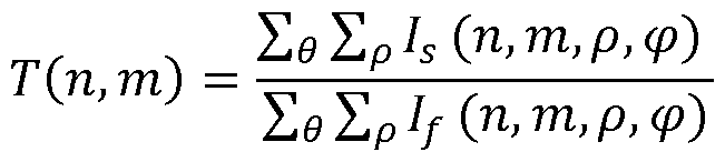
The differential phase contrast images in horizontal and vertical directions are calculated by estimating the shift of the individual unit cell self-images. This can be done by a number of methods, for instance, spatial correlation estimation. Here, a method is proposed based on a linear square fit of the local estimated phase difference between the sample and flat fringes with a theoretical model that is valid for a sinusoidal approximation of the fringes. If the sample fringe is shifted by (xO, yO) then the local phase difference for one unit cell is given by

The experimental local phase shift is calculated by a
Hilbert phase retrieval in the x or y direction. The theoretical model is then fitted to the experimental phase and the values xO and yO are estimated.
The directional scattering images are obtained by radial Fourier analysis of the recorded circular fringes. The scattering contrast is calculated by the appropriate Fourier coefficient of the radius of the fringe. The ratio of the Fourier coefficients results in the scatter contrast under that specific angle. Specifically, directional scattering images are given by
C(n,m,f) R
RX' where Rk is the k-th harmonic of the discrete Fourier transform of the recorded fringe in direction f and
k=P' /p' .
The method was experimentally validated at the TOMCAT beam line of the Swiss Light Source at Paul Scherrer Institut, CH-5232 Villigen PSI, and on a polychromatic X-ray tubes with large and small focal points. The repetition rate of the unit cell of the optical element was 100 pm, annulus width of 25 pm, spacing between consecutive annuli was 25 pm, and the diffractive array of the annuli was achieved by etching trenches of a width of 0.5 pm with a period of 1 pm. The trenchers were etched to a depth of 23 pm which is optimal for a design energy of 17 keV illumination. A scanning electron microscopy (SEM) image of a single unit cell of the optical element can be seen in Fig. 4. The photon energy was selected by a multilayer monochromator. A pco . edge 5.5 CCD camera with a pixel size of 6.5 pm was placed 34 cm behind the optical element 4.
The directional scattering image of the carbon fibre loop imaged on a synchrotron can be seen in Fig. 2. A similar loop shown in Fig. 3 was imaged at a microfocal x-ray tube.
Claims
1. An arrangement for x-rays, in particular hard x-rays, for obtaining quantitative x-ray images from a sample, which is characterised by:
a) an X-ray source (1) for generating an x-ray beam, preferably a standard polychromatic X-ray source, optionally being a structured source;
b) an optical element (4) placed in the x-ray beam
downstream or upstream of the sample and in any case upstream of a pixel detector (5) ;
c) the pixel detector (5) having sufficient spatial
resolution to resolve the intensity modulation caused by the optical element (4);
d) means for recording the images of the detector (5) ;
e) means for evaluating the intensities in a single shot image in order to obtain the characteristics of the sample including absorption, differential phase contrast and directional (small-angle) scattering contrast, preferably for specified regions of pixels; and
f) optionally, an aperture array (2) downstream of the X-ray source ( 1 ) ;
g) wherein the optical element (4) is a periodic structure composed of unit cells (6) wherein the unit cells (6) are placed on a Cartesian or Hexagonal grid, said unit cells (6) are composed of circular structures being separated by a predetermined distance (D) ;
h) each circular structure comprising a diffractive
substructure wherein the period of the unit cell is p, the width of each circular structure is S and the spacing between consecutive circular structures is D,
i) the sum of S and D is defined as the period of the circular structure within the unit cell and is noted as p=S+D; and wherein
j) the substructures within each circular structure diffract the incoming X-rays in order to minimize the transmitted x- ray intensity (also known as zeroth order) through the circular structure; preferably achieved by inducing a periodic phase shift or absorption of the incoming x-rays wherein the period of this substructure is noted as gi.
2. The arrangement according to claim 1, wherein the
circular structure is a concentric annuli or concentric polygons defining diffractive and non-diftractive areas.
3. The arrangement according to claim 1 or 2, wherein the optical element (4) is made by deep etching into silicon, a polymer or similar material, or deposition of a metal into gaps of a low-absorbing structure or growing of metal on low-absorbing substrate, or growing metal or polymer by 3D printing.
4. The arrangement according to any of the preceding claims, wherein the optical element (4) creates a periodic intensity pattern with a repetition of each unit cell P' and the period within each unit cell is p' at a known distance downstream on the detector; P' and p' match the radius of curvature of an incident wave front by relation p' = p di+li p' _ p di+li wpere
 fs the distance between the h h
X-ray source (or the aperture array if used) to the optical element, dx is the distance between the optical element and the x-ray detector.
5. The arrangement according to any of the preceding claims
1 to 4, wherein the aperture array (2) is preferably a 2D repetition of holes with pitch of P0 = P X— or integer
d
multiples thereof, or when the aperture array is not used but the X-ray source comprises 2D array of individual
sources that may be mutually incoherent and whose lateral separation P0 = P X— or integer multiples thereof,
cL
wherein the width of the apertures in any direction of the imaging plane or the individual source size is less than r' X— .
6. The arrangement according to any of the preceding claims 1 to 5, wherein a mechanism is comprised to place a sample (S) to be investigated between the X-ray source (or the aperture array if used) and the optical element, or between the optical element and the x-ray detector.
7. The arrangement according to any of the preceding claims 1 to 6, comprising means for rotating the sample (3) relatively to the remaining components to perform data collection for a tomographic scan, wherein the
orientation of the rotation axis can be arbitrary, preferably adjustable in pitch.
8. The arrangement according to any of the preceding claims 1 to 7, where the detector (5) comprise resolution enhancement capabilities in terms of introducing virtual pixels smaller than the physical detector pixel size by exploiting the charge sharing effect between neighbouring pixels .
Applications Claiming Priority (2)
| Application Number | Priority Date | Filing Date | Title |
|---|---|---|---|
| EP18153643.4 | 2018-01-26 | ||
| EP18153643.4A EP3517939A1 (en) | 2018-01-26 | 2018-01-26 | Arrangement for omnidirectional scattering imaging |
Publications (1)
| Publication Number | Publication Date |
|---|---|
| WO2019145157A1 true WO2019145157A1 (en) | 2019-08-01 |
Family
ID=61054232
Family Applications (1)
| Application Number | Title | Priority Date | Filing Date |
|---|---|---|---|
| PCT/EP2019/050506 Ceased WO2019145157A1 (en) | 2018-01-26 | 2019-01-10 | Arrangement for omnidirectional scattering imaging |
Country Status (2)
| Country | Link |
|---|---|
| EP (1) | EP3517939A1 (en) |
| WO (1) | WO2019145157A1 (en) |
Cited By (1)
| Publication number | Priority date | Publication date | Assignee | Title |
|---|---|---|---|---|
| CN115876812A (en) * | 2022-12-15 | 2023-03-31 | 浙江大学杭州国际科创中心 | Single Phase Grating X-ray Microscopic Imaging System Based on Two-Stage Amplification |
Families Citing this family (1)
| Publication number | Priority date | Publication date | Assignee | Title |
|---|---|---|---|---|
| CN112198176B (en) * | 2020-09-24 | 2022-12-02 | 中国科学院上海光学精密机械研究所 | Single-exposure X-ray diffraction imaging device and method based on high-order spatial correlation of light field |
Citations (4)
| Publication number | Priority date | Publication date | Assignee | Title |
|---|---|---|---|---|
| US20150071402A1 (en) * | 2013-09-09 | 2015-03-12 | Canon Kabushiki Kaisha | X-ray imaging system |
| WO2015168473A1 (en) * | 2014-05-01 | 2015-11-05 | Sigray, Inc. | X-ray interferometric imaging system |
| WO2017032512A1 (en) * | 2015-08-25 | 2017-03-02 | Paul Scherrer Institut | Omnidirectional scattering- and bidirectional phase-sensitivity with single shot grating interferometry |
| US20170125134A1 (en) * | 2015-10-30 | 2017-05-04 | Canon Kabushiki Kaisha | X-ray diffractive grating and x-ray talbot interferometer |
-
2018
- 2018-01-26 EP EP18153643.4A patent/EP3517939A1/en not_active Withdrawn
-
2019
- 2019-01-10 WO PCT/EP2019/050506 patent/WO2019145157A1/en not_active Ceased
Patent Citations (4)
| Publication number | Priority date | Publication date | Assignee | Title |
|---|---|---|---|---|
| US20150071402A1 (en) * | 2013-09-09 | 2015-03-12 | Canon Kabushiki Kaisha | X-ray imaging system |
| WO2015168473A1 (en) * | 2014-05-01 | 2015-11-05 | Sigray, Inc. | X-ray interferometric imaging system |
| WO2017032512A1 (en) * | 2015-08-25 | 2017-03-02 | Paul Scherrer Institut | Omnidirectional scattering- and bidirectional phase-sensitivity with single shot grating interferometry |
| US20170125134A1 (en) * | 2015-10-30 | 2017-05-04 | Canon Kabushiki Kaisha | X-ray diffractive grating and x-ray talbot interferometer |
Non-Patent Citations (1)
| Title |
|---|
| MATIAS KAGIAS ET AL: "2D-Omnidirectional Hard-X-Ray Scattering Sensitivity in a Single Shot", PHYSICAL REVIEW LETTERS, vol. 116, no. 9, 3 March 2016 (2016-03-03), US, XP055495072, ISSN: 0031-9007, DOI: 10.1103/PhysRevLett.116.093902 * |
Cited By (2)
| Publication number | Priority date | Publication date | Assignee | Title |
|---|---|---|---|---|
| CN115876812A (en) * | 2022-12-15 | 2023-03-31 | 浙江大学杭州国际科创中心 | Single Phase Grating X-ray Microscopic Imaging System Based on Two-Stage Amplification |
| CN115876812B (en) * | 2022-12-15 | 2026-01-09 | 浙江大学杭州国际科创中心 | Single-phase grating X-ray microscopy system based on two-stage amplification |
Also Published As
| Publication number | Publication date |
|---|---|
| EP3517939A1 (en) | 2019-07-31 |
Similar Documents
| Publication | Publication Date | Title |
|---|---|---|
| Berujon et al. | X-ray multimodal imaging using a random-phase object | |
| CN102221565B (en) | X-ray source grating stepping imaging system and imaging method | |
| Kagias et al. | 2D-Omnidirectional hard-X-ray scattering sensitivity in a single shot | |
| AU2006257026B2 (en) | Interferometer for quantative phase contrast imaging and tomography with an incoherent polychromatic x-ray source | |
| EP3341714B1 (en) | Omnidirectional scattering- and bidirectional phase-sensitivity with single shot grating interferometry | |
| EP3845892B1 (en) | X-ray scattering apparatus | |
| JP2012187341A (en) | X-ray imaging apparatus | |
| EP2942619A1 (en) | Tilted-grating approach for scanning-mode X-ray grating interferometry | |
| CN107850680A (en) | For phase-contrast and/or the X-ray detector of dark-field imaging | |
| US12204086B2 (en) | Apparatus and method of estimating values from images | |
| He et al. | Experimental lensless soft-x-ray imaging using iterative algorithms: phasing diffuse scattering | |
| EP3344979B1 (en) | Dual phase grating interferometer for x-ray phase contrast imaging | |
| WO2019145157A1 (en) | Arrangement for omnidirectional scattering imaging | |
| Tian et al. | Influence of diffuser grain size on the speckle tracking technique | |
| Weitkamp et al. | In-line phase contrast in synchrotron-radiation microradiography and tomography | |
| US5864599A (en) | X-ray moire microscope | |
| Chapman | Phase-retrieval x-ray microscopy by Wigner-distribution deconvolution: signal processing | |
| Xue et al. | Characterization of the error of the speckle-based wavefront metrology device at Shanghai Synchrotron Radiation Facility | |
| Wang et al. | At-wavelength metrology using the moiré fringe analysis method based on a two dimensional grating interferometer | |
| Aminzadeh et al. | High-resolution X-ray scanning with a diffuse Huffman-patterned probe to reduce radiation damage | |
| Shashev et al. | Talbot-Lau interferometry with a non-binary phase grating for non-destructive testing | |
| Nagai | A phase demodulation method for two-dimensional grating-based X-ray interferometry | |
| Takeuchi et al. | X-ray imaging microscope with a partial coherent illumination | |
| Xue et al. | At-wavelength optics characterization metrology at Shanghai Synchrotron Radiation Facility | |
| Saliba et al. | High-Resolution Hard X-ray Holography by Unconfined Atomic Layer Deposited Phase-Shifting 3D References |
Legal Events
| Date | Code | Title | Description |
|---|---|---|---|
| 121 | Ep: the epo has been informed by wipo that ep was designated in this application |
Ref document number: 19701989 Country of ref document: EP Kind code of ref document: A1 |
|
| NENP | Non-entry into the national phase |
Ref country code: DE |
|
| 122 | Ep: pct application non-entry in european phase |
Ref document number: 19701989 Country of ref document: EP Kind code of ref document: A1 |