WO2019143226A1 - Method for transmitting and receiving channel state information in wireless communication system and device therefor - Google Patents
Method for transmitting and receiving channel state information in wireless communication system and device therefor Download PDFInfo
- Publication number
- WO2019143226A1 WO2019143226A1 PCT/KR2019/000913 KR2019000913W WO2019143226A1 WO 2019143226 A1 WO2019143226 A1 WO 2019143226A1 KR 2019000913 W KR2019000913 W KR 2019000913W WO 2019143226 A1 WO2019143226 A1 WO 2019143226A1
- Authority
- WO
- WIPO (PCT)
- Prior art keywords
- information
- channel
- matrix
- base station
- csi
- Prior art date
Links
Classifications
-
- H—ELECTRICITY
- H04—ELECTRIC COMMUNICATION TECHNIQUE
- H04B—TRANSMISSION
- H04B7/00—Radio transmission systems, i.e. using radiation field
- H04B7/02—Diversity systems; Multi-antenna system, i.e. transmission or reception using multiple antennas
- H04B7/04—Diversity systems; Multi-antenna system, i.e. transmission or reception using multiple antennas using two or more spaced independent antennas
- H04B7/06—Diversity systems; Multi-antenna system, i.e. transmission or reception using multiple antennas using two or more spaced independent antennas at the transmitting station
- H04B7/0613—Diversity systems; Multi-antenna system, i.e. transmission or reception using multiple antennas using two or more spaced independent antennas at the transmitting station using simultaneous transmission
- H04B7/0615—Diversity systems; Multi-antenna system, i.e. transmission or reception using multiple antennas using two or more spaced independent antennas at the transmitting station using simultaneous transmission of weighted versions of same signal
- H04B7/0619—Diversity systems; Multi-antenna system, i.e. transmission or reception using multiple antennas using two or more spaced independent antennas at the transmitting station using simultaneous transmission of weighted versions of same signal using feedback from receiving side
- H04B7/0658—Feedback reduction
- H04B7/0663—Feedback reduction using vector or matrix manipulations
-
- H—ELECTRICITY
- H04—ELECTRIC COMMUNICATION TECHNIQUE
- H04B—TRANSMISSION
- H04B7/00—Radio transmission systems, i.e. using radiation field
- H04B7/02—Diversity systems; Multi-antenna system, i.e. transmission or reception using multiple antennas
- H04B7/04—Diversity systems; Multi-antenna system, i.e. transmission or reception using multiple antennas using two or more spaced independent antennas
- H04B7/0413—MIMO systems
- H04B7/0456—Selection of precoding matrices or codebooks, e.g. using matrices antenna weighting
-
- H—ELECTRICITY
- H04—ELECTRIC COMMUNICATION TECHNIQUE
- H04B—TRANSMISSION
- H04B7/00—Radio transmission systems, i.e. using radiation field
- H04B7/02—Diversity systems; Multi-antenna system, i.e. transmission or reception using multiple antennas
- H04B7/04—Diversity systems; Multi-antenna system, i.e. transmission or reception using multiple antennas using two or more spaced independent antennas
- H04B7/0413—MIMO systems
- H04B7/0417—Feedback systems
-
- H—ELECTRICITY
- H04—ELECTRIC COMMUNICATION TECHNIQUE
- H04B—TRANSMISSION
- H04B7/00—Radio transmission systems, i.e. using radiation field
- H04B7/02—Diversity systems; Multi-antenna system, i.e. transmission or reception using multiple antennas
- H04B7/04—Diversity systems; Multi-antenna system, i.e. transmission or reception using multiple antennas using two or more spaced independent antennas
- H04B7/0413—MIMO systems
- H04B7/0452—Multi-user MIMO systems
-
- H—ELECTRICITY
- H04—ELECTRIC COMMUNICATION TECHNIQUE
- H04B—TRANSMISSION
- H04B7/00—Radio transmission systems, i.e. using radiation field
- H04B7/02—Diversity systems; Multi-antenna system, i.e. transmission or reception using multiple antennas
- H04B7/04—Diversity systems; Multi-antenna system, i.e. transmission or reception using multiple antennas using two or more spaced independent antennas
- H04B7/06—Diversity systems; Multi-antenna system, i.e. transmission or reception using multiple antennas using two or more spaced independent antennas at the transmitting station
- H04B7/0613—Diversity systems; Multi-antenna system, i.e. transmission or reception using multiple antennas using two or more spaced independent antennas at the transmitting station using simultaneous transmission
- H04B7/0615—Diversity systems; Multi-antenna system, i.e. transmission or reception using multiple antennas using two or more spaced independent antennas at the transmitting station using simultaneous transmission of weighted versions of same signal
- H04B7/0619—Diversity systems; Multi-antenna system, i.e. transmission or reception using multiple antennas using two or more spaced independent antennas at the transmitting station using simultaneous transmission of weighted versions of same signal using feedback from receiving side
- H04B7/0621—Feedback content
- H04B7/0626—Channel coefficients, e.g. channel state information [CSI]
-
- H—ELECTRICITY
- H04—ELECTRIC COMMUNICATION TECHNIQUE
- H04L—TRANSMISSION OF DIGITAL INFORMATION, e.g. TELEGRAPHIC COMMUNICATION
- H04L25/00—Baseband systems
- H04L25/02—Details ; arrangements for supplying electrical power along data transmission lines
- H04L25/0202—Channel estimation
- H04L25/021—Estimation of channel covariance
-
- H—ELECTRICITY
- H04—ELECTRIC COMMUNICATION TECHNIQUE
- H04L—TRANSMISSION OF DIGITAL INFORMATION, e.g. TELEGRAPHIC COMMUNICATION
- H04L25/00—Baseband systems
- H04L25/02—Details ; arrangements for supplying electrical power along data transmission lines
- H04L25/0202—Channel estimation
- H04L25/0224—Channel estimation using sounding signals
-
- H—ELECTRICITY
- H04—ELECTRIC COMMUNICATION TECHNIQUE
- H04W—WIRELESS COMMUNICATION NETWORKS
- H04W48/00—Access restriction; Network selection; Access point selection
- H04W48/08—Access restriction or access information delivery, e.g. discovery data delivery
- H04W48/12—Access restriction or access information delivery, e.g. discovery data delivery using downlink control channel
-
- H—ELECTRICITY
- H04—ELECTRIC COMMUNICATION TECHNIQUE
- H04W—WIRELESS COMMUNICATION NETWORKS
- H04W48/00—Access restriction; Network selection; Access point selection
- H04W48/16—Discovering, processing access restriction or access information
Definitions
- the present invention relates to a wireless communication system, and more particularly, to a method for transmitting / receiving channel state information
- the mobile communication system has been developed to provide voice service while ensuring the user 's activity.
- the mobile communication system has expanded the area from voice to data service.
- Due to an explosion of traffic a shortage of resources is caused and users demand a higher speed service. Therefore, a more advanced mobile communication system is required .
- next-generation mobile communication system should greatly support the explosive increase in data rate per user acceptance of data traffic, the acceptance of a significantly increased number of connected devices, very low end-to-end latency, and high energy efficiency do.
- a dual connectivity a massive multiple input multiple output (MIMO), an in-band full duplex, a non-orthogonal (NOMA)
- the present disclosure proposes a method for reporting channel state information, i.e., reducing the overhead of feedback in a wireless communication system.
- the present disclosure proposes a method of taking into account the characteristics seonggim (sparsity) of the channel do not the feedback information for the whole, only the feedback of a portion effective (valid) information.
- the method for the UE to perform the CSI (channel state information) report comprising: setting related to the CSI reported for the downlink channel (downlink channel) from the base station information, (confi gurat ion information ) #; Receiving, from the base station, at least one CSI-RS for the CSI report; Calculating feedback information by the at least one CSI-RS; And using a feedback information (inf ormation feedback) the output, comprising the step of performing the CSI reported by the base station is the setting information,
- the feedback information includes at least one valid region related to the calculation of the feedback information and the feedback information includes positional imposition information for at least one channel matrix element included in the specific valid region, 3 ⁇ 4 3 ⁇ 4J: (value) ⁇ % 5L3 ⁇ 43 ⁇ 4 ⁇ $ _! ⁇
- the at least one information on the effective area is, for each valid area center (center) the index of the range and / or each of the effective area of the position of each effective area of the channel matrix elements in the above-mentioned method according to an embodiment of the invention n You can include ex
- the step of calculating the feedback information comprises generating a channel matrix based on the measurements on the at least one - channel matrix; Generating a second channel matrix by applying a preset transform matrix to the first channel matrix; generating the third channel matrix by applying the specific effective region to the channel matrix; And quantizing the third channel matrix to yield the feedback information
- the setting information may include at least one of an angular information # Includes, and by applying the predetermined effective area on said second channel matrix, wherein the step of generating a three channel matrix, the first with the exception of certain elements set of the elements of the second channel matrix based on the angle information element Lt; / RTI > to zero .
- the particular elements may be included an element which is located within a predetermined range relative to the central element and the central element are set using the AoD and the support area, .
- the preset 10 transform matrix is set based on a spatial rotation matrix shared between the terminal and the base station, space rotation parameters relating to the matrix can contain a (spatial rotation parameter).
- the first channel 15 is a matrix, wherein the at least one CSI - has channel covariance matrix channel covariance matrix) days by RS.
- the method may further include receiving information on the number of the at least one valid region from the base station.
- the wireless terminal In a wireless communication system according to the 20th embodiment of the present invention to the terminal to perform the CSI (channel state i nformation) report, the wireless terminal Include (Radio Frequency) RF send and receive a signal unit and the RF unit and a processor that is operatively connected to, and wherein the processor is set up concerning the CSI reported for the downlink channel (downlink channel) from the base station information (configuration information) 3 ⁇ 4 ⁇ receive; Receiving, from the base station, at least one CSI-RS for the CSI report; Calculate feedback information by the at least one CSI-RS; And using a feedback information (feedback inf ormation) calculated above, but controlled so as to perform the CS I reported to the base station in the setting information is, for at least one effective region (valid region) associated with the calculation of the feedback information can contain a (Value): it contains information, the feedback information is at least one element of the channel matrix (channel matrix element) wicha information (position information) and 3 ⁇ 4] to be included in
- information for the at least one effective area of the position of the center (center) channel matrix elements of each effective region, the range of each of the valid area, and / or each valid And may include an index of the region.
- the processor regarding the calculation of the feedback information, the processor generates a first channel matrix based on the measurement for the at least one CSI-RS; By applying a predetermined transformation matrix (transform matrix) in the first channel matrix and the second channel matrix (channel Claim to produce a three channel matrix, and quantization of the third channel matrix, can be controlled to output the feedback information.
- a predetermined transformation matrix transform matrix
- the second channel matrix channel Claim to produce a three channel matrix, and quantization of the third channel matrix
- the processor may further include a step of selecting, from the elements of the second channel matrix, You can control to set the remaining elements to zero .
- the processor in the setting information related to the generation of the third channel matrix, further comprising: an angular information (angular i nformation) associated with the downlink channel, the processor It is possible to set the remaining elements of the second 10- channel matrix other than the specific elements set based on the angle information to zero .
- the feedback information includes position information (position information) of at least one channel matrix element included in a
- channel information is extracted by extracting only a portion having meaningful information from the covariance matrix information of the channel information, so that the accuracy of the channel information can be improved and the overhead can be reduced.
- FIG. 2 is a block diagram of a wireless communication system in which the method proposed herein can be applied. The relation between the uplink frame and the downlink frame is shown in the system.
- FIG 3 shows an example of a frame structure in the NR system.
- FIG. 4 shows an example of a resource grid (grid resource) that supports a wireless communication system that can be applied to the method proposed herein.
- FIG. 5 shows examples of resource ports of an antenna port and a remotely deployed to which the proposed method can be applied.
- FIG. 6 shows an example of a self-contained structure to which the method proposed herein can be applied.
- FIG. 7 shows an example of a signal transmitting / receiving method.
- FIG. 10 shows an example of a terminal acquiring information on DL time synchronization.
- FIG. 11 shows an example of a system information (SI) acquisition process.
- SI system information
- FIG. 13 shows an example of a threshold value for the SS block for the RACH resource association.
- FIG 4 shows an example of the power ramping of the counter PRACH.
- FIG. 17 is a schematic view of an embodiment of the present invention.
- 19 shows a specific example of setting the effective area of the channel information to which the embodiment proposed in this specification can be applied.
- FIG. 21 shows an example of an operation flow diagram of a terminal for performing 0 £ 1 reports in a wireless communication system that can be applied to the method proposed herein.
- FIG. 22 shows an example of an operation flowchart of a base station receiving a 031 report in a wireless communication system to which the method proposed in this specification can be applied.
- FIG. 23 illustrates a block diagram of a wireless communication 5 device to which the methods proposed herein may be applied.
- 24 illustrates a block diagram of a communication apparatus according to an embodiment of the present invention.
- 25 shows an example of a yaw module of a wireless communication apparatus to which the method suggested in the present specification can be applied.
- Figure 26 shows another example of the second yaw module of a wireless communication device that can be applied to the method proposed herein.
- a downlink means communication from a branch station to a terminal
- an uplink means communication from a terminal to a base station.
- the transmitter may be part of the base station, and the receiver may be part of the terminal.
- the transmitter may be part of the terminal and the receiver may be part of the base station.
- the base station may be represented by a first communication device
- the terminal may be represented by a second communication device.
- a base station includes a fixed station, a Node B, an evolved NodeB (eNB), a Next Generation Node B (gNB), a base transceiver system (BTS), an access point (AP) Network), an AI system, a road side unit (RSU), a robot, and the like.
- a terminal may be fixed or mobile, and may be a user equipment (UE), a mobile station (MS), a user terminal (UT)
- MSS mobile subscriber station
- SS subscriber station 2019/143226 1 »
- Machine-Type Communication MTC
- Machine-to-Mchain Device-to-Device
- Vehicle Vehicle
- CDMA can be implemented with wireless technologies such as Universal Terrestrial Radio Access (UTRA) or CDMA2000.
- the TDMA may be implemented in a wireless technology such as Global System for Mobile communications (GSM) / General Packet Radio Service (GPRS) / Enhanced Data Rates for GSM Evolution (EDGE).
- GSM Global System for Mobile communications
- GPRS General Packet Radio Service
- EDGE Enhanced Data Rates for GSM Evolution
- OFDMA may be implemented in wireless technologies such as IEEE 802.11 (Wi-Fi), IEEE 802.16 (WiMAX), IEEE 802-20, and Evolved UTRA (E-UTRA).
- UTRA is part of the Universal Mobile Telecommunications System (UMTS).
- 3GPP (3rd Generation Partnership Project) LTE Long Term Evolution
- LTE-A Advanced
- LTE -A pro of E-UMTS (Evolved UMTS) that uses, the E-UTRA! Is an evolved version of the 3GPP LTE to be.
- 3GPP NR New Radio or New Radio Access Technology
- 3GPP LTE / LTE-A / LTE-A pr ⁇ is an evolutionary version of 3GPP LTE / LTE-A / LTE-A pr ⁇ .
- LTE refers to technology of 3GPP TS 36. xxx Release 8 or later.
- NR is T S 38. xxx means Release 15 technology or later.
- LTE / NR can be supported by 3 GPP systems.
- n xxx '' denotes the standard document detail number.
- LTE / NR can be referred to as 3 GPP system.
- terminology, acronyms, etc. used in the description of the present invention reference may be made to the description in standard documents published prior to the present invention. For example, you can refer to the following document:
- RRC Radio Resource Control
- Massive MTC Machine Type Communica- tions
- eMBB enhanced mobile broadband communication
- MMC massive MTC
- URLLC ultra-reliable low latency communication
- NR 5G wireless access technology
- the new RAT system uses the OFDM transmission scheme or a similar transmission scheme.
- the new RAT system may follow OFDM parameters different from the OFDM parameters of LTE.
- the new RAT system follows the existing LTE / LTE-A numerology but can have a larger system bandwidth (eg, 100 MHz).
- one cell may support a plurality of memorylogies. In other words, terminals operating in different radio environments can coexist within a single cell.
- eLTE eNB is an evolution (evolution) of the eNB and EPC to support the connection to the NGC.
- gNB Not only the connection with NGC, but also the node that wants to connect.
- New RAN A wireless access network that supports NR or E-UTRA or interacts with NGC.
- Network slice is a network defined by an operator to provide an optimized solution for a specific market scenario that requires specific requirements with end-to-end coverage.
- Network functions are logical nodes within a network infrastructure with a well-defined and well-defined external interfaces Functional operation.
- NGC NG2 reference point between the new RAN and NGC (ref erence point) control plane interface used to.
- NG-U NG3 reference point between the new RAN and NGC (ref erence point) user plane interface used to.
- Non-stand-alone (Non -standalone) NR gNB the LTE eNB the control request to the EPC Rose anchor for the connection plane or the eNB eLTE arrangement requiring to as an anchor for the control plane connection NGC configuration.
- Non-stand-alone E-UTRA A deployment configuration where the eLTE eNB obtains the gNB as an anchor for the control plane connection to the NGC.
- User plane gateway Endpoint of the NG-U interface.
- NG-RAN is in the NG-RA-plane (new AS sublayer / PDCP / RLC / MAC / PHY) and control plane (RRC) gNB to provide a protocol termination for the UE (Us er Equipment)
- NG-RA-plane new AS sublayer / PDCP / RLC / MAC / PHY
- RRC control plane
- the gNBs are interconnected via the Xn interface.
- the gNB is also connected to the NGC via the NG interface.
- the gNB is connected to the AMF (Acce ss and Mobility Management Function ) through the N2 interface and the UPF (User Plane Function ) through the N3 interface.
- AMF Acce ss and Mobility Management Function
- UPF User Plane Function
- the enumeration roll which may be defined by a sub-carrier spacing (subcarrier spacing) and CP (Cyclic Prefix) overhead.
- the number of sub-carrier interval is N (integer or a basic sub-carrier spacing, the // 2019/143226 1 » (: 1/10/01 019/000913
- the utilized memoryless can be selected independently of the frequency band.
- various frame structures according to a plurality of ring signals can be supported.
- OFDM Orthogonal Frequency Division Multiplexing
- the number of OFDM neuron rolls supported in the NR system can be defined as shown in Table 1.
- FIG. 2 illustrates a relationship between an uplink frame and a downlink frame in a wireless communication system to which the method proposed in the present invention can be applied.
- the slots are arranged in the subframe
- Ag mb Being made up of consecutive OFDM symbols, Ag mb is determined in accordance with the enumeration roll paper and setting slot (slot configuration) is used.
- Nf start of the slot in the sub frame is arranged in a start time and an OFDM symbol «, llb in the same subframe.
- all the terminals can simultaneously transmit and receive, which downlink slot (downlink slot) or UL uplink slot; It means that all the OFDM symbols of the slot) is not be used.
- Table 2 shows the number (%) of OFDM symbols per slot in a normal CP , frame A7 subframe, // number of slots per frame, and number of slots per subframe.
- Table 3 shows the number of OFDM symbols per slot in the extended CP , the number of slots per radio frame, Indicates the number of separate slots.
- FIG. 3 shows an example of a frame structure in the NR system.
- FIG. 3 is merely for convenience of description and does not limit the scope of the present invention.
- SCS subcarrier spacing
- mini-slot and (mini -slot) will also be comprised of a 2, 4 or 7 symbol (symbol), there doelsudo composed of more or less symbols.
- the physical resource (physical resource) in the NR system such as antenna ports (antenna port), the resource grid (resource grid), the resource elements (resource element), resource blocks (resource block), the carrier parts (carrier part) Can be considered.
- an antenna port is a channel from which the symbol carrying the symbol on the antenna port is carried, to the other symbol on the same antenna port Is defined so that it can be deduced if one of the symbols in a wide range of characteristics of the channel that is carried (large -scale property) on the antenna ports can be deduced from the channel that carries the symbols on the different antenna ports, the two antenna ports QC / QCL (quasi co-located or quasi co-location ) relationship.
- the wide range of properties including the delay spread (Delay spread), Doppler spread (Doppler spread), frequency shift (Frequency shift), the average received power (Average received power), the reception timing (Received Timing) Heavy or more.
- FIG. 4 shows an example of a resource grid supported in a wireless communication system to which the method proposed in the present invention can be applied.
- One subframe is composed of subcarriers . 2 OFDM symbols, but is not limited thereto.
- the transmitted signal is One or more resource grids comprised of subcarriers and /
- the iV B AxA represents the maximum transmission bandwidth, which may vary not only between the uplink and downlink as well as the neighbors .
- one resource grid may be set for each of the radio network M and the antenna port p .
- FIG. 5 illustrates an antenna port to which the method proposed herein may be applied; and FIG. Examples of resource grids per annum
- Each element of the resource grid for the neurorrosion and antenna port p is referred to as a resource element and is uniquely identified by the index pair ⁇
- / 0, ..., 2 ⁇ 3 ⁇ 41- 1 refers to the position of the symbol within the subframe.
- the index pair ⁇ , /) are used.
- / 0 ..., ⁇ -l
- Enumeration metrology // and resource elements (kj) of the antenna port is a complex value (complex va lue) . If there is no risk of confusion (confusion), or when a particular antenna port or enumeration roll land that is not specific, and the index p '' is can be drop (drop), the result is a complex value j ⁇ or 1, the .
- P oint A will act as a common reference point of the resource block grid (common re ference point) and can be obtained as follows.
- ToPointA for PCell downlink denotes a frequency offset between the SS / PBCH block overlaps with the lowest resource block lowest sub-carrier and the point A of the use by the [for initial cell selection, 15k Hz for FR1 subcarriers It is represented by a resource block (unit) assuming a 60 kHz subcarrier interval for interval and FR2; 2 019/143226 1 »(: 1/10/01 019/000913
- absoluteFrequencyPointA represents the frequency-position of point A, expressed as in an absolute radio-frequency channel number (ARFCN ) .
- Common resource blocks (resource block common) are numbered (numbering) upwards from zero in the frequency domain for a set or sub-carrier interval.
- the center of the subcarrier ⁇ of the common resource block 0 for the subcarrier interval setting coincides with 'point A'.
- the resource block number (number R B ) and the resource element (k , l ) for the subcarrier interval setting in the frequency domain can be given by Equation 1 below.
- Equation 11 k is a k - can be defined relative to the point A corresponding to a subcarrier centered at point A is zero.
- Physical resource blocks have a bandwidth of size 1
- B WP bandwidth part
- ⁇ CRB W PRB + ⁇ BWP, i
- ⁇ WP May be a common resource block that starts relative to BWP processing resource block 0.
- 2019/143226 1 » (: 1/10 public 019/000913
- NR systems can be supported up to 400 MHz per component carrier (CC).
- CC component carrier
- the use case eg, eMBB, URLLC , Mmtc, V2X , etc. (Eg, sub-carrier spacing 7) for each frequency band, .
- the capability for the maximum bandwidth may vary from one version to another.
- the base station can instruct the terminal to operate only on some bandwidth, not the entire bandwidth of the wideband CC, and define some bandwidth as a bandwidth part (BWP) for convenience.
- BWP can be composed of consecutive resource blocks (RBs) on the frequency bands and can correspond to one numerology (eg, sub-carrier spacing, CP length, slot / mini-slot duration).
- numerology eg, sub-carrier spacing, CP length, slot / mini
- the base station can set a plurality of BWPs in one CC configured for the terminal. For example, in a PDCCH monitoring slot, a BWP occupying a relatively small frequency range is set, and a PDSCH indicated in a PDCCH can be scheduled on a BWP larger than the PDSCH.
- some UEs may be set to different BWPs for load balancing when UEs are routed to a particular BWP.
- 2019/143226 1 » considering the frequency domain inter-cell interference cancellation between neighboring cells, 2019/143226 1 » (: 1/10/01 019/000913
- the base station can configure at least one DL / UL BWP for the associated terminal with the wideband CC, and at least one of the configured DL / UL BWP (s)
- the DL / UL BWP can be activated (eg by LI signaling or MAC CE or RRC signaling) and switching to other configured DL / UL BWPs can be indicated (eg by LI signaling or MAC CE or RRC signaling) When the value is expired, it may be switched to the specified DL / UL BWP. At this time, the activated DL / UL BWP is defined as active DL / UL BWP.
- DL / UL BWP may not receive configuration for DL / UL BWP in the initial access procedure or RRC connection setup.
- the DL / UL BWP assumed by the terminal is initial active DL / UL BWP.
- a time division duplexing (TDD) structure considered in the NR system is a structure that processes both an uplink (UL) and a downlink (DL) in one slot (or a subframe). This is to minimize the latency of data transmission in a TDD system, and the structure may be referred to as a self-contained structure or a self-contained slot.
- UL uplink
- DL downlink
- 2019/143226 1 » (: 1/10 public 019/000913
- FIG. 6 shows an example of a self-contained structure to which the method proposed herein can be applied.
- Fig. 6 is merely for convenience of explanation and does not limit the scope of the invention.
- one transmission unit eg, slot subframe
- OFDM orthogonal frequency division multiplexing
- an area 602 denotes a downlink control region
- an area 604 denotes an uplink control region.
- an area other than the area 602 and the area 604 i.e., an area without a separate mark
- Uplink control information, and downlink control information Can be transmitted in one self-contained slot.
- uplink data or downlink data can be transmitted in one self-contained slot.
- downlink transmission and uplink transmission are sequentially performed in one self-contained slot, and downlink data transmission and uplink ACK / NACK reception can be performed.
- the transition from the base station (eNodeB, eNB, gNB) and / or the terminal (terminal, UE (User Equipment) ) the transmission mode (transmission mode) to the reception mode (reception mode) or the time gap (time gap) is required for shifting to a transmission mode in the receive mode.
- some OFDM symbol (s) may be set as a guard period (GP ) .
- FIG. 7 is a diagram showing an example of a signal transmitting / receiving method.
- the terminal performs the initial cell searching (Initial cell search) operation, such as the power is turned on or when a new entry to the cell matching the base station and the synchronization (S701).
- the UE receives a Primary Synchronization Channel (P-SCH ) and a Secondary Synchronization Channel (S-SCH) from a base station and synchronizes with the base station and acquires information such as a cell ID may Thereafter, the terminal may receive a physical broadcast channel (physical broadcast channel) from the base station to acquire the broadcast information within the cell. Meanwhile, the UE can receive the downlink reference signal (DL RS ) in the initial cell search step to check the downlink channel state.
- DL RS downlink reference signal
- the UE After completion of the initial cell search, the UE transmits a Physical Downlink Control Channel Downlink Control Channel; PDCCH) and a physical downlink control channel (PDSCH ) according to the information on the PDCCH (S702).
- PDCCH Physical Downlink Control Channel Downlink Control Channel
- PDSCH physical downlink control channel
- the terminal transmits a random access procedure (Random Access Procedure) to the base station.
- Random Access Procedure Random Access Procedure
- the UE transmits a specific sequence through a Physical Random Access Channel (PRACH ) as a preamble (S703 and S70, and receives a response message for the preamble through the PDCCH and the corresponding UE (S704 and S706) .
- PRACH Physical Random Access Channel
- a contention resolution procedure can be performed in a cost-effective manner.
- the terminal performs the same procedure as described above hanba since as a general uplink / downlink signal transmission procedure PDCCH / PDSCH reception (S707) ', and a physical uplink shared channel (Physical Uplink Shared Channel; PUSCH) / Physical uplink control channel (Physical Uplink Control Channel (PUCCH ) transmission (S708) .
- the UE transmits downlink control information (Downlink
- Control Information includes control information such as resource allocation information for the UE, and formats are different according to the purpose of use.
- the control information transmitted by the terminal to the base station through the uplink or received by the terminal from the base station includes a downlink / uplink ACK / NACK signal, A channel quality indicator (CQI), a precoding matrix index (PMI), a rank indicator (RI), and the like.
- CQI channel quality indicator
- PMI precoding matrix index
- RI rank indicator
- the UE can transmit control information such as the CQI / PMI / RI described above via the PUSCH and / or the PUCCH.
- Table 4 shows an example of the DCI format in the NR system.
- DCI format 0_0 is used for scheduling PUSCH in a cell of a galaxy.
- DCI format 0_0 is CRC scrambled and transmitted by C-RNTI or CS-RNTI or MCS-C-RNTI.
- DCI format 0_1 is used to reserve PUSCH in one cell.
- the information included in DCI format 0_1 is CRC scrambled and transmitted by C-RNTI or CS-RNTI or SP-CSI-RNTI or MCS-C-RNTI.
- DCI format 1_0 is used for the scheduling of the PDSCH in the DL cell of the Galaxy.
- the information included in DCI format 1_0 is CRC scrambled and transmitted by C-RNTI or CS-RNTI or MCS-C-RNTI.
- the DCI format 11 is used for scheduling the PDSCH in one cell.
- DCI The information included in format 1_1 is CRC scrambled and transmitted by C-RNTI or CS-RNTI or MCS-C-RNTI.
- the DCI format 2_1 is used to advertise the PRB ( s ) and OFDM symbol ( s) that the terminal may assume is not intended to transmit.
- the next information included in the DCI format 2_1 is CRC scrambled and transmitted by the INT-RNTI.
- IA Initial Access
- Figure 8 illustrates the SSB structure.
- the UE can perform a cell search based on the SSB (search), the information acquisition system, the beam alignment for initial access, DL measurements.
- SSB is mixed with SS / PBCH (Synchronization Signal / Physical Broadcast channel ) block.
- SS / PBCH Synchronization Signal / Physical Broadcast channel
- SSB is composed of PSS, SSS and PBCH.
- SSB consists of four consecutive OFDM symbols, and PSS, PBCH, SSS / PBCH and PBCH are transmitted per OFDM symbol.
- PSS and SSS are composed of one OFDM symbol and 127 subcarriers, respectively, and the PBCH is composed of 3 OFDM symbols and 576 subcarriers.
- Dolby coding and Quadrature Phase Shift Keying (QPSK) are applied to the PBCH.
- the PBCH consists of data RE and demodulation reference signal ( DMRS ) RE for each OFDM symbol. There are three DMRS REs per RB, and there are three data REs between the DMRS REs. (2) cell search (cell search)
- Cell search means a process that the mobile station acquires the time / frequency synchronization of a cell, the cell geomjul ID (Identifier) (for example, Physical layer Cell ID, PCID) of the cell.
- the PSS is used to detect the cell ID in the cell ID group
- the SSS is used to detect the cell ID group.
- the PBCH is used for SSB ( time) index detection and half-frame detection.
- the cell search procedure of the UE can be summarized as shown in the following table.
- cell 10 can be defined by Equation (3). :
- ⁇ ' 3 ⁇ + ⁇ where , ) £ ⁇ 0 Mountain ... , 335 ⁇ , and ⁇ ) 4>,!, 2 ⁇ .
- / 61 111 1 shows a cell 113 (for example, £ 1 0). 1) 113 is obtained providing / via overview 3 shows a cell 10 group. ⁇ 1 (2) 10) indicates the cell in the cell group 10 is provided / acquired via the de Mock.
- Figure 9 illustrates SSB transmission.
- S SB is periodically transmitted in accordance with the SSB periodicity .
- the SSB base period assumed by the UE during the second cell search is defined as 20 ms. After cell connection, the SSB period may be set to one of ⁇ 5 ms, 10 ms, 20 ms, 40 ms, 80 ms, 160 ms ⁇ by the network ( eg, base station ) .
- the SSB burst (burst) set is configured at the start of the cycle SSB.
- the SSB burst set consists of a 5 ms time window ( i.e., half-frame ) , and the SSB can be transmitted up to a maximum of N times within the SS burst set.
- the maximum number of SSB transmissions can be given by the frequency band of the carrier as follows: One slot contains a maximum of two SSBs .
- the time position of the SSB candidate within the SS burst set can be defined as follows according to the SCS . Are indexed by 0 ⁇ L -1 in time sequence within (index SSB) the time position of the SSB candidate SSB burst set (frames that is, a half).
- the index of the candidate 33-bit start symbol is ⁇ 2 , 8 ⁇ +
- the UE may acquire the [synchronization by detecting the 33 eight.
- the terminal on the basis of the detected index, and 38 6 can identify the structure of the third set of bursts 36, whereby the symbol / slot / half-it is possible to detect the frame boundary.
- the number of the frame / half-frame to which the detected iodine fragment belongs can be identified by using the SFN information and the half-frame indication information.
- the UE can acquire 10-bit SFN (System Frame Number) information from the PBCH (s0 to s9) . Six bits of the 10-bit SFN information are obtained from the MIB (Master Information Block ) , and the remaining 4 bits are obtained from the PBCH TB (Transport Block ) .
- MIB Master Information Block
- the terminal can obtain 1-bit half-frame indication information ( C0) .
- the half-frame indication information may be implicitly signaled using PBCH DMRS .
- SSB index based on PB CH payload can obtain the SSB index.
- the S SB candidates are indexed from 0 to L-1 in chronological order within an SSB burst set ( i.e., half-frame ) .
- the least significant bit (LSB ) 3 bits of the SSB index can be indicated using eight different PBCH DMRS sequences (b0 to b2 ) .
- SI System Information
- the terminal can acquire A S - / NAS - information through the SI acquisition process.
- SI acquisition procedure can be applied to terminals in RR C _IDLE state, RRC_INA CTIVE state, and RR C _ CONNECTED state.
- the SI includes a Master Information Block (MIB) and a plurality of SIBs
- RMSI Remaining Minimum System Information
- the SIB1 contains the information / parameters related to the reception of the SIB1 (SystemlnformationBlockl ) and is transmitted via the demodulation of the SSB .
- the terminal assumes that the half-frame having the SSB is repeated at a cycle of 20 ms.
- the UE can verify based on the MIB TypeO-PD CCH common search space (common search space) is (Resource Control Set) CORESET for existence.
- the TypeO-PD CCH common search space is a kind of PD CCH search space and is used to transmit PD CCH to schedule SI messages.
- the terminal information in the MIB on the basis of (for example, pdcch- ConfigSIBl) (i) C ORESET plural and (ii) a contiguous RB Waha or more consecutive symbols that make up the PD CCH opportunity ( i. E. , The time domain location for PD CCH reception ) .
- the pdcch-Conf ig SIBl provides information on the frequency location where SSB / SIB1 exists and the frequency range where SSB / SIB1 does not exist.
- SIB1 contains information related to the availability and scheduling (e.g., transmission period, SI- window size) of the remaining SIBs ( SIBx, x is an integer greater than or equal to 2). For example, SIB1 can tell whether the SIBx that periodically broadcast service at the request of the terminal by using the on- demand method. If SIBx is provided by an on- demand method, SIB1 may contain information necessary for the terminal to perform a SI request. SIB1 is transmitted on the PDSCH , the PDCCH for scheduling SIB1 is transmitted on the Type O-PDCCH common search space, and SIB1 is transmitted on the PDSCH indicated by the PDCCH :
- RA Random Access
- the random access procedure of the terminal can be summarized as shown in Table 6 and FIG.
- a long sequence length 839 is applied with a subcarrier spacing of 1.25 and 5 kHz
- a short sequence length 139 is applied to subcarriers of 15, 30, 60 and 120 kHz It is applied as an interval.
- a long sequence supports both an unrestricted set and a limited set of type A and type B
- a short sequence supports only an unrestricted set.
- CH multiple RA preamble formats are defined by one or RA CH OFDM symbols of the ahsang, and different cyclic prefix (cyclic prefix) and guard times (guard time).
- the PRA CH preamble configuration for use is provided in the system information header .
- the UE can retransmit the PR ACH preamble within a predetermined number of times by power-ramping.
- the terminal calculates the PRA CH transmit power for retransmission of the preamble based on the most recent path loss and power ramping counter.
- the UE performs a switching beam (beam switching)
- the power ramping counter remains unchanged.
- the system information informs the terminal of the association between the SS block and the RACH resource (asociation).
- the diagram shows an example of a threshold for an SS block for RA H resource association
- the threshold of the SS block for the RACH resource association is based on RSRP and configurable network.
- the transmission or retransmission of the RACH preamble is based on the SS blocks satisfying the threshold.
- UE DL - upon receiving a random access response on SCH, DL - SCH timing alignment information, RA - RNTI can provide - the preamble ID, initial UL grant and temporary C et al
- the UE can transmit UL transmission on the UL -SCH as Msg3 of the random access procedure.
- Msg3 may include an RRC connection request and a terminal identifier.
- the network may transmit Msg4 , which may be treated as a contention resolution message on the DL .
- Msg4 may be treated as a contention resolution message on the DL .
- Layer-1 Prior to initiating the physical random access procedure, Layer-1 must receive a set of SS / PBCH block indices from a higher layer , 02019/143226 1> (1 '/ 1? 2019/000913
- a set of RSRP inerts should be provided to the higher layer.
- Layer-1 Prior to initiating the physical random access procedure, Layer-1 must receive the following information from the higher layer:
- PRACH physical random access channel
- the PRACH preamble sequence set index into the logical root sequence table, cyclic shift ( N_CS), and type of set ( unrestricted set, restricted set A, or restricted set B) Parameters for determining their cyclic shift.
- the L1 random access procedure includes the transmission of a random access preamble (Msgl ) in the PRACH, a random access response (RAR) message (Msg2 ) with PDCCH / PDSCH : and, if applicable: Msg3 - PUSCH, and PDSCH.
- Msgl random access preamble
- RAR random access response
- the random access preamble transmission is performed with the same subcarrier spacing as the random access preamble transmission initiated by the higher layer.
- the UE When the UE is configured with two UL carriers for one service cell and the UE detects a "PDCCH order ", the UE receives a UL / SUL (supplement UL ) indicator field from the detected & Value to determine the UL carrier for the corresponding random access preamble transmission
- the higher-layer configuration for PRACH transmission includes the following:
- Preamble index Preamble interval between subcarriers , ⁇ RACHtarge. ⁇ That RA _ RNTI, and PRACH resources.
- the preamble using the selected PRACH forms on the indicated PRACH resource is transmitted as a transmission power RAC 1 ⁇ / ⁇ ).
- a number of SS / PBCH blocks associated with one PRACH occasion are provided to the UE by the value of the higher layer parameter SSB-perRACH-Occasion.
- the value of SSB-perRACH-Occasion is less than 1, one SS / PBCH block is mapped to 1 / SSB-per-RACH-occasions consecutive PRACH opportunities.
- the UE is provided with a number of preambles per SS / PBCH block by the value of the higher layer parameter cb-preamblePerSSB / the UE calculates the total number of preambles per SSB per PRACH by the value of SSB-perRACH- Occasion and the value of cb- preamblePerSSB It is determined by a multiple of the value.
- the SS / PBCH block indexes are mapped to PRACH opportunities in the following order.
- mapping to increasing order of frequency resource indices for frequency multiplexed PRACH opportunities.
- the period for mapping to the PRACH opportunities for the S S / PBCH block is a frame
- the number of SS / PBCH blocks that can be mapped to the PRACH configuration period is the number of SS / PBCH blocks that can be mapped to the PRACH configuration period.
- this time PDCCH case between the first symbol of the received last symbol and the PRACH transmission of of time is N: + a, + a starter mm or dark, and the same, in which, when N is corresponding to the PUSCH preparation time for the PUSCH capacity And a duration (durat on i) of symbols, A BWPSwi te h lg is defined in advance, A Dela y> 0.
- the UE In response to the P RACH transmission, the UE is the RA for the window that is controlled by the higher layer - attempts to detect the PDCCH having RNTI the window Typel - PDCCH the earliest in the control set of resources the UE is configured for the common search space That is, at least after the last symbol of the preamble sequence transmission Start after the symbol .
- the length of the window as the number of slots is provided by the higher layer parser rar-W ndowLength based on the intercarrier spacing for the TypeO - PDCCH general search space. () 2 019/143226 1 » (: 1/10/01 019/000913
- the user terminal When in a Window that the mobile station detects that the PD PD CCH and SCH including a DL- SCH transport block having a RA-R NTI (transport block) , the user terminal transmits the transmission block to the higher layer.
- the higher layer parses the transport block for the random access preamble identification (RAPI D) associated with the PR ACH transmission. If the higher layer identifies R API D in the R AR message ( s) of the DL-S CH transport block, the higher layer indicates that the physical layer is allowed to uplink. This physical layer within a random access response (RAR) is referred to as UL grant (grant). If the higher layer does not identify the R API D associated with the PRA CH transmission, the higher layer may instruct the physical layer to transmit the PRA CH .
- RAR random access response
- CH PDS was the last symbol and a minimum time between transmission of a first symbol of PRACH reception ⁇ TJ + An +05 ms, and the same, in which 1 is sno sex additional PD SCH DM -R S furniture A ⁇ 3 () For PD SCH processing capacity 1
- the terminal PD the CCH and the CCH order PD movable work a DM-RS antenna port QCL Attribute.
- the RAR UL grant schedules the PUSCH transmission from the end (Msg3 PU SCH) .
- the contents of "1 3 ⁇ 4 New III" are given in Table 7, ending in ⁇ 8.
- Table 7 shows the field size of the random access response : contents ( 0 - 6111 :)
- the frequency resource allocation is for the uplink resource allocation type 1.
- the first 3 < Th one or two bits,
- Table 8 shows the amount 3 3 £> 1! 3 (for instruction on Show 2 019/143226 1 (: 1 ⁇ 1 ⁇ 2 019/000913
- 0 £ 1 request field is interpreted to determine whether or not the aperiodic report 031 included in the £> ⁇ transport.
- the 051 request field is reserved.
- the terminal is in the above window. !: With If it does not detect the 1 31 ⁇ 3 (3 ⁇ 4 transport block, the UE performs a procedure for the random access response reception failure.
- the MS may perform power ramping for retransmission of the random access preamble based on a power ramp counter, but in Figure 14 below This power ramping counter remains unchanged.
- the UE can increase the power ramping counter by 1 when it retransmits the random access preamble for the same beam. However, if the beam changes, this power ramping counter remains unchanged.
- higher layer parameters msg3-tp indicates whether or not the terminal to the terminal to apply the transform precoding (transform precoding) for the Msg3 transmission P USCH.
- transform precoding transform precoding
- the frequency offset for the second hop is given in Table 9. [ Table 9 shows the frequency offset for the second hop for transmission on the Msg3 PU SCH with frequency hopping.
- the inter-carrier spacing for the Msg3 PU SCH transmission is provided by the higher layer parameter msg3-SCS .
- the UE will transmit the PRA CH and Msg3 P USCH on the same uplink carrier as the same serving cell.
- P UL Msg3 USCH B WP for transmission are indicated by the Systemlnf ormationBlockl ⁇
- PD SCH and PU SCH transmit the RAR when there is a gap between subcarriers
- the minimum time between the first signals of the Msg3 PUSCH transmission is It is like milliseconds.
- Additional PD SCH is the elapsed time of symbols corresponding to the PDSCH reception time for PD SCH processing capacity 1 when DM-RS is mapped , and M, 2 is
- the UE When the C- RNTI is not provided to the UE in response to the Msg3 PUS CH transmission, the UE attempts to detect a PDCCH having a corresponding T C -RNTI for scheduling the PD SCH including identification of the UE contention resolution. In response to receipt of the PD SCH having the identification of the UE contention resolution, the mobile station transmits an HAR Q -ACK information PU in the CCH. The minimum time between the first symbol in the HAR Q -A CK transferred to the last symbol of the PD SCH received and this is equal to the ⁇ 1+ ° ⁇ 5 ms.
- a closed-loop MIMO (Multi Input Mulit Output) operation is performed through implicit CSI feedback (i.e., implicit CSI reporting ) : NR systems), a base station and a terminal that is large in massive M IMO environment to consider the number of antennas, than Multi user (based on the fine channel information MU) at - explicit CSI feedback (i.e. to improve MIMO performance of , Explicit CSI reporting) can be considered.
- implicit CSI feedback i.e., implicit CSI reporting
- NR systems NR systems
- N _ T is the number of the number of base station antenna ports, the number of N _ R eundan end of the antenna port, play dominant eigenvector.
- the sparsity (that is, the bending property ) in the angular domain with respect to the channel information of the transmitting and receiving end tends to be larger, and the details of this may be the same as in Fig.
- the sparsity may mean a characteristic in which information appears densely in a specific region (s).
- the effective (valid) information of the channel covariance matrix may be identified that are concentrated in a specific area distribution.
- the amount of channel coefficients to be fed back by the terminal may increase in all of the three schemes (i.e., channel information 1, channel information 2, and channel information 3 ) .
- An example of an existing explicit CS I feedback technique related to this may be as follows.
- N _ N _ T x for the entire complex value of T 2019/143226 1 » (: 1/10/01 019/000913
- the magnitude of the complex value is more than a certain level, feedback of the position information and the complex value of the corresponding value may be required even in the case of feedback of the corresponding value.
- the angular spread may mean the same in downlink (DL) as well. This can be achieved even in the FDD environment where the difference in carrier frequency between and about GHz .
- angle information through (angular information) 3 ⁇ 4, and the angle (angle) characteristic of the DL can be calculated, when utilizing this terminal is the number of instantaneous channel gain (channel gain) to the feedback can be reduced significantly being obtained by means of the UL signal have.
- the characteristics of the UL channel may be as shown in FIG.
- FIG. 15 shows an example of the az imuth angle of arrival ( AoA ) and the magnitude of the energy for the UL channel.
- the valid information of the channel may be determined that is concentrated in a limited support for the AoA a certain number of regions (region support). Based on these characteristics, the azimuth angle of departure ( AoD ) of the base station and the range of the corresponding supporting area are determined by the difference value of the carrier frequency
- the explicit CSI feedback techniques may increase the feedback overhead for obtaining accurate channel information.
- the FDD has 5 channel information is different for each link problem.
- explicit CSI feedback Techniques it may be important to deliver a high level of accurate channel information while effectively reducing the feedback overhead.
- the present invention proposes 15 techniques and signaling procedures for achieving the above object by using information related to channel sparsity characteristics occurring in a very high frequency massive MIMO wireless communication environment.
- the channel information is described based on a covariance matrix, it is of course possible to extend to other channel types.
- the UE-specific reference 20 signal (reference signal, RS) set for the CSI determined and / or generated from a base station: receiving (e.g., CSI-RS, etc.) Is assumed.
- the UE can determine or calculate the CSI using the specific RS received by the UE 2019/143226 1 » (: 1/10/01 019/000913
- a specific signaling e.g., RRC signaling, MAC-CE,
- a particular region may refer to a region in which effective information (or elements ) of a channel covariance matrix is densely distributed due to sparsity characteristics.
- the terminal may be configured to report the location information and the corresponding value as a long-term or a short-term. Also, in the case where existing location information exists, reporting of the location information may be performed in a di-ferential manner in which only difference information is reported from previously reported information. Hereinafter, the method will be described in more detail.
- a significant value of the channel information according to the channel sparsity may have a feature of being concentrated in a specific area.
- the significant channel information may mean information in which the size of the corresponding channel information element is greater than or equal to a specific reference value Therefore, if the method of estimating the channel between the base station and the terminal and the characteristic information of the channel are grasped and signaling only the channel-information having a meaningful value instead of the whole channel information, the channel information can be obtained with a high level of accuracy while reducing the feedback overhead. There is an estimated effect.
- the effective value of the channel information are the transformation matrix: as it affects the position and range according to the properties (for example, DFT (discrete fourier transform), orthogonal basis), can be indicated / configured to be shared to the subscriber station and the base station and the information .
- the transformation matrix may be a predefined / set matrix.
- the transform matrices are represented by T_1 and T_2, and the channel information matrix is represented by X
- the CSI feedback validity range setting information can distinguish the operation according to the estimation method instructed from the terminal or the base station.
- the feature is determined by the principal angle and support range (i. E., Support area) of the signaling path between the base station and the terminal.
- spatial rotation operation is further performed to improve the sparsity characteristic by estimating the angle more accurately and reducing the size of the support range.
- the channel information to which the DFT operation and the spatial rotation are applied can be constructed as shown in Equation (6).
- a (0) is an array manifold vector, which is affected by the antenna structure.
- ULA Uniform Linear Array
- S a (0 ki ) represent sub-channels in the beam-space and are orthogonal to each other.
- a (0 w ) may be a particular column of the DFT matrix. 0 2019/143226 1 » (: 1/10/01 019/000913
- the degree of quantization of the mapping value can be adjusted according to the intensity and / or the order of the signal. Further, after calculating the magnitude and angle of the complex value, the magnitude and angle are converted into the quantization method, The degree of quantization of size and angle may be adjusted accordingly.
- the number of bits allocated to one quantization of a complex number is 10
- 5 bits may be assigned to both large and angular degrees, or a 7: 3 ratio may be assigned to each quantization.
- a method of quantizing the maximum size of an element to a real value can also be considered.
- each feedback value is assigned to each element in the valid region If omitted, the UE can transmit information of the corresponding value continuously to the Node B without index information of valid elements.
- the UE transmits the channel information in order to the transmission direction agreed with the BS 02019/143226 1> (1 '/ 10 technique 019/000913
- the terminal may group specific elements for a plurality of elements and feed back to a single index.
- the UE may perform element group-by-element group based feedback, and in this case, the index information about the element group may be included or omitted in the above-described manner.
- the reporting of the location information or the values of the elements of the effective area performed by the terminal may be performed by using a numerical value which is a method of performing the measurement on the time domain and / (short-term) scheme.
- the report may be performed based on a long-term scheme with intervals of a specific duration, i.e., in the same unit as the implicit based CSI reporting of the terminal E.g., a subband and / or a wideband of an LTE system), the terminal may perform the measurement and / or reporting of the information.
- the reporting of the significant information may be performed in a manner of reporting the entire information.
- the terminal may report the location information to the base station in a differential form reflecting the location of the significant elements and extent of change of the range.
- the position of the valid region i.e., the center point of the valid region
- a specific channel matrix e.g., 100X100 matrix
- the UE reports the corresponding value itself to the base station through signaling or reports the location change (+ 9, - 7) and range change ( -2, +2), which are differential information, to the base station, It can also be corrected with new position and range information.
- the offer is because it requires an explicit value for the channel information, implicit CSI feedback (implicit CSI feedback) rank indicator (rank in dicator, RI), or a channel quality indicator (channel quality in dicator, CQI) in such
- a method of making an appointment to not report, or a method of setting in advance may be considered.
- a (broadband band precoder for example: sub-band and / or a) a pre-coding matrix, the index (precoding matrix in dex, PMI) lines on the basis of, or a base station the performance side and a precoder (precoder) with or set appointments in advance used in the RI and CQI may be calculated.
- the base station may calculate the CQI and / or by the number and the unique values of the significant eigenvalue (eigenvalue) for the above-mentioned channel information 3.
- the non-can be used in a system for the transmission and reception operation techniques to improve the linear pre-coding (non -linear preco ding) and / or the system performance, however,.
- the priority of the CSI feedback may be set according to the service support requirements of the terminal and the base station.
- the terminal's CSI feedback priority may be set in the order of explicit CSI feedback> type 2 CSI feedback (type II CSI feedback ) and type 1 CSI feedback (type I CSI feedback ) .
- the CSI feedback priority of the UE may be set in the order of CRI (CS I -RS resource ind cator ) / RI> ground-based CSI feedback>PMI> C QI .
- the base station may include one or more of the following information to the configuration information for the DL CSI feedback set for the terminal (configurat ion information).
- the setting information for the average window for the channel estimate may be a window interval T value, an M value for averaging the estimates of T , etc.
- DL channel characteristic information may include strong AoD ( s ) AoD support range ( s ) , which is a range of angular regions having significant energy in the vicinity thereof, signal strength information in the AoD , signal selection number information L, etc.
- the information may be center point positions of the channel effective area, ranges of the effective area, and the like. Specifically, setting information related to the channel estimation value, i.e., setting information for an average window for the channel estimation value, will be described in detail.
- the BS may transmit continuous CSI-RSs in a time domain and / or a frequency domain for a specific number of Ts.
- the terminal transforms the remaining elements excluding the elements exceeding the threshold value (preset) to 0 with respect to the T sample covariance matrix obtainable through the CSI-RSs (By the base station ) .
- the region where the index of non-zero values that overlap more than M (£ T) times is the region where the index of non-zero values that overlap more than M (£ T) times
- R _ mean Defined as R _ mean, and is over the minimum rectangular area or the base station a channel enabling region setting information indicates that includes the area, a method for setting the R _ mean can be considered.
- a base station supports a region having a significant energy in the angle region (angular domain) as close to the AoD and the table of the DL channel is based on the UL channel AoD region (3> 01: ⁇ per ⁇ 1) a - angle reciprocity ( ⁇ 1191 the first group ⁇ It can be calculated using the same method and then informed to the terminal.
- the location of a specific element of the channel matrix and a specific range based thereon can be set.
- the specific range is defined as the radius of the value of the element Or may be determined to be 5 by R x R region or the like.
- the range for the specific area may be set through the effective area setting information indicated by the base station.
- the number of significant element locations and the size of R centered on that location can be transformed through adjustment. For example, five significant components of a particular channel and corresponding values
- the size of the component may be set to a position having a value greater than or equal to a specific size value set by the base station and a range of the channel at a corresponding position.
- a significant channel region may be set differentially based on the L components starting from the largest value according to the number value.
- the remaining 20 elements outside the specified range of the channel covariance matrix at the terminal can be converted into 0's .
- the second example corresponds to the case of utilizing the DL channel characteristic information.
- the window interval (i.e., the number of times of performing the estimation) T is 10
- the value at the time of averaging the estimated values of T is set to ⁇ 15, 12, 10 ⁇ .
- CSI-RS For 10 sample covariance matrix obtained through 10 cycles CSI-RS can be applied to a pre-promised transformation matrix corresponding terminal thereto each element of the sample covariance matrix transformed to a 0 of the element does not exceed a specific value, depending Then, the terminal averages the sizes of the element values corresponding to the regions where the positions of the non- zero element values are overlapped seven or more times out of the ten matrixes 5 and the corresponding element values.
- the terminal searches for a valid range of the channel by setting the minimum rectangular areas including the corresponding elements, and can determine the effective channel range through the range of the upper signal intensity set by the base station and the range of the corresponding area.
- the corresponding area based on the value of the element having the highest signal intensity is set to 2 15X15, and the area may be set to 12X12, 10X10 for the following elements.
- the channel information 3 described above After applying the transform matrix to the channel matrix 10, specific - it is possible to obtain the information to - (d ecomposition the coming ⁇ ) decomposition. Thereafter, the UE uses the information of the upper L eigenvalues ( s ) and the eigenvectors ( s ) corresponding thereto to accumulate the eigenvectors ( s ) , And a valid 5 feedback channel may ultimately be determined.
- the number of standard components in the base station set i.e., signal strength selection number
- ⁇ AoD _i, range _i, R _i ⁇ 3
- ⁇ AoD _i, range _i, R _i ⁇ 3
- the base station When utilizing the above-described channel information 2, the base station based on the UL channel with a reference to the terminal signal (reference signal ⁇ (i.e., reference UL preferred) the UL - As applied to a DL angle reciprocity, DL holding nalwa AoD and can calculate the range of AoD support having a significant value relative to the channel size required area is 15. At this time, the base station may report to the terminal after determining the AoD wadae _i] 6 _ 1 for the upper L dog to clean up the channel size value at each AoD in descending order.
- reference signal ⁇ i.e., reference UL preferred
- the UE can set a location and a range of a significant element of the channel information 2 through a specific mapping method of the channel information and the information reported from the base station. That is, similar to the method described in the first example, the effective range may have a radius of a value centered on the position of a specific 20 elements, or may be determined by an R x R area or the like.
- the UE may use the R i value reported by the base station to determine the range Or channel information and if the UE has a certain degree of similarity to the direction of the reported and eigenvector (s) (eg, inner product, etc.) satisfy eigenvector (s) (eigenvector (s)) and the specific value (s) (eigenvalue (s)) a may report to calculate the effective feedback channel to the base station how to - for the DL CSI feedback as described above
- the terminal receiving the configuration information can report the CSI to the branch using one or more of the CSI feedback configuration information.
- the UE can report the setting information of the effective area of the channel to the BS.
- the reported information is
- Sequence can be the like (sequence) information.
- the UE can construct channel information from a reference signal (e.g., CSI-RS ) , and can specify or determine the position and range of a channel element to be fed back by utilizing the channel effective region information indicated by the base station.
- the UE can transmit the value of the element to the base station through a mapping method between the base station and the quantization scheme or feedback index that is promised by the base station so that the base station can construct a DL channel based on the information received from the UE have.
- the UE when the UE operates using the configuration information for ( DL ) CSI feedback, the UE can designate (or set) the effective position information and the range information of the channel information and transmit the information to the base station.
- the terminal may transmit L , which is the upper number selection information for the size information and size for the channel component value.
- L is the upper number selection information for the size information and size for the channel component value.
- the corresponding location and range can be calculated through the channel estimation scheme indicated by the base station.
- the specific range may have a radius of the value of the seed around the position of the specific element, or may be set to an R x R region, an arbitrary rectangular region, or the like. For a region whose size is outside the size of the channel information matrix with respect to the region of the specified position, a range can be set excluding the portion.
- the terminal may inform the base station that the number of effective area setting of the DL channel.
- the terminal may report information on a component of a channel having a specific signal strength or more after the quantization operation to the base station according to a method.
- the UE, the UE for the time domain / frequency 15 area implicit CSI reported in the same units as those that perform (e.g., in the LTE system, the sub- Band and / or broadband band), the information can be measured or reported.
- FIG. 16 shows an example of a base station-to-terminal signaling procedure for CSI feedback to which an embodiment proposed in this specification can be applied.
- Fig. 16 is merely for convenience of explanation, and does not limit the scope of the present invention. 16 , it is assumed that the terminal and the base station operate based on the methods described in the first embodiment described above. That is, the procedure shown in FIG. 16 shows a method of reducing CSI feedback overhead using channel sparsity .
- the specific procedure for using the channel covariance matrix is as follows.
- the base station transmitted pilot UL (UL pilot transmission) a UL channel information by the terminal: - may be a measured or calculated (for example, UL channel matrix, the power angle spectrum, etc.)) (S1605).
- UL pilot transmission may mean that the mobile station transmits a UL reference signal to a base station for the measurement of the UL channel.
- the base station may transmit the measured UL channel information, i.e. UL channel estimation information, to the terminal (31610).
- steps 1605 and 81615 may be omitted.
- the UE can measure 1 channel information and configure channel information through the 0 5 reference signal received from the base station.
- a 1 ⁇ 11 matrix can be created (or configured) 1620 ).
- the terminal to apply the method of setting the effective area of the channels for the generated first matrix can produce M2 matrix (greater than 162 ⁇ .
- the method of zero setting the channel effective area is the following example Can be the same.
- the UE calculates the maximum size of each element size value of one matrix (here, it means the above-mentioned number of the effective area setting for the channel) Quot;) < / RTI > to zero.
- the UE can be configured to convert the remaining elements of the one matrix except for the elements exceeding a specific threshold value to zero .
- a particular range refers to the location of a particular element
- the terminal may perform the conversion operation by adjusting the number of specific element positions according to a dominant path L or a signal intensity order and / or adjusting a size of a seed around the corresponding position.
- the UE converts the remaining elements excluding the elements exceeding the specific threshold value from the Ml matrices obtained through consecutive CSI-RSs to zero for a predetermined number of times ) then, the indexes of the non-zero value, may be applied a method of defining an area overlapping M (£ T) times as R _ mean.
- R _ mean there is a minimum rectangular area containing the area R _ may be set to mean 0 .
- T + 1 beonjjae CSI-RS from a certain number of times the terminal may be set to convert the rest of the elements other than the R_ mean Ml matrix to zero.
- the terminal may generate an M 3 matrix by performing quantization on the generated matrix M2 (S162) , where the quantization may be the same as the following examples.
- the terminal can be set to real (real) / imaginary mapping the complex valued elements of the M2 matrix in a two-dimensional area of the (imaginary) to a specific value, changing the index corresponding thereto.
- certain criteria and it could be a mapping quantization level adjustment in the sequence (such as a dominant path or signal).
- the terminal may be configured to calculate the magnitude and angle of the complex value of 20 , which is an element of the matrix M2 , and then quantize and convert the calculated magnitude and angle, respectively.
- mappings quantized in the order of the dominant path or signal The degree may be adjusted. For example, when the number of bits required for quantization of a single complex value is 10 , 5 bits may be allocated equally to the magnitude and angle of the complex value, or the number of bits may be deallocated at a ratio of 7: 3 .
- the terminal may be set to quantize only the maximum size of the corresponding 5 element roots to a real value.
- the terminal may include the generated M3 matrix value in the feedback information and transmit ( or report ) the generated M3 matrix value to the base station (S1635).
- the terminal can quantize the value of the M3 matrix and the index and transmit the quantized value to the base station.
- the UE may share the position of a specific element with a specific sequence scheme that is fed back through the signaling between the Node B and the UE with respect to the value of the M3 matrix, and may transmit the complex value ( s ) to the Node B.
- the BS restores the M3 matrix through a recovery operation on the feedback information transmitted from the UE, and derives the channel information based on the restored M3 matrix (S1640).
- the restore operation, the feedback index and the five complex-valued maegwang a matrix consisting of 0 is the same size as the C, or by using the active region and a particular sequence scheme of the M3 matrix defined in the subscriber station and the base station sequentially M3 May be an operation of restoring the matrix.
- the base station may inform the effective area set number of L (i.e., channel channel sparsity information to the terminal or, the terminal a quantization operation (for example, according to the 20 method:. S1630) And then report the detected L to the base station.
- L i.e., channel channel sparsity information
- the base station may inform the effective area set number of L (i.e., channel channel sparsity information to the terminal or, the terminal a quantization operation (for example, according to the 20 method:. S1630) And then report the detected L to the base station.
- L value i.e., By sharing the procedure of reporting only some valid element (s), rather than reporting the entire element, it is possible to pre-determine the feedback index, thereby reducing the feedback overhead.
- this procedure is based on the 20- channel modeling , and the channel (i.e., information on the channel state, 031 ) is fed back using 0,
- the present invention is not limited thereto. Performance results in the case of applying the method proposed in this embodiment will be described.
- the UE desires to transmit the DL channel covariance matrix to the base station.
- the digital feedback (digital feedback) for explicit CSI feedback can be considered. That is, it is assumed that the channel information is transmitted in the form of a payload via the feedback channel.
- the channel matrix and the covariance matrix may be as shown in Table 11.
- the channel covariance matrix (the feedback overhead of the embodiments thereof, may be as shown in Table 12
- the scheme # 3 may include the scheme considering the AoD and the corresponding support area, that is, the scheme described in the present embodiment.
- the feedback overhead for acquiring the channel information at the terminal and / or the base station is greatly reduced It may be possible.
- the 3 ⁇ 4) th element consists of () 2019/143226 1/10/10/10 Public 019/000913
- N _ T is the transfer unit: represents the number of antenna ports (e.g., base station).
- the resolution of the DFT can be greatly improved due to the massive antenna configuration of the transmitting end (e.g., N_T " 1), and the angular spread and angular spread of the signal through the DFT operation can be corrected with a relatively high accuracy It is possible.
- the DFT operation converts the channel information into sub-channels that are uniformly spaced in the entire beam-space.
- the points (or positions) having non- zero values can be interpreted as an angular spread around a particular direction of arrival (DoA) of the channel.
- DoA direction of arrival
- the number of antennas in the transmitting end is finite, which may limit the resolution of the DFT .
- the power for each subchannel is connected to the outflow to the adjacent subchannel, so that the number of non- zero subchannel powers can be increased compared to when the DFT resolution is high. This may weaken the sparsity of the channel, which may be a burden on the channel information feedback of the UE.
- a method for by performing a spatial rotation (spatial rotation) of the radio channel by aligning (align) the direction to a higher accuracy of the signal flowing into the sub-channels reduces the power drain of subchannels .
- the & sparsity effect of the channel through spatial rotation and DFT 'operation may be as shown in FIG.
- channel 0 information is represented by 28 subchannels, while when spatial rotation is performed in a cost-effective manner, 11 subchannels can be expressed.
- a method for optimization the application of additional space 5 rotation (spatial rotation) in performing the explicit feedback like described above, by utilizing the characteristics of the channel
- a specific signaling example between a mobile station and a base station signaling- 001, etc. the position information and / or the corresponding values of the elements corresponding to the specific region of the channel information (for example, a 3 ⁇ 6 channel covariance matrix ) .
- a particular domain may refer to a region in which the effective information (or elements) of the channel covariance matrix is densely distributed due to sparsity characteristics
- the terminal may be configured to report the location information and the corresponding value as a long-term or a short-term. Also, if existing location information exists, reporting of the location information may be performed in a di ff rential manner in which only difference information from the previously reported information is fed back. Hereinafter, the method will be described in more detail.
- a significant value of the channel information according to the channel sparsity may have a feature of being concentrated in a specific area.
- the significant channel information may mean information in which the size of the corresponding channel information element is greater than or equal to a specific reference value Therefore, if the method of estimating the channel between the base station and the terminal and the characteristic information of the channel are grasped and only the channel information having a significant value other than the entire channel information is signaled, the channel information can be estimated with high level and accuracy while reducing the feedback overhead There is an effect that can be.
- the effective values of the channel information can be directed / set to share the information with the terminal and the base station since it affects the position and the range according to the attribute of the transformation matrix, eg, 0 fourier transform, or orthogonal basis. It may be a defined / set matrix.
- the transformation matrices T and T _ _ l is represented by 2, the channel information matrix X
- the CSI feedback validity range setting information can distinguish the operation according to the estimation method instructed from the terminal or the base station.
- the estimation of the channel information in the Massive MIMO environment is characterized by the main angle and the support range (i.e., the support area) of the signaling path between the base station and the terminal. .
- Channel information and applying the DFT operation s patial ro tation may be configured as shown in Equation 8.
- Equation (8) p ki represents the complex gain (comp le x gain) of the corresponding sub-channel, ei (N T - medium k) represents a spatial rotation matrix, and ⁇ y.
- E N j denotes a spatial rotation parameter.
- a (0) is an array manifold vector, which is influenced by the antenna structure.
- ULA Uniform Linear Array
- a (0) i , / F sin .., / f (N - 1) sin0 where d is the spacing between the antennas and A is the wavelength of the signal.
- the S a (0 k, i ) represent sub-channels in the beam-space and are orthogonal to each other.
- 3 (0) may be a particular column of the DFT matrix.
- the BS may include one or more of the following information in the configuration information (configuration infmation) for the DL CSI feedback to be set for the UE.
- setting information for window average for the channel estimate may be a window 5 interval T values, M values or when the mean T a single estimate.
- DL channel characteristics is strong (strong) AoD (s) of AoD coverage range of the angle region has a significant energy the dress to the periphery (support r ange) (s), the A oD eseoui signal strength information, the signal selection Number information L, and so on.
- the setting information for the feedback channel effective area may be the channel: center point positions of the valid area, ranges of the valid 10 area, indices for the appointed area setting, and the like.
- the configuration information for the DL CSI feedback may additionally include group information according to overlapping of the AoD and the corresponding support range.
- the setting information related to the channel estimation value i.e., the setting information for the averaging window for the channel estimation value 15 .
- the base station May transmit - (Reference Signal Channel State Information) to the time domain and / or frequency domain - first, the base station continuously for a certain number of the CSI (T) RS.
- T CSI
- R_mean an area where an index of non- zero values is overlapped by M (£ T) or more is defined as R_mean, and R_mean is set through a minimum rectangular area including the corresponding area or channel effective area setting information Can be considered.
- the terminal feeds back ( i.e., reports ) the calculated R_mean region to the base station, it may transmit all indexes of the corresponding region, or may designate a horizontal and / or vertical range based on the specific index. Then, for a certain number of times from the ( T + 1) th CSI- RS , the rest of the elements other than R_mean of the channel covariance matrix at the UE can be converted to zero.
- the base station transmits the AoD of the DL channel based on the UL channel and AoD, which is a region having significant energy in the angular domain .
- the support region may be calculated using a method such as UL-DL angular reciprocity , and then the terminal may be informed of the support region.
- the corresponding base station may instruct operation or signaling of the terminal by using angular information of each terminal.
- the grouping in supporting a plurality of terminal environment, AoD and thus of the respective nodes corresponding support area of the terminal via the overlap (overlap) the presence or absence of the (support region) (i.e., the user), the grouping (per 2: 011: 111 ⁇ 5) can be done.
- This grouping A pilot / training sequence setting, a CSI feedback method setting, and the like.
- the pilot / training sequence may refer to a sequence of UL signals transmitted from the UE to the base station for estimation and measurement of UL channel information.
- the base station can group terminals that overlap with each other with similar AoD and angular spread through the angle information calculated based on the UL channel information of the UEs.
- the UEs are configured to use an orthogonal pilot / training sequence, and may be utilized for reuse of the above-mentioned sequences for other groups. This may alleviate the pilot contamination problem while reducing the overhead in system operation.
- the base station may branch differently in such a way that the manner of CSI feedback is explicit or implicitly mplicit according to the group.
- two of the three terminals in which a base station to support let AoD wagak also assumes the situation is similar to the diffusion angle in the overlapping area (angular domain) are generated each other, that the other is superimposed is not generated.
- the two terminals are set or instructed ( by the base station ) to perform explicit CSI feedback, and the other terminal is set (By the base station ) to report the channel information in a manner known per se.
- a position and a specific range based on the position of the specific element of the channel matrix can be set.
- the specific range may have a radius of the value of R centered on the position of the specific element, or may be determined as x area 5, and so on.
- a preset area of the or a defined shape to the index (index) may be the area specified range set based on a coefficient (coefficient) position of the channel covariance matrix, the UE reports.
- 18 shows an example of channel information to which the presently proposed embodiment can be applied, an effective area, and an index for each effective area. Fig. 18 is merely for convenience of explanation, It is not a limitation.
- the terminal can determine the range of the specific range as the effective range. Thereafter, the terminal can be fed back to the sequential suit and have set the actual complex values complex value) that is included in the effective range order in advance.
- FIG. 19 is a flow chart of channel information to which the embodiment proposed in this specification can be applied.
- FIG. 19 is only for convenience of explanation, and does not limit the scope of the present invention
- the channel covariance matrix may be coefficients are distributed in a square / round / cross-shaped form by starting with each of the valid area center symmetrically (symmetric).
- itgetda be set by applying the pre-defined pre-defned) region containing the largest number of the effective position relative to the center position of each rectangle.
- the area can be set by setting the index in the predefined area in the same manner with reference to the top and bottom or left and right of the reference position.
- priority 2 and quantization level may be adjusted depending on the level of feedback overhead and accuracy requirements. That is, the most important effective regions in the recov- ery of the channel covariance matrix are each square And may be information corresponding to the center portion in the region. Therefore, from the viewpoint of reduction of the overhead, the terminal can search for [Location: ( 8,8 ) / index: 3], [Location: ( 25,7 ) / index: 6]
- the UE calculates a value of ' 0' as a value indicated by ' #' in the corresponding region.
- a value indicated by ' #' in the corresponding region.
- the terminal may be configured to perform a feedback operation utilizing a position and an index including all of the valid region using a predefined region.
- the UE having received the configuration information for the DL CSI feedback as described above can report the CSI to the base station using one or more of the CSI feedback configuration information.
- the UE can be reported to the base station to the lines above the space rotation parameters (spatial rotation parameter).
- the terminal may report setting information on the effective area of the channel to the base station. If the UE reporting the setting information to the base station, reported information may include the size and the order (sequence) information for the position / range-specified value, the channel component value of the channel component.
- the UE can construct channel information from a reference signal (e.g., CSI-RS ), and can specify or determine the position and range of a channel element to be fed back by utilizing the channel effective region information indicated by the base station. If, five terminal through a mapping method of the quantized (quantization) scheme or feedback index promised with the base station is able to transmit the value of the element to the base station. through this, the base station configuring the DL channel based on the received from the terminal information can do.
- a reference signal e.g., CSI-RS
- the UE when the UE operates using the configuration information for the ( DL ) CSI feedback, the UE can transmit the valid position information and the range information of the channel information to the base station by designating (or setting 10 )
- the UE may transmit size information on the channel component value and upper number selection information on the size.
- the corresponding position and range can be calculated through the channel estimation scheme instructed by the base station.
- the specific range may be a radius of the value of the urine around the position of the specific element, or an index (for example, Rx R region, arbitrary rectangular region, or effective region preset with the base station example: Fig. 18) may be set to, etc., can be set in a range except for the extent of about the outside of the size of the channel information matrix area for the region of the seedlings at the given location.
- the terminal may notify the base station L of the number of the effective area setting of the DL channel.
- the UE is also able to report information about the components of the channel having a certain or higher intensity signal after quantization operation to the base station 20 in accordance with the method.
- the UE may set a spatial rotation parameter to reduce the feedback overhead by further improving the sparsity of the channel information in addition to the operation, and report the result to the base station.
- the actual channel information can be restored by utilizing the received spatial rotation parameter value in a spatial rotation matrix that the base station and the terminal promise in advance
- the terminal prior to constructing a channel covariance matrix to be fed back using the CSI-RS ( s ) received by the terminal, the terminal itself sets spatial rotation to a specific resolution
- Equation ( 9) a channel covariance matrix to which the DFT operation fine is applied based on the set spatial rotation parameter values
- the coefficients in the modified channel covariance matrix ( s ) are assumed to be valid values.
- the terminal to view the space rotation parameter values also the base station, it is possible to set the BS and the MS to have the same spatial rotation matrix.
- the base station may be the channel covariance matrix (restoring it by using a predetermined space rotation matrix.
- the base station to the available angle information corresponding to the own cluster (s) (cluster (s)) affects the antenna and the global positioning angle (global position angle) considering both the geographical environment of the terminal and sparse channel configuration Let's assume that you can.
- the base station reports the angle: information to the terminal, and the terminal can calculate the space rotation parameter.
- the base station after the base station itself calculates the spatial rotation parameter, it may report this value to the terminal and construct a channel covariance matrix to be fed back.
- the terminal is implicitly CSI reported ( ⁇ mplicit based CSI reporting) to that (for example in the same units to perform for the time domain / the frequency domain: the LTE system subband And / or broadband band ) , the information can be measured or reported.
- the position of the feedback element can be determined in advance by sharing such information with the base station and the terminal, thereby reducing the feedback overhead.
- Method proposed in the present embodiment (s) is two-dimensional (2 dimension, 2D) based on the channel model (channel modeling) by using a AoD, AoA channel for feeding back (that is, information, CSI for the channel state)
- the method (s) are three-dimensional (3D) is that be also applied to a channel considering it extends on the channel model, ZoD (zenith angles of departure), ZoA (zenith angles of Zrrival) and the like.
- Equation (10) a channel considering both horizontal and vertical information can be expressed by a Kronecker product as shown in Equation (10) below.
- Equation ( 11 ) a two-dimensional array manifold vector and a spatial rotation matrix width (middle) can be defined as shown in Equation ( 11 ) below.
- a two-dimensional array manifold vector can be constructed through each array manifold vector assuming ULA in a horizontal and vertical environment.
- the horizontal / vertical DoA values 0 and 0 can be estimated through the UL channel information.
- a spatial rotation matrix can also be constructed utilizing values in the horizontal / vertical angular region.
- the space rotation matrix may include N_T 1-dimensional or 2-D DFT beams, And may be configured based on orthogonality.
- 20 shows an example of a base station-to-terminal signaling procedure for CSI feedback to which another embodiment proposed in this specification can be applied. 20 is merely for convenience of explanation, and does not limit the scope of the present invention.
- the procedure shown in FIG. 20 shows 10 methods for reducing GSI feedback overhead by applying DFT operation and spatial rotation based on channel sparsity .
- the specific procedure for using the channel covariance matrix is as follows
- the base station UL pilot transmission (UL pilot transmission) a UL channel information by the terminal: - may be a measured or calculated (for example, UL channel matrix, the power angle spectrum, etc.)) (S200 ⁇ Here, UL pilot transmission. may mean that the mobile station transmits a UL reference signal to a base station for 15 measurements of the UL channel. then, the BS may transmit a UL channel information (i.e., UL channel estimation information) measured by the UE (S2010 ) .
- UL channel information i.e., UL channel estimation information
- the terminal based on the UL channel information received from the base station can be 20 can measure a DL channel information, the channel configuration information can not covariance matrix (C) to be fed back to the base station (S201 ⁇ .
- the UE can measure the DL channel information through the reference signal received from the base station, and configure the channel information.
- the terminal may generate ( or construct ) an Ml matrix by multiplying the left and right sides of the constructed covariance matrix by the hermitiari of the transformation matrix and the transformation matrix ( S2020).
- the method of setting the transformation matrix may be the same as the following examples.
- a DFT matrix according to the magnitude of the covariance matrix or a matrix formed based on the orthogonality, an arbitrary matrix, and the like can be used.
- the setting of the transformation matrix may be performed according to the following steps.
- the terminal may instruct the value itself to be used for reporting or by mapping to an index
- step S2040 It may be used for the restoration operation in step S2040 .
- the UE can generate the M2 matrix by applying a scheme of setting the effective region of the channel to the generated Ml matrix (S202) .
- the method of setting the channel effective region to 5 is the same as the following examples It was successful.
- the UE calculates the L size of each element size of the Ml matrix ( L means the above-mentioned L , and the setting of the effective area for the DL channel It can be set to convert the remaining elements to 0 except for the element of the number.
- the UE can be configured to convert the remaining elements except the elements exceeding a certain threshold value to 0 in each element size value of the Ml matrix.
- the terminal and AoD and using the information about the support area setting or determining a specific range of positions and 15 this reference to specific elements of the Ml matrix may be set to convert the remaining elements to zero .
- the specific range may have a radius of a value of R centered on the position of a specific element, or may be set to an RxR area, etc.
- the terminal may calculate a dominant path L
- the adjustment of the number of specific element positions and / or the size of the R centered on the position may be adjusted by 20, or may be converted through a configuration value.
- an index for predefined valid area information centered on the location of a particular element may be reported
- the channel effective area can be set.
- converting the remaining elements from the Ml matrix that terminal is acquired from a sequence CSI-RS for a specified number of times (T), except the over element a particular threshold to zero after one, five indices of non-zero values may be subject to a scheme that defines the area overlapping M (£ T) times as R _ mean. At least two of the rectangular area that includes the area may be set to R _ mean. During this case, T + 1 beonjjae CSI-RS from a certain number of times, the terminal doelsudo set to convert the rest of the elements other than the R_ mean Ml matrix to zero.
- the terminal may generate a 10 M3 matrix by performing quantization on the generated M2 matrix (S2025) , where the quantization may be the same as the following examples.
- the terminal may be set to map a complex-valued elements in the M2 matrix in a two-dimensional area of the real number (real) / Im (imaginary) to a specific value, and to change the index corresponding
- a specific by: mapping and could be a quantization level adjusted in accordance with the procedure of 15 (for the dominant path or signal).
- the terminal may be configured to calculate the magnitude and angle of the complex value, which is an element of the matrix M2 , and then to quantize and convert the calculated magnitude and angle, respectively.
- the degree of mapping quantization may be adjusted according to a specific standard example : a dominant path or a sequence of signals. For example, when the number of bits 20 required for quantization of a single complex value is 10 , the size and the angle of the complex value may be equally divided into 5 bits or 7: 3 , respectively.
- the quantization level based on a specific location set to the difference (differential) method may be used. For example, in the case of a valid region set to 3 x 3 , the quantization bits of (2, 2) corresponding to the center position are set to 1 ° bits, and the quantization bits 5 may be set to be smaller each time have.
- the terminal may be configured to quantize only the element size maximum value to a real value if the element value has only a real number value.
- the terminal comprises a matrix M3 yut generated value to the feedback information can be transmitted (or report) to the base station (S203 ⁇ .
- the terminal and the values of the matrix M3 are transmitted (or report) to the base station (S203 ⁇ .
- the UE may transmit a complex value ( s ) to a base station by sharing a position of a specific element with a specific sequence scheme to be fed back through a signal line between the base station and the UE with respect to the value of the M3 matrix.
- the BS reconstructs the M3 matrix through a recovery operation of feedback information transmitted from the MS, and derives channel information based on the restored M3 matrix (S2040).
- the restore operation, the feedback index and map the complex value in a matrix consisting of 0 is the same size as the C or sequentially M3 matrix by utilizing the effective area and a particular sequence scheme of the defined M3 matrix in the subscriber station and the base station As shown in FIG.
- the base station can inform the terminal of the channel sparsity information L (that is, the number of effective area setting of the channel )
- the terminal may report the detected L to the base station after the quantization operation (e.g., S1630 ).
- the terminal index and the base station can pre-determine the feedback index by sharing the L value (i.e., by sharing the procedure of reporting only some valid element (s), rather than reporting the entire element to the channel) Feedback 5 Overhead can be reduced.
- such a procedure describes a method of feeding back a channel (i.e., information on channel state, CSI ) using AoD, AoA, etc. based on 2D channel modeling, but is extended to 3D channel modeling , ZoD, ZoA , and the like.
- a channel i.e., information on channel state, CSI
- FIG. 21 shows an operation flowchart of a terminal performing an I report in a wireless communication system to which the method proposed in the present specification can be applied.
- Fig. 21 is for convenience of description of the terminal, and does not limit the scope of the present invention.
- the terminal and the base station perform I feedback (i.e., CSI report) based on the methods in the first and second embodiments described in the present terrain
- a UE can receive configuration information related to the CS I report for a downlink channel from a base station ( S210 .
- the UE may receive configuration information for the I- feedback from the base station as described in the above-described method 1 - 1 ) and method 2 - 1 ).
- the setting information is transmitted through semi-static signaling (e.g., RR signaling, etc.) Lt; / RTI >
- the setting information may include information related to a CSI reporting setting.
- the setting information may include position information and value of at least one channel matrix element included in the feature valid area as described above.
- the terminal is able to receive at least one CSI-RS is (S210 ⁇ for the CSI reported from the base station.
- the UE can calculate the feedback information received by at least one CSI- RS ( S2110)
- the terminal feedback information (i.e., CSI) information elements to calculate may be configured to rotate the parameter space, the effective channel area setting information, quantization information, and reporting sequence information).
- the above-described channel covariance matrix for generating conversion terminal is preset matrix (transform matrix) wherein the first second channel matrix, by applying a channel matrix (channel matrix) (e.g., the above-described Ml matrix) for generating a terminal by applying the predetermined effective area on the second channel matrix a third channel matrix (e.g. the step of generating the above-described matrix M2) and terminals the feedback information (e.g., by quantizing the third channel matrix: can be done through the step of calculating information) containing the above-described matrix M3.
- a channel matrix e.g., the above-described Ml matrix
- the feedback information e.g., by quantizing the third channel matrix: can be done through the step of calculating information
- the UE can generate the third channel matrix by setting the remaining elements excluding the elements satisfying the predetermined threshold condition among the elements of the second channel matrix to zero .
- the setting information in step 52105 further includes angle information related to the downlink channel
- the terminal calculates, based on the angle information of the elements of the second channel matrix, It is possible to generate a sieve 3- channel matrix by setting the remaining elements other than the set specific elements to zero .
- the angle information is AoD (angle of departure) and a support region of the AoD, the particular elements may range relative to the central element and the central element are set using the AoD and the support area, Elements that are located.
- the preset conversion matrix is set based on a spatial rotation matrix shared between the terminal and the base station, and the feedback information includes a spatial rotation parameter related to the spatial rotation matrix can do.
- the UE can perform the CSI reporting to the BS using the feedback information (step S211).
- the terminal number of the at least one effective area from a base station is also able to receive information about (for example, the above L value).
- the UE can receive data from the BS according to data scheduling information of the BS.
- 22 shows an operation flow chart of a base station receiving a CSI report in a wireless communication system to which a method proposed in the present invention can be applied.
- Figure 22 And are merely for convenience of explanation and do not limit the scope of the present invention.
- the terminal and the base station perform CSI feedback (i.e., CSI reporting ) based on the methods in the first and second embodiments described hereinabove.
- the BS transmits the downlink channel downlink channel
- the setting information (configuration i nf o rmation) associated with the CSI reported can be transmitted (in S220 ⁇ example, the base station is the above-described methods 1 - 1) configuration information for the CSI feedback, such as that described in 1) and method 2 To the terminal.
- the setting information is semi-static signaling: 10 may be passed through (for example, RRC signaling, and so on).
- the setting information may be, comprises at least one channel matrix element position information (position in formation) mitgap (value) of the (channel matrix element) it included in the specific effective region as described above.
- the base station includes at least one CSI for the CSI reported by the terminal, -
- 15 RS can be transmitted (S220 .
- the base station from the terminal, wherein the at least one CSI - can be by using the RS receives the CSI reported including the feedback information (feedback in f ormation) lines by the terminal (S2210).
- the corresponding CSI report may include effective region information, a complex value information, a quantization information, a spatial rotation parameter 20 information, and the like of a channel ( i.e., a DL channel ) .
- the base station number of the at least one effective area of the terminal may send the information on the above L value.
- the base station receiving such a CSI report can calculate data scheduling and SU (Single u: ser) / MU ( Multi- user) -MIMO precoding considering the channel condition of the UE. ( E.g., DMRS, PTRS) for decoding the data and data to which the pre-coding is applied.
- DMRS single u: ser
- MU Multi- user
- CSI reporting method proposed in this specification i.e., the explicit CSI feedback method
- FIG. 23 illustrates a block diagram of a wireless communication device to which the methods proposed herein may be applied .
- the wireless communication system includes a base station 2310 and a plurality of terminals 2320 located in a base station 2310 area.
- the base station 2310 includes a processor (processor, 23 11), memory (memory, 23 12) and RF unit (radio frequency unit, 2313).
- the processor 2311 implements the functions, processes, and / or methods suggested earlier in FIGS. 1-22 .
- the layers of the air interface protocol may be implemented by the processor 2311 .
- Memory 2312 is connected to the processor 2311, and stores a variety of information for driving the processor (23, 11).
- the RF unit 2313 is connected to the processor 2311 to transmit and / or receive a radio signal.
- the processor 2311 may transmit the setting information (configuration inf ormation) associated with the CSI reported for controlling the RF unit 2313 down-link channel to the mobile station (downlink channe l) (S2205).
- the processor 2311 is in the terminal controls the RF unit 2313, the at least one CSI for the CSI report may transmit a RS (S220 ⁇ In addition, the processor 2311 is a RF unit 2313. the control from the shopping terminal, the at least one CSI -.
- the processor 2311 transmits Data scheduling and a single user (SU ) / multi user (MU ) - MIMO precoding can be calculated in consideration of the state.
- the processor 2311 to the RS for the decoding of the data and apply the data to the precoding output to control the RF unit (2313) can be sent (for example, DMRS, PTRS) to the terminal.
- the terminal 2320 includes a processor 2321, a memory 2322 and an RF section 2323.
- Processor 2321 is also 1 to implement the functions, processes and / or methods proposed in the above Fig. 22.
- the radio interface protocol layers may be implemented by processor 2321.
- Memory 2322 is connected to the processor 2321, and stores a variety of information for driving the processor (2321).
- the RF unit 2323 is connected to the processor 2321 to transmit and / or receive a radio signal.
- the processor 2321 may be setting information (configuration information) concerning the reception # CSI reports of a downlink channel (downlink channel) from the base station to control the RF unit (2323) (S2105).
- the processor 2321 also controls the RF unit 2323 to receive at least one CSI - RS for the CSI report from the base station (S210 ) .
- the processor 2321 may receive at least one of CSI - it is possible to calculate the feedback information by the RS (S2110) More specifically, the calculation of the feedback information, the processor 2321 where the at least one CSI -., based on the measurement of the RS a first channel matrix (such as : generating the above-described channel covariance matrix); by applying the processor 2321 is a preset transformation matrix (transform matrix) in the first channel matrix, the second channel Generating an (for example, the above-described matrix Ml); matrix (channel matrix) Generating an (for example, the above-described matrix M2); a processor (2321) is the first to apply the predetermined effective area on the second channel matrix that the channel matrix U And a processor (2321), Oh the third quantizes the channel matrix, the feedback information may be performed through the step of calculating (for example, including the above-described M3 matrix information). Then, the processor 2321 is able to perform the CSI reported by controlling the RF unit 2323, using the feedback information
- Memory (2312, 2322) may be coupled to the processor (2311, 2321) may be internal or external, the processor (2311, 2321) in a variety of well-known means.
- the low-delay (low latency) downlink data in a wireless communication system that supports a service (DL data) to the terminal RF (Radio Fre quency) for transmitting and receiving a radio signal for transmitting and receiving unit, and the RF unit and And may include a functionally linked processor.
- the base station 2310 and / or UE 2320 can take the one antenna (single antenna) or multiple antennas (multiple antenna).
- FIG. 24 illustrates a block diagram of a communication apparatus according to an embodiment of the present invention.
- the terminal includes a processor (or digital signal processor (DSP: digital si gnal processor) (2410), RF module (RF mo dule) (or RF unit) (2435), the power management module (power management module ) 2405, an antenna (when the ⁇ ) (2440), the battery (battery) (2455), A display 2415, a keypad 2420, a memory 2430, a SIM (Subscriber Identification Module) car d 2425 (this configuration is optional ), a speaker A microphone 2445, and a microphone 2450.
- the microphone 2450 may be any type of microphone .
- a terminal may also include a single antenna or multiple antennas.
- Processor 2410 is also 1 to implement the functions, processes and / or methods proposed in FIG. 22 above.
- the layer of the air interface protocol may be implemented by the processor 24 10 .
- Memory 2430 is connected to the processor 2410, and stores information related to the operation of the processor 2410.
- Memory 2430 may be in the internal or external to the processor 2410, can be a variety of means well-known coupled to the processor 2410 as.
- the user for example, and inputs the command information such as telephone numbers by pressing the buttons on the keypad (2420), or (or touch or), or a microphone voice activation using the (2450) (voice activation).
- Processor 2410 receives such command information and processes it to perform appropriate functions, such as dialing a telephone number.
- Operational data may be extracted from the sim card 2425 or from the memory 2430 .
- the processor 2410 may also display command information or drive information on the display 2415 for the user to recognize and for convenience.
- the R F module 243 is coupled to the processor 2410 to transmit and / or receive an RF signal.
- the processor 2410 may be, for example, And transmits the command information to the RF module 243 to transmit the wireless signal constituting the data.
- RF module (2435) is composed of a receiver (receiver) and the transmitter (transmitter) to the receiving and transmitting a radio signal: is.
- the antenna 2440 functions to transmit and receive a radio signal.
- the processed signals are audible ttoneunga out the speaker (244 ⁇ dock
- FIG. 25 is a diagram showing an example of an RF module of a wireless communication apparatus to which the method proposed in the present specification can be applied.
- FIG. 25 shows an example of an RF module that can be implemented in an FDD (Frequency Division Duplex) system.
- FDD Frequency Division Duplex
- the processor described in FIGS. 22 and 23 processes the data to be transmitted and provides an analog output signal to the transmitter 2510 .
- the analog output signal is digital-to-be filtered by an analog conversion (ADC), low-pass filter (Low Pass Filter, LPF) (2511) in order to remove images caused by the up-converter ( Mixer, 2512) and up-converted to RF from the baseband by, and amplified by a variable gain amplifier (variable gain amplifier, VGA) (2513), the amplified signal is filtered by a filter 2514, a power amplifier (power Amplifier, PA) 2515 and routed through the duplexer ( s ) 2550 / antenna switch ( s ) 2560 , And transmitted via an antenna 2570 .
- ADC analog conversion
- LPF Low Pass Filter
- VGA variable gain amplifier
- the antenna receives signals from the outside and provides the received signals, which are routed through the antenna switches 2560 / duplexers 2550 and transmitted to the receiver 2520 .
- the received signals are low-noise amplifier is amplified by the (Low Noise Amplifier, LNA) (2523), it is filtered by the band-pass filter (2524), by the down-converter (Mixer, 2525) RF To baseband.
- LNA Low Noise Amplifier
- the down-converted signal is filtered by a low-pass filter LPF 2526 ,
- a local oscillator (L generator 2540) provides the transmit and receive LO signals to the up-converter 2512 and the down-converter 2525 , respectively.
- a phase locked loop (PLL) 2530 receives control information from the processor to generate transmit and receive LO signals at appropriate frequencies and provides control signals to the LO generator 2540 .
- PLL phase locked loop
- circuits may be arranged differently than the configuration shown in FIG. 25 and shown in Figure 25.
- FIG. 26 is a block diagram of a wireless communication device to which the method proposed herein may be applied. Specifically, FIG. 26 shows an example of a module that can be implemented in a TDD (Time Division Duplex) system
- the transmitter 2610 and receiver 2620 of the RF module in the TDD system are identical in structure to the transmitter and receiver of the RF module in the FDD 5 system.
- TDD system is decided with reference to Figure 15 of the description of the view at a, and the same structure only the RF module and the difference between the FDD system I structure.
- PA power amplifier
- a 10 signal is routed through a band select switch 2650 , a band pass filter (BPF ) 660 and an antenna switch ( s ) 2670 and transmitted via an antenna 2680 .
- BPF band pass filter
- s antenna switch
- the antenna receives signals from the outside and provides received signals that are routed through antenna switch ( s ) 2670 , bandpass 15 filter 2660 and band select switch 2650 And is provided to a receiver 2620 . While the present invention has been described with reference to what are presently considered to be the preferred embodiments, it is to be understood that the invention is not limited to the disclosed embodiments, but, on the contrary,
- Embodiments according to the present invention may be implemented by various means such as hardware firmware, software, or a combination thereof.
- an embodiment of the present invention may include one or more application specific integrated circuits (ASICs), digital signal processors (DSPs), digital signal processing devices (DSPDs), programmable logic devices (PLDs) programmable gate arrays), processors, controllers, microcontrollers, microprocessors, etc.
- ASICs application specific integrated circuits
- DSPs digital signal processors
- DSPDs digital signal processing devices
- PLDs programmable logic devices programmable gate arrays
- processors controllers, microcontrollers, microprocessors, etc.
- an embodiment of the present invention may be implemented in the form of a module procedure function or the like which performs the functions or operations described above.
- the software code may be stored in a memory and be driven by a processor.
- the memory may be located within or outside the processor and may exchange data with the processor by various means already known
Abstract
Disclosed are a method for transmitting and receiving channel state information (CSI) in a wireless communication system and a device therefor. Particularly, a method by which a terminal reports channel state information in a wireless communication system can comprise the steps of: receiving, from a base station, configuration information relating to the CSI report on a downlink channel; receiving, from the base station, at least one CSI-RS for the CSI report; outputting feedback information by means of the at least one CSI-RS; and reporting the CSI to the base station by using the outputted feedback information.
Description
【명세세 【Specification Tax
【발명의 명칭】 Title of the Invention
무선 통신 시스템에서 채널 상태 정보를 송수신하는 방법 및 이를 위한 장치 Method and apparatus for transmitting and receiving channel state information in a wireless communication system
【기술분야】 TECHNICAL FIELD
본 발명은 무선 통신 시스템에 관한 것으로서 보다 상세하게 채널 상태 정보 (channel state inf ormation )를 송수신하기 위한 방법 및 이를 지원하는장치에 관한것이다 BACKGROUND OF THE INVENTION 1. Field of the Invention The present invention relates to a wireless communication system, and more particularly, to a method for transmitting / receiving channel state information
【배경기술】 BACKGROUND ART [0002]
이동 통신 시스템은 사용자의 활동성을 보장하면서 음성 서비스를 제공하기 위해 개발되었다. 그러나 이동통신 시스템은 음성뿐 아니라 데이터 서비스까지 영역을 확장하였으며, 현재에는 폭발적인 트래픽의 증가로 인하여 자원의 부족 현상이 야기되고 사용자들이 보다 고속의 서비스를 요구하므로, 보다발전된 이동통신 시스템이 요구되고 있다. The mobile communication system has been developed to provide voice service while ensuring the user 's activity. However, the mobile communication system has expanded the area from voice to data service. At present, due to an explosion of traffic, a shortage of resources is caused and users demand a higher speed service. Therefore, a more advanced mobile communication system is required .
차세대 이동 통신 시스템의 요구 조건은 크게 폭발적인 데이터 트래픽의 수용 사용자 당 전송률의 획기적인 증가 대폭 증가된 연결 디바이스 개수의 수용, 매우 낮은 단대단 지연 (End-to-End Latency) , 고에너지 효율을 지원할 수 있어야 한다. 이를 위하여 이중 연결성 (Dual Connectivity) , 대규모 다중 입줄력 (Massive MIMO : Massive Multiple Input Multiple Output) , 전이중 (In-band Full Duplex) , 비직교 다중접속 (NOMA: Non-Orthogonal The requirements of the next-generation mobile communication system should greatly support the explosive increase in data rate per user acceptance of data traffic, the acceptance of a significantly increased number of connected devices, very low end-to-end latency, and high energy efficiency do. For this purpose, a dual connectivity, a massive multiple input multiple output (MIMO), an in-band full duplex, a non-orthogonal (NOMA)
Multiple Access ) , 초광대역 (Super wideband) 지원, 단말
네트워킹 ( Device Networking) 등다양한기술들이 연구되고있다. Multiple Access, Super wideband support, And networking (Device Networking ) .
【발명의상세한설명】 DETAILED DESCRIPTION OF THE INVENTION
【기술적 과제】 [Technical Problem]
본 명세서는,무선 통신 시스템에서 채널 상태 정보 보고 즉, 피드백 의 오버헤드를감소시키는 방법을제안한다. The present disclosure proposes a method for reporting channel state information, i.e., reducing the overhead of feedback in a wireless communication system.
구체적으로, 본 명세서는, 채널의 성김 특성 (sparsity)를 고려하여 전체 정보에 대한 피드백이 아닌, 일부 유효한 (valid) 정보에 대한 피드백만을 수행하는방법을 제안한다. Specifically, the present disclosure proposes a method of taking into account the characteristics seonggim (sparsity) of the channel do not the feedback information for the whole, only the feedback of a portion effective (valid) information.
본 발명에서 이루고자 하는 기술적 과제들은 이상에서 언급한 기술적 과제들로 제한되지 않으며, 언급하지 않은 또 다른 기술적 과제들은 아래의 기재로부터 본발명이 속하는 기술분야에서 통상의 자식을 가진 자에게 명확하게 이해될수 있을 것이다. The technical objects to be achieved by the present invention are not limited to the above-mentioned technical problems, and other technical subjects which are not mentioned can be clearly understood by those having ordinary children in the technical field to which the present invention belongs There will be.
【기술적 해결방법】 [Technical Solution]
본 발명의 실시 예에 따른 무선 통신 시스템에서 단말이 채널 상태 정보 ( channel state information) 보고를 수행하는 방법에 있어서 , 상기 방법은 기지국으로부터 하향링크 채널 ( downlink channel )에 대한 상기 CSI 보고와 관련된 설정 정보 ( confi gurat ion information) # 수신하는 단계 ; 상기 기지국으로부터, 상기 CSI보고를위한적어도하나의 CSI-RS를수신하는 단계; 상기 적어도 하나의 CSI-RS에 의해 피드백 정보를 산출하는 단계; 및 상기 산출된 피드백 정보 ( feedback inf ormation)를 이용하여 , 상기 기지국으로 상기 CSI 보고를 수행하는 단계를 포함하되 상기 설정 정보는,
상기 피드백 정보의 산출과 관련된 적어도 하나의 유효 영역 (valid region)에 대한정보를포함하며 상기 피드백 정보는 특정 유효영역에 포함되는 적어도 하나의 채널 행렬 요소 (channel matrix element)에 대한 위치 정 imposition information) ¾ ¾J: (value ) ·% 5L¾¾·
 $_!ᄃ In a wireless communication system according to an embodiment of the invention the method for the UE to perform the CSI (channel state information) report, the method comprising: setting related to the CSI reported for the downlink channel (downlink channel) from the base station information, (confi gurat ion information ) #; Receiving, from the base station, at least one CSI-RS for the CSI report; Calculating feedback information by the at least one CSI-RS; And using a feedback information (inf ormation feedback) the output, comprising the step of performing the CSI reported by the base station is the setting information, Wherein the feedback information includes at least one valid region related to the calculation of the feedback information and the feedback information includes positional imposition information for at least one channel matrix element included in the specific valid region, ¾ ¾J: (value) ·% 5L¾¾ · $ _! ᄃ
또한 본발명의 실시 예에 따른상기 방법에 있어서 상기 적어도하나의 유효 영역에 대한 정보는, 각 유효 영역의 중심 (center) 채널 행렬 요소의 위치 각유효영역의 범위 및/또는각유효영역의 인덱스 n ex를포함할 수있다 In addition, the at least one information on the effective area is, for each valid area center (center) the index of the range and / or each of the effective area of the position of each effective area of the channel matrix elements in the above-mentioned method according to an embodiment of the invention n You can include ex
또한 본발명의 실시 예에 따른상기 방법에 았어서 상기 피드백 정보를 산출하는 단계는 상기 적어도 하나의 - 에 대한 측정에 기반하여 제 채널 행렬을 생성하는 단계; 미리 설정된 변환 행렬 ( transform matrix)을 상기 제 1 채널 행렬에 적용하여 , 제 2 채널 행렬 (channel matrix)을 생성하는 단계 상기 제 채널 행렬에 상기특정 유효영역을적용하여 제 3채널 행렬을 생성하는 단계 및 상기 제 3 채널 행렬을 양자화하여 상기 피드백 정보를 산줄하는단계를포함할수있다 Also in the method according to an embodiment of the present invention, the step of calculating the feedback information comprises generating a channel matrix based on the measurements on the at least one - channel matrix; Generating a second channel matrix by applying a preset transform matrix to the first channel matrix; generating the third channel matrix by applying the specific effective region to the channel matrix; And quantizing the third channel matrix to yield the feedback information
또한 본 발명의 실시 예에 따른 상기 방법에 있어서 상기 제 2 채널 행렬에상기특정유효영역을적용하여 상기 제 채널 행렬을생성하는단계는 상기 제 2채널행렬의요소들중미리 설정된임계 값조건을만족하는요소들을 제외한나머지요소들을 으로설정하는단계를포함할수있다 In addition, the step of generating the first channel matrix by applying the predetermined effective area on the second channel matrix according to the method according to an embodiment of the present invention meet the threshold criteria previously set of the elements of the second channel matrix And setting the remaining elements to < RTI ID = 0.0 >
또한 본발명의 실시 예에 따른상기 방법에 있어서 상기 설정 정보는 상기 하향링크 채널과 관련된 각도 정보 (angular information) # 더
포함하며, 상기 제 2 채널 행렬에 상기 특정 유효 영역을 적용하여, 상기 제 3 채널 행렬을 생성하는 단계는, 상기 제 2 채널 행렬의 요소들 중 상기 각도 정보에 기반하여 설정된특정 요소들을제외한나머지 요소들을 0으로설정하는 단계를포함할수있다. Further, in the method according to an embodiment of the present invention, the setting information may include at least one of an angular information # Includes, and by applying the predetermined effective area on said second channel matrix, wherein the step of generating a three channel matrix, the first with the exception of certain elements set of the elements of the second channel matrix based on the angle information element Lt; / RTI > to zero .
5 또한, 본 발명의 실시 예에 따른 상기 방법에 있어서, 상기 각도 정보는 5 Also, in the method according to an embodiment of the present invention,
AoD (angle of departure ) 및상기 AoD의 지원 영역을포함하며 , 상기 특정 요소들은 상기 AoD 및 상기 지원 영역을 이용하여 설정된 중심 요소 및 상기 중심요소를기준으로하는일정 범위 내에 위치하는요소들을포함할수있다. 또한, 본 발명의 실시 예에 따른상기 방법에 있어서, 상기 미리 설정된 10 변환 행렬은, 상기 단말 및 기지국 간에 공유된 공간 회전 행렬 spatial rotation matrix)에 기반하여 설정되며 , 상기 피드백 정보는, 상기 공간 회전 행렬과 관련된 공간 회전 파라미터 ( spatial rotation parameter)를 포함할수있다. AoD (angle of departure) and a support region of the AoD, the particular elements may be included an element which is located within a predetermined range relative to the central element and the central element are set using the AoD and the support area, . In addition, in the method according to an embodiment of the present invention, the preset 10 transform matrix is set based on a spatial rotation matrix shared between the terminal and the base station, space rotation parameters relating to the matrix can contain a (spatial rotation parameter).
또한, 본 발명의 실시 예에 따른 상기 방법에 있어서, 상기 제 1 채널 15 행렬은, 상기 적어도 하나의 CSI-RS에 의한 채널 공분산 행렬 channel covariance matrix)일수있다. Moreover, in the method according to an embodiment of the invention, the first channel 15 is a matrix, wherein the at least one CSI - has channel covariance matrix channel covariance matrix) days by RS.
또한, 본발명의 실시 예에 따른상기 방법에 있어서, 상기 적어도하나의 유효영역의 수에 대한정보를상기 기지국으로부터 수신하는단계를더 포함할 수있다. In addition, in the method according to an embodiment of the present invention, the method may further include receiving information on the number of the at least one valid region from the base station.
20 본발명의 실시 예에 따른무선통신시스템에서 채널상태 정보 ( channel state information) 보고를 수행하는 단말에 있어서, 상기 단말은 무선
신호를 송수신하기 위한 RF (Radio Frequency) 유닛과 상기 RF 유닛과 기능적으로 연결되어 있는 프로세서를 포함하고, 상기 프로세서는, 기지국으로부터 하향링크 채널 (downlink channel)에 대한 상기 CSI 보고와 관련된 설정 정보 ( configuration information)¾· 수신하고; 상기 기지국으로부터, 상기 CSI 보고를 위한 적어도 하나의 CSI-RS를 수신하고; 상기 적어도 하나의 CSI-RS에 의해 피드백 정보를 산출하며; 및 상기 산출된 피드백 정보 (feedback inf ormation )를이용하여, 상기 기지국으로상기 CS I 보고를 수행하도록 제어하되 상기 설정 정보는,상기 피드백 정보의 산출과 관련된 적어도 하나의 유효 영역 (valid region)에 대한 정보를 포함하며, 상기 피드백 정보는, 특정 유효 영역에 포함되는 적어도 하나의 채널 행렬 요소 (channel matrix element)에 대한위차정보 (position information) 및 ¾]:(Value)을포함할수있다 . In a wireless communication system according to the 20th embodiment of the present invention to the terminal to perform the CSI (channel state i nformation) report, the wireless terminal Include (Radio Frequency) RF send and receive a signal unit and the RF unit and a processor that is operatively connected to, and wherein the processor is set up concerning the CSI reported for the downlink channel (downlink channel) from the base station information (configuration information) ¾ · receive; Receiving, from the base station, at least one CSI-RS for the CSI report; Calculate feedback information by the at least one CSI-RS; And using a feedback information (feedback inf ormation) calculated above, but controlled so as to perform the CS I reported to the base station in the setting information is, for at least one effective region (valid region) associated with the calculation of the feedback information can contain a (Value): it contains information, the feedback information is at least one element of the channel matrix (channel matrix element) wicha information (position information) and ¾] to be included in a given effective area.
또한,본발명의 실시 예에 따른상기 단말에 있어서,상기 적어도하나의 유효 영역에 대한 정보는, 각 유효 영역의 중심 (center) 채널 행렬 요소의 위치 , 각유효영역의 범위 , 및/또는각유효영역의 인덱스 (index)를포함할 수있다. Moreover, in the terminal according to an embodiment of the present invention, information for the at least one effective area of the position of the center (center) channel matrix elements of each effective region, the range of each of the valid area, and / or each valid And may include an index of the region.
또한,본발명의 실시 예에 따른상기 단말에 있어서,상기 피드백 정보의 산출과관련하여, 상기 프로세서는, 상기 적어도하나의 CSI-RS에 대한측정에 기반하여 제 1 채널 행렬을 생성하며 ; 미리 설정된 변환 행렬 (transform matrix)을 상기 제 1 채널 행렬에 적용하여, 제 2 채널 행렬 (channel
 제 3 채널 행렬을 생성하고 상기 제 3 채널 행렬을 양자화하여, 상기 피드백 정보를산출하도록제어할수있다. Further, in the UE according to the embodiment of the present invention, regarding the calculation of the feedback information, the processor generates a first channel matrix based on the measurement for the at least one CSI-RS; By applying a predetermined transformation matrix (transform matrix) in the first channel matrix and the second channel matrix (channel Claim to produce a three channel matrix, and quantization of the third channel matrix, can be controlled to output the feedback information.
또한, 본 발명의 실시 예에 따른 상기 단말에 있어서, 상기 제 3 채널 행렬의 생성과 관련하여, 상기 프로세서는, 상기 제 2 채널 행렬의 요소들 중 5 미리 설정된 임계 H조건을 만족하는요소들을 제외한나머지 요소들을 0으로 설정하도록제어할수있다. In addition, in the UE according to the embodiment of the present invention, with respect to the generation of the third channel matrix, the processor may further include a step of selecting, from the elements of the second channel matrix, You can control to set the remaining elements to zero .
또한, 본 발명의 실시 예에 따른상기 단말에 있어서, 상기 설정 정보는 상기 하향링크 채널과 관련된 각도 정보 (angular information)를 더 포함하며, 상기 제 3 채널 행렬의 생성과 관련하여, 상기 프로세서는 상기 제 2 10 채널 행렬의 요소들중상기 각도정보에 기반하여 설정된특정 요소들을제외한 나머지요소들을 0으로설정하도록제어할수있다. Moreover, in the terminal according to an embodiment of the present invention, in the setting information related to the generation of the third channel matrix, further comprising: an angular information (angular i nformation) associated with the downlink channel, the processor It is possible to set the remaining elements of the second 10- channel matrix other than the specific elements set based on the angle information to zero .
본발명의 실시 예에 따른무선통신 시스템에서 채널상태 정보 channel state information ) 보고를수신하는 기지국에 있어서, 상기 기지국은무선 신호를 송수신하기 위한 RF (Radio Frequency) 유닛과 상기 RF 유닛과 15 기능적으로 연결되어 있는 프로세서를 포함하고, 상기 프로세서는, 단말로, 하향링크 채널 (downlink channel )에 대한 상기 CSI 보고와 관련된 설정 정보 ( configuration inf ormation)를 전송하고 상기 단말로, 상기 CSI 보고를위한적어도하나의 CSI-RS를전송하고 상기 적어도하나의 CSI-RS를 이용하여 상기 단말에 의해 산줄된 피드백 정보 feedback inf ormation )를 20 포함하는 상기 CSI 보고를 상기 단말로부터 수신하도록 제어하되 상기 설정 정보는, 상기 피드백 정보의 산출과 관련된 적어도 하나의 유효 영역 (valid
region )에 대한 정보를 포함하며 , 상기 피드백 정보는, 특정 유효 영역에 포함되는 적어도 하나의 채널 행렬 요소 ( channe l mat rix e lement )에 대한 위치 정보 ( pos i t ion informati on ) 및 ¾ ( va lue )
 포함할 수 있다. The base station receiving the CSI channel state i nformation) reports in a wireless communication system according to the present invention, the BS to the RF (Radio Frequency) unit and the RF unit and 15 functional for transmitting and receiving a radio signal the processor, and a processor that is connected is sent to the terminal, it transmits a downlink channel setting information (configuration i nf ormation) associated with the CSI reported for (downlink channel) and at least for the CSI reported by the terminal, a CSI - transmitting the RS, and the at least one CSI - but controlled to receive the CSI reported including the feedback information feedback i nf ormation) lines by the terminal using the RS 20 from the terminal the setting information , At least one valid area associated with the calculation of the feedback information (valid wherein the feedback information includes position information (position information) of at least one channel matrix element included in a specific effective area and va lue ) .
【유리한효과】 【Advantageous effect】
본 발명의 실시 예에 따르면,채널 정보의 공분산 행렬 정보에서 유의미한 정보를 가지는 부분만을 추출하여 채널 정보를 보고하기 때문에, 채널 정보의 정확성을향상시키면서도낮은오버헤드로도구성할수 있는효과가 있다. According to the embodiment of the present invention, channel information is extracted by extracting only a portion having meaningful information from the covariance matrix information of the channel information, so that the accuracy of the channel information can be improved and the overhead can be reduced.
또한,본 발명의 실시 예에 따르면,단말 측에서 수행해야 할 공간 회전 파라미터 (spatial rotation parameter)의 최적화 및 유효영역 설정에 대해서는 특별한 연산 복잡도를 지니는 동작이 없기 때문에 단말 구현에도 용이하다는 장점이 있다. In addition, according to the embodiment of the present invention, there is an advantage that it is easy to implement a terminal because there is no operation having a specific computational complexity for optimization of a spatial rotation parameter and effective area setting to be performed on a terminal side.
본 발명에서 얻을수 있는 효과는 이상에서 언급한효과로 제한되지 않으며, 언급하지 않은 또 다른 효과들은 아래의 기재로부터 본 발명이 속하는 기술분야에서 통상의 지식을가진 자에게 명확하게 이해될수 있을 것이다. The effects obtained in the present invention are not limited to the effects mentioned above, and other effects not mentioned can be clearly understood by those skilled in the art from the following description.
【도면의 간단한설명】 BRIEF DESCRIPTION OF THE DRAWINGS
본 발명에 관한 이해를 돕기 위해 상세한 설명의 일부로 포함되는, 첨부 도면은 본 발명에 대한 실시 예를 제공하고, 상세한 설명과 함께 본 발명의 기술적 특징을설명한다. The accompanying drawings, which are included to provide a further understanding of the invention and are incorporated in and constitute a part of the specification, illustrate embodiments of the invention and, together with the description, serve to explain the technical features of the invention.
도 1은 본 명세서에서 제안하는 방법이 적용될 수 있는 의 전체적인 시스템 구조의 일례를나타낸다. 1 shows an example of the overall system structure of the method to which the presently proposed method can be applied.
도 2는 본 명세서에서 제안하는 방법이 적용될 수 있는 무선 통신
시스템에서 상향링크프레임과하향링크프레임 간의 관계를나타낸다. 2 is a block diagram of a wireless communication system in which the method proposed herein can be applied. The relation between the uplink frame and the downlink frame is shown in the system.
도 3은 NR시스템에서의 프레임 구조의 일례를나타낸다. 3 shows an example of a frame structure in the NR system.
도 4는 본 명세서에서 제안하는 방법이 적용될 수 있는 무선 통신 시스템에서 지원하는자원 그리드 ( resource grid)의 일례를나타낸다. 4 shows an example of a resource grid (grid resource) that supports a wireless communication system that can be applied to the method proposed herein.
도 5는 본 명세서에서 제안하는 방법이 적용될 수 있는 안테나 포트 및 뉴머롤로지 별 자원 그리드의 예들을나타낸다. FIG. 5 shows examples of resource ports of an antenna port and a remotely deployed to which the proposed method can be applied.
도 6은 본 명세서에서 제안하는 방법이 적용될 수 있는 self-contained 구조의 일례를나타낸다. 6 shows an example of a self-contained structure to which the method proposed herein can be applied.
도 7은신호송수신 방법의 일례를나타낸다. 7 shows an example of a signal transmitting / receiving method.
도 8은 SSB구조의 일례를나타낸다. 8 shows an example of the SSB structure.
도 9는 SSB전송의 일례를나타낸다. 9 shows an example of SSB transmission.
도 10은 단말이 DL 시간 동기에 관한 정보를 획득하는 것의 일례를 나타낸다. FIG. 10 shows an example of a terminal acquiring information on DL time synchronization.
도 11은시스템 정보 ( SI ) 획득과정의 일례를나타낸다. 11 shows an example of a system information (SI) acquisition process.
도 12는랜덤 액세스절차의 일례를나타낸다. 12 shows an example of a random access procedure.
도 13은 RACH 자원 연관을 위한 SS 블록에 대한 임계값의 일례를 나타낸다. 13 shows an example of a threshold value for the SS block for the RACH resource association.
도 14는 PRACH의 파워 램핑카운터의 일례를나타낸다. FIG 4 shows an example of the power ramping of the counter PRACH.
도 15는 DL채널에 대한공분산행렬 ( covariance matrix)의 각요소에 대한각도영역 ( angular domain)의크기에 대한일례를나타낸다. 15 shows an example of the magnitude of the angular region (angular domain) for each element of the covariance matrix (covariance matrix) of the DL channel.
도 16은 본 명세서에서 제안하는 일 실시 예가 적용될 수 있는 CSI
2019/143226 1»(:1^1{2019/000913 FIG. 16 is a block diagram of a CSI < RTI ID = 0.0 > 2019/143226 1 » (: 1 ^ {2019/000913
9 9
피드백을위한기지국과단말간시그널링 절차의 일례를나타낸다. An exemplary signaling procedure between the base station and the terminal for feedback is shown.
도 17은 본 명세서에서 제안하는 실시 예가 적용될 수 있는 공간 회전 및
 FIG. 17 is a schematic view of an embodiment of the present invention,
도 18은 본 명세서에서 제안하는 실시 예가 적용될 수 있는 채널 정보의 5 유효영역 및 각유효영역에 대한인덱스의 일례를나타낸다. 18 shows an example of five effective regions and an index for each effective region of channel information to which the embodiment proposed in this specification can be applied.
도 19는 본 명세서에서 제안하는 실시 예가 적용될 수 있는 채널 정보의 유효영역을설정하는구체적인 일례를나타낸다. 19 shows a specific example of setting the effective area of the channel information to which the embodiment proposed in this specification can be applied.
도 20은 본 명세서에서 제안하는 다른 실시 예가 적용될 수 있는 031 피드백을위한기지국과단말간시그널링 절차의 일례를나타낸다. 20 shows an example of a base station-to-terminal signaling procedure for 031 feedback to which another embodiment proposed in this specification can be applied.
0 도 21은 본 명세서에서 제안하는 방법이 적용될 수 있는 무선 통신 시스템에서 0£1보고를수행하는단말의 동작순서도의 일례를나타낸다. 0 Figure 21 shows an example of an operation flow diagram of a terminal for performing 0 £ 1 reports in a wireless communication system that can be applied to the method proposed herein.
도 22는 본 명세서에서 제안하는 방법이 적용될 수 있는 무선 통신 시스템에서 031보고를수신하는기지국의 동작순서도의 일례를나타낸다. FIG. 22 shows an example of an operation flowchart of a base station receiving a 031 report in a wireless communication system to which the method proposed in this specification can be applied.
도 23는 본 명세서에서 제안하는 방법들이 적용될 수 있는 무선 통신 5 장치의 블록구성도를 예시한다. 23 illustrates a block diagram of a wireless communication 5 device to which the methods proposed herein may be applied.
도 24는본발명의 일 실시 예에 따른통신 장치의 블록구성도를 예시한다. 도 25는본 명세서에서 제안하는 방법이 적용될 수 있는 무선 통신 장치의 요 모듈의 일례를나타낸다. 24 illustrates a block diagram of a communication apparatus according to an embodiment of the present invention. 25 shows an example of a yaw module of a wireless communication apparatus to which the method suggested in the present specification can be applied.
도 26은 본 명세서에서 제안하는 방법이 적용될 수 있는 무선 통신 장치의 2 요 모듈의 또다른일례를나타낸다. Figure 26 shows another example of the second yaw module of a wireless communication device that can be applied to the method proposed herein.
【발명의 실시를위한형태】
2019/143226 1»(:1/10公019/000913 DETAILED DESCRIPTION OF THE INVENTION 2019/143226 1 » (: 1/10/01 019/000913
10 10
이하, 본 발명에 따른 바람직한 실시 형태를 첨부된 도면을 참조하여 상세하게 설명한다.첨부된 도면과 함께 이하에 개시될상세한설명은본 발명의 예시적인 실시형태를설명하고자하는 것이며,본 발명이 실시될수 있는유일한 실시형태를 나타내고자 하는 것이 아니다. 이하의 상세한 설명은 본 발명의 완전한 이해를 제공하기 위해서 구체적 세부사항을포함한다.그러나,당업자는 본발명이 이러한구체적 세부사항 없이도실시될수 있음을안다. DETAILED DESCRIPTION OF THE PREFERRED EMBODIMENT Hereinafter, preferred embodiments according to the present invention will be described in detail with reference to the accompanying drawings. The following detailed description with reference to the attached drawings is for explaining exemplary embodiments of the present invention. It is not intended to be the only embodiment that may be employed. The following detailed description includes specific details in order to provide a thorough understanding of the present invention, however, those skilled in the art will appreciate that the present invention may be practiced without these specific details.
몇몇 경우,본 발명의 개념이 모호해지는 것을 피하기 위하여 공지의 구조 및 장치는 생략되거나, 각 구조 및 장치의 핵심기능을 중심으로 한 블록도 형식으로도시될수 있다. In some instances, well-known structures and devices may be omitted or may be shown in block diagram form, centering on the core functionality of each structure and device, to avoid obscuring the concepts of the present invention.
이하에서 , 하향링크 (DL: downlink)는 가지국에서 단말로의 통신을 의미하며, 상향링크 (UL: uplink)는 단말에서 기지국으로의 통신을 의미한다. 하향링크에서 송신기는 기지국의 일부이고,수신기는 단말의 일부일 수 있다. 상향링크에서 송신기는 단말의 일부이고,수신기는 기지국의 일부일 수 있다. 기지국은 제 1 통신 장치로, 단말은 제 2 통신 장치로 표현될 수도 있다. 기지국 (BS: Base Station)은 고정국 (fixed station) , Node B, eNB (evolved-NodeB) , gNB (Next Generation NodeB) , BTS (base transceiver system), 액세스 포인트 (AP: Access Point), 네트워크 (5G 네트워크), AI 시스템, RSU ( road side unit), 로봇 등의 용어에 의해 대체될 수 있다. 또한, 단말 (Terminal)은 고정되거나 이동성을 가질 수 있으며 , UE (User Equipment), MS (Mobile Station), UT (user terminal),Hereinafter, a downlink (DL) means communication from a branch station to a terminal, and an uplink (UL) means communication from a terminal to a base station. In the downlink, the transmitter may be part of the base station, and the receiver may be part of the terminal. In the uplink, the transmitter may be part of the terminal and the receiver may be part of the base station. The base station may be represented by a first communication device, and the terminal may be represented by a second communication device. A base station (BS) includes a fixed station, a Node B, an evolved NodeB (eNB), a Next Generation Node B (gNB), a base transceiver system (BTS), an access point (AP) Network), an AI system, a road side unit (RSU), a robot, and the like. In addition, a terminal may be fixed or mobile, and may be a user equipment (UE), a mobile station (MS), a user terminal (UT)
MSS (Mobile Subscriber Station) , SS ( Subscriber Station) ,
2019/143226 1»(:1/10公019/000913 A mobile subscriber station (MSS), a subscriber station (SS) 2019/143226 1 » (: 1/10/01 019/000913
11 11
AMS (Advanced Mobile Station) , (加丄 크 七죤!:打I丄11크1 ) ,AMS (Advanced Mobile Station), (CATCHO JON:
MTC (Machine-Type Communication) 장치 , M2M (Machine-to-M五chine ) 장치 , D2D (Device-to-Device ) 장치 , 차량 (vehicle) , 로봇 (robot) , AI 모듈등의 용어로대체될 수 있다. It can be replaced by terms such as Machine-Type Communication (MTC), Machine-to-Mchain, Device-to-Device, Vehicle, have.
이하의 기술은 CDMA, FDMA, TDMA, OFDMA, SC-FDMA 등과 같은 다양한 무선 접속 시스템에 시·용될 수 있다. CDMA는 UTRA (Universal Terrestrial Radio Access)나 CDMA2000과 같은 무선 기술로 구현될 수 있다. TDMA는 GSM (Global System for Mobile communications) /GPRS (General Packet Radio Service ) /EDGE (Enhanced Data Rates for GSM Evolution)와 같은 무선 기술로 구현될 수 있다. OFDMA는 IEEE 802.11 (Wi-Fi) , IEEE 802.16 (WiMAX) , IEEE 802-20, E-UTRA (Evolved UTRA) 등과 같은 무선 기술로 구현될 수 있다. UTRA는 UMTS (Universal Mobile Telecommunications System)의 일부이다. 3GPP ( 3rd Generation Partnership Project) LTE (Long Term Evolution)은 E-UTRA를 !·용하는 E-UMTS (Evolved UMTS )의 일부이고 LTE-A (Advanced) /LTE-A pro는 3GPP LTE의 진화된 버전이다. 3GPP NR (New Radio or New Radio Access Technology)는 3GPP LTE/LTE-A/LTE-A pr◦의 진화된 버전이다. The following techniques can be used for various radio access systems such as CDMA, FDMA, TDMA, OFDMA, SC-FDMA and the like. CDMA can be implemented with wireless technologies such as Universal Terrestrial Radio Access (UTRA) or CDMA2000. The TDMA may be implemented in a wireless technology such as Global System for Mobile communications (GSM) / General Packet Radio Service (GPRS) / Enhanced Data Rates for GSM Evolution (EDGE). OFDMA may be implemented in wireless technologies such as IEEE 802.11 (Wi-Fi), IEEE 802.16 (WiMAX), IEEE 802-20, and Evolved UTRA (E-UTRA). UTRA is part of the Universal Mobile Telecommunications System (UMTS). 3GPP (3rd Generation Partnership Project) LTE (Long Term Evolution) is part of an LTE-A (Advanced) / LTE -A pro of E-UMTS (Evolved UMTS) that uses, the E-UTRA! Is an evolved version of the 3GPP LTE to be. 3GPP NR (New Radio or New Radio Access Technology) is an evolutionary version of 3GPP LTE / LTE-A / LTE-A pr◦.
설명을 명확하게 하기 위해, 3GPP 통신 시스템 (예, LTE-A, NR)을 기반으로 설명하지만 본 발명의 기술적 사상이 이에 제한되는 것은 아니다. LTE는 3GPP TS 36. xxx Release 8 이후의 기술을 의미한다. 세부적으로, For clarity, the description is based on a 3GPP communication system (e.g., LTE-A, NR), but the technical idea of the present invention is not limited thereto. LTE refers to technology of 3GPP TS 36. xxx Release 8 or later. In detail,
3 ?모 36. XXX 1 16336 10 이후의 1/ 기술은 묘-요로 지칭되고, 30??
2019/143226 1»(:1/10公019/000913 3 / mo 36. XXX 1 16 336 10 The following 1 / technique is called the tomb-yoy, 2 019/143226 1 »(: 1/10/01 019/000913
12 12
TS 36. xxx Release 13 이후의 LTE 기술은 LTE-A pro로 지칭된다. 3GPP T S 36. xxx Release 13 and later LTE technology is referred to as LTE-A pro. 3 GPP
NR은 TS 38 . xxx Release 15 이후의 기술을 의미한다. LTE/NR은 3GPP 시스템으로 지청될 수 있다. nxxx’’는 표준 문서 세부 번호를 의미한다. LTE/NR은 3GPP시스템으로통칭될수있다. 본발명의 설명에 사용된 배경기술, 용어, 약어 등에 관해서는 본 발명 이전에 공개된 표준 문서에 기재된 사항을 참조할수있다. 예를들어, 다음문서를참조할수있다. NR is T S 38. xxx means Release 15 technology or later. LTE / NR can be supported by 3 GPP systems. n xxx '' denotes the standard document detail number. LTE / NR can be referred to as 3 GPP system. For background information, terminology, acronyms, etc. used in the description of the present invention, reference may be made to the description in standard documents published prior to the present invention. For example, you can refer to the following document:
3GPP LTE 3 GPP LTE
- 36.211: Physical channels and modulation - 36.211: Physical channels and modulation
一 36.212: Multiplexing and channel coding 36.212: Multiplexing and channel coding
- 36.213: Physical layer procedures - 36.213: Physical layer procedures
- 36.300: Overall description - 36.300: Overall description
- 36.331: Radio Resource Control (RRC) - 36.331: Radio Resource Control (RRC)
3GPP NR 3GPP NR
- 38.211: Physical channels and modulation - 38.211: Physical channels and modulation
- 38.212: Multiplexing and channel coding - 38.212: Multiplexing and channel coding
- 38.213: Physical layer procedures for control - 38.213: Physical layer procedures for control
- 38.214: Physical layer procedures for data - 38.214: Physical layer procedures for data
- 38.300: NR and NG-RAN Overall Description - 38.300: NR and NG-RAN Overall Description
- 36.331: Radio Resource Control (RRC) protocol specification
2019/143226 1»(:1/10公019/000913 - 36.331: Radio Resource Control (RRC) protocol specification 2019/143226 1 » (: 1/10/01 019/000913
13 13
더욱 많은통신 기기들이 더욱큰통신 용량을요구하게 됨에 따라기존의 radio access technology에 비해 향상된 mobile broadband통신에 대한 필요성이 대두되고있다. 또한다수의 기기 및사물들을연결하여 언제어디서나 다양한서비스를 제공하는 massive MTC (Machine Type Commun丄 cations ) 역시 차세대 통신에서 고려될 주요 이슈 중 하나이다. 뿐만 아니라 reliability 및 latency 에 민감한 서비스/단말을 고려한 통신 시스템 디자인이 논의되고 있다. 이와 같이 eMBB ( enhanced mobile broadband communication ) , Mmtc (massive MTC ) , URLLC (Ultra-Reliable and Low Latency Communication) 등을 고려한 차세대 radio access technology 의 도입이 논의되고. 있으며, 본 명세서에서는 편의상 해당 technology 를 NR 이라고 부른다. 은 5G 무선 접속 기술 ( iadio access technology, RAT)의 일례를나타낸표현이다. As more and more communication devices require more communication capacity, there is a need for improved mobile broadband communication over existing radio access technology. Massive MTC (Machine Type Communica- tions), which provide a variety of services by connecting multiple devices and objects, is also one of the major issues to be considered in next-generation communications. In addition, communication system design considering service / terminal sensitive to reliability and latency is being discussed. The introduction of next-generation radio access technology with consideration of enhanced mobile broadband communication (eMBB), massive MTC (MMC), ultra-reliable low latency communication (URLLC) For convenience, the technology is referred to as NR in this specification. Is an example of the 5G wireless access technology (RAT).
NR을 포함하는 새로운 RAT 시스템은 OFDM 전송 방식 또는 이와 유사한 전송 방식을사용한다. 새로운 RAT 시스템은 LTE의 OFDM파라미터들과는다른 OFDM파라미터들을따를수있다. 또는새로운 RAT시스템은기존의 LTE/LTE- A의 뉴머롤로지 (numerology)를 그대로 따르나 더 큰 시스템 대역폭 (예, 100MHz )를 지닐 수 있다. 또는 하나의 셀이 복수 개의 뉴머롤로지들을 지원할 수도 있다. 즉, 서로 다른 뉴머롤로지로 동작하는 하는 단말들이 하나의 셀 안에서공존할수있다. The new RAT system, including NR, uses the OFDM transmission scheme or a similar transmission scheme. The new RAT system may follow OFDM parameters different from the OFDM parameters of LTE. Alternatively, the new RAT system follows the existing LTE / LTE-A numerology but can have a larger system bandwidth (eg, 100 MHz). Or one cell may support a plurality of memorylogies. In other words, terminals operating in different radio environments can coexist within a single cell.
뉴머로러지 (numerology)는 주파수 영역에서 하나의 subcarrier spacing에 대응한다. Reference subcarrier spacing을 정수 N으로
함으로써, 상이한 111:11:16;1:010당7가정의될수있다. 용어 정의 Numerology corresponds to one subcarrier spacing in the frequency domain. Reference subcarrier spacing to integer N , There can be seven assumptions per 111 : 11 : 16 ; 1 : 010 different. Term Definition
eLTE eNB: eLTE eNB는 EPC 및 NGC에 대한 연결을 지원하는 eNB의 진화 (evolution)이다. eLTE eNB: eLTE eNB is an evolution (evolution) of the eNB and EPC to support the connection to the NGC.
gNB: NGC와의 연결뿐만아니라 을지원하는노드. gNB: Not only the connection with NGC, but also the node that wants to connect.
새로운 RAN: NR 또는 E-UTRA를 지원하거나 NGC와 상호 작용하는 무선 액세스네트워크. New RAN: A wireless access network that supports NR or E-UTRA or interacts with NGC.
네트워크 슬라이스 (network slice ) : 네트워크 슬라이스는 종단 간 범위와 함께 특정 요구 사항을 요구하는 특정 시장 시나리오에 대해 최적화된 솔루션을제공하도록 operator에 의해정의된네트워크. Network slice : A network slice is a network defined by an operator to provide an optimized solution for a specific market scenario that requires specific requirements with end-to-end coverage.
네트워크 기능 (network function) : 네트워크 기능은 잘 정의된 외부 인터페이스와 잘 정의된 기능적 동작을 가진 네트워크인프라 내에서의 논리적 노드. Network functions (network function): Network functions are logical nodes within a network infrastructure with a well-defined and well-defined external interfaces Functional operation.
NG-C: 새로운 RAN과 NGC 사이의 NG2 레퍼런스 포인트 ( ref erence point)에사용되는제어 평면인터페이스. NGC: NG2 reference point between the new RAN and NGC (ref erence point) control plane interface used to.
NG-U: 새로운 RAN과 NGC 사이의 NG3 레퍼런스 포인트 ( ref erence point)에사용되는사용자평면인터페이스. NG-U: NG3 reference point between the new RAN and NGC (ref erence point) user plane interface used to.
비 독립형 (Non-standalone) NR: gNB가 LTE eNB를 EPC로제어 플레인 연결을 위한 앵커로 요구하거나 또는 eLTE eNB를 NGC로 제어 플레인 연결을 위한앵커로요구하는배치구성 .
비 독립형 E-UTRA: eLTE eNB가 NGC로 제어 플레인 연결을위한 앵커로 gNB를요구하는배치구성 . Non-stand-alone (Non -standalone) NR: gNB the LTE eNB the control request to the EPC Rose anchor for the connection plane or the eNB eLTE arrangement requiring to as an anchor for the control plane connection NGC configuration. Non-stand-alone E-UTRA: A deployment configuration where the eLTE eNB obtains the gNB as an anchor for the control plane connection to the NGC.
사용자평면게이트웨이: NG-U인터페이스의 종단점 . 시스템일반 User plane gateway: Endpoint of the NG-U interface. System General
도 1은 본 명세서에서 제안하는 방법이 적용될 수 있는 NR£1 전체적인 시스템 구조의 일례를나타낸다. 1 shows an example of the NR £ 1 overall system architecture in this method can be applied to suggest herein.
도 1을 참조하면, NG-RAN은 NG-RA 사용자 평면 (새로운 AS sublayer/PDCP/RLC/MAC/PHY) 및 UE ( Us er Equipment)에 대한 제어 평면 ( RRC ) 프로토콜종단을제공하는 gNB들로구성된다、 Referring to Figure 1, NG-RAN is in the NG-RA-plane (new AS sublayer / PDCP / RLC / MAC / PHY) and control plane (RRC) gNB to provide a protocol termination for the UE (Us er Equipment) Respectively,
상기 gNB는 Xn인터페이스를통해상호연결된다. The gNBs are interconnected via the Xn interface.
상기 gNB는또한, NG인터페이스를통해 NGC로연결된다. The gNB is also connected to the NGC via the NG interface.
보다구체적으로는, 상기 gNB는 N2 인터페이스를통해 AMF ( Acce s s and Mobility Management Function)로, N3 인터페이스를 통해 UPF ( Us e r Plane Function)로연결된다. More specifically, the gNB is connected to the AMF (Acce ss and Mobility Management Function ) through the N2 interface and the UPF (User Plane Function ) through the N3 interface.
NR (New Rat) 뉴머롤로지 (Numerolocry》 및프레임 (frame) 구조 NR (New Rat) Numerolocry " and frame structure
NR 시스템에서는 다수의 뉴머롤로지 ( nume rology )들이 지원될 수 있다. 여기에서 , 뉴머롤로지는 서브캐리어 간격 ( subcarrier spacing)과 CP (Cyclic Prefix) 오버헤드에 의해 정의될 수 있다. 이 때 , 다수의 서브캐리어 간격은 기본 서브캐리어 간격을 정수 N (또는, // 으로
2019/143226 1»(:1/10公019/000913 Numerous rologies can be supported in NR systems. Here, the enumeration roll which may be defined by a sub-carrier spacing (subcarrier spacing) and CP (Cyclic Prefix) overhead. At this time, the number of sub-carrier interval is N (integer or a basic sub-carrier spacing, the // 2019/143226 1 » (: 1/10/01 019/000913
16 16
스케일링 (scaling) 함으로써 유도될 수 있다· 또한, 매우 높은 반송파 주파수에서 매우 낮은 서브캐리어 간격을 이용하지 않는다고 가정될지라도, 이용되는뉴머롤로지는주파수 대역과독립적으로선택될수 있다. Scaling. Furthermore, even though it is assumed that the very low subcarrier spacing is not used at a very high carrier frequency, the utilized memoryless can be selected independently of the frequency band.
또한, NR시스템에서는 다수의 뉴머롤로지에 따른 다양한 프레임 구조들이 지원될수 있다. Also, in NR system, various frame structures according to a plurality of ring signals can be supported.
이하, NR 시스템에서 고려될 수 있는 OFDM (Orthogonal Frequency Division Multiplexing) 뉴머롤로지 및프레임구조를살펴본다. Hereinafter, an Orthogonal Frequency Division Multiplexing (OFDM ) neighbors and frame structure that can be considered in an NR system will be described.
NR시스템에서 지원되는다수의 OFDM뉴머롤로지들은표 1과같이 정의될 수있다. The number of OFDM neuron rolls supported in the NR system can be defined as shown in Table 1.
【표 1]
 [Table 1]
NR 시스템에서의 프레임 구조 (frame structure)와 관련하여 , 시간 영역의 다양한필드의 크기는 =1/(4 / . )의 시간단위의 배수로표현된다. 여기에서 ,
 4096 이다. 하향링크 (downlink) 및 상향링크 (uplink) 전송은 7; =(A/_ ./ 100).7; =10ms의 구간을 가지는 무선 프레임 (radio frame)으로 구성된다. 여기에서 , 무선 프레임은 각각 rsf =(A/;ax7Vf/l 000)-7; = lms 의 구간을 가지는 10 개의 서브프레임 ( subframe)들로 구성된다. 이 경우, 상향링크에 대한 한 세트의 프레임들및하향링크에 대한한세트의프레임들이존재할수있다.
2019/143226 1»(:1/10公019/000913 In relation to the frame structure (frame structure) of the NR in the system, the size of the various fields in the time domain is expressed in multiples of a time unit = 1 / (4 /). From here , 4096. DL (downlink) and UL (uplink) transmission 7; = (A / _ ./ 100). 7; = it consists of a 10ms radio frame (radio frame) having a duration of. Here, the radio frame r sf = (A /; ax7Vf / l 000) , respectively; consists of = 10 subframes (subframe) has a duration of lms -7. In this case, there may be one set of frames for the uplink and one set of frames for the downlink. 2 019/143226 1 »(: 1/10/01 019/000913
4096 이다. 하향링크 (downlink) 및 상향링크 (uplink) 전송은 7; =(A/_ ./ 100).7; =10ms의 구간을 가지는 무선 프레임 (radio frame)으로 구성된다. 여기에서 , 무선 프레임은 각각 rsf =(A/;ax7Vf/l 000)-7; = lms 의 구간을 가지는 10 개의 서브프레임 ( subframe)들로 구성된다. 이 경우, 상향링크에 대한 한 세트의 프레임들및하향링크에 대한한세트의프레임들이존재할수있다.
2019/143226 1»(:1/10公019/000913 In relation to the frame structure (frame structure) of the NR in the system, the size of the various fields in the time domain is expressed in multiples of a time unit = 1 / (4 /). From here , 4096. DL (downlink) and UL (uplink) transmission 7; = (A / _ ./ 100). 7; = it consists of a 10ms radio frame (radio frame) having a duration of. Here, the radio frame r sf = (A /; ax7Vf / l 000) , respectively; consists of = 10 subframes (subframe) has a duration of lms -7. In this case, there may be one set of frames for the uplink and one set of frames for the downlink. 2 019/143226 1 »(: 1/10/01 019/000913
17 17
도 2는 본 명세서에서 제안하는 방법이 적용될 수 있는 무선 통신 시스템에서상향링크프레임과하향링크프레임간의 관계를나타낸다. FIG. 2 illustrates a relationship between an uplink frame and a downlink frame in a wireless communication system to which the method proposed in the present invention can be applied.
도 2에 나타난 것과 같이 , 단말 (User Equipment, UE)로 부터의 상향링크 프레임 번호 i의 전송은 해당 단말에서의 해당 하향링크 프레임의 시작보다 T =N T이전에 시작해야한다. As shown in FIG. 2, the transmission of the UL frame number i from the User Equipment ( UE) must start before T = NT before the start of the corresponding DL frame in the corresponding UE.
뉴머롤로지 M 에 대하여 , 슬롯 (slot)들은 서브프레임 내에서For the memoryless M , the slots are arranged in the subframe
< e ...,7\^=^니1의 증가하는 순서로 번호가 매겨지고,무선 프레임 내에서
 < e >, 7 < "> ^ &
연속하는 OFDM 심볼들로 구성되고, Agmb는, 이용되는 뉴머롤로지 및 슬롯 설정 (slot configuration)에 따라 결정된다. 서브프레임에서 슬롯 nf 의 시작은동일서브프레임에서 OFDM심볼 «,llb의 시작과시간적으로정렬된다. 모든 단말이 동시에 송신 및 수신을 할 수 있는 것은 아니며, 이는 하향링크 슬롯 (downlink slot ) 또는 상향링크 슬롯 uplink; slot)의 모든 OFDM심볼들이 이용될수는없다는것을의미한다. Being made up of consecutive OFDM symbols, Ag mb is determined in accordance with the enumeration roll paper and setting slot (slot configuration) is used. Nf start of the slot in the sub frame is arranged in a start time and an OFDM symbol «, llb in the same subframe. Not necessarily that all the terminals can simultaneously transmit and receive, which downlink slot (downlink slot) or UL uplink slot; It means that all the OFDM symbols of the slot) is not be used.
표 2는 일반 (normal) CP에서 슬롯 별 OFDM 심볼의 개수 (% ), 무선
 frames A7subframe,// 프레임 별 슬롯의 개수 ( ), 서브프레임 별 슬롯의 개수 ( )를 나타내며 , 표 3은 확장 (extended) CP에서 슬롯 별 OFDM심볼의 개수, 무선 프레임 별슬롯의 개수,서브프레임 별슬롯의 개수를나타낸다. Table 2 shows the number (%) of OFDM symbols per slot in a normal CP , frame A7 subframe, // number of slots per frame, and number of slots per subframe. Table 3 shows the number of OFDM symbols per slot in the extended CP , the number of slots per radio frame, Indicates the number of separate slots.
【표 2]
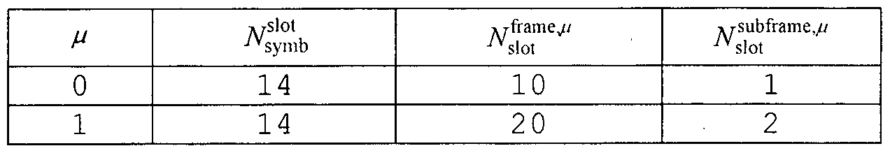 2019/143226 1»(:1/10公019/000913 [Table 2] 2 019/143226 1 »(: 1/10/01 019/000913
18 1 8

【표 3] [Table 3]

도 3은 NR 시스템에서의 프레임 구조의 일례를 나타낸다. 도 3은 단지 설명의 편의를위한것일뿐,본발명의 범위를제한하는것이 아니다. 3 shows an example of a frame structure in the NR system. FIG. 3 is merely for convenience of description and does not limit the scope of the present invention.
표 3의 경우, =2인 경우, 즉서브캐리어 간격 (subcarrier spacing, SCS)이 60kHz인 경우의 일례로서, 표 2를 참고하면 1 서브프레임 (또는 프레임 )은 4개의 슬롯들을 포함할 수 있으며 , 도 3에 도시된 1 서브프레임 = {1,2, 4} 슬롯들은 일례로서 , 1 서브프레임에 포함될 수 있는 스롯 (들)의 개수는표 2와같이 정의될수있다. In Table 3, one subframe ( or frame ) may include four slots, as shown in Table 2, as an example when = 2, i.e., a subcarrier spacing ( SCS) The number of slot ( s ) that can be included in one subframe can be defined as shown in Table 2 , as an example, with one subframe = {1,2,4 } slots shown in FIG.
또한, 미니-슬롯 (mini-slot )은 2, 4또는 7심볼 (symbol)들로구성될 수도있고, 더 많거나또는더 적은심볼들로구성될수도있다. Further, the mini-slot, and (mini -slot) will also be comprised of a 2, 4 or 7 symbol (symbol), there doelsudo composed of more or less symbols.
NR 시스템에서의 물리 자원 (physical resource)과 관련하여 , 안테나 포트 (antenna port), 자원 그리드 (resource grid) , 자원 요소 (resource element ) , 자원블록 (resource block) , 캐리어 파트 (carrier part ) 등이 고려될수있다. In relation to the physical resource (physical resource) in the NR system, such as antenna ports (antenna port), the resource grid (resource grid), the resource elements (resource element), resource blocks (resource block), the carrier parts (carrier part) Can be considered.
이하, NR시스템에서 고려될 수 있는상기 물리 자원들에 대해 구체적으로 살펴본다. Hereinafter, the physical resources that can be considered in the NR system will be described in detail.
먼저, 안테나 포트와 관련하여, 안테나 포트는 안테나 포트 상의 심볼이 운반되는 채널이 동일한 안테나 포트 상의 다른 심볼이 운반되는 채널로부터
추론될 수 있도록 정의된다.하나의 안테나포트상의 심볼이 운반되는 채널의 광범위 특성 ( large-scale property)이 다른 안테나 포트 상의 심볼이 운반되는 채널로부터 유추될 수 있는 경우, 2 개의 안테나 포트는 QC/QCL (quasi co-located혹은 quasi co-location) 관계에 있다고할수 있다. 여기에서 , 상기 광범위 특성은 지연 확산 (Delay spread) , 도플러 확산 (Doppler spread), 주파수 쉬프트 ( Frequency shift), 평균 수신 파워 (Average received power) , 수신 타이밍 ( Received Timing) 중하나 이상을포함한다. First, with respect to an antenna port, an antenna port is a channel from which the symbol carrying the symbol on the antenna port is carried, to the other symbol on the same antenna port Is defined so that it can be deduced if one of the symbols in a wide range of characteristics of the channel that is carried (large -scale property) on the antenna ports can be deduced from the channel that carries the symbols on the different antenna ports, the two antenna ports QC / QCL (quasi co-located or quasi co-location ) relationship. Here, the wide range of properties, including the delay spread (Delay spread), Doppler spread (Doppler spread), frequency shift (Frequency shift), the average received power (Average received power), the reception timing (Received Timing) Heavy or more.
도 4는 본 명세서에서 제안하는 방법이 적용될 수 있는 무선 통신 시스템에서 지원하는자원그리드 (resource grid)의 일례를나타낸다. 4 shows an example of a resource grid supported in a wireless communication system to which the method proposed in the present invention can be applied.
도 4를 참고하면, 자원 그리드가 주파수 영역 상으로
 서브캐리어들로구성되고, 하나의 서브프레임이 14.2 OFDM심볼들로구성되는 것을예시적으로기술하나,이에 한정되는것은아니다. 4, if the resource grid is in the frequency domain One subframe is composed of subcarriers . 2 OFDM symbols, but is not limited thereto.
NR 시스템에서 , 전송되는 신호 (transmitted signal)는
 서브캐리어들로 구성되는 하나 또는 그 이상의 자원 그리드들 및
 In the NR system, the transmitted signal is One or more resource grids comprised of subcarriers and /
OFDM심볼들에 의해 설명된다 . 여기에서 , ¾<세 ax 이다 . 상기 iV™B axA는최대 전송 대역폭을 나타내고 ,이는,뉴머롤로지들뿐만 아니라 상향링크와 하향링크 간에도달라질수있다. OFDM symbols. Here, ¾ <three ax . The iV B AxA represents the maximum transmission bandwidth, which may vary not only between the uplink and downlink as well as the neighbors .
이 경우,도 5와같이,뉴머롤로지 M및 안테나포트 p별로하나의 자원 그리드가설정될수있다. In this case, as shown in FIG. 5 , one resource grid may be set for each of the radio network M and the antenna port p .
도 5는 본 명세서에서 제안하는 방법이 적용될 수 있는 안테나 포트 및
뉴머롤로지 별자원그리드의 예들을나타낸다 FIG. 5 illustrates an antenna port to which the method proposed herein may be applied; and FIG. Examples of resource grids per annum
뉴머롤로지 나 및 안테나 포트 p에 대한 자원 그리드의 각 요소는 자원 요소 (resource element)로 지칭되며 , 인덱스 쌍 {kj)에 의해 고유적으로
 Each element of the resource grid for the neurorrosion and antenna port p is referred to as a resource element and is uniquely identified by the index pair {
/=0,...,2 \¾1-1는 서브프레임 내에서 심볼의 위치를 지칭한다.슬롯에서 자원 요소를 지칭할 때에는, 인덱스 쌍 江,/)이 이용된다.여기에서, /=0...,^ -l 이다 / = 0, ..., 2 \ ¾1- 1 refers to the position of the symbol within the subframe. When referring to a resource element out of the slot, the index pair江, /) are used. Here, / = 0 ..., ^ -l
뉴머롤로지 // 및 안테나 포트 에 대한 자원 요소 (kj)는 복소 값 ( complex value )
 해당한다. 혼동 ( confusion)될위험이 없는경우 혹은특정 안테나포트또는뉴머롤로지가특정되지 않은경우에는 , 인덱스들 p 및 //는 드롭 (drop)될 수 있으며 , 그 결과복소 값은 a^j 1또는 ,이 될 수 있다. Enumeration metrology // and resource elements (kj) of the antenna port is a complex value (complex va lue) . If there is no risk of confusion (confusion), or when a particular antenna port or enumeration roll land that is not specific, and the index p '' is can be drop (drop), the result is a complex value j ^ or 1, the .
또한, 물리 자원블록 (physical resource block)은주파수 영역 상의 Af3 =12연속적인서브캐리어들로정의된다. In addition, the physical resource block (physical resource block) is defined as Af 3 = 12 consecutive subcarriers in a frequency domain.
Point A는 자원 블록 그리드의 공통 참조 지점 ( common reference point)으로서 역할을하며 다음과같이 획득될수있다. P oint A will act as a common reference point of the resource block grid (common re ference point) and can be obtained as follows.
- PCell다운링크에 대한 offsetToPointA는초기 셀선택을위해 [ 에 의해 사용된 SS/PBCH 블록과 겹치는 가장 낮은 자원 블록의 가장 낮은 서브 캐리어와 point A 간의 주파수 오프셋을 나타내며, FR1에 대해 15kHz 서브캐리어 간격 및 FR2에 대해 60kHz 서브캐리어 간격을가정한리소스블록 단위 (unit )들로표현되고;
2019/143226 1»(:1/10公019/000913 - offset ToPointA for PCell downlink denotes a frequency offset between the SS / PBCH block overlaps with the lowest resource block lowest sub-carrier and the point A of the use by the [for initial cell selection, 15k Hz for FR1 subcarriers It is represented by a resource block (unit) assuming a 60 kHz subcarrier interval for interval and FR2; 2 019/143226 1 »(: 1/10/01 019/000913
21 21
absoluteFrequencyPointA는 ARFCN (absolute radio-frequency channel number)에서와같이표현된 point A의 주파수-위치를나타낸다. 공통자원블록 ( common resource block)들은서브캐리어 간격 설정 나 에 대한주파수영역에서 0부터 위쪽으로넘버링 ( numbering )된다. 서브캐리어 간격 설정 에 대한 공통 자원 블록 0의 subcarrier ◦의 중심은 'point A'와일치한다. 주파수영역에서 공통자원블록번호 ( number ) RB와 서브캐리어 간격 설정 에 대한 자원 요소 ( k, l)은 아래 수학식 1과 같이주어질수있다. absoluteFrequencyPointA represents the frequency-position of point A, expressed as in an absolute radio-frequency channel number (ARFCN ) . Common resource blocks (resource block common) are numbered (numbering) upwards from zero in the frequency domain for a set or sub-carrier interval. The center of the subcarrier ◦ of the common resource block 0 for the subcarrier interval setting coincides with 'point A'. The resource block number (number R B ) and the resource element (k , l ) for the subcarrier interval setting in the frequency domain can be given by Equation 1 below.
【수학식 11
 여기에서, k 는 k - 0 이 point A를 중심으로 하는 subcarrier에 해당하도록 point A에 상대적으로정의될수있다. 물리 자원블록들은대역폭 사 size 1 Equation 11 Here, k is a k - can be defined relative to the point A corresponding to a subcarrier centered at point A is zero. Physical resource blocks have a bandwidth of size 1
파트 ( bandwidth part, BWP) 내에서 0부터 BWiV 까지 번호가매겨지고, > 는 BWP의 번호이다. BWP i에서 물리 자원 블록 "PRB와공통 자원 블록 «CRB 간의 관계는아래수학식 2에 의해주어질수있다. In the part (bandwidth part, B WP) , numbers from 0 to BWiV are numbered, and> is the number of the BWP . In BWP i relationships between the physical resource blocks "and the common resource block PRB« CRB may be given by equation (2) below.
【수학식 2] &Quot; (2) "
^CRB = WPRB + ^ BWP, i ^ CRB = W PRB + ^ BWP, i
x厂 start x 厂 start
여기에서, ^WP,;는 BWP가공통자원 블록 0에상대적으로시작하는공통 자원블록일 수 있다.
() 2019/143226 1»(:1/10公019/000913 Here, ^ WP,; May be a common resource block that starts relative to BWP processing resource block 0. () 2019/143226 1 » (: 1/10 public 019/000913
22 22
대역폭파트 (Bandwidth part, BWP) Bandwidth part (BWP)
NR 시스템은 하나의 component carrier (CC) 당 죄대 400 MHz까지 지원될 수 있다. 이러한 wideband CC 에서 동작하는 단말이 항상 CC 전체에 대한 RF 를 켜둔 채로 동작한다면 단말 배터리 소모가 커질 수 있다 혹은 하나의 wideband CC 내에 동작하는 여러 : use case 들 (e.g., eMBB, URLLC, Mmtc, V2X 등)을 고려할 때 해당 CC 내에 주파수 대역 별로 서로 다른 numerology (e.g., sub-carrier spac丄 ng)7}
 수 있다. 혹은 ¾¾ 별로 최대 bandwidth 에 대한 capability 가 다를 수 있다. 이를 고려하여 기지국은 wideband CC 의 전체 bandwidth 가 아닌 일부 bandwidth 에서만 동작하도록 단말에게 지시할 수 있으며, 해당 일부 bandwidth를 편의상 bandwidth part (BWP)로 정의한다. BWP 는 주파수 죽 상에서 연속한 resource block (RB) 들로 구성될 수 있으며, 하나의 numerology (e.g., sub-carrier spacing, CP length, slot/mini-slot duration) 에 대응될수있다. NR systems can be supported up to 400 MHz per component carrier (CC). This, if a terminal operating in a wideband CC is operated while always on an incandescent RF for the full CC number that can increase the terminal battery consumption or operation within a wideband CC: The use case (eg, eMBB, URLLC , Mmtc, V2X , etc. (Eg, sub-carrier spacing 7) for each frequency band, . Alternatively, the capability for the maximum bandwidth may vary from one version to another. Considering this, the base station can instruct the terminal to operate only on some bandwidth, not the entire bandwidth of the wideband CC, and define some bandwidth as a bandwidth part (BWP) for convenience. BWP can be composed of consecutive resource blocks (RBs) on the frequency bands and can correspond to one numerology (eg, sub-carrier spacing, CP length, slot / mini-slot duration).
한편, 기지국은 단말에게 configure 된 하나의 CC 내에서도 다수의 BWP 를 설정할 수 있다. 일 예로, PDCCH monitoring slot 에서는 상대적으로 작은 주파수 영역을 차지하는 BWP 를 설정하고, PDCCH 에서 지시하는 PDSCH 는 그보다 큰 BWP 상에 schedule 될 수 있다. 혹은, 특정 BWP 에 UE 들이 몰리는 경우 load balancing 을 위해 일부 UE 들을 다른 BWP 로 설정할 수 있다. 혹은, 이웃 셀 간의 frequency domain inter-cell interference cancellation 등을 고려하여 전체 bandwidth 중 가운데 일부 spectrum 을
2019/143226 1»(:1/10公019/000913 Meanwhile, the base station can set a plurality of BWPs in one CC configured for the terminal. For example, in a PDCCH monitoring slot, a BWP occupying a relatively small frequency range is set, and a PDSCH indicated in a PDCCH can be scheduled on a BWP larger than the PDSCH. Alternatively, some UEs may be set to different BWPs for load balancing when UEs are routed to a particular BWP. In addition, considering the frequency domain inter-cell interference cancellation between neighboring cells, 2019/143226 1 » (: 1/10/01 019/000913
23 23
배제하고 양쪽 묘 모 들을 동일 내에서도 설정할 수 있다 즉 기지국은 wideband CC 와 association 된 단말에게 적어도 하나의 DL/UL BWP 를 configure 해 줄 수 있으며, 특정 시점에 configured DL/UL BWP ( s ) 중 적어도 하나의 DL/UL BWP 를 (LI signaling or MAC CE or RRC signalling 등에 의해) activation 시킬 수 있고 다른 configured DL/UL BWP 로 switching 이 (LI signaling or MAC CE or RRC signalling 등에 의해) 지시될 수 있거나 timer 기반으로 timer 값이 expire 되면 정해진 DL/UL BWP 로 switching 될 수 도 있다. 이 때, activation 된 DL/UL BWP 를 active DL/UL BWP 로 정의한다. 그런데 단말이 initial access 과정에 있거나, 혹은 RRC connection 아 set up 되가 전 등의 상황에서는 DL/UL BWP 에 대한 configuration 을 수신하지 못할 수 있는데, 이러한 상황에서 단말이 가정하는 DL/UL BWP 는 initial active DL/UL BWP 라고 정의한다. Self-contained구조 The base station can configure at least one DL / UL BWP for the associated terminal with the wideband CC, and at least one of the configured DL / UL BWP (s) The DL / UL BWP can be activated (eg by LI signaling or MAC CE or RRC signaling) and switching to other configured DL / UL BWPs can be indicated (eg by LI signaling or MAC CE or RRC signaling) When the value is expired, it may be switched to the specified DL / UL BWP. At this time, the activated DL / UL BWP is defined as active DL / UL BWP. However, DL / UL BWP may not receive configuration for DL / UL BWP in the initial access procedure or RRC connection setup. In this situation, the DL / UL BWP assumed by the terminal is initial active DL / UL BWP. Self-contained structure
NR 시스템에서 고려되는 TDD (Time Division Duplexing) 구조는 상향링크 (Uplink, UL)와 하향링크 ( Downlink, DL)를 하나의 슬롯 (slot) (또는 서브프레임 (subframe) )에서 모두 처리하는 구조이다. 이는, TDD 시스템에서 데이터 전송의 지연 (latency)을 최소화하기 위한 것이며 , 상기 구조는 self-contained 구조 또는 self-contained 슬롯으로 지칭될 수 있다.
() 2019/143226 1»(:1/10公019/000913 A time division duplexing (TDD) structure considered in the NR system is a structure that processes both an uplink (UL) and a downlink (DL) in one slot (or a subframe). This is to minimize the latency of data transmission in a TDD system, and the structure may be referred to as a self-contained structure or a self-contained slot. () 2019/143226 1 » (: 1/10 public 019/000913
24 24
도 6은 본 명세서에서 제안하는 방법이 적용될 수 있는 self-contained 구조의 일례를 나타낸다 도 6은 단지 설명의 편의를 위한 것일 뿐,본 발명의 범위를 제한하는것이 아니다 、 6 shows an example of a self-contained structure to which the method proposed herein can be applied. Fig. 6 is merely for convenience of explanation and does not limit the scope of the invention,
도 6을 참고하면, legacy LTE의 경우와 같이, 하나의 전송 단위 (예: 슬롯 서브프레임 )이 14개의 OFDM (Orthogonal Frequency Division Multiplexing) 심볼 ( symbol )들로구성되는 경우가가정된다. Referring to FIG. 6, it is assumed that one transmission unit (eg, slot subframe) is composed of 14 orthogonal frequency division multiplexing (OFDM) symbols as in legacy LTE.
도 6에서, 영역 602는 하향링크 제어 명역 ( downlink control region)을 의미하고, 영역 604는 상향링크 제어 영역 (uplink control region)을 의미한다. 또한, 영역 602 및 영역 604 이외의 영역 (즉, 별도의 표시가 없는 영역 )은 하향링크 데이터 (downlink data ) 또는 상향링크 데이터 (uplink data )의 전송을위해 이용될 수 있다. In FIG. 6, an area 602 denotes a downlink control region, and an area 604 denotes an uplink control region. Further, an area other than the area 602 and the area 604 (i.e., an area without a separate mark) can be used for the transmission of downlink data or uplink data.
죽, 상향링크 제어 정보 (uplink control information) 및 하향링크 제어 정보 (downlink control information)
 하나의 self-contained 슬롯에서 전송될 수 있다. 반면, 데이터 (data)의 경우, 상향링크 데이터 또는 하향링크 데이터가하나의 self-contained슬롯에서 전송될 수있다. Uplink control information, and downlink control information, Can be transmitted in one self-contained slot. On the other hand, in the case of data , uplink data or downlink data can be transmitted in one self-contained slot.
도 6에 나타난 구조를 이용하는 경우, 하나의 self-contained 슬롯 내에서, 하향링크 전송과 상향링크 전송이 순차적으로 진행되며, 하향링크 데이터의 전송 및 상향링크 ACK/NACK의 수신이 수행될수 있다. In the case of using the structure shown in FIG. 6, downlink transmission and uplink transmission are sequentially performed in one self-contained slot, and downlink data transmission and uplink ACK / NACK reception can be performed.
결과적으로, 데이터 전송의 에러가 발생하는 경우, 데이터의 재전송까지 소요되는 시간이 감소할 수 있다. 이를 통해, 데이터 전달과 관련된 지연이 최소화될수있다.
2019/143226 1»(:1/10公019/000913 As a result, when an error occurs in data transmission, the time required until data retransmission can be reduced. This allows the delay associated with data transfer to be minimized. 2019/143226 1 » (: 1/10/01 019/000913
25 25
도 6과 같은 self-contained 슬롯 구조에서, 기지국 (eNodeB, eNB, gNB) 및/또는 단말 (terminal, UE (User Equipment) )이 전송 모드 (transmission mode)에서 수신 모드 (reception mode)로 전환하는 과정 또는 수신 모드에서 전송 모드로 전환하는 과정을 위한 시간 갭 (time gap)이 요구된다. 상기 시간 캡과관련하여, 상기 self-contained슬롯에서 하향링크 전송 이후에 상향링크 전송이 수행되는 경우, 일부 OFDM 심볼 (들)이 보호구간 (Guard Period, GP)으로설정될수있다.. 무선신호송수신방법 In the self-contained slot structure as shown in Fig. 6, the transition from the base station (eNodeB, eNB, gNB) and / or the terminal (terminal, UE (User Equipment) ) the transmission mode (transmission mode) to the reception mode (reception mode) or the time gap (time gap) is required for shifting to a transmission mode in the receive mode. In connection with the time cap, when uplink transmission is performed after downlink transmission in the self-contained slot, some OFDM symbol (s) may be set as a guard period (GP ) . [ Way
도 7은신호송수신방법의 일례를나타낸도아다. 7 is a diagram showing an example of a signal transmitting / receiving method.
도 7을 참고하면, 단말은 전원이 켜지거나 새로이 셀에 진입한 경우 기지국과 동기를 맞추는 등의 초기 셀 탐색 (Initial cell search) 작업을 수행한다 (S701). 이를 위해, 단말은 기지국으로부터 주 동기 채널 (Primary Synchronization Channel ; P-SCH) 및 부 동기 채널 (Secondary Synchronization Channel ; S-SCH)을수신하여 기지국과동기를맞주고, 셀 ID 등의 정보를 획득할 수 있다.그 후, 단말은 기지국으로부터 물리 방송 채널 (Physical Broadcast Channel)를수신하여 셀 내 방송 정보를 획득할 수 있다. 한편, 단말은초기 셀 탐색 단계에서 하향링크 참조신호 (Downlink Reference Signal ; DL RS)를 수신하여 하향링크 채널 상태를 확인할 수 있다. _ Referring to Figure 7, the terminal performs the initial cell searching (Initial cell search) operation, such as the power is turned on or when a new entry to the cell matching the base station and the synchronization (S701). To this end, the UE receives a Primary Synchronization Channel (P-SCH ) and a Secondary Synchronization Channel (S-SCH) from a base station and synchronizes with the base station and acquires information such as a cell ID may Thereafter, the terminal may receive a physical broadcast channel (physical broadcast channel) from the base station to acquire the broadcast information within the cell. Meanwhile, the UE can receive the downlink reference signal (DL RS ) in the initial cell search step to check the downlink channel state. _
초기 셀 탐색을 마친 단말은 물리 하향링크 제어 채널 (Physical
Downlink Control Channel; PDCCH) 및 상기 PDCCH에 실린 정보에 따라 물리 하향링크공유채널 (Physical Downlink Control Channel; PDSCH)을 수신함으로써좀더구체적인시스템정보를획득할수있다 (S702) . After completion of the initial cell search, the UE transmits a Physical Downlink Control Channel Downlink Control Channel; PDCCH) and a physical downlink control channel (PDSCH ) according to the information on the PDCCH (S702).
한편,기지국에 최초로 접속하거나 신호 송신을 위한 무선 자원이 없는 경우 단말은 기지국에 대해 임의 접속·과정 (Random Access Procedure;On the other hand, when there is no radio resource for the first time access to the base station or for signal transmission, the terminal transmits a random access procedure (Random Access Procedure) to the base station.
RACH)을수행할수있다 (단계 S703내지 단계 S706) . 이를위해, 단말은물리 임의 접속 채널 (Physical Random Access Channel ; PRACH)을 통해 특정 시퀀스를프리앰블로송신하고 (S703 및 S70引 , PDCCH 및 대응하는 모 대를 통해 프리앰블에 대한 응답 메시지를 수신할 수 있다 (S704 및: S706). 경쟁 기반 RACH의 경우, 주가적으로 중돌 해결 절차 (Contention Resolution Procedure)를수행할수있다. RACH) ( steps S703 to S706 ). To this end, the UE transmits a specific sequence through a Physical Random Access Channel (PRACH ) as a preamble (S703 and S70, and receives a response message for the preamble through the PDCCH and the corresponding UE (S704 and S706) . In case of the contention-based RACH, a contention resolution procedure can be performed in a cost-effective manner.
상술한바와 같은 절차를 수행한단말은 이후 일반적인 상/하향링크 신호 송신 절차로서 PDCCH/PDSCH 수신 (S707) '및 물리 상향링크 공유 채널 (Physical Uplink Shared Channel ; PUSCH) /물리 상향링크 제어 채널 (Physical Uplink Control Channel ; PUCCH) 송신 (S708)을 수행할 수 있다. 특히 단말은 PDCCH를 통하여 하향링크 제어 정보 (DownlinkThe terminal performs the same procedure as described above hanba since as a general uplink / downlink signal transmission procedure PDCCH / PDSCH reception (S707) ', and a physical uplink shared channel (Physical Uplink Shared Channel; PUSCH) / Physical uplink control channel (Physical Uplink Control Channel (PUCCH ) transmission (S708) . In particular, the UE transmits downlink control information (Downlink
Control Information; DCI)를 수신한다. 여기서 DCI는 단말에 대한 자원 할당 정보와 같은 제어 정보를 포함하며,그 사용 목적에 따라 포맷이 서로 다르다. Control Information; DCI). Here, the DCI includes control information such as resource allocation information for the UE, and formats are different according to the purpose of use.
한편, 단말이 상향링크를 통해 기지국에 송신하는 또는 단말이 기지국으로부터 수신하는 제어 정보는 하향링크/상향링크 ACK/NACK 신호,
CQI ( Channel Quality Indicator) , PMI ( Precoding Matrix 인덱스) , RI ( Rank Indicator) 등을 포함한다. 3GPP LTE 시스템의 경우, 단말은 상술한 CQI /PMI /RI등의 제어 정보를 PUSCH및/또는 PUCCH를통해 송신할수 있다. On the other hand, the control information transmitted by the terminal to the base station through the uplink or received by the terminal from the base station includes a downlink / uplink ACK / NACK signal, A channel quality indicator (CQI), a precoding matrix index (PMI), a rank indicator (RI), and the like. In the case of the 3GPP LTE system, the UE can transmit control information such as the CQI / PMI / RI described above via the PUSCH and / or the PUCCH.
표 4는 NR시스템에서의 DCI포맷 ( format )의 일례를나타낸다. Table 4 shows an example of the DCI format in the NR system.
【표 4 ] [Table 4]

표 4를참고하면, DCI format 0_0은하나의 셀에서 PUSCH의 스케줄링에 사용된다. Referring to Table 4, DCI format 0_0 is used for scheduling PUSCH in a cell of a galaxy.
DCI format 0_0에 포함된 정보는 C-RNTI 또는 CS-RNTI 또는 MCS-C- RNTI에 의해 CRC 스크램블링되어 전송된다. 그리고, DCI format 0_1은 하나의 셀에서 PUSCH를 예약하는 데 사용된다. DCI format 0_1에 포함된 정보는 C-RNTI 또는 CS-RNTI 또는 SP-CSI-RNTI 또는 MCS-C-RNTI에 의해 CRC스크램블링되어 전송된다. DCI format 1_0은하나의 DL셀에서 PDSCH의 스케줄링을 위해 사용된다. DCI format 1_0에 포함된 정보는 C-RNTI 또는 CS-RNTI 또는 MCS-C-RNTI에 의해 CRC 스크램블링되어 전송된다. DCI format 1 1은 하나의 셀에서 PDSCH의 스케줄링을 위해 사용된다. DCI
format 1_1에 포함되는 정보는 C-RNTI 또는 CS-RNTI 또는 MCS-C-RNTI에 의해 CRC 스크램블링되어 전송된다. DCI 포맷 2_1은 단말이 전송을 의도하지 않은것으로가정할수있는 PRB (들) 및 OFDM심볼 (들)을알리는데사용된다. The information included in DCI format 0_0 is CRC scrambled and transmitted by C-RNTI or CS-RNTI or MCS-C-RNTI. And DCI format 0_1 is used to reserve PUSCH in one cell. The information included in DCI format 0_1 is CRC scrambled and transmitted by C-RNTI or CS-RNTI or SP-CSI-RNTI or MCS-C-RNTI. DCI format 1_0 is used for the scheduling of the PDSCH in the DL cell of the Galaxy. The information included in DCI format 1_0 is CRC scrambled and transmitted by C-RNTI or CS-RNTI or MCS-C-RNTI. The DCI format 11 is used for scheduling the PDSCH in one cell. DCI The information included in format 1_1 is CRC scrambled and transmitted by C-RNTI or CS-RNTI or MCS-C-RNTI. The DCI format 2_1 is used to advertise the PRB ( s ) and OFDM symbol ( s) that the terminal may assume is not intended to transmit.
DCI 포맷 2_1에 포함되는 다음 정보는 INT-RNTI에 의해 CRC 스크램블링되어 전송된다. 초기 접속 (Initial Access , IA) 절차 The next information included in the DCI format 2_1 is CRC scrambled and transmitted by the INT-RNTI. Initial Access (IA ) Procedure
( 1 ) SSB ( Synchroni zat ion Signal Block) 전송및관련동작 (1) SSB (Synchronization Signal Block) transmission and related operation
도 8은 SSB구조를 예시한다. 단말은 SSB에 기반하여 셀탐색 ( search ) , 시스템 정보획득, 초기 접속을위한 빔 정렬, DL측정 등을수행할수 있다. SSB는 SS/PBCH ( Synchroni zation Signal /Physical Broadcast channel ) 블록과혼용된다. Figure 8 illustrates the SSB structure. The UE can perform a cell search based on the SSB (search), the information acquisition system, the beam alignment for initial access, DL measurements. SSB is mixed with SS / PBCH (Synchronization Signal / Physical Broadcast channel ) block.
도 8을 참조하면, SSB는 PSS , SSS와 PBCH로 구성된다. SSB는 4개의 연속된 OFDM 심볼에 구성되며, OFDM 심볼 별로 PSS , PBCH, SSS/PBCH 및 PBCH가전송된다. PSS와 SSS는각각 1개의 OFDM심볼과 127개의 부반송파로 구성되고, PBCH는 3개의 OFDM 심볼과 576개의 부반송파로 구성된다. PBCH에는 돌라 코딩 및 QPSK (Quadrature Phase Shift Keying)이 적용된다. PBCH는 OFDM 심볼마다 데이터 RE와 DMRS ( Demodulat ion Reference Signal ) RE로 구성된다. RB 별로 3개의 DMRS RE가 존재하며, DMRS RE사이에는 3개의 데이터 RE가존재한다.
( 2 ) 셀탐색 (cell search ) Referring to FIG. 8, SSB is composed of PSS, SSS and PBCH. SSB consists of four consecutive OFDM symbols, and PSS, PBCH, SSS / PBCH and PBCH are transmitted per OFDM symbol. PSS and SSS are composed of one OFDM symbol and 127 subcarriers, respectively, and the PBCH is composed of 3 OFDM symbols and 576 subcarriers. Dolby coding and Quadrature Phase Shift Keying (QPSK) are applied to the PBCH. The PBCH consists of data RE and demodulation reference signal ( DMRS ) RE for each OFDM symbol. There are three DMRS REs per RB, and there are three data REs between the DMRS REs. (2) cell search (cell search)
셀 탐색은 단말이 셀의 시간/주파수 동기를 획득하고, 상기 셀의 셀 ID ( Identifier ) (예, Physical layer Cell ID, PCID)를검줄하는과정을 의미한다. PSS는셀 ID그룹내에서 셀 ID를 검출하는데 사용되고, SSS는 셀 ID 그룹을 검출하는데 사용된다. PBCH는 SSB (시간) 인텍스 검출 및 하프- 프레임 검출에사용된다. Cell search means a process that the mobile station acquires the time / frequency synchronization of a cell, the cell geomjul ID (Identifier) (for example, Physical layer Cell ID, PCID) of the cell. The PSS is used to detect the cell ID in the cell ID group, and the SSS is used to detect the cell ID group. The PBCH is used for SSB ( time) index detection and half-frame detection.
단말의 셀탐색과정은하기 표 과같이 정리될수있다. The cell search procedure of the UE can be summarized as shown in the following table.
【표 5】 [Table 5]

336개의 셀 내 그룹이 존재하고, 셀 대 그룹 별로 3개의 셀 가
2019/143226 1»(:1/10公019/000913 There are 336 intra-cell groups, and three cells per cell-group 2 019/143226 1 »(: 1/10/01 019/000913
30 30
존재한다.총 1008개의 셀 1[)가존재하며, 셀 10는수학식 3에 의해 정의될수 있다. : There are a total of 1008 cells 1 [ ], and cell 10 can be defined by Equation (3). :
【수학식 3】 [Equation 3 ]
<'=3^+^ 여기서, )£{0山…, 335}이고, <)4>,!,2}. <'= 3 ^ + ^ where , ) £ {0 Mountain ... , 335}, and <) 4>,!, 2} .
여기서/ 1 61111:는 셀 113(예, £ 10)를 나타낸다. 1)113는 셀 10 그룹을 나타내며 3요3를 통해 제공/획득된다. ^1(2)10)는 셀 10 그룹 내의 셀 를나타내며 모크드를통해제공/획득된다. Where / 61 111 1: shows a cell 113 (for example, £ 1 0). 1) 113 is obtained providing / via overview 3 shows a cell 10 group. ^ 1 (2) 10) indicates the cell in the cell group 10 is provided / acquired via the de Mock.
모3£시퀀스(犯으이미는수학식 4를만족하도록정의될수있다. Mo 3 £ sequence (犯coming already can be defined so as to satisfy the equation (4).
【수학식 4]
 (4)
(4)
여기서 , 4' + 7) =(斗 + 4) + ))■( 2이고 , ( 4 '+ 7 ) = (D + 4 ) +)) ( 2 ,
ᅣ(6) 5) 4) ,:(3) 2) ,:(1) :(0)]=[1 1 1 0 1 1 이이다. (6) 5) 4), (3) 2), (1): (0)] = [1 1 1 0 1 1.
333시퀀스(犯크이미는수학식 5를만족하도록정의될수있다. 333 sequence (Crime can be defined to satisfy Equation 5).
【수학식 5】 [Equation 5]
6?5$5  6? 5 $ 5
,지 =八 ) ) 1!10간 112 , J = 8 ) ) 1! 10 Intersection 112
0<«<127
2019/143226 1»(:1/10公019/000913 0 <<<127 2019/143226 1 » (: 1/10/01 019/000913
31 31
½ (, + 7) = (入, o + 4) +x0 (/))mod 2 ½ (, + 7) = (in, o + 4) + x 0 ( / )) mod 2
여기서, 지(’.+7)= W’.+I)+자 (0)mod2 이고, Here , ( +. 7) = W ' . + I) + ( 0 ) mod2 ,
[x0(6) x0(5) ⑷ x0(3) x0(2) x0(l) \:0(o)]= [O 0 0 0 0 0 1] [x 0 (6) x 0 (5) ⑷ x 0 (3) x 0 (2) x 0 (l) \: 0 (o)] = [O 0 0 0 0 0 1]
U\ ( 6) Ai (5) (4) (3) i(2)치 (1) Ai(0)]=[0 0 0 0 0 0 이다. Ui ( 6 ) Ai ( 5 ) ( 4 ) ( 3 ) i ( 2 ) value (1) Ai (0)] = 0 0 0 0 0 0 .
도 9는 SSB전송을예시한다. SSB는 SSB 주기 (periodicity)에 맞줘 주기적으로 전송된다. 초가 셀 탐색 시에 단말이 가정하는 SSB 기본 주기는 20ms로 정의된다. 셀 접속 후, SSB주기는네트워크 (예, 기지국)에 의해 {5ms, 10ms, 20ms , 40ms, 80ms, 160ms} 중 하나로 설정될 수 있다. SSB 주기의 시작 부분에 SSB 버스트 (burst) 세트가 구성된다. SSB 버스트 세트는 5ms 시간 원도우 (즉, 하프-프레임)로구성되며 , SSB는 SS 버스트 세트 내에서 최대 L번 전송될 수 있다. SSB의 최대 전송 횟수 은 반송파의 주파수 대역에 따라 다음과 같이 주어질수있다.하나의슬롯은최대 2개의 SSB를포함한다. Figure 9 illustrates SSB transmission. S SB is periodically transmitted in accordance with the SSB periodicity . The SSB base period assumed by the UE during the second cell search is defined as 20 ms. After cell connection, the SSB period may be set to one of {5 ms, 10 ms, 20 ms, 40 ms, 80 ms, 160 ms} by the network ( eg, base station ) . The SSB burst (burst) set is configured at the start of the cycle SSB. The SSB burst set consists of a 5 ms time window ( i.e., half-frame ) , and the SSB can be transmitted up to a maximum of N times within the SS burst set. The maximum number of SSB transmissions can be given by the frequency band of the carrier as follows: One slot contains a maximum of two SSBs .
- For frequency range up to 3 GHz, L = 4 - For frequency ran ge up to 3 GHz, L = 4
- For frequency range from 3GHz to 6 GHz, L = 8 - For frequency range from 3 GHz to 6 GHz, L = 8
- For frequency range from 6 GHz to 52.6 GHz , L = 64 - For frequency range from 6 GHz to 52.6 GHz, L = 64
SS 버스트세트내에서 SSB후보의 시간위치는 SCS에 따라다음과 같이 정의될 수 있다. SSB후보의 시간위치는 SSB버스트 세트 (즉, 하프-프레임 ) 내에서 시간순서에 따라 0〜 L-1로인덱싱 된다 (SSB인덱스) . The time position of the SSB candidate within the SS burst set can be defined as follows according to the SCS . Are indexed by 0~ L -1 in time sequence within (index SSB) the time position of the SSB candidate SSB burst set (frames that is, a half).
- Case A - 15 kHz SCS : 후보 SSB의 시작심볼의 인덱스는 {2, 8} +
\¥02019/143226 1>(:1'/1 ?2019/000913 - Case A - 15 k Hz SCS: The starting symbol index of the candidate SSB is {2, 8 } + \ \ 02 019/143226 1> (: 1 '/ 1? 2 019/000913
32 32
14 으로주어진다. 반송파주파수가
 이하인 경우 11=0, 1이다. 반송파 주파수가 3(3 ~ 6( 인경우 11=0, 1, 2, 3이다. Lt; / RTI > The carrier frequency is Or less, 11 = 0 , 1. If the carrier frequency is 3 (3 to 6 ( 11 = 0 , 1, 2, 3).
- 0336 8 - 30 태 303 : 후보 33묘의 시작 심볼의 인덱스는 {4, 8, 16, 20} + 28*11으로주어진다. 반송파주파수가 3
 이하인 경우 0=0이다. 반송파주파수가 3 GY{7. -
 1이다. - 0 336 8 - 30 State 303: The index of the starting symbol of the 33- point candidate is given as {4 , 8, 16, 20 } + 28 * 11 . If the carrier frequency is 3 0 " If the carrier frequency is 3 GY {7 . - 1.
- 03360 - 30
 503 : 후보 33모의 시작심볼의 인덱스는 {2, 8 } + - 0336 0 - 30 5 03: The index of the candidate 33-bit start symbol is {2 , 8 } +
14 으로주어진다. 반송파주파수가 3( 이하인 경우 11=0, 1이다. 반송파 주파수가 3( 〜 6
 1, 2, 3이다. Lt; / RTI > When the carrier frequency is 3 (or less, 11 = 0, 1 ). If the carrier frequency is 3 (~ 6 1, 2, and 3, respectively.
- 0336 0 - 120 내 303 : 후보 33묘의 시작심볼의 인덱스는 {4, 8, 16, 20} + 28 으로주어진다. 반송파주파수가 6(3 보다큰경우 11=0, 1,- 0336 0 - 120 303: candidate 3 3 The index of the start symbol of the seed is given as {4 , 8, 16, 20 } + 28. If the carrier frequency is greater than 6 (311 = 0, 1,
2, 3, 5, 6, 7, 8, 10, 11, 12, 13, 15, 16, 17, 18이다. 2, 3, 5, 6, 7, 8, 10, 11, 12, 13, 15, 16, 17,
- 0836 또 - 240 태 303 : 후보 33묘의 시작심볼의 인덱스는 {8, 12, 16, 20, 32, 36, 40, 44} + 56*11으로 주어진다. 반송파 주파수가 6
 도 10은단말이 [凡시간동기에 관한정보를획득하는것을예시한다. - 0 836 In-240 state 303: The index of the candidate 33 seedlings start symbol is given by {8, 12, 16, 20, 32, 36, 40, 44} + 56 * 11. If the carrier frequency is 6 FIG. 10 illustrates that the tip acquires information about time synchronization.
단말은 338를 검출함으로써 [ 동기를 획득할 수 있다. 단말은 검출된 386 인덱스에 기반하여 336버스트세트의 구조를식별할수 있고, 이에 따라 심볼/슬롯/하프-프레임 경계를 검출할 수 있다. 검출된 요드묘가 속하는 프레임/하프-프레임의 번호는 번호는 SFN 정보와 하프-프레임 지시 정보를 이용하여식별될수있다.
구체적으로, 단말은 PBCH로부터 10 비트 SFN (System Frame Number) 정보를 획득할수있다 (s0~s9). 10비트 SFN정보중 6비트는 MIB (Master Information Block)로부터 얻어지고, 나머지 4비트는 PBCH TB (Transport Block)으로부터 얻어진다. The UE may acquire the [synchronization by detecting the 33 eight. The terminal on the basis of the detected index, and 38 6 can identify the structure of the third set of bursts 36, whereby the symbol / slot / half-it is possible to detect the frame boundary. The number of the frame / half-frame to which the detected iodine fragment belongs can be identified by using the SFN information and the half-frame indication information. Specifically, the UE can acquire 10-bit SFN (System Frame Number) information from the PBCH (s0 to s9) . Six bits of the 10-bit SFN information are obtained from the MIB (Master Information Block ) , and the remaining 4 bits are obtained from the PBCH TB (Transport Block ) .
다음으로, 단말은 1 비트하프-프레임 지시 정보를획득할수 있다 (C0). 반송파 주파수가 3GHz 이하인 경우, 하프-프레임 지시 정보는 PBCH DMRS를 이용하여 묵시적으로 (implicitly) 시그널링 될수있다. PBCH DMRS는 8개의 PBCH DMRS시퀀스들중하나를사용함으로써 3비트정보를지시한다. 따라서, L=4의 경우, 8개의 PBCH DMRS 시퀀스를 이용하여 지시될수 있는 3비트중 SSB인덱스를지시하고남는 1비트는하프-프레임 지시용도로사용될수있다 마지막으로, 단말은 DMRS 시퀀스와 PBCH 페이로드에 기반하여 SSB 인덱스를 획득할 수 있다. SSB 후보는 SSB 버스트 세트 (즉, 하프-프레임 ) 내에서 시간 순서에 따라 0 ~ L-1로 인덱싱 된다. L = 8 또는 64인 경우, SSB 인덱스의 LSB (Least Significant Bit) 3 비트는 8개의 서로 다른 PBCH DMRS시퀀스를이용하여 지시될수있다 (b0~b2). L = 64인 경우, SSB 인덱스의 MSB (Most Significant Bit) 3 비트는 PBCH를 통해 지시된다 (b3~b引 . L = 2인 경우, SSB 인덱스의 LSB 2 비트는 4개의 서로 다른 PBCH DMRS시퀀스를이용하여 지시될수있다 (b0, bl) . L = 4인경우, 8개의 PBCH DMRS시퀀스를이용하여 지시할수 있는 3비트중 SSB인덱스를 지시하고남는 1비트는하프-프레임지시 용도로사용될수있다山2 ) .
(3) 시스템정보획득 Next, the terminal can obtain 1-bit half-frame indication information ( C0) . If the carrier frequency is below 3 GHz , the half-frame indication information may be implicitly signaled using PBCH DMRS . PBCH DMRS indicates the 3-bit information by using one of the eight PB CH DMRS sequence. Therefore, in the case of L = 4, 1 bit indicating the S SB index among the 3 bits that can be indicated using 8 PBCH DMRS sequences can be used for half-frame indication. Finally, based on PB CH payload can obtain the SSB index. The S SB candidates are indexed from 0 to L-1 in chronological order within an SSB burst set ( i.e., half-frame ) . For L = 8 or 64, the least significant bit (LSB ) 3 bits of the SSB index can be indicated using eight different PBCH DMRS sequences (b0 to b2 ) . For L = 64, the MSB (Most Significant Bit ) 3 bits of the S SB index are indicated via PB CH (b3 to b , where L = 2, the L SB 2 bits of the S SB index are 4 different PB CH DMRS can be indicated by using a sequence (b0, bl) L = 4 Ann Wu, eight PB CH can instruct using the DMRS sequence one bit left and indicate the S SB index of three bits in the half-frames can be used by the instruction purposes山2). (3) Obtaining system information
도 11은시스템 정보 (SI) 획득과정을 예시한다. 단말은 SI 획득과정을 통해 AS-/NAS-정보를 획득할 수 있다. SI 획득 과정은 RRC_IDLE 상태, RRC_INACTIVE상태, 및 RRC_CONNECTED상태의 단말에게 적용될수있다. 11 illustrates the process of acquiring System Information (SI) . The terminal can acquire A S - / NAS - information through the SI acquisition process. SI acquisition procedure can be applied to terminals in RR C _IDLE state, RRC_INA CTIVE state, and RR C _ CONNECTED state.
SI는 MIB (Master Information Block)와 복수의 SIB ( System The SI includes a Master Information Block (MIB) and a plurality of SIBs
Information Block)으로 나눠진다. MIB 외의 SI는 RMSI (Remaining Minimum System Information)으로 지칭될 수 있다. 자세한 사항은 다음을 참조할수 있다. Information block). An SI other than the MIB may be referred to as Remaining Minimum System Information (RMSI). For more information, please see:
- 대는 SIB1 ( Systemlnf ormationBlockl ) 수신과 관련된 정보/파라미터를 포함하며 SSB의 모묘대를 통해 전송된다. 초기 셀 선택 시, 단말은 SSB를 갖는 하프-프레임이 20ms 주기로 반복된다고 가정한다. 단말은 MIB에 기반하여 TypeO-PDCCH 공통 탐색 공간 (common search space)을 위한 CORESET (Control Resource Set)이 존재하는지 확인할 수 있다 . TypeO-PDCCH 공통 탐색 공간은 PDCCH 탐색 공간의 일종이며, SI 메세지를 스케줄링 하는 PDCCH를전송하는데사용된다. TypeO-PDCCH공통탐색 공간이 존재하는 경우, 단말은 MIB 내의 정보 (예, pdcch-ConfigSIBl)에 기반하여 (i) CORESET을구성하는복수의 연속된 RB와하나이상의 연속된심볼과 (ii) PDCCH 기회 (즉, PDCCH 수신을 위한 시간 도메인 위치 )를 결정할 수 있다. TypeO-PDCCH 공통 탐색 공간이 존재하지 않는 경우, pdcch-Conf igSIBl은 SSB/SIB1이존재하는주파수위치와 SSB/SIB1이 존재하지 않는주파수범위에 관한정보를제공한다.
- S IB1은 나머지 SIB들(이하, SIBx, x는 2 이상의 정수)의 가용성 및 스케줄링(예, 전송주기, SI-원도우사이즈)과관련된 정보를포함한다. 예를 들어, SIB1은 SIBx가주기적으로방송되는지 on-demand방식에 의해 단말의 요청에 의해 제공되는지 여부를 알려줄 수 있다. SIBx가 on-demand 방식에 의해 제공되는 경우, SIB1은 단말이 SI 요청을 수행하는데 필요한 정보를 포함할 수 있다. SIB1은 PDSCH를 통해 전송되며, SIB1을 스케줄링 하는 PDCCH는 Type O-PDCCH 공통 탐색 공간을 통해 전송되며, S IB1은 상기 PDCCH에 의해지시되는 PDSCH를통해 전송된다: The SIB1 contains the information / parameters related to the reception of the SIB1 (SystemlnformationBlockl ) and is transmitted via the demodulation of the SSB . When the initial cell is selected, the terminal assumes that the half-frame having the SSB is repeated at a cycle of 20 ms. The UE can verify based on the MIB TypeO-PD CCH common search space (common search space) is (Resource Control Set) CORESET for existence. The TypeO-PD CCH common search space is a kind of PD CCH search space and is used to transmit PD CCH to schedule SI messages. When a PDC-TypeO CH common search space is present, the terminal information in the MIB on the basis of (for example, pdcch- ConfigSIBl) (i) C ORESET plural and (ii) a contiguous RB Waha or more consecutive symbols that make up the PD CCH opportunity ( i. E. , The time domain location for PD CCH reception ) . If the TypeO-PD CCH common search space does not exist, the pdcch-Conf ig SIBl provides information on the frequency location where SSB / SIB1 exists and the frequency range where SSB / SIB1 does not exist. - S IB1 contains information related to the availability and scheduling (e.g., transmission period, SI- window size) of the remaining SIBs ( SIBx, x is an integer greater than or equal to 2). For example, SIB1 can tell whether the SIBx that periodically broadcast service at the request of the terminal by using the on- demand method. If SIBx is provided by an on- demand method, SIB1 may contain information necessary for the terminal to perform a SI request. SIB1 is transmitted on the PDSCH , the PDCCH for scheduling SIB1 is transmitted on the Type O-PDCCH common search space, and SIB1 is transmitted on the PDSCH indicated by the PDCCH :
- SIBx는 SI 메세지에 포함되며 PDSCH를 통해 전송된다. 각각의 SI 메세지는주기적으로발생하는시간윈도우(즉, SI-윈도우) 내에서 전송된다. 랜덤 액세스(Random Access , RA) 절차 - SIBx is included in the SI message and transmitted on the PDSCH . Each SI message is transmitted within a time window that occurs periodically (i.e., SI - window). Random Access ( RA ) procedure
단말의 랜덤 액세스절차는표 6및도 12와같이요약할수있다. The random access procedure of the terminal can be summarized as shown in Table 6 and FIG.
도 12는랜덤 액세스절차의 일례를예시한다. 12 illustrates an example of a random access procedure.
【표 6】 [Table 6]

36 3 6

전송할수 있다. Can be transmitted.
서로 다른 두 길이를 가지는 랜덤 액세스 프리앰블 시원스가 지원된다.긴 시퀀스 길이 839는 1.25 및 5 kHz의 부반송파 간 간격 (subcarrier spacing)으로써 적용되며, 짧은 시퀀스 길이 139는 15, 30, 60 및 120 kHz의 부반송파 간 간격으로써 적용된다. 긴 시퀀스는 제한되지 않은 세트와 타입 A 및 타입 B의 제한된 세트를 모두 지원하는 반면, 짧은 시퀀스는 제한되지 않은세트만을지원한다. A long sequence length 839 is applied with a subcarrier spacing of 1.25 and 5 kHz , and a short sequence length 139 is applied to subcarriers of 15, 30, 60 and 120 kHz It is applied as an interval. A long sequence supports both an unrestricted set and a limited set of type A and type B , whereas a short sequence supports only an unrestricted set.
다수의 RACH프리앰블포맷들은하나또는그아상의 RACH OFDM심볼들, 및 서로 다른 순환 전치 ( cyclic prefix ) 및 가드 시간 ( guard time)으로 정의된다. 사용을위한 PRACH프리앰블구성 ( conf iguration )이 시스템 정보 내단말로제공된다. CH multiple RA preamble formats are defined by one or RA CH OFDM symbols of the ahsang, and different cyclic prefix (cyclic prefix) and guard times (guard time). The PRA CH preamble configuration for use is provided in the system information header .
Msgl에 대한 응답이 없으면, 단말은 파워 람핑 (powet ramping)으로써 PRACH프리앰블을소정의 회수이내에서 재전송할수있다. 단말은가장최근의 경로 손실 및 파워 램핑 카운터를기반으로 프리앰블의 재전송에 대한 PRACH 전송파워를계산한다. 단말이 빔 스위칭 (beam switching)을수행하는경우,
파워 램핑의 카운터는변하지 않고유지된다. If there is no response to Msgl, the UE can retransmit the PR ACH preamble within a predetermined number of times by power-ramping. The terminal calculates the PRA CH transmit power for retransmission of the preamble based on the most recent path loss and power ramping counter. When the UE performs a switching beam (beam switching), The power ramping counter remains unchanged.
시스템 정보는 단말에게 SS 블록과 RACH 자원 간의 연관 ( as sociation )을 알려 준다. 도 은 RA H 자원 연관을 위한 SS 블록에 대한 임계값의 일례를 나타낸다 The system information informs the terminal of the association between the SS block and the RACH resource (asociation). The diagram shows an example of a threshold for an SS block for RA H resource association
RACH 자원 연관에 대한 SS 블록의 임계값은 RSRP 및 구성 가능한 네트워크를 기반으로 한다 . RACH 프리앰블의 전송 또는 재전송은 임계값을 충족하는 SS블록들을기반으로한다. The threshold of the SS block for the RACH resource association is based on RSRP and configurable network. The transmission or retransmission of the RACH preamble is based on the SS blocks satisfying the threshold.
단말이 DL-SCH 상에서 랜덤 액세스 응답을수신하면, DL-SCH는 타이밍 정렬정보, RA-프리앰블 ID, 초기 UL허여 grant 및 임시 C-RNTI를제공할 수있다 UE DL - upon receiving a random access response on SCH, DL - SCH timing alignment information, RA - RNTI can provide - the preamble ID, initial UL grant and temporary C et al
이러한 정보를 기반으로, 상기 단말은 UL-SCH 상에서 UL 전송을 랜덤 액세스 절차의 Msg3로서 전송할 수 있다. Msg3은 RRC 연결 요청 및 단말 식별자를포함할수있다. Based on this information, the UE can transmit UL transmission on the UL -SCH as Msg3 of the random access procedure. Msg3 may include an RRC connection request and a terminal identifier.
이에 대한 응답으로서, 네트워크는 Msg4를 전송할 수 있으며, 이는 DL 상에서의 경쟁 해결 메시지로 취급될 수 있다. 이를 수신함으로써, 단말은 RRC 연결된 상태에 진입할수 있다. In response, the network may transmit Msg4 , which may be treated as a contention resolution message on the DL . By receiving this, the UE can enter the RRC connected state.
각각의 단계에 대한상세한설명은아래와같다: A detailed description of each step is as follows :
물리적인 랜덤 액세스 절차를 개시하기 전에, Layer-1은 higher layer로부터 SS/PBCH 블록 인덱스들의 세트를 수신해야 하며, 이에 해당하는
02019/143226 1>(그1'/1 ?2019/000913 Prior to initiating the physical random access procedure, Layer-1 must receive a set of SS / PBCH block indices from a higher layer , 02019/143226 1> (1 '/ 1? 2019/000913
38 38
RSRP즉정들의세트를 higher layer로제공해야한다. A set of RSRP inerts should be provided to the higher layer.
물리적인 랜덤 액세스 절차를 개시하기 전에, Layer-1이 다음 정보를 higher layer로부터 수신해야 한다: Prior to initiating the physical random access procedure, Layer-1 must receive the following information from the higher layer:
-물리적 랜덤 액세스 채널 (PRACH) 전송 파라미터들 (PRACH 전송을 위한 PRACH프리앰블 양식,시간자원,및 주파수자원)의 구성 . - Configuration of physical random access channel (PRACH) transmission parameters ( PRACH preamble form, time resource, and frequency resource for PRACH transmission ) .
- PRACH 프리엠블 시퀀스 세트 (논리적 루트 시퀀스 테이블로의 인덱스, 싸이클릭 쉬프트 (N_CS), 및 세트의 유형 (제한되지 않은 세트,제한된 세트 A, 또는 제한된 세트 B) )、내 루트 시퀀스들 및 이들의 싸이클릭 쉬프트를 결정하가 위한파라미터들. - the PRACH preamble sequence set ( index into the logical root sequence table, cyclic shift ( N_CS), and type of set ( unrestricted set, restricted set A, or restricted set B) Parameters for determining their cyclic shift.
physical layer의 관점에서, L1 랜덤 액세스 절차는 PRACH 내 랜덤 액세스 프리앰블 (Msgl )의 전송, PDCCH/PDSCH를 : 가지는 랜덤 액세스 응답 ( RAR ) 메시지 (Msg2 ) , 및 적용 가능한 경우, :경쟁 해결을 위한 Msg3 - PUSCH, 및 PDSCH의 전송을포함한다. From the point of view of the physical layer, the L1 random access procedure includes the transmission of a random access preamble (Msgl ) in the PRACH, a random access response (RAR) message (Msg2 ) with PDCCH / PDSCH : and, if applicable: Msg3 - PUSCH, and PDSCH.
랜덤 액세스 절차가 단말로의 "PDCCH 오더 ( order )’’에 의해 개시되는 경우, 랜덤 액세스 프리앰블 전송은 higher layer에 의해 개시되는 랜덤 액세스프리엠블전송과동일한부반송파간간격으로써수행된다. When the random access procedure is initiated by the "PDCCH order " to the terminal, the random access preamble transmission is performed with the same subcarrier spacing as the random access preamble transmission initiated by the higher layer.
단말이 하나의 서비스 셀에 대해 두 개의 UL 반송파로 구성되고, 상기 단말이 "PDCCH order’’를 탐지하는 경우에, 상기 단말은 탐지된 "PDCCH order”로부터의 UL/SUL (supplement UL) 지시자 필드 값을 사용하여 해당하는랜덤 액세스프리엠블전송을위한 UL반송파를결정한다 When the UE is configured with two UL carriers for one service cell and the UE detects a "PDCCH order ", the UE receives a UL / SUL (supplement UL ) indicator field from the detected & Value to determine the UL carrier for the corresponding random access preamble transmission
랜덤 액세스프리앰블전송단계와관련하여 , 물리적인 랜덤 액세스절차는
2019/143226 1»(:1/10公019/000913 With respect to the random access preamble transmission step, the physical random access procedure 2019/143226 1 » (: 1/10/01 019/000913
39 39
higher layer 또는 PDCCH order에 의한 PRACH 전송의 요청으로 족발된다. PRACH전송욜위한 higher layer에 의한구성은다음을포함한다: and is requested to request a PRACH transmission by a higher layer or a PDCCH order. The higher-layer configuration for PRACH transmission includes the following:
- PRACH전송을위한구성 . - Configuration for PRACH transmission.
-프리앰블인덱스, 프리앰블부반송파간간격 , ^RACHtarge. ^ 해당하는 RA_ RNTI , 및 PRACH자원. Preamble index , preamble interval between subcarriers , ^ RACHtarge. ^ That RA _ RNTI, and PRACH resources.
프리앰블은 지시된 PRACH 자원 상에서 선택된 PRACH 양식을 사용하여 전송파워 RAC1此/· )로써 전송된다 . The preamble using the selected PRACH forms on the indicated PRACH resource is transmitted as a transmission power RAC 1此/ ·).
higher layer 파라미터 SSB-perRACH-Occasion의 값에 의해 하나의 PRACH기회 ( occasion)와연관된 다수의 SS/PBCH블록들이 단말에게 제공된다. SSB-perRACH-Occasion의 값이 1보다 작을 때는, 하나의 SS/PBCH 블록이 1/SSB-per-rach-occas丄 on 연속적인 PRACH 기회들로 매핑된다. 상기 단말에는 higher layer파라미터 cb-preamblePerSSB의 값에 의해 SS/PBCH 블록 당 다수의 프리앰블들이 제공되며/상기 단말은 PRACH 경우 당 SSB 당 프리앰블들의 총 개수를 SSB-perRACH-Occasion의 값 및 cb- preamblePerSSB의 값의 배수로결정한다. A number of SS / PBCH blocks associated with one PRACH occasion are provided to the UE by the value of the higher layer parameter SSB-perRACH-Occasion. When the value of SSB-perRACH-Occasion is less than 1, one SS / PBCH block is mapped to 1 / SSB-per-RACH-occasions consecutive PRACH opportunities. The UE is provided with a number of preambles per SS / PBCH block by the value of the higher layer parameter cb-preamblePerSSB / the UE calculates the total number of preambles per SSB per PRACH by the value of SSB-perRACH- Occasion and the value of cb- preamblePerSSB It is determined by a multiple of the value.
SS/PBCH블록인덱스는다음과같은순서로 PRACH기회들로매핑된다 . The SS / PBCH block indexes are mapped to PRACH opportunities in the following order.
-첫 번째로, 단일 PRACH 기회 ( occasion ) 내 프리앰블 인덱스들의 증가하는순서로매핑 First, mapping in increasing order of preamble indices in a single PRACH occasion
-두 번째로, 주파수 멀티플텍스 PRACH 기회들에 대한 주파수 자원 인덱스들의증가하는순서로매핑 . - second, mapping to increasing order of frequency resource indices for frequency multiplexed PRACH opportunities.
-세 번째로, PRACH슬롯내 시간멀티플렉스 PRACH기회들에 대한시간
자원인덱스들의증가하는순서로매핑 - Third, the time for the time multiplexed PRACH opportunities in the PRACH slot Mapping in ascending order of resource indices
-네번째로, PRACH슬롯에 대한인덱스들의증가하는순서로매핑 . - Fourth, mapping to increasing order of indices for the PRACH slot.
SS/PBCH 블록에 대한 PRACH 기회들로 매핑하기 위한 주기는 프레임 The period for mapping to the PRACH opportunities for the S S / PBCH block is a frame
0으로부터 시작하며 , lx '/八 penod 보다크거나같은 { 2 , 4 } PRACH 구성 주기들 중 가장 작은 값으로서, 이 때 :상기 단말은 higher layer 0 , and is the smallest of the {2, 4} PRACH configuration periods greater than or equal to lx ' / 8 penod , where:
ATSSB ᅳ AT SSB ᅳ
파라미터 SSB-transmitted-SIBl로부터 를획득하며
 하나의Parameter SSB-transmitted - Obtained from SIBl Single
PRACH구성주기에 매핑될수있는 SS /PBCH블록들의 개수이다. The number of SS / PBCH blocks that can be mapped to the PRACH configuration period.
랜덤 액세스 절차가 PDCCH order에 、의해 개시되는 경우, higher layer가 요청하면 단말은 사용 가능한 첫 번째 PRACH 기회에서 PRACH를 전송하게 될것이며, 이 때 PDCCH경우수신의마지막심볼과 PRACH전송의 첫 번째 심볼사이의 시간은 N: + A , + A 밀리초보다크거나 같게 되며, 여기서, N시는 PUSCH 처리 용량에 대한 PUSCH 준비 시간에 해당하는
 심볼들의 지속 시간 ( durat i on )이고, ABWPSwitehlg 는 사전에 정의되며, ADelay > 0 이다. If the random access procedure initiated by a PDCCH order,, if higher layer requests the UE to use and will transmit a PRACH in the first PRACH opportunities available, this time PDCCH case between the first symbol of the received last symbol and the PRACH transmission of of time is N: + a, + a starter mm or dark, and the same, in which, when N is corresponding to the PUSCH preparation time for the PUSCH capacity And a duration (durat on i) of symbols, A BWPSwi te h lg is defined in advance, A Dela y> 0.
PRACH 전송에 대한 응답으로, 단말은 higher layer에 의해 제어되는 윈도우동안해당 RA-RNTI를가지는 PDCCH의 탐지를시도한다 상기 윈도우는 Typel-PDCCH 일반 검색 공간에 대해 단말이 구성된 가장 초기의 제어 자원 세트의 첫 번째 심볼에서 즉프리앰블시퀀스전송의 마지막심볼이후적어도
 심볼 이후에 시작한다. 슬롯의 개수로서의 윈도우의 길이는, TypeO-PDCCH 일반 검색 공간에 대한 부반송파 간 간격을 기반으로 higher layer 파라이터 rar-W丄 ndowLength에 의해 제공된다 .
() 2019/143226 1»(:1/10公019/000913 In response to the P RACH transmission, the UE is the RA for the window that is controlled by the higher layer - attempts to detect the PDCCH having RNTI the window Typel - PDCCH the earliest in the control set of resources the UE is configured for the common search space That is, at least after the last symbol of the preamble sequence transmission Start after the symbol . The length of the window as the number of slots is provided by the higher layer parser rar-W ndowLength based on the intercarrier spacing for the TypeO - PDCCH general search space. () 2 019/143226 1 » (: 1/10/01 019/000913
심볼 이후에 시작한다. 슬롯의 개수로서의 윈도우의 길이는, TypeO-PDCCH 일반 검색 공간에 대한 부반송파 간 간격을 기반으로 higher layer 파라이터 rar-W丄 ndowLength에 의해 제공된다 .
() 2019/143226 1»(:1/10公019/000913 In response to the P RACH transmission, the UE is the RA for the window that is controlled by the higher layer - attempts to detect the PDCCH having RNTI the window Typel - PDCCH the earliest in the control set of resources the UE is configured for the common search space That is, at least after the last symbol of the preamble sequence transmission Start after the symbol . The length of the window as the number of slots is provided by the higher layer parser rar-W ndowLength based on the intercarrier spacing for the TypeO - PDCCH general search space. () 2 019/143226 1 » (: 1/10/01 019/000913
41 41
단말이 해당하는 원도우내에 RA-RNTI를가지는 PDCCH 및 DL-SCH 전송 블록 ( transport block)을 포함하는 해당 PDSCH를 탐지하면, 상기 단말은 상기 전송 블록을 higher layer로 전달한다. 상기 higher layer는 PRACH 전송과연관된 랜덤 액세스프리앰블식별 ( RAPI D)에 대한전송블록을파싱한다. higher layer가 DL-SCH 전송 블록의 RAR 메시지 (들) 내에서 RAPI D를 식별하면, 상기 higher layer는 physical layer에 업링크를허용하는 것을 지시한다. 이를 physical layer 내와 랜덤 액세스 응답 ( RAR) UL 허여 ( grant )라 한다. higher layer가 PRACH 전송과 연관된 RAPI D를 식별하지 않으면, 상기 higher layer는 physical layer에게 PRACH를 전송하도록 지시할 수 있다. PDSCH 수신의 마지막 심볼과 PRACH 전송의 첫 번째 심볼사이의 최소 시간은 ^TJ+An +05 밀리초와·같으며, 여기서 ᄉ노1은 추가적인 PDSCH DM-RS가구성되고 A^ ³ () 알때 PDSCH 처리 용량 1에 대한When in a Window that the mobile station detects that the PD PD CCH and SCH including a DL- SCH transport block having a RA-R NTI (transport block) , the user terminal transmits the transmission block to the higher layer. The higher layer parses the transport block for the random access preamble identification (RAPI D) associated with the PR ACH transmission. If the higher layer identifies R API D in the R AR message ( s) of the DL-S CH transport block, the higher layer indicates that the physical layer is allowed to uplink. This physical layer within a random access response (RAR) is referred to as UL grant (grant). If the higher layer does not identify the R API D associated with the PRA CH transmission, the higher layer may instruct the physical layer to transmit the PRA CH . CH PDS was the last symbol and a minimum time between transmission of a first symbol of PRACH reception ^ TJ + An +05 ms, and the same, in which 1 is sno sex additional PD SCH DM -R S furniture A ^ ³ () For PD SCH processing capacity 1
PDSCH수신시간에 해당하는 N\ 심볼들의 경과시간이다. And the elapsed time of N \ symbols corresponding to the PDSCH reception time.
단말은 해당하는 RA-RNTI 를 가지는 PDCCH 및 탐지된 SS/PBCH 블록 또는수신된 CSI-RS와동일한 DM-RS 안테나포트 QCL ( quasi co-location) 속성을가지는 DL-SCH전송블록을포함하는해당 PDSCH를수신하게 될 것이다. 단말이 PDCCH order에 의해 개시된 PRACH전송에 대한응답으로서 해당 RA- RNTI를가지는 PDCCH에 대한탐지를시도하는 경우, 상기 단말은상기 PDCCH 및 상기 PDCCH order가동일한 DM-RS 안테나포트 QCL속성을 가지고 있는 것으로가정한다. The UE detects the PD CCH and an SS / PB CH or block the received CSI -R S vortex days a DM-RS antenna port QCL (quasi co-location) DL- SCH transport block with the attribute with the RA-R that NTI Lt ; RTI ID = 0.0 > PD < / RTI > When the UE attempts to detect for PD CCH having the RA- RNTI as a response to a transmission initiated by the PRACH PD CCH order, the terminal PD the CCH and the CCH order PD movable work a DM-RS antenna port QCL Attribute.
RAR UL grant는단말 (Msg3 PUSCH )로부터 PUSCH전송을스케줄링한다.
1¾새 III」 양에!;의 내용은, 1 8에서 사작하여 므에서 끝나며, 표 7에서 주어진다. 표 7은 랜덤 액세스응답양크: 내용(0이- 6111:) 필드크기를 보여 준다 The RAR UL grant schedules the PUSCH transmission from the end (Msg3 PU SCH) . The contents of "1 ¾ New III" are given in Table 7, ending in §8. Table 7 shows the field size of the random access response : contents ( 0 - 6111 :)
【표 7】 [Table 7 ]

½353 £>11301 주파수 자원 할당은 상향링크 자원 할당 유형 1에 대한 것이다.주파수 호핑의 경우,주파수 호핑 플래그 필드의 지시를 기반으로, 1^앙3 £>[]3<2 주파수 자원 할당 필드의 첫 번째의 하나 또는 두 개의 비트,
 The frequency resource allocation is for the uplink resource allocation type 1. In the case of frequency hopping, based on the indication of the frequency hopping flag field, the first 3 < Th one or two bits,
인덱스들로부터 결정된다.Lt; / RTI >
£ 명령
 £) 대의 파워를설정하기 위해사용되며, 표The £ command It is used to set the £) band power, Table
8에 따라 해석된다. 표 8은 3양3 £>1!3(대에 대한 명령
 보여 준다
2019/143226 1»(:1^1{2019/000913 8 . Table 8 shows the amount 3 3 £> 1! 3 (for instruction on Show 2 019/143226 1 (: 1 ^ 1 {2 019/000913
보여 준다
2019/143226 1»(:1^1{2019/000913 8 . Table 8 shows the amount 3 3 £> 1! 3 (for instruction on Show 2 019/143226 1 (: 1 ^ 1 {2 019/000913
43 43
【표 8】 [Table 8]

비경쟁 기반의 랜덤 액세스 절차에서, 0£1 요청 필드는 비주기적 031 보고가 해당 £> ^전송에 포함되었는지의 여부를 결정하는 것으로 해석된다. 경쟁 기반의 랜덤 액세스 절차에서는, 051요청 필드가유보된다.
 In the non-contention-based random access procedure, 0 £ 1 request field is interpreted to determine whether or not the aperiodic report 031 included in the £> ^ transport. In the contention-based random access procedure, the 051 request field is reserved.
이후의 모 대를수신한다 Receive the next module
단말이 상기 윈도우내에 해당묘요-! !:를가지는
 해당 131广3(¾ 전송블록을탐지하지 않는경우에 , 상기 단말은 랜덤 액세스응답수신 실패를 위한절차를수행한다. The terminal is in the above window. !: With If it does not detect the 1 31广3 (¾ transport block, the UE performs a procedure for the random access response reception failure.
예를 들어, 상기 단말은 파워 램핑 카운터를 기반으로 랜덤 액세스 프리앰블의 재전송을 위한 파워 램핑을 수행할 수 있다 하지만,아래 도 14에
 이러한파워 램핑 카운터는 변경되지 않고유지된다. For example, the MS may perform power ramping for retransmission of the random access preamble based on a power ramp counter, but in Figure 14 below This power ramping counter remains unchanged.
도 14는 PRACH의 파워 램핑 카운터의 일례를나타낸다. 14 shows an example of a power ramping counter of the PRACH .
도 14에서, 단말은 자신이 동일한 빔에 대한 랜덤 액세스 프리앰블을 재전송할 때 파워 램핑 카운터를 1 만큼 증가시킬 수 있다. 하지만, 빔이 변경되면,이러한파워 램핑 카운터는변경되지 않고유지된다. In Fig. 14 , the UE can increase the power ramping counter by 1 when it retransmits the random access preamble for the same beam. However, if the beam changes, this power ramping counter remains unchanged.
Msg 3 PUSCH 전송과 관련하여, higher layer 파라미터 msg3-tp는 단말에게 상기 단말이 Msg3 PUSCH 전송에 대한 변환 프리코딩 (transform precoding)을 적용해야 하는지의 여부를 지시한다 . 단말이 주파수 호핑을 가지는 Msg3 PUSCH에 전송변환프리코딩을적용하는경우, 두번째홉에 대한 주파수 오프셋이 표 9에 주어진다. 표 9는 주파수 호핑을 가지는 Msg3 PUSCH에 전송에 대한두번째홉에 대한주파수오프셋을보여 준다. In relation to the Msg 3 P USCH transmission, higher layer parameters msg3-tp indicates whether or not the terminal to the terminal to apply the transform precoding (transform precoding) for the Msg3 transmission P USCH. When the UE applies transmit transform precoding to the Msg3 PU SCH with frequency hopping, the frequency offset for the second hop is given in Table 9. [ Table 9 shows the frequency offset for the second hop for transmission on the Msg3 PU SCH with frequency hopping.
【표 9】 【Table 9】

45 45
Msg3 PUSCH 전송을 위한 부반송파 간 간격은 higher layer 파라미터 msg3-SCS에 의해 제공된다. 단말은동일한서비스제공 셀와동일한상향링크 캐리어 상에서 PRACH 및 Msg3 PUSCH을 전송하게 될 것이다. Msg3 PUSCH 전송을위한 UL BWP는 Systemlnf ormationBlockl에 의해지시된다· The inter-carrier spacing for the Msg3 PU SCH transmission is provided by the higher layer parameter msg3-SCS . The UE will transmit the PRA CH and Msg3 P USCH on the same uplink carrier as the same serving cell. P UL Msg3 USCH B WP for transmission are indicated by the Systemlnf ormationBlockl ·
PDSCH 및 PUSCH가동일한부반송파 간 간격을 가질 때 RAR을 전송하는PD SCH and PU SCH transmit the RAR when there is a gap between subcarriers
PDSCH수신의 마지막신호와 단말에 대해 PDSCH 내 RAR에 의해 예정된 해당The last signal of the PD SCH reception and the corresponding signal scheduled by the RAR in the PD SCH for the terminal
Msg3 PUSCH 전송의 첫 번째 신호 사이의 최소 시간은
 밀리초와같다.
 추가적인 PDSCH DM-RS가구성될 때 PDSCH 처리 용량 1에 대한 PDSCH 수신 시간에 해당하는 심볼들의 경과 시간이고, M,2는
 The minimum time between the first signals of the Msg3 PUSCH transmission is It is like milliseconds. Additional PD SCH is the elapsed time of symbols corresponding to the PDSCH reception time for PD SCH processing capacity 1 when DM-RS is mapped , and M, 2 is
타이밍 조정 값이다. Timing adjustment value.
Msg3 PUSCH 전송에 대한 응답으로 단말에 C-RNTI가 제공되지 않은 경우에, 상기 단말은단말경쟁 해결의 식별을포함하는 PDSCH를스케줄링하는 해당 TC-RNTI를가지는 PDCCH를탐지하려 시도한다. 단말경쟁 해결의 식별을 가지는 PDSCH의 수신에 대한 응답으로, 상기 단말은 HARQ-ACK 정보를 PUCCH내에서 전송한다. PDSCH수신의 마지막심볼과이에 해당하는 HARQ-ACK 전송의 첫 번째 심볼 사이의 최소 시간은 ^1+°·5 밀리초와 같다. ,1는 추가적인 PDSCH DM-RS가구성될 때 PDSCH 처리 용량 1에 대한 PDSCH 수신 시간에 해당하는 N' 심볼들의 경과시간이다.
2019/143226 1»(:1/10公019/000913 When the C- RNTI is not provided to the UE in response to the Msg3 PUS CH transmission, the UE attempts to detect a PDCCH having a corresponding T C -RNTI for scheduling the PD SCH including identification of the UE contention resolution. In response to receipt of the PD SCH having the identification of the UE contention resolution, the mobile station transmits an HAR Q -ACK information PU in the CCH. The minimum time between the first symbol in the HAR Q -A CK transferred to the last symbol of the PD SCH received and this is equal to the ^ 1+ ° · 5 ms. 1 is an elapsed time of the N 'received symbols corresponding to a PD SCH time for the PDSCH processing capacity of 1 when the additional property PD SCH DM -R S furniture. 2019/143226 1 »(: 1/10公019/000913
4646
명시적 CSI피드백《Explicit CSI feedback) Explicit CSI feedback " Explicit CSI feedback)
기존의 통신 시스템 (예 : LTE 시스템)에서는 암시적 CSI 피드백 (즉, 암시적 CSI 보고)을 통한 폐-루프 MIMO (Multi Input Mulit Output ) 동작이 수행되고 있다, 이에 추가적으로, 차세대 이동 통신 시스템 (예: NR 시스템)에서는 기지국과 단말 즉에서의 많은 안테나 수를 고려하는 massive MIMO환경에서 , 보다정교한 채널 정보를 바탕으로 MU (Multi user ) -MIMO의 성능을 향상시킬 수 있는 명시적 CSI 피드백 (즉, 명시적 CSI 보고)이 고려될 수있다. In a conventional communication system ( e.g., an LTE system ) , a closed-loop MIMO (Multi Input Mulit Output) operation is performed through implicit CSI feedback (i.e., implicit CSI reporting ) : NR systems), a base station and a terminal that is large in massive M IMO environment to consider the number of antennas, than Multi user (based on the fine channel information MU) at - explicit CSI feedback (i.e. to improve MIMO performance of , Explicit CSI reporting) can be considered.
명시적 CSI 피드백은 단말에서 측정된 채널 정보를 고-해상도 (high resolution)로양자화 ( quantization)하여 기지국에 전달하는방식을의미할 수 있다. 이 경우, 채널의 전달 형태에 따라서 표 10과 같이 세 가지 정보로 구분될수있으며, N_T는기지국안테나포트의 수, N_R은단말안테나포트의 수, 노는 dominant eigenvector의 개수를나타낸다. May be quantized (quantization) to the resolution (high resolution) means a method for passing the base station explicitly CSI feedback and the channel information measured by the terminal. In this case, according to the delivery form of the channel and be separated by three pieces of information as shown in Table 10, N _ T is the number of the number of base station antenna ports, the number of N _ R eundan end of the antenna port, play dominant eigenvector.
【표 10】 [Table 10 ]

도 15는 DL채널에 대한공분산행렬 ( covariance matrix)의 각요소에 대한각도영역 ( angular domain)의크기에 대한일례를나타낸다. 15 shows an example of the magnitude of the angular region (angular domain) for each element of the covariance matrix (covariance matrix) of the DL channel.
도 15를 참고하면, 기지국의 송신 안테나 포트 수가 128개로 구성된 경우가 가정된다. 도 15를 통해, 채널 공분산 행렬 ( channel covariance matrix)의 유효한 ( valid ) 정보는 특정 영역에 밀집되어 분포한다는 사실이 확인될수있다. 이와 같은 시스템 환경에서 , 상술한 세 가지 방식들 (즉, 채널 정보 1, 채널 정보 2, 채널 정보 3) 모두 기지국 안테나 포트의 수에 따라서, 단말이 피드백해야 하는 채널 coefficient의 양이 증가할 수 있다. 이와 관련된 기존의 명시적 CS I피드백기법의 예시는다음과같을수있다. Referring to FIG. 15, it is assumed that the number of transmission antenna ports of the base station is 128. Fig through 15, the effective (valid) information of the channel covariance matrix (channel covariance matrix) may be identified that are concentrated in a specific area distribution. In such a system environment, depending on the number of base station antenna ports, the amount of channel coefficients to be fed back by the terminal may increase in all of the three schemes (i.e., channel information 1, channel information 2, and channel information 3 ) . An example of an existing explicit CS I feedback technique related to this may be as follows.
먼저 , 채널 정보 1의 경우, 채널 행렬 (matrix)에 해당하는 요소 (element) 전체에 대한 피드백이 요구될 수 있다. First, in the case of the channel information 1, feedback on the entire element corresponding to the channel matrix may be requested.
또한, 채널 정보 2의 경우, N_T x N_T의 복소수 값 전체에 대한
2019/143226 1»(:1/10公019/000913 In addition, when the channel information 2, N _ N _ T x for the entire complex value of T 2019/143226 1 » (: 1/10/01 019/000913
48 48

복소수 값에 대해 피드백이 필요할 수 있다.이 때,복소수 값의 크기가 일정 수준 이상이면,해당 값을 피드백하는 방법의 경우에도 해당 값의 위치 정보와 복소수 값에 대한피드백이 요구될 수 있다. If the magnitude of the complex value is more than a certain level, feedback of the position information and the complex value of the corresponding value may be required even in the case of feedback of the corresponding value.
또한, 채널 정보 3의 경우, dominant eigenvector를 선택하는 k의 값에 따라 N_T x k만큼의 채널 정보요소에 대한피드백이 필요하며,단말의 분해 (decomposition) 기법에 의해 연산 복잡도가 (세!ᄊ3)으로 증가할 수 있다 In addition, when the channel information 3, depending on the value of k for selecting the dominant eigenvector N _ need feedback on the channel information elements as T xk, and the computational complexity by decomposition (decomposition) techniques of terminal (three! Ss 3)
다시 말해, 기존의 명시적 CSI 피드백 기법들은 massive MIMO 환경에서 매우 높은 피드백 오버헤드 ( feedback overhead)를 발생시키며, 이는 시스템 성능의 저하로이어지게된다 In other words, existing explicit CSI feedback schemes generate very high feedback overhead in massive MIMO environments, which leads to degradation of system performance
FDD (Frequency_Division_Duplexing)에서의_UL-DL_각도 호혜성 (angular reciprocity) _UL-DL_ Angular reciprocity in FDD (Frequency_Division_Duplexing)
TDD (Time Division Duplexing)와는 달리 , 송수신 신호에 대해 서로 다른 캐리어 주파수 (carrier frequency)를 이용하는 FDD의 경우, 채널 정보에 대한 호혜성 (reciprocity)이 보장될 수 없다. 다만, 초고주파 대역의 특성으로 인하여 , 송수신 신호에 대한 각도 영역 (angular domain)에서의 호혜성은존재할수있다. Unlike TDD (Time Division Duplexing), in the case of FDD using different carrier frequencies for transmission and reception signals, reciprocity of channel information can not be guaranteed. However, owing to the characteristics of a very high frequency band, reciprocity in an angular domain with respect to a transmission signal can exist.
49 4 9
각도 확산 ( angular spread)이 하향링크 ( DL )에서도 동일한 것을 의미할 수 있다. 이는 과 의 캐리어 주파수의 차이가수 GHz정도인 FDD환경에서도 성립될수있다. The angular spread may mean the same in downlink (DL) as well. This can be achieved even in the FDD environment where the difference in carrier frequency between and about GHz .
따라서 , UL신호를통해 획득되는 각도 정보 ( angular information) ¾ 통해 DL의 각도 ( angle ) 특성이 산출될 수 있으며 , 이를 활용하면 단말이 피드백해야 할 순시적인 채널 이득 ( channel gain)의 수가 대폭 줄어들 수 있다. 일례로, UL채널의특성은도 15와같을수있다. Accordingly, angle information through (angular information) ¾, and the angle (angle) characteristic of the DL can be calculated, when utilizing this terminal is the number of instantaneous channel gain (channel gain) to the feedback can be reduced significantly being obtained by means of the UL signal have. For example, the characteristics of the UL channel may be as shown in FIG.
도 15는 UL 채널에 대한 AoA ( az imuth angle of arrival ) 및 에너지의크기의 일례를나타낸다. FIG. 15 shows an example of the az imuth angle of arrival ( AoA ) and the magnitude of the energy for the UL channel.
도 15를참고하면, 채널의 유효한정보는특정 수의 AoA들에 대한한정된 지원 영역 ( support region)에 집중되어 있음이 확인될 수 있다. 이러한 특성에 기반하여 , 기지국의 AoD ( azimuth angle of departure)와해당지원 영역의 범위는 캐리어 주파수의 차이 값인 | f_UL - f_DL |에 기반하여 추정될 수 있으며, 이를 UL-DL 각도 호혜성으로 지칭할 수 있다. 따라서, DL 채널 공분산행렬 ( DL channel covariance matrix)의 유효한복소수값을가지는 위치와 영역에 대해서는, power-angle spectrum을 통한 AoD와 해당 지원 영역의 범위는상호간에높은상관도를가지고있을수있다. Referring to FIG. 15, the valid information of the channel may be determined that is concentrated in a limited support for the AoA a certain number of regions (region support). Based on these characteristics, the azimuth angle of departure ( AoD ) of the base station and the range of the corresponding supporting area are determined by the difference value of the carrier frequency | f_UL - f_DL |, which can be referred to as UL-DL angular reciprocity. Therefore, for a location and a region having a valid complex value of a DL channel covariance matrix , the range of the AoD through the power-angle spectrum may have a high correlation with each other.
상술한바와같은기존의 명시적 031 피드백 기법들의 경우, 051 피드백 오버헤드가증가할 수 있는 문제가 있다. 구체적으로, 앞서 언급한 바와 같은
명시적 CSI 피드백 기법들은 단말이나 기지국의 안테나 포트 수가 증가함에 따라, 정확한 채널 정보를 획득하기 위한 피드백 오버헤드가 증가할 수 있다. 또한, TDD 환경에서는 UL와 DL의 채널 정보에 대한'호혜성 (reciprocity)을 활용할 수 있는 반면, FDD에서는 각 링크의 채널 정보가 상이한 문제점도 5 가지고 있다.이러한 점을 고려할 때,, 명시적 CSI 피드백 기법의 경우,피드백 오버헤드를 효과적으로 줄이면서도 높은 수준의 정확한 채널 정보를 전달하는 것이 중요할수 있다. In the case of the conventional explicit 031 feedback techniques as described above, there is a problem that the 051 feedback overhead may increase. Specifically, As the number of antenna ports of the UE or base station increases, the explicit CSI feedback techniques may increase the feedback overhead for obtaining accurate channel information. Further, in the TDD environment, while to take advantage of the "reciprocity (reciprocity) to the channel information of the UL and DL, the FDD has 5 channel information is different for each link problem. In view of this point ,, explicit CSI feedback Techniques, it may be important to deliver a high level of accurate channel information while effectively reducing the feedback overhead.
이하본 명세서에서는 명시적 CSI 피드백의 오버헤드를 효과적으로 줄이는 방법들을 제안한다.구체적으로, 채널 정보에 대한모든요소가아니라, 채널의 10 특성 (예 : sparsity)을 활용할 수 있는 단말과 기지국 간의 주가적인 시그널링을통해 채널 정보의 정확도에 주요한 영향을주는요소들을 피드백하는 방법이 고려될 수 있다. Hereinafter in this specification, we propose a method to reduce the overhead of explicit CSI feedback effectively Specifically, not all of the elements of the channel information, the 10 characteristics of the channel (for example: sparsity) weeks between utilize the subscriber station and the base station that the of A method of feeding back factors that have a major influence on the accuracy of channel information through signaling can be considered.
일례로, 본 명세서에서는 초고주파 massive MIMO 무선통신 환경에서 발생하는 채널 sparsity특성과 관련된 정보를 활용하여 상기 목적을 달성하는 15 기법 및 시그널링 절차를 제안한다. 여기에서, 채널 정보는 공분산 행렬 (covariance matrix)을 기준으로 설명되나, 다른 채널 형태에 대해서도 확장이 가능함은물론이다. For example, the present invention proposes 15 techniques and signaling procedures for achieving the above object by using information related to channel sparsity characteristics occurring in a very high frequency massive MIMO wireless communication environment. Here, although the channel information is described based on a covariance matrix, it is of course possible to extend to other channel types.
이하 설명되는 실시 예들에서는, CSI를 결정 및/또는 생성하기 위하여, 단말이 기지국으로부터 CSI 결정 및/또는 생성을 위해 설정된 특정 참조 20 신호 (reference signal, RS) (예 : CSI-RS 등)를 수신하는 경우가 가정된다. 해당 단말은 자신이 수신한 특정 RS를 이용하여 CSI를 결정 또는 산출 할 수
2019/143226 1»(:1/10公019/000913 In the embodiments described below, to determine the CSI and / or generated, the UE-specific reference 20 signal (reference signal, RS) set for the CSI determined and / or generated from a base station: receiving (e.g., CSI-RS, etc.) Is assumed. The UE can determine or calculate the CSI using the specific RS received by the UE 2019/143226 1 » (: 1/10/01 019/000913
51 51
있으며,이를 (피드백 형식으로) 기지국으로보고하도록설정될수 있다 , And can be configured to report this to the base station (in feedback form )
또한, 이하 설명되는 실시 예들은 설명의 편의를 위해 구분된 것일 뿐, 어느 실시 예의 구성이 다른 실시 예의 구성으로 치환되거나, 상호 결합되어 적용될수 있음은물론이다 제1실시 예 Further, the following description, exemplary embodiments are intended to be separated for ease of explanation only, the structure of one embodiment is substituted with another embodiment, may be mutually applied in combination, of course, the first embodiment
이하,채널의 특성을 활용하여 명시적 CSI피드백을 수행하는 방법에 대해 구체적으로살펴본다. Hereinafter, a method of performing explicit CSI feedback using channel characteristics will be described in detail.
방법 1 ) Method 1)
먼저, 단말과 기지국 간의 특정 시그널링 (예: RRC 시그널링, MAC-CE, First, a specific signaling (e.g., RRC signaling, MAC-CE,
DCI 등)을 통해, 채널 정보 (예 : sparse 채널 공분산 행렬)의 특정 영역에 해당하는 요소 ( element )들에 대한 위치 정보 및/또는 해당 값을 피드백 ( feedback )하도록 설정될 수 있다. 일례로, 특정 영역은 성김 ( sparsity ) 특성으로 인하여 채널 공분산 행렬의 유효한 정보 (또는 요소)가밀집되어 분포하는영역을의미할수있다. DCI, or the like), position information and / or a corresponding value of elements corresponding to a specific region of channel information (e.g., a sparse channel covariance matrix). For example, a particular region may refer to a region in which effective information (or elements ) of a channel covariance matrix is densely distributed due to sparsity characteristics.
이 때, 단말은 상기 위치 정보 및 해당 값을 롱-텀 ( long-term) 또는 숏- 텀 ( short-term)으로 보고하도록 설정될 수 있다. 또한, 기존에 보고된 위치 정보가존재하는 경우, 해당위치 정보에 대한보고는 이전에 보고된 정보와의 차이 정보만을 피드백하는 차등 ( di f ferential ) 방식으로 수행될 수도 있다. 이하, 상기 방식에 대해보다구체적으로살펴본다.
 At this time, the terminal may be configured to report the location information and the corresponding value as a long-term or a short-term. Also, in the case where existing location information exists, reporting of the location information may be performed in a di-ferential manner in which only difference information is reported from previously reported information. Hereinafter, the method will be described in more detail.
시스템 상황에서의 채널 성김 특성 (channel sparsity)을 활용하는 방법을 제안한다. We propose a method to utilize the channel sparsity in the system situation.
이 때, 채널 sparsity에 따른 채널 정보의 유의미한 값은 특정 영역에 밀집되어 있는특징을 가질 수 있다.여기에서,유의미한 채널 정보는 해당 채널 정보요소의 크기가특정 기준 값 이상이 되는정보를 의미할수 있다.따라서, 기지국과 단말 간에 채널을 추정하는 방식과 채널의 특성 정보를 파악하며 채널 정보 전체가 아닌 유의미한 값을 갖는 채널-정보만을 시그널링하면, 피드백 오버헤드를 줄이면서도 높은 수준의 정확도로 채널 정보를 추정할 수 있는 효과가있다. In this case, a significant value of the channel information according to the channel sparsity may have a feature of being concentrated in a specific area. Here, the significant channel information may mean information in which the size of the corresponding channel information element is greater than or equal to a specific reference value Therefore, if the method of estimating the channel between the base station and the terminal and the characteristic information of the channel are grasped and signaling only the channel-information having a meaningful value instead of the whole channel information, the channel information can be obtained with a high level of accuracy while reducing the feedback overhead. There is an estimated effect.
먼저, 채널 정보의 유효한 값들은 변환 행렬 (예 : DFT (discrete fourier transform) , orthogonal basis )의 속성에 따라 위치와 범위에 영향을주므로, 단말과기지국과해당정보를공유할수있도록지시/설정할수 있다. 또는, 변환행렬은미리 정의된/설정된행렬일수도있다. First, the effective value of the channel information are the transformation matrix: as it affects the position and range according to the properties (for example, DFT (discrete fourier transform), orthogonal basis), can be indicated / configured to be shared to the subscriber station and the base station and the information . Alternatively, the transformation matrix may be a predefined / set matrix.
예를들어, 변환 행렬들은 T_1 및 T_2로표현되고, 채널 정보 행렬은 X For example, the transform matrices are represented by T_1 and T_2, and the channel information matrix is represented by X
( M by K)로표현되는경우를가정하자. 이 경우, 변환된 행렬交는 C = TX HXT2 로표현될수잇다. (M by K). In this case, the transformed matrix intersection can be expressed as C = T X H XT 2 .
변환 행렬 정보를 통해 변환된 채널 정보에 기반하여, CSI 피드백 유효 범위 설정 정보는단말이나기지국으로부터 지시 받은추정 방식에 따라동작을 구분할수있다. Based on the channel information converted through the transform matrix information, the CSI feedback validity range setting information can distinguish the operation according to the estimation method instructed from the terminal or the base station.
뿐만 아니라, 언급한 바와 같이 Massive MIMO 환경에서 채널 정보의
2019/143226 1»(:1/10公019/000913 In addition, as mentioned above, in the Massive MIMO environment, 2019/143226 1 » (: 1/10/01 019/000913
53 53
주정은 기지국과 단말 간의 시그널링 경로 (signaling path)에 대한 주요 각도 (angle)과 지원 범위 (support range ) (즉, 지원 영역)에 의해 특성이 결정된다. The feature is determined by the principal angle and support range (i. E., Support area) of the signaling path between the base station and the terminal.
따라서, DFT 동작과 같은 변환에 추가적으로 공간 회전 (spatial rotation) 동작을 수행하여 보다 더 정확한 각도의 추정과 지원 범위의 크기를 작게하여 sparsity 특성을 향상시키고자 한다. DFT 동작과 spatial rotation을 적용한 채널 정보는 다음 수학식 6과 같이 구성될 수 있다. Therefore, in addition to the transformation such as DFT operation, spatial rotation operation is further performed to improve the sparsity characteristic by estimating the angle more accurately and reducing the size of the support range. The channel information to which the DFT operation and the spatial rotation are applied can be constructed as shown in Equation (6).
【수학식 6】 Equation ( 6)
s s
hk = : Pk,i中 (中 k)a(0ki) hk =: Pk, i in (middle k) a (0ki)
i=l 수학식 6에서 , pkj 는 해당 서브-채널 (sub-channel)의 복소 이득 (complex gain)을 나타내고, ø(<(¾) = diag{[l, e k .” 7—1)中 k]}는 공간 회전 행렬 (spatial rotation matrix)을 나타내고, Jk 는 공간
 In the i = l Equation 6, p kj is the sub-denotes a complex gain (complex gain) of the channel (sub-channel), ø ( <(¾) = diag {[l, e k "7 -. 1) Middle k ]} denotes a spatial rotation matrix, J k denotes space
회전 파라미터 (spatial rotation parameter)를 나타낸다. Represents a spatial rotation parameter.
이 때, a(0)는 배열 다양체 벡터 (array manifold vector)로서 안테나 구조에 영향을 받는다. 특히 , ULA (Uniform Linear Array)의 경우, 형태를 보이며, 이는 안테나 간의 간격을
 In this case, a (0) is an array manifold vector, which is affected by the antenna structure. Especially, in the case of ULA (Uniform Linear Array), it shows the shape,
나타내며, A는신호의 파장을나타낸다. And A represents the wavelength of the signal.
또한, S개의 a(0ki) 는 빔-공간 (beam- space)에서의 서브-채널 (sub channel)들을 나타내며, 서로 직교적이다. 일례로, ULA 환경에서는, a(0w)가 DFT 행렬의 특정 열 (column)일 수 있다.
0 2019/143226 1»(:1/10公019/000913 Also, S a (0 ki ) represent sub-channels in the beam-space and are orthogonal to each other. For example, in a ULA environment, a (0 w ) may be a particular column of the DFT matrix. 0 2019/143226 1 » (: 1/10/01 019/000913
54 54
따라서 , 공간 회전 ( spatial rotation )을 통해 채널의 특성을 더욱 효과적으로 반영하기 위해서는, 공간 회전 파라미터 ( spatial rotation parameter )의 값을 최적화하는 동작이 필요할 수 있다. 이와 관련된 구체적인 사항은본명세서에서 제안하는방법 1-2 에서 보다상세하설명한다 채널 양자화 정보는, 실수 (real) /허수 (imaginary)의 2차원 영역에서 채널 행렬 (channel matrix)의 요소인 복소수 값을 특정 값으로 매핑 (mapping)하고, 그에 상응하는 인덱스로 변환될 수 있다. 이 때, 신호의 세기 및/또는순서 등에 따라,매핑 값의 양자화 정도가조정될수 있다.또한, 복소수 값의 크기와각도를산출한후,크기와각도를각각 양자화하는 방식으로 변환하여 특정 기준에 따라크기와각도의 양자화정도가조정될수도있다. Therefore, in order to more effectively reflect the characteristics of the channel through spatial rotation, it may be necessary to optimize the value of the spatial rotation parameter. The associated specific information, detailed description will be quantized channel information, the real number (real) / imaginary components of the complex valued channel matrix (channel matrix) in a two-dimensional area of the (imaginary) than in the method proposed in this specification 1-2 It is a mapping (mapping) to a particular value, and can be converted to the corresponding index. In this case, the degree of quantization of the mapping value can be adjusted according to the intensity and / or the order of the signal. Further, after calculating the magnitude and angle of the complex value, the magnitude and angle are converted into the quantization method, The degree of quantization of size and angle may be adjusted accordingly.
예를 들어, 복소수 값 하나의 양자화에 할당된 비트수가 10인 경우, 크게와 각도에 각각 균등하게 5비트가 할당되거나, 7: 3의 바율로 할당될 수도 있다.또는,실수 값만 가지는 경우,해당 요소의 최대 크기를 실수 값으로만 양자화하는방법도고려될수 있다. For example, if the number of bits allocated to one quantization of a complex number is 10 , then 5 bits may be assigned to both large and angular degrees, or a 7: 3 ratio may be assigned to each quantization. A method of quantizing the maximum size of an element to a real value can also be considered.
채널 정보에 대한 유효 영역 (valid region, valid range)이 설정되고, 해당 유효 영역 내의 복수의 요소들에 대해 element-by-element 피드백을 수행하는 경우,각각의 피드백 값에 유효 영역 내의 각각의 요소에 대한 인덱스 정보가 포함되거나, 생략될 수도 있다.생략되는 경우, 단말은 유효한 요소의 인덱스정보없이 해당값의 정보를 연속하여 기지국으로전송할수 있다. When a valid region for channel information is set and element-by-element feedback is performed on a plurality of elements in the valid region, each feedback value is assigned to each element in the valid region If omitted, the UE can transmit information of the corresponding value continuously to the Node B without index information of valid elements.
즉, 단말은 기지국과 약속된 전송 방향과 순서대로 해당 채널 정보를
02019/143226 1>(그1'/10技019/000913 That is, the UE transmits the channel information in order to the transmission direction agreed with the BS 02019/143226 1> (1 '/ 10 technique 019/000913
55 55
매핑하고, 기지국에 해당 정수로 보고하도록 설정될 수 있다. 또는, 단말은 복수의 요소들에 대해 특정 요소들을 묶어서 하나의 인덱스로 피드백 할 수도 있다. 다시 말해, 단말은 element group-by-element group 기반 피드백을 수행할 수도 있고, 이 경우에도 상술한 바와 같은 방식으로 요소 그룹 (element group)에 대한인덱스정보가포함되거나,생략될수도있다. And report it to the base station with the corresponding integer. Alternatively, the terminal may group specific elements for a plurality of elements and feed back to a single index. In other words, the UE may perform element group-by-element group based feedback, and in this case, the index information about the element group may be included or omitted in the above-described manner.
단말에 의해 수행되는 유효 영역에 대한 위치 정보 혹은 해당 요소들의 값에 대한 보고는, 시간 영역 (time domain) 및/또는 주파수 영역 (frequency domain)에 대한 측정을 매 채널마다 수행하는 방식인 숫-텀 ( short-term) 방식에 기반하여 수행될 수 있다. 또는, 해당 보고는 특정 구간 (duration)을 간격으로 하는 롱-텀 (long-term) 방식에 기반하여 수행될 수도 있다、 즉, 단말의 암시적 CSI 보고 (implicit based CSI reporting)과 동일한 단위로 (예 : LTE 시스템의 서브 밴드 (subband) 및/또는 광대역밴드 (wideband) ) , 단말은 상기 정보의 측정 및/또는 보고를 수행할 수도있다. The reporting of the location information or the values of the elements of the effective area performed by the terminal may be performed by using a numerical value which is a method of performing the measurement on the time domain and / (short-term) scheme. Alternatively, the report may be performed based on a long-term scheme with intervals of a specific duration, i.e., in the same unit as the implicit based CSI reporting of the terminal E.g., a subband and / or a wideband of an LTE system), the terminal may perform the measurement and / or reporting of the information.
이 때 유의미한 영역 즉,상기 특정 영역,유효 영역 에 대한 위치 정보의 보고는, 해당 정보 전체를 보고하는 방식으로 수행될 수 있다. 또는, 기존의 위치 정보가 존재하는 경우, 단말은 기존 정보와의 유의미한 요소의 위치와 범위의 변화 정도를 반영하는 차분 (또는 차이 ) (differential) 형태로 위치 정보를기지국으로보고할수도 있다. In this case, the reporting of the significant information, that is, the location information of the specific area and the valid area may be performed in a manner of reporting the entire information. Alternatively, if existing location information is present, the terminal may report the location information to the base station in a differential form reflecting the location of the significant elements and extent of change of the range.
예를 들어,특정 채널 행렬 (예 : 100X100 행렬)에서 유효 영역의 위치 (즉, 유효 영역의 중심점)가 (51, 77)인 경우, 단말 및 기지국은 해당 위치를
중심으로 5X5인 영역을 채널의 유효영역에 대한 정보로공유하도록 설정될 수 있다.이 때,다음 DL 채널 측정을통한、유효 영역의 위치 및 범위의 결과가 (60,70) 및 3X7인 경우, 단말은 해당 값 자체를 시그널링을통해 기지국으로 보고하거나, 차분 (differential ) 정보인 위치 변화 ( + 9,-7) 및 범위 변화 (-2, +2)를 기지국으로보고하여 , 유효영역에 대한새로운위치와범위 정보로 보정할수도있다. For example, when the position of the valid region ( i.e., the center point of the valid region ) in a specific channel matrix ( e.g., 100X100 matrix ) is (51, 77) Can be configured to share the center 5X5-in area to the information on the effective area of the channel. At this time, in case the result is (60,70) and 3 X7 of the position and range of the effective area through the DL channel measured , The UE reports the corresponding value itself to the base station through signaling or reports the location change (+ 9, - 7) and range change ( -2, +2), which are differential information, to the base station, It can also be corrected with new position and range information.
상기 제안하는 방법은 채널 정보에 대한 명시적인 값을 필요로 하므로, 암시적 CSI 피드백 (implicit CSI feedback)에서의 랭크 지시자 (rank indicator, RI ) 또는 채널 품질 지시자 (channel quality indicator, CQI) 등은보고되지 않는 것으로약속하거나, 미리 설정하는방법도고려될 수 있다. 또는, 기지국이 성능 측면이나 미리 약속된 또는 설정된 프리코더 (precoder) (예 : 서브 밴드 및/또는 : 광대역 밴드 프리코더 )를 바탕으로 산줄된 프리코딩 행렬·인덱스 (precoding matrix index , PMI)를 이용하여 RI와 CQI를산출할수도있다.또한, 기지국은상술한채널 정보 3에 대해 유의미한고유 값 (eigenvalue)들의 개수 및 해당고유 값들을 이용하여 CQI및/또는 를계산할수도있다. Wherein the offer is because it requires an explicit value for the channel information, implicit CSI feedback (implicit CSI feedback) rank indicator (rank in dicator, RI), or a channel quality indicator (channel quality in dicator, CQI) in such A method of making an appointment to not report, or a method of setting in advance may be considered. A (broadband band precoder for example: sub-band and / or a) a pre-coding matrix, the index (precoding matrix in dex, PMI) lines on the basis of, or a base station the performance side and a precoder (precoder) with or set appointments in advance used in the RI and CQI may be calculated. in addition, the base station may calculate the CQI and / or by the number and the unique values of the significant eigenvalue (eigenvalue) for the above-mentioned channel information 3.
또한, 명시적 CSI 피드백은 채널 정보의 정확도가 높으므로, 비-선형 프리코딩 (non-linear precoding) 및/또는 시스템 성능을 향상시킬 수 있는 송수신 기법이 동작하는시스템에서 이용될수 있다.다만,이를위해서는높은 단말 능력 (UE capability)이 요구될 수 있다. 따라서, 단말 및 기지국의 서비스 지원 요구 사항에 따라, CSI 피드백의 우선순위가 설정될 수도 있다.
일례로, 단말의 CSI 피드백 우선 순위는 명시적 CSI 피드백 > 유형 2 CSI 피드백 ( type II CSI feedback) > 유형 1 CSI 피드백 ( type I CSI feedback)의 순서로 설정될 수 있다. 또는, 단말의 CSI 피드백 우선 순위는 CRI ( CS I-RS resource ind cator) /RI >땅시적 CSI 피드백 > PMI > CQI 순서등으로설정될수도있다. 방법 1-1 ) Moreover, explicit feedback CSI has higher accuracy of the channel information, the non-can be used in a system for the transmission and reception operation techniques to improve the linear pre-coding (non -linear preco ding) and / or the system performance, however,. For this purpose may be required to have high capability terminal (UE capa bility). Accordingly, the priority of the CSI feedback may be set according to the service support requirements of the terminal and the base station. For example, the terminal's CSI feedback priority may be set in the order of explicit CSI feedback> type 2 CSI feedback (type II CSI feedback ) and type 1 CSI feedback (type I CSI feedback ) . Alternatively, the CSI feedback priority of the UE may be set in the order of CRI (CS I -RS resource ind cator ) / RI> ground-based CSI feedback>PMI> C QI . Method 1-1)
이 때, 기지국은 단말에 대해 설정할 DL CSI 피드백에 대한 구성 정보 ( configurat ion information)에 다음중하나 이상의 정보를포함시킬 수있다. At this time, the base station may include one or more of the following information to the configuration information for the DL CSI feedback set for the terminal (configurat ion information).
- 채널 주정치에 대한 평균 원도우 ( ave raging window)에 대한 설정 정보 - Setting information for the average window (ave raging window )
- DL채널특성 정보 - DL channel characteristics information
-피드백 채널 유효영역에 대한설정 정보 - Setting information for feedback channel effective area
예를 들어, 상기 채널 추정치에 대한 평균 윈도우에 대한 설정 정보는 윈도우구간 T값, T번의 추정치를 평균할 때의 M값등일 수 있다.또한, DL 채널 특성 정보는 강한 (strong) AoD (들)와 이를 주변으로 유의미한 에너지를 가지는 각도 영역의 범위인 AoD 지원 범위 (support range) (들) , 해당 AoD에서의 신호세기 정보,신호선택 개수정보 L등일 수 있다.또한,피드백 채널 유효 영역에 대한 설정 정보는 채널 유효 영역의 중심점 위치 들 , 유효 영역의 범위 들 등일 수 있다.
구체적으로, 채널 추정치와 관련된 설정 정보즉 상기 채널 추정치에 대한 평균 원도우 (averaging window)에 대한 설정 정보)에 대해 구체적으로 살펴본다. For example, the setting information for the average window for the channel estimate may be a window interval T value, an M value for averaging the estimates of T , etc. DL channel characteristic information may include strong AoD ( s ) AoD support range ( s ) , which is a range of angular regions having significant energy in the vicinity thereof, signal strength information in the AoD , signal selection number information L, etc. Also, The information may be center point positions of the channel effective area, ranges of the effective area, and the like. Specifically, setting information related to the channel estimation value, i.e., setting information for an average window for the channel estimation value, will be described in detail.
먼저 , 기지국은 특정 횟수 (T) 동안 연속된 CSI-RS ( Channel State Information-Reference Signal )들을시간 영역 및 /또는 주파수 영역으로 전송할 수 있다. 이 경우, 단말은 상기 CSI-RS들을 통해 획득 가능한 T개의 샘宣· 공분산 행렬 ( sample covariance matrix )에 대하여 , (미리 설정된) 임계 값 ( threshold value )을 넘는 요소를 제외한 나머지 요소들을 0으로 변환하도록 (기지국에 의해 ) 지시받을수있다 . First, the BS may transmit continuous CSI-RSs in a time domain and / or a frequency domain for a specific number of Ts. In this case, the terminal transforms the remaining elements excluding the elements exceeding the threshold value (preset) to 0 with respect to the T sample covariance matrix obtainable through the CSI-RSs (By the base station ) .
일례로, 0이 아닌 값들의 인덱스가 M(£T)번 이상 중복되는 영역을In one example, the region where the index of non-zero values that overlap more than M (£ T) times
R_mean으로 정의하고, 해당 영역을 포함하는 최소한의 사각형 영역이나 기지국이 지시한 채널 유효 영역 설정 정보를 통해 R_mean을 설정하는 방법이 고려될 수 있다.단말이 산출된 R_mean 영역을 기지국으로 피드백 (즉, 보고)할 때, 해당 영역의 인덱스를 모두 전송하거나, 특정 인덱스를 기준으로 가로 및/또는 세로의 범위를 설정하여 지시할 수도 있다. 그 후, T+1번째 CSI- RS부터 특정 횟수 동안, 단말에서의 채널 공분산 행렬의 R_mean외의 나머지 요소들은 0으로 변환될 수 있다. Defined as R _ mean, and is over the minimum rectangular area or the base station a channel enabling region setting information indicates that includes the area, a method for setting the R _ mean can be considered. The R _ mean area the terminal is calculated When feedback ( that is, reporting ) to the base station, it is possible to transmit all indexes of the corresponding region, or to specify a horizontal and / or vertical range based on a specific index. Then, T + 1 beonjjae CSI - for a certain number of times from the RS, the remaining element other than the R _ mean channel covariance matrix of the terminals can be converted to zero.
또는, 본 명세서에서 제안하는 DL 채널 특성 정보를 기지국이 획득하기 위해서, 기지국은 UL 채널을 기반으로 DL 채널의 AoD 및 해당표 를 주변으로 각도 영역 (angular domain)에서 유의미한 에너지를 가지는 영역인 AoD 지원 영역 ( 3 >01:七 당丄이1 )을 - 각도 호혜성 (五1191그1石 七기와
같은방법을 이용하여 산출한후,이를 단말에 알려줄수 있다. Or, to the base station acquires the DL channel characteristics proposed in the present specification, a base station supports a region having a significant energy in the angle region (angular domain) as close to the AoD and the table of the DL channel is based on the UL channel AoD region (3> 01:丄per七1) a - angle reciprocity (五1191 the first group石七 It can be calculated using the same method and then informed to the terminal.
AoD 및 해당 지원 영역 정보에 기반하여, 채널 행렬의 특정 요소에 대한 위치와 이를 기준으로 한 특정 범위가 설정될 수 있다.여기에서,특정 범위는 특정 요소의 위치를 중심으로, 요의 값의 반경을 가지거나 R x R 영역 등으로 5 결정될 수도 있다. Based on the AoD and the corresponding coverage area information, the location of a specific element of the channel matrix and a specific range based thereon can be set. Here, the specific range is defined as the radius of the value of the element Or may be determined to be 5 by R x R region or the like.
또는, 기지국이 지시한 유효 영역 설정 정보를 통해 특정 영역에 대한 범위가 설정될 수도 있다. 또는, 채널 성김 특성 (channel sparsity)에 의해 발생하는 특정 영역에 대한 중요도 정보 예 : 신호의 세기, 유의미한 영역의 범위 가활용될수도있다.Alternatively, the range for the specific area may be set through the effective area setting information indicated by the base station. Alternatively, the channel characteristics seonggim importance information for an example of the specific area generated by a (channel sparsity): There is a range of signal strength, significant areas doelsudo utilized.
0 즉,특정 위치의 신호 세기를 측정하여 유의미한 특정 요소 위치의 개수와 해당위치를중심으로하는 R의 크기가조절을통해 변환될 수 있다.예를 들어, 특정 채널의 유의미한 구성요소 5개와 해당 값의 크기 정보에 대해, 기지국으로부터 설정된 특정 크기 값 이상을 가지는 위치와 해당 위치에서의 범위가 유의미한 채널 영역으로 설정될 수 있다.또한,구성 요소의 크기 값을 5 내림차순으로 정리하여,기지국에서 설정해 준 개수 값 에 따라 가장 큰 값을 시작으로 L개의 구성 요소들을 기준으로 유의미한 채널 영역이 차등적으로 설정될 수도 있다. 이와 같은 시그널링을 통해, 기지국 및 단말은 DL 채널와 유효한값에 대한영역을서로공유할수 있다. 0 By measuring the signal strength of a specific location, the number of significant element locations and the size of R centered on that location can be transformed through adjustment. For example, five significant components of a particular channel and corresponding values The size of the component may be set to a position having a value greater than or equal to a specific size value set by the base station and a range of the channel at a corresponding position. A significant channel region may be set differentially based on the L components starting from the largest value according to the number value. Through such signaling, the BS and the UE can share the DL channel and the area for the valid value with each other.
이에 기반하여,단말에서의 채널 공분산 행렬의 지정된 범위 외에 나머지 20 요소들은 0으로변환될수있다. Based on this, the remaining 20 elements outside the specified range of the channel covariance matrix at the terminal can be converted into 0's .
이하, 두 가지 예시들은 기지국이 단말에 대해 설정할 수 있는 정보를
 Hereinafter, two examples are described in which the base station transmits information that can be set for the terminal
추정치에 대한 평균 윈도우를 이용하는 경우에 해당하며, 제2 예시는 상기 DL 채널 특성 정보를활용하는 경우에 해당할수 있다. And the second example corresponds to the case of utilizing the DL channel characteristic information.
(제1예시) ( First example)
5 먼저,채널 추정치에 기반한방식에 대한 예시를살펴본다. 5 First, an example of a method based on channel estimates will be described.
해당 예시에서는 윈도우구간(즉,추정의 수행 횟수)(T)가 10이며, T번의 추정치를 평균할 때의 값(비은 7이며, 가지국에사 설정해 준 구성 요소들의 수(즉,신호 세기 선별 개수)(미은 3이며,유효 영역의 범위(R)은 {15, 12, 10}으로설정되는 경우를가정한다.In this example, the window interval (i.e., the number of times of performing the estimation) T is 10 , and the value at the time of averaging the estimated values of T (the ratio is 7 and the number of components set in the branch station Number of times (the number of bits is 3 ) and the range ( R ) of the effective area is set to {15, 12, 10} .
0 상술한 채널 정보 2를 활용하는 경우, 단말은 기지국으로부터 전송된0 In the case of utilizing the channel information 2 described above,
10회의 CSI-RS를 통해 획득한 10개의 sample covariance matrix에 대해 미리 약속된 변환 행렬을 적용할수 있다 해당단말은 이에 따라 변환된 각각의 샘플 공분산 행렬의 요소들이 특정 값을 넘지 못하면 해당 요소들을 0으로 설정할 수 있다.그 후, 단말은 0이 아닌 요소 값들의 위치가 10개의 행렬들 5 중에서 7번 이상 중복되는 영역과 그에 해당하는 요소 값의 크기를 평균한다. 단말은 해당 요소들을 포함하는 최소한의 사각형 영역들을 설정하여 채널의 유효한 범위를 탐색하고, 기지국에서 설정된 상위 신호 세기 선별 개수(미와 해당영역의 범위(리를통해 유효채널 범위를최종적으로결정할수 있다. 즉, 신호의 세기가 가장 큰 요소의 값을 기준으로 하는 해당 영역은 2 15X15로 설정이 되며, 다음의 요소들에 대해서는 12X12, 10X10의 크기로 영역이 설정될 수도 있다. 또는,상술한 채널 정보 3의 경우, 단말은 측정한
10개의 채널 행렬에 대해 변환 행렬을 적용한 후, 고유-분해(으切에 - decomposition)로 해당 정보를 획득할 수 있다. 이 후, 단말은 의 정보를 활용하여 상위 L개의 고유 값(들)(eigenvalue(s))과 이에 해당하는 고유 벡터(들)(eigenvector(s))을 특정 수로 누적한 푸 평균한 값을 통해 , 유효 5 피드백 채널을최종적으로결정할수도있다. For 10 sample covariance matrix obtained through 10 cycles CSI-RS can be applied to a pre-promised transformation matrix corresponding terminal thereto each element of the sample covariance matrix transformed to a 0 of the element does not exceed a specific value, depending Then, the terminal averages the sizes of the element values corresponding to the regions where the positions of the non- zero element values are overlapped seven or more times out of the ten matrixes 5 and the corresponding element values. The terminal searches for a valid range of the channel by setting the minimum rectangular areas including the corresponding elements, and can determine the effective channel range through the range of the upper signal intensity set by the base station and the range of the corresponding area. That is, the corresponding area based on the value of the element having the highest signal intensity is set to 2 15X15, and the area may be set to 12X12, 10X10 for the following elements. Alternatively, in the case of the channel information 3 described above, After applying the transform matrix to the channel matrix 10, specific - it is possible to obtain the information to - (d ecomposition the coming切) decomposition. Thereafter, the UE uses the information of the upper L eigenvalues ( s ) and the eigenvectors ( s ) corresponding thereto to accumulate the eigenvectors ( s ) , And a valid 5 feedback channel may ultimately be determined.
(제 2 예시) ( Second example)
다음으로, DL채널특성에 기반한방식에대한예시를살펴본다. 해당 예시에서는, 기지국에서 설정해 준구성 요소들의 수(즉, 신호세기 선별 개수)( 은 3이며 , {AoD_i, range_i, R_i}(i는 1 내지 미인 경우를 10 가정한다. Next, an example of a method based on DL channel characteristics will be described. In the example, the number of standard components in the base station set (i.e., signal strength selection number) (is 3, {AoD _i, range _i, R _i} (i is assumed to be one 10 to beauty.
상술한 채널 정보 2를 활용하는 경우, 기지국은 단말의 참조 신호(reference signal }(즉, UL 참조 선호)를 통한 UL 채널에 기반하여 상기 UL-DL 각도 호혜성을 적용함에 따라, DL 채날와 AoD 및 해당 요 를 기준으로유의미한 채널 크기 값을 가지는 범위인 AoD지원 영역을산출할수 15 있다. 이 때, 기지국은 각 AoD에서의 채널 크기 값을 내림차순으로 정리하여 상위 L개에 해당하는 AoD_i와대] 6_1를 결정한후 단말에 보고할 수 있다. 이후, 단말은기지국으로부터 보고받은정보및 채널정보의 특정 매핑 방식을 통해채널정보 2에 대한유의미한요소의위치 및해당범위를설정할수있다. 즉, 상술한 제 1 예시에서 설명한 방식과 유사하게, 유효 범위는 특정 20 요소의 위치를중심으로요의 값의 반경을가지거나 R x R영역 등으로 결정될 수 있다. 또는, 단말은 기지국에서 보고한 R i 값을 이용하여 해당 범위를
결정할 수도 있다 또는 채널 정보 와 경우 단말은 보고 받은 _ 및 고유 벡터 (들) (eigenvector (s) )의 방향에 관한 유사성을 즉정할 수 있는 방식 (예 : 내적 (inner product ) 등)을 특정 수준으로 만족하는 고유 벡터 (들) (eigenvector (s) ) 및 해당 고유 값 (들) ( eigenvalue ( s ) )을 기지국으로보고하여 유효피드백 채널을산출할수도있다 방법 - 상술한바와같은 DL CSI 피드백에 대한구성 정보를수신한단말은, CSI 피드백 구성 정보중하나이상을이용하여,가지국으로 CSI를보고할수 있다. 이 때,단말은 채널의 유효 영역에 대한설정 정보를 기지국으로보고할수 있다. 단말이 해당 설정 정보를 기지국으로 보고하는 경우, 보고되는 정보는
 When utilizing the above-described channel information 2, the base station based on the UL channel with a reference to the terminal signal (reference signal} (i.e., reference UL preferred) the UL - As applied to a DL angle reciprocity, DL holding nalwa AoD and can calculate the range of AoD support having a significant value relative to the channel size required area is 15. At this time, the base station may report to the terminal after determining the AoD wadae _i] 6 _ 1 for the upper L dog to clean up the channel size value at each AoD in descending order. Thereafter, the UE can set a location and a range of a significant element of the channel information 2 through a specific mapping method of the channel information and the information reported from the base station. That is, similar to the method described in the first example, the effective range may have a radius of a value centered on the position of a specific 20 elements, or may be determined by an R x R area or the like. Alternatively, the UE may use the R i value reported by the base station to determine the range Or channel information and if the UE has a certain degree of similarity to the direction of the reported and eigenvector (s) (eg, inner product, etc.) satisfy eigenvector (s) (eigenvector (s)) and the specific value (s) (eigenvalue (s)) a may report to calculate the effective feedback channel to the base station how to - for the DL CSI feedback as described above The terminal receiving the configuration information can report the CSI to the branch using one or more of the CSI feedback configuration information. At this time, the UE can report the setting information of the effective area of the channel to the BS. When the terminal reports the setting information to the base station, the reported information is
순서 (sequence) 정보등을포함할수 있다. Sequence can be the like (sequence) information.
구체적으로, DL CSI 피드백에 대한 구성 정보를 수신한 단말이 CSI 등을 기지국으로보고하는방법에 대해 구체적으로살펴본다. Specifically, a method of reporting the CSI and the like to the base station by the UE receiving the configuration information on the DL CSI feedback will be described in detail.
단말은 참조 신호 (reference signal) (예 : CSI-RS 등)로부터 채널 정보를 구성하고, 기지국에서 지시한 채널 유효 영역 정보를 활용하여 피드백해야할채널 요소의 위치 및 범위를지정 또는결정할수 있다.이 경우, 단말은 기지국과 약속된 양자화 (quantization) 방식 또는 피드백 인덱스와의 매핑 방식을통해 요소의 값을 기지국으로전송할수 있다.이를통해,기지국은 단말로부터 수신한정보에 기반하여 DL채널을구성할수 있다.
상술한바와같이, 단말이 (DL) CSI피드백에 대한구성 정보를활용하여 동작할 경우, 단말은 채널 정보의 유효 위치 정보와 범위 정보를 지정(또는 설정)하여 기지국으로전송할수있다. 또는, 단말은채널구성요소값에 대한 크기 정보 및 크기에 대한 상위 개수 선택 정보인 L을 전송할수도 있다. 이 5 경우, 기지국이 지시한 채널 추정 방식을통해 해당위치 및 범위가산출될 수 있다. 여기에서, 특정 범위는 특정 요소의 위치를 중심으로 묘의 값의 반경을 가지거나, R x R 영역, 또는 임의의 사각형 영역 등으로 설정될 수 있다. 지정된 위치께서의 영역 묘에 대해 채널 정보 행렬의 크기를 벗어나는 영역에 대해서는, 그부분만큼을제외하여 범위가설정될수있다. The UE can construct channel information from a reference signal ( e.g., CSI-RS ) , and can specify or determine the position and range of a channel element to be fed back by utilizing the channel effective region information indicated by the base station. The UE can transmit the value of the element to the base station through a mapping method between the base station and the quantization scheme or feedback index that is promised by the base station so that the base station can construct a DL channel based on the information received from the UE have. As described above, when the UE operates using the configuration information for ( DL ) CSI feedback, the UE can designate (or set) the effective position information and the range information of the channel information and transmit the information to the base station. Alternatively, the terminal may transmit L , which is the upper number selection information for the size information and size for the channel component value. In this case, the corresponding location and range can be calculated through the channel estimation scheme indicated by the base station. Here, the specific range may have a radius of the value of the seed around the position of the specific element, or may be set to an R x R region, an arbitrary rectangular region, or the like. For a region whose size is outside the size of the channel information matrix with respect to the region of the specified position, a range can be set excluding the portion.
10 상술한방법 1-1)에서 언급된 바와같이, 단말은 DL 채널의 유효한 영역 설정 개수인 을 기지국에게 알려줄 수도 있다. 또는, 방식에 따라 단말이 양자화 동작 이후 특정 신호 세기 이상을 가지는 채널의 구성 요소에 대한 정보를기지국으로보고할수도있다. 10 As described in the above-mentioned method 1-1 ), the terminal may inform the base station that the number of effective area setting of the DL channel. Alternatively, the terminal may report information on a component of a channel having a specific signal strength or more after the quantization operation to the base station according to a method.
이 때, 해당 정보에 대한 보고와 관련하여, 단말은, 시간 영역/주파수 15 영역에 대해 단말이 암시적 CSI 보고(implicit based CSI reporting)를 수행하는 것과 동일한 단위로(예 : LTE 시스템의 서브 밴드 및/또는 광대역 밴드) , 상기 정보를측정하거나보고할수있다. At this time, with respect to the reporting of such information, the UE, the UE for the time domain / frequency 15 area implicit CSI reported (i mplicit based CSI reporting) in the same units as those that perform (e.g., in the LTE system, the sub- Band and / or broadband band), the information can be measured or reported.
이와 같은 정보를 기지국과 단말이 공유함으로써 피드백 요소의 위치에 대한 사전 결정이 가능하고, 이를 통해, 피드백 오버헤드가 감소될 수 있는 20 효과가있다.By doing the same information shared by the base station and the terminal can be pre-determined for the location of the feedback elements, there are 20 effects that can be reduced in this, the feedback overhead through.
먼저, 기지국은 단말의 UL 파일럿 전송 (UL pilot transmission)을 통해 UL 채널 정보 (예 : UL 채널 행렬, 전력-각도 스펙트럼 등)를 측정 또는 산출)할 수 있다 (S1605). 여기에서, UL 파일럿 전송은 UL 채널의 측정을 위하여 단말이 기지국으로 UL 참조 신호를 전송하는 것을 의미할 수 있다. 이 후, 기지국은 측정한 UL 채널 정보 즉, UL 채널 추정 정보 를 단말로 전송할 수 있다 (31610). First, the base station transmitted pilot UL (UL pilot transmission) a UL channel information by the terminal: - may be a measured or calculated (for example, UL channel matrix, the power angle spectrum, etc.)) (S1605). Here, UL pilot transmission may mean that the mobile station transmits a UL reference signal to a base station for the measurement of the UL channel. Thereafter, the base station may transmit the measured UL channel information, i.e. UL channel estimation information, to the terminal (31610).
65 65
측정할 수 있으며, 기지국으로 피드백할 채널 정보인 공분산 행렬(이를 구성할 수 있다( 61引 . And can construct a covariance matrix ( 61 ), which is channel information to be fed back to the base station.
이 때, 01-[ 채널 호혜성이 성립되지 않는 경우,상술한 £1605 단계 및 81615 단계는 생략될 수 있다. 이 경우, 단말은 기지국으로부터 수신한 0 5 참조신호를통해 1 채널 정보를측정하고,채널 정보를구성할수 있다.At this time, if 01 - [channel reciprocity is not established, steps 1605 and 81615 may be omitted. In this case, the UE can measure 1 channel information and configure channel information through the 0 5 reference signal received from the base station.
변환 행렬을곱하여, 1X11행렬을 생성(또는구성)할수 있다 1620) . By multiplying the transformation matrix, a 1 × 11 matrix can be created (or configured) 1620 ).
또한,단말은 생성된 1 행렬에 대해 채널의 유효 영역을 설정하는 방식을 적용하여 M2 행렬을 생성할 수 있다(크162引 .이 때,상기 채널 유효 영역을 0 설정하는방법은다음 예시들과같을수 있다. Also, the terminal to apply the method of setting the effective area of the channels for the generated first matrix can produce M2 matrix (greater than 162引. At this time, the method of zero setting the channel effective area is the following example Can be the same.
예를들어,채널 유효 영역의 설정과 관련하여,단말은 1 행렬의 각요소 크기 값에서 가장 크기가큰 개(여기에서 은 앞서 언급된 을 의미하며, 채널에 대한유효 영역의 설정 개수를 의미함)의 요소를제외한나머지 요소들을 0으로변환하도록설정될수 있다.For example, with respect to the setting of the channel effective area, the UE calculates the maximum size of each element size value of one matrix (here, it means the above-mentioned number of the effective area setting for the channel) Quot;) < / RTI > to zero.
5 다른 예를 들어,채널 유효 영역의 설정과관련하여,단말은 1 행렬의 각 요소 크기 값에서 특정 임계 값이 넘는 요소를 제외한 나머지 요소들을 0으로 변환하도록설정될수 있다. 5 For another example, with respect to the setting of the channel effective area, the UE can be configured to convert the remaining elements of the one matrix except for the elements exceeding a specific threshold value to zero .
또 다른 예를 들어, 채널 유효 영역의 설정과 관련하여, 단말은 요애 및
 For another example, with respect to the setting of the channel effective area,
2 이를 기준으로 하는 특정 범위를 설정(또는 결정)하고,나머지 요소들을 0으로 변환하도록 설정될 수 있다. 여기에서, 특정 범위는 특정 요소의 위치를
 2 can be set to set (or determine) a specific range based on this, and to convert the remaining elements to zero . Here, a particular range refers to the location of a particular element
단말은 도미넌트 경로 (dominant path) L또는 신호의 세기 순서에 따른 특정 요소 위치 개수에 대한 조정 및/또는 해당 위치를 중심으로 하는 묘의 크기에 대한조정을통해 상기 변환동작을수행할수도 있다. The terminal may perform the conversion operation by adjusting the number of specific element positions according to a dominant path L or a signal intensity order and / or adjusting a size of a seed around the corresponding position.
5 또 다른 예를 들어, 채널 유효 영역의 설정과 관련하여, 단말이 특정 횟수 ) 동안 연속된 CSI-RS들을 통해 획득되는 Ml 행렬들로부터 특정 임계 값이 넘는 요소를 제외한 나머지 요소들을 0으로 변환한 후, 0이 아닌 값들의 인덱스가 M(£T)번 중복되는 영역을 R_mean으로 정의하는 방식이 적용될 수도 있다.해당 영역을 포함하는 최소한의 사각형 영역이 R_mean으로 설정될 수도 0 있다. 이 경우, T+1번째 CSI-RS부터 특정 횟수 동안, 단말은 Ml 행렬의 R_mean외의 나머지 요소들을 0으로 변환하도록설정될 수도 있다. 5 Another example, regarding the setting of the channel effective region, the UE converts the remaining elements excluding the elements exceeding the specific threshold value from the Ml matrices obtained through consecutive CSI-RSs to zero for a predetermined number of times ) then, the indexes of the non-zero value, may be applied a method of defining an area overlapping M (£ T) times as R _ mean. there is a minimum rectangular area containing the area R _ may be set to mean 0 . During this case, T + 1 beonjjae CSI-RS from a certain number of times, the terminal may be set to convert the rest of the elements other than the R_ mean Ml matrix to zero.
또한,단말은 생성된 M2 행렬에 대한 양자화 (quantization)를 수행하여 M3 행렬을 생성할 수 있다 (S162引 .이 때,상기 양자화는 다음 예시들과 같을 수 있다.In addition, the terminal may generate an M 3 matrix by performing quantization on the generated matrix M2 (S162) , where the quantization may be the same as the following examples.
5 예를 들어, 단말은 실수 (real)/허수 (imaginary)의 2차원 영역에서 M2 행렬의 요소인 복소수 값을 특정 값으로 매핑하고, 그에 상응하는 인덱스로 변경하도록 설정될 수 있다.이 때,특정 기준 (예 : 도미넌트 경로또는신호)의 순서에 따라매핑 양자화정도가조정될수도 있다. 5, for example, the terminal can be set to real (real) / imaginary mapping the complex valued elements of the M2 matrix in a two-dimensional area of the (imaginary) to a specific value, changing the index corresponding thereto. Here, certain criteria, and it could be a mapping quantization level adjustment in the sequence (such as a dominant path or signal).
다른 예를 들어, 단말은 M2 행렬의 요소인 복소수 값의 크기와 각도를 20 산출한후,산출된 크기와각도를 각각양자화하여 변환하도록설정될 수도 있다. 이 때, 특정 기준 예: 도미넌트 경로 또는 신호 의 순서에 따라 매핑 양자화
정도가 조정될 수도 있다. 일례로, 복소수 값 하나의 양자화에 요구되는 비트 수가 10인 경우, 복소수 값의 크기 및 각도에 각각 균등하게 5비트가 할당되거나, 7:3의 비율로 비트수가할당탈수도 있다. In another example, the terminal may be configured to calculate the magnitude and angle of the complex value of 20 , which is an element of the matrix M2 , and then quantize and convert the calculated magnitude and angle, respectively. At this time, the specific reference example, mappings quantized in the order of the dominant path or signal The degree may be adjusted. For example, when the number of bits required for quantization of a single complex value is 10 , 5 bits may be allocated equally to the magnitude and angle of the complex value, or the number of bits may be deallocated at a ratio of 7: 3 .
또 다른 예를 들어, 단말은 요소의 값아 실수 값만을 가지는 경우, 해당 5 요소뢰 최대 크기를실수 값으로만양자화하도록설정될 수도 있다. As another example, if the terminal has only a real value of the value of an element, it may be set to quantize only the maximum size of the corresponding 5 element roots to a real value.
이후, 단말은 생성된 M3 행렬 값을 피드백 정보에 포함시켜, 기지국으로 전송 (또는 보고)할 수 있다 (S1635). 예를 들어, 단말은 M3 행렬의 값과 인텍스를 양자화하여 기지국으로 전달할 수 있다. 다른 예를 들어, 단말은 M3 행렬의 값에 대하여 기지국과 단말 간의 시그널링을 통해 특정 요소의 위치와 0 피드백되는 특정 시퀀스 방식을 공유하여,복소수 값 (들)을 기지국으로 전달할 수도 있다. Then, the terminal may include the generated M3 matrix value in the feedback information and transmit ( or report ) the generated M3 matrix value to the base station (S1635). For example, the terminal can quantize the value of the M3 matrix and the index and transmit the quantized value to the base station. In another example, the UE may share the position of a specific element with a specific sequence scheme that is fed back through the signaling between the Node B and the UE with respect to the value of the M3 matrix, and may transmit the complex value ( s ) to the Node B.
이후, 기지국은 단말로부터 전송되는 피드백 정보에 대한 복원 동작 (recovery operation)을 통해 M3 행렬을 복원하고, 이에 기반하여 채널 정보를 도출할수 있다 (S1640). 일례로,상기 복원 동작은,피드백된 인덱스와 5 복소수 값을 C와 동일한 크기의 0으로 구성된 행렬에 매광하거나, 단말과 기지국에 정의된 M3 행렬의 유효 영역 및 특정 시퀀스 방식을 활용하여 순차적으로 M3행렬을복원하는동작일 수 있다. Thereafter, the BS restores the M3 matrix through a recovery operation on the feedback information transmitted from the UE, and derives the channel information based on the restored M3 matrix (S1640). In one example, the restore operation, the feedback index and the five complex-valued maegwang a matrix consisting of 0 is the same size as the C, or by using the active region and a particular sequence scheme of the M3 matrix defined in the subscriber station and the base station sequentially M3 May be an operation of restoring the matrix.
이와 같은 절차에서, 상술한 방법과 같이, 기지국은 채널 sparsity 정보인 L (즉,채널의유효 영역 설정 개수 을 단말에게 알려줄 수 있다.또는, 20 방식에 따라, 단말이 양자화 동작 (예 : S1630) 이후 검출된 L을 기지국으로 보고할 수도 있다. 단말 및 기지국이 L 값을 공유함으로써 (즉, 채널에 대한
전체 요소를 보고할 것이 아닌, 일부 유효한 요소(들)만을 보고하는 절차를 공유함으로써),피드백 인덱스에 대한사전 결정이 가능하고, 이를 통해 피드백 오버헤드가감소될수 있다. In such a process, as shown in the above-described method, the base station may inform the effective area set number of L (i.e., channel channel sparsity information to the terminal or, the terminal a quantization operation (for example, according to the 20 method:. S1630) And then report the detected L to the base station. By sharing the L value ( i.e., By sharing the procedure of reporting only some valid element (s), rather than reporting the entire element), it is possible to pre-determine the feedback index, thereby reducing the feedback overhead.
앞서 언급한바와같이,이와같은 절차는 20채널 모델링을 기준으로 0, 요 등을 이용하여 채널(즉, 채널 상태에 대한 정보, 031)을 피드백하는
 As described above, this procedure is based on the 20- channel modeling , and the channel (i.e., information on the channel state, 031 ) is fed back using 0,
고려하는 채널로도 적용될수 있음은물론이다. 본 실시 예에서 제안하는 방법을 적용하는 경우의 성능 결과에 대해 살펴본다. The present invention is not limited thereto. Performance results in the case of applying the method proposed in this embodiment will be described.
이 경우, 단말이 DL 채널 공분산 행렬을 기지국에 전달하고자하는 경우가 가정된다. 또한, 명시적 CSI 피드백을 위한 디지털 피드백(digital feedback)이 고려될 수 있다. 즉, 피드백 채널을 통해, 채널 정보가 페이로드(payload) 형태로전달되는것이 가정된다. In this case, it is assumed that the UE desires to transmit the DL channel covariance matrix to the base station. In addition, the digital feedback (digital feedback) for explicit CSI feedback can be considered. That is, it is assumed that the channel information is transmitted in the form of a payload via the feedback channel.
또한,기지국및 단말의 안테나포트수를각각 N_T및 N_R로설정한경우, 채널 행렬과해당공분산 행렬은표 11과같을수 있다. Further, when the number of antenna ports of the base station and the terminal set T and the respective N _ N _ R roseol, the channel matrix and the covariance matrix may be as shown in Table 11.
【표 11】 [Table 11]

69 69

이 때, 채널 공분산 행렬 (이의 실시 예들에 따른 피드백 오버헤드는 표 12에 나타난것과 같을수 있다 In this case, the channel covariance matrix (the feedback overhead of the embodiments thereof, may be as shown in Table 12
【표 12] [Table 12]


70 70
미리 설정된 임계 값)을 넘는 경우에 해당하는 인덱스 및 그 값을 피드백하는 방식을 의미한다. 또한, scheme #3는 AoD 및 해당 지원 영역을 고려하는 방식 즉,본실시 예에서 상술한방식 을의끼할수있다. A predetermined threshold value ) , and a method of feeding back the index and its value. In addition, the scheme # 3 may include the scheme considering the AoD and the corresponding support area, that is, the scheme described in the present embodiment.
Scheme #3의 경우에 즉정된 오버헤드 값을 고려할 때, 본 실시 예에서 제안하는방식이 CSI피드백에서 효율적으로 적용될 수있음을알수 있다. 제 2실시 예 Considering the overhead value that is instantiated in case of Scheme # 3 , it can be seen that the scheme proposed in this embodiment can be efficiently applied in CSI feedback. Second Embodiment
본 명세서에서 제안하는 방법의 경우, massive MIMO 무선 채널 환경의 sparsity에 기반한 채널 정보의 low-rank 특성을 활용하여, 단말 및/또는 기지국이 에서의 채널 정보를 획득하기 :위한피드백 오버헤드를 대폭 줄이는 것이가능할수있다. In the method proposed in the present specification, by utilizing the low-rank characteristic of the channel information based on the sparsity of the massive MIMO radio channel environment, the feedback overhead for acquiring the channel information at the terminal and / or the base station is greatly reduced It may be possible.
이를 수행하기 위해서는 low-rank에 해당하는 채널의 각도 정보 (angular information)를 주정하고 활용하는 것이 요구될 수 있다. 기존의 MUSIC (multiple signal classification), ESPRIT (estimation of signal parameters via rotational invariance technique) 등과 같은 방식은 massive 안테나 환경에서 높은 복잡도를 유발할 뿐 아니라 유입되는 신호들의특성을제대로반영하지못하는한계점이 있다. In order to do this, it may be required to teach and utilize the angular information of the channel corresponding to the low-rank. Conventional methods such as multiple signal classification (MUSIC) and estimation of signal parameters via rotational invariance technique (ESPRIT) have a limitation in not only causing high complexity in a massive antenna environment but also failing to accurately reflect the characteristics of incoming signals.
따라서 , 안테나 배열 (antenna array)에 기반한 신호처리 및 DFT 동작의 수행을 통해, massive MIMO 환경에서의 각도 정보 (angular inf ormation)를 효율적으로 획득하여 채널 주정 (channel estimation )에 활용할수 있다.여기서 행렬 의 中, ¾)번째 요소는 다음과 같이 구성될
() 2019/143226 1 1/10公019/000913 Accordingly, by performing signal processing and DFT operation based on an antenna array, angular infmation in a massive MIMO environment can be efficiently acquired and used for channel estimation. Here, , The ¾) th element consists of () 2019/143226 1/10/10 Public 019/000913
71 71
수있다. .
【수학식 7】
 Equation (7)
수학식 7에서, N_T는 전송 장치 (예 : 기지국)의 안테나 포트 수를 나타낸다. In Equation 7, N _ T is the transfer unit: represents the number of antenna ports (e.g., base station).
즉, 송신단의 massive 안테나 구성(예 : N_T » 1 )으로 인하여 DFT의 해상도 ( resolution)가대폭향상될수있고, DFT동작을통해신호의 각도및 각도확산 ( angular spread)을비교적 높은정확도로주정하는것이 가능할수 있다. That is, the resolution of the DFT can be greatly improved due to the massive antenna configuration of the transmitting end (e.g., N_T " 1), and the angular spread and angular spread of the signal through the DFT operation can be corrected with a relatively high accuracy It is possible.
예를 들어, ULA 환경에서, DFT 동작은 채널 정보를 전체 빔-공간에서 균일한간격으로구성된서브-채널들로변환한다. 이 때, 0이 아닌값을가지는 지점 (또는 위치) (point )들은 채널의 특정 DoA (direction of arrival )를 중심으로한각도확산 (angular spread)으로해석될 수 있다 . 본 명세서에서 고려하는무선환경에서는, 이러한서브채널의 수가제한적이고밀집되어 있는 sparse한형태를보이는경우가가정된다. For example, in the ULA environment, the DFT operation converts the channel information into sub-channels that are uniformly spaced in the entire beam-space. In this case, the points (or positions) having non- zero values can be interpreted as an angular spread around a particular direction of arrival (DoA) of the channel. In the wireless environment considered in this specification, it is assumed that there is a sparse form in which the number of such sub-channels is limited and dense.
반면, 실제적인 구현의 관점에서는, 송신단의 안테나수는유한하며 이는 DFT의 해상도에 제약을 줄 수도 있다. 이 경우, 각각의 서브 채널에 대한 전력 (power )은 인접한 서브 채널로의 유출로 이어지게 되어 DFT의 해상도가 높을 때와비교하여 서브-채널 전력이 0이 아닌 개수가늘어나게 될 수 있다. 이는, 채널의 sparsity를 약화시키게 되어 단말의 채널 정보 피드백에 부담을 주는요인이 될수도있다.
이러한 점을 고려말 때, 무선 채널의 공간 회전 ( spatial rotation)을 수행함으로써, 서브 채널들과 유입되는 신호의 방향을 보다 높은 정확도로 정렬 (align)하여 서브 채널들의 전력 유출을 감소하는 방법이 고려될 수 있다. 일례로, 공간 회전 (spatial rotation) 및 DFT' 동작을 통한 채널의 & sparsity 효과는 도 17과 같을 수 있다.On the other hand, from a practical implementation point of view, the number of antennas in the transmitting end is finite, which may limit the resolution of the DFT . In this case, the power for each subchannel is connected to the outflow to the adjacent subchannel, so that the number of non- zero subchannel powers can be increased compared to when the DFT resolution is high. This may weaken the sparsity of the channel, which may be a burden on the channel information feedback of the UE. When the end of this point, consider a method for by performing a spatial rotation (spatial rotation) of the radio channel, by aligning (align) the direction to a higher accuracy of the signal flowing into the sub-channels reduces the power drain of subchannels . For example, the & sparsity effect of the channel through spatial rotation and DFT 'operation may be as shown in FIG.
도 은본명세서에서 제안하는실시 예가적용될수 있는공간회전 및 DFT 동작이 적용된 채널 성김 (sparsity) 효과의 일 예를 나타낸다. 도 17은 단지 설명의 편의를위한것일뿐 본발명의 범위를제한하는것이 아니다 Shows an example of a channel sparsity effect to which a spatial rotation and DFT operation is applied, to which the embodiment proposed in the specification of the present invention can be applied. Figure 17 is merely for convenience of description and does not limit the scope of the present invention
도 17을 참고하면 기존의 동작의 경우 28개의 서브 채널로 채널0 정보를 표현한 반면, 공간 회전 (spatial· rotation)을 주가적으로 수행하였을 경우 11개로도서브채널표현이 가능할수있다 이하본실시 예에서는 상술한바와같아채널의 특성을활용하여 명시적 피드백을 수행함에 있어 예 상술한 제 1 실시 예 , 추가적으로 공간5 회전 (spatial rotation)의 적용을 최적화 (optimization)하는 방법에 대해 구체적으로살펴본다 Referring to FIG. 17 , in the conventional operation, channel 0 information is represented by 28 subchannels, while when spatial rotation is performed in a cost-effective manner, 11 subchannels can be expressed. in looks specifically at the example here for the above-described first embodiment, a method for optimization (optimization) the application of additional space 5 rotation (spatial rotation) in performing the explicit feedback like described above, by utilizing the characteristics of the channel
본 실시 예에서 설명되는 방법 들은 상술한 제 실시 예의 방법들과 연관되며 공간 회전의 적용을 최적화함에 따른 추가 방법 들으로 고려될 수 있다 The methods described in this embodiment may be considered as additional methods as they are associated with the methods of the above-described embodiment and are optimized for application of space rotation
방법 2) Method 2)
먼저 단말과 기지국 간의 특정 시그널링 예 시그널링 -
001 등)을 통해, 채널 정보 (예 : 3 3^6 채널 공분산 행렬)의 특정 영역에 해당하는 요소 ( e lement )들에 대한 위치 정보 및/또는 해당 값을 피드백 ( feedback )하도록 설정될 수 있다. 일례로, 특정 영역은 성김 ( spars i ty ) 특성으로 인하여 채널 공분산 행렬의 유효한 정보 (또는 요소 가밀집되어 분포하는영역을의미할수았다 First, a specific signaling example between a mobile station and a base station signaling- 001, etc. ) , the position information and / or the corresponding values of the elements corresponding to the specific region of the channel information (for example, a 3 ^ 6 channel covariance matrix ) . For example, a particular domain may refer to a region in which the effective information (or elements) of the channel covariance matrix is densely distributed due to sparsity characteristics
이 때, 단말은 상기 위치 정보 및 해당 값을 통-텀 ( long-term) 또는 숏- 팀 ( short-term)으로 보고하도록 설정될 수 있다. 또한, 기존에 보고된 위치 정보가존재하는 경우 해당위치 정보에 대한보고는 이전에 보고된 정보와의 차이 정보만을 피드백하는 차등 ( di f fe rential ) 방식으로 수행될 수도 있다. 이하,상기 방식에 대해 보다구체적으로살펴본다. At this time, the terminal may be configured to report the location information and the corresponding value as a long-term or a short-term. Also, if existing location information exists, reporting of the location information may be performed in a di ff rential manner in which only difference information from the previously reported information is fed back. Hereinafter, the method will be described in more detail.
본 명세서에서는 CSI 피드백 오버헤드를 줄이기 위하여, 상기 고려하는 시스템 상황에서의 채널 성김 특성 (channel sparsity)을 활용하는 방법을 제안한다. In this specification, to reduce the CSI feedback overhead, a method of utilizing the channel sparsity in the considered system situation is proposed.
이 때, 채널 sparsity에 따른 채널 정보의 유의미한 값은 특정 영역에 밀집되어 있는특징을가질 수 있다.여기에서,유의미한채널 정보는해당 채널 정보요소의 크기가특정 기준 값 이상이 되는 정보를 의미할수 있다.따라서, 기지국과 단말 간에 채널을 추정하는 방식과 채널의 특성 정보를 파악하여 채널 정보 전체가 아닌 유의미한 값을 갖는 채널 정보만을 시그널링하면, 피드백 오버헤드를 줄이면서도 높은 수준와 정확도로 채널 정보를 추정할 수 있는 효과가 있다.
먼저, 채널 정보의 유효한 값들은 변환 행렬 예 : 0 fourier transform) , orthogonal basis)의 속성에 따과 위치와 범위에 영향을주므로 단말과기지국과해당정보를공유할수 있도록지시/설정할수 있다.또는 변환행렬은미리 정의된/설정된 행렬일수도있다. In this case, a significant value of the channel information according to the channel sparsity may have a feature of being concentrated in a specific area. Here, the significant channel information may mean information in which the size of the corresponding channel information element is greater than or equal to a specific reference value Therefore, if the method of estimating the channel between the base station and the terminal and the characteristic information of the channel are grasped and only the channel information having a significant value other than the entire channel information is signaled, the channel information can be estimated with high level and accuracy while reducing the feedback overhead There is an effect that can be. First, the effective values of the channel information can be directed / set to share the information with the terminal and the base station since it affects the position and the range according to the attribute of the transformation matrix, eg, 0 fourier transform, or orthogonal basis. It may be a defined / set matrix.
예를 들어, 변환 행렬들은 T_l 및 T_2로표현되고, 채널 정보 행렬은 X
 For example, the transformation matrices T and T _ _ l is represented by 2, the channel information matrix X
로표현될수잇다. Can be expressed as.
변환 행렬 정보를 통해 변환된 채널 정보에 기반하여 CSI 피드백 유효 범위 설정 정보는단말이나기지국으로부터 지시 받은추정 방식에 따라동작을 구분할수있다. Based on the channel information converted through the transform matrix information, the CSI feedback validity range setting information can distinguish the operation according to the estimation method instructed from the terminal or the base station.
뿐만 아니라, 언급한 바와 같이 Massive MIMO 환경에서 채널 정보의 추정은 기지국과 단말 간의 시그널링 경로 (signaling path)에 대한 주요 각도 (angle)과 지원 범위 (support range ) (즉, 지원 영역)에 의해 특성이 결정된다. In addition, as mentioned above, the estimation of the channel information in the Massive MIMO environment is characterized by the main angle and the support range (i.e., the support area) of the signaling path between the base station and the terminal. .
따라서 , DFT 동작과 같은 변환에 추가적으로 공간 회전 (spatial rotation) 동작을수행하여 보다더 정확한각도의 추정과지원범위의 크기를 작게하여 sparsity 특성을 향상시키고자 한다. DFT 동작과 spatial rotation을적용한채널정보는다음수학식 8과같이 구성될수있다. Therefore, in addition to the transformation such as DFT operation, spatial rotation operation is further performed to improve the sparsity characteristic by estimating the angle more accurately and reducing the size of the support range. Channel information and applying the DFT operation s patial ro tation may be configured as shown in Equation 8.
【수학식 8] &Quot; ( 8) & quot ;
S S
hk = Y Pk,i中 M)k)a(0ki)
2019/143226 1»(:1/10公019/000913 hk = Y Pk, i in M ) k) a (0 ki) 2019/143226 1 » (: 1/10/01 019/000913
75 75
수학식 8에서 , pki 는 해당 서브 채널 (sub-channel)의 복소 이득 (complex gain)을 나타내고,
 ei(NT- 中 k])는 공간 회전 행렬 (spatial rotation matrix)을 나타내고, ^y. E
 Nj 는 공간 회전 파라미터 (spatial rotation parameter)를나타낸다· In Equation (8), p ki represents the complex gain (comp le x gain) of the corresponding sub-channel, ei (N T - medium k) represents a spatial rotation matrix, and ^ y. E N j denotes a spatial rotation parameter.
이 때, a(0)는 배열 다양체 벡터 (array man丄 fold vector)로서 안테나 구조에 영향을 받는다. 특히 ULA (Uniform Linear Array)의 경우, In this case, a (0) is an array manifold vector, which is influenced by the antenna structure. Especially, in case of ULA (Uniform Linear Array)
T T
a(0) = i,/Fsin ..,/f(N-1)sin0 의 형태를보이며, d는안테나 간의 간격을 나타내며, A는신호의 파장을나타낸다. a (0) = i , / F sin .., / f (N - 1) sin0 where d is the spacing between the antennas and A is the wavelength of the signal.
또한, S개의 a(0k,i) 는 빔-공간 (beam-space )에서의 서브-채널 (sub- channel)들을나타내며 , 서로직교적이다. 일례로, ULA환경에서는, 3(0 )가 DFT행렬의 특정 열 (column)일수있다. Also, the S a (0 k, i ) represent sub-channels in the beam-space and are orthogonal to each other. For example, in the ULA environment, 3 (0) may be a particular column of the DFT matrix.
따라서 , 공간 회전 (spatial rotation)을 통해 채널의 특성을 더욱 효과적으로 반영하기 위해서는, 공간 회전 파라미터 (spatial rotation parameter)의 값을 최적화하는동작이 필요할수 있다. 이와관련된 구체적인 사항은본명세서에서 제안하는방법 2 - 2 )에서 보다상세히 설명한다 . 방법 2-1) Therefore, in order to more effectively reflect the characteristics of the channel through spatial rotation, it may be necessary to optimize the value of the spatial rotation parameter. Details related to this will be described in more detail in the method 2-2 proposed in the present specification. Method 2-1)
이 때, 기지국은 단말에 대해 설정할 DL CSI 피드백에 대한 구성 정보 (configuration inf ormation)에 다음중하나 이상의 정보를 포함시킬 수있다. At this time, the BS may include one or more of the following information in the configuration information (configuration infmation) for the DL CSI feedback to be set for the UE.
- 채널 주정치에 대한 평균 원도우 (averaging window)에 대한 설정
정보 - Settings for the averaging window for channel preferences Information
- 채널특성 정보 - Channel characteristics information
-피드백채널유효영역에 대한설정 정보 - Setting information for feedback channel effective area
예를 들어, 상기 채널 추정치에 대한 평균 윈도우에 대한 설정 정보는 5 윈도우구간 T값, T번의 추정치를평균할때의 M값등일 수있다. 또한, DL 채널 특성 정보는 강한 ( strong) AoD (들)와이를 주변으로유의미한에너지를 가지는 각도 영역의 범위인 AoD 지원 범위 ( support range ) (들) , 해당 AoD에서의신호세기 정보, 신호선택 개수정보 L등일수있다. 또한, 피드백 채널 유효 영역에 대한설정 정보는 채널:유효 영역의 중심점 위치 들 , 유효 10 영역의 범위 들 , 약속된영역 설정에 대한인덱스들 등일수있다. For example, setting information for window average for the channel estimate may be a window 5 interval T values, M values or when the mean T a single estimate. In addition, DL channel characteristics is strong (strong) AoD (s) of AoD coverage range of the angle region has a significant energy the dress to the periphery (support r ange) (s), the A oD eseoui signal strength information, the signal selection Number information L, and so on. Also, the setting information for the feedback channel effective area may be the channel: center point positions of the valid area, ranges of the valid 10 area, indices for the appointed area setting, and the like.
또한, 상기 DL 채널 특성 정보과 관련하여, · 기지국이 다중 단말을 지원하는 경우, DL CSI 피드백에 대한구성 정보는 AoD및 해당 지원 범위의 중첩에 따른그룹정보를추가적으로포함할수도있다. In addition, with respect to the DL channel characteristic information, when the base station supports multiple terminals, the configuration information for the DL CSI feedback may additionally include group information according to overlapping of the AoD and the corresponding support range.
구체적으로, 채널 추정치와 관련된 설정 정보 (즉, 상기 채널 추정치에 15 대한평균윈도우 ( averaging window)에 대한설정 정보)에 대해 구체적으로 살펴본다. Specifically, the setting information related to the channel estimation value ( i.e., the setting information for the averaging window for the channel estimation value 15 ) will be described in detail.
먼저 , 기지국은 특정 횟수 (T ) 동안 연속된 CSI-RS (Channel State Information-Reference Signal )들을 시간 영역 및/또는 주파수 영역으로 전송할 수 있다. 이 경우, 단말은 상기 CSI-RS들을 통해 획득 가능한 개의 20 샘풀 공분산 행렬 sample covariance matrix)에 대하여 , (미리 설정된) 임계 값 ( threshold value )을 넘는 요소를 제외한 나머지 요소들을 0으로
변환하도록 (기지국에 의해) 지시받을수있다. May transmit - (Reference Signal Channel State Information) to the time domain and / or frequency domain - first, the base station continuously for a certain number of the CSI (T) RS. In this case, the CSI UE - with the possible saempul 20 of the covariance matrix obtained through RS sample c ovariance against ma trix), (pre-set) threshold value (threshold v 0 the remaining elements except the elements over a alue) (By the base station ) .
일례로, 0이 아닌 값들의 인덱스가 M (£T)번 이상 중복되는 영역을 R_mean으로 정의하고, 해당 영역을 포함하는 최소한의 사각형 영역이나 기지국이 지시한 채널 유효 영역 설정 정보를 통해 R_mean을설정하는 방법이 고려될수있다. 단말이산출된 R_mean영역을기지국으로피드백 (즉, 보고)할 때, 해당 영역의 인덱스를 모두 전송하거나, 특정 인덱스를 기준으로 가로 및/또는 세로의 범위를 설정하여 지시할 수도 있다. 그 후, T+1번째 CSI- RS부터 특정 횟수 동안, 단말에서의 채널 공분산 행렬의 R_mean외의 나머지、 요소들은 0으로변환될수있다. For example, an area where an index of non- zero values is overlapped by M (£ T) or more is defined as R_mean, and R_mean is set through a minimum rectangular area including the corresponding area or channel effective area setting information Can be considered. When the terminal feeds back ( i.e., reports ) the calculated R_mean region to the base station, it may transmit all indexes of the corresponding region, or may designate a horizontal and / or vertical range based on the specific index. Then, for a certain number of times from the ( T + 1) th CSI- RS , the rest of the elements other than R_mean of the channel covariance matrix at the UE can be converted to zero.
또는, 본 명세서에서 제안하는 DL 채널 특성 정보를 기지국이 획득하기 위해서, 기지국은 UL채널을기반으로 DL채널의 AoD및 해당요애를주변으로 각도 영역 ( angular domain)에서 유의마한에너지를가지는 영역인 AoD 지원 영역 ( support region)을 UL-DL 각도 호혜성 (angular reciprocity )와 같은방법을이용하여 산출한후, 이를단말에 알려줄수있다. 또한,기지국이 다수의 단말들을 고려 또는 지원하는 경우,해당 기지국은 각 단말에 대한 각도 정보 (angular information)를 활용하여 단말의 동작이나시그널링을지시할수도 있다. Alternatively, in order for the base station to acquire the DL channel characteristic information proposed in this specification, the base station transmits the AoD of the DL channel based on the UL channel and AoD, which is a region having significant energy in the angular domain , The support region may be calculated using a method such as UL-DL angular reciprocity , and then the terminal may be informed of the support region. Also, when a base station considers or supports a plurality of terminals, the corresponding base station may instruct operation or signaling of the terminal by using angular information of each terminal.
특히, 다수의 단말들을 지원하는 환경에서, 각 단말의 AoD 및 이에 해당하는지원영역 ( support region)의 중첩 ( overlap ) 유무를통해 단말 (즉, 사용자)를 그룹핑 (당2:011:111<5 )할 수 있다. 이와 같은 그룹핑은
파일럿 (pilot ) /트레이닝 시퀀스 (training sequence ) 설정, CSI 피드백 방식 설정 등에 다양한 방식으로 활용될 수 있다. 여기에서, 파일럿/트레이닝 시퀀스는 UL 채널 정보의 추정 및 측정을 위하여 단말이 기지국으로 전송하는 UL신호에 대한시퀀스를의미할수 있다. In particular, in supporting a plurality of terminal environment, AoD and thus of the respective nodes corresponding support area of the terminal via the overlap (overlap) the presence or absence of the (support region) (i.e., the user), the grouping (per 2: 011: 111 < 5) can be done. This grouping A pilot / training sequence setting, a CSI feedback method setting, and the like. Here, the pilot / training sequence may refer to a sequence of UL signals transmitted from the UE to the base station for estimation and measurement of UL channel information.
먼저, 파일럿/트레이닝 시퀀스 설정과 관련하여, 기지국은 단말들의 UL 채널 정보에 기반하여 산출된 각도 정보를 통해 유사한 AoD 및 각도 확산의 중첩이 발생하는 단말들을 그룹핑할 수 있다.이 때,같은 그룹 내의 단말들은 직교적인 (orthogonal) 파일럿/트레이닝 시퀀스를 이용하도록 설정되며 , 다른 그룹에 대해서는 앞서 언급한 시퀀스들을 재사용 (reuse)하는 형태로 활용될 수 있다. 이에 따라, 시스템 동작에서의 오버헤드를 줄이면서도 파일럿 오류 (pilot contamination) 문제가 완화될 수도 있다. First, with respect to the pilot / training sequence setting, the base station can group terminals that overlap with each other with similar AoD and angular spread through the angle information calculated based on the UL channel information of the UEs. The UEs are configured to use an orthogonal pilot / training sequence, and may be utilized for reuse of the above-mentioned sequences for other groups. This may alleviate the pilot contamination problem while reducing the overhead in system operation.
또는, 산줄된 각도 정보 (angular information)에 기반하여 , 기지국은 CSI 피드백의 방식을 그룹에 따라 명시적 (explicit) 또는 암시적implicit)인 방법으로 상이하게 지사할 수도 있다. 일례로, 기지국이 지원하고자하는 3개의 단말들중 2개는 AoD와각도확산이 서로유사하여 각도 영역 (angular domain)에서 중첩이 발생되고, 나머지 하나는 중첩이 발생되지 않는 상황을 가정하자. 이 때, 중첩이 일어나는 두 단말들 간의 간섭 제어를 보다 용이하도록 하는 측면에서, 상기 두 단말들은 명시적 CSI 피드백을 수행하도록 (기지국에 의해) 설정 또는 지시되고,나머지 하나의 단말은 명시적 또는 암시적인 방법으로 채널 정보를 보고하도록 (기지국에 의해) 설정 또는 지시될수 있다.
또한, AoD 및 해당 support 영역 정보를 이용하여, 채널 행렬의 특정 요소에 대한 위치 및 이를 기준으로 한 특정 범위가 설정될 수 있다. 특정 범위는 특정 요소의 위치를 중심으로 R의 값의 반경을 가지거나, x 영역 5 등으로 결정될 수 있다. 또는 미리 약속된 또는 정의된 형태의 영역들을 인덱스 (index)로 지정하여, 단말이 보고하는 채널 공분산 행렬의 계수 (coefficient) 위치를 기준으로 해당특정 범위 영역이 설정될 수도 있다. 도 18은 본 명세서에서 제안하는 실시 예가 적용될 수 있는 채널 정보와 유효 영역 및 각 유효 영역에 대한 인덱스의 일 예를 나타낸다.도 18은 단지 0 설명의 편의를위한것일 뿐,본발명의 범위를제한하는 것이 아니다. Alternatively, based on the angular information, the base station may branch differently in such a way that the manner of CSI feedback is explicit or implicitly mplicit according to the group. In one example, two of the three terminals in which a base station to support let AoD wagak also assumes the situation is similar to the diffusion angle in the overlapping area (angular domain) are generated each other, that the other is superimposed is not generated. At this time, in view of facilitating interference control between the two terminals where overlap occurs, the two terminals are set or instructed ( by the base station ) to perform explicit CSI feedback, and the other terminal is set (By the base station ) to report the channel information in a manner known per se. Further, by using the AoD and the corresponding support region information, a position and a specific range based on the position of the specific element of the channel matrix can be set. The specific range may have a radius of the value of R centered on the position of the specific element, or may be determined as x area 5, and so on. Or by specifying a preset area of the or a defined shape to the index (index), may be the area specified range set based on a coefficient (coefficient) position of the channel covariance matrix, the UE reports. 18 shows an example of channel information to which the presently proposed embodiment can be applied, an effective area, and an index for each effective area. Fig. 18 is merely for convenience of explanation, It is not a limitation.
도 18에 나타난 것과 같이, 1부터 10까지 번호가 설정된 (numbering) 10개의 약속된 영역들을단말과기지국이 미리 공유하고 있는경우를 가정하자. 이 경우, 채널 공분산 행렬의 유효 계수 coefficient) 위치가 , 이면,해당 위치가 도 18에 표현된 영역 1802들 중 어느 하나에 해당하며,As shown in FIG. 18 , assume that the terminal and the base station share in advance 10 promised areas numbered from 1 to 10 (numbering) . In this case, if the position of the effective coefficient coefficient of the channel covariance matrix is, if the position corresponds to any one of the areas 1802 represented in FIG. 18 ,
15 이를 기준으로 단말은 특정 범위 영역을 유효 범위로 결정할 수 있다. 이 후, 단말은 유효 범위에 포함되어 있는 실제 복소 값complex value)들을 미리 설정해 둔순서에 맞게 순차적으로피드백할수 있다. 15 Based on this, the terminal can determine the range of the specific range as the effective range. Thereafter, the terminal can be fed back to the sequential suit and have set the actual complex values complex value) that is included in the effective range order in advance.
이와 관련된 구체적인 예시로, 기지국 안테나의 수가 36 (즉, N_T=36)인 채널 공분산 행렬에서 미리 약속된 영역 및 인덱스를 활용하여 유효 영역을 설정 20 또는 결정하는방법에 대해 살펴본다. Related to the concrete example, the number of the base station antenna 36 (i.e., N T = _ 36) utilizing the preset region and the index in the channel covariance matrix to learn how to set 20 or determining an effective area.
도 19는 본 명세서에서 제안하는 실시 예가 적용될 수 있는 채널 정보의
유효 영역을 설정하는구체적인 일 예를 나타낸다 도 19는 단지 설명의 편의를 위한것일 뿐,본발명의 범위를 제한하는것이 아니다 FIG. 19 is a flow chart of channel information to which the embodiment proposed in this specification can be applied. FIG. 19 is only for convenience of explanation, and does not limit the scope of the present invention
도 19를 참고하면, 36x36으로 설정된 sparse 채널 공분산 행렬의 유효 영역을 설정하는 경우가 가정된다.이는 하나의 예시일 뿐,채널 공분산 행렬의 크기가다른 경우에도동일한방식으로적용될수 :있음은물론이다. 19 , it is assumed that the effective region of the sparse channel covariance matrix set to 36x36 is set. It should be noted that this is only an example, and the same method can be applied even when the size of the channel covariance matrix is different .
이 때, 채널 공분산 행렬의 유효 계수 (coefficient)를 가지는 위치를 'o'으로 표현한 후 해당 영역을 포함하는 사각형 영역을 상정하되, 유효 계수가 포함되지 않는 위치를 '#'으로 표현하여 구분하는 방식이 고려될 수 있다. At this time, after the image of the position having the effective coefficient (coefficient) of the channel covariance matrix as 'o', but assumed a rectangular area containing the area, how to separate and representing the position where it does not include the significant coefficients with '#' Can be considered.
이러한 방식을통해 사각형 영역들을설정하면,도 19에 나타난 것과 같이When rectangular areas are set through this method, as shown in FIG. 19
3개의 사각형들이 생성될 수 있다. 이 때, 채널 공분산 행렬은 대칭적 (symmetric)으로 각각의 유효한 영역이 중앙을 시작으로 하여 사각형/원형/십자형 형태로계수들이 분포할수 있다. Three rectangles can be created. At this time, the channel covariance matrix may be coefficients are distributed in a square / round / cross-shaped form by starting with each of the valid area center symmetrically (symmetric).
따라서, 각 사각형의 가운데 위치를 기준으로 가장 많은 유효 위치를 포함하는 미리 정의된pre-defned) 영역을 적용하여 설정할 수 있겠다. 설정한 영역 바깥 쪽의 유효 영역이 남아있는 경우, 기준된 위치의 상하 혹은 좌우를 기준으로 하여 마찬가지의 방법으로 미리 정의된 영역에서 인덱스를 설정하여 영역을설정해줄수 있다. Thus, itgetda be set by applying the pre-defined pre-defned) region containing the largest number of the effective position relative to the center position of each rectangle. When the effective area outside the set area remains, the area can be set by setting the index in the predefined area in the same manner with reference to the top and bottom or left and right of the reference position.
또한 피드백오버헤드및 정확도 요구수준에 따른우선순위 2 및 양자화 수준 ( quant i zat ion level ) 등이 조정될 수도 있다. 즉, 채널 공분산 행렬의 복원 ( recove ry )에서 가장 중요한 유효 영역들은 각각의 사각형
영역에서 중심 부분에 해당하는 정보일 수 있다. 따라서, 오버헤드 감소 관점에서, 단말은 [위치: (8, 8) / index: 3], [위치: (25,7) / index: 6],In addition, priority 2 and quantization level may be adjusted depending on the level of feedback overhead and accuracy requirements. That is, the most important effective regions in the recov- ery of the channel covariance matrix are each square And may be information corresponding to the center portion in the region. Therefore, from the viewpoint of reduction of the overhead, the terminal can search for [Location: ( 8,8 ) / index: 3], [Location: ( 25,7 ) / index: 6]
[위치: (25, 26) / index:3]과 그에 해당하는 계수만 피드백하도록 설정될 수 있다.계수의 피드백 시,단말은 해당 영역에서 :'#'으로 표시된 부분을 '0'의 값으로 처라할 수 있다. 또는, 정확도 측면에서, 단말은 미리 정의된 영역을 이용하여 유효영역의 전부를포함하는위치와 인덱스를 활용하여 피드백 동작을 수행하도록 설정될수도 있다. [0030] In the feedback of the coefficient, the UE calculates a value of '0' as a value indicated by '#' in the corresponding region. [Position: (25 , 26 ) / index: 3] I can say that. Alternatively, in terms of accuracy, the terminal may be configured to perform a feedback operation utilizing a position and an index including all of the valid region using a predefined region.
또한, 계수 양자화와 관련하여, 가운데 영역과 바깔족 영역의 양자화 수준을 동일하게 가져가거나 차등적으로 부여함으로써,성능과 피드백 오버헤드 간의 트레이드-오프 (trade-off)를조절하는것도가능할수있다. 방법 2-2) In addition, with respect to the coefficients quantized by the same go get the quantized level of the center region and the bar region kkaljok assigned differentially, trade between performance and feedback overhead - can be possible to control the off (trade -off). Method 2-2)
상술한바와 같은 DL CSI피드백에 대한구성 정보를수신한단말은, CSI 피드백 구성 정보중하나이상을이용하여,기지국으로 CSI를보고할수 있다. 이 때 , 단말은 상술한 공간 회전 파라미터 (spatial rotation parameter)를산줄하여 기지국으로보고할수 있다. 또한, 단말은 채널의 유효 영역에 대한 설정 정보를 기지국으로 보고할 수도 있다. 단말이 해당 설정 정보를 기지국으로보고하는 경우,보고되는정보는채널 구성 요소의 위치/범위 지정 값, 채널 구성 요소 값의 크기 및 순서 (sequence) 정보 등을 포함할 수 있다. The UE having received the configuration information for the DL CSI feedback as described above can report the CSI to the base station using one or more of the CSI feedback configuration information. At this time, the UE can be reported to the base station to the lines above the space rotation parameters (spatial rotation parameter). Also, the terminal may report setting information on the effective area of the channel to the base station. If the UE reporting the setting information to the base station, reported information may include the size and the order (sequence) information for the position / range-specified value, the channel component value of the channel component.
구체적으로, 01 031 피드백에 대한구성 1보를수신한단말이
기지국으로보고하는방법에 대해 구체적으로살펴본다. Specifically, the terminal receiving the configuration 1 feedback configuration A method of reporting to a base station will be described in detail.
단말은 참조 신호(reference signal)(예: CSI-RS 등)로부터 채널 정보를 구성하고, 기지국에서 지시한 채널 유효 영역 정보를 활용하여 피드백해야할 채널 요소의 위치 및 범위를지정 또는 결정할수 있다.이 경우, 5 단말은 기지국과 약속된 양자화(quantization) 방식 또는 피드백 인덱스와의 매핑 방식을통해 요소의 값을 기지국으로 전송할수 있다.이를통해,기지국은 단말로부터 수신한정보에 기반하여 DL채널을구성할수 있다. The UE can construct channel information from a reference signal (e.g., CSI-RS ), and can specify or determine the position and range of a channel element to be fed back by utilizing the channel effective region information indicated by the base station. If, five terminal through a mapping method of the quantized (quantization) scheme or feedback index promised with the base station is able to transmit the value of the element to the base station. through this, the base station configuring the DL channel based on the received from the terminal information can do.
상술한바와 같이,단말이 (DL) CSI 피드백에 대한구성 정보를 활용하여 동작할 경우, 단말은 채널 정보의 유효 위치 정보와 범위 정보를 지정(또는 10 설정)하여 기지국으로 전송할수 있다.또는,단말은 채널 구성 요소 값에 대한 크기 정보 및 크기에 대한 상위 개수 선택 정보인 을 전송할 수도 있다. 이 경우,기지국이 지시한 채널 추정 방식을 통해 해당 위치 및 범위가 산출될 수 있다. 여기에서, 특정 범위는 특정 요소의 위치를 중심으로 요의 값의 반경을 가지거나, R x R영역,임의의 사각형 영역,또는 기지국과 미리 약속한(또는 5 설정한) 유효 영역에 대한 인덱스(예 : 도 18) 등으로 설정될 수 있다.지정된 위치에서의 영역 묘에 대해 채널 정보 행렬의 크기를 벗어나는 영역에 대해서는, 그부분만큼을제외하여 범위가설정될수 있다. As described above, when the UE operates using the configuration information for the ( DL ) CSI feedback, the UE can transmit the valid position information and the range information of the channel information to the base station by designating (or setting 10 ) The UE may transmit size information on the channel component value and upper number selection information on the size. In this case, the corresponding position and range can be calculated through the channel estimation scheme instructed by the base station. Here, the specific range may be a radius of the value of the urine around the position of the specific element, or an index (for example, Rx R region, arbitrary rectangular region, or effective region preset with the base station example: Fig. 18) may be set to, etc., can be set in a range except for the extent of about the outside of the size of the channel information matrix area for the region of the seedlings at the given location.
상술한 방법 2-1)에서 언급된 바와 같이,단말은 DL채널의 유효한 영역 설정 개수인 L을 기지국에게 알려줄 수도 있다. 또는, 방식에 따라 단말이 20 양자화 동작 이후 특정 신호 세기 이상을 가지는 채널의 구성 요소에 대한 정보를기지국으로보고할수도 있다.
또한, 앞서 언급한 바와 같이, 단말은 동작과 더불어 채널 정보의 sparsity를 보다 향상하여 피드백 오버헤드를 줄이기 위한 공간 회전 파라미터 (spatial rotation parameter)를 설정하여 , 이를 기지국으로 보고할 수 있다 기지국은 단말로부터 전달받은 공간 회전 파라미터 값을 기지국과 단말이 미리 약속한 공간 회전 행렬 (spatial rotation matrix)에 활용하여 실제채널정보를복원할수있다 As mentioned in the above-mentioned method 2-1 ), the terminal may notify the base station L of the number of the effective area setting of the DL channel. Or, the UE is also able to report information about the components of the channel having a certain or higher intensity signal after quantization operation to the base station 20 in accordance with the method. Also, as described above, the UE may set a spatial rotation parameter to reduce the feedback overhead by further improving the sparsity of the channel information in addition to the operation, and report the result to the base station. The actual channel information can be restored by utilizing the received spatial rotation parameter value in a spatial rotation matrix that the base station and the terminal promise in advance
예를 들어 , 단말이 수신한 CSI-RS (들)을 활용하여 피드백해야할 채널 공분산 행렬 이를 구성하기에 앞서 단말은 자체적으로 공간 회전 을 특정 해상도 (resolution) 또는 지정된 방식으로
 For example, prior to constructing a channel covariance matrix to be fed back using the CSI-RS ( s ) received by the terminal, the terminal itself sets spatial rotation to a specific resolution
미리 설정할수있다.보다구체적인 예로,설정된 각각의 공간회전 파라미터 값을 바탕으로 공간 회전 0(4 ) 및 DFT 동작미이 적용된 채널 공분산 행렬 는아래수학식 9와같을수있다. (4) and a channel covariance matrix to which the DFT operation fine is applied based on the set spatial rotation parameter values may be expressed by Equation ( 9) below.
【수학식 91 Equation 91
C’ 4 =C '4 =
<<
l(l> )FCF <i(4 )l (l) FCF < i (4)
이 때,위와 같이 변형된 채널 공분산 행렬 (들)에서 특정 임계 값 이상인 계수들을유효한값으로상정하도록 한다.단말은유효한계수의 수가가장작게 되는 공간 회전 파라미터 <()= 를 1차원적인 탐색 (one-dimensional search)을 통해 검출 또는 산출할 수 있다. 또한, 단말은 공간 회전 파라미터 값을 기지국에게도 보고하여, 기지국과 단말이 동일한 공간 회전 행렬을 가지도록 설정할 수 있다.이 후,기지국은 설정된 공간 회전 행렬을 이용하여 채널 공분산 행렬 (이를복원할수 있다.
또는,기지국이,자신의 안테나와 단말의 지리적 환경을 모두 고려한 전역 위치 각도 (global position angle) 및 sparse 채널 구성에 영향을 끼치는 클러스터 (들) (cluster (s) )에 상응하는 각도 정보를 가용할 수 있는 경우를 가정하자. 이 경우, 기지국이 해당 각도 :정보를 단말로 보고하여 단말이 공간 회전 파라미터를 산출할 수 있다. 또는, 기지국이 자체적으로 공간 회전 파라미터를 산출한 후, 이 값을 단말로 보고하여 피드백해야 할 채널 공분산 행렬을구성할수도 있다. In this case, the coefficients in the modified channel covariance matrix ( s ) are assumed to be valid values. The UE searches the one-dimensional space rotation parameter < () = -dimensional search). Also, the terminal to view the space rotation parameter values also the base station, it is possible to set the BS and the MS to have the same spatial rotation matrix. Then, the base station may be the channel covariance matrix (restoring it by using a predetermined space rotation matrix. Alternatively, the base station, to the available angle information corresponding to the own cluster (s) (cluster (s)) affects the antenna and the global positioning angle (global position angle) considering both the geographical environment of the terminal and sparse channel configuration Let's assume that you can. In this case, the base station reports the angle: information to the terminal, and the terminal can calculate the space rotation parameter. Alternatively, after the base station itself calculates the spatial rotation parameter, it may report this value to the terminal and construct a channel covariance matrix to be fed back.
이 때, 해당 정보에 대한 보고와 관련하여, 단말은, 시간 영역/주파수 영역에 대해 단말이 암시적 CSI 보고 (丄mplicit based CSI reporting)를 수행하는 것과 동일한 단위로 (예: LTE 시스템의 서브 밴드 및/또는 광대역 밴드) ,상기 정보를측정하거나보고할수 있다. At this time, with respect to the reporting of such information, the terminal, the terminal is implicitly CSI reported (丄 mplicit based CSI reporting) to that (for example in the same units to perform for the time domain / the frequency domain: the LTE system subband And / or broadband band ) , the information can be measured or reported.
이와 같은 정보를 기지국과 단말이 공유함으로써 피드백 요소의 위치에 대한 사전 결정이 가능하고, 이를 통해, 피드백 오버헤드가 감소될 수 있는 효과가 있다. The position of the feedback element can be determined in advance by sharing such information with the base station and the terminal, thereby reducing the feedback overhead.
본 실시 예에서 제안하는 방법 (들)은 2차원 ( 2 dimension, 2D) 채널 모델링 (channel modeling)을 기준으로 AoD, AoA 등을 이용하여 채널 (즉, 채널 상태에 대한정보, CSI )을피드백하는 방식에 대하여 기술 했지만, 해당 방법 (들)은 3차원 ( 3D ) 채널 모델링으로 확장되어, ZoD ( zenith angles of departure ) , ZoA ( zenith angles of Zrrival ) 등을.고려하는 채널로도 적용될수있음은물론이다. Method proposed in the present embodiment (s) is two-dimensional (2 dimension, 2D) based on the channel model (channel modeling) by using a AoD, AoA channel for feeding back (that is, information, CSI for the channel state) Although described with respect to methods, the method (s) are three-dimensional (3D) is that be also applied to a channel considering it extends on the channel model, ZoD (zenith angles of departure), ZoA (zenith angles of Zrrival) and the like. Of course.
특히, 기존의 안테나 배열 신호 처리 (antenna array signal
2019/143226 1»(:1/10公019/000913 In particular, the conventional antenna array signal processing 2019/143226 1 » (: 1/10/01 019/000913
85 85
processing) 방식을고려하는 ULA의 형상에서 2차원 형태의 안테나형상 (예 : UPA(un丄 form planar array) 등)이 고.려될 수 있다. 이 경우, 수평적 (horizontal ) /수직적 (vertical ) 정보를 모두 고려한 채널은 아래 수학식 10과 같이 크로네커 곱 (Kronecker product)로 구성하여 표현될 수 있겠다. (eg, UPA (unified form planar array), etc.) may be considered in the ULA shape considering the processing method. In this case, a channel considering both horizontal and vertical information can be expressed by a Kronecker product as shown in Equation (10) below.
【수학식 10】
 [Equation 10]
여기에서, 2차원 배열 다양체 벡터 (array manifold vector) 제)와 공간 회전 행렬 (spatial rotation matrix) 巾 (中 )는 아래 수학식 11과같이 정의될수있다. Here, a two-dimensional array manifold vector) and a spatial rotation matrix width (middle) can be defined as shown in Equation ( 11 ) below.
【수학식 11】 Equation (11)
a(9k,i- ®kj) = ah(9ki)®av(0kj)a (9k, i-? kj) = a h (9k)? a v (0kj)
즉, 2차원의 배열 다양체 벡터는 수평적 (horizontal) 및 수직적 (vertical)인 환경에서의 ULA를 상정한 각각의 배열 다양체 벡터를 통해 구성될 수 있다 . 또한, 수평 /수직 DoA값인 0 와 0 는 UL 채널 정보를 통해추정될수있다. That is, a two-dimensional array manifold vector can be constructed through each array manifold vector assuming ULA in a horizontal and vertical environment. In addition, the horizontal / vertical DoA values 0 and 0 can be estimated through the UL channel information.
이와 유사하게, 공간 회전、 행렬 (spatial rotation matrix)도 수평/수직 각도 영역에서의 값을 활용하여 구성될 수 있다. 또한, 안테나 구조와별도로, 공간회전 행렬은 N_T개의 1차원또는 2차원 DFT 빔 또는특정
직교성에 기반하여구성될수도있다. 도 20은 본 명세서에서 제안하는 다른 실시 예가 적용될 수 있는 CSI 피드백을 위한 기지국과 단말 간 시그널랑 절차의 일례를 나타낸다. 도 20은 5 단지 설명의 편의를위한 것일 뿐,본발명의 범위를 제한하는 것이 아니다. Likewise, a spatial rotation matrix can also be constructed utilizing values in the horizontal / vertical angular region. In addition, apart from the antenna structure, the space rotation matrix may include N_T 1-dimensional or 2-D DFT beams, And may be configured based on orthogonality. 20 shows an example of a base station-to-terminal signaling procedure for CSI feedback to which another embodiment proposed in this specification can be applied. 20 is merely for convenience of explanation, and does not limit the scope of the present invention.
도 20을 참고하면, 단말 및 기지국은 상술한 제2 실시 예에서 설명된 방법들에 기반하여 동작하는 경우가 가정된다. 즉, 도 20에 나타난 절차는, 채널 성김 특성 (channel sparsity)에 기반하여, DFT 동작 및 공간 회전 (spatial rotation)을 적용하여 GSI 피드백 오버헤드를 감소시키는 10 방법을 나타낸다. 채널 공분산 행렬을 활용하는 방법에 대한 구체적인 절차는 다음과같다 20 , it is assumed that the terminal and the base station operate based on the methods described in the second embodiment described above. That is, the procedure shown in FIG. 20 shows 10 methods for reducing GSI feedback overhead by applying DFT operation and spatial rotation based on channel sparsity . The specific procedure for using the channel covariance matrix is as follows
먼저, 기지국은 단말의 UL 파일럿 전송 (UL pilot transmission)을 통해 UL 채널 정보 (예 : UL 채널 행렬, 전력-각도 스펙트럼 등)를 측정 또는 산출)할 수 있다 (S200引 . 여기에서, UL 파일럿 전송은 UL 채널의 측정을 15 위하여 단말이 기지국으로 UL 참조 신호를 전송하는 것을 의미할 수 있다. 이 후, 기지국은 측정한 UL 채널 정보 (즉, UL 채널 추정 정보)를 단말로 전송할 수 있다 (S2010) . . First, the base station UL pilot transmission (UL pilot transmission) a UL channel information by the terminal: - may be a measured or calculated (for example, UL channel matrix, the power angle spectrum, etc.)) (S200引Here, UL pilot transmission. may mean that the mobile station transmits a UL reference signal to a base station for 15 measurements of the UL channel. then, the BS may transmit a UL channel information (i.e., UL channel estimation information) measured by the UE (S2010 ) .
단말은 기지국으로부터 수신한 UL 채널 정보에 기반하여 DL 채널 정보를 측정할 수 있으며,기지국으로 피드백할 채널 정보안 공분산 행렬 (C)를 구성할 20 수 있다 (S201引 . The terminal based on the UL channel information received from the base station can be 20 can measure a DL channel information, the channel configuration information can not covariance matrix (C) to be fed back to the base station (S201引.
이 때, UL-DL채널 호혜성이 성립되지 않는 경우,상술한 S2005 단계 및
32015 단계는 생략될 수 있다. 이 경우, 단말은 기지국으로부터 수신한 참조신호를통해 DL채널 정보를측정하고,채널 정보를구성할수 있다. At this time, if the UL-DL channel reciprocity is not established, step S2005 and step < RTI ID = 0.0 > Step 32015 may be omitted. In this case, the UE can measure the DL channel information through the reference signal received from the base station, and configure the channel information.
단말은 구성된 공분산 행렬의 좌변과 우변에 변환 행렬의 hermitiari과 변환 행렬을 곱하여, Ml 행렬을 생성 (또는 구성 )할 수 있다S2020). 이 때, 상기 변환행렬을설정하는 방법은 다음 예사들과 같을수 있다. The terminal may generate ( or construct ) an Ml matrix by multiplying the left and right sides of the constructed covariance matrix by the hermitiari of the transformation matrix and the transformation matrix ( S2020). At this time, the method of setting the transformation matrix may be the same as the following examples.
예를 들어,변환 행렬의 설정과 관련하여,공분산 행렬 이의 크기에 따른 DFT 행렬 또는 직교성 기반으로구성된 행렬,임의의 행렬 등이 이용될 수 있다. 다른 예를 들어, 단말과 기지국이 상기 공간 회전 행렬의 구조 O를 공유하고 있는 상황에서, 다음과 같은 단계에 따라 변환 행렬의 설정이 수행될 수있다.For example, with respect to the setting of the transform matrix, a DFT matrix according to the magnitude of the covariance matrix or a matrix formed based on the orthogonality, an arbitrary matrix, and the like can be used. For another example, in a situation where the terminal and the base station share the structure O of the space rotation matrix, the setting of the transformation matrix may be performed according to the following steps.
의한 지시로 인하여 균일하거나, 특정한 해상도 ( resolution )로 양자화될 수 있으며 , 단말은 이 값 자체를 보고 ( reporting )에 활용하거나 인덱스로 매핑하여지시할수도있다 Or may be quantized to a specific resolution, and the terminal may instruct the value itself to be used for reporting or by mapping to an index
다음으로, S2015 단계의 공분상 행렬 (C)에 대해서 , 단말은 DFT 행렬 와 공간 회전 행렬 & 를 활용하여 변환된 채널 공분산 행렬 c, (0iter ) = (0iter)FCf K0iter)"을구성할수있다. 이 때, c' 0iter )에서 특정 임계 값이상인계수들을유효한값으로결정할수있다Next, for the covariance matrix C in step S2015, the UE constructs a channel covariance matrix c ( 0 iter) = ( 0 iter) FCf K0 iter) transformed using the DFT matrix and the spatial rotation matrix & In this case, c '0 iter) , it is possible to determine the effective values of the coefficients above a certain threshold value
수있다 단말은유효한계수의 수가가장작게 되는최적의 공간회전파라미터 中 를산출할수 있다 산출된 파라미터로구성된 4|; 이 Ml 행렬이다
뿐만 아니라, 산출된 파라미터는 이후 £2035 단계에서 기지국으로 전달되어May be the terminal 4 is configured by a parameter calculation can be calculated optimum rotational parameter space中is the smallest number of valid coefficients | ; This is the Ml matrix In addition, the calculated parameters are then transmitted to the base station in step 2035
S2040단계의 복원동작에 이용될수 있다. It may be used for the restoration operation in step S2040 .
또한,단말은 생성된 Ml 행렬에 대해 채널의 유효 영역을 설정하는 방식을 적용하여 M2 행렬을 생성할 수 있다 (S202引 . 이 때,상기 채널 유효 영역을 5 설정하는방법은다음 예시들과같을수 았다. In addition, the UE can generate the M2 matrix by applying a scheme of setting the effective region of the channel to the generated Ml matrix (S202) . In this case, the method of setting the channel effective region to 5 is the same as the following examples It was successful.
예를들어,채널 유효 영역의 설정과관련하여,단말은 Ml 행렬의 각요소 크기 값에서 가장 크기가 큰 L개 (여기에서 L은 앞서 언급된 L을 의미하며, DL 채널에 대한유효영역의 설정 개수를 의미함 의 요소를 제외한나머지 요소들을 0으로변환하도록설정될수 있다. For example, with respect to the setting of the channel effective area, the UE calculates the L size of each element size of the Ml matrix ( L means the above-mentioned L , and the setting of the effective area for the DL channel It can be set to convert the remaining elements to 0 except for the element of the number.
10 다른 예를들어,채널 유효 영역의 설정과관련하여,단말은 Ml 행렬의 각 요소 크기 값에서 특정 임계 값이 넘는 요소를 제외한 나머지 요소들을 0으로 변환하도록설정될수 있다. 10 For another example, with respect to the setting of the channel effective area, the UE can be configured to convert the remaining elements except the elements exceeding a certain threshold value to 0 in each element size value of the Ml matrix.
또 다른 예를 들어, 채널 유효 영역의 설정과 관련하여, 단말은 AoD 및 해당 지원 영역에 대한 정보를 이용하여 Ml 행렬의 특정 요소에 대한 위치 및 15 이를 기준으로 하는 특정 범위를 설정 또는 결정 하고,나머지 요소들을 0으로 변환하도록 설정될 수 있다. 여기에서, 특정 범위는 특정 요소의 위치를 중심으로 R의 값의 반경을 가지거나, RxR영역 등으로 설정될 수 있다.이 때, 단말은 도미넌트 경로 (dominant path) L 또는 신호의 세기 순서에 따른 특정 요소 위치 개수에 대한 조정 및/또는 해당 위치를 중심으로 하는 R의 크기를 20 조정하거나, 설정 ( configuration) 값을 통해 변환할 수도 있다. 또는, 특정 요소의 위치를 중심으로 미리 정의된 유효 영역 정보에 대한 인덱스를 보고하여
채널 유효영역이 설정될수있다. In another example, with respect to the set of channels the effective area, the terminal and AoD and using the information about the support area setting or determining a specific range of positions and 15 this reference to specific elements of the Ml matrix, And may be set to convert the remaining elements to zero . Here, the specific range may have a radius of a value of R centered on the position of a specific element, or may be set to an RxR area, etc. At this time, the terminal may calculate a dominant path L The adjustment of the number of specific element positions and / or the size of the R centered on the position may be adjusted by 20, or may be converted through a configuration value. Alternatively, an index for predefined valid area information centered on the location of a particular element may be reported The channel effective area can be set.
또 다른 예를 들어, 채널 유효 영역의 설정과 관련하여, 단말이 특정 횟수 (T) 동안 연속된 CSI-RS들을 통해 획득되는 Ml 행렬들로부터 특정 임계 값이 넘는 요소를 제외한 나머지 요소들을 0으로 변환한 후, 0이 아닌 값들의 5 인덱스가 M(£T)번 중복되는 영역을 R_mean으로 정의하는 방식이 적용될 수도 있다. 해당 영역을 포함하는 최소한의 사각형 영역이 R_mean으로 설정될 수도 있다. 이 경우, T+1번째 CSI-RS부터 특정 횟수 동안, 단말은 Ml 행렬의 R_mean외의 나머지 요소들을 0으로 변환하도록설정될수도 있다. As another example, in relation to the setting of the channel effective region, converting the remaining elements from the Ml matrix that terminal is acquired from a sequence CSI-RS for a specified number of times (T), except the over element a particular threshold to zero after one, five indices of non-zero values may be subject to a scheme that defines the area overlapping M (£ T) times as R _ mean. At least two of the rectangular area that includes the area may be set to R _ mean. During this case, T + 1 beonjjae CSI-RS from a certain number of times, the terminal doelsudo set to convert the rest of the elements other than the R_ mean Ml matrix to zero.
또한, 단말은 생성된 M2 행렬에 대한 양자화 (quantization)를 수행하여 10 M3 행렬을 생성할수 있다 (S2025) .이 때,상기 양자화는 다음 예시들과 같을 수 있다. In addition, the terminal may generate a 10 M3 matrix by performing quantization on the generated M2 matrix (S2025) , where the quantization may be the same as the following examples.
예를 들어, 단말은 실수 (real)/허수 (imaginary)의 2차원 영역에서 M2 행렬의 요소인 복소수 값을 특정 값으로 매핑하고, 그에 상응하는 인덱스로 변경하도록설정될 수 있다.이 때,특정 기준 (예: 도미넌트 경로또는 신호)의 15 순서에 따라매핑 양자화정도가조정될수도 있다. For example, the terminal may be set to map a complex-valued elements in the M2 matrix in a two-dimensional area of the real number (real) / Im (imaginary) to a specific value, and to change the index corresponding At this time, a specific by: mapping and could be a quantization level adjusted in accordance with the procedure of 15 (for the dominant path or signal).
다른 예를 들어, 단말은 M2 행렬의 요소인 복소수 값의 크기와 각도를 산출한후,산출된 크기와각도를 각각 양자화하여 변환하도록설정될 수도 있다. 이 때, 특정 기준 예: 도미넌트 경로 또는 신호 의 순서에 따라 매핑 양자화 정도가 조정될 수도 있다. 일례로, 복소수 값 하나의 양자화에 요구되는 비트 20 수가 10인 경우, 복소수 값의 크기 및 각도에 각각 균등하게 5비트가 할당되거나, 7: 3의 비율로비트수가할당될수도 있다.
또한, 유효 영역에 대하여, 특정 위치를 기준으로 양자화 정도를 차분 (differential) 방식으로 설정하는 방식이 이용될 수도 있다. 일례로, 3x3로 설정된 유효 영역의 경우, 가운데 위치에 해당하는 (2, 2)의 양자화 비트는 1◦비트로 설정되고, 상하좌우 한 영역만큼 멀어질 때마다 양자화 비트 5 수가작아지도록설정될 수 있다. For another example, the terminal may be configured to calculate the magnitude and angle of the complex value, which is an element of the matrix M2 , and then to quantize and convert the calculated magnitude and angle, respectively. At this time, the degree of mapping quantization may be adjusted according to a specific standard example : a dominant path or a sequence of signals. For example, when the number of bits 20 required for quantization of a single complex value is 10 , the size and the angle of the complex value may be equally divided into 5 bits or 7: 3 , respectively. Further, with respect to the effective area, there is a way that the quantization level based on a specific location set to the difference (differential) method may be used. For example, in the case of a valid region set to 3 x 3 , the quantization bits of (2, 2) corresponding to the center position are set to 1 ° bits, and the quantization bits 5 may be set to be smaller each time have.
또 다른 예를 들어, 단말은 요소의 값이 실수:값만을 가지는 경우, 해당 요소뢰 최대 크기를실수 값으로만양자화하도록설정될 수도 있다. In another example, the terminal may be configured to quantize only the element size maximum value to a real value if the element value has only a real number value.
이후, 단말윧 생성된 M3 행렬 값을 피드백 정보에 포함시켜, 기지국으로 전송 (또는 보고)할 수 있다 (S203引 . 예를 들어, 단말은 M3 행렬의 값과Subsequently, the terminal comprises a matrix M3 yut generated value to the feedback information can be transmitted (or report) to the base station (S203引. For instance, the terminal and the values of the matrix M3
10 인덱스를 양자화하여 기지국으로 전달할 수 있다. 다른 예를 들어, 단말은 M3 행렬의 값에 대하여 기지국과 단말 간의 시그널랑을 통해 특정 요소의 위치와 피드백되는 특정 시퀀스 방식을 공유하여,복소수 값 (들)을 기지국으로 전달할 수도 있다. 10 indexes can be quantized and transmitted to the base station. For example, the UE may transmit a complex value ( s ) to a base station by sharing a position of a specific element with a specific sequence scheme to be fed back through a signal line between the base station and the UE with respect to the value of the M3 matrix.
이후, 기지국은 단말로부터 전송되는 피드백 정보에 대한 복원 5 동작 (recovery operation)을 통해 M3 행렬을복원하고,이에 기반하여 채널 정보를도출할수 있다 (S2040). 일례로,상기 복원 동작은,피드백된 인덱스와 복소수 값을 C와 동일한 크기의 0으로 구성된 행렬에 매핑하거나, 단말과 기지국에 정의된 M3 행렬의 유효 영역 및 특정 시퀀스 방식을 활용하여 순차적으로 M3 행렬을복원하는동작일 수 있다. Thereafter, the BS reconstructs the M3 matrix through a recovery operation of feedback information transmitted from the MS, and derives channel information based on the restored M3 matrix (S2040). In one example, the restore operation, the feedback index and map the complex value in a matrix consisting of 0 is the same size as the C or sequentially M3 matrix by utilizing the effective area and a particular sequence scheme of the defined M3 matrix in the subscriber station and the base station As shown in FIG.
2 이와 같은 절차에서, 상술한 방법과 같이, 기지국은 채널 sparsity 정보인 L (즉,채널의 유효 영역 설정 개수)을 단말에게 알려줄수 있다.또는,
방식에 따라, 단말이 양자화 동작(예 : S1630) 이후 검출된 L을 기지국으로 보고할 수도 있다. 단말 및 기지국이 L 값을 공유함으로써(즉, 채널에 대한 전체 요소를 보고할 것이 아닌, 일부 유효한 요소(들)만을 보고하는 절차를 공유함으로써),피드백 인덱스에 대한사전 결정이 가능하고,이를 통해 피드백 5 오버헤드가감소될수 있다. 2 In this procedure, as in the above-described method, the base station can inform the terminal of the channel sparsity information L ( that is, the number of effective area setting of the channel ) The terminal may report the detected L to the base station after the quantization operation (e.g., S1630 ). The terminal index and the base station can pre-determine the feedback index by sharing the L value (i.e., by sharing the procedure of reporting only some valid element (s), rather than reporting the entire element to the channel) Feedback 5 Overhead can be reduced.
앞서 언급한바와같이,이와같은 절차는 2D채널 모델링을 기준으로 AoD, AoA 등을 이용하여 채널(즉, 채널 상태에 대한 정보, CSI)을 피드백하는 방식에 대하여 기술 되지만, 3D 채널 모델링으로 확장되어, ZoD, ZoA 등을 고려하는채널로도적용될수 있음은물론이다. As described above, such a procedure describes a method of feeding back a channel (i.e., information on channel state, CSI ) using AoD, AoA, etc. based on 2D channel modeling, but is extended to 3D channel modeling , ZoD, ZoA , and the like.
10 10
도 21은 본 명세서에서 제안하는 방법이 적용될 수 있는 무선 통신 시스템에서 I보고를수행하는단말의 동작순서도를나타낸다. 도 21은단자 설명의 편의를위한것일뿐 본발명의 범위를제한하는것이 아니다. FIG. 21 shows an operation flowchart of a terminal performing an I report in a wireless communication system to which the method proposed in the present specification can be applied. Fig. 21 is for convenience of description of the terminal, and does not limit the scope of the present invention.
도 21을 참고하면 단말 및 기지국은본 땅세서에서 상술한 제 1 실시 예 및 제 2 실시 예에서의 방법들에 기반하여 I 피드백(즉 CSI 보고)를 수행하는경우가가정된다 Referring to FIG. 21 , it is assumed that the terminal and the base station perform I feedback (i.e., CSI report) based on the methods in the first and second embodiments described in the present terrain
먼저 , 단말은 기지국으로부터 하향링크 채널(downlink channel)에 대한 상기 CS I 보고와 관련된 설정 정보( configuration information)를 수신할 수있다(S210引 . 일례로 단말은상술한방법 1-1) 및 방법 2-1)에서 설명된 것과 같은 I 피드백에 대한구성 정보를 기지국으로부터 수신할수 있다. 이 경우 해당 설정 정보는 반-정적인 시그널링(예 : RR 시그널링 등)을 통해
전달될 수 있다. 또한, 일례로, 상기 설정 정보는 CSI 보고 설정 CSI reporting setting )과 관련된 정보를 포함할수도 있다. First, a UE can receive configuration information related to the CS I report for a downlink channel from a base station ( S210 . For example, the UE may receive configuration information for the I- feedback from the base station as described in the above-described method 1 - 1 ) and method 2 - 1 ). In this case, the setting information is transmitted through semi-static signaling (e.g., RR signaling, etc.) Lt; / RTI > In addition, for example, the setting information may include information related to a CSI reporting setting.
여기에서 상기설정 정보는상술한것과같이 특장유효영역에 포함되는 적어도 하나의 채널 행렬 요소 ( channel matrix element )에 대한 위치 정보 (pos ition information ) 및 값 ( value )을 포함할 수 있다. Here, the setting information may include position information and value of at least one channel matrix element included in the feature valid area as described above.
이후,단말은 상기 기지국으로부터,상기 CSI 보고를 위한 적어도 하나의 CSI-RS를 수신할 수 있다 (S210引 .또한,단말은 수신한 적어도 하나의 CSI- RS에 의해 피드백 정보를 산출할 수 있다 (S2110). 이 경우, 단말은 피드백 정보 (즉, CSI)를산출하기 위한요소정보 (예 : 공간회전 파라미터,채널 유효 영역 설정 정보,양자화정보,보고순서 정보등)를구성할수도 있다. Then, the terminal is able to receive at least one CSI-RS is (S210引for the CSI reported from the base station. In addition, the UE can calculate the feedback information received by at least one CSI- RS ( S2110) In this case, the terminal feedback information (i.e., CSI) information elements to calculate (for example, may be configured to rotate the parameter space, the effective channel area setting information, quantization information, and reporting sequence information).
이 때,피드백 정보의 산출은,단말이 상기 적어도 하나의 CSI-RS에 대한 측정에 기반하여 제1 채널 행렬 예 : 상술한 채널 공분산 행렬 을 생성하는 단계 단말이 미리 설정된 변환 행렬 (transform matrix)을 상기 제 1 채널 행렬에 적용하여 제2 채널 행렬 (channel matrix ) (예 : 상술한 Ml 행렬)을 생성하는 단계 단말이 상기 제2 채널 행렬에 상기 특정 유효 영역을 적용하여 제3 채널 행렬 (예 : 상술한 M2 행렬)을 생성하는 단계 및 단말이 상기 제3 채널 행렬을 양자화하여 상기 피드백 정보 (예 : 상술한 M3 행렬을포함하는 정보)를산출하는 단계를통해 수행될수 있다. Calculation of this time, the feedback information, the UE first channel matrix for example on the basis of the measurement for the at least one CSI-RS: the above-described channel covariance matrix for generating conversion terminal is preset matrix (transform matrix) wherein the first second channel matrix, by applying a channel matrix (channel matrix) (e.g., the above-described Ml matrix) for generating a terminal by applying the predetermined effective area on the second channel matrix a third channel matrix (e.g. the step of generating the above-described matrix M2) and terminals the feedback information (e.g., by quantizing the third channel matrix: can be done through the step of calculating information) containing the above-described matrix M3.
특히, 상기 제3 채널 행렬의 생성과 관련하여, 단말은 상기 제2 채널 행렬의 요소들중 미리 설정된 임계 값조건을 만족하는요소들을제외한나머지 요소들을 0으로설정하여 제3채널 행렬을생성할수 있다.
또는, 52105 단계에서의 설정 정보가 상기 하향링크 채널과 관련된 각도 정보를 더 포함하는 경우,상기 제3 채널 행렬와 생성과 관련하여,단말은상기 제2 채널 행렬의 요소들 중 상기 각도 정보에 기반하여 설정된 특정 요소들을 제외한 나머지 요소들을 0으로 설정하여 체3 채널 행렬을 생성할 수 있다. 이 때,상기 각도정보는 AoD (angle of departure) 및 상기 AoD의 지원 영역을 포함하며,상기 특정 요소들은 상기 AoD및 상기 지원 영역을 이용하여 설정된 중심 요소 및 상기 중심 요소를 기준으로 하는 일정 범위 내에 위치하는 요소들을포함할수 있다. In particular, with respect to the generation of the third channel matrix, the UE can generate the third channel matrix by setting the remaining elements excluding the elements satisfying the predetermined threshold condition among the elements of the second channel matrix to zero . Alternatively, when the setting information in step 52105 further includes angle information related to the downlink channel, in connection with the generation of the third channel matrix, the terminal calculates, based on the angle information of the elements of the second channel matrix, It is possible to generate a sieve 3- channel matrix by setting the remaining elements other than the set specific elements to zero . In this case, the angle information is AoD (angle of departure) and a support region of the AoD, the particular elements may range relative to the central element and the central element are set using the AoD and the support area, Elements that are located.
또한,상기 미리 설정된 변환 행렬은,상기 단말 및 기지국 간에 공유된 공간 회전 행렬 ( spatial rotation matrix )에 기반하여 설정되며 , 상기 피드백 정보는, 상기 공간 회전 행렬과 관련된 공간 회전 파라미터 spatial rotation parameter )를 포함할 수 있다. In addition, the preset conversion matrix is set based on a spatial rotation matrix shared between the terminal and the base station, and the feedback information includes a spatial rotation parameter related to the spatial rotation matrix can do.
이 후, 단말은 상기 산줄된 피드백 정보 ( feedback information ) ·¾ 이용하여 , 상기 기지국으로상기 CSI보고를수행할수있다 ( S211引 . Thereafter, the UE can perform the CSI reporting to the BS using the feedback information (step S211).
또한, 단말은 기지국으로부터 상기 적어도 하나의 유효 영역의 수 (예 : 상술한 L값)에 대한정보를수신할수도 있다. In addition, the terminal number of the at least one effective area from a base station: is also able to receive information about (for example, the above L value).
또한,이와같은 CSI보고가수행된 후,단말은 기지국의 데이터 스케줄링 정보등에 따라,상기 기지국으로부터 데이터를수신할수 있다. 도 22는 본 명세서에서 제안하는 방법이 적용될 수 있는 무선 통신 시스템에서 CSI 보고를 수신하는 기지국의 동작 순서도를 나타낸다. 도 22는
단지설명의편의를위한것일뿐, 본발명의 범위를제한하는것이 아니다. Also, after the CSI reporting is performed, the UE can receive data from the BS according to data scheduling information of the BS. 22 shows an operation flow chart of a base station receiving a CSI report in a wireless communication system to which a method proposed in the present invention can be applied. Figure 22 And are merely for convenience of explanation and do not limit the scope of the present invention.
도 22를 참고하면, 단말 및 기지국은본 명세서에서 상술한 제 1 실시 예 및 제 2 실시 예에서의 방법들에 기반하여 CSI 피드백 (즉, CSI 보고)를 수행하는경우가가정된다. Referring to FIG. 22 , it is assumed that the terminal and the base station perform CSI feedback ( i.e., CSI reporting ) based on the methods in the first and second embodiments described hereinabove.
5 먼저 , 기지국은 단말로하향링크 채널 downlink channel )에 대한상기 5 , the BS transmits the downlink channel downlink channel
CSI 보고와 관련된 설정 정보 ( configuration inf ormation)를 전송할 수 있다 ( S220引 . 일례로, 기지국은상술한 방법 1-1 ) 및 방법 2-1 )에서 설명된 것과 같은 CSI 피드백에 대한구성 정보를 단말로 전송할수 있다. 이 경우, 해당설정 정보는반-정적인시그널링 (예 : RRC시그널링 등)을통해 전달될수 10 있다. The setting information (configuration i nf o rmation) associated with the CSI reported can be transmitted (in S220引example, the base station is the above-described methods 1 - 1) configuration information for the CSI feedback, such as that described in 1) and method 2 To the terminal. In this case, the setting information is semi-static signaling: 10 may be passed through (for example, RRC signaling, and so on).
여기에서, 상기설정 정보는상술한것과같이, 특정 유효영역에 포함되는 적어도 하나의 채널 행렬 요소 ( channel matrix element )에 대한 위치 정보 (position information) 및값 (value )을포함할수있다. Here, the setting information may be, comprises at least one channel matrix element position information (position in formation) mitgap (value) of the (channel matrix element) it included in the specific effective region as described above.
이후, 기지국은상기 단말로, 상기 CSI 보고를위한적어도하나의 CSI-Then, the base station includes at least one CSI for the CSI reported by the terminal, -
15 RS를전송할수있다 ( S220引 . 15 RS can be transmitted (S220 .
이후, 기지국은상기 단말로부터, 상기 적어도하나의 CSI-RS를이용하여 상기 단말에 의해 산줄된 피드백 정보 ( feedback inf ormation)를 포함하는 상기 CSI보고를수신할수있다 ( S2210 ) . 일례로, 해당 CSI보고에는채널 (즉, DL 채널)의 유효영역 정보, 복소값정보, :양자화정보, 공간회전 파라미터 20 정보등이포함될수있다. Then, the base station from the terminal, wherein the at least one CSI - can be by using the RS receives the CSI reported including the feedback information (feedback in f ormation) lines by the terminal (S2210). For example, the corresponding CSI report may include effective region information, a complex value information, a quantization information, a spatial rotation parameter 20 information, and the like of a channel ( i.e., a DL channel ) .
이 때, 피드백 정보의 산출과 관련된 내용은, 도 21에서 설명된 것과
동일하므로,중복되는구체적인 설명은생략된다. At this time, the contents related to the calculation of the feedback information are the same as those described in Fig. 21 Therefore, duplicate detailed explanations are omitted.
또한,기지국은 단말로 상기 적어도 하나의 유효 영역의 수 예 : 상술한 L 값 에 대한정보를 전송할수도 있다. In addition, the base station number of the at least one effective area of the terminal for example, may send the information on the above L value.
또한, 이와 같은 CSI 보고를 수신한 기지국은, 단말의 채널 상태를 5 고려하여 데이터 스케줄링 및 SU (Single u:ser) /MU (Mult丄 user) -MIMO 프리코딩을산출할수 있다.해당 기지국은산출된 프리코딩을 적용한 데이터 및 데이터의 디코딩을위한 RS (예 : DMRS, PTRS)를단말로 전송할수 있다. 본 명세서에서 제안하는 CSI 보고 방식(즉, 명시적 CSI 피드백 방식 )의 0 경우다음과같은기술적 효과를가질 수 있다. In addition, the base station receiving such a CSI report can calculate data scheduling and SU (Single u: ser) / MU ( Multi- user) -MIMO precoding considering the channel condition of the UE. ( E.g., DMRS, PTRS) for decoding the data and data to which the pre-coding is applied. In the case of the CSI reporting method proposed in this specification ( i.e., the explicit CSI feedback method ), the following technical effect can be obtained.
기존의 CSI 보고의 경우,안테나 포트 수에 비례하게 증가하는 복잡도 및 오버헤드 문제로 인하여 단말이 산출한 채널 정보와 가장 높은 유사성 가지는 코드북 (codebook)의 인덱스를 전송하는 방식을 수행하였다 (예 : codebook- based CSI feedback) . In the case of the existing CSI report, a method of transmitting an index of a codebook having the highest similarity with the channel information calculated by the UE due to the complexity and overhead problem that increases in proportion to the number of antenna ports ( e.g., codebook - based CSI feedback) .
15 하지만, 본 명세서에서 제안하는 방법에서는 채널 정보의 공분산 행렬 정보에서 유의미한 정보를 가지는 부분만을 추출하여 채널 정보를 보고하기 때문에, 채널 정보의 정확성을 향상시키면서도 낮은 오버헤드로도 구성할 수 있다는 장점을 지니게 된다. 또한, 단말 측에서 수행해야 할 공간 회전 파라미터의 최적화 및 유효영역 설정에 대해서는,특별한 연산복잡도를 지니는 20 동작이 없기 때문에 단말구현에도용이하다고할수 있다.
본발명이적용될수있는장치 일반 15, however, the advantage that the method proposed in the present specification because reports the channel information by extracting only the part having the significant information in the covariance matrix of information of the channel information, and improve the accuracy of channel information, while still can be constructed at a low overhead . In addition, optimization of the space rotation parameter and effective area setting to be performed on the terminal side can be said to be easy for the terminal implementation because there is no 20 operation having a special computational complexity. Apparatus to which the present invention may be applied
도 23는 본 명세서에서 제안하는 방법들이 적용될 수 있는 무선 통신 장치의블록구성도를예시한다. 23 illustrates a block diagram of a wireless communication device to which the methods proposed herein may be applied .
도 23을 참조하면, 무선 통신 시스템은 기지국 (2310)과 기지국 (2310) 영역 내에 위치한다수의 단말 (2320)을포함한다. Referring to FIG. 23, the wireless communication system includes a base station 2310 and a plurality of terminals 2320 located in a base station 2310 area.
기지국 (2310)은프로세서 (processor, 2311) , 메모리 (memory, 2312 ) 및 RF부 (radio frequency unit , 2313)을 포함한다. 프로세서 (2311)는 앞서 도 1내지 도 22에서 제안된 기능, 과정 및/또는방법을구현한다. 무선 인터페이스 프로토콜의 계층들은 프로세서 (2311)에 의해 구현될 수 있다. 메모리 (2312)는 프로세서 (2311)와 연결되어 , 프로세서 (2311)를 구동하기 위한 다양한 정보를 저장한다. RF부 (2313)는 프로세서 (2311)와 연결되어 , 무선신호를송신및/또는수신한다. The base station 2310 includes a processor (processor, 23 11), memory (memory, 23 12) and RF unit (radio frequency unit, 2313). The processor 2311 implements the functions, processes, and / or methods suggested earlier in FIGS. 1-22 . The layers of the air interface protocol may be implemented by the processor 2311 . Memory 2312 is connected to the processor 2311, and stores a variety of information for driving the processor (23, 11). The RF unit 2313 is connected to the processor 2311 to transmit and / or receive a radio signal.
예를 들어 , 프로세서 (2311)은 RF부 (2313)을 제어하여 단말로 하향링크 채널 (downlink channel)에 대한 상기 CSI 보고와 관련된 설정 정보 ( configuration inf ormation)를 전송할 수 있다 (S2205) . 또한, 프로세서 (2311)은 RF부 (2313)을 제어하여 상기 단말로, 상기 CSI 보고를 위한 적어도 하나의 CSI-RS를 전송할 수 있다 (S220引 . 또한, 프로세서 (2311)은 RF부 (2313)을 제어하여 상가 단말로부터 , 상기 적어도 하나의 CSI-RS를 이용하여 상기 단말에 의해 산출된 피드백 정보 (feedback information)를 포함하는 상기 CSI 보고를 수신할 수 있다 (S2210) . 또한, 이와 같은 CSI 보고를 수산한 기지국의 경우, 프로세서 (2311)는 단말의 채널
상태를 고려하여 데이터 스케줄링 및 SU (Single user) /MU (Mult丄 user) - MIMO 프리코딩을 산출할 수 있다. 해당 프로세서 (2311)는 RF부 (2313)을 제어하여 산출된프리코딩을 적용한 데이터 및 데이터의 디코딩을 위한 RS (예: DMRS, PTRS)를단말로전송할수있다 . For example, the processor 2311 may transmit the setting information (configuration inf ormation) associated with the CSI reported for controlling the RF unit 2313 down-link channel to the mobile station (downlink channe l) (S2205). In addition, the processor 2311 is in the terminal controls the RF unit 2313, the at least one CSI for the CSI report may transmit a RS (S220引In addition, the processor 2311 is a RF unit 2313. the control from the shopping terminal, the at least one CSI -. be able to receive the CSI reported including the feedback information (feedback in formation) calculated by the MS using the RS (S2210) Further, this CSI In the case of a base station that has received the report, the processor 2311 transmits Data scheduling and a single user (SU ) / multi user (MU ) - MIMO precoding can be calculated in consideration of the state. The processor 2311 to the RS for the decoding of the data and apply the data to the precoding output to control the RF unit (2313) can be sent (for example, DMRS, PTRS) to the terminal.
단말 (2320)은 프로세서 (2321), 메모리 (2322) 및 RF부 (2323)을 포함한다. The terminal 2320 includes a processor 2321, a memory 2322 and an RF section 2323. [
프로세서 (2321)는앞서 도 1 내지 도 22에서 제안된 기능, 과정 및/또는 방법을구현한다.무선인터페이스프로토콜의 계층들은프로세서 (2321)에 의해 구현될 수 있다. 메모리 (2322)는 프로세서 (2321)와 연결되어 , 프로세서 (2321)를 구동하기 위한 다양한 정보를 저장한다. RF부 (2323)는 프로세서 (2321)와연결되어,무선신호를송신및/또는수신한다. Processor 2321 is also 1 to implement the functions, processes and / or methods proposed in the above Fig. 22. The radio interface protocol layers may be implemented by processor 2321. Memory 2322 is connected to the processor 2321, and stores a variety of information for driving the processor (2321). The RF unit 2323 is connected to the processor 2321 to transmit and / or receive a radio signal.
예를 들어 , 프로세서 (2321)는 RF부 (2323)을 제어하여 기지국으로부터 하향링크 채널 (downlink channel)에 대한 상기 CSI 보고와 관련된 설정 정보 ( configuration information) # 수신할 수 있다 (S2105) . 또한, 프로세서 (2321)는 RF부 (2323)을 제어하여 상기 기지국으로부터 , 상기 CSI 보고를 위한 적어도 하나의 CSI-RS를 수신할 수 있다 (S210引 . 또한, 프로세서 (2321)는수신한적어도하나의 CSI-RS에 의해 피드백 정보를산출할 수 있다 (S2110) . 구체적으로, 피드백 정보의 산출은, 프로세서 (2321)이 상기 적어도하나의 CSI-RS에 대한측정에 기반하여 제 1 채널 행렬 (예 :상술한채널 공분산 행렬)을 생성하는 단계 ; 프로세서 (2321)이 미리 설정된 변환 행렬 (transform matrix)을 상기 제 1 채널 행렬에 적용하여 제 2 채널
행렬 (channel matrix) (예 : 상술한 Ml 행렬)을 생성하는 단계 ; 프로세서 (2321)이 상기 제 2 채널 행렬에 상기 특정 유효영역을 적용하여 저 U 채널 행렬 (예 : 상술한 M2 행렬)을 생성하는 단계; 및 프로세서 (2321)아상기 제 3채널 행렬을양자화하여 상기 피드백 정보 (예 : 상술한 M3 행렬을포함하는 정보)를 산출하는 단계를 통해 수행될 수 있다. 이 후, 프로세서 (2321)는 RF부 (2323)을 제어하여 , 상기 산출된 피드백 정보 (feedback information)를이용하여상기 CSI보고를수행할수있다 (S2115) . For example, the processor 2321 may be setting information (configuration information) concerning the reception # CSI reports of a downlink channel (downlink channel) from the base station to control the RF unit (2323) (S2105). The processor 2321 also controls the RF unit 2323 to receive at least one CSI - RS for the CSI report from the base station (S210 ) . Also, the processor 2321 may receive at least one of CSI - it is possible to calculate the feedback information by the RS (S2110) More specifically, the calculation of the feedback information, the processor 2321 where the at least one CSI -., based on the measurement of the RS a first channel matrix (such as : generating the above-described channel covariance matrix); by applying the processor 2321 is a preset transformation matrix (transform matrix) in the first channel matrix, the second channel Generating an (for example, the above-described matrix Ml); matrix (channel matrix) Generating an (for example, the above-described matrix M2); a processor (2321) is the first to apply the predetermined effective area on the second channel matrix that the channel matrix U And a processor (2321), Oh the third quantizes the channel matrix, the feedback information may be performed through the step of calculating (for example, including the above-described M3 matrix information). Then, the processor 2321 is able to perform the CSI reported by controlling the RF unit 2323, using the feedback information (feedback information), calculates the (S2115).
메모리 (2312, 2322)는 프로세서 (2311, 2321) 내부 또는 외부에 있을 수있고, 잘알려진 다양한수단으로프로세서 (2311, 2321)와연결될수있다. 일 예로서 , 저 지연 (low latency) 서비스를 지원하는 무선 통신 시스템에서 하향링크 데이터 (DL data)를송수신하기 위해 단말은 무선 신호를 송수신하기 위한 RF (Radio Frequency) 유닛 , 및 상기 RF유닛과기능적으로 연결되는프로세서를포함할수있다. Memory (2312, 2322) may be coupled to the processor (2311, 2321) may be internal or external, the processor (2311, 2321) in a variety of well-known means. In one example, the low-delay (low latency) downlink data in a wireless communication system that supports a service (DL data) to the terminal RF (Radio Fre quency) for transmitting and receiving a radio signal for transmitting and receiving unit, and the RF unit and And may include a functionally linked processor.
또한, 기지국 (2310) 및/또는 단말 (2320)은 한 개의 안테나 (single antenna) 또는다중안테나 (multiple antenna)를가질수있다. In addition, the base station 2310 and / or UE 2320 can take the one antenna (single antenna) or multiple antennas (multiple antenna).
도 24는본발명의 일 실시 예에 따른통신 장치의 블록구성도를 예시한다: 특히,도 24에서는앞서 도 23의 단말을보다상세히 예시하는도면이다. 도 24를 참조하면, 단말은 프로세서 (또는 디지털 신호 프로세서 (DSP: digital signal processor) (2410) , RF 모듈 (RF module ) (또는 RF 유닛 ) (2435) , 파워 관리 모듈 (power management module) (2405) , 안테나 ( 七에때) (2440) , 배터리 (battery) (2455) ,
디스플레이 (display) (2415) , 키패드 (keypad) (2420) , 메모리 (memory) (2430) , 심카드 ( SIM ( Subscriber Identification Module ) card) (2425) (이 구성은 선택적임), 스피커 ( speaker )( 2445 ) 및 마이크로폰 (microphone ) (2450)을 포함하여 구성될 수 있다. 단말은 또한 단일의 안테나또는다중의 안테나를포함할수있다. FIG. 24 illustrates a block diagram of a communication apparatus according to an embodiment of the present invention. In particular, FIG. 24 illustrates the terminal of FIG. 23 in more detail. Referring to Figure 24, the terminal includes a processor (or digital signal processor (DSP: digital si gnal processor) (2410), RF module (RF mo dule) (or RF unit) (2435), the power management module (power management module ) 2405, an antenna (when the 七) (2440), the battery (battery) (2455), A display 2415, a keypad 2420, a memory 2430, a SIM (Subscriber Identification Module) car d 2425 ( this configuration is optional ), a speaker A microphone 2445, and a microphone 2450. The microphone 2450 may be any type of microphone . A terminal may also include a single antenna or multiple antennas.
프로세서 (2410)는앞서 도 1내지 도 22에서 제안된 기능, 과정 및/또는 방법을 구현한다. 무선 인터페이스 프로토콜의 계층은 프로세서 (2410)에 의해 구현될수있다. Processor 2410 is also 1 to implement the functions, processes and / or methods proposed in FIG. 22 above. The layer of the air interface protocol may be implemented by the processor 24 10 .
메모리 (2430)는 프로세서 (2410)와 연결되고, 프로세서 (2410)의 동작과 관련된 정보를 저장한다. 메모리 (2430)는 프로세서 (2410) 내부 또는 외부에 있을수있고, 잘알려진다양한수단으로프로세서 (2410)와연결될수있다. 사용자는 예를 들어 , 키패드 (2420)의 버튼을 누르거나 (혹은 터치하거나) 또는마이크로폰 (2450)를이용한음성 구동 (voice activation)에 의해 전화 번호등과 같은 명령 정보를 입력한다. 프로세서 (2410)는 이러한 명령 정보를 수신하고, 전화 번호로 전화를 거는 등 적절한 기능을 수행하도록 처리한다. 구동 상의 데이터 (operational data)는 심카드 (2425) 또는 메모리 (2430)로부터 추출할 수 있다. 또한, 프로세서 (2410)는 사용자가 인지하고또한편의를위해명령 정보또는구동정보를디스플레이 (2415) 상에 디스플레이할수있다. Memory 2430 is connected to the processor 2410, and stores information related to the operation of the processor 2410. Memory 2430 may be in the internal or external to the processor 2410, can be a variety of means well-known coupled to the processor 2410 as. The user, for example, and inputs the command information such as telephone numbers by pressing the buttons on the keypad (2420), or (or touch or), or a microphone voice activation using the (2450) (voice activation). Processor 2410 receives such command information and processes it to perform appropriate functions, such as dialing a telephone number. Operational data may be extracted from the sim card 2425 or from the memory 2430 . The processor 2410 may also display command information or drive information on the display 2415 for the user to recognize and for convenience.
RF모듈 (243引는프로세서 (2410)에 연결되어: RF신호를송신 및/또는 수신한다. 프로세서 (2410)는 통신을 개시하기 위하여 예를 들어 , 음성 통신
데이터를 구성하는 무선 신호를 전송하도록 명령 정보를 RF 모듈 243引에 전달한다. RF 모듈 (2435)은 무선 신호를 수신 및 송신하기 위하여 수신기 (receiver) 및 전송기 (transmitter)로 구성:된다. 안테나 (2440)는 무선 신호를 송신 및 수신하는 기능을 한다. 무선 신호를 수신할 때, RF 모듈 (243引은 프로세서 (2410)에 의해 처리하기 위하여 신호를 전달하고 기저 대역으로신호를 변환할수 있다.처리된 신호는스피커 (244引를통해 출력되는 가청 또는가독정보로 변환될수 있다. 도 25는 본 명세서에서 제안하는 방법이 적용될 수 있는무선 통신 장치의 RF모듈의 일례를나타낸도이다. The R F module 243 is coupled to the processor 2410 to transmit and / or receive an RF signal. The processor 2410 may be, for example, And transmits the command information to the RF module 243 to transmit the wireless signal constituting the data. RF module (2435) is composed of a receiver (receiver) and the transmitter (transmitter) to the receiving and transmitting a radio signal: is. The antenna 2440 functions to transmit and receive a radio signal. Upon receiving radio signals, RF module (243引can pass a signal to processing by the processor 2410 and converts the signal to baseband. The processed signals are audible ttoneunga out the speaker (244引dock FIG. 25 is a diagram showing an example of an RF module of a wireless communication apparatus to which the method proposed in the present specification can be applied.
구체적으로, 도 25는 FDD ( Frequency Division Duplex ) 시스템에서 구현될수있 ¾ RF모듈의 일례를나타낸다. Specifically, FIG. 25 shows an example of an RF module that can be implemented in an FDD (Frequency Division Duplex) system.
먼저, 전송 경로에서, 도 22 및 도 23에서 기술된 프로세서는 전송될 데이터를프로세싱하여아날로그출력신호를송신기 (2510)에 제공한다. First, in the transmission path, the processor described in FIGS. 22 and 23 processes the data to be transmitted and provides an analog output signal to the transmitter 2510 .
송신기 (2510) 내에서, 아날로그 출력 신호는 디지털-대-아날로그 변환 (ADC)에 의해 야기되는 이미지들을 제거하기 위해 저역 통과 필터 (Low Pass Filter, LPF) (2511)에 의해 필터링되고,상향변환기 (Mixer, 2512)에 의해 기저대역으로부터 RF로상향변환되고, 가변이득증폭기 (Variable Gain Amplifier, VGA) (2513)에 의해 증폭되며, 증폭된 신호는 필터 (2514)에 의해 필터링되고, 전력 증폭기 (Power Amplifier, PA) (2515)에 의해 주가로 증폭되며 , 듀플렉서 (들) (2550) /안테나스위치 (들) (2560)을통해 라우팅되고,
안테나 (2570)을통해 전송된다. In the transmitter 2510, the analog output signal is digital-to-be filtered by an analog conversion (ADC), low-pass filter (Low Pass Filter, LPF) (2511) in order to remove images caused by the up-converter ( Mixer, 2512) and up-converted to RF from the baseband by, and amplified by a variable gain amplifier (variable gain amplifier, VGA) (2513), the amplified signal is filtered by a filter 2514, a power amplifier (power Amplifier, PA) 2515 and routed through the duplexer ( s ) 2550 / antenna switch ( s ) 2560 , And transmitted via an antenna 2570 .
또한, 수신 경로에서, 안테나는 외부로부터 신호들을 수신하여 수신된 신호들을 제공하며, 이 신호들은 안테나 스위치 들 2560) /듀플렉서들 (2550)을통해 라우팅되고,수신기 (2520)으로제공된디-. Also, in the receive path, the antenna receives signals from the outside and provides the received signals, which are routed through the antenna switches 2560 / duplexers 2550 and transmitted to the receiver 2520 .
5 수신기 (2520 )내에서, 수신된 신호들은 저잡음 증폭기 (Low Noise Amplifier, LNA)(2523)에 의해 증폭되며, 대역통과 필터 (2524)에 의해 필터링되고, 하향 변환기 (Mixer, 2525)에 의해 RF로부터 기저대역으로 하향 변환된다. In the 5 receiver 2520, the received signals are low-noise amplifier is amplified by the (Low Noise Amplifier, LNA) (2523), it is filtered by the band-pass filter (2524), by the down-converter (Mixer, 2525) RF To baseband.
상기 하향 변환된 신호는 저역 통과 필터 LPF, 2526)에 의해 필터링되며,The down-converted signal is filtered by a low-pass filter LPF 2526 ,
10 VGA(2527)에 의해 증폭되어 아날로그 입력 신호를 획득하고, 이는도 22 및 도 10 VGA 2527 to obtain an analog input signal, which is shown in Figures 22 and < RTI ID = 0.0 >
23에서 기술된 프로세서에 제공된다. 23 < / RTI >
또한, 로컬 오실레이터 (local oscillator, L이 발생기 (2540)는 전송 및 수신 LO 신호들을 발생 및 상향 변환기 (2512) 및 하향 변환기 (2525)에 각각제공한다. In addition, a local oscillator (L generator 2540) provides the transmit and receive LO signals to the up-converter 2512 and the down-converter 2525 , respectively.
15 또한, 위상 고정 루프 (Phase Locked Loop, PLL) (2530)은 적절한 주파수들에서 전송 및 수신 LO 신호들을 생성하기 위해 프로세서로부터 제어 정보를수신하고, 제어 신호들을 LO발생기 (2540)에 제공한다. 15 Also, a phase locked loop (PLL) 2530 receives control information from the processor to generate transmit and receive LO signals at appropriate frequencies and provides control signals to the LO generator 2540 .
또한, 도 25에 도시된 회로들은 도 25에 도시된 구성과 다르게 배열될 수도 있다. In addition, the circuits may be arranged differently than the configuration shown in FIG. 25 and shown in Figure 25.
20 20
도 26은 본 명세서에서 제안하는 방법이 적용될 수 있는 무선 통신 장치의
 구체적으로, 도 2 6은 TDD ( Time Divi s ion DUplex ),시스템에서 구현될 수있는 모듈의 일례를나타낸다 26 is a block diagram of a wireless communication device to which the method proposed herein may be applied. Specifically, FIG. 26 shows an example of a module that can be implemented in a TDD (Time Division Duplex) system
TDD 시스템에서의 RF 모듈의 송신기 (2610) 및 수신기 (2620)은 FDD 5 시스템에서의 RF모듈의 송신기 및 수신기의 구조와동일하다. The transmitter 2610 and receiver 2620 of the RF module in the TDD system are identical in structure to the transmitter and receiver of the RF module in the FDD 5 system.
이하, TDD 시스템의 RF 모듈은 FDD 시스템의 RF 모듈과 차이가 나는 구조에 대해서만 살펴보기로 하고, 동일한 구조에 대해서는 도 15의 설명을 참조하기로한다. RF module below, TDD system is decided with reference to Figure 15 of the description of the view at a, and the same structure only the RF module and the difference between the FDD system I structure.
송신기의 전력 증폭기 (Power Amplifier,PA)(2615)에 의해 증폭된And is amplified by a power amplifier ( PA) 2615 of the transmitter
10 신호는 밴드 선택 스위치 (Band Select Switch, 2650) , 밴드 통과 필터 (BPF,호660) 및 안테나 스위치 (들) (2670)을 통해 라우팅되고, 안테나 (2680)을통해 전송된다. 10 signal is routed through a band select switch 2650 , a band pass filter (BPF ) 660 and an antenna switch ( s ) 2670 and transmitted via an antenna 2680 .
또한, 수신 경로에서, 안테나는 외부로부터 신호들을 수신하여 수신된 신호들을 제공하며, 이 신호들은 안테나 스위치 (들) (2670) , 밴드 통과 15 필터 (2660) 및 밴드 선택 스위치 (2650)을 통해 라우팅되고, 수신기 (2620)으로 제공된다. 이상에서 설명된 실시 예들은 본 발명의 구성요소들과 특징들이 소정 형태로 결합된 것들이다.각 구성요소 또는 특징은 별도의 명시적 언급이 없는In addition, in the receive path, the antenna receives signals from the outside and provides received signals that are routed through antenna switch ( s ) 2670 , bandpass 15 filter 2660 and band select switch 2650 And is provided to a receiver 2620 . While the present invention has been described with reference to what are presently considered to be the preferred embodiments, it is to be understood that the invention is not limited to the disclosed embodiments, but, on the contrary,
20 한선택적인 것으로고려되어야한다.각구성요소또는특징은 다른구성요소나 특징과 결합되지 않은 형태로 실시될 수 있다.또한, 일부 구성요소들 및/또는
특징들을 결합하여 본 발명의 실시 예를 구성하는 것도 가능하다. 본 발명의 실시 예들에서 설명되는동작들의 순서는 변경될 수 있다 어느실시예의 일부 구성이나특징은다른실시 예에 포함될수 있고 또는다른실시예의 대응하는 구성 또는특징과교체될수있다 특허청구범위에서 명시적인 인용관계가있지 않은 청구항들을결합하여 실시 예를구성하거나출원후의 보정에 의해 새로운 청구항으로포함시킬수있음은자명하다 20 hanseontaek to be considered of. Each element or feature may be practiced without being combined with other elements or features. Also, some structural elements and / or It is also possible to configure embodiments of the present invention by combining features. The order of operations described in the embodiments of the present invention may be varied. Some configurations or features of certain embodiments may be included in other embodiments or may be replaced with corresponding configurations or features of other embodiments. It is obvious that a claim which is not related to a quotation may be combined to constitute an embodiment or be included in a new claim by a correction after the application
본 발명에 따른 실시 예는 다양한 수단 예를 들어 하드웨어 펌웨어 (firmware) , 소프트웨어 또는 그것들의 결합 등에 의해 구현될 수 있다. 하드웨어에 의한 구현의 경우 본 발명의 일 실시 예는 하나 또는 그 이상의 ASICs (application specific integrated circuits) , DSPs (digital signal processors ) , DSPDs (digital signal processing devices) , PLDs (programmable logic devices ) , FPGAs (field programmable gate arrays ) , 프로세서 , 콘트를러 , 마이크로 콘트롤러 , 마이크로 프로세서 등에 의해구현될수있다 Embodiments according to the present invention may be implemented by various means such as hardware firmware, software, or a combination thereof. In the case of hardware implementation, an embodiment of the present invention may include one or more application specific integrated circuits (ASICs), digital signal processors (DSPs), digital signal processing devices (DSPDs), programmable logic devices (PLDs) programmable gate arrays), processors, controllers, microcontrollers, microprocessors, etc.
펌웨어나 소프트웨어에 의한 구현의 경우 본 발명의 일 실시 예는 이상에서 설명된 기능 또는 동작들을 수행하는 모듈 절차 함수 등의 형태로 구현될수있다 소프트웨어 코드는메모리에 저장되어 프로세서에 의해 구동될 수있다 상기 메모리는상기프로세서 내부또는외부에 위치하여 이미 공지된 다양한수단에 의해상기프로세서와데이터를주고받을수있다 In the case of an implementation by firmware or software, an embodiment of the present invention may be implemented in the form of a module procedure function or the like which performs the functions or operations described above. The software code may be stored in a memory and be driven by a processor. The memory may be located within or outside the processor and may exchange data with the processor by various means already known
본 발명은 본 발명의 필수적 특징을 벗어나지 않는 범위에서 다른특정한 형태로구체화될수있음은통상의 기술자에게자명하다 따라서 상술한상세한
2019/143226 1»(:1^1{2019/000913 It will be apparent to one of ordinary skill in the art that the present invention may be embodied in other specific forms without departing from the essential characteristics thereof. 2019/143226 1 » (: 1 ^ {2019/000913
104 104
설명은 모든 면에서 제한적으로 해석되어서는 아니 되고 예시적인 것으로 고려되어야 한다. 본 발명의 범위는 첨부된 청구항의 합리적 해석에 의해 결정되어야 하고, 본 발명의 등가적 범위 내에서의 모든 변경은 본 발명의 범위에 포함된다. The description is not to be construed in a limiting sense in all respects and should be considered illustrative. The scope of the present invention should be determined by rational interpretation of the appended claims, and all changes within the scope of equivalents of the present invention are included in the scope of the present invention.
【산업상 이용가능성】 [Industrial applicability]
본 발명의 무선 통신 시스템에서 채널 상태 정보를 송수신하는 방안은
 A method for transmitting and receiving channel state information in the wireless communication system of the present invention
중심으로 설명하였으나, 이외에도 다양한 무선 통신 시스템에 적용하는 것이 가능하다
It is possible to apply the present invention to various wireless communication systems
Claims
【청구의 범위】 Claims:
【청구항 1] [Claim 1]
무선 통신 시스템에서 단말이 채널? 상태 정보 ( channe l state information) 보고를수행하는방법에 있어서, A method in a wireless communication system that the mobile station performs channel? State information (state information channe l) report,
기지국으로부터 하향링크 채널 (downlink channel [에 대한 상기 CSI 보고와관련된설정 정보 ( conf igurati on inf ormation )를수신하는단계 ; 상기 기지국으로부터, 상기 CSI 보고를 위한 적어도 하나의 CSI-RS를 수신하는단계 Receiving a downlink channel (downlink channel [setting information (inf ormation on igurati conf) associated with the CSI reported on from a base station; receiving at least one CSI-RS for the CSI reported from the base station
상기 적어도하나의 CSI-RS에 의해피드백정보를산출하는단계; 및 상기 산줄된 피드백 정보 ( feedback information)를 이용하여 , 상기 기지국으로상기 CSI보고를수행하는단계를포함하되; Calculating feedback information by the at least one CSI-RS; And using a feedback information (feedback information) of the lines, comprising the step of performing the CSI reported by the base station;
상기 설정 정보는, 상기 피드백 정보의 산출과관련된 적어도하나의 유효 영역 ( valid region)에 대한정보를포함하며, The setting information comprises information about at least one effective region (valid region) associated with the calculation of the feedback information,
상기 피드백 정보는, 특정 유효영역에 포함되는적어도하나의 채널 행렬 요소 ( channe l matrix element)에 대한위치 정보 (position information) 및값 (value )을포함하는것을특징으로하는방법 . The feedback information, characterized in that it comprises at least one channel matrix element position information (position information) mitgap (value) of the (matrix element channe l) included in the specific effective area.
【청구항 2] [Claim 2]
제 1항에 있어서, The method according to claim 1,
상기 적어도 하나의 유효 영역에 대한 정보는, 각 유효 영역의 중심 (center) 채널 행렬 요소의 위치, 각 유효 영역의 범위, 및/또는 각 유효
영역의 인덱스 (index)를포함하는 것을특징으로하는방법 . Wherein the information on the at least one valid region includes at least one of a location of a center channel matrix element of each valid region, a range of each valid region, and / And an index of the region.
【청구항 3】 [Claim 3 ]
제 1항에 있어서, The method according to claim 1 ,
상기 피드백 정보를산출하는단계는, The step of calculating the feedback information includes:
상기 적어도 하나의 CSI-RS에 대한 측정에 기반하여 제1 채널 행렬을 생성하는단계 Generating a first channel matrix based on the measurements for the at least one CSI-RS;
미리 설정된 변환 행렬 ( trans form matrix )을 상기 제 1 채널 행렬에 적용하여 , 제 2 채널 행렬 ( channel matrix )을 생성하는 단계; Applying a preset transform matrix to the first channel matrix to generate a second channel matrix;
상기 제2 채널 행렬에 상기 특정 유효 영역을 적용하여,게3 채널 행렬을 생성하는단계 및 The step of applying the predetermined effective area on the second channel matrix to generate a channel matrix 3, and
상기 저i3 채널 행렬을 양자화하여,상기 피드백 정보를 산출하는 단계를 포함하는것을특징으로하는방법 . 【청구항 】 And quantizing the low i 3 channel matrix to calculate the feedback information. Claims:
제 항에 있어서 In the paragraph
상기 제 채널 행렬에 상기 특정 유효 영역을 적용하여 상기 제 채널 행렬을생성하는단계는 Wherein the step of generating the channel matrix by applying the specific effective region to the channel matrix
상기 제2 채널 행렬의 요소들 중 미리 설정된 임계 값 조건을 만족하는 요소들을 제외한 나머지 요소들을 0으로 설정하는 단계를 포함하는 것을 특징으로하는방법 .
【청구항 5】 And setting the remaining elements of the second channel matrix to 0 , excluding elements satisfying a preset threshold condition. [Claim 5 ]
제 3항에 있어서, The method of claim 3,
상기 설정 정보는, 상기 하향링크 채널과 관련된 각도 정보 ( angular informat i_on)를더 포함하며 , The setting information includes angle information (angular information i_on) related to the downlink channel,
상기 제2 채널 행렬에 상기 특정 유효 영역을 적용하여, 상기 제3 채널 행렬을생성하는단계는, Wherein the step of generating the third channel matrix by applying the specific effective region to the second channel matrix comprises:
상기 제2 채널 행렬의 요소들 중 상기 각도 정보에 기반하여 설정된 특정 요소들을 제외한 나머지 요소들을 0으로 설정하는 단계를 포함하는 것을 특징으로하는방법 . And setting the other elements of the second channel matrix excluding the specific elements set to 0 based on the angle information.
【청구항 6] [Claim 6]
제 5항에 있어서, 6. The method of claim 5 ,
상기 각도 정보는 AoD (angle of departure ) 및 상기 AoD의 자원 영역을포함하며, Wherein the angle information comprises an angle of departure (AoD) and a resource region of the AoD,
상기 특정 요소들은 상기 AoD및 상기 지원 영역을 이용하여 설정된 중심 요소 및 상기 중심 요소를 기준으로 하는 일정 범위 내에 위치하는 요소들을 포함하는것을특징으로하는방법 【청구항 7】 The specific elements characterized in that it comprises an element which is located within a predetermined range relative to the central element and the central element are set using the AoD and the support area 7. The
제 3항에 있어서,
상기 미리 설정된 변환 행렬은, 상기 단말 및 기지국 간에 공유된 공간 회전행렬 ( spat ia l rotation matrix)에 기반하여 설정되며 , The method of claim 3 , The predetermined transform matrix, is set on the basis of the spatial rotation matrix (spat ia l rotation matrix) shared between the terminal and the base station,
상기 피드백 정보는, 상기 공간 회전 행렬과 관련된 공간 회전 파라미터 ( spati al rotation parameter )를 포함하는 것을 특징으로 하는 방법 . The feedback information, characterized in that it comprises a space for the rotation parameter (spati al rotation parameter) associated with the spatial rotation matrix.
【청구항 8】 8.
제 3항에 있어서, The method of claim 3,
상기 제 1 채널 행렬은, 상기 적어도 하나의 CSI-RS에 의한 채널 공분산 행렬 (channel covariance matrix)인 것을 특징으로 하는 방법 . Wherein the first channel matrix is a channel covariance matrix by the at least one CSI-RS.
【청구항 9】 [Claim 9]
제 3항에 있어서, The method of claim 3,
상기 적어도 하나의 유효 영역의 수에 대한 정보를 상기 기지국으로부터 수신하는단계를더 포함하는 것을특징으로하는방법 . Further comprising receiving from the base station information on the number of the at least one valid region.
【청구항 10】 Claim 10
무선 통신 시스템에서 채널 상태 정보 ( channel state information) 보고를수행하는단말에 있어서, A terminal for reporting channel state information in a wireless communication system,
무선신호를송수신하기위한 RF ( Radio Frequency) 유닛과,An RF (Radio Frequency) unit for transmitting and receiving a radio signal,
109 109
상기프로세서는, The processor comprising:
기지국으로부터 하향링크 채널 (downlink channel)에 대한 상기 CSI 보고와관련된설정 정보 ( configuration inf ormation )를수신하고; Receiving the downlink channel setting information (configuration inf ormation) associated with the CSI reported for (downlink channel) from the base station;
상기 기지국으로부터, 상기 CSI 보고를 위한 적어도 하나의 CSI-RS를 수신하고; Receiving, from the base station, at least one CSI-RS for the CSI report;
상기 적어도하나의 CSI-RS에 의해피드백정보를산출하며; 및 Calculate feedback information by the at least one CSI-RS; And
상기 산줄된 피드백 정보 (feedback inf ormat丄 on )를 이용하여 , 상기 기지국으로상기 CSI보고를수행하도록제어하되; Using the feedback information (feedback inf ormat丄on) above the lines, but the control to perform the CSI reported by the base station;
상기 설정 정보는,상기 피드백 정보의 산출과관련된 적어도하나의 유효 영역 (valid region)에 대한정보를포함하며 , The setting information comprises information about at least one effective region (valid region) associated with the calculation of the feedback information,
상기 피드백 정보는,특정 유효영역에 포함되는적어도하나의 채널 행렬 요소 (channel matrix element)에 대한위치 정보 (position information) 및값 (value)을포함하는것을특징으로하는단말. 【청구항 11】 The feedback information, the terminal characterized in that it comprises at least one channel matrix element position information for the (channel matrix element) (position information ) mitgap (value) contained in the specified scope. Claim 11
제 10항에 있어서, 11. The method of claim 10,
상기 적어도 하나의 유효 영역에 대한 정보는, 각 유효 영역의 중심 (center) 채널 행렬 요소의 위치, 각 유효 영역의 범위, 및/또는 각 유효 영역의 인덱스 (index)를포함하는것을특징으로하는단말. The terminal characterized in that the information for the at least one effective area is, a center (center) position of the channel matrix element, the index (index) of each effective area range, and / or each of the effective area of the respective effective region .
【청구항 12】
제 10항에 있어서, Claim 12 11. The method of claim 10 ,
상기 프로세서는,상기 피드백 정보의 산출과관련하여, Wherein the processor, in connection with the calculation of the feedback information,
상기 적어도 하나의 CSI-RS에 대한 측정에 기반하여 제1 채널 행렬을 생성하며 Generates a first channel matrix based on the measurements for the at least one CSI-RS
미리 설정된 변환 행렬 (transform matrix)을 상기 제 1 채널 행렬에 적용하여 , 제 2 채널 행렬 (channel matrix)을 생성하고; Applying a predetermined transform matrix to the first channel matrix to generate a second channel matrix;
상기 제2 채널 행렬에 상기 특정 유효 영역을 적용하여,제3 채널 행렬을 생성하고 By applying the predetermined effective area on the second channel matrix to generate the third channel matrix
상기 제3 채널 행렬을 양자화하여, 상기 피드백 정보를 산출하도록 제어하는것을특징으로하는단말. And quantizes the third channel matrix to calculate the feedback information.
【청구항 13】 Claim 13
제 12항에 있어서, 13. The method of claim 12 ,
상기 프로세서는,상기 제3채널 행렬의 생성과관련하여, Wherein the processor, in connection with the generation of the third channel matrix,
상기 제2 채널 행렬의 요소들 중 미리 설정된 임계 값 조건을 만족하는 요소들을 제외한 나머지 요소들을 0으로 설정하도록 제어하는 것을 특징으로 하는단말. And controls the remaining elements excluding the elements satisfying the predetermined threshold condition among the elements of the second channel matrix to be zero .
【청구항 14】
14.
제 12항에 있어서,13. The method of claim 12 ,
상기 프로세서는,상기 제3채널 행렬의 생성과관련하여, Wherein the processor, in connection with the generation of the third channel matrix,
상기 제2 채널 행렬의 요소들 중 상기 각도 정보에 기반하여 설정된 특정 요소들을 제외한 나머지 요소들을 0으로 설정하도록 제어하는 것을 특징으로 하는 단말. And sets the remaining elements of the second channel matrix excluding the specific elements set based on the angle information to zero .
【청구항 15】
15.
무선 통신 시스템에서 채널 상태 정보 (channel state information ) 보고를수신하는기지국에 있어서 A base station receiving a channel state information report in a wireless communication system
무선 신호를 송수신하기 위한 RF (Radio Frequency) 유닛과, An RF (Radio Frequency) unit for transmitting and receiving a radio signal,
상기 RF유닛과기능적으로연결되어 있는프로세서를포함하고, 상기프로세서는 And a processor operatively coupled to the RF unit,
단말로, 하향링크 채널 (downlink channel)에 대한 상기 CSI 보고와 관련된 설정 정보 ( configuration inf ormatioh)를 전송하고; To the UE, configuration information related to the CSI report for the downlink channel;
상기 단말로 상기 보고를위한적어도하나의 - 를전송하고 상기 적어도 하나의 - 를 이용하여 상기 단말에 의해 산출된 피드백 정보 (feedback inf ormation )를 포함하는 상기 CSI 보고를 상기 단말로부터 수신하도록제어하되 - transmitting at least one - for the reporting to the terminal and controlling the terminal to receive the CSI report including the feedback infomation generated by the terminal using the at least one -
상기 설정 정보는 상기 피드백 정보의 산출과관련된 적어도하나의 유효 영역 (valid region)에 대한 정보를 포함하며 , Wherein the setting information includes information on at least one valid region associated with the calculation of the feedback information,
상기 피드백 정보는 특정 유효영역에 포함되는적어도하나의 채널 행렬
2019/143226 1»(:1/10公019/000913 The feedback information may include at least one channel matrix 2019/143226 1 » (: 1/10/01 019/000913
112 112
요소 (channel matrix element)어) 대한 위치 정보 (posit丄 on information) 및 값 (value)을 포함하는 것을 특징으로 하는 기지국 .
Wherein the base station comprises position information and a value for a channel matrix element.
Priority Applications (1)
| Application Number | Priority Date | Filing Date | Title |
|---|---|---|---|
| US16/963,205 US11265060B2 (en) | 2018-01-22 | 2019-01-22 | Method for transmitting and receiving channel state information in wireless communication system and device therefor |
Applications Claiming Priority (6)
| Application Number | Priority Date | Filing Date | Title |
|---|---|---|---|
| US201862620454P | 2018-01-22 | 2018-01-22 | |
| US62/620,454 | 2018-01-22 | ||
| US201862636163P | 2018-02-28 | 2018-02-28 | |
| US62/636,163 | 2018-02-28 | ||
| KR20180166668 | 2018-12-20 | ||
| KR10-2018-0166668 | 2018-12-20 |
Publications (1)
| Publication Number | Publication Date |
|---|---|
| WO2019143226A1 true WO2019143226A1 (en) | 2019-07-25 |
Family
ID=67302428
Family Applications (1)
| Application Number | Title | Priority Date | Filing Date |
|---|---|---|---|
| PCT/KR2019/000913 WO2019143226A1 (en) | 2018-01-22 | 2019-01-22 | Method for transmitting and receiving channel state information in wireless communication system and device therefor |
Country Status (2)
| Country | Link |
|---|---|
| US (1) | US11265060B2 (en) |
| WO (1) | WO2019143226A1 (en) |
Cited By (3)
| Publication number | Priority date | Publication date | Assignee | Title |
|---|---|---|---|---|
| WO2021212327A1 (en) * | 2020-04-21 | 2021-10-28 | Nokia Shanghai Bell Co., Ltd. | Csi feedback with low overhead |
| CN113746509A (en) * | 2020-05-28 | 2021-12-03 | 维沃移动通信有限公司 | Channel information processing method and device |
| WO2022099671A1 (en) * | 2020-11-16 | 2022-05-19 | Qualcomm Incorporated | Indicating channel state information reference signal pattern for sparse channel estimation |
Families Citing this family (5)
| Publication number | Priority date | Publication date | Assignee | Title |
|---|---|---|---|---|
| WO2020209996A1 (en) * | 2019-04-09 | 2020-10-15 | Commscope Technologies Llc | Radio environment monitoring in a base station using a mobile chip |
| US11444734B2 (en) * | 2019-09-10 | 2022-09-13 | Qualcomm Incorporated | Beam-specific group delay / frequency lookup table signaling for high-precision multi-round-trip-time |
| CN115917982A (en) * | 2021-06-07 | 2023-04-04 | 北京小米移动软件有限公司 | Information feedback method, device, user equipment, base station, system model and storage medium |
| CN115701695A (en) * | 2021-08-02 | 2023-02-10 | 华为技术有限公司 | Method and device for determining channel statistical covariance |
| CN117641433A (en) * | 2022-08-10 | 2024-03-01 | 维沃移动通信有限公司 | CSI prediction processing method, device, communication equipment and readable storage medium |
Citations (3)
| Publication number | Priority date | Publication date | Assignee | Title |
|---|---|---|---|---|
| US20170134082A1 (en) * | 2015-11-11 | 2017-05-11 | Samsung Electronics Co., Ltd | Method and apparatus for reduced feedback mimo |
| WO2017171305A1 (en) * | 2016-03-29 | 2017-10-05 | 엘지전자 주식회사 | Method for reporting channel state and apparatus therefor in wireless communication system |
| US20170302353A1 (en) * | 2016-04-19 | 2017-10-19 | Samsung Electronics Co., Ltd | Method and apparatus for explicit csi reporting in advanced wireless communication systems |
Family Cites Families (3)
| Publication number | Priority date | Publication date | Assignee | Title |
|---|---|---|---|---|
| WO2014059581A1 (en) * | 2012-10-15 | 2014-04-24 | 华为技术有限公司 | Method, base station and access point for configuring channel state information reference signal |
| US20150043444A1 (en) * | 2013-08-12 | 2015-02-12 | Acer Incorporated | Concurrent device to device and cellular communication method with multiple antennas, user equipment using the same, base station using the same and communication system using the same |
| WO2017026813A1 (en) * | 2015-08-11 | 2017-02-16 | 엘지전자(주) | Method for transmitting/receiving wireless signal in wireless communication system and device therefor |
-
2019
- 2019-01-22 WO PCT/KR2019/000913 patent/WO2019143226A1/en active Application Filing
- 2019-01-22 US US16/963,205 patent/US11265060B2/en active Active
Patent Citations (3)
| Publication number | Priority date | Publication date | Assignee | Title |
|---|---|---|---|---|
| US20170134082A1 (en) * | 2015-11-11 | 2017-05-11 | Samsung Electronics Co., Ltd | Method and apparatus for reduced feedback mimo |
| WO2017171305A1 (en) * | 2016-03-29 | 2017-10-05 | 엘지전자 주식회사 | Method for reporting channel state and apparatus therefor in wireless communication system |
| US20170302353A1 (en) * | 2016-04-19 | 2017-10-19 | Samsung Electronics Co., Ltd | Method and apparatus for explicit csi reporting in advanced wireless communication systems |
Non-Patent Citations (2)
| Title |
|---|
| ERICSSON: "Type II CSI for beamformed CSI-RS and hybrid operation", RL -1705928, 3GPP TSG-RAN WG1 MEETING #88BIS, 25 March 2017 (2017-03-25), Spokane, U.S., XP051252259 * |
| ZTE: "Overhead reduction for Type II CSI", RL-1712295, 3GPP TSG RAN WG1 MEETING #90, 12 August 2017 (2017-08-12), Prague, Czech ia, XP051315111 * |
Cited By (4)
| Publication number | Priority date | Publication date | Assignee | Title |
|---|---|---|---|---|
| WO2021212327A1 (en) * | 2020-04-21 | 2021-10-28 | Nokia Shanghai Bell Co., Ltd. | Csi feedback with low overhead |
| CN113746509A (en) * | 2020-05-28 | 2021-12-03 | 维沃移动通信有限公司 | Channel information processing method and device |
| CN113746509B (en) * | 2020-05-28 | 2022-11-01 | 维沃移动通信有限公司 | Channel information processing method, device, terminal, network side equipment and medium |
| WO2022099671A1 (en) * | 2020-11-16 | 2022-05-19 | Qualcomm Incorporated | Indicating channel state information reference signal pattern for sparse channel estimation |
Also Published As
| Publication number | Publication date |
|---|---|
| US20210126692A1 (en) | 2021-04-29 |
| US11265060B2 (en) | 2022-03-01 |
Similar Documents
| Publication | Publication Date | Title |
|---|---|---|
| WO2019143226A1 (en) | Method for transmitting and receiving channel state information in wireless communication system and device therefor | |
| CN111758291B (en) | Method and apparatus for waveform indication in high frequency band | |
| JP6657474B2 (en) | Method and apparatus for performing CSI reporting in a wireless communication system | |
| JP7023353B2 (en) | A method for a terminal to transmit positioning information in a wireless communication system that supports sidelinks and a device for that purpose. | |
| EP3742820B1 (en) | Method for transmitting/receiving signal in wireless communication system, and device therefor | |
| CA3030799C (en) | Method of transmitting uplink phase tracking reference signal by user equipment in wireless communication system and apparatus supporting same | |
| CA3053235C (en) | Method for measuring and reporting channel state information in wireless communication system and device therefor | |
| EP3553978B1 (en) | Method and apparatus for time and frequency tracking in cellular communication system | |
| CN110679189B (en) | Method for receiving downlink channel in wireless communication system and apparatus therefor | |
| EP3771248A1 (en) | Method for determining transmission beam in wireless communication system supporting sidelink, and terminal therefor | |
| CN109964435B (en) | Method and communication device for transmitting reference signal | |
| WO2016163842A1 (en) | Method for reporting channel state information in wireless communication system and device therefor | |
| EP3683996B1 (en) | Method for handling collision between csi-rs and dmrs in wireless communication system, and device therefor | |
| WO2015065113A1 (en) | Method and apparatus for performing device-to-device communication in wireless communication system | |
| KR20140036247A (en) | Channel state information transmitting method and user equipment, and channel state information receiving method and base station | |
| EP3657719B1 (en) | Method for multiplexing between reference signals in wireless communication system, and apparatus for same | |
| CN109302739A (en) | A kind of sending method of synchronization signal, method of reseptance and device | |
| EP4123917A1 (en) | Method and device for transmitting and receiving sounding reference signal in wireless communication system | |
| EP4124141A1 (en) | Method and device for transmitting or receiving pusch in wireless communication system | |
| EP4117205A1 (en) | Method and device for transmitting or receiving signal on basis of space parameter in wireless communication system | |
| EP4304257A1 (en) | Sidelink transmitting and receiving method in wireless communication system, and apparatus therefor | |
| WO2019208992A1 (en) | Method for transmitting or receiving channel state information in wireless communication system and device therefor | |
| KR20200038248A (en) | Scalable process to indicate beam selection | |
| EP3731447A1 (en) | Method for transmitting and receiving sounding reference signal in wireless communication system and apparatus therefor | |
| US20230047906A1 (en) | Method for transmitting demodulation reference signal for uplink data in wireless communication system, and device for same |
Legal Events
| Date | Code | Title | Description |
|---|---|---|---|
| 121 | Ep: the epo has been informed by wipo that ep was designated in this application |
Ref document number: 19740695 Country of ref document: EP Kind code of ref document: A1 |
|
| NENP | Non-entry into the national phase |
Ref country code: DE |
|
| 122 | Ep: pct application non-entry in european phase |
Ref document number: 19740695 Country of ref document: EP Kind code of ref document: A1 |