WO2019142331A1 - Failure prediction system and failure prediction method - Google Patents
Failure prediction system and failure prediction method Download PDFInfo
- Publication number
- WO2019142331A1 WO2019142331A1 PCT/JP2018/001648 JP2018001648W WO2019142331A1 WO 2019142331 A1 WO2019142331 A1 WO 2019142331A1 JP 2018001648 W JP2018001648 W JP 2018001648W WO 2019142331 A1 WO2019142331 A1 WO 2019142331A1
- Authority
- WO
- WIPO (PCT)
- Prior art keywords
- period
- failure
- prediction
- time
- fault
- Prior art date
Links
Images


Classifications
-
- G—PHYSICS
- G06—COMPUTING; CALCULATING OR COUNTING
- G06F—ELECTRIC DIGITAL DATA PROCESSING
- G06F11/00—Error detection; Error correction; Monitoring
- G06F11/07—Responding to the occurrence of a fault, e.g. fault tolerance
- G06F11/0703—Error or fault processing not based on redundancy, i.e. by taking additional measures to deal with the error or fault not making use of redundancy in operation, in hardware, or in data representation
- G06F11/0766—Error or fault reporting or storing
-
- G—PHYSICS
- G06—COMPUTING; CALCULATING OR COUNTING
- G06N—COMPUTING ARRANGEMENTS BASED ON SPECIFIC COMPUTATIONAL MODELS
- G06N20/00—Machine learning
-
- G—PHYSICS
- G06—COMPUTING; CALCULATING OR COUNTING
- G06F—ELECTRIC DIGITAL DATA PROCESSING
- G06F11/00—Error detection; Error correction; Monitoring
- G06F11/07—Responding to the occurrence of a fault, e.g. fault tolerance
- G06F11/0703—Error or fault processing not based on redundancy, i.e. by taking additional measures to deal with the error or fault not making use of redundancy in operation, in hardware, or in data representation
- G06F11/0706—Error or fault processing not based on redundancy, i.e. by taking additional measures to deal with the error or fault not making use of redundancy in operation, in hardware, or in data representation the processing taking place on a specific hardware platform or in a specific software environment
-
- G—PHYSICS
- G06—COMPUTING; CALCULATING OR COUNTING
- G06F—ELECTRIC DIGITAL DATA PROCESSING
- G06F11/00—Error detection; Error correction; Monitoring
- G06F11/07—Responding to the occurrence of a fault, e.g. fault tolerance
- G06F11/0703—Error or fault processing not based on redundancy, i.e. by taking additional measures to deal with the error or fault not making use of redundancy in operation, in hardware, or in data representation
- G06F11/0751—Error or fault detection not based on redundancy
- G06F11/0754—Error or fault detection not based on redundancy by exceeding limits
- G06F11/0757—Error or fault detection not based on redundancy by exceeding limits by exceeding a time limit, i.e. time-out, e.g. watchdogs
-
- G—PHYSICS
- G06—COMPUTING; CALCULATING OR COUNTING
- G06F—ELECTRIC DIGITAL DATA PROCESSING
- G06F11/00—Error detection; Error correction; Monitoring
- G06F11/07—Responding to the occurrence of a fault, e.g. fault tolerance
- G06F11/0703—Error or fault processing not based on redundancy, i.e. by taking additional measures to deal with the error or fault not making use of redundancy in operation, in hardware, or in data representation
- G06F11/0751—Error or fault detection not based on redundancy
- G06F11/0754—Error or fault detection not based on redundancy by exceeding limits
- G06F11/076—Error or fault detection not based on redundancy by exceeding limits by exceeding a count or rate limit, e.g. word- or bit count limit
-
- G—PHYSICS
- G06—COMPUTING; CALCULATING OR COUNTING
- G06F—ELECTRIC DIGITAL DATA PROCESSING
- G06F11/00—Error detection; Error correction; Monitoring
- G06F11/07—Responding to the occurrence of a fault, e.g. fault tolerance
- G06F11/0703—Error or fault processing not based on redundancy, i.e. by taking additional measures to deal with the error or fault not making use of redundancy in operation, in hardware, or in data representation
- G06F11/0766—Error or fault reporting or storing
- G06F11/0778—Dumping, i.e. gathering error/state information after a fault for later diagnosis
-
- G—PHYSICS
- G06—COMPUTING; CALCULATING OR COUNTING
- G06F—ELECTRIC DIGITAL DATA PROCESSING
- G06F11/00—Error detection; Error correction; Monitoring
- G06F11/07—Responding to the occurrence of a fault, e.g. fault tolerance
- G06F11/0703—Error or fault processing not based on redundancy, i.e. by taking additional measures to deal with the error or fault not making use of redundancy in operation, in hardware, or in data representation
- G06F11/0793—Remedial or corrective actions
-
- G—PHYSICS
- G06—COMPUTING; CALCULATING OR COUNTING
- G06Q—INFORMATION AND COMMUNICATION TECHNOLOGY [ICT] SPECIALLY ADAPTED FOR ADMINISTRATIVE, COMMERCIAL, FINANCIAL, MANAGERIAL OR SUPERVISORY PURPOSES; SYSTEMS OR METHODS SPECIALLY ADAPTED FOR ADMINISTRATIVE, COMMERCIAL, FINANCIAL, MANAGERIAL OR SUPERVISORY PURPOSES, NOT OTHERWISE PROVIDED FOR
- G06Q10/00—Administration; Management
- G06Q10/04—Forecasting or optimisation specially adapted for administrative or management purposes, e.g. linear programming or "cutting stock problem"
Definitions
- the present invention relates to a system for diagnosing the presence or absence of a sign of failure in a device and predicting the failure of the device.
- Preventive maintenance records the operation history and operation status of equipment and facilities, and based on this information, performs maintenance such as parts replacement before a failure occurs, and prevents in advance the entire equipment and facilities from stopping. It is As a system to predict the future failure based on the operation history of the device, cut out the part for a certain period of time before the failure occurrence from the operation log and associate it with the failure, and perform machine learning using the corresponding operation log and failure information as input It has been proposed to create a model and use it to predict future obstacles.
- Patent Document 1 discloses a technique for adjusting an operation log period (failure indication period) used for learning for each case of a failure.
- parameters used for operation control of an image forming apparatus are stored as time-series information, classified against failure patterns in a predetermined period for each failure type, and classified, failure prediction Technology is disclosed.
- the usage status of the device based on the operation log of the device Based on the numerical data representing the tendency and the type of the fault, the time difference and the period length by the fault type of the operation log (fault symptom) to be extracted for use in learning are determined .
- Patent Document 1 it is possible to absorb the time difference in which the symptom of the failure occurs for each failure type.
- Patent Document 1 is based on the premise that in a device whose operation state is implicitly similar to each other, a failure occurs after a predetermined period of time from a omen. Therefore, there is a limit to the response when there is a variation in the period from the symptom of the failure to the occurrence of the actual failure.
- An object of the present invention is to provide a technique for improving the prediction accuracy of the occurrence of a failure of a device or facility.
- a fault prediction system includes a storage device that stores data in a writable and readable manner, and a processor that executes processing of a software program using data stored in the storage device.
- the storage device stores operation log information including the past operation state of the prediction target device and failure record information including failure content and failure occurrence date and time regarding the failure that has occurred in the prediction target device in the past, and the processor
- the period from the point when going back by a predetermined first period length from the reference point of time corresponding to the predicted execution point to the reference point of time is taken as the sign detection period If a failure occurs from the reference time to the second period after the period until the end of the period, the period from the reference time to the failure occurrence time is the prediction target period, and the reference time is sequentially
- the feature quantity based on the operation log information in the sign detection period is used as an explanatory variable, and from the reference time to the failure time point whether there is a specific event in the operation log information corresponding to the failure occurrence in the failure record information in the
- the learning is performed in consideration of a period until the occurrence of the failure of the device.
- the variation in the period from the sign to the occurrence of the failure can be learned, and the sign detection accuracy can be improved.
- the period is divided by the state change point of the device due to maintenance or the statistical change point of the variable, and the machine is divided by each period
- the predictive detection accuracy can be improved by providing a simple means for characterizing the time-series change of the operation log to be learned.
- FIG. 1 It is a block diagram of a fault prediction system by this embodiment. It is a figure which shows the hardware constitutions for implement
- FIG. 1 is a block diagram of a failure prediction system according to the present embodiment.
- FIG. 2 is a diagram showing a hardware configuration for realizing the failure prediction system shown in FIG.
- the processor 31, the main memory 32, the storage device 33, the communication device 34, the input device 35, and the display device 36 are bus 37 It is conceivable to implement with connected hardware.
- the storage device 33 stores data in a writable and readable manner, and the storage device 33 implements the device operation log storage unit 105 and the failure maintenance record storage unit 106 shown in FIG.
- the processor 31 reads the data stored in the storage device 33 into the main memory 32 and executes the processing of the software program.
- the processor 31 causes the failure model learning unit 107 shown in FIG.
- the unit 109 and the determination unit 111 are realized.
- the communication device 34 can transmit the information processed by the processor 31 via a wire or wirelessly.
- the input device 35 includes a keyboard, a mouse and the like, and is for inputting information.
- the operation log 120 and the maintenance record 121 of the devices 101-1 to 101-n are input through the communication device 34 and the input device 35.
- the display device 36 includes output means such as a display, and can display and output a prediction model, a maintenance list, and the like.
- Each of the devices 101-1 to 101-n has a function of collecting operation logs, storing them internally, and transmitting them (not shown).
- FIG. 3 is a diagram showing an example of operation logs collected by the devices 101-1 to 101-n shown in FIG.
- the operation logs collected by the devices 101-1 to 101-n shown in FIG. 1 include the past operation states of the devices 101-1 to 101-n, and for example, as shown in FIG. It is composed of a device ID 401 which can uniquely identify the device, and various record information accompanying the operation recorded corresponding to the date and time 402 when the operation log is recorded.
- the various record information accompanying the operation includes the number of occurrences 403 for each specific event which is a detection record such as malfunction of the device, the value 404 of the sensor monitoring the operation of the device, the history 405 where the operator or user operated the device, It comprises the setting parameter 406 of the device at that time and the like.
- FIG. 4 is a diagram showing an example of the failure maintenance record 104 shown in FIG.
- fault record information including fault contents regarding faults and fault occurrence dates, such as fault occurrence dates and times of maintenance and repairs, etc., occurring in the devices 101-1 to 101-n is recorded. .
- a maintenance worker records it as a work record, and as shown in FIG. 4, a device ID 501 which can uniquely identify the device, date and time of failure 502, maintenance The date and time of implementation 503, the target 504 for which maintenance has been performed due to a failure, the content of maintenance 505, and the like are included. Since maintenance content may be handwritten by a worker at a maintenance site, fluctuations or omissions in notation may occur. Further, there are also cases where it is possible to easily classify and collect faults and maintenance contents in data processing by writing symbols 506 according to the maintenance target 504 and the maintenance content 505.
- the operation log 120 collected from the devices 101-1 to 101-n is recorded and accumulated in the device operation log recording unit 105.
- the operation log recorded and accumulated in the device operation log recording unit 105 includes prediction of failure, machine learning for extracting features of failure sign, prediction of failure occurrence probability by a model of failure generated by machine learning, and Used for two purposes.
- the operation log 123 for machine learning is input to the failure model learning unit 107, and learning for generating a failure prediction model is performed.
- the operation log 122 for predicting the failure occurrence probability is input to the failure prediction unit 109.
- the maintenance record 121 collected from the devices 101-1 to 101-n or the maintenance worker is recorded and accumulated in the failure maintenance record storage unit 106.
- the maintenance record 121 recorded and accumulated in the fault maintenance record storage unit 106 is classified into a fault occurrence date 124, fault content 125, and maintenance date 126, and is input to the fault model learning unit 107.
- the failure model learning unit 107 whether there is a symptom related to a failure in the operation log collected from the devices 101-1 to 101-n prior to the failure occurring in the devices 101-1 to 101-n is correlated Do machine learning to analyze
- Machine learning generates a model that classifies a state according to an operation log that is input as an explanatory variable, using a failure or a specific event as a teacher signal (target variable).
- a model is represented by a polynomial called regression equation, and a target variable is predicted by inputting data corresponding to an explanatory variable into the polynomial.
- learning is performed on the operation log of the device implicitly as a normal case, and an abnormality is caused by the statistical distance of the state space when abnormal data is input.
- determining a model that classifies a state according to an operation log that is input as an explanatory variable using a failure or a specific event as a teacher signal (target variable).
- the failure model learning unit 107 sets a period from the time point when going back by a predetermined first period length from the reference time point corresponding to the predicted execution time to perform maintenance to the reference time point as the sign detection time period. If the failure does not occur until after a predetermined second period length, the period until the second period length is taken as the target period for the period until the failure occurrence point if the failure occurs after the reference period to the second period length Sequentially change the feature amount based on the operation log information in the sign detection period as an explanatory variable, and from the reference time to the presence / absence of the specific event occurrence in the operation log information corresponding to the failure occurrence in the failure record information of the prediction target period By performing machine learning with the failure index value based on the period length up to the occurrence point as the objective variable, it is possible to predict future failure in the devices 101-1 to 101-n. It will produce a failure prediction model.
- the failure prediction model 108 generated by machine learning in the failure model learning unit 107 is input to the failure prediction unit 109.
- the failure prediction unit 109 also receives the prediction operation log 122 output from the device operation log recording unit 105, and based on the failure prediction model 108 and the prediction operation log 122, the failure prediction unit 109 in the devices 101-1 to 101-n Predict the rate of failure.
- it may be a model that predicts the occurrence of failure as a target variable, or may predict the occurrence rate of a specific event related to the failure.
- the failure occurrence rate 110 predicted by the failure prediction unit 109 is input to the determination unit 111, and threshold determination is performed in the determination 111, and the maintenance target device list 112 is output as a list of devices with high possibility of failure.
- the apparatus operation log recording unit 105, the failure maintenance record storage unit 106, and the failure model learning unit 107 described above will be described in detail below.
- FIG. 5 is a diagram showing the configuration of the apparatus operation log recording unit 105, the failure maintenance record storage unit 106, and the failure model learning unit 107 shown in FIG.
- the device operation log storage unit 105 shown in FIG. 1 includes a device operation log storage unit 201, a device operation log screening unit 202, and a feature quantity calculation unit 213.
- the operation log 120 collected from the devices 101-1 to 101-n is recorded in the device operation log storage unit 201 of the device operation log recording unit 105.
- the machine operation log of a machine is collected if there are duplicates or deletions due to the operation status of the machine and the collection route, and items with almost no records or inappropriate data in analysis There is.
- the apparatus operation log screening unit 202 cleans (removes, corrects, complements) these inappropriate data.
- the fault maintenance record storage unit 106 shown in FIG. 1 includes a fault maintenance information storage unit 203, a fault maintenance information log screening unit 204, a fault occurrence date storage unit 205, and a fault content storage unit. It has 206 and maintenance implementation date storage part 207.
- the maintenance record 121 collected from the devices 101-1 to 101-n or the maintenance worker is stored in the fault maintenance information storage unit 203 of the fault maintenance record storage unit 106. Then, similarly to the device log operation recording unit 105, the failure maintenance information screening unit 204 cleanses (removes, corrects, complements) the failure maintenance data.
- the fault maintenance information is not continuous data but an event, it is classified into the fault occurrence date, fault content, and the record of the maintenance implementation date, and the fault occurrence date storage unit 205, fault content storage unit 206, and maintenance implementation date storage unit It is stored in 207 respectively.
- the maintenance date 126 is input to the failure model learning unit 107.
- the failure model learning unit 107 shown in FIG. 1 includes the device state change detection unit 207, the period-specific explanatory variable generation unit 208, the period change objective variable generation unit 209, and the machine learning unit 212. Have.
- the period variable objective variable generation unit 209 generates the objective variable 211 based on the operation log or the failure maintenance information related to the failure, and the period-specific explanatory variable generation unit At 208, an explanatory variable 210 of failure sign is generated based on the learning operation log prior to the failure.
- the data period of the operation log for learning 123, failure occurrence date and time information 124, failure content information 125 and maintenance date and time information 126 for generating the explanatory variable 210 and the objective variable 211 is determined according to the state change of the device. Is distinctive.
- the state change of the equipment means that when the operation of the operation log changes due to the consumption or damage of the mechanical parts and electronic parts that constitute the apparatus before the failure of the apparatus occurs (predictive phenomenon), Or, when the device actually fails or when maintenance is performed and parts are replaced.
- the device state change is detected by the device state change detection unit 207.
- the device state change detection unit 207 refers to the learning operation log 123, and when the statistical property changes, performs period setting of the explanatory variable and the objective variable using the failure occurrence date information 124 and the maintenance implementation date information 126. .
- the period-specific explanatory variable generation unit 208 and the period fluctuation objective variable generation unit 209 respectively generate the explanatory variable 210 and the objective variable 211 based on the information of the device state change detected by the device state change detection unit 207, and perform machine learning. Input to the part 212.
- the machine learning unit 212 generates and outputs the failure prediction model 108 using the input explanatory variables 210 and the target variables 211.
- FIG. 6 is a diagram showing the configuration of failure prediction unit 109 and determination unit 111 shown in FIG.
- the failure prediction unit 109 shown in FIG. 1 includes a failure rate prediction value calculation unit 302 as shown in FIG.
- the failure prediction unit 109 uses the prediction operation log 122 output from the device operation log recording unit 105 to the failure prediction model 108 obtained by the machine learning in the failure model learning unit 107 in the failure rate prediction value calculation unit 302. By inputting, the occurrence rate of failure is predicted for each of the devices 110-1 to 110-n.
- the failure prediction model 108 is configured by a polynomial, and the failure occurrence rate 110 is calculated by inputting the operation log 122 for prediction that is feature-characterized by the feature amount computing unit 213.
- the determination unit 111 shown in FIG. 1 includes a threshold determination unit 305 and a threshold determination unit 304 as shown in FIG.
- the threshold determination unit 305 compares the failure occurrence rate 110 calculated by the failure prediction unit 109 with a threshold to extract devices exceeding the threshold, and is used as a maintenance target device list 112 for performing preventive maintenance. Output.
- the threshold may be input to the system in advance, or may be determined by the threshold determination unit 304 based on the number of extracted targets such as targets.
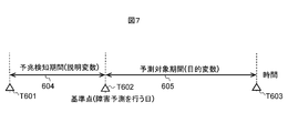
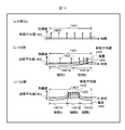
- FIG. 7 is a view showing a concept of a period for learning a sign of failure in the failure prediction system shown in FIG.
- FIG. 8 is a diagram showing the relationship between the occurrence of a failure in a device and the incidence of a specific event related to the failure.
- the purpose is to predict whether failure will occur in the period from the reference point T602 to T603 using the device operation log of the period from the reference point T602 to T601.
- the period 604 from T601 to T602 past the reference point may be referred to as a sign detection period.
- a period 605 from T602 to T603 in the future from the reference point may be referred to as a prediction target period.
- the occurrence 701 of the specific event related to the failure occurrence and the failure occurrence 703 continuously occur after the prediction 701 appears in the operation log. It shows the case that occurs.
- the occurrence rate of the specific event related to the occurrence of the failure does not increase for a while after the occurrence of the prediction 704 in the operation log on the basis of the reference point T602 at which the failure is predicted.
- An example is shown in which an increase in the incidence rate of a specific event 705 and a failure occurrence 706 occur thereafter.
- machine learning is performed with the fixed period 604 from the reference point T601 to the reference point T602 as a precursor detection period and the fixed period 605 from the reference point T602 to the predetermined period T603 as the prediction target period.
- the main period of the device B although there is a sign, the increase in the incidence rate of the specific event does not occur in the prediction period, and the learning accuracy is deteriorated.
- the target variable is generated in consideration of the time from the reference point to the failure occurrence in the prediction target period.
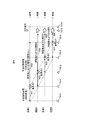
- FIG. 9 is a diagram for explaining a method of generating a target variable in consideration of the time from the reference point to the occurrence of a failure in the period to be predicted shown in FIG.
- the failure model learning unit 107 in this embodiment sequentially changes the reference points so as to set the sign detection period and the prediction target period while shifting the period for one device. It is conceivable to perform machine learning repeatedly.
- Period 1 is an example in which learning is performed with a period 801 from T810 to T811 as a sign detection period and a period 802 from T811 to T814 as a prediction target period.
- the length of the period 801 may be referred to as a first period length
- the length of the period 802 may be referred to as a second period length.
- Period 2 is an example in which learning is performed with a period 803 from T811 to T812 as a sign detection period and a period from T811 to T816 as a prediction target period. That is, in this example, the length of the period 803 may be referred to as a first period length. At this time, a failure has occurred at the timing of T815 in the prediction target period. Since the device state changes significantly before and after the failure, it is not appropriate to perform learning with data of a period including the device failure. So, in this form, learning is performed by making the period from T812 to T815 before a failure generation into a prediction object period. That is, in this example, the length of the period 804 from T811 to T815 may be referred to as a second period length.
- the lengths of the periods 804, 806, 808 until occurrence of a failure are different from the respective reference points T812, T813, T814.
- a coefficient is set to the incidence rate of the specific event which is the objective variable according to the length of the period from the reference point to the failure occurrence, and as the period from the reference point to the failure occurrence is shorter Learn to be highly valued.
- failure risk is calculated as a large value if the period until failure is short. It becomes possible.
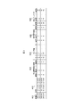
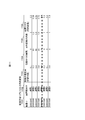
- FIG. 10 is a diagram showing an example of explanatory variables used in the failure model learning unit 107 shown in FIG.
- the device ID 1001 which can uniquely identify the device and the period identifier 1002 which can uniquely identify the period are the keys.
- the feature quantified operation log items are expressed.
- the occurrence rate of a specific event (event A occurrence rate 1003), the recording of a specific action (action B activation count 1004), environment information (in-casing temperature 1005), and a sensor for monitoring a device Values (Sensor 1 Value 1006) and the like.
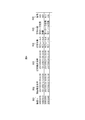
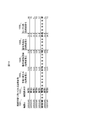
- FIG. 11 is a diagram showing an example of the objective variable used in the failure model learning unit 107 shown in FIG.
- the objective variables used by the failure model learning unit 107 shown in FIG. 1 are, as shown in FIG. 11, a device ID 1101 which can uniquely identify the device and a period identifier 1102 which can uniquely identify the period as keys. Items 1103 to 1106 related to the fault related to it are represented.
- the target of prediction is the occurrence probability of a specific event, the incidence 1103 of a specific event related to a fault, but the coefficient of the objective variable according to the period 1104 to the fault in the prediction target period
- a target variable 1106 serving as a failure index value is calculated as a failure risk. Zero period until failure occurrence indicates a case where no failure occurs in the forecast target period of the period.
- condition of the failure is generated by changing the coefficient of the objective variable according to the period up to the failure in the prediction target period and calculating the failure index value by multiplying the occurrence rate of the event by the coefficient. It becomes possible to study according to
- Period 1 to period 4 of period identifier 1101 in FIG. 11 correspond to period 1 to period 4 in FIG.
- the occurrence rate 1103 “0.1” of the learning target is used as it is as the target variable 1106.
- the coefficient 1105 of the objective variable determined according to the period 1104 until the failure occurrence is set as “1.2”. Then, “0.24” obtained by multiplying the occurrence rate 1103 “0.2” of the failure to be predicted by the coefficient 1105 of the objective variable is used as the objective variable serving as the failure risk.
- the coefficient 1105 of the objective variable determined according to the period 1104 until the occurrence of failure is set larger as the period until the occurrence of failure is shorter. As a result, the risk of failure can be evaluated more correctly even if the period from the sign to the occurrence of the failure varies.
- FIG. 12 is a diagram for explaining a method of generating an explanatory variable and a target variable when maintenance is performed in the sign detection period or the prediction target period shown in FIG. 7.
- T910 to T911 are the precursor detection period 901
- T911 to T915 are the prediction target period 902, but maintenance is performed at T912 in the prediction target period.
- T911 to T913 are the precursor detection period
- maintenance is performed at T912 in the precursor detection period.
- the state of the apparatus largely changes before and after maintenance. Therefore, in any of the sign detection period and the prediction target period, those including maintenance in the learning data cause deterioration in the learning accuracy. Therefore, in the present embodiment, the maintenance implementation time at which maintenance was performed in response to the failure is recorded in failure record information, and the information at the maintenance implementation time is utilized for generation of the objective variable and explanatory variable.
- the operation log information of the predictive detection period and the prediction target period including the maintenance implementation time in is excluded from machine learning. Thus, noise can be reduced and the accuracy of machine learning can be improved by excluding information of a period in which the state of the apparatus changes due to maintenance execution from machine learning.
- the explanatory variable whose period identifier 1002 is indicated by the period 5 to the period 8 corresponds to the period 5 to the period 8 in FIG. Since maintenance is performed in the sign detection period for period 6, the information of period 6 is excluded from the learning data.
- the explanatory variable whose period identifier 1102 is indicated by the period 5 to the period 8 corresponds to the period 5 to the period 8 in FIG.
- Information on period 5 is excluded from the learning data because maintenance is performed for period 5 in the prediction target period.
- the explanatory variable and the objective variable perform learning in pairs, and when the explanatory variable or the objective variable is excluded by maintenance, the paired objective variable or the explanatory variable is also included. At the same time, it is necessary to exclude it from the training data.
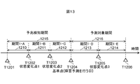
- FIG. 13 is a diagram for explaining the sub-period division of the sign detection period and the prediction target period in the failure prediction system shown in FIG.
- the auxiliary period division is to further divide the sign detection period or the prediction target period into one or more, add a unique identifier, and perform machine learning in each period.
- the sign detection period 1215 indicated by T1201 to T1204 includes a period 1-A: 1210 from T1201 to T1202; a period 1-B from T1202 to T1203; a period 1-C from T1203 to T1204; Divided into three precursor detection assistance periods, and the prediction target period 1216 indicated by T 1204 to T 1206 is divided into a period 1-D of T 1204 to T 1205; a period 1-E of T 1205 to T 1206; The example divided
- the sign detection period and the prediction target period are divided into a plurality of parts, and machine learning is performed as separate information to reflect changes in the appearance of the operation log in the sign detection period and the prediction target period in the failure prediction model.
- the accuracy of failure prediction can be improved.
- the division number is not particularly limited to one or more, and only the sign detection period may be divided and only the prediction target period may be divided.
- FIG. 14 is a diagram for explaining a method of dividing the sign detection period and the prediction target period into auxiliary periods in the failure prediction system shown in FIG. 1, (a) shows no division, (b) shows two divisions, (C) shows an example of division into three.
- the data shows the case where a particular event 1402 occurs discretely six times during the period of interest 1401.
- the target data is a continuous value such as a sensor output.
- the failure model learning unit 107 does not perform period division.
- the period is divided into three: period A; 1401 A, period B; 1401 B, and period C; 1401 C, with the period label as a key and the explanatory variable or
- the period label as a key and the explanatory variable or
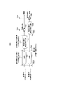
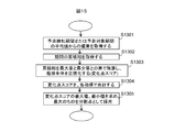
- FIG. 15 is a flowchart for describing a method of dividing the sign detection period and the prediction target period into the auxiliary periods at statistical change points in the failure prediction system shown in FIG.
- step 1301 an average value of the sign detection period or the prediction target period of the target operation log item The deviation from is obtained (step 1301).
- the increasing part is expressed as positive
- the decreasing part is expressed as negative.
- a transition (accumulated sum) obtained by sequentially adding log item values in the period from the top to the end of the period is acquired (step 1302).
- the cumulative sum has a positive slope when it is increasing and a negative slope when it is decreasing, so the point at which the operation log turns upward or downward is observed as a peak.
- the cumulative sum transition is normalized for each log item (divided by the difference between the maximum value and the minimum value) in order to calculate the state change of the device by summing the target log items (step 1303) . This prevents the contribution of each log item from becoming unbalanced in the change point score.
- the added cumulative sum is the change point score in the section, and a positive or negative peak is adopted as a division point according to the number of divisions (step 1305).
- division points are determined by extracting the peak of the absolute value of the change point score in order from the largest.
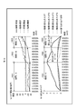
- FIG. 16 is a diagram showing an example in which the period division is performed using the index obtained from the operation log, (a) shows the transition of the log item value (deviation), (b) shows the change point score It is a figure which shows transition.
- the horizontal axis indicates the date, and the transition from March 19, 16 to May 28, 16 is shown.
- the log item values show a constant transition from March 19 to April 22, 2004, and thereafter, each index rises. Then, from about 14 May, it has further increased.
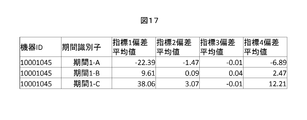
- FIG. 17 is a diagram showing the average value of the deviation in each section of each log item serving as the index shown in FIG.
- the deviation of index 1 takes a large negative value in period 1-A, a positive value in section 1-B, and a large positive value in section 1-C. This indicates that the index 1 tends to increase in this period.
- the deviation average value of the index 3 does not change significantly in each period, and the index indicates that there is no tendency to increase or decrease in this period.
- the operation log information is subjected to statistical processing that removes noises and errors from the operation log information and takes out objective feature quantities.
- a good failure prediction model can be obtained, and failure prediction accuracy can be improved. It is also conceivable to divide the sign detection period and the prediction target period not into a plurality of periods at a statistical change point, but to divide them at a failure occurrence time or a maintenance implementation time.
- the variation in the period from the omen to the occurrence of the failure can be reflected in the failure prediction model. It is possible to improve the accuracy.
- 101-1 to 101-n device, 104: failure maintenance record, 105: device operation log recording unit, 106: failure maintenance record storage unit, 107: failure model learning unit, 109: failure prediction unit, 111: determination unit
Abstract
The present invention performs machine learning wherein: the period between a reference time point, which corresponds to a failure prediction time point, and an earlier time point, which is a predetermined first length of time earlier than the reference time point, is set as a warning sign detection period; if no failure occurred during the period between the reference time point and a later time point, which is a predetermined second length of time later than the reference time point, then that period is set as a prediction period, and otherwise if a failure occurred during the period between the reference time point and the later time point, then the period between the reference time point and the time point at which the failure occurred is set as the prediction period; the reference time point is then sequentially shifted; a feature quantity based on operation log information obtained during the warning sign detection period is set as an explanatory variable; and a failure index value is set as a response variable, said failure index value being based on whether or not occurrence of a specific event is indicated by operation log information associated with failure occurrence indicated by failure record information obtained during the prediction period, and also based on the length of time between the reference time point and the time point at which the failure occurred.
Description
本発明は、装置における障害の予兆の有無を診断し、装置の障害を予測するシステムに関する。
The present invention relates to a system for diagnosing the presence or absence of a sign of failure in a device and predicting the failure of the device.
装置や設備が障害により停止すると、保守コストが増大し、同時に顧客満足度が毀損される。そのため装置や設備の予防保守が望まれる。予防保守は、装置や設備の動作履歴や稼動状態を記録し、この情報をもとに障害が発生する前に部品交換などの保守を行い、装置や設備の全体が停止するのを事前に防止するものである。装置の動作履歴に基づき将来の障害を予測するシステムとして、稼働ログから障害発生前の一定時間の部分を切り出して障害と対応づけ、対応づけた稼動ログと障害の情報を入力として機械学習を行ってモデルを作成し、そのモデルを用いて将来の障害を予測するものが提案されている。
If equipment or facilities fail due to a failure, maintenance costs increase and at the same time customer satisfaction is lost. Therefore, preventive maintenance of equipment and facilities is desired. Preventive maintenance records the operation history and operation status of equipment and facilities, and based on this information, performs maintenance such as parts replacement before a failure occurs, and prevents in advance the entire equipment and facilities from stopping. It is As a system to predict the future failure based on the operation history of the device, cut out the part for a certain period of time before the failure occurrence from the operation log and associate it with the failure, and perform machine learning using the corresponding operation log and failure information as input It has been proposed to create a model and use it to predict future obstacles.
近年の装置や設備は、機械機構と電子回路によって構成され、情報装置と精密装置の両面の特性を持つものが多い。機械的な消耗による障害だけでなく、電子回路の障害も想定され、障害のパターン(モード)は多岐にわたる。また、一般的に、装置や設備の障害は、機構部品の消耗や経年による電子部品などの劣化による障害と、外的要因などによる突発的な障害とに大別される。ここでは、前者を劣化障害、後者を突発障害と定義する。
In recent years, devices and equipment are composed of mechanical mechanisms and electronic circuits, and often have characteristics of both information devices and precision devices. Not only failures due to mechanical wear, but also failures of electronic circuits are conceivable, and the pattern (mode) of failures is diverse. Further, in general, failures in devices and facilities are roughly classified into failures due to wear of mechanical parts and deterioration of electronic components due to aging and sudden failures due to external factors and the like. Here, the former is defined as a deterioration failure, and the latter as a sudden failure.
劣化障害では、致命的な障害に至る前に装置の動作に変化が起こることがあり、これが障害の予兆として観測される。たとえば、回転部分のローラやベルトが経年磨耗などにより変質すると、起動時に空回りしたり、回転数にムラが出るなどする。これをセンサなどによって観測し、事前に現象を捉えることができれば、致命的な障害が生じる前に保守を行うことが可能になり、装置や設備が障害で停止するのを防止できる。
In the case of degradation failure, changes in the operation of the device may occur before reaching a fatal failure, which is observed as a sign of failure. For example, if the roller or the belt in the rotating portion is deteriorated due to age-related wear, the roller may idle at start-up or the number of rotations may become uneven. If this can be observed by a sensor or the like and the phenomenon can be grasped in advance, maintenance can be performed before a fatal failure occurs, and it is possible to prevent the apparatus or equipment from being stopped due to a failure.
一方、突発障害は事前の予測は困難であるが、装置に対して誤った操作が行われたことで起こる負荷の増大などの現象を障害の前兆として捉えることが可能である。しかし、装置や設備のどの部分が破損するか、さらにはその後の稼動状態によって、劣化の兆候が観測されてから、劣化が進行し、致命的な障害にいたるまでの期間はさまざまである。パターン化のために切り出し、記録する稼動ログの期間は、一律に障害の前の一定期間で定義されるものではない。障害発生に先立って一律の時間差で切り出した稼動ログで学習、障害予測を行うと、必ずしもその稼動ログに障害の予兆が含まれているとは限らず、予測精度を悪化させる。
On the other hand, sudden failure is difficult to predict in advance, but it is possible to grasp phenomena such as an increase in load caused by an erroneous operation on the device as a precursor to failure. However, depending on which part of the device or equipment is damaged, and further, depending on the operating condition thereafter, the period from the observation of the sign of deterioration to the progress of deterioration to the fatal failure varies. The period of the operation log extracted and recorded for patterning is not uniformly defined in a certain period before the failure. If learning and failure prediction are performed using operation logs cut out with a uniform time difference prior to failure occurrence, the operation log does not necessarily include a symptom of failure, and the prediction accuracy is degraded.
特許文献1には、学習に使用される稼動ログ期間(障害兆候期間)を、障害の事例毎に調整する技術が開示されている。
Patent Document 1 discloses a technique for adjusting an operation log period (failure indication period) used for learning for each case of a failure.
例えば、特許文献1には、画像形成装置(ファクシミリ)の動作制御に用いるパラメータを時系列情報として記憶し、障害の種別ごとにあらかじめ定められた期間の障害パターンと照合して分類し、障害予測を行う技術が開示されている。装置の稼動ログに基づく装置の使用状況についてその傾向を表す数値データと障害の種別をもとに、学習に用いるために切り出す稼動ログ(障害兆候)の障害種別による時間差および期間長が決定される。
For example, in Patent Document 1, parameters used for operation control of an image forming apparatus (facsimile) are stored as time-series information, classified against failure patterns in a predetermined period for each failure type, and classified, failure prediction Technology is disclosed. Regarding the usage status of the device based on the operation log of the device Based on the numerical data representing the tendency and the type of the fault, the time difference and the period length by the fault type of the operation log (fault symptom) to be extracted for use in learning are determined .
特許文献1に開示された技術によれば、障害種別毎に障害の兆候が生じる時間差を吸収することが可能となる。
According to the technology disclosed in Patent Document 1, it is possible to absorb the time difference in which the symptom of the failure occurs for each failure type.
しかしながら、特許文献1の技術は、暗黙に稼動状態が互いに類似する装置においては、予兆から一定期間後に障害が発生するという前提に基づいている。そのため、障害の兆候から実際の障害が発生するまでの期間にばらつきがある場合の対応には限界がある。
However, the technology of Patent Document 1 is based on the premise that in a device whose operation state is implicitly similar to each other, a failure occurs after a predetermined period of time from a omen. Therefore, there is a limit to the response when there is a variation in the period from the symptom of the failure to the occurrence of the actual failure.
本発明の目的は、装置や設備の障害発生の予測精度を向上する技術を提供することである。
An object of the present invention is to provide a technique for improving the prediction accuracy of the occurrence of a failure of a device or facility.
本発明の1つの態様による障害予測システムは、書き込みおよび読み出しが可能にデータを記憶する記憶装置と、記憶装置に記録されたデータを用いてソフトウェアプログラムの処理を実行するプロセッサと、を有し、記憶装置は、予測対象装置の過去の稼働状態を含む稼働ログ情報と、予測対象装置に過去に発生した障害に関する障害内容および障害発生日時を含む障害記録情報と、を記憶し、プロセッサは、障害予測実行時点に相当する基準時点から所定の第1期間長だけ遡った時点から基準時点までの期間を予兆検知期間とし、基準時点から所定の第2期間長後まで障害が発生しなければ第2期間長後までの期間を、基準時点から第2期間長後までに障害が発生すれば障害発生時点までの期間を予測対象期間として、基準時点を順次変更し、予兆検知期間の稼働ログ情報に基づく特徴量を説明変数とし、予測対象期間の障害記録情報における障害発生に対応する稼働ログ情報における特定事象の発生の有無および基準時点から障害発生時点までの期間長に基づく障害指標値を目的変数として機械学習を行うことにより、予測対象装置に将来発生する障害を予測するための障害予測モデルを生成する。
A fault prediction system according to one aspect of the present invention includes a storage device that stores data in a writable and readable manner, and a processor that executes processing of a software program using data stored in the storage device. The storage device stores operation log information including the past operation state of the prediction target device and failure record information including failure content and failure occurrence date and time regarding the failure that has occurred in the prediction target device in the past, and the processor The period from the point when going back by a predetermined first period length from the reference point of time corresponding to the predicted execution point to the reference point of time is taken as the sign detection period If a failure occurs from the reference time to the second period after the period until the end of the period, the period from the reference time to the failure occurrence time is the prediction target period, and the reference time is sequentially Furthermore, the feature quantity based on the operation log information in the sign detection period is used as an explanatory variable, and from the reference time to the failure time point whether there is a specific event in the operation log information corresponding to the failure occurrence in the failure record information in the prediction target period By performing machine learning with the failure index value based on the period length of C as a target variable, a failure prediction model for predicting a failure that will occur in the future in the device to be predicted is generated.
本発明の1つの態様によれば、装置の稼動ログを使用して機械学習を行い、そのモデルによって装置の障害を予測するシステムにおいて、装置の障害発生までの期間を考慮した学習を行うことで、予兆から障害発生までの期間のばらつきを学習可能にし、予兆検知精度を向上することができる。また、予兆検知期間(説明変数)と予測対象期間(目的変数)とのそれぞれについて、保守による装置の状態変化点、またはその変数の統計的変化点によって、期間を分割し、それぞれの期間で機械学習を行う稼動ログの時系列変化を特徴量化する簡便な手段を提供することで、予兆検知精度を向上することができる。
According to one aspect of the present invention, in a system that performs machine learning using an operation log of a device and predicts a failure of the device based on the model, learning is performed in consideration of a period until the occurrence of the failure of the device. The variation in the period from the sign to the occurrence of the failure can be learned, and the sign detection accuracy can be improved. Also, for each of the sign detection period (explanatory variable) and the prediction target period (target variable), the period is divided by the state change point of the device due to maintenance or the statistical change point of the variable, and the machine is divided by each period The predictive detection accuracy can be improved by providing a simple means for characterizing the time-series change of the operation log to be learned.
図1は、本実施形態による障害予測システムのブロック図である。図2は、図1に示した障害予測システムを実現するためのハードウェア構成を示す図である。
FIG. 1 is a block diagram of a failure prediction system according to the present embodiment. FIG. 2 is a diagram showing a hardware configuration for realizing the failure prediction system shown in FIG.
本形態は図1に示すように、予測対象装置となる複数の装置101-1~101-nから収集される稼動ログ120と、複数の装置101-1~101-nに関する障害保守記録104とを機械学習し、障害予測モデルを生成するものであって、装置ログ記録部105と、障害保守記録記憶部106と、障害モデル学習部107と、障害予測部109と、判定部111とを有している。そして、生成された障害予測モデルに装置稼動ログを入力することで、障害の発生率を予測、閾値判定し、それにより、装置101-1~101-nの障害リスクを判定する。
In this embodiment, as shown in FIG. 1, operation logs 120 collected from a plurality of devices 101-1 to 101-n to be predicted and failure maintenance records 104 for the plurality of devices 101-1 to 101-n and Machine learning to generate a failure prediction model, and the apparatus log recording unit 105, failure maintenance record storage unit 106, failure model learning unit 107, failure prediction unit 109, and determination unit 111 are provided. doing. Then, by inputting the device operation log to the generated failure prediction model, the occurrence rate of failure is predicted and threshold determination is performed, and thereby the failure risk of the devices 101-1 to 101-n is determined.
このように構成された障害予測システムは、図2に示すように、プロセッサ31と、メインメモリ32と、記憶装置33と、通信装置34と、入力装置35と、表示装置36とがバス37で接続されたハードウェアで実現することが考えられる。記憶装置33は、書込みおよび読み出しが可能にデータを記憶するものであって、この記憶装置33によって、図1に示した装置稼働ログ記録部105および障害保守記録記憶部106が実現される。プロセッサ31は、記憶装置33に記憶されたデータをメインメモリ32に読み出してソフトウェアプログラムの処理を実行するものであって、このプロセッサ31によって、図1に示した障害モデル学習部107と、障害予測部109と、判定部111とが実現される。通信装置34は、プロセッサ31にて処理された情報を有線または無線を介して送信することができる。入力装置35は、キーボードやマウスなどから構成され、情報を入力するためのものである。装置101-1~101-nの稼働ログ120や、保守記録121は、通信装置34や入力装置35を介して入力される。表示装置36は、ディスプレイなどの出力手段からなり、予測モデルや保守リストなどを表示出力することができる。
In the failure prediction system configured in this way, as shown in FIG. 2, the processor 31, the main memory 32, the storage device 33, the communication device 34, the input device 35, and the display device 36 are bus 37 It is conceivable to implement with connected hardware. The storage device 33 stores data in a writable and readable manner, and the storage device 33 implements the device operation log storage unit 105 and the failure maintenance record storage unit 106 shown in FIG. The processor 31 reads the data stored in the storage device 33 into the main memory 32 and executes the processing of the software program. The processor 31 causes the failure model learning unit 107 shown in FIG. The unit 109 and the determination unit 111 are realized. The communication device 34 can transmit the information processed by the processor 31 via a wire or wirelessly. The input device 35 includes a keyboard, a mouse and the like, and is for inputting information. The operation log 120 and the maintenance record 121 of the devices 101-1 to 101-n are input through the communication device 34 and the input device 35. The display device 36 includes output means such as a display, and can display and output a prediction model, a maintenance list, and the like.
装置101-1~101-nは、稼動ログを収集し、内部に蓄積、送信する機能を持つ(不図示)。
Each of the devices 101-1 to 101-n has a function of collecting operation logs, storing them internally, and transmitting them (not shown).
図3は、図1に示した装置101-1~101-nにて収集される稼動ログの一例を示す図である。
FIG. 3 is a diagram showing an example of operation logs collected by the devices 101-1 to 101-n shown in FIG.
図1に示した装置101-1~101-nにて収集される稼動ログは、装置101-1~101-nの過去の稼働状態を含むものであって、例えば図3に示すように、当該装置をユニークに識別できる機器ID401と、稼動ログが記録された日時402にそれぞれ対応して記録された、稼動に伴う各種記録情報から構成される。稼動に伴う各種記録情報には、装置の不調などの検出記録である特定事象ごとの発生回数403や、装置の動作を監視するセンサの値404、オペレータやユーザが当該装置を操作した履歴405、当該装置のその時点での設定パラメータ406などから構成される。
The operation logs collected by the devices 101-1 to 101-n shown in FIG. 1 include the past operation states of the devices 101-1 to 101-n, and for example, as shown in FIG. It is composed of a device ID 401 which can uniquely identify the device, and various record information accompanying the operation recorded corresponding to the date and time 402 when the operation log is recorded. The various record information accompanying the operation includes the number of occurrences 403 for each specific event which is a detection record such as malfunction of the device, the value 404 of the sensor monitoring the operation of the device, the history 405 where the operator or user operated the device, It comprises the setting parameter 406 of the device at that time and the like.
図4は、図1に示した障害保守記録104の一例を示す図である。
FIG. 4 is a diagram showing an example of the failure maintenance record 104 shown in FIG.
図1に示した障害保守記録104は、装置101-1~101-nで発生した障害の発生日時と保守、修理などの、障害に関する障害内容および障害発生日時を含む障害記録情報が記録される。装置自身が自動的に記録するもののほか、保守作業員が作業記録として記録するものが想定され、図4に示すように、当該装置をユニークに識別できる機器ID501や、障害の発生日時502、保守実施の日時503、障害が発生して保守が行われた対象504、保守の内容505などから構成される。保守内容は、保守現場で作業員が手書きで記録する場合もあるため、表記のゆれや欠落が生じる場合がある。また、保守対象504と保守内容505とに応じた記号506を表記することで、データ処理上において、障害と保守の内容を分類、集計を容易にする場合もある。
In the fault maintenance record 104 shown in FIG. 1, fault record information including fault contents regarding faults and fault occurrence dates, such as fault occurrence dates and times of maintenance and repairs, etc., occurring in the devices 101-1 to 101-n is recorded. . In addition to what is recorded automatically by the device itself, it is assumed that a maintenance worker records it as a work record, and as shown in FIG. 4, a device ID 501 which can uniquely identify the device, date and time of failure 502, maintenance The date and time of implementation 503, the target 504 for which maintenance has been performed due to a failure, the content of maintenance 505, and the like are included. Since maintenance content may be handwritten by a worker at a maintenance site, fluctuations or omissions in notation may occur. Further, there are also cases where it is possible to easily classify and collect faults and maintenance contents in data processing by writing symbols 506 according to the maintenance target 504 and the maintenance content 505.
一般的に、装置に障害が発生してから、保守が実施されるまでは時間差がある。当該装置の動作は、障害が発生したときと、保守が実施されたときとの少なくとも2回その状態が大きく変化する。
In general, there is a time lag between maintenance of a device and maintenance. The operation of the device largely changes its state at least twice when a failure occurs and when maintenance is performed.
装置101-1~101-nから収集された稼動ログ120は、装置稼動ログ記録部105に記録、蓄積される。装置稼動ログ記録部105に記録、蓄積された稼動ログは、障害の予測、障害の予兆の特徴を抽出するための機械学習と、機械学習によって生成された障害のモデルによる障害発生確率の予測との2つの目的で使われる。機械学習用の稼動ログ123は、障害モデル学習部107に入力され、障害予測モデルを生成する学習が行われる。障害発生確率の予測用の稼動ログ122は、障害予測部109に入力される。
The operation log 120 collected from the devices 101-1 to 101-n is recorded and accumulated in the device operation log recording unit 105. The operation log recorded and accumulated in the device operation log recording unit 105 includes prediction of failure, machine learning for extracting features of failure sign, prediction of failure occurrence probability by a model of failure generated by machine learning, and Used for two purposes. The operation log 123 for machine learning is input to the failure model learning unit 107, and learning for generating a failure prediction model is performed. The operation log 122 for predicting the failure occurrence probability is input to the failure prediction unit 109.
装置101-1~101-nまたは保守作業員から収集された保守記録121は、障害保守記録記憶部106に記録・蓄積される。障害保守記録記憶部106に記録・蓄積された保守記録121は、障害の発生日時124と、障害内容125と、保守日時126とに分類され、障害モデル学習部107に入力される。障害モデル学習部107では、装置101-1~101-nに発生した障害に先行して、装置101-1~101-nから収集された稼動ログに障害に関連する兆候があるかどうか、相関を分析するための機械学習を行う。
The maintenance record 121 collected from the devices 101-1 to 101-n or the maintenance worker is recorded and accumulated in the failure maintenance record storage unit 106. The maintenance record 121 recorded and accumulated in the fault maintenance record storage unit 106 is classified into a fault occurrence date 124, fault content 125, and maintenance date 126, and is input to the fault model learning unit 107. In the failure model learning unit 107, whether there is a symptom related to a failure in the operation log collected from the devices 101-1 to 101-n prior to the failure occurring in the devices 101-1 to 101-n is correlated Do machine learning to analyze
機械学習は、障害や特定事象の発生を教師信号(目的変数)として、説明変数として入力される稼動ログによって状態を分類するモデルを生成するものである。判別分析、ロジスティック回帰、決定木などさまざまな手法があり、ここでは詳述しない。一般的には、回帰式と呼ばれる多項式でモデルは表現され、説明変数に相当するデータを多項式に入力することで目的変数を予測する。障害や特定事象の発生を教師信号として学習する教師あり学習のほかに、暗黙的に正常ケースとして装置の稼動ログで学習を行い、異常データが入力されたときの状態空間の統計的距離によって異常を判定する手法もある。
Machine learning generates a model that classifies a state according to an operation log that is input as an explanatory variable, using a failure or a specific event as a teacher signal (target variable). There are various methods such as discriminant analysis, logistic regression, decision trees, etc., which will not be described in detail here. In general, a model is represented by a polynomial called regression equation, and a target variable is predicted by inputting data corresponding to an explanatory variable into the polynomial. In addition to supervised learning that learns the occurrence of a failure or a specific event as a teacher signal, learning is performed on the operation log of the device implicitly as a normal case, and an abnormality is caused by the statistical distance of the state space when abnormal data is input. There is also a method of determining
障害モデル学習部107は、後述するように、保守を実行する予測実行時点に相当する基準時点から所定の第1期間長だけ遡った時点から基準時点までの期間を予兆検知期間とし、基準時点から所定の第2期間長後まで障害が発生しなければ第2期間長後までの期間を、基準時点から第2期間長後までに障害が発生すれば障害発生時点までの期間を予測対象期間として、基準時点を順次変更し、予兆検知期間の稼働ログ情報に基づく特徴量を説明変数とし、予測対象期間の前記障害記録情報における障害発生に対応する稼働ログ情報における特定事象の発生の有無および基準時点から障害発生時点までの期間長に基づく障害指標値を目的変数として機械学習を行うことにより、装置101-1~101-nに将来発生する障害を予測するための障害予測モデルを生成することになる。
As will be described later, the failure model learning unit 107 sets a period from the time point when going back by a predetermined first period length from the reference time point corresponding to the predicted execution time to perform maintenance to the reference time point as the sign detection time period. If the failure does not occur until after a predetermined second period length, the period until the second period length is taken as the target period for the period until the failure occurrence point if the failure occurs after the reference period to the second period length Sequentially change the feature amount based on the operation log information in the sign detection period as an explanatory variable, and from the reference time to the presence / absence of the specific event occurrence in the operation log information corresponding to the failure occurrence in the failure record information of the prediction target period By performing machine learning with the failure index value based on the period length up to the occurrence point as the objective variable, it is possible to predict future failure in the devices 101-1 to 101-n. It will produce a failure prediction model.
障害モデル学習部107において機械学習によって生成された障害予測モデル108は、障害予測部109に入力される。障害予測部109は、装置稼働ログ記録部105から出力された予測用稼動ログ122も入力され、これら障害予測モデル108と予測用稼動ログ122とに基づいて、装置101-1~101-nにおける障害の発生率を予測する。このとき、目的変数として障害の発生有無を予測するモデルであっても良いし、障害に関連する特定の事象の発生率などを予測するものであってもよい。
The failure prediction model 108 generated by machine learning in the failure model learning unit 107 is input to the failure prediction unit 109. The failure prediction unit 109 also receives the prediction operation log 122 output from the device operation log recording unit 105, and based on the failure prediction model 108 and the prediction operation log 122, the failure prediction unit 109 in the devices 101-1 to 101-n Predict the rate of failure. At this time, it may be a model that predicts the occurrence of failure as a target variable, or may predict the occurrence rate of a specific event related to the failure.
障害予測部109にて予測された障害発生率110は、判定部111に入力され、判定111において閾値判定され、障害の可能性が高い装置のリストとして保守対象装置リスト112が出力される。
The failure occurrence rate 110 predicted by the failure prediction unit 109 is input to the determination unit 111, and threshold determination is performed in the determination 111, and the maintenance target device list 112 is output as a list of devices with high possibility of failure.
以下に、上述した装置稼動ログ記録部105、障害保守記録記憶部106および障害モデル学習部107について詳細に説明する。
The apparatus operation log recording unit 105, the failure maintenance record storage unit 106, and the failure model learning unit 107 described above will be described in detail below.
図5は、図1に示した装置稼動ログ記録部105、障害保守記録記憶部106および障害モデル学習部107の構成を示す図である。
FIG. 5 is a diagram showing the configuration of the apparatus operation log recording unit 105, the failure maintenance record storage unit 106, and the failure model learning unit 107 shown in FIG.
図1に示した装置稼動ログ記録部105は図5に示すように、装置稼働ログ記憶部201と、装置稼働ログスクリーニング部202と、特徴量演算部213とを有している。
As shown in FIG. 5, the device operation log storage unit 105 shown in FIG. 1 includes a device operation log storage unit 201, a device operation log screening unit 202, and a feature quantity calculation unit 213.
装置101-1~101-nから収集された稼動ログ120は、装置稼動ログ記録部105の装置稼動ログ記憶部201に記録される。一般的に、機械的に収集される装置の稼動ログは、装置の稼働状況や、収集経路によって重複や欠損があると同時に、ほとんど記録のない項目や、分析に不適切なデータが含まれる場合がある。
The operation log 120 collected from the devices 101-1 to 101-n is recorded in the device operation log storage unit 201 of the device operation log recording unit 105. Generally, the machine operation log of a machine is collected if there are duplicates or deletions due to the operation status of the machine and the collection route, and items with almost no records or inappropriate data in analysis There is.
そのため、装置稼動ログスクリーニング部202において、これらの不適切なデータをクレンジング(除去、補正、補完)する。また、稼動ログの種類によっては、適切な集計処理を施すことが必要な場合もある。たとえば、一定期間で平均化処理を行ったり、絶対値ではなく率や分布で参照したりする場合などである。そのため特徴量演算部213にて、そのような集計処理を行い、学習用稼働ログ123として出力する。
Therefore, the apparatus operation log screening unit 202 cleans (removes, corrects, complements) these inappropriate data. In addition, depending on the type of operation log, it may be necessary to perform appropriate tabulation processing. For example, the averaging process may be performed in a certain period, or the reference may be made not by an absolute value but by a rate or a distribution. Therefore, the feature amount calculation unit 213 performs such aggregation processing and outputs it as the learning operation log 123.
また、図1に示した障害保守記録記憶部106は図5に示すように、障害保守情報記憶部203と、障害保守情報ログスクリーニング部204と、障害発生日時記憶部205と、障害内容記憶部206と、保守実施日時記憶部207とを有している。
Further, as shown in FIG. 5, the fault maintenance record storage unit 106 shown in FIG. 1 includes a fault maintenance information storage unit 203, a fault maintenance information log screening unit 204, a fault occurrence date storage unit 205, and a fault content storage unit. It has 206 and maintenance implementation date storage part 207.
装置101-1~101-nまたは保守作業員から収集された保守記録121は、障害保守記録記憶部106の障害保守情報記憶部203に記憶される。そして、装置ログ稼働記録部105と同様に、障害保守情報スクリーニング部204によって障害保守データのクレンジング(除去、補正、補完)が行われる。
The maintenance record 121 collected from the devices 101-1 to 101-n or the maintenance worker is stored in the fault maintenance information storage unit 203 of the fault maintenance record storage unit 106. Then, similarly to the device log operation recording unit 105, the failure maintenance information screening unit 204 cleanses (removes, corrects, complements) the failure maintenance data.
そして、障害保守情報は連続データではなくイベントであるため、障害の発生日時、障害内容、保守実施日の記録に分類され、障害発生日時記憶部205、障害内容記憶部206および保守実施日時記憶部207にそれぞれ記憶される。
Since the fault maintenance information is not continuous data but an event, it is classified into the fault occurrence date, fault content, and the record of the maintenance implementation date, and the fault occurrence date storage unit 205, fault content storage unit 206, and maintenance implementation date storage unit It is stored in 207 respectively.
特徴量演算部213から出力された学習用稼動ログ123と、障害発生日時記憶部205、障害内容記憶部206および保守実施日時記憶部207にそれぞれ記憶された、障害発生日時124、障害内容125および保守日時126は、障害モデル学習部107に入力される。
The fault occurrence date 124, fault content 125, and fault content 125 stored in the learning operation log 123 output from the feature amount computation unit 213, and the fault occurrence date storage unit 205, the fault content storage unit 206, and the maintenance execution date storage unit 207, respectively. The maintenance date 126 is input to the failure model learning unit 107.
図1に示した障害モデル学習部107は図5に示すように、機器状態変化検出部207と、期間別説明変数生成部208と、期間変動目的変数生成部209と、機械学習部212とを有している。
As shown in FIG. 5, the failure model learning unit 107 shown in FIG. 1 includes the device state change detection unit 207, the period-specific explanatory variable generation unit 208, the period change objective variable generation unit 209, and the machine learning unit 212. Have.
このように構成された障害モデル学習部107では、期間変動目的変数生成部209において、障害に関連する稼動ログまたは障害保守情報に基づいて目的変数211が生成され、また、期間別説明変数生成部208において、障害に先立つ学習用稼動ログに基づいて障害の予兆の説明変数210が生成される。
In the failure model learning unit 107 configured as described above, the period variable objective variable generation unit 209 generates the objective variable 211 based on the operation log or the failure maintenance information related to the failure, and the period-specific explanatory variable generation unit At 208, an explanatory variable 210 of failure sign is generated based on the learning operation log prior to the failure.
このとき、説明変数210および目的変数211を生成するための、学習用稼動ログ123、障害発生日時情報124、障害内容情報125および保守日時情報126のデータ期間を、機器の状態変化によって決定することが、特徴的である。
At this time, the data period of the operation log for learning 123, failure occurrence date and time information 124, failure content information 125 and maintenance date and time information 126 for generating the explanatory variable 210 and the objective variable 211 is determined according to the state change of the device. Is distinctive.
機器の状態変化とは、装置に障害が発生する前に、装置を構成する機構部品や電子部品の消耗や損傷により、動作が変化し、稼動ログの統計的性質が変化したとき(予兆)、あるいは、装置に実際に障害が発生したとき、あるいは保守が行われて部品の交換などが行われたときのことである。
The state change of the equipment means that when the operation of the operation log changes due to the consumption or damage of the mechanical parts and electronic parts that constitute the apparatus before the failure of the apparatus occurs (predictive phenomenon), Or, when the device actually fails or when maintenance is performed and parts are replaced.
機器の状態変化は、機器状態変化検出部207によって検出される。機器状態変化検出部207では、学習用稼動ログ123を参照し、統計的性質が変化したとき、障害発生日時情報124や保守実施日時情報126を使って、説明変数と目的変数の期間設定を行う。期間別説明変数生成部208および期間変動目的変数生成部209は、機器状態変化検出部207によって検出された機器状態変化の情報をもとに説明変数210および目的変数211をそれぞれ生成し、機械学習部212に入力する。
The device state change is detected by the device state change detection unit 207. The device state change detection unit 207 refers to the learning operation log 123, and when the statistical property changes, performs period setting of the explanatory variable and the objective variable using the failure occurrence date information 124 and the maintenance implementation date information 126. . The period-specific explanatory variable generation unit 208 and the period fluctuation objective variable generation unit 209 respectively generate the explanatory variable 210 and the objective variable 211 based on the information of the device state change detected by the device state change detection unit 207, and perform machine learning. Input to the part 212.
機械学習部212は、入力された説明変数210および目的変数211を用いて障害予測モデル108を生成して出力する。
The machine learning unit 212 generates and outputs the failure prediction model 108 using the input explanatory variables 210 and the target variables 211.
以下に、図1に示した障害予測部109および判定部111について詳細に説明する。
Hereinafter, the failure prediction unit 109 and the determination unit 111 illustrated in FIG. 1 will be described in detail.
図6は、図1に示した障害予測部109および判定部111の構成を示す図である。
FIG. 6 is a diagram showing the configuration of failure prediction unit 109 and determination unit 111 shown in FIG.
図1に示した障害予測部109は図6に示すように、障害率予測値計算部302を有している。障害予測部109は、障害率予測値計算部302において、障害モデル学習部107にて機械学習によって求められた障害予測モデル108に、装置稼働ログ記録部105から出力された予測用稼動ログ122を入力することで、装置110-1~110-n毎に障害の発生率を予測する。一般的には、障害予測モデル108は多項式で構成され、これに特徴量演算部213により特徴量化された予測用稼動ログ122を入力することで、障害発生率110が計算される。
The failure prediction unit 109 shown in FIG. 1 includes a failure rate prediction value calculation unit 302 as shown in FIG. The failure prediction unit 109 uses the prediction operation log 122 output from the device operation log recording unit 105 to the failure prediction model 108 obtained by the machine learning in the failure model learning unit 107 in the failure rate prediction value calculation unit 302. By inputting, the occurrence rate of failure is predicted for each of the devices 110-1 to 110-n. In general, the failure prediction model 108 is configured by a polynomial, and the failure occurrence rate 110 is calculated by inputting the operation log 122 for prediction that is feature-characterized by the feature amount computing unit 213.
図1に示した判定部111は図6に示すように、閾値判定部305と、閾値決定部304とを有している。判定部111では、閾値判定部305において、障害予測部109にて計算された障害発生率110を閾値と比較して閾値を上回る装置を抽出し、予防保守をおこなうための保守対象機器リスト112として出力する。この際、閾値はあらかじめシステムに入力しておいても良いし、ターゲットなどの抽出台数などをもとに、閾値決定部304にて決定してもよい。
The determination unit 111 shown in FIG. 1 includes a threshold determination unit 305 and a threshold determination unit 304 as shown in FIG. In the determination unit 111, the threshold determination unit 305 compares the failure occurrence rate 110 calculated by the failure prediction unit 109 with a threshold to extract devices exceeding the threshold, and is used as a maintenance target device list 112 for performing preventive maintenance. Output. At this time, the threshold may be input to the system in advance, or may be determined by the threshold determination unit 304 based on the number of extracted targets such as targets.
以下に、装置の状態変化に応じて説明変数と目的変数を生成するデータ区間を決定する方法について説明する。
Hereinafter, a method of determining a data section for generating an explanatory variable and an objective variable in accordance with a change in the state of the apparatus will be described.
図7は、図1に示した障害予測システムにて障害の予兆を学習するための期間の考え方を示す図である。図8は、装置における障害発生とその障害に関連する特定事象の発生率との関係を示す図である。
FIG. 7 is a view showing a concept of a period for learning a sign of failure in the failure prediction system shown in FIG. FIG. 8 is a diagram showing the relationship between the occurrence of a failure in a device and the incidence of a specific event related to the failure.
図7に示すように、ある基準点T602において、その装置の障害の予兆を検出することを考える。目的は、基準点T602からT603までの期間において障害が発生するかどうかを、基準点T602から遡ってT601までに期間の装置稼動ログを使って予測する。ここで、基準点より過去のT601からT602の期間604は、予兆検知期間と言ってもよい。また、基準点より未来のT602からT603までの期間605は、予測対象期間と言ってもよい。
As shown in FIG. 7, it is considered to detect a sign of failure of the device at a certain reference point T602. The purpose is to predict whether failure will occur in the period from the reference point T602 to T603 using the device operation log of the period from the reference point T602 to T601. Here, the period 604 from T601 to T602 past the reference point may be referred to as a sign detection period. In addition, a period 605 from T602 to T603 in the future from the reference point may be referred to as a prediction target period.
機械学習では、予兆検知期間604の稼動ログを説明変数として、予測対象期間605の障害発生、また障害に関連する事象の発生率を目的変数として、繰り返し学習を行うことで、障害に関連する稼動ログの特徴がモデル化される。
In machine learning, by using the operation log of the sign detection period 604 as an explanatory variable, the occurrence of a failure in the prediction target period 605, and the occurrence rate of events related to a failure as an objective variable, repetitive learning is performed to operate the failure. The features of the log are modeled.
つまり、図8に示すように、障害に至る固体は、障害発生の前に、障害に関連する特定事象の発生率が上昇し、さらにその前の稼動ログには障害の予兆が現れていると仮定している。しかし、一般には、装置を構成する機構部品や電子部品の消耗が生じて何らかの状態変化が起こり、障害発生に関連する特定事象の発生率の上昇が起こり、実際に障害に至るまでの期間は一律ではなく、装置のおかれた環境や稼働率などに依存して大きく変動する。
In other words, as shown in FIG. 8, it is assumed that the individuals leading to the failure have an increased incidence of specific events related to the failure before the occurrence of the failure, and that there is a sign of failure in the operation log before that. I'm assuming. However, in general, the mechanical parts and electronic parts constituting the apparatus are consumed, some state changes occur, the occurrence rate of specific events related to the occurrence of a fault occurs, and the period until the fault is practically uniform. Rather, it varies greatly depending on the environment and availability of the device.
図8では、装置Aについては障害予測を行う基準点T602を基準として、稼動ログに予兆701が現れてから、障害発生に関連する特定事象の発生率の上昇702、障害発生703が連続して起こるケースを示している。一方で、装置Bについては、障害予測を行う基準点T602を基準として、稼動ログに予兆704が現れてから、障害発生に関連する特定事象の発生率の上昇はしばらく起こらず、T603まで時間が経ってから特定事象の発生率の上昇705と障害発生706が起こる例を示している。
In FIG. 8, with respect to the device A, with reference to the reference point T 602 at which failure prediction is performed, the occurrence 701 of the specific event related to the failure occurrence and the failure occurrence 703 continuously occur after the prediction 701 appears in the operation log. It shows the case that occurs. On the other hand, for the device B, the occurrence rate of the specific event related to the occurrence of the failure does not increase for a while after the occurrence of the prediction 704 in the operation log on the basis of the reference point T602 at which the failure is predicted. An example is shown in which an increase in the incidence rate of a specific event 705 and a failure occurrence 706 occur thereafter.
このように、基準点より一定期間前T601から基準点T602までの固定期間604を予兆検知期間とし、基準点T602から一定期間後T603までの固定期間605を予測対象期間として機械学習を行うと、装置Bの本期間については、予兆があるにもかかわらず予測期間では特定事象の発生率の上昇が起こらない学習データとなり、学習精度を悪化させてしまう。
As described above, machine learning is performed with the fixed period 604 from the reference point T601 to the reference point T602 as a precursor detection period and the fixed period 605 from the reference point T602 to the predetermined period T603 as the prediction target period. With regard to the main period of the device B, although there is a sign, the increase in the incidence rate of the specific event does not occur in the prediction period, and the learning accuracy is deteriorated.
そこで、本形態では、予測対象期間において基準点から障害発生までの時間を考慮した目的変数の生成を行う。
Therefore, in the present embodiment, the target variable is generated in consideration of the time from the reference point to the failure occurrence in the prediction target period.
図9は、図7に示した予測対象期間において基準点から障害発生までの時間を考慮した目的変数の生成を行う方法を説明するための図である。
FIG. 9 is a diagram for explaining a method of generating a target variable in consideration of the time from the reference point to the occurrence of a failure in the period to be predicted shown in FIG.
本形態における障害モデル学習部107においては、例えば、図9に示すように、1つの装置に対して、期間をずらしながら予兆検知期間と予測対象期間とを設定するように基準点を順次変更し、繰り返し機械学習を行うことが考えられる。
For example, as shown in FIG. 9, the failure model learning unit 107 in this embodiment sequentially changes the reference points so as to set the sign detection period and the prediction target period while shifting the period for one device. It is conceivable to perform machine learning repeatedly.
期間1は、T810からT811までの期間801を予兆検知期間とし、T811からT814までの期間802を予測対象期間として学習を行う例である。本例では、期間801の長さを第1期間長といい、期間802の長さを第2期間長と言ってもよい。このとき、予測期間802では障害は発生していないので、実際の予測対象期間の特定事象発生率を目的変数として学習を行う。機器が正常な場合、特定事象発生率は低いことが想定されるので、期間1については正常ケースとしての学習データとなる。
Period 1 is an example in which learning is performed with a period 801 from T810 to T811 as a sign detection period and a period 802 from T811 to T814 as a prediction target period. In this example, the length of the period 801 may be referred to as a first period length, and the length of the period 802 may be referred to as a second period length. At this time, since no failure occurs in the prediction period 802, learning is performed using the specific event occurrence rate of the actual prediction target period as a target variable. When the device is normal, it is assumed that the specific event occurrence rate is low, so period 1 is learning data as a normal case.
期間2は、T811からT812までの期間803を予兆検知期間とし、T811からT816までの期間を予測対象期間として学習を行う例である。すなわち、本例では、期間803の長さを第1期間長と言ってもよい。このとき、予測対象期間中のT815のタイミングで障害が起こっている。障害の前後で装置状態は大きく変わるため、装置障害を含んだ期間のデータで学習を行うことは適切ではない。そこで、本形態では、障害発生前までの、T812からT815までの期間を予測対象期間として学習を行う。すなわち、本例では、T811からT815までの期間804の長さを第2期間長と言ってもよい。
Period 2 is an example in which learning is performed with a period 803 from T811 to T812 as a sign detection period and a period from T811 to T816 as a prediction target period. That is, in this example, the length of the period 803 may be referred to as a first period length. At this time, a failure has occurred at the timing of T815 in the prediction target period. Since the device state changes significantly before and after the failure, it is not appropriate to perform learning with data of a period including the device failure. So, in this form, learning is performed by making the period from T812 to T815 before a failure generation into a prediction object period. That is, in this example, the length of the period 804 from T811 to T815 may be referred to as a second period length.
期間3および期間4についても、予測対象期間に相当する期間において、障害が発生しているため、予測対象期間はそれぞれT813からT815の期間806、T814からT815の期間808で学習を行う。
Also in the period 3 and the period 4, since failure occurs in the period corresponding to the prediction target period, learning is performed in the period 806 from T813 to T815 and the period 808 from T814 to T815, respectively.
期間2、期間3および期間4において、それぞれの基準点T812,T813,T814から、障害発生までの期間804,806,808の長さが異なる。本実施形態では、基準点から障害発生までの期間の長さに応じて、目的変数である特定事象の発生率に係数を設定し、基準点から障害発生までの期間が短いほど、障害リスクが高く評価されるよう学習を行う。
In the period 2, the period 3 and the period 4, the lengths of the periods 804, 806, 808 until occurrence of a failure are different from the respective reference points T812, T813, T814. In this embodiment, a coefficient is set to the incidence rate of the specific event which is the objective variable according to the length of the period from the reference point to the failure occurrence, and as the period from the reference point to the failure occurrence is shorter Learn to be highly valued.
このように、予測を実行している時点から障害発生の時点までの期間長に応じた値を取る係数を目的変数に含むことで、障害発生まで期間が短ければ障害リスクを大きな値として算出するということが可能となる。
In this way, by including in the objective variable a coefficient that takes a value corresponding to the period length from the time of prediction to the time of failure occurrence, failure risk is calculated as a large value if the period until failure is short. It becomes possible.
図10は、図1に示した障害モデル学習部107にて用いられる説明変数の例を示す図である。
FIG. 10 is a diagram showing an example of explanatory variables used in the failure model learning unit 107 shown in FIG.
図1に示した障害モデル学習部107にて用いられる説明変数は、図10に示すように、装置をユニークに特定可能な機器ID1001と、期間をユニークに識別可能な期間識別子1002とがキーとなり、それに関係し、特徴量化された稼働ログ項目が表現される。特徴量化された稼動ログ項目として、特定の事象の発生率(事象A発生率1003)や、特定動作の記録(動作B起動回数1004)、環境情報(筐体内温度1005)、装置をモニタするセンサの値(センサ1値1006)などがある。
As the explanatory variables used in the failure model learning unit 107 shown in FIG. 1, as shown in FIG. 10, the device ID 1001 which can uniquely identify the device and the period identifier 1002 which can uniquely identify the period are the keys. , And related to it, the feature quantified operation log items are expressed. The occurrence rate of a specific event (event A occurrence rate 1003), the recording of a specific action (action B activation count 1004), environment information (in-casing temperature 1005), and a sensor for monitoring a device Values (Sensor 1 Value 1006) and the like.
図11は、図1に示した障害モデル学習部107にて用いられる目的変数の例を示す図である。
FIG. 11 is a diagram showing an example of the objective variable used in the failure model learning unit 107 shown in FIG.
図1に示した障害モデル学習部107にて用いられる目的変数は、図11に示すように、装置をユニークに特定可能な機器ID1101と、期間をユニークに識別可能な期間識別子1102がキーとなり、それに関係する障害に関連する項目1103~1106が表現される。ここで、予測の対象となるのは、特定事象の発生確率である、障害に関連する特定の事象の発生率1103であるが、予測対象期間における障害までの期間1104に応じて目的変数の係数1105を変化させ、事象の発生率1103に係数1105を乗算することにより障害指標値となる目的変数1106を故障リスクとして算出する。障害発生までの期間ゼロは、当該期間の予測対象期間に障害が発生していないケースを示す。
The objective variables used by the failure model learning unit 107 shown in FIG. 1 are, as shown in FIG. 11, a device ID 1101 which can uniquely identify the device and a period identifier 1102 which can uniquely identify the period as keys. Items 1103 to 1106 related to the fault related to it are represented. Here, the target of prediction is the occurrence probability of a specific event, the incidence 1103 of a specific event related to a fault, but the coefficient of the objective variable according to the period 1104 to the fault in the prediction target period By changing 1105 and multiplying the occurrence rate 1103 of the event by the coefficient 1105, a target variable 1106 serving as a failure index value is calculated as a failure risk. Zero period until failure occurrence indicates a case where no failure occurs in the forecast target period of the period.
このように、予測対象期間における障害までの期間に応じて目的変数の係数を変化させ、事象の発生率に係数を乗算することにより障害指標値を算出することで、障害が発生するまでの状況に応じた学習が可能となる。
Thus, the condition of the failure is generated by changing the coefficient of the objective variable according to the period up to the failure in the prediction target period and calculating the failure index value by multiplying the occurrence rate of the event by the coefficient. It becomes possible to study according to
図11における期間識別子1101の期間1から期間4までが、図9の期間1から期間4に対応する。期間1については、予測対象期間内で障害が発生していないため、学習対象となる事象の発生率1103“0.1”は、そのまま目的変数1106として用いられる。
Period 1 to period 4 of period identifier 1101 in FIG. 11 correspond to period 1 to period 4 in FIG. For period 1, since no failure occurs in the prediction target period, the occurrence rate 1103 “0.1” of the learning target is used as it is as the target variable 1106.
期間2から期間4については、予測対象期間内において障害が発生しているため、障害発生までの期間1104に応じて決定される目的変数の係数1105が“1.2”として設定される。そして、予測対象である障害に関連する事象の発生率1103“0.2”に、目的変数の係数1105を乗算した“0.24”が、故障リスクとなる目的変数として用いられる。
In the period 2 to the period 4, since a failure occurs in the prediction target period, the coefficient 1105 of the objective variable determined according to the period 1104 until the failure occurrence is set as “1.2”. Then, “0.24” obtained by multiplying the occurrence rate 1103 “0.2” of the failure to be predicted by the coefficient 1105 of the objective variable is used as the objective variable serving as the failure risk.
障害発生までの期間1104に応じて決定される目的変数の係数1105は、障害発生までの期間が短いほど大きく設定される。これにより、予兆から障害発生までの期間にばらつきがあっても、故障リスクがより正しく評価される。
The coefficient 1105 of the objective variable determined according to the period 1104 until the occurrence of failure is set larger as the period until the occurrence of failure is shorter. As a result, the risk of failure can be evaluated more correctly even if the period from the sign to the occurrence of the failure varies.
図12は、図7に示した予兆検知期間または予測対象期間において保守が実施された場合に説明変数および目的変数の生成を行う方法を説明するための図である。
FIG. 12 is a diagram for explaining a method of generating an explanatory variable and a target variable when maintenance is performed in the sign detection period or the prediction target period shown in FIG. 7.
図12に示したものにおいては、T912のタイミングで保守が実施されている。期間5について、T910からT911が予兆検知期間901であり、T911からT915が予測対象期間902であるが、予測対象期間中のT912にて保守が実施されている。また、期間6については、T911からT913が予兆検知期間であるが、予兆検知期間中のT912にて保守が実施されている。
In the example shown in FIG. 12, maintenance is performed at the timing of T912. In period 5, T910 to T911 are the precursor detection period 901, and T911 to T915 are the prediction target period 902, but maintenance is performed at T912 in the prediction target period. In period 6, although T911 to T913 are the precursor detection period, maintenance is performed at T912 in the precursor detection period.
保守によって、清掃や部品の交換、調整が行われると、保守の前後で大きく装置の状態は変化する。したがって、予兆検知期間および予測対象期間いずれについても、学習データ中に保守が含まれるものは、学習精度を悪化させる原因となる。そこで、本形態においては、障害に対応して保守を実施した保守実施時点を障害記録情報に記録しておき、目的変数および説明変数の生成にこの保守実施時点の情報を活用し、障害記録情報における保守実施時点を含む予兆検知期間や予測対象期間の稼働ログ情報を機械学習から除外する。このように、保守実施により装置の状態が変化する期間の情報を機械学習から除外することにより、ノイズを減らして、機械学習の精度を向上させることができる。
When maintenance, cleaning, replacement of parts, or adjustment is performed, the state of the apparatus largely changes before and after maintenance. Therefore, in any of the sign detection period and the prediction target period, those including maintenance in the learning data cause deterioration in the learning accuracy. Therefore, in the present embodiment, the maintenance implementation time at which maintenance was performed in response to the failure is recorded in failure record information, and the information at the maintenance implementation time is utilized for generation of the objective variable and explanatory variable. The operation log information of the predictive detection period and the prediction target period including the maintenance implementation time in is excluded from machine learning. Thus, noise can be reduced and the accuracy of machine learning can be improved by excluding information of a period in which the state of the apparatus changes due to maintenance execution from machine learning.
図10に示した説明変数の例では、期間識別子1002が期間5から期間8で示す説明変数が、図12における期間5から期間8に対応している。期間6について予兆検知期間にて保守が実施されているため、期間6の情報を学習データから除外する。
In the example of the explanatory variable shown in FIG. 10, the explanatory variable whose period identifier 1002 is indicated by the period 5 to the period 8 corresponds to the period 5 to the period 8 in FIG. Since maintenance is performed in the sign detection period for period 6, the information of period 6 is excluded from the learning data.
図11に示した目的変数の例では、期間識別子1102が期間5から期間8で示す説明変数が、図12における期間5から期間8に対応している。期間5について予測対象期間にて保守が実施されているため、期間5の情報を学習データから除外する。
In the example of the objective variable shown in FIG. 11, the explanatory variable whose period identifier 1102 is indicated by the period 5 to the period 8 corresponds to the period 5 to the period 8 in FIG. Information on period 5 is excluded from the learning data because maintenance is performed for period 5 in the prediction target period.
図12における期間7および期間8については、予兆検知期間、予測対象期間中に保守が発生していないので、特に学習データからの除外は行わない。
In the period 7 and the period 8 in FIG. 12, since maintenance does not occur during the precursor detection period and the prediction target period, the exclusion from learning data is not particularly performed.
また、図示は省略するが、説明変数と目的変数とは対になって学習を行うものであり、説明変数または目的変数が保守の実施によって除外された場合、対となる目的変数または説明変数も、同時に学習データから除外する必要がある。
Although illustration is omitted, the explanatory variable and the objective variable perform learning in pairs, and when the explanatory variable or the objective variable is excluded by maintenance, the paired objective variable or the explanatory variable is also included. At the same time, it is necessary to exclude it from the training data.
次に、予兆検知期間または予測期間の、指標の時系列変化の学習方法について説明する。
Next, the learning method of the time-series change of the index in the sign detection period or the prediction period will be described.
図13は、図1に示した障害予測システムにおける予兆検知期間および予測対象期間の補助期間分割について説明するための図である。ここで、補助期間分割とは、予兆検知期間または予測対象期間を、さらに1以上に分割し、固有の識別子を付与した上でそれぞれの期間で機械学習を行うことである。
FIG. 13 is a diagram for explaining the sub-period division of the sign detection period and the prediction target period in the failure prediction system shown in FIG. Here, the auxiliary period division is to further divide the sign detection period or the prediction target period into one or more, add a unique identifier, and perform machine learning in each period.
図13では、T1201からT1204で示される予兆検知期間1215を、T1201からT1202の期間1-A;1210と、T1202からT1203の期間1-B;1211と、T1203からT1204の期間1-C;1212との3つの予兆検知補助期間に分割し、また、T1204からT1206で示される予測対象期間1216を、T1204からT1205の期間1-D;1213と、T1205からT1206の期間1-E;1214との2つの予測対象補助期間に分割した例を示している。
In FIG. 13, the sign detection period 1215 indicated by T1201 to T1204 includes a period 1-A: 1210 from T1201 to T1202; a period 1-B from T1202 to T1203; a period 1-C from T1203 to T1204; Divided into three precursor detection assistance periods, and the prediction target period 1216 indicated by T 1204 to T 1206 is divided into a period 1-D of T 1204 to T 1205; a period 1-E of T 1205 to T 1206; The example divided | segmented into two prediction object auxiliary periods is shown.
このように、予兆検知期間や予測対象期間を複数に分割し、それぞれ別個の情報として機械学習を行うことにより、予兆検知期間や予測対象期間における稼働ログの様相の変化を障害予測モデルに反映させ、障害予測の精度を向上させることが可能となる。なお、分割数は1以上特に制限はなく、また、予兆検知期間のみを分割、予測対象期間のみを分割するものであってもよい。
In this manner, the sign detection period and the prediction target period are divided into a plurality of parts, and machine learning is performed as separate information to reflect changes in the appearance of the operation log in the sign detection period and the prediction target period in the failure prediction model. The accuracy of failure prediction can be improved. The division number is not particularly limited to one or more, and only the sign detection period may be divided and only the prediction target period may be divided.
補助期間の分割方法は、装置の状態の変化点を用いるのがより望ましい構成と言えるが、単に等間隔で分割する構成であっても、後述する時系列変化を捉える効果は得られる。
It can be said that it is more desirable to use the change point of the state of the device as the method of dividing the auxiliary period, but even if it is a configuration in which division is performed at even intervals, the effect of capturing time-series changes described later can be obtained.
図14は、図1に示した障害予測システムにおける予兆検知期間および予測対象期間を補助期間に分割する方法について説明するための図であり、(a)は分割なし、(b)は2分割、(c)は3分割の例を示している。簡便化のため、3つの場合のいずれにおいても、データは対象とする期間1401中に特定の事象1402が離散的に6回起こる場合を示している。もちろん、対象となるデータがセンサ出力のような連続値であっても同様の効果が得られる。
FIG. 14 is a diagram for explaining a method of dividing the sign detection period and the prediction target period into auxiliary periods in the failure prediction system shown in FIG. 1, (a) shows no division, (b) shows two divisions, (C) shows an example of division into three. For simplicity, in any of the three cases, the data shows the case where a particular event 1402 occurs discretely six times during the period of interest 1401. Of course, the same effect can be obtained even if the target data is a continuous value such as a sensor output.
図14(a)に示すように、期間1401中に特定の事象1402が一定間隔で起こる場合は、期間の前後で発生頻度が変化しないため、時系列変化は生じず、事象の発生確率のみを観測すべきケースである。そのため、障害モデル学習部107においては、期間分割は行わない。
As shown in FIG. 14A, when a specific event 1402 occurs at a constant interval during the period 1401, the occurrence frequency does not change before and after the period, so time-series change does not occur and only the occurrence probability of the event is This is the case to be observed. Therefore, the failure model learning unit 107 does not perform period division.
また、図14(b)に示すように、期間1401中に特定の事象1402の発生頻度が徐々に増加していく場合は、移動平均値1404を取ると、期間の後半に行くに従って傾きが増加していく。このとき、期間1401中の全体平均値1403から、移動平均値を減算した偏差1405を取得すると、期間前半では負の値となり、期間後半では正の値となる。そのため、傾きが増加する時点において、期間を期間A;1401Aと期間B;1401Bとの2つに分割し、それぞれ期間ラベルをキーにした上で説明変数または目的変数として機械学習に入力することで、期間B;1401Bにおいてより大きな値をとること、または期間A;1401Aにおいてより小さな値を取ることができ、それにより、本指標の増加を示す特徴が抽出されたモデルが生成されることが期待される。
Further, as shown in FIG. 14B, when the frequency of occurrence of a specific event 1402 gradually increases during the period 1401, if the moving average value 1404 is taken, the slope increases in the second half of the period. I will. At this time, when the deviation 1405 obtained by subtracting the moving average value from the overall average value 1403 in the period 1401 is obtained, it becomes a negative value in the first half of the period and a positive value in the second half of the period. Therefore, by dividing the period into two of period A; 1401 A and period B; 1401 B at the time when the slope increases, and using the period label as a key, input to machine learning as an explanatory variable or objective variable. 1401B, or a smaller value in period A; 1401 A, which is expected to generate a model from which features indicating an increase in this index are extracted Be done.
また、図14(c)に示すように、期間1401中の特定の事象1402の発生頻度が一時的に上昇する場合は、移動平均値1404を取ると、期間の中間で上昇し、期間の前後では低下する。このとき、期間1401中の全体平均値1403から、移動平均値を減算した偏差1405を取得すると、期間の前よりと後よりでは負の値となり、期間中間では正の値となる。そのため、一時的な頻度の上昇の前後で、期間を期間A;1401Aと、期間B;1401Bと、期間C;1401Cとの3つに分割し、それぞれ期間ラベルをキーにした上で説明変数または目的変数として機械学習に入力することで、期間B;1401Bにおいてより大きな値をとること、または期間A;1401A及び期間C;1401Cにおいてより小さな値を取ることができ、本指標の一時的な上昇として特徴が抽出されたモデルが生成されることが期待される。
Further, as shown in FIG. 14C, when the occurrence frequency of a specific event 1402 in the period 1401 temporarily rises, when the moving average value 1404 is taken, it rises in the middle of the period, before and after the period. It will decrease. At this time, if the deviation 1405 obtained by subtracting the moving average value from the overall average value 1403 in the period 1401 is obtained, the deviation becomes a negative value before and after the period, and becomes a positive value in the middle of the period. Therefore, before and after the temporary increase in frequency, the period is divided into three: period A; 1401 A, period B; 1401 B, and period C; 1401 C, with the period label as a key and the explanatory variable or By entering into machine learning as an objective variable, it is possible to take a larger value in period B; 1401 B, or take a smaller value in period A; 1401 A and period C; 1401 C, and temporarily increase this indicator. It is expected that a model with features extracted is generated.
図15は、図1に示した障害予測システムにおける予兆検知期間および予測対象期間を統計的変化点で補助期間に分割する方法について説明するためのフローチャートである。
FIG. 15 is a flowchart for describing a method of dividing the sign detection period and the prediction target period into the auxiliary periods at statistical change points in the failure prediction system shown in FIG.
図1に示した障害予測システムにおける予兆検知期間および予測対象期間を統計的変化点で補助期間に分割する場合は、まず、対象となる稼動ログ項目の、予兆検知期間または予測対象期間の平均値からの偏差を取得する(ステップ1301)。これにより、期間中、増加している部分が正、減少している部分が負として表現される。
When the sign detection period and the prediction target period in the failure prediction system shown in FIG. 1 are divided into auxiliary periods at statistical change points, first, an average value of the sign detection period or the prediction target period of the target operation log item The deviation from is obtained (step 1301). As a result, during the period, the increasing part is expressed as positive, and the decreasing part is expressed as negative.
次に、期間中のログ項目値を、先頭から順に期間最後まで加算した遷移(累積和)を取得する(ステップ1302)。累積和は、増加しているときは正の傾きを持ち、減少しているときは負の傾きを持つため、稼動ログが上昇や下降に転じる時点がピークとして観測される。
Next, a transition (accumulated sum) obtained by sequentially adding log item values in the period from the top to the end of the period is acquired (step 1302). The cumulative sum has a positive slope when it is increasing and a negative slope when it is decreasing, so the point at which the operation log turns upward or downward is observed as a peak.
次に、対象となるログ項目を合算して、装置の状態変化を求めるため、累積和推移を、ログ項目ごとに正規化する(最大値と最小値との差で除算する)(ステップ1303)。これにより、変化点スコアにおいて、各ログ項目の寄与がアンバランスになることを防止する。
Next, the cumulative sum transition is normalized for each log item (divided by the difference between the maximum value and the minimum value) in order to calculate the state change of the device by summing the target log items (step 1303) . This prevents the contribution of each log item from becoming unbalanced in the change point score.
次に、変化点スコアを各ログ項目で求め、正規化した累積和を、全ログ項目で加算する(ステップ1304)。
Next, a change point score is obtained for each log item, and the normalized cumulative sum is added for all log items (step 1304).
この加算された累積和がその区間における変化点スコアであり、分割数に応じて正または負のピークを分割点として採用する(ステップ1305)。所望の分割数にするため、変化点スコアの絶対値のピークを、最大から順番に摘出することで分割点を決定する。
The added cumulative sum is the change point score in the section, and a positive or negative peak is adopted as a division point according to the number of divisions (step 1305). In order to obtain a desired number of divisions, division points are determined by extracting the peak of the absolute value of the change point score in order from the largest.
図16は、稼動ログから得られた指標を用いて期間分割を実施した例を示す図であり、(a)はログ項目値(偏差)の推移を示す図、(b)は変化点スコアの推移を示す図である。なお、図16においては、横軸に日付を示し、16年3月19日から16年5月28日の推移を示している。
FIG. 16 is a diagram showing an example in which the period division is performed using the index obtained from the operation log, (a) shows the transition of the log item value (deviation), (b) shows the change point score It is a figure which shows transition. In FIG. 16, the horizontal axis indicates the date, and the transition from March 19, 16 to May 28, 16 is shown.
ログ項目値(偏差)は、図16(a)に示すように、16年3月19日から4月22日ころまでは一定の推移をしており、その後各指標とも上昇している。その後、5月14日ころからは、さらに傾きを増している。
As shown in FIG. 16A, the log item values (deviations) show a constant transition from March 19 to April 22, 2004, and thereafter, each index rises. Then, from about 14 May, it has further increased.
これを変化点スコアで表した場合、図16(b)に示すように、正規化された変化点スコアを加算した変化点スコア合計において、4月22日ころに最大値ピークをとり、さらに第2のピークが5月14日付近にあることが分かる。そのため、本形態では、4月22日と5月14日を分割点に決定し、期間1-A;1501)と、期間1-B;1502と、期間1-C;1503とに分割している。
When this is expressed as a change point score, as shown in FIG. 16 (b), in the change point score sum obtained by adding the normalized change point score, the maximum value peak is taken around April 22 and It can be seen that the second peak is near May 14th. Therefore, in this embodiment, April 22 and May 14 are decided as division points, and divided into period 1-A; 1501), period 1-B; 1502, and period 1-C; 1503. There is.
図17は、図16に示した指標となる各ログ項目それぞれの区間での偏差の平均値を示す図である。
FIG. 17 is a diagram showing the average value of the deviation in each section of each log item serving as the index shown in FIG.
図17に示すように、たとえば、指標1の偏差では、期間1-Aでは大きな負の値をとり、区間1-Bでは正の値、区間1-Cでは大きな正の値となっている。これは、本期間において、指標1が増加傾向にあることを示している。一方で、指標3の偏差平均値は、各期間とも大きな変化はなく、本指標は、この期間において、増減の傾向は無いことを示している。
As shown in FIG. 17, for example, the deviation of index 1 takes a large negative value in period 1-A, a positive value in section 1-B, and a large positive value in section 1-C. This indicates that the index 1 tends to increase in this period. On the other hand, the deviation average value of the index 3 does not change significantly in each period, and the index indicates that there is no tendency to increase or decrease in this period.
このように、稼働ログ情報を、この稼働ログ情報からノイズや誤差を除去し、客観的な特徴量を取り出す統計処理して得られる特徴量の所定の変化点である統計的変化点にて予兆検知期間や予測対象期間を複数の期間に分割することにより、良好な障害予測モデルが得られ、障害予測精度を向上させることができる。なお、予兆検知期間や予測対象期間を統計的変化点にて複数の期間に分割するのではなく、障害発生時点や保守実施時点で分割することも考えられる。
In this manner, the operation log information is subjected to statistical processing that removes noises and errors from the operation log information and takes out objective feature quantities. By dividing the detection period and the prediction target period into a plurality of periods, a good failure prediction model can be obtained, and failure prediction accuracy can be improved. It is also conceivable to divide the sign detection period and the prediction target period not into a plurality of periods at a statistical change point, but to divide them at a failure occurrence time or a maintenance implementation time.
上述したように本形態においては、予兆から障害発生までの期間長を考慮した機械学習を行うことにより、予兆から障害発生までの期間のばらつきを障害予測モデルに反映させることができ、障害予測の精度を向上させることが可能となる。
As described above, in the present embodiment, by performing machine learning in consideration of the period length from the omen to the occurrence of the failure, the variation in the period from the omen to the occurrence of the failure can be reflected in the failure prediction model. It is possible to improve the accuracy.
101-1~101-n…装置、104…障害保守記録、105…装置稼働ログ記録部、106…障害保守記録記憶部、107…障害モデル学習部、109…障害予測部、111…判定部
101-1 to 101-n: device, 104: failure maintenance record, 105: device operation log recording unit, 106: failure maintenance record storage unit, 107: failure model learning unit, 109: failure prediction unit, 111: determination unit
Claims (14)
- 書き込みおよび読み出しが可能にデータを記憶する記憶装置と、
前記記憶装置に記録されたデータを用いてソフトウェアプログラムの処理を実行するプロセッサと、を有し、
前記記憶装置は、予測対象装置の過去の稼働状態を含む稼働ログ情報と、前記予測対象装置に過去に発生した障害に関する障害内容および障害発生日時を含む障害記録情報と、を記憶し、
前記プロセッサは、
障害予測実行時点に相当する基準時点から所定の第1期間長だけ遡った時点から前記基準時点までの期間を予兆検知期間とし、前記基準時点から所定の第2期間長後まで障害が発生しなければ前記第2期間長後までの期間を、前記基準時点から前記第2期間長後までに障害が発生すれば障害発生時点までの期間を予測対象期間として、前記基準時点を順次変更し、
前記予兆検知期間の前記稼働ログ情報に基づく特徴量を説明変数とし、前記予測対象期間の前記障害記録情報における障害発生に対応する前記稼働ログ情報における特定事象の発生の有無および前記基準時点から前記障害発生時点までの期間長に基づく障害指標値を目的変数として機械学習を行うことにより、前記予測対象装置に将来発生する障害を予測するための障害予測モデルを生成する、
障害予測システム。 A storage device for storing data in a writable and readable manner;
A processor that executes processing of a software program using data recorded in the storage device;
The storage device stores operation log information including a past operation state of a prediction target device, and failure record information including failure content and failure occurrence date and time regarding a failure that has occurred in the prediction target device in the past;
The processor is
The period from the point when going back by a predetermined first period length from the reference point of time corresponding to the failure prediction execution point to the reference point of time is taken as the sign detection period, and if the failure does not occur from the reference point of time after the predetermined second period of time. If a failure occurs in the period from the reference time to the second period after the second period, the reference time is sequentially changed with the period from the reference time to the failure occurrence time as a prediction target period,
The feature quantity based on the operation log information in the sign detection period is used as an explanatory variable, and the presence or absence of occurrence of a specific event in the operation log information corresponding to the failure occurrence in the failure record information in the prediction target period Machine learning is performed using a failure index value based on a period length up to the failure occurrence point as a target variable, thereby generating a failure prediction model for predicting a failure that will occur in the future in the device to be predicted.
Failure prediction system. - 前記障害指標値は、前記基準時点から前記障害発生時点までの期間長に応じた値をとる係数を含む、請求項1に記載の障害予測システム。 The fault prediction system according to claim 1, wherein the fault index value includes a coefficient taking a value according to a period length from the reference time point to the failure occurrence time point.
- 前記障害指標値は、特定事象の発生確率に前記係数を乗算することにより算出される、請求項2に記載の障害予測システム。 The fault prediction system according to claim 2, wherein the fault index value is calculated by multiplying the occurrence probability of a specific event by the coefficient.
- 前記プロセッサは、前記予兆検知期間を複数の予兆検知補助期間に分割し、前記予兆検知補助期間のそれぞれの稼働ログ情報を別個の情報として前記機械学習を行う、請求項1に記載の障害予測システム。 The fault prediction system according to claim 1, wherein the processor divides the sign detection period into a plurality of sign detection auxiliary periods, and performs the machine learning as operation log information of each of the sign detection auxiliary periods as separate information. .
- 前記プロセッサは、前記稼働ログ情報を統計処理して得られる前記特徴量の所定の変化点である統計的変化点にて前記予兆検知期間を前記予兆検知補助期間に分割する、請求項4に記載の障害予測システム。 The processor according to claim 4, wherein the processor divides the sign detection period into the sign detection assistance period at a statistical change point which is a predetermined change point of the feature value obtained by statistically processing the operation log information. Failure prediction system.
- 前記プロセッサは、前記障害記録情報における前記障害発生時点にて前記予兆検知期間を前記予兆検知補助期間に分割する、請求項4に記載の障害予測システム。 The fault prediction system according to claim 4, wherein the processor divides the sign detection period into the sign detection assistance period at the fault occurrence point in the fault record information.
- 前記障害記録情報には前記障害に対応して保守を実施した保守実施時点が記録されており、
前記プロセッサは、前記障害記録情報における前記保守実施時点にて前記予兆検知期間を前記予兆検知補助期間に分割する、請求項4に記載の障害予測システム。 In the failure record information, a maintenance implementation time point at which maintenance was performed in response to the failure is recorded.
The fault prediction system according to claim 4, wherein the processor divides the sign detection period into the sign detection assistance period at the maintenance implementation time point in the fault record information. - 前記障害記録情報には前記障害に対応して保守を実施した保守実施時点が記録されており、
前記プロセッサは、前記障害記録情報における保守実施時点を含む予兆検知補助期間の稼働ログ情報を前記機械学習から除外する、請求項4に記載の障害予測システム。 In the failure record information, a maintenance implementation time point at which maintenance was performed in response to the failure is recorded.
The fault prediction system according to claim 4, wherein the processor excludes, from the machine learning, operation log information of a predictive detection assistance period including a maintenance implementation time point in the fault record information. - 前記プロセッサは、前記予測対象期間を複数の予測対象補助期間に分割し、前記予測対象補助期間のそれぞれの前記稼働ログ情報を別個の情報として前記機械学習を行う、請求項1に記載の障害予測システム。 The fault prediction according to claim 1, wherein the processor divides the prediction target period into a plurality of prediction target auxiliary periods, and performs the machine learning using the operation log information of each of the prediction target auxiliary periods as separate information. system.
- 前記プロセッサは、前記稼働ログ情報を統計処理して得られる前記特徴量の所定の変化点である統計的変化点にて前記予測対象期間を前記予測対象補助期間に分割する、請求項9に記載の障害予測システム。 The processor according to claim 9, wherein the processor divides the prediction target period into the prediction target auxiliary period at a statistical change point which is a predetermined change point of the feature value obtained by statistically processing the operation log information. Failure prediction system.
- 前記プロセッサは、前記障害記録情報における前記障害発生時点にて前記予測対象期間を前記予測対象補助期間に分割する、請求項9に記載の障害予測システム。 The fault prediction system according to claim 9, wherein the processor divides the prediction target period into the prediction target auxiliary periods at the failure occurrence time in the failure record information.
- 前記障害記録情報には前記障害に対応して保守を実施した保守実施時点が記録されており、
前記プロセッサは、前記障害記録情報における前記保守実施時点にて前記予測対象期間を前記予測対象補助期間に分割する、請求項9に記載の障害予測システム。 In the failure record information, a maintenance implementation time point at which maintenance was performed in response to the failure is recorded.
The fault prediction system according to claim 9, wherein the processor divides the forecast target period into the forecast target auxiliary period at the maintenance implementation time in the fault record information. - 前記障害記録情報には前記障害に対応して保守を実施した保守実施時点が記録されており、
前記プロセッサは、前記障害記録情報における保守実施時点を含む予測対象補助期間の稼働ログ情報を前記機械学習から除外する、請求項9に記載の障害予測システム。 In the failure record information, a maintenance implementation time point at which maintenance was performed in response to the failure is recorded.
The fault prediction system according to claim 9, wherein the processor excludes operation log information of a prediction target assistance period including a maintenance implementation time point in the fault record information from the machine learning. - 書き込みおよび読み出しが可能にデータを記憶する記憶装置と、前記記憶装置に記録されたデータを用いてソフトウェアプログラムの処理を実行するプロセッサと、を有するコンピュータが行う障害予測方法であって、
前記記憶装置は、予測対象装置の過去の稼働状態を含む稼働ログ情報と、前記予測対象装置に過去に発生した障害に関する障害内容および障害発生日時を含む障害記録情報と、を記憶し、
前記プロセッサは、
障害予測実行時点に相当する基準時点から所定の第1期間長だけ遡った時点から前記基準時点までの期間を予兆検知期間とし、前記基準時点から所定の第2期間長後まで障害が発生しなければ前記第2期間長後までの期間を、前記基準時点から前記第2期間長後までに障害が発生すれば障害発生時点までの期間を予測対象期間として、前記基準時点を順次変更し、
前記予兆検知期間の前記稼働ログ情報に基づく特徴量を説明変数とし、前記予測対象期間の前記障害記録情報における障害発生に対応する前記稼働ログ情報における特定事象の発生の有無および前記基準時点から前記障害発生時点までの期間長に基づく障害指標値を目的変数として機械学習を行うことにより、前記予測対象装置に将来発生する障害を予測するための障害予測モデルを生成する、
障害予測方法。 A failure prediction method performed by a computer comprising: a storage device that stores data in a writable and readable manner; and a processor that executes processing of a software program using the data stored in the storage device,
The storage device stores operation log information including a past operation state of a prediction target device, and failure record information including failure content and failure occurrence date and time regarding a failure that has occurred in the prediction target device in the past;
The processor is
The period from the point when going back by a predetermined first period length from the reference point of time corresponding to the failure prediction execution point to the reference point of time is taken as the sign detection period, and if the failure does not occur from the reference point of time after the predetermined second period of time. If a failure occurs in the period from the reference time to the second period after the second period, the reference time is sequentially changed with the period from the reference time to the failure occurrence time as a prediction target period,
The feature quantity based on the operation log information in the sign detection period is used as an explanatory variable, and the presence or absence of occurrence of a specific event in the operation log information corresponding to the failure occurrence in the failure record information in the prediction target period Machine learning is performed using a failure index value based on a period length up to the failure occurrence point as a target variable, thereby generating a failure prediction model for predicting a failure that will occur in the future in the device to be predicted.
Failure prediction method.
Priority Applications (4)
| Application Number | Priority Date | Filing Date | Title |
|---|---|---|---|
| PCT/JP2018/001648 WO2019142331A1 (en) | 2018-01-19 | 2018-01-19 | Failure prediction system and failure prediction method |
| JP2019565664A JP7003159B2 (en) | 2018-01-19 | 2018-01-19 | Failure prediction system and failure prediction method |
| CN201880081401.0A CN111542846B (en) | 2018-01-19 | 2018-01-19 | Fault Prediction System and Fault Prediction Method |
| US16/959,630 US11403160B2 (en) | 2018-01-19 | 2018-01-19 | Fault predicting system and fault prediction method |
Applications Claiming Priority (1)
| Application Number | Priority Date | Filing Date | Title |
|---|---|---|---|
| PCT/JP2018/001648 WO2019142331A1 (en) | 2018-01-19 | 2018-01-19 | Failure prediction system and failure prediction method |
Publications (1)
| Publication Number | Publication Date |
|---|---|
| WO2019142331A1 true WO2019142331A1 (en) | 2019-07-25 |
Family
ID=67301383
Family Applications (1)
| Application Number | Title | Priority Date | Filing Date |
|---|---|---|---|
| PCT/JP2018/001648 WO2019142331A1 (en) | 2018-01-19 | 2018-01-19 | Failure prediction system and failure prediction method |
Country Status (4)
| Country | Link |
|---|---|
| US (1) | US11403160B2 (en) |
| JP (1) | JP7003159B2 (en) |
| CN (1) | CN111542846B (en) |
| WO (1) | WO2019142331A1 (en) |
Cited By (10)
| Publication number | Priority date | Publication date | Assignee | Title |
|---|---|---|---|---|
| CN111209131A (en) * | 2019-12-30 | 2020-05-29 | 航天信息股份有限公司广州航天软件分公司 | Method and system for determining fault of heterogeneous system based on machine learning |
| JP2021043891A (en) * | 2019-09-13 | 2021-03-18 | 株式会社日立製作所 | Storage system and control method thereof |
| JP2021064099A (en) * | 2019-10-11 | 2021-04-22 | キヤノン株式会社 | Information processing apparatus, information processing system, learning model generation method, anomaly prediction method, and program |
| CN113093702A (en) * | 2021-03-31 | 2021-07-09 | 上海明略人工智能(集团)有限公司 | Fault data prediction method and device, electronic equipment and storage medium |
| EP3885915A1 (en) * | 2020-03-23 | 2021-09-29 | Fujitsu Limited | Failure cause identifying program, failure cause identifying apparatus, and failure cause identifying method |
| WO2021193396A1 (en) * | 2020-03-27 | 2021-09-30 | 住友重機械工業株式会社 | Shovel management device, shovel management system, shovel support device, and shovel |
| EP3965373A1 (en) | 2020-09-02 | 2022-03-09 | Fujitsu Limited | Abnormality detection method and abnormality detection program |
| CN115263587A (en) * | 2021-04-29 | 2022-11-01 | 三一汽车制造有限公司 | Engine maintenance prompting method and device for working machine and electronic equipment |
| US11500368B2 (en) * | 2020-05-21 | 2022-11-15 | Tata Consultancy Services Limited | Predicting early warnings of an operating mode of equipment in industry plants |
| JP7409080B2 (en) | 2019-12-27 | 2024-01-09 | 富士通株式会社 | Learning data generation method, learning data generation program, and information processing device |
Families Citing this family (19)
| Publication number | Priority date | Publication date | Assignee | Title |
|---|---|---|---|---|
| US11935646B1 (en) * | 2018-03-26 | 2024-03-19 | Glassbeam, Inc. | Predicting medical device failure based on operational log data |
| US11275646B1 (en) * | 2019-03-11 | 2022-03-15 | Marvell Asia Pte, Ltd. | Solid-state drive error recovery based on machine learning |
| EP3761240A1 (en) * | 2019-07-01 | 2021-01-06 | Palantir Technologies Inc. | Predictive data objects |
| KR102367831B1 (en) * | 2019-07-23 | 2022-02-28 | 엘지전자 주식회사 | An artificial intelligence apparatus for the self-diagnosis using log data and artificial intelligence model and method for the same |
| US20210042644A1 (en) * | 2019-08-07 | 2021-02-11 | Carnegie Mellon University | Integrated circuit defect diagnosis using machine learning |
| CN110765619B (en) * | 2019-10-28 | 2023-05-30 | 中国人民解放军63921部队 | Failure-free canned motor pump fault short-term multi-step prediction method based on multi-state parameters |
| JP7335154B2 (en) * | 2019-12-17 | 2023-08-29 | 株式会社東芝 | Information processing device, information processing method, and program |
| WO2022074778A1 (en) * | 2020-10-08 | 2022-04-14 | 三菱電機ビルテクノサービス株式会社 | Device malfunction sign reporting apparatus |
| CN112731903B (en) * | 2020-11-27 | 2022-05-10 | 成都飞机工业(集团)有限责任公司 | Diagnosis system and method for all-electric transmission flight control fault |
| CN112465237B (en) * | 2020-12-02 | 2023-04-07 | 浙江正泰电器股份有限公司 | Fault prediction method, device, equipment and storage medium based on big data analysis |
| CN112861256B (en) * | 2021-01-08 | 2023-12-19 | 北京空间飞行器总体设计部 | Life prediction and maintenance prediction method |
| US11620162B2 (en) * | 2021-05-24 | 2023-04-04 | Capital One Services, Llc | Resource allocation optimization for multi-dimensional machine learning environments |
| CN113094200B (en) * | 2021-06-07 | 2021-08-24 | 腾讯科技(深圳)有限公司 | Application program fault prediction method and device |
| US11914460B2 (en) * | 2021-06-14 | 2024-02-27 | EMC IP Holding Company LLC | Intelligently determining when to perform enhanced logging |
| CN114490303B (en) * | 2022-04-07 | 2022-07-12 | 阿里巴巴达摩院(杭州)科技有限公司 | Fault root cause determination method and device and cloud equipment |
| CN115543665A (en) * | 2022-09-23 | 2022-12-30 | 超聚变数字技术有限公司 | Memory reliability evaluation method and device and storage medium |
| CN116489687B (en) * | 2023-03-31 | 2023-11-17 | 宁夏回族自治区水利工程建设中心 | Water conservancy intelligent monitoring system and method based on 5G communication technology |
| CN117131992A (en) * | 2023-09-07 | 2023-11-28 | 比聆数据科技(湖北)有限公司 | Big data electric power rush-repair hot spot prediction system |
| CN117390496B (en) * | 2023-12-08 | 2024-03-29 | 骊阳(广东)节能科技股份有限公司 | Operation information identification method and system for industrial gas generator set system |
Citations (3)
| Publication number | Priority date | Publication date | Assignee | Title |
|---|---|---|---|---|
| JP2009086896A (en) * | 2007-09-28 | 2009-04-23 | Toshiba Corp | Failure prediction system and failure prediction method for computer |
| JP2009128636A (en) * | 2007-11-22 | 2009-06-11 | Ricoh Co Ltd | Operation status determination method and image forming apparatus |
| JP2010206496A (en) * | 2009-03-03 | 2010-09-16 | Fuji Xerox Co Ltd | Monitoring device, information processing system, and monitoring program |
Family Cites Families (32)
| Publication number | Priority date | Publication date | Assignee | Title |
|---|---|---|---|---|
| JP3243129B2 (en) * | 1994-11-15 | 2002-01-07 | 株式会社東芝 | Fund management support equipment for automatic transaction equipment |
| US20080059120A1 (en) * | 2006-08-30 | 2008-03-06 | Fei Xiao | Using fault history to predict replacement parts |
| US7730364B2 (en) * | 2007-04-05 | 2010-06-01 | International Business Machines Corporation | Systems and methods for predictive failure management |
| US8339637B2 (en) | 2007-08-03 | 2012-12-25 | Ricoh Company, Ltd. | Management apparatus, management system, operation status determination method, and image forming apparatus |
| US8751195B2 (en) * | 2008-09-24 | 2014-06-10 | Inotera Memories, Inc. | Method for automatically shifting a base line |
| WO2010096783A1 (en) * | 2009-02-20 | 2010-08-26 | The Trustees Of Columbia University In The City Of New York | Dynamic contingency avoidance and mitigation system |
| JP5271761B2 (en) * | 2009-03-12 | 2013-08-21 | 株式会社富士通エフサス | Troubleshooting method and apparatus |
| US9069730B2 (en) * | 2009-06-29 | 2015-06-30 | Hewlett-Packard Development Company, L. P. | Coordinated reliability management of virtual machines in a virtualized system |
| JP5625689B2 (en) * | 2010-09-29 | 2014-11-19 | 株式会社リコー | Management device, management system, and management method |
| US20120191439A1 (en) * | 2011-01-25 | 2012-07-26 | Power Analytics Corporation | Systems and methods for automated model-based real-time simulation of a microgrid for market-based electric power system optimization |
| JP5623950B2 (en) * | 2011-03-25 | 2014-11-12 | 株式会社日立ソリューションズ | IT failure sign detection device and program |
| WO2014043623A1 (en) * | 2012-09-17 | 2014-03-20 | Siemens Corporation | Log-based predictive maintenance |
| JP6075240B2 (en) * | 2013-08-16 | 2017-02-08 | 富士ゼロックス株式会社 | Predictive failure diagnosis apparatus, predictive failure diagnosis system, predictive failure diagnosis program, and predictive failure diagnosis method |
| US9716633B2 (en) * | 2013-10-18 | 2017-07-25 | Telefonaktiebolaget Lm Ericsson (Publ) | Alarm prediction in a telecommunication network |
| US9774522B2 (en) * | 2014-01-06 | 2017-09-26 | Cisco Technology, Inc. | Triggering reroutes using early learning machine-based prediction of failures |
| JP6167948B2 (en) | 2014-03-14 | 2017-07-26 | 富士ゼロックス株式会社 | Failure prediction system, failure prediction device, and program |
| JP6301791B2 (en) * | 2014-09-17 | 2018-03-28 | 株式会社東芝 | Distribution network failure sign diagnosis system and method |
| US9542296B1 (en) * | 2014-12-01 | 2017-01-10 | Amazon Technologies, Inc. | Disk replacement using a predictive statistical model |
| US10417076B2 (en) * | 2014-12-01 | 2019-09-17 | Uptake Technologies, Inc. | Asset health score |
| US10048996B1 (en) * | 2015-09-29 | 2018-08-14 | Amazon Technologies, Inc. | Predicting infrastructure failures in a data center for hosted service mitigation actions |
| CN105701574B (en) * | 2016-01-18 | 2020-01-14 | 南京邮电大学 | Power distribution system reliability assessment method with non-constant fault rate |
| US20170286854A1 (en) * | 2016-03-30 | 2017-10-05 | General Electric Company | Automatic revision of a predictive damage model |
| CN105893208A (en) * | 2016-03-31 | 2016-08-24 | 城云科技(杭州)有限公司 | Cloud computing platform system fault prediction method based on hidden semi-Markov models |
| US11003518B2 (en) * | 2016-09-29 | 2021-05-11 | Hewlett-Packard Development Company, L.P. | Component failure prediction |
| US10216558B1 (en) * | 2016-09-30 | 2019-02-26 | EMC IP Holding Company LLC | Predicting drive failures |
| CN106356846B (en) * | 2016-10-18 | 2019-02-19 | 国网山东省电力公司烟台供电公司 | A kind of time-based initial stage power grid cascading fault simulation emulation mode |
| WO2018116862A1 (en) * | 2016-12-22 | 2018-06-28 | ソニー株式会社 | Information processing device and method, and program |
| CN107067100B (en) * | 2017-01-25 | 2020-12-04 | 国网冀北电力有限公司 | Wind power abnormal data identification method and identification device |
| US11057284B2 (en) * | 2017-06-06 | 2021-07-06 | International Business Machines Corporation | Cognitive quality of service monitoring |
| US10901832B2 (en) * | 2017-07-26 | 2021-01-26 | Hitachi, Ltd. | System for maintenance recommendation based on failure prediction |
| US10462027B2 (en) * | 2017-08-22 | 2019-10-29 | Bank Of America Corporation | Cloud network stability |
| US11194692B2 (en) * | 2017-09-22 | 2021-12-07 | Nec Corporation | Log-based system maintenance and management |
-
2018
- 2018-01-19 CN CN201880081401.0A patent/CN111542846B/en active Active
- 2018-01-19 JP JP2019565664A patent/JP7003159B2/en active Active
- 2018-01-19 WO PCT/JP2018/001648 patent/WO2019142331A1/en active Application Filing
- 2018-01-19 US US16/959,630 patent/US11403160B2/en active Active
Patent Citations (3)
| Publication number | Priority date | Publication date | Assignee | Title |
|---|---|---|---|---|
| JP2009086896A (en) * | 2007-09-28 | 2009-04-23 | Toshiba Corp | Failure prediction system and failure prediction method for computer |
| JP2009128636A (en) * | 2007-11-22 | 2009-06-11 | Ricoh Co Ltd | Operation status determination method and image forming apparatus |
| JP2010206496A (en) * | 2009-03-03 | 2010-09-16 | Fuji Xerox Co Ltd | Monitoring device, information processing system, and monitoring program |
Cited By (15)
| Publication number | Priority date | Publication date | Assignee | Title |
|---|---|---|---|---|
| JP7273669B2 (en) | 2019-09-13 | 2023-05-15 | 株式会社日立製作所 | Storage system and its control method |
| JP2021043891A (en) * | 2019-09-13 | 2021-03-18 | 株式会社日立製作所 | Storage system and control method thereof |
| JP2021064099A (en) * | 2019-10-11 | 2021-04-22 | キヤノン株式会社 | Information processing apparatus, information processing system, learning model generation method, anomaly prediction method, and program |
| JP7391601B2 (en) | 2019-10-11 | 2023-12-05 | キヤノン株式会社 | Information processing device, information processing system, learning model generation method, abnormality prediction method, and program |
| JP7409080B2 (en) | 2019-12-27 | 2024-01-09 | 富士通株式会社 | Learning data generation method, learning data generation program, and information processing device |
| CN111209131A (en) * | 2019-12-30 | 2020-05-29 | 航天信息股份有限公司广州航天软件分公司 | Method and system for determining fault of heterogeneous system based on machine learning |
| JP7415714B2 (en) | 2020-03-23 | 2024-01-17 | 富士通株式会社 | Failure cause identification system, failure cause identification method, and failure cause identification program |
| EP3885915A1 (en) * | 2020-03-23 | 2021-09-29 | Fujitsu Limited | Failure cause identifying program, failure cause identifying apparatus, and failure cause identifying method |
| WO2021193396A1 (en) * | 2020-03-27 | 2021-09-30 | 住友重機械工業株式会社 | Shovel management device, shovel management system, shovel support device, and shovel |
| US11500368B2 (en) * | 2020-05-21 | 2022-11-15 | Tata Consultancy Services Limited | Predicting early warnings of an operating mode of equipment in industry plants |
| US11637764B2 (en) | 2020-09-02 | 2023-04-25 | Fujitsu Limited | Abnormality detection method and a non-transitory computer-readable storage medium for storing abnormality detection program |
| EP3965373A1 (en) | 2020-09-02 | 2022-03-09 | Fujitsu Limited | Abnormality detection method and abnormality detection program |
| CN113093702A (en) * | 2021-03-31 | 2021-07-09 | 上海明略人工智能(集团)有限公司 | Fault data prediction method and device, electronic equipment and storage medium |
| CN115263587B (en) * | 2021-04-29 | 2023-10-20 | 三一汽车制造有限公司 | Engine maintenance prompting method and device of working machine and electronic equipment |
| CN115263587A (en) * | 2021-04-29 | 2022-11-01 | 三一汽车制造有限公司 | Engine maintenance prompting method and device for working machine and electronic equipment |
Also Published As
| Publication number | Publication date |
|---|---|
| CN111542846B (en) | 2023-08-29 |
| JP7003159B2 (en) | 2022-01-20 |
| US20200371858A1 (en) | 2020-11-26 |
| US11403160B2 (en) | 2022-08-02 |
| JPWO2019142331A1 (en) | 2020-12-03 |
| CN111542846A (en) | 2020-08-14 |
Similar Documents
| Publication | Publication Date | Title |
|---|---|---|
| WO2019142331A1 (en) | Failure prediction system and failure prediction method | |
| EP3776113B1 (en) | Apparatus and method for controlling system | |
| CN108628281B (en) | Abnormality detection system and abnormality detection method | |
| Moghaddass et al. | An integrated framework for online diagnostic and prognostic health monitoring using a multistate deterioration process | |
| US10402511B2 (en) | System for maintenance recommendation based on performance degradation modeling and monitoring | |
| US20170293862A1 (en) | Machine learning device and machine learning method for learning fault prediction of main shaft or motor which drives main shaft, and fault prediction device and fault prediction system including machine learning device | |
| Gutschi et al. | Log-based predictive maintenance in discrete parts manufacturing | |
| Porotsky et al. | Remaining useful life estimation for systems with non-trendability behaviour | |
| JP6708203B2 (en) | Information processing apparatus, information processing method, and program | |
| CN108829933A (en) | A kind of method of the predictive maintenance and health control of semiconductor manufacturing facility | |
| JP6521096B2 (en) | Display method, display device, and program | |
| WO2013041440A1 (en) | System and method for plant wide asset management | |
| CN113196311A (en) | System and method for identifying and predicting abnormal sensing behavior patterns of a machine | |
| JPWO2019239542A1 (en) | Abnormality detection device, abnormality detection method, and abnormality detection program | |
| CN112534370A (en) | System and method for predicting industrial machine failure | |
| CN111382494A (en) | System and method for detecting anomalies in sensory data of industrial machines | |
| US20190265088A1 (en) | System analysis method, system analysis apparatus, and program | |
| Saranya et al. | Data-driven prognostics for run-to-failure data employing machine learning models | |
| JP6915693B2 (en) | System analysis method, system analyzer, and program | |
| Lughofer et al. | Prologue: Predictive maintenance in dynamic systems | |
| KR102108975B1 (en) | Apparatus and method for condition based maintenance support of naval ship equipment | |
| Borissova et al. | A concept of intelligent e-maintenance decision making system | |
| Xin et al. | Dynamic probabilistic model checking for sensor validation in Industry 4.0 applications | |
| JP6662222B2 (en) | Abnormal state diagnostic method and abnormal state diagnostic apparatus for manufacturing process | |
| JP2022191680A (en) | Data selection support device, and data selection support method |
Legal Events
| Date | Code | Title | Description |
|---|---|---|---|
| 121 | Ep: the epo has been informed by wipo that ep was designated in this application |
Ref document number: 18901454 Country of ref document: EP Kind code of ref document: A1 |
|
| ENP | Entry into the national phase |
Ref document number: 2019565664 Country of ref document: JP Kind code of ref document: A |
|
| NENP | Non-entry into the national phase |
Ref country code: DE |
|
| 122 | Ep: pct application non-entry in european phase |
Ref document number: 18901454 Country of ref document: EP Kind code of ref document: A1 |