WO2019138570A1 - 部分処理定義データのデータ構造、部分処理定義データ生成方法、および部分処理定義データ生成プログラム - Google Patents
部分処理定義データのデータ構造、部分処理定義データ生成方法、および部分処理定義データ生成プログラム Download PDFInfo
- Publication number
- WO2019138570A1 WO2019138570A1 PCT/JP2018/000795 JP2018000795W WO2019138570A1 WO 2019138570 A1 WO2019138570 A1 WO 2019138570A1 JP 2018000795 W JP2018000795 W JP 2018000795W WO 2019138570 A1 WO2019138570 A1 WO 2019138570A1
- Authority
- WO
- WIPO (PCT)
- Prior art keywords
- data
- processing
- data processing
- node
- definition
- Prior art date
- Legal status (The legal status is an assumption and is not a legal conclusion. Google has not performed a legal analysis and makes no representation as to the accuracy of the status listed.)
- Ceased
Links
Images










Classifications
-
- G—PHYSICS
- G06—COMPUTING OR CALCULATING; COUNTING
- G06F—ELECTRIC DIGITAL DATA PROCESSING
- G06F8/00—Arrangements for software engineering
Definitions
- the present invention relates to a data structure of partial process definition data, a partial process definition data generation method, and a partial process definition data generation program.
- IoT Internet of Things
- ICT information and communication technology
- a system (IoT system) that realizes services using IoT is a distributed processing system configured by various devices, and the service using IoT is realized by operating the devices in cooperation.
- IoT application software IoT application
- the IoT application is software for causing a device included in the IoT system to execute data processing assigned to the device. As each device executes data processing assigned to that device, linked operations by a plurality of devices become possible.
- a distributed system capable of performing efficient processing as a whole system by dynamically determining a node executing an execution module.
- a technology related to IoT there is also a technology in which a node in the network determines that another node in the network is sleepy (that can be in sleep mode).
- conventional software development tools that can automatically generate software can not automatically generate software (for example, an IoT application) to be executed by each device when communicating a plurality of devices via a network and performing linked operations. That is, a conventional software development tool capable of automatically generating software is premised on creating an application operating on a single device. Therefore, the application generated by the conventional software development tool lacks information for uniquely identifying another device to be linked and operated from the device on which the application operates.
- software for each device can not be automatically generated for causing a plurality of devices to communicate via the network and perform linked operation.
- the application developer creates software for each device using a development tool corresponding to each of the various devices, and it takes time to develop software for linked operation through a network of a plurality of devices. .
- the present invention aims to enable automatic generation of software that causes a plurality of devices to operate in conjunction.
- the partial process definition data has data process definition information and data transmission definition information.
- the data processing definition information is the execution of the first data processing among the overall processing definition data that defines the execution content of the first data processing and the execution content of the second data processing using the processing result of the first data processing. It is a definition part of the content.
- the data transmission definition information includes a communication identifier for identifying communication between the first device for executing the first data processing and the second device for executing the second data processing, and the output data as a result of the first data processing is transmitted to the network. It defines the contents of execution of processing to be transmitted to the second device via the connection.
- the data processing definition information is used to execute the first data processing by the first device.
- FIG. 1 is a diagram illustrating an example of a flow-based application development environment. It is a figure which shows the 1st example of deployment of the distribution application corresponding to each node shown by whole application flow data. It is a figure which shows the 2nd example of deployment of the distribution application corresponding to each node shown by whole application flow data. It is a figure showing an example of IoT system configuration. It is a figure which shows one structural example of the hardware of an application development server. It is a block diagram showing an example of a function of application development server. It is a figure which shows an example of a device information storage part. It is a figure which shows an example of a whole application flow data storage part.
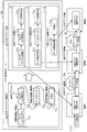
- FIG. 1 is a diagram showing an outline of the first embodiment.
- the information processing apparatus 10 automatically generates software to be executed by the first device 2 and the second device 3 connected via the network 4.
- the device identifier for identifying the first device 2 on the system is “A”
- the device identifier for identifying the second device 3 on the system is “B”.
- a process to be executed by one device is defined by combining definition information indicating the process content of the unit process.
- the information processing apparatus 10 includes a storage unit 11 and a processing unit 12.
- the storage unit 11 is, for example, a memory included in the information processing apparatus 10 or a storage device.
- the processing unit 12 is, for example, a processor or an arithmetic circuit included in the information processing apparatus 10.
- the storage unit 11 stores an overall process definition data 1 that defines a processing procedure when one apparatus performs all processes without performing distributed processing.
- the overall process definition data 1 the execution content of the first data process and the execution content of the second data process using the process result of the first data process are defined.
- the execution content of the first data processing is defined by the first data processing definition information 1a.
- the execution content of the second data processing is defined by the second data processing definition information 1 b.
- the overall process definition data 1 is an example of software for causing one device to execute the first data process and the second data process.
- the processing unit 12 automatically generates software for each device for performing distributed processing of the first data processing and the second data processing with different devices based on the overall processing definition data 1. For example, the processing unit 12 extracts, from the entire process definition data 1, the first data process definition information 1a which is a definition part of the execution content of the first data process. Next, the processing unit 12 generates data transmission definition information 1c that defines the execution content of processing of transmitting output data, which is the result of the first data processing, via the network 4. Then, the processing unit 12 sets, in the data transmission definition information 1c, a communication identifier for identifying communication between the first device 2 that executes the first data processing and the second device 3 that executes the second data processing.
- the processing unit 12 generates, as a communication identifier, information including, for example, a device identifier "A" for identifying the first device 2 and a device identifier "B" for identifying the second device 3, and the data transmission definition information 1c.
- the processing unit 12 generates partial process definition data 1-1 on the transmission side including the first data process definition information 1a and the data transmission definition information 1c in which the communication identifier is set.
- the processing unit 12 generates a file including the partial process definition data 1-1 and stores the file in the memory or the storage device.
- the partial process definition data 1-1 is an example of software for causing the first device 2 to execute the first data process.
- the partial process definition data 1-1 thus generated is used for the execution of the first data process by the first device 2 and includes the first data process definition information 1a and the data transmission definition information 1c. It is a data structure that it has.
- the first data processing definition information 1a is the first of the overall processing definition data 1 defining the execution content of the first data processing and the execution content of the second data processing using the processing result of the first data processing. It is a definition part of the execution content of data processing.
- the data transmission definition information 1 c defines the content of execution of processing for transmitting output data, which is the result of the first data processing, to the second device 3 via the network 4.
- the data transmission definition information 1c includes a communication identifier that identifies communication between the first device 2 that executes the first data processing and the second device 3 that performs the second data processing.
- the processing unit 12 also extracts, from the overall process definition data 1, second data process definition information 1 b which is a definition part of the execution content of the second data process. Next, the processing unit 12 performs the same communication as that set in the data transmission definition information 1c in the data reception definition information 1d that defines the execution content of processing for receiving output data as a result of the first data processing via the network 4 Set the identifier. Then, the processing unit 12 generates partial process definition data 1-2 on the receiving side including the second data process definition information 1b and the data reception definition information 1d in which the communication identifier is set. For example, the processing unit 12 generates a file including the partial process definition data 1-2 and stores the file in the memory or the storage device.
- the process definition data 1-2 is an example of software for causing the second device 3 to execute the second data process.
- the partial process definition data 1-2 generated in this manner is used for the execution of the second data process by the second device 3, and includes the second data process definition information 1b and the data reception definition information 1d. It is a data structure that it has.
- the second data processing definition information 1 b is the second of the overall processing definition data 1 defining the execution content of the first data processing and the execution content of the second data processing using the processing result of the first data processing. It is a definition part of the execution content of data processing.
- the data reception definition information 1 d defines the content of execution of processing in which the second device 3 receives output data, which is the result of the first data processing, via the network 4.
- the data reception definition information 1 d includes a communication identifier that identifies communication between the first device 2 that executes the first data processing and the second device 3 that executes the second data processing.
- the processing unit 12 transmits the partial process definition data 1-1 on the transmission side to the first device 2, and transmits the partial process definition data 1-2 on the reception side to the second device 3.
- the processing unit 12 transmits a file including each of the partial process definition data 1-1 and 1-2 to the first device 2 and the second device 3.
- the first device 2 can execute the processing assigned to the first device 2 based on the partial process definition data 1-1.
- the second device 3 can execute the process assigned to the second device 3 based on the partial process definition data 1-2.
- the first device 2 executes the first data processing according to the first data processing definition information 1a to generate output data.
- the first device 2 uniquely identifies the communication path by the communication identifier, and transmits the output data to the second device 3 via the network 4.
- the second device 3 uniquely identifies the communication path by the communication identifier according to the data reception definition information 1 d, and receives the output data from the first device 2. Then, the second device 3 executes the second data processing using the received output data in accordance with the second data processing definition information 1 b.
- the partial process definition data 1-1 and 1-2 have a communication identifier in the data structure. Therefore, when the first device 2 and the second device 3 execute processing using the partial process definition data 1-1, 1-2, the first device 2 and the second device 3 uniquely communicate with each other. The identified cooperative processing is possible. Moreover, the partial process definition data 1-1 and 1-2 are automatically generated based on the entire process definition data 1. That is, according to the first embodiment, automatic generation of software that causes the first device 2 and the second device 3 to cooperate with each other can be performed.
- the processing unit 12 can identify the first data processing and the second data processing by comparing the devices that execute each data processing. For example, the processing unit 12 first selects a judgment target data process from among a plurality of data processes defined in the entire process definition data 1. Next, the processing unit 12 executes, based on the information indicating the device that executes each of the plurality of data processings, the device that executes the judgment target data processing, and the other data processing using the processing result of the judgment target data processing. It is determined whether or not the same device is the same. If the devices at the deployment destination are different, the processing unit 12 determines that the determination target data processing is the first data processing, and determines another data processing using the processing result of the determination target data processing as the second data processing. In this way, it is possible to identify the part where communication between different devices occurs. As a result, the data transmission definition information 1c and the data reception definition information 1d can be appropriately added, and highly reliable distributed processing is possible.
- the processing unit 12 may determine the communication protocol used for communication between devices in accordance with the type of the network 4 used for communication. For example, based on the type of the network 4 connecting the first device 2 executing the first data processing and the second device 3 executing the second data processing, the processing unit 12 communicates the communication protocol when transmitting the output data. Decide. For example, if the network 4 is an external network such as a wide area network, the processing unit 12 determines to transmit using a highly secure communication protocol. If the network 4 is, for example, a local network in an enterprise, the processing unit 12 determines to transmit using a communication protocol that allows efficient processing. Then, the processing unit 12 generates partial process definition data 1-1 including the data transmission definition information 1c for transmitting the output data by the determined communication protocol. The processing unit 12 also generates partial process definition data 1-2 including data reception definition information 1d for receiving output data according to the determined communication protocol. As described above, by performing communication between devices by an appropriate communication protocol, it is possible to improve processing efficiency while maintaining the safety of data.
- a second embodiment will be described.
- generation and deployment of an IoT application operating on a distributed device environment can be easily realized using a flow-based application development environment.
- deploying an IoT application means sending the IoT application to the device, installing the IoT application on the device, and causing the device to start executing the IoT application.
- instructions for causing a device at a deployment destination to execute data processing on the application layer and service providing processing are described.
- FIG. 2 is a diagram illustrating an example of a flow-based application development environment.
- the application development server having a flow-based application development environment displays the entire application flow editing screen 91.
- a functional block display area 91a and a flow display area 91b are provided.
- the flow display area 91a is an editing area for creating an entire application flow 93 indicating a procedure to be executed by the IoT system.
- a function for causing the IoT system to execute a process and a procedure of the process are represented by nodes 93a and 93b corresponding to the function and a line connecting the nodes 93a and 93b.
- the nodes 93a and 93b are obtained by adding, to a functional block, definition information (such as parameters) of processing to be executed by the function corresponding to the functional block.
- the user selects a function block corresponding to the function to be executed by the IoT system from the function block display area 91a to the application development server, and arranges it as nodes 93a and 93b of the entire application flow 93 in the flow display area 91b. Perform the operation.
- the user specifies, for example, a process to be performed by the function corresponding to the nodes 93a and 93b by setting parameters in the arranged nodes 93a and 93b.
- the user performs an operation of connecting the right side of the node indicating the function to be executed first and the left side of the node indicating the function to be executed next to the application development server with a line.
- the right side of the node 93 a corresponding to the “function ⁇ ” and the left side of the node 93 b corresponding to the “function ⁇ ” are connected. This represents that the execution result of the process by “function ⁇ ” is used as the input of the process by “function ⁇ ”.
- the application development server creates whole application flow data 94 representing the whole application flow 93.
- the entire application flow data 94 is described by, for example, JSON (JavaScript (registered trademark) Object Notation).
- JSON JavaScript (registered trademark) Object Notation
- information (data processing definition information 94a, 94b) defining the processing to be executed by the device according to the nodes 93a, 93b is described.
- the identifier "566fcac9.d0f784" of the transfer destination node of the processing result is set as wires property information. That is, by tracing wires property information of a certain node, the connection relationship between the nodes can be known.
- a plurality of nodes can be grouped and defined as a subflow.
- One whole application may be defined by connecting a plurality of subflows.
- IoT application By connecting nodes realizing a specific data processing function on the entire application flow editing screen 91, it is possible to define a flow of data processing to be executed as an IoT application. That is, by simply connecting nodes graphically, IoT applications can be developed without coding in a programming language. If each device in the IoT system builds an execution base of processing based on the entire application flow data 94, it is possible to cause each device to execute the definition part of the node as the IoT application.
- the operating environment of Node-RED which is one of flow-based application development environments, can be built on various OSs.
- the IoT application that causes the device to execute processing corresponding to a part of nodes in the entire application flow 93 is called a distribution application.
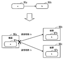
- the data structure of the overall application flow data 94 is not a data structure that is assumed to span distributed devices. That is, in the general application flow data 94, there is wires property information as information indicating the data transfer destination between the nodes 93a and 93b, but this simply indicates the data processing order between the nodes. Even if a function corresponding to each of the nodes 93a and 93b is deployed to a plurality of devices, and wires property information is regarded as identification information (communication path information) of a device to which data is transferred, it is possible to operate across devices There is not enough information to uniquely identify the other party.
- FIG. 3 is a diagram illustrating a first deployment example of the distribution application corresponding to each node indicated in the general application flow data.
- the distribution application 97a corresponding to the node 95a that is the data transmission source is deployed to the device 96a
- the distribution applications 97b and 97c corresponding to the node 95b that is the data transmission destination are two devices 96b and 96c. It is deployed.
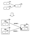
- FIG. 4 is a diagram illustrating a second deployment example of the distribution application corresponding to each node indicated in the general application flow data.
- the processing result of each of the two nodes 95a and 95b is transmitted to one node 95c.
- the distribution application 97a corresponding to the node 95a is deployed to the device 96a
- the distribution application 97b corresponding to the node 95b is deployed to the device 96b
- the distribution application 97c corresponding to the node 95c of the data transmission destination is deployed to the device 96c. ing.
- the devices 96a and 96b regard the transfer destination information held by the distribution applications 97a and 97b corresponding to the nodes 95a and 95b as the identifier of the device 96c of the transfer destination and use it as communication path information, data from the devices 96a and 96b It can be sent.
- the device 96c that has received the data can not determine from which device 96a or 96b the data is transmitted from data received from each of the two communication paths having the same communication identifier.
- the application development server automatically generates a distribution application corresponding to each device, having a communication identifier that has a unique route between the individual devices.
- FIG. 5 is a diagram showing an example of an IoT system configuration.
- An IoT system is built using various devices.
- the IoT system includes sensor nodes 41, 42, and so on which are connected to the sensors 31, 32, and so on and sensors 31, 32, and so on to transmit and receive sensor data.
- the IoT system also includes a GW (gateway) node 51 that relays data between the sensor node and the cloud computing system.
- the GW node 51 is connected to the cloud computing system via the wide area network 20, for example.
- the cloud computing system includes a plurality of servers 52, 53,.
- the servers 52, 53,... include various servers such as a web server, an application server, and a database server.
- terminal devices 61, 62,... are connected to the wide area network 20.
- the terminal devices 61, 62,... are, for example, personal computers or mobile terminal devices.
- An application development server 100 is further connected to the wide area network 20.
- the application development server 100 creates a distribution application to be executed on each of a plurality of devices included in the IoT system, and deploys the distribution application to each device.
- each of the sensor nodes 41, 42, ..., the GW node 51, the servers 52, 53, ..., the terminal devices 61, 62, ... is a deployment destination device.
- the sensor nodes 41, 42, ..., the GW node 51, the servers 52, 53, ..., the terminal devices 61, 62, ..., and the application development server 100 are realized by, for example, a computer.
- FIG. 6 is a diagram showing an exemplary configuration of hardware of the application development server.
- the application development server 100 is entirely controlled by the processor 101.
- a memory 102 and a plurality of peripheral devices are connected to the processor 101 via a bus 109.
- the processor 101 may be a multiprocessor.
- the processor 101 is, for example, a central processing unit (CPU), a micro processing unit (MPU), or a digital signal processor (DSP).
- CPU central processing unit
- MPU micro processing unit
- DSP digital signal processor
- At least a part of the functions realized by the processor 101 executing a program may be realized by an electronic circuit such as an application specific integrated circuit (ASIC) or a programmable logic device (PLD).
- ASIC application specific integrated circuit
- PLD programmable logic device
- the memory 102 is used as a main storage device of the application development server 100.
- the memory 102 temporarily stores at least part of an OS program and application programs to be executed by the processor 101.
- the memory 102 also stores various data used for processing by the processor 101.
- a volatile semiconductor memory device such as a random access memory (RAM) is used.
- the peripheral devices connected to the bus 109 include a storage device 103, a graphic processing device 104, an input interface 105, an optical drive device 106, a device connection interface 107, and a network interface 108.
- the storage device 103 electrically or magnetically writes data to and reads data from a built-in storage medium.
- the storage device 103 is used as an auxiliary storage device of a computer.
- the storage device 103 stores an OS program, an application program, and various data.
- an HDD Hard Disk Drive
- an SSD Solid State Drive
- a monitor 21 is connected to the graphic processing device 104.
- the graphic processing device 104 displays an image on the screen of the monitor 21 in accordance with an instruction from the processor 101.
- the monitor 21 includes a display device using an organic EL (Electro Luminescence), a liquid crystal display device, and the like.
- a keyboard 22 and a mouse 23 are connected to the input interface 105.
- the input interface 105 transmits the signal sent from the keyboard 22 or the mouse 23 to the processor 101.
- the mouse 23 is an example of a pointing device, and other pointing devices can also be used. Other pointing devices include touch panels, tablets, touch pads, and track balls.
- the optical drive device 106 reads data recorded on the optical disc 24 using a laser beam or the like.
- the optical disc 24 is a portable recording medium in which data is recorded so as to be readable by reflection of light.
- the optical disc 24 includes a DVD (Digital Versatile Disc), a DVD-RAM, a CD-ROM (Compact Disc Read Only Memory), a CD-R (Recordable) / RW (ReWritable), and the like.
- the device connection interface 107 is a communication interface for connecting peripheral devices to the application development server 100.
- the memory device 25 and the memory reader / writer 26 can be connected to the device connection interface 107.
- the memory device 25 is a recording medium provided with a communication function with the device connection interface 107.
- the memory reader / writer 26 is a device that writes data to the memory card 27 or reads data from the memory card 27.
- the memory card 27 is a card-type recording medium.
- the network interface 108 is connected to the wide area network 20.
- the network interface 108 transmits and receives data to and from another computer or communication device via the wide area network 20.
- the processing function of the application development server 100 in the second embodiment can be realized.
- sensor nodes 41, 42, ..., GW node 51, servers 52, 53, ..., and terminal devices 61, 62, ... may also be realized by hardware similar to that of the application development server 100.
- the information processing apparatus 10 shown in the first embodiment can also be realized by the same hardware as the application development server 100 shown in FIG.
- the application development server 100 realizes the processing function of the second embodiment by executing a program recorded in a computer readable recording medium, for example.
- the program describing the processing content to be executed by the application development server 100 can be recorded in various recording media.
- a program to be executed by the application development server 100 can be stored in the storage device 103.
- the processor 101 loads at least a part of the program in the storage apparatus 103 into the memory 102 and executes the program.
- the program to be executed by the application development server 100 can also be recorded in a portable recording medium such as the optical disk 24, the memory device 25, and the memory card 27.
- the program stored in the portable recording medium becomes executable after being installed in the storage apparatus 103 under the control of the processor 101, for example.
- the processor 101 can also read and execute the program directly from the portable recording medium.
- FIG. 7 is a block diagram showing an example of the function of the application development server.
- the application development server 100 includes a device information storage unit 110, an entire application flow data storage unit 120, a deployment instruction unit 130, an entire application flow editing unit 140, a distribution application generation unit 150, and a distribution application deployment unit 160.
- the device information storage unit 110 stores information on the deployment destination device included in the IoT system. For example, a part of the storage area of the memory 102 or the storage device 103 is used as the device information storage unit 110.
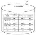
- FIG. 8 is a diagram illustrating an example of the device information storage unit.
- a device management table 111 is stored in the device information storage unit 110.
- the IP address of the deployment destination device, the subnet mask, and the device identifier are set in association with the device name of the deployment destination device.
- the subnet mask is information indicating the range of the network unit in the IP address.
- the value (network address) of the network unit can be acquired by bitwise ANDing the IP address and the subnet mask. It can be determined that a plurality of deployment destination devices having a common network address are connected by the internal network.
- the device identifier is an identifier that uniquely identifies the deployment destination device.
- the device identifier can be used as an identifier of a communication path between deployment destination devices. For example, by creating a communication identifier by combining the device identifier of the deployment destination device of the data transmission source and the device identifier of the deployment destination device of the data transmission destination, an identifier uniquely identifying the communication path between the devices is generated. Can.
- the IP address may be used as the device identifier of the deployment destination device.
- the information in the device information storage unit 110 is registered in advance, for example, by the system administrator. Further, when the deployment destination device is connected to the network, the deployment destination device may transmit the device name, the IP address, the subnet mask, and the device identifier to the application development server 100. In this case, the application development server 100 stores the information sent from the deployment destination device in the device information storage unit 110.
- the whole application flow data storage unit 120 stores data (whole application flow data) indicating a processing procedure when a single device executes a process to be performed by the IoT system.
- FIG. 9 is a diagram illustrating an example of the entire application flow data storage unit.
- the general application flow data storage unit 120 stores general application flow data 121.
- the whole application flow data 121 is created by the whole application flow editing unit 140, and is stored in the whole application flow data storage unit 120 by the deployment instruction unit 130, for example. Details of the content of the entire application flow data 121 will be described later (see FIG. 17).
- the deployment instruction unit 130 controls distribution application generation based on the entire application flow and deployment of the distribution application. For example, upon receiving the overall application flow data 121 from the overall application flow editing unit 140, the deployment instruction unit 130 stores the overall application flow data 121 in the overall application flow data storage unit 120. Also, the deployment instruction unit 130 receives, from the application developer, a designation input of a deployment destination device that is a deployment destination of the function corresponding to each node included in the entire application flow. This specification input can be received, for example, by having the application developer select a deployment destination device from the list of deployment destination devices displayed on the screen.
- the deployment instruction unit 130 refers to the device information storage unit 110 and displays a list of deployment destination device names registered in the device management table 111 on the screen.
- the application developer selects from the entire application flow the node to which the deployment destination device is to be specified, and selects the name of the deployment destination device to which the function corresponding to that node is to be deployed from the list of deployment destination device names Do. Then, the deployment instruction unit 130 recognizes that the deployment destination of the function corresponding to the selected node is the selected deployment destination device.
- the deployment instruction unit 130 transmits the general application flow data 121 in the general application flow data storage unit 120 to the distribution application generation unit 150. Furthermore, the deployment instruction unit 130 specifies, for the distribution application generation unit 150, the deployment destination of the function corresponding to each node indicated in the general application flow data 121. After that, when the distribution application flow data for each deployment destination device is generated by the distribution application generation unit 150, the deployment instruction unit 130 specifies the distribution application deployment destination for the distribution application deployment unit 160, and performs distribution. Instruct application deployment.
- the whole application flow editor 140 creates the whole application flow according to the input from the application developer.
- the entire application flow editor 140 is, for example, a flow-based application development environment such as Node-RED.
- the entire application flow editing unit 140 displays an editing screen of the entire application flow on the Web browser, and creates an entire application flow in the editing screen of the entire application flow according to an input by the application developer.
- the whole application flow editing unit 140 generates the whole application flow on the whole application flow editing screen, the whole application flow data 121 is generated, and the generated whole application flow data 121 is, for example, the whole through the deployment instruction unit 130 It is stored in the application flow data storage unit 120.
- the distribution application generation unit 150 generates a distribution application for each deployment destination of the function corresponding to the node based on the general application flow data 121 according to the instruction from the deployment instruction unit 130.
- the distribution application generation unit 150 transmits the generated distribution application to the distribution application deployment unit 160.
- the distribution application deploying unit 160 deploys the distribution application to the deployment destination device corresponding to the distribution application in accordance with the instruction from the deployment instruction unit 130. For example, the distribution application deployment unit 160 transmits distribution application flow data indicating the distribution application to the deployment destination device, and instructs the deployment destination device to install and start the distribution application.
- FIG. 10 is a diagram illustrating an example of automatic generation and deployment processing of a distribution application.
- the whole application flow editing unit 140 creates the whole application flow 71 based on the input of the application developer.
- a deployment destination of the corresponding function is designated by the application developer.
- the deployment destination of the function (sensor device control, sensor input value processing) corresponding to the nodes 71a and 71b is “device A”.
- the deployment destination of the function (filtering) corresponding to the node 71 c is “device B”.
- the deployment destination of the function (visualization) corresponding to the node 71 d is “device C”.
- the entire application flow 71 uses, for example, data acquired from a sensor as input data, data acquisition processing specific to a specific device, processing of acquired data, processing of filtering data (for example, averaging, etc.), visualization of acquired data, etc. Indicates to do in order.
- the general application flow data 121 defining the general application flow 71 created by the general application flow editor 140 is distributed by the deployment instruction unit 130 to the general application flow data storage unit 120. Read from Then, the whole application flow data 121 is transmitted from the deployment instruction unit 130 to the distribution application generation unit 150. Then, the distribution application generation unit 150 generates the distribution applications 72 to 74 based on the entire application flow data 121.
- the distribution application generation unit 150 first divides the nodes in the entire application flow 71 for each deployment destination device.
- the deployment destination is divided into nodes 71a and 71b of "device A”
- the deployment destination is a node 71c of "device B”
- the deployment destination is a node 71d of "device C”.
- the distribution application generation unit 150 replaces the link of the divided part of the entire application flow 71 (connection line in the entire application flow 71) with the communication processing node. Specifically, the distribution application generation unit 150 adds a data transmission processing node on the output side (right side in the figure) of the data transmission source node, and the data on the input side (left side in the figure) of the data transmission destination node Add a node for reception processing. In the example of FIG. 10, a node 71e of data transmission processing is added to the output side of the node 71b.
- a node 71f of data reception processing is added to the input side of the node 71c
- a node 71g of data transmission processing is added to the output side of the node 71c
- a node 71h for data reception processing is added to the input side of the node 71d.
- the nodes 71 e and 71 g of the added data transmission process are assigned, for example, an identifier uniquely indicating communication with the device of the data transmission destination. Further, an identifier uniquely indicating communication with the device of the data transmission source, for example, is assigned to the added nodes 71f and 71h of the data reception process.
- adding a node to the output side of an existing node means adding a node to be added to the application flow in the distributed application flow, and connecting the communication link between the output side of the existing node and the input side of the node to be added. It is to connect with the line shown.
- Adding a node on the input side of an existing node means adding a node to be added to the application flow in the distributed application flow, and indicating a communication link between the input side of the existing node and the output side of the node to be added. It is to connect with a line.
- the distribution applications 72 to 74 for each deployment destination device are generated.
- the generated distribution applications 72 to 74 are deployed to the designated deployment destination devices. Specifically, the distribution application 72 for "device A” is deployed to “device A”, the distribution application 73 for "device B” is deployed to “device B”, and the distribution application 74 for "device C” Are deployed to "Device C”.
- the distribution application generation unit 150 when adding a node for data transmission or data reception, adds a node that performs communication according to a common communication protocol on the data transmission side and the data reception side. For example, when high security is required for communication, the distribution application generation unit 150 determines the communication protocol to be a protocol having a high security function. That is, in the case of communication via a wide area network such as the Internet, there is a risk that data may be leaked to a third party. In such a case, the distribution application generation unit 150 transmits data for communication using a protocol having a high security function such as HTTP (Hypertext Transfer Protocol) so that transmitted data is not leaked to a third party. Add a receiving node. HTTP is a protocol capable of communication using an authentication or encryption technology such as, for example, HTTPS (Hypertext Transfer Protocol Secure).
- HTTPS Hypertext Transfer Protocol Secure
- the distribution application generation unit 150 determines the communication protocol as a protocol that enables efficient communication. For example, when collecting data from a large amount of devices via a private network such as a local network in an enterprise, if the processing load for individual data communication is high, the load on the collected devices will be excessive. At the same time, the communication load on the network is also excessive. In such a case, the distribution application generation unit 150 adds data transmission and data reception nodes for communication by a protocol that enables efficient data communication such as MQTT (Message Queue Telemetry Transport). MQTT is a protocol that has a very small header size compared to HTTP, and can reduce the amount of communication and the load on devices that send and receive.
- MQTT Message Queue Telemetry Transport
- the "device A” and the “device B” are connected by the local network 20a. That is, for the “device A”, the “device B” is a device connected via the internal network.
- the “device B” and the “device C” are connected by the wide area network 20. That is, for the “device B”, the “device C” is a device connected by an external network.
- the distribution application generation unit 150 determines the communication protocol according to whether the data transmission destination is connected to the data transmission source device via the internal network or connected via the external network. Do.
- FIG. 11 is a diagram illustrating an example of determination of a communication protocol.
- the distribution application generation unit 150 extracts, from the overall application flow 71, a node whose deployment destination device of the data transmission destination is different from its own deployment destination device among the nodes that are data transmission sources. In the example of FIG. 11, two nodes of the node 71b and the node 71c are extracted.
- the distribution application generation unit 150 determines whether the deployment destination device of the extracted node and the deployment destination device of the node of the data transmission destination are connected via the internal network, via the external network Determine if it is connected.
- the distribution application generation unit 150 refers to the device management table 111 in the device information storage unit 110, and acquires the network address of the deployment destination device based on the IP address of the deployment destination device and the subnet mask. Then, the distribution application generation unit 150 determines that the communication is via the internal network if the network addresses of the transmission destination deployment destination device and the transmission destination deployment destination device are common. The distribution application generation unit 150 determines that the communication is via an external network if the network addresses of the deployment destination device of the transmission source and the deployment destination device of the transmission destination are different. In the example of FIG. 11, the node 71b is determined to be communication via the internal network, and the node 71c is determined to be communication via the external network.
- the distribution application generation unit 150 adds a node 71 e of data transmission processing for performing data transmission by MQTT on the output side of the node 71 b for transmitting data via the internal network.
- the distribution application generation unit 150 adds a node 71g of data transmission processing that performs data transmission by HTTP on the output side of the node 71c that transmits data via the external network.
- the distribution application generation unit 150 adds a node 71f of data reception processing for performing data reception by MQTT on the input side of the node 71c of the data transmission destination of the node 71b that transmits data via the internal network.
- the distribution application generation unit 150 adds a node 71h of data reception processing that performs data reception by HTTP to the input side of the node 71d of the data transmission destination of the node 71c that transmits data via the external network.
- the deployment destination devices can communicate between the devices using an appropriate protocol.
- FIG. 12 is a flow chart showing a distribution application generation and deployment procedure. Hereinafter, the process illustrated in FIG. 12 will be described in order of step number.
- the overall application flow editing unit 140 creates an overall application flow that defines data processing to be executed as an IoT application based on input from the application developer.
- the deployment instruction unit 130 designates, from the application developer, with which device on the actual IoT system the processing is to be performed on the node or subflow defined in the overall application flow (deployment destination device) Accept For example, the deployment instruction unit 130 displays the device name registered in the device management table 111 on the monitor 21 as a deployment destination device candidate.
- the application developer selects, for each node or subflow, a deployment destination device that executes a function corresponding to the node or subflow from among the device names displayed as candidates.
- the deployment instruction unit 130 stores the device name selected for each node or subflow in the memory 102 as the device name of the deployment destination device of that node or subflow.
- the deployment instruction unit 130 receives a deployment application deployment instruction from the application developer.
- the deployment instruction separates the entire application for each deployment destination device, adds an appropriate function to generate a distribution application, and instructs processing to transfer the distribution application to the corresponding deployment destination device.
- the deployment instruction unit 130 transmits, to the distribution application generation unit 150, overall application flow data representing the overall application flow and deployment destination information of each node in the overall application flow data.
- the distribution application generation unit 150 generates a distribution application based on the entire application flow and the deployment destination information. Details of the distribution application generation process will be described later (see FIG. 13).
- the distribution application generation unit 150 transmits distribution application flow data indicating the generated distribution application to the distribution application deployment unit 160.
- the distribution application deploying unit 160 deploys the distribution application to the deployment destination device of the distribution application. Specifically, the distribution application deployment unit 160 transmits distribution application flow data of the distribution application for each deployment destination device to the deployment destination device corresponding to the distribution application. Various communication protocols such as HTTP communication and websocket communication can be used as communication protocols when sending distribution application flow data from the distribution application deployment unit 160 to the deployment destination device. Furthermore, the distribution application deployment unit 160 transmits, to the deployment destination device, a distribution application installation and activation request based on the transmitted distribution application flow data. Thus, the deployment destination device performs installation work and activates the distribution application so that the process defined in the distribution application flow data can be executed.
- Various communication protocols such as HTTP communication and websocket communication can be used as communication protocols when sending distribution application flow data from the distribution application deployment unit 160 to the deployment destination device.
- the distribution application deployment unit 160 transmits, to the deployment destination device, a distribution application installation and activation request based on the transmitted distribution application flow data.
- the deployment destination device performs installation work and
- the deployment destination device may have an API (Application Programming Interface) for importing distribution application flow data.
- the distribution application deployment unit 160 sends data to, for example, an API for distribution application flow registration of the deployment destination device.
- the distribution application flow data is set as an execution target in the execution software of the distribution application flow data in the deployment destination device.
- deployment of the distribution application by the distribution application deployment unit 160 may be performed continuously from the generation of the distribution application in the distribution application generation process, or after the generation of the distribution application, an instruction of an arbitrary timing from the application developer. It may be done accordingly.
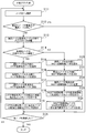
- FIG. 13 is a flowchart illustrating an example of a distribution application generation process. The process shown in FIG. 13 will be described below in order of step number.
- the distribution application generation unit 150 selects one node from the entire application flow.
- the distribution application generation unit 150 based on the designation of the deployment destination device received in step S102, the deployment destination device of the node (transfer destination node) that is the transfer destination of the output data of the selected node (selected node). Determines whether it is the same as the deployment destination device of the selected node. If the deployment destination devices are the same, the process proceeds to step S125. If the deployment destination device is different, the process proceeds to step S113.
- the distribution application generation unit 150 separates the application flow including the selected node between the selected node and the transfer destination node. For example, the distribution application generation unit 150 separates the application flow including the selected node into an application flow whose end is the selected node and an application flow whose head is the transfer destination node. The application flow generated by separation becomes a distribution application flow. The distribution application flow may be further separated. By separating the application flow, application flow data (distribution application flow data) indicating a distribution application flow after separation is generated.
- the distribution application generation unit 150 automatically edits the distribution application flow by the processing of the following steps S114 to S124.
- the editing process of the distribution application generation unit 150 is a process of editing distribution application flow data in the memory 102.
- Step S114 The distribution application generation unit 150 determines whether the transfer destination node is connected via an external network. For example, when the address of the network unit in the IP address of the selected node and the transfer destination node is different, for example, the distribution application generation unit 150 determines that the connection is made via an external network. If the distribution application generation unit 150 is connected via an external network, the process proceeds to step S115. If the distribution application generation unit 150 is connected via the internal network, the process proceeds to step S120.
- the distribution application generation unit 150 adds an HTTP transmission processing node to the output side of the selected node.
- the HTTP transmission processing node to be added is, for example, a node corresponding to a functional block in which processing for passing through an HTTP proxy server installed for connection to an external network is described. Furthermore, the distribution application generation unit 150 adds a response node for processing the response from the transfer destination node on the output side of the HTTP transmission processing node.
- the distribution application generation unit 150 adds an HTTP reception processing node to the input side of the transfer destination node. Furthermore, the distribution application generation unit 150 adds a response node for sending an HTTP reception response to the selected node on the output side of the HTTP reception processing node.
- the distribution application generation unit 150 changes the transfer destination of the selected node to the added HTTP transmission processing node. For example, the distribution application generation unit 150 changes the information indicating the transfer destination of the selected node to the node ID of the HTTP transmission processing node.
- Step S118 The distribution application generation unit 150 assigns the node ID of the transfer destination node to the transfer destination information of the added HTTP reception processing node.
- Step S119 The distribution application generation unit 150 sets the IP address of the deployment destination device of the transfer destination node in the added HTTP transmission processing node. Thereafter, the distribution application generation unit 150 proceeds with the process to step S125.
- the distribution application generation unit 150 adds an MQTT transmission processing node to the output side of the selected node.
- the distribution application generation unit 150 adds an MQTT reception processing node to the input side of the transfer destination node.
- the distribution application generation unit 150 changes the transfer destination of the selected node to the added MQTT transmission processing node. For example, the distribution application generation unit 150 changes the information indicating the transfer destination of the selected node to the node ID of the MQTT transmission processing node.
- the distribution application generation unit 150 assigns the node ID of the transfer destination node to the transfer destination information of the added MQTT reception processing node.
- the distributed application generation unit 150 sets, to each of the added MQTT transmission processing node and the added MQTT reception processing node, a communication identifier uniquely indicating a set of the MQTT transmission processing node and the MQTT reception processing node. .
- the communication identifier in MQTT is called a topic.
- Step S125 The distribution application generation unit 150 determines whether all the nodes in the entire application flow have been selected. The distribution application generation unit 150 ends the distribution application generation process if all the nodes have been selected. If there is an unselected node, the distribution application generation unit 150 proceeds with the process to step S111.
- the entire application is divided into nodes for which the specified deployment destination device is common, and the communication processing function between the deployment destination devices for cooperation of the distribution application in the distributed environment is distributed on the distribution application flow. Can be added automatically to the appropriate position of Moreover, an appropriate communication protocol can be applied depending on whether the communication between the deployment destination devices passes through the external network.
- the distribution application generation unit 150 adds HTTP communication processing as a communication processing function. Then, the distribution application generation unit 150 sets the IP address of the deployment destination device as the transmission destination to the HTTP transmission processing node automatically added by separation of the application flow, thereby enabling HTTP communication.
- the HTTP reception processing node since the IP address of the transmission source of the packet is included in HTTP communication, the HTTP reception processing node uniquely identifies the transmission source by the IP address of the received packet even when processing results of a plurality of distribution applications are received. Can be distinguished.
- the distribution application generation unit 150 adds MQTT communication processing as a communication processing function. Then, the distributed application generation unit 150 enables MQTT communication by setting an appropriate topic to the MQTT node automatically added by separation of the application flow.
- the deployment destination device When the deployment destination device receives the distribution application flow data transferred from the application development server 100, the deployment destination device executes the distribution application based on the distribution application flow data.
- FIG. 14 is a block diagram illustrating an example of the function of the deployment destination device.
- the deployment destination device 200 includes a distribution application reception unit 210, a distribution application flow data storage unit 220, a distribution application control unit 230, a function execution module storage unit 240, and an application execution unit 250.
- the distribution application receiving unit 210 receives distribution application flow data from the application development server 100 together with instructions for installation and activation of the distribution application.
- the distribution application reception unit 210 stores the received distribution application flow data in the distribution application flow data storage unit 220.
- the distribution application flow data storage unit 220 stores distribution application flow data.
- the distribution application flow data storage unit 220 is realized by part of a memory or a storage area of a storage device.
- the distribution application control unit 230 controls the execution of the distribution application 261 based on the distribution application flow data stored in the distribution application flow data storage unit 220. For example, the distribution application control unit 230 reads out distribution application flow data from the distribution application flow data storage unit 220, and transmits the read out distribution application flow data to the application execution unit 250. Then, the distribution application control unit 230 instructs the application execution unit 250 to start the distribution application based on the distribution application flow data.
- the function execution module storage unit 240 stores the execution modules 241, 242,... For each function.
- the execution modules 241, 242,... are program modules for realizing the functions of the functional blocks prepared in advance in the general application flow editing unit 140 of the application development server 100 by the deployment destination device 200.
- the function execution module storage unit 240 is realized by, for example, a part of a memory or a storage area of a storage device.
- the application execution unit 250 starts the execution of the distribution application 261 based on the distribution application flow data. For example, the application execution unit 250 executes the distribution application 261 using an execution module corresponding to the function name indicated in the distribution application flow data. At this time, the application execution unit 250 sets definition information such as parameters indicated in the distribution application flow data as an execution condition of the distribution application 261.
- the application execution unit 250 acquires, for example, data indicating the execution result of the distribution application by another deployment destination device 200a, and processes the acquired data based on the distribution application 261. Further, the application execution unit 250 transmits, for example, the execution result of the process based on the distribution application 261 to the other deployment destination device 200b.
- the sensor nodes 41, 42, ..., the GW node 51, the servers 52, 53, ..., the terminal devices 61, 62, ... each have the function of the deployment destination device 200 shown in Fig. 14. There is.
- FIG. 15 is a flowchart illustrating an example of a procedure of processing by the deployment destination device. Hereinafter, the process shown in FIG. 15 will be described in order of step number.
- the distribution application receiving unit 210 receives distribution application flow data from the application development server 100.
- the distribution application reception unit 210 stores the received distribution application flow data in the distribution application flow data storage unit 220.
- the distribution application control unit 230 sets the received distribution application flow data as an execution target of the application execution unit 250. For example, when the application execution unit 250 has an interface for fetching (importing) application flow data, the distribution application control unit 230 causes the application execution unit 250 to fetch the received distribution application flow data via the interface. Then, the distribution application control unit 230 instructs the application execution unit 250 to execute distribution application flow data (start of the distribution application).
- the application execution unit 250 starts the execution of the distribution application based on the distribution application flow data. For example, the application execution unit 250 reads an execution module corresponding to each node from the function execution module storage unit 240 in the order indicated by the distribution application flow data, and executes the read function execution module.
- the processing of the distribution application is executed based on the distribution application flow data transmitted to the deployment destination device.
- the distribution application flow data transmitted to the deployment destination device.
- FIG. 16 is a diagram showing an example of the entire application flow editing screen.
- the data format of the generated date data is converted to date character format (Fri Dec 15 2017 14:10:21 GMT + 0900 (Tokyo (standard time), etc.)).
- date character format Fri Dec 15 2017 14:10:21 GMT + 0900 (Tokyo (standard time), etc.)
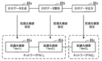
- the functional blocks displayed in the functional block display area 81a of the general application flow editing screen 81 include a function block 82a of "date data generation”, a function block 82b of "date data shaping", and a function of "date data output” A block 82c is included.
- the application developer makes an input to the entire application flow editing unit 140, and arranges nodes 83a to 83c corresponding to the functional blocks 82a to 82c in the flow display area 81b.
- the application developer makes an input to the entire application flow editor 140, and the communication link between the output side of the "date data generation” node 83a and the input side of the "date data shaping" node 83b is made. Connect with the indicated line.
- the application developer makes an input to the entire application flow editor 140, and indicates the communication link of the output side of the node 83b of "date data shaping" and the input side of the node 83c of "date data output”. Connect by wire. Thus, the entire application flow 83 is completed.
- the overall application flow editor 140 When the overall application flow 83 is completed, the overall application flow editor 140 generates overall application flow data indicating the overall application flow 83.
- the whole application flow data is stored in the whole application flow data storage unit 120 via the deployment instruction unit 130.
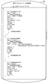
- FIG. 17 is a diagram showing an example of the entire application flow data.
- the entire application flow data 84 is created by the JSON data structure.
- the overall application flow data 84 includes descriptions (data processing definition information 84-1 to 84-3) defining each of the nodes 83a, 83b and 83c in the overall application flow 83.
- Data processing definition information 84-1 to 84-3 defining each node 83a, 83b, 83c indicate the identifier of that node as the value of the item name "id".
- the value of the item name "name” the name of the functional block corresponding to the node is shown.
- the identifier of the data transmission destination node is indicated as the value of the item name "wires”.
- the application developer makes an input to the deployment instruction unit 130 for specifying the deployment destination device of the function corresponding to each of the nodes 83a to 83c. Do.
- FIG. 18 is a diagram showing an example of designation of a deployment destination device.
- the deployment destination device 85a is designated as a deployment destination device for deploying the function corresponding to the node 83a of "date data generation”.
- the deployment destination device 85 b is designated as a deployment destination device for deploying the function corresponding to the node 83 b of “date data shaping”.
- the deployment destination device 85c is designated as a deployment destination device for deploying the function corresponding to the node 83c of "date data output”.
- the identifier of the deployment destination device 85a is “dev1”, and the deployment destination device 85a belongs to the network “N1”.
- the identifier of the deployment destination device 85b is “dev2”, and the deployment destination device 85b belongs to the network "N1”.
- the identifier of the deployment destination device 85c is "dev3”, and the deployment destination device 85c belongs to the network "N2". That is, although the deployment destination device 85a and the deployment destination device 85b belong to the same local network, the deployment destination devices 85a and 85b and the deployment destination device 85c belong to different networks.
- the deployment instruction unit 130 having received the designation of the deployment destination device transmits, to the distribution application generation unit 150, the entire application flow data 84 and the information indicating the deployment destination devices of the nodes 83a to 83c. Then, the distribution application generation unit 150 generates distribution application flow data for each of the deployment destination devices 85a to 85c based on the entire application flow data 84.
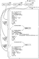
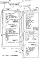
- FIG. 19 is a diagram showing an example of distribution application flow data for a deployment destination device for deploying the “date data generation” function.
- the deployment destination device 85 a to which the “date data generation” function is deployed and the deployment destination device 85 b of the “date data shaping” function belong to the same local network.
- the distribution application generation unit 150 generates distribution application flow data 84a representing the distribution application flow 83-1 for transmitting the date data generated by the "date data generation” function by the MQTT.
- the distribution application flow 83-1 includes a node 83a of "date data generation” and a node 83d corresponding to a functional block "data transmission_MQTT" that performs data transmission by MQTT.
- the output side of the node 83a and the input side of the node 83d are connected by a line indicating a communication link.
- the identifier of the transmission destination node indicated by the value of the item name "wires" in the data processing definition information 84a-1 defining the node 83a corresponding to "date data generation" is the identifier of the node 83d. has been changed. Further, data processing definition information 84a-2 defining the node 83d is added to the distribution application flow data 84a. In the data processing definition information 84a-2 defining the node 83d, the value of the MQTT topic is set as the value of the item name "topic".
- the value of the MQTT topic is the identifier “dev1” of the deployment destination device 85 a that is the deployment destination of the node 83 a of “date data generation” and the identifier “of deployment destination device 85 b that is the deployment destination of the node 83 b of“ date data formatting ” "dev2".
- the value "dev1todev2" is set as the MQTT topic.
- the detailed information of the broker (transfer control function) used for the MQTT communication is described in the definition part having the value of the item name “broker” as the value of the item name “id”.
- the deployment destination device 85a to which the “date data generation” function is deployed generates date data based on such distribution application flow data 84a, and transmits the generated date data to the deployment destination device 85b by MQTT. Can.
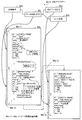
- FIG. 20 is a diagram of an example of distribution application flow data for a deployment destination device for deploying the “date data shaping” function.
- the deployment destination device 85b to which the "date data shaping" function is deployed and the deployment destination device 85c of the "date data output” function belong to different networks.
- the distribution application generation unit 150 generates distribution application flow data 84b representing the distribution application flow 83-2 for transmitting, by HTTP, the date data formatted by the "date data shaping" function.
- the distribution application flow 83-2 includes a node 83e of “data reception_MQTT”, a node 83b of “date data shaping”, a node 83f of “data transmission_HTTP”, and a node 83g of “HTTP response”.
- the node 83e corresponds to a functional block that receives data in the MQTT.
- the node 83f corresponds to a functional block that transmits data by HTTP.
- the node 83g corresponds to a functional block that performs processing according to the response to the PUT request by HTTP.
- the output side of the node 83e and the input side of the node 83b are connected by a line indicating a communication link.
- the output side of the node 83b and the input side of the node 83f are connected by a line indicating a communication link. Furthermore, the output side of the node 83f and the input side of the node 83g are connected by a line indicating a communication link.
- the data processing definition information 84b-1 defining the node 83e corresponding to "data reception_MQTT" indicates the name of the functional block corresponding to the node 83e as the value of the item name "name”.
- the identifier of the data transmission destination node 83b is shown as the value of the item name "wires”.
- the detailed information of the broker (transfer control function) used for the MQTT communication is described in the definition part having the value of the item name “broker” as the value of the item name “id”.
- the value of the item name "wires” is changed to the identifier of the node 83f.
- the value of the item name "name” indicates the name of the functional block corresponding to the node 83f.
- the value of the item name "method” indicates that data transmission is performed in the PUT process of HTTP.
- the data transmission destination is indicated by the URL of the deployment destination device as the transmission destination in the PUT process, which is set as the value of the item name "url”.
- the identifier of the node 83 g of the transmission destination of the data indicating the PUT processing result (the transmission of the PTU processing request) is shown.
- the data processing definition information 84b-4 defining the node 83g corresponding to "HTTP response" indicates the name of the functional block corresponding to the node 83f as the value of the item name "name”.
- the deployment destination device 85b which is the deployment destination of the "date data shaping" function, receives the date data based on such distribution application flow data 84b, shapes the received date data, and formats the date data after shaping, It can be transmitted to the deployment destination device 85c by HTTP.
- FIG. 21 is a diagram showing an example of distribution application flow data for a deployment destination device for deploying the “date data output” function.
- the distribution application generation unit 150 receives the formatted date data, and generates distribution application flow data 84c that represents the distribution application flow 83-3 that outputs the received date data.
- the distribution application flow 83-3 includes a “periodically acquired” node 83h, a “data reception_HTTP” node 83i, a “date data output” node 83c, and an “HTTP response” node 83j.
- the node 83 h corresponds to a functional block that periodically acquires data.
- the node 83i corresponds to a functional block that receives data by HTTP.
- the node 83 j corresponds to a functional block that performs processing according to the response to the HTTP GET request.
- the output side of the node 83 h and the input side of the node 83 i are connected by a line indicating a communication link.
- the output side of the node 83i and the input side of the node 83c are connected by a line indicating a communication link. Furthermore, the output side of the node 83i and the input side of the node 83j are connected by a line indicating a communication link.
- the data processing definition information 84c-1 defining the node 83h corresponding to "periodical acquisition” indicates the name of the functional block corresponding to the node 83h as the value of the item name "name”. Further, as the value of the item name "repeat", it is shown that data reception is performed every 10 seconds. The identifier of the data transmission destination node 83i is shown as the value of the item name "wires”.
- Data processing definition information 84c-2 defining the node 83i corresponding to "data reception_HTTP" indicates the name of the functional block corresponding to the node 83i as the value of the item name "name”. Further, as the value of the item name "method”, it is shown that data is acquired by HTTP GET processing. As the data acquisition destination, the position (the position in the deployment destination device 85c) which is the acquisition destination in the GET process is indicated by the URL set to the value of the item name “url”. Then, as the value of the item name "wires”, the identifiers of the two nodes 83c and 83j as data transmission destinations are shown.
- the data processing definition information 84c-3 defining the node 83c corresponding to "date data output” indicates the name of the functional block corresponding to the node 83c as the value of the item name "name”.
- the data processing definition information 84c-4 defining the node 83j corresponding to "HTTP response" indicates the name of the functional block corresponding to the node 83j as the value of the item name "name”.
- the deployment destination device 85c which is the deployment destination of the “date data output” function, receives the formatted date data based on such distribution application flow data 84c, and outputs the date data to a previously designated output destination ( Output to a predetermined file, monitor, etc.).
- the distributed application flow data 84a to 84c as shown in FIGS. 19 to 21 are deployed to the deployment destination devices 85a to 85c, respectively.
- the data format of the generated date data is converted to the date character format, and the output process is executed.
- the application development server 100 automatically divides the entire application flow into a plurality of distribution application flows that define the processing procedure of each of the plurality of distribution applications based on the deployment destination devices designated to each node. Can. Furthermore, the application development server 100 enables data communication between deployment destination devices of the distribution application by adding a node for data transmission and reception via the network to the distribution application flow. At this time, an identifier (topic or URL) uniquely identifying the deployment destination device in which the node serving as the communication partner is deployed is assigned to the node for data transmission and reception, so each deployment destination to which the distribution application is deployed The device can uniquely identify the communication partner. As a result, for example, as shown in FIG.
- the transmission source device can distinguish between the transmission destination devices and transmit appropriate data.
- the device that receives the data uniquely identifies the device that is the transmission source of the data, and the transmission source and the received data Appropriate data processing can be implemented.
- the application development server 100 can perform efficient communication using MQTT as the communication protocol.
- the application development server 100 can perform highly reliable communication by using HTTP as a communication protocol. As a result, it is possible to improve processing efficiency while avoiding deterioration in reliability due to distributed processing in the IoT system.
- the entire application flow data or the distribution application flow data is represented by data of a JSON data structure, but may be represented by data of another data structure.
- overall application flow data or distribution application flow data can also be represented as tabular data.
- FIG. 22 is a diagram showing an example of distribution application flow data represented in tabular form.
- FIG. 22 shows an example in which the distribution application flow 83-1 is represented by a tabular data structure using a plurality of data tables 86a to 86c.
- the node 83a of "date data generation” is represented by one data table 86a.
- the node 83 d of “data transmission_MQTT” is represented by two data tables 86 b and 86 c.
- values corresponding to the item names are set in association with the item names of the data.
- an identifier of the data table is set in association with the item name "id”.
- an identifier of the data table 86d corresponding to the node 83d of the data transmission destination is set in association with the item name "wires”.
- an identifier of the data table 86c indicating detailed information of communication according to MQTT is set.
- distributed application flow data can also be represented in tabular form.
- FIG. 22 shows an example of distribution application flow data, but overall application flow data can be similarly represented in a tabular form.
- the whole application flow can also be edited using a terminal device.
- the whole application flow editing unit 140 generates data for the whole application flow editing screen in HTML format.
- the entire application flow editing unit 140 transmits data for the entire application flow editing screen to the terminal device connected to the application development server 100 via the network.
- the terminal device is, for example, a personal computer having a web browsing function.
- the application developer can access the overall application flow editor 140 using the terminal device to edit the overall application flow.
- the designation of the deployment destination device from the application developer to the deployment instruction unit 130 can also be performed using a terminal device connected to the application development server 100.
- the deployment instruction unit 130 generates data for a deployment destination device specification screen in HTML format.
- the deployment instruction unit 130 transmits data for the deployment destination device specification screen to the application development server 100 via the network, for example, to a terminal device having a Web browsing function.
- the application developer can use the terminal device to access the deployment instruction unit 130, and can specify a deployment destination device for each node in the entire application flow.
Landscapes
- Engineering & Computer Science (AREA)
- General Engineering & Computer Science (AREA)
- Theoretical Computer Science (AREA)
- Software Systems (AREA)
- Physics & Mathematics (AREA)
- General Physics & Mathematics (AREA)
- Information Transfer Between Computers (AREA)
Abstract
複数の機器を連係動作させるソフトウェアの自動生成を可能とする。 第1機器(2)による第1データ処理の実行に用いられる部分処理定義データ(1-1)には、データ構造上、第1データ処理定義情報(1a)とデータ送信定義情報(1c)と、を有する。第1データ処理定義情報(1a)は、第1データ処理の実行内容と、第1データ処理の処理結果を用いた第2データ処理の実行内容とを定義した全体処理定義データ(1)のうちの、第1データ処理の実行内容の定義部分である。データ送信定義情報(1c)は、第1データ処理の結果である出力データをネットワーク(4)経由で第2機器(3)に送信する処理の実行内容を定義している。データ送信定義情報(1c)は、第1データ処理を実行させる第1機器(2)と第2データ処理を実行させる第2機器(3)との通信を識別する通信識別子を含む。
Description
本発明は、部分処理定義データのデータ構造、部分処理定義データ生成方法、および部分処理定義データ生成プログラムに関する。
現在、ICT(Information and Communication Technology)システムの大きな潮流として、IoT(Internet of Things)が注目を浴びており、様々な分野においてIoT実現に向けた技術開発が行われ、新サービスが立ち上がってきている。IoTとは、従来はインターネットに直接接続されてこなかった機器やモノが、それ自身がインターネットに接続できるようになることである。例えば、従来から、コンピュータやモバイル端末などの人間が操作する情報通信機器はインターネットに接続されている。これらの機器に加え、IoTでは、センサや計測器機器、家電や制御機器、さらにはRFID(Radio Frequency IDentifier)などによってタグ付けされた物品までも、インターネットに接続される。
IoTを用いたサービスを実現するシステム(IoTシステム)は、様々な機器によって構成される分散処理システムであり、それらの機器が連携動作することでIoTを用いたサービスが実現される。各機器には、その機器に実行させる処理に対応するIoTアプリケーションソフトウェア(IoTアプリ)がインストールされる。IoTアプリは、IoTシステムに含まれる機器に、その機器に割り当てられたデータ処理を実行させるためのソフトウェアである。各機器が、その機器に割り当てられたデータ処理を実行することで、複数の機器による連係動作が可能となる。
このような分散処理システムで動作するIoTアプリの開発は、使用する各機器、その機器上で動作するプラットフォーム(例えばOS(Operating System))、開発用のプログラミング言語など、さまざまな条件それぞれに適合する開発環境を利用して行われる。そのため様々な機器を連係動作させる場合、複数の開発環境を利用して機器ごとのIoTアプリを作成することとなり、開発者の負担が大きい。
そこで、IoTの利用を促進させるためにも、IoTアプリを容易に開発できることが重要となる。単一の機器に処理を実行させるためのソフトウェアの開発ツールであれば、処理機能に対応するノードを接続したグラフから、プログラムを自動生成するものがある。このように、グラフに基づいてソフトウェアを自動生成するソフトウェア開発ツールとして、例えばNode-REDがある。
分散処理システムでのソフトウェア開発に有用な技術としては、例えば実行モジュールを実行するノードを動的に決定することでシステム全体として効率的な処理が可能な分散システムがある。またIoTに関する技術として、ネットワーク内のノードが、ネットワーク内の他のノードがスリーピ(スリープモードになり得ること)であることを決定する技術もある。
しかし、従来のソフトウェア自動生成可能なソフトウェア開発ツールでは、複数の機器をネットワーク経由で通信させて連係動作させる際に、各機器に実行させるソフトウェア(例えばIoTアプリ)を自動生成することができない。すなわち、従来のソフトウェア自動生成可能なソフトウェア開発ツールでは、単一のデバイス上で動作するアプリを作成することが前提である。そのため従来のソフトウェア開発ツールで生成されるアプリには、そのアプリが動作する機器から、連係動作させる他の機器を一意に識別するための情報が不足している。
このように、従来の技術では、複数の機器をネットワーク経由で通信させて連係動作させるための機器ごとのソフトウェアを自動生成することができない。その結果、アプリ開発者が、様々な機器それぞれに応じた開発ツールを用いて機器ごとのソフトウェアを作成することとなり、複数の機器のネットワークを介して連係動作させるソフトウェアの開発に手間がかかっている。
1つの側面では、本件は、複数の機器を連係動作させるソフトウェアの自動生成を可能とすることを目的とする。
1つの案では、以下のような部分処理定義データのデータ構造が提供される。
部分処理定義データは、データ処理定義情報とデータ送信定義情報とを有する。データ処理定義情報は、第1データ処理の実行内容と、第1データ処理の処理結果を用いた第2データ処理の実行内容とを定義した全体処理定義データのうちの、第1データ処理の実行内容の定義部分である。データ送信定義情報は、第1データ処理を実行させる第1機器と第2データ処理を実行させる第2機器との通信を識別する通信識別子を含み、第1データ処理の結果である出力データをネットワーク経由で第2機器に送信する処理の実行内容を定義したものである。そしてデータ処理定義情報は、第1機器による第1データ処理の実行に用いられる。
部分処理定義データは、データ処理定義情報とデータ送信定義情報とを有する。データ処理定義情報は、第1データ処理の実行内容と、第1データ処理の処理結果を用いた第2データ処理の実行内容とを定義した全体処理定義データのうちの、第1データ処理の実行内容の定義部分である。データ送信定義情報は、第1データ処理を実行させる第1機器と第2データ処理を実行させる第2機器との通信を識別する通信識別子を含み、第1データ処理の結果である出力データをネットワーク経由で第2機器に送信する処理の実行内容を定義したものである。そしてデータ処理定義情報は、第1機器による第1データ処理の実行に用いられる。
1態様によれば、複数の機器を連係動作させるソフトウェアの自動生成が可能となる。
本発明の上記および他の目的、特徴および利点は本発明の例として好ましい実施の形態を表す添付の図面と関連した以下の説明により明らかになるであろう。
本発明の上記および他の目的、特徴および利点は本発明の例として好ましい実施の形態を表す添付の図面と関連した以下の説明により明らかになるであろう。
以下、本実施の形態について図面を参照して説明する。なお各実施の形態は、矛盾のない範囲で複数の実施の形態を組み合わせて実施することができる。
〔第1の実施の形態〕
まず、第1の実施の形態について説明する。
〔第1の実施の形態〕
まず、第1の実施の形態について説明する。
図1は、第1の実施の形態の概要を示す図である。第1の実施の形態では、ネットワーク4を介して接続されている第1機器2および第2機器3に実行させるソフトウェアを、情報処理装置10で自動生成する。ここで、第1機器2をシステム上で識別するための機器識別子は「A」、第2機器3をシステム上で識別するための機器識別子は「B」である。なお第1の実施の形態におけるソフトウェアは、単位処理の処理内容を示す定義情報を組み合わせることによって、1つの機器に実行させる処理が定義されている。
情報処理装置10は、記憶部11と処理部12とを有する。記憶部11は、例えば情報処理装置10が有するメモリ、またはストレージ装置である。処理部12は、例えば情報処理装置10が有するプロセッサ、または演算回路である。
記憶部11には、分散処理を行わず、1つの機器にすべての処理を実行させた場合の処理手順を定義した全体処理定義データ1を記憶する。図1の例では、全体処理定義データ1には、第1データ処理の実行内容と、第1データ処理の処理結果を用いた第2データ処理の実行内容とが定義されている。第1データ処理の実行内容は、第1データ処理定義情報1aによって定義されている。また、第2データ処理の実行内容は、第2データ処理定義情報1bによって定義されている。全体処理定義データ1は、1つの機器に第1データ処理と第2データ処理とを実行させるためのソフトウェアの一例である。
処理部12は、全体処理定義データ1に基づいて、第1データ処理と第2データ処理とを異なる機器で分散処理させるための、機器ごとのソフトウェアを自動生成する。
例えば処理部12は、全体処理定義データ1から、第1データ処理の実行内容の定義部分である第1データ処理定義情報1aを抽出する。次に処理部12は、第1データ処理の結果である出力データをネットワーク4経由で送信する処理の実行内容を定義したデータ送信定義情報1cを生成する。そして処理部12は、データ送信定義情報1cに、第1データ処理を実行させる第1機器2と第2データ処理を実行させる第2機器3との通信を識別する通信識別子を設定する。処理部12は、例えば第1機器2を識別する機器識別子「A」と、第2機器3を識別する機器識別子「B」とを含む情報を、通信識別子として生成し、データ送信定義情報1cに設定する。そして処理部12は、第1データ処理定義情報1aと、通信識別子が設定されたデータ送信定義情報1cとを含む送信側の部分処理定義データ1-1を生成する。例えば処理部12は、部分処理定義データ1-1を含むファイルを生成し、メモリまたはストレージ装置に格納する。部分処理定義データ1-1は、第1機器2に第1データ処理を実行させるためのソフトウェアの一例である。
例えば処理部12は、全体処理定義データ1から、第1データ処理の実行内容の定義部分である第1データ処理定義情報1aを抽出する。次に処理部12は、第1データ処理の結果である出力データをネットワーク4経由で送信する処理の実行内容を定義したデータ送信定義情報1cを生成する。そして処理部12は、データ送信定義情報1cに、第1データ処理を実行させる第1機器2と第2データ処理を実行させる第2機器3との通信を識別する通信識別子を設定する。処理部12は、例えば第1機器2を識別する機器識別子「A」と、第2機器3を識別する機器識別子「B」とを含む情報を、通信識別子として生成し、データ送信定義情報1cに設定する。そして処理部12は、第1データ処理定義情報1aと、通信識別子が設定されたデータ送信定義情報1cとを含む送信側の部分処理定義データ1-1を生成する。例えば処理部12は、部分処理定義データ1-1を含むファイルを生成し、メモリまたはストレージ装置に格納する。部分処理定義データ1-1は、第1機器2に第1データ処理を実行させるためのソフトウェアの一例である。
このようにして生成された部分処理定義データ1-1は、第1機器2による第1データ処理の実行に用いられるものであり、第1データ処理定義情報1aと、データ送信定義情報1cとを有するデータ構造である。第1データ処理定義情報1aは、第1データ処理の実行内容と、第1データ処理の処理結果を用いた第2データ処理の実行内容とを定義した全体処理定義データ1のうちの、第1データ処理の実行内容の定義部分である。またデータ送信定義情報1cは、第1データ処理の結果である出力データをネットワーク4経由で第2機器3に送信する処理の実行内容を定義している。データ送信定義情報1cは、第1データ処理を実行させる第1機器2と第2データ処理を実行させる第2機器3との通信を識別する通信識別子を含む。
また処理部12は、全体処理定義データ1から、第2データ処理の実行内容の定義部分である第2データ処理定義情報1bを抽出する。次に処理部12は、第1データ処理の結果である出力データをネットワーク4経由で受信する処理の実行内容を定義したデータ受信定義情報1dに、データ送信定義情報1cに設定したものと同じ通信識別子を設定する。そして処理部12は、第2データ処理定義情報1bと、通信識別子が設定されたデータ受信定義情報1dとを含む受信側の部分処理定義データ1-2を生成する。例えば処理部12は、部分処理定義データ1-2を含むファイルを生成し、メモリまたはストレージ装置に格納する。処理定義データ1-2は、第2機器3に第2データ処理を実行させるためのソフトウェアの一例である。
このようにして生成された部分処理定義データ1-2は、第2機器3による第2データ処理の実行に用いられるものであり、第2データ処理定義情報1bと、データ受信定義情報1dとを有するデータ構造である。第2データ処理定義情報1bは、第1データ処理の実行内容と、第1データ処理の処理結果を用いた第2データ処理の実行内容とを定義した全体処理定義データ1のうちの、第2データ処理の実行内容の定義部分である。またデータ受信定義情報1dは、第1データ処理の結果である出力データをネットワーク4経由で第2機器3が受信する処理の実行内容を定義している。データ受信定義情報1dは、第1データ処理を実行させる第1機器2と第2データ処理を実行させる第2機器3との通信を識別する通信識別子を含む。
そして処理部12は、送信側の部分処理定義データ1-1を第1機器2に送信し、受信側の部分処理定義データ1-2を第2機器3に送信する。例えば処理部12は、部分処理定義データ1-1,1-2それぞれを含むファイルを、第1機器2と第2機器3とに送信する。
これにより、第1機器2は、部分処理定義データ1-1に基づいて、第1機器2に割り当てられた処理を実行することができる。また第2機器3は、部分処理定義データ1-2に基づいて、第2機器3に割り当てられた処理を実行することができる。例えば第1機器2は、第1データ処理定義情報1aに従って第1データ処理を実行し、出力データを生成する。さらに第1機器2は、データ送信定義情報1cに従って、通信識別子によって通信路を一意に特定して、ネットワーク4を介して、出力データを第2機器3に送信する。第2機器3は、データ受信定義情報1dに従って、通信識別子によって通信路を一意に特定して、第1機器2から出力データを受信する。そして第2機器3は、第2データ処理定義情報1bに従って、受信した出力データを用いた第2データ処理を実行する。
このように、第1の実施の形態では、部分処理定義データ1-1,1-2が、データ構造上、通信識別子を有する。そのため、部分処理定義データ1-1,1-2を用いて第1機器2と第2機器3が処理を実行することで、第1機器2と第2機器3とは、通信相手を一意に識別した連携処理が可能となる。しかも部分処理定義データ1-1,1-2は、全体処理定義データ1に基づいて自動生成されている。すなわち、第1の実施の形態により、第1機器2と第2機器3とを連携動作させるソフトウェアの自動生成が可能となっている。
なお処理部12は、各データ処理を実行させる機器を比較することで、第1データ処理と第2データ処理とを特定することができる。例えば処理部12は、まず全体処理定義データ1に定義された複数のデータ処理の中から判断対象データ処理を選択する。次に処理部12は、複数のデータ処理のそれぞれを実行する機器を示す情報に基づいて、判断対象データ処理を実行する機器と、判断対象データ処理の処理結果を用いた他のデータ処理を実行する機器とが同じか否かを判断する。配備先の機器が異なる場合、処理部12は、判断対象データ処理を第1データ処理と判断し、判断対象データ処理の処理結果を用いた他のデータ処理を第2データ処理と判断する。このようにして、異なる機器間の通信が発生する部分を特定することができる。その結果、データ送信定義情報1cやデータ受信定義情報1dを適切に追加することができ、信頼性の高い分散処理が可能となる。
また処理部12は、機器間の通信に使用する通信プロトコルを、通信に使用されるネットワーク4の種別に応じて決定してもよい。例えば処理部12は、第1データ処理を実行する第1機器2と第2データ処理を実行する第2機器3とを接続するネットワーク4の種別に基づいて、出力データを送信する際の通信プロトコルを決定する。例えばネットワーク4が、広域ネットワークのような外部ネットワークであれば、処理部12は、安全性の高い通信プロトコルで送信することを決定する。またネットワーク4が、例えば企業内のローカルネットワークであれば、処理部12は、効率的な処理が可能な通信プロトコルで送信することを決定する。そして処理部12は、決定した通信プロトコルで出力データを送信するデータ送信定義情報1cを含む部分処理定義データ1-1を生成する。また処理部12は、決定した通信プロトコルで出力データを受信するデータ受信定義情報1dを含む部分処理定義データ1-2を生成する。このように、適切な通信プロトコルで機器間の通信を行わせることで、データの安全性を維持したまま処理の効率化を図ることができる。
〔第2の実施の形態〕
次に第2の実施の形態について説明する。第2の実施の形態は、分散機器環境上で動作するIoTアプリの生成および配備を、フローベースのアプリケーション開発環境を用いて容易に実現できるようにしたものである。なおIoTアプリを配備するとは、IoTアプリを機器に送信し、IoTアプリを機器にインストールし、機器にIoTアプリの実行を開始させることである。IoTアプリには、例えばアプリレイヤ上のデータ処理、およびサービス提供処理を、配備先の機器に実行させるための命令が記述されている。
次に第2の実施の形態について説明する。第2の実施の形態は、分散機器環境上で動作するIoTアプリの生成および配備を、フローベースのアプリケーション開発環境を用いて容易に実現できるようにしたものである。なおIoTアプリを配備するとは、IoTアプリを機器に送信し、IoTアプリを機器にインストールし、機器にIoTアプリの実行を開始させることである。IoTアプリには、例えばアプリレイヤ上のデータ処理、およびサービス提供処理を、配備先の機器に実行させるための命令が記述されている。
図2は、フローベースのアプリケーション開発環境の一例を示す図である。フローベースのアプリケーション開発環境を有するアプリ開発サーバは、全体アプリフロー編集画面91を表示する。全体アプリフロー編集画面91内には、機能ブロック表示領域91aとフロー表示領域91bとが設けられている。
機能ブロック表示領域91aには、アプリケーション開発環境内に予め用意された機能に対応するオブジェクト(機能ブロック92a,92b,・・・)が表示されている。フロー表示領域91bは、IoTシステムに実行させる手順を示す全体アプリフロー93を作成するための編集領域である。全体アプリフロー93は、機能に対応するノード93a,93bと、ノード93a,93b間を接続する線により、IoTシステムに処理を実行させるための機能と、処理の手順とが表されている。ノード93a,93bは、機能ブロックに対して、その機能ブロック対応する機能に実行させる処理の定義情報(パラメータなど)を付加したものである。
ユーザは、アプリ開発サーバに対して、機能ブロック表示領域91aから、IoTシステムに実行させる機能に対応する機能ブロックを選択し、フロー表示領域91b内に、全体アプリフロー93のノード93a,93bとして配置する操作を行う。ユーザは、配置したノード93a,93bに、例えばパラメータを設定することで、ノード93a,93bに対応する機能に実行させる処理を指定する。
さらにユーザは、アプリ開発サーバに対して、先に実行させる機能を示すノードの右側と、次に実行させる機能を示すノードの左側とを線で接続する操作を行う。図2の例では、「機能α」に対応するノード93aの右側と「機能β」に対応するノード93bの左側とが接続されている。これは、「機能α」による処理の実行結果を、「機能β」による処理の入力とすることを表している。
アプリ開発サーバは、全体アプリフロー編集画面91上で全体アプリフロー93が作成されると、全体アプリフロー93を表す全体アプリフローデータ94を作成する。全体アプリフローデータ94は、例えばJSON(JavaScript(登録商標) Object Notation)によって記述される。全体アプリフローデータ94には、ノード93a,93bに応じて機器に実行させる処理を定義する情報(データ処理定義情報94a,94b)が記述されている。
また、ノード93aに関するデータ処理定義情報94a内には、処理結果の転送先ノードの識別子「566fcac9.d0f784」がwiresプロパティ情報として設定されている。つまり、あるノードのwiresプロパティ情報をたどることでノード間の接続関係がわかる。
なお、複数のノードをグループ化してサブフローとして定義することも可能である。サブフローを複数接続することで1つの全体アプリを定義してもよい。
このように全体アプリフロー編集画面91上で特定のデータ処理機能を実現するノード同士を繋げることで、IoTアプリとして実行させるデータ処理の流れ(フロー)を定義できる。すなわち、ノードをグラフィカルに接続するだけで、プログラミング言語によるコーディングなしにIoTアプリを開発できる。またIoTシステム内の各機器に、全体アプリフローデータ94に基づく処理の実行基盤を構築しておけば、ノードの定義部分をIoTアプリとして、各機器に実行させることができる。例えばフローベースのアプリケーション開発環境の1つであるNode-REDの動作環境は、さまざまなOS上に構築することができる。以下、全体アプリフロー93内の一部のノードに対応する処理を機器に実行させるIoTアプリを、分配アプリと呼ぶ。
このように全体アプリフロー編集画面91上で特定のデータ処理機能を実現するノード同士を繋げることで、IoTアプリとして実行させるデータ処理の流れ(フロー)を定義できる。すなわち、ノードをグラフィカルに接続するだけで、プログラミング言語によるコーディングなしにIoTアプリを開発できる。またIoTシステム内の各機器に、全体アプリフローデータ94に基づく処理の実行基盤を構築しておけば、ノードの定義部分をIoTアプリとして、各機器に実行させることができる。例えばフローベースのアプリケーション開発環境の1つであるNode-REDの動作環境は、さまざまなOS上に構築することができる。以下、全体アプリフロー93内の一部のノードに対応する処理を機器に実行させるIoTアプリを、分配アプリと呼ぶ。
なお、全体アプリフローデータ94のデータ構造は、分散機器を跨ることを想定したデータ構造になっていない。すなわち、全体アプリフローデータ94には、ノード93a,93b間でのデータ転送先を示す情報としてwiresプロパティ情報があるが、これは単にノード間のデータ処理順序を示すものである。仮に各ノード93a,93bに対応する機能を複数の機器に配備し、wiresプロパティ情報を、データ転送先の機器の識別情報(通信経路情報)とみなしても、デバイス間を跨って動作させるために、通信相手を一意に識別する情報としては不足している。
図3は、全体アプリフローデータに示される各ノードに対応する分配アプリの第1の配備例を示す図である。図3の例では、データの送信元のノード95aに対応する分配アプリ97aを機器96aに配備し、データの送信先のノード95bに対応する分配アプリ97b,97cを2台の機器96b,96cに配備している。この場合、機器96aが分配アプリ97aを実行したときの実行結果の送信先として指定された識別子(通信経路情報)を有する分配アプリ97b,97cが2つ存在する。そのため、機器96aは、分配アプリ97aの実行結果の送信先を一意に識別することができず、処理結果の送信先を決定することができない。
図4は、全体アプリフローデータに示される各ノードに対応する分配アプリの第2の配備例を示す図である。図4に示す全体アプリフローでは、2つのノード95a,95bそれぞれの処理結果を、1つのノード95cへ送信することが定義されている。そしてノード95aに対応する分配アプリ97aを機器96aに配備し、ノード95bに対応する分配アプリ97bを機器96bに配備し、データの送信先のノード95cに対応する分配アプリ97cを機器96cに配備している。この場合、機器96a,96bは、ノード95a,95bに対応する分配アプリ97a,97bが持つ転送先情報を転送先の機器96cの識別子とみなして通信経路情報とすると、機器96a,96bからデータを送信することはできる。しかし、データを受信した機器96cでは、同じ通信識別子を持つ2つの通信経路それぞれから受信したデータに関して、どちらの機器96a,96bから送信されたデータなのかが判別できない。
このように、全体アプリフローデータ94のままでは、分散環境上で動作する分配アプリとして動作させることはできない。そこで、第2の実施の形態では、アプリ開発サーバにおいて、個別機器間で一意な経路を持つような通信識別子を備えた、各機器に対応した分配アプリを自動生成する。
図5は、IoTシステム構成の一例を示す図である。IoTシステムは、様々な機器を用いて構築される。例えばIoTシステムには、センサ31,32,・・・、およびセンサ31,32,・・・と接続してセンサデータの送受信を行うセンサノード41,42,・・・が含まれる。また、IoTシステムには、センサノードとクラウドコンピューティングシステムとの間でデータを中継するGW(ゲートウェイ)ノード51が含まれる。GWノード51は、例えば広域ネットワーク20を介してクラウドコンピューティングシステムに接続される。
クラウドコンピューティングシステムは、複数のサーバ52,53,・・・を含んでいる。サーバ52,53,・・・には、Webサーバ、アプリケーションサーバ、データベースサーバなどの、各種サーバが含まれる。
さらに広域ネットワーク20には、複数の端末装置61,62,・・・が接続されている。端末装置61,62,・・・は、例えばパーソナルコンピュータ、またはモバイル端末装置である。
広域ネットワーク20には、さらにアプリ開発サーバ100が接続されている。アプリ開発サーバ100は、IoTシステムに含まれる複数の機器それぞれに実行させる分配アプリを作成し、分配アプリを各機器に配備する。
このように、IoTシステムには、様々な種別の装置が、分配アプリの配備先として存在する。以下、分配アプリの配備先となり得る機器を、配備先機器と呼ぶ。図5の例では、センサノード41,42,・・・、GWノード51、サーバ52,53,・・・、端末装置61,62,・・・それぞれが、配備先機器である。なお、センサノード41,42,・・・、GWノード51、サーバ52,53,・・・、端末装置61,62,・・・、およびアプリ開発サーバ100は、例えばコンピュータによって実現される。
図6は、アプリ開発サーバのハードウェアの一構成例を示す図である。アプリ開発サーバ100は、プロセッサ101によって装置全体が制御されている。プロセッサ101には、バス109を介してメモリ102と複数の周辺機器が接続されている。プロセッサ101は、マルチプロセッサであってもよい。プロセッサ101は、例えばCPU(Central Processing Unit)、MPU(Micro Processing Unit)、またはDSP(Digital Signal Processor)である。プロセッサ101がプログラムを実行することで実現する機能の少なくとも一部を、ASIC(Application Specific Integrated Circuit)、PLD(Programmable Logic Device)などの電子回路で実現してもよい。
メモリ102は、アプリ開発サーバ100の主記憶装置として使用される。メモリ102には、プロセッサ101に実行させるOSのプログラムやアプリケーションプログラムの少なくとも一部が一時的に格納される。また、メモリ102には、プロセッサ101による処理に利用する各種データが格納される。メモリ102としては、例えばRAM(Random Access Memory)などの揮発性の半導体記憶装置が使用される。
バス109に接続されている周辺機器としては、ストレージ装置103、グラフィック処理装置104、入力インタフェース105、光学ドライブ装置106、機器接続インタフェース107およびネットワークインタフェース108がある。
ストレージ装置103は、内蔵した記録媒体に対して、電気的または磁気的にデータの書き込みおよび読み出しを行う。ストレージ装置103は、コンピュータの補助記憶装置として使用される。ストレージ装置103には、OSのプログラム、アプリケーションプログラム、および各種データが格納される。なお、ストレージ装置103としては、例えばHDD(Hard Disk Drive)やSSD(Solid State Drive)を使用することができる。
グラフィック処理装置104には、モニタ21が接続されている。グラフィック処理装置104は、プロセッサ101からの命令に従って、画像をモニタ21の画面に表示させる。モニタ21としては、有機EL(Electro Luminescence)を用いた表示装置や液晶表示装置などがある。
入力インタフェース105には、キーボード22とマウス23とが接続されている。入力インタフェース105は、キーボード22やマウス23から送られてくる信号をプロセッサ101に送信する。なお、マウス23は、ポインティングデバイスの一例であり、他のポインティングデバイスを使用することもできる。他のポインティングデバイスとしては、タッチパネル、タブレット、タッチパッド、トラックボールなどがある。
光学ドライブ装置106は、レーザ光などを利用して、光ディスク24に記録されたデータの読み取りを行う。光ディスク24は、光の反射によって読み取り可能なようにデータが記録された可搬型の記録媒体である。光ディスク24には、DVD(Digital Versatile Disc)、DVD-RAM、CD-ROM(Compact Disc Read Only Memory)、CD-R(Recordable)/RW(ReWritable)などがある。
機器接続インタフェース107は、アプリ開発サーバ100に周辺機器を接続するための通信インタフェースである。例えば機器接続インタフェース107には、メモリ装置25やメモリリーダライタ26を接続することができる。メモリ装置25は、機器接続インタフェース107との通信機能を搭載した記録媒体である。メモリリーダライタ26は、メモリカード27へのデータの書き込み、またはメモリカード27からのデータの読み出しを行う装置である。メモリカード27は、カード型の記録媒体である。
ネットワークインタフェース108は、広域ネットワーク20に接続されている。ネットワークインタフェース108は、広域ネットワーク20を介して、他のコンピュータまたは通信機器との間でデータの送受信を行う。
以上のようなハードウェア構成によって、第2の実施の形態におけるアプリ開発サーバ100の処理機能を実現することができる。また、センサノード41,42,・・・、GWノード51、サーバ52,53,・・・、および端末装置61,62,・・・も、アプリ開発サーバ100と同様のハードウェアにより実現することができる。さらに、第1の実施の形態に示した情報処理装置10も、図6に示したアプリ開発サーバ100と同様のハードウェアにより実現することができる。
アプリ開発サーバ100は、例えばコンピュータ読み取り可能な記録媒体に記録されたプログラムを実行することにより、第2の実施の形態の処理機能を実現する。アプリ開発サーバ100に実行させる処理内容を記述したプログラムは、様々な記録媒体に記録しておくことができる。例えば、アプリ開発サーバ100に実行させるプログラムをストレージ装置103に格納しておくことができる。プロセッサ101は、ストレージ装置103内のプログラムの少なくとも一部をメモリ102にロードし、プログラムを実行する。またアプリ開発サーバ100に実行させるプログラムを、光ディスク24、メモリ装置25、メモリカード27などの可搬型記録媒体に記録しておくこともできる。可搬型記録媒体に格納されたプログラムは、例えばプロセッサ101からの制御により、ストレージ装置103にインストールされた後、実行可能となる。またプロセッサ101が、可搬型記録媒体から直接プログラムを読み出して実行することもできる。
次に、アプリ開発サーバ100が有する機能について説明する。
図7は、アプリ開発サーバの機能の一例を示すブロック図である。アプリ開発サーバ100は、デバイス情報記憶部110、全体アプリフローデータ記憶部120、配備指示部130、全体アプリフロー編集部140、分配アプリ生成部150、および分配アプリ配備部160を有する。
図7は、アプリ開発サーバの機能の一例を示すブロック図である。アプリ開発サーバ100は、デバイス情報記憶部110、全体アプリフローデータ記憶部120、配備指示部130、全体アプリフロー編集部140、分配アプリ生成部150、および分配アプリ配備部160を有する。
デバイス情報記憶部110は、IoTシステムに含まれる配備先機器についての情報を記憶する。例えばデバイス情報記憶部110として、メモリ102またはストレージ装置103の記憶領域の一部が使用される。
図8は、デバイス情報記憶部の一例を示す図である。デバイス情報記憶部110には、デバイス管理テーブル111が格納されている。デバイス管理テーブル111には、例えば配備先機器の機器名に対応付けて、配備先機器のIPアドレス、サブネットマスク、および機器識別子が設定されている。サブネットマスクは、IPアドレスのうちのネットワーク部の範囲を示す情報である。IPアドレスとサブネットマスクとのビット単位の論理積により、ネットワーク部の値(ネットワークアドレス)が取得できる。ネットワークアドレスが共通の複数の配備先機器は、内部ネットワークで接続されているものと判断できる。機器識別子は、配備先機器を一意に識別する識別子である。機器識別子は、配備先機器間の通信路の識別子に用いることができる。例えば、データ送信元の配備先機器の機器識別子とデータ送信先の配備先機器の機器識別子とを組み合わせて通信識別子を作成することで、機器間の通信路を一意に識別する識別子を生成することができる。なお、IPアドレスを配備先機器の機器識別子として用いてもよい。
なお、デバイス情報記憶部110内の情報は、例えばシステムの運用者によって予め登録されている。また、配備先機器がネットワークに接続された際に、その配備先機器が、アプリ開発サーバ100へ、機器名、IPアドレス、サブネットマスク、機器識別子を送信してもよい。この場合、アプリ開発サーバ100は、配備先機器から送られた情報を、デバイス情報記憶部110に格納する。
以下、図7の説明に戻る。
全体アプリフローデータ記憶部120は、IoTシステムに実行させる処理を、単一の機器に実行させた場合の処理手順を示すデータ(全体アプリフローデータ)を記憶する。
全体アプリフローデータ記憶部120は、IoTシステムに実行させる処理を、単一の機器に実行させた場合の処理手順を示すデータ(全体アプリフローデータ)を記憶する。
図9は、全体アプリフローデータ記憶部の一例を示す図である。全体アプリフローデータ記憶部120には、全体アプリフローデータ121が格納されている。全体アプリフローデータ121は、全体アプリフロー編集部140により作成され、例えば配備指示部130により、全体アプリフローデータ記憶部120に格納される。全体アプリフローデータ121の内容の詳細は後述する(図17参照)。
以下、図7の説明に戻る。
配備指示部130は、全体アプリフローに基づく分配アプリの生成、および分配アプリの配備を制御する。例えば配備指示部130は、全体アプリフロー編集部140から全体アプリフローデータ121を受け取ると、全体アプリフローデータ121を全体アプリフローデータ記憶部120に格納する。また配備指示部130は、アプリ開発者からの、全体アプリフローに含まれる各ノードに対応する機能の配備先である配備先機器の指定入力を受け付ける。この指定入力の受け付けは、例えば画面に表示された配備先機器のリストの中から、アプリ開発者に配備先機器を選択させることで行うことができる。この場合、配備指示部130は、デバイス情報記憶部110を参照して、デバイス管理テーブル111に登録されている配備先機器の名称のリストを画面に表示する。アプリ開発者は、全体アプリフローから配備先機器の指定対象とするノードを選択すると共に、そのノードに対応する機能の配備先となる配備先機器の名称を、配備先機器の名称のリストから選択する。すると配備指示部130は、選択されたノードに対応する機能の配備先が、選択された配備先機器であると認識する。
配備指示部130は、全体アプリフローに基づく分配アプリの生成、および分配アプリの配備を制御する。例えば配備指示部130は、全体アプリフロー編集部140から全体アプリフローデータ121を受け取ると、全体アプリフローデータ121を全体アプリフローデータ記憶部120に格納する。また配備指示部130は、アプリ開発者からの、全体アプリフローに含まれる各ノードに対応する機能の配備先である配備先機器の指定入力を受け付ける。この指定入力の受け付けは、例えば画面に表示された配備先機器のリストの中から、アプリ開発者に配備先機器を選択させることで行うことができる。この場合、配備指示部130は、デバイス情報記憶部110を参照して、デバイス管理テーブル111に登録されている配備先機器の名称のリストを画面に表示する。アプリ開発者は、全体アプリフローから配備先機器の指定対象とするノードを選択すると共に、そのノードに対応する機能の配備先となる配備先機器の名称を、配備先機器の名称のリストから選択する。すると配備指示部130は、選択されたノードに対応する機能の配備先が、選択された配備先機器であると認識する。
全体アプリフロー内のすべてのノードについて配備先機器が指定されると、配備指示部130は、全体アプリフローデータ記憶部120内の全体アプリフローデータ121を分配アプリ生成部150に送信する。さらに配備指示部130は、分配アプリ生成部150に対して、全体アプリフローデータ121に示される各ノードに対応する機能の配備先を指定する。その後、分配アプリ生成部150によって、配備先機器ごとの分配アプリフローデータが生成されると、配備指示部130は、分配アプリ配備部160に対して、分配アプリの配備先を指定して、分配アプリの配備を指示する。
全体アプリフロー編集部140は、アプリ開発者からの入力に従って、全体アプリフローを作成する。全体アプリフロー編集部140は、例えばNode-REDなどのフローベースのアプリ開発環境である。例えば全体アプリフロー編集部140は、Webブラウザ上での全体アプリフローの編集画面を表示し、アプリ開発者による入力に応じて、全体アプリフローの編集画面内で全体アプリフローを作成する。全体アプリフロー編集部140は、全体アプリフロー編集画面上での全体アプリフローを作成すると、全体アプリフローデータ121を生成し、生成した全体アプリフローデータ121を、例えば配備指示部130を介して全体アプリフローデータ記憶部120に格納する。
分配アプリ生成部150は、配備指示部130からの指示に従って、全体アプリフローデータ121に基づいて、ノードに対応する機能の配備先ごとの分配アプリを生成する。分配アプリ生成部150は、生成した分配アプリを分配アプリ配備部160に送信する。
分配アプリ配備部160は、配備指示部130からの指示に従って、分配アプリを、その分配アプリに対応する配備先機器に配備する。例えば分配アプリ配備部160は、分配アプリを示す分配アプリフローデータを配備先機器に送信し、配備先機器に対して分配アプリのインストールおよび起動を指示する。
次に、全体アプリフローに基づく分配アプリの自動生成と配備処理について説明する。
図10は、分配アプリの自動生成および配備処理の一例を示す図である。全体アプリフロー編集部140は、アプリ開発者の入力に基づいて、全体アプリフロー71を作成する。全体アプリフロー71に含まれる各ノード71a~71dは、アプリ開発者によって、対応する機能の配備先が指定されている。例えばノード71a,71bに対応する機能(センサデバイス制御、センサ入力値加工)の配備先は「機器A」である。ノード71cに対応する機能(フィルタリング)の配備先は「機器B」である。ノード71dに対応する機能(可視化)の配備先は「機器C」である。この全体アプリフロー71は、例えばセンサから取得したデータを入力データとして、特定デバイス固有のデータ取得処理、取得したデータの加工処理、データのフィルタリング処理(例えば平均化処理など)、取得データの可視化などを順に行うことを示す。
図10は、分配アプリの自動生成および配備処理の一例を示す図である。全体アプリフロー編集部140は、アプリ開発者の入力に基づいて、全体アプリフロー71を作成する。全体アプリフロー71に含まれる各ノード71a~71dは、アプリ開発者によって、対応する機能の配備先が指定されている。例えばノード71a,71bに対応する機能(センサデバイス制御、センサ入力値加工)の配備先は「機器A」である。ノード71cに対応する機能(フィルタリング)の配備先は「機器B」である。ノード71dに対応する機能(可視化)の配備先は「機器C」である。この全体アプリフロー71は、例えばセンサから取得したデータを入力データとして、特定デバイス固有のデータ取得処理、取得したデータの加工処理、データのフィルタリング処理(例えば平均化処理など)、取得データの可視化などを順に行うことを示す。
アプリ開発者から分配アプリの生成指示が入力されると、全体アプリフロー編集部140が作成した全体アプリフロー71を定義する全体アプリフローデータ121が、配備指示部130により全体アプリフローデータ記憶部120から読み出される。そして配備指示部130から分配アプリ生成部150へ全体アプリフローデータ121が送信される。すると分配アプリ生成部150は、全体アプリフローデータ121に基づいて、分配アプリ72~74を生成する。
例えば分配アプリ生成部150は、まず全体アプリフロー71内のノードを、配備先機器ごとに分割する。図10の例では、配備先が「機器A」のノード71a,71bと、配備先が「機器B」のノード71cと、配備先が「機器C」のノード71dとに分割される。
さらに分配アプリ生成部150は、全体アプリフロー71の分割部分のリンク(全体アプリフロー71における接続線)を通信処理ノードに置き換える。具体的には、分配アプリ生成部150は、データ送信元のノードの出力側(図中右側)にデータ送信処理のノードを追加し、データ送信先のノードの入力側(図中左側)にデータ受信処理のノードを追加する。図10の例では、ノード71bの出力側に、データ送信処理のノード71eが追加されている。またノード71cの入力側に、データ受信処理のノード71fが追加され、ノード71cの出力側に、データ送信処理のノード71gが追加されている。さらにノード71dの入力側に、データ受信処理のノード71hが追加されている。追加されたデータ送信処理のノード71e,71gには、例えばデータ送信先の機器との通信を一意に示す識別子が付与される。また追加されたデータ受信処理のノード71f,71hには、例えばデータ送信元の機器との通信を一意に示す識別子が付与される。
なお、既存のノードの出力側にノードを追加するとは、分配アプリフローにおいて、追加するノードをアプリフローに追加すると共に、既存のノードの出力側と追加するノードの入力側とを通信のリンクを示す線で接続することである。また既存のノードの入力側にノードを追加するとは、分配アプリフローにおいて、追加するノードをアプリフローに追加すると共に、既存のノードの入力側と追加するノードの出力側とを通信のリンクを示す線で接続することである。
このようにして、配備先機器ごとの分配アプリ72~74が生成される。生成された分配アプリ72~74は、それぞれ指定された配備先機器に配備される。具体的には、「機器A」用の分配アプリ72は「機器A」に配備され、「機器B」用の分配アプリ73は「機器B」に配備され、「機器C」用の分配アプリ74は「機器C」に配備される。
なお分配アプリ生成部150は、データ送信用またはデータ受信用のノードを追加する際、データ送信側とデータ受信側とで共通の通信プロトコルにより通信を行うノードを追加する。例えば分配アプリ生成部150は、通信に高いセキュリティが求められる場合には、通信プロトコルを、高いセキュリティ機能を有するプロトコルに決定する。すなわち、インターネットのような広域ネットワークを経由した通信の場合、データが第3者に漏洩する危険がある。このような場合、分配アプリ生成部150は、送信されるデータが第3者に漏洩しないように、HTTP(Hypertext Transfer Protocol)のような高いセキュリティ機能を有するプロトコルで通信するためのデータ送信およびデータ受信のノードを追加する。HTTPは、例えばHTTPS(Hypertext Transfer Protocol Secure)のような認証や暗号化技術を用いた通信が可能なプロトコルである。
また分配アプリ生成部150は、高い処理効率が求められる場合には、通信プロトコルを、効率的な通信が可能なプロトコルに決定する。例えば、企業内のローカルネットワークのようなプライベートのネットワークを経由して、大量の機器からデータを収集する場合、個々のデータ通信のための処理負荷が高いと、収集する機器における負荷が過大となると共に、ネットワーク上の通信負荷も過大となる。このような場合、分配アプリ生成部150は、MQTT(Message Queue Telemetry Transport)のような効率的なデータ通信が可能なプロトコルで通信するためのデータ送信およびデータ受信のノードを追加する。MQTTは、HTTPに比べてヘッダサイズが非常に小さく、通信量や送受信する機器の負荷を低く抑えることができるプロトコルである。
図10の例では、「機器A」と「機器B」とは、ローカルネットワーク20aによって接続されている。すなわち、「機器A」にとって、「機器B」は、内部ネットワーク経由で接続された機器である。また「機器B」と「機器C」とは、広域ネットワーク20によって接続されている。すなわち、「機器B」にとって、「機器C」は、外部ネットワークで接続された機器である。分配アプリ生成部150は、データの送信元の機器に対して、データ送信先が内部ネットワークを経由して接続されているのか、外部ネットワークを経由して接続されているのかによって、通信プロトコルを決定する。
図11は、通信プロトコルの決定例を示す図である。分配アプリ生成部150は、全体アプリフロー71から、データ送信元となっているノードのうち、データ送信先の配備先機器が自身の配備先機器と異なるノードを抽出する。図11の例では、ノード71bとノード71cとの2つのノードが抽出される。
次に、分配アプリ生成部150は、抽出したノードそれぞれについて、抽出したノードの配備先機器とデータ送信先のノードの配備先機器とが、内部ネットワーク経由で接続されているのか、外部ネットワーク経由で接続されているのかを判断する。
例えば分配アプリ生成部150は、デバイス情報記憶部110内のデバイス管理テーブル111を参照し、配備先機器のIPアドレスとサブネットマスクとに基づいて、配備先機器のネットワークアドレスを取得する。そして分配アプリ生成部150は、送信元の配備先機器と送信先の配備先機器とのネットワークアドレスが共通であれば、内部ネットワーク経由の通信であると判断する。また分配アプリ生成部150は、送信元の配備先機器と送信先の配備先機器とのネットワークアドレスが異なっていれば、外部ネットワーク経由の通信であると判断する。図11の例では、ノード71bについては、内部ネットワーク経由の通信であると判断され、ノード71cについては、外部ネットワーク経由の通信であると判断される。
分配アプリ生成部150は、内部ネットワーク経由でデータを送信するノード71bの出力側に、MQTTによるデータ送信を行うデータ送信処理のノード71eを追加する。また分配アプリ生成部150は、外部ネットワーク経由でデータを送信するノード71cの出力側に、HTTPによるデータ送信を行うデータ送信処理のノード71gを追加する。
さらに分配アプリ生成部150は、内部ネットワーク経由でデータを送信するノード71bのデータ送信先のノード71cの入力側に、MQTTによるデータ受信を行うデータ受信処理のノード71fを追加する。また分配アプリ生成部150は、外部ネットワーク経由でデータを送信するノード71cのデータ送信先のノード71dの入力側に、HTTPによるデータ受信を行うデータ受信処理のノード71hを追加する。
このようにして、配備先機器に対して、機器間の通信を適切なプロトコルを用いて行わせることができる。
次に、分配アプリの生成および配備の手順について詳細に説明する。
次に、分配アプリの生成および配備の手順について詳細に説明する。
図12は、分配アプリの生成および配備手順を示すフローチャートである。以下、図12に示す処理をステップ番号に沿って説明する。
[ステップS101]全体アプリフロー編集部140は、アプリ開発者からの入力に基づいて、IoTアプリとして実行するデータ処理を定義する全体アプリフローを作成する。
[ステップS101]全体アプリフロー編集部140は、アプリ開発者からの入力に基づいて、IoTアプリとして実行するデータ処理を定義する全体アプリフローを作成する。
[ステップS102]配備指示部130は、アプリ開発者からの、全体アプリフローで定義したノードあるいはサブフローに対して、実際のIoTシステム上のどの機器でその処理を行うか(配備先機器)の指定を受け付ける。例えば配備指示部130は、デバイス管理テーブル111に登録されている機器名を、配備先機器の候補としてモニタ21に表示する。アプリ開発者は、ノードまたはサブフローごとに、そのノードまたはサブフローに対応する機能を実行させる配備先機器を、候補として表示された機器名の中から選択する。配備指示部130は、ノードまたはサブフローごとに選択された機器名を、そのノードまたはサブフローの配備先機器の機器名としてメモリ102に格納する。
[ステップS103]配備指示部130は、アプリ開発者からの、分配アプリの配備指示を受け付ける。配備の指示とは、全体アプリを指定した配備先機器ごとに分離し、適切な機能を追加して分配アプリを生成し、分配アプリを対応する配備先機器に転送する処理を指示するものである。配備指示部130は、配備指示が入力されると、全体アプリフローを表す全体アプリフローデータと、全体アプリフローデータ内の各ノードの配備先情報を分配アプリ生成部150に送信する。
[ステップS104]分配アプリ生成部150は、全体アプリフローと配備先情報とに基づいて、分配アプリを生成する。分配アプリ生成処理の詳細は後述する(図13参照)。分配アプリ生成部150は、生成した分配アプリを示す分配アプリフローデータを、分配アプリ配備部160に送信する。
[ステップS105]分配アプリ配備部160は、分配アプリを、その分配アプリの配備先機器に配備する。具体的には、分配アプリ配備部160は、配備先機器ごとの分配アプリの分配アプリフローデータを、その分配アプリに対応する配備先機器に対して送信する。分配アプリ配備部160から配備先機器への分配アプリフローデータの送付の際の通信プロトコルとして、HTTP通信、websocket通信などの各種の通信プロトコルが利用可能である。さらに分配アプリ配備部160は、送信した分配アプリフローデータによる分配アプリのインストールおよび起動要求を、配備先機器に送信する。これにより、配備先機器は、分配アプリフローデータに定義された処理が実行できるように、インストール作業を行い、分配アプリを起動する。
なお配備先機器が、分配アプリフローデータをインポートするAPI(Application Programming Interface)を備えている場合がある。この場合、分配アプリ配備部160は、例えば配備先機器の分配アプリフロー登録用のAPIに対してデータを送付する。これにより、配備先機器内の分配アプリフローデータの実行ソフトウェアに分配アプリフローデータが実行対象として設定される。このように、分配アプリフロー登録用のAPIを用いて分配アプリを配備することも可能である。
なお、分配アプリ配備部160による分配アプリの配備は、分配アプリ生成処理での分配アプリ生成から連続して行ってもよいし、あるいは分配アプリ生成後にさらにアプリ開発者からの任意のタイミングの指示に応じて行ってもよい。
次に、分配アプリ生成処理について詳細に説明する。
図13は、分配アプリ生成処理の手順の一例を示すフローチャートである。以下、図13に示す処理をステップ番号に沿って説明する。
図13は、分配アプリ生成処理の手順の一例を示すフローチャートである。以下、図13に示す処理をステップ番号に沿って説明する。
[ステップS111]分配アプリ生成部150は、全体アプリフローからノードを1つ選択する。
[ステップS112]分配アプリ生成部150は、ステップS102において受け付けた配備先機器の指定に基づいて、選択したノード(選択ノード)の出力データの転送先となるノード(転送先ノード)の配備先機器が、選択ノードの配備先機器と同じか否かを判断する。配備先機器が同じであれば、処理をステップS125に進める。配備先機器が異なれば、処理をステップS113に進める。
[ステップS112]分配アプリ生成部150は、ステップS102において受け付けた配備先機器の指定に基づいて、選択したノード(選択ノード)の出力データの転送先となるノード(転送先ノード)の配備先機器が、選択ノードの配備先機器と同じか否かを判断する。配備先機器が同じであれば、処理をステップS125に進める。配備先機器が異なれば、処理をステップS113に進める。
[ステップS113]分配アプリ生成部150は、選択ノードと転送先ノードとの間で、選択ノードを含むアプリフローを分離する。例えば分配アプリ生成部150は、選択ノードを含むアプリフローを、選択ノードを最後尾とするアプリフローと、転送先ノードを先頭とするアプリフローとに分離する。分離により生成されたアプリフローが、分配アプリフローとなる。なお、分配アプリフローがさらに分離される場合もある。アプリフローが分離されることで、分離後の分配アプリフローを示すアプリフローデータ(分配アプリフローデータ)が生成される。
分配アプリ生成部150は、以下のステップS114~ステップS124の処理により、分配アプリフローを自動編集する。分配アプリ生成部150の編集処理は、具体的には、メモリ102内で分配アプリフローデータを編集する処理である。
[ステップS114]分配アプリ生成部150は、転送先ノードが、外部のネットワークを介して接続されているか否かを判断する。例えば分配アプリ生成部150は、選択したノードと転送先ノードとのIPアドレス内のネットワーク部のアドレスが異なる場合、外部のネットワークを介して接続されていると判断する。分配アプリ生成部150は、外部のネットワークを介して接続されている場合、処理をステップS115に進める。また分配アプリ生成部150は、内部のネットワークを介して接続されている場合、処理をステップS120に進める。
[ステップS115]分配アプリ生成部150は、選択ノードの出力側にHTTP送信処理ノードを追加する。追加されるHTTP送信処理ノードは、例えば外部ネットワークへの接続のために設置されたHTTPプロキシサーバを通過するための処理が記述された機能ブロックに対応するノードである。さらに、分配アプリ生成部150は、HTTP送信処理ノードの出力側に、転送先ノードからの応答を処理するための応答ノードを追加する。
[ステップS116]分配アプリ生成部150は、転送先ノードの入力側にHTTP受信処理ノードを追加する。さらに、分配アプリ生成部150は、HTTP受信処理ノードの出力側に、選択ノードへのHTTP受信応答を行うための応答ノードを追加する。
[ステップS117]分配アプリ生成部150は、選択ノードの転送先を、追加したHTTP送信処理ノードに変更する。例えば分配アプリ生成部150は、選択ノードの転送先を示す情報を、HTTP送信処理ノードのノードIDに変更する。
[ステップS118]分配アプリ生成部150は、追加したHTTP受信処理ノードの転送先情報に、転送先ノードのノードIDを付与する。
[ステップS119]分配アプリ生成部150は、追加したHTTP送信処理ノードに、転送先ノードの配備先機器のIPアドレスを設定する。その後、分配アプリ生成部150は、処理をステップS125に進める。
[ステップS119]分配アプリ生成部150は、追加したHTTP送信処理ノードに、転送先ノードの配備先機器のIPアドレスを設定する。その後、分配アプリ生成部150は、処理をステップS125に進める。
[ステップS120]分配アプリ生成部150は、選択ノードの出力側に、MQTT送信処理ノードを追加する。
[ステップS121]分配アプリ生成部150は、転送先ノードの入力側に、MQTT受信処理ノードを追加する。
[ステップS121]分配アプリ生成部150は、転送先ノードの入力側に、MQTT受信処理ノードを追加する。
[ステップS122]分配アプリ生成部150は、選択ノードの転送先を、追加したMQTT送信処理ノードに変更する。例えば分配アプリ生成部150は、選択ノードの転送先を示す情報を、MQTT送信処理ノードのノードIDに変更する。
[ステップS123]分配アプリ生成部150は、追加したMQTT受信処理ノードの転送先情報に、転送先ノードのノードIDを付与する。
[ステップS124]分配アプリ生成部150は、追加したMQTT送信処理ノードと追加したMQTT受信処理ノードとのそれぞれに、MQTT送信処理ノードとMQTT受信処理ノードとの組を一意に示す通信識別子を設定する。なお、MQTTにおける通信識別子はトピックと呼ばれる。
[ステップS124]分配アプリ生成部150は、追加したMQTT送信処理ノードと追加したMQTT受信処理ノードとのそれぞれに、MQTT送信処理ノードとMQTT受信処理ノードとの組を一意に示す通信識別子を設定する。なお、MQTTにおける通信識別子はトピックと呼ばれる。
[ステップS125]分配アプリ生成部150は、全体アプリフロー内のすべてのノードを選択したか否かを判断する。分配アプリ生成部150は、すべてのノードが選択済みであれば、分配アプリ生成処理を終了する。分配アプリ生成部150は、未選択のノードが存在すれば、処理をステップS111に進める。
このようにして、全体アプリを、指定された配備先機器が共通のノードごとに分割し、分散環境上での分配アプリの連携のための配備先機器間の通信処理機能を、分配アプリフロー上の適切な位置に自動的に付加することができる。しかも、配備先機器間の通信が、外部ネットワークを経由するのか否かにより、適切な通信プロトコルを適用することができる。
すなわち、外部ネットワーク経由の通信であれば、分配アプリ生成部150は、通信処理機能としてHTTPの通信処理を追加する。そして分配アプリ生成部150が、アプリフローの分離により自動的に付加したHTTP送信処理ノードに対して、送信先となる配備先機器のIPアドレスを設定することで、HTTP通信が可能となる。なおHTTP通信では、パケットの送信元のIPアドレスが含まれるため、HTTP受信処理ノードでは、複数の分配アプリの処理結果を受信する場合であっても、受信したパケットのIPアドレスによって送信元を一意に区別することができる。
また内部ネットワーク経由の通信であれば、分配アプリ生成部150は、通信処理機能としてMQTTの通信処理を追加する。そして分配アプリ生成部150が、アプリフローの分離により自動的に付加したMQTTノードに対して、適切なトピックを設定することで、MQTT通信が可能となる。
次に配備先機器における処理について説明する。配備先機器は、アプリ開発サーバ100側から転送されてきた分配アプリフローデータを受信すると、分配アプリフローデータに基づいて分配アプリを実行する。
図14は、配備先機器の機能の一例を示すブロック図である。配備先機器200は、分配アプリ受信部210、分配アプリフローデータ記憶部220、分配アプリ制御部230、機能実行モジュール記憶部240、およびアプリ実行部250を有する。
分配アプリ受信部210は、アプリ開発サーバ100から、分配アプリのインストールおよび起動の指示と共に、分配アプリフローデータを受信する。分配アプリ受信部210は、受信した分配アプリフローデータを分配アプリフローデータ記憶部220に格納する。
分配アプリフローデータ記憶部220は、分配アプリフローデータを記憶する。例えば分配アプリフローデータ記憶部220は、メモリまたはストレージ装置の記憶領域の一部によって実現される。
分配アプリ制御部230は、分配アプリフローデータ記憶部220に格納された分配アプリフローデータに基づいて、分配アプリ261の実行を制御する。例えば分配アプリ制御部230は、分配アプリフローデータ記憶部220から分配アプリフローデータを読み出し、読み出した分配アプリフローデータをアプリ実行部250に送信する。そして分配アプリ制御部230は、分配アプリフローデータに基づく分配アプリの起動を、アプリ実行部250に指示する。
機能実行モジュール記憶部240は、機能ごとの実行モジュール241,242,・・・を記憶する。実行モジュール241,242,・・・は、アプリ開発サーバ100の全体アプリフロー編集部140に予め用意された機能ブロックそれぞれの機能を、配備先機器200で実現するためのプログラムモジュールである。機能実行モジュール記憶部240は、例えばメモリまたはストレージ装置の記憶領域の一部によって実現される。
アプリ実行部250は、分配アプリフローデータに基づいて分配アプリ261の実行を開始する。例えばアプリ実行部250は、分配アプリフローデータに示される機能名に対応する実行モジュールを用いて分配アプリ261を実行する。その際、アプリ実行部250は、分配アプリフローデータに示されているパラメータなどの定義情報を、分配アプリ261の実行条件として設定する。
アプリ実行部250は、分配アプリ261の実行を開始すると、例えば他の配備先機器200aによる分配アプリの実行結果を示すデータを取得し、分配アプリ261に基づいて、取得したデータを処理する。またアプリ実行部250は、分配アプリ261に基づく処理の実行結果を、例えば他の配備先機器200bに送信する。
図14に示した配備先機器200の機能を、センサノード41,42,・・・、GWノード51、サーバ52,53,・・・、端末装置61,62,・・・それぞれが有している。
図15は、配備先機器による処理の手順の一例を示すフローチャートである。以下、図15に示す処理をステップ番号に沿って説明する。
[ステップS201]分配アプリ受信部210は、アプリ開発サーバ100から分配アプリフローデータを受信する。
[ステップS201]分配アプリ受信部210は、アプリ開発サーバ100から分配アプリフローデータを受信する。
[ステップS202]分配アプリ受信部210は、受信した分配アプリフローデータを、分配アプリフローデータ記憶部220に格納する。
[ステップS203]分配アプリ制御部230は、アプリ実行部250の実行対象として、受信した分配アプリフローデータを設定する。例えばアプリ実行部250にアプリフローデータを取り込む(インポート)ためのインタフェースがある場合、分配アプリ制御部230は、そのインタフェースを介して、受信した分配アプリフローデータをアプリ実行部250に取り込ませる。そして分配アプリ制御部230は、アプリ実行部250に、分配アプリフローデータの実行(分配アプリの起動)を指示する。
[ステップS203]分配アプリ制御部230は、アプリ実行部250の実行対象として、受信した分配アプリフローデータを設定する。例えばアプリ実行部250にアプリフローデータを取り込む(インポート)ためのインタフェースがある場合、分配アプリ制御部230は、そのインタフェースを介して、受信した分配アプリフローデータをアプリ実行部250に取り込ませる。そして分配アプリ制御部230は、アプリ実行部250に、分配アプリフローデータの実行(分配アプリの起動)を指示する。
[ステップS204]アプリ実行部250は、分配アプリフローデータに基づいて、分配アプリの実行を開始する。例えば、アプリ実行部250は、分配アプリフローデータに示される順番で、各ノードに対応する実行モジュールを機能実行モジュール記憶部240から読み出し、読み出した機能実行モジュールを実行する。
このようにして、配備先機器に送信された分配アプリフローデータに基づいて、分配アプリの処理が実行される。
以下、図16~図21を参照して、分配アプリフローデータの生成例を説明する。
以下、図16~図21を参照して、分配アプリフローデータの生成例を説明する。
図16は、全体アプリフロー編集画面の一例を示す図である。図16の例では、アプリ開発者は、日付データを生成した後、生成した日付データのデータ形式を日付文字形式(Fri Dec 15 2017 14:10:21 GMT+0900(東京(標準時)など)に変換し、出力するアプリを作成するものとする。
全体アプリフロー編集画面81の機能ブロック表示領域81a内に表示されている機能ブロックには、「日付データ生成」の機能ブロック82a、「日付データ整形」の機能ブロック82b、「日付データ出力」の機能ブロック82cが含まれている。アプリ開発者は、全体アプリフロー編集部140に対して入力を行い、フロー表示領域81b内に、機能ブロック82a~82cそれぞれに対応するノード83a~83cを配置させる。次にアプリ開発者は、全体アプリフロー編集部140に対して入力を行い、「日付データ生成」のノード83aの出力側と「日付データ整形」のノード83bの入力側とを、通信のリンクを示す線で接続させる。さらにアプリ開発者は、全体アプリフロー編集部140に対して入力を行い、「日付データ整形」のノード83bの出力側と「日付データ出力」のノード83cの入力側とを、通信のリンクを示す線で接続させる。これにより、全体アプリフロー83が完成する。
全体アプリフロー83が完成すると、全体アプリフロー編集部140は、全体アプリフロー83を示す全体アプリフローデータを生成する。全体アプリフローデータは、配備指示部130を介して、全体アプリフローデータ記憶部120に格納される。
図17は、全体アプリフローデータの一例を示す図である。図17の例では、JSONデータ構造によって全体アプリフローデータ84が作成されている。全体アプリフローデータ84には、全体アプリフロー83内のノード83a,83b,83cそれぞれを定義する記述(データ処理定義情報84-1~84-3)が含まれている。各ノード83a,83b,83cを定義するデータ処理定義情報84-1~84-3には、項目名「id」の値としてそのノードの識別子が示されている。また、項目名「name」の値として、そのノードに対応する機能ブロックの名前が示されている。そして、出力側が他のノードに接続されたノードを定義するデータ処理定義情報には、項目名「wires」の値として、データ送信先のノードの識別子が示されている。
全体アプリフローデータ84が全体アプリフローデータ記憶部120に格納されると、アプリ開発者は、配備指示部130に対して、各ノード83a~83cに対応する機能の配備先機器を指定する入力を行う。
図18は、配備先機器の指定例を示す図である。図18の例では、「日付データ生成」のノード83aに対応する機能を配備する配備先機器として、配備先機器85aが指定されている。「日付データ整形」のノード83bに対応する機能を配備する配備先機器として、配備先機器85bが指定されている。「日付データ出力」のノード83cに対応する機能を配備する配備先機器として、配備先機器85cが指定されている。
なお、図18の例では、配備先機器85aの識別子は「dev1」であり、配備先機器85aはネットワーク「N1」に属している。配備先機器85bの識別子は「dev2」であり、配備先機器85bはネットワーク「N1」に属している。配備先機器85cの識別子は「dev3」であり、配備先機器85cはネットワーク「N2」に属している。すなわち、配備先機器85aと配備先機器85bとは、同じローカルネットワークに属するが、配備先機器85a,85bそれぞれと配備先機器85cとは、異なるネットワークに属する。
配備先機器の指定を受けた配備指示部130は、全体アプリフローデータ84と各ノード83a~83cの配備先機器を示す情報とを、分配アプリ生成部150に送信する。すると分配アプリ生成部150は、全体アプリフローデータ84に基づいて、配備先機器85a~85cごとの分配アプリフローデータを生成する。
図19は、「日付データ生成」機能を配備する配備先機器用の分配アプリフローデータの一例を示す図である。「日付データ生成」機能の配備先である配備先機器85aと、「日付データ整形」機能の配備先機器85bとは、同じローカルネットワークに属する。この場合、分配アプリ生成部150は、「日付データ生成」機能によって生成された日付データを、MQTTで送信する分配アプリフロー83-1を表す分配アプリフローデータ84aを生成する。
分配アプリフロー83-1は、「日付データ生成」のノード83aと、MQTTでデータ送信を行う機能ブロック「データ送信_MQTT」に対応するノード83dとを有する。そしてノード83aの出力側とノード83dの入力側とが、通信のリンクを示す線で接続をされている。
分配アプリフローデータ84aでは、「日付データ生成」に対応するノード83aを定義するデータ処理定義情報84a-1における項目名「wires」の値に示される送信先ノードの識別子が、ノード83dの識別子に変更されている。また分配アプリフローデータ84aには、ノード83dを定義するデータ処理定義情報84a-2が追加されている。ノード83dを定義するデータ処理定義情報84a-2内には、項目名「topic」の値として、MQTTトピックの値が設定されている。MQTTトピックの値は、「日付データ生成」のノード83aの配備先である配備先機器85aの識別子「dev1」と、「日付データ整形」のノード83bの配備先である配備先機器85bの識別子「dev2」とを含む値である。図19の例では、MQTTトピックとして値「dev1todev2」が設定されている。
なお、MQTT通信に用いるブローカ(転送制御機能)の詳細情報は、項目名「broker」の値を、項目名「id」の値として有する定義部分に記述されている。
「日付データ生成」機能の配備先である配備先機器85aは、このような分配アプリフローデータ84aに基づいて、日付データを生成し、生成した日付データをMQTTによって配備先機器85bに送信することができる。
「日付データ生成」機能の配備先である配備先機器85aは、このような分配アプリフローデータ84aに基づいて、日付データを生成し、生成した日付データをMQTTによって配備先機器85bに送信することができる。
図20は、「日付データ整形」機能を配備する配備先機器用の分配アプリフローデータの一例を示す図である。「日付データ整形」機能の配備先である配備先機器85bと、「日付データ出力」機能の配備先機器85cとは、異なるネットワークに属する。この場合、分配アプリ生成部150は、「日付データ整形」機能によって整形された日付データを、HTTPで送信する分配アプリフロー83-2を表す分配アプリフローデータ84bを生成する。
分配アプリフロー83-2は、「データ受信_MQTT」のノード83e、「日付データ整形」のノード83b、「データ送信_HTTP」のノード83f、および「HTTP応答」のノード83gを有する。ノード83eは、MQTTでデータ受信を行う機能ブロックに対応する。ノード83fは、HTTPでデータ送信を行う機能ブロックに対応する。ノード83gは、HTTPによるPUT要求に対する応答に応じた処理を行う機能ブロックに対応する。そしてノード83eの出力側とノード83bの入力側とが、通信のリンクを示す線で接続されている。またノード83bの出力側とノード83fの入力側とが、通信のリンクを示す線で接続されている。さらにノード83fの出力側とノード83gの入力側とが、通信のリンクを示す線で接続されている。
「データ受信_MQTT」に対応するノード83eを定義するデータ処理定義情報84b-1には、項目名「name」の値として、ノード83eに対応する機能ブロックの名前が示されている。そして、項目名「wires」の値として、データ送信先のノード83bの識別子が示されている。MQTT通信に用いるブローカ(転送制御機能)の詳細情報は、項目名「broker」の値を、項目名「id」の値として有する定義部分に記述されている。
「日付データ整形」に対応するノード83bを定義するデータ処理定義情報84b-2では、項目名「wires」の値が、ノード83fの識別子に変更されている。
「データ送信_HTTP」に対応するノード83fを定義するデータ処理定義情報84b-3には、項目名「name」の値に、ノード83fに対応する機能ブロックの名前が示されている。また項目名「method」の値に、HTTPのPUT処理でデータ送信を行うことが示されている。データの送信先は、項目名「url」の値として設定された、PUT処理での送信先となる配備先機器のURLによって示されている。さらに、項目名「wires」の値に、PUT処理結果(PTU処理要求を送信したこと)を示すデータの送信先のノード83gの識別子が示されている。
「データ送信_HTTP」に対応するノード83fを定義するデータ処理定義情報84b-3には、項目名「name」の値に、ノード83fに対応する機能ブロックの名前が示されている。また項目名「method」の値に、HTTPのPUT処理でデータ送信を行うことが示されている。データの送信先は、項目名「url」の値として設定された、PUT処理での送信先となる配備先機器のURLによって示されている。さらに、項目名「wires」の値に、PUT処理結果(PTU処理要求を送信したこと)を示すデータの送信先のノード83gの識別子が示されている。
「HTTP応答」に対応するノード83gを定義するデータ処理定義情報84b-4には、項目名「name」の値として、ノード83fに対応する機能ブロックの名前が示されている。
「日付データ整形」機能の配備先である配備先機器85bは、このような分配アプリフローデータ84bに基づいて、日付データを受信し、受信した日付データを整形し、整形後の日付データを、HTTPによって配備先機器85cに送信することができる。
図21は、「日付データ出力」機能を配備する配備先機器用の分配アプリフローデータの一例を示す図である。分配アプリ生成部150は、整形された日付データを受信し、受信した日付データを出力する分配アプリフロー83-3を表す分配アプリフローデータ84cを生成する。
分配アプリフロー83-3は、「定期取得」のノード83h、「データ受信_HTTP」のノード83i、「日付データ出力」のノード83c、および「HTTP応答」のノード83jを有する。ノード83hは、データの定期取得を行う機能ブロックに対応する。ノード83iは、HTTPでデータ受信を行う機能ブロックに対応する。ノード83jは、HTTPのGET要求に対する応答に応じた処理を行う機能ブロックに対応する。そしてノード83hの出力側とノード83iの入力側とが、通信のリンクを示す線で接続されている。またノード83iの出力側とノード83cの入力側とが、通信のリンクを示す線で接続されている。さらにノード83iの出力側とノード83jの入力側とが、通信のリンクを示す線で接続されている。
「定期取得」に対応するノード83hを定義するデータ処理定義情報84c-1には、項目名「name」の値として、ノード83hに対応する機能ブロックの名前が示されている。また項目名「repeat」の値として、10秒ごとにデータ受信を行うことが示されている。そして、項目名「wires」の値として、データ送信先のノード83iの識別子が示されている。ノード83hに対応する定期取得機能を実行することで、データ受信タイミングであることを示す情報が、10秒間隔で出力される。
「データ受信_HTTP」に対応するノード83iを定義するデータ処理定義情報84c-2には、項目名「name」の値として、ノード83iに対応する機能ブロックの名前が示されている。また項目名「method」の値として、HTTPのGET処理でデータを取得することが示されている。データ取得先としては、GET処理での取得先となる位置(配備先機器85c内の位置)が、項目名「url」の値に設定されたURLによって示されている。そして、項目名「wires」の値として、データ送信先となる2つのノード83c,83jそれぞれの識別子が示されている。
「日付データ出力」に対応するノード83cを定義するデータ処理定義情報84c-3には、項目名「name」の値として、ノード83cに対応する機能ブロックの名前が示されている。
「HTTP応答」に対応するノード83jを定義するデータ処理定義情報84c-4には、項目名「name」の値として、ノード83jに対応する機能ブロックの名前が示されている。
「日付データ出力」機能の配備先である配備先機器85cは、このような分配アプリフローデータ84cに基づいて、整形された日付データを受信し、その日付データを、予め指定された出力先(所定のファイル、モニタなど)に出力することができる。
図19~図21に示したような各分配アプリフローデータ84a~84cは、それぞれ配備先機器85a~85cに配備される。その結果、配備先機器85a~85cの連携処理により、日付データを生成した後、生成した日付データのデータ形式を日付文字形式に変換し、出力する処理が実行される。
このように、アプリ開発サーバ100は、全体アプリフローを、各ノードに指定された配備先機器に基づいて、複数の分配アプリそれぞれの処理手順を定義した複数の分配アプリフローに自動で分割することができる。しかもアプリ開発サーバ100は、分配アプリフローに、ネットワークを介したデータ送受信用のノードを追加することで、分配アプリの配備先機器間のデータ通信を可能としている。この際、データ送受信用のノードには、通信相手となるノードが配備される配備先機器を一意に特定可能な識別子(トピックまたはURL)が付与されるため、分配アプリが配備された各配備先機器は、通信相手を一意に識別することができる。その結果、例えば図3に示したように、データの送信先が複数存在する場合であっても、送信元の機器は、送信先の機器それぞれを区別して、適切なデータを送信することができる。また例えば図4に示したように、複数の機器からデータを受信する場合であっても、データを受信する機器は、データの送信元の機器を一意に識別し、送信元と受信したデータとを関連付けた適切なデータ処理を実施することができる。
しかもアプリ開発サーバ100は、通信がローカルネットワーク内で行われる場合には、通信プロトコルとしてMQTTを用い、効率的な通信を行うことができる。それに対し、アプリ開発サーバ100は、通信が外部ネットワークを経由する場合には、通信プロトコルとしてHTTPを用い、信頼性の高い通信を行うことができる。その結果、IoTシステムにおける分散処理による信頼性の低下を回避しながら、処理の効率化を図ることができる。
〔その他の実施の形態〕
第2の実施の形態では、全体アプリフローデータまたは分配アプリフローデータを、JSONデータ構造のデータで表しているが、他のデータ構造のデータで表すこともできる。例えば、全体アプリフローデータまたは分配アプリフローデータを、表形式のデータで表すこともできる。
第2の実施の形態では、全体アプリフローデータまたは分配アプリフローデータを、JSONデータ構造のデータで表しているが、他のデータ構造のデータで表すこともできる。例えば、全体アプリフローデータまたは分配アプリフローデータを、表形式のデータで表すこともできる。
図22は、表形式で表した分配アプリフローデータの一例を示す図である。図22には、分配アプリフロー83-1を、複数のデータテーブル86a~86cを用いた表形式のデータ構造で表した例が示されている。
例えば「日付データ生成」のノード83aは、1つのデータテーブル86aで表されている。また「データ送信_MQTT」のノード83dは、2つのデータテーブル86b,86cで表されている。各データテーブル86a~86cには、データの項目名に対応付けて、その項目名に対応する値が設定されている。例えば各データテーブル86a~86cの先頭のレコードには、項目名「id」に対応付けて、そのデータテーブルの識別子が設定されている。また「日付データ生成」のノード83aを示すデータテーブル86aの最後のレコードには、項目名「wires」に対応付けて、データ送信先のノード83dに対応するデータテーブル86dの識別子が設定されている。データテーブル86bの項目名「broker」のレコードには、MQTTによる通信の詳細情報を示すデータテーブル86cの識別子が設定されている。
このように、分配アプリフローデータを表形式で表すこともできる。なお図22には、分配アプリフローデータの例を示したが、全体アプリフローデータも同様に表形式で表すことができる。
また第2の実施の形態では、全体アプリフローの編集を、アプリ開発サーバ100に接続した入出力デバイス(モニタ21、キーボード22、マウス23)を介して行うことを想定しているが、他の端末装置を用いて全体アプリフローを編集することもできる。例えば全体アプリフロー編集部140は、HTML形式の全体アプリフロー編集画面用のデータを生成する。そして全体アプリフロー編集部140は、全体アプリフロー編集画面用のデータを、アプリ開発サーバ100にネットワークを介して接続された端末装置に送信する。端末装置は、例えばWebブラウジング機能を有するパーソナルコンピュータである。アプリ開発者は、端末装置を用いて全体アプリフロー編集部140にアクセスし、全体アプリフローを編集することができる。
またアプリ開発者から配備指示部130への配備先機器の指定についても、アプリ開発サーバ100に接続された端末装置を用いて行うこともできる。例えば配備指示部130は、HTML形式の配備先機器指定画面用のデータを生成する。そして配備指示部130は、配備先機器指定画面用のデータを、アプリ開発サーバ100にネットワークを介して、例えばWebブラウジング機能を有する端末装置に送信する。アプリ開発者は、端末装置を用いて配備指示部130にアクセスし、全体アプリフロー内の各ノードについて、配備先機器を指定することができる。
上記については単に本発明の原理を示すものである。さらに、多数の変形、変更が当業者にとって可能であり、本発明は上記に示し、説明した正確な構成および応用例に限定されるものではなく、対応するすべての変形例および均等物は、添付の請求項およびその均等物による本発明の範囲とみなされる。
1 全体処理定義データ
1-1,1-2 部分処理定義データ
1a 第1データ処理定義情報
1b 第2データ処理定義情報
1c データ送信定義情報
1d データ受信定義情報
2 第1機器
3 第2機器
4 ネットワーク
10 情報処理装置
11 記憶部
12 処理部
1-1,1-2 部分処理定義データ
1a 第1データ処理定義情報
1b 第2データ処理定義情報
1c データ送信定義情報
1d データ受信定義情報
2 第1機器
3 第2機器
4 ネットワーク
10 情報処理装置
11 記憶部
12 処理部
Claims (11)
- 第1データ処理の実行内容と、前記第1データ処理の処理結果を用いた第2データ処理の実行内容とを定義した全体処理定義データのうちの、前記第1データ処理の実行内容の定義部分であるデータ処理定義情報と、
前記第1データ処理を実行させる第1機器と前記第2データ処理を実行させる第2機器との通信を識別する通信識別子を含み、前記第1データ処理の結果である出力データをネットワーク経由で前記第2機器に送信する処理の実行内容を定義したデータ送信定義情報と、を有し、
前記第1機器による前記第1データ処理の実行に用いられる、
部分処理定義データのデータ構造。 - 前記第1機器が、前記データ処理定義情報に基づいて、前記第1データ処理を実行し、前記第1データ処理の結果生成された前記出力データを、前記データ送信定義情報に基づいて、前記通信識別子によって特定される前記第2機器に対して送信する、処理の実行に用いられる、
請求項1記載の部分処理定義データのデータ構造。 - 前記通信識別子は、前記第1機器を識別する第1機器識別子と、前記第2機器を識別する第2機器識別子とを含む、
請求項1または2記載の部分処理定義データのデータ構造。 - 前記データ送信定義情報は、前記第1機器と前記第2機器との通信に用いるプロトコルを指定する情報を含む、
請求項1ないし3のいずれかに記載の部分処理定義データのデータ構造。 - 前記全体処理定義データには、第3データ処理の実行内容が定義されており、前記第1データ処理は、前記第3データ処理の処理結果を用いたデータ処理であり、
さらに、前記第3データ処理を実行させる第3機器と前記第1機器との通信を識別する受信用通信識別子を含み、前記第3データ処理の結果である入力データをネットワーク経由で前記第3機器から受信する処理の実行内容を定義したデータ受信定義情報を有する、
請求項1ないし4のいずれかに記載の部分処理定義データのデータ構造。 - コンピュータが、
第1データ処理の実行内容と、前記第1データ処理の処理結果を用いた第2データ処理の実行内容とを定義した全体処理定義データから、前記第1データ処理の実行内容の定義部分であるデータ処理定義情報を抽出し、
前記第1データ処理の結果である出力データをネットワーク経由で送信する処理の実行内容を定義したデータ送信定義情報に、前記第1データ処理を実行させる第1機器と前記第2データ処理を実行させる第2機器との通信を識別する通信識別子を設定し、
前記データ処理定義情報と、前記通信識別子が設定された前記データ送信定義情報とを含む部分処理定義データを生成する、
部分処理定義データ生成方法。 - 前記コンピュータは、さらに、
前記複数のデータ処理のそれぞれを実行する機器を示す情報に基づいて、前記全体処理定義データに定義された複数のデータ処理の中から判断対象データ処理を選択し、前記判断対象データ処理を実行する機器と、前記判断対象データ処理の処理結果を用いた他のデータ処理を実行する機器とが異なる場合、前記判断対象データ処理を前記第1データ処理と判断し、前記他のデータ処理を前記第2データ処理と判断する、
請求項6記載の部分処理定義データ生成方法。 - 前記コンピュータは、さらに、
前記第1データ処理を実行する前記第1機器と前記第2データ処理を実行する前記第2機器とを接続する前記ネットワークの種別に基づいて、前記出力データを送信する際の通信プロトコルを決定し、
決定した前記通信プロトコルで前記出力データを送信する前記データ送信定義情報を含む前記部分処理定義データを生成する、
請求項6または7記載の部分処理定義データ生成方法。 - 前記コンピュータは、さらに、
生成した前記部分処理定義データを前記第1機器に送信する、
請求項6ないし8のいずれかに記載の部分処理定義データ生成方法。 - 前記コンピュータは、さらに、
前記全体処理定義データから、前記第2データ処理の実行内容の定義部分である受信側データ処理定義情報を抽出し、
前記第1データ処理の結果である前記出力データを前記ネットワーク経由で受信する処理の実行内容を定義したデータ受信定義情報に、前記通信識別子を設定し、
前記受信側データ処理定義情報と、前記通信識別子が設定された前記データ送信定義情報とを含む受信側部分処理定義データを生成する、
請求項6ないし9のいずれかに記載の部分処理定義データ生成方法。 - コンピュータに、
第1データ処理の実行内容と、前記第1データ処理の処理結果を用いた第2データ処理の実行内容とを定義した全体処理定義データから、前記第1データ処理の実行内容の定義部分であるデータ処理定義情報を抽出し、
前記第1データ処理の結果である出力データをネットワーク経由で送信する処理の実行内容を定義したデータ送信定義情報に、前記第1データ処理を実行させる第1機器と前記第2データ処理を実行させる第2機器との通信を識別する通信識別子を設定し、
前記データ処理定義情報と、前記通信識別子が設定された前記データ送信定義情報とを含む部分処理定義データを生成する、
処理を実行させる部分手順定義データ生成プログラム。
Priority Applications (1)
| Application Number | Priority Date | Filing Date | Title |
|---|---|---|---|
| PCT/JP2018/000795 WO2019138570A1 (ja) | 2018-01-15 | 2018-01-15 | 部分処理定義データのデータ構造、部分処理定義データ生成方法、および部分処理定義データ生成プログラム |
Applications Claiming Priority (1)
| Application Number | Priority Date | Filing Date | Title |
|---|---|---|---|
| PCT/JP2018/000795 WO2019138570A1 (ja) | 2018-01-15 | 2018-01-15 | 部分処理定義データのデータ構造、部分処理定義データ生成方法、および部分処理定義データ生成プログラム |
Publications (1)
| Publication Number | Publication Date |
|---|---|
| WO2019138570A1 true WO2019138570A1 (ja) | 2019-07-18 |
Family
ID=67218551
Family Applications (1)
| Application Number | Title | Priority Date | Filing Date |
|---|---|---|---|
| PCT/JP2018/000795 Ceased WO2019138570A1 (ja) | 2018-01-15 | 2018-01-15 | 部分処理定義データのデータ構造、部分処理定義データ生成方法、および部分処理定義データ生成プログラム |
Country Status (1)
| Country | Link |
|---|---|
| WO (1) | WO2019138570A1 (ja) |
Cited By (1)
| Publication number | Priority date | Publication date | Assignee | Title |
|---|---|---|---|---|
| JP2021163092A (ja) * | 2020-03-31 | 2021-10-11 | 株式会社日立製作所 | プログラム実行支援装置、及びプログラム実行支援方法 |
Citations (4)
| Publication number | Priority date | Publication date | Assignee | Title |
|---|---|---|---|---|
| JPH06332828A (ja) * | 1993-05-19 | 1994-12-02 | Hitachi Ltd | 通信処理プログラム開発支援システム |
| JPH06332689A (ja) * | 1993-05-21 | 1994-12-02 | Hitachi Ltd | プログラムの表示方法およびプログラムの編集受付け方法 |
| JP2000305763A (ja) * | 1999-04-23 | 2000-11-02 | Nec Corp | ビジュアルプログラミング方法及びそのシステム並びに情報記録媒体 |
| JP2015222517A (ja) * | 2014-05-23 | 2015-12-10 | セイコーエプソン株式会社 | 情報処理装置およびプログラム生成方法 |
-
2018
- 2018-01-15 WO PCT/JP2018/000795 patent/WO2019138570A1/ja not_active Ceased
Patent Citations (4)
| Publication number | Priority date | Publication date | Assignee | Title |
|---|---|---|---|---|
| JPH06332828A (ja) * | 1993-05-19 | 1994-12-02 | Hitachi Ltd | 通信処理プログラム開発支援システム |
| JPH06332689A (ja) * | 1993-05-21 | 1994-12-02 | Hitachi Ltd | プログラムの表示方法およびプログラムの編集受付け方法 |
| JP2000305763A (ja) * | 1999-04-23 | 2000-11-02 | Nec Corp | ビジュアルプログラミング方法及びそのシステム並びに情報記録媒体 |
| JP2015222517A (ja) * | 2014-05-23 | 2015-12-10 | セイコーエプソン株式会社 | 情報処理装置およびプログラム生成方法 |
Non-Patent Citations (2)
| Title |
|---|
| BLACKSTOCK, MICHAEL ET AL.: "Toward a Distributed Data Flow Platform for the Web of Things (Distributed Node-RED", PROCEEDINGS OF THE 5TH INTERNATIONAL WORKSHOP ON WEB OF THINGS (WOT 2014), ACM, 8 October 2014 (2014-10-08), pages 34 - 39, XP058067893, ISBN: 978-1-4503-3066-4, DOI: 10.1145/2684432.2684439 * |
| TASAKA ET AL: "Routing Control Method for Control Messages in the Digital Appliance Network", DICOMO2008, no. 1, 2 July 2018 (2018-07-02), pages 1692 - 1699, ISSN: 1882-0840 * |
Cited By (2)
| Publication number | Priority date | Publication date | Assignee | Title |
|---|---|---|---|---|
| JP2021163092A (ja) * | 2020-03-31 | 2021-10-11 | 株式会社日立製作所 | プログラム実行支援装置、及びプログラム実行支援方法 |
| JP7313309B2 (ja) | 2020-03-31 | 2023-07-24 | 株式会社日立製作所 | プログラム実行支援装置、及びプログラム実行支援方法 |
Similar Documents
| Publication | Publication Date | Title |
|---|---|---|
| TWI670672B (zh) | 雲製造服務的自動建置方法、電腦程式產品、雲製造系統 | |
| US20060190806A1 (en) | Systems and method for deploying a software application on a wireless device | |
| US20140289366A1 (en) | Service providing method and system for instance hosting | |
| CN109286653A (zh) | 智能云工程平台 | |
| JP6424823B2 (ja) | 情報処理装置、及び、システム設計支援方法 | |
| Khodadadi et al. | Simurgh: A framework for effective discovery, programming, and integration of services exposed in IoT | |
| US20100142538A1 (en) | M2M data router | |
| CN106790131B (zh) | 一种参数修改方法、装置及分布式平台 | |
| JP7132494B2 (ja) | マルチクラウド運用プログラム、およびマルチクラウド運用方法 | |
| CN110704296A (zh) | 一种调用方法及装置 | |
| CN109213498A (zh) | 一种互联网web前端的配置方法及服务器 | |
| CN114416169B (zh) | 基于微前端的数据处理方法、介质、装置和计算设备 | |
| CN117130318B (zh) | 工业数据采集方法、装置、系统和可读存储介质 | |
| JP5095934B2 (ja) | アーキテクチャ非依存プログラミング及びネットワークアプリケーション合成システム及び方法 | |
| WO2019138570A1 (ja) | 部分処理定義データのデータ構造、部分処理定義データ生成方法、および部分処理定義データ生成プログラム | |
| Limosani et al. | Connecting ROS and FIWARE: Concepts and tutorial | |
| US20250267191A1 (en) | Cross-application protocol describing integration dependencies | |
| CN100596139C (zh) | 使用元数据定义映射来构建组件应用程序的系统和方法 | |
| JP2011186607A (ja) | フィールドデバイス、フィールドデバイスの設定方法、フィールドデバイス管理装置及びプログラム | |
| KR101004798B1 (ko) | P2p 네트워크를 이용한 센서노드별 가상의 피어를 생성하는 방법 및 그 장치 | |
| CN112583891A (zh) | 接口文档获取方法、装置和服务器 | |
| JP6193104B2 (ja) | 監視データ転送システム及び監視データ転送方法 | |
| Rendon et al. | A mashup-based approach for virtual SDN management | |
| US20230289236A1 (en) | Method and system for integrating multiple cloud platforms with diagraming tools | |
| JP6070799B1 (ja) | 通信情報算出装置、通信情報算出方法、通信情報算出プログラム、及び、通信管理システム |
Legal Events
| Date | Code | Title | Description |
|---|---|---|---|
| 121 | Ep: the epo has been informed by wipo that ep was designated in this application |
Ref document number: 18899715 Country of ref document: EP Kind code of ref document: A1 |
|
| NENP | Non-entry into the national phase |
Ref country code: DE |
|
| 122 | Ep: pct application non-entry in european phase |
Ref document number: 18899715 Country of ref document: EP Kind code of ref document: A1 |
|
| NENP | Non-entry into the national phase |
Ref country code: JP |