WO2019130948A1 - 情報表示装置 - Google Patents
情報表示装置 Download PDFInfo
- Publication number
- WO2019130948A1 WO2019130948A1 PCT/JP2018/043544 JP2018043544W WO2019130948A1 WO 2019130948 A1 WO2019130948 A1 WO 2019130948A1 JP 2018043544 W JP2018043544 W JP 2018043544W WO 2019130948 A1 WO2019130948 A1 WO 2019130948A1
- Authority
- WO
- WIPO (PCT)
- Prior art keywords
- light
- image
- information display
- display unit
- concave mirror
- Prior art date
- Legal status (The legal status is an assumption and is not a legal conclusion. Google has not performed a legal analysis and makes no representation as to the accuracy of the status listed.)
- Ceased
Links
Images








Classifications
-
- B—PERFORMING OPERATIONS; TRANSPORTING
- B60—VEHICLES IN GENERAL
- B60K—ARRANGEMENT OR MOUNTING OF PROPULSION UNITS OR OF TRANSMISSIONS IN VEHICLES; ARRANGEMENT OR MOUNTING OF PLURAL DIVERSE PRIME-MOVERS IN VEHICLES; AUXILIARY DRIVES FOR VEHICLES; INSTRUMENTATION OR DASHBOARDS FOR VEHICLES; ARRANGEMENTS IN CONNECTION WITH COOLING, AIR INTAKE, GAS EXHAUST OR FUEL SUPPLY OF PROPULSION UNITS IN VEHICLES
- B60K35/00—Instruments specially adapted for vehicles; Arrangement of instruments in or on vehicles
- B60K35/20—Output arrangements, i.e. from vehicle to user, associated with vehicle functions or specially adapted therefor
- B60K35/21—Output arrangements, i.e. from vehicle to user, associated with vehicle functions or specially adapted therefor using visual output, e.g. blinking lights or matrix displays
- B60K35/23—Head-up displays [HUD]
- B60K35/235—Head-up displays [HUD] with means for detecting the driver's gaze direction or eye points
-
- B—PERFORMING OPERATIONS; TRANSPORTING
- B60—VEHICLES IN GENERAL
- B60K—ARRANGEMENT OR MOUNTING OF PROPULSION UNITS OR OF TRANSMISSIONS IN VEHICLES; ARRANGEMENT OR MOUNTING OF PLURAL DIVERSE PRIME-MOVERS IN VEHICLES; AUXILIARY DRIVES FOR VEHICLES; INSTRUMENTATION OR DASHBOARDS FOR VEHICLES; ARRANGEMENTS IN CONNECTION WITH COOLING, AIR INTAKE, GAS EXHAUST OR FUEL SUPPLY OF PROPULSION UNITS IN VEHICLES
- B60K35/00—Instruments specially adapted for vehicles; Arrangement of instruments in or on vehicles
- B60K35/20—Output arrangements, i.e. from vehicle to user, associated with vehicle functions or specially adapted therefor
- B60K35/28—Output arrangements, i.e. from vehicle to user, associated with vehicle functions or specially adapted therefor characterised by the type of the output information, e.g. video entertainment or vehicle dynamics information; characterised by the purpose of the output information, e.g. for attracting the attention of the driver
-
- G—PHYSICS
- G02—OPTICS
- G02B—OPTICAL ELEMENTS, SYSTEMS OR APPARATUS
- G02B13/00—Optical objectives specially designed for the purposes specified below
- G02B13/16—Optical objectives specially designed for the purposes specified below for use in conjunction with image converters or intensifiers, or for use with projectors, e.g. objectives for projection TV
-
- G—PHYSICS
- G02—OPTICS
- G02B—OPTICAL ELEMENTS, SYSTEMS OR APPARATUS
- G02B17/00—Systems with reflecting surfaces, with or without refracting elements
- G02B17/08—Catadioptric systems
-
- G—PHYSICS
- G02—OPTICS
- G02B—OPTICAL ELEMENTS, SYSTEMS OR APPARATUS
- G02B27/00—Optical systems or apparatus not provided for by any of the groups G02B1/00 - G02B26/00, G02B30/00
- G02B27/01—Head-up displays
Definitions
- the present invention relates to an information display apparatus that projects video information on a windshield or a combiner of a car, a train, an aircraft, etc. and observes the video information as a virtual image through the windshield.
- HUD head-up display
- the device is known.
- Patent Document 1 proposes a small-sized display device including a device for displaying an image and a projection optical system for projecting (projecting) the displayed image, and having a small screen distortion over the entire viewpoint area of the driver. It is done.
- a laser beam for pixel display emitted from a light source unit is deflected by a two-dimensional deflecting means (MEMS mirror) and reflected toward a curved screen which is a transmitting member via a concave mirror.
- MEMS mirror two-dimensional deflecting means
- An arrangement for forming an intermediate image is disclosed.
- the intermediate image is then reflected by the concave mirror, and the image light is projected onto the windshield or the combiner of the automobile to form a virtual image.
- the head-up display device needs a windshield or a combiner as a final reflection surface for providing a virtual image to the driver, and the inventors further improve the visibility to obtain good resolution performance. I realized that it was important.
- the size of the concave mirror is matched to the observation range, and the magnification of the virtual image is determined in consideration of the image display unit. I had no choice. Therefore, in the prior art, in order to obtain a large virtual image in a desired observation range, the distance from the concave mirror to the virtual image is increased, that is, the distance between the final reflection surface, the windshield or the combiner, and the concave mirror is simultaneously increased. , It was necessary to increase the size of the concave mirror. These requirements are factors that prevent the miniaturization of the device.
- Patent Document 1 and Patent Document 2 do not disclose a technique for miniaturizing the configuration of the apparatus and obtaining a large virtual image in a desired observation range. Further, as the device is miniaturized, distortion and aberration of a virtual image visually recognized by the driver increase, but a technique for effectively solving this is not disclosed.
- the object of the present invention is to propose a technical means for obtaining a larger virtual image in a desired observation range while miniaturizing the apparatus.
- the present invention is an information display apparatus for projecting a video on a projection member, wherein a video display unit for arranging a light source on the back side to generate video light of the video, and the video light generated by the video display unit
- the curved shape of the display surface of the image display unit is determined so as to reduce the curvature of field generated in the virtual image by the shape of the concave mirror.
- an information display apparatus for obtaining a larger virtual image in a desired observation range while reducing the size of the apparatus, and reducing distortion and aberration of the virtual image visually recognized by the driver to form a virtual image having high visibility. Can be realized.
- FIG. 1 It is a schematic block diagram which shows an information display apparatus and its peripheral device. It is a figure explaining the generation
- FIG. 15 is a ray diagram enlarging a part of the virtual image optical system of FIG. 14. It is an external view of a liquid crystal panel and a back light. It is an enlarged view of a light source unit in a back light. It is a figure which shows the external appearance of a light guide. It is a principal part cross section enlarged view of a light guide. It is a figure which shows the simulation result of the emitted light which passed the liquid crystal panel. It is a figure which shows the luminance distribution of the output surface of a liquid crystal panel.
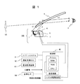
- FIG. 1 is a schematic configuration view showing an information display apparatus and its peripheral device according to an embodiment of the present invention.
- the information display apparatus 100 which projects video information on the windshield of a motor vehicle is demonstrated as the example.
- this information display device 100 forms a virtual image V1 ahead of the host vehicle at the driver's viewpoint (eye point) 8
- various information reflected by the projection member 6 Is a device that displays as a virtual image VI (Virtual Image), a so-called head-up display (HUD) device.
- the projection member 6 should just be a member by which imaging
- the video information to be displayed as the virtual image VI includes, for example, vehicle information such as a vehicle speed and foreground information captured by an on-vehicle camera.
- the configuration of the information display device 100 includes an image display unit 4 such as a liquid crystal display (LCD) that generates image light of image information to be displayed, and a backlight 5 disposed on the back side of the image display unit 4 and serving as a light source of image light.
- an image display unit 4 such as a liquid crystal display (LCD) that generates image light of image information to be displayed
- a backlight 5 disposed on the back side of the image display unit 4 and serving as a light source of image light.
- the optical element 2 is for correcting distortion or aberration which occurs when projecting a video light to form a virtual image.
- the image light reflected by the concave mirror 1 is reflected by the projection member 6 and travels to the viewpoint 8 of the driver to display a virtual image VI.
- the video display unit 4 and the backlight 5 are controlled by the control unit 40.
- the control unit 40 uses the navigation system 61 to set various information such as the speed limit and the number of lanes of the road corresponding to the current position where the host vehicle is traveling, the planned travel route of the host vehicle set in the navigation system 61, etc. It is acquired as foreground information (that is, information to be displayed in front of the host vehicle by the virtual image).
- the driving support ECU 62 is a control device that realizes driving support control by controlling a drive system and a control system in accordance with an obstacle detected as a result of monitoring by the periphery monitoring device 63.
- the driver assistance control includes, for example, known techniques such as cruise control, adaptive cruise control, pre-crash safety, and lane keeping assist.
- the periphery monitoring device 63 is a device that monitors the situation around the host vehicle, and as an example, a camera that detects an object present around the host vehicle based on an image obtained by photographing the periphery of the host vehicle, a survey wave
- the search device or the like detects an object present around the host vehicle based on the result of transmitting and receiving
- the control unit 40 acquires such information from the driving support ECU 62 (for example, the distance to the preceding vehicle and the heading of the preceding vehicle, the position where an obstacle or a sign is present, etc.) as foreground information. Furthermore, an ignition (IG) signal and the vehicle state information detected by the various sensors 64 are input to the control unit 40. Among these pieces of information, the vehicle state information is information acquired as vehicle information, and for example, a predetermined abnormal state such as the remaining amount of fuel of the internal combustion engine or the temperature of the cooling water Contains warning information to represent. In addition, the operation result of the turn indicator, the traveling speed of the host vehicle, and the shift position information are also included. The control unit 40 described above is activated when an ignition signal is input.
- optical components such as the image display unit 4, the backlight 5 and the concave mirror 1 form a virtual image optical system described below.
- FIG. 2 is a diagram for explaining the generation principle of a virtual image.
- an object (image source) AB is disposed inside the focal point F of the concave mirror 1 'which is a reflection surface (position a on the reflection surface side in the figure)
- a virtual image is formed at position b with size A'B'. Be done.
- the reflective surface is a lens surface
- a virtual image is formed at a relative position (not shown) to the reflective surface.
- the shape of the concave mirror 1 for reducing distortion of a displayed virtual image will be described with reference to FIG.
- a light beam is incident below the windshield 6, and the distance (L1 + L2) to the driver's viewpoint 8 is relatively short, so the radius of curvature is reduced to increase the magnification.
- the radius of curvature is increased so as to decrease the magnification.
- the distortion itself can be reduced by inclining the image display unit 4 with respect to the optical axis of the concave mirror 1 to correct the difference in the virtual image magnification.
- FIG. 3 is a top view of a car equipped with the information display device
- FIG. 4 is a view showing a curved shape of the windshield 6.
- the radius of curvature Rh in the horizontal direction is different from the radius of curvature Rv in the vertical direction with respect to the vehicle body 101, and generally, there is a relationship of Rh> Rv. Therefore, when the windshield 6 is regarded as a reflection surface, it becomes a toroidal concave mirror. For this reason, the shape of the concave mirror 1 in the information display device 100 is such that the virtual image magnification due to the shape of the windshield 6 is corrected. That is, in order to correct the difference between the curvature radiuses Rh and Rv of the windshield 6 in the horizontal direction and the vertical direction, the average curvature radius is different in the horizontal direction and the vertical direction.
- the shape of the concave mirror 1 is preferably corrected as a function of the coordinates (x, y) of the surface from the optical axis of the mirror surface as the shape of a free-form surface shown by the following [Equation 1].
- a spherical or non-spherical shape shown by [Equation 2] below
- [Equation 2] a spherical or non-spherical shape symmetrical to the optical axis is a function of the distance r from the optical axis and can not control the horizontal and vertical cross-sectional shapes separately. It is from.
- a lens element is disposed as an optical element 2 between the image display unit 4 and the concave mirror 1 to control the emission direction of the light beam to the concave mirror 1.
- the distortion aberration of the virtual image is corrected together with the correction function of the concave mirror 1.
- the optical element 2 realizes aberration correction of a virtual image including astigmatism which is caused by the difference between the curvature radii Rh and Rv in the horizontal and vertical directions of the windshield 6 described above.
- an optical element optimally designed may be provided between the concave mirror 1 and the image display unit 4.
- the optical distance between the concave mirror 1 and the image display unit 4 is changed to change the display position of the virtual image by changing the thickness in the optical axis direction of the optical element 2 described above. It is also possible to change continuously from a distance to a close position. Further, by arranging the image display unit 4 to be inclined with respect to the optical axis normal of the concave mirror 1, it is possible to correct the difference in the magnification of the virtual image in the vertical direction.
- the image light emitted toward the concave mirror 1 from the image display unit 4 is reflected on the surface of the optical element 2 disposed halfway and is displayed on the image display unit 4.
- the light may be reflected back and superimposed on the original image light to degrade the image quality.
- an antireflection film is formed on the surface of the optical element 2 to suppress reflection, but also the lens surface shape of at least one of the image light incident surface and the output surface of the optical element 2 is The concave surface is directed to 4 so that the above-described reflected light is not condensed on a part of the image display unit 4.
- the image display unit 4 (hereinafter, also referred to as a liquid crystal panel), in order to absorb the reflected light from the optical element 2 described above, in addition to the first polarizing plate disposed close to the liquid crystal panel 4 If the second polarizing plate is disposed separately from the liquid crystal panel 4, the deterioration of the image quality can be reduced. Further, the backlight 5 of the liquid crystal panel 4 is controlled so that the incident direction of light incident on the liquid crystal panel 4 is efficiently incident on the incident pupil of the concave mirror 1. At this time, if the divergence angle of the light beam incident on the liquid crystal panel 4 is made small, not only the video light can be efficiently directed to the driver's viewpoint 8 but also a video with high contrast and high visibility is obtained. Is possible.
- FIG. 5 is a diagram showing the angle characteristics of the backlight luminance of the liquid crystal panel in the vertical direction.
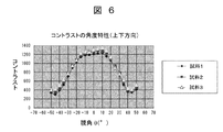
- FIG. 6 is a diagram showing the angle characteristics of the contrast of the liquid crystal panel in the vertical direction.
- the contrast performance with respect to the divergence angle of the image is within ⁇ 20 degrees in the vertical direction, and excellent characteristics are obtained.
- a solid light source having a long product life in particular, an LED (Light Emitting Diode) having a small change in light output with respect to fluctuation of ambient temperature is preferable.
- PBS Polarizing Beam Splitter
- polarizing plates are disposed on the light incident surface side and the light emitting surface side, thereby enhancing the contrast ratio of the image light.
- a high contrast ratio can be obtained by adopting an iodine-based polarizing plate having a high degree of polarization as the polarizing plate provided on the light incident surface side.
- a dye-based polarizing plate on the light emitting surface side high reliability can be obtained even when external light is incident or when the environmental temperature is high.
- a ⁇ / 4 plate may be disposed on the optical element 2 side of the polarizing plate disposed on the exit surface side of the liquid crystal panel 4 to convert image light aligned in a specific polarization direction into circularly polarized light. preferable.
- the windshield 6 as a projection member is present on the front part of the driver's seat of the car body 101.
- the windshield 6 has different inclination angles with respect to the vehicle body depending on the type of automobile.
- the inventors investigated the radius of curvature of the windshield 6 in order to realize an optimum virtual image optical system.
- the windshield 6 is different in the horizontal curvature radius Rh parallel to the contact surface of the automobile and the vertical curvature radius Rv orthogonal to the horizontal axis. It is found that there is a general relationship of Rh> Rv between and Rv. Specifically, it was also found that the ratio of radius of curvature Rh / Rv was often in the range of 1.5 times to 2.5 times.
- the commercial product was investigated also about the inclination angle of the windshield 6.
- FIG. As a result, depending on the vehicle type, it was 20 degrees to 30 degrees for the minicar and 1 Box type, 30 degrees to 40 degrees for the sedan type, and 40 degrees or more for the sport type. Therefore, in the present embodiment, the virtual image optical system is designed in consideration of the difference between the horizontal curvature radius Rh of the windshield and the curvature radius Rv in the vertical direction, and the inclination angle of the windshield.
- the horizontal curvature radius Rh and the vertical curvature radius Rv of the windshield 6 are largely different, they are in a plane perpendicular to the optical axis (Z axis), that is, perpendicular to the horizontal direction (X axis) of the windshield 6
- Z axis optical axis
- X axis horizontal direction
- Y axis vertical curvature radius
- the viewing angle (FOV) is 7 degrees in the horizontal direction and 2.6 degrees in the vertical direction, and the virtual image distance is 2 m, as a condition for the miniaturization study.
- one optical path turning mirror was disposed between the video display unit 4 and the concave mirror 1 with the concave mirror 1 for generating a virtual image, the video display unit 4 and the backlight 5 as basic configurations.
- simulations were performed using the arrangement of each member and the distance from the image display unit 4 to the concave mirror 1 as parameters.
- the volume of the information display device 100 became 3.6 liters.
- the optical path turning mirror a flat mirror provided to increase the optical path length or reduce the volume.
- FIG. 7 is an entire configuration diagram of the virtual image optical system in FIG. 1 and is shown together with the information display device 100 including the windshield 6 and the viewpoint 8 of the driver.
- FIG. 8 is a diagram showing the basic configuration of the virtual image optical system, and the miniaturization will be described based on this.
- the concave mirror 1 is drawn as a plane mirror for the sake of simplicity.
- the optical element 2 for aberration correction is omitted for simplification of the description.
- a liquid crystal panel is assumed for the image display unit 4, and a configuration in which the backlight 5 is disposed behind is basically used.
- the image display unit 4 arranges the displayed image so that a virtual image can be obtained by the concave mirror 1.
- the restriction condition is that when the image light R1 from the upper end of the screen of the image display unit 4, the image light R2 from the center, and the image light R3 from the lower end are reflected by the concave mirror 1 in the light beam shown in FIG. It is to arrange so that light may not be blocked by interfering with the image display unit 4.
- the distance between the concave mirror 1 and the image display unit (liquid crystal panel) 4 so as to satisfy the above-mentioned constraint conditions and the above-mentioned study conditions (FOV horizontal: 7 degrees, vertical: 2.6 degrees, virtual image distance 2 m)
- the volume of the information display apparatus 100 was determined using Z as a parameter.
- the distance Z is a distance along the image light R 2 and is a horizontal distance between the center of the concave mirror 1 and the center of the image display unit 4.
- FIG. 9 is a diagram showing the positional relationship between the concave mirror 1 and the image display unit 4, and shows the distance Z as a parameter.
- the distance Z is 100 mm
- the configuration is as shown in (c), and in this case, the vertical dimension of the concave mirror 1 can be made the smallest.
- the distance Z is 75 mm, as shown in (b), the angle ⁇ 2 between the horizontal plane and the concave mirror 1 increases, and the vertical dimension of the concave mirror 1 also increases.
- the distance Z is further shortened to 50 mm or less, as shown in (a), the angle ⁇ 3 between the horizontal plane and the concave mirror 1 becomes larger, and the vertical dimension of the concave mirror 1 also becomes larger.
- the set height is increased.
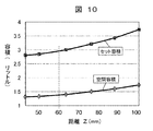
- FIG. 10 is a diagram showing the relationship between the distance Z and the volume of the information display device 100.
- the relationship between the distance Z and the set volume is steeper in the set volume (including the LCD drive circuit, the light source drive circuit, the backlight volume, etc.) compared to the change in the spatial volume from the image display unit 4 to the concave mirror 1 .
- the distance between the image display unit 4 and the upper end of the concave mirror 1 (corresponding to the light beam R1) is long, and the distance between the image display unit 4 and the lower end of the concave mirror 1 (corresponding to the light beam R3) is short. Therefore, it is preferable to dispose the video display unit 4 so that the distance between the video display unit 4 and the concave mirror 1 is as uniform as possible. Then, the optimum value of the distance Z is determined so as to satisfy the condition that the distance between the image display unit 4 and the concave mirror 1 becomes uniform.
- the display surface (hereinafter, panel surface) of the liquid crystal panel which is the image display unit 4 is characterized in that it has a curved shape.
- the optical element 2 is disposed to reduce distortion and aberration generated by the concave mirror 1.
- the optical element 2 is a transmission type optical lens, and has the following configuration in order to reduce the change of the refractive power of the lens due to the change of the refractive index and the shape due to the change of the ambient temperature.
- the distortion of the locally generated distortion is corrected by diverging the image light from the image display unit 4 by the optical element 2 and refracting the position where the image light is incident on the concave mirror 1 from the optical axis can do. At this time, since the lens action of the optical element 2 has negative refractive power on the optical axis, it is necessary to increase the relative positive refractive power of the concave mirror 1.
- the above is the correction of distortion in the vicinity of the optical axis of the concave mirror 1, but by making the shape of the optical element 2 an aspheric shape, a decentered aspheric shape away from the optical axis, or a free curved surface shape
- the optical element 2 has local positive or negative refractive power, and distortion can be corrected at a higher degree.
- the degree of freedom of aberration correction is increased, and the above-described distortion is also corrected.
- a plurality of transmissive optical elements may be used.
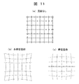
- FIG. 11 is a view for explaining a typical state of field curvature (distortion).
- (A) is an image pattern without distortion
- (b) shows a state in which pincushion distortion occurs
- (c) shows a state in which barrel distortion occurs. Therefore, the virtual image optical system of the present embodiment is characterized in that the liquid crystal panel surface which is the image display unit 4 has a curved shape.
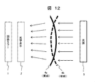
- FIG. 12 is a view schematically showing a configuration in which the liquid crystal panel surface has a curved shape.
- a panel surface 4 a shown by a solid line
- curvature of field generated is reduced.
- An optical system using such a concave panel will be referred to as a "first virtual image optical system”.
- the panel surface may be reversely directed as indicated by a reference numeral 4b (indicated by a broken line), and may be curved so as to be convex with respect to the concave mirror 1 (indicated by a broken line).
- An optical system using such a convex panel is called a "second virtual image optical system".
- the curvature of field generated is increased, and the image plane position is further moved away from the driver.
- the size of the virtual image that can be obtained as the virtual image formation position is further increased.
- the aberration correction capability can be compensated by providing a plurality of the optical elements 2 described above, and a good virtual image with high visibility can be obtained.
- the curvature of the image plane of the image from the image display unit 4 can also be reduced by curving it in conformity with the curved surface of the windshield 6 as well. Specifically, since the curvature radius Rv in the vertical direction of the windshield 6 is smaller than the curvature radius Rh in the horizontal direction, optical power in the vertical direction is large when the windshield 6 is replaced with a concave mirror. For this reason, the curvature of curvature in the vertical direction of the panel surface 4a is reduced relative to the horizontal direction to reduce the curvature of field. This can be realized by making the panel surface 4 a convexly curved with respect to the light source 5 (first virtual image optical system). In addition, as described above, since the windshield 6 has different radii of curvature in the vertical direction and the horizontal direction, the curved shape of the panel surface 4 a is also set corresponding to the different radius of curvature of the windshield 6. Is preferred.
- the miniaturization of the device is realized, and the curvature of field by the optical element 2 which is indispensable for the miniaturization of the device is reduced. Then, the reflection at the concave mirror 1 can display a highly visible virtual image at high resolution.
- FIG. 13 is a diagram showing a configuration in which the light emitting surface of the light source 5 is curved together with the liquid crystal panel surface.
- the radius of curvature of the light emitting surface of the light source 5a (shown by a solid line) is made to substantially coincide with the radius of curvature of the panel surface 4a so as to be concave with respect to the concave mirror 1.
- the reflection at the concave mirror 1 can display a highly visible virtual image with higher luminance and resolution.
- the radius of curvature of the light emitting surface of the light source 5b (shown by a broken line) is made to substantially coincide with the radius of curvature of the panel surface 4b and configured to be convex with respect to the concave mirror 1. .
- the effect in this case is the same as that of the first virtual image optical system.
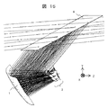
- FIG. 14 shows a ray diagram of the entire virtual image optical system of this embodiment, where (a) is a cross-sectional view in the vertical direction (Y-axis direction) and (b) is a cross-sectional view in the horizontal direction (X-axis direction).
- AB represents an image light source
- A'B ' represents the position of a virtual image, and indicates the positional relationship between the concave mirror 1 and the windshield 6.
- FIG. 15 is a ray diagram in which a part of the virtual image optical system of FIG. 14 is enlarged, and the vicinity of the optical element 2, the concave mirror 1, and the windshield 6 is enlarged.
- the optical element 2 is composed of two lens elements.
- a method of bending a liquid crystal panel as an image display unit according to an embodiment of the present invention will be described below.
- the cover glass As a base material into a necessary curved shape.
- the desired shape is obtained by heating the flat glass substrate to a thermal deformation temperature, pressing it with a mold having a desired curved surface shape, deforming it, and precooling it.
- a liquid crystal panel is bonded to the obtained curved glass substrate in accordance with the curved surface.
- the device may be large and the manufacturing tact may be long and productivity may be low.
- a method of bonding a liquid crystal panel or the like to a member curved in the air for example, described in JP-A-2016-179600.
- JP-A-2016-179600 There is a technology of
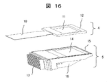
- FIG. 16 is an external view of an image display unit (liquid crystal panel) 4 and a light source (backlight) 5.
- the liquid crystal panel 4 includes a panel display surface 11, a frame 12, and a flexible substrate 10, and the backlight 5 includes an exterior member 16 that houses a light source unit, a diffusion member 14, a frame 15, and heat dissipating fins 13.
- the liquid crystal panel 4 displays an image on the panel display surface 11 by modulating the light from the backlight 5 with the image signal input from the flexible substrate 10.
- the displayed image is converted into a virtual image by the virtual image optical system, and is transmitted to the driver as image information.
- the output surfaces of the liquid crystal panel 4 and the backlight 5 are shown as a plane for simplicity, but as shown in FIG. 12 and FIG. 13, they have a curved shape as needed.
- a relatively inexpensive and reliable LED light source is used as a light emitting element of the backlight 5 as a solid state light emitting element. Since the LED uses a surface emitting type to achieve high output, the light utilization efficiency is improved using the technical device described later.
- the luminous efficiency with respect to the input power of the LED varies depending on the luminous color, but is about 20 to 30%, and most of the remaining is converted to heat.
- the frame 15 to which the LED is attached is provided with fins 13 for heat dissipation made of a member with high thermal conductivity (for example, a metal member such as aluminum) to dissipate the heat to the outside, thereby the luminous efficiency of the LED itself Improve.
- the red light emitting LEDs currently on the market are greatly reduced in luminous efficiency as the junction temperature increases, and at the same time the chromaticity of the image is changed, so the temperature reduction priority of the LEDs is increased. It is preferable to enlarge the area of the corresponding radiation fin 13 to increase the cooling efficiency.
- a light guide symbol 18 in FIG. 17
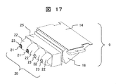
- FIG. 17 is an enlarged view of the light source unit 9 in the backlight 5.
- the light source unit 9 has a light funnel unit 20 including a plurality of LED light sources, a light guide 18 and a diffusion member 14.
- the light funnel unit 20 takes in diverging rays from the plurality of LEDs 21 at the openings 23 of the corresponding plurality of light funnels 22.
- the opening 23 is a flat surface, and a medium is inserted between the LED 21 and optically connected, or a convex light shape is provided to have a condensing action, so that diverging source light is parallel light as much as possible.
- the incident angle of light incident on the interface of the light funnel 22 is reduced.
- the divergence angle can be further reduced after passing through the light funnel 22, control of light source light directed to the liquid crystal panel 4 after being reflected by the light guide 18 becomes easy.
- polarization conversion is performed using a polarization conversion element (PBS) at the junction 25 of the light funnel 22 and the light guide 18 to convert it into a desired polarization direction.
- PBS polarization conversion element
- a light flux from the LED 21 whose divergence angle is reduced is controlled by the light guide 18, and is reflected by the total reflection surface provided on the slope of the light guide 18, and a diffusion member disposed between the facing surface and the liquid crystal panel 4 After being diffused by the light source 14, the light enters the liquid crystal panel 4.
- the diffusion member 14 is disposed between the light guide 18 and the liquid crystal panel 4 in the present embodiment, a structure in which the end face of the light guide 18 has a diffusion effect, for example, a structure in which a minute uneven shape is provided The same effect is obtained.
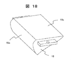
- FIG. 18 is a view showing the appearance of the light guide 18.
- the luminous flux whose divergence angle is reduced by the light funnel 22 shown in FIG. 17 enters the incident surface 18a of the light guide 18 and exits from the emission surface 18c.
- the divergence angle in the vertical direction (vertical direction in FIG. 19) is controlled by the shape effect (the cross-sectional shape is shown in FIG. 19) of the incident surface 18a, and the light is efficiently propagated in the light guide 18.
- FIG. 19 is an enlarged sectional view of an essential part of the light guide 18.
- the light source light whose divergence angle is reduced by the light funnel 22 is incident from the incident surface 18a via the joint portion 25 as shown in (a), totally reflected by the prism 18b provided on the opposite surface, and then emitted. Head to face 18c.
- the total reflection prism 18b is in the vicinity of the incident surface 18a ((b), B part enlargement) and at the end ((c) figure, A part enlargement), the shape is the divergence angle of the light beam incident on each surface Accordingly, it is divided into steps and formed, thereby controlling the angle of the total reflection surface.
- the division size of the reflection surface of the total reflection prism 18b is taken as a variable so that the light quantity distribution in the light exit surface of the liquid crystal panel 4 becomes uniform after the light flux incident on the liquid crystal panel 4 is reflected. Control the arrival position and the amount of energy.
- FIG. 20 is a view showing a simulation result in a state where the light emitted from the backlight 5 has passed through the liquid crystal panel 4.
- (A) shows the emission state of light as viewed from the longitudinal direction of the liquid crystal panel 4, and
- (b) shows the emission state of light as viewed from the lateral direction of the liquid crystal panel 4.
- the horizontal diffusion angle is increased relative to the vertical direction, and even when the driver shakes his head or the eye position moves, It is designed so that the brightness of the virtual image visually recognized by the left and right eyes does not change extremely. Further, by reducing the divergence angle in the vertical direction of the backlight 5, the divergence angle in the screen vertical direction of the image displayed on the liquid crystal panel 4 is reduced, thereby suppressing the occurrence of double images.
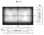
- FIG. 21 is a diagram showing the luminance distribution of the exit surface of the liquid crystal panel 4.
- the light guide 18 is used for the backlight 5 to control the light emission direction and intensity.
- the inclination of the luminance reduction can be reduced outside the effective range in the screen horizontal direction (X-axis direction) with respect to the luminance distribution in the screen vertical direction (Y-axis direction).
- the angle of the total reflection surface of the light guide 18 and the light source light from the LED 21 by the light funnel 22 are obtained so that the emitted light from the liquid crystal panel 4 taken into the virtual image optical system can be obtained as light perpendicular to the screen.
- the divergence angle of to narrow the viewing angle characteristics of the backlight 5 to a small range high luminance is obtained.
- light with a range of ⁇ 30 ° at the left and right viewing angles is used, and in consideration of contrast performance, focusing on ⁇ 20 ° or less simultaneously achieves good image quality. I could get a virtual image using video.
- the contrast performance that affects the image quality of the video display unit is determined by how much the luminance (black luminance) in black display, which is the basis for determining the image quality, can be reduced. Therefore, it is preferable to use an iodine-based polarizing plate having a high degree of polarization between the liquid crystal panel 4 and the backlight 5. On the other hand, by using a dye-based polarizing plate as the polarizing plate provided on the light emitting surface side of the liquid crystal panel 4, high reliability can be obtained even when external light is incident or when the environmental temperature is high.
- color filters corresponding to the respective pixels are provided. Therefore, when the light source color of the backlight 5 is white, the light absorption by the color filter is large and the loss is large. Therefore, as shown in FIG. 17 above, using a plurality of LEDs 21, (1) A green LED having a large contribution to brightness is added as compared to the case where a plurality of white LEDs are used. (2) Add red or blue LED to white LED to enhance the glossiness of the image. (3) If the red, blue, and green LEDs are individually arranged, and the green LEDs that have a large contribution to the brightness are added to drive the LEDs individually, the color reproduction range is expanded and the glossiness is enhanced. The brightness also improves at the same time.
- the transmittance of each color filter with respect to the peak luminance of the red, blue, and green LEDs is increased to improve the overall brightness.
- PBS is placed between the light funnel and the light guide and aligned to a specific polarization, thereby reducing damage to the polarizing plate on the liquid crystal panel incident side Do.
- the polarization direction of the polarizing plate disposed on the liquid crystal panel incident side may be a direction through which polarized light aligned in a specific direction passes through the PBS.
- the image display unit 4 it is also possible to provide a ⁇ / 4 plate on the exit surface of the liquid crystal panel to make the exit light circularly polarized. As a result, the driver can observe a good virtual image even when wearing polarized sunglasses.
- the liquid crystal panel is assumed to have a structure in which liquid crystal is sealed between transparent glass substrates, but is not limited to this.
- the backlight is not limited to the side light type using a light guide, but may be a direct type.
- the curved shape of the liquid crystal panel may be a curved one axis or a curved one having two or more axes. In that case, the curvature of the curvature at the center of the liquid crystal panel may be different from the curvature at the periphery.
- shafts you may make curvature different for every axis
- the reflection film of the reflection mirror used in the virtual image optical system is formed of a metal multilayer film, the angle dependency of the reflectance is small, and the reflectance changes depending on the polarization direction (P wave or S wave) Therefore, the chromaticity and brightness of the screen can be kept uniform.
- the liquid crystal can be obtained even when external light (sunlight) is incident. Since the panel and the polarizing plate can be reduced from the temperature rise and damage, the reliability of the information display device is not impaired.
- the virtual image optical system of this embodiment performs optimum design including the difference between the curvature radius in the vehicle horizontal direction and the curvature radius in the vertical direction of the windshield as the projection member, and the windshield 5 and the image display unit 4 (or an intermediate image A concave mirror 1 having a concave surface facing the front glass 6 is disposed between the display sections), whereby the image of the video display section 4 is enlarged and reflected on the front glass 6.
- the optical element 2 is disposed between the concave mirror 1 and the image display unit 4 described above, and on the other hand, an enlarged image (virtual image) of the image formed corresponding to the viewpoint position 8 of the driver.
- the image light beam forming the light passes through the optical element 2 disposed between the image display units 4 and corrects distortion and aberration generated in the concave mirror 1. Therefore, it is possible to obtain a virtual image in which distortion and aberration are greatly reduced as compared with the conventional virtual image optical system of only the concave mirror 1.
- the virtual image VI obtained by being reflected by the upper portion (upper portion in the vehicle body vertical direction) of the windshield 6 needs to be imaged farther.
- the above-described optical element disposed between the concave mirror 1 and the image display unit 4 The focal length f1 of the element 2 is set short.
- the virtual image obtained by being reflected by the lower part (lower part in the vehicle body vertical direction) of the windshield 6 needs to be imaged closer.
- the combined focal length f2 of the element 2 may be set relatively long.
- the information display device of the present embodiment is mounted on a car and observed as a virtual image through a windshield, the present invention is not limited to this.
- the information display device is mounted on a "vehicle" such as a train or an aircraft. The same applies to the case where the
- the present invention is not limited to the embodiments described above, but includes various modifications.
- the above-described embodiment describes the entire apparatus in detail in order to explain the present invention in an easy-to-understand manner, and is not necessarily limited to one having all the described configurations.
- part of the configuration of one embodiment can be replaced with the configuration of another embodiment, and the configuration of another embodiment can be added to the configuration of one embodiment.
Landscapes
- Engineering & Computer Science (AREA)
- Physics & Mathematics (AREA)
- Chemical & Material Sciences (AREA)
- Combustion & Propulsion (AREA)
- Transportation (AREA)
- Mechanical Engineering (AREA)
- General Physics & Mathematics (AREA)
- Optics & Photonics (AREA)
- Instrument Panels (AREA)
- Lenses (AREA)
Abstract
本発明は、装置の小型化を図りながら視認性の高いより大きな虚像を得るための情報表示装置を提供する。投影部材6に映像を投影する情報表示装置100は、背面側に光源5を配置し映像の映像光を生成する映像表示部4と、映像表示部4で生成された映像光を凹面ミラー1で反射し、投影部材6に投影することで投影部材の前方に虚像VIを表示させる光学系と、を備え、映像表示部4の表示面を凹面ミラー1に向って湾曲形状となるように形成した。ここに映像表示部4の表示面の湾曲形状は、凹面ミラー1の形状により虚像VIに発生する像面湾曲を低減するように定める。
Description
本発明は、自動車や電車や航空機等のフロントガラス又はコンバイナに映像情報を投影し、その映像情報をフロントガラス越しに虚像として観察する情報表示装置に関する。
自動車のフロントガラスやコンバイナに映像光を投影して虚像を形成し、ルート情報や渋滞情報などの交通情報や燃料残量や冷却水温度等の自動車情報を表示する、所謂、ヘッドアップディスプレイ(HUD)装置が知られている。例えば、特許文献1には、画像を表示するデバイスと、表示された画像を投射(投影)する投射光学系とを備え、運転者の視点領域全域で画面歪みが小さく、小型な表示装置について提案されている。
また、例えば特許文献2には、光源部から出射された画素表示用レーザ光を2次元偏向手段(MEMSミラー)により偏向して、凹面鏡を介して、透過部材である湾曲スクリーンに向けて反射し、中間像を形成する構成が開示されている。この装置では、その後中間像を凹面ミラーにより反射して、自動車のフロントガラスやコンバイナに映像光を投影して虚像を形成している。
この種の情報表示装置においては、運転者が虚像を観察できる領域を拡大することが望まれる一方、虚像が高解像度で視認性が高いことも重要な性能要因である。また、ヘッドアップディスプレイ装置は、運転者に虚像を提供する最終反射面としてフロントガラス又はコンバイナが必要であり、発明者らは視認性が高く良好な解像性能を得るためには、さらなる改善が重要であることに気付いた。
一般的に、凹面ミラーで生成する虚像が見える範囲を広げるためには、物点を焦点に近づけて物寸法に対して凹面ミラーを大きくすると良いが、所望の倍率を得るためには、凹面ミラーの曲率半径が小さくなるためこれらを両立することは困難となる。その結果、ミラーサイズが小さくなり、実効的に拡大率は大きいが、観察可能な範囲が小さい虚像しか得られないという結果となる。
このため、(1)所望の虚像サイズ、(2)必要な虚像の倍率、を同時に満足するためには、凹面ミラーの寸法は観察範囲に合わせ、映像表示部との兼ね合いで虚像の倍率を決めざるを得なかった。このため従来技術では、所望の観察範囲において大きな虚像を得るためには、凹面ミラーから虚像までの距離を大きく、すなわち、最終反射面であるフロントガラス又はコンバイナと凹面ミラーの距離を大きくし、同時に、凹面ミラーのサイズを大きくする必要があった。これらの要請は、装置の小型化を阻む要因となる。
上記した特許文献1や特許文献2には、装置の構成を小型化するとともに、所望の観察範囲において大きな虚像を得るための技術については開示されていない。また、装置の小型化に伴い、運転者が視認する虚像の歪みと収差が増大するが、これを有効に解決する技術についても開示されていない。
本発明は上述した従来技術の課題を鑑み、その目的は、装置の小型化を図りながら、所望の観察範囲においてより大きな虚像を得るための技術手段を提案することである。併せて、運転者が視認する虚像の歪みと収差を実用上問題のないレベルまで軽減させ、視認性の高い虚像を形成する情報表示装置を提供することである。
本発明は、投影部材に映像を投影する情報表示装置であって、背面側に光源を配置し前記映像の映像光を生成する映像表示部と、前記映像表示部で生成された前記映像光を凹面ミラーで反射し、前記投影部材に投影することで前記投影部材の前方に虚像を表示させる光学系と、を備え、前記映像表示部の表示面を前記凹面ミラーに向って湾曲形状となるように形成したことを特徴とする。ここに前記映像表示部の表示面の湾曲形状は、前記凹面ミラーの形状により前記虚像に発生する像面湾曲を低減するように定める。
本発明によれば、装置の小型化を図りながら、所望の観察範囲においてより大きな虚像を得るとともに、運転者が視認する虚像の歪みと収差を軽減し視認性の高い虚像を形成する情報表示装置を実現することができる。
以下、図面等を用いて、本発明の実施例について詳細に説明する。なお、本発明は以下の説明に限定されるものではなく、本明細書に開示される技術的思想の範囲内において当業者による様々な変更及び修正が可能である。また、本発明を説明するための全図において、同一の機能を有するものは、同一の符号を付け、その繰り返しの説明は省略する場合がある。
<情報表示装置の構成>
図1は、本発明の一実施例に係る情報表示装置とその周辺装置を示す概略構成図である。ここでは、その一例として、自動車のフロントガラスに映像情報を投影する情報表示装置100について説明する。
図1は、本発明の一実施例に係る情報表示装置とその周辺装置を示す概略構成図である。ここでは、その一例として、自動車のフロントガラスに映像情報を投影する情報表示装置100について説明する。
この情報表示装置100は、運転者の視点(アイポイント)8において自車両の前方に虚像V1を形成するため、投影部材6(本実施例では、フロントガラスの内面)にて反射された各種情報を虚像VI(Virtual Image)として表示する装置、いわゆるヘッドアップディスプレイ(HUD)装置である。なお、投影部材6は、映像情報が投影される部材であればよく、フロントガラスだけでなく、コンバイナ等、他の投影部材であっても良い。虚像VIとして表示する映像情報としては、例えば、車速などの車両情報や車載カメラで撮影した前景情報などが含まれる。
情報表示装置100の構成は、表示する映像情報の映像光を生成する液晶ディスプレイ(LCD)などの映像表示部4と、映像表示部4の背面側に配し映像光の光源であるバックライト5、映像表示部4にて生成された映像光を反射する凹面ミラー1、映像表示部4と凹面ミラー1の間に設けたレンズなどの光学素子2を有し、これらは筐体7に収納されている。光学素子2は、映像光を投影して虚像を形成する際に発生する歪や収差を補正するためのものである。凹面ミラー1で反射した映像光は、投影部材6にて反射されて運転者の視点8へ向かい、虚像VIを表示する。
上記映像表示部4とバックライト5は、制御部40で制御される。制御部40は、ナビゲーションシステム61から、自車両が走行している現在位置に対応する道路の制限速度や車線数、ナビゲーションシステム61に設定された自車両の移動予定経路などの各種の情報を、前景情報(すなわち、上記虚像により自車両の前方に表示する情報)として取得する。
運転支援ECU62は、周辺監視装置63での監視の結果として検出された障害物に従って駆動系や制御系を制御することで、運転支援制御を実現する制御装置である。運転支援制御としては、例えば、クルーズコントロール、アダプティブクルーズコントロール、プリクラッシュセーフティ、レーンキーピングアシストなどの周知技術を含む。
周辺監視装置63は、自車両の周辺の状況を監視する装置であり、一例としては、自車両の周辺を撮影した画像に基づいて自車両の周辺に存在する物体を検出するカメラや、探査波を送受信した結果に基づいて自車両の周辺に存在する物体を検出する探査装置などである。
制御部40は、このような運転支援ECU62からの情報(例えば、先行車両までの距離及び先行車両の方位、障害物や標識が存在する位置など)を前景情報として取得する。さらに、制御部40には、イグニッション(IG)信号、及び、各種センサ64で検出した自車状態情報が入力される。これらの情報の内、自車状態情報とは、車両情報として取得される情報であり、例えば、内燃機関の燃料の残量や冷却水の温度など、予め規定された異常状態となったことを表す警告情報を含んでいる。また、方向指示器の操作結果や自車両の走行速度、さらには、シフトポジション情報なども含まれている。以上述べた制御部40は、イグニッション信号が入力されると起動する。
情報表示装置100における光学系の構成において、映像表示部4とバックライト5と凹面ミラー1などの光学部品は、以下に述べる虚像光学系を形成する。
図2は、虚像の発生原理を説明する図である。反射面である凹面ミラー1'の焦点Fの内側(同図では反射面側の位置a)に物体(映像源)ABを配置した場合、虚像はA’B’の大きさで位置bに形成される。反射面がレンズ面である場合には、反射面に対する相対位置(図示せず)に虚像が形成される。
図1において、表示される虚像の歪みを低減するための凹面ミラー1の形状について説明する。凹面ミラー1の上部領域では、フロントガラス6の下方に光線が入射し、相対的に運転者の視点8との距離(L1+L2)が短いので、拡大率が大きくなるように曲率半径を小さくする。他方、凹面ミラー1の下部領域では、フロントガラス6の上方に光線が入射し、相対的に運転者の視点8との距離が長いので、拡大率が小さくなるように曲率半径を大きくする。また、映像表示部4を凹面ミラー1の光軸に対して傾斜させて上述した虚像倍率の違いを補正することによっても、発生する歪みそのものを低減することができる。
また虚像光学系では、自動車のフロントガラス6の曲面形状に対する補正を行う。
図3は、情報表示装置を搭載した自動車の上面図、図4は、フロントガラス6の曲面形状を示す図である。自動車本体101に対し、水平方向の曲率半径Rhと垂直方向の曲率半径Rvとは異なり、一般には、Rh>Rvの関係にある。このため、フロントガラス6を反射面として捉えると、トロイダル状の凹面ミラーとなる。このため、情報表示装置100における凹面ミラー1の形状は、フロントガラス6の形状による虚像倍率を補正するような形状とする。すなわち、フロントガラス6の水平方向と垂直方向の曲率半径Rh,Rvの違いを補正するように、水平方向と垂直方向で異なる平均曲率半径とする。
図3は、情報表示装置を搭載した自動車の上面図、図4は、フロントガラス6の曲面形状を示す図である。自動車本体101に対し、水平方向の曲率半径Rhと垂直方向の曲率半径Rvとは異なり、一般には、Rh>Rvの関係にある。このため、フロントガラス6を反射面として捉えると、トロイダル状の凹面ミラーとなる。このため、情報表示装置100における凹面ミラー1の形状は、フロントガラス6の形状による虚像倍率を補正するような形状とする。すなわち、フロントガラス6の水平方向と垂直方向の曲率半径Rh,Rvの違いを補正するように、水平方向と垂直方向で異なる平均曲率半径とする。
この時、凹面ミラー1の形状は、以下の[数式1]で示す自由曲面の形状として、ミラー面の光軸からの面の座標(x,y)の関数として補正することが好ましい。なぜなら、光軸に対称な球面または非球面(以下に[数式2]で示す)形状では、光軸からの距離rの関数であり、離れた場所の水平断面と垂直断面形状を個別に制御できないからである。


さらに図1において、映像表示部4と凹面ミラー1の間の光学素子2として例えばレンズ素子を配置し、もって、凹面ミラー1への光線の出射方向を制御する。これにより、凹面ミラー1による補正機能と合わせて虚像の歪曲収差の補正を行なう。またこれと同時に光学素子2により、前述したフロントガラス6の水平方向と垂直方向の曲率半径Rh,Rvの違いによって生じる、非点収差を含めた虚像の収差補正を実現する。
さらに、収差補正能力を向上させるために、凹面ミラー1と映像表示部4の間に最適設計された光学素子を設けてもよい。加えて、上述した光学素子2の光軸方向の厚さを変化させることで、本来の収差補正の他に凹面ミラー1と映像表示部4の光学的な距離を変えて、虚像の表示位置を遠方から近接位置まで、連続的に変化させることもできる。また、映像表示部4を凹面ミラー1の光軸法線に対して傾けて配置することで、虚像の上下方向の倍率の違いを補正することもできる。
一方、情報表示装置100の画質を低下させる要因として、映像表示部4から凹面ミラー1に向かって出射する映像光が、途中に配置された光学素子2の表面で反射して映像表示部4に戻り、再度反射して本来の映像光に重畳されて、画質を低下させることがある。このため、光学素子2の表面に反射防止膜を成膜して反射を抑えるだけでなく、さらに、光学素子2の映像光入射面と出射面の少なくとも一方のレンズ面形状を、例えば映像表示部4に凹面を向けた形状とし、上述した反射光が映像表示部4の一部分に集光しないようにする。
次に、映像表示部4(以下、液晶パネルとも呼ぶ)においては、上述した光学素子2からの反射光を吸収させるために、液晶パネル4に近接して配置された第一の偏光板に加えて、第二の偏光板を液晶パネル4と分離して配置すれば、画質の低下を軽減できる。また、液晶パネル4のバックライト5は、液晶パネル4に入射する光の入射方向を凹面ミラー1の入射瞳に効率良く入射するように制御される。この時、液晶パネル4に入射する光束の発散角を小さくすれば、効率良く運転者の視点8に映像光を向けることができるばかりでなく、さらに、コントラストの高い視認性の良い映像を得ることが可能となる。
図5は、液晶パネルのバックライト輝度の上下方向の角度特性を示す図である。また図6は、液晶パネルのコントラストの上下方向の角度特性を示す図である。このように、映像の発散角に対するコントラスト性能は上下方向に±20度以内となり、優れた特性が得られる。さらにコントラスト性能を向上させるためには、±10度以内のバックライト光束を利用すると良い。
一方、光源(バックライト)4の発光素子としては、製品寿命が長い固体光源、特に、周囲温度の変動に対する光出力変化が少ないLED(Light Emitting Diode)が好ましい。そして、光の発散角を低減する光学手段を設けたPBS(Polarizing Beam Splitter)を用いて偏光変換を行なうことが好ましい。
液晶パネル4は、光入射面側と光出射面側に偏光板が配置されており、これにより、映像光のコントラスト比を高めている。光入射面側に設ける偏光板には、偏光度が高いヨウ素系のものを採用すれば、高いコントラスト比が得られる。一方、光出射面側には染料系の偏光板を用いることで、外光が入射した場合や環境温度が高い場合でも、高い信頼性を得ることができる。
また、映像表示部4として液晶パネルを用いる場合、特に、運転者が偏光サングラスを着用している場合には、特定の偏波が遮蔽されて映像が見えない不具合が発生する。これを防ぐために、液晶パネル4の出射面側に配置した偏光板の光学素子2側にλ/4板を配置し、もって、特定の偏光方向に揃った映像光を円偏光に変換することが好ましい。
<虚像光学系の詳細>
次に、本実施例に係る虚像光学系及び映像表示部を詳細に説明する。
図3で上述したように、自動車本体101の運転席前部には、投影部材としてのフロントガラス6が存在する。なお、このフロントガラス6は、自動車のタイプによって車体に対する傾斜角度が異なる。発明者らは、最適な虚像光学系を実現するため、フロントガラス6の曲率半径について調査した。その結果、図4に示すように、フロントガラス6は、自動車の接地面に対して平行な水平方向の曲率半径Rhと、水平軸に対して直交する垂直方向の曲率半径Rvとで異なり、RhとRvの間には、一般にRh>Rvの関係があることが判った。具体的には、この曲率半径の比Rh/Rvは、1.5倍から2.5倍の範囲にあるものが多いことも判明した。
次に、本実施例に係る虚像光学系及び映像表示部を詳細に説明する。
図3で上述したように、自動車本体101の運転席前部には、投影部材としてのフロントガラス6が存在する。なお、このフロントガラス6は、自動車のタイプによって車体に対する傾斜角度が異なる。発明者らは、最適な虚像光学系を実現するため、フロントガラス6の曲率半径について調査した。その結果、図4に示すように、フロントガラス6は、自動車の接地面に対して平行な水平方向の曲率半径Rhと、水平軸に対して直交する垂直方向の曲率半径Rvとで異なり、RhとRvの間には、一般にRh>Rvの関係があることが判った。具体的には、この曲率半径の比Rh/Rvは、1.5倍から2.5倍の範囲にあるものが多いことも判明した。
さらに、フロントガラス6の傾斜角度についても市販品を調査した。その結果、車体タイプによっても異なるが、軽自動車や1Boxタイプでは20度~30度、セダンタイプでは30度~40度、スポーツタイプでは40度以上であった。そこで本実施例では、フロントガラスの水平方向の曲率半径Rhと垂直方向の曲率半径Rvの違い、及びフロントガラスの傾斜角について考慮し、虚像光学系の設計を行った。
より詳細には、フロントガラス6の水平曲率半径Rhと垂直曲率半径Rvは大きく異なるため、光軸(Z軸)に対して直交する面内、すなわちフロントガラス6の水平方向(X軸)と垂直方向(Y軸)に関し軸非対称な光学素子2を虚像光学系内に設けることにより、良好な収差補正を実現した。
次に、情報表示装置100の小型化について説明する。小型化検討の条件として、視野角(FOV)は水平方向7度、垂直方向2.6度とし、さらに、虚像距離2mとした。まず、予備検討では、虚像を生成する凹面ミラー1と映像表示部4及びバックライト5を基本構成として、映像表示部4と凹面ミラー1の間に光路折り返しミラーを1枚配置した。そして、情報表示装置100の容積が最小となるように、それぞれの部材の配置と映像表示部4から凹面ミラー1までの距離をパラメータとしてシミュレーションを行った。
その結果、映像表示部4からの映像光がそれぞれの部品に干渉しないように配置した場合、情報表示装置100の容積は3.6リットルとなった。その後、さらなる小型化を狙って、光路折り返しミラー(光路長を稼ぐため、または、容積を小さくするために設けられる平面ミラー)を除いた直接方式について検討を行った。
図7は、図1における虚像光学系の全体構成図であり、情報表示装置100とともにフロントガラス6や運転者の視点8を含めて示している。また図8は、虚像光学系の基本構成を示す図であり、これに基づいて小型化の説明を行なう。なお、図面では凹面ミラー1は簡単のため平面ミラーとして描いている。また説明の簡略化のために、収差補正用の光学素子2は省略している。映像表示部4には液晶パネルを想定し、バックライト5を背後に配置した構成を基本とする。
映像表示部4は、表示された映像が凹面ミラー1によって虚像が得られるように配置する。その制約条件は、図8に示す光線に関し、映像表示部4の画面上端からの映像光R1、中央からの映像光R2、及び下端からの映像光R3は、それぞれ、凹面ミラー1で反射した際に、映像表示部4に干渉して光が遮られないように配置することである。
上述した制約条件と、上述した検討条件(FOVの水平:7度,垂直:2.6度、虚像距離2m)を満足するように、凹面ミラー1と映像表示部(液晶パネル)4との距離Zをパラメータとして情報表示装置100の容積を求めた。なお、距離Zは、映像光R2に沿った距離で、凹面ミラー1の中央部と映像表示部4の中央部間の水平距離である。
図9は、凹面ミラー1と映像表示部4の位置関係を示す図で、距離Zをパラメータとして示している。距離Zが100mmの場合は、(c)に示した構成となり、この場合、凹面ミラー1の垂直寸法を最も小さくできる。距離Zを75mmとした場合には、(b)に示すように、水平面と凹面ミラー1の角度α2が大きくなり、凹面ミラー1の垂直寸法も大きくなる。距離Zを更に短縮して50mm以下にすると、(a)に示すように、水平面と凹面ミラー1の角度α3が大きくなり、凹面ミラー1の垂直寸法も更に大きくなる。このように、距離Zをパラメータとして、情報表示装置(セット)100の高さと奥行きの関係は、距離Zを小さくすればセット奥行きが低減できるが、一方でセット高さが高くなる。
図10は、距離Zと情報表示装置100の容積の関係を示す図である。距離Zとセット容積の関係は、映像表示部4から凹面ミラー1までの空間容積の変化に比べ、セット容積(LCD駆動回路、光源駆動回路、バックライト体積などを含む)の変化は急峻となる。そして、距離Zが100mmの場合を基準にすると、距離Zを60mm以下とすることでセット容積は約80%(=3/3.7リットル)以下となり、十分小型化できることが判明した。
以上のことから、情報表示装置100を小型化するためには、映像表示部4に表示された映像を直接凹面ミラー1で拡大する距離Zが短い虚像光学系を実現する必要があり、図9(a)のように、映像表示部4の画面垂直方向中心は凹面ミラー1の中心より下側に配置されることが必要であることが判った。
一方この配置では、映像表示部4と凹面ミラー1の上端までの距離(光線R1に対応)が長く、映像表示部4と凹面ミラー1の下端までの距離(光線R3に対応)は短くなる。そこで、映像表示部4と凹面ミラー1の距離が可能な限り均一になるように映像表示部4を配置するのが良い。そして、映像表示部4と凹面ミラー1の距離が均一となる条件を満足するように、距離Zの最適値を決定する。
本実施例の虚像光学系では、映像表示部4と凹面ミラー1の間に光学素子2を設けることで、装置小型化に伴う虚像の歪み補正と虚像で発生する収差の補正を行っている。さらには、光学素子2による補正能力を補うために、映像表示部4である液晶パネルの表示面(以下、パネル面)を湾曲形状としたことに特徴がある。以下、これらについて詳細に説明する。
本実施例の虚像光学系では、凹面ミラー1で発生する歪みと収差を低減するために光学素子2を配置している。この光学素子2は透過型の光学レンズであって、周辺温度の変化により屈折率と形状が変化してレンズの屈折力が変化することを低減するため、次のような構成とする。
(1)レンズの入射面と出射面がほぼ平行な形状で局部的なレンズ作用を持たない形状とする。この時、テレセントリックな光束として凹面ミラー1の反射面へ入射する映像光は、凹面ミラー1への入射位置と発生する収差の補正に寄与する。
(2)映像表示部4からの映像光を光学素子2により発散させ、凹面ミラー1に映像光が入射する位置を光軸から離すように屈折させることで、局部的に発生する歪曲収差を補正することができる。この時、光学素子2のレンズ作用は光軸上では負の屈折力を持つため、凹面ミラー1の相対的な正屈折力は大きくする必要がある。
(3)映像表示部4からの映像光を光学素子2により集光させ、凹面ミラー1に映像光が入射する位置を光軸に近づけることでも、局部的に発生する歪曲収差を補正することができる。この時、光学素子2のレンズ作用は光軸上では正の屈折力を持つため、凹面ミラー1の相対的な正屈折力は小さくできる。
(4)以上は凹面ミラー1の光軸近辺での歪曲収差の補正であるが、光学素子2の形状を非球面形状や光軸から離れた偏心非球面形状、または自由曲面形状とすることで、光学素子2に局部的な正または負の屈折力を持たせ、より高度に歪曲収差の補正が可能となる。
さらに、光学素子2の入射面と出射面の少なくとも一方を非球面、または偏心非球面、または自由曲面とすることで、収差補正の自由度を大きくし、上述した歪曲収差の補正も行なう。本実施例では一つの光学素子について述べたが、複数の透過型の光学素子であっても良い。
さらに、光学素子2の入射面と出射面の少なくとも一方を非球面、または偏心非球面、または自由曲面とすることで、収差補正の自由度を大きくし、上述した歪曲収差の補正も行なう。本実施例では一つの光学素子について述べたが、複数の透過型の光学素子であっても良い。
<像面湾曲の低減技術>
一方、装置小型化の実現には凹面ミラー1の正屈折力の増大が不可欠であるが、光学素子2による像面湾曲の補正能力が不足し、結果としてその他の収差の補正能力も不足する。そのため、凹面ミラー1で反射される映像の解像度が低下してしまい、視認性の高い映像が得られないことが分かった。つまり、凹面ミラー1の正屈折力を強くするに伴い、像面湾曲が大きくなるという課題がある。具体的には、光軸から離れた部分では像面が後方に倒れ像面湾曲が発生する。
一方、装置小型化の実現には凹面ミラー1の正屈折力の増大が不可欠であるが、光学素子2による像面湾曲の補正能力が不足し、結果としてその他の収差の補正能力も不足する。そのため、凹面ミラー1で反射される映像の解像度が低下してしまい、視認性の高い映像が得られないことが分かった。つまり、凹面ミラー1の正屈折力を強くするに伴い、像面湾曲が大きくなるという課題がある。具体的には、光軸から離れた部分では像面が後方に倒れ像面湾曲が発生する。
図11は、典型的な像面湾曲(歪曲)の状態を説明する図である。(a)は歪曲なしの映像パターンで、(b)は糸巻型歪曲が発生した状態、(c)は樽型歪曲が発生した状態を示す。
そこで、本実施例の虚像光学系では、映像表示部4である液晶パネル面を湾曲形状としたことに特徴がある。
そこで、本実施例の虚像光学系では、映像表示部4である液晶パネル面を湾曲形状としたことに特徴がある。
図12は、液晶パネル面を湾曲形状とした構成を模式的に示す図である。映像表示部4の表示面であるパネル面4a(実線で示す)を、凹面ミラー1に対して凹面となるように湾曲させることで発生する像面湾曲を低減する。このような凹面状パネルを用いた光学系を「第一の虚像光学系」と呼ぶことにする。この結果、前述した光学素子2の収差補正能力を補うことで、視認性の高い良好な虚像を得ることができる。
他方、変形例としてパネル面を符号4b(破線で示す)で示すように逆向きとし、凹面ミラー1に対して凸面となるように湾曲させた形状とすることもできる(破線で示す)。このような凸面状パネルを用いた光学系を「第二の虚像光学系」と呼ぶ。この光学系では、発生する像面湾曲を大きくし、像面位置を運転者からより遠ざける。この結果、虚像の形成位置が遠くなり得られる虚像のサイズも大きくなる。この場合、発生する収差をより高精度に補正するため、前述した光学素子2を複数枚設けることで収差補正能力を補い、視認性の高い良好な虚像を得ることができる。
また、フロントガラス6の湾曲面にも適合して湾曲させることによっても、映像表示部4からの映像像面の湾曲を低減することができる。具体的には、フロントガラス6の垂直方向の曲率半径Rvは水平方向の曲率半径Rhより小さいため、フロントガラス6を凹面ミラーに置き換えると垂直方向の光学的なパワーが大きい。このため、パネル面4aの垂直方向の曲率半径を水平方向に対して小さくして像面湾曲を低減する。これは、パネル面4aを光源5に対して凸状に湾曲した形状(第一の虚像光学系)とすることで実現できる。なお、フロントガラス6は、上述したように、垂直方向と水平方向において異なる曲率半径を有していることから、パネル面4aの湾曲形状も、フロントガラス6の異なる曲率半径に対応させて設定することが好ましい。
このように、虚像光学系を構成する映像表示部4であるパネル面4aを湾曲することにより、装置の小型化を実現するとともに、装置の小型化に不可欠な光学素子2による像面湾曲を低減して、凹面ミラー1での反射によって高い解像度で視認性の高い虚像を表示することができる。
図13は、液晶パネル面とともに光源5の出射面を湾曲させた構成を示す図である。第一の虚像光学系においては、光源5a(実線で示す)の出射面の曲率半径をパネル面4aの曲率半径と略一致させ、凹面ミラー1に対して凹面となるように構成する。かかる構成によれば、装置の小型化の実現に不可欠な光学素子2の入射側の湾曲面に適合して湾曲すると同時に、上述した虚像光学系に光源光をより効率良く取り込むことが可能となる。よって、凹面ミラー1での反射によって、より高い輝度や解像度で視認性の高い虚像を表示することができる。
同様に、第二の虚像光学系においては、光源5b(破線で示す)の出射面の曲率半径をパネル面4bの曲率半径と略一致させ、凹面ミラー1に対して凸面となるように構成する。この場合の効果も第一の虚像光学系の場合と同様である。
図14は、本実施例の虚像光学系の全体の光線図を示し、(a)は垂直方向(Y軸方向)の断面図、(b)は水平方向(X軸方向)の断面図である。ABは映像光源、A’B’は虚像の位置を表し、凹面ミラー1とフロントガラス6との位置関係を示している。
図15は、図14の虚像光学系の一部を拡大した光線図を示し、光学素子2、凹面ミラー1、フロントガラス6の近傍を拡大している。この例では光学素子2は2枚のレンズ素子で構成している。
<湾曲した映像表示部の製造方法>
本発明の一実施例に係る、映像表示部である液晶パネルを湾曲させる方法について以下に述べる。曲面液晶パネルを実現するためにはベース素材としてのカバーガラスを必要な曲面形状とする必要がある。このために平面ガラス基板を熱変形温度まで加熱し所望の曲面形状を有する型により加圧して変形させ序冷することで所望の形状を得る。得られた曲面形状のガラス基板に曲面に合わせて液晶パネルを貼り合せる。この時、曲面ガラスと液晶パネルの間に気泡の混入がないように真空中で貼りあわせを行うと良いが、この手法では貼り付けを行う前に真空チャンバ内に2つの部材を導入しチャンバ内の真空引きを行い、貼り付け後に真空中から取り出しことで貼り付け面への気泡の混入を防止する。
本発明の一実施例に係る、映像表示部である液晶パネルを湾曲させる方法について以下に述べる。曲面液晶パネルを実現するためにはベース素材としてのカバーガラスを必要な曲面形状とする必要がある。このために平面ガラス基板を熱変形温度まで加熱し所望の曲面形状を有する型により加圧して変形させ序冷することで所望の形状を得る。得られた曲面形状のガラス基板に曲面に合わせて液晶パネルを貼り合せる。この時、曲面ガラスと液晶パネルの間に気泡の混入がないように真空中で貼りあわせを行うと良いが、この手法では貼り付けを行う前に真空チャンバ内に2つの部材を導入しチャンバ内の真空引きを行い、貼り付け後に真空中から取り出しことで貼り付け面への気泡の混入を防止する。
上述した手法では装置が大型化し、製造タクトが長く生産性が低い可能性があるが、大気中で湾曲した部材に液晶パネルなどを貼り合せる手法としては、例えば特開2016-179600号公報に記載の技術がある。
<光源(バックライト)の実装構造>
次に、小型化を図った情報表示装置100における映像表示部(液晶パネル)4と光源(バックライト)5の好適な実装構造について説明する。
次に、小型化を図った情報表示装置100における映像表示部(液晶パネル)4と光源(バックライト)5の好適な実装構造について説明する。
図16は、映像表示部(液晶パネル)4と光源(バックライト)5の外観図である。液晶パネル4は、パネル表示面11とフレーム12、及びフレキシブル基板10からなり、バックライト5は、光源ユニットを収納する外装部材16、拡散部材14、フレーム15及び放熱フィン13からなる。液晶パネル4は、フレキシブル基板10から入力された映像信号により、バックライト5からの光を変調することで、パネル表示面11に映像を表示する。表示された映像は虚像光学系にて虚像に変換され、運転者に映像情報として伝えられる。なお、ここでは液晶パネル4とバックライト5の出射面は簡単のために平面で示しているが、図12、図13で示したように、必要に応じて湾曲形状を有するものとする。
上記の構成では、バックライト5の発光素子には、固体発光素子として比較的安価で信頼性の高いLED光源を用いる。LEDは、高出力化するために面発光タイプを使用するので、後述する技術的な工夫を用いて光利用効率を向上させる。LEDの入力電力に対する発光効率は、発光色によっても異なるが20~30%程度であり、残りの殆どは熱に変換される。このため、LEDを取り付けるフレーム15には、熱伝導率の高い部材(例えば、アルミニウム等の金属部材)からなる放熱用のフィン13を設けて熱を外部に放散させることにより、LEDの発光効率そのものを向上させる。
特に、現在市場に出回っている赤色を発光色とするLEDは、ジャンクション温度が高くなると発光効率が大幅に低下し、同時に映像の色度も変化するので、LEDの温度低減の優先度を上げ、対応する放熱フィン13の面積を大きくして冷却効率を高めた構成とすることが好ましい。また、LEDからの拡散光を効率よく液晶パネル4に導くため、導光体(図17の符号18)を用いるが、塵などの付着がないように、外装部材16によって全体を覆った構成とすることが好ましい。
図17は、バックライト5内の光源ユニット9の拡大図である。光源ユニット9は、複数のLED光源を含むライトファネルユニット20、導光体18及び拡散部材14を有する。ライトファネルユニット20は、複数のLED21からの発散光線を対応する複数のライトファネル22の開口部23で取込む。その際、開口部23を平面とし、LED21との間に媒質を挿入して光学的に接続するか、若しくは、凸面形状として集光作用を持たすことで、発散する光源光を可能な限り平行光として、ライトファネル22の界面に入射する光の入射角を小さくする。その結果、ライトファネル22を通過後、さらに発散角を小さくできるので、導光体18で反射後に液晶パネル4に向う光源光の制御が容易になる。
さらに、LED21からの発散光の利用効率を向上させるために、ライトファネル22と導光体18の接合部25において、偏光変換素子(PBS)を用いて偏光変換を行ない、所望の偏光方向に変換することで、液晶パネル4への入射光の効率を向上させることができる。
光源光の偏光方向を揃えた場合には、導光体18の素材としては、複屈折が少ない材料を用い、もって偏波の方向が回転して液晶パネル4を通過する際に、例えば黒表示時に色付きなどの問題が発生しないようにするとさらに良い。
発散角を低減したLED21からの光束は導光体18により制御され、導光体18の斜面に設けた全反射面にて反射し、対向する面と液晶パネル4の間に配置された拡散部材14により拡散された後、液晶パネル4に入射する。本実施例では、導光体18と液晶パネル4の間に拡散部材14を配置したが、導光体18の端面に拡散効果を持たせた構造、例えば、微細な凹凸形状を設けた構造でも同様の効果が得られる。
図18は、導光体18の外観を示す図である。図17に示したライトファネル22により発散角が低減された光束は、導光体18の入射面18aに入射し、出射面18cから出射する。この時、入射面18aの形状効果(断面形状を図19に示す)により垂直方向(図19の上下方向)の発散角が制御され、導光体18内を効率よく伝播する。
図19は、導光体18の要部断面拡大図である。ライトファネル22で発散角が低減された光源光は、(a)に示すように接合部25を経由して、入射面18aから入射し、対向面に設けられたプリズム18bによって全反射して出射面18cに向かう。全反射プリズム18bは、入射面18aの近傍((b)図、B部拡大)と端部((c)図、A部拡大)で、その形状がそれぞれの面に入射する光束の発散角に応じて、階段状に分割されて形成されており、これにより、全反射面の角度を制御している。一方、液晶パネル4に入射する光束が液晶パネル4の出射面内での光量分布が均一となるように、全反射プリズム18bの反射面の分割寸法を変数として、分割された光束の反射後の到達位置とエネルギー量を制御する。
図20は、バックライト5からの出射光が液晶パネル4を通過した状態のシミュレーション結果を示す図である。(a)は液晶パネル4の長手方向から見た光の出射状態を示し、(b)は液晶パネル4の短手方向から見た光の出射状態を示す。本実施例では、FOVの水平角度を設計以上に広げるため、水平方向の拡散角度を垂直方向に対して大きくして、運転者が首を振ったりして眼の位置が動いた場合においても、左右の眼によって視認される虚像の明るさが極端に変化しないように設計している。また、バックライト5の垂直方向の発散角を小さくすることで液晶パネル4に表示した映像の画面垂直方向の発散角を小さくして、二重像の発生を抑えている。
図21は、液晶パネル4の出射面の輝度分布を示す図である。ここでは、バックライト5に導光体18を用いて、光の出射方向と強度を制御している。図から明らかなように、画面垂直方向(Y軸方向)の輝度分布に対して画面水平方向(X軸方向)の有効範囲以外での輝度低下の傾斜を小さくできる。
このように、虚像光学系に取り込む液晶パネル4からの出射光をできる限り画面に垂直な光として得られるように、導光体18の全反射面の角度とライトファネル22によるLED21からの光源光の発散角の制御を行なって、バックライト5の視角特性を少ない範囲に絞り込むことで、高い輝度を得た。具体的には高輝度な映像を得るためには、左右の視野角で±30°の範囲の光を使用し、コントラスト性能も考慮すると、±20°以下に絞ることで、同時に良好な画質の映像を用いた虚像を得ることができた。
以上にも述べたように、映像表示部の画質を左右するコントラスト性能は、画質を決める基となる黒表示した場合の輝度(黒輝度)をどこまで下げられるかで決まる。このため、液晶パネル4とバックライト5の間には、偏光度が高いヨウ素系の偏光板を用いることが好ましい。一方、液晶パネル4の光出射面側に設ける偏光板としては、染料系偏光板を用いることで、外光が入射した場合や環境温度が高い場合においても高い信頼性を得ることができる。
液晶パネル4でカラー表示を行なう場合には、それぞれの画素に対応したカラーフィルターを設ける。このため、バックライト5の光源色が白色の場合には、カラーフィルターでの光吸収が大きく損失が大きくなる。そこで、上記の図17に示したように、複数のLED21を使用して、
(1)白色LEDを複数使用する場合に比べ、明るさへの寄与が大きい緑LEDを追加する。
(2)白色LEDに赤色又は青色LEDを追加して、画像の艶色性を高める。
(3)赤、青、緑のLED個別に配置し、明るさへの寄与が大きい緑色LEDを追加して個別にLEDを駆動することで、色再現範囲を拡大して艶色性を高めると同時に明るさも向上する。
(4)上記の(3)を実施することで赤、青、緑LEDのピーク輝度に対するそれぞれのカラーフィルターの透過率を上げて、全体としての明るさを向上する。
(5)さらに、バックライトの第二の実施例として、ライトファネルと導光体の間にPBSを配置して特定の偏波に揃えることで、液晶パネル入射側の偏光板へのダメージを軽減する。なお、液晶パネル入射側の配置する偏光板の偏光方向は、PBS通過後に特定方向に揃えた偏波が通過する方向とすれば良い。
(1)白色LEDを複数使用する場合に比べ、明るさへの寄与が大きい緑LEDを追加する。
(2)白色LEDに赤色又は青色LEDを追加して、画像の艶色性を高める。
(3)赤、青、緑のLED個別に配置し、明るさへの寄与が大きい緑色LEDを追加して個別にLEDを駆動することで、色再現範囲を拡大して艶色性を高めると同時に明るさも向上する。
(4)上記の(3)を実施することで赤、青、緑LEDのピーク輝度に対するそれぞれのカラーフィルターの透過率を上げて、全体としての明るさを向上する。
(5)さらに、バックライトの第二の実施例として、ライトファネルと導光体の間にPBSを配置して特定の偏波に揃えることで、液晶パネル入射側の偏光板へのダメージを軽減する。なお、液晶パネル入射側の配置する偏光板の偏光方向は、PBS通過後に特定方向に揃えた偏波が通過する方向とすれば良い。
以上、本発明の実施形態を詳細に述べたが、さらに様々な変形が可能である。
映像表示部4として、液晶パネル出射面にはλ/4板を設けて出射光を円偏光とすることも可能である。その結果、運転者は、偏光サングラスを装着していても、良好な虚像を観察することができる。
映像表示部4として、液晶パネル出射面にはλ/4板を設けて出射光を円偏光とすることも可能である。その結果、運転者は、偏光サングラスを装着していても、良好な虚像を観察することができる。
また、液晶パネルは、透明なガラス基板間に液晶を封止した構造を想定しているが、これに限定されるものではなく、例えば、透明ポリイミド基板間に液晶を封止したフレキシブル液晶パネルであっても良い。また、バックライトは、導光体を用いたサイドライト型に限定されず、直下型でも良い。更に、液晶パネルの湾曲形状は、1軸を湾曲させたものであっても、2軸以上で湾曲させたものでも良い。その場合、液晶パネルの中心における湾曲の曲率と周辺部における曲率を異ならせてもよい。また、2軸以上で湾曲させる場合、軸毎に曲率を異ならせても良い。尚、2軸以上に湾曲されることば難しい場合、フロントガラスの曲率半径の小さい垂直方向の曲率Rvに対応する1軸のみの曲面とすることも可能である。
さらに、虚像光学系で使用する反射ミラーの反射膜を金属多層膜で成膜することによっても、反射率の角度依存性が少なく、偏光方向(P波又はS波)によって反射率が変わることがないため、画面の色度や明るさを均一に保つことが可能となる。
さらに、虚像光学系とフロントガラスの間に、紫外線反射膜や赤外線反射膜のいずれか、あるいは両方を合わせた光学部材を設けることによれば、外光(太陽光)が入射しても、液晶パネル及び偏光板をその温度上昇やダメージから軽減できるので、情報表示装置の信頼性を損なうことがない。
本実施例の虚像光学系は、投影部材であるフロントガラスの車両水平方向の曲率半径と垂直方向の曲率半径の差も含めて最適設計を行い、フロントガラス5と映像表示部4(又は中間像表示部)の間には、フロントガラス6側に凹面を向けた凹面ミラー1を配置しており、これにより、映像表示部4の映像を拡大し、フロントガラス6において反射する。この時、前述の凹面ミラー1と映像表示部4の間には、光学素子2が配置されており、他方、運転者の視点位置8に対応して結像する前記映像の拡大像(虚像)を形成する映像光束は、映像表示部4間に配置された前記光学素子2を通過し、凹面ミラー1で発生する歪みや収差を補正する。そのため、従来の凹面ミラー1のみの虚像光学系に比べて、歪みと収差が大幅に低減された虚像を得ることができる。
さらに、図1に示した構成では、フロントガラス6の上部(車体垂直方向上部)に反射されて得られる虚像VIは、より遠方に結像する必要がある。このため、これに対応した映像が表示される映像表示部4の上部から発散される映像光束を良好に結像させるためには、前述の凹面ミラー1と映像表示部4の間に配置した光学素子2の焦点距離f1は短く設定する。反対に、フロントガラス6の下部(車体垂直方向下部)に反射されて得られる虚像は、より近傍に結像する必要がある。このため、これに対応した映像が表示される映像表示部4の下部から発散される映像光束を良好に結像させるため、前述の凹面ミラー1と映像表示部4の間に配置した複数の光学素子2の合成焦点距離f2は、相対的に長く設定されると良い。
また本実施例では、フロントガラス6の水平方向(地面に平行)曲率半径と、これに垂直な方向の曲率半径が異なることで、運転者が観察する虚像の画面歪みを補正するため、虚像光学系に、光軸に対して軸対称性が異なる光学素子2を配置することで、上述した歪みの補正を実現している。
本実施例の情報表示装置は、自動車に搭載してフロントガラス越しに虚像として観察する場合について説明したが、これに限らず、電車や航空機等の「乗り物」に搭載して、運転者(操縦者)が観察する場合にも同様に適用できる。
以上、本発明の情報表示装置に係る種々の光学系の構成について述べた。本発明は、上述した実施例のみに限定されるものではなく、様々な変形例が含まれる。例えば、上記した実施例は本発明を分かりやすく説明するために装置全体を詳細に説明したものであり、必ずしも説明した全ての構成を備えるものに限定されるものではない。また、ある実施例の構成の一部を他の実施例の構成に置き換えることが可能であり、また、ある実施例の構成に他の実施例の構成を加えることも可能である。また、各実施例の構成の一部について、他の構成の追加・削除・置換をすることが可能である。
1…凹面ミラー、2…光学素子、4…映像表示部(液晶パネル、LCD)、5…光源(バックライト)、6…投影部材(フロントガラス)、7…筐体、8…運転者の視点、9…光源ユニット、10…フレキシブル基板、11…パネル表示面、12…フレーム、13…放熱フィン、14…拡散部材、15…フレーム、16…外装部材、18…導光体、20…ライトファネルユニット、21…LED、22…ライトファネル、23…開口部、25…接合部、40…制御部、100…情報表示装置、VI…虚像。
Claims (10)
- 投影部材に映像を投影する情報表示装置において、
背面側に光源を配置し前記映像の映像光を生成する映像表示部と、
前記映像表示部で生成された前記映像光を凹面ミラーで反射し、前記投影部材に投影することで前記投影部材の前方に虚像を表示させる光学系と、を備え、
前記映像表示部の表示面を前記凹面ミラーに向って湾曲形状となるように形成したことを特徴とする情報表示装置。 - 投影部材に映像を投影する情報表示装置において、
背面側に光源を配置し前記映像の映像光を生成する映像表示部と、
前記映像表示部で生成された映像光を凹面ミラーで反射し、前記投影部材に投影することで前記投影部材の前方に虚像を表示させる光学系を備え、
前記光学系は、前記映像表示部と前記凹面ミラーとの間にさらに光学素子を有し、当該光学素子は、前記凹面ミラーの形状により前記虚像に発生する歪みを補正するものであり、
前記映像表示部の表示面を前記光学素子に向って湾曲形状となるように形成したことを特徴とする情報表示装置。 - 請求項1または2に記載の情報表示装置において、
前記映像表示部の表示面の湾曲形状は、前記凹面ミラーの形状により前記虚像に発生する像面湾曲を低減するように定めたことを特徴とする情報表示装置。 - 請求項3に記載の情報表示装置において、
前記映像表示部の表示面の湾曲形状は、さらに、前記投影部材の湾曲形状により前記虚像に発生する像面湾曲を低減するように定めたことを特徴とする情報表示装置。 - 請求項1または2に記載の情報表示装置において、
前記光源の出射面を、前記映像表示部の表示面の湾曲形状と同様の湾曲形状となるように形成したことを特徴とする情報表示装置。 - 請求項1または2に記載の情報表示装置において、
前記映像表示部として液晶パネルを使用したことを特徴とする情報表示装置。 - 請求項6に記載の情報表示装置において、
前記光源は、固体発光素子と、前記固体発光素子からの光源光の発散角を小さくするライトファネルと、前記ライトファネルにより発散角を小さくした光源光を偏光変換する偏光変換素子と、所望の偏光方向の光源光を光量分布が均一になるよう制御して前記液晶パネルに入射させる導光体と、を備えていることを特徴とする情報表示装置。 - 請求項7に記載の情報表示装置において、
前記導光体からの出射光が前記液晶パネルを通過した後、前記液晶パネルの長手方向から見た光の出射状態と短手方向から見た光の出射状態が異なることを特徴とする情報表示装置。 - 請求項6に記載の情報表示装置において、
前記液晶パネルの出射面側にλ/4板を設けたことを特徴とする情報表示装置。 - 請求項6に記載の情報表示装置において、
前記光学系と前記投影部材との間に、紫外線及び赤外線の少なくとも一方を反射する光学部材を備えていることを特徴とする情報表示装置。
Applications Claiming Priority (2)
| Application Number | Priority Date | Filing Date | Title |
|---|---|---|---|
| JP2017250869A JP7021939B2 (ja) | 2017-12-27 | 2017-12-27 | 情報表示装置 |
| JP2017-250869 | 2017-12-27 |
Publications (1)
| Publication Number | Publication Date |
|---|---|
| WO2019130948A1 true WO2019130948A1 (ja) | 2019-07-04 |
Family
ID=67067124
Family Applications (1)
| Application Number | Title | Priority Date | Filing Date |
|---|---|---|---|
| PCT/JP2018/043544 Ceased WO2019130948A1 (ja) | 2017-12-27 | 2018-11-27 | 情報表示装置 |
Country Status (2)
| Country | Link |
|---|---|
| JP (1) | JP7021939B2 (ja) |
| WO (1) | WO2019130948A1 (ja) |
Cited By (3)
| Publication number | Priority date | Publication date | Assignee | Title |
|---|---|---|---|---|
| JP2022071745A (ja) * | 2020-10-28 | 2022-05-16 | パナソニックIpマネジメント株式会社 | 光屈折部材、光学システム、照明システム、表示システム、移動体及び金型 |
| CN115113394A (zh) * | 2021-03-23 | 2022-09-27 | 群创光电股份有限公司 | 抬头显示系统 |
| EP4261594A4 (en) * | 2020-12-14 | 2024-05-29 | JVCKenwood Corporation | DISPLAY DEVICE |
Citations (7)
| Publication number | Priority date | Publication date | Assignee | Title |
|---|---|---|---|---|
| US6402321B1 (en) * | 1999-10-29 | 2002-06-11 | Delphi Technologies, Inc. | Head up display with modular projection system |
| WO2015186488A1 (ja) * | 2014-06-03 | 2015-12-10 | 矢崎総業株式会社 | 車両用投影表示装置 |
| JP2016136222A (ja) * | 2014-10-24 | 2016-07-28 | 株式会社リコー | 画像表示装置及び物体装置 |
| JP2017072668A (ja) * | 2015-10-06 | 2017-04-13 | 株式会社ジャパンディスプレイ | 表示装置及び表示システム |
| WO2017072841A1 (ja) * | 2015-10-27 | 2017-05-04 | 日立マクセル株式会社 | 情報表示装置 |
| JP2017187685A (ja) * | 2016-04-07 | 2017-10-12 | 日本化薬株式会社 | 曲面形状の光反射フィルム及びその製造方法、ならびに当該光反射フィルムを用いた光制御フィルム、光学フィルム、機能性ガラスおよびヘッドアップディスプレイ |
| JP2018112628A (ja) * | 2017-01-10 | 2018-07-19 | 株式会社デンソー | ヘッドアップディスプレイ装置 |
-
2017
- 2017-12-27 JP JP2017250869A patent/JP7021939B2/ja active Active
-
2018
- 2018-11-27 WO PCT/JP2018/043544 patent/WO2019130948A1/ja not_active Ceased
Patent Citations (7)
| Publication number | Priority date | Publication date | Assignee | Title |
|---|---|---|---|---|
| US6402321B1 (en) * | 1999-10-29 | 2002-06-11 | Delphi Technologies, Inc. | Head up display with modular projection system |
| WO2015186488A1 (ja) * | 2014-06-03 | 2015-12-10 | 矢崎総業株式会社 | 車両用投影表示装置 |
| JP2016136222A (ja) * | 2014-10-24 | 2016-07-28 | 株式会社リコー | 画像表示装置及び物体装置 |
| JP2017072668A (ja) * | 2015-10-06 | 2017-04-13 | 株式会社ジャパンディスプレイ | 表示装置及び表示システム |
| WO2017072841A1 (ja) * | 2015-10-27 | 2017-05-04 | 日立マクセル株式会社 | 情報表示装置 |
| JP2017187685A (ja) * | 2016-04-07 | 2017-10-12 | 日本化薬株式会社 | 曲面形状の光反射フィルム及びその製造方法、ならびに当該光反射フィルムを用いた光制御フィルム、光学フィルム、機能性ガラスおよびヘッドアップディスプレイ |
| JP2018112628A (ja) * | 2017-01-10 | 2018-07-19 | 株式会社デンソー | ヘッドアップディスプレイ装置 |
Cited By (4)
| Publication number | Priority date | Publication date | Assignee | Title |
|---|---|---|---|---|
| JP2022071745A (ja) * | 2020-10-28 | 2022-05-16 | パナソニックIpマネジメント株式会社 | 光屈折部材、光学システム、照明システム、表示システム、移動体及び金型 |
| JP7493149B2 (ja) | 2020-10-28 | 2024-05-31 | パナソニックIpマネジメント株式会社 | 光屈折部材、光学システム、照明システム、表示システム、移動体及び金型 |
| EP4261594A4 (en) * | 2020-12-14 | 2024-05-29 | JVCKenwood Corporation | DISPLAY DEVICE |
| CN115113394A (zh) * | 2021-03-23 | 2022-09-27 | 群创光电股份有限公司 | 抬头显示系统 |
Also Published As
| Publication number | Publication date |
|---|---|
| JP2019117277A (ja) | 2019-07-18 |
| JP7021939B2 (ja) | 2022-02-17 |
Similar Documents
| Publication | Publication Date | Title |
|---|---|---|
| US12204101B2 (en) | Information display apparatus | |
| US12287480B2 (en) | Information display apparatus | |
| JP7526777B2 (ja) | ヘッドアップディスプレイ装置 | |
| JP7562805B2 (ja) | 情報表示装置 | |
| WO2020031654A1 (ja) | 情報表示装置および情報表示方法 | |
| WO2020026841A1 (ja) | 情報表示装置および情報表示方法 | |
| JP7021939B2 (ja) | 情報表示装置 | |
| JP7351818B2 (ja) | 情報表示装置 |
Legal Events
| Date | Code | Title | Description |
|---|---|---|---|
| 121 | Ep: the epo has been informed by wipo that ep was designated in this application |
Ref document number: 18895552 Country of ref document: EP Kind code of ref document: A1 |
|
| NENP | Non-entry into the national phase |
Ref country code: DE |
|
| 122 | Ep: pct application non-entry in european phase |
Ref document number: 18895552 Country of ref document: EP Kind code of ref document: A1 |