WO2019130392A1 - 表示装置 - Google Patents
表示装置 Download PDFInfo
- Publication number
- WO2019130392A1 WO2019130392A1 PCT/JP2017/046433 JP2017046433W WO2019130392A1 WO 2019130392 A1 WO2019130392 A1 WO 2019130392A1 JP 2017046433 W JP2017046433 W JP 2017046433W WO 2019130392 A1 WO2019130392 A1 WO 2019130392A1
- Authority
- WO
- WIPO (PCT)
- Prior art keywords
- stand
- display device
- hole
- holes
- angle
- Prior art date
- Legal status (The legal status is an assumption and is not a legal conclusion. Google has not performed a legal analysis and makes no representation as to the accuracy of the status listed.)
- Ceased
Links
Images



















Classifications
-
- G—PHYSICS
- G09—EDUCATION; CRYPTOGRAPHY; DISPLAY; ADVERTISING; SEALS
- G09F—DISPLAYING; ADVERTISING; SIGNS; LABELS OR NAME-PLATES; SEALS
- G09F9/00—Indicating arrangements for variable information in which the information is built-up on a support by selection or combination of individual elements
-
- H—ELECTRICITY
- H04—ELECTRIC COMMUNICATION TECHNIQUE
- H04N—PICTORIAL COMMUNICATION, e.g. TELEVISION
- H04N5/00—Details of television systems
- H04N5/64—Constructional details of receivers, e.g. cabinets or dust covers
Definitions
- the present invention relates to a display device that adjusts the tilt angle of a display surface by a stand.
- the stand of the conventional display device has holes in a wide range of the back cover and is attached with a screw or the like, the display device in which the substrate etc. is disposed in close contact with the back cover is provided with an adjustable angle stand.
- the display apparatus which adjusts several angles by several stand, since components increase for every angle, it was further difficult to provide a stand, and it also became a factor of high cost.
- An object of the present invention is to provide a display device capable of adjusting an inclination angle of a display surface in a limited space in view of the above-mentioned problems.
- the present invention is a display device for adjusting the angle of a display screen by a stand, and the stand having a projection for attaching to the display device, and a storage portion for storing the stand. And a plurality of holes which are provided in the storage portion and in which the protrusions are fitted to make the stand pivotable, and the protrusions are fitted in the holes to rotate the stand. And adjusting the angle by pressing the stand against the wall surface of the storage unit for each hole.
- the display device further includes a slit which is provided between the holes and is a passage for moving the stand to which the protrusion is fitted to another hole, the protrusion being the slit Processing according to the width is a preferred embodiment.
- the angle is determined by the distance between each hole and the wall surface.
- the angle is determined by adjusting the length of the leg of the stand.
- the angle is determined by the distance between the holes.
- the protrusions are formed symmetrically with respect to the longitudinal direction of the stand, and the protrusions are respectively fitted in opposing holes in the storage portion. It is.
- the inclination angle of the display surface can be adjusted in a limited space.
- FIG. 6 shows a hole for fixing the stand and a slit to allow movement in an embodiment. It is a perspective view from the bottom at the time of storing of the stand in an embodiment. It is a perspective view from the bottom at the time of deployment of the stand in an embodiment. It is a side view in the state where the inclination angle of the display in an embodiment is 0 degrees. It is the enlarged view which expanded a part of back in the state of 0 degree of inclination angles of the display apparatus in embodiment. It is sectional drawing of the stand in the state in which the inclination angle of the display apparatus in embodiment is 0 degree.
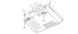
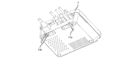
- FIG. 1 is a perspective view showing an example of a bottom portion of a display device in the embodiment.
- the display device 1 is a monitor that displays information, and is, for example, a liquid crystal display or the like in the palm vein authentication device, but is not limited to the liquid crystal display.
- the display device 1 is designed to have an angle (tilt), that is, to be adjustable in order to improve the visibility of the display (display screen) and the operability when holding a hand over the display.
- the display device 1 when the display device 1 is installed in a store or the like and visibility is bad due to the influence of illumination in the store, external light, etc., it is possible to adjust the angle to improve the visibility of the display.
- the display device 1 holds the palm over the display, such as a palm vein authentication device, the height varies depending on the user holding the hand, so that the operability can be improved by adjusting the angle according to the height. .
- the angle adjustment can be performed using a stand 11 described later, a stand storage portion (hereinafter simply referred to as a storage portion) 12, a hole 13 and a slit 14. These are provided on the bottom surface portion 10 of the display device 1 (See Figure 1).
- the bottom surface portion 10 has a removable structure on the bottom surface of the display device 1, for example, a structure in which a convex portion provided on the main body side of the display device 1 and a concave portion provided on the bottom surface portion 10 side are fitted Combined.
- the structure for coupling is not limited to this, and may be coupled by another structure.
- the display device 1 can connect a wiring group 16 for supplying power to the display device 1 or transmitting information as shown in FIG.
- a stand 11 (11a, 11b), a storage portion 12 (12a, 12b) for storing the stand 11, and a hole 13 (13a) for fitting the stand 11 , 13b, 13c, 13d) and slits 14 (14a, 14b, 14c, 14d) connecting the plurality of holes 13 are provided.
- Each of the holes 13 is provided with a pair of oppositely facing holes in the storage portion 12, and a projection 20 of a stand 11 described later is fitted in each of the holes 13. Further, the slits 14 are similarly provided with a pair of opposing slits in the storage portion 12 and used as a passage when the stand 11 moves between the holes 13 as described later.
- the stand 11 is attached to the bottom surface portion 10 and exposed from the storage portion 12 to give an angle to the display surface of the display device 1. As for how to set the angle, rotate the stand 11 after fitting it in the hole 13, and press the stand 11 against the wall surface 15 (15a, 15b) of the storage unit 12 shown in FIG.
- the stand 11 is fixed and placed at an angle by placing the display device 1 on etc.
- the wall surface 15 is a wall surface of the storage portion 12 that abuts when the stand 11 is rotated.
- the protrusions 11 (20 a and 20 b) are formed on the stand 11 symmetrically with respect to the longitudinal direction of the stand 11.
- the stand 11 is attached by fitting the projection 20 into the hole 13. That is, the protrusions 20 are formed symmetrically with respect to the longitudinal direction of the stand 11, and the respective protrusions 20 are respectively fitted in the facing holes 13 in the housing 12.
- the protrusion 11a is fitted in the hole 13a
- the hole 20b is fitted in the pair of holes 13b facing the hole 13a
- the stand 11 is attached in the storage 12.
- two projections 20 for example, 20a and 20b
- two holes 13 for example, 13a and 13b
- 1 corresponding to one projection 20 Alternatively, only one hole 13 may be used.
- the stand 11 when the stand 11 is fitted into the hole 13, the notches 21 (21a and 21b) may be provided in a part of the stand 11 so as to be easily fitted. As a result, it expands and contracts in the lateral direction of the stand 11. Therefore, at the time of fitting, one of the protrusions 20 (for example, 20a) is inserted into the hole 13 (for example, 13a), and in this state, a force is applied in the lateral direction of the stand 11 to expand and contract, and the other protrusion 20 (for example, , 20b) are pushed into the holes 13 (for example, 13b) to be a pair of holes 13a. Thereby, the stand 11 can be easily fitted in the hole 13.
- the stand 11 is preferably a stretchable material, for example, a material such as plastic, but is not limited thereto.
- notches 22 are provided on the protrusion 20 of the stand 11.
- the notch 22 is formed by processing a part of the cylindrical portion of the protrusion 20 flat. That is, the protrusion 20 is processed according to the width 31 of the slit 14.
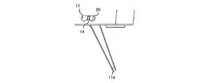
- the width 31 of the slit 14 (14a) is configured to be narrower than the length 30 of the diameter of the circle of the hole 13 (13a).
- the stand 11 (11a, 11b) is unfolded (exposed) from the storage portion 12 (12a, 12b), and a desk etc. in a state where the stand 11 is pressed against the wall 15 of the storage portion 12 described later.
- the display surface 1 is angled by placing the display device 1 on the screen. In this state (the expanded state), a force may be applied from the top of the display device 1, but even if a force is applied, the projection 20 is not moved to the other hole 13 via the slit 14.
- the width 31 of the slit 14 is narrower than the diameter 30 of the circle of the hole 13. As a result, even if a force is applied, the protrusions 20 are less likely to move to the other holes 13, and the angle set at the time of operation can be maintained.
- a notch 22 is provided in a part of the protrusion 20 so that the notch 20 can be passed without being caught by the slit 14. Cut out so that the length 23 from the end of the notched flat surface to the opposite circular end is equal to or shorter than the width 31 of the slit 14 in order to allow the slit 14 to pass smoothly (see FIG. 2) ).
- a flat surface may be provided on the side opposite to the flat surface, and two flat surfaces may be provided.
- the storage portion 12 is a space for storing the stand 11 as shown in FIG. 1 and is obtained by hollowing out a part of the bottom portion 10.
- the space of the storage portion 12 is covered with four wall surfaces.
- the storage portion 12 is a space having a rectangular solid (or cube) shape, but is not limited to this, and may be a space having another shape such as a cylindrical shape.
- the housing portion 12 is provided with a hole 13 and a slit 14.
- the housing portion 12a is provided with holes 13a and 13b and slits 14a and 14b.
- the hole 13a and the hole 13b, and the slit 14a and the slit 14b face each other in the storage portion 12, respectively, and are in pairs.
- the state as shown in FIG. 4 is obtained, and the stand 11 (11a, 11b) is developed (exposed) from the storage portion 12 In this case, the state is as shown in FIG.
- the display surface When the stand 11 is stored in the storage unit 12, the display surface is not angled, and the display surface is flat with respect to the desk surface on which the display device 1 is placed. On the other hand, when the display 11 is placed on a desk with the stand 11 expanded from the storage unit 12 and the stand 11 pressed against the wall surface 15 (15a, 15b) of the storage unit 12, the display surface is angled (See FIG. 5).
- the hole 13 is for fitting the projection 20 of the stand 11 to attach the stand 11 to the bottom portion 10, and makes the stand 11 rotatable.
- the holes 13 have opposing holes that form a pair in the storage 12. For example, in FIG. 1, the hole 13a and the hole 13b, and the hole 13c and the hole 13d are a pair of holes.
- the number of holes 13 is not limited to this, and there may be more holes. Since the holes 13 are aligned in a straight line in the lateral direction, the turning range of the stand 11 increases as the holes 13 move away from the predetermined wall surface 15 of the storage 12, and the angle formed by the stand 11 decreases. . Therefore, as the hole 13 moves away from the wall surface 15, the inclination of the display surface of the display device 1 becomes gentle. That is, the angle is determined and adjusted by the distance between each hole and the wall surface 15 of the storage portion 12.
- the slits 14 are provided between the holes 13 and serve as a passage for moving the stand 11 to the other holes 13.
- the slits 14 each have a pair of opposed slits in the storage portion 12 as well as the holes 13.
- the slits 14a and 14b and the slits 14c and 14d are a pair of slits. Since the slits 14 are paths connecting between the holes 13, if the number of the holes 13 increases, the number of the slits 14 also increases.
- the width 31 of the slit 14 is narrower than the diameter 30 of the circle of the hole 13. This is made by fitting the stand 11 to the hole 13 and placing the display device 1 on a desk or the like in an angled state, and when a force is applied from the top of the display device 1, the protrusion 20 of the stand 11 This is to prevent movement to the hole 13. Even if the width 31 of the slit 14 is smaller than the length 30 of the diameter of the circle of the hole 13, the projection can be easily performed when moving the stand 11 to another hole 13 for angle adjustment.
- the notch portion 22 is provided in the portion 20. Thus, the projection 20 does not move to the other hole 13 when the stand 11 is fixed, and the projection 20 can be easily moved to the other hole 13 when adjusting the angle.
- FIG. 6A is a side view of the display device 1 in a state where the tilt angle of the display device 1 is 0 degrees.
- the display device 1 is placed horizontally to the desk installation surface 60.
- region containing the hole part 13 with which the stand 11 which is a part of back surface (surface to which the wiring group 16 is connected) at this time was fitted is shown to FIG. 6B.
- the stand 11 When the inclination angle of the display device 1 is 0 degrees, the stand 11 is housed in the housing 12 in a state of being fitted in the hole 13. That is, the stand 11 is not exposed. At this time, the flat surface of the notch 22 of the protrusion 20 of the stand 11 is not parallel to the moving direction 61 of the slit 14. This makes it difficult for the projection 20 of the stand 11 to move to the other hole 13 via the slit 14.
- FIG. 6C A cross-sectional view of the stand 11 stored in the storage unit 11 at this time is shown in FIG. 6C.
- the stand 11 is stored in the storage portion 12 in a non-exposed manner.
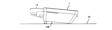
- FIG. 7A is a side view of the display device 1 in a state where the tilt angle of the display device 1 is 5 degrees. As shown in FIG. 7A, since the inclination angle of the display device 1 is 5 degrees, the display device 1 is in a state of being inclined 5 degrees with respect to the installation surface 60 of the desk. The thing which expanded the area
- the projection 20 When the inclination angle of the display device 1 is 5 degrees, the projection 20 is engaged with the hole 13 different from the hole 13 with which the projection 20 of the stand 11 is engaged when the inclination angle is 0 ° There is. This rotates the stand 11 accommodated and unfolds from the accommodation portion 12, with the flat surface of the notch 22 of the projection 20 parallel to the moving direction 61 of the slit 14 and through the slit 14. The projection 20 is moved to the other hole 13 and fitted.
- the flat surface of the notch 22 of the protrusion 20 of the stand 11 is not parallel to the moving direction 61 of the slit 14. As a result, even if a force is applied from the upper part of the display device 1 or the like, the protrusion 20 of the stand 11 is less likely to move to the other hole 13 via the slit 14.
- FIG. 7C A cross-sectional view of the stand 11 at this time is shown in FIG. 7C.
- the stand 11 is fixed when it is placed on the installation surface 60 of the desk by being pressed against (abuts on) the wall surface 15 of the storage unit 12, and the inclination angle (5 degrees) to the display device 1 It is attached.
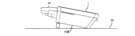
- FIG. 8A is a side view of the display device 1 in a state where the tilt angle of the display device 1 is 10 degrees.
- the display device 1 is in a state of being inclined 10 degrees with respect to the installation surface 60 of the desk.
- region containing the hole part 13 with which the stand 11 which is a part of back surface at this time was fitted is shown to FIG. 8B.
- the projections 20 are fitted in the holes 13 different from the holes 13 in which the projections 20 of the stand 11 were fitted. There is.
- the stand 11 is rotated to make the flat surface of the notch 22 of the projection 20 parallel to the moving direction 61 of the slit 14 through the slit 14. Then, the projection 20 is moved to another hole 13 and fitted.
- the fitted hole 13 is the same as the hole 13 in which the projection 20 was fitted at an inclination angle of 0 degrees.
- the direction of the flat surface of the notch 22 of the projection 20 is different from the direction of the state of being fitted in the hole 13 at each inclination angle. This is because the stand 11 is rotating to give an angle.
- the flat surface of the notch 22 of the protrusion 20 of the stand 11 is not parallel to the moving direction 61 of the slit 14. As a result, even if a force is applied from the upper part of the display device 1 or the like, the protrusion 20 of the stand 11 is less likely to move to the other hole 13 via the slit 14.
- FIG. 8C A cross-sectional view of the stand 11 at this time is shown in FIG. 8C.
- the stand 11 is fixed when it is placed on the installation surface 60 of the desk by being pressed against (abuts on) the wall surface 15 of the storage unit 12, and the tilt angle (10 degrees) to the display device 1 It is attached.
- FIG. 9A is a view showing the back of the display device 1 when the slit 20 of the projection 20 of the stand 11 is moved.
- the display device 1 is lifted and the stand 11 is rotated to make the flat surface of the notch 22 of the protrusion 20 parallel to the moving direction 61 of the slit 14.
- the enlarged view of the stand 11 at the time of slit movement is shown to FIG. 9B and a perspective view to FIG. 9C.
- FIGS. 9B and 9C the state in which the stand 11 is rotated so that the flat surface of the notch 22 is parallel to the moving direction 61 of the slit 14 is shown.
- the projection 20 can be moved easily without being caught by the slit 14 and the structure becomes firm when the stand 11 is deployed (fixed).
- FIG. 10A is a diagram showing the back surface of the display device 1 in the case where the inclination angle is smaller next to 0 degree among four steps.
- the four inclination angles are, for example, stages of angles such as 0 degree, 3 degrees, 5 degrees, 10 degrees, etc., and three holes 13 and respective holes 13 for providing these four steps of inclination angles.
- Two slits 14 to be connected are required.
- An enlarged view of the stand 11 (11a) at this time is shown in FIG. 10B, and a sectional view is shown in FIG. 10C.
- FIG. 10B there are three holes 13 in which the protrusions 20 of the stand 11a can be fitted, and the protrusions 20 are fitted in the holes 13i.
- an inclination angle for example, 3 degrees
- an inclination angle for example, 5 degrees
- the projection 20 is moved over the slit 14 to fit in the central hole 13k
- an inclination angle for example, 10 degrees
- the portion 20 is moved on the slit 14 and fitted in the hole 13m at the right end.
- FIG. 10D shows a perspective view from the bottom surface side of the display device 1 when the inclination angle is smaller next to 0 degree among the four steps of the stand 11 (11a, 11b).
- the display device 1 can have a minimum inclination angle. As described above, by increasing the number of holes 13, the inclination angle can be set in multiple steps.
- FIG. 11A is a rear view of the display device 1 when the inclination angle is 15 degrees.
- the stand 11 (11a, 11b) here is longer than the legs of the stand 11 (11a, 11b) described above.
- two holes 13 are provided, it is possible to finely adjust the angle by increasing the number of holes 13 and the number of slits 14 as described above.
- FIG. 11B shows an enlarged view of the stand 11a when the inclination angle is 15 degrees
- FIG. 11C shows a cross-sectional view of the stand 11a.
- a perspective view from the bottom side of the display device 1 in this case is shown in FIG. 11D.
- the display device 1 When placed on a desk or the like in this state, the display device 1 can be inclined at an angle of 15 degrees.
- the legs of the stand 11 can also be made extensible. This allows finer adjustment of the tilt angle.
- FIG. 12A is a rear view of the display device 1 when the distance between the holes 13 is increased.
- the distance between the holes 13 (between the holes 13a and 13e) is longer than that between the holes 13 (between the holes 13a and 13e) in FIG.
- the rotation area until the stand 11 is pressed against the wall surface 15 of the storage portion 12 becomes larger, so the inclination angle can be adjusted smaller. That is, the angle is determined by the distance between the holes 13.
- the hole 13 c after movement is separated from the hole 13 g, that is, the wall 11 is separated.
- the angle between the bottom surface of the display device 1 and the desk installation surface 60 decreases.
- the inclination angle can be adjusted by adjusting the distance between the holes 13.
- the inclination angle of the display surface can be adjusted in a limited space. Further, the number of parts for forming the angle can be reduced, and the cost can be reduced.
- the notch portion of the stand makes it easy to move the slit, and at the time of installation (at the time of fixing), the projection can be made difficult to move to another hole.
Landscapes
- Engineering & Computer Science (AREA)
- Physics & Mathematics (AREA)
- General Physics & Mathematics (AREA)
- Theoretical Computer Science (AREA)
- Multimedia (AREA)
- Signal Processing (AREA)
- Devices For Indicating Variable Information By Combining Individual Elements (AREA)
Abstract
限られたスペースで表示面の傾斜角度の調節を行うことができる表示装置を提供する。表示装置(1)に取り付けるための突起部(20)を有するスタンド(11)と、スタンドを収納する収納部(12)と、収納部に設けられ、突起部を嵌合させてスタンドを回動可能にする複数の穴部(13)と、を備え、穴部に突起部を嵌合させてスタンドを回動させ、収納部の壁面(15)へのスタンドの押し当てを穴部ごとに行うことによって角度を調節する。
Description
本発明は、スタンドにより表示面の傾斜角度を調節する表示装置に関する。
従来からスタンドを用いて表示面の傾斜角度を調節する表示装置がある(下記の特許文献1を参照)。このような表示装置は背面にスタンドを取り付け、スタンドを回転させることによって角度調節するようになっている。一方で、表示装置の小型化が進み、基板などの部品を搭載できる内部スペースは限られているため、表示装置の背面カバーに密着して基板などが配置されている。
しかし、従来の表示装置のスタンドは、背面カバーの広い範囲において穴を開けてネジなどで取り付けられるため、背面カバーに密着して基板などが配置される表示装置では角度調節可能なスタンドを設けることが困難であった。また、複数のスタンドによって複数の角度を調節する表示装置では角度ごとに部品が増えるため、スタンドを設けることが一層困難であり、コスト高の要因にもなった。
本発明は、上記課題に鑑み、限られたスペースで表示面の傾斜角度の調節を行うことができる表示装置を提供することを目的とする。
上記目的を達成するために、本発明は、表示画面の角度をスタンドにより調節する表示装置であって、前記表示装置に取り付けるための突起部を有する前記スタンドと、前記スタンドを収納する収納部と、前記収納部に設けられ、前記突起部を嵌合させて前記スタンドを回動可能にする複数の穴部と、を備え、前記穴部に前記突起部を嵌合させて前記スタンドを回動させ、前記収納部の壁面への前記スタンドの押し当てを前記穴部ごとに行うことによって前記角度を調節することを特徴とする。
また、本発明の表示装置において、前記穴部の間に設けられ、前記突起部が嵌合された前記スタンドを他の穴部へ移動させる通路であるスリットを更に備え、前記突起部が前記スリット幅に応じて加工されたことは好ましい態様である。
また、本発明の表示装置において、前記角度がそれぞれの穴部と前記壁面との距離によって決定されることは好ましい態様である。
また、本発明の表示装置において、前記角度が前記スタンドの脚の長さを調節することによって決定されることは好ましい態様である。
また、本発明の表示装置において、前記角度が前記穴部の間の距離によって決定されることは好ましい態様である。
また、本発明の表示装置において、前記突起部が前記スタンドの長手方向に対して左右対称に形成され、それぞれの前記突起部を前記収納部内で対向する穴部にそれぞれ嵌合させることは好ましい態様である。
本発明によれば、限られたスペースで表示面の傾斜角度の調節を行うことができる。
以下、実施形態について図面を参照して説明する。図1は実施形態における表示装置の底面部の一例を示す斜視図である。表示装置1は情報を表示するモニタであって、例えば手のひら静脈認証装置における液晶ディスプレイなどであるが、液晶ディスプレイに限定されるものではない。表示装置1はディスプレイ(表示画面)の視認性やディスプレイへ手をかざす際の操作性をよくするために角度(傾斜)をつけられる、すなわち角度調節できるようになっている。
例えば、店舗などに表示装置1が設置され、店舗内の照明や外光などの影響により視認性が悪い場合には、角度を調節してディスプレイの視認性を向上させることが可能である。また、表示装置1が手のひら静脈認証装置のように手のひらをディスプレイにかざすものの場合、手をかざすユーザによって身長が異なるため、身長に応じて角度を調節して操作性を向上させることが可能である。
角度調節は、後述するスタンド11、スタンド収納部(以下、単に収納部と言う)12、穴部13、スリット14を用いて行うことができ、これらは表示装置1の底面部10に設けられている(図1を参照)。底面部10は表示装置1の底面に取り外し可能な構造、例えば表示装置1の本体側に設けられた凸部と底面部10側に設けられた凹部を嵌合させる構造により表示装置1の本体に結合される。結合のための構造はこれに限定されるものではなく、他の構造によって結合されるものであってもよい。なお、表示装置1は、図1に示すように表示装置1へ電源を供給したり、情報を伝達したりするための配線群16を接続することが可能となっている。
図1から図5に示すように、底面部10にはスタンド11(11a、11b)、スタンド11を収納する収納部12(12a、12b)、スタンド11を嵌合させるための穴部13(13a、13b、13c、13d)、複数の穴部13を結ぶスリット14(14a、14b、14c、14d)が設けられている。
穴部13それぞれには収納部12内において対向するペアとなる穴部が設けられ、後述するスタンド11の突起部20がペアとなる穴部13それぞれに嵌合される。また、スリット14も同様に収納部12内において対向するペアとなるスリットが設けられ、後述するように穴部13間をスタンド11が移動する際の通路として用いられる。
スタンド11は、底面部10に取り付け、収納部12から露出させることで表示装置1のディスプレイ面に角度をつけるものである。角度のつけ方としては、スタンド11を穴部13に嵌合後に回動させ、図1に示す収納部12の壁面15(15a、15b)にスタンド11を押し当てて(当接させて)机などに表示装置1を置くことでスタンド11を固定して角度をつける。ここでの壁面15は収納部12の壁面のうちスタンド11を回動させた際に当接する壁面である。
また、スタンド11は、図2に示すようにスタンド11の長手方向に対して左右対称に突起部20(20a、20b)が形成されている。突起部20を穴部13に嵌合させることによりスタンド11を取り付ける。すなわち、突起部20はスタンド11の長手方向に対して左右対称に形成され、それぞれの突起部20を収納部12内で対向する穴部13にそれぞれ嵌合させる。例えば、突起部20aを穴部13aに嵌合させ、穴部20bを穴部13aに対向するペアの穴部13bに嵌合させてスタンド11を収納部12内に取り付ける。
なお、ここではスタンド11を取り付ける際、2つの突起部20(例えば、20aと20b)と2つの穴部13(例えば、13aと13b)を用いているが、1つの突起部20と対応する1つの穴部13のみを用いて取り付けるようにしてもよい。
また、スタンド11は、穴部13へ嵌合する際、嵌合しやすいようにスタンド11の一部に切り込み部21(21a、21b)が設けられていてもよい。これにより、スタンド11の横手方向において伸縮する。そのため、嵌合時には一方の突起部20(例えば20a)を穴部13(例えば、13a)に嵌め込み、その状態でスタンド11の横手方向に力を加えて伸縮させ、もう一方の突起部20(例えば、20b)を穴部13aのペアとなる穴部13(例えば、13b)に押し込む。これにより、容易にスタンド11を穴部13に嵌合させることができる。この場合のスタンド11は伸縮可能な素材、例えばプラスチックなどの素材が好ましいが、これに限定されるものではない。
また、スタンド11の突起部20には図2に示すように切り欠き部22(22a、22b)が施されている。切り欠き部22は突起部20の円柱部分の一部を平らに加工したものである。すなわち、突起部20はスリット14の幅31に応じて加工されている。ここでは、図3に示すようにスリット14(14a)の幅31を穴部13(13a)の円の直径の長さ30より狭くするよう構成されている。
このような構成とする理由がある。図5に示すようにスタンド11(11a、11b)が収納部12(12a、12b)から展開され(露出し)、スタンド11が後述する収納部12の壁面15に押し当てられた状態で机などに表示装置1が置かれることによりディスプレイ面に角度がつけられる。この状態(展開された状態)で表示装置1の上部から力が加えられることがあるが、力を加えられても突起部20がスリット14を介して他の穴部13へ移動しないように、スリット14の幅31を穴部13の円の直径の長さ30より狭くしている。これにより、力が加わっても突起部20が他の穴部13へ移動しにくく、運用時に設定した角度を維持することができる。
一方で、後述するように、角度を調節する際にはスタンド11の突起部20を他の穴部13へ嵌合させるため、穴部13の間を容易に移動できるようにする必要がある。そのため、突起部20の一部に切り欠き部22を設け、切り欠いた突起部20がスリット14に引っかかることなく通過できるようにしている。スムーズにスリット14を通過できるようにするため、切り欠いた平らな面の端から対向する円形端までの長さ23がスリット14の幅31と同等か短くなるように切り欠く(図2を参照)。ここでは切り欠いた平らな面は1つのみであるが、上記平らな面に対向する側にも平らな面を設け、平らな面を2つ設けるなどしてもよい。
収納部12は、図1に示すようにスタンド11を収納する空間であって、底面部10の一部をくり抜いたものであり、収納部12の空間は4つの壁面で覆われている。この例では、収納部12は直方体(又は立方体)の形状の空間となっているがこれに限定されるものではなく、円柱形など他の形状の空間であってもよい。
収納部12には穴部13及びスリット14が設けられており、例えば収納部12aには穴部13a、13b及びスリット14a、14bが設けられている。穴部13aと穴部13b及びスリット14aとスリット14bは、それぞれ収納部12内において対向しており、それぞれがペアとなっている。
収納部12にスタンド11(11a、11b)が収納されている場合には図4に示すような状態となり、収納部12からスタンド11(11a、11b)が展開している(露出している)場合には図5に示すような状態となる。
スタンド11が収納部12に収納されている場合にはディスプレイ面に角度がつかず、表示装置1が置かれる机面に対してディスプレイ面はフラットな状態となる。一方、スタンド11が収納部12から展開され、収納部12の壁面15(15a、15b)にスタンド11が押し当てられた状態で表示装置1が机に置かれるとディスプレイ面に角度がついた状態となる(図5を参照)。
穴部13は、スタンド11の突起部20を嵌合させてスタンド11を底面部10に取り付けるためのものであり、スタンド11を回動可能にするものである。穴部13は、収納部12においてそれぞれペアとなる対向する穴部を有している。例えば、図1では穴部13aと穴部13b、穴部13cと穴部13dがそれぞれペアの穴部である。
なお、穴部13の数はこれに限定されるものではなく、さらに多くの穴部があってもよい。穴部13が横方向の一直線上に並んでいるため、穴部13が収納部12の所定の壁面15から遠ざかるにつれてスタンド11の回動範囲が大きくなり、スタンド11によって形成される角度が小さくなる。よって、穴部13が壁面15から遠ざかるにつれて表示装置1のディスプレイ面の傾斜が緩やかになる。すなわち、角度はそれぞれの穴部と収納部12の壁面15との距離によって決定、調節される。
スリット14は、それぞれの穴部13の間に設けられ、スタンド11を他の穴部13へ移動させる通路となるものである。スリット14は穴部13と同様に、収納部12においてそれぞれペアとなる対向するスリットを有している。例えば、図1ではスリット14aとスリット14b、スリット14cとスリット14dがペアのスリットである。スリット14は、穴部13間を結ぶ通路であるため、穴部13が増えればスリット14の数も増える。
スリット14の幅31は、穴部13の円の直径の長さ30よりも狭くなっている。これはスタンド11を穴部13に嵌合させ、角度をつけた状態で机などに表示装置1が置かれ、表示装置1の上部から力が加わった際にスタンド11の突起部20が他の穴部13へ移動しないようにするためである。スリット14の幅31が穴部13の円の直径の長さ30より狭くなっていても、角度調節をするためにスタンド11を他の穴部13へ移動させる際に容易に行えるように、突起部20に切り欠き部22が設けられている。これにより、スタンド11の固定時には突起部20は他の穴部13へ移動せず、角度調節時には容易に突起部20を他の穴部13へ移動させることが可能となる。
次に、実施形態における表示装置の角度調節構造の具体例について説明する。まず、表示装置1の傾斜角度が0度の状態について図6Aから図6Cを用いて説明する。図6Aは表示装置1の傾斜角度が0度の状態の表示装置1の側面図である。図6Aに示すように、表示装置1の傾斜角度が0度のため、表示装置1は机の設置面60に対して水平に置かれた状態となっている。このときの背面(配線群16が接続される面)の一部であるスタンド11が嵌合された穴部13を含む領域を拡大したものを図6Bに示す。
表示装置1の傾斜角度が0度の場合、スタンド11は穴部13に嵌合した状態で収納部12に収納されている。すなわち、スタンド11は露出していない。このとき、スタンド11の突起部20の切り欠き部22の平らな面はスリット14における移動方向61に対して平行でない。これにより、スリット14を介してスタンド11の突起部20が他の穴部13へ移動しにくくしている。
このときの収納部11に収納されたスタンド11の断面図を図6Cに示す。図6Cに示すように、スタンド11は露出しない形で収納部12に収納されている。
次に、表示装置1の傾斜角度が5度の状態について図7Aから図7Cを用いて説明する。図7Aは表示装置1の傾斜角度が5度の状態の表示装置1の側面図である。図7Aに示すように、表示装置1の傾斜角度が5度のため、表示装置1は机の設置面60に対して5度傾いた状態となっている。このときの背面の一部であるスタンド11が嵌合された穴部13を含む領域を拡大したものを図7Bに示す。
表示装置1の傾斜角度が5度の場合、傾斜角度が0度の場合にスタンド11の突起部20が嵌合していた穴部13とは異なる穴部13に突起部20が嵌合されている。これは収納されているスタンド11を回動させ、収納部12から展開し、突起部20の切り欠き部22の平らな面をスリット14における移動方向61に対して平行にしてスリット14を介して突起部20を他の穴部13へ移動させ、嵌合させた状態である。
このとき、スタンド11の突起部20の切り欠き部22の平らな面はスリット14における移動方向61に対して平行でない。これにより、表示装置1の上部などから力が加わってもスリット14を介してスタンド11の突起部20が他の穴部13へ移動しにくくなる。
このときのスタンド11の断面図を図7Cに示す。図7Cに示すように、スタンド11は収納部12の壁面15に押し当てられる(当接する)ことによって机の設置面60に置かれた際に固定され、表示装置1に傾斜角度(5度)がつけられる。
次に、表示装置1の傾斜角度が10度の状態について図8Aから図8Cを用いて説明する。図8Aは表示装置1の傾斜角度が10度の状態の表示装置1の側面図である。図8Aに示すように、表示装置1の傾斜角度が10度のため、表示装置1は机の設置面60に対して10度傾いた状態となっている。このときの背面の一部であるスタンド11が嵌合された穴部13を含む領域を拡大したものを図8Bに示す。
表示装置1の傾斜角度が10度の場合、傾斜角度が5度の場合にスタンド11の突起部20が嵌合していた穴部13とは異なる穴部13に突起部20が嵌合されている。傾斜角度5度から10度に変更する場合には、スタンド11を回動させ、突起部20の切り欠き部22の平らな面をスリット14における移動方向61に対して平行にしてスリット14を介して突起部20を他の穴部13へ移動させ、嵌合させる。嵌合された穴部13は傾斜角度0度の際に突起部20が嵌合されていた穴部13と同じである。ただし、突起部20の切り欠き部22の平らな面の向きはそれぞれの傾斜角度の際に穴部13に嵌合された状態の向きとは異なる。角度をつけるためにスタンド11が回動しているためである。
このとき、スタンド11の突起部20の切り欠き部22の平らな面はスリット14における移動方向61に対して平行でない。これにより、表示装置1の上部などから力が加わってもスリット14を介してスタンド11の突起部20が他の穴部13へ移動しにくくなる。
このときのスタンド11の断面図を図8Cに示す。図8Cに示すように、スタンド11は収納部12の壁面15に押し当てられる(当接する)ことによって机の設置面60に置かれた際に固定され、表示装置1に傾斜角度(10度)がつけられる。
次に、スタンド11の突起部20のスリット14の移動の詳細について説明する。図9Aはスタンド11の突起部20のスリット移動時の表示装置1の背面を示す図である。突起部20のスリット移動時には表示装置1を持ち上げ、スタンド11を回動させ、突起部20の切り欠き部22の平らな面をスリット14における移動方向61に対して平行にする。スリット移動時のスタンド11の拡大図を図9B、斜視図を図9Cに示す。
図9B及び図9Cに示すように、切り欠き部22の平らな面がスリット14における移動方向61に対して平行になるようにスタンド11を回動させた状態が示されている。これにより、突起部20がスリット14に引っ掛からずにスリット移動が容易にでき、さらにスタンド11の展開時(固定時)には強固な構造になる。
次に、傾斜角度を4段階とした場合の表示装置1について説明する。図10Aは4段階のうち0度の次に傾斜角度が小さい場合の表示装置1の背面を示す図である。傾斜角度が4段階とは、例えば0度、3度、5度、10度などの角度の段階であり、これら4段階の傾斜角度をつけるために3つの穴部13とそれぞれの穴部13をつなぐ2つのスリット14が必要となる。このときのスタンド11(11a)の拡大図を図10B、断面図を図10Cに示す。
図10Bに示すように、スタンド11aの突起部20の嵌合可能な穴部13は3つあり、穴部13iに突起部20が嵌合され、図10Cに示すようにスタンド11aが収納部12の壁面15に押し当てられることによって4段階のうち0度の次に小さい傾斜角度(例えば、3度)が形成される。さらに傾斜角度(例えば、5度)をつける場合には突起部20をスリット14上で移動させて中央の穴部13kに嵌合させ、さらに傾斜角度(例えば、10度)をつける場合には突起部20をスリット14上で移動させて右端の穴部13mに嵌合させる。
スタンド11(11a、11b)の4段階のうち0度の次に傾斜角度が小さい場合の表示装置1の底面側からの斜視図を図10Dに示す。この状態で机などに置かれると表示装置1に最小の傾斜角度をつけることができる。このように、穴部13の数を増やすことで多段階的に傾斜角度をつけることができる。
次に、スタンド11の脚の長さや穴部13間の距離を調節することで傾斜角度を調節することについて説明する。
まず、スタンド11の脚の長さを調節して傾斜角度を調節することについて説明する。図11Aは傾斜角度15度の場合における表示装置1の背面図である。ここでのスタンド11(11a、11b)は上述したスタンド11(11a、11b)の脚よりも長いものである。なお、ここでは穴部13が2つのみであるが、上述したように穴部13の数とスリット14の数を増やすことでさらに角度調節を細かく行うことが可能となる。
図11Bは傾斜角度が15度の場合のスタンド11aの拡大図を示し、図11Cはそのスタンド11aの断面図を示している。スタンド11(11a)の脚の長さを長くすることによって、同じ穴部13に突起部20を嵌合させ、収納部12の壁面15に押し当てた脚の短いスタンドよりも傾斜角度をつけることが可能となる。この場合の表示装置1の底面側からの斜視図を図11Dに示す。この状態で机などに置かれると表示装置1に15度の傾斜角度をつけることができる。なお、スタンド11の脚は伸縮可能にすることも可能である。これにより、より細かな傾斜角度の調節が可能になる。
次に、穴部13間の距離を調節することで傾斜角度を調節することについて説明する。図12Aは穴部13間の距離を離した場合における表示装置1の背面図である。ここでの穴部13間(穴部13aと穴部13eの間)の距離は上述した図3などの穴部13間(穴部13aと穴部13eの間)よりも長い。穴部13の間の距離を長くすることによってスタンド11が収納部12の壁面15に押し当てられるまでの回動域が大きくなるため、傾斜角度をより小さく調節することができる。すなわち、角度は穴部13の間の距離によって決定される。
例えば、図12Bに示すように、スタンド11の突起部22が穴部13gに嵌合され、スタンド11が収納部12に収納されている状態を考える。この状態から、スタンド11を回動させ、収納部12から展開し、突起部20の切り欠き部22の平らな面をスリット14における移動方向61に対して平行にしてスリット14cを介して突起部20を他の穴部13cへ移動させる。
移動後、スタンド11をさらに回動させ、収納部12の壁面15に押し当てる際、移動後の穴部13cが穴部13gと距離が離れている、すなわち壁面15と離れているため、スタンド11はより大きく回動し、表示装置1の底面と机の設置面60との間の角度が小さくなる。このように、穴部13間の距離を調節することで傾斜角度を調節することができる。
上述したような表示装置によれば、限られたスペースで表示面の傾斜角度の調節を行うことができる。また、角度をつけるための部品点数を削減することができ、コストを削減することができる。また、スタンドの切り欠き部により、スリット移動が容易にでき、設置時(固定時)には突起部が他の穴部へ移動しにくい構造にすることができる。
また、上述した実施の形態は、上述したものに限定されるものではなく、実施の形態の要旨を逸脱しない範囲において種々の変更を加えることができる。
1 表示装置
10 底面部
11 スタンド
12 スタンド収納部
13 穴部
14 スリット
15 壁面
16 配線群
20 突起部
21 切り込み部
22 切り欠き部
31 幅
60 机の設置面
61 スリットにおける移動方向
10 底面部
11 スタンド
12 スタンド収納部
13 穴部
14 スリット
15 壁面
16 配線群
20 突起部
21 切り込み部
22 切り欠き部
31 幅
60 机の設置面
61 スリットにおける移動方向
Claims (6)
- 表示画面の角度をスタンドにより調節する表示装置であって、
前記表示装置に取り付けるための突起部を有する前記スタンドと、
前記スタンドを収納する収納部と、
前記収納部に設けられ、前記突起部を嵌合させて前記スタンドを回動可能にする複数の穴部と、を備え、
前記穴部に前記突起部を嵌合させて前記スタンドを回動させ、前記収納部の壁面への前記スタンドの押し当てを前記穴部ごとに行うことによって前記角度を調節することを特徴とする表示装置。 - 前記穴部の間に設けられ、前記突起部が嵌合された前記スタンドを他の穴部へ移動させる通路であるスリットを更に備え、
前記突起部は前記スリット幅に応じて加工されたことを特徴とする請求項1に記載の表示装置。 - 前記角度はそれぞれの穴部と前記壁面との距離によって決定されることを特徴とする請求項1又は2に記載の表示装置。
- 前記角度は前記スタンドの脚の長さを調節することによって決定されることを特徴とする請求項1から3のいずれか1つに記載の表示装置。
- 前記角度は前記穴部の間の距離によって決定されることを特徴とする請求項1から4のいずれか1つに記載の表示装置。
- 前記突起部は前記スタンドの長手方向に対して左右対称に形成され、それぞれの前記突起部を前記収納部内で対向する穴部にそれぞれ嵌合させることを特徴とする請求項1から5のいずれか1つに記載の表示装置。
Priority Applications (2)
| Application Number | Priority Date | Filing Date | Title |
|---|---|---|---|
| JP2019561404A JP6865505B2 (ja) | 2017-12-25 | 2017-12-25 | 表示装置 |
| PCT/JP2017/046433 WO2019130392A1 (ja) | 2017-12-25 | 2017-12-25 | 表示装置 |
Applications Claiming Priority (1)
| Application Number | Priority Date | Filing Date | Title |
|---|---|---|---|
| PCT/JP2017/046433 WO2019130392A1 (ja) | 2017-12-25 | 2017-12-25 | 表示装置 |
Publications (1)
| Publication Number | Publication Date |
|---|---|
| WO2019130392A1 true WO2019130392A1 (ja) | 2019-07-04 |
Family
ID=67063334
Family Applications (1)
| Application Number | Title | Priority Date | Filing Date |
|---|---|---|---|
| PCT/JP2017/046433 Ceased WO2019130392A1 (ja) | 2017-12-25 | 2017-12-25 | 表示装置 |
Country Status (2)
| Country | Link |
|---|---|
| JP (1) | JP6865505B2 (ja) |
| WO (1) | WO2019130392A1 (ja) |
Citations (8)
| Publication number | Priority date | Publication date | Assignee | Title |
|---|---|---|---|---|
| JP2002152628A (ja) * | 2000-09-20 | 2002-05-24 | Acer Communications & Multimedia Inc | 壁掛けユニット |
| JP2004361764A (ja) * | 2003-06-06 | 2004-12-24 | Funai Electric Co Ltd | 液晶テレビ用スタンドおよび液晶表示装置用スタンド |
| JP2008115925A (ja) * | 2006-11-02 | 2008-05-22 | Hitachi Communication Technologies Ltd | 電子機器のチルト装置 |
| JP2009271790A (ja) * | 2008-05-08 | 2009-11-19 | Oki Electric Ind Co Ltd | チルト機構付支持装置 |
| JP2009278414A (ja) * | 2008-05-15 | 2009-11-26 | Iwatsu Electric Co Ltd | スタンド付き電子機器 |
| JP2010085479A (ja) * | 2008-09-29 | 2010-04-15 | Nec Personal Products Co Ltd | スタンド付き表示装置 |
| JP2013110543A (ja) * | 2011-11-21 | 2013-06-06 | Hitachi Ltd | 角度調整機構 |
| US20140306074A1 (en) * | 2013-04-12 | 2014-10-16 | Wistron Corporation | Angle adjustable stand mechanism |
-
2017
- 2017-12-25 JP JP2019561404A patent/JP6865505B2/ja active Active
- 2017-12-25 WO PCT/JP2017/046433 patent/WO2019130392A1/ja not_active Ceased
Patent Citations (8)
| Publication number | Priority date | Publication date | Assignee | Title |
|---|---|---|---|---|
| JP2002152628A (ja) * | 2000-09-20 | 2002-05-24 | Acer Communications & Multimedia Inc | 壁掛けユニット |
| JP2004361764A (ja) * | 2003-06-06 | 2004-12-24 | Funai Electric Co Ltd | 液晶テレビ用スタンドおよび液晶表示装置用スタンド |
| JP2008115925A (ja) * | 2006-11-02 | 2008-05-22 | Hitachi Communication Technologies Ltd | 電子機器のチルト装置 |
| JP2009271790A (ja) * | 2008-05-08 | 2009-11-19 | Oki Electric Ind Co Ltd | チルト機構付支持装置 |
| JP2009278414A (ja) * | 2008-05-15 | 2009-11-26 | Iwatsu Electric Co Ltd | スタンド付き電子機器 |
| JP2010085479A (ja) * | 2008-09-29 | 2010-04-15 | Nec Personal Products Co Ltd | スタンド付き表示装置 |
| JP2013110543A (ja) * | 2011-11-21 | 2013-06-06 | Hitachi Ltd | 角度調整機構 |
| US20140306074A1 (en) * | 2013-04-12 | 2014-10-16 | Wistron Corporation | Angle adjustable stand mechanism |
Also Published As
| Publication number | Publication date |
|---|---|
| JP6865505B2 (ja) | 2021-04-28 |
| JPWO2019130392A1 (ja) | 2020-04-09 |
Similar Documents
| Publication | Publication Date | Title |
|---|---|---|
| KR101608754B1 (ko) | 휴대용 전자,전기 기기의 액세서리 | |
| US8936229B2 (en) | Housing assembly and electronic device using the same | |
| EP2230437B1 (en) | Hinge device with a spherical joint | |
| US10503210B2 (en) | Folding device of foldable display and display device having the same | |
| US9942639B2 (en) | Articulating, self retained on-wall bracket mounting system | |
| JP6639643B2 (ja) | 挟持構造及び該挟持構造を有する曇台 | |
| US5862214A (en) | Low cost adjustable base stand | |
| US20150050077A1 (en) | Quick release device | |
| KR20160108120A (ko) | 휴대용 절첩식 가상 현실 기기 | |
| US8072532B2 (en) | Camera module with switching lenses | |
| JP2007278497A (ja) | 電子機器の角度調節脚機構 | |
| CN109268359A (zh) | 位置调节装置及设备 | |
| US10148799B2 (en) | Auxiliary optical system for use with mobile electronic device in protective case | |
| US9632536B1 (en) | Dock | |
| KR20230098099A (ko) | 플렉서블디스플레이 휴대용기기의 힌지구조시스템 | |
| US20090020672A1 (en) | Supporting apparatus | |
| JP2005142671A (ja) | 携帯通信端末用スタンド | |
| CN101839275A (zh) | 枢转装置 | |
| CN102469177A (zh) | 便携式电子装置 | |
| JP2011258176A (ja) | コンピュータシステム及びそのベース構造 | |
| WO2019130392A1 (ja) | 表示装置 | |
| US20050241108A1 (en) | Rotating structure and electronic device utilizing same | |
| WO2020258144A1 (zh) | 手持云台 | |
| WO2009128153A1 (ja) | 脚装置 | |
| US20070090239A1 (en) | Support for a computer peripheral device |
Legal Events
| Date | Code | Title | Description |
|---|---|---|---|
| 121 | Ep: the epo has been informed by wipo that ep was designated in this application |
Ref document number: 17936923 Country of ref document: EP Kind code of ref document: A1 |
|
| ENP | Entry into the national phase |
Ref document number: 2019561404 Country of ref document: JP Kind code of ref document: A |
|
| NENP | Non-entry into the national phase |
Ref country code: DE |
|
| 122 | Ep: pct application non-entry in european phase |
Ref document number: 17936923 Country of ref document: EP Kind code of ref document: A1 |