WO2019129672A1 - Heat pump system in washer-dryers - Google Patents
Heat pump system in washer-dryers Download PDFInfo
- Publication number
- WO2019129672A1 WO2019129672A1 PCT/EP2018/086451 EP2018086451W WO2019129672A1 WO 2019129672 A1 WO2019129672 A1 WO 2019129672A1 EP 2018086451 W EP2018086451 W EP 2018086451W WO 2019129672 A1 WO2019129672 A1 WO 2019129672A1
- Authority
- WO
- WIPO (PCT)
- Prior art keywords
- air
- washer
- tub
- heat pump
- dryers
- Prior art date
- Legal status (The legal status is an assumption and is not a legal conclusion. Google has not performed a legal analysis and makes no representation as to the accuracy of the status listed.)
- Ceased
Links
Images



Classifications
-
- D—TEXTILES; PAPER
- D06—TREATMENT OF TEXTILES OR THE LIKE; LAUNDERING; FLEXIBLE MATERIALS NOT OTHERWISE PROVIDED FOR
- D06F—LAUNDERING, DRYING, IRONING, PRESSING OR FOLDING TEXTILE ARTICLES
- D06F25/00—Washing machines with receptacles, e.g. perforated, having a rotary movement, e.g. oscillatory movement, the receptacle serving both for washing and for centrifugally separating water from the laundry and having further drying means, e.g. using hot air
-
- D—TEXTILES; PAPER
- D06—TREATMENT OF TEXTILES OR THE LIKE; LAUNDERING; FLEXIBLE MATERIALS NOT OTHERWISE PROVIDED FOR
- D06F—LAUNDERING, DRYING, IRONING, PRESSING OR FOLDING TEXTILE ARTICLES
- D06F58/00—Domestic laundry dryers
- D06F58/20—General details of domestic laundry dryers
- D06F58/206—Heat pump arrangements
-
- D—TEXTILES; PAPER
- D06—TREATMENT OF TEXTILES OR THE LIKE; LAUNDERING; FLEXIBLE MATERIALS NOT OTHERWISE PROVIDED FOR
- D06F—LAUNDERING, DRYING, IRONING, PRESSING OR FOLDING TEXTILE ARTICLES
- D06F37/00—Details specific to washing machines covered by groups D06F21/00 - D06F25/00
- D06F37/02—Rotary receptacles, e.g. drums
- D06F37/04—Rotary receptacles, e.g. drums adapted for rotation or oscillation about a horizontal or inclined axis
Definitions
- the subject matter of the present invention relates to a heat pump system developed for washer-dryers.
- washing machines usage of dryers is also increasing. Users prefer environmentally friendly and functional washing machines and dryers that occupy less space. In order to save space and time, washing machines and dryers are integrated in a single body, creating a new selection alternative for users.
- washer-dryers are able to meet this demand. Washer-dryers are used more commonly every day due to their above mentioned advantages. Accordingly, products with high energy performance intensify competition on the market of washer-dryers, and users are encouraged to use such eco-friendly products.
- Air condensing and water condensing washer-dryers in the market have similar energy efficiencies.
- the basic principle in both systems is condensing the humidity in the process air by air and/or water.
- a process line is provided in the closed cycle flow.
- the process line consists of a tub, air heater, process fan, condenser and the line combining the air flow in these components.
- Open line enables the cold air from outside to be transmitted to a condenser and to be discharged out again.
- This line consists of a cold air fan, condenser and the components combining the air flow.
- water cooled products Similar to air cooled products, water cooled products have two separate flow lines, namely a closed cycle flow line and an open cycle flow line.
- a process line is provided in the closed cycle flow.
- the process line consists of a tub, air heater, process fan, condenser and the line connecting the air flow in these components.
- the open line consists of a valve, condenser, tub and a pump. In air cooled condensers, air dehumidifies the process air without mixing into the process line, whereas in water cooled condensers, water dehumidifies air by mixing with the process air.
- Heat pump systems are generally integrated in washing machines by producing non-standard sized products.
- a patent publication of technical interest which may be referred to is US2010/0083524.
- Said patent publication relates to dryers with a heat pump system.
- a tub, heat exchanger, evaporator, fan and a heater are provided on the first air path which is a closed cycle.
- the second system consists of a fan enabling sucking air from outside, a heat exchanger (the side that receives the thermal load on the cooling portion), and a condenser. Dehumidification is performed by means of a single path.
- the thermal load on the closed cycle is taken off by means of the air drawn from outside.
- WO2012/089569 Another patent publication of technical interest which may be referred to is WO2012/089569. Said patent publication relates to increasing the temperature of the process water in heat pump systems used in washing machines or dryers.
- a condenser is connected to a water tank adapted to provide water to the tub.
- an evaporator is connected to a heat exchanger. By this, the hot and humid air coming from the tub during drying is cooled and condensed in this region.
- EP1634984 Another patent publication of technical interest which may be referred to is EP1634984.
- Said patent publication relates to placement of a heat pump system at the bottom floor of a washing machine.
- a condenser is connected to a water tank adapted to provide water to the tub.
- an evaporator is connected to a heat exchanger.
- a perforated structure is formed in a drum shaft, thereby enabling air to directly contact the laundry items, and preventing leakage between the drum and the tub. Furthermore, displacing the heat pump group to a rear portion enables air inlet through the shaft of the drum and air suction from behind the tub, thereby shortening the air duct and enhancing the efficiency of the system. Cost advantage is also provided since the components used along the path of the duct will not be displaced. A shorter air duct further reduces the pressure loss of the system, thereby eliminating the need for using a fan with high flow rate.
- the system proposed according to the present invention relates to increasing drying and washing volume by reducing usage of ducts with the heat pump group.
- the main aim of the present invention relates to forming a perforated structure a drum shaft, thereby enabling air to directly contact the laundry items, and preventing leakage between the drum and the tub.
- Another aim of the present invention is to enable air inlet through the shaft of the drum, and air suction from behind the tub by placing the heat pump group to a rear section, thereby enhancing the efficiency of the system as a result of shortening the air duct.
- a further aim of the present invention is to provide cost advantage by eliminating the necessity to displace the components used along the path of the duct.
- Yet another aim of the present invention is to reduce pressure losses of the system by means of shortening the air duct, and to thereby eliminate the need to use a fan with high flow rate.
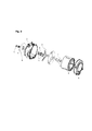
- Figure 1 is an exploded view of the washer-dryer provided according to the present invention.
- Figure 2 is an exploded perspective view of the washer-dryer provided according to the present invention.
- Figure 3 is a frontal view of the drum of the washer-dryer provided according to the present invention.
- Figure 4 is a view of the A-A section of drum of Figure 3 provided according to the present invention.
- the heat pump group consisting of a compressor, evaporator, condenser and a reducer, is grouped outside the body of the appliance.
- An air duct (1) introduced into the heat pump is directed to a shaft (4) in a drum (2), enabling transmitting air to the laundry items with minimal losses.
- Figure 1 shows general system components used in a washer-dryer.
- Figure 2 displays the placement of the oil seals (6) and the ball bearings (5) used to minimize energy losses in washer-dryers in which a continuous rotation occurs.
- Said figure also shows a tub air inlet (9) having said air duct (1).
- a perforated structure is formed on the shaft (4) provided in the drum (2) and air directly contacts the laundry items.
- leakage between the drum (2) and the tub (8) is prevented by means of an air lid (7).
- System efficiency is enhanced as the air duct (1) is shortened by providing air inlet from the shaft (4) of the drum (2) and air suction from behind the tub (8).
- the perforated structure opening to the air orifice on the rear shaft (4) of the drum (2) may have different geometries.
- air inlet of a machine with steam function can also be introduced through the orifice opened in the tub, thereby enabling wrinkle removal and mal-odor removal functions.
- a washer-dryer having a flange (3) and a shaft (4) in a tub (8) enabling transmitting to a drum (2) the air coming from a heater in a heat pump unit.
- the washer-dryer comprises a tub air inlet (9) having a line through which an air duct (1) passes.
- the washer-dryer comprises said flange (3) in said tub (8) having an air connection with said drum (2).
- the washer-dryer comprises oil seals (6) such that water does not enter into a ball bearing (5) region through said flange (3) gap in said tub (8).
- the washer-dryer comprises an orifice opening from said air duct (1) into said tub (8).
Landscapes
- Engineering & Computer Science (AREA)
- Textile Engineering (AREA)
- Detail Structures Of Washing Machines And Dryers (AREA)
Abstract
In practice, the present invention relates to a heat pump system developed for washer-dryers. More clearly, according to the present invention, a washer-dryer proposed having a flange (3) and a shaft (4) in a tub (8) enabling transmitting to drum (2) the air coming from a heater in a heat pump unit.
Description
The subject matter of the present invention relates to a heat pump system developed for washer-dryers.
Currently, heat pump systems used in washer-dryers are known.
Along with washing machines, usage of dryers is also increasing. Users prefer environmentally friendly and functional washing machines and dryers that occupy less space. In order to save space and time, washing machines and dryers are integrated in a single body, creating a new selection alternative for users. Nowadays, washer-dryers are able to meet this demand. Washer-dryers are used more commonly every day due to their above mentioned advantages. Accordingly, products with high energy performance intensify competition on the market of washer-dryers, and users are encouraged to use such eco-friendly products.
Commercially available machines use varying methods for drying, such as air condensing and water condensing washer-dryers. Air condensing and water condensing washer-dryers in the market have similar energy efficiencies. The basic principle in both systems is condensing the humidity in the process air by air and/or water.
There are two separate flows in air cooled products, namely a closed cycle flow and an open cycle flow. A process line is provided in the closed cycle flow. The process line consists of a tub, air heater, process fan, condenser and the line combining the air flow in these components. Open line enables the cold air from outside to be transmitted to a condenser and to be discharged out again. This line consists of a cold air fan, condenser and the components combining the air flow.
Similar to air cooled products, water cooled products have two separate flow lines, namely a closed cycle flow line and an open cycle flow line. A process line is provided in the closed cycle flow. The process line consists of a tub, air heater, process fan, condenser and the line connecting the air flow in these components. The open line consists of a valve, condenser, tub and a pump. In air cooled condensers, air dehumidifies the process air without mixing into the process line, whereas in water cooled condensers, water dehumidifies air by mixing with the process air.
In solo dryers, products with high energy efficiency are achieved by using a heat pump system therein. Low energy consuming washer-dryers can also be produced using a heat pump system.
Placement of a heat pump system in a standard sized appliance is a major issue. Heat pump systems are generally integrated in washing machines by producing non-standard sized products.
Placing a heat pump system in a solo dryer creates certain problems. Expansion of an air duct throughout an appliance requires displacing present components, increasing system and operational costs. It is important to resolve this problem by shortening the air duct and directing the process air into the drum without displacing many components.
A patent publication of technical interest which may be referred to is US2010/0083524. Said patent publication relates to dryers with a heat pump system. In said system having two separate air lines, a tub, heat exchanger, evaporator, fan and a heater are provided on the first air path which is a closed cycle. The second system consists of a fan enabling sucking air from outside, a heat exchanger (the side that receives the thermal load on the cooling portion), and a condenser. Dehumidification is performed by means of a single path. The thermal load on the closed cycle is taken off by means of the air drawn from outside.
Another patent publication of technical interest which may be referred to is WO2012/089569. Said patent publication relates to increasing the temperature of the process water in heat pump systems used in washing machines or dryers. A condenser is connected to a water tank adapted to provide water to the tub. In addition, an evaporator is connected to a heat exchanger. By this, the hot and humid air coming from the tub during drying is cooled and condensed in this region.
Another patent publication of technical interest which may be referred to is EP1634984. Said patent publication relates to placement of a heat pump system at the bottom floor of a washing machine. A condenser is connected to a water tank adapted to provide water to the tub. In addition, an evaporator is connected to a heat exchanger. By this, the hot and humid air coming from the tub during drying is cooled and condensed in this region.
In the heat pump system proposed in the present invention, a perforated structure is formed in a drum shaft, thereby enabling air to directly contact the laundry items, and preventing leakage between the drum and the tub. Furthermore, displacing the heat pump group to a rear portion enables air inlet through the shaft of the drum and air suction from behind the tub, thereby shortening the air duct and enhancing the efficiency of the system. Cost advantage is also provided since the components used along the path of the duct will not be displaced. A shorter air duct further reduces the pressure loss of the system, thereby eliminating the need for using a fan with high flow rate.
In other terms, the system proposed according to the present invention relates to increasing drying and washing volume by reducing usage of ducts with the heat pump group.
The main aim of the present invention relates to forming a perforated structure a drum shaft, thereby enabling air to directly contact the laundry items, and preventing leakage between the drum and the tub.
Another aim of the present invention is to enable air inlet through the shaft of the drum, and air suction from behind the tub by placing the heat pump group to a rear section, thereby enhancing the efficiency of the system as a result of shortening the air duct.
A further aim of the present invention is to provide cost advantage by eliminating the necessity to displace the components used along the path of the duct.
Yet another aim of the present invention is to reduce pressure losses of the system by means of shortening the air duct, and to thereby eliminate the need to use a fan with high flow rate.
A product realized to achieve the aim of the present invention is illustrated in the accompanying drawings, and brief descriptions of these drawings are provided below.
In interpreting the protection scope of the invention, the technical drawings appended to the present specification shall not be used singly without consulting the specification. On the other hand, the appended technical drawings should be used not to determine and delimit but to interpret the protection scope of the present invention described in the claims.
Unless otherwise specified, the appended figures do not designate the absolute dimensions of the invention and the proportions of mutual parts do not exactly reflect the original product.
Figure 1 is an exploded view of the washer-dryer provided according to the present invention.
Figure 2 is an exploded perspective view of the washer-dryer provided according to the present invention.
Figure 3 is a frontal view of the drum of the washer-dryer provided according to the present invention.
Figure 4 is a view of the A-A section of drum of Figure 3 provided according to the present invention.
The parts displayed in the figures incorporated to the specification for a better understanding of the invention, are individually numbered, and the description of each numbered part is given below.
1) Air duct
2) Drum
3) Flange
4) Shaft
5) Ball bearing
6) Oil seal
7) Air lid
8) Tub
9) Tub air inlet
In the washer-dryer with heat pump unit of the invention, the heat pump group consisting of a compressor, evaporator, condenser and a reducer, is grouped outside the body of the appliance. An air duct (1) introduced into the heat pump is directed to a shaft (4) in a drum (2), enabling transmitting air to the laundry items with minimal losses.
Figure 1 shows general system components used in a washer-dryer. The air ejected from a heater and a condenser in the heat pump group installed out of the appliance body, passes through a perforated flange (3) in the tub and is transmitted to said drum (2) through said shaft (4). Figure 2 displays the placement of the oil seals (6) and the ball bearings (5) used to minimize energy losses in washer-dryers in which a continuous rotation occurs. Said figure also shows a tub air inlet (9) having said air duct (1).
As can be seen in Figure 4 having a detailed view of the A-A section of Figure 3, in the heat pump system, a perforated structure is formed on the shaft (4) provided in the drum (2) and air directly contacts the laundry items. In addition, leakage between the drum (2) and the tub (8) is prevented by means of an air lid (7). System efficiency is enhanced as the air duct (1) is shortened by providing air inlet from the shaft (4) of the drum (2) and air suction from behind the tub (8). The perforated structure opening to the air orifice on the rear shaft (4) of the drum (2) may have different geometries. In addition, air inlet of a machine with steam function can also be introduced through the orifice opened in the tub, thereby enabling wrinkle removal and mal-odor removal functions.
In an embodiment of the invention, a washer-dryer is proposed having a flange (3) and a shaft (4) in a tub (8) enabling transmitting to a drum (2) the air coming from a heater in a heat pump unit.
According to another embodiment of the invention, the washer-dryer comprises a tub air inlet (9) having a line through which an air duct (1) passes.
According to another embodiment of the invention, the washer-dryer comprises said flange (3) in said tub (8) having an air connection with said drum (2).
According to another embodiment of the invention, the washer-dryer comprises oil seals (6) such that water does not enter into a ball bearing (5) region through said flange (3) gap in said tub (8).
According to another embodiment of the invention, the washer-dryer comprises an orifice opening from said air duct (1) into said tub (8).
Claims (4)
- A washer-dryer comprising a flange (3) and a shaft (4) in a tub (8) enabling transmitting to a drum (2) the air coming from a heater in a heat pump unit, characterized in that said washer-dryer further comprisesa tub air inlet (9) having a line through which an air duct (1) passes.
- A washer-dryer according to claim 1, characterized in that, it further comprises said flange (3) in said tub (8) having an air connection with said drum (2).
- A washer-dryer according to claim 1 or 2, characterized in that, it further comprises oil seals (6) such that water does not enter into a ball bearing (5) region through said flange (3) gap in said tub (8).
- A washer-dryer according to claim 1, characterized in that, it further comprises an orifice opening from said air duct (1) into said tub (8).
Applications Claiming Priority (2)
| Application Number | Priority Date | Filing Date | Title |
|---|---|---|---|
| TR2017/21922A TR201721922A2 (en) | 2017-12-26 | 2017-12-26 | HEAT PUMP SYSTEM IN DRYING WASHING MACHINES |
| TRA2017/21922 | 2017-12-26 |
Publications (1)
| Publication Number | Publication Date |
|---|---|
| WO2019129672A1 true WO2019129672A1 (en) | 2019-07-04 |
Family
ID=65010751
Family Applications (1)
| Application Number | Title | Priority Date | Filing Date |
|---|---|---|---|
| PCT/EP2018/086451 Ceased WO2019129672A1 (en) | 2017-12-26 | 2018-12-21 | Heat pump system in washer-dryers |
Country Status (2)
| Country | Link |
|---|---|
| TR (1) | TR201721922A2 (en) |
| WO (1) | WO2019129672A1 (en) |
Citations (7)
| Publication number | Priority date | Publication date | Assignee | Title |
|---|---|---|---|---|
| DE69205632T2 (en) * | 1991-07-10 | 1996-06-20 | Ardam Snc | Method and device for removing fluff in washing and drying machines. |
| US20050072022A1 (en) * | 2003-09-24 | 2005-04-07 | Etsushi Nagae | Washing/drying machine |
| EP1634984A1 (en) | 2004-09-09 | 2006-03-15 | Electrolux Home Products Corporation N.V. | Combined drying-washing machine with heating pump |
| US20100083524A1 (en) | 2006-09-13 | 2010-04-08 | Bsh Bosch Und Siemens Haugerate Gmbh | Apparatus and process for drying items of laundry, using a heat pump and a heat exchanger |
| US20100107703A1 (en) * | 2005-07-26 | 2010-05-06 | Kabushiki Kaisha Toshiba | Drum-type washer/dryer |
| WO2012089569A2 (en) | 2010-12-29 | 2012-07-05 | Electrolux Home Products Corporation N.V. | A household appliance |
| WO2014110957A1 (en) * | 2013-01-15 | 2014-07-24 | 海尔集团公司 | Low-pressure clothes dryer |
-
2017
- 2017-12-26 TR TR2017/21922A patent/TR201721922A2/en unknown
-
2018
- 2018-12-21 WO PCT/EP2018/086451 patent/WO2019129672A1/en not_active Ceased
Patent Citations (7)
| Publication number | Priority date | Publication date | Assignee | Title |
|---|---|---|---|---|
| DE69205632T2 (en) * | 1991-07-10 | 1996-06-20 | Ardam Snc | Method and device for removing fluff in washing and drying machines. |
| US20050072022A1 (en) * | 2003-09-24 | 2005-04-07 | Etsushi Nagae | Washing/drying machine |
| EP1634984A1 (en) | 2004-09-09 | 2006-03-15 | Electrolux Home Products Corporation N.V. | Combined drying-washing machine with heating pump |
| US20100107703A1 (en) * | 2005-07-26 | 2010-05-06 | Kabushiki Kaisha Toshiba | Drum-type washer/dryer |
| US20100083524A1 (en) | 2006-09-13 | 2010-04-08 | Bsh Bosch Und Siemens Haugerate Gmbh | Apparatus and process for drying items of laundry, using a heat pump and a heat exchanger |
| WO2012089569A2 (en) | 2010-12-29 | 2012-07-05 | Electrolux Home Products Corporation N.V. | A household appliance |
| WO2014110957A1 (en) * | 2013-01-15 | 2014-07-24 | 海尔集团公司 | Low-pressure clothes dryer |
Also Published As
| Publication number | Publication date |
|---|---|
| TR201721922A2 (en) | 2019-07-22 |
Similar Documents
| Publication | Publication Date | Title |
|---|---|---|
| KR101265616B1 (en) | laundry dryer and method for controlling the same | |
| EP3129541B1 (en) | Washing and drying machine | |
| CN101617078B (en) | Home laundry drier | |
| CN105283598B (en) | Washing machine | |
| EP3082554B1 (en) | Dishwasher comprising heat pump system | |
| US10544540B2 (en) | Drying machine | |
| EP2270276A1 (en) | Appliance for drying laundry | |
| CN107675453A (en) | Device for clothing processing | |
| CN101356311A (en) | Household clothes dryers with additional condensers | |
| EP3379992B1 (en) | Household appliance with a heat pump and method for operating a household appliance | |
| KR20080078367A (en) | dryer | |
| KR100826205B1 (en) | dryer | |
| US20220341085A1 (en) | Appliance for drying laundry and method for operating such an appliance | |
| CN206346058U (en) | For the condenser of clothes treatment device and the clothes treatment device with it | |
| JP4612563B2 (en) | Clothes dryer | |
| JP2007209526A (en) | Clothes dryer | |
| RU2583908C2 (en) | Domestic electrical appliance | |
| CN101057019B (en) | Drum Washer Dryer | |
| KR100826204B1 (en) | dryer | |
| CN204803583U (en) | Clothe nursing machine | |
| KR20080091660A (en) | Laundry dryer | |
| JP2013220138A (en) | Dryer | |
| JP2011092510A (en) | Clothes dryer | |
| CN114687176A (en) | Outer barrel assembly and clothes drying equipment | |
| US12448723B2 (en) | Washing machine with dryer |
Legal Events
| Date | Code | Title | Description |
|---|---|---|---|
| 121 | Ep: the epo has been informed by wipo that ep was designated in this application |
Ref document number: 18833040 Country of ref document: EP Kind code of ref document: A1 |
|
| NENP | Non-entry into the national phase |
Ref country code: DE |
|
| 122 | Ep: pct application non-entry in european phase |
Ref document number: 18833040 Country of ref document: EP Kind code of ref document: A1 |