WO2019129405A1 - A cooker comprising an ignition washer - Google Patents
A cooker comprising an ignition washer Download PDFInfo
- Publication number
- WO2019129405A1 WO2019129405A1 PCT/EP2018/078584 EP2018078584W WO2019129405A1 WO 2019129405 A1 WO2019129405 A1 WO 2019129405A1 EP 2018078584 W EP2018078584 W EP 2018078584W WO 2019129405 A1 WO2019129405 A1 WO 2019129405A1
- Authority
- WO
- WIPO (PCT)
- Prior art keywords
- ignition
- gas tap
- washer
- pin
- cooker
- Prior art date
- Legal status (The legal status is an assumption and is not a legal conclusion. Google has not performed a legal analysis and makes no representation as to the accuracy of the status listed.)
- Ceased
Links
Images



Classifications
-
- F—MECHANICAL ENGINEERING; LIGHTING; HEATING; WEAPONS; BLASTING
- F24—HEATING; RANGES; VENTILATING
- F24C—DOMESTIC STOVES OR RANGES ; DETAILS OF DOMESTIC STOVES OR RANGES, OF GENERAL APPLICATION
- F24C3/00—Stoves or ranges for gaseous fuels
- F24C3/10—Arrangement or mounting of ignition devices
- F24C3/103—Arrangement or mounting of ignition devices of electric ignition devices
Definitions
- the present invention relates to a cooker comprising an ignition washer that is mounted onto the gas tap pin.
- push type ignition units are used.
- the ignition is realized by pushing a knob.
- An ignition washer is mounted onto the gas tap pin such that the ignition process is realized independently of the model, size and the design of the knob.
- the ignition washer that moves together with the gas tap pin completes the circuit and enables the ignition process to be realized.
- a cooker comprising a C-shaped ignition washer that is produced from synthetic plastic material.
- the ignition washer is a ring having a plurality of cut-outs.
- EP2383520 Another state of the art document is European Patent Application No. EP2383520.
- a conical spacer that functions as the ignition washer is disclosed, and a spring is provided between the spacer and the pin.
- the aim of the present invention is the realization of a cooker comprising an ignition washer that enables the ignition switches of the gas taps to be operated.
- the cooker realized in order to attain the aim of the present invention, explicated in the first claim and the respective claims thereof comprises an ignition washer that is mounted onto the gas tap pin, that is actuated by the knob enabling the user to control the gas tap and the ignition switch, that is arranged between the knob and the ignition switch, that is mounted onto the gas tap pin, that provides a bearing for the gas tap pin and that stretches in the horizontal direction and the vertical direction.
- the ignition pin extending from the ignition switch that is placed onto the gas tap so as to engage with the gas tap pin is controlled by means of the knob that is mounted onto the gas tap pin.
- the ignition washer is disposed between the knob and the ignition switch and contacts the ignition pin. Since the ignition washer stretches in the vertical axis when the knob is pushed downwards, the ignition washer pushes the ignition pin on the ignition switch and enables the ignition switch to be operated.
- the ignition washer of the present invention circumferentially fits onto the gas tap pin.
- the ignition washer can also stretch in the horizontal direction so as to firmly surround the gas tap pin, to be prevented from slipping and to be easily mounted onto and detached from the gas tap pin. Thus, the ignition washer can be easily and quickly mounted onto and detached from the gas tap pin.
- the ignition washer can stretch in the horizontal direction, the ignition washer firmly surrounds the gas tap pin when mounted thereon and does not move on the gas tap pin relative to the gas tap pin.
- the movement of the knob can be completely transferred to the ignition switch, and the ignition switch immediately responds to the movement of the knob so as to be actuated and the ignition process can be performed properly.
- the ignition washer comprises a first cut-out and a second cut-out that surround at least partially in the radial direction the bearing through which the gas tap pin is inserted.
- the bearing is enabled to stretch in the horizontal direction and the base is enabled to stretch in the vertical direction.
- the cut-outs are arcs with angle of 180o at most. In the embodiment of the present invention, the cut-outs do not merge.
- the ignition washer further comprises at least two housings that are arranged at the ends of the first and the second cut-outs and that extend parallel to the axis of the bearing, and at least two claws that are arranged between the housings and that can stretch by means of the housings.
- the cooker comprises a channel that is provided on the gas tap pin, that surrounds the gas tap pin in the radial direction, and that receives the ignition washer.
- the ignition washer is mounted onto the gas tap pin, the ignition washer is moved to the channel, and the claws, upon reaching the channel, stretch towards the axis of the bearing and fit firmly into the channel such that the ignition washer is firmly fixed to the gas tap pin.
- the ignition washer is prevented from spontaneously moving on and detaching from the gas tap pin.
- the strength of the ignition washer is increased, and the knob is enabled to be completely seated onto the ignition washer and the ignition washer is enabled to homogeneously stretch.
- the ignition washer is firmly fixed when the claws fit into the channel on the gas tap pin. Since the claws can stretch in a direction perpendicular to the central axis of the bearing by means of the first and second cut-outs, the user is enabled to easily remove the ignition washer from the gas tap pin or mount the same onto the gas tap pin. Furthermore, by means of the first and the second cut-outs, the ignition washer can also stretch in the vertical direction, thus contacting the ignition pin thereunder so as to enable the ignition switch to be the activated.
- the ignition washer is enabled to be easily and quickly mounted onto and detached from the gas tap pin. Furthermore, by means of the present invention, the ignition washer is prevented from spontaneously moving on the gas tap pin and detaching from the gas tap pin. Moreover, the movement of the knob is completely transferred to the ignition washer, and the ignition pin is enabled to quickly respond to the movement of the knob and the ignition switch is enabled to be actuated.
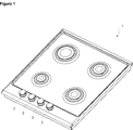
- Figure 1 - is the perspective view of a cooker.
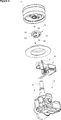
- Figure 2 - is the sideways detailed view of an ignition switch, a gas tap, a knob and an ignition washer.
- Figure 3 - is the exploded top view of the ignition switch, the gas tap, the knob and the ignition washer.
- Figure 4 - is the exploded bottom view of the ignition switch, the gas tap, the knob and the ignition washer.
- Figure 5 - is the top perspective view of an ignition washer.
- Figure 6 - is the bottom perspective view of the ignition washer.
- the cooker (1) comprises at least one gas tap (3) that is connected to the gas network and that has a gas tap pin (4) thereon; an ignition switch (6) that is attached to the gas tap (3) and that has an ignition pin (7) performing the ignition process; a knob (2) that is attached to the gas tap pin (4) and that enables the user to control the gas tap (3) and the ignition switch (6), and an ignition washer (8)
- the gas tap (3) is connected to the gas delivery pipe that is arranged under the cooker (1) and connected to the gas network.
- the ignition switch (6) is placed onto the gas tap (3) so as to fit around the gas tap pin (4) on the gas tap (3).
- the ignition pin (7) that extends from the ignition switch (6) is controlled by means of the knob (2) that is attached to the gas tap pin (4).
- the ignition washer (8) is disposed between the knob (2) and the ignition switch (6), and the base (13) contacts the ignition pin (7). When the knob (2) is pushed downwards, the ignition washer (8) stretches by means of the base (13) and pushes the ignition pin (7) on the ignition switch (6) and enables the ignition switch (6) to be activated.
- the ignition washer (8) of the present invention circumferentially fits onto the gas tap pin (4).
- the bearing (9) provided in the middle of the ignition washer (8) and wherein the gas tap pin (4) is borne is also flexible such that the ignition washer (8) firmly surrounds the gas tap pin (4), is prevented from slipping and is easily mounted onto and detached from the gas tap pin (4).
- the ignition washer (8) can be easily and quickly mounted onto and detached from the gas tap pin (4).
- the bearing (9) can stretch in the horizontal direction, the ignition washer (8) firmly surrounds the gas tap pin (4) when mounted thereon and does not move on the gas tap pin (4). Thanks to the ignition washer (8) that can stretch in the vertical direction, the movement of the knob (2) is properly transferred to the ignition pin (7) and the ignition switch (6) by means of the ignition washer (8), and the ignition process is enabled to be performed properly (Figure 3 and Figure 4).
- the ignition washer (8) comprises a step (12) wherein an opening allowing the passage of the gas tap pin (4) therethrough is provided; a base (13) that is provided on the step (12), a bearing (9) that is formed between the step (12) and the base (13) and through which the gas tap pin (4) is inserted, and a first cut-out (10) and a second cut-out (11) that surround the bearing (9) at least partially in the radial direction.
- the bearing (9) is enabled to stretch in the horizontal direction and the base (13) is enabled to stretch in the vertical direction.
- the first and second cut-outs (10 and 11) are oppositely positioned.
- the ignition washer (8) further comprises at least two housings (14) that are provided at the ends of the first and the second cut-outs (10 and 11) and that extend parallel to the axis of the bearing (9) over the wall of the step (12), and at least two claws (16) that remain between the housings (14), that are extensions of the step (12) and that are enabled to stretch by means of the housings (14) ( Figure 5 and Figure 6).
- the first and second cut-outs (10 and 11) are arcs with an angle of 180o at most.
- the cooker (1) comprises a channel (5) that is provided on the gas tap pin (4), that surrounds the gas tap pin (4) in the radial direction, and that receives the ignition washer (8).
- the ignition washer (8) is mounted onto the gas tap pin (4), the ignition washer (8) is moved to the channel (5), and the claws (16), upon reaching the channel (5), stretch towards the axis of the bearing (9) or the gas tap pin (4) and fit firmly into the channel (5) such that the ignition washer (8) is firmly fixed to the gas tap pin (4).
- the ignition washer (8) is prevented from spontaneously moving on and detaching from the gas tap pin (4).
- the ignition washer (8) comprises a wall (15) that circumferentially surrounds the edge of the base (13) and that extends perpendicular to the plane of the base (13).
- the wall (15) increases the strength of the ignition washer (8) and enables the knob (2) to be completely seated onto the ignition washer (8) and the ignition washer (8) to homogeneously stretch.
- the ignition washer (8) is firmly fixed when the claws (16) fit into the channel (5) on the gas tap pin (4). Since the claws (16) can stretch in a direction perpendicular to the axis of the bearing (9) by means of the first and second cut-outs (10 and 11), the user is enabled to easily remove the ignition washer (8) from the gas tap pin (4) or mount the same onto the gas tap pin (4). Furthermore, by means of the first and second cut-outs (10 and 11), the ignition washer (8) can also stretch in the vertical direction, thus contacting the ignition pin (7) thereunder so as to enable the ignition switch (6) to be the activated.
- the ignition washer (8) is enabled to be easily and quickly mounted onto and detached from the gas tap pin (4). Furthermore, by means of the present invention, the ignition washer (8) is prevented from spontaneously moving on the gas tap pin (4) and detaching from the gas tap pin (4). Moreover, the movement of the knob (2) is completely transferred to the ignition washer (8), and the ignition pin (7) is enabled to quickly respond to the movement of the knob (2) and the ignition switch (6) is enabled to be actuated.
Landscapes
- Engineering & Computer Science (AREA)
- Chemical & Material Sciences (AREA)
- Combustion & Propulsion (AREA)
- Mechanical Engineering (AREA)
- General Engineering & Computer Science (AREA)
- Feeding And Controlling Fuel (AREA)
Abstract
The present invention relates to a cooker (1) comprising at least one gas tap (3) that is connected to the gas network and that has a gas tap pin (4) thereon; an ignition switch (6) that is attached to the gas tap (3) and that has an ignition pin (7) perfornning the ignition process; a knob (2) that is attached to the gas tap pin (4) and that enables the user to control the gas tap (3) and the ignition switch (6).
Description
The present invention relates to a cooker comprising an ignition washer that is mounted onto the gas tap pin.
In modern gas cookers, push type ignition units are used. In this embodiment, the ignition is realized by pushing a knob. An ignition washer is mounted onto the gas tap pin such that the ignition process is realized independently of the model, size and the design of the knob. Thus, the ignition washer that moves together with the gas tap pin completes the circuit and enables the ignition process to be realized.
In the state of the art European Patent Application No. EP2290288, a C-shaped ignition washer is disclosed, and a plurality of housings that enable the ignition washer to be easily mounted onto the gas tap pin are provided on the edge of the ignition washer that faces the center.
In the state of the art International Patent Application No. WO2008135839, a cooker is disclosed, comprising a C-shaped ignition washer that is produced from synthetic plastic material.
In the state of the art European Patent Application No. EP2390575, the ignition washer is a ring having a plurality of cut-outs.
Another state of the art document is European Patent Application No. EP2383520. In this document, a conical spacer that functions as the ignition washer is disclosed, and a spring is provided between the spacer and the pin.
The aim of the present invention is the realization of a cooker comprising an ignition washer that enables the ignition switches of the gas taps to be operated.
The cooker realized in order to attain the aim of the present invention, explicated in the first claim and the respective claims thereof comprises an ignition washer that is mounted onto the gas tap pin, that is actuated by the knob enabling the user to control the gas tap and the ignition switch, that is arranged between the knob and the ignition switch, that is mounted onto the gas tap pin, that provides a bearing for the gas tap pin and that stretches in the horizontal direction and the vertical direction.
The ignition pin extending from the ignition switch that is placed onto the gas tap so as to engage with the gas tap pin is controlled by means of the knob that is mounted onto the gas tap pin. In the embodiment of the present invention, the ignition washer is disposed between the knob and the ignition switch and contacts the ignition pin. Since the ignition washer stretches in the vertical axis when the knob is pushed downwards, the ignition washer pushes the ignition pin on the ignition switch and enables the ignition switch to be operated. The ignition washer of the present invention circumferentially fits onto the gas tap pin. The ignition washer can also stretch in the horizontal direction so as to firmly surround the gas tap pin, to be prevented from slipping and to be easily mounted onto and detached from the gas tap pin. Thus, the ignition washer can be easily and quickly mounted onto and detached from the gas tap pin. Furthermore, since the ignition washer can stretch in the horizontal direction, the ignition washer firmly surrounds the gas tap pin when mounted thereon and does not move on the gas tap pin relative to the gas tap pin. By means of the ignition washer that can stretch in the vertical direction, the movement of the knob can be completely transferred to the ignition switch, and the ignition switch immediately responds to the movement of the knob so as to be actuated and the ignition process can be performed properly.
In the embodiment of the present invention, the ignition washer comprises a first cut-out and a second cut-out that surround at least partially in the radial direction the bearing through which the gas tap pin is inserted. By means of the first cut-out and the second cut-out, the bearing is enabled to stretch in the horizontal direction and the base is enabled to stretch in the vertical direction. In the preferred embodiment of the present invention, the cut-outs are arcs with angle of 180º at most. In the embodiment of the present invention, the cut-outs do not merge.
In the embodiment of the present invention, the ignition washer further comprises at least two housings that are arranged at the ends of the first and the second cut-outs and that extend parallel to the axis of the bearing, and at least two claws that are arranged between the housings and that can stretch by means of the housings.
In the embodiment of the present invention, the cooker comprises a channel that is provided on the gas tap pin, that surrounds the gas tap pin in the radial direction, and that receives the ignition washer. When the ignition washer is mounted onto the gas tap pin, the ignition washer is moved to the channel, and the claws, upon reaching the channel, stretch towards the axis of the bearing and fit firmly into the channel such that the ignition washer is firmly fixed to the gas tap pin. Thus, the ignition washer is prevented from spontaneously moving on and detaching from the gas tap pin.
In the embodiment of the present invention, by means of the wall that circumferentially surrounds the edge of the base and that extends perpendicular to the surface of the base, the strength of the ignition washer is increased, and the knob is enabled to be completely seated onto the ignition washer and the ignition washer is enabled to homogeneously stretch.
In an embodiment of the present invention, the ignition washer is firmly fixed when the claws fit into the channel on the gas tap pin. Since the claws can stretch in a direction perpendicular to the central axis of the bearing by means of the first and second cut-outs, the user is enabled to easily remove the ignition washer from the gas tap pin or mount the same onto the gas tap pin. Furthermore, by means of the first and the second cut-outs, the ignition washer can also stretch in the vertical direction, thus contacting the ignition pin thereunder so as to enable the ignition switch to be the activated.
By means of the present invention, the ignition washer is enabled to be easily and quickly mounted onto and detached from the gas tap pin. Furthermore, by means of the present invention, the ignition washer is prevented from spontaneously moving on the gas tap pin and detaching from the gas tap pin. Moreover, the movement of the knob is completely transferred to the ignition washer, and the ignition pin is enabled to quickly respond to the movement of the knob and the ignition switch is enabled to be actuated.
A cooker realized in order to attain the aim of the present invention is illustrated in the attached figures, where:
Figure 1 - is the perspective view of a cooker.
Figure 2 - is the sideways detailed view of an ignition switch, a gas tap, a knob and an ignition washer.
Figure 3 - is the exploded top view of the ignition switch, the gas tap, the knob and the ignition washer.
Figure 4 - is the exploded bottom view of the ignition switch, the gas tap, the knob and the ignition washer.
Figure 5 - is the top perspective view of an ignition washer.
Figure 6 - is the bottom perspective view of the ignition washer.
The elements illustrated in the figures are numbered as follows:
- Cooker
- Knob
- Gas tap
- Gas tap pin
- Channel
- Ignition switch
- Ignition pin
- Ignition washer
- Bearing
- First cut-out
- Second cut-out
- Step
- Base
- Housing
- Wall
- Claw
The cooker (1) comprises at least one gas tap (3) that is connected to the gas network and that has a gas tap pin (4) thereon; an ignition switch (6) that is attached to the gas tap (3) and that has an ignition pin (7) performing the ignition process; a knob (2) that is attached to the gas tap pin (4) and that enables the user to control the gas tap (3) and the ignition switch (6), and an ignition washer (8)
- that is arranged between the knob (2) and the ignition switch (6),
- that is mounted onto the gas tap pin (4),
- that has a bearing (9) wherein the gas tap pin (4) is borne and that stretches in the horizontal direction, and a base (13) that can stretch in the vertical direction (Figure 1 and Figure 2).
The gas tap (3) is connected to the gas delivery pipe that is arranged under the cooker (1) and connected to the gas network. The ignition switch (6) is placed onto the gas tap (3) so as to fit around the gas tap pin (4) on the gas tap (3). The ignition pin (7) that extends from the ignition switch (6) is controlled by means of the knob (2) that is attached to the gas tap pin (4). In the embodiment of the present invention, the ignition washer (8) is disposed between the knob (2) and the ignition switch (6), and the base (13) contacts the ignition pin (7). When the knob (2) is pushed downwards, the ignition washer (8) stretches by means of the base (13) and pushes the ignition pin (7) on the ignition switch (6) and enables the ignition switch (6) to be activated. The ignition washer (8) of the present invention circumferentially fits onto the gas tap pin (4). The bearing (9) provided in the middle of the ignition washer (8) and wherein the gas tap pin (4) is borne is also flexible such that the ignition washer (8) firmly surrounds the gas tap pin (4), is prevented from slipping and is easily mounted onto and detached from the gas tap pin (4). Thus, the ignition washer (8) can be easily and quickly mounted onto and detached from the gas tap pin (4). Furthermore, since the bearing (9) can stretch in the horizontal direction, the ignition washer (8) firmly surrounds the gas tap pin (4) when mounted thereon and does not move on the gas tap pin (4). Thanks to the ignition washer (8) that can stretch in the vertical direction, the movement of the knob (2) is properly transferred to the ignition pin (7) and the ignition switch (6) by means of the ignition washer (8), and the ignition process is enabled to be performed properly (Figure 3 and Figure 4).
In the embodiment of the present invention, the ignition washer (8) comprises a step (12) wherein an opening allowing the passage of the gas tap pin (4) therethrough is provided; a base (13) that is provided on the step (12), a bearing (9) that is formed between the step (12) and the base (13) and through which the gas tap pin (4) is inserted, and a first cut-out (10) and a second cut-out (11) that surround the bearing (9) at least partially in the radial direction. By means of the first and second cut-outs (10 and 11), the bearing (9) is enabled to stretch in the horizontal direction and the base (13) is enabled to stretch in the vertical direction. In the embodiment of the present invention, the first and second cut-outs (10 and 11) are oppositely positioned. The ignition washer (8) further comprises at least two housings (14) that are provided at the ends of the first and the second cut-outs (10 and 11) and that extend parallel to the axis of the bearing (9) over the wall of the step (12), and at least two claws (16) that remain between the housings (14), that are extensions of the step (12) and that are enabled to stretch by means of the housings (14) (Figure 5 and Figure 6).
In the preferred embodiment of the present invention, the first and second cut-outs (10 and 11) are arcs with an angle of 180º at most.
In the embodiment of the present invention, the cooker (1) comprises a channel (5) that is provided on the gas tap pin (4), that surrounds the gas tap pin (4) in the radial direction, and that receives the ignition washer (8). When the ignition washer (8) is mounted onto the gas tap pin (4), the ignition washer (8) is moved to the channel (5), and the claws (16), upon reaching the channel (5), stretch towards the axis of the bearing (9) or the gas tap pin (4) and fit firmly into the channel (5) such that the ignition washer (8) is firmly fixed to the gas tap pin (4). Thus, the ignition washer (8) is prevented from spontaneously moving on and detaching from the gas tap pin (4).
In the embodiment of the present invention, the ignition washer (8) comprises a wall (15) that circumferentially surrounds the edge of the base (13) and that extends perpendicular to the plane of the base (13). The wall (15) increases the strength of the ignition washer (8) and enables the knob (2) to be completely seated onto the ignition washer (8) and the ignition washer (8) to homogeneously stretch.
In an embodiment of the present invention, the ignition washer (8) is firmly fixed when the claws (16) fit into the channel (5) on the gas tap pin (4). Since the claws (16) can stretch in a direction perpendicular to the axis of the bearing (9) by means of the first and second cut-outs (10 and 11), the user is enabled to easily remove the ignition washer (8) from the gas tap pin (4) or mount the same onto the gas tap pin (4). Furthermore, by means of the first and second cut-outs (10 and 11), the ignition washer (8) can also stretch in the vertical direction, thus contacting the ignition pin (7) thereunder so as to enable the ignition switch (6) to be the activated.
By means of the present invention, the ignition washer (8) is enabled to be easily and quickly mounted onto and detached from the gas tap pin (4). Furthermore, by means of the present invention, the ignition washer (8) is prevented from spontaneously moving on the gas tap pin (4) and detaching from the gas tap pin (4). Moreover, the movement of the knob (2) is completely transferred to the ignition washer (8), and the ignition pin (7) is enabled to quickly respond to the movement of the knob (2) and the ignition switch (6) is enabled to be actuated.
Claims (7)
- A cooker (1) comprising at least one gas tap (3) that is connected to the gas network and that has a gas tap pin (4) thereon; an ignition switch (6) that is attached to the gas tap (3) and that has an ignition pin (7) performing the ignition process; a knob (2) that is attached to the gas tap pin (4) and that enables the user to control the gas tap (3) and the ignition switch (6), characterized by an ignition washer (8)- that is arranged between the knob (2) and the ignition switch (6),- that is mounted onto the gas tap pin (4),- that has a bearing (9) wherein the gas tap pin (4) is borne and that stretches in the horizontal direction, and a base (13) that can stretch in the vertical direction.
- A cooker (1) as in Claim 1, characterized by a step (12) wherein an opening allowing the passage of the gas tap pin (4) therethrough is provided; a base (13) that is provided on the step (12), a bearing (9) that is formed between the step (12) and the base (13) and through which the gas tap pin (4) is inserted, and a first cut-out (10) and a second cut-out (11) that surround the bearing (9) at least partially in the radial direction.
- A cooker (1) as in Claim 2, characterized by the first cut-out (10) and the second cut-out (11) that are oppositely positioned.
- A cooker (1) as in Claim 2, characterized by the ignition washer (8) that comprises at least two housings (14) that are provided at the ends of the first and the second cut-outs (10 and 11) and that extend parallel to the axis of the bearing (9) over the wall of the step (12), and at least two claws (16) that remain between the housings (14), that are extensions of the step (12) and that are enabled to stretch by means of the housings (14).
- A cooker (1) as in any one of the Claims 2 to 5, characterized by the first and second cut-outs (10 and 11) that are arcs with an angle of 180º at most.
- A cooker (1) as in Claim 1, characterized by a channel (5) that is provided on the gas tap pin (4), that surrounds the gas tap pin (4) in the radial direction, and that receives the ignition washer (8).
- A cooker (1) as in any one of the above claims, characterized by the ignition washer (8) comprising a wall (15) that circumferentially surrounds the edge of the base (13) and extends perpendicular to the plane of the base (13).
Applications Claiming Priority (2)
| Application Number | Priority Date | Filing Date | Title |
|---|---|---|---|
| TRA2017/21655 | 2017-12-25 | ||
| TR201721655 | 2017-12-25 |
Publications (1)
| Publication Number | Publication Date |
|---|---|
| WO2019129405A1 true WO2019129405A1 (en) | 2019-07-04 |
Family
ID=63915275
Family Applications (1)
| Application Number | Title | Priority Date | Filing Date |
|---|---|---|---|
| PCT/EP2018/078584 Ceased WO2019129405A1 (en) | 2017-12-25 | 2018-10-18 | A cooker comprising an ignition washer |
Country Status (1)
| Country | Link |
|---|---|
| WO (1) | WO2019129405A1 (en) |
Citations (7)
| Publication number | Priority date | Publication date | Assignee | Title |
|---|---|---|---|---|
| EP1500881A2 (en) * | 2003-07-25 | 2005-01-26 | ITW Industrial Components S.r.l. | Integrated device for gas-cooking hobs including a gas tap and an ignitor |
| WO2008135839A2 (en) | 2007-05-04 | 2008-11-13 | Itw Industrial Components S.R.L. Con Unico Socio | Control device including a gas tap and a catenary element for burners of a cooking range |
| WO2009034445A2 (en) * | 2007-09-11 | 2009-03-19 | Itw Industrial Components S.R.L. Con Unico Socio | Rotary control device including a gas tap and a catenary element for burners of a cooking range |
| EP2290288A2 (en) | 2009-09-01 | 2011-03-02 | Turas Gaz Armatürleri Sanayi. Ve Ticaret A.S. | Ignition module push ring |
| EP2383520A2 (en) | 2010-04-28 | 2011-11-02 | BSH Bosch und Siemens Hausgeräte GmbH | Gas valve with ignition device |
| EP2390575A2 (en) | 2010-05-24 | 2011-11-30 | BSH Bosch und Siemens Hausgeräte GmbH | Gas valve with an actuating device for an electric switch |
| WO2017209709A1 (en) * | 2016-05-30 | 2017-12-07 | Ferel Elektroni̇k Sanayi̇ Ti̇caret Anoni̇m Şi̇rketi̇ | A connection ring for gas taps |
-
2018
- 2018-10-18 WO PCT/EP2018/078584 patent/WO2019129405A1/en not_active Ceased
Patent Citations (7)
| Publication number | Priority date | Publication date | Assignee | Title |
|---|---|---|---|---|
| EP1500881A2 (en) * | 2003-07-25 | 2005-01-26 | ITW Industrial Components S.r.l. | Integrated device for gas-cooking hobs including a gas tap and an ignitor |
| WO2008135839A2 (en) | 2007-05-04 | 2008-11-13 | Itw Industrial Components S.R.L. Con Unico Socio | Control device including a gas tap and a catenary element for burners of a cooking range |
| WO2009034445A2 (en) * | 2007-09-11 | 2009-03-19 | Itw Industrial Components S.R.L. Con Unico Socio | Rotary control device including a gas tap and a catenary element for burners of a cooking range |
| EP2290288A2 (en) | 2009-09-01 | 2011-03-02 | Turas Gaz Armatürleri Sanayi. Ve Ticaret A.S. | Ignition module push ring |
| EP2383520A2 (en) | 2010-04-28 | 2011-11-02 | BSH Bosch und Siemens Hausgeräte GmbH | Gas valve with ignition device |
| EP2390575A2 (en) | 2010-05-24 | 2011-11-30 | BSH Bosch und Siemens Hausgeräte GmbH | Gas valve with an actuating device for an electric switch |
| WO2017209709A1 (en) * | 2016-05-30 | 2017-12-07 | Ferel Elektroni̇k Sanayi̇ Ti̇caret Anoni̇m Şi̇rketi̇ | A connection ring for gas taps |
Similar Documents
| Publication | Publication Date | Title |
|---|---|---|
| US3696734A (en) | Commercial waffle baker | |
| CN106158481B (en) | Keyboard switch | |
| EP2485111B1 (en) | Improved retractable control device for domestic appliance | |
| CA2729064A1 (en) | Adjustable grate foot for home appliance | |
| MXPA04007182A (en) | Integrated device for gas-cooking hobs including a gas tap and an ignitor. | |
| CN114424883B (en) | Control method, control device, pressure cooking appliance and storage medium | |
| US2725438A (en) | Alternating current switch mechanism | |
| US2336389A (en) | Slow make and break switch | |
| EP3933272B1 (en) | Gas stove | |
| WO2018007156A2 (en) | A household appliance having an illuminated rotary control button | |
| CN217235672U (en) | Gear regulator and gas stove | |
| US2936347A (en) | Electric switch | |
| CN209733493U (en) | pressure cooking utensil | |
| CN111292987B (en) | Self-resetting dynamic seal button switch structure with touch feedback function | |
| CN116006721B (en) | A temperature-controlled water switch | |
| EP1798471B1 (en) | Microswitch assembly which can be associated to a gas cock, in particular for cooktops and the like | |
| CN107303131B (en) | cooking utensils | |
| GB2207554A (en) | A push-button switch having cleaning means | |
| EP2390580B1 (en) | Switching-arrangement and household appliance comprising such switching arrangement | |
| WO2015032673A2 (en) | A cooker comprising a burner housing | |
| KR101460203B1 (en) | knob of gas range | |
| US7511239B2 (en) | Simultaneous control of multiple liquid level settings in a diaphragm valve, using a single rotatable control shaft | |
| CN206726996U (en) | A kind of rocker switch | |
| CN219759461U (en) | Waterproof temperature control switch | |
| EP2876754B1 (en) | Domestic appliance with a button holder |
Legal Events
| Date | Code | Title | Description |
|---|---|---|---|
| 121 | Ep: the epo has been informed by wipo that ep was designated in this application |
Ref document number: 18789619 Country of ref document: EP Kind code of ref document: A1 |
|
| NENP | Non-entry into the national phase |
Ref country code: DE |
|
| 122 | Ep: pct application non-entry in european phase |
Ref document number: 18789619 Country of ref document: EP Kind code of ref document: A1 |