WO2019127418A1 - Network service management method, related device and system - Google Patents
Network service management method, related device and system Download PDFInfo
- Publication number
- WO2019127418A1 WO2019127418A1 PCT/CN2017/119978 CN2017119978W WO2019127418A1 WO 2019127418 A1 WO2019127418 A1 WO 2019127418A1 CN 2017119978 W CN2017119978 W CN 2017119978W WO 2019127418 A1 WO2019127418 A1 WO 2019127418A1
- Authority
- WO
- WIPO (PCT)
- Prior art keywords
- instance
- nfvo
- access point
- nested
- service
- Prior art date
Links
Images


Classifications
-
- H—ELECTRICITY
- H04—ELECTRIC COMMUNICATION TECHNIQUE
- H04L—TRANSMISSION OF DIGITAL INFORMATION, e.g. TELEGRAPHIC COMMUNICATION
- H04L41/00—Arrangements for maintenance, administration or management of data switching networks, e.g. of packet switching networks
- H04L41/40—Arrangements for maintenance, administration or management of data switching networks, e.g. of packet switching networks using virtualisation of network functions or resources, e.g. SDN or NFV entities
-
- H—ELECTRICITY
- H04—ELECTRIC COMMUNICATION TECHNIQUE
- H04L—TRANSMISSION OF DIGITAL INFORMATION, e.g. TELEGRAPHIC COMMUNICATION
- H04L41/00—Arrangements for maintenance, administration or management of data switching networks, e.g. of packet switching networks
- H04L41/50—Network service management, e.g. ensuring proper service fulfilment according to agreements
-
- G—PHYSICS
- G06—COMPUTING; CALCULATING OR COUNTING
- G06F—ELECTRIC DIGITAL DATA PROCESSING
- G06F9/00—Arrangements for program control, e.g. control units
- G06F9/06—Arrangements for program control, e.g. control units using stored programs, i.e. using an internal store of processing equipment to receive or retain programs
- G06F9/44—Arrangements for executing specific programs
- G06F9/455—Emulation; Interpretation; Software simulation, e.g. virtualisation or emulation of application or operating system execution engines
- G06F9/45533—Hypervisors; Virtual machine monitors
- G06F9/45558—Hypervisor-specific management and integration aspects
-
- H—ELECTRICITY
- H04—ELECTRIC COMMUNICATION TECHNIQUE
- H04L—TRANSMISSION OF DIGITAL INFORMATION, e.g. TELEGRAPHIC COMMUNICATION
- H04L41/00—Arrangements for maintenance, administration or management of data switching networks, e.g. of packet switching networks
- H04L41/50—Network service management, e.g. ensuring proper service fulfilment according to agreements
- H04L41/5041—Network service management, e.g. ensuring proper service fulfilment according to agreements characterised by the time relationship between creation and deployment of a service
-
- H—ELECTRICITY
- H04—ELECTRIC COMMUNICATION TECHNIQUE
- H04L—TRANSMISSION OF DIGITAL INFORMATION, e.g. TELEGRAPHIC COMMUNICATION
- H04L67/00—Network arrangements or protocols for supporting network services or applications
- H04L67/14—Session management
- H04L67/141—Setup of application sessions
-
- G—PHYSICS
- G06—COMPUTING; CALCULATING OR COUNTING
- G06F—ELECTRIC DIGITAL DATA PROCESSING
- G06F9/00—Arrangements for program control, e.g. control units
- G06F9/06—Arrangements for program control, e.g. control units using stored programs, i.e. using an internal store of processing equipment to receive or retain programs
- G06F9/44—Arrangements for executing specific programs
- G06F9/455—Emulation; Interpretation; Software simulation, e.g. virtualisation or emulation of application or operating system execution engines
- G06F9/45533—Hypervisors; Virtual machine monitors
- G06F9/45558—Hypervisor-specific management and integration aspects
- G06F2009/45595—Network integration; Enabling network access in virtual machine instances
Definitions
- the present application relates to the field of cloud computing technologies, and in particular, to a network service management method, related devices, and systems.
- Network Function Virtualization refers to the use of virtualization technology in the field of information technology (IT) by telecom network operators to implement the functions of some telecommunications networks in general servers, switches and memories. Decoupling software and hardware enables network services (NS) to be deployed quickly and efficiently while achieving operational goals of saving investment costs CAPEX and operating costs OPEX.
- This technology requires telecommunications network functions to be implemented in software and can run on common server hardware, can be migrated, instantiated, deployed in different physical locations on the network as needed, and does not require new equipment to be installed.
- the virtualized network service (NS) in the NFV may be, for example, an IP multimedia subsystem (IMS) or an evolved packet core (EPC) service.
- An NS can contain several virtualized network functions (VNFs).
- VNF is a software implementation of network functions that can be deployed on an NFV infrastructure.
- service request devices such as operations and business support systems (OSS/BSS)
- OSS/BSS operations and business support systems
- NFVO NFV orchestrator
- NSD Network service descriptor
- the descriptor of the NS mainly describes the topology of the NS and the descriptors of the member instances of the NS.
- a virtual link (VL) is used in the topology to describe the connections between member instances.
- VNF virtual network function
- MANO dynamic management and orchestration
- ETSI European Telecommunications Standards Institute
- IFA interface and architecture
- NFVO NFV Orchestrator
- NSD network service descriptor
- VNFFG virtual network function forwarding map
- VNFF virtual network function forwarding map
- VNF manager VNF manager, VNFM
- NFVO can also communicate with a virtualised infrastructure manager (VIM) to perform resource allocation and/or reservation, exchange of virtualized resource configuration and status information.
- VIP virtualised infrastructure manager
- VNFM implements virtualized network function VNF lifecycle management, including management of virtualized network function descriptor (VNF descriptor, VNFD), instantiation of VNF, elastic scaling of VNF instance (including Scaling out/up and Scaling in/down), healing of VNF instances, and termination of VNF instances.
- VNFM also supports the elastic scaling mechanism delivered by NFVO to implement automated VNF elastic scaling.
- VIM Virtual Infrastructure Manager
- Operation and Business Support System Supports various end-to-end telecom services, mainly refers to the operator's existing operation and maintenance system OSS/BSS.
- the OSS/BSS can load the NSD to the NFVO and initiate a request to instantiate the NS to the NFVO.
- Element Management Performs traditional fault management, configuration management, account management, performance management, security management (FCAPS) functions for the VNF.
- VNF Virtualized Network Function
- PNF physical network function
- MME virtualized EPC node
- SGW SGW
- PGW PGW
- the VNF can be composed of multiple lower-level VNF components (VNFCs). Therefore, one VNF can be deployed on multiple virtual machines (VMs), each VM carrying a VNF component function; VNF It can also be deployed on a VM.
- VNFCs lower-level VNF components
- NFVI NFV Infrastructure: NFVI consists of hardware resources and virtual resources and virtualization layers. From a VNF perspective, the virtualization layer and hardware resources appear to be a complete entity that provides the required virtual resources.
- the consumer NFVO (Consumer NFVO) will be the member of the composite NS instance.
- the VNF instance is connected to the nested NS instance.
- VL virtual link
- the present application provides a network service management method, related device and system.
- a virtual link information model from the perspective of a nested network service instance, the requirement for establishing a network connection from the perspective of a nested network service instance can be met.
- the present application provides a network service management method, applied to a first NFVO (ie, consumer NFVO) side, the method may include: the first NFVO sends a first request to a second NFVO, where the first request is available.
- the first request carries the information of the SAP instance associated with the nested NS instance (ie, SapInfo).
- the SapInfo can be used by the second NFVO to establish a connection between the nested NS instance and the composite NS instance, the member instance in the composite NS instance, and the second NFVO to establish a member instance in the nested NS instance based on the SAP instance.
- the connection between the two ie, consumer NFVO
- the present application provides a network service management method, applied to a second NFVO (ie, provider NFVO) side, the method may include: the second NFVO receives a first request sent by the first NFVO, where the first request is available. Request to create a nested NS instance in a composite NS instance. The first request carries a nested NS instance association (ie, SapInfo). The SapInfo can be used by the second NFVO to establish a connection between the nested NS instance and the composite NS instance, the member instance in the composite NS instance, and the second NFVO to establish a member instance in the nested NS instance based on the SAP instance. The connection between the two.
- the second NFVO establishes a connection between the nested NS instance and the composite NS instance and the member instance in the composite NS instance based on the SAP instance according to the SapInfo, and establishes a connection between the member instances in the nested NS instance based on the SAP instance. relationship.
- the provider NFVO can be instructed to follow the SapInfo from the nested NS instance.
- the perspective of creating nested NS instances for outgoing and inbound network connections can meet the need to establish a network connection from a nested NS perspective.
- SapInfo may include two parts: first information and second information.
- the first information is specifically used to describe an external virtual link information model, and may be used by the second NFVO to establish a connection between the nested NS instance through the SAP instance (outward) and the member instance in the composite network NS instance.
- the second information is specifically used to describe the internal virtual link information model, and can be used by the second NFVO to establish a connection between the nested NS instance and the member instance in the nested NS instance through the SAP instance (inward).
- the first information may include: an identifier of the external virtual link instance, an identifier of the port used by the SAP instance to connect to the external virtual link instance, and a peer connection point of the SAP instance connected by the external virtual link instance.
- the peer connection point of the SAP instance connected by the external virtual link instance may be an external connection point of the member instance in the composite NS instance connected by the SAP instance through the external virtual link instance, for example, the external connection point VnfExtCp of the VNF instance.
- the peer connection point that the SAP instance connects through the external virtual link instance may also be the service access point SAP of the composite NS instance.
- the second information may include: an identifier of the internal virtual link instance, a port used by the SAP instance to connect the internal virtual link instance, and an identifier of the peer connection point that the SAP instance connects through the internal virtual link instance.
- the peer connection point that the SAP instance connects through the internal virtual link instance may be an external connection point of the member instance in the nested NS instance connected by the SAP instance through the internal virtual link instance, for example, an external connection of the VNF instance. Point VnfExtCp, or the external connection point PnfExtCp of the PNF instance, or the service access point SAP of the child nested NS instance.
- the information of the peer connection point may not be reflected in the internal virtual link model. That is, the second information may optionally include: an identifier of the second virtual link instance, a port used by the internal virtual link instance connected by the SAP instance, and not a pair connected by the SAP instance through the internal virtual link instance.
- the identity of the connection point That is to say, the internal peer connection point of the nested NS instance through the SAP instance inbound is not visible to the outside (that is, the composite NS instance and other member instances in the composite NS instance).
- the second NFVO managing the nested NS can create the virtual link information model in the following manner Indicated connection.
- the implementation manner that the second NFVO establishes the connection indicated by the external virtual link model based on the SAP instance of the nested NS instance may include at least one of the following:
- the second NFVO establishes a connection between the SAP instance and the SAP instance of the composite NS instance through the external virtual link instance according to the first information in the SapInfo.
- the second NFVO establishes, according to the first information in the SapInfo, the connection between the SAP instance and the SAP instance of the nested NS instance in the composite NS instance through the external virtual link instance.
- the second NFVO establishes a connection between the SAP instance and the external connection point with the VNF instance in the composite NS instance through the external virtual link instance according to the first information in the SapInfo.
- the second NFVO establishes a connection between the SAP instance through the external virtual link instance and the external connection point with the PNF in the composite NS instance according to the first information in the SapInfo.
- the implementation manner that the second NFVO establishes the connection indicated by the internal virtual link model based on the SAP instance of the nested NS instance may include at least one of the following:
- the second NFVO establishes, according to the second information in the SapInfo, the connection between the SAP instance and the SAP instance of the sub-nested NS instance in the nested NS instance through the internal virtual link instance.
- the second NFVO establishes a connection between the SAP instance and the external connection point of the VNF instance in the nested NS instance through the internal virtual link instance according to the second information in the SapInfo.
- the second NFVO establishes, according to the second information in the SapInfo, the connection between the internal virtual link instance and the external connection point of the PNF instance in the nested NS instance.
- the first NFVO can send a second request to the second NFVO.
- the second request may be used to request to update the nested NS instance in the composite NS instance.
- the second request may carry the SapInfo associated with the nested NS instance.
- the second NFVO receives the second request sent by the first NFVO.
- the second NFVO may update the connection between the nested NS instance outward and the composite NS instance and the constituent members in the composite NS instance according to the SapInfo associated with the nested NS instance carried in the second request, or update the embedded
- the set of NS instances are inbound at the SAP instance and the connections between the constituent members within the nested NS instance.
- the SapInfo is specifically used to describe the virtual link information model associated with the SAP instance, and can be used for updating the network connection associated with the nested NS instance by the second NFVO, that is, updating the nested NS instance at the SAP instance and the composite NS instance. And the connection between the constituent members in the composite NS instance, or the connection between the nested NS instance at the SAP instance and the constituent members within the nested NS instance.
- updating the network connection associated with the nested NS instance may include at least one of: establishing a new network connection associated with the nested NS instance, or modifying an existing network connection associated with the NS instance, or removing the nested NS instance. Associated existing network connections.
- the provider NFVO can be instructed to update the nested NS instance outward and inward according to the SapInfo from the perspective of the nested NS instance.
- the network connection can better meet the need to update the network connection from the perspective of the nested NS.
- the first NFVO can send a third request to the second NFVO.
- the third request can be used to request an existing nested NS instance managed by the second NFVO.
- the third request carries information about the newly added SAP instance in the composite NS instance managed by the first NFVO in the nested NS instance, and the information of the newly added SAP instance is used to establish the existing NFVO based on the newly added SAP instance.
- a network connection in which a nested NS instance is in a composite NS instance.
- the second NFVO receives the third request sent by the first NFVO.
- the second NFVO may establish a network connection of the existing nested NS instance in the composite NS instance based on the newly added SAP instance according to the information of the newly added SAP instance.
- the provider NFVO can be instructed to establish the nested NS according to the SapInfo from the perspective of the existing nested NS instance.
- the network connection associated with the instance in the composite NS instance managed by the consumer NFVO can satisfy the requirement of establishing a network connection associated with the nested NS instance from the perspective of the existing nested NS instance.
- the present application provides an apparatus that can implement a consumer NFVO, ie, the first NFVO described above, the apparatus can include a processing unit and a communication unit. among them:
- the communication unit can be configured to receive a request from the sender (eg, OSS/BSS) to create a composite NS instance.
- a request from the sender eg, OSS/BSS
- the communication unit is operative to send a first request to the provider NFVO (the second NFVO described above), the first request for requesting the provider NFVO to create a nested NS instance in the composite NS instance.
- the processing unit may be configured to create a member instance (ie, other member instances) other than the above-described nested NS instance in the composite NS instance, and establish a network connection between the member instances.
- the first request carries information about the SAP instance associated with the nested NS instance.
- the information of the SAP instance can be used by the provider NFVO to establish a connection between the nested NS instance and the composite NS instance and the member instance in the composite NS instance based on the SAP instance, and also for the provider NFVO to establish the nest based on the SAP instance.
- the communication unit is further configured to receive a request by the sender (eg, OSS/BSS) to update the composite NS instance.
- the communication unit is further operable to send a second request to the second NFVO, the second request being operative to request to update the nested NS instance in the composite NS instance.
- the second request carries information about the SAP instance associated with the nested NS instance, and the information of the SAP instance is used by the second NFVO to update the network connection associated with the nested NS instance in the composite NS instance based on the SAP instance.
- the processing unit is further configured to update a member instance (ie, other member instances) other than the nested NS instance in the composite NS instance, and update a network connection between the member instances.
- the communication unit is further operable to send a third request to the second NFVO, the third request being available to request that the second NFVO management is used
- the third request carries information about the newly added SAP instance in the composite NS instance managed by the first device in the nested NS instance, and the information of the newly added SAP instance can be based on the newly added SAP by the second NFVO.
- the instance establishes a network connection of the existing nested NS instance in the composite NS instance.
- processing unit and the communication unit can be used to perform the method provided by the first aspect, or the method provided by any one of the possible implementations of the first aspect, and details are not described herein again.
- the present application provides an apparatus that can implement a provider NFVO, ie, the second NFVO described above, the apparatus can include a processing unit and a receiving unit. among them:
- the receiving unit is configured to receive the first request sent by the first NFVO.
- the first request carries the information of the SAP instance associated with the nested NS instance, and is used to request the second device to create a nested NS instance in the composite NS instance.
- the processing unit may be configured to establish a connection between the nested NS instance and the composite NS instance and the member instance in the composite NS instance based on the SAP instance, and establish a connection between the member instances in the nested NS instance based on the SAP instance. Connection relationship.
- the information of the SAP instance may include the first information and the second information, where the first information may be used by the second device to create a nested NS instance based on the SAP instance and the member instance in the composite NS instance.
- the second information may be used by the second device to create a connection relationship between the nested NS instance and the member instance in the nested NS instance based on the SAP instance.
- SapInfo For a specific implementation of the SapInfo, reference may be made to the related description in the foregoing method embodiments, and details are not described herein again.
- the receiving unit is further configured to receive a second request sent by the first NFVO, and the second request can be used to request to update the nested NS instance in the composite NS instance.
- the second request carries information about the SAP instance associated with the nested NS instance, and the information of the SAP instance is used by the second device to update the network connection associated with the nested NS instance in the composite NS instance based on the SAP instance.
- the processing unit is further configured to update, according to the information of the SAP instance, the network connection associated with the nested NS instance in the composite NS instance.
- the receiving unit is further configured to receive a third request sent by the first NFVO, the third request being usable for an existing nested NS instance managed using the second device.
- the third request carries information about the newly added SAP instance in the composite NS instance managed by the first NFVO in the nested NS instance, and the information of the newly added SAP instance can be based on the newly added SAP by using the second device.
- the instance establishes a network connection of the existing nested NS instance in the composite NS instance.
- the processing unit is further configured to establish, according to the newly added SAP instance, the network connection of the existing nested NS instance in the composite NS instance based on the newly added SAP instance.
- the present application provides an apparatus for performing the network service management method described in the first aspect.
- the apparatus implements consumer NFVO in the method described in the first aspect, and can include: a memory and a processor, transceiver coupled to the memory, wherein: the transceiver is for use with other devices (eg, implementing provider NFVO) Device) communication.
- the memory is configured to store implementation code of a network service management method described in the first aspect
- the processor is configured to execute program code stored in the memory, that is, to perform the method provided by the first aspect, or the first aspect is possible A method provided by any of the embodiments.
- the present application provides an apparatus for performing the network service management method described in the second aspect.
- the apparatus implements the provider NFVO in the method described in the first aspect, and can include: a memory and a processor, transceiver coupled to the memory, wherein: the transceiver is for use with other devices (eg, implementing consumer NFVO Device) communication.
- the memory is configured to store implementation code of a network service management method described in the second aspect
- the processor is configured to execute program code stored in the memory, that is, to perform the method provided by the second aspect, or the second aspect is possible A method provided by any of the embodiments.
- the present application provides an NFV MANO system including a first device (implementing consumer NFVO) and a second device (implementing provider NFVO), wherein: the first device may be provided by the third aspect or the fifth aspect The device, the second device may be the device provided by the fourth aspect or the sixth aspect.
- a computer readable storage medium storing the network service management method provided by implementing the first aspect, or provided by any one of the possible implementations of the first aspect
- the program code of the network service management method comprising an execution instruction of the network service management method provided by running the network service management method provided by the first aspect, or any one of the possible implementation manners of the first aspect.
- a ninth aspect a computer readable storage medium storing the network service management method provided by implementing the second aspect, or provided by any one of the possible implementation manners of the second aspect,
- the program code of the network service management method comprising an execution instruction of the network service management method provided by running the network service management method provided by the second aspect, or any one of the possible implementations of the second aspect.
- a computer program product comprising instructions which, when run on a computer, cause the computer to perform the network service management method described in the first aspect above.
- a computer program product comprising instructions for causing a computer to perform the network service management method described in the second aspect above when provided on a computer.
- FIG. 1 is a schematic diagram of a conventional NFV MANO architecture
- FIG. 2 is a schematic diagram of an NFV MANO architecture in a network service provision scenario of a multi-administrative domain
- Figure 3 shows a schematic diagram of a composite network service and a nested network service
- Figure 4 shows a schematic diagram of a plurality of management domains and respective corresponding NFVOs
- Figure 5 shows a schematic diagram of the hierarchical structure of the composite NS
- 6A-6C are schematic diagrams of a virtual state information model of a prior art design
- FIGS. 7A-7C are schematic diagrams of virtual link information models corresponding to the operational states of Figs. 6A-6C;
- FIGS. 8A-8C are schematic diagrams of a virtual state information model of a prior art design
- FIGS. 8A-8C are schematic diagrams of virtual link information models corresponding to the operational states of Figs. 8A-8C;
- 10A-10C are schematic diagrams of a virtual link information model of a design state defined from a nested NS perspective provided by the present application;
- 11A-11C are schematic diagrams of the virtual link information model of the operational state defined by the nested NS angle corresponding to 10A-10C;
- FIG. 12 is a schematic flowchart of a network service management method provided by the present application.
- FIG. 13 exemplarily shows a schematic diagram of a network connection network established from a nested NS perspective in a composite NS;
- FIG. 14 is a schematic flowchart of an implementation process of a network service management method provided by the present application in an application scenario
- 15 is a schematic flowchart of a network service management method provided by the present application in another application scenario
- 16 is a schematic flowchart of a network service management method provided by the present application in another application scenario
- 17 is a schematic flowchart of a network service management method provided by the present application in another application scenario
- FIG. 18 is a schematic structural diagram of a network element provided by the present application.
- FIG. 19 is a functional block diagram of an NFV MANO system and related apparatus provided by the present application.
- FIG. 2 exemplarily shows an NFV MANO architecture in a network service provision scenario of a multi-admin domain.
- a network service provision scenario of multiple management domains may occur in a large service provider to provide global network services (NS) through collaboration of branches, or network services may be provided by different service providers through a network sharing protocol (NS) rental service.
- the global network service (NS) is also called the composite network service (Composite NS).
- the NFV MANO architecture shown in Figure 2 (a network service provision scenario for multiple administrative domains) has some changes.
- the consumer NFVO manages the composite NS, which is composed of the provider NFVO management.
- a nested NS of composite NS A nested NS of composite NS.
- NFV MANO architecture such as NFVO, VNFM, VIM, OSS/BSS, EM, VNF, NFVI
- FIG. 2 The functions and definitions of the various parts of the NFV MANO architecture (such as NFVO, VNFM, VIM, OSS/BSS, EM, VNF, NFVI) shown in FIG. 2 can be referred to the related description in the background art, and are not described herein again.
- NFV MANO architecture shown in FIG. 2 is only for better explaining the technical solution of the present application, and does not constitute a limitation of the present application. Those skilled in the art may know that the network service providing scenario of multiple administrative domains is applicable. The NFV MANO architecture can be further evolved.
- a composite network service can contain one or more nested network services, and each nested network service can be provided by an administrative domain that is different from the one providing the composite network service. The details are described below in conjunction with Figures 3-4.
- FIG. 3 exemplarily shows a composite network service and a nested network service.
- the composite network service C provided by the management domain C includes nested network services A and B, wherein the nested network services A and B are provided by the management domains A, B, respectively.
- Nested network services A or B can also be shared by other composite network services (not composite network service C) in the same or different management domains.
- a management domain is a MANO management function entity consisting of one or more data centers (DCs), one or more VIMs managing these data centers, and one or more VNFMs (including all VNFs managed by VNFM). set.
- Each administrative domain includes an NFVO that is responsible for the provision of a specific set of network services within the administrative domain.
- FIG. 4 exemplarily shows a plurality of administrative domains, wherein each administrative domain provides a set of network services.
- NFVO-1 in management domain C is at the top level, meaning that NFVO-1 manages composite network service C.
- NFVO-2 in management domain A and NFVO-3 in management domain B manage nested network services A and B, respectively, and expose nested network services to NFVO-1 in management domain C.
- different NFVOs can interact with each other through a reference point Or-Or.
- a composite NS instance can usually be represented as a tree-like hierarchical structure.
- the NS instance at the top of the hierarchical structure (the root node of the tree structure) is called a composite NS instance.
- a member instance of a composite NS instance may contain one or more nested NS instances, and a member instance of a composite NS instance may also contain one or more VNF instances, PNF instances.
- VNF instances, PNF instances Within a composite NS instance, the locations of nested NS instances and VNF instances, PNF instances are equivalent.
- a member instance of a nested NS instance can contain one or more VNF instances, PNF instances.
- a member instance of a nested NS instance may include a child nested NS instance.
- a plurality of nested NS instances may be formed by using a member VNF instance.
- the vMME function and the control plane function of the vSGW and the control plane function of the vPGW form a control plane network service of the vEPC
- the user plane functions of the vSGW and the vPGW form a user plane (or forwarding plane) network service of the vEPC
- the functions related to policy control constitute the policy control network service of vEPC.
- vEPC is a composite NS
- vEPC's control plane network service, vEPC's user plane (or forwarding plane) network service, and vEPC's policy control network service belong to nested NS.
- NFVO in the group company network can be mapped to consumer NFVO (NFVO-1), and NFVO in each provincial company network can be mapped to provider NFVO (NFVO-2).
- the telecom operator determines to provide the network service vEPC from the level of the group company network, it can specify the control plane network service composed of the Guangdong company network to form the vEPC, and the user network service composed of the vEPC is provided by the Jiangsu company network.
- the provincial company network provides a policy control network service that constitutes vEPC.
- the composite NS and the nested NS are respectively located in different management domains, and the lifecycle management is performed by NFVO (consumer NFVO and one or more providers NFVO) of different management domains.
- NFVO consumer NFVO and one or more providers NFVO
- the virtual link information model defined in the existing ETSI NFV standard is described below from the design state and the operational state.
- Figures 6A-6C illustrate various member instance virtual link information models for connecting to network services.
- the definition of the virtual link (VL) information model starts from the association relationship between the descriptors of the design state (Descriptor).
- the virtual link descriptor is a template of the information model that needs to be referenced when instantiating a virtual link, including the static attributes of the virtual link instance before it is created.
- the network service descriptor needs to indicate the VNF descriptor (VNFD) and/or the PNF descriptor (PNFD) associated with the virtual link descriptor, and
- VNFD VNF descriptor
- PNFD PNF descriptor
- VNF external connection point descriptor VNF external connection point descriptor
- PNF external connection point descriptor PNF external connection point descriptor, and/or the virtual link descriptor.
- PnfExtCpd associates the corresponding PNFD.
- the creation of the virtual link instance is performed with reference to the virtual link descriptor. Specifically, refer to the virtual link descriptor, associate the virtual link instance with a specific VNF instance (indicating that the virtual link instance is connected to the VNF instance), and/or associate the virtual link instance with a specific PNF instance (indicating the The virtual link instance is connected to the PNF instance).
- the association between the virtual link instance and the VNF instance (or PNF instance) is between the external connection point VnfExtCp instance (or PnfExtCp instance) configuring the VNF instance (or PNF instance) and the port NsLinkPort of the virtual link instance. The link to achieve.
- the running virtual link instance is finally mapped to the corresponding virtual network resource at the NFVI layer, and the configured virtual computing and storage resources are connected through the layer 2 (layer 2, L2) or layer 3 (layer 3, L3) network link.
- layer 2 layer 2, L2
- layer 3 layer 3, L3
- FIG. 7A-7C illustrate how a virtual link is used to connect to a member instance of a network service and a service access point (SAP) of the network service.
- SAP service access point
- VNFD or PNFD
- SAPD service access point descriptor
- VnfExtCpd VNF External Connection Point Descriptor
- PnfExtCpd PNF External Connection Point Descriptor
- the virtual link descriptor associate the virtual link instance with a specific VNF instance (or PNF instance), and the SAP instance, indicating the virtual link instance and the VNF instance (or PNF). Example), the SAP instance is connected.
- the running virtual link instance is finally mapped to the corresponding virtual network resource at the NFVI layer, and the configured virtual computing and storage resources are connected through the layer 2 (layer 2, L2) or layer 3 (layer 3, L3) network link.
- layer 2, L2 layer 2
- layer 3 layer 3, L3
- the design state mentioned in this application refers to defining various descriptors (such as network service descriptors, VNF descriptors, PNF descriptors, virtual link descriptors, external connection points) before instantiating a network service or creating a network connection.
- the stage of the association between descriptors, etc. refers to setting each instance (such as a network service instance, VNF) according to the association relationship between various descriptors defined by the design state during or after the process of instantiating the network service or creating the network connection.
- the virtual link information model defined in the existing ETSI NFV standard mainly describes the connection between the VNF instance and/or the PNF instance in the NS instance from the perspective of the consumer NFVO performing the network connection, and the VNF instance. And/or the connection between the PNF instance and the SAP of the NS instance, missing the virtual link information model defined from the perspective of the nested NS instance.
- VnfExtCpd VNF External Connection Point Descriptor
- VnfExtCpd VNF External Connection Point Descriptor
- VnfExtCpd VNF External Connection Point Descriptor
- the topology described by the virtual link information model defined in the existing ETSI NFV standard is externally visible. Therefore, the virtual link information model defined in the existing ETSI NFV standard cannot satisfy the information isolation between different management domains. demand.
- the present application provides a network service management method, which defines a virtual link information model from the perspective of a nested NS instance, and can implement a virtual NS instance and a composite NS instance and a member in a composite NS instance based on a nested NS instance.
- the instance builds the connection, which enables a nested NS instance to be built inwardly with each member instance in the nested NS instance through the virtual link.
- the virtual link information model defined from the perspective of a nested NS instance may include two parts: an external virtual link information model and an internal virtual link information model.
- a nested NS instance can connect to external link points of other member instances in the composite NS instance through an external virtual link at its SAP instance, such as the external connection point VnfExtCp of the VNF instance, or PNF.
- the nested NS instance can also connect to the SAP instance of the composite NS instance through an external virtual link at its SAP instance. That is, an external virtual link instance can be used for a nested NS instance to connect to a member instance in a composite NS instance at its SAP instance.
- the nested NS instance connects to the external link point of the member instance in the nested NS instance through its internal virtual link at its SAP instance, such as the external connection point VnfExtCp of the VNF instance, or PNF The external connection point PnfExtCp of the instance, or the service access point SAP of the child nested NS instance. That is, an internal virtual link instance can be used for a nested NS instance to connect inwardly to a member instance in the nested NS instance at its SAP instance.
- the external virtual link information model of the design state is mainly used to indicate the association relationship between the descriptors, and provides a reference for the subsequent connection of the connection relationship involved in the external virtual link.
- the nested network service descriptor Nested NSD #1 associates the descriptor NSVirtualLinkDesc#1 of the external virtual link with the descriptor VNFD#2 of the VNF in the composite network service.
- NSVirtualLinkDesc#1 associates Nested NSD#1 with SAP descriptors Sapd#1.1 and Sapd#1.2
- NSVirtualLinkDesc#1 associates VNFD#2 with the external connection point descriptor PnfExtCp#2.1.
- the nested network service descriptor Nested NSD #1 associates the descriptor NSVirtualLinkDesc#1 of the external virtual link with the descriptor Nested NSD#2 of another nested network service in the composite network service.
- NSVirtualLinkDesc#1 associates NSD#1 with SAP descriptors Sapd#1.1 and Sapd#1.2
- NSVirtualLinkDesc#1 associates Nested NSD#2 with the service access point descriptors Sapd#2.1 and Sapd#2.2.
- the nested network service descriptor Nested NSD #1 associates the descriptor NSVirtualLinkDesc#1 of the external virtual link with the descriptor Sapd#2 of the service access point of the composite network service.
- FIGS. 9A-9C exemplarily illustrate an external virtual link information model of an operating state based nested NS-based SAP.
- the external virtual link information model of the running state is mainly used to indicate the association relationship between each instance, and is used to create a connection between each instance.
- the external virtual link information model of the running state shown in FIGS. 9A-9C is created with reference to the external virtual link information model of the design state shown in FIGS. 8A-8C, respectively.
- the nested NS instance Nested NS#1 connects to the outside of the VNF instance VNF#2 in the composite NS instance through the external virtual link instance NSVirtualLink#1 at its serving access point Sap#1.1 and Sap#1.1.
- Link point VnfExtCp#2.1 Specifically, NSVirtualLink#1 connects to Sap#1.1 through port instance NsLinkPort#1.1, NSVirtualLink#1 connects to Sap#1.2 through port instance NsLinkPort#1.2, and NSVirtualLink#1 connects to VnfExtCp#2.1 through port instance NsLinkPort#1.3. It can be seen that the connection indicated by the external virtual link information model shown in FIG. 9A is created with reference to the virtual link information model of the design state shown in FIG. 8A.
- the nested NS instance Nested NS#1 connects another nested NS instance Nested in the composite NS instance through the external virtual link instance NSVirtualLink#1 at its serving access point Sap#1.1, Sap#1.1. NS#2 service access point Sap#2.1.
- NSVirtualLink#1 connects to Sap#1.1 through port instance NsLinkPort#1.1
- NSVirtualLink#1 connects to Sap#1.2 through port instance NsLinkPort#1.2
- NSVirtualLink#1 connects to Sap#2.1 through port instance NsLinkPort#1.3. It can be seen that the connection indicated by the external virtual link information model shown in FIG. 9B is created with reference to the virtual link information model of the design state shown in FIG. 8B.
- the nested NS instance Nested NS#1 connects the service access point Sap#1 of the composite NS instance through its external virtual link instance NSVirtualLink#1 at its serving access point Sap#1.1. Specifically, NSVirtualLink#1 connects to Sap#1.1 through port instance NsLinkPort#1.1. It can be seen that the connection indicated by the external virtual link information model shown in FIG. 9C is created with reference to the virtual link information model of the design state shown in FIG. 8C.
- the internal virtual link information model of the design state is mainly used to indicate the association relationship between the descriptors, and provides a reference for the subsequent instantiation of the connection relationship involved in the internal virtual link.
- the descriptor Sub-Nested NSD#1 of the child nested NS within the nested NS associates the descriptor NSVirtualLinkDesc#1 of the internal virtual link with the descriptor Sapd#2 of the SAP of the nested NS.
- NSVirtualLinkDesc#1 associates Sub-Nested NSD#1 with SAP descriptor Sapd#1.1.
- the descriptor VNFD#1 of the VNF within the nested NS associates the descriptor NSVirtualLinkDesc#1 of the internal virtual link with the descriptor Sapd#2 of the SAP of the nested NS.
- NSVirtualLinkDesc#1 associates VNFD#1 with the external connection point descriptor VnfExtCpd#1.1.
- the descriptor PNFD #1 of the PNF in the nested NS associates the descriptor NSVirtualLinkDesc#1 of the internal virtual link with the descriptor Sapd#2 of the SAP of the nested NS.
- NSVirtualLinkDesc#1 associates PNFD#1 with the external connection point descriptor VnfExtCpd#1.1.
- FIGS. 11A-11C exemplarily illustrate an internal virtual link information model of an operating state based nested NS-based SAP.
- the internal virtual link information model of the running state is mainly used to indicate the association relationship between each instance, and is used to create a connection between each instance.
- the internal virtual link information model of the running state shown in FIGS. 11A-11C is created with reference to the internal virtual link information model of the design state shown in FIGS. 10A-10C, respectively.
- the child nested NS instance Sub-Nested NS#1 connects the service access point instance Sap of the nested NS instance through the internal virtual link instance NSVirtualLink#1 at its serving access point instance Sap#1.1. #1.
- NSVirtualLink#1 connects to Sap#1.1 through port instance NsLinkPort#1.1
- NSVirtualLink#1 connects to Sap#1 through port instance NsLinkPort#1.3. It can be seen that the connection indicated by the internal virtual link information model shown in FIG. 11A is created with reference to the virtual link information model of the design state shown in FIG. 10A.
- the VNF instance VNF#1 connects the service access point instance Sap#1 of the nested NS instance through its internal virtual link instance NSVirtualLink#1 at its external connection point VnfExtCp#1.1.
- NSVirtualLink#1 connects to VnfExtCp#1.1 through port instance NsLinkPort#1.1
- NSVirtualLink#1 connects to Sap#1 through port instance NsLinkPort#1.3. It can be seen that the connection indicated by the internal virtual link information model shown in FIG. 11B is created with reference to the virtual link information model of the design state shown in FIG. 10B.
- the PNF instance PNF#1 connects the service access point instance Sap#1 of the nested NS instance through its internal virtual link instance NSVirtualLink#1 at its external connection point PnfExtCp#1.1.
- NSVirtualLink#1 connects to PnfExtCp#1.1 through port instance NsLinkPort#1.1
- NSVirtualLink#1 connects to Sap#1 through port instance NsLinkPort#1.3. It can be seen that the connection indicated by the internal virtual link information model shown in FIG. 11C is created with reference to the virtual link information model of the design state shown in FIG. 10C.
- the virtual link information model defined in the present application is designed from the perspective of a nested NS instance, and can better meet the need to describe the network connection from the perspective of a nested NS, such as the consumer NFVO (NFVO-1). And the provider NFVO (NFVO-2) needs to establish a connection between the nested NS instance managed by NFVO-2 and the composite NS instance managed by NFVO-1 through a virtual link.
- NFVO-1 the provider NFVO
- the nested NS is connected to the peer connection point through the internal virtual link, such as the SAP of the child nested NS, the external connection point of the VNF, the external connection point of the VnfExtCp, and the external connection point of the PNF.
- PnfExtCp which can be invisible to consumers NFVO. That is, the information of the peer connection point may not be reflected in the virtual link information model. In this way, information isolation requirements between different administrative domains can be further satisfied.
- the provider NFVO managing the nested NS can create a connection indicated by the virtual link information model.
- the overall flow of the network service management method provided by the present application is described below with reference to FIG. The following expands as follows:
- the first NFVO sends a first request to the second NFVO.
- the first NFVO may be a consumer NFVO that manages a composite NS instance
- the second NFVO may be a provider NFVO that manages a nested NS instance.
- the first request is used to request to create the nested NS instance in the composite NS instance, where the first request carries information about the SAP instance associated with the nested NS instance.
- the information of the SAP instance is specifically used to describe a virtual link information model associated with the SAP instance, and may be used by the second NFVO to establish a connection indicated by the virtual link model, that is, establishing a nested NS instance at the SAP instance. And a connection between the composite NS instance and the constituent members of the composite NS instance, and establishing a connection between the nested NS instance at the SAP instance and the constituent members within the nested NS instance.
- the second NFVO receives the first request sent by the first NFVO.
- the second NFVO may perform a process of creating a nested NS instance, and then may return an instance creation success response to the first NFVO.
- the response may carry the identifier of the created nested NS instance.
- the second NFVO may establish, according to the information of the SAP instance associated with the nested NS instance carried in the first request (hereinafter referred to as SapInfo), the nested NS instance and the composite NS instance and the composite NS instance through the SAP instance.
- SapInfo the information of the SAP instance associated with the nested NS instance carried in the first request
- the connection between the constituent members in the building, and the establishment of a nested NS instance through the SAP instance inbound and the connection between the constituent members within the nested NS instance.
- the second NFVO can then return a connection creation completion response to the first NFVO.
- the connection creation completion response may also be merged in the foregoing instance creation success response, that is, the second NFVO may not explicitly return the connection creation completion response to the first NFVO, but indicate in the instance creation success response response.
- the connection is created.
- the provider NFVO can be instructed to create a nested NS instance outward and inward according to the SapInfo from the perspective of the nested NS instance.
- the network connection can meet the need to establish a network connection from the perspective of a nested NS.
- SapInfo may include two parts: first information and second information.
- the first information is specifically used to describe an external virtual link information model, and may be used by the second NFVO to establish a connection between the nested NS instance through the SAP instance (outward) and the member instance in the composite network NS instance.
- the second information is specifically used to describe the internal virtual link information model, and can be used by the second NFVO to establish a connection between the nested NS instance and the member instance in the nested NS instance through the SAP instance (inward).
- the first information may include: an identifier of the external virtual link instance, an identifier of the port used by the SAP instance to connect to the external virtual link instance, and a peer connection point of the SAP instance connected by the external virtual link instance.
- the peer connection point of the SAP instance connected by the external virtual link instance may be an external connection point of the member instance in the composite NS instance connected by the SAP instance through the external virtual link instance, for example, the external connection point VnfExtCp of the VNF instance.
- the peer connection point that the SAP instance connects through the external virtual link instance may also be the service access point SAP of the composite NS instance.
- the second information may include: an identifier of the internal virtual link instance, a port used by the SAP instance to connect the internal virtual link instance, and an identifier of the peer connection point that the SAP instance connects through the internal virtual link instance.
- the peer connection point that the SAP instance connects through the internal virtual link instance may be an external connection point of the member instance in the nested NS instance connected by the SAP instance through the internal virtual link instance, for example, an external connection of the VNF instance. Point VnfExtCp, or the external connection point PnfExtCp of the PNF instance, or the service access point SAP of the child nested NS instance.
- the information of the peer connection point may not be reflected in the internal virtual link model. That is, the second information may optionally include: an identifier of the second virtual link instance, a port used by the internal virtual link instance connected by the SAP instance, and not a pair connected by the SAP instance through the internal virtual link instance.
- the identity of the connection point That is to say, the internal peer connection point of the nested NS instance through the SAP instance inbound is not visible to the outside (that is, the composite NS instance and other member instances in the composite NS instance).
- Tables 1-3 exemplarily show one implementation of SapInfo.
- Table 2 exemplarily shows the internal association (Ingress Association) in Table 1 (meeting the information isolation requirements between different management domains). details as follows:
- Table 3 exemplarily shows the Outgress Association in Table 1. details as follows:
- Table 1 shows the content included in SapInfo, where the Ingress Association is the second information, and the Outgress Association is the first information.
- Table 2 shows the contents of the internal association (IngressAssociation).
- the information of the peer connection point is not reflected here, that is, the internal peer connection point is not visible to the outside.
- Table 3 shows the content included in the Outgress Association, where the peer connection point may be the external connection point VnfExtCp of the VNF instance in the composite NS instance, the external connection point PnfExtCp of the PNF instance, or another The service access point SAP of the nested NS instance.
- the peer connection point may also be the service access point SAP of the composite NS instance.
- the second NFVO managing the nested NS can create a connection indicated by the virtual link information model according to the virtual link information model.
- all member instances in the composite NS instance may include all nested NS instances, all VNF instances, and all PNF instances in the composite NS instance.
- the implementation manner that the second NFVO establishes the connection indicated by the external virtual link model based on the SAP instance of the nested NS instance may include at least one of the following:
- the second NFVO establishes a connection between the SAP instance and the SAP instance of the composite NS instance through the external virtual link instance according to the first information in the SapInfo.
- the second NFVO establishes, according to the first information in the SapInfo, the connection between the SAP instance and the SAP instance of the nested NS instance in the composite NS instance through the external virtual link instance.
- the second NFVO establishes a connection between the SAP instance and the external connection point with the VNF instance in the composite NS instance through the external virtual link instance according to the first information in the SapInfo.
- the second NFVO establishes a connection between the SAP instance through the external virtual link instance and the external connection point with the PNF in the composite NS instance according to the first information in the SapInfo.
- the implementation manner that the second NFVO establishes the connection indicated by the internal virtual link model based on the SAP instance of the nested NS instance may include at least one of the following:
- the second NFVO establishes, according to the second information in the SapInfo, the connection between the SAP instance and the SAP instance of the sub-nested NS instance in the nested NS instance through the internal virtual link instance.
- the second NFVO establishes a connection between the SAP instance and the external connection point of the VNF instance in the nested NS instance through the internal virtual link instance according to the second information in the SapInfo.
- the second NFVO establishes, according to the second information in the SapInfo, the connection between the internal virtual link instance and the external connection point of the PNF instance in the nested NS instance.
- the connection indicated by the virtual link information model described by the SapInfo according to SapInfo is described in detail below with reference to FIG. 13 for SapInfo and the second NFVO. Assuming that the first NFVO manages the composite NS instance in FIG. 13, the second NFVO manages the nested NS#2 in FIG. Moreover, the first request carries the information of the SAP instance associated with the nested NS#2 (ie, SapInfo).
- the SapInfo associated with the nested NS#2 includes: information of SAP#2.1, information of SAP#2.2, and information of SAP#2.3. among them:
- SAP #2.1 The information of SAP #2.1 is used to describe the virtual link information model associated with SAP #2.1: internal virtual link (VL#2) information model and external virtual link (VL#4) information model. Among them, SAP#2.1 connects VNF#2 to the outside through the external virtual link (VL#4), and SAP#2.1 connects PNF#1 inward through the internal virtual link (VL#2).
- the information of SAP#2.1 may include the first information and the second information.
- the first information may include: an identifier of VL#4, an identifier of a port (not shown) used by SAP#2.1 to connect an external peer connection point through VL#4, and an SAP#2.1 connection through VL#4.
- the identity of the peer connection point ie VNF#2's external connection point VnfExtCP#2.1.
- the second information may include: an identifier of VL#2, an identifier of a port (not shown) used by SAP#2.1 to connect the internal peer-to-peer connection point inward through VL#2.
- the identifier of the internal peer-to-peer connection point that is, the identifiers of the external link points PnfExtCP#1.1 and PnfExtCP#1.2 of the PNF#1 may be included in the second information or may not be included in the second information.
- the identity of the internal peer-to-peer connection point is not included in the second information.
- SAP#2.2 The information of SAP#2.2 is used to describe the virtual link information model associated with SAP#2.2: internal virtual link (VL#3) information model and external virtual link (VL#5) information model. Among them, SAP#2.2 connects the nested NS#3 through the external virtual link (VL#5), and SAP#2.2 connects the child nested NS#1 inward through the internal virtual link (VL#3).
- the information of SAP#2.2 may include the first information and the second information.
- the first information may include: an identifier of VL#5, an identifier of a port (not shown) used by SAP#2.2 to connect an external peer connection point through VL#5, and an SAP#2.2 connection through VL#5.
- the identity of the peer-to-peer connection point ie, the service access point SAP#3.1 nested in NS#3).
- the second information may include: an identifier of VL#3, an identifier of a port (not shown) that SAP#2.2 uses to connect the internal peer-to-peer connection point inward through VL#3.
- the identifier of the internal peer-to-peer connection point may or may not be included in the second information.
- the identity of the internal peer-to-peer connection point is not included in the second information.
- SAP#2.3 The information of SAP#2.3 is used to describe the virtual link information model associated with SAP#2.3: internal virtual link (VL#1) information model and external virtual link (VL#6) information model. Among them, SAP#2.3 connects to the composite NS instance through the external virtual link (VL#6), and SAP#2.3 connects VNF#1 inward through the internal virtual link (VL#1).
- the information of SAP#2.3 may include the first information and the second information.
- the first information may include: an identifier of VL#6, an identifier of a port (not shown) used by SAP#2.3 to connect an external peer connection point through VL#6, and a connection of SAP#2.3 through VL#6.
- the identity of the peer-to-peer connection point ie, the service access point SAP#5.1 of the composite NS instance.
- the second information may include: an identifier of VL#1, an identifier of a port (not shown) that SAP#2.3 uses to connect the internal peer-to-peer connection point inward through VL#1.
- the identifier of the internal peer-to-peer connection point that is, the identifiers of the external connection points VnfExtCP#1.1 and VnfExtCP#1.2 of the VNF#1 may be included in the second information or may not be included in the second information.
- the identity of the internal peer-to-peer connection point is not included in the second information.
- the second NFVO creates a connection indicated by the virtual link information model described by the SapInfo according to SapInfo.
- the manner in which the second NFVO establishes a connection according to the information of SAP#2.1 may include:
- the second NFVO may establish a connection between SAP #2.1 and VL#4 to the external connection point VnfExtCP#2.1 of VNF#2 in the composite NS instance according to the first information in the information of SAP#2.1.
- the second NFVO can establish the external connection points PnfExtCP#1.1 and PnfExtCP#1.2 of SAP#2.1 through VL#2 inward and nested NS#2 in PNF#1 according to the second information in the information of SAP#2.1. the connection between.
- the second NFVO may autonomously determine an internal peer connection point that SAP#2.1 connects inward through VL#2 according to a preset policy.
- the second NFVO may select an internal peer-to-peer connection point of the VL#2 inbound connection according to the service type, wherein the service type responsible for the internal peer connection point is selected and the VnfExtCP#2.1 connected by SAP#2.1 through VL#4.
- the associated business types are consistent. The examples are merely illustrative of the application and should not be construed as limiting.
- the manner in which the second NFVO can establish a connection according to the information of SAP#2.2 may include:
- the second NFVO may establish a connection between SAP#2.2 and VL#5 to the service access point SAP#3.1 of the nested NS#3 in the composite NS instance according to the first information in the information of SAP#2.2. .
- the second NFVO can establish SAP#2.2 through the VL#3 inward and nested NS#2 child nested NS#1 service access point SAP# according to the second information in the SAP#2.2 information.
- the second NFVO may autonomously determine an internal peer connection point that SAP#2.2 connects inward through VL#3 according to a preset policy.
- the second NFVO may select an internal peer-to-peer connection point of the VL#3 inbound connection according to the service type, wherein the selected service type associated with the internal peer connection point is SAP# connected by SAP#2.2 through VL#5. 3.1
- the associated service types are consistent.
- the examples are merely illustrative of the application and should not be construed as limiting.
- the manner in which the second NFVO can establish a connection according to the information of SAP#2.3 may include:
- the second NFVO may establish a connection between SAP#2.3 and the service access point SAP#5.1 of the composite NS instance through VL#6 according to the first information in the information of SAP#2.3.
- the second NFVO can establish the external connection point VnfExtCP#1.1 and VnfExtCP#1.2 of SAP#2.3 through VL#1 inward and VNF#1 in nested NS#2 according to the second information in the information of SAP#2.3. the connection between.
- the second NFVO may autonomously determine an internal peer connection point that SAP#2.3 connects inward through VL#1 according to a preset policy.
- the second NFVO may select an internal peer-to-peer connection point of the VL#3 inbound connection according to the service type, where the selected service type associated with the internal peer connection point is consistent with the service type associated with SAP#5.1.
- the examples are merely illustrative of the application and should not be construed as limiting.
- the SapInfo associated with the nested NS#3 includes: information of SAP#3.1, information of SAP#3.2, and information of SAP#3.3.
- the second NFVO managing the nested NS#3 can create a connection indicated by the virtual link model described by the SapInfo according to the SapInfo associated with the nested NS#3.
- details please refer to the example in FIG. 13 , and details are not described herein again.
- an external virtual link may be referred to as a first virtual link
- an internal virtual link may be referred to as a second virtual link.
- the first NFVO may also initiate a process of updating a nested NS instance to the second NFVO, such as adding a service access point or modifying a service access point, etc., indicating that the second NFVO updates the nested NS.
- the network connection associated with the instance is as follows:
- the first NFVO sends a second request to the second NFVO.
- the second request may be used to request to update the nested NS instance in the composite NS instance.
- the second request may further include an NS update type, such as adding a service access point or modifying a service access point.
- the second request may carry the SapInfo associated with the nested NS instance.
- the SapInfo is specifically used to describe the virtual link information model associated with the SAP instance, and can be used for updating the network connection associated with the nested NS instance by the second NFVO, that is, updating the nested NS instance at the SAP instance and the composite NS instance. And the connection between the constituent members in the composite NS instance, or the connection between the nested NS instance at the SAP instance and the constituent members within the nested NS instance.
- SAPInfo refer to the related description in S101-S105, and details are not described here.
- the second NFVO receives the second request sent by the first NFVO.
- the second NFVO may perform a process of updating the nested NS instance and may then return an instance update success response to the first NFVO.
- the second NFVO may update the connection between the nested NS instance at the SAP instance and the composite NS instance and the constituent members in the composite NS instance according to the SapInfo associated with the nested NS instance carried in the second request. Or update the connection between the nested NS instance at the SAP instance and the constituent members within the nested NS instance.
- the second NFVO can then return a connection update success response to the first NFVO.
- updating the network connection associated with the nested NS instance may include at least one of: establishing a new network connection associated with the nested NS instance, or modifying an existing network connection associated with the NS instance, or removing the nested NS instance. Associated existing network connections.
- the second NFVO can newly create a nested NS#2 outbound and inbound connection based on SAP#2.4 according to the information of SAP#2.4, that is, establish a new network connection associated with the nested NS instance.
- the NS update type included in the second request is a modified SAP instance, and the second request includes the SapInfo as the updated SAP#.
- the information of 2.2 wherein the first information is updated to: the identifier of VL#11, the identifier of the port used by SAP#2.2 to connect external peer-to-peer connection points through VL#11, and the pair of SAP#2.2 connected by VL#11
- the identity of the connection point ie, the service access point ExtVnfCP#3.1
- the second NFVO can update the nested NS#2 outbound connection based on SAP#2.2 according to the updated information of SAP#2.2, that is, update the network connection associated with the nested NS instance.
- the second NFVO can remove the nested NS#2 internal and external connections based on SAP#2.2, that is, remove the network connection associated with the nested NS instance.
- the provider NFVO can be instructed to update the nested NS instance outward and inward according to the SapInfo from the perspective of the nested NS instance.
- the network connection can better meet the need to update the network connection from the perspective of the nested NS.
- SAPD SAPD
- the newly added "AssociatedSapdID" field defines other SAP instances in which the design state is connected to the SAP instance created by SAPD shown in Table 4.
- the identity of the associated SAPD In this way, NFVO can establish a connection between the corresponding SAP instance and the SAP instance according to the relationship between SAPD and SAPD.
- the first NFVO is referred to as NFVO-1
- the second NFVO is referred to as NFVO-2.
- FIG. 14 shows a process of instantiating a composite NS by a top-down method.
- NFVO-1 initiates the instantiation of each nested NS. This process focuses on the interactions performed by the reference point Or-Or.
- Each nested NS instance is not shared by other composite network services.
- the process shown in Figure 14 can be expanded as follows:
- the sender (such as OSS/BSS) sends a request to NFVO-1 to create a composite NS ID.
- the sender (such as OSS/BSS) sends a request to NFVO-1 to create a composite NS ID.
- the sender (such as OSS/BSS) sends a request to NFVO-1 to create a composite NS ID.
- NFVO-1 returns the ID of the composite NS instance to the sender.
- NFVO-1 returns the ID of the composite NS instance to the sender.
- this step refer to clause 7.3.2 of the protocol ETSI GS NFV-IFA013, and details are not described herein.
- NFVO-1 sends a composite NS ID creation notification to the sender.
- this step refers to the clause 8.3.2.9 in the protocol ETSI GS NFV-IFA013, which will not be repeated here.
- the sending direction sends an instantiated composite NS request to the NFVO-1, where the request carries the ID of the nested NS instance.
- the request carries the ID of the nested NS instance.
- NFVO-1 returns a composite NS instantiation response to the sender.
- this step refers to clause 7.3.3 of the protocol ETSI GS NFV-IFA013, and details are not described herein.
- NFVO-1 obtains a composite NSD for instantiating a composite NS and sends a notification of the lifecycle change of the composite NS to the sender "instantiation start".
- this step refers to clause 8.3.2.2 in the protocol ETSI GS NFV-IFA013, which will not be described here.
- NFVO-1 finds the NFVO-2 corresponding to each nested NSD that constitutes the composite NSD from the mapping relationship ⁇ NSD, NFVO-2>. For each member nested NS, NFVO-1 sends a nested NS request (used to request the creation of a nested NS instance) to the NFVO-2 that manages the nested NS, which may carry SapInfo.
- the SapInfo can be used by NFVO-2 to establish internal and external network connections based on SAP instances of nested NS instances.
- SapInfo refer to the related description in the foregoing content, and details are not described herein again.
- NFVO-2 returns the ID of the nested NS instance to NFVO-1.
- NFVO-2 sends a nested NS instance ID creation notification to NFVO-1.
- NFVO-1 sends an instantiated nested NS request to NFVO-2, which carries the ID of the nested NS instance for requesting instantiation of the nested NS.
- NFVO-2 returns a nested NS instantiation response to NFVO-1.
- NFVO-2 sends a nested NS lifecycle change notification "instantiation start" to NFVO-1.
- NFVO-2 performs the instantiation process of nested NS.
- NFVO-2 sends a lifecycle change notification "result" to NFVO-1.
- NFVO-1 For the specific implementation of this step, refer to clause 8.3.2.2 in the protocol ETSI GS NFV-IFA013, which will not be described here.
- NFVO-1 instantiates other constituent members, such as VNF, PNF.
- NFVO-1 sends a notification to NFVO-2 to inform all members that the instantiation is successful.
- NFVO-2 establishes a connection between the nested NS instance through the SAP instance (outward) and the member instance in the composite NS instance according to the SapInfo carried in the request message, and the nested NS instance passes the SAP instance (inward) The connection to the member instance in the nested NS instance.
- NFVO-1 establishes a connection between other member instances (member instances outside of the nested NS instance) and connections between other member instances and the composite NS instance.
- NFVO-2 creates a successful response to the NFVO-1 return connection, indicating that the internal and external network connections formed by the nested NS instance through the SAP instance have been successfully created.
- NFVO-1 sends the composite NS's lifecycle change notification "result" to the sender.
- this step refers to clause 8.3.2.2 in the protocol ETSI GS NFV-IFA013, which will not be described here.
- the create nested NS request in step 7 carries SAPInfo, which is equivalent to the first request mentioned in the method flow of FIG. 12, wherein SapInfo can be used for NFVO-2 to establish an SAP instance based on the nested NS instance. Internal and external network connection.
- SAPInfo may also be carried in the instantiated nested NS request in step 9.
- the instantiated nested NS request may be equivalent to the first request mentioned in the method flow of FIG.
- connection between other member instances mentioned in step 18 refers to the network connection involved in the non-nested NS instance.
- the connections between other member instances include: VNF #2 at its external connection point VnfExtCP #2.2 through the connection between VL #9 and SAP # 5.2 of the composite NS instance.
- VNF #2 at its external connection point
- VnfExtCP #2.2 through the connection between VL #9 and SAP # 5.2 of the composite NS instance.
- the examples are merely illustrative of the application and should not be construed as limiting.
- NFVO-1 can use the virtual link information model defined in the existing ETSI NFV standard to create a network connection between other instances, which is not described here.
- Figure 15 provides a variation of instantiating a composite NS in which nested NS instances in a composite NS instance that have been instantiated are from existing nested NS instances used by other composite NS instances. Therefore, the nested NS instance is shared by multiple composite NS instances, which can be provided in different administrative domains.
- NS instances There are nested NS instances that are NFVO-2 managed and can be used directly to instantiate a composite NS.
- NFVO-1 can subscribe to notifications from NFVO-2 for capturing the state of nested NSS-associated nested NS instances in the administrative domain in which NFVO-2 is located Variety. State changes for nested NS instances can include: created but not instantiated, instantiated but not shared, instantiated, shared, and so on. NFVO-1 may further utilize the state information of the nested NS instance (eg, instantiated and shared) to instantiate the composite NS, such as deciding whether a nested NS instance is available for use in the new composite NS.
- state information of the nested NS instance eg, instantiated and shared
- NFVO-2 subscribes to notifications from all relevant NFVO (including NFVO-1) NS instance usage status. The relevant NFVO interacts with NFVO-2 through the Or-Or reference point.
- an NFVO selects a set of NFVOs (the NFVO needs to subscribe to the notifications provided by the set of NFVOs) depending on the specific scenario, for example, as a suitable way, you can subscribe to other Every notification known by NFVO.
- NFVO-1 subscribes to notifications from NFVO-2, known as state changes of an NS instance (associated with an NSD or directly indicated by NFVO-1) in the administrative domain in which NFVO-2 is located.
- the status of an NS instance can include: created but not instantiated, instantiated but not shared, instantiated, shared, and so on.
- the NFVO-2 sends an NS instance status change notification to the NFVO-1, the notification may carry the identifier of the NS instance and the new status of the NS instance.
- Steps 4-7 are the same as steps 1-4 in FIG. 14, mainly for the flow of the request to instantiate the composite NS in the direction of transmission NFVO-1.
- NFVO-1 sends a notification to NFVO-2 to decide to use the NS instance to inform NFVO-1 based on the state of the existing NS instance (as instantiated and shared) and other restrictions, such as the capacity of the NS instance. Restrictions, etc., decided to instantiate the composite NS using an existing NS instance managed by NFVO-2.
- NFVO-2 can establish a usage relationship between the existing NS instance and NFVO-1.
- the existing NS instance needs to add an SAP instance in the composite NS managed by NFVO-1, the new SAP.
- An instance may be used to establish a connection between a member instance of the existing NS instance and the NFVO-1 managed composite NS such that the existing NS instance constitutes a member instance in the composite NS.
- the decision to use the NS instance notification may carry the SapInfo associated with the newly added SAP instance, and the NFVO-2 uses the SapInfo to establish a network connection based on the new SAP instance.
- NFVO-1 returns a composite NS instantiation response to the sender.
- this step refers to clause 7.3.3 of the protocol ETSI GS NFV-IFA013, and details are not described herein.
- NFVO-1 obtains a composite NSD for instantiating a composite NS and sends a notification of the lifecycle change of the composite NS to the sender "instantiation start".
- this step refers to clause 8.3.2.2 in the protocol ETSI GS NFV-IFA013, which will not be described here.
- NFVO-1 instantiates other constituent members, such as VNF, PNF.
- NFVO-1 sends a notification to NFVO-2 to inform all members that the instantiation is successful.
- NFVO-2 can use the SapInfo to establish a network connection of the existing NS instance based on the new SAP instance in the composite NS managed by NFVO-1. Specifically, NFVO-2 may establish a connection between the existing NS instance by adding a new SAP instance (outward) and a member instance in the composite NS instance, and the existing NS instance by adding a new SAP instance (inward) A connection to a member instance in the existing NS instance.
- NFVO-2 returns a connection to NFVO-1 to create a successful response indicating that the existing NS instance has been successfully created in the composite NS managed by NFVO-1 based on the new SAP instance.
- NFVO-1 uses the existing NS instance managed by NFVO-2 to form a composite NS instance.
- NFVO-1 sends the composite NS's lifecycle change notification "result" to the sender.
- this step refers to clause 8.3.2.2 in the protocol ETSI GS NFV-IFA013, which will not be described here.
- the decision in step 8 uses the NS instance notification to carry SapInfo, where SapInfo can be used for NFVO-2 to establish an internal and external network connection based on the nested NS instance-based SAP instance.
- the decision to use the NS instance notification may be referred to as a third request.
- Figure 16 shows the process of instantiating a composite NS by the bottom-up method.
- the sender (OSS/BSS) initiates the instantiation of each nested NS before instantiating the composite NS. This process focuses on the interactions performed by the reference point Or-Or.
- Each nested NS instance is not shared by other composite NSs.
- NFVO-1 subscribes to nested NS's NS lifecycle changes generated by NFVO-2.
- NFVO-2 For specific implementation of this step, refer to clause 7.4 of the protocol ETSI GS NFV-IFA013, and details are not described herein.
- the sender (such as OSS/BSS) sends a request to NFVO-2 to create a nested NS ID.
- the request may carry SapInfo.
- the SapInfo can be used by NFVO-2 to establish internal and external network connections based on SAP instances of nested NS instances.
- SapInfo refer to the related description in the foregoing content, and details are not described herein again.
- NFVO-2 returns the ID of the nested NS instance to the sender.
- this step refers to clause 7.3.2 of the protocol ETSI GS NFV-IFA013, and details are not described herein.
- NFVO-2 sends a nested NS ID creation notification to the sender.
- this step refers to the clause 8.3.2.9 in the protocol ETSI GS NFV-IFA013, which will not be repeated here.
- NFVO-2 notifies NFVO-1 of the creation of the nested NS instance ID.
- the sending direction NFVO-2 sends an instantiated nested NS request carrying the ID of the nested NS instance.
- This step refer to clause 7.3.3 of the protocol ETSI GS NFV-IFA013, and details are not described herein.
- NFVO-2 returns a nested NS instantiation response to the sender.
- this step refers to clause 7.3.3 of the protocol ETSI GS NFV-IFA013, and details are not described herein.
- NFVO-2 sends the nested NS lifecycle change notification "instantiation start" to the sender.
- this step refers to clause 8.3.2.2 in the protocol ETSI GS NFV-IFA013, which will not be described here.
- NFVO-2 notifies NFVO-1 of the "instantiation start" of the nested NS lifecycle changes.
- NFVO-2 performs the instantiation process of nested NS.
- NFVO-2 sends a lifecycle change notification "instantiation result" to the sender.
- NFVO-2 sends a lifecycle change notification "instantiation result" to the sender.
- this step refers to clause 8.3.2.2 in the protocol ETSI GS NFV-IFA013, which will not be described here.
- NFVO-2 If NFVO-1 is already subscribed (refer to step 1), NFVO-2 notifies NFVO-1 of the "instantiation result" of the lifecycle change of the nested NS instance.
- the send direction NFVO-1 sends a request to create a composite NS ID.
- this step refer to clause 7.3.2 of the protocol ETSI GS NFV-IFA013, and details are not described herein.
- NFVO-1 returns the ID of the composite NS instance to the sender.
- this step refer to clause 7.3.2 of the protocol ETSI GS NFV-IFA013, and details are not described herein.
- NFVO-1 sends a composite NS ID creation notification to the sender.
- this step refers to the clause 8.3.2.9 in the protocol ETSI GS NFV-IFA013, which will not be repeated here.
- the sending direction NFVO-1 sends an instantiated composite NS request carrying the ID of the nested NS instance.
- This step refer to clause 7.3.3 of the protocol ETSI GS NFV-IFA013, and details are not described herein.
- NFVO-1 returns a composite NS instantiation response to the sender.
- this step refers to clause 7.3.3 of the protocol ETSI GS NFV-IFA013, and details are not described herein.
- NFVO-1 sends the composite NS lifecycle change notification "instantiation start" to the sender.
- this step refers to clause 8.3.2.2 in the protocol ETSI GS NFV-IFA013, which will not be described here.
- NFVO-1 checks the availability of the required nested NS instances according to the notification in step 11.
- NFVO-1 instantiates the VNF and/or PNF.
- NFVO-1 sends a notification to NFVO-2 to inform all members that the instantiation is successful.
- NFVO-2 based on SapInfo, establishes a connection between a nested NS instance through an SAP instance (outward) and a member instance in a composite NS instance, and a nested NS instance through the SAP instance (inward) with the nested NS The connection between member instances in the instance.
- NFVO-2 creates a successful response to the NFVO-1 return connection, indicating that the internal and external network connections formed by the nested NS instance through the SAP instance have been successfully created.
- NFVO-1 establishes a connection between other member instances (member instances outside of the nested NS instance) and connections between other member instances and the composite NS instance.
- NFVO-1 sends the composite NS's lifecycle change notification "result" to the sender.
- this step refers to clause 8.3.2.2 in the protocol ETSI GS NFV-IFA013, which will not be described here.
- the create nested NS request in step 2 carries SAPInfo, which is equivalent to the first request mentioned in the method flow of FIG. 12, wherein SapInfo can be used for NFVO-2 to establish an SAP instance based on the nested NS instance. Internal and external network connection.
- SAPInfo may also be carried in the instantiated nested NS request in step 6.
- the instantiated nested NS request may be equivalent to the first request mentioned in the method flow of FIG.
- Figure 17 shows the process of updating the composite NS.
- the composite NS managed by NFVO-1 includes nested NS managed by NFVO-2. This process focuses on the interactions performed by the reference point Or-Or.
- the NS update type associated with the nested NS instance may include, but is not limited to, adding a nested NS SAP, modifying a nested NS SAP, removing a nested NS SAP, adding a nested NS, and removing a nested NS.
- adding a nested NS SAP modify a nested NS SAP
- removing a nested NS SAP remove a nested NS
- adding a nested NS may be mainly discussed.
- NFVO-2 subscribes to notifications from all relevant NFVO (including NFVO-1) NS instance usage status. The relevant NFVO interacts with NFVO-2 through the Or-Or reference point.
- an NFVO selects a set of NFVOs (the NFVO needs to subscribe to the notifications provided by the set of NFVOs) depending on the specific scenario, for example, as a suitable way, you can subscribe to other Every notification known by NFVO.
- the sender e.g., OSS/BSS
- OSS/BSS sends a composite NS update request for performing an NS update operation to NFVO-1.
- NFVO-1 returns an NS update response to the sender.
- NFVO-1 sends a notification of the lifecycle change of the nested NS to the sender "Update Start".
- this step refers to clause 8.3.2.2 in the protocol ETSI GS NFV-IFA013, which will not be described here.
- NFVO-1 sends an update nested NS instance request to NFVO-2, which carries SapInfo.
- the request may also include an NS update type, such as adding a service access point or modifying a service access point.
- the SapInfo may be the information of all the SAP instances managed by the nested NS instance, or the information of the newly added SAP instance or the information of the SAP instance to be modified or the information of the SAP instance to be deleted.
- the SapInfo can be used for NFVO-2 to update nested NS-associated network connections.
- SAPInfo refer to the related description in the method flow of FIG. 12, and details are not described herein again.
- NFVO-2 updates nested NS instances. Specifically, NFVO-2 can update the NS instance according to the NS update type, such as adding or modifying an SAP instance.
- NFVO-2 returns a nested NS instance update success response to NFVO-1.
- NFVO-2 updates the network connection associated with the nested NS instance according to SapInfo.
- updating the network connection associated with the nested NS instance may include at least one of: establishing a new network connection associated with the nested NS instance, or modifying an existing network connection associated with the NS instance, or removing the nested NS instance. Associated existing network connections.
- NFVO-2 returns a connection update success response to NFVO-1.
- NFVO-1 updates other member instances (member instances other than nested NS instances managed by NFVO-2).
- NFVO-1 updates the network connections associated with other member instances.
- NFVO-1 sends a "update result" notification of the lifecycle change of the composite NS to the sender.
- this step refers to clause 8.3.2.2 in the protocol ETSI GS NFV-IFA013, which will not be described here.
- the update nested NS instance request in step 5 carries SAPInfo, which is equivalent to the second request mentioned in the method flow of FIG.
- the related content in the overall method flow described in FIG. 12 may be referred to, and details are not described herein again.
- Apparatus 100 can be used in the NFV MANO system shown in FIG.
- the device 100 is mainly used to implement the function of the NFVO, that is, mainly implements management and processing of a network service descriptor (NSD), a virtual network function forwarding map (VNFFG), and management of a network service life cycle.
- the device 100 may further integrate the functions of the VNFM, and may also be used to implement VNF lifecycle management and global view functions of virtual resources.
- the device 100 may further integrate the functions of the VIM, and may also be used to perform resource allocation and/or reservation, exchange virtualized resource configuration, and status information.
- apparatus 100 can include a transceiver 103, one or more ports 107 coupled to the transceiver 103, a memory 105, and a processor 101 coupled to the memory 105. among them:
- Transceiver 103 can be a transmitter, a receiver, or a combination thereof that transmits or receives data over port 107.
- Memory 105 is coupled to processor 101 for storing various software programs and/or sets of instructions.
- memory 105 may include high speed random access memory 105, and may also include non-volatile memory 105, such as one or more magnetic disk storage devices, flash memory devices, or other non-volatile solid state storage devices.
- the memory 105 can store an operating system (hereinafter referred to as a system) such as an embedded operating system such as uCOS, VxWorks, or RTLinux.
- the memory 105 may store an implementation program of the network service management method provided by one or more embodiments of the present application, that is, the NFVO module 1053, which may be executed on the processor 101.
- the processor 101 can be used to perform the network service management method provided by the present application.
- the memory 105 can also store an NFV module 1051 that can be used to house, store, and implement network functions of one or more virtualized network devices.
- an NFV module 1051 that can be used to house, store, and implement network functions of one or more virtualized network devices.
- Processor 101 may include one or more multi-core processors 101 and/or memory 105.
- the processor 101 can be a general purpose processor 101, an application specific integrated circuit (ASIC), or a digital signal processor (DSP), or a system on chip (SoC).
- the processor 101 is coupled to the transceiver 103 and can be used to process data received or transmitted by the transceiver 103.
- the processor 101 can be used to read and execute computer readable instructions.
- the processor 101 can be used to invoke a program stored in the memory 105, such as an implementation program of the network service management method provided by one or more embodiments of the present application, and execute the instructions contained in the program.
- the apparatus 100 shown in FIG. 18 can be used to run the consumer NFVO (ie, the first NFVO or NFVO-1) mentioned in the above method embodiments, and can also be used to run the operations mentioned in the above method embodiments.
- Provider NFVO ie second NFVO or NFVO-2).
- the device 100 may be implemented as a computing device such as a router, a server, or a switch.
- the device 100 shown in FIG. 18 is only one implementation of the embodiment of the present application. In an actual application, the device 100 may further include more or less components, which are not limited herein.
- FIG. 19 illustrates an NFV MANO system and apparatus.
- the NFV MANO system 10 can include a first device 200 and a second device 300.
- the first device 200 may be the consumer NFVO (ie, the first NFVO or NFVO-1) in the foregoing method embodiment
- the second device 300 may be the provider NFVO (ie, the second NFVO or NFVO in the foregoing method embodiment).
- the NFV MANO system 10 can be the NFV MANO system depicted in FIG. Described separately below.
- the first device 200 may include a processing unit 201 and a communication unit 203. among them:
- the communication unit 203 can be configured to receive a request sent by a sender (such as an OSS/BSS) to create a composite NS instance.
- a sender such as an OSS/BSS
- the communication unit 203 can be configured to send a first request to the second device 300 (ie, the provider NFVO) for requesting the second device 300 to create a nested NS instance in the composite NS instance.
- the second device 300 ie, the provider NFVO
- the processing unit 201 can be configured to create a member instance (ie, other member instances) other than the above-described nested NS instance in the composite NS instance, and establish a network connection between the member instances.
- the first request carries information about the SAP instance associated with the nested NS instance.
- the information of the SAP instance is used by the second device 300 to establish a connection between the nested NS instance and the composite NS instance and the member instance in the composite NS instance based on the SAP instance, and is further used by the second device 300 to establish the SAP instance based on the SAP instance.
- the member instance in the composite NS instance may include at least one nested NS instance, and the member instance in the nested NS instance may include at least one of the following: a nested NS instance, a VNF instance, or a PNF instance.
- the information of the SAP instance may include the first information and the second information, where the first information may be used by the second device 300 to create a nested NS instance based on the SAP instance and the member instance in the composite NS instance.
- the second information may be used by the second device 3000 to create a connection relationship between the nested NS instance and the member instance in the nested NS instance based on the SAP instance.
- SapInfo reference may be made to the related description in the foregoing method embodiments, and details are not described herein again.
- the communication unit 203 is further configured to receive a request by the sender (such as the OSS/BSS) to update the composite NS instance.
- the communication unit 203 is further configured to send a second request to the second device 300, where the second request can be used to request to update the nested NS instance in the composite NS instance.
- the second request carries information about the SAP instance associated with the nested NS instance, and the information of the SAP instance is used by the second device 300 to update the network connection associated with the nested NS instance in the composite NS instance based on the SAP instance.
- the processing unit 201 is further configured to update a member instance (ie, other member instances) other than the above-mentioned nested NS instance in the composite NS instance, and update a network connection between the member instances.
- the communication unit 203 is further configured to send a third request to the second device 300, where the third request is available to request to use the second device 300.
- Managed existing nested NS instances form a composite NS instance.
- the third request carries information about the newly added SAP instance in the composite NS instance managed by the first device 200, and the information of the newly added SAP instance can be added based on the second device 300.
- the SAP instance establishes the network connection of the existing nested NS instance in the composite NS instance.
- the second device 300 may include a processing unit 301 and a receiving unit 303. among them:
- the receiving unit 303 can be configured to receive the first request sent by the first device 200 (ie, the consumer NFVO).
- the first request carries the information of the SAP instance associated with the nested NS instance, and is used to request the second device 300 to create a nested NS instance in the composite NS instance.
- the processing unit 301 is configured to establish, according to the information of the SAP instance, a connection between the nested NS instance and the composite NS instance and the member instance in the composite NS instance, and establish a relationship between the member instances in the nested NS instance based on the SAP instance. Connection relationship.
- the member instance in the composite NS instance may include at least one nested NS instance, and the member instance in the nested NS instance may include at least one of the following: a nested NS instance, a VNF instance, or a PNF instance.
- the information of the SAP instance may include the first information and the second information, where the first information may be used by the second device 300 to create a nested NS instance based on the SAP instance and the member instance in the composite NS instance.
- the second information may be used by the second device 300 to create a connection relationship between the nested NS instance and the member instance in the nested NS instance based on the SAP instance.
- SapInfo For a specific implementation of the SapInfo, reference may be made to the related description in the foregoing method embodiments, and details are not described herein again.
- the communication unit is further configured to receive a second request sent by the first device 200, and the second request can be used to request to update the nested NS instance in the composite NS instance.
- the second request carries information about the SAP instance associated with the nested NS instance, and the information of the SAP instance is used by the second device 300 to update the network connection associated with the nested NS instance in the composite NS instance based on the SAP instance.
- the processing unit 301 is further configured to update, according to the information of the SAP instance, the network connection associated with the nested NS instance in the composite NS instance based on the SAP instance.
- the communication unit is further operable to receive a third request sent by the first device 200, the third request being available for an existing nested NS instance managed using the second device 300.
- the third request carries information about the newly added SAP instance in the composite NS instance managed by the first device 200, and the information of the newly added SAP instance can be added based on the second device 300.
- the SAP instance establishes the network connection of the existing nested NS instance in the composite NS instance.
- the processing unit 301 is further configured to establish, according to the information about the newly added SAP instance, the network connection of the existing nested NS instance in the composite NS instance based on the newly added SAP instance.
- the provider NFVO may be instructed to create a nest according to the SapInfo from the perspective of the nested NS instance.
- the NS instance connects to the outside and inward networks to meet the need to establish a network connection from the perspective of a nested NS.
- the provider NFVO can be instructed to update the nested NS instance outward and inward from the perspective of the nested NS instance according to the SapInfo. Connections can better meet the need to update network connections from the perspective of nested NS.
- the program can be stored in a computer readable storage medium, when the program is executed
- the flow of the method embodiments as described above may be included.
- the foregoing storage medium includes various media that can store program codes, such as a ROM or a random access memory RAM, a magnetic disk, or an optical disk.
Abstract
Disclosed by the present application is network service management, wherein the method may comprise: a second network function virtualization orchestrator (NFVO) receiving a first request sent by a first NFVO, the first request being used to request to create a nested network service (NS) instance in a composite NS instance; the first request carrying information of a service access point instance associated with the nested NS instance; according to the information of the service access point instance, the second NFVO establishing a connection between the nested NS instance and the composite NS instance and a member instance in the composite NS instance on the basis of the service access point instance.
Description
本申请涉及云计算技术领域,尤其涉及网络服务管理方法、相关装置及系统。The present application relates to the field of cloud computing technologies, and in particular, to a network service management method, related devices, and systems.
网络功能虚拟化(Network Function Virtualization,NFV)是指电信网络运营商借鉴了信息技术(Information Technology,IT)领域的虚拟化技术,在通用的服务器、交换机和存储器中将部分电信网络功能的实现进行软件和硬件解耦,从而实现网络服务(Network Service,NS)快速、高效部署,同时达到节省投资成本CAPEX和运营成本OPEX的运营目标。这种技术需要电信网络功能以软件方式实现,并能在通用的服务器硬件上运行,可以根据需要进行迁移、实例化、部署在网络的不同物理位置,并且不需要安装新设备。Network Function Virtualization (NFV) refers to the use of virtualization technology in the field of information technology (IT) by telecom network operators to implement the functions of some telecommunications networks in general servers, switches and memories. Decoupling software and hardware enables network services (NS) to be deployed quickly and efficiently while achieving operational goals of saving investment costs CAPEX and operating costs OPEX. This technology requires telecommunications network functions to be implemented in software and can run on common server hardware, can be migrated, instantiated, deployed in different physical locations on the network as needed, and does not require new equipment to be installed.
NFV中虚拟化的网络服务(network service,NS),举例来说,可以是一个IP多媒体子系统(IP multimedia subsystem,IMS),或者一个演进型分组核心网(evolved packet core,EPC)服务。一个NS可以包含若干个虚拟网络功能(virtualized network functions,VNF)。VNF是可以部署在NFV基础架构上的网络功能的软件实现。在部署一个NS时,业务请求装置,如运营和商务支撑系统(operations and business support systems,OSS/BSS),需要向服务提供装置,如NFV编排器(NFV orchestrator,NFVO),提供该NS的描述符(network service descriptor,NSD)。NS的描述符主要描述该NS的拓扑结构以及该NS包含的各成员实例的描述符。拓扑结构中使用虚拟链路(virtual link,VL)描述各成员实例之间的连接。The virtualized network service (NS) in the NFV may be, for example, an IP multimedia subsystem (IMS) or an evolved packet core (EPC) service. An NS can contain several virtualized network functions (VNFs). VNF is a software implementation of network functions that can be deployed on an NFV infrastructure. When deploying an NS, service request devices, such as operations and business support systems (OSS/BSS), need to provide a description of the NS to a service providing device, such as NFV orchestrator (NFVO). Network service descriptor (NSD). The descriptor of the NS mainly describes the topology of the NS and the descriptors of the member instances of the NS. A virtual link (VL) is used in the topology to describe the connections between member instances.
目前,NFV的标准化工作主要集中在虚拟网络功能(VNF)和虚拟资源的动态管理和编排(management and orchestration,MANO),由欧洲通信标准协会(european telecommunications standards institute,ETSI)下的NFV接口与架构组(interface and architecture,IFA)工作组完成MANO框架内的功能制订工作,其功能架构如图1所示:At present, the standardization work of NFV mainly focuses on virtual network function (VNF) and dynamic management and orchestration (MANO) of virtual resources. The NFV interface and architecture under the European Telecommunications Standards Institute (ETSI) The interface and architecture (IFA) working group completed the function development in the MANO framework. Its functional architecture is shown in Figure 1:
(1)NFV编排器(NFVO):NFVO主要实现网络服务描述符(NSD),虚拟网络功能转发图(VNFFG,VNF Forwarding Graph)的管理及处理,网络服务生命周期的管理,和VNF管理器(VNF manager,VNFM)配合实现VNF的生命周期管理和虚拟资源的全局视图功能。另外,NFVO还可以和虚拟基础设施管理器(virtualised infrastructure manager,VIM)通信,执行资源分配和/或预留、交换虚拟化资源配置和状态信息。(1) NFV Orchestrator (NFVO): NFVO mainly implements network service descriptor (NSD), management and processing of virtual network function forwarding map (VNFFG, VNF Forwarding Graph), management of network service life cycle, and VNF manager ( VNF manager, VNFM) cooperates with the VNF lifecycle management and global view function of virtual resources. In addition, NFVO can also communicate with a virtualised infrastructure manager (VIM) to perform resource allocation and/or reservation, exchange of virtualized resource configuration and status information.
(2)VNF管理器(VNFM):VNFM实现虚拟化网络功能VNF的生命周期管理,包括虚拟化网络功能描述符(VNF descriptor,VNFD)的管理、VNF的实例化、VNF实例的弹性伸缩(包括扩容Scaling out/up和缩容Scaling in/down)、VNF实例的治愈(healing)以及VNF实例的终止。VNFM还支持接收NFVO下发的弹性伸缩(scaling)策略,实现自动化的VNF弹性伸缩。(2) VNF Manager (VNFM): VNFM implements virtualized network function VNF lifecycle management, including management of virtualized network function descriptor (VNF descriptor, VNFD), instantiation of VNF, elastic scaling of VNF instance (including Scaling out/up and Scaling in/down), healing of VNF instances, and termination of VNF instances. VNFM also supports the elastic scaling mechanism delivered by NFVO to implement automated VNF elastic scaling.
(3)虚拟基础设施管理器(VIM):主要负责基础设施层硬件资源,虚拟化资源的管理(包括预留和分配),虚拟资源状态的监控和故障上报,面向上层应用提供虚拟化资源池。(3) Virtual Infrastructure Manager (VIM): Responsible for infrastructure layer hardware resources, management of virtualized resources (including reservation and allocation), monitoring of virtual resource status and fault reporting, and provision of virtualized resource pools for upper-layer applications .
(5)运营和商务支撑系统(OSS/BSS):支持各种端到端电信业务,主要指运营商现有的运行维护系统OSS/BSS。OSS/BSS可以向NFVO装载NSD以及向NFVO发起实例化 NS的请求。(5) Operation and Business Support System (OSS/BSS): Supports various end-to-end telecom services, mainly refers to the operator's existing operation and maintenance system OSS/BSS. The OSS/BSS can load the NSD to the NFVO and initiate a request to instantiate the NS to the NFVO.
(6)网元管理系统(Element Manager,EM):针对VNF执行传统的故障、配置、用户、性能和安全管理(fault management,configuration management,account management,performance management,security management,FCAPS)功能。(6) Element Management (EM): Performs traditional fault management, configuration management, account management, performance management, security management (FCAPS) functions for the VNF.
(7)虚拟化网络功能(VNF):相当于传统非虚拟化网络中的物理网络功能(physical network function,PNF),如虚拟化的EPC节点(MME,SGW,PGW等)。网络功能的功能性行为和状态与虚拟化与否无关,NFV技术需求希望VNF和PNF拥有相同的功能性行为和外部接口。(7) Virtualized Network Function (VNF): equivalent to a physical network function (PNF) in a traditional non-virtualized network, such as a virtualized EPC node (MME, SGW, PGW, etc.). The functional behavior and state of network functions are independent of virtualization. NFV technology requires that VNF and PNF have the same functional behavior and external interfaces.
VNF可以由多个更低级别的VNF组件(VNF Component,VNFC)来组成,因此,一个VNF可以部署在多个虚拟机(Virtual Machine,VM)上,每个VM承载一个VNF组件的功能;VNF也可以部署在一个VM上。The VNF can be composed of multiple lower-level VNF components (VNFCs). Therefore, one VNF can be deployed on multiple virtual machines (VMs), each VM carrying a VNF component function; VNF It can also be deployed on a VM.
(8)NFV基础架构(NFV Infrastructure,NFVI):NFVI由硬件资源和虚拟资源以及虚拟化层组成。从VNF的角度来说,虚拟化层和硬件资源看起来是一个能够提供所需虚拟资源的完整实体。(8) NFV Infrastructure (NFVI): NFVI consists of hardware resources and virtual resources and virtualization layers. From a VNF perspective, the virtualization layer and hardware resources appear to be a complete entity that provides the required virtual resources.
在多管理域(multiple administrative domain)的网络服务提供场景中,一旦复合NS实例中的成员VNF实例和嵌套NS实例全部可用,消费者NFVO(Consumer NFVO)就会将该复合NS实例中的成员VNF实例和嵌套NS实例连接起来。但是,现有ETSI NFV标准中定义的虚拟链路(VL)信息模型仅仅是从消费者NFVO执行网络连接的角度设计的。In a network service provisioning scenario with multiple administrative domains, once the member VNF instance and the nested NS instance in the composite NS instance are all available, the consumer NFVO (Consumer NFVO) will be the member of the composite NS instance. The VNF instance is connected to the nested NS instance. However, the virtual link (VL) information model defined in the existing ETSI NFV standard is only designed from the perspective of the consumer NFVO performing network connections.
发明内容Summary of the invention
本申请提供了网络服务管理方法、相关装置及系统,通过从嵌套网络服务实例的角度定义虚拟链路信息模型,可以满足需要从嵌套网络服务实例的角度建立网络连接的需求。The present application provides a network service management method, related device and system. By defining a virtual link information model from the perspective of a nested network service instance, the requirement for establishing a network connection from the perspective of a nested network service instance can be met.
第一方面,本申请提供了一种网络服务管理方法,应用于第一NFVO(即消费者NFVO)侧,该方法可包括:第一NFVO向第二NFVO发送第一请求,第一请求可用于请求创建复合NS实例中的嵌套NS实例。其中,第一请求携带有嵌套NS实例关联的SAP实例的信息(即SapInfo)。该SapInfo可用于第二NFVO基于SAP实例建立嵌套NS实例与复合NS实例、复合NS实例中的成员实例之间的连接,还用于第二NFVO基于SAP实例建立嵌套NS实例中的成员实例之间的连接关系。In a first aspect, the present application provides a network service management method, applied to a first NFVO (ie, consumer NFVO) side, the method may include: the first NFVO sends a first request to a second NFVO, where the first request is available. Request to create a nested NS instance in a composite NS instance. The first request carries the information of the SAP instance associated with the nested NS instance (ie, SapInfo). The SapInfo can be used by the second NFVO to establish a connection between the nested NS instance and the composite NS instance, the member instance in the composite NS instance, and the second NFVO to establish a member instance in the nested NS instance based on the SAP instance. The connection between the two.
第二方面,本申请提供了一种网络服务管理方法,应用于第二NFVO(即提供者NFVO)侧,该方法可包括:第二NFVO接收第一NFVO发送的第一请求,第一请求可用于请求创建复合NS实例中的嵌套NS实例。其中,第一请求携带有嵌套NS实例关联的(即SapInfo)。该SapInfo可用于第二NFVO基于SAP实例建立嵌套NS实例与复合NS实例、复合NS实例中的成员实例之间的连接,还用于第二NFVO基于SAP实例建立嵌套NS实例中的成员实例之间的连接关系。然后,第二NFVO根据该SapInfo基于SAP实例建立嵌套NS实例与复合NS实例以及复合NS实例中的成员实例之间的连接,以及基于SAP实例建立嵌套NS实例中的成员实例之间的连接关系。In a second aspect, the present application provides a network service management method, applied to a second NFVO (ie, provider NFVO) side, the method may include: the second NFVO receives a first request sent by the first NFVO, where the first request is available. Request to create a nested NS instance in a composite NS instance. The first request carries a nested NS instance association (ie, SapInfo). The SapInfo can be used by the second NFVO to establish a connection between the nested NS instance and the composite NS instance, the member instance in the composite NS instance, and the second NFVO to establish a member instance in the nested NS instance based on the SAP instance. The connection between the two. Then, the second NFVO establishes a connection between the nested NS instance and the composite NS instance and the member instance in the composite NS instance based on the SAP instance according to the SapInfo, and establishes a connection between the member instances in the nested NS instance based on the SAP instance. relationship.
可以理解的,实施第一方面和第二方面描述的方法,通过在用于创建嵌套NS实例的请求(即第一请求)中携带SapInfo,可以指示提供者NFVO根据该SapInfo从嵌套NS实 例的角度创建嵌套NS实例向外和向内的网络连接,可以满足需要从嵌套NS的角度建立网络连接的需求。It can be understood that, by implementing the methods described in the first aspect and the second aspect, by carrying SapInfo in the request for creating a nested NS instance (ie, the first request), the provider NFVO can be instructed to follow the SapInfo from the nested NS instance. The perspective of creating nested NS instances for outgoing and inbound network connections can meet the need to establish a network connection from a nested NS perspective.
结合第一方面或第二方面,下面描述本申请中的SAPInfo的具体的实现。In connection with the first aspect or the second aspect, a specific implementation of SAPInfo in the present application is described below.
本申请中,SapInfo可包括两部分:第一信息和第二信息。其中,第一信息具体用于描述外部虚拟链路信息模型,可用于第二NFVO建立嵌套NS实例通过SAP实例(向外)与复合网络NS实例中的成员实例之间的连接。第二信息具体用于描述内部虚拟链路信息模型,可用于第二NFVO建立嵌套NS实例通过SAP实例(向内)与该嵌套NS实例中的成员实例之间的连接。In the present application, SapInfo may include two parts: first information and second information. The first information is specifically used to describe an external virtual link information model, and may be used by the second NFVO to establish a connection between the nested NS instance through the SAP instance (outward) and the member instance in the composite network NS instance. The second information is specifically used to describe the internal virtual link information model, and can be used by the second NFVO to establish a connection between the nested NS instance and the member instance in the nested NS instance through the SAP instance (inward).
本申请中,第一信息可包括:外部虚拟链路实例的标识、上述SAP实例连接外部虚拟链路实例所采用的端口的标识、上述SAP实例通过外部虚拟链路实例连接的对等连接点的标识。这里,上述SAP实例通过外部虚拟链路实例连接的对等连接点可以为上述SAP实例通过外部虚拟链路实例连接的复合NS实例中的成员实例的外部连接点,例如VNF实例的外部连接点VnfExtCp、PNF实例的外部连接点PnfExtCp或者另一个嵌套NS实例的服务接入点SAP。SAP实例通过外部虚拟链路实例连接的对等连接点也可以为复合NS实例的服务接入点SAP。In this application, the first information may include: an identifier of the external virtual link instance, an identifier of the port used by the SAP instance to connect to the external virtual link instance, and a peer connection point of the SAP instance connected by the external virtual link instance. Logo. Here, the peer connection point of the SAP instance connected by the external virtual link instance may be an external connection point of the member instance in the composite NS instance connected by the SAP instance through the external virtual link instance, for example, the external connection point VnfExtCp of the VNF instance. The external connection point PnfExtCp of the PNF instance or the service access point SAP of another nested NS instance. The peer connection point that the SAP instance connects through the external virtual link instance may also be the service access point SAP of the composite NS instance.
本申请中,第二信息可包括:内部虚拟链路实例的标识、上述SAP实例连接内部虚拟链路实例所采用的端口、上述SAP实例通过内部虚拟链路实例连接的对等连接点的标识。这里,上述SAP实例通过内部虚拟链路实例连接的对等连接点可以为上述SAP实例通过内部虚拟链路实例连接的上述嵌套NS实例中的成员实例的外部连接点,例如VNF实例的外部连接点VnfExtCp,或者PNF实例的外部连接点PnfExtCp,或者子级嵌套NS实例的服务接入点SAP。In this application, the second information may include: an identifier of the internal virtual link instance, a port used by the SAP instance to connect the internal virtual link instance, and an identifier of the peer connection point that the SAP instance connects through the internal virtual link instance. Here, the peer connection point that the SAP instance connects through the internal virtual link instance may be an external connection point of the member instance in the nested NS instance connected by the SAP instance through the internal virtual link instance, for example, an external connection of the VNF instance. Point VnfExtCp, or the external connection point PnfExtCp of the PNF instance, or the service access point SAP of the child nested NS instance.
为了确保不同管理域之间的信息隔离,内部虚拟链路模型中可以不体现出对等连接点的信息。即,第二信息可选的可以包括:第二虚拟链路实例的标识、上述SAP实例连接的内部虚拟链路实例所采用的端口,而不包括上述SAP实例通过内部虚拟链路实例连接的对等连接点的标识。也即是说,嵌套NS实例通过SAP实例向内连接的内部对等连接点对外(即复合NS实例以及复合NS实例中的其他成员实例)不可见。In order to ensure information isolation between different management domains, the information of the peer connection point may not be reflected in the internal virtual link model. That is, the second information may optionally include: an identifier of the second virtual link instance, a port used by the internal virtual link instance connected by the SAP instance, and not a pair connected by the SAP instance through the internal virtual link instance. The identity of the connection point. That is to say, the internal peer connection point of the nested NS instance through the SAP instance inbound is not visible to the outside (that is, the composite NS instance and other member instances in the composite NS instance).
结合第一方面或第二方面,在一些实施例中,一旦复合NS实例中的全部成员实例均可用(available),管理嵌套NS的第二NFVO可以通过下述方式创建该虚拟链路信息模型指示的连接。In conjunction with the first aspect or the second aspect, in some embodiments, once all member instances in the composite NS instance are available, the second NFVO managing the nested NS can create the virtual link information model in the following manner Indicated connection.
1.本申请中,第二NFVO基于嵌套NS实例的SAP实例建立外部虚拟链路模型指示的连接的实现方式可包括以下至少一种:In this application, the implementation manner that the second NFVO establishes the connection indicated by the external virtual link model based on the SAP instance of the nested NS instance may include at least one of the following:
第1种,第二NFVO根据SapInfo中的第一信息建立SAP实例通过外部虚拟链路实例向外与复合NS实例的SAP实例之间的连接。First, the second NFVO establishes a connection between the SAP instance and the SAP instance of the composite NS instance through the external virtual link instance according to the first information in the SapInfo.
第2种,第二NFVO根据SapInfo中的第一信息建立SAP实例通过外部虚拟链路实例向外与与复合NS实例中的嵌套NS实例的SAP实例之间的连接。In the second type, the second NFVO establishes, according to the first information in the SapInfo, the connection between the SAP instance and the SAP instance of the nested NS instance in the composite NS instance through the external virtual link instance.
第3种,第二NFVO根据SapInfo中的第一信息建立SAP实例通过外部虚拟链路实例向外与与复合NS实例中的VNF实例的外部连接点之间的连接。In the third type, the second NFVO establishes a connection between the SAP instance and the external connection point with the VNF instance in the composite NS instance through the external virtual link instance according to the first information in the SapInfo.
第4种,第二NFVO根据SapInfo中的第一信息建立SAP实例通过外部虚拟链路实例 向外与与复合NS实例中的PNF的外部连接点之间的连接。In the fourth type, the second NFVO establishes a connection between the SAP instance through the external virtual link instance and the external connection point with the PNF in the composite NS instance according to the first information in the SapInfo.
2.本申请中,第二NFVO基于嵌套NS实例的SAP实例建立内部虚拟链路模型指示的连接的实现方式可包括以下至少一种:2. In this application, the implementation manner that the second NFVO establishes the connection indicated by the internal virtual link model based on the SAP instance of the nested NS instance may include at least one of the following:
第1种,第二NFVO根据SapInfo中的第二信息建立SAP实例通过内部虚拟链路实例向内与该嵌套NS实例中的子嵌套NS实例的SAP实例之间的连接。First, the second NFVO establishes, according to the second information in the SapInfo, the connection between the SAP instance and the SAP instance of the sub-nested NS instance in the nested NS instance through the internal virtual link instance.
第2种,第二NFVO根据SapInfo中的第二信息建立SAP实例通过内部虚拟链路实例向内与该嵌套NS实例中的VNF实例的外部连接点之间的连接。In the second type, the second NFVO establishes a connection between the SAP instance and the external connection point of the VNF instance in the nested NS instance through the internal virtual link instance according to the second information in the SapInfo.
第3种,第二NFVO根据SapInfo中的第二信息建立SAP实例通过内部虚拟链路实例向内与该嵌套NS实例中的PNF实例的外部连接点之间的连接。In the third type, the second NFVO establishes, according to the second information in the SapInfo, the connection between the internal virtual link instance and the external connection point of the PNF instance in the nested NS instance.
结合第一方面或第二方面,在一些实施例中,第一NFVO可以向第二NFVO发送第二请求。具体的,第二请求可用于请求更新复合NS实例中的嵌套NS实例。具体的,第二请求中可携带该嵌套NS实例关联的SapInfo。相应的,第二NFVO接收到第一NFVO发送的第二请求。第二NFVO可以根据第二请求中携带的嵌套NS实例关联的SapInfo,更新嵌套NS实例在SAP实例处向外和复合NS实例以及复合NS实例中的组成成员之间的连接,或者更新嵌套NS实例在SAP实例处向内和该嵌套NS实例内的组成成员之间的连接。In conjunction with the first aspect or the second aspect, in some embodiments, the first NFVO can send a second request to the second NFVO. Specifically, the second request may be used to request to update the nested NS instance in the composite NS instance. Specifically, the second request may carry the SapInfo associated with the nested NS instance. Correspondingly, the second NFVO receives the second request sent by the first NFVO. The second NFVO may update the connection between the nested NS instance outward and the composite NS instance and the constituent members in the composite NS instance according to the SapInfo associated with the nested NS instance carried in the second request, or update the embedded The set of NS instances are inbound at the SAP instance and the connections between the constituent members within the nested NS instance.
这里,该SapInfo具体用于描述SAP实例关联的虚拟链路信息模型,可用于第二NFVO更新嵌套NS实例关联的网络连接,即:更新嵌套NS实例在SAP实例处向外和复合NS实例以及复合NS实例中的组成成员之间的连接,或者更新嵌套NS实例在SAP实例处向内和该嵌套NS实例内的组成成员之间的连接。Here, the SapInfo is specifically used to describe the virtual link information model associated with the SAP instance, and can be used for updating the network connection associated with the nested NS instance by the second NFVO, that is, updating the nested NS instance at the SAP instance and the composite NS instance. And the connection between the constituent members in the composite NS instance, or the connection between the nested NS instance at the SAP instance and the constituent members within the nested NS instance.
具体的,更新嵌套NS实例关联的网络连接可包括以下至少一项:建立嵌套NS实例关联的新的网络连接,或者修改NS实例关联的已有的网络连接,或者移除嵌套NS实例关联的已有的网络连接。Specifically, updating the network connection associated with the nested NS instance may include at least one of: establishing a new network connection associated with the nested NS instance, or modifying an existing network connection associated with the NS instance, or removing the nested NS instance. Associated existing network connections.
可以理解的,通过在用于更新嵌套NS实例的请求(即第二请求)中携带SapInfo,可以指示提供者NFVO根据该SapInfo从嵌套NS实例的角度更新嵌套NS实例向外和向内的网络连接,可以更好的满足需要从嵌套NS的角度更新网络连接的需求。It can be understood that by carrying SapInfo in the request for updating the nested NS instance (ie, the second request), the provider NFVO can be instructed to update the nested NS instance outward and inward according to the SapInfo from the perspective of the nested NS instance. The network connection can better meet the need to update the network connection from the perspective of the nested NS.
结合第一方面或第二方面,在一些实施例中,第一NFVO可以向第二NFVO发送第三请求。具体的,第三请求可用于请求使用第二NFVO管理的已存在嵌套NS实例。第三请求携带有已存在嵌套NS实例在第一NFVO管理的复合NS实例中新增的SAP实例的信息,新增的SAP实例的信息用于第二NFVO基于新增的SAP实例建立已存在嵌套NS实例在复合NS实例中的网络连接。相应的,第二NFVO接收到第一NFVO发送的第三请求。第二NFVO可以根据新增的SAP实例的信息基于新增的SAP实例建立已存在嵌套NS实例在复合NS实例中的网络连接。In conjunction with the first aspect or the second aspect, in some embodiments, the first NFVO can send a third request to the second NFVO. Specifically, the third request can be used to request an existing nested NS instance managed by the second NFVO. The third request carries information about the newly added SAP instance in the composite NS instance managed by the first NFVO in the nested NS instance, and the information of the newly added SAP instance is used to establish the existing NFVO based on the newly added SAP instance. A network connection in which a nested NS instance is in a composite NS instance. Correspondingly, the second NFVO receives the third request sent by the first NFVO. The second NFVO may establish a network connection of the existing nested NS instance in the composite NS instance based on the newly added SAP instance according to the information of the newly added SAP instance.
可以理解的,在NS实例共享场景中,通过在决定使用NS实例通知(即第三请求)中携带SapInfo,可以指示提供者NFVO根据该SapInfo从已存在嵌套NS实例的角度建立该嵌套NS实例在本消费者NFVO管理的复合NS实例中关联的网络连接,可以满足从已存在的嵌套NS实例的角度建立该嵌套NS实例关联的网络连接的需求。It can be understood that, in the NS instance sharing scenario, by carrying SapInfo in the decision to use the NS instance notification (ie, the third request), the provider NFVO can be instructed to establish the nested NS according to the SapInfo from the perspective of the existing nested NS instance. The network connection associated with the instance in the composite NS instance managed by the consumer NFVO can satisfy the requirement of establishing a network connection associated with the nested NS instance from the perspective of the existing nested NS instance.
第三方面,本申请提供了一种装置,该装置可以实现消费者NFVO,即上述第一NFVO,该装置可包括:处理单元和通信单元。其中:In a third aspect, the present application provides an apparatus that can implement a consumer NFVO, ie, the first NFVO described above, the apparatus can include a processing unit and a communication unit. among them:
通信单元可用于接收发送方(如OSS/BSS)发送的创建复合NS实例的请求。The communication unit can be configured to receive a request from the sender (eg, OSS/BSS) to create a composite NS instance.
通信单元可用于向提供者NFVO(上述第二NFVO)发送第一请求,第一请求用于请求提供者NFVO创建复合NS实例中的嵌套NS实例。The communication unit is operative to send a first request to the provider NFVO (the second NFVO described above), the first request for requesting the provider NFVO to create a nested NS instance in the composite NS instance.
处理单元可用于创建该复合NS实例中的上述嵌套NS实例之外的成员实例(即其他成员实例),以及建立该成员实例之间的网络连接。The processing unit may be configured to create a member instance (ie, other member instances) other than the above-described nested NS instance in the composite NS instance, and establish a network connection between the member instances.
具体的,第一请求携带有嵌套NS实例关联的SAP实例的信息。SAP实例的信息可用于提供者NFVO基于该SAP实例建立该嵌套NS实例与复合NS实例以及复合NS实例中的成员实例之间的连接,还用于提供者NFVO基于该SAP实例建立该嵌套NS实例中的成员实例之间的连接关系。Specifically, the first request carries information about the SAP instance associated with the nested NS instance. The information of the SAP instance can be used by the provider NFVO to establish a connection between the nested NS instance and the composite NS instance and the member instance in the composite NS instance based on the SAP instance, and also for the provider NFVO to establish the nest based on the SAP instance. The connection relationship between member instances in an NS instance.
在一些实施例中,通信单元还可用于接收发送方(如OSS/BSS)发送的更新复合NS实例的请求。通信单元还可用于向第二NFVO发送第二请求,第二请求可用于请求更新复合NS实例中的嵌套NS实例。具体的,第二请求携带有嵌套NS实例关联的SAP实例的信息,该SAP实例的信息可用于第二NFVO基于SAP实例更新嵌套NS实例在所述复合NS实例中关联的网络连接。可选的,处理单元还可用于更新该复合NS实例中的上述嵌套NS实例之外的成员实例(即其他成员实例),以及更新该成员实例之间的网络连接。In some embodiments, the communication unit is further configured to receive a request by the sender (eg, OSS/BSS) to update the composite NS instance. The communication unit is further operable to send a second request to the second NFVO, the second request being operative to request to update the nested NS instance in the composite NS instance. Specifically, the second request carries information about the SAP instance associated with the nested NS instance, and the information of the SAP instance is used by the second NFVO to update the network connection associated with the nested NS instance in the composite NS instance based on the SAP instance. Optionally, the processing unit is further configured to update a member instance (ie, other member instances) other than the nested NS instance in the composite NS instance, and update a network connection between the member instances.
在一些实施例中,在接收到发送方发送的用于创建复合NS实例的请求之后,通信单元还可用于向第二NFVO发送第三请求,第三请求可用于请求使用第二NFVO管理的已存在嵌套NS实例组成复合NS实例。具体的,第三请求携带有该已存在嵌套NS实例在第一装置管理的复合NS实例中新增的SAP实例的信息,该新增的SAP实例的信息可用第二NFVO基于新增的SAP实例建立该已存在嵌套NS实例在复合NS实例中的网络连接。In some embodiments, after receiving a request sent by the sender to create a composite NS instance, the communication unit is further operable to send a third request to the second NFVO, the third request being available to request that the second NFVO management is used There are nested NS instances that make up a composite NS instance. Specifically, the third request carries information about the newly added SAP instance in the composite NS instance managed by the first device in the nested NS instance, and the information of the newly added SAP instance can be based on the newly added SAP by the second NFVO. The instance establishes a network connection of the existing nested NS instance in the composite NS instance.
可理解的,处理单元和通信单元可用于相应的执行第一方面所提供的方法,或者第一方面可能的实施方式中的任意一种所提供的方法,这里不再赘述。It is to be understood that the processing unit and the communication unit can be used to perform the method provided by the first aspect, or the method provided by any one of the possible implementations of the first aspect, and details are not described herein again.
第四方面,本申请提供了一种装置,该装置可以实现提供者NFVO,即上述第二NFVO,该装置可包括:处理单元和接收单元。其中:In a fourth aspect, the present application provides an apparatus that can implement a provider NFVO, ie, the second NFVO described above, the apparatus can include a processing unit and a receiving unit. among them:
接收单元可用于接收第一NFVO发送的第一请求。其中,第一请求携带有嵌套NS实例关联的SAP实例的信息,用于请求第二装置创建复合NS实例中的嵌套NS实例。The receiving unit is configured to receive the first request sent by the first NFVO. The first request carries the information of the SAP instance associated with the nested NS instance, and is used to request the second device to create a nested NS instance in the composite NS instance.
处理单元可用于根据SAP实例的信息基于SAP实例建立嵌套NS实例与复合NS实例以及复合NS实例中的成员实例之间的连接,以及基于SAP实例建立嵌套NS实例中的成员实例之间的连接关系。The processing unit may be configured to establish a connection between the nested NS instance and the composite NS instance and the member instance in the composite NS instance based on the SAP instance, and establish a connection between the member instances in the nested NS instance based on the SAP instance. Connection relationship.
本申请中,上述SAP实例的信息可以包括第一信息和第二信息,其中,第一信息可以用于第二装置基于SAP实例创建嵌套NS实例通过SAP实例与复合NS实例中的成员实例之间的连接关系。第二信息可以用于第二装置基于SAP实例创建嵌套NS实例通过SAP实例与嵌套NS实例中的成员实例之间的连接关系。具体的,关于SapInfo的具体实现可参考前述方法实施例中的相关描述,这里不再赘述。In this application, the information of the SAP instance may include the first information and the second information, where the first information may be used by the second device to create a nested NS instance based on the SAP instance and the member instance in the composite NS instance. The connection between the two. The second information may be used by the second device to create a connection relationship between the nested NS instance and the member instance in the nested NS instance based on the SAP instance. For a specific implementation of the SapInfo, reference may be made to the related description in the foregoing method embodiments, and details are not described herein again.
在一些实施例中,接收单元还可用于接收第一NFVO发送的第二请求,第二请求可用于请求更新复合NS实例中的嵌套NS实例。具体的,第二请求携带有嵌套NS实例关联的SAP实例的信息,该SAP实例的信息可用于第二装置基于SAP实例更新嵌套NS实例在所述复合NS实例中关联的网络连接。相应的,处理单元还可用于根据该SAP实例的信息基 于SAP实例更新嵌套NS实例在复合NS实例中关联的网络连接。In some embodiments, the receiving unit is further configured to receive a second request sent by the first NFVO, and the second request can be used to request to update the nested NS instance in the composite NS instance. Specifically, the second request carries information about the SAP instance associated with the nested NS instance, and the information of the SAP instance is used by the second device to update the network connection associated with the nested NS instance in the composite NS instance based on the SAP instance. Correspondingly, the processing unit is further configured to update, according to the information of the SAP instance, the network connection associated with the nested NS instance in the composite NS instance.
在一些实施例中,接收单元还可用于接收第一NFVO发送的第三请求,第三请求可用于使用第二装置管理的已存在嵌套NS实例。具体的,第三请求携带有该已存在嵌套NS实例在第一NFVO管理的复合NS实例中新增的SAP实例的信息,该新增的SAP实例的信息可用第二装置基于新增的SAP实例建立该已存在嵌套NS实例在复合NS实例中的网络连接。相应的,处理单元还可用于根据新增的SAP实例的信息基于新增的SAP实例建立该已存在嵌套NS实例在复合NS实例中的网络连接。In some embodiments, the receiving unit is further configured to receive a third request sent by the first NFVO, the third request being usable for an existing nested NS instance managed using the second device. Specifically, the third request carries information about the newly added SAP instance in the composite NS instance managed by the first NFVO in the nested NS instance, and the information of the newly added SAP instance can be based on the newly added SAP by using the second device. The instance establishes a network connection of the existing nested NS instance in the composite NS instance. Correspondingly, the processing unit is further configured to establish, according to the newly added SAP instance, the network connection of the existing nested NS instance in the composite NS instance based on the newly added SAP instance.
第五方面,本申请提供了一种装置,用于执行第一方面描述的网络服务管理方法。该装置实现了第一方面描述的方法中的消费者NFVO,可包括:存储器以及与所述存储器耦合的处理器、收发器,其中:所述收发器用于与其他装置(如实现提供者NFVO的装置)通信。所述存储器用于存储第一方面描述的网络服务管理方法的实现代码,所述处理器用于执行所述存储器中存储的程序代码,即执行第一方面所提供的方法,或者第一方面可能的实施方式中的任意一种所提供的方法。In a fifth aspect, the present application provides an apparatus for performing the network service management method described in the first aspect. The apparatus implements consumer NFVO in the method described in the first aspect, and can include: a memory and a processor, transceiver coupled to the memory, wherein: the transceiver is for use with other devices (eg, implementing provider NFVO) Device) communication. The memory is configured to store implementation code of a network service management method described in the first aspect, the processor is configured to execute program code stored in the memory, that is, to perform the method provided by the first aspect, or the first aspect is possible A method provided by any of the embodiments.
第六方面,本申请提供了一种装置,用于执行第二方面描述的网络服务管理方法。该装置实现了第一方面描述的方法中的提供者NFVO,可包括:存储器以及与所述存储器耦合的处理器、收发器,其中:所述收发器用于与其他装置(如实现消费者NFVO的装置)通信。所述存储器用于存储第二方面描述的网络服务管理方法的实现代码,所述处理器用于执行所述存储器中存储的程序代码,即执行第二方面所提供的方法,或者第二方面可能的实施方式中的任意一种所提供的方法。In a sixth aspect, the present application provides an apparatus for performing the network service management method described in the second aspect. The apparatus implements the provider NFVO in the method described in the first aspect, and can include: a memory and a processor, transceiver coupled to the memory, wherein: the transceiver is for use with other devices (eg, implementing consumer NFVO Device) communication. The memory is configured to store implementation code of a network service management method described in the second aspect, the processor is configured to execute program code stored in the memory, that is, to perform the method provided by the second aspect, or the second aspect is possible A method provided by any of the embodiments.
第七方面,本申请提供了一种NFV MANO系统,包括第一装置(实现消费者NFVO)和第二装置(实现提供者NFVO),其中:第一装置可以是第三方面或第五方面提供的装置,第二装置可以是第四方面或第六方面提供的装置。In a seventh aspect, the present application provides an NFV MANO system including a first device (implementing consumer NFVO) and a second device (implementing provider NFVO), wherein: the first device may be provided by the third aspect or the fifth aspect The device, the second device may be the device provided by the fourth aspect or the sixth aspect.
第八方面,提供了一种计算机可读存储介质,所述可读存储介质上存储有实现第一方面所提供的网络服务管理方法,或者第一方面可能的实施方式中的任意一种所提供的网络服务管理方法的程序代码,该程序代码包含运行第一方面所提供的网络服务管理方法,或者第一方面可能的实施方式中的任意一种所提供的网络服务管理方法的执行指令。According to an eighth aspect, a computer readable storage medium is provided, the readable storage medium storing the network service management method provided by implementing the first aspect, or provided by any one of the possible implementations of the first aspect The program code of the network service management method, the program code comprising an execution instruction of the network service management method provided by running the network service management method provided by the first aspect, or any one of the possible implementation manners of the first aspect.
第九方面,提供了一种计算机可读存储介质,所述可读存储介质上存储有实现第二方面所提供的网络服务管理方法,或者第二方面可能的实施方式中的任意一种所提供的网络服务管理方法的程序代码,该程序代码包含运行第二方面所提供的网络服务管理方法,或者第二方面可能的实施方式中的任意一种所提供的网络服务管理方法的执行指令。A ninth aspect, a computer readable storage medium storing the network service management method provided by implementing the second aspect, or provided by any one of the possible implementation manners of the second aspect, The program code of the network service management method, the program code comprising an execution instruction of the network service management method provided by running the network service management method provided by the second aspect, or any one of the possible implementations of the second aspect.
第十方面,提供了一种包含指令的计算机程序产品,当其在计算机上运行时,使得计算机执行上述第一方面描述的网络服务管理方法。In a tenth aspect, there is provided a computer program product comprising instructions which, when run on a computer, cause the computer to perform the network service management method described in the first aspect above.
第十一方面,提供了一种包含指令的计算机程序产品,当其在计算机上运行时,使得计算机执行上述第二方面描述的网络服务管理方法。In an eleventh aspect, a computer program product comprising instructions for causing a computer to perform the network service management method described in the second aspect above when provided on a computer.
为了更清楚地说明本申请实施例或背景技术中的技术方案,下面将对本申请实施例或背景技术中所需要使用的附图进行说明。In order to more clearly illustrate the technical solutions in the embodiments of the present application or the background art, the drawings to be used in the embodiments of the present application or the background art will be described below.
图1是现有的NFV MANO架构示意图;1 is a schematic diagram of a conventional NFV MANO architecture;
图2是多管理域的网络服务提供场景下的NFV MANO架构示意图;2 is a schematic diagram of an NFV MANO architecture in a network service provision scenario of a multi-administrative domain;
图3示出了复合网络服务和嵌套网络服务的示意图;Figure 3 shows a schematic diagram of a composite network service and a nested network service;
图4示出了多个管理域和各自对应的NFVO的示意图;Figure 4 shows a schematic diagram of a plurality of management domains and respective corresponding NFVOs;
图5示出了复合NS的层级结构的示意图;Figure 5 shows a schematic diagram of the hierarchical structure of the composite NS;
图6A-6C是一种现有的设计态的虚拟链路信息模型的示意图;6A-6C are schematic diagrams of a virtual state information model of a prior art design;
图7A-7C是对应图6A-6C的运行态的虚拟链路信息模型的示意图;7A-7C are schematic diagrams of virtual link information models corresponding to the operational states of Figs. 6A-6C;
图8A-8C是一种现有的设计态的虚拟链路信息模型的示意图;8A-8C are schematic diagrams of a virtual state information model of a prior art design;
图9A-9C是对应图8A-8C的运行态的虚拟链路信息模型的示意图;9A-9C are schematic diagrams of virtual link information models corresponding to the operational states of Figs. 8A-8C;
图10A-10C是本申请提供的从嵌套NS角度定义的设计态的虚拟链路信息模型的示意图;10A-10C are schematic diagrams of a virtual link information model of a design state defined from a nested NS perspective provided by the present application;
图11A-11C是10A-10C对应的从嵌套NS角度定义的运行态的虚拟链路信息模型的示意图;11A-11C are schematic diagrams of the virtual link information model of the operational state defined by the nested NS angle corresponding to 10A-10C;
图12是本申请提供的一种网络服务管理方法的流程示意图;12 is a schematic flowchart of a network service management method provided by the present application;
图13示例性的示出了复合NS中从嵌套NS角度建立的网络连接网络的示意图;FIG. 13 exemplarily shows a schematic diagram of a network connection network established from a nested NS perspective in a composite NS;
图14是本申请提供的网络服务管理方法在一种应用场景中实施流程示意图;14 is a schematic flowchart of an implementation process of a network service management method provided by the present application in an application scenario;
图15是本申请提供的网络服务管理方法在另一种应用场景中实施流程示意图;15 is a schematic flowchart of a network service management method provided by the present application in another application scenario;
图16是本申请提供的网络服务管理方法在再一种应用场景中实施流程示意图;16 is a schematic flowchart of a network service management method provided by the present application in another application scenario;
图17是本申请提供的网络服务管理方法在再一种应用场景中实施流程示意图;17 is a schematic flowchart of a network service management method provided by the present application in another application scenario;
图18是本申请提供的网元的结构示意图;18 is a schematic structural diagram of a network element provided by the present application;
图19是本申请提供的NFV MANO系统和相关装置的功能框图。19 is a functional block diagram of an NFV MANO system and related apparatus provided by the present application.
本申请的实施方式部分使用的术语仅用于对本申请的具体实施例进行解释,而非旨在限定本申请。The terms used in the embodiments of the present application are only used to explain the specific embodiments of the present application, and are not intended to limit the present application.
图2示例性的示出了多管理域的网络服务提供场景下的NFV MANO架构。多管理域的网络服务提供场景可以发生于一个大的服务提供商内通过各分支机构的协作提供全局性的网络服务(NS),或者不同的服务提供商之间通过网络共享协议提供网络服务(NS)的租赁服务。其中,全局性的网络服务(NS)又称为复合网络服务(Composite NS)。相比图1所示的NFV MANO架构,图2所示的NFV MANO架构(应用于多管理域的网络服务提供场景)有一些变化,由消费者NFVO管理复合NS,由提供者NFVO管理组成该复合NS的嵌套NS。图2所示的NFV MANO架构中的各个部分(如NFVO、VNFM、VIM、OSS/BSS、EM、VNF、NFVI)的功能和定义,可参考背景技术中的相关描述,这里不再赘述。FIG. 2 exemplarily shows an NFV MANO architecture in a network service provision scenario of a multi-admin domain. A network service provision scenario of multiple management domains may occur in a large service provider to provide global network services (NS) through collaboration of branches, or network services may be provided by different service providers through a network sharing protocol ( NS) rental service. Among them, the global network service (NS) is also called the composite network service (Composite NS). Compared with the NFV MANO architecture shown in Figure 1, the NFV MANO architecture shown in Figure 2 (a network service provision scenario for multiple administrative domains) has some changes. The consumer NFVO manages the composite NS, which is composed of the provider NFVO management. A nested NS of composite NS. The functions and definitions of the various parts of the NFV MANO architecture (such as NFVO, VNFM, VIM, OSS/BSS, EM, VNF, NFVI) shown in FIG. 2 can be referred to the related description in the background art, and are not described herein again.
需要说明的,图2示出的NFV MANO架构仅仅是为了更加清楚的说明本申请的技术方案,并不构成对本申请的限定,本领域普通技术人员可知,适用多管理域的网络服务提供场景的NFV MANO架构还可以进一步演变。It should be noted that the NFV MANO architecture shown in FIG. 2 is only for better explaining the technical solution of the present application, and does not constitute a limitation of the present application. Those skilled in the art may know that the network service providing scenario of multiple administrative domains is applicable. The NFV MANO architecture can be further evolved.
(1)多管理域的网络服务提供(1) Multi-administrative domain network service provision
一个复合网络服务可以包含一个或多个嵌套网络服务,每个嵌套网络服务可以由不同 于提供复合网络服务的管理域提供。下面结合图3-4详细说明。A composite network service can contain one or more nested network services, and each nested network service can be provided by an administrative domain that is different from the one providing the composite network service. The details are described below in conjunction with Figures 3-4.
图3示例性示出了复合网络服务和嵌套网络服务。如图3所示,由管理域C提供的复合网络服务C包括嵌套网络服务A和B,其中,嵌套网络服务A和B分别由管理域A、B提供。嵌套网络服务A或B也可以被相同或不同管理域中的其他复合网络服务(不是复合网络服务C)共享。管理域是指由一个或多个数据中心(DC,Data Center)、管理这些数据中心的一个或多个VIM、一个或多个VNFM(包括VNFM管理的所有VNF)组成的一个MANO管理功能实体的集合。每个管理域包括一个NFVO,用于负责该管理域内的一组特定集合的网络服务的提供。FIG. 3 exemplarily shows a composite network service and a nested network service. As shown in FIG. 3, the composite network service C provided by the management domain C includes nested network services A and B, wherein the nested network services A and B are provided by the management domains A, B, respectively. Nested network services A or B can also be shared by other composite network services (not composite network service C) in the same or different management domains. A management domain is a MANO management function entity consisting of one or more data centers (DCs), one or more VIMs managing these data centers, and one or more VNFMs (including all VNFs managed by VNFM). set. Each administrative domain includes an NFVO that is responsible for the provision of a specific set of network services within the administrative domain.
图4示例性示出了多个管理域,其中,每一个管理域提供一组网络服务。管理域C中的NFVO-1在顶层,意味着NFVO-1管理复合网络服务C。管理域A中的NFVO-2和管理域B中的NFVO-3分别管理嵌套网络服务A和B,并将嵌套网络服务暴露给管理域C中的NFVO-1。这里,不同NFVO之间可以通过参考点(reference point)Or-Or进行交互。FIG. 4 exemplarily shows a plurality of administrative domains, wherein each administrative domain provides a set of network services. NFVO-1 in management domain C is at the top level, meaning that NFVO-1 manages composite network service C. NFVO-2 in management domain A and NFVO-3 in management domain B manage nested network services A and B, respectively, and expose nested network services to NFVO-1 in management domain C. Here, different NFVOs can interact with each other through a reference point Or-Or.
具体的,复合NS和嵌套NS的概念是针对一个NS实例的层级结构而提出的。如图5所示,一个复合NS实例通常可以表示为一个树状的层级结构,位于层级结构顶端(树状结构的根节点)的NS实例称为复合NS实例。一个复合NS实例的成员实例可以包含一个或多个嵌套NS实例,一个复合NS实例的成员实例还可以包含一个或多个VNF实例、PNF实例。在复合NS实例内,嵌套NS实例和VNF实例、PNF实例的位置是等同的。一个嵌套NS实例的成员实例可以包含一个或多个VNF实例、PNF实例。可选的,一个嵌套NS实例的成员实例可以包括子级嵌套NS实例。Specifically, the concept of composite NS and nested NS is proposed for the hierarchical structure of an NS instance. As shown in Figure 5, a composite NS instance can usually be represented as a tree-like hierarchical structure. The NS instance at the top of the hierarchical structure (the root node of the tree structure) is called a composite NS instance. A member instance of a composite NS instance may contain one or more nested NS instances, and a member instance of a composite NS instance may also contain one or more VNF instances, PNF instances. Within a composite NS instance, the locations of nested NS instances and VNF instances, PNF instances are equivalent. A member instance of a nested NS instance can contain one or more VNF instances, PNF instances. Optionally, a member instance of a nested NS instance may include a child nested NS instance.
举一个例子说明复合NS和嵌套NS的概念。为了实现一个虚拟化的演进分组核心(Evolved Packet Core,EPC)网络服务,可以利用成员VNF实例组成若干个嵌套NS实例。例如:将vMME功能和vSGW的控制面功能、vPGW的控制面功能组成vEPC的控制面网络服务,将vSGW和vPGW的用户面功能组成vEPC的用户面(或转发面)网络服务,将vPCRF、vTDF、vSCEF等策略控制相关的功能组成vEPC的策略控制网络服务。在这个应用中,vEPC是复合NS,而vEPC的控制面网络服务、vEPC的用户面(或转发面)网络服务和vEPC的策略控制网络服务属于嵌套NS。Give an example to illustrate the concept of composite NS and nested NS. In order to implement a virtualized Evolved Packet Core (EPC) network service, a plurality of nested NS instances may be formed by using a member VNF instance. For example, the vMME function and the control plane function of the vSGW and the control plane function of the vPGW form a control plane network service of the vEPC, and the user plane functions of the vSGW and the vPGW form a user plane (or forwarding plane) network service of the vEPC, and vPCRF, vTDF The functions related to policy control such as vSCEF constitute the policy control network service of vEPC. In this application, vEPC is a composite NS, while vEPC's control plane network service, vEPC's user plane (or forwarding plane) network service, and vEPC's policy control network service belong to nested NS.
进一步地,考虑如何在一个拥有超大规模用户数的电信运营商中提供vEPC网络服务。假设该电信运营商的网络具有两级结构:一个集团公司网络和下属的多个省公司网络,每一级网络都有自己的管理域,并配置一个NFVO。在这个场景下,集团公司网络中的NFVO可以映射为消费者NFVO(NFVO-1),而每个省公司网络中的NFVO可以映射为提供者NFVO(NFVO-2)。当该电信运营商确定从集团公司网络的层面提供网络服务vEPC时,可以指定由广东省公司网络提供组成vEPC的控制面网络服务,由江苏省公司网络提供组成vEPC的用户面网络服务,由浙江省公司网络提供组成vEPC的策略控制网络服务。Further, consider how to provide vEPC network services in a telecom operator with a very large number of users. Assume that the telecom operator's network has a two-level structure: a group company network and a number of subordinate provincial company networks, each level of the network has its own management domain, and configure an NFVO. In this scenario, NFVO in the group company network can be mapped to consumer NFVO (NFVO-1), and NFVO in each provincial company network can be mapped to provider NFVO (NFVO-2). When the telecom operator determines to provide the network service vEPC from the level of the group company network, it can specify the control plane network service composed of the Guangdong company network to form the vEPC, and the user network service composed of the vEPC is provided by the Jiangsu company network. The provincial company network provides a policy control network service that constitutes vEPC.
在多管理域的网络服务提供场景中,复合NS和嵌套NS分别位于不同的管理域,由不同管理域的NFVO(消费者NFVO和一个或多个提供者NFVO)进行生命周期管理。In the network service provision scenario of multiple management domains, the composite NS and the nested NS are respectively located in different management domains, and the lifecycle management is performed by NFVO (consumer NFVO and one or more providers NFVO) of different management domains.
(2)网络服务的虚拟链路信息模型(2) Virtual link information model of network service
下面分别从设计态和运行态来说明现有ETSI NFV标准中定义的虚拟链路信息模型。The virtual link information model defined in the existing ETSI NFV standard is described below from the design state and the operational state.
图6A-6C示出了用于连接网络服务中的各个成员实例虚拟链路信息模型。Figures 6A-6C illustrate various member instance virtual link information models for connecting to network services.
如图6A所示,虚拟链路(VL)信息模型的定义从设计态的描述符(Descriptor)之间的关联关系开始。虚拟链路描述符(virtual link descriptor)是实例化虚拟链路时所需参照的信息模型的模板,其中包括了虚拟链路实例在创建前的静态属性。在设计态时,网络服务的描述符(network service descriptor,NSD)需要指示出虚拟链路描述符关联的VNF描述符(VNF descriptor,VNFD)和/或PNF描述符(PNF descriptor,PNFD),以及虚拟链路描述符通过哪个VNF外部连接点描述符(VNF external connection point descriptor,VnfExtCpd)关联相应的VNFD,和/或虚拟链路描述符通过哪个PNF外部连接点描述符(PNF external connection point descriptor,PnfExtCpd)关联相应的PNFD。As shown in FIG. 6A, the definition of the virtual link (VL) information model starts from the association relationship between the descriptors of the design state (Descriptor). The virtual link descriptor is a template of the information model that needs to be referenced when instantiating a virtual link, including the static attributes of the virtual link instance before it is created. In the design state, the network service descriptor (NSD) needs to indicate the VNF descriptor (VNFD) and/or the PNF descriptor (PNFD) associated with the virtual link descriptor, and The VNF external connection point descriptor (VnfExtCpd) is associated with the corresponding VNFD by the virtual link descriptor, and/or the PNF external connection point descriptor (PNF external connection point descriptor, and/or the virtual link descriptor. PnfExtCpd) associates the corresponding PNFD.
如图6B所示,进入运行态后,虚拟链路实例的创建参照虚拟链路描述符进行。具体的,参考虚拟链路描述符,关联虚拟链路实例和特定的VNF实例(表明该虚拟链路实例与该VNF实例相连),和/或关联虚拟链路实例和特定的PNF实例(表明该虚拟链路实例与该PNF实例相连)。虚拟链路实例与VNF实例(或PNF实例)之间的关联关系是通过配置该VNF实例(或PNF实例)的外部连接点VnfExtCp实例(或PnfExtCp实例)和该虚拟链路实例的端口NsLinkPort之间的联系来实现的。运行态的虚拟链路实例最终在NFVI层映射为相应的虚拟网络资源,通过层2(layer 2,L2)或层3(layer 3,L3)的网络链路连接被配置的虚拟计算和存储资源的VNF实例的虚拟端口或者PNF实例的虚拟端口,可参考图6C。As shown in FIG. 6B, after entering the running state, the creation of the virtual link instance is performed with reference to the virtual link descriptor. Specifically, refer to the virtual link descriptor, associate the virtual link instance with a specific VNF instance (indicating that the virtual link instance is connected to the VNF instance), and/or associate the virtual link instance with a specific PNF instance (indicating the The virtual link instance is connected to the PNF instance). The association between the virtual link instance and the VNF instance (or PNF instance) is between the external connection point VnfExtCp instance (or PnfExtCp instance) configuring the VNF instance (or PNF instance) and the port NsLinkPort of the virtual link instance. The link to achieve. The running virtual link instance is finally mapped to the corresponding virtual network resource at the NFVI layer, and the configured virtual computing and storage resources are connected through the layer 2 (layer 2, L2) or layer 3 (layer 3, L3) network link. For the virtual port of the VNF instance or the virtual port of the PNF instance, refer to FIG. 6C.
图7A-7C示出了虚拟链路如何用来连接网络服务的成员实例和网络服务的服务接入点(service access point,SAP)。7A-7C illustrate how a virtual link is used to connect to a member instance of a network service and a service access point (SAP) of the network service.
类似的,如图7A所示,在设计态时,需要指示出虚拟链路描述符关联的VNFD(或PNFD)以及服务接入点描述符(SAP descriptor,SAPD),以及虚拟链路描述符通过哪个VNF外部连接点描述符(VnfExtCpd)或PNF外部连接点描述符(PnfExtCpd)去关联相应的SAPD。Similarly, as shown in FIG. 7A, in the design state, the VNFD (or PNFD) and the service access point descriptor (SAP descriptor, SAPD) indicating the virtual link descriptor association, and the virtual link descriptor are required to pass. Which VNF External Connection Point Descriptor (VnfExtCpd) or PNF External Connection Point Descriptor (PnfExtCpd) is associated with the corresponding SAPD.
如图7B所示,进入运行态后,参考虚拟链路描述符,关联虚拟链路实例和特定的VNF实例(或PNF实例)、SAP实例,表明该虚拟链路实例和该VNF实例(或PNF实例)、SAP实例相连。运行态的虚拟链路实例最终在NFVI层映射为相应的虚拟网络资源,通过层2(layer 2,L2)或层3(layer 3,L3)的网络链路连接被配置的虚拟计算和存储资源的VNF实例的虚拟端口或者PNF实例的虚拟端口、SAP实例被配置的的虚拟端口,可参考图7C。As shown in FIG. 7B, after entering the running state, refer to the virtual link descriptor, associate the virtual link instance with a specific VNF instance (or PNF instance), and the SAP instance, indicating the virtual link instance and the VNF instance (or PNF). Example), the SAP instance is connected. The running virtual link instance is finally mapped to the corresponding virtual network resource at the NFVI layer, and the configured virtual computing and storage resources are connected through the layer 2 (layer 2, L2) or layer 3 (layer 3, L3) network link. Refer to Figure 7C for the virtual port of the VNF instance or the virtual port of the PNF instance and the virtual port where the SAP instance is configured.
本申请中提及的设计态是指在实例化网络服务或创建网络连接之前,定义各种描述符(如网络服务描述符、VNF描述符、PNF描述符、虚拟链路描述符、外部连接点描述符等)之间的关联关系的阶段。本申请中提及的运行态是指在实例化网络服务或创建网络连接的过程中或过程之后,按照设计态定义的各种描述符之间的关联关系设置各个实例(如网络服务实例、VNF实例、PNF实例、虚拟链路实例、外部连接点实例等)之间的关联关系的阶段。应理解的,各个实例都参照其对应的描述符文件进行创建或更新。The design state mentioned in this application refers to defining various descriptors (such as network service descriptors, VNF descriptors, PNF descriptors, virtual link descriptors, external connection points) before instantiating a network service or creating a network connection. The stage of the association between descriptors, etc.). The operating state mentioned in the present application refers to setting each instance (such as a network service instance, VNF) according to the association relationship between various descriptors defined by the design state during or after the process of instantiating the network service or creating the network connection. The phase of the association between an instance, a PNF instance, a virtual link instance, an external connection point instance, and so on. It should be understood that each instance is created or updated with reference to its corresponding descriptor file.
从上可以看出,现有ETSI NFV标准中定义的虚拟链路信息模型主要是从消费者NFVO执行网络连接的角度描述NS实例内的VNF实例和/或PNF实例之间的连接,以及VNF实例和/或PNF实例与该NS实例的SAP之间的连接,缺失从嵌套NS实例的角度定义的虚拟链路信息模型。It can be seen from the above that the virtual link information model defined in the existing ETSI NFV standard mainly describes the connection between the VNF instance and/or the PNF instance in the NS instance from the perspective of the consumer NFVO performing the network connection, and the VNF instance. And/or the connection between the PNF instance and the SAP of the NS instance, missing the virtual link information model defined from the perspective of the nested NS instance.
另外,在多管理域的NS提供场景中,不同管理域之间可能存在信息隔离性需求。例 如消费者NFVO对应的管理域中的VNF外部连接点描述符(VnfExtCpd)对提供者NFVO是不可见的。同样的,提供者NFVO对应的管理域中的VNF外部连接点描述符(VnfExtCpd)对消费者NFVO是不可见的。但是,现有ETSI NFV标准中定义的虚拟链路信息模型描述的拓扑结构对外都是可见的,因此,现有ETSI NFV标准中定义的虚拟链路信息模型不能满足不同管理域之间的信息隔离需求。In addition, in the NS provisioning scenario of multiple management domains, there may be information isolation requirements between different management domains. For example, the VNF External Connection Point Descriptor (VnfExtCpd) in the administrative domain corresponding to the consumer NFVO is invisible to the provider NFVO. Similarly, the VNF External Connection Point Descriptor (VnfExtCpd) in the management domain corresponding to the provider NFVO is invisible to the consumer NFVO. However, the topology described by the virtual link information model defined in the existing ETSI NFV standard is externally visible. Therefore, the virtual link information model defined in the existing ETSI NFV standard cannot satisfy the information isolation between different management domains. demand.
本申请提供了一种网络服务管理方法,从嵌套NS实例的角度定义虚拟链路信息模型,可实现基于嵌套NS实例通过虚拟链路向外与复合NS实例、复合NS实例中的各成员实例构建连接,可实现基于嵌套NS实例通过虚拟链路向内与嵌套NS实例中的各成员实例构建连接。The present application provides a network service management method, which defines a virtual link information model from the perspective of a nested NS instance, and can implement a virtual NS instance and a composite NS instance and a member in a composite NS instance based on a nested NS instance. The instance builds the connection, which enables a nested NS instance to be built inwardly with each member instance in the nested NS instance through the virtual link.
本申请中,从嵌套NS实例的角度定义的虚拟链路信息模型可以包括两部分:外部虚拟链路信息模型和内部虚拟链路信息模型。In the present application, the virtual link information model defined from the perspective of a nested NS instance may include two parts: an external virtual link information model and an internal virtual link information model.
(1)外部虚拟链路信息模型:嵌套NS实例在其SAP实例处可以通过外部虚拟链路连接复合NS实例中的其他成员实例的外部链接点,例如VNF实例的外部连接点VnfExtCp,或者PNF实例的外部连接点PnfExtCp,或者另一个嵌套NS实例的服务接入点SAP。嵌套NS实例在其SAP实例处还可以通过外部虚拟链路连接复合NS实例的SAP实例。也即是说,外部虚拟链路实例可用于嵌套NS实例在其SAP实例处向外连接复合NS实例中的成员实例。(1) External virtual link information model: A nested NS instance can connect to external link points of other member instances in the composite NS instance through an external virtual link at its SAP instance, such as the external connection point VnfExtCp of the VNF instance, or PNF. The external connection point PnfExtCp of the instance, or the service access point SAP of another nested NS instance. The nested NS instance can also connect to the SAP instance of the composite NS instance through an external virtual link at its SAP instance. That is, an external virtual link instance can be used for a nested NS instance to connect to a member instance in a composite NS instance at its SAP instance.
(2)内部虚拟链路信息模型:嵌套NS实例在其SAP实例处通过内部虚拟链路连接该嵌套NS实例中的成员实例的外部链接点,例如VNF实例的外部连接点VnfExtCp,或者PNF实例的外部连接点PnfExtCp,或者子级嵌套NS实例的服务接入点SAP。也即是说,内部虚拟链路实例可用于嵌套NS实例在其SAP实例处向内连接该嵌套NS实例中的成员实例。(2) Internal virtual link information model: The nested NS instance connects to the external link point of the member instance in the nested NS instance through its internal virtual link at its SAP instance, such as the external connection point VnfExtCp of the VNF instance, or PNF The external connection point PnfExtCp of the instance, or the service access point SAP of the child nested NS instance. That is, an internal virtual link instance can be used for a nested NS instance to connect inwardly to a member instance in the nested NS instance at its SAP instance.
1.首先,介绍外部虚拟链路信息模型。1. First, introduce the external virtual link information model.
图8A-8C示例性的示出了设计态的外部虚拟链路信息模型。设计态的外部虚拟链路信息模型主要用于指示各个描述符之间的关联关系,为后续实例化外部虚拟链路涉及的连接关系提供参考。8A-8C exemplarily illustrate an external virtual link information model of a design state. The external virtual link information model of the design state is mainly used to indicate the association relationship between the descriptors, and provides a reference for the subsequent connection of the connection relationship involved in the external virtual link.
如图8A所示,嵌套网络服务的描述符Nested NSD#1关联外部虚拟链路的描述符NSVirtualLinkDesc#1和复合网络服务中的VNF的描述符VNFD#2。具体的,NSVirtualLinkDesc#1通过SAP的描述符Sapd#1.1、Sapd#1.2关联Nested NSD#1,NSVirtualLinkDesc#1通过外部连接点的描述符PnfExtCp#2.1关联VNFD#2。As shown in FIG. 8A, the nested network service descriptor Nested NSD # 1 associates the descriptor NSVirtualLinkDesc# 1 of the external virtual link with the descriptor VNFD# 2 of the VNF in the composite network service. Specifically, NSVirtualLinkDesc# 1 associates Nested NSD# 1 with SAP descriptors Sapd#1.1 and Sapd#1.2, and NSVirtualLinkDesc# 1 associates VNFD# 2 with the external connection point descriptor PnfExtCp#2.1.
如图8B所示,嵌套网络服务的描述符Nested NSD#1关联外部虚拟链路的描述符NSVirtualLinkDesc#1和复合网络服务中的另一个嵌套网络服务的描述符Nested NSD#2。具体的,NSVirtualLinkDesc#1通过SAP的描述符Sapd#1.1、Sapd#1.2关联NSD#1,NSVirtualLinkDesc#1通过服务接入点的描述符Sapd#2.1、Sapd#2.2关联Nested NSD#2。As shown in FIG. 8B, the nested network service descriptor Nested NSD # 1 associates the descriptor NSVirtualLinkDesc# 1 of the external virtual link with the descriptor Nested NSD# 2 of another nested network service in the composite network service. Specifically, NSVirtualLinkDesc# 1 associates NSD# 1 with SAP descriptors Sapd#1.1 and Sapd#1.2, and NSVirtualLinkDesc# 1 associates Nested NSD# 2 with the service access point descriptors Sapd#2.1 and Sapd#2.2.
如图8C所示,嵌套网络服务的描述符Nested NSD#1关联外部虚拟链路的描述符NSVirtualLinkDesc#1和复合网络服务的服务接入点的描述符Sapd#2。As shown in FIG. 8C, the nested network service descriptor Nested NSD # 1 associates the descriptor NSVirtualLinkDesc# 1 of the external virtual link with the descriptor Sapd# 2 of the service access point of the composite network service.
图9A-9C示例性的示出了运行态的基于嵌套NS的SAP的外部虚拟链路信息模型。运 行态的外部虚拟链路信息模型主要用于指示各个实例之间的关联关系,用于创建各个实例之间的连接。进入运行态后,图9A-9C所示的运行态的外部虚拟链路信息模型的创建分别参考图8A-8C所示的设计态的外部虚拟链路信息模型。9A-9C exemplarily illustrate an external virtual link information model of an operating state based nested NS-based SAP. The external virtual link information model of the running state is mainly used to indicate the association relationship between each instance, and is used to create a connection between each instance. After entering the running state, the external virtual link information model of the running state shown in FIGS. 9A-9C is created with reference to the external virtual link information model of the design state shown in FIGS. 8A-8C, respectively.
如图9A所示,嵌套NS实例Nested NS#1在其服务接入点Sap#1.1、Sap#1.1处通过外部虚拟链路实例NSVirtualLink#1连接复合NS实例中的VNF实例VNF#2的外部链接点VnfExtCp#2.1。具体的,NSVirtualLink#1通过端口实例NsLinkPort#1.1连接Sap#1.1,NSVirtualLink#1通过端口实例NsLinkPort#1.2连接Sap#1.2,NSVirtualLink#1通过端口实例NsLinkPort#1.3连接VnfExtCp#2.1。可以看出,图9A所示的外部虚拟链路信息模型指示的连接是参考图8A所示的设计态的虚拟链路信息模型创建的。As shown in FIG. 9A, the nested NS instance Nested NS# 1 connects to the outside of the VNF instance VNF# 2 in the composite NS instance through the external virtual link instance NSVirtualLink# 1 at its serving access point Sap#1.1 and Sap#1.1. Link point VnfExtCp#2.1. Specifically, NSVirtualLink# 1 connects to Sap#1.1 through port instance NsLinkPort#1.1, NSVirtualLink# 1 connects to Sap#1.2 through port instance NsLinkPort#1.2, and NSVirtualLink# 1 connects to VnfExtCp#2.1 through port instance NsLinkPort#1.3. It can be seen that the connection indicated by the external virtual link information model shown in FIG. 9A is created with reference to the virtual link information model of the design state shown in FIG. 8A.
如图9B所示,嵌套NS实例Nested NS#1在其服务接入点Sap#1.1、Sap#1.1处通过外部虚拟链路实例NSVirtualLink#1连接复合NS实例中的另一个嵌套NS实例Nested NS#2的服务接入点Sap#2.1。具体的,NSVirtualLink#1通过端口实例NsLinkPort#1.1连接Sap#1.1,NSVirtualLink#1通过端口实例NsLinkPort#1.2连接Sap#1.2,NSVirtualLink#1通过端口实例NsLinkPort#1.3连接Sap#2.1。可以看出,图9B所示的外部虚拟链路信息模型指示的连接是参考图8B所示的设计态的虚拟链路信息模型创建的。As shown in FIG. 9B, the nested NS instance Nested NS# 1 connects another nested NS instance Nested in the composite NS instance through the external virtual link instance NSVirtualLink# 1 at its serving access point Sap#1.1, Sap#1.1. NS# 2 service access point Sap#2.1. Specifically, NSVirtualLink# 1 connects to Sap#1.1 through port instance NsLinkPort#1.1, NSVirtualLink# 1 connects to Sap#1.2 through port instance NsLinkPort#1.2, and NSVirtualLink# 1 connects to Sap#2.1 through port instance NsLinkPort#1.3. It can be seen that the connection indicated by the external virtual link information model shown in FIG. 9B is created with reference to the virtual link information model of the design state shown in FIG. 8B.
如图9C所示,嵌套NS实例Nested NS#1在其服务接入点Sap#1.1处通过外部虚拟链路实例NSVirtualLink#1连接复合NS实例的服务接入点Sap#1。具体的,NSVirtualLink#1通过端口实例NsLinkPort#1.1连接Sap#1.1。可以看出,图9C所示的外部虚拟链路信息模型指示的连接是参考图8C所示的设计态的虚拟链路信息模型创建的。As shown in FIG. 9C, the nested NS instance Nested NS# 1 connects the service access point Sap# 1 of the composite NS instance through its external virtual link instance NSVirtualLink# 1 at its serving access point Sap#1.1. Specifically, NSVirtualLink# 1 connects to Sap#1.1 through port instance NsLinkPort#1.1. It can be seen that the connection indicated by the external virtual link information model shown in FIG. 9C is created with reference to the virtual link information model of the design state shown in FIG. 8C.
图8A-8C、图9A-9C所示的实例仅仅用于解释本申请,不应构成限定。The examples shown in Figures 8A-8C and Figures 9A-9C are for illustrative purposes only and should not be construed as limiting.
2.其次,介绍内部虚拟链路信息模型。2. Secondly, introduce the internal virtual link information model.
图10A-10C示例性的示出了设计态的内部虚拟链路信息模型。设计态的内部虚拟链路信息模型主要用于指示各个描述符之间的关联关系,为后续实例化内部虚拟链路涉及的连接关系提供参考。10A-10C exemplarily illustrate an internal virtual link information model of a design state. The internal virtual link information model of the design state is mainly used to indicate the association relationship between the descriptors, and provides a reference for the subsequent instantiation of the connection relationship involved in the internal virtual link.
如图10A所示,嵌套NS内的子级嵌套NS的描述符Sub-Nested NSD#1关联内部虚拟链路的描述符NSVirtualLinkDesc#1和嵌套NS的SAP的描述符Sapd#2。具体的,NSVirtualLinkDesc#1通过SAP的描述符Sapd#1.1关联Sub-Nested NSD#1。As shown in FIG. 10A, the descriptor Sub-Nested NSD# 1 of the child nested NS within the nested NS associates the descriptor NSVirtualLinkDesc# 1 of the internal virtual link with the descriptor Sapd# 2 of the SAP of the nested NS. Specifically, NSVirtualLinkDesc# 1 associates Sub-Nested NSD# 1 with SAP descriptor Sapd#1.1.
如图10B所示,嵌套NS内的VNF的描述符VNFD#1关联内部虚拟链路的描述符NSVirtualLinkDesc#1和嵌套NS的SAP的描述符Sapd#2。具体的,NSVirtualLinkDesc#1通过外部连接点的描述符VnfExtCpd#1.1关联VNFD#1。As shown in FIG. 10B, the descriptor VNFD# 1 of the VNF within the nested NS associates the descriptor NSVirtualLinkDesc# 1 of the internal virtual link with the descriptor Sapd# 2 of the SAP of the nested NS. Specifically, NSVirtualLinkDesc# 1 associates VNFD# 1 with the external connection point descriptor VnfExtCpd#1.1.
如图10C所示,嵌套NS内的PNF的描述符PNFD#1关联内部虚拟链路的描述符NSVirtualLinkDesc#1和嵌套NS的SAP的描述符Sapd#2。具体的,NSVirtualLinkDesc#1通过外部连接点的描述符VnfExtCpd#1.1关联PNFD#1。As shown in FIG. 10C, the descriptor PNFD # 1 of the PNF in the nested NS associates the descriptor NSVirtualLinkDesc# 1 of the internal virtual link with the descriptor Sapd# 2 of the SAP of the nested NS. Specifically, NSVirtualLinkDesc# 1 associates PNFD# 1 with the external connection point descriptor VnfExtCpd#1.1.
图11A-11C示例性的示出了运行态的基于嵌套NS的SAP的内部虚拟链路信息模型。运行态的内部虚拟链路信息模型主要用于指示各个实例之间的关联关系,用于创建各个实例之间的连接。进入运行态后,图11A-11C所示的运行态的内部虚拟链路信息模型的创建分别参考图10A-10C所示的设计态的内部虚拟链路信息模型。11A-11C exemplarily illustrate an internal virtual link information model of an operating state based nested NS-based SAP. The internal virtual link information model of the running state is mainly used to indicate the association relationship between each instance, and is used to create a connection between each instance. After entering the running state, the internal virtual link information model of the running state shown in FIGS. 11A-11C is created with reference to the internal virtual link information model of the design state shown in FIGS. 10A-10C, respectively.
如图11A所示,子级嵌套NS实例Sub-Nested NS#1在其服务接入点实例Sap#1.1处通 过内部虚拟链路实例NSVirtualLink#1连接嵌套NS实例的服务接入点实例Sap#1。具体的,NSVirtualLink#1通过端口实例NsLinkPort#1.1连接Sap#1.1,NSVirtualLink#1通过端口实例NsLinkPort#1.3连接Sap#1。可以看出,图11A所示的内部虚拟链路信息模型指示的连接是参考图10A所示的设计态的虚拟链路信息模型创建的。As shown in FIG. 11A, the child nested NS instance Sub-Nested NS# 1 connects the service access point instance Sap of the nested NS instance through the internal virtual link instance NSVirtualLink# 1 at its serving access point instance Sap#1.1. #1. Specifically, NSVirtualLink# 1 connects to Sap#1.1 through port instance NsLinkPort#1.1, and NSVirtualLink# 1 connects to Sap#1 through port instance NsLinkPort#1.3. It can be seen that the connection indicated by the internal virtual link information model shown in FIG. 11A is created with reference to the virtual link information model of the design state shown in FIG. 10A.
如图11B所示,VNF实例VNF#1在其外部连接点VnfExtCp#1.1处通过内部虚拟链路实例NSVirtualLink#1连接嵌套NS实例的服务接入点实例Sap#1。具体的,NSVirtualLink#1通过端口实例NsLinkPort#1.1连接VnfExtCp#1.1,NSVirtualLink#1通过端口实例NsLinkPort#1.3连接Sap#1。可以看出,图11B所示的内部虚拟链路信息模型指示的连接是参考图10B所示的设计态的虚拟链路信息模型创建的。As shown in FIG. 11B, the VNF instance VNF# 1 connects the service access point instance Sap# 1 of the nested NS instance through its internal virtual link instance NSVirtualLink# 1 at its external connection point VnfExtCp#1.1. Specifically, NSVirtualLink# 1 connects to VnfExtCp#1.1 through port instance NsLinkPort#1.1, and NSVirtualLink# 1 connects to Sap#1 through port instance NsLinkPort#1.3. It can be seen that the connection indicated by the internal virtual link information model shown in FIG. 11B is created with reference to the virtual link information model of the design state shown in FIG. 10B.
如图11C所示,PNF实例PNF#1在其外部连接点PnfExtCp#1.1处通过内部虚拟链路实例NSVirtualLink#1连接嵌套NS实例的服务接入点实例Sap#1。具体的,NSVirtualLink#1通过端口实例NsLinkPort#1.1连接PnfExtCp#1.1,NSVirtualLink#1通过端口实例NsLinkPort#1.3连接Sap#1。可以看出,图11C所示的内部虚拟链路信息模型指示的连接是参考图10C所示的设计态的虚拟链路信息模型创建的。As shown in FIG. 11C, the PNF instance PNF# 1 connects the service access point instance Sap# 1 of the nested NS instance through its internal virtual link instance NSVirtualLink# 1 at its external connection point PnfExtCp#1.1. Specifically, NSVirtualLink# 1 connects to PnfExtCp#1.1 through port instance NsLinkPort#1.1, and NSVirtualLink# 1 connects to Sap#1 through port instance NsLinkPort#1.3. It can be seen that the connection indicated by the internal virtual link information model shown in FIG. 11C is created with reference to the virtual link information model of the design state shown in FIG. 10C.
图10A-10C、图11A-11C所示的实例仅仅用于解释本申请,不应构成限定。The examples shown in Figures 10A-10C and Figures 11A-11C are for illustrative purposes only and should not be construed as limiting.
可以理解的,本申请定义的虚拟链路信息模型是从嵌套NS实例的角度设计的,可以更好的满足需要从嵌套NS的角度描述网络连接的需求,例如消费者NFVO(NFVO-1)和提供者NFVO(NFVO-2)之间需要通过虚拟链路将NFVO-2管理的嵌套NS实例和NFVO-1管理的复合NS实例建立起连接。It can be understood that the virtual link information model defined in the present application is designed from the perspective of a nested NS instance, and can better meet the need to describe the network connection from the perspective of a nested NS, such as the consumer NFVO (NFVO-1). And the provider NFVO (NFVO-2) needs to establish a connection between the nested NS instance managed by NFVO-2 and the composite NS instance managed by NFVO-1 through a virtual link.
在一些可选的实施例中,嵌套NS通过内部虚拟链路连接的对等连接点(peer connection point),例如子级嵌套NS的SAP、VNF的外部连接点VnfExtCp、PNF的外部连接点PnfExtCp,对消费者NFVO可以是不可见的。即,虚拟链路信息模型中可以不体现对等连接点的信息。这样,可以进一步满足不同管理域之间存在信息隔离性需求。In some optional embodiments, the nested NS is connected to the peer connection point through the internal virtual link, such as the SAP of the child nested NS, the external connection point of the VNF, the external connection point of the VnfExtCp, and the external connection point of the PNF. PnfExtCp, which can be invisible to consumers NFVO. That is, the information of the peer connection point may not be reflected in the virtual link information model. In this way, information isolation requirements between different administrative domains can be further satisfied.
基于本申请定义的虚拟链路信息模型,管理嵌套NS的提供者NFVO可以创建该虚拟链路信息模型指示的连接。下面结合图12说明本申请提供的网络服务管理方法的总体流程。下面展开如下:Based on the virtual link information model defined in this application, the provider NFVO managing the nested NS can create a connection indicated by the virtual link information model. The overall flow of the network service management method provided by the present application is described below with reference to FIG. The following expands as follows:
S101,第一NFVO向第二NFVO发送第一请求。这里,第一NFVO可以为管理复合NS实例的消费者NFVO,第二NFVO可以为管理嵌套NS实例的提供者NFVO。具体的,第一请求可用于请求创建该复合NS实例中的该嵌套NS实例,第一请求中携带有该嵌套NS实例关联的SAP实例的信息。S101. The first NFVO sends a first request to the second NFVO. Here, the first NFVO may be a consumer NFVO that manages a composite NS instance, and the second NFVO may be a provider NFVO that manages a nested NS instance. Specifically, the first request is used to request to create the nested NS instance in the composite NS instance, where the first request carries information about the SAP instance associated with the nested NS instance.
这里,该SAP实例的信息具体用于描述SAP实例关联的虚拟链路信息模型,可用于第二NFVO建立该虚拟链路模型指示的连接,即:建立嵌套NS实例在该SAP实例处向外和复合NS实例以及复合NS实例中的组成成员之间的连接,以及建立嵌套NS实例在该SAP实例处向内和该嵌套NS实例内的组成成员之间的连接。Here, the information of the SAP instance is specifically used to describe a virtual link information model associated with the SAP instance, and may be used by the second NFVO to establish a connection indicated by the virtual link model, that is, establishing a nested NS instance at the SAP instance. And a connection between the composite NS instance and the constituent members of the composite NS instance, and establishing a connection between the nested NS instance at the SAP instance and the constituent members within the nested NS instance.
S102-S103,相应的,第二NFVO接收到第一NFVO发送的第一请求。响应第一请求,第二NFVO可以执行创建嵌套NS实例的流程,然后可以向第一NFVO返回实例创建成功应答。该应答中可携带创建的嵌套NS实例的标识。S102-S103. Correspondingly, the second NFVO receives the first request sent by the first NFVO. In response to the first request, the second NFVO may perform a process of creating a nested NS instance, and then may return an instance creation success response to the first NFVO. The response may carry the identifier of the created nested NS instance.
S104-S105,第二NFVO可以根据第一请求中携带的嵌套NS实例关联的SAP实例的信息(以下简称SapInfo),建立嵌套NS实例通过该SAP实例向外和复合NS实例以及复合NS实例中的组成成员之间的连接,以及建立嵌套NS实例通过该SAP实例向内和该嵌套NS实例内的组成成员之间的连接。然后,第二NFVO可以向第一NFVO返回连接创建完毕应答。可选的,该连接创建完毕应答也可以合并在前述实例创建成功应答中,即第二NFVO可以不显式的向第一NFVO返回该连接创建完毕应答,而是在实例创建成功应答应答中指示出连接创建完毕。S104-S105: The second NFVO may establish, according to the information of the SAP instance associated with the nested NS instance carried in the first request (hereinafter referred to as SapInfo), the nested NS instance and the composite NS instance and the composite NS instance through the SAP instance. The connection between the constituent members in the building, and the establishment of a nested NS instance through the SAP instance inbound and the connection between the constituent members within the nested NS instance. The second NFVO can then return a connection creation completion response to the first NFVO. Optionally, the connection creation completion response may also be merged in the foregoing instance creation success response, that is, the second NFVO may not explicitly return the connection creation completion response to the first NFVO, but indicate in the instance creation success response response. The connection is created.
可以理解的,通过在用于创建嵌套NS实例的请求(即第一请求)中携带SapInfo,可以指示提供者NFVO根据该SapInfo从嵌套NS实例的角度创建嵌套NS实例向外和向内的网络连接,可以满足需要从嵌套NS的角度建立网络连接的需求。It can be understood that by carrying SapInfo in the request for creating a nested NS instance (ie, the first request), the provider NFVO can be instructed to create a nested NS instance outward and inward according to the SapInfo from the perspective of the nested NS instance. The network connection can meet the need to establish a network connection from the perspective of a nested NS.
下面详细描述SapInfo的具体实现。The specific implementation of SapInfo is described in detail below.
本申请中,SapInfo可包括两部分:第一信息和第二信息。其中,第一信息具体用于描述外部虚拟链路信息模型,可用于第二NFVO建立嵌套NS实例通过SAP实例(向外)与复合网络NS实例中的成员实例之间的连接。第二信息具体用于描述内部虚拟链路信息模型,可用于第二NFVO建立嵌套NS实例通过SAP实例(向内)与该嵌套NS实例中的成员实例之间的连接。In the present application, SapInfo may include two parts: first information and second information. The first information is specifically used to describe an external virtual link information model, and may be used by the second NFVO to establish a connection between the nested NS instance through the SAP instance (outward) and the member instance in the composite network NS instance. The second information is specifically used to describe the internal virtual link information model, and can be used by the second NFVO to establish a connection between the nested NS instance and the member instance in the nested NS instance through the SAP instance (inward).
本申请中,第一信息可包括:外部虚拟链路实例的标识、上述SAP实例连接外部虚拟链路实例所采用的端口的标识、上述SAP实例通过外部虚拟链路实例连接的对等连接点的标识。这里,上述SAP实例通过外部虚拟链路实例连接的对等连接点可以为上述SAP实例通过外部虚拟链路实例连接的复合NS实例中的成员实例的外部连接点,例如VNF实例的外部连接点VnfExtCp、PNF实例的外部连接点PnfExtCp或者另一个嵌套NS实例的服务接入点SAP。SAP实例通过外部虚拟链路实例连接的对等连接点也可以为复合NS实例的服务接入点SAP。In this application, the first information may include: an identifier of the external virtual link instance, an identifier of the port used by the SAP instance to connect to the external virtual link instance, and a peer connection point of the SAP instance connected by the external virtual link instance. Logo. Here, the peer connection point of the SAP instance connected by the external virtual link instance may be an external connection point of the member instance in the composite NS instance connected by the SAP instance through the external virtual link instance, for example, the external connection point VnfExtCp of the VNF instance. The external connection point PnfExtCp of the PNF instance or the service access point SAP of another nested NS instance. The peer connection point that the SAP instance connects through the external virtual link instance may also be the service access point SAP of the composite NS instance.
本申请中,第二信息可包括:内部虚拟链路实例的标识、上述SAP实例连接内部虚拟链路实例所采用的端口、上述SAP实例通过内部虚拟链路实例连接的对等连接点的标识。这里,上述SAP实例通过内部虚拟链路实例连接的对等连接点可以为上述SAP实例通过内部虚拟链路实例连接的上述嵌套NS实例中的成员实例的外部连接点,例如VNF实例的外部连接点VnfExtCp,或者PNF实例的外部连接点PnfExtCp,或者子级嵌套NS实例的服务接入点SAP。In this application, the second information may include: an identifier of the internal virtual link instance, a port used by the SAP instance to connect the internal virtual link instance, and an identifier of the peer connection point that the SAP instance connects through the internal virtual link instance. Here, the peer connection point that the SAP instance connects through the internal virtual link instance may be an external connection point of the member instance in the nested NS instance connected by the SAP instance through the internal virtual link instance, for example, an external connection of the VNF instance. Point VnfExtCp, or the external connection point PnfExtCp of the PNF instance, or the service access point SAP of the child nested NS instance.
为了确保不同管理域之间的信息隔离,内部虚拟链路模型中可以不体现出对等连接点的信息。即,第二信息可选的可以包括:第二虚拟链路实例的标识、上述SAP实例连接的内部虚拟链路实例所采用的端口,而不包括上述SAP实例通过内部虚拟链路实例连接的对等连接点的标识。也即是说,嵌套NS实例通过SAP实例向内连接的内部对等连接点对外(即复合NS实例以及复合NS实例中的其他成员实例)不可见。In order to ensure information isolation between different management domains, the information of the peer connection point may not be reflected in the internal virtual link model. That is, the second information may optionally include: an identifier of the second virtual link instance, a port used by the internal virtual link instance connected by the SAP instance, and not a pair connected by the SAP instance through the internal virtual link instance. The identity of the connection point. That is to say, the internal peer connection point of the nested NS instance through the SAP instance inbound is not visible to the outside (that is, the composite NS instance and other member instances in the composite NS instance).
举例说明,表1-3示例性的示出了SapInfo的一种实现方式。By way of example, Tables 1-3 exemplarily show one implementation of SapInfo.


表1Table 1
表2示例性的示出了表1中的内部关联(IngressAssociation)(满足不同管理域之间的信息隔离需求)。具体如下:Table 2 exemplarily shows the internal association (Ingress Association) in Table 1 (meeting the information isolation requirements between different management domains). details as follows:

表2Table 2
表3示例性的示出了表1中的外部关联(OutgressAssociation)。具体如下:Table 3 exemplarily shows the Outgress Association in Table 1. details as follows:

表3table 3
结合上述表1-3,表1示出了SapInfo包括的内容,其中,内部关联(IngressAssociation)即第二信息,外部关联(OutgressAssociation)即第一信息。表2示出了内部关联(IngressAssociation)包括的内容,这里没有体现对等连接点的信息,即内部对等连接点对外不可见。表3示出了外部关联(OutgressAssociation)包括的内容,其中,对等连接点(peer connection point)可以为复合NS实例中的VNF实例的外部连接点VnfExtCp、PNF实例的外部连接点PnfExtCp或者另一个嵌套NS实例的服务接入点SAP。该对等连接点也可以为复合NS实例的服务接入点SAP。In conjunction with Table 1-3 above, Table 1 shows the content included in SapInfo, where the Ingress Association is the second information, and the Outgress Association is the first information. Table 2 shows the contents of the internal association (IngressAssociation). The information of the peer connection point is not reflected here, that is, the internal peer connection point is not visible to the outside. Table 3 shows the content included in the Outgress Association, where the peer connection point may be the external connection point VnfExtCp of the VNF instance in the composite NS instance, the external connection point PnfExtCp of the PNF instance, or another The service access point SAP of the nested NS instance. The peer connection point may also be the service access point SAP of the composite NS instance.
一旦复合NS实例中的全部成员实例均可用(available),管理嵌套NS的第二NFVO可以根据该虚拟链路信息模型,创建该虚拟链路信息模型指示的连接。这里,复合NS实例中的全部成员实例可包括该复合NS实例中的全部嵌套NS实例、全部VNF实例以及全部 PNF实例。Once all member instances in the composite NS instance are available, the second NFVO managing the nested NS can create a connection indicated by the virtual link information model according to the virtual link information model. Here, all member instances in the composite NS instance may include all nested NS instances, all VNF instances, and all PNF instances in the composite NS instance.
1.本申请中,第二NFVO基于嵌套NS实例的SAP实例建立外部虚拟链路模型指示的连接的实现方式可包括以下至少一种:In this application, the implementation manner that the second NFVO establishes the connection indicated by the external virtual link model based on the SAP instance of the nested NS instance may include at least one of the following:
第1种,第二NFVO根据SapInfo中的第一信息建立SAP实例通过外部虚拟链路实例向外与复合NS实例的SAP实例之间的连接。First, the second NFVO establishes a connection between the SAP instance and the SAP instance of the composite NS instance through the external virtual link instance according to the first information in the SapInfo.
第2种,第二NFVO根据SapInfo中的第一信息建立SAP实例通过外部虚拟链路实例向外与与复合NS实例中的嵌套NS实例的SAP实例之间的连接。In the second type, the second NFVO establishes, according to the first information in the SapInfo, the connection between the SAP instance and the SAP instance of the nested NS instance in the composite NS instance through the external virtual link instance.
第3种,第二NFVO根据SapInfo中的第一信息建立SAP实例通过外部虚拟链路实例向外与与复合NS实例中的VNF实例的外部连接点之间的连接。In the third type, the second NFVO establishes a connection between the SAP instance and the external connection point with the VNF instance in the composite NS instance through the external virtual link instance according to the first information in the SapInfo.
第4种,第二NFVO根据SapInfo中的第一信息建立SAP实例通过外部虚拟链路实例向外与与复合NS实例中的PNF的外部连接点之间的连接。In the fourth type, the second NFVO establishes a connection between the SAP instance through the external virtual link instance and the external connection point with the PNF in the composite NS instance according to the first information in the SapInfo.
2.本申请中,第二NFVO基于嵌套NS实例的SAP实例建立内部虚拟链路模型指示的连接的实现方式可包括以下至少一种:2. In this application, the implementation manner that the second NFVO establishes the connection indicated by the internal virtual link model based on the SAP instance of the nested NS instance may include at least one of the following:
第1种,第二NFVO根据SapInfo中的第二信息建立SAP实例通过内部虚拟链路实例向内与该嵌套NS实例中的子嵌套NS实例的SAP实例之间的连接。First, the second NFVO establishes, according to the second information in the SapInfo, the connection between the SAP instance and the SAP instance of the sub-nested NS instance in the nested NS instance through the internal virtual link instance.
第2种,第二NFVO根据SapInfo中的第二信息建立SAP实例通过内部虚拟链路实例向内与该嵌套NS实例中的VNF实例的外部连接点之间的连接。In the second type, the second NFVO establishes a connection between the SAP instance and the external connection point of the VNF instance in the nested NS instance through the internal virtual link instance according to the second information in the SapInfo.
第3种,第二NFVO根据SapInfo中的第二信息建立SAP实例通过内部虚拟链路实例向内与该嵌套NS实例中的PNF实例的外部连接点之间的连接。In the third type, the second NFVO establishes, according to the second information in the SapInfo, the connection between the internal virtual link instance and the external connection point of the PNF instance in the nested NS instance.
下面结合图13详细描述SapInfo以及第二NFVO如何根据SapInfo创建该SapInfo所描述的虚拟链路信息模型指示的连接。假设第一NFVO管理图13中的复合NS实例,第二NFVO管理图13中的嵌套NS#2。而且,第一请求中携带嵌套NS#2关联的SAP实例的信息(即SapInfo)。The connection indicated by the virtual link information model described by the SapInfo according to SapInfo is described in detail below with reference to FIG. 13 for SapInfo and the second NFVO. Assuming that the first NFVO manages the composite NS instance in FIG. 13, the second NFVO manages the nested NS# 2 in FIG. Moreover, the first request carries the information of the SAP instance associated with the nested NS#2 (ie, SapInfo).
(一)嵌套NS#2关联的SapInfo(1) Nested NS# 2 associated SapInfo
如图13所示,嵌套NS#2关联的SapInfo包括:SAP#2.1的信息、SAP#2.2的信息、SAP#2.3的信息。其中:As shown in FIG. 13, the SapInfo associated with the nested NS# 2 includes: information of SAP#2.1, information of SAP#2.2, and information of SAP#2.3. among them:
(1)SAP#2.1的信息用于描述SAP#2.1关联的虚拟链路信息模型:内部虚拟链路(VL#2)信息模型和外部虚拟链路(VL#4)信息模型。其中,SAP#2.1通过外部虚拟链路(VL#4)向外连接VNF#2,SAP#2.1通过内部虚拟链路(VL#2)向内连接PNF#1。(1) The information of SAP #2.1 is used to describe the virtual link information model associated with SAP #2.1: internal virtual link (VL#2) information model and external virtual link (VL#4) information model. Among them, SAP#2.1 connects VNF# 2 to the outside through the external virtual link (VL#4), and SAP#2.1 connects PNF# 1 inward through the internal virtual link (VL#2).
具体的,SAP#2.1的信息可包括第一信息和第二信息。其中,第一信息可以包括:VL#4的标识、SAP#2.1通过VL#4向外连接外部对等连接点所采用的端口(未示出)的标识,以及SAP#2.1通过VL#4连接的对等连接点(即VNF#2的外部连接点VnfExtCP#2.1)的标识。第二信息可以包括:VL#2的标识、SAP#2.1通过VL#2向内连接内部对等连接点所采用的端口(未示出)的标识。可选的,内部对等连接点的标识,即PNF#1的外部链接点PnfExtCP#1.1和PnfExtCP#1.2的标识,可以包含于第二信息中,也可以不包含于第二信息中。在不同管理域之间存在信息隔离的需求时,内部对等连接点的标识不包含于第二信息中。Specifically, the information of SAP#2.1 may include the first information and the second information. The first information may include: an identifier of VL# 4, an identifier of a port (not shown) used by SAP#2.1 to connect an external peer connection point through VL# 4, and an SAP#2.1 connection through VL# 4. The identity of the peer connection point (ie VNF# 2's external connection point VnfExtCP#2.1). The second information may include: an identifier of VL# 2, an identifier of a port (not shown) used by SAP#2.1 to connect the internal peer-to-peer connection point inward through VL# 2. Optionally, the identifier of the internal peer-to-peer connection point, that is, the identifiers of the external link points PnfExtCP#1.1 and PnfExtCP#1.2 of the PNF# 1 may be included in the second information or may not be included in the second information. When there is a need for information isolation between different administrative domains, the identity of the internal peer-to-peer connection point is not included in the second information.
(2)SAP#2.2的信息用于描述SAP#2.2关联的虚拟链路信息模型:内部虚拟链路(VL#3)信息模型和外部虚拟链路(VL#5)信息模型。其中,SAP#2.2通过外部虚拟链路(VL#5)向外连接嵌套NS#3,SAP#2.2通过内部虚拟链路(VL#3)向内连接子级嵌套NS#1。(2) The information of SAP#2.2 is used to describe the virtual link information model associated with SAP#2.2: internal virtual link (VL#3) information model and external virtual link (VL#5) information model. Among them, SAP#2.2 connects the nested NS# 3 through the external virtual link (VL#5), and SAP#2.2 connects the child nested NS# 1 inward through the internal virtual link (VL#3).
具体的,SAP#2.2的信息可包括第一信息和第二信息。其中,第一信息可以包括:VL#5的标识、SAP#2.2通过VL#5向外连接外部对等连接点所采用的端口(未示出)的标识,以及SAP#2.2通过VL#5连接的对等连接点(即嵌套NS#3的服务接入点SAP#3.1)的标识。第二信息可以包括:VL#3的标识、SAP#2.2通过VL#3向内连接内部对等连接点所采用的端口(未示出)的标识。可选的,内部对等连接点的标识,即子级嵌套NS#1的服务接入点SAP#1.1的标识,可以包含于第二信息中,也可以不包含于第二信息中。在不同管理域之间存在信息隔离的需求时,内部对等连接点的标识不包含于第二信息中。Specifically, the information of SAP#2.2 may include the first information and the second information. The first information may include: an identifier of VL# 5, an identifier of a port (not shown) used by SAP#2.2 to connect an external peer connection point through VL# 5, and an SAP#2.2 connection through VL# 5. The identity of the peer-to-peer connection point (ie, the service access point SAP#3.1 nested in NS#3). The second information may include: an identifier of VL# 3, an identifier of a port (not shown) that SAP#2.2 uses to connect the internal peer-to-peer connection point inward through VL# 3. Optionally, the identifier of the internal peer-to-peer connection point, that is, the identifier of the service access point SAP#1.1 of the child nesting NS#1, may or may not be included in the second information. When there is a need for information isolation between different administrative domains, the identity of the internal peer-to-peer connection point is not included in the second information.
(3)SAP#2.3的信息用于描述SAP#2.3关联的虚拟链路信息模型:内部虚拟链路(VL#1)信息模型和外部虚拟链路(VL#6)信息模型。其中,SAP#2.3通过外部虚拟链路(VL#6)向外连接复合NS实例,SAP#2.3通过内部虚拟链路(VL#1)向内连接VNF#1。(3) The information of SAP#2.3 is used to describe the virtual link information model associated with SAP#2.3: internal virtual link (VL#1) information model and external virtual link (VL#6) information model. Among them, SAP#2.3 connects to the composite NS instance through the external virtual link (VL#6), and SAP#2.3 connects VNF# 1 inward through the internal virtual link (VL#1).
具体的,SAP#2.3的信息可包括第一信息和第二信息。其中,第一信息可以包括:VL#6的标识、SAP#2.3通过VL#6向外连接外部对等连接点所采用的端口(未示出)的标识,以及SAP#2.3通过VL#6连接的对等连接点(即复合NS实例的服务接入点SAP#5.1)的标识。第二信息可以包括:VL#1的标识、SAP#2.3通过VL#1向内连接内部对等连接点所采用的端口(未示出)的标识。可选的,内部对等连接点的标识,即VNF#1的外部连接点VnfExtCP#1.1和VnfExtCP#1.2的标识,可以包含于第二信息中,也可以不包含于第二信息中。在不同管理域之间存在信息隔离的需求时,内部对等连接点的标识不包含于第二信息中。Specifically, the information of SAP#2.3 may include the first information and the second information. The first information may include: an identifier of VL# 6, an identifier of a port (not shown) used by SAP#2.3 to connect an external peer connection point through VL# 6, and a connection of SAP#2.3 through VL# 6. The identity of the peer-to-peer connection point (ie, the service access point SAP#5.1 of the composite NS instance). The second information may include: an identifier of VL# 1, an identifier of a port (not shown) that SAP#2.3 uses to connect the internal peer-to-peer connection point inward through VL# 1. Optionally, the identifier of the internal peer-to-peer connection point, that is, the identifiers of the external connection points VnfExtCP#1.1 and VnfExtCP#1.2 of the VNF# 1 may be included in the second information or may not be included in the second information. When there is a need for information isolation between different administrative domains, the identity of the internal peer-to-peer connection point is not included in the second information.
(二)第二NFVO根据SapInfo创建该SapInfo所描述的虚拟链路信息模型指示的连接(2) The second NFVO creates a connection indicated by the virtual link information model described by the SapInfo according to SapInfo.
(1)具体的,第二NFVO根据SAP#2.1的信息建立连接的方式可包括:(1) Specifically, the manner in which the second NFVO establishes a connection according to the information of SAP#2.1 may include:
1.第二NFVO可以根据SAP#2.1的信息中的第一信息建立SAP#2.1通过VL#4向外与复合NS实例中的VNF#2的外部连接点VnfExtCP#2.1之间的连接。1. The second NFVO may establish a connection between SAP #2.1 and VL# 4 to the external connection point VnfExtCP#2.1 of VNF# 2 in the composite NS instance according to the first information in the information of SAP#2.1.
2.第二NFVO可以根据SAP#2.1的信息中的第二信息,建立SAP#2.1通过VL#2向内与嵌套NS#2中的PNF#1的外部连接点PnfExtCP#1.1和PnfExtCP#1.2之间的连接。可选的,当第二信息不包含PnfExtCP#1.1和PnfExtCP#1.2的标识时,第二NFVO可以根据预设策略自主确定SAP#2.1通过VL#2向内连接的内部对等连接点。例如,第二NFVO可以根据业务类型来选择VL#2向内连接的内部对等连接点,其中,选择出内部对等连接点负责的业务类型与SAP#2.1通过VL#4连接的VnfExtCP#2.1关联的业务类型一致。示例仅仅用于解释本申请,不应构成限定。2. The second NFVO can establish the external connection points PnfExtCP#1.1 and PnfExtCP#1.2 of SAP#2.1 through VL# 2 inward and nested NS# 2 in PNF# 1 according to the second information in the information of SAP#2.1. the connection between. Optionally, when the second information does not include the identifiers of PnfExtCP#1.1 and PnfExtCP#1.2, the second NFVO may autonomously determine an internal peer connection point that SAP#2.1 connects inward through VL# 2 according to a preset policy. For example, the second NFVO may select an internal peer-to-peer connection point of the VL# 2 inbound connection according to the service type, wherein the service type responsible for the internal peer connection point is selected and the VnfExtCP#2.1 connected by SAP#2.1 through VL# 4. The associated business types are consistent. The examples are merely illustrative of the application and should not be construed as limiting.
(2)具体的,第二NFVO可以根据SAP#2.2的信息建立连接的方式可包括:(2) Specifically, the manner in which the second NFVO can establish a connection according to the information of SAP#2.2 may include:
1.第二NFVO可以根据SAP#2.2的信息中的第一信息建立SAP#2.2通过VL#5向外与复合NS实例中的嵌套NS#3的服务接入点SAP#3.1之间的连接。1. The second NFVO may establish a connection between SAP#2.2 and VL# 5 to the service access point SAP#3.1 of the nested NS# 3 in the composite NS instance according to the first information in the information of SAP#2.2. .
2.第二NFVO可以根据SAP#2.2的信息中的第二信息,建立SAP#2.2通过VL#3向内与嵌套NS#2中的子级嵌套NS#1的服务接入点SAP#1.1之间的连接。可选的,当第二信 息不包含SAP#1.1的标识时,第二NFVO可以根据预设策略自主确定SAP#2.2通过VL#3向内连接的内部对等连接点。例如,第二NFVO可以根据业务类型来选择VL#3向内连接的内部对等连接点,其中,选择出的内部对等连接点关联的业务类型与SAP#2.2通过VL#5连接的SAP#3.1关联的业务类型一致。示例仅仅用于解释本申请,不应构成限定。2. The second NFVO can establish SAP#2.2 through the VL# 3 inward and nested NS# 2 child nested NS# 1 service access point SAP# according to the second information in the SAP#2.2 information. The connection between 1.1. Optionally, when the second information does not include the identifier of SAP#1.1, the second NFVO may autonomously determine an internal peer connection point that SAP#2.2 connects inward through VL# 3 according to a preset policy. For example, the second NFVO may select an internal peer-to-peer connection point of the VL# 3 inbound connection according to the service type, wherein the selected service type associated with the internal peer connection point is SAP# connected by SAP#2.2 through VL# 5. 3.1 The associated service types are consistent. The examples are merely illustrative of the application and should not be construed as limiting.
(3)具体的,第二NFVO可以根据SAP#2.3的信息建立连接的方式可包括:(3) Specifically, the manner in which the second NFVO can establish a connection according to the information of SAP#2.3 may include:
1.第二NFVO可以根据SAP#2.3的信息中的第一信息建立SAP#2.3通过VL#6向外与复合NS实例的服务接入点SAP#5.1之间的连接。1. The second NFVO may establish a connection between SAP#2.3 and the service access point SAP#5.1 of the composite NS instance through VL# 6 according to the first information in the information of SAP#2.3.
2.第二NFVO可以根据SAP#2.3的信息中的第二信息,建立SAP#2.3通过VL#1向内与嵌套NS#2中的VNF#1的外部连接点VnfExtCP#1.1和VnfExtCP#1.2之间的连接。可选的,当第二信息不包含VnfExtCP#1.1和VnfExtCP#1.2的标识时,第二NFVO可以根据预设策略自主确定SAP#2.3通过VL#1向内连接的内部对等连接点。例如,第二NFVO可以根据业务类型来选择VL#3向内连接的内部对等连接点,其中,选择出的内部对等连接点关联的业务类型与SAP#5.1关联的业务类型一致。示例仅仅用于解释本申请,不应构成限定。2. The second NFVO can establish the external connection point VnfExtCP#1.1 and VnfExtCP#1.2 of SAP#2.3 through VL# 1 inward and VNF# 1 in nested NS# 2 according to the second information in the information of SAP#2.3. the connection between. Optionally, when the second information does not include the identifiers of VnfExtCP#1.1 and VnfExtCP#1.2, the second NFVO may autonomously determine an internal peer connection point that SAP#2.3 connects inward through VL# 1 according to a preset policy. For example, the second NFVO may select an internal peer-to-peer connection point of the VL# 3 inbound connection according to the service type, where the selected service type associated with the internal peer connection point is consistent with the service type associated with SAP#5.1. The examples are merely illustrative of the application and should not be construed as limiting.
类似的,对于图13示例中管理嵌套NS#3的第二NFVO来说,嵌套NS#3关联的SapInfo包括:SAP#3.1的信息、SAP#3.2的信息、SAP#3.3的信息。管理嵌套NS#3的第二NFVO可以根据嵌套NS#3关联的SapInfo创建该SapInfo所描述的虚拟链路模型指示的连接。具体可参考图13示例,这里不再赘述。Similarly, for the second NFVO managing the nested NS# 3 in the example of FIG. 13, the SapInfo associated with the nested NS# 3 includes: information of SAP#3.1, information of SAP#3.2, and information of SAP#3.3. The second NFVO managing the nested NS# 3 can create a connection indicated by the virtual link model described by the SapInfo according to the SapInfo associated with the nested NS# 3. For details, please refer to the example in FIG. 13 , and details are not described herein again.
本申请中,可以将外部虚拟链路称为第一虚拟链路,可以将内部虚拟链路称为第二虚拟链路。In this application, an external virtual link may be referred to as a first virtual link, and an internal virtual link may be referred to as a second virtual link.
可扩展的,如图12所示,第一NFVO还可以向第二NFVO发起更新嵌套NS实例的过程,例如增加服务接入点或修改服务接入点等,指示第二NFVO更新嵌套NS实例关联的网络连接。具体展开如下:Extensible, as shown in FIG. 12, the first NFVO may also initiate a process of updating a nested NS instance to the second NFVO, such as adding a service access point or modifying a service access point, etc., indicating that the second NFVO updates the nested NS. The network connection associated with the instance. The specific details are as follows:
S106,第一NFVO向第二NFVO发送第二请求。具体的,第二请求可用于请求更新复合NS实例中的嵌套NS实例。可选的,第二请求还可以包括NS更新类型,例如增加服务接入点或修改服务接入点等。具体的,第二请求中可携带该嵌套NS实例关联的SapInfo。S106. The first NFVO sends a second request to the second NFVO. Specifically, the second request may be used to request to update the nested NS instance in the composite NS instance. Optionally, the second request may further include an NS update type, such as adding a service access point or modifying a service access point. Specifically, the second request may carry the SapInfo associated with the nested NS instance.
这里,该SapInfo具体用于描述SAP实例关联的虚拟链路信息模型,可用于第二NFVO更新嵌套NS实例关联的网络连接,即:更新嵌套NS实例在SAP实例处向外和复合NS实例以及复合NS实例中的组成成员之间的连接,或者更新嵌套NS实例在SAP实例处向内和该嵌套NS实例内的组成成员之间的连接。关于SAPInfo的具体实现,可参考S101-S105部分的相关描述,这里不再赘述。Here, the SapInfo is specifically used to describe the virtual link information model associated with the SAP instance, and can be used for updating the network connection associated with the nested NS instance by the second NFVO, that is, updating the nested NS instance at the SAP instance and the composite NS instance. And the connection between the constituent members in the composite NS instance, or the connection between the nested NS instance at the SAP instance and the constituent members within the nested NS instance. For the specific implementation of SAPInfo, refer to the related description in S101-S105, and details are not described here.
S107-S108,相应的,第二NFVO接收到第一NFVO发送的第二请求。响应第二请求,第二NFVO可以执行更新嵌套NS实例的流程,然后可以向第一NFVO返回实例更新成功应答。S107-S108, correspondingly, the second NFVO receives the second request sent by the first NFVO. In response to the second request, the second NFVO may perform a process of updating the nested NS instance and may then return an instance update success response to the first NFVO.
S109-S110,第二NFVO可以根据第二请求中携带的嵌套NS实例关联的SapInfo,更新嵌套NS实例在SAP实例处向外和复合NS实例以及复合NS实例中的组成成员之间的连接,或者更新嵌套NS实例在SAP实例处向内和该嵌套NS实例内的组成成员之间的连接。然 后,第二NFVO可以向第一NFVO返回连接更新成功应答。S109-S110, the second NFVO may update the connection between the nested NS instance at the SAP instance and the composite NS instance and the constituent members in the composite NS instance according to the SapInfo associated with the nested NS instance carried in the second request. Or update the connection between the nested NS instance at the SAP instance and the constituent members within the nested NS instance. The second NFVO can then return a connection update success response to the first NFVO.
具体的,更新嵌套NS实例关联的网络连接可包括以下至少一项:建立嵌套NS实例关联的新的网络连接,或者修改NS实例关联的已有的网络连接,或者移除嵌套NS实例关联的已有的网络连接。Specifically, updating the network connection associated with the nested NS instance may include at least one of: establishing a new network connection associated with the nested NS instance, or modifying an existing network connection associated with the NS instance, or removing the nested NS instance. Associated existing network connections.
例如,在图13示例中,对于管理嵌套NS#2的第二NFVO来说,假设第二请求包含的NS更新类型是新增SAP实例,且第二请求包含的SapInfo为“SAP#2.4”(未示出)的信息。那么,第二NFVO可以根据SAP#2.4的信息新建嵌套NS#2基于SAP#2.4的向外和向内的连接,即建立嵌套NS实例关联的新的网络连接。For example, in the example of FIG. 13, for the second NFVO managing the nested NS# 2, it is assumed that the NS update type included in the second request is a new SAP instance, and the second request contains the SapInfo as "SAP#2.4". Information (not shown). Then, the second NFVO can newly create a nested NS# 2 outbound and inbound connection based on SAP#2.4 according to the information of SAP#2.4, that is, establish a new network connection associated with the nested NS instance.
又例如,在图13示例中,对于管理嵌套NS#2的第二NFVO来说,假设第二请求包含的NS更新类型是修改SAP实例,且第二请求包含的SapInfo为更新后的SAP#2.2的信息,其中第一信息更新为:VL#11的标识、SAP#2.2通过VL#11向外连接外部对等连接点所采用的端口的标识,以及SAP#2.2通过VL#11连接的对等连接点(即嵌套VNF#3(未示出)的服务接入点ExtVnfCP#3.1)的标识。那么,第二NFVO可以根据更新后的SAP#2.2的信息更新嵌套NS#2基于SAP#2.2的向外连接,即更新嵌套NS实例关联的网络连接。For another example, in the example of FIG. 13, for managing the second NFVO of the nested NS# 2, it is assumed that the NS update type included in the second request is a modified SAP instance, and the second request includes the SapInfo as the updated SAP#. The information of 2.2, wherein the first information is updated to: the identifier of VL#11, the identifier of the port used by SAP#2.2 to connect external peer-to-peer connection points through VL#11, and the pair of SAP#2.2 connected by VL#11 The identity of the connection point (ie, the service access point ExtVnfCP#3.1) nested with VNF #3 (not shown). Then, the second NFVO can update the nested NS# 2 outbound connection based on SAP#2.2 according to the updated information of SAP#2.2, that is, update the network connection associated with the nested NS instance.
再例如,在图13示例中,对于管理嵌套NS#2的第二NFVO来说,假设第二请求包含的NS更新类型是移除SAP实例,且第二请求包含的SapInfo为待移除的SAP#2.3的信息。那么,第二NFVO可以移除嵌套NS#2基于SAP#2.2的内外连接,即移除嵌套NS实例关联的网络连接。For another example, in the example of FIG. 13, for the second NFVO managing the nested NS# 2, it is assumed that the NS update type included in the second request is the removal of the SAP instance, and the SapInfo included in the second request is to be removed. SAP#2.3 information. Then, the second NFVO can remove the nested NS# 2 internal and external connections based on SAP#2.2, that is, remove the network connection associated with the nested NS instance.
上述示例仅仅用于解释本申请,不应构成限定。The above examples are merely illustrative of the application and should not be construed as limiting.
可以理解的,通过在用于更新嵌套NS实例的请求(即第二请求)中携带SapInfo,可以指示提供者NFVO根据该SapInfo从嵌套NS实例的角度更新嵌套NS实例向外和向内的网络连接,可以更好的满足需要从嵌套NS的角度更新网络连接的需求。It can be understood that by carrying SapInfo in the request for updating the nested NS instance (ie, the second request), the provider NFVO can be instructed to update the nested NS instance outward and inward according to the SapInfo from the perspective of the nested NS instance. The network connection can better meet the need to update the network connection from the perspective of the nested NS.
另外,为了实现从嵌套NS角度定义虚拟链路信息模型,本申请对SAPD进行了扩展。扩展后的SAPD包含的内容可如表4所示:In addition, in order to implement a virtual link information model defined from a nested NS perspective, the present application extends SAPD. The expanded SAPD contains the contents as shown in Table 4:
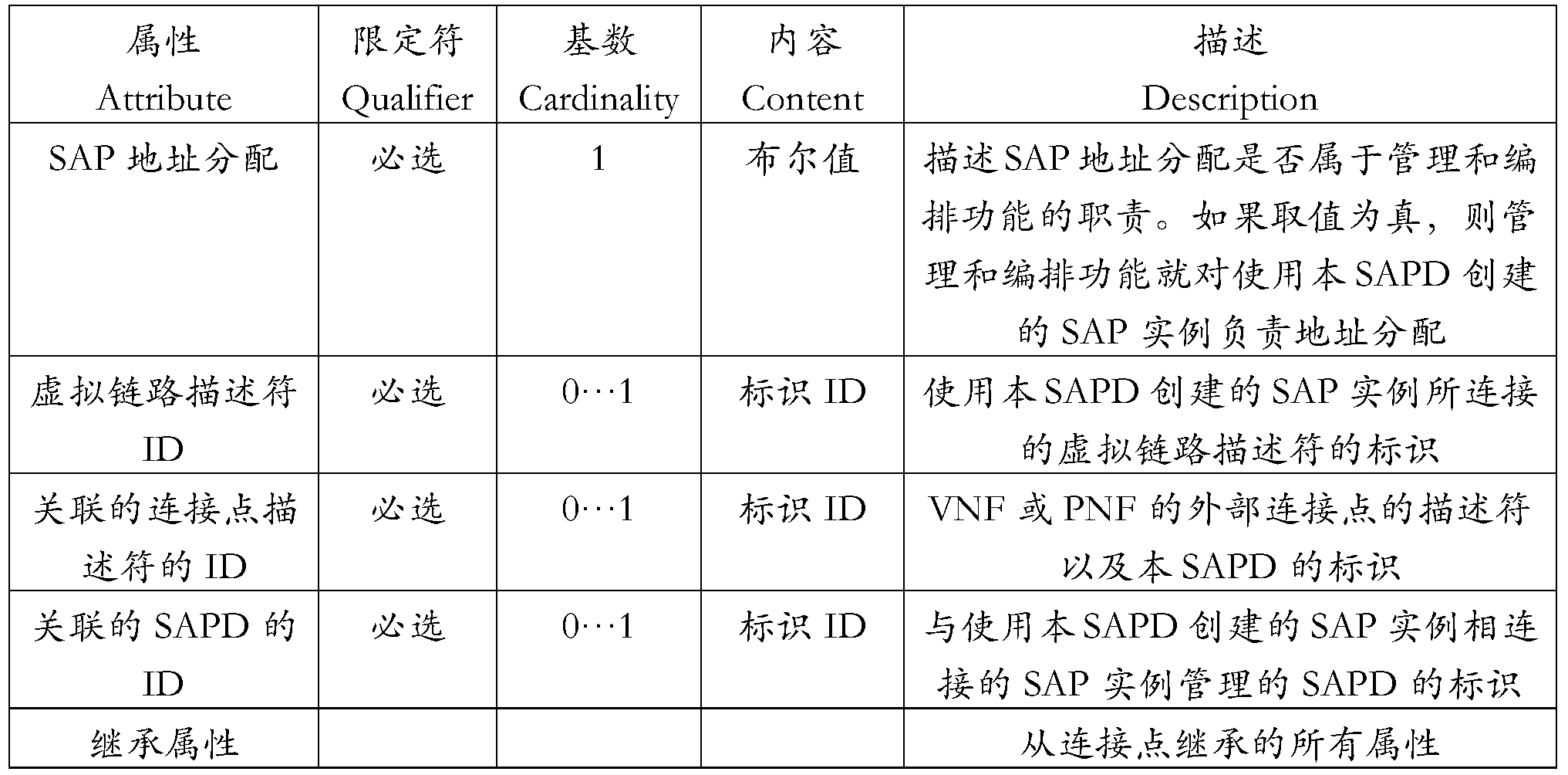
表4Table 4
在表4所示的扩展后的SAPD中,新增的“关联的SAPD的ID”(associatedSapdID)这一字段定义了设计态通过表4所示的SAPD创建的SAP实例相连接的其他SAP实例所关联的SAPD的标识。这样,NFVO可以根据SAPD与SAPD之间的关联关系建立相应的SAP实例与SAP实例之间的连接。In the expanded SAPD shown in Table 4, the newly added "AssociatedSapdID" field defines other SAP instances in which the design state is connected to the SAP instance created by SAPD shown in Table 4. The identity of the associated SAPD. In this way, NFVO can establish a connection between the corresponding SAP instance and the SAP instance according to the relationship between SAPD and SAPD.
下面通过几个实施例介绍本申请提供的网络服务管理方法在不同场景中的实施。为了描述方便,在下述几个实施例中,第一NFVO简称NFVO-1,第二NFVO简称NFVO-2。The implementation of the network service management method provided by the present application in different scenarios is described below through several embodiments. For convenience of description, in the following embodiments, the first NFVO is referred to as NFVO-1, and the second NFVO is referred to as NFVO-2.
(一)实施例一(1) Embodiment 1
图14示出了通过top-down方法实例化复合NS的过程。其中,NFVO-1发起每一个嵌套NS的实例化。该过程主要关注通过参考点Or-Or执行的交互。FIG. 14 shows a process of instantiating a composite NS by a top-down method. Among them, NFVO-1 initiates the instantiation of each nested NS. This process focuses on the interactions performed by the reference point Or-Or.
图14实施例的假设如下:The assumptions of the embodiment of Figure 14 are as follows:
a.映射关系<NSD,NFVO-2>对于NFVO-1来说是可用的。a. Mapping relationship <NSD, NFVO-2> is available for NFVO-1.
b.没有直接可供复合网络服务用来实例化的已存在的嵌套网络服务实例,即复合NS中的全部嵌套NS都需要新建。b. There is no existing nested network service instance that can be directly used by the composite network service to instantiate, that is, all nested NSs in the composite NS need to be newly created.
c.每一个嵌套NS实例都没有被其他复合网络服务共享。图14所示流程可展开如下:c. Each nested NS instance is not shared by other composite network services. The process shown in Figure 14 can be expanded as follows:
1.发送方(如OSS/BSS)向NFVO-1发送用于创建复合NS ID的请求。关于该步骤的具体实现可参考协议ETSI GS NFV-IFA013中的7.3.2节,这里不再赘述。2.NFVO-1向发送方返回复合NS实例的ID。关于该步骤的具体实现可参考协议ETSI GS NFV-IFA013中的条款7.3.2,这里不再赘述。1. The sender (such as OSS/BSS) sends a request to NFVO-1 to create a composite NS ID. For the specific implementation of this step, refer to Section 7.3.2 of the protocol ETSI GS NFV-IFA013, which will not be described here. 2. NFVO-1 returns the ID of the composite NS instance to the sender. For specific implementation of this step, refer to clause 7.3.2 of the protocol ETSI GS NFV-IFA013, and details are not described herein.
3.NFVO-1向发送方发送复合NS ID创建通知。关于该步骤的具体实现可参考协议ETSI GS NFV-IFA013中的条款8.3.2.9,这里不再赘述。3. NFVO-1 sends a composite NS ID creation notification to the sender. For the specific implementation of this step, refer to the clause 8.3.2.9 in the protocol ETSI GS NFV-IFA013, which will not be repeated here.
4.发送方向NFVO-1发送实例化复合NS请求,该请求中携带有嵌套NS实例的ID。关于该步骤的具体实现可参考协议ETSI GS NFV-IFA013中的条款7.3.3,这里不再赘述。4. The sending direction sends an instantiated composite NS request to the NFVO-1, where the request carries the ID of the nested NS instance. For specific implementation of this step, refer to clause 7.3.3 of the protocol ETSI GS NFV-IFA013, and details are not described herein.
5.NFVO-1向发送方返回复合NS实例化应答。关于该步骤的具体实现可参考协议ETSI GS NFV-IFA013中的条款7.3.3,这里不再赘述。5. NFVO-1 returns a composite NS instantiation response to the sender. For specific implementation of this step, refer to clause 7.3.3 of the protocol ETSI GS NFV-IFA013, and details are not described herein.
6.NFVO-1获取用于实例化复合NS的复合NSD,并向发送方发送复合NS的生命周期变化通知“实例化开始”。关于该步骤的具体实现可参考协议ETSI GS NFV-IFA013中的条款8.3.2.2,这里不再赘述。6. NFVO-1 obtains a composite NSD for instantiating a composite NS and sends a notification of the lifecycle change of the composite NS to the sender "instantiation start". For the specific implementation of this step, refer to clause 8.3.2.2 in the protocol ETSI GS NFV-IFA013, which will not be described here.
7.NFVO-1从映射关系<NSD,NFVO-2>中查找出组成复合NSD的每一个嵌套NSD对应的NFVO-2。对于每一个成员嵌套NS,NFVO-1向管理该嵌套NS的NFVO-2发送创建嵌套NS请求(用于请求创建嵌套NS实例),该请求中可携带有SapInfo。该SapInfo可用于NFVO-2建立基于嵌套NS实例的SAP实例的内外网络连接。关于SapInfo的具体实现,可参考前述内容中的相关说明,这里不再赘述。7. NFVO-1 finds the NFVO-2 corresponding to each nested NSD that constitutes the composite NSD from the mapping relationship <NSD, NFVO-2>. For each member nested NS, NFVO-1 sends a nested NS request (used to request the creation of a nested NS instance) to the NFVO-2 that manages the nested NS, which may carry SapInfo. The SapInfo can be used by NFVO-2 to establish internal and external network connections based on SAP instances of nested NS instances. For the specific implementation of SapInfo, refer to the related description in the foregoing content, and details are not described herein again.
8.NFVO-2向NFVO-1返回嵌套NS实例的ID。8. NFVO-2 returns the ID of the nested NS instance to NFVO-1.
9.NFVO-2向NFVO-1发送嵌套NS实例ID创建通知。9. NFVO-2 sends a nested NS instance ID creation notification to NFVO-1.
10.NFVO-1向NFVO-2发送实例化嵌套NS请求,该请求携带嵌套NS实例的ID,用于请求实例化嵌套NS。10. NFVO-1 sends an instantiated nested NS request to NFVO-2, which carries the ID of the nested NS instance for requesting instantiation of the nested NS.
11.NFVO-2向NFVO-1返回嵌套NS实例化应答。11. NFVO-2 returns a nested NS instantiation response to NFVO-1.
12.NFVO-2向NFVO-1发送嵌套NS的生命周期变化通知“实例化开始”。12. NFVO-2 sends a nested NS lifecycle change notification "instantiation start" to NFVO-1.
13.NFVO-2执行嵌套NS的实例化过程。13. NFVO-2 performs the instantiation process of nested NS.
14.一旦嵌套NS实例化成功,NFVO-2向NFVO-1发送生命周期变化通知“结果”。关于该步骤的具体实现可参考协议ETSI GS NFV-IFA013中的条款8.3.2.2,这里不再赘述。14. Once the nested NS instantiation is successful, NFVO-2 sends a lifecycle change notification "result" to NFVO-1. For the specific implementation of this step, refer to clause 8.3.2.2 in the protocol ETSI GS NFV-IFA013, which will not be described here.
15.NFVO-1实例化其他组成成员,例如VNF、PNF。15. NFVO-1 instantiates other constituent members, such as VNF, PNF.
16.一旦复合NS实例中的全部成员实例化成功,NFVO-1向NFVO-2发送通知,用于通知全部成员实例化成功。16. Once all members of the composite NS instance are instantiated successfully, NFVO-1 sends a notification to NFVO-2 to inform all members that the instantiation is successful.
17.NFVO-2根据请求消息中携带的SapInfo,建立嵌套NS实例通过SAP实例(向外)与复合NS实例中的成员实例之间的连接,以及嵌套NS实例通过SAP实例(向内)与该嵌套NS实例中的成员实例之间的连接。17. NFVO-2 establishes a connection between the nested NS instance through the SAP instance (outward) and the member instance in the composite NS instance according to the SapInfo carried in the request message, and the nested NS instance passes the SAP instance (inward) The connection to the member instance in the nested NS instance.
18.一旦复合NS实例中的全部成员实例化成功,NFVO-1建立其他成员实例(嵌套NS实例之外的成员实例)之间的连接,以及其他成员实例和复合NS实例之间的连接。18. Once all members of the composite NS instance are instantiated successfully, NFVO-1 establishes a connection between other member instances (member instances outside of the nested NS instance) and connections between other member instances and the composite NS instance.
19.NFVO-2向NFVO-1返回连接创建成功应答,用于指示嵌套NS实例通过SAP实例形成的内外网络连接已经成功创建。19. NFVO-2 creates a successful response to the NFVO-1 return connection, indicating that the internal and external network connections formed by the nested NS instance through the SAP instance have been successfully created.
20.NFVO-1向发送方发送复合NS的生命周期变化通知“结果”。关于该步骤的具体实现可参考协议ETSI GS NFV-IFA013中的条款8.3.2.2,这里不再赘述。20. NFVO-1 sends the composite NS's lifecycle change notification "result" to the sender. For the specific implementation of this step, refer to clause 8.3.2.2 in the protocol ETSI GS NFV-IFA013, which will not be described here.
本实施例中,步骤7中的创建嵌套NS请求携带有SAPInfo,相当于图12方法流程中提及的第一请求,其中,SapInfo可用于NFVO-2建立基于嵌套NS实例的SAP实例的内外网络连接。可选的,SAPInfo也可以携带于步骤9中的实例化嵌套NS请求中,此时,该实例化嵌套NS请求可相当于图12方法流程中提及的第一请求。In this embodiment, the create nested NS request in step 7 carries SAPInfo, which is equivalent to the first request mentioned in the method flow of FIG. 12, wherein SapInfo can be used for NFVO-2 to establish an SAP instance based on the nested NS instance. Internal and external network connection. Optionally, SAPInfo may also be carried in the instantiated nested NS request in step 9. In this case, the instantiated nested NS request may be equivalent to the first request mentioned in the method flow of FIG.
本实施例中,针对步骤17,关于第二NFVO根据SapInfo建立SapInfo所描述的虚拟链路模型指示连接的具体实现,可参考图12描述的总体方法流程中的相关内容,这里不再赘述。In this embodiment, for the specific implementation of the virtual link model indicating the connection of the second NFVO according to the SapInfo establishment SapInfo, the relevant content in the overall method flow described in FIG. 12 may be referred to, and details are not described herein again.
本实施例中,步骤18中提及的其他成员实例之间的连接是指非嵌套NS实例涉及的网络连接。例如,在图13示例中,其他成员实例之间的连接包括:VNF#2在其外部连接点VnfExtCP#2.2处通过VL#9和复合NS实例的SAP#5.2之间的连接。示例仅仅用于解释本申请,不应构成限定。可选的,NFVO-1可以利用现有ETSI NFV标准中已定义的虚拟链路信息模型来创建其他实例之间的网络连接,这里不再赘述。In this embodiment, the connection between other member instances mentioned in step 18 refers to the network connection involved in the non-nested NS instance. For example, in the example of FIG. 13, the connections between other member instances include: VNF # 2 at its external connection point VnfExtCP #2.2 through the connection between VL # 9 and SAP # 5.2 of the composite NS instance. The examples are merely illustrative of the application and should not be construed as limiting. Optionally, NFVO-1 can use the virtual link information model defined in the existing ETSI NFV standard to create a network connection between other instances, which is not described here.
(二)实施例二(2) Example 2
图15提供了实例化复合NS的一种变形场景,在该场景中,已经实例化的复合NS实例中的嵌套NS实例来自其他复合NS实例使用的已经存在的嵌套NS实例。因此,该嵌套NS实例被多个复合NS实例共享,这多个复合实例可以提供于不同管理域。Figure 15 provides a variation of instantiating a composite NS in which nested NS instances in a composite NS instance that have been instantiated are from existing nested NS instances used by other composite NS instances. Therefore, the nested NS instance is shared by multiple composite NS instances, which can be provided in different administrative domains.
图15实施例的假设如下:The assumptions of the embodiment of Figure 15 are as follows:
a.映射关系<嵌套NSD,NFVO-2>对于NFVO-1来说是可用的。a. Mapping relationship <Nested NSD, NFVO-2> is available for NFVO-1.
b.存在NFVO-2管理的且能够直接用来实例化复合NS的嵌套NS实例。b. There are nested NS instances that are NFVO-2 managed and can be used directly to instantiate a composite NS.
c.由NFVO-1决定是否使用已存在的嵌套NS实例来组成复合NS。c. Determine whether to use the existing nested NS instance to form a composite NS by NFVO-1.
由于映射关系<嵌套NSD,NFVO-2>的辅助,NFVO-1可以订阅来自NFVO-2的通知,用于在NFVO-2所处管理域中捕捉嵌套NSD关联的嵌套NS实例的状态变化。嵌套NS实例的状态变化可如下包括:已创建但未实例化、已实例化但未共享、已实例化且已共享等。NFVO-1可以进一步利用嵌套NS实例的状态信息(如已实例化且已共享)来实例化复合NS,例如决定是否嵌套NS实例可用于新的复合NS中。Due to the mapping relationship < Nested NSD, NFVO-2>, NFVO-1 can subscribe to notifications from NFVO-2 for capturing the state of nested NSS-associated nested NS instances in the administrative domain in which NFVO-2 is located Variety. State changes for nested NS instances can include: created but not instantiated, instantiated but not shared, instantiated, shared, and so on. NFVO-1 may further utilize the state information of the nested NS instance (eg, instantiated and shared) to instantiate the composite NS, such as deciding whether a nested NS instance is available for use in the new composite NS.
图15所示流程可展开如下:The process shown in Figure 15 can be expanded as follows:
1.NFVO-2订阅来自所有相关NFVO(包括NFVO-1)的NS实例使用状态的通知。相关NFVO与NFVO-2通过Or-Or参考点交互。1. NFVO-2 subscribes to notifications from all relevant NFVO (including NFVO-1) NS instance usage status. The relevant NFVO interacts with NFVO-2 through the Or-Or reference point.
这里,一个NFVO(如本实施例中的NFVO-2)选择一组NFVO(该NFVO需要订阅这组NFVO提供的通知)的方式取决于具体场景,例如,作为一种合适的方式,可以订阅其他每一个已知NFVO所提供的通知。Here, an NFVO (such as NFVO-2 in this embodiment) selects a set of NFVOs (the NFVO needs to subscribe to the notifications provided by the set of NFVOs) depending on the specific scenario, for example, as a suitable way, you can subscribe to other Every notification known by NFVO.
2.NFVO-1订阅来自NFVO-2的通知,以NFVO-2所处的管理域中的某个NS实例(关联一个NSD或直接被NFVO-1指示)的状态变化获知。NS实例的状态可包括:已创建但未实例化、已实例化但未共享、已实例化且已共享等。2. NFVO-1 subscribes to notifications from NFVO-2, known as state changes of an NS instance (associated with an NSD or directly indicated by NFVO-1) in the administrative domain in which NFVO-2 is located. The status of an NS instance can include: created but not instantiated, instantiated but not shared, instantiated, shared, and so on.
3.当相应事件发生时,NFVO-2向NFVO-1发送NS实例状态变化通知,该通知可携带该NS实例的标识和该NS实例的新状态。3. When the corresponding event occurs, the NFVO-2 sends an NS instance status change notification to the NFVO-1, the notification may carry the identifier of the NS instance and the new status of the NS instance.
步骤4-7与图14中的步骤1-4相同,主要为发送方向NFVO-1发起实例化复合NS的请求的流程。Steps 4-7 are the same as steps 1-4 in FIG. 14, mainly for the flow of the request to instantiate the composite NS in the direction of transmission NFVO-1.
8.NFVO-1向NFVO-2发送决定使用NS实例的通知,以通知NFVO-1基于该已存在的NS实例的状态(如已实例化且已共享)以及其他限制,如该NS实例的容量限制等,决定使用NFVO-2管理的已存在的NS实例来实例化复合NS。8. NFVO-1 sends a notification to NFVO-2 to decide to use the NS instance to inform NFVO-1 based on the state of the existing NS instance (as instantiated and shared) and other restrictions, such as the capacity of the NS instance. Restrictions, etc., decided to instantiate the composite NS using an existing NS instance managed by NFVO-2.
响应该通知,NFVO-2可以为该已存在NS实例和NFVO-1之间建立使用关系。In response to the notification, NFVO-2 can establish a usage relationship between the existing NS instance and NFVO-1.
可以理解的,当NFVO-1决定使用NFVO-2管理的已存在NS实例作为成员NS实例时,该已存在NS实例需要在NFVO-1管理的复合NS中新增SAP实例,该新增的SAP实例可用于该已存在NS实例和NFVO-1管理的复合NS中的成员实例建立连接,使得该已存在NS实例构成该复合NS中的成员实例。本实施例中,该决定使用NS实例的通知可携带新增SAP实例关联的SapInfo,用于NFVO-2利用该SapInfo建立基于新的SAP实例的网络连接。It can be understood that when NFVO-1 decides to use the existing NS instance managed by NFVO-2 as the member NS instance, the existing NS instance needs to add an SAP instance in the composite NS managed by NFVO-1, the new SAP. An instance may be used to establish a connection between a member instance of the existing NS instance and the NFVO-1 managed composite NS such that the existing NS instance constitutes a member instance in the composite NS. In this embodiment, the decision to use the NS instance notification may carry the SapInfo associated with the newly added SAP instance, and the NFVO-2 uses the SapInfo to establish a network connection based on the new SAP instance.
9.NFVO-1向发送方返回复合NS实例化应答。关于该步骤的具体实现可参考协议ETSI GS NFV-IFA013中的条款7.3.3,这里不再赘述。9. NFVO-1 returns a composite NS instantiation response to the sender. For specific implementation of this step, refer to clause 7.3.3 of the protocol ETSI GS NFV-IFA013, and details are not described herein.
10.NFVO-1获取用于实例化复合NS的复合NSD,并向发送方发送复合NS的生命周期变化通知“实例化开始”。关于该步骤的具体实现可参考协议ETSI GS NFV-IFA013中的条款8.3.2.2,这里不再赘述。10. NFVO-1 obtains a composite NSD for instantiating a composite NS and sends a notification of the lifecycle change of the composite NS to the sender "instantiation start". For the specific implementation of this step, refer to clause 8.3.2.2 in the protocol ETSI GS NFV-IFA013, which will not be described here.
11.NFVO-1实例化其他组成成员,例如VNF、PNF。11. NFVO-1 instantiates other constituent members, such as VNF, PNF.
12.一旦复合NS实例中的全部成员实例化成功,NFVO-1向NFVO-2发送通知,用于通知全部成员实例化成功。12. Once all members of the composite NS instance are instantiated successfully, NFVO-1 sends a notification to NFVO-2 to inform all members that the instantiation is successful.
13.NFVO-2可以利用该SapInfo建立该已存在NS实例在NFVO-1管理的复合NS中基于新的SAP实例的网络连接。具体的,NFVO-2可以建立该已存在NS实例通过新增SAP实例(向外)与复合NS实例中的成员实例之间的连接,以及该已存在NS实例通过新增SAP实例(向内)与该已存在NS实例中的成员实例之间的连接。13. NFVO-2 can use the SapInfo to establish a network connection of the existing NS instance based on the new SAP instance in the composite NS managed by NFVO-1. Specifically, NFVO-2 may establish a connection between the existing NS instance by adding a new SAP instance (outward) and a member instance in the composite NS instance, and the existing NS instance by adding a new SAP instance (inward) A connection to a member instance in the existing NS instance.
14.NFVO-2向NFVO-1返回连接创建成功应答,用于指示该已存在NS实例在NFVO-1管理的复合NS中基于新的SAP实例的网络连接已经成功创建。14. NFVO-2 returns a connection to NFVO-1 to create a successful response indicating that the existing NS instance has been successfully created in the composite NS managed by NFVO-1 based on the new SAP instance.
15.NFVO-1使用NFVO-2管理的该已存在NS实例组成复合NS实例。15. NFVO-1 uses the existing NS instance managed by NFVO-2 to form a composite NS instance.
16.NFVO-1向发送方发送复合NS的生命周期变化通知“结果”。关于该步骤的具体实现可参考协议ETSI GS NFV-IFA013中的条款8.3.2.2,这里不再赘述。16. NFVO-1 sends the composite NS's lifecycle change notification "result" to the sender. For the specific implementation of this step, refer to clause 8.3.2.2 in the protocol ETSI GS NFV-IFA013, which will not be described here.
本实施例中,步骤8中的决定使用NS实例通知携带有SapInfo,其中,SapInfo可用于NFVO-2建立基于嵌套NS实例的SAP实例的内外网络连接。本申请中,可以将该决定使用NS实例通知称为第三请求。In this embodiment, the decision in step 8 uses the NS instance notification to carry SapInfo, where SapInfo can be used for NFVO-2 to establish an internal and external network connection based on the nested NS instance-based SAP instance. In this application, the decision to use the NS instance notification may be referred to as a third request.
本实施例中,针对步骤13,关于第二NFVO根据SapInfo建立SapInfo所描述的虚拟链路模型指示连接的具体实现,可参考图12描述的总体方法流程中的相关内容,这里不再赘述。In this embodiment, for the specific implementation of the virtual link model indicating the connection of the second NFVO according to the SapInfo establishment SapInfo, the relevant content in the overall method flow described in FIG. 12 may be referred to, and details are not described herein again.
(三)实施例三(III) Third embodiment
图16示出了通过bottom-up方法实例化复合NS的过程。其中,发送方(OSS/BSS)在实例化复合NS之前先发起每一个嵌套NS的实例化。该过程主要关注通过参考点Or-Or执行的交互。Figure 16 shows the process of instantiating a composite NS by the bottom-up method. The sender (OSS/BSS) initiates the instantiation of each nested NS before instantiating the composite NS. This process focuses on the interactions performed by the reference point Or-Or.
图16实施例的假设如下:The assumptions of the embodiment of Figure 16 are as follows:
a.映射关系<嵌套NSD,NFVO-2>对于NFVO-1来说是可用的。a. Mapping relationship <Nested NSD, NFVO-2> is available for NFVO-1.
b.每一个嵌套NS实例都没有被其他复合NS共享。b. Each nested NS instance is not shared by other composite NSs.
图16所示流程可展开如下:The process shown in Figure 16 can be expanded as follows:
1.NFVO-1订阅嵌套NS的由NFVO-2产生的NS生命周期变化。关于该步骤的具体实现可参考协议ETSI GS NFV-IFA013中的条款7.4,这里不再赘述。1. NFVO-1 subscribes to nested NS's NS lifecycle changes generated by NFVO-2. For specific implementation of this step, refer to clause 7.4 of the protocol ETSI GS NFV-IFA013, and details are not described herein.
2.发送方(如OSS/BSS)向NFVO-2发送用于创建嵌套NS ID的请求。关于该步骤的具体实现可参考协议ETSI GS NFV-IFA013中的条款7.3.2,这里不再赘述。具体的,该请求中可携带有SapInfo。该SapInfo可用于NFVO-2建立基于嵌套NS实例的SAP实例的内外网络连接。关于SapInfo的具体实现,可参考前述内容中的相关说明,这里不再赘述。2. The sender (such as OSS/BSS) sends a request to NFVO-2 to create a nested NS ID. For specific implementation of this step, refer to clause 7.3.2 of the protocol ETSI GS NFV-IFA013, and details are not described herein. Specifically, the request may carry SapInfo. The SapInfo can be used by NFVO-2 to establish internal and external network connections based on SAP instances of nested NS instances. For the specific implementation of SapInfo, refer to the related description in the foregoing content, and details are not described herein again.
3.NFVO-2向发送方返回嵌套NS实例的ID。关于该步骤的具体实现可参考协议ETSI GS NFV-IFA013中的条款7.3.2,这里不再赘述。3. NFVO-2 returns the ID of the nested NS instance to the sender. For specific implementation of this step, refer to clause 7.3.2 of the protocol ETSI GS NFV-IFA013, and details are not described herein.
4.NFVO-2向发送方发送嵌套NS ID创建通知。关于该步骤的具体实现可参考协议ETSI GS NFV-IFA013中的条款8.3.2.9,这里不再赘述。4. NFVO-2 sends a nested NS ID creation notification to the sender. For the specific implementation of this step, refer to the clause 8.3.2.9 in the protocol ETSI GS NFV-IFA013, which will not be repeated here.
5.如果NFVO-1已经订阅(参考步骤1),NFVO-2将嵌套NS实例ID的创建通知 给NFVO-1。5. If NFVO-1 is already subscribed (refer to step 1), NFVO-2 notifies NFVO-1 of the creation of the nested NS instance ID.
6.发送方向NFVO-2发送实例化嵌套NS请求,该请求中携带有嵌套NS实例的ID。关于该步骤的具体实现可参考协议ETSI GS NFV-IFA013中的条款7.3.3,这里不再赘述。6. The sending direction NFVO-2 sends an instantiated nested NS request carrying the ID of the nested NS instance. For specific implementation of this step, refer to clause 7.3.3 of the protocol ETSI GS NFV-IFA013, and details are not described herein.
7.NFVO-2向发送方返回嵌套NS实例化应答。关于该步骤的具体实现可参考协议ETSI GS NFV-IFA013中的条款7.3.3,这里不再赘述。7. NFVO-2 returns a nested NS instantiation response to the sender. For specific implementation of this step, refer to clause 7.3.3 of the protocol ETSI GS NFV-IFA013, and details are not described herein.
8.NFVO-2向发送方发送嵌套NS的生命周期变化通知“实例化开始”。关于该步骤的具体实现可参考协议ETSI GS NFV-IFA013中的条款8.3.2.2,这里不再赘述。8. NFVO-2 sends the nested NS lifecycle change notification "instantiation start" to the sender. For the specific implementation of this step, refer to clause 8.3.2.2 in the protocol ETSI GS NFV-IFA013, which will not be described here.
9.如果NFVO-1已经订阅(参考步骤1),NFVO-2将嵌套NS的生命周期变化“实例化开始”通知给NFVO-1。9. If NFVO-1 is already subscribed (refer to step 1), NFVO-2 notifies NFVO-1 of the "instantiation start" of the nested NS lifecycle changes.
10.NFVO-2执行嵌套NS的实例化过程。10. NFVO-2 performs the instantiation process of nested NS.
11.一旦嵌套NS实例化成功,NFVO-2向发送方发送生命周期变化通知“实例化结果”。关于该步骤的具体实现可参考协议ETSI GS NFV-IFA013中的条款8.3.2.2,这里不再赘述。11. Once the nested NS instantiation is successful, NFVO-2 sends a lifecycle change notification "instantiation result" to the sender. For the specific implementation of this step, refer to clause 8.3.2.2 in the protocol ETSI GS NFV-IFA013, which will not be described here.
12.如果NFVO-1已经订阅(参考步骤1),NFVO-2将嵌套NS实例的生命周期变化“实例化结果”通知给NFVO-1。12. If NFVO-1 is already subscribed (refer to step 1), NFVO-2 notifies NFVO-1 of the "instantiation result" of the lifecycle change of the nested NS instance.
13.一旦全部的嵌套NS实例化成功,发送方向NFVO-1发送用于创建复合NS ID的请求。关于该步骤的具体实现可参考协议ETSI GS NFV-IFA013中的条款7.3.2,这里不再赘述。13. Once all nested NS instantiations are successful, the send direction NFVO-1 sends a request to create a composite NS ID. For specific implementation of this step, refer to clause 7.3.2 of the protocol ETSI GS NFV-IFA013, and details are not described herein.
14.NFVO-1向发送方返回复合NS实例的ID。关于该步骤的具体实现可参考协议ETSI GS NFV-IFA013中的条款7.3.2,这里不再赘述。14. NFVO-1 returns the ID of the composite NS instance to the sender. For specific implementation of this step, refer to clause 7.3.2 of the protocol ETSI GS NFV-IFA013, and details are not described herein.
15.NFVO-1向发送方发送复合NS ID创建通知。关于该步骤的具体实现可参考协议ETSI GS NFV-IFA013中的条款8.3.2.9,这里不再赘述。15. NFVO-1 sends a composite NS ID creation notification to the sender. For the specific implementation of this step, refer to the clause 8.3.2.9 in the protocol ETSI GS NFV-IFA013, which will not be repeated here.
16.发送方向NFVO-1发送实例化复合NS请求,该请求中携带有嵌套NS实例的ID。关于该步骤的具体实现可参考协议ETSI GS NFV-IFA013中的条款7.3.3,这里不再赘述。16. The sending direction NFVO-1 sends an instantiated composite NS request carrying the ID of the nested NS instance. For specific implementation of this step, refer to clause 7.3.3 of the protocol ETSI GS NFV-IFA013, and details are not described herein.
17.NFVO-1向发送方返回复合NS实例化应答。关于该步骤的具体实现可参考协议ETSI GS NFV-IFA013中的条款7.3.3,这里不再赘述。17. NFVO-1 returns a composite NS instantiation response to the sender. For specific implementation of this step, refer to clause 7.3.3 of the protocol ETSI GS NFV-IFA013, and details are not described herein.
18.NFVO-1向发送方发送复合NS的生命周期变化通知“实例化开始”。关于该步骤的具体实现可参考协议ETSI GS NFV-IFA013中的条款8.3.2.2,这里不再赘述。18. NFVO-1 sends the composite NS lifecycle change notification "instantiation start" to the sender. For the specific implementation of this step, refer to clause 8.3.2.2 in the protocol ETSI GS NFV-IFA013, which will not be described here.
19.NFVO-1根据步骤11中的通知检查需要的嵌套NS实例的可用性。19. NFVO-1 checks the availability of the required nested NS instances according to the notification in step 11.
20.如果复合NS包括VNF和/或PNF,则NFVO-1实例化该VNF和/或PNF。20. If the composite NS comprises VNF and/or PNF, NFVO-1 instantiates the VNF and/or PNF.
21.一旦复合NS实例中的全部成员实例化成功,NFVO-1向NFVO-2发送通知,用于通知全部成员实例化成功。21. Once all members of the composite NS instance are instantiated successfully, NFVO-1 sends a notification to NFVO-2 to inform all members that the instantiation is successful.
22.NFVO-2根据SapInfo,建立嵌套NS实例通过SAP实例(向外)与复合NS实例中的成员实例之间的连接,以及嵌套NS实例通过SAP实例(向内)与该嵌套NS实例中的成员实例之间的连接。22. NFVO-2, based on SapInfo, establishes a connection between a nested NS instance through an SAP instance (outward) and a member instance in a composite NS instance, and a nested NS instance through the SAP instance (inward) with the nested NS The connection between member instances in the instance.
23.NFVO-2向NFVO-1返回连接创建成功应答,用于指示嵌套NS实例通过SAP 实例形成的内外网络连接已经成功创建。23. NFVO-2 creates a successful response to the NFVO-1 return connection, indicating that the internal and external network connections formed by the nested NS instance through the SAP instance have been successfully created.
24.一旦复合NS实例中的全部成员实例化成功,NFVO-1建立其他成员实例(嵌套NS实例之外的成员实例)之间的连接,以及其他成员实例和复合NS实例之间的连接。24. Once all members of the composite NS instance are instantiated successfully, NFVO-1 establishes a connection between other member instances (member instances outside of the nested NS instance) and connections between other member instances and the composite NS instance.
25.NFVO-1向发送方发送复合NS的生命周期变化通知“结果”。关于该步骤的具体实现可参考协议ETSI GS NFV-IFA013中的条款8.3.2.2,这里不再赘述。25. NFVO-1 sends the composite NS's lifecycle change notification "result" to the sender. For the specific implementation of this step, refer to clause 8.3.2.2 in the protocol ETSI GS NFV-IFA013, which will not be described here.
本实施例中,步骤2中的创建嵌套NS请求携带有SAPInfo,相当于图12方法流程中提及的第一请求,其中,SapInfo可用于NFVO-2建立基于嵌套NS实例的SAP实例的内外网络连接。可选的,SAPInfo也可以携带于步骤6中的实例化嵌套NS请求中,此时,该实例化嵌套NS请求可相当于图12方法流程中提及的第一请求。In this embodiment, the create nested NS request in step 2 carries SAPInfo, which is equivalent to the first request mentioned in the method flow of FIG. 12, wherein SapInfo can be used for NFVO-2 to establish an SAP instance based on the nested NS instance. Internal and external network connection. Optionally, SAPInfo may also be carried in the instantiated nested NS request in step 6. In this case, the instantiated nested NS request may be equivalent to the first request mentioned in the method flow of FIG.
本实施例中,针对步骤22,关于第二NFVO根据SapInfo建立SapInfo所描述的虚拟链路模型指示连接的具体实现,可参考图12描述的总体方法流程中的相关内容,这里不再赘述。In this embodiment, for the specific implementation of the virtual link model indicating the connection of the second NFVO according to the SapInfo establishment SapInfo, the relevant content in the overall method flow described in FIG. 12 may be referred to, and details are not described herein again.
(四)实施例四(4) Example 4
图17示出了更新复合NS的过程。其中,NFVO-1管理的复合NS中包含NFVO-2管理的嵌套NS。该过程主要关注通过参考点Or-Or执行的交互。Figure 17 shows the process of updating the composite NS. Among them, the composite NS managed by NFVO-1 includes nested NS managed by NFVO-2. This process focuses on the interactions performed by the reference point Or-Or.
嵌套NS实例关联的NS更新类型可包括但不限于:新增嵌套NS的SAP、修改嵌套NS的SAP、移除嵌套NS的SAP、新增嵌套NS、移除嵌套NS。本实施例中主要讨论嵌套NS的SAP的新增或修改或移除。The NS update type associated with the nested NS instance may include, but is not limited to, adding a nested NS SAP, modifying a nested NS SAP, removing a nested NS SAP, adding a nested NS, and removing a nested NS. In this embodiment, the addition or modification or removal of the SAP of the nested NS is mainly discussed.
图17所示流程可展开如下:The process shown in Figure 17 can be expanded as follows:
1.NFVO-2订阅来自所有相关NFVO(包括NFVO-1)的NS实例使用状态的通知。相关NFVO与NFVO-2通过Or-Or参考点交互。1. NFVO-2 subscribes to notifications from all relevant NFVO (including NFVO-1) NS instance usage status. The relevant NFVO interacts with NFVO-2 through the Or-Or reference point.
这里,一个NFVO(如本实施例中的NFVO-2)选择一组NFVO(该NFVO需要订阅这组NFVO提供的通知)的方式取决于具体场景,例如,作为一种合适的方式,可以订阅其他每一个已知NFVO提供的通知。Here, an NFVO (such as NFVO-2 in this embodiment) selects a set of NFVOs (the NFVO needs to subscribe to the notifications provided by the set of NFVOs) depending on the specific scenario, for example, as a suitable way, you can subscribe to other Every notification known by NFVO.
2.发送方(如OSS/BSS)向NFVO-1发送用于执行NS更新操作的复合NS更新请求。关于该步骤的具体实现可参考协议ETSI GS NFV-IFA013中的条款7.3.5,这里不再赘述。2. The sender (e.g., OSS/BSS) sends a composite NS update request for performing an NS update operation to NFVO-1. For specific implementation of this step, refer to clause 7.3.5 of the protocol ETSI GS NFV-IFA013, and details are not described herein.
3.NFVO-1向发送方返回NS更新应答。3. NFVO-1 returns an NS update response to the sender.
4.NFVO-1向发送方发送嵌套NS的生命周期变化通知“更新开始”。关于该步骤的具体实现可参考协议ETSI GS NFV-IFA013中的条款8.3.2.2,这里不再赘述。4. NFVO-1 sends a notification of the lifecycle change of the nested NS to the sender "Update Start". For the specific implementation of this step, refer to clause 8.3.2.2 in the protocol ETSI GS NFV-IFA013, which will not be described here.
5.NFVO-1向NFVO-2发送更新嵌套NS实例请求,该请求中携带SapInfo。该请求还可以包括NS更新类型,例如增加服务接入点或修改服务接入点等。5. NFVO-1 sends an update nested NS instance request to NFVO-2, which carries SapInfo. The request may also include an NS update type, such as adding a service access point or modifying a service access point.
具体的,该SapInfo可以是嵌套NS实例管理的全部SAP实例的信息,也可以是新增SAP实例的信息或者待修改SAP实例的信息或者待移除SAP实例的信息。该SapInfo可用于NFVO-2更新嵌套NS关联的网络连接。关于SAPInfo的具体实现,可参考图12方法流程中的相关描述,这里不再赘述。Specifically, the SapInfo may be the information of all the SAP instances managed by the nested NS instance, or the information of the newly added SAP instance or the information of the SAP instance to be modified or the information of the SAP instance to be deleted. The SapInfo can be used for NFVO-2 to update nested NS-associated network connections. For the specific implementation of SAPInfo, refer to the related description in the method flow of FIG. 12, and details are not described herein again.
6.NFVO-2更新嵌套NS实例。具体的,NFVO-2可以根据NS更新类型,更新NS实 例,例如新增或修改SAP实例。6. NFVO-2 updates nested NS instances. Specifically, NFVO-2 can update the NS instance according to the NS update type, such as adding or modifying an SAP instance.
7.NFVO-2向NFVO-1返回嵌套NS实例更新成功应答。7. NFVO-2 returns a nested NS instance update success response to NFVO-1.
8.NFVO-2根据SapInfo更新嵌套NS实例关联的网络连接。具体的,更新嵌套NS实例关联的网络连接可包括以下至少一项:建立嵌套NS实例关联的新的网络连接,或者修改NS实例关联的已有的网络连接,或者移除嵌套NS实例关联的已有的网络连接。8. NFVO-2 updates the network connection associated with the nested NS instance according to SapInfo. Specifically, updating the network connection associated with the nested NS instance may include at least one of: establishing a new network connection associated with the nested NS instance, or modifying an existing network connection associated with the NS instance, or removing the nested NS instance. Associated existing network connections.
9.NFVO-2向NFVO-1返回连接更新成功应答。9. NFVO-2 returns a connection update success response to NFVO-1.
10.NFVO-1更新其他成员实例(NFVO-2管理的嵌套NS实例之外的成员实例)。10. NFVO-1 updates other member instances (member instances other than nested NS instances managed by NFVO-2).
11.NFVO-1更新其他成员实例关联的网络连接。11. NFVO-1 updates the network connections associated with other member instances.
12.NFVO-1向发送方发送复合NS的生命周期变化“更新结果”通知。关于该步骤的具体实现可参考协议ETSI GS NFV-IFA013中的条款8.3.2.2,这里不再赘述。12. NFVO-1 sends a "update result" notification of the lifecycle change of the composite NS to the sender. For the specific implementation of this step, refer to clause 8.3.2.2 in the protocol ETSI GS NFV-IFA013, which will not be described here.
本实施例中,步骤5中的更新嵌套NS实例请求携带有SAPInfo,相当于图12方法流程中提及的第二请求。In this embodiment, the update nested NS instance request in step 5 carries SAPInfo, which is equivalent to the second request mentioned in the method flow of FIG.
本实施例中,针对步骤8,关于第二NFVO根据SapInfo更新嵌套NS实例关联的网络连接的具体实现,可参考图12描述的总体方法流程中的相关内容,这里不再赘述。In this embodiment, for the specific implementation of the network connection that the second NFVO updates the nested NS instance according to the SapInfo, the related content in the overall method flow described in FIG. 12 may be referred to, and details are not described herein again.
参考图18,图18示出了本申请的提供一种装置100。装置100可用于在图2所示的NFV MANO系统中。装置100主要可用于实现NFVO的功能,即主要实现网络服务描述符(NSD),虚拟网络功能转发图(VNFFG)的管理及处理,网络服务生命周期的管理。可选的,装置100还可以进一步集成VNFM的功能,还可用于实现VNF的生命周期管理和虚拟资源的全局视图功能。可选的,装置100还可以进一步集成VIM的功能,还可用于执行资源分配和/或预留、交换虚拟化资源配置和状态信息。Referring to Figure 18, there is shown an apparatus 100 provided by the present application. Apparatus 100 can be used in the NFV MANO system shown in FIG. The device 100 is mainly used to implement the function of the NFVO, that is, mainly implements management and processing of a network service descriptor (NSD), a virtual network function forwarding map (VNFFG), and management of a network service life cycle. Optionally, the device 100 may further integrate the functions of the VNFM, and may also be used to implement VNF lifecycle management and global view functions of virtual resources. Optionally, the device 100 may further integrate the functions of the VIM, and may also be used to perform resource allocation and/or reservation, exchange virtualized resource configuration, and status information.
如图18所示,装置100可包括收发器103、耦合于该收发器103的一个或多个端口107、存储器105以及耦合于存储器105的处理器101。其中:As shown in FIG. 18, apparatus 100 can include a transceiver 103, one or more ports 107 coupled to the transceiver 103, a memory 105, and a processor 101 coupled to the memory 105. among them:
收发器103可以是发射器、接收器或其组合,通过端口107发送或接收数据。 Transceiver 103 can be a transmitter, a receiver, or a combination thereof that transmits or receives data over port 107.
存储器105与处理器101耦合,用于存储各种软件程序和/或多组指令。具体的,存储器105可包括高速随机存取的存储器105,并且也可包括非易失性存储器105,例如一个或多个磁盘存储设备、闪存设备或其他非易失性固态存储设备。存储器105可以存储操作系统(下述简称系统),例如uCOS、VxWorks、RTLinux等嵌入式操作系统。 Memory 105 is coupled to processor 101 for storing various software programs and/or sets of instructions. In particular, memory 105 may include high speed random access memory 105, and may also include non-volatile memory 105, such as one or more magnetic disk storage devices, flash memory devices, or other non-volatile solid state storage devices. The memory 105 can store an operating system (hereinafter referred to as a system) such as an embedded operating system such as uCOS, VxWorks, or RTLinux.
本申请中,存储器105可以存储本申请的一个或多个实施例提供的网络服务管理方法的实现程序,即NFVO模块1053,NFVO模块1053可以在处理器101上被执行。当NFVO模块1053被执行时,处理器101可用于执行本申请提供的网络服务管理方法。In the present application, the memory 105 may store an implementation program of the network service management method provided by one or more embodiments of the present application, that is, the NFVO module 1053, which may be executed on the processor 101. When the NFVO module 1053 is executed, the processor 101 can be used to perform the network service management method provided by the present application.
可选的,存储器105还可以存储NFV模块1051,NFV模块1051可用于容纳、存储及实现一个或多个虚拟化网络设备的网络功能。Optionally, the memory 105 can also store an NFV module 1051 that can be used to house, store, and implement network functions of one or more virtualized network devices.
处理器101可包含一个或多个多核处理器101和/或存储器105。处理器101可以是一个通用处理器101,专用集成电路(application specific integrated circuit,ASIC),或数字信号处理器101(digital signal processor,DSP),或片上系统(system on chip,SoC)。处理器101耦合到收发器103,可以用于处理收发器103接收或发送的数据。处理器101可用于读取和执行计算机可读指令。具体的,处理器101可用于调用存储于存储器105中的程序,例如 本申请的一个或多个实施例提供的网络服务管理方法的实现程序,并执行该程序包含的指令。 Processor 101 may include one or more multi-core processors 101 and/or memory 105. The processor 101 can be a general purpose processor 101, an application specific integrated circuit (ASIC), or a digital signal processor (DSP), or a system on chip (SoC). The processor 101 is coupled to the transceiver 103 and can be used to process data received or transmitted by the transceiver 103. The processor 101 can be used to read and execute computer readable instructions. Specifically, the processor 101 can be used to invoke a program stored in the memory 105, such as an implementation program of the network service management method provided by one or more embodiments of the present application, and execute the instructions contained in the program.
本申请中,图18所示的装置100可以用于运行上述方法实施例中提及的消费者NFVO(即第一NFVO或者NFVO-1),也可以用于运行上述方法实施例中提及的提供者NFVO(即第二NFVO或者NFVO-2)。In the present application, the apparatus 100 shown in FIG. 18 can be used to run the consumer NFVO (ie, the first NFVO or NFVO-1) mentioned in the above method embodiments, and can also be used to run the operations mentioned in the above method embodiments. Provider NFVO (ie second NFVO or NFVO-2).
具体的,装置100可以是实现为路由器、服务器或交换机等计算装置。Specifically, the device 100 may be implemented as a computing device such as a router, a server, or a switch.
需要说明的,图18所示的装置100仅仅是本申请实施例的一种实现方式,实际应用中,装置100还可以包括更多或更少的部件,这里不作限制。It should be noted that the device 100 shown in FIG. 18 is only one implementation of the embodiment of the present application. In an actual application, the device 100 may further include more or less components, which are not limited herein.
参考考图19,图19示出了本申请提供一种NFV MANO系统及装置。NFV MANO系统10可包括:第一装置200和第二装置300。其中,第一装置200可以为上述方法实施例中的消费者NFVO(即第一NFVO或者NFVO-1),第二装置300可以为上述方法实施例中的提供者NFVO(即第二NFVO或者NFVO-2),NFV MANO系统10可以是图2描述的NFV MANO系统。下面分别描述。Referring to Figure 19, Figure 19 illustrates an NFV MANO system and apparatus. The NFV MANO system 10 can include a first device 200 and a second device 300. The first device 200 may be the consumer NFVO (ie, the first NFVO or NFVO-1) in the foregoing method embodiment, and the second device 300 may be the provider NFVO (ie, the second NFVO or NFVO in the foregoing method embodiment). -2) The NFV MANO system 10 can be the NFV MANO system depicted in FIG. Described separately below.
如图19所示,第一装置200可包括:处理单元201和通信单元203。其中:As shown in FIG. 19, the first device 200 may include a processing unit 201 and a communication unit 203. among them:
通信单元203可用于接收发送方(如OSS/BSS)发送的创建复合NS实例的请求。The communication unit 203 can be configured to receive a request sent by a sender (such as an OSS/BSS) to create a composite NS instance.
通信单元203可用于向第二装置300(即提供者NFVO)发送第一请求,第一请求用于请求第二装置300创建复合NS实例中的嵌套NS实例。The communication unit 203 can be configured to send a first request to the second device 300 (ie, the provider NFVO) for requesting the second device 300 to create a nested NS instance in the composite NS instance.
处理单元201可用于创建该复合NS实例中的上述嵌套NS实例之外的成员实例(即其他成员实例),以及建立该成员实例之间的网络连接。The processing unit 201 can be configured to create a member instance (ie, other member instances) other than the above-described nested NS instance in the composite NS instance, and establish a network connection between the member instances.
具体的,第一请求携带有嵌套NS实例关联的SAP实例的信息。SAP实例的信息可用于第二装置300基于该SAP实例建立该嵌套NS实例与复合NS实例以及复合NS实例中的成员实例之间的连接,还用于第二装置300基于该SAP实例建立该嵌套NS实例中的成员实例之间的连接关系。Specifically, the first request carries information about the SAP instance associated with the nested NS instance. The information of the SAP instance is used by the second device 300 to establish a connection between the nested NS instance and the composite NS instance and the member instance in the composite NS instance based on the SAP instance, and is further used by the second device 300 to establish the SAP instance based on the SAP instance. The connection relationship between member instances in a nested NS instance.
本申请中,复合NS实例中的成员实例可以包括至少一个嵌套NS实例,嵌套NS实例中的成员实例可以包括以下至少一项:嵌套NS实例、VNF实例或PNF实例。In this application, the member instance in the composite NS instance may include at least one nested NS instance, and the member instance in the nested NS instance may include at least one of the following: a nested NS instance, a VNF instance, or a PNF instance.
本申请中,上述SAP实例的信息可以包括第一信息和第二信息,其中,第一信息可以用于第二装置300基于SAP实例创建嵌套NS实例通过SAP实例与复合NS实例中的成员实例之间的连接关系。第二信息可以用于第二装置3000基于SAP实例创建嵌套NS实例通过SAP实例与嵌套NS实例中的成员实例之间的连接关系。具体的,关于SapInfo的具体实现可参考前述方法实施例中的相关描述,这里不再赘述。In this application, the information of the SAP instance may include the first information and the second information, where the first information may be used by the second device 300 to create a nested NS instance based on the SAP instance and the member instance in the composite NS instance. The connection between the two. The second information may be used by the second device 3000 to create a connection relationship between the nested NS instance and the member instance in the nested NS instance based on the SAP instance. For a specific implementation of the SapInfo, reference may be made to the related description in the foregoing method embodiments, and details are not described herein again.
在一些实施例中,通信单元203还可用于接收发送方(如OSS/BSS)发送的更新复合NS实例的请求。通信单元203还可用于向第二装置300发送第二请求,第二请求可用于请求更新复合NS实例中的嵌套NS实例。具体的,第二请求携带有嵌套NS实例关联的SAP实例的信息,该SAP实例的信息可用于第二装置300基于SAP实例更新嵌套NS实例在所述复合NS实例中关联的网络连接。可选的,处理单元201还可用于更新该复合NS实例中的上述嵌套NS实例之外的成员实例(即其他成员实例),以及更新该成员实例之间的网络连接。In some embodiments, the communication unit 203 is further configured to receive a request by the sender (such as the OSS/BSS) to update the composite NS instance. The communication unit 203 is further configured to send a second request to the second device 300, where the second request can be used to request to update the nested NS instance in the composite NS instance. Specifically, the second request carries information about the SAP instance associated with the nested NS instance, and the information of the SAP instance is used by the second device 300 to update the network connection associated with the nested NS instance in the composite NS instance based on the SAP instance. Optionally, the processing unit 201 is further configured to update a member instance (ie, other member instances) other than the above-mentioned nested NS instance in the composite NS instance, and update a network connection between the member instances.
在一些实施例中,在接收到发送方发送的用于创建复合NS实例的请求之后,通信单元203还可用于向第二装置300发送第三请求,第三请求可用于请求使用第二装置300管理的已存在嵌套NS实例组成复合NS实例。具体的,第三请求携带有该已存在嵌套NS实例在第一装置200管理的复合NS实例中新增的SAP实例的信息,该新增的SAP实例的信息可用第二装置300基于新增的SAP实例建立该已存在嵌套NS实例在复合NS实例中的网络连接。In some embodiments, after receiving the request sent by the sender for creating the composite NS instance, the communication unit 203 is further configured to send a third request to the second device 300, where the third request is available to request to use the second device 300. Managed existing nested NS instances form a composite NS instance. Specifically, the third request carries information about the newly added SAP instance in the composite NS instance managed by the first device 200, and the information of the newly added SAP instance can be added based on the second device 300. The SAP instance establishes the network connection of the existing nested NS instance in the composite NS instance.
可以理解的,关于第一装置200的各个功能单元的具体实现可参考前述各个方法实施例,这里不再赘述。For a specific implementation of the various functional units of the first device 200, reference may be made to the foregoing various method embodiments, and details are not described herein again.
如图19所示,第二装置300可包括:处理单元301和接收单元303。其中:As shown in FIG. 19, the second device 300 may include a processing unit 301 and a receiving unit 303. among them:
接收单元303可用于接收第一装置200(即消费者NFVO)发送的第一请求。其中,第一请求携带有嵌套NS实例关联的SAP实例的信息,用于请求第二装置300创建复合NS实例中的嵌套NS实例。The receiving unit 303 can be configured to receive the first request sent by the first device 200 (ie, the consumer NFVO). The first request carries the information of the SAP instance associated with the nested NS instance, and is used to request the second device 300 to create a nested NS instance in the composite NS instance.
处理单元301可用于根据SAP实例的信息基于SAP实例建立嵌套NS实例与复合NS实例以及复合NS实例中的成员实例之间的连接,以及基于SAP实例建立嵌套NS实例中的成员实例之间的连接关系。The processing unit 301 is configured to establish, according to the information of the SAP instance, a connection between the nested NS instance and the composite NS instance and the member instance in the composite NS instance, and establish a relationship between the member instances in the nested NS instance based on the SAP instance. Connection relationship.
本申请中,复合NS实例中的成员实例可以包括至少一个嵌套NS实例,嵌套NS实例中的成员实例可以包括以下至少一项:嵌套NS实例、VNF实例或PNF实例。In this application, the member instance in the composite NS instance may include at least one nested NS instance, and the member instance in the nested NS instance may include at least one of the following: a nested NS instance, a VNF instance, or a PNF instance.
本申请中,上述SAP实例的信息可以包括第一信息和第二信息,其中,第一信息可以用于第二装置300基于SAP实例创建嵌套NS实例通过SAP实例与复合NS实例中的成员实例之间的连接关系。第二信息可以用于第二装置300基于SAP实例创建嵌套NS实例通过SAP实例与嵌套NS实例中的成员实例之间的连接关系。具体的,关于SapInfo的具体实现可参考前述方法实施例中的相关描述,这里不再赘述。In this application, the information of the SAP instance may include the first information and the second information, where the first information may be used by the second device 300 to create a nested NS instance based on the SAP instance and the member instance in the composite NS instance. The connection between the two. The second information may be used by the second device 300 to create a connection relationship between the nested NS instance and the member instance in the nested NS instance based on the SAP instance. For a specific implementation of the SapInfo, reference may be made to the related description in the foregoing method embodiments, and details are not described herein again.
在一些实施例中,通信单元还可用于接收第一装置200发送的第二请求,第二请求可用于请求更新复合NS实例中的嵌套NS实例。具体的,第二请求携带有嵌套NS实例关联的SAP实例的信息,该SAP实例的信息可用于第二装置300基于SAP实例更新嵌套NS实例在所述复合NS实例中关联的网络连接。相应的,处理单元301还可用于根据该SAP实例的信息基于SAP实例更新嵌套NS实例在复合NS实例中关联的网络连接。In some embodiments, the communication unit is further configured to receive a second request sent by the first device 200, and the second request can be used to request to update the nested NS instance in the composite NS instance. Specifically, the second request carries information about the SAP instance associated with the nested NS instance, and the information of the SAP instance is used by the second device 300 to update the network connection associated with the nested NS instance in the composite NS instance based on the SAP instance. Correspondingly, the processing unit 301 is further configured to update, according to the information of the SAP instance, the network connection associated with the nested NS instance in the composite NS instance based on the SAP instance.
在一些实施例中,通信单元还可用于接收第一装置200发送的第三请求,第三请求可用于使用第二装置300管理的已存在嵌套NS实例。具体的,第三请求携带有该已存在嵌套NS实例在第一装置200管理的复合NS实例中新增的SAP实例的信息,该新增的SAP实例的信息可用第二装置300基于新增的SAP实例建立该已存在嵌套NS实例在复合NS实例中的网络连接。相应的,处理单元301还可用于根据新增的SAP实例的信息基于新增的SAP实例建立该已存在嵌套NS实例在复合NS实例中的网络连接。In some embodiments, the communication unit is further operable to receive a third request sent by the first device 200, the third request being available for an existing nested NS instance managed using the second device 300. Specifically, the third request carries information about the newly added SAP instance in the composite NS instance managed by the first device 200, and the information of the newly added SAP instance can be added based on the second device 300. The SAP instance establishes the network connection of the existing nested NS instance in the composite NS instance. Correspondingly, the processing unit 301 is further configured to establish, according to the information about the newly added SAP instance, the network connection of the existing nested NS instance in the composite NS instance based on the newly added SAP instance.
可以理解的,关于第二装置300的各个功能单元的具体实现可参考前述各个方法实施例,这里不再赘述。For a specific implementation of the various functional units of the second device 300, reference may be made to the foregoing various method embodiments, and details are not described herein again.
综上,实施本申请提供的技术方案,通过在用于创建嵌套NS实例的请求(即第一请求)中携带SapInfo,可以指示提供者NFVO根据该SapInfo从嵌套NS实例的角度创建嵌 套NS实例向外和向内的网络连接,可以满足需要从嵌套NS的角度建立网络连接的需求。另外,通过在用于更新嵌套NS实例的请求(即第二请求)中携带SapInfo,可以指示提供者NFVO根据该SapInfo从嵌套NS实例的角度更新嵌套NS实例向外和向内的网络连接,可以更好的满足需要从嵌套NS的角度更新网络连接的需求。In summary, by implementing the technical solution provided by the present application, by carrying SapInfo in a request for creating a nested NS instance (ie, the first request), the provider NFVO may be instructed to create a nest according to the SapInfo from the perspective of the nested NS instance. The NS instance connects to the outside and inward networks to meet the need to establish a network connection from the perspective of a nested NS. In addition, by carrying SapInfo in the request for updating the nested NS instance (ie, the second request), the provider NFVO can be instructed to update the nested NS instance outward and inward from the perspective of the nested NS instance according to the SapInfo. Connections can better meet the need to update network connections from the perspective of nested NS.
本领域普通技术人员可以理解实现上述实施例方法中的全部或部分流程,该流程可以由计算机程序来指令相关的硬件完成,该程序可存储于计算机可读取存储介质中,该程序在执行时,可包括如上述各方法实施例的流程。而前述的存储介质包括:ROM或随机存储记忆体RAM、磁碟或者光盘等各种可存储程序代码的介质。One of ordinary skill in the art can understand all or part of the process of implementing the above embodiments, which can be completed by a computer program to instruct related hardware, the program can be stored in a computer readable storage medium, when the program is executed The flow of the method embodiments as described above may be included. The foregoing storage medium includes various media that can store program codes, such as a ROM or a random access memory RAM, a magnetic disk, or an optical disk.
Claims (26)
- 一种网络服务管理方法,其特征在于,包括:A network service management method, comprising:第二网络功能虚拟化编排器NFVO接收第一NFVO发送的第一请求,所述第一请求用于请求创建复合网络服务实例中的嵌套网络服务实例;所述第一请求携带所述嵌套网络服务实例关联的服务接入点实例的信息;The second network function virtualization orchestrator NFVO receives the first request sent by the first NFVO, the first request is for requesting to create a nested network service instance in the composite network service instance; the first request carries the nesting Information about the service access point instance associated with the network service instance;所述第二NFVO根据所述服务接入点实例的信息基于所述服务接入点实例建立所述嵌套网络服务实例与所述复合网络服务实例以及所述复合网络服务实例中的成员实例之间的连接,以及基于所述服务接入点实例建立所述嵌套网络服务实例与所述嵌套网络服务实例中的成员实例之间的网络连接。The second NFVO establishes the nested network service instance and the composite network service instance and member instances in the composite network service instance based on the service access point instance according to the information of the service access point instance. An inter-connection, and establishing a network connection between the nested network service instance and a member instance in the nested network service instance based on the service access point instance.
- 如权利要求1所述的方法,其特征在于,所述服务接入点实例的信息包括第一信息和第二信息,其中,所述第一信息用于所述第二NFVO基于所述服务接入点实例建立所述嵌套网络服务实例与所述复合网络服务实例以及所述复合网络服务实例中的成员实例之间的连接;所述第二信息用于所述第二NFVO基于所述服务接入点实例建立所述嵌套网络服务实例中的成员实例之间的网络连接。The method of claim 1, wherein the information of the serving access point instance comprises first information and second information, wherein the first information is used for the second NFVO based on the service An ingress instance establishes a connection between the nested network service instance and the composite network service instance and a member instance in the composite network service instance; the second information is used by the second NFVO based on the service The access point instance establishes a network connection between member instances in the nested network service instance.
- 如权利要求2所述的方法,其特征在于,所述第一信息包括:第一虚拟链路实例的标识、所述服务接入点实例连接所述第一虚拟链路实例所采用的端口的标识、所述服务接入点实例通过所述第一虚拟链路实例连接的对等连接点的标识;其中,所述第一虚拟链路实例用于所述嵌套网络服务实例在所述服务接入点实例向外连接所述复合网络服务实例中的成员实例;所述服务接入点实例通过所述第一虚拟链路实例连接的对等连接点为所述服务接入点实例通过所述第一虚拟链路实例连接的所述复合网络服务实例中的成员实例的外部连接点。The method according to claim 2, wherein the first information comprises: an identifier of a first virtual link instance, and a port used by the serving access point instance to connect to the first virtual link instance Identifying, by the service access point instance, an identifier of a peer-to-peer connection point connected by the first virtual link instance; wherein the first virtual link instance is used by the nested network service instance in the service The access point instance is connected to the member instance in the composite network service instance; the peer access point of the service access point instance connected by the first virtual link instance is the service access point instance passing through An external connection point of a member instance in the composite network service instance to which the first virtual link instance is connected.
- 如权利要求3所述的方法,其特征在于,所述复合网络服务实例中的成员实例包括以下至少一项:嵌套网络服务实例、虚拟网络功能实例或物理网络功能实例;The method of claim 3, wherein the member instances in the composite network service instance comprise at least one of: a nested network service instance, a virtual network function instance, or a physical network function instance;所述第二NFVO根据所述服务接入点实例的信息基于所述服务接入点实例建立所述嵌套网络服务实例与所述复合网络服务实例以及所述复合网络服务实例中的成员实例之间的连接,具体包括:The second NFVO establishes the nested network service instance and the composite network service instance and member instances in the composite network service instance based on the service access point instance according to the information of the service access point instance. The connection between the two specifically includes:所述第二NFVO根据所述第一信息基于所述服务接入点实例建立所述服务接入点实例通过所述第一虚拟链路实例向外与所述复合网络服务实例的服务接入点实例之间的连接;或者,The second NFVO establishes, according to the first information, the serving access point instance to the service access point of the composite network service instance by using the first virtual link instance based on the serving access point instance. a connection between instances; or,所述第二NFVO根据所述第一信息基于所述服务接入点实例建立所述服务接入点实例通过所述第一虚拟链路实例向外与所述复合网络服务实例中的嵌套网络服务实例的服务接入点实例之间的连接;或者,The second NFVO establishes the serving access point instance based on the first information according to the service access point instance, and the nested network in the composite network service instance by using the first virtual link instance The connection between the service access point instances of the service instance; or,所述第二NFVO根据所述第一信息基于所述服务接入点实例建立所述服务接入点实例通过所述第一虚拟链路实例向外与所述复合网络服务实例中的虚拟网络功能实例的外部连 接点之间的连接;或者,The second NFVO establishes, according to the first information, the virtual network function in the service instance of the service network by using the first virtual link instance and the virtual network instance based on the service access point instance. The connection between the external connection points of the instance; or,所述第二NFVO根据所述第一信息基于所述服务接入点实例建立所述服务接入点实例通过所述第一虚拟链路实例向外与所述复合网络服务实例中的物理网络功能实例的外部连接点之间的连接。The second NFVO establishes, according to the first information, the physical network function in the service instance of the service network by using the first virtual link instance and the service instance in the composite network service instance based on the service access point instance. The connection between the external connection points of the instance.
- 如权利要求2-4中任一项所述的方法,其特征在于,所述第二信息包括:第二虚拟链路实例的标识、所述服务接入点实例连接所述第二虚拟链路实例所采用的端口;The method according to any one of claims 2 to 4, wherein the second information comprises: an identifier of a second virtual link instance, the service access point instance is connected to the second virtual link The port used by the instance;或者,or,所述第二信息包括:第二虚拟链路实例的标识、所述服务接入点实例连接所述第二虚拟链路实例所采用的端口、所述服务接入点实例通过所述第二虚拟链路实例连接的对等连接点的标识;所述服务接入点实例通过所述第二虚拟链路实例连接的对等连接点为所述服务接入点实例通过所述第二虚拟链路实例连接的所述嵌套网络服务实例中的成员实例的外部连接点;The second information includes: an identifier of the second virtual link instance, a port that the service access point instance connects to the second virtual link instance, and the service access point instance passes the second virtual An identifier of the peer connection point to which the link instance is connected; the peer connection point that the service access point instance connects through the second virtual link instance is the service access point instance through the second virtual link An external connection point of a member instance in the nested network service instance to which the instance is connected;其中,所述第二虚拟链路实例用于所述嵌套网络服务实例在所述服务接入点实例向内连接所述嵌套网络服务实例中的成员实例。The second virtual link instance is used by the nested network service instance to connect a member instance of the nested network service instance inwardly to the service access point instance.
- 如权利要求5所述的方法,其特征在于,所述嵌套网络服务实例中的成员实例包括以下至少一项:子级嵌套网络服务实例、虚拟网络功能实例或物理网络功能实例;The method of claim 5, wherein the member instances in the nested network service instance comprise at least one of: a child nested network service instance, a virtual network function instance, or a physical network function instance;所述第二NFVO根据所述服务接入点实例的信息基于所述服务接入点实例建立所述嵌套网络服务实例与所述嵌套网络服务实例中的成员实例之间的网络连接,具体包括:The second NFVO establishes, according to the information of the serving access point instance, a network connection between the nested network service instance and a member instance in the nested network service instance, according to the service access point instance, specifically include:所述第二NFVO根据所述第二信息基于所述服务接入点实例建立所述服务接入点实例通过所述第二虚拟链路实例向内与所述嵌套网络服务实例中的子级嵌套网络服务实例的服务接入点实例之间的连接;或者,The second NFVO establishes, according to the second information, the service access point instance based on the serving access point instance, and the child in the nested network service instance inward through the second virtual link instance a connection between service access point instances of nested network service instances; or,所述第二NFVO根据所述第二信息基于所述服务接入点实例建立所述服务接入点实例通过所述第二虚拟链路实例向内与所述嵌套网络服务实例中的虚拟网络功能实例的外部连接点之间的连接;或者,Determining, by the second NFVO, the service access point instance based on the second access information to the virtual network in the nested network service instance by using the second virtual link instance The connection between the external connection points of the function instance; or,所述第二NFVO根据所述第二信息基于所述服务接入点实例建立所述服务接入点实例通过所述第二虚拟链路实例向内与所述嵌套网络服务实例中的物理网络功能实例的外部连接点之间的连接。The second NFVO establishes, according to the second information, the service access point instance based on the serving access point instance, and the physical network in the nested network service instance inward through the second virtual link instance. The connection between the external connection points of the function instance.
- 如权利要求1-6中任一项所述的方法,其特征在于,还包括:The method of any of claims 1-6, further comprising:所述第二NFVO接收所述第一NFVO发送的第二请求,所述第二请求用于请求更新复合网络服务实例中的嵌套网络服务实例;所述第二请求携带所述嵌套网络服务实例关联的服务接入点实例的信息;The second NFVO receives a second request sent by the first NFVO, the second request is for requesting to update a nested network service instance in a composite network service instance; the second request carries the nested network service Information about the instance of the service access point associated with the instance;所述第二NFVO根据所述服务接入点实例的信息基于所述服务接入点实例更新所述嵌套网络服务实例在所述复合网络服务实例中关联的网络连接。The second NFVO updates the network connection associated with the nested network service instance in the composite network service instance based on the service access point instance based on the information of the serving access point instance.
- 如权利要求1-7中任一项所述的方法,其特征在于,还包括:The method of any of claims 1-7, further comprising:所述第二NFVO接收所述第一NFVO发送的第三请求,述第三请求用于请求使用所述第二NFVO管理的已存在嵌套网络服务实例;所述第三请求携带所述已存在嵌套网络服务实例在所述第一NFVO管理的复合网络服务实例中新增的服务接入点实例的信息;The second NFVO receives a third request sent by the first NFVO, and the third request is used to request an existing nested network service instance managed by using the second NFVO; the third request carries the existing Information of a service access point instance newly added by the nested network service instance in the composite network service instance managed by the first NFVO;所述第二NFVO根据所述新增的服务接入点实例的信息基于新增的所述服务接入点实例建立所述已存在嵌套网络服务实例在所述复合网络服务实例中的网络连接。Establishing, by the second NFVO, the network connection of the existing nested network service instance in the composite network service instance based on the newly added service access point instance according to the information of the newly added service access point instance. .
- 一种网络服务管理方法,其特征在于,包括:A network service management method, comprising:第一NFVO向第二NFVO发送第一请求,所述第一请求用于请求创建复合网络服务实例中的嵌套网络服务实例;所述第一请求携带所述嵌套网络服务实例关联的服务接入点实例的信息;Transmitting, by the first NFVO, a first request to the second NFVO, the first request for requesting to create a nested network service instance in the composite network service instance; the first request carrying the service connection associated with the nested network service instance Information about the entry instance;所述第二NFVO接收所述第一NFVO发送的所述第一请求;Receiving, by the second NFVO, the first request sent by the first NFVO;所述第二NFVO根据所述服务接入点实例的信息基于所述服务接入点实例建立所述嵌套网络服务实例与所述复合网络服务实例以及所述复合网络服务实例中的成员实例之间的连接,以及基于所述服务接入点实例建立所述嵌套网络服务实例与所述嵌套网络服务实例中的成员实例之间的网络连接。The second NFVO establishes the nested network service instance and the composite network service instance and member instances in the composite network service instance based on the service access point instance according to the information of the service access point instance. An inter-connection, and establishing a network connection between the nested network service instance and a member instance in the nested network service instance based on the service access point instance.
- 如权利要求9所述的方法,其特征在于,所述服务接入点实例的信息包括第一信息和第二信息,其中,所述第一信息用于所述第二NFVO基于所述服务接入点实例建立所述嵌套网络服务实例与所述复合网络服务实例以及所述复合网络服务实例中的成员实例之间的连接;所述第二信息用于所述第二NFVO基于所述服务接入点实例建立所述嵌套网络服务实例中的成员实例之间的网络连接。The method of claim 9, wherein the information of the serving access point instance comprises first information and second information, wherein the first information is used for the second NFVO based on the service An ingress instance establishes a connection between the nested network service instance and the composite network service instance and a member instance in the composite network service instance; the second information is used by the second NFVO based on the service The access point instance establishes a network connection between member instances in the nested network service instance.
- 如权利要求10所述的方法,其特征在于,所述第一信息包括:第一虚拟链路实例的标识、所述服务接入点实例连接所述第一虚拟链路实例所采用的端口的标识、所述服务接入点实例通过所述第一虚拟链路实例连接的对等连接点的标识;其中,所述第一虚拟链路实例用于所述嵌套网络服务实例在所述服务接入点实例向外连接所述复合网络服务实例中的成员实例;所述服务接入点实例通过所述第一虚拟链路实例连接的对等连接点为所述服务接入点实例通过所述第一虚拟链路实例连接的所述复合网络服务实例中的成员实例的外部连接点。The method according to claim 10, wherein the first information comprises: an identifier of the first virtual link instance, and a port used by the serving access point instance to connect the first virtual link instance Identifying, by the service access point instance, an identifier of a peer-to-peer connection point connected by the first virtual link instance; wherein the first virtual link instance is used by the nested network service instance in the service The access point instance is connected to the member instance in the composite network service instance; the peer access point of the service access point instance connected by the first virtual link instance is the service access point instance passing through An external connection point of a member instance in the composite network service instance to which the first virtual link instance is connected.
- 如权利要求10-11中任一项所述的方法,其特征在于,所述第二信息包括:第二虚拟链路实例的标识、所述服务接入点实例连接所述第二虚拟链路实例所采用的端口;The method according to any one of claims 10-11, wherein the second information comprises: an identifier of a second virtual link instance, the service access point instance is connected to the second virtual link The port used by the instance;或者,or,所述第二信息包括:第二虚拟链路实例的标识、所述服务接入点实例连接所述第二虚拟链路实例所采用的端口、所述服务接入点实例通过所述第二虚拟链路实例连接的对等连接点的标识;所述服务接入点实例通过所述第二虚拟链路实例连接的对等连接点为所述服务接入点实例通过所述第二虚拟链路实例连接的所述嵌套网络服务实例中的成员实例的外部连接点;The second information includes: an identifier of the second virtual link instance, a port that the service access point instance connects to the second virtual link instance, and the service access point instance passes the second virtual An identifier of the peer connection point to which the link instance is connected; the peer connection point that the service access point instance connects through the second virtual link instance is the service access point instance through the second virtual link An external connection point of a member instance in the nested network service instance to which the instance is connected;其中,所述第二虚拟链路实例用于所述嵌套网络服务实例在所述服务接入点实例向内连接所述嵌套网络服务实例中的成员实例。The second virtual link instance is used by the nested network service instance to connect a member instance of the nested network service instance inwardly to the service access point instance.
- 如权利要求9-12中任一项所述的方法,其特征在于,还包括:The method of any of claims 9-12, further comprising:所述第一NFVO向所述第二NFVO发送第二请求,所述第二请求用于请求更新复合网络服务实例中的嵌套网络服务实例;所述第二请求携带所述嵌套网络服务实例关联的服务接入点实例的信息;The first NFVO sends a second request to the second NFVO, the second request is for requesting to update a nested network service instance in a composite network service instance; the second request carries the nested network service instance Information about the associated service access point instance;所述第二NFVO接收所述第一NFVO发送的所述第二请求;Receiving, by the second NFVO, the second request sent by the first NFVO;所述第二NFVO根据根据所述新增的服务接入点实例的信息基于新增的所述服务接入点实例建立所述已存在嵌套网络服务实例在所述复合网络服务实例中的网络连接。The second NFVO establishes, according to the newly added service access point instance, the network of the existing nested network service instance in the composite network service instance based on the newly added service access point instance. connection.
- 如权利要求9-13中任一项所述的方法,其特征在于,还包括:The method of any of claims 9-13, further comprising:所述第一NFVO向所述第二NFVO发送第三请求,所述第三请求用于请求使用所述第二NFVO管理的已存在嵌套网络服务实例;所述第三请求携带所述已存在嵌套网络服务实例在所述第一NFVO管理的复合网络服务实例中新增的服务接入点实例的信息;Transmitting, by the first NFVO, a third request to the second NFVO, the third request for requesting an existing nested network service instance managed by using the second NFVO; the third request carrying the existing Information of a service access point instance newly added by the nested network service instance in the composite network service instance managed by the first NFVO;所述第二NFVO接收所述第一NFVO发送的所述第三请求;Receiving, by the second NFVO, the third request sent by the first NFVO;所述第二NFVO根据所述新增的服务接入点实例的信息基于新增的所述服务接入点实例建立所述已存在嵌套网络服务实例在所述复合网络服务实例中的网络连接。Establishing, by the second NFVO, the network connection of the existing nested network service instance in the composite network service instance based on the newly added service access point instance according to the information of the newly added service access point instance. .
- 一种装置,其特征在于,包括:接收单元和处理单元,其中:An apparatus, comprising: a receiving unit and a processing unit, wherein:所述接收单元用于接收第一NFVO发送的第一请求,所述第一请求用于请求创建复合网络服务实例中的嵌套网络服务实例;所述第一请求携带所述嵌套网络服务实例关联的服务接入点实例的信息;The receiving unit is configured to receive a first request sent by the first NFVO, where the first request is used to request to create a nested network service instance in a composite network service instance; the first request carries the nested network service instance Information about the associated service access point instance;所述处理单元用于根据所述服务接入点实例的信息基于所述服务接入点实例建立所述嵌套网络服务实例与所述复合网络服务实例以及所述复合网络服务实例中的成员实例之间的连接,以及基于所述服务接入点实例建立所述嵌套网络服务实例与所述嵌套网络服务实例中的成员实例之间的网络连接。The processing unit is configured to establish, according to the information of the serving access point instance, the nested network service instance and the composite network service instance and a member instance in the composite network service instance based on the service access point instance. a connection between the network and establishing a network connection between the nested network service instance and a member instance in the nested network service instance based on the service access point instance.
- 如权利要求15所述的装置,其特征在于,所述服务接入点实例的信息包括第一信息和第二信息,其中,所述第一信息用于所述第二NFVO基于所述服务接入点实例建立所述嵌套网络服务实例与所述复合网络服务实例以及所述复合网络服务实例中的成员实例之间的连接;所述第二信息用于所述第二NFVO基于所述服务接入点实例建立所述嵌套网络服务实例中的成员实例之间的网络连接。The apparatus according to claim 15, wherein the information of the service access point instance comprises first information and second information, wherein the first information is used for the second NFVO based on the service connection An ingress instance establishes a connection between the nested network service instance and the composite network service instance and a member instance in the composite network service instance; the second information is used by the second NFVO based on the service The access point instance establishes a network connection between member instances in the nested network service instance.
- 如权利要求16所述的装置,其特征在于,所述第一信息包括:第一虚拟链路实例的标识、所述服务接入点实例连接所述第一虚拟链路实例所采用的端口的标识、所述服务接入点实例通过所述第一虚拟链路实例连接的对等连接点的标识;其中,所述第一虚拟链路实例用于所述嵌套网络服务实例在所述服务接入点实例向外连接所述复合网络服务实例 中的成员实例;所述服务接入点实例通过所述第一虚拟链路实例连接的对等连接点为所述服务接入点实例通过所述第一虚拟链路实例连接的所述复合网络服务实例中的成员实例的外部连接点。The apparatus according to claim 16, wherein the first information comprises: an identifier of a first virtual link instance, and a port used by the serving access point instance to connect the first virtual link instance Identifying, by the service access point instance, an identifier of a peer-to-peer connection point connected by the first virtual link instance; wherein the first virtual link instance is used by the nested network service instance in the service The access point instance is connected to the member instance in the composite network service instance; the peer access point of the service access point instance connected by the first virtual link instance is the service access point instance passing through An external connection point of a member instance in the composite network service instance to which the first virtual link instance is connected.
- 如权利要求17所述的装置,其特征在于,所述复合网络服务实例中的成员实例包括以下至少一项:嵌套网络服务实例、虚拟网络功能实例或物理网络功能实例;The device according to claim 17, wherein the member instance in the composite network service instance comprises at least one of: a nested network service instance, a virtual network function instance or a physical network function instance;所述处理单元具体用于:The processing unit is specifically configured to:根据所述第一信息基于所述服务接入点实例建立所述服务接入点实例通过所述第一虚拟链路实例向外与所述复合网络服务实例的服务接入点实例之间的连接;或者,Establishing, according to the first information, a connection between the serving access point instance and the serving access point instance of the composite network service instance by using the first virtual link instance based on the serving access point instance ;or,根据所述第一信息基于所述服务接入点实例建立所述服务接入点实例通过所述第一虚拟链路实例向外与所述复合网络服务实例中的嵌套网络服务实例的服务接入点实例之间的连接;或者,Establishing, according to the first information, the service access point instance based on the service access point instance, and the service connection of the nested network service instance in the composite network service instance by using the first virtual link instance The connection between the inbound instances; or,根据所述第一信息基于所述服务接入点实例建立所述服务接入点实例通过所述第一虚拟链路实例向外与所述复合网络服务实例中的虚拟网络功能实例的外部连接点之间的连接;或者,Establishing, according to the first information, an external connection point of the service access point instance to the virtual network function instance in the composite network service instance by using the first virtual link instance Connection between; or,根据所述第一信息基于所述服务接入点实例建立所述服务接入点实例通过所述第一虚拟链路实例向外与所述复合网络服务实例中的物理网络功能实例的外部连接点之间的连接。Establishing, according to the first information, an external connection point of the service access point instance to the physical network function instance in the composite network service instance by using the first virtual link instance based on the service access point instance the connection between.
- 如权利要求16-18中任一项所述的装置,其特征在于,所述第二信息包括:第二虚拟链路实例的标识、所述服务接入点实例连接所述第二虚拟链路实例所采用的端口;The apparatus according to any one of claims 16 to 18, wherein the second information comprises: an identifier of a second virtual link instance, the service access point instance is connected to the second virtual link The port used by the instance;或者,or,所述第二信息包括:第二虚拟链路实例的标识、所述服务接入点实例连接所述第二虚拟链路实例所采用的端口、所述服务接入点实例通过所述第二虚拟链路实例连接的对等连接点的标识;所述服务接入点实例通过所述第二虚拟链路实例连接的对等连接点为所述服务接入点实例通过所述第二虚拟链路实例连接的所述嵌套网络服务实例中的成员实例的外部连接点;The second information includes: an identifier of the second virtual link instance, a port that the service access point instance connects to the second virtual link instance, and the service access point instance passes the second virtual An identifier of the peer connection point to which the link instance is connected; the peer connection point that the service access point instance connects through the second virtual link instance is the service access point instance through the second virtual link An external connection point of a member instance in the nested network service instance to which the instance is connected;其中,所述第二虚拟链路实例用于所述嵌套网络服务实例在所述服务接入点实例向内连接所述嵌套网络服务实例中的成员实例。The second virtual link instance is used by the nested network service instance to connect a member instance of the nested network service instance inwardly to the service access point instance.
- 如权利要求19所述的装置,其特征在于,所述嵌套网络服务实例中的成员实例包括以下至少一项:子级嵌套网络服务实例、虚拟网络功能实例或物理网络功能实例;The device according to claim 19, wherein the member instance in the nested network service instance comprises at least one of: a child nested network service instance, a virtual network function instance or a physical network function instance;所述处理单元具体用于:The processing unit is specifically configured to:根据所述第二信息基于所述服务接入点实例建立所述服务接入点实例通过所述第二虚拟链路实例向内与所述嵌套网络服务实例中的子级嵌套网络服务实例的服务接入点实例之间的连接;或者,Establishing, according to the second information, the serving access point instance based on the second virtual link instance inward and the child nested network service instance in the nested network service instance. The connection between the service access point instances; or,根据所述第二信息基于所述服务接入点实例建立所述服务接入点实例通过所述第二虚拟链路实例向内与所述嵌套网络服务实例中的虚拟网络功能实例的外部连接点之间的连接;或者,Establishing, according to the second information, the external access connection between the service access point instance and the virtual network function instance in the nested network service instance by using the second virtual link instance a connection between points; or,根据所述第二信息基于所述服务接入点实例建立所述服务接入点实例通过所述第二虚拟链路实例向内与所述嵌套网络服务实例中的物理网络功能实例的外部连接点之间的连接。Establishing, according to the second information, an external connection of the service access point instance to the physical network function instance in the nested network service instance inward through the second virtual link instance based on the service access point instance The connection between the points.
- 如权利要求15-20中任一项所述的装置,其特征在于,所述接收单元还用于接收所述第一NFVO发送的第二请求,所述第二请求用于请求更新复合网络服务实例中的嵌套网络服务实例;所述第二请求携带所述嵌套网络服务实例关联的服务接入点实例的信息;The apparatus according to any one of claims 15 to 20, wherein the receiving unit is further configured to receive a second request sent by the first NFVO, where the second request is used to request to update a composite network service. a nested network service instance in the instance; the second request carries information of a service access point instance associated with the nested network service instance;所述处理单元还用于根据所述服务接入点实例的信息基于所述服务接入点实例更新所述嵌套网络服务实例在所述复合网络服务实例中关联的网络连接。The processing unit is further configured to update, according to the information of the serving access point instance, the network connection associated with the nested network service instance in the composite network service instance based on the service access point instance.
- 如权利要求15-21中任一项所述的装置,其特征在于,所述接收单元还用于接收所述第一NFVO发送的第三请求,述第三请求用于请求使用所述第二NFVO管理的已存在嵌套网络服务实例;所述第三请求携带所述已存在嵌套网络服务实例在所述第一NFVO管理的复合网络服务实例中新增的服务接入点实例的信息;The apparatus according to any one of claims 15 to 21, wherein the receiving unit is further configured to receive a third request sent by the first NFVO, and the third request is used to request to use the second An existing nested network service instance managed by the NFVO; the third request carrying information of the service access point instance newly added by the existing nested network service instance in the first NFVO managed composite network service instance;所述处理单元用于根据所述新增的服务接入点实例的信息基于新增的所述服务接入点实例建立所述已存在嵌套网络服务实例在所述复合网络服务实例中的网络连接。The processing unit is configured to establish, according to the newly added service access point instance, the network of the existing nested network service instance in the composite network service instance based on the newly added service access point instance. connection.
- 一种网络功能虚拟化管理和编排系统,其特征在于,包括:第一NFVO、第二NFVO,其中:A network function virtualization management and orchestration system, comprising: a first NFVO, a second NFVO, wherein:所述第一NFVO用于向第二NFVO发送第一请求,所述第一请求用于请求创建复合网络服务实例中的嵌套网络服务实例;所述第一请求携带所述嵌套网络服务实例关联的服务接入点实例的信息;The first NFVO is configured to send a first request to a second NFVO, the first request is used to request to create a nested network service instance in a composite network service instance; the first request carries the nested network service instance Information about the associated service access point instance;所述第二NFVO用于接收所述第一NFVO发送的所述第一请求;The second NFVO is configured to receive the first request sent by the first NFVO;所述第二NFVO用于根据所述服务接入点实例的信息基于所述服务接入点实例建立所述嵌套网络服务实例与所述复合网络服务实例以及所述复合网络服务实例中的成员实例之间的连接,以及基于所述服务接入点实例建立所述嵌套网络服务实例与所述嵌套网络服务实例中的成员实例之间的网络连接。The second NFVO is configured to establish the nested network service instance and the composite network service instance and members in the composite network service instance based on the service access point instance according to the service access point instance a connection between the instances, and establishing a network connection between the nested network service instance and a member instance in the nested network service instance based on the service access point instance.
- 如权利要求23所述的系统,其特征在于,所述第一NFVO还用于向所述第二NFVO发送第二请求,所述第二请求用于请求更新复合网络服务实例中的嵌套网络服务实例;所述第二请求携带所述嵌套网络服务实例关联的服务接入点实例的信息;The system of claim 23, wherein the first NFVO is further configured to send a second request to the second NFVO, the second request to request to update a nested network in a composite network service instance a service instance; the second request carries information of a service access point instance associated with the nested network service instance;所述第二NFVO还用于接收所述第一NFVO发送的所述第二请求;The second NFVO is further configured to receive the second request sent by the first NFVO;所述第二NFVO还用于根据根据所述新增的服务接入点实例的信息基于新增的所述服务接入点实例建立所述已存在嵌套网络服务实例在所述复合网络服务实例中的网络连接。The second NFVO is further configured to establish, according to the newly added service access point instance, the existing nested network service instance in the composite network service instance according to the newly added service access point instance. Network connection.
- 如权利要求23或24所述的系统,其特征在于,所述第一NFVO还用于向所述第二NFVO发送第三请求,所述第三请求用于请求使用所述第二NFVO管理的已存在嵌套网络服务实例;所述第三请求携带所述已存在嵌套网络服务实例在所述第一NFVO管理的复合网络服务实例中新增的服务接入点实例的信息;A system according to claim 23 or 24, wherein said first NFVO is further for transmitting a third request to said second NFVO, said third request for requesting management using said second NFVO The nested network service instance already exists; the third request carries information of the service access point instance newly added by the existing nested network service instance in the first NFVO managed composite network service instance;所述第二NFVO还用于接收所述第一NFVO发送的所述第三请求;The second NFVO is further configured to receive the third request sent by the first NFVO;所述第二NFVO还用于根据所述新增的服务接入点实例的信息基于新增的所述服务接入点实例建立所述已存在嵌套网络服务实例在所述复合网络服务实例中的网络连接。The second NFVO is further configured to establish, according to the newly added service access point instance, the existing nested network service instance in the composite network service instance based on the newly added service access point instance. Network connection.
- 一种装置,其特征在于,包括:存储器以及耦合于所述存储器的处理器,所述存储器用于存储可由所述处理器执行的指令,所述处理器用于调用所述存储器中的所述指令,执行权利要求1-8中任一项所述的方法。An apparatus, comprising: a memory and a processor coupled to the memory, the memory for storing instructions executable by the processor, the processor for invoking the instructions in the memory The method of any one of claims 1-8.
Priority Applications (8)
| Application Number | Priority Date | Filing Date | Title |
|---|---|---|---|
| EP17936264.5A EP3723325B1 (en) | 2017-12-29 | 2017-12-29 | Network service management method, related device and system |
| ES17936264T ES2929061T3 (en) | 2017-12-29 | 2017-12-29 | Related system, device and network service management method |
| PCT/CN2017/119978 WO2019127418A1 (en) | 2017-12-29 | 2017-12-29 | Network service management method, related device and system |
| CN202111143961.4A CN114024863A (en) | 2017-12-29 | 2017-12-29 | Network service management method, related device and system |
| EP22190506.0A EP4170991A1 (en) | 2017-12-29 | 2017-12-29 | Network service management system |
| CN201780098087.2A CN111527726B (en) | 2017-12-29 | 2017-12-29 | Network service management method, related device and system |
| US16/910,317 US11108653B2 (en) | 2017-12-29 | 2020-06-24 | Network service management method, related apparatus, and system |
| US17/387,507 US11502919B2 (en) | 2017-12-29 | 2021-07-28 | Network service management method, related apparatus, and system |
Applications Claiming Priority (1)
| Application Number | Priority Date | Filing Date | Title |
|---|---|---|---|
| PCT/CN2017/119978 WO2019127418A1 (en) | 2017-12-29 | 2017-12-29 | Network service management method, related device and system |
Related Child Applications (1)
| Application Number | Title | Priority Date | Filing Date |
|---|---|---|---|
| US16/910,317 Continuation US11108653B2 (en) | 2017-12-29 | 2020-06-24 | Network service management method, related apparatus, and system |
Publications (1)
| Publication Number | Publication Date |
|---|---|
| WO2019127418A1 true WO2019127418A1 (en) | 2019-07-04 |
Family
ID=67062916
Family Applications (1)
| Application Number | Title | Priority Date | Filing Date |
|---|---|---|---|
| PCT/CN2017/119978 WO2019127418A1 (en) | 2017-12-29 | 2017-12-29 | Network service management method, related device and system |
Country Status (5)
| Country | Link |
|---|---|
| US (2) | US11108653B2 (en) |
| EP (2) | EP4170991A1 (en) |
| CN (2) | CN111527726B (en) |
| ES (1) | ES2929061T3 (en) |
| WO (1) | WO2019127418A1 (en) |
Cited By (5)
| Publication number | Priority date | Publication date | Assignee | Title |
|---|---|---|---|---|
| CN110958170A (en) * | 2019-11-25 | 2020-04-03 | 中国联合网络通信集团有限公司 | Network interconnection method and device |
| CN112448833A (en) * | 2019-09-02 | 2021-03-05 | 华为技术有限公司 | Multi-management-domain communication method and device |
| CN113055211A (en) * | 2019-12-27 | 2021-06-29 | 华为技术有限公司 | Network service instantiation method and network function virtualization orchestrator |
| WO2021156374A1 (en) * | 2020-02-06 | 2021-08-12 | Telefonaktiebolaget L M Ericsson (Publ) | Controlling network node, and method performed therein |
| WO2022126389A1 (en) * | 2020-12-15 | 2022-06-23 | 华为技术有限公司 | Method and device for establishing network connection |
Families Citing this family (5)
| Publication number | Priority date | Publication date | Assignee | Title |
|---|---|---|---|---|
| US11082299B2 (en) * | 2018-03-26 | 2021-08-03 | Apple Inc. | Managing virtual links in a network service instance |
| US11382150B2 (en) * | 2018-03-26 | 2022-07-05 | Apple Inc. | System and method of managing PNF connectivity in a network slice instance |
| CN110569101B (en) * | 2018-06-05 | 2022-05-31 | 华为技术有限公司 | Method and device for managing container service |
| CN110572272B (en) * | 2018-06-06 | 2020-11-06 | 大唐移动通信设备有限公司 | Network slice creating method and management arrangement system |
| CN111949364A (en) * | 2019-05-16 | 2020-11-17 | 华为技术有限公司 | Deployment method of containerized VNF and related equipment |
Citations (4)
| Publication number | Priority date | Publication date | Assignee | Title |
|---|---|---|---|---|
| CN106031116A (en) * | 2015-01-19 | 2016-10-12 | 华为技术有限公司 | Method, apparatus and system for associating NS with VNF |
| US20170048165A1 (en) * | 2015-08-10 | 2017-02-16 | Futurewei Technologies, Inc. | System and Method for Resource Management |
| WO2017035735A1 (en) * | 2015-08-31 | 2017-03-09 | 华为技术有限公司 | Method and apparatus for deploying network services |
| WO2017157708A1 (en) * | 2016-03-15 | 2017-09-21 | Nokia Solutions And Networks Oy | Conflict resolution in network virtualization scenarios |
Family Cites Families (10)
| Publication number | Priority date | Publication date | Assignee | Title |
|---|---|---|---|---|
| CN103031116B (en) | 2011-09-29 | 2016-03-02 | 上海美纤智能科技有限公司 | A kind of heat-storing material microcapsule and production thereof and application |
| US9853869B1 (en) * | 2015-01-27 | 2017-12-26 | Amdocs Software Systems Limited | System, method, and computer program for automatically instructing a virtual network function (VNF) to operate in accordance with one of a plurality of function definitions |
| WO2017031698A1 (en) * | 2015-08-25 | 2017-03-02 | 华为技术有限公司 | Method, apparatus, and system for acquiring vnf information |
| CN106856438B (en) * | 2015-12-09 | 2020-02-14 | 华为技术有限公司 | Network service instantiation method, device and NFV system |
| EP4195608A1 (en) * | 2016-11-17 | 2023-06-14 | Huawei Technologies Co., Ltd. | Network service life cycle management grant method and apparatus |
| WO2018120222A1 (en) * | 2016-12-30 | 2018-07-05 | 华为技术有限公司 | Vnffg management method, device and system |
| US10924943B2 (en) * | 2017-01-05 | 2021-02-16 | Apple Inc. | Instantiation and management of physical and virtualized network functions of a radio access network node |
| CN111917571B (en) * | 2017-01-25 | 2022-09-23 | 华为技术有限公司 | Policy management method, device and system |
| CN108696373B (en) * | 2017-04-06 | 2019-09-20 | 华为技术有限公司 | Virtual resource allocation method, NFVO and system |
| US10397132B2 (en) * | 2017-04-07 | 2019-08-27 | Futurewei Technologies, Inc. | System and method for granting virtualized network function life cycle management |
-
2017
- 2017-12-29 EP EP22190506.0A patent/EP4170991A1/en active Pending
- 2017-12-29 CN CN201780098087.2A patent/CN111527726B/en active Active
- 2017-12-29 ES ES17936264T patent/ES2929061T3/en active Active
- 2017-12-29 EP EP17936264.5A patent/EP3723325B1/en active Active
- 2017-12-29 WO PCT/CN2017/119978 patent/WO2019127418A1/en unknown
- 2017-12-29 CN CN202111143961.4A patent/CN114024863A/en active Pending
-
2020
- 2020-06-24 US US16/910,317 patent/US11108653B2/en active Active
-
2021
- 2021-07-28 US US17/387,507 patent/US11502919B2/en active Active
Patent Citations (4)
| Publication number | Priority date | Publication date | Assignee | Title |
|---|---|---|---|---|
| CN106031116A (en) * | 2015-01-19 | 2016-10-12 | 华为技术有限公司 | Method, apparatus and system for associating NS with VNF |
| US20170048165A1 (en) * | 2015-08-10 | 2017-02-16 | Futurewei Technologies, Inc. | System and Method for Resource Management |
| WO2017035735A1 (en) * | 2015-08-31 | 2017-03-09 | 华为技术有限公司 | Method and apparatus for deploying network services |
| WO2017157708A1 (en) * | 2016-03-15 | 2017-09-21 | Nokia Solutions And Networks Oy | Conflict resolution in network virtualization scenarios |
Non-Patent Citations (1)
| Title |
|---|
| See also references of EP3723325A4 * |
Cited By (10)
| Publication number | Priority date | Publication date | Assignee | Title |
|---|---|---|---|---|
| CN112448833A (en) * | 2019-09-02 | 2021-03-05 | 华为技术有限公司 | Multi-management-domain communication method and device |
| WO2021043066A1 (en) * | 2019-09-02 | 2021-03-11 | 华为技术有限公司 | Communication method and apparatus for multiple management domains |
| CN112448833B (en) * | 2019-09-02 | 2022-05-17 | 华为技术有限公司 | Multi-management-domain communication method and device |
| CN110958170A (en) * | 2019-11-25 | 2020-04-03 | 中国联合网络通信集团有限公司 | Network interconnection method and device |
| CN110958170B (en) * | 2019-11-25 | 2021-09-14 | 中国联合网络通信集团有限公司 | Network interconnection method and device |
| CN113055211A (en) * | 2019-12-27 | 2021-06-29 | 华为技术有限公司 | Network service instantiation method and network function virtualization orchestrator |
| WO2021129868A1 (en) * | 2019-12-27 | 2021-07-01 | 华为技术有限公司 | Network service instantiation method and network function virtualization orchestrator |
| CN113055211B (en) * | 2019-12-27 | 2022-07-22 | 华为技术有限公司 | Method for instantiating network service and network function virtualization orchestrator |
| WO2021156374A1 (en) * | 2020-02-06 | 2021-08-12 | Telefonaktiebolaget L M Ericsson (Publ) | Controlling network node, and method performed therein |
| WO2022126389A1 (en) * | 2020-12-15 | 2022-06-23 | 华为技术有限公司 | Method and device for establishing network connection |
Also Published As
| Publication number | Publication date |
|---|---|
| EP3723325B1 (en) | 2022-09-14 |
| ES2929061T3 (en) | 2022-11-24 |
| CN111527726B (en) | 2021-09-21 |
| CN114024863A (en) | 2022-02-08 |
| US20200322232A1 (en) | 2020-10-08 |
| US11502919B2 (en) | 2022-11-15 |
| EP3723325A1 (en) | 2020-10-14 |
| EP3723325A4 (en) | 2020-12-02 |
| EP4170991A1 (en) | 2023-04-26 |
| CN111527726A (en) | 2020-08-11 |
| US20210359919A1 (en) | 2021-11-18 |
| US11108653B2 (en) | 2021-08-31 |
Similar Documents
| Publication | Publication Date | Title |
|---|---|---|
| WO2019127418A1 (en) | Network service management method, related device and system | |
| CN109952796B (en) | Shareable slice instance creation and modification | |
| Guerzoni et al. | Analysis of end‐to‐end multi‐domain management and orchestration frameworks for software defined infrastructures: an architectural survey | |
| US10291462B1 (en) | Annotations for intelligent data replication and call routing in a hierarchical distributed system | |
| KR102140636B1 (en) | Building a pool-based M2M service layer through NFV | |
| EP3022888B1 (en) | Network element and method of running applications in a cloud computing system | |
| WO2017162089A1 (en) | Service configuration method and device for network service | |
| WO2019047835A1 (en) | Instantiation method for virtual network function | |
| WO2016183832A1 (en) | Network service instantiation method and device | |
| US20220350637A1 (en) | Virtual machine deployment method and related apparatus | |
| US10785056B1 (en) | Sharing a subnet of a logically isolated network between client accounts of a provider network | |
| Nguyen et al. | Toward a programmable software-defined IoT architecture for sensor service provision on demand | |
| WO2021147358A1 (en) | Network interface establishing method, apparatus, and system | |
| KR20220104241A (en) | Network working methods, devices, equipment and storage media | |
| Kostenko et al. | Selforganizing cloud platform | |
| WO2019072033A1 (en) | Network method and system, and terminal | |
| CN114124740A (en) | VNF instantiation method and device | |
| WO2018014351A1 (en) | Method and apparatus for resource configuration | |
| WO2022126389A1 (en) | Method and device for establishing network connection | |
| WO2022089291A1 (en) | Data stream mirroring method and device | |
| CN113098705B (en) | Authorization method and device for life cycle management of network service | |
| WO2018045540A1 (en) | Lifecycle management method and management unit | |
| Yoon et al. | Orchestration for multiple domain transport networks | |
| WO2017197572A1 (en) | Application management method and management unit | |
| CN116661941A (en) | Virtual Network Function (VNF) instantiation method and device |
Legal Events
| Date | Code | Title | Description |
|---|---|---|---|
| 121 | Ep: the epo has been informed by wipo that ep was designated in this application |
Ref document number: 17936264 Country of ref document: EP Kind code of ref document: A1 |
|
| NENP | Non-entry into the national phase |
Ref country code: DE |
|
| ENP | Entry into the national phase |
Ref document number: 2017936264 Country of ref document: EP Effective date: 20200708 |