WO2019124479A1 - Power system, energy system, energy exchange system, program, terminal, and mobile body - Google Patents
Power system, energy system, energy exchange system, program, terminal, and mobile body Download PDFInfo
- Publication number
- WO2019124479A1 WO2019124479A1 PCT/JP2018/046910 JP2018046910W WO2019124479A1 WO 2019124479 A1 WO2019124479 A1 WO 2019124479A1 JP 2018046910 W JP2018046910 W JP 2018046910W WO 2019124479 A1 WO2019124479 A1 WO 2019124479A1
- Authority
- WO
- WIPO (PCT)
- Prior art keywords
- energy
- power
- storage device
- portable
- consumer
- Prior art date
Links
- 238000004146 energy storage Methods 0.000 claims abstract description 168
- 230000005856 abnormality Effects 0.000 claims abstract description 90
- 238000012546 transfer Methods 0.000 claims description 157
- 238000000034 method Methods 0.000 claims description 37
- 230000002776 aggregation Effects 0.000 claims description 7
- 238000004220 aggregation Methods 0.000 claims description 7
- 230000004931 aggregating effect Effects 0.000 claims description 4
- 230000004044 response Effects 0.000 claims description 3
- 238000004891 communication Methods 0.000 description 29
- 230000032258 transport Effects 0.000 description 29
- 238000010248 power generation Methods 0.000 description 10
- 230000005611 electricity Effects 0.000 description 7
- 230000005540 biological transmission Effects 0.000 description 6
- 238000012544 monitoring process Methods 0.000 description 5
- 239000002551 biofuel Substances 0.000 description 4
- 229910052739 hydrogen Inorganic materials 0.000 description 4
- 239000001257 hydrogen Substances 0.000 description 4
- 238000003384 imaging method Methods 0.000 description 4
- 230000010365 information processing Effects 0.000 description 4
- 230000002123 temporal effect Effects 0.000 description 4
- UFHFLCQGNIYNRP-UHFFFAOYSA-N Hydrogen Chemical compound [H][H] UFHFLCQGNIYNRP-UHFFFAOYSA-N 0.000 description 3
- 230000008569 process Effects 0.000 description 3
- 238000004364 calculation method Methods 0.000 description 2
- 238000005265 energy consumption Methods 0.000 description 2
- 238000012545 processing Methods 0.000 description 2
- 230000004075 alteration Effects 0.000 description 1
- 238000002485 combustion reaction Methods 0.000 description 1
- 230000007547 defect Effects 0.000 description 1
- 238000002716 delivery method Methods 0.000 description 1
- 230000006866 deterioration Effects 0.000 description 1
- 238000005516 engineering process Methods 0.000 description 1
- 239000000446 fuel Substances 0.000 description 1
- 150000002431 hydrogen Chemical group 0.000 description 1
- 238000007726 management method Methods 0.000 description 1
- 238000012986 modification Methods 0.000 description 1
- 230000004048 modification Effects 0.000 description 1
- NJPPVKZQTLUDBO-UHFFFAOYSA-N novaluron Chemical compound C1=C(Cl)C(OC(F)(F)C(OC(F)(F)F)F)=CC=C1NC(=O)NC(=O)C1=C(F)C=CC=C1F NJPPVKZQTLUDBO-UHFFFAOYSA-N 0.000 description 1
- 230000002093 peripheral effect Effects 0.000 description 1
Images


Classifications
-
- H—ELECTRICITY
- H01—ELECTRIC ELEMENTS
- H01M—PROCESSES OR MEANS, e.g. BATTERIES, FOR THE DIRECT CONVERSION OF CHEMICAL ENERGY INTO ELECTRICAL ENERGY
- H01M10/00—Secondary cells; Manufacture thereof
- H01M10/42—Methods or arrangements for servicing or maintenance of secondary cells or secondary half-cells
- H01M10/425—Structural combination with electronic components, e.g. electronic circuits integrated to the outside of the casing
-
- B—PERFORMING OPERATIONS; TRANSPORTING
- B64—AIRCRAFT; AVIATION; COSMONAUTICS
- B64D—EQUIPMENT FOR FITTING IN OR TO AIRCRAFT; FLIGHT SUITS; PARACHUTES; ARRANGEMENTS OR MOUNTING OF POWER PLANTS OR PROPULSION TRANSMISSIONS IN AIRCRAFT
- B64D27/00—Arrangement or mounting of power plant in aircraft; Aircraft characterised thereby
- B64D27/02—Aircraft characterised by the type or position of power plant
- B64D27/24—Aircraft characterised by the type or position of power plant using steam, electricity, or spring force
-
- B—PERFORMING OPERATIONS; TRANSPORTING
- B64—AIRCRAFT; AVIATION; COSMONAUTICS
- B64D—EQUIPMENT FOR FITTING IN OR TO AIRCRAFT; FLIGHT SUITS; PARACHUTES; ARRANGEMENTS OR MOUNTING OF POWER PLANTS OR PROPULSION TRANSMISSIONS IN AIRCRAFT
- B64D9/00—Equipment for handling freight; Equipment for facilitating passenger embarkation or the like
-
- B—PERFORMING OPERATIONS; TRANSPORTING
- B64—AIRCRAFT; AVIATION; COSMONAUTICS
- B64F—GROUND OR AIRCRAFT-CARRIER-DECK INSTALLATIONS SPECIALLY ADAPTED FOR USE IN CONNECTION WITH AIRCRAFT; DESIGNING, MANUFACTURING, ASSEMBLING, CLEANING, MAINTAINING OR REPAIRING AIRCRAFT, NOT OTHERWISE PROVIDED FOR; HANDLING, TRANSPORTING, TESTING OR INSPECTING AIRCRAFT COMPONENTS, NOT OTHERWISE PROVIDED FOR
- B64F1/00—Ground or aircraft-carrier-deck installations
- B64F1/007—Helicopter portable landing pads
-
- B—PERFORMING OPERATIONS; TRANSPORTING
- B64—AIRCRAFT; AVIATION; COSMONAUTICS
- B64F—GROUND OR AIRCRAFT-CARRIER-DECK INSTALLATIONS SPECIALLY ADAPTED FOR USE IN CONNECTION WITH AIRCRAFT; DESIGNING, MANUFACTURING, ASSEMBLING, CLEANING, MAINTAINING OR REPAIRING AIRCRAFT, NOT OTHERWISE PROVIDED FOR; HANDLING, TRANSPORTING, TESTING OR INSPECTING AIRCRAFT COMPONENTS, NOT OTHERWISE PROVIDED FOR
- B64F1/00—Ground or aircraft-carrier-deck installations
- B64F1/32—Ground or aircraft-carrier-deck installations for handling freight
-
- B—PERFORMING OPERATIONS; TRANSPORTING
- B64—AIRCRAFT; AVIATION; COSMONAUTICS
- B64U—UNMANNED AERIAL VEHICLES [UAV]; EQUIPMENT THEREFOR
- B64U50/00—Propulsion; Power supply
- B64U50/30—Supply or distribution of electrical power
- B64U50/37—Charging when not in flight
-
- G—PHYSICS
- G05—CONTROLLING; REGULATING
- G05B—CONTROL OR REGULATING SYSTEMS IN GENERAL; FUNCTIONAL ELEMENTS OF SUCH SYSTEMS; MONITORING OR TESTING ARRANGEMENTS FOR SUCH SYSTEMS OR ELEMENTS
- G05B19/00—Programme-control systems
- G05B19/02—Programme-control systems electric
- G05B19/04—Programme control other than numerical control, i.e. in sequence controllers or logic controllers
- G05B19/042—Programme control other than numerical control, i.e. in sequence controllers or logic controllers using digital processors
-
- G—PHYSICS
- G06—COMPUTING; CALCULATING OR COUNTING
- G06Q—INFORMATION AND COMMUNICATION TECHNOLOGY [ICT] SPECIALLY ADAPTED FOR ADMINISTRATIVE, COMMERCIAL, FINANCIAL, MANAGERIAL OR SUPERVISORY PURPOSES; SYSTEMS OR METHODS SPECIALLY ADAPTED FOR ADMINISTRATIVE, COMMERCIAL, FINANCIAL, MANAGERIAL OR SUPERVISORY PURPOSES, NOT OTHERWISE PROVIDED FOR
- G06Q50/00—Systems or methods specially adapted for specific business sectors, e.g. utilities or tourism
- G06Q50/06—Electricity, gas or water supply
-
- H—ELECTRICITY
- H02—GENERATION; CONVERSION OR DISTRIBUTION OF ELECTRIC POWER
- H02J—CIRCUIT ARRANGEMENTS OR SYSTEMS FOR SUPPLYING OR DISTRIBUTING ELECTRIC POWER; SYSTEMS FOR STORING ELECTRIC ENERGY
- H02J13/00—Circuit arrangements for providing remote indication of network conditions, e.g. an instantaneous record of the open or closed condition of each circuitbreaker in the network; Circuit arrangements for providing remote control of switching means in a power distribution network, e.g. switching in and out of current consumers by using a pulse code signal carried by the network
- H02J13/00032—Systems characterised by the controlled or operated power network elements or equipment, the power network elements or equipment not otherwise provided for
-
- H—ELECTRICITY
- H02—GENERATION; CONVERSION OR DISTRIBUTION OF ELECTRIC POWER
- H02J—CIRCUIT ARRANGEMENTS OR SYSTEMS FOR SUPPLYING OR DISTRIBUTING ELECTRIC POWER; SYSTEMS FOR STORING ELECTRIC ENERGY
- H02J3/00—Circuit arrangements for ac mains or ac distribution networks
- H02J3/28—Arrangements for balancing of the load in a network by storage of energy
- H02J3/32—Arrangements for balancing of the load in a network by storage of energy using batteries with converting means
- H02J3/322—Arrangements for balancing of the load in a network by storage of energy using batteries with converting means the battery being on-board an electric or hybrid vehicle, e.g. vehicle to grid arrangements [V2G], power aggregation, use of the battery for network load balancing, coordinated or cooperative battery charging
-
- H—ELECTRICITY
- H02—GENERATION; CONVERSION OR DISTRIBUTION OF ELECTRIC POWER
- H02J—CIRCUIT ARRANGEMENTS OR SYSTEMS FOR SUPPLYING OR DISTRIBUTING ELECTRIC POWER; SYSTEMS FOR STORING ELECTRIC ENERGY
- H02J9/00—Circuit arrangements for emergency or stand-by power supply, e.g. for emergency lighting
- H02J9/04—Circuit arrangements for emergency or stand-by power supply, e.g. for emergency lighting in which the distribution system is disconnected from the normal source and connected to a standby source
-
- B—PERFORMING OPERATIONS; TRANSPORTING
- B64—AIRCRAFT; AVIATION; COSMONAUTICS
- B64U—UNMANNED AERIAL VEHICLES [UAV]; EQUIPMENT THEREFOR
- B64U2101/00—UAVs specially adapted for particular uses or applications
- B64U2101/60—UAVs specially adapted for particular uses or applications for transporting passengers; for transporting goods other than weapons
-
- G—PHYSICS
- G05—CONTROLLING; REGULATING
- G05B—CONTROL OR REGULATING SYSTEMS IN GENERAL; FUNCTIONAL ELEMENTS OF SUCH SYSTEMS; MONITORING OR TESTING ARRANGEMENTS FOR SUCH SYSTEMS OR ELEMENTS
- G05B2219/00—Program-control systems
- G05B2219/20—Pc systems
- G05B2219/26—Pc applications
- G05B2219/2639—Energy management, use maximum of cheap power, keep peak load low
-
- H—ELECTRICITY
- H01—ELECTRIC ELEMENTS
- H01M—PROCESSES OR MEANS, e.g. BATTERIES, FOR THE DIRECT CONVERSION OF CHEMICAL ENERGY INTO ELECTRICAL ENERGY
- H01M2220/00—Batteries for particular applications
- H01M2220/20—Batteries in motive systems, e.g. vehicle, ship, plane
-
- Y—GENERAL TAGGING OF NEW TECHNOLOGICAL DEVELOPMENTS; GENERAL TAGGING OF CROSS-SECTIONAL TECHNOLOGIES SPANNING OVER SEVERAL SECTIONS OF THE IPC; TECHNICAL SUBJECTS COVERED BY FORMER USPC CROSS-REFERENCE ART COLLECTIONS [XRACs] AND DIGESTS
- Y02—TECHNOLOGIES OR APPLICATIONS FOR MITIGATION OR ADAPTATION AGAINST CLIMATE CHANGE
- Y02E—REDUCTION OF GREENHOUSE GAS [GHG] EMISSIONS, RELATED TO ENERGY GENERATION, TRANSMISSION OR DISTRIBUTION
- Y02E60/00—Enabling technologies; Technologies with a potential or indirect contribution to GHG emissions mitigation
- Y02E60/10—Energy storage using batteries
-
- Y—GENERAL TAGGING OF NEW TECHNOLOGICAL DEVELOPMENTS; GENERAL TAGGING OF CROSS-SECTIONAL TECHNOLOGIES SPANNING OVER SEVERAL SECTIONS OF THE IPC; TECHNICAL SUBJECTS COVERED BY FORMER USPC CROSS-REFERENCE ART COLLECTIONS [XRACs] AND DIGESTS
- Y02—TECHNOLOGIES OR APPLICATIONS FOR MITIGATION OR ADAPTATION AGAINST CLIMATE CHANGE
- Y02T—CLIMATE CHANGE MITIGATION TECHNOLOGIES RELATED TO TRANSPORTATION
- Y02T50/00—Aeronautics or air transport
- Y02T50/60—Efficient propulsion technologies, e.g. for aircraft
Definitions
- the present invention relates to a power system, an energy system, an energy transfer method, a program, a terminal, and a mobile body.
- Patent Document 1 Japanese Patent Application Publication No. 2003-324850
- a power system may include a first mounting portion on which the portable power storage device capable of storing power is removably mounted.
- the power system may include a second mounting portion on which the portable power storage device is removably mounted.
- the power system comprises a first power consumer having a first receiver and a first power consumer consuming power, and a second power consumer having a second receiver and a second power consumer.
- An abnormality acquisition unit may be provided for acquiring an abnormality of the power line provided for the exchange of the power laid on the ground.
- the power system When the power acquisition system acquires an abnormality when the portable power storage device is mounted on the first mounting portion, the power system causes the portable power storage device to be detached from the first mounting portion, and (2) The mobile power storage device may be mounted on the mounting portion so as to load the mobile power storage device, and the mobile body may autonomously move.
- the first power consumer may have a fixed power storage device fixed to the first power consumer unlike the portable power storage device.
- the mobile unit may load and move the portable power storage device in a non-connected state where the power system is not connected to a power system.
- a power system may include a first mounting portion on which the portable power storage device capable of storing power is removably mounted.
- the power system may include a second mounting portion on which the portable power storage device is removably mounted.
- the power system includes power installed between a power supplier having a first receiver and a power generator that generates power, and a power consumer having a second receiver and a power consumer that consumes power.
- an abnormality acquisition unit for acquiring an abnormality of the power line provided for the exchange of The power system is configured to cause the portable power storage device to be detached from the first mounting portion and to place the portable power storage device on the second mounting portion when the abnormality acquisition unit acquires an abnormality.
- the mobile storage device may be provided with a mobile unit that carries the power storage device and moves autonomously.
- an energy system may comprise a first mount on which a portable energy storage device capable of storing energy or an energy source is removably mounted.
- the energy system may comprise a second receiver on which the portable energy storage device is removably mounted.
- the energy system comprises a first energy consumer having a first load and a first energy consumer consuming energy, and a second energy consumer having a second load and a second energy consumer. You may provide the abnormality acquisition part which acquires the abnormality of the energy carrying path provided to transfer of the installed energy.
- the energy system causes the portable energy storage device to be detached from the first mounting portion when the abnormality acquiring unit acquires an abnormality when the portable energy storage device is mounted on the first mounting portion, and
- the mobile energy storage device may be mounted on the mounting portion so that the mobile energy storage device can be mounted on the mounting portion and the mobile body can move autonomously.
- an energy transfer method comprises: a first energy demander having a first mounting portion for detachably mounting a portable energy storage device capable of storing energy or an energy source, and a first energy consuming device for consuming energy; Acquires an abnormality in the energy transfer path provided for the exchange of energy installed between the second energy demander having the second placement unit for detachably mounting the portable energy storage device and the second energy consuming device;
- the step of The energy transfer method is a method for moving a portable energy storage device loaded and autonomously moved when an abnormality is acquired when the portable energy storage device is placed on the first placement unit.
- the method may include the steps of: (1) detaching the portable energy storage device from the mounting portion; and (ii) mounting the portable energy storage device on the second mounting portion on the movable body.
- a program for causing a computer to execute the energy transfer method may be provided.
- a power system may include a first mounting portion on which the portable power storage device capable of storing power is removably mounted.
- the power system may include a second mounting portion on which the portable power storage device is removably mounted.
- the power system may include a third mounting portion on which the portable power storage device is removably mounted.
- the power system is communicable with a first power consumer having a first receiver and a first power consumer that consumes power, and a second power consumer having a second receiver and a second power consumer. It may be connected and it may be provided with an aggregation device which aggregates the demand and supply of electric power, and a mobile.
- the aggregation device is configured to transmit and receive electric power between the electric power supplier and the second electric power consumer, and the first exchange information including information on the cost or loss when the electric power supplier and the electric power consumer exchange electric power. And an information acquisition unit that acquires information on second exchange information including information on cost or loss.
- the aggregation device may have a receiver determination unit that determines a power receiver to receive power via the portable power storage device based on the first transfer information and the second transfer information acquired by the information acquisition unit. . When the receiver determination unit determines the second power consumer as the power receiver, the mobile object detaches the portable power storage device from the third mounting unit, and stores the portable power storage unit in the second mounting unit.
- the portable power storage device may be loaded and moved autonomously to place the device.
- the first transfer information may include information on cost or loss when the power supplier and the first power consumer exchange power via the portable power storage device
- the second transfer information may include information on cost or loss when the power supplier and the second power consumer exchange power via the portable power storage device.
- the first transfer information may include first received consideration information which is a price to be paid when the first power customer receives power
- the second transfer information may include power of the second power customer. It may include second received consideration information which is a consideration to be paid when it is received.
- the first transfer information and the second transfer information may include awarding payment information which is a compensation to be received by the power supplier when awarding power.
- an energy system may comprise a first mount on which a portable energy storage device capable of storing energy or an energy source is removably mounted.
- the energy system may comprise a second receiver on which the portable energy storage device is removably mounted.
- the energy system may comprise a third receiver on which the portable energy storage device is removably mounted.
- the energy system comprises: a first energy consumer having a first receiver and a first energy consumer consuming energy; a second energy consumer having a second receiver and a second energy consumer; An aggregating apparatus communicably connected to an energy supplier having at least one of an energy generating device for generating an energy source and an energy storage device for storing an energy or energy source and aggregating the supply and demand of energy And a mobile.
- the aggregation device is configured such that the first exchange information including information on cost or loss when the energy supplier and the first energy consumer exchange energy, and the energy supplier and the second energy consumer use the energy or the energy source. It may have an information acquisition part which acquires the 2nd exchange information including the information on cost or loss in the case of exchange.
- the aggregation device has a receiver determination unit that determines an energy receiver who receives an energy or an energy source via the portable energy storage device based on the first transfer information and the second transfer information acquired by the information acquisition unit. You may When the receiver determination unit determines the second energy consumer as the energy receiver, the mobile object causes the portable energy storage device to be detached from the third mounting unit, and the portable energy storage unit is stored in the second mounting unit. The portable energy storage device may be loaded and moved autonomously to place the device.
- an energy transfer method comprises: a first energy demander and an energy or a first energy consumer having a first mounting portion on which a portable energy storage device capable of storing energy or an energy source can be removably mounted and a first energy consuming device consuming energy;
- An energy supplier comprising at least one of an energy generating device for generating an energy source and an energy storage device for storing an energy or energy source, and a third mounting portion for removably mounting a portable energy storage device Or the second energy demand having the first receiving information including the information of the cost or the loss when transferring the energy source, the second mounting portion for detachably mounting the portable energy storage device, and the second energy consuming device Cost when house and energy supplier exchange energy or energy source or It may comprise a step of obtaining a second transfer information including information loss.
- the energy delivery method may comprise determining an energy recipient receiving the energy or energy source via the portable energy storage device based on the first delivery information and the second delivery information.
- the portable energy storage device is detached from the third mounting portion on a mobile body that carries the portable energy storage device and moves autonomously. And moving the portable energy storage device on the second mounting unit.
- a program for causing a computer to execute the energy transfer method is provided.
- a server comprises: a first energy consumer and an energy or energy source comprising a first station on which a portable energy storage device capable of storing energy or an energy source is removably mounted and a first energy consuming device consuming energy
- An energy supplier having at least one of an energy generating device for generating energy and an energy storage device for storing energy or an energy source, and a third mounting portion on which the portable energy storage device is detachably mounted
- a second energy demander having a first receiving information including information on cost or loss when receiving a source, a second placement unit on which the portable energy storage device is detachably mounted, and a second energy consuming device
- a second exchange of information including information on costs or losses in the case of exchange of energy or an energy source It may comprise an information acquisition unit that acquires.
- the server may include a receiver determination unit that determines an energy receiver to receive the energy or energy source via the portable energy storage device based on the first transfer information and the second transfer information.
- the server determines the second energy consumer as the energy receiver, the server causes the mobile energy carrying the portable energy storage device to autonomously move away from the third mounting unit,
- a mobile control unit may be provided to place the portable energy storage device on the second placement unit.
- an energy transfer method detachably mounts at least one of an energy generating device generating energy or an energy source and an energy storage device storing energy or an energy source, and a portable energy storage device capable of storing energy or an energy source Providing transfer information including information on the cost or loss when transferring the energy or the energy source to the energy supplier having the mounting portion or the energy intensive house which integrates the supply or demand of the energy or the energy source May be equipped.
- the energy transfer method is a mobile that loads and moves the portable energy storage device autonomously in response to having been determined to receive the energy or the energy source via the portable energy storage device based on the transfer information. Receiving from the mobile body the portable energy storage device detached from the receiver of the energy supplier.
- an energy transfer method detachably mounts at least one of an energy generating device generating energy or an energy source and an energy storage device storing energy or an energy source, and a portable energy storage device capable of storing energy or an energy source From the first energy demander having an energy supply house having the first home place where the portable energy storage device is removably placed and the first energy consumption consumer which consumes energy
- the method may further include the step of obtaining first exchange information including information on cost or loss when the first energy consumer and the energy supplier exchange energy or an energy source.
- the energy supply house supplies energy to the second energy demander from the second energy demander having the second placement unit on which the portable energy storage device can be removably placed and the second energy consumption machine.
- the energy transfer method is a step in which the energy supplier determines, as the second energy consumer, an object to receive the energy or the energy source through the portable energy storage device based on the first transfer information and the second transfer information. May be equipped.
- the energy transfer method comprises the steps of causing the energy supplier to move the portable energy storage device from the supply house placement unit to the mobile object that is loaded with the portable energy storage device and moves autonomously;
- the method may include the step of placing the portable energy storage device on the placement unit.
- a portable energy storage device capable of storing energy or an energy source and / or an energy storage device generating energy or an energy storage device for storing an energy source
- a terminal provided on the energy supplier having the supplier home placing part on which the user can removably place the home.
- the terminal is a first energy demander and an energy supplyer from a first energy demander having a first placement section on which the portable energy storage equipment can be removably placed and a first energy consumer that consumes energy.
- the first transfer information including information on the cost or loss when transferring the energy or energy source is acquired, and the second mounting portion for detachably mounting the portable energy storage device and the second energy consuming device are provided.
- a transfer information acquisition unit may be provided that acquires, from the energy consumer, second transfer information including information on the cost or loss when the second energy consumer and the energy supplier exchange energy or an energy source.
- the terminal may include a receiver determination unit that determines an energy receiver to receive the energy or energy source via the portable energy storage device based on the first transfer information and the second transfer information.
- the terminal detaches the portable energy storage device from the supply house placement unit to the mobile body that loads the portable energy storage device and moves autonomously, and places the portable energy storage device on the second placement unit
- a moving object control unit may be provided.
- a mobile body comprises a first energy demander and a first energy consumer and a first energy consumer having a first mounting part on which a portable energy storage device capable of storing energy or an energy source can be removably mounted and a first energy consuming device consuming energy.
- An energy supplier having at least one of an energy generating device for generating a source and an energy storage device for storing an energy or an energy source, and a third mounting portion on which the portable energy storage device is detachably mounted;
- a second energy demander having a first transfer information including information on cost or loss when transferring an energy source, a second placement unit on which the portable energy storage device is removably mounted, and a second energy consuming device Information about costs or losses when the energy and the When the second energy consumer is determined as the energy receiver who receives the energy or energy source via the portable energy storage device based on the second transfer information, the portable energy from the third placement unit
- the portable energy storage device may be loaded and autonomously moved so that the storage device is detached and the portable energy storage device is placed on the second placement unit.
- FIG. 1 schematically shows an example of a power system 100.
- FIG. 11 schematically shows another example of the power system 100.
- 11 schematically shows another example of the power system 100.
- An example of functional composition of server 200 is shown roughly.
- An example of functional composition of terminal 400 is shown roughly.
- An example of a functional configuration of unmanned aerial vehicle 110 is schematically shown.
- An example of the hardware constitutions of the computer 1000 which functions as the server 200 or the terminal 400 is shown roughly.
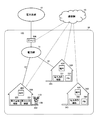
- FIG. 1 schematically illustrates an example of a power system 100.
- the power system 100 illustrated in FIG. 1 acquires an abnormality of a power line provided for the exchange of power installed between a plurality of power consumers in a community such as a Community Energy Management System (CEMS).
- CEMS Community Energy Management System
- the power can be exchanged between the power consumers by the mobile unit transporting the portable power storage device between the power consumers when the abnormality acquiring unit acquires the abnormality of the power lines. It can be done.
- the unmanned aerial vehicle 110 transports a MB (Mobile Battery) 130 between the power demander 310 and the power demander 320 in the CEMS 30 .
- the number of power consumers in the CEMS 30 is not limited to this, and more power consumers may be included in the CEMS 30.
- the unmanned aerial vehicle 110 is, for example, a drone.
- the unmanned aerial vehicle 110 is an example of a moving body.
- the MB 130 is an example of a portable power storage device.
- the CEMS 30 includes a power grid 31, a power demander 310, a power demander 320, a server 200, a station 140, and an unmanned aerial vehicle 110.
- the power grid 31 includes power lines 32 connected to a plurality of power consumers in the CEMS 30.
- the power customer 310 and the power customer 320 can exchange power via the power line 32 of the power network 31.
- Power demander 310 and power demander 320 may be directly connected via power line 32 without power network 31.
- the power demander 310 and the power demander 320 may be so-called low voltage demanders such as general households.
- power demander 310 and power demander 320 may be so-called high-pressure small-lot customers, or may be so-called high-pressure large-lot customers.
- the power consumer 310 has a power consumer 311.
- the power consumption device 311 may be a device that consumes power, such as a home appliance.
- the power consumer 310 may have a fixed power storage device fixed to the power consumer 310 unlike the MB 130.
- the FB (Fixed Battery) 312 illustrated in FIG. 1 is an example of a fixed power storage device.
- the FB 312 supplies power to the power consuming device 311.
- the power customer 310 has a mounting unit 313 on which the MB 130 is detachably mounted.
- the placement unit 313 may be capable of placing only one MB 130. Further, the placement unit 313 may be capable of placing a plurality of MBs 130 thereon.
- the MB 130 is placed on the placement unit 313, the MB 130 and the power consumption device 311 are electrically connected, and the power consumption device 311 can receive power from the MB 130.
- the energization of the MB 130 and the placement unit 313 may be contact-type energization in which the terminal of the MB 130 contacts the terminal of the placement unit 313.
- mounting the MB 130 on the mounting portion 313 in a removable manner may be mounting so that the terminal of the MB 130 and the terminal of the mounting portion 313 are in contact with each other.
- the energization between the MB 130 and the placement unit 313 may be contactless energization.
- mounting the MB 130 on the placement unit 313 in a removable manner may be placing the MB 130 and the placement unit 313 in any arrangement that allows contactless energization.
- the energization between the MB 130 and the placement unit 313 may be non-contact energization.
- placing the MB 130 on the placement unit 313 in a removable manner may be placing the MB 130 and the placement unit 313 in any arrangement that allows non-contact type energization.
- the power consumer 311 may receive power from both the FB 312 and the MB 130 placed on the placement unit 313. In this case, even when the MB 130 is removed from the placement unit 313, the supply of power to the power consuming device 311 is continued by the FB 312.
- the power consumption device 311 may receive power from either the FB 312 or the MB 130 placed on the placement unit 313. For example, when the power consumption device 311 receives power from the MB 130 and the MB 130 is removed from the placement unit 313, the power supply source to the power consumption device 311 may switch from the MB 130 to the FB 312. Thus, the power supply to the power consuming device 311 is continued.
- the power consumer 320 has a power consumer 321, an FB 322, and a receiver 323.
- the power consumer 321 may be similar to the power consumer 311.
- FB 322 may be similar to FB 312.
- the placement unit 323 may be similar to the placement unit 313.
- the power consumer 310 supplies, for example, the power of the FB 312 to the power consumer 320 via the power grid 31. Further, for example, when the MB 130 is placed on the placement unit 313, the power customer 310 supplies the power of the MB 130 to the power customer 320 via the power network 31.
- the power supplied from the power consumer 310 to the power consumer 320 may be supplied to the power consumer 321 and may be stored in the FB 322.
- the server 200 may be connected to the power system 10 as shown in FIG.
- the server 200 may manage the power in the CEMS 30.
- the server 200 may be an example of an aggregation device that aggregates the supply and demand of power among a plurality of power receivers.
- the server 200 is provided by, for example, a power concentrator that aggregates the supply and demand of electricity in the CEMS 30. Power intensive homes are sometimes called aggregators.
- the server 200 includes an abnormality acquisition unit 210 that acquires an abnormality of the power line 32.
- the abnormality of the power line 32 is, for example, a state in which power transmission via the power line 32 can not be performed, or a state in which the transmission loss of power transmission via the power line 32 is higher than usual.
- An abnormality in the power line 32 is, for example, a break in the power line 32.
- the abnormality in the power line 32 is, for example, a defect in the power line 32 such as damage to the power line 32.
- the abnormality acquisition unit 210 detects an abnormality of the power line 32, for example. Further, the abnormality acquisition unit 210, for example, estimates an abnormality of the power line 32.
- the abnormality acquisition unit 210 may acquire an abnormality of the power line 32 using any method. For example, the abnormality acquisition unit 210 acquires an abnormality of the power line 32 with the power customer 310 when it is not possible to exchange power with the power customer 310. In addition, the abnormality acquisition unit 210 may acquire the abnormality of the power line 32 by monitoring the impedance of the power line 32 between the power customer 310 and the abnormality acquisition unit 210.
- the abnormality acquisition unit 210 may obtain the abnormality of the power line 32 from the power consumer 310 or the power consumer 320.
- the abnormality acquiring unit 210 is a terminal that the power customer 310 has, via the communication network 20, information indicating that an abnormality has occurred in the power line 32 installed between the power customer 310 and the power customer 320. It receives from the terminal 420 which 400 or the power demander 320 has.
- Terminal 400 and terminal 420 may be any communication terminal having a communication function.
- the communication network 20 may include at least one of the Internet, a mobile telephone network, and a dedicated network such as a LAN (Local Area Network) in the CEMS 30. Communication between the communication network 20 with the server 200, the terminal 400 of the power customer 310, and the terminal 420 of the power customer 320 may be wired communication or wireless communication.
- a LAN Local Area Network
- the terminal 400 can not supply power to the power customer 320 via the power line 32, and when the terminal 400 can not receive power from the power customer 320 via the power line 32, etc.
- Information indicating that an abnormality has occurred in the power line 32 laid between the home 320 and the home 320 is transmitted to the server 200 via the communication network 20.
- the terminal 420 can not supply power to the power customer 310 via the power line 32, and when the terminal 420 can not receive power from the power customer 310 via the power line 32, etc.
- Information indicating that an abnormality has occurred in the power line 32 laid between the home 320 and the home 320 is transmitted to the server 200 via the communication network 20.
- the unmanned aerial vehicle 110 transports the MB 130 when the anomaly acquiring unit 210 acquires an anomaly of the power line 32.
- the abnormality acquisition unit 210 acquires an abnormality of the power line 32 provided for the exchange of power between the power customer 310 and the power customer 320
- the unmanned aerial vehicle 110 is mounted on the mounting unit 313. Transport the MBs 130 to the placement unit 323.
- the unmanned aerial vehicle 110 supplies power to the power customer 320 by transporting the MB 130 from the mounting unit 313 to the mounting unit 323. can do.
- the MB 130 to the placement unit 323 for example, even when the remaining amount of power stored in the FB 322 is exhausted, power can be supplied to the power consumption device 321. Further, by transporting the MB 130 to the placement unit 323, the maximum storage capacity of the power customer 320 can be expanded.
- Unmanned aerial vehicle 110 may be in communication with server 200.
- the unmanned aerial vehicle 110 and the server 200 communicate, for example, via the communication network 20.
- the server 200 acquires an abnormality of the power line 32 between the power customer 310 and the power customer 320, and causes the unmanned aerial vehicle 110 to leave the MB 130 from the mounting unit 313 when the abnormality is acquired.
- the step of placing the MB 130 on the placement unit 323 on the unmanned aerial vehicle 110 may be executed. For example, when the server 200 acquires an abnormality of the power line 32 between the power consumer 310 and the power consumer 320, the server 200 transmits, to the unmanned aerial vehicle 110, an instruction to withdraw the MB 130 from the mounting unit 313.
- an instruction to place the MB 130 on the mounting unit 323 is transmitted to the unmanned aerial vehicle 110.
- the server 200 acquires an abnormality of the power line 32 between the power customer 310 and the power customer 320
- the server 200 instructs the mounting unit 313 to detach the MB 130 and causes the mounting unit 323 to place the MB 130. May be sent to the unmanned aerial vehicle 110.
- the server 200 transmits the information indicating the transport source of the MB 130 and the information indicating the transport destination of the MB 130 to the unmanned aerial vehicle 110,
- the 110 may carry the MB 130.
- the server 200 causes the unmanned aerial vehicle 110 to detach the MB 130 from the mounting unit 313, and the mounting unit You may have a moving body control part not shown which controls the unmanned aerial vehicle 110 to mount MB130 on H.323.
- the information indicating the transport source of the MB 130 may be any information as long as the position where the MB 130 is placed can be specified.
- the information which shows the conveyance origin of MB130 is information which shows the position where MB130 is mounted.
- the information indicating the transport source of the MB 130 is information for identifying the placement unit on which the MB 130 is placed.
- the unmanned aerial vehicle 110 may associate and store information identifying the mounting unit and information indicating the position of the mounting unit.
- the information indicating the transport source of the MB 130 is information identifying the power consumer on which the MB 130 is mounted.
- the unmanned aerial vehicle 110 may store information identifying a power consumer and information indicating a position of the power consumer in association with each other.
- the information indicating the transport destination of the MB 130 may be any information as long as the position where the MB 130 is to be mounted can be specified.
- the information indicating the transport source of the MB 130 is information identifying a placement unit on which the MB 130 is placed, information identifying a power consumer on which the MB 130 is placed, and the like.
- the unmanned aerial vehicle 110 moves to a position where the MB 130 is mounted according to the information indicating the transport source of the MB 130 received from the server 200, holds the MB 130, and moves the MB 130 according to the information indicating the transport destination of the MB 130. You may When the information indicating the conveyance source indicates the placement unit 313 and the information indicating the conveyance destination indicates the placement unit 323, the unmanned aerial vehicle 110 moves to the placement unit 313 and holds the MB 130, and the placement unit 323 It moves to place the MB 130 on the placement unit 323.
- the unmanned aerial vehicle 110 may have a monitoring unit that monitors the position where the MB 130 is mounted.
- the server 200 may transmit information indicating the transport destination of the MB 130 to the unmanned aerial vehicle 110 without transmitting information indicating the transport source of the MB 130.
- the unmanned aerial vehicle 110 receives the information indicating the transport destination of the MB 130
- the unmanned aerial vehicle 110 moves to the position where the MB 130 monitored by the monitoring unit is placed and holds the MB 130, and the MB 130 according to the information indicating the transport destination of the MB 130 You may move the
- the monitoring unit monitors the MB 130, for example, by analyzing an image captured by an imaging unit of the unmanned aerial vehicle 110.
- the monitoring unit may monitor the position of the MB 130 by periodically receiving the position of the MB 130 from the server 200 or the like.
- the unmanned aerial vehicle 110 may stand by on the MB 130. Also in this case, the server 200 may transmit the information indicating the transport destination of the MB 130 to the unmanned aerial vehicle 110 without transmitting the information indicating the transport source of the MB 130. When the unmanned aerial vehicle 110 receives the information indicating the transport destination of the MB 130, the unmanned aerial vehicle 110 may load the MB 130 on standby and move the MB 130 according to the information indicating the transport destination of the MB 130.
- the unmanned aerial vehicle 110 may thus be waiting on the MB 130.
- the unmanned aerial vehicle 110 may stand by in the vicinity of the placement unit 313 or in the vicinity of the placement unit 323.
- the unmanned aerial vehicle 110 may be on standby at the station 140.
- the station 140 may have a mounting unit on which the unmanned aerial vehicle 110 is mounted.
- Station 140 may be capable of supplying power to mounted unmanned aerial vehicle 110.
- the number of unmanned aerial vehicles 110 in the CEMS 30 may be one or more.
- the terminal 400 may have the abnormality acquisition unit 210.
- the terminal 400 indicates the placement unit 313 as a transport source and the placement unit 323 as a transport destination. May be transmitted to the unmanned aerial vehicle 110 via the communication network 20.
- the terminal 400 may indicate, for example, the placement unit 323 as a transport source, and may transmit information indicating the placement unit 313 as a transport destination to the unmanned aerial vehicle 110 via the communication network 20.
- the terminal 400 acquires an abnormality in the step of acquiring the abnormality of the power line 32 between the power customer 310 and the power customer 320 and the MB 130 is placed on the placement unit 313 Power exchange of the unmanned aerial vehicle 110, and the step of disposing the MB 130 on the mounting unit 323 of the electric power consumer 320 on the unmanned aerial vehicle 110.
- the terminal 400 causes the MB 130 to be detached from the mounting unit 313 when the abnormality acquisition unit 210 and the abnormality acquisition unit 210 acquire an abnormality of the power line 32 between the power customer 310 and the power customer 320, and the terminal 400 is placed. It may have a mobile control unit (not shown) that controls the unmanned aerial vehicle 110 so as to be mounted on the unit 323.
- FIG. 1 exemplifies an example of transporting the MB 130 in the non-connected state where the CEMS 30 is not connected to the power system 10, the MB 130 may be transported in the connected state where the CEMS 30 is connected to the power system 10 .
- FIG. 1 illustrates the case where the CEMS 30 is connected to the power system 10 as an example, the present invention is not limited to this.
- the CEMS 30 may not be connected to the power system 10. That is, the CEMS 30 may be a so-called off grid type CEMS.
- the energy acquiring unit acquires an abnormality of the energy transfer path provided for the exchange of energy installed between a plurality of energy consumers in the community, and the energy or energy
- An energy system may be provided that comprises a portable energy storage device capable of storing a source, and a mobile that autonomously moves among a plurality of energy consumers.
- Examples of energy or energy sources other than power include hydrogen for fuel cells and biofuels for combustion generators. If the subject is hydrogen, the energy transfer path may be a hydrogen pipeline and the portable energy storage device may be a mobile hydrogen tank. If the subject is a biofuel, the energy transfer path may be a biofuel pipeline and the portable energy storage device may be a mobile biofuel tank.
- the server 200 includes a first energy demander having a first placement unit on which a first energy consuming device such as a home appliance and a portable energy storage device can be removably placed, a second energy consuming device and a portable energy Acquiring an abnormality of the energy transfer path between the second energy demander having the second mounting portion on which the storage device is removably mounted, and mounting the portable energy storage device on the first mounting portion And causing the unmanned aerial vehicle 110 to withdraw the portable energy storage device from the first mounting portion when acquiring an abnormality when the vehicle is in an unmanned aerial vehicle 110; And the step of placing an energy transfer method.
- a first energy consuming device such as a home appliance and a portable energy storage device can be removably placed
- a second energy consuming device and a portable energy Acquiring an abnormality of the energy transfer path between the second energy demander having the second mounting portion on which the storage device is removably mounted and mounting the portable energy storage device on the first mounting portion
- the unmanned aerial vehicle 110 to withdraw the portable energy storage device from
- the step of the first energy demander acquiring an abnormality of the energy transfer path between the first energy demander and the second energy demander, and the portable energy at the mounting portion of the first energy demander Causing the unmanned aerial vehicle 110 to withdraw the portable energy storage device from the mounting portion of the first energy consumer when acquiring the abnormality when the storage appliance is mounted; And E. placing the portable energy storage device on the mounting portion of the energy consumer.
- the energy demander It can be made possible to exchange energy between them.
- FIG. 2 schematically illustrates another example of a power system 100.
- the CEMS 30 includes a power grid 31, a power supply house 330, a power demander 320, a server 200, a station 140, and an unmanned aerial vehicle 110.
- the power supplier 330 may include a power generating device 331 that generates power and a power storage device 332 that stores power.
- the power generation device 331 may be any device as long as it can generate power.
- the power generation device 331 is a solar power generation device.
- the power supplier 330 may supply the power generated by the power generation device 331 to the outside.
- the power supplier 330 supplies the power generated by the power generation device 331 to the outside via the power grid 31, for example.
- the power supplier 330 supplies the power generated by the power generation device 331 to the outside via the MB 130, for example.
- the power supplier 330 may supply the power stored in the power storage device 332 to the outside.
- the power supplier 330 supplies the power stored in the power storage device 332 to the outside via the power network 31, for example.
- the power supplier 330 supplies the power stored in the power storage device 332 to the outside via the MB 130, for example.
- the power storage device 332 may store the power supplied from the power grid 10 via the power grid 31.
- the power storage device 332 may also store the power generated by the power generation device 331.
- the power supplier 330 may have only one of the power generation device 331 and the power storage device 332.
- the power supplier 330 may be a general household in the CEMS 30, or may be a power supply facility that supplies power to the power consumers in the CEMS 30.
- the power supplier 330 has a receiver 333.
- the power supplier 330 may store the power generated by the power generation device 331 in the MB 130 placed on the placement unit 333.
- the power supplier 330 may store the power stored in the power storage device 332 in the MB 130 mounted on the mounting unit 333.
- the terminal 400 of the power supplier 330 acquires an abnormality in the step of acquiring an abnormality of the power line 32 between the power supplier 330 and the power customer 320, and when the MB 130 is placed on the placement unit 333. Then, the unmanned aerial vehicle 110 may execute the power transfer method including the steps of: disengaging the MB 130 from the placement unit 333; and placing the MB 130 on the placement unit 323.
- the server 200 acquires an abnormality of the power line 32 between the power supplier 330 and the power customer 320, and causes the unmanned aerial vehicle 110 to withdraw the MB 130 from the mounting unit 313 when the abnormality is acquired. And the step of placing the MB 130 on the placement unit 323 on the unmanned aerial vehicle 110 may be executed.
- FIG. 3 schematically shows another example of the power system 100. As shown in FIG. Here, points different from FIG. 2 will be mainly described.
- the CEMS 30 includes a power consumer 340 in addition to the power supplier 330 and the power consumer 320.
- the power consumer 340 is not connected to the power network 31.
- the power supplier 330 supplies power to either the power consumer 320 or the power consumer 340 via the MB 130.
- the power supplier 330 and the power consumer 340 have exchange information 325 indicating the cost or loss when the power supplier 330 and the power customer 320 exchange power.
- Transfer information 345 indicating the cost or loss in the case of transferring power is obtained.
- the electric power supplier 330 determines an electric power receiver to receive electric power through the MB 130.
- the electric power supplier 330 decides the electric power consumer 340 as an electric power receiver, the unmanned aerial vehicle 110 is dismounted so that the MB 130 is removed from the mounting portion 333 and the MB 130 is mounted on the electric power receiver mounting portion. You may control.
- the terminal 400 of the power supplier 330 receives power via the MB 130 based on the steps of acquiring the exchange information 325, acquiring the exchange information 345, and the exchange information 325 and the exchange information 345. Determining the power demander 340 for the power recipient, disengaging the MB 130 from the mounting unit on which the MB 130 is mounted on the unmanned aerial vehicle 110, and mounting the power demander 340 on the unmanned aerial vehicle 110 And the step of placing the MB 130 on the unit 343 may be performed.
- the terminal 440 of the power customer 340 has its step of providing transfer information 345 to the terminal 400, and the terminal 400 determines itself as the target of receiving power via the MB 130 based on the transfer information 345. And the step of receiving from the unmanned aerial vehicle 110 the MB 130 detached from the mounting unit 333 by the unmanned aerial vehicle 110 may be executed.
- the transfer information 325 may indicate the cost or loss when the power supplier 330 and the power consumer 320 exchange power via the MB 130.
- the transfer information 325 may include received compensation information when the power consumer 320 receives power via the MB 130.
- the transfer information 325 may include the amount of power desired by the power consumer 320.
- the transfer information 325 may include award value information indicating a fee to be received when the power supplier 330 grants the power demander 320 power via the MB 130.
- the transfer information 325 may include an electrical loss when the power supplier 330 gives power to the power consumer 320 via the MB 130.
- the electrical loss may be, for example, the power consumption of the MB 130 required to transport the MB 130 from the power supplier 330 to the power consumer 320.
- the transfer information 325 may include a time loss when the power supplier 330 gives power to the power consumer 320 via the MB 130.
- the loss in time may be, for example, the time required to transport the MB 130 from the power supplier 330 to the power consumer 320.
- the transfer information 325 may include mechanical loss when the power supplier 330 gives power to the power consumer 320 via the MB 130.
- the mechanical loss may be, for example, deterioration of the MB 130 when transporting the MB 130 from the power supplier 330 to the power consumer 320.
- the transfer information 345 may indicate the cost or loss when the power supplier 330 and the power consumer 340 exchange power via the MB 130.
- the transfer information 345 may include received compensation information when the power consumer 340 receives power via the MB 130.
- the transfer information 345 may include the amount of power desired by the power consumer 340.
- the transfer information 325 may include award value information indicating a fee to be received when the power supplier 330 grants the power demander 340 power via the MB 130.
- the exchange information 345 may include an electrical loss when the power supplier 330 gives power to the power consumer 340 via the MB 130.
- the exchange information 325 may include a time loss when the power supplier 330 gives power to the power consumer 340 via the MB 130.
- the transfer information 345 may include mechanical loss when the power supplier 330 gives power to the power consumer 340 via the MB 130.
- the terminal 400 compares, for example, the received consideration information included in the exchange information 325 with the received exchange information included in the exchange information 345, to obtain the monetary profit of the power supplier 330 among the power customer 320 and the power customer 340. Choose the one who receives more as a power recipient. As described above, when the exchange information 325 and the exchange information 345 include the received fee information, the exchange of the power convincing to the power consumer can be established.
- the terminal 400 compares, for example, the payment consideration information included in the delivery information 325 with the payment compensation information included in the delivery information 345, and the money of the power supplier 330 among the power customer 320 and the power customer 340. Select the person who receives the highest profit as a power recipient. As described above, when the exchange information 325 and the exchange information 345 include the award value information, the exchange of the power convincing to the power supplier 330 can be established.
- the terminal 400 compares, for example, the electrical loss included in the transfer information 325 with the electrical loss included in the transfer information 345, to determine the electrical loss among the power consumer 320 and the power consumer 340. Choose the lesser one as the power recipient.
- the terminal 400 compares the temporal loss included in the exchange information 325 with the temporal loss included in the exchange information 345 to determine the temporal loss of the power customer 320 and the power customer 340. Choose the lesser one as the power recipient.
- the terminal 400 compares the mechanical loss included in the exchange information 325 with the mechanical loss included in the exchange information 345 to determine the mechanical loss among the power customer 320 and the power customer 340. Choose the lesser one as the power recipient.
- the terminal 400 takes account of two or more of the received consideration information including the exchange information 325, the received consideration information, the electrical loss, the time loss, and the mechanical loss, and the power demand 320 and the power demand Any of 340 may be selected as a power recipient.
- the transfer information 325 may indicate the cost or loss when the power supplier 330 and the power consumer 320 exchange power via the power network 31.
- the transfer information 325 may include received fee information when the power consumer 320 receives power via the power network 31.
- the transfer information 325 may include the amount of power desired by the power consumer 320.
- the transfer information 325 may include award value information indicating a fee to be received when the power supplier 330 grants power to the power consumer 320 via the power network 31.
- the transfer information 325 may include an electrical loss in the case where the power supplier 330 gives power to the power consumer 320 via the power grid 31.
- the electrical loss may be, for example, a transmission loss or the like when power is transmitted from the power supplier 330 to the power consumer 320 via the power grid 31.
- the transfer information 325 may include a time loss when the power supplier 330 gives power to the power consumer 320 via the power network 31.
- the temporal loss may be, for example, the time required to transmit the amount of electricity from the power supplier 330 to the power consumer 320 via the power grid 31.
- the transfer information 325 may include mechanical loss in the case of providing power from the power supplier 330 to the power consumer 320 via the power grid 31.
- the power supplier 330 receives power demand via the power network 31.
- the power supply house 330 can have an advantageous result.
- the power supplier 330 grants power to the power consumer 340 via the MB 130 rather than the power supplier 330 grants power to the power consumer 320 via the power grid 31 when the amount of power is greater than May be advantageous to the power supplier 330.
- the power supplier 330, the power consumer 320, and the server 200 communicably connected to the power supplier 330 cause the unmanned aerial vehicle 110 to dismount the MB 130 from the mounting unit 333 and mount it. Control may be performed so as to be placed on the placement unit 323 or the placement unit 343.
- the server 200 receives the exchange information 325 from the power customer 320, receives the exchange information 345 from the power customer 340, and receives the electric power via the MB 130 based on the exchange information 325 and the exchange information 345.
- the unmanned aircraft 110 is caused to withdraw the MB 130 mounted on the mounting portion 333 from the mounting portion 333 and the power receiver determined Place it on the placement part of the
- the method of determining the power receiver based on the transfer information 325 and the transfer information 345 may be the same as the method by the terminal 400 described above.
- the server 200 obtains the transfer information 325 and the transfer information 345, determines the power receiver who receives the power via the MB 130 based on the transfer information 325 and the transfer information 345, and When the power consumer 340 is determined as the recipient, the unmanned aircraft 110 is made to withdraw the MB 130 from the mounting portion 333 and the unmanned aircraft 110 is made to place the MB 130 on the pedestal of the power receiver. Power transfer methods may be implemented.
- the example described in FIG. 3 may be directed to energy or energy sources other than power. That is, the power supplier 330 can attach and detach the energy generating device capable of storing the energy or the energy source and / or the energy storage device generating the energy or the energy source and / or the energy storage device storing the energy or the energy source And an electricity supplier having the mounting unit mounted on the first power demand, and the power demander 320 is the first energy demand having the mounting unit on which the portable energy storage device is detachably mounted and the energy consuming device that consumes energy
- a power consumer 340 is a second energy consumer having a mounting portion on which a portable energy storage device is detachably mounted and an energy consuming device, a power grid 31 is an energy transfer path, and an MB 130 is a portable energy It may be a storage device.
- the portable energy storage device Determining as an energy receiver to receive an energy or energy source via the and, when determining the energy receiver, causing the unmanned aerial vehicle 110 to withdraw the portable energy storage device from the mounting of the energy supplier, Placing the portable energy storage device on the mounting portion of the energy recipient; and There.
- the energy supplier obtains, from the first energy consumer, the first transfer information including information on the cost or loss when the first energy consumer transfers energy or an energy source, and the second energy demand.
- the second energy demander is a step of providing the first delivery information to the energy supplier or the server 200, and an object to receive the energy or the energy source through the portable energy storage device based on the first delivery information.
- the energy transfer method may be performed including the step of receiving from the unmanned aerial vehicle 110 the portable energy storage device detached from the mounting part of the energy supplier by the unmanned aerial vehicle 110.
- the first transfer information may include received compensation information when the first energy consumer receives the energy or energy source via the portable energy storage device.
- the first transfer information may include the amount of energy or energy source desired by the first energy consumer.
- the first transfer information may include payment consideration information indicating a charge to be received when the energy supplier grants the energy or energy source to the first energy consumer via the portable energy storage device.
- the first transfer information may include a time loss when giving energy or energy source from the energy supplier to the first energy consumer via the portable energy storage device.
- the first transfer information may include mechanical losses in the case of providing the energy or energy source from the energy supplier to the first energy consumer via the portable energy storage device.
- the second transfer information may include received compensation information when the second energy consumer receives the energy or energy source via the portable energy storage device.
- the second transfer information may include the amount of energy or energy source desired by the second energy consumer.
- the second transfer information may include payment consideration information indicating a charge to be received when the energy supplier grants the energy or energy source to the second energy consumer via the portable energy storage device.
- the second transfer information may include a time loss when giving energy or energy source from the energy supplier to the second energy consumer via the portable energy storage device.
- the second transfer information may include mechanical losses in the case of providing the energy or energy source from the energy supplier to the first energy consumer via the portable energy storage device.
- FIG. 4 schematically shows another example of the power system 100. As shown in FIG. Here, points different from FIG. 3 will be mainly described.
- the unmanned aerial vehicle 110 also transports the power customer 370 in the CEMS 36 different from the CEMS 30.
- the CEMS 36 includes an aggregator 500, a power network 37, a power supplier 360, a power consumer 350, and a power consumer 370.
- the power supplier 360 and the power customer 350 are connected to the power network 37, and the power customer 370 is not connected to the power network 37.
- the server 200 receives, for example, transfer information from the power supplier 330 to the power consumer 340 via the MB 130 from the power consumer 340 via the communication network 20 (not shown), and via the MB 130 Transfer information from the power supplier 330 to the power customer 370 is received from the power customer 370 via the communication network 20 (not shown), and the power customer 340 or the power is received based on the received information.
- the unmanned aerial vehicle 110 is made to withdraw MB130 from the mounting part of the power supplier 330, and the power customer 370 is mounted. Place it on the table.
- the power supplier 330 receives, for example, transfer information from the power supplier 330 to the power consumer 340 via the MB 130 from the power consumer 340 via the communication network 20 (not shown).
- Information on transmission and reception of power from the power supplier 330 to the power customer 370 via the MB 130 is received from the power customer 370 via the communication network 20 (not shown), and power demand is obtained based on the received information.
- the unmanned aircraft 110 causes the MB 130 to be removed from the mounting portion of the power supplier 330 and the power demand is selected. It is placed on the placement unit of the house 370.
- FIG. 5 schematically illustrates an example of a functional configuration of the server 200.
- the server 200 illustrated in FIG. 5 includes an information acquisition unit 222, a receiver determination unit 224, and a mobile control unit 226.
- the information acquisition unit 222 acquires the transfer information 325.
- the information acquisition unit 222 may receive the exchange information 325 from the power customer 320. Further, the information acquisition unit 222 may receive the transfer information 325 from the power supplier 330.
- the information acquisition unit 222 acquires the exchange information 345.
- the information acquisition unit 222 may receive the transfer information 345 from the power customer 340.
- the information acquisition unit 222 may receive the transfer information 345 from the power supplier 330.
- the information acquisition unit 222 may acquire delivery information including information on cost or loss in the case of delivering and receiving power between the power supplier 330 and the power consumer 370.
- the information acquisition unit 222 receives, for example, the transfer information from the power customer 370.
- the receiver determination unit 224 determines a power receiver to receive power via the MB 130.
- the receiver determination unit 224 determines the power customer 320 or the power customer 340 as a power receiver, for example, based on the transfer information 325 and the transfer information 345.
- the mobile control unit 226 controls the unmanned aerial vehicle 110.
- the mobile control unit 226 may control the unmanned aerial vehicle 110 to cause the unmanned aerial vehicle 110 to carry the MB 130.
- the mobile object control unit 226 causes the unmanned aerial vehicle 110 to separate the MB 130 from the mounting unit 333 and causes the mounting unit 343 to be selected when the power receiving unit 340 is determined as the power receiving unit by the receiver determining unit 224. Place the MB130.
- FIG. 5 has been described by taking the case of power as an example, the server 200 may target energy or energy sources other than power.
- FIG. 6 schematically illustrates an example of a functional configuration of the terminal 400.
- the terminal 400 illustrated in FIG. 6 includes an exchange information acquisition unit 402, a receiver determination unit 404, and a mobile control unit 406.
- the exchange information acquisition unit 402 acquires exchange information.
- the exchange information acquisition unit 402 may acquire the exchange information 325.
- the exchange information acquisition unit 402 receives the exchange information 325 from the power customer 320, for example.
- the exchange information acquisition unit 402 may acquire the exchange information 345.
- the exchange information acquisition unit 402 receives the exchange information 345 from the power customer 340, for example.
- the exchange information acquisition unit 402 may acquire exchange information including information on the cost or loss in the case of exchanging electric power between the electric power supplier 330 and the electric power consumer 370.
- the exchange information acquisition unit 402 receives, for example, the exchange information from the power customer 370.
- the receiver determination unit 404 determines a power receiver who receives power via the MB 130 based on the transfer information acquired by the information acquisition unit 222.
- the receiver determination unit 404 determines the power customer 320 or the power customer 340 as a power receiver, for example, based on the transfer information 325 and the transfer information 345.
- the mobile control unit 406 controls the unmanned aerial vehicle 110.
- the mobile control unit 406 may control the unmanned aerial vehicle 110 to transport the MB 130 to the unmanned aerial vehicle 110.
- the mobile object control unit 406 causes the unmanned aircraft 110 to separate the MB 130 from the mounting unit 333 and causes the mounting unit 343 to be selected when the power receiving unit 340 is determined to be a power receiving unit by the receiver determining unit 224. Place the MB130.
- FIG. 6 has been described by taking the case of power as an example, the terminal 400 may target energy or energy sources other than power.
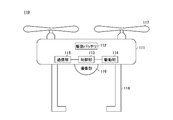
- FIG. 7 schematically illustrates an example of a functional configuration of the unmanned aerial vehicle 110.
- the unmanned aerial vehicle 110 illustrated in FIG. 7 includes a main body 111, a drive battery 112, a control unit 113, a drive unit 114, a communication unit 115, an imaging unit 116, a propeller 117, and a holding arm 118.
- the control unit 113 controls each unit.
- the drive unit 114 drives the propeller 117 according to the control of the control unit 113.
- the communication unit 115 executes communication via the communication network 20 and the like.
- the imaging unit 116 images the periphery of the unmanned aerial vehicle 110.
- the holding arm 118 holds the MB 130.
- the drive battery 112 and the MB 130 may be electrically connected.
- the UAV 110 may charge the drive battery 112 with the power of the MB 130 while the holding arm 118 holds the MB 130. Also, the UAV 110 may charge the MB 130 with the power of the drive battery 112 while the holding arm 118 holds the MB 130.
- the unmanned aircraft 110 when the power customer 320 is determined as a power receiver by the server 200 or the terminal 400 based on the transfer information 325 and the transfer information 345, the unmanned aircraft 110 causes the MB 130 to leave the mounting unit 333. The sheet is placed on the placement unit 323.
- the unmanned aerial vehicle 110 removes the MB 130 from the mounting unit 333 and places the MB 130 on the mounting unit 323. You may
- the unmanned aerial vehicle 110 was mentioned and demonstrated as an example of a mobile body in the said embodiment, it is not restricted to this. It may be other than the unmanned aerial vehicle 110 as long as it can carry the MB 130 and move autonomously.
- an autonomous car such as an automatic ATV (All Terrain Vehicle) may be used.
- the loading of the MB 130 by the mobile includes any form in which the mobile can carry the MB 130.
- to load the MB 130 by the mobile includes holding the MB 130 by the mobile.
- loading the MB 130 by the mobile includes loading the MB 130 on the mobile.
- the loading of the MB 130 by the mobile includes placing the MB 130 on the top when the mobile has a top.
- the MB 130 is described as an example of the portable power storage device, but the present invention is not limited to this.
- the portable power storage device may be a battery mounted on a mobile and moving with the mobile.
- the portable power storage device is a battery mounted in the vehicle and moving with the vehicle.
- the portable power storage device may be a battery that is always mounted on the autonomous vehicle and drives the autonomous vehicle.
- FIG. 8 schematically illustrates an example of a computer 1000 functioning as the server 200 or the terminal 400.
- a computer 1000 includes a CPU peripheral unit having a CPU 1010, a RAM 1030, and a graphic controller 1085 mutually connected by a host controller 1092, a ROM 1020 connected to a host controller 1092 by an input / output controller 1094, and a communication I / O. It comprises an input / output unit having an F 1040, a hard disk drive 1050, a DVD drive 1070 and an input / output chip 1080.
- the CPU 1010 operates based on programs stored in the ROM 1020 and the RAM 1030 to control each part.
- the graphic controller 1085 acquires image data generated by the CPU 1010 or the like on a frame buffer provided in the RAM 1030 and causes the display 1090 to display the image data.
- the graphic controller 1085 may internally include a frame buffer that stores image data generated by the CPU 1010 or the like.
- the communication I / F 1040 communicates with other devices via a network by wire or wirelessly.
- the communication I / F 1040 also functions as hardware for performing communication.
- the hard disk drive 1050 stores programs and data used by the CPU 1010.
- the DVD drive 1070 reads a program or data from the DVD-ROM 1072 and provides it to the hard disk drive 1050 through the RAM 1030.
- the ROM 1020 stores a boot program executed when the computer 1000 starts up, a program depending on the hardware of the computer 1000, and the like.
- the input / output chip 1080 connects various input / output devices to the input / output controller 1094 via, for example, a parallel port, a serial port, a keyboard port, a mouse port and the like.
- the program provided to the hard disk drive 1050 via the RAM 1030 is stored in a recording medium such as the DVD-ROM 1072 or an IC card and provided by the user.
- the program is read from the recording medium, installed in the hard disk drive 1050 via the RAM 1030, and executed by the CPU 1010.
- a program installed in the computer 1000 and causing the computer 1000 to function as the server 200 may operate the CPU 1010 or the like to cause the computer 1000 to function as each part of the server 200.
- the information processing described in these programs functions as an abnormality acquisition unit and a mobile control unit, which are specific means in which software and the various hardware resources described above cooperated by being read into the computer 1000. Do. Also, the information processing described in these programs is read by the computer 1000, and the information acquisition unit 222, which is a specific means in which software and the various hardware resources described above cooperated, receiver determination It functions as the unit 224 and the mobile control unit 226. Then, by realizing calculation or processing of information according to the purpose of use of the computer 1000 in this embodiment by these specific means, a unique server 200 according to the purpose of use is constructed.
- a program installed in the computer 1000 and causing the computer 1000 to function as the terminal 400 may operate on the CPU 1010 or the like to cause the computer 1000 to function as each part of the terminal 400.
- the information processing described in these programs functions as an abnormality acquisition unit and a mobile control unit, which are specific means in which software and the various hardware resources described above cooperated by being read into the computer 1000. Do. Also, the information processing described in these programs is read and executed by the computer 1000, and the transfer information acquisition unit 402, which is a specific means in which the software and the various hardware resources described above cooperate, and the receiver It functions as the determination unit 404 and the mobile control unit 406. Then, by realizing calculation or processing of information according to the purpose of use of the computer 1000 in this embodiment by these specific means, a specific terminal 400 according to the purpose of use is constructed.
- SYMBOLS 10 electric power system, 20 communication network, 31 electric power network, 32 electric power line, 37 electric power network, 100 electric power system, 110 unmanned aerial vehicle, 111 main body, 112 drive battery, 113 control part, 114 drive part, 115 communication part, 116 imaging part, 117 propeller , 118 holding arm, 130 MB, 140 station, 200 server, 222 information acquisition unit, 224 receiver determination unit, 226 mobile unit control unit, 310 power demander, 311 power consumption device, 312 FB, 313 placement unit, 320 Power consumer, 321 power consumption equipment, 322 FB, 323 mounting unit, 325 transfer information, 330 power supply provider, 331 power generation device, 332 power storage device, 333 mounting unit, 340 power customer, 343 mounting unit , 345 Transfer information, 3 0 Power consumer, 360 power supplier, 370 power consumer, 400 terminal, 402 transfer information acquisition unit, 404 receiver determination unit, 406 mobile control unit, 420 terminal, 440 terminal, 500 aggregator, 1000 computer, 10
Abstract
Provided is an energy system provided with: a first mounting unit whereon transportable energy storage equipment that can store energy or an energy source is detachably mounted; a second mounting unit whereon transportable energy storage equipment is detachably mounted; an abnormality acquisition unit for acquiring abnormalities in energy delivery path used for exchanges of energy established between a first energy consumer having the first mounting unit and first energy consuming equipment and a second energy consumer having a second mounting unit and second energy consuming equipment; and a mobile body that removes the transportable energy storage equipment from the first mounting unit, and takes up the transportable energy storage equipment and moves autonomously so as to mount the transportable energy storage equipment on the second mounting unit.
Description
本発明は、電力システム、エネルギーシステム、エネルギー授受方法、プログラム、端末、及び移動体に関する。
The present invention relates to a power system, an energy system, an energy transfer method, a program, a terminal, and a mobile body.
電力需要家間での送電又は受電を制御する電力需給調整システムが知られていた(例えば、特許文献1参照)。
[先行技術文献]
[特許文献]
[特許文献1]特開2003-324850号公報 There has been known a power supply and demand adjustment system for controlling power transmission and reception among power consumers (see, for example, Patent Document 1).
[Prior art document]
[Patent Document]
[Patent Document 1] Japanese Patent Application Publication No. 2003-324850
電力等のエネルギーの授受を適切に行える技術を提供することが望ましい。
It is desirable to provide a technology that can properly transfer energy such as power.
本発明の第1の態様によれば、電力システムが提供される。電力システムは、電力を蓄積可能な可搬電力蓄積機器を着脱可能に載置する第1載置部を備えてよい。電力システムは、可搬電力蓄積機器を着脱可能に載置する第2載置部を備えてよい。電力システムは、第1載置部及び電力を消費する第1電力消費機器を有する第1の電力需要家と、第2載置部及び第2電力消費機器を有する第2電力需要家との間に敷設された電力の授受に供される電力線の異常を取得する異常取得部を備えてよい。電力システムは、第1載置部に可搬電力蓄積機器が載置されている場合に異常取得部が異常を取得したときに、第1載置部から可搬電力蓄積機器を離脱させ、第2載置部へ該可搬電力蓄積機器を載置するよう該可搬電力蓄積機器を積載し自律的に移動する移動体を備えてよい。
According to a first aspect of the invention, a power system is provided. The power system may include a first mounting portion on which the portable power storage device capable of storing power is removably mounted. The power system may include a second mounting portion on which the portable power storage device is removably mounted. The power system comprises a first power consumer having a first receiver and a first power consumer consuming power, and a second power consumer having a second receiver and a second power consumer. An abnormality acquisition unit may be provided for acquiring an abnormality of the power line provided for the exchange of the power laid on the ground. When the power acquisition system acquires an abnormality when the portable power storage device is mounted on the first mounting portion, the power system causes the portable power storage device to be detached from the first mounting portion, and (2) The mobile power storage device may be mounted on the mounting portion so as to load the mobile power storage device, and the mobile body may autonomously move.
上記第1電力需要家は、上記可搬電力蓄積機器とは異なり上記第1電力需要家に固定される固定電力蓄積機器を有してよい。上記移動体は、上記電力システムが電力系統に接続されない非接続状態において、上記可搬電力蓄積機器を積載し移動してよい。
The first power consumer may have a fixed power storage device fixed to the first power consumer unlike the portable power storage device. The mobile unit may load and move the portable power storage device in a non-connected state where the power system is not connected to a power system.
本発明の第2の態様によれば、電力システムが提供される。電力システムは、電力を蓄積可能な可搬電力蓄積機器を着脱可能に載置する第1載置部を備えてよい。電力システムは、可搬電力蓄積機器を着脱可能に載置する第2載置部を備えてよい。電力システムは、第1載置部及び電力を発生する電力発生機器を有する電力供給家と、第2載置部及び電力を消費する電力消費機器を有する電力需要家との間に敷設された電力の授受に供される電力線の異常を取得する異常取得部を備えてよい。電力システムは、異常取得部が異常を取得したときに、第1載置部から可搬電力蓄積機器を離脱させ、第2載置部へ該可搬電力蓄積機器を載置するよう該可搬電力蓄積機器を積載し自律的に移動する移動体を備えてよい。
According to a second aspect of the invention, a power system is provided. The power system may include a first mounting portion on which the portable power storage device capable of storing power is removably mounted. The power system may include a second mounting portion on which the portable power storage device is removably mounted. The power system includes power installed between a power supplier having a first receiver and a power generator that generates power, and a power consumer having a second receiver and a power consumer that consumes power. And an abnormality acquisition unit for acquiring an abnormality of the power line provided for the exchange of The power system is configured to cause the portable power storage device to be detached from the first mounting portion and to place the portable power storage device on the second mounting portion when the abnormality acquisition unit acquires an abnormality. The mobile storage device may be provided with a mobile unit that carries the power storage device and moves autonomously.
本発明の第3の態様によれば、エネルギーシステムが提供される。エネルギーシステムは、エネルギー又はエネルギー源を蓄積可能な可搬エネルギー蓄積機器を着脱可能に載置する第1載置部を備えてよい。エネルギーシステムは、可搬エネルギー蓄積機器を着脱可能に載置する第2載置部を備えてよい。エネルギーシステムは、第1載置部及びエネルギーを消費する第1エネルギー消費機器を有する第1エネルギー需要家と、第2載置部及び第2エネルギー消費機器を有する第2エネルギー需要家との間に敷設されたエネルギーの授受に供されるエネルギー搬路の異常を取得する異常取得部を備えてよい。エネルギーシステムは、第1載置部に可搬エネルギー蓄積機器が載置されている場合に異常取得部が異常を取得したときに、第1載置部から可搬エネルギー蓄積機器を離脱させ、第2載置部へ該可搬エネルギー蓄積機器を載置するよう該可搬エネルギー蓄積機器を積載し自律的に移動する移動体を備えてよい。
According to a third aspect of the invention, an energy system is provided. The energy system may comprise a first mount on which a portable energy storage device capable of storing energy or an energy source is removably mounted. The energy system may comprise a second receiver on which the portable energy storage device is removably mounted. The energy system comprises a first energy consumer having a first load and a first energy consumer consuming energy, and a second energy consumer having a second load and a second energy consumer. You may provide the abnormality acquisition part which acquires the abnormality of the energy carrying path provided to transfer of the installed energy. The energy system causes the portable energy storage device to be detached from the first mounting portion when the abnormality acquiring unit acquires an abnormality when the portable energy storage device is mounted on the first mounting portion, and The mobile energy storage device may be mounted on the mounting portion so that the mobile energy storage device can be mounted on the mounting portion and the mobile body can move autonomously.
本発明の第4の態様によれば、エネルギー授受方法が提供される。エネルギー授受方法は、エネルギー又はエネルギー源を蓄積可能な可搬エネルギー蓄積機器を着脱可能に載置する第1載置部及びエネルギーを消費する第1エネルギー消費機器を有する第1エネルギー需要家と、可搬エネルギー蓄積機器を着脱可能に載置する第2載置部及び第2エネルギー消費機器を有する第2エネルギー需要家との間に敷設されたエネルギーの授受に供されるエネルギー搬路の異常を取得するステップを備えてよい。エネルギー授受方法は、第1載置部に可搬エネルギー蓄積機器が載置されている場合に異常が取得されたときに、可搬エネルギー蓄積機器を積載し自律的に移動する移動体に、第1載置部から可搬エネルギー蓄積機器を離脱させるステップと、移動体に、第2載置部へ該可搬エネルギー蓄積機器を載置させるステップを備えてよい。
According to a fourth aspect of the present invention, an energy transfer method is provided. The energy transfer method comprises: a first energy demander having a first mounting portion for detachably mounting a portable energy storage device capable of storing energy or an energy source, and a first energy consuming device for consuming energy; Acquires an abnormality in the energy transfer path provided for the exchange of energy installed between the second energy demander having the second placement unit for detachably mounting the portable energy storage device and the second energy consuming device And the step of The energy transfer method is a method for moving a portable energy storage device loaded and autonomously moved when an abnormality is acquired when the portable energy storage device is placed on the first placement unit. The method may include the steps of: (1) detaching the portable energy storage device from the mounting portion; and (ii) mounting the portable energy storage device on the second mounting portion on the movable body.
本発明の第5の態様によれば、コンピュータに上記エネルギー授受方法を実行させるためのプログラムが提供されてよい。
According to a fifth aspect of the present invention, there may be provided a program for causing a computer to execute the energy transfer method.
本発明の第6の態様によれば、電力システムが提供される。電力システムは、電力を蓄積可能な可搬電力蓄積機器を着脱可能に載置する第1載置部を備えてよい。電力システムは、可搬電力蓄積機器を着脱可能に載置する第2載置部を備えてよい。電力システムは、可搬電力蓄積機器を着脱可能に載置する第3載置部を備えてよい。電力システムは、第1載置部及び電力を消費する第1電力消費機器を有する第1電力需要家と、第2載置部及び第2電力消費機器を有する第2電力需要家と通信可能に接続され、電力の需給を集約する集約装置、及び移動体を備えてよい。集約装置は、電力供給家と第1電力需要家とが電力を授受する場合の費用又は損失の情報を含む第1授受情報と、電力供給家と第2電力需要家とが電力を授受する場合の費用又は損失の情報を含む第2授受情報とを取得する情報取得部を有してよい。集約装置は、情報取得部が取得した第1授受情報及び第2授受情報に基づいて、可搬電力蓄積機器を介して電力を受領する電力受領家を決定する受領家決定部を有してよい。移動体は、受領家決定部が第2電力需要家を電力受領家として決定したときに、第3載置部から可搬電力蓄積機器を離脱させ、第2載置部に該可搬電力蓄積機器を載置するよう該可搬電力蓄積機器を積載し自律的に移動してよい。
According to a sixth aspect of the invention, a power system is provided. The power system may include a first mounting portion on which the portable power storage device capable of storing power is removably mounted. The power system may include a second mounting portion on which the portable power storage device is removably mounted. The power system may include a third mounting portion on which the portable power storage device is removably mounted. The power system is communicable with a first power consumer having a first receiver and a first power consumer that consumes power, and a second power consumer having a second receiver and a second power consumer. It may be connected and it may be provided with an aggregation device which aggregates the demand and supply of electric power, and a mobile. The aggregation device is configured to transmit and receive electric power between the electric power supplier and the second electric power consumer, and the first exchange information including information on the cost or loss when the electric power supplier and the electric power consumer exchange electric power. And an information acquisition unit that acquires information on second exchange information including information on cost or loss. The aggregation device may have a receiver determination unit that determines a power receiver to receive power via the portable power storage device based on the first transfer information and the second transfer information acquired by the information acquisition unit. . When the receiver determination unit determines the second power consumer as the power receiver, the mobile object detaches the portable power storage device from the third mounting unit, and stores the portable power storage unit in the second mounting unit. The portable power storage device may be loaded and moved autonomously to place the device.
上記電力システムにおいて、上記第1授受情報は、上記電力供給家と上記第1電力需要家とが上記可搬電力蓄積機器を介して電力を授受する場合の費用又は損失の情報を含んでよく、上記第2授受情報は、上記電力供給家と上記第2電力需要家とが上記可搬電力蓄積機器を介して電力を授受する場合の費用又は損失の情報を含んでよい。上記第1授受情報は、上記第1電力需要家が電力を受領する場合に支払う対価である第1受領対価情報を含んでよく、上記第2授受情報は、上記第2電力需要家が電力を受領する場合に支払う対価である第2受領対価情報を含んでよい。上記第1授受情報及び上記第2授受情報は、上記電力供給家が電力を授与する場合に受ける対価である授与対価情報を含んでよい。
In the power system, the first transfer information may include information on cost or loss when the power supplier and the first power consumer exchange power via the portable power storage device, The second transfer information may include information on cost or loss when the power supplier and the second power consumer exchange power via the portable power storage device. The first transfer information may include first received consideration information which is a price to be paid when the first power customer receives power, and the second transfer information may include power of the second power customer. It may include second received consideration information which is a consideration to be paid when it is received. The first transfer information and the second transfer information may include awarding payment information which is a compensation to be received by the power supplier when awarding power.
本発明の第7の態様によれば、エネルギーシステムが提供される。エネルギーシステムは、エネルギー又はエネルギー源を蓄積可能な可搬エネルギー蓄積機器を着脱可能に載置する第1載置部を備えてよい。エネルギーシステムは、可搬エネルギー蓄積機器を着脱可能に載置する第2載置部を備えてよい。エネルギーシステムは、可搬エネルギー蓄積機器を着脱可能に載置する第3載置部を備えてよい。エネルギーシステムは、第1載置部及びエネルギーを消費する第1エネルギー消費機器を有する第1エネルギー需要家と、第2載置部及び第2エネルギー消費機器を有する第2エネルギー需要家と、エネルギー又はエネルギー源を発生するエネルギー発生機器及びエネルギー又はエネルギー源を蓄積するエネルギー蓄積機器の少なくともいずれかと、第3載置部とを有するエネルギー供給家と通信可能に接続され、エネルギーの需給を集約する集約装置、及び移動体を備えてよい。集約装置は、エネルギー供給家と第1エネルギー需要家とがエネルギーを授受する場合の費用又は損失の情報を含む第1授受情報と、エネルギー供給家と第2エネルギー需要家とがエネルギー又はエネルギー源を授受する場合の費用又は損失の情報を含む第2授受情報とを取得する情報取得部を有してよい。集約装置は、情報取得部が取得した第1授受情報及び第2授受情報に基づいて、可搬エネルギー蓄積機器を介してエネルギー又はエネルギー源を受領するエネルギー受領家を決定する受領家決定部を有してよい。移動体は、受領家決定部が第2エネルギー需要家をエネルギー受領家として決定したときに、第3載置部から可搬エネルギー蓄積機器を離脱させ、第2載置部に該可搬エネルギー蓄積機器を載置するよう該可搬エネルギー蓄積機器を積載し自律的に移動してよい。
According to a seventh aspect of the invention, an energy system is provided. The energy system may comprise a first mount on which a portable energy storage device capable of storing energy or an energy source is removably mounted. The energy system may comprise a second receiver on which the portable energy storage device is removably mounted. The energy system may comprise a third receiver on which the portable energy storage device is removably mounted. The energy system comprises: a first energy consumer having a first receiver and a first energy consumer consuming energy; a second energy consumer having a second receiver and a second energy consumer; An aggregating apparatus communicably connected to an energy supplier having at least one of an energy generating device for generating an energy source and an energy storage device for storing an energy or energy source and aggregating the supply and demand of energy And a mobile. The aggregation device is configured such that the first exchange information including information on cost or loss when the energy supplier and the first energy consumer exchange energy, and the energy supplier and the second energy consumer use the energy or the energy source. It may have an information acquisition part which acquires the 2nd exchange information including the information on cost or loss in the case of exchange. The aggregation device has a receiver determination unit that determines an energy receiver who receives an energy or an energy source via the portable energy storage device based on the first transfer information and the second transfer information acquired by the information acquisition unit. You may When the receiver determination unit determines the second energy consumer as the energy receiver, the mobile object causes the portable energy storage device to be detached from the third mounting unit, and the portable energy storage unit is stored in the second mounting unit. The portable energy storage device may be loaded and moved autonomously to place the device.
本発明の第8の態様によれば、エネルギー授受方法が提供される。エネルギー授受方法は、エネルギー又はエネルギー源を蓄積可能な可搬エネルギー蓄積機器を着脱可能に載置する第1載置部及びエネルギーを消費する第1エネルギー消費機器を有する第1エネルギー需要家とエネルギー又はエネルギー源を発生するエネルギー発生機器及びエネルギー又はエネルギー源を蓄積するエネルギー蓄積機器の少なくともいずれかと、可搬エネルギー蓄積機器を着脱可能に載置する第3載置部とを有するエネルギー供給家とがエネルギー又はエネルギー源を授受する場合の費用又は損失の情報を含む第1授受情報と、可搬エネルギー蓄積機器を着脱可能に載置する第2載置部及び第2エネルギー消費機器を有する第2エネルギー需要家とエネルギー供給家とがエネルギー又はエネルギー源を授受する場合の費用又は損失の情報を含む第2授受情報とを取得するステップを備えてよい。エネルギー授受方法は、第1授受情報及び第2授受情報に基づいて、可搬エネルギー蓄積機器を介してエネルギー又はエネルギー源を受領するエネルギー受領家を決定するステップを備えてよい。エネルギー授受方法は、第2エネルギー需要家をエネルギー受領家として決定したときに、可搬エネルギー蓄積機器を積載し自律的に移動する移動体に、第3載置部から可搬エネルギー蓄積機器を離脱させるステップと、移動体に、第2載置部に該可搬エネルギー蓄積機器を載置させるステップを備えてよい。
According to an eighth aspect of the present invention there is provided an energy transfer method. The energy transfer method comprises: a first energy demander and an energy or a first energy consumer having a first mounting portion on which a portable energy storage device capable of storing energy or an energy source can be removably mounted and a first energy consuming device consuming energy; An energy supplier comprising at least one of an energy generating device for generating an energy source and an energy storage device for storing an energy or energy source, and a third mounting portion for removably mounting a portable energy storage device Or the second energy demand having the first receiving information including the information of the cost or the loss when transferring the energy source, the second mounting portion for detachably mounting the portable energy storage device, and the second energy consuming device Cost when house and energy supplier exchange energy or energy source or It may comprise a step of obtaining a second transfer information including information loss. The energy delivery method may comprise determining an energy recipient receiving the energy or energy source via the portable energy storage device based on the first delivery information and the second delivery information. In the energy transfer method, when the second energy demander is determined as the energy receiver, the portable energy storage device is detached from the third mounting portion on a mobile body that carries the portable energy storage device and moves autonomously. And moving the portable energy storage device on the second mounting unit.
本発明の第9の態様によれば、コンピュータに、上記エネルギー授受方法を実行させるためのプログラムが提供される。
According to a ninth aspect of the present invention, there is provided a program for causing a computer to execute the energy transfer method.
本発明の第10の態様によれば、サーバが提供される。サーバは、エネルギー又はエネルギー源を蓄積可能な可搬エネルギー蓄積機器を着脱可能に載置する第1載置部及びエネルギーを消費する第1エネルギー消費機器を有する第1エネルギー需要家とエネルギー又はエネルギー源を発生するエネルギー発生機器及びエネルギー又はエネルギー源を蓄積するエネルギー蓄積機器の少なくともいずれかと、可搬エネルギー蓄積機器を着脱可能に載置する第3載置部とを有するエネルギー供給家とがエネルギー又はエネルギー源を授受する場合の費用又は損失の情報を含む第1授受情報と、可搬エネルギー蓄積機器を着脱可能に載置する第2載置部及び第2エネルギー消費機器を有する第2エネルギー需要家とがエネルギー又はエネルギー源を授受する場合の費用又は損失の情報を含む第2授受情報とを取得する情報取得部を備えてよい。サーバは、第1授受情報及び第2授受情報に基づいて、可搬エネルギー蓄積機器を介してエネルギー又はエネルギー源を受領するエネルギー受領家を決定する受領家決定部を備えてよい。サーバは、第2エネルギー需要家をエネルギー受領家として決定したときに、可搬エネルギー蓄積機器を積載し自律的に移動する移動体に、第3載置部から可搬エネルギー蓄積機器を離脱させ、第2載置部に該可搬エネルギー蓄積機器を載置させる移動体制御部を備えてよい。
According to a tenth aspect of the present invention, a server is provided. The server comprises: a first energy consumer and an energy or energy source comprising a first station on which a portable energy storage device capable of storing energy or an energy source is removably mounted and a first energy consuming device consuming energy An energy supplier having at least one of an energy generating device for generating energy and an energy storage device for storing energy or an energy source, and a third mounting portion on which the portable energy storage device is detachably mounted A second energy demander having a first receiving information including information on cost or loss when receiving a source, a second placement unit on which the portable energy storage device is detachably mounted, and a second energy consuming device A second exchange of information including information on costs or losses in the case of exchange of energy or an energy source It may comprise an information acquisition unit that acquires. The server may include a receiver determination unit that determines an energy receiver to receive the energy or energy source via the portable energy storage device based on the first transfer information and the second transfer information. When the server determines the second energy consumer as the energy receiver, the server causes the mobile energy carrying the portable energy storage device to autonomously move away from the third mounting unit, A mobile control unit may be provided to place the portable energy storage device on the second placement unit.
本発明の第11の態様によれば、エネルギー授受方法が提供される。エネルギー授受方法は、エネルギー若しくはエネルギー源を発生するエネルギー発生機器及びエネルギー若しくはエネルギー源を蓄積するエネルギー蓄積機器の少なくともいずれかと、エネルギー若しくはエネルギー源を蓄積可能な可搬エネルギー蓄積機器を着脱可能に載置する載置部とを有するエネルギー供給家、又は、エネルギー若しくはエネルギー源の需給を集約するエネルギー集約家に、エネルギー又はエネルギー源を授受する場合の費用又は損失の情報を含む授受情報を提供するステップを備えてよい。エネルギー授受方法は、授受情報に基づいて可搬エネルギー蓄積機器を介してエネルギー又はエネルギー源を受領する対象として決定されたことに応じて、可搬エネルギー蓄積機器を積載し自律的に移動する移動体によってエネルギー供給家の載置部から離脱された可搬エネルギー蓄積機器を、移動体から受け付けるステップを備えてよい。
According to an eleventh aspect of the present invention there is provided an energy transfer method. The energy transfer method detachably mounts at least one of an energy generating device generating energy or an energy source and an energy storage device storing energy or an energy source, and a portable energy storage device capable of storing energy or an energy source Providing transfer information including information on the cost or loss when transferring the energy or the energy source to the energy supplier having the mounting portion or the energy intensive house which integrates the supply or demand of the energy or the energy source May be equipped. The energy transfer method is a mobile that loads and moves the portable energy storage device autonomously in response to having been determined to receive the energy or the energy source via the portable energy storage device based on the transfer information. Receiving from the mobile body the portable energy storage device detached from the receiver of the energy supplier.
本発明の第12の態様によれば、エネルギー授受方法が提供される。エネルギー授受方法は、エネルギー若しくはエネルギー源を発生するエネルギー発生機器及びエネルギー若しくはエネルギー源を蓄積するエネルギー蓄積機器の少なくともいずれかと、エネルギー若しくはエネルギー源を蓄積可能な可搬エネルギー蓄積機器を着脱可能に載置する供給家載置部とを有するエネルギー供給家が、可搬エネルギー蓄積機器を着脱可能に載置する第1載置部及びエネルギーを消費するエネルギー第1消費機器を有する第1エネルギー需要家から、第1エネルギー需要家とエネルギー供給家とがエネルギー又はエネルギー源を授受する場合の費用又は損失の情報を含む第1授受情報を取得するステップを備えてよい。エネルギー授受方法は、エネルギー供給家が、可搬エネルギー蓄積機器を着脱可能に載置する第2載置部及び第2エネルギー消費機器を有する第2エネルギー需要家から、第2エネルギー需要家とエネルギー供給家とがエネルギー又はエネルギー源を授受する場合の費用又は損失の情報を含む第2授受情報を取得するステップを備えてよい。エネルギー授受方法は、エネルギー供給家が、第1授受情報及び第2授受情報に基づいて、可搬エネルギー蓄積機器を介してエネルギー又はエネルギー源を受領する対象を第2エネルギー需要家に決定するステップを備えてよい。エネルギー授受方法は、エネルギー供給家が、可搬エネルギー蓄積機器を積載し自律的に移動する移動体に、供給家載置部から可搬エネルギー蓄積機器を離脱させるステップと、移動体に、第2載置部に該可搬エネルギー蓄積機器を載置させるステップを備えてよい。
According to a twelfth aspect of the present invention there is provided an energy transfer method. The energy transfer method detachably mounts at least one of an energy generating device generating energy or an energy source and an energy storage device storing energy or an energy source, and a portable energy storage device capable of storing energy or an energy source From the first energy demander having an energy supply house having the first home place where the portable energy storage device is removably placed and the first energy consumption consumer which consumes energy The method may further include the step of obtaining first exchange information including information on cost or loss when the first energy consumer and the energy supplier exchange energy or an energy source. According to the energy transfer method, the energy supply house supplies energy to the second energy demander from the second energy demander having the second placement unit on which the portable energy storage device can be removably placed and the second energy consumption machine. There may be a step of obtaining second transfer information including information on cost or loss when transferring energy or an energy source with the house. The energy transfer method is a step in which the energy supplier determines, as the second energy consumer, an object to receive the energy or the energy source through the portable energy storage device based on the first transfer information and the second transfer information. May be equipped. The energy transfer method comprises the steps of causing the energy supplier to move the portable energy storage device from the supply house placement unit to the mobile object that is loaded with the portable energy storage device and moves autonomously; The method may include the step of placing the portable energy storage device on the placement unit.
本発明の第13の態様によれば、エネルギー若しくはエネルギー源を発生するエネルギー発生機器及びエネルギー若しくはエネルギー源を蓄積するエネルギー蓄積機器の少なくともいずれかと、エネルギー若しくはエネルギー源を蓄積可能な可搬エネルギー蓄積機器を着脱可能に載置する供給家載置部とを有するエネルギー供給家が備える端末が提供される。端末は、可搬エネルギー蓄積機器を着脱可能に載置する第1載置部及びエネルギーを消費する第1エネルギー消費機器を有する第1エネルギー需要家から、第1エネルギー需要家とエネルギー供給家とがエネルギー又はエネルギー源を授受する場合の費用又は損失の情報を含む第1授受情報を取得し、可搬エネルギー蓄積機器を着脱可能に載置する第2載置部及び第2エネルギー消費機器を有する第2エネルギー需要家から、第2エネルギー需要家とエネルギー供給家とがエネルギー又はエネルギー源を授受する場合の費用又は損失の情報を含む第2授受情報を取得する授受情報取得部を備えてよい。端末は、第1授受情報及び第2授受情報に基づいて、可搬エネルギー蓄積機器を介してエネルギー又はエネルギー源を受領するエネルギー受領家を決定する受領家決定部を備えてよい。端末は、可搬エネルギー蓄積機器を積載し自律的に移動する移動体に、供給家載置部から可搬エネルギー蓄積機器を離脱させ、第2載置部に該可搬エネルギー蓄積機器を載置させる移動体制御部を備えてよい。
According to a thirteenth aspect of the present invention, a portable energy storage device capable of storing energy or an energy source and / or an energy storage device generating energy or an energy storage device for storing an energy source And a terminal provided on the energy supplier having the supplier home placing part on which the user can removably place the home. The terminal is a first energy demander and an energy supplyer from a first energy demander having a first placement section on which the portable energy storage equipment can be removably placed and a first energy consumer that consumes energy. The first transfer information including information on the cost or loss when transferring the energy or energy source is acquired, and the second mounting portion for detachably mounting the portable energy storage device and the second energy consuming device are provided. (2) A transfer information acquisition unit may be provided that acquires, from the energy consumer, second transfer information including information on the cost or loss when the second energy consumer and the energy supplier exchange energy or an energy source. The terminal may include a receiver determination unit that determines an energy receiver to receive the energy or energy source via the portable energy storage device based on the first transfer information and the second transfer information. The terminal detaches the portable energy storage device from the supply house placement unit to the mobile body that loads the portable energy storage device and moves autonomously, and places the portable energy storage device on the second placement unit A moving object control unit may be provided.
本発明の第14の態様によれば、移動体が提供される。移動体は、エネルギー又はエネルギー源を蓄積可能な可搬エネルギー蓄積機器を着脱可能に載置する第1載置部及びエネルギーを消費する第1エネルギー消費機器を有する第1エネルギー需要家とエネルギー又はエネルギー源を発生するエネルギー発生機器及びエネルギー又はエネルギー源を蓄積するエネルギー蓄積機器の少なくともいずれかと、可搬エネルギー蓄積機器を着脱可能に載置する第3載置部とを有するエネルギー供給家とがエネルギー又はエネルギー源を授受する場合の費用又は損失の情報を含む第1授受情報と、可搬エネルギー蓄積機器を着脱可能に載置する第2載置部及び第2エネルギー消費機器を有する第2エネルギー需要家とエネルギー供給家とがエネルギー又はエネルギー源を授受する場合の費用又は損失の情報を含む第2授受情報とに基づいて、可搬エネルギー蓄積機器を介してエネルギー又はエネルギー源を受領するエネルギー受領家に第2エネルギー需要家が決定された場合に、第3載置部から可搬エネルギー蓄積機器を離脱させ、第2載置部に該可搬エネルギー蓄積機器を載置するよう該可搬エネルギー蓄積機器を積載し自律的に移動してよい。
According to a fourteenth aspect of the present invention, a mobile is provided. A mobile body comprises a first energy demander and a first energy consumer and a first energy consumer having a first mounting part on which a portable energy storage device capable of storing energy or an energy source can be removably mounted and a first energy consuming device consuming energy. An energy supplier having at least one of an energy generating device for generating a source and an energy storage device for storing an energy or an energy source, and a third mounting portion on which the portable energy storage device is detachably mounted; A second energy demander having a first transfer information including information on cost or loss when transferring an energy source, a second placement unit on which the portable energy storage device is removably mounted, and a second energy consuming device Information about costs or losses when the energy and the When the second energy consumer is determined as the energy receiver who receives the energy or energy source via the portable energy storage device based on the second transfer information, the portable energy from the third placement unit The portable energy storage device may be loaded and autonomously moved so that the storage device is detached and the portable energy storage device is placed on the second placement unit.
なお、上記の発明の概要は、本発明の必要な特徴の全てを列挙したものではない。また、これらの特徴群のサブコンビネーションもまた、発明となりうる。
Note that the above summary of the invention does not enumerate all the necessary features of the present invention. In addition, a subcombination of these feature groups can also be an invention.
以下、発明の実施の形態を通じて本発明を説明するが、以下の実施形態は請求の範囲にかかる発明を限定するものではない。また、実施形態の中で説明されている特徴の組み合わせの全てが発明の解決手段に必須であるとは限らない。
Hereinafter, the present invention will be described through the embodiments of the invention, but the following embodiments do not limit the invention according to the claims. Moreover, not all combinations of features described in the embodiments are essential to the solution of the invention.
図1は、電力システム100の一例を概略的に示す。図1に例示する電力システム100は、例えば、CEMS(Community Energy Management System)等のコミュニティ内の複数の電力需要家の間に敷設された電力の授受に供される電力線の異常を取得する異常取得部と、電力を蓄積可能な可搬電力蓄積機器を積載し複数の電力需要家の間を自律的に移動する移動体とを備える。異常取得部が電力線の異常を取得したときに移動体が電力需要家間で可搬電力蓄積機器を運搬することによって、電力線に異常が生じた場合でも、電力需要家間で電力の授受を行えるようにできる。
FIG. 1 schematically illustrates an example of a power system 100. For example, the power system 100 illustrated in FIG. 1 acquires an abnormality of a power line provided for the exchange of power installed between a plurality of power consumers in a community such as a Community Energy Management System (CEMS). And a mobile unit carrying a portable power storage device capable of storing power and autonomously moving among a plurality of power consumers. Even when the abnormality occurs in the power line, the power can be exchanged between the power consumers by the mobile unit transporting the portable power storage device between the power consumers when the abnormality acquiring unit acquires the abnormality of the power lines. It can be done.
図1では、CEMS30内の電力需要家310と電力需要家320との間で、無人航空機110がMB(Mobile Battery)130を運搬する例を挙げる。CEMS30内の電力需要家の数はこれに限らず、より多くの電力需要家がCEMS30内に含まれてもよい。無人航空機110は、例えば、ドローンである。無人航空機110は、移動体の一例である。MB130は、可搬電力蓄積機器の一例である。
In FIG. 1, an example in which the unmanned aerial vehicle 110 transports a MB (Mobile Battery) 130 between the power demander 310 and the power demander 320 in the CEMS 30 is given. The number of power consumers in the CEMS 30 is not limited to this, and more power consumers may be included in the CEMS 30. The unmanned aerial vehicle 110 is, for example, a drone. The unmanned aerial vehicle 110 is an example of a moving body. The MB 130 is an example of a portable power storage device.
CEMS30は、電力網31、電力需要家310、電力需要家320、サーバ200、ステーション140、及び無人航空機110を含む。電力網31は、CEMS30内の複数の電力需要家に接続された電力線32を含む。電力需要家310と電力需要家320とは、電力網31の電力線32を介して電力を授受可能である。なお、電力需要家310と電力需要家320とが、電力網31を介さずに、電力線32を介して直接接続されていてもよい。
The CEMS 30 includes a power grid 31, a power demander 310, a power demander 320, a server 200, a station 140, and an unmanned aerial vehicle 110. The power grid 31 includes power lines 32 connected to a plurality of power consumers in the CEMS 30. The power customer 310 and the power customer 320 can exchange power via the power line 32 of the power network 31. Power demander 310 and power demander 320 may be directly connected via power line 32 without power network 31.
電力需要家310及び電力需要家320は、一般家庭等のいわゆる低圧需要家であってよい。また、電力需要家310及び電力需要家320は、いわゆる高圧小口需要家であってもよく、また、いわゆる高圧大口需要家であってもよい。
The power demander 310 and the power demander 320 may be so-called low voltage demanders such as general households. In addition, power demander 310 and power demander 320 may be so-called high-pressure small-lot customers, or may be so-called high-pressure large-lot customers.
電力需要家310は、電力消費機器311を有する。電力消費機器311は、家電等の、電力を消費する機器であってよい。また、電力需要家310は、MB130とは異なり電力需要家310に固定される固定電力蓄積機器を有してよい。図1に示すFB(Fixed Battery)312は、固定電力蓄積機器の一例である。FB312は、電力消費機器311に電力を供給する。
The power consumer 310 has a power consumer 311. The power consumption device 311 may be a device that consumes power, such as a home appliance. Also, the power consumer 310 may have a fixed power storage device fixed to the power consumer 310 unlike the MB 130. The FB (Fixed Battery) 312 illustrated in FIG. 1 is an example of a fixed power storage device. The FB 312 supplies power to the power consuming device 311.
電力需要家310は、MB130を着脱可能に載置する載置部313を有する。載置部313は、1つのMB130のみを載置可能であってよい。また、載置部313は、複数のMB130を載置可能であってもよい。MB130が載置部313に載置されると、MB130と電力消費機器311とが電気的に接続され、電力消費機器311はMB130から電力を受領することができる。MB130と載置部313との通電は、MB130の端子と載置部313の端子とが接触する接点式通電であってよい。接点式通電である場合、MB130を載置部313に着脱可能に載置するとは、MB130の端子と載置部313の端子とが接触するように載置することであってよい。MB130と載置部313との通電は、無接点式通電であってもよい。無接点式通電である場合、MB130を載置部313に着脱可能に載置するとは、MB130と載置部313とが無接点式通電を行える任意の配置で載置することであってよい。MB130と載置部313との通電は、非接触式通電であってもよい。非接触式通電である場合、MB130を載置部313に着脱可能に載置するとは、MB130と載置部313とが非接触式通電を行える任意の配置で載置することであってよい。
The power customer 310 has a mounting unit 313 on which the MB 130 is detachably mounted. The placement unit 313 may be capable of placing only one MB 130. Further, the placement unit 313 may be capable of placing a plurality of MBs 130 thereon. When the MB 130 is placed on the placement unit 313, the MB 130 and the power consumption device 311 are electrically connected, and the power consumption device 311 can receive power from the MB 130. The energization of the MB 130 and the placement unit 313 may be contact-type energization in which the terminal of the MB 130 contacts the terminal of the placement unit 313. In the case of contact-type energization, mounting the MB 130 on the mounting portion 313 in a removable manner may be mounting so that the terminal of the MB 130 and the terminal of the mounting portion 313 are in contact with each other. The energization between the MB 130 and the placement unit 313 may be contactless energization. In the case of contactless energization, mounting the MB 130 on the placement unit 313 in a removable manner may be placing the MB 130 and the placement unit 313 in any arrangement that allows contactless energization. The energization between the MB 130 and the placement unit 313 may be non-contact energization. In the case of non-contact type energization, placing the MB 130 on the placement unit 313 in a removable manner may be placing the MB 130 and the placement unit 313 in any arrangement that allows non-contact type energization.
電力消費機器311は、FB312と、載置部313に載置されたMB130との両方から電力を受領してよい。この場合、MB130が載置部313から離脱された場合であっても、FB312によって電力消費機器311への電力の供給が継続される。
The power consumer 311 may receive power from both the FB 312 and the MB 130 placed on the placement unit 313. In this case, even when the MB 130 is removed from the placement unit 313, the supply of power to the power consuming device 311 is continued by the FB 312.
電力消費機器311は、FB312と、載置部313に載置されたMB130とのいずれか一方から電力を受領してもよい。例えば、電力消費機器311がMB130から電力を受領しているときに、MB130が載置部313から離脱される場合、電力消費機器311への電力供給元がMB130からFB312から切り替わってよい。これにより、電力消費機器311への電力供給が継続される。
The power consumption device 311 may receive power from either the FB 312 or the MB 130 placed on the placement unit 313. For example, when the power consumption device 311 receives power from the MB 130 and the MB 130 is removed from the placement unit 313, the power supply source to the power consumption device 311 may switch from the MB 130 to the FB 312. Thus, the power supply to the power consuming device 311 is continued.
電力需要家320は、電力消費機器321、FB322、及び載置部323を有する。電力消費機器321は電力消費機器311と同様であってよい。FB322は、FB312と同様であってよい。載置部323は、載置部313と同様であってよい。
The power consumer 320 has a power consumer 321, an FB 322, and a receiver 323. The power consumer 321 may be similar to the power consumer 311. FB 322 may be similar to FB 312. The placement unit 323 may be similar to the placement unit 313.
電力需要家310は、例えば、FB312の電力を、電力網31を介して電力需要家320に供給する。また、電力需要家310は、例えば、載置部313にMB130が載置されている場合に、MB130の電力を、電力網31を介して電力需要家320に供給する。電力需要家310から電力需要家320に対して供給された電力は、電力消費機器321に供給されてよく、また、FB322に蓄積されてもよい。
The power consumer 310 supplies, for example, the power of the FB 312 to the power consumer 320 via the power grid 31. Further, for example, when the MB 130 is placed on the placement unit 313, the power customer 310 supplies the power of the MB 130 to the power customer 320 via the power network 31. The power supplied from the power consumer 310 to the power consumer 320 may be supplied to the power consumer 321 and may be stored in the FB 322.
サーバ200は、図1に示すように、電力系統10に接続されていてよい。サーバ200は、CEMS30内の電力を管理してよい。サーバ200は、複数の電力受領家間の電力の需給を集約する集約装置の一例であってよい。サーバ200は、例えば、CEMS30内の電気の需給を集約する電力集約家によって提供される。電力集約家は、アグリゲータと呼ばれる場合もある。
The server 200 may be connected to the power system 10 as shown in FIG. The server 200 may manage the power in the CEMS 30. The server 200 may be an example of an aggregation device that aggregates the supply and demand of power among a plurality of power receivers. The server 200 is provided by, for example, a power concentrator that aggregates the supply and demand of electricity in the CEMS 30. Power intensive homes are sometimes called aggregators.
図1に示す例において、サーバ200は、電力線32の異常を取得する異常取得部210を有する。電力線32の異常とは、例えば、電力線32を介した送電ができない状態、及び電力線32を介した送電の送電損失が通常よりも高い状態等である。電力線32の異常は、例えば、電力線32の断線である。また、電力線32の異常は、例えば、電力線32の損傷等の電力線32の不具合である。異常取得部210は、例えば、電力線32の異常を検出する。また、異常取得部210は、例えば、電力線32の異常を推定する。
In the example illustrated in FIG. 1, the server 200 includes an abnormality acquisition unit 210 that acquires an abnormality of the power line 32. The abnormality of the power line 32 is, for example, a state in which power transmission via the power line 32 can not be performed, or a state in which the transmission loss of power transmission via the power line 32 is higher than usual. An abnormality in the power line 32 is, for example, a break in the power line 32. Further, the abnormality in the power line 32 is, for example, a defect in the power line 32 such as damage to the power line 32. The abnormality acquisition unit 210 detects an abnormality of the power line 32, for example. Further, the abnormality acquisition unit 210, for example, estimates an abnormality of the power line 32.
異常取得部210は、任意の手法を用いて電力線32の異常を取得してよい。例えば、異常取得部210は、電力需要家310との間で電力の授受ができない場合に、電力需要家310との間の電力線32の異常を取得する。また、異常取得部210は、電力需要家310との間の電力線32のインピーダンスを監視することによって、電力線32の異常を取得してもよい。
The abnormality acquisition unit 210 may acquire an abnormality of the power line 32 using any method. For example, the abnormality acquisition unit 210 acquires an abnormality of the power line 32 with the power customer 310 when it is not possible to exchange power with the power customer 310. In addition, the abnormality acquisition unit 210 may acquire the abnormality of the power line 32 by monitoring the impedance of the power line 32 between the power customer 310 and the abnormality acquisition unit 210.
異常取得部210は、電力線32の異常を、電力需要家310又は電力需要家320から知得してもよい。異常取得部210は、例えば、電力需要家310と電力需要家320との間に敷設された電力線32に異常が発生したことを示す情報を、通信網20を介して電力需要家310が有する端末400又は電力需要家320が有する端末420から受信する。端末400及び端末420は、通信機能を有する任意の通信端末であってよい。
The abnormality acquisition unit 210 may obtain the abnormality of the power line 32 from the power consumer 310 or the power consumer 320. For example, the abnormality acquiring unit 210 is a terminal that the power customer 310 has, via the communication network 20, information indicating that an abnormality has occurred in the power line 32 installed between the power customer 310 and the power customer 320. It receives from the terminal 420 which 400 or the power demander 320 has. Terminal 400 and terminal 420 may be any communication terminal having a communication function.
通信網20は、インターネット、携帯電話網、及びCEMS30内のLAN(Local Area Network)等の専用網の少なくともいずれかを含んでよい。サーバ200、電力需要家310が有する端末400、及び電力需要家320が有する端末420と、通信網20との間の通信は、有線通信であっても、無線通信であってもよい。
The communication network 20 may include at least one of the Internet, a mobile telephone network, and a dedicated network such as a LAN (Local Area Network) in the CEMS 30. Communication between the communication network 20 with the server 200, the terminal 400 of the power customer 310, and the terminal 420 of the power customer 320 may be wired communication or wireless communication.
端末400は、例えば、電力需要家320に対して電力線32を介して電力を供給できない場合、及び電力需要家320から電力線32を介して電力を受領できない場合等に、電力需要家310と電力需要家320との間に敷設された電力線32に異常が発生したことを示す情報を、通信網20を介してサーバ200に送信する。
For example, when the terminal 400 can not supply power to the power customer 320 via the power line 32, and when the terminal 400 can not receive power from the power customer 320 via the power line 32, etc. Information indicating that an abnormality has occurred in the power line 32 laid between the home 320 and the home 320 is transmitted to the server 200 via the communication network 20.
端末420は、例えば、電力需要家310に対して電力線32を介して電力を供給できない場合、及び電力需要家310から電力線32を介して電力を受領できない場合等に、電力需要家310と電力需要家320との間に敷設された電力線32に異常が発生したことを示す情報を、通信網20を介してサーバ200に送信する。
For example, when the terminal 420 can not supply power to the power customer 310 via the power line 32, and when the terminal 420 can not receive power from the power customer 310 via the power line 32, etc. Information indicating that an abnormality has occurred in the power line 32 laid between the home 320 and the home 320 is transmitted to the server 200 via the communication network 20.
無人航空機110は、異常取得部210が電力線32の異常を取得したときに、MB130を運搬する。例えば、電力需要家310と電力需要家320との間における電力の授受に供される電力線32の異常を異常取得部210が取得したときに、無人航空機110は、載置部313に載置されているMB130を載置部323に運搬する。
The unmanned aerial vehicle 110 transports the MB 130 when the anomaly acquiring unit 210 acquires an anomaly of the power line 32. For example, when the abnormality acquisition unit 210 acquires an abnormality of the power line 32 provided for the exchange of power between the power customer 310 and the power customer 320, the unmanned aerial vehicle 110 is mounted on the mounting unit 313. Transport the MBs 130 to the placement unit 323.
例えば、CEMS30が電力系統10と接続されない非接続状態において、電力需要家310と電力需要家320との間の電力線32が断線した場合、電力需要家320は、電力網31を介して電力系統10からも電力需要家310からも電力を受領することができなくなる。このような場合であっても、本実施形態に係る電力システム100によれば、無人航空機110が載置部313から載置部323にMB130を運搬することによって、電力需要家320に電力を供給することができる。載置部323にMB130を運搬することによって、例えば、FB322が蓄積している電力の残量がなくなった場合であっても、電力消費機器321に電力を供給することができる。また、載置部323にMB130を運搬することによって、電力需要家320における最大蓄電容量を拡張することができる。
For example, in the unconnected state where the CEMS 30 is not connected to the power system 10, when the power line 32 between the power customer 310 and the power customer 320 is disconnected, the power customer 320 can connect from the power system 10 via the power network 31. Also, no power can be received from the power demander 310. Even in such a case, according to the power system 100 according to the present embodiment, the unmanned aerial vehicle 110 supplies power to the power customer 320 by transporting the MB 130 from the mounting unit 313 to the mounting unit 323. can do. By transporting the MB 130 to the placement unit 323, for example, even when the remaining amount of power stored in the FB 322 is exhausted, power can be supplied to the power consumption device 321. Further, by transporting the MB 130 to the placement unit 323, the maximum storage capacity of the power customer 320 can be expanded.
無人航空機110は、サーバ200と通信してよい。無人航空機110とサーバ200とは、例えば、通信網20を介して通信する。サーバ200は、電力需要家310と電力需要家320との間の電力線32の異常を取得するステップと、異常が取得されたときに、無人航空機110に、載置部313からMB130を離脱させるステップと、無人航空機110に、載置部323にMB130を載置させるステップとを含む電力授受方法を実行してよい。サーバ200は、例えば、電力需要家310と電力需要家320との間の電力線32の異常を取得したときに、載置部313からMB130を離脱させる指示を無人航空機110に送信し、無人航空機110によってMB130が載置部313から離脱された後に、MB130を載置部323に載置させる指示を無人航空機110に送信する。また、サーバ200は、電力需要家310と電力需要家320との間の電力線32の異常を取得したときに、載置部313からMB130を離脱させ、載置部323にMB130を載置させる指示を無人航空機110に送信してもよい。サーバ200は、例えば、異常取得部210が電力線32の異常を取得したときに、MB130の運搬元を示す情報と、MB130の運搬先を示す情報とを無人航空機110に送信することによって、無人航空機110にMB130を運搬させてよい。サーバ200は、異常取得部210が電力需要家310と電力需要家320との間の電力線32の異常を取得したときに、無人航空機110に、載置部313からMB130を離脱させ、載置部323にMB130を載置させるよう無人航空機110を制御する不図示の移動体制御部を有してもよい。
Unmanned aerial vehicle 110 may be in communication with server 200. The unmanned aerial vehicle 110 and the server 200 communicate, for example, via the communication network 20. The server 200 acquires an abnormality of the power line 32 between the power customer 310 and the power customer 320, and causes the unmanned aerial vehicle 110 to leave the MB 130 from the mounting unit 313 when the abnormality is acquired. And the step of placing the MB 130 on the placement unit 323 on the unmanned aerial vehicle 110 may be executed. For example, when the server 200 acquires an abnormality of the power line 32 between the power consumer 310 and the power consumer 320, the server 200 transmits, to the unmanned aerial vehicle 110, an instruction to withdraw the MB 130 from the mounting unit 313. After the MB 130 is released from the mounting unit 313 by the above, an instruction to place the MB 130 on the mounting unit 323 is transmitted to the unmanned aerial vehicle 110. In addition, when the server 200 acquires an abnormality of the power line 32 between the power customer 310 and the power customer 320, the server 200 instructs the mounting unit 313 to detach the MB 130 and causes the mounting unit 323 to place the MB 130. May be sent to the unmanned aerial vehicle 110. For example, when the abnormality acquisition unit 210 acquires an abnormality of the power line 32, the server 200 transmits the information indicating the transport source of the MB 130 and the information indicating the transport destination of the MB 130 to the unmanned aerial vehicle 110, The 110 may carry the MB 130. When the abnormality acquisition unit 210 acquires an abnormality of the power line 32 between the power customer 310 and the power customer 320, the server 200 causes the unmanned aerial vehicle 110 to detach the MB 130 from the mounting unit 313, and the mounting unit You may have a moving body control part not shown which controls the unmanned aerial vehicle 110 to mount MB130 on H.323.
MB130の運搬元を示す情報とは、MB130が載置されている位置を特定することができれば、どのような情報であってもよい。例えば、MB130の運搬元を示す情報は、MB130が載置されている位置を示す情報である。また、例えば、MB130の運搬元を示す情報は、MB130が載置されている載置部を識別する情報である。無人航空機110は、載置部を識別する情報と載置部の位置を示す情報とを対応付けて格納していてよい。また、例えば、MB130の運搬元を示す情報は、MB130が載置されている電力需要家を識別する情報である。無人航空機110は、電力需要家を識別する情報と電力需要家の位置を示す情報とを対応付けて格納していてよい。
The information indicating the transport source of the MB 130 may be any information as long as the position where the MB 130 is placed can be specified. For example, the information which shows the conveyance origin of MB130 is information which shows the position where MB130 is mounted. Further, for example, the information indicating the transport source of the MB 130 is information for identifying the placement unit on which the MB 130 is placed. The unmanned aerial vehicle 110 may associate and store information identifying the mounting unit and information indicating the position of the mounting unit. Further, for example, the information indicating the transport source of the MB 130 is information identifying the power consumer on which the MB 130 is mounted. The unmanned aerial vehicle 110 may store information identifying a power consumer and information indicating a position of the power consumer in association with each other.
MB130の運搬先を示す情報とは、MB130を載置する位置を特定することができれば、どのような情報であってもよい。例えば、MB130の運搬元を示す情報は、MB130を載置する載置部を識別する情報、及びMB130を載置する電力需要家を識別する情報等である。
The information indicating the transport destination of the MB 130 may be any information as long as the position where the MB 130 is to be mounted can be specified. For example, the information indicating the transport source of the MB 130 is information identifying a placement unit on which the MB 130 is placed, information identifying a power consumer on which the MB 130 is placed, and the like.
無人航空機110は、サーバ200から受信したMB130の運搬元を示す情報に従って、MB130が載置されている位置に移動して、MB130を保持し、MB130の運搬先を示す情報に従って、MB130を移動させてよい。運搬元を示す情報が載置部313を示し、運搬先を示す情報が載置部323を示す場合、無人航空機110は、載置部313に移動してMB130を保持し、載置部323に移動してMB130を載置部323に載置する。
The unmanned aerial vehicle 110 moves to a position where the MB 130 is mounted according to the information indicating the transport source of the MB 130 received from the server 200, holds the MB 130, and moves the MB 130 according to the information indicating the transport destination of the MB 130. You may When the information indicating the conveyance source indicates the placement unit 313 and the information indicating the conveyance destination indicates the placement unit 323, the unmanned aerial vehicle 110 moves to the placement unit 313 and holds the MB 130, and the placement unit 323 It moves to place the MB 130 on the placement unit 323.
無人航空機110は、MB130が載置されている位置を監視する監視部を有していてもよい。この場合、サーバ200は、MB130の運搬元を示す情報は送信せずに、MB130の運搬先を示す情報を無人航空機110に送信してよい。無人航空機110は、MB130の運搬先を示す情報を受信した場合、監視部によって監視しているMB130が載置されている位置に移動してMB130を保持し、MB130の運搬先を示す情報に従ってMB130を移動させてよい。監視部は、例えば、無人航空機110が有する撮像部によって撮像された画像を解析することによって、MB130を監視する。また、例えば、サーバ200がMB130の位置を把握している場合、監視部は、サーバ200からMB130の位置を定期的に受信すること等によって、MB130の位置を監視してよい。
The unmanned aerial vehicle 110 may have a monitoring unit that monitors the position where the MB 130 is mounted. In this case, the server 200 may transmit information indicating the transport destination of the MB 130 to the unmanned aerial vehicle 110 without transmitting information indicating the transport source of the MB 130. When the unmanned aerial vehicle 110 receives the information indicating the transport destination of the MB 130, the unmanned aerial vehicle 110 moves to the position where the MB 130 monitored by the monitoring unit is placed and holds the MB 130, and the MB 130 according to the information indicating the transport destination of the MB 130 You may move the The monitoring unit monitors the MB 130, for example, by analyzing an image captured by an imaging unit of the unmanned aerial vehicle 110. Also, for example, when the server 200 knows the position of the MB 130, the monitoring unit may monitor the position of the MB 130 by periodically receiving the position of the MB 130 from the server 200 or the like.
無人航空機110は、MB130上で待機していてもよい。この場合も、サーバ200は、MB130の運搬元を示す情報は送信せずに、MB130の運搬先を示す情報を無人航空機110に送信してよい。無人航空機110は、MB130の運搬先を示す情報を受信した場合、待機していたMB130を積載し、MB130の運搬先を示す情報に従って、MB130を移動させてよい。
The unmanned aerial vehicle 110 may stand by on the MB 130. Also in this case, the server 200 may transmit the information indicating the transport destination of the MB 130 to the unmanned aerial vehicle 110 without transmitting the information indicating the transport source of the MB 130. When the unmanned aerial vehicle 110 receives the information indicating the transport destination of the MB 130, the unmanned aerial vehicle 110 may load the MB 130 on standby and move the MB 130 according to the information indicating the transport destination of the MB 130.
無人航空機110は、このように、MB130上で待機していてよい。また、無人航空機110は、載置部313の付近又は載置部323の付近で待機していてもよい。また、無人航空機110は、ステーション140上で待機していてもよい。ステーション140は、無人航空機110を載置する載置部を有してよい。ステーション140は、載置された無人航空機110に電力を供給可能であってよい。CEMS30内の無人航空機110の数は1台であっても、複数台であってもよい。
The unmanned aerial vehicle 110 may thus be waiting on the MB 130. In addition, the unmanned aerial vehicle 110 may stand by in the vicinity of the placement unit 313 or in the vicinity of the placement unit 323. Also, the unmanned aerial vehicle 110 may be on standby at the station 140. The station 140 may have a mounting unit on which the unmanned aerial vehicle 110 is mounted. Station 140 may be capable of supplying power to mounted unmanned aerial vehicle 110. The number of unmanned aerial vehicles 110 in the CEMS 30 may be one or more.
図1では、サーバ200が異常取得部210を有する例を挙げて説明したが、これに限らず、端末400が異常取得部210を有してもよい。例えば、CEMS30が電力系統10と接続されない非接続状態において、異常取得部210が電力線32の異常を取得したとき、端末400は、運搬元として載置部313を示し、運搬先として載置部323を示す情報を、通信網20を介して無人航空機110に送信してよい。また、端末400は、例えば、運搬元として載置部323を示し、運搬先として載置部313を示す情報を、通信網20を介して無人航空機110に送信してよい。
Although FIG. 1 has been described by taking an example in which the server 200 has the abnormality acquisition unit 210, the present invention is not limited to this. The terminal 400 may have the abnormality acquisition unit 210. For example, in a non-connected state where the CEMS 30 is not connected to the power system 10, when the abnormality acquisition unit 210 acquires an abnormality of the power line 32, the terminal 400 indicates the placement unit 313 as a transport source and the placement unit 323 as a transport destination. May be transmitted to the unmanned aerial vehicle 110 via the communication network 20. Further, the terminal 400 may indicate, for example, the placement unit 323 as a transport source, and may transmit information indicating the placement unit 313 as a transport destination to the unmanned aerial vehicle 110 via the communication network 20.
端末400は、このように、電力需要家310と電力需要家320との間の電力線32の異常を取得するステップと、載置部313にMB130が載置されている場合に異常を取得したときに、無人航空機110に、電力需要家310の載置部313からMB130を離脱させるステップと、無人航空機110に、電力需要家320の載置部323にMB130を載置させるステップとを備える電力授受方法を実行してよい。端末400は、異常取得部210と、異常取得部210が電力需要家310と電力需要家320との間の電力線32の異常を取得したときに、載置部313からMB130を離脱させ、載置部323に載置させるように、無人航空機110を制御する不図示の移動体制御部を有してもよい。
Thus, when the terminal 400 acquires an abnormality in the step of acquiring the abnormality of the power line 32 between the power customer 310 and the power customer 320 and the MB 130 is placed on the placement unit 313 Power exchange of the unmanned aerial vehicle 110, and the step of disposing the MB 130 on the mounting unit 323 of the electric power consumer 320 on the unmanned aerial vehicle 110. You may carry out the method. The terminal 400 causes the MB 130 to be detached from the mounting unit 313 when the abnormality acquisition unit 210 and the abnormality acquisition unit 210 acquire an abnormality of the power line 32 between the power customer 310 and the power customer 320, and the terminal 400 is placed. It may have a mobile control unit (not shown) that controls the unmanned aerial vehicle 110 so as to be mounted on the unit 323.
図1では、CEMS30が電力系統10と接続されない非接続状態において、MB130を運搬する例を一例として挙げたが、CEMS30が電力系統10と接続されている接続状態において、MB130を運搬してもよい。
Although FIG. 1 exemplifies an example of transporting the MB 130 in the non-connected state where the CEMS 30 is not connected to the power system 10, the MB 130 may be transported in the connected state where the CEMS 30 is connected to the power system 10 .
また、図1では、CEMS30が電力系統10に接続されている場合を例に挙げて説明したが、これに限らず、CEMS30は電力系統10に接続されていなくてもよい。すなわち、CEMS30は、いわゆるオフグリッド型CEMSであってもよい。
Although FIG. 1 illustrates the case where the CEMS 30 is connected to the power system 10 as an example, the present invention is not limited to this. The CEMS 30 may not be connected to the power system 10. That is, the CEMS 30 may be a so-called off grid type CEMS.
図1では、電力を対象とする例を挙げて説明したが、これに限らず、電力以外のエネルギー又はエネルギー源を対象としてもよい。すなわち、コミュニティ内の複数のエネルギー需要家の間に敷設されたエネルギーの授受に供されるエネルギー搬路の異常を取得する異常取得部と、異常取得部が異常を取得したときに、エネルギー又はエネルギー源を蓄積可能な可搬エネルギー蓄積機器を積載し複数のエネルギー需要家の間を自律的に移動する移動体とを備えるエネルギーシステムを提供してもよい。
Although the example which made electric power the object was mentioned and demonstrated in FIG. 1, it is good not only this but energy or energy sources other than electric power. That is, when the abnormality acquiring unit acquires an abnormality, the energy acquiring unit acquires an abnormality of the energy transfer path provided for the exchange of energy installed between a plurality of energy consumers in the community, and the energy or energy An energy system may be provided that comprises a portable energy storage device capable of storing a source, and a mobile that autonomously moves among a plurality of energy consumers.
電力以外のエネルギー又はエネルギー源の例としては、燃料電池用の水素及び燃焼発電機用のバイオ燃料等が挙げられる。対象が水素である場合、エネルギー搬路は水素パイプラインであってよく、可搬エネルギー蓄積機器はモバイル水素タンクであってよい。対象がバイオ燃料である場合、エネルギー搬路はバイオ燃料パイプラインであってよく、可搬エネルギー蓄積機器はモバイルバイオ燃料タンクであってよい。
Examples of energy or energy sources other than power include hydrogen for fuel cells and biofuels for combustion generators. If the subject is hydrogen, the energy transfer path may be a hydrogen pipeline and the portable energy storage device may be a mobile hydrogen tank. If the subject is a biofuel, the energy transfer path may be a biofuel pipeline and the portable energy storage device may be a mobile biofuel tank.
例えば、サーバ200は、家電等の第1エネルギー消費機器及び可搬エネルギー蓄積機器を着脱可能に載置する第1載置部を有する第1エネルギー需要家と、第2エネルギー消費機器及び可搬エネルギー蓄積機器を着脱可能に載置する第2載置部を有する第2エネルギー需要家との間のエネルギー搬路の異常を取得するステップと、第1載置部に可搬エネルギー蓄積機器が載置されている場合に異常を取得したときに、無人航空機110に、第1載置部から可搬エネルギー蓄積機器を離脱させるステップと、無人航空機110に、第2載置部に可搬エネルギー蓄積機器を載置させるステップとを備えるエネルギー授受方法を実行してよい。
For example, the server 200 includes a first energy demander having a first placement unit on which a first energy consuming device such as a home appliance and a portable energy storage device can be removably placed, a second energy consuming device and a portable energy Acquiring an abnormality of the energy transfer path between the second energy demander having the second mounting portion on which the storage device is removably mounted, and mounting the portable energy storage device on the first mounting portion And causing the unmanned aerial vehicle 110 to withdraw the portable energy storage device from the first mounting portion when acquiring an abnormality when the vehicle is in an unmanned aerial vehicle 110; And the step of placing an energy transfer method.
また、例えば、第1エネルギー需要家が、第1エネルギー需要家と第2エネルギー需要家との間のエネルギー搬路の異常を取得するステップと、第1エネルギー需要家の載置部に可搬エネルギー蓄積機器が載置されている場合に異常を取得したときに、無人航空機110に、第1エネルギー需要家の載置部から可搬エネルギー蓄積機器を離脱させるステップと、無人航空機110に、第2エネルギー需要家の載置部に可搬エネルギー蓄積機器を載置させるステップとを備えるエネルギー授受方法を実行してよい。異常取得部がエネルギー搬路の異常を取得したときに、無人航空機110にエネルギー需要家間で可搬エネルギー蓄積機器を運搬させることによって、エネルギー搬路に異常が生じた場合にも、エネルギー需要家間でエネルギーの授受を行えるようにできる。
Also, for example, the step of the first energy demander acquiring an abnormality of the energy transfer path between the first energy demander and the second energy demander, and the portable energy at the mounting portion of the first energy demander Causing the unmanned aerial vehicle 110 to withdraw the portable energy storage device from the mounting portion of the first energy consumer when acquiring the abnormality when the storage appliance is mounted; And E. placing the portable energy storage device on the mounting portion of the energy consumer. Even when an abnormality occurs in the energy transfer path by causing the unmanned aerial vehicle 110 to transport the portable energy storage device between the energy consumers when the abnormality acquisition unit acquires an abnormality in the energy transfer path, the energy demander It can be made possible to exchange energy between them.
図2は、電力システム100の他の一例を概略的に示す。ここでは、図1と異なる点を主に説明する。図2に示す例では、CEMS30が、電力網31、電力供給家330、電力需要家320、サーバ200、ステーション140、及び無人航空機110を含む。
FIG. 2 schematically illustrates another example of a power system 100. Here, points different from FIG. 1 will be mainly described. In the example shown in FIG. 2, the CEMS 30 includes a power grid 31, a power supply house 330, a power demander 320, a server 200, a station 140, and an unmanned aerial vehicle 110.
電力供給家330は、電力を生成する電力生成機器331及び電力を蓄積する電力蓄積機器332を有してよい。電力生成機器331は、電力を生成することができればどのような機器であってもよい。例えば、電力生成機器331は、太陽光発電機器である。
The power supplier 330 may include a power generating device 331 that generates power and a power storage device 332 that stores power. The power generation device 331 may be any device as long as it can generate power. For example, the power generation device 331 is a solar power generation device.
電力供給家330は、電力生成機器331によって生成された電力を、外部に供給してよい。電力供給家330は、例えば、電力生成機器331によって生成された電力を、電力網31を介して外部に供給する。また、電力供給家330は、例えば、電力生成機器331によって生成された電力を、MB130を介して外部に供給する。
The power supplier 330 may supply the power generated by the power generation device 331 to the outside. The power supplier 330 supplies the power generated by the power generation device 331 to the outside via the power grid 31, for example. In addition, the power supplier 330 supplies the power generated by the power generation device 331 to the outside via the MB 130, for example.
また、電力供給家330は、電力蓄積機器332に蓄積されている電力を外部に供給してよい。電力供給家330は、例えば、電力蓄積機器332に蓄積されている電力を、電力網31を介して外部に供給する。また、電力供給家330は、例えば、電力蓄積機器332に蓄積されている電力を、MB130を介して外部に供給する。
In addition, the power supplier 330 may supply the power stored in the power storage device 332 to the outside. The power supplier 330 supplies the power stored in the power storage device 332 to the outside via the power network 31, for example. In addition, the power supplier 330 supplies the power stored in the power storage device 332 to the outside via the MB 130, for example.
電力蓄積機器332は、電力網31を介して電力系統10から供給された電力を蓄積してよい。また、電力蓄積機器332は、電力生成機器331によって生成された電力を蓄積してもよい。
The power storage device 332 may store the power supplied from the power grid 10 via the power grid 31. The power storage device 332 may also store the power generated by the power generation device 331.
電力供給家330は、電力生成機器331及び電力蓄積機器332のいずれか一方のみを有してもよい。電力供給家330は、CEMS30内の一般家庭であってよく、CEMS30内の電力需要家に電力を供給する電力供給施設であってもよい。
The power supplier 330 may have only one of the power generation device 331 and the power storage device 332. The power supplier 330 may be a general household in the CEMS 30, or may be a power supply facility that supplies power to the power consumers in the CEMS 30.
電力供給家330は、載置部333を有する。電力供給家330は、電力生成機器331によって生成された電力を、載置部333に載置されたMB130に蓄積してよい。電力供給家330は、電力蓄積機器332に蓄積されている電力を載置部333に載置されたMB130に蓄積してよい。
The power supplier 330 has a receiver 333. The power supplier 330 may store the power generated by the power generation device 331 in the MB 130 placed on the placement unit 333. The power supplier 330 may store the power stored in the power storage device 332 in the MB 130 mounted on the mounting unit 333.
電力供給家330が有する端末400は、電力供給家330と電力需要家320との間の電力線32の異常を取得するステップと、載置部333にMB130が載置されている場合に異常を取得したときに、無人航空機110に、載置部333からMB130を離脱させるステップと、無人航空機110に、載置部323にMB130を載置させるステップとを含む電力授受方法を実行してよい。
The terminal 400 of the power supplier 330 acquires an abnormality in the step of acquiring an abnormality of the power line 32 between the power supplier 330 and the power customer 320, and when the MB 130 is placed on the placement unit 333. Then, the unmanned aerial vehicle 110 may execute the power transfer method including the steps of: disengaging the MB 130 from the placement unit 333; and placing the MB 130 on the placement unit 323.
サーバ200は、電力供給家330と電力需要家320との間の電力線32の異常を取得するステップと、異常が取得されたときに、無人航空機110に、載置部313からMB130を離脱させるステップと、無人航空機110に、載置部323にMB130を載置させるステップとを含む電力授受方法を実行してよい。
The server 200 acquires an abnormality of the power line 32 between the power supplier 330 and the power customer 320, and causes the unmanned aerial vehicle 110 to withdraw the MB 130 from the mounting unit 313 when the abnormality is acquired. And the step of placing the MB 130 on the placement unit 323 on the unmanned aerial vehicle 110 may be executed.
図3は、電力システム100の他の一例を概略的に示す。ここでは、図2とは異なる点を主に説明する。図3に示す例では、CEMS30が、電力供給家330及び電力需要家320に加えて、電力需要家340を含む。電力需要家340は、電力網31と接続されていない。
FIG. 3 schematically shows another example of the power system 100. As shown in FIG. Here, points different from FIG. 2 will be mainly described. In the example illustrated in FIG. 3, the CEMS 30 includes a power consumer 340 in addition to the power supplier 330 and the power consumer 320. The power consumer 340 is not connected to the power network 31.
図3に示す例において、電力供給家330は、電力需要家320及び電力需要家340のいずれか一方に、MB130を介して電力を供給する。例えば、電力供給家330が有する端末400は、電力供給家330と電力需要家320とが電力を授受する場合の費用又は損失を示す授受情報325と、電力供給家330と電力需要家340とが電力を授受する場合の費用又は損失を示す授受情報345とを取得する。次に、電力供給家330は、授受情報325及び授受情報345に基づいて、MB130を介して電力を受領する電力受領家を決定する。電力供給家330は、電力需要家340を電力受領家として決定したときに、載置部333からMB130を離脱させ、電力受領家の載置部にMB130を載置するように、無人航空機110を制御してよい。
In the example illustrated in FIG. 3, the power supplier 330 supplies power to either the power consumer 320 or the power consumer 340 via the MB 130. For example, in the terminal 400 of the power supplier 330, the power supplier 330 and the power consumer 340 have exchange information 325 indicating the cost or loss when the power supplier 330 and the power customer 320 exchange power. Transfer information 345 indicating the cost or loss in the case of transferring power is obtained. Next, based on the exchange information 325 and the exchange information 345, the electric power supplier 330 determines an electric power receiver to receive electric power through the MB 130. When the electric power supplier 330 decides the electric power consumer 340 as an electric power receiver, the unmanned aerial vehicle 110 is dismounted so that the MB 130 is removed from the mounting portion 333 and the MB 130 is mounted on the electric power receiver mounting portion. You may control.
このように、電力供給家330が有する端末400は、授受情報325を取得するステップと、授受情報345を取得するステップと、授受情報325及び授受情報345に基づいて、MB130を介して電力を受領する電力受領家に電力需要家340を決定するステップと、無人航空機110に、MB130が載置されている載置部からMB130を離脱させるステップと、無人航空機110に、電力需要家340の載置部343に、MB130を載置させるステップとを含む電力授受方法を実行してよい。
Thus, the terminal 400 of the power supplier 330 receives power via the MB 130 based on the steps of acquiring the exchange information 325, acquiring the exchange information 345, and the exchange information 325 and the exchange information 345. Determining the power demander 340 for the power recipient, disengaging the MB 130 from the mounting unit on which the MB 130 is mounted on the unmanned aerial vehicle 110, and mounting the power demander 340 on the unmanned aerial vehicle 110 And the step of placing the MB 130 on the unit 343 may be performed.
また、電力需要家340が有する端末440は、端末400に対して授受情報345を提供するステップと、端末400によって、授受情報345に基づいて、MB130を介して電力を受領対象として自らが決定されたことに応じて、無人航空機110によって載置部333から離脱されたMB130を、無人航空機110から受け付けるステップとを含む電力授受方法を実行してよい。
Also, the terminal 440 of the power customer 340 has its step of providing transfer information 345 to the terminal 400, and the terminal 400 determines itself as the target of receiving power via the MB 130 based on the transfer information 345. And the step of receiving from the unmanned aerial vehicle 110 the MB 130 detached from the mounting unit 333 by the unmanned aerial vehicle 110 may be executed.
授受情報325は、電力供給家330と電力需要家320とがMB130を介して電力を授受する場合の費用又は損失を示してよい。授受情報325は、電力需要家320がMB130を介して電力を受領する場合の受領対価情報を含んでよい。授受情報325は、電力需要家320が希望する電力量を含んでよい。授受情報325は、電力供給家330が電力需要家320にMB130を介して電力を授与する場合に受ける対価を示す授与対価情報を含んでよい。
The transfer information 325 may indicate the cost or loss when the power supplier 330 and the power consumer 320 exchange power via the MB 130. The transfer information 325 may include received compensation information when the power consumer 320 receives power via the MB 130. The transfer information 325 may include the amount of power desired by the power consumer 320. The transfer information 325 may include award value information indicating a fee to be received when the power supplier 330 grants the power demander 320 power via the MB 130.
授受情報325は、電力供給家330から電力需要家320にMB130を介して電力を授与する場合の電気的な損失を含んでよい。電気的な損失は、例えば、電力供給家330から電力需要家320にMB130を運搬するために必要なMB130の消費電力等であってよい。授受情報325は、電力供給家330から電力需要家320にMB130を介して電力を授与する場合の時間的な損失を含んでよい。時間的な損失は、例えば、電力供給家330から電力需要家320にMB130を運搬するために必要な時間等であってよい。授受情報325は、電力供給家330から電力需要家320にMB130を介して電力を授与する場合の機械的な損失を含んでよい。機械的な損失は、例えば、電力供給家330から電力需要家320にMB130を運搬する場合の、MB130の劣化等であってよい。
The transfer information 325 may include an electrical loss when the power supplier 330 gives power to the power consumer 320 via the MB 130. The electrical loss may be, for example, the power consumption of the MB 130 required to transport the MB 130 from the power supplier 330 to the power consumer 320. The transfer information 325 may include a time loss when the power supplier 330 gives power to the power consumer 320 via the MB 130. The loss in time may be, for example, the time required to transport the MB 130 from the power supplier 330 to the power consumer 320. The transfer information 325 may include mechanical loss when the power supplier 330 gives power to the power consumer 320 via the MB 130. The mechanical loss may be, for example, deterioration of the MB 130 when transporting the MB 130 from the power supplier 330 to the power consumer 320.
授受情報345は、電力供給家330と電力需要家340とがMB130を介して電力を授受する場合の費用又は損失を示してよい。授受情報345は、電力需要家340がMB130を介して電力を受領する場合の受領対価情報を含んでよい。授受情報345は、電力需要家340が希望する電力量を含んでよい。授受情報325は、電力供給家330が電力需要家340にMB130を介して電力を授与する場合に受ける対価を示す授与対価情報を含んでよい。
The transfer information 345 may indicate the cost or loss when the power supplier 330 and the power consumer 340 exchange power via the MB 130. The transfer information 345 may include received compensation information when the power consumer 340 receives power via the MB 130. The transfer information 345 may include the amount of power desired by the power consumer 340. The transfer information 325 may include award value information indicating a fee to be received when the power supplier 330 grants the power demander 340 power via the MB 130.
授受情報345は、電力供給家330から電力需要家340にMB130を介して電力を授与する場合の電気的な損失を含んでよい。授受情報325は、電力供給家330から電力需要家340にMB130を介して電力を授与する場合の時間的な損失を含んでよい。授受情報345は、電力供給家330から電力需要家340にMB130を介して電力を授与する場合の機械的な損失を含んでよい。
The exchange information 345 may include an electrical loss when the power supplier 330 gives power to the power consumer 340 via the MB 130. The exchange information 325 may include a time loss when the power supplier 330 gives power to the power consumer 340 via the MB 130. The transfer information 345 may include mechanical loss when the power supplier 330 gives power to the power consumer 340 via the MB 130.
端末400は、例えば、授受情報325が含む受領対価情報と、授受情報345が含む受領対価情報とを比較して、電力需要家320及び電力需要家340のうち、電力供給家330の金銭的利益がより多くなる方を、電力受領家として選択する。このように、授受情報325及び授受情報345が受領対価情報を含むことによって、電力需要家側の納得する電力の授受を成立することができる。
The terminal 400 compares, for example, the received consideration information included in the exchange information 325 with the received exchange information included in the exchange information 345, to obtain the monetary profit of the power supplier 330 among the power customer 320 and the power customer 340. Choose the one who receives more as a power recipient. As described above, when the exchange information 325 and the exchange information 345 include the received fee information, the exchange of the power convincing to the power consumer can be established.
また、端末400は、例えば、授受情報325が含む授与対価情報と、授受情報345が含む授与対価情報とを比較して、電力需要家320及び電力需要家340のうち、電力供給家330の金銭的利益がより多くなる方を、電力受領家として選択する。このように、授受情報325及び授受情報345が授与対価情報を含むことによって、電力供給家330側の納得する電力の授受を成立することができる。
Further, the terminal 400 compares, for example, the payment consideration information included in the delivery information 325 with the payment compensation information included in the delivery information 345, and the money of the power supplier 330 among the power customer 320 and the power customer 340. Select the person who receives the highest profit as a power recipient. As described above, when the exchange information 325 and the exchange information 345 include the award value information, the exchange of the power convincing to the power supplier 330 can be established.
また、端末400は、例えば、授受情報325が含む電気的な損失と、授受情報345が含む電気的な損失とを比較して、電力需要家320及び電力需要家340のうち、電気的な損失がより少なくなる方を、電力受領家として選択する。また、端末400は、例えば、授受情報325が含む時間的な損失と、授受情報345が含む時間的な損失とを比較して、電力需要家320及び電力需要家340のうち、時間的な損失がより少なくなる方を、電力受領家として選択する。また、端末400は、例えば、授受情報325が含む機械的な損失と、授受情報345が含む機械的な損失とを比較して、電力需要家320及び電力需要家340のうち、機械的な損失がより少なくなる方を、電力受領家として選択する。端末400は、授受情報325含む受領対価情報、授与対価情報、電気的な損失、時間的な損失、及び機械的な損失のうち、2つ以上を考慮して、電力需要家320及び電力需要家340のうちいずれかを電力受領家として選択してもよい。
Also, the terminal 400 compares, for example, the electrical loss included in the transfer information 325 with the electrical loss included in the transfer information 345, to determine the electrical loss among the power consumer 320 and the power consumer 340. Choose the lesser one as the power recipient. In addition, for example, the terminal 400 compares the temporal loss included in the exchange information 325 with the temporal loss included in the exchange information 345 to determine the temporal loss of the power customer 320 and the power customer 340. Choose the lesser one as the power recipient. Also, for example, the terminal 400 compares the mechanical loss included in the exchange information 325 with the mechanical loss included in the exchange information 345 to determine the mechanical loss among the power customer 320 and the power customer 340. Choose the lesser one as the power recipient. The terminal 400 takes account of two or more of the received consideration information including the exchange information 325, the received consideration information, the electrical loss, the time loss, and the mechanical loss, and the power demand 320 and the power demand Any of 340 may be selected as a power recipient.
授受情報325は、電力供給家330と電力需要家320とが電力網31を介して電力を授受する場合の費用又は損失を示してよい。授受情報325は、電力需要家320が電力網31を介して電力を受領する場合の受領対価情報を含んでよい。授受情報325は、電力需要家320が希望する電力量を含んでよい。授受情報325は、電力供給家330が電力需要家320に電力網31を介して電力を授与する場合に受ける対価を示す授与対価情報を含んでよい。
The transfer information 325 may indicate the cost or loss when the power supplier 330 and the power consumer 320 exchange power via the power network 31. The transfer information 325 may include received fee information when the power consumer 320 receives power via the power network 31. The transfer information 325 may include the amount of power desired by the power consumer 320. The transfer information 325 may include award value information indicating a fee to be received when the power supplier 330 grants power to the power consumer 320 via the power network 31.
授受情報325は、電力供給家330から電力需要家320に電力網31を介して電力を授与する場合の電気的な損失を含んでよい。電気的な損失は、例えば、電力供給家330から電力需要家320に電力網31を介して電力を送電する場合における送電損失等であってよい。授受情報325は、電力供給家330から電力需要家320に電力網31を介して電力を授与する場合の時間的な損失を含んでよい。時間的な損失は、例えば、電力供給家330から電力需要家320に電力網31を介して電量を送電するために必要な時間等であってよい。授受情報325は、電力供給家330から電力需要家320に電力網31を介して電力を授与する場合の機械的な損失を含んでよい。
The transfer information 325 may include an electrical loss in the case where the power supplier 330 gives power to the power consumer 320 via the power grid 31. The electrical loss may be, for example, a transmission loss or the like when power is transmitted from the power supplier 330 to the power consumer 320 via the power grid 31. The transfer information 325 may include a time loss when the power supplier 330 gives power to the power consumer 320 via the power network 31. The temporal loss may be, for example, the time required to transmit the amount of electricity from the power supplier 330 to the power consumer 320 via the power grid 31. The transfer information 325 may include mechanical loss in the case of providing power from the power supplier 330 to the power consumer 320 via the power grid 31.
例えば、電力供給家330と電力需要家340との間の電力線32が断線している場合、及び電力線32に不具合が発生している場合等に、電力供給家330が電力網31を介して電力需要家320に電力を授与するよりも、電力供給家330がMB130を介して電力需要家340に電力授与する方が、電力供給家330にとって有利になる場合があり、このような場合に、MB130を介して電力需要家340に電力を授与するように制御することによって、電力供給家330に有利な結果とすることができる。なお、授受情報345に含まれる受領対価情報が示す対価が、授受情報325に含まれる受領対価情報よりも高い場合や、授受情報345に含まれる希望する電力量が、授受情報325に含まれる希望する電力量よりも多い場合等に、電力供給家330が電力網31を介して電力需要家320に電力を授与するよりも、電力供給家330がMB130を介して電力需要家340に電力授与する方が、電力供給家330にとって有利になる場合があり得る。
For example, in the case where the power line 32 between the power supplier 330 and the power customer 340 is broken, or in the case where a failure occurs in the power line 32, the power supplier 330 receives power demand via the power network 31. In some cases, it may be advantageous for the electricity supplier 330 to provide electricity to the electricity demander 340 via the MB 130, rather than to supply electricity to the house 320, in which case the MB 130 By controlling the power demander 340 to supply power via the power demander 340, the power supply house 330 can have an advantageous result. If the value indicated by the received consideration information included in the exchange information 345 is higher than the received consideration information included in the exchange information 325, or if the desired amount of power included in the exchange information 345 is included in the exchange information 325 The power supplier 330 grants power to the power consumer 340 via the MB 130 rather than the power supplier 330 grants power to the power consumer 320 via the power grid 31 when the amount of power is greater than May be advantageous to the power supplier 330.
図3に示す例において、電力供給家330、電力需要家320、及び電力供給家330と通信可能に接続されたサーバ200が、無人航空機110に、載置部333からMB130を離脱させて、載置部323又は載置部343に載置させるように制御してもよい。
In the example illustrated in FIG. 3, the power supplier 330, the power consumer 320, and the server 200 communicably connected to the power supplier 330 cause the unmanned aerial vehicle 110 to dismount the MB 130 from the mounting unit 333 and mount it. Control may be performed so as to be placed on the placement unit 323 or the placement unit 343.
例えば、サーバ200は、電力需要家320から授受情報325を受信し、電力需要家340から授受情報345を受信し、授受情報325及び授受情報345に基づいて、MB130を介して電力を受領する電力受領家を決定し、電力受領家として電力需要家340を決定したときに、無人航空機110に、載置部333に載置されているMB130を載置部333から離脱させ、決定した電力受領家の載置部に載置させる。授受情報325及び授受情報345に基づいて電力受領家を決定する手法は、上述した端末400による手法と同様であってよい。
For example, the server 200 receives the exchange information 325 from the power customer 320, receives the exchange information 345 from the power customer 340, and receives the electric power via the MB 130 based on the exchange information 325 and the exchange information 345. When the receiver is determined and the power consumer 340 is determined as the power receiver, the unmanned aircraft 110 is caused to withdraw the MB 130 mounted on the mounting portion 333 from the mounting portion 333 and the power receiver determined Place it on the placement part of the The method of determining the power receiver based on the transfer information 325 and the transfer information 345 may be the same as the method by the terminal 400 described above.
このように、サーバ200は、授受情報325及び授受情報345を取得するステップと、授受情報325及び授受情報345に基づいて、MB130を介して電力を受領する電力受領家を決定するステップと、電力受領家として電力需要家340を決定したときに、無人航空機110に、載置部333からMB130を離脱させるステップと、無人航空機110に、電力受領家の載置部にMB130を載置させるステップとを含む電力授受方法を実行してよい。
Thus, the server 200 obtains the transfer information 325 and the transfer information 345, determines the power receiver who receives the power via the MB 130 based on the transfer information 325 and the transfer information 345, and When the power consumer 340 is determined as the recipient, the unmanned aircraft 110 is made to withdraw the MB 130 from the mounting portion 333 and the unmanned aircraft 110 is made to place the MB 130 on the pedestal of the power receiver. Power transfer methods may be implemented.
図3で説明した例についても図1で説明した例と同様、電力以外のエネルギー又はエネルギー源を対象としてもよい。すなわち、電力供給家330を、エネルギー又はエネルギー源を発生するエネルギー発生機器及びエネルギー又はエネルギー源を蓄積するエネルギー蓄積機器の少なくともいずれかと、エネルギー又はエネルギー源を蓄積可能な可搬エネルギー蓄積機器を着脱可能に載置する載置部とを有するエネルギー供給家とし、電力需要家320を、可搬エネルギー蓄積機器を着脱可能に載置する載置部及びエネルギーを消費するエネルギー消費機器を有する第1エネルギー需要家とし、電力需要家340を、可搬エネルギー蓄積機器を着脱可能に載置する載置部及びエネルギー消費機器を有する第2エネルギー需要家とし、電力網31をエネルギー搬路とし、MB130を可搬エネルギー蓄積機器としてもよい。
Similarly to the example described in FIG. 1, the example described in FIG. 3 may be directed to energy or energy sources other than power. That is, the power supplier 330 can attach and detach the energy generating device capable of storing the energy or the energy source and / or the energy storage device generating the energy or the energy source and / or the energy storage device storing the energy or the energy source And an electricity supplier having the mounting unit mounted on the first power demand, and the power demander 320 is the first energy demand having the mounting unit on which the portable energy storage device is detachably mounted and the energy consuming device that consumes energy A power consumer 340 is a second energy consumer having a mounting portion on which a portable energy storage device is detachably mounted and an energy consuming device, a power grid 31 is an energy transfer path, and an MB 130 is a portable energy It may be a storage device.
サーバ200は、エネルギー供給家と第1エネルギー需要家とがエネルギーを授受する場合の費用又は損失の情報を含む第1授受情報と、エネルギー供給家と第2エネルギー需要家とが電力を授受する場合の費用又は損失の情報を含む第2授受情報とを取得するステップと、第1授受情報及び第2授受情報に基づいて、第1エネルギー需要家又は第2エネルギー需要家を、可搬エネルギー蓄積機器を介してエネルギー又はエネルギー源を受領するエネルギー受領家として決定するステップと、エネルギー受領家を決定したときに、無人航空機110に、エネルギー供給家の載置部から可搬エネルギー蓄積機器を離脱させ、エネルギー受領家の載置部に該可搬エネルギー蓄積機器を載置させるステップとを含むエネルギー授受方法を実行してよい。
In the case where the server 200 transmits and receives electric power between the energy supplier and the second energy consumer including the information on the cost or loss when the energy supplier and the first energy consumer exchange energy, and the energy supplier and the second energy consumer Acquiring the second transfer information including the cost or loss information, and the first energy demander or the second energy demander based on the first transfer information and the second transfer information, the portable energy storage device Determining as an energy receiver to receive an energy or energy source via the and, when determining the energy receiver, causing the unmanned aerial vehicle 110 to withdraw the portable energy storage device from the mounting of the energy supplier, Placing the portable energy storage device on the mounting portion of the energy recipient; and There.
また、エネルギー供給家は、第1エネルギー需要家から、第1エネルギー需要家がエネルギー又はエネルギー源を授受する場合の費用又は損失の情報を含む第1授受情報を取得するステップと、第2エネルギー需要家から、第2エネルギー需要家がエネルギー又はエネルギー源を授受する場合の費用又は損失の情報を含む第2授受情報を取得するステップと、第1授受情報及び第2授受情報に基づいて、可搬エネルギー蓄積機器を介してエネルギー又はエネルギー源を受領する対象として第1エネルギー需要家又は第2エネルギー需要家を選択するステップと、無人航空機110に、可搬エネルギー蓄積機器が載置されている載置部から可搬エネルギー蓄積機器を離脱させるステップと、無人航空機110に、選択した第1エネルギー需要家又は第2エネルギー需要家の載置部に該可搬エネルギー蓄積機器を載置させるステップとを含むエネルギー授受方法を実行してよい。
In addition, the energy supplier obtains, from the first energy consumer, the first transfer information including information on the cost or loss when the first energy consumer transfers energy or an energy source, and the second energy demand. The step of acquiring second transfer information including the cost or loss information when the second energy consumer transfers energy or an energy source from the house, and based on the first transfer information and the second transfer information, portable. Selecting a first energy consumer or a second energy consumer for receiving energy or an energy source via the energy storage device, and placing the portable energy storage device on the unmanned aerial vehicle 110 Removing the portable energy storage device from the storage unit, and the first energy demand selected for the unmanned aerial vehicle 110 Or it may perform energy transfer method comprising the step of placing the movable transportable energy storage device to the second energy consumer of the bearing member.
また、第2エネルギー需要家は、エネルギー供給家又はサーバ200に第1授受情報を提供するステップと、第1授受情報に基づいて可搬エネルギー蓄積機器を介してエネルギー又はエネルギー源を受領する対象として選択されたことに応じて、無人航空機110によってエネルギー供給家の載置部から離脱された可搬エネルギー蓄積機器を、無人航空機110から受け付けるステップとを含むエネルギー授受方法を実行してよい。
In addition, the second energy demander is a step of providing the first delivery information to the energy supplier or the server 200, and an object to receive the energy or the energy source through the portable energy storage device based on the first delivery information. In response to the selection, the energy transfer method may be performed including the step of receiving from the unmanned aerial vehicle 110 the portable energy storage device detached from the mounting part of the energy supplier by the unmanned aerial vehicle 110.
第1授受情報は、第1エネルギー需要家が可搬エネルギー蓄積機器を介してエネルギー又はエネルギー源を受領する場合の受領対価情報を含んでよい。第1授受情報は、第1エネルギー需要家が希望するエネルギー又はエネルギー源の量を含んでよい。第1授受情報は、エネルギー供給家が第1エネルギー需要家に可搬エネルギー蓄積機器を介してエネルギー又はエネルギー源を授与する場合に受ける対価を示す授与対価情報を含んでよい。第1授受情報は、エネルギー供給家から第1エネルギー需要家に可搬エネルギー蓄積機器を介してエネルギー又はエネルギー源を授与する場合の時間的な損失を含んでよい。第1授受情報は、エネルギー供給家から第1エネルギー需要家に可搬エネルギー蓄積機器を介してエネルギー又はエネルギー源を授与する場合の機械的な損失を含んでよい。
The first transfer information may include received compensation information when the first energy consumer receives the energy or energy source via the portable energy storage device. The first transfer information may include the amount of energy or energy source desired by the first energy consumer. The first transfer information may include payment consideration information indicating a charge to be received when the energy supplier grants the energy or energy source to the first energy consumer via the portable energy storage device. The first transfer information may include a time loss when giving energy or energy source from the energy supplier to the first energy consumer via the portable energy storage device. The first transfer information may include mechanical losses in the case of providing the energy or energy source from the energy supplier to the first energy consumer via the portable energy storage device.
第2授受情報は、第2エネルギー需要家が可搬エネルギー蓄積機器を介してエネルギー又はエネルギー源を受領する場合の受領対価情報を含んでよい。第2授受情報は、第2エネルギー需要家が希望するエネルギー又はエネルギー源の量を含んでよい。第2授受情報は、エネルギー供給家が第2エネルギー需要家に可搬エネルギー蓄積機器を介してエネルギー又はエネルギー源を授与する場合に受ける対価を示す授与対価情報を含んでよい。第2授受情報は、エネルギー供給家から第2エネルギー需要家に可搬エネルギー蓄積機器を介してエネルギー又はエネルギー源を授与する場合の時間的な損失を含んでよい。第2授受情報は、エネルギー供給家から第1エネルギー需要家に可搬エネルギー蓄積機器を介してエネルギー又はエネルギー源を授与する場合の機械的な損失を含んでよい。
The second transfer information may include received compensation information when the second energy consumer receives the energy or energy source via the portable energy storage device. The second transfer information may include the amount of energy or energy source desired by the second energy consumer. The second transfer information may include payment consideration information indicating a charge to be received when the energy supplier grants the energy or energy source to the second energy consumer via the portable energy storage device. The second transfer information may include a time loss when giving energy or energy source from the energy supplier to the second energy consumer via the portable energy storage device. The second transfer information may include mechanical losses in the case of providing the energy or energy source from the energy supplier to the first energy consumer via the portable energy storage device.
図4は、電力システム100の他の一例を概略的に示す。ここでは、図3と異なる点を主に説明する。図4に示す例では、無人航空機110が、CEMS30とは異なるCEMS36内の電力需要家370にも運搬する。
FIG. 4 schematically shows another example of the power system 100. As shown in FIG. Here, points different from FIG. 3 will be mainly described. In the example illustrated in FIG. 4, the unmanned aerial vehicle 110 also transports the power customer 370 in the CEMS 36 different from the CEMS 30.
CEMS36は、アグリゲータ500、電力網37、電力供給家360、電力需要家350、及び電力需要家370を含む。電力供給家360及び電力需要家350は、電力網37に接続されており、電力需要家370は、電力網37に接続されていない。
The CEMS 36 includes an aggregator 500, a power network 37, a power supplier 360, a power consumer 350, and a power consumer 370. The power supplier 360 and the power customer 350 are connected to the power network 37, and the power customer 370 is not connected to the power network 37.
サーバ200は、例えば、MB130を介して電力供給家330から電力需要家340に電力を授受する場合の授受情報を不図示の通信網20を介して電力需要家340から受信し、MB130を介して電力供給家330から電力需要家370に電力を授受する場合の授受情報を電力需要家370から不図示の通信網20を介して受信し、受信した授受情報に基づいて、電力需要家340又は電力需要家370を電力受領家として選択し、電力受領家として電力需要家370を選択した場合、無人航空機110に、電力供給家330の載置部からMB130を離脱させて、電力需要家370の載置部に載置させる。
The server 200 receives, for example, transfer information from the power supplier 330 to the power consumer 340 via the MB 130 from the power consumer 340 via the communication network 20 (not shown), and via the MB 130 Transfer information from the power supplier 330 to the power customer 370 is received from the power customer 370 via the communication network 20 (not shown), and the power customer 340 or the power is received based on the received information. When the customer 370 is selected as a power receiver and the power customer 370 is selected as a power receiver, the unmanned aerial vehicle 110 is made to withdraw MB130 from the mounting part of the power supplier 330, and the power customer 370 is mounted. Place it on the table.
また、電力供給家330は、例えば、MB130を介して電力供給家330から電力需要家340に電力を授受する場合の授受情報を不図示の通信網20を介して電力需要家340から受信し、MB130を介して電力供給家330から電力需要家370に電力を授受する場合の授受情報を電力需要家370から不図示の通信網20を介して受信し、受信した授受情報に基づいて、電力需要家340又は電力需要家370を電力受領家として選択し、電力受領家として電力需要家370を選択した場合、無人航空機110に、電力供給家330の載置部からMB130を離脱させて、電力需要家370の載置部に載置させる。
Further, the power supplier 330 receives, for example, transfer information from the power supplier 330 to the power consumer 340 via the MB 130 from the power consumer 340 via the communication network 20 (not shown). Information on transmission and reception of power from the power supplier 330 to the power customer 370 via the MB 130 is received from the power customer 370 via the communication network 20 (not shown), and power demand is obtained based on the received information. When the house 340 or the power customer 370 is selected as the power receiver and the power customer 370 is selected as the power receiver, the unmanned aircraft 110 causes the MB 130 to be removed from the mounting portion of the power supplier 330 and the power demand is selected. It is placed on the placement unit of the house 370.
図5は、サーバ200の機能構成の一例を概略的に示す。図5で例示するサーバ200は、情報取得部222、受領家決定部224、及び移動体制御部226を備える。
FIG. 5 schematically illustrates an example of a functional configuration of the server 200. The server 200 illustrated in FIG. 5 includes an information acquisition unit 222, a receiver determination unit 224, and a mobile control unit 226.
情報取得部222は、授受情報325を取得する。情報取得部222は、電力需要家320から授受情報325を受信してよい。また、情報取得部222は、電力供給家330から授受情報325を受信してもよい。
The information acquisition unit 222 acquires the transfer information 325. The information acquisition unit 222 may receive the exchange information 325 from the power customer 320. Further, the information acquisition unit 222 may receive the transfer information 325 from the power supplier 330.
また、情報取得部222は、授受情報345を取得する。情報取得部222は、電力需要家340から授受情報345を受信してよい。情報取得部222は、電力供給家330から授受情報345を受信してもよい。
Further, the information acquisition unit 222 acquires the exchange information 345. The information acquisition unit 222 may receive the transfer information 345 from the power customer 340. The information acquisition unit 222 may receive the transfer information 345 from the power supplier 330.
情報取得部222は、電力供給家330と電力需要家370との間で電力を授受する場合の費用又は損失の情報を含む授受情報を取得してよい。情報取得部222は、例えば、該授受情報を電力需要家370から受信する。
The information acquisition unit 222 may acquire delivery information including information on cost or loss in the case of delivering and receiving power between the power supplier 330 and the power consumer 370. The information acquisition unit 222 receives, for example, the transfer information from the power customer 370.
受領家決定部224は、情報取得部222が取得した授受情報に基づいて、MB130を介して電力を受領する電力受領家を決定する。受領家決定部224は、例えば、授受情報325及び授受情報345に基づいて、電力需要家320又は電力需要家340を電力受領家として決定する。
Based on the transfer information acquired by the information acquisition unit 222, the receiver determination unit 224 determines a power receiver to receive power via the MB 130. The receiver determination unit 224 determines the power customer 320 or the power customer 340 as a power receiver, for example, based on the transfer information 325 and the transfer information 345.
移動体制御部226は、無人航空機110を制御する。移動体制御部226は、無人航空機110を制御して、無人航空機110にMB130を運搬させてよい。例えば、移動体制御部226は、受領家決定部224によって電力需要家340が電力受領家に決定されたときに、無人航空機110に、載置部333からMB130を離脱させ、載置部343にMB130を載置させる。
The mobile control unit 226 controls the unmanned aerial vehicle 110. The mobile control unit 226 may control the unmanned aerial vehicle 110 to cause the unmanned aerial vehicle 110 to carry the MB 130. For example, the mobile object control unit 226 causes the unmanned aerial vehicle 110 to separate the MB 130 from the mounting unit 333 and causes the mounting unit 343 to be selected when the power receiving unit 340 is determined as the power receiving unit by the receiver determining unit 224. Place the MB130.
図5では、電力を対象とする場合を例に挙げて説明したが、サーバ200は、電力以外のエネルギー又はエネルギー源を対象としてもよい。
Although FIG. 5 has been described by taking the case of power as an example, the server 200 may target energy or energy sources other than power.
図6は、端末400の機能構成の一例を概略的に示す。図6で例示する端末400は、授受情報取得部402、受領家決定部404、及び移動体制御部406を備える。
FIG. 6 schematically illustrates an example of a functional configuration of the terminal 400. The terminal 400 illustrated in FIG. 6 includes an exchange information acquisition unit 402, a receiver determination unit 404, and a mobile control unit 406.
授受情報取得部402は、授受情報を取得する。授受情報取得部402は、授受情報325を取得してよい。授受情報取得部402は、例えば、電力需要家320から授受情報325を受信する。授受情報取得部402は、授受情報345を取得してよい。授受情報取得部402は、例えば、電力需要家340から授受情報345を受信する。授受情報取得部402は、電力供給家330と電力需要家370との間で電力を授受する場合の費用又は損失の情報を含む授受情報を取得してよい。授受情報取得部402は、例えば、該授受情報を電力需要家370から受信する。
The exchange information acquisition unit 402 acquires exchange information. The exchange information acquisition unit 402 may acquire the exchange information 325. The exchange information acquisition unit 402 receives the exchange information 325 from the power customer 320, for example. The exchange information acquisition unit 402 may acquire the exchange information 345. The exchange information acquisition unit 402 receives the exchange information 345 from the power customer 340, for example. The exchange information acquisition unit 402 may acquire exchange information including information on the cost or loss in the case of exchanging electric power between the electric power supplier 330 and the electric power consumer 370. The exchange information acquisition unit 402 receives, for example, the exchange information from the power customer 370.
受領家決定部404は、情報取得部222が取得した授受情報に基づいて、MB130を介して電力を受領する電力受領家を決定する。受領家決定部404は、例えば、授受情報325及び授受情報345に基づいて、電力需要家320又は電力需要家340を電力受領家として決定する。
The receiver determination unit 404 determines a power receiver who receives power via the MB 130 based on the transfer information acquired by the information acquisition unit 222. The receiver determination unit 404 determines the power customer 320 or the power customer 340 as a power receiver, for example, based on the transfer information 325 and the transfer information 345.
移動体制御部406は、無人航空機110を制御する。移動体制御部406は、無人航空機110を制御して、無人航空機110にMB130を運搬させてよい。例えば、移動体制御部406は、受領家決定部224によって電力需要家340が電力受領家に決定されたときに、無人航空機110に、載置部333からMB130を離脱させ、載置部343にMB130を載置させる。
The mobile control unit 406 controls the unmanned aerial vehicle 110. The mobile control unit 406 may control the unmanned aerial vehicle 110 to transport the MB 130 to the unmanned aerial vehicle 110. For example, the mobile object control unit 406 causes the unmanned aircraft 110 to separate the MB 130 from the mounting unit 333 and causes the mounting unit 343 to be selected when the power receiving unit 340 is determined to be a power receiving unit by the receiver determining unit 224. Place the MB130.
図6では、電力を対象とする場合を例に挙げて説明したが、端末400は、電力以外のエネルギー又はエネルギー源を対象としてもよい。
Although FIG. 6 has been described by taking the case of power as an example, the terminal 400 may target energy or energy sources other than power.
図7は、無人航空機110の機能構成の一例を概略的に示す。図7で例示する無人航空機110は、本体111、駆動バッテリ112、制御部113、駆動部114、通信部115、撮像部116、プロペラ117、及び保持アーム118を備える。
FIG. 7 schematically illustrates an example of a functional configuration of the unmanned aerial vehicle 110. The unmanned aerial vehicle 110 illustrated in FIG. 7 includes a main body 111, a drive battery 112, a control unit 113, a drive unit 114, a communication unit 115, an imaging unit 116, a propeller 117, and a holding arm 118.
制御部113は、各部を制御する。駆動部114は、制御部113の制御に従ってプロペラ117を駆動させる。通信部115は、通信網20等を介した通信を実行する。撮像部116は、無人航空機110の周囲を撮像する。保持アーム118は、MB130を保持する。
The control unit 113 controls each unit. The drive unit 114 drives the propeller 117 according to the control of the control unit 113. The communication unit 115 executes communication via the communication network 20 and the like. The imaging unit 116 images the periphery of the unmanned aerial vehicle 110. The holding arm 118 holds the MB 130.
保持アーム118がMB130を保持したときに、駆動バッテリ112とMB130とが電気的に接続されてもよい。無人航空機110は、保持アーム118がMB130を保持している間に、MB130の電力によって駆動バッテリ112を充電してもよい。また、無人航空機110は、保持アーム118がMB130を保持している間に、駆動バッテリ112の電力によってMB130を充電してもよい。
When the holding arm 118 holds the MB 130, the drive battery 112 and the MB 130 may be electrically connected. The UAV 110 may charge the drive battery 112 with the power of the MB 130 while the holding arm 118 holds the MB 130. Also, the UAV 110 may charge the MB 130 with the power of the drive battery 112 while the holding arm 118 holds the MB 130.
無人航空機110は、例えば、サーバ200又は端末400によって、授受情報325及び授受情報345に基づいて、電力需要家320が電力受領家として決定されたときに、載置部333からMB130を離脱させ、載置部323に載置する。無人航空機110は、サーバ200又は端末400によって送信された情報に従って、電力需要家320が電力受領家として決定されたときに、載置部333からMB130を離脱させ、載置部323に載置してよい。
For example, when the power customer 320 is determined as a power receiver by the server 200 or the terminal 400 based on the transfer information 325 and the transfer information 345, the unmanned aircraft 110 causes the MB 130 to leave the mounting unit 333. The sheet is placed on the placement unit 323. When the power customer 320 is determined as a power receiver according to the information transmitted by the server 200 or the terminal 400, the unmanned aerial vehicle 110 removes the MB 130 from the mounting unit 333 and places the MB 130 on the mounting unit 323. You may
上記実施形態では、移動体の一例として無人航空機110を挙げて説明したが、これに限られない。MB130を積載し自律的に移動可能であれば、無人航空機110以外であってもよい。例えば、移動体の例として、自動ATV(All Terrain Vehicle)等の自動運転車を用いてもよい。移動体がMB130を積載するとは、移動体がMB130を運搬可能な任意の形態を含む。例えば、移動体がMB130を積載するとは、移動体がMB130を保持することを含む。また、例えば、移動体がMB130を積載するとは、移動体の上にMB130を載せることを含む。具体例として、移動体がMB130を積載するとは、移動体が天板を有する場合に、天板の上にMB130を載せることを含む。
Although the unmanned aerial vehicle 110 was mentioned and demonstrated as an example of a mobile body in the said embodiment, it is not restricted to this. It may be other than the unmanned aerial vehicle 110 as long as it can carry the MB 130 and move autonomously. For example, as an example of a moving body, an autonomous car such as an automatic ATV (All Terrain Vehicle) may be used. The loading of the MB 130 by the mobile includes any form in which the mobile can carry the MB 130. For example, to load the MB 130 by the mobile includes holding the MB 130 by the mobile. Also, for example, loading the MB 130 by the mobile includes loading the MB 130 on the mobile. As a specific example, the loading of the MB 130 by the mobile includes placing the MB 130 on the top when the mobile has a top.
上記実施形態では、可搬電力蓄積機器の一例としてMB130を挙げて説明したが、これに限られない。可搬電力蓄積機器は、移動体に搭載され、移動体と共に移動するバッテッリであってもよい。例えば、移動体が車両である場合、可搬電力蓄積機器は、車両に搭載され、車両と共に移動するバッテリである。具体例として、移動体が自動運転車である場合、可搬電力蓄積機器は、自動運転車に常に搭載され、自動運転車を駆動させるためのバッテリであってよい。
In the above embodiment, the MB 130 is described as an example of the portable power storage device, but the present invention is not limited to this. The portable power storage device may be a battery mounted on a mobile and moving with the mobile. For example, when the mobile object is a vehicle, the portable power storage device is a battery mounted in the vehicle and moving with the vehicle. As a specific example, when the mobile body is an autonomous vehicle, the portable power storage device may be a battery that is always mounted on the autonomous vehicle and drives the autonomous vehicle.
図8は、サーバ200又は端末400として機能するコンピュータ1000の一例を概略的に示す。本実施形態に係るコンピュータ1000は、ホストコントローラ1092により相互に接続されるCPU1010、RAM1030、及びグラフィックコントローラ1085を有するCPU周辺部と、入出力コントローラ1094によりホストコントローラ1092に接続されるROM1020、通信I/F1040、ハードディスクドライブ1050、DVDドライブ1070及び入出力チップ1080を有する入出力部を備える。
FIG. 8 schematically illustrates an example of a computer 1000 functioning as the server 200 or the terminal 400. A computer 1000 according to this embodiment includes a CPU peripheral unit having a CPU 1010, a RAM 1030, and a graphic controller 1085 mutually connected by a host controller 1092, a ROM 1020 connected to a host controller 1092 by an input / output controller 1094, and a communication I / O. It comprises an input / output unit having an F 1040, a hard disk drive 1050, a DVD drive 1070 and an input / output chip 1080.
CPU1010は、ROM1020及びRAM1030に格納されたプログラムに基づいて動作し、各部の制御を行う。グラフィックコントローラ1085は、CPU1010等がRAM1030内に設けたフレーム・バッファ上に生成する画像データを取得し、ディスプレイ1090上に表示させる。これに代えて、グラフィックコントローラ1085は、CPU1010等が生成する画像データを格納するフレーム・バッファを、内部に含んでもよい。
The CPU 1010 operates based on programs stored in the ROM 1020 and the RAM 1030 to control each part. The graphic controller 1085 acquires image data generated by the CPU 1010 or the like on a frame buffer provided in the RAM 1030 and causes the display 1090 to display the image data. Alternatively, the graphic controller 1085 may internally include a frame buffer that stores image data generated by the CPU 1010 or the like.
通信I/F1040は、有線又は無線によりネットワークを介して他の装置と通信する。また、通信I/F1040は、通信を行うハードウエアとして機能する。ハードディスクドライブ1050は、CPU1010が使用するプログラム及びデータを格納する。DVDドライブ1070は、DVD-ROM1072からプログラム又はデータを読み取り、RAM1030を介してハードディスクドライブ1050に提供する。
The communication I / F 1040 communicates with other devices via a network by wire or wirelessly. The communication I / F 1040 also functions as hardware for performing communication. The hard disk drive 1050 stores programs and data used by the CPU 1010. The DVD drive 1070 reads a program or data from the DVD-ROM 1072 and provides it to the hard disk drive 1050 through the RAM 1030.
ROM1020は、コンピュータ1000が起動時に実行するブート・プログラム及びコンピュータ1000のハードウエアに依存するプログラム等を格納する。入出力チップ1080は、例えばパラレル・ポート、シリアル・ポート、キーボード・ポート、マウス・ポート等を介して各種の入出力装置を入出力コントローラ1094へと接続する。
The ROM 1020 stores a boot program executed when the computer 1000 starts up, a program depending on the hardware of the computer 1000, and the like. The input / output chip 1080 connects various input / output devices to the input / output controller 1094 via, for example, a parallel port, a serial port, a keyboard port, a mouse port and the like.
RAM1030を介してハードディスクドライブ1050に提供されるプログラムは、DVD-ROM1072、又はICカード等の記録媒体に格納されて利用者によって提供される。プログラムは、記録媒体から読み出され、RAM1030を介してハードディスクドライブ1050にインストールされ、CPU1010において実行される。
The program provided to the hard disk drive 1050 via the RAM 1030 is stored in a recording medium such as the DVD-ROM 1072 or an IC card and provided by the user. The program is read from the recording medium, installed in the hard disk drive 1050 via the RAM 1030, and executed by the CPU 1010.
コンピュータ1000にインストールされ、コンピュータ1000をサーバ200として機能させるプログラムは、CPU1010等に働きかけて、コンピュータ1000を、サーバ200の各部としてそれぞれ機能させてよい。これらのプログラムに記述された情報処理は、コンピュータ1000に読込まれることにより、ソフトウエアと上述した各種のハードウエア資源とが協働した具体的手段である異常取得部及び移動体制御部として機能する。また、これらのプログラムに記述された情報処理は、コンピュータ1000に読込まれることにより、ソフトウエアと上述した各種のハードウエア資源とが協働した具体的手段である情報取得部222、受領家決定部224、及び移動体制御部226として機能する。そして、これらの具体的手段によって、本実施形態におけるコンピュータ1000の使用目的に応じた情報の演算又は加工を実現することにより、使用目的に応じた特有のサーバ200が構築される。
A program installed in the computer 1000 and causing the computer 1000 to function as the server 200 may operate the CPU 1010 or the like to cause the computer 1000 to function as each part of the server 200. The information processing described in these programs functions as an abnormality acquisition unit and a mobile control unit, which are specific means in which software and the various hardware resources described above cooperated by being read into the computer 1000. Do. Also, the information processing described in these programs is read by the computer 1000, and the information acquisition unit 222, which is a specific means in which software and the various hardware resources described above cooperated, receiver determination It functions as the unit 224 and the mobile control unit 226. Then, by realizing calculation or processing of information according to the purpose of use of the computer 1000 in this embodiment by these specific means, a unique server 200 according to the purpose of use is constructed.
コンピュータ1000にインストールされ、コンピュータ1000を端末400として機能させるプログラムは、CPU1010等に働きかけて、コンピュータ1000を、端末400の各部としてそれぞれ機能させてよい。これらのプログラムに記述された情報処理は、コンピュータ1000に読込まれることにより、ソフトウエアと上述した各種のハードウエア資源とが協働した具体的手段である異常取得部及び移動体制御部として機能する。また、これらのプログラムに記述された情報処理は、コンピュータ1000に読込まれることにより、ソフトウエアと上述した各種のハードウエア資源とが協働した具体的手段である授受情報取得部402、受領家決定部404、及び移動体制御部406として機能する。そして、これらの具体的手段によって、本実施形態におけるコンピュータ1000の使用目的に応じた情報の演算又は加工を実現することにより、使用目的に応じた特有の端末400が構築される。
A program installed in the computer 1000 and causing the computer 1000 to function as the terminal 400 may operate on the CPU 1010 or the like to cause the computer 1000 to function as each part of the terminal 400. The information processing described in these programs functions as an abnormality acquisition unit and a mobile control unit, which are specific means in which software and the various hardware resources described above cooperated by being read into the computer 1000. Do. Also, the information processing described in these programs is read and executed by the computer 1000, and the transfer information acquisition unit 402, which is a specific means in which the software and the various hardware resources described above cooperate, and the receiver It functions as the determination unit 404 and the mobile control unit 406. Then, by realizing calculation or processing of information according to the purpose of use of the computer 1000 in this embodiment by these specific means, a specific terminal 400 according to the purpose of use is constructed.
以上、本発明を実施の形態を用いて説明したが、本発明の技術的範囲は上記実施の形態に記載の範囲には限定されない。上記実施の形態に、多様な変更または改良を加えることが可能であることが当業者に明らかである。その様な変更または改良を加えた形態も本発明の技術的範囲に含まれ得ることが、請求の範囲の記載から明らかである。
As mentioned above, although this invention was demonstrated using embodiment, the technical scope of this invention is not limited to the range as described in the said embodiment. It is apparent to those skilled in the art that various changes or modifications can be added to the above embodiment. It is also apparent from the scope of the claims that the embodiments added with such alterations or improvements can be included in the technical scope of the present invention.
請求の範囲、明細書、および図面中において示した装置、システム、プログラム、および方法における動作、手順、ステップ、および段階等の各処理の実行順序は、特段「より前に」、「先立って」等と明示しておらず、また、前の処理の出力を後の処理で用いるのでない限り、任意の順序で実現しうることに留意すべきである。請求の範囲、明細書、および図面中の動作フローに関して、便宜上「まず、」、「次に、」等を用いて説明したとしても、この順で実施することが必須であることを意味するものではない。
The order of execution of each process such as operations, procedures, steps, and steps in the apparatuses, systems, programs, and methods shown in the claims, the specification, and the drawings is particularly "before", "before" It should be noted that it can be realized in any order, unless explicitly stated as etc., and unless the output of the previous process is used in the later process. With regard to the operation flow in the claims, the specification, and the drawings, even if it is described using “first,” “next,” etc. for convenience, it means that it is essential to carry out in this order. is not.
10 電力系統、20 通信網、31 電力網、32 電力線、37 電力網、100 電力システム、110 無人航空機、111 本体、112 駆動バッテリ、113 制御部、114 駆動部、115 通信部、116 撮像部、117 プロペラ、118 保持アーム、130 MB、140 ステーション、200 サーバ、222 情報取得部、224 受領家決定部、226 移動体制御部、310 電力需要家、311 電力消費機器、312 FB、313 載置部、320 電力需要家、321 電力消費機器、322 FB、323 載置部、325 授受情報、330 電力供給家、331 電力生成機器、332 電力蓄積機器、333 載置部、340 電力需要家、343 載置部、345 授受情報、350 電力需要家、360 電力供給家、370 電力需要家、400 端末、402 授受情報取得部、404 受領家決定部、406 移動体制御部、420 端末、440 端末、500 アグリゲータ、1000 コンピュータ、1010 CPU、1020 ROM、1030 RAM、1040 通信I/F、1050 ハードディスクドライブ、1070 DVDドライブ、1072 DVD-ROM、1080 入出力チップ、1085 グラフィックコントローラ、1090 ディスプレイ、1092 ホストコントローラ、1094 入出力コントローラ
DESCRIPTION OF SYMBOLS 10 electric power system, 20 communication network, 31 electric power network, 32 electric power line, 37 electric power network, 100 electric power system, 110 unmanned aerial vehicle, 111 main body, 112 drive battery, 113 control part, 114 drive part, 115 communication part, 116 imaging part, 117 propeller , 118 holding arm, 130 MB, 140 station, 200 server, 222 information acquisition unit, 224 receiver determination unit, 226 mobile unit control unit, 310 power demander, 311 power consumption device, 312 FB, 313 placement unit, 320 Power consumer, 321 power consumption equipment, 322 FB, 323 mounting unit, 325 transfer information, 330 power supply provider, 331 power generation device, 332 power storage device, 333 mounting unit, 340 power customer, 343 mounting unit , 345 Transfer information, 3 0 Power consumer, 360 power supplier, 370 power consumer, 400 terminal, 402 transfer information acquisition unit, 404 receiver determination unit, 406 mobile control unit, 420 terminal, 440 terminal, 500 aggregator, 1000 computer, 1010 CPU 1020 ROM 1030 RAM 1040 communication I / F 1050 hard disk drive 1070 DVD drive 1072 DVD-ROM 1080 I / O chip 1085 graphic controller 1090 display 1092 host controller 1094 I / O controller
Claims (19)
- 電力を蓄積可能な可搬電力蓄積機器を着脱可能に載置する第1載置部と、
前記可搬電力蓄積機器を着脱可能に載置する第2載置部と、
前記第1載置部及び電力を消費する第1電力消費機器を有する第1電力需要家と、前記第2載置部及び第2電力消費機器を有する第2電力需要家との間に敷設された電力の授受に供される電力線の異常を取得する異常取得部と、
前記第1載置部に前記可搬電力蓄積機器が載置されている場合に前記異常取得部が異常を取得したときに、前記第1載置部から前記可搬電力蓄積機器を離脱させ、前記第2載置部へ該可搬電力蓄積機器を載置するよう該可搬電力蓄積機器を積載し自律的に移動する移動体と
を備える電力システム。 A first mounting portion for detachably mounting a portable power storage device capable of storing power;
A second placement unit on which the portable power storage device is removably placed;
It is installed between a first power consumer having the first mounting portion and a first power consumer consuming power, and a second power consumer having the second mounting portion and the second power consumer. An abnormality acquisition unit for acquiring an abnormality of a power line provided for the exchange of
When the abnormality acquiring unit acquires an abnormality when the portable power storage device is mounted on the first mounting portion, the portable power storage device is detached from the first mounting portion, And a mobile unit that autonomously mounts the portable power storage device so as to mount the portable power storage device on the second mounting unit. - 前記第1電力需要家は、前記可搬電力蓄積機器とは異なり前記第1電力需要家に固定される固定電力蓄積機器を有する、請求項1に記載の電力システム。 The power system according to claim 1, wherein the first power customer has a fixed power storage device fixed to the first power customer unlike the portable power storage device.
- 前記移動体は、前記電力システムが電力系統に接続されない非接続状態において、前記可搬電力蓄積機器を積載し移動する、請求項1又は2に記載の電力システム。 The power system according to claim 1, wherein the mobile body loads and moves the portable power storage device in a non-connected state where the power system is not connected to a power system.
- 電力を蓄積可能な可搬電力蓄積機器を着脱可能に載置する第1載置部と、
前記可搬電力蓄積機器を着脱可能に載置する第2載置部と、
前記第1載置部及び電力を発生する電力発生機器を有する電力供給家と、前記第2載置部及び電力を消費する電力消費機器を有する電力需要家との間に敷設された電力の授受に供される電力線の異常を取得する異常取得部と、
前記第1載置部に前記可搬電力蓄積機器が載置されている場合に前記異常取得部が異常を取得したときに、前記第1載置部から前記可搬電力蓄積機器を離脱させ、前記第2載置部へ該可搬電力蓄積機器を載置するよう該可搬電力蓄積機器を積載し自律的に移動する移動体と
を備える電力システム。 A first mounting portion for detachably mounting a portable power storage device capable of storing power;
A second placement unit on which the portable power storage device is removably placed;
Transfer of power laid between a power supplier having the first mounting portion and a power generating device generating power, and a power consumer having the second mounting portion and a power consuming device consuming the power An abnormality acquisition unit for acquiring an abnormality of the power line provided to the
When the abnormality acquiring unit acquires an abnormality when the portable power storage device is mounted on the first mounting portion, the portable power storage device is detached from the first mounting portion, And a mobile unit that autonomously mounts the portable power storage device so as to mount the portable power storage device on the second mounting unit. - エネルギー又はエネルギー源を蓄積可能な可搬エネルギー蓄積機器を着脱可能に載置する第1載置部と、
前記可搬エネルギー蓄積機器を着脱可能に載置する第2載置部と、
前記第1載置部及びエネルギーを消費する第1エネルギー消費機器を有する第1エネルギー需要家と、前記第2載置部及び第2エネルギー消費機器を有する第2エネルギー需要家との間に敷設されたエネルギーの授受に供されるエネルギー搬路の異常を取得する異常取得部と、
前記第1載置部に前記可搬エネルギー蓄積機器が載置されている場合に前記異常取得部が異常を取得したときに、前記第1載置部から前記可搬エネルギー蓄積機器を離脱させ、前記第2載置部へ該可搬エネルギー蓄積機器を載置するよう該可搬エネルギー蓄積機器を積載し自律的に移動する移動体と
を備えるエネルギーシステム。 A first mounting portion on which a portable energy storage device capable of storing energy or an energy source is removably mounted;
A second placement unit on which the portable energy storage device is removably placed;
Between a first energy consumer having the first receiver and a first energy consumer consuming energy and a second energy consumer having the second consumer and the second energy consumer An abnormality acquisition unit for acquiring an abnormality of an energy transfer path provided for the exchange of energy;
When the abnormality acquisition unit acquires an abnormality when the portable energy storage device is mounted on the first mounting portion, the portable energy storage device is detached from the first mounting portion, An energy system comprising: a mobile body that loads the portable energy storage device so as to place the portable energy storage device on the second placement unit and moves autonomously. - エネルギー又はエネルギー源を蓄積可能な可搬エネルギー蓄積機器を着脱可能に載置する第1載置部及びエネルギーを消費する第1エネルギー消費機器を有する第1エネルギー需要家と、前記可搬エネルギー蓄積機器を着脱可能に載置する第2載置部及び第2エネルギー消費機器を有する第2エネルギー需要家との間に敷設されたエネルギーの授受に供されるエネルギー搬路の異常を取得するステップと、
前記第1載置部に前記可搬エネルギー蓄積機器が載置されている場合に前記異常が取得されたときに、前記可搬エネルギー蓄積機器を積載し自律的に移動する移動体に、前記第1載置部から前記可搬エネルギー蓄積機器を離脱させるステップと、
前記移動体に、前記第2載置部へ該可搬エネルギー蓄積機器を載置させるステップと
を備えるエネルギー授受方法。 A first energy demander having a first mounting portion for detachably mounting a portable energy storage device capable of storing energy or an energy source, and a first energy consuming device for consuming energy, and the portable energy storage device Acquiring an abnormality of the energy transfer path provided for the exchange of energy installed between the second placing part on which the second energy demander having the second placing part and the second energy consuming device are removably placed;
In the mobile object for loading and autonomously moving the portable energy storage device when the abnormality is acquired when the portable energy storage device is placed on the first placement unit. (B) removing the portable energy storage device from the mounting portion;
Placing the portable energy storage device on the second placement unit on the movable body. - コンピュータに、請求項6に記載のエネルギー授受方法を実行させるためのプログラム。 A program for causing a computer to execute the energy transfer method according to claim 6.
- 電力を蓄積可能な可搬電力蓄積機器を着脱可能に載置する第1載置部と、
前記可搬電力蓄積機器を着脱可能に載置する第2載置部と、
前記可搬電力蓄積機器を着脱可能に載置する第3載置部と、
前記第1載置部及び電力を消費する第1電力消費機器を有する第1電力需要家と、前記第2載置部及び第2電力消費機器を有する第2電力需要家と、電力を発生する電力発生機器及び電力を蓄積する電力蓄積機器の少なくともいずれかと前記第3載置部とを有する電力供給家と通信可能に接続され、電力の需給を集約する集約装置であって、
前記電力供給家と前記第1電力需要家とが電力を授受する場合の費用又は損失の情報を含む第1授受情報と、前記電力供給家と前記第2電力需要家とが電力を授受する場合の費用又は損失の情報を含む第2授受情報とを取得する情報取得部と、
前記情報取得部が取得した前記第1授受情報及び前記第2授受情報に基づいて、前記可搬電力蓄積機器を介して電力を受領する電力受領家を決定する受領家決定部と
を有する集約装置と、
前記受領家決定部が前記第2電力需要家を前記電力受領家として決定したときに、前記第3載置部から前記可搬電力蓄積機器を離脱させ、前記第2載置部に該可搬電力蓄積機器を載置するよう該可搬電力蓄積機器を積載し自律的に移動する移動体と
を備える電力システム。 A first mounting portion for detachably mounting a portable power storage device capable of storing power;
A second placement unit on which the portable power storage device is removably placed;
A third placement unit on which the portable power storage device is removably placed;
Generating a first power consumer having the first receiver and a first power consumer consuming the power; and a second power consumer having the second receiver and the second power consumer. An aggregating apparatus communicably connected to an electric power supplier having at least one of an electric power generating apparatus and an electric power storage apparatus and the third mounting unit, and aggregating supply and demand of electric power,
First exchange information including information of cost or loss when the electric power supplier and the first electric power supplier exchange electric power, and the electric power supplier and the second electric power customer exchange electric power An information acquisition unit for acquiring second transfer information including information on cost or loss of
A receiver determination unit that determines a power receiver to receive power via the portable power storage device based on the first transfer information and the second transfer information acquired by the information acquisition unit; When,
When the receiver determination unit determines the second power consumer as the power receiver, the portable power storage device is detached from the third mounting unit, and the second power unit is configured to transfer the power storage unit to the second mounting unit. And a mobile unit that autonomously carries the portable power storage device so as to mount the power storage device. - 前記第1授受情報は、前記電力供給家と前記第1電力需要家とが前記可搬電力蓄積機器を介して電力を授受する場合の費用又は損失の情報を含み、
前記第2授受情報は、前記電力供給家と前記第2電力需要家とが前記可搬電力蓄積機器を介して電力を授受する場合の費用又は損失の情報を含む、請求項8に記載の電力システム。 The first transfer information includes information on cost or loss when the power supplier and the first power consumer exchange power via the portable power storage device,
The power according to claim 8, wherein the second transfer information includes information of cost or loss when the power supplier and the second power consumer transfer power via the portable power storage device. system. - 前記第1授受情報は、前記第1電力需要家が電力を受領する場合に支払う対価である第1受領対価情報を含み、
前記第2授受情報は、前記第2電力需要家が電力を受領する場合に支払う対価である第2受領対価情報を含む、請求項8又は9に記載の電力システム。 The first transfer information includes first received consideration information which is a consideration to be paid when the first power customer receives power.
The power system according to claim 8, wherein the second transfer information includes second received consideration information which is a consideration to be paid when the second power customer receives the power. - 前記第1授受情報及び前記第2授受情報は、前記電力供給家が電力を授与する場合に受ける対価である授与対価情報を含む、請求項8から10のいずれか一項に記載の電力システム。 The electric power system according to any one of claims 8 to 10, wherein the first exchange information and the second exchange information include award payment information which is a fee received when the electric power supplier grants electric power.
- エネルギー又はエネルギー源を蓄積可能な可搬エネルギー蓄積機器を着脱可能に載置する第1載置部と、
前記可搬エネルギー蓄積機器を着脱可能に載置する第2載置部と、
前記可搬エネルギー蓄積機器を着脱可能に載置する第3載置部と、
前記第1載置部及びエネルギーを消費する第1エネルギー消費機器を有する第1エネルギー需要家と、前記第2載置部及び第2エネルギー消費機器を有する第2エネルギー需要家と、エネルギー又はエネルギー源を発生するエネルギー発生機器及びエネルギー又はエネルギー源を蓄積するエネルギー蓄積機器の少なくともいずれかと前記第3載置部とを有するエネルギー供給家と通信可能に接続され、エネルギーの需給を集約する集約装置であって、
前記エネルギー供給家と前記第1エネルギー需要家とがエネルギーを授受する場合の費用又は損失の情報を含む第1授受情報と、前記エネルギー供給家と前記第2エネルギー需要家とがエネルギー又はエネルギー源を授受する場合の費用又は損失の情報を含む第2授受情報とを取得する情報取得部と、
前記情報取得部が取得した前記第1授受情報及び前記第2授受情報に基づいて、前記可搬エネルギー蓄積機器を介してエネルギー又はエネルギー源を受領するエネルギー受領家を決定する受領家決定部と
を有する集約装置と、
前記受領家決定部が前記第2エネルギー需要家を前記エネルギー受領家として決定したときに、前記第3載置部から前記可搬エネルギー蓄積機器を離脱させ、前記第2載置部に該可搬エネルギー蓄積機器を載置するよう該可搬エネルギー蓄積機器を積載し自律的に移動する移動体と
を備えるエネルギーシステム。 A first mounting portion on which a portable energy storage device capable of storing energy or an energy source is removably mounted;
A second placement unit on which the portable energy storage device is removably placed;
A third placement unit on which the portable energy storage device is removably placed;
A first energy consumer having the first receiver and a first energy consumer consuming the energy; a second energy consumer having the second receiver and the second energy consumer; an energy or energy source And an energy storage device having at least one of an energy storage device for generating energy and an energy storage device for storing energy or an energy source, and an energy supply device communicably connected to the energy supply house to consolidate energy supply and demand. ,
First exchange information including information on cost or loss when the energy supplier and the first energy consumer exchange energy, and the energy supplier and the second energy consumer use energy or an energy source An information acquisition unit for acquiring second exchange information including information on cost or loss in exchange of information;
A receiver determination unit that determines an energy receiver to receive an energy or an energy source via the portable energy storage device based on the first transfer information and the second transfer information acquired by the information acquisition unit; An aggregation device,
When the receiver determination unit determines the second energy consumer as the energy receiver, the portable energy storage device is detached from the third receiver, and the second receiver can transfer the portable energy storage device to the second receiver. And an autonomously moving vehicle that is loaded with the portable energy storage device so as to mount the energy storage device. - エネルギー又はエネルギー源を蓄積可能な可搬エネルギー蓄積機器を着脱可能に載置する第1載置部及びエネルギーを消費する第1エネルギー消費機器を有する第1エネルギー需要家とエネルギー又はエネルギー源を発生するエネルギー発生機器及びエネルギー又はエネルギー源を蓄積するエネルギー蓄積機器の少なくともいずれかと、前記可搬エネルギー蓄積機器を着脱可能に載置する第3載置部とを有するエネルギー供給家とがエネルギー又はエネルギー源を授受する場合の費用又は損失の情報を含む第1授受情報と、前記可搬エネルギー蓄積機器を着脱可能に載置する第2載置部及び第2エネルギー消費機器を有する第2エネルギー需要家と前記エネルギー供給家とがエネルギー又はエネルギー源を授受する場合の費用又は損失の情報を含む第2授受情報とを取得するステップと、
前記第1授受情報及び前記第2授受情報に基づいて、前記可搬エネルギー蓄積機器を介してエネルギー又はエネルギー源を受領するエネルギー受領家を決定するステップと
前記第2エネルギー需要家を前記エネルギー受領家として決定したときに、前記可搬エネルギー蓄積機器を積載し自律的に移動する移動体に、前記第3載置部から前記可搬エネルギー蓄積機器を離脱させるステップと、
前記移動体に、前記第2載置部に該可搬エネルギー蓄積機器を載置させるステップと
を備えるエネルギー授受方法。 Generating a first energy demander and an energy or energy source comprising a first mounting part for releasably mounting a portable energy storage device capable of storing energy or an energy source and a first energy consuming device consuming energy An energy supplier comprising: at least one of an energy generating device and an energy storage device for storing energy or an energy source; and a third mounting portion on which the portable energy storage device is removably mounted. A second energy demander having a first receiving information including information of cost or loss in the case of receiving and receiving, a second placement portion for detachably mounting the portable energy storage device, and a second energy consuming device; Information on the cost or loss when an energy supplier exchanges energy or an energy source Obtaining a second exchange information including,
Determining an energy recipient receiving energy or an energy source via the portable energy storage device based on the first delivery information and the second delivery information; and the second energy consumer serving as the energy recipient Moving the portable energy storage device from the third placement unit to the mobile object that autonomously moves with the portable energy storage device determined as;
Placing the portable energy storage device on the second placement unit on the movable body. - コンピュータに、請求項13に記載のエネルギー授受方法を実行させるためのプログラム。 A program for causing a computer to execute the energy transfer method according to claim 13.
- エネルギー又はエネルギー源を蓄積可能な可搬エネルギー蓄積機器を着脱可能に載置する第1載置部及びエネルギーを消費する第1エネルギー消費機器を有する第1エネルギー需要家とエネルギー又はエネルギー源を発生するエネルギー発生機器及びエネルギー又はエネルギー源を蓄積するエネルギー蓄積機器の少なくともいずれかと、前記可搬エネルギー蓄積機器を着脱可能に載置する第3載置部とを有するエネルギー供給家とがエネルギー又はエネルギー源を授受する場合の費用又は損失の情報を含む第1授受情報と、前記可搬エネルギー蓄積機器を着脱可能に載置する第2載置部及び第2エネルギー消費機器を有する第2エネルギー需要家と前記エネルギー供給家とがエネルギー又はエネルギー源を授受する場合の費用又は損失の情報を含む第2授受情報とを取得する情報取得部と、
前記第1授受情報及び前記第2授受情報に基づいて、前記可搬エネルギー蓄積機器を介してエネルギー又はエネルギー源を受領するエネルギー受領家を決定する受領家決定部と
前記第2エネルギー需要家を前記エネルギー受領家として決定したときに、前記可搬エネルギー蓄積機器を積載し自律的に移動する移動体に、前記第3載置部から前記可搬エネルギー蓄積機器を離脱させ、前記第2載置部に該可搬エネルギー蓄積機器を載置させる移動体制御部と
を備えるサーバ。 Generating a first energy demander and an energy or energy source comprising a first mounting part for releasably mounting a portable energy storage device capable of storing energy or an energy source and a first energy consuming device consuming energy An energy supplier comprising: at least one of an energy generating device and an energy storage device for storing energy or an energy source; and a third mounting portion on which the portable energy storage device is removably mounted. A second energy demander having a first receiving information including information of cost or loss in the case of receiving and receiving, a second placement portion for detachably mounting the portable energy storage device, and a second energy consuming device; Information on the cost or loss when an energy supplier exchanges energy or an energy source An information acquisition section for acquiring the second exchange information including,
A receiver determination unit that determines an energy receiver to receive an energy or an energy source via the portable energy storage device based on the first transfer information and the second transfer information, and the second energy consumer When it is determined as an energy receiver, the mobile energy storage device is caused to move autonomously by loading the mobile energy storage device, and the mobile energy storage device is detached from the third mounting portion, and the second mounting portion A mobile unit control unit on which the portable energy storage device is placed. - エネルギー若しくはエネルギー源を発生するエネルギー発生機器及びエネルギー若しくはエネルギー源を蓄積するエネルギー蓄積機器の少なくともいずれかと、エネルギー若しくはエネルギー源を蓄積可能な可搬エネルギー蓄積機器を着脱可能に載置する載置部とを有するエネルギー供給家、又は、エネルギー若しくはエネルギー源の需給を集約するエネルギー集約家に、エネルギー又はエネルギー源を授受する場合の費用又は損失の情報を含む授受情報を提供するステップと、
前記授受情報に基づいて前記可搬エネルギー蓄積機器を介してエネルギー又はエネルギー源を受領する対象として決定されたことに応じて、前記可搬エネルギー蓄積機器を積載し自律的に移動する移動体によって前記エネルギー供給家の前記載置部から離脱された前記可搬エネルギー蓄積機器を、前記移動体から受け付けるステップと
を備えるエネルギー授受方法。 At least one of an energy generating device for generating energy or an energy source and an energy storage device for storing energy or an energy source, and a mounting portion for detachably mounting a portable energy storage device capable of storing energy or an energy source Providing transfer information including information on cost or loss when transferring the energy or the energy source to an energy supply house having the energy supply or the energy intensive house which consolidates the supply and demand of the energy or the energy source;
The portable energy storage device is loaded by the mobile object loaded and moved autonomously in response to having been determined to receive the energy or the energy source via the portable energy storage device based on the transfer information. Receiving the portable energy storage device detached from the placing part of the energy supplier from the moving body. - エネルギー若しくはエネルギー源を発生するエネルギー発生機器及びエネルギー若しくはエネルギー源を蓄積するエネルギー蓄積機器の少なくともいずれかと、エネルギー若しくはエネルギー源を蓄積可能な可搬エネルギー蓄積機器を着脱可能に載置する供給家載置部とを有するエネルギー供給家が、前記可搬エネルギー蓄積機器を着脱可能に載置する第1載置部及びエネルギーを消費する第1エネルギー消費機器を有する第1エネルギー需要家から、前記第1エネルギー需要家と前記エネルギー供給家とがエネルギー又はエネルギー源を授受する場合の費用又は損失の情報を含む第1授受情報を取得するステップと、
前記エネルギー供給家が、前記可搬エネルギー蓄積機器を着脱可能に載置する第2載置部及び第2エネルギー消費機器を有する第2エネルギー需要家から、前記第2エネルギー需要家と前記エネルギー供給家とがエネルギー又はエネルギー源を授受する場合の費用又は損失の情報を含む第2授受情報を取得するステップと、
前記エネルギー供給家が、前記第1授受情報及び前記第2授受情報に基づいて、前記可搬エネルギー蓄積機器を介してエネルギー又はエネルギー源を受領する対象を前記第2エネルギー需要家に決定するステップと、
前記エネルギー供給家が、前記可搬エネルギー蓄積機器を積載し自律的に移動する移動体に、前記供給家載置部から前記可搬エネルギー蓄積機器を離脱させるステップと、
前記エネルギー供給家が、前記移動体に、前記第2載置部に該可搬エネルギー蓄積機器を載置させるステップと
を備えるエネルギー授受方法。 An energy generating device for generating energy or an energy source and / or an energy storage device for storing energy or an energy source, and a portable energy storage device capable of storing energy or an energy source A first energy consumer having a first mounting portion on which the portable energy storage device is removably mounted and a first energy consuming device that consumes energy, the energy supplier having the Acquiring first exchange information including information of cost or loss when a consumer and the energy supplier exchange energy or an energy source;
The second energy consumer and the energy supplier are from the second energy consumer having the second receiver and the second energy consumer on which the energy supplier removably places the portable energy storage device. Obtaining second transfer information including information of cost or loss when the transfer of energy or an energy source is performed;
Determining the target of receiving an energy or an energy source via the portable energy storage device as the second energy consumer based on the first delivery information and the second delivery information; ,
Allowing the energy supplier to withdraw the portable energy storage device from the supply house placement unit by a mobile body that loads the portable energy storage device and moves autonomously;
And D. the energy supplier placing the portable energy storage device on the second placement unit on the movable body. - エネルギー若しくはエネルギー源を発生するエネルギー発生機器及びエネルギー若しくはエネルギー源を蓄積するエネルギー蓄積機器の少なくともいずれかと、エネルギー若しくはエネルギー源を蓄積可能な可搬エネルギー蓄積機器を着脱可能に載置する供給家載置部とを有するエネルギー供給家が備える端末であって、
前記可搬エネルギー蓄積機器を着脱可能に載置する第1載置部及びエネルギーを消費する第1エネルギー消費機器を有する第1エネルギー需要家から、前記第1エネルギー需要家と前記エネルギー供給家とがエネルギー又はエネルギー源を授受する場合の費用又は損失の情報を含む第1授受情報を取得し、前記可搬エネルギー蓄積機器を着脱可能に載置する第2載置部及び第2エネルギー消費機器を有する第2エネルギー需要家から、前記第2エネルギー需要家と前記エネルギー供給家とがエネルギー又はエネルギー源を授受する場合の費用又は損失の情報を含む第2授受情報を取得する授受情報取得部と、
前記第1授受情報及び前記第2授受情報に基づいて、前記可搬エネルギー蓄積機器を介してエネルギー又はエネルギー源を受領するエネルギー受領家を決定する受領家決定部と、
前記可搬エネルギー蓄積機器を積載し自律的に移動する移動体に、前記供給家載置部から前記可搬エネルギー蓄積機器を離脱させ、前記第2載置部に該可搬エネルギー蓄積機器を載置させる移動体制御部と
を備える端末。 An energy generating device for generating energy or an energy source and / or an energy storage device for storing energy or an energy source, and a portable energy storage device capable of storing energy or an energy source A terminal provided to an energy supplier having
The first energy consumer and the energy supplier are provided from a first energy consumer having a first mounting portion for removably mounting the portable energy storage device and a first energy consumer that consumes energy. It has a second placement unit for acquiring first transfer information including information on cost or loss when transferring energy or an energy source, and detachably mounting the portable energy storage device and a second energy consuming device A transfer information acquisition unit that acquires, from a second energy consumer, second transfer information including information on the cost or loss when the second energy consumer and the energy supplier exchange energy or an energy source;
A receiver determination unit that determines an energy receiver who receives an energy or an energy source via the portable energy storage device based on the first transfer information and the second transfer information;
The portable energy storage device is detached from the supply house placement unit and the portable energy storage device is placed on the second placement portion on the mobile body that loads the portable energy storage device and moves autonomously. And a mobile control unit to be placed. - エネルギー又はエネルギー源を蓄積可能な可搬エネルギー蓄積機器を着脱可能に載置する第1載置部及びエネルギーを消費する第1エネルギー消費機器を有する第1エネルギー需要家とエネルギー又はエネルギー源を発生するエネルギー発生機器及びエネルギー又はエネルギー源を蓄積するエネルギー蓄積機器の少なくともいずれかと、前記可搬エネルギー蓄積機器を着脱可能に載置する第3載置部とを有するエネルギー供給家とがエネルギー又はエネルギー源を授受する場合の費用又は損失の情報を含む第1授受情報と、前記可搬エネルギー蓄積機器を着脱可能に載置する第2載置部及び第2エネルギー消費機器を有する第2エネルギー需要家と前記エネルギー供給家がエネルギー又はエネルギー源を授受する場合の費用又は損失の情報を含む第2授受情報とに基づいて、前記可搬エネルギー蓄積機器を介してエネルギー又はエネルギー源を受領するエネルギー受領家に前記第2エネルギー需要家が決定された場合に、前記第3載置部から前記可搬エネルギー蓄積機器を離脱させ、前記第2載置部に該可搬エネルギー蓄積機器を載置するよう該可搬エネルギー蓄積機器を積載し自律的に移動する移動体。 Generating a first energy demander and an energy or energy source comprising a first mounting part for releasably mounting a portable energy storage device capable of storing energy or an energy source and a first energy consuming device consuming energy An energy supplier comprising: at least one of an energy generating device and an energy storage device for storing energy or an energy source; and a third mounting portion on which the portable energy storage device is removably mounted. A second energy demander having a first receiving information including information of cost or loss in the case of receiving and receiving, a second placement portion for detachably mounting the portable energy storage device, and a second energy consuming device; Information on the cost or loss when the energy supplier receives or receives energy or an energy source When the second energy consumer is determined to be an energy receiver who receives an energy or energy source via the portable energy storage device based on the second transfer information including the second transfer information, from the third placement unit A mobile body which is configured to move and autonomously move the portable energy storage device so as to leave the portable energy storage device and place the portable energy storage device on the second placement unit.
Priority Applications (4)
| Application Number | Priority Date | Filing Date | Title |
|---|---|---|---|
| JP2019524282A JP6571905B1 (en) | 2017-12-21 | 2018-12-20 | Electric power system, energy system, energy transfer method, program, terminal, and moving object |
| EP18893258.6A EP3731330A4 (en) | 2017-12-21 | 2018-12-20 | Power system, energy system, energy exchange system, program, terminal, and mobile body |
| US16/955,780 US10962948B2 (en) | 2017-12-21 | 2018-12-20 | Power system, energy system, energy exchange method, program, terminal, and mobile object |
| CN201880082817.4A CN111492530B (en) | 2017-12-21 | 2018-12-20 | Energy system, energy supply method, program, and moving object |
Applications Claiming Priority (2)
| Application Number | Priority Date | Filing Date | Title |
|---|---|---|---|
| JP2017-245057 | 2017-12-21 | ||
| JP2017245057 | 2017-12-21 |
Publications (1)
| Publication Number | Publication Date |
|---|---|
| WO2019124479A1 true WO2019124479A1 (en) | 2019-06-27 |
Family
ID=66992588
Family Applications (1)
| Application Number | Title | Priority Date | Filing Date |
|---|---|---|---|
| PCT/JP2018/046910 WO2019124479A1 (en) | 2017-12-21 | 2018-12-20 | Power system, energy system, energy exchange system, program, terminal, and mobile body |
Country Status (4)
| Country | Link |
|---|---|
| US (1) | US10962948B2 (en) |
| EP (1) | EP3731330A4 (en) |
| JP (1) | JP6571905B1 (en) |
| WO (1) | WO2019124479A1 (en) |
Cited By (1)
| Publication number | Priority date | Publication date | Assignee | Title |
|---|---|---|---|---|
| WO2021246298A1 (en) * | 2020-06-02 | 2021-12-09 | 株式会社スリーダム | Mobile battery, information processing device, information processing system, information processing method, program, and recording medium |
Families Citing this family (1)
| Publication number | Priority date | Publication date | Assignee | Title |
|---|---|---|---|---|
| CN110890766B (en) * | 2019-11-28 | 2020-12-22 | 山东理工大学 | Power distribution network mobile energy storage configuration method based on Fourier-Legendre series |
Citations (2)
| Publication number | Priority date | Publication date | Assignee | Title |
|---|---|---|---|---|
| JP2017118604A (en) * | 2015-12-21 | 2017-06-29 | 株式会社デンソーウェーブ | Power transfer system |
| JP2017195722A (en) * | 2016-04-21 | 2017-10-26 | ソフトバンク株式会社 | Battery control system, battery control device, and program |
Family Cites Families (12)
| Publication number | Priority date | Publication date | Assignee | Title |
|---|---|---|---|---|
| JP2003324850A (en) | 2002-04-26 | 2003-11-14 | Nippon Telegr & Teleph Corp <Ntt> | Power demand/supply adjusting system and customer controller |
| WO2005019846A1 (en) * | 2003-08-22 | 2005-03-03 | Uber Iii Arthur E | Power line property measurement devices and power line fault location methods,devices and systems |
| WO2008086114A2 (en) * | 2007-01-03 | 2008-07-17 | Gridpoint, Inc. | Utility console for controlling energy resources |
| CN103180164B (en) * | 2010-10-29 | 2016-04-20 | Abb研究有限公司 | Dispatch the mobile energy to respond electric network state |
| JP5936320B2 (en) | 2011-09-01 | 2016-06-22 | 三菱重工業株式会社 | Power transfer system, power storage information management device, control method, and program |
| US9384668B2 (en) | 2012-05-09 | 2016-07-05 | Singularity University | Transportation using network of unmanned aerial vehicles |
| WO2015061008A1 (en) * | 2013-10-26 | 2015-04-30 | Amazon Technologies, Inc. | Unmanned aerial vehicle delivery system |
| US20150280465A1 (en) * | 2014-03-25 | 2015-10-01 | Go-Tech Energy Co., Ltd. | Battery sharing system |
| US9868421B2 (en) * | 2015-06-17 | 2018-01-16 | Ample, Inc. | Robot assisted modular battery interchanging system |
| EP4336476A2 (en) * | 2015-09-30 | 2024-03-13 | Alarm.com Incorporated | Drone-augmented emergency response services |
| US20180012196A1 (en) * | 2016-07-07 | 2018-01-11 | NextEv USA, Inc. | Vehicle maintenance manager |
| US10562398B2 (en) * | 2016-11-22 | 2020-02-18 | Walmart Apollo, Llc | System and method for autonomous battery replacement |
-
2018
- 2018-12-20 US US16/955,780 patent/US10962948B2/en active Active
- 2018-12-20 EP EP18893258.6A patent/EP3731330A4/en active Pending
- 2018-12-20 WO PCT/JP2018/046910 patent/WO2019124479A1/en unknown
- 2018-12-20 JP JP2019524282A patent/JP6571905B1/en active Active
Patent Citations (2)
| Publication number | Priority date | Publication date | Assignee | Title |
|---|---|---|---|---|
| JP2017118604A (en) * | 2015-12-21 | 2017-06-29 | 株式会社デンソーウェーブ | Power transfer system |
| JP2017195722A (en) * | 2016-04-21 | 2017-10-26 | ソフトバンク株式会社 | Battery control system, battery control device, and program |
Non-Patent Citations (1)
| Title |
|---|
| See also references of EP3731330A4 * |
Cited By (1)
| Publication number | Priority date | Publication date | Assignee | Title |
|---|---|---|---|---|
| WO2021246298A1 (en) * | 2020-06-02 | 2021-12-09 | 株式会社スリーダム | Mobile battery, information processing device, information processing system, information processing method, program, and recording medium |
Also Published As
| Publication number | Publication date |
|---|---|
| US10962948B2 (en) | 2021-03-30 |
| EP3731330A1 (en) | 2020-10-28 |
| JPWO2019124479A1 (en) | 2019-12-19 |
| JP6571905B1 (en) | 2019-09-04 |
| EP3731330A4 (en) | 2021-07-07 |
| CN111492530A (en) | 2020-08-04 |
| US20200341441A1 (en) | 2020-10-29 |
Similar Documents
| Publication | Publication Date | Title |
|---|---|---|
| US20190263282A1 (en) | Integrated photovoltaic charging, storage and swapping station and power distribution method therefor | |
| KR101991963B1 (en) | System, charging device, and method of supplying current to a power storage device | |
| US8854013B2 (en) | System for monitoring a battery charger | |
| US20160250942A1 (en) | Charging state management method, charging state management device, and program | |
| CN110312635A (en) | A kind of battery altering base station of modular extendable | |
| US20100114800A1 (en) | Cartridge battery, management device, battery system, management method, and program | |
| CN110165736B (en) | Electric quantity sharing method and system based on charging state monitoring and mobile terminal | |
| WO2019124479A1 (en) | Power system, energy system, energy exchange system, program, terminal, and mobile body | |
| CN102868210A (en) | Wireless field device with removavble power source | |
| US20160276842A1 (en) | Method for controlling charging power, system for controlling charging power, and program | |
| US7952227B2 (en) | Feed intermediate apparatus, feeding system, and feed intermediate method | |
| CN106471694A (en) | Load balance for distribution | |
| GB2551876A (en) | System and method for charging of electric vehicle | |
| EP3684084A1 (en) | Device and method for varying communication path of electric vehicle charger | |
| KR101934938B1 (en) | Charging device, system, and method for controlling a charging device | |
| US10120403B2 (en) | Energy management system and power interchange method | |
| WO2012012023A1 (en) | Reservation system for electric vehicle charging stations and method of using the same | |
| US20170230783A1 (en) | Electricity storage device, method of controlling electricity storage device, charging device, method of controlling charging device, and wireless connection setting system | |
| CN111492530B (en) | Energy system, energy supply method, program, and moving object | |
| JP5810949B2 (en) | Multihop wireless power transfer compatible information transmission system | |
| JP7196584B2 (en) | Energy management device, energy management system, terminal device, energy management method | |
| CN107659646A (en) | Shown with real time electrical quantity and the cloud control system and its working method of charging function | |
| JP7084173B2 (en) | Management equipment, information processing methods, energy supply equipment, information processing systems, and programs | |
| US20180024606A1 (en) | Energy storage servicing systems and methods | |
| CN109465833B (en) | Intelligent robot system applied to data center |
Legal Events
| Date | Code | Title | Description |
|---|---|---|---|
| ENP | Entry into the national phase |
Ref document number: 2019524282 Country of ref document: JP Kind code of ref document: A |
|
| 121 | Ep: the epo has been informed by wipo that ep was designated in this application |
Ref document number: 18893258 Country of ref document: EP Kind code of ref document: A1 |
|
| NENP | Non-entry into the national phase |
Ref country code: DE |
|
| ENP | Entry into the national phase |
Ref document number: 2018893258 Country of ref document: EP Effective date: 20200721 |