WO2019124248A1 - 画像処理装置、コンテンツ処理装置、コンテンツ処理システム、および画像処理方法 - Google Patents
画像処理装置、コンテンツ処理装置、コンテンツ処理システム、および画像処理方法 Download PDFInfo
- Publication number
- WO2019124248A1 WO2019124248A1 PCT/JP2018/046100 JP2018046100W WO2019124248A1 WO 2019124248 A1 WO2019124248 A1 WO 2019124248A1 JP 2018046100 W JP2018046100 W JP 2018046100W WO 2019124248 A1 WO2019124248 A1 WO 2019124248A1
- Authority
- WO
- WIPO (PCT)
- Prior art keywords
- image
- depth image
- data
- depth
- unit
- Prior art date
- Legal status (The legal status is an assumption and is not a legal conclusion. Google has not performed a legal analysis and makes no representation as to the accuracy of the status listed.)
- Ceased
Links
Images


Classifications
-
- H—ELECTRICITY
- H04—ELECTRIC COMMUNICATION TECHNIQUE
- H04N—PICTORIAL COMMUNICATION, e.g. TELEVISION
- H04N13/00—Stereoscopic video systems; Multi-view video systems; Details thereof
- H04N13/10—Processing, recording or transmission of stereoscopic or multi-view image signals
- H04N13/106—Processing image signals
- H04N13/161—Encoding, multiplexing or demultiplexing different image signal components
-
- H—ELECTRICITY
- H04—ELECTRIC COMMUNICATION TECHNIQUE
- H04N—PICTORIAL COMMUNICATION, e.g. TELEVISION
- H04N19/00—Methods or arrangements for coding, decoding, compressing or decompressing digital video signals
- H04N19/10—Methods or arrangements for coding, decoding, compressing or decompressing digital video signals using adaptive coding
- H04N19/102—Methods or arrangements for coding, decoding, compressing or decompressing digital video signals using adaptive coding characterised by the element, parameter or selection affected or controlled by the adaptive coding
- H04N19/124—Quantisation
-
- H—ELECTRICITY
- H04—ELECTRIC COMMUNICATION TECHNIQUE
- H04N—PICTORIAL COMMUNICATION, e.g. TELEVISION
- H04N13/00—Stereoscopic video systems; Multi-view video systems; Details thereof
- H04N13/10—Processing, recording or transmission of stereoscopic or multi-view image signals
- H04N13/194—Transmission of image signals
-
- H—ELECTRICITY
- H04—ELECTRIC COMMUNICATION TECHNIQUE
- H04N—PICTORIAL COMMUNICATION, e.g. TELEVISION
- H04N13/00—Stereoscopic video systems; Multi-view video systems; Details thereof
- H04N13/20—Image signal generators
- H04N13/271—Image signal generators wherein the generated image signals comprise depth maps or disparity maps
-
- H—ELECTRICITY
- H04—ELECTRIC COMMUNICATION TECHNIQUE
- H04N—PICTORIAL COMMUNICATION, e.g. TELEVISION
- H04N19/00—Methods or arrangements for coding, decoding, compressing or decompressing digital video signals
- H04N19/10—Methods or arrangements for coding, decoding, compressing or decompressing digital video signals using adaptive coding
- H04N19/102—Methods or arrangements for coding, decoding, compressing or decompressing digital video signals using adaptive coding characterised by the element, parameter or selection affected or controlled by the adaptive coding
- H04N19/124—Quantisation
- H04N19/126—Details of normalisation or weighting functions, e.g. normalisation matrices or variable uniform quantisers
-
- H—ELECTRICITY
- H04—ELECTRIC COMMUNICATION TECHNIQUE
- H04N—PICTORIAL COMMUNICATION, e.g. TELEVISION
- H04N19/00—Methods or arrangements for coding, decoding, compressing or decompressing digital video signals
- H04N19/10—Methods or arrangements for coding, decoding, compressing or decompressing digital video signals using adaptive coding
- H04N19/134—Methods or arrangements for coding, decoding, compressing or decompressing digital video signals using adaptive coding characterised by the element, parameter or criterion affecting or controlling the adaptive coding
- H04N19/136—Incoming video signal characteristics or properties
-
- H—ELECTRICITY
- H04—ELECTRIC COMMUNICATION TECHNIQUE
- H04N—PICTORIAL COMMUNICATION, e.g. TELEVISION
- H04N19/00—Methods or arrangements for coding, decoding, compressing or decompressing digital video signals
- H04N19/10—Methods or arrangements for coding, decoding, compressing or decompressing digital video signals using adaptive coding
- H04N19/134—Methods or arrangements for coding, decoding, compressing or decompressing digital video signals using adaptive coding characterised by the element, parameter or criterion affecting or controlling the adaptive coding
- H04N19/167—Position within a video image, e.g. region of interest [ROI]
-
- H—ELECTRICITY
- H04—ELECTRIC COMMUNICATION TECHNIQUE
- H04N—PICTORIAL COMMUNICATION, e.g. TELEVISION
- H04N19/00—Methods or arrangements for coding, decoding, compressing or decompressing digital video signals
- H04N19/10—Methods or arrangements for coding, decoding, compressing or decompressing digital video signals using adaptive coding
- H04N19/169—Methods or arrangements for coding, decoding, compressing or decompressing digital video signals using adaptive coding characterised by the coding unit, i.e. the structural portion or semantic portion of the video signal being the object or the subject of the adaptive coding
- H04N19/17—Methods or arrangements for coding, decoding, compressing or decompressing digital video signals using adaptive coding characterised by the coding unit, i.e. the structural portion or semantic portion of the video signal being the object or the subject of the adaptive coding the unit being an image region, e.g. an object
- H04N19/172—Methods or arrangements for coding, decoding, compressing or decompressing digital video signals using adaptive coding characterised by the coding unit, i.e. the structural portion or semantic portion of the video signal being the object or the subject of the adaptive coding the unit being an image region, e.g. an object the region being a picture, frame or field
-
- H—ELECTRICITY
- H04—ELECTRIC COMMUNICATION TECHNIQUE
- H04N—PICTORIAL COMMUNICATION, e.g. TELEVISION
- H04N19/00—Methods or arrangements for coding, decoding, compressing or decompressing digital video signals
- H04N19/50—Methods or arrangements for coding, decoding, compressing or decompressing digital video signals using predictive coding
- H04N19/587—Methods or arrangements for coding, decoding, compressing or decompressing digital video signals using predictive coding involving temporal sub-sampling or interpolation, e.g. decimation or subsequent interpolation of pictures in a video sequence
-
- H—ELECTRICITY
- H04—ELECTRIC COMMUNICATION TECHNIQUE
- H04N—PICTORIAL COMMUNICATION, e.g. TELEVISION
- H04N19/00—Methods or arrangements for coding, decoding, compressing or decompressing digital video signals
- H04N19/50—Methods or arrangements for coding, decoding, compressing or decompressing digital video signals using predictive coding
- H04N19/597—Methods or arrangements for coding, decoding, compressing or decompressing digital video signals using predictive coding specially adapted for multi-view video sequence encoding
-
- H—ELECTRICITY
- H04—ELECTRIC COMMUNICATION TECHNIQUE
- H04N—PICTORIAL COMMUNICATION, e.g. TELEVISION
- H04N19/00—Methods or arrangements for coding, decoding, compressing or decompressing digital video signals
- H04N19/90—Methods or arrangements for coding, decoding, compressing or decompressing digital video signals using coding techniques not provided for in groups H04N19/10-H04N19/85, e.g. fractals
- H04N19/98—Adaptive-dynamic-range coding [ADRC]
-
- H—ELECTRICITY
- H04—ELECTRIC COMMUNICATION TECHNIQUE
- H04N—PICTORIAL COMMUNICATION, e.g. TELEVISION
- H04N2213/00—Details of stereoscopic systems
- H04N2213/003—Aspects relating to the "2D+depth" image format
-
- H—ELECTRICITY
- H04—ELECTRIC COMMUNICATION TECHNIQUE
- H04N—PICTORIAL COMMUNICATION, e.g. TELEVISION
- H04N2213/00—Details of stereoscopic systems
- H04N2213/005—Aspects relating to the "3D+depth" image format
-
- H—ELECTRICITY
- H04—ELECTRIC COMMUNICATION TECHNIQUE
- H04N—PICTORIAL COMMUNICATION, e.g. TELEVISION
- H04N23/00—Cameras or camera modules comprising electronic image sensors; Control thereof
- H04N23/60—Control of cameras or camera modules
- H04N23/698—Control of cameras or camera modules for achieving an enlarged field of view, e.g. panoramic image capture
Definitions
- the present invention relates to an image processing apparatus that performs processing including compression of image data, a content processing apparatus that performs processing using image data, a content processing system including them, and an image processing method performed by them.
- depth Information information on the distance from the imaging surface to the subject, so-called depth Information is becoming more important.
- depth information it becomes possible to express a real object as a polygon, to display a stereoscopic image without discomfort even when the line of sight moves, and to realize a more realistic and immersive content.
- the depth information is also important in realizing interaction with the user's action in the VR space and AR space, such as throwing a ball as a virtual object into a space represented as a video.
- the immediacy is deteriorated or the image quality is deteriorated due to the limitation of the communication band It is possible to do.
- it is attempted to transmit depth information using a communication band in which only color image data has conventionally been transmitted it is naturally necessary to take measures to reduce the resolution of the color image or to increase the compression rate. Is likely to deteriorate.
- Such problems are likely to be manifested when using a large-scale network such as the Internet or when using wireless communication.
- the present invention has been made in view of these problems, and an object thereof is to provide a technology capable of realizing highly accurate processing using measured depth information without increasing the size of data to be transmitted. .
- the image processing apparatus includes a depth image acquisition unit for acquiring data of a depth image having pixel values of the distance measured by a camera for measuring the distance of the object, and a plurality of photographed images obtained by photographing the object from different viewpoints
- a captured image acquisition unit for acquiring the data of the depth image
- a depth image compression unit for compressing the data of the depth image using data of the plurality of captured images, data of the plurality of captured images, and data of the compressed depth image
- an output unit for outputting.
- the “image processing apparatus” refers to an information processing terminal, an information processing apparatus, a server that can perform image processing such as a server that can be connected to various apparatuses via a network, and integrated circuits that constitute a part of those apparatuses. Any one may be used.
- the “image processing device” may be an imaging device or an integrated circuit that constitutes a part of it.
- the content processing apparatus acquires data of a plurality of photographed images obtained by photographing the subject from different viewpoints, and data after compression of the depth image measured by the camera measuring the distance of the subject and having the distance as a pixel value.
- a depth image expansion unit that expands data of the compressed depth image using data of a plurality of photographed images, and data of at least the expanded depth image
- an output unit for outputting the signal.
- the “content processing device” refers to a head mounted display, an information terminal, an information processing device, a server that can be connected to various devices via a network, an apparatus that processes content itself, and integrated circuits that form a part of those devices. It may be any of these.
- the content processing system performs image processing for transmitting data of a depth image having a pixel value of the distance measured by a camera that measures the distance of the subject, and data of a plurality of photographed images obtained by photographing the subject from different viewpoints.
- a content processing system that includes an apparatus and a content processing apparatus that performs information processing using data of depth images and data of captured images, and the image processing apparatus includes data of depth images as a plurality of captured images.
- the content processing apparatus includes a depth image compression unit that compresses using data, an output unit that outputs data of a plurality of photographed images, and data of a depth image after compression, and the content processing apparatus calculates the data of the depth image after compression
- a depth image expanding unit for expanding using data of a plurality of photographed images, and predetermined processing using data of the expanded depth image at least An output unit have to output the result, characterized by comprising a.
- Yet another aspect of the present invention relates to an image processing method.
- the image processing apparatus measures the distance of the subject, and the camera measures the distance to obtain depth image data with the pixel value, and a plurality of shootings obtained by shooting the subject from different viewpoints.
- Another aspect of the present invention also relates to an image processing method.
- the content processing apparatus performs compression on a plurality of photographed image data obtained by photographing a subject from different viewpoints, and a depth image measured by a camera that measures the distance of the subject and takes the distance as a pixel value.
- the steps of acquiring data of the data, decompressing the data of the compressed depth image using the data of the plurality of photographed images, and performing predetermined processing using the data of the decompressed depth image at least And the step of outputting.
- any combination of the above-described components, and one obtained by converting the expression of the present invention between a method, an apparatus, a system, a computer program, a recording medium recording a computer program, etc. are also effective as an embodiment of the present invention. .
- FIG. 5 is a diagram showing the configuration and process flow of functional blocks of a depth image compression unit and a depth image expansion unit when adjusting the number of gradations of pixel values of the difference image shown in FIG. 4 as shown in FIG. 5 is there.
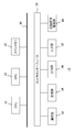
- FIG. 1 shows a configuration example of a content processing system to which the present embodiment can be applied.
- the content processing system 1 includes an imaging device 12 for capturing an image of an actual space, an image processing device 10 for converting a captured image into a form for processing and transmitting the image, and a content processing device 14 for performing predetermined information processing using the captured image transmitted , And a display device 16 that outputs the result of the information processing.
- the image processing apparatus 10 and the content processing apparatus 14 establish communication via the network 8 as needed.
- the image processing device 10 and the imaging device 12, and the content processing device 14 and the display device 16 may be connected by a wired cable, or may be wirelessly connected by a wireless local area network (LAN) or the like.
- the image processing device 10 and the imaging device 12, and the content processing device 14 and the display device 16 may be integrated devices.
- the image processing apparatus 10 and the imaging apparatus 12 may be combined to be an imaging apparatus having a transmission function to the network 8, or may be a server for distributing content data.
- the content processing device 14 and the display device 16 may be combined to form a portable terminal or a head mounted display.
- the network 8 connecting the image processing apparatus 10 and the content processing apparatus 14 may be a large scale network such as the Internet, or may be a local network such as a LAN established by wired or wireless.
- the appearance shape and the connection form of the imaging device 12, the image processing device 10, the content processing device 14, and the display device 16 are not limited to those illustrated.
- the imaging device 12 includes a stereo camera 18 that captures an object space at a predetermined frame rate, and a depth camera 19 that acquires information on the distance to an object in the same object space at a predetermined frame rate.
- the stereo camera 18 is a video camera including an imaging device such as a complementary metal oxide semiconductor (CMOS) sensor and an image processing mechanism that performs demosaicing, lens distortion correction, color correction, etc. on output data thereof to generate data of a captured image.
- CMOS complementary metal oxide semiconductor
- the depth camera 19 is composed of a mechanism that irradiates reference light such as near infrared light to the subject space, and a CMOS sensor that detects the reflected light, and the subject due to the time from irradiation to detection, distortion of the reflected light distribution, etc. Deriving the distance to The former method is a technique generally known as a ToF (Time of Flight) method and the latter method is a pattern irradiation method.
- the configuration of the depth camera and the method of deriving the distance are not limited to this.
- the imaging device 12 supplies, to the image processing device 10, a stereo image consisting of a pair of color images taken from the left and right viewpoints and data of a corresponding depth image at a predetermined rate.
- the depth image is an image representing a distance value as a pixel value of an image of a subject.
- the imaging device 12 in the same figure arranges the sensor of the depth camera 19 in the middle of the sensors of the stereo camera 18, the arrangement and the number of each sensor are not limited to this.
- the depth camera may be disposed close to the stereo camera for capturing a color image as a stereo camera for capturing from the left and right viewpoints, or the stereo camera for capturing a color image may be a camera for capturing a depth image It may double as well.
- stereo image a pair of general captured images that are not depth images is referred to as "stereo image”.
- the image processing apparatus 10 compresses the data of the image supplied from the imaging apparatus 12 into a transmission form, and transmits the data to the content processing apparatus 14 at a predetermined rate. Specifically, the data size of the depth image is reduced by using the redundancy of the stereo image and the depth image. For example, a depth image is obtained by calculation using a stereo image, and a difference image with the depth image which is a result of measurement by the depth camera is used as data of compressed depth information.
- the content processing apparatus 14 restores the depth image by decompressing the compressed depth information among the data thus transmitted. That is, when the above-mentioned difference image is transmitted as depth information, a depth image is obtained by calculation using a stereo image, and the measured depth image is restored by adding to the difference image.
- the content processing apparatus 14 performs information processing using the restored depth image and stereo image, and generates output data such as a display image and sound.
- the content of the output data is not particularly limited, and may vary depending on the function requested by the user to the system, the content of the application activated, and the like.
- the content processing apparatus 14 connects images so that stereo images are displayed in the left and right areas of the display device 16, and draws a virtual object that interacts with the subject based on the distance value represented by the depth image.
- the motion of the subject in the real space may be acquired from the depth image, and the game may be progressed by converting it into a command input to generate the game screen.
- the display device 16 includes a display such as liquid crystal, plasma, or organic EL that outputs an image, and a speaker that outputs an audio, and outputs the output data supplied from the content processing device 14 as an image or an audio.
- the display device 16 may be a television receiver, various monitors, a display screen of a portable terminal, an electronic finder of a camera, or the like, or a head mounted display mounted on the head of a user and displaying an image in front of the eye.
- corresponding points of the same image in a stereo image are obtained by block matching or the like, and a distance is derived from the amount of shift in the horizontal direction according to the principle of triangulation.
- the resolution of the depth image is low because the correspondence between both images is a block unit.
- the matching accuracy that is, the accuracy of the depth image largely fluctuates.
- the accuracy of the information processing can be maintained high. Also, by realizing data compression using stereo images and the like that are simultaneously transmitted, it is possible to suppress the bandwidth required for transmission of depth images. As a result, many bands can be used for transmission of color stereo images, so that high-accuracy processing can be realized without degrading the image quality.
- FIG. 2 shows the internal circuit configuration of the image processing apparatus 10.
- the image processing apparatus 10 includes a central processing unit (CPU) 23, a graphics processing unit (GPU) 24, and a main memory 26. These units are connected to one another via a bus 30.
- An input / output interface 28 is further connected to the bus 30.
- the I / O interface 28 outputs data to a peripheral device interface such as USB or IEEE 1394, a communication unit 32 including a wired or wireless LAN network interface, a storage unit 34 such as a hard disk drive or nonvolatile memory, or an external device.
- An output unit 36, an input unit 38 for inputting data from an imaging device 12 or an input device (not shown), and a recording medium drive unit 40 for driving a removable recording medium such as a magnetic disk, an optical disk or a semiconductor memory are connected.
- the CPU 23 controls the entire image processing apparatus 10 by executing the operating system stored in the storage unit 34.
- the CPU 23 also executes various programs read from the removable recording medium and loaded into the main memory 26 or downloaded via the communication unit 32.
- the GPU 24 has a function of a geometry engine and a function of a rendering processor, performs drawing processing according to a drawing command from the CPU 23, and outputs the drawing processing to the output unit 36.
- the main memory 26 is configured by a RAM (Random Access Memory), and stores programs and data necessary for processing.
- the internal circuit configuration of the content processing apparatus 14 may be the same as this.
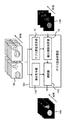
- FIG. 3 shows the configuration of functional blocks of the image processing apparatus 10 and the content processing apparatus 14.
- Each functional block shown in the figure can be realized by the various circuits shown in FIG. 2 in terms of hardware, and in terms of software, an image analysis function, an information processing function, an image loaded into the main memory from a recording medium It is realized by a program that exhibits various functions such as a drawing function and a data input / output function. Therefore, it is understood by those skilled in the art that these functional blocks can be realized in various forms by hardware only, software only, or a combination thereof, and is not limited to any of them.
- the image processing apparatus 10 includes a stereo image acquisition unit 50 for acquiring stereo image data from the imaging device 12, a depth image acquisition unit 52 for acquiring depth image data, and a depth image for compressing depth image data using a stereo image A compression unit 54 and an output unit 56 for outputting data of a stereo image and a depth image after compression are included.
- the stereo image acquisition unit 50 and the depth image acquisition unit 52 are all realized by the input unit 38, the CPU 23, the main memory 26 and the like of FIG. 2, and the former is stereo image data and the latter is depth image data. It acquires one by one at a predetermined frame rate from 12.
- the stereo image acquiring unit 50 constitutes a photographed image acquiring unit that acquires data of a plurality of photographed images formed by photographing an object from different viewpoints.
- the stereo image acquisition unit 50 and the depth image acquisition unit 52 may each acquire data in a stream format sequentially from the row in which exposure has been completed in the imaging device 12.
- the depth image compression unit 54 is realized by the CPU 23, the GPU 24, the main memory 26 and the like of FIG. 2, and compresses the data size of the depth image. Specifically, as described above, the difference image between the depth image obtained by calculation using the stereo image and the depth image acquired by the depth image acquisition unit 52 is generated.
- the depth image compression unit 54 may change the number of gradations per unit distance of data representing the distance value according to the distance to the subject, and may perform quantization.
- the depth image compression unit 54 may extract the image of the subject in any of the stereo images, and assign an appropriate number of gradations according to the distance range for each subject.
- the depth image compression unit 54 may adjust the number of gradations according to the distance on the difference image between the depth image obtained by calculation using the stereo image and the measured depth image.
- the difference image, the image in which the number of gradations per unit distance has been adjusted, and the data accompanying the same are collectively referred to as “a compressed depth image”.
- the output unit 56 is realized by the CPU 23, the main memory 26, the communication unit 32, and the like in FIG. 2, and the data of the stereo image acquired by the stereo image acquisition unit 50 and the compressed depth image generated by the depth image compression unit 54. Output data.
- the output destination may be the content processing apparatus 14 or a recording medium readable by the content processing apparatus 14. Alternatively, it may be temporarily stored in the storage unit 34 of the image processing apparatus 10 and may be transmitted in response to a request from the content processing apparatus 14.
- the output unit 56 may compress and encode data to be output according to a general method, or may packetize the data.
- the content processing device 14 obtains an image data acquisition unit 60 that acquires stereo image data and compressed depth image data, a depth image expansion unit 62 that expands compressed depth image data, and predetermined data using stereo image and depth image data. And an output unit 66 for outputting data of a display image and sound generated as a result of the information processing.
- the image data acquisition unit 60 is realized by the communication unit 32, the CPU 23, the main memory 26 and the like in FIG. 2, and sequentially acquires stereo image data and compressed depth image data from the image processing apparatus 10 at a predetermined frame rate.
- the image data acquisition unit 60 sequentially reads those image data by the recording medium drive unit 40. Even when a recording medium is used, the data size stored in the present embodiment can be reduced.
- the image data acquisition part 60 returns it to two-dimensional image data by decoding it.
- the depth image expanding unit 62 is realized by the CPU 23, the GPU 24, the main memory 26, and the like in FIG. 2, and expands the compressed depth image to generate an original depth image.
- the contents of the decompression processing are basically processing that follows the compression processing performed by the depth image compression unit 54 in the image processing apparatus 10 in reverse. A specific example will be described later.
- the information processing unit 64 is realized by the CPU 23, the GPU 24, the main memory 26, and the like in FIG. 2, and performs predetermined information processing using a stereo image and a decompressed depth image to generate output data. As described above, the content of the process performed by the information processing unit 64 is not particularly limited.
- the output unit 66 is realized by the CPU 23, the main memory 26, the output unit 36 and the like of FIG. 2, and outputs output data such as a display image generated in this manner to the display device 16.
- the depth image expanding unit 62 of the content processing apparatus 14 may be an image data expanding apparatus independent of an apparatus that performs processing related to a game or display.
- FIG. 4 shows a depth image compression unit 54 in the case of using a difference image between a depth image obtained by calculation using a stereo image and a depth image measured by a depth camera.
- the configuration of the functional blocks of the depth image decompression unit 62 and the flow of processing are shown.
- the depth image compression unit 54a in the image processing apparatus 10 in this case includes a depth image calculation unit 70 and a difference image acquisition unit 72.
- the depth image calculation unit 70 uses the stereo image 80 as input data, and generates a depth image by calculation.
- stereo matching determines corresponding points of both, and the distance to the subject is derived from the parallax of the two based on the principle of triangulation.
- a reference block is set to one image of a stereo image, and a block having a high degree of similarity in the other image is searched in the horizontal direction.
- a depth value at a corresponding viewpoint is generated by calculating a distance value based on the parallax obtained as a result and mapping the reference block to the set image.
- the difference image acquisition unit 72 uses the depth image 82 captured by the depth camera and the depth image generated by the depth image calculation unit 70 as input data, and generates a difference image 84 representing the difference between the pixel values of the two.
- the difference image acquisition unit 72 can be actually realized by a circuit similar to that for acquiring a difference between frames of a moving image, which is used in the conventional technique of differential pulse code modulation (DPCM). The same applies to the difference image acquisition unit 72 in the following figures.
- the image processing apparatus 10 outputs the differential image 84 generated in this manner as a compressed depth image together with the data of the stereo image 80.
- the depth image expanding unit 62 a of the content processing apparatus 14 includes a depth image calculating unit 74 and a difference image adding unit 76.
- the depth image calculation unit 74 uses the stereo image 80 as input data, and generates a depth image by calculation. This process is the same as the process performed by the depth image computing unit 70 in the depth image compression unit 54 a of the image processing apparatus 10.
- the difference image addition unit 76 takes the difference image 84, which is a compressed depth image, and the depth image generated by the depth image calculation unit 74 as input data, adds the pixel values of both, and the depth measured by the imaging device 12 A depth image 86 equivalent to the image 82 is generated.
- the difference image addition unit 76 can be actually realized by a circuit similar to the circuit that decodes a moving image frame in the above-described difference pulse code modulation. The same applies to the difference image adding unit 76 in the following figures.
- the depth images generated by the depth image calculation units 70 and 74 by the above-described method have a lower resolution than the stereo image used for the calculation, and the accuracy is likely to vary depending on the degree of the feature points on the object surface.
- the difference image 84 with the depth image 82 measured by the depth camera compensates for such a reduction in resolution and accuracy.
- the difference image 84 as a transmission target, it is possible to transmit information equivalent to the depth image 82 with a data size smaller than the actually measured depth image 82.
- the size and resolution of the stereo image 80, depth image 82 and difference image 84 may be set independently. If the size (resolution) of the image used for the generation and addition of the difference image is different, the pixels at the same position may be calculated after enlargement and reduction appropriately by the existing interpolation technique. Further, in the imaging device 12, the depth camera 82 may be a stereo image from the left and right viewpoints by configuring the depth camera also as a stereo camera.
- the difference image 84 may also be a stereo image from the left and right viewpoints by calculating the difference between one depth image generated by the depth image operation unit 70 by the calculation and each of the depth images of the left and right viewpoints. That is, the depth image compression unit 54a generates the difference image 84 for each of the plurality of depth images.
- the depth image compression unit 54a By measuring the depth images of the left and right viewpoints, even if it is a blind spot from one viewpoint, the distance is found from the other viewpoint, and high-accuracy information processing is performed using a wider range of distance information in the real world. Can do Even in such a mode, it is possible to suppress an increase in the size of transmission data by compressing both depth images into a difference image.
- the depth image compression unit 54a converts one depth image based on parallax into two depth images from the viewpoint when the depth image to be compressed is actually measured, and then the difference from the depth image to be compressed.
- the difference stereo image can be generated by calculating the depth images of the corresponding viewpoints.
- the method of shifting the image in the depth image obtained by the calculation so as to be viewed from the viewpoint of the depth camera is the number and position of the depth cameras if the positional relationship between the stereo camera and the depth camera is known. It is applicable regardless of.
- a general computer graphics technique can be applied to a method of generating an image from different viewpoints based on distance information of an object.
- FIG. 5 shows depth image compression unit 54 and depth image expansion unit 62 in the case of changing the number of gradations of the distance value which is the pixel value of the depth image according to the distance of the object. Shows the configuration of the functional blocks and the flow of processing.
- the depth image compression unit 54b in the image processing apparatus 10 in this case includes a subject recognition unit 90 and a gradation assignment unit 92.
- the subject recognition unit 90 uses at least one of the stereo images 100 to recognize a subject appearing as an image.
- the subject recognition unit 90 specifies an area of the image of the subject by, for example, extracting an outline in the image 100 using an edge extraction filter.
- a face, a tree, and other background areas are identified from the image 100.
- segmentation techniques for separating an area of an image of a subject in an image, and any one of them may be adopted in the present embodiment.
- face recognition technology may be introduced to the face area, or template matching may be introduced to a subject of known shape.
- object tracking from the previous image frame may be performed using a technique such as optical flow.
- both of the actually measured depth image 102 and stereo image may be used as appropriate.
- the object recognition by the object recognition unit 90 aims to assign the number of gradations of the pixel value of the depth image according to the distance, so it is not necessary to strictly separate the images of all the objects. For example, when a plurality of subjects are in contact, it is not necessary to distinguish between the two.
- the gradation assigning unit 92 is a unit distance of a distance value represented as a pixel value of the depth image based on the depth image 102 captured by the depth camera and the area of the image of each subject recognized by the subject recognition unit 90.
- the number of tonality levels is determined for each subject.
- the accuracy of the depth information is determined for objects closer to the imaging device. That is, even in the real world, the movement amount on the image becomes larger as it is closer to the imaging device, even if the movement amount is the same. In a general environment, a main object such as a user is likely to be closer to the imaging device than other objects.
- the gradation assigning unit 92 assigns a greater number of tones to the closer subject, and quantizes the pixel value of the depth image 102. For example, with respect to the bit depth representing the pixel value of the depth image, the number of bits is 50% for the pixel value of the face image, 30% for the pixel value of the tree behind, and 20% for other parts. assign. Such assignment naturally changes also with the number of subjects with different distances.
- the gradation assigning unit 92 assigns the appropriate number of gradations to each object and quantizes the depth image 104 and the correspondence information 106 of the pixel values before and after quantization as data of the compressed depth image.
- the image processing apparatus 10 outputs the data of the compressed depth image and the data of the stereo image.
- the depth image expanding unit 62 b of the content processing apparatus 14 includes a depth value acquiring unit 96.
- the depth value acquisition unit 96 uses, as input data, the data of the compressed depth image, that is, the depth image 104 in which the number of gradations has been adjusted according to the distance, and the correspondence information 106 of pixel values before and after quantization.
- the depth image 108 is restored. That is, data of pixel values having different resolutions depending on the distance, which are represented in the depth image 104 transmitted from the image processing apparatus 10, are converted into data in the uniform resolved brain. For conversion, correspondence information 106 of pixel values before and after quantization is used.
- FIG. 6 is a diagram for explaining correspondence information of pixel values before and after quantization, which is used to expand a depth image.
- the example shown in (a) shows a change in the distance after quantization with respect to the actually measured distance in the case of assigning the gradation number based on the distance of the subject recognized as described above.
- the values after quantization are discrete, they are schematically shown as continuous values in FIG. Moreover, it is not the meaning which limits the format of corresponding information with the same graph. That is, as long as the content processing apparatus 14 can obtain the value before quantization from the value after quantization, the data format such as a function or a lookup table is not limited.
- the distance after quantization is determined so as to be directly proportional to the value of the actual measurement distance, as indicated by a change 180 indicated by an alternate long and short dash line in (a).
- a change 180 indicated by an alternate long and short dash line in (a) As indicated by a change 182 indicated by a solid line, more gradations are allocated to the distance range in which the subject is present, and more gradations are allocated as the distance from the imaging device 12 decreases.
- the number of gradations A, B, and C are respectively set in the distance range of the face closest to the imaging device side, the distance range of the tree behind it, and the distance range such as the wall behind it. Assign C such that A> B> C.
- a predetermined number of gradations smaller than the number of gradations C is assigned to the distance range between objects (distance range in which no object exists). This is because the importance of the division of the distance between the objects is low as compared with the unevenness of the object surface and the distance between the objects.
- the “distance range” may be a range of distance actually appearing as a pixel value of an image of a subject in a depth image, or may be set in advance for each type of subject in consideration of thickness and the like.
- the ratio of the gradation numbers A, B and C is determined, for example, by the reciprocal of the average distance for each subject.
- the determination range of the distance range of the subject and the number of gradations to be assigned is not limited to this.
- the gradation assigning unit 92 of the image processing apparatus 10 determines the number of gradations A, B, and C to be assigned according to the recognition result of the object and the distance range, the distance values before and after quantization are uniquely corresponded as illustrated. Information can be generated.
- the depth value acquisition unit 96 of the content processing apparatus 14 refers to the information and acquires the measured distance from the distance after quantization represented by the transmitted depth image, thereby being equivalent to the original depth image. Can generate an image.
- (B) of FIG. 6 shows an example of the change in the case where the change in the distance after the quantization to the measured distance is fixed regardless of the presence of the subject and the distance as a modification of (a). ing. Also in this case, qualitatively, as the distance is closer, more gradations are allocated, but by changing the distance after quantization in a curved shape with respect to the measured distance, it depends on the position and the number of objects. It is made to be applicable. In this way, even if there is no subject in the vicinity of the imaging device, many gradations may be uniformly assigned, but the processing of the subject recognition unit 90 can be omitted. Therefore, the processing speed can be increased while maintaining the accuracy depending on the shooting environment and the content of the information processing, such as a game where the user is often in front of the imaging apparatus.
- FIG. 7 shows the depth image compression unit 54 and the depth in the case where the number of gradations of the pixel values of the difference image shown in FIG. 4 is adjusted as shown in FIG.
- the configuration and processing flow of functional blocks of the image decompression unit 62 are shown.
- the depth image compression unit 54c in the image processing apparatus 10 in this case includes a depth image calculation unit 70, a difference image acquisition unit 72, and a gradation assignment unit 92.
- the depth image calculation unit 70 and the difference image acquisition unit 72 have the same functions as the depth image calculation unit 70 and the difference image acquisition unit 72 shown in FIG. 4.
- the depth image calculation unit 70 calculates a depth image from the stereo image 112 by calculation
- the difference image acquisition unit 72 generates a difference image between the actually measured depth image 114 and the depth image calculated by calculation.
- the gradation allocation unit 92 has the same function as the gradation allocation unit 92 shown in FIG. 5, but sets the difference image generated by the difference image acquisition unit 72 as a processing target. Also in the difference between the measured depth image and the depth image obtained by calculation from the stereo image, the closer the distance from the imaging device 12 is to the subject, the more easily the accuracy affects the accuracy of the information processing.
- the processing accuracy for the main object can be improved by assigning more gradation numbers to objects closer in distance, or the bit depth of pixel values can be reduced and the data size of the difference image can be further compressed.
- the image processing apparatus 10 outputs the difference image 116 whose gradation has been adjusted and the correspondence information 118 of pixel values before and after quantization as data of the depth image after compression, together with the data of the stereo image 112.
- the depth image expanding unit 62 c of the content processing apparatus 14 includes a depth image calculating unit 74, a difference value acquiring unit 110, and a difference image adding unit 76.
- the depth image calculation unit 74 and the difference image addition unit 76 have the same functions as the depth image calculation unit 74 and the difference image addition unit 76 shown in FIG. 4. That is, the depth image calculation unit 74 calculates the depth image from the stereo image 112 by calculation, and the difference image addition unit 76 generates the original depth image 119 by adding the depth image and the difference image.
- the difference value acquisition unit 110 has a function similar to that of the depth value acquisition unit 96 shown in FIG. 5, but sets a difference image whose number of gradations per unit difference is adjusted as a processing target. That is, referring to the correspondence information 118 of pixel values before and after quantization, an actual difference value is obtained for each pixel from the difference value after quantization represented by the difference image 116. By inputting the difference image restored by this to the difference image adding unit 76, the original depth image 119 can be generated as shown in FIG. In the example shown in FIG. 7, the correspondence information 118 of the pixel values before and after quantization is shown as (b) in FIG. 6, but of course it may be as shown in (a). In this case, the object recognition unit 90 may be provided in the depth image compression unit 54c.
- FIG. 8 shows functional blocks in the case where the depth image compression unit 54 and the depth image expansion unit 62 use the data that can be acquired from the server to compress / expand the depth image.
- the depth image providing server 120 is connected to the network 8.
- the depth image providing server 120 has a function of generating and returning a corresponding depth image from the captured image transmitted via the network.
- the depth image providing server 120 generates a depth image based on the photographed image transmitted from the image processing device 10 and the content processing device 14 and sends it back to the transmission source.
- the imaging device 12 can also be configured of a monocular color image capturing camera and a depth camera in some cases. However, this is not the case when using stereo images for display.
- the depth image compression unit 54 d of the image processing apparatus 10 includes a depth image acquisition unit 122 and a difference image acquisition unit 72.
- the depth image acquisition unit 122 transmits the data of the captured image acquired from the imaging device 12 to the depth image providing server 120, and acquires the returned depth image in response thereto.
- the difference image acquisition unit 72 has the same function as the difference image acquisition unit 72 shown in FIG. 4 and generates a difference image 128 between the actually measured depth image 126 and the depth image transmitted from the depth image providing server 120. Do. Also in this embodiment, the gradation assigning unit 92 shown in FIG. 7 may be introduced to adjust the number of gradations of the difference image according to the distance of the subject.
- the image processing apparatus 10 outputs the data of the compressed depth image and the data of the color photographed image.
- the depth image expanding unit 62 d of the content processing apparatus 14 includes a depth image acquiring unit 130 and a difference image adding unit 76.
- the depth image acquisition unit 130 transmits data of a color captured image to the depth image providing server 120, and acquires the returned depth image in response thereto.
- the difference image addition unit 76 has the same function as the difference image addition unit 76 shown in FIG. 4. That is, the difference image addition unit 76 generates the original depth image 132 by adding the depth image transmitted from the depth image providing server 120 and the difference image 128 transmitted from the image processing apparatus 10.
- the function of the difference value acquisition unit 110 shown in FIG. 7 is introduced to the depth image expansion unit 62d.
- FIG. 9 shows the configuration and processing flow of functional blocks of the depth image expanding unit 62 of the content processing apparatus 14 in a mode in which the frame rate of the depth image is made lower than that of the stereo image.
- the image processing apparatus 10 transmits, to the content processing apparatus 14, data of stereo images at a predetermined frame rate, and transmits data of compressed depth images at a lower frame rate.
- the difference image with the calculated depth image is assumed as the data of the compressed depth image in the same figure, it may be data in which the number of gradations of the depth image or the difference image is adjusted according to the distance of the subject.
- the depth image expanding unit 62 e includes a depth image calculating unit 74, a difference image adding unit 76, a motion acquiring unit 140, and an interpolating unit 142.
- the depth image calculation unit 74 and the difference image addition unit 76 have the same functions as the depth image calculation unit 74 and the difference image addition unit 76 shown in FIG. 4. That is, the depth image calculation unit 74 calculates the depth image from the stereo image 144 by calculation, and the difference image addition unit 76 generates the original depth image by adding the depth image and the difference image 146. However, the depth image calculation unit 74 may obtain the depth image only for the image frame of the time corresponding to the difference image 146. For example, in the case where the frame rate of the difference image 146 is 1 ⁇ 2 that of the stereo image, the depth image computing unit 74 obtains a depth image using stereo images at every other frame.
- the difference image addition unit 76 adds the difference image 146 to the difference image 146, whereby the original depth image can be obtained at the same frame rate as the difference image 146.
- the motion acquisition unit 140 acquires the motion vector of the subject by taking the inter-frame difference of one of the stereo images 144.
- the method of acquiring the motion vector of the subject in the moving image is a general technique.
- the interpolation unit 142 predicts the motion up to the next time step using the motion vector in the past, and applies the depth image at the low frame rate generated by the difference image addition unit 76 on the time axis. Interpolate the depth image with.
- the frame rates of the stereo image and the depth image can be set independently, it is possible to select the optimum frame rate for each taking into consideration the difference between the imaging principles of the cameras that capture each image, and improve the image quality of both. it can.
- the imaging timing of a stereo image and a depth image does not correspond by setting a frame rate independently, a difference image is produced using the stereo image imaged at the timing nearest to the imaging timing of a depth image, or a depth image You may restore it.
- the depth image computing unit 74 may generate depth images for all image frames of the stereo image 144 in order to acquire motion vectors. That is, the motion acquisition unit 140 obtains a motion vector by taking the inter-frame difference of the depth image obtained by calculation instead of the stereo image. Also in this case, the processing of the interpolation unit 142 is the same as described above.
- an image processing apparatus that sends out data uses the depth image obtained by calculation from the stereo image. And compress the data of the measured depth image.
- the content processing apparatus that has acquired the compressed data restores the actually measured depth image using the depth image obtained by calculation from the stereo image. Since the depth image obtained by the calculation and the actually measured depth image have high similarity, the difference image can be represented by a significantly smaller number of gradations than the original pixel value.
- the number of gradations representing the pixel value of the depth image or the difference image is adjusted according to the distance of the subject indicated by the measured depth image.
- the size of transmission data can be further reduced by transmitting compressed depth images at a lower frame rate than stereo images and using interpolation for motion compensation using stereo images at the stage of information processing.
- the imaging device 12 is configured to include a pair of stereo cameras and a depth camera, but the configuration of the imaging device is not limited as long as stereo images and depth images can be captured at the same time. Further, as long as the depth image can be generated by at least the calculation, the image photographed with the depth image is not limited to the stereo image and the color image.
- FIG. 10 schematically shows an overhead view of an imaging device in a modification.
- the imaging device 150 has a configuration in which a plurality of video cameras (for example, video cameras 152) are annularly connected so that the optical axis is radial in a horizontal plane parallel to the drawing. At the time of operation, the imaging device 150 is pivoted in a predetermined direction (for example, the direction of the arrow) on a horizontal plane around the center of the ring. In the drawing, the drive mechanism for turning is not shown. With such a configuration, it is possible to fit all the objects at 360 ° around each time within the field of view of any camera, and even for objects in areas where the fields of view do not overlap, slight time deviations Can be put into the field of view of the following camera.
- a predetermined direction for example, the direction of the arrow
- the depth image can be compressed as in the present embodiment. Images can be transmitted while suppressing the increase in data size.
- the number of cameras constituting the imaging device can be reduced.
- images from different viewpoints may be captured by moving one camera, and two images captured before and after in time may be used as a stereo image at an average time.
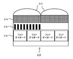
- FIG. 11 shows the element structure of the imaging device in another modification.
- the figure schematically shows the functional structure of the element cross section, and detailed structures such as interlayer insulating films and wirings are omitted. Further, in the drawing, the cross-sectional structure of two adjacent pixels is illustrated.
- the pixel 210 includes a microlens layer 212, a color filter layer 214, a polarizer layer 216, and a photoelectric conversion layer 218.
- the microlens layer 212 is provided for each pixel and condenses incident light.
- the color filter layer 214 transmits light of a different color for each pixel.
- the polarizer layer 216 includes a wire grid type polarizer in which a plurality of linear conductor members, for example, members (wires) such as tungsten and aluminum are arranged in stripes at intervals smaller than the wavelength of incident light.
- Polarized luminance is obtained by converting the transmitted polarization component into charge in the photoelectric conversion layer 218.
- An image acquisition technique using a wire grid type polarizer as illustrated is disclosed, for example, in Japanese Patent Application Laid-Open No. 2012-80065 and the like.
- the polarizer is not limited to the wire grid type, and may be any practical one such as a linear dichroism polarizer.
- a cross section of the wire extending in the depth direction of the drawing is shown as a polarizer, but the principal axis angle of the polarizer is four, and the direction of the wire is different accordingly.
- the polarizer layer 216 may have regions with and without a polarizer depending on the pixel. In a region where a polarizer is not provided, light transmitted through the color filter layer 214 is incident on the photoelectric conversion layer 218 as it is.
- the photoelectric conversion layer 218 includes a general photodiode and outputs incident light as a charge. By providing a plurality of photodiodes for one microlens as shown, light transmitted through different regions of the focusing lens is separately converted into charges.
- a technique for performing focus detection based on the phase difference of light detected in this manner is put to practical use as a method of phase difference autofocus (see, for example, Japanese Patent Application Laid-Open No. 2013-106194).
- the luminance of one pixel in a general imaging device can be obtained. That is, according to the element structure of the pixel shown in FIG. 11, it is possible to simultaneously obtain a general color image, polarization images of a plurality of azimuths, and a phase difference image.
- the phase difference image is a pair of images in which only one of the detection values of two photodiodes provided for each pixel is a pixel.
- the displacement amount of the position of the image in the phase difference image is 0 at the focal length, and becomes larger as the distance from the focal length is increased.
- the direction of shift is reversed if it is farther or closer than the focal length.
- the image processing apparatus can acquire the distance of the subject from the amount of image shift in the phase difference image using this relationship.
- the shift amount can be specified, the distance can be obtained only to the portion where the feature point such as the outline of the object exists. Therefore, if the normal vector of the surface of the subject is acquired by the existing method using polarized images of a plurality of azimuths, and the distance value is interpolated based on the inclination of the surface obtained from the result, the distance value of the entire subject can be obtained.
- a stereo camera is acquired by introducing a general camera separately from the camera having the element structure as shown and taking it from different viewpoints. May be Alternatively, stereo images may be acquired by a plurality of cameras having element structures as illustrated. In this case, the imaging device may have a structure as shown in FIG.
- one camera having an element structure as illustrated is moved to acquire a stereo image, or a depth image is acquired from one color image using the depth image providing server 120 shown in FIG. May be In any case, the same effects can be obtained by applying the image processing apparatus and the content processing apparatus described in the present embodiment.
- 1 content processing system 10 image processing devices, 12 imaging devices, 14 content processing devices, 16 display devices, 18 stereo cameras, 19 depth cameras, 23 CPUs, 24 GPUs, 26 main memory, 32 communication units, 34 storage units, 36 Output unit, 38 input unit, 40 recording medium drive unit, 50 stereo image acquisition unit, 52 depth image acquisition unit, 54 depth image compression unit, 56 output unit, 60 image data acquisition unit, 62 depth image decompression unit, 64 information processing Part, 66 output part.
- the present invention is applicable to various devices such as an imaging device, a head mount display, a sensor, an image processing device, a content reproduction device, and a system including the same.
Landscapes
- Engineering & Computer Science (AREA)
- Multimedia (AREA)
- Signal Processing (AREA)
- Compression Or Coding Systems Of Tv Signals (AREA)
- Testing, Inspecting, Measuring Of Stereoscopic Televisions And Televisions (AREA)
- Compression Of Band Width Or Redundancy In Fax (AREA)
- Studio Devices (AREA)
Priority Applications (2)
| Application Number | Priority Date | Filing Date | Title |
|---|---|---|---|
| US16/771,908 US11503267B2 (en) | 2017-12-21 | 2018-12-14 | Image processing device, content processing device, content processing system, and image processing method |
| EP18891483.2A EP3731528A4 (en) | 2017-12-21 | 2018-12-14 | IMAGE PROCESSING DEVICE, CONTENT PROCESSING DEVICE, CONTENT PROCESSING SYSTEM AND IMAGE PROCESSING METHOD |
Applications Claiming Priority (2)
| Application Number | Priority Date | Filing Date | Title |
|---|---|---|---|
| JP2017-244861 | 2017-12-21 | ||
| JP2017244861A JP7105062B2 (ja) | 2017-12-21 | 2017-12-21 | 画像処理装置、コンテンツ処理装置、コンテンツ処理システム、および画像処理方法 |
Publications (1)
| Publication Number | Publication Date |
|---|---|
| WO2019124248A1 true WO2019124248A1 (ja) | 2019-06-27 |
Family
ID=66992666
Family Applications (1)
| Application Number | Title | Priority Date | Filing Date |
|---|---|---|---|
| PCT/JP2018/046100 Ceased WO2019124248A1 (ja) | 2017-12-21 | 2018-12-14 | 画像処理装置、コンテンツ処理装置、コンテンツ処理システム、および画像処理方法 |
Country Status (4)
| Country | Link |
|---|---|
| US (1) | US11503267B2 (https=) |
| EP (1) | EP3731528A4 (https=) |
| JP (1) | JP7105062B2 (https=) |
| WO (1) | WO2019124248A1 (https=) |
Cited By (5)
| Publication number | Priority date | Publication date | Assignee | Title |
|---|---|---|---|---|
| CN112164017A (zh) * | 2020-09-27 | 2021-01-01 | 中国兵器工业集团第二一四研究所苏州研发中心 | 一种基于深度学习的偏振彩色化方法 |
| WO2021166707A1 (ja) * | 2020-02-21 | 2021-08-26 | ソニーセミコンダクタソリューションズ株式会社 | 情報処理装置および方法 |
| JP2023160275A (ja) * | 2022-04-22 | 2023-11-02 | 株式会社ノビアス | 2次元動画を3次元的に表示するためのシステム、方法、およびプログラム |
| JP2024004366A (ja) * | 2022-06-28 | 2024-01-16 | トヨタ自動車株式会社 | 送信装置、プログラム、及び受信装置 |
| WO2025121066A1 (ja) * | 2023-12-08 | 2025-06-12 | 株式会社Jvcケンウッド | 画像処理装置、画像処理方法 |
Families Citing this family (7)
| Publication number | Priority date | Publication date | Assignee | Title |
|---|---|---|---|---|
| US11949848B2 (en) * | 2019-04-01 | 2024-04-02 | Google Llc | Techniques to capture and edit dynamic depth images |
| TWI853102B (zh) | 2019-10-07 | 2024-08-21 | 日商索尼半導體解決方案公司 | 電子機器 |
| US12475725B2 (en) | 2021-07-30 | 2025-11-18 | Zoox, Inc. | Three-dimensional point clouds based on images and depth data |
| US12056934B2 (en) | 2021-07-30 | 2024-08-06 | Zoox, Inc. | Three-dimensional object detection based on image data |
| WO2024057902A1 (ja) * | 2022-09-12 | 2024-03-21 | ソニーグループ株式会社 | 情報処理装置および方法、並びにプログラム |
| WO2024186242A1 (en) * | 2023-03-08 | 2024-09-12 | Telefonaktiebolaget Lm Ericsson (Publ) | Holographic communication system |
| JP7745854B2 (ja) * | 2023-03-28 | 2025-09-30 | Pciソリューションズ株式会社 | 重量推定装置及び教師データ作成方法 |
Citations (6)
| Publication number | Priority date | Publication date | Assignee | Title |
|---|---|---|---|---|
| JP2009163717A (ja) * | 2007-12-10 | 2009-07-23 | Fujifilm Corp | 距離画像処理装置および方法、距離画像再生装置および方法並びにプログラム |
| JP2012080065A (ja) | 2010-09-07 | 2012-04-19 | Sony Corp | 固体撮像素子、固体撮像装置、撮像機器、及び、偏光素子の製造方法 |
| JP2013106194A (ja) | 2011-11-14 | 2013-05-30 | Canon Inc | 撮像装置の駆動方法 |
| US20140035905A1 (en) * | 2012-07-31 | 2014-02-06 | Samsung Electronics Co., Ltd. | Method for converting 2-dimensional images into 3-dimensional images and display apparatus thereof |
| JP2015518338A (ja) * | 2012-04-25 | 2015-06-25 | ノキア コーポレイション | ビデオコーディング方法および装置 |
| JP2017208641A (ja) * | 2016-05-17 | 2017-11-24 | キヤノン株式会社 | 圧縮センシングを用いた撮像装置、撮像方法および撮像プログラム |
Family Cites Families (9)
| Publication number | Priority date | Publication date | Assignee | Title |
|---|---|---|---|---|
| JP3159230B2 (ja) | 1993-06-10 | 2001-04-23 | 日本電信電話株式会社 | 画像信号用可変レート符号化装置 |
| US20100185093A1 (en) * | 2009-01-19 | 2010-07-22 | James Hamilton | System and method for processing a real-time ultrasound signal within a time window |
| US20090148038A1 (en) * | 2007-12-10 | 2009-06-11 | Youichi Sawachi | Distance image processing apparatus and method |
| KR101367282B1 (ko) | 2007-12-21 | 2014-03-12 | 삼성전자주식회사 | 깊이 정보에 대한 적응적 정보 표현 방법 및 그 장치 |
| KR101158491B1 (ko) | 2008-12-08 | 2012-06-20 | 한국전자통신연구원 | 다시점 영상 부호화, 복호화 방법 및 그 장치. |
| US9191646B2 (en) * | 2011-08-29 | 2015-11-17 | Nokia Technologies Oy | Apparatus, a method and a computer program for video coding and decoding |
| US9462164B2 (en) * | 2013-02-21 | 2016-10-04 | Pelican Imaging Corporation | Systems and methods for generating compressed light field representation data using captured light fields, array geometry, and parallax information |
| US9519972B2 (en) * | 2013-03-13 | 2016-12-13 | Kip Peli P1 Lp | Systems and methods for synthesizing images from image data captured by an array camera using restricted depth of field depth maps in which depth estimation precision varies |
| CN108389226A (zh) | 2018-02-12 | 2018-08-10 | 北京工业大学 | 一种基于卷积神经网络和双目视差的无监督深度预测方法 |
-
2017
- 2017-12-21 JP JP2017244861A patent/JP7105062B2/ja active Active
-
2018
- 2018-12-14 EP EP18891483.2A patent/EP3731528A4/en active Pending
- 2018-12-14 WO PCT/JP2018/046100 patent/WO2019124248A1/ja not_active Ceased
- 2018-12-14 US US16/771,908 patent/US11503267B2/en active Active
Patent Citations (6)
| Publication number | Priority date | Publication date | Assignee | Title |
|---|---|---|---|---|
| JP2009163717A (ja) * | 2007-12-10 | 2009-07-23 | Fujifilm Corp | 距離画像処理装置および方法、距離画像再生装置および方法並びにプログラム |
| JP2012080065A (ja) | 2010-09-07 | 2012-04-19 | Sony Corp | 固体撮像素子、固体撮像装置、撮像機器、及び、偏光素子の製造方法 |
| JP2013106194A (ja) | 2011-11-14 | 2013-05-30 | Canon Inc | 撮像装置の駆動方法 |
| JP2015518338A (ja) * | 2012-04-25 | 2015-06-25 | ノキア コーポレイション | ビデオコーディング方法および装置 |
| US20140035905A1 (en) * | 2012-07-31 | 2014-02-06 | Samsung Electronics Co., Ltd. | Method for converting 2-dimensional images into 3-dimensional images and display apparatus thereof |
| JP2017208641A (ja) * | 2016-05-17 | 2017-11-24 | キヤノン株式会社 | 圧縮センシングを用いた撮像装置、撮像方法および撮像プログラム |
Non-Patent Citations (1)
| Title |
|---|
| See also references of EP3731528A4 |
Cited By (10)
| Publication number | Priority date | Publication date | Assignee | Title |
|---|---|---|---|---|
| WO2021166707A1 (ja) * | 2020-02-21 | 2021-08-26 | ソニーセミコンダクタソリューションズ株式会社 | 情報処理装置および方法 |
| JPWO2021166707A1 (https=) * | 2020-02-21 | 2021-08-26 | ||
| JP7615116B2 (ja) | 2020-02-21 | 2025-01-16 | ソニーセミコンダクタソリューションズ株式会社 | 情報処理装置および方法 |
| US12206867B2 (en) * | 2020-02-21 | 2025-01-21 | Sony Semiconductor Solutions Corporation | Information processing device and method |
| CN112164017A (zh) * | 2020-09-27 | 2021-01-01 | 中国兵器工业集团第二一四研究所苏州研发中心 | 一种基于深度学习的偏振彩色化方法 |
| CN112164017B (zh) * | 2020-09-27 | 2023-11-17 | 中国兵器工业集团第二一四研究所苏州研发中心 | 一种基于深度学习的偏振彩色化方法 |
| JP2023160275A (ja) * | 2022-04-22 | 2023-11-02 | 株式会社ノビアス | 2次元動画を3次元的に表示するためのシステム、方法、およびプログラム |
| JP2024004366A (ja) * | 2022-06-28 | 2024-01-16 | トヨタ自動車株式会社 | 送信装置、プログラム、及び受信装置 |
| JP7711641B2 (ja) | 2022-06-28 | 2025-07-23 | トヨタ自動車株式会社 | 送信装置及び受信装置 |
| WO2025121066A1 (ja) * | 2023-12-08 | 2025-06-12 | 株式会社Jvcケンウッド | 画像処理装置、画像処理方法 |
Also Published As
| Publication number | Publication date |
|---|---|
| EP3731528A1 (en) | 2020-10-28 |
| US20200404238A1 (en) | 2020-12-24 |
| EP3731528A4 (en) | 2021-08-11 |
| JP2019114842A (ja) | 2019-07-11 |
| JP7105062B2 (ja) | 2022-07-22 |
| US11503267B2 (en) | 2022-11-15 |
Similar Documents
| Publication | Publication Date | Title |
|---|---|---|
| US11503267B2 (en) | Image processing device, content processing device, content processing system, and image processing method | |
| US12289470B2 (en) | Three-dimensional data encoding method, three-dimensional data decoding method, three-dimensional data encoding device, and three-dimensional data decoding device | |
| JP7277372B2 (ja) | 三次元モデル符号化装置、三次元モデル復号装置、三次元モデル符号化方法、および、三次元モデル復号方法 | |
| US20200051269A1 (en) | Hybrid depth sensing pipeline | |
| US11295516B2 (en) | Reconstruction method, reconstruction device, and generation method for generating a three-dimensional (3D) model | |
| US20210233303A1 (en) | Image processing apparatus and image processing method | |
| JP2014056466A (ja) | 画像処理装置及び方法 | |
| JPWO2009101798A1 (ja) | 複眼撮像装置、測距装置、視差算出方法及び測距方法 | |
| WO2012132167A1 (ja) | 情報処理システム、情報処理装置、撮像装置、および情報処理方法 | |
| KR20120074925A (ko) | 빈공간 채움 방법 및 이를 수행하는 3차원 비디오 시스템 | |
| WO2019198501A1 (ja) | 画像処理装置、画像処理方法、プログラム、および画像伝送システム | |
| US12063389B2 (en) | 3D prediction method for video coding | |
| JPWO2019050038A1 (ja) | 画像生成方法および画像生成装置 | |
| WO2020183710A1 (ja) | 画像処理装置及び3次元計測システム | |
| JP2013025649A (ja) | 画像処理装置及び画像処理方法、プログラム | |
| US12563229B2 (en) | 3D prediction method for video coding | |
| JP2013150071A (ja) | 符号化装置、符号化方法、プログラム及び記憶媒体 | |
| KR20120093751A (ko) | 정면시점 영상합성을 통한 시선 맞춤 장치 및 방법 | |
| CN117956130A (zh) | 视频处理方法、装置、设备、系统及可读取存储介质 | |
| US10257488B2 (en) | View synthesis using low resolution depth maps | |
| JP6905184B2 (ja) | 画像圧縮プログラム、画像圧縮装置、及び画像圧縮方法 | |
| WO2021168185A1 (en) | Method and device for processing image content | |
| US12382080B2 (en) | Method for encoding and decoding a multi-view video | |
| US20250358395A1 (en) | Generating 3d images and videos from 2d images and videos | |
| WO2011158562A1 (ja) | 多視点画像符号化装置 |
Legal Events
| Date | Code | Title | Description |
|---|---|---|---|
| 121 | Ep: the epo has been informed by wipo that ep was designated in this application |
Ref document number: 18891483 Country of ref document: EP Kind code of ref document: A1 |
|
| NENP | Non-entry into the national phase |
Ref country code: DE |
|
| ENP | Entry into the national phase |
Ref document number: 2018891483 Country of ref document: EP Effective date: 20200721 |