WO2019107607A1 - Cooling device and method therefor - Google Patents
Cooling device and method therefor Download PDFInfo
- Publication number
- WO2019107607A1 WO2019107607A1 PCT/KR2017/013901 KR2017013901W WO2019107607A1 WO 2019107607 A1 WO2019107607 A1 WO 2019107607A1 KR 2017013901 W KR2017013901 W KR 2017013901W WO 2019107607 A1 WO2019107607 A1 WO 2019107607A1
- Authority
- WO
- WIPO (PCT)
- Prior art keywords
- cooling
- tip
- heat
- end portion
- air
- Prior art date
Links
Images


Classifications
-
- A—HUMAN NECESSITIES
- A61—MEDICAL OR VETERINARY SCIENCE; HYGIENE
- A61B—DIAGNOSIS; SURGERY; IDENTIFICATION
- A61B18/00—Surgical instruments, devices or methods for transferring non-mechanical forms of energy to or from the body
-
- A—HUMAN NECESSITIES
- A61—MEDICAL OR VETERINARY SCIENCE; HYGIENE
- A61B—DIAGNOSIS; SURGERY; IDENTIFICATION
- A61B18/00—Surgical instruments, devices or methods for transferring non-mechanical forms of energy to or from the body
- A61B18/02—Surgical instruments, devices or methods for transferring non-mechanical forms of energy to or from the body by cooling, e.g. cryogenic techniques
-
- A—HUMAN NECESSITIES
- A61—MEDICAL OR VETERINARY SCIENCE; HYGIENE
- A61B—DIAGNOSIS; SURGERY; IDENTIFICATION
- A61B90/00—Instruments, implements or accessories specially adapted for surgery or diagnosis and not covered by any of the groups A61B1/00 - A61B50/00, e.g. for luxation treatment or for protecting wound edges
-
- A—HUMAN NECESSITIES
- A61—MEDICAL OR VETERINARY SCIENCE; HYGIENE
- A61F—FILTERS IMPLANTABLE INTO BLOOD VESSELS; PROSTHESES; DEVICES PROVIDING PATENCY TO, OR PREVENTING COLLAPSING OF, TUBULAR STRUCTURES OF THE BODY, e.g. STENTS; ORTHOPAEDIC, NURSING OR CONTRACEPTIVE DEVICES; FOMENTATION; TREATMENT OR PROTECTION OF EYES OR EARS; BANDAGES, DRESSINGS OR ABSORBENT PADS; FIRST-AID KITS
- A61F7/00—Heating or cooling appliances for medical or therapeutic treatment of the human body
- A61F7/02—Compresses or poultices for effecting heating or cooling
-
- A—HUMAN NECESSITIES
- A61—MEDICAL OR VETERINARY SCIENCE; HYGIENE
- A61F—FILTERS IMPLANTABLE INTO BLOOD VESSELS; PROSTHESES; DEVICES PROVIDING PATENCY TO, OR PREVENTING COLLAPSING OF, TUBULAR STRUCTURES OF THE BODY, e.g. STENTS; ORTHOPAEDIC, NURSING OR CONTRACEPTIVE DEVICES; FOMENTATION; TREATMENT OR PROTECTION OF EYES OR EARS; BANDAGES, DRESSINGS OR ABSORBENT PADS; FIRST-AID KITS
- A61F9/00—Methods or devices for treatment of the eyes; Devices for putting-in contact lenses; Devices to correct squinting; Apparatus to guide the blind; Protective devices for the eyes, carried on the body or in the hand
- A61F9/007—Methods or devices for eye surgery
Definitions
- the present invention relates to an apparatus and a method for rapidly producing an anesthetic or a painless state through rapid cooling using a thermoelectric cooling device using a Peltier effect in direct contact with mucosal skin or living tissue of an eye.
- Anesthesiologists at the time of anesthesia have some considerations different from the anesthetic management at other sites, and since anesthesia care itself may determine the success of ophthalmic surgery, There is a difficulty in understanding the systemic action by diseases or ophthalmologically treated drugs and the interaction of such drugs with anesthetic agents.
- IVT Intravitreal injection
- the present invention has been made in order to solve the problems of the prior art as described above, and it is an object of the present invention to provide an apparatus and a method for determining a center of gravity in a region corresponding to 40 to 80% Characterized in that the gripping portion is constituted so as to include a gripping portion which is easily gripped by a user so as to be easily manipulated so that the center of gravity of the product is associated with the gripping portion, And the like.
- a cooling anesthesia apparatus having a structure capable of treating a patient while preventing contamination or transmission by an apparatus through a disposable tip that can be mounted and detached.
- a cooling anesthesia apparatus characterized by having a structure capable of stably operating the apparatus while rapidly or rapidly cooling anesthesia through an air flow structure considering effective heat dissipation We will propose.
- a proximal end portion 210 provided with a cooling medium 310 for cooling a target region through thermal coupling with a detachable cooling tip 10, And a body portion 20 formed of a distal end portion 220 formed at the other end of the body portion 20.
- the body center portion of the body portion 20 is located at the proximal end portion 210, And a grip unit 230 for easily operating the user at a predetermined position.
- the grip portion 230 is positioned corresponding to the center-of-gravity region, and the center-of-gravity region corresponds to 40% to 80% of the length of the body portion 20 with respect to the end of the distal end portion 220
- the center of gravity of the grip portion 230 is positioned at a position corresponding to the center of gravity of the grip portion 230, .
- a stopper 231 protruding from the proximal end portion 210 of the grip portion 230 by a predetermined height and guiding a user's gripping position is formed on the grip portion 230,
- a seating groove 232 formed in a shape corresponding to a predetermined depth by a predetermined depth may be formed at a portion where a user's finger to be held is in contact with.
- a cooling medium 310 extending from the body 20 to the outside in a direction of the proximal end 210 by a predetermined length;
- a plurality of containers 340 may be provided between the cooling medium 310 and the heat dissipating unit 330 to provide a seating space for the thermoelectric elements. 310, and a coupling guide portion 341 is formed in which the cooling medium is inserted and seated at a predetermined depth.
- a cooling apparatus for a cooling apparatus including: a cooling unit having a cooling medium for cooling a target region;
- the heat dissipating unit 330 includes a proximal end 210 including the heat dissipating unit 330 and a body part 20 formed by the distal end 220 formed at the other end of the heat dissipating unit 330, And a cooling fan 332 for generating an active air flow in the cooling fan 331.
- a predetermined area of the proximal end portion 210 corresponding to the region where the cooling fan 332 is provided is provided with a suction port And a radiating opening 221 for radiating air to the outside and an air flow cycle for sucking and discharging air in a predetermined region of the body portion 20 may be provided.
- passive air flow moving in the opposite direction of the gravitational force of the heat absorbed air can be used with the active air flow by the cooling fan 332 when the user grasps and is used in a predetermined angular range with respect to the horizontal.
- the inlet 211 is formed in the front end region of the heat dissipating unit 320 and the heat dissipating unit 221 is formed in the rear end area of the cooling fan 332.
- the air flow discharged to the outlet may include a first air flow directly discharged from the cooling fan 332 and a second air flow reflected to the partition wall 240.
- At least one of the suction port 211 and the discharge port of the body 20 is formed in a region having a predetermined inclination angle and the suction port 211 is upwardly moved from the cooling tip 10 toward the stopper 231 And the heat discharging opening 221 may be formed to be inclined downward toward the distal end 220 side of the grip portion 230.
- the air flow between the intake port 211 and the heat dissipation port 221 passes through the cooling fin of the heat sink provided in the main body and the time for passing the cooling fin passes through the intake port 211, Can be different.
- the control unit 500 may further include a cooling fan 332 for controlling the air flow to be discharged to the side of the heat sink unit 221.
- the air flow in the air inlet 211 and the heat sink unit 330 may not be parallel.
- a method of manufacturing a semiconductor device comprising: a detachable cooling tip (10) for cooling the target area through contact with a target area; And a coupling member (120) for mounting the cooling tip (10) to a cooling device, wherein the cooling tip (10) is thermally coupled to the cooling medium (310)
- a cooling device for coupling can be provided.
- the potential coupling may have a potential corresponding to a potential of one of the thermoelectric elements in which the potential of the cooling tip 10 contacts the cooling medium 310 and the cooling medium 310, And the cooling medium 310 may be grounded via the potential coupling.
- the tip case is provided with an electric circuit for determining whether or not the cooling tip 10 is to be reused, and the electric circuit 511 is electrically connected with the electric circuit Can be opened.
- the reuse alarm unit 540 may further include a reuse alarm unit 540 for signaling whether the cooling tip 10 is reused or not, and the reuse alarm unit 540 may display the reuse information Information can be signaled.
- the reuse judging unit 510 judges whether the electrical connection is to be reused or not, and the reuse preventing unit 530 for restricting the use of the apparatus in a predetermined manner when reuse is performed. , It may further include an electric circuit opening portion 520 for opening the electric circuit for preventing reuse.
- the coupling member 120 of the tip case is coupled using one of a button type and a screw type.
- the cooling tip case 110 is provided with a predetermined shape (not shown) so as to be thermally coupled by an elastic member 130 that provides an elastic force in a direction opposite to the direction of attachment of the device, A grip portion 111 of the grip portion 111 may be formed.
- the patient's waiting and the hospital load due to the slow anesthesia procedure required for the conventional ophthalmic anesthesia procedure are dramatically solved, and the patient's psychological burden And pain can be reduced dramatically.
- the cooling anesthesia can be stably held and the patient can be treated through the structure considering the ergonomics and the center of gravity.
- the patient can be treated while preventing contamination or transmission by the device through a disposable replaceable tip that is mountable and detachable.
- the apparatus can be stably operated at high speed or rapid cooling through an air flow structure considering effective heat dissipation.
- FIGS. 1A to 1H are a diagram showing the entire configuration and individual configurations of an eye cooling anesthesia apparatus according to an embodiment of the present invention.
- FIGS. 2A to 2F are views showing an air flow and a heat dissipation structure of a heat source generated in a cooling anesthesia apparatus body according to an embodiment of the present invention.
- 3A to 3H are views showing the structure of the tip cover and the inner engaging member of the cooling anesthesia apparatus according to the embodiment of the present invention.
- Cooling tip 20 Body part
- Cooling Control Unit 211 Inlet
- Electric circuit 510 Reuse judgment unit
- Figs. 1A to 1H are views showing the overall configuration and the respective individual configurations of the cooling apparatus according to the embodiment of the present invention.
- the cooling device is configured to be able to provide fast and safe anesthesia on the ocular surface to aid in intraocular injection or other medical procedures related to the eye.
- the cooling apparatus and method according to the embodiment of the present invention will be described with reference to the ocular surgery, but it goes without saying that the present invention is applicable to other cooling apparatuses and methods.
- FIG. 1A and FIG. 1B are diagrams showing an overall configuration according to a preferred embodiment of the present invention.
- a cooling anesthetic device includes a proximal end portion 210 provided with a cooling medium 310 to be thermally coupled with a removable cooling tip 10 to be directly contacted with a target for cooling, And a body portion 20 formed of a distal end portion 220 formed at the other end of the body portion 20.
- the center of gravity region of the body portion 20 is located adjacent to the proximal end portion 210, And a grip portion 230 for facilitating the operation at a predetermined position.
- the one end of the detachable cooling tip 10 is physically contacted with the detachable cooling tip 10 and extends to the distal end 220 side so as to be physically contacted with one side of the thermoelectric element 10,
- a cooling medium 310 made of a thermally conductive material is provided.
- the cooling medium 310 may be referred to as a cooling rod, a cooling arm, or the like.
- thermoelectric cooling unit 320 A heat sink for dissipating heat generated in the thermoelectric cooling unit 320 and the thermoelectric cooling unit 320 around the cooling medium 310 in the internal space of the body; And a cooling control unit 250 for discharging the cooling water.
- a heat sink, a cooling medium 310, a Peltier element, a disposable tip cover (containing a cooling contact medium), a cooling fan 332, and the like are disposed in the front part.
- a board and a battery 400 may be disposed in the second half.
- the present invention has one feature in that it is portable.
- the portable function implies that the user can easily operate the invention with the user's hand.
- the grip portion 230 is placed in the front half portion like a writing instrument (pencil or ballpoint pen) to naturally induce and support a stable grip.
- the weight of the internal parts located in the latter half is designed to arrange the parts with less than 50% of the total invention weight.
- the cooling function which is an important function of the product, functions by utilizing the heat endothermic phenomenon occurring on each side of the Peltier element. And the heat sink is in contact with the heat sink and the heat absorbing portion is in contact with the cooling medium 310.
- the cooling conducting contact again contacts the cooling medium (310) in contact with the heat absorbing portion.
- the contact area is constant, if the distance between the cooling contact surface and the Peltier element heat absorbing surface, that is, the length of the cooling medium 310, is long, heat loss occurs in terms of heat transfer.
- the distance between the cooling contact surface and the heat engine should be close and should be located in the first half. Therefore, the front half portion where the grip portion 230 is located naturally includes the center-of-gravity region.
- the grip portion 230 is provided at a position corresponding to 65% to 95% of the length of the body portion 20 with respect to the distal end portion 220.
- the grip portion 230 is provided to be positioned in the center of gravity region of the body portion 20 so that the user can easily operate the grip portion.
- the body is formed to extend by a predetermined length, and is formed in a shape such as a pencil which the user grasps and is easy to handle, and the shape of the cross section is circular, oval or polygonal, And the like.
- a detachable cooling tip 10 which is in direct contact with a target, is coupled to one end of the body 20.
- an end portion of the body main body 20 which engages with the cooling tip 10 is defined as a proximal end portion 210, and the other end portion is referred to as a distal end portion 220.
- the proximal portion 210 is directed toward the target region for anesthesia or the like of the patient, and the distal end portion 220 is provided at a position facing upward from the ground at a predetermined angle.
- the grip portion 230 is formed at a position biased toward the proximal portion 210, and is formed at a position where the user grips the grip portion 230 and is easy to operate. And a stopper 231 protruding from the proximal end 210 of the grip 230 by a predetermined height and guiding a user's gripping position is formed.
- the stopper 231 is formed at a position nearer to the proximal end 210 of the grip unit 230 so that the position of the user's finger is set toward the proximal end 210 of the grip unit 230 when the user grips the stopper 231 It also plays a role of fixing. Due to the configuration of the stopper 231, it is possible to stably maintain the gripped state of the user at the time of a work such as a detailed medical treatment or the like.
- the stopper 231 is formed somewhat higher than the outer diameter of the outer circumferential surface of the body 20, and the shape thereof can be variously embodied. It is preferable that the position and shape of the stopper 231 are also determined in conjunction with the shape and position of the seating groove 232 formed to correspond to the shape of the finger that the user touches when gripping the user to be described later.
- the grip portion 230 is formed with a seating groove 232 formed at an obtuse angle corresponding to the shape of a finger that the user touches for gripping.
- the seating groove 232 is formed at one or more positions on the outer circumferential surface of the body and is formed in a shape corresponding to the shape of the user's finger contacting the outer circumferential surface of the body at the time of gripping.
- the grip 230 is formed on the outer circumferential surface of the body in a shape corresponding to the shape of the portion where the user touches the thumb, So that the stable gripping state of the user is maintained.
- the grip unit 230 may be configured to be detachable for the user to selectively adjust the position.
- 1C is a view showing a position and a structure of a center-of-gravity region according to a preferred embodiment of the present invention.
- the center of gravity region may include a cooling unit 320, a heat dissipation unit 330, and the like.
- the cooling unit 320 includes a cooling medium 310 extending from the body 20 to the outside of the proximal end 210 by a predetermined length, a thermoelectric element for cooling the cooling medium 310, . Further, a heat dissipating unit 330 for dissipating heat generated in the cooling unit 320 is provided.
- the thermoelectric cooling unit is also referred to as a cooling unit 320, and will be used in combination for convenience of explanation.
- the container 340 is further provided between the cooling medium 310 and the heat dissipating unit 330 to provide a seating space for the thermoelectric element. And a coupling guide part 341 provided in a shape corresponding to the shape of the outer surface and in which the cooling medium 310 is inserted and seated at a predetermined depth.
- the container 340 may be composed of a plurality of separation units, and a coupling guide 341 is formed on one side of the container 340 to accommodate the thermoelectric elements,
- the container 340 is provided with a guide unit to which the separating unit is coupled to allow the cooling rod to be seated, and allows the thermoelectric element, the cooling rod, and the heat radiating unit to be thermally and mechanically coupled.
- the center-of-gravity region includes the center of gravity of the cooling apparatus, and includes the region of 40% to 80% of the length of the body portion 20, % ≪ / RTI >
- a grip portion 230 provided in the center of gravity for gripping by a user to easily operate the grip portion 230.
- the center of gravity of the product is associated with the grip portion 230,
- a cooling assist device for cooling an anesthetic device is provided.
- the center of gravity is in the range of 40% to 80% of the overall length of the body with respect to the distal end 220 to enable the user to grasp and facilitate handling.
- the grip portion 230 is provided so as to correspond to a region corresponding to ⁇ 10% in the lengthwise direction from the center of gravity of the entire product for ease of operation at the time of gripping.
- the grip portion 230 may be provided in the center-of-gravity region and may overlap with the center-of-gravity region so that the user can precisely manipulate the product.
- the center-of-gravity region extends from a position corresponding to 65% of the entire length of the body with respect to the distal end portion 220 to a position corresponding to 90%.
- the grip portion 230 may be provided in the center of gravity region or may be ergonomically provided outside the center of gravity region in consideration of gripping
- FIG. 1D is a view showing a configuration of a gripper 230 according to a preferred embodiment of the present invention.
- the user grasps the body by hand as if using a writing instrument. That is, the grip portion 230 is gripped by using the thumb, the index finger, and the stopper, and is used by operating the target region such as the eyeball of the patient within the angular range of approximately 45 degrees in the leftward and rightward directions with reference to the vertical axis of the paper.
- a stopper 231 protruding from the proximal end portion 210 of the grip portion 230 by a predetermined height and guiding a user's gripping position is provided at one or more positions.
- the stopper 231 prevents the finger held by the user in the direction of the removable cooling tip 10 from being pushed down to the cooling tip 10 during the operation so as to prevent a problem that is hindered by the treatment action, So that a stable gripping state of the gripper can be maintained.
- the grip portion 230 has a seating groove 232 corresponding to the shape of a finger that the user touches when gripping and is formed at a predetermined depth by a predetermined depth on the outer circumferential surface of the body.
- a pair of containers 340 are symmetrically positioned with respect to the longitudinal direction of the cooling medium 310, and they are maintained in close contact with each other by bolt-nut coupling.
- a phage barricade that is, a protruding groove or a stopper 231 is formed on the tip case 110 from the contact area between the tip case 110 and the case of the body part 20 to about 10 to 3 mm At two or more positions in a spaced apart position.
- the grip 230 supports the user's finger in a direction opposite to the direction of the force applied by the cooling tip 10 to the treatment area so that the cooling tip 10 can stably contact the treatment area .
- FIGS. 1E to 1H are views showing the configuration of a cooling unit 320 according to a preferred embodiment of the present invention.
- the center-of-gravity region is provided with a cooling medium 310 extending from the body 20 by a predetermined length to the end of the proximal portion 210.
- a cooling medium 310 extending from the body 20 to the outside of the proximal end 210 by a predetermined length and a cooling medium 310 cooling the cooling medium 310 and the cooling medium 310, A heat sink unit for dissipating heat generated in the thermoelectric cooling unit 320, and the like.
- thermoelectric element refers to a device that generates a peltier effect that absorbs heat on one side according to the direction of current when a direct current is applied to both ends of two different elements and generates heat on the other side. In general, it is also referred to as a Peltier element.
- the Peltier effect is an effect of generating a temperature difference at the same time when a potential difference is given by an effect opposite to that of the seekbeck effect, both of which generate heat and endothermic phenomenon simultaneously.
- the heat absorbing surface of the thermoelectric element that is, the surface to be cooled, thermally couples with the cooling medium 310. That is, the cooling heat is transferred to the cooling medium 310 through the surface contact.
- thermoelectric element radiates heat to the outside through a plurality of cooling fins formed in the heat sink through thermal coupling with the heat sink.
- the coupling structure and the order are configured to thermally couple the cooling medium 310, the cooling surface of the thermoelectric element, and the heat-generating surface of the thermoelectric element in order of heat sink. At this time, more than 30% of the total weight of the product can be concentrated in the center of gravity region.
- the far end 220 is provided with a battery 400 for supplying electricity and a control unit 500 for controlling the operation and operation of the product.
- the control unit 500 is also referred to as a control unit, and will be used in combination for convenience of explanation.
- the control unit 500 and the battery 400 are spatially and thermally isolated and shielded from the components provided in the center of gravity region through the barrier ribs 240. At this time, when the battery 400 is provided in the distal end portion 220, more than 20% of the total weight is concentrated in the center of gravity region of the grip portion 230.
- the weight of the distal end portion 220 is 50% or less of the weight of the body portion 20.
- the container 340 is formed with a thermoelectric element coupling guide portion 341 formed to correspond to the width of the cooling medium 310 in the longitudinal direction and in which the cooling medium 310 is inserted and seated at a predetermined depth, do.
- thermoelectric element and the heat sink mounted on the container 340 can stably maintain a physical contact state with the cooling medium 310.
- the cooling surface of the thermoelectric element is in contact with the thermoelectric element on the basis of the cooling medium 310, and the heat sink is coupled to the heat generating surface of the thermoelectric element through surface contact.
- a pair of containers 340 are symmetrically positioned with respect to the longitudinal direction of the cooling medium 310, and the container 340 is maintained in close contact with each other by bolt-nut coupling.
- a cooling medium 310 for heat-transferring the cooling heat generated in the thermoelectric cooling unit 320 to the detachable cooling tip 10 is interposed between the thermoelectric cooling unit 320 and the detachable cooling tip 10 And the cooling medium 310 is provided so that the thermoelectric cooling part 320 and the removable cooling tip 10 are in physical contact with each other.
- the body includes a proximal portion 210 having a detachable cooling tip 10 extending in a predetermined length so as to allow the user to grasp and manipulate the detachable cooling tip 10 in direct contact with the target region and a proximal portion 210 220, respectively.
- the proximal end portion 210 of the body is provided with a detachable cooling tip 10, and is thermally coupled to the thermoelectric cooling portion 320 to be in direct contact with a target portion such as a patient's eyeball.
- the cooling medium 310 is physically contacted with one end of the detachable cooling tip 10 and extends toward the distal end 220.
- the cooling medium 310 may be formed in a shape of a rectangle extending in a predetermined length, a shape of a cylinder, a plate having a predetermined length, or a variety of shapes. In the embodiment of the present invention, a rectangle extending by a predetermined length will be described as a reference.
- the cooling medium 310 may be referred to as a cooling rod, a cooling arm, or the like.
- thermoelectric cooling part 320 A cooling surface of the thermoelectric cooling part 320 is physically brought into contact with the outer surface of the cooling medium 310 to conduct cooling heat.
- a heat sink is physically brought into contact with the heat generating surface of the thermoelectric cooling part 320 Respectively.
- thermoelectric cooling unit 320 and the heat sink are physically and parallelly in contact with each other in order to symmetrically bidirectionally with respect to the longitudinal direction of the cooling medium 310.
- a container 340 is provided between the thermoelectric cooling unit 320 and the heat sink to provide a seating space having a corresponding shape in the shape of the thermoelectric cooling unit 320 and the heat sink.
- a pair of containers 340 are symmetrically positioned with respect to the cooling medium 310 so that the thermoelectric cooling unit 320 and the heat sink are positioned at a predetermined position through a bolt- Respectively.
- thermoelectric cooling part 320 seating part which is fixed in a position of the thermoelectric cooling part 320 and formed in a shape corresponding to the external shape of the thermoelectric cooling part 320.
- a heat sink seating portion on which the heat sink is mounted is formed.
- the seating portion of the heat sink includes a seating space formed in a shape corresponding to the shape of the heat sink and a partition wall 240 for preventing a flow of the outer circumference of the heat sink.
- thermoelectric cooling unit 320 and the heat sink are positioned in the container 340, the heat generating unit of the thermoelectric cooling unit 320 and the heat sink physically contact each other to conduct heat conduction .
- the container 340 is formed with a coupling guide portion 341 formed to correspond to the width of the cooling medium 310 in the longitudinal direction and to be inserted into the cooling medium 310 by a predetermined depth.
- thermoelectric cooling unit 320 mounted on the container 340 and the heat sink can stably maintain a physical contact state with the cooling medium 310.
- the cooling surface of the thermoelectric cooling part 320 is in contact with the thermoelectric cooling part 320 with respect to the cooling medium 310 and the heat sink is connected to the heat generating surface of the thermoelectric cooling part 320 through the surface contact, .
- the container 340 may be made of a material having a low thermal conductivity, and serves to insulate the cooling medium 310 and the heat sink.
- FIGS. 2A to 2F are views showing an air flow and a heat dissipation structure of a heat source generated in a cooling anesthesia apparatus body according to an embodiment of the present invention.
- FIGS. 2A and 2B are views showing an air flow according to a preferred embodiment of the present invention and a configuration therefor.
- the disposable tip case 110 located at the front half of the product for air flow control and the air inlet 211 located at the coupling of the tip case 110 (the inlet 211 is a circular, Is shown in FIG.
- air containing heat is emitted through the air outlet located behind the fan for air flow control from the first half to the second half.
- the inlet 211 is formed in the front end region of the thermoelectric cooling unit 320 having the heat radiating fin 331.
- the heat radiating hole 221 is formed in the cooling control unit including the cooling fan 332 and the motor 250).
- the cooling control unit 250 performs a function of forcibly dissipating a heat source generated in the heat dissipating unit 330 or the like through driving of the motor according to a control command of the controller 500.
- the air inlet 211 and the air outlet 221 are formed at the proximal end 210 and the distal end 220 of the body 20 and allow the outside air to flow into the body 20. And serves as an outlet for dissipating the internal heat source to the outside.
- Either one of the inlet 211 and the outlet 221 may be formed at a position that tilts the body 20.
- the outline of the body part 20 is formed at a predetermined position of the proximal end part 210 at an end of the removable cooling tip 10, that is, up to a stopper 231 provided at one side of the grip part 230 And has a substantially horizontal cross-section at the grip portion 230 and the center-of-gravity region.
- the inlet 211 is formed in the upward inclined end face of the proximal end 210. And may have a plurality of through holes having a predetermined outer diameter in the shape of the inlet 211.
- the suction port 211 may be radially formed on the outer circumferential surface of the body 20 in the form of a long hole in the longitudinal direction of the body 20.
- the inlet 211 may be formed in a ring shape having a predetermined distance in the circumferential direction on the outer circumferential surface of the body 20.
- the inlet 211 may have various shapes. Also, the shape of the heat dissipation port 221 and the shape of the intake port 211 can be applied.
- the intake port 211 and the heat dissipation port 221 located at the inclined portion are formed to have a structure capable of facilitating the inflow of air into the thermoelectric cooling unit 320 and the heat source generated in the thermoelectric cooling unit 320, Lt; / RTI >
- a suction port 211 for guiding external air is provided at one side of the grip portion 230, and a suction port 211 for guiding the suction of the external air is provided at one side of the grip portion 230.
- a heat discharging opening 221 for discharging the inside heat source to the outside at a predetermined distance In correspondence with the distance passed through the heat radiating portion 330 and the cooling fan 332 And a heat discharging opening 221 for discharging the inside heat source to the outside at a predetermined distance.
- the shape of the inlet 211 and the heat discharging hole 221 may be a plurality of circular holes, a long hole or a variety of shapes.
- the suction port 211 is formed between the grip portion 230 and the detachable cooling tip 10 and the heat dissipation port 221 is formed at the other edge portion of the grip portion 230.
- the heat source radiating through the heat sink provided inside the body is higher than the surrounding air temperature, And moves toward the heat radiating port 221 side to radiate heat, and air in the room flows into the side of the air inlet 211 to naturally cool.
- Figures 2c and 2d illustrate an internal configuration corresponding to an internal air flow according to a preferred embodiment of the present invention
- the cooling flow path between the inlet 211 and the heat dissipating port 221 is configured to pass through a plurality of cooling fins formed on the outer surface of the heat sink provided in the body.
- Airflow within the product has a significant effect on the endothermic function.
- the endothermic phenomenon occurs between the heat radiation surface of the Peltier element and the heat sink.
- Heat dissipation occurs between the heat sink and the airflow.
- the directionality and structure of the air flow pass through the fins of the heat sink and can efficiently dissipate heat.
- this is related to the speed of air passing between the pins of the heat sink. From the viewpoint of the speed of the air passing through the pins, the flow of the air sucked in the suction port 211 proceeds parallel to the space between the pins when there is no air flow control. However, if the volume of the air is concentrated at the lowermost end of the fin, the airflow may be generated by gradually spreading to the space between the pins. Therefore, the suction port 211 in the fastening portion of the disposable tip case 110 and the tip case 110 is provided at a position capable of guiding the air sucked to the lowermost tip of the tip of the heat sink. According to a preferred embodiment, It can be designed within ⁇ 2mm from the lowermost part of the sink pin.
- the heat dissipating port 221 is designed to maximize the resistance that obstructs the flow of air, so that the air having the largest volume can escape within the same time.
- the air flow moves parallel to the back of the cooling fan 332, which is the controller, and bumps against the wall inside the case, blocking the area where the board (not shown) A flow of returning is created.
- an irregular flow is created between the pen and the inner wall. This acts as another resistance to the release of air with the case inside the case, except for the outlet on the outside of the case. Therefore, it is necessary to have a structure inside the case to induce the flow of air naturally into the discharge port.
- the cooling control unit 250 even when the cooling control unit 250 is forcibly cooled, it has a positional structure in which the cooling and radiating efficiency can be maximized due to the shape of the position where the inlet 211 and the radiating hole 221 are formed.
- the cooling passage between the intake port 211 and the heat dissipation port 221 passes through a cooling fin formed in a heat sink provided in the main body, and a distance through the cooling fin is the same,
- the time taken to stay in the body part 20 differs depending on the position of the air sucked in the body part 20.
- the residence time in the case of the air may be different depending on the position of the air sucked into the suction port 211.
- the suction port 211 is formed overlapping with the radiating fin 331, not only the residence time but also the time or distance through the radiating fin 331 may be different. That is, the distance through the cooling fins is constant, but the residence times from the inlet 211 formed at the different positions to the heat dissipation holes 221 may be different.
- a heat sink structure for internal air flow according to a preferred embodiment of the present invention is provided, the shape of the heat sink corresponding to the shape of the body portion 20, The interval between the inner surface of the body portion 20 and the inner surface 331 is within a predetermined numerical range.
- the cooling control unit 250 includes a cooling fan 332 and a motor (not shown) to control the air flow for forcedly sucking the outside air through the inlet 211 and discharging the air to the heat radiating port 221 side do.
- the air flow discharged to the heat radiating port 221 includes an air flow generated from the cooling fan 332 and an air flow reflected from the partition 240.
- FIG. 2E is a diagram illustrating the operation principle of the controller 500 according to the preferred embodiment of the present invention.
- a controller 500 for controlling a cooling fan 332 for sucking outside air from the inlet 211 and forcibly dissipating the heat source toward the heat discharging opening 221 is provided in the body .
- the controller 500 may include a fan driven by a motor for forcibly moving air in one direction or both directions and a cooling controller 250 provided at one side of the body 10 and including a thermal sensor for measuring the temperature of the interior And the like.
- control unit 500 is mounted on the board (not shown), and controls the cooling control unit 250 by determining temperature information inputted through the heat sensing sensor and controlling the cooling control unit 250 .
- the control unit 500 controls not only the operation and control of the cooling control unit 250 but also the determination of the reuse of the detachable cooling tip 10 and the operation restriction.
- the controller 500 selectively operates the cooling controller 250 so that the internal temperature can be maintained at a predetermined temperature or less.
- a display unit (not shown) may be further provided on one side of the body to indicate a temperature measured by the heat sensing sensor. The user determines whether or not the cooling anesthesia device is used through a change in temperature and color shown in the display.
- a heat sensing sensor for sensing the temperature of the detachable cooling tip 10 is also provided on one side of the detachable cooling tip 10.
- the current temperature of the detachable cooling tip 10 measured at the heat sensing sensor can also be shown on the display.
- the current temperature of the removable cooling tip 10 may be displayed as a number through a separate display or may be displayed as a color change.
- a non-contact type temperature sensor such as an infrared temperature sensor can be used.
- the cooling tip 10 is provided with a black body radiation through the coating or the like.
- the cooling device includes a proximal end portion 210 provided with a cooling medium 310 thermally coupled to a removable cooling tip 10 in direct contact with a target region for cooling and a distal end portion 220 formed at the other end And a cooling fan (332) for generating an air flow in a heat sink portion for dissipating heat of the cooling medium (310), wherein the cooling fan (332) includes a body portion (20) A suction port 211 for guiding external air suction is formed in a predetermined area of the body part 20 in a region where the cooling fan 332 is provided and a discharge port 211 for discharging the internal heat source to the outside, And a cooling device 221 in which cooling water is supplied.
- FIG. 2F is a diagram illustrating air flow during use according to a preferred embodiment of the present invention.
- the use environment is inclined within a predetermined angle range with respect to the horizontal state as the ground surface It will be used.
- the passive air flow causes the heat source generated inside the body 20 to heat the internal air, so that it has a temperature higher than the temperature of the external or ambient air, , which is referred to as a passive air flow.
- the passive air flow is not a flow of air due to an external force, but a circulation of the atmosphere according to a natural law according to a difference in specific gravity of the air.
- the active air flow is a concept that contrasts with the above-described passive air flow, and refers to an air flow that is forcibly generated due to the operation of the fan provided in the body portion 20.
- the active air flow is a forced flow of air generated by the rotation of the fan caused by the driving of a motor or the like, and the direction includes an upward direction with respect to the ground surface or a downward direction against the gravity direction .
- the air flow by the passive air flow and the air flow by the active air flow are combined in the same direction to maximize the cooling effect.
- the grip 230 is used at an angle of 30 to 60 degrees with the ground at the side of the extension line. At this time, the heat-absorbed air between the pins of the heat sink is lighter than the air sucked from the suction port 211 due to gravity, thereby acting as a force for controlling the airflow in addition to the fan for active air control.
- the proximal end portion 210 provided with the thermoelectric cooling portion 320 for cooling the target region and the proximal end portion 210 provided with the cooling control portion 250 for controlling the cooling are provided in the body portion 20, 210) for preventing airflow between the partition walls (240).
- the thermoelectric cooling unit 320 includes a thermoelectric element including a thermoelectric element and a heat sink unit thermally coupled to the thermoelectric element to dissipate the heat generated by the thermoelectric element.
- the cooling control unit 250 includes a motor unit for forcibly cooling the thermoelectric cooling unit 320 and provided with a driving force and a fan for generating a forced air flow using the rotational force transmitted from the motor unit 332).
- thermoelectric cooling unit 320 and a cooling control unit 250 provided in the center of gravity region and a distal end portion 220 including a battery 400 and a control unit 500 are physically and thermally Respectively. Airflow for heat radiation, either by passive air flow or by active air flow, is blocked by the partition 240 toward the distal end 220 side.
- FIG. 3A to 3E are views showing the configuration of the tip case 110 of the cooling anesthesia apparatus according to the embodiment of the present invention and the inner engaging member 120.
- FIG. In the cooling anesthesia apparatus, a detachable cooling tip (10) for cooling the target area through direct contact with a target area and a coupling member (120) for mounting the cooling tip (10) And a tip case 110 including the tip case 110, which will be described in detail with reference to the drawings.
- FIG. 3A is a view showing a configuration of a detachable tip according to a preferred embodiment of the present invention.
- the cooling tip 10 has a structure that is in direct physical contact with the cooling medium 310, and is coupled through thermal coupling and dislocation coupling.
- the potential coupling means that the potential of the cooling tip 10 has a potential corresponding to the potential of the cooling medium 310 together with the thermal coupling.
- the cooling tip 10 to which the potential is coupled and the cooling medium 310 can be electrically coupled with a component that can function as a capacitor, so that the potential can be stabilized.
- the capacitor-functioning component may be a battery.
- the battery serves to stabilize the combined potential of the cooling tip 10 and the cooling medium 310 without forming an independent capacitor as described above, The combined potential of the cooling medium 310 can be stabilized within the working potential range of the thermoelectric cooling portion 320.
- Potential bonding of the cooling tip 10, the cooling medium 310, and capacitors is performed during a period before the operation, and the potential can be stabilized in advance before reaching the treatment site.
- the potential coupling of the component that functions as the cooling tip 10, the cooling medium 310, and the capacitor can be achieved both before and during the procedure.
- the cooling tip 10 which contacts the treatment region through the electric potential coupling, has electrical stability and can stably prevent sparks and the like even when the cooling tip 10 contacts the target region of the human body.
- the cooling medium 310 i.e., in a preferred embodiment, the cooling rod is physically in surface contact with the heat sink through the Peltier element, It has a flatness of less than a meter and is plated with metal with excellent heat transfer. And the cooling medium is coupled to the cooling contact area of the detachable tip case 110 in a physical manner. That is, the cooling contact region thermally couples with the Peltier element, the heat sink, and the cooling medium 310.
- the function of the detachable tip is divided into two functions.
- the heat transfer function to the cooling contact area in terms of heat transfer of the cooling medium using the heat sink and the Peltier element and the cooling medium using the heat dissipation phenomenon has the function of cooling And may have a reuse prevention function for hygienic sterilization maintenance of the contact area.
- the cooling medium and the cooling contact area of the detachable disposable tip cover must be thermally coupled with a minimum resistance.
- the physical clearance between the cooling medium and the cooling contact area is the largest resistance element on the heat transfer side.
- a fastening method that minimizes physical clearance is needed.
- Fig. 3B shows one example of the screwing method.
- the tip end of the cooling medium (ARM) is processed into a screw shape to minimize the physical clearance with the tip case (110).
- Figs. 3B and 3C show a structure for preventing the reuse of the removable tip.
- the coupling member 120 provided in the tip case 110 may be a button or a screw coupling method.
- the detachable cooling tip 10 is coupled to the cooling anesthesia device through thermal coupling with the cooling medium 310 protruding from the cooling anesthesia device by a predetermined length.
- a pressure is applied between the cooling medium (310) As shown in Fig.
- FIGS. 3D and 3E are views showing the configuration of the cooling unit 320 when the elastic member 130 according to the preferred embodiment of the present invention is provided.
- the elastic member 130 in the case where the cooling rods can be attached and detached, the elastic member 130 is used So that the bonding force can be improved.
- an elastic member 130 which provides an elastic force in a direction opposite to the direction of engagement with the cooling anesthetic apparatus, Thermal bonding can be achieved.
- the cooling unit 320 is installed in the body such that the cooling unit 320 is movable in the longitudinal direction, and the elastic member 130 elastically supports the cooling unit 320 at a rear side thereof, The cooling portion 320 can be pushed toward the cooling tip 10 for close contact with the cooling tip.
- the elastic member 130 can improve the thermal coupling between the cooling rods and the thermoelectric elements by utilizing an elastic member not only in the direction in which the tips are joined but also in the direction in which the container 340 is joined.
- 3F to 3H are views showing a tip case structure according to a preferred embodiment of the present invention.
- the tip structure includes a case that extends to an outer case and an extension line, a barricade for convenient detachable guidance, a suction port 211 for smooth air suction, A conduit interior, and the like.
- Figure 3F shows the electrical and physical design for the function of reuse prevention.
- FIG. 3E is a view showing a case where the physical appearance of the electric circuit 511 is deformed after fastening.
- the cooling tip 10 is further equipped with a reuse alarm unit 540 for signaling the reuse of the cooling tip 10.
- the reuse alarm unit 540 may be configured using one or more of display, sound, or vibration modes such as LEDs.
- the reuse alarm unit 540 determines whether the cooling tip 10 is reused in the control unit 500 when the replaceable cooling tip 10 is coupled to the cooling tip 10, (540).
- the physical design of the tip case 110 causes electrical coupling between the tip case 110 and the body case at the time of attachment and sends a signal to the main board (or control) to recognize the coupling.
- the signal acts as a count and can be disabled after a single use.
- This signal may act as a trigger to send a physical signal to both the user and the subject for reuse prevention. For example, it can be a beep or an LED light.
- a grip portion 111 having a predetermined shape is formed at an end of the tip case 110 in a direction of coupling with the cooling anesthesia device.
- the grip portion 111 provides a space that facilitates manipulation of a finger used by the user in joining or detaching the tip case 110 with the cooling anesthesia apparatus.
- the grip portion 111 is formed to taper in the direction of the central axis of the portion that engages with the cooling anesthesia device, thereby providing a predetermined depth and space around the coupling portion when engaged with the cooling anesthesia device.
- the user can place a finger in a work space formed between the grip part 111 and the cooling anesthesia device during detachment of the tip case 110 and perform a desorption operation through a pressing or rotating operation.
- An electrical circuit 511 is provided on the inner surface of the tip case 110 to determine whether electrical connection is made to prevent reuse of the used cooling tip 10. According to a preferred embodiment, when the electric circuit 511 is used for the first time, a closed circuit is formed through an electrical connection at a predetermined site, and when the closed circuit is constituted, it is recognized as normal use.
- the electric circuit 511 is cut off or the shape thereof is changed to make it impossible to constitute a closed circuit.
- a part of the electric circuit 511 is constituted by a fuse, and after it is determined that the fuse is normally used, the electric circuit 511 Can be opened.
- the electric circuit 511 may have a structure in which the electric circuit 511 is opened by an electric method or a physical method due to an applied pressure. At least one of the cooling tip 10 and the cooling medium 310 is grounded through an electrical connection with the cooling anesthetic device.
- an electric circuit opening part 520 for opening the electric circuit for preventing reuse is provided.
- the electric circuit 511 may be opened in the same manner as the fuse, or may be opened according to the pressure upon coupling.
- the electric circuit 511 may be bent so that the electric circuit 511 is opened at the time of reuse.
Abstract
According to an embodiment of the present invention, provided is a cooling anesthesia device, which significantly resolves a patient's wait and a hospital workload according to a slow anesthesia procedure required for a conventional procedure for ocular anesthesia, and can significantly reduce a patient's psychological burden and pain about a current ocular anesthesia method. According to an embodiment of the present invention, provided is the cooling device including a body part comprising: a proximal end portion including a cooling part having a cooling medium thermally coupled to a target area, and a heat dissipation part for dissipating heat at the cooling part; and a distal end portion formed at the other end thereof, wherein the heat dissipation part includes a cooling fan for generating an active air flow in heat dissipation fins provided at the heat dissipation part, a suction hole for guiding the suctioning of external air and a heat dissipation hole for discharging air therein to the outside are formed in a predetermined area of the proximal end portion, which corresponds to the area in which the cooling fan is provided, and an air flow cycle for suctioning and discharging the air is performed within the predetermined area of the body part.
Description
본 발명은 안구의 점막피부 또는 생체조직 등과 직접 접촉하여 펠티에 효과를 이용한 열전냉각소자를 이용한 급속냉각을 통한 빠른 마취 또는 무통증 상태를 만들어주는 장치 및 방법에 관한 것이다. The present invention relates to an apparatus and a method for rapidly producing an anesthetic or a painless state through rapid cooling using a thermoelectric cooling device using a Peltier effect in direct contact with mucosal skin or living tissue of an eye.
현재 황반변성과 당뇨망막병증, 녹내장은 실명을 야기하는 3대 망막질환이다. 노령인구가 늘고 당뇨병에 걸린 사람이 증가하면서 이들 망막질환도 세계적으로 급증하고 있다. 이런 망막질환을 치료하는 데는 주로 레이저 시술이나 유리체 교체 시술 등이 이용됐다. 하지만 이런 방식의 경우 입원이 필요하고 시간도 오래 걸린다는 문제점이 있다. Currently, macular degeneration, diabetic retinopathy, and glaucoma are the three major retinal diseases causing blindness. As the elderly population increases and the number of people with diabetes increases, these retinal diseases are increasing rapidly worldwide. Laser treatments and vitreous replacement procedures were used to treat these retinal diseases. However, this method has a problem that hospitalization is necessary and takes a long time.
안과수술의 마취시 마취과 의사들은 다른 부위 수술에서의 마취 관리와는 다른 몇 가지의 유의점을 가지고 있고, 마취관리자체가 안과수술의 성공여부를 결정지을 수도 있으므로 마취과 의사는 수술 전 환자가 가지고 있는 전신질환이나 안과적으로 처치되는 약물들에 의한 전신작용 및 그 약들과 마취제와의 상호작용을 이해하여야 하는 어려움이 있다.Anesthesiologists at the time of anesthesia have some considerations different from the anesthetic management at other sites, and since anesthesia care itself may determine the success of ophthalmic surgery, There is a difficulty in understanding the systemic action by diseases or ophthalmologically treated drugs and the interaction of such drugs with anesthetic agents.
여러 망막질환에 효과적인 약품을 개발하여 망막질환 환자 안구에 내에 약품을 주사하는 시술인 '안내주사요법(Intravitreal injection, IVT)'이 주요 치료법으로 자리 잡았다. 현재 망막질환 치료 중 90% 넘게 IVT가 쓰이며, 관련 질병 치료의 임상기준이 됐다. 그러나 이러한 IVT 시술은 환자의 눈을 마취시킨 뒤 약품을 투여하여야 하며, 이러한 마취 발현 시간으로 인하여, 시술시간이 지연되는 문제점이 있다.'Intravitreal injection (IVT)', which is a technique to develop drugs effective for various retinal diseases and inject drugs into the eyes of patients with retinal disease, has become a major treatment. Currently, more than 90% of IVT is used in the treatment of retinal diseases, and it became a clinical standard for the treatment of related diseases. However, such an IVT procedure requires administration of the drug after anesthesia of the patient's eye, and the procedure time is delayed due to the time of the anesthesia.
망막질환 환자수가 급격히 늘어남에 IVT 수도 급격히 증가했지만 느린 마취 시술은 환자 대기와 병원 부하를 늘려왔다며 더욱이 현재 안구 마취 방식에 대한 환자의 심리적 부담과 고통이 크다고 보고되고 있는 점 등으로 인해 현재 IVT 방식의 안구마취방법이 개선해야 할 문제점으로 대두되고 있다.Although IVT has rapidly increased since the number of patients with retinal disease has increased sharply, slow anesthesia has increased the patient's atmospheric and hospital burden. Furthermore, because of the psychological burden and suffering of the patient who is currently undergoing anesthetic anesthesia, The anesthetic method of the eye is becoming a problem to be improved.
본 발명은 상기와 같은 종래기술의 문제점을 해결하기 위한 것으로, 본 발명의 실시예에서는, 전체 제품 길이의 40 내지 80%에 해당하는 영역에 무게중심영역으로 정의하고, 상기 무게중심 영역에 대응하여 사용자가 파지하여 조작을 용이하게 구비되는 파지부를 포함하여 구성되도록 하여, 상기 파지부에 제품의 무게중심이 연관되도록 구비되어, 사용자의 정밀한 조작을 용이한 구조를 가지는 것을 특징으로 하는 냉각마취장치에 관한 기술을 제안하기로 한다.SUMMARY OF THE INVENTION The present invention has been made in order to solve the problems of the prior art as described above, and it is an object of the present invention to provide an apparatus and a method for determining a center of gravity in a region corresponding to 40 to 80% Characterized in that the gripping portion is constituted so as to include a gripping portion which is easily gripped by a user so as to be easily manipulated so that the center of gravity of the product is associated with the gripping portion, And the like.
또한 본 발명의 다른 실시예에서는 장착 및 탈착이 가능한 일회용 팁을 통하여 기기에 의한 오염 또는 전염을 방지하면서 환자를 치료할 수 있는 구조를 가지는 것을 특징으로 하는 냉각마취장치에 관한 기술을 제안하기로 한다.In another embodiment of the present invention, there is provided a cooling anesthesia apparatus having a structure capable of treating a patient while preventing contamination or transmission by an apparatus through a disposable tip that can be mounted and detached.
또한, 본 발명의 또 다른 실시예에서, 효과적인 방열을 고려한 공기흐름 구조를 통하여 고속 또는 급속으로 냉각마취를 하면서 안정적으로 장치를 운용할 수 있는 구조를 가지는 것을 특징으로 하는 냉각마취장치에 관한 기술을 제안하기로 한다.According to still another embodiment of the present invention, there is provided a cooling anesthesia apparatus characterized by having a structure capable of stably operating the apparatus while rapidly or rapidly cooling anesthesia through an air flow structure considering effective heat dissipation We will propose.
상기와 같은 기술적 과제를 해결하기 위해서 본 발명의 실시 예에 의할 때, 착탈식 냉각팁(10)과의 열적결합을 통하여, 타겟영역을 냉각하기 위한 냉각매체(310)가 구비되는 근단부(210)와, 타단에 형성되는 원단부(220)로 형성되는 바디부(20)를 포함하되, 상기 바디부(20)의 무게중심영역은 상기 근단부(210)에 위치하며, 상기 근단부(210)의 미리 설정된 위치에 사용자의 조작이 용이하도록 파지부(230);가 구비되는 냉각 장치가 제공될 수 있다.According to an embodiment of the present invention, a proximal end portion 210 provided with a cooling medium 310 for cooling a target region through thermal coupling with a detachable cooling tip 10, And a body portion 20 formed of a distal end portion 220 formed at the other end of the body portion 20. The body center portion of the body portion 20 is located at the proximal end portion 210, And a grip unit 230 for easily operating the user at a predetermined position.
여기서, 상기 파지부(230)는 상기 무게중심 영역에 상응하여 위치하되, 상기 무게중심영역은 상기 원단부(220)의 끝을 기준으로 상기 바디부(20) 길이의 40% 내지 80%에 해당하는 위치에 형성되고, 상기 파지부(230)는 상기 무게중심 영역에 상응하여 위치하되, 상기 무게중심영역은 상기 바디부(20)의 무게중심을 기준으로 전체 길이의 ±10% 위치에 위치하도록 구비될 수 있다.Here, the grip portion 230 is positioned corresponding to the center-of-gravity region, and the center-of-gravity region corresponds to 40% to 80% of the length of the body portion 20 with respect to the end of the distal end portion 220 The center of gravity of the grip portion 230 is positioned at a position corresponding to the center of gravity of the grip portion 230, .
또한, 상기 파지부(230)의 근단부(210)측 방향으로, 소정의 높이만큼 돌출형성되어 사용자의 파지하는 위치를 가이드하는 스톱퍼(231)(stopper)가 형성되며, 상기 파지부(230)는 사용자의 파지하는 손가락이 접촉하는 부위에 소정의 깊이만큼 음각으로 대응되는 형상으로 형성되는 안착홈(232)이 형성될 수 있다.A stopper 231 protruding from the proximal end portion 210 of the grip portion 230 by a predetermined height and guiding a user's gripping position is formed on the grip portion 230, A seating groove 232 formed in a shape corresponding to a predetermined depth by a predetermined depth may be formed at a portion where a user's finger to be held is in contact with.
또한, 상기 무게중심영역에는 상기 바디부(20)에서 상기 근단부(210) 방향의 외부로, 소정의 길이만큼 연장형성되는 냉각매체(310); 상기 냉각매체(310)를 냉각하기 위한 열전소자를 포함하는 냉각부(320); 및 상기 열전냉각부(320)에서 발생한 열을 방열시키는 방열부(330);가 구비된다.A cooling medium 310 extending from the body 20 to the outside in a direction of the proximal end 210 by a predetermined length; A cooling unit 320 including a thermoelectric element for cooling the cooling medium 310; And a heat dissipating unit 330 for dissipating heat generated in the thermoelectric cooling unit 320.
또한, 상기 냉각매체(310)와 상기 방열부(330) 사이에는, 상기 열전소자의 안착공간을 제공하는 컨테이너(340)가 더 구비되고, 상기 컨테이너(340)는 복수개 결합하여, 상기 냉각매체(310)의 외면의 형상에 대응되는 형상으로 구비되고, 상기 냉각매체가 소정의 깊이만큼 삽입되어 안착되는 결합 가이드부(341)가 형성되어 구비된다.A plurality of containers 340 may be provided between the cooling medium 310 and the heat dissipating unit 330 to provide a seating space for the thermoelectric elements. 310, and a coupling guide portion 341 is formed in which the cooling medium is inserted and seated at a predetermined depth.
또한, 상기 무게중심영역을 기준으로 냉각매체(310)와 냉각팁(10)이 있는 위치와 반대편에 배터리(400)가 위치하며, 상기 원단부(220)에 배터리(400)가 구비되는 경우, 상기 무게중심영역에는 전체 무게의 20% 이상이 집중될 수 있다.When the battery 400 is installed on the distal end portion 220 of the battery 400 on the opposite side of the position where the cooling medium 310 and the cooling tip 10 are located with respect to the center of gravity region, In the center of gravity region, more than 20% of the total weight can be concentrated.
상기와 같은 기술적 과제를 해결하기 위해서 본 발명의 다른 실시 예에 의할 때, 타겟 영역을 냉각하기 위한 냉각매체(310)가 구비된 냉각부(320) 및 상기 냉각부(320)를 방열하기 위한 방열부(330)를 포함한 근단부(210)와, 타단에 형성되는 원단부(220)로 형성되는 바디부(20)를 포함하되, 상기 방열부(330)는 방열부(330)에 구비된 방열핀(331)에 액티브 공기흐름을 발생하기 위한 냉각팬(332)을 포함하며, 상기 냉각팬(332)이 구비되는 영역에 대응하는 근단부(210)의 소정 영역에는 외부의 공기흡입을 안내하는 흡입구(211)와, 내부의 공기를 외부로 방출하는 방열구(221)가 형성되며, 상기 바디부(20)의 소정 영역내에서 공기의 흡입 및 방출의 공기흐름 사이클 이루어지는 냉각 장치가 제공될 수 있다.According to another aspect of the present invention, there is provided a cooling apparatus for a cooling apparatus, including: a cooling unit having a cooling medium for cooling a target region; The heat dissipating unit 330 includes a proximal end 210 including the heat dissipating unit 330 and a body part 20 formed by the distal end 220 formed at the other end of the heat dissipating unit 330, And a cooling fan 332 for generating an active air flow in the cooling fan 331. A predetermined area of the proximal end portion 210 corresponding to the region where the cooling fan 332 is provided is provided with a suction port And a radiating opening 221 for radiating air to the outside and an air flow cycle for sucking and discharging air in a predetermined region of the body portion 20 may be provided.
여기서, 사용자가 파지하여 사용시, 수평에 대하여 소정의 각도 범위에서 사용되어, 흡열된 공기의 중력 반대방향으로 이동하는 패시브 공기흐름이 상기 냉각팬(332)에 의한 액티브 공기흐름과 결합될 수 있다.Here, passive air flow moving in the opposite direction of the gravitational force of the heat absorbed air can be used with the active air flow by the cooling fan 332 when the user grasps and is used in a predetermined angular range with respect to the horizontal.
또한, 타겟영역을 냉각하기 위한 냉각부(320)가 구비된 상기 근단부(210) 및 상기 냉각을 제어하기 위한 냉각 제어부(250)가 구비되는 상기 원단부(220)사이의 공기흐름을 차단하는 격벽(240)이 구비되며, 상기 흡입구(211)는 상기 방열부(320)의 전단 영역에 형성되고, 상기 방열구(221)는 냉각팬(332)의 후단 영역에 형성된다.The proximal end portion 210 provided with the cooling portion 320 for cooling the target region and the partition 220 interposed between the distal end portions 220 provided with the cooling control portion 250 for controlling the cooling The inlet 211 is formed in the front end region of the heat dissipating unit 320 and the heat dissipating unit 221 is formed in the rear end area of the cooling fan 332. [
그리고 상기 방출구로 방출되는 공기흐름은 냉각팬(332)에서 직접 방출되는 제1 공기흐름 및 격벽(240)에 반사되는 제2 공기흐름을 포함할 수 있다.And the air flow discharged to the outlet may include a first air flow directly discharged from the cooling fan 332 and a second air flow reflected to the partition wall 240. [
또한, 상기 바디부(20)에서 상기 흡입구(211) 및 방출구 중 적어도 하나는 소정의 경사각을 가지는 영역에 형성되며, 상기 흡입구(211)는 냉각팁(10)에서 스톱퍼(231) 방향으로 상향경사지도록 형성되고, 상기 방열구(221)는 상기 파지부(230)에 원단부(220)측으로 하향경사지도록 형성될 수 있다.At least one of the suction port 211 and the discharge port of the body 20 is formed in a region having a predetermined inclination angle and the suction port 211 is upwardly moved from the cooling tip 10 toward the stopper 231 And the heat discharging opening 221 may be formed to be inclined downward toward the distal end 220 side of the grip portion 230. [
여기서, 상기 흡입구(211)와 방열구(221)사이의 공기흐름은 본체 내부에 구비된 히트 싱크의 냉각핀을 경유하되, 상기 냉각핀을 경유하는 시간은 흡입구(211)에서 흡입된 공기의 위치에 따라 상이할 수 있다.The air flow between the intake port 211 and the heat dissipation port 221 passes through the cooling fin of the heat sink provided in the main body and the time for passing the cooling fin passes through the intake port 211, Can be different.
상기 방열부(330)의 방열핀(331)과 상기 바디부(20)의 케이스와의 간격은 미리 설정된 범위 이내이며, 상기 근단부(210)에는 상기 흡입구(211)에서 외부공기를 흡입해서 상기 방열구(221)측으로 방출시키는 공기흐름을 제어하기 위한 냉각팬(332) 제어부(500)가 더 구비되고, 상기 흡입구(211)와 방열부(330)에서의 공기흐름이 평행이 아닐 수 있다.The space between the radiating fin 331 of the heat dissipating unit 330 and the case of the body unit 20 is within a predetermined range and the near end 210 sucks the outside air from the inlet 211, The control unit 500 may further include a cooling fan 332 for controlling the air flow to be discharged to the side of the heat sink unit 221. The air flow in the air inlet 211 and the heat sink unit 330 may not be parallel.
상기와 같은 기술적 과제를 해결하기 위해서 본 발명의 다른 실시 예에 의할 때, 타겟 영역과의 접촉을 통하여 상기 타겟영역을 냉각하는 착탈식 냉각팁(10) 및 상기 냉각팁(10)을 지지하며, 상기 냉각팁(10)을 냉각 장치에 장착하기 위한 결합부재(120)를 포함하는 팁케이스를 포함하되, 상기 냉각팁(10)은 상기 냉각 장치에 구비된 냉각매체(310)에 열적결합 및 전위결합을 하는 냉각 장치가 제공될 수 있다.According to another embodiment of the present invention, there is provided a method of manufacturing a semiconductor device, comprising: a detachable cooling tip (10) for cooling the target area through contact with a target area; And a coupling member (120) for mounting the cooling tip (10) to a cooling device, wherein the cooling tip (10) is thermally coupled to the cooling medium (310) A cooling device for coupling can be provided.
상기 전위결합은 상기 냉각팁(10)의 전위가 상기 냉각매체(310) 및 상기 냉각매체(310)에 접촉한 열전소자 중 하나에 전위에 대응하는 전위를 가질 수 있으며, 상기 냉각팁(10) 및 냉각매체(310) 중 적어도 하나는 상기 전위결합을 통하여 접지될 수 있다.The potential coupling may have a potential corresponding to a potential of one of the thermoelectric elements in which the potential of the cooling tip 10 contacts the cooling medium 310 and the cooling medium 310, And the cooling medium 310 may be grounded via the potential coupling.
또한, 상기 팁케이스는 상기 냉각팁(10)의 재사용여부를 판단하기 위한 전기 회로가 구비되며, 상기 전기회로(511)는 전기신호에 따른 전기적 방법 또는 압력에 따른 물리적인 방법으로 상기 전기 회로가 개방될 수 있다.The tip case is provided with an electric circuit for determining whether or not the cooling tip 10 is to be reused, and the electric circuit 511 is electrically connected with the electric circuit Can be opened.
또한, 상기 냉각팁(10)의 재사용 여부를 시그널링하는 재사용 알람부(540)가 더 구비되며, 상기 재사용 알람부(540)는 디스플레이, 소리, 진동 중 적어도 하나의 방식으로 사용자에게 재사용 여부에 대한 정보를 시그널링할 수 있다.The reuse alarm unit 540 may further include a reuse alarm unit 540 for signaling whether the cooling tip 10 is reused or not, and the reuse alarm unit 540 may display the reuse information Information can be signaled.
여기서, 전기적 접속을 판단하여 재사용 여부를 판단하는 재사용 판단부(510) 및 재사용인 경우, 미리 설정된 방식으로 상기 장치의 사용을 제한하는 재사용 방지부(530)를 더 포함할 수 있고, 정상 사용의 경우, 재사용 방지를 위하여 상기 전기 회로를 개방하는 전기회로 개방부(520)를 더 포함할 수 있다.The reuse judging unit 510 judges whether the electrical connection is to be reused or not, and the reuse preventing unit 530 for restricting the use of the apparatus in a predetermined manner when reuse is performed. , It may further include an electric circuit opening portion 520 for opening the electric circuit for preventing reuse.
또한, 상기 팁케이스의 결합부재(120)는 버튼 방식 및 스크류 방식 중 하나를 이용하여 결합하며, 상기 냉각팁(10) 및 상기 냉각매체(310)와의 열적 결합을 위하여, 상기 냉각팁(10) 장치의 결합 방향에 반대 방향으로 탄성력을 제공하는 탄성부재(130)에 의하여 열적결합이 이루어지고, 상기 냉각팁(10)장치의 탈착을 용이하게 하도록, 상기 냉각팁 케이스(110)에는 미리 설정된 형상의 그립부(111)가 형성될 수 있다.In addition, the coupling member 120 of the tip case is coupled using one of a button type and a screw type. In order to thermally couple the cooling tip 10 and the cooling medium 310, The cooling tip case 110 is provided with a predetermined shape (not shown) so as to be thermally coupled by an elastic member 130 that provides an elastic force in a direction opposite to the direction of attachment of the device, A grip portion 111 of the grip portion 111 may be formed.
상기와 같은 본 발명의 실시 예에 의할 때, 기존의 안구마취를 위한 시술에서 필요로 하는 느린 마취 시술에 따른 환자 대기와 병원 부하를 획기적으로 해소하고, 현재 안구 마취 방식에 대한 환자의 심리적 부담과 고통을 획기적으로 줄일 수 있다는 효과를 기대할 수 있다.According to the embodiment of the present invention as described above, the patient's waiting and the hospital load due to the slow anesthesia procedure required for the conventional ophthalmic anesthesia procedure are dramatically solved, and the patient's psychological burden And pain can be reduced dramatically.
본 발명의 실시예에서는, 인체공학 및 무게중심 등을 고려한 구조를 통하여 안정적으로 냉각마취기를 파지하고 환자를 치료할 수 있다.In the embodiment of the present invention, the cooling anesthesia can be stably held and the patient can be treated through the structure considering the ergonomics and the center of gravity.
또한 본 발명의 다른 실시예에서는 장착 및 탈착이 가능한 일회용 교체가능한 팁을 통하여 기기에 의한 오염 또는 전염을 방지하면서 환자를 치료할 수 있다.In another embodiment of the present invention, the patient can be treated while preventing contamination or transmission by the device through a disposable replaceable tip that is mountable and detachable.
또한 본 발명의 또 다른 실시예에서, 효과적인 방열을 고려한 공기흐름 구조를 통하여 고속 또는 급속으로 냉각마취를 하면서 안정적으로 장치를 운용할 수 있다.Further, in another embodiment of the present invention, the apparatus can be stably operated at high speed or rapid cooling through an air flow structure considering effective heat dissipation.
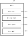
도 1a 내지 도 1h는 본 발명의 실시예에 따른 안구 냉각마취장치의 전체구성 및 각 개별구성을 나타내는 도면이다.FIGS. 1A to 1H are a diagram showing the entire configuration and individual configurations of an eye cooling anesthesia apparatus according to an embodiment of the present invention.
도 2a 내지 2f는 본 발명의 실시예에 따른 냉각마취장치 바디 내부에서 발생하는 열원의 공기흐름과 방열 구조를 나타내는 도면이다.FIGS. 2A to 2F are views showing an air flow and a heat dissipation structure of a heat source generated in a cooling anesthesia apparatus body according to an embodiment of the present invention.
도 3a 내지 3h는 본 발명의 실시예에 따는 냉각마취장치의 팁 커버의 구성과 내부 결합부재를 나타내는 도면이다.3A to 3H are views showing the structure of the tip cover and the inner engaging member of the cooling anesthesia apparatus according to the embodiment of the present invention.
* 도면의 주요 부호* Main symbols of drawings
10. 냉각팁 20. 바디부10. Cooling tip 20. Body part
110. 팁 케이스 111. 그립부110. Tip case 111. Grip part
120. 결합부재 130. 탄성부재120. Coupling member 130. Elastic member
210. 근단부 220. 원단부210. Proximal end 220. End portion
230. 파지부 240. 격벽230. Grip 240. Bulkhead
250. 냉각 제어부 211. 흡입구250. Cooling Control Unit 211. Inlet
221. 방열구 231. 스톱퍼221. Heat sink 231. Stopper
232. 안착홈 310. 냉각매체232. seating groove 310. cooling medium
320. 냉각부 330. 방열부320. Cooling section 330. Heat-
340. 컨테이너 341. 결합가이드부340. Container 341. Coupling guide portion
331. 방열핀 332. 냉각팬331. Radiating Fins 332. Cooling Fans
400. 배터리 500. 제어부400. Battery 500. Control unit
511. 전기회로 510. 재사용 판단부511. Electric circuit 510. Reuse judgment unit
520. 전기회로 개방부 530. 재사용 방지부520. Electric circuit opening part 530. Reuse prevention part
540. 재사용 알람부540. Reuse alarm section
후술하는 본 발명에 대한 상세한 설명은 본 발명이 실시될 수 있는 특정 실시 예를 예시로서 도시하는 첨부 도면을 참조한다. 이들 실시 예는 해당 업계 종사자가 본 발명에 대한 실시가 가능하도록 상세히 설명된다. 본 발명의 다양한 실시 예는 서로 다르지만 상호 배타적일 필요는 없다. 예를 들어 여기에 기재되어 있는 특정 형상, 구조 및 특성은 일 실시 예에 관련하여 본 발명의 기술적 사상 및 범위를 벗어나지 않으면서 다른 실시 예로 구현될 수 있다. 또한, 각각 개시된 실시 예 내의 개별 구성요소의 위치 또는 배치는 본 발명의 기술적 사상 및 범위를 벗어나지 않으면서 변경될 수 있다. 따라서 후술하는 상세한 설명은 한정적인 의미로서 취하려는 것이 아니며, 본 발명의 범위는, 적절하게 설명된다면, 그 청구항들이 주장하는 것과 균등한 모든 범위와 더불어 첨부된 청구항에 의해서만 한정된다. 또한, 단수형은 문구에서 특별히 언급하지 않은 한 복수형도 포함하며, 도면에서 유사한 참조부호는 여러 측면에 걸쳐서 같거나 유사한 기능을 지칭한다.The following detailed description of the invention refers to the accompanying drawings, which illustrate, by way of illustration, specific embodiments in which the invention may be practiced. These embodiments are described in detail to enable those skilled in the art to practice the invention. The various embodiments of the present invention are different but need not be mutually exclusive. For example, certain shapes, structures, and characteristics described herein may be implemented in other embodiments without departing from the spirit and scope of the invention in connection with one embodiment. Further, the position or arrangement of the individual components in the respective disclosed embodiments may be changed without departing from the spirit and scope of the present invention. The following detailed description is, therefore, not to be taken in a limiting sense, and the scope of the present invention is to be limited only by the appended claims, along with the full scope of equivalents to which such claims are entitled, if properly explained. Also, the singular forms include plural forms unless the context clearly dictates otherwise, in which like reference numerals refer to like or similar features throughout the several views.
이하 본 발명이 속하는 기술 분야에서 통상의 지식을 가진 자가 본 발명을 쉽게 실시할 수 있게 하고자, 본 발명의 바람직한 실시 예들에 관하여 첨부된 도면을 참조하여 상세히 설명하기로 하나 제시되는 실시 예에 제한되지 아니하며, 본 발명의 사상을 이해하는 당업자는 동일한 사상의 범위 내에서 다른 실시 예를 용이하게 제안할 수 있을 것이다. DETAILED DESCRIPTION OF THE PREFERRED EMBODIMENT Hereinafter, exemplary embodiments of the present invention will be described in detail with reference to the accompanying drawings. Those skilled in the art, who understands the spirit of the present invention, will readily be able to suggest other embodiments within the scope of the same concept.
도 1a 내지 도 1h는 본 발명의 실시예에 따른 냉각 장치의 전체구성 및 각 개별구성을 나타내는 도면이다.Figs. 1A to 1H are views showing the overall configuration and the respective individual configurations of the cooling apparatus according to the embodiment of the present invention. Fig.
본 발명의 실시 예에 따른 냉각장치는 안구내의 주입 또는 안구에 관한 다른 의료시술에 도움을 주기 위해서 안구표면에 빠르고 안전한 마취를 제공 가능하도록 구성된다. 본 발명의 실시 예에 따른 냉각장치 및 방법을 안구 시술을 중심으로 설명하나, 그 외의 냉각 장치 및 방법에 적용가능함은 물론이다. The cooling device according to an embodiment of the present invention is configured to be able to provide fast and safe anesthesia on the ocular surface to aid in intraocular injection or other medical procedures related to the eye. The cooling apparatus and method according to the embodiment of the present invention will be described with reference to the ocular surgery, but it goes without saying that the present invention is applicable to other cooling apparatuses and methods.
도 1a 및 도1b는 본 발명의 바람직한 실시예에 따른 전체 구성을 나타낸 도면이다.FIG. 1A and FIG. 1B are diagrams showing an overall configuration according to a preferred embodiment of the present invention.
도 1a를 참조하면, 본 발명의 실시예에 따른 냉각마취장치에 있어서, 냉각을 하기 위한 타겟 직접 접촉하는 탈부착형 냉각팁(10)과 열적 결합하는 냉각매체(310)가 구비되는 근단부(210)와, 타단에 형성되는 원단부(220)로 형성되는 바디부(20)를 포함하되, 상기 바디부(20)의 무게중심영역은 근단부(210)에 상대적으로 인접하여 위치하며, 상기 근단부(210)의 미리 설정된 위치에 사용의 조작이 용이하도록 파지부(230)를 포함하여 구성된다.Referring to FIG. 1A, a cooling anesthetic device according to an embodiment of the present invention includes a proximal end portion 210 provided with a cooling medium 310 to be thermally coupled with a removable cooling tip 10 to be directly contacted with a target for cooling, And a body portion 20 formed of a distal end portion 220 formed at the other end of the body portion 20. The center of gravity region of the body portion 20 is located adjacent to the proximal end portion 210, And a grip portion 230 for facilitating the operation at a predetermined position.
한편, 상기 탈부착형 냉각팁(10)의 일단은, 상기 탈부착형 냉각팁(10)과 물리적으로 접촉하여 결합하여 상기 원단부(220)측으로 연장하여 형성되고, 열전소자의 일측면과 물리적으로 접촉하는 열전도성 소재로 된 냉각매체(310)가 구비된다. 상기 냉각매체(310)는 냉각봉, 냉각팔(cooling arm) 등으로 지칭할 수 있다.The one end of the detachable cooling tip 10 is physically contacted with the detachable cooling tip 10 and extends to the distal end 220 side so as to be physically contacted with one side of the thermoelectric element 10, A cooling medium 310 made of a thermally conductive material is provided. The cooling medium 310 may be referred to as a cooling rod, a cooling arm, or the like.
상기 바디의 내부공간에는 상기 냉각매체(310)를 중심으로 열전냉각부(320)와 상기 열전냉각부(320)에서 발생한 열을 방열시키는 히트싱크와, 상기 히트싱크에서 방열되는 열을 외부로 강제배출시키는 냉각 제어부(250)가 위치하게 된다.A heat sink for dissipating heat generated in the thermoelectric cooling unit 320 and the thermoelectric cooling unit 320 around the cooling medium 310 in the internal space of the body; And a cooling control unit 250 for discharging the cooling water.
한편, 본 발명의 공간 치수 상 범위를 전반부 와 후반부로 나눌 수 있으며, 이 경우, 전반부에는 히트싱크, 냉각매체(310), 펠티에 소자 그리고 일회용 팁커버(냉각 접촉매체 내포), 냉각팬(332) 등이 구비되고, 후반부에는 보드 및 배터리(400)가 배치될 수 있다.In this case, a heat sink, a cooling medium 310, a Peltier element, a disposable tip cover (containing a cooling contact medium), a cooling fan 332, and the like are disposed in the front part. And a board and a battery 400 may be disposed in the second half.
본 발명은 휴대가능하다는 점을 하나의 특징으로 가진다. 이때, 휴대가능의 기능은 사용자의 손으로 발명품을 쉽게 기능할 수 있다는 점을 내포한다. 이를 위해 필기도구 (연필 이나 볼펜)처럼 파지부(230)를 전반부에 둠으로써 안정감 있는 파지를 자연스럽게 유도하고 지원한다. 이를 위하여, 후반부에 위치하는 내부 부속품들의 무게를 전체 발명품 무게의 50% 미만으로 부품들을 배치하도록 설계한다. 제품의 중요기능인 냉각기능은 펠티에 소자의 각 면에서 일어나는 발열 흡열 현상을 이용하여 기능한다. 그리고 발열면은 히트싱크, 흡열 부분은 냉각매체(310)와 접촉한다.The present invention has one feature in that it is portable. At this time, the portable function implies that the user can easily operate the invention with the user's hand. For this purpose, the grip portion 230 is placed in the front half portion like a writing instrument (pencil or ballpoint pen) to naturally induce and support a stable grip. For this purpose, the weight of the internal parts located in the latter half is designed to arrange the parts with less than 50% of the total invention weight. The cooling function, which is an important function of the product, functions by utilizing the heat endothermic phenomenon occurring on each side of the Peltier element. And the heat sink is in contact with the heat sink and the heat absorbing portion is in contact with the cooling medium 310.
냉각 실시 접촉면은 흡열 부분과 접촉해 있는 냉각매체(310)와 다시 접촉한다. 이때, 접촉 면적이 일정하다는 가정아래, 냉각 실시 접촉면과 펠티어 소자 흡열면과의 거리 즉, 냉각매체(310)의 길이 가 길어진다면 열전달 측면에서 열손실이 일어난다. 냉각 실시 접촉면과 히트엔진 (냉각기능을 직접적으로 일으키는 조합)의 거리는 밀접 하여야 하고 전반부에 위치하는 것이 타당하다. 따라서 파지부(230)가 위치되는 전반부는 무게 중심영역을 자연스럽게 내포하게 된다.The cooling conducting contact again contacts the cooling medium (310) in contact with the heat absorbing portion. At this time, assuming that the contact area is constant, if the distance between the cooling contact surface and the Peltier element heat absorbing surface, that is, the length of the cooling medium 310, is long, heat loss occurs in terms of heat transfer. The distance between the cooling contact surface and the heat engine (the combination that directly causes the cooling function) should be close and should be located in the first half. Therefore, the front half portion where the grip portion 230 is located naturally includes the center-of-gravity region.
도 1b를 참조하면, 상기 파지부(230)는, 상기 원단부(220)를 기준으로 상기 바디부(20) 길이의 65% 내지 95%에 해당하는 위치에 구비된다. 그리고 상기 파지부(230)는 사용자의 조작이 용이하도록 상기 바디부(20)의 무게중심영역에 위치하도록 구비된다.Referring to FIG. 1B, the grip portion 230 is provided at a position corresponding to 65% to 95% of the length of the body portion 20 with respect to the distal end portion 220. The grip portion 230 is provided to be positioned in the center of gravity region of the body portion 20 so that the user can easily operate the grip portion.
한편, 본 발명의 실시예에 있어서 상기 바디는 소정의 길이만큼 연장 형성되고, 대략 연필 등과 같이 사용자가 파지하여 조작이 용이한 형상으로 구비되고, 그 단면의 형상은 원형, 타원형 또는 다각형 혹은 그 조합 등으로 다양하게 구비될 수 있다.Meanwhile, in the embodiment of the present invention, the body is formed to extend by a predetermined length, and is formed in a shape such as a pencil which the user grasps and is easy to handle, and the shape of the cross section is circular, oval or polygonal, And the like.
상기 바디부(20)의 일단부에는 타겟 직접 접촉하는 탈부착형 냉각팁(10)이 결합하여 구비된다. 이때, 상기 바디주(20)의 냉각팁(10)과 결합하는 단부를 근단부(210)라 정하고, 그 타단을 원단부(220)로 하기로 한다.A detachable cooling tip 10, which is in direct contact with a target, is coupled to one end of the body 20. At this time, an end portion of the body main body 20 which engages with the cooling tip 10 is defined as a proximal end portion 210, and the other end portion is referred to as a distal end portion 220.
이때, 상기 근단부(210)는 환자의 마취 등을 위한 타겟 영역측을 향하고, 상기 원단부(220)는 지면으로부터 소정의 각도를 가지고 상방향으로 향하는 위치에 구비된다.At this time, the proximal portion 210 is directed toward the target region for anesthesia or the like of the patient, and the distal end portion 220 is provided at a position facing upward from the ground at a predetermined angle.
그리고 상기 파지부(230)는 상기 근단부(210)측으로 치우치는 위치에 형성되고, 사용자가 파지하여 조작이 용이한 위치에 형성된다. 그리고 상기 파지부(230)의 근단부(210)측 경계부에는, 소정의 높이만큼 돌출 형성되어 사용자의 파지하는 위치를 가이드하는 스톱퍼(231)가 형성되는 것을 특징으로 한다.The grip portion 230 is formed at a position biased toward the proximal portion 210, and is formed at a position where the user grips the grip portion 230 and is easy to operate. And a stopper 231 protruding from the proximal end 210 of the grip 230 by a predetermined height and guiding a user's gripping position is formed.
상기 스톱퍼(231)(stopper)는 상기 파지부(230)의 근단부(210)측 방향에 위치하여 형성되고, 사용자의 파지 시에 파지부(230)의 근단부(210)측으로 사용자의 손가락의 위치를 고정시켜주는 역할을 수행한다. 상기 스톱퍼(231)의 구성으로 인해 세밀한 의료시술 등과 같은 작업 시에 사용자의 파지된 상태를 안정적으로 유지시켜줄 수 있게 된다.The stopper 231 is formed at a position nearer to the proximal end 210 of the grip unit 230 so that the position of the user's finger is set toward the proximal end 210 of the grip unit 230 when the user grips the stopper 231 It also plays a role of fixing. Due to the configuration of the stopper 231, it is possible to stably maintain the gripped state of the user at the time of a work such as a detailed medical treatment or the like.
상기 스톱퍼(231)는 상기 바디부(20)의 외주면의 외경보다 다소 높게 형성되고, 그 형상은 다양하게 구현될 수 있다. 후술하게 될 사용자의 파지시에 사용자의 접촉하는 손가락 형상에 대응하도록 형성되는 안착홈(232)의 형상 및 위치와 연계해서 상기 스톱퍼(231)의 위치 및 형상도 정해지는 것이 바람직하다. 한편, 상기 파지부(230)에는, 사용자가 파지를 위해 접촉하는 손가락의 형상에 대응하도록 음각으로 형성되는 안착홈(232)이 형성된다. 상기 안착홈(232)은 상기 바디의 외주면에 1개소 이상에 형성되고, 파지 시에 바디의 외주면에 접촉하는 사용자의 손가락 형상에 대응하는 형상으로 형성된다. 예를 들어, 필기도구와 같은 형상으로 바디의 외형이 구비되는 경우에 사용자가 파지하여 접촉하게 되는 엄지, 검지 및 중지의 접촉되는 부위의 형상에 대응되는 형상으로 바디의 외주면에 파지부(230)가 형성되어 사용자의 안정적인 파지상태를 유지시켜주게 된다.The stopper 231 is formed somewhat higher than the outer diameter of the outer circumferential surface of the body 20, and the shape thereof can be variously embodied. It is preferable that the position and shape of the stopper 231 are also determined in conjunction with the shape and position of the seating groove 232 formed to correspond to the shape of the finger that the user touches when gripping the user to be described later. On the other hand, the grip portion 230 is formed with a seating groove 232 formed at an obtuse angle corresponding to the shape of a finger that the user touches for gripping. The seating groove 232 is formed at one or more positions on the outer circumferential surface of the body and is formed in a shape corresponding to the shape of the user's finger contacting the outer circumferential surface of the body at the time of gripping. For example, when the outer shape of the body is provided in the same shape as the writing tool, the grip 230 is formed on the outer circumferential surface of the body in a shape corresponding to the shape of the portion where the user touches the thumb, So that the stable gripping state of the user is maintained.
본 발명의 다른 실시예에 의할 때 상기 파지부(230)는, 사용자가 선택적으로 위치를 조절하기 위해서 탈부착이 가능하도록 구성할 수 있다.According to another embodiment of the present invention, the grip unit 230 may be configured to be detachable for the user to selectively adjust the position.
도 1c는 본 발명의 바람직한 실시예에 따른 무게중심 영역의 위치 및 구조에 대하여 나타낸 도면이다.1C is a view showing a position and a structure of a center-of-gravity region according to a preferred embodiment of the present invention.
상기 무게중심영역에는 냉각부(320), 방열부(330) 등이 구비될 수 있다. 상기 냉각부(320)는 바디부(20)에서 상기 근단부(210) 방향의 외부로, 소정의 길이만큼 연장형성되는 냉각매체(310), 상기 냉각매체(310)를 냉각하기 위한 열전소자 등을 포함한다. 또한, 상기 냉각부(320)에서 발생한 열을 방열시키는 방열부(330)가 구비된다. 상기 열전냉각부는 냉각부(320)로도 지칭하며, 이하, 설명의 편의를 위하여 혼용하여 사용하기로 한다.The center of gravity region may include a cooling unit 320, a heat dissipation unit 330, and the like. The cooling unit 320 includes a cooling medium 310 extending from the body 20 to the outside of the proximal end 210 by a predetermined length, a thermoelectric element for cooling the cooling medium 310, . Further, a heat dissipating unit 330 for dissipating heat generated in the cooling unit 320 is provided. The thermoelectric cooling unit is also referred to as a cooling unit 320, and will be used in combination for convenience of explanation.
그리고, 상기 냉각매체(310)와 상기 방열부(330) 사이에는, 상기 열전소자의 안착공간을 제공하는 컨테이너(340)가 더 구비되며, 상기 컨테이너(340)에는, 상기 냉각매체(310)의 외면의 형상에 대응되는 형상으로 구비되고, 상기 냉각매체(310)가 소정의 깊이만큼 삽입되어 안착되는 결합 가이드부(341)가 구비되는 것을 특징으로 한다. 본 발명의 바람직한 실시예에 의할 때, 컨테이너(340)는 복수개의 분리 유닛으로 구성될 수 있고, 상기 컨테이너(340)의 일면에는 열전소자가 수용될 수 있는 결합가이드(341)가 형성되며, 상기 컨테이너(340)는 분리 유닛이 결합되어 상기 냉각봉이 안착될 수 있는 가이드부를 제공함과 동시에 열전소자, 냉각봉, 방열부가 열적 및 기구적으로 결합할 수 있도록 한다.The container 340 is further provided between the cooling medium 310 and the heat dissipating unit 330 to provide a seating space for the thermoelectric element. And a coupling guide part 341 provided in a shape corresponding to the shape of the outer surface and in which the cooling medium 310 is inserted and seated at a predetermined depth. According to a preferred embodiment of the present invention, the container 340 may be composed of a plurality of separation units, and a coupling guide 341 is formed on one side of the container 340 to accommodate the thermoelectric elements, The container 340 is provided with a guide unit to which the separating unit is coupled to allow the cooling rod to be seated, and allows the thermoelectric element, the cooling rod, and the heat radiating unit to be thermally and mechanically coupled.
본 발명에 따른 무게중심영역은 냉각 장치의 무게중심을 포함하여, 상기 바디부(20) 길이의 40% 내지 80% 영역을 포함하거나, 상기 무게중심을 기준으로 전체 길이 대비하여, 좌우 방향으로 20%의 영역을 포함할 수 있다.The center-of-gravity region according to the present invention includes the center of gravity of the cooling apparatus, and includes the region of 40% to 80% of the length of the body portion 20, % ≪ / RTI >
또한 무게중심영역에 대응하여 사용자가 파지하여 조작을 용이하게 구비되는 파지부(230)를 포함하여 구성되도록 하여, 상기 파지부(230)에 제품의 무게중심이 연관되도록 구비되어, 사용자의 정밀한 조작을 용이한 구조를 가지는 것을 특징으로 하는 냉각마취장치에 관한 기술을 제안하기로 한다.And a grip portion 230 provided in the center of gravity for gripping by a user to easily operate the grip portion 230. The center of gravity of the product is associated with the grip portion 230, A cooling assist device for cooling an anesthetic device is provided.
본 발명의 바람직한 실시예에 의할 때, 무게중심은 사용자가 파지하고 용이하게 핸들링을 가능하도록 하기 위해서 상기 원단부(220)를 기준으로 상기 바디 전체길이의 40% 내지 80%의 범위에 해당하는 위치에 구비되고, 파지부(230)에는 파지시에 조작의 용이성을 위하여, 제품 전체의 무게중심에서 길이방향 ±10% 에 해당하는 영역에 대응하도록 구비된다. 바람직한 실시예에 의할 때, 상기 파지부(230)는 무게중심 영역내에 구비될 수도 있고, 무게중심영역과 오버랩되어 구비되어, 사용자가 정밀하게 제품을 조작이 가능한 구조를 가지도록 제공된다.According to a preferred embodiment of the present invention, the center of gravity is in the range of 40% to 80% of the overall length of the body with respect to the distal end 220 to enable the user to grasp and facilitate handling. And the grip portion 230 is provided so as to correspond to a region corresponding to ± 10% in the lengthwise direction from the center of gravity of the entire product for ease of operation at the time of gripping. According to a preferred embodiment, the grip portion 230 may be provided in the center-of-gravity region and may overlap with the center-of-gravity region so that the user can precisely manipulate the product.
상기 실시예에 의할 때, 상기와 같은 구성을 통해 제품의 전체 무게의 20%이상이 상기 무게중심영여에 집중되도록 하여, 사용자가 파지 시에 정밀한 핸들링이 가능하고, 파지된 상태의 안정성을 지속적으로 유지될 수 있는 구성을 제공한다.According to the above embodiment, it is possible to concentrate more than 20% of the total weight of the product on the center of gravity of the product through the above-described structure, so that the user can precisely handle the grip when gripping, Lt; / RTI >
다른 실시예에 의할 때, 상기 무게중심영역은 상기 원단부(220)를 기준으로 상기 바디의 전체길이의 65%에 해당하는 지점에서 시작해서 90%에 해당하는 위치에 걸쳐서 구비된다. 상기 파지부(230)는 무게중심영역내에 구비될 수도 있고, 파지를 고려하여 인체공학적으로 무게중심영역 외부에 구비될 수도 있다According to another embodiment, the center-of-gravity region extends from a position corresponding to 65% of the entire length of the body with respect to the distal end portion 220 to a position corresponding to 90%. The grip portion 230 may be provided in the center of gravity region or may be ergonomically provided outside the center of gravity region in consideration of gripping
도 1d는 본 발명의 바람직한 실시예에 따른 파지부(230)의 구성을 나타낸 도면이다.FIG. 1D is a view showing a configuration of a gripper 230 according to a preferred embodiment of the present invention.
사용자는 상기 바디를 필기도구를 사용하듯이 손으로 파지한다. 즉, 상기 파지부(230)를 엄지, 검지 및 중지를 이용하여 파지하고, 환자의 안구 등과 같은 타겟 영역에 대해서 지면의 수직축을 기준으로 좌우방향으로 대략 45°각도 범위안에서 조작하여 사용하게 된다.The user grasps the body by hand as if using a writing instrument. That is, the grip portion 230 is gripped by using the thumb, the index finger, and the stopper, and is used by operating the target region such as the eyeball of the patient within the angular range of approximately 45 degrees in the leftward and rightward directions with reference to the vertical axis of the paper.
한편, 상기 파지부(230)의 근단부(210)측 경계부에는, 소정의 높이만큼 돌출 형성되어 사용자의 파지하는 위치를 가이드하는 스톱퍼(231)가 1개소 이상의 위치에 형성되어 구비된다. 상기 스톱퍼(231)는 사용자가 조작 시에 상기 탈부착형 냉각팁(10) 방향으로 파지한 손가락이 상기 냉각팁(10) 부분까지 밀려 내려가서 치료행위에 저해되는 문제가 발생하는 것을 방지하고, 사용자의 안정적인 파지상태가 유지될 수 있도록 하는 역할을 수행한다.On the other hand, a stopper 231 protruding from the proximal end portion 210 of the grip portion 230 by a predetermined height and guiding a user's gripping position is provided at one or more positions. The stopper 231 prevents the finger held by the user in the direction of the removable cooling tip 10 from being pushed down to the cooling tip 10 during the operation so as to prevent a problem that is hindered by the treatment action, So that a stable gripping state of the gripper can be maintained.
그리고 상기 파지부(230)에는 사용자가 파지 시에 접촉하는 손가락의 형상에 대응하고, 소정의 깊이만큼 음각으로 형성되는 안착홈(232)이 상기 바디의 외주면에 구비된다. 그리고 상기 냉각매체(310)의 길이방향을 기준으로 한쌍의 컨테이너(340)가 대칭적으로 위치하게 되고, 볼트 너트결합으로 각각의 밀착상태를 유지하게 된다. 또한, 파지법의 자연스러운 유도를 위해 파지 바리케이드, 즉 돌출홈 또는 스톱퍼(231)를 팁케이스(110)와 상기 바디부(20)의 케이스의 접촉부위로부터 팁케이스(110) 면에 10 내지 3mm 정도의 이격된 위치에 2개소 이상으로 구비된다. The grip portion 230 has a seating groove 232 corresponding to the shape of a finger that the user touches when gripping and is formed at a predetermined depth by a predetermined depth on the outer circumferential surface of the body. A pair of containers 340 are symmetrically positioned with respect to the longitudinal direction of the cooling medium 310, and they are maintained in close contact with each other by bolt-nut coupling. In order to naturally induce the grasping method, a phage barricade, that is, a protruding groove or a stopper 231 is formed on the tip case 110 from the contact area between the tip case 110 and the case of the body part 20 to about 10 to 3 mm At two or more positions in a spaced apart position.
그럼으로써, 파지 바리케이드 이상으로 사용자의 손이 내려가지 않음으로써 안정감 있는 파지 및 제품 기능을 지원한다. 또한 이 바리케이드 일회용 팁케이스(110)의 탈부착시, 손과의 마찰을 일으켜 안정감 있는 탈부착을 도와준다.As a result, the user's hands are not lowered beyond the phage barricades, thus providing a stable grip and product function. In addition, when the barricade disposable tip case 110 is detached and attached, friction with the hand is generated, thereby assuring a stable detachment and attachment.
또한, 상기 파지부(230)는 상기 냉각팁(10)이 시술부위에 가하는 힘의 방향과 반대 방향으로 사용자의 손가락을 지지해 줌으로써, 상기 냉각팁(10)이 시술부위에 열적 접촉이 안정적으로 이루어질 수 있게 한다.The grip 230 supports the user's finger in a direction opposite to the direction of the force applied by the cooling tip 10 to the treatment area so that the cooling tip 10 can stably contact the treatment area .
도 1e 내지 도 1h는 본 발명의 바람직한 실시예에 따는 냉각부(320)의 구성을 나타낸 도면이다.1E to 1H are views showing the configuration of a cooling unit 320 according to a preferred embodiment of the present invention.
상술한 바와 같이 본 발명에 따른 상기 무게중심영역에는, 상기 바디부(20)에서 상기 근단부(210) 방향의 단부로 소정의 길이만큼 연장 형성되는 냉각매체(310)가 구비된다.As described above, the center-of-gravity region according to the present invention is provided with a cooling medium 310 extending from the body 20 by a predetermined length to the end of the proximal portion 210.
그리고 상기 무게중심영역에는, 상기 바디부(20)에서 상기 근단부(210)의 외부로 소정의 길이만큼 연장 형성되는 냉각매체(310)와 상기 냉각매체(310) 및 상기 냉각매체(310)를 냉각시키기 위한 열전소자를 포함하는 열전소자부 또는 상기 열전냉각부(320)에서 발생한 열을 방열시키는 히트싱크부 등이 위치하게 된다.A cooling medium 310 extending from the body 20 to the outside of the proximal end 210 by a predetermined length and a cooling medium 310 cooling the cooling medium 310 and the cooling medium 310, A heat sink unit for dissipating heat generated in the thermoelectric cooling unit 320, and the like.
상기 열전소자는 서로 다른 두개의 소자 양단에 직류전류를 가하면 전류의 방향에 따라 한쪽면은 흡열하고, 반대쪽 면에서는 발열현상을 일으키는 펠티에(peltier)효과를 일으키는 소자를 말한다. 일반적으로, 펠티에 소자라고도 한다.The thermoelectric element refers to a device that generates a peltier effect that absorbs heat on one side according to the direction of current when a direct current is applied to both ends of two different elements and generates heat on the other side. In general, it is also referred to as a Peltier element.
상기 펠티에 효과는 제에백(seekbeck)효과와 반대의 효과로 전위차를 주었을 때, 양쪽에서 발열과 흡열현상이 동시에 일어나 온도차를 발생시키는 효과이다. 한편, 상기 열전소자의 흡열면 즉, 냉각되는 면은 상기 냉각매체(310)와 열적결합을 하게 된다. 즉, 면접촉을 통해서 냉각열을 상기 냉각매체(310)로 전달하게 된다.The Peltier effect is an effect of generating a temperature difference at the same time when a potential difference is given by an effect opposite to that of the seekbeck effect, both of which generate heat and endothermic phenomenon simultaneously. On the other hand, the heat absorbing surface of the thermoelectric element, that is, the surface to be cooled, thermally couples with the cooling medium 310. That is, the cooling heat is transferred to the cooling medium 310 through the surface contact.
그리고 상기 열전소자의 발열면은 상기 히트싱크부와 열적결합을 통해서, 상기 히트싱크부에 형성된 다수개의 냉각핀을 통해서 외부로 열을 발산하게 된다.The heat generating surface of the thermoelectric element radiates heat to the outside through a plurality of cooling fins formed in the heat sink through thermal coupling with the heat sink.
이때, 결합구조 및 순서는, 냉각매체(310)와 상기 열전소자의 냉각면, 그리고 상기 열전소자의 발열면과 히트싱크 순으로 각각 열적결합을 하는 구성을 가진다. 이때, 상기 무게중심영역에는 제품 전체무게의 30% 이상이 집중될 수 있다.At this time, the coupling structure and the order are configured to thermally couple the cooling medium 310, the cooling surface of the thermoelectric element, and the heat-generating surface of the thermoelectric element in order of heat sink. At this time, more than 30% of the total weight of the product can be concentrated in the center of gravity region.
한편, 상기 원단부(220)에는 전기를 공급하는 배터리(400)와 제품의 구동 및 동작여부를 제어하는 제어부(500)가 각각 위치하게 된다. 상기 제어부(500)는 컨트롤부로도 지칭하며, 이하, 설명의 편의를 위하여 혼용하여 사용하기로 한다.Meanwhile, the far end 220 is provided with a battery 400 for supplying electricity and a control unit 500 for controlling the operation and operation of the product. The control unit 500 is also referred to as a control unit, and will be used in combination for convenience of explanation.
상기 제어부(500)와 배터리(400)는 상기 무게중심영역에 구비된 구성들과는 격벽(240)을 통해서 공간적으로 그리고 열적으로 분리 및 차폐된다. 이때, 상기 원단부(220)에 배터리(400)가 구비되는 경우, 상기 파지부(230)의 무게중심영역에는 전체 무게의 20%이상이 집중된다.The control unit 500 and the battery 400 are spatially and thermally isolated and shielded from the components provided in the center of gravity region through the barrier ribs 240. At this time, when the battery 400 is provided in the distal end portion 220, more than 20% of the total weight is concentrated in the center of gravity region of the grip portion 230.
한편, 상기 원단부(220)의 무게는 상기 바디부(20) 전체 무게의 50% 이하로 구성하게 된다.The weight of the distal end portion 220 is 50% or less of the weight of the body portion 20.
한편, 상기 컨테이너(340)에는 상기 냉각매체(310)의 길이방향의 폭에 대응하도록 형성되고, 상기 냉각매체(310)가 소정의 깊이만큼 삽입되어 안착되는 열전소자 결합 가이드부(341)가 형성된다.The container 340 is formed with a thermoelectric element coupling guide portion 341 formed to correspond to the width of the cooling medium 310 in the longitudinal direction and in which the cooling medium 310 is inserted and seated at a predetermined depth, do.
상기와 같은 구성을 통해서, 상기 컨테이너(340)에 안착된 열전소자와 히트싱크는 상기 냉각매체(310)와의 물리적 접촉상태를 안정적으로 유지하게 된다. 상기 냉각매체(310)를 기준으로 상기 열전소자의 냉각면이 상기 열전소자에 접하고, 상기 열전소자의 발열면에 상기 히트싱크가 면접촉을 통해서 결합하게 된다.With the above configuration, the thermoelectric element and the heat sink mounted on the container 340 can stably maintain a physical contact state with the cooling medium 310. The cooling surface of the thermoelectric element is in contact with the thermoelectric element on the basis of the cooling medium 310, and the heat sink is coupled to the heat generating surface of the thermoelectric element through surface contact.
그리고 상기 냉각매체(310)의 길이방향을 기준으로 한쌍의 컨테이너(340)가 대칭적으로 위치하게 되고, 상기 컨테이너(340)는 볼트 너트결합으로 각각의 밀착상태를 유지하게 된다.A pair of containers 340 are symmetrically positioned with respect to the longitudinal direction of the cooling medium 310, and the container 340 is maintained in close contact with each other by bolt-nut coupling.
이때, 상기 열전냉각부(320)과 탈부착형 냉각팁(10) 사이에는 상기 열전냉각부(320)에서 발생된 냉각열을 상기 탈부착형 냉각팁(10)으로 열전도하는 냉각매체(310)가 개재되고, 상기 냉각매체(310)는 상기 열전냉각부(320)와 탈부착형 냉각팁(10)이 각각 물리적으로 접촉하도록 구비된다.At this time, a cooling medium 310 for heat-transferring the cooling heat generated in the thermoelectric cooling unit 320 to the detachable cooling tip 10 is interposed between the thermoelectric cooling unit 320 and the detachable cooling tip 10 And the cooling medium 310 is provided so that the thermoelectric cooling part 320 and the removable cooling tip 10 are in physical contact with each other.
살펴보면, 상기 바디는 사용자가 파지하여 조작이 가능하도록 소정의 길이만큼 연장 형성되고, 타겟 영역과 직접 접촉하는 탈부착형 냉각팁(10)이 구비된 근단부(210)와, 타단에 형성되는 원단부(220)를 포함하여 형성되어 구비된다.The body includes a proximal portion 210 having a detachable cooling tip 10 extending in a predetermined length so as to allow the user to grasp and manipulate the detachable cooling tip 10 in direct contact with the target region and a proximal portion 210 220, respectively.
이때, 상기 바디의 근단부(210)에는 탈부착형 냉각팁(10) 구비되고, 상기 열전냉각부(320)와 열적으로 결합하여 환자의 안구 등과 같은 타겟 부위에 직접 접촉하도록 구비된다. At this time, the proximal end portion 210 of the body is provided with a detachable cooling tip 10, and is thermally coupled to the thermoelectric cooling portion 320 to be in direct contact with a target portion such as a patient's eyeball.
상기 냉각매체(310)는 상기 탈부착형 냉각팁(10)의 일단부와 물리적으로 접촉하여 결합되고, 상기 원단부(220)측으로 연장하여 형성된다. 상기 냉각매체(310)는 소정의 길이만큼 연장형성된 장방형, 원기둥의 형상, 소정의 길이를 가진 판형상이든 다양한 형상으로 설계변경 등을 통해서 실시가 가능하다. 본 발명의 실시예에서는 소정의 길이만큼 연장형성된 장방형을 기준으로 설명하기로 한다. 상기 냉각매체(310)는 냉각봉, 쿨링암 등으로 지칭할 수 있다.The cooling medium 310 is physically contacted with one end of the detachable cooling tip 10 and extends toward the distal end 220. The cooling medium 310 may be formed in a shape of a rectangle extending in a predetermined length, a shape of a cylinder, a plate having a predetermined length, or a variety of shapes. In the embodiment of the present invention, a rectangle extending by a predetermined length will be described as a reference. The cooling medium 310 may be referred to as a cooling rod, a cooling arm, or the like.
상기 냉각매체(310)의 외측면에는 열전냉각부(320)의 냉각면이 물리적으로 접촉하여 냉각열을 전도하도록 구비되고, 상기 열전냉각부(320)의 발열면에는 히트싱크가 물리적으로 접촉하도록 구비된다.A cooling surface of the thermoelectric cooling part 320 is physically brought into contact with the outer surface of the cooling medium 310 to conduct cooling heat. A heat sink is physically brought into contact with the heat generating surface of the thermoelectric cooling part 320 Respectively.
상기 냉각매체(310)의 길이방향을 기준으로 양방향 대칭되도록 열전냉각부(320) 그리고 히트싱크는 각각 순서대로 물리적으로 평행하게 접촉하도록 구비되는 구조를 가진다.The thermoelectric cooling unit 320 and the heat sink are physically and parallelly in contact with each other in order to symmetrically bidirectionally with respect to the longitudinal direction of the cooling medium 310.
상기 열전냉각부(320)와 히트싱크 사이에는, 상기 열전냉각부(320)와 히트싱크의 형상에 각각 대응형상의 안착공간을 제공하는 컨테이너(340)가 구비된다.A container 340 is provided between the thermoelectric cooling unit 320 and the heat sink to provide a seating space having a corresponding shape in the shape of the thermoelectric cooling unit 320 and the heat sink.
상기 냉각매체(310)를 중심으로, 한쌍의 컨테이너(340)가 서로 대칭되는 위치에 구비되어 볼트-너트 결합을 통해서 상기 열전냉각부(320)와 히트싱크를 정위치에 위치시키고 물리적 접촉상태를 유지시키도록 구비된다.A pair of containers 340 are symmetrically positioned with respect to the cooling medium 310 so that the thermoelectric cooling unit 320 and the heat sink are positioned at a predetermined position through a bolt- Respectively.
상기 컨테이너(340)의 일측에는, 상기 열전냉각부(320)의 위치를 고정하고, 상기 열전냉각부(320)의 외형형상에 대응되는 형상으로 형성되는 열전냉각부(320) 안착부가 구비된다.One side of the container 340 is provided with a thermoelectric cooling part 320 seating part which is fixed in a position of the thermoelectric cooling part 320 and formed in a shape corresponding to the external shape of the thermoelectric cooling part 320.
그리고 상기 컨테이너(340)에는 상기 히트싱크가 안착되는 히트싱크 안착부가 형성된다. 상기 히트싱크의 안착부는 상기 히트싱크의 형상에 대응되는 형상으로 형성되는 안착공간과, 상기 히트싱크의 외주면 유동을 방지하는 격벽(240)으로 포함하여 형성된다.In the container 340, a heat sink seating portion on which the heat sink is mounted is formed. The seating portion of the heat sink includes a seating space formed in a shape corresponding to the shape of the heat sink and a partition wall 240 for preventing a flow of the outer circumference of the heat sink.
이때, 상기 열전냉각부(320)와 상기 히트싱크가 상기 컨테이너(340)에 각각 정위치하면, 상기 열전냉각부(320)의 발열부와 상기 히트싱크가 물리적으로 접촉하여 열전도를 하는 구성을 가진다.At this time, when the thermoelectric cooling unit 320 and the heat sink are positioned in the container 340, the heat generating unit of the thermoelectric cooling unit 320 and the heat sink physically contact each other to conduct heat conduction .
한편, 상기 컨테이너(340)에는 상기 냉각매체(310)의 길이방향의 폭에 대응하도록 형성되고, 상기 냉각매체(310)가 소정의 깊이만큼 삽입되어 안착되는 결합 가이드부(341)가 형성된다.The container 340 is formed with a coupling guide portion 341 formed to correspond to the width of the cooling medium 310 in the longitudinal direction and to be inserted into the cooling medium 310 by a predetermined depth.
상기와 같은 구성을 통해서, 상기 컨테이너(340)에 안착된 열전냉각부(320)와 히트싱크는 상기 냉각매체(310)와의 물리적 접촉상태를 안정적으로 유지하게 된다. 상기 냉각매체(310)를 기준으로 상기 열전냉각부(320)의 냉각면이 상기 열전냉각부(320)에 접하고, 상기 열전냉각부(320)의 발열면에 상기 히트싱크가 면접촉을 통해서 결합하게 된다.With the above configuration, the thermoelectric cooling unit 320 mounted on the container 340 and the heat sink can stably maintain a physical contact state with the cooling medium 310. The cooling surface of the thermoelectric cooling part 320 is in contact with the thermoelectric cooling part 320 with respect to the cooling medium 310 and the heat sink is connected to the heat generating surface of the thermoelectric cooling part 320 through the surface contact, .
또한, 상기 컨테이너(340)은 열전도도가 낮은 물질로 만들어질 수 있고, 상기 냉각매체(310)과 상기 히트싱크를 단열시키는 역할을 한다.In addition, the container 340 may be made of a material having a low thermal conductivity, and serves to insulate the cooling medium 310 and the heat sink.
도 2a 내지 2f는 본 발명의 실시예에 따른 냉각마취장치 바디 내부에서 발생하는 열원의 공기흐름과 방열 구조를 나타내는 도면이다.FIGS. 2A to 2F are views showing an air flow and a heat dissipation structure of a heat source generated in a cooling anesthesia apparatus body according to an embodiment of the present invention.
도 2a 및 도2b는 본 발명의 바람직한 실시예에 따른 공기 흐름 및 이를 위한 구성을 나타낸 도면이다.FIGS. 2A and 2B are views showing an air flow according to a preferred embodiment of the present invention and a configuration therefor.
도 2a를 참조하면, 공기흐름 컨트롤을 위한 제품의 전반부에 위치한 일회용 팁케이스(110) 및 팁케이스(110) 결합부에 위치한 공기 흡입구(211) (흡입구(211)는 원, 원통 및 살 문양으로 될 수 있다)가 도시되어 있다. 또한, 전반부에서 후반부로 넘어가는 공기흐름 컨트롤을 위한 팬 뒤에 위치한 공기 방출구를 통하여 열을 포함한 공기가 방출된다.2A, the disposable tip case 110 located at the front half of the product for air flow control and the air inlet 211 located at the coupling of the tip case 110 (the inlet 211 is a circular, Is shown in FIG. In addition, air containing heat is emitted through the air outlet located behind the fan for air flow control from the first half to the second half.
한편, 흡입구(211)는 방열핀(331)을 구비한 상기 열전냉각부(320)의 전단 영역에 형성되고, 방열구(221)는 냉각팬(332)과 모터(미도시)를 포함한 상기 냉각 제어부(250)의 후단 영역에 형성된다. The inlet 211 is formed in the front end region of the thermoelectric cooling unit 320 having the heat radiating fin 331. The heat radiating hole 221 is formed in the cooling control unit including the cooling fan 332 and the motor 250).
상기 냉각제어부(250)는 제어부(500)의 제어명령에 따라, 모터의 구동을 통해서 상기 방열부(330) 등에서 발생하는 열원을 강제로 방열시키는 역할을 수행한다.The cooling control unit 250 performs a function of forcibly dissipating a heat source generated in the heat dissipating unit 330 or the like through driving of the motor according to a control command of the controller 500.
한편, 상기 흡입구(211)와 방열구(221)는 각각 상기 바디부(20)의 근단부(210)와 원단부(220)측에 형성되고, 외부의 공기를 상기 바디부(20) 내부로 유입시키는 입구가 되고, 내부의 열원을 외부로 방열시키는 출구의 역할을 수행한다.The air inlet 211 and the air outlet 221 are formed at the proximal end 210 and the distal end 220 of the body 20 and allow the outside air to flow into the body 20. And serves as an outlet for dissipating the internal heat source to the outside.
한편, 상기 흡입구(211)와 방열구(221) 중 어느 하나는 상기 바디부(20)의 경사를 이루는 부위에 형성될 수 있다.Either one of the inlet 211 and the outlet 221 may be formed at a position that tilts the body 20.
상기 바디부(20)의 개략적인 외형은, 탈착 가능한 냉각팁(10)의 단부에서 상기 근단부(210)의 소정의 위치 즉, 상기 파지부(230)의 일측에 구비된 스톱퍼(231)까지 상향 경사되는 단면을 가지다가, 파지부(230)와 무게중심영역부위에서는 대략 수평단면을 이룬다.The outline of the body part 20 is formed at a predetermined position of the proximal end part 210 at an end of the removable cooling tip 10, that is, up to a stopper 231 provided at one side of the grip part 230 And has a substantially horizontal cross-section at the grip portion 230 and the center-of-gravity region.
상기 파지부(230)와 무게중심영역에서 상기 원단부(220)의 소정의 위치까지는 하향 경사하는 단면을 가진다. 이때, 상기 흡입구(211)는 상기 근단부(210)의 상향경사 단면부에 형성된다. 상기 흡입구(211)의 형상의 소정의 외경을 가진 다수개의 통공으로 형성될 수 있다.And has a section inclined downward to a predetermined position of the distal end portion 220 from the center of gravity region with the grip portion 230. At this time, the inlet 211 is formed in the upward inclined end face of the proximal end 210. And may have a plurality of through holes having a predetermined outer diameter in the shape of the inlet 211.
또한, 상기 흡입구(211)는 상기 바디부(20)의 길이방향으로 긴 장공형태로 외주면에 방사상으로 형성될 수 있다. 또한, 상기 흡입구(211)는 상기 바디부(20)의 외주면에 원주방향으로 소정의 이격 거리를 가지는 링 형상으로 형성될 수 있다. 상기 흡입구(211)의 형상은 다양한 형상으로 구비될 수 있다. 그리고 상기 방열구(221) 또한 상기 흡입구(211)의 형상에서 제시한 형상의 적용이 가능하다.In addition, the suction port 211 may be radially formed on the outer circumferential surface of the body 20 in the form of a long hole in the longitudinal direction of the body 20. The inlet 211 may be formed in a ring shape having a predetermined distance in the circumferential direction on the outer circumferential surface of the body 20. The inlet 211 may have various shapes. Also, the shape of the heat dissipation port 221 and the shape of the intake port 211 can be applied.
경사부에 위치한 상기 흡입구(211)와 방열구(221)는, 상기 열전냉각부(320)로의 공기의 유입과 상기 열전냉각부(320)에서 발생한 열원을 외부로의 방열을 용이하게 할 수 있는 구조를 가지고 있다.The intake port 211 and the heat dissipation port 221 located at the inclined portion are formed to have a structure capable of facilitating the inflow of air into the thermoelectric cooling unit 320 and the heat source generated in the thermoelectric cooling unit 320, Lt; / RTI >
한편, 도 2b를 참조하면, 상기 파지부(230)의 일측에는 외부의 공기흡입을 안내하는 흡입구(211)가 구비되고, 방열부(330)와 냉각팬(332)을 경유한 거리에 대응하여, 소정의 거리를 두고 타측에는 내부의 열원을 외부로 방출하는 방열구(221)가 각각 구비된다. 상기 흡입구(211)와 방열구(221)의 형상은 다수개의 원형의 통공, 장공형 또는 다양한 형상으로 적용될 수 있다. 상세히, 상기 흡입구(211)는 상기 파지부(230)와 탈부착형 냉각팁(10) 사이에 형성되고, 상기 방열구(221)는 상기 파지부(230)의 타측 경계부에 형성된다.2B, a suction port 211 for guiding external air is provided at one side of the grip portion 230, and a suction port 211 for guiding the suction of the external air is provided at one side of the grip portion 230. In correspondence with the distance passed through the heat radiating portion 330 and the cooling fan 332 And a heat discharging opening 221 for discharging the inside heat source to the outside at a predetermined distance. The shape of the inlet 211 and the heat discharging hole 221 may be a plurality of circular holes, a long hole or a variety of shapes. The suction port 211 is formed between the grip portion 230 and the detachable cooling tip 10 and the heat dissipation port 221 is formed at the other edge portion of the grip portion 230.
사용자가 냉각마취장치를 파지하여 지면에 대해서 45 내지 90% 범위내에서 사용하는 경우에, 상기 바디 내부에 구비된 히트싱크를 통해서 방열되는 열원은 주위의 공기온도보다 높으므로, 발생된 열원은 중력의 반대방향으로 이동하여 상기 방열구(221) 측으로 이동하여 방열되고, 상기 흡입구(211) 측으로 실내의 공기가 유입되어 자연 냉각시키게 구성을 가진다.When the user grasps the cooling anesthesia device and uses it within the range of 45 to 90% with respect to the ground, the heat source radiating through the heat sink provided inside the body is higher than the surrounding air temperature, And moves toward the heat radiating port 221 side to radiate heat, and air in the room flows into the side of the air inlet 211 to naturally cool.
도 2c 및 도 2d는 본 발명의 바람직한 실시예에 따른 내부 공기흐름에 대응하는 내부 구성을 나타낸 도면이다Figures 2c and 2d illustrate an internal configuration corresponding to an internal air flow according to a preferred embodiment of the present invention
도 2c를 참조하면, 흡입구(211)와 방열구(221)사이의 냉각유로는, 바디 내부에 구비된 히트싱크의 외면에 형성된 다수개의 냉각핀을 경유하도록 구성된다.Referring to FIG. 2C, the cooling flow path between the inlet 211 and the heat dissipating port 221 is configured to pass through a plurality of cooling fins formed on the outer surface of the heat sink provided in the body.
제품 내에서의 공기흐름은 흡열기능에 중대한 영향을 미친다. 이때, 흡열현상은 펠티에 소자의 방열 면과 히트싱크 사이에서 일어난다. 방열 현상은 히트싱크와 공기흐름사이에서 일어난다. 공기흐름의 방향성과 구조는 히트싱크의 핀들을 빠짐없이 지나며 방열을 효율적으로 수행할 수 있다.Airflow within the product has a significant effect on the endothermic function. At this time, the endothermic phenomenon occurs between the heat radiation surface of the Peltier element and the heat sink. Heat dissipation occurs between the heat sink and the airflow. The directionality and structure of the air flow pass through the fins of the heat sink and can efficiently dissipate heat.
바람직할 실시예에 의할 때, 히트싱크의 핀 사이를 지나가는 공기의 속도와 연관이 있다. 핀들을 지나가는 공기의 속도 관점에서 봤을 때 흡입구(211)에서 흡입되는 공기의 흐름은 공기흐름 컨트롤이 없었을 시, 핀 사이의 공간과 평행하게 진행하기 된다. 하지만 핀의 최하단부로 공기의 부피를 밀집시키면 핀 사이의 공간으로 진행하면서 서서히 퍼지는 식으로 공기흐름이 발생할 수 있다. 따라서 일회용 팁 케이스(110)와 팁케이스(110) 체결부에 있는 흡입구(211)는 히트싱크의 팁 최하단부로 흡입되는 공기를 유도할 수 있는 위치에 구비되며, 바람직한 실시예에 의할 때, 히트싱크 핀 최하단부로부터 ±2mm 이내로 설계할 수 있다.According to a preferred embodiment, this is related to the speed of air passing between the pins of the heat sink. From the viewpoint of the speed of the air passing through the pins, the flow of the air sucked in the suction port 211 proceeds parallel to the space between the pins when there is no air flow control. However, if the volume of the air is concentrated at the lowermost end of the fin, the airflow may be generated by gradually spreading to the space between the pins. Therefore, the suction port 211 in the fastening portion of the disposable tip case 110 and the tip case 110 is provided at a position capable of guiding the air sucked to the lowermost tip of the tip of the heat sink. According to a preferred embodiment, It can be designed within ± 2mm from the lowermost part of the sink pin.
또한, 반대되는 관점에서 방열구(221)는 공기의 흐름을 방해하는 저항을 최대한 줄임으로써 최대한 큰 부피의 공기가 같은 시간 내에 빠져 나갈 수 있도록 설계한다. 별 다른 공기흐름 컨트롤을 위한 설계가 없다면 공기의 흐름은 컨트롤러인 냉각팬(332) 뒤로 평행하게 나아가, 보드(미도시) 및 배터리(400)가 내장되는 영역을 가로막는 케이스 내부의 벽에 부딪히며 반대 방향으로 돌아오는 흐름이 만들어 지게 된다. 이러한 경우, 펜과 내부의 벽 사이에는 불규칙한 흐름이 생성되고. 이는 케이스 내부의 벽, 케이스 외부의 방출구를 제외한 케이스 와 함께 공기의 방출에 또 다른 저항으로 작용한다. 따라서 공기의 흐름을 자연스럽게 방출구로 밀집되도록 유도 하는 구조가 케이스 내부의 벽에는 필요하다.Also, from the opposite viewpoint, the heat dissipating port 221 is designed to maximize the resistance that obstructs the flow of air, so that the air having the largest volume can escape within the same time. Unless there is a design for different air flow control, the air flow moves parallel to the back of the cooling fan 332, which is the controller, and bumps against the wall inside the case, blocking the area where the board (not shown) A flow of returning is created. In this case, an irregular flow is created between the pen and the inner wall. This acts as another resistance to the release of air with the case inside the case, except for the outlet on the outside of the case. Therefore, it is necessary to have a structure inside the case to induce the flow of air naturally into the discharge port.
또한, 상기 냉각 제어부(250)의 강제 냉각 시에도 상기 흡입구(211)와 방열구(221)가 형성된 위치의 형상으로 인해서 그 냉각 및 방열효율이 극대화될 수 있는 위치적인 구조를 가지고 있다.In addition, even when the cooling control unit 250 is forcibly cooled, it has a positional structure in which the cooling and radiating efficiency can be maximized due to the shape of the position where the inlet 211 and the radiating hole 221 are formed.
도 2d를 참조하면, 상기 흡입구(211)와 방열구(221)사이의 냉각유로는, 본체 내부에 구비된 히트 싱크에 형성된 냉각핀을 경유하되, 냉각핀을 경유하는 거리는 동일하고, 흡입구(211)에서 흡입된 공기의 위치에 따라 상기 바디부(20)내에 체류하는 시간은 상이하다.2D, the cooling passage between the intake port 211 and the heat dissipation port 221 passes through a cooling fin formed in a heat sink provided in the main body, and a distance through the cooling fin is the same, The time taken to stay in the body part 20 differs depending on the position of the air sucked in the body part 20.
즉, 상기 흡입구(211)에 흡입되는 공기의 위치에 따라 공기의 케이스내에 체류시간이 상이할 수 있다. 흡입구(211)가 방열핀(331)과 오버랩되어 형성되는 경우, 체류시간뿐만 아니라, 방열핀(331)을 경유하는 시간 또는 거리도 상이할 수 있다. 즉, 상기 냉각핀을 경유하는 거리는 일정하나 상기 서로 다른 위치에 형성된 흡입구(211)에서 상기 방열구(221)까지 도달하는 체류시간은 각기 상이할 수 있다.That is, depending on the position of the air sucked into the suction port 211, the residence time in the case of the air may be different. In the case where the suction port 211 is formed overlapping with the radiating fin 331, not only the residence time but also the time or distance through the radiating fin 331 may be different. That is, the distance through the cooling fins is constant, but the residence times from the inlet 211 formed at the different positions to the heat dissipation holes 221 may be different.
도 2d를 참조하여, 본 발명의 바람직한 실시예에 따른 내부 공기흐름을 위한 히트싱크 구조를 살펴보면, 상기 히트싱크의 형상은 상기 바디부(20)의 형상에 대응하도록 구비되고, 상기 히트싱크의 방열핀(331)과 상기 바디부(20)의 내면의 간격은 기 설정된 수치 범위내인 것이다.Referring to FIG. 2D, a heat sink structure for internal air flow according to a preferred embodiment of the present invention is provided, the shape of the heat sink corresponding to the shape of the body portion 20, The interval between the inner surface of the body portion 20 and the inner surface 331 is within a predetermined numerical range.
즉, 상기 히트싱크의 형상은 상기 바디부(20)의 내면 공간이 제공하는 형상에 대응하도록 형성되어 구비되고, 상기 방열핀(331)의 단부는 상기 바디부(20)의 내면과 소정의 기 설정된 수치범위내의 간격을 형성하도록 구비된다. 한편, 상기 흡입구(211)에서 외부공기를 강제 흡입하여 상기 방열구(221)측으로 방출시키는 공기유동을 제어하기 위해서 냉각팬(332) 및 모터(미도시)를 포함하는 냉각 제어부(250)가 더 구비된다.That is, the shape of the heat sink is formed to correspond to the shape provided by the inner surface space of the body portion 20, and the end portion of the heat radiating fin 331 is formed with predetermined inner surface of the body portion 20 To form an interval within the numerical range. The cooling control unit 250 includes a cooling fan 332 and a motor (not shown) to control the air flow for forcedly sucking the outside air through the inlet 211 and discharging the air to the heat radiating port 221 side do.
한편, 상기 방열구(221)로 방출되는 공기흐름은 상기 냉각팬(332)에서 발생하는 공기유동 및 상기 격벽(240)에서 반사되는 공기흐름이 더해진 것을 포함한다.Meanwhile, the air flow discharged to the heat radiating port 221 includes an air flow generated from the cooling fan 332 and an air flow reflected from the partition 240.
도 2e는 본 발명의 바람직한 실시예에 따른 제어부(500)의 작동 원리를 나타낸 도면이다.FIG. 2E is a diagram illustrating the operation principle of the controller 500 according to the preferred embodiment of the present invention.
본 발명의 바람직한 실시예에 의할 때, 바디 내부에는, 상기 흡입구(211)에서 외부공기를 흡입해서 상기 방열구(221)측으로 열원을 강제 방열시키는 냉각팬(332)을 제어하는 제어부(500)가 더 구비된다. 상기 제어부(500)는, 일방향 또는 양방향으로 공기를 강제로 이동시키는 모터로 구동하는 팬과, 바디(10) 일측에 구비되어 내부의 온도를 측정하는 열감지 센서를 포함하여 구성되는 냉각 제어부(250)의 구동 등을 제어한다.According to a preferred embodiment of the present invention, a controller 500 for controlling a cooling fan 332 for sucking outside air from the inlet 211 and forcibly dissipating the heat source toward the heat discharging opening 221 is provided in the body . The controller 500 may include a fan driven by a motor for forcibly moving air in one direction or both directions and a cooling controller 250 provided at one side of the body 10 and including a thermal sensor for measuring the temperature of the interior And the like.
상세히, 상기 제어부(500)는 상기 보드(미도시)에 안착되어 구비되고, 상기 열감지 센서를 통해서 입력되는 온도 등을 정보를 판단하여 상기 냉각 제어부(250)의 구동 및 제어 등의 역할을 수행하게 된다.In detail, the control unit 500 is mounted on the board (not shown), and controls the cooling control unit 250 by determining temperature information inputted through the heat sensing sensor and controlling the cooling control unit 250 .
한편, 상기 제어부(500)는 상기 냉각 제어부(250)에 대한 구동 및 제어 뿐만 아니라, 후술할 탈부착 가능한 냉각팁(10)의 재사용 여부 등을 판단 및 작동제한 등을 컨트롤 하는 역할 또한 수행한다.The control unit 500 controls not only the operation and control of the cooling control unit 250 but also the determination of the reuse of the detachable cooling tip 10 and the operation restriction.
상기 열감지 센서에서 설정된 소정의 온도이상이 감지되는 경우에, 상기 제어부(500)는 상기 냉각 제어부(250)를 선택적으로 동작하여 내부의 온도를 소정의 온도이하로 유지될 수 있도록 한다.The controller 500 selectively operates the cooling controller 250 so that the internal temperature can be maintained at a predetermined temperature or less.
그리고 바디 일측에 상기 열감지 센서에서 측정된 온도를 도시하는 디스플레이부(미도시)가 더 구비될 수 있다. 사용자는 상기 디스플레이에서 도시하는 온도와 색상의 변화 등을 통해서 냉각마취장치의 사용여부를 판단하게 된다.Further, a display unit (not shown) may be further provided on one side of the body to indicate a temperature measured by the heat sensing sensor. The user determines whether or not the cooling anesthesia device is used through a change in temperature and color shown in the display.
한편, 상기 탈부착형 냉각팁(10)의 일측에도 상기 탈부착형 냉각팁(10)의 온도를 감지하는 열감지 센서가 구비된다. 상기 열감지 센서에서 측정된 탈부착형 냉각팁(10)의 현재 온도 역시 상기 디스플레이에 도시되는 것이 가능하다. 또한, 상기 탈부착형 냉각팁(10)의 현재 온도는 별도의 디스플레이를 통해서 숫자로 표시되거나 사용가능여부를 색상변화로 도시하는 것이 가능하다. 이 때, 상기 탈부착형 냉각팁(10)의 온도 측정을 용이하게 하기 위해, 적외선 온도센서 등 비접촉식 온도 센서가 사용될 수 있고, 정밀한 온도측정을 위해, 상기 냉각팁(10)이 흑체복사(black body radiation)를 따르는 표면을 코팅 등을 통해 가질 수 있다.A heat sensing sensor for sensing the temperature of the detachable cooling tip 10 is also provided on one side of the detachable cooling tip 10. The current temperature of the detachable cooling tip 10 measured at the heat sensing sensor can also be shown on the display. The current temperature of the removable cooling tip 10 may be displayed as a number through a separate display or may be displayed as a color change. In order to facilitate temperature measurement of the detachable cooling tip 10, a non-contact type temperature sensor such as an infrared temperature sensor can be used. In order to accurately measure the temperature, the cooling tip 10 is provided with a black body radiation through the coating or the like.
상기 냉각장치는, 냉각을 하기 위한 타겟 영역과 직접 접촉하는 탈부착형 냉각팁(10)과 열적 결합하는 냉각매체(310)가 구비되는 근단부(210)와, 타단에 형성되는 원단부(220)로 형성되는 바디부(20)를 포함하되, 상기 냉각매체(310)의 열을 방열시키는 히트싱크부에 공기유동을 발생하기 위한 냉각팬(332)을 포함하고, 상기 근단부(210)에서 내부 및 외부의 공기유동 사이클이 이루어지고, 상기 냉각팬(332)이 구비되는 영역의 바디부(20)의 소정 영역에는 외부의 공기흡입을 안내하는 흡입구(211)와, 내부의 열원을 외부로 방출하는 방열구(221)가 형성되어 있는 냉각장치의 구성이 구비된다.The cooling device includes a proximal end portion 210 provided with a cooling medium 310 thermally coupled to a removable cooling tip 10 in direct contact with a target region for cooling and a distal end portion 220 formed at the other end And a cooling fan (332) for generating an air flow in a heat sink portion for dissipating heat of the cooling medium (310), wherein the cooling fan (332) includes a body portion (20) A suction port 211 for guiding external air suction is formed in a predetermined area of the body part 20 in a region where the cooling fan 332 is provided and a discharge port 211 for discharging the internal heat source to the outside, And a cooling device 221 in which cooling water is supplied.
도 2f는 본 발명의 바람직한 실시예에 따른 사용시 공기흐름을 설명한 도면이다.FIG. 2F is a diagram illustrating air flow during use according to a preferred embodiment of the present invention.
이때, 사용자가 상기 바디부(20)를 파지하여 사용시에, 지면에 대해서 소정의 각도 범위에서 사용되고, 흡열된 공기의 중력반대 방향으로 이동하는 패시브(passive) 공기유동이 상기 냉각팬(332)에 의한 액티브(active) 공기유동과 결합하는 공기흐름을 가지게 된다.At this time, a passive air flow that is used in a predetermined angular range with respect to the ground when the user grasps the body part 20 and moves in the opposite direction of the gravity of the heat absorbed air flows to the cooling fan 332 Lt; RTI ID = 0.0 > airflow. ≪ / RTI >
상세히, 사용자의 상기 바디부(20)를 파지하여 타겟 영역에 대해서 접촉하여 해당부위를 냉각 또는 마취시키는 행위를 하는 경우에, 그 사용 환경이 지면인 수평상태에 대해서 소정의 각도 범위 내에서 기울어진 채로 사용하게 된다.In detail, when the body part 20 of the user is gripped to contact the target area to cool or anesthetize the part, the use environment is inclined within a predetermined angle range with respect to the horizontal state as the ground surface It will be used.
이때, 상기 패시브(passive) 공기유동은 상기 바디부(20) 내부에서 발생된 열원이 내부의 공기를 가열하게 되어 외부 혹은 주위의 공기의 온도 대비 높은 온도를 가지게 되어 중력의 반대방향인 상방향으로의 흐름을 가지게 되는 데 이를 패시브(passive) 공기유동으로 칭한다. 상기 패시브(passive) 공기유동은 외부의 타력에 의한 공기의 흐름이 아니라, 공기의 비중의 차이에 따른 자연의 법칙에 따른 대기의 순환을 의미하게 된다. 반면, 액티브(active) 공기유동은, 상기 패시브(passive) 공기유동과는 대비되는 개념으로, 상기 바디부(20) 내부에 구비된 팬의 구동으로 강제적으로 발생하는 공기흐름을 의미한다.At this time, the passive air flow causes the heat source generated inside the body 20 to heat the internal air, so that it has a temperature higher than the temperature of the external or ambient air, , Which is referred to as a passive air flow. The passive air flow is not a flow of air due to an external force, but a circulation of the atmosphere according to a natural law according to a difference in specific gravity of the air. On the other hand, the active air flow is a concept that contrasts with the above-described passive air flow, and refers to an air flow that is forcibly generated due to the operation of the fan provided in the body portion 20.
상기 액티브(active) 공기유동은, 모터 등의 구동으로 인해 발생하는 팬의 회전에 의해서 발생하는 공기의 강제적인 흐름으로써, 그 방향은 지면에 대해서 상방향 혹은 중력방향을 거스르는 하방향을 모두 포함한다.The active air flow is a forced flow of air generated by the rotation of the fan caused by the driving of a motor or the like, and the direction includes an upward direction with respect to the ground surface or a downward direction against the gravity direction .
일반적인 사용자의 사용시에는, 상기 패시브 공기유동에 의한 공기흐름과 상기 액티브 공기유동에 의한 공기흐름이 동일한 방향으로 합쳐져서 그 냉각효과를 극대화하는 데 이용된다.When a general user is used, the air flow by the passive air flow and the air flow by the active air flow are combined in the same direction to maximize the cooling effect.
또한 사용자가 제품을 사용할 시에는 파지부(230)와 연장선상의 측면에서 지면과 30 내지 60°도 사이의 각도로 사용 하게 된다. 이때 히트싱크의 핀 사이에서 흡열현상을 거친 공기들은 중력으로 인해 흡입구(211)에서 흡입된 공기보다 가벼워 짐으로써 능동적인 공기 컨트롤을 위한 팬 이외에 또 다른 공기흐름 컨트롤을 위한 힘으로 작용하게 된다.In addition, when the user uses the product, the grip 230 is used at an angle of 30 to 60 degrees with the ground at the side of the extension line. At this time, the heat-absorbed air between the pins of the heat sink is lighter than the air sucked from the suction port 211 due to gravity, thereby acting as a force for controlling the airflow in addition to the fan for active air control.
한편, 상기 바디부(20)의 내부에는, 타겟 영역을 냉각하기 위한 열전냉각부(320)가 구비된 상기 근단부(210) 및 상기 냉각을 제어하기 위한 냉각 제어부(250)가 구비되는 상기 근단부(210) 사이의 공기흐름을 차단하는 격벽(240)이 구비된다.The proximal end portion 210 provided with the thermoelectric cooling portion 320 for cooling the target region and the proximal end portion 210 provided with the cooling control portion 250 for controlling the cooling are provided in the body portion 20, 210) for preventing airflow between the partition walls (240).
상기 열전냉각부(320)는 열전소자를 포함한 열전소자부와, 상기 열전소자부와 열적으로 결합하여 상기 열전소자부에서 발생한 열원을 방열시키는 히트싱크부를 포함하여 구성된다.The thermoelectric cooling unit 320 includes a thermoelectric element including a thermoelectric element and a heat sink unit thermally coupled to the thermoelectric element to dissipate the heat generated by the thermoelectric element.
상기 냉각 제어부(250)는, 상기 열전냉각부(320)를 강제로 냉각시키기 위한 것으로써, 구동력을 제공하는 모터부와, 상기 모터부에서 전달되는 회전력을 이용하여 강제 공기유동을 발생시키는 팬(332)을 포함하여 구성된다.The cooling control unit 250 includes a motor unit for forcibly cooling the thermoelectric cooling unit 320 and provided with a driving force and a fan for generating a forced air flow using the rotational force transmitted from the motor unit 332).
상기 무게중심영역 내에 구비된 열전냉각부(320)와 냉각 제어부(250)가 구비되고, 배터리(400)와 제어부(500) 등이 구비되는 원단부(220)는 격벽(240)으로 물리적으로 열적으로 상호 분리되는 구성을 가진다. 패시브 공기유동에 의해서든, 액티브 공기유동에 의해서든 방열을 위한 공기흐름은 상기 격벽(240)에 의해서 상기 원단부(220) 측으로 공기흐름은 차단된다.A thermoelectric cooling unit 320 and a cooling control unit 250 provided in the center of gravity region and a distal end portion 220 including a battery 400 and a control unit 500 are physically and thermally Respectively. Airflow for heat radiation, either by passive air flow or by active air flow, is blocked by the partition 240 toward the distal end 220 side.
도 3a 내지 3e는 본 발명의 실시예에 따는 냉각마취장치의 팁 케이스(110)의 구성과 내부 결합부재(120)를 나타내는 도면이다. 상기 냉각마취장치에 있어서, 타겟 영역과의 직접 접촉을 통하여 상기 타겟 영역을 냉각하는 착탈식 냉각팁(10)과 상기 냉각팁(10)을 지지하면 상기 냉각마취장치에 장착하기 위한 결합부재(120)를 포함하는 팁 케이스(110)를 포함하여 구성되며, 도면을 참조하여 상세히 설명하기로 한다.3A to 3E are views showing the configuration of the tip case 110 of the cooling anesthesia apparatus according to the embodiment of the present invention and the inner engaging member 120. FIG. In the cooling anesthesia apparatus, a detachable cooling tip (10) for cooling the target area through direct contact with a target area and a coupling member (120) for mounting the cooling tip (10) And a tip case 110 including the tip case 110, which will be described in detail with reference to the drawings.
도 3a는 본 발명의 바람직한 실시예에 따른 탈착식 팁의 구성을 나타낸 도면이다. FIG. 3A is a view showing a configuration of a detachable tip according to a preferred embodiment of the present invention.
도 3a를 참조하면, 상기 냉각팁(10)은 상기 냉각매체(310)와 물리적인 직접 접촉을 통하여, 열적결합 및 전위결합을 통해서 결합하는 구조를 가진다. 상기 전위결합은, 상기 냉각팁(10)의 전위가 열적결합과 더불어, 상기 냉각매체(310)의 전위에 대응하는 전위를 가지는 것을 의미한다. 이 때, 전위가 결합된 상기 냉각팁(10)과 상기 냉각매체(310)은 콘덴서(capacitor) 기능을 할 수 있는 부품과 전기적으로 결합되어 전위를 안정화시킬 수 있다. 어떤 예에서는, 상기 콘덴서(capacitor)기능을 하는 부품은 배터리일 수 있다. 이와 같이, 독립적인 콘덴서(capacitor)를 구성하지 않고, 배터리가 상기 냉각팁(10)과 상기 냉각매체(310)의 결합된 전위를 안정화시키는 역할을 수행할 때에는, 상기 냉각팁(10)과 상기 냉각매체(310)의 결합된 전위가 상기 열전냉각부((320)의 작동 전위 범위 안에서 안정화될 수 있다. Referring to FIG. 3A, the cooling tip 10 has a structure that is in direct physical contact with the cooling medium 310, and is coupled through thermal coupling and dislocation coupling. The potential coupling means that the potential of the cooling tip 10 has a potential corresponding to the potential of the cooling medium 310 together with the thermal coupling. At this time, the cooling tip 10 to which the potential is coupled and the cooling medium 310 can be electrically coupled with a component that can function as a capacitor, so that the potential can be stabilized. In some instances, the capacitor-functioning component may be a battery. When the battery serves to stabilize the combined potential of the cooling tip 10 and the cooling medium 310 without forming an independent capacitor as described above, The combined potential of the cooling medium 310 can be stabilized within the working potential range of the thermoelectric cooling portion 320. [
이러한 냉각팁(10), 냉각매체(310), 콘덴서(capacitor) 기능을 하는 부품의 전위 결합은 시술 전 기간 동안 이루어져 시술 부위에 닿기 전에 미리 전위를 안정화시킬 수 있다. 또 다른 예에서는, 냉각팁(10), 냉각매체(310), 콘덴서(capacitor) 기능을 하는 부품의 전위 결합은 시술 전과 시술 동안 모두 이루어질 수 있다.Potential bonding of the cooling tip 10, the cooling medium 310, and capacitors is performed during a period before the operation, and the potential can be stabilized in advance before reaching the treatment site. In yet another example, the potential coupling of the component that functions as the cooling tip 10, the cooling medium 310, and the capacitor can be achieved both before and during the procedure.
이러한 전위 결합을 통하여 시술부위에 접촉하는 상기 냉각팁(10)이 전기적인 안정성을 가지며, 인체의 타겟 영역에 접촉하는 경우에도 스파크 등을 안정적으로 방지할 수 있다. The cooling tip 10, which contacts the treatment region through the electric potential coupling, has electrical stability and can stably prevent sparks and the like even when the cooling tip 10 contacts the target region of the human body.
본 발명의 바람직한 실시예에 의할 때, 냉각매체(310), 즉 바람직한 실시예에 의할 때, 냉각봉은 펠티에 소자를 사이에 두고 히트싱크와 물리적으로 표면이 접촉해 있다 그리고 이 표면은 0.1 마이크로미터 이하의 평탄도를 가지고 열전달이 뛰어난 금속으로 도금이 되어있다. 그리고 냉각 매체는 탈착식 팁 케이스(110)의 냉각 접촉 부위와 물리적인 방법으로 결합이 된다. 즉, 냉각 접촉 부위는 펠티에 소자, 히트싱크 그리고 냉각매체(310) 와 열적으로 결합한다.In accordance with a preferred embodiment of the present invention, the cooling medium 310, i.e., in a preferred embodiment, the cooling rod is physically in surface contact with the heat sink through the Peltier element, It has a flatness of less than a meter and is plated with metal with excellent heat transfer. And the cooling medium is coupled to the cooling contact area of the detachable tip case 110 in a physical manner. That is, the cooling contact region thermally couples with the Peltier element, the heat sink, and the cooling medium 310.
탈착식 팁의 기능은 크게 두 가지로 나뉜다. 일 실시예에 의할 때, 히트싱크 와 펠티에 소자를 이용한 흡열 및 방열 현상을 이용한 냉각 매체의 급속냉각의 열전달 측면에서의 냉각 접촉 부위로의 열전달 기능을 가지고, 다른 실시예에 의할 때, 냉각 접촉 부위의 위생상 멸균 유지를 위한 재사용 방지 기능을 가질 수 있다.The function of the detachable tip is divided into two functions. According to one embodiment, the heat transfer function to the cooling contact area in terms of heat transfer of the cooling medium using the heat sink and the Peltier element and the cooling medium using the heat dissipation phenomenon has the function of cooling And may have a reuse prevention function for hygienic sterilization maintenance of the contact area.
이러한 기능을 달성하기 위해서는 탈착식 일회용 팁커버의 냉각 매체와(Arm) 와 냉각 접촉 부위는 열적으로 최소한의 저항을 가지면서 결합해야 한다. 이때 열전달적인 측면에서 냉각 매채와 냉각 접촉 부위 사이의 물리적인 유격이 가장 큰 저항요소이다. 이를 최소화 하며 냉각 접촉부위가 하나의 냉각 매체로 기능하기 위해서는 물리적인 유격을 최소화 하는 체결 방식이 필요하다. 그 예시로서는 다음과 같은 방식이 있다. 도 3B는 그 예시중 하나인 스크류 채결 방식을 보여준다. 냉각매채(ARM) 의 끝부분에 스크류 형상으로 가공을 하여 팁 케이스(110)와의 물리적인 유격을 최소화 한다. In order to achieve this function, the cooling medium and the cooling contact area of the detachable disposable tip cover must be thermally coupled with a minimum resistance. In this case, the physical clearance between the cooling medium and the cooling contact area is the largest resistance element on the heat transfer side. To minimize this and to allow the cooling contact area to function as a single cooling medium, a fastening method that minimizes physical clearance is needed. For example, there are the following methods. Fig. 3B shows one example of the screwing method. The tip end of the cooling medium (ARM) is processed into a screw shape to minimize the physical clearance with the tip case (110).
도 3b 및 도 3c는 탈착식 팁의 재사용방지 기능을 위한 구조를 나타낸다.Figs. 3B and 3C show a structure for preventing the reuse of the removable tip.
도 3b 및 도 3c를 참조하면, 상기 팁 케이스(110)에 구비된 결합부재(120)는, 버튼방식 또는 나사결합 방식 중 어느 하나가 적용된다. 이때, 상기 착탈식 냉각팁(10)은 상기 냉각마취장치 외부로 소정의 길이만큼 연장하여 돌출 형성되는 냉각매체(310)와 열적결합을 통해서 상기 냉각마취장치와 결합하게 된다. 본 발명의 바람직한 실시예로, 물리적으로 냉각팁(10) 케이스와 바디부(20) 케이스의 결합을 통하여, 냉각매체(310)와 냉각 접촉부위 사이를 좁히는 압력을 가해서, 일정 기준 압력 이상을 접촉을 유지시키는 체결방식을 도시한다.Referring to FIGS. 3B and 3C, the coupling member 120 provided in the tip case 110 may be a button or a screw coupling method. At this time, the detachable cooling tip 10 is coupled to the cooling anesthesia device through thermal coupling with the cooling medium 310 protruding from the cooling anesthesia device by a predetermined length. In the preferred embodiment of the present invention, by physically coupling the cooling tip (10) and the case (20) case, a pressure is applied between the cooling medium (310) As shown in Fig.
도 3d 및 3e는 본 발명의 바람직한 실시예에 따른 탄성부재(130)를 구비한 경우, 냉각부(320)의 구성을 나타낸 도면이다.FIGS. 3D and 3E are views showing the configuration of the cooling unit 320 when the elastic member 130 according to the preferred embodiment of the present invention is provided.
발명의 실시예에 의할 때, 냉각봉은 고정되고 팁이 장착되는 경우를 기준으로 설명하고 있으나, 발명의 다른 실시예에 의할 때, 냉각봉도 탈부착이 가능한 경우는, 탄성부재(130)를 이용하여 결합력을 향상할 수 있다. 도 3d를 참조하면, 상기 교체 가능한 냉각팁(10)과 냉각매체(310)와의 열적결합을 위해서, 상기 냉각마취장치와의 결합방향에 대해서 반대방향으로 탄성력을 제공하는 탄성부재(130)를 하여 열적결합이 이루어질 수 있다.According to another embodiment of the present invention, in the case where the cooling rods can be attached and detached, the elastic member 130 is used So that the bonding force can be improved. Referring to FIG. 3D, in order to thermally couple the replaceable cooling tip 10 and the cooling medium 310, an elastic member 130, which provides an elastic force in a direction opposite to the direction of engagement with the cooling anesthetic apparatus, Thermal bonding can be achieved.
예를 들어, 냉각부(320)가 길이방향으로 이동가능하게 바디내에 설치되고, 탄성부재(130)가 이의 후방에서 냉각부(320)를 탄성적으로 지지하면서 냉각팁(10)과 냉각매체(310)와의 밀착을 위해 냉각부(320)를 냉각팁(10)을 향해 푸쉬할 수 있다.For example, the cooling unit 320 is installed in the body such that the cooling unit 320 is movable in the longitudinal direction, and the elastic member 130 elastically supports the cooling unit 320 at a rear side thereof, The cooling portion 320 can be pushed toward the cooling tip 10 for close contact with the cooling tip.
도 3e를 참조하면, 상기 탄성부재(130)는 팁의 결합방향뿐만 아니라, 상기 컨테이너(340)의 결합방향으로도 탄셩부재를 활용하여, 냉각봉과 열전소자와의 열적결합을 향상시킬 수 있다. Referring to FIG. 3E, the elastic member 130 can improve the thermal coupling between the cooling rods and the thermoelectric elements by utilizing an elastic member not only in the direction in which the tips are joined but also in the direction in which the container 340 is joined.
도 3f 내지 3h는 본 발명의 바람직한 실시예에 따른 팁케이스 구조를 도시한 도면이다.3F to 3H are views showing a tip case structure according to a preferred embodiment of the present invention.
도 3f를 참조하면, 본 발명의 실시예에 의할 때, 상기 팁구조는 외곽 케이스와 연장선으로 이어지는 케이스, 편리한 탈착 유도를 위한 바리케이드, 원활한 공기 흡입을 위한 흡입구(211) 그리고 재사용 방지를 위한 전기 전도 내장품 등을 포함하여 구성될 수 있다. 도 3F 는 재사용 방지를 기능을 위한 전기적 물리적인 설계를 나타낸다. 그리고 도 3E는 체결후 상기 전기회로(511)가 물리적인 외형이 변형되는 경우를 나타낸 그림이다.Referring to FIG. 3F, according to an embodiment of the present invention, the tip structure includes a case that extends to an outer case and an extension line, a barricade for convenient detachable guidance, a suction port 211 for smooth air suction, A conduit interior, and the like. Figure 3F shows the electrical and physical design for the function of reuse prevention. FIG. 3E is a view showing a case where the physical appearance of the electric circuit 511 is deformed after fastening.
도 3h를 참조하면, 상기 냉각팁(10)은, 상기 냉각팁(10)의 재사용을 시그널링하는 재사용 알람부(540)가 더 구비되어 장착된다. 이때, 상기 재사용 알람부(540)는 LED와 같은 디스플레이, 소리 또는 진동방식 중에서 하나 이상의 방식을 이용한 구성이 적용 가능하다. 상기 재사용 알람부(540)는 상기 교체 가능한 냉각팁(10)이 상기 냉각팁(10)과의 결합시 상기 제어부(500)에서 상기 냉각팁(10)의 재사용 여부를 판단하고, 상기 재사용 알람부(540)로 신호를 전송하게 된다.Referring to FIG. 3H, the cooling tip 10 is further equipped with a reuse alarm unit 540 for signaling the reuse of the cooling tip 10. At this time, the reuse alarm unit 540 may be configured using one or more of display, sound, or vibration modes such as LEDs. The reuse alarm unit 540 determines whether the cooling tip 10 is reused in the control unit 500 when the replaceable cooling tip 10 is coupled to the cooling tip 10, (540).
팁 케이스(110)의 물리적인 설계는 부착시 팁 케이스(110)와 몸통 케이스 사이와 전기적 결합을 하게 되고 메인 보드(또는 제어부)로 결합을 인지하는 신호를 보낸다. 신호는 카운트로써 작용하며 일회 사용 후에는 기기를 작동하지 않도록 할 수 있다. 이 신호는 사용자 및 사용대상자 모두에게 재사용 방지를 위한 물리적인 신호를 보내는 트리거로써 작용 할 수도 있다. 예를 들자면 신호음이나 LED 불빛으로 들 수 있다.The physical design of the tip case 110 causes electrical coupling between the tip case 110 and the body case at the time of attachment and sends a signal to the main board (or control) to recognize the coupling. The signal acts as a count and can be disabled after a single use. This signal may act as a trigger to send a physical signal to both the user and the subject for reuse prevention. For example, it can be a beep or an LED light.
상기 냉각마취장치로부터의 탈착을 용이하게 하기 위해서, 상기 팁 케이스(110)의 상기 냉각마취장치에 결합하는 방향의 단부에는 기 설정된 형상의 그립부(111)가 형성된다. 상기 그립부(111)는, 사용자가 상기 팁 케이스(110)를 상기 냉각마취장치로 결합 또는 탈거시에 사용하는 손가락의 조작이 용이하게 하는 공간을 제공한다.In order to facilitate the detachment from the cooling anesthesia device, a grip portion 111 having a predetermined shape is formed at an end of the tip case 110 in a direction of coupling with the cooling anesthesia device. The grip portion 111 provides a space that facilitates manipulation of a finger used by the user in joining or detaching the tip case 110 with the cooling anesthesia apparatus.
일 실시예로 상기 그립부(111)는 상기 냉각마취장치와 결합하는 부위의 중심축방향으로 테이퍼지도록 형성되어, 상기 냉각마취장치와 결합 시에 결합부위 주변에 소정의 깊이와 공간을 제공하게 된다.In one embodiment, the grip portion 111 is formed to taper in the direction of the central axis of the portion that engages with the cooling anesthesia device, thereby providing a predetermined depth and space around the coupling portion when engaged with the cooling anesthesia device.
사용자는 상기 팁 케이스(110)의 탈착시에 상기 그립부(111)와 상기 냉각마취장치사이에 형성된 작업공간에 손가락을 위치하여 가압 또는 회전동작을 통해서 탈착작업을 수행할 수 있다. 한편, 상기 팁 케이스(110)의 내면에는, 사용된 냉각팁(10)의 재사용을 방지하기 위하여 전기적인 접속여부를 판단하기 위한 전기회로(511)가 구비된다. 바람직한 실시예에 의할 때, 상기 전기회로(511)가 최초 사용시에는 미리 설정된 부위에 전기저인 접속을 통하여 폐회를 구성하고, 폐회로가 구성되면 정상 사용이라고 인식한다.The user can place a finger in a work space formed between the grip part 111 and the cooling anesthesia device during detachment of the tip case 110 and perform a desorption operation through a pressing or rotating operation. An electrical circuit 511 is provided on the inner surface of the tip case 110 to determine whether electrical connection is made to prevent reuse of the used cooling tip 10. According to a preferred embodiment, when the electric circuit 511 is used for the first time, a closed circuit is formed through an electrical connection at a predetermined site, and when the closed circuit is constituted, it is recognized as normal use.
물리적인 개방의 바람직한 실시예에 의할 때, 사용후에는 상기 전기회로(511)가 끊어지거나 모양이 변경되어 폐회로를 구성할 수 없게 되어, 이러한 구성을 통하여 재사용 여부를 판단할 수 있다.According to the preferred embodiment of the physical opening, after use, the electric circuit 511 is cut off or the shape thereof is changed to make it impossible to constitute a closed circuit.
전기적인 구성의 바람직한 실시예에 의할 때, 상기 전기회로(511)의 일부분을 퓨즈로 구성하여, 정상 사용이라고 판단된 후에는, 상기 퓨즈가 단선된 정도로 제어를 통하여, 전기회로(511)를 개방할 수 있다.According to a preferred embodiment of the electrical configuration, a part of the electric circuit 511 is constituted by a fuse, and after it is determined that the fuse is normally used, the electric circuit 511 Can be opened.
상술한 바와 같이, 상기 전기회로(511)는, 전기적 방법 또는 가해지는 압력으로 인한 물리적인 방법으로 상기 전기회로(511)가 개방되는 구조를 가질 수 있다. 그리고 상기 냉각팁(10)과 냉각매체(310) 중 적어도 어느 하나는 상기 냉각마취장치와의 전기적 연결을 통해서 접지되는 구조를 가진다. 상기 전기적 접속을 판단하여 상기 냉각팁(10)이 재사용품인지 여부를 판단하는 재사용 판단부(510)와, 재사용으로 판명되는 경우에는, 상기 냉각마취장치의 사용을 제한하도록 설정된 재사용 방지부(530)가 더 구비된다. 이때, 정상 사용으로 판단되는 경우에는, 재사용 방지를 위한 상기 전기 회로를 개방하는 전기회로 개방부(520)가 구비된다.As described above, the electric circuit 511 may have a structure in which the electric circuit 511 is opened by an electric method or a physical method due to an applied pressure. At least one of the cooling tip 10 and the cooling medium 310 is grounded through an electrical connection with the cooling anesthetic device. A reuse judging unit 510 for judging whether the cooling tip 10 is a re-supply item by judging the electrical connection; and a reuse preventing unit 530 for limiting use of the cooling anesthesia device, ). At this time, if it is determined that the battery is normally used, an electric circuit opening part 520 for opening the electric circuit for preventing reuse is provided.
상기 전기회로(511)는 퓨즈와 같은 방식으로 개방될 수도 있고, 결합시 압력에 따라 개방될 수도 있다. 결합하면서, 상기 전기회로(511)가 구부러져서, 재사용시에 전기회로(511)가 개방되도록 구성할 수도 있다.The electric circuit 511 may be opened in the same manner as the fuse, or may be opened according to the pressure upon coupling. The electric circuit 511 may be bent so that the electric circuit 511 is opened at the time of reuse.
Claims (10)
- 냉각 장치에 있어서,In the cooling device,타겟 영역과의 접촉을 통하여 상기 타겟영역을 냉각하는 착탈식 냉각팁 ; 및A detachable cooling tip for cooling the target area through contact with the target area; And상기 냉각팁을 지지하며, 상기 냉각팁을 냉각장치에 장착하기 위한 결합부재를 포함하는 팁케이스;를 포함하되,A tip case for supporting the cooling tip and including a coupling member for mounting the cooling tip to the cooling device,상기 냉각팁은 상기 냉각장치에 구비된 냉각매체에 열적결합 및 전위결합을 하는 것을 특징으로 하는 냉각 장치.Wherein the cooling tip thermally couples and couples to the cooling medium provided in the cooling device.
- 제 1항에 있어서,The method according to claim 1,상기 전위결합은 상기 냉각팁의 전위가 상기 냉각매체 및 상기 냉각매체에 접촉한 열전소자 중 하나에 전위에 대응하는 전위를 가지는 것을 특징으로 하는 냉각장치.Wherein the potential coupling has a potential corresponding to a potential of the potential of the cooling tip to one of the cooling medium and the thermoelectric element in contact with the cooling medium.
- 제 1항에 있어서,The method according to claim 1,상기 팁케이스는 상기 냉각팁의 재사용여부를 판단하기 위한 전기 회로가 구비되며, 상기 전기회로는 전기신호에 따른 전기적 방법 또는 압력에 따른 물리적인 방법으로 상기 전기 회로가 개방되는 것을 특징으로 하는 냉각 장치.Wherein the tip case is provided with an electric circuit for judging whether or not the cooling tip is reused and the electric circuit is opened by an electric method according to an electric signal or a physical method according to a pressure, .
- 제 1항에 있어서,The method according to claim 1,상기 냉각팁의 재사용 여부를 시그널링하는 재사용 알람부가 더 구비되며, A reuse alarm unit for signaling reuse of the cooling tip,상기 재사용 알람부는 디스플레이, 소리, 진동 중 적어도 하나의 방식으로 사용자에게 재사용 여부에 대한 정보를 시그널링하는 냉각장치.Wherein the reuse alarm unit signals information on reuse to the user in at least one of display, sound, and vibration.
- 제 1항에 있어서,The method according to claim 1,상기 냉각장치는The cooling device상기 타겟 영역과 열적결합하는 냉각매체가 구비된 냉각부 및 상기 냉각부를 방열하기 위한 방열부를 포함한 근단부와, 타단에 형성되는 원단부로 형성되는 바디부를 포함하되,A proximal end portion including a cooling portion provided with a cooling medium thermally coupled to the target region and a heat radiating portion for radiating the cooling portion, and a body portion formed as a distal end portion formed at the other end,상기 방열부는 상기 방열부에 구비된 방열핀에 액티브 공기흐름을 발생하기 위한 냉각팬을 포함하며, 상기 냉각팬이 구비되는 영역에 대응하는 근단부의 소정 영역에는 외부의 공기흡입을 안내하는 흡입구와, 내부의 공기를 외부로 방출하는 방열구가 형성되며, The heat dissipating unit includes a cooling fan for generating an active air flow in the heat dissipating fin provided in the heat dissipating unit, and a predetermined area of a proximal end corresponding to a region where the cooling fan is provided, And a heat dissipating unit for dissipating air from the outside to the outside,상기 바디부의 소정 영역내에서 공기의 흡입 및 방출의 공기흐름 사이클 이루어지는 것을 특징으로 하는 냉각장치.Wherein an air flow cycle of suction and discharge of air in a predetermined region of the body portion is performed.
- 제 5항에 있어서,6. The method of claim 5,사용자가 파지하여 사용시, 수평에 대하여 소정의 각도 범위에서 사용되어, 흡열된 공기의 중력 반대방향으로 이동하는 패시브 공기흐름이 상기 냉각팬에 의한 액티브 공기흐름과 결합되는 공기흐름을 가지는 냉각장치.Wherein the passive airflow is used in a predetermined angular range with respect to the horizontal when the user grasps and uses, and the passive airflow moving in the opposite direction of gravity of the heat absorbed air is combined with the active airflow by the cooling fan.
- 제 5항에 있어서,6. The method of claim 5,냉각장치에 있어서,In the cooling device,타겟영역을 냉각하기 위한 냉각부가 구비된 상기 근단부 및 상기 냉각을 제어하기 위한 냉각제어부가 구비되는 상기 원단부사이의 공기흐름을 차단하는 격벽이 구비되는 상기 냉각장치And a cooling control unit for controlling the cooling, and a partition wall for blocking the air flow of the far end portion,
- 제 1항에 있어서,The method according to claim 1,상기 냉각장치는The cooling device냉각을 하기 위한 타겟 영역과 직접 접촉하는 탈부착형 냉각팁과 열적결합하는 냉각매체가 구비되는 근단부와, 타단에 형성되는 원단부로 형성되는 바디부를 포함하되,And a body portion formed of a proximal end portion provided with a cooling medium for thermally coupling with a detachable cooling tip in direct contact with a target region for cooling and a distal end portion formed at the other end,상기 바디부의 무게중심영역은 상기 근단부에 위치하며, A center-of-gravity region of the body portion is located at the proximal end portion,상기 근단부의 미리 설정된 위치에 사용자의 조작이 용이하도록 파지부;가 구비되는 냉각장치.And a grasping portion for easily operating the user at a predetermined position of the proximal end portion.
- 제 1항에 있어서, The method according to claim 1,상기 무게중심영역은,The center-상기 원단부의 끝을 기준으로 상기 바디부 길이의 40% 내지 80%에 해당하는 위치에 형성되는 냉각장치.Wherein the body portion is formed at a position corresponding to 40% to 80% of the length of the body portion with respect to an end of the distal end portion.
- 제 2항에 있어서,3. The method of claim 2,상기 무게중심영역을 기준으로 냉각매체와 냉각팁이 있는 위치와 반대편에 배터리가 위치하는 것을 특징으로 하는 냉각장치.Wherein the battery is located opposite to a position where the cooling medium and the cooling tip are present based on the center-of-gravity region.
Priority Applications (1)
| Application Number | Priority Date | Filing Date | Title |
|---|---|---|---|
| PCT/KR2017/013901 WO2019107607A1 (en) | 2017-11-30 | 2017-11-30 | Cooling device and method therefor |
Applications Claiming Priority (1)
| Application Number | Priority Date | Filing Date | Title |
|---|---|---|---|
| PCT/KR2017/013901 WO2019107607A1 (en) | 2017-11-30 | 2017-11-30 | Cooling device and method therefor |
Publications (1)
| Publication Number | Publication Date |
|---|---|
| WO2019107607A1 true WO2019107607A1 (en) | 2019-06-06 |
Family
ID=66664099
Family Applications (1)
| Application Number | Title | Priority Date | Filing Date |
|---|---|---|---|
| PCT/KR2017/013901 WO2019107607A1 (en) | 2017-11-30 | 2017-11-30 | Cooling device and method therefor |
Country Status (1)
| Country | Link |
|---|---|
| WO (1) | WO2019107607A1 (en) |
Citations (5)
| Publication number | Priority date | Publication date | Assignee | Title |
|---|---|---|---|---|
| KR20080045022A (en) * | 2006-11-17 | 2008-05-22 | 강승주 | Cooling device for skin |
| KR20150030264A (en) * | 2012-07-03 | 2015-03-19 | 마일스톤 사이언티픽 인코포레이티드 | Drug infusion with pressure sensing and non-continuous flow with indentification of and injection into fluid-filled anatomic spaces |
| JP2015510802A (en) * | 2012-03-22 | 2015-04-13 | サノフィ−アベンティス・ドイチュラント・ゲゼルシャフト・ミット・ベシュレンクテル・ハフツング | Medical injection device with injection site pain relief device |
| KR20160048425A (en) * | 2014-10-24 | 2016-05-04 | 박장원 | The massage machine with the handle to be positioned at the center of gravity |
| KR20170130470A (en) * | 2015-03-26 | 2017-11-28 | 더 리젠츠 오브 더 유니버시티 오브 미시건 | Applicators for cooling anesthesia and pain relief |
-
2017
- 2017-11-30 WO PCT/KR2017/013901 patent/WO2019107607A1/en active Application Filing
Patent Citations (5)
| Publication number | Priority date | Publication date | Assignee | Title |
|---|---|---|---|---|
| KR20080045022A (en) * | 2006-11-17 | 2008-05-22 | 강승주 | Cooling device for skin |
| JP2015510802A (en) * | 2012-03-22 | 2015-04-13 | サノフィ−アベンティス・ドイチュラント・ゲゼルシャフト・ミット・ベシュレンクテル・ハフツング | Medical injection device with injection site pain relief device |
| KR20150030264A (en) * | 2012-07-03 | 2015-03-19 | 마일스톤 사이언티픽 인코포레이티드 | Drug infusion with pressure sensing and non-continuous flow with indentification of and injection into fluid-filled anatomic spaces |
| KR20160048425A (en) * | 2014-10-24 | 2016-05-04 | 박장원 | The massage machine with the handle to be positioned at the center of gravity |
| KR20170130470A (en) * | 2015-03-26 | 2017-11-28 | 더 리젠츠 오브 더 유니버시티 오브 미시건 | Applicators for cooling anesthesia and pain relief |
Similar Documents
| Publication | Publication Date | Title |
|---|---|---|
| WO2021206229A1 (en) | Diffuser and hair dryer having same | |
| WO2021206232A1 (en) | Hairdryer | |
| WO2020117030A1 (en) | Cooling apparatus and cooling method | |
| WO2021206234A1 (en) | Hair dryer | |
| WO2021206231A1 (en) | Diffuser and hairdryer including same | |
| WO2022015066A1 (en) | Method of safely using controlled cooling systems and devices | |
| WO2021206235A1 (en) | Diffuser and hairdryer including same | |
| WO2019209081A1 (en) | Cooling apparatus and cooling method | |
| WO2018169128A1 (en) | Maxillary sinus puncture apparatus | |
| WO2021177582A1 (en) | High intensity focused ultrasonic device for generating ultrasonic waves by sensing skin contact | |
| WO2021206230A1 (en) | Diffuser and hairdryer including same | |
| WO2021206228A1 (en) | Diffuser and hair dryer including same | |
| WO2011142632A2 (en) | Laser irradiator | |
| WO2022182201A1 (en) | Cleaner | |
| WO2019107607A1 (en) | Cooling device and method therefor | |
| WO2021177577A1 (en) | Cartridge equipped with sealing member, and high intensity focused ultrasonic device with cartridge coupled thereto | |
| WO2022015067A1 (en) | Medical cooling system and medical cooling device using same | |
| WO2019151777A1 (en) | Air blowing device having air purification function and portable air purifier | |
| WO2018230987A1 (en) | Laser generating device for skin treatment | |
| WO2021177581A1 (en) | High-intensity focused ultrasonic device including cartridge with cooling unit | |
| WO2021177580A1 (en) | Cartridge coupled to high intensity focused ultrasonic device and having built-in driving device, and high intensity focused ultrasonic device coupled to cartridge | |
| WO2020159022A1 (en) | Endoscope coupling device | |
| WO2017183858A1 (en) | Feedback device providing thermal feedback | |
| WO2012111898A1 (en) | Hair iron | |
| WO2022245159A1 (en) | Aerosol-generating device |
Legal Events
| Date | Code | Title | Description |
|---|---|---|---|
| 121 | Ep: the epo has been informed by wipo that ep was designated in this application |
Ref document number: 17933816 Country of ref document: EP Kind code of ref document: A1 |
|
| NENP | Non-entry into the national phase |
Ref country code: DE |
|
| 122 | Ep: pct application non-entry in european phase |
Ref document number: 17933816 Country of ref document: EP Kind code of ref document: A1 |