WO2019106936A1 - Organ container - Google Patents
Organ container Download PDFInfo
- Publication number
- WO2019106936A1 WO2019106936A1 PCT/JP2018/036652 JP2018036652W WO2019106936A1 WO 2019106936 A1 WO2019106936 A1 WO 2019106936A1 JP 2018036652 W JP2018036652 W JP 2018036652W WO 2019106936 A1 WO2019106936 A1 WO 2019106936A1
- Authority
- WO
- WIPO (PCT)
- Prior art keywords
- film
- organ
- organ container
- tube
- liver
- Prior art date
Links
Images


Classifications
-
- C—CHEMISTRY; METALLURGY
- C12—BIOCHEMISTRY; BEER; SPIRITS; WINE; VINEGAR; MICROBIOLOGY; ENZYMOLOGY; MUTATION OR GENETIC ENGINEERING
- C12M—APPARATUS FOR ENZYMOLOGY OR MICROBIOLOGY; APPARATUS FOR CULTURING MICROORGANISMS FOR PRODUCING BIOMASS, FOR GROWING CELLS OR FOR OBTAINING FERMENTATION OR METABOLIC PRODUCTS, i.e. BIOREACTORS OR FERMENTERS
- C12M21/00—Bioreactors or fermenters specially adapted for specific uses
- C12M21/08—Bioreactors or fermenters specially adapted for specific uses for producing artificial tissue or for ex-vivo cultivation of tissue
-
- A—HUMAN NECESSITIES
- A01—AGRICULTURE; FORESTRY; ANIMAL HUSBANDRY; HUNTING; TRAPPING; FISHING
- A01N—PRESERVATION OF BODIES OF HUMANS OR ANIMALS OR PLANTS OR PARTS THEREOF; BIOCIDES, e.g. AS DISINFECTANTS, AS PESTICIDES OR AS HERBICIDES; PEST REPELLANTS OR ATTRACTANTS; PLANT GROWTH REGULATORS
- A01N1/00—Preservation of bodies of humans or animals, or parts thereof
- A01N1/02—Preservation of living parts
- A01N1/0236—Mechanical aspects
- A01N1/0242—Apparatuses, i.e. devices used in the process of preservation of living parts, such as pumps, refrigeration devices or any other devices featuring moving parts and/or temperature controlling components
- A01N1/0247—Apparatuses, i.e. devices used in the process of preservation of living parts, such as pumps, refrigeration devices or any other devices featuring moving parts and/or temperature controlling components for perfusion, i.e. for circulating fluid through organs, blood vessels or other living parts
-
- C—CHEMISTRY; METALLURGY
- C12—BIOCHEMISTRY; BEER; SPIRITS; WINE; VINEGAR; MICROBIOLOGY; ENZYMOLOGY; MUTATION OR GENETIC ENGINEERING
- C12M—APPARATUS FOR ENZYMOLOGY OR MICROBIOLOGY; APPARATUS FOR CULTURING MICROORGANISMS FOR PRODUCING BIOMASS, FOR GROWING CELLS OR FOR OBTAINING FERMENTATION OR METABOLIC PRODUCTS, i.e. BIOREACTORS OR FERMENTERS
- C12M23/00—Constructional details, e.g. recesses, hinges
- C12M23/02—Form or structure of the vessel
- C12M23/06—Tubular
-
- C—CHEMISTRY; METALLURGY
- C12—BIOCHEMISTRY; BEER; SPIRITS; WINE; VINEGAR; MICROBIOLOGY; ENZYMOLOGY; MUTATION OR GENETIC ENGINEERING
- C12M—APPARATUS FOR ENZYMOLOGY OR MICROBIOLOGY; APPARATUS FOR CULTURING MICROORGANISMS FOR PRODUCING BIOMASS, FOR GROWING CELLS OR FOR OBTAINING FERMENTATION OR METABOLIC PRODUCTS, i.e. BIOREACTORS OR FERMENTERS
- C12M23/00—Constructional details, e.g. recesses, hinges
- C12M23/02—Form or structure of the vessel
- C12M23/14—Bags
-
- C—CHEMISTRY; METALLURGY
- C12—BIOCHEMISTRY; BEER; SPIRITS; WINE; VINEGAR; MICROBIOLOGY; ENZYMOLOGY; MUTATION OR GENETIC ENGINEERING
- C12M—APPARATUS FOR ENZYMOLOGY OR MICROBIOLOGY; APPARATUS FOR CULTURING MICROORGANISMS FOR PRODUCING BIOMASS, FOR GROWING CELLS OR FOR OBTAINING FERMENTATION OR METABOLIC PRODUCTS, i.e. BIOREACTORS OR FERMENTERS
- C12M23/00—Constructional details, e.g. recesses, hinges
- C12M23/26—Constructional details, e.g. recesses, hinges flexible
-
- C—CHEMISTRY; METALLURGY
- C12—BIOCHEMISTRY; BEER; SPIRITS; WINE; VINEGAR; MICROBIOLOGY; ENZYMOLOGY; MUTATION OR GENETIC ENGINEERING
- C12M—APPARATUS FOR ENZYMOLOGY OR MICROBIOLOGY; APPARATUS FOR CULTURING MICROORGANISMS FOR PRODUCING BIOMASS, FOR GROWING CELLS OR FOR OBTAINING FERMENTATION OR METABOLIC PRODUCTS, i.e. BIOREACTORS OR FERMENTERS
- C12M23/00—Constructional details, e.g. recesses, hinges
- C12M23/38—Caps; Covers; Plugs; Pouring means
Definitions
- the present invention relates to an organ container for containing an organ.
- organ transplantation surgery such as liver transplantation
- the organ is temporarily stored outside the body until the organ is transplanted to the recipient.
- a tube is connected to the organ to perfuse the preservation solution in the organ.
- the removal of the organ from the donor and the transplantation of the organ to the recipient are performed at different places, it is also necessary to transport the organ while preserving it.
- Patent Document 1 A conventional apparatus for storing organs outside the body is described, for example, in Patent Document 1.
- the organ is held in a hammock made of a hydrophobic cloth.
- a hammock made of a hydrophobic cloth.
- simply placing an organ on a hammock easily shifts the position of the organ relative to the hammock. For this reason, it is difficult to transport the donor and the recipient without damaging the organ.
- the present invention has been made in view of such circumstances, and it is an object of the present invention to provide an organ container capable of preserving an organ while perfusing a liquid and suppressing displacement and damage of the organ.
- the 1st invention of this application is an organ container which stores an organ, and the flexible film which holds the organ, the opening and closing part which opens and closes the end of the film, and the inside of the film And a tube holder for holding a tube extending between the organ and the exterior of the film.
- a second invention of the present application is the organ container according to the first invention, wherein the film is a sheet-like first film covering the lower part of the organ, and a sheet-like second film covering the upper part of the organ. And the organ is sandwiched and held between the first film and the second film.
- a third invention of the present application is the organ container according to the second invention, wherein the opening and closing portion supports an annular lower frame supporting from the lower side the overlapping peripheral portions of the first film and the second film, and And an annular upper frame sandwiching the peripheral portions of the first film and the second film with the lower frame.
- a fourth invention of the present application is the organ container according to the third invention, wherein the lower frame and the upper frame are locked to each other by bringing the lower frame and the upper frame close to each other. It has a part.
- a fifth invention of the present application is the organ container according to the third invention or the fourth invention, wherein the tube holding portion has a groove provided on at least one of the upper surface of the lower frame and the lower surface of the upper frame. , The tube is fitted in the groove.
- a sixth invention of the present application is the organ container of the fifth invention, wherein the tube holding portion has a plurality of the grooves, and the plurality of grooves are provided at intervals in the circumferential direction.
- a seventh invention of the present application is the organ container according to the first invention, including a bag-like film bag formed of the film, and the organ is accommodated in the film bag.
- An eighth invention of the present application is the organ container according to the seventh invention, wherein the opening and closing part is an openable and closable chuck provided at an opening of the film bag.
- a ninth invention of the present application is the organ container according to the eighth invention, wherein the chuck has a pair of chuck members which can be in close contact with and separated from each other, and the tube holding portion is at least one of the pair of chuck members. It has a groove provided on one side, and the tube is fitted in the groove.
- a tenth invention of the present application is the organ container according to the seventh invention, wherein the opening and closing part has an operation cord capable of contracting the opening of the film bag.
- the eleventh invention of the present application is the organ container according to any one of the first invention to the tenth invention, wherein the film is made of resin.
- the first to eleventh inventions of the present application it is possible to hold the organ while perfusing the liquid through the tube.
- movement of the organ relative to the organ container can be suppressed, and damage to the organ can also be suppressed.
- the lower frame and the upper frame can be fixed by one touch without using a fixing tool such as a screw.
- the tube can be held while suppressing positional deviation of the tube.
- the tube can be fixed to any one of a plurality of grooves prepared in advance.
- the number of parts of the organ container can be reduced.
- the tube can be held while suppressing positional deviation of the tube.
- “donor” and “recipient” may be human or non-human animals. That is, in the present application, the "organ” including the “liver” may be a human organ or an organ of a non-human animal.
- the non-human animals may be rodents including mice and rats, ungulates including pigs, goats and sheep, non-human primates including chimpanzees, other non-human mammals, mammals It may be other animals.
- FIG. 1 is a perspective view of the organ container 1 according to the first embodiment.
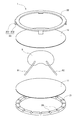
- FIG. 2 is an exploded perspective view of the organ container 1.
- the organ container 1 is a container for temporarily containing the liver 9 removed from the donor when performing liver transplantation. After removal from the donor, it is necessary to preserve the liver 9 in a state of being perfused with a preservation solution until transplantation into a recipient. For this reason, a liquid supply tube 91 for supplying the storage liquid and a drainage tube 92 for discharging the storage liquid are connected to the liver 9.
- the fluid supply tube 91 is connected to, for example, the portal vein or hepatic artery of the liver 9 by a catheter.
- the drainage tube 92 is connected, for example, to the upper hepatic inferior vena cava or the inferior hepatic inferior vena cava of the liver 9 by a catheter.
- the organ container 1 of the present embodiment has a first film 11, a second film 12, a lower frame 21, and an upper frame 22.
- the first film 11 is a sheet-like film covering the lower part of the liver 9.
- the second film 12 is a sheet-like film covering the top of the liver 9.
- Each of the first film 11 and the second film 12 is made of a material that can be flexibly deformed.
- the shapes of the first film 11 and the second film 12 of the present embodiment are circular in top view. However, the first film 11 and the second film 12 may have other shapes such as an ellipse.
- the sizes of the first film 11 and the second film 12 are substantially the same, and are larger than the liver 9 in top view.
- the upper surface of the first film 11 contacts the lower part of the liver 9.
- the lower surface of the second film 12 contacts the upper portion of the liver 9. That is, the liver 9 is held by being sandwiched between the first film 11 and the second film 12.
- Each of the first film 11 and the second film 12 deforms along the surface shape of the liver 9 because of flexibility.
- first film 11 and the second film 12 a resin having biocompatibility, sterilization retention, and flexibility is used.
- polypropylene, polyethylene, polyurethane, polyvinylidene chloride, polystyrene, elastomer resin, silicone, rubber, gel material, or polyamide can be used as the material of the first film 11 and the second film 12.
- the first film 11 and the second film 12 may be permeable to the storage solution, or may not be permeable to the storage solution.
- the liquid permeability of the first film 11 and the second film 12 may be appropriately selected depending on the condition of use.
- the first film 11 and the second film 12 may have a property of transmitting a gas such as oxygen.
- the lower frame 21 is an annular member disposed below the first film 11.
- the upper surface of the lower frame 21 contacts the lower surface of the peripheral portion of the first film 11 to support the peripheral portion of the first film 11 from below.
- the upper frame 22 is an annular member disposed above the second film 12.
- the lower surface of the upper frame 22 contacts the upper surface of the peripheral portion of the second film 12.
- the lower frame 21 and the upper frame 22 are rigid bodies that do not deform easily. That is, the lower frame 21 and the upper frame 22 are made of a material having lower flexibility than the first film 11 and the second film 12.
- a resin or a metal is used for the material of the lower frame 21 and the upper frame 22.
- the lower frame 21 and the upper frame 22 serve as an opening and closing part that opens and closes the ends of the first film 11 and the second film 12.
- the shapes of the lower frame 21 and the upper frame 22 are circular in top view.
- the lower frame 21 and the upper frame 22 may have other shapes such as a rectangle.
- the first film 11 is disposed on the upper side of the lower frame 21. Then, the liver 9 extracted from the donor is placed at the center of the upper surface of the first film 11. Subsequently, the upper part of the liver 9 is covered with the second film 12. At this time, the peripheral portion of the first film 11 and the peripheral portion of the second film 12 are superimposed on each other. That is, the upper surface of the peripheral portion of the first film 11 and the lower surface of the peripheral portion of the second film 12 are brought into contact with each other.
- the lower frame 21 and the first film 11 may be fixed to each other in advance by a fixing tool such as a clip.
- the upper frame 22 has a plurality of locking portions 23.
- the locking portion 23 has, for example, an arm portion 231 extending downward from the edge of the upper frame 22, and a claw portion 232 provided at the tip of the arm portion 231.
- the plurality of locking portions 23 are locked to the lower frame 21. Thereby, as shown in FIG. 1, the lower frame 21 and the upper frame 22 are fixed.
- the aforementioned peripheral portions of the first film 11 and the second film 12 are sandwiched between the upper surface of the lower frame 21 and the lower surface of the upper frame 22. As a result, the peripheral portions of the first film 11 and the second film 12 are closed. As a result, the liver 9 is held between the first film 11 and the second film 12.
- the lower frame 21 has a plurality of grooves 24.
- the plurality of grooves 24 are provided on the upper surface of the lower frame 21 at intervals in the circumferential direction (for example, at equal intervals). Each groove 24 extends in the radial direction from the inner peripheral edge of the upper surface of the lower frame 21 to the outer peripheral edge.
- the liquid supply tube 91 and the drainage tube 92 connected to the liver 9 are respectively fitted to any one of the plurality of grooves 24 via the first film 11.
- the liquid supply tube 91 and the drainage tube 92 extend from the liver 9 held inside the first film 11 and the second film 12 through the groove 24 to the outside of the first film 11 and the second film 12. Thereby, positional deviation of the liquid supply tube 91 and the drainage tube 92 is suppressed.
- the plurality of grooves 24 serve as a tube holding portion that holds the liquid supply tube 91 and the drain tube 92.
- the plurality of grooves 24 may be provided on the lower surface of the upper frame 22.
- the plurality of grooves 24 may be provided on both the upper surface of the lower frame 21 and the lower surface of the upper frame 22.
- the locking portion 23 is first removed from the lower frame 21. Then, the lower frame 21 and the upper frame 22 are pulled apart up and down. Next, peripheral portions of the first film 11 and the second film 12 are opened, and the second film 12 is peeled off. Thereafter, the liver 9 is taken out of the upper surface of the first film 11 and transplanted to the recipient.
- the organ container 1 can hold the liver 9 and can also hold the liquid supply tube 91 and the drainage tube 92. Therefore, the liver 9 can be stored while perfusion of the storage solution through the liquid supply tube 91 and the drainage tube 92.
- the organ container 1 also accommodates the liver 9 between the flexible first film 11 and the second film 12. Then, the first film 11 and the second film 12 are brought into contact with the surface of the liver 9 to hold the liver 9. Thereby, the liver 9 can be stored while suppressing the relative movement of the liver 9 with respect to the first film 11 and the second film 12. Further, damage to the surface of the liver 9 can be suppressed more than when the liver 9 is held by a rigid body.
- two separate films 11 and 12 are used to hold the liver 9.
- the first film 11 and the second film 12 can be largely opened up and down. Therefore, the liver 9 can be easily put in and out of the organ container 1.
- the lower frame 21 and the upper frame 22 of the present embodiment can be fixed with one touch by the locking portion 23 only by bringing the lower frame 21 and the upper frame 22 close to each other. For this reason, it is not necessary to use a fixing tool such as a screw for fixing the lower frame 21 and the upper frame 22. Therefore, the liver 9 removed from the donor can be quickly stored in the organ container 1.
- the locking portion 23 may be provided on the lower frame 21. Further, the locking portion 23 may be omitted, and the lower frame 21 and the upper frame 22 may be fixed by a fixing tool such as a screw or a clip.
- Second embodiment> 3 and 4 are perspective views of the organ container 2 according to the second embodiment.
- the organ container 2 is also used to temporarily contain the liver 9 removed from the donor when performing liver transplantation.
- FIG. 3 shows a state in which the opening 31 for inserting and removing the liver 9 is closed.
- FIG. 4 shows the state where the opening 31 is opened.
- the organ container 2 has a film bag 30 and a chuck 40 provided in the opening 31 of the film bag 30.
- the film bag 30 is a bag-like container formed of a film.
- the film forming the film bag 30 is made of a flexible deformable material.
- the shape of the film bag 30 is, for example, rectangular.
- the size of the film bag 30 is slightly larger than the liver 9.
- a gusset may be provided on the bottom or side of the film bag 30.
- the liver 9 is housed inside the film bag 30.
- the film forming the film bag 30 contacts the surface of the liver 9 and deforms along the surface shape of the liver 9.
- a resin having biocompatibility, sterilization retention, and flexibility is used for the material of the film bag 30.
- polypropylene, polyethylene, polyurethane, polyvinylidene chloride, polystyrene, elastomer resin, silicone, rubber, gel material, or polyamide can be used as the material of the film bag 30.
- the film bag 30 may be one that allows the preservation solution to permeate, or one that does not allow the preservation solution to permeate. The presence or absence of the liquid permeability of the film bag 30 may be appropriately selected depending on the condition of use.
- the film bag 30 may have a property of transmitting a gas such as oxygen.
- the chuck 40 is an open / close unit provided at an end of the film bag 30.
- the chuck 40 has a pair of chuck members 41.
- the pair of chuck members 41 have minute concavo-convex portions 42 fitted to each other.
- the concavo-convex portion 42 of one chuck member 41 and the concavo-convex portion 42 of the other chuck member 41 are fitted and the chuck members 41 adhere to each other. Thereby, the film bag 30 is sealed. Further, when the pair of chuck members 41 are separated from each other, the fitting of the concavo-convex portion 42 is released, and the opening 31 of the film bag 30 is opened.
- the material of the chuck member 41 for example, the same resin as that of the film bag 30 is used.
- the pair of chuck members 41 each have two grooves 43.
- the two grooves 43 are provided at mutually opposing positions of the pair of chuck members 41.
- the liquid supply tube 91 and the drainage tube 92 connected to the liver 9 are fitted in the two grooves 43 respectively. That is, the liquid supply tube 91 and the drainage tube 92 extend from the liver 9 held inside the film bag 30 through the groove 43 to the outside of the film bag 30. Thereby, positional deviation of the liquid supply tube 91 and the drainage tube 92 is suppressed.
- the two grooves 43 serve as a tube holding portion that holds the liquid supply tube 91 and the drain tube 92.
- the two grooves 43 may be provided in only one of the pair of chuck members 41.
- the end of the film bag 30 is first opened by pulling apart the pair of chuck members 41. Then, the liver 9 extracted from the donor is inserted between the pair of chuck members 41 into the film bag 30. At this time, a supply tube 91 and a drainage tube 92 are connected to the liver 9.
- the liquid supply tube 91 and the drain tube 92 are respectively fitted in the grooves 43 of the chuck member 41. Then, the pair of chuck members 41 are brought into close contact with each other. Thereby, the film bag 30 is closed.
- the end of the film bag 30 is first opened by pulling apart the pair of chuck members 41. Then, the liquid supply tube 91 and the liquid discharge tube 92 are removed from the groove 43 of the chuck member 41. Thereafter, the liver 9 is removed from the inside of the film bag 30 and transplanted to the recipient.
- the organ container 2 can hold the liver 9 and can also hold the liquid supply tube 91 and the drainage tube 92. Therefore, the liver 9 can be stored while perfusion of the storage solution through the liquid supply tube 91 and the drainage tube 92.
- the organ container 1 also accommodates the liver 9 inside the flexible film bag 30. Then, the inner surface of the film bag 30 is brought into contact with the surface of the liver 9 to hold the liver 9. Thereby, the liver 9 can be stored while suppressing the relative movement of the liver 9 with respect to the film bag 30. Further, damage to the surface of the liver 9 can be suppressed more than when the liver 9 is held by a rigid body.
- the liver 9 is accommodated in an integral film bag 30 instead of using a plurality of films.
- the number of parts of the organ container 2 can be reduced.
- the film bag 30 and the chuck 40 are integrated. Thereby, the number of parts of the organ container 2 is further reduced. As a result, the handling of the organ container 2 becomes easier.
- the chuck 40 may be omitted, and the opening 31 of the film bag 30 may be sealed by a clip as an open / close unit.
- the clip may be provided with a groove as a tube holding portion.
- zipper 40 may be abbreviate
- the opening 31 of the film bag 30 can be contracted by pulling the operation cord 50 as in the case of a drawstring bag.
- the opening 31 after contraction serves as a tube holding unit that holds the liquid supply tube 91 and the drain tube 92.
- the organ container 1 of the first embodiment may be accommodated inside the outer casing 3 having air tightness or liquid tightness.
- the outer casing 3 is preferably a rigid body that is not easily deformed. In this way, the liver 9 can be easily transported while suppressing the application of pressure to the film.
- the inside of the outer casing 3 may be filled with a preservation solution together with the organ container 1.
- the outer casing 3 may have a heat retention function and a heat insulation function in order to keep the internal temperature constant.
- the pair of relay tubes 61 and 62 is fixed to the outer casing 3.
- One end of each of the relay tubes 61 and 62 is located outside the outer casing.
- connectors 611 and 621 having pushbuttons for release are provided at the one ends of the relay tubes 61 and 62, respectively. In this way, the user can remove and connect the connectors 611 and 621 of the relay tubes 61 and 62 and the external tubes 71 and 72 having the corresponding connectors 711 and 712 with one touch.
- the other ends of the relay tubes 61 and 62 are located inside the outer casing 3. Further, connectors 612 and 622 having pushbuttons for release are provided at the other ends of the relay tubes 61 and 62, respectively. Further, connectors 911 and 921 corresponding to the connectors are provided at outer ends of the liquid supply tube 91 and the liquid discharge tube 92. In this way, the user can remove and connect the connector 612 of one of the relay tubes 61 and the connector 911 of the liquid supply tube 91 with one touch. Also, the user can remove and connect the connector 622 of the other relay tube 62 and the connector 921 of the drainage tube 92 with one touch.
- the above connector structure it is possible to connect and disconnect the tubes while keeping the inside of each tube clean. Further, in organ transplantation surgery, the rapidity of the treatment is extremely important. By using the above connector structure in combination with the organ container 1, organ transplant surgery can be more reliably and rapidly progressed.
- the above connector structure may be provided only on either the outside or the inside of the outer casing 3.
- organ container 2 of the second embodiment may be similarly housed inside the outer casing 3.
- the organ container which accommodates the liver 9 was demonstrated.
- the organ container may contain organs other than the liver 9, such as the heart, pancreas, and kidney.
- two tubes 91 and 92 are connected to the liver 9.
- the number of tubes connected to the organ may be one or three or more.
Abstract
This organ container (1) has flexible films (11, 12) and a tube holding part (24). The films (11, 12) hold an organ (9) while in contact with the outer surface of the organ (9). The tube holding part (24) holds tubes (91, 92) that extend between the organ (9) inside the films (11, 12), and the outside of the films (11, 12). As a result, the organ (9) can be held and preserved while allowing the perfusion of a fluid through the tubes (91, 92). In addition, movement of the organ (9) relative to the organ container (1) can be limited and damage to the organ (9) can also be limited.
Description
本発明は、臓器を収容する臓器収容器に関する。
The present invention relates to an organ container for containing an organ.
肝臓移植等の臓器の移植手術では、ドナーから臓器を摘出した後、当該臓器をレシピエントへ移植するまでの間、一時的に臓器を体外で保存する。このとき、臓器が阻血状態となることを防止するために、臓器にチューブを接続して、臓器内に保存液を灌流させる。また、ドナーからの臓器の摘出と、レシピエントへの臓器の移植とを、異なる場所で行う場合には、臓器を保存しつつ運搬する必要もある。
In organ transplantation surgery such as liver transplantation, after the organ is removed from the donor, the organ is temporarily stored outside the body until the organ is transplanted to the recipient. At this time, in order to prevent the organ from becoming ischemic, a tube is connected to the organ to perfuse the preservation solution in the organ. In addition, when the removal of the organ from the donor and the transplantation of the organ to the recipient are performed at different places, it is also necessary to transport the organ while preserving it.
臓器を体外で保存する従来の装置については、例えば、特許文献1に記載されている。
A conventional apparatus for storing organs outside the body is described, for example, in Patent Document 1.
特許文献1の装置では、疎水性布からなるハンモックに臓器が保持される。しかしながら、特許文献1のように、ハンモックに臓器を載置するだけでは、ハンモックに対する臓器の位置がずれやすい。このため、ドナーとレシピエントとの間で、臓器を損傷させることなく運搬することが困難である。
In the device of Patent Document 1, the organ is held in a hammock made of a hydrophobic cloth. However, as in Patent Document 1, simply placing an organ on a hammock easily shifts the position of the organ relative to the hammock. For this reason, it is difficult to transport the donor and the recipient without damaging the organ.
本発明は、このような事情に鑑みなされたものであり、液体を灌流させつつ臓器を保存でき、かつ、臓器の位置ずれおよび損傷も抑制できる臓器収容器を提供することを目的とする。
The present invention has been made in view of such circumstances, and it is an object of the present invention to provide an organ container capable of preserving an organ while perfusing a liquid and suppressing displacement and damage of the organ.
上記課題を解決するため、本願の第1発明は、臓器を収容する臓器収容器であって、前記臓器を保持する柔軟なフィルムと、前記フィルムの端部を開閉する開閉部と、前記フィルム内の前記臓器と前記フィルムの外部との間で延びるチューブを保持するチューブ保持部と、を有する。
In order to solve the above-mentioned subject, the 1st invention of this application is an organ container which stores an organ, and the flexible film which holds the organ, the opening and closing part which opens and closes the end of the film, and the inside of the film And a tube holder for holding a tube extending between the organ and the exterior of the film.
本願の第2発明は、第1発明の臓器収容器であって、前記フィルムは、前記臓器の下部を覆うシート状の第1フィルムと、前記臓器の上部を覆うシート状の第2フィルムと、を含み、前記臓器が、前記第1フィルムと前記第2フィルムとの間に挟まれて保持される。
A second invention of the present application is the organ container according to the first invention, wherein the film is a sheet-like first film covering the lower part of the organ, and a sheet-like second film covering the upper part of the organ. And the organ is sandwiched and held between the first film and the second film.
本願の第3発明は、第2発明の臓器収容器であって、前記開閉部は、前記第1フィルムおよび前記第2フィルムの互いに重なる周縁部を、下方から支持する環状の下フレームと、前記下フレームとの間に、前記第1フィルムおよび前記第2フィルムの前記周縁部を挟む環状の上フレームと、を有する。
A third invention of the present application is the organ container according to the second invention, wherein the opening and closing portion supports an annular lower frame supporting from the lower side the overlapping peripheral portions of the first film and the second film, and And an annular upper frame sandwiching the peripheral portions of the first film and the second film with the lower frame.
本願の第4発明は、第3発明の臓器収容器であって、前記下フレームと前記上フレームとを、互いに接近させることにより、前記下フレームと前記上フレームとを互いに係止固定する係止部をさらに有する。
A fourth invention of the present application is the organ container according to the third invention, wherein the lower frame and the upper frame are locked to each other by bringing the lower frame and the upper frame close to each other. It has a part.
本願の第5発明は、第3発明または第4発明の臓器収容器であって、前記チューブ保持部は、前記下フレームの上面および前記上フレームの下面の少なくとも一方に設けられた溝を有し、前記溝に前記チューブが嵌まる。
A fifth invention of the present application is the organ container according to the third invention or the fourth invention, wherein the tube holding portion has a groove provided on at least one of the upper surface of the lower frame and the lower surface of the upper frame. , The tube is fitted in the groove.
本願の第6発明は、第5発明の臓器収容器であって、前記チューブ保持部は、複数の前記溝を有し、複数の前記溝が、周方向に間隔をあけて設けられている。
A sixth invention of the present application is the organ container of the fifth invention, wherein the tube holding portion has a plurality of the grooves, and the plurality of grooves are provided at intervals in the circumferential direction.
本願の第7発明は、第1発明の臓器収容器であって、前記フィルムにより形成された袋状のフィルムバッグを有し、前記フィルムバッグ内に前記臓器が収容される。
A seventh invention of the present application is the organ container according to the first invention, including a bag-like film bag formed of the film, and the organ is accommodated in the film bag.
本願の第8発明は、第7発明の臓器収容器であって、前記開閉部は、前記フィルムバッグの開口部に設けられた開閉可能なチャックである。
An eighth invention of the present application is the organ container according to the seventh invention, wherein the opening and closing part is an openable and closable chuck provided at an opening of the film bag.
本願の第9発明は、第8発明の臓器収容器であって、前記チャックは、互いに密着および離間が可能な一対のチャック部材を有し、前記チューブ保持部は、前記一対のチャック部材の少なくとも一方に設けられた溝を有し、前記溝に前記チューブが嵌まる。
A ninth invention of the present application is the organ container according to the eighth invention, wherein the chuck has a pair of chuck members which can be in close contact with and separated from each other, and the tube holding portion is at least one of the pair of chuck members. It has a groove provided on one side, and the tube is fitted in the groove.
本願の第10発明は、第7発明の臓器収容器であって、前記開閉部は、前記フィルムバッグの開口部を収縮させることが可能な操作紐を有する。
A tenth invention of the present application is the organ container according to the seventh invention, wherein the opening and closing part has an operation cord capable of contracting the opening of the film bag.
本願の第11発明は、第1発明から第10発明までのいずれか1発明の臓器収容器であって、前記フィルムは、樹脂製である。
The eleventh invention of the present application is the organ container according to any one of the first invention to the tenth invention, wherein the film is made of resin.
本願の第1発明から第11発明によれば、チューブを介して液体を灌流させつつ、臓器を保持できる。また、臓器収容器に対して臓器が動くことを抑制し、かつ、臓器の損傷も抑制できる。
According to the first to eleventh inventions of the present application, it is possible to hold the organ while perfusing the liquid through the tube. In addition, movement of the organ relative to the organ container can be suppressed, and damage to the organ can also be suppressed.
特に、本願の第2発明によれば、別体の第1フィルムおよび第2フィルムを用いることにより、これらのフィルムを上下に大きく開くことができる。このため、臓器収容器に対する臓器の出し入れが容易となる。
In particular, according to the second invention of the present application, by using separate first films and second films, these films can be widely opened up and down. For this reason, it becomes easy to put in and out the organ with respect to the organ container.
特に、本願の第4発明によれば、下フレームと上フレームとを、ねじ等の固定具を用いることなく、ワンタッチで固定できる。
In particular, according to the fourth invention of the present application, the lower frame and the upper frame can be fixed by one touch without using a fixing tool such as a screw.
特に、本願の第5発明によれば、チューブの位置ずれを抑制しつつ、チューブを保持できる。
In particular, according to the fifth invention of the present application, the tube can be held while suppressing positional deviation of the tube.
特に、本願の第6発明によれば、予め用意された複数の溝のうち、任意の溝にチューブを固定できる。
In particular, according to the sixth invention of the present application, the tube can be fixed to any one of a plurality of grooves prepared in advance.
特に、本願の第7発明によれば、臓器収容器の部品点数を低減できる。
In particular, according to the seventh invention of the present application, the number of parts of the organ container can be reduced.
特に、本願の第9発明によれば、チューブの位置ずれを抑制しつつ、チューブを保持できる。
In particular, according to the ninth invention of the present application, the tube can be held while suppressing positional deviation of the tube.
以下、本発明の実施形態について、図面を参照しつつ説明する。
Hereinafter, embodiments of the present invention will be described with reference to the drawings.
本願において「ドナー」および「レシピエント」は、ヒトであってもよいし、非ヒト動物であってもよい。すなわち、本願において、「肝臓」を含む「臓器」は、ヒトの臓器であってもよいし、非ヒト動物の臓器であってもよい。また、非ヒト動物は、マウスおよびラットを含む齧歯類、ブタ、ヤギおよびヒツジを含む有蹄類、チンパンジーを含む非ヒト霊長類、その他の非ヒトほ乳動物であってもよいし、ほ乳動物以外の動物であってもよい。
In the present application, “donor” and “recipient” may be human or non-human animals. That is, in the present application, the "organ" including the "liver" may be a human organ or an organ of a non-human animal. The non-human animals may be rodents including mice and rats, ungulates including pigs, goats and sheep, non-human primates including chimpanzees, other non-human mammals, mammals It may be other animals.
<1.第1実施形態>
図1は、第1実施形態に係る臓器収容器1の斜視図である。図2は、臓器収容器1の分解斜視図である。 <1. First embodiment>
FIG. 1 is a perspective view of theorgan container 1 according to the first embodiment. FIG. 2 is an exploded perspective view of the organ container 1.
図1は、第1実施形態に係る臓器収容器1の斜視図である。図2は、臓器収容器1の分解斜視図である。 <1. First embodiment>
FIG. 1 is a perspective view of the
この臓器収容器1は、肝臓移植手術を行うときに、ドナーから摘出された肝臓9を一時的に収容するための容器である。ドナーからの摘出後、レシピエントへの移植までの間、肝臓9を、保存液を灌流させた状態で保存する必要がある。このため、肝臓9には、保存液を供給するための給液チューブ91と、保存液を排出するための排液チューブ92とが、接続されている。給液チューブ91は、例えば、肝臓9の門脈または肝動脈に、カテーテルにより接続される。排液チューブ92は、例えば、肝臓9の肝上部下大静脈または肝下部下大静脈に、カテーテルにより接続される。
The organ container 1 is a container for temporarily containing the liver 9 removed from the donor when performing liver transplantation. After removal from the donor, it is necessary to preserve the liver 9 in a state of being perfused with a preservation solution until transplantation into a recipient. For this reason, a liquid supply tube 91 for supplying the storage liquid and a drainage tube 92 for discharging the storage liquid are connected to the liver 9. The fluid supply tube 91 is connected to, for example, the portal vein or hepatic artery of the liver 9 by a catheter. The drainage tube 92 is connected, for example, to the upper hepatic inferior vena cava or the inferior hepatic inferior vena cava of the liver 9 by a catheter.
図1および図2に示すように、本実施形態の臓器収容器1は、第1フィルム11、第2フィルム12、下フレーム21、および上フレーム22を有する。
As shown in FIGS. 1 and 2, the organ container 1 of the present embodiment has a first film 11, a second film 12, a lower frame 21, and an upper frame 22.
第1フィルム11は、肝臓9の下部を覆うシート状のフィルムである。第2フィルム12は、肝臓9の上部を覆うシート状のフィルムである。第1フィルム11および第2フィルム12は、いずれも、柔軟に変形可能な素材からなる。本実施形態の第1フィルム11および第2フィルム12の形状は、上面視において円形である。ただし、第1フィルム11および第2フィルム12は、楕円等の他の形状であってもよい。第1フィルム11および第2フィルム12の大きさは、略同一であり、上面視において肝臓9よりも大きい。第1フィルム11の上面は、肝臓9の下部に接触する。第2フィルム12の下面は、肝臓9の上部に接触する。すなわち、肝臓9は、第1フィルム11と第2フィルム12との間に挟まれることによって、保持される。第1フィルム11および第2フィルム12は、柔軟性を有するため、それぞれ、肝臓9の表面形状に沿って変形する。
The first film 11 is a sheet-like film covering the lower part of the liver 9. The second film 12 is a sheet-like film covering the top of the liver 9. Each of the first film 11 and the second film 12 is made of a material that can be flexibly deformed. The shapes of the first film 11 and the second film 12 of the present embodiment are circular in top view. However, the first film 11 and the second film 12 may have other shapes such as an ellipse. The sizes of the first film 11 and the second film 12 are substantially the same, and are larger than the liver 9 in top view. The upper surface of the first film 11 contacts the lower part of the liver 9. The lower surface of the second film 12 contacts the upper portion of the liver 9. That is, the liver 9 is held by being sandwiched between the first film 11 and the second film 12. Each of the first film 11 and the second film 12 deforms along the surface shape of the liver 9 because of flexibility.
第1フィルム11および第2フィルム12の材料には、生体適応性および滅菌保持性を有し、かつ、柔軟性を有する樹脂が用いられる。例えば、ポリプロピレン、ポリエチレン、ポリウレタン、ポリ塩化ビニリデン、ポリスチレン、エラストマー樹脂、シリコン、ゴム、ゲル材料、またはポリアミドを、第1フィルム11および第2フィルム12の材料として用いることができる。第1フィルム11および第2フィルム12は、保存液を透過させるものであってもよく、あるいは、保存液を透過させないものであってもよい。第1フィルム11および第2フィルム12の液透過性の有無については、使用される状況に応じて、適宜に選択すればよい。また、第1フィルム11および第2フィルム12は、酸素等の気体を透過させる性質を有していてもよい。
For the material of the first film 11 and the second film 12, a resin having biocompatibility, sterilization retention, and flexibility is used. For example, polypropylene, polyethylene, polyurethane, polyvinylidene chloride, polystyrene, elastomer resin, silicone, rubber, gel material, or polyamide can be used as the material of the first film 11 and the second film 12. The first film 11 and the second film 12 may be permeable to the storage solution, or may not be permeable to the storage solution. The liquid permeability of the first film 11 and the second film 12 may be appropriately selected depending on the condition of use. In addition, the first film 11 and the second film 12 may have a property of transmitting a gas such as oxygen.
下フレーム21は、第1フィルム11の下方に配置される環状の部材である。下フレーム21の上面は、第1フィルム11の周縁部の下面に接触して、第1フィルム11の周縁部を下方から支持する。上フレーム22は、第2フィルム12の上方に配置される環状の部材である。上フレーム22の下面は、第2フィルム12の周縁部の上面に接触する。下フレーム21および上フレーム22は、容易に変形しない剛体である。すなわち、下フレーム21および上フレーム22は、第1フィルム11および第2フィルム12よりも、柔軟性が小さい材料からなる。下フレーム21および上フレーム22の材料には、例えば、樹脂または金属が用いられる。
The lower frame 21 is an annular member disposed below the first film 11. The upper surface of the lower frame 21 contacts the lower surface of the peripheral portion of the first film 11 to support the peripheral portion of the first film 11 from below. The upper frame 22 is an annular member disposed above the second film 12. The lower surface of the upper frame 22 contacts the upper surface of the peripheral portion of the second film 12. The lower frame 21 and the upper frame 22 are rigid bodies that do not deform easily. That is, the lower frame 21 and the upper frame 22 are made of a material having lower flexibility than the first film 11 and the second film 12. For the material of the lower frame 21 and the upper frame 22, for example, a resin or a metal is used.
本実施形態では、下フレーム21および上フレーム22が、第1フィルム11および第2フィルム12の端部を開閉する開閉部となる。なお、図1および図2の例では、下フレーム21および上フレーム22の形状が、上面視において円形である。ただし、下フレーム21および上フレーム22は、矩形等の他の形状であってもよい。
In the present embodiment, the lower frame 21 and the upper frame 22 serve as an opening and closing part that opens and closes the ends of the first film 11 and the second film 12. In the example of FIGS. 1 and 2, the shapes of the lower frame 21 and the upper frame 22 are circular in top view. However, the lower frame 21 and the upper frame 22 may have other shapes such as a rectangle.
臓器収容器1の使用時には、まず、下フレーム21の上側に第1フィルム11を配置する。そして、ドナーから摘出された肝臓9が、第1フィルム11の上面の中央に載置される。続いて、肝臓9の上部を第2フィルム12で覆う。このとき、第1フィルム11の周縁部と、第2フィルム12の周縁部とを、互いに重ね合わせる。つまり、第1フィルム11の周縁部の上面と、第2フィルム12の周縁部の下面とを、互いに接触させる。なお、下フレーム21と第1フィルム11とは、予め、クリップ等の固定具で互いに固定されていてもよい。
When using the organ container 1, first, the first film 11 is disposed on the upper side of the lower frame 21. Then, the liver 9 extracted from the donor is placed at the center of the upper surface of the first film 11. Subsequently, the upper part of the liver 9 is covered with the second film 12. At this time, the peripheral portion of the first film 11 and the peripheral portion of the second film 12 are superimposed on each other. That is, the upper surface of the peripheral portion of the first film 11 and the lower surface of the peripheral portion of the second film 12 are brought into contact with each other. The lower frame 21 and the first film 11 may be fixed to each other in advance by a fixing tool such as a clip.
上フレーム22は、複数の係止部23を有する。係止部23は、例えば、上フレーム22の縁から下方へ向けて延びる腕部231と、腕部231の先端に設けられた爪部232とを有する。下フレーム21に対して上フレーム22を上方から接近させると、複数の係止部23が、下フレーム21に係止される。これにより、図1のように、下フレーム21と上フレーム22とが固定される。
The upper frame 22 has a plurality of locking portions 23. The locking portion 23 has, for example, an arm portion 231 extending downward from the edge of the upper frame 22, and a claw portion 232 provided at the tip of the arm portion 231. When the upper frame 22 approaches the lower frame 21 from above, the plurality of locking portions 23 are locked to the lower frame 21. Thereby, as shown in FIG. 1, the lower frame 21 and the upper frame 22 are fixed.
第1フィルム11および第2フィルム12の上述した周縁部は、下フレーム21の上面と、上フレーム22の下面との間に挟まれる。これにより、第1フィルム11および第2フィルム12の周縁部が閉じられた状態となる。その結果、第1フィルム11と第2フィルム12との間に、肝臓9が保持される。
The aforementioned peripheral portions of the first film 11 and the second film 12 are sandwiched between the upper surface of the lower frame 21 and the lower surface of the upper frame 22. As a result, the peripheral portions of the first film 11 and the second film 12 are closed. As a result, the liver 9 is held between the first film 11 and the second film 12.
下フレーム21は、複数の溝24を有する。複数の溝24は、下フレーム21の上面に、周方向に間隔をあけて(例えば等間隔に)設けられている。各溝24は、下フレーム21の上面の内周縁から外周縁まで、径方向に延びる。肝臓9に接続された給液チューブ91および排液チューブ92は、それぞれ、複数の溝24のうちのいずれか1つに、第1フィルム11を介して嵌められる。給液チューブ91および排液チューブ92は、第1フィルム11および第2フィルム12の内部に保持された肝臓9から、溝24を通って、第1フィルム11および第2フィルム12の外部まで延びる。これにより、給液チューブ91および排液チューブ92の位置ずれが抑制される。
The lower frame 21 has a plurality of grooves 24. The plurality of grooves 24 are provided on the upper surface of the lower frame 21 at intervals in the circumferential direction (for example, at equal intervals). Each groove 24 extends in the radial direction from the inner peripheral edge of the upper surface of the lower frame 21 to the outer peripheral edge. The liquid supply tube 91 and the drainage tube 92 connected to the liver 9 are respectively fitted to any one of the plurality of grooves 24 via the first film 11. The liquid supply tube 91 and the drainage tube 92 extend from the liver 9 held inside the first film 11 and the second film 12 through the groove 24 to the outside of the first film 11 and the second film 12. Thereby, positional deviation of the liquid supply tube 91 and the drainage tube 92 is suppressed.
本実施形態では、この複数の溝24が、給液チューブ91および排液チューブ92を保持するチューブ保持部となる。なお、複数の溝24は、上フレーム22の下面に設けられていてもよい。また、複数の溝24は、下フレーム21の上面および上フレーム22の下面の双方に設けられていてもよい。
In the present embodiment, the plurality of grooves 24 serve as a tube holding portion that holds the liquid supply tube 91 and the drain tube 92. The plurality of grooves 24 may be provided on the lower surface of the upper frame 22. The plurality of grooves 24 may be provided on both the upper surface of the lower frame 21 and the lower surface of the upper frame 22.
臓器収容器1に保持された肝臓9をレシピエントへ移植するときには、まず、下フレーム21から係止部23を外す。そして、下フレーム21と上フレーム22とを、上下に引き離す。次に、第1フィルム11および第2フィルム12の周縁部を開き、第2フィルム12を剥がす。その後、第1フィルム11の上面から肝臓9を取り出して、レシピエントへ移植する。
When transplanting the liver 9 held by the organ container 1 to the recipient, the locking portion 23 is first removed from the lower frame 21. Then, the lower frame 21 and the upper frame 22 are pulled apart up and down. Next, peripheral portions of the first film 11 and the second film 12 are opened, and the second film 12 is peeled off. Thereafter, the liver 9 is taken out of the upper surface of the first film 11 and transplanted to the recipient.
以上のように、この臓器収容器1は、肝臓9を保持するとともに、給液チューブ91および排液チューブ92も保持できる。このため、給液チューブ91および排液チューブ92を介して保存液を灌流させつつ、肝臓9を保存できる。また、この臓器収容器1は、柔軟性を有する第1フィルム11および第2フィルム12の間に、肝臓9を収容する。そして、第1フィルム11および第2フィルム12を肝臓9の表面に接触させて、肝臓9を保持する。これにより、第1フィルム11および第2フィルム12に対して肝臓9が相対的に動くことを抑制しつつ、肝臓9を保存できる。また、剛体で肝臓9を保持する場合よりも、肝臓9の表面の損傷を抑制できる。
As described above, the organ container 1 can hold the liver 9 and can also hold the liquid supply tube 91 and the drainage tube 92. Therefore, the liver 9 can be stored while perfusion of the storage solution through the liquid supply tube 91 and the drainage tube 92. The organ container 1 also accommodates the liver 9 between the flexible first film 11 and the second film 12. Then, the first film 11 and the second film 12 are brought into contact with the surface of the liver 9 to hold the liver 9. Thereby, the liver 9 can be stored while suppressing the relative movement of the liver 9 with respect to the first film 11 and the second film 12. Further, damage to the surface of the liver 9 can be suppressed more than when the liver 9 is held by a rigid body.
特に、本実施形態では、肝臓9の保持に2枚の別体のフィルム11,12が用いられている。このようにすれば、図2のように、第1フィルム11と第2フィルム12とを、上下に大きく開くことができる。このため、臓器収容器1に対する肝臓9の出し入れが容易となる。
In particular, in the present embodiment, two separate films 11 and 12 are used to hold the liver 9. In this way, as shown in FIG. 2, the first film 11 and the second film 12 can be largely opened up and down. Therefore, the liver 9 can be easily put in and out of the organ container 1.
また、本実施形態の下フレーム21および上フレーム22は、互いに接近させるだけで、係止部23により、ワンタッチで固定できる。このため、下フレーム21および上フレーム22の固定に、ねじ等の固定具を用いる必要がない。したがって、ドナーから摘出された肝臓9を、臓器収容器1内に迅速に収容できる。なお、係止部23は、下フレーム21に設けられていてもよい。また、係止部23を省略し、下フレーム21と上フレーム22とを、ねじまたはクリップ等の固定具で固定してもよい。
Further, the lower frame 21 and the upper frame 22 of the present embodiment can be fixed with one touch by the locking portion 23 only by bringing the lower frame 21 and the upper frame 22 close to each other. For this reason, it is not necessary to use a fixing tool such as a screw for fixing the lower frame 21 and the upper frame 22. Therefore, the liver 9 removed from the donor can be quickly stored in the organ container 1. The locking portion 23 may be provided on the lower frame 21. Further, the locking portion 23 may be omitted, and the lower frame 21 and the upper frame 22 may be fixed by a fixing tool such as a screw or a clip.
<2.第2実施形態>
図3および図4は、第2実施形態に係る臓器収容器2の斜視図である。この臓器収容器2も、第1実施形態の臓器収容器1と同じく、肝臓移植手術を行うときに、ドナーから摘出された肝臓9を一時的に収容するために用いられる。図3は、肝臓9を出し入れするための開口部31が閉じられた状態を示している。図4は、開口部31が開かれた状態を示している。 <2. Second embodiment>
3 and 4 are perspective views of theorgan container 2 according to the second embodiment. Like the organ container 1 of the first embodiment, the organ container 2 is also used to temporarily contain the liver 9 removed from the donor when performing liver transplantation. FIG. 3 shows a state in which the opening 31 for inserting and removing the liver 9 is closed. FIG. 4 shows the state where the opening 31 is opened.
図3および図4は、第2実施形態に係る臓器収容器2の斜視図である。この臓器収容器2も、第1実施形態の臓器収容器1と同じく、肝臓移植手術を行うときに、ドナーから摘出された肝臓9を一時的に収容するために用いられる。図3は、肝臓9を出し入れするための開口部31が閉じられた状態を示している。図4は、開口部31が開かれた状態を示している。 <2. Second embodiment>
3 and 4 are perspective views of the
図3および図4に示すように、臓器収容器2は、フィルムバッグ30と、フィルムバッグ30の開口部31に設けられたチャック40と、を有する。
As shown in FIGS. 3 and 4, the organ container 2 has a film bag 30 and a chuck 40 provided in the opening 31 of the film bag 30.
フィルムバッグ30は、フィルムにより形成された袋状の容器である。フィルムバッグ30を形成するフィルムは、柔軟に変形可能な素材からなる。フィルムバッグ30の形状は、例えば矩形状である。フィルムバッグ30の大きさは、肝臓9よりもやや大きい。フィルムバッグ30の底部または側部には、マチが設けられていてもよい。肝臓9は、フィルムバッグ30の内部に収容される。フィルムバッグ30を形成するフィルムは、肝臓9の表面に接触し、肝臓9の表面形状に沿って変形する。
The film bag 30 is a bag-like container formed of a film. The film forming the film bag 30 is made of a flexible deformable material. The shape of the film bag 30 is, for example, rectangular. The size of the film bag 30 is slightly larger than the liver 9. A gusset may be provided on the bottom or side of the film bag 30. The liver 9 is housed inside the film bag 30. The film forming the film bag 30 contacts the surface of the liver 9 and deforms along the surface shape of the liver 9.
フィルムバッグ30を形成するフィルムの材料には、生体適応性および滅菌保持性を有し、かつ、柔軟性を有する樹脂が用いられる。例えば、ポリプロピレン、ポリエチレン、ポリウレタン、ポリ塩化ビニリデン、ポリスチレン、エラストマー樹脂、シリコン、ゴム、ゲル材料、またはポリアミドを、フィルムバッグ30の材料として用いることができる。フィルムバッグ30は、保存液を透過させるものであってもよく、あるいは、保存液を透過させないものであってもよい。フィルムバッグ30の液透過性の有無については、使用される状況に応じて、適宜に選択すればよい。また、フィルムバッグ30は、酸素等の気体を透過させる性質を有していてもよい。
For the material of the film forming the film bag 30, a resin having biocompatibility, sterilization retention, and flexibility is used. For example, polypropylene, polyethylene, polyurethane, polyvinylidene chloride, polystyrene, elastomer resin, silicone, rubber, gel material, or polyamide can be used as the material of the film bag 30. The film bag 30 may be one that allows the preservation solution to permeate, or one that does not allow the preservation solution to permeate. The presence or absence of the liquid permeability of the film bag 30 may be appropriately selected depending on the condition of use. In addition, the film bag 30 may have a property of transmitting a gas such as oxygen.
チャック40は、フィルムバッグ30の端部に設けられた開閉部である。チャック40は、一対のチャック部材41を有する。一対のチャック部材41は、互いに嵌合する微小な凹凸部42を有する。一対のチャック部材41を接触させて圧力を加えると、一方のチャック部材41の凹凸部42と、他方のチャック部材41の凹凸部42とが嵌合して、チャック部材41同士が密着する。これにより、フィルムバッグ30が密閉される。また、一対のチャック部材41を互いに引き離すと、凹凸部42の嵌合が解けて、フィルムバッグ30の開口部31が開放される。チャック部材41の材料には、例えば、フィルムバッグ30と同一の樹脂が用いられる。
The chuck 40 is an open / close unit provided at an end of the film bag 30. The chuck 40 has a pair of chuck members 41. The pair of chuck members 41 have minute concavo-convex portions 42 fitted to each other. When pressure is applied by bringing the pair of chuck members 41 into contact with each other, the concavo-convex portion 42 of one chuck member 41 and the concavo-convex portion 42 of the other chuck member 41 are fitted and the chuck members 41 adhere to each other. Thereby, the film bag 30 is sealed. Further, when the pair of chuck members 41 are separated from each other, the fitting of the concavo-convex portion 42 is released, and the opening 31 of the film bag 30 is opened. For the material of the chuck member 41, for example, the same resin as that of the film bag 30 is used.
また、図4に示すように、一対のチャック部材41は、それぞれ、2つの溝43を有する。2つの溝43は、一対のチャック部材41の互いに対向する位置に設けられている。肝臓9に接続された給液チューブ91および排液チューブ92は、2つの溝43に、それぞれ嵌められる。すなわち、給液チューブ91および排液チューブ92は、フィルムバッグ30の内部に保持された肝臓9から、溝43を通って、フィルムバッグ30の外部まで延びる。これにより、給液チューブ91および排液チューブ92の位置ずれが抑制される。
Further, as shown in FIG. 4, the pair of chuck members 41 each have two grooves 43. The two grooves 43 are provided at mutually opposing positions of the pair of chuck members 41. The liquid supply tube 91 and the drainage tube 92 connected to the liver 9 are fitted in the two grooves 43 respectively. That is, the liquid supply tube 91 and the drainage tube 92 extend from the liver 9 held inside the film bag 30 through the groove 43 to the outside of the film bag 30. Thereby, positional deviation of the liquid supply tube 91 and the drainage tube 92 is suppressed.
本実施形態では、この2つの溝43が、給液チューブ91および排液チューブ92を保持するチューブ保持部となる。なお、2つの溝43は、一対のチャック部材41のいずれか一方のみに設けられていてもよい。
In the present embodiment, the two grooves 43 serve as a tube holding portion that holds the liquid supply tube 91 and the drain tube 92. The two grooves 43 may be provided in only one of the pair of chuck members 41.
臓器収容器2の使用時には、まず、一対のチャック部材41を引き離すことによって、フィルムバッグ30の端部を開放する。そして、ドナーから摘出された肝臓9を、一対のチャック部材41の間を通って、フィルムバッグ30内へ挿入する。このとき、肝臓9には、給液チューブ91および排液チューブ92が接続されている。フィルムバッグ30内に肝臓9が収容されると、給液チューブ91および排液チューブ92を、それぞれ、チャック部材41の溝43に嵌める。そして、一対のチャック部材41を互いに密着させる。これにより、フィルムバッグ30を閉じる。
When the organ container 2 is used, the end of the film bag 30 is first opened by pulling apart the pair of chuck members 41. Then, the liver 9 extracted from the donor is inserted between the pair of chuck members 41 into the film bag 30. At this time, a supply tube 91 and a drainage tube 92 are connected to the liver 9. When the liver 9 is accommodated in the film bag 30, the liquid supply tube 91 and the drain tube 92 are respectively fitted in the grooves 43 of the chuck member 41. Then, the pair of chuck members 41 are brought into close contact with each other. Thereby, the film bag 30 is closed.
また、フィルムバッグ30内に保持された肝臓9をレシピエントへ移植するときには、まず、一対のチャック部材41を引き離すことによって、フィルムバッグ30の端部を開放する。そして、給液チューブ91および排液チューブ92を、チャック部材41の溝43から取り外す。その後、フィルムバッグ30の内部から肝臓9を取り出して、レシピエントへ移植する。
When the liver 9 held in the film bag 30 is transplanted to the recipient, the end of the film bag 30 is first opened by pulling apart the pair of chuck members 41. Then, the liquid supply tube 91 and the liquid discharge tube 92 are removed from the groove 43 of the chuck member 41. Thereafter, the liver 9 is removed from the inside of the film bag 30 and transplanted to the recipient.
以上のように、この臓器収容器2は、肝臓9を保持するとともに、給液チューブ91および排液チューブ92も保持できる。このため、給液チューブ91および排液チューブ92を介して保存液を灌流させつつ、肝臓9を保存できる。また、この臓器収容器1は、柔軟性を有するフィルムバッグ30の内部に、肝臓9を収容する。そして、フィルムバッグ30の内面を肝臓9の表面に接触させて、肝臓9を保持する。これにより、フィルムバッグ30に対して肝臓9が相対的に動くことを抑制しつつ、肝臓9を保存できる。また、剛体で肝臓9を保持する場合よりも、肝臓9の表面の損傷を抑制できる。
As described above, the organ container 2 can hold the liver 9 and can also hold the liquid supply tube 91 and the drainage tube 92. Therefore, the liver 9 can be stored while perfusion of the storage solution through the liquid supply tube 91 and the drainage tube 92. The organ container 1 also accommodates the liver 9 inside the flexible film bag 30. Then, the inner surface of the film bag 30 is brought into contact with the surface of the liver 9 to hold the liver 9. Thereby, the liver 9 can be stored while suppressing the relative movement of the liver 9 with respect to the film bag 30. Further, damage to the surface of the liver 9 can be suppressed more than when the liver 9 is held by a rigid body.
特に、本実施形態では、複数のフィルムを用いるのではなく、一体のフィルムバッグ30内に肝臓9を収容する。これにより、臓器収容器2の部品点数を低減できる。また、本実施形態では、フィルムバッグ30とチャック40とが、一体化されている。これにより、臓器収容器2の部品点数がさらに低減される。その結果、臓器収容器2の取り扱いがより容易となる。
In particular, in the present embodiment, the liver 9 is accommodated in an integral film bag 30 instead of using a plurality of films. Thereby, the number of parts of the organ container 2 can be reduced. Further, in the present embodiment, the film bag 30 and the chuck 40 are integrated. Thereby, the number of parts of the organ container 2 is further reduced. As a result, the handling of the organ container 2 becomes easier.
ただし、チャック40を省略し、フィルムバッグ30の開口部31を、開閉部としてのクリップにより封止してもよい。この場合、クリップに、チューブ保持部としての溝を設けておけばよい。
However, the chuck 40 may be omitted, and the opening 31 of the film bag 30 may be sealed by a clip as an open / close unit. In this case, the clip may be provided with a groove as a tube holding portion.
また、チャック40を省略し、図5のように、フィルムバッグ30の開口部に、開閉部としての操作紐50を設けてもよい。図5の例では、巾着袋のように、操作紐50を引くことによって、フィルムバッグ30の開口部31を収縮させることができる。この場合、収縮後の開口部31が、給液チューブ91および排液チューブ92を保持するチューブ保持部となる。
Moreover, the chuck | zipper 40 may be abbreviate | omitted and the operation cord 50 as an opening-and-closing part may be provided in the opening part of the film bag 30, like FIG. In the example of FIG. 5, the opening 31 of the film bag 30 can be contracted by pulling the operation cord 50 as in the case of a drawstring bag. In this case, the opening 31 after contraction serves as a tube holding unit that holds the liquid supply tube 91 and the drain tube 92.
<3.変形例>
以上、本発明の第1実施形態および第2実施形態について説明したが、本発明は、上記の実施形態に限定されるものではない。 <3. Modified example>
As mentioned above, although 1st Embodiment and 2nd Embodiment of this invention were described, this invention is not limited to said embodiment.
以上、本発明の第1実施形態および第2実施形態について説明したが、本発明は、上記の実施形態に限定されるものではない。 <3. Modified example>
As mentioned above, although 1st Embodiment and 2nd Embodiment of this invention were described, this invention is not limited to said embodiment.
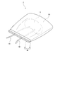
図6のように、第1実施形態の臓器収容器1は、気密性または液密性を有するアウターケーシング3の内部に収容されるものであってもよい。アウターケーシング3は、容易に変形しない剛体であることが好ましい。このようにすれば、フィルムに圧力が加わることを抑制しつつ、肝臓9を容易に運搬できる。アウターケーシング3の内部に、臓器収容器1とともに、保存液を充填してもよい。また、アウターケーシング3は、内部の温度を一定に保つために、保温機能および断熱機能を有していてもよい。
As shown in FIG. 6, the organ container 1 of the first embodiment may be accommodated inside the outer casing 3 having air tightness or liquid tightness. The outer casing 3 is preferably a rigid body that is not easily deformed. In this way, the liver 9 can be easily transported while suppressing the application of pressure to the film. The inside of the outer casing 3 may be filled with a preservation solution together with the organ container 1. In addition, the outer casing 3 may have a heat retention function and a heat insulation function in order to keep the internal temperature constant.
図6の例では、アウターケーシング3に、一対の中継チューブ61,62が固定されている。各中継チューブ61,62の一端は、アウターケーシングの外部に位置する。また、各中継チューブ61,62の当該一端には、解除用のプッシュボタンを有するコネクタ611,621が設けられている。このようにすれば、ユーザは、各中継チューブ61,62の当該コネクタ611,621と、対応するコネクタ711,712を有する外部のチューブ71,72とを、ワンタッチで取り外しおよび接続することができる。
In the example of FIG. 6, the pair of relay tubes 61 and 62 is fixed to the outer casing 3. One end of each of the relay tubes 61 and 62 is located outside the outer casing. Further, connectors 611 and 621 having pushbuttons for release are provided at the one ends of the relay tubes 61 and 62, respectively. In this way, the user can remove and connect the connectors 611 and 621 of the relay tubes 61 and 62 and the external tubes 71 and 72 having the corresponding connectors 711 and 712 with one touch.
一方、各中継チューブ61,62の他端は、アウターケーシング3の内部に位置する。また、各中継チューブ61,62の当該他端には、解除用のプッシュボタンを有するコネクタ612,622が設けられている。さらに、給液チューブ91および排液チューブ92の外側の端部には、当該コネクタに対応するコネクタ911,921が設けられている。このようにすれば、ユーザは、一方の中継チューブ61のコネクタ612と給液チューブ91のコネクタ911とを、ワンタッチで取り外しおよび接続することができる。また、ユーザは、他方の中継チューブ62のコネクタ622と排液チューブ92のコネクタ921とを、ワンタッチで取り外しおよび接続することができる。
On the other hand, the other ends of the relay tubes 61 and 62 are located inside the outer casing 3. Further, connectors 612 and 622 having pushbuttons for release are provided at the other ends of the relay tubes 61 and 62, respectively. Further, connectors 911 and 921 corresponding to the connectors are provided at outer ends of the liquid supply tube 91 and the liquid discharge tube 92. In this way, the user can remove and connect the connector 612 of one of the relay tubes 61 and the connector 911 of the liquid supply tube 91 with one touch. Also, the user can remove and connect the connector 622 of the other relay tube 62 and the connector 921 of the drainage tube 92 with one touch.
上記のコネクタ構造を採用すれば、各チューブの内部を清潔な状態に維持しつつ、チューブの接続および取り外しを行うことができる。また、臓器移植手術においては、処置の迅速性が極めて重要である。上記のコネクタ構造を、臓器収容器1と併用することによって、より確実かつ迅速に臓器移植手術を進めることができる。なお、上記のコネクタ構造は、アウターケーシング3の外部および内部のいずれか一方のみに設けられていてもよい。
With the above connector structure, it is possible to connect and disconnect the tubes while keeping the inside of each tube clean. Further, in organ transplantation surgery, the rapidity of the treatment is extremely important. By using the above connector structure in combination with the organ container 1, organ transplant surgery can be more reliably and rapidly progressed. The above connector structure may be provided only on either the outside or the inside of the outer casing 3.
また、第2実施形態の臓器収容器2も、同様に、アウターケーシング3の内部に収容されるものであってもよい。
Also, the organ container 2 of the second embodiment may be similarly housed inside the outer casing 3.
また、上記の第1実施形態および第2実施形態では、肝臓9を収容する臓器収容器について説明した。しかしながら、臓器収容器は、心臓、膵臓、腎臓等の肝臓9以外の臓器を収容するものであってもよい。また、上記の第1実施形態および第2実施形態では、肝臓9に2本のチューブ91,92が接続されていた。しかしながら、臓器に接続されるチューブの数は、1本であってもよく、3本以上であってもよい。
Moreover, in said 1st Embodiment and 2nd Embodiment, the organ container which accommodates the liver 9 was demonstrated. However, the organ container may contain organs other than the liver 9, such as the heart, pancreas, and kidney. Further, in the first and second embodiments described above, two tubes 91 and 92 are connected to the liver 9. However, the number of tubes connected to the organ may be one or three or more.
また、上記の実施形態や変形例に登場した各要素を、矛盾が生じない範囲で、適宜に組み合わせてもよい。
In addition, each element appearing in the above-described embodiment and modification may be combined appropriately as long as no contradiction occurs.
1,2 臓器収容器
3 アウターケーシング
9 肝臓
11 第1フィルム
12 第2フィルム
21 下フレーム
22 上フレーム
23 係止部
24 溝
30 フィルムバッグ
31 開口部
40 チャック
41 チャック部材
42 凹凸部
43 溝
50 操作紐
61,62 中継チューブ
91 給液チューブ
92 排液チューブ 1, 2Organ container 3 Outer casing 9 Liver 11 First film 12 Second film 21 Lower frame 22 Upper frame 23 Locking portion 24 Groove 30 Film bag 31 Opening 40 Chuck 41 Chuck member 42 Irregular portion 43 Groove 50 Operation cord 61, 62 relay tube 91 supply tube 92 drain tube
3 アウターケーシング
9 肝臓
11 第1フィルム
12 第2フィルム
21 下フレーム
22 上フレーム
23 係止部
24 溝
30 フィルムバッグ
31 開口部
40 チャック
41 チャック部材
42 凹凸部
43 溝
50 操作紐
61,62 中継チューブ
91 給液チューブ
92 排液チューブ 1, 2
Claims (11)
- 臓器を収容する臓器収容器であって、
前記臓器を保持する柔軟なフィルムと、
前記フィルムの端部を開閉する開閉部と、
前記フィルム内の前記臓器と前記フィルムの外部との間で延びるチューブを保持するチューブ保持部と、
を有する、臓器収容器。 An organ container for containing an organ, wherein
A flexible film for holding the organ,
An opening and closing unit for opening and closing an end of the film;
A tube holder for holding a tube extending between the organ in the film and the exterior of the film;
Have an organ container. - 請求項1に記載の臓器収容器であって、
前記フィルムは、
前記臓器の下部を覆うシート状の第1フィルムと、
前記臓器の上部を覆うシート状の第2フィルムと、
を含み、
前記臓器が、前記第1フィルムと前記第2フィルムとの間に挟まれて保持される、臓器収容器。 The organ container according to claim 1, wherein
The film is
A sheet-like first film covering the lower part of the organ;
A sheet-like second film covering the upper part of the organ;
Including
An organ container, wherein the organ is held sandwiched between the first film and the second film. - 請求項2に記載の臓器収容器であって、
前記開閉部は、
前記第1フィルムおよび前記第2フィルムの互いに重なる周縁部を、下方から支持する環状の下フレームと、
前記下フレームとの間に、前記第1フィルムおよび前記第2フィルムの前記周縁部を挟む環状の上フレームと、
を有する、臓器収容器。 The organ container according to claim 2, wherein
The opening and closing unit is
An annular lower frame supporting the overlapping peripheral portions of the first film and the second film from below;
An annular upper frame sandwiching the peripheral portions of the first film and the second film with the lower frame;
Have an organ container. - 請求項3に記載の臓器収容器であって、
前記下フレームと前記上フレームとを、互いに接近させることにより、前記下フレームと前記上フレームとを互いに係止固定する係止部
をさらに有する、臓器収容器。 The organ container according to claim 3, wherein
An organ container further comprising a locking portion configured to lock and fix the lower frame and the upper frame to each other by bringing the lower frame and the upper frame close to each other. - 請求項3または請求項4に記載の臓器収容器であって、
前記チューブ保持部は、
前記下フレームの上面および前記上フレームの下面の少なくとも一方に設けられた溝
を有し、
前記溝に前記チューブが嵌まる、臓器収容器。 The organ container according to claim 3 or 4, wherein
The tube holder is
It has a groove provided on at least one of the upper surface of the lower frame and the lower surface of the upper frame,
An organ container in which the tube is fitted in the groove. - 請求項5に記載の臓器収容器であって、
前記チューブ保持部は、複数の前記溝を有し、
複数の前記溝が、周方向に間隔をあけて設けられている、臓器収容器。 The organ container according to claim 5, wherein
The tube holding portion has a plurality of the grooves.
The organ container, wherein a plurality of the grooves are provided at circumferential intervals. - 請求項1に記載の臓器収容器であって、
前記フィルムにより形成された袋状のフィルムバッグ
を有し、
前記フィルムバッグ内に前記臓器が収容される、臓器収容器。 The organ container according to claim 1, wherein
A bag-shaped film bag formed of the film;
An organ container, wherein the organ is accommodated in the film bag. - 請求項7に記載の臓器収容器であって、
前記開閉部は、前記フィルムバッグの開口部に設けられた開閉可能なチャックである、臓器収容器。 The organ container according to claim 7, wherein
The organ container, wherein the opening and closing part is an openable and closable chuck provided at an opening of the film bag. - 請求項8に記載の臓器収容器であって、
前記チャックは、
互いに密着および離間が可能な一対のチャック部材
を有し、
前記チューブ保持部は、
前記一対のチャック部材の少なくとも一方に設けられた溝
を有し、
前記溝に前記チューブが嵌まる、臓器収容器。 The organ container according to claim 8, wherein
The chuck is
It has a pair of chuck members that can be in close contact and separation from each other
The tube holder is
A groove provided in at least one of the pair of chuck members;
An organ container in which the tube is fitted in the groove. - 請求項7に記載の臓器収容器であって、
前記開閉部は、前記フィルムバッグの開口部を収縮させることが可能な操作紐
を有する、臓器収容器。 The organ container according to claim 7, wherein
The organ container, wherein the opening and closing part has an operation cord capable of contracting the opening of the film bag. - 請求項1から請求項10までのいずれか1項に記載の臓器収容器であって、
前記フィルムは、樹脂製である、臓器収容器。 An organ container according to any one of claims 1 to 10, wherein
The film is made of resin, an organ container.
Priority Applications (3)
| Application Number | Priority Date | Filing Date | Title |
|---|---|---|---|
| US16/765,283 US11459534B2 (en) | 2017-11-28 | 2018-10-01 | Organ container |
| EP18884777.6A EP3718402A4 (en) | 2017-11-28 | 2018-10-01 | Organ container |
| CN201880072728.1A CN111315215B (en) | 2017-11-28 | 2018-10-01 | Organ container |
Applications Claiming Priority (2)
| Application Number | Priority Date | Filing Date | Title |
|---|---|---|---|
| JP2017-227718 | 2017-11-28 | ||
| JP2017227718A JP6967434B2 (en) | 2017-11-28 | 2017-11-28 | Organ container |
Publications (1)
| Publication Number | Publication Date |
|---|---|
| WO2019106936A1 true WO2019106936A1 (en) | 2019-06-06 |
Family
ID=66664871
Family Applications (1)
| Application Number | Title | Priority Date | Filing Date |
|---|---|---|---|
| PCT/JP2018/036652 WO2019106936A1 (en) | 2017-11-28 | 2018-10-01 | Organ container |
Country Status (5)
| Country | Link |
|---|---|
| US (1) | US11459534B2 (en) |
| EP (1) | EP3718402A4 (en) |
| JP (1) | JP6967434B2 (en) |
| CN (1) | CN111315215B (en) |
| WO (1) | WO2019106936A1 (en) |
Cited By (3)
| Publication number | Priority date | Publication date | Assignee | Title |
|---|---|---|---|---|
| EP3756460A1 (en) * | 2019-06-26 | 2020-12-30 | SCREEN Holdings Co., Ltd. | Frame and organ holder |
| WO2021156460A1 (en) * | 2020-02-06 | 2021-08-12 | The University Of Strathclyde | Organ transport apparatus |
| CN113261554A (en) * | 2020-02-14 | 2021-08-17 | 株式会社斯库林集团 | Organ container |
Families Citing this family (6)
| Publication number | Priority date | Publication date | Assignee | Title |
|---|---|---|---|---|
| JP2021017433A (en) | 2019-07-24 | 2021-02-15 | 株式会社Screenホールディングス | Organ reception container |
| JP7355567B2 (en) * | 2019-09-11 | 2023-10-03 | 株式会社Screenホールディングス | organ storage container |
| JP2022049795A (en) * | 2020-09-17 | 2022-03-30 | 株式会社Screenホールディングス | Organ storage container |
| JP2022100507A (en) * | 2020-12-24 | 2022-07-06 | 株式会社Screenホールディングス | Organ container |
| WO2022204436A1 (en) * | 2021-03-25 | 2022-09-29 | Vanderbilt University | Veno-arterial venous cross-circulation for extracorporeal organ support |
| CN113384379B (en) * | 2021-06-17 | 2022-12-02 | 深圳华越再生医学生物科技有限公司 | For wrapping device for transplanting visceral organs |
Citations (9)
| Publication number | Priority date | Publication date | Assignee | Title |
|---|---|---|---|---|
| JPH02111701A (en) * | 1988-10-20 | 1990-04-24 | Olympus Optical Co Ltd | Internal organ storing unit |
| JPH03151303A (en) | 1989-11-06 | 1991-06-27 | Olympus Optical Co Ltd | Organ-preservation apparatus |
| JPH0616501A (en) * | 1992-05-06 | 1994-01-25 | Tonokura Ika Kogyo Kk | Method and device for carrying organ and pump for organ-carrying device |
| JPH07101802A (en) * | 1993-10-01 | 1995-04-18 | Kohei Hasegawa | Accommodation of encleated organ |
| JPH07101801A (en) * | 1993-10-01 | 1995-04-18 | Kohei Hasegawa | Accommodation of enucleated organ |
| JP2000309377A (en) * | 1999-04-27 | 2000-11-07 | Hirotoshi Kosugi | Pinching type packaging container |
| JP2001039473A (en) * | 1999-07-28 | 2001-02-13 | Shiro Ono | Packaging container |
| JP2003267471A (en) * | 2002-03-15 | 2003-09-25 | Nipro Corp | Protecting external packaging bag for container for freezing and storing living tissue |
| JP2017039497A (en) * | 2015-08-17 | 2017-02-23 | トッパン・フォームズ株式会社 | Article holding container |
Family Cites Families (17)
| Publication number | Priority date | Publication date | Assignee | Title |
|---|---|---|---|---|
| JPS4740995Y1 (en) | 1969-07-17 | 1972-12-12 | ||
| CN86203016U (en) | 1986-05-17 | 1986-12-10 | 上海市塑料研究所 | Medical ultralow temp. cell and tissue-storing bag |
| US8409846B2 (en) * | 1997-09-23 | 2013-04-02 | The United States Of America As Represented By The Department Of Veteran Affairs | Compositions, methods and devices for maintaining an organ |
| US6100082A (en) * | 1997-09-23 | 2000-08-08 | Hassanein; Waleed H. | Perfusion apparatus and method including chemical compositions for maintaining an organ |
| WO2004026031A2 (en) * | 2002-09-18 | 2004-04-01 | Lifeblood Medical Inc. | Organ preservation and transportation apparatus and method |
| NL1024022C2 (en) * | 2003-07-30 | 2005-02-01 | Technologiestichting Stw | Portable preservation device for a donor organ. |
| CN2896900Y (en) | 2006-03-27 | 2007-05-09 | 董礼明 | Refrigeration bag for transplanting kidney |
| EP2285211B1 (en) * | 2008-05-06 | 2019-07-24 | XVIVO Perfusion AB | Apparatus for housing an organ during evaluation and preservation |
| CN201345874Y (en) | 2009-01-08 | 2009-11-18 | 孔佑华 | Medical cell tissue cryopreservation bag |
| CN202232704U (en) | 2011-09-09 | 2012-05-30 | 明英姿 | Special specimen cold storage bag for transplanted kidney |
| US10034738B2 (en) * | 2012-12-07 | 2018-07-31 | The Governing Council Of The University Of Toronto | Cardiac tissue constructs and methods of fabrication thereof |
| US10111418B2 (en) * | 2013-06-07 | 2018-10-30 | Perfusion Solutions Pty Ltd | Organ perfusion system and device |
| CN103688924B (en) * | 2013-12-24 | 2015-07-22 | 大连医科大学 | Transplant cold protection bag |
| US9781920B2 (en) | 2014-04-09 | 2017-10-10 | Paul Jeffrey Campsen | Suspendable organ transplant system and method of use |
| CN205962505U (en) | 2016-05-19 | 2017-02-22 | 眀英姿 | Multi -functional organ preservation bag |
| US11632951B2 (en) * | 2020-01-31 | 2023-04-25 | Paragonix Technologies, Inc. | Apparatus for tissue transport and preservation |
| JP2022020909A (en) * | 2020-07-21 | 2022-02-02 | 株式会社Screenホールディングス | Organ preservation device |
-
2017
- 2017-11-28 JP JP2017227718A patent/JP6967434B2/en active Active
-
2018
- 2018-10-01 WO PCT/JP2018/036652 patent/WO2019106936A1/en unknown
- 2018-10-01 EP EP18884777.6A patent/EP3718402A4/en active Pending
- 2018-10-01 CN CN201880072728.1A patent/CN111315215B/en active Active
- 2018-10-01 US US16/765,283 patent/US11459534B2/en active Active
Patent Citations (9)
| Publication number | Priority date | Publication date | Assignee | Title |
|---|---|---|---|---|
| JPH02111701A (en) * | 1988-10-20 | 1990-04-24 | Olympus Optical Co Ltd | Internal organ storing unit |
| JPH03151303A (en) | 1989-11-06 | 1991-06-27 | Olympus Optical Co Ltd | Organ-preservation apparatus |
| JPH0616501A (en) * | 1992-05-06 | 1994-01-25 | Tonokura Ika Kogyo Kk | Method and device for carrying organ and pump for organ-carrying device |
| JPH07101802A (en) * | 1993-10-01 | 1995-04-18 | Kohei Hasegawa | Accommodation of encleated organ |
| JPH07101801A (en) * | 1993-10-01 | 1995-04-18 | Kohei Hasegawa | Accommodation of enucleated organ |
| JP2000309377A (en) * | 1999-04-27 | 2000-11-07 | Hirotoshi Kosugi | Pinching type packaging container |
| JP2001039473A (en) * | 1999-07-28 | 2001-02-13 | Shiro Ono | Packaging container |
| JP2003267471A (en) * | 2002-03-15 | 2003-09-25 | Nipro Corp | Protecting external packaging bag for container for freezing and storing living tissue |
| JP2017039497A (en) * | 2015-08-17 | 2017-02-23 | トッパン・フォームズ株式会社 | Article holding container |
Non-Patent Citations (1)
| Title |
|---|
| See also references of EP3718402A4 |
Cited By (7)
| Publication number | Priority date | Publication date | Assignee | Title |
|---|---|---|---|---|
| EP3756460A1 (en) * | 2019-06-26 | 2020-12-30 | SCREEN Holdings Co., Ltd. | Frame and organ holder |
| JP2021004208A (en) * | 2019-06-26 | 2021-01-14 | 株式会社Screenホールディングス | Frame and organ holding tool |
| US11357227B2 (en) | 2019-06-26 | 2022-06-14 | SCREEN Holdings Co., Ltd. | Frame and organ holder |
| JP7190398B2 (en) | 2019-06-26 | 2022-12-15 | 株式会社Screenホールディングス | frame and organ holder |
| WO2021156460A1 (en) * | 2020-02-06 | 2021-08-12 | The University Of Strathclyde | Organ transport apparatus |
| CN113261554A (en) * | 2020-02-14 | 2021-08-17 | 株式会社斯库林集团 | Organ container |
| EP3864960A1 (en) * | 2020-02-14 | 2021-08-18 | SCREEN Holdings Co., Ltd. | Organ container |
Also Published As
| Publication number | Publication date |
|---|---|
| CN111315215B (en) | 2022-03-15 |
| US20200308520A1 (en) | 2020-10-01 |
| JP6967434B2 (en) | 2021-11-17 |
| CN111315215A (en) | 2020-06-19 |
| EP3718402A1 (en) | 2020-10-07 |
| US11459534B2 (en) | 2022-10-04 |
| EP3718402A4 (en) | 2021-03-24 |
| JP2019094315A (en) | 2019-06-20 |
Similar Documents
| Publication | Publication Date | Title |
|---|---|---|
| WO2019106936A1 (en) | Organ container | |
| JP7143167B2 (en) | Organ-receiving bag and transplantation method | |
| EP1553828A2 (en) | Organ preservation and transportation apparatus and method | |
| JP2004329202A (en) | Tool for cryopreservation of egg | |
| US9781920B2 (en) | Suspendable organ transplant system and method of use | |
| JP2008525155A5 (en) | ||
| JP2020083785A (en) | Organ preservation device and organ preservation method | |
| EP3942930A1 (en) | Organ preservation system | |
| EP3864960A1 (en) | Organ container | |
| JP3150696U (en) | Fixative bag | |
| BR112020001067A2 (en) | sterile packaging system for a catheter | |
| US10343841B1 (en) | Waste containment and isolating system and method of isolating waste thereof | |
| JP2017176358A (en) | Packaging material and cap package | |
| JP2022049795A (en) | Organ storage container | |
| WO2022195936A1 (en) | Organ storage container | |
| WO2023047976A1 (en) | Organ placement platform, organ storage container, and organ placement method | |
| US20200022771A1 (en) | Sterile packaging for surgical tools | |
| AU6323198A (en) | Blood evacuating system and method of use thereof | |
| CN219216076U (en) | Packaging structure and packaging system of artificial valve | |
| WO2023037836A1 (en) | Organ storage container, organ storage device, and production method for organ storage container | |
| JP2018511304A (en) | Cell encapsulation loading device | |
| JP2024048935A (en) | Fecal component extraction container | |
| JP2023039401A (en) | Organ preservation container, organ preservation device, and method for manufacturing organ preservation container | |
| JP2023002022A (en) | Leak valve and storage container | |
| FR3027591A1 (en) | PACKAGING FOR TRANSPORTING A PORTION OF THE HUMAN OR ANIMAL BODY |
Legal Events
| Date | Code | Title | Description |
|---|---|---|---|
| 121 | Ep: the epo has been informed by wipo that ep was designated in this application |
Ref document number: 18884777 Country of ref document: EP Kind code of ref document: A1 |
|
| NENP | Non-entry into the national phase |
Ref country code: DE |
|
| ENP | Entry into the national phase |
Ref document number: 2018884777 Country of ref document: EP Effective date: 20200629 |