WO2019106929A1 - Charging member for electrophotographic apparatus - Google Patents
Charging member for electrophotographic apparatus Download PDFInfo
- Publication number
- WO2019106929A1 WO2019106929A1 PCT/JP2018/035584 JP2018035584W WO2019106929A1 WO 2019106929 A1 WO2019106929 A1 WO 2019106929A1 JP 2018035584 W JP2018035584 W JP 2018035584W WO 2019106929 A1 WO2019106929 A1 WO 2019106929A1
- Authority
- WO
- WIPO (PCT)
- Prior art keywords
- charging member
- electrophotographic apparatus
- base layer
- surface layer
- rubber
- Prior art date
Links
- 229920001971 elastomer Polymers 0.000 claims abstract description 78
- 239000005060 rubber Substances 0.000 claims abstract description 77
- 239000010410 layer Substances 0.000 claims abstract description 74
- 239000006258 conductive agent Substances 0.000 claims abstract description 64
- 239000002344 surface layer Substances 0.000 claims abstract description 51
- 239000006229 carbon black Substances 0.000 claims abstract description 38
- 239000000203 mixture Substances 0.000 claims abstract description 34
- -1 sulfonate anion Chemical class 0.000 claims abstract description 23
- 125000001153 fluoro group Chemical group F* 0.000 claims abstract description 14
- 229910052731 fluorine Inorganic materials 0.000 claims abstract description 13
- 125000000217 alkyl group Chemical group 0.000 claims abstract description 12
- 125000001495 ethyl group Chemical group [H]C([H])([H])C([H])([H])* 0.000 claims abstract description 4
- 125000002496 methyl group Chemical group [H]C([H])([H])* 0.000 claims abstract description 4
- 150000002500 ions Chemical class 0.000 claims description 68
- 239000002245 particle Substances 0.000 claims description 17
- 125000003903 2-propenyl group Chemical group [H]C([*])([H])C([H])=C([H])[H] 0.000 claims description 10
- 125000004432 carbon atom Chemical group C* 0.000 claims description 10
- 229920000642 polymer Polymers 0.000 claims description 10
- 239000004952 Polyamide Substances 0.000 claims description 9
- KRKNYBCHXYNGOX-UHFFFAOYSA-N citric acid Chemical compound OC(=O)CC(O)(C(O)=O)CC(O)=O KRKNYBCHXYNGOX-UHFFFAOYSA-N 0.000 claims description 9
- 239000004814 polyurethane Substances 0.000 claims description 8
- 229920000178 Acrylic resin Polymers 0.000 claims description 6
- 239000004925 Acrylic resin Substances 0.000 claims description 6
- 229920002647 polyamide Polymers 0.000 claims description 6
- 125000000472 sulfonyl group Chemical group *S(*)(=O)=O 0.000 claims description 6
- 229920002635 polyurethane Polymers 0.000 claims description 5
- JOYRKODLDBILNP-UHFFFAOYSA-N Ethyl urethane Chemical compound CCOC(N)=O JOYRKODLDBILNP-UHFFFAOYSA-N 0.000 claims description 4
- 239000004971 Cross linker Substances 0.000 claims description 3
- 229920006122 polyamide resin Polymers 0.000 claims description 3
- 229920005749 polyurethane resin Polymers 0.000 claims description 3
- XOLBLPGZBRYERU-UHFFFAOYSA-N tin dioxide Chemical compound O=[Sn]=O XOLBLPGZBRYERU-UHFFFAOYSA-N 0.000 claims description 3
- 229910001887 tin oxide Inorganic materials 0.000 claims description 3
- 239000003431 cross linking reagent Substances 0.000 abstract description 25
- 230000000740 bleeding effect Effects 0.000 abstract description 20
- 230000007547 defect Effects 0.000 abstract description 4
- 125000003118 aryl group Chemical group 0.000 abstract 1
- 239000000806 elastomer Substances 0.000 abstract 1
- 150000001768 cations Chemical class 0.000 description 25
- 238000002360 preparation method Methods 0.000 description 19
- 238000004132 cross linking Methods 0.000 description 14
- 239000003795 chemical substances by application Substances 0.000 description 10
- 239000000463 material Substances 0.000 description 9
- PYGSKMBEVAICCR-UHFFFAOYSA-N hexa-1,5-diene Chemical group C=CCCC=C PYGSKMBEVAICCR-UHFFFAOYSA-N 0.000 description 8
- ZXMGHDIOOHOAAE-UHFFFAOYSA-N 1,1,1-trifluoro-n-(trifluoromethylsulfonyl)methanesulfonamide Chemical compound FC(F)(F)S(=O)(=O)NS(=O)(=O)C(F)(F)F ZXMGHDIOOHOAAE-UHFFFAOYSA-N 0.000 description 7
- 229920000459 Nitrile rubber Polymers 0.000 description 7
- NINIDFKCEFEMDL-UHFFFAOYSA-N Sulfur Chemical compound [S] NINIDFKCEFEMDL-UHFFFAOYSA-N 0.000 description 7
- 230000000694 effects Effects 0.000 description 7
- 238000011156 evaluation Methods 0.000 description 7
- OKTJSMMVPCPJKN-UHFFFAOYSA-N Carbon Chemical compound [C] OKTJSMMVPCPJKN-UHFFFAOYSA-N 0.000 description 6
- OKKJLVBELUTLKV-UHFFFAOYSA-N Methanol Chemical compound OC OKKJLVBELUTLKV-UHFFFAOYSA-N 0.000 description 6
- HEMHJVSKTPXQMS-UHFFFAOYSA-M Sodium hydroxide Chemical compound [OH-].[Na+] HEMHJVSKTPXQMS-UHFFFAOYSA-M 0.000 description 6
- 150000001450 anions Chemical class 0.000 description 6
- 238000006298 dechlorination reaction Methods 0.000 description 6
- 230000003993 interaction Effects 0.000 description 6
- 229910052717 sulfur Inorganic materials 0.000 description 6
- 239000011593 sulfur Substances 0.000 description 6
- XLOMVQKBTHCTTD-UHFFFAOYSA-N zinc oxide Inorganic materials [Zn]=O XLOMVQKBTHCTTD-UHFFFAOYSA-N 0.000 description 6
- 229920005601 base polymer Polymers 0.000 description 5
- 230000015572 biosynthetic process Effects 0.000 description 5
- 238000006243 chemical reaction Methods 0.000 description 5
- 230000000052 comparative effect Effects 0.000 description 5
- 229910052757 nitrogen Inorganic materials 0.000 description 5
- 150000002978 peroxides Chemical class 0.000 description 5
- MNDIARAMWBIKFW-UHFFFAOYSA-N 1-bromohexane Chemical compound CCCCCCBr MNDIARAMWBIKFW-UHFFFAOYSA-N 0.000 description 4
- 239000004721 Polyphenylene oxide Substances 0.000 description 4
- 229920006311 Urethane elastomer Polymers 0.000 description 4
- 239000000654 additive Substances 0.000 description 4
- 229910052799 carbon Inorganic materials 0.000 description 4
- 229920001577 copolymer Polymers 0.000 description 4
- 229920000570 polyether Polymers 0.000 description 4
- 239000000126 substance Substances 0.000 description 4
- 239000011787 zinc oxide Substances 0.000 description 4
- ZWEHNKRNPOVVGH-UHFFFAOYSA-N 2-Butanone Chemical compound CCC(C)=O ZWEHNKRNPOVVGH-UHFFFAOYSA-N 0.000 description 3
- CSCPPACGZOOCGX-UHFFFAOYSA-N Acetone Chemical compound CC(C)=O CSCPPACGZOOCGX-UHFFFAOYSA-N 0.000 description 3
- WEVYAHXRMPXWCK-UHFFFAOYSA-N Acetonitrile Chemical compound CC#N WEVYAHXRMPXWCK-UHFFFAOYSA-N 0.000 description 3
- LFQSCWFLJHTTHZ-UHFFFAOYSA-N Ethanol Chemical compound CCO LFQSCWFLJHTTHZ-UHFFFAOYSA-N 0.000 description 3
- XEKOWRVHYACXOJ-UHFFFAOYSA-N Ethyl acetate Chemical compound CCOC(C)=O XEKOWRVHYACXOJ-UHFFFAOYSA-N 0.000 description 3
- 244000043261 Hevea brasiliensis Species 0.000 description 3
- 235000021355 Stearic acid Nutrition 0.000 description 3
- YXFVVABEGXRONW-UHFFFAOYSA-N Toluene Chemical compound CC1=CC=CC=C1 YXFVVABEGXRONW-UHFFFAOYSA-N 0.000 description 3
- 239000002253 acid Substances 0.000 description 3
- 239000003125 aqueous solvent Substances 0.000 description 3
- 238000000576 coating method Methods 0.000 description 3
- 238000010494 dissociation reaction Methods 0.000 description 3
- 230000005593 dissociations Effects 0.000 description 3
- 150000003949 imides Chemical class 0.000 description 3
- 229910052751 metal Inorganic materials 0.000 description 3
- 239000002184 metal Substances 0.000 description 3
- VLKZOEOYAKHREP-UHFFFAOYSA-N n-Hexane Chemical compound CCCCCC VLKZOEOYAKHREP-UHFFFAOYSA-N 0.000 description 3
- 229920003052 natural elastomer Polymers 0.000 description 3
- 229920001194 natural rubber Polymers 0.000 description 3
- QIQXTHQIDYTFRH-UHFFFAOYSA-N octadecanoic acid Chemical compound CCCCCCCCCCCCCCCCCC(O)=O QIQXTHQIDYTFRH-UHFFFAOYSA-N 0.000 description 3
- OQCDKBAXFALNLD-UHFFFAOYSA-N octadecanoic acid Natural products CCCCCCCC(C)CCCCCCCCC(O)=O OQCDKBAXFALNLD-UHFFFAOYSA-N 0.000 description 3
- 239000003960 organic solvent Substances 0.000 description 3
- 239000011347 resin Substances 0.000 description 3
- 229920005989 resin Polymers 0.000 description 3
- 150000003839 salts Chemical class 0.000 description 3
- 239000008117 stearic acid Substances 0.000 description 3
- 238000003756 stirring Methods 0.000 description 3
- ITMCEJHCFYSIIV-UHFFFAOYSA-M triflate Chemical compound [O-]S(=O)(=O)C(F)(F)F ITMCEJHCFYSIIV-UHFFFAOYSA-M 0.000 description 3
- OSDWBNJEKMUWAV-UHFFFAOYSA-N Allyl chloride Chemical compound ClCC=C OSDWBNJEKMUWAV-UHFFFAOYSA-N 0.000 description 2
- IJGRMHOSHXDMSA-UHFFFAOYSA-N Atomic nitrogen Chemical compound N#N IJGRMHOSHXDMSA-UHFFFAOYSA-N 0.000 description 2
- CPELXLSAUQHCOX-UHFFFAOYSA-M Bromide Chemical compound [Br-] CPELXLSAUQHCOX-UHFFFAOYSA-M 0.000 description 2
- XEEYBQQBJWHFJM-UHFFFAOYSA-N Iron Chemical compound [Fe] XEEYBQQBJWHFJM-UHFFFAOYSA-N 0.000 description 2
- WHXSMMKQMYFTQS-UHFFFAOYSA-N Lithium Chemical compound [Li] WHXSMMKQMYFTQS-UHFFFAOYSA-N 0.000 description 2
- NTIZESTWPVYFNL-UHFFFAOYSA-N Methyl isobutyl ketone Chemical compound CC(C)CC(C)=O NTIZESTWPVYFNL-UHFFFAOYSA-N 0.000 description 2
- UIHCLUNTQKBZGK-UHFFFAOYSA-N Methyl isobutyl ketone Natural products CCC(C)C(C)=O UIHCLUNTQKBZGK-UHFFFAOYSA-N 0.000 description 2
- 239000006057 Non-nutritive feed additive Substances 0.000 description 2
- 239000005062 Polybutadiene Substances 0.000 description 2
- 239000000853 adhesive Substances 0.000 description 2
- 230000001070 adhesive effect Effects 0.000 description 2
- RDHPKYGYEGBMSE-UHFFFAOYSA-N bromoethane Chemical compound CCBr RDHPKYGYEGBMSE-UHFFFAOYSA-N 0.000 description 2
- 238000013329 compounding Methods 0.000 description 2
- GDVKFRBCXAPAQJ-UHFFFAOYSA-A dialuminum;hexamagnesium;carbonate;hexadecahydroxide Chemical compound [OH-].[OH-].[OH-].[OH-].[OH-].[OH-].[OH-].[OH-].[OH-].[OH-].[OH-].[OH-].[OH-].[OH-].[OH-].[OH-].[Mg+2].[Mg+2].[Mg+2].[Mg+2].[Mg+2].[Mg+2].[Al+3].[Al+3].[O-]C([O-])=O GDVKFRBCXAPAQJ-UHFFFAOYSA-A 0.000 description 2
- 125000005442 diisocyanate group Chemical group 0.000 description 2
- 229920005558 epichlorohydrin rubber Polymers 0.000 description 2
- CEIPQQODRKXDSB-UHFFFAOYSA-N ethyl 3-(6-hydroxynaphthalen-2-yl)-1H-indazole-5-carboximidate dihydrochloride Chemical compound Cl.Cl.C1=C(O)C=CC2=CC(C3=NNC4=CC=C(C=C43)C(=N)OCC)=CC=C21 CEIPQQODRKXDSB-UHFFFAOYSA-N 0.000 description 2
- 238000010438 heat treatment Methods 0.000 description 2
- 229960001545 hydrotalcite Drugs 0.000 description 2
- 229910001701 hydrotalcite Inorganic materials 0.000 description 2
- 229920003049 isoprene rubber Polymers 0.000 description 2
- 229910052744 lithium Inorganic materials 0.000 description 2
- 238000000034 method Methods 0.000 description 2
- 238000002156 mixing Methods 0.000 description 2
- 238000000465 moulding Methods 0.000 description 2
- 125000000864 peroxy group Chemical group O(O*)* 0.000 description 2
- 229920001084 poly(chloroprene) Polymers 0.000 description 2
- 229920002857 polybutadiene Polymers 0.000 description 2
- 229920001296 polysiloxane Polymers 0.000 description 2
- 150000003242 quaternary ammonium salts Chemical group 0.000 description 2
- 239000000243 solution Substances 0.000 description 2
- 125000001889 triflyl group Chemical group FC(F)(F)S(*)(=O)=O 0.000 description 2
- GKNWQHIXXANPTN-UHFFFAOYSA-M 1,1,2,2,2-pentafluoroethanesulfonate Chemical compound [O-]S(=O)(=O)C(F)(F)C(F)(F)F GKNWQHIXXANPTN-UHFFFAOYSA-M 0.000 description 1
- XBWQFDNGNOOMDZ-UHFFFAOYSA-N 1,1,2,2,3,3,3-heptafluoropropane-1-sulfonic acid Chemical compound OS(=O)(=O)C(F)(F)C(F)(F)C(F)(F)F XBWQFDNGNOOMDZ-UHFFFAOYSA-N 0.000 description 1
- YXIWHUQXZSMYRE-UHFFFAOYSA-N 1,3-benzothiazole-2-thiol Chemical class C1=CC=C2SC(S)=NC2=C1 YXIWHUQXZSMYRE-UHFFFAOYSA-N 0.000 description 1
- YHMYGUUIMTVXNW-UHFFFAOYSA-N 1,3-dihydrobenzimidazole-2-thione Chemical class C1=CC=C2NC(S)=NC2=C1 YHMYGUUIMTVXNW-UHFFFAOYSA-N 0.000 description 1
- BGPJLYIFDLICMR-UHFFFAOYSA-N 1,4,2,3-dioxadithiolan-5-one Chemical compound O=C1OSSO1 BGPJLYIFDLICMR-UHFFFAOYSA-N 0.000 description 1
- AYMUQTNXKPEMLM-UHFFFAOYSA-N 1-bromononane Chemical compound CCCCCCCCCBr AYMUQTNXKPEMLM-UHFFFAOYSA-N 0.000 description 1
- VMKOFRJSULQZRM-UHFFFAOYSA-N 1-bromooctane Chemical compound CCCCCCCCBr VMKOFRJSULQZRM-UHFFFAOYSA-N 0.000 description 1
- YZWKKMVJZFACSU-UHFFFAOYSA-N 1-bromopentane Chemical compound CCCCCBr YZWKKMVJZFACSU-UHFFFAOYSA-N 0.000 description 1
- CYNYIHKIEHGYOZ-UHFFFAOYSA-N 1-bromopropane Chemical compound CCCBr CYNYIHKIEHGYOZ-UHFFFAOYSA-N 0.000 description 1
- BMVXCPBXGZKUPN-UHFFFAOYSA-N 1-hexanamine Chemical compound CCCCCCN BMVXCPBXGZKUPN-UHFFFAOYSA-N 0.000 description 1
- RNFJDJUURJAICM-UHFFFAOYSA-N 2,2,4,4,6,6-hexaphenoxy-1,3,5-triaza-2$l^{5},4$l^{5},6$l^{5}-triphosphacyclohexa-1,3,5-triene Chemical compound N=1P(OC=2C=CC=CC=2)(OC=2C=CC=CC=2)=NP(OC=2C=CC=CC=2)(OC=2C=CC=CC=2)=NP=1(OC=1C=CC=CC=1)OC1=CC=CC=C1 RNFJDJUURJAICM-UHFFFAOYSA-N 0.000 description 1
- GQHTUMJGOHRCHB-UHFFFAOYSA-N 2,3,4,6,7,8,9,10-octahydropyrimido[1,2-a]azepine Chemical class C1CCCCN2CCCN=C21 GQHTUMJGOHRCHB-UHFFFAOYSA-N 0.000 description 1
- OIXNFJTTYAIBNF-UHFFFAOYSA-N 2-(chloromethyl)oxirane;oxirane Chemical compound C1CO1.ClCC1CO1 OIXNFJTTYAIBNF-UHFFFAOYSA-N 0.000 description 1
- KXGFMDJXCMQABM-UHFFFAOYSA-N 2-methoxy-6-methylphenol Chemical class [CH]OC1=CC=CC([CH])=C1O KXGFMDJXCMQABM-UHFFFAOYSA-N 0.000 description 1
- ALKYHXVLJMQRLQ-UHFFFAOYSA-N 3-Hydroxy-2-naphthoate Chemical class C1=CC=C2C=C(O)C(C(=O)O)=CC2=C1 ALKYHXVLJMQRLQ-UHFFFAOYSA-N 0.000 description 1
- REEBWSYYNPPSKV-UHFFFAOYSA-N 3-[(4-formylphenoxy)methyl]thiophene-2-carbonitrile Chemical compound C1=CC(C=O)=CC=C1OCC1=C(C#N)SC=C1 REEBWSYYNPPSKV-UHFFFAOYSA-N 0.000 description 1
- UPMLOUAZCHDJJD-UHFFFAOYSA-N 4,4'-Diphenylmethane Diisocyanate Chemical compound C1=CC(N=C=O)=CC=C1CC1=CC=C(N=C=O)C=C1 UPMLOUAZCHDJJD-UHFFFAOYSA-N 0.000 description 1
- QGZKDVFQNNGYKY-UHFFFAOYSA-O Ammonium Chemical compound [NH4+] QGZKDVFQNNGYKY-UHFFFAOYSA-O 0.000 description 1
- DKPFZGUDAPQIHT-UHFFFAOYSA-N Butyl acetate Natural products CCCCOC(C)=O DKPFZGUDAPQIHT-UHFFFAOYSA-N 0.000 description 1
- 239000005977 Ethylene Substances 0.000 description 1
- YCKRFDGAMUMZLT-UHFFFAOYSA-N Fluorine atom Chemical compound [F] YCKRFDGAMUMZLT-UHFFFAOYSA-N 0.000 description 1
- 239000004677 Nylon Substances 0.000 description 1
- 239000002202 Polyethylene glycol Substances 0.000 description 1
- VYPSYNLAJGMNEJ-UHFFFAOYSA-N Silicium dioxide Chemical compound O=[Si]=O VYPSYNLAJGMNEJ-UHFFFAOYSA-N 0.000 description 1
- 229910006404 SnO 2 Inorganic materials 0.000 description 1
- 229910010413 TiO 2 Inorganic materials 0.000 description 1
- NIXOWILDQLNWCW-UHFFFAOYSA-N acrylic acid group Chemical group C(C=C)(=O)O NIXOWILDQLNWCW-UHFFFAOYSA-N 0.000 description 1
- 229920000800 acrylic rubber Polymers 0.000 description 1
- 238000004220 aggregation Methods 0.000 description 1
- 230000002776 aggregation Effects 0.000 description 1
- 229920000180 alkyd Polymers 0.000 description 1
- 229910052782 aluminium Inorganic materials 0.000 description 1
- XAGFODPZIPBFFR-UHFFFAOYSA-N aluminium Chemical compound [Al] XAGFODPZIPBFFR-UHFFFAOYSA-N 0.000 description 1
- 230000003712 anti-aging effect Effects 0.000 description 1
- 239000002518 antifoaming agent Substances 0.000 description 1
- 239000007864 aqueous solution Substances 0.000 description 1
- 239000012752 auxiliary agent Substances 0.000 description 1
- 150000001558 benzoic acid derivatives Chemical class 0.000 description 1
- 150000001642 boronic acid derivatives Chemical class 0.000 description 1
- 150000004649 carbonic acid derivatives Chemical class 0.000 description 1
- 125000003178 carboxy group Chemical group [H]OC(*)=O 0.000 description 1
- 230000008859 change Effects 0.000 description 1
- 125000001309 chloro group Chemical group Cl* 0.000 description 1
- 238000001816 cooling Methods 0.000 description 1
- 239000012933 diacyl peroxide Substances 0.000 description 1
- 238000010586 diagram Methods 0.000 description 1
- YIOJGTBNHQAVBO-UHFFFAOYSA-N dimethyl-bis(prop-2-enyl)azanium Chemical compound C=CC[N+](C)(C)CC=C YIOJGTBNHQAVBO-UHFFFAOYSA-N 0.000 description 1
- 238000007598 dipping method Methods 0.000 description 1
- 239000002270 dispersing agent Substances 0.000 description 1
- 238000009826 distribution Methods 0.000 description 1
- PXJJSXABGXMUSU-UHFFFAOYSA-N disulfur dichloride Chemical compound ClSSCl PXJJSXABGXMUSU-UHFFFAOYSA-N 0.000 description 1
- 229920005561 epichlorohydrin homopolymer Polymers 0.000 description 1
- 125000003700 epoxy group Chemical group 0.000 description 1
- RTZKZFJDLAIYFH-UHFFFAOYSA-N ether Substances CCOCC RTZKZFJDLAIYFH-UHFFFAOYSA-N 0.000 description 1
- 239000000945 filler Substances 0.000 description 1
- 239000003063 flame retardant Substances 0.000 description 1
- 239000011737 fluorine Substances 0.000 description 1
- 239000004088 foaming agent Substances 0.000 description 1
- 229910002804 graphite Inorganic materials 0.000 description 1
- 239000010439 graphite Substances 0.000 description 1
- FUZZWVXGSFPDMH-UHFFFAOYSA-M hexanoate Chemical compound CCCCCC([O-])=O FUZZWVXGSFPDMH-UHFFFAOYSA-M 0.000 description 1
- 150000002432 hydroperoxides Chemical class 0.000 description 1
- 125000002887 hydroxy group Chemical group [H]O* 0.000 description 1
- 230000003100 immobilizing effect Effects 0.000 description 1
- 229910052742 iron Inorganic materials 0.000 description 1
- 239000004611 light stabiliser Substances 0.000 description 1
- 239000007788 liquid Substances 0.000 description 1
- 239000000314 lubricant Substances 0.000 description 1
- 230000007246 mechanism Effects 0.000 description 1
- 239000003607 modifier Substances 0.000 description 1
- WSTNFGAKGUERTC-UHFFFAOYSA-N n-ethylhexan-1-amine Chemical compound CCCCCCNCC WSTNFGAKGUERTC-UHFFFAOYSA-N 0.000 description 1
- WGESLFUSXZBFQF-UHFFFAOYSA-N n-methyl-n-prop-2-enylprop-2-en-1-amine Chemical compound C=CCN(C)CC=C WGESLFUSXZBFQF-UHFFFAOYSA-N 0.000 description 1
- XJINZNWPEQMMBV-UHFFFAOYSA-N n-methylhexan-1-amine Chemical compound CCCCCCNC XJINZNWPEQMMBV-UHFFFAOYSA-N 0.000 description 1
- 125000002560 nitrile group Chemical group 0.000 description 1
- 229920001778 nylon Polymers 0.000 description 1
- 125000005634 peroxydicarbonate group Chemical group 0.000 description 1
- 239000005011 phenolic resin Substances 0.000 description 1
- 239000000049 pigment Substances 0.000 description 1
- 229920003023 plastic Polymers 0.000 description 1
- 239000004033 plastic Substances 0.000 description 1
- 229920000058 polyacrylate Polymers 0.000 description 1
- 229920001223 polyethylene glycol Polymers 0.000 description 1
- 229920001451 polypropylene glycol Polymers 0.000 description 1
- 239000005077 polysulfide Substances 0.000 description 1
- 229920001021 polysulfide Polymers 0.000 description 1
- 150000008117 polysulfides Polymers 0.000 description 1
- 230000002265 prevention Effects 0.000 description 1
- 238000007639 printing Methods 0.000 description 1
- 239000011241 protective layer Substances 0.000 description 1
- 150000003873 salicylate salts Chemical class 0.000 description 1
- 229920002050 silicone resin Polymers 0.000 description 1
- 239000007787 solid Substances 0.000 description 1
- 239000002904 solvent Substances 0.000 description 1
- 238000001179 sorption measurement Methods 0.000 description 1
- 238000005507 spraying Methods 0.000 description 1
- 229910001220 stainless steel Inorganic materials 0.000 description 1
- 239000010935 stainless steel Substances 0.000 description 1
- 229920003048 styrene butadiene rubber Polymers 0.000 description 1
- 150000003871 sulfonates Chemical class 0.000 description 1
- 229940052367 sulfur,colloidal Drugs 0.000 description 1
- 230000003746 surface roughness Effects 0.000 description 1
- 239000004094 surface-active agent Substances 0.000 description 1
- KUAZQDVKQLNFPE-UHFFFAOYSA-N thiram Chemical compound CN(C)C(=S)SSC(=S)N(C)C KUAZQDVKQLNFPE-UHFFFAOYSA-N 0.000 description 1
- 229960002447 thiram Drugs 0.000 description 1
- DVKJHBMWWAPEIU-UHFFFAOYSA-N toluene 2,4-diisocyanate Chemical compound CC1=CC=C(N=C=O)C=C1N=C=O DVKJHBMWWAPEIU-UHFFFAOYSA-N 0.000 description 1
- 239000004034 viscosity adjusting agent Substances 0.000 description 1
- 238000004073 vulcanization Methods 0.000 description 1
- XOOUIPVCVHRTMJ-UHFFFAOYSA-L zinc stearate Chemical class [Zn+2].CCCCCCCCCCCCCCCCCC([O-])=O.CCCCCCCCCCCCCCCCCC([O-])=O XOOUIPVCVHRTMJ-UHFFFAOYSA-L 0.000 description 1
Images

Classifications
-
- G—PHYSICS
- G03—PHOTOGRAPHY; CINEMATOGRAPHY; ANALOGOUS TECHNIQUES USING WAVES OTHER THAN OPTICAL WAVES; ELECTROGRAPHY; HOLOGRAPHY
- G03G—ELECTROGRAPHY; ELECTROPHOTOGRAPHY; MAGNETOGRAPHY
- G03G15/00—Apparatus for electrographic processes using a charge pattern
- G03G15/02—Apparatus for electrographic processes using a charge pattern for laying down a uniform charge, e.g. for sensitising; Corona discharge devices
- G03G15/0208—Apparatus for electrographic processes using a charge pattern for laying down a uniform charge, e.g. for sensitising; Corona discharge devices by contact, friction or induction, e.g. liquid charging apparatus
- G03G15/0216—Apparatus for electrographic processes using a charge pattern for laying down a uniform charge, e.g. for sensitising; Corona discharge devices by contact, friction or induction, e.g. liquid charging apparatus by bringing a charging member into contact with the member to be charged, e.g. roller, brush chargers
- G03G15/0233—Structure, details of the charging member, e.g. chemical composition, surface properties
-
- B—PERFORMING OPERATIONS; TRANSPORTING
- B32—LAYERED PRODUCTS
- B32B—LAYERED PRODUCTS, i.e. PRODUCTS BUILT-UP OF STRATA OF FLAT OR NON-FLAT, e.g. CELLULAR OR HONEYCOMB, FORM
- B32B1/00—Layered products having a non-planar shape
- B32B1/08—Tubular products
-
- B—PERFORMING OPERATIONS; TRANSPORTING
- B32—LAYERED PRODUCTS
- B32B—LAYERED PRODUCTS, i.e. PRODUCTS BUILT-UP OF STRATA OF FLAT OR NON-FLAT, e.g. CELLULAR OR HONEYCOMB, FORM
- B32B15/00—Layered products comprising a layer of metal
- B32B15/04—Layered products comprising a layer of metal comprising metal as the main or only constituent of a layer, which is next to another layer of the same or of a different material
- B32B15/06—Layered products comprising a layer of metal comprising metal as the main or only constituent of a layer, which is next to another layer of the same or of a different material of natural rubber or synthetic rubber
-
- B—PERFORMING OPERATIONS; TRANSPORTING
- B32—LAYERED PRODUCTS
- B32B—LAYERED PRODUCTS, i.e. PRODUCTS BUILT-UP OF STRATA OF FLAT OR NON-FLAT, e.g. CELLULAR OR HONEYCOMB, FORM
- B32B15/00—Layered products comprising a layer of metal
- B32B15/18—Layered products comprising a layer of metal comprising iron or steel
-
- B—PERFORMING OPERATIONS; TRANSPORTING
- B32—LAYERED PRODUCTS
- B32B—LAYERED PRODUCTS, i.e. PRODUCTS BUILT-UP OF STRATA OF FLAT OR NON-FLAT, e.g. CELLULAR OR HONEYCOMB, FORM
- B32B15/00—Layered products comprising a layer of metal
- B32B15/20—Layered products comprising a layer of metal comprising aluminium or copper
-
- B—PERFORMING OPERATIONS; TRANSPORTING
- B32—LAYERED PRODUCTS
- B32B—LAYERED PRODUCTS, i.e. PRODUCTS BUILT-UP OF STRATA OF FLAT OR NON-FLAT, e.g. CELLULAR OR HONEYCOMB, FORM
- B32B25/00—Layered products comprising a layer of natural or synthetic rubber
- B32B25/02—Layered products comprising a layer of natural or synthetic rubber with fibres or particles being present as additives in the layer
-
- B—PERFORMING OPERATIONS; TRANSPORTING
- B32—LAYERED PRODUCTS
- B32B—LAYERED PRODUCTS, i.e. PRODUCTS BUILT-UP OF STRATA OF FLAT OR NON-FLAT, e.g. CELLULAR OR HONEYCOMB, FORM
- B32B25/00—Layered products comprising a layer of natural or synthetic rubber
- B32B25/04—Layered products comprising a layer of natural or synthetic rubber comprising rubber as the main or only constituent of a layer, which is next to another layer of the same or of a different material
- B32B25/08—Layered products comprising a layer of natural or synthetic rubber comprising rubber as the main or only constituent of a layer, which is next to another layer of the same or of a different material of synthetic resin
-
- B—PERFORMING OPERATIONS; TRANSPORTING
- B32—LAYERED PRODUCTS
- B32B—LAYERED PRODUCTS, i.e. PRODUCTS BUILT-UP OF STRATA OF FLAT OR NON-FLAT, e.g. CELLULAR OR HONEYCOMB, FORM
- B32B25/00—Layered products comprising a layer of natural or synthetic rubber
- B32B25/12—Layered products comprising a layer of natural or synthetic rubber comprising natural rubber
-
- B—PERFORMING OPERATIONS; TRANSPORTING
- B32—LAYERED PRODUCTS
- B32B—LAYERED PRODUCTS, i.e. PRODUCTS BUILT-UP OF STRATA OF FLAT OR NON-FLAT, e.g. CELLULAR OR HONEYCOMB, FORM
- B32B25/00—Layered products comprising a layer of natural or synthetic rubber
- B32B25/14—Layered products comprising a layer of natural or synthetic rubber comprising synthetic rubber copolymers
-
- B—PERFORMING OPERATIONS; TRANSPORTING
- B32—LAYERED PRODUCTS
- B32B—LAYERED PRODUCTS, i.e. PRODUCTS BUILT-UP OF STRATA OF FLAT OR NON-FLAT, e.g. CELLULAR OR HONEYCOMB, FORM
- B32B7/00—Layered products characterised by the relation between layers; Layered products characterised by the relative orientation of features between layers, or by the relative values of a measurable parameter between layers, i.e. products comprising layers having different physical, chemical or physicochemical properties; Layered products characterised by the interconnection of layers
- B32B7/04—Interconnection of layers
- B32B7/12—Interconnection of layers using interposed adhesives or interposed materials with bonding properties
-
- C—CHEMISTRY; METALLURGY
- C08—ORGANIC MACROMOLECULAR COMPOUNDS; THEIR PREPARATION OR CHEMICAL WORKING-UP; COMPOSITIONS BASED THEREON
- C08J—WORKING-UP; GENERAL PROCESSES OF COMPOUNDING; AFTER-TREATMENT NOT COVERED BY SUBCLASSES C08B, C08C, C08F, C08G or C08H
- C08J3/00—Processes of treating or compounding macromolecular substances
- C08J3/24—Crosslinking, e.g. vulcanising, of macromolecules
-
- C—CHEMISTRY; METALLURGY
- C08—ORGANIC MACROMOLECULAR COMPOUNDS; THEIR PREPARATION OR CHEMICAL WORKING-UP; COMPOSITIONS BASED THEREON
- C08K—Use of inorganic or non-macromolecular organic substances as compounding ingredients
- C08K3/00—Use of inorganic substances as compounding ingredients
- C08K3/02—Elements
- C08K3/04—Carbon
-
- C—CHEMISTRY; METALLURGY
- C08—ORGANIC MACROMOLECULAR COMPOUNDS; THEIR PREPARATION OR CHEMICAL WORKING-UP; COMPOSITIONS BASED THEREON
- C08K—Use of inorganic or non-macromolecular organic substances as compounding ingredients
- C08K5/00—Use of organic ingredients
- C08K5/16—Nitrogen-containing compounds
- C08K5/17—Amines; Quaternary ammonium compounds
- C08K5/19—Quaternary ammonium compounds
-
- C—CHEMISTRY; METALLURGY
- C08—ORGANIC MACROMOLECULAR COMPOUNDS; THEIR PREPARATION OR CHEMICAL WORKING-UP; COMPOSITIONS BASED THEREON
- C08L—COMPOSITIONS OF MACROMOLECULAR COMPOUNDS
- C08L21/00—Compositions of unspecified rubbers
-
- B—PERFORMING OPERATIONS; TRANSPORTING
- B32—LAYERED PRODUCTS
- B32B—LAYERED PRODUCTS, i.e. PRODUCTS BUILT-UP OF STRATA OF FLAT OR NON-FLAT, e.g. CELLULAR OR HONEYCOMB, FORM
- B32B2250/00—Layers arrangement
- B32B2250/02—2 layers
-
- B—PERFORMING OPERATIONS; TRANSPORTING
- B32—LAYERED PRODUCTS
- B32B—LAYERED PRODUCTS, i.e. PRODUCTS BUILT-UP OF STRATA OF FLAT OR NON-FLAT, e.g. CELLULAR OR HONEYCOMB, FORM
- B32B2255/00—Coating on the layer surface
- B32B2255/10—Coating on the layer surface on synthetic resin layer or on natural or synthetic rubber layer
-
- B—PERFORMING OPERATIONS; TRANSPORTING
- B32—LAYERED PRODUCTS
- B32B—LAYERED PRODUCTS, i.e. PRODUCTS BUILT-UP OF STRATA OF FLAT OR NON-FLAT, e.g. CELLULAR OR HONEYCOMB, FORM
- B32B2255/00—Coating on the layer surface
- B32B2255/26—Polymeric coating
-
- B—PERFORMING OPERATIONS; TRANSPORTING
- B32—LAYERED PRODUCTS
- B32B—LAYERED PRODUCTS, i.e. PRODUCTS BUILT-UP OF STRATA OF FLAT OR NON-FLAT, e.g. CELLULAR OR HONEYCOMB, FORM
- B32B2307/00—Properties of the layers or laminate
- B32B2307/20—Properties of the layers or laminate having particular electrical or magnetic properties, e.g. piezoelectric
- B32B2307/202—Conductive
-
- B—PERFORMING OPERATIONS; TRANSPORTING
- B32—LAYERED PRODUCTS
- B32B—LAYERED PRODUCTS, i.e. PRODUCTS BUILT-UP OF STRATA OF FLAT OR NON-FLAT, e.g. CELLULAR OR HONEYCOMB, FORM
- B32B2307/00—Properties of the layers or laminate
- B32B2307/70—Other properties
- B32B2307/732—Dimensional properties
-
- B—PERFORMING OPERATIONS; TRANSPORTING
- B32—LAYERED PRODUCTS
- B32B—LAYERED PRODUCTS, i.e. PRODUCTS BUILT-UP OF STRATA OF FLAT OR NON-FLAT, e.g. CELLULAR OR HONEYCOMB, FORM
- B32B2457/00—Electrical equipment
Definitions
- the present invention relates to a charging member for an electrophotographic apparatus suitably used in an electrophotographic apparatus such as a copying machine, a printer, a facsimile, and the like adopting an electrophotographic method.
- a document image is formed as an electrostatic latent image on a photosensitive drum charged by a charging member, and toner charged by a developing member is attached to the electrostatic latent image to form a toner image.
- the charging member is known to have a base layer and a surface layer.
- Patent Document 1 describes a charging roll having a base layer made of a conductive rubber elastic body on the outer periphery of a core metal and having a surface layer on the outer periphery of the base layer.
- Patent Document 1 an ion conductive agent whose cation is diallyldimethylammonium is used in the base layer. This cation is presumed to form a bond with the base polymer upon crosslinking of the base polymer of the base layer by having two allyl groups. As a result, the cation is immobilized on the base layer, and bleeding of the ion conductive agent can be suppressed. However, this alone can not sufficiently suppress the bleeding of the ion conductive agent, and the ion conductive agent may bleed from the base layer to the surface of the surface layer to cause an image failure.
- the problem to be solved by the present invention is to provide a charging member for an electrophotographic apparatus capable of suppressing an image failure due to bleeding of an ion conductive agent and maintaining excellent chargeability.
- a charging member for an electrophotographic apparatus is a charging member for an electrophotographic apparatus having a base layer made of a conductive rubber elastic body and a surface layer,
- the base layer is (A) Crosslinkable rubber, (B) Crosslinker, (C) An ion conductive agent represented by the following general formula (1) (D) carbon black,
- the gist of the present invention is a crosslinked product of a conductive rubber composition containing
- R 1 and R 2 are an allyl group
- R 3 is a methyl group or an ethyl group
- R 4 is a linear alkyl group having 6 to 8 carbon atoms.
- X - is a sulfonate anion having a fluorine atom or a bis (sulfonyl) imide anion having a fluorine atom.
- the specific surface area of the (d) carbon black is preferably in the range of 40 to 300 m 2 / g.
- the specific surface area of the (d) carbon black is preferably in the range of 42 to 240 m 2 / g.
- the R 4 is preferably a linear alkyl group having 6 carbon atoms.
- the X ⁇ is preferably an N, N-bis (trifluoromethanesulfonyl) imide anion.
- the content of the ion conductive agent (c) is preferably in the range of 0.1 to 10 parts by mass with respect to 100 parts by mass of the crosslinkable rubber (a).
- the content of the (d) carbon black is preferably in the range of 5 to 40 parts by mass with respect to 100 parts by mass of the (a) crosslinkable rubber.
- the surface layer preferably contains at least one selected from polyamide, polyurethane, and acrylic resin. Further, the surface layer preferably contains at least one selected from polyamide and polyurethane.
- the surface layer is preferably formed of a composition containing polyamide, citric acid, conductive tin oxide, and urethane particles.
- the polymer component of the surface layer is preferably crosslinked.
- a charging member for an electrophotographic apparatus has a shaft, the base layer, and the surface layer, the base layer is formed on the outer periphery of the shaft, and the surface layer is formed on the outer periphery of the base layer. Can be mentioned.
- the base layer is (a) a crosslinkable rubber, (b) a crosslinking agent, (c) an ion conductive agent represented by the above general formula (1), (d) carbon
- the base layer is (a) a crosslinkable rubber, (b) a crosslinking agent, (c) an ion conductive agent represented by the above general formula (1), (d) carbon
- the cation of the ion conductive agent represented by the above general formula (1) has two allyl groups, thereby forming a bond with the crosslinkable rubber at the time of crosslinking of the crosslinkable rubber of the base layer and immobilizing it.
- the cation which did not form a bond with the crosslinkable rubber is adsorbed on the carbon black by the interaction between the linear alkyl group having 6 to 8 carbon atoms represented by R 4 and (d) carbon black in the base layer. It is guessed.
- the ion conductive agent of (c) is likely to be ion-dissociated, and the value of the dielectric constant of the ion conductive agent of (c) is Not only can the base layer be made higher in chargeability, but the degree of freedom of the cation becomes higher, and the cation having two allyl groups can be easily made to have a high molecular weight.
- the content of the ion conductive agent in (c) is in the range of 0.1 to 10 parts by mass with respect to 100 parts by mass of (a) the crosslinkable rubber, the conductivity and the bleeding of the ion conductive agent are Excellent balance of suppressing effects.
- the content of (d) carbon black is in the range of 5 to 40 parts by mass with respect to 100 parts by mass of (a) crosslinkable rubber, the balance between the hardness and the conductivity of the base layer is excellent.
- the surface layer contains at least one selected from polyamide, polyurethane and acrylic resin
- the ion conductive agent tends to easily pass through the surface layer, but according to the present invention, even such a surface layer Excellent in the effect of suppressing the bleeding of the ion conductive agent.
- the polymer component of the said surface layer is bridge
- FIG. 1 is a schematic cross-sectional view of a charging blade for an electrophotographic apparatus according to an embodiment of the present invention.
- the shape of the charging member for an electrophotographic apparatus is not particularly limited as long as it charges a member to be charged such as a photosensitive drum.
- a member to be charged such as a photosensitive drum.
- FIG. 1 shows an embodiment of a roll-shaped charging member (charging roll).
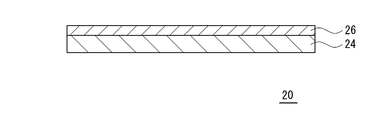
- FIG. 2 shows an embodiment of a blade-like charging member (charging blade).
- the charging roll 10 includes a shaft 12, a base layer 14 formed on the outer periphery of the shaft 12, and a surface layer 16 formed on the outer periphery of the base layer 14.
- the base layer 14 is a layer to be a base of the charging roll 10.
- the surface layer 16 is a layer appearing on the surface of the charging roll 10.
- the charging blade 20 includes a base layer 24 and a surface layer 26 formed on the surface of the base layer 24.
- the base layer 24 is a layer to be a base of the charging blade 20.
- the surface layer 26 is a layer appearing on the surface of the charging blade 20.
- the base layer 24 and the surface layer 26 of the charging blade 20 have the same material configuration as the base layer 14 and the surface layer 16 of the charging roll 10.
- the base layer 14 is a crosslinked body of a conductive rubber composition containing the following (a) to (d).
- the base layer 14 is made of a conductive rubber elastic body.
- (A) Crosslinkable rubber (b) Crosslinking agent (c) Specific ion conductive agent (d) carbon black
- Crosslinkable rubber is rubber which can be crosslinked using (b) a crosslinking agent.
- Crosslinking rubber is obtained by crosslinking the uncrosslinked crosslinking rubber.
- the crosslinked rubber constitutes the base polymer of the base layer 14.
- the crosslinkable rubber may be polar rubber or nonpolar rubber.
- the crosslinkable rubber is more preferably a polar rubber from the viewpoint of excellent conductivity and the like.
- the polar rubber is a rubber having a polar group, and examples of the polar group include chloro group, nitrile group, carboxyl group and epoxy group. Specific examples of polar rubbers include hydrin rubber, nitrile rubber (NBR), urethane rubber (U), acrylic rubber (copolymer of acrylic ester and 2-chloroethyl vinyl ether, ACM), chloroprene rubber (CR) And epoxidized natural rubber (ENR).
- polar rubbers hydrin rubber and nitrile rubber (NBR) are preferable from the viewpoint that the volume resistivity of the conductive rubber composition tends to be particularly low.
- hydrin rubbers examples include epichlorohydrin homopolymer (CO), epichlorohydrin-ethylene oxide binary copolymer (ECO), epichlorohydrin-allyl glycidyl ether binary copolymer (GCO), epichlorohydrin-ethylene oxide-allyl glycidyl ether ternary A copolymer (GECO) etc. can be mentioned.
- CO epichlorohydrin homopolymer
- ECO epichlorohydrin-ethylene oxide binary copolymer
- GCO epichlorohydrin-allyl glycidyl ether binary copolymer
- GECO epichlorohydrin-ethylene oxide-allyl glycidyl ether ternary A copolymer
- the urethane rubber may, for example, be a polyether urethane rubber having an ether bond in the molecule.
- the polyether type urethane rubber can be produced by the reaction of a polyether having a hydroxyl group at both ends with a diisocyanate.
- the polyether is not particularly limited, and polyethylene glycol, polypropylene glycol and the like can be mentioned. Although it does not specifically limit as diisocyanate, Tolylene diisocyanate, diphenylmethane diisocyanate etc. can be mentioned.
- nonpolar rubbers examples include isoprene rubber (IR), natural rubber (NR), styrene butadiene rubber (SBR), butadiene rubber (BR) and the like.
- the (b) crosslinking agent is a crosslinking agent that crosslinks the (a) crosslinkable rubber.
- the crosslinking agent (b) is not particularly limited as long as it crosslinks the crosslinking rubber (a).
- a crosslinking agent (b) a sulfur crosslinking agent, a peroxide crosslinking agent, and a dechlorination crosslinking agent can be mentioned. These crosslinking agents may be used alone or in combination of two or more.
- sulfur crosslinking agents include conventionally known sulfur crosslinking agents such as powdered sulfur, precipitated sulfur, colloidal sulfur, surface-treated sulfur, insoluble sulfur, sulfur chloride, thiuram vulcanization accelerator, and polymeric polysulfides. it can.
- peroxide crosslinking agents include conventionally known peroxide crosslinking agents such as peroxy ketals, dialkyl peroxides, peroxy esters, ketone peroxides, peroxy dicarbonates, diacyl peroxides and hydroperoxides. Can.
- a dithiocarbonate compound As a dechlorination crosslinking agent, a dithiocarbonate compound can be mentioned. More specifically, quinoxaline-2,3-dithiocarbonate, 6-methylquinoxaline-2,3-dithiocarbonate, 6-isopropylquinoxaline-2,3-dithiocarbonate, 5,8-dimethylquinoxaline-2,3- A dithio carbonate etc. can be mentioned.
- a dechlorination crosslinking accelerator may be used in combination.
- a dechlorination crosslinking accelerator 1,8-diazabicyclo (5,4,0) undecen-7 (hereinafter abbreviated as DBU) or a weak acid salt thereof can be mentioned.
- DBU 1,8-diazabicyclo (5,4,0) undecen-7
- the dechlorination crosslinking accelerator may be used in the form of DBU, it is preferably used in the form of its weak acid salt from the viewpoint of its handling.
- the content of the (b) crosslinking agent is 0.5 to 7.0 parts by mass with respect to 100 parts by mass of the (a) crosslinking rubber in consideration of the hardness and the degree of crosslinking of the base layer 14 and the like. It is preferable to be in the range of parts. More preferably, it is in the range of 1.0 to 5.0 parts by mass.
- the specific ion conductive agent is a quaternary ammonium salt represented by the following general formula (1).
- R 1 and R 2 are an allyl group
- R 3 is a methyl group or an ethyl group
- R 4 is a linear alkyl group having 6 to 8 carbon atoms.
- X - is a sulfonate anion having a fluorine atom or a bis (sulfonyl) imide anion having a fluorine atom.
- X - is sulfonate anion having a fluorine atom in, there can be mentioned trifluoromethane sulfonate (TF), pentafluoroethane sulfonate, perfluoroalkane sulfonates, such as heptafluoropropane sulfonate.
- TF trifluoromethane sulfonate
- pentafluoroethane sulfonate pentafluoroethane sulfonate
- perfluoroalkane sulfonates such as heptafluoropropane sulfonate.
- a bis (sulfonyl) imide anion having a fluorine atom in X ⁇ N, N-bis (fluorosulfonyl) imide (FSI), N, N-bis (trifluoromethanesulfonyl) imide (TFSI), N, N Mention may be made of perfluorobis (sulfonyl) imides such as -bis (pentafluoroethanesulfonyl) imide, N, N-bis (heptafluoropropanesulfonyl) imide, N, N-bis (nonafluorobutanesulfonyl) imide and the like.
- perfluorobis (sulfonyl) imides such as -bis (pentafluoroethanesulfonyl) imide, N, N-bis (heptafluoropropanesulfonyl) imide, N, N-bis (nonafluorobut
- TF, FSI, TFSI and the like are preferable from the viewpoint of easy ion dissociation and the like.
- the content of the (c) specific ion conductive agent is 0.1 to 10 parts by weight with respect to 100 parts by weight of (a) crosslinkable rubber in consideration of the conductivity and bleeding of the ion conductive agent. It is preferable to be in the range of parts. More preferably, it is in the range of 0.3 to 5.0 parts by mass, still more preferably in the range of 0.5 to 3.0 parts by mass.
- Carbon black is used as an electron conductive agent in the base layer 14.
- Carbon black having a specific surface area in a specific range can be preferably used.
- the specific surface area of the carbon black (d) is preferably in the range of 40 to 300 m 2 / g. More preferably, it is in the range of 42 to 240 m 2 / g.
- the specific surface area of carbon black can be measured by a nitrogen adsorption method.
- the content of (d) carbon black is within the range of 5 to 40 parts by mass with respect to 100 parts by mass of the crosslinkable rubber (a) in consideration of the hardness and the conductivity of the base layer 14 Is preferred. More preferably, it is in the range of 10 to 30 parts by mass.
- the conductive rubber composition may optionally contain (d) an electronic conductive agent other than carbon black, a lubricant, an antiaging agent, a light stabilizer, a viscosity modifier, a processing aid, a reaction aid, a flame retardant, and a plastic
- an electronic conductive agent other than carbon black e.g., a lubricant, an antiaging agent, a light stabilizer, a viscosity modifier, a processing aid, a reaction aid, a flame retardant, and a plastic
- an agent, a foaming agent, a filler, a dispersing agent, an antifoaming agent, a pigment, and a releasing agent may be contained.
- the thickness of the base layer 14 is not particularly limited, but as the charge roll 10, it is preferably in the range of 0.1 to 10 mm, more preferably in the range of 0.5 to 5 mm, and still more preferably 1 to It is in the range of 3 mm.
- the volume resistivity of the base layer 14 is not particularly limited, but the charge roll 10 is preferably 10 2 to 10 10 ⁇ ⁇ cm, more preferably 10 3 to 10 9 ⁇ ⁇ cm, still more preferably It is in the range of 10 4 to 10 8 ⁇ ⁇ cm.
- the shaft 12 is not particularly limited as long as it has conductivity. Specifically, a solid body made of metal such as iron, stainless steel, or aluminum, a cored bar made of a hollow body, and the like can be exemplified. An adhesive, a primer or the like may be applied to the surface of the shaft 12 as necessary. The adhesive, the primer, etc. may be made conductive as required.
- the surface layer 16 can function as a protective layer on the roll surface.
- the surface layer 16 preferably contains polymer components such as polyamide, polyurethane, acrylic resin, alkyd resin, phenol resin, fluorine resin, silicone resin, and modified products thereof as main materials.
- polymer components such as polyamide, polyurethane, acrylic resin, alkyd resin, phenol resin, fluorine resin, silicone resin, and modified products thereof as main materials.
- the modifying group in the modifying body include N-methoxymethyl group, silicone group, fluorine group and the like.
- These polymer components may be contained alone as a surface layer material, or may be contained in combination of two or more.
- the polymer component of the surface layer 16 may be crosslinked.
- ion conductive agent quaternary ammonium salt
- Conventional conductive agents such as borates, surfactants and the like can be added as appropriate.
- various additives may be added as appropriate.
- particles for forming roughness may be added.
- the roughness-forming particles form surface irregularities on the surface layer 16.
- the roughness-forming particles include resin particles and silica particles.
- resin particles urethane particles, silicone particles, acrylic particles and the like can be mentioned.
- the average particle size of the roughness-forming particles is preferably in the range of 3 to 50 ⁇ m.
- the average particle size of the roughness-forming particles can be calculated from the median size using a laser diffraction type particle size distribution measuring apparatus.
- the thickness of the surface layer 16 is not particularly limited, but is preferably in the range of 0.01 to 100 ⁇ m, more preferably in the range of 0.1 to 20 ⁇ m, and still more preferably in the range of 0.3 to 10 ⁇ m. It is.
- the volume resistivity of the surface layer 16 is preferably in the range of 10 7 to 10 12 ⁇ ⁇ cm, more preferably 10 8 to 10 11 ⁇ ⁇ cm, still more preferably 10 9 to 10 10 ⁇ ⁇ cm. .
- the charging roll 10 can be manufactured, for example, as follows. First, the shaft body 12 is coaxially installed in the hollow portion of the roll molding die, and the conductive rubber composition is injected, heated and cured, and then removed or the surface of the shaft body 12 The base layer 14 is formed on the outer periphery of the shaft body 12 by extruding the conductive rubber composition. Subsequently, the composition for surface layer formation is coated on the outer periphery of the formed base layer 14, and the surface layer 16 is formed by performing ultraviolet irradiation and heat treatment as needed. Thereby, the charging roll 10 can be manufactured.
- the composition for surface layer formation comprises the above-mentioned main material, a conductive agent, and other additives optionally contained.
- Other additives may include crosslinkers for polymer components, leveling agents, surface modifiers and the like.
- the composition for surface layer formation is, from the viewpoint of adjusting the viscosity, etc., an organic solvent such as methyl ethyl ketone, toluene, acetone, ethyl acetate, butyl acetate, methyl isobutyl ketone (MIBK), THF, DMF or the like, or an aqueous solvent such as methanol or ethanol. It may contain a solvent such as an organic solvent as appropriate.
- various coating methods such as a roll coating method, a dipping method, and a spray coating method can be applied.
- a conductive rubber composition in which the base layer 14 contains (a) polar rubber, (b) crosslinking agent, (c) specific ion conductive agent, and (d) carbon black.
- the crosslinked product of (c) can suppress image defects due to bleeding of a specific ion conductive agent and maintain excellent chargeability. This is presumed to be due to the following mechanism.
- the specific ion conductive agent represented by the above general formula (1) has, as an anion, a sulfonate anion having a fluorine atom or a bis (sulfonyl) imide anion having a fluorine atom. Since this anion contains a fluorine group in its structure, the anion itself is small in basicity and forms relatively weak ionic bond with the cation. Therefore, (c) a specific ion conductive agent is easily dissociated into ions in (a) polar rubber.
- the cation of a specific ion conductive agent has two allyl groups, whereby the crosslinking of the (a) polar rubber of the base layer 14 is carried out in the presence of radicals (in the presence of a crosslinking agent) by the following formula (3) The molecular weight is increased as shown in. At this time, a bond is formed with (a) polar rubber. Thereby, the cation of the (c) specific ion conductive agent is taken in and fixed in the polymer skeleton of (a) polar rubber with a structure shown in the following formula (3).
- l is the number of repeating units, and is any positive integer.
- the cation of a specific ion conductive agent is more likely to be adsorbed to (d) carbon black as the surface charge density is higher.
- the surface charge density is smaller as the chain of the alkyl group of the cation is longer. That is, the longer the chain of the alkyl group of the cation, the harder it is to adsorb to (d) carbon black.
- the chain of the alkyl group of the cation is short, the interaction with the anion becomes strong, the ion dissociation hardly occurs, and the conductivity is lowered.
- n is an integer larger than 1, even if n is an integer from 5 to 7, the interaction between the cation and (d) carbon black is reduced, and (c) bleeding of a specific ion conductive agent is sufficient. It can not be suppressed.
- n is an integer larger than 7, even if m is 0 or 1, the interaction between the cation and (d) carbon black is reduced, and (c) bleeding of a specific ion conductive agent is sufficiently suppressed. Absent.
- n is an integer smaller than 5, the interaction between the cation and the anion becomes strong even if m is 0 or 1, so that the ion dissociation is difficult and the conductivity is not satisfactory. Therefore, m in the above general formulas (2) and (3) is 0 or 1, and n is an integer of 5 to 7.
- the specific surface area of (d) carbon black is preferably in the range of 40 to 300 m 2 / g. . More preferably, it is in the range of 42 to 240 m 2 / g.
- the surface layer 16 preferably contains at least one selected from polyamides, polyurethanes, and acrylic resins, from the viewpoint of being excellent in toner adhesion prevention, flexible and hardly damaging the member to be charged.
- the ion conductive agent tends to easily pass through the surface layer 16, but even with such a surface layer 16, according to the present invention (c) the effect of suppressing bleeding of a specific ion conductive agent is excellent.
- the polymer component of the surface layer 16 is crosslinked, bleeding of the specific ion conductive agent (c) can be more easily suppressed than when it is not crosslinked.
- the configuration of the charging roll according to the present invention is not limited to the configuration shown in FIG.
- another elastic layer may be provided between the shaft 12 and the base layer 14.
- the other elastic layer is a layer to be a base of the charging roll, and the base layer 14 functions as a resistance adjusting layer or the like for adjusting the resistance of the charging roll.
- the other elastic layer can be made of, for example, any of the materials mentioned as the material constituting the base layer 14.
- another elastic layer may be provided between the base layer 14 and the surface layer 16.
- the base layer 14 is a layer to be a base of the charging roll, and the other elastic layer functions as a resistance adjusting layer for adjusting the resistance of the charging roll.
- diallyl hexyl methyl ammonium bis (trifluoromethane sulfonyl) imide is added by adding the obtained diallyl hexyl methyl ammonium bromide and lithium bis (trifluoromethane sulfonyl) imidate to an aqueous solvent, and stirring at room temperature for 4 hours.
- diallyl hexyl methyl ammonium bis (trifluoromethane sulfonyl) imide is added by adding the obtained diallyl hexyl methyl ammonium bromide and lithium bis (trifluoromethane sulfonyl) imidate to an aqueous solvent, and stirring at room temperature for 4 hours.
- diallyl hexyl methyl ammonium bis (trifluoromethane sulfonyl) imide is added by adding the obtained diallyl hexyl methyl ammonium bromide and lithium bis (trifluoromethane sulfonyl
- diallylhexylamine and ethyl bromide were reacted in an organic solvent to obtain diallylhexylethylammonium bromide.
- diallyl hexyl ethyl ammonium bis (trifluoro methane sulfonyl) imide is added by adding the obtained diallyl hexyl ethyl ammonium bromide and lithium bis (trifluoro methane sulfonyl) imidate to an aqueous solvent, and stirring at room temperature for 4 hours.
- Crosslinkable rubber-Hydrated rubber ECO, manufactured by Nippon Zeon "Hydrin T3106"
- Nitrile rubber NBR, manufactured by Nippon Zeon "Nipol DN 302”
- Cross-linking agent Peroxide “Parkmill D40” made by NOF Corporation -Carbon black Carbon black ⁇ 1>: Tokai Carbon "Siest SO”, specific surface area 42 m 2 / g Carbon black ⁇ 2>: Tokai Carbon “Siest 9”, specific surface area 142 m 2 / g Carbon black ⁇ 3>: Cabot “BLACK PEARLS 880”, specific surface area 240 m 2 / g ⁇ Stearic acid (processing aid) [Nippon Yushi Co., Ltd.
- Example 1 ⁇ Preparation of Conductive Rubber Composition> Carbon black ⁇ 1> 20 parts by mass, ion conductive agent ⁇ 1> 1 part by mass, crosslinking agent 3 parts by mass, stearic acid 0.7 parts by mass, zinc oxide 5 parts by mass, hydrotalcite 2 with respect to 100 parts by mass of hydrin rubber
- the conductive rubber composition according to Example 1 was prepared by blending parts by mass and stirring and mixing these with a stirrer.
- a core metal (diameter 6 mm) is set in a molding die, the conductive rubber composition is injected, and heating is carried out at 170 ° C. for 30 minutes, followed by cooling and demolding to obtain a thickness of 1.
- a base layer of 75 mm conductive rubber elastic body was formed.
- Examples 2 to 3 A charge roll was produced in the same manner as in Example 1 except that the ion conductive agent was changed in the preparation of the conductive rubber composition.
- Examples 4 to 5 A charge roll was produced in the same manner as Example 1 except that carbon black was changed in preparation of the conductive rubber composition.
- Example 6 A charge roll was produced in the same manner as Example 1, except that the crosslinkable rubber was changed in the preparation of the conductive rubber composition.
- Example 7 A charge roll was produced in the same manner as in Example 1 except that the polymer was changed in the preparation of the composition for surface layer formation.
- -Polyurethane Mitsui Chemicals "Takelac W6061”
- -Acrylic resin "Parachron Precoat 200" manufactured by Negami Chemical Industries, Ltd.
- Example 4 A charge roll was produced in the same manner as Example 1, except that carbon black was not blended in preparation of the conductive rubber composition.
- the evaluation of the bleed and the evaluation of the charge amount were performed for each of the manufactured charging rolls.
- the evaluation results, the compounding composition (parts by mass) of the conductive rubber composition, and the compounding composition (parts by mass) of the composition for forming a surface layer are shown in the following table.
- the charging roll prepared in the drum unit was set using “ECOSYS P5026 cdw” manufactured by Kyocera as an evaluation machine, and left in a 32.5 ° C. ⁇ 85% RH environment for 12 hours. Thereafter, a halftone image was output in an environment of 23 ° C. ⁇ 53% RH.
- the case where white streaks of the drum pitch disappear due to the ion conductive agent bleeding from the charging roll within 20 sheets of the output image is " ⁇ ", and the white streaks of the drum pitch do not disappear even with 20 sheets or more of the output image "X".
- the charging roll produced in the drum unit was set using "ECOSYS P5026 cdw" manufactured by KYOCERA as an evaluation machine, and the charge amount was measured when applying 1200 V in an environment of 10 ° C. ⁇ 10% RH. The case where the charge amount was over 300 V was taken as “ ⁇ ”, and the case where the charge amount was 300 V or less was taken as “ ⁇ ”.
Landscapes
- Chemical & Material Sciences (AREA)
- Physics & Mathematics (AREA)
- Polymers & Plastics (AREA)
- Health & Medical Sciences (AREA)
- Chemical Kinetics & Catalysis (AREA)
- Medicinal Chemistry (AREA)
- Organic Chemistry (AREA)
- Engineering & Computer Science (AREA)
- Plasma & Fusion (AREA)
- General Physics & Mathematics (AREA)
- Mechanical Engineering (AREA)
- Electrostatic Charge, Transfer And Separation In Electrography (AREA)
- Processes Of Treating Macromolecular Substances (AREA)
- Compositions Of Macromolecular Compounds (AREA)
Abstract
The purpose of the present invention is to provide a charging member for an electrophotographic apparatus, wherein image defects due to the bleeding of an ion-conductive agent are suppressed, and excellent chargeability can be maintained. Provided is a charging member 10 for an electrophotographic apparatus, the charging member comprising: a base layer 14 composed of a conductive rubber elastomer; and a surface layer 16, wherein the base layer 14 is a crosslinked body of a conductive rubber composition containing a) a crosslinkable rubber, (b) a crosslinking agent, (c) an ion-conductive agent represented by general formula (1), and (d) carbon black. R1 and R2 are aryl groups, R3 is a methyl group or an ethyl group, and R4 is C6-8 linear alkyl group. X- is a sulfonate anion having a fluorine atom, or a bis(sulfonyl)imide anion having a fluorine atom.
Description
本発明は、電子写真方式を採用する複写機、プリンター、ファクシミリなどの電子写真機器において好適に用いられる電子写真機器用帯電部材に関するものである。
The present invention relates to a charging member for an electrophotographic apparatus suitably used in an electrophotographic apparatus such as a copying machine, a printer, a facsimile, and the like adopting an electrophotographic method.
電子写真機器による複写や印字は、帯電部材により帯電させた感光ドラムに原稿像を静電潜像として形成し、現像部材により帯電させたトナーを静電潜像に付着させてトナー像を形成し、トナー像を複写紙に転写することにより行われている。帯電部材は、基層と表層とを有するものが知られている。例えば特許文献1には、芯金の外周に導電性ゴム弾性体からなる基層を有し、基層の外周に表層を有する帯電ロールが記載されている。
In copying and printing by an electrophotographic apparatus, a document image is formed as an electrostatic latent image on a photosensitive drum charged by a charging member, and toner charged by a developing member is attached to the electrostatic latent image to form a toner image. , By transferring the toner image to a copy sheet. The charging member is known to have a base layer and a surface layer. For example, Patent Document 1 describes a charging roll having a base layer made of a conductive rubber elastic body on the outer periphery of a core metal and having a surface layer on the outer periphery of the base layer.
特許文献1では、基層において、カチオンがジアリルジメチルアンモニウムからなるイオン導電剤を用いている。このカチオンは、2つのアリル基を有することで、基層のベースポリマーの架橋時に、ベースポリマーと結合を形成すると推察される。これにより、カチオンが基層に固定化されるため、イオン導電剤のブリードが抑えられる。しかし、これだけではイオン導電剤のブリードは十分に抑えられず、基層から表層の表面にイオン導電剤がブリードし、画像不具合が生じることがある。これは、2つのアリル基を有するカチオンであっても、基層のベースポリマーの架橋時にベースポリマーと結合を形成しないものも存在し、これにより、イオン導電剤のブリードが生じるためと推察される。
In Patent Document 1, an ion conductive agent whose cation is diallyldimethylammonium is used in the base layer. This cation is presumed to form a bond with the base polymer upon crosslinking of the base polymer of the base layer by having two allyl groups. As a result, the cation is immobilized on the base layer, and bleeding of the ion conductive agent can be suppressed. However, this alone can not sufficiently suppress the bleeding of the ion conductive agent, and the ion conductive agent may bleed from the base layer to the surface of the surface layer to cause an image failure. This is presumed to be due to the fact that even if it is a cation having two allyl groups, it does not form a bond with the base polymer at the time of crosslinking of the base polymer of the base layer, which causes bleeding of the ion conductive agent.
本発明が解決しようとする課題は、イオン導電剤のブリードによる画像不具合が抑えられるとともに優れた帯電性が維持できる電子写真機器用帯電部材を提供することにある。
The problem to be solved by the present invention is to provide a charging member for an electrophotographic apparatus capable of suppressing an image failure due to bleeding of an ion conductive agent and maintaining excellent chargeability.
上記課題を解決するため本発明に係る電子写真機器用帯電部材は、導電性ゴム弾性体からなる基層と、表層と、を有する電子写真機器用帯電部材であって、
前記基層は、
(a)架橋性ゴム、
(b)架橋剤、
(c)下記一般式(1)で示されるイオン導電剤、
(d)カーボンブラック、
を含有する導電性ゴム組成物の架橋体であることを要旨とするものである。

ただし、R1およびR2はアリル基であり、R3はメチル基またはエチル基であり、R4は炭素数6~8の直鎖アルキル基である。X-は、フッ素原子を有するスルホネートアニオンまたはフッ素原子を有するビス(スルホニル)イミドアニオンである。
In order to solve the above problems, a charging member for an electrophotographic apparatus according to the present invention is a charging member for an electrophotographic apparatus having a base layer made of a conductive rubber elastic body and a surface layer,
The base layer is
(A) Crosslinkable rubber,
(B) Crosslinker,
(C) An ion conductive agent represented by the following general formula (1)
(D) carbon black,
The gist of the present invention is a crosslinked product of a conductive rubber composition containing
However, R 1 and R 2 are an allyl group, R 3 is a methyl group or an ethyl group, and R 4 is a linear alkyl group having 6 to 8 carbon atoms. X - is a sulfonate anion having a fluorine atom or a bis (sulfonyl) imide anion having a fluorine atom.
前記基層は、
(a)架橋性ゴム、
(b)架橋剤、
(c)下記一般式(1)で示されるイオン導電剤、
(d)カーボンブラック、
を含有する導電性ゴム組成物の架橋体であることを要旨とするものである。
The base layer is
(A) Crosslinkable rubber,
(B) Crosslinker,
(C) An ion conductive agent represented by the following general formula (1)
(D) carbon black,
The gist of the present invention is a crosslinked product of a conductive rubber composition containing
前記(d)カーボンブラックの比表面積は、40~300m2/gの範囲内であることが好ましい。また、前記(d)カーボンブラックの比表面積は、42~240m2/gの範囲内であることが好ましい。前記R4は、炭素数6の直鎖アルキル基であることが好ましい。前記X-は、N,N-ビス(トリフルオロメタンスルホニル)イミドアニオンであることが好ましい。前記(c)のイオン導電剤の含有量は、(a)架橋性ゴム100質量部に対し、0.1~10質量部の範囲内であることが好ましい。前記(d)カーボンブラックの含有量は、(a)架橋性ゴム100質量部に対し、5~40質量部の範囲内であることが好ましい。前記表層は、ポリアミド、ポリウレタン、アクリル樹脂から選択される少なくとも1種を含むことが好ましい。また、前記表層は、ポリアミド、ポリウレタンから選択される少なくとも1種を含むことが好ましい。また、前記表層は、ポリアミド、クエン酸、導電性酸化スズ、およびウレタン粒子を含む組成物から形成されることが好ましい。前記表層のポリマー成分は、架橋されていることが好ましい。
The specific surface area of the (d) carbon black is preferably in the range of 40 to 300 m 2 / g. The specific surface area of the (d) carbon black is preferably in the range of 42 to 240 m 2 / g. The R 4 is preferably a linear alkyl group having 6 carbon atoms. The X − is preferably an N, N-bis (trifluoromethanesulfonyl) imide anion. The content of the ion conductive agent (c) is preferably in the range of 0.1 to 10 parts by mass with respect to 100 parts by mass of the crosslinkable rubber (a). The content of the (d) carbon black is preferably in the range of 5 to 40 parts by mass with respect to 100 parts by mass of the (a) crosslinkable rubber. The surface layer preferably contains at least one selected from polyamide, polyurethane, and acrylic resin. Further, the surface layer preferably contains at least one selected from polyamide and polyurethane. The surface layer is preferably formed of a composition containing polyamide, citric acid, conductive tin oxide, and urethane particles. The polymer component of the surface layer is preferably crosslinked.
電子写真機器用帯電部材としては、軸体と、前記基層と、前記表層と、を有し、前記軸体の外周に前記基層が形成され、前記基層の外周に前記表層が形成されているものが挙げられる。
A charging member for an electrophotographic apparatus has a shaft, the base layer, and the surface layer, the base layer is formed on the outer periphery of the shaft, and the surface layer is formed on the outer periphery of the base layer. Can be mentioned.
本発明に係る電子写真機器用帯電部材によれば、基層が、(a)架橋性ゴム、(b)架橋剤、(c)上記一般式(1)で示されるイオン導電剤、(d)カーボンブラック、を含有する導電性ゴム組成物の架橋体であることで、イオン導電剤のブリードによる画像不具合が抑えられるとともに優れた帯電性が維持できる。これは、上記一般式(1)で示されるイオン導電剤のカチオンが、2つのアリル基を有することで、基層の架橋性ゴムの架橋時に架橋性ゴムと結合を形成し固定化されるとともに、架橋性ゴムと結合を形成しなかったカチオンは、R4で示される炭素数6~8の直鎖アルキル基と基層中の(d)カーボンブラックとの相互作用によりカーボンブラックに吸着されるためと推察される。
According to the charging member for an electrophotographic apparatus according to the present invention, the base layer is (a) a crosslinkable rubber, (b) a crosslinking agent, (c) an ion conductive agent represented by the above general formula (1), (d) carbon By being a cross-linked body of the conductive rubber composition containing black, image defects due to bleeding of the ion conductive agent can be suppressed and excellent chargeability can be maintained. This is because the cation of the ion conductive agent represented by the above general formula (1) has two allyl groups, thereby forming a bond with the crosslinkable rubber at the time of crosslinking of the crosslinkable rubber of the base layer and immobilizing it. The cation which did not form a bond with the crosslinkable rubber is adsorbed on the carbon black by the interaction between the linear alkyl group having 6 to 8 carbon atoms represented by R 4 and (d) carbon black in the base layer. It is guessed.
この際、(d)カーボンブラックの比表面積が40~300m2/gの範囲内であると、イオン導電剤のブリードを抑える効果と帯電性とのバランスに優れる。上記比表面積が42~240m2/gの範囲内であると、より一層、イオン導電剤のブリードを抑える効果と帯電性とのバランスに優れる。そして、上記X-が、N,N-ビス(トリフルオロメタンスルホニル)イミドアニオンであると、(c)のイオン導電剤がイオン解離しやすく、(c)のイオン導電剤の比誘電率の値が大きくなって基層の荷電性能を高くできるだけでなく、カチオンの自由度が高くなり、2つのアリル基を有するカチオンが高分子量化しやすくなる。そして、上記(c)のイオン導電剤の含有量が、(a)架橋性ゴム100質量部に対し、0.1~10質量部の範囲内であると、導電性とイオン導電剤のブリードを抑える効果のバランスに優れる。そして、上記(d)カーボンブラックの含有量が、(a)架橋性ゴム100質量部に対し、5~40質量部の範囲内であると、基層の硬さと導電性のバランスに優れる。
At this time, when the specific surface area of (d) carbon black is in the range of 40 to 300 m 2 / g, the balance between the effect of suppressing the bleeding of the ion conductive agent and the chargeability is excellent. When the specific surface area is in the range of 42 to 240 m 2 / g, the balance between the effect of suppressing the bleeding of the ion conductive agent and the chargeability is further enhanced. When the above X - is N, N-bis (trifluoromethanesulfonyl) imide anion, the ion conductive agent of (c) is likely to be ion-dissociated, and the value of the dielectric constant of the ion conductive agent of (c) is Not only can the base layer be made higher in chargeability, but the degree of freedom of the cation becomes higher, and the cation having two allyl groups can be easily made to have a high molecular weight. Then, when the content of the ion conductive agent in (c) is in the range of 0.1 to 10 parts by mass with respect to 100 parts by mass of (a) the crosslinkable rubber, the conductivity and the bleeding of the ion conductive agent are Excellent balance of suppressing effects. When the content of (d) carbon black is in the range of 5 to 40 parts by mass with respect to 100 parts by mass of (a) crosslinkable rubber, the balance between the hardness and the conductivity of the base layer is excellent.
そして、上記表層が、ポリアミド、ポリウレタン、アクリル樹脂から選択される少なくとも1種を含むと、イオン導電剤が表層を通過しやすい傾向にあるが、このような表層であっても本発明によればイオン導電剤のブリードを抑える効果に優れる。そして、上記表層のポリマー成分が架橋されていると、架橋されていない場合よりも(c)のイオン導電剤のブリードを抑えやすい。
And, when the surface layer contains at least one selected from polyamide, polyurethane and acrylic resin, the ion conductive agent tends to easily pass through the surface layer, but according to the present invention, even such a surface layer Excellent in the effect of suppressing the bleeding of the ion conductive agent. And when the polymer component of the said surface layer is bridge | crosslinked, it is easier to suppress the bleed of the ion conductive agent of (c) rather than the case where it is not bridge | crosslinked.
以下、本発明について詳細に説明する。
Hereinafter, the present invention will be described in detail.
本発明に係る電子写真機器用帯電部材は、感光ドラムなどの被帯電体を帯電させるものであれば、特に形状が限定されるものではない。例えば、ロール状、ブレード状などの形状のものが適用可能である。図1には、ロール状の帯電部材(帯電ロール)の一実施形態を示している。図2には、ブレード状の帯電部材(帯電ブレード)の一実施形態を示している。
The shape of the charging member for an electrophotographic apparatus according to the present invention is not particularly limited as long as it charges a member to be charged such as a photosensitive drum. For example, the shape of a roll, a blade, etc. is applicable. FIG. 1 shows an embodiment of a roll-shaped charging member (charging roll). FIG. 2 shows an embodiment of a blade-like charging member (charging blade).
図1に示すように、帯電ロール10は、軸体12と、軸体12の外周に形成された基層14と、基層14の外周に形成された表層16と、を備える。基層14は、帯電ロール10のベースとなる層である。表層16は、帯電ロール10の表面に現れる層となっている。
As shown in FIG. 1, the charging roll 10 includes a shaft 12, a base layer 14 formed on the outer periphery of the shaft 12, and a surface layer 16 formed on the outer periphery of the base layer 14. The base layer 14 is a layer to be a base of the charging roll 10. The surface layer 16 is a layer appearing on the surface of the charging roll 10.
図2に示すように、帯電ブレード20は、基層24と、基層24の面上に形成された表層26と、を備える。基層24は、帯電ブレード20のベースとなる層である。表層26は、帯電ブレード20の表面に現れる層となっている。
As shown in FIG. 2, the charging blade 20 includes a base layer 24 and a surface layer 26 formed on the surface of the base layer 24. The base layer 24 is a layer to be a base of the charging blade 20. The surface layer 26 is a layer appearing on the surface of the charging blade 20.
以下、帯電ロール10を例に挙げて説明する。帯電ブレード20の基層24、表層26は、帯電ロール10の基層14、表層16と同様の材料構成となる。
Hereinafter, the charging roll 10 will be described as an example. The base layer 24 and the surface layer 26 of the charging blade 20 have the same material configuration as the base layer 14 and the surface layer 16 of the charging roll 10.
基層14は、以下の(a)~(d)を含有する導電性ゴム組成物の架橋体である。基層14は、導電性ゴム弾性体からなる。
(a)架橋性ゴム
(b)架橋剤
(c)特定のイオン導電剤
(d)カーボンブラック Thebase layer 14 is a crosslinked body of a conductive rubber composition containing the following (a) to (d). The base layer 14 is made of a conductive rubber elastic body.
(A) Crosslinkable rubber (b) Crosslinking agent (c) Specific ion conductive agent (d) carbon black
(a)架橋性ゴム
(b)架橋剤
(c)特定のイオン導電剤
(d)カーボンブラック The
(A) Crosslinkable rubber (b) Crosslinking agent (c) Specific ion conductive agent (d) carbon black
(a)架橋性ゴムは、(b)架橋剤を用いて架橋可能なゴムである。未架橋の架橋性ゴムを架橋することにより、架橋ゴムが得られる。架橋ゴムは、基層14のベースポリマーを構成する。架橋性ゴムは、極性ゴムであってもよいし、非極性ゴムであってもよい。導電性に優れるなどの観点から、架橋性ゴムは極性ゴムがより好ましい。
(A) Crosslinkable rubber is rubber which can be crosslinked using (b) a crosslinking agent. Crosslinking rubber is obtained by crosslinking the uncrosslinked crosslinking rubber. The crosslinked rubber constitutes the base polymer of the base layer 14. The crosslinkable rubber may be polar rubber or nonpolar rubber. The crosslinkable rubber is more preferably a polar rubber from the viewpoint of excellent conductivity and the like.
極性ゴムは、極性基を有するゴムであり、極性基としては、クロロ基、ニトリル基、カルボキシル基、エポキシ基などを挙げることができる。極性ゴムとしては、具体的には、ヒドリンゴム、ニトリルゴム(NBR)、ウレタンゴム(U)、アクリルゴム(アクリル酸エステルと2-クロロエチルビニルエーテルとの共重合体、ACM)、クロロプレンゴム(CR)、エポキシ化天然ゴム(ENR)などを挙げることができる。
The polar rubber is a rubber having a polar group, and examples of the polar group include chloro group, nitrile group, carboxyl group and epoxy group. Specific examples of polar rubbers include hydrin rubber, nitrile rubber (NBR), urethane rubber (U), acrylic rubber (copolymer of acrylic ester and 2-chloroethyl vinyl ether, ACM), chloroprene rubber (CR) And epoxidized natural rubber (ENR).
極性ゴムのうちでは、上記導電性ゴム組成物の体積抵抗率が特に低くなりやすいなどの観点から、ヒドリンゴム、ニトリルゴム(NBR)が好ましい。
Among polar rubbers, hydrin rubber and nitrile rubber (NBR) are preferable from the viewpoint that the volume resistivity of the conductive rubber composition tends to be particularly low.
ヒドリンゴムとしては、エピクロルヒドリンの単独重合体(CO)、エピクロルヒドリン-エチレンオキサイド二元共重合体(ECO)、エピクロルヒドリン-アリルグリシジルエーテル二元共重合体(GCO)、エピクロルヒドリン-エチレンオキサイド-アリルグリシジルエーテル三元共重合体(GECO)などを挙げることができる。
Examples of hydrin rubbers include epichlorohydrin homopolymer (CO), epichlorohydrin-ethylene oxide binary copolymer (ECO), epichlorohydrin-allyl glycidyl ether binary copolymer (GCO), epichlorohydrin-ethylene oxide-allyl glycidyl ether ternary A copolymer (GECO) etc. can be mentioned.
ウレタンゴムとしては、分子内にエーテル結合を有するポリエーテル型のウレタンゴムなどを挙げることができる。ポリエーテル型のウレタンゴムは、両末端にヒドロキシル基を有するポリエーテルとジイソシアネートとの反応により製造できる。ポリエーテルとしては、特に限定されるものではないが、ポリエチレングリコール、ポリプロピレングリコールなどを挙げることができる。ジイソシアネートとしては、特に限定されるものではないが、トリレンジイソシアネート、ジフェニルメタンジイソシアネートなどを挙げることができる。
The urethane rubber may, for example, be a polyether urethane rubber having an ether bond in the molecule. The polyether type urethane rubber can be produced by the reaction of a polyether having a hydroxyl group at both ends with a diisocyanate. The polyether is not particularly limited, and polyethylene glycol, polypropylene glycol and the like can be mentioned. Although it does not specifically limit as diisocyanate, Tolylene diisocyanate, diphenylmethane diisocyanate etc. can be mentioned.
非極性ゴムとしては、イソプレンゴム(IR)、天然ゴム(NR)、スチレンブタジエンゴム(SBR)、ブタジエンゴム(BR)などを挙げることができる。
Examples of nonpolar rubbers include isoprene rubber (IR), natural rubber (NR), styrene butadiene rubber (SBR), butadiene rubber (BR) and the like.
(b)架橋剤は、(a)架橋性ゴムを架橋する架橋剤である。(b)架橋剤としては、(a)架橋性ゴムを架橋する架橋剤であれば特に限定されるものではない。(b)架橋剤としては、硫黄架橋剤、過酸化物架橋剤、脱塩素架橋剤を挙げることができる。これらの架橋剤は、単独で用いても良いし、2種以上組み合わせて用いても良い。
The (b) crosslinking agent is a crosslinking agent that crosslinks the (a) crosslinkable rubber. The crosslinking agent (b) is not particularly limited as long as it crosslinks the crosslinking rubber (a). As a crosslinking agent (b), a sulfur crosslinking agent, a peroxide crosslinking agent, and a dechlorination crosslinking agent can be mentioned. These crosslinking agents may be used alone or in combination of two or more.
硫黄架橋剤としては、粉末硫黄、沈降硫黄、コロイド硫黄、表面処理硫黄、不溶性硫黄、塩化硫黄、チウラム系加硫促進剤、高分子多硫化物などの従来より公知の硫黄架橋剤を挙げることができる。
Examples of sulfur crosslinking agents include conventionally known sulfur crosslinking agents such as powdered sulfur, precipitated sulfur, colloidal sulfur, surface-treated sulfur, insoluble sulfur, sulfur chloride, thiuram vulcanization accelerator, and polymeric polysulfides. it can.
過酸化物架橋剤としては、パーオキシケタール、ジアルキルパーオキサイド、パーオキシエステル、ケトンパーオキサイド、パーオキシジカーボネート、ジアシルパーオキサイド、ハイドロパーオキサイドなどの従来より公知の過酸化物架橋剤を挙げることができる。
Examples of peroxide crosslinking agents include conventionally known peroxide crosslinking agents such as peroxy ketals, dialkyl peroxides, peroxy esters, ketone peroxides, peroxy dicarbonates, diacyl peroxides and hydroperoxides. Can.
脱塩素架橋剤としては、ジチオカーボネート化合物を挙げることができる。より具体的には、キノキサリン-2,3-ジチオカーボネート、6-メチルキノキサリン-2,3-ジチオカーボネート、6-イソプロピルキノキサリン-2,3-ジチオカーボネート、5,8-ジメチルキノキサリン-2,3-ジチオカーボネートなどを挙げることができる。
As a dechlorination crosslinking agent, a dithiocarbonate compound can be mentioned. More specifically, quinoxaline-2,3-dithiocarbonate, 6-methylquinoxaline-2,3-dithiocarbonate, 6-isopropylquinoxaline-2,3-dithiocarbonate, 5,8-dimethylquinoxaline-2,3- A dithio carbonate etc. can be mentioned.
(b)架橋剤として脱塩素架橋剤を用いる場合には、脱塩素架橋促進剤を併用しても良い。脱塩素架橋促進剤としては、1,8-ジアザビシクロ(5,4,0)ウンデセン-7(以下、DBUと略称する。)もしくはその弱酸塩を挙げることができる。脱塩素架橋促進剤は、DBUの形態として用いても良いが、その取り扱い面から、その弱酸塩の形態として用いることが好ましい。DBUの弱酸塩としては、炭酸塩、ステアリン酸塩、2-エチルヘキシル酸塩、安息香酸塩、サリチル酸塩、3-ヒドロキシ-2-ナフトエ酸塩、フェノール樹脂塩、2-メルカプトベンゾチアゾール塩、2-メルカプトベンズイミダゾール塩などを挙げることができる。
(B) When a dechlorination crosslinking agent is used as the crosslinking agent, a dechlorination crosslinking accelerator may be used in combination. As a dechlorination crosslinking accelerator, 1,8-diazabicyclo (5,4,0) undecen-7 (hereinafter abbreviated as DBU) or a weak acid salt thereof can be mentioned. Although the dechlorination crosslinking accelerator may be used in the form of DBU, it is preferably used in the form of its weak acid salt from the viewpoint of its handling. As weak acid salts of DBU, carbonates, stearates, 2-ethylhexyl salts, benzoates, salicylates, 3-hydroxy-2-naphthoates, phenolic resin salts, 2-mercaptobenzothiazole salts, 2- Mercapto benzimidazole salts and the like can be mentioned.
上記導電性ゴム組成物において、(b)架橋剤の含有量は、基層14の硬さや架橋度などを考慮し、(a)架橋性ゴム100質量部に対して0.5~7.0質量部の範囲内であることが好ましい。より好ましくは1.0~5.0質量部の範囲内である。
In the conductive rubber composition, the content of the (b) crosslinking agent is 0.5 to 7.0 parts by mass with respect to 100 parts by mass of the (a) crosslinking rubber in consideration of the hardness and the degree of crosslinking of the base layer 14 and the like. It is preferable to be in the range of parts. More preferably, it is in the range of 1.0 to 5.0 parts by mass.
(c)特定のイオン導電剤は、下記一般式(1)で示される第四級アンモニウム塩である。

ただし、R1およびR2はアリル基であり、R3はメチル基またはエチル基であり、R4は炭素数6~8の直鎖アルキル基である。X-は、フッ素原子を有するスルホネートアニオンまたはフッ素原子を有するビス(スルホニル)イミドアニオンである。
(C) The specific ion conductive agent is a quaternary ammonium salt represented by the following general formula (1).
However, R 1 and R 2 are an allyl group, R 3 is a methyl group or an ethyl group, and R 4 is a linear alkyl group having 6 to 8 carbon atoms. X - is a sulfonate anion having a fluorine atom or a bis (sulfonyl) imide anion having a fluorine atom.
X-におけるフッ素原子を有するスルホネートアニオンとしては、トリフルオロメタンスルホネート(TF)、ペンタフルオロエタンスルホネート、ヘプタフルオロプロパンスルホネートなどのパーフルオロアルカンスルホネートを挙げることができる。また、X-におけるフッ素原子を有するビス(スルホニル)イミドアニオンとしては、N,N-ビス(フルオロスルホニル)イミド(FSI)、N,N-ビス(トリフルオロメタンスルホニル)イミド(TFSI)、N,N-ビス(ペンタフルオロエタンスルホニル)イミド、N,N-ビス(ヘプタフルオロプロパンスルホニル)イミド、N,N-ビス(ノナフルオロブタンスルホニル)イミドなどのパーフルオロビス(スルホニル)イミドを挙げることができる。これらは、(c)特定のイオン導電剤のアニオンとして1種単独で含まれていてもよいし、2種以上が組み合わされて含まれていてもよい。これらのうちでは、イオン解離しやすいなどの観点から、TF、FSI、TFSIなどが好ましい。
X - is sulfonate anion having a fluorine atom in, there can be mentioned trifluoromethane sulfonate (TF), pentafluoroethane sulfonate, perfluoroalkane sulfonates, such as heptafluoropropane sulfonate. Further, as a bis (sulfonyl) imide anion having a fluorine atom in X − , N, N-bis (fluorosulfonyl) imide (FSI), N, N-bis (trifluoromethanesulfonyl) imide (TFSI), N, N Mention may be made of perfluorobis (sulfonyl) imides such as -bis (pentafluoroethanesulfonyl) imide, N, N-bis (heptafluoropropanesulfonyl) imide, N, N-bis (nonafluorobutanesulfonyl) imide and the like. These may be contained singly as an anion of (c) a specific ion conductive agent, or two or more may be contained in combination. Among these, TF, FSI, TFSI and the like are preferable from the viewpoint of easy ion dissociation and the like.
上記導電性ゴム組成物において、(c)特定のイオン導電剤の含有量は、導電性やイオン導電剤のブリードを考慮し、(a)架橋性ゴム100質量部に対し0.1~10質量部の範囲内であることが好ましい。より好ましくは0.3~5.0質量部の範囲内、さらに好ましくは0.5~3.0質量部の範囲内である。
In the conductive rubber composition, the content of the (c) specific ion conductive agent is 0.1 to 10 parts by weight with respect to 100 parts by weight of (a) crosslinkable rubber in consideration of the conductivity and bleeding of the ion conductive agent. It is preferable to be in the range of parts. More preferably, it is in the range of 0.3 to 5.0 parts by mass, still more preferably in the range of 0.5 to 3.0 parts by mass.
(d)カーボンブラックは、基層14における電子導電剤として用いられるものである。(d)カーボンブラックは、比表面積が特定範囲にあるものを好ましく用いることができる。(d)カーボンブラックの比表面積は、40~300m2/gの範囲内が好ましい。より好ましくは42~240m2/gの範囲内である。(d)カーボンブラックの比表面積は、窒素吸着法により測定することができる。
(D) Carbon black is used as an electron conductive agent in the base layer 14. (D) Carbon black having a specific surface area in a specific range can be preferably used. The specific surface area of the carbon black (d) is preferably in the range of 40 to 300 m 2 / g. More preferably, it is in the range of 42 to 240 m 2 / g. (D) The specific surface area of carbon black can be measured by a nitrogen adsorption method.
上記導電性ゴム組成物において、(d)カーボンブラックの含有量は、基層14の硬さや導電性を考慮し、(a)架橋性ゴム100質量部に対して5~40質量部の範囲内であることが好ましい。より好ましくは10~30質量部の範囲内である。
In the conductive rubber composition, the content of (d) carbon black is within the range of 5 to 40 parts by mass with respect to 100 parts by mass of the crosslinkable rubber (a) in consideration of the hardness and the conductivity of the base layer 14 Is preferred. More preferably, it is in the range of 10 to 30 parts by mass.
上記導電性ゴム組成物は、必要に応じて、(d)カーボンブラック以外の電子導電剤、滑剤、老化防止剤、光安定剤、粘度調整剤、加工助剤、反応助剤、難燃剤、可塑剤、発泡剤、充填剤、分散剤、消泡剤、顔料、離型剤などの各種添加剤を1種または2種以上含有していても良い。
The conductive rubber composition may optionally contain (d) an electronic conductive agent other than carbon black, a lubricant, an antiaging agent, a light stabilizer, a viscosity modifier, a processing aid, a reaction aid, a flame retardant, and a plastic One or more kinds of various additives such as an agent, a foaming agent, a filler, a dispersing agent, an antifoaming agent, a pigment, and a releasing agent may be contained.
基層14の厚さは、特に限定されるものではないが、帯電ロール10としては、好ましくは0.1~10mmの範囲内、より好ましくは0.5~5mmの範囲内、さらに好ましくは1~3mmの範囲内である。
The thickness of the base layer 14 is not particularly limited, but as the charge roll 10, it is preferably in the range of 0.1 to 10 mm, more preferably in the range of 0.5 to 5 mm, and still more preferably 1 to It is in the range of 3 mm.
基層14の体積抵抗率としては、特に限定されるものではないが、帯電ロール10としては、好ましくは102~1010Ω・cm、より好ましくは103~109Ω・cm、さらに好ましくは104~108Ω・cmの範囲内である。
The volume resistivity of the base layer 14 is not particularly limited, but the charge roll 10 is preferably 10 2 to 10 10 Ω · cm, more preferably 10 3 to 10 9 Ω · cm, still more preferably It is in the range of 10 4 to 10 8 Ω · cm.
軸体12は、導電性を有するものであれば特に限定されない。具体的には、鉄、ステンレス、アルミニウムなどの金属製の中実体、中空体からなる芯金などを例示することができる。軸体12の表面には、必要に応じて、接着剤、プライマーなどを塗布しても良い。接着剤、プライマーなどには、必要に応じて導電化を行なっても良い。
The shaft 12 is not particularly limited as long as it has conductivity. Specifically, a solid body made of metal such as iron, stainless steel, or aluminum, a cored bar made of a hollow body, and the like can be exemplified. An adhesive, a primer or the like may be applied to the surface of the shaft 12 as necessary. The adhesive, the primer, etc. may be made conductive as required.
表層16は、ロール表面の保護層などとして機能し得る。表層16は、主材料として、ポリアミド、ポリウレタン、アクリル樹脂、アルキッド樹脂、フェノール樹脂、フッ素樹脂、シリコーン樹脂、これらの変性体などのポリマー成分が含まれることが好ましい。変性体における変性基としては、例えば、N-メトキシメチル基、シリコーン基、フッ素基などを挙げることができる。これらのポリマー成分は、表層材料として1種単独で含まれていてもよいし、2種以上組み合わされて含まれていてもよい。表層16のポリマー成分は、架橋されていてもよい。
The surface layer 16 can function as a protective layer on the roll surface. The surface layer 16 preferably contains polymer components such as polyamide, polyurethane, acrylic resin, alkyd resin, phenol resin, fluorine resin, silicone resin, and modified products thereof as main materials. Examples of the modifying group in the modifying body include N-methoxymethyl group, silicone group, fluorine group and the like. These polymer components may be contained alone as a surface layer material, or may be contained in combination of two or more. The polymer component of the surface layer 16 may be crosslinked.
表層16には、導電性付与のため、カーボンブラック、グラファイト、c-TiO2、c-ZnO、c-SnO2(c-は、導電性を意味する。)、イオン導電剤(4級アンモニウム塩、ホウ酸塩、界面活性剤など)などの従来より公知の導電剤を適宜添加することができる。また、必要に応じて、各種添加剤を適宜添加しても良い。また、表面粗さを確保するため、粗さ形成用粒子を添加してもよい。
Carbon black, graphite, c-TiO 2 , c-ZnO, c-SnO 2 (c-means conductivity), ion conductive agent (quaternary ammonium salt) for imparting conductivity to the surface layer 16 Conventional conductive agents such as borates, surfactants and the like can be added as appropriate. In addition, various additives may be added as appropriate. Further, in order to secure the surface roughness, particles for forming roughness may be added.
粗さ形成用粒子は、表層16に表面凹凸を形成する。粗さ形成用粒子としては、樹脂粒子、シリカ粒子などを挙げることができる。樹脂粒子としては、ウレタン粒子、シリコーン粒子、アクリル粒子などを挙げることができる。粗さ形成用粒子の平均粒子径は、3~50μmの範囲内であることが好ましい。粗さ形成用粒子の平均粒子径は、レーザ回折式粒度分布測定装置を用い、メジアン径により算出することができる。
The roughness-forming particles form surface irregularities on the surface layer 16. Examples of the roughness-forming particles include resin particles and silica particles. As resin particles, urethane particles, silicone particles, acrylic particles and the like can be mentioned. The average particle size of the roughness-forming particles is preferably in the range of 3 to 50 μm. The average particle size of the roughness-forming particles can be calculated from the median size using a laser diffraction type particle size distribution measuring apparatus.
表層16の厚さは、特に限定されるものではないが、好ましくは0.01~100μmの範囲内、より好ましくは0.1~20μmの範囲内、さらに好ましくは0.3~10μmの範囲内である。表層16の体積抵抗率は、好ましくは、107~1012Ω・cm、より好ましくは、108~1011Ω・cm、さらに好ましくは、109~1010Ω・cmの範囲内である。
The thickness of the surface layer 16 is not particularly limited, but is preferably in the range of 0.01 to 100 μm, more preferably in the range of 0.1 to 20 μm, and still more preferably in the range of 0.3 to 10 μm. It is. The volume resistivity of the surface layer 16 is preferably in the range of 10 7 to 10 12 Ω · cm, more preferably 10 8 to 10 11 Ω · cm, still more preferably 10 9 to 10 10 Ω · cm. .
帯電ロール10は、例えば、次のようにして製造することができる。まず、軸体12をロール成形金型の中空部に同軸的に設置し、上記導電性ゴム組成物を注入して、加熱・硬化させた後、脱型するか、あるいは、軸体12の表面に上記導電性ゴム組成物を押出成形するなどにより、軸体12の外周に基層14を形成する。次いで、形成した基層14の外周に表層形成用組成物を塗工し、必要に応じて紫外線照射や熱処理を行うことにより、表層16を形成する。これにより、帯電ロール10を製造することができる。
The charging roll 10 can be manufactured, for example, as follows. First, the shaft body 12 is coaxially installed in the hollow portion of the roll molding die, and the conductive rubber composition is injected, heated and cured, and then removed or the surface of the shaft body 12 The base layer 14 is formed on the outer periphery of the shaft body 12 by extruding the conductive rubber composition. Subsequently, the composition for surface layer formation is coated on the outer periphery of the formed base layer 14, and the surface layer 16 is formed by performing ultraviolet irradiation and heat treatment as needed. Thereby, the charging roll 10 can be manufactured.
表層形成用組成物は、上記主材料、導電剤、必要に応じて含有されるその他の添加剤を含有するものからなる。その他の添加剤としては、ポリマー成分の架橋剤、レベリング剤、表面改質剤などを挙げることができる。表層形成用組成物は、粘度を調整するなどの観点から、メチルエチルケトン、トルエン、アセトン、酢酸エチル、酢酸ブチル、メチルイソブチルケトン(MIBK)、THF、DMFなどの有機溶剤や、メタノール、エタノールなどの水溶性溶剤などの溶剤を適宜含んでいても良い。塗工方法としては、ロールコーティング法や、ディッピング法、スプレーコート法などの各種コーティング法を適用することができる。
The composition for surface layer formation comprises the above-mentioned main material, a conductive agent, and other additives optionally contained. Other additives may include crosslinkers for polymer components, leveling agents, surface modifiers and the like. The composition for surface layer formation is, from the viewpoint of adjusting the viscosity, etc., an organic solvent such as methyl ethyl ketone, toluene, acetone, ethyl acetate, butyl acetate, methyl isobutyl ketone (MIBK), THF, DMF or the like, or an aqueous solvent such as methanol or ethanol. It may contain a solvent such as an organic solvent as appropriate. As a coating method, various coating methods such as a roll coating method, a dipping method, and a spray coating method can be applied.
以上の構成の帯電ロール10によれば、基層14が、(a)極性ゴム、(b)架橋剤、(c)特定のイオン導電剤、(d)カーボンブラック、を含有する導電性ゴム組成物の架橋体であることで、(c)特定のイオン導電剤のブリードによる画像不具合が抑えられるとともに優れた帯電性が維持できる。これは、以下の機構によるものと推察される。
According to the charging roll 10 having the above configuration, a conductive rubber composition in which the base layer 14 contains (a) polar rubber, (b) crosslinking agent, (c) specific ion conductive agent, and (d) carbon black. The crosslinked product of (c) can suppress image defects due to bleeding of a specific ion conductive agent and maintain excellent chargeability. This is presumed to be due to the following mechanism.
上記一般式(1)で示される特定のイオン導電剤は、アニオンとして、フッ素原子を有するスルホネートアニオンまたはフッ素原子を有するビス(スルホニル)イミドアニオンを有する。このアニオンは、構造中にフッ素基を含んでいるため、アニオン自体の塩基性が小さく、カチオンと比較的弱いイオン結合を形成する。そのため、(c)特定のイオン導電剤は、(a)極性ゴム中でイオンに解離しやすくなっている。これにより、(c)特定のイオン導電剤の比誘電率の値が大きくなって基層14の荷電性能を高くできるだけでなく、カチオンの自由度が高くなり、2つのアリル基を有するカチオンが高分子量化しやすくなる。
The specific ion conductive agent represented by the above general formula (1) has, as an anion, a sulfonate anion having a fluorine atom or a bis (sulfonyl) imide anion having a fluorine atom. Since this anion contains a fluorine group in its structure, the anion itself is small in basicity and forms relatively weak ionic bond with the cation. Therefore, (c) a specific ion conductive agent is easily dissociated into ions in (a) polar rubber. As a result, (c) the specific dielectric constant of the specific ion conductive agent is increased, and not only the chargeability of the base layer 14 can be enhanced, but also the degree of freedom of the cation is increased, and the cation having two allyl groups has a high molecular weight It is easy to
(c)特定のイオン導電剤のカチオンは、下記の一般式(2)のように示すことができる。mは0または1であり、nは5~7の整数である。

(C) The cation of a specific ion conductive agent can be represented as the following general formula (2). m is 0 or 1, and n is an integer of 5 to 7.
(c)特定のイオン導電剤のカチオンは、2つのアリル基を有することで、基層14の(a)極性ゴムの架橋時に、ラジカル存在下(架橋剤存在下)で、下記の式(3)に示すように高分子量化する。この際、(a)極性ゴムと結合を形成する。これにより、(c)特定のイオン導電剤のカチオンは、下記の式(3)に示す構造で、(a)極性ゴムの高分子骨格内に取り込まれ固定化される。このとき、2つのアリル基を有するカチオンであっても、基層14の(a)極性ゴムの架橋時に(a)極性ゴムと結合を形成しないものも存在する。(a)極性ゴムと結合を形成していないカチオンは、カチオンにおける直鎖アルキル基と基層中の(d)カーボンブラックとの相互作用により(d)カーボンブラックに吸着される。これにより、(c)特定のイオン導電剤のブリードが抑えられ、画像不具合が抑えられる。
(C) The cation of a specific ion conductive agent has two allyl groups, whereby the crosslinking of the (a) polar rubber of the base layer 14 is carried out in the presence of radicals (in the presence of a crosslinking agent) by the following formula (3) The molecular weight is increased as shown in. At this time, a bond is formed with (a) polar rubber. Thereby, the cation of the (c) specific ion conductive agent is taken in and fixed in the polymer skeleton of (a) polar rubber with a structure shown in the following formula (3). At this time, even if it is a cation which has two allyl groups, the thing which does not form a bond with (a) polar rubber at the time of bridge | crosslinking of (a) polar rubber of base layer 14 also exists. The cation (a) not forming a bond with the polar rubber is adsorbed onto the carbon black (d) by the interaction between the linear alkyl group in the cation and the carbon black (d) in the base layer. As a result, (c) bleeding of a specific ion conductive agent can be suppressed, and image defects can be suppressed.
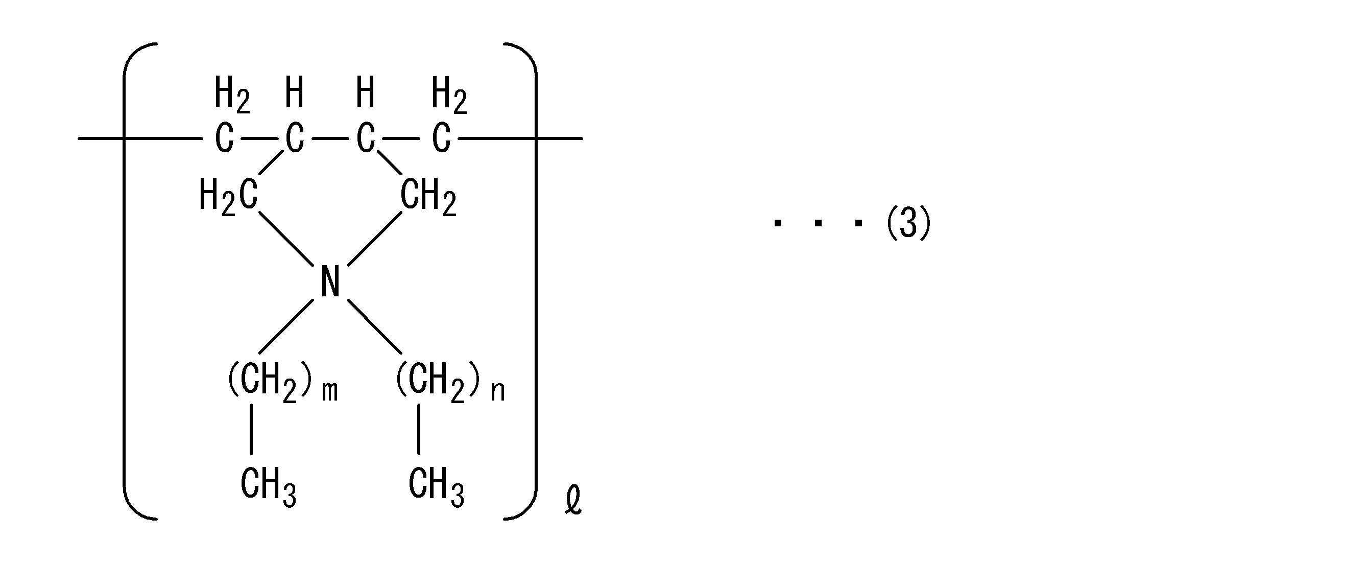
(c)特定のイオン導電剤のカチオンは、表面電荷密度が高いほど、(d)カーボンブラックに吸着しやすい。表面電荷密度は、カチオンのアルキル基の鎖が長いほど小さい。すなわち、カチオンのアルキル基の鎖が長いほど、(d)カーボンブラックに吸着しにくくなる。一方で、カチオンのアルキル基の鎖が短いと、アニオンとの相互作用が強くなり、イオン解離しにくくなって導電性が低下する。mが1よりも大きい整数であると、nが5~7の整数であっても、カチオンと(d)カーボンブラックの相互作用が小さくなり、(c)特定のイオン導電剤のブリードが十分に抑えられない。nが7よりも大きい整数であると、mが0または1であっても、カチオンと(d)カーボンブラックの相互作用が小さくなり、(c)特定のイオン導電剤のブリードが十分に抑えられない。nが5よりも小さい整数であると、mが0または1であっても、カチオンとアニオンの相互作用が強くなり、イオン解離しにくくなって導電性が満足しない。したがって、上記の一般式(2)(3)のmは0または1であり、nは5~7の整数である。
(C) The cation of a specific ion conductive agent is more likely to be adsorbed to (d) carbon black as the surface charge density is higher. The surface charge density is smaller as the chain of the alkyl group of the cation is longer. That is, the longer the chain of the alkyl group of the cation, the harder it is to adsorb to (d) carbon black. On the other hand, when the chain of the alkyl group of the cation is short, the interaction with the anion becomes strong, the ion dissociation hardly occurs, and the conductivity is lowered. When m is an integer larger than 1, even if n is an integer from 5 to 7, the interaction between the cation and (d) carbon black is reduced, and (c) bleeding of a specific ion conductive agent is sufficient. It can not be suppressed. When n is an integer larger than 7, even if m is 0 or 1, the interaction between the cation and (d) carbon black is reduced, and (c) bleeding of a specific ion conductive agent is sufficiently suppressed. Absent. When n is an integer smaller than 5, the interaction between the cation and the anion becomes strong even if m is 0 or 1, so that the ion dissociation is difficult and the conductivity is not satisfactory. Therefore, m in the above general formulas (2) and (3) is 0 or 1, and n is an integer of 5 to 7.
(d)カーボンブラックは、比表面積が大きいほど、(c)特定のイオン導電剤のカチオンを吸着しやすくなる。一方で、比表面積が大きいほど、凝集しやすく、導電性が低下する。したがって、(c)特定のイオン導電剤のブリードを抑える効果と帯電性とのバランスに優れる観点から、(d)カーボンブラックの比表面積は、40~300m2/gの範囲内であることが好ましい。より好ましくは、42~240m2/gの範囲内である。
As (d) carbon black has a larger specific surface area, (c) it becomes easier to adsorb a cation of a specific ion conductive agent. On the other hand, the larger the specific surface area, the easier the aggregation and the lower the conductivity. Therefore, from the viewpoint of excellent balance between the (c) effect of suppressing bleeding of a specific ion conductive agent and the chargeability, the specific surface area of (d) carbon black is preferably in the range of 40 to 300 m 2 / g. . More preferably, it is in the range of 42 to 240 m 2 / g.
表層16は、トナー付着防止に優れる、柔軟で被帯電体を傷つけにくいなどの観点から、ポリアミド、ポリウレタン、アクリル樹脂から選択される少なくとも1種を含むことが好ましい。この場合、一般にはイオン導電剤が表層16を通過しやすい傾向にあるが、このような表層16であっても本発明によれば(c)特定のイオン導電剤のブリードを抑える効果に優れる。このとき、表層16のポリマー成分が架橋されていると、架橋されていない場合よりも(c)特定のイオン導電剤のブリードを抑えやすい。
The surface layer 16 preferably contains at least one selected from polyamides, polyurethanes, and acrylic resins, from the viewpoint of being excellent in toner adhesion prevention, flexible and hardly damaging the member to be charged. In this case, in general, the ion conductive agent tends to easily pass through the surface layer 16, but even with such a surface layer 16, according to the present invention (c) the effect of suppressing bleeding of a specific ion conductive agent is excellent. At this time, when the polymer component of the surface layer 16 is crosslinked, bleeding of the specific ion conductive agent (c) can be more easily suppressed than when it is not crosslinked.
本発明に係る帯電ロールの構成としては、図1に示す構成に限定されるものではない。例えば、図1に示す帯電ロール10において、軸体12と基層14との間に他の弾性体層を備えた構成であってもよい。この場合、他の弾性体層は、帯電ロールのベースとなる層であり、基層14が帯電ロールの抵抗調整を行う抵抗調整層などとして機能する。他の弾性体層は、例えば、基層14を構成する材料として挙げられた材料のいずれかにより構成することができる。また、例えば、図1に示す帯電ロール10において、基層14と表層16との間に他の弾性体層を備えた構成であってもよい。この場合、基層14が帯電ロールのベースとなる層であり、他の弾性体層は、帯電ロールの抵抗調整を行う抵抗調整層などとして機能する。
The configuration of the charging roll according to the present invention is not limited to the configuration shown in FIG. For example, in the charging roll 10 shown in FIG. 1, another elastic layer may be provided between the shaft 12 and the base layer 14. In this case, the other elastic layer is a layer to be a base of the charging roll, and the base layer 14 functions as a resistance adjusting layer or the like for adjusting the resistance of the charging roll. The other elastic layer can be made of, for example, any of the materials mentioned as the material constituting the base layer 14. For example, in the charging roll 10 shown in FIG. 1, another elastic layer may be provided between the base layer 14 and the surface layer 16. In this case, the base layer 14 is a layer to be a base of the charging roll, and the other elastic layer functions as a resistance adjusting layer for adjusting the resistance of the charging roll.
以下、実施例および比較例を用いて本発明を詳細に説明する。なお、実施例は、軸体の外周に基層と表層とがこの順に積層された2層構造の帯電ロールを例に挙げるものであるが、本発明はこの構成に限定されるものではない。
Hereinafter, the present invention will be described in detail using examples and comparative examples. In addition, although an Example takes up the charge roll of 2 layer structure which the base layer and surface layer were laminated | stacked in this order on the outer periphery of a shaft is mentioned as an example, this invention is not limited to this structure.
<イオン導電剤<1>:ジアリル/C1/C6・TFSIの調製>
ジアリルメチルアミン150mmol、n-ヘキシルブロミド180mmol、アセトニトリル50gを混合し、105℃で24時間反応させた。その後、反応液を室温まで冷却し、ヘキサンを添加して未反応分を抽出除去し、残液をエバポレーターを用いて減圧下で濃縮し、ジアリルヘキシルメチルアンモニウム・ブロミドを得た。次いで、得られたジアリルヘキシルメチルアンモニウム・ブロミドとビス(トリフルオロメタンスルホニル)イミド酸リチウムとを水系溶媒に添加し、室温で4時間攪拌することにより、ジアリルヘキシルメチルアンモニウム・ビス(トリフルオロメタンスルホニル)イミドを調製した。 <Preparation of Ion Conducting Agent <1>: Diallyl / C1 / C6 · TFSI>
150 mmol of diallyl methylamine, 180 mmol of n-hexyl bromide and 50 g of acetonitrile were mixed, and reacted at 105 ° C. for 24 hours. Thereafter, the reaction solution was cooled to room temperature, hexane was added to extract and remove unreacted components, and the remaining solution was concentrated under reduced pressure using an evaporator to obtain diallylhexylmethylammonium bromide. Subsequently, diallyl hexyl methyl ammonium bis (trifluoromethane sulfonyl) imide is added by adding the obtained diallyl hexyl methyl ammonium bromide and lithium bis (trifluoromethane sulfonyl) imidate to an aqueous solvent, and stirring at room temperature for 4 hours. Was prepared.
<イオン導電剤<2>:ジアリル/C1/C8・TFSIの調製>
n-ヘキシルブロミドに代えてn-オクチルブロミドを用いた以外はイオン導電剤<1>の調製と同様にして、ジアリルオクチルメチルアンモニウム・ビス(トリフルオロメタンスルホニル)イミドを調製した。 <Preparation of Ion Conducting Agent <2>: Diallyl / C1 / C8 · TFSI>
A diallyloctylmethylammonium bis (trifluoromethanesulfonyl) imide was prepared in the same manner as in the preparation of the ion conductive agent <1> except that n-octylbromide was used instead of n-hexylbromide.
<イオン導電剤<3>:ジアリル/C2/C6・TFSIの調製>
n-ヘキシルアミン500mmolと25wt%水酸化ナトリウム水溶液384g(水酸化ナトリウムとして2400mmol)を混合し、80℃まで加熱した。その後、アリルクロライド1200mmolを2時間かけて滴下し、追加で80℃で2時間撹拌した。得られた液から油層のみ取り出し、余分なアリルクロライドを減圧留去することでジアリルヘキシルアミンを得た。次いで、得られたジアリルヘキシルアミンとエチルブロミドとを有機溶媒中で反応させることにより、ジアリルヘキシルエチルアンモニウム・ブロミドを得た。次いで、得られたジアリルヘキシルエチルアンモニウム・ブロミドとビス(トリフルオロメタンスルホニル)イミド酸リチウムとを水系溶媒に添加し、室温で4時間攪拌することにより、ジアリルヘキシルエチルアンモニウム・ビス(トリフルオロメタンスルホニル)イミドを調製した。 <Preparation of Ion Conducting Agent <3>: Diallyl / C2 / C6 · TFSI>
500 mmol of n-hexylamine and 384 g of a 25 wt% aqueous solution of sodium hydroxide (2400 mmol as sodium hydroxide) were mixed and heated to 80.degree. Thereafter, 1200 mmol of allyl chloride was dropped over 2 hours, and additionally stirred at 80 ° C. for 2 hours. Only the oil layer was taken out of the obtained liquid, and excess allyl chloride was distilled off under reduced pressure to obtain diallylhexylamine. Then, the obtained diallylhexylamine and ethyl bromide were reacted in an organic solvent to obtain diallylhexylethylammonium bromide. Subsequently, diallyl hexyl ethyl ammonium bis (trifluoro methane sulfonyl) imide is added by adding the obtained diallyl hexyl ethyl ammonium bromide and lithium bis (trifluoro methane sulfonyl) imidate to an aqueous solvent, and stirring at room temperature for 4 hours. Was prepared.
<イオン導電剤<4>:ジアリル/C1/C9・TFSIの調製>
n-ヘキシルブロミドに代えてn-ノニルブロミドを用いた以外はイオン導電剤<1>の調製と同様にして、ジアリルノニルメチルアンモニウム・ビス(トリフルオロメタンスルホニル)イミドを調製した。 <Preparation of Ion Conducting Agent <4>: Diallyl / C1 / C9 · TFSI>
In the same manner as in the preparation of the ion conductive agent <1> except that n-nonyl bromide was used in place of n-hexyl bromide, diallynonylmethyl ammonium bis (trifluoromethanesulfonyl) imide was prepared.
<イオン導電剤<5>:ジアリル/C1/C5・TFSIの調製>
n-ヘキシルブロミドに代えてn-ペンチルブロミドを用いた以外はイオン導電剤<1>の調製と同様にして、ジアリルペンチルメチルアンモニウム・ビス(トリフルオロメタンスルホニル)イミドを調製した。 <Preparation of Ion Conducting Agent <5>: Diallyl / C1 / C5 · TFSI>
A diallylpentylmethylammonium bis (trifluoromethanesulfonyl) imide was prepared in the same manner as in the preparation of the ion conductive agent <1> except that n-pentyl bromide was used instead of n-hexyl bromide.
<イオン導電剤<6>:ジアリル/C3/C6・TFSIの調製>
エチルブロミドに代えてn-プロピルブロミドを用いた以外はイオン導電剤<3>の調製と同様にして、ジアリルヘキシルプロピルアンモニウム・ビス(トリフルオロメタンスルホニル)イミドを調製した。 <Preparation of Ion Conducting Agent <6>: Diallyl / C3 / C6 · TFSI>
A diallylhexylpropylammonium bis (trifluoromethanesulfonyl) imide was prepared in the same manner as in the preparation of the ion conductive agent <3> except that n-propyl bromide was used in place of ethyl bromide.
導電性ゴム組成物のイオン導電剤以外の材料として、以下の材料を準備した。
・架橋性ゴム
ヒドリンゴム:ECO、日本ゼオン社製「HydrinT3106」
ニトリルゴム:NBR、日本ゼオン社製「NipolDN302」
・架橋剤
過酸化物:日油製「パークミルD40」
・カーボンブラック
カーボンブラック<1>:東海カーボン製「シーストSO」、比表面積42m2/g
カーボンブラック<2>:東海カーボン製「シースト9」、比表面積142m2/g
カーボンブラック<3>:キャボット製「BLACK PEARLS 880」、比表面積240m2/g
・ステアリン酸(加工助剤)[日本油脂(株)製、「ステアリン酸さくら」]
・酸化亜鉛(反応助剤)[堺化学工業(株)製、「酸化亜鉛2種」]
・ハイドロタルサイト(反応助剤)[協和化学工業製「DHT4A」] The following materials were prepared as materials other than the ion conductive agent of a conductive rubber composition.
Crosslinkable rubber-Hydrated rubber: ECO, manufactured by Nippon Zeon "Hydrin T3106"
Nitrile rubber: NBR, manufactured by Nippon Zeon "Nipol DN 302"
Cross-linking agent Peroxide: “Parkmill D40” made by NOF Corporation
-Carbon black Carbon black <1>: Tokai Carbon "Siest SO", specific surface area 42 m 2 / g
Carbon black <2>: Tokai Carbon “Siest 9”, specific surface area 142 m 2 / g
Carbon black <3>: Cabot “BLACK PEARLS 880”, specific surface area 240 m 2 / g
・ Stearic acid (processing aid) [Nippon Yushi Co., Ltd. product, "stearic acid sakura"]
-Zinc oxide (reaction auxiliary agent) (Sakai Chemical Industry Co., Ltd., "Zinc oxide 2")
・ Hydrotalcite (reaction aid) [Kyowa Chemical Industry "DHT4A"]
(実施例1)
<導電性ゴム組成物の調製>
ヒドリンゴム100質量部に対し、カーボンブラック<1>20質量部、イオン導電剤<1>1質量部、架橋剤3質量部、ステアリン酸0.7質量部、酸化亜鉛5質量部、ハイドロタルサイト2質量部を配合し、これらを攪拌機により撹拌、混合して、実施例1に係る導電性ゴム組成物を調製した。 Example 1
<Preparation of Conductive Rubber Composition>
Carbon black <1> 20 parts by mass, ion conductive agent <1> 1 part by mass, crosslinking agent 3 parts by mass, stearic acid 0.7 parts by mass, zinc oxide 5 parts by mass, hydrotalcite 2 with respect to 100 parts by mass of hydrin rubber The conductive rubber composition according to Example 1 was prepared by blending parts by mass and stirring and mixing these with a stirrer.
<基層の作製>
成形金型に芯金(直径6mm)をセットし、上記導電性ゴム組成物を注入し、170℃で30分加熱した後、冷却、脱型して、芯金の外周に、厚さ1.75mmの導電性ゴム弾性体からなる基層を形成した。 <Preparation of base layer>
A core metal (diameter 6 mm) is set in a molding die, the conductive rubber composition is injected, and heating is carried out at 170 ° C. for 30 minutes, followed by cooling and demolding to obtain a thickness of 1. A base layer of 75 mm conductive rubber elastic body was formed.
<表層の作製>
N-メトキシメチル化ナイロン(ナガセケムテックス社製、「EF30T」)100質量部と、導電性酸化スズ(三菱マテリアル社製、「S-2000」)60質量部と、ウレタン粒子(根上工業製「アートパールC600」、平均粒子径10μm)30質量部と、クエン酸(架橋剤)1質量部と、メタノール300質量部とを混合して、表層形成用組成物を調製した。次いで、基層の表面に表層形成用組成物をロールコートし、120℃で50分加熱して、基層の外周に、厚さ10μmの表層を形成した。これにより、実施例1に係る帯電ロールを作製した。 <Preparation of surface>
100 parts by mass of N-methoxymethylated nylon (manufactured by Nagase ChemteX Co., Ltd., "EF30T"), 60 parts by mass of conductive tin oxide (manufactured by Mitsubishi Materials, "S-2000"), urethane particles (manufactured by Negami Industrial Co., Ltd.) "Art Pearl C600" (average particle diameter: 10 μm) 30 parts by mass, 1 part by mass of citric acid (crosslinking agent), and 300 parts by mass of methanol were mixed to prepare a composition for forming a surface layer. Subsequently, the composition for surface layer formation was roll-coated on the surface of the base layer and heated at 120 ° C. for 50 minutes to form a surface layer having a thickness of 10 μm on the outer periphery of the base layer. Thus, a charging roll according to Example 1 was produced.
(実施例2~3)
導電性ゴム組成物の調製においてイオン導電剤を変更した以外は実施例1と同様にして、帯電ロールを作製した。 (Examples 2 to 3)
A charge roll was produced in the same manner as in Example 1 except that the ion conductive agent was changed in the preparation of the conductive rubber composition.
導電性ゴム組成物の調製においてイオン導電剤を変更した以外は実施例1と同様にして、帯電ロールを作製した。 (Examples 2 to 3)
A charge roll was produced in the same manner as in Example 1 except that the ion conductive agent was changed in the preparation of the conductive rubber composition.
(実施例4~5)
導電性ゴム組成物の調製においてカーボンブラックを変更した以外は実施例1と同様にして、帯電ロールを作製した。 (Examples 4 to 5)
A charge roll was produced in the same manner as Example 1 except that carbon black was changed in preparation of the conductive rubber composition.
導電性ゴム組成物の調製においてカーボンブラックを変更した以外は実施例1と同様にして、帯電ロールを作製した。 (Examples 4 to 5)
A charge roll was produced in the same manner as Example 1 except that carbon black was changed in preparation of the conductive rubber composition.
(実施例6)
導電性ゴム組成物の調製において架橋性ゴムを変更した以外は実施例1と同様にして、帯電ロールを作製した。 (Example 6)
A charge roll was produced in the same manner as Example 1, except that the crosslinkable rubber was changed in the preparation of the conductive rubber composition.
導電性ゴム組成物の調製において架橋性ゴムを変更した以外は実施例1と同様にして、帯電ロールを作製した。 (Example 6)
A charge roll was produced in the same manner as Example 1, except that the crosslinkable rubber was changed in the preparation of the conductive rubber composition.
(実施例7~8)
表層形成用組成物の調製においてポリマーを変更した以外は実施例1と同様にして、帯電ロールを作製した。
・ポリウレタン:三井化学製「タケラックW6061」
・アクリル樹脂:根上工業製「パラクロンプレコート200」 (Examples 7 to 8)
A charge roll was produced in the same manner as in Example 1 except that the polymer was changed in the preparation of the composition for surface layer formation.
-Polyurethane: Mitsui Chemicals "Takelac W6061"
-Acrylic resin: "Parachron Precoat 200" manufactured by Negami Chemical Industries, Ltd.
(比較例1~3)
導電性ゴム組成物の調製においてイオン導電剤を変更した以外は実施例1と同様にして、帯電ロールを作製した。 (Comparative Examples 1 to 3)
A charge roll was produced in the same manner as in Example 1 except that the ion conductive agent was changed in the preparation of the conductive rubber composition.
導電性ゴム組成物の調製においてイオン導電剤を変更した以外は実施例1と同様にして、帯電ロールを作製した。 (Comparative Examples 1 to 3)
A charge roll was produced in the same manner as in Example 1 except that the ion conductive agent was changed in the preparation of the conductive rubber composition.
(比較例4)
導電性ゴム組成物の調製においてカーボンブラックを配合しなかった以外は実施例1と同様にして、帯電ロールを作製した。 (Comparative example 4)
A charge roll was produced in the same manner as Example 1, except that carbon black was not blended in preparation of the conductive rubber composition.
導電性ゴム組成物の調製においてカーボンブラックを配合しなかった以外は実施例1と同様にして、帯電ロールを作製した。 (Comparative example 4)
A charge roll was produced in the same manner as Example 1, except that carbon black was not blended in preparation of the conductive rubber composition.
作製した各帯電ロールについて、ブリードの評価、帯電量の評価を行った。評価結果と導電性ゴム組成物の配合組成(質量部)、表層形成用組成物の配合組成(質量部)を以下の表に示す。
The evaluation of the bleed and the evaluation of the charge amount were performed for each of the manufactured charging rolls. The evaluation results, the compounding composition (parts by mass) of the conductive rubber composition, and the compounding composition (parts by mass) of the composition for forming a surface layer are shown in the following table.
(ブリードの評価)
評価機として京セラ製「ECOSYS P5026cdw」を用い、ドラムユニットに作製した帯電ロールをセットし、32.5℃×85%RH環境に12時間放置した。その後、23℃×53%RH環境にてハーフトーン画像を出力した。出力画像の20枚以内に帯電ロールからイオン導電剤がブリードしたことに起因するドラムピッチの白スジが消失した場合を「○」、出力画像の20枚以上でもドラムピッチの白スジが消失しない場合を「×」とした。 (Evaluation of bleed)
The charging roll prepared in the drum unit was set using “ECOSYS P5026 cdw” manufactured by Kyocera as an evaluation machine, and left in a 32.5 ° C. × 85% RH environment for 12 hours. Thereafter, a halftone image was output in an environment of 23 ° C. × 53% RH. The case where white streaks of the drum pitch disappear due to the ion conductive agent bleeding from the charging roll within 20 sheets of the output image is "○", and the white streaks of the drum pitch do not disappear even with 20 sheets or more of the output image "X".
(帯電量の評価)
評価機として京セラ製「ECOSYS P5026cdw」を用い、ドラムユニットに作製した帯電ロールをセットし、10℃×10%RH環境にて1200V印加した際の帯電量を測定した。帯電量が300V超であった場合を「○」、帯電量が300V以下であった場合を「×」とした。 (Evaluation of charge amount)
The charging roll produced in the drum unit was set using "ECOSYS P5026 cdw" manufactured by KYOCERA as an evaluation machine, and the charge amount was measured when applying 1200 V in an environment of 10 ° C. × 10% RH. The case where the charge amount was over 300 V was taken as “○”, and the case where the charge amount was 300 V or less was taken as “×”.

表1によれば、本願請求項1を満足する構成において、イオン導電剤のブリードによる画像不具合が抑えられるとともに優れた帯電性が維持できることがわかる。比較例のように、特定のイオン導電剤とカーボンブラックを併用していない場合には、上記効果を奏しない。そして、実施例1~3、比較例1~3によれば、上記一般式(1)において、R3が炭素数3以上であると、R4が炭素数6~8の直鎖アルキル基であってもイオン導電剤のブリードが抑えられず、R4が炭素数9以上であると、R3が炭素数1~2であってもイオン導電剤のブリードが抑えられず、R4が炭素数5以下であると、帯電性を満足しないことがわかる。
According to Table 1, it can be seen that in the configuration satisfying the claim 1 of the present application, it is possible to suppress the image failure due to the bleeding of the ion conductive agent and to maintain the excellent chargeability. As in the comparative example, when the specific ion conductive agent and carbon black are not used in combination, the above effect is not obtained. Then, according to Examples 1 to 3 and Comparative Examples 1 to 3, in the general formula (1), when R 3 has 3 or more carbon atoms, R 4 is a linear alkyl group having 6 to 8 carbon atoms. Even if the ion conductive agent bleeds can not be suppressed, and if R 4 has 9 or more carbon atoms, the bleed of the ion conductive agent can not be suppressed even if R 3 has 1 or 2 carbon atoms, and R 4 is carbon It is understood that the chargeability is not satisfied if the number is 5 or less.
以上、本発明の実施形態・実施例について説明したが、本発明は上記実施形態・実施例に何ら限定されるものではなく、本発明の趣旨を逸脱しない範囲内で種々の改変が可能である。
As mentioned above, although embodiment and Example of this invention were described, this invention is not limited at all to the said embodiment and Example, A various change is possible within the range which does not deviate from the meaning of this invention .
Claims (12)
- 導電性ゴム弾性体からなる基層と、表層と、を有する電子写真機器用帯電部材であって、
前記基層は、
(a)架橋性ゴム、
(b)架橋剤、
(c)下記一般式(1)で示されるイオン導電剤、
(d)カーボンブラック、
を含有する導電性ゴム組成物の架橋体であることを特徴とする電子写真機器用帯電部材。

The base layer is
(A) Crosslinkable rubber,
(B) Crosslinker,
(C) An ion conductive agent represented by the following general formula (1)
(D) carbon black,
What is claimed is: 1. A charging member for an electrophotographic apparatus, which is a crosslinked product of a conductive rubber composition comprising:
- 前記(d)カーボンブラックの比表面積が、40~300m2/gの範囲内であることを特徴とする請求項1に記載の電子写真機器用帯電部材。 The charging member for an electrophotographic apparatus according to claim 1, wherein the specific surface area of the carbon black (d) is in the range of 40 to 300 m 2 / g.
- 前記(d)カーボンブラックの比表面積が、42~240m2/gの範囲内であることを特徴とする請求項1に記載の電子写真機器用帯電部材。 The charging member for an electrophotographic apparatus according to claim 1, wherein the specific surface area of the carbon black (d) is in the range of 42 to 240 m 2 / g.
- 前記R4は、炭素数6の直鎖アルキル基であることを特徴とする請求項1から3のいずれか1項に記載の電子写真機器用帯電部材。 The charging member for an electrophotographic apparatus according to any one of claims 1 to 3, wherein the R 4 is a linear alkyl group having 6 carbon atoms.
- 前記X-は、N,N-ビス(トリフルオロメタンスルホニル)イミドアニオンであることを特徴とする請求項1から4のいずれか1項に記載の電子写真機器用帯電部材。 The charging member according to any one of claims 1 to 4, wherein the X - is an N, N-bis (trifluoromethanesulfonyl) imide anion.
- 前記(c)のイオン導電剤の含有量が、(a)架橋性ゴム100質量部に対し、0.1~10質量部の範囲内であることを特徴とする請求項1から5のいずれか1項に記載の電子写真機器用帯電部材。 The content of the ion conductive agent in (c) is in the range of 0.1 to 10 parts by mass with respect to 100 parts by mass of (a) the crosslinkable rubber. A charging member for an electrophotographic apparatus according to item 1.
- 前記(d)カーボンブラックの含有量が、(a)架橋性ゴム100質量部に対し、5~40質量部の範囲内であることを特徴とする請求項1から6のいずれか1項に記載の電子写真機器用帯電部材。 The content of the (d) carbon black is in the range of 5 to 40 parts by mass with respect to 100 parts by mass of the (a) crosslinkable rubber according to any one of claims 1 to 6, Charging member for electrophotographic equipment.
- 前記表層が、ポリアミド、ポリウレタン、アクリル樹脂から選択される少なくとも1種を含むことを特徴とする請求項1から7のいずれか1項に記載の電子写真機器用帯電部材。 The charging member for an electrophotographic apparatus according to any one of claims 1 to 7, wherein the surface layer contains at least one selected from polyamide, polyurethane, and acrylic resin.
- 前記表層が、ポリアミド、ポリウレタンから選択される少なくとも1種を含むことを特徴とする請求項1から7のいずれか1項に記載の電子写真機器用帯電部材。 The electrophotographic apparatus charging member according to any one of claims 1 to 7, wherein the surface layer contains at least one selected from polyamide and polyurethane.
- 前記表層が、ポリアミド、クエン酸、導電性酸化スズ、およびウレタン粒子を含む組成物から形成されることを特徴とする請求項1から7のいずれか1項に記載の電子写真機器用帯電部材。 The charging member for an electrophotographic apparatus according to any one of claims 1 to 7, wherein the surface layer is formed of a composition containing polyamide, citric acid, conductive tin oxide, and urethane particles.
- 前記表層のポリマー成分が架橋されていることを特徴とすることを特徴とする請求項1から10のいずれか1項に記載の電子写真機器用帯電部材。 The electrophotographic apparatus charging member according to any one of claims 1 to 10, wherein the polymer component of the surface layer is crosslinked.
- 軸体と、前記基層と、前記表層と、を有し、前記軸体の外周に前記基層が形成され、前記基層の外周に前記表層が形成されていることを特徴とする請求項1から11のいずれか1項に記載の電子写真機器用帯電部材。
The shaft layer, the base layer, and the surface layer, wherein the base layer is formed on the outer periphery of the shaft body, and the surface layer is formed on the outer periphery of the base layer. The charging member for an electrophotographic apparatus according to any one of the above.
Priority Applications (2)
| Application Number | Priority Date | Filing Date | Title |
|---|---|---|---|
| CN201880066702.6A CN111213094B (en) | 2017-11-30 | 2018-09-26 | Charging member for electrophotographic apparatus |
| US16/812,363 US10795277B2 (en) | 2017-11-30 | 2020-03-08 | Charging member for electrophotographic apparatus |
Applications Claiming Priority (2)
| Application Number | Priority Date | Filing Date | Title |
|---|---|---|---|
| JP2017-229786 | 2017-11-30 | ||
| JP2017229786A JP6918688B2 (en) | 2017-11-30 | 2017-11-30 | Charging member for electrophotographic equipment |
Related Child Applications (1)
| Application Number | Title | Priority Date | Filing Date |
|---|---|---|---|
| US16/812,363 Continuation US10795277B2 (en) | 2017-11-30 | 2020-03-08 | Charging member for electrophotographic apparatus |
Publications (1)
| Publication Number | Publication Date |
|---|---|
| WO2019106929A1 true WO2019106929A1 (en) | 2019-06-06 |
Family
ID=66663912
Family Applications (1)
| Application Number | Title | Priority Date | Filing Date |
|---|---|---|---|
| PCT/JP2018/035584 WO2019106929A1 (en) | 2017-11-30 | 2018-09-26 | Charging member for electrophotographic apparatus |
Country Status (4)
| Country | Link |
|---|---|
| US (1) | US10795277B2 (en) |
| JP (1) | JP6918688B2 (en) |
| CN (1) | CN111213094B (en) |
| WO (1) | WO2019106929A1 (en) |
Citations (7)
| Publication number | Priority date | Publication date | Assignee | Title |
|---|---|---|---|---|
| JP2005031203A (en) * | 2003-07-08 | 2005-02-03 | Tokai Rubber Ind Ltd | Electrifying roll |
| JP2006189894A (en) * | 2006-02-22 | 2006-07-20 | Tokai Rubber Ind Ltd | Charged member |
| WO2011007731A1 (en) * | 2009-07-14 | 2011-01-20 | 日本アエロジル株式会社 | Surface-modified metal oxide powder and process for producing same |
| JP2013097118A (en) * | 2011-10-31 | 2013-05-20 | Sumitomo Rubber Ind Ltd | Semiconductive roller |
| JP2014065811A (en) * | 2012-09-26 | 2014-04-17 | Tokai Rubber Ind Ltd | Conductive rubber composition for electrophotographic equipment, and conductive member for electrophotographic equipment using the same |
| JP2014142529A (en) * | 2013-01-25 | 2014-08-07 | Tokai Rubber Ind Ltd | Conductive composition for electrophotographic apparatus, and conductive member for electrophotographic apparatus |
| US20150064403A1 (en) * | 2013-08-27 | 2015-03-05 | Lexmark International, Inc. | Elastomeric Roll for an Electrophotographic Image Forming Device having Compressible Hollow Microparticles Defining a Surface Texture of the Roll |
Family Cites Families (20)
| Publication number | Priority date | Publication date | Assignee | Title |
|---|---|---|---|---|
| US5849399A (en) * | 1996-04-19 | 1998-12-15 | Xerox Corporation | Bias transfer members with fluorinated carbon filled fluoroelastomer outer layer |
| US6052550A (en) * | 1998-11-13 | 2000-04-18 | Xerox Corporation | Image separator having conformable layer for contact electrostatic printing |
| JP2000304032A (en) * | 1999-04-22 | 2000-10-31 | Ricoh Co Ltd | Charging member |
| US6620476B2 (en) * | 1999-08-13 | 2003-09-16 | Xerox Corporation | Nonbleeding fluorinated carbon and zinc oxide filled layer for bias charging member |
| JP3744339B2 (en) * | 1999-12-27 | 2006-02-08 | 東海ゴム工業株式会社 | Conductive material |
| AU2001249373A1 (en) * | 2000-03-23 | 2001-10-03 | Ameripol Synpol Corporation | Carbon black coupler |
| JP3804476B2 (en) * | 2001-06-26 | 2006-08-02 | 東海ゴム工業株式会社 | Charging member |
| JP5093636B2 (en) * | 2001-08-16 | 2012-12-12 | ダイソー株式会社 | Semiconductive vulcanized rubber composition |
| CN100580574C (en) * | 2006-04-28 | 2010-01-13 | 夏普株式会社 | Charging roller, process cartridge and image forming apparatus |
| JP4666051B2 (en) * | 2008-10-24 | 2011-04-06 | 富士ゼロックス株式会社 | Charging member, charging device, process cartridge, and image forming apparatus |
| EP2518568B1 (en) * | 2009-12-22 | 2017-03-22 | Canon Kabushiki Kaisha | Charging member, electrophotographic device and process cartridge |
| JP2012047871A (en) * | 2010-08-25 | 2012-03-08 | Tokai Rubber Ind Ltd | Conductive member for electrophotographic apparatus |
| US20120251171A1 (en) * | 2011-03-29 | 2012-10-04 | Canon Kabushiki Kaisha | Conductive member |
| JP6265716B2 (en) * | 2012-12-13 | 2018-01-24 | キヤノン株式会社 | Electrophotographic member, process cartridge, and electrophotographic apparatus |
| JP6082622B2 (en) * | 2013-02-27 | 2017-02-15 | 住友理工株式会社 | Conductive rubber composition for electrophotographic equipment and charging roll for electrophotographic equipment using the same |
| JP6624943B2 (en) * | 2015-01-30 | 2019-12-25 | キヤノン株式会社 | Developer amount regulating blade and image forming apparatus |
| WO2016158813A1 (en) * | 2015-03-30 | 2016-10-06 | 住友理工株式会社 | Electrophotographic equipment-use electrically conductive member |
| US9869945B2 (en) * | 2015-04-14 | 2018-01-16 | Xerox Corporation | Electrostatic charging member |
| JP6860319B2 (en) * | 2015-10-23 | 2021-04-14 | キヤノン株式会社 | Develop members, process cartridges and electrophotographic image forming equipment |
| US10884352B2 (en) * | 2018-03-30 | 2021-01-05 | Canon Kabushiki Kaisha | Electrophotographic member, process cartridge and electrophotographic apparatus |
-
2017
- 2017-11-30 JP JP2017229786A patent/JP6918688B2/en active Active
-
2018
- 2018-09-26 CN CN201880066702.6A patent/CN111213094B/en active Active
- 2018-09-26 WO PCT/JP2018/035584 patent/WO2019106929A1/en active Application Filing
-
2020
- 2020-03-08 US US16/812,363 patent/US10795277B2/en active Active
Patent Citations (7)
| Publication number | Priority date | Publication date | Assignee | Title |
|---|---|---|---|---|
| JP2005031203A (en) * | 2003-07-08 | 2005-02-03 | Tokai Rubber Ind Ltd | Electrifying roll |
| JP2006189894A (en) * | 2006-02-22 | 2006-07-20 | Tokai Rubber Ind Ltd | Charged member |
| WO2011007731A1 (en) * | 2009-07-14 | 2011-01-20 | 日本アエロジル株式会社 | Surface-modified metal oxide powder and process for producing same |
| JP2013097118A (en) * | 2011-10-31 | 2013-05-20 | Sumitomo Rubber Ind Ltd | Semiconductive roller |
| JP2014065811A (en) * | 2012-09-26 | 2014-04-17 | Tokai Rubber Ind Ltd | Conductive rubber composition for electrophotographic equipment, and conductive member for electrophotographic equipment using the same |
| JP2014142529A (en) * | 2013-01-25 | 2014-08-07 | Tokai Rubber Ind Ltd | Conductive composition for electrophotographic apparatus, and conductive member for electrophotographic apparatus |
| US20150064403A1 (en) * | 2013-08-27 | 2015-03-05 | Lexmark International, Inc. | Elastomeric Roll for an Electrophotographic Image Forming Device having Compressible Hollow Microparticles Defining a Surface Texture of the Roll |
Also Published As
| Publication number | Publication date |
|---|---|
| JP6918688B2 (en) | 2021-08-11 |
| CN111213094A (en) | 2020-05-29 |
| CN111213094B (en) | 2022-04-19 |
| US10795277B2 (en) | 2020-10-06 |
| US20200209779A1 (en) | 2020-07-02 |
| JP2019101127A (en) | 2019-06-24 |
Similar Documents
| Publication | Publication Date | Title |
|---|---|---|
| JP5687135B2 (en) | Conductive rubber composition for electrophotographic equipment and charging roll for electrophotographic equipment using the same | |
| WO2012026355A1 (en) | Conductive member for electrophotographic devices | |
| US10444655B2 (en) | Charging roll for electrophotographic equipment | |
| JP2014065811A (en) | Conductive rubber composition for electrophotographic equipment, and conductive member for electrophotographic equipment using the same | |
| JP7319907B2 (en) | Conductive roll for electrophotographic equipment | |
| JP6082622B2 (en) | Conductive rubber composition for electrophotographic equipment and charging roll for electrophotographic equipment using the same | |
| US10656555B2 (en) | Development roll for electrophotography device | |
| JP6637758B2 (en) | Conductive members for electrophotographic equipment | |
| WO2019106929A1 (en) | Charging member for electrophotographic apparatus | |
| US11753519B2 (en) | Conductive roll for electrophotographic machine | |
| JP6013175B2 (en) | Conductive roll for electrophotographic equipment | |
| US10859938B2 (en) | Charging member for electrophotographic equipment | |
| JP7132883B2 (en) | Conductive roll for electrophotographic equipment | |
| WO2023127398A1 (en) | Charging roll for electrophotographic devices and method for producing charging roll for electrophotographic devices | |
| JP2017194072A (en) | Electric conductive roller and image forming device | |
| JP5925584B2 (en) | Manufacturing method of conductive roller | |
| JP2017194495A (en) | Conductive roller and image forming apparatus |
Legal Events
| Date | Code | Title | Description |
|---|---|---|---|
| 121 | Ep: the epo has been informed by wipo that ep was designated in this application |
Ref document number: 18884186 Country of ref document: EP Kind code of ref document: A1 |
|
| NENP | Non-entry into the national phase |
Ref country code: DE |
|
| 122 | Ep: pct application non-entry in european phase |
Ref document number: 18884186 Country of ref document: EP Kind code of ref document: A1 |