WO2019102706A1 - Pon system, optical network unit, optical line terminal, method for registering optical network unit, and data structure - Google Patents
Pon system, optical network unit, optical line terminal, method for registering optical network unit, and data structure Download PDFInfo
- Publication number
- WO2019102706A1 WO2019102706A1 PCT/JP2018/035434 JP2018035434W WO2019102706A1 WO 2019102706 A1 WO2019102706 A1 WO 2019102706A1 JP 2018035434 W JP2018035434 W JP 2018035434W WO 2019102706 A1 WO2019102706 A1 WO 2019102706A1
- Authority
- WO
- WIPO (PCT)
- Prior art keywords
- reception level
- onu
- home
- olt
- station
- Prior art date
Links
Images


Classifications
-
- H—ELECTRICITY
- H04—ELECTRIC COMMUNICATION TECHNIQUE
- H04B—TRANSMISSION
- H04B10/00—Transmission systems employing electromagnetic waves other than radio-waves, e.g. infrared, visible or ultraviolet light, or employing corpuscular radiation, e.g. quantum communication
- H04B10/60—Receivers
- H04B10/66—Non-coherent receivers, e.g. using direct detection
- H04B10/67—Optical arrangements in the receiver
-
- H—ELECTRICITY
- H04—ELECTRIC COMMUNICATION TECHNIQUE
- H04Q—SELECTING
- H04Q11/00—Selecting arrangements for multiplex systems
- H04Q11/0001—Selecting arrangements for multiplex systems using optical switching
- H04Q11/0062—Network aspects
- H04Q11/0067—Provisions for optical access or distribution networks, e.g. Gigabit Ethernet Passive Optical Network (GE-PON), ATM-based Passive Optical Network (A-PON), PON-Ring
-
- H—ELECTRICITY
- H04—ELECTRIC COMMUNICATION TECHNIQUE
- H04B—TRANSMISSION
- H04B10/00—Transmission systems employing electromagnetic waves other than radio-waves, e.g. infrared, visible or ultraviolet light, or employing corpuscular radiation, e.g. quantum communication
- H04B10/27—Arrangements for networking
- H04B10/272—Star-type networks or tree-type networks
-
- H—ELECTRICITY
- H04—ELECTRIC COMMUNICATION TECHNIQUE
- H04L—TRANSMISSION OF DIGITAL INFORMATION, e.g. TELEGRAPHIC COMMUNICATION
- H04L12/00—Data switching networks
- H04L12/28—Data switching networks characterised by path configuration, e.g. LAN [Local Area Networks] or WAN [Wide Area Networks]
- H04L12/44—Star or tree networks
-
- H—ELECTRICITY
- H04—ELECTRIC COMMUNICATION TECHNIQUE
- H04Q—SELECTING
- H04Q11/00—Selecting arrangements for multiplex systems
- H04Q11/0001—Selecting arrangements for multiplex systems using optical switching
- H04Q11/0062—Network aspects
- H04Q2011/0064—Arbitration, scheduling or medium access control aspects
Definitions
- the present invention relates to a PON system, a home-side device, a station-side device, a method of registering a home-side device, and a data structure.
- a passive optical network is a system that performs point-to-multipoint optical communication between an optical line terminal (OLT) and one or more optical network units (ONUs).
- An optical line termination device is a unit generally located at the service provider's premises, also referred to as a "station-side device.”
- An optical network unit (ONU) is a unit located at or near a subscriber's premises, and is also referred to as a "home-side device”.
- the OLT reception circuit detects the level of the received signal and performs gain control based on the detected level.
- Patent Document 1 discloses a bias control circuit that controls a DC voltage applied to an avalanche photodiode (APD).
- the bias control circuit detects the photocurrent generated by the APD and controls the voltage source according to the detected current.
- Patent Document 2 discloses a configuration for setting a bias voltage of an APD.
- the parent station (OLT) measures the reception level of the upstream optical signal in advance for each slave station (ONU), and stores the reception level.
- the master station sets the bias voltage of the APD based on the stored reception strength immediately before receiving the upstream optical signal from the specific slave station.
- Patent Document 3 Japanese Patent Application Laid-Open Nos. 2016-9897 (Patent Document 3) and Japanese Patent Application Laid-Open No. 2016-15640 (Patent Document 4) propose configurations for gain control of an optical amplifier.
- the burst signal is branched into signal light and monitor light by the optical coupler, and the level of the monitor light is detected.
- An optical fiber for delaying is introduced into the transmission path of the signal light.
- the gain of the optical amplifier can be controlled in accordance with the reception timing of the signal light.
- 100 Gbps class PON for example, 100 G-EPON
- the same fiber line as 10 G-EPON is used, and four different wavelength mutually having transmission capacity of 25.78 125 Gb / s (hereinafter referred to as “25 Gbps”)
- the transmission loss of the fiber line is a minimum of 15 dB / a maximum of 29 dB.
- Transmission speed is about 2.5 times faster for 100G-EPON than for 10G-EPON.
- the OLT is required to have an optical receiver having a wide band.
- the reception sensitivity of the OLT-side receiver is degraded by about 4 to 5 dB as compared with 10G-EPON.
- the increase in transmission rate causes deterioration in waveform quality of the transmission signal and an increase in penalty due to fiber chromatic dispersion.
- an optical multiplexer / demultiplexer is used to multiplex / demultiplex four waves. For this reason, it is necessary to consider the insertion loss (about 1.5 dB or so) of each of the optical multiplexer and the optical demultiplexer when receiving an optical signal in the station side apparatus.
- An OLT may receive a relatively strong optical signal from one ONU and may receive a relatively weak optical signal from another ONU.
- Patent Document 5 discloses a PON system capable of solving such a problem. In this PON system, communication is performed at a plurality of transmission rates. A terminal device not registered in the PON system sends a discovery response at one transmission rate within the discovery period.
- a PON system includes a station-side device, at least one home-side device, and an optical fiber connecting the station-side device and the home-side device, and is sent from the station-side device through the optical fiber.
- the reception level classification for dividing the reception level of the optical signal in the home apparatus is set, and the station apparatus corresponds to the reception level classification in the discovery process for searching for and registering an unregistered home apparatus. It is configured to register a home-side device.
- a PON system includes a station-side device, at least one home-side device, and an optical fiber that connects the station-side device and the home-side device.
- the station-side device includes an amplifier configured to amplify the optical signal received from the home-side device with variable gain, and is configured to determine and register the division of gain in the discovery process.
- the station-side apparatus sets the gain sections of the amplifier's gain in order from the lowest gain.
- An unregistered home device tries to respond to the discovery process in order from the lowest gain of the amplifier.
- the station-side device sets a gain classification for the unregistered home-side device.
- a home-side apparatus includes: a receiver configured to receive an optical signal; and a registration unit configured to register a reception level classification related to the reception level of the optical signal in the receiver; When the reception level classification specified in the discovery process for searching for and registering an unregistered home-side device falls under the reception level registered in the registration unit, a response to the discovery process is transmitted in the form of an optical signal And a transmitter configured.
- a station-side apparatus includes a receiver configured to receive an optical signal, and an amplifier provided upstream of the receiver and configured to amplify the optical signal with variable gain. And a transmitter configured to transmit an optical signal for discovery processing for searching for and registering an unregistered home apparatus, and the discovery process for comparison with the reception level classification of the home apparatus And a registration unit configured to register a home-side device that has specified the reception level division associated with the gain of the amplifier and responds to the discovery process.
- a method of registering a home device is a method of registering a home device in a PON system in which a station device and at least one home device are connected by an optical fiber. Setting the reception level division in the home apparatus for dividing the reception level in the home apparatus of the optical signal sent through the fiber, the station apparatus specifying the reception level, and registering the unregistered home side A step of executing a discovery process for searching for and registering a device, and an unregistered home-side device when the reception level designated by the station-side device corresponds to the reception level classification set in the unregistered home-side device And the station-side device register the home-side device that has responded to the discovery process.
- the data structure according to an aspect of the present invention is a data structure used for a discovery process in a PON system that causes a station-side device to recognize an unregistered home-side device, and the discovery process is specified by the station-side device
- the station-side device searches for the home-side device having the reception level segment, and the data structure includes the reception level segment for the notification from the station-side device to the home-side device.
- FIG. 1 is a view showing a configuration example of an optical communication system according to a first embodiment.
- FIG. 2 is a diagram for explaining the relationship between ONU reception level division and OLT reception level division according to the first embodiment.
- FIG. 3 is a sequence diagram for explaining an example of processing at the time of activating the ONU according to the first embodiment.
- FIG. 4 is a sequence diagram for explaining an example of a discovery process according to the first embodiment.
- FIG. 5 is a sequence diagram for explaining an example of the normal processing according to the first embodiment.
- FIG. 6 is a diagram schematically showing a part of a discovery gate message data structure according to the first mode.
- FIG. 7 is a diagram showing an example of the configuration of the optical communication system according to the second embodiment.
- FIG. 1 is a view showing a configuration example of an optical communication system according to a first embodiment.
- FIG. 2 is a diagram for explaining the relationship between ONU reception level division and OLT reception level division according to the first embodiment.
- FIG. 3 is
- FIG. 8 is a sequence diagram for explaining an example of processing at the time of activating the ONU according to the second embodiment.
- FIG. 9 is a sequence diagram for explaining an example of discovery processing (failure in registration of ONU) according to the second embodiment.
- FIG. 10 is a sequence diagram for explaining an example of the discovery process (the registration of the ONU is successful) according to the second embodiment.
- FIG. 11 is a diagram schematically showing an example of mapping information applicable to the third embodiment.
- FIG. 12 is a diagram schematically showing a part of the data structure of a discovery gate message according to the third mode.
- FIG. 13 is a first sequence diagram illustrating an example of a discovery process according to the third embodiment.
- FIG. 14 is a second sequence diagram for explaining a process following the process shown in FIG. FIG.
- FIG. 15 is a first sequence diagram for explaining another example of the discovery process according to the third embodiment.
- FIG. 16 is a second sequence diagram for explaining the process following the process shown in FIG.
- FIG. 17 is a diagram showing another example of the mapping information according to the third embodiment.
- FIG. 18 is a diagram showing an example of the configuration of an optical communication system according to a fourth embodiment.
- FIG. 19 is a diagram showing a configuration example of measuring transmission power of an ONU according to the fourth embodiment.
- FIG. 20 is a sequence diagram for explaining an example of processing at the time of activating the ONU according to the fourth embodiment.
- FIG. 21 is a sequence diagram for explaining an example of a discovery process according to the fourth embodiment.
- FIG. 22 is a diagram showing setting of reception level classification of ONU according to the fifth embodiment.
- FIG. 23 is a schematic diagram showing an example of a discovery message according to the fifth embodiment.
- FIG. 24 is a sequence diagram for explaining an example of processing at the time of activation of an ONU according to the fifth embodiment.
- FIG. 25 is a sequence diagram for explaining an example of a discovery process according to the fifth embodiment.
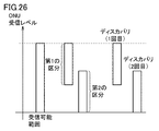
- FIG. 26 is a diagram showing setting of reception level division of ONU according to the sixth embodiment.
- FIG. 27 is a schematic diagram for explaining a discovery process according to the sixth embodiment.
- FIG. 28 is a diagram for explaining the determination of the reception level division of the ONU by the OLT.
- FIG. 29 is a diagram showing the relationship between the discovery process and the gain of the SOA.
- FIG. 30 is a sequence diagram for explaining an example of a discovery process according to the seventh embodiment.
- FIG. 30 is a sequence diagram for explaining an example of a discovery process according to the seventh embodiment.
- FIG. 31 is a sequence diagram for explaining an example of a discovery process according to the eighth embodiment.
- FIG. 32 is a sequence diagram for explaining another example of the discovery process according to the eighth embodiment.
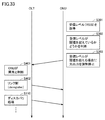
- FIG. 33 is a sequence diagram for explaining another example of the process in communication according to the ninth embodiment.
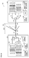
- FIG. 34 is a diagram showing an example of configuration of an optical communication system according to the tenth embodiment.
- the OLT Before registering an ONU, the OLT can not have information on the reception level of that ONU. Thus, the OLT can not guarantee gain control in receiving the optical signal from its ONU. None of the documents mentioned above propose a solution to such a problem.
- An object of the present disclosure is to provide an apparatus and method for enabling to register an ONU while guaranteeing gain control in reception of an optical signal from an unregistered ONU. [Effect of the present disclosure] According to the present disclosure, it is possible to register an ONU while guaranteeing gain control in reception of an optical signal from an unregistered ONU.
- a PON system includes a station-side device, at least one home-side device, and an optical fiber connecting the station-side device and the home-side device, and the station-side device Reception level classification is set in order to classify the reception level of the optical signal sent through the home device in the home device, and in the discovery process in which the station device searches for and registers an unregistered home device, the reception level classification Are configured to register the corresponding home-side device.
- the length of the optical fiber connecting the station-side device and the home-side device can be different for each home-side device. Because the length of the optical fiber may differ depending on the distance from the station apparatus to the home apparatus due to the transmission loss of the optical fiber, the reception level of the optical signal from each home apparatus is the station side apparatus. It can be different.
- the station-side device is configured to set the reception level classification and to register the home-side device corresponding to the reception level. During the discovery process, a signal having an appropriate intensity is input from the home device to the station device. Therefore, while guaranteeing gain control in reception of an optical signal from an unregistered home apparatus, the home apparatus can be registered by discovery processing.
- the station-side apparatus is configured to specify the reception level division in the discovery process.
- the unregistered home-side apparatus determines the reception level classification based on the reception level, and responds to the station-side apparatus when the reception level designated by the station-side apparatus falls under the determined reception level classification. Configured as.
- the station-side apparatus includes an amplifier configured to amplify an optical signal received from the home-side apparatus with variable gain, and is configured to specify a reception level division in a discovery process.
- the receive level segment is associated with the gain of the amplifier.
- the unregistered home-side apparatus tries the response to the discovery process in order from the lower gain of the amplifier, and the reception level classification specified in the discovery process for which the response is successful is taken as the reception level classification of the unregistered home-side apparatus.
- the station-side device determines the reception level division.
- the station apparatus includes an amplifier configured to amplify an optical signal received from the home apparatus with variable gain.
- the reception level segments are associated with one or more gain level segments of gain.
- the station-side device is configured to transmit the reception level division determined by the station-side device to the home-side device.
- the reception level division can be set optimally according to the characteristics of the amplifier of the station side apparatus. For example, gain control can be realized in consideration of individual differences in amplifier characteristics.
- the station-side device is configured to determine whether or not the unregistered home-side device can be registered when the unregistered home-side device responds to the discovery process.
- the station-side device can more accurately determine whether the home-side device should be registered.
- the determination by the station apparatus includes comparing the correction frequency in the error correction process with a threshold.
- the station-side device can determine whether to register the home-side device based on the correction frequency in the error correction process.
- the reception level division is set based on the reception power of the home apparatus.
- the station-side device can directly grasp the reception level of the home-side device from the reception power of the home-side device.
- the reception level division is set based on the line loss of the optical fiber corresponding to the difference between the transmission power of the station apparatus and the reception power of the home apparatus.
- the station-side device can estimate the reception level of the home-side device from the line loss of the optical fiber.
- the reception level division is set by the maximum value of the reception level of the home apparatus and the minimum value of the reception level of the home apparatus.
- the reception level division can be set by the range of reception levels. (11)
- the station-side device executes the discovery process, the station-side device includes the maximum value and the minimum value in the discovery gate message.
- the station-side device can notify the home-side device of the reception level division by the discovery gate message.
- At least one of the maximum value and the minimum value is a variable value.
- the range of reception levels for one reception level division can be set arbitrarily.
- the station-side device changes the reception level division from the first division to a second division having a range overlapping with a part of the first division.
- the home apparatus receives the higher one of the first and second divisions.
- the level division is set, it responds to the station apparatus.
- the home-side device measures the reception level of the home-side device, and determines whether the reception level corresponds to the reception level classification based on the measurement value of the reception level.
- the station-side device can register the home-side device corresponding to the reception level classification.
- the reception level division is set based on the line loss of the optical fiber corresponding to the difference between the transmission power of the station apparatus and the reception power of the home apparatus.
- the station-side device can register the home-side device corresponding to the reception level classification.
- the station apparatus sets a set of maximum value and minimum value multiple times.
- the plurality of sets includes a first set and a second set that satisfy the relation that the maximum value of the second set is larger than the minimum value of the first set.
- the station-side apparatus executes discovery processing in order from the highest one of the plurality of sets.
- a PON system includes a station-side device, at least one home-side device, and an optical fiber connecting the station-side device and the home-side device.
- the station-side device includes an amplifier configured to amplify the optical signal received from the home-side device with variable gain, and is configured to determine and register the division of gain in the discovery process.
- the station-side apparatus sets the gain sections of the amplifier's gain in order from the lowest gain.
- the unregistered home-side device tries to respond to the discovery process in order from the lowest gain of the amplifier.
- the station-side device sets a gain classification for the unregistered home-side device.
- the unregistered home apparatus tries to respond to the discovery process in order from the lower gain of the amplifier.
- the station apparatus can amplify the optical signal with low gain.
- the station-side device can receive an optical signal having an appropriate intensity.
- the home device can be registered by the discovery process while guaranteeing gain control in receiving an optical signal from an unregistered home device.
- the station-side device repeatedly performs setting of the gain of the amplifier, and sets the gain division for the home-side device whose response is confirmed with a gain lower than the registered gain division.
- the station-side device includes an optical receiver that receives the optical signal amplified by the amplifier.
- the local apparatus selects a gain section having the smallest gain, and resets the gain sections in order from the lowest gain.
- the home apparatus monitors the reception level of the home apparatus, and stops the light output when the reception level exceeds the threshold.
- the station-side device determines that the home-side device is abnormal by stopping the light output from the home-side device, releases the logical link of the home-side device to the PON system, and performs the discovery process. Register the device again.
- the station apparatus includes an optical receiver that receives an optical signal from the home apparatus and changes the multiplication factor according to the applied voltage.
- the station-side device changes the voltage applied to the optical receiver according to the reception level division.
- the station-side apparatus can change the amplification factor of the optical signal.
- a home-side apparatus is a receiver configured to receive an optical signal, and a registration configured to register a reception level classification related to the reception level of the optical signal at the receiver. Sends a response to the discovery process in the form of an optical signal when the reception level classification specified in the discovery process for searching and registering an unregistered home-side device corresponds to the reception level registered in the registration unit. And a transmitter configured to:
- the home-side device when the reception level classification of its own corresponds to the reception level classification specified in the discovery processing, the home-side device responds to the discovery processing. Therefore, management of the home apparatus based on the reception level classification can be realized.
- a station-side apparatus includes a receiver configured to receive an optical signal, and a receiver provided at a front stage of the receiver, configured to amplify the optical signal with variable gain. And a transmitter configured to transmit an optical signal for a discovery process to search for and register an unregistered home device, and for matching with the reception level classification of the home device.
- the method further includes a registration unit that is configured to register a home-side device that is specified in the discovery process and that is associated with the reception level division associated with the gain of the amplifier and that responds to the discovery process.
- the station-side device registers the home-side device having the reception level classification corresponding to the designated reception level classification. Therefore, management of the home apparatus based on the reception level classification can be realized.
- a method of registering a home device is a method of registering a home device in a PON system in which a station device and at least one home device are connected by an optical fiber, Step of setting reception level division in the home apparatus for dividing reception level in the home apparatus of the optical signal sent from the apparatus through the optical fiber, and the station apparatus designates the reception level and is not registered Step of executing a discovery process for searching and registering a home-side device, and the reception level designated by the station-side device being unregistered if it corresponds to the reception level classification set in the unregistered home-side device
- the home-side device responds to the discovery process, and the station-side device registers the home-side device that responded to the discovery process. .
- the station-side device registers the home-side device having the reception level classification corresponding to the designated reception level classification. Therefore, management of the home apparatus based on the reception level classification can be realized.
- a data structure according to an aspect of the present invention is a data structure used for discovery processing in a PON system that causes an unregistered home apparatus to be recognized by a station apparatus, and the discovery process is performed by the station apparatus
- the station-side device searches for a home-side device having a designated reception level segment, and the data structure includes a reception level segment for notification from the station-side device to the home-side device.
- data can be acquired in the home apparatus for determining in the home apparatus whether the registered reception level classification corresponds to the designated reception level classification.
- PON is shown as an embodiment of the optical communication system. Unless otherwise limited, "PON” includes EPON (Ethernet (R) Passive Optical Network).
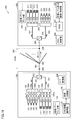
- FIG. 1 is a view showing a configuration example of an optical communication system according to a first embodiment.
- the PON system 300 includes an OLT (station-side device) 100, an ONU (home-side device) 200, and an optical distribution network 301.
- OLT station-side device
- ONU home-side device
- optical distribution network 301 optical distribution network
- the optical distribution network 301 is constituted by an optical fiber line and an optical splitter 302.
- the OLT 100 and the ONUs 200 are connected to the optical distribution network 301.
- An ODN (Optical Distribution Network) section 306 is a section of the optical distribution network 301 that includes the optical splitter 302 and is sandwiched by defining points 304 and 305.
- the optical splitter 302 splits the optical distribution network 301. Thereby, a plurality of ONUs can be connected to the optical distribution network 301. In FIG. 1, one ONU 200 is representatively shown.
- the PON system 300 realizes a 100 Gbps class PON (for example, 100 G-EPON).
- 100G-EPON the same fiber line as 10G-EPON is used to transmit four optical signals with different wavelengths, each having a transmission capacity of 25.78125 Gb / s (hereinafter referred to as "25 Gbps").
- Ru the same fiber line as 10G-EPON is used to transmit four optical signals with different wavelengths, each having a transmission capacity of 25.78125 Gb / s (hereinafter referred to as "25 Gbps").
- the OLT 100 includes an optical transmission path 101, an optical reception path 102, a diplexer filter 103, and semiconductor optical amplifiers (SOAs) 105a, 105b, 105c, 105d, 106a, 106b, 106c, and 106d. , An optical multiplexer 110, an optical demultiplexer 120, optical transmitters 111-114, and optical receivers 121-124.
- the OLT 100 can include a module (for example, an optical transceiver) that includes the above-described elements.
- FIG. 1 shows a configuration related to transmission and reception of an optical signal of the OLT 100.
- the light transmission path 101 and the light reception path 102 are configured by an optical waveguide, an optical fiber, and the like.
- the diplexer filter 103 is a component for optically separating the light transmission path 101 and the light reception path 102.
- Each of the optical transmitters 111 to 114 includes, for example, an electro-absorption modulator integrated laser diode (EML) as a light emitting element for generating an optical signal.
- EML electro-absorption modulator integrated laser diode
- the optical transmitters 111 to 114 emit light of different wavelengths.
- Each optical transmitter has a transmission capacity of 25 Gbps. Therefore, 25 Gbps ⁇ 4 channels are realized. There is no particular limitation on which one of the four channels each optical transmitter is assigned to.
- the SOAs 105a, 105b, 105c, and 105d amplify optical signals emitted from the optical transmitters 111 to 114, respectively.
- the optical multiplexer 110 multiplexes the four optical signals amplified by the SOAs 105 a, 105 b, 105 c, and 105 d by wavelength multiplexing.
- the optical transmission path 101 optically couples the optical multiplexer 110 and the SOAs 105 a, 105 b, 105 c, and 105 d to the optical transmitters 111 to 114.
- the optical signal from the optical multiplexer 110 is transmitted through the optical transmission path 101.
- the optical signal passes through the diplexer filter 103 and is sent out from the OLT 100 to the optical distribution network 301.
- the OLT 100 receives an optical signal from the ONU 200.
- This optical signal is a burst signal.
- the burst signal passes through the diplexer filter 103 and is routed to the optical receiving path 102.
- the optical signal from the ONU 200 is a wavelength division multiplexed (WDM) optical signal.
- the optical demultiplexer 120 separates the optical signal transmitted through the optical receiving path 102 into four optical signals based on the wavelength.
- the optical reception path 102 is optically coupled to the SOAs 106 a, 106 b, 106 c, and 106 d by being optically coupled to the optical demultiplexer 120.
- the SOAs 106a, 106b, 106c, and 106d are provided in front of the optical receivers 121 to 124, respectively, and amplify the optical signals input from the optical demultiplexer 120.
- Each of the light receivers 121 to 124 is a light receiver having high sensitivity, and includes, for example, an avalanche photodiode (APD) as a light receiving element.
- the optical receivers 121, 122, 123, 124 are respectively associated with four channels.
- the OLT 100 further includes an OLT control unit 130, an ONU information management unit 131, and a gain control unit 132.
- the OLT control unit 130 controls the operation of the OLT 100.
- the ONU information management unit 131 registers an ONU corresponding to the reception level classification designated by the OLT 100 in a discovery process of searching for and registering an unregistered ONU. Thereby, the ONU information management unit 131 manages information on the reception level of each ONU 200.
- An SOA is an amplifier with variable gain.
- the gain control unit 132 controls the gains of the SOAs 106 a, 106 b, 106 c, and 106 d based on the information (reception level of each ONU 200) managed by the ONU information management unit 131.
- the OLT control unit 130, the ONU information management unit 131, and the gain control unit 132 are realized by a single semiconductor circuit.
- the OLT control unit 130, the ONU information management unit 131, and the gain control unit 132 may be realized by individual semiconductor integrated circuits. Any two of the OLT control unit 130, the ONU information management unit 131, and the gain control unit 132 may be realized by one semiconductor integrated circuit.
- Such a semiconductor integrated circuit can be, for example, an application specific integrated circuit (ASIC), a field programmable gate array (FPGA), or the like.
- the OLT control unit 130, the ONU information management unit 131, and the gain control unit 132 are included in the OLT 100. However, at least one of the OLT control unit 130, the ONU information management unit 131, and the gain control unit 132 may be provided outside the OLT 100.
- the ONU 200 includes an optical transmission path 201, an optical reception path 202, a diplexer filter 203, an optical transmission path 204, an optical multiplexer 210, an optical demultiplexer 220, optical transmitters 211 to 214, and an optical receiver 221 to And an ONU control unit 240, a received signal strength indication (RSSI) circuit 241, and a reception level classification registration / holding unit 243.
- An ONU 200 can include a module (eg, an optical transceiver) that includes the elements described above.
- the modules of the ONU 200 may include optional elements of the components shown in FIG.
- the “selective elements” are, for example, the optical transmission path 201, the optical reception path 202, the diplexer filter 203, the optical multiplexer 210, the optical demultiplexer 220, the optical transmitters 211 to 214, and the optical receivers 221 to 224. It is also good.
- the above-mentioned "optional element” may include the same number of optical transmitters and optical receivers selected among the optical transmitters 211 to 214 and the optical receivers 221 to 224.
- the OLT 100 can similarly include the same number of optical transmitters and optical receivers selected from among the optical transmitters 111 to 114 and the optical receivers 121 to 124 as "selective elements”. .
- the light transmission path 201, the light reception path 202, and the light transmission path 204 are configured by an optical waveguide, an optical fiber, and the like.
- the diplexer filter 203 is a component for optically separating the light transmission path 201 and the light reception path 202.
- the optical transmission path 204 is a transmission path common to the optical transmission path 201 and the optical reception path 202.
- the optical multiplexer 210 is disposed in the optical transmission path 201.
- the optical demultiplexer 220 is disposed in the optical receiving path 202.
- Each of the light transmitters 211 to 214 can include an EML as a light emitting element.
- the light emitting element of each of the light transmitters 211-214 may be a Direct Modulation Laser Diode (DML).
- DML Direct Modulation Laser Diode
- the optical transmitters 211 to 214 emit optical signals of different wavelengths. This optical signal is a burst signal.
- Each optical transmitter has a transmission capacity of 25 Gbps. Therefore, 25 Gbps ⁇ 4 channels are realized. There is no particular limitation on which one of the four channels each optical transmitter is assigned to.
- the optical multiplexer 210 multiplexes the four optical signals respectively emitted from the optical transmitters 211 to 214 by wavelength multiplexing.
- the multiplexed optical signal is transmitted through the optical transmission path 201 and passes through the diplexer filter 203.
- the optical signal transmitted through the optical transmission path 201 is sent out to the optical distribution network 301 as an upstream optical signal from the ONU 200.
- the ONU 200 receives an optical signal from the OLT 100.
- the optical signal is transmitted through the optical transmission path 204 and routed to the optical reception path 202 by the diplexer filter 203.
- the optical demultiplexer 220 separates the optical signal transmitted through the optical receiving path 202 into four optical signals based on the wavelength.
- the four optical signals are input to the optical receivers 221 to 224, respectively.
- Each of the light receivers 221 to 224 is a light receiver having high sensitivity.
- Each of the light receivers 221 to 224 can include an avalanche photodiode as a light receiving element.
- the optical receivers 221, 222, 223 and 224 are respectively associated with four channels.
- the RSSI circuit 241 is a monitor circuit that monitors the reception level (received signal strength) of the ONU 200. In one embodiment, the RSSI circuit 241 monitors the reception level in any one of the four channels. The RSSI circuit 241 may monitor the maximum value or the minimum value of the reception levels of the four channels. Alternatively, the RSSI circuit 241 may monitor the average value of the reception levels of the four channels.
- the reception level classification registration / holding unit 243 is a registration unit for registering the reception level classification of the ONU 200.
- the reception level segment registration / holding unit 243 registers the reception level segment of the ONU 200 based on the output of the RSSI circuit 241 and holds the information of the reception level segment.
- the reception level of the ONU 200 is divided into, for example, “high”, “medium”, and “low”.
- the ONU control unit 240, the RSSI circuit 241, and the reception level division registration / holding unit 243 can be realized by one or more semiconductor integrated circuits.
- a semiconductor integrated circuit can be, for example, an application specific integrated circuit (ASIC), a field programmable gate array (FPGA), or the like.
- reception level divisions are set for dividing the reception level at the ONU 200 of the optical signal transmitted from the OLT 100 through the optical distribution network 301 (optical fiber).
- the OLT 100 is configured to register an ONU 200 corresponding to the reception level classification in a discovery process of searching for and registering an unregistered ONU.
- One ONU 200 is shown in FIG. 1 and the drawings described hereinafter. Although this ONU 200 is connected to the optical distribution network 301, it is assumed that it has not been registered in the OLT 100 yet.
- the OLT 100 transmits a message, which may also be called a discovery gate, in order to search for and register an unregistered ONU.
- the OLT 100 designates the reception level division at the discovery gate and transmits the designated discovery gate.
- the transmission of the discovery gate is also referred to below as "discovery notification”.
- the OLT 100 controls the gain of the receiving side SOA in association with the designated reception level division.
- the “receiving side SOA” is an SOA that amplifies an optical signal received at the OLT 100, and is at least one of the SOAs 106a to 106d.
- the gain control unit 132 reduces the gain of the receiving side SOA.
- the gain control unit 132 increases the gain of the reception side SOA.
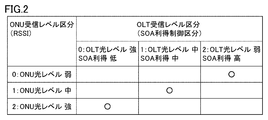
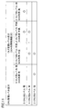
- FIG. 2 is a diagram for explaining the relationship between ONU reception level division and OLT reception level division according to the first embodiment.
- the ONU reception level is divided into three, for example, “weak”, “medium”, and “strong”.
- the number of reception level divisions may be two or more, and is not limited to three.
- the ONU reception level division and the OLT reception level division have a one-to-one relationship. Therefore, the OLT reception level is also divided into three, "weak", “medium” and “strong". Symbols indicated by circles in FIG. 2 indicate the correspondence between ONU reception level divisions and OLT reception level divisions.
- the optical signal in the ODN section 306 is attenuated more. Therefore, when the ONU reception level segment is "weak", the OLT reception level segment is "weak". On the other hand, when the ODN section 306 is short, the attenuation of the optical signal in the ODN section 306 is small. When the ONU reception level classification is "strong”, the OLT reception level classification is "strong".
- the OLT reception level and the gain control section of the receiving side SOA of the OLT are in an inverse relationship to each other.
- the OLT reception level segment is "weak”
- the OLT reception level segment is "weak”
- the gain control segment of the SOA is "strong”.
- the OLT reception level segment is "strong”
- the gain control segment of the SOA is "weak”.
- both the OLT reception level division and the gain control division of the SOA are "middle”.
- the relationship shown in FIG. 2 is held by the OLT 100 and the ONU 200 as a rule common to the OLT 100 and the ONU 200.
- specifications for each of the OLT 100 and the ONU 200 to operate according to the relationship shown in FIG. 2 may be predetermined.
- the controller (OLT control unit 130 and ONU control unit 240) of each of the OLT 100 and the ONU 200 may operate according to a program in which the relationship shown in FIG. 2 is defined, and even if information according to FIG. Good.
- the OLT 100 and the ONU 200 may receive the information according to FIG. 2 from an external device not shown.
- the ONU 200 may receive the information according to FIG. 2 from the OLT 100.
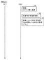
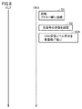
- FIG. 3 is a sequence diagram for explaining an example of processing at the time of activating the ONU according to the first embodiment.
- the ONU 200 is activated by powering on the ONU 200.
- the ONU 200 can be optically coupled to the optical fiber network (optical distribution network 301). That is, the ONU 200 is connected to the optical fiber network.
- the optical signal from the OLT 100 is distributed to a plurality of ONUs connected to the optical distribution network 301.
- the ONU 200 confirms the reception of the optical signal.
- the RSSI circuit 241 of the ONU 200 acquires a reception level (RSSI) based on the output of the optical receiver.
- the reception level segment registration / holding unit 243 registers and holds reception level segments according to the reception level.
- the reception level division is "medium".
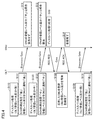
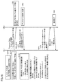
- FIG. 4 is a sequence diagram for explaining an example of a discovery process according to the first embodiment. As shown in FIG. 4, in step S110, a discovery process in which the OLT reception level classification is set to "strong" is executed.
- Step S110 includes step S111.
- the OLT 100 sets the gain of the receiving side SOA to “low”.
- the OLT 100 transmits a discovery gate (Discovery Gate) message to notify the OLT 100 of the reception level division ("strong").
- the reception level classification of the OLT 100 corresponds to the condition for registering an unregistered ONU.
- the ONU 200 receives a discovery gate message.
- the ONU 200 checks the reception level classification (notified reception level classification) included in the discovery gate message with the reception level classification registered in the ONU 200. Since the reception level segment registered in the ONU 200 is “middle”, the notified reception level segment does not correspond to the reception level segment registered in the ONU 200. Thus, the ONU 200 does not respond to the discovery gate message.
- Step S120 a discovery process in which the OLT reception level classification is set to "middle" is executed.
- Step S120 includes steps S121 and S122.
- step S121 the OLT 100 sets the gain of the receiving side SOA to "medium”.
- the OLT 100 transmits a discovery gate message to notify the reception level classification ("middle") of the OLT 100.
- step S12 the ONU 200 receives a discovery gate message.
- the ONU 200 collates the reception level classification included in the discovery gate message with the reception level classification registered in the ONU 200.
- the notified reception level classification corresponds to the reception level classification registered in the ONU 200.
- step S13 the ONU 200 responds to the discovery gate message.
- the ONU 200 transmits a registration request (REG_REQ) to the OLT 100.
- the OLT 100 registers the ONU (ONU 200) that has responded to the discovery message.
- the OLT 100 sends a registration (Register) message to the ONU 200 and notifies an LLID (Logical Link ID).
- the OLT 100 transmits a Gate message for notifying the ONU 200 of the transmission band and transmission timing.
- the ONU 200 transmits a reception response (REG_ACK) of the registration message (Register) to the OLT 100 (Step S14).
- the OLT 100 holds the reception level classification of the registered ONU.
- the ONU information management unit 131 holds information on the reception level classification of the ONU.
- Step S130 a discovery process in which the OLT reception level classification is set to "weak” is executed.
- Step S130 includes step S131.
- the OLT 100 sets the gain of the reception side SOA to "strong”.
- the OLT 100 transmits a discovery gate message to notify the OLT 100 of the reception level classification ("weak").
- the OLT 100 repeatedly executes the processes of steps S110, S120, and S130.
- the reception level classification registration / holding unit 243 determines whether the registered reception level classification corresponds to the reception level classification designated by the OLT 100.
- the ONU corresponding to the designated reception level division responds to the discovery notification from the OLT 100.
- the reception level segment registration / holding unit 243 gives transmission permission to at least one of the optical transmitters 211 to 214.
- the ONU 200 transmits a signal (registration request) in response to the discovery notification.
- the OLT 100 receives a registration request from the ONU 200.
- the ONU information management unit 131 registers the ONU 200 together with the reception level classification of the ONU 200.
- the OLT 100 registers an ONU corresponding to the reception level classification designated by the OLT 100.
- the OLT 100 can manage the reception level division of each of the plurality of registered ONUs.
- FIG. 5 is a sequence diagram for explaining an example of the normal processing according to the first embodiment.
- the OLT 100 receives a burst signal from the ONU 200.
- the OLT 100 designates to the ONU 200 the timing at which the ONU 200 transmits a burst signal by band allocation. Therefore, the OLT 100 knows the timing at which the ONU 200 transmits a burst signal.
- the OLT 100 acquires the reception level division of the ONU which will transmit a signal to be received by the OLT 100.
- step S202 the OLT 100 sets the gain of the receiving-side SOA corresponding to the ONU reception level division at the signal reception timing. As shown in FIG. 2, the ONU reception level division and the OLT reception level division are associated.
- the gain control unit 132 reads the information on the reception level classification of the ONU 200 from the ONU information management unit 131.
- the gain control unit 132 executes gain control of the receiving side SOA according to the timing of reception of the burst signal.
- step S20 the ONU 200 transmits a burst signal at the transmission timing designated by the OLT 100.
- step S203 the OLT 100 receives a burst signal.
- the receiving side SOA of the OLT 100 amplifies the burst signal with a gain corresponding to the OLT reception level division.
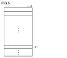
- FIG. 6 is a diagram schematically showing a part of a discovery gate message data structure according to the first mode.
- the discovery gate message 10 includes, as an item, an OLT reception level division 11 for notifying the reception level division set by the OLT 100 from the OLT 100 to an unregistered ONU.
- the position of the OLT reception level segment 11 in the discovery gate message 10 and the data length of the OLT reception level segment 11 are not limited.
- the OLT 100 can set the gain of the receiving side SOA prior to the reception of the burst signal. If the burst signal is strong, the OLT 100 can start receiving the burst signal with the gain of the receiving side SOA lowered. Thereby, it is possible to prevent strong light from entering the light receiver of the OLT 100. Therefore, the possibility of damaging the light receiving element included in the optical receiver can be reduced.
- the ONU can be registered by the discovery process while guaranteeing gain control in the reception of optical signals from unregistered ONUs.
- a high-speed level detection circuit In order to control the gain of the receiving side SOA after the burst signal strength is detected by the OLT, a high-speed level detection circuit is required. Alternatively, an optical element such as a branching element and an optical fiber for delaying signal light as shown in Patent Documents 3 and 4 is required. On the other hand, according to the first embodiment, it is possible to eliminate the need for a high-speed level detection circuit or an additional optical component. Therefore, cost reduction or miniaturization of the OLT 100 can be achieved. Furthermore, the problem of insertion loss due to the addition of optical components can also be avoided.
- FIG. 7 is a diagram showing an example of the configuration of the optical communication system according to the second embodiment. Compared with the first embodiment, the configuration of the ONU 200 is different in the second embodiment. As shown in FIG. 7, in the ONU 200, the RSSI circuit 241 is omitted. An SOA gain classification identifying unit 244 is provided in the ONU 200 in place of the reception level classification registration / holding unit 243.
- the SOA gain category identification unit 244 holds the history regarding the registration process.
- the SOA gain category identification unit 244 associates the reception level category of the ONU 200 with the result (success or failure) of responding to the discovery.
- the ONU 200 changes the ONU reception segment and tries registration processing.
- the reception level classification of the ONU 200 is “strong”, “medium”, “weak”.
- the relation between the ONU reception level division and the OLT reception level division according to the second embodiment can be made equal to the relation of the first embodiment (see FIG. 2).
- FIG. 8 is a sequence diagram for explaining an example of processing at the time of activating the ONU according to the second embodiment.
- the processes of steps S1 and S2 shown in FIG. 8 are the same as the corresponding processes shown in FIG.
- the ONU 200 performs initial setting of ONU reception level division.
- the initial setting of the reception division of the ONU 200 is “strong”.
- the SOA gain category identification unit 244 temporarily registers “strong” as the ONU reception level category.
- FIG. 9 is a sequence diagram for explaining an example of discovery processing (failure in registration of ONU) according to the second embodiment.
- step S110 a discovery process in which the OLT reception level classification is set to "strong” is executed.
- step S111 the OLT 100 sets the gain of the receiving side SOA to “low”.
- the OLT 100 transmits a discovery gate message to notify the OLT 100 of the reception level classification ("strong").
- step S31 the unregistered ONU (ONU 200) receives the discovery gate message and receives the reception level classification (notified reception level classification) included in the discovery gate message with the reception level classification temporarily registered in the ONU 200. Match. Since the reception level segment registered in the ONU 200 is “strong”, the notified reception level segment corresponds to the registered reception level segment.
- step S32 the ONU 200 transmits a registration request (REG_REQ) to the OLT 100 in response to the discovery gate message.
- the OLT 100 receives the response from the ONU 200 in step S112. If the actual reception level is "medium”, the actual reception level does not match the ONU's reception level division ("high"). In this case, the OLT 100 can not receive the optical signal from the ONU 200 with an appropriate SOA gain, and fails to receive (step S113).
- step S120 a discovery process in which the OLT reception level classification is set to "middle" is executed.
- step S121 the OLT 100 sets the gain of the receiving side SOA to "medium”.
- the OLT 100 transmits a discovery gate message to notify the reception level classification ("middle") of the OLT 100.
- step S33 the ONU 200 receives a discovery gate message.
- the notified reception level classification does not correspond to the reception level classification registered in the ONU 200.
- the ONU 200 does not respond to the discovery gate message.
- step S130 a discovery process in which the OLT reception level classification is set to "weak” is executed.
- step S131 the OLT 100 sets the gain of the receiving side SOA to “high”.
- the OLT 100 transmits a discovery gate message to notify the OLT 100 of the reception level classification ("weak").
- step S34 the ONU 200 receives a discovery gate message.
- the notified reception level classification does not correspond to the reception level classification registered in the ONU 200.
- the ONU 200 does not respond to the discovery gate message.
- the ONU 200 determines that the discovery process has failed.
- the OLT 100 repeats the series of processes of S110 to S130. Since the provisionally registered reception level classification of the unregistered ONU 200 is "strong", the ONU 200 determines that the discovery processing has failed each time the processing of S110 to S130 is repeated.
- the OLT 100 does not register the ONU 200. That is, the registration of the ONU 200 in the OLT 100 fails (step S140).
- the ONU 200 changes the reception level division by one stage due to the failure of the registration process.
- the reception level classification is changed from "strong" to "medium” (step S40).
- a plurality of ONUs not registered may respond simultaneously.
- the response messages from the plurality of ONUs collide, and the OLT 100 can not receive the response message. Therefore, even if the discovery process fails, the discovery process is repeated with the same reception level division.
- the ONU 200 receives the discovery gate message and responds after a random delay time. Therefore, message collision can be avoided by repeating the discovery process.
- FIG. 10 is a sequence diagram for explaining an example of the discovery process (the registration of the ONU is successful) according to the second embodiment.
- step S110 a discovery process in which the OLT reception level classification is set to "strong" is executed.
- step S111 the OLT 100 sets the gain of the receiving side SOA to “low”.
- the OLT 100 transmits a discovery gate message to notify the OLT 100 of the reception level classification ("strong").
- step S51 the ONU 200 receives the discovery gate message, and collates the reception level classification (notified reception level classification) included in the discovery gate message with the reception level classification registered in the ONU 200. Since the reception level segment registered in the ONU 200 is “middle”, the notified reception level segment does not correspond to the reception level segment registered in the ONU 200. Thus, the ONU 200 does not respond to the discovery gate message.
- step S120 a discovery process in which the OLT reception level classification is set to "middle" is executed.
- step S121 the OLT 100 sets the gain of the receiving side SOA to "medium”.
- the OLT 100 transmits a discovery gate message to notify the reception level classification ("middle") of the OLT 100.
- step S52 the ONU 200 receives the discovery gate message, and collates the reception level segment included in the discovery gate message with the reception level segment registered in the ONU 200.
- the reception level classification notified by the discovery gate message corresponds to the reception level classification registered in the ONU 200.
- step S53 the ONU 200 responds to the discovery gate message.
- step S122 the OLT 100 receives a response from the ONU 200. Since the actual reception level is "medium", it corresponds to the ONU's reception level classification. In this case, since the OLT 100 can receive the optical signal from the ONU 200 with an appropriate SOA gain, the OLT 100 successfully receives (step S122).
- the OLT 100 registers the ONU 200 (step S123). The process for registering ONU 200 is the same as the process described above, and therefore the description will not be repeated. The registration of the ONU 200 is completed (step S54).
- the ONU 200 determines that the current reception classification is inappropriate. In this case, the ONU 200 changes the reception level classification from "strong” to “medium” or “medium” to “weak” and tries registration processing again.
- the change of the reception level division in the ONU 200 is based on the information of the reception level division stored in the SOA gain classification identification unit 244.
- Each of the OLT 100 and the ONU 200 establishes the reception level classification at the stage where the registration process is successful.
- the SOA gain category identification unit 244 can store the determined reception level category.
- the configuration of the ONU can be simplified.
- the ONU always tries to respond to the discovery notification in order from the lowest SOA gain.
- the OLT 100 sets the reception level classification specified in the discovery process in which the response is successful as the reception level classification of the unregistered ONU. Therefore, the possibility that the receiver of the OLT 100 is damaged by the light from the ONU can be reduced.
- the order of setting and changing the SOA gain division of the OLT and the reception level division of the ONU can be held by the OLT 100 and the ONU 200 as a common rule of the OLT 100 and the ONU 200.
- Embodiment 3 The configuration of the optical communication system according to the third embodiment is basically the same as the configuration of the optical communication system according to the first embodiment (see FIG. 1).
- a correspondence table with the OLT reception classification for which the registration process is attempted is used.
- This correspondence table is stored, for example, as mapping information in the inside of the OLT 100, for example, in the memory of the optical transceiver.
- the OLT 100 notifies the ONU of mapping information. Therefore, information on the characteristics of the SOA of the OLT 100 can be shared between the OLT 100 and the ONU.
- the reception level classification can be set optimally according to the characteristics of the SOA of the OLT 100. For example, gain control can be realized in consideration of individual differences in amplifier characteristics.
- FIG. 11 is a diagram schematically showing an example of mapping information applicable to the third embodiment. As shown in FIG. 11, a plurality of (for example, two) OLT reception level partitions are associated with one ONU reception level partition. The third embodiment is different from the first and second embodiments in this point.
- the OLT reception level segment candidates overlap.
- the OLT reception level divisions “strong” and “middle strength” correspond to “strong” in the ONU reception level division
- the OLT reception level division “middle strong” in the “middle” of the ONU reception level division And “medium weak” correspond. Therefore, the OLT reception level sections “medium-strong” are overlapping candidates.
- the detection of the RSSI in the ONU 200 may include an error. Therefore, there is a possibility that the ONU reception level division and the OLT reception level division do not match exactly.
- By associating a plurality of (for example, two) OLT reception level segments with one ONU reception level segment it is possible to associate a more suitable OLT reception level segment with each ONU reception level segment.
- the RSSI circuit 241 of the ONU 200 monitors the reception level of the ONU 200.
- the ONU reception level is divided into, for example, “strong”, “medium”, and “weak”.
- the reception level segment registration / holding unit 243 registers the ONU reception level segment monitored by the RSSI circuit 241.
- a plurality of SOA gains are associated with one ONU reception level section.
- the ONU attempts discovery response from the lower SOA gain.
- FIG. 12 is a diagram schematically showing a part of the data structure of a discovery gate message according to the third mode.
- the discovery gate message 10 includes, as items, an OLT reception level segment 11 and mapping information 12.
- the OLT 100 shares information (mapping information) on the characteristics of the SOA of the OLT 100 with the ONU by transmitting a discovery gate message.
- FIG. 13 is a first sequence diagram illustrating an example of a discovery process according to the third embodiment.
- FIG. 14 is a second sequence diagram for explaining a process following the process shown in FIG.
- step S81 the unregistered ONU registers ONU reception level classification based on the monitoring result of the RSSI.
- ONU reception level division 1 (“medium”) is registered.
- step S110 a discovery process in which the OLT reception level classification is set to "strong" is performed.
- step S111 the OLT 100 sets the gain of the receiving side SOA to “low”.
- step S82 the ONU 200 receives the discovery gate message, and collates the reception level classification (notified reception level classification) included in the discovery gate message with the reception level classification registered in the ONU 200. Since the reception level segment registered in the ONU 200 is “middle”, the notified reception level segment does not correspond to the reception level segment registered in the ONU 200. Thus, the ONU 200 does not respond to the discovery gate message.
- Step S150 a discovery process in which the OLT reception level classification is set to "medium strong” is executed.
- Step S150 includes steps S151 and S152.
- step S151 the OLT 100 sets the gain of the receiving side SOA to “medium to low”.
- the ONU 200 receives a discovery gate message.
- the notified reception level classification corresponds to the reception level classification registered in the ONU 200. Therefore, in step S84, the ONU 200 transmits a registration request (REG_REQ) message to respond to the discovery process.
- the registration request message also includes ONU reception level segmentation. In the above case, the ONU reception level segment is "1" (ie, "medium").
- step S152 the OLT 100 successfully receives the registration request message.
- the OLT 100 evaluates the propriety of the registration of the ONU 200 without registering the ONU 200 immediately. As one embodiment of the evaluation, the OLT 100 confirms the correction frequency in the error correction process for the message from the ONU 200. Furthermore, the OLT 100 determines whether the correction frequency is equal to or less than a threshold. If the correction frequency is greater than the threshold, the OLT 100 suspends the registration of the ONU 200. The OLT 100 records the correction frequency.
- the OLT 100 sets the OLT reception level division in the division in the following order. In this case, the OLT reception level classification is changed from "0" ("strong") to "1" ("medium-strong”). Furthermore, the OLT 100 transmits a gate message to the ONU.
- the gated message includes LLID, ONU reception level division ("1" ("middle” in this case), and OLT reception level division ("2" in this case). Further, gated messages are pending registration. To the ONU 200.
- step S85 the ONU 200 changes the response OLT reception level division to “2” (“medium weak”).
- the ONU 200 transmits a response message (REG_ACK) to the OLT.
- the response message contains LLID and registration pending information.
- step S160 a discovery process is performed in which the OLT reception level classification is set to "medium weak".
- step S160 includes steps S161, S162, and S163.
- step S161 the OLT 100 sets the gain of the receiving side SOA to “middle high”.
- the ONU 200 receives the discovery gate message, and collates the reception level classification (notified reception level classification) included in the discovery gate message with the reception level classification registered in the ONU 200. Since the reception level segment registered in the ONU 200 is 2 (“medium weak”), the notified reception level segment corresponds to the reception level segment registered in the ONU. Thus, the ONU sends a registration request (REG_REQ) message to respond to the discovery process.
- the ONU 100 receives notification of ONU reception level division “2” (that is, “medium weak”) by the registration request message.
- step S162 the OLT 100 successfully receives the registration request message.
- the OLT 100 evaluates whether or not the ONU 200 can be registered.
- the OLT 100 confirms the correction frequency in the error correction process. If the correction frequency is smaller than the threshold or if the recording of the correction frequency of all the target OLT reception level sections is completed, the optimum section is determined (step S163).
- the OLT 100 transmits a gate message to the ONU 200.
- the ONU reception level division is set to “1” (“middle”), and the OLT reception level division is set to “2” (“medium weakness”).
- the gate message further includes information for notifying the ONU 200 of the completion of registration.
- the ONU 200 receives the gated message, and transmits a response message (REG_ACK) including the information of LLID and registration completion to the OLT 100 (step S87).
- REG_ACK response message
- the OLT reception level division “2” (“medium weak”) and the ONU reception level division “1” are registered.
- the OLT reception level division is changed in the order of “1” and “2”, and the OLT reception level division “2” is decided as the optimum division.
- the OLT reception level division is changed back to “1” after being changed from “1” to “2”.
- the OLT reception level classification "1" is decided as the optimum classification.
- FIG. 15 is a first sequence diagram for explaining another example of the discovery process according to the third embodiment.
- FIG. 16 is a second sequence diagram for explaining the process following the process shown in FIG.
- the processes of steps S160, S161, and S162 (OLT 100 side) and the process of step S86 (ONU 200 side) shown in FIG. 15 are the same as the processes shown in FIG. In step S162, the propriety of registration of the ONU 200 is evaluated.
- the division evaluation completion flag of the ONU 200 is a flag for distinguishing it from the processing of the first division evaluation, and is notified to the OLT 100.
- the ONU 200 If the OLT reception fails a plurality of times (for example, 5 times) consecutively, the ONU 200 returns the OLT reception level division to “1” (“medium strength”) (step S88). In order to distinguish it from the process of the first segment evaluation, the ONU 200 notifies the OLT 100 of a segment evaluation completion flag.
- step S170 a discovery process in which the OLT reception level classification is set to "medium-strong" is performed.
- Step S170 includes steps S171 and S172.
- step S171 the OLT 100 sets the gain of the reception side SOA to “medium to low”.
- step S91 the ONU 200 receives a discovery gate message.
- the notified reception level classification corresponds to the reception level classification registered in the ONU 200. Therefore, in step S92, the ONU 200 transmits a registration request (REG_REQ) message to respond to the discovery process.
- REG_REQ registration request
- step S172 the OLT 100 successfully receives the registration request message.
- the OLT 100 evaluates whether or not the ONU 200 can be registered.
- the OLT 100 transmits a gate message to the ONU 200.
- the gated message in this case includes ONU reception level segment “1” (“medium”) and OLT reception level segment “1” (“medium strong”). Furthermore, the gate message notifies the ONU that the registration is completed.
- the ONU 200 transmits a response message (REG_ACK) including LLID and registration pending information to the OLT 100 (step S93).
- REG_ACK response message
- the OLT reception level division “1” (“medium strength”) and the ONU reception level division “1” are registered, and the registration is completed.
- Reception may fail at the OLT 100 even though the OLT reception level division is returned to the division that the OLT has successfully received earlier. In such a case, processing continues to return the division within the remaining target divisions.
- the ONU 200 responds to the discovery including the corresponding OLT reception level division based on the information notified from the OLT 100 (the mapping information illustrated in FIG. 11). As in the second embodiment, the ONU 200 evaluates the OLT reception level divisions in the order of “strong”, “medium-strong”, “medium-weak”, and “weak”. That is, the initial setting of the ONU reception level division is "strong". Since the ONU tries to respond to the discovery notification in order from the lowest SOA gain, the possibility that the receiver of the OLT 100 is damaged by light from the ONU can be reduced.
- FIG. 17 is a diagram showing another example of the mapping information according to the third embodiment. Compared to the mapping information shown in FIG. 17, the ONU reception level is divided into more divisions. For example, mapping information can be set according to the characteristics of the SOA. In the example of FIG. 17, the ONU reception level has eight sections from “0” to “7”. Each of ONU reception level segments “0” to “4” is associated with OLT reception level segment “3”.
- FIG. 18 is a diagram showing an example of the configuration of an optical communication system according to a fourth embodiment.
- the configuration of the OLT 100 is different in the fourth embodiment compared to the first embodiment.
- a transmission power monitor unit 133 is added in the OLT 100.
- the transmission power monitor unit 133 is a circuit that monitors the intensity (transmission signal intensity) of the optical signal transmitted from the OLT 100.
- the configuration of the other parts of the OLT 100 is the same as the configuration of the corresponding parts shown in FIG.
- the received power of the OLT 100 is represented as OLT_Rx_Pow
- the received power of the ONU 200 is represented as ONU_Rx_Pow.
- the value of ONU_Rx_Pow is detected by the RSSI circuit 241.
- the reception level division of the ONU 200 is set based on the reception power (ONU_Rx_Pow) of the ONU 200.
- the reception level division of the OLT 100 is estimated based on the reception level division of the ONU 200, and the gain of the SOA is controlled based on the estimated reception level division.
- the OLT 100 can directly grasp the reception level of the ONU 200 from the reception power of the ONU 200.
- the reception level division of the ONU 200 is set based on the line loss of the optical fiber.
- the transmission power of the OLT 100 is represented by OLT_Tx_Pow
- the transmission power of the ONU 200 is represented by ONU_Tx_Pow
- the line loss between the OLT 100 and the OLT 200 is represented by Loss, the following relationship is established. Note that, depending on the upstream wavelength and the downstream wavelength, the upstream line loss and the downstream line loss may be different. However, in order to facilitate understanding, in the following description, it is assumed that the line loss is the same between the upstream and the downstream.
- OLT_Tx_Pow-ONU_Rx_Pow OLT_Rx_Pow-Loss (2)
- Expression (1) represents that the line loss Loss corresponds to the difference between the transmission power of the OLT 100 and the reception power of the ONU 200.
- Expression (2) represents that the reception power of the OLT 100 corresponds to the difference between the transmission power of the ONU 200 and the line loss.
- OLT_Tx_Pow is almost constant.
- OLT_Rx_Pow ONU_Rx_Pow + (ONU_Tx_Pow-OLT_Tx_Pow) (3)
- (ONU_Tx_Pow-OLT_Tx_Pow) is treated as a constant A.
- the RSSI circuit 241 of the ONU 200 measures ONU_Rx_Pow
- the transmission power monitor unit 133 of the OLT 100 measures OLT_Tx_Pow. According to the fourth embodiment, the accuracy of estimation of OLT_Rx_Pow can be enhanced.
- ONU_Tx_Pow may be a known value. Alternatively, as shown in FIG. 19, ONU 200 may measure ONU_Tx_Pow.
- the ONU 200 includes a transmission power monitor unit 245 for measuring the transmission power of the ONU 200.
- the ONU 200 transmits an optical signal by burst transmission. For this reason, the transmission power monitor unit 245 can not be used to measure ONU_Tx_Pow until the ONU 200 emits light once.
- the following method is used. First, a specification value is adopted as an initial value of ONU_Tx_Pow. After the light emission of the ONU 200, the measurement value of the transmission power monitor unit 245 is acquired. When the difference between the measured value and the initial value is large (the threshold is exceeded), the value of ONU_Tx_Pow is switched from the initial value to the value measured by the transmission power monitoring unit 245. When the difference between the measured value and the initial value is small (less than the threshold), the initial value can be used as it is.
- FIG. 20 is a sequence diagram for explaining an example of processing at the time of activating the ONU according to the fourth embodiment.
- the sequence shown in FIG. 20 is basically the same as the sequence shown in FIG.
- the sequence shown in FIG. 20 differs from the sequence shown in FIG. 3 in the following points.
- step S1A the OLT 100 acquires transmission power monitor information, that is, the value of OLT_Tx_Pow. As shown in FIG. 18 and FIG. 19, the transmission power monitor unit 133 monitors the transmission power of the OLT 100 to acquire transmission power monitor information.
- the ONU 200 acquires a reception level (RSSI) in step S3.
- the RSSI circuit 241 of the ONU 200 obtains information of the received power of the ONU 200, that is, the value of ONU_Rx_Pow, based on the output of the optical receiver.
- the OLT 100 includes the transmission power monitor information of the OLT 100 in the discovery gate message, and transmits the discovery gate message.
- the ONU 200 receives a discovery gate message.
- step S3A the ONU 200 applies the value of OLT_Tx_Pow included in the discovery gate message and the value of ONU_Rx_Pow acquired by the RSSI circuit 241 to the equation (1) to calculate the line loss (Loss).
- the ONU 200 determines the division of the line loss based on the calculated value, and registers the division inside the ONU 200.
- the reception level classification registration / holding unit 243 holds the classification of line loss as a reception level classification.
- FIG. 21 is a sequence diagram for explaining an example of a discovery process according to the fourth embodiment.
- the sequence shown in FIG. 21 is basically the same as the sequence shown in FIG. 4, but the term "reception level division” is replaced with "line loss division”.
- step S110 a discovery process is performed in which the line loss classification on the OLT 100 side is set to "small".
- the line loss is small, the power of the optical signal input to the OLT 100 may be large. Therefore, in step S111, the OLT 100 sets the gain of the receiving side SOA to "low".
- the OLT 100 transmits a discovery gate message to notify of the line loss classification ("small") of the OLT 100.
- the ONU 200 receives a discovery gate message.
- the ONU 200 collates the line loss category (notified reception level category) included in the discovery gate message with the line loss category registered in the ONU 200. Since the line loss category registered in the ONU 200 is “medium”, the notified line loss category does not correspond to the line loss category registered in the ONU 200. Thus, the ONU 200 does not respond to the discovery gate message.
- step S120 a discovery process in which the OLT line loss category is set to "middle" is performed.
- step S121 the OLT 100 sets the gain of the receiving side SOA to "medium”.
- the OLT 100 transmits a discovery gate message to notify the line loss classification ("middle") of the OLT 100.
- step S12 the ONU 200 receives a discovery gate message.
- the ONU 200 collates the line loss category included in the discovery gate message with the line loss category registered in the ONU 200.
- the notified line loss class corresponds to the line loss class registered in the ONU 200.
- step S13 the ONU 200 responds to the discovery gate message.
- the subsequent process for registering the ONU 200 is the same as the process shown in FIG.
- step S122 the ONU information management unit 131 of the OLT 100 registers information on the line loss classification of the ONU (ONU 200) that has responded to the discovery message.
- step S130 a discovery process in which the OLT line loss classification is set to "large” is performed.
- step S131 the OLT 100 sets the gain of the reception side SOA to "strong”.
- the OLT 100 transmits a discovery gate message to notify the line loss classification ("high") of the OLT 100.
- the information required to determine the reception level division of the ONU is not limited to specific information.
- the information that directly indicates the strength of the optical signal received by the ONU may be used, and in any of the information that can estimate the strength of the optical signal received by the ONU, in the embodiment of the present invention, the reception level division of the ONU is used. It can be decided. Thereby, in the OLT, not only can gain control in receiving an optical signal from the ONU can be guaranteed, but also the ONU can be registered.
- the reception level classification may be set based on the line loss.
- “line loss division” can be used as “reception level division” in each of the first to third embodiments.
- the segment “strong” in the “reception level segment” is replaced with the segment “small” in the “line loss segment” and the segment “weak” in the “reception level segment” is the segment “line loss segment” Replaced with “large”.
- the Fifth Preferred Embodiment The optical communication system according to the fifth embodiment can have the same configuration as the configuration shown in any of FIG. 1, FIG. 7, FIG. 18 and FIG.
- the reception level division of the ONU is defined by the range of the reception level (RSSI) of the ONU.
- RSSI reception level
- the receive level segment of the ONU has a maximum value of receive level and a minimum value of receive level.
- FIG. 22 is a diagram showing setting of reception level classification of ONU according to the fifth embodiment. As shown in FIG. 22, the maximum value and the minimum value are set within the range of the reception level of the ONU. The maximum value of the reception level and the minimum value of the reception level set the reception level classification to be subjected to the discovery process.
- the maximum value and the minimum value of the ONU reception level division are both variable.
- the number of reception level sections is one, and the maximum value and the minimum value of the reception level sections are variable.
- FIG. 22 shows an example in which the maximum value and the minimum value are simultaneously changed. However, only one of the maximum value and the minimum value may be changed.
- the range of reception levels for one reception level division can be set arbitrarily.
- the reception level classification of the ONU is set by the OLT 100.
- the OLT 100 includes the maximum value and the minimum value of the reception level division in the discovery gate message. Therefore, the maximum value and the minimum value of the reception level division are notified from the OLT 100 to the ONU 200 by the discovery gate message.
- FIG. 23 is a schematic diagram showing an example of a discovery message according to the fifth embodiment.
- the discovery gate message 10 can include, as items, a segment maximum value 11A and a segment minimum value 11B.
- the section maximum value 11A and the section minimum value 11B correspond to the OLT reception level section 11 according to the first embodiment.
- the ONU 200 When the ONU 200 is activated, the ONU 200 monitors its own reception level. At the time of execution of a discovery process, the ONU 200 receives a discovery gate message from the OLT 100. The ONU 200 compares the segment maximum value 11A and the segment minimum value 11B notified by the discovery gate message with the reception level of the ONU 200. When the reception level of the ONU 200 is between the segment maximum value 11A and the segment minimum value 11B, the ONU 200 responds to the discovery gate message. The OLT 100 registers the ONU 200 in response to the response from the ONU 200. Therefore, as in the first embodiment, in the discovery process, the OLT 100 can register the home-side apparatus corresponding to the reception level classification.
- FIG. 24 is a sequence diagram for explaining an example of processing at the time of activation of an ONU according to the fifth embodiment.
- the ONU 200 is activated by powering on the ONU 200.
- the ONU 200 is connected to the optical fiber network.
- the ONU 200 confirms the reception of the optical signal.
- the ONU 200 measures the reception level.
- the RSSI circuit 241 acquires a reception level (RSSI) based on the output of the optical receiver.
- the reception level classification registration / holding unit 243 holds the value (measurement value) of the reception level.
- FIG. 25 is a sequence diagram for explaining an example of a discovery process according to the fifth embodiment.
- the sequence shown in FIG. 25 is basically the same as the sequence shown in FIG. In the fifth embodiment, the range of reception levels is changed by the OLT 100.
- the reception level of the ONU 200 is assumed to be a level corresponding to the “medium” reception level division in the first embodiment.
- step S110 a range of OLT reception level classification is set.
- the OLT reception level division corresponds to "strong" in the first embodiment.
- step S111 the OLT 100 sets the gain of the receiving side SOA to “low”.
- the OLT 100 notifies the ONU 200 of the reception level division by the discovery gate.
- the discovery gate message includes the segment maximum value 11A and the segment minimum value 11B.
- step S11 the ONU 200 collates the measured value of the reception level (see FIG. 24) of the ONU 200 with the reception level classification notified from the OLT 100.
- the reception level of the ONU 200 is out of the range corresponding to the reception level classification, the reception level of the ONU 200 does not correspond to the reception level classification notified by the OLT 100. Thus, ONU 200 does not respond to discovery gate messages.
- step S120 the OLT 100 sets the range of reception level division.
- the reception level classification set in step S120 corresponds to the reception level classification "medium" in the first embodiment.
- step S121 the OLT 100 sets the gain of the receiving side SOA to "medium”. The OLT 100 notifies the ONU 200 of the reception level division by the discovery gate.
- step S12 the ONU 200 receives a discovery gate message.
- the ONU 200 collates the reception level (see FIG. 24) of the ONU 200 with the reception level classification notified from the OLT 100. Since the reception level of the ONU 200 is included in the range corresponding to the reception level classification, the reception level of the ONU 200 corresponds to the reception level classification notified by the OLT 100. Thus, in step S13, the ONU 200 responds to the discovery gate message.
- step S13 the ONU 200 transmits a registration request (REG_REQ) to the OLT 100.
- step S122 the OLT 100 registers the ONU (ONU 200) that has responded to the discovery message.
- the OLT 100 transmits a Gate message for notifying the ONU 200 of the transmission band and transmission timing.
- step S14 the ONU 200 transmits, to the OLT 100, a reception response (REG_ACK) of a registration message (Register). This completes the registration.
- REG_ACK reception response
- step S130 the OLT 100 sets the range of reception level division.
- the reception level classification set in step S130 corresponds to the reception level classification "weak" in the first embodiment.
- step S131 the OLT 100 sets the gain of the reception side SOA to "strong”. The OLT 100 notifies the ONU 200 of the reception level division by the discovery gate message.
- the method for determining the maximum value and the minimum value of the reception level division is not particularly limited.
- the maximum value and the minimum value may be predetermined values.
- the reception level division can be set based on the line loss of the optical fiber.
- the segment maximum value and the segment minimum value can be set based on the line loss of the optical fiber.
- the difference between the transmission power of the OLT 100 and the reception power of the ONU 200 may be the line loss of the optical fiber.
- Embodiment 6 In the sixth embodiment, a plurality of (for example, two) reception level sections are associated with the ONU reception level.
- the ONU attempts discovery response from the lower one of the SOA gains, that is, the higher one of the reception level divisions.
- FIG. 26 is a diagram showing setting of reception level division of ONU according to the sixth embodiment. As in the fifth embodiment, the maximum value of the reception level and the minimum value of the reception level are set within the range of the reception level of the ONU. This sets the reception level classification.
- FIG. 26 illustrates the first section and the second section.
- the OLT 100 changes the reception level division from the first division to the second division.
- the reception level classification is set to the first classification
- the reception level classification is set to the second classification.
- the range of the first section and the range of the second section partially overlap each other.
- FIG. 27 is a schematic diagram for explaining a discovery process according to the sixth embodiment.
- the reception level divisions are repeatedly set in the order of the first division, the second division, and the third division.
- the reception level division may be sequentially switched to the first division, the second division, and the third division within one cycle.
- the maximum value of the first section is greater than the maximum value of the second section.
- the maximum value of the second section is greater than the maximum value of the third section.
- the reception level division is set so that the reception level changes from high to low. In this case, the SOA gain switches from low to high.
- a portion of the first section and a portion of the second section overlap each other.
- part of the second section and part of the third section overlap each other.
- the maximum value of the second segment is greater than the minimum value of the first segment.
- the maximum value of the third section is greater than the minimum value of the second section.
- the minimum value of the first section is greater than the maximum value of the third section. Therefore, the first division and the third division do not overlap.
- FIG. 28 is a diagram for explaining the determination of the reception level division of the ONU by the OLT.
- “Yes” means that the ONU reception level corresponds to the division set by the OLT.
- “No” means that the ONU reception level does not fall under the category.
- the reception level section is set to the first section.
- the ONU reception level corresponds to the first and second divisions, but not to the third division, the ONU reception level is within the overlapping range of the first and second divisions.
- the ONU 200 responds to the OLT 100 in the discovery process when the segment with the higher reception level is set. In this case, the ONU 200 responds to the OLT 100 in the discovery process when the first segment is set. Therefore, the reception level division is set to the first division.
- the reception level division is set to the second division.
- the ONU reception level corresponds to the second and third divisions, but the ONU reception level does not correspond to the first division, the ONU reception level is within the overlapping range of the second and third divisions.
- the ONU 200 responds to the OLT 100 in the discovery process when the segment with the higher reception level is set. Therefore, the reception level division is set to the second division.
- the reception level division is set to the third division.
- the determination as to whether the ONU reception level falls under each of the first to third divisions can be performed within one period described above.
- the reception level division is determined by the maximum value and the minimum value of the reception level. Therefore, instead of setting the reception level multiple times, the maximum value and the minimum value may be set multiple times. For example, instead of the first to third divisions, three sets of maximum value and minimum value can be set. The first set, the second set and the third set correspond to the first to third sections, respectively. Thus, the maximum value of the second set may be larger than the minimum value of the first set, and the maximum value of the third set may be larger than the minimum value of the second set.
- the reception level is monitored at the ONU, it is possible that errors or fluctuations in the reception level may occur. According to the sixth embodiment, even in such a case, the possibility that the ONU is not registered can be reduced.
- the reception level segments may be notified to the ONU in descending order of the maximum value.
- damage to the OLT 100 damage to the SOA or APD can be reduced.
- the OLT registers the level of the gain of the receiving unit of the OLT in association with each ONU.
- the ONU determines whether to respond to the discovery message independently of the ONU's own reception level classification.
- the ONU may measure its own reception level.
- measurement of the reception level is not essential for the discovery process. It is also conceivable that, due to the occurrence of a defect in the receiving function on the ONU side, the accuracy of the reception level of the optical signal decreases in the ONU, or the receiving function becomes unusable. Such problems can be solved since the reception level measured by the ONU is not essential for the discovery process.
- FIG. 29 is a diagram showing the relationship between the discovery process and the gain of the SOA.
- the OLT 100 opens a time window (discovery window 20) for discovery processing at a constant cycle.
- the OLT 100 switches the gain of the SOA each time the discovery window 20 is opened.
- the gain of SOA changes from low to high.
- FIG. 29 shows an example in which the gain of the SOA has three levels (small, medium and large).
- the OLT reception level classification changes in the order of strong, medium, and weak. Therefore, the gain level of the SOA changes repeatedly as small, medium, large, small, medium, and so on.
- An unregistered ONU can transmit a registration request (Register request) each time a discovery gate message is transmitted from the OLT 100. However, the ONU does not recognize its own reception level.
- the power of the optical signal that the OLT 100 receives from that ONU is large.
- the level of gain of the SOA is high, and the ONU responding to the discovery gate may damage the optical receiver of the OLT 100.
- FIG. 30 is a sequence diagram for explaining an example of a discovery process according to the seventh embodiment.
- the OLT 100 includes an identification number i corresponding to the gain level of the SOA in the discovery gate message.
- the identification number i may be a number corresponding to the reception level classification of the OLT.
- the ONU can send a registration request for all discovery gate messages.
- the OLT 100 can confirm the response from the ONU 200. Therefore, the OLT 100 registers the ONU 200 and sets a gain division (gain level LV1 (small)) for the ONU 200.
- the OLT 100 registers, for each ONU, an identification number i when the Register request is normally received.
- the OLT 100 associates each ONU with the identification number i and registers each ONU. That is, the OLT 100 registers the gain division of the SOA for each registered ONU. After the ONU is registered in the OLT 100, the OLT 100 sets a gain according to the value of the registered identification number i in communication with the ONU.
- the seventh embodiment it is possible to avoid receiving an optical signal with large transmission power from the ONU in a state where the SOA gain in the OLT 100 is high. Therefore, damage to the OLT 100 receiver can be prevented. Furthermore, since the OLT 100 can set an appropriate SOA gain for each ONU, communication with the ONU can be stabilized. Thus, communication quality can be secured.
- Embodiment 8 As in the seventh embodiment, in the eighth embodiment, the OLT 100 requests responses from all unregistered ONUs in the discovery section without relying on measurement of the reception level on the ONU side.
- the OLT 100 registers the level of the gain of the receiving unit of the OLT 100 in association with each ONU.
- the OLT 100 registers an ONU, there is a possibility that an appropriate SOA gain can not be set for the ONU due to the collision of burst signals among a plurality of ONUs or the timing of activation of the ONU in the discovery section. .
- the eighth embodiment can solve such a problem.
- the ONU may measure its own reception level. However, measurement of reception level is not essential for the discovery process. It is also conceivable that, due to the occurrence of a defect in the receiving function on the ONU side, the accuracy of the reception level of the optical signal decreases in the ONU, or the receiving function becomes unusable. Such problems can be solved since the reception level measured by the ONU is not essential for the discovery process.
- the change of the SOA gain is repeated in the discovery section.
- the OLT 100 sets the SOA gain associated with each ONU such that the SOA gain associated with each ONU is a lower gain. This can reduce the possibility of damage to the optical receiver in the OLT 100.
- FIG. 31 is a sequence diagram for explaining an example of a discovery process according to the eighth embodiment.
- the sequence shown in FIG. 31 is the same as the sequence shown in FIG. 30 in that the gain level (gain division) of the SOA changes in the order of small, medium and large.
- the unregistered ONU becomes Ready at the timing immediately before the level of the SOA gain becomes LV3 (large). Thereafter, the ONU sends a registration request in response to the discovery gate message. First, the ONU sends a registration request for a discovery gate message whose identification number i is set to 3. If the OLT can receive the registration request, the OLT 100 temporarily registers LV 3 as an SOA gain for this ONU.
- the OLT 100 determines whether the lower SOA gain level LV1 or LV2 can be registered as the SOA gain level for this ONU.
- the ONU transmits a registration request in response to a discovery gate message whose identification number i is set to 1. If the OLT 100 can receive this registration request, the OLT 100 updates the setting of the SOA gain for this ONU. Therefore, LV1 which is a lower gain level than LV3 is formally registered as the SOA gain level for this ONU.
- the ONU transmits a registration request in response to a discovery gate message whose identification number i is 1. If the OLT 100 can not obtain the registration request because the transmission power from the ONU is low, the SOA gain level is maintained at the temporarily registered LV3. Next, the ONU transmits a registration request in response to the discovery gate message whose identification number i is 2. If the OLT 100 can obtain the registration request, the OLT 100 registers LV2 as the SOA gain level for this ONU. Therefore, the level of main registration is LV2.
- the OLT 100 main-registers LV3 as the SOA gain level for this ONU.
- the OLT 100 performs the same process even if there is an ONU that has been registered but can confirm the response with a gain lower than the registered gain. This causes the OLT 100 to associate lower SOA gains to the ONUs.
- the gain level provisionally registered is LV1
- the level of main registration is also set as LV1.
- the gain division is set to the lowest level division, and Make settings again.
- FIG. 32 is a sequence diagram for explaining another example of the discovery process according to the eighth embodiment.
- an unregistered ONU becomes Ready at a timing immediately before the level of the SOA gain becomes LV2 (middle).
- the ONU sends a registration request in response to the discovery gate message.
- the optical power amplified by the SOA of the OLT 100 exceeds the breakdown level of the optical receiver. Even for light of high power, damage to the light receiving element can be prevented if the time input to the light receiver is very short.
- the OLT 100 next sets the level of the SOA gain to LV3. However, when strong light enters the optical receiver, in this case, the OLT 100 sets the level of the SOA gain to the lowest level (LV1) and performs gain setting again. For example, the OLT 100 determines whether to switch the level of SOA gain from LV2 to LV3 or to switch the level of SOA gain from LV2 to LV1 by comparing the detected intensity of the optical receiver with a threshold value. Can.
- the ONU sends a registration request in response to the discovery gate message. Since the power of light input to the optical receiver of the OLT 100 is at a normal level, the OLT 100 can normally acquire the registration request. Thus, the OLT 100 registers LV1 as the SOA gain level for this ONU. Therefore, damage to the light receiving element of the optical receiver can be prevented.
- the OLT 100 performs BER (Bit Error Rate) measurement in (the synchronization pattern section of) the discovery burst. If the BER of the signal transmitted from the ONU deteriorates to a threshold (for example, 10 ⁇ 4 , 10 ⁇ 5, etc.) or more, the OLT 100 determines that the gain setting is too low for that ONU. In this case, the OLT 100 raises the level of gain (for example, raises it by one step). Then, the OLT 100 registers the level. Thereby, the SOA gain for each ONU can be properly set. Communication between the OLT 100 and the ONU can be stabilized by registering the set gain in the OLT. Thus, communication quality can be secured.
- BER Bit Error Rate
- the ONU monitors the intensity of the optical signal even during normal communication. When the intensity of the optical signal exceeds a threshold, the ONU forcibly stops the output of the ONU. Thereby, damage to the optical receiver of the OLT 100 can be avoided.
- the configuration of the PON system according to the ninth embodiment may be the same as the configuration shown in FIG.
- FIG. 33 is a sequence diagram for explaining another example of the process in communication according to the ninth embodiment.
- the RSSI circuit 241 of the ONU 200 acquires a reception level (RSSI) based on the output of the optical receiver.
- RSSI reception level
- step S302 the ONU 200 (for example, the ONU control unit 240) determines whether the reception level exceeds a preset threshold. If the reception level does not exceed a preset threshold, normal communication is performed. On the other hand, when the reception level exceeds the preset threshold, the ONU 200 forcibly stops the light output (step S303).
- the OLT 100 determines that the ONU 200 is abnormal (step S401). In this case, the OLT 100 executes a process (deregister) for releasing the logical link of the ONU 200 (step S402).
- the OLT 100 executes a discovery process, for example, according to the first embodiment (step S110). Thus, the OLT 100 registers the ONU 200 again.
- the discovery process performed by the OLT 100 is not limited to the discovery process according to the first embodiment.
- the OLT 100 can execute a discovery process according to any of the above-described embodiments.
- the possibility that the OLT 100 receives an optical signal with large power can be reduced while the gain of the SOA on the OLT 100 side is high. Therefore, the optical receiver of the OLT 100 can be protected.
- the OLT 100 amplifies the optical signal from the ONU 200 by the SOA.
- the SOA on the receiving side can be omitted.
- the reception current multiplication factor of the optical receivers 121 to 124 may be changed.
- SYMBOLS 10 Discovery gate message 11 reception level division, 12 mapping information, 101, 201 optical transmission path, 102, 202 optical reception path, 103, 203 diplexer filter, 110, 210 optical multiplexer, 111, 114, 211, 214 optical transmitter , 120, 220 multiplexer, 121, 122, 123, 124, 221, 222, 223, 224 optical receiver, 130 OLT control unit, 131 ONU information management unit, 132 gain control unit, 133, 245 transmission power monitoring unit, 204 Optical transmission line, 240 ONU control section, 241 RSSI circuit, 243 reception level section registration / holding section, 244 SOA gain section identification section, 300 PON system, 301 optical distribution network, 302 optical splitter, 304, 05 Specified Point, 306 ODN Sections S1, S1A, S2, S3, S11, S12, S13, S14, S31, S32, S33, S34, S40, S51, S52, S
Abstract
A PON system according to one aspect of the present invention is provided with an optical line terminal (OLT), at least one optical network unit (ONU), and an optical fiber that connects the OLT and the ONU, wherein a reception level class for classifying the reception level in the ONU of an optical signal transmitted from the OLT through the optical fiber is set, and the OLT is configured so as to, in discovery processing for searching for and registering unregistered ONUs, register ONUs corresponding to the reception level class.
Description
本発明は、PONシステム、宅側装置、局側装置、宅側装置の登録方法およびデータ構造に関する。本出願は、2017年11月22日に出願した日本特許出願である特願2017-224851号に基づく優先権、および、2018年2月16日に出願した日本特許出願である特願2018-025986号に基づく優先権を主張する。当該日本特許出願に記載された全ての記載内容は、参照によって本明細書に援用される。
The present invention relates to a PON system, a home-side device, a station-side device, a method of registering a home-side device, and a data structure. Priority is claimed on Japanese Patent Application No. 2017-224851 filed on Nov. 22, 2017, and Japanese Patent Application No. 2018-025986 filed on Feb. 16, 2018. Claim priority based on The entire contents of the description of the Japanese patent application are incorporated herein by reference.
パッシブ光ネットワーク(PON)は、光回線終端装置(OLT)と、1つ以上の光ネットワークユニット(ONU)との間でポイント・ツー・マルチポイントの光通信を行うシステムである。光回線終端装置は、一般にサービスプロバイダの構内に配置されるユニットであり、「局側装置」とも呼ばれる。光ネットワークユニット(ONU)は、加入者の構内あるいはその近くに配置されるユニットであり、「宅側装置」とも呼ばれる。
A passive optical network (PON) is a system that performs point-to-multipoint optical communication between an optical line terminal (OLT) and one or more optical network units (ONUs). An optical line termination device is a unit generally located at the service provider's premises, also referred to as a "station-side device." An optical network unit (ONU) is a unit located at or near a subscriber's premises, and is also referred to as a "home-side device".
OLTの受信回路は、受信信号のレベルを検出して、その検出したレベルに基づく利得制御を実行する。たとえば特開2006-86737号公報(特許文献1)は、アバランシェフォトダイオード(APD)に印加される直流電圧を制御するバイアス制御回路を開示する。バイアス制御回路は、APDによって生成される光電流を検出し、その検出電流に応じて電圧源を制御する。
The OLT reception circuit detects the level of the received signal and performs gain control based on the detected level. For example, Japanese Patent Application Laid-Open No. 2006-86737 (Patent Document 1) discloses a bias control circuit that controls a DC voltage applied to an avalanche photodiode (APD). The bias control circuit detects the photocurrent generated by the APD and controls the voltage source according to the detected current.
加入者から光スプリッタまでの距離、ONU内の送信器出力の個体差などにより、局側装置の光増幅器に入力されるバースト信号の強度に、ばらつきが生じる。特開2005-39309号公報(特許文献2)は、APDのバイアス電圧を設定するための構成を開示する。親局(OLT)は、子局(ONU)ごとに、上り光信号の受信レベルを予め測定して、その受信レベルを記憶する。親局は、特定の子局からの上り光信号を受信する直前に、記憶された受信強度に基づいて、APDのバイアス電圧を設定する。
Due to the distance from the subscriber to the optical splitter, individual differences among the transmitter outputs in the ONU, and the like, variations occur in the strength of the burst signal input to the optical amplifier of the station-side device. Japanese Patent Laying-Open No. 2005-39309 (Patent Document 2) discloses a configuration for setting a bias voltage of an APD. The parent station (OLT) measures the reception level of the upstream optical signal in advance for each slave station (ONU), and stores the reception level. The master station sets the bias voltage of the APD based on the stored reception strength immediately before receiving the upstream optical signal from the specific slave station.
特開2016-9897号公報(特許文献3)および特開2016-15640号公報(特許文献4)は、光増幅器の利得制御のための構成を提案する。バースト信号が光カプラにより信号光とモニタ光とに分岐され、モニタ光のレベルが検出される。信号光の伝送路には、遅延用の光ファイバが導入される。これにより、信号光の受信タイミングに合わせて光増幅器の利得を制御することができる。
Japanese Patent Application Laid-Open Nos. 2016-9897 (Patent Document 3) and Japanese Patent Application Laid-Open No. 2016-15640 (Patent Document 4) propose configurations for gain control of an optical amplifier. The burst signal is branched into signal light and monitor light by the optical coupler, and the level of the monitor light is detected. An optical fiber for delaying is introduced into the transmission path of the signal light. Thus, the gain of the optical amplifier can be controlled in accordance with the reception timing of the signal light.
100Gbps級PON(たとえば100G-EPON)では、10G-EPONと同じファイバ線路が使用されて、25.78125Gb/s(以下では「25Gbps」と表記する)の伝送容量を有する、互いに波長が異なる4本の光信号が伝送される。ファイバ線路の伝送損失は、最小15dB/最大29dBである。10G-EPONに比べて100G-EPONでは、伝送速度が約2.5倍になる。伝送速度が高いほど、OLTには、広い帯域を有する光受信器が求められる。この結果、100G-EPONでは、10G-EPONに比べて、OLT側の受信器の受信感度が約4~5dB劣化すると見積もられる。伝送速度が高まることにより、伝送信号の波形品質の劣化、および、ファイバ波長分散によるペナルティの増加が生じる。
In 100 Gbps class PON (for example, 100 G-EPON), the same fiber line as 10 G-EPON is used, and four different wavelength mutually having transmission capacity of 25.78 125 Gb / s (hereinafter referred to as “25 Gbps”) Light signal is transmitted. The transmission loss of the fiber line is a minimum of 15 dB / a maximum of 29 dB. Transmission speed is about 2.5 times faster for 100G-EPON than for 10G-EPON. As the transmission rate is higher, the OLT is required to have an optical receiver having a wide band. As a result, in 100G-EPON, it is estimated that the reception sensitivity of the OLT-side receiver is degraded by about 4 to 5 dB as compared with 10G-EPON. The increase in transmission rate causes deterioration in waveform quality of the transmission signal and an increase in penalty due to fiber chromatic dispersion.
100G-EPONでは、4波を合波/分波するために光マルチプレクサ/デマルチプレクサが使用される。このため、局側装置における光信号の受信において、光マルチプレクサおよび光デマルチプレクサの各々の挿入損失(約1.5dB程度)を考慮する必要がある。
In 100 G-EPON, an optical multiplexer / demultiplexer is used to multiplex / demultiplex four waves. For this reason, it is necessary to consider the insertion loss (about 1.5 dB or so) of each of the optical multiplexer and the optical demultiplexer when receiving an optical signal in the station side apparatus.
OLTの受信感度の劣化のための対策として、誤り訂正を導入することが考えられる。しかし、既に、10G-EPONではBER(Bit Error Ratio)を10-3から10-12相当まで低減する誤り訂正機能が導入されている。このため、さらに誤り訂正能力の高い訂正符号を導入したとしても、受信感度の劣化を補うことは容易ではない。
It is possible to introduce error correction as a measure for deterioration of the OLT reception sensitivity. However, in 10G-EPON, an error correction function has already been introduced to reduce the BER (Bit Error Ratio) from 10 -3 to 10 -12 or so. For this reason, even if a correction code having a higher error correction capability is introduced, it is not easy to compensate for the deterioration of the reception sensitivity.
OLT側の受信感度の劣化を補うために、ONUの送信パワーを上げることが考えられる。しかし、ONUの送信パワーを増加させることによって、ONUのコストが増加する可能性を考慮する必要がある。PONシステムでは光分配ネットワークに複数のONU200が接続されるので、各ONUのコストの増加が、PONシステムの全体のコストに大きく影響する。このような観点から、OLTでの受信に半導体光増幅器(Semiconductor Optical Amplifier;SOA)を適用することが検討されている(K.P. Jackson、外6名、"PR30 Link Budget Considerations from a Component Perspective"、[0nline]、IEEE P802.3ca 100G-EPON Task Force meeting、2017年5月23-25日、[2017年10月2日検索]、インターネット<URL:http://www.ieee802.org/3/ca/public/meeting_archive/2017/05/jackson_3ca_1b_0517.pdf>(非特許文献1))。OLTに光増幅器を適用することによって、OLT側の受信感度を改善しつつ、ONUのコストが大幅に増加することを抑えることができると考えられる。
In order to compensate for the degradation of the reception sensitivity on the OLT side, it is conceivable to increase the transmission power of the ONU. However, it is necessary to consider the possibility of increasing the cost of the ONU by increasing the transmission power of the ONU. In the PON system, since a plurality of ONUs 200 are connected to the optical distribution network, the increase in cost of each ONU greatly affects the overall cost of the PON system. From this point of view, it has been considered to apply a semiconductor optical amplifier (SOA) to reception at the OLT (KP Jackson, 6 others, "PR30 Link Budget Considerations from a Component Perspective", [ 0nline], IEEE P802.3ca 100G-EPON Task Force meeting, May 23-25, 2017, [October 2, 2017 search], Internet <URL: http://www.ieee802.org/3/ca /public/meeting_archive/2017/05/jackson_3ca_1b_0517.pdf> (non-patent document 1)). By applying the optical amplifier to the OLT, it is considered possible to suppress a significant increase in the cost of the ONU while improving the reception sensitivity on the OLT side.
PONでは、OLTからの距離およびファイバの分岐数がONUごとに異なるので、ONUごとにファイバ線路の伝送損失が異なる。OLTは、あるONUからは比較的強い光信号を受信し、別のONUからは比較的弱い光信号を受信する可能性がある。ONUの送信パワーを上げる場合、あるいはOLTの受信にSOAを適用する場合に、OLTの受光デバイスの最大受信レベルが、そのデバイスのdamage thresholdを上回る(すなわち、受光デバイスが破損する)可能性が指摘されている(Hanhyub Lee、外1名、" SOA pre-amplified upstream signal power in 100G EPON"、[0nline]、IEEE P802.3ca 100G-EPON Task Force、2017年5月22-26日、[2017年10月2日検索]、インターネット<URL:http://www.ieee802.org/3/ca/public/meeting_archive/2017/05/lee_3ca_1_0517.pdf>(非特許文献2))。
In PON, since the distance from the OLT and the number of fiber branches are different for each ONU, the transmission loss of the fiber line is different for each ONU. An OLT may receive a relatively strong optical signal from one ONU and may receive a relatively weak optical signal from another ONU. In case of increasing the transmission power of ONU or applying SOA to reception of OLT, it is pointed out that the maximum reception level of the light receiving device of OLT may exceed the damage threshold of that device (that is, the light receiving device is broken) (Hanhyub Lee, 1 other person, "SOA pre-amplified upstream signal power in 100 G EPON", [0 nline], IEEE P 802.3 ca 100 G-EPON Task Force, May 22-26, 2017, [2017] Search on October 2], Internet <URL: http://www.ieee 802.org/3/ca/public/meeting_archive/2017/05/lee_3ca_1_0517.pdf> (non-patent document 2)).
この問題を解決する手段として、SOAプリアンプを用いたOLTでの受信において、バースト信号ごとにSOAの利得を制御することが提案されている。たとえばOLTが強い光信号を受信する場合には、OLTはSOAの利得を下げる(D. Umeda、外1名、"SOA Gain Control at OLT"、[0nline]、IEEE P802.3ca 100G-EPON Task Force meeting、2017年7月11-13日、[2017年10月2日検索]、インターネット<URL:http://www.ieee802.org/3/ca/public/meeting_archive/2017/07/umeda_3ca_1_0717.pdf>(非特許文献3))。
As a means for solving this problem, it has been proposed to control the gain of the SOA for each burst signal in reception at the OLT using the SOA preamplifier. For example, if the OLT receives a strong optical signal, the OLT lowers the gain of the SOA (D. Umeda, one other person, "SOA Gain Control at OLT", [0nline], IEEE P802.3ca 100G-EPON Task Force) meeting, July 11-13, 2017, [October 2, 2017 search], Internet <URL: http://www.ieee802.org/3/ca/public/meeting_archive/2017/07/07 umeda_3 ca_1_0717.pdf > (Non-Patent Document 3)).
SOA利得を制御するためには、OLTの受信レベルを検出または推定する必要がある。OLTの受信レベルを検出した後にSOAの利得を制御する場合には、SOAの利得の制御(高利得から低利得への変更)が間に合わない可能性がある。強い光入力に対して十分な耐性を有さない受信デバイスでは、SOAの利得の制御が完了する前に受信デバイスが破損するおそれがある。加えて、バースト信号の受信レベルを高速に検出するのは技術的に難しい。
In order to control the SOA gain, it is necessary to detect or estimate the reception level of the OLT. When controlling the gain of the SOA after detecting the reception level of the OLT, there is a possibility that control of the gain of the SOA (change from high gain to low gain) can not be in time. For receiving devices that do not have sufficient immunity to strong light input, the receiving device may be corrupted before the gain control of the SOA is complete. In addition, it is technically difficult to quickly detect the reception level of the burst signal.
一方、特許文献3あるいは特許文献4に開示されたような光信号を分岐する方式では、光信号の強度が低下する。さらに、光信号を分岐するための構成が必要であるのでコストおよび実装の点で課題がある。
On the other hand, in the method of branching an optical signal as disclosed in Patent Document 3 or Patent Document 4, the intensity of the optical signal decreases. Furthermore, there is a problem in cost and implementation because a configuration for branching an optical signal is required.
未登録のONUを発見する処理(「ディスカバリ」)以前には、OLTは、そのONUに関する情報を持つことができない。したがって、OLTは、受信処理に必要な情報を得ることができない。たとえば特開2007-243284号公報(特許文献5)は、このような問題を解決可能なPONシステムを開示する。このPONシステムでは、複数種類の伝送レートで通信が行われる。PONシステムに未登録である端末装置は、ディスカバリ期間内に、1種類の伝送レートでディスカバリ応答を行う。
Prior to the process of discovering unregistered ONUs ("Discovery"), an OLT can not have information about that ONU. Therefore, the OLT can not obtain information necessary for reception processing. For example, Japanese Patent Laid-Open No. 2007-243284 (Patent Document 5) discloses a PON system capable of solving such a problem. In this PON system, communication is performed at a plurality of transmission rates. A terminal device not registered in the PON system sends a discovery response at one transmission rate within the discovery period.
本発明の一態様に係るPONシステムは、局側装置と、少なくとも1つの宅側装置と、局側装置と宅側装置とを接続する光ファイバとを備え、局側装置から光ファイバを通じて送られた光信号の宅側装置における受信レベルを区分するための受信レベル区分が設定されており、局側装置は、未登録の宅側装置を探索および登録するディスカバリ処理において、受信レベル区分に該当する宅側装置を登録するように構成される。
A PON system according to an aspect of the present invention includes a station-side device, at least one home-side device, and an optical fiber connecting the station-side device and the home-side device, and is sent from the station-side device through the optical fiber. The reception level classification for dividing the reception level of the optical signal in the home apparatus is set, and the station apparatus corresponds to the reception level classification in the discovery process for searching for and registering an unregistered home apparatus. It is configured to register a home-side device.
本発明の一態様に係るPONシステムは、局側装置と、少なくとも1つの宅側装置と、局側装置と宅側装置とを接続する光ファイバとを備える。局側装置は、宅側装置から受信した光信号を可変の利得で増幅するように構成された増幅器を含み、ディスカバリ処理において、利得の区分を決定および登録するように構成される。ディスカバリ処理において、局側装置は、増幅器の利得の利得区分を利得の低いほうから順に設定する。未登録の宅側装置は、増幅器の利得の低いほうから順に前記ディスカバリ処理に対する応答を試みる。局側装置は、未登録の宅側装置からの応答を確認できた場合に、未登録の宅側装置に対する利得区分を設定する。
A PON system according to an aspect of the present invention includes a station-side device, at least one home-side device, and an optical fiber that connects the station-side device and the home-side device. The station-side device includes an amplifier configured to amplify the optical signal received from the home-side device with variable gain, and is configured to determine and register the division of gain in the discovery process. In the discovery process, the station-side apparatus sets the gain sections of the amplifier's gain in order from the lowest gain. An unregistered home device tries to respond to the discovery process in order from the lowest gain of the amplifier. When the station-side device can confirm the response from the unregistered home-side device, the station-side device sets a gain classification for the unregistered home-side device.
本発明の一態様に係る宅側装置は、光信号を受信するように構成された受信器と、受信器における光信号の受信レベルに関する受信レベル区分を登録するように構成された登録部と、未登録の宅側装置を探索および登録するディスカバリ処理において指定された受信レベル区分が、登録部に登録された受信レベルに該当する場合に、ディスカバリ処理に対する応答を光信号の形態で送信するように構成された送信器とを備える。
A home-side apparatus according to an aspect of the present invention includes: a receiver configured to receive an optical signal; and a registration unit configured to register a reception level classification related to the reception level of the optical signal in the receiver; When the reception level classification specified in the discovery process for searching for and registering an unregistered home-side device falls under the reception level registered in the registration unit, a response to the discovery process is transmitted in the form of an optical signal And a transmitter configured.
本発明の一態様に係る局側装置は、光信号を受信するように構成された受信器と、受信器の前段に設けられて、光信号を可変の利得で増幅するように構成された増幅器と、未登録の宅側装置を探索および登録するディスカバリ処理のための光信号を送信するように構成された送信器とを備え、宅側装置の受信レベル区分との照合のために、ディスカバリ処理において増幅器の利得に関連付けられた受信レベル区分が指定され、ディスカバリ処理に対して応答した宅側装置を登録するように構成された登録部をさらに備える。
A station-side apparatus according to an aspect of the present invention includes a receiver configured to receive an optical signal, and an amplifier provided upstream of the receiver and configured to amplify the optical signal with variable gain. And a transmitter configured to transmit an optical signal for discovery processing for searching for and registering an unregistered home apparatus, and the discovery process for comparison with the reception level classification of the home apparatus And a registration unit configured to register a home-side device that has specified the reception level division associated with the gain of the amplifier and responds to the discovery process.
本発明の一態様に係る宅側装置の登録方法は、光ファイバによって局側装置および少なくとも1つの宅側装置が接続されたPONシステムにおける宅側装置の登録方法であって、局側装置から光ファイバを通じて送られた光信号の宅側装置における受信レベルを区分するための受信レベル区分を、宅側装置において設定するステップと、局側装置が、受信レベルを指定して、未登録の宅側装置を探索および登録するディスカバリ処理を実行するステップと、局側装置により指定された受信レベルが、未登録の宅側装置において設定された受信レベル区分に該当する場合に、未登録の宅側装置がディスカバリ処理に対して応答するステップと、局側装置が、ディスカバリ処理に対して応答した宅側装置を登録するステップとを備える。
A method of registering a home device according to an aspect of the present invention is a method of registering a home device in a PON system in which a station device and at least one home device are connected by an optical fiber. Setting the reception level division in the home apparatus for dividing the reception level in the home apparatus of the optical signal sent through the fiber, the station apparatus specifying the reception level, and registering the unregistered home side A step of executing a discovery process for searching for and registering a device, and an unregistered home-side device when the reception level designated by the station-side device corresponds to the reception level classification set in the unregistered home-side device And the station-side device register the home-side device that has responded to the discovery process.
本発明の一態様に係るデータ構造は、未登録の宅側装置を局側装置に認識させる、PONシステムにおけるディスカバリ処理に用いられるデータ構造であって、ディスカバリ処理は、局側装置により指定された受信レベル区分を有する宅側装置を、局側装置が探索するステップを含み、データ構造は、局側装置から宅側装置への通知のための受信レベル区分を含む。
The data structure according to an aspect of the present invention is a data structure used for a discovery process in a PON system that causes a station-side device to recognize an unregistered home-side device, and the discovery process is specified by the station-side device The station-side device searches for the home-side device having the reception level segment, and the data structure includes the reception level segment for the notification from the station-side device to the home-side device.
[本開示が解決しようとする課題]
ONUを登録する前には、OLTは、そのONUの受信レベルの情報を持つことができない。このため、OLTは、そのONUからの光信号の受信における利得制御を保証することができない。上記した文献は、いずれも、このような課題に対する解決を提案していない。 [Problems to be solved by the present disclosure]
Before registering an ONU, the OLT can not have information on the reception level of that ONU. Thus, the OLT can not guarantee gain control in receiving the optical signal from its ONU. None of the documents mentioned above propose a solution to such a problem.
本開示の目的は、未登録のONUからの光信号の受信における利得制御を保証しながら、そのONUを登録することを可能にするための装置および方法を提供することである。
[本開示の効果]
本開示によれば、未登録のONUからの光信号の受信における利得制御を保証しながら、そのONUを登録することができる。 An object of the present disclosure is to provide an apparatus and method for enabling to register an ONU while guaranteeing gain control in reception of an optical signal from an unregistered ONU.
[Effect of the present disclosure]
According to the present disclosure, it is possible to register an ONU while guaranteeing gain control in reception of an optical signal from an unregistered ONU.
[本発明の実施形態の説明]
最初に本発明の実施態様を列記して説明する。 Description of the embodiment of the present invention
First, the embodiments of the present invention will be listed and described.
最初に本発明の実施態様を列記して説明する。 Description of the embodiment of the present invention
First, the embodiments of the present invention will be listed and described.
(1) 本発明の一態様に係るPONシステムは、局側装置と、少なくとも1つの宅側装置と、局側装置と宅側装置とを接続する光ファイバとを備え、局側装置から光ファイバを通じて送られた光信号の宅側装置における受信レベルを区分するための受信レベル区分が設定されており、局側装置は、未登録の宅側装置を探索および登録するディスカバリ処理において、受信レベル区分に該当する宅側装置を登録するように構成される。
(1) A PON system according to an aspect of the present invention includes a station-side device, at least one home-side device, and an optical fiber connecting the station-side device and the home-side device, and the station-side device Reception level classification is set in order to classify the reception level of the optical signal sent through the home device in the home device, and in the discovery process in which the station device searches for and registers an unregistered home device, the reception level classification Are configured to register the corresponding home-side device.
局側装置と宅側装置とを接続する光ファイバの長さは、宅側装置ごとに異なり得る。光ファイバの伝送損失等のため、局側装置から宅側装置までの距離に応じて、光ファイバの長さが異なり得るので、各々の宅側装置からの光信号の局側装置における受信レベルが異なり得る。局側装置は、受信レベル区分を設定した上で、その受信レベルに該当する宅側装置を登録するように構成される。ディスカバリ処理の際に、適切な強度を有する信号が宅側装置から局側装置に入力される。したがって未登録の宅側装置からの光信号の受信における利得制御を保証しながら、その宅側装置をディスカバリ処理によって登録することができる。
The length of the optical fiber connecting the station-side device and the home-side device can be different for each home-side device. Because the length of the optical fiber may differ depending on the distance from the station apparatus to the home apparatus due to the transmission loss of the optical fiber, the reception level of the optical signal from each home apparatus is the station side apparatus. It can be different. The station-side device is configured to set the reception level classification and to register the home-side device corresponding to the reception level. During the discovery process, a signal having an appropriate intensity is input from the home device to the station device. Therefore, while guaranteeing gain control in reception of an optical signal from an unregistered home apparatus, the home apparatus can be registered by discovery processing.
(2) 好ましくは、局側装置は、ディスカバリ処理において受信レベル区分を指定するように構成される。未登録の宅側装置は、受信レベル区分を受信レベルに基づいて判定し、局側装置によって指定された受信レベルが判定された受信レベル区分に該当する場合に、局側装置に対して応答するように構成される。
(2) Preferably, the station-side apparatus is configured to specify the reception level division in the discovery process. The unregistered home-side apparatus determines the reception level classification based on the reception level, and responds to the station-side apparatus when the reception level designated by the station-side apparatus falls under the determined reception level classification. Configured as.
上記によれば、未登録の宅側装置からの光信号の受信における利得制御を保証しながら、その宅側装置をディスカバリ処理によって登録することができる。
According to the above, it is possible to register the home device by the discovery process while assuring gain control in receiving an optical signal from the unregistered home device.
(3) 好ましくは、局側装置は、宅側装置から受信した光信号を可変の利得で増幅するように構成された増幅器を含み、ディスカバリ処理において受信レベル区分を指定するように構成される。受信レベル区分は、増幅器の利得に関連付けられている。未登録の宅側装置は、増幅器の利得の低いほうから順にディスカバリ処理に対する応答を試み、応答が成功となるディスカバリ処理において指定された受信レベル区分を、未登録の宅側装置の受信レベル区分として設定する。
(3) Preferably, the station-side apparatus includes an amplifier configured to amplify an optical signal received from the home-side apparatus with variable gain, and is configured to specify a reception level division in a discovery process. The receive level segment is associated with the gain of the amplifier. The unregistered home-side apparatus tries the response to the discovery process in order from the lower gain of the amplifier, and the reception level classification specified in the discovery process for which the response is successful is taken as the reception level classification of the unregistered home-side apparatus. Set
上記によれば、増幅器の利得の低いほうから順に、ディスカバリ通知に対する応答が試みられる。したがって、局側装置の受信器が宅側装置の光信号によって損傷する可能性を低くすることができる。
According to the above, responses to discovery notifications are tried in order from the lowest gain of the amplifier. Therefore, the possibility that the receiver of the station apparatus is damaged by the light signal of the home apparatus can be reduced.
(4) 好ましくは、局側装置は、受信レベル区分を決定する。局側装置は、宅側装置から受信した光信号を可変の利得で増幅するように構成された増幅器を含む。受信レベル区分は、利得の1または複数の利得レベル区分に対応付けられている。未登録の宅側装置は、1の受信レベル区分に対して、複数の利得レベル区分が割り当てられている場合には、複数の利得レベル区分のうちの低いほうから順にディスカバリ処理に対する応答を試みる。
(4) Preferably, the station-side device determines the reception level division. The station apparatus includes an amplifier configured to amplify an optical signal received from the home apparatus with variable gain. The reception level segments are associated with one or more gain level segments of gain. When a plurality of gain level sections are assigned to one reception level section, an unregistered home-side apparatus attempts to respond to the discovery process in order from the lower one of the plurality of gain level sections.
上記によれば、宅側装置側の1つの受信レベル区分に対して、複数の利得レベル区分が対応付けられているので、各々の宅側装置側の受信レベル区分に対して、より適した利得レベル区分を対応付けることができる。これにより、未登録の宅側装置からの光信号の受信における利得制御をより確実に保証できる。
According to the above, since a plurality of gain level sections are associated with one reception level section on the home apparatus side, a gain more suitable for each reception level section on the home apparatus side Level classification can be associated. This makes it possible to more reliably guarantee gain control in reception of an optical signal from an unregistered home apparatus.
(5) 好ましくは、局側装置は、局側装置により決定された受信レベル区分を、宅側装置に伝達するように構成される。
(5) Preferably, the station-side device is configured to transmit the reception level division determined by the station-side device to the home-side device.
上記によれば、局側装置の増幅器の特性に応じて受信レベル区分を最適に設定することができる。たとえば増幅器の特性の個体差を考慮した利得制御を実現することができる。
According to the above, the reception level division can be set optimally according to the characteristics of the amplifier of the station side apparatus. For example, gain control can be realized in consideration of individual differences in amplifier characteristics.
(6) 好ましくは、局側装置は、未登録の宅側装置がディスカバリ処理に対して応答した場合には、未登録の宅側装置の登録の可否を判定するように構成される。
(6) Preferably, the station-side device is configured to determine whether or not the unregistered home-side device can be registered when the unregistered home-side device responds to the discovery process.
上記によれば、局側装置は、宅側装置を登録すべきか否かをより正確に判定することができる。
According to the above, the station-side device can more accurately determine whether the home-side device should be registered.
(7) 好ましくは、局側装置による判定は、誤り訂正処理における訂正頻度を閾値と比較することを含む。
(7) Preferably, the determination by the station apparatus includes comparing the correction frequency in the error correction process with a threshold.
上記によれば、局側装置は、誤り訂正処理における訂正頻度に基づいて宅側装置を登録すべきか否かを判定することができる。
According to the above, the station-side device can determine whether to register the home-side device based on the correction frequency in the error correction process.
(8) 好ましくは、受信レベル区分は、宅側装置の受信パワーに基づいて設定される。
(8) Preferably, the reception level division is set based on the reception power of the home apparatus.
上記によれば、局側装置は、宅側装置の受信パワーから、宅側装置の受信レベルを直接把握することができる。
According to the above, the station-side device can directly grasp the reception level of the home-side device from the reception power of the home-side device.
(9) 好ましくは、受信レベル区分は、局側装置の送信パワーと宅側装置の受信パワーとの差分に相当する光ファイバの線路損失に基づいて設定される。
(9) Preferably, the reception level division is set based on the line loss of the optical fiber corresponding to the difference between the transmission power of the station apparatus and the reception power of the home apparatus.
上記によれば、局側装置は、光ファイバの線路損失から、宅側装置の受信レベルを推定することができる。
According to the above, the station-side device can estimate the reception level of the home-side device from the line loss of the optical fiber.
(10) 好ましくは、受信レベル区分は、宅側装置の受信レベルの最大値および宅側装置の受信レベルの最小値によって設定される。
(10) Preferably, the reception level division is set by the maximum value of the reception level of the home apparatus and the minimum value of the reception level of the home apparatus.
上記によれば、受信レベル区分を受信レベルの範囲により設定することができる。
(11) 好ましくは、局側装置がディスカバリ処理を実行する際に、局側装置は、ディスカバリゲートメッセージに最大値および最小値を含める。 According to the above, the reception level division can be set by the range of reception levels.
(11) Preferably, when the station-side device executes the discovery process, the station-side device includes the maximum value and the minimum value in the discovery gate message.
上記によれば、局側装置は、ディスカバリゲートメッセージによって、宅側装置に受信レベル区分を通知することができる。
According to the above, the station-side device can notify the home-side device of the reception level division by the discovery gate message.
(12) 好ましくは、最大値および最小値のうちの少なくとも一方は可変の値である。
(12) Preferably, at least one of the maximum value and the minimum value is a variable value.
上記によれば、1つの受信レベル区分に対する受信レベルの範囲を任意に設定することができる。
According to the above, the range of reception levels for one reception level division can be set arbitrarily.
(13) 好ましくは、局側装置は、受信レベル区分を、第1の区分から、第1の区分の一部と重なる範囲を有する第2の区分へと変化させる。宅側装置の受信レベルが、第1の区分および第2の区分の両方に含まれる場合には、宅側装置は、第1の区分および第2の区分のうち、受信レベルが高いほうの受信レベル区分が設定されたときに、局側装置に対して応答する。
(13) Preferably, the station-side device changes the reception level division from the first division to a second division having a range overlapping with a part of the first division. When the reception level of the home apparatus is included in both the first and second divisions, the home apparatus receives the higher one of the first and second divisions. When the level division is set, it responds to the station apparatus.
上記によれば、宅側装置において、受信レベルの誤差あるいは変動が生じる場合に宅側装置が登録されない可能性を低減することができる。
According to the above, it is possible to reduce the possibility that the home apparatus will not be registered when errors or fluctuations in the reception level occur in the home apparatus.
(14) 好ましくは、宅側装置は、宅側装置の受信レベルを測定して、受信レベルの測定値に基づいて、受信レベルが受信レベル区分に該当するかどうかを判定する。
(14) Preferably, the home-side device measures the reception level of the home-side device, and determines whether the reception level corresponds to the reception level classification based on the measurement value of the reception level.
上記によれば、局側装置は、受信レベル区分に該当する宅側装置が登録することができる。
According to the above, the station-side device can register the home-side device corresponding to the reception level classification.
(15) 受信レベル区分は、局側装置の送信パワーと宅側装置の受信パワーとの差分に相当する光ファイバの線路損失に基づいて設定される。
(15) The reception level division is set based on the line loss of the optical fiber corresponding to the difference between the transmission power of the station apparatus and the reception power of the home apparatus.
上記によれば、局側装置は、受信レベル区分に該当する宅側装置が登録することができる。
According to the above, the station-side device can register the home-side device corresponding to the reception level classification.
(16) 局側装置は、最大値および最小値の組を複数回設定する。複数の組は、第1の組の最小値よりも、第2の組の最大値が大きいという関係を満たす第1の組および第2の組を含む。局側装置は、複数の組のうち、最大値の高いほうから順に、ディスカバリ処理を実行する。
(16) The station apparatus sets a set of maximum value and minimum value multiple times. The plurality of sets includes a first set and a second set that satisfy the relation that the maximum value of the second set is larger than the minimum value of the first set. The station-side apparatus executes discovery processing in order from the highest one of the plurality of sets.
上記によれば、宅側装置において、受信レベルの誤差あるいは変動が生じる場合に宅側装置が登録されない可能性を低減することができる。
According to the above, it is possible to reduce the possibility that the home apparatus will not be registered when errors or fluctuations in the reception level occur in the home apparatus.
(17) 本発明の一態様に係るPONシステムは、局側装置と、少なくとも1つの宅側装置と、局側装置と宅側装置とを接続する光ファイバとを備える。局側装置は、宅側装置から受信した光信号を可変の利得で増幅するように構成された増幅器を含み、ディスカバリ処理において、利得の区分を決定および登録するように構成される。ディスカバリ処理において、局側装置は、増幅器の利得の利得区分を利得の低いほうから順に設定する。未登録の宅側装置は、増幅器の利得の低いほうから順にディスカバリ処理に対する応答を試みる。局側装置は、未登録の宅側装置からの応答を確認できた場合に、未登録の宅側装置に対する利得区分を設定する。
(17) A PON system according to an aspect of the present invention includes a station-side device, at least one home-side device, and an optical fiber connecting the station-side device and the home-side device. The station-side device includes an amplifier configured to amplify the optical signal received from the home-side device with variable gain, and is configured to determine and register the division of gain in the discovery process. In the discovery process, the station-side apparatus sets the gain sections of the amplifier's gain in order from the lowest gain. The unregistered home-side device tries to respond to the discovery process in order from the lowest gain of the amplifier. When the station-side device can confirm the response from the unregistered home-side device, the station-side device sets a gain classification for the unregistered home-side device.
上記によれば、未登録の宅側装置は、増幅器の利得の低いほうから順にディスカバリ処理に対する応答を試みる。宅側装置から送られた光信号の強度が大きい場合において、局側装置は、その光信号を低い利得で増幅することができる。したがって、局側装置は、適切な強度を有する光信号を受信できる。未登録の宅側装置からの光信号の受信における利得制御を保証しながら、その宅側装置をディスカバリ処理によって登録することができる。
According to the above, the unregistered home apparatus tries to respond to the discovery process in order from the lower gain of the amplifier. When the intensity of the optical signal sent from the home apparatus is large, the station apparatus can amplify the optical signal with low gain. Thus, the station-side device can receive an optical signal having an appropriate intensity. The home device can be registered by the discovery process while guaranteeing gain control in receiving an optical signal from an unregistered home device.
(18) 局側装置は、ディスカバリ処理において、増幅器の利得の設定を繰り返し実行し、登録された利得区分よりも低い利得で応答が確認された宅側装置に対して、利得区分を設定する。
(18) In the discovery process, the station-side device repeatedly performs setting of the gain of the amplifier, and sets the gain division for the home-side device whose response is confirmed with a gain lower than the registered gain division.
上記によれば、宅側装置からの光信号の強度に応じた適切な利得を設定することができる。
According to the above, it is possible to set an appropriate gain according to the intensity of the optical signal from the home apparatus.
(19) 局側装置は、増幅器によって増幅された光信号を受信する光受信器を含む。光受信器に入力された光信号の強度が閾値を上回る場合、局側装置は、利得が最小となる利得区分を選択して、利得の低いほうから順に利得区分の設定をやり直す。
(19) The station-side device includes an optical receiver that receives the optical signal amplified by the amplifier. When the intensity of the optical signal input to the optical receiver exceeds the threshold value, the local apparatus selects a gain section having the smallest gain, and resets the gain sections in order from the lowest gain.
上記によれば、光受信器が損傷する可能性を低減することができる。
(20) 宅側装置は、宅側装置の受信レベルをモニタして、受信レベルが閾値を超える場合に、光出力を停止する。局側装置は、宅側装置からの光出力が停止したことにより、宅側装置が異常であると判断して、PONシステムへの宅側装置の論理リンクを解除し、ディスカバリ処理により、宅側装置を、再度登録する。 According to the above, the possibility of damage to the optical receiver can be reduced.
(20) The home apparatus monitors the reception level of the home apparatus, and stops the light output when the reception level exceeds the threshold. The station-side device determines that the home-side device is abnormal by stopping the light output from the home-side device, releases the logical link of the home-side device to the PON system, and performs the discovery process. Register the device again.
上記によれば、何からの理由により宅側装置からの光信号の強度が大きくなった場合に、適切な利得を設定することができる。
According to the above, it is possible to set an appropriate gain when the intensity of the optical signal from the home apparatus is increased for any reason.
(21) 局側装置は、宅側装置から光信号を受信し、印加電圧に応じて増倍率を変化させる光受信器を含む。局側装置は、受信レベル区分に応じて、光受信器の印加電圧を変化させる。
(21) The station apparatus includes an optical receiver that receives an optical signal from the home apparatus and changes the multiplication factor according to the applied voltage. The station-side device changes the voltage applied to the optical receiver according to the reception level division.
上記によれば、光受信器の印加電圧を変化させることによって、局側装置では光信号の増幅率を変化させることができる。
According to the above, by changing the voltage applied to the optical receiver, the station-side apparatus can change the amplification factor of the optical signal.
(22) 本発明の一態様に係る宅側装置は、光信号を受信するように構成された受信器と、受信器における光信号の受信レベルに関する受信レベル区分を登録するように構成された登録部と、未登録の宅側装置を探索および登録するディスカバリ処理において指定された受信レベル区分が、登録部に登録された受信レベルに該当する場合に、ディスカバリ処理に対する応答を光信号の形態で送信するように構成された送信器とを備える。
(22) A home-side apparatus according to an aspect of the present invention is a receiver configured to receive an optical signal, and a registration configured to register a reception level classification related to the reception level of the optical signal at the receiver. Sends a response to the discovery process in the form of an optical signal when the reception level classification specified in the discovery process for searching and registering an unregistered home-side device corresponds to the reception level registered in the registration unit. And a transmitter configured to:
上記によれば、宅側装置は、自身の受信レベル区分が、ディスカバリ処理において指定された受信レベル区分に該当する場合に、そのディスカバリ処理に対して応答する。したがって受信レベル区分に基づく宅側装置の管理を実現できる。
According to the above, when the reception level classification of its own corresponds to the reception level classification specified in the discovery processing, the home-side device responds to the discovery processing. Therefore, management of the home apparatus based on the reception level classification can be realized.
(23) 本発明の一態様に係る局側装置は、光信号を受信するように構成された受信器と、受信器の前段に設けられて、光信号を可変の利得で増幅するように構成された増幅器と、未登録の宅側装置を探索および登録するディスカバリ処理のための光信号を送信するように構成された送信器とを備え、宅側装置の受信レベル区分との照合のために、ディスカバリ処理において増幅器の利得に関連付けられた受信レベル区分が指定され、ディスカバリ処理に対して応答した宅側装置を登録するように構成された登録部をさらに備える。
(23) A station-side apparatus according to an aspect of the present invention includes a receiver configured to receive an optical signal, and a receiver provided at a front stage of the receiver, configured to amplify the optical signal with variable gain. And a transmitter configured to transmit an optical signal for a discovery process to search for and register an unregistered home device, and for matching with the reception level classification of the home device The method further includes a registration unit that is configured to register a home-side device that is specified in the discovery process and that is associated with the reception level division associated with the gain of the amplifier and that responds to the discovery process.
上記によれば、局側装置は、指定した受信レベル区分に該当する受信レベル区分を有する宅側装置を登録する。したがって、受信レベル区分に基づく宅側装置の管理を実現できる。
According to the above, the station-side device registers the home-side device having the reception level classification corresponding to the designated reception level classification. Therefore, management of the home apparatus based on the reception level classification can be realized.
(24) 本発明の一態様に係る宅側装置の登録方法は、光ファイバによって局側装置および少なくとも1つの宅側装置が接続されたPONシステムにおける宅側装置の登録方法であって、局側装置から光ファイバを通じて送られた光信号の宅側装置における受信レベルを区分するための受信レベル区分を、宅側装置において設定するステップと、局側装置が、受信レベルを指定して、未登録の宅側装置を探索および登録するディスカバリ処理を実行するステップと、局側装置により指定された受信レベルが、未登録の宅側装置において設定された受信レベル区分に該当する場合に、未登録の宅側装置がディスカバリ処理に対して応答するステップと、局側装置が、ディスカバリ処理に対して応答した宅側装置を登録するステップとを備える。
(24) A method of registering a home device according to an aspect of the present invention is a method of registering a home device in a PON system in which a station device and at least one home device are connected by an optical fiber, Step of setting reception level division in the home apparatus for dividing reception level in the home apparatus of the optical signal sent from the apparatus through the optical fiber, and the station apparatus designates the reception level and is not registered Step of executing a discovery process for searching and registering a home-side device, and the reception level designated by the station-side device being unregistered if it corresponds to the reception level classification set in the unregistered home-side device The home-side device responds to the discovery process, and the station-side device registers the home-side device that responded to the discovery process. .
上記によれば、局側装置は、指定した受信レベル区分に該当する受信レベル区分を有する宅側装置を登録する。したがって、受信レベル区分に基づく宅側装置の管理を実現できる。
According to the above, the station-side device registers the home-side device having the reception level classification corresponding to the designated reception level classification. Therefore, management of the home apparatus based on the reception level classification can be realized.
(25) 本発明の一態様に係るデータ構造は、未登録の宅側装置を局側装置に認識させる、PONシステムにおけるディスカバリ処理に用いられるデータ構造であって、ディスカバリ処理は、局側装置により指定された受信レベル区分を有する宅側装置を、局側装置が探索するステップを含み、データ構造は、局側装置から宅側装置への通知のための受信レベル区分を含む。
(25) A data structure according to an aspect of the present invention is a data structure used for discovery processing in a PON system that causes an unregistered home apparatus to be recognized by a station apparatus, and the discovery process is performed by the station apparatus The station-side device searches for a home-side device having a designated reception level segment, and the data structure includes a reception level segment for notification from the station-side device to the home-side device.
上記によれば、宅側装置において、登録された受信レベル区分が、指定された受信レベル区分に該当するかどうかを宅側装置において判断するためのデータを宅側装置において取得することができる。
According to the above, in the home apparatus, data can be acquired in the home apparatus for determining in the home apparatus whether the registered reception level classification corresponds to the designated reception level classification.
[本発明の実施形態の詳細]
以下、本発明の実施の形態について図面を用いて説明する。図中同一または相当部分には同一符号を付してその説明は繰り返さない。 Details of the Embodiment of the Present Invention
Hereinafter, embodiments of the present invention will be described using the drawings. The same or corresponding parts in the drawings have the same reference characters allotted and description thereof will not be repeated.
以下の説明において、光通信システムの一実施形態としてPONが示される。限定しない限りにおいて、「PON」はEPON(Ethernet(登録商標) Passive Optical Network)を含む。
In the following description, a PON is shown as an embodiment of the optical communication system. Unless otherwise limited, "PON" includes EPON (Ethernet (R) Passive Optical Network).
<実施の形態1>
図1は、第1の実施の形態に係る光通信システムの構成例を示した図である。図1に示されるように、PONシステム300は、OLT(局側装置)100と、ONU(宅側装置)200と、光分配ネットワーク301とを備える。Embodiment 1
FIG. 1 is a view showing a configuration example of an optical communication system according to a first embodiment. As shown in FIG. 1, thePON system 300 includes an OLT (station-side device) 100, an ONU (home-side device) 200, and an optical distribution network 301.
図1は、第1の実施の形態に係る光通信システムの構成例を示した図である。図1に示されるように、PONシステム300は、OLT(局側装置)100と、ONU(宅側装置)200と、光分配ネットワーク301とを備える。
FIG. 1 is a view showing a configuration example of an optical communication system according to a first embodiment. As shown in FIG. 1, the
光分配ネットワーク301は、光ファイバ線路および光スプリッタ302によって構成される。OLT100およびONU200は、光分配ネットワーク301に接続される。
The optical distribution network 301 is constituted by an optical fiber line and an optical splitter 302. The OLT 100 and the ONUs 200 are connected to the optical distribution network 301.
ODN(Optical Distribution Network)区間306は、光スプリッタ302を含み、かつ規定点304,305で挟まれた光分配ネットワーク301の区間である。光スプリッタ302により、光分配ネットワーク301が分岐される。これにより、複数のONUが光分配ネットワーク301に接続されることができる。図1では、代表的に1つのONU200が示される。
An ODN (Optical Distribution Network) section 306 is a section of the optical distribution network 301 that includes the optical splitter 302 and is sandwiched by defining points 304 and 305. The optical splitter 302 splits the optical distribution network 301. Thereby, a plurality of ONUs can be connected to the optical distribution network 301. In FIG. 1, one ONU 200 is representatively shown.
PONシステム300は、100Gbps級PON(たとえば100G-EPON)を実現する。100G-EPONでは、10G-EPONと同じファイバ線路が使用されて、25.78125Gb/s(以下では「25Gbps」と表記する)の伝送容量を有する、互いに波長が異なる4本の光信号が伝送される。
The PON system 300 realizes a 100 Gbps class PON (for example, 100 G-EPON). In 100G-EPON, the same fiber line as 10G-EPON is used to transmit four optical signals with different wavelengths, each having a transmission capacity of 25.78125 Gb / s (hereinafter referred to as "25 Gbps"). Ru.
OLT100は、光送信路101と、光受信路102と、ダイプレクサフィルタ(Diplexer filter)103と、半導体光増幅器(Semiconductor Optical Amplifier;SOA)105a,105b,105c,105d,106a,106b,106c,106dと、光マルチプレクサ110と、光デマルチプレクサ120と、光送信器111~114と、光受信器121~124とを含む。OLT100は、上記の要素を含むモジュール(たとえば光トランシーバ)を含むことができる。図1では、OLT100の光信号の送信および受信に関する構成を示している。
The OLT 100 includes an optical transmission path 101, an optical reception path 102, a diplexer filter 103, and semiconductor optical amplifiers (SOAs) 105a, 105b, 105c, 105d, 106a, 106b, 106c, and 106d. , An optical multiplexer 110, an optical demultiplexer 120, optical transmitters 111-114, and optical receivers 121-124. The OLT 100 can include a module (for example, an optical transceiver) that includes the above-described elements. FIG. 1 shows a configuration related to transmission and reception of an optical signal of the OLT 100.
光送信路101および光受信路102は、光導波路、光ファイバ等により構成される。ダイプレクサフィルタ103は、光送信路101および光受信路102を光学的に分離するための部品である。
The light transmission path 101 and the light reception path 102 are configured by an optical waveguide, an optical fiber, and the like. The diplexer filter 103 is a component for optically separating the light transmission path 101 and the light reception path 102.
光送信器111~114の各々は、光信号を発生させる発光素子として、たとえば電界吸収型変調器集積レーザダイオード(Electro-absorption Modulator Laser Diode;EML)を含む。光送信器111~114は、波長の互いに異なる光を発する。各々の光送信器は25Gbpsの伝送容量を有する。したがって25Gbps×4チャネルが実現される。各々の光送信器が4つのチャネルのうちの、いずれの1つに割り当てられるのかは特に限定されない。
Each of the optical transmitters 111 to 114 includes, for example, an electro-absorption modulator integrated laser diode (EML) as a light emitting element for generating an optical signal. The optical transmitters 111 to 114 emit light of different wavelengths. Each optical transmitter has a transmission capacity of 25 Gbps. Therefore, 25 Gbps × 4 channels are realized. There is no particular limitation on which one of the four channels each optical transmitter is assigned to.
SOA105a,105b,105c,105dは、光送信器111~114のそれぞれから発せられる光信号を増幅する。光マルチプレクサ110は、SOA105a,105b,105c,105dによってそれぞれ増幅された4つの光信号を波長多重によって多重化する。
The SOAs 105a, 105b, 105c, and 105d amplify optical signals emitted from the optical transmitters 111 to 114, respectively. The optical multiplexer 110 multiplexes the four optical signals amplified by the SOAs 105 a, 105 b, 105 c, and 105 d by wavelength multiplexing.
光送信路101は、光マルチプレクサ110およびSOA105a,105b,105c,105dを光送信器111~114に光学的に結合する。光マルチプレクサ110からの光信号は、光送信路101を伝送される。光信号は、ダイプレクサフィルタ103を通過して、OLT100から光分配ネットワーク301に送出される。
The optical transmission path 101 optically couples the optical multiplexer 110 and the SOAs 105 a, 105 b, 105 c, and 105 d to the optical transmitters 111 to 114. The optical signal from the optical multiplexer 110 is transmitted through the optical transmission path 101. The optical signal passes through the diplexer filter 103 and is sent out from the OLT 100 to the optical distribution network 301.
OLT100はONU200から光信号を受ける。この光信号は、バースト信号である。バースト信号はダイプレクサフィルタ103を通過して、光受信路102に経路付けられる。ONU200からの光信号は波長分割多重(WDM)光信号である。光デマルチプレクサ120は、光受信路102を伝送された光信号を、波長に基づいて4つの光信号に分離する。
The OLT 100 receives an optical signal from the ONU 200. This optical signal is a burst signal. The burst signal passes through the diplexer filter 103 and is routed to the optical receiving path 102. The optical signal from the ONU 200 is a wavelength division multiplexed (WDM) optical signal. The optical demultiplexer 120 separates the optical signal transmitted through the optical receiving path 102 into four optical signals based on the wavelength.
光受信路102は、光デマルチプレクサ120に光学的に結合されることにより、SOA106a,106b,106c,106dに光学的に結合される。SOA106a,106b,106c,106dは、それぞれ、光受信器121~124の前段に設けられて、光デマルチプレクサ120から入力された光信号を増幅する。
The optical reception path 102 is optically coupled to the SOAs 106 a, 106 b, 106 c, and 106 d by being optically coupled to the optical demultiplexer 120. The SOAs 106a, 106b, 106c, and 106d are provided in front of the optical receivers 121 to 124, respectively, and amplify the optical signals input from the optical demultiplexer 120.
光受信器121~124の各々は、高感度を有する受光器であり、たとえば、受光素子としてアバランシェフォトダイオード(Avalanche Photodiode;APD)を含む。光受信器121,122,123,124は、4つのチャネルにそれぞれ関連付けられる。
Each of the light receivers 121 to 124 is a light receiver having high sensitivity, and includes, for example, an avalanche photodiode (APD) as a light receiving element. The optical receivers 121, 122, 123, 124 are respectively associated with four channels.
OLT100は、さらに、OLT制御部130と、ONU情報管理部131と、利得制御部132とを含む。OLT制御部130は、OLT100の動作を制御する。ONU情報管理部131は、未登録のONUを探索および登録するディスカバリ処理において、OLT100が指定した受信レベル区分に該当するONUを登録する。これにより、ONU情報管理部131は、各ONU200の受信レベルに関する情報を管理する。
The OLT 100 further includes an OLT control unit 130, an ONU information management unit 131, and a gain control unit 132. The OLT control unit 130 controls the operation of the OLT 100. The ONU information management unit 131 registers an ONU corresponding to the reception level classification designated by the OLT 100 in a discovery process of searching for and registering an unregistered ONU. Thereby, the ONU information management unit 131 manages information on the reception level of each ONU 200.
SOAは、可変の利得を有する増幅器である。利得制御部132は、ONU情報管理部131によって管理された情報(各ONU200の受信レベル)に基づいて、SOA106a,106b,106c,106dの利得を制御する。
An SOA is an amplifier with variable gain. The gain control unit 132 controls the gains of the SOAs 106 a, 106 b, 106 c, and 106 d based on the information (reception level of each ONU 200) managed by the ONU information management unit 131.
一実施形態では、OLT制御部130、ONU情報管理部131および利得制御部132は、単一の半導体回路により実現される。OLT制御部130、ONU情報管理部131および利得制御部132は、個別の半導体集積回路により実現されてもよい。OLT制御部130、ONU情報管理部131および利得制御部132のうちの任意の2つが1つの半導体集積回路により実現されてもよい。このような半導体集積回路は、たとえばASIC(Application Specific Integrated Circuit),FPGA(Field Programmable Gate Array)等でありえる。
In one embodiment, the OLT control unit 130, the ONU information management unit 131, and the gain control unit 132 are realized by a single semiconductor circuit. The OLT control unit 130, the ONU information management unit 131, and the gain control unit 132 may be realized by individual semiconductor integrated circuits. Any two of the OLT control unit 130, the ONU information management unit 131, and the gain control unit 132 may be realized by one semiconductor integrated circuit. Such a semiconductor integrated circuit can be, for example, an application specific integrated circuit (ASIC), a field programmable gate array (FPGA), or the like.
図1に示した構成では、OLT制御部130、ONU情報管理部131、および利得制御部132がOLT100に含められる。しかしながら、OLT制御部130、ONU情報管理部131、および利得制御部132のうち少なくとも1つがOLT100の外部に設けられていてもよい。
In the configuration shown in FIG. 1, the OLT control unit 130, the ONU information management unit 131, and the gain control unit 132 are included in the OLT 100. However, at least one of the OLT control unit 130, the ONU information management unit 131, and the gain control unit 132 may be provided outside the OLT 100.
ONU200は、光送信路201と、光受信路202と、ダイプレクサフィルタ203と、光伝送路204と、光マルチプレクサ210と、光デマルチプレクサ220と、光送信器211~214と、光受信器221~224と、ONU制御部240と、受信信号強度表示(Received Signal Strength Indication;RSSI)回路241と、受信レベル区分登録/保持部243とを含む。ONU200は、上記の要素を含むモジュール(たとえば光トランシーバ)を含むことができる。
The ONU 200 includes an optical transmission path 201, an optical reception path 202, a diplexer filter 203, an optical transmission path 204, an optical multiplexer 210, an optical demultiplexer 220, optical transmitters 211 to 214, and an optical receiver 221 to And an ONU control unit 240, a received signal strength indication (RSSI) circuit 241, and a reception level classification registration / holding unit 243. An ONU 200 can include a module (eg, an optical transceiver) that includes the elements described above.
ONU200のモジュールは、図1に示された構成要素のうちの選択的な要素を含んでもよい。「選択的な要素」とは、たとえば光送信路201、光受信路202、ダイプレクサフィルタ203、光マルチプレクサ210、光デマルチプレクサ220、光送信器211~214、および光受信器221~224であってもよい。さらに、上記の「選択的な要素」は、光送信器211~214および光受信器221~224の中から選択された同数の光送信器および光受信器を含んでもよい。この場合には、OLT100も同様に、光送信器111~114および光受信器121~124の中から選択された同数の光送信器および光受信器を「選択的な要素」として含むことができる。
The modules of the ONU 200 may include optional elements of the components shown in FIG. The “selective elements” are, for example, the optical transmission path 201, the optical reception path 202, the diplexer filter 203, the optical multiplexer 210, the optical demultiplexer 220, the optical transmitters 211 to 214, and the optical receivers 221 to 224. It is also good. Furthermore, the above-mentioned "optional element" may include the same number of optical transmitters and optical receivers selected among the optical transmitters 211 to 214 and the optical receivers 221 to 224. In this case, the OLT 100 can similarly include the same number of optical transmitters and optical receivers selected from among the optical transmitters 111 to 114 and the optical receivers 121 to 124 as "selective elements". .
光送信路201、光受信路202および、光伝送路204は、光導波路、光ファイバ等により構成される。ダイプレクサフィルタ203は、光送信路201および光受信路202を光学的に分離するための部品である。光伝送路204は、光送信路201および光受信路202に共通する伝送路である。光マルチプレクサ210は光送信路201に配置される。光デマルチプレクサ220は、光受信路202に配置される。
The light transmission path 201, the light reception path 202, and the light transmission path 204 are configured by an optical waveguide, an optical fiber, and the like. The diplexer filter 203 is a component for optically separating the light transmission path 201 and the light reception path 202. The optical transmission path 204 is a transmission path common to the optical transmission path 201 and the optical reception path 202. The optical multiplexer 210 is disposed in the optical transmission path 201. The optical demultiplexer 220 is disposed in the optical receiving path 202.
光送信器211~214の各々は、発光素子としてEMLを含むことができる。代わりに、光送信器211~214の各々の発光素子は、直接変調レーザダイオード(Direct Modulation Laser Diode;DML)であってもよい。光送信器211~214は、波長の互いに異なる光信号を発する。この光信号はバースト信号である。
Each of the light transmitters 211 to 214 can include an EML as a light emitting element. Alternatively, the light emitting element of each of the light transmitters 211-214 may be a Direct Modulation Laser Diode (DML). The optical transmitters 211 to 214 emit optical signals of different wavelengths. This optical signal is a burst signal.
各々の光送信器は25Gbpsの伝送容量を有する。したがって25Gbps×4チャネルが実現される。各々の光送信器が4つのチャネルのうちの、いずれの1つに割り当てられるのかは特に限定されない。
Each optical transmitter has a transmission capacity of 25 Gbps. Therefore, 25 Gbps × 4 channels are realized. There is no particular limitation on which one of the four channels each optical transmitter is assigned to.
光マルチプレクサ210は、光送信器211~214からそれぞれ発せられた4つの光信号を波長多重によって多重化する。多重化された光信号は、光送信路201を伝送されて、ダイプレクサフィルタ203を通過する。光送信路201を伝送された光信号は、ONU200からの上り光信号として、光分配ネットワーク301へと送出される。
The optical multiplexer 210 multiplexes the four optical signals respectively emitted from the optical transmitters 211 to 214 by wavelength multiplexing. The multiplexed optical signal is transmitted through the optical transmission path 201 and passes through the diplexer filter 203. The optical signal transmitted through the optical transmission path 201 is sent out to the optical distribution network 301 as an upstream optical signal from the ONU 200.
ONU200は、OLT100から光信号を受ける。その光信号は、光伝送路204を伝送されて、ダイプレクサフィルタ203によって、光受信路202に経路付けられる。光デマルチプレクサ220は、光受信路202を伝送された光信号を波長に基づいて4つの光信号に分離する。4つの光信号は、光受信器221~224に、それぞれ入力される。
The ONU 200 receives an optical signal from the OLT 100. The optical signal is transmitted through the optical transmission path 204 and routed to the optical reception path 202 by the diplexer filter 203. The optical demultiplexer 220 separates the optical signal transmitted through the optical receiving path 202 into four optical signals based on the wavelength. The four optical signals are input to the optical receivers 221 to 224, respectively.
光受信器221~224の各々は、高感度を有する受光器である。光受信器221~224の各々は、受光素子としてアバランシェフォトダイオードを含むことができる。光受信器221,222,223,224は、4つのチャネルにそれぞれ関連付けられる。
Each of the light receivers 221 to 224 is a light receiver having high sensitivity. Each of the light receivers 221 to 224 can include an avalanche photodiode as a light receiving element. The optical receivers 221, 222, 223 and 224 are respectively associated with four channels.
RSSI回路241は、ONU200の受信レベル(受信信号強度)をモニタするモニタ回路である。一実施形態では、RSSI回路241は、4つのチャネルのうち、いずれか1つのチャネルにおける受信レベルをモニタする。RSSI回路241は、4つのチャネルの受信レベルのうちの最大値、あるいは最小値をモニタしてもよい。あるいは、RSSI回路241は、4つのチャネルの受信レベルの平均値をモニタするのでもよい。
The RSSI circuit 241 is a monitor circuit that monitors the reception level (received signal strength) of the ONU 200. In one embodiment, the RSSI circuit 241 monitors the reception level in any one of the four channels. The RSSI circuit 241 may monitor the maximum value or the minimum value of the reception levels of the four channels. Alternatively, the RSSI circuit 241 may monitor the average value of the reception levels of the four channels.
受信レベル区分登録/保持部243は、ONU200の受信レベル区分を登録するための登録部である。受信レベル区分登録/保持部243は、RSSI回路241の出力に基づいて、ONU200の受信レベルの区分を登録するとともに、その受信レベル区分の情報を保持する。第1の実施の形態において、ONU200の受信レベルは、たとえば「高」、「中」、「低」のように区分される。
The reception level classification registration / holding unit 243 is a registration unit for registering the reception level classification of the ONU 200. The reception level segment registration / holding unit 243 registers the reception level segment of the ONU 200 based on the output of the RSSI circuit 241 and holds the information of the reception level segment. In the first embodiment, the reception level of the ONU 200 is divided into, for example, “high”, “medium”, and “low”.
一実施形態では、ONU制御部240と、RSSI回路241と、受信レベル区分登録/保持部243とは、1または複数の半導体集積回路によって実現可能である。このような半導体集積回路は、たとえばASIC(Application Specific Integrated Circuit),FPGA(Field Programmable Gate Array)等でありえる。
In one embodiment, the ONU control unit 240, the RSSI circuit 241, and the reception level division registration / holding unit 243 can be realized by one or more semiconductor integrated circuits. Such a semiconductor integrated circuit can be, for example, an application specific integrated circuit (ASIC), a field programmable gate array (FPGA), or the like.
第1の実施の形態において、OLT100から光分配ネットワーク301(光ファイバ)を通じて送られた光信号のONU200における受信レベルを区分するための受信レベル区分が設定されている。OLT100は、未登録のONUを探索および登録するディスカバリ処理において、その受信レベル区分に該当するONU200を登録するように構成される。
In the first embodiment, reception level divisions are set for dividing the reception level at the ONU 200 of the optical signal transmitted from the OLT 100 through the optical distribution network 301 (optical fiber). The OLT 100 is configured to register an ONU 200 corresponding to the reception level classification in a discovery process of searching for and registering an unregistered ONU.
図1および以後説明する図面に1つのONU200が示されている。このONU200は、光分配ネットワーク301に接続されているものの、OLT100には未だ登録されていないものとする。
One ONU 200 is shown in FIG. 1 and the drawings described hereinafter. Although this ONU 200 is connected to the optical distribution network 301, it is assumed that it has not been registered in the OLT 100 yet.
OLT100は、未登録のONUを探索および登録するために、ディスカバリゲート(Discovery Gate)とも呼ばれうるメッセージを送信する。OLT100は、ディスカバリゲートにおいて受信レベル区分を指定して、その指定されたディスカバリゲートを送信する。ディスカバリゲートの送信を以下では「ディスカバリ通知」とも呼ぶ。
The OLT 100 transmits a message, which may also be called a discovery gate, in order to search for and register an unregistered ONU. The OLT 100 designates the reception level division at the discovery gate and transmits the designated discovery gate. The transmission of the discovery gate is also referred to below as "discovery notification".
OLT100は、指定された受信レベル区分に関連付けて、受信側SOAの利得を制御する。「受信側SOA」は、OLT100において受信された光信号を増幅するSOAであり、SOA106a~106dのうちの少なくとも1つである。受信レベル区分が「高」である場合に、利得制御部132は、受信側SOAの利得を低下させる。一方、受信レベル区分が「低」である場合に、利得制御部132は、受信側SOAの利得を高くする。
The OLT 100 controls the gain of the receiving side SOA in association with the designated reception level division. The “receiving side SOA” is an SOA that amplifies an optical signal received at the OLT 100, and is at least one of the SOAs 106a to 106d. When the reception level division is "high", the gain control unit 132 reduces the gain of the receiving side SOA. On the other hand, when the reception level division is “low”, the gain control unit 132 increases the gain of the reception side SOA.
図2は、第1の実施の形態に係る、ONU受信レベル区分とOLT受信レベル区分との間の関係を説明するための図である。図2に例示されるように、ONU受信レベルが、たとえば「弱」、「中」、「強」の3つに区分される。受信レベルの区分の数は2以上であればよく、3に限定されない。
FIG. 2 is a diagram for explaining the relationship between ONU reception level division and OLT reception level division according to the first embodiment. As illustrated in FIG. 2, the ONU reception level is divided into three, for example, “weak”, “medium”, and “strong”. The number of reception level divisions may be two or more, and is not limited to three.
第1の実施の形態では、ONU受信レベル区分と、OLT受信レベル区分とが1対1の関係にある。したがってOLT受信レベルも、「弱」、「中」、「強」の3つに区分される。図2中に丸で示される記号は、ONU受信レベル区分とOLT受信レベル区分との対応関係を示している。
In the first embodiment, the ONU reception level division and the OLT reception level division have a one-to-one relationship. Therefore, the OLT reception level is also divided into three, "weak", "medium" and "strong". Symbols indicated by circles in FIG. 2 indicate the correspondence between ONU reception level divisions and OLT reception level divisions.
図1に示すODN区間306が長いほど、ODN区間306において光信号が大きく減衰する。したがって、ONU受信レベル区分が「弱」であるときにはOLT受信レベル区分は「弱」である。一方、ODN区間306が短い場合には、ODN区間306において光信号の減衰が小さい。ONU受信レベル区分が「強」であるときにはOLT受信レベル区分は「強」である。
As the ODN section 306 shown in FIG. 1 is longer, the optical signal in the ODN section 306 is attenuated more. Therefore, when the ONU reception level segment is "weak", the OLT reception level segment is "weak". On the other hand, when the ODN section 306 is short, the attenuation of the optical signal in the ODN section 306 is small. When the ONU reception level classification is "strong", the OLT reception level classification is "strong".
OLT受信レベルが低いほどSOAの利得が大きくされる。したがって、OLT受信レベルと、OLTの受信側SOAの利得制御区分とは互いに逆の関係にある。ONU受信レベル区分が「弱」のときには、OLT受信レベル区分は「弱」であり、SOAの利得制御区分は「強」である。一方、ONU受信レベル区分が「強」のときには、OLT受信レベル区分は「強」であり、SOAの利得制御区分は「弱」である。ONU受信レベル区分が「中」のときには、OLT受信レベル区分、SOAの利得制御区分ともに「中」である。
The lower the OLT reception level, the larger the gain of the SOA. Therefore, the OLT reception level and the gain control section of the receiving side SOA of the OLT are in an inverse relationship to each other. When the ONU reception level segment is "weak", the OLT reception level segment is "weak" and the gain control segment of the SOA is "strong". On the other hand, when the ONU reception level segment is "strong", the OLT reception level segment is "strong" and the gain control segment of the SOA is "weak". When the ONU reception level division is "middle", both the OLT reception level division and the gain control division of the SOA are "middle".
受信レベル区分に数値を割り当てることができる。図2に示した例では「弱」、「中」、「強」にそれぞれ「0」、「1」、「2」が割り当てられる。
You can assign numerical values to the reception level indicator. In the example shown in FIG. 2, "0", "1", and "2" are assigned to "weak", "medium", and "strong", respectively.
図2に示した関係は、OLT100およびONU200の共通のルールとして、OLT100およびONU200が保持する。たとえばOLT100およびONU200の各々が図2に示した関係に従って動作するための仕様が予め定められていてもよい。OLT100およびONU200の各々のコントローラ(OLT制御部130およびONU制御部240)は、図2に示した関係が規定されたプログラムに従って動作してもよく、図2に従う情報をメモリ等に記憶してもよい。あるいは、OLT100およびONU200は、図示しない外部装置から図2に従う情報を受信してもよい。あるいはONU200は、OLT100から図2に従う情報を受信してもよい。
The relationship shown in FIG. 2 is held by the OLT 100 and the ONU 200 as a rule common to the OLT 100 and the ONU 200. For example, specifications for each of the OLT 100 and the ONU 200 to operate according to the relationship shown in FIG. 2 may be predetermined. The controller (OLT control unit 130 and ONU control unit 240) of each of the OLT 100 and the ONU 200 may operate according to a program in which the relationship shown in FIG. 2 is defined, and even if information according to FIG. Good. Alternatively, the OLT 100 and the ONU 200 may receive the information according to FIG. 2 from an external device not shown. Alternatively, the ONU 200 may receive the information according to FIG. 2 from the OLT 100.
図3は、第1の実施の形態に係る、ONUの起動時の処理の一例を説明するシーケンス図である。図3に示すように、ステップS1において、ONU200への電源投入によりONU200が起動される。これにより、ONU200は、光ファイバ網(光分配ネットワーク301)に光学的に結合可能な状態となる。すなわちONU200は、光ファイバ網に接続される。
FIG. 3 is a sequence diagram for explaining an example of processing at the time of activating the ONU according to the first embodiment. As shown in FIG. 3, in step S1, the ONU 200 is activated by powering on the ONU 200. As a result, the ONU 200 can be optically coupled to the optical fiber network (optical distribution network 301). That is, the ONU 200 is connected to the optical fiber network.
OLT100からの光信号は、光分配ネットワーク301に接続された複数のONUに分配される。ステップS2において、ONU200は、光信号の受信を確認する。ステップS3において、ONU200のRSSI回路241は、光受信器の出力に基づいて、受信レベル(RSSI)を取得する。受信レベル区分登録/保持部243は、その受信レベルに応じた受信レベル区分を登録するとともに保持する。一例として、受信レベル区分は「中」である。
The optical signal from the OLT 100 is distributed to a plurality of ONUs connected to the optical distribution network 301. In step S2, the ONU 200 confirms the reception of the optical signal. In step S3, the RSSI circuit 241 of the ONU 200 acquires a reception level (RSSI) based on the output of the optical receiver. The reception level segment registration / holding unit 243 registers and holds reception level segments according to the reception level. As an example, the reception level division is "medium".
図4は、第1の実施の形態に係る、ディスカバリ処理の一例を説明するシーケンス図である。図4に示すように、ステップS110において、OLT受信レベル区分を「強」に設定したディスカバリ処理が実行される。
FIG. 4 is a sequence diagram for explaining an example of a discovery process according to the first embodiment. As shown in FIG. 4, in step S110, a discovery process in which the OLT reception level classification is set to "strong" is executed.
ステップS110は、ステップS111を含む。ステップS111において、OLT100は、受信側SOAの利得を「低」に設定する。OLT100は、ディスカバリゲート(Discovery Gate)メッセージを送信して、OLT100の受信レベル区分(「強」)を通知する。OLT100の受信レベル区分は、未登録のONUを登録するための条件に該当する。
Step S110 includes step S111. In step S111, the OLT 100 sets the gain of the receiving side SOA to “low”. The OLT 100 transmits a discovery gate (Discovery Gate) message to notify the OLT 100 of the reception level division ("strong"). The reception level classification of the OLT 100 corresponds to the condition for registering an unregistered ONU.
ステップS11において、ONU200(未登録のONU)は、ディスカバリゲートメッセージを受信する。ONU200は、ディスカバリゲートメッセージに含まれる受信レベル区分(通知された受信レベル区分)を、ONU200に登録された受信レベル区分と照合する。ONU200に登録された受信レベル区分は「中」であるので、通知された受信レベル区分は、ONU200に登録された受信レベル区分に該当しない。したがって、ONU200はディスカバリゲートメッセージに応答しない。
In step S11, the ONU 200 (unregistered ONU) receives a discovery gate message. The ONU 200 checks the reception level classification (notified reception level classification) included in the discovery gate message with the reception level classification registered in the ONU 200. Since the reception level segment registered in the ONU 200 is “middle”, the notified reception level segment does not correspond to the reception level segment registered in the ONU 200. Thus, the ONU 200 does not respond to the discovery gate message.
次にステップS120において、OLT受信レベル区分を「中」に設定したディスカバリ処理が実行される。ステップS120は、ステップS121,S122を含む。ステップS121において、OLT100は、受信側SOAの利得を「中」に設定する。OLT100は、ディスカバリゲートメッセージを送信して、OLT100の受信レベル区分(「中」)を通知する。
Next, in step S120, a discovery process in which the OLT reception level classification is set to "middle" is executed. Step S120 includes steps S121 and S122. In step S121, the OLT 100 sets the gain of the receiving side SOA to "medium". The OLT 100 transmits a discovery gate message to notify the reception level classification ("middle") of the OLT 100.
ステップS12において、ONU200は、ディスカバリゲートメッセージを受信する。ONU200は、ディスカバリゲートメッセージに含まれる受信レベル区分を、ONU200に登録された受信レベル区分と照合する。通知された受信レベル区分は、ONU200に登録された受信レベル区分に該当する。したがって、ステップS13において、ONU200はディスカバリゲートメッセージに応答する。
In step S12, the ONU 200 receives a discovery gate message. The ONU 200 collates the reception level classification included in the discovery gate message with the reception level classification registered in the ONU 200. The notified reception level classification corresponds to the reception level classification registered in the ONU 200. Thus, in step S13, the ONU 200 responds to the discovery gate message.
ONU200は、OLT100に対して登録要求(REG_REQ)を送信する。ステップS122において、OLT100は、ディカバリゲートメッセージに応答したONU(ONU200)を登録する。OLT100は、ONU200に、登録(Register)メッセージを送り、LLID(Logical Link ID)を通知する。OLT100は、ONU200に送信帯域および送信タイミングを通知するためのゲート(Gate)メッセージを送信する。ONU200は、登録メッセージ(Register)の受信応答(REG_ACK)をOLT100に送信する(ステップS14)。
The ONU 200 transmits a registration request (REG_REQ) to the OLT 100. In step S122, the OLT 100 registers the ONU (ONU 200) that has responded to the discovery message. The OLT 100 sends a registration (Register) message to the ONU 200 and notifies an LLID (Logical Link ID). The OLT 100 transmits a Gate message for notifying the ONU 200 of the transmission band and transmission timing. The ONU 200 transmits a reception response (REG_ACK) of the registration message (Register) to the OLT 100 (Step S14).
OLT100は、登録されたONUの受信レベル区分を保持する。ONUの受信レベル区分に関する情報は、ONU情報管理部131に保持される。
The OLT 100 holds the reception level classification of the registered ONU. The ONU information management unit 131 holds information on the reception level classification of the ONU.
続いてステップS130において、OLT受信レベル区分を「弱」に設定したディスカバリ処理が実行される。ステップS130は、ステップS131を含む。ステップS131において、OLT100は、受信側SOAの利得を「強」に設定する。OLT100は、ディスカバリゲートメッセージを送信して、OLT100の受信レベル区分(「弱」)を通知する。
Subsequently, in step S130, a discovery process in which the OLT reception level classification is set to "weak" is executed. Step S130 includes step S131. In step S131, the OLT 100 sets the gain of the reception side SOA to "strong". The OLT 100 transmits a discovery gate message to notify the OLT 100 of the reception level classification ("weak").
OLT100は、ステップS110,S120,S130の処理を繰り返して実行する。未登録のONUにおいて、受信レベル区分登録/保持部243は、登録された受信レベル区分が、OLT100により指定された受信レベル区分に該当するかどうかを判定する。
The OLT 100 repeatedly executes the processes of steps S110, S120, and S130. In an unregistered ONU, the reception level classification registration / holding unit 243 determines whether the registered reception level classification corresponds to the reception level classification designated by the OLT 100.
指定された受信レベル区分に該当するONUが、OLT100からのディスカバリ通知に対して応答する。この場合、受信レベル区分登録/保持部243は、光送信器211~214のうちの少なくとも1つに対して送信許可を与える。ONU200は、ディスカバリ通知に対する応答の信号(登録要求)を送信する。
The ONU corresponding to the designated reception level division responds to the discovery notification from the OLT 100. In this case, the reception level segment registration / holding unit 243 gives transmission permission to at least one of the optical transmitters 211 to 214. The ONU 200 transmits a signal (registration request) in response to the discovery notification.
OLT100は、ONU200からの登録要求を受ける。ONU情報管理部131は、ONU200を、ONU200の受信レベル区分とともに登録する。OLT100は、OLT100が指定した受信レベル区分に該当するONUを登録する。これにより、OLT100は、複数の登録されたONUの各々の受信レベル区分を管理することができる。
The OLT 100 receives a registration request from the ONU 200. The ONU information management unit 131 registers the ONU 200 together with the reception level classification of the ONU 200. The OLT 100 registers an ONU corresponding to the reception level classification designated by the OLT 100. Thus, the OLT 100 can manage the reception level division of each of the plurality of registered ONUs.
図5は、第1の実施の形態に係る、通常処理の一例を説明するシーケンス図である。登録処理が完了した後の通常処理、すなわちOLT100とONU200との間の通信において、OLT100は、ONU200からのバースト信号を受信する。OLT100は、帯域割り当てにより、ONU200がバースト信号を送信するタイミングをONU200に対して指定する。したがって、OLT100は、ONU200がバースト信号を送信するタイミングを把握している。ステップS201において、OLT100は、OLT100が受信すべき信号を送信するであろうONUの受信レベル区分を取得する。
FIG. 5 is a sequence diagram for explaining an example of the normal processing according to the first embodiment. In the normal process after the registration process is completed, that is, in the communication between the OLT 100 and the ONU 200, the OLT 100 receives a burst signal from the ONU 200. The OLT 100 designates to the ONU 200 the timing at which the ONU 200 transmits a burst signal by band allocation. Therefore, the OLT 100 knows the timing at which the ONU 200 transmits a burst signal. In step S201, the OLT 100 acquires the reception level division of the ONU which will transmit a signal to be received by the OLT 100.
ステップS202において、OLT100は、信号の受信タイミングにおいて、ONU受信レベル区分に該当する、受信側SOAの利得を設定する。図2に示されるように、ONU受信レベル区分とOLT受信レベル区分とは関連付けられている。利得制御部132は、ONU情報管理部131から、ONU200の受信レベル区分に関する情報を読み出す。利得制御部132は、バースト信号の受信のタイミングに従って、受信側SOAの利得制御を実行する。
In step S202, the OLT 100 sets the gain of the receiving-side SOA corresponding to the ONU reception level division at the signal reception timing. As shown in FIG. 2, the ONU reception level division and the OLT reception level division are associated. The gain control unit 132 reads the information on the reception level classification of the ONU 200 from the ONU information management unit 131. The gain control unit 132 executes gain control of the receiving side SOA according to the timing of reception of the burst signal.
ステップS20において、ONU200は、OLT100によって指定された送信タイミングでバースト信号を送信する。ステップS203において、OLT100はバースト信号を受信する。このときにOLT100の受信側SOAは、OLT受信レベル区分に応じた利得でバースト信号を増幅する。
In step S20, the ONU 200 transmits a burst signal at the transmission timing designated by the OLT 100. In step S203, the OLT 100 receives a burst signal. At this time, the receiving side SOA of the OLT 100 amplifies the burst signal with a gain corresponding to the OLT reception level division.
図6は、第1の形態に係る、ディスカバリゲートメッセージのデータ構造の一部を概略的に示した図である。図6に示すように、ディスカバリゲートメッセージ10は、項目として、OLT100が設定した受信レベル区分をOLT100から未登録のONUへ通知するためのOLT受信レベル区分11を含む。ディスカバリゲートメッセージ10におけるOLT受信レベル区分11の位置、およびOLT受信レベル区分11のデータ長は限定されるものではない。
FIG. 6 is a diagram schematically showing a part of a discovery gate message data structure according to the first mode. As shown in FIG. 6, the discovery gate message 10 includes, as an item, an OLT reception level division 11 for notifying the reception level division set by the OLT 100 from the OLT 100 to an unregistered ONU. The position of the OLT reception level segment 11 in the discovery gate message 10 and the data length of the OLT reception level segment 11 are not limited.
第1の実施の形態によれば、OLT100は、バースト信号の受信に先立って受信側SOAの利得を設定できる。バースト信号が強い場合には、受信側SOAの利得を低くした状態で、OLT100はバースト信号の受信を開始できる。これにより、OLT100の光受信器に強い光が入射することを防ぐことが可能である。したがって光受信器に含まれる受光素子が損傷する可能性を低くすることができる。未登録のONUからの光信号の受信における利得制御を保証しながら、そのONUをディスカバリ処理によって登録することができる。
According to the first embodiment, the OLT 100 can set the gain of the receiving side SOA prior to the reception of the burst signal. If the burst signal is strong, the OLT 100 can start receiving the burst signal with the gain of the receiving side SOA lowered. Thereby, it is possible to prevent strong light from entering the light receiver of the OLT 100. Therefore, the possibility of damaging the light receiving element included in the optical receiver can be reduced. The ONU can be registered by the discovery process while guaranteeing gain control in the reception of optical signals from unregistered ONUs.
バースト信号の強度をOLTで検出してから受信側SOAの利得を制御するためには、高速のレベル検出回路が必要である。あるいは、特許文献3,4に示されたような、分岐素子、および信号光を遅延させるための光ファイバといった光学素子が必要である。これに対して第1の実施の形態によれば、高速のレベル検出回路あるいは追加の光学部品を不要とすることができる。したがって、OLT100の低コスト化あるいは小型化を図ることができる。さらに、光学部品の追加による挿入損失の問題も回避することができる。
In order to control the gain of the receiving side SOA after the burst signal strength is detected by the OLT, a high-speed level detection circuit is required. Alternatively, an optical element such as a branching element and an optical fiber for delaying signal light as shown in Patent Documents 3 and 4 is required. On the other hand, according to the first embodiment, it is possible to eliminate the need for a high-speed level detection circuit or an additional optical component. Therefore, cost reduction or miniaturization of the OLT 100 can be achieved. Furthermore, the problem of insertion loss due to the addition of optical components can also be avoided.
<実施の形態2>
図7は、第2の実施の形態に係る光通信システムの構成例を示した図である。第1の実施の形態と比較して、第2の実施の形態ではONU200の構成が異なる。図7に示されるように、ONU200において、RSSI回路241が省略される。受信レベル区分登録/保持部243に替えて、SOA利得区分識別部244がONU200に設けられる。 Second Embodiment
FIG. 7 is a diagram showing an example of the configuration of the optical communication system according to the second embodiment. Compared with the first embodiment, the configuration of theONU 200 is different in the second embodiment. As shown in FIG. 7, in the ONU 200, the RSSI circuit 241 is omitted. An SOA gain classification identifying unit 244 is provided in the ONU 200 in place of the reception level classification registration / holding unit 243.
図7は、第2の実施の形態に係る光通信システムの構成例を示した図である。第1の実施の形態と比較して、第2の実施の形態ではONU200の構成が異なる。図7に示されるように、ONU200において、RSSI回路241が省略される。受信レベル区分登録/保持部243に替えて、SOA利得区分識別部244がONU200に設けられる。 Second Embodiment
FIG. 7 is a diagram showing an example of the configuration of the optical communication system according to the second embodiment. Compared with the first embodiment, the configuration of the
SOA利得区分識別部244は、登録処理に関する履歴を保持する。SOA利得区分識別部244は、ONU200の受信レベル区分と、ディスカバリに応答した結果(成功または失敗)とを関連付ける。
The SOA gain category identification unit 244 holds the history regarding the registration process. The SOA gain category identification unit 244 associates the reception level category of the ONU 200 with the result (success or failure) of responding to the discovery.
ONU200は、ONU受信区分を変化させて登録処理を試みる。一例として、ONU200の受信レベル区分は、「強」、「中」、「弱」である。第2の実施の形態に係る、ONU受信レベル区分とOLT受信レベル区分との間の関係は、第1の実施の形態の関係と等しくすることができる(図2を参照)。
The ONU 200 changes the ONU reception segment and tries registration processing. As an example, the reception level classification of the ONU 200 is “strong”, “medium”, “weak”. The relation between the ONU reception level division and the OLT reception level division according to the second embodiment can be made equal to the relation of the first embodiment (see FIG. 2).
図8は、第2の実施の形態に係る、ONUの起動時の処理の一例を説明するシーケンス図である。図8に示したステップS1,S2の処理は、図3に示した対応する処理と同じである。ステップS3Aにおいて、ONU200は、ONU受信レベル区分の初期設定を行う。ONU200の受信区分の初期設定は「強」である。SOA利得区分識別部244は、ONU受信レベル区分として「強」を仮登録する。
FIG. 8 is a sequence diagram for explaining an example of processing at the time of activating the ONU according to the second embodiment. The processes of steps S1 and S2 shown in FIG. 8 are the same as the corresponding processes shown in FIG. In step S3A, the ONU 200 performs initial setting of ONU reception level division. The initial setting of the reception division of the ONU 200 is “strong”. The SOA gain category identification unit 244 temporarily registers “strong” as the ONU reception level category.
図9は、第2の実施の形態に係る、ディスカバリ処理(ONUの登録が失敗)の一例を説明するシーケンス図である。図9に示したように、ステップS110において、OLT受信レベル区分を「強」に設定したディスカバリ処理が実行される。ステップS111において、OLT100は、受信側SOAの利得を「低」に設定する。OLT100は、ディスカバリゲートメッセージを送信して、OLT100の受信レベル区分(「強」)を通知する。
FIG. 9 is a sequence diagram for explaining an example of discovery processing (failure in registration of ONU) according to the second embodiment. As shown in FIG. 9, in step S110, a discovery process in which the OLT reception level classification is set to "strong" is executed. In step S111, the OLT 100 sets the gain of the receiving side SOA to “low”. The OLT 100 transmits a discovery gate message to notify the OLT 100 of the reception level classification ("strong").
ステップS31において、未登録のONU(ONU200)は、ディスカバリゲートメッセージを受信して、ディスカバリゲートメッセージに含まれる受信レベル区分(通知された受信レベル区分)を、ONU200に仮登録された受信レベル区分と照合する。ONU200に登録された受信レベル区分は「強」であるので、通知された受信レベル区分は、登録された受信レベル区分に該当する。
In step S31, the unregistered ONU (ONU 200) receives the discovery gate message and receives the reception level classification (notified reception level classification) included in the discovery gate message with the reception level classification temporarily registered in the ONU 200. Match. Since the reception level segment registered in the ONU 200 is “strong”, the notified reception level segment corresponds to the registered reception level segment.
ステップS32において、ONU200はディスカバリゲートメッセージに応答して、OLT100に対して登録要求(REG_REQ)を送信する。
In step S32, the ONU 200 transmits a registration request (REG_REQ) to the OLT 100 in response to the discovery gate message.
OLT100は、ステップS112において、ONU200からの応答を受信する。
実際の受信レベルが「中」である場合、実際の受信レベルはONUの受信レベル区分(=「強」)に一致しない。この場合、OLT100は、ONU200からの光信号を適切なSOA利得で受信することができず、受信に失敗する(ステップS113)。 TheOLT 100 receives the response from the ONU 200 in step S112.
If the actual reception level is "medium", the actual reception level does not match the ONU's reception level division ("high"). In this case, theOLT 100 can not receive the optical signal from the ONU 200 with an appropriate SOA gain, and fails to receive (step S113).
実際の受信レベルが「中」である場合、実際の受信レベルはONUの受信レベル区分(=「強」)に一致しない。この場合、OLT100は、ONU200からの光信号を適切なSOA利得で受信することができず、受信に失敗する(ステップS113)。 The
If the actual reception level is "medium", the actual reception level does not match the ONU's reception level division ("high"). In this case, the
次にステップS120において、OLT受信レベル区分を「中」に設定したディスカバリ処理が実行される。ステップS121において、OLT100は、受信側SOAの利得を「中」に設定する。OLT100は、ディスカバリゲートメッセージを送信して、OLT100の受信レベル区分(「中」)を通知する。
Next, in step S120, a discovery process in which the OLT reception level classification is set to "middle" is executed. In step S121, the OLT 100 sets the gain of the receiving side SOA to "medium". The OLT 100 transmits a discovery gate message to notify the reception level classification ("middle") of the OLT 100.
ステップS33において、ONU200は、ディスカバリゲートメッセージを受信する。通知された受信レベル区分は、ONU200に登録された受信レベル区分に該当しない。したがって、ONU200はディスカバリゲートメッセージに応答しない。
In step S33, the ONU 200 receives a discovery gate message. The notified reception level classification does not correspond to the reception level classification registered in the ONU 200. Thus, the ONU 200 does not respond to the discovery gate message.
続いてステップS130において、OLT受信レベル区分を「弱」に設定したディスカバリ処理が実行される。ステップS131において、OLT100は、受信側SOAの利得を「高」に設定する。OLT100は、ディスカバリゲートメッセージを送信して、OLT100の受信レベル区分(「弱」)を通知する。
Subsequently, in step S130, a discovery process in which the OLT reception level classification is set to "weak" is executed. In step S131, the OLT 100 sets the gain of the receiving side SOA to “high”. The OLT 100 transmits a discovery gate message to notify the OLT 100 of the reception level classification ("weak").
ステップS34において、ONU200は、ディスカバリゲートメッセージを受信する。通知された受信レベル区分は、ONU200に登録された受信レベル区分に該当しない。したがって、ONU200はディスカバリゲートメッセージに応答しない。
In step S34, the ONU 200 receives a discovery gate message. The notified reception level classification does not correspond to the reception level classification registered in the ONU 200. Thus, the ONU 200 does not respond to the discovery gate message.
ステップS31~S34の一連の処理の結果、ONU200は、ディスカバリ処理が失敗したと判断する。OLT100は、S110~S130の一連の処理を繰り返す。未登録のONU200の仮登録された受信レベル区分は「強」であるので、S110~S130の処理が繰り返されるごとに、ONU200は、ディスカバリ処理が失敗したと判断する。
As a result of the series of processes of steps S31 to S34, the ONU 200 determines that the discovery process has failed. The OLT 100 repeats the series of processes of S110 to S130. Since the provisionally registered reception level classification of the unregistered ONU 200 is "strong", the ONU 200 determines that the discovery processing has failed each time the processing of S110 to S130 is repeated.
上述したディスカバリ処理の失敗が4回繰り返される。ディスカバリ処理の失敗の総回数が5回に達する。したがって、OLT100は、ONU200を登録しない。すなわちOLT100におけるONU200の登録は失敗する(ステップS140)。ONU200は、登録処理の失敗により、受信レベル区分を1段階変更する。受信レベル区分は「強」から「中」に変更される(ステップS40)。
Failure of the above-described discovery process is repeated four times. The total number of discovery process failures reaches five. Therefore, the OLT 100 does not register the ONU 200. That is, the registration of the ONU 200 in the OLT 100 fails (step S140). The ONU 200 changes the reception level division by one stage due to the failure of the registration process. The reception level classification is changed from "strong" to "medium" (step S40).
ディスカバリ処理では登録されていない複数のONUが同時に応答する可能性がある。この場合、それらの複数のONUからの応答メッセージが衝突して、OLT100がその応答メッセージを受信することができない。したがって、ディスカバリ処理が失敗した場合でも、同じ受信レベル区分でディスカバリ処理を繰り返している。ONU200は、ディスカバリゲートメッセージを受信し、ランダムの遅延時間の後に応答する。このため、ディスカバリ処理を繰り返すことによって、メッセージの衝突を回避することができる。
In the discovery process, a plurality of ONUs not registered may respond simultaneously. In this case, the response messages from the plurality of ONUs collide, and the OLT 100 can not receive the response message. Therefore, even if the discovery process fails, the discovery process is repeated with the same reception level division. The ONU 200 receives the discovery gate message and responds after a random delay time. Therefore, message collision can be avoided by repeating the discovery process.
図10は、第2の実施の形態に係る、ディスカバリ処理(ONUの登録が成功)の一例を説明するシーケンス図である。図10に示すように、ステップS110において、OLT受信レベル区分を「強」に設定したディスカバリ処理が実行される。ステップS111において、OLT100は、受信側SOAの利得を「低」に設定する。OLT100は、ディスカバリゲートメッセージを送信して、OLT100の受信レベル区分(「強」)を通知する。
FIG. 10 is a sequence diagram for explaining an example of the discovery process (the registration of the ONU is successful) according to the second embodiment. As shown in FIG. 10, in step S110, a discovery process in which the OLT reception level classification is set to "strong" is executed. In step S111, the OLT 100 sets the gain of the receiving side SOA to “low”. The OLT 100 transmits a discovery gate message to notify the OLT 100 of the reception level classification ("strong").
ステップS51において、ONU200は、ディスカバリゲートメッセージを受信して、ディスカバリゲートメッセージに含まれる受信レベル区分(通知された受信レベル区分)を、ONU200に登録された受信レベル区分と照合する。ONU200に登録された受信レベル区分は「中」であるので、通知された受信レベル区分は、ONU200に登録された受信レベル区分に該当しない。したがって、ONU200はディスカバリゲートメッセージに応答しない。
In step S51, the ONU 200 receives the discovery gate message, and collates the reception level classification (notified reception level classification) included in the discovery gate message with the reception level classification registered in the ONU 200. Since the reception level segment registered in the ONU 200 is “middle”, the notified reception level segment does not correspond to the reception level segment registered in the ONU 200. Thus, the ONU 200 does not respond to the discovery gate message.
次にステップS120において、OLT受信レベル区分を「中」に設定したディスカバリ処理が実行される。ステップS121において、OLT100は、受信側SOAの利得を「中」に設定する。OLT100は、ディスカバリゲートメッセージを送信して、OLT100の受信レベル区分(「中」)を通知する。
Next, in step S120, a discovery process in which the OLT reception level classification is set to "middle" is executed. In step S121, the OLT 100 sets the gain of the receiving side SOA to "medium". The OLT 100 transmits a discovery gate message to notify the reception level classification ("middle") of the OLT 100.
ステップS52において、ONU200は、ディスカバリゲートメッセージを受信して、ディスカバリゲートメッセージに含まれる受信レベル区分を、ONU200に登録された受信レベル区分と照合する。ディスカバリゲートメッセージによって通知された受信レベル区分は、ONU200に登録された受信レベル区分に該当する。したがって、ステップS53において、ONU200はディスカバリゲートメッセージに応答する。
In step S52, the ONU 200 receives the discovery gate message, and collates the reception level segment included in the discovery gate message with the reception level segment registered in the ONU 200. The reception level classification notified by the discovery gate message corresponds to the reception level classification registered in the ONU 200. Thus, in step S53, the ONU 200 responds to the discovery gate message.
ステップS122において、OLT100は、ONU200からの応答を受信する。実際の受信レベルは「中」であるので、ONUの受信レベル区分に一致する。この場合、OLT100は、ONU200からの光信号を適切なSOA利得で受信することができるので、受信に成功する(ステップS122)。OLT100は、ONU200を登録する(ステップS123)。ONU200を登録するための処理は、上述した処理と同じであるので説明を繰り返さない。ONU200の登録が完了する(ステップS54)。
In step S122, the OLT 100 receives a response from the ONU 200. Since the actual reception level is "medium", it corresponds to the ONU's reception level classification. In this case, since the OLT 100 can receive the optical signal from the ONU 200 with an appropriate SOA gain, the OLT 100 successfully receives (step S122). The OLT 100 registers the ONU 200 (step S123). The process for registering ONU 200 is the same as the process described above, and therefore the description will not be repeated. The registration of the ONU 200 is completed (step S54).
ONU200は、登録処理に複数回失敗した場合に、現在の受信区分が不適切であると判断する。この場合、ONU200は、受信レベル区分を「強」から「中」、あるいは「中」から「弱」へと変更して、登録処理を再度試みる。
When the ONU 200 fails in the registration process multiple times, the ONU 200 determines that the current reception classification is inappropriate. In this case, the ONU 200 changes the reception level classification from "strong" to "medium" or "medium" to "weak" and tries registration processing again.
ONU200における受信レベル区分の変更は、SOA利得区分識別部244に記憶された受信レベル区分の情報に基づく。OLT100およびONU200の各々は、登録処理に成功した段階において、受信レベル区分を確定させる。ONU200において、SOA利得区分識別部244は確定された受信レベル区分を記憶することができる。
The change of the reception level division in the ONU 200 is based on the information of the reception level division stored in the SOA gain classification identification unit 244. Each of the OLT 100 and the ONU 200 establishes the reception level classification at the stage where the registration process is successful. In the ONU 200, the SOA gain category identification unit 244 can store the determined reception level category.
第2の実施の形態によれば、ONU側に、ONUの受信強度をモニタするための回路(RSSI回路)を実装しなくてもよい。したがって、ONUの構成を簡素化することができる。
According to the second embodiment, it is not necessary to mount a circuit (RSSI circuit) for monitoring the reception strength of the ONU on the ONU side. Therefore, the configuration of the ONU can be simplified.
第2の実施の形態によれば、ONUは、必ず、SOA利得の低いほうから順に、ディスカバリ通知に対する応答を試みる。OLT100は、応答が成功となるディスカバリ処理において指定された受信レベル区分を、未登録のONUの受信レベル区分として設定する。したがって、OLT100の受信器がONUからの光によって損傷する可能性を低くすることができる。
According to the second embodiment, the ONU always tries to respond to the discovery notification in order from the lowest SOA gain. The OLT 100 sets the reception level classification specified in the discovery process in which the response is successful as the reception level classification of the unregistered ONU. Therefore, the possibility that the receiver of the OLT 100 is damaged by the light from the ONU can be reduced.
第1の実施の形態と同様に、OLTのSOA利得区分およびONUの受信レベル区分の設定および変更の順序は、OLT100およびONU200の共通のルールとして、OLT100およびONU200が保持することができる。
Similar to the first embodiment, the order of setting and changing the SOA gain division of the OLT and the reception level division of the ONU can be held by the OLT 100 and the ONU 200 as a common rule of the OLT 100 and the ONU 200.
<実施の形態3>
第3の実施の形態に係る光通信システムの構成は、基本的に、第1の実施の形態に係る光通信システムの構成と同様である(図1を参照)。第3の実施の形態では、ONU受信レベル区分に対して、登録処理を試みるOLT受信区分との対応表が使用される。この対応表は、たとえばマッピング情報として、OLT100の内部、たとえば光トランシーバのメモリに記憶される。OLT100はマッピング情報をONUに通知する。したがってOLT100のSOAの特性に関する情報をOLT100とONUとの間で共有できる。これにより、OLT100のSOAの特性に応じて受信レベル区分を最適に設定することができる。たとえば増幅器の特性の個体差を考慮した利得制御を実現することができる。Embodiment 3
The configuration of the optical communication system according to the third embodiment is basically the same as the configuration of the optical communication system according to the first embodiment (see FIG. 1). In the third embodiment, for the ONU reception level classification, a correspondence table with the OLT reception classification for which the registration process is attempted is used. This correspondence table is stored, for example, as mapping information in the inside of theOLT 100, for example, in the memory of the optical transceiver. The OLT 100 notifies the ONU of mapping information. Therefore, information on the characteristics of the SOA of the OLT 100 can be shared between the OLT 100 and the ONU. As a result, the reception level classification can be set optimally according to the characteristics of the SOA of the OLT 100. For example, gain control can be realized in consideration of individual differences in amplifier characteristics.
第3の実施の形態に係る光通信システムの構成は、基本的に、第1の実施の形態に係る光通信システムの構成と同様である(図1を参照)。第3の実施の形態では、ONU受信レベル区分に対して、登録処理を試みるOLT受信区分との対応表が使用される。この対応表は、たとえばマッピング情報として、OLT100の内部、たとえば光トランシーバのメモリに記憶される。OLT100はマッピング情報をONUに通知する。したがってOLT100のSOAの特性に関する情報をOLT100とONUとの間で共有できる。これにより、OLT100のSOAの特性に応じて受信レベル区分を最適に設定することができる。たとえば増幅器の特性の個体差を考慮した利得制御を実現することができる。
The configuration of the optical communication system according to the third embodiment is basically the same as the configuration of the optical communication system according to the first embodiment (see FIG. 1). In the third embodiment, for the ONU reception level classification, a correspondence table with the OLT reception classification for which the registration process is attempted is used. This correspondence table is stored, for example, as mapping information in the inside of the
図11は、第3の実施の形態に適用可能なマッピング情報の一例を概略的に示した図である。図11に示すように、1つのONU受信レベル区分に、複数(たとえば2つ)のOLT受信レベル区分が対応づけられる。この点において第3の実施の形態は第1および第2の実施の形態と異なる。
FIG. 11 is a diagram schematically showing an example of mapping information applicable to the third embodiment. As shown in FIG. 11, a plurality of (for example, two) OLT reception level partitions are associated with one ONU reception level partition. The third embodiment is different from the first and second embodiments in this point.
ONU受信レベル区分の隣り合う2つの区分では、OLT受信レベル区分の候補が重なり合う。図11に示した例では、ONU受信レベル区分の「強」にOLT受信レベル区分「強」および「中強」が対応し、ONU受信レベル区分の「中」にOLT受信レベル区分「中強」および「中弱」が対応する。したがって、OLT受信レベル区分「中強」が重なり合った候補である。
In two adjacent ONU reception level segments, the OLT reception level segment candidates overlap. In the example shown in FIG. 11, the OLT reception level divisions “strong” and “middle strength” correspond to “strong” in the ONU reception level division, and the OLT reception level division “middle strong” in the “middle” of the ONU reception level division And "medium weak" correspond. Therefore, the OLT reception level sections “medium-strong” are overlapping candidates.
ONU200におけるRSSIの検出には誤差が含まれる可能性がある。したがって、ONU受信レベル区分とOLT受信レベル区分とが厳密に一致しない可能性がある。1つのONU受信レベル区分に、複数(たとえば2つ)のOLT受信レベル区分が対応付けることによって、各々のONU受信レベル区分に対して、より適したOLT受信レベル区分を対応付けることができる。
The detection of the RSSI in the ONU 200 may include an error. Therefore, there is a possibility that the ONU reception level division and the OLT reception level division do not match exactly. By associating a plurality of (for example, two) OLT reception level segments with one ONU reception level segment, it is possible to associate a more suitable OLT reception level segment with each ONU reception level segment.
第1の実施の形態と同じく、ONU200のRSSI回路241は、ONU200の受信レベルをモニタする。ONU受信レベルは、たとえば「強」、「中」、「弱」に区分される。受信レベル区分登録/保持部243は、RSSI回路241によってモニタされたONU受信レベル区分を登録する。
As in the first embodiment, the RSSI circuit 241 of the ONU 200 monitors the reception level of the ONU 200. The ONU reception level is divided into, for example, "strong", "medium", and "weak". The reception level segment registration / holding unit 243 registers the ONU reception level segment monitored by the RSSI circuit 241.
第3の実施の形態では、1つのONU受信レベル区分に対して複数のSOA利得が対応付けられている。ONUは、SOA利得の低いほうからディスカバリ応答を試みる。
In the third embodiment, a plurality of SOA gains are associated with one ONU reception level section. The ONU attempts discovery response from the lower SOA gain.
図12は、第3の形態に係る、ディスカバリゲートメッセージのデータ構造の一部を概略的に示した図である。図12に示されるように、ディスカバリゲートメッセージ10は、項目として、OLT受信レベル区分11およびマッピング情報12を含む。OLT100は、ディスカバリゲートメッセージを送信することによって、OLT100のSOAの特性に関する情報(マッピング情報)をONUと共有する。
FIG. 12 is a diagram schematically showing a part of the data structure of a discovery gate message according to the third mode. As shown in FIG. 12, the discovery gate message 10 includes, as items, an OLT reception level segment 11 and mapping information 12. The OLT 100 shares information (mapping information) on the characteristics of the SOA of the OLT 100 with the ONU by transmitting a discovery gate message.
図13は、第3の実施の形態に係る、ディスカバリ処理の一例を説明する第1のシーケンス図である。図14は、図13に示した処理に続く処理を説明する第2のシーケンス図である。
FIG. 13 is a first sequence diagram illustrating an example of a discovery process according to the third embodiment. FIG. 14 is a second sequence diagram for explaining a process following the process shown in FIG.
図13に示したように、ステップS81において、未登録のONUは、RSSIのモニタ結果に基づいて、ONU受信レベル区分を登録する。この例では、ONU受信レベル区分=1(「中」)が登録される。
As shown in FIG. 13, in step S81, the unregistered ONU registers ONU reception level classification based on the monitoring result of the RSSI. In this example, ONU reception level division = 1 (“medium”) is registered.
ステップS110において、OLT受信レベル区分を「強」に設定したディスカバリ処理が実行される。ステップS111において、OLT100は、受信側SOAの利得を「低」に設定する。OLT100は、ディスカバリゲートメッセージを送信して、マッピング情報とともにOLT100の受信レベル区分=0(「強」)を通知する。
In step S110, a discovery process in which the OLT reception level classification is set to "strong" is performed. In step S111, the OLT 100 sets the gain of the receiving side SOA to “low”. The OLT 100 transmits a discovery gate message to notify the reception level division of the OLT 100 = 0 ("strong") together with the mapping information.
ステップS82において、ONU200は、ディスカバリゲートメッセージを受信して、ディスカバリゲートメッセージに含まれる受信レベル区分(通知された受信レベル区分)を、ONU200に登録された受信レベル区分と照合する。ONU200に登録された受信レベル区分は「中」であるので、通知された受信レベル区分は、ONU200に登録された受信レベル区分に該当しない。したがって、ONU200はディスカバリゲートメッセージに応答しない。
In step S82, the ONU 200 receives the discovery gate message, and collates the reception level classification (notified reception level classification) included in the discovery gate message with the reception level classification registered in the ONU 200. Since the reception level segment registered in the ONU 200 is “middle”, the notified reception level segment does not correspond to the reception level segment registered in the ONU 200. Thus, the ONU 200 does not respond to the discovery gate message.
次にステップS150において、OLT受信レベル区分を「中強」に設定したディスカバリ処理が実行される。ステップS150は、ステップS151,S152を含む。ステップS151において、OLT100は、受信側SOAの利得を「中低」に設定する。OLT100は、ディスカバリゲートメッセージを送信して、マッピング情報とともに、OLT100の受信レベル区分=1(「中強」)を通知する。
Next, in step S150, a discovery process in which the OLT reception level classification is set to "medium strong" is executed. Step S150 includes steps S151 and S152. In step S151, the OLT 100 sets the gain of the receiving side SOA to “medium to low”. The OLT 100 transmits a discovery gate message to notify the reception level division of the OLT 100 = 1 (“medium strength”) together with the mapping information.
ステップS83において、ONU200は、ディスカバリゲートメッセージを受信する。通知された受信レベル区分は、ONU200に登録された受信レベル区分に該当する。したがって、ステップS84において、ONU200は登録要求(REG_REQ)メッセージを送信して、ディスカバリ処理に応答する。第3の実施の形態では、登録要求メッセージはONU受信レベル区分も含む。上述の場合においては、ONU受信レベル区分は「1」(すなわち「中」)である。
In step S83, the ONU 200 receives a discovery gate message. The notified reception level classification corresponds to the reception level classification registered in the ONU 200. Therefore, in step S84, the ONU 200 transmits a registration request (REG_REQ) message to respond to the discovery process. In the third embodiment, the registration request message also includes ONU reception level segmentation. In the above case, the ONU reception level segment is "1" (ie, "medium").
ステップS152において、OLT100は登録要求メッセージの受信に成功する。OLT100は、ONU200を即座には登録せずに、ONU200の登録の可否を評価する。評価の一実施形態として、OLT100は、ONU200からのメッセージに対する誤り訂正処理における訂正頻度を確認する。さらに、OLT100は、その訂正頻度が閾値以下であるかどうかを判断する。訂正頻度が閾値よりも大きい場合には、OLT100は、ONU200の登録を保留する。OLT100は、その訂正頻度を記録する。
In step S152, the OLT 100 successfully receives the registration request message. The OLT 100 evaluates the propriety of the registration of the ONU 200 without registering the ONU 200 immediately. As one embodiment of the evaluation, the OLT 100 confirms the correction frequency in the error correction process for the message from the ONU 200. Furthermore, the OLT 100 determines whether the correction frequency is equal to or less than a threshold. If the correction frequency is greater than the threshold, the OLT 100 suspends the registration of the ONU 200. The OLT 100 records the correction frequency.
OLT100は、OLT受信レベル区分を次の順に従う区分に設定する。この場合、OLT受信レベル区分は「0」(「強」)から「1」(「中強」)に変更される。さらに、OLT100は、ゲートメッセージをONUに送信する。ゲートメッセージは、LLID、ONU受信レベル区分(この場合は「1」(「中」)、およびOLT受信レベル区分(この場合は「1」(「中強」)を含む。さらにゲートメッセージは登録保留をONU200に通知する。
The OLT 100 sets the OLT reception level division in the division in the following order. In this case, the OLT reception level classification is changed from "0" ("strong") to "1" ("medium-strong"). Furthermore, the OLT 100 transmits a gate message to the ONU. The gated message includes LLID, ONU reception level division ("1" ("middle" in this case), and OLT reception level division ("2" in this case). Further, gated messages are pending registration. To the ONU 200.
ステップS85において、ONU200は、応答OLT受信レベル区分を「2」(「中弱」)に変更する。ONU200は、応答メッセージ(REG_ACK)をOLTに送信する。応答メッセージはLLIDおよび登録保留の情報を含む。
In step S85, the ONU 200 changes the response OLT reception level division to “2” (“medium weak”). The ONU 200 transmits a response message (REG_ACK) to the OLT. The response message contains LLID and registration pending information.
次に図14に示したシーケンスに従って処理が実行される。ステップS160において、OLT受信レベル区分を「中弱」に設定したディスカバリ処理が実行される。ステップS160は、ステップS161,S162,S163を含む。ステップS161において、OLT100は、受信側SOAの利得を「中高」に設定する。OLT100は、ディスカバリゲートメッセージを送信して、マッピング情報とともにOLT100の受信レベル区分=2(「中弱」)を通知する。
Next, the process is executed according to the sequence shown in FIG. In step S160, a discovery process is performed in which the OLT reception level classification is set to "medium weak". Step S160 includes steps S161, S162, and S163. In step S161, the OLT 100 sets the gain of the receiving side SOA to “middle high”. The OLT 100 transmits a discovery gate message to notify the reception level division of the OLT 100 = 2 ("medium weak") together with the mapping information.
ステップS86において、ONU200は、ディスカバリゲートメッセージを受信して、ディスカバリゲートメッセージに含まれる受信レベル区分(通知された受信レベル区分)を、ONU200に登録された受信レベル区分と照合する。ONU200に登録された受信レベル区分は2(「中弱」)であるので、通知された受信レベル区分は、ONUに登録された受信レベル区分に該当する。したがって、ONUは登録要求(REG_REQ)メッセージを送信して、ディスカバリ処理に応答する。登録要求メッセージにより、ONU受信レベル区分「2」(すなわち「中弱」)がOLT100に通知される。
In step S86, the ONU 200 receives the discovery gate message, and collates the reception level classification (notified reception level classification) included in the discovery gate message with the reception level classification registered in the ONU 200. Since the reception level segment registered in the ONU 200 is 2 (“medium weak”), the notified reception level segment corresponds to the reception level segment registered in the ONU. Thus, the ONU sends a registration request (REG_REQ) message to respond to the discovery process. The ONU 100 receives notification of ONU reception level division “2” (that is, “medium weak”) by the registration request message.
ステップS162において、OLT100は登録要求メッセージの受信に成功する。OLT100は、ONU200の登録の可否を評価する。OLT100は、誤り訂正処理における訂正頻度を確認する。訂正頻度が閾値より小さい場合、または、すべての対象のOLT受信レベル区分の訂正頻度の記録が完了した場合には、最適区分を決定する(ステップS163)。
In step S162, the OLT 100 successfully receives the registration request message. The OLT 100 evaluates whether or not the ONU 200 can be registered. The OLT 100 confirms the correction frequency in the error correction process. If the correction frequency is smaller than the threshold or if the recording of the correction frequency of all the target OLT reception level sections is completed, the optimum section is determined (step S163).
たとえば訂正頻度が閾値よりも小さいとする。OLT100は、ゲートメッセージをONU200に送信する。この場合のゲートメッセージにおいて、ONU受信レベル区分が「1」(「中」)に設定されるとともに、OLT受信レベル区分が「2」(「中弱」)に設定される。ゲートメッセージは、さらに、登録完了をONU200に通知するための情報を含む。
For example, suppose that the correction frequency is smaller than the threshold. The OLT 100 transmits a gate message to the ONU 200. In the gate message in this case, the ONU reception level division is set to “1” (“middle”), and the OLT reception level division is set to “2” (“medium weakness”). The gate message further includes information for notifying the ONU 200 of the completion of registration.
ONU200は、ゲートメッセージを受信して、LLIDおよび登録完了の情報を含む応答メッセージ(REG_ACK)をOLT100に送信する(ステップS87)。これにより、OLT受信レベル区分「2」(「中弱」)およびONU受信レベル区分「1」が登録される。
The ONU 200 receives the gated message, and transmits a response message (REG_ACK) including the information of LLID and registration completion to the OLT 100 (step S87). As a result, the OLT reception level division “2” (“medium weak”) and the ONU reception level division “1” are registered.
図13、図14に示した例では、OLT受信レベル区分が「1」、「2」の順に変更されて、OLT受信レベル区分「2」が最適区分として確定される。しかしながら、OLT受信レベル区分が「1」から「2」に変更された後に「1」に戻される場合もあり得る。この場合、OLT受信レベル区分「1」が最適区分として確定される。このようなシーケンスについて、図15および図16を参照しながら説明する。
In the example shown in FIGS. 13 and 14, the OLT reception level division is changed in the order of “1” and “2”, and the OLT reception level division “2” is decided as the optimum division. However, it may be possible that the OLT reception level division is changed back to “1” after being changed from “1” to “2”. In this case, the OLT reception level classification "1" is decided as the optimum classification. Such a sequence will be described with reference to FIGS. 15 and 16.
図15は、第3の実施の形態に係る、ディスカバリ処理の別の例を説明する第1のシーケンス図である。図16は、図15に示した処理に続く処理を説明する第2のシーケンス図である。図15に示したステップS160,S161,S162の処理(OLT100側)およびステップS86の処理(ONU200側)は、図14に示した処理と同じである。ステップS162において、ONU200の登録の可否が評価される。誤り訂正処理における訂正頻度が閾値より小さい場合、すべての対象のOLT受信レベル区分の訂正頻度の記録が完了した場合、または、ONU200の登録要求(REG_REQ)において、区分評価完了を示すフラグが設定される(区分評価完了フラグ=「1」)場合のいずれかにおいて、最適区分が決定される。ONU200の区分評価完了フラグは、1回目の区分評価の処理と区別するためのフラグであり、OLT100に通知される。
FIG. 15 is a first sequence diagram for explaining another example of the discovery process according to the third embodiment. FIG. 16 is a second sequence diagram for explaining the process following the process shown in FIG. The processes of steps S160, S161, and S162 (OLT 100 side) and the process of step S86 (ONU 200 side) shown in FIG. 15 are the same as the processes shown in FIG. In step S162, the propriety of registration of the ONU 200 is evaluated. If the correction frequency in the error correction processing is smaller than the threshold, the flag indicating the evaluation of division is set is set in the case where the recording of correction frequencies of all target OLT reception level divisions is completed or in the registration request (REG_REQ) of ONU 200 In either case (division evaluation completion flag = “1”), the optimum classification is determined. The division evaluation completion flag of the ONU 200 is a flag for distinguishing it from the processing of the first division evaluation, and is notified to the OLT 100.
図15に示すシーケンスでは、OLT受信レベル区分が変更されたものの、ディスカバリ通知に対するONU200からの応答メッセージがOLT100に返らないことが連続する。すなわちOLT100における受信が失敗する(ステップS164)。
In the sequence shown in FIG. 15, although the OLT reception level classification is changed, it is continuous that the response message from the ONU 200 to the discovery notification is not returned to the OLT 100. That is, the reception in the OLT 100 fails (step S164).
OLTの受信が複数回(たとえば5回)連続して失敗した場合、ONU200はOLT受信レベル区分を「1」(「中強」)に戻す(ステップS88)。1回目の区分評価の処理と区別するため、ONU200は区分評価完了フラグをOLT100に通知する。
If the OLT reception fails a plurality of times (for example, 5 times) consecutively, the ONU 200 returns the OLT reception level division to “1” (“medium strength”) (step S88). In order to distinguish it from the process of the first segment evaluation, the ONU 200 notifies the OLT 100 of a segment evaluation completion flag.
図16を参照して、ステップS170において、OLT受信レベル区分を「中強」に設定したディスカバリ処理が実行される。ステップS170は、ステップS171,S172を含む。ステップS171において、OLT100は、受信側SOAの利得を「中低」に設定する。OLT100は、ディスカバリゲートメッセージを送信して、マッピング情報とともに、OLT100の受信レベル区分=1(「中強」)を通知する。
Referring to FIG. 16, in step S170, a discovery process in which the OLT reception level classification is set to "medium-strong" is performed. Step S170 includes steps S171 and S172. In step S171, the OLT 100 sets the gain of the reception side SOA to “medium to low”. The OLT 100 transmits a discovery gate message to notify the reception level division of the OLT 100 = 1 (“medium strength”) together with the mapping information.
ステップS91において、ONU200は、ディスカバリゲートメッセージを受信する。通知された受信レベル区分は、ONU200に登録された受信レベル区分に該当する。したがって、ステップS92において、ONU200は登録要求(REG_REQ)メッセージを送信して、ディスカバリ処理に応答する。
In step S91, the ONU 200 receives a discovery gate message. The notified reception level classification corresponds to the reception level classification registered in the ONU 200. Therefore, in step S92, the ONU 200 transmits a registration request (REG_REQ) message to respond to the discovery process.
ステップS172において、OLT100は登録要求メッセージの受信に成功する。OLT100は、ONU200の登録の可否を評価する。OLT100は、誤り訂正処理における訂正頻度を確認する。訂正頻度が閾値より小さい場合、すべての対象のOLT受信レベル区分の訂正頻度の記録が完了した場合、または、区分評価完了を示すフラグが設定される(区分評価完了フラグ=「1」)場合のいずれかの場合に、最適区分が決定される。
In step S172, the OLT 100 successfully receives the registration request message. The OLT 100 evaluates whether or not the ONU 200 can be registered. The OLT 100 confirms the correction frequency in the error correction process. When the correction frequency is smaller than the threshold, recording of the correction frequency of all target OLT reception level classifications is completed, or a flag indicating division evaluation completion is set (division evaluation completion flag = "1") In either case, the best fit is determined.
区分評価完了を示すフラグが設定されているので、これまでのOLT受信レベル区分の訂正頻度を比較して最適区分が決定される。ONU200が完了フラグを立てて応答しているため、OLT100は訂正頻度が取得されている区分で最適区分を選択する。すなわち、「1」および「2」のOLT100の受信レベル区分の中から最適区分が決定される。この場合、OLT100の受信レベル区分=「2」が最適区分である。OLT100は、ゲートメッセージをONU200に送信する。この場合のゲートメッセージは、ONU受信レベル区分「1」(「中」)、およびOLT受信レベル区分「1」(「中強」)を含む。さらにゲートメッセージは登録完了をONUに通知する。ONU200は、LLIDおよび登録保留の情報を含む応答メッセージ(REG_ACK)をOLT100に送信する(ステップS93)。これにより、OLT受信レベル区分「1」(「中強」)およびONU受信レベル区分「1」が登録されて、登録が完了する。
Since a flag indicating division evaluation completion is set, the correction frequency of the OLT reception level divisions so far is compared to determine the optimum division. Since the ONU 200 responds with the completion flag set, the OLT 100 selects the optimum segment in the segment for which the correction frequency has been acquired. That is, the optimum division is determined from among the reception level divisions of the OLT 100 of “1” and “2”. In this case, the reception level division of the OLT 100 = "2" is the optimum division. The OLT 100 transmits a gate message to the ONU 200. The gated message in this case includes ONU reception level segment “1” (“medium”) and OLT reception level segment “1” (“medium strong”). Furthermore, the gate message notifies the ONU that the registration is completed. The ONU 200 transmits a response message (REG_ACK) including LLID and registration pending information to the OLT 100 (step S93). As a result, the OLT reception level division “1” (“medium strength”) and the ONU reception level division “1” are registered, and the registration is completed.
先にOLTが受信に成功した区分に、OLT受信レベル区分を戻したにもかかわらず、OLT100において受信が失敗する可能性がある。このような場合には、残っている対象区分の範囲内で区分を戻す処理が続けられる。
Reception may fail at the OLT 100 even though the OLT reception level division is returned to the division that the OLT has successfully received earlier. In such a case, processing continues to return the division within the remaining target divisions.
ONU200は、OLT100から通知された情報(図11に例示したマッピング情報)に基づいて、該当するOLT受信レベル区分を含むディスカバリに応答する。第2の実施の形態と同じく、ONU200は、OLT受信レベル区分を「強」、「中強」、「中弱」、「弱」の順に評価する。すなわち、ONU受信レベル区分の初期設定は「強」である。ONUが、SOA利得の低いほうから順に、ディスカバリ通知に対する応答を試みるので、OLT100の受信器がONUからの光によって損傷する可能性を低くすることができる。
The ONU 200 responds to the discovery including the corresponding OLT reception level division based on the information notified from the OLT 100 (the mapping information illustrated in FIG. 11). As in the second embodiment, the ONU 200 evaluates the OLT reception level divisions in the order of “strong”, “medium-strong”, “medium-weak”, and “weak”. That is, the initial setting of the ONU reception level division is "strong". Since the ONU tries to respond to the discovery notification in order from the lowest SOA gain, the possibility that the receiver of the OLT 100 is damaged by light from the ONU can be reduced.
図17は、第3の実施の形態に係るマッピング情報の他の例を示した図である。図17に示したマッピング情報に比べて、ONU受信レベルは、より多くの区分に分けられる。たとえばSOAの特性に応じてマッピング情報を設定することができる。図17の例では、ONU受信レベルは「0」から「7」までの8つの区分がある。ONU受信レベル区分の「0」から「4」の各々が、OLT受信レベル区分「3」に関連付けられる。
FIG. 17 is a diagram showing another example of the mapping information according to the third embodiment. Compared to the mapping information shown in FIG. 17, the ONU reception level is divided into more divisions. For example, mapping information can be set according to the characteristics of the SOA. In the example of FIG. 17, the ONU reception level has eight sections from “0” to “7”. Each of ONU reception level segments “0” to “4” is associated with OLT reception level segment “3”.
<実施の形態4>
図18は、第4の実施の形態に係る光通信システムの構成例を示した図である。第1の実施の形態と比較して、第4の実施の形態ではOLT100の構成が異なる。図18に示されるように、OLT100において、送信パワーモニタ部133が追加される。送信パワーモニタ部133は、OLT100から送信される光信号の強度(送信信号強度)をモニタする回路である。OLT100の他の部分の構成には、図1に示された対応する部分の構成を同じである。 Fourth Preferred Embodiment
FIG. 18 is a diagram showing an example of the configuration of an optical communication system according to a fourth embodiment. The configuration of theOLT 100 is different in the fourth embodiment compared to the first embodiment. As shown in FIG. 18, in the OLT 100, a transmission power monitor unit 133 is added. The transmission power monitor unit 133 is a circuit that monitors the intensity (transmission signal intensity) of the optical signal transmitted from the OLT 100. The configuration of the other parts of the OLT 100 is the same as the configuration of the corresponding parts shown in FIG.
図18は、第4の実施の形態に係る光通信システムの構成例を示した図である。第1の実施の形態と比較して、第4の実施の形態ではOLT100の構成が異なる。図18に示されるように、OLT100において、送信パワーモニタ部133が追加される。送信パワーモニタ部133は、OLT100から送信される光信号の強度(送信信号強度)をモニタする回路である。OLT100の他の部分の構成には、図1に示された対応する部分の構成を同じである。 Fourth Preferred Embodiment
FIG. 18 is a diagram showing an example of the configuration of an optical communication system according to a fourth embodiment. The configuration of the
OLT100の受信パワーをOLT_Rx_Powと表し、ONU200の受信パワーをONU_Rx_Powと表す。ONU_Rx_Powの値はRSSI回路241によって検出される。
The received power of the OLT 100 is represented as OLT_Rx_Pow, and the received power of the ONU 200 is represented as ONU_Rx_Pow. The value of ONU_Rx_Pow is detected by the RSSI circuit 241.
第1から第3の実施の形態では、ONU200の受信レベル区分は、ONU200の受信パワー(ONU_Rx_Pow)に基づいて設定される。第1から第3の実施の形態では、ONU200の受信レベル区分に基づいてOLT100の受信レベル区分が推定されて、その推定された受信レベル区分に基づいてSOAの利得が制御される。第1から第3の実施の形態によれば、OLT100は、ONU200の受信パワーから、ONU200の受信レベルを直接把握することができる。
In the first to third embodiments, the reception level division of the ONU 200 is set based on the reception power (ONU_Rx_Pow) of the ONU 200. In the first to third embodiments, the reception level division of the OLT 100 is estimated based on the reception level division of the ONU 200, and the gain of the SOA is controlled based on the estimated reception level division. According to the first to third embodiments, the OLT 100 can directly grasp the reception level of the ONU 200 from the reception power of the ONU 200.
ONU200の受信パワー(ONU_Rx_Pow)は、たとえば図1に示すように、RSSI回路241によってモニタすることができる。このような制御は、OLT_Rx_Pow=ONU_Rx_Pow+A(Aは定数)という関係に基づく。したがって、ONU_Rx_PowからOLT100の受信パワーを推定することができる。
The received power (ONU_Rx_Pow) of the ONU 200 can be monitored by the RSSI circuit 241, for example, as shown in FIG. Such control is based on the relationship OLT_Rx_Pow = ONU_Rx_Pow + A (A is a constant). Therefore, the received power of the OLT 100 can be estimated from ONU_Rx_Pow.
第4の実施の形態では、光ファイバの線路損失に基づいてONU200の受信レベル区分が設定される。OLT100の送信パワーをOLT_Tx_Powと表し、ONU200の送信パワーをONU_Tx_Powと表し、OLT100とOLT200との間の線路損失をLossと表すと、以下の関係が成立する。なお、上り波長および下り波長により、上りの線路損失と下りの線路損失とが異なることが起こり得る。しかし、理解を容易にするため、以下の説明では、上りと下りとでは線路損失は同じであるとする。
In the fourth embodiment, the reception level division of the ONU 200 is set based on the line loss of the optical fiber. The transmission power of the OLT 100 is represented by OLT_Tx_Pow, the transmission power of the ONU 200 is represented by ONU_Tx_Pow, and the line loss between the OLT 100 and the OLT 200 is represented by Loss, the following relationship is established. Note that, depending on the upstream wavelength and the downstream wavelength, the upstream line loss and the downstream line loss may be different. However, in order to facilitate understanding, in the following description, it is assumed that the line loss is the same between the upstream and the downstream.
Loss=OLT_Tx_Pow-ONU_Rx_Pow (1)
OLT_Rx_Pow=ONU_Tx_Pow-Loss (2)
式(1)は、線路損失Lossが、OLT100の送信パワーとONU200の受信パワーとの差分に相当することを表す。式(2)は、OLT100の受信パワーが、ONU200の送信パワーと線路損失との差分に相当することを表す。 Loss = OLT_Tx_Pow-ONU_Rx_Pow (1)
OLT_Rx_Pow = ONU_Tx_Pow-Loss (2)
Expression (1) represents that the line loss Loss corresponds to the difference between the transmission power of theOLT 100 and the reception power of the ONU 200. Expression (2) represents that the reception power of the OLT 100 corresponds to the difference between the transmission power of the ONU 200 and the line loss.
OLT_Rx_Pow=ONU_Tx_Pow-Loss (2)
式(1)は、線路損失Lossが、OLT100の送信パワーとONU200の受信パワーとの差分に相当することを表す。式(2)は、OLT100の受信パワーが、ONU200の送信パワーと線路損失との差分に相当することを表す。 Loss = OLT_Tx_Pow-ONU_Rx_Pow (1)
OLT_Rx_Pow = ONU_Tx_Pow-Loss (2)
Expression (1) represents that the line loss Loss corresponds to the difference between the transmission power of the
OLT_Tx_Powがほぼ一定であるとする。式(1)から理解されるように、線路損失が大きければONU200の受信パワーは小さくなり、線路損失が小さければONU200の受信パワーは大きい。すなわち線路損失とONU200の受信パワーとの間には相関がある。したがって、光ファイバの線路損失に基づいてONU200の受信レベル区分を推定して、その推定した区分をONU200の受信レベル区分として設定することができる。
It is assumed that OLT_Tx_Pow is almost constant. As understood from the equation (1), the larger the line loss, the smaller the received power of the ONU 200, and the smaller the line loss, the larger the received power of the ONU 200. That is, there is a correlation between the line loss and the received power of the ONU 200. Therefore, the reception level division of the ONU 200 can be estimated based on the line loss of the optical fiber, and the estimated division can be set as the reception level classification of the ONU 200.
式(1)および式(2)から以下の式(3)が成立する。
OLT_Rx_Pow=ONU_Rx_Pow+(ONU_Tx_Pow-OLT_Tx_Pow) (3)
第1から第3の実施の形態では、(ONU_Tx_Pow-OLT_Tx_Pow)を、定数Aとして扱う。第4の実施の形態では、ONU200のRSSI回路241がONU_Rx_Powを測定するとともに、OLT100の送信パワーモニタ部133がOLT_Tx_Powを測定する。第4の実施の形態によれば、OLT_Rx_Powの推定の精度を高めることができる。 The following equation (3) is established from the equations (1) and (2).
OLT_Rx_Pow = ONU_Rx_Pow + (ONU_Tx_Pow-OLT_Tx_Pow) (3)
In the first to third embodiments, (ONU_Tx_Pow-OLT_Tx_Pow) is treated as a constant A. In the fourth embodiment, theRSSI circuit 241 of the ONU 200 measures ONU_Rx_Pow, and the transmission power monitor unit 133 of the OLT 100 measures OLT_Tx_Pow. According to the fourth embodiment, the accuracy of estimation of OLT_Rx_Pow can be enhanced.
OLT_Rx_Pow=ONU_Rx_Pow+(ONU_Tx_Pow-OLT_Tx_Pow) (3)
第1から第3の実施の形態では、(ONU_Tx_Pow-OLT_Tx_Pow)を、定数Aとして扱う。第4の実施の形態では、ONU200のRSSI回路241がONU_Rx_Powを測定するとともに、OLT100の送信パワーモニタ部133がOLT_Tx_Powを測定する。第4の実施の形態によれば、OLT_Rx_Powの推定の精度を高めることができる。 The following equation (3) is established from the equations (1) and (2).
OLT_Rx_Pow = ONU_Rx_Pow + (ONU_Tx_Pow-OLT_Tx_Pow) (3)
In the first to third embodiments, (ONU_Tx_Pow-OLT_Tx_Pow) is treated as a constant A. In the fourth embodiment, the
ONU_Tx_Powは、既知の値であってもよい。あるいは、図19に示すように、ONU200において、ONU_Tx_Powを測定してもよい。ONU200は、ONU200の送信パワーを測定するための送信パワーモニタ部245を含む。
ONU_Tx_Pow may be a known value. Alternatively, as shown in FIG. 19, ONU 200 may measure ONU_Tx_Pow. The ONU 200 includes a transmission power monitor unit 245 for measuring the transmission power of the ONU 200.
ONU200はバースト送信により光信号を送信する。このため、ONU200が一度発光するまでは、送信パワーモニタ部245は、ONU_Tx_Powの測定に使用することができない。送信パワーモニタ部245の測定値をONU_Tx_Powの値として使用するために、たとえば以下の方法が用いられる。まず、ONU_Tx_Powの初期値として仕様値が採用される。ONU200の発光後に送信パワーモニタ部245の測定値が取得される。初期値に対する測定値の差が大きい(閾値を超える)場合に、ONU_Tx_Powの値が、初期値から送信パワーモニタ部245によって測定された値へと切り換えられる。なお、初期値に対する測定値の差が小さい(閾値未満)場合には、初期値をそのまま用いることができる。
The ONU 200 transmits an optical signal by burst transmission. For this reason, the transmission power monitor unit 245 can not be used to measure ONU_Tx_Pow until the ONU 200 emits light once. In order to use the measurement value of the transmission power monitoring unit 245 as the value of ONU_Tx_Pow, for example, the following method is used. First, a specification value is adopted as an initial value of ONU_Tx_Pow. After the light emission of the ONU 200, the measurement value of the transmission power monitor unit 245 is acquired. When the difference between the measured value and the initial value is large (the threshold is exceeded), the value of ONU_Tx_Pow is switched from the initial value to the value measured by the transmission power monitoring unit 245. When the difference between the measured value and the initial value is small (less than the threshold), the initial value can be used as it is.
図20は、第4の実施の形態に係る、ONUの起動時の処理の一例を説明するシーケンス図である。図20に示したシーケンスは、基本的には、図3に示したシーケンスと同じである。図20に示したシーケンスは、以下の点において、図3に示したシーケンスと相違する。
FIG. 20 is a sequence diagram for explaining an example of processing at the time of activating the ONU according to the fourth embodiment. The sequence shown in FIG. 20 is basically the same as the sequence shown in FIG. The sequence shown in FIG. 20 differs from the sequence shown in FIG. 3 in the following points.
ステップS1Aにおいて、OLT100は、送信パワーモニタ情報、すなわちOLT_Tx_Powの値を取得する。図18および図19に示されるように、送信パワーモニタ部133がOLT100の送信パワーをモニタして送信パワーモニタ情報を取得する。
In step S1A, the OLT 100 acquires transmission power monitor information, that is, the value of OLT_Tx_Pow. As shown in FIG. 18 and FIG. 19, the transmission power monitor unit 133 monitors the transmission power of the OLT 100 to acquire transmission power monitor information.
ONU200は、ステップS3において、受信レベル(RSSI)を取得する。ONU200のRSSI回路241は、光受信器の出力に基づいて、ONU200の受信パワーの情報、すなわちONU_Rx_Powの値を取得する。
The ONU 200 acquires a reception level (RSSI) in step S3. The RSSI circuit 241 of the ONU 200 obtains information of the received power of the ONU 200, that is, the value of ONU_Rx_Pow, based on the output of the optical receiver.
OLT100は、OLT100の送信パワーモニタ情報をディスカバリゲートメッセージに含めて、そのディスカバリゲートメッセージを送信する。ONU200は、ディスカバリゲートメッセージを受信する。
The OLT 100 includes the transmission power monitor information of the OLT 100 in the discovery gate message, and transmits the discovery gate message. The ONU 200 receives a discovery gate message.
ステップS3Aにおいて、ONU200は、ディスカバリゲートメッセージに含まれるOLT_Tx_Powの値、RSSI回路241によって取得されたONU_Rx_Powの値を式(1)に適用して線路損失(Loss)を計算する。ONU200は、その計算された値に基づいて線路損失の区分を決定し、その区分をONU200の内部に登録する。受信レベル区分登録/保持部243は、受信レベル区分として、線路損失の区分を保持する。
In step S3A, the ONU 200 applies the value of OLT_Tx_Pow included in the discovery gate message and the value of ONU_Rx_Pow acquired by the RSSI circuit 241 to the equation (1) to calculate the line loss (Loss). The ONU 200 determines the division of the line loss based on the calculated value, and registers the division inside the ONU 200. The reception level classification registration / holding unit 243 holds the classification of line loss as a reception level classification.
図21は、第4の実施の形態に係る、ディスカバリ処理の一例を説明するシーケンス図である。図21に示したシーケンスは、基本的には、図4に示したシーケンスと同じであるが、「受信レベル区分」との用語は「線路損失区分」に置き換えられている。
FIG. 21 is a sequence diagram for explaining an example of a discovery process according to the fourth embodiment. The sequence shown in FIG. 21 is basically the same as the sequence shown in FIG. 4, but the term "reception level division" is replaced with "line loss division".
ステップS110において、OLT100側の線路損失区分を「小」に設定したディスカバリ処理が実行される。線路損失が小さい場合には、OLT100に入力される光信号のパワーが大きい可能性がある。そこでステップS111において、OLT100は、受信側SOAの利得を「低」に設定する。OLT100は、ディスカバリゲートメッセージを送信して、OLT100の線路損失区分(「小」)を通知する。
In step S110, a discovery process is performed in which the line loss classification on the OLT 100 side is set to "small". When the line loss is small, the power of the optical signal input to the OLT 100 may be large. Therefore, in step S111, the OLT 100 sets the gain of the receiving side SOA to "low". The OLT 100 transmits a discovery gate message to notify of the line loss classification ("small") of the OLT 100.
ステップS11において、ONU200(未登録のONU)は、ディスカバリゲートメッセージを受信する。ONU200は、ディスカバリゲートメッセージに含まれる線路損失区分(通知された受信レベル区分)を、ONU200に登録された線路損失区分と照合する。ONU200に登録された線路損失区分は「中」であるので、通知された線路損失区分は、ONU200に登録された線路損失区分に該当しない。したがって、ONU200はディスカバリゲートメッセージに応答しない。
In step S11, the ONU 200 (unregistered ONU) receives a discovery gate message. The ONU 200 collates the line loss category (notified reception level category) included in the discovery gate message with the line loss category registered in the ONU 200. Since the line loss category registered in the ONU 200 is “medium”, the notified line loss category does not correspond to the line loss category registered in the ONU 200. Thus, the ONU 200 does not respond to the discovery gate message.
ステップS120において、OLT線路損失区分を「中」に設定したディスカバリ処理が実行される。ステップS121において、OLT100は、受信側SOAの利得を「中」に設定する。OLT100は、ディスカバリゲートメッセージを送信して、OLT100の線路損失区分(「中」)を通知する。
In step S120, a discovery process in which the OLT line loss category is set to "middle" is performed. In step S121, the OLT 100 sets the gain of the receiving side SOA to "medium". The OLT 100 transmits a discovery gate message to notify the line loss classification ("middle") of the OLT 100.
ステップS12において、ONU200は、ディスカバリゲートメッセージを受信する。ONU200は、ディスカバリゲートメッセージに含まれる線路損失区分を、ONU200に登録された線路損失区分と照合する。通知された線路損失区分は、ONU200に登録された線路損失区分に該当する。したがって、ステップS13において、ONU200はディスカバリゲートメッセージに応答する。ONU200を登録するための以後の処理は、図4に示した処理と同様である。なお、ステップS122において、OLT100のONU情報管理部131は、ディカバリゲートメッセージに応答したONU(ONU200)の線路損失区分に関する情報を登録する。
In step S12, the ONU 200 receives a discovery gate message. The ONU 200 collates the line loss category included in the discovery gate message with the line loss category registered in the ONU 200. The notified line loss class corresponds to the line loss class registered in the ONU 200. Thus, in step S13, the ONU 200 responds to the discovery gate message. The subsequent process for registering the ONU 200 is the same as the process shown in FIG. In step S122, the ONU information management unit 131 of the OLT 100 registers information on the line loss classification of the ONU (ONU 200) that has responded to the discovery message.
続いてステップS130において、OLT線路損失区分を「大」に設定したディスカバリ処理が実行される。ステップS131において、OLT100は、受信側SOAの利得を「強」に設定する。OLT100は、ディスカバリゲートメッセージを送信して、OLT100の線路損失区分(「大」)を通知する。
Subsequently, in step S130, a discovery process in which the OLT line loss classification is set to "large" is performed. In step S131, the OLT 100 sets the gain of the reception side SOA to "strong". The OLT 100 transmits a discovery gate message to notify the line loss classification ("high") of the OLT 100.
上記実施の形態1~4から理解されるように、ONUの受信レベル区分を決定するために必要な情報は、特定の情報に限定されるものではない。ONUが受信した光信号の強度を直接示す情報でもよく、ONUが受信した光信号の強度を推定することができる情報のいずれであっても、本発明の実施の形態ではONUの受信レベル区分を決定することができる。これにより、OLTにおいて、そのONUからの光信号の受信における利得制御を保証することができるだけでなく、そのONUを登録することができる。
As understood from Embodiments 1 to 4 above, the information required to determine the reception level division of the ONU is not limited to specific information. The information that directly indicates the strength of the optical signal received by the ONU may be used, and in any of the information that can estimate the strength of the optical signal received by the ONU, in the embodiment of the present invention, the reception level division of the ONU is used. It can be decided. Thereby, in the OLT, not only can gain control in receiving an optical signal from the ONU can be guaranteed, but also the ONU can be registered.
なお、第1から第3の実施の形態の各々の変形例において、線路損失に基づいて受信レベル区分を設定してもよい。この場合、第1から第3の実施の形態の各々における「受信レベル区分」として「線路損失区分」を用いることができる。さらに「受信レベル区分」のうちの区分「強」は、「線路損失区分」における区分「小」に置き換えられるとともに「受信レベル区分」のうちの区分「弱」が「線路損失区分」の区分「大」に置き換えられる。
In each modification of the first to third embodiments, the reception level classification may be set based on the line loss. In this case, “line loss division” can be used as “reception level division” in each of the first to third embodiments. Furthermore, the segment "strong" in the "reception level segment" is replaced with the segment "small" in the "line loss segment" and the segment "weak" in the "reception level segment" is the segment "line loss segment" Replaced with "large".
<実施の形態5>
第5の実施の形態に係る光通信システムは、図1、図7、図18および図19のいずれかに示した構成と同じ構成を有することができる。 The Fifth Preferred Embodiment
The optical communication system according to the fifth embodiment can have the same configuration as the configuration shown in any of FIG. 1, FIG. 7, FIG. 18 and FIG.
第5の実施の形態に係る光通信システムは、図1、図7、図18および図19のいずれかに示した構成と同じ構成を有することができる。 The Fifth Preferred Embodiment
The optical communication system according to the fifth embodiment can have the same configuration as the configuration shown in any of FIG. 1, FIG. 7, FIG. 18 and FIG.
第5の実施の形態では、ONUの受信レベル区分がONUの受信レベル(RSSI)の範囲によって定義される。したがってONUの受信レベル区分は、受信レベルの最大値および受信レベルの最小値を有する。
In the fifth embodiment, the reception level division of the ONU is defined by the range of the reception level (RSSI) of the ONU. Thus, the receive level segment of the ONU has a maximum value of receive level and a minimum value of receive level.
図22は、第5の実施の形態に係る、ONUの受信レベル区分の設定を示した図である。図22に示すように、ONUの受信レベルの範囲内で最大値および最小値が設定される。受信レベルの最大値および受信レベルの最小値によって、ディスカバリ処理の対象となる受信レベル区分が設定される。
FIG. 22 is a diagram showing setting of reception level classification of ONU according to the fifth embodiment. As shown in FIG. 22, the maximum value and the minimum value are set within the range of the reception level of the ONU. The maximum value of the reception level and the minimum value of the reception level set the reception level classification to be subjected to the discovery process.
ONUの受信レベル区分の最大値および最小値はともに可変である。図22に示した例では、受信レベル区分の数は1つであり、その受信レベル区分の最大値および最小値が可変である。図22には、最大値および最小値が同時に変更される例が示される。しかし、最大値および最小値のいずれか一方のみが変更されるのでもよい。1つの受信レベル区分に対する受信レベルの範囲を任意に設定することができる。
The maximum value and the minimum value of the ONU reception level division are both variable. In the example shown in FIG. 22, the number of reception level sections is one, and the maximum value and the minimum value of the reception level sections are variable. FIG. 22 shows an example in which the maximum value and the minimum value are simultaneously changed. However, only one of the maximum value and the minimum value may be changed. The range of reception levels for one reception level division can be set arbitrarily.
ONUの受信レベル区分は、OLT100により設定される。詳細には、OLT100は、受信レベル区分の最大値および最小値をディスカバリゲートメッセージに含める。したがって、受信レベル区分の最大値および最小値は、ディスカバリゲートメッセージによって、OLT100からONU200に通知される。
The reception level classification of the ONU is set by the OLT 100. Specifically, the OLT 100 includes the maximum value and the minimum value of the reception level division in the discovery gate message. Therefore, the maximum value and the minimum value of the reception level division are notified from the OLT 100 to the ONU 200 by the discovery gate message.
図23は、第5の実施の形態に係るディスカバリメッセージの一例を示した模式図である。図23に示すように、ディスカバリゲートメッセージ10は、項目として、区分最大値11Aおよび区分最小値11Bを含むことができる。区分最大値11Aおよび区分最小値11Bは、第1の実施の形態に係るOLT受信レベル区分11に相当する。
FIG. 23 is a schematic diagram showing an example of a discovery message according to the fifth embodiment. As shown in FIG. 23, the discovery gate message 10 can include, as items, a segment maximum value 11A and a segment minimum value 11B. The section maximum value 11A and the section minimum value 11B correspond to the OLT reception level section 11 according to the first embodiment.
ONU200が起動されると、ONU200は、自己の受信レベルをモニタする。ディスカバリ処理の実行時に、ONU200は、ディスカバリゲートメッセージをOLT100から受信する。ONU200は、ディスカバリゲートメッセージによって通知された区分最大値11Aおよび区分最小値11Bを、ONU200の受信レベルと比較する。ONU200の受信レベルが、区分最大値11Aと区分最小値11Bとの間にある場合、ONU200は、ディスカバリゲートメッセージに対して応答する。OLT100は、ONU200からの応答により、ONU200を登録する。したがって第1の実施の形態1と同様に、OLT100は、ディスカバリ処理において、受信レベル区分に該当する宅側装置を登録することができる。
When the ONU 200 is activated, the ONU 200 monitors its own reception level. At the time of execution of a discovery process, the ONU 200 receives a discovery gate message from the OLT 100. The ONU 200 compares the segment maximum value 11A and the segment minimum value 11B notified by the discovery gate message with the reception level of the ONU 200. When the reception level of the ONU 200 is between the segment maximum value 11A and the segment minimum value 11B, the ONU 200 responds to the discovery gate message. The OLT 100 registers the ONU 200 in response to the response from the ONU 200. Therefore, as in the first embodiment, in the discovery process, the OLT 100 can register the home-side apparatus corresponding to the reception level classification.
図24は、第5の実施の形態に係る、ONUの起動時の処理の一例を説明するシーケンス図である。ステップS1において、ONU200への電源投入によりONU200が起動される。これにより、ONU200は、光ファイバ網に接続される。ステップS2において、ONU200は、光信号の受信を確認する。ステップS3において、ONU200は、受信レベルを測定する。RSSI回路241は、光受信器の出力に基づいて、受信レベル(RSSI)を取得する。受信レベル区分登録/保持部243は、その受信レベルの値(測定値)を保持する。
FIG. 24 is a sequence diagram for explaining an example of processing at the time of activation of an ONU according to the fifth embodiment. In step S1, the ONU 200 is activated by powering on the ONU 200. Thus, the ONU 200 is connected to the optical fiber network. In step S2, the ONU 200 confirms the reception of the optical signal. In step S3, the ONU 200 measures the reception level. The RSSI circuit 241 acquires a reception level (RSSI) based on the output of the optical receiver. The reception level classification registration / holding unit 243 holds the value (measurement value) of the reception level.
図25は、第5の実施の形態に係る、ディスカバリ処理の一例を説明するシーケンス図である。図25に示すシーケンスは、基本的には、図4に示したシーケンスと同じである。第5の実施の形態では、OLT100によって、受信レベルの範囲が変更される。図25に示した例では、ONU200の受信レベルは、第1の実施の形態における「中」の受信レベル区分に相当するレベルであるとする。
FIG. 25 is a sequence diagram for explaining an example of a discovery process according to the fifth embodiment. The sequence shown in FIG. 25 is basically the same as the sequence shown in FIG. In the fifth embodiment, the range of reception levels is changed by the OLT 100. In the example shown in FIG. 25, the reception level of the ONU 200 is assumed to be a level corresponding to the “medium” reception level division in the first embodiment.
ステップS110において、OLT受信レベル区分の範囲が設定される。OLT受信レベル区分は、第1の実施の形態では、「強」に相当する。ステップS111において、OLT100は、受信側SOAの利得を「低」に設定する。OLT100は、ディスカバリゲートにより、受信レベル区分をONU200に通知する。ディスカバリゲートメッセージは、上記の通り、ディスカバリゲートメッセージは、区分最大値11Aおよび区分最小値11Bを含む。
In step S110, a range of OLT reception level classification is set. The OLT reception level division corresponds to "strong" in the first embodiment. In step S111, the OLT 100 sets the gain of the receiving side SOA to “low”. The OLT 100 notifies the ONU 200 of the reception level division by the discovery gate. In the discovery gate message, as described above, the discovery gate message includes the segment maximum value 11A and the segment minimum value 11B.
ステップS11において、ONU200は、ONU200の受信レベル(図24を参照)の測定値と、OLT100から通知された受信レベル区分とを照合する。ONU200の受信レベルが、受信レベル区分に該当する範囲から外れている場合、ONU200の受信レベルが、OLT100によって通知された受信レベル区分に該当しない。したがってONU200は、ディスカバリゲートメッセージには応答しない。
In step S11, the ONU 200 collates the measured value of the reception level (see FIG. 24) of the ONU 200 with the reception level classification notified from the OLT 100. When the reception level of the ONU 200 is out of the range corresponding to the reception level classification, the reception level of the ONU 200 does not correspond to the reception level classification notified by the OLT 100. Thus, ONU 200 does not respond to discovery gate messages.
ステップS120において、OLT100は、受信レベル区分の範囲を設定する。ステップS120において設定された受信レベル区分は、第1の実施の形態における受信レベル区分「中」に相当する。ステップS121において、OLT100は、受信側SOAの利得を「中」に設定する。OLT100は、ディスカバリゲートにより、受信レベル区分をONU200に通知する。
In step S120, the OLT 100 sets the range of reception level division. The reception level classification set in step S120 corresponds to the reception level classification "medium" in the first embodiment. In step S121, the OLT 100 sets the gain of the receiving side SOA to "medium". The OLT 100 notifies the ONU 200 of the reception level division by the discovery gate.
ステップS12において、ONU200は、ディスカバリゲートメッセージを受信する。ONU200は、ONU200の受信レベル(図24を参照)と、OLT100から通知された受信レベル区分とを照合する。ONU200の受信レベルが、受信レベル区分に該当する範囲に含まれるので、ONU200の受信レベルが、OLT100によって通知された受信レベル区分に該当する。したがって、ステップS13において、ONU200はディスカバリゲートメッセージに応答する。
In step S12, the ONU 200 receives a discovery gate message. The ONU 200 collates the reception level (see FIG. 24) of the ONU 200 with the reception level classification notified from the OLT 100. Since the reception level of the ONU 200 is included in the range corresponding to the reception level classification, the reception level of the ONU 200 corresponds to the reception level classification notified by the OLT 100. Thus, in step S13, the ONU 200 responds to the discovery gate message.
ステップS13において、ONU200は、OLT100に対して登録要求(REG_REQ)を送信する。ステップS122において、OLT100は、ディカバリゲートメッセージに応答したONU(ONU200)を登録する。OLT100は、ONU200に送信帯域および送信タイミングを通知するためのゲート(Gate)メッセージを送信する。ステップS14において、ONU200は、登録メッセージ(Register)の受信応答(REG_ACK)をOLT100に送信する。これにより登録が完了する。
In step S13, the ONU 200 transmits a registration request (REG_REQ) to the OLT 100. In step S122, the OLT 100 registers the ONU (ONU 200) that has responded to the discovery message. The OLT 100 transmits a Gate message for notifying the ONU 200 of the transmission band and transmission timing. In step S14, the ONU 200 transmits, to the OLT 100, a reception response (REG_ACK) of a registration message (Register). This completes the registration.
ステップS130において、OLT100は、受信レベル区分の範囲を設定する。ステップS130において設定された受信レベル区分は、第1の実施の形態における受信レベル区分「弱」に相当する。ステップS131において、OLT100は、受信側SOAの利得を「強」に設定する。OLT100は、ディスカバリゲートメッセージにより、受信レベル区分をONU200に通知する。
In step S130, the OLT 100 sets the range of reception level division. The reception level classification set in step S130 corresponds to the reception level classification "weak" in the first embodiment. In step S131, the OLT 100 sets the gain of the reception side SOA to "strong". The OLT 100 notifies the ONU 200 of the reception level division by the discovery gate message.
第5の実施の形態において、受信レベル区分の最大値および最小値を決定するための方法は特に限定されない。最大値および最小値は、予め定められた値であってもよい。一実施形態では、第4の実施形態と同様に、光ファイバの線路損失に基づいて受信レベル区分を設定することができる。その場合、区分最大値および区分最小値を、光ファイバの線路損失に基づいて設定することができる。OLT100の送信パワーとONU200の受信パワーとの間の差分を光ファイバの線路損失としてもよい。
In the fifth embodiment, the method for determining the maximum value and the minimum value of the reception level division is not particularly limited. The maximum value and the minimum value may be predetermined values. In one embodiment, as in the fourth embodiment, the reception level division can be set based on the line loss of the optical fiber. In that case, the segment maximum value and the segment minimum value can be set based on the line loss of the optical fiber. The difference between the transmission power of the OLT 100 and the reception power of the ONU 200 may be the line loss of the optical fiber.
<実施の形態6>
第6の実施の形態では、ONU受信レベルに、複数(たとえば2つ)の受信レベル区分が対応づけられる。ONUは、SOA利得の低いほう、すなわち受信レベル区分の高いほうからディスカバリ応答を試みる。 Embodiment 6
In the sixth embodiment, a plurality of (for example, two) reception level sections are associated with the ONU reception level. The ONU attempts discovery response from the lower one of the SOA gains, that is, the higher one of the reception level divisions.
図26は、第6の実施の形態に係る、ONUの受信レベル区分の設定を示した図である。第5の実施の形態と同じく、ONUの受信レベルの範囲内で受信レベルの最大値および受信レベルの最小値が設定される。これによって受信レベル区分が設定される。
FIG. 26 is a diagram showing setting of reception level division of ONU according to the sixth embodiment. As in the fifth embodiment, the maximum value of the reception level and the minimum value of the reception level are set within the range of the reception level of the ONU. This sets the reception level classification.
図26は、第1の区分および第2の区分を例示する。OLT100は、受信レベル区分を、第1の区分から、第2の区分へと変化させる。たとえば1回目のディスカバリ処理では、受信レベル区分が第1の区分に設定され、2回目のディスカバリ処理では、受信レベル区分が第2の区分に設定される。第1の区分の範囲と第2の区分の範囲は、一部どうしが互いに重なり合う。
FIG. 26 illustrates the first section and the second section. The OLT 100 changes the reception level division from the first division to the second division. For example, in the first discovery process, the reception level classification is set to the first classification, and in the second discovery process, the reception level classification is set to the second classification. The range of the first section and the range of the second section partially overlap each other.
図27は、第6の実施の形態に係る、ディスカバリ処理を説明するための模式図である。図27に示すように、受信レベル区分が、第1の区分、第2の区分、第3の区分の順に繰り返して設定される。1つの周期内で受信レベル区分を、第1の区分、第2の区分、第3の区分と順次切り替えてもよい。第1の区分の最大値は、第2の区分の最大値よりも大きい。第2の区分の最大値は、第3の区分の最大値よりも大きい。受信レベルが高いほうから低いほうへと変化するように受信レベル区分が設定される。この場合、SOA利得は低いほうから高いほうへと切り替わる。
FIG. 27 is a schematic diagram for explaining a discovery process according to the sixth embodiment. As shown in FIG. 27, the reception level divisions are repeatedly set in the order of the first division, the second division, and the third division. The reception level division may be sequentially switched to the first division, the second division, and the third division within one cycle. The maximum value of the first section is greater than the maximum value of the second section. The maximum value of the second section is greater than the maximum value of the third section. The reception level division is set so that the reception level changes from high to low. In this case, the SOA gain switches from low to high.
第1の区分の一部と第2の区分の一部とが互いに重なり合う。同様に、第2の区分の一部と第3の区分の一部とが互いに重なり合う。したがって第2の区分の最大値が第1の区分の最小値よりも大きい。さらに、第3の区分の最大値が第2の区分の最小値よりも大きい。第1の区分の最小値は、第3の区分の最大値よりも大きい。したがって第1の区分と第3の区分とは重ならない。
A portion of the first section and a portion of the second section overlap each other. Similarly, part of the second section and part of the third section overlap each other. Thus, the maximum value of the second segment is greater than the minimum value of the first segment. Furthermore, the maximum value of the third section is greater than the minimum value of the second section. The minimum value of the first section is greater than the maximum value of the third section. Therefore, the first division and the third division do not overlap.
図28は、OLTによりONUの受信レベル区分の決定を説明するための図である。図28において、「Yes」は、ONU受信レベルが、OLTにより設定された区分に該当することを意味する。「No」は、ONU受信レベルが、区分に該当しないことを意味する。
FIG. 28 is a diagram for explaining the determination of the reception level division of the ONU by the OLT. In FIG. 28, “Yes” means that the ONU reception level corresponds to the division set by the OLT. “No” means that the ONU reception level does not fall under the category.
図27および図28を参照して、ONU受信レベルが第1の区分に該当する一方、第2および第3の区分に該当しない場合、受信レベル区分は第1の区分に設定される。
Referring to FIGS. 27 and 28, when the ONU reception level corresponds to the first section, but does not correspond to the second and third sections, the reception level section is set to the first section.
ONU受信レベルが第1の区分および第2の区分に該当する一方、第3の区分に該当しない場合、ONU受信レベルは、第1の区分と第2の区分とが重なり合う範囲内にある。ONU200は、受信レベルが高いほうの区分が設定されたときのディスカバリ処理において、OLT100に対して応答する。この場合、ONU200は、第1の区分が設定されたときのディスカバリ処理において、OLT100に対して応答する。したがって、受信レベル区分が第1の区分に設定される。
When the ONU reception level corresponds to the first and second divisions, but not to the third division, the ONU reception level is within the overlapping range of the first and second divisions. The ONU 200 responds to the OLT 100 in the discovery process when the segment with the higher reception level is set. In this case, the ONU 200 responds to the OLT 100 in the discovery process when the first segment is set. Therefore, the reception level division is set to the first division.
ONU受信レベルが第2の区分に該当する一方、第1の区分および第3の区分に該当しない場合、受信レベル区分は第2の区分に設定される。
If the ONU reception level corresponds to the second division but does not correspond to the first and third divisions, the reception level division is set to the second division.
ONU受信レベルが第2の区分および第3の区分に該当する一方、第1の区分に該当しない場合、ONU受信レベルは、第2の区分と第3の区分とが重なり合う範囲内にある。ONU200は、受信レベルが高いほうの区分が設定されたときのディスカバリ処理において、OLT100に対して応答する。したがって、受信レベル区分は第2の区分に設定される。
If the ONU reception level corresponds to the second and third divisions, but the ONU reception level does not correspond to the first division, the ONU reception level is within the overlapping range of the second and third divisions. The ONU 200 responds to the OLT 100 in the discovery process when the segment with the higher reception level is set. Therefore, the reception level division is set to the second division.
ONU受信レベルが第3の区分に該当する一方、第1の区分および第3の区分に該当しない場合、受信レベル区分は第3の区分に設定される。
If the ONU reception level corresponds to the third division but does not correspond to the first and third divisions, the reception level division is set to the third division.
ONU受信レベルが第1から第3の区分の各々に該当するか否かの判断は、上述した1つの周期内で実行することができる。
The determination as to whether the ONU reception level falls under each of the first to third divisions can be performed within one period described above.
第6の実施の形態では、受信レベル区分は、受信レベルの最大値および最小値により決定される。したがって、受信レベルを複数回設定する代わりに、最大値および最小値を複数回設定してもよい。たとえば第1~第3の区分に代えて、最大値および最小値の3つの組を設定することができる。第1の組、第2の組および第3の組は、それぞれ第1~第3の区分に対応する。したがって、第1の組の最小値よりも第2の組の最大値が大きく、第2の組の最小値よりも第3の組の最大値が大きくてもよい。
In the sixth embodiment, the reception level division is determined by the maximum value and the minimum value of the reception level. Therefore, instead of setting the reception level multiple times, the maximum value and the minimum value may be set multiple times. For example, instead of the first to third divisions, three sets of maximum value and minimum value can be set. The first set, the second set and the third set correspond to the first to third sections, respectively. Thus, the maximum value of the second set may be larger than the minimum value of the first set, and the maximum value of the third set may be larger than the minimum value of the second set.
ONUにおいて受信レベルがモニタされる際に、受信レベルの誤差あるいは変動が生じる可能性が考えられる。第6の実施の形態によれば、このような場合であっても、ONUが登録されない可能性を低減することができる。
When the reception level is monitored at the ONU, it is possible that errors or fluctuations in the reception level may occur. According to the sixth embodiment, even in such a case, the possibility that the ONU is not registered can be reduced.
ディスカバリ処理を実行する際には、最大値の大きい順に、受信レベル区分がONUに通知されてもよい。OLT100での光信号の受信時において、OLT100のダメージ(SOAあるいはAPDのダメージ)を低減することができる。
When performing the discovery process, the reception level segments may be notified to the ONU in descending order of the maximum value. When receiving an optical signal at the OLT 100, damage to the OLT 100 (damage to the SOA or APD) can be reduced.
<実施の形態7>
実施の形態7では、OLTは、OLTの受信部の利得のレベルを、各ONUに対応付けて登録する。ONUは、ディスカバリメッセージに応答するか否かの判断を、ONU自身の受信レベル区分とは独立に実行する。ONUは、ONU自身の受信レベルを測定してもよい。しかし、実施の形態7では、受信レベルの測定は、ディスカバリ処理にとって必須ではない。ONU側の受信機能に不具合が発生したことにより、ONUで光信号の受信レベルの精度が低下すること、あるいは受信機能が使用不能となることも考えられる。ONUによって測定された受信レベルがディスカバリ処理に必須ではないので、このような問題を解決することができる。 Seventh Embodiment
In the seventh embodiment, the OLT registers the level of the gain of the receiving unit of the OLT in association with each ONU. The ONU determines whether to respond to the discovery message independently of the ONU's own reception level classification. The ONU may measure its own reception level. However, in the seventh embodiment, measurement of the reception level is not essential for the discovery process. It is also conceivable that, due to the occurrence of a defect in the receiving function on the ONU side, the accuracy of the reception level of the optical signal decreases in the ONU, or the receiving function becomes unusable. Such problems can be solved since the reception level measured by the ONU is not essential for the discovery process.
図29は、ディスカバリ処理およびSOAの利得の間の関係を示した図である。OLT100は、一定の周期でディスカバリ処理のための時間窓(ディスカバリウィンドウ20)を開く。OLT100は、ディスカバリウィンドウ20を開くたびにSOAの利得を切り替える。SOAの利得は、低いほうから高いほうへと変化する。
FIG. 29 is a diagram showing the relationship between the discovery process and the gain of the SOA. The OLT 100 opens a time window (discovery window 20) for discovery processing at a constant cycle. The OLT 100 switches the gain of the SOA each time the discovery window 20 is opened. The gain of SOA changes from low to high.
図29は、SOAの利得が3段階のレベル(小、中、大)を有する例を示している。OLTの受信レベル区分は、強、中、弱の順に変化する。したがってSOAの利得のレベルは、小、中、大、小、中、・・・と繰り返し変化する。
FIG. 29 shows an example in which the gain of the SOA has three levels (small, medium and large). The OLT reception level classification changes in the order of strong, medium, and weak. Therefore, the gain level of the SOA changes repeatedly as small, medium, large, small, medium, and so on.
未登録のONUは、OLT100からディスカバリゲートメッセージが送信されるたびに、登録要求(Register request)を送信することができる。しかし、ONUは自身の受信レベルを認識していない。
An unregistered ONU can transmit a registration request (Register request) each time a discovery gate message is transmitted from the OLT 100. However, the ONU does not recognize its own reception level.
たとえば、タイミングt1において、1つのONUがPON回線に接続されたとする。そのONUとOLT100との間の距離が短い場合、OLT100がそのONUから受ける光信号のパワーは大きい。タイミングt1の次のディスカバリウィンドウでは、SOAの利得のレベルが大であるので、ONUがディスカバリゲートに応答することにより、OLT100の光受信器が損傷する可能性がある。
For example, it is assumed that one ONU is connected to the PON line at timing t1. When the distance between the ONU and the OLT 100 is short, the power of the optical signal that the OLT 100 receives from that ONU is large. In the next discovery window at timing t1, the level of gain of the SOA is high, and the ONU responding to the discovery gate may damage the optical receiver of the OLT 100.
図30は、第7の実施の形態に係る、ディスカバリ処理の一例を説明するシーケンス図である。図30に示すように、OLT100は、ディスカバリゲートメッセージに、SOAの利得レベルに応じた識別番号iを含める。たとえばi=1,2,3は、それぞれ、SOA利得のレベル(利得区分)がLV1(小)、LV2(中)、LV3(大)であることを示す。識別番号iは、OLTの受信レベル区分に応じた番号でもよい。この場合、i=1,2,3は、それぞれ、OLTの受信レベル区分が強、中、弱であることを示す。
FIG. 30 is a sequence diagram for explaining an example of a discovery process according to the seventh embodiment. As shown in FIG. 30, the OLT 100 includes an identification number i corresponding to the gain level of the SOA in the discovery gate message. For example, i = 1, 2, 3 respectively indicate that the level of SOA gain (gain division) is LV1 (small), LV2 (medium), LV3 (large). The identification number i may be a number corresponding to the reception level classification of the OLT. In this case, i = 1, 2, 3 respectively indicate that the reception level classification of the OLT is strong, medium or weak.
ONUは、すべてのディスカバリゲートメッセージに対して登録要求を送信可能である。この実施の形態では、未登録のONU(ONU200)は、必ずi=1のときに登録要求の送信を開始する。たとえばSOA利得のレベルがLV3(大)になる直前のタイミングでONU200がReadyになったとする。しかし、ONU200が最初に受信するディスカバリゲートメッセージでは、i=3となっているため、ONU200は、ディスカバリゲートメッセージには応答できない。i=1のときに初めてONU200は登録要求(Register request)を送信できる。OLT100は、ONU200からの応答を確認できる。したがって、OLT100は、ONU200を登録するとともに、ONU200のための利得区分(利得レベルLV1(小))を設定する。
The ONU can send a registration request for all discovery gate messages. In this embodiment, an unregistered ONU (ONU 200) always starts transmitting a registration request when i = 1. For example, it is assumed that the ONU 200 becomes Ready at a timing immediately before the level of the SOA gain becomes LV3 (large). However, in the discovery gate message that the ONU 200 receives first, i = 3, so the ONU 200 can not respond to the discovery gate message. Only when i = 1, the ONU 200 can transmit a register request. The OLT 100 can confirm the response from the ONU 200. Therefore, the OLT 100 registers the ONU 200 and sets a gain division (gain level LV1 (small)) for the ONU 200.
OLT100は、ONUごとに、Register requestを正常に受信したときの識別番号iを登録する。OLT100は、各ONUと識別番号iとを関連付けて、各ONUを登録する。すなわちOLT100は、登録されたONUごとにSOAの利得区分を登録する。ONUがOLT100に登録された後、OLT100は、そのONUとの通信において、登録された識別番号iの値に応じた利得を設定する。
The OLT 100 registers, for each ONU, an identification number i when the Register request is normally received. The OLT 100 associates each ONU with the identification number i and registers each ONU. That is, the OLT 100 registers the gain division of the SOA for each registered ONU. After the ONU is registered in the OLT 100, the OLT 100 sets a gain according to the value of the registered identification number i in communication with the ONU.
第7の実施の形態によれば、OLT100でのSOA利得が高い状態で、送信パワーの大きい光信号をONUから受信することを回避できる。したがって、OLT100の受信器の損傷を防ぐことができる。さらに、OLT100はONUごとに適切なSOA利得を設定することができるので、ONUとの通信を安定させることができる。これにより通信品質を確保することができる。
According to the seventh embodiment, it is possible to avoid receiving an optical signal with large transmission power from the ONU in a state where the SOA gain in the OLT 100 is high. Therefore, damage to the OLT 100 receiver can be prevented. Furthermore, since the OLT 100 can set an appropriate SOA gain for each ONU, communication with the ONU can be stabilized. Thus, communication quality can be secured.
<実施の形態8>
実施の形態7と同じく、実施の形態8では、OLT100は、ONU側の受信レベルの測定に頼ることなく、ディスカバリ区間において、未登録の全ONUに応答を要求する。OLT100は、OLT100の受信部の利得のレベルを、各ONUに対応付けて登録する。複数のONUの間でのバースト信号の衝突、あるいは、ディスカバリ区間内のONUの起動のタイミングにより、OLT100がONUを登録する際に、そのONUに対して適正なSOA利得を設定できない可能性がある。実施の形態8では、このような問題を解決することができる。 Embodiment 8
As in the seventh embodiment, in the eighth embodiment, theOLT 100 requests responses from all unregistered ONUs in the discovery section without relying on measurement of the reception level on the ONU side. The OLT 100 registers the level of the gain of the receiving unit of the OLT 100 in association with each ONU. When the OLT 100 registers an ONU, there is a possibility that an appropriate SOA gain can not be set for the ONU due to the collision of burst signals among a plurality of ONUs or the timing of activation of the ONU in the discovery section. . The eighth embodiment can solve such a problem.
実施の形態7と同じく、実施の形態8では、OLT100は、ONU側の受信レベルの測定に頼ることなく、ディスカバリ区間において、未登録の全ONUに応答を要求する。OLT100は、OLT100の受信部の利得のレベルを、各ONUに対応付けて登録する。複数のONUの間でのバースト信号の衝突、あるいは、ディスカバリ区間内のONUの起動のタイミングにより、OLT100がONUを登録する際に、そのONUに対して適正なSOA利得を設定できない可能性がある。実施の形態8では、このような問題を解決することができる。 Embodiment 8
As in the seventh embodiment, in the eighth embodiment, the
ONUは、ONU自身の受信レベルを測定してもよい。しかし、受信レベルの測定は、ディスカバリ処理にとって必須ではない。ONU側の受信機能に不具合が発生したことにより、ONUで光信号の受信レベルの精度が低下すること、あるいは受信機能が使用不能となることも考えられる。ONUによって測定された受信レベルがディスカバリ処理に必須ではないので、このような問題を解決することができる。
The ONU may measure its own reception level. However, measurement of reception level is not essential for the discovery process. It is also conceivable that, due to the occurrence of a defect in the receiving function on the ONU side, the accuracy of the reception level of the optical signal decreases in the ONU, or the receiving function becomes unusable. Such problems can be solved since the reception level measured by the ONU is not essential for the discovery process.
実施の形態8では、ディスカバリ区間内でSOA利得の変更を繰り返す。これにより、OLT100は、各ONUに関連付けられるSOA利得がより低い利得となるように、各ONUに関連付けられるSOA利得を設定する。これにより、OLT100において光受信器が損傷する可能性を低くすることができる。
In the eighth embodiment, the change of the SOA gain is repeated in the discovery section. Thus, the OLT 100 sets the SOA gain associated with each ONU such that the SOA gain associated with each ONU is a lower gain. This can reduce the possibility of damage to the optical receiver in the OLT 100.
図31は、第8の実施の形態に係る、ディスカバリ処理の一例を説明するシーケンス図である。図31に示すシーケンスは、SOAの利得のレベル(利得区分)が、小、中、大の順に変化する点において、図30に示すシーケンスと同じである。
FIG. 31 is a sequence diagram for explaining an example of a discovery process according to the eighth embodiment. The sequence shown in FIG. 31 is the same as the sequence shown in FIG. 30 in that the gain level (gain division) of the SOA changes in the order of small, medium and large.
図30に示される例と同じく、SOA利得のレベルがLV3(大)になる直前のタイミングで未登録のONUがReadyになるとする。以後、このONUは、ディスカバリゲートメッセージに対して登録要求を送信する。最初に、ONUは、識別番号iが3に設定されたディスカバリゲートメッセージに対して登録要求を送信する。OLTが登録要求を受信できた場合、OLT100は、このONUに対するSOA利得として、LV3を仮登録する。
Similar to the example shown in FIG. 30, it is assumed that the unregistered ONU becomes Ready at the timing immediately before the level of the SOA gain becomes LV3 (large). Thereafter, the ONU sends a registration request in response to the discovery gate message. First, the ONU sends a registration request for a discovery gate message whose identification number i is set to 3. If the OLT can receive the registration request, the OLT 100 temporarily registers LV 3 as an SOA gain for this ONU.
この場合、OLT100は、このONUに対するSOA利得レベルとして、より低いSOA利得レベルであるLV1またはLV2を登録可能であるかどうかを判定する。ONUは、識別番号iが1に設定されたディスカバリゲートメッセージに対して登録要求を送信する。OLT100が、この登録要求を受信できた場合、OLT100は、このONUに対するSOA利得の設定を更新する。したがって、LV3よりも低い利得レベルであるLV1が、このONUに対するSOA利得レベルとして正式に登録される。
In this case, the OLT 100 determines whether the lower SOA gain level LV1 or LV2 can be registered as the SOA gain level for this ONU. The ONU transmits a registration request in response to a discovery gate message whose identification number i is set to 1. If the OLT 100 can receive this registration request, the OLT 100 updates the setting of the SOA gain for this ONU. Therefore, LV1 which is a lower gain level than LV3 is formally registered as the SOA gain level for this ONU.
識別番号iが1であるディスカバリゲートメッセージに応答してONUが登録要求を送信したとする。ONUからの送信パワーが低いためにOLT100がその登録要求を取得できない場合、SOA利得レベルは、仮登録されたLV3のままに維持される。次に、ONUが、識別番号iが2であるディスカバリゲートメッセージに応答して登録要求を送信する。OLT100がその登録要求を取得できた場合、OLT100は、このONUに対するSOA利得レベルとしてLV2を登録する。したがって本登録のレベルはLV2である。
Suppose that the ONU transmits a registration request in response to a discovery gate message whose identification number i is 1. If the OLT 100 can not obtain the registration request because the transmission power from the ONU is low, the SOA gain level is maintained at the temporarily registered LV3. Next, the ONU transmits a registration request in response to the discovery gate message whose identification number i is 2. If the OLT 100 can obtain the registration request, the OLT 100 registers LV2 as the SOA gain level for this ONU. Therefore, the level of main registration is LV2.
LV1およびLV2のいずれも本登録のレベルではない場合には、OLT100は、このONUに対するSOA利得レベルとしてLV3を本登録する。
When neither LV1 nor LV2 is at the level of main registration, the OLT 100 main-registers LV3 as the SOA gain level for this ONU.
登録済みであるものの、登録された利得よりも低い利得で応答を確認できるONUが存在する場合にも、OLT100は、同じ処理を実行する。これにより、OLT100は、より低いSOA利得をONUに関連付ける。なお、仮登録された利得レベルがLV1である場合には、本登録のレベルもそのままLV1とする。
The OLT 100 performs the same process even if there is an ONU that has been registered but can confirm the response with a gain lower than the registered gain. This causes the OLT 100 to associate lower SOA gains to the ONUs. When the gain level provisionally registered is LV1, the level of main registration is also set as LV1.
また、OLT100の光受信器において、OLT100のSOAにより増幅された光のパワーが、その光受信器の破壊レベルを超えた場合には、利得区分を最低レベルの区分に設定するとともに、利得区分の設定をやり直す。
In the optical receiver of the OLT 100, when the power of light amplified by the SOA of the OLT 100 exceeds the breakdown level of the optical receiver, the gain division is set to the lowest level division, and Make settings again.
図32は、第8の実施の形態に係る、ディスカバリ処理の別の例を説明するシーケンス図である。図32に示すように、SOA利得のレベルがLV2(中)になる直前のタイミングで未登録のONUがReadyになるとする。ONUは、ディスカバリゲートメッセージに対して登録要求を送信する。OLT100のSOAにより増幅された光のパワーが、光受信器の破壊レベルを超過したとする。なお、強いパワーの光であっても、光受信器に入力される時間が非常に短ければ、受光素子の損傷を防ぐことができる。
FIG. 32 is a sequence diagram for explaining another example of the discovery process according to the eighth embodiment. As shown in FIG. 32, it is assumed that an unregistered ONU becomes Ready at a timing immediately before the level of the SOA gain becomes LV2 (middle). The ONU sends a registration request in response to the discovery gate message. It is assumed that the optical power amplified by the SOA of the OLT 100 exceeds the breakdown level of the optical receiver. Even for light of high power, damage to the light receiving element can be prevented if the time input to the light receiver is very short.
通常のシーケンスでは、OLT100は、次に、SOA利得のレベルを、LV3に設定する。しかし、強い光が光受信器に入る場合、この場合には、OLT100は、SOA利得のレベルを最低レベル(LV1)に設定して、利得設定をやり直す。たとえば光受信器の検知した強度を閾値と比較することにより、OLT100は、SOA利得のレベルをLV2からLV3へと切り替えるか、または、SOA利得のレベルをLV2からLV1へと切り替えるかを判断することができる。
In the normal sequence, the OLT 100 next sets the level of the SOA gain to LV3. However, when strong light enters the optical receiver, in this case, the OLT 100 sets the level of the SOA gain to the lowest level (LV1) and performs gain setting again. For example, the OLT 100 determines whether to switch the level of SOA gain from LV2 to LV3 or to switch the level of SOA gain from LV2 to LV1 by comparing the detected intensity of the optical receiver with a threshold value. Can.
ONUは、ディスカバリゲートメッセージに対して登録要求を送信する。OLT100の光受信器に入力される光のパワーが正常なレベルであるので、OLT100は、その登録要求を正常に取得できる。これにより、OLT100は、このONUに対するSOA利得レベルとしてLV1を本登録する。したがって光受信器の受光素子の損傷を防ぐことができる。
The ONU sends a registration request in response to the discovery gate message. Since the power of light input to the optical receiver of the OLT 100 is at a normal level, the OLT 100 can normally acquire the registration request. Thus, the OLT 100 registers LV1 as the SOA gain level for this ONU. Therefore, damage to the light receiving element of the optical receiver can be prevented.
OLT100の光受信器により受信された光信号の強度が小さすぎる場合、OLT100においてデータの読み取りの誤りが多く発生する。したがって、ディスカバリバースト(の同期パターン区間)において、OLT100はBER(Bit Error Rate)測定を実施する。ONUから送信された信号のBERが閾値(たとえば10-4、10-5等)以上に悪化した場合、OLT100は、そのONUに関しては利得設定が低すぎると判断する。この場合、OLT100は、利得のレベルを高くする(たとえば1段階高くする)。そしてOLT100は、そのレベルを登録する。これにより、各ONUに対するSOA利得を適正に設定することができる。その設定された利得をOLTに登録することにより、OLT100とONUとの間の通信を安定させることができる。これにより通信品質を確保することができる。
If the intensity of the optical signal received by the optical receiver of the OLT 100 is too low, many errors in reading data occur in the OLT 100. Therefore, the OLT 100 performs BER (Bit Error Rate) measurement in (the synchronization pattern section of) the discovery burst. If the BER of the signal transmitted from the ONU deteriorates to a threshold (for example, 10 −4 , 10 −5, etc.) or more, the OLT 100 determines that the gain setting is too low for that ONU. In this case, the OLT 100 raises the level of gain (for example, raises it by one step). Then, the OLT 100 registers the level. Thereby, the SOA gain for each ONU can be properly set. Communication between the OLT 100 and the ONU can be stabilized by registering the set gain in the OLT. Thus, communication quality can be secured.
<実施の形態9>
上述の各実施の形態では、光伝送路(光ファイバ)での損失には変化がないことを前提としている。しかしながら、OLT100およびONU200は正常であるものの、何らかの事情によって、光伝送路の損失に時間的な変化が生じる可能性がある。たとえば、光トランシーバと光ファイバとをつなぐ光コネクタでの接触不良が生じた場合、あるいは、運用中に光ファイバの曲げ損失が改善するような場合には、光伝送路の損失が時間的に変化しうる。 <Embodiment 9>
In each of the embodiments described above, it is assumed that there is no change in the loss in the optical transmission line (optical fiber). However, although theOLT 100 and the ONU 200 are normal, there is a possibility that temporal loss may occur in the loss of the optical transmission line under some circumstances. For example, if there is a contact failure in the optical connector that connects the optical transceiver and the optical fiber, or if the bending loss of the optical fiber improves during operation, the loss of the optical transmission line changes with time It can.
上述の各実施の形態では、光伝送路(光ファイバ)での損失には変化がないことを前提としている。しかしながら、OLT100およびONU200は正常であるものの、何らかの事情によって、光伝送路の損失に時間的な変化が生じる可能性がある。たとえば、光トランシーバと光ファイバとをつなぐ光コネクタでの接触不良が生じた場合、あるいは、運用中に光ファイバの曲げ損失が改善するような場合には、光伝送路の損失が時間的に変化しうる。 <Embodiment 9>
In each of the embodiments described above, it is assumed that there is no change in the loss in the optical transmission line (optical fiber). However, although the
特に、光伝送路の損失が低下した場合、OLT100に入力される光信号のパワーが大きくなる。このために、OLT100の光受信器が損傷する可能性がある。この実施の形態では、ONUは、通常の通信中にも光信号の強度を監視する。光信号の強度が閾値を上回る場合に、ONUは、ONUの出力を強制的に停止する。これにより、OLT100の光受信器が損傷することを回避できる。
In particular, when the loss of the optical transmission line decreases, the power of the optical signal input to the OLT 100 increases. For this reason, the optical receiver of the OLT 100 may be damaged. In this embodiment, the ONU monitors the intensity of the optical signal even during normal communication. When the intensity of the optical signal exceeds a threshold, the ONU forcibly stops the output of the ONU. Thereby, damage to the optical receiver of the OLT 100 can be avoided.
実施の形態9に係るPONシステムの構成は、図1に示す構成と同じであってもよい。図33は、第9の実施の形態に係る通信中の処理の別の例を説明するシーケンス図である。図33を参照して、ステップS301において、ONU200のRSSI回路241は、光受信器の出力に基づいて、受信レベル(RSSI)を取得する。
The configuration of the PON system according to the ninth embodiment may be the same as the configuration shown in FIG. FIG. 33 is a sequence diagram for explaining another example of the process in communication according to the ninth embodiment. Referring to FIG. 33, in step S301, the RSSI circuit 241 of the ONU 200 acquires a reception level (RSSI) based on the output of the optical receiver.
ステップS302において、ONU200(たとえばONU制御部240)は、受信レベルが、予め設定された閾値を超えるかどうかを判断する。受信レベルが、予め設定された閾値を超えていない場合には、通常の通信が実行される。一方、受信レベルが、予め設定された閾値を超えている場合、ONU200は、光出力を強制的に停止する(ステップS303)。
In step S302, the ONU 200 (for example, the ONU control unit 240) determines whether the reception level exceeds a preset threshold. If the reception level does not exceed a preset threshold, normal communication is performed. On the other hand, when the reception level exceeds the preset threshold, the ONU 200 forcibly stops the light output (step S303).
ONU200が光出力を停止することにより、OLT100は、ONU200が異常であると判断する(ステップS401)。この場合、OLT100は、ONU200の論理リンクを解除するための処理(deregister)を実行する(ステップS402)。
When the ONU 200 stops the light output, the OLT 100 determines that the ONU 200 is abnormal (step S401). In this case, the OLT 100 executes a process (deregister) for releasing the logical link of the ONU 200 (step S402).
OLT100は、たとえば実施の形態1に従って、ディスカバリ処理を実行する(ステップS110)。これにより、OLT100はONU200を再度登録する。OLT100が実行するディスカバリ処理は、実施の形態1によるディスカバリ処理に限定されない。OLT100は、上述のいずれかの実施形態に係るディスカバリ処理を実行することができる。
The OLT 100 executes a discovery process, for example, according to the first embodiment (step S110). Thus, the OLT 100 registers the ONU 200 again. The discovery process performed by the OLT 100 is not limited to the discovery process according to the first embodiment. The OLT 100 can execute a discovery process according to any of the above-described embodiments.
以上のように実施の形態9によれば、OLT100側のSOAの利得が高い状態で、大きいパワーの光信号をOLT100が受信する可能性を低減できる。したがって、OLT100の光受信器を保護することができる。
As described above, according to the ninth embodiment, the possibility that the OLT 100 receives an optical signal with large power can be reduced while the gain of the SOA on the OLT 100 side is high. Therefore, the optical receiver of the OLT 100 can be protected.
<実施の形態10>
上述の各実施の形態では、OLT100は、SOAによってONU200からの光信号を増幅する。しかしながら、図34に示すように、OLT100において受信側のSOAを省略することができる。光受信器121~124の電圧を変化させることによって、光受信器121~124の受信電流増倍率を変化させてもよい。これにより、OLT100では、ONUからの光信号の増幅の利得を制御することが可能である。 <Embodiment 10>
In each of the embodiments described above, theOLT 100 amplifies the optical signal from the ONU 200 by the SOA. However, as shown in FIG. 34, in the OLT 100, the SOA on the receiving side can be omitted. By changing the voltage of the optical receivers 121 to 124, the reception current multiplication factor of the optical receivers 121 to 124 may be changed. Thereby, in the OLT 100, it is possible to control the gain of amplification of the optical signal from the ONU.
上述の各実施の形態では、OLT100は、SOAによってONU200からの光信号を増幅する。しかしながら、図34に示すように、OLT100において受信側のSOAを省略することができる。光受信器121~124の電圧を変化させることによって、光受信器121~124の受信電流増倍率を変化させてもよい。これにより、OLT100では、ONUからの光信号の増幅の利得を制御することが可能である。 <
In each of the embodiments described above, the
今回開示された実施の形態はすべての点で例示であって、制限的なものではないと考えられるべきである。本発明の範囲は上記した実施の形態ではなく請求の範囲によって示され、請求の範囲と均等の意味、および範囲内でのすべての変更が含まれることが意図される。
It should be understood that the embodiments disclosed herein are illustrative in all respects and not restrictive. The scope of the present invention is shown not by the embodiments described above but by the scope of claims, and is intended to include meanings equivalent to the scope of claims and all modifications within the scope.
10 ディスカバリゲートメッセージ、11 受信レベル区分、12 マッピング情報、101,201 光送信路、102,202 光受信路、103,203 ダイプレクサフィルタ、110,210 光マルチプレクサ、111,114,211,214 光送信器、120,220 マルチプレクサ、121,122,123,124,221,222,223,224 光受信器、130 OLT制御部、131 ONU情報管理部、132 利得制御部、133,245 送信パワーモニタ部、204 光伝送路、240 ONU制御部、241 RSSI回路、243 受信レベル区分登録/保持部、244 SOA利得区分識別部、300 PONシステム、301 光分配ネットワーク、302 光スプリッタ、304,305 規定点、306 ODN区間、S1,S1A,S2,S3,S3A,S11,S12,S13,S14,S20,S31,S32,S33,S34,S40,S51,S52,S53,S54,S81,S82,S83,S84,S85,S86,S87,S88,S91,S92,S93,S110,S111,S112,S113,S120,S121,S122,S123,S130,S131,S140,S150,S151,S152,S160,S161,S162,S163,S164,S170,S171,S172,S201,S202,S203 ステップ。
DESCRIPTION OF SYMBOLS 10 Discovery gate message, 11 reception level division, 12 mapping information, 101, 201 optical transmission path, 102, 202 optical reception path, 103, 203 diplexer filter, 110, 210 optical multiplexer, 111, 114, 211, 214 optical transmitter , 120, 220 multiplexer, 121, 122, 123, 124, 221, 222, 223, 224 optical receiver, 130 OLT control unit, 131 ONU information management unit, 132 gain control unit, 133, 245 transmission power monitoring unit, 204 Optical transmission line, 240 ONU control section, 241 RSSI circuit, 243 reception level section registration / holding section, 244 SOA gain section identification section, 300 PON system, 301 optical distribution network, 302 optical splitter, 304, 05 Specified Point, 306 ODN Sections S1, S1A, S2, S3, S11, S12, S13, S14, S31, S32, S33, S34, S40, S51, S52, S53, S81, S82, S82 S83, S84, S85, S86, S88, S91, S92, S92, S110, S111, S112, S113, S120, S121, S122, S123, S130, S131, S140, S150, S151, S152, S160, S160, S160 Steps S162, S163, S164, S170, S171, S172, S201, S202, S203.
Claims (25)
- PONシステムであって、
局側装置と、
少なくとも1つの宅側装置と、
前記局側装置と前記宅側装置とを接続する光ファイバとを備え、
前記局側装置から前記光ファイバを通じて送られた光信号の前記宅側装置における受信レベルを区分するための受信レベル区分が設定されており、
前記局側装置は、未登録の宅側装置を探索および登録するディスカバリ処理において、前記受信レベル区分に該当する宅側装置を登録するように構成される、PONシステム。 PON system,
Station side equipment,
At least one home device;
An optical fiber connecting the station apparatus and the home apparatus;
A reception level division is set for dividing the reception level of the optical signal transmitted from the station apparatus through the optical fiber in the home apparatus,
The PON system, wherein the station-side apparatus is configured to register a home-side apparatus corresponding to the reception level classification in a discovery process of searching for and registering an unregistered home-side apparatus. - 前記局側装置は、前記ディスカバリ処理において前記受信レベル区分を指定するように構成され、
前記未登録の宅側装置は、前記受信レベル区分を前記受信レベルに基づいて判定し、前記局側装置によって指定された受信レベルが前記判定された受信レベル区分に該当する場合に、前記局側装置に対して応答するように構成される、請求項1に記載のPONシステム。 The station apparatus is configured to specify the reception level division in the discovery process,
The unregistered home-side apparatus determines the reception level classification based on the reception level, and when the reception level designated by the station-side apparatus corresponds to the determined reception level classification, the station-side apparatus The PON system according to claim 1, configured to respond to the device. - 前記局側装置は、前記宅側装置から受信した光信号を可変の利得で増幅するように構成された増幅器を含み、前記ディスカバリ処理において前記受信レベル区分を指定するように構成され、
前記受信レベル区分は、前記増幅器の前記利得に関連付けられており、
前記未登録の宅側装置は、前記増幅器の前記利得の低いほうから順に前記ディスカバリ処理に対する応答を試み、前記応答が成功となる前記ディスカバリ処理において指定された前記受信レベル区分を、前記未登録の宅側装置の前記受信レベル区分として設定する、請求項1に記載のPONシステム。 The station apparatus includes an amplifier configured to amplify an optical signal received from the home apparatus with variable gain, and is configured to specify the reception level division in the discovery process;
The receive level segment is associated with the gain of the amplifier,
The unregistered home-side apparatus tries the response to the discovery process in order from the lower gain of the amplifier, and the reception level classification specified in the discovery process for which the response is successful is not registered. The PON system according to claim 1, wherein the PON system is set as the reception level classification of the home apparatus. - 前記局側装置は、前記受信レベル区分を決定して、前記局側装置は、前記宅側装置から受信した光信号を可変の利得で増幅するように構成された増幅器を含み、
前記受信レベル区分は、前記利得の1または複数の利得レベル区分に対応付けられており、
前記未登録の宅側装置は、1の前記受信レベル区分に対して、前記複数の利得レベル区分が割り当てられている場合には、前記複数の利得レベル区分のうちの低いほうから順に前記ディスカバリ処理に対する応答を試みる、請求項1から請求項3のいずれか1項に記載のPONシステム。 The station-side device determines the reception level division, and the station-side device includes an amplifier configured to amplify an optical signal received from the home-side device with a variable gain,
The reception level segment is associated with one or more gain level segments of the gain,
When the plurality of gain level sections are assigned to the reception level section of 1, the unregistered home apparatus may perform the discovery process in order from the lower of the plurality of gain level sections. The PON system according to any one of claims 1 to 3, which attempts to respond to. - 前記局側装置は、前記局側装置により決定された前記受信レベル区分を、前記宅側装置に伝達するように構成される、請求項4に記載のPONシステム。 The PON system according to claim 4, wherein the station-side device is configured to transmit the reception level division determined by the station-side device to the home-side device.
- 前記局側装置は、前記未登録の宅側装置が前記ディスカバリ処理に対して応答した場合には、前記未登録の宅側装置の登録の可否を判定するように構成される、請求項4または請求項5に記載のPONシステム。 The station-side apparatus is configured to determine whether or not the unregistered home-side apparatus can be registered if the unregistered home-side apparatus responds to the discovery process. The PON system according to claim 5.
- 前記局側装置による判定は、誤り訂正処理における訂正頻度を閾値と比較することを含む、請求項6に記載のPONシステム。 The PON system according to claim 6, wherein the determination by the station-side device includes comparing a correction frequency in an error correction process with a threshold.
- 前記受信レベル区分は、前記宅側装置の受信パワーに基づいて設定される、請求項1から請求項7のいずれか1項に記載のPONシステム。 The PON system according to any one of claims 1 to 7, wherein the reception level division is set based on the reception power of the home apparatus.
- 前記受信レベル区分は、前記局側装置の送信パワーと前記宅側装置の受信パワーとの差分に相当する前記光ファイバの線路損失に基づいて設定される、請求項1から請求項7のいずれか1項に記載のPONシステム。 The reception level division is set based on the line loss of the optical fiber corresponding to the difference between the transmission power of the station-side device and the reception power of the home-side device. The PON system described in item 1.
- 前記受信レベル区分は、前記宅側装置の受信レベルの最大値および前記宅側装置の前記受信レベルの最小値によって設定される、請求項1から請求項7のいずれか1項に記載のPONシステム。 The PON system according to any one of claims 1 to 7, wherein the reception level division is set by the maximum value of the reception level of the home apparatus and the minimum value of the reception level of the home apparatus. .
- 前記局側装置が前記ディスカバリ処理を実行する際に、前記局側装置は、ディスカバリゲートメッセージに前記最大値および前記最小値を含める、請求項10に記載のPONシステム。 The PON system according to claim 10, wherein the station-side device includes the maximum value and the minimum value in a discovery gate message when the station-side device executes the discovery process.
- 前記最大値および前記最小値のうちの少なくとも一方は可変の値である、請求項10または請求項11に記載のPONシステム。 The PON system according to claim 10, wherein at least one of the maximum value and the minimum value is a variable value.
- 前記局側装置は、前記受信レベル区分を、第1の区分から、前記第1の区分の一部と重なる範囲を有する第2の区分へと変化させ、
前記宅側装置の受信レベルが、前記第1の区分および前記第2の区分の両方に含まれる場合には、前記宅側装置は、前記第1の区分および前記第2の区分のうち、前記受信レベルが高いほうの前記受信レベル区分が設定されたときに、前記局側装置に対して応答する、請求項10から請求項12のいずれか1項に記載のPONシステム。 The station-side apparatus changes the reception level division from a first division to a second division having a range overlapping with a part of the first division;
In the case where the reception level of the home apparatus is included in both of the first section and the second section, the home apparatus is configured to select one of the first section and the second section. The PON system according to any one of claims 10 to 12, wherein the PON system responds to the station-side device when the higher reception level section is set. - 前記宅側装置は、前記宅側装置の受信レベルを測定して、前記受信レベルの測定値に基づいて、前記受信レベルが前記受信レベル区分に該当するかどうかを判定する、請求項10から請求項13のいずれか1項に記載のPONシステム。 The home-side device measures the reception level of the home-side device, and determines whether the reception level corresponds to the reception level classification based on the measurement value of the reception level. A PON system according to any one of items 13.
- 前記受信レベル区分は、前記局側装置の送信パワーと前記宅側装置の受信パワーとの差分に相当する前記光ファイバの線路損失に基づいて設定される、請求項10から請求項14のいずれか1項に記載のPONシステム。 15. The reception level division is set based on the line loss of the optical fiber corresponding to the difference between the transmission power of the station apparatus and the reception power of the home apparatus. The PON system described in item 1.
- 前記局側装置は、前記最大値および前記最小値の組を複数回設定し、
複数の前記組は、第1の組の前記最小値よりも、第2の組の前記最大値が大きいという関係を満たす前記第1の組および前記第2の組を含み、
前記局側装置は、前記複数の組のうち、前記最大値の高いほうから順に、前記ディスカバリ処理を実行する、請求項10から請求項12のいずれか1項に記載のPONシステム。 The station-side apparatus sets the set of the maximum value and the minimum value multiple times,
The plurality of sets include the first set and the second set that satisfy the relation that the maximum value of the second set is larger than the minimum value of the first set;
The PON system according to any one of claims 10 to 12, wherein the station-side device executes the discovery process in order from the highest one of the plurality of sets. - PONシステムであって、
局側装置と、
少なくとも1つの宅側装置と、
前記局側装置と前記宅側装置とを接続する光ファイバとを備え、
前記局側装置は、前記宅側装置から受信した光信号を可変の利得で増幅するように構成された増幅器を含み、ディスカバリ処理において、前記利得の区分を決定および登録するように構成され、
前記ディスカバリ処理において、前記局側装置は、前記増幅器の前記利得の利得区分を前記利得の低いほうから順に設定し、
前記未登録の宅側装置は、前記増幅器の前記利得の低いほうから順に前記ディスカバリ処理に対する応答を試み、
前記局側装置は、前記未登録の宅側装置からの前記応答を確認できた場合に、前記未登録の宅側装置に対する前記利得区分を設定する、PONシステム。 PON system,
Station side equipment,
At least one home device;
An optical fiber connecting the station apparatus and the home apparatus;
The station apparatus includes an amplifier configured to amplify an optical signal received from the home apparatus with variable gain, and is configured to determine and register the division of the gain in a discovery process;
In the discovery process, the station-side apparatus sets gain sections of the gain of the amplifier in order from the low gain side,
The unregistered home-side apparatus attempts to respond to the discovery process in order from the lower gain of the amplifier,
The PON system, wherein the station-side device sets the gain division for the unregistered home-side device when the response from the unregistered home-side device can be confirmed. - 前記局側装置は、前記ディスカバリ処理において、前記増幅器の前記利得の設定を繰り返し実行し、登録された前記利得区分よりも低い利得で前記応答が確認された宅側装置に対して、前記利得区分を設定する、請求項17に記載のPONシステム。 The station-side device repeatedly performs setting of the gain of the amplifier in the discovery process, and the gain division is performed on the home-side device whose response is confirmed with a gain lower than the registered gain division. The PON system according to claim 17, wherein
- 前記局側装置は、前記増幅器によって増幅された光信号を受信する光受信器を含み、
前記光受信器に入力された前記光信号の強度が閾値を上回る場合、前記局側装置は、前記利得が最小となる前記利得区分を選択して、前記利得の低いほうから順に前記利得区分の設定をやり直す、請求項17または請求項18に記載のPONシステム。 The station-side apparatus includes an optical receiver that receives the optical signal amplified by the amplifier,
When the intensity of the optical signal input to the optical receiver exceeds a threshold, the station-side apparatus selects the gain section with the smallest gain, and selects the gain sections in order from the lowest gain. The PON system according to claim 17 or 18, wherein setting is re-set. - 前記宅側装置は、前記宅側装置の受信レベルをモニタして、前記受信レベルが閾値を超える場合に、光出力を停止し、
前記局側装置は、前記宅側装置からの前記光出力が停止したことにより、前記宅側装置が異常であると判断して、前記PONシステムへの前記宅側装置の論理リンクを解除し、前記ディスカバリ処理により、前記宅側装置を、再度登録する、請求項1から請求項19のいずれか1項に記載のPONシステム。 The home-side device monitors the reception level of the home-side device and stops light output when the reception level exceeds a threshold.
The station-side device determines that the home-side device is abnormal due to the stop of the light output from the home-side device, and releases the logical link of the home-side device to the PON system, The PON system according to any one of claims 1 to 19, wherein the home apparatus is registered again by the discovery process. - 前記局側装置は、
前記宅側装置から光信号を受信し、印加電圧に応じて増倍率を変化させる光受信器を含み、
前記局側装置は、前記受信レベル区分に応じて、前記光受信器の前記印加電圧を変化させる、請求項1および請求項10~16のいずれか1項に記載のPONシステム。 The station-side device
An optical receiver for receiving an optical signal from the home apparatus and changing a multiplication factor according to an applied voltage;
The PON system according to any one of claims 1 and 10, wherein the station-side device changes the applied voltage of the optical receiver according to the reception level division. - 宅側装置であって、
光信号を受信するように構成された受信器と、
前記受信器における光信号の受信レベルに関する受信レベル区分を登録するように構成された登録部と、
未登録の宅側装置を探索および登録するディスカバリ処理において指定された受信レベル区分が、前記登録部に登録された受信レベルに該当する場合に、前記ディスカバリ処理に対する応答を光信号の形態で送信するように構成された送信器とを備える、宅側装置。 A home device,
A receiver configured to receive the optical signal;
A registration unit configured to register reception level classifications related to the reception level of the optical signal in the receiver;
A response to the discovery process is transmitted in the form of an optical signal when the reception level classification specified in the discovery process for searching for and registering an unregistered home-side device falls under the reception level registered in the registration unit. And a transmitter configured as described above. - 局側装置であって、
光信号を受信するように構成された受信器と、
前記受信器の前段に設けられて、前記光信号を可変の利得で増幅するように構成された増幅器と、
未登録の宅側装置を探索および登録するディスカバリ処理のための光信号を送信するように構成された送信器とを備え、
前記宅側装置の受信レベル区分との照合のために、前記ディスカバリ処理において前記増幅器の前記利得に関連付けられた受信レベル区分が指定され、
前記ディスカバリ処理に対して応答した宅側装置を登録するように構成された登録部をさらに備える、局側装置。 A station-side device,
A receiver configured to receive the optical signal;
An amplifier provided in front of the receiver and configured to amplify the optical signal with variable gain;
A transmitter configured to transmit an optical signal for a discovery process to search for and register unregistered home devices;
The reception level distribution associated with the gain of the amplifier is specified in the discovery process for comparison with the reception level distribution of the home apparatus.
The station apparatus, further comprising: a registration unit configured to register a home apparatus that has responded to the discovery process. - 光ファイバによって局側装置および少なくとも1つの宅側装置が接続されたPONシステムにおける宅側装置の登録方法であって、
前記局側装置から前記光ファイバを通じて送られた光信号の前記宅側装置における受信レベルを区分するための受信レベル区分を、前記宅側装置において設定するステップと、
前記局側装置が、受信レベルを指定して、未登録の宅側装置を探索および登録するディスカバリ処理を実行するステップと、
前記局側装置により指定された受信レベルが、前記未登録の宅側装置において設定された前記受信レベル区分に該当する場合に、前記未登録の宅側装置が前記ディスカバリ処理に対して応答するステップと、
前記局側装置が、前記ディスカバリ処理に対して応答した宅側装置を登録するステップとを備える、宅側装置の登録方法。 A method for registering a home-side device in a PON system in which a station-side device and at least one home-side device are connected by an optical fiber,
Setting in the home-side device a reception level division for dividing the reception level of the optical signal sent from the station-side device through the optical fiber in the home-side device;
Executing a discovery process in which the station-side device specifies a reception level and searches for and registers an unregistered home-side device;
A step in which the unregistered home apparatus responds to the discovery process when the reception level specified by the station apparatus corresponds to the reception level classification set in the unregistered home apparatus When,
And a station-side device registering the home-side device that has responded to the discovery process. - 未登録の宅側装置を局側装置に認識させる、PONシステムにおけるディスカバリ処理に用いられるデータ構造であって、前記ディスカバリ処理は、前記局側装置により指定された受信レベル区分を有する宅側装置を、前記局側装置が探索するステップを含み、
前記データ構造は、前記局側装置から前記宅側装置への通知のための受信レベル区分を含む、データ構造。 A data structure used in a discovery process in a PON system that causes a station-side device to recognize an unregistered home-side device, wherein the discovery process includes a home-side device having a reception level classification designated by the station-side device. The station-side device searches,
The data structure includes a reception level division for notification from the station apparatus to the home apparatus.
Priority Applications (3)
| Application Number | Priority Date | Filing Date | Title |
|---|---|---|---|
| JP2019556116A JP7380218B2 (en) | 2017-11-22 | 2018-09-25 | PON system |
| US16/765,715 US11070295B2 (en) | 2017-11-22 | 2018-09-25 | PON system, optical network unit, optical line terminal, method of registering optical network unit, and data structure |
| CN201880075189.7A CN111386680B (en) | 2017-11-22 | 2018-09-25 | PON system, optical network unit, optical line terminal and method for registering optical network unit |
Applications Claiming Priority (4)
| Application Number | Priority Date | Filing Date | Title |
|---|---|---|---|
| JP2017224851 | 2017-11-22 | ||
| JP2017-224851 | 2017-11-22 | ||
| JP2018-025986 | 2018-02-16 | ||
| JP2018025986 | 2018-02-16 |
Publications (1)
| Publication Number | Publication Date |
|---|---|
| WO2019102706A1 true WO2019102706A1 (en) | 2019-05-31 |
Family
ID=66631439
Family Applications (1)
| Application Number | Title | Priority Date | Filing Date |
|---|---|---|---|
| PCT/JP2018/035434 WO2019102706A1 (en) | 2017-11-22 | 2018-09-25 | Pon system, optical network unit, optical line terminal, method for registering optical network unit, and data structure |
Country Status (4)
| Country | Link |
|---|---|
| US (1) | US11070295B2 (en) |
| JP (1) | JP7380218B2 (en) |
| CN (1) | CN111386680B (en) |
| WO (1) | WO2019102706A1 (en) |
Cited By (1)
| Publication number | Priority date | Publication date | Assignee | Title |
|---|---|---|---|---|
| FR3132998A1 (en) * | 2022-02-22 | 2023-08-25 | Orange | Amplification method in PON access network, computer program product, corresponding optical line termination equipment |
Families Citing this family (3)
| Publication number | Priority date | Publication date | Assignee | Title |
|---|---|---|---|---|
| US11272271B1 (en) * | 2020-11-12 | 2022-03-08 | Verizon Patent And Licensing Inc. | Systems and methods for collision resolution during ONU activation |
| CN116405115A (en) * | 2021-12-28 | 2023-07-07 | 华为技术有限公司 | Method for transmitting and receiving registration signal, optical transmitting device, optical receiving device and system |
| CN117097400A (en) * | 2022-05-13 | 2023-11-21 | 华为技术有限公司 | Optical communication method and related device |
Citations (3)
| Publication number | Priority date | Publication date | Assignee | Title |
|---|---|---|---|---|
| JP2007173908A (en) * | 2005-12-19 | 2007-07-05 | Fujitsu Access Ltd | Burst optical signal receiver and gain setting method thereof |
| JP2013258559A (en) * | 2012-06-12 | 2013-12-26 | Nippon Telegr & Teleph Corp <Ntt> | Optical communication system and newly connected terminal detecting method |
| JP2015220567A (en) * | 2014-05-16 | 2015-12-07 | 日本電信電話株式会社 | Optical signal receiver and optical signal reception method |
Family Cites Families (20)
| Publication number | Priority date | Publication date | Assignee | Title |
|---|---|---|---|---|
| CN1186889C (en) * | 2002-01-25 | 2005-01-26 | 北京润光泰力科技发展有限公司 | Method for respectively treating diffevent state grade subscriber in ethernet passive optical network |
| US8027473B2 (en) * | 2003-01-13 | 2011-09-27 | Conexant Systems, Inc. | System and method for improved data protection in PONs |
| JP3778183B2 (en) | 2003-05-19 | 2006-05-24 | 住友電気工業株式会社 | Master station apparatus in optical communication system |
| US7242868B2 (en) * | 2003-06-10 | 2007-07-10 | Soto Alexander I | System and method for performing high-speed communications over fiber optical networks |
| US9413487B2 (en) * | 2004-06-01 | 2016-08-09 | Alcatel Lucent | System and method for providing packetized video over an optical network |
| JP4501612B2 (en) | 2004-09-15 | 2010-07-14 | 住友電気工業株式会社 | Bias control circuit |
| JP4466589B2 (en) | 2006-03-06 | 2010-05-26 | 住友電気工業株式会社 | PON system and terminal device registration method |
| JP4410789B2 (en) * | 2006-12-08 | 2010-02-03 | 株式会社日立コミュニケーションテクノロジー | Passive optical network system, optical termination device and optical network unit |
| CN101179332A (en) * | 2007-11-24 | 2008-05-14 | 华为技术有限公司 | Method and device for measuring optical power |
| JP4941349B2 (en) * | 2008-02-19 | 2012-05-30 | 富士通株式会社 | Optical transmission device used in PON system |
| US8406620B2 (en) * | 2009-07-15 | 2013-03-26 | Pmc Sierra Israel Ltd. | Passive optical network (PON) in-band optical time domain reflectometer (OTDR) |
| US8983308B2 (en) * | 2009-09-22 | 2015-03-17 | Calix, Inc. | Optical network device with multi-transport support |
| EP2586145B1 (en) * | 2010-07-07 | 2017-06-21 | Huawei Technologies Co., Ltd. | Power saving in passive optical networks using dynamic data rate scaling |
| JP5564393B2 (en) * | 2010-10-06 | 2014-07-30 | 株式会社日立製作所 | Passive optical network system |
| JP6044311B2 (en) * | 2012-12-07 | 2016-12-14 | 富士通株式会社 | Amplifying device and communication system |
| JP6093281B2 (en) * | 2013-10-23 | 2017-03-08 | 日本電信電話株式会社 | Optical communication system, signal transmission control method, and station side optical line termination device |
| CN105409142A (en) * | 2014-06-09 | 2016-03-16 | 华为技术有限公司 | Method and apparatus for wavelength initialization and device registration in passive optical network |
| JP2016009897A (en) | 2014-06-23 | 2016-01-18 | 日本電信電話株式会社 | Light amplifier and control method |
| JP6504380B2 (en) | 2014-07-02 | 2019-04-24 | 住友電気工業株式会社 | Reception signal processing apparatus, optical signal relay apparatus using the same, and optical signal relay method |
| CN107295428B (en) * | 2016-03-31 | 2020-07-31 | 南京中兴软件有限责任公司 | Optical network unit registration method and device and optical line terminal |
-
2018
- 2018-09-25 JP JP2019556116A patent/JP7380218B2/en active Active
- 2018-09-25 CN CN201880075189.7A patent/CN111386680B/en active Active
- 2018-09-25 US US16/765,715 patent/US11070295B2/en active Active
- 2018-09-25 WO PCT/JP2018/035434 patent/WO2019102706A1/en active Application Filing
Patent Citations (3)
| Publication number | Priority date | Publication date | Assignee | Title |
|---|---|---|---|---|
| JP2007173908A (en) * | 2005-12-19 | 2007-07-05 | Fujitsu Access Ltd | Burst optical signal receiver and gain setting method thereof |
| JP2013258559A (en) * | 2012-06-12 | 2013-12-26 | Nippon Telegr & Teleph Corp <Ntt> | Optical communication system and newly connected terminal detecting method |
| JP2015220567A (en) * | 2014-05-16 | 2015-12-07 | 日本電信電話株式会社 | Optical signal receiver and optical signal reception method |
Cited By (2)
| Publication number | Priority date | Publication date | Assignee | Title |
|---|---|---|---|---|
| FR3132998A1 (en) * | 2022-02-22 | 2023-08-25 | Orange | Amplification method in PON access network, computer program product, corresponding optical line termination equipment |
| WO2023161016A1 (en) * | 2022-02-22 | 2023-08-31 | Orange | Amplification method in a pon access network, computer program product, corresponding optical line termination device |
Also Published As
| Publication number | Publication date |
|---|---|
| JPWO2019102706A1 (en) | 2020-11-26 |
| US11070295B2 (en) | 2021-07-20 |
| JP7380218B2 (en) | 2023-11-15 |
| CN111386680A (en) | 2020-07-07 |
| US20200295845A1 (en) | 2020-09-17 |
| CN111386680B (en) | 2022-01-18 |
Similar Documents
| Publication | Publication Date | Title |
|---|---|---|
| WO2019102706A1 (en) | Pon system, optical network unit, optical line terminal, method for registering optical network unit, and data structure | |
| US10158421B2 (en) | Rogue optical network interface device detection | |
| US8971704B2 (en) | Optical networks | |
| US8824889B2 (en) | High capacity optical frequency division multiple access passive optical network | |
| US8594496B2 (en) | Tunable coherent optical time division reflectometry | |
| US9838150B2 (en) | Method and apparatus for detecting optical network unit, and passive optical network system | |
| US20170033863A1 (en) | Optical Time Domain Reflectometer Implementation Apparatus and System | |
| US8494360B2 (en) | In-service optical network testing | |
| US20140369676A1 (en) | Pon system, olt, and onu | |
| US11095372B2 (en) | Optical communication apparatus, wavelength calibration method, and program | |
| KR100675839B1 (en) | System and method for monitoring and controlling the optical characteristics of the optical transceiver in WDM-PONs | |
| US7660529B2 (en) | System and method for providing failure protection in optical networks | |
| US8331791B2 (en) | Colorless optical transceiver and optical communication system | |
| JP5930990B2 (en) | Optical receiver | |
| US20110076012A1 (en) | Optical network terminal and method for detecting transmission error in optical network terminal | |
| JP4879369B2 (en) | Optical transmitter erroneous light emission prevention circuit | |
| KR20140125163A (en) | Optical Network Termination with detect error, reset, power off, and storing the information | |
| JP6178264B2 (en) | Wavelength monitoring method, wavelength monitoring system, and parent node | |
| US20240080095A1 (en) | Method and apparatus applied to pon system, system, and storage medium | |
| JP2018056735A (en) | Station side termination device | |
| EP2819323B1 (en) | Detection of alien signal injection in passive optical networks | |
| JP2017183877A (en) | Measurement device and measurement method | |
| JPWO2013140454A1 (en) | PON system, OLT and ONU |
Legal Events
| Date | Code | Title | Description |
|---|---|---|---|
| 121 | Ep: the epo has been informed by wipo that ep was designated in this application |
Ref document number: 18881051 Country of ref document: EP Kind code of ref document: A1 |
|
| ENP | Entry into the national phase |
Ref document number: 2019556116 Country of ref document: JP Kind code of ref document: A |
|
| NENP | Non-entry into the national phase |
Ref country code: DE |
|
| 122 | Ep: pct application non-entry in european phase |
Ref document number: 18881051 Country of ref document: EP Kind code of ref document: A1 |