WO2019100772A1 - Wireless communication method and device - Google Patents
Wireless communication method and device Download PDFInfo
- Publication number
- WO2019100772A1 WO2019100772A1 PCT/CN2018/100878 CN2018100878W WO2019100772A1 WO 2019100772 A1 WO2019100772 A1 WO 2019100772A1 CN 2018100878 W CN2018100878 W CN 2018100878W WO 2019100772 A1 WO2019100772 A1 WO 2019100772A1
- Authority
- WO
- WIPO (PCT)
- Prior art keywords
- serving cell
- failure recovery
- channel
- communication failure
- downlink
- Prior art date
Links
- 238000004891 communication Methods 0.000 title claims abstract description 653
- 238000000034 method Methods 0.000 title claims abstract description 99
- 238000011084 recovery Methods 0.000 claims abstract description 439
- 230000004044 response Effects 0.000 claims abstract description 211
- 230000002776 aggregation Effects 0.000 claims abstract description 15
- 238000004220 aggregation Methods 0.000 claims abstract description 15
- 238000001514 detection method Methods 0.000 claims description 12
- 238000012545 processing Methods 0.000 claims description 11
- 230000005540 biological transmission Effects 0.000 claims description 10
- 238000004590 computer program Methods 0.000 claims description 9
- 238000005516 engineering process Methods 0.000 abstract description 4
- 230000006870 function Effects 0.000 description 17
- 239000000969 carrier Substances 0.000 description 15
- 238000010586 diagram Methods 0.000 description 15
- 230000008569 process Effects 0.000 description 11
- 230000003993 interaction Effects 0.000 description 9
- 230000011664 signaling Effects 0.000 description 8
- 238000003491 array Methods 0.000 description 2
- 230000009286 beneficial effect Effects 0.000 description 2
- 230000008859 change Effects 0.000 description 2
- 230000007246 mechanism Effects 0.000 description 2
- 230000003287 optical effect Effects 0.000 description 2
- 230000002093 peripheral effect Effects 0.000 description 2
- 241000760358 Enodes Species 0.000 description 1
- 238000013461 design Methods 0.000 description 1
- 230000007774 longterm Effects 0.000 description 1
- 238000012423 maintenance Methods 0.000 description 1
- 230000001902 propagating effect Effects 0.000 description 1
- 230000005855 radiation Effects 0.000 description 1
- 238000006467 substitution reaction Methods 0.000 description 1
- 230000001960 triggered effect Effects 0.000 description 1
Images


Classifications
-
- H—ELECTRICITY
- H04—ELECTRIC COMMUNICATION TECHNIQUE
- H04W—WIRELESS COMMUNICATION NETWORKS
- H04W76/00—Connection management
- H04W76/10—Connection setup
- H04W76/18—Management of setup rejection or failure
-
- H—ELECTRICITY
- H04—ELECTRIC COMMUNICATION TECHNIQUE
- H04L—TRANSMISSION OF DIGITAL INFORMATION, e.g. TELEGRAPHIC COMMUNICATION
- H04L5/00—Arrangements affording multiple use of the transmission path
-
- H—ELECTRICITY
- H04—ELECTRIC COMMUNICATION TECHNIQUE
- H04W—WIRELESS COMMUNICATION NETWORKS
- H04W24/00—Supervisory, monitoring or testing arrangements
- H04W24/04—Arrangements for maintaining operational condition
-
- H—ELECTRICITY
- H04—ELECTRIC COMMUNICATION TECHNIQUE
- H04W—WIRELESS COMMUNICATION NETWORKS
- H04W36/00—Hand-off or reselection arrangements
-
- H—ELECTRICITY
- H04—ELECTRIC COMMUNICATION TECHNIQUE
- H04W—WIRELESS COMMUNICATION NETWORKS
- H04W72/00—Local resource management
- H04W72/04—Wireless resource allocation
- H04W72/044—Wireless resource allocation based on the type of the allocated resource
- H04W72/0453—Resources in frequency domain, e.g. a carrier in FDMA
-
- H—ELECTRICITY
- H04—ELECTRIC COMMUNICATION TECHNIQUE
- H04W—WIRELESS COMMUNICATION NETWORKS
- H04W72/00—Local resource management
- H04W72/20—Control channels or signalling for resource management
- H04W72/23—Control channels or signalling for resource management in the downlink direction of a wireless link, i.e. towards a terminal
-
- H—ELECTRICITY
- H04—ELECTRIC COMMUNICATION TECHNIQUE
- H04W—WIRELESS COMMUNICATION NETWORKS
- H04W74/00—Wireless channel access
- H04W74/08—Non-scheduled access, e.g. ALOHA
- H04W74/0833—Random access procedures, e.g. with 4-step access
-
- H—ELECTRICITY
- H04—ELECTRIC COMMUNICATION TECHNIQUE
- H04W—WIRELESS COMMUNICATION NETWORKS
- H04W80/00—Wireless network protocols or protocol adaptations to wireless operation
- H04W80/02—Data link layer protocols
Definitions
- the embodiments of the present invention relate to the field of communications technologies, and in particular, to a wireless communication method and apparatus.
- CA Carrier Aggregation
- CC component carrier
- a terminal configuring a CA may be connected to multiple serving cells, and each serving cell corresponds to one component carrier CC.
- the carrier can be divided into a low frequency carrier and a high frequency carrier, and the component carriers participating in the CA can be low frequency carriers, both high frequency carriers, or both low frequency carriers and high frequency carriers.
- the terminal needs to perform beam management on the high frequency carrier.
- the high frequency carrier in the NR system usually due to the movement or rotation of the terminal, the occlusion of the obstacle, and the change of the surrounding environment during communication, the communication quality between the base station and the terminal is affected, and even the base station and the terminal are caused.
- the communication between the beam to the link is interrupted.
- a base station communicates with a terminal through a beam pair link of a carrier
- the terminal re-recognizes the candidate beam information on the carrier, and recovers the base station by the identified candidate beam information.
- Communication between since the carrier used by the base station and the terminal is currently in a communication interruption state, the terminal directly recovers the communication with the base station through the identified candidate beam information on the carrier, and may need to make multiple attempts, so that the loopback time is long, which is not conducive to Fast recovery of communication failures.
- Embodiments of the present invention provide a wireless communication method and apparatus for improving recovery efficiency of communication failures.
- a first aspect provides a wireless communication method, where the method is applied to a chip built in a terminal or a terminal, and the base station provides a carrier aggregation service for the terminal by using at least two serving cells, where the at least two serving cells include the first serving cell and the second service.
- the method includes: when detecting a downlink communication failure of the first serving cell, determining that downlink communication of the second serving cell is normal; transmitting a communication failure recovery request in an uplink channel of the second serving cell, and using a communication failure recovery request for Requesting to resume downlink communication failure of the first serving cell; detecting a communication failure recovery response in a downlink channel of the second serving cell, the communication failure recovery response being used to indicate resources of downlink communication of the first serving cell.
- the terminal when the terminal detects that the downlink communication failure occurs in the first serving cell, the terminal determines that the downlink communication of the second serving cell is normal, and sends a communication failure recovery request of the first serving cell in the uplink channel of the second serving cell, The communication failure recovery response is detected in the downlink channel of the second serving cell, so that the success rate of the communication failure recovery can be improved, thereby achieving rapid recovery of the communication failure.
- the second serving cell is a serving cell for normal communication, the terminal does not need to perform beam scanning to acquire candidate beam information, which saves beam scanning time.
- the method before the sending the communication failure recovery request, further includes: receiving failure recovery request configuration information from the base station, where the failure recovery request configuration information is used to indicate that the communication failure recovery request is sent
- the uplink channel which is one of the following channels: a physical uplink control channel, a physical random access channel, or a physical uplink shared channel.
- the base station configures, for the terminal, an uplink channel that sends a communication failure recovery request, so that the terminal can send a communication failure recovery request in the configured uplink channel, and improve the success rate of the base station detecting the communication failure recovery request.
- the uplink channel that sends the communication failure recovery request is a physical uplink shared channel
- the communication failure recovery request carried in the physical uplink shared channel is controlled by the media access control layer control unit MAC- CE bearer.
- a method for carrying a communication failure recovery request in an uplink channel of a second serving cell where the terminal transmits a communication failure through a physical uplink shared channel because the amount of data carried by the physical uplink shared channel is large.
- the recovery request can save signaling interaction between the terminal and the base station.
- the MAC-CE when the communication failure recovery request carried in the physical uplink shared channel is carried by the medium access control layer control unit MAC-CE, the MAC-CE includes a MAC request indication and a communication failure.
- a recovery request the MAC request indication is used to indicate that the payload in the current MAC-CE is a communication failure recovery request.
- the terminal may indicate to the base station that the current MAC-CE load is a communication failure recovery request by using a MAC request indication, so that signaling interaction between the terminal and the base station may be saved.
- the terminal includes a medium access control MAC layer and a physical layer, and sends a communication failure recovery request in an uplink channel of the second serving cell, where: the terminal sends a MAC request at the MAC layer. Instructing and communicating a failure recovery request packet to obtain a MAC-CE data packet; the terminal transmitting the data packet through a physical uplink shared channel of the second serving cell in the physical layer.
- the terminal may obtain a MAC response indication by decapsulating to determine that the current MAC-CE payload is a communication fault recovery response, so that signaling interaction between the terminal and the base station may be saved.
- the indication information of the failure recovery request is used to indicate that the data packet includes a communication failure recovery request.
- a method for carrying a communication failure recovery request in an uplink channel of a second serving cell where the terminal transmits a communication failure through a physical uplink shared channel because the amount of data carried by the physical uplink shared channel is large.
- the recovery request can save signaling interaction between the terminal and the base station.
- the method before detecting the communication failure recovery response, further includes: receiving failure recovery response configuration information from the base station, where the failure recovery response configuration information is used to indicate that the communication failure recovery response is detected.
- a downlink channel the downlink channel being one of the following channels: a physical downlink control channel, or a physical downlink shared channel.
- the base station configures, for the terminal, a downlink channel that detects a communication failure recovery response, so that the terminal can detect the communication failure recovery response in the configured downlink channel, and improve the success rate of the terminal detecting the communication failure recovery response.
- the communication failure recovery response carried in the physical downlink shared channel is controlled by the media access control layer control unit MAC- CE bearer.
- a method for carrying a communication failure recovery request in an uplink channel of a second serving cell where the terminal transmits a communication failure through a physical uplink shared channel because the amount of data carried by the physical uplink shared channel is large.
- the recovery request can save signaling interaction between the terminal and the base station.
- the MAC-CE when the communication failure recovery response carried in the physical downlink shared channel is carried by the medium access control layer control unit MAC-CE, the MAC-CE includes a MAC response indication and a communication failure. The response is restored, and the MAC response indication is used to indicate that the payload in the current MAC-CE is a communication failure recovery response.
- the terminal includes a medium access control MAC layer and a physical layer, and detects a communication fault recovery response in a downlink channel of the second serving cell, where: the terminal passes the second layer in the physical layer.
- the physical downlink shared channel of the serving cell detects a data packet from the base station; the terminal unpacks the data packet in the MAC layer, and determines a communication fault recovery response according to the MAC response indication obtained by the unpacking.
- detecting a communication failure recovery response in a downlink channel of the second serving cell including: detecting a data packet from the base station in a downlink channel of the second serving cell, the data packet The indication information of the communication failure recovery response is included, and the indication information is used to indicate that the communication failure recovery response is included in the data packet.
- a method for carrying a communication fault recovery response in an uplink channel of a second serving cell is provided.
- the base station transmits a communication fault through the physical downlink shared channel because the physical downlink shared channel carries a large amount of data. Restoring the response can save signaling interaction between the terminal and the base station.
- the second serving cell further satisfies at least one of the following conditions: a minimum index of the second serving cell, an optimal channel quality of the downlink channel of the second serving cell, and a second service The cell corresponds to the lowest carrier frequency.
- the method further includes: when it is detected that the downlink communication of the at least two serving cells is faulty, determining that the second serving cell meets at least one of the following conditions: the second serving cell The index of the serving cell is the smallest, the channel quality of the downlink channel of the second serving cell is optimal, and the carrier frequency corresponding to the second serving cell is the lowest.
- the efficiency and success rate of the communication fault recovery can be further improved.
- the communication fault recovery request includes an index of the first serving cell and a candidate reference signal resource indication of the first serving cell, where the candidate reference signal resource indication may also be referred to as candidate beam information, candidate The reference signal resource indication is used to characterize the candidate reference signal port.
- the communication fault recovery response includes an index of the first serving cell and a target reference signal resource indication of the first serving cell, that is, a reference signal resource selected by the base station from the candidate reference signal resource indication.
- the indication, the target reference signal resource indication may also be referred to as downlink beam information, and the target reference signal resource indication is used to characterize the target reference signal port.
- a method for wireless communication is provided.
- the method is applied to a chip built in a base station or a base station.
- the base station provides a carrier aggregation service for the terminal by using at least two serving cells, where the at least two serving cells include the first serving cell and the second service.
- a cell the method includes: receiving, in an uplink channel of the second serving cell, a communication failure recovery request from the terminal, the communication failure recovery request is used to request to resume a downlink communication failure of the first serving cell; generating a communication failure recovery response, and the communication failure is restored.
- Responding to a resource for indicating downlink communication of the first serving cell transmitting a communication failure recovery response to the terminal in a downlink channel of the second serving cell.
- the method before receiving the communication failure recovery request from the terminal, the method further includes: sending the fault recovery request configuration information to the terminal, where the fault recovery request configuration information is used to indicate that the communication communication failure is restored.
- the requested uplink channel which is one of the following channels: a physical uplink control channel, a physical random access channel, or a physical uplink shared channel.
- the communication failure recovery request medium access control layer control unit MAC- carried in the physical uplink shared channel CE bearer.
- the MAC-CE when the communication failure recovery request carried in the physical uplink shared channel is carried by the medium access control layer control unit MAC-CE, the MAC-CE includes a MAC request indication and a communication failure.
- a recovery request the MAC request indication is used to indicate that the payload in the current MAC-CE is a communication failure recovery request.
- the base station includes a media access control MAC layer and a physical layer, and receives a communication failure recovery request from the terminal in an uplink channel of the second serving cell, where the base station passes through the physical layer.
- the physical uplink shared channel of the second serving cell receives the data packet from the terminal; the base station unpacks the data packet in the MAC layer, and determines the communication fault recovery request according to the MAC request indication obtained by the unpacking.
- receiving a communication failure recovery request from the terminal in an uplink channel of the second serving cell comprising: receiving a data packet from the terminal in an uplink channel of the second serving cell, where The data packet includes indication information of the communication failure recovery request, where the indication information is used to indicate that the data packet includes a communication failure recovery request, so as to determine, according to the indication information, that the data packet includes a communication failure recovery request.
- a method for carrying a communication failure recovery request in an uplink channel of a second serving cell is provided, where the terminal transmits a communication failure through a physical uplink shared channel because the amount of data carried by the physical uplink shared channel is large.
- the recovery request can save signaling interaction between the terminal and the base station.
- the method before the sending the communication fault recovery response to the terminal, the method further includes: sending the fault recovery response configuration information to the terminal, where the fault recovery response configuration information is used to indicate the detection communication failure recovery response.
- the downlink channel is one of the following channels: a physical downlink control channel, or a physical downlink shared channel.
- the communication failure recovery response carried in the physical downlink shared channel is controlled by the media access control layer control unit MAC- CE bearer.
- the MAC-CE when the communication failure recovery response carried in the physical downlink shared channel is carried by the medium access control layer control unit MAC-CE, the MAC-CE includes the MAC response indication and the communication.
- a failure recovery response the MAC response indication is used to indicate that the payload in the current MAC-CE is a communication failure recovery response.
- the base station includes a medium access control MAC layer and a physical layer, and sends a communication failure recovery response to the terminal in the downlink channel of the second serving cell, where: the base station sends the MAC at the MAC layer.
- the data packet of the MAC-CE is obtained by responding to the indication and the communication failure recovery response packet; the base station transmits the data packet through the physical downlink shared channel of the second serving cell in the physical layer.
- indication information including a communication failure recovery response the indication information is used to indicate that the data packet includes a communication failure recovery response, so that the terminal can determine, according to the indication information, that the communication failure recovery response is included in the data packet.
- the second serving cell further satisfies at least one of the following conditions: a minimum index of the second serving cell, an optimal channel quality of the downlink channel of the second serving cell, and a second service The cell corresponds to the lowest carrier frequency.
- the communication fault recovery request includes an index of the first serving cell and a candidate reference signal resource indication of the first serving cell, where the candidate reference signal resource indication may also be referred to as candidate beam information, candidate The reference signal resource indication is used to characterize the candidate reference signal port.
- the communication fault recovery response includes an index of the first serving cell and a target reference signal resource indication of the first serving cell, that is, a reference signal resource selected by the base station from the candidate reference signal resource indication
- the indication, the target reference signal resource indication may also be referred to as downlink beam information, and the target reference signal resource indication is used to characterize the target reference signal port.
- a wireless communication device comprising the functionality of the wireless communication method that can be implemented by any of the possible implementations of the first aspect to the first aspect.
- the functions may be implemented by hardware or by corresponding software implemented by hardware.
- the hardware or software includes one or more corresponding units of the above functions.
- the wireless communication device includes a processor and a memory connected to the processor, where the memory is used to store program code, when the program code is executed by the processor, The wireless communication device performs the steps of: determining that downlink communication of the second serving cell is normal when detecting a downlink communication failure of the first serving cell; transmitting a communication failure recovery request, communication failure recovery request in an uplink channel of the second serving cell And a downlink communication failure for requesting recovery of the first serving cell; detecting a communication failure recovery response in the downlink channel of the second serving cell, where the communication failure recovery response is used to indicate the downlink communication resource of the first serving cell.
- the wireless communication device before transmitting the communication failure recovery request, the wireless communication device further performs the steps of: receiving failure recovery request configuration information from the base station, where the failure recovery request configuration information is used to indicate that the communication is sent
- the uplink channel of the fault recovery request is one of the following channels: a physical uplink control channel, a physical random access channel, or a physical uplink shared channel.
- the uplink channel that sends the communication failure recovery request is the physical uplink shared channel
- the communication failure recovery request carried in the physical uplink shared channel is used by the media access control layer.
- the control unit MAC-CE bears.
- the MAC-CE when the communication failure recovery request carried in the physical uplink shared channel is carried by the medium access control layer control unit MAC-CE, the MAC-CE includes a MAC request indication and a communication failure.
- a recovery request the MAC request indication is used to indicate that the payload in the current MAC-CE is a communication failure recovery request.
- the wireless communications apparatus includes a medium access control MAC layer and a physical layer, the wireless communications apparatus further performing the steps of: performing MAC request indication and communication fault recovery request group at the MAC layer Packet, the MAC-CE data packet is obtained; the data packet is sent through the physical uplink shared channel of the second serving cell in the physical layer.
- the wireless communications apparatus further performs the step of: transmitting a data packet in an uplink channel of the second serving cell, where the data packet includes indication information of a communication fault recovery request, the indication The information is used to indicate that the packet contains a communication failure recovery request.
- the wireless communication device before detecting the communication failure recovery response, the wireless communication device further performs the steps of: receiving failure recovery response configuration information from the base station, where the failure recovery response configuration information is used to indicate that the communication is detected
- the downlink channel of the fault recovery response is one of the following channels: a physical downlink control channel, or a physical downlink shared channel.
- the communication failure recovery response carried in the physical downlink shared channel is controlled by the medium access control layer MAC- CE bearer.
- the MAC-CE when the communication failure recovery response carried in the physical downlink shared channel is carried by the medium access control layer control unit MAC-CE, the MAC-CE includes a MAC response indication and a communication failure. The response is restored, and the MAC response indication is used to indicate that the payload in the current MAC-CE is a communication failure recovery response.
- the wireless communications apparatus includes a medium access control MAC layer and a physical layer, and the wireless communications apparatus further performs the step of: adopting a physical downlink shared channel of the second serving cell in the physical layer A data packet from the base station is detected; the data packet is unpacked in the MAC layer, and a communication failure recovery response is determined according to the MAC response indication obtained by the unpacking.
- the wireless communication apparatus further performs the step of: detecting, in a downlink channel of the second serving cell, a data packet from the base station, where the data packet includes an indication of a communication fault recovery response Information indicating that the data packet includes a communication failure recovery response.
- the second serving cell further satisfies at least one of the following conditions: a minimum index of the second serving cell, an optimal channel quality of the downlink channel of the second serving cell, and a second service The cell corresponds to the lowest carrier frequency.
- the wireless communications apparatus further performs the step of: determining that the second serving cell meets at least one of the following conditions when detecting that the downlink communications of the at least two serving cells are both faulty: The index of the second serving cell is the smallest, the channel quality of the downlink channel of the second serving cell is optimal, and the carrier frequency corresponding to the second serving cell is the lowest.
- a wireless communication device which may be a base station or a chip built in a base station, and the wireless communication device may implement any of the possible implementations of the second aspect to the second aspect.
- the function of the wireless communication method can be implemented by hardware or by hardware implementation of the corresponding software.
- the hardware or software includes one or more corresponding units of the above functions.
- the wireless communication device is a base station or a chip for a base station, where the base station provides a carrier aggregation service for the terminal by using at least two serving cells, where the at least two serving cells include the first serving cell And a second serving cell, the wireless communication device comprising a processor and a memory coupled to the processor, the memory for storing program code, when the program code is executed by the processor, causing the wireless communication device to perform the following steps Receiving a communication failure recovery request from the terminal in an uplink channel of the second serving cell, the communication failure recovery request is for requesting recovery of a downlink communication failure of the first serving cell; generating a communication failure recovery response, the communication failure recovery response is used to indicate a resource for downlink communication of a serving cell; transmitting a communication failure recovery response to the terminal in a downlink channel of the second serving cell.
- the wireless communications apparatus further performs the step of: transmitting fault recovery request configuration information to the terminal, where the fault recovery request configuration information is used to indicate an uplink channel that sends the communication fault recovery request, the uplink
- the channel is one of the following channels: a physical uplink control channel, a physical random access channel, or a physical uplink shared channel.
- the uplink channel indicating that the communication failure recovery request is sent is a physical uplink shared channel
- the communication failure recovery request carried in the physical uplink shared channel is carried by the media access control layer control unit.
- the MAC-CE when the communication failure recovery request carried in the physical uplink shared channel is carried by the medium access control layer control unit MAC-CE, the MAC-CE includes a MAC request indication and a communication failure.
- a recovery request the MAC request indication is used to indicate that the payload in the current MAC-CE is a communication failure recovery request.
- the wireless communications apparatus includes a medium access control MAC layer and a physical layer, and the wireless communications apparatus further performs the step of: passing a physical uplink shared channel of the second serving cell in the physical layer Receiving a data packet from the terminal; unpacking the data packet in the MAC layer, and determining a communication failure recovery request according to the MAC request indication obtained by the unpacking.
- the wireless communications apparatus further performs the step of: receiving, in an uplink channel of the second serving cell, a data packet from the terminal, where the data packet includes indication information of the communication fault recovery request And the indication information is used to indicate that the data packet includes a communication failure recovery request, so as to determine, according to the indication information, that the data packet includes a communication failure recovery request.
- the wireless communications apparatus further performs the step of: transmitting fault recovery response configuration information to the terminal, where the fault recovery response configuration information is used to indicate a downlink channel for detecting a communication fault recovery response, the downlink
- the channel is one of the following channels: a physical downlink control channel, or a physical downlink shared channel.
- the communication failure recovery response carried in the physical downlink shared channel is controlled by the medium access control layer control unit MAC -CE bearer.
- the MAC-CE when the communication failure recovery response carried in the physical downlink shared channel is carried by the medium access control layer control unit MAC-CE, the MAC-CE includes a MAC response indication and communication.
- a failure recovery response the MAC response indication is used to indicate that the payload in the current MAC-CE is a communication failure recovery response.
- the wireless communications apparatus includes a medium access control MAC layer and a physical layer, and the wireless communications apparatus further performs the following steps: the MAC response indication and the communication fault recovery response group at the MAC layer Packet, the MAC-CE data packet is obtained; the data packet is sent through the physical downlink shared channel of the second serving cell in the physical layer.
- the wireless communications apparatus further performs the step of: transmitting a data packet in a downlink channel of the second serving cell, where the data packet includes indication information of a communication fault recovery response, the indication The information is used to indicate that the data packet includes a communication failure recovery response, so that the terminal can determine, according to the indication information, that the communication failure recovery response is included in the data packet.
- the second serving cell further satisfies at least one of the following conditions: a minimum index of the second serving cell, an optimal channel quality of the downlink channel of the second serving cell, and a second service The cell corresponds to the lowest carrier frequency.
- a still further aspect of the present application provides a computer readable storage medium having stored therein instructions that, when executed on a computer, cause the computer to perform the first aspect or the first aspect described above
- a wireless communication method provided by any of the possible implementations.
- a still further aspect of the present application provides a computer readable storage medium having stored therein instructions that, when executed on a computer, cause the computer to perform the second aspect or the second aspect described above
- a wireless communication method provided by any of the possible implementations.
- a computer program product comprising instructions which, when run on a computer, cause the computer to perform the wireless provided by any of the first aspect or any of the possible implementations of the first aspect Communication method.
- a computer program product comprising instructions which, when run on a computer, cause the computer to perform the wireless provided by any of the possible implementations of the second aspect or the second aspect described above Communication method.
- a communication system includes a terminal and a base station, where the base station provides a carrier aggregation service for the terminal by using at least two serving cells, where the at least two serving cells include the first serving cell and the second serving cell .
- the terminal may be a terminal provided by the foregoing aspects, and is used to support the terminal to perform the wireless communication method provided by any of the foregoing first aspect or any possible implementation manner of the first aspect; and/or, the base station is the foregoing The base station is provided to support a base station to perform the wireless communication method provided by any one of the foregoing second aspect or the second aspect.
- FIG. 1 is a schematic structural diagram of a communication system according to an embodiment of the present invention.
- FIG. 2 is a schematic diagram showing an example of a process of a communication failure recovery method according to an embodiment of the present invention
- FIG. 3 is a schematic flowchart diagram of a method for wireless communication according to an embodiment of the present disclosure
- FIG. 4 is a schematic diagram of a bearer communication failure recovery request according to an embodiment of the present invention.
- FIG. 5 is a schematic flowchart of sending a communication failure recovery request according to an embodiment of the present invention.
- FIG. 6 is a schematic diagram of a bearer communication failure recovery response according to an embodiment of the present invention.
- FIG. 7 is a schematic flowchart of detecting a communication failure recovery response according to an embodiment of the present invention.
- FIG. 8 is a schematic flowchart diagram of another wireless communication method according to an embodiment of the present disclosure.
- FIG. 9 is a schematic structural diagram of a wireless communication apparatus according to an embodiment of the present invention.
- FIG. 10 is a schematic structural diagram of another wireless communication apparatus according to an embodiment of the present disclosure.
- FIG. 11 is a schematic structural diagram of still another wireless communication apparatus according to an embodiment of the present disclosure.
- FIG. 12 is a schematic structural diagram of still another wireless communication apparatus according to an embodiment of the present invention.
- CA Carrier Aggregation
- the carrier can be aggregated to a bandwidth of 40 MHz.
- the carrier corresponding to different cells participating in the CA may be referred to as a component carrier (CC).
- the terminal configured with the CA may be connected to multiple serving cells, and the number of multiple serving cells that the terminal can connect may be determined by the 3GPP protocol and the capabilities of the terminal.
- the serving cell is a serving cell where the terminal camps, and the serving cell is responsible for the RRC between the base station and the terminal.
- Communication The base station can configure other serving cells to the terminal by establishing an RRC connection.
- the deployment scenarios of the CA under the 3GPP definition may include: co-site coverage, co-site coverage, co-site patching, co-site coverage, remote radio heads (RRH), and co-site different coverage + repeaters. .
- the embodiments of the present application may be applicable to a communication system including any of the foregoing CA deployment scenarios, and the communication system may include a Long Term Evolution (LTE) system, an NR system, and any communication system that may occur in the future.
- the communication system may include a base station and a terminal, and the terminal may be connected to multiple serving cells.
- the base station may specifically include a macro base station, a micro base station, a Node B (NodeB, NB), an eNB (eNode B), and a gNB (NR Node B), etc., which are collectively referred to as a base station in the embodiment of the present application.
- the terminal may specifically include a mobile phone, a user device, an electronic device, a mobile terminal, an electronic terminal, a wearable device (such as a smart wristband, a smart watch, etc.), a console, and the like. For the terminal.
- the available frequency band in the NR system can be divided into two frequency bands, for example, 6 GHz, that is, a frequency lower than 6 GHz and a frequency higher than 6 GHz, and a carrier in a frequency lower than 6 GHz can be called a low frequency.
- Carrier, a carrier in a frequency band higher than 6 GHz may be referred to as a high frequency carrier, and 6 GHz may be divided into a range of high frequency carriers or may be divided into a range of low frequency carriers.
- the frequency bands of the low frequency carrier and the high frequency carrier in the embodiments of the present application are relatively low, and the low frequency carrier and the high frequency carrier may be divided by other standards.
- a carrier may include multiple beams, and the coverage of the multiple beams is within the coverage of the carrier, that is, the coverage of the multiple beams is a subset of the coverage of the carrier, and the carrier may be a high frequency carrier. It can also be a low frequency carrier.
- an omnidirectional antenna may be used, or a beamformed antenna may be used for communication.
- Beamforming refers to generating electromagnetic waves with certain directivity by controlling the correlation between the units of the antenna.
- the direction of the electromagnetic waves is as close as possible to the direction of the terminal relative to the base station, so that the link transmission between the base station and the terminal can be improved. Noise ratio.
- a beam can be understood as a directional electromagnetic wave propagating in free space.
- a beam can refer to a reference signal port, and different reference signal ports represent different reference signal configurations, that is, reference signals having different directivities.
- a beam can also be understood as a setting of a transmitting antenna or a receiving antenna, so that the transmitting antenna or the receiving antenna can efficiently generate or receive the above-described directional electromagnetic waves.
- a beam may refer to an antenna port, and different antenna ports have different antenna configurations, so that the above-mentioned directional electromagnetic waves can be efficiently generated or received.
- the terminal may use the beam included in the high frequency carrier to transmit information to the base station or receive the information sent by the base station, and the base station may also receive the terminal through the beam included in the high frequency carrier.
- the information sent or sent to the terminal Specifically, it is assumed that the terminal uses beam 1 to beam 3 on a certain carrier, and the base station uses beam 4 to beam 6. If the terminal uses the beam 1 to transmit information to the base station, and the base station receives the information sent by the terminal through the beam 4, the beam 1 and the beam 4 may be referred to as a beam pair, where the beam pair may refer to both sides of the communication for transmitting information and A pair of beams received.
- the link in which beam 1 or beam 4 is located may be referred to as a beam link.
- the beam link here may refer to a link where a single beam for communication is located, and the beam pair link may refer to a link where a pair of beams for information transmission and reception are used by the communication parties.
- the base station and the terminal communicate through the beam, the base station and the terminal need to support the beamforming technology, and the beamforming technology can improve the signal-to-noise ratio of the link transmission between the base station and the terminal, and improve the system capacity.
- FIG. 1 is a system architecture diagram of an NR system including a CA deployment scenario according to an embodiment of the present application.
- the NR system uses a CA deployment scenario as a common station different coverage + RRH as an example.
- the NR system includes a base station 101, a terminal 102, and an RRH 103.
- the base station 101 is provided with a plurality of antenna arrays, some of which are directly arranged on the base station 101, and some antenna arrays are disposed at the far end through the RRH 103.
- the component carriers participating in the CA include the first carrier and the second carrier, and the carrier frequency of the first carrier is smaller than the carrier frequency of the second carrier, and the first carrier passes through the antenna array directly disposed on the base station 101.
- the coverage of the terminal cell corresponding to the first carrier may include A1, A2, and A3, and the coverage of the terminal cell corresponding to the second carrier may include B1, B2, B3, B4, and B5.
- the terminal 102 may reside in a serving cell corresponding to the first carrier, that is, in A1, A2, or A3 in FIG.
- the terminal 102 may also reside in a cell corresponding to the second carrier, that is, located in B1, B2, B3, B4 or B5 in FIG.
- the base station 101 and the terminal 102 may communicate through a beam included in the first carrier, or may communicate through a beam included in the second carrier.
- the beam in the first carrier can be used to carry the control channel and the data channel between the base station 101 and the terminal 102, and the beam in the second carrier can also be used.
- the control channel is carried, but only the physical uplink control channel (PUCCH) in the control channel is carried on the first carrier.
- PUCCH physical uplink control channel
- the base station 101 and the terminal 102 can use the beam in the first carrier to send control information (this When the uplink control information is carried in the PUCCH and the data information, the control information of the beam in the second carrier (in this case, the uplink control information is carried on other uplink channels except the PUCCH) and the data information may be used.
- the terminal 102 camps on the serving cell corresponding to the first carrier, if the serving cell corresponding to the second carrier is in an inactive state, the base station 101 and the terminal 102 can use the beam in the first carrier to send control information and data information.
- the data information is not transmitted between the base station 101 and the terminal 102 using the beam in the second carrier.
- the terminal needs to perform each high frequency carrier.
- Beam management can refer to the maintenance of uplink and downlink transmit and receive beam pair links.
- the quality of the communication between the base station and the terminal may be affected due to the movement, rotation of the terminal, the occlusion of the obstacle, and the change of the surrounding environment during communication, and may even cause The communication of the beam link of the current communication is interrupted. Therefore, when the communication between the base station and the terminal is interrupted, the terminal needs to perform downlink communication failure recovery.
- the downlink communication failure may mean that the signal quality of the downlink channel of the serving cell falls to a sufficiently low level.
- the signal quality or intensity is below a certain threshold, or the signal quality or intensity is below a certain threshold for a period of time.
- normal communication may mean that no communication failure occurs in the serving cell.
- the downlink channel of the serving cell may refer to all downlink channels except the data channel of the serving cell, and may include a Physical Downlink Control Channel (PDCCH), and a Channel Station Indication Reference Signal (Channel Station Indication Reference Signal, CSI-RS), Synchronizing Signal Block (SS Block), may also be part of the downlink channel.
- the signal quality of the downlink channel of the serving cell is reduced to be sufficiently low, which may mean that the signal quality of all downlink channels in all the downlink channels is reduced to be sufficiently low, or may be one or more of them.
- the embodiment of the present application provides a wireless communication method, which is used for single-carrier communication failure recovery.
- the method may be triggered by a terminal, and may specifically include four aspects: beam failure detection, new candidate beam identification, and communication failure recovery request transmission.
- the terminal monitors the response of the base station to the communication failure recovery request. Specifically, when the terminal communicates with the base station by using a single carrier, the terminal may perform beam fault detection on the CSI-RS/SS Block carried by the first carrier. When a beam failure is detected, the terminal may perform beam scanning on the CSI-RS/SS Block to identify a new candidate beam.
- the terminal sends a communication failure recovery request in the PRACH/PUCCH carried by the first carrier.
- the terminal detects a response of the base station to the communication failure recovery request in the PDCCH carried by the first carrier.
- the cell in which the terminal is currently camped is the serving cell c
- the carrier corresponding to the serving cell c is the first carrier.
- the process of recovering the communication fault may be as shown in FIG. 2 . It is assumed that the terminal uses the beam a1 to the beam a2 on the first carrier, the base station uses the beam a3 to the beam a4, the beam a1 and the beam a3 are one beam pair, and the beam a2 and the beam a4 are one beam pair.
- the terminal carries the uplink channel by using the beam a1 in the first carrier, the uplink channel may include a PRACH/PUCCH, and the terminal detects the downlink channel by using the beam a2 in the first carrier, where the downlink channel may include a CSI-RS/SS Block and a PDCCH.
- the terminal may send the uplink control information to the base station by using the beam a1 in the first carrier, and the terminal may detect the downlink control information sent by the base station by using the beam a2.
- the terminal may perform beam scanning on the first carrier on the CSI-RS/SS Block to identify the candidate beam pair link (for example, on the first carrier)
- the terminal uses beam b1 to beam b2
- the base station uses beam b3 to beam b4, beam b1 and beam b3 are one beam pair, and beam b2 and beam b4 are one beam pair).
- the terminal may send a communication failure recovery request to the base station in the PRACH/PUCCH carried by the beam a1, where the communication failure recovery request includes candidate beam information (for example, b3 to beam b4).
- the base station may select the beam b3 from the candidate beam information, and send a communication failure recovery response carrying the beam information of b3 to the terminal.
- the terminal may detect the communication failure recovery response in the PDCCH carried by the beam a2.
- the terminal may recover the beam information of the b3 carried in the response according to the communication failure, thereby determining that the base station uses the new beam b3 to send information.
- the same beam pairing beam b1 is used to receive the information transmitted by the base station. If the terminal does not detect the communication failure recovery response, and determines that the detection has not timed out, the terminal may increase the uplink transmission power or replace the uplink beam to initiate the communication failure recovery request again; if the terminal does not detect the communication failure recovery response, and determines the detection If the timeout has expired, the terminal can determine that the current communication failure recovery failed.
- FIG. 3 is a schematic flowchart of a method for wireless communication according to an embodiment of the present disclosure.
- the method is applied to a communication system including a terminal and a base station, where the base station provides a carrier aggregation CA service for the terminal through at least two serving cells, and at least two services.
- the cell includes a first serving cell and a second serving cell. Referring to FIG. 3, the method includes the following steps.
- Step 301 When the terminal detects that the downlink communication failure occurs in the first serving cell, the terminal determines that the downlink communication of the second serving cell is normal.
- the component carrier participating in the CA may include multiple carriers, for example, the multiple carriers include a first carrier and a second carrier, and the serving cell corresponding to the first carrier is referred to as a first serving cell, and the serving cell corresponding to the second carrier is called It is the second serving cell.
- the first serving cell may be any serving cell in which downlink communication failure occurs in at least two serving cells
- the second serving cell may be any serving cell in normal communication in at least two serving cells.
- the concepts of the serving cell and the carrier corresponding to the serving cell may be replaced by each other. For example, when the carrier corresponding to the first serving cell is the first carrier, the subsequent first serving cell may be replaced with the first The carrier, the first carrier may also be replaced with the first serving cell.
- the downlink communication failure of the first serving cell may also be referred to as a downlink communication failure of the first carrier.
- the signal quality of the downlink channel of the first serving cell may be low enough, that is, when the terminal detects When the signal quality of the downlink channel to the first serving cell is sufficiently low, the terminal may determine that the first serving cell has a downlink communication failure.
- the terminal may determine, from the at least two serving cells, whether there is a second serving cell that is normally communicating. If there are multiple serving cells that are normally communicating, the terminal may arbitrarily select one serving cell as the second serving cell from the serving cell that is normally communicating, or select a serving cell that meets the specific condition from the serving cell of the normal communication as the second. Service area.
- the specific condition that the second serving cell satisfies may be any one of the following conditions: the second serving cell carries the PUCCH, the index of the second serving cell is the smallest, the carrier frequency corresponding to the second serving cell is the lowest, and the second serving cell
- the downlink channel quality is optimal; or the specific condition may be understood as: the PUCCH is carried on the second carrier, the index of the second serving cell corresponding to the second carrier is the smallest, the carrier frequency of the second carrier is the lowest, and the second carrier is used.
- the downlink channel quality is optimal.
- the second serving cell carrying the PUCCH is selected, and the communication can be directly carried through the PUCCH.
- the failure recovery request can improve the efficiency of recovering the communication failure of the first serving cell.
- the serving cell with the smallest index of the serving cell is the serving cell where the terminal currently camps, and the serving cell carries the control channel (for example, PRACH/PUCCH), and the control channel It can be directly used to carry a communication failure recovery request, so that the efficiency of recovering the communication failure of the first serving cell can be improved.
- the control channel for example, PRACH/PUCCH
- the specific condition that the carrier frequency corresponding to the second serving cell is the lowest since the carrier frequency is lower, the corresponding coverage is larger, and the information transmission stability is higher. Therefore, the second serving cell with the lowest carrier frequency is selected, and the first service cell is restored.
- the communication failure of the serving cell can improve the success rate of communication failure recovery.
- the downlink channel quality of the second serving cell is optimal: the downlink channel quality is optimal, indicating that the transmission stability and reliability are higher. Therefore, the second serving cell with the best downlink channel quality is selected, and the communication fault of the first serving cell is restored. Can improve the success rate of communication failure recovery.
- each serving cell in which downlink communication is normal in at least two serving cells may be referred to as a second serving cell, that is, at least two.
- the serving cells may include a plurality of second serving cells, such that the second serving cell satisfying the specific condition may be a second serving cell selected from the plurality of second serving cells.
- Step 302 The terminal sends a communication failure recovery request in the uplink channel of the second serving cell, where the communication failure recovery request is used to request to resume the downlink communication failure of the first serving cell.
- the base station may receive a communication failure recovery request in the downlink channel of the second serving cell, and determine that the communication failure recovery request is used to restore the first serving cell. Downlink communication failure.
- the uplink channel may include a physical uplink control channel (PUCCH), a physical random access channel (PRACH), or a physical uplink shared channel (PUCCH) for carrying control information.
- the terminal may carry a communication failure recovery request by using any one of the foregoing uplink channels, that is, the terminal may send a communication failure recovery request to the base station in any of the foregoing uplink channels, and the base station may receive the communication failure recovery through the corresponding uplink channel. request.
- the terminal when the terminal sends a communication failure recovery request to the base station in the uplink channel of the second serving cell, the terminal may determine a control channel carried on the second serving cell. If the PRACH/PUCCH is carried on the second serving cell, the terminal may send a communication failure recovery request to the base station in the PRACH/PUCCH of the second serving cell, and the base station may receive the communication failure recovery request through the PRACH/PUCCH. If the PUCCH is carried on the second serving cell, the terminal may send a communication failure recovery request to the base station in the PUCCH of the second serving cell, and the base station may receive the communication failure recovery request through the PUCCH.
- the terminal may preferentially select the PUSCH to send a communication failure recovery request to the base station, and the base station receives the communication failure recovery request on the PUSCH.
- the terminal may preferentially select the PUCCH to send a communication failure recovery request to the base station, and the base station receives the communication failure recovery request at the PUCCH.
- the terminal may also select a channel for sending a communication failure recovery request to the base station by using other methods, which is not specifically implemented in this embodiment of the present application. limited.
- the communication failure recovery request may include: an index of the first serving cell and a candidate reference signal resource indication of the first serving cell, where the candidate reference signal resource indication is used to indicate the candidate reference signal port.
- the candidate reference signal resource indication is referred to as candidate beam information
- the candidate beam information may be downlink beam information in the second serving cell
- the candidate reference signal resource indication of the first serving cell may refer to the second service.
- the downlink beam information in the cell is used as the downlink beam information of the first serving cell, and is used for communication failure recovery of the first serving cell.
- the index of the first serving cell may also be an index of the first carrier
- the communication fault recovery request may include: an index of the first carrier and candidate beam information, where the candidate beam information refers to beam information included in the second carrier,
- the beam information may be information of a plurality of beams.
- the bearer mode of the communication fault recovery request is described in detail according to different uplink channels used to carry the communication fault recovery request on the second serving cell.
- the first type when the terminal sends a communication bundle failure recovery request in the PUCCH, the communication failure recovery request can be carried in the following manner.
- (a1) carrying a communication failure recovery request by a code modulation method which may include Code Division Multiplexing (CDM), Time Division Multiplexing (TDM), and Frequency Division Multiplexing (Frequency Division). Multiplexing, FDM).
- CDM Code Division Multiplexing
- TDM Time Division Multiplexing
- FDM Frequency Division Multiplexing
- the code modulation mode specifically used to carry the communication failure recovery request can be set in advance.
- the bearer communication failure recovery request by the CDM means that when the terminal uses the PUCCH to carry the communication failure recovery request, the terminal modulates the communication failure recovery request by using the orthogonal sequence code, and transmits the signal through the PUCCH, and the corresponding base station receives the When the PUCCH is reached, it is demodulated using the same orthogonal sequence code to obtain a communication failure recovery request.
- the TCM bearer communication failure recovery request means that when the terminal uses the PUCCH to carry the communication failure recovery request, the terminal sends a communication failure recovery request through the PUCCH on the specified time domain resource, and the corresponding base station receives the communication failure in the same time domain resource. Restore the request.
- the FCM bearer communication failure recovery request means that when the terminal uses the PUCCH to carry the communication failure recovery request, the terminal transmits the PUCCH through the PUCCH on the designated frequency domain resource, and the corresponding base station receives the communication failure recovery request in the same frequency domain resource.
- the specific sequence may be a reserved sequence, which refers to a sequence that is not currently configured for use.
- the PUCCH occupies a 10-bit binary, where the first 3 bits of the binary are reserved resources, the 4th bit binary is the indicator bit, and when it is set to 1, the base station is instructed to resolve the reserved resources.
- the sequence corresponding to the 3-bit binary may include 000, 001, 010, 011, 100, 101, 110, and 111.
- the sequence currently used for configuration is 000 to 110, and 111 is a reserved sequence.
- the terminal may configure the reservation sequence 111, that is, when the indication sequence in the PUCCH is configured to be 111, it is used to indicate that the PUCCH carries the communication failure recovery request, and when the corresponding base station receives the PUCCH, if the fourth position is 1, Then, the base station parses the first three bits of the binary, and when the sequence corresponding to the current three-bit binary is 111, it can be determined that the communication failure recovery request is carried in the PUCCH.
- the communication failure recovery request can be carried in the following manner.
- (b1) carrying a communication failure recovery request by using a coded modulation mode which may include CDM, TDM, and FDM.
- a coded modulation mode which may include CDM, TDM, and FDM.
- the manner in which the communication fault recovery request is carried by the code modulation in the PRACH is similar to the manner in the foregoing PUCCH, and specifically participates in the foregoing description, and the details are not described herein again.
- the specific Preamble sequence may be a reserved Preamble sequence, and the reserved Preamble sequence refers to a sequence that is not currently configured for use.
- the description of the bearer communication failure recovery request in the PRACH through the specific Preamble sequence is similar to the manner in the foregoing PUCCH, and specifically participates in the foregoing description, and the details are not described herein again.
- the communication failure recovery request may be carried in the following manner.
- the terminal may include a Media Access Control (MAC) layer and a physical layer, and the terminal may carry a communication failure recovery request by using a MAC Control Element (MAC-CE) of the MAC layer.
- the MAC-CE for carrying the communication failure recovery request may include a MAC request indication and a communication failure recovery request, and the MAC request indication may also be referred to as a header of the current MAC-CE, for indicating that the load in the current MAC-CE is Communication failure recovery request.
- the terminal may carry the communication failure recovery request in the payload sent to the base station.
- the terminal may group the currently scheduled payload and communication failure recovery request (eg, the index of the first carrier and the candidate beam information) at the MAC layer.
- the communication failure recovery request is added after the scheduled load, and may also be placed in front of the scheduled load, or only the communication failure recovery request is grouped when there is no scheduled load, and the scheduled load refers to the current PUSCH. The scheduled load.
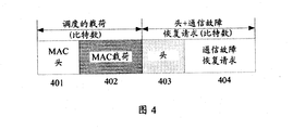
- the obtained payload of the terminal after the MAC layer group packet may be 401+402+403+404, where 401 is the MAC Header of the currently scheduled payload, 402 is the currently scheduled payload, and 403 is the Header of the communication failure recovery request, 403
- the Header is used to indicate that the payload in 404 is a communication failure recovery request.
- the terminal transmits the packet after the packet to the base station through the PUSCH of the physical layer.
- the base station can decode the data packet at the physical layer, and unpack the decoded data packet at the MAC layer to obtain a communication failure recovery request.
- the process of the terminal selecting to carry the communication failure recovery request may be as shown in FIG. 5.
- the terminal first determines whether to transmit a communication failure recovery request (REQ) through the PUSCH, and if yes, selects an optimal normal communication CC from the component carriers carrying the PUSCH, and the physical layer of the terminal sends a communication failure recovery request to the MAC layer,
- the communication failure recovery request packet is carried by the MAC layer and then carried in the PUSCH of the selected CC.
- the component carrier of the optimal normal communication is selected, and it is determined whether there is a PUCCH on the selected component carrier; if the PUCCH exists, the communication failure recovery request is carried in the PUCCH, If there is no PUCCH, the communication failure recovery request is carried in the PRACH. Thereafter, the terminal transmits a communication failure recovery request to the base station.
- the data packet sent by the terminal to the base station in the PUSCH of the second serving cell includes indication information of the communication failure recovery request, where the indication information is used to indicate that the data packet sent by the terminal includes a communication failure recovery request.
- the base station may determine that it includes the communication failure recovery request.
- Step 303 The terminal detects a communication failure recovery response sent by the base station in the downlink channel of the second serving cell, where the communication failure recovery response is used to indicate the downlink communication resource of the first serving cell.
- the base station When the base station receives the communication failure recovery request in the downlink channel of the second serving cell, the base station may generate a communication failure recovery response according to the communication failure recovery request, and send a communication failure recovery response to the terminal in the downlink channel of the second serving cell, Thereby the terminal can detect a communication failure recovery response in the downlink channel of the second serving cell.
- the downlink channel may include a physical downlink control channel (PDCCH) for carrying a control channel, and a physical downlink shared channel (PDSCH) for carrying data information.
- the terminal may detect a communication failure recovery response by using any one of the downlink channels.
- the communication failure recovery response is used to indicate the resource of the downlink communication of the first serving cell
- the resource of the downlink communication may be the target reference signal resource indication of the first serving cell
- the target reference signal resource indication refers to the reference signal resource selected by the base station. Indicates that the target reference signal resource indication is used to indicate the reference signal port.
- the base station may generate a communication failure recovery response, and send a communication failure recovery response to the terminal.
- the base station may send a communication failure recovery response in the PDCCH after generating the communication failure recovery response, and the corresponding terminal detects the communication failure recovery response sent by the base station in the PDCCH.
- the PDSCH is carried on the second serving cell, the base station may send a communication failure recovery response in the PDSCH after generating the communication failure recovery response, and the corresponding terminal detects the communication failure recovery response sent by the base station in the PDSCH.
- the base station may preferentially send a communication failure recovery response in the PDSCH after generating the communication failure recovery response, and the terminal detects the communication failure recovery response sent by the base station in the PDSCH.
- the communication failure recovery response may include: an index of the first serving cell and a target reference signal resource indication of the first serving cell, where the target reference signal resource indication refers to the reference signal resource indication selected by the base station, and the target reference signal resource indication is used for Indicates the reference signal port.
- the target reference signal resource indication is referred to as downlink beam information.
- the index of the first serving cell may also be an index of the first carrier
- the communication failure recovery response may include: an index of the first carrier and downlink beam information, where the downlink beam information refers to a candidate included by the base station from the communication failure recovery request.
- the downlink beam information selected in the beam information is used to indicate a downlink beam.
- the downlink beam information may be a beam number.
- the communication failure recovery response when the terminal detects a communication failure recovery response sent by the base station in the PDCCH, the communication failure recovery response may be carried in the following manner.
- (c1) carrying a communication failure recovery response by a coded modulation mode which may include CDM, TDM, and FDM.
- a coded modulation mode which may include CDM, TDM, and FDM.
- the manner in which the communication fault recovery response is carried by the code modulation in the PDCCH is similar to the manner in which the coded modulation bearer communication failure recovery request is in the PUCCH. For details, refer to the foregoing description, which is not described herein again.
- (c2) Carrying a communication failure recovery response by a specific sequence, which may be a reserved sequence, which refers to a sequence that is not currently configured for use.
- the PDCCH occupies a 10-bit binary, where the first 3 bits of the binary are reserved resources.
- the 3-bit binary corresponding sequence may include 000, 001, 010, 011, 100, 101, 110, 111, and the sequence currently used for configuration is 000-110, 111 is a reserved sequence.
- the reservation sequence 111 may be configured to indicate that the PDCCH carries a communication failure recovery response when the indication sequence in the PDCCH is configured to be 111.
- the terminal may parse the reserved resource of the PDCCH. If the corresponding sequence in the reserved resource is 111, it may be determined that the PDCCH carries the communication failure recovery response.
- the communication failure recovery response when the terminal detects the communication failure recovery response sent by the base station in the PDSCH, the communication failure recovery response may be carried in the following manner.
- the base station may include a MAC layer and a physical layer, and the base station may perform a communication failure recovery response by using a MAC-CE.
- the MAC-CE for carrying the communication failure recovery response may include a MAC response indication and a communication failure recovery response, and the MAC response indication may also be referred to as a header of the current MAC-CE, for indicating that the load in the current MAC-CE is Communication failure recovery response.
- the base station may carry the communication failure recovery response in the payload sent to the terminal.
- the base station may group the currently scheduled payload and the communication failure recovery response (eg, the first carrier index and the downlink beam information) at the MAC layer.
- the communication failure recovery response may be added after the load, or may be placed in front of the payload, or only the communication failure recovery response may be grouped when there is no load, and the scheduled payload refers to the currently scheduled payload in the PDSCH.
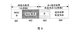
- the load of the base station after the MAC layer group packet may be 601+602+603+604, where 601 is the MAC Header of the current scheduling payload, 602 is the currently scheduled MAC payload, and 603 is the Header of the communication failure recovery response, 603
- the header is used to indicate that the payload in 604 is a communication failure recovery response.
- the base station sends the packet after the packet to the terminal through the PDSCH of the physical layer.
- the terminal may decode the data packet in the physical layer, and unpack the data packet decoded by the MAC layer to obtain a communication failure recovery response.
- the terminal may determine the corresponding downlink beam by using the downlink beam information included in the communication fault recovery response, thereby determining that the base station sends information through the downlink beam, thereby implementing fast recovery of the communication fault.
- the process of the terminal selecting to detect the communication failure recovery response may be as shown in FIG. 7.
- the terminal first determines whether a communication failure recovery response (RSP) is detected through the PDSCH, and if so, selects an optimal normal communication CC from the component carriers, and then detects a communication failure recovery response in the PDSCH. If no (ie, determining that the communication failure recovery response is not detected by the PDSCH), determining whether there is a CC of the optimal normal communication of the PDCCH; if present, the terminal detects a communication failure recovery response in the PDCCH, and if not, the terminal is on the failed carrier A communication failure recovery response is detected in the PDCCH (refer to step 304 - step 306 for a specific process).
- RSP communication failure recovery response
- the data packet sent by the base station to the terminal in the PDCCH of the second serving cell includes indication information of the communication failure recovery response, where the indication information is used to indicate that the data packet sent by the base station includes the communication failure recovery response.
- the terminal detects the data packet sent by the base station in the PDCCH of the second serving cell determining, according to the indication information of the communication failure recovery response included in the data packet, that the data packet includes a communication failure recovery response.
- the beam fault recovery process in this application is illustrated by taking the example of the base station providing the carrier aggregation service for the terminal through the two serving cells. It is assumed that the two serving cells are the serving cell X and the serving cell Y, the component carrier corresponding to the terminal cell X is the first carrier, and the component carrier corresponding to the terminal cell Y is the second carrier.
- the terminal uses the beam a1 to the beam a2, the base station uses the beam a3 to the beam a4, the beam a1 and the beam a3 are one beam pair, and the beam a2 and the beam a4 are one beam pair (assuming that the terminal carries the PRACH/PUCCH through the beam a1)
- the terminal carries the CSI-RS/SS Block, PDCCH) through the beam a2.
- the terminal uses the beam c1 to the beam c2, the base station uses the beam c3 to the beam c4, the beam c1 and the beam c3 are one beam pair, and the beam c2 and the beam c4 are one beam pair (assuming that the terminal carries the PRACH/PUCCH through the beam c1) And PUSCH, the terminal carries CSI-RS/SS Block, PDCCH, and PDSCH through beam c2.
- the terminal when the terminal detects a beam failure of the first serving cell in the CSI-RS/SS Block carried by the a2, if the terminal determines that the communication of the second serving cell is normal, the terminal may include multiple downlinks included in the second carrier.
- the information of the beam (for example, the beam b3 to the beam b4) is used as candidate beam information, and the communication failure recovery request is sent in the uplink channel of the second serving cell (for example, PRACH/PUCCH or PUSCH carried by the beam c1), and the communication failure recovery request is received.
- the index of the first carrier and the information of the beam c3 to the beam c4 are included.
- the base station may select the beam c3 as the downlink beam it transmits, so as to send the information of the beam c3 to the terminal through the communication failure recovery response.
- the terminal detects a communication failure recovery response in a downlink channel of the second serving cell (for example, a PDCCH or a PDSCH carried by the beam c2), the terminal may determine that the base station uses the beam c3 to transmit information, thereby receiving the beam c1 in the same beam pair. Information sent by the base station.
- the terminal when the terminal detects that the downlink communication failure occurs in the first serving cell, the terminal determines that the downlink communication of the second serving cell is normal, so that the communication failure of the first serving cell is sent in the uplink channel of the second serving cell.
- the recovery request is used to detect a communication failure recovery response in the downlink channel of the second serving cell, so that beam scanning of the carrier corresponding to the first serving cell is not required to acquire candidate beam information, thereby saving beam scanning time.
- the communication failure recovery request is sent in the uplink channel of the second serving cell, and the communication failure recovery response is detected in the downlink channel of the second serving cell, and the communication failure is Compared with the direct communication failure recovery on the serving cell, the success rate of the communication failure recovery can be improved, and the communication failure can be quickly recovered.
- the terminal when the terminal detects that at least two serving cells are faulty, the terminal may recover the downlink communication fault of the first serving cell by using the preferred serving cell of the at least two serving cells, as described below.
- Step 304 When the terminal detects that the downlink communication of the at least two serving cells is faulty, it is determined that the second serving cell meets a specific condition, where the specific condition includes at least one of the following conditions: the serving cell of the second serving cell has the smallest index. The channel quality of the downlink channel of the second serving cell is optimal, and the carrier frequency corresponding to the second serving cell is the lowest.
- the terminal may select one of the at least two serving cells of the communication fault.
- the serving cell here assumes that the second serving cell is a better serving cell.
- the index of the second serving cell is the smallest; or the carrier frequency corresponding to the second serving cell is the smallest; or the downlink channel quality of the second serving cell is best in at least two serving cells. Wait.
- the second serving cell may also be a serving cell that is selected by other means, so as to improve the efficiency of the communication failure recovery, which is not specifically limited in this embodiment of the present application.
- each of the at least two serving cells except the first serving cell may be referred to as a second serving cell. That is, the at least two serving cells may include a plurality of second serving cells, so that the second serving cell that satisfies the specific condition may be a second serving cell selected from the plurality of second serving cells.
- Step 305 The terminal sends a communication failure recovery request to the base station in the uplink channel of the second serving cell.
- Step 306 The terminal detects a communication fault recovery response sent by the base station in the downlink channel of the second serving cell.
- the process in which the terminal sends a communication failure recovery request to the base station in the uplink channel of the second serving cell is consistent with the process of sending the communication failure recovery request to the base station in the uplink channel of the second serving cell in step 302, and the terminal is simultaneously
- the detection of the communication failure recovery response sent by the base station in the downlink channel of the second serving cell is also consistent with the detection of the communication failure recovery response sent by the base station in the downlink channel of the second serving cell in step 303.
- step 302 and step 303 above. The description of the present application will not be repeated herein.
- the terminal when communication failure occurs in at least two serving cells, the terminal selects a better second serving cell bearer communication fault recovery process, and compares with the first serving cell bearer communication fault recovery process directly. To a certain extent, the success rate of communication failure recovery can also be improved, thereby improving recovery efficiency.
- the base station may further configure, for the terminal, the uplink channel that sends the communication failure recovery request, which may include: the base station sends the fault recovery request configuration information to the terminal, and the fault recovery request configuration information is used to indicate the sending communication.
- the uplink channel of the fault recovery request is one of the following channels: a physical uplink control channel, a physical random access channel, or a physical uplink shared channel.
- the terminal receives the fault recovery request configuration information from the base station, so that when the terminal sends the communication fault recovery request, the terminal may send the communication fault request in the corresponding uplink channel according to the fault recovery request configuration information.
- the base station may further configure, for the terminal, the downlink channel that detects the communication failure recovery response, which may include: the base station sends the fault recovery response configuration information to the terminal, and the fault recovery response configuration information is used to indicate the detection.
- the downlink channel of the communication failure recovery request the downlink channel is one of the following channels: a physical downlink control channel, or a physical downlink shared channel.
- the terminal receives the fault recovery response configuration information from the base station, so that when the terminal detects the communication fault recovery response sent by the base station, the terminal may detect the communication fault recovery response in the corresponding downlink channel according to the fault recovery response configuration information.
- the terminal can also report the capability it has to the base station.
- the terminal has the capability of transmitting a communication failure recovery request across carriers (for example, a communication failure recovery mechanism in which the terminal carries the first serving cell through the second serving cell when the first serving cell fails), and carries the communication failure recovery request through the PUSCH.
- Capability eg, the terminal transmitting a communication failure recovery request through the PUSCH of the second serving cell
- having one of detecting a communication failure recovery response capability through the PDSCH (eg, the terminal detecting a communication failure recovery response in the PDSCH of the second serving cell) kind or more.
- the base station may send corresponding configuration information to the terminal to indicate that the terminal uses one or more of the capabilities.
- the terminal may send the first indication information to the base station, where the first indication information is used by the terminal to have the capability of transmitting a communication failure recovery request across the carrier; or the terminal may send the second indication information to the base station, where the second indication information is used to indicate
- the terminal may send a communication failure recovery request through the PUSCH; or the terminal may send the third indication information to the base station, where the third indication information is used to indicate that the terminal can detect the communication failure recovery response by using the PDSCH.
- the terminal can also report the multiple capabilities of the terminal to the base station at one time. For example, the terminal can simultaneously report any two of the above three capabilities to the base station, or simultaneously The capability is reported to the base station in one time. The embodiment of the present application does not specifically limit this.
- each network element such as a terminal and a base station.
- each network element such as a terminal and a base station.
- it includes hardware structures and/or software modules corresponding to the execution of the respective functions.
- the present application can be implemented in a combination of hardware or hardware and computer software in combination with the elements and algorithm steps of the various examples described in the embodiments disclosed herein. Whether a function is implemented in hardware or computer software to drive hardware depends on the specific application and design constraints of the solution. A person skilled in the art can use different methods to implement the described functions for each particular application, but such implementation should not be considered to be beyond the scope of the present application.
- the embodiment of the present application may divide the function module into the terminal and the base station according to the foregoing method.
- each function module may be divided according to each function, or two or more functions may be integrated into one module.
- the above integrated modules can be implemented in the form of hardware or in the form of software functional modules. It should be noted that the division of the module in the embodiment of the present application is schematic, and is only a logical function division, and the actual implementation may have another division manner. The following is an example of dividing each functional module by using corresponding functions:
- FIG. 9 shows a possible structural diagram of the wireless communication device involved in the above embodiment.
- the wireless communication device may be a terminal or a chip built in the terminal, and the wireless communication device includes a processing unit 901, a transmitting unit 902, and a receiving unit 903.
- the processing unit 901 is configured to support the wireless communication device to perform step 301 or step 304 in the foregoing embodiment, and/or other processes for the techniques described herein;
- the sending unit 902 is configured to support the wireless communication device to perform Step 302 or step 305 in the above embodiment;
- the receiving unit 903 supports the wireless communication device to perform step 303 or step 306 in the above embodiment. All the related content of the steps involved in the foregoing method embodiments may be referred to the functional description of the corresponding functional modules, and details are not described herein again.
- the processing unit 901 in the present application may be a processor of the wireless communication device
- the sending unit 902 may be a transmitter of the wireless communication device
- the receiving unit 903 may be a receiver, a transmitter of the wireless communication device. It can usually be integrated with a receiver for use as a transceiver, and a specific transceiver can also be referred to as a communication interface.
- FIG. 10 is a schematic diagram showing a possible logical structure of a wireless communication device involved in the foregoing embodiment provided by an embodiment of the present application.
- the wireless communication device may be a chip built in a terminal or a terminal, and the wireless communication device includes a processor 1002 and a communication interface 1003.
- the processor 1002 is configured to perform control management on the operation of the wireless communication device, for example, the processor 1002 is configured to support the wireless communication device to perform step 301, step 304 in the above embodiments, and/or for the techniques described herein. Other processes.
- the wireless communication device may further include a memory 1001 and a bus 1004.
- the processor 1002, the communication interface 1003, and the memory 1001 are connected to each other through a bus 1004.
- the communication interface 1003 is configured to support communication by the wireless communication device.
- the memory 1001 is configured to store the wireless communication device. Program code and data for the wireless communication device.
- the processor 1002 can be a central processing unit, a general purpose processor, a digital signal processor, an application specific integrated circuit, a field programmable gate array or other programmable logic device, a transistor logic device, a hardware component, or any combination thereof. It is possible to implement or carry out the various illustrative logical blocks, modules and circuits described in connection with the present disclosure.
- the processor may also be a combination of computing functions, for example, including one or more microprocessor combinations, combinations of digital signal processors and microprocessors, and the like.
- the bus 1004 may be a Peripheral Component Interconnect (PCI) bus or an Extended Industry Standard Architecture (EISA) bus.
- PCI Peripheral Component Interconnect
- EISA Extended Industry Standard Architecture
- FIG. 11 shows a possible structural diagram of the wireless communication device involved in the above embodiment.
- the wireless communication device may be a chip built in a base station or a base station, and the wireless communication device includes a receiving unit 1101, a processing unit 1102, and a transmitting unit 1103.
- the receiving unit 1101 is configured to support the wireless communication device to receive the communication failure recovery request sent by step 302 in the foregoing embodiment, or the communication failure recovery request sent in step 305;
- the processing unit 1102 is configured to support the wireless communication device to perform the foregoing implementation.
- the transmitting unit 1103 supports the wireless communication device performing the steps of transmitting a communication failure recovery response to the terminal in the above-described embodiments. All the related content of the steps involved in the foregoing method embodiments may be referred to the functional description of the corresponding functional modules, and details are not described herein again.
- the processing unit 1102 in the present application may be a processor of the wireless communication device
- the receiving unit 1101 may be a receiver of the wireless communication device
- the sending unit 1103 may be a transmitter, a transmitter of the wireless communication device. It can usually be integrated with a receiver for use as a transceiver, and a specific transceiver can also be referred to as a communication interface.
- FIG. 12 is a schematic diagram showing a possible logical structure of a wireless communication device involved in the foregoing embodiment provided by an embodiment of the present application.
- the wireless communication device may be a base station or a base station built in the terminal, and the wireless communication device includes a processor 1202 and a communication interface 1203.
- the processor 1202 is configured to control management of the wireless communication device actions, for example, the processor 1202 is configured to support the wireless communication device to generate a communication failure recovery response, and/or other processes for the techniques described herein.
- the wireless communication device may further include a memory 1201 and a bus 1204.
- the processor 1202, the communication interface 1203, and the memory 1201 are connected to each other through a bus 1204.
- the communication interface 1203 is configured to support the wireless communication device for communication; and the memory 1201 is configured to store the wireless communication device. Program code and data for the wireless communication device.
- the processor 1202 can be a central processing unit, a general purpose processor, a digital signal processor, an application specific integrated circuit, a field programmable gate array or other programmable logic device, a transistor logic device, a hardware component, or any combination thereof. It is possible to implement or carry out the various illustrative logical blocks, modules and circuits described in connection with the present disclosure.
- the processor may also be a combination of computing functions, for example, including one or more microprocessor combinations, combinations of digital signal processors and microprocessors, and the like.
- the bus 1204 may be a Peripheral Component Interconnect (PCI) bus or an Extended Industry Standard Architecture (EISA) bus.
- PCI Peripheral Component Interconnect
- EISA Extended Industry Standard Architecture
- a readable storage medium stores computer execution instructions, when a device (which may be a single chip microcomputer, a chip, etc.) or a processor executes the above method embodiment.
- the steps of the terminal in the provided wireless communication method may include various media that can store program codes, such as a USB flash drive, a removable hard disk, a read only memory, a random access memory, a magnetic disk, or an optical disk.
- a readable storage medium stores computer execution instructions, when a device (which may be a single chip microcomputer, a chip, etc.) or a processor executes the above method embodiment.
- the steps of the base station in the provided wireless communication method may include various media that can store program codes, such as a USB flash drive, a removable hard disk, a read only memory, a random access memory, a magnetic disk, or an optical disk.
- a computer program product comprising computer executed instructions stored in a computer readable storage medium; at least one processor of the device may be Reading the storage medium reads the computer execution instructions, and the at least one processor executing the computer to execute the instructions causes the steps of the terminal in the wireless communication method provided by the apparatus embodiment embodiment.
- a computer program product comprising computer executed instructions stored in a computer readable storage medium; at least one processor of the device may be Reading the storage medium reads the computer execution instructions, and the at least one processor executing the computer to execute the instructions such that the apparatus described above implements the steps of the base station in the wireless communication method provided.
- a communication system in another embodiment of the present application, includes a base station and a terminal, where the base station provides a carrier aggregation service for the terminal by using at least two serving cells, where the at least two serving cells include the first serving cell and The second service is small.
- the chip built in the terminal or the terminal may be the wireless communication device provided in FIG. 9 or FIG. 10, and used to perform the steps of the terminal in the foregoing method embodiment; and/or the chip built in the base station or the base station may be FIG. 11 or The wireless communication device provided by FIG. 12 is used to perform the steps of the base station in the above method embodiment.
- the terminal when the terminal detects that the downlink communication failure occurs in the first serving cell, the terminal determines that the downlink communication of the second serving cell is normal, so that the communication failure of the first serving cell is sent in the uplink channel of the second serving cell.
- the recovery request is used to detect a communication failure recovery response in the downlink channel of the second serving cell, so that beam scanning of the carrier corresponding to the first serving cell is not required to acquire candidate beam information, thereby saving beam scanning time.
- the communication failure recovery request is sent in the uplink channel of the second serving cell, and the communication failure recovery response is detected in the downlink channel of the second serving cell, and the communication failure is Compared with the direct communication failure recovery on the serving cell, the success rate of the communication failure recovery can be improved, and the communication failure can be quickly recovered.
Landscapes
- Engineering & Computer Science (AREA)
- Signal Processing (AREA)
- Computer Networks & Wireless Communication (AREA)
- Mobile Radio Communication Systems (AREA)
Abstract
Description
Claims (30)
- 一种无线通信方法,其特征在于,所述方法应用于终端或终端内置的芯片,基站通过至少两个服务小区为所述终端提供载波聚合服务,所述至少两个服务小区包括第一服务小区和第二服务小区,所述方法包括:A wireless communication method, wherein the method is applied to a chip built in a terminal or a terminal, and the base station provides a carrier aggregation service for the terminal by using at least two serving cells, where the at least two serving cells include a first serving cell And the second serving cell, the method includes:当检测到所述第一服务小区的下行通信故障时,确定所述第二服务小区的下行通信正常;Determining that downlink communication of the second serving cell is normal when detecting a downlink communication failure of the first serving cell;在所述第二服务小区的上行信道中发送通信故障恢复请求,所述通信故障恢复请求用于请求恢复所述第一服务小区的下行通信故障;Sending a communication failure recovery request in an uplink channel of the second serving cell, where the communication failure recovery request is used to request to recover a downlink communication failure of the first serving cell;在所述第二服务小区的下行信道中检测通信故障恢复响应,所述通信故障恢复响应用于指示所述第一服务小区的下行通信的资源。A communication failure recovery response is detected in a downlink channel of the second serving cell, where the communication failure recovery response is used to indicate a resource of downlink communication of the first serving cell.
- 根据权利要求1所述的无线通信方法,其特征在于,在发送通信故障恢复请求之前,所述方法还包括:The wireless communication method according to claim 1, wherein before the sending of the communication failure recovery request, the method further comprises:接收来自所述基站的故障恢复请求配置信息,所述故障恢复请求配置信息用于指示发送所述通信故障恢复请求的上行信道,所述上行信道为以下信道中的一种:物理上行控制信道,物理随机接入信道,或物理上行共享信道。Receiving, by the base station, fault recovery request configuration information, where the fault recovery request configuration information is used to indicate an uplink channel that sends the communication failure recovery request, where the uplink channel is one of the following channels: a physical uplink control channel, Physical random access channel, or physical uplink shared channel.
- 根据权利要求2所述的无线通信方法,其特征在于,当发送所述通信故障恢复请求的上行信道为所述物理上行共享信道时,所述物理上行共享信道中承载的所述通信故障恢复请求由媒体接入控制层控制单元承载。The wireless communication method according to claim 2, wherein the communication failure recovery request carried in the physical uplink shared channel is when the uplink channel that sends the communication failure recovery request is the physical uplink shared channel It is carried by the media access control layer control unit.
- 根据权利要求1-3任一项所述的无线通信方法,其特征在于,在检测通信故障恢复响应之前,所述方法还包括:The wireless communication method according to any one of claims 1 to 3, wherein before the detecting a communication failure recovery response, the method further comprises:接收来自所述基站的故障恢复响应配置信息,所述故障恢复响应配置信息用于指示检测所述通信故障恢复响应的下行信道,所述下行信道为以下信道中的一种:物理下行控制信道,或物理下行共享信道。Receiving failure recovery response configuration information from the base station, the failure recovery response configuration information is used to indicate a downlink channel that detects the communication failure recovery response, and the downlink channel is one of the following channels: a physical downlink control channel, Or physical downlink shared channel.
- 根据权利要求4所述的无线通信方法,其特征在于,当检测所述通信故障恢复响应的下行信道为所述物理下行共享信道时,所述物理下行共享信道中承载的所述通信故障恢复响应由媒体接入控制层控制单元承载。The wireless communication method according to claim 4, wherein the communication failure recovery response carried in the physical downlink shared channel when detecting that the downlink channel of the communication failure recovery response is the physical downlink shared channel It is carried by the media access control layer control unit.
- 根据权利要求1-5所述的无线通信方法,其特征在于,所述第二服务小区还满足以下条件中的至少一个:所述第二服务小区的索引最小,所述第二服务小区的下行信道的信道质量最优,所述第二服务小区对应的载频最低。The wireless communication method according to claim 1-5, wherein the second serving cell further satisfies at least one of the following conditions: an index of the second serving cell is the smallest, and a downlink of the second serving cell The channel quality of the channel is optimal, and the carrier frequency corresponding to the second serving cell is the lowest.
- 根据权利要求1所述的无线通信方法,其特征在于,所述方法还包括:The wireless communication method according to claim 1, wherein the method further comprises:当检测到所述至少两个服务小区的下行通信均故障时,确定所述第二服务小区满足以下条件中至少一个:所述第二服务小区的索引最小,所述第二服务小区的下行信道的信道质量最优,所述第二服务小区对应的载频最低。When it is detected that the downlink communication of the at least two serving cells is faulty, determining that the second serving cell meets at least one of the following conditions: an index of the second serving cell is the smallest, and a downlink channel of the second serving cell The channel quality is optimal, and the second serving cell corresponds to the lowest carrier frequency.
- 一种无线通信方法,其特征在于,所述方法应用于基站或基站内置的芯片,所述基站通过至少两个服务小区为终端提供载波聚合服务,所述至少两个服务小区包括第一服务小区和第二服务小区,所述方法包括:A wireless communication method, the method is applied to a chip built in a base station or a base station, the base station provides a carrier aggregation service for a terminal by using at least two serving cells, where the at least two serving cells include a first serving cell And the second serving cell, the method includes:在所述第二服务小区的上行信道中接收来自所述终端的通信故障恢复请求,所述通信故障恢复请求用于请求恢复所述第一服务小区的下行通信故障;Receiving, in an uplink channel of the second serving cell, a communication failure recovery request from the terminal, where the communication failure recovery request is used to request to recover a downlink communication failure of the first serving cell;生成通信故障恢复响应,所述通信故障恢复响应用于指示所述第一服务小区的下行通信的资源;Generating a communication failure recovery response, the communication failure recovery response being used to indicate a resource of downlink communication of the first serving cell;在所述第二服务小区的下行信道中向所述终端发送所述通信故障恢复响应。Transmitting the communication failure recovery response to the terminal in a downlink channel of the second serving cell.
- 根据权利要求8所述的无线通信方法,其特征在于,在接收来自所述终端的通信故障恢复之前,所述方法还包括:The wireless communication method according to claim 8, wherein the method further comprises: before receiving the communication failure recovery from the terminal, the method further comprising:向所述终端发送故障恢复请求配置信息,所述故障恢复请求配置信息用于指示发送所述通信故障恢复请求的上行信道,所述上行信道为以下信道中的一种:物理上行控制信道,物理随机接入信道,或物理上行共享信道。And sending, to the terminal, fault recovery request configuration information, where the fault recovery request configuration information is used to indicate an uplink channel that sends the communication fault recovery request, where the uplink channel is one of the following channels: a physical uplink control channel, and a physical Random access channel, or physical uplink shared channel.
- 根据权利要求9所述的无线通信方法,其特征在于,当指示发送所述通信故障恢复请求的上行信道为所述物理上行共享信道时,所述物理上行共享信道中承载的所述通信故障恢复请求由媒体接入控制层控制单元承载。The wireless communication method according to claim 9, wherein when the uplink channel indicating the transmission of the communication failure recovery request is the physical uplink shared channel, the communication failure recovery in the physical uplink shared channel is performed. The request is carried by the media access control layer control unit.
- 根据权利要求8-10任一项所述的无线通信方法,其特征在于,在向所述终端发送通信故障恢复响应之前,所述方法还包括:The wireless communication method according to any one of claims 8 to 10, wherein before the sending a communication failure recovery response to the terminal, the method further comprises:向所述终端发送故障恢复响应配置信息,所述故障恢复响应配置信息用于指示检测所述通信故障恢复响应的下行信道,所述下行信道为以下信道中的一种:物理下行控制信道,或物理下行共享信道。Sending, by the terminal, failure recovery response configuration information, where the failure recovery response configuration information is used to indicate a downlink channel that detects the communication failure recovery response, where the downlink channel is one of the following channels: a physical downlink control channel, or Physical downlink shared channel.
- 根据权利要求11所述的无线通信方法,其特征在于,当指示检测所述通信故障恢复响应的下行信道为所述物理下行共享信道时,所述物理下行共享信道中承载的所述通信故障恢复响应由媒体接入控制层控制单元承载。The wireless communication method according to claim 11, wherein when the downlink channel indicating the detection of the communication failure recovery response is the physical downlink shared channel, the communication failure recovery in the physical downlink shared channel is performed. The response is carried by the media access control layer control unit.
- 根据权利要求8-12任一项所述的无线通信方法,其特征在于,所述第二服务小区还满足以下条件中的至少一个:所述第二服务小区的索引最小,所述第二服务小区的下行信道的信道质量最优,所述第二服务小区对应的载频最低。The wireless communication method according to any one of claims 8 to 12, wherein the second serving cell further satisfies at least one of the following conditions: the index of the second serving cell is the smallest, the second service The channel quality of the downlink channel of the cell is optimal, and the carrier frequency corresponding to the second serving cell is the lowest.
- 一种无线通信装置,其特征在于,所述无线通信装置为终端或用于终端的芯片,基站通过至少两个服务小区为所述终端提供载波聚合服务,所述至少两个服务小区包括第一服务小区和第二服务小区,所述无线通信装置包括:A wireless communication device, wherein the wireless communication device is a terminal or a chip for a terminal, and the base station provides a carrier aggregation service for the terminal by using at least two serving cells, where the at least two serving cells include the first The serving cell and the second serving cell, the wireless communication device includes:处理单元,用于当检测到所述第一服务小区的下行通信故障时,确定所述第二服务小区的下行通信正常;a processing unit, configured to determine that downlink communication of the second serving cell is normal when detecting a downlink communication failure of the first serving cell;发送单元,用于在所述第二服务小区的上行信道中发送通信故障恢复请求,所述通信故障恢复请求用于请求恢复所述第一服务小区的下行通信故障;a sending unit, configured to send a communication failure recovery request in an uplink channel of the second serving cell, where the communication failure recovery request is used to request to recover a downlink communication failure of the first serving cell;接收单元,用于在所述第二服务小区的下行信道中检测通信故障恢复响应,所述通信故障恢复响应用于指示所述第一服务小区的下行通信的资源。And a receiving unit, configured to detect a communication failure recovery response in a downlink channel of the second serving cell, where the communication failure recovery response is used to indicate a resource of downlink communication of the first serving cell.
- 根据权利要求14所述的无线通信装置,其特征在于:The wireless communication device of claim 14 wherein:所述接收单元,还用于接收来自所述基站的故障恢复请求配置信息,所述故障恢复请求配置信息用于指示发送所述通信故障恢复请求的上行信道,所述上行信道为以下信道中的一种:物理上行控制信道,物理随机接入信道,或物理上行共享信道。The receiving unit is further configured to receive failure recovery request configuration information from the base station, where the fault recovery request configuration information is used to indicate an uplink channel that sends the communication failure recovery request, where the uplink channel is in the following channel One: a physical uplink control channel, a physical random access channel, or a physical uplink shared channel.
- 根据权利要求15所述的无线通信装置,其特征在于,当发送所述通信故障恢复请求的上行信道为所述物理上行共享信道时,所述物理上行共享信道中承载的所述通信故障恢复请求由媒体接入控制层控制单元承载。The wireless communication device according to claim 15, wherein the communication failure recovery request carried in the physical uplink shared channel when the uplink channel that sends the communication failure recovery request is the physical uplink shared channel It is carried by the media access control layer control unit.
- 根据权利要求14-16任一项所述的无线通信装置,其特征在于:A wireless communication device according to any of claims 14-16, characterized in that:所述接收单元,还用于接收来自所述基站的故障恢复响应配置信息,所述故障恢复响应配置信息用于指示检测所述通信故障恢复响应的下行信道,所述下行信道为以下信道中的一种:物理下行控制信道,或物理下行共享信道。The receiving unit is further configured to receive fault recovery response configuration information from the base station, where the fault recovery response configuration information is used to indicate a downlink channel that detects the communication fault recovery response, where the downlink channel is in the following channel One: a physical downlink control channel, or a physical downlink shared channel.
- 根据权利要求17所述的无线通信装置,其特征在于,当检测所述通信故障恢复响应的下行信道为所述物理下行共享信道时,所述物理下行共享信道中承载的所述通信故障恢复响应由媒体接入控制层控制单元承载。The wireless communication device according to claim 17, wherein the communication failure recovery response carried in the physical downlink shared channel when detecting that the downlink channel of the communication failure recovery response is the physical downlink shared channel It is carried by the media access control layer control unit.
- 根据权利要求14-18所述的无线通信装置,其特征在于,所述第二服务小区还满足以下条件中的至少一个:所述第二服务小区的索引最小,所述第二服务小区的下行信道的信道质量最优,所述第二服务小区对应的载频最低。The wireless communication device according to any one of claims 14-18, wherein the second serving cell further satisfies at least one of the following conditions: a minimum index of the second serving cell, and a downlink of the second serving cell The channel quality of the channel is optimal, and the carrier frequency corresponding to the second serving cell is the lowest.
- 根据权利要求14所述的无线通信装置,其特征在于:The wireless communication device of claim 14 wherein:所述处理单元,还用于当检测到所述至少两个服务小区的下行通信均故障时,确定所述第二服务小区满足以下条件中至少一个:所述第二服务小区的索引最小,所述第二服务小区的下行信道的信道质量最优,所述第二服务小区对应的载频最低。The processing unit is further configured to: when it is detected that the downlink communication of the at least two serving cells is faulty, determine that the second serving cell meets at least one of the following conditions: the index of the second serving cell is the smallest, The channel quality of the downlink channel of the second serving cell is optimal, and the carrier frequency corresponding to the second serving cell is the lowest.
- 一种无线通信装置,其特征在于,所述无线通信装置为基站或用于基站的芯片,所述基站通过至少两个服务小区为终端提供载波聚合服务,所述至少两个服务小区包括第一服务小区和第二服务小区,所述无线通信装置包括:A wireless communication device, wherein the wireless communication device is a base station or a chip for a base station, and the base station provides a carrier aggregation service for the terminal by using at least two serving cells, where the at least two serving cells include the first The serving cell and the second serving cell, the wireless communication device includes:接收单元,用于在所述第二服务小区的上行信道中接收来自所述终端的通信故障恢复请求,所述通信故障恢复请求用于请求恢复所述第一服务小区的下行通信故障;a receiving unit, configured to receive, in an uplink channel of the second serving cell, a communication failure recovery request from the terminal, where the communication failure recovery request is used to request to recover a downlink communication failure of the first serving cell;处理单元,用于生成通信故障恢复响应,所述通信故障恢复响应用于指示所述第一服务小区的下行通信的资源;a processing unit, configured to generate a communication failure recovery response, where the communication failure recovery response is used to indicate a resource of downlink communication of the first serving cell;发送单元,用于在所述第二服务小区的下行信道中向所述终端发送所述通信故障恢复响应。And a sending unit, configured to send the communication fault recovery response to the terminal in a downlink channel of the second serving cell.
- 根据权利要求21所述的无线通信装置,其特征在于:The wireless communication device of claim 21, wherein:所述接收单元,还用于向所述终端发送故障恢复请求配置信息,所述故障恢复请求配置信息用于指示发送所述通信故障恢复请求的上行信道,所述上行信道为以下信道中的一种:物理上行控制信道,物理随机接入信道,或物理上行共享信道。The receiving unit is further configured to send, to the terminal, fault recovery request configuration information, where the fault recovery request configuration information is used to indicate an uplink channel that sends the communication fault recovery request, where the uplink channel is one of the following channels. Species: physical uplink control channel, physical random access channel, or physical uplink shared channel.
- 根据权利要求22所述的无线通信装置,其特征在于,当指示发送所述通信故障恢复请求的上行信道为所述物理上行共享信道时,所述物理上行共享信道中承载的所述通信故障恢复请求由媒体接入控制层控制单元承载。The wireless communication device according to claim 22, wherein when the uplink channel indicating the transmission of the communication failure recovery request is the physical uplink shared channel, the communication failure recovery in the physical uplink shared channel is performed. The request is carried by the media access control layer control unit.
- 根据权利要求21-23任一项所述的无线通信装置,其特征在于:A wireless communication device according to any of claims 21-23, characterized in that:所述发送单元,还用于向所述终端发送故障恢复响应配置信息,所述故障恢复响应配置信息用于指示检测所述通信故障恢复响应的下行信道,所述下行信道为以下信道中的一种:物理下行控制信道,或物理下行共享信道。The sending unit is further configured to send fault recovery response configuration information to the terminal, where the fault recovery response configuration information is used to indicate a downlink channel that detects the communication fault recovery response, and the downlink channel is one of the following channels. Species: physical downlink control channel, or physical downlink shared channel.
- 根据权利要求24所述的无线通信装置,其特征在于,当指示检测所述通信故障恢复响应的下行信道为所述物理下行共享信道时,所述物理下行共享信道中承载的所述通信故障恢复响应由媒体接入控制层控制单元承载。The wireless communication device according to claim 24, wherein when the downlink channel indicating the detection of the communication failure recovery response is the physical downlink shared channel, the communication failure recovery in the physical downlink shared channel is performed. The response is carried by the media access control layer control unit.
- 根据权利要求21-25任一项所述的无线通信装置,其特征在于,所述第二服务小区满足以下条件中的至少一个:所述第二服务小区的索引最小,所述第二服务小区的下行信道的信道质量最优,所述第二服务小区对应的载频最低。The wireless communication apparatus according to any one of claims 21 to 25, wherein the second serving cell satisfies at least one of the following conditions: an index of the second serving cell is the smallest, the second serving cell The channel quality of the downlink channel is optimal, and the carrier frequency corresponding to the second serving cell is the lowest.
- 一种可读存储介质,其特征在于,所述可读存储介质中存储有指令,当所述可读存储介质在设备上运行时,使得所述设备执行权利要求1-7任一项所述的无线通信方法。A readable storage medium, wherein the readable storage medium stores instructions, when the readable storage medium is run on a device, causing the device to perform any one of claims 1-7 Wireless communication method.
- 一种可读存储介质,其特征在于,所述可读存储介质中存储有指令,当所述可读存储介质在设备上运行时,使得所述设备执行权利要求8-13任一项所述的无线通信方法。A readable storage medium, wherein the readable storage medium stores instructions, when the readable storage medium is run on a device, causing the device to perform any one of claims 8-13 Wireless communication method.
- 一种计算机程序产品,其特征在于,当所述计算机程序产品在计算机上运行时,使得所述计算机执行权利要求1-7任一项所述的无线通信方法。A computer program product, wherein the computer program product, when run on a computer, causes the computer to perform the wireless communication method of any of claims 1-7.
- 一种计算机程序产品,其特征在于,当所述计算机程序产品在计算机上运行时,使得所述计算机执行权利要求8-13任一项所述的无线通信方法。A computer program product, wherein the computer program product, when run on a computer, causes the computer to perform the wireless communication method of any one of claims 8-13.
Priority Applications (5)
| Application Number | Priority Date | Filing Date | Title |
|---|---|---|---|
| BR112020002174-1A BR112020002174A2 (en) | 2017-11-24 | 2018-08-16 | wireless communication method, device, readable storage medium and computer program product |
| JP2020503037A JP6962519B2 (en) | 2017-11-24 | 2018-08-16 | Wireless communication methods and equipment |
| EP18880640.0A EP3644649B1 (en) | 2017-11-24 | 2018-08-16 | Wireless communication method and device |
| CN201880055005.0A CN111052797B (en) | 2017-11-24 | 2018-08-16 | Wireless communication method and device |
| US16/778,105 US11924901B2 (en) | 2017-11-24 | 2020-01-31 | Wireless communication method and apparatus |
Applications Claiming Priority (2)
| Application Number | Priority Date | Filing Date | Title |
|---|---|---|---|
| CN201711189027.X | 2017-11-24 | ||
| CN201711189027.XA CN109842499B (en) | 2017-11-24 | 2017-11-24 | Wireless communication method and device |
Related Child Applications (1)
| Application Number | Title | Priority Date | Filing Date |
|---|---|---|---|
| US16/778,105 Continuation US11924901B2 (en) | 2017-11-24 | 2020-01-31 | Wireless communication method and apparatus |
Publications (1)
| Publication Number | Publication Date |
|---|---|
| WO2019100772A1 true WO2019100772A1 (en) | 2019-05-31 |
Family
ID=66630489
Family Applications (1)
| Application Number | Title | Priority Date | Filing Date |
|---|---|---|---|
| PCT/CN2018/100878 WO2019100772A1 (en) | 2017-11-24 | 2018-08-16 | Wireless communication method and device |
Country Status (6)
| Country | Link |
|---|---|
| US (1) | US11924901B2 (en) |
| EP (1) | EP3644649B1 (en) |
| JP (1) | JP6962519B2 (en) |
| CN (3) | CN113301596B (en) |
| BR (1) | BR112020002174A2 (en) |
| WO (1) | WO2019100772A1 (en) |
Families Citing this family (10)
| Publication number | Priority date | Publication date | Assignee | Title |
|---|---|---|---|---|
| WO2019130523A1 (en) * | 2017-12-27 | 2019-07-04 | 株式会社Nttドコモ | User terminal and radio communication method |
| US11601181B2 (en) * | 2018-03-16 | 2023-03-07 | Lenovo (Beijing) Limited | Beam failure recovery |
| CN111479284B (en) * | 2019-01-24 | 2022-02-08 | 大唐移动通信设备有限公司 | Sending method, monitoring method, base station and terminal for beam failure recovery response |
| EP3989628A1 (en) * | 2019-06-21 | 2022-04-27 | Ntt Docomo, Inc. | Terminal |
| WO2020258278A1 (en) | 2019-06-28 | 2020-12-30 | Zte Corporation | Methods for wireless radio link recovery |
| CN112584443A (en) * | 2019-09-27 | 2021-03-30 | 苹果公司 | Secondary cell link recovery request transmission |
| EP3799518A1 (en) * | 2019-09-27 | 2021-03-31 | Apple Inc. | Secondary cell link recovery request transmission |
| EP4075856A4 (en) * | 2019-12-13 | 2023-08-16 | Beijing Xiaomi Mobile Software Co., Ltd. | Wireless communication method and device, and storage medium |
| WO2021243512A1 (en) * | 2020-06-01 | 2021-12-09 | Qualcomm Incorporated | Beam failure recovery response optimization |
| US11996934B2 (en) * | 2020-06-09 | 2024-05-28 | Qualcomm Incorporated | Broadcasting packets using network coding with feedback |
Citations (5)
| Publication number | Priority date | Publication date | Assignee | Title |
|---|---|---|---|---|
| US20140198768A1 (en) * | 2013-01-16 | 2014-07-17 | Lg Electronics Inc. | Method and apparatus for switching connection in wireless communication system |
| CN104219787A (en) * | 2014-09-10 | 2014-12-17 | 电信科学技术研究院 | Wireless link recovery method and device |
| CN104468029A (en) * | 2013-09-18 | 2015-03-25 | 中国移动通信集团公司 | Mobile terminal communication method and device and related device |
| CN104581998A (en) * | 2014-12-30 | 2015-04-29 | 大唐移动通信设备有限公司 | Method and system for processing communication faults |
| CN105338653A (en) * | 2014-08-07 | 2016-02-17 | 北京三星通信技术研究有限公司 | Method and equipment supporting UE bearing recovery |
Family Cites Families (42)
| Publication number | Priority date | Publication date | Assignee | Title |
|---|---|---|---|---|
| US7102999B1 (en) * | 1999-11-24 | 2006-09-05 | Juniper Networks, Inc. | Switching device |
| CN101754494A (en) * | 2008-12-04 | 2010-06-23 | 中兴通讯股份有限公司 | Method and system for realizing recovery of main carrier in multi-carrier cell |
| KR101633936B1 (en) * | 2009-04-21 | 2016-06-28 | 엘지전자 주식회사 | Apparatus and method of configuring radio connection in multiple carrier system |
| CN101938757B (en) * | 2009-06-29 | 2013-06-05 | 华为技术有限公司 | Method, base station and system for detecting premature handover |
| GB2475164B (en) * | 2009-11-04 | 2012-05-16 | Lg Electronics Inc | Method for handling radio link failure in multiple carrier system |
| US8792328B2 (en) * | 2009-11-06 | 2014-07-29 | Intel Corporation | Radio-link reliability using multi-carrier capability in wireless broadband systems |
| KR101781853B1 (en) * | 2010-02-09 | 2017-09-28 | 엘지전자 주식회사 | Method and apparatus of transmitting and receiving configuration information of a plurality of celles in a wireless system |
| RU2012140501A (en) * | 2010-02-22 | 2014-03-27 | Телефонактиеболагет Л М Эрикссон (Пабл) | RLF LINK FAILURE DETECTION FOR ITS SOLVING |
| KR101724371B1 (en) * | 2010-05-28 | 2017-04-10 | 삼성전자주식회사 | Apparatus and method for supporting mobility in heterogeneous wireless communication system |
| WO2012108718A2 (en) * | 2011-02-10 | 2012-08-16 | 엘지전자 주식회사 | Method and device for scheduling in carrier aggregate system |
| CN103188800B (en) * | 2011-12-29 | 2017-03-29 | 中兴通讯股份有限公司 | A kind of WCDMA channel arrangement methods and device |
| US9049698B2 (en) * | 2012-01-18 | 2015-06-02 | Mediatek Inc. | Method of enhanced connection recovery and cell selection |
| EP2826327B1 (en) * | 2012-03-15 | 2017-08-23 | Telefonaktiebolaget LM Ericsson (publ) | Method and arrangement for connection re-establishment in a telecommunication system |
| ES2700648T3 (en) * | 2013-02-28 | 2019-02-18 | Nec Corp | Radio communication system, radio station, radio terminal, communication control method and transient media interpretable by computer |
| CN104038955B (en) * | 2013-03-08 | 2017-06-20 | 中国移动通信集团公司 | A kind of method of fault detect and treatment in GSM and base station |
| CN105684491B (en) * | 2013-10-30 | 2020-02-07 | 株式会社Kt | Method for configuring dual connection in mobile communication network and apparatus therefor |
| CN103828481B (en) * | 2013-11-30 | 2018-09-28 | 华为技术有限公司 | Data transmission set, communication system and communication means |
| JP2015142363A (en) * | 2014-01-30 | 2015-08-03 | 株式会社Nttドコモ | mobile station, re-connection request method, base station and re-connection request processing method |
| KR20160004061A (en) * | 2014-07-02 | 2016-01-12 | 한국전자통신연구원 | Method and apparatus of mobility management in small cell environment |
| US9867226B2 (en) * | 2015-12-14 | 2018-01-09 | Qualcomm Incorporated | Radio link failure (RLF) failover in a multi-connectivity environment |
| CN108464047B (en) * | 2016-01-08 | 2023-05-23 | 日本电气株式会社 | Wireless station system, wireless terminal and method thereof |
| WO2017171999A1 (en) * | 2016-03-31 | 2017-10-05 | Intel IP Corporation | Physical random access channel design for licensed assisted access |
| EP3244655B1 (en) * | 2016-05-10 | 2018-06-27 | Intel IP Corporation | Methods and devices for circuit-switched fallback procedures |
| CN106792948B (en) * | 2017-02-16 | 2019-11-08 | 北京小米移动软件有限公司 | Cell switching method and device |
| US11134492B2 (en) * | 2017-04-12 | 2021-09-28 | Samsung Electronics Co., Ltd. | Method and apparatus for beam recovery in next generation wireless systems |
| CN108810940B (en) * | 2017-04-28 | 2020-06-02 | 维沃移动通信有限公司 | Beam recovery processing method and terminal |
| EP3620029A1 (en) * | 2017-05-03 | 2020-03-11 | IDAC Holdings, Inc. | Beam recovery mechanism |
| EP3641436B1 (en) * | 2017-06-14 | 2024-02-28 | Fujitsu Limited | Transmission resource configuration device for beam failure recovery request and communication system |
| JP2020526086A (en) * | 2017-06-23 | 2020-08-27 | 華為技術有限公司Huawei Technologies Co.,Ltd. | Integrated RLF detection in NR, multi-beam RLM, and full diversity BFR mechanism |
| US10893540B2 (en) * | 2017-07-28 | 2021-01-12 | Qualcomm Incorporated | Random access channel procedures with multiple carriers |
| WO2019027294A1 (en) * | 2017-08-04 | 2019-02-07 | Samsung Electronics Co., Ltd. | Method and user equipment (ue) for beam management framework for carrier aggregation |
| US11419173B2 (en) * | 2017-08-09 | 2022-08-16 | Idac Holdings, Inc. | Methods and systems for beam recovery and management |
| US10855359B2 (en) * | 2017-08-10 | 2020-12-01 | Comcast Cable Communications, Llc | Priority of beam failure recovery request and uplink channels |
| CN109391984B (en) * | 2017-08-10 | 2020-10-27 | 维沃移动通信有限公司 | Beam switching method, mobile terminal and computer readable storage medium |
| WO2019032017A1 (en) * | 2017-08-11 | 2019-02-14 | Telefonaktiebolaget Lm Ericsson (Publ) | Apparatuses and methods for performing beam recovery |
| US11792874B2 (en) * | 2017-09-08 | 2023-10-17 | Interdigital Patent Holdings, Inc. | Multiple TRPs and panels transmission with dynamic bandwidth for NR |
| US10892811B2 (en) * | 2017-09-11 | 2021-01-12 | Qualcomm Incorporated | Beam recovery procedure using a second component carrier |
| US10979917B2 (en) * | 2017-09-16 | 2021-04-13 | Qualcomm Incorporated | Systems and methods for communication beam loss recovery |
| EP3462633A1 (en) * | 2017-09-28 | 2019-04-03 | Panasonic Intellectual Property Corporation of America | Resource allocation for the beam failure recovery procedure |
| US10784943B2 (en) * | 2017-10-23 | 2020-09-22 | Apple, Inc. | Beam failure recovery operation |
| CN111492684B (en) * | 2017-11-02 | 2023-10-24 | 株式会社Ntt都科摩 | User terminal and wireless communication method |
| RU2745448C1 (en) * | 2017-11-16 | 2021-03-25 | Телефонактиеболагет Лм Эрикссон (Пабл) | Radio link control / reconfiguration in case of radio line failure after switching bandwidth parts |
-
2017
- 2017-11-24 CN CN202110415040.2A patent/CN113301596B/en active Active
- 2017-11-24 CN CN201711189027.XA patent/CN109842499B/en active Active
-
2018
- 2018-08-16 CN CN201880055005.0A patent/CN111052797B/en active Active
- 2018-08-16 WO PCT/CN2018/100878 patent/WO2019100772A1/en unknown
- 2018-08-16 EP EP18880640.0A patent/EP3644649B1/en active Active
- 2018-08-16 JP JP2020503037A patent/JP6962519B2/en active Active
- 2018-08-16 BR BR112020002174-1A patent/BR112020002174A2/en unknown
-
2020
- 2020-01-31 US US16/778,105 patent/US11924901B2/en active Active
Patent Citations (5)
| Publication number | Priority date | Publication date | Assignee | Title |
|---|---|---|---|---|
| US20140198768A1 (en) * | 2013-01-16 | 2014-07-17 | Lg Electronics Inc. | Method and apparatus for switching connection in wireless communication system |
| CN104468029A (en) * | 2013-09-18 | 2015-03-25 | 中国移动通信集团公司 | Mobile terminal communication method and device and related device |
| CN105338653A (en) * | 2014-08-07 | 2016-02-17 | 北京三星通信技术研究有限公司 | Method and equipment supporting UE bearing recovery |
| CN104219787A (en) * | 2014-09-10 | 2014-12-17 | 电信科学技术研究院 | Wireless link recovery method and device |
| CN104581998A (en) * | 2014-12-30 | 2015-04-29 | 大唐移动通信设备有限公司 | Method and system for processing communication faults |
Non-Patent Citations (1)
| Title |
|---|
| See also references of EP3644649A4 |
Also Published As
| Publication number | Publication date |
|---|---|
| US11924901B2 (en) | 2024-03-05 |
| CN109842499B (en) | 2021-04-20 |
| CN113301596B (en) | 2023-06-06 |
| BR112020002174A2 (en) | 2020-07-28 |
| EP3644649B1 (en) | 2022-10-05 |
| CN113301596A (en) | 2021-08-24 |
| US20200170065A1 (en) | 2020-05-28 |
| JP2020532162A (en) | 2020-11-05 |
| CN111052797A (en) | 2020-04-21 |
| JP6962519B2 (en) | 2021-11-05 |
| EP3644649A1 (en) | 2020-04-29 |
| CN111052797B (en) | 2021-11-19 |
| EP3644649A4 (en) | 2020-07-29 |
| CN109842499A (en) | 2019-06-04 |
Similar Documents
| Publication | Publication Date | Title |
|---|---|---|
| WO2019100772A1 (en) | Wireless communication method and device | |
| US11271632B2 (en) | Apparatus and method for transmitting or receiving signal using beamforming in wireless communication system | |
| US10893566B2 (en) | Method for receiving beam recovery request and network device | |
| CN113923679B (en) | System and method for communication beam recovery | |
| WO2019214713A1 (en) | Link recovery method and device | |
| CN112312423B (en) | Method and device for processing beam failure | |
| JP7306474B2 (en) | Beam failure recovery method, apparatus and communication system | |
| KR20220047266A (en) | Recovering from beam disturbances in group-based secondary cells | |
| US20160198411A1 (en) | Network-assisted power consumption reduction in a wireless communication terminal | |
| WO2020192369A1 (en) | Beam failure processing method and device | |
| EP3691147B1 (en) | Method for determining bundling size, user terminal, and network side device | |
| WO2021194926A1 (en) | Ue split architecture with distributed tx/rx chains | |
| US20240205905A1 (en) | Communication method and device | |
| US20240129767A1 (en) | Communication apparatus, base station, and communication method | |
| US20240155387A1 (en) | Communication apparatus, base station, and communication method | |
| US20240129014A1 (en) | Communication apparatus, base station, and communication method | |
| US20240138013A1 (en) | Communication apparatus, base station, and communication method | |
| JP2020535668A (en) | How to transmit data, network equipment and terminal equipment |
Legal Events
| Date | Code | Title | Description |
|---|---|---|---|
| 121 | Ep: the epo has been informed by wipo that ep was designated in this application |
Ref document number: 18880640 Country of ref document: EP Kind code of ref document: A1 |
|
| ENP | Entry into the national phase |
Ref document number: 2020503037 Country of ref document: JP Kind code of ref document: A |
|
| ENP | Entry into the national phase |
Ref document number: 2018880640 Country of ref document: EP Effective date: 20200122 |
|
| REG | Reference to national code |
Ref country code: BR Ref legal event code: B01A Ref document number: 112020002174 Country of ref document: BR |
|
| NENP | Non-entry into the national phase |
Ref country code: DE |
|
| ENP | Entry into the national phase |
Ref document number: 112020002174 Country of ref document: BR Kind code of ref document: A2 Effective date: 20200131 |