WO2019098218A1 - Vehicle drive apparatus - Google Patents
Vehicle drive apparatus Download PDFInfo
- Publication number
- WO2019098218A1 WO2019098218A1 PCT/JP2018/042083 JP2018042083W WO2019098218A1 WO 2019098218 A1 WO2019098218 A1 WO 2019098218A1 JP 2018042083 W JP2018042083 W JP 2018042083W WO 2019098218 A1 WO2019098218 A1 WO 2019098218A1
- Authority
- WO
- WIPO (PCT)
- Prior art keywords
- rotation
- rotating
- rotating element
- gear
- torque
- Prior art date
Links
Images


Classifications
-
- F—MECHANICAL ENGINEERING; LIGHTING; HEATING; WEAPONS; BLASTING
- F16—ENGINEERING ELEMENTS AND UNITS; GENERAL MEASURES FOR PRODUCING AND MAINTAINING EFFECTIVE FUNCTIONING OF MACHINES OR INSTALLATIONS; THERMAL INSULATION IN GENERAL
- F16H—GEARING
- F16H3/00—Toothed gearings for conveying rotary motion with variable gear ratio or for reversing rotary motion
- F16H3/44—Toothed gearings for conveying rotary motion with variable gear ratio or for reversing rotary motion using gears having orbital motion
- F16H3/62—Gearings having three or more central gears
- F16H3/66—Gearings having three or more central gears composed of a number of gear trains without drive passing from one train to another
-
- B—PERFORMING OPERATIONS; TRANSPORTING
- B60—VEHICLES IN GENERAL
- B60L—PROPULSION OF ELECTRICALLY-PROPELLED VEHICLES; SUPPLYING ELECTRIC POWER FOR AUXILIARY EQUIPMENT OF ELECTRICALLY-PROPELLED VEHICLES; ELECTRODYNAMIC BRAKE SYSTEMS FOR VEHICLES IN GENERAL; MAGNETIC SUSPENSION OR LEVITATION FOR VEHICLES; MONITORING OPERATING VARIABLES OF ELECTRICALLY-PROPELLED VEHICLES; ELECTRIC SAFETY DEVICES FOR ELECTRICALLY-PROPELLED VEHICLES
- B60L15/00—Methods, circuits, or devices for controlling the traction-motor speed of electrically-propelled vehicles
- B60L15/20—Methods, circuits, or devices for controlling the traction-motor speed of electrically-propelled vehicles for control of the vehicle or its driving motor to achieve a desired performance, e.g. speed, torque, programmed variation of speed
- B60L15/2036—Electric differentials, e.g. for supporting steering vehicles
-
- B—PERFORMING OPERATIONS; TRANSPORTING
- B60—VEHICLES IN GENERAL
- B60K—ARRANGEMENT OR MOUNTING OF PROPULSION UNITS OR OF TRANSMISSIONS IN VEHICLES; ARRANGEMENT OR MOUNTING OF PLURAL DIVERSE PRIME-MOVERS IN VEHICLES; AUXILIARY DRIVES FOR VEHICLES; INSTRUMENTATION OR DASHBOARDS FOR VEHICLES; ARRANGEMENTS IN CONNECTION WITH COOLING, AIR INTAKE, GAS EXHAUST OR FUEL SUPPLY OF PROPULSION UNITS IN VEHICLES
- B60K1/00—Arrangement or mounting of electrical propulsion units
-
- B—PERFORMING OPERATIONS; TRANSPORTING
- B60—VEHICLES IN GENERAL
- B60K—ARRANGEMENT OR MOUNTING OF PROPULSION UNITS OR OF TRANSMISSIONS IN VEHICLES; ARRANGEMENT OR MOUNTING OF PLURAL DIVERSE PRIME-MOVERS IN VEHICLES; AUXILIARY DRIVES FOR VEHICLES; INSTRUMENTATION OR DASHBOARDS FOR VEHICLES; ARRANGEMENTS IN CONNECTION WITH COOLING, AIR INTAKE, GAS EXHAUST OR FUEL SUPPLY OF PROPULSION UNITS IN VEHICLES
- B60K17/00—Arrangement or mounting of transmissions in vehicles
- B60K17/02—Arrangement or mounting of transmissions in vehicles characterised by arrangement, location, or kind of clutch
-
- B—PERFORMING OPERATIONS; TRANSPORTING
- B60—VEHICLES IN GENERAL
- B60K—ARRANGEMENT OR MOUNTING OF PROPULSION UNITS OR OF TRANSMISSIONS IN VEHICLES; ARRANGEMENT OR MOUNTING OF PLURAL DIVERSE PRIME-MOVERS IN VEHICLES; AUXILIARY DRIVES FOR VEHICLES; INSTRUMENTATION OR DASHBOARDS FOR VEHICLES; ARRANGEMENTS IN CONNECTION WITH COOLING, AIR INTAKE, GAS EXHAUST OR FUEL SUPPLY OF PROPULSION UNITS IN VEHICLES
- B60K17/00—Arrangement or mounting of transmissions in vehicles
- B60K17/04—Arrangement or mounting of transmissions in vehicles characterised by arrangement, location, or kind of gearing
- B60K17/06—Arrangement or mounting of transmissions in vehicles characterised by arrangement, location, or kind of gearing of change-speed gearing
- B60K17/08—Arrangement or mounting of transmissions in vehicles characterised by arrangement, location, or kind of gearing of change-speed gearing of mechanical type
-
- B—PERFORMING OPERATIONS; TRANSPORTING
- B60—VEHICLES IN GENERAL
- B60L—PROPULSION OF ELECTRICALLY-PROPELLED VEHICLES; SUPPLYING ELECTRIC POWER FOR AUXILIARY EQUIPMENT OF ELECTRICALLY-PROPELLED VEHICLES; ELECTRODYNAMIC BRAKE SYSTEMS FOR VEHICLES IN GENERAL; MAGNETIC SUSPENSION OR LEVITATION FOR VEHICLES; MONITORING OPERATING VARIABLES OF ELECTRICALLY-PROPELLED VEHICLES; ELECTRIC SAFETY DEVICES FOR ELECTRICALLY-PROPELLED VEHICLES
- B60L15/00—Methods, circuits, or devices for controlling the traction-motor speed of electrically-propelled vehicles
- B60L15/20—Methods, circuits, or devices for controlling the traction-motor speed of electrically-propelled vehicles for control of the vehicle or its driving motor to achieve a desired performance, e.g. speed, torque, programmed variation of speed
- B60L15/2009—Methods, circuits, or devices for controlling the traction-motor speed of electrically-propelled vehicles for control of the vehicle or its driving motor to achieve a desired performance, e.g. speed, torque, programmed variation of speed for braking
-
- B—PERFORMING OPERATIONS; TRANSPORTING
- B60—VEHICLES IN GENERAL
- B60L—PROPULSION OF ELECTRICALLY-PROPELLED VEHICLES; SUPPLYING ELECTRIC POWER FOR AUXILIARY EQUIPMENT OF ELECTRICALLY-PROPELLED VEHICLES; ELECTRODYNAMIC BRAKE SYSTEMS FOR VEHICLES IN GENERAL; MAGNETIC SUSPENSION OR LEVITATION FOR VEHICLES; MONITORING OPERATING VARIABLES OF ELECTRICALLY-PROPELLED VEHICLES; ELECTRIC SAFETY DEVICES FOR ELECTRICALLY-PROPELLED VEHICLES
- B60L15/00—Methods, circuits, or devices for controlling the traction-motor speed of electrically-propelled vehicles
- B60L15/20—Methods, circuits, or devices for controlling the traction-motor speed of electrically-propelled vehicles for control of the vehicle or its driving motor to achieve a desired performance, e.g. speed, torque, programmed variation of speed
- B60L15/2054—Methods, circuits, or devices for controlling the traction-motor speed of electrically-propelled vehicles for control of the vehicle or its driving motor to achieve a desired performance, e.g. speed, torque, programmed variation of speed by controlling transmissions or clutches
-
- B—PERFORMING OPERATIONS; TRANSPORTING
- B60—VEHICLES IN GENERAL
- B60L—PROPULSION OF ELECTRICALLY-PROPELLED VEHICLES; SUPPLYING ELECTRIC POWER FOR AUXILIARY EQUIPMENT OF ELECTRICALLY-PROPELLED VEHICLES; ELECTRODYNAMIC BRAKE SYSTEMS FOR VEHICLES IN GENERAL; MAGNETIC SUSPENSION OR LEVITATION FOR VEHICLES; MONITORING OPERATING VARIABLES OF ELECTRICALLY-PROPELLED VEHICLES; ELECTRIC SAFETY DEVICES FOR ELECTRICALLY-PROPELLED VEHICLES
- B60L15/00—Methods, circuits, or devices for controlling the traction-motor speed of electrically-propelled vehicles
- B60L15/20—Methods, circuits, or devices for controlling the traction-motor speed of electrically-propelled vehicles for control of the vehicle or its driving motor to achieve a desired performance, e.g. speed, torque, programmed variation of speed
- B60L15/2072—Methods, circuits, or devices for controlling the traction-motor speed of electrically-propelled vehicles for control of the vehicle or its driving motor to achieve a desired performance, e.g. speed, torque, programmed variation of speed for drive off
-
- F—MECHANICAL ENGINEERING; LIGHTING; HEATING; WEAPONS; BLASTING
- F16—ENGINEERING ELEMENTS AND UNITS; GENERAL MEASURES FOR PRODUCING AND MAINTAINING EFFECTIVE FUNCTIONING OF MACHINES OR INSTALLATIONS; THERMAL INSULATION IN GENERAL
- F16D—COUPLINGS FOR TRANSMITTING ROTATION; CLUTCHES; BRAKES
- F16D49/00—Brakes with a braking member co-operating with the periphery of a drum, wheel-rim, or the like
- F16D49/08—Brakes with a braking member co-operating with the periphery of a drum, wheel-rim, or the like shaped as an encircling band extending over approximately 360 degrees
-
- F—MECHANICAL ENGINEERING; LIGHTING; HEATING; WEAPONS; BLASTING
- F16—ENGINEERING ELEMENTS AND UNITS; GENERAL MEASURES FOR PRODUCING AND MAINTAINING EFFECTIVE FUNCTIONING OF MACHINES OR INSTALLATIONS; THERMAL INSULATION IN GENERAL
- F16D—COUPLINGS FOR TRANSMITTING ROTATION; CLUTCHES; BRAKES
- F16D67/00—Combinations of couplings and brakes; Combinations of clutches and brakes
- F16D67/02—Clutch-brake combinations
-
- F—MECHANICAL ENGINEERING; LIGHTING; HEATING; WEAPONS; BLASTING
- F16—ENGINEERING ELEMENTS AND UNITS; GENERAL MEASURES FOR PRODUCING AND MAINTAINING EFFECTIVE FUNCTIONING OF MACHINES OR INSTALLATIONS; THERMAL INSULATION IN GENERAL
- F16H—GEARING
- F16H3/00—Toothed gearings for conveying rotary motion with variable gear ratio or for reversing rotary motion
- F16H3/44—Toothed gearings for conveying rotary motion with variable gear ratio or for reversing rotary motion using gears having orbital motion
- F16H3/46—Gearings having only two central gears, connected by orbital gears
- F16H3/48—Gearings having only two central gears, connected by orbital gears with single orbital gears or pairs of rigidly-connected orbital gears
- F16H3/52—Gearings having only two central gears, connected by orbital gears with single orbital gears or pairs of rigidly-connected orbital gears comprising orbital spur gears
- F16H3/54—Gearings having only two central gears, connected by orbital gears with single orbital gears or pairs of rigidly-connected orbital gears comprising orbital spur gears one of the central gears being internally toothed and the other externally toothed
-
- F—MECHANICAL ENGINEERING; LIGHTING; HEATING; WEAPONS; BLASTING
- F16—ENGINEERING ELEMENTS AND UNITS; GENERAL MEASURES FOR PRODUCING AND MAINTAINING EFFECTIVE FUNCTIONING OF MACHINES OR INSTALLATIONS; THERMAL INSULATION IN GENERAL
- F16H—GEARING
- F16H3/00—Toothed gearings for conveying rotary motion with variable gear ratio or for reversing rotary motion
- F16H3/44—Toothed gearings for conveying rotary motion with variable gear ratio or for reversing rotary motion using gears having orbital motion
- F16H3/62—Gearings having three or more central gears
- F16H3/64—Gearings having three or more central gears composed of a number of gear trains, the drive always passing through all the trains, each train having not more than one connection for driving another train
-
- F—MECHANICAL ENGINEERING; LIGHTING; HEATING; WEAPONS; BLASTING
- F16—ENGINEERING ELEMENTS AND UNITS; GENERAL MEASURES FOR PRODUCING AND MAINTAINING EFFECTIVE FUNCTIONING OF MACHINES OR INSTALLATIONS; THERMAL INSULATION IN GENERAL
- F16H—GEARING
- F16H61/00—Control functions within control units of change-speed- or reversing-gearings for conveying rotary motion ; Control of exclusively fluid gearing, friction gearing, gearings with endless flexible members or other particular types of gearing
- F16H61/68—Control functions within control units of change-speed- or reversing-gearings for conveying rotary motion ; Control of exclusively fluid gearing, friction gearing, gearings with endless flexible members or other particular types of gearing specially adapted for stepped gearings
- F16H61/684—Control functions within control units of change-speed- or reversing-gearings for conveying rotary motion ; Control of exclusively fluid gearing, friction gearing, gearings with endless flexible members or other particular types of gearing specially adapted for stepped gearings without interruption of drive
- F16H61/686—Control functions within control units of change-speed- or reversing-gearings for conveying rotary motion ; Control of exclusively fluid gearing, friction gearing, gearings with endless flexible members or other particular types of gearing specially adapted for stepped gearings without interruption of drive with orbital gears
-
- F—MECHANICAL ENGINEERING; LIGHTING; HEATING; WEAPONS; BLASTING
- F16—ENGINEERING ELEMENTS AND UNITS; GENERAL MEASURES FOR PRODUCING AND MAINTAINING EFFECTIVE FUNCTIONING OF MACHINES OR INSTALLATIONS; THERMAL INSULATION IN GENERAL
- F16H—GEARING
- F16H61/00—Control functions within control units of change-speed- or reversing-gearings for conveying rotary motion ; Control of exclusively fluid gearing, friction gearing, gearings with endless flexible members or other particular types of gearing
- F16H61/04—Smoothing ratio shift
- F16H2061/044—Smoothing ratio shift when a freewheel device is disengaged or bridged
-
- F—MECHANICAL ENGINEERING; LIGHTING; HEATING; WEAPONS; BLASTING
- F16—ENGINEERING ELEMENTS AND UNITS; GENERAL MEASURES FOR PRODUCING AND MAINTAINING EFFECTIVE FUNCTIONING OF MACHINES OR INSTALLATIONS; THERMAL INSULATION IN GENERAL
- F16H—GEARING
- F16H2200/00—Transmissions for multiple ratios
- F16H2200/0021—Transmissions for multiple ratios specially adapted for electric vehicles
-
- F—MECHANICAL ENGINEERING; LIGHTING; HEATING; WEAPONS; BLASTING
- F16—ENGINEERING ELEMENTS AND UNITS; GENERAL MEASURES FOR PRODUCING AND MAINTAINING EFFECTIVE FUNCTIONING OF MACHINES OR INSTALLATIONS; THERMAL INSULATION IN GENERAL
- F16H—GEARING
- F16H2200/00—Transmissions for multiple ratios
- F16H2200/003—Transmissions for multiple ratios characterised by the number of forward speeds
- F16H2200/0034—Transmissions for multiple ratios characterised by the number of forward speeds the gear ratios comprising two forward speeds
-
- F—MECHANICAL ENGINEERING; LIGHTING; HEATING; WEAPONS; BLASTING
- F16—ENGINEERING ELEMENTS AND UNITS; GENERAL MEASURES FOR PRODUCING AND MAINTAINING EFFECTIVE FUNCTIONING OF MACHINES OR INSTALLATIONS; THERMAL INSULATION IN GENERAL
- F16H—GEARING
- F16H2200/00—Transmissions for multiple ratios
- F16H2200/20—Transmissions using gears with orbital motion
- F16H2200/2002—Transmissions using gears with orbital motion characterised by the number of sets of orbital gears
- F16H2200/2005—Transmissions using gears with orbital motion characterised by the number of sets of orbital gears with one sets of orbital gears
-
- F—MECHANICAL ENGINEERING; LIGHTING; HEATING; WEAPONS; BLASTING
- F16—ENGINEERING ELEMENTS AND UNITS; GENERAL MEASURES FOR PRODUCING AND MAINTAINING EFFECTIVE FUNCTIONING OF MACHINES OR INSTALLATIONS; THERMAL INSULATION IN GENERAL
- F16H—GEARING
- F16H2200/00—Transmissions for multiple ratios
- F16H2200/20—Transmissions using gears with orbital motion
- F16H2200/2002—Transmissions using gears with orbital motion characterised by the number of sets of orbital gears
- F16H2200/2007—Transmissions using gears with orbital motion characterised by the number of sets of orbital gears with two sets of orbital gears
-
- F—MECHANICAL ENGINEERING; LIGHTING; HEATING; WEAPONS; BLASTING
- F16—ENGINEERING ELEMENTS AND UNITS; GENERAL MEASURES FOR PRODUCING AND MAINTAINING EFFECTIVE FUNCTIONING OF MACHINES OR INSTALLATIONS; THERMAL INSULATION IN GENERAL
- F16H—GEARING
- F16H2200/00—Transmissions for multiple ratios
- F16H2200/20—Transmissions using gears with orbital motion
- F16H2200/203—Transmissions using gears with orbital motion characterised by the engaging friction means not of the freewheel type, e.g. friction clutches or brakes
- F16H2200/2035—Transmissions using gears with orbital motion characterised by the engaging friction means not of the freewheel type, e.g. friction clutches or brakes with two engaging means
-
- F—MECHANICAL ENGINEERING; LIGHTING; HEATING; WEAPONS; BLASTING
- F16—ENGINEERING ELEMENTS AND UNITS; GENERAL MEASURES FOR PRODUCING AND MAINTAINING EFFECTIVE FUNCTIONING OF MACHINES OR INSTALLATIONS; THERMAL INSULATION IN GENERAL
- F16H—GEARING
- F16H2200/00—Transmissions for multiple ratios
- F16H2200/20—Transmissions using gears with orbital motion
- F16H2200/203—Transmissions using gears with orbital motion characterised by the engaging friction means not of the freewheel type, e.g. friction clutches or brakes
- F16H2200/2038—Transmissions using gears with orbital motion characterised by the engaging friction means not of the freewheel type, e.g. friction clutches or brakes with three engaging means
-
- F—MECHANICAL ENGINEERING; LIGHTING; HEATING; WEAPONS; BLASTING
- F16—ENGINEERING ELEMENTS AND UNITS; GENERAL MEASURES FOR PRODUCING AND MAINTAINING EFFECTIVE FUNCTIONING OF MACHINES OR INSTALLATIONS; THERMAL INSULATION IN GENERAL
- F16H—GEARING
- F16H2200/00—Transmissions for multiple ratios
- F16H2200/20—Transmissions using gears with orbital motion
- F16H2200/203—Transmissions using gears with orbital motion characterised by the engaging friction means not of the freewheel type, e.g. friction clutches or brakes
- F16H2200/2066—Transmissions using gears with orbital motion characterised by the engaging friction means not of the freewheel type, e.g. friction clutches or brakes using one freewheel mechanism
-
- F—MECHANICAL ENGINEERING; LIGHTING; HEATING; WEAPONS; BLASTING
- F16—ENGINEERING ELEMENTS AND UNITS; GENERAL MEASURES FOR PRODUCING AND MAINTAINING EFFECTIVE FUNCTIONING OF MACHINES OR INSTALLATIONS; THERMAL INSULATION IN GENERAL
- F16H—GEARING
- F16H2200/00—Transmissions for multiple ratios
- F16H2200/20—Transmissions using gears with orbital motion
- F16H2200/203—Transmissions using gears with orbital motion characterised by the engaging friction means not of the freewheel type, e.g. friction clutches or brakes
- F16H2200/2069—Transmissions using gears with orbital motion characterised by the engaging friction means not of the freewheel type, e.g. friction clutches or brakes using two freewheel mechanism
-
- F—MECHANICAL ENGINEERING; LIGHTING; HEATING; WEAPONS; BLASTING
- F16—ENGINEERING ELEMENTS AND UNITS; GENERAL MEASURES FOR PRODUCING AND MAINTAINING EFFECTIVE FUNCTIONING OF MACHINES OR INSTALLATIONS; THERMAL INSULATION IN GENERAL
- F16H—GEARING
- F16H2200/00—Transmissions for multiple ratios
- F16H2200/20—Transmissions using gears with orbital motion
- F16H2200/2079—Transmissions using gears with orbital motion using freewheel type mechanisms, e.g. freewheel clutches
- F16H2200/2082—Transmissions using gears with orbital motion using freewheel type mechanisms, e.g. freewheel clutches one freewheel mechanisms
-
- Y—GENERAL TAGGING OF NEW TECHNOLOGICAL DEVELOPMENTS; GENERAL TAGGING OF CROSS-SECTIONAL TECHNOLOGIES SPANNING OVER SEVERAL SECTIONS OF THE IPC; TECHNICAL SUBJECTS COVERED BY FORMER USPC CROSS-REFERENCE ART COLLECTIONS [XRACs] AND DIGESTS
- Y02—TECHNOLOGIES OR APPLICATIONS FOR MITIGATION OR ADAPTATION AGAINST CLIMATE CHANGE
- Y02T—CLIMATE CHANGE MITIGATION TECHNOLOGIES RELATED TO TRANSPORTATION
- Y02T10/00—Road transport of goods or passengers
- Y02T10/60—Other road transportation technologies with climate change mitigation effect
- Y02T10/64—Electric machine technologies in electromobility
-
- Y—GENERAL TAGGING OF NEW TECHNOLOGICAL DEVELOPMENTS; GENERAL TAGGING OF CROSS-SECTIONAL TECHNOLOGIES SPANNING OVER SEVERAL SECTIONS OF THE IPC; TECHNICAL SUBJECTS COVERED BY FORMER USPC CROSS-REFERENCE ART COLLECTIONS [XRACs] AND DIGESTS
- Y02—TECHNOLOGIES OR APPLICATIONS FOR MITIGATION OR ADAPTATION AGAINST CLIMATE CHANGE
- Y02T—CLIMATE CHANGE MITIGATION TECHNOLOGIES RELATED TO TRANSPORTATION
- Y02T10/00—Road transport of goods or passengers
- Y02T10/60—Other road transportation technologies with climate change mitigation effect
- Y02T10/72—Electric energy management in electromobility
Abstract
A vehicle drive apparatus (1) is provided with: a rotary electric machine (10); an output member (3) that is drivably connected to wheels (2); and a differential gear device (21) that is provided between the rotary electric machine (10) and the output member (3). The differential gear device (21) is provided with a first rotary element (E1) that is drivably connected to the rotary electric machine (10), a second rotary element (E2) that is drivably connected to the output member (3), and a third rotary element (E3) that is selectively fixed to a non-rotary member (4) by a one-way clutch (F) switchable between a one-way regulated state and a rotation regulated state, and that is selectively fixed to the non-rotary member (4) by a friction brake (B).
Description
本発明は、車両用駆動装置に関する。
The present invention relates to a drive system for a vehicle.
回転電機と、車輪に駆動連結される出力部材と、回転電機と出力部材との間の動力伝達経路に設けられる差動歯車装置とを備えた車両用駆動装置が知られている。このような車両用駆動装置の一例が、特開2011-51460号公報(特許文献1)に開示されている。以下、背景技術の説明において括弧内に示す符号は特許文献1のものである。
There is known a vehicle drive device provided with a rotary electric machine, an output member drivingly connected to a wheel, and a differential gear device provided in a power transmission path between the rotary electric machine and the output member. An example of such a vehicle drive device is disclosed in Japanese Patent Application Laid-Open No. 2011-51460 (Patent Document 1). Hereinafter, reference numerals in parentheses in the description of the background art are those of Patent Document 1.
特許文献1の車両駆動制御装置(1)は、電動モータ(5)と、車輪に駆動連結される差動機構(9)と、電動モータ(7)と差動機構(9)との間の動力伝達経路に設けられるプラネタリーギヤ機構(7)とを備えている。この車両駆動制御装置(1)は、静止系部材(39)と内歯車(25)との間に配置される第2クラッチ(13)を備えている。そして、車両駆動制御装置(1)は、電動モータ(5)のトルクにより車輪を駆動する際には第2クラッチ(13)を係合することで、電動モータ(5)の回転をプラネタリーギヤ機構(7)で減速して差動機構(9)に伝達する(段落0034,0042)。また、この車両駆動制御装置(1)は、2ウェイクラッチにより構成される第1クラッチ(11)を備えている。そして、車両駆動制御装置(1)は、電動モータ(5)に発電させる際には、第2クラッチ(13)を解放して第1クラッチ(11)を係合することで、プラネタリーギヤ機構(7)による変速が行われない状態とする(段落0035)。すなわち、プラネタリーギヤ機構(7)は、クラッチ(11,13)の係合の状態に応じて変速比が切り替えられる。
The vehicle drive control device (1) of Patent Document 1 includes an electric motor (5), a differential mechanism (9) drivingly connected to wheels, an electric motor (7), and a differential mechanism (9). And a planetary gear mechanism (7) provided in the power transmission path. The vehicle drive control device (1) includes a second clutch (13) disposed between the stationary system member (39) and the internal gear (25). Then, when the vehicle drive control device (1) drives the wheels by the torque of the electric motor (5), the second clutch (13) is engaged to rotate the electric motor (5) as a planetary gear. The speed is reduced by the mechanism (7) and transmitted to the differential mechanism (9) (paragraphs 0034 and 0042). Further, the vehicle drive control device (1) includes a first clutch (11) configured by a two-way clutch. When the electric motor (5) generates electric power, the vehicle drive control device (1) releases the second clutch (13) and engages the first clutch (11) to provide a planetary gear mechanism. It is assumed that the shift according to (7) is not performed (paragraph 0035). That is, in the planetary gear mechanism (7), the gear ratio is switched according to the state of engagement of the clutch (11, 13).
ところで、特許文献1において電動モータ(5)のトルクにより車両を走行させる際に係合される第2クラッチ(13)は、制御装置(15)により断続制御される係合装置である(段落0038)。このため、第2クラッチ(13)が解放されている状態から電動モータ(5)のトルクを車輪に伝達させて車両を発進させる際に、第2クラッチ(13)を係合させる制御が必要となり、車両の発進時の制御が複雑化する。また、第2クラッチ(13)が油圧駆動式の場合には、油圧が十分に高まるまでの間は第2クラッチ(13)の伝達トルク容量を大きく確保することができず、車両の発進の際に電動モータ(5)からの大きなトルクを即座に車輪に伝達できない場合がある。
By the way, the second clutch (13) engaged when causing the vehicle to travel by the torque of the electric motor (5) in Patent Document 1 is an engagement device that is intermittently controlled by the control device (15) (paragraph 0038) ). Therefore, when the torque of the electric motor (5) is transmitted to the wheels from the state where the second clutch (13) is released to start the vehicle, control for engaging the second clutch (13) is necessary. , The control at the time of start of the vehicle becomes complicated. In addition, when the second clutch (13) is hydraulically driven, it is not possible to secure a large transfer torque capacity of the second clutch (13) until the hydraulic pressure is sufficiently increased, and the vehicle is started. In some cases, large torque from the electric motor (5) can not be immediately transmitted to the wheels.
そこで、回転電機と出力部材との間の動力伝達経路に、係合装置の係合の状態に応じて変速比が切り替えられる差動歯車装置を備える場合に、回転電機のトルクにより車両を発進させる際の制御を簡素化できると共に、車両の発進の際に回転電機からのトルクを即座に車輪に伝達可能な状態とすることができる車両用駆動装置の実現が望まれる。
Therefore, when the power transmission path between the rotating electrical machine and the output member is provided with a differential gear device in which the gear ratio is switched according to the engagement state of the engagement device, the vehicle is started by the torque of the rotating electrical machine It is desirable to realize a vehicle drive device capable of simplifying control at the time of starting the vehicle and in a state where torque from the rotating electrical machine can be immediately transmitted to the wheels at the time of start of the vehicle.
本開示に係る第1の車両用駆動装置は、
回転電機と、
車輪に駆動連結される出力部材と、
前記回転電機と前記出力部材との間の動力伝達経路に設けられる差動歯車装置と、を備え、
前記差動歯車装置は、前記回転電機に駆動連結される第1回転要素と、前記出力部材に駆動連結される第2回転要素と、ワンウェイクラッチによって非回転部材に選択的に固定されると共に摩擦ブレーキによって非回転部材に選択的に固定される第3回転要素と、を少なくとも備え、
前記第1回転要素、前記第2回転要素、及び前記第3回転要素のうちの2つの回転要素を選択的に連結するクラッチを備え、
前記回転電機が前進力行方向の正トルクを出力した場合に前記第3回転要素に作用する反力トルクを第1反力トルクとし、前記回転電機が前記正トルクとは反対方向の負トルクを出力した場合に前記第3回転要素に作用する反力トルクを第2反力トルクとして、
前記ワンウェイクラッチは、少なくとも前記第3回転要素の一方向の回転を規制する一方向規制状態と、前記第3回転要素の双方向の回転を規制する回転規制状態と、に切替可能に構成されると共に、前記一方向規制状態で、前記第3回転要素の前記第1反力トルクによる回転方向の回転を規制し、前記第3回転要素の前記第2反力トルクによる回転方向の回転を許容する。 The first vehicle drive device according to the present disclosure is
With a rotating electrical machine,
An output member drivingly connected to the wheel;
A differential gear device provided in a power transmission path between the rotating electrical machine and the output member;
The differential gear device is selectively fixed to a non-rotating member by a first rotating element drivingly connected to the rotating electrical machine, a second rotating element drivingly connected to the output member, and a one-way clutch, and also a friction member. And at least a third rotating element selectively fixed to the non-rotating member by the brake.
A clutch selectively coupling two of the first, second and third rotating elements;
When the rotating electric machine outputs positive torque in the forward power running direction, the reaction torque acting on the third rotating element is taken as a first reaction torque, and the rotating electric machine outputs negative torque in the opposite direction to the positive torque. If the reaction force torque acting on the third rotation element when the
The one-way clutch is configured to be switchable between a one-way restricting state for restricting the rotation of at least the third rotating element in one direction and a rotation restricting state for restricting the two-way rotation of the third rotating element. At the same time, in the one-way restricted state, the rotation of the third rotary element in the rotational direction by the first reaction torque is restricted, and the rotation of the third rotary element in the rotational direction by the second reaction torque is permitted. .
この構成によれば、回転電機が正トルクを出力した場合に第3回転要素に作用する第1反力トルクを、一方向規制状態のワンウェイクラッチにより回転が規制された状態の第3回転要素によって受けることができる。よって、回転電機側から第1回転要素に入力された回転が、差動歯車装置のギヤ比に応じた変速比で変速されて第2回転要素から出力部材側に出力される前進用の変速段(以下、「第1変速段」という。)を形成することができる。また、クラッチを係合させることで、回転電機側から第1回転要素に入力された回転が、第1変速段の形成時とは異なる回転速度で第2回転要素から出力部材側に出力される前進用の変速段(以下、「第2変速段」という。)を形成することができる。すなわち、回転電機の正トルクを車輪に伝達させて車両を前進走行させる際に、第1変速段及び第2変速段を選択的に形成することができる。
According to this configuration, when the rotating electrical machine outputs the positive torque, the first reaction torque acting on the third rotating element is controlled by the third rotating element in a state in which the rotation is restricted by the one-way clutch in the one-way restricted state. Can receive. Therefore, the forward shift speed in which the rotation input from the rotating electrical machine side to the first rotating element is shifted at a gear ratio according to the gear ratio of the differential gear device and output from the second rotating element to the output member side (Hereinafter, referred to as "first gear position") can be formed. Further, by engaging the clutch, the rotation input from the rotating electrical machine to the first rotating element is output from the second rotating element to the output member at a rotational speed different from that at the time of formation of the first gear. A forward gear (hereinafter referred to as a "second gear") can be formed. That is, when the positive torque of the rotating electrical machine is transmitted to the wheels to cause the vehicle to travel forward, the first gear and the second gear can be selectively formed.
このとき、クラッチを係合させることで形成される第2変速段において、回転電機側から第1回転要素に入力された回転を、そのままの回転速度で第2回転要素から出力部材側に出力することができる。よって、例えば第2変速段が増速段であるような構成に比べて、大きな駆動力に的確に対応することができる。或いは、例えば2つの変速段(第1変速段/第2変速段)がいずれも減速段であるような構成に比べて、より高速回転に対応することができる。
At this time, in the second gear formed by engaging the clutch, the rotation input from the rotating electric machine to the first rotating element is output from the second rotating element to the output member at the same rotational speed. be able to. Thus, for example, compared to a configuration in which the second gear is the speed-up gear, it is possible to properly cope with a large driving force. Alternatively, for example, as compared with a configuration in which two gear stages (first gear stage / second gear stage) are both reduction gears, higher speed rotation can be supported.
ここで、一方向規制状態のワンウェイクラッチは、回転電機の正トルクに応じて第3回転要素に作用する第1反力トルクによって自動的に係合する。このため、回転電機に正トルクを出力させて車両を発進させる際に特段の制御を実行する必要がなく、制御の簡素化を図ることができる。また、一方向規制状態のワンウェイクラッチが自動的に係合するのと同時に、回転電機からのトルクが車輪に伝達可能な状態となる。従って、回転電機のトルクにより車両を発進させる際の制御を簡素化できると共に、車両の発進の際に回転電機からのトルクを即座に車輪に伝達可能な状態とすることができる車両用駆動装置を実現することができる。
Here, the one-way clutch in the one-way restricted state is automatically engaged by the first reaction torque acting on the third rotating element according to the positive torque of the rotary electric machine. Therefore, there is no need to execute special control when starting the vehicle by causing the rotating electrical machine to output positive torque, and control can be simplified. At the same time as the one-way clutch in the one-way restricted state is automatically engaged, the torque from the rotating electrical machine can be transmitted to the wheels. Therefore, it is possible to simplify the control at the time of starting the vehicle by the torque of the rotating electrical machine, and to make it possible to immediately transmit the torque from the rotating electrical machine to the wheels when starting the vehicle. It can be realized.
また、回転電機が負トルクを出力した場合に第3回転要素に作用する第2反力トルクを、回転規制状態のワンウェイクラッチにより回転が規制された状態の第3回転要素によって受けることができる。よって、第1変速段での前進走行中にワンウェイクラッチを回転規制状態に切り替えることで、第1変速段が形成された状態のまま、回転電機が出力する負トルクを車輪に伝達すること、すなわち、回転電機に発電を行わせることが可能となる。
Further, the second reaction force torque that acts on the third rotating element when the rotating electrical machine outputs the negative torque can be received by the third rotating element in a state in which the rotation is restricted by the one-way clutch in the rotation restricted state. Therefore, by switching the one-way clutch to the rotation restricted state during forward traveling at the first gear, transmitting the negative torque output from the rotating electrical machine to the wheels while the first gear is being formed, ie, , Makes it possible to cause the rotating electrical machine to generate power.
更に、第3回転要素を非回転部材に選択的に固定する摩擦ブレーキを備えているので、回転電機が負トルクを出力して発電を行っている状態で、第2変速段が形成された状態から、クラッチを解放しつつ摩擦ブレーキを係合させて、第2反力トルクに逆らって第3回転要素の回転速度を低下させることができる。そして、第3回転要素の回転速度がゼロとなった後にワンウェイクラッチを回転規制状態とすることで、回転電機に発電を行わせたまま第1変速段を形成することができる。すなわち、回生走行中に、第2変速段から第1変速段への変速段の切り替えを行うことができる。
Furthermore, since the friction brake that selectively fixes the third rotating element to the non-rotating member is provided, the second gear is formed while the rotating electrical machine is generating electric power by outputting negative torque. Thus, the friction brake can be engaged while releasing the clutch to reduce the rotational speed of the third rotating element against the second reaction torque. Then, by setting the one-way clutch in the rotation restriction state after the rotation speed of the third rotation element becomes zero, it is possible to form the first gear while the electric rotating machine is generating power. That is, it is possible to switch the shift position from the second shift position to the first shift position during regenerative traveling.
本開示に係る第2の車両用駆動装置は、
回転電機と、
車輪に駆動連結される出力部材と、
前記回転電機と前記出力部材との間の動力伝達経路に設けられる差動歯車装置と、を備え、
前記差動歯車装置は、前記回転電機に駆動連結される第1回転要素と、前記出力部材に駆動連結される第2回転要素と、ワンウェイクラッチによって非回転部材に選択的に固定されると共に摩擦ブレーキによって非回転部材に選択的に固定される第3回転要素と、前記摩擦ブレーキとは別の第2ブレーキによって非回転部材に選択的に固定される第4回転要素と、を備え、
前記回転電機が前進力行方向の正トルクを出力した場合に前記第3回転要素に作用する反力トルクを第1反力トルクとし、前記回転電機が前記正トルクとは反対方向の負トルクを出力した場合に前記第3回転要素に作用する反力トルクを第2反力トルクとして、
前記ワンウェイクラッチは、少なくとも前記第3回転要素の一方向の回転を規制する一方向規制状態と、前記第3回転要素の双方向の回転を規制する回転規制状態と、に切替可能に構成されると共に、前記一方向規制状態で、前記第3回転要素の前記第1反力トルクによる回転方向の回転を規制し、前記第3回転要素の前記第2反力トルクによる回転方向の回転を許容する。 The second vehicle drive device according to the present disclosure is
With a rotating electrical machine,
An output member drivingly connected to the wheel;
A differential gear device provided in a power transmission path between the rotating electrical machine and the output member;
The differential gear device is selectively fixed to a non-rotating member by a first rotating element drivingly connected to the rotating electrical machine, a second rotating element drivingly connected to the output member, and a one-way clutch, and also a friction member. A third rotating element selectively fixed to the non-rotating member by the brake, and a fourth rotating element selectively fixed to the non-rotating member by the second brake different from the friction brake;
When the rotating electric machine outputs positive torque in the forward power running direction, the reaction torque acting on the third rotating element is taken as a first reaction torque, and the rotating electric machine outputs negative torque in the opposite direction to the positive torque. If the reaction force torque acting on the third rotation element when the
The one-way clutch is configured to be switchable between a one-way restricting state for restricting the rotation of at least the third rotating element in one direction and a rotation restricting state for restricting the two-way rotation of the third rotating element. At the same time, in the one-way restricted state, the rotation of the third rotary element in the rotational direction by the first reaction torque is restricted, and the rotation of the third rotary element in the rotational direction by the second reaction torque is permitted. .
この構成によれば、回転電機が正トルクを出力した場合に第3回転要素に作用する第1反力トルクを、一方向規制状態のワンウェイクラッチにより回転が規制された状態の第3回転要素によって受けることができる。よって、回転電機側から第1回転要素に入力された回転が、差動歯車装置のギヤ比に応じた変速比で変速されて第2回転要素から出力部材側に出力される前進用の変速段(以下、「第1変速段」という。)を形成することができる。また、第2ブレーキを係合させることで、回転電機側から第1回転要素に入力された回転が、第1変速段の形成時とは異なる回転速度で第2回転要素から出力部材側に出力される前進用の変速段(以下、「第2変速段」という。)を形成することができる。すなわち、回転電機の正トルクを車輪に伝達させて車両を前進走行させる際に、第1変速段及び第2変速段を選択的に形成することができる。
According to this configuration, when the rotating electrical machine outputs the positive torque, the first reaction torque acting on the third rotating element is controlled by the third rotating element in a state in which the rotation is restricted by the one-way clutch in the one-way restricted state. Can receive. Therefore, the forward shift speed in which the rotation input from the rotating electrical machine side to the first rotating element is shifted at a gear ratio according to the gear ratio of the differential gear device and output from the second rotating element to the output member side (Hereinafter, referred to as "first gear position") can be formed. In addition, by engaging the second brake, the rotation input from the rotating electrical machine to the first rotating element is output from the second rotating element to the output member at a rotational speed different from that at the time of formation of the first gear. It is possible to form a forward gear (hereinafter referred to as a "second gear"). That is, when the positive torque of the rotating electrical machine is transmitted to the wheels to cause the vehicle to travel forward, the first gear and the second gear can be selectively formed.
このとき、第2ブレーキを係合させることで形成される第2変速段において、回転電機側から第1回転要素に入力された回転を、例えば第1変速段の形成時とは異なる回転速度に減速して第2回転要素から出力部材側に出力することができる。よって、例えば2つの変速段(第1変速段/第2変速段)の双方が減速段となる構成を、コンパクトに実現することが容易である。
At this time, in the second gear, which is formed by engaging the second brake, the rotation input from the rotating electrical machine to the first rotating element is set to, for example, a rotational speed different from that at the time of forming the first gear. It can decelerate and can output to the output member side from the 2nd rotation element. Therefore, it is easy to realize, for example, compactly the configuration in which both of the two shift speeds (first shift speed / second shift speed) are decelerating stages.
ここで、一方向規制状態のワンウェイクラッチは、回転電機の正トルクに応じて第3回転要素に作用する第1反力トルクによって自動的に係合する。このため、回転電機に正トルクを出力させて車両を発進させる際に特段の制御を実行する必要がなく、制御の簡素化を図ることができる。また、一方向規制状態のワンウェイクラッチが自動的に係合するのと同時に、回転電機からのトルクが車輪に伝達可能な状態となる。従って、回転電機のトルクにより車両を発進させる際の制御を簡素化できると共に、車両の発進の際に回転電機からのトルクを即座に車輪に伝達可能な状態とすることができる車両用駆動装置を実現することができる。
Here, the one-way clutch in the one-way restricted state is automatically engaged by the first reaction torque acting on the third rotating element according to the positive torque of the rotary electric machine. Therefore, there is no need to execute special control when starting the vehicle by causing the rotating electrical machine to output positive torque, and control can be simplified. At the same time as the one-way clutch in the one-way restricted state is automatically engaged, the torque from the rotating electrical machine can be transmitted to the wheels. Therefore, it is possible to simplify the control at the time of starting the vehicle by the torque of the rotating electrical machine, and to make it possible to immediately transmit the torque from the rotating electrical machine to the wheels when starting the vehicle. It can be realized.
また、回転電機が負トルクを出力した場合に第3回転要素に作用する第2反力トルクを、回転規制状態のワンウェイクラッチにより回転が規制された状態の第3回転要素によって受けることができる。よって、第1変速段での前進走行中にワンウェイクラッチを回転規制状態に切り替えることで、第1変速段が形成された状態のまま、回転電機が出力する負トルクを車輪に伝達すること、すなわち、回転電機に発電を行わせることが可能となる。
Further, the second reaction force torque that acts on the third rotating element when the rotating electrical machine outputs the negative torque can be received by the third rotating element in a state in which the rotation is restricted by the one-way clutch in the rotation restricted state. Therefore, by switching the one-way clutch to the rotation restricted state during forward traveling at the first gear, transmitting the negative torque output from the rotating electrical machine to the wheels while the first gear is being formed, ie, , Makes it possible to cause the rotating electrical machine to generate power.
更に、第3回転要素を非回転部材に選択的に固定する摩擦ブレーキを備えているので、回転電機が負トルクを出力して発電を行っている状態で、第2変速段が形成された状態から、第2ブレーキを解放しつつ摩擦ブレーキを係合させて、第2反力トルクに逆らって第3回転要素の回転速度を低下させることができる。そして、第3回転要素の回転速度がゼロとなった後にワンウェイクラッチを回転規制状態とすることで、回転電機に発電を行わせたまま第1変速段を形成することができる。すなわち、回生走行中に、第2変速段から第1変速段への変速段の切り替えを行うことができる。
Furthermore, since the friction brake that selectively fixes the third rotating element to the non-rotating member is provided, the second gear is formed while the rotating electrical machine is generating electric power by outputting negative torque. Thus, the friction brake can be engaged while releasing the second brake, and the rotational speed of the third rotating element can be reduced against the second reaction torque. Then, by setting the one-way clutch in the rotation restriction state after the rotation speed of the third rotation element becomes zero, it is possible to form the first gear while the electric rotating machine is generating power. That is, it is possible to switch the shift position from the second shift position to the first shift position during regenerative traveling.
本開示に係る技術のさらなる特徴と利点は、図面を参照して記述する以下の例示的かつ非限定的な実施形態の説明によってより明確になるであろう。
Further features and advantages of the technology according to the present disclosure will become more apparent from the following description of exemplary and non-limiting embodiments which will be described with reference to the drawings.
〔第1実施形態〕
車両用駆動装置の第1実施形態について、図面を参照して説明する。なお、以下に説明する実施形態では、第1差動歯車装置21が「差動歯車装置」に相当し、ケース4が「非回転部材」に相当する。 First Embodiment
A first embodiment of a vehicle drive system will be described with reference to the drawings. In the embodiment described below, the firstdifferential gear device 21 corresponds to a "differential gear device", and the case 4 corresponds to a "non-rotational member".
車両用駆動装置の第1実施形態について、図面を参照して説明する。なお、以下に説明する実施形態では、第1差動歯車装置21が「差動歯車装置」に相当し、ケース4が「非回転部材」に相当する。 First Embodiment
A first embodiment of a vehicle drive system will be described with reference to the drawings. In the embodiment described below, the first
以下の説明において、「駆動連結」とは、2つの回転要素が駆動力(トルクと同義)を伝達可能に連結された状態を指し、当該2つの回転要素が一体的に回転するように連結された状態、或いは当該2つの回転要素が1つ又は2つ以上の伝動部材を介して駆動力を伝達可能に連結された状態を含む。このような伝動部材としては、回転を同速で又は変速して伝達する各種の部材、例えば、軸、歯車機構、ベルト、チェーン等が含まれる。なお、伝動部材として、回転及び駆動力を選択的に伝達する係合装置、例えば、摩擦係合装置、噛み合い式係合装置等が含まれていても良い。
In the following description, “drive connection” refers to a state in which two rotating elements are connected to be able to transmit driving force (synonymous with torque), and the two rotating elements are connected to rotate integrally. Or the state in which the two rotary elements are movably connected to one another via one or more transmission members. Such transmission members include various members that transmit rotation at the same speed or at different speeds, such as a shaft, a gear mechanism, a belt, a chain, and the like. Note that, as the transmission member, an engagement device that selectively transmits the rotation and the driving force, for example, a friction engagement device, a meshing engagement device, or the like may be included.
また、「回転電機」は、モータ(電動機)、ジェネレータ(発電機)、及び必要に応じてモータ及びジェネレータの双方の機能を果たすモータジェネレータのいずれをも含む概念として用いている。
Further, "rotary electric machine" is used as a concept including any of a motor (electric motor), a generator (generator), and a motor generator that fulfills both functions of the motor and the generator as needed.
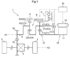
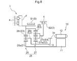
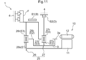
図1に示すように、車両用駆動装置1は、回転電機10と、車輪2に駆動連結される出力部材3と、回転電機10と出力部材3との間の動力伝達経路に設けられる第1差動歯車装置21とを備えている。本実施形態の車両用駆動装置1は、更に、第1差動歯車装置21と出力部材3との間の動力伝達経路に第2差動歯車装置22を備えている。また、車両用駆動装置1は、回転電機10及び第1差動歯車装置21を収容するケース4を備えており、このケース4には、第2差動歯車装置22や出力用差動歯車装置5も収容されている。
As shown in FIG. 1, the vehicle drive device 1 is provided in a power transmission path between the rotary electric machine 10, an output member 3 drivingly connected to the wheel 2, and the rotary electric machine 10 and the output member 3. A differential gear device 21 is provided. The vehicle drive device 1 of the present embodiment further includes a second differential gear device 22 in the power transmission path between the first differential gear device 21 and the output member 3. The vehicle drive device 1 further includes a case 4 for housing the rotating electrical machine 10 and the first differential gear device 21. The case 4 includes a second differential gear device 22 and an output differential gear device. 5 is also housed.
車両用駆動装置1は、車輪2の駆動力源として回転電機10を備え、回転電機10の出力トルクを車輪2に伝達させて車両を走行させる。なお、車輪2の駆動力源として内燃機関等の他の駆動力源が車両に設けられ、車両用駆動装置1が、回転電機10及び当該他の駆動力源の一方又は双方の出力トルクを車輪2に伝達させて車両を走行させる構成とすることもできる。ここで、内燃機関は、機関内部における燃料の燃焼により駆動されて動力を取り出す原動機(ガソリンエンジンやディーゼルエンジン等)である。
The vehicle drive device 1 includes a rotating electrical machine 10 as a driving force source of the wheel 2 and transmits the output torque of the rotating electrical machine 10 to the wheel 2 to drive the vehicle. It should be noted that another driving power source such as an internal combustion engine is provided in the vehicle as a driving power source of the wheel 2, and the vehicle drive device 1 outputs the output torque of one or both of the rotating electric machine 10 and the other driving power source. It can also be configured to be transmitted to 2 and run the vehicle. Here, the internal combustion engine is a prime mover (a gasoline engine, a diesel engine, etc.) which is driven by combustion of fuel inside the engine to extract power.
車両用駆動装置1は、出力部材3と左右2つの車輪2との間の動力伝達経路に出力用差動歯車装置5を備えている。出力用差動歯車装置5は、出力部材3に設けられた出力ギヤ3aに噛み合う差動入力ギヤ5aを備えており、出力部材3から差動入力ギヤ5aに入力されたトルクを、左右2つの車輪2に分配して伝達する。このように、本実施形態では、回転電機10が左右2つの車輪2に駆動連結される構成(すなわち、回転電機10が当該2つの車輪2の駆動力源である構成)としているが、車両用駆動装置1が出力用差動歯車装置5を備えず、回転電機10が1つの車輪2にのみ駆動連結される構成であっても良い。
The vehicle drive device 1 includes an output differential gear device 5 in a power transmission path between the output member 3 and the two left and right wheels 2. The output differential gear device 5 includes a differential input gear 5a meshing with an output gear 3a provided on the output member 3. The torque input from the output member 3 to the differential input gear 5a can be divided into two left and right Distributed to wheels 2 and transmitted. As described above, in the present embodiment, the rotary electric machine 10 is configured to be drivingly connected to the left and right two wheels 2 (that is, the rotary electric machine 10 is a driving force source of the two wheels 2). The drive device 1 may not include the output differential gear device 5, and the rotary electric machine 10 may be drivingly connected to only one wheel 2.
図1に示すように、回転電機10、出力部材3、及び第1差動歯車装置21が、同軸に(ここでは、第1軸A1上に)配置されている。本実施形態では、第2差動歯車装置22も、第1軸A1上に配置されている。すなわち、第2差動歯車装置22は、第1差動歯車装置21と同軸に配置されている。一方、出力用差動歯車装置5は、第1軸A1に平行であり且つ第1軸A1とは異なる第2軸A2上に配置されている。第1軸A1や第2軸A2は仮想軸である。なお、図1では、第2差動歯車装置22が、軸方向において、第1差動歯車装置21に対して回転電機10側とは反対側に配置される場合を例示しているが、第2差動歯車装置22が、当該軸方向における第1差動歯車装置21と回転電機10との間に配置される構成であっても良い。
As shown in FIG. 1, the rotary electric machine 10, the output member 3, and the first differential gear device 21 are coaxially arranged (here, on the first axis A1). In the present embodiment, the second differential gear device 22 is also disposed on the first axis A1. That is, the second differential gear device 22 is disposed coaxially with the first differential gear device 21. On the other hand, the output differential gear device 5 is disposed on a second axis A2 which is parallel to the first axis A1 and different from the first axis A1. The first axis A1 and the second axis A2 are virtual axes. Although FIG. 1 illustrates the case where the second differential gear device 22 is disposed on the opposite side of the first differential gear device 21 in the axial direction with respect to the rotary electric machine 10 side, The two differential gear devices 22 may be arranged between the first differential gear device 21 and the rotary electric machine 10 in the axial direction.
回転電機10は、ケース4に固定されるステータ12と、ステータ12に対して回転自在に支持されるロータ11とを備えている。回転電機10は、バッテリやキャパシタ等の蓄電装置(図示せず)と電気的に接続されており、蓄電装置から電力の供給を受けて力行し、或いは、車両の慣性力等により発電した電力を蓄電装置に供給して蓄電させる。
The rotary electric machine 10 includes a stator 12 fixed to the case 4 and a rotor 11 rotatably supported with respect to the stator 12. The rotating electrical machine 10 is electrically connected to a storage device (not shown) such as a battery or a capacitor, receives power supply from the storage device to perform power running, or generates power generated by the inertial force of a vehicle or the like. Supply to the power storage device for storage.
第1差動歯車装置21は、回転電機10に駆動連結される第1回転要素E1と、出力部材3に駆動連結される第2回転要素E2と、ワンウェイクラッチFによってケース4に選択的に固定されると共に摩擦ブレーキBによってケース4に選択的に固定される第3回転要素E3とを備えている。第1回転要素E1は、第1差動歯車装置21の他の回転要素を介することなく、更にはクラッチCを介することなく、回転電機10に駆動連結されている。第2回転要素E2は、第1差動歯車装置21の他の回転要素を介することなく、更にはクラッチCを介することなく、出力部材3に駆動連結されている。第1回転要素E1は、回転電機10(ロータ11)と一体回転するように連結されている。第2回転要素E2は、第2差動歯車装置22を介して出力部材3に駆動連結されている。
The first differential gear device 21 is selectively fixed to the case 4 by the first rotating element E1 drivingly connected to the rotating electrical machine 10, the second rotating element E2 drivingly connected to the output member 3, and the one-way clutch F And a third rotating element E3 selectively fixed to the case 4 by the friction brake B. The first rotary element E1 is drivably connected to the rotary electric machine 10 without passing through the other rotary elements of the first differential gear device 21 and further without passing through the clutch C. The second rotating element E2 is drivably connected to the output member 3 without passing through the other rotating elements of the first differential gear device 21 and further without passing through the clutch C. The first rotating element E1 is connected to rotate integrally with the rotating electrical machine 10 (the rotor 11). The second rotating element E2 is drivably connected to the output member 3 via the second differential gear device 22.
車両用駆動装置1は、摩擦ブレーキBとは別に、係合装置Dを備えている。この係合装置Dは、係合状態で第1差動歯車装置21の状態を第3回転要素が固定されて形成される状態とは異なる状態とする。本実施形態の係合装置DはクラッチCで構成されており、第1回転要素E1、第2回転要素E2、及び第3回転要素E3のうちの2つの回転要素が、クラッチCにより選択的に連結される。本実施形態では、クラッチCは、第1回転要素E1と第2回転要素E2とを選択的に連結するように設けられている。クラッチCとして、例えば、油圧駆動式の摩擦係合装置や電磁駆動式の摩擦係合装置を用いることができる。
The vehicle drive device 1 includes an engagement device D separately from the friction brake B. In the engaged state, the engagement device D sets the state of the first differential gear device 21 to a state different from the state in which the third rotating element is fixed and formed. The engagement device D of this embodiment is configured by a clutch C, and two of the first rotation element E1, the second rotation element E2, and the third rotation element E3 are selectively selected by the clutch C. It is connected. In the present embodiment, the clutch C is provided to selectively connect the first rotating element E1 and the second rotating element E2. As the clutch C, for example, a hydraulic drive type friction engagement device or an electromagnetic drive type friction engagement device can be used.
第1差動歯車装置21は、1つの遊星歯車機構により構成されており、第1回転要素E1、第2回転要素E2、及び第3回転要素E3の、3つの回転要素のみを備えている。本実施形態では、第1差動歯車装置21は、シングルピニオン型の遊星歯車機構で構成されている。そして、当該遊星歯車機構のサンギヤ(第1サンギヤ21s)が第1回転要素E1であり、キャリヤ(第1キャリヤ21c)が第2回転要素E2であり、リングギヤ(第1リングギヤ21r)が第3回転要素E3である。よって、本実施形態では、図2に示すように、3つの回転要素E1~E3の回転速度の順は、第1回転要素E1、第2回転要素E2、及び第3回転要素E3の順である。
The first differential gear device 21 is configured by one planetary gear mechanism, and includes only three rotating elements of a first rotating element E1, a second rotating element E2, and a third rotating element E3. In the present embodiment, the first differential gear device 21 is configured by a single pinion type planetary gear mechanism. The sun gear (first sun gear 21s) of the planetary gear mechanism is the first rotation element E1, the carrier (first carrier 21c) is the second rotation element E2, and the ring gear (first ring gear 21r) is the third rotation. It is an element E3. Therefore, in the present embodiment, as shown in FIG. 2, the order of the rotational speeds of the three rotary elements E1 to E3 is the order of the first rotary element E1, the second rotary element E2, and the third rotary element E3. .
ここで、「回転速度の順」とは、各回転要素の回転状態における回転速度の順番のことである。各回転要素の回転速度は、差動歯車装置の回転状態によって変化するが、各回転要素の回転速度の高低の並び順は、差動歯車装置の構造によって定まるものであるため一定となる。なお、「各回転要素の回転速度の順」は、各回転要素の速度線図(共線図、図2参照)における配置順に等しい。ここで、「各回転要素の速度線図における配置順」とは、速度線図(共線図)における各回転要素に対応する軸が、当該軸に直交する方向に沿って配置される順番のことである。速度線図(共線図)における各回転要素に対応する軸の配置方向は、速度線図の描き方によって異なるが、その配置順は差動歯車装置の構造によって定まるものであるため一定となる。
Here, "the order of the rotational speed" is the order of the rotational speed in the rotational state of each rotating element. The rotational speed of each rotary element changes depending on the rotational state of the differential gear device, but the order of the rotational speeds of the rotational elements is determined by the structure of the differential gear device, and is constant. Note that “the order of the rotational speeds of the respective rotating elements” is equal to the arrangement order in the velocity diagram (see the alignment chart, FIG. 2) of the respective rotating elements. Here, "the order of arrangement of the rotational elements in the velocity diagram" is the order of arrangement of the axes corresponding to the respective rotational elements in the velocity diagram (collinear diagram) along the direction orthogonal to the axes. It is. The arrangement direction of the axis corresponding to each rotation element in the velocity diagram (collinear diagram) varies depending on how the velocity diagram is drawn, but the arrangement order is fixed because it is determined by the structure of the differential gear device .
第2差動歯車装置22は、回転速度の順に、第2回転要素E2に駆動連結される第4回転要素E4と、出力部材3に駆動連結される第5回転要素E5と、ケース4に固定される第6回転要素E6とを備えている。すなわち、第2差動歯車装置22は減速機構として構成されており、第1差動歯車装置21側から第4回転要素E4に入力された回転を、第2差動歯車装置22のギヤ比に応じた変速比で減速して、第5回転要素E5から出力部材3側に出力する。第4回転要素E4は、第2差動歯車装置22の他の回転要素を介することなく、第2回転要素E2に駆動連結されている。第5回転要素E5は、第2差動歯車装置22の他の回転要素を介することなく、出力部材3に駆動連結されている。第4回転要素E4は、第2回転要素E2と一体回転するように連結されている。第5回転要素E5は、出力部材3と一体回転するように連結されている。
The second differential gear device 22 is fixed to the case 4 in the order of rotational speed, the fourth rotation element E4 drivingly connected to the second rotation element E2, the fifth rotation element E5 drivingly connected to the output member 3, and And a sixth rotating element E6. That is, the second differential gear device 22 is configured as a speed reduction mechanism, and the rotation input from the first differential gear device 21 to the fourth rotating element E4 is the gear ratio of the second differential gear device 22. It decelerates by the gear ratio according to, and outputs to the output member 3 side from the 5th rotation element E5. The fourth rotating element E4 is drivingly connected to the second rotating element E2 without passing through the other rotating elements of the second differential gear device 22. The fifth rotating element E5 is drivably connected to the output member 3 without passing through the other rotating elements of the second differential gear device 22. The fourth rotation element E4 is coupled to rotate integrally with the second rotation element E2. The fifth rotation element E5 is coupled to the output member 3 so as to rotate integrally therewith.
第2差動歯車装置22は、1つのシングルピニオン型の遊星歯車機構で構成されている。そして、当該遊星歯車機構のサンギヤ(第2サンギヤ22s)が第4回転要素E4であり、キャリヤ(第2キャリヤ22c)が第5回転要素E5であり、リングギヤ(第2リングギヤ22r)が第6回転要素である。
The second differential gear device 22 is configured by one single pinion type planetary gear mechanism. The sun gear (second sun gear 22s) of the planetary gear mechanism is the fourth rotation element E4, the carrier (second carrier 22c) is the fifth rotation element E5, and the ring gear (second ring gear 22r) is the sixth rotation. It is an element.
上述したように、第3回転要素E3は、ワンウェイクラッチFによってケース4に選択的に固定されると共に摩擦ブレーキBによってケース4に選択的に固定される。すなわち、車両用駆動装置1は、第3回転要素E3をケース4に選択的に固定するために、ワンウェイクラッチF及び摩擦ブレーキBの双方を備えている。
As described above, the third rotating element E3 is selectively fixed to the case 4 by the one-way clutch F and selectively fixed to the case 4 by the friction brake B. That is, the vehicle drive device 1 includes both the one-way clutch F and the friction brake B in order to selectively fix the third rotating element E3 to the case 4.
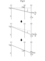
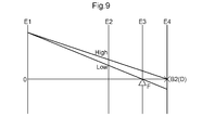
ワンウェイクラッチFは、少なくとも、第3回転要素E3の一方向の回転を規制する一方向規制状態と、第3回転要素E3の双方向の回転を規制する回転規制状態とに切替可能に構成されている。そして、回転電機10が前進力行方向の正転トルク(車両を前進させる前進加速方向のトルク;以下、「正トルクT1」と言う。)を出力した場合に第3回転要素E3に作用する反力トルクを第1反力トルクTR1として(図2参照)、ワンウェイクラッチFは、一方向規制状態で、第3回転要素E3の第1反力トルクTR1による回転方向の回転を規制するように構成されている。すなわち、ワンウェイクラッチFは、一方向規制状態で、第3回転要素E3に作用する第1反力トルクTR1により係合することで、第3回転要素E3の一方向の回転(第1反力トルクTR1による回転方向の回転)を規制する。なお、図2において、上向きの三角形が、一方向規制状態のワンウェイクラッチFを表している。
The one-way clutch F is configured to be switchable between at least a one-way restricting state that restricts the one-way rotation of the third rotating element E3 and a rotation restricting state that restricts the two-way rotation of the third rotating element E3. There is. The reaction force acting on the third rotation element E3 when the rotary electric machine 10 outputs forward rotation torque in the forward power running direction (torque in the forward acceleration direction for advancing the vehicle; hereinafter referred to as "positive torque T1"). The torque is set as the first reaction force torque TR1 (see FIG. 2), and the one-way clutch F is configured to restrict rotation of the third rotation element E3 in the rotation direction by the first reaction force torque TR1 in the one-way restriction state. ing. That is, the one-way clutch F engages with the first reaction force torque TR1 acting on the third rotation element E3 in the one-way restricted state, thereby rotating the third rotation element E3 in one direction (first reaction force torque Regulating rotation in the direction of rotation by TR1). In FIG. 2, the upward triangle represents the one-way clutch F in the one-way restricted state.
また、回転電機10が逆転トルク(正転トルクT1(正トルクT1)とは反対方向のトルクであって、車両を制動させる前進減速方向のトルク;以下、「負トルクT2」と言う。)を出力した場合に第3回転要素E3に作用する反力トルクを第2反力トルクTR2として(図3参照)、ワンウェイクラッチFは、図2に示す一方向規制状態で、第3回転要素E3の第2反力トルクTR2による回転方向の回転を許容するように構成されている。すなわち、ワンウェイクラッチFは、一方向規制状態で、第3回転要素E3に作用する第2反力トルクTR2により解放される。このように、一方向規制状態のワンウェイクラッチFは、第3回転要素E3に作用する第1反力トルクTR1により係合すると共に第3回転要素E3に作用する第2反力トルクTR2により解放されることで、第3回転要素E3の一方向の回転(第1反力トルクTR1による回転方向の回転)だけを規制する。
In addition, the rotating electric machine 10 is a reverse rotation torque (a torque in the opposite direction to the forward rotation torque T1 (positive torque T1) and a torque in the forward / decelerating direction to brake the vehicle; hereinafter referred to as "negative torque T2"). When the reaction force torque acting on the third rotating element E3 is output as the second reaction force torque TR2 (see FIG. 3), the one-way clutch F is in the one-way restricted state shown in FIG. It is comprised so that rotation of the rotation direction by 2nd reaction force torque TR2 is permitted. That is, the one-way clutch F is released by the second reaction force torque TR2 acting on the third rotating element E3 in the one-way restricted state. As described above, the one-way clutch F in the one-way restricted state is engaged by the first reaction force torque TR1 acting on the third rotation element E3 and released by the second reaction force torque TR2 acting on the third rotation element E3. Thus, only rotation in one direction of the third rotary element E3 (rotation in the rotational direction by the first reaction force torque TR1) is restricted.
なお、本実施形態では、回転速度の順が、第1回転要素E1、第2回転要素E2、及び第3回転要素E3の順であるため、図2に示すように第1反力トルクTR1は正トルクT1とは反対方向のトルクとなり、図3に示すように第2反力トルクTR2は負トルクT2とは反対方向のトルクとなる。よって、車両の前進走行時の第2回転要素E2の回転方向を正方向として(以下、同様)、第3回転要素E3の負方向の回転が一方向規制状態のワンウェイクラッチFによって規制され、第3回転要素E3の正方向の回転は一方向規制状態のワンウェイクラッチFによっては規制されずに許容される。
In the present embodiment, since the order of the rotational speed is the order of the first rotation element E1, the second rotation element E2, and the third rotation element E3, as shown in FIG. 2, the first reaction force torque TR1 is The torque in the opposite direction to the positive torque T1 is obtained, and as shown in FIG. 3, the second reaction force torque TR2 is a torque in the opposite direction to the negative torque T2. Therefore, the rotation direction of the third rotation element E3 is restricted by the one-way clutch F in the one-way restriction state, with the rotation direction of the second rotation element E2 as the forward direction (following, the same) The forward rotation of the three-rotation element E3 is permitted without being restricted by the one-way clutch F in the one-way restricted state.
また、ワンウェイクラッチFは、図3に示す回転規制状態で、第3回転要素E3の第1反力トルクTR1による回転方向の回転を規制すると共に第3回転要素E3の第2反力トルクTR2による回転方向の回転も規制する。これにより、回転規制状態のワンウェイクラッチFは、第3回転要素E3の回転を正方向にも負方向にも規制して、第3回転要素E3をケース4に固定する。なお、図3において、上向きの三角形と下向きの三角形とを組み合わせた図形が、回転規制状態のワンウェイクラッチFを表している。
Further, in the rotation restricted state shown in FIG. 3, the one-way clutch F restricts the rotation in the rotational direction by the first reaction force torque TR1 of the third rotating element E3 and the second reaction force torque TR2 of the third rotating element E3. It also regulates rotation in the direction of rotation. Thereby, the one-way clutch F in the rotation restricted state restricts the rotation of the third rotating element E3 in the positive direction and the negative direction, and fixes the third rotating element E3 to the case 4. In FIG. 3, a graphic combining an upward triangle and a downward triangle represents the one-way clutch F in the rotation restricted state.
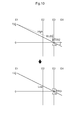
本実施形態のワンウェイクラッチFは、一方向規制状態と回転規制状態とに加え、更に、第3回転要素E3の他の一方向の回転を規制する他方向規制状態と、第3回転要素E3の双方向の回転を許容する規制無効状態とに切替可能に構成されている。このようなワンウェイクラッチFとしては、種々の形式の、一方向規制状態と他方向規制状態と回転規制状態と規制無効状態とに切替可能なツーウェイクラッチ(セレクタブルツーウェイクラッチ)を用いることができる。すなわち、そのようなツーウェイクラッチの一部の機能を流用して、本実施形態のワンウェイクラッチFを構成することができる。本実施形態では、そのようなツーウェイクラッチの一部の機能を流用したものも、「ワンウェイクラッチF」と称する。
The one-way clutch F according to the present embodiment further includes, in addition to the one-way restricted state and the rotation restricted state, the other-direction restricted state for restricting the rotation of the third rotating element E3 in the other direction; It is configured to be switchable to a restriction disabled state that allows bi-directional rotation. As such a one-way clutch F, it is possible to use various types of two-way clutches (selectable two-way clutches) that can be switched between one-way restricted state, other direction restricted state, rotation restricted state and restricted state. That is, the one-way clutch F of this embodiment can be configured by diverting part of the functions of such two-way clutch. In this embodiment, a part of the function of such a two-way clutch is also referred to as "one-way clutch F".
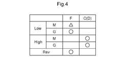
車両用駆動装置1は、上述したようなワンウェイクラッチF及びクラッチCを備えているため、図4に示すように、回転電機10の正トルクT1を車輪2に伝達させて車両を前進走行させる前進用の変速段として、2つの変速段を切替可能に形成することができる。なお、本実施形態では、第3回転要素E3をケース4に選択的に固定するため摩擦ブレーキBは、変速段を形成(維持)する目的では係合されない。摩擦ブレーキBを設けることの意義については、後述する。
Since the vehicle drive device 1 is provided with the one-way clutch F and the clutch C as described above, as shown in FIG. 4, the forward torque T1 of the rotary electric machine 10 is transmitted to the wheels 2 to move the vehicle forward. Two gear stages can be formed switchably as gear stages for the motor. In the present embodiment, in order to selectively fix the third rotating element E3 to the case 4, the friction brake B is not engaged for the purpose of forming (maintaining) the gear. The significance of providing the friction brake B will be described later.
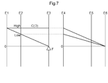
車両用駆動装置1は、2つの変速段として、低速段(Low)と高速段(High)とを形成可能である。ここで、低速段(Low)は、回転電機10側から第1回転要素E1に入力される正方向の回転を、第1差動歯車装置21のギヤ比に応じた変速比で減速して第2回転要素E2から出力部材3側に出力する変速段(減速段)である。高速段(High)は、回転電機10側から第1回転要素E1に入力される正方向の回転を、そのままの回転速度で第2回転要素E2から出力部材3側に出力する変速段(直結段)である。
The vehicle drive device 1 can form a low speed (Low) and a high speed (High) as the two shift speeds. Here, in the low-speed stage (Low), the rotation in the positive direction, which is input to the first rotating element E1 from the rotating electrical machine 10 side, is reduced by a speed ratio corresponding to the gear ratio of the first differential gear device 21 It is a shift stage (deceleration stage) that is output from the 2-rotation element E2 to the output member 3 side. The high-speed stage (High) is a shift stage that directly outputs the rotation in the positive direction input from the rotating electrical machine 10 to the first rotating element E1 from the second rotating element E2 to the output member 3 at the same rotational speed ).
また、車両用駆動装置1は、回転電機10の負トルクT2を車輪2に伝達させて車両を後進走行させる後進用の変速段(後進段;Rev)を形成することができる。後進段(Rev)は、回転電機10側から第1回転要素E1に入力される負方向の回転を、第1差動歯車装置21のギヤ比に応じた変速比で減速して第2回転要素E2から出力部材3側に出力する変速段となっている。
In addition, the vehicle drive device 1 can form a reverse gear (Rev) for transmitting the negative torque T2 of the rotary electric machine 10 to the wheels 2 to cause the vehicle to travel backward. The reverse gear (Rev) decelerates the rotation in the negative direction, which is input to the first rotating element E1 from the rotating electrical machine 10 side, at a gear ratio corresponding to the gear ratio of the first differential gear device 21, and generates a second rotating element. It is a shift stage that is output from E2 to the output member 3 side.
なお、図4の作動表において、ワンウェイクラッチFについての三角印は、一方向規制状態であることを示し、丸印は、回転規制状態であることを示し、無印は、一方向規制状態又は規制無効状態であることを示している。また、クラッチCについての丸印は、係合された状態であることを示し、無印は、解放された状態であることを示している。また、“M”は、回転電機10が正トルクT1を出力している状態(力行状態)を示し、“G”は、回転電機10が負トルクT2を出力している状態(回生状態)を示している。
In the operation table of FIG. 4, a triangular mark for the one-way clutch F indicates that it is in the one-way restricted state, a circle indicates that it is in the rotation restricted state, and a non-mark indicates that it is in the one-way restricted state. It indicates that it is in an invalid state. Also, a circle for the clutch C indicates that it is in the engaged state, and no indicates that it is in the released state. Further, "M" indicates a state (powering state) in which the rotary electric machine 10 outputs a positive torque T1, and "G" indicates a state (regeneration state) in which the rotary electric machine 10 outputs a negative torque T2. It shows.
図4に示すように、低速段(Low)は、クラッチCが解放された状態で、回転電機10のトルクの出力状態に応じてワンウェイクラッチFを一方向規制状態又は回転規制状態とすることで形成される。前進力行時の低速段(M-Low)は、クラッチCが解放された状態で、ワンウェイクラッチFを一方向規制状態とすることで形成される。図2に示すように、回転電機10が正トルクT1を出力することによって第3回転要素E3に作用する第1反力トルクTR1を、一方向規制状態のワンウェイクラッチFにより回転が規制された状態の第3回転要素E3によって受けることができる。これにより、回転電機10側から第1回転要素E1に入力された正方向の回転を、第1差動歯車装置21のギヤ比に応じた変速比で減速して、第2回転要素E2から出力部材3側に出力することができる。
As shown in FIG. 4, in the low speed stage (Low), the one-way clutch F is set to the one-way restricted state or the rotation restricted state according to the torque output state of the rotary electric machine 10 in the state where the clutch C is released. It is formed. The low speed gear (M-Low) at the time of forward power running is formed by setting the one-way clutch F in a one-way restricted state with the clutch C released. As shown in FIG. 2, when the rotating electric machine 10 outputs the positive torque T1, the first reaction force torque TR1 acting on the third rotating element E3 is restricted in rotation by the one-way clutch F in the one-way restriction state. Can be received by the third rotating element E3. Thereby, the rotation in the positive direction input from the rotary electric machine 10 side to the first rotating element E1 is decelerated at a gear ratio according to the gear ratio of the first differential gear device 21, and output from the second rotating element E2 It can be output to the member 3 side.
一方、前進回生時の低速段(G-Low)は、クラッチCが解放された状態で、ワンウェイクラッチFを回転規制状態とすることで形成される。図3に示すように、回転電機10が負トルクT2を出力することによって第3回転要素E3に作用する第2反力トルクTR2を、回転規制状態のワンウェイクラッチFにより回転が規制された状態の第3回転要素E3によって受けることができる。なお、前進力行時の低速段(M-Low)と同様にワンウェイクラッチFを一方向規制状態とする場合には、第3回転要素E3に作用する第2反力トルクTR2によって当該ワンウェイクラッチFが解放されるため、低速段(G-Low)を適切に形成できない。そこで、ワンウェイクラッチFを回転規制状態とすることにより、前進回生時の低速段(G-Low)を適切に形成可能としている。
On the other hand, the low speed gear (G-Low) at the time of forward regeneration is formed by setting the one-way clutch F in the rotation restriction state in a state where the clutch C is released. As shown in FIG. 3, the rotation of the second reaction force torque TR2 acting on the third rotation element E3 by the rotary electric machine 10 outputting the negative torque T2 is restricted by the one-way clutch F in the rotation restricted state. It can be received by the third rotating element E3. When the one-way clutch F is in the one-way restricted state as in the low-speed gear (M-Low) at the time of forward power running, the one-way clutch F is operated by the second reaction force torque TR2 acting on the third rotation element E3. As it is released, the low speed stage (G-Low) can not be properly formed. Therefore, by setting the one-way clutch F in the rotation restriction state, it is possible to appropriately form the low speed gear (G-Low) at the time of forward regeneration.
図4に示すように、高速段(High)は、回転電機10のトルクの出力状態によらずに(言い換えれば、前進力行時及び前進回生時の双方で)、ワンウェイクラッチFが一方向規制状態又は規制無効状態とされた状態でクラッチCを係合させることで形成される。クラッチCを係合させることで、第1差動歯車装置21の全ての回転要素が同速で一体回転する状態(すなわち、第1差動歯車装置21の差動回転が禁止される状態)となる。これにより、図2及び図3に示すように、回転電機10側から第1回転要素E1に入力された正方向の回転を、そのままの回転速度で、第2回転要素E2から出力部材3側に出力することができる。
As shown in FIG. 4, in the high speed stage (High), the one-way clutch F is in the one-way restricted state regardless of the torque output state of the rotary electric machine 10 (in other words, in both forward power running and forward regeneration). Or, it is formed by engaging the clutch C in a state in which the restriction invalid state is made. By engaging the clutch C, all the rotating elements of the first differential gear device 21 integrally rotate at the same speed (that is, the differential rotation of the first differential gear device 21 is prohibited) Become. Thereby, as shown in FIG. 2 and FIG. 3, the rotation in the positive direction inputted from the rotating electrical machine 10 side to the first rotating element E1 from the second rotating element E2 to the output member 3 side at the same rotational speed It can be output.
図4に示すように、後進段(Rev)は、クラッチCが解放された状態で、ワンウェイクラッチFを回転規制状態とすることで形成される。図3に示すように、回転電機10が負トルクT2を出力することによって第3回転要素E3に作用する第2反力トルクTR2を、回転規制状態のワンウェイクラッチFにより回転が規制された状態の第3回転要素E3によって受けることができる。これにより、回転電機10側から第1回転要素E1に入力された負方向の回転を、第1差動歯車装置21のギヤ比に応じた変速比で減速して、第2回転要素E2から出力部材3側に出力することができる。
As shown in FIG. 4, the reverse gear (Rev) is formed by bringing the one-way clutch F into a rotation restriction state with the clutch C released. As shown in FIG. 3, the rotation of the second reaction force torque TR2 acting on the third rotation element E3 by the rotary electric machine 10 outputting the negative torque T2 is restricted by the one-way clutch F in the rotation restricted state. It can be received by the third rotating element E3. Thereby, the rotation in the negative direction input to the first rotating element E1 from the rotary electric machine 10 side is decelerated at a gear ratio according to the gear ratio of the first differential gear device 21, and output from the second rotating element E2 It can be output to the member 3 side.
図1に示すように、車両用駆動装置1は、クラッチCの係合の状態と、ワンウェイクラッチFの一方向規制状態と回転規制状態との切替の状態とを制御する制御装置30を備えている。制御装置30は、摩擦ブレーキBの係合の状態や、回転電機10の駆動も制御する。制御装置30は、CPU(Central Processing Unit)等の演算処理装置を中核部材として備えると共に、RAM(Random Access Memory)やROM(Read Only Memory)等の当該演算処理装置が参照可能な記憶装置を備えている。そして、ROM等の記憶装置に記憶されたソフトウェア(プログラム)又は別途設けられた演算回路等のハードウェア、或いはそれらの両方により、制御装置30の各機能が実現される。制御装置30が、互いに通信可能な複数のハードウェア(複数の分離したハードウェア)の集合によって構成されても良い。
As shown in FIG. 1, the vehicle drive device 1 includes a control device 30 that controls a state of engagement of the clutch C and a state of switching between the one-way restricting state and the rotation restricting state of the one-way clutch F. There is. The control device 30 also controls the engagement state of the friction brake B and the drive of the rotary electric machine 10. The control device 30 includes an arithmetic processing unit such as a central processing unit (CPU) as a core member, and includes a storage device to which the arithmetic processing unit such as a random access memory (RAM) or a read only memory (ROM) can refer. ing. Then, each function of the control device 30 is realized by software (program) stored in a storage device such as a ROM, hardware such as an arithmetic circuit provided separately, or both of them. Control device 30 may be configured by a set of a plurality of pieces of hardware (a plurality of separated pieces of hardware) capable of communicating with each other.
制御装置30は、車両に備えられた各種センサによる検出結果の情報(センサ検出情報)を取得可能に構成されている。センサ検出情報は、例えば、アクセル開度の情報、車速の情報、回転電機10に電力を供給する蓄電装置の充電状態又は蓄電量の情報等である。
制御装置30は、制御マップを参照する等して、センサ検出情報に基づき、第1差動歯車装置21において形成する目標変速段や回転電機10の目標トルクを決定する。詳細は省略するが、目標変速段は、低車速域では基本的に低速段(Low)に決定され、高車速域では基本的に高速段(High)に決定される。そして、制御装置30は、決定した目標変速段を形成するように、クラッチCの係合の状態と、ワンウェイクラッチFの切替の状態とを制御する。 Thecontrol device 30 is configured to be able to acquire information (sensor detection information) of detection results by various sensors provided in the vehicle. The sensor detection information is, for example, information on an accelerator opening degree, information on a vehicle speed, information on a state of charge of a power storage device that supplies electric power to the rotary electric machine 10, or information on a storage amount.
Thecontrol device 30 determines a target gear position of the first differential gear device 21 and a target torque of the rotary electric machine 10 based on the sensor detection information by referring to the control map or the like. Although the details will be omitted, the target shift speed is basically determined to be the low speed (Low) in the low vehicle speed region, and is basically determined to be the high speed (High) in the high vehicle speed region. Then, the control device 30 controls the engagement state of the clutch C and the switching state of the one-way clutch F so as to form the determined target shift speed.
制御装置30は、制御マップを参照する等して、センサ検出情報に基づき、第1差動歯車装置21において形成する目標変速段や回転電機10の目標トルクを決定する。詳細は省略するが、目標変速段は、低車速域では基本的に低速段(Low)に決定され、高車速域では基本的に高速段(High)に決定される。そして、制御装置30は、決定した目標変速段を形成するように、クラッチCの係合の状態と、ワンウェイクラッチFの切替の状態とを制御する。 The
The
制御装置30は、例えば、油圧アクチュエータ、電動アクチュエータ、電磁アクチュエータ等のアクチュエータの作動を制御して、クラッチCの係合の状態やワンウェイクラッチFの切替の状態を制御する。また、制御装置30は、決定した目標トルクを出力するように回転電機10を制御する。詳細は省略するが、制御装置30は、蓄電装置の直流電圧を交流電圧に変換して回転電機10に供給するインバータ装置を制御することで、回転電機10の駆動を制御する。
The control device 30 controls the operation of an actuator such as a hydraulic actuator, an electric actuator, or an electromagnetic actuator, for example, to control the engagement state of the clutch C and the switching state of the one-way clutch F. Further, control device 30 controls rotary electric machine 10 to output the determined target torque. Although the details will be omitted, control device 30 controls the drive of rotating electric machine 10 by controlling an inverter device which converts the DC voltage of the power storage device into an AC voltage and supplies it to rotating electric machine 10.
例えば低速段(Low)で車両を走行させる際には、制御装置30は、クラッチCを解放すると共にワンウェイクラッチFを一方向規制状態とする。一方向規制状態のワンウェイクラッチFは、回転電機10の正トルクT1に応じて第3回転要素E3に作用する第1反力トルクTR1によって自動的に係合する。このため、回転電機10に正トルクT1を出力させて車両を発進させる際に特段の制御を実行する必要がなく、制御の簡素化を図ることができる。また、一方向規制状態のワンウェイクラッチFが自動的に係合するのと同時に、回転電機10からのトルクが車輪2に伝達可能な状態となる。従って、回転電機10のトルクにより車両を発進させる際の制御を簡素化できると共に、車両の発進の際に回転電機10からのトルクを即座に車輪2に伝達可能な状態とすることができる。従って、ゼロ回転から比較的大きなトルクを出力可能な回転電機10の特性を活かしやすい。
For example, when the vehicle travels at a low speed (Low), the control device 30 releases the clutch C and puts the one-way clutch F in a one-way restricted state. The one-way clutch F in the one-way restricted state is automatically engaged by the first reaction force torque TR1 acting on the third rotating element E3 according to the positive torque T1 of the rotary electric machine 10. For this reason, when making the rotary electric machine 10 output the positive torque T1 and start the vehicle, it is not necessary to execute special control, and the control can be simplified. At the same time as the one-way clutch F in the one-way restricted state is automatically engaged, the torque from the rotating electrical machine 10 can be transmitted to the wheel 2. Therefore, the control when starting the vehicle can be simplified by the torque of the rotating electrical machine 10, and the torque from the rotating electrical machine 10 can be immediately transmitted to the wheel 2 when the vehicle is started. Therefore, it is easy to take advantage of the characteristics of the rotary electric machine 10 capable of outputting relatively large torque from zero rotation.
また例えば、車速域での前進力行時に車速が次第に低下して低車速域にシフトした場合、制御装置30において、目標変速段が高速段(High)から低速段(Low)へと変更される場合がある。このような場合には、制御装置30は、ワンウェイクラッチFを一方向規制状態とすると共に、高速段(High)の形成時に係合されていたクラッチCを解放させる。すると、第1差動歯車装置21の差動回転が許容されると共に、回転電機10の正トルクT1に応じて第3回転要素E3に作用する第1反力トルクTR1により、第3回転要素E3の回転速度が次第に低下していく。やがて第3回転要素E3の回転速度がゼロとなると、一方向規制状態のワンウェイクラッチFが自動的に係合し、新たに低速段(Low)が形成される。このように、前進力行時には、ワンウェイクラッチFを一方向規制状態とすると共にクラッチCを解放させるだけの簡単な制御で、高速段(High)から低速段(Low)への変速段の切り替えを半自動的に行うことができる。
Further, for example, when the vehicle speed gradually decreases and shifts to the low vehicle speed region during forward power running in the vehicle speed region, in the control device 30, the target gear is changed from high gear (High) to low gear (Low) There is. In such a case, the control device 30 sets the one-way clutch F in the one-way restricted state and releases the clutch C engaged at the time of the formation of the high gear (High). Then, the differential rotation of the first differential gear device 21 is permitted, and the third reaction force torque TR1 acting on the third rotation element E3 in accordance with the positive torque T1 of the rotary electric machine 10 causes the third rotation element E3. The rotational speed of will gradually decrease. When the rotational speed of the third rotating element E3 eventually becomes zero, the one-way clutch F in the one-way restricted state is automatically engaged, and a low speed (Low) is newly formed. In this way, during forward power running, the shift control from the high gear (High) to the low gear (Low) can be performed semi-automatically by a simple control that brings the one-way clutch F into one-way regulation and releases the clutch C. Can be done.
また例えば、高車速域での前進回生時に車速が次第に低下して低車速域にシフトした場合、制御装置30において、目標変速段が高速段(High)から低速段(Low)へと変更される場合がある。但し、前進回生時に回転電機10の負トルクT2に応じて第3回転要素E3に作用する第2反力トルクTR2は、第3回転要素E3の回転速度を上昇させるように作用するため、前進力行時の場合とは異なり、自動的にはワンウェイクラッチFを係合させることができない。そこで、この車両用駆動装置1は、第3回転要素E3をケース4に選択的に固定するための固定手段として、ワンウェイクラッチFとは別に、それに加えて摩擦ブレーキBを備えている。
Further, for example, when the vehicle speed gradually decreases and shifts to the low vehicle speed region during forward regeneration in the high vehicle speed region, the target shift speed is changed from the high gear (High) to the low gear (Low) in the control device 30 There is a case. However, the second reaction force torque TR2 acting on the third rotating element E3 according to the negative torque T2 of the rotating electrical machine 10 at the time of forward regeneration works to increase the rotational speed of the third rotating element E3, so the forward powering Unlike when, the one-way clutch F can not be automatically engaged. Therefore, the vehicle drive device 1 is provided with a friction brake B in addition to the one-way clutch F as a fixing means for selectively fixing the third rotating element E3 to the case 4.
摩擦ブレーキBは、物体どうしの摩擦抵抗を利用したブレーキ(制動装置)である。摩擦ブレーキBとしては、ブレーキディスクを摩擦材で挟んで締め付けることで制動力を得るディスクブレーキ(単板/多板)、円筒形ドラムにブレーキシューを押し付けることで制動力を得るドラムブレーキ、及び円筒形ドラムの外周を帯状の摩擦材で締め付けることで制動力を得るバンドブレーキ等、種々の形式のものを用いることができる。これらの中では、セルフサーボ効果(自己倍力効果)が期待できる、ドラムブレーキ又はバンドブレーキを好ましく用いることができる。本実施形態では、摩擦ブレーキBは、遊星歯車機構からなる第1差動歯車装置21に対して装置の大型化をほとんど招くことなく組み込むことが可能な、バンドブレーキで構成されている。摩擦ブレーキBは、例えば油圧駆動式や電磁駆動式のものを用いることができる。
The friction brake B is a brake (braking device) using frictional resistance between objects. As the friction brake B, a disc brake (single plate / multiplate) for obtaining a braking force by sandwiching and clamping a brake disc with a friction material, a drum brake for obtaining a braking force by pressing a brake shoe against a cylindrical drum, and a cylinder A variety of types can be used, such as a band brake that obtains a braking force by tightening the outer periphery of the shaped drum with a band-like friction material. Among these, a drum brake or a band brake that can be expected to have a self-servo effect (self-boosting effect) can be preferably used. In the present embodiment, the friction brake B is a band brake that can be incorporated into the first differential gear device 21 composed of a planetary gear mechanism with almost no increase in size of the device. The friction brake B may be, for example, a hydraulic drive type or an electromagnetic drive type.
摩擦ブレーキBをスリップ係合させることで、前進回生時に回転電機10の負トルクT2に応じた正方向の第2反力トルクTR2が第3回転要素E3に作用していても、図5の上段に示すように第3回転要素E3の回転速度を次第に低下させることができる。ここで、「スリップ係合」とは、摩擦ブレーキBの係合部材(例えばバンドブレーキである場合には円筒形ドラムと帯状摩擦材)が、両者間に差回転を有しつつトルクを伝達するように係合している状態を意味する。本実施形態においてバンドブレーキからなる摩擦ブレーキBは、第3回転要素E3の正方向(前進方向)の回転速度を低下させる向きにセルフサーボ効果が生じるように設けられている。このようにすれば、摩擦ブレーキBとしてのバンドブレーキに生じる摩擦力によって帯状摩擦材の円筒形ドラムへの圧接が助長されるので、比較的小型の摩擦ブレーキBを用いつつ、第3回転要素E3の回転速度を適切に低下させることができる。
Even when the second reaction force torque TR2 in the positive direction corresponding to the negative torque T2 of the rotating electrical machine 10 during the forward regeneration is acting on the third rotating element E3 by causing the friction brake B to slip engage, the upper stage in FIG. The rotational speed of the third rotating element E3 can be gradually reduced as shown in FIG. Here, “slip engagement” means that an engagement member of the friction brake B (for example, a cylindrical drum and a band-shaped friction member in the case of a band brake) transmit torque while having a differential rotation between them. It means the state of being engaged. In the present embodiment, the friction brake B, which is a band brake, is provided so as to generate a self-servo effect in the direction of decreasing the rotational speed in the forward direction (forward direction) of the third rotating element E3. In this way, the friction force generated in the band brake as the friction brake B promotes the pressure contact of the band-like friction material to the cylindrical drum, so the third rotating element E3 can be used while using the relatively small friction brake B. The rotation speed of can be reduced appropriately.
摩擦ブレーキBの係合が深まっていくと、やがて第3回転要素E3の回転速度がゼロまで低下する(図5の中段)。この第3回転要素E3の回転速度ゼロの状態で、制御装置30は、高速段(High)の形成時に一方向規制状態とされていたワンウェイクラッチFを、回転規制状態とする(図5の下段)。このように、制御装置30は、クラッチCが係合していると共に回転電機10が負トルクT2を出力している状態から、クラッチCを解放させつつ摩擦ブレーキBをスリップ係合させて第3回転要素E3の回転速度を低下させ、第3回転要素E3の回転速度がゼロとなったらワンウェイクラッチFを回転規制状態とする。これにより、前進回生時においても、クラッチCの解放及び摩擦ブレーキBの係合、並びにワンウェイクラッチFの一方向規制状態から回転規制状態への切り替えを制御することで、高速段(High)から低速段(Low)への変速段の切り替えを行うことができる。
As the engagement of the friction brake B deepens, the rotational speed of the third rotating element E3 eventually decreases to zero (middle stage in FIG. 5). In the state where the rotational speed of the third rotating element E3 is zero, the control device 30 sets the one-way clutch F, which has been in the one-way restriction state when forming the high gear (High), in the rotation restriction state (FIG. 5 lower stage) ). As described above, from the state where the clutch C is engaged and the rotary electric machine 10 outputs the negative torque T2, the control device 30 causes the friction brake B to slip engage while releasing the clutch C. The rotational speed of the rotary element E3 is reduced, and when the rotational speed of the third rotary element E3 becomes zero, the one-way clutch F is put into the rotation restricted state. Thus, even during forward regeneration, by controlling the release of the clutch C and the engagement of the friction brake B, and the switching of the one-way clutch F from the one-way restricted state to the rotation restricted state, high speed to low speed It is possible to switch the gear to Low.
前進回生時の低速段(G-Low)への切り替えの直後は、摩擦ブレーキBが係合していると共にワンウェイクラッチFが回転規制状態となっている。本実施形態では、制御装置30は、前進回生時にワンウェイクラッチFを回転規制状態として低速段(G-Low)を形成した後、回転電機10が負トルクT2を出力している間(すなわち、その前進回生が継続している間)、回転規制状態を継続させる。制御装置30は、ワンウェイクラッチFを回転規制状態とした後、摩擦ブレーキBを解放させて良い。このように、本実施形態の摩擦ブレーキBは、基本的に、前進回生時に高速段(High)から低速段(Low)への変速段の切り替えを行うためだけに係合され、形成された低速段(Low)を維持する目的では係合されない。このため、摩擦ブレーキBによる最大保持トルクは、ワンウェイクラッチFによる最大保持トルクよりも小さくて良く、この点からも、比較的小型の摩擦ブレーキBを用いることができる。また、摩擦ブレーキBが常開型である場合には、変速段の切替時以外は当該摩擦ブレーキBのアクチュエータを駆動する必要がないので、車両用駆動装置1のエネルギ効率を向上させることができる。
Immediately after switching to the low-speed gear (G-Low) at the time of forward regeneration, the friction brake B is engaged and the one-way clutch F is in the rotation restriction state. In the present embodiment, the control device 30 forms the low speed gear (G-Low) with the one-way clutch F in the rotation restriction state at the time of forward regeneration, while the rotary electric machine 10 outputs the negative torque T2 (that is, While the forward regeneration is continuing), the rotation regulation state is continued. The control device 30 may release the friction brake B after the one-way clutch F is in the rotation restriction state. As described above, the friction brake B according to the present embodiment is basically engaged only to switch the gear from high gear to low gear during forward regeneration, and is formed at a low speed. It is not engaged for the purpose of maintaining Low. Therefore, the maximum holding torque by the friction brake B may be smaller than the maximum holding torque by the one-way clutch F. From this point as well, a relatively small friction brake B can be used. Further, when the friction brake B is of the normally open type, it is not necessary to drive the actuator of the friction brake B except when switching the gear, so that the energy efficiency of the vehicle drive device 1 can be improved. .
〔第2実施形態〕
車両用駆動装置の第2実施形態について、図面を参照して説明する。本実施形態では、第1差動歯車装置21及び第2差動歯車装置22を中核として構成される変速機構の具体的構成が第1実施形態とは異なっている。以下、本実施形態の車両用駆動装置1について、主に第1実施形態との相違点について説明する。なお、特に明記しない点に関しては、第1実施形態と同様であり、同一の符号を付して詳細な説明は省略する。 Second Embodiment
A second embodiment of the vehicle drive device will be described with reference to the drawings. In the present embodiment, the specific configuration of the transmission mechanism configured around the firstdifferential gear device 21 and the second differential gear device 22 is different from that of the first embodiment. Hereinafter, differences between the vehicle drive device 1 of the present embodiment and the first embodiment will be mainly described. In addition, about the point which does not specify in particular, it is the same as that of 1st Embodiment, attaches | subjects the same code | symbol and abbreviate | omits detailed description.
車両用駆動装置の第2実施形態について、図面を参照して説明する。本実施形態では、第1差動歯車装置21及び第2差動歯車装置22を中核として構成される変速機構の具体的構成が第1実施形態とは異なっている。以下、本実施形態の車両用駆動装置1について、主に第1実施形態との相違点について説明する。なお、特に明記しない点に関しては、第1実施形態と同様であり、同一の符号を付して詳細な説明は省略する。 Second Embodiment
A second embodiment of the vehicle drive device will be described with reference to the drawings. In the present embodiment, the specific configuration of the transmission mechanism configured around the first
図6に示すように、本実施形態の第1差動歯車装置21も、第1回転要素E1、第2回転要素E2、及び第3回転要素E3の3つの回転要素のみを備えるシングルピニオン型の遊星歯車機構で構成されている。本実施形態では、当該遊星歯車機構のリングギヤ(第1リングギヤ21r)が第1回転要素E1であり、キャリヤ(第1キャリヤ21c)が第2回転要素E2であり、サンギヤ(第1サンギヤ21s)が第3回転要素E3である。これら3つの回転要素E1~E3の回転速度の順は、図7に示すように、第1回転要素E1、第2回転要素E2、及び第3回転要素E3の順となっている。
As shown in FIG. 6, the first differential gear device 21 of the present embodiment is also a single pinion type having only three rotating elements, the first rotating element E1, the second rotating element E2, and the third rotating element E3. It is composed of a planetary gear mechanism. In this embodiment, the ring gear (first ring gear 21r) of the planetary gear mechanism is the first rotating element E1, the carrier (first carrier 21c) is the second rotating element E2, and the sun gear (first sun gear 21s) is It is a third rotating element E3. As shown in FIG. 7, the order of the rotational speeds of these three rotation elements E1 to E3 is the order of the first rotation element E1, the second rotation element E2, and the third rotation element E3.
また、本実施形態の第2差動歯車装置22も、第4回転要素E4、第5回転要素E5、及び第6回転要素E6の3つの回転要素のみを備えるシングルピニオン型の遊星歯車機構で構成されている。当該遊星歯車機構のサンギヤ(第2サンギヤ22s)が第4回転要素E4であり、キャリヤ(第2キャリヤ22c)が第5回転要素E5であり、リングギヤ(第2リングギヤ22r)が第6回転要素である。これら3つの回転要素E4~E6の回転速度の順は、図7に示すように、第4回転要素E4、第5回転要素E5、及び第6回転要素E6の順となっている。なお、図7には、前進力行時の第1差動歯車装置21及び第2差動歯車装置22の速度線図を示している。
In addition, the second differential gear device 22 of the present embodiment is also configured by a single pinion type planetary gear mechanism provided with only three rotation elements of the fourth rotation element E4, the fifth rotation element E5, and the sixth rotation element E6. It is done. The sun gear (second sun gear 22s) of the planetary gear mechanism is the fourth rotation element E4, the carrier (second carrier 22c) is the fifth rotation element E5, and the ring gear (second ring gear 22r) is the sixth rotation element. is there. As shown in FIG. 7, the order of the rotational speeds of these three rotating elements E4 to E6 is the order of the fourth rotating element E4, the fifth rotating element E5, and the sixth rotating element E6. FIG. 7 shows velocity diagrams of the first differential gear device 21 and the second differential gear device 22 at the time of forward power running.
第2差動歯車装置22は、軸方向において回転電機10と第1差動歯車装置21との間に配置されている。すなわち、これらの軸方向における並び順は、回転電機10、第2差動歯車装置22、第1差動歯車装置21の順となっている。そして、出力ギヤ3aを有する出力部材3は、軸方向において回転電機10と第2差動歯車装置22との間に配置されている。
The second differential gear device 22 is disposed between the rotary electric machine 10 and the first differential gear device 21 in the axial direction. That is, the alignment order in these axial directions is the order of the rotary electric machine 10, the second differential gear device 22, and the first differential gear device 21. The output member 3 having the output gear 3 a is disposed between the rotary electric machine 10 and the second differential gear device 22 in the axial direction.
車両用駆動装置1は、摩擦ブレーキBとは別に、係合装置DとしてのクラッチCを備えている。本実施形態の係合装置Dは、第1差動歯車装置21の第2回転要素E2(第1キャリヤ21c)と第3回転要素E3(第1サンギヤ21s)とを選択的に連結するように設けられている。
The vehicle drive device 1 is provided with a clutch C as an engagement device D separately from the friction brake B. The engagement device D of the present embodiment selectively connects the second rotation element E2 (first carrier 21c) of the first differential gear device 21 and the third rotation element E3 (first sun gear 21s). It is provided.
このような構成の車両用駆動装置1でも、第1実施形態と同様の効果を得ることができる。すなわち、回転電機10のトルクにより車両を発進させる際の制御を簡素化できると共に、車両の発進の際に回転電機10からのトルクを即座に車輪2に伝達可能な状態とすることができる。また、前進力行時に、ワンウェイクラッチFを一方向規制状態とすると共にクラッチCを解放させるだけの簡単な制御で、高速段(High)から低速段(Low)への変速段の切り替えを半自動的に行うことができる。また、前進回生時においても、クラッチCの解放及び摩擦ブレーキBの係合、並びにワンウェイクラッチFの一方向規制状態から回転規制状態への切り替えを制御することで、高速段(High)から低速段(Low)への変速段の切り替えを行うことができる。さらに、変速段の切替時以外は当該摩擦ブレーキBのアクチュエータを駆動する必要がないので、車両用駆動装置1のエネルギ効率を向上させることができる。
The same effect as that of the first embodiment can be obtained by the vehicle drive device 1 having such a configuration. That is, the control when starting the vehicle can be simplified by the torque of the rotating electrical machine 10, and the torque from the rotating electrical machine 10 can be immediately transmitted to the wheel 2 when the vehicle is started. Also, at the time of forward power running, the shift control from high gear (High) to low gear (Low) can be semi-automatically performed by simple control that only one-way clutch F is in one-way restricted state and clutch C is released. It can be carried out. Further, also during forward regeneration, by controlling the release of the clutch C and the engagement of the friction brake B, and the switching from the one-way regulation state of the one-way clutch F to the rotation regulation state, the high speed stage (High) to the low speed stage It is possible to switch the gear to (Low). Furthermore, since it is not necessary to drive the actuator of the friction brake B except when switching the gear position, the energy efficiency of the vehicle drive device 1 can be improved.
〔第3実施形態〕
車両用駆動装置の第3実施形態について、図面を参照して説明する。本実施形態では、変速機構の具体的構成が第1実施形態とは異なっている。以下、本実施形態の車両用駆動装置1について、主に第1実施形態との相違点について説明する。なお、特に明記しない点に関しては、第1実施形態と同様であり、同一の符号を付して詳細な説明は省略する。 Third Embodiment
A third embodiment of the vehicle drive system will be described with reference to the drawings. In the present embodiment, the specific configuration of the transmission mechanism is different from that of the first embodiment. Hereinafter, differences between thevehicle drive device 1 of the present embodiment and the first embodiment will be mainly described. In addition, about the point which does not specify in particular, it is the same as that of 1st Embodiment, attaches | subjects the same code | symbol and abbreviate | omits detailed description.
車両用駆動装置の第3実施形態について、図面を参照して説明する。本実施形態では、変速機構の具体的構成が第1実施形態とは異なっている。以下、本実施形態の車両用駆動装置1について、主に第1実施形態との相違点について説明する。なお、特に明記しない点に関しては、第1実施形態と同様であり、同一の符号を付して詳細な説明は省略する。 Third Embodiment
A third embodiment of the vehicle drive system will be described with reference to the drawings. In the present embodiment, the specific configuration of the transmission mechanism is different from that of the first embodiment. Hereinafter, differences between the
図8に示すように、本実施形態の車両用駆動装置1は、第1回転要素E1、第2回転要素E2、第3回転要素E3、及び第4回転要素E4の4つの回転要素を備える差動歯車装置25を備えている。また、車両用駆動装置1は、摩擦ブレーキBとしての第1ブレーキB1とは別に、係合装置Dとしての第2ブレーキB2を備えている。
As shown in FIG. 8, the vehicle drive device 1 according to the present embodiment includes four rotating elements of a first rotating element E1, a second rotating element E2, a third rotating element E3, and a fourth rotating element E4. A dynamic gear device 25 is provided. In addition to the first brake B1 as the friction brake B, the vehicle drive device 1 further includes a second brake B2 as the engagement device D.
差動歯車装置25の第1回転要素E1は、回転電機10に駆動連結されている。第2回転要素E2は、出力部材3に駆動連結されている。第3回転要素E3は、ワンウェイクラッチFによってケース4に選択的に固定されると共に第1ブレーキB1(摩擦ブレーキB)によってケース4に選択的に固定される。第4回転要素E4は、第2ブレーキB2(係合装置D)によってケース4に選択的に固定される。
The first rotating element E1 of the differential gear device 25 is drivingly connected to the rotating electrical machine 10. The second rotating element E2 is drivingly connected to the output member 3. The third rotating element E3 is selectively fixed to the case 4 by the one-way clutch F, and is selectively fixed to the case 4 by the first brake B1 (friction brake B). The fourth rotating element E4 is selectively fixed to the case 4 by the second brake B2 (engaging device D).
本実施形態の差動歯車装置25は、第1遊星歯車機構26と第2遊星歯車機構27とが組み合わされてなる複合装置として構成されている。第1遊星歯車機構26は、第1サンギヤ26s、第1キャリヤ26c、及び第1リングギヤ26rからなるシングルピニオン型の遊星歯車機構である。第2遊星歯車機構27は、第2サンギヤ27s、第2キャリヤ27c、及び第2リングギヤ27rからなるダブルピニオン型の遊星歯車機構である。
The differential gear device 25 of the present embodiment is configured as a combined device in which a first planetary gear mechanism 26 and a second planetary gear mechanism 27 are combined. The first planetary gear mechanism 26 is a single pinion type planetary gear mechanism including a first sun gear 26s, a first carrier 26c, and a first ring gear 26r. The second planetary gear mechanism 27 is a double pinion type planetary gear mechanism including a second sun gear 27s, a second carrier 27c, and a second ring gear 27r.
第1遊星歯車機構26の第1サンギヤ26sは、回転電機10に駆動連結されている。また、第1遊星歯車機構26の第1キャリヤ26cと第2遊星歯車機構27の第2サンギヤ27sとが一体回転するように連結され、これらは出力部材3に駆動連結されている。また、第1遊星歯車機構26の第1リングギヤ26rと第2遊星歯車機構27の第2リングギヤ27rとが一体回転するように連結され、これらは、ワンウェイクラッチF又は第1ブレーキB1(摩擦ブレーキB)によってケース4に選択的に固定される。また、第2遊星歯車機構27の第2キャリヤ27cは、第2ブレーキB2(係合装置D)によってケース4に選択的に固定される。
The first sun gear 26s of the first planetary gear mechanism 26 is drivingly connected to the rotary electric machine 10. Further, the first carrier 26 c of the first planetary gear mechanism 26 and the second sun gear 27 s of the second planetary gear mechanism 27 are coupled so as to integrally rotate, and these are drivingly coupled to the output member 3. Further, the first ring gear 26r of the first planetary gear mechanism 26 and the second ring gear 27r of the second planetary gear mechanism 27 are coupled so as to integrally rotate, and these are connected by the one-way clutch F or the first brake B1 (friction brake B1 Is selectively fixed to the case 4 by Further, the second carrier 27c of the second planetary gear mechanism 27 is selectively fixed to the case 4 by the second brake B2 (engaging device D).
本実施形態では、第1サンギヤ26sが第1回転要素E1であり、一体回転する第1キャリヤ26c及び第2サンギヤ27sが第2回転要素E2であり、一体回転する第1リングギヤ26r及び第2リングギヤ27rが第3回転要素E3であり、第2キャリヤ27cが第4回転要素E4である。これら4つの回転要素E1~E4の回転速度の順は、図9に示すように、第1回転要素E1、第2回転要素E2、第3回転要素E3、及び第4回転要素E4の順となっている。なお、図9には、前進力行時の差動歯車装置25の速度線図を示している。
In this embodiment, the first sun gear 26s is the first rotating element E1, and the first carrier 26c and the second sun gear 27s, which rotate together, are the second rotating element E2, and the first ring gear 26r and the second ring gear rotate together. 27r is a third rotating element E3, and the second carrier 27c is a fourth rotating element E4. As shown in FIG. 9, the order of the rotational speeds of the four rotating elements E1 to E4 is the order of the first rotating element E1, the second rotating element E2, the third rotating element E3, and the fourth rotating element E4. ing. FIG. 9 shows a velocity diagram of the differential gear device 25 at the time of forward power running.
本実施形態の車両用駆動装置1も、2つの変速段として、低速段(Low)と高速段(High)とを形成可能である。ここで、本実施形態の低速段(Low)は、回転電機10側から第1回転要素E1に入力される正方向の回転を、第1減速比で減速して第2回転要素E2から出力部材3側に出力する変速段(第1減速段)である。高速段(High)は、回転電機10側から第1回転要素E1に入力される正方向の回転を、第1減速比よりも小さい第2減速比で減速して第2回転要素E2から出力部材3側に出力する変速段(第2減速段)である。このように、本実施形態では、2つの変速段として減速比の異なる2つの減速段が切替可能となっている。
The vehicle drive device 1 according to the present embodiment can also form a low gear (Low) and a high gear (High) as the two shift speeds. Here, in the low speed stage (Low) of the present embodiment, the rotation in the positive direction input from the rotary electric machine 10 side to the first rotating element E1 is decelerated by the first reduction ratio to output members from the second rotating element E2 It is a transmission gear (first reduction gear) that is output to the 3 side. The high speed stage (High) decelerates the rotation in the positive direction input from the rotating electric machine 10 side to the first rotating element E1 at a second reduction ratio smaller than the first reduction ratio, and outputs a member from the second rotating element E2 It is a shift gear (second reduction gear) that is output to the 3 side. As described above, in this embodiment, two reduction gears having different reduction ratios can be switched as the two shift gears.
前進力行時の低速段(Low)は、第2ブレーキB2が解放された状態で、ワンウェイクラッチFを一方向規制状態とすることで形成される(図9を参照)。そして、一方向規制状態のワンウェイクラッチFにより第3回転要素E3がケース4に固定された状態で、回転電機10側から第1回転要素E1に入力された正方向の回転を、第1遊星歯車機構26のギヤ比に応じた第1減速比で減速して、第2回転要素E2から出力部材3側に出力することができる。また、前進回生時の低速段(Low)は、第2ブレーキB2が解放された状態で、ワンウェイクラッチFを回転規制状態とすることで形成される。
The low speed stage (Low) at the time of forward power running is formed by bringing the one-way clutch F into a one-way restricted state with the second brake B2 released (see FIG. 9). Then, in a state in which the third rotating element E3 is fixed to the case 4 by the one-way clutch F in the one-way restricted state, the rotation in the positive direction input from the rotating electrical machine 10 to the first rotating element E1 is a first planetary gear It can decelerate by the 1st reduction ratio according to the gear ratio of mechanism 26, and can output to the output member 3 side from the 2nd rotation element E2. Further, the low speed stage (Low) at the time of forward regeneration is formed by setting the one-way clutch F in the rotation restricted state in a state where the second brake B2 is released.
また、前進力行時及び前進回生時の高速段(High)は、第1ブレーキB1が解放された状態で、第2ブレーキB2を係合状態とすることで形成される(図9を参照)。そして、係合状態の第2ブレーキB2により第4回転要素E4がケース4に固定された状態で、回転電機10側から第1回転要素E1に入力された正方向の回転を、第1遊星歯車機構26及び第2遊星歯車機構27の各ギヤ比に応じた第2減速比(<第1減速比)で減速して、第2回転要素E2から出力部材3側に出力することができる。
Further, the high speed stage (High) during forward power running and forward regeneration is formed by engaging the second brake B2 with the first brake B1 released (see FIG. 9). Then, in a state in which the fourth rotating element E4 is fixed to the case 4 by the second brake B2 in the engaged state, the rotation in the positive direction input from the rotating electrical machine 10 to the first rotating element E1 is a first planetary gear It can decelerate by the 2nd reduction ratio (<1st reduction ratio) according to each gear ratio of mechanism 26 and the 2nd planetary gear mechanism 27, and can output to the output member 3 side from the 2nd rotation element E2.
本実施形態の車両用駆動装置1でも、第1実施形態と同様の効果を得ることができる。すなわち、回転電機10のトルクにより車両を発進させる際の制御を簡素化できると共に、車両の発進の際に回転電機10からのトルクを即座に車輪2に伝達可能な状態とすることができる。また、前進力行時に、ワンウェイクラッチFを一方向規制状態とすると共に第2ブレーキB2を解放させるだけの簡単な制御で、高速段(High)から低速段(Low)への変速段の切り替えを半自動的に行うことができる。また、前進回生時においても、第2ブレーキB2の解放及び第1ブレーキB1の係合、並びにワンウェイクラッチFの一方向規制状態から回転規制状態への切り替えを制御することで、高速段(High)から低速段(Low)への変速段の切り替えを行うことができる(図10を参照)。さらに、変速段の切替時以外は当該摩擦ブレーキBのアクチュエータを駆動する必要がないので、車両用駆動装置1のエネルギ効率を向上させることができる。
Also in the vehicle drive device 1 of the present embodiment, the same effect as that of the first embodiment can be obtained. That is, the control when starting the vehicle can be simplified by the torque of the rotating electrical machine 10, and the torque from the rotating electrical machine 10 can be immediately transmitted to the wheel 2 when the vehicle is started. In addition, at the time of forward power running, switching the gear from high gear (High) to low gear (Low) is semiautomatic with simple control that only one-way clutch F is in one-way restricted state and the second brake B2 is released. Can be done. Also, even during forward regeneration, by controlling the release of the second brake B2 and the engagement of the first brake B1 and the switching from the one-way restricted state of the one-way clutch F to the rotation restricted state, high speed (High) It is possible to switch the gear from low gear to low gear (Low) (see FIG. 10). Furthermore, since it is not necessary to drive the actuator of the friction brake B except when switching the gear position, the energy efficiency of the vehicle drive device 1 can be improved.
さらに、本実施形態では、切替可能な2つの変速段(Low/High)が減速比の異なる2つの減速段であるので、小型の回転電機10を用いつつより大きな駆動力に対応することができる。また、高速段(High)の形成時にも回転電機10側から第1回転要素E1に入力された正方向の回転が減速されて各回転要素E2~E4に伝達されるので、第1ブレーキB1やワンウェイクラッチFによる固定対象となる第3回転要素E3の最高回転速度を低く抑えることができる。
Furthermore, in the present embodiment, since the two switchable shift speeds (Low / High) are the two reduction gears having different reduction ratios, it is possible to cope with a larger driving force while using the small-sized rotary electric machine 10 . Further, even in the formation of the high speed stage (High), the rotation in the positive direction input from the rotating electric machine 10 to the first rotating element E1 is decelerated and transmitted to the respective rotating elements E2 to E4. The maximum rotational speed of the third rotating element E3 to be fixed by the one-way clutch F can be suppressed low.
〔その他の実施形態〕
(1)上記の各実施形態では、ワンウェイクラッチFとしてツーウェイクラッチの一部の機能を流用している構成を例として説明した。しかし、そのような構成に限定されることなく、ワンウェイクラッチFとして、一方向規制状態と回転規制状態とに切替可能な専用のワンウェイクラッチ(セレクタブルワンウェイクラッチ)を用いても良い。 Other Embodiments
(1) In each of the above embodiments, the configuration in which a part of the function of the two-way clutch is used as the one-way clutch F has been described as an example. However, without being limited to such a configuration, as the one-way clutch F, a dedicated one-way clutch (selectable one-way clutch) that can be switched between the one-way restricted state and the rotation restricted state may be used.
(2)上記の第1実施形態及び第2実施形態では、第1差動歯車装置21の3つの回転要素E1~E3の回転速度の順が、第1回転要素E1、第2回転要素E2、及び第3回転要素E3の順である構成を例として説明した。しかし、そのような構成に限定されることなく、例えば3つの回転要素E1~E3の回転速度の順が、第1回転要素E1、第3回転要素E3、及び第2回転要素E2の順であっても良い。このような構成は、例えば第1差動歯車装置21をダブルピニオン型の遊星歯車機構で構成することによって実現することができる。
(2) In the first and second embodiments described above, the rotational speeds of the three rotary elements E1 to E3 of the first differential gear device 21 are in the order of the first rotary element E1, the second rotary element E2, The configuration in the order of the third rotation element E3 has been described as an example. However, without being limited to such a configuration, for example, the order of the rotational speeds of the three rotating elements E1 to E3 is the order of the first rotating element E1, the third rotating element E3, and the second rotating element E2. It is good. Such a configuration can be realized, for example, by configuring the first differential gear device 21 with a double pinion type planetary gear mechanism.
(3)上記の第3実施形態では、差動歯車装置25の4つの回転要素E1~E4の回転速度の順が、第1回転要素E1、第2回転要素E2、第3回転要素E3、及び第4回転要素E4の順である構成を例として説明した。しかし、そのような構成に限定されることなく、例えば4つの回転要素E1~E4の回転速度の順が、第1回転要素E1、第2回転要素E2、第4回転要素E4、及び第3回転要素E3の順であっても良い。
(3) In the third embodiment described above, the rotational speeds of the four rotating elements E1 to E4 of the differential gear device 25 are in the order of the first rotating element E1, the second rotating element E2, the third rotating element E3, and The configuration in the order of the fourth rotation element E4 has been described as an example. However, without being limited to such a configuration, for example, the order of the rotational speeds of the four rotation elements E1 to E4 is the first rotation element E1, the second rotation element E2, the fourth rotation element E4, and the third rotation It may be in the order of element E3.
(4)上記の各実施形態では、出力部材3が出力用差動歯車装置5に連結される構成、具体的には、出力ギヤ3aが差動入力ギヤ5aに噛み合う構成を例として説明した。しかし、そのような構成に限定されることなく、例えば出力部材3と出力用差動歯車装置5との間の動力伝達経路にカウンタギヤ機構が設けられ、出力部材3からカウンタギヤ機構を介して出力用差動歯車装置5にトルクが伝達されても良い。
(4) In the above embodiments, the configuration in which the output member 3 is connected to the output differential gear 5, specifically, the configuration in which the output gear 3a meshes with the differential input gear 5a has been described as an example. However, without being limited to such a configuration, for example, a counter gear mechanism is provided in the power transmission path between the output member 3 and the output differential gear device 5, and the output member 3 is connected via the counter gear mechanism. The torque may be transmitted to the output differential gear device 5.
(5)上記の第1実施形態及び第2実施形態では、第1差動歯車装置21と出力部材3との間の動力伝達経路に第2差動歯車装置22が設けられた構成を例として説明した。しかし、そのような構成に限定されることなく、第1差動歯車装置21と出力部材3との間の動力伝達経路に第2差動歯車装置22が設けられなくても良い。或いは、第1差動歯車装置21と出力部材3との間の動力伝達経路に、第2差動歯車装置22に加えて1つ以上の他の差動歯車装置や他の形式の減速装置等が設けられても良い。
(5) In the first and second embodiments described above, the second differential gear device 22 is provided in the power transmission path between the first differential gear device 21 and the output member 3 as an example. explained. However, without being limited to such a configuration, the second differential gear device 22 may not be provided in the power transmission path between the first differential gear device 21 and the output member 3. Alternatively, in the power transmission path between the first differential gear device 21 and the output member 3, in addition to the second differential gear device 22, one or more other differential gear devices, other types of reduction gears, etc. May be provided.
(6)上記の第1実施形態及び第2実施形態では、第2差動歯車装置22が第1差動歯車装置21と同軸に配置される構成を例として説明したが、そのような構成に限定されることなく、第2差動歯車装置22が第1差動歯車装置21とは別軸に配置されても良い。また、上記の各実施形態では、出力用差動歯車装置5が第1差動歯車装置21(又は差動歯車装置25)とは別軸に配置される構成を例として説明したが、出力用差動歯車装置5が第1差動歯車装置21等と同軸に配置されても良い。また、上記の各実施形態では、回転電機10が第1差動歯車装置21(又は差動歯車装置25)と同軸に配置される構成を例として説明したが、回転電機10が第1差動歯車装置21等とは別軸に配置されても良い。
(6) In the first and second embodiments described above, the second differential gear device 22 is described as being disposed coaxially with the first differential gear device 21 by way of example. Without limitation, the second differential gear device 22 may be disposed separately from the first differential gear device 21. In each of the above-described embodiments, the output differential gear unit 5 is described as an example in which the first differential gear unit 21 (or the differential gear unit 25) is disposed on another shaft. The differential gear unit 5 may be disposed coaxially with the first differential gear unit 21 or the like. In each of the above embodiments, the configuration in which the rotary electric machine 10 is disposed coaxially with the first differential gear device 21 (or the differential gear device 25) has been described as an example. It may be disposed on a separate shaft from the gear device 21 and the like.
(7)上記の第1実施形態及び第2実施形態では、第1差動歯車装置21及び第2差動歯車装置22の双方が1つのシングルピニオン型の遊星歯車機構で構成される例について説明した。しかし、そのような構成に限定されることなく、第1差動歯車装置21及び第2差動歯車装置22の一方又は双方が、1つのダブルピニオン型の遊星歯車機構で構成されても良い。また、上記の第3実施形態では、差動歯車装置25が第1遊星歯車機構26と第2遊星歯車機構27との複合装置として構成されている例について説明した。しかし、そのような構成に限定されることなく、例えばラビニヨ型の遊星歯車機構で差動歯車装置25が構成されても良い。さらに、差動歯車装置25としては、例えば図11や図12等に示す構造のものを用いても良いし、をそれ以外の構造のものを用いることも可能である。
(7) In the first and second embodiments described above, an example in which both the first differential gear device 21 and the second differential gear device 22 are configured by one single pinion type planetary gear mechanism will be described. did. However, without being limited to such a configuration, one or both of the first differential gear device 21 and the second differential gear device 22 may be configured by one double pinion type planetary gear mechanism. Further, in the third embodiment described above, an example in which the differential gear device 25 is configured as a combined device of the first planetary gear mechanism 26 and the second planetary gear mechanism 27 has been described. However, the differential gear device 25 may be configured by, for example, a Ravigneaux type planetary gear mechanism without being limited to such a configuration. Furthermore, as the differential gear device 25, for example, one having a structure shown in FIG. 11 or 12 may be used, or one having a structure other than that may be used.
(8)上記の各実施形態では、摩擦ブレーキBによる最大保持トルクがワンウェイクラッチFによる最大保持トルクよりも小さい構成を例として説明した。しかし、そのような構成に限定されることなく、例えば摩擦ブレーキBによる最大保持トルクがワンウェイクラッチFによる最大保持トルクよりも大きくても良いし、両者が略等しくても良い。
(8) In the above embodiments, the configuration in which the maximum holding torque by the friction brake B is smaller than the maximum holding torque by the one-way clutch F has been described as an example. However, without being limited to such a configuration, for example, the maximum holding torque by the friction brake B may be larger than the maximum holding torque by the one-way clutch F, or both may be substantially equal.
(9)上記の各実施形態では、摩擦ブレーキBがバンドブレーキで構成されている例について説明した。しかし、そのような構成に限定されることなく、たとえセルフサーボ効果を享受できないにしても、例えばディスクブレーキで摩擦ブレーキBを構成する等しても良い。
(9) In each of the above embodiments, an example in which the friction brake B is configured by a band brake has been described. However, without being limited to such a configuration, even if the self-servo effect can not be obtained, for example, the friction brake B may be configured by a disk brake.
(10)上述した各実施形態(上記の各実施形態及びその他の実施形態を含む;以下同様)で開示される構成は、矛盾が生じない限り、他の実施形態で開示される構成と組み合わせて適用することも可能である。その他の構成に関しても、本明細書において開示された実施形態は全ての点で例示であって、本開示の趣旨を逸脱しない範囲内で適宜改変することが可能である。
(10) The configurations disclosed in the above-described embodiments (including the above-described embodiments and other embodiments; the same applies to the following) may be combined with the configurations disclosed in the other embodiments unless a contradiction arises. It is also possible to apply. With regard to other configurations, the embodiment disclosed in the present specification is illustrative in all respects, and can be appropriately modified within the scope of the present disclosure.
〔実施形態の概要〕
以上をまとめると、本開示に係る車両用駆動装置は、好適には、以下の各構成を備える。 Outline of Embodiment
Summarizing the above, the vehicle drive device according to the present disclosure preferably includes the following configurations.
以上をまとめると、本開示に係る車両用駆動装置は、好適には、以下の各構成を備える。 Outline of Embodiment
Summarizing the above, the vehicle drive device according to the present disclosure preferably includes the following configurations.
車両用駆動装置(1)であって、
回転電機(10)と、
車輪(2)に駆動連結される出力部材(3)と、
前記回転電機(10)と前記出力部材(3)との間の動力伝達経路に設けられる差動歯車装置(21)と、を備え、
前記差動歯車装置(21)は、前記回転電機(10)に駆動連結される第1回転要素(E1)と、前記出力部材(3)に駆動連結される第2回転要素(E2)と、ワンウェイクラッチ(F)によって非回転部材(4)に選択的に固定されると共に摩擦ブレーキ(B)によって非回転部材(4)に選択的に固定される第3回転要素(E3)と、を少なくとも備え、
係合状態で前記差動歯車装置(21)の状態を前記第3回転要素(E3)が固定されて形成される状態とは異なる状態とする係合装置(D)を備え、
前記回転電機(10)が前進力行方向の正トルク(T1)を出力した場合に前記第3回転要素(E3)に作用する反力トルクを第1反力トルク(TR1)とし、前記回転電機(10)が前記正トルク(T1)とは反対方向の負トルク(T2)を出力した場合に前記第3回転要素(E3)に作用する反力トルクを第2反力トルク(TR2)として、
前記ワンウェイクラッチ(F)は、少なくとも前記第3回転要素(E3)の一方向の回転を規制する一方向規制状態と、前記第3回転要素(E3)の双方向の回転を規制する回転規制状態と、に切替可能に構成されると共に、前記一方向規制状態で、前記第3回転要素(E3)の前記第1反力トルク(TR1)による回転方向の回転を規制し、前記第3回転要素(E3)の前記第2反力トルク(TR2)による回転方向の回転を許容する。 A vehicle drive unit (1),
With a rotating electrical machine (10),
An output member (3) drivingly connected to the wheel (2);
A differential gear device (21) provided in a power transmission path between the rotating electrical machine (10) and the output member (3);
The differential gear device (21) includes a first rotating element (E1) drivingly connected to the rotating electric machine (10), and a second rotating element (E2) drivingly connected to the output member (3). A third rotating element (E3) selectively fixed to the non-rotating member (4) by the one-way clutch (F) and selectively fixed to the non-rotating member (4) by the friction brake (B) Equipped
It has an engagement device (D) that brings the differential gear (21) into a state different from a state in which the third rotating element (E3) is fixed and formed in an engaged state,
When the rotating electric machine (10) outputs a positive torque (T1) in the forward power running direction, a reaction torque acting on the third rotating element (E3) is taken as a first reaction torque (TR1), 10) The reaction torque acting on the third rotating element (E3) when the negative torque (T2) in the opposite direction to the positive torque (T1) is output as the second reaction torque (TR2),
The one-way clutch (F) restricts at least one direction of rotation of the third rotating element (E3) in one direction, and restricts rotation of the third rotating element (E3) in both directions. , And, in the one-way restricted state, restricting the rotation of the third rotating element (E3) in the rotating direction by the first reaction force torque (TR1), and the third rotating element The rotation in the rotational direction by the second reaction force torque (TR2) of (E3) is permitted.
この構成によれば、回転電機(10)が正トルク(T1)を出力した場合に第3回転要素(E3)に作用する第1反力トルク(TR1)を、一方向規制状態のワンウェイクラッチ(F)により回転が規制された状態の第3回転要素(E3)によって受けることができる。よって、回転電機(10)側から第1回転要素(E1)に入力された回転が、差動歯車装置(21)のギヤ比に応じた変速比で変速されて第2回転要素(E2)から出力部材(3)側に出力される前進用の変速段(以下、「第1変速段」という。)を形成することができる。また、係合装置(D)を係合させることで、回転電機(10)側から第1回転要素(E1)に入力された回転が、第1変速段の形成時とは異なる回転速度で第2回転要素(E2)から出力部材(3)側に出力される前進用の変速段(以下、「第2変速段」という。)を形成することができる。すなわち、回転電機(10)の正トルク(T1)を車輪(2)に伝達させて車両を前進走行させる際に、第1変速段及び第2変速段を選択的に形成することができる。
According to this configuration, the first reaction torque (TR1) acting on the third rotating element (E3) when the rotating electrical machine (10) outputs the positive torque (T1) F) can be received by the third rotating element (E3) in a state in which the rotation is restricted. Therefore, the rotation input from the rotating electric machine (10) to the first rotating element (E1) is shifted at a gear ratio according to the gear ratio of the differential gear device (21), and from the second rotating element (E2) It is possible to form a forward gear (hereinafter referred to as "first gear") that is output to the output member (3) side. In addition, by engaging the engagement device (D), the rotation input from the rotating electric machine (10) side to the first rotating element (E1) is performed at a rotational speed different from that at the time of formation of the first gear. A forward gear (hereinafter referred to as a "second gear") can be formed which is output from the 2-rotation element (E2) to the output member (3) side. That is, when the positive torque (T1) of the rotating electrical machine (10) is transmitted to the wheel (2) to cause the vehicle to travel forward, the first gear and the second gear can be selectively formed.
ここで、一方向規制状態のワンウェイクラッチ(F)は、回転電機(10)の正トルク(T1)に応じて第3回転要素(E3)に作用する第1反力トルク(TR1)によって自動的に係合する。このため、回転電機(10)に正トルク(T1)を出力させて車両を発進させる際に特段の制御を実行する必要がなく、制御の簡素化を図ることができる。また、一方向規制状態のワンウェイクラッチ(F)が自動的に係合するのと同時に、回転電機(10)からのトルクが車輪(2)に伝達可能な状態となる。従って、回転電機(10)のトルクにより車両を発進させる際の制御を簡素化できると共に、車両の発進の際に回転電機(10)からのトルクを即座に車輪(2)に伝達可能な状態とすることができる車両用駆動装置(1)を実現することができる。
Here, the one-way clutch (F) in the one-way restricted state is automatically operated by the first reaction force torque (TR1) acting on the third rotating element (E3) according to the positive torque (T1) of the rotating electrical machine (10) Engage in For this reason, when making the rotating electrical machine (10) output a positive torque (T1) to start the vehicle, there is no need to execute special control, and control can be simplified. At the same time as the one-way clutch (F) in the one-way restricted state is automatically engaged, the torque from the rotating electrical machine (10) can be transmitted to the wheel (2). Therefore, the control at the time of starting the vehicle can be simplified by the torque of the rotating electric machine (10), and the torque from the rotating electric machine (10) can be immediately transmitted to the wheel (2) when starting the vehicle. A vehicle drive device (1) that can be implemented can be realized.
また、回転電機(10)が負トルク(T2)を出力した場合に第3回転要素(E3)に作用する第2反力トルク(TR2)を、回転規制状態のワンウェイクラッチ(F)により回転が規制された状態の第3回転要素(E3)によって受けることができる。よって、第1変速段での前進走行中にワンウェイクラッチ(F)を回転規制状態に切り替えることで、第1変速段が形成された状態のまま、回転電機(10)が出力する負トルク(T2)を車輪(2)に伝達すること、すなわち、回転電機(10)に発電を行わせることが可能となる。
In addition, the second reaction force torque (TR2) acting on the third rotating element (E3) when the rotating electrical machine (10) outputs a negative torque (T2) is rotated by the one-way clutch (F) in the rotation restricted state. It can be received by the third rotating element (E3) in a restricted state. Therefore, by switching the one-way clutch (F) to the rotation restricted state during forward traveling at the first gear, negative torque (T2) output from the rotating electric machine (10) while the first gear is formed. ) Can be transmitted to the wheel (2), that is, it is possible to cause the rotating electric machine (10) to generate power.
更に、第3回転要素(E3)を非回転部材(4)に選択的に固定する摩擦ブレーキ(B)を備えているので、回転電機(10)が負トルク(T2)を出力して発電を行っている状態で、第2変速段が形成された状態から、係合装置(D)を解放しつつ摩擦ブレーキ(B)を係合させて、第2反力トルク(TR2)に逆らって第3回転要素(E3)の回転速度を低下させることができる。そして、第3回転要素(E3)の回転速度がゼロとなった後にワンウェイクラッチ(F)を回転規制状態とすることで、回転電機(10)に発電を行わせたまま第1変速段を形成することができる。すなわち、回生走行中に、第2変速段から第1変速段への変速段の切り替えを行うことができる。
Furthermore, since the friction brake (B) for selectively fixing the third rotating element (E3) to the non-rotating member (4) is provided, the rotating electric machine (10) outputs negative torque (T2) to generate electricity. In the running state, from the state where the second gear is formed, the friction brake (B) is engaged while releasing the engagement device (D), and the second reaction force torque (TR2) The rotational speed of the three-rotation element (E3) can be reduced. Then, after the rotational speed of the third rotating element (E3) becomes zero, by setting the one-way clutch (F) in the rotation restriction state, the first gear is formed while the electric rotating machine (10) is generating power. can do. That is, it is possible to switch the shift position from the second shift position to the first shift position during regenerative traveling.
車両用駆動装置(1)であって、
回転電機(10)と、
車輪(2)に駆動連結される出力部材(3)と、
前記回転電機(10)と前記出力部材(3)との間の動力伝達経路に設けられる差動歯車装置(21)と、を備え、
前記差動歯車装置(21)は、前記回転電機(10)に駆動連結される第1回転要素(E1)と、前記出力部材(3)に駆動連結される第2回転要素(E2)と、ワンウェイクラッチ(F)によって非回転部材(4)に選択的に固定されると共に摩擦ブレーキ(B)によって非回転部材(4)に選択的に固定される第3回転要素(E3)と、を少なくとも備え、
前記第1回転要素(E1)、前記第2回転要素(E2)、及び前記第3回転要素(E3)のうちの2つの回転要素を選択的に連結するクラッチ(C)を備え、
前記回転電機(10)が前進力行方向の正トルク(T1)を出力した場合に前記第3回転要素(E3)に作用する反力トルクを第1反力トルク(TR1)とし、前記回転電機(10)が前記正トルク(T1)とは反対方向の負トルク(T2)を出力した場合に前記第3回転要素(E3)に作用する反力トルクを第2反力トルク(TR2)として、
前記ワンウェイクラッチ(F)は、少なくとも前記第3回転要素(E3)の一方向の回転を規制する一方向規制状態と、前記第3回転要素(E3)の双方向の回転を規制する回転規制状態と、に切替可能に構成されると共に、前記一方向規制状態で、前記第3回転要素(E3)の前記第1反力トルク(TR1)による回転方向の回転を規制し、前記第3回転要素(E3)の前記第2反力トルク(TR2)による回転方向の回転を許容する。 A vehicle drive unit (1),
With a rotating electrical machine (10),
An output member (3) drivingly connected to the wheel (2);
A differential gear device (21) provided in a power transmission path between the rotating electrical machine (10) and the output member (3);
The differential gear device (21) includes a first rotating element (E1) drivingly connected to the rotating electric machine (10), and a second rotating element (E2) drivingly connected to the output member (3). A third rotating element (E3) selectively fixed to the non-rotating member (4) by the one-way clutch (F) and selectively fixed to the non-rotating member (4) by the friction brake (B) Equipped
A clutch (C) selectively coupling two of the first rotating element (E1), the second rotating element (E2), and the third rotating element (E3);
When the rotating electric machine (10) outputs a positive torque (T1) in the forward power running direction, a reaction torque acting on the third rotating element (E3) is taken as a first reaction torque (TR1), 10) The reaction torque acting on the third rotating element (E3) when the negative torque (T2) in the opposite direction to the positive torque (T1) is output as the second reaction torque (TR2),
The one-way clutch (F) restricts at least one direction of rotation of the third rotating element (E3) in one direction, and restricts rotation of the third rotating element (E3) in both directions. , And, in the one-way restricted state, restricting the rotation of the third rotating element (E3) in the rotating direction by the first reaction force torque (TR1), and the third rotating element The rotation in the rotational direction by the second reaction force torque (TR2) of (E3) is permitted.
この構成によれば、回転電機(10)が正トルク(T1)を出力した場合に第3回転要素(E3)に作用する第1反力トルク(TR1)を、一方向規制状態のワンウェイクラッチ(F)により回転が規制された状態の第3回転要素(E3)によって受けることができる。よって、回転電機(10)側から第1回転要素(E1)に入力された回転が、差動歯車装置(21)のギヤ比に応じた変速比で変速されて第2回転要素(E2)から出力部材(3)側に出力される前進用の変速段(以下、「第1変速段」という。)を形成することができる。また、クラッチ(C)を係合させることで、回転電機(10)側から第1回転要素(E1)に入力された回転が、第1変速段の形成時とは異なる回転速度で第2回転要素(E2)から出力部材(3)側に出力される前進用の変速段(以下、「第2変速段」という。)を形成することができる。すなわち、回転電機(10)の正トルク(T1)を車輪(2)に伝達させて車両を前進走行させる際に、第1変速段及び第2変速段を選択的に形成することができる。
According to this configuration, the first reaction torque (TR1) acting on the third rotating element (E3) when the rotating electrical machine (10) outputs the positive torque (T1) F) can be received by the third rotating element (E3) in a state in which the rotation is restricted. Therefore, the rotation input from the rotating electric machine (10) to the first rotating element (E1) is shifted at a gear ratio according to the gear ratio of the differential gear device (21), and from the second rotating element (E2) It is possible to form a forward gear (hereinafter referred to as "first gear") that is output to the output member (3) side. Further, by engaging the clutch (C), the rotation input from the rotating electric machine (10) side to the first rotating element (E1) is the second rotation at a rotation speed different from that at the time of formation of the first gear. It is possible to form a forward gear (hereinafter referred to as "second gear") which is output from the element (E2) to the output member (3) side. That is, when the positive torque (T1) of the rotating electrical machine (10) is transmitted to the wheel (2) to cause the vehicle to travel forward, the first gear and the second gear can be selectively formed.
このとき、クラッチ(C)を係合させることで形成される第2変速段において、回転電機(10)側から第1回転要素(E1)に入力された回転を、そのままの回転速度で第2回転要素(E2)から出力部材(3)側に出力することができる。よって、例えば第2変速段が増速段であるような構成に比べて、大きな駆動力に的確に対応することができる。或いは、例えば2つの変速段(第1変速段/第2変速段)がいずれも減速段であるような構成に比べて、より高速回転に対応することができる。
At this time, in the second gear, which is formed by engaging the clutch (C), the rotation input from the rotating electrical machine (10) side to the first rotating element (E1) is the second rotation speed as it is at the second speed. It is possible to output from the rotating element (E2) to the output member (3) side. Thus, for example, compared to a configuration in which the second gear is the speed-up gear, it is possible to properly cope with a large driving force. Alternatively, for example, as compared with a configuration in which two gear stages (first gear stage / second gear stage) are both reduction gears, higher speed rotation can be supported.
ここで、一方向規制状態のワンウェイクラッチ(F)は、回転電機(10)の正トルク(T1)に応じて第3回転要素(E3)に作用する第1反力トルク(TR1)によって自動的に係合する。このため、回転電機(10)に正トルク(T1)を出力させて車両を発進させる際に特段の制御を実行する必要がなく、制御の簡素化を図ることができる。また、一方向規制状態のワンウェイクラッチ(F)が自動的に係合するのと同時に、回転電機(10)からのトルクが車輪(2)に伝達可能な状態となる。従って、回転電機(10)のトルクにより車両を発進させる際の制御を簡素化できると共に、車両の発進の際に回転電機(10)からのトルクを即座に車輪(2)に伝達可能な状態とすることができる車両用駆動装置(1)を実現することができる。
Here, the one-way clutch (F) in the one-way restricted state is automatically operated by the first reaction force torque (TR1) acting on the third rotating element (E3) according to the positive torque (T1) of the rotating electrical machine (10) Engage in For this reason, when making the rotating electrical machine (10) output a positive torque (T1) to start the vehicle, there is no need to execute special control, and control can be simplified. At the same time as the one-way clutch (F) in the one-way restricted state is automatically engaged, the torque from the rotating electrical machine (10) can be transmitted to the wheel (2). Therefore, the control at the time of starting the vehicle can be simplified by the torque of the rotating electric machine (10), and the torque from the rotating electric machine (10) can be immediately transmitted to the wheel (2) when starting the vehicle. A vehicle drive device (1) that can be implemented can be realized.
また、回転電機(10)が負トルク(T2)を出力した場合に第3回転要素(E3)に作用する第2反力トルク(TR2)を、回転規制状態のワンウェイクラッチ(F)により回転が規制された状態の第3回転要素(E3)によって受けることができる。よって、第1変速段での前進走行中にワンウェイクラッチ(F)を回転規制状態に切り替えることで、第1変速段が形成された状態のまま、回転電機(10)が出力する負トルク(T2)を車輪(2)に伝達すること、すなわち、回転電機(10)に発電を行わせることが可能となる。
In addition, the second reaction force torque (TR2) acting on the third rotating element (E3) when the rotating electrical machine (10) outputs a negative torque (T2) is rotated by the one-way clutch (F) in the rotation restricted state. It can be received by the third rotating element (E3) in a restricted state. Therefore, by switching the one-way clutch (F) to the rotation restricted state during forward traveling at the first gear, negative torque (T2) output from the rotating electric machine (10) while the first gear is formed. ) Can be transmitted to the wheel (2), that is, it is possible to cause the rotating electric machine (10) to generate power.
更に、第3回転要素(E3)を非回転部材(4)に選択的に固定する摩擦ブレーキ(B)を備えているので、回転電機(10)が負トルク(T2)を出力して発電を行っている状態で、第2変速段が形成された状態から、クラッチ(C)を解放しつつ摩擦ブレーキ(B)を係合させて、第2反力トルク(TR2)に逆らって第3回転要素(E3)の回転速度を低下させることができる。そして、第3回転要素(E3)の回転速度がゼロとなった後にワンウェイクラッチ(F)を回転規制状態とすることで、回転電機(10)に発電を行わせたまま第1変速段を形成することができる。すなわち、回生走行中に、第2変速段から第1変速段への変速段の切り替えを行うことができる。
Furthermore, since the friction brake (B) for selectively fixing the third rotating element (E3) to the non-rotating member (4) is provided, the rotating electric machine (10) outputs negative torque (T2) to generate electricity. In the running state, from the state where the second gear is formed, the friction brake (B) is engaged while releasing the clutch (C), and the third rotation against the second reaction force torque (TR2) The rotational speed of the element (E3) can be reduced. Then, after the rotational speed of the third rotating element (E3) becomes zero, by setting the one-way clutch (F) in the rotation restriction state, the first gear is formed while the electric rotating machine (10) is generating power. can do. That is, it is possible to switch the shift position from the second shift position to the first shift position during regenerative traveling.
一態様として、
回転速度の順が、前記第1回転要素(E1)、前記第2回転要素(E2)、及び前記第3回転要素(E3)の順であることが好ましい。 As one aspect,
It is preferable that the order of the rotational speed is the order of the first rotation element (E1), the second rotation element (E2), and the third rotation element (E3).
回転速度の順が、前記第1回転要素(E1)、前記第2回転要素(E2)、及び前記第3回転要素(E3)の順であることが好ましい。 As one aspect,
It is preferable that the order of the rotational speed is the order of the first rotation element (E1), the second rotation element (E2), and the third rotation element (E3).
この構成によれば、第1変速段を、第2変速段よりも変速比(減速比)が大きい変速段とすることができる。具体的には、第1変速段を、回転電機(10)側から第1回転要素(E1)に入力された回転が、差動歯車装置(21)のギヤ比に応じた変速比で減速されて第2回転要素(E2)から出力部材(3)側に出力される減速段とすることができる。よって、車速が低い場合には第1変速段を形成することで車輪(2)の駆動力を大きく確保しつつ、車速が高い場合には第2変速段を形成することで回転電機(10)の回転速度が高くなり過ぎることを抑制できる。すなわち、小型の回転電機(10)を用いて装置全体の小型化を図りつつ、必要な駆動力を確保することができる。よって、コンパクトでありながらも必要な駆動力を確保可能な車両用駆動装置(1)を実現することができる。
According to this configuration, the first gear can be set to a gear having a gear ratio (reduction ratio) larger than that of the second gear. Specifically, the rotation input to the first rotating element (E1) from the rotating electrical machine (10) side is decelerated at the transmission gear ratio of the first gear to the first gear ratio of the differential gear (21). Thus, the reduction gear can be output from the second rotating element (E2) to the output member (3) side. Therefore, when the vehicle speed is low, the driving force of the wheel (2) is largely secured by forming the first gear, and when the vehicle speed is high, the second gear is formed, so that the rotating electrical machine (10) It is possible to suppress the rotational speed of the lens from becoming too high. That is, the necessary driving force can be secured while achieving downsizing of the entire device using a small-sized rotating electrical machine (10). Therefore, it is possible to realize the vehicle drive device (1) which is compact but can secure the necessary driving force.
一態様として、
前記差動歯車装置を第1差動歯車装置(21)として、前記第1差動歯車装置(21)と前記出力部材(3)との間の動力伝達経路に、前記第1差動歯車装置(21)と同軸に配置される第2差動歯車装置(22)を備え、
前記第2差動歯車装置(22)は、回転速度の順に、前記第2回転要素(E2)に駆動連結される第4回転要素(E4)と、前記出力部材(3)に駆動連結される第5回転要素(E5)と、非回転部材(4)に固定される第6回転要素(E6)と、を備えていることが好ましい。 As one aspect,
In the power transmission path between the first differential gear (21) and the output member (3), using the differential gear as the first differential gear (21), the first differential gear A second differential gear device (22) disposed coaxially with (21);
The second differential gear device (22) is drivably connected to the fourth rotating element (E4) which is drivably connected to the second rotating element (E2) in the order of rotational speed, and the output member (3) Preferably, a fifth rotating element (E5) and a sixth rotating element (E6) fixed to the non-rotating member (4) are provided.
この構成によれば、第1差動歯車装置(21)から出力部材(3)側に出力された回転を、第2差動歯車装置(22)によって減速して出力部材(3)側に出力することができるため、回転電機(10)の小型化を図ることができる。また、第2差動歯車装置(22)が第1差動歯車装置(21)と同軸に配置されるため、装置全体の軸方向に直交する方向における大型化を抑制しつつ第2差動歯車装置(22)を設けることができる。
According to this configuration, the rotation output from the first differential gear device (21) to the output member (3) side is reduced by the second differential gear device (22) and output to the output member (3) side As a result, the size of the rotating electrical machine (10) can be reduced. Further, since the second differential gear device (22) is disposed coaxially with the first differential gear device (21), the second differential gear can be suppressed while suppressing an increase in size in a direction orthogonal to the axial direction of the entire device. A device (22) can be provided.
一態様として、
前記第1差動歯車装置(21)は、前記第1回転要素(E1)としての第1リングギヤ(21r)、前記第2回転要素(E2)としての第1キャリヤ(21c)、及び前記第3回転要素(E3)としての第1サンギヤ(21s)からなるシングルピニオン型の遊星歯車機構であり、
前記第2差動歯車装置(22)は、前記第4回転要素(E4)としての第2サンギヤ(22s)、前記第5回転要素(E5)としての第2キャリヤ(22c)、及び前記第6回転要素(E6)としての第2リングギヤ(22r)からなるシングルピニオン型の遊星歯車機構であり、
前記クラッチ(C)は、前記第1サンギヤ(21s)と前記第1キャリヤ(21c)とを選択的に連結することが好ましい。 As one aspect,
The first differential gear device (21) includes a first ring gear (21r) as the first rotating element (E1), a first carrier (21c) as the second rotating element (E2), and the third carrier. It is a single pinion type planetary gear mechanism consisting of a first sun gear (21s) as a rotating element (E3),
The second differential gear device (22) includes a second sun gear (22s) as the fourth rotating element (E4), a second carrier (22c) as the fifth rotating element (E5), and the sixth It is a single pinion type planetary gear mechanism composed of a second ring gear (22r) as a rotating element (E6),
Preferably, the clutch (C) selectively connects the first sun gear (21s) and the first carrier (21c).
この構成によれば、回転電機(10)の小型化を図ることができ、装置全体の大型化を抑制することができ、コンパクトでありながらも必要な駆動力を確保可能な車両用駆動装置(1)を実現することができる。
According to this configuration, downsizing of the rotating electrical machine (10) can be achieved, and upsizing of the entire device can be suppressed, and although it is compact, it is possible to secure a necessary driving force although it is compact ( 1) can be realized.
一態様として、
前記クラッチ(C)及び前記摩擦ブレーキ(B)のそれぞれの係合の状態と、前記ワンウェイクラッチ(F)の前記一方向規制状態と前記回転規制状態との切替の状態と、を制御する制御装置(30)を備え、
前記制御装置(30)は、前記クラッチ(C)が係合していると共に前記回転電機(10)が前記負トルク(T2)を出力している状態から、前記クラッチ(C)を解放させつつ前記摩擦ブレーキ(B)をスリップ係合させて前記第3回転要素(E3)の回転速度を低下させ、前記第3回転要素(E3)の回転速度がゼロとなったら前記ワンウェイクラッチ(F)を前記回転規制状態とすることが好ましい。 As one aspect,
A control device for controlling the state of engagement of each of the clutch (C) and the friction brake (B), and the state of switching between the one-way restricting state of the one-way clutch (F) and the rotation restricting state Equipped with (30)
The control device (30) releases the clutch (C) while the clutch (C) is engaged and the rotating electrical machine (10) is outputting the negative torque (T2). The friction brake (B) is slip engaged to reduce the rotational speed of the third rotating element (E3), and when the rotational speed of the third rotating element (E3) becomes zero, the one-way clutch (F) It is preferable to set the rotation restriction state.
この構成によれば、回生走行中における第2変速段から第1変速段への変速段の切り替えを円滑に行うことができる。
According to this configuration, it is possible to smoothly switch the shift position from the second shift position to the first shift position during regenerative traveling.
一態様として、
前記制御装置(30)は、前記ワンウェイクラッチ(F)を前記回転規制状態とした後、前記回転電機(10)が前記負トルク(T2)を出力している間、前記回転規制状態を継続させることが好ましい。 As one aspect,
The control device (30) continues the rotation restriction state while the rotary electric machine (10) outputs the negative torque (T2) after setting the one-way clutch (F) to the rotation restriction state. Is preferred.
この構成によれば、ワンウェイクラッチ(F)の回転規制状態を継続させることで、第1変速段を維持したまま、摩擦ブレーキ(B)を解放することができる。第1変速段を維持させるために摩擦ブレーキ(B)のアクチュエータを駆動する必要がないので、車両用駆動装置(1)のエネルギ効率を向上させることができる。
According to this configuration, by continuing the rotation restriction state of the one-way clutch (F), it is possible to release the friction brake (B) while maintaining the first gear. Since it is not necessary to drive the actuator of the friction brake (B) to maintain the first gear, the energy efficiency of the vehicle drive system (1) can be improved.
車両用駆動装置(1)であって、
回転電機(10)と、
車輪(2)に駆動連結される出力部材(3)と、
前記回転電機(10)と前記出力部材(3)との間の動力伝達経路に設けられる差動歯車装置(21)と、を備え、
前記差動歯車装置(21)は、前記回転電機(10)に駆動連結される第1回転要素(E1)と、前記出力部材(3)に駆動連結される第2回転要素(E2)と、ワンウェイクラッチ(F)によって非回転部材(4)に選択的に固定されると共に摩擦ブレーキ(B)によって非回転部材(4)に選択的に固定される第3回転要素(E3)と、前記摩擦ブレーキ(B1)とは別の第2ブレーキ(B2)によって非回転部材(4)に選択的に固定される第4回転要素(E4)と、を備え、
前記回転電機(10)が前進力行方向の正トルク(T1)を出力した場合に前記第3回転要素(E3)に作用する反力トルクを第1反力トルク(TR1)とし、前記回転電機(10)が前記正トルク(T1)とは反対方向の負トルク(T2)を出力した場合に前記第3回転要素(E3)に作用する反力トルクを第2反力トルク(TR2)として、
前記ワンウェイクラッチ(F)は、少なくとも前記第3回転要素(E3)の一方向の回転を規制する一方向規制状態と、前記第3回転要素(E3)の双方向の回転を規制する回転規制状態と、に切替可能に構成されると共に、前記一方向規制状態で、前記第3回転要素(E3)の前記第1反力トルク(TR1)による回転方向の回転を規制し、前記第3回転要素(E3)の前記第2反力トルク(TR2)による回転方向の回転を許容する。 A vehicle drive unit (1),
With a rotating electrical machine (10),
An output member (3) drivingly connected to the wheel (2);
A differential gear device (21) provided in a power transmission path between the rotating electrical machine (10) and the output member (3);
The differential gear device (21) includes a first rotating element (E1) drivingly connected to the rotating electric machine (10), and a second rotating element (E2) drivingly connected to the output member (3). A third rotating element (E3) selectively fixed to the non-rotating member (4) by the one-way clutch (F) and selectively fixed to the non-rotating member (4) by the friction brake (B); A fourth rotating element (E4) selectively fixed to the non-rotating member (4) by a second brake (B2) different from the brake (B1);
When the rotating electric machine (10) outputs a positive torque (T1) in the forward power running direction, a reaction torque acting on the third rotating element (E3) is taken as a first reaction torque (TR1), 10) The reaction torque acting on the third rotating element (E3) when the negative torque (T2) in the opposite direction to the positive torque (T1) is output as the second reaction torque (TR2),
The one-way clutch (F) restricts at least one direction of rotation of the third rotating element (E3) in one direction, and restricts rotation of the third rotating element (E3) in both directions. , And, in the one-way restricted state, restricting the rotation of the third rotating element (E3) in the rotating direction by the first reaction force torque (TR1), and the third rotating element The rotation in the rotational direction by the second reaction force torque (TR2) of (E3) is permitted.
この構成によれば、回転電機(10)が正トルク(T1)を出力した場合に第3回転要素(E3)に作用する第1反力トルク(TR1)を、一方向規制状態のワンウェイクラッチ(F)により回転が規制された状態の第3回転要素(E3)によって受けることができる。よって、回転電機(10)側から第1回転要素(E1)に入力された回転が、差動歯車装置(21)のギヤ比に応じた変速比で変速されて第2回転要素(E2)から出力部材(3)側に出力される前進用の変速段(以下、「第1変速段」という。)を形成することができる。また、第2ブレーキ(B2)を係合させることで、回転電機(10)側から第1回転要素(E1)に入力された回転が、第1変速段の形成時とは異なる回転速度で第2回転要素(E2)から出力部材(3)側に出力される前進用の変速段(以下、「第2変速段」という。)を形成することができる。すなわち、回転電機(10)の正トルク(T1)を車輪(2)に伝達させて車両を前進走行させる際に、第1変速段及び第2変速段を選択的に形成することができる。
According to this configuration, the first reaction torque (TR1) acting on the third rotating element (E3) when the rotating electrical machine (10) outputs the positive torque (T1) F) can be received by the third rotating element (E3) in a state in which the rotation is restricted. Therefore, the rotation input from the rotating electric machine (10) to the first rotating element (E1) is shifted at a gear ratio according to the gear ratio of the differential gear device (21), and from the second rotating element (E2) It is possible to form a forward gear (hereinafter referred to as "first gear") that is output to the output member (3) side. In addition, by engaging the second brake (B2), the rotation input from the rotating electrical machine (10) side to the first rotating element (E1) takes place at a rotational speed different from that at the time of formation of the first gear. A forward gear (hereinafter referred to as a "second gear") can be formed which is output from the 2-rotation element (E2) to the output member (3) side. That is, when the positive torque (T1) of the rotating electrical machine (10) is transmitted to the wheel (2) to cause the vehicle to travel forward, the first gear and the second gear can be selectively formed.
このとき、第2ブレーキ(B2)を係合させることで形成される第2変速段において、回転電機(10)側から第1回転要素(E1)に入力された回転を、例えば第1変速段の形成時とは異なる回転速度に減速して第2回転要素(E2)から出力部材(3)側に出力することができる。よって、例えば2つの変速段(第1変速段/第2変速段)の双方が減速段となる構成を、コンパクトに実現することが容易である。
At this time, in the second gear, which is formed by engaging the second brake (B2), the rotation input to the first rotating element (E1) from the rotating electrical machine (10) side is, for example, the first gear The rotation speed can be reduced to a speed different from that at the time of formation, and output from the second rotation element (E2) to the output member (3) side. Therefore, it is easy to realize, for example, compactly the configuration in which both of the two shift speeds (first shift speed / second shift speed) are decelerating stages.
ここで、一方向規制状態のワンウェイクラッチ(F)は、回転電機(10)の正トルク(T1)に応じて第3回転要素(E3)に作用する第1反力トルク(TR1)によって自動的に係合する。このため、回転電機(10)に正トルク(T1)を出力させて車両を発進させる際に特段の制御を実行する必要がなく、制御の簡素化を図ることができる。また、一方向規制状態のワンウェイクラッチ(F)が自動的に係合するのと同時に、回転電機(10)からのトルクが車輪(2)に伝達可能な状態となる。従って、回転電機(10)のトルクにより車両を発進させる際の制御を簡素化できると共に、車両の発進の際に回転電機(10)からのトルクを即座に車輪(2)に伝達可能な状態とすることができる車両用駆動装置(1)を実現することができる。
Here, the one-way clutch (F) in the one-way restricted state is automatically operated by the first reaction force torque (TR1) acting on the third rotating element (E3) according to the positive torque (T1) of the rotating electrical machine (10) Engage in For this reason, when making the rotating electrical machine (10) output a positive torque (T1) to start the vehicle, there is no need to execute special control, and control can be simplified. At the same time as the one-way clutch (F) in the one-way restricted state is automatically engaged, the torque from the rotating electrical machine (10) can be transmitted to the wheel (2). Therefore, the control at the time of starting the vehicle can be simplified by the torque of the rotating electric machine (10), and the torque from the rotating electric machine (10) can be immediately transmitted to the wheel (2) when starting the vehicle. A vehicle drive device (1) that can be implemented can be realized.
また、回転電機(10)が負トルク(T2)を出力した場合に第3回転要素(E3)に作用する第2反力トルク(TR2)を、回転規制状態のワンウェイクラッチ(F)により回転が規制された状態の第3回転要素(E3)によって受けることができる。よって、第1変速段での前進走行中にワンウェイクラッチ(F)を回転規制状態に切り替えることで、第1変速段が形成された状態のまま、回転電機(10)が出力する負トルク(T2)を車輪(2)に伝達すること、すなわち、回転電機(10)に発電を行わせることが可能となる。
In addition, the second reaction force torque (TR2) acting on the third rotating element (E3) when the rotating electrical machine (10) outputs a negative torque (T2) is rotated by the one-way clutch (F) in the rotation restricted state. It can be received by the third rotating element (E3) in a restricted state. Therefore, by switching the one-way clutch (F) to the rotation restricted state during forward traveling at the first gear, negative torque (T2) output from the rotating electric machine (10) while the first gear is formed. ) Can be transmitted to the wheel (2), that is, it is possible to cause the rotating electric machine (10) to generate power.
更に、第3回転要素(E3)を非回転部材(4)に選択的に固定する摩擦ブレーキ(B)を備えているので、回転電機(10)が負トルク(T2)を出力して発電を行っている状態で、第2変速段が形成された状態から、第2ブレーキ(B2)を解放しつつ摩擦ブレーキ(B)を係合させて、第2反力トルク(TR2)に逆らって第3回転要素(E3)の回転速度を低下させることができる。そして、第3回転要素(E3)の回転速度がゼロとなった後にワンウェイクラッチ(F)を回転規制状態とすることで、回転電機(10)に発電を行わせたまま第1変速段を形成することができる。すなわち、回生走行中に、第2変速段から第1変速段への変速段の切り替えを行うことができる。
Furthermore, since the friction brake (B) for selectively fixing the third rotating element (E3) to the non-rotating member (4) is provided, the rotating electric machine (10) outputs negative torque (T2) to generate electricity. In the running state, from the state where the second gear is formed, the friction brake (B) is engaged while releasing the second brake (B2), and the second reaction torque (TR2) is countered. The rotational speed of the three-rotation element (E3) can be reduced. Then, after the rotational speed of the third rotating element (E3) becomes zero, by setting the one-way clutch (F) in the rotation restriction state, the first gear is formed while the electric rotating machine (10) is generating power. can do. That is, it is possible to switch the shift position from the second shift position to the first shift position during regenerative traveling.
一態様として、
回転速度の順が、前記第1回転要素(E1)、前記第2回転要素(E2)、前記第3回転要素(E3)、及び前記第4回転要素(E4)の順であることが好ましい。 As one aspect,
It is preferable that the order of the rotational speed is the order of the first rotation element (E1), the second rotation element (E2), the third rotation element (E3), and the fourth rotation element (E4).
回転速度の順が、前記第1回転要素(E1)、前記第2回転要素(E2)、前記第3回転要素(E3)、及び前記第4回転要素(E4)の順であることが好ましい。 As one aspect,
It is preferable that the order of the rotational speed is the order of the first rotation element (E1), the second rotation element (E2), the third rotation element (E3), and the fourth rotation element (E4).
この構成によれば、第2ブレーキ(B2)を係合させることで形成される第2変速段において、回転電機(10)側から第1回転要素(E1)に入力された回転を、第1変速段の形成時よりも高い回転速度に減速して第2回転要素(E2)から出力部材(3)側に出力することができる。2つの変速段(第1変速段/第2変速段)の双方が減速段となるので、小型の回転電機(10)を用いつつより大きな駆動力に的確に対応することができる。
According to this configuration, in the second shift stage formed by engaging the second brake (B2), the rotation input to the first rotating element (E1) from the rotating electrical machine (10) side is It is possible to decelerate to a rotational speed higher than that at the time of formation of the shift speed and output from the second rotating element (E2) to the output member (3) side. Since both of the two gear stages (first gear stage / second gear stage) become the reduction gear stage, it is possible to properly cope with a larger driving force while using the small-sized rotary electric machine (10).
一態様として、
前記差動歯車装置(25)は、第1サンギヤ(26s)、第1キャリヤ(26c)、及び第1リングギヤ(26r)からなるシングルピニオン型の第1遊星歯車機構(26)と、第2サンギヤ(27s)、第2キャリヤ(27c)、及び第2リングギヤ(27r)からなるダブルピニオン型の第2遊星歯車機構(27)とを備え、前記第1リングギヤ(26r)と前記第2リングギヤ(27r)とが連結されるとともに前記第1キャリヤ(26c)と前記第2サンギヤ(27s)とが連結されてなる複合装置であり、
前記第1回転要素(E1)が前記第1サンギヤ(26s)であり、前記第2回転要素(E2)が一体回転する前記第1キャリヤ(26c)及び前記第2サンギヤ(27s)であり、前記第3回転要素(E3)が一体回転する前記第1リングギヤ(26r)及び前記第2リングギヤ(27r)であり、前記第4回転要素(E4)が前記第2キャリヤ(27c)であることが好ましい。 As one aspect,
The differential gear device (25) comprises a single pinion type first planetary gear mechanism (26) comprising a first sun gear (26s), a first carrier (26c), and a first ring gear (26r), and a second sun gear. (27s), a second carrier (27c), and a second pinion gear type second planetary gear mechanism (27) consisting of a second ring gear (27r), the first ring gear (26r) and the second ring gear (27r) And the first carrier (26c) and the second sun gear (27s).
The first rotating element (E1) is the first sun gear (26s), and the second rotating element (E2) is the first carrier (26c) and the second sun gear (27s) that rotate together. It is preferable that the third rotating element (E3) is the first ring gear (26r) and the second ring gear (27r) that integrally rotate, and the fourth rotating element (E4) is the second carrier (27c). .
この構成によれば、2つの変速段(第1変速段/第2変速段)の双方が減速段となり、小型の回転電機(10)を用いつつより大きな駆動力に的確に対応することができ、コンパクトでありながらも必要な駆動力を確保可能な車両用駆動装置(1)を実現することができる。
According to this configuration, both of the two gear stages (first gear stage / second gear stage) become the reduction gear stage, and it is possible to properly cope with a larger driving force while using the small-sized rotary electric machine (10). It is possible to realize a vehicle drive device (1) which is compact but can secure necessary driving force.
一態様として、
前記摩擦ブレーキ(B)及び前記第2ブレーキ(B2)のそれぞれの係合の状態と、前記ワンウェイクラッチ(F)の前記一方向規制状態と前記回転規制状態との切替の状態と、を制御する制御装置(30)を備え、
前記制御装置(30)は、前記第2ブレーキ(B2)が係合していると共に前記回転電機(10)が前記負トルク(T2)を出力している状態から、前記第2ブレーキ(B2)を解放させつつ前記摩擦ブレーキ(B)をスリップ係合させて前記第3回転要素(E3)の回転速度を低下させ、前記第3回転要素(E3)の回転速度がゼロとなったら前記ワンウェイクラッチ(F)を前記回転規制状態とすることが好ましい。 As one aspect,
Controlling a state of engagement of each of the friction brake (B) and the second brake (B2) and a state of switching between the one-way restricting state and the rotation restricting state of the one-way clutch (F) Equipped with a control unit (30)
The control device (30) is engaged with the second brake (B2) and the rotary electric machine (10) is outputting the negative torque (T2), the second brake (B2) The friction brake (B) is slip engaged while releasing the second rotation element (E3) to reduce the rotation speed of the third rotation element (E3), and when the rotation speed of the third rotation element (E3) becomes zero, the one-way clutch It is preferable to set (F) to the rotation restriction state.
この構成によれば、回生走行中における第2変速段から第1変速段への変速段の切り替えを円滑に行うことができる。
According to this configuration, it is possible to smoothly switch the shift position from the second shift position to the first shift position during regenerative traveling.
一態様として、
前記制御装置(30)は、前記ワンウェイクラッチ(F)を前記回転規制状態とした後、前記回転電機(10)が前記負トルク(T2)を出力している間、前記回転規制状態を継続させることが好ましい。 As one aspect,
The control device (30) continues the rotation restriction state while the rotary electric machine (10) outputs the negative torque (T2) after setting the one-way clutch (F) to the rotation restriction state. Is preferred.
前記制御装置(30)は、前記ワンウェイクラッチ(F)を前記回転規制状態とした後、前記回転電機(10)が前記負トルク(T2)を出力している間、前記回転規制状態を継続させることが好ましい。 As one aspect,
The control device (30) continues the rotation restriction state while the rotary electric machine (10) outputs the negative torque (T2) after setting the one-way clutch (F) to the rotation restriction state. Is preferred.
この構成によれば、ワンウェイクラッチ(F)の回転規制状態を継続させることで、第1変速段を維持したまま、摩擦ブレーキ(B)を解放することができる。第1変速段を維持させるために摩擦ブレーキ(B)のアクチュエータを駆動する必要がないので、車両用駆動装置(1)のエネルギ効率を向上させることができる。
According to this configuration, by continuing the rotation restriction state of the one-way clutch (F), it is possible to release the friction brake (B) while maintaining the first gear. Since it is not necessary to drive the actuator of the friction brake (B) to maintain the first gear, the energy efficiency of the vehicle drive system (1) can be improved.
一態様として、
前記摩擦ブレーキ(B)による最大保持トルクが、前記ワンウェイクラッチ(F)による最大保持トルクよりも小さいことが好ましい。 As one aspect,
Preferably, the maximum holding torque by the friction brake (B) is smaller than the maximum holding torque by the one-way clutch (F).
前記摩擦ブレーキ(B)による最大保持トルクが、前記ワンウェイクラッチ(F)による最大保持トルクよりも小さいことが好ましい。 As one aspect,
Preferably, the maximum holding torque by the friction brake (B) is smaller than the maximum holding torque by the one-way clutch (F).
この構成によれば、摩擦ブレーキ(B)として比較的小型のものを用いることができ、回生走行中の第2変速段から第1変速段への変速段の切り替えを可能としつつ、装置全体の小型化を図ることができる。
According to this configuration, it is possible to use a relatively small friction brake (B), and it is possible to switch the shift position from the second shift position to the first shift position during regenerative traveling, Miniaturization can be achieved.
一態様として、
前記摩擦ブレーキ(B)が、バンドブレーキで構成されていると共に、前記第3回転要素(E3)の前進方向の回転速度を低下させる向きにセルフサーボ効果が生じるように設けられていることが好ましい。 As one aspect,
It is preferable that the friction brake (B) is a band brake and is provided so as to produce a self-servo effect in a direction to reduce the forward rotational speed of the third rotating element (E3). .
この構成によれば、摩擦ブレーキ(B)を構成するバンドブレーキに生じる摩擦力によって当該バンドブレーキの係合部材間の圧接が助長されるので、比較的小型の摩擦ブレーキ(B)を用いることができる。よって、回生走行中の第2変速段から第1変速段への変速段の切り替えを可能としつつ、装置全体の小型化を図ることができる。
According to this configuration, the friction force generated in the band brake constituting the friction brake (B) promotes pressure contact between the engagement members of the band brake, so that a relatively small friction brake (B) may be used. it can. As a result, it is possible to miniaturize the entire device while making it possible to switch the shift position from the second shift position to the first shift position during regenerative travel.
本開示に係る車両用駆動装置は、上述した各効果のうち、少なくとも1つを奏することができれば良い。
The vehicle drive device according to the present disclosure only needs to be able to exhibit at least one of the above-described effects.
1 車両用駆動装置
2 車輪
3 出力部材
4 ケース(非回転部材)
10 回転電機
21 第1差動歯車装置(差動歯車装置)
22 第2差動歯車装置
25 差動歯車装置
26 第1遊星歯車機構
26s 第1サンギヤ
26c 第1キャリヤ
26r 第1リングギヤ
27 第2遊星歯車機構
27s 第2サンギヤ
27c 第2キャリヤ
27r 第2リングギヤ
30 制御装置
E1 第1回転要素
E2 第2回転要素
E3 第3回転要素
E4 第4回転要素
E5 第5回転要素
E6 第6回転要素
F ワンウェイクラッチ
D 係合装置
C クラッチ
B 摩擦ブレーキ
B1 第1ブレーキ(摩擦ブレーキ)
B2 第2ブレーキ
T1 正トルク
T2 負トルク
TR1 第1反力トルク
TR2 第2反力トルク
1 Vehicle Drive Device 2 Wheel 3Output Member 4 Case (Non-Rotating Member)
10 rotaryelectric machine 21 first differential gear device (differential gear device)
22 seconddifferential gear device 25 differential gear device 26 first planetary gear mechanism 26s first sun gear 26c first carrier 26r first ring gear 27 second planetary gear mechanism 27s second sun gear 27c second carrier 27r second ring gear 30 control Device E1 first rotating element E2 second rotating element E3 third rotating element E4 fourth rotating element E5 fifth rotating element E6 sixth rotating element F one-way clutch D engagement device C clutch B friction brake B1 first brake (friction brake )
B2 Second brake T1 Positive torque T2 Negative torque TR1 First reaction force torque TR2 Second reaction force torque
2 車輪
3 出力部材
4 ケース(非回転部材)
10 回転電機
21 第1差動歯車装置(差動歯車装置)
22 第2差動歯車装置
25 差動歯車装置
26 第1遊星歯車機構
26s 第1サンギヤ
26c 第1キャリヤ
26r 第1リングギヤ
27 第2遊星歯車機構
27s 第2サンギヤ
27c 第2キャリヤ
27r 第2リングギヤ
30 制御装置
E1 第1回転要素
E2 第2回転要素
E3 第3回転要素
E4 第4回転要素
E5 第5回転要素
E6 第6回転要素
F ワンウェイクラッチ
D 係合装置
C クラッチ
B 摩擦ブレーキ
B1 第1ブレーキ(摩擦ブレーキ)
B2 第2ブレーキ
T1 正トルク
T2 負トルク
TR1 第1反力トルク
TR2 第2反力トルク
1 Vehicle Drive Device 2 Wheel 3
10 rotary
22 second
B2 Second brake T1 Positive torque T2 Negative torque TR1 First reaction force torque TR2 Second reaction force torque
Claims (13)
- 回転電機と、
車輪に駆動連結される出力部材と、
前記回転電機と前記出力部材との間の動力伝達経路に設けられる差動歯車装置と、を備え、
前記差動歯車装置は、前記回転電機に駆動連結される第1回転要素と、前記出力部材に駆動連結される第2回転要素と、ワンウェイクラッチによって非回転部材に選択的に固定されると共に摩擦ブレーキによって非回転部材に選択的に固定される第3回転要素と、を少なくとも備え、
前記第1回転要素、前記第2回転要素、及び前記第3回転要素のうちの2つの回転要素を選択的に連結するクラッチを備え、
前記回転電機が前進力行方向の正トルクを出力した場合に前記第3回転要素に作用する反力トルクを第1反力トルクとし、前記回転電機が前記正トルクとは反対方向の負トルクを出力した場合に前記第3回転要素に作用する反力トルクを第2反力トルクとして、
前記ワンウェイクラッチは、少なくとも前記第3回転要素の一方向の回転を規制する一方向規制状態と、前記第3回転要素の双方向の回転を規制する回転規制状態と、に切替可能に構成されると共に、前記一方向規制状態で、前記第3回転要素の前記第1反力トルクによる回転方向の回転を規制し、前記第3回転要素の前記第2反力トルクによる回転方向の回転を許容する車両用駆動装置。 With a rotating electrical machine,
An output member drivingly connected to the wheel;
A differential gear device provided in a power transmission path between the rotating electrical machine and the output member;
The differential gear device is selectively fixed to a non-rotating member by a first rotating element drivingly connected to the rotating electrical machine, a second rotating element drivingly connected to the output member, and a one-way clutch, and also a friction member. And at least a third rotating element selectively fixed to the non-rotating member by the brake.
A clutch selectively coupling two of the first, second and third rotating elements;
When the rotating electric machine outputs positive torque in the forward power running direction, the reaction torque acting on the third rotating element is taken as a first reaction torque, and the rotating electric machine outputs negative torque in the opposite direction to the positive torque. If the reaction force torque acting on the third rotation element when the
The one-way clutch is configured to be switchable between a one-way restricting state for restricting the rotation of at least the third rotating element in one direction and a rotation restricting state for restricting the two-way rotation of the third rotating element. At the same time, in the one-way restricted state, the rotation of the third rotary element in the rotational direction by the first reaction torque is restricted, and the rotation of the third rotary element in the rotational direction by the second reaction torque is permitted. Vehicle drive system. - 回転速度の順が、前記第1回転要素、前記第2回転要素、及び前記第3回転要素の順である請求項1に記載の車両用駆動装置。 The vehicle drive system according to claim 1, wherein the order of rotational speeds is the order of the first rotating element, the second rotating element, and the third rotating element.
- 前記差動歯車装置を第1差動歯車装置として、前記第1差動歯車装置と前記出力部材との間の動力伝達経路に、前記第1差動歯車装置と同軸に配置される第2差動歯車装置を備え、
前記第2差動歯車装置は、回転速度の順に、前記第2回転要素に駆動連結される第4回転要素と、前記出力部材に駆動連結される第5回転要素と、非回転部材に固定される第6回転要素と、を備えている請求項2に記載の車両用駆動装置。 A second difference disposed coaxially with the first differential gear device in a power transmission path between the first differential gear device and the output member, with the differential gear device as a first differential gear device Equipped with a dynamic gear system,
The second differential gear device is fixed to a fourth rotating element that is drivingly connected to the second rotating element, a fifth rotating element that is drivingly connected to the output member, and a non-rotating member in order of rotational speed The drive device for a vehicle according to claim 2, further comprising: a sixth rotation element. - 前記第1差動歯車装置は、前記第1回転要素としての第1リングギヤ、前記第2回転要素としての第1キャリヤ、及び前記第3回転要素としての第1サンギヤからなるシングルピニオン型の遊星歯車機構であり、
前記第2差動歯車装置は、前記第4回転要素としての第2サンギヤ、前記第5回転要素としての第2キャリヤ、及び前記第6回転要素としての第2リングギヤからなるシングルピニオン型の遊星歯車機構であり、
前記クラッチは、前記第1サンギヤと前記第1キャリヤとを選択的に連結する請求項3に記載の車両用駆動装置。 The first differential gear device is a single pinion type planetary gear including a first ring gear as the first rotating element, a first carrier as the second rotating element, and a first sun gear as the third rotating element. It is a mechanism,
The second differential gear device is a single pinion type planetary gear including a second sun gear as the fourth rotating element, a second carrier as the fifth rotating element, and a second ring gear as the sixth rotating element. It is a mechanism,
The vehicle drive device according to claim 3, wherein the clutch selectively connects the first sun gear and the first carrier. - 前記クラッチ及び前記摩擦ブレーキのそれぞれの係合の状態と、前記ワンウェイクラッチの前記一方向規制状態と前記回転規制状態との切替の状態と、を制御する制御装置を備え、
前記制御装置は、前記クラッチが係合していると共に前記回転電機が前記負トルクを出力している状態から、前記クラッチを解放させつつ前記摩擦ブレーキをスリップ係合させて前記第3回転要素の回転速度を低下させ、前記第3回転要素の回転速度がゼロとなったら前記ワンウェイクラッチを前記回転規制状態とする請求項1から4のいずれか一項に記載の車両用駆動装置。 The control device controls a state of engagement of the clutch and the friction brake, and a state of switching between the one-way restricting state and the rotation restricting state of the one-way clutch.
The control device causes the friction brake to be slip engaged while releasing the clutch from the state in which the clutch is engaged and the rotary electric machine is outputting the negative torque, and thereby the third rotating element The vehicle drive device according to any one of claims 1 to 4, wherein the one-way clutch is set to the rotation restriction state when the rotation speed is reduced and the rotation speed of the third rotation element becomes zero. - 前記制御装置は、前記ワンウェイクラッチを前記回転規制状態とした後、前記回転電機が前記負トルクを出力している間、前記回転規制状態を継続させる請求項5に記載の車両用駆動装置。 The vehicle drive device according to claim 5, wherein the control device continues the rotation restriction state while the rotating electrical machine is outputting the negative torque after the one-way clutch is in the rotation restriction state.
- 回転電機と、
車輪に駆動連結される出力部材と、
前記回転電機と前記出力部材との間の動力伝達経路に設けられる差動歯車装置と、を備え、
前記差動歯車装置は、前記回転電機に駆動連結される第1回転要素と、前記出力部材に駆動連結される第2回転要素と、ワンウェイクラッチによって非回転部材に選択的に固定されると共に摩擦ブレーキによって非回転部材に選択的に固定される第3回転要素と、前記摩擦ブレーキとは別の第2ブレーキによって非回転部材に選択的に固定される第4回転要素と、を備え、
前記回転電機が前進力行方向の正トルクを出力した場合に前記第3回転要素に作用する反力トルクを第1反力トルクとし、前記回転電機が前記正トルクとは反対方向の負トルクを出力した場合に前記第3回転要素に作用する反力トルクを第2反力トルクとして、
前記ワンウェイクラッチは、少なくとも前記第3回転要素の一方向の回転を規制する一方向規制状態と、前記第3回転要素の双方向の回転を規制する回転規制状態と、に切替可能に構成されると共に、前記一方向規制状態で、前記第3回転要素の前記第1反力トルクによる回転方向の回転を規制し、前記第3回転要素の前記第2反力トルクによる回転方向の回転を許容する車両用駆動装置。 With a rotating electrical machine,
An output member drivingly connected to the wheel;
A differential gear device provided in a power transmission path between the rotating electrical machine and the output member;
The differential gear device is selectively fixed to a non-rotating member by a first rotating element drivingly connected to the rotating electrical machine, a second rotating element drivingly connected to the output member, and a one-way clutch, and also a friction member. A third rotating element selectively fixed to the non-rotating member by the brake, and a fourth rotating element selectively fixed to the non-rotating member by the second brake different from the friction brake;
When the rotating electric machine outputs positive torque in the forward power running direction, the reaction torque acting on the third rotating element is taken as a first reaction torque, and the rotating electric machine outputs negative torque in the opposite direction to the positive torque. If the reaction force torque acting on the third rotation element when the
The one-way clutch is configured to be switchable between a one-way restricting state for restricting the rotation of at least the third rotating element in one direction and a rotation restricting state for restricting the two-way rotation of the third rotating element. At the same time, in the one-way restricted state, the rotation of the third rotary element in the rotational direction by the first reaction torque is restricted, and the rotation of the third rotary element in the rotational direction by the second reaction torque is permitted. Vehicle drive system. - 回転速度の順が、前記第1回転要素、前記第2回転要素、前記第3回転要素、及び前記第4回転要素の順である請求項7に記載の車両用駆動装置。 The drive system for a vehicle according to claim 7, wherein the order of the rotational speed is the order of the first rotation element, the second rotation element, the third rotation element, and the fourth rotation element.
- 前記差動歯車装置は、第1サンギヤ、第1キャリヤ、及び第1リングギヤからなるシングルピニオン型の第1遊星歯車機構と、第2サンギヤ、第2キャリヤ、及び第2リングギヤからなるダブルピニオン型の第2遊星歯車機構とを備え、前記第1リングギヤと前記第2リングギヤとが連結されるとともに前記第1キャリヤと前記第2サンギヤとが連結されてなる複合装置であり、
前記第1回転要素が前記第1サンギヤであり、前記第2回転要素が一体回転する前記第1キャリヤ及び前記第2サンギヤであり、前記第3回転要素が一体回転する前記第1リングギヤ及び前記第2リングギヤであり、前記第4回転要素が前記第2キャリヤである請求項8に記載の車両用駆動装置。 The differential gear device is a single pinion type first planetary gear mechanism consisting of a first sun gear, a first carrier and a first ring gear, and a double pinion type consisting of a second sun gear, a second carrier and a second ring gear. A combined device comprising a second planetary gear mechanism, wherein the first ring gear and the second ring gear are connected, and the first carrier and the second sun gear are connected.
The first rotating element is the first sun gear, and the second rotating element is the first carrier and the second sun gear, which rotate together. The first ring gear and the first rotating wheel rotate together. 9. The drive system for a vehicle according to claim 8, which is a two-ring gear, and the fourth rotating element is the second carrier. - 前記摩擦ブレーキ及び前記第2ブレーキのそれぞれの係合の状態と、前記ワンウェイクラッチの前記一方向規制状態と前記回転規制状態との切替の状態と、を制御する制御装置を備え、
前記制御装置は、前記第2ブレーキが係合していると共に前記回転電機が前記負トルクを出力している状態から、前記第2ブレーキを解放させつつ前記摩擦ブレーキをスリップ係合させて前記第3回転要素の回転速度を低下させ、前記第3回転要素の回転速度がゼロとなったら前記ワンウェイクラッチを前記回転規制状態とする請求項7から9のいずれか一項に記載の車両用駆動装置。 The control device controls a state of engagement of each of the friction brake and the second brake, and a state of switching between the one-way restricting state and the rotation restricting state of the one-way clutch.
The control device causes the friction brake to slip engage while releasing the second brake from a state in which the second brake is engaged and the rotary electric machine is outputting the negative torque. 10. The drive device for a vehicle according to claim 7, wherein the one-way clutch is set to the rotation restriction state by decreasing the rotation speed of the three rotation element and setting the rotation speed of the third rotation element to zero. . - 前記制御装置は、前記ワンウェイクラッチを前記回転規制状態とした後、前記回転電機が前記負トルクを出力している間、前記回転規制状態を継続させる請求項10に記載の車両用駆動装置。 The vehicle drive device according to claim 10, wherein the control device continues the rotation restriction state while the rotary electric machine outputs the negative torque after the one-way clutch is in the rotation restriction state.
- 前記摩擦ブレーキによる最大保持トルクが、前記ワンウェイクラッチによる最大保持トルクよりも小さい請求項1から11のいずれか一項に記載の車両用駆動装置。 The vehicle drive device according to any one of claims 1 to 11, wherein a maximum holding torque by the friction brake is smaller than a maximum holding torque by the one-way clutch.
- 前記摩擦ブレーキが、バンドブレーキで構成されていると共に、前記第3回転要素の前進方向の回転速度を低下させる向きにセルフサーボ効果が生じるように設けられている請求項1から12のいずれか一項に記載の車両用駆動装置。
13. The friction brake according to any one of claims 1 to 12, wherein the friction brake is configured of a band brake and a self-servo effect is generated in a direction to reduce the rotational speed in the forward direction of the third rotating element. The vehicle drive device according to any one of the above.
Priority Applications (4)
| Application Number | Priority Date | Filing Date | Title |
|---|---|---|---|
| US16/645,686 US11028906B2 (en) | 2017-11-17 | 2018-11-14 | Vehicle drive system |
| CN201880068303.3A CN111247357B (en) | 2017-11-17 | 2018-11-14 | Vehicle drive device |
| JP2019554243A JP6806267B2 (en) | 2017-11-17 | 2018-11-14 | Vehicle drive |
| EP18879194.1A EP3667122B1 (en) | 2017-11-17 | 2018-11-14 | Vehicle drive apparatus |
Applications Claiming Priority (4)
| Application Number | Priority Date | Filing Date | Title |
|---|---|---|---|
| JP2017222311 | 2017-11-17 | ||
| JP2017-222311 | 2017-11-17 | ||
| JP2018-044453 | 2018-03-12 | ||
| JP2018044453 | 2018-03-12 |
Publications (1)
| Publication Number | Publication Date |
|---|---|
| WO2019098218A1 true WO2019098218A1 (en) | 2019-05-23 |
Family
ID=66538660
Family Applications (1)
| Application Number | Title | Priority Date | Filing Date |
|---|---|---|---|
| PCT/JP2018/042083 WO2019098218A1 (en) | 2017-11-17 | 2018-11-14 | Vehicle drive apparatus |
Country Status (5)
| Country | Link |
|---|---|
| US (1) | US11028906B2 (en) |
| EP (1) | EP3667122B1 (en) |
| JP (1) | JP6806267B2 (en) |
| CN (1) | CN111247357B (en) |
| WO (1) | WO2019098218A1 (en) |
Cited By (2)
| Publication number | Priority date | Publication date | Assignee | Title |
|---|---|---|---|---|
| DE102019119952A1 (en) * | 2019-07-24 | 2021-01-28 | Schaeffler Technologies AG & Co. KG | Drive device for a motor vehicle with either a planetary gear carrier or ring gear that can be switched to the housing |
| CN114294385A (en) * | 2022-01-04 | 2022-04-08 | 吉林大学 | Unpowered-interruption two-gear variable-speed electric drive axle and electric automobile |
Families Citing this family (5)
| Publication number | Priority date | Publication date | Assignee | Title |
|---|---|---|---|---|
| CN214743084U (en) * | 2018-04-02 | 2021-11-16 | 驾驶科技有限公司 | Speed change system for electric automobile |
| KR20210146471A (en) * | 2020-05-26 | 2021-12-06 | 현대자동차주식회사 | Powertrain for electric vehicle |
| US11718172B1 (en) * | 2022-04-25 | 2023-08-08 | Dana Automotive Systems Group, Llc | Multi-speed gearbox system and gearbox operating method |
| US11801747B1 (en) * | 2022-06-09 | 2023-10-31 | Alon Goldman | Electrical motor transmission |
| CN115111286B (en) * | 2022-06-30 | 2023-06-09 | 沈阳卓越汽车科技有限公司 | Energy-saving clutch for vehicle sliding |
Citations (4)
| Publication number | Priority date | Publication date | Assignee | Title |
|---|---|---|---|---|
| JP2011051460A (en) | 2009-09-01 | 2011-03-17 | Gkn Driveline Japan Ltd | Vehicle drive control device |
| JP2012106712A (en) * | 2010-10-31 | 2012-06-07 | Fine Mec:Kk | Drive device for motor vehicle |
| JP2013245736A (en) * | 2012-05-24 | 2013-12-09 | Aisin Seiki Co Ltd | Transmission for electric vehicle |
| JP2017180669A (en) * | 2016-03-30 | 2017-10-05 | 本田技研工業株式会社 | Power transmission device |
Family Cites Families (11)
| Publication number | Priority date | Publication date | Assignee | Title |
|---|---|---|---|---|
| JP4026959B2 (en) * | 1998-10-20 | 2007-12-26 | 本田技研工業株式会社 | transmission |
| JP2005030430A (en) | 2003-07-07 | 2005-02-03 | Fuji Heavy Ind Ltd | Transmission for electric vehicle |
| US8012059B2 (en) | 2007-05-30 | 2011-09-06 | GM Global Technology Operations LLC | Multi-speed automatic transmission |
| JP5077709B2 (en) * | 2009-08-10 | 2012-11-21 | アイシン・エィ・ダブリュ株式会社 | Vehicle drive device |
| KR20140019871A (en) * | 2011-07-27 | 2014-02-17 | 도요타지도샤가부시키가이샤 | Drive device for hybrid vehicle |
| WO2013046748A1 (en) * | 2011-09-26 | 2013-04-04 | 日本精工株式会社 | Electric vehicle drive unit |
| EP2829450B1 (en) * | 2012-03-21 | 2018-04-25 | Toyota Jidosha Kabushiki Kaisha | Drive control device for hybrid vehicle |
| JP2015031313A (en) * | 2013-07-31 | 2015-02-16 | アイシン・エィ・ダブリュ株式会社 | Change gear |
| US9279478B2 (en) * | 2014-03-07 | 2016-03-08 | Gm Global Technology Operations, Llc | Multi-speed transmission |
| EP3751180A4 (en) * | 2018-04-27 | 2021-04-07 | Aisin Aw Co., Ltd. | Oil supplying device, and drive transmitting device for vehicle |
| US20210091629A1 (en) * | 2018-06-08 | 2021-03-25 | Aisin Aw Co., Ltd. | Rotary electric machine and vehicle drive device provided with rotary electric machine |
-
2018
- 2018-11-14 CN CN201880068303.3A patent/CN111247357B/en active Active
- 2018-11-14 JP JP2019554243A patent/JP6806267B2/en active Active
- 2018-11-14 WO PCT/JP2018/042083 patent/WO2019098218A1/en unknown
- 2018-11-14 EP EP18879194.1A patent/EP3667122B1/en active Active
- 2018-11-14 US US16/645,686 patent/US11028906B2/en active Active
Patent Citations (4)
| Publication number | Priority date | Publication date | Assignee | Title |
|---|---|---|---|---|
| JP2011051460A (en) | 2009-09-01 | 2011-03-17 | Gkn Driveline Japan Ltd | Vehicle drive control device |
| JP2012106712A (en) * | 2010-10-31 | 2012-06-07 | Fine Mec:Kk | Drive device for motor vehicle |
| JP2013245736A (en) * | 2012-05-24 | 2013-12-09 | Aisin Seiki Co Ltd | Transmission for electric vehicle |
| JP2017180669A (en) * | 2016-03-30 | 2017-10-05 | 本田技研工業株式会社 | Power transmission device |
Non-Patent Citations (1)
| Title |
|---|
| See also references of EP3667122A4 |
Cited By (3)
| Publication number | Priority date | Publication date | Assignee | Title |
|---|---|---|---|---|
| DE102019119952A1 (en) * | 2019-07-24 | 2021-01-28 | Schaeffler Technologies AG & Co. KG | Drive device for a motor vehicle with either a planetary gear carrier or ring gear that can be switched to the housing |
| DE102019119952B4 (en) | 2019-07-24 | 2021-07-22 | Schaeffler Technologies AG & Co. KG | Drive device for a motor vehicle with either a planetary gear carrier or ring gear that can be switched fixed to the housing |
| CN114294385A (en) * | 2022-01-04 | 2022-04-08 | 吉林大学 | Unpowered-interruption two-gear variable-speed electric drive axle and electric automobile |
Also Published As
| Publication number | Publication date |
|---|---|
| EP3667122A1 (en) | 2020-06-17 |
| EP3667122A4 (en) | 2020-07-08 |
| US20200278011A1 (en) | 2020-09-03 |
| JPWO2019098218A1 (en) | 2020-11-19 |
| JP6806267B2 (en) | 2021-01-06 |
| US11028906B2 (en) | 2021-06-08 |
| CN111247357A (en) | 2020-06-05 |
| EP3667122B1 (en) | 2021-11-24 |
| CN111247357B (en) | 2023-06-23 |
Similar Documents
| Publication | Publication Date | Title |
|---|---|---|
| WO2019098218A1 (en) | Vehicle drive apparatus | |
| JP6255510B2 (en) | Hybrid drive unit | |
| JP4257800B1 (en) | Hybrid drive device | |
| KR101199103B1 (en) | Power Train for Hybrid Vehicle | |
| KR101283039B1 (en) | Power transmission system of hybrid electric vehicle | |
| KR101283040B1 (en) | Power transmission system of hybrid electric vehicle | |
| JP6460044B2 (en) | Drive device | |
| US20130035188A1 (en) | Hybrid drive apparatus | |
| KR101000136B1 (en) | Power Train for Hybrid Vehicle | |
| KR101484219B1 (en) | Transmission system of hybrid electric vehicle | |
| KR20120140099A (en) | Power transmission system of hybrid electric vehicle | |
| JP6743617B2 (en) | Power transmission device | |
| JP4993200B2 (en) | Hybrid drive unit | |
| KR101551014B1 (en) | Hybrid powertrain | |
| JP4906665B2 (en) | Hybrid drive unit | |
| JP2010234830A (en) | Hybrid driving device | |
| JP4853173B2 (en) | Power transmission system | |
| JP2011161964A (en) | Driving device of vehicle | |
| JP2009078617A (en) | Hybrid drive unit | |
| JP2017206213A (en) | Drive unit for vehicle | |
| JP2019113090A (en) | Drive unit for vehicle | |
| JP2019094929A (en) | Driving device for vehicle | |
| JP2006042510A (en) | Hybrid transmission | |
| JP2010089634A (en) | Hybrid driving device | |
| KR20190025415A (en) | Power train for hybrid vehicles |
Legal Events
| Date | Code | Title | Description |
|---|---|---|---|
| 121 | Ep: the epo has been informed by wipo that ep was designated in this application |
Ref document number: 18879194 Country of ref document: EP Kind code of ref document: A1 |
|
| ENP | Entry into the national phase |
Ref document number: 2019554243 Country of ref document: JP Kind code of ref document: A |
|
| ENP | Entry into the national phase |
Ref document number: 2018879194 Country of ref document: EP Effective date: 20200310 |
|
| NENP | Non-entry into the national phase |
Ref country code: DE |