WO2019097922A1 - Terminal device, base station device, and method - Google Patents
Terminal device, base station device, and method Download PDFInfo
- Publication number
- WO2019097922A1 WO2019097922A1 PCT/JP2018/038328 JP2018038328W WO2019097922A1 WO 2019097922 A1 WO2019097922 A1 WO 2019097922A1 JP 2018038328 W JP2018038328 W JP 2018038328W WO 2019097922 A1 WO2019097922 A1 WO 2019097922A1
- Authority
- WO
- WIPO (PCT)
- Prior art keywords
- base station
- station apparatus
- terminal device
- information
- satellite
- Prior art date
Links
Images


Classifications
-
- H—ELECTRICITY
- H04—ELECTRIC COMMUNICATION TECHNIQUE
- H04W—WIRELESS COMMUNICATION NETWORKS
- H04W56/00—Synchronisation arrangements
- H04W56/004—Synchronisation arrangements compensating for timing error of reception due to propagation delay
- H04W56/0045—Synchronisation arrangements compensating for timing error of reception due to propagation delay compensating for timing error by altering transmission time
-
- H—ELECTRICITY
- H04—ELECTRIC COMMUNICATION TECHNIQUE
- H04B—TRANSMISSION
- H04B7/00—Radio transmission systems, i.e. using radiation field
- H04B7/14—Relay systems
- H04B7/15—Active relay systems
- H04B7/185—Space-based or airborne stations; Stations for satellite systems
-
- H—ELECTRICITY
- H04—ELECTRIC COMMUNICATION TECHNIQUE
- H04B—TRANSMISSION
- H04B7/00—Radio transmission systems, i.e. using radiation field
- H04B7/14—Relay systems
- H04B7/15—Active relay systems
- H04B7/185—Space-based or airborne stations; Stations for satellite systems
- H04B7/18502—Airborne stations
- H04B7/18504—Aircraft used as relay or high altitude atmospheric platform
-
- H—ELECTRICITY
- H04—ELECTRIC COMMUNICATION TECHNIQUE
- H04B—TRANSMISSION
- H04B7/00—Radio transmission systems, i.e. using radiation field
- H04B7/14—Relay systems
- H04B7/15—Active relay systems
- H04B7/185—Space-based or airborne stations; Stations for satellite systems
- H04B7/1851—Systems using a satellite or space-based relay
- H04B7/18513—Transmission in a satellite or space-based system
-
- H—ELECTRICITY
- H04—ELECTRIC COMMUNICATION TECHNIQUE
- H04B—TRANSMISSION
- H04B7/00—Radio transmission systems, i.e. using radiation field
- H04B7/14—Relay systems
- H04B7/15—Active relay systems
- H04B7/185—Space-based or airborne stations; Stations for satellite systems
- H04B7/18578—Satellite systems for providing broadband data service to individual earth stations
- H04B7/18589—Arrangements for controlling an end to end session, i.e. for initialising, synchronising or terminating an end to end link
-
- H—ELECTRICITY
- H04—ELECTRIC COMMUNICATION TECHNIQUE
- H04B—TRANSMISSION
- H04B7/00—Radio transmission systems, i.e. using radiation field
- H04B7/14—Relay systems
- H04B7/15—Active relay systems
- H04B7/204—Multiple access
- H04B7/212—Time-division multiple access [TDMA]
- H04B7/2125—Synchronisation
-
- H—ELECTRICITY
- H04—ELECTRIC COMMUNICATION TECHNIQUE
- H04W—WIRELESS COMMUNICATION NETWORKS
- H04W48/00—Access restriction; Network selection; Access point selection
- H04W48/16—Discovering, processing access restriction or access information
-
- H—ELECTRICITY
- H04—ELECTRIC COMMUNICATION TECHNIQUE
- H04W—WIRELESS COMMUNICATION NETWORKS
- H04W56/00—Synchronisation arrangements
-
- H—ELECTRICITY
- H04—ELECTRIC COMMUNICATION TECHNIQUE
- H04W—WIRELESS COMMUNICATION NETWORKS
- H04W56/00—Synchronisation arrangements
- H04W56/0005—Synchronisation arrangements synchronizing of arrival of multiple uplinks
-
- H—ELECTRICITY
- H04—ELECTRIC COMMUNICATION TECHNIQUE
- H04W—WIRELESS COMMUNICATION NETWORKS
- H04W56/00—Synchronisation arrangements
- H04W56/004—Synchronisation arrangements compensating for timing error of reception due to propagation delay
- H04W56/005—Synchronisation arrangements compensating for timing error of reception due to propagation delay compensating for timing error by adjustment in the receiver
-
- H—ELECTRICITY
- H04—ELECTRIC COMMUNICATION TECHNIQUE
- H04W—WIRELESS COMMUNICATION NETWORKS
- H04W84/00—Network topologies
- H04W84/02—Hierarchically pre-organised networks, e.g. paging networks, cellular networks, WLAN [Wireless Local Area Network] or WLL [Wireless Local Loop]
- H04W84/04—Large scale networks; Deep hierarchical networks
- H04W84/06—Airborne or Satellite Networks
-
- H—ELECTRICITY
- H04—ELECTRIC COMMUNICATION TECHNIQUE
- H04W—WIRELESS COMMUNICATION NETWORKS
- H04W88/00—Devices specially adapted for wireless communication networks, e.g. terminals, base stations or access point devices
- H04W88/08—Access point devices
Definitions
- the present disclosure relates to a terminal device, a base station device and a method.
- LTE Long Term Evolution
- LTE-A Long Term Evolution
- LTE-A Pro Long Term Evolution Pro
- NR New Radio Access Technology
- NRAT New Radio Access Technology
- EUTRA Evolved Universal Terrestrial Radio Access
- FEUTRA Further EUTRA
- 3GPP Third Generation Partnership
- the base station apparatus In LTE, the base station apparatus (base station) is eNodeB (evolved NodeB), in NR the base station apparatus (base station) is gNodeB, in LTE and NR the terminal apparatus (mobile station, mobile station apparatus, terminal) is UE (User Equipment) Also called.
- LTE and NR are cellular communication systems in which a plurality of areas covered by a base station apparatus are arranged in a cell. A single base station apparatus may manage multiple cells.
- NR is a radio access technology (RAT) different from LTE as a next-generation radio access scheme for LTE.
- RAT radio access technology
- NR is an access technology that can handle various use cases including Enhanced mobile broadband (eMBB), Massive machine type communications (mMTC), and Ultra reliable and low latency communications (URLLC).
- eMBB Enhanced mobile broadband
- mMTC Massive machine type communications
- URLLC Ultra reliable and low latency communications
- Non-Terrestrial Networks in which a wireless network is provided from devices floating in the air or space is started.
- a wireless network is provided to a terminal device on the ground (earth terminal device described later) via a non-ground station device such as a satellite station device or an aircraft.
- a non-ground station device such as a satellite station device or an aircraft.
- integrated operation between the terrestrial network and the non-terrestrial network is facilitated by using the same radio access method as the terrestrial network.
- the communication performed between the non-ground station apparatus and the terminal on the ground has a larger propagation delay than the communication performed between the base station apparatus provided on the ground and the terminal on the ground.
- synchronization technology related to transmission from a terminal on the ground to a non-ground station has not been considered up to now. As a result, it can not be said that the radio link quality regarding transmission from the terminal on the ground to the non-ground station apparatus is sufficient.
- a terminal device including: a control unit that acquires information on the type of a base station device and controls transmission timing of a signal to the base station device based on the information on the type of the base station device Be done.
- a base station apparatus that communicates with a terminal apparatus, the control section transmitting information related to the type of the base station apparatus to the terminal apparatus.
- a processor includes acquiring information on the type of a base station apparatus and controlling transmission timing of a signal to the base station apparatus based on the information on the type of the base station apparatus. A method to be performed is provided.
- a mechanism capable of improving the radio link quality regarding transmission from a ground terminal device to a non-ground station device is provided.
- the above-mentioned effects are not necessarily limited, and, along with or instead of the above-mentioned effects, any of the effects shown in the present specification or other effects that can be grasped from the present specification May be played.
- NR-PRACH Physical Random Access Channel
- NR-PRACH Physical Random Access Channel
- terms that are not preceded by “NR-” may be taken as terms unique to NR, or may be taken as terms not unique to NR (for example, terms in LTE).
- PRACH may be captured as NR-PRACH, or may be captured as LTE PRACH.
- the wireless communication system includes at least the base station apparatus 100 and the terminal apparatus 200.
- the base station device 100 can accommodate a plurality of terminal devices 200.
- the base station apparatus 100 can be connected to each other by means of another base station apparatus 100 and an X2 interface.
- the base station apparatus 100 can connect to an EPC (Evolved Packet Core) by means of the S1 interface.
- the base station apparatus 100 can be connected to an MME (Mobility Management Entity) by means of an S1-MME interface, and can be connected to an S-GW (Serving Gateway) by means of an S1-U interface.
- the S1 interface supports many-to-many connection between the MME and / or S-GW and the base station apparatus 100.
- the base station apparatus 100 and the terminal apparatus 200 support LTE and / or NR, respectively.
- the base station apparatus 100 and the terminal apparatus 200 each support one or more radio access technologies (RATs).
- the RAT includes LTE and NR.
- One RAT corresponds to one cell (component carrier). That is, when multiple RATs are supported, those RATs correspond to different cells.
- the cell is a combination of downlink resources, uplink resources, and / or side links. Further, in the following description, a cell corresponding to LTE is referred to as an LTE cell, and a cell corresponding to NR is referred to as an NR cell.
- the downlink communication is communication from the base station apparatus 100 to the terminal apparatus 200.
- Downlink transmission is transmission from the base station apparatus 100 to the terminal apparatus 200, and is transmission of a downlink physical channel and / or downlink physical signal.
- the uplink communication is communication from the terminal device 200 to the base station device 100.
- downlink physical channels and downlink physical signals transmitted in downlink are also collectively referred to as downlink signals.
- the uplink transmission is transmission from the terminal device 200 to the base station device 100, and is transmission of an uplink physical channel and / or uplink physical signal.
- uplink physical channels and uplink physical signals transmitted in uplink are also collectively referred to as uplink signals.
- the side link communication is communication from the terminal device 200 to another terminal device 200.
- Side link transmission is transmission from a terminal apparatus 200 to another terminal apparatus 200, and is transmission of a side link physical channel and / or a side link physical signal.
- the sidelink physical channel and the sidelink physical signal to be sidelink transmitted are also collectively referred to as a sidelink signal.
- Side link communication is defined for proximity direct detection and proximity direct communication between the terminal devices 200.
- Sidelink communication can use the same frame configuration as uplink and downlink. Also, sidelink communication may be limited to uplink resources and / or a subset of downlink resources.
- the base station apparatus 100 and the terminal apparatus 200 can support communication using a set of one or more cells in downlink, uplink, and / or side links. Communication by a set of cells or a set of cells is also referred to as carrier aggregation or dual connectivity. The details of carrier aggregation and dual connectivity will be described later. Also, each cell uses a predetermined frequency bandwidth. The maximum value, the minimum value and the settable values for a given frequency bandwidth can be predefined.
- FIG. 1 is a view showing an example of setting of component carriers according to the present embodiment.
- one LTE cell and two NR cells are set.
- One LTE cell is set as a primary cell.
- Two NR cells are set as a primary secondary cell and a secondary cell, respectively.
- Two NR cells are integrated by carrier aggregation.
- LTE cell and NR cell are integrated by dual connectivity. Note that LTE cells and NR cells may be integrated by carrier aggregation.
- since NR can be assisted in connection by the LTE cell which is a primary cell, it may not support some functions like the function for communicating by stand-alone.
- the functions for communicating in a stand-alone manner include the functions required for initial connection.
- FIG. 2 is a diagram showing an example of setting of component carriers according to the present embodiment.
- two NR cells are set.
- Two NR cells are set as a primary cell and a secondary cell, respectively, and are integrated by carrier aggregation.
- the LTE cell assist is not necessary.
- the two NR cells may be integrated by dual connectivity.
- ⁇ Frame configuration of NR In each of the NR cells, one or more predetermined parameters are used in a certain predetermined time length (eg, subframe). That is, in the NR cell, the downlink signal and the uplink signal are generated using one or more predetermined parameters in each predetermined time length.
- the terminal device 200 generates downlink signals transmitted from the base station device 100 and uplink signals transmitted to the base station device 100 with one or more predetermined parameters in a predetermined time length. It is assumed that Further, in the base station apparatus 100, the downlink signal to be transmitted to the terminal apparatus 200 and the uplink signal transmitted from the terminal apparatus 200 are generated with one or more predetermined parameters in a predetermined time length.
- the predetermined method includes Frequency Division Multiplexing (FDM), Time Division Multiplexing (TDM), Code Division Multiplexing (CDM), and / or Spatial Division Multiplexing (SDM).
- FDM Frequency Division Multiplexing
- TDM Time Division Multiplexing
- CDM Code Division Multiplexing
- SDM Spatial Division Multiplexing
- FIG. 3 is a diagram illustrating an example of an NR downlink subframe according to the present embodiment.
- signals generated using parameter set 1, parameter set 0 and parameter set 2 are FDM in a cell (system bandwidth).
- the diagram shown in FIG. 3 is also referred to as the NR downlink resource grid.
- the base station apparatus 100 can transmit NR downlink physical channels and / or NR downlink physical signals in downlink subframes to the terminal apparatus 200.
- the terminal device 200 can receive the NR downlink physical channel and / or the NR downlink physical signal in the downlink subframe from the base station device 100.
- FIG. 4 is a diagram showing an example of an uplink subframe of NR according to the present embodiment.
- signals generated using parameter set 1, parameter set 0 and parameter set 2 are FDM in a cell (system bandwidth).
- the diagram shown in FIG. 4 is also referred to as NR uplink resource grid.
- the base station apparatus 100 can transmit the NR uplink physical channel and / or the NR uplink physical signal in the uplink subframe to the terminal apparatus 200.
- the terminal device 200 can receive the NR uplink physical channel and / or the NR uplink physical signal in the uplink subframe from the base station device 100.
- physical resources may be defined as follows.
- One slot is defined by a plurality of symbols.
- the physical signal or physical channel transmitted in each of the slots is represented by a resource grid.
- a resource grid is defined by a plurality of subcarriers in the frequency direction and a plurality of OFDM symbols in the time direction.
- the resource grid is defined by multiple subcarriers in the frequency direction and multiple OFDM symbols or SC-FDMA symbols in the time direction.
- the number of subcarriers or resource blocks may depend on the bandwidth of the cell.
- the number of symbols in one slot depends on the type of CP (Cyclic Prefix).
- the type of CP is normal CP or extended CP.
- the number of OFDM symbols or SC-FDMA symbols constituting one slot is seven.
- the number of OFDM symbols or SC-FDMA symbols constituting one slot is six.
- Each of the elements in the resource grid is called a resource element.
- a resource element is identified using a subcarrier index (number) and a symbol index (number).
- an OFDM symbol or SC-FDMA symbol is also simply referred to as a symbol.
- Resource blocks are used to map certain physical channels (such as PDSCH or PUSCH) to resource elements.
- the resource blocks include virtual resource blocks and physical resource blocks. Certain physical channels are mapped to virtual resource blocks. Virtual resource blocks are mapped to physical resource blocks.
- One physical resource block is defined by a predetermined number of consecutive symbols in the time domain.
- One physical resource block is defined from a predetermined number of consecutive subcarriers in the frequency domain. The number of symbols and the number of subcarriers in one physical resource block are determined based on the type of CP in that cell, subcarrier spacing, and / or parameters set by the upper layer, and the like.
- one physical resource block is composed of (7 ⁇ 12) resource elements. Physical resource blocks are numbered from zero in the frequency domain. Also, two resource blocks in one subframe corresponding to the same physical resource block number are defined as physical resource block pairs (PRB pair, RB pair).
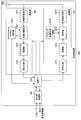
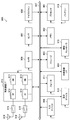
- FIG. 5 is a schematic block diagram showing the configuration of the base station apparatus 100 according to the present embodiment.
- the base station apparatus 100 includes an upper layer processing unit 101, a control unit 103, a receiving unit 105, a transmitting unit 107, and a transmitting / receiving antenna 109.
- the receiving unit 105 is configured to include a decoding unit 1051, a demodulation unit 1053, a demultiplexing unit 1055, a wireless reception unit 1057, and a channel measurement unit 1059.
- the transmission unit 107 includes an encoding unit 1071, a modulation unit 1073, a multiplexing unit 1075, a radio transmission unit 1077, and a downlink reference signal generation unit 1079.
- the base station apparatus 100 can support one or more RATs. Some or all of the units included in the base station apparatus 100 shown in FIG. 5 can be individually configured according to the RAT. For example, the receiving unit 105 and the transmitting unit 107 are individually configured with LTE and NR. Further, in the NR cell, some or all of the units included in the base station apparatus 100 shown in FIG. 5 can be individually configured according to the parameter set related to the transmission signal. For example, in an NR cell, the wireless reception unit 1057 and the wireless transmission unit 1077 can be individually configured according to a parameter set related to a transmission signal.
- the upper layer processing unit 101 includes a Medium Access Control (MAC) layer, a Packet Data Convergence Protocol (PDCP) layer, a Radio Link Control (RLC) layer, and a Radio Resource Control (Radio Resource Control). Resource Control (RRC) layer processing is performed. Also, the upper layer processing unit 101 generates control information to control the receiving unit 105 and the transmitting unit 107, and outputs the control information to the control unit 103.
- MAC Medium Access Control
- PDCP Packet Data Convergence Protocol
- RLC Radio Link Control
- RRC Radio Resource Control
- the control unit 103 controls the receiving unit 105 and the transmitting unit 107 based on the control information from the upper layer processing unit 101.
- the control unit 103 generates control information for the upper layer processing unit 101, and outputs the control information to the upper layer processing unit 101.
- Control section 103 receives the decoded signal from decoding section 1051 and the channel estimation result from channel measurement section 1059.
- the control unit 103 outputs the signal to be encoded to the encoding unit 1071. Also, the control unit 103 is used to control the whole or a part of the base station apparatus 100.
- the upper layer processing unit 101 performs processing and management regarding RAT control, radio resource control, subframe configuration, scheduling control, and / or CSI report control.
- the processing and management in upper layer processing section 101 are performed commonly for each terminal apparatus 200 or commonly for terminal apparatuses 200 connected to base station apparatus 100.
- the processing and management in upper layer processing section 101 may be performed only in upper layer processing section 101, or may be acquired from an upper node or another base station apparatus 100.
- the processing and management in upper layer processing section 101 may be performed individually according to the RAT.
- the upper layer processing unit 101 separately performs processing and management in LTE and processing and management in NR.
- management regarding the RAT is performed.
- management regarding LTE and / or management regarding NR are performed.
- Management regarding NR includes setting and processing of parameter sets regarding transmission signals in NR cells.
- radio resource control in upper layer processing section 101, generation and / or management of downlink data (transport block), system information, RRC message (RRC parameter), and / or MAC control element (CE: Control Element) To be done.
- transport block transport block
- RRC message RRC parameter
- CE MAC control element
- subframe setting in upper layer processing section 101 management of subframe setting, subframe pattern setting, uplink-downlink setting, uplink reference UL-DL setting, and / or downlink reference UL-DL setting is performed. It will be.
- the subframe setting in upper layer processing section 101 is also referred to as base station subframe setting.
- the subframe setting in the upper layer processing unit 101 can be determined based on the uplink traffic volume and the downlink traffic volume.
- the subframe setting in the upper layer processing unit 101 can be determined based on the scheduling result of the scheduling control in the upper layer processing unit 101.
- control unit 103 In scheduling control in upper layer processing section 101, frequencies and subframes to which physical channels are allocated and physical channels based on received channel state information and channel path estimation values and channel quality received from channel measurement section 1059, etc. The coding rate, modulation scheme, transmission power, etc. are determined. For example, the control unit 103 generates control information (DCI format) based on the scheduling result of the scheduling control in the upper layer processing unit 101.
- DCI format control information
- CSI reporting of terminal apparatus 200 is controlled.
- the setting regarding the CSI reference resource for assuming to calculate CSI in the terminal device 200 is controlled.
- the reception unit 105 Under the control of the control unit 103, the reception unit 105 receives a signal transmitted from the terminal device 200 via the transmission / reception antenna 109, and further performs reception processing such as separation, demodulation, decoding, etc. It is output to the control unit 103. In addition, the reception process in the receiving part 105 is performed based on the setting prescribed beforehand or the setting which the base station apparatus 100 notified the terminal device 200.
- the wireless reception unit 1057 performs conversion (down conversion) to an intermediate frequency, removal of unnecessary frequency components, and signal level to be appropriately maintained for the uplink signal received via the transmission / reception antenna 109.
- Control of amplification level, quadrature demodulation based on in-phase and quadrature components of received signal, conversion from analog signal to digital signal, removal of guard interval (GI), and / or fast Fourier transform (Fast Fourier transform) Performs frequency domain signal extraction by Transform: FFT.
- the demultiplexing unit 1055 separates uplink channels and / or uplink reference signals such as PUCCH (Physical Uplink Control Channel) or PUSCH (Physical Uplink shared Channel) from the signal input from the wireless reception unit 1057.
- the demultiplexing unit 1055 outputs the uplink reference signal to the channel measurement unit 1059.
- the demultiplexing unit 1055 performs propagation channel compensation for the uplink channel from the propagation channel estimation value input from the channel measurement unit 1059.
- Demodulation section 1053 is a received signal using a modulation scheme such as Binary Phase Shift Keying (BPSK), Quadrature Phase Shift Keying (QPSK), Quadrature Amplitude Modulation (16 QAM), 64 QAM, 256 QAM or the like for modulation symbols of the uplink channel Demodulate the The demodulation unit 1053 performs separation and demodulation of the MIMO multiplexed uplink channel.
- BPSK Binary Phase Shift Keying
- QPSK Quadrature Phase Shift Keying
- QAM Quadrature Amplitude Modulation
- 64 QAM 64 QAM
- 256 QAM 256 QAM
- the decoding unit 1051 performs a decoding process on the demodulated coded bits of the uplink channel.
- the decoded uplink data and / or uplink control information is output to control section 103.
- the decoding unit 1051 performs decoding processing for each transport block for the PUSCH.
- Channel measuring section 1059 measures an estimated value of the propagation path and / or channel quality from the uplink reference signal input from demultiplexing section 1055, and outputs the measured value to demultiplexing section 1055 and / or control section 103.
- the channel measurement unit 1059 measures an estimated value of a propagation path for performing channel compensation for PUCCH or PUSCH using UL-DMRS, and uses uplink sound quality (SRS) (Sounding Reference Signal) to measure channel quality in uplink. taking measurement.
- SRS Sound quality
- the transmission unit 107 performs transmission processing such as encoding, modulation, and multiplexing on the downlink control information and the downlink data input from the upper layer processing unit 101 according to the control from the control unit 103. For example, the transmission unit 107 generates and multiplexes a PHICH, a PDCCH, an EPDCCH, a PDSCH, and a downlink reference signal to generate a transmission signal. Note that the transmission processing in transmission section 107 is based on settings defined in advance, settings notified to terminal apparatus 200 by base station apparatus 100, or settings notified via PDCCH or EPDCCH transmitted in the same subframe. To be done.
- Coding section 1071 performs predetermined coding such as block coding, convolutional coding, turbo coding, and the like on HARQ indicator (HARQ-ACK), downlink control information, and downlink data input from control section 103. Encoding is performed using a scheme.
- the modulator 1073 modulates the coded bits input from the encoder 1071 according to a predetermined modulation scheme such as BPSK, QPSK, 16 QAM, 64 QAM, 256 QAM, and the like.
- the downlink reference signal generation unit 1079 generates a downlink reference signal based on physical cell identification (PCI), RRC parameters set in the terminal device 200, and the like.
- the multiplexing unit 1075 multiplexes the modulation symbol of each channel and the downlink reference signal, and arranges them in a predetermined resource element.
- the wireless transmission unit 1077 converts the signal from the multiplexing unit 1075 into a time domain signal by Inverse Fast Fourier Transform (IFFT), adds a guard interval, and generates a baseband digital signal. Performs processing such as conversion to analog signal, quadrature modulation, conversion of intermediate frequency signal to high frequency signal (up convert: up convert), removal of extra frequency components, amplification of power, etc. .
- IFFT Inverse Fast Fourier Transform
- the transmission signal output from the wireless transmission unit 1077 is transmitted from the transmission / reception antenna 109.
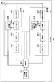
- FIG. 6 is a schematic block diagram showing the configuration of the terminal device 200 according to the present embodiment.
- the terminal device 200 includes an upper layer processing unit 201, a control unit 203, a receiving unit 205, a transmitting unit 207, and a transmitting / receiving antenna 209.
- the receiving unit 205 is configured to include a decoding unit 2051, a demodulation unit 2053, a demultiplexing unit 2055, a wireless reception unit 2057, and a channel measurement unit 2059.
- the transmission unit 207 includes an encoding unit 2071, a modulation unit 2073, a multiplexing unit 2075, a radio transmission unit 2077, and an uplink reference signal generation unit 2079.
- the terminal device 200 can support one or more RATs. Some or all of the units included in the terminal device 200 shown in FIG. 6 may be individually configured according to the RAT. For example, the reception unit 205 and the transmission unit 207 are individually configured with LTE and NR. Also, in the NR cell, some or all of the units included in the terminal device 200 shown in FIG. 6 can be individually configured according to the parameter set related to the transmission signal. For example, in an NR cell, the wireless reception unit 2057 and the wireless transmission unit 2077 can be individually configured according to a parameter set related to a transmission signal.
- Upper layer processing section 201 outputs uplink data (transport block) to control section 203.
- the upper layer processing unit 201 includes a Medium Access Control (MAC) layer, a Packet Data Convergence Protocol (PDCP) layer, a Radio Link Control (RLC) layer, and a Radio Resource Control (Radio Resource Control).
- MAC Medium Access Control
- PDCP Packet Data Convergence Protocol
- RLC Radio Link Control
- RRC Radio Resource Control
- RRC Radio Resource Control
- the upper layer processing unit 201 generates control information to control the receiving unit 205 and the transmitting unit 207, and outputs the control information to the control unit 203.
- the control unit 203 controls the reception unit 205 and the transmission unit 207 based on the control information from the upper layer processing unit 201.
- the control unit 203 generates control information for the upper layer processing unit 201 and outputs the control information to the upper layer processing unit 201.
- the control unit 203 inputs the decoded signal from the decoding unit 2051 and the channel estimation result from the channel measurement unit 2059.
- the control unit 203 outputs the signal to be encoded to the encoding unit 2071.
- the control unit 203 may be used to control the whole or a part of the terminal device 200.
- the upper layer processing unit 201 performs processing and management regarding RAT control, radio resource control, subframe setting, scheduling control, and / or CSI report control.
- the processing and management in upper layer processing section 201 are performed based on settings defined in advance and / or settings based on control information set or notified from base station apparatus 100.
- control information from the base station device 100 includes an RRC parameter, a MAC control element, or a DCI.
- the processing and management in upper layer processing section 201 may be performed individually according to the RAT.
- the upper layer processing unit 201 separately performs processing and management in LTE and processing and management in NR.
- management regarding the RAT is performed.
- management regarding LTE and / or management regarding NR are performed.
- Management regarding NR includes setting and processing of parameter sets regarding transmission signals in NR cells.
- radio resource control in the upper layer processing unit 201 management of setting information in the own apparatus is performed.
- radio resource control in upper layer processing section 201 generation and / or management of uplink data (transport block), system information, RRC message (RRC parameter), and / or MAC control element (CE: Control Element) To be done.
- subframe setting in upper layer processing section 201 subframe setting in base station apparatus 100 different from base station apparatus 100 and / or base station apparatus 100 is managed.
- the subframe configuration includes uplink or downlink configuration for subframes, subframe pattern configuration, uplink-downlink configuration, uplink reference UL-DL configuration, and / or downlink reference UL-DL configuration.
- the subframe setting in upper layer processing section 201 is also referred to as terminal subframe setting.
- control information for performing control related to scheduling for receiving section 205 and transmitting section 207 is generated based on DCI (scheduling information) from base station apparatus 100.
- CSI report control in upper layer processing section 201 control on reporting of CSI to base station apparatus 100 is performed.
- the setting regarding the CSI reference resource to be assumed to calculate CSI in channel measurement section 2059 is controlled.
- resources (timing) used to report CSI are controlled based on DCI and / or RRC parameters.
- the receiving unit 205 Under the control of the control unit 203, the receiving unit 205 receives a signal transmitted from the base station apparatus 100 via the transmission / reception antenna 209, and further performs reception processing such as separation, demodulation, decoding, etc. Are output to the control unit 203. Note that the reception process in the reception unit 205 is performed based on a preset setting or a notification or setting from the base station apparatus 100.
- the wireless reception unit 2057 performs conversion (down conversion) to an intermediate frequency, removal of unnecessary frequency components, and signal level to be appropriately maintained for the uplink signal received via the transmission / reception antenna 209. Control of amplification level, quadrature demodulation based on in-phase and quadrature components of received signal, conversion from analog signal to digital signal, removal of guard interval (GI), and / or fast Fourier transform (Fast Fourier transform) Performs signal extraction in the frequency domain by Transform: FFT.
- FFT fast Fourier transform
- the demultiplexing unit 2055 demultiplexes the downlink channel such as PHICH, PDCCH, EPDCCH, or PDSCH, the downlink synchronization signal, and / or the downlink reference signal from the signal input from the wireless reception unit 2057.
- the demultiplexing unit 2055 outputs the downlink reference signal to the channel measurement unit 2059.
- the demultiplexing unit 2055 performs propagation channel compensation for the downlink channel from the propagation channel estimation value input from the channel measurement unit 2059.
- Demodulation section 2053 demodulates the received signal using a modulation scheme such as BPSK, QPSK, 16 QAM, 64 QAM, 256 QAM or the like on the modulation symbol of the downlink channel.
- Demodulation section 2053 performs separation and demodulation of the MIMO multiplexed downlink channel.
- the decoding unit 2051 performs a decoding process on the demodulated coded bits of the downlink channel.
- the decoded downlink data and / or downlink control information is output to the control unit 203.
- the decoding unit 2051 performs a decoding process for each transport block with respect to the PDSCH.
- the channel measurement unit 2059 measures the estimated value of the propagation path and / or the channel quality from the downlink reference signal input from the demultiplexing unit 2055, and outputs the measured value to the demultiplexing unit 2055 and / or the control unit 203.
- the downlink reference signal used for measurement by the channel measurement unit 2059 may be determined based on at least a transmission mode set by RRC parameters and / or other RRC parameters.
- the DL-DMRS measures channel estimates for performing channel compensation for PDSCH or EPDCCH.
- the CRS measures channel estimates for performing channel compensation for the PDCCH or PDSCH, and / or channels in the downlink for reporting CSI.
- CSI-RS measures the channel in downlink for reporting CSI.
- the channel measurement unit 2059 calculates reference signal received power (RSRP) and / or reference signal received quality (RSRQ) based on CRS, CSI-RS, or the detected signal, and outputs the calculated signal to the upper layer processing unit 201.
- RSRP reference signal received
- the transmission unit 207 performs transmission processing such as encoding, modulation, and multiplexing on the uplink control information and the uplink data input from the upper layer processing unit 201 according to the control from the control unit 203. For example, the transmission unit 207 generates and multiplexes uplink channels and / or uplink reference signals such as PUSCH or PUCCH, and generates a transmission signal. In addition, the transmission process in the transmission part 207 is performed based on the setting prescribed beforehand, or the setting or notification from the base station apparatus 100. FIG.
- Coding section 2071 performs predetermined coding such as block coding, convolutional coding, turbo coding, etc. on the HARQ indicator (HARQ-ACK), uplink control information and uplink data inputted from control section 203. Encoding is performed using a scheme.
- the modulation unit 2073 modulates the coded bits input from the coding unit 2071 according to a predetermined modulation scheme such as BPSK, QPSK, 16 QAM, 64 QAM, or 256 QAM.
- the uplink reference signal generation unit 2079 generates an uplink reference signal based on RRC parameters and the like set in the terminal device 200.
- the multiplexing unit 2075 multiplexes the modulation symbols of each channel and the uplink reference signal, and arranges them in predetermined resource elements.
- the wireless transmission unit 2077 converts the signal from the multiplexing unit 2075 into a time domain signal by Inverse Fast Fourier Transform (IFFT), adds a guard interval, and generates a baseband digital signal. Performs processing such as conversion to analog signal, quadrature modulation, conversion of intermediate frequency signal to high frequency signal (up convert: up convert), removal of extra frequency components, amplification of power, etc. .
- IFFT Inverse Fast Fourier Transform
- the transmission signal output from the wireless transmission unit 2077 is transmitted from the transmission / reception antenna 209.
- the base station apparatus 100 and the terminal apparatus 200 can use various methods for signaling (notification, notification, setting) of control information.
- Signaling of control information can be performed at various layers.
- the signaling of control information includes physical layer signaling that is signaling through a physical layer (layer), RRC signaling that is signaling through an RRC layer, MAC signaling that is signaling through an MAC layer, and the like.
- RRC signaling is dedicated RRC signaling (Dedicated RRC signaling) for notifying the terminal device 200 of unique control information, or common RRC signaling (Common RRC signaling) for notifying the base station device 100 of unique control information.
- Signaling used by upper layers with respect to the physical layer, such as RRC signaling and MAC signaling is also referred to as upper layer signaling.
- RRC signaling is realized by signaling RRC parameters.
- MAC signaling is implemented by signaling a MAC control element.
- Physical layer signaling is realized by signaling downlink control information (DCI) or uplink control information (UCI).
- DCI downlink control information
- UCI uplink control information
- the RRC parameters and the MAC control element are transmitted using PDSCH or PUSCH.
- DCI is transmitted using PDCCH or EPDCCH.
- UCI is transmitted using PUCCH or PUSCH.
- RRC signaling and MAC signaling are used to signal semi-static control information, also called semi-static signaling.
- Physical layer signaling is used to signal dynamic control information, also referred to as dynamic signaling.
- the DCI is used for PDSCH scheduling or PUSCH scheduling.
- the UCI is used for CSI reporting, HARQ-ACK reporting, and / or scheduling request (SR).
- SR scheduling request
- the initial connection is a process of transitioning from a state where the terminal device 200 is not connected to any cell (idle state) to a state where a connection with any cell is established (connected state).
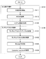
- FIG. 7 is a flowchart showing an example of an initial connection procedure of the terminal device 200 according to the present embodiment.
- the terminal device 200 in an idle state performs a cell selection procedure (step S110).
- the cell selection procedure includes steps of detection of synchronization signal (step S111) and decoding of PBCH (step S112).
- the terminal device 200 performs downlink synchronization with the cell based on the detection of the synchronization signal. Then, after downlink synchronization is established, the terminal device 200 attempts to decode the PBCH and acquires first system information.
- the terminal device 200 acquires second system information based on the first system information included in the PBCH (step S120).
- the terminal device 200 performs a random access procedure (random access procedure, RACH procedure, RACH procedure) based on the first system information and / or the second system information (step S130).
- a random access procedure random access procedure, RACH procedure, RACH procedure
- transmission of random access preamble step S131
- reception of random access response step S132
- transmission of message 3 message 3)
- reception of collision resolution step S133
- Step S134 is included.
- the terminal device 200 first selects a predetermined PRACH preamble and performs transmission.
- the terminal device 200 receives a PDSCH including a random access response corresponding to the transmitted PRACH preamble.
- the terminal device 200 transmits the PUSCH including the message 3 using the resource scheduled by the random access response grant included in the received random access response.
- the terminal device 200 receives a PDSCH including collision resolution corresponding to that PUSCH.
- Message 3 includes an RRC message of RRC connection request.
- the collision resolution includes an RRC message of RRC connection setup.
- the terminal device 200 When receiving the RRC message of RRC connection setup, the terminal device 200 performs RRC connection operation, and transitions from the RRC idle state to the RRC connected state. After transitioning to the RRC connection state, the terminal device 200 transmits an RRC message of RRC connection setup completion to the base station device 100.
- the terminal device 200 can be connected to the base station device 100 by this series of operations.
- the random access preamble is also referred to as message 1, random access response as message 2, collision resolution as message 4, and the message of RRC connection setup completion as message 5.
- the terminal device 200 can transition to a state (connected state) connected to the cell.
- the random access procedure shown in FIG. 7 is also referred to as a four-step RACH procedure.
- the random access procedure in which the terminal device 200 also transmits Message 3 along with the transmission of random access preambles and the base station device 100 transmits a random access response and Contention resolution as their response is a two-step RACH procedure. It is called.
- the random access preamble is transmitted in association with the PRACH.
- the random access response is sent on PDSCH.
- the PDSCH including the random access response is scheduled on the PDCCH.
- Message 3 is sent on PUSCH.
- the PUSCH including the message 3 is scheduled by the uplink grant included in the random access response.
- System information is information that broadcasts settings in a cell that transmits the system information.
- the system information includes, for example, information on access to the cell, information on cell selection, information on other RATs and other systems, and the like.
- System information can be classified into a master information block (MIB) and a system information block (SIB).
- MIB is information of a fixed payload size broadcasted by PBCH.
- the MIB contains information for acquiring the SIB.
- the SIB is system information other than the MIB.
- the SIB is broadcasted by the PDSCH.
- system information can be classified into first system information, second system information, and third system information.
- the first system information and the second system information include information on access to the cell, information on acquisition of other system information, and information on cell selection.
- LTE it can be considered that the information contained in MIB is the first system information
- SIB1 and SIB2 is the second system information. If the terminal device can not acquire all of the first system information and the second system information from the cell, it is assumed that access to the cell is prohibited.
- the MIB is physical layer information necessary to receive system information, and includes downlink system bandwidth, part of a system frame number, scheduling information of SIB, and the like.
- SIB1 is cell access control information and scheduling information of system information other than SIB1, and cell access information, cell selection information, maximum uplink transmission power information, TDD configuration information, system information cycle, and system information mapping information , SI window length, etc. are included.
- the SIB 2 includes connection prohibition information, common radio resource configuration information (radioResourceConfigCommon), uplink carrier information, and the like.
- the cell common radio resource setting information includes cell common PRACH and RACH setting information.
- System information of NR is broadcasted from the NR cell.
- the physical channel carrying system information may be transmitted in slots or minislots.
- a minislot is defined by the number of symbols smaller than the number of symbols in the slot.
- the first system information is sent on the NR-PBCH, and the second system information is sent on a different physical channel than the NR-PBCH.
- the RACH procedure performs RRC connection setup from idle state to inactive state or connected state, request for state transition from inactive state to connected state, handover to switch connected cell, and resource request for uplink data transmission. This is done to achieve the objectives such as request, timing advance adjustment to adjust uplink synchronization, on-demand SI request to request unsent system information, return of broken beam connection (beam recovery), etc.
- the RRC connection setup from the idle state to the inactive state or the connected state is an operation performed when the terminal device 200 connects with the base station device 100 in response to the occurrence of traffic or the like. Specifically, it is an operation of passing information (for example, UE context) related to connection from the base station apparatus 100 to the terminal apparatus 200.
- the UE context is managed by predetermined terminal device identification information (for example, C-RNTI) instructed from the base station device 100.
- C-RNTI terminal device identification information
- the request for state transition from the inactive state to the connected state is an operation for requesting the state transition from the inactive state to the connected state in response to the occurrence of traffic or the like.
- the terminal device 200 can transmit and receive unicast data with the base station device 100.
- the handover for switching the connection cell is an operation for switching the connection from a cell (serving) connected to a cell adjacent to the cell (neighboring cell) due to a change in radio environment such as movement of the terminal device 200.
- the terminal device 200 that has received the handover command from the base station device 100 makes a connection request to the neighbor cell specified by the handover command.
- the scheduling request is an operation of making a resource request for uplink data transmission in response to the occurrence of traffic or the like.
- the base station apparatus 100 allocates the PUSCH resource to the terminal apparatus 200 after successfully receiving this scheduling request.
- the scheduling request is also made by the PUCCH.
- Timing advance adjustment for adjusting uplink synchronization is an operation for adjusting an error in downlink and uplink frames caused by propagation delay.
- the terminal device 200 transmits the PRACH at the timing adjusted to the downlink frame.
- the base station apparatus 100 can recognize the propagation delay with the terminal apparatus 200, and can instruct the terminal apparatus 200 the value of timing advance using message 2 or the like.
- the broken beam connection recovery is an operation to make a recovery request when the communication quality is degraded due to the movement of the terminal 200 or the blocking of the communication path by another object after the beam is established. .
- the base station apparatus 100 that has received this request tries to connect with the terminal apparatus 200 using different beams.
- the RACH procedure further includes a collision based RACH procedure and a non-collision RACH procedure.
- the collision based RACH procedure is a RACH procedure that is performed by the terminal device 200.
- the collision based RACH procedure is a four-step procedure starting with the transmission of message 1 from the terminal device 200.
- the terminal device 200 selects a plurality of RACH resources and a plurality of PRACH preambles set in advance, and transmits the PRACH. Since the plurality of RACH resources and the plurality of PRACH preambles are shared with other terminal apparatuses 200, the PRACH may collide.
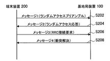
- FIG. 8 is a sequence diagram showing an example of the flow of a collision based RACH procedure according to the present embodiment.
- the terminal device 200 transmits a random access preamble also referred to as message 1 to the base station device 100 (step S202).
- the base station apparatus 100 transmits a random access response, also referred to as message 2, to the terminal apparatus 200 (step S204).
- the terminal device 200 transmits, to the base station device 100, an RRC message of RRC connection request, which is also referred to as message 3 (step S206).
- the base station apparatus 100 transmits, to the terminal apparatus 200, the collision resolution also referred to as the message 4 (step S208).
- the non-collision RACH procedure is a RACH procedure performed mainly by the base station apparatus 100.
- the non-collision RACH procedure is a total of three steps starting from the transmission of the PDCCH order from the base station apparatus 100.
- the terminal device 200 transmits a random access preamble using the PRACH indicated in the PDCCH order.
- the base station apparatus 100 scheduling a random access preamble makes it difficult for the PRACH to collide.
- FIG. 9 is a sequence diagram showing an example of the flow of the non-collision RACH procedure according to the present embodiment.
- the base station apparatus 100 transmits a PDCCH order to the terminal apparatus 200 (step S302).
- the terminal device 200 transmits a random access preamble to the base station device 100 (step S304).
- the base station apparatus 100 transmits a random access response to the terminal apparatus 200 (step S306).
- the NR-PRACH is configured using a Zadoff-Chu sequence or an M sequence.
- a plurality of preamble formats are defined.
- the preamble format is defined by a combination of parameters such as PRACH subcarrier interval, transmission bandwidth, sequence length, number of symbols used for transmission, transmission repetition number, CP length, guard period length, and the like.
- the type of sequence (Zadoff-Chu sequence or M sequence) used for transmission of the NR-PRACH may be designated by the preamble format.
- setting relating to the NR-PRACH is performed by system information. Furthermore, for the terminal device 200 in the connection mode, settings relating to the NR-PRACH are performed by dedicated RRC signaling.
- the NR-PRACH is transmitted by a physical resource (NR-PRACH occasion) that can be transmitted by the NR-PRACH.
- the physical resource is indicated by the setting for NR-PRACH.
- the terminal device 200 selects one of the physical resources and transmits an NR-PRACH. Furthermore, the terminal device 200 in the connection mode transmits an NR-PRACH using an NR-PRACH resource.
- the NR-PRACH resource is a combination of the NR-PRACH preamble and its physical resources.
- the base station apparatus 100 can indicate the NR-PRACH resource to the terminal apparatus 200.
- the sequence types of the NR-PRACH preamble are numbered.
- the sequence type number of the preamble is called a preamble index.
- the NR-PRACH is retransmitted when the random access procedure fails.
- the terminal device 200 stands by for transmission of the NR-PRACH for a standby period calculated from the value of backoff (backoff indicator, BI).
- the backoff value may differ depending on the terminal category of the terminal device 200 and the priority of the generated traffic. At that time, a plurality of backoff values are notified, and the terminal device 200 selects a backoff value to be used according to the priority.
- the transmission power of the NR-PRACH is increased relative to the initial transmission (this procedure is called power ramping).
- the NR random access response is sent by the NR-PDSCH.
- the NR-PDSCH including the random access response is scheduled by the NR-PDCCH in which the CRC is scrambled by the RA-RNTI.
- the NR-PDCCH is transmitted on a common control subband.
- the NR-PDCCH is arranged in a CSS (Common Search Space).
- the value of RA-RNTI is determined based on the transmission resource (time resource (slot or subframe) and frequency resource (resource block)) of NR-PRACH corresponding to the random access response.
- the NR-PDCCH may be arranged in a search space associated with the NR-PRACH associated with the random access response.
- the search space in which the NR-PDCCH is arranged is set in association with the NR-PRACH preamble and / or the physical resource to which the NR-PRACH is transmitted.
- the search space in which the NR-PDCCH is allocated is set in association with the preamble index and / or the index of the physical resource.
- the NR-PDCCH is NR-SS and QCL.
- the NR random access response is MAC information.
- the NR random access response includes at least an uplink grant for transmitting message 3 of NR, a value of timing advance used to adjust uplink frame synchronization, and a value of temporary C-RNTI.
- the NR random access response includes the PRACH index used for NR-PRACH transmission corresponding to the random access response.
- the NR random access response includes information on backoff used for waiting for PRACH transmission.
- the base station apparatus 100 transmits the NR-PDSCH, including these pieces of information. From these pieces of information, the terminal device 200 determines whether transmission of the random access preamble is successful.
- the terminal device 200 If it is determined from this information that the transmission of the random access preamble has failed, the terminal device 200 performs the process of transmitting the NR message 3 in accordance with the information included in the random access response. On the other hand, when it is determined that the transmission of the random access preamble has failed, the terminal device 200 considers that the random access procedure has failed and performs retransmission processing of the NR-PRACH.
- a plurality of uplink grants for transmitting the NR message 3 may be included in the NR random access response.
- the terminal device 200 can select one resource for transmitting the message 3 from the plurality of uplink grants. As a result, when different terminal devices 200 receive the same NR random access response, it is possible to alleviate the collision of NR message 3 transmission, and a more stable random access procedure can be provided.
- the NR message 3 is sent by the NR-PUSCH.
- the NR-PUSCH is sent using the resources indicated by the random access response.
- the NR message 3 includes an RRC connection request message.
- the waveform of the NR-PUSCH transmitted including the NR message 3 is indicated by the parameters contained in the system information. Specifically, OFDM or DFT-s-OFDM is determined according to the indication of the parameter.
- the base station device 100 When the base station device 100 receives the NR message 3 normally, the base station device 100 shifts to a collision resolution transmission process. On the other hand, when the base station apparatus 100 can not receive the NR message 3 normally, it can try to receive the NR message 3 again at least for a predetermined period.
- the base station apparatus 100 instructs the terminal apparatus 200 to retransmit the message 3 as a specific example of the process after the NR message 3 can not be normally received.
- the base station apparatus 100 transmits an instruction to resend message 3 using a downlink resource after a predetermined number of slots (or subframes, radio frames) from the resource instructed to transmit message 3.
- an indication by retransmission of the random access response may be mentioned.
- the NR-PDSCH including the retransmitted random access response is scheduled by the NR-PDCCH in which the CRC is scrambled by the RA-RNTI.
- the value of RA-RNTI is the same as the value of RA-RNTI used in the first transmission. That is, it is determined based on the transmission resource of NR-PRACH corresponding to the random access response. Alternatively, the value of RA-RNTI may be determined based on information identifying the initial transmission and retransmission in addition to the transmission resource of NR-PRACH.
- the NR-PDCCH is arranged in a CSS (Common Search Space).
- the NR-PDSCH including the retransmitted random access response is scheduled by the NR-PDCCH scrambled with CRC by the temporary C-RNTI or C-RNTI included in the random access response transmitted in the first transmission.
- an indication by NR-PDCCH used for indication of retransmission of message 3 can be mentioned.
- the NR-PDCCH is an uplink grant.
- the resource of message 3 retransmission is indicated by the DCI of the NR-PDCCH.
- the terminal device 200 retransmits the message 3 based on the indication of the uplink grant.
- the base station apparatus 100 attempts to receive the message 3 in the retransmission resource instructed in advance.
- the terminal device 200 transmits the NR-PUSCH including the message 3 using the resource for retransmission instructed in advance. Do.
- the terminal device 200 when the terminal device 200 receives a NACK for the message 3, the terminal device 200 transmits an NR-PUSCH including the message 3 using a resource for retransmission designated in advance corresponding to the NACK.
- the resource for retransmission instructed in advance is included in, for example, system information or a random access response.
- the terminal device 200 If the number of retransmissions of the NR message 3 exceeds a predetermined number, or if the reception of the NR collision resolution is not successful within a predetermined period, the terminal device 200 considers that the random access procedure has failed. , NR-PRACH retransmission processing is performed.
- the transmission beam of the terminal device 200 used for retransmission of the NR message 3 may be different from the transmission beam of the terminal device 200 used for the first transmission of the message 3.
- terminal apparatus 200 If neither the collision resolution of NR nor the instruction to retransmit message 3 can be received within a predetermined period, terminal apparatus 200 considers that the random access procedure has failed and performs retransmission processing of NR-PRACH.
- the predetermined period is set, for example, by system information.
- NR collision resolution is sent by the NR-PDSCH.
- the NR-PDSCH including collision resolution is scheduled by NR-PDCCH in which CRC is scrambled by temporary C-RNTI or C-RNTI.
- the NR-PDCCH is transmitted on a common control subband.
- the NR-PDCCH is allocated to USS (UE-specific search space). Note that the NR-PDCCH may be arranged in the CSS.
- the terminal device 200 When the terminal device 200 normally receives the NR-PDSCH including collision resolution, the terminal device 200 returns an ACK to the base station device 100. Thereafter, the terminal device 200 is in a connected state, assuming that the random access procedure is successful. On the other hand, when a NACK for the NR-PDSCH including collision resolution is received from the terminal apparatus 200 or no response is received, the base station apparatus 100 retransmits the NR-PDSCH including the collision resolution. Furthermore, if the NR collision resolution can not be received within a predetermined period, the terminal device 200 considers that the random access procedure has failed and performs NR-PRACH retransmission processing.
- FIG. 10 is a diagram for explaining an example of uplink synchronization adjustment according to the present embodiment.
- the terminal device 200A is located near the base station device 100 in the cell 90 provided by the base station device 100, and the terminal device 200B is located far from the base station device 100. It is assumed that these terminal devices 200 simultaneously perform uplink communication.
- each uplink signal is a base station due to different propagation delay and processing delay specific to the terminal device 200. It is received by the apparatus 100 at different reception timings. If the reception timing of each uplink signal is different, inter-symbol interference may occur and the characteristics may be degraded.
- the transmission timing of the uplink signal of the terminal device 200 is adjusted in advance so that the transmission timing of the downlink signal of the base station device 100 and the reception timing of the uplink signal are aligned.
- FIG. 11 is a diagram for explaining an example of uplink synchronization adjustment according to the present embodiment.
- the downlink transmission timing of the base station apparatus 100 is shown in the first stage from the top, and the downlink reception timing of the terminal apparatus 200 is shown in the second stage from the top.
- the uplink transmission timing of the terminal device 200 is shown in the third stage from the top, and the uplink reception timing of the base station apparatus 100 is shown in the fourth stage from the top.
- Each row consists of a plurality of rectangles, and one rectangle indicates one radio frame.
- the downlink signal from the base station apparatus 100 is received by the terminal apparatus 200 with a predetermined time delay due to the influence of the propagation delay and the processing delay of the terminal apparatus 200.
- the terminal device 200 adjusts the uplink transmission timing using the timing advance value instructed from the base station device 100 on the basis of the timing at which the downlink signal is received. Specifically, as shown in the third stage, the terminal device 200 transmits the uplink physical signal by advancing the timing advance value by the timing at which the corresponding downlink signal is received. Thereby, as shown in the fourth stage, the adjusted uplink signal of the terminal device 200 is received by the base station device 100 at the same timing as the downlink transmission timing.
- the timing advance value is calculated as approximately twice the one-way delay time.
- the timing advance value is specific to the terminal device 200.
- the timing advance value is uniquely notified to the terminal device 200.
- the PRACH is used to calculate the timing advance value.
- a random access response (RAR) is used for notification of the timing advance value.
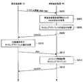
- FIG. 12 is a sequence diagram showing an example of the flow of the uplink synchronization adjustment procedure according to the present embodiment.
- the base station apparatus 100 transmits downlink synchronization signals (PSS (primary synchronization signal) and SSS (secondary synchronization signal)) to the terminal apparatus 200 (step S402).
- PSS primary synchronization signal
- SSS secondary synchronization signal
- the terminal device 200 performs downlink synchronization based on the downlink synchronization signal transmitted from the base station device 100 (step S404).
- the base station apparatus 100 transmits system information (MIB and SIB) (step S406).
- the terminal device 200 receives system information, and acquires a RACH setting from the received system information (step S408).
- MIB and SIB system information
- terminal apparatus 200 transmits PRACH based on the frame timing synchronized by the downlink synchronization signal (step S410).
- the base station apparatus 100 calculates the propagation delay and the timing advance value based on the difference between the reception timing of the PRACH and the timing of the uplink frame of the base station apparatus 100 (step S412).
- the base station apparatus 100 transmits a random access response (RAR) including the timing advance value to the terminal apparatus 200 (step S414).
- RAR random access response
- the terminal device 200 acquires a timing advance value from the received RAR, and adjusts the uplink transmission timing to move forward (step S416).
- the terminal device 200 transmits uplink physical channels / signals such as PUSCH, PUCCH and SRS at the uplink transmission timing adjusted in step S416 (step S418).
- Non-terrestrial network In cellular mobile communication, cells (macro cells, micro cells, femto cells, or small cells) are configured from base station devices or relay devices (hereinafter referred to as ground station devices) installed on the ground to configure a wireless network. .
- the radio network provided by this ground station is called a Terrestrial Network.
- satellite station equipment satellite base station equipment, satellite relay station equipment, space station
- satellite station equipment orbiting the earth because of the cost reduction of the base station equipment and the provision of coverage to difficult areas where radio waves reach from the base station equipment.
- a wireless network provided from other than this ground station apparatus is called a non-terrestrial network.
- the non-ground station apparatus includes a satellite station apparatus and an air station apparatus.
- the satellite station apparatus is an apparatus having a wireless communication function, which is configured as an apparatus such as a satellite for floating outside the atmosphere.
- the satellite station apparatus according to the present embodiment is a low orbit (LEO, Low Earth Orbiting) satellite, a medium orbit (MEO, Medium Earth Orbiting) satellite, a geostationary (GEO, Geostationary Earth Orbiting) satellite, or a high elliptical orbit (HEO, Highly) Elliptical Orbiting satellites and the like.
- the air station apparatus is an apparatus having a wireless communication function, which is configured as an apparatus suspended in the atmosphere such as an aircraft or a balloon.
- the air station apparatus includes an unmanned air system (UAS, Unmanned Aircraft Systems), a tethered unmanned air system (tethered UAS), a light unmanned air system (Lighter than Air UAS, LTA), and a heavy unmanned air system (Heavier than). It may be configured by Air UAS, HTA), or High Altitude UAS Platforms (HAPs) or the like.
- UAS Unmanned Aircraft Systems
- tethered UAS tethered unmanned air system
- LTA light unmanned air system
- Heavier than Heavier than
- It may be configured by Air UAS, HTA), or High Altitude UAS Platforms (HAPs) or the like.
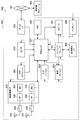
- FIG. 13 is a diagram showing an example of the non-terrestrial wave network according to the present embodiment.
- the system 1 shown in FIG. 13 includes a satellite station device 10A configured as a geostationary satellite, satellite station devices 10B to 10D configured as low orbit satellites, and an air station device 20 configured as an unmanned aerial system. Wave network.
- the satellite station apparatus 10 and the air station apparatus 20 are connected to an apparatus provided on the ground via the relay station 30.
- the satellite station apparatus 10 and the aviation station apparatus 20 are connected to the core network 31 via the relay station 30A, and connected to the Internet 32 and the terrestrial network 33 via the core network 31.
- the satellite station apparatuses 10A and 10B are also connected to the femtocell base station 40A that provides the femtocell via the relay station 30B.
- the relay station 30 is also referred to as an earth station (Very Small Aperture Terminal: VSAT), and may also be referred to as a control earth station or a HUB station.
- VSAT Very Small Aperture Terminal
- the satellite station device 10 and the air station device 20 may be directly connected to a device provided on the ground, not via the VSAT 30.
- the satellite station device 10B and the air station device 20 are directly connected to the macrocell base station 40B.
- the satellite station apparatus 10 and the air station apparatus 20 communicate with a terminal device (also referred to as an earth terminal device) 40 corresponding to a non-terrestrial wave network.
- the earth terminal device 40 includes a mobile phone, a smartphone, a car, a bus, a train, an aircraft, an M2M (Machine to Machine) device, an IoT (Internet of Things) device, a relay station relaying satellite communication, and a base station transmitting and receiving satellite communication. Includes the device.
- the macrocell base station 40 B and the UE 40 C correspond to the earth terminal device 40.
- a femtocell base station 40A connected to a non-terrestrial network via a relay by VSAT 30B and a UE 40D connected to a non-terrestrial network via a relay by UE 40C are also regarded as earth terminal apparatuses 40 corresponding to the non-terrestrial network May be
- the satellite station device 10 and the air station device 20 can transmit and receive uplink traffic and downlink traffic to and from the earth terminal device 40.
- the satellite station devices 10A and 10B and the air station device 20 transmit and receive uplink traffic and downlink traffic with the UE 40C.
- the satellite station apparatus 10 and the air station apparatus 20 can transmit and receive backhaul traffic (in other words, backhaul signals) with the earth terminal apparatus 40.
- the satellite station apparatuses 10A and 10B transmit and receive backhaul traffic for communication performed between the femtocell base station 40A and the UE 40C with the femtocell base station 40A via the VSAT 30B.
- the satellite station apparatus 10B and the air station apparatus 20 directly transmit and receive backhaul traffic for communication between the macrocell base station 40B and the UE 40C with the macrocell base station 40B.
- the satellite communication according to the present embodiment refers to communication between the satellite station device 10 and the earth terminal device 40.
- the satellite station device 10 is divided into a geostationary satellite station device mainly composed of geostationary satellites and a low orbit satellite station device composed of low orbit satellites.
- a geostationary satellite station located at an altitude of approximately 35786 km, orbits the earth at the same speed as the earth's rotation speed.
- the geostationary satellite station device is a satellite station device which has a relative velocity to the earth terminal device 40 substantially zero, and is observed from the earth terminal device 40 as if it were stationary.
- Low orbit satellite stations are generally located between 500 km and 2000 km, and orbit the earth at a lower altitude than geostationary satellite stations.
- the low orbit satellite station device has a relative velocity with the earth terminal device 40 and is observed as if it is moving from the earth terminal device 40.
- the satellite station apparatus 10 can provide a cell of a size corresponding to the height. This point will be described with reference to FIG.
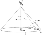
- FIG. 14 is a diagram for explaining an example of a cell provided by the satellite station device 10 according to the present embodiment.
- the satellite station apparatus 10A shown in FIG. 14 is a geostationary satellite station apparatus, and the satellite station apparatuses 10B and 10C are low orbit satellite station apparatuses.
- the low orbit satellite station devices 10B and 10C provide larger cells 90B and 10C than the cell 90D provided by the macro cell base station 40B on the ground.
- the geostationary satellite station device 10A provides a larger cell 90A than the cells 90B and 10C provided by the low orbit satellite station devices 10B and 10C.
- the larger the cell the larger the difference in distance to the satellite station device 10 among the plurality of earth terminal devices 40 located in the cell, and as a result, the difference in propagation delay becomes larger. Further, as the altitude is higher, the distance between the satellite station apparatus 10 and the earth terminal apparatus 40 is longer, so that the propagation delay is longer.
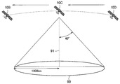
- FIG. 15 is a diagram for explaining an example of a cell provided by the low orbit satellite station apparatus according to the present embodiment.
- the low orbit satellite station devices 10B, 10C, and 10D revolve on the low orbit. These low orbit satellite station devices 10 construct predetermined directivity toward the ground and provide satellite communications to the earth terminal device 40.
- the low orbit satellite station apparatus 10 transmits and receives signals with the beam width angle of 40 degrees, and as a result, the cell 90 becomes a circle with a radius of 1000 km.
- the beam width angle is a direction in which the directivity gain is half of the maximum directivity gain based on the direction (vertical line 91 in the example shown in FIG. 15) where the maximum directivity gain can be obtained. It is defined as an angle.
- the low orbit satellite station device 10 moves at a predetermined relative speed with respect to the ground. Therefore, the cell 90 provided by the low orbit satellite station device 10 moves on the ground at a predetermined speed. When it becomes difficult to provide satellite communication to the earth terminal device 40, satellite communication is provided from a subsequent lower satellite (neighbor satellite station).
- -Service extension to terminals mainly IoT / MTC devices and public safety / critical communication
- terminals located in areas that can not be covered by terrestrial networks
- connectivity • Service connection and provision to aircraft terminals such as plane passengers or drones • Service connection and provision to mobile terminals such as ships or trains • A / V (audio / visual) content, group communication
- IoT broadcast services software downloads, and emergency messages-Traffic offload between terrestrial and non-terrestrial networks
- non-terrestrial networks In order to meet these requirements, it is desirable for non-terrestrial networks to realize commonality of radio interface with higher layer operation integration and radio access technologies such as NR or LTE.
- the timing advance value is derived by the following equation (1).
- TA (N TA + N TA offset ) T S (1)
- TA is a timing advance value.
- N TA is a variable number for adjusting the timing advance value.
- N TA can take a value of 0 or more and 20 512 or less (that is, 0 ⁇ N TA ⁇ 20512).
- N TAoffset is an offset for adjusting the timing advance value.
- TA is the may take the following values 20512 ⁇ Ts (i.e., 0 ⁇ TA ⁇ 20512 ⁇ Ts ). In other words, TA can take a value of 0 ms or more and 0.67 ms (that is, 0 ms ⁇ TA ⁇ 0.67 ms).
- the range of the timing advance value is set to correspond to the minimum value and the maximum value of the propagation delay difference that can occur in the cell.
- the propagation delay difference between the terminal apparatus and the base station apparatus becomes the minimum value when the terminal apparatus exists at the same point as the base station apparatus, and the terminal apparatus is at the cell edge. It will be the maximum value if it exists.
- the range of the timing advance value for uplink transmission is sufficient with the above-mentioned range (0 ⁇ TA ⁇ 20512 ⁇ Ts, that is, 0 ms ⁇ TA ⁇ 0.67 ms).
- the distance between the satellite station apparatus and the earth terminal apparatus is significantly increased as compared to the case of LTE. Therefore, the minimum propagation delay and the maximum propagation delay involved in the communication between the satellite station apparatus and the earth terminal apparatus are significantly increased as compared with the case of LTE.
- the minimum propagation delay is a propagation delay when the earth terminal device is located directly below (that is, a vertical line) the satellite station device.
- the altitude of the satellite station device is 500 km to 2000 km, and the minimum propagation delay at each altitude is in the range of 3.3 ms to 13.3 ms.
- the maximum propagation delay is the propagation delay when the earth terminal device is located at the cell edge of the satellite station device.
- the altitude of the satellite station device is 500 km to 2000 km
- the maximum propagation delay in the low orbit satellite cell using the parameters of FIG. 15 at each altitude is 4.35 ms to 17 It is in the range of .4 ms.
- the maximum propagation distance is obtained by the following equation (3).
- (Maximum propagation distance) ((altitude of satellite station ⁇ 2 + cell radius ⁇ 2) (3)
- the maximum propagation distance at each altitude is approximately 652.7 to 2610.8 km.
- the propagation delay of 3.3 ms to 17.4 ms be compensated by the timing advance. Furthermore, it is desirable that the larger propagation delay be compensated for by the timing advance, since the geostationary satellite has a higher altitude of 35,786 km and a larger propagation delay.
- the range of timing advance value in LTE could not sufficiently compensate for propagation delay in satellite communication. Therefore, it is difficult to synchronize the transmission from the earth terminal device to the satellite station device in satellite communication.
- the present disclosure provides a mechanism capable of sufficiently compensating for propagation delay in satellite communication.
- FIG. 16 is a diagram for explaining an example of a functional configuration of the satellite station device 10 according to the present embodiment.
- the satellite station apparatus 10 according to the present embodiment includes a setting unit 11 and a message transmission / reception unit 13.
- Each component shown in FIG. 16 can be implemented in any component such as upper layer processing unit 101 or control unit 103 shown in FIG. 5. That is, in the present embodiment, the base station apparatus 100 shown in FIG. 5 is configured as the satellite station apparatus 10.
- the setting unit 11 has a function of generating setting information on transmission parameters used for transmission of a channel / signal from the earth terminal device 40 to the satellite station device 10. Specifically, the setting unit 11 generates satellite station apparatus related information described later. At least a part of the satellite station apparatus related information (for example, orbit information described later) is set or stored in advance in the satellite station apparatus 10. The setting unit 11 transmits the generated satellite station apparatus related information to the earth terminal apparatus 40.
- the message transmission / reception unit 13 has a function of transmitting / receiving a message to / from the earth terminal device 40 based on the setting by the setting unit 11. Specifically, the message transmitting / receiving unit 13 receives the channel / signal transmitted by the earth terminal apparatus 40 using the transmission parameter based on the satellite station apparatus related information. At that time, the message transmission / reception unit 13 receives using the reception parameter corresponding to the transmission parameter used for the earth terminal device 40. For example, the message transmission / reception unit 13 performs reception processing according to the setting of the timing advance and / or the setting of the CP used by the earth terminal device 40.
- FIG. 17 is a view for explaining an example of the functional configuration of the earth terminal device 40 according to the present embodiment.
- the earth terminal apparatus 40 according to the present embodiment includes a setting unit 41 and a message transmitting / receiving unit 43.
- Each component shown in FIG. 17 can be implemented in any component such as upper layer processing unit 201 or control unit 203 shown in FIG. That is, in the present embodiment, the terminal device 200 shown in FIG. 6 is configured as the earth terminal device 40.
- the setting unit 41 has a function of setting transmission parameters used for transmission of channels / signals from the earth terminal device 40 to the satellite station device 10 based on setting information received from the satellite station device 10. Specifically, the setting unit 41 performs setting of timing advance and / or setting of CP based on the satellite station apparatus related information.
- the message transmission / reception unit 43 has a function of transmitting / receiving a message to / from the satellite station apparatus 10 based on the setting by the setting unit 41. Specifically, the message transmitting / receiving unit 43 transmits a channel / signal to the satellite station apparatus 10 using the set transmission parameter.
- the channel / signal transmitted from the satellite station apparatus 10 to the earth terminal apparatus 40 may be a downlink signal (downlink physical channel or downlink physical signal) or backhaul traffic. May be Similarly, the channel / signal transmitted from the earth terminal apparatus 40 to the satellite station apparatus 10 may be an uplink signal (uplink physical channel or uplink physical signal) or may be backhaul traffic. . In the following, for simplicity of explanation, the channel / signal transmitted from the satellite station apparatus 10 to the earth terminal apparatus 40 is a downlink signal, and the channel / signal transmitted from the earth terminal apparatus 40 to the satellite station apparatus 10 is , And uplink signals.
- the satellite station device 10 transmits or notifies the earth terminal device 40 of information on the type of the satellite station device 10. Then, the earth terminal device 40 acquires information on the type of the satellite station device 10, and controls the transmission timing of the signal to the earth terminal device 40 based on the information on the type of the earth terminal device 40. As a result, the earth terminal device 40 can transmit the uplink signal at the transmission timing based on the type of the satellite station device 10. Therefore, it is possible to sufficiently compensate for the propagation delay in satellite communication.
- the information on the type of the satellite station device 10 is also referred to as satellite station device related information.
- the satellite station device related information may include information on the altitude of the satellite station device 10.
- the altitude of the satellite station device 10 greatly affects the propagation delay between the satellite station device 10 and the earth terminal device 40 in the cell. Therefore, the earth terminal device 40 controls transmission timing to compensate for a propagation delay occurring in communication with the satellite station device 10 by notifying the earth terminal device 40 of information on the altitude of the satellite station device 10 It becomes possible.
- Information regarding the altitude of the satellite station device 10 may be provided in various forms.
- the information on the altitude of the satellite station apparatus 10 may be provided as information indicating the range of altitude in which the satellite station apparatus 10 can be located.
- the information on the altitude of the satellite station device 10 may be provided as information indicating the altitude of the satellite station device 10.
- information indicating the altitude of the satellite station apparatus 10 may be provided as orbit information.
- the orbit information includes at least information indicating the altitude of the satellite station device 10.
- orbit information of the low orbit satellite station apparatus is shown in Table 1 below.
- the number of orbits, the number of satellite station devices, the altitude, and the angle are shown.
- the number of trajectories in Table 1 indicates the number of trajectories of the same altitude and angle.
- the number of satellite station devices in Table 1 indicates the number of satellite station devices 10 orbiting at the same altitude and angle.
- the altitudes in Table 1 are orbital altitudes.
- the trajectory information includes information indicating a change in altitude.
- the satellite station device 10 orbits at a speed according to the altitude. That is, it can be said that the altitude included in the orbit information is information indicating the moving speed of the satellite station device 10.
- the orbit information may separately include the moving speed of the satellite station apparatus 10 itself in addition to the altitude.
- the angle in Table 1 is the angle of the trajectory relative to the latitude or longitude. That is, it can be said that the angle included in the orbit information is information indicating the moving direction of the satellite station device 10.
- the satellite station apparatus related information may include various other information. An example will be described below. The information described below can also be grasped as information on the altitude of the satellite station apparatus 10.
- the satellite station apparatus related information may include information indicating whether or not it is a satellite cell. This information may be 1-bit information indicating whether the satellite station apparatus 10 provides a satellite cell.
- the satellite station apparatus related information may include information indicating the type of the satellite station apparatus 10. Such information is information indicating a ground station, low orbit satellites, medium orbit satellites, high orbit satellites, or geostationary satellites.
- the satellite station apparatus related information may include information indicating the maximum coverage (eg, cell radius, beam width or beam angle of a beam used by the satellite station) of the satellite station apparatus 10.
- the satellite station apparatus related information may include information indicating a control method of transmission timing (for example, a range of timing advance value to be described later, adjustment granularity, replacement rule, TA satelite, etc.).
- a control method of transmission timing for example, a range of timing advance value to be described later, adjustment granularity, replacement rule, TA satelite, etc.
- the satellite station apparatus related information may include information indicating a control method of CP length (for example, CP length, etc.).
- the satellite station apparatus related information may include information related to filtering (for example, information indicating a predetermined waveform, filter information (filtering function, roll-off value, etc.), etc.).
- satellite station apparatus related information is broadcast from the satellite station apparatus 10 to the earth terminal apparatus 40 in the cell using, for example, system information (MIB and / or SIB).
- MIB and / or SIB system information
- SIB system information
- SIB is easier to expand than MIB.
- MgNB is a ground station apparatus and SgNB is a satellite station apparatus 10.
- the satellite station apparatus related information is notified from the macro cell (cell of PCell or MgNB) to the earth terminal apparatus 40 using, for example, system information or RRC signaling.
- RRC signaling it is desirable that satellite station related information be notified by dedicated RRC signaling.
- satellite station apparatus related information may be notified from the source base station apparatus to the earth terminal apparatus 40 using, for example, system information or RRC signaling. In particular, it is desirable that satellite station related information be notified by dedicated RRC signaling. Besides, the satellite station apparatus related information may be notified from the source base station apparatus to the earth terminal apparatus 40 using, for example, L1 signaling (handover command). Specifically, satellite station apparatus related information is notified by DCI included in the PDCCH order or PDSCH including a handover command.
- Satellite station apparatus related information may be associated with a predetermined band (band, center frequency).
- the earth terminal device 40 when performing communication in a predetermined band used for low orbit satellite communication, the earth terminal device 40 is a satellite station associated with the low orbit satellite communication from among a set of predefined satellite station device related information Device related information is set.
- the earth terminal device 40 when performing communication in a predetermined band used for geostationary satellite communication, the earth terminal device 40 may be a satellite station apparatus associated with geostationary satellite communication from among a set of predefined satellite station apparatus related information Information is set.
- the earth terminal device 40 sets transmission timing (for example, in LTE) assuming communication with a ground station device, and setting transmission timing assuming communication with the satellite station device 10.
- the transmission timing is controlled by switching on a predetermined basis. For example, when the earth terminal device 40 recognizes that satellite communication is to be performed by receiving the satellite station device related information, the earth terminal device 40 may switch to the setting of the transmission timing assuming communication with the satellite station device 10. Further, when supporting the satellite communication, the earth terminal device 40 may switch to the setting of the transmission timing assuming communication with the satellite station device 10. Whether to support satellite communication may be linked to the corresponding frequency band. For example, the earth terminal device 40 sets the transmission timing assuming communication with the ground station device in a frequency band not compatible with satellite communication, and assumes communication with the satellite station device 10 in a frequency band corresponding to satellite communication. Configure the set transmission timing.
- Control of transmission timing may include switching of setting of timing advance.
- the earth terminal device 40 sets a timing advance value capable of compensating for the propagation delay according to the type of the satellite station device 10. As a result, the earth terminal apparatus 40 can synchronize on uplink transmission even when performing satellite communication.
- Control of transmission timing may include switching of CP settings.
- the earth terminal device 40 sets a CP length capable of compensating for the propagation delay according to the type of the satellite station device 10. As a result, even when performing satellite communication, it is possible to sufficiently remove intersymbol interference and intersubcarrier interference related to uplink transmission and achieve symbol synchronization.
- Control of transmission timing may include switching of filtering.
- the earth terminal device 40 sets filtering capable of compensating for the propagation delay according to the type of the satellite station device 10. As a result, even when performing satellite communication, it is possible to sufficiently remove intersymbol interference and intersubcarrier interference related to uplink transmission and achieve symbol synchronization.
- the switching of the setting of the timing advance value, the switching of the setting of the CP, and the switching of the filtering may be performed alone or in combination.
- the compensation of the propagation delay may be shared by the timing advance value and the CP length. That is, the compensation amount of the propagation delay may be divided by the timing advance value and the CP length.
- the timing advance value is set to a value capable of compensating (ie, absorbing) a part of the propagation delay involved in communication with the satellite station apparatus 10, and the CP length is capable of compensating (ie, absorbing) the remaining part. Possible) is set.
- the timing advance value is set to a value that can compensate (ie, absorb) a part of the propagation delay involved in communication with the satellite station device 10, and the filtering can compensate for the remaining part (ie, absorb Set to enable).
- the filtering can compensate for the remaining part (ie, absorb Set to enable).
- FIG. 18 is a flow chart showing an example of a procedure for transmission timing control executed by the earth terminal device 40 according to the present embodiment.
- the earth terminal device 40 performs setting of timing advance (in LTE, for example) and setting of CP assuming communication with a ground station device.
- the earth terminal apparatus 40 acquires system information (MIB and / or SIB) (step S502).
- the earth terminal apparatus 40 determines whether the satellite station apparatus related information is included in the system information (step S504). If it is determined that it is included (step S504 / YES), the earth terminal apparatus 40 switches setting of timing advance and / or setting of CP based on the satellite station apparatus related information (step S506). On the other hand, when it is determined that it is not included (step S504 / NO), the earth terminal apparatus 40 continues setting of timing advance (in LTE, for example) and setting of CP assuming communication with the ground station apparatus. Use.
- timing advance in LTE, for example
- the range of the timing advance value is a range in which the timing advance value can be set.
- the satellite station apparatus 10 calculates or determines the timing advance value.
- the earth terminal device 40 switches the range of the timing advance value in order to enable setting of the timing advance value calculated or determined by the satellite station device 10.
- the range of the timing advance value is switched based on the maximum propagation delay according to the type of the satellite station apparatus 10. Specifically, the maximum value of the range of the timing advance value is set to a value capable of compensating (that is, absorbing) the maximum propagation delay according to the type of the satellite station device 10. That is, the maximum value of the range of the timing advance value is set to a value equal to or larger than the maximum propagation delay according to the type of the satellite station apparatus 10. Thereby, even if the maximum propagation delay assumed according to the type of the satellite station apparatus 10 occurs, the earth terminal apparatus 40 can set the timing advance value capable of achieving synchronization regarding uplink transmission.
- the range of the timing advance value may be switched based on the minimum propagation delay according to the type of the satellite station apparatus 10.
- the minimum value of the range of the timing advance value may be set to a value capable of compensating (that is, absorbing) the minimum propagation delay according to the type of the satellite station device 10. That is, the minimum value of the range of the timing advance value is set to a value equal to or less than the minimum propagation delay according to the type of the satellite station device 10.
- the maximum propagation delay according to the type of the satellite station device 10 is the propagation delay when the satellite station device 10 is located at the highest altitude of the type and the earth terminal device 40 is located at the cell edge of the satellite station device 10 .
- the maximum propagation delay when the satellite station device 10 is a low orbit satellite is the propagation delay when the satellite station device 10 is located at an altitude of 2000 km and the earth terminal device 40 is located at the cell edge.
- the maximum propagation delay for the low orbit satellite cell of FIG. 15 is 17.4 ms.
- the minimum propagation delay according to the type of the satellite station device 10 means that the satellite station device 10 is located at the lowest altitude of the type and the earth terminal device 40 is located directly under the satellite station device 10 (that is, vertical line). Propagation delay.
- the minimum propagation delay when the satellite station device 10 is a low orbit satellite is the propagation delay when the satellite station device 10 is located at an altitude of 500 km and the earth terminal device 40 is located directly below the satellite station device 10 .
- the propagation delay in this case is 3.3 ms.
- the range of the timing advance value may be switched by switching the maximum value of the timing advance value.
- the maximum value of the timing advance value can be switched to a value capable of compensating for the maximum propagation delay according to the type of the satellite station apparatus 10.
- the maximum value of the timing advance value is expanded by a factor of X according to the altitude of the satellite station apparatus 10. That is, the range of the timing advance value is extended by X times (0 ⁇ TA ⁇ X ⁇ 20512 ⁇ Ts, that is, 0 ms ⁇ TA ⁇ X ⁇ 0.67 ms).
- X 26.
- the satellite station apparatus related information may include information indicating the above X.
- X may be fixedly set in the earth terminal device 40.
- the earth terminal apparatus 40 supporting satellite communication extends the range of the timing advance value to X times in satellite communication. It is desirable that the area for storing the timing advance value in the RAR is also extended according to the extension of the range of the timing advance value. For example, it is desirable to extend (ie, add) 5 bits.
- the range of the timing advance value may be switched by switching the adjustment granularity of the timing advance value.
- the adjustment granularity of the timing advance value can be switched to a size that can compensate for the maximum propagation delay according to the type of the satellite station device 10.
- the adjustment of the timing advance value is performed at a granularity 16 times the adjustment granularity Ts in the above equation (1) (that is, 16 ⁇ Ts).
- This adjustment granularity is expanded by a factor of X according to the altitude of the satellite station apparatus 10 (ie, X ⁇ 16 ⁇ Ts).
- the satellite station apparatus related information may include information indicating the above X.
- X may be fixedly set in the earth terminal device 40.
- the earth terminal apparatus 40 supporting satellite communication extends the adjustment granularity of the timing advance value to X times when performing satellite communication.
- the earth terminal apparatus 40 reads the minimum value and the maximum value of the range of the timing advance value into values capable of compensating for the minimum propagation delay and the maximum propagation delay according to the type of the satellite station apparatus 10, respectively. For example, if it is a low orbit satellite and the beam width angle is 40 degrees, the minimum value of the range of timing advance values can be read as a value capable of compensating for the minimum propagation delay of 3.3 ms.
- the maximum value of the timing advance value range can be read as a value capable of compensating for the maximum propagation delay 17.4 ms. That is, when the satellite is a low orbit satellite and the beam width angle is 40 degrees, the timing advance value can be read as a value that can compensate for the propagation delay of 3.3 ms to 17.4 ms (101376 ⁇ Ts ⁇ TA ⁇ 53530 X Ts, that is, 3.3 ms ⁇ TA ⁇ 17.4 ms).
- the satellite station apparatus related information may include information indicating the presence or absence of replacement.
- the satellite station apparatus related information may include a replacement rule including the minimum value and the maximum value of the range of the timing advance value.
- the replacement rule may be fixedly set in the earth terminal device 40. The earth terminal device 40 supporting satellite communication applies the re-reading rule when performing satellite communication.
- the notification of the timing advance value by the RAR is performed in the existing range (0 ⁇ TA ⁇ 20512 ⁇ Ts, that is, 0 ms ⁇ TA ⁇ 0.67 ms).
- the earth terminal apparatus 40 maps the timing advance value included in the RAR into the range (101376 ⁇ Ts ⁇ TA ⁇ 535530 ⁇ Ts, that is, 3.3 ms ⁇ TA ⁇ 17.4 ms) of the pseudo extended timing advance value.
- the timing advance value suitable for satellite communication is acquired by replacing it.
- the earth terminal apparatus 40 maps the timing advance value to the range of the timing advance value extended from 0 in the existing range, thereby the minimum value 101376 to the timing advance value.
- Set ⁇ Ts ie 3.3 ms.
- FIG. 19 is a sequence diagram showing an example of the flow of the synchronization adjustment procedure including the switching of the range of the timing advance value executed in the system 1 according to the present embodiment.
- the satellite station apparatus 10 and the earth terminal apparatus 40 are involved in this sequence.
- the processes corresponding to steps S402 and S404 shown in FIG. 12 are omitted.
- the earth terminal apparatus 40 has set the timing advance (for example, in LTE) assuming communication with the ground station apparatus.
- the satellite station apparatus 10 transmits satellite station apparatus related information and system information (MIB and SIB) including RACH settings to the earth terminal apparatus 40 (step S602).
- the earth terminal apparatus 40 receives system information, and acquires satellite station apparatus related information and RACH setting from the system information (step S604).
- the earth terminal apparatus 40 switches setting of timing advance based on the satellite station apparatus related information (step S606). Specifically, the earth terminal apparatus 40 switches the range of the timing advance value according to the type of the satellite station apparatus 10 included in the satellite station apparatus related information.
- the earth terminal device 40 transmits the PRACH based on the frame timing synchronized by the downlink synchronization signal (step S608).
- the satellite station apparatus 10 calculates the propagation delay and the timing advance value based on the difference between the reception timing of the PRACH and the timing of the uplink frame of the satellite station apparatus 10 (step S610).
- the satellite station apparatus 10 transmits the random access response (RAR) including the timing advance value to the earth terminal apparatus 40 (step S612).
- RAR random access response
- the earth terminal apparatus 40 acquires a timing advance value from the received RAR, and adjusts the uplink transmission timing to move forward (step S614).
- the earth terminal apparatus 40 switches the range of the timing advance value in advance according to the type of the satellite station apparatus 10 in step S606, the propagation delay with the satellite station apparatus 10 is sufficiently compensated.
- the timing advance value that can be set can be set. Thereafter, the earth terminal apparatus 40 transmits the PUSCH at the uplink transmission timing adjusted in step S614 (step S616).
- Offset consideration due to satellite station altitude ⁇ 4.2.2. Offset consideration due to satellite station altitude>
- a technique for switching the timing advance value is described by switching the presence or absence of the offset consideration due to the altitude of the satellite station apparatus in order to cope with satellite communication.
- FIG. 20 is a view for explaining an example of a method of calculating a timing advance value according to the present embodiment.
- the earth terminal device 40A is located immediately below the satellite station device 10
- the earth terminal device 40B is located away from the space directly below the satellite station device 10. positioned.
- the satellite station apparatus 10 is assumed to be a low orbit satellite station apparatus.
- the propagation delay between the satellite station apparatus 10 and the earth terminal apparatus 40 in the cell 90 of the satellite station apparatus 10 includes at least the propagation delay for the altitude of the satellite station apparatus 10.
- the earth terminal device 40 adds the second value based on the position of the earth terminal device 40 in the cell provided by the satellite station device 10 to the first value based on the type of the satellite station device 10 to obtain the timing. Calculate the advance value.
- the first value is a value corresponding to the type of the satellite station device 10, and more specifically, is an offset corresponding to the altitude 92 of the satellite station device 10.
- the first value corresponds to TA satelite in FIG.
- the first value allows the propagation delay due to the altitude of the satellite station device 10 to be compensated (i.e. absorbed).
- the second value is a value based on the position of the earth terminal device 40 in the cell provided by the satellite station device 10, and more specifically, is a value corresponding to the propagation delay difference between the earth terminal devices 40 in the cell.
- the second value corresponds to TA normal in FIG.
- the second value allows the propagation delay difference between the earth terminals 40 in the cell to be compensated (or absorbed).
- the earth terminal device 40 calculates the timing advance value by the following formula (4).
- TA TA satelite + TA normal ... (4)
- the uplink signals transmitted from each of the earth terminal devices 40A and 40B have the same timing as the respective downlink signals. It is received by the satellite station device 10.
- the timing advance value by the sum of the first value and the second value, propagation caused by the altitude of the satellite station device 10 as well as the propagation delay difference between the earth terminal devices 40 It also becomes possible to compensate for the delay.
- the timing advance value is calculated based only on the second value.
- Range TA satelite is tuned with a coarser (ie larger) tuning granularity compared to the TA normal tuning granularity (16 ⁇ Ts).
- the range of TA normal is expanded to correspond to the coverage of the satellite station device 10 (for example, a radius of 1000 km for a low orbit satellite base station).
- the range of TA normal is calculated based on the altitude of the satellite station device 10 so that the center to the edge is covered.
- the maximum value (TA normalMAX ) of the TA normal range indicates the height 92 of the satellite station 10 from the distance between the satellite station 10 and the edge 93 of the cell 90 provided by the satellite station 10.
- the maximum value (TA normalMAX ) of the TA normal range corresponds to the distance obtained by subtracting the altitude of the satellite station device 10 from the maximum propagation distance in the cell of the satellite station device 10.
- the minimum value of the TA normal range corresponds to the distance obtained by subtracting the altitude of the satellite station device 10 from the minimum propagation distance in the cell of the satellite station device 10. Since the minimum propagation distance in the cell of the satellite station device 10 is equal to the altitude of the satellite station device 10, the minimum value of the range of TA normal is 0.
- the calculation of the range of TA normal may be performed by the earth terminal device 40 or may be performed by the satellite station device 10.
- the satellite station device related information includes information for range calculation.
- the satellite station apparatus related information may include the height of the satellite station apparatus 10 and the angle of the beam width, in which case the earth terminal apparatus 40 calculates the maximum propagation distance using the above equation (2).
- Maximum propagation delay is calculated based on the maximum propagation distance.
- the satellite station apparatus related information may include the altitude and cell radius of the satellite station apparatus 10, in which case, the earth terminal apparatus 40 calculates the maximum propagation distance using the above equation (3), and Calculate the maximum propagation delay based on the propagation distance.
- the earth terminal apparatus 40 may use a range corresponding to the altitude of the satellite station apparatus 10. For example, the earth terminal device 40 stores in advance the TA normal range corresponding to the candidate for the altitude of the satellite station device 10, and selects and uses the range according to the altitude of the satellite station device 10.
- Signaling TA satelite is semi-statically determined and TA normal is dynamically determined.
- the TA satelite is calculated based on the information indicating the type of the satellite station device 10, more specifically, on the altitude.
- the TA satelite is broadcast from the satellite station device 10 to the earth terminal device 40 in the cell, using, for example, system information (MIB and / or SIB).
- MIB and / or SIB system information
- the earth terminal device 40 transmits the PRACH to the satellite station device 10 at a transmission timing based on TA satelite . More specifically, the earth terminal apparatus 40 transmits the PRACH to the satellite station apparatus 10 by advancing it by TA satelite . As a result, the satellite station device 10 receives the PRACH in which the propagation delay has occurred according to the position of the earth terminal device 40 in the cell. Therefore, the satellite station apparatus 10 can calculate the timing advance value TA normal for compensating for the propagation delay difference, excluding the influence of the propagation delay due to the altitude of the satellite station apparatus 10.
- the satellite station apparatus 10 calculates a timing advance value TA normal for compensating for the propagation delay difference based on the reception timing of the PRACH from the earth terminal apparatus 40. Specifically, the satellite station apparatus 10 recognizes the propagation delay according to the position of the earth terminal apparatus 40 in the cell based on the reception timing of the PRACH, and uses the timing advance value TA normal for compensating the recognized propagation delay. calculate. Then, the satellite station device 10 transmits to the earth terminal device 40, including the timing advance value TA normal for compensating the calculated propagation delay difference in the RAR. Thus, the earth terminal apparatus 40 acquires TA normal from the satellite station apparatus 10. Then, the earth terminal apparatus 40 transmits uplink physical channels / signals such as PUSCH, PUCCH and SRS, using a value obtained by adding TA satelite and TA normal as a timing advance value.
- uplink physical channels / signals such as PUSCH, PUCCH and SRS
- FIG. 21 is a sequence diagram showing an example of the flow of the synchronization adjustment procedure including the consideration of the offset due to the altitude of the satellite station device 10 executed in the system 1 according to this embodiment.
- the satellite station apparatus 10 and the earth terminal apparatus 40 are involved in this sequence.
- the processes corresponding to steps S402 and S404 shown in FIG. 12 are omitted.
- the earth terminal apparatus 40 has set the timing advance (for example, in LTE) assuming communication with the ground station apparatus.
- the satellite station apparatus 10 transmits satellite station apparatus related information and system information (MIB and SIB) including RACH settings to the earth terminal apparatus 40 (step S702).
- the earth terminal apparatus 40 receives system information, and acquires satellite station apparatus related information and RACH setting from the system information (step S704).
- the earth terminal apparatus 40 switches the setting of timing advance based on the satellite station apparatus related information, and performs the first uplink synchronization adjustment (step S706).
- the earth terminal apparatus 40 switches the range of the timing advance value (TA normal ) for compensating the propagation delay difference according to the type of the satellite station apparatus 10 included in the satellite station apparatus related information.
- the earth terminal device 40 sets an offset TA satelite caused by the altitude of the satellite station device 10 according to the type of the satellite station device 10 contained in the satellite station device related information.
- the earth terminal apparatus 40 transmits the PRACH to the satellite station apparatus 10 at the transmission timing based on the frame timing synchronized by the downlink synchronization signal and the offset TA satelite caused by the altitude of the satellite station apparatus 10 (step S708). .
- the satellite station apparatus 10 calculates the propagation delay and the timing advance value based on the difference between the reception timing of the PRACH and the timing of the uplink frame of the satellite station apparatus 10 (step S710).
- the timing advance value calculated here is the timing advance value TA normal for compensating for the propagation delay difference in the cell.
- the satellite station apparatus 10 transmits the random access response (RAR) including the timing advance value TA normal to the earth terminal apparatus 40 (step S 712).
- RAR random access response
- the earth terminal apparatus 40 acquires the timing advance value TA normal from the received RAR, and performs the second uplink synchronization adjustment (step S714). Specifically, the earth terminal apparatus 40 sets a value obtained by adding TA satelite to TA normal as a timing advance value used for uplink transmission. Here, the earth terminal apparatus 40 switches the range of the timing advance value (TA normal ) for compensating the propagation delay difference in advance in accordance with the type of the satellite station apparatus 10 in step S706. Therefore, the earth terminal apparatus 40 can set a timing advance value capable of sufficiently compensating for the propagation delay with the satellite station apparatus 10. Thereafter, the earth terminal apparatus 40 transmits the PUSCH at the uplink transmission timing adjusted in step S714 (step S716).
- the propagation delay difference in the cell can be compensated by the application of CP length extension and filtering, the need for the propagation delay difference compensation by the RACH procedure is reduced.
- the earth terminal device 40 uses a predetermined value as the timing advance value.
- the predetermined value here is a value based on the propagation delay caused by the altitude of the satellite station device 10. That is, the predetermined value here is a value according to the type or altitude of the satellite station device 10. As a result, the earth terminal device 40 can synchronize with respect to uplink transmission.
- the earth terminal apparatus 40 may not transmit the PRACH. Thereby, the communication load and the processing load of the satellite station apparatus 10 and the earth terminal apparatus 40 are reduced.
- FIG. 22 is a sequence diagram showing an example of the flow of the synchronization adjustment procedure in the case of considering only the offset caused by the altitude of the satellite station device 10 executed in the system 1 according to the present embodiment.
- the satellite station apparatus 10 and the earth terminal apparatus 40 are involved in this sequence.
- the processes corresponding to steps S402 and S404 shown in FIG. 12 are omitted.
- the earth terminal apparatus 40 has set the timing advance (for example, in LTE) assuming communication with the ground station apparatus.
- the satellite station apparatus 10 transmits satellite station apparatus related information and system information (MIB and SIB) including RACH settings to the earth terminal apparatus 40 (step S802).
- the satellite station apparatus related information includes information indicating the type of the satellite station apparatus 10.
- the earth terminal apparatus 40 receives system information, and acquires satellite station apparatus related information and RACH settings from the system information (step S804).
- the earth terminal apparatus 40 switches the setting of timing advance based on the satellite station apparatus related information, and performs uplink synchronization adjustment (step S806).
- the earth terminal device 40 sets a predetermined value to the timing advance value.
- the earth terminal apparatus 40 transmits the PUSCH at the uplink transmission timing adjusted in step S806 (step S808).
- CP extension> The following describes switching of CP settings.
- the earth terminal device 40 controls the CP length according to the type of the satellite station device 10.
- the CP length of the physical channel transmitted from the earth terminal device 40 to the satellite station device 10 is set based on the maximum propagation delay according to the type of the satellite station device 10. Specifically, the CP length is set to a value capable of compensating (that is, absorbing) the maximum propagation delay according to the type of the satellite station apparatus 10. That is, the CP length is set to a value equal to or larger than the maximum propagation delay according to the type of the satellite station apparatus 10. As a result, even if the maximum propagation delay assumed according to the type of satellite station apparatus 10 occurs, it is possible to sufficiently eliminate inter-symbol interference and inter-subcarrier interference related to uplink transmission and achieve symbol synchronization. Become.
- the earth terminal device 40 lengthens the CP length as compared with the case of communicating with the ground station device. Increasing the CP length may be considered as increasing the symbol length.
- the first way to increase the symbol length is to change the FFT size.
- the earth terminal apparatus 40 may increase the symbol length by narrowing the subcarrier interval and / or changing the sample period.
- the second method of increasing the symbol length is to connect symbols repeatedly without changing the FFT size.
- the earth terminal apparatus 40 may extend the symbol length by repeatedly connecting the symbols.
- the earth terminal device 40 controls the filter configuration in accordance with the type of the satellite station device 10.
- the filter of the physical channel transmitted from the earth terminal device 40 to the satellite station apparatus 10 is set with a filter different from the filter of the physical channel transmitted to the ground station.
- Filtering includes waveform.
- the filtering corresponding to satellite communication is, for example, a filter bank.
- the waveform corresponding to satellite communication is, for example, FBMC (Filter Bank Multi-Carrier).
- the base station apparatus 100 is configured as the satellite station apparatus 10 and the terminal apparatus 200 is configured as the earth terminal apparatus 40 corresponding to the non-terrestrial network in the above description, the present technology is not limited to such an example.
- the base station device 100 may be configured as the earth terminal device 40.
- the earth terminal device 40 provides a wireless communication service to another earth terminal device (for example, UE), and transmits / receives backhaul traffic to / from the satellite station device 10.
- the control of transmission parameters for backhaul traffic transmitted from the base station apparatus 100 configured as the earth terminal apparatus 40 to the satellite station apparatus 10 is similar to the control of transmission parameters for uplink signals described above. It will be. Specifically, the setting of the timing advance and / or the setting of the CP is switched based on the satellite station apparatus related information.
- the earth terminal device 40 may be realized as any type of eNB (evolved Node B) such as a macro eNB or a small eNB.
- the small eNB may be an eNB that covers a cell smaller than a macro cell, such as a pico eNB, a micro eNB, or a home (femto) eNB.
- the earth terminal device 40 may be realized as another type of base station such as a Node B or a BTS (Base Transceiver Station).
- the earth terminal device 40 may include a main body (also referred to as a base station device) that controls wireless communication, and one or more RRHs (Remote Radio Heads) disposed at a location different from the main body.
- RRHs Remote Radio Heads
- various types of terminals to be described later may operate as the earth terminal device 40 by executing the base station function temporarily or semi-permanently.
- the earth terminal device 40 is a mobile terminal such as a smartphone, a tablet PC (Personal Computer), a notebook PC, a portable game terminal, a portable / dongle type mobile router or a digital camera, or an on-vehicle terminal such as a car navigation device. It may be realized.
- the earth terminal device 40 may be realized as a terminal (also referred to as a machine type communication (MTC) terminal) that performs machine-to-machine (M2M) communication.
- MTC machine type communication
- M2M machine-to-machine
- the earth terminal device 40 may be a wireless communication module (for example, an integrated circuit module configured with one die) mounted on these terminals.
- FIG. 23 is a block diagram illustrating a first example of a schematic configuration of an eNB to which the technology of the present disclosure may be applied.
- the eNB 800 has one or more antennas 810 and a base station apparatus 820. Each antenna 810 and the base station apparatus 820 may be connected to each other via an RF cable.
- Each of the antennas 810 has a single or a plurality of antenna elements (for example, a plurality of antenna elements constituting a MIMO antenna), and is used for transmission and reception of radio signals by the base station apparatus 820.
- the eNB 800 may have a plurality of antennas 810 as shown in FIG. 23, and the plurality of antennas 810 may correspond to, for example, a plurality of frequency bands used by the eNB 800.
- FIG. 23 shows an example in which the eNB 800 has a plurality of antennas 810, the eNB 800 may have a single antenna 810.
- the base station apparatus 820 includes a controller 821, a memory 822, a network interface 823 and a wireless communication interface 825.
- the controller 821 may be, for example, a CPU or a DSP, and operates various functions of the upper layer of the base station device 820. For example, the controller 821 generates a data packet from data in the signal processed by the wireless communication interface 825, and transfers the generated packet through the network interface 823. The controller 821 may generate a bundled packet by bundling data from a plurality of baseband processors and transfer the generated bundled packet. Also, the controller 821 is a logic that executes control such as radio resource management (Radio Resource Control), radio bearer control (Radio Bearer Control), mobility management (Mobility Management), admission control (Admission Control), scheduling (Scheduling), etc. Function may be provided.
- Radio Resource Control Radio Resource Control
- Radio Bearer Control Radio Bearer Control
- Mobility Management Mobility Management
- Admission control Admission Control
- scheduling scheduling
- the control may be performed in cooperation with neighboring eNBs or core network nodes.
- the memory 822 includes a RAM and a ROM, and stores programs executed by the controller 821 and various control data (eg, terminal list, transmission power data, scheduling data, etc.).
- the network interface 823 is a communication interface for connecting the base station device 820 to the core network 824.
- the controller 821 may communicate with core network nodes or other eNBs via the network interface 823.
- the eNB 800 and the core network node or another eNB may be connected to each other by a logical interface (for example, an S1 interface or an X2 interface).
- the network interface 823 may be a wired communication interface or a wireless communication interface for a wireless backhaul.
- the network interface 823 may use a higher frequency band for wireless communication than the frequency band used by the wireless communication interface 825.
- the wireless communication interface 825 supports any cellular communication scheme such as LTE (Long Term Evolution) or LTE-Advanced, and provides a wireless connection to a terminal located in the cell of the eNB 800 via the antenna 810.
- the wireless communication interface 825 may typically include a baseband (BB) processor 826 and RF circuitry 827 and the like.
- the BB processor 826 may perform, for example, coding / decoding, modulation / demodulation, multiplexing / demultiplexing, etc., and each layer (eg, L1, medium access control (MAC), radio link control (RLC), and PDCP). Perform various signal processing (Packet Data Convergence Protocol).
- the BB processor 826 may have some or all of the logical functions described above instead of the controller 821.
- the BB processor 826 may be a memory that stores a communication control program, a processor that executes the program, and a module including related circuits, and the function of the BB processor 826 can be changed by updating the program. Good.
- the module may be a card or a blade inserted into a slot of the base station apparatus 820, or may be a chip mounted on the card or the blade.
- the RF circuit 827 may include a mixer, a filter, an amplifier, and the like, and transmits and receives a wireless signal through the antenna 810.
- the wireless communication interface 825 may include a plurality of BB processors 826 as illustrated in FIG. 23, and the plurality of BB processors 826 may correspond to, for example, a plurality of frequency bands used by the eNB 800.
- the wireless communication interface 825 may include a plurality of RF circuits 827 as illustrated in FIG. 23, and the plurality of RF circuits 827 may correspond to, for example, a plurality of antenna elements.
- FIG. 23 shows an example in which the wireless communication interface 825 includes a plurality of BB processors 826 and a plurality of RF circuits 827, the wireless communication interface 825 includes a single BB processor 826 or a single RF circuit 827. May be.
- the setting unit 41 and / or the message transmitting / receiving unit 43 described with reference to FIG. 17 may be the wireless communication interface 825 (for example, the BB processor 826 and / or the RF circuit 827), the controller 821 and / or Or may be implemented in the network interface 823.
- the wireless communication interface 825, the controller 821, and / or the network interface 823 acquires setting information from the satellite station apparatus 10, and transmits a channel / signal to the satellite station apparatus 10 using transmission parameters corresponding to the setting information. I do.
- a function for performing these operations may be implemented.
- an eNB 800, a base station device 820, or the above-described module may be provided, and a program for causing a processor to perform the above-described operation may be provided.
- the readable recording medium which recorded the said program may be provided.
- FIG. 24 is a block diagram illustrating a second example of a schematic configuration of an eNB to which the technology of the present disclosure may be applied.
- the eNB 830 includes one or more antennas 840, a base station device 850, and an RRH 860. Each antenna 840 and RRH 860 may be connected to each other via an RF cable. Also, the base station device 850 and the RRH 860 may be connected to each other by a high speed line such as an optical fiber cable.
- Each of the antennas 840 has a single or a plurality of antenna elements (for example, a plurality of antenna elements constituting a MIMO antenna), and is used for transmission and reception of radio signals by the RRH 860.
- the eNB 830 may have a plurality of antennas 840 as shown in FIG. 24, and the plurality of antennas 840 may correspond to, for example, a plurality of frequency bands used by the eNB 830. Note that although FIG. 24 illustrates an example in which the eNB 830 has a plurality of antennas 840, the eNB 830 may have a single antenna 840.
- the base station device 850 includes a controller 851, a memory 852, a network interface 853, a wireless communication interface 855, and a connection interface 857.
- the controller 851, the memory 852 and the network interface 853 are similar to the controller 821, the memory 822 and the network interface 823 described with reference to FIG.
- the wireless communication interface 855 supports any cellular communication scheme such as LTE or LTE-Advanced, and provides a wireless connection to terminals located in a sector corresponding to the RRH 860 via the RRH 860 and the antenna 840.
- the wireless communication interface 855 may typically include a BB processor 856 or the like.
- the BB processor 856 is similar to the BB processor 826 described with reference to FIG. 23 except that it is connected to the RF circuit 864 of the RRH 860 via the connection interface 857.
- the wireless communication interface 855 may include a plurality of BB processors 856 as illustrated in FIG. 24, and the plurality of BB processors 856 may correspond to, for example, a plurality of frequency bands used by the eNB 830.
- FIG. 24 shows an example in which the wireless communication interface 855 includes a plurality of BB processors 856, the wireless communication interface 855 may include a single BB processor 856.
- connection interface 857 is an interface for connecting the base station device 850 (wireless communication interface 855) to the RRH 860.
- the connection interface 857 may be a communication module for communication on the high-speed line that connects the base station device 850 (wireless communication interface 855) and the RRH 860.
- the RRH 860 also includes a connection interface 861 and a wireless communication interface 863.
- connection interface 861 is an interface for connecting the RRH 860 (wireless communication interface 863) to the base station device 850.
- the connection interface 861 may be a communication module for communication on the high speed line.
- the wireless communication interface 863 transmits and receives a wireless signal via the antenna 840.
- the wireless communication interface 863 may typically include an RF circuit 864 and the like.
- the RF circuit 864 may include a mixer, a filter, an amplifier, and the like, and transmits and receives wireless signals via the antenna 840.
- the wireless communication interface 863 may include a plurality of RF circuits 864 as illustrated in FIG. 24, and the plurality of RF circuits 864 may correspond to, for example, a plurality of antenna elements.
- FIG. 24 shows an example in which the wireless communication interface 863 includes a plurality of RF circuits 864, the wireless communication interface 863 may include a single RF circuit 864.
- the setting unit 41 and / or the message transmitting / receiving unit 43 described with reference to FIG. 17 may be the wireless communication interface 855, the wireless communication interface 863 (for example, the BB processor 856 and / or the RF circuit 864). , Controller 851 and / or network interface 853.
- the wireless communication interface 855, the wireless communication interface 863, the controller 851, and / or the network interface 853 obtain setting information from the satellite station apparatus 10, and use the transmission parameters corresponding to the setting information to the satellite station apparatus 10. Perform channel / signal transmission.
- a processor included in the wireless communication interface 855 and / or the wireless communication interface 863 may be implemented with functions for performing these operations.
- the eNB 830, the base station device 850, or the above module may be provided, and a program for causing the processor to perform the above operation may be provided.
- the readable recording medium which recorded the said program may be provided.
- FIG. 25 is a block diagram illustrating an example of a schematic configuration of a smartphone 900 to which the technology according to the present disclosure may be applied.
- the smartphone 900 includes a processor 901, a memory 902, a storage 903, an external connection interface 904, a camera 906, a sensor 907, a microphone 908, an input device 909, a display device 910, a speaker 911, a wireless communication interface 912, one or more antenna switches 915 , One or more antennas 916, a bus 917, a battery 918 and an auxiliary controller 919.
- the processor 901 may be, for example, a CPU or a SoC (System on Chip), and controls functions of an application layer and other layers of the smartphone 900.
- the memory 902 includes a RAM and a ROM, and stores programs and data to be executed by the processor 901.
- the storage 903 may include a storage medium such as a semiconductor memory or a hard disk.
- the external connection interface 904 is an interface for connecting an external device such as a memory card or a USB (Universal Serial Bus) device to the smartphone 900.
- the camera 906 includes an imaging element such as, for example, a charge coupled device (CCD) or a complementary metal oxide semiconductor (CMOS), and generates a captured image.
- the sensor 907 may include, for example, a sensor group such as a positioning sensor, a gyro sensor, a geomagnetic sensor, and an acceleration sensor.
- the microphone 908 converts audio input to the smartphone 900 into an audio signal.
- the input device 909 includes, for example, a touch sensor that detects a touch on the screen of the display device 910, a keypad, a keyboard, a button, a switch, or the like, and receives an operation or information input from the user.
- the display device 910 has a screen such as a liquid crystal display (LCD) or an organic light emitting diode (OLED) display, and displays an output image of the smartphone 900.
- the speaker 911 converts an audio signal output from the smartphone 900 into an audio.
- the wireless communication interface 912 supports any cellular communication scheme such as LTE or LTE-Advanced to perform wireless communication.
- the wireless communication interface 912 may typically include a BB processor 913, an RF circuit 914, and the like.
- the BB processor 913 may perform, for example, encoding / decoding, modulation / demodulation, multiplexing / demultiplexing, etc., and perform various signal processing for wireless communication.
- the RF circuit 914 may include a mixer, a filter, an amplifier, and the like, and transmits and receives a wireless signal through the antenna 916.
- the wireless communication interface 912 may be a one-chip module in which the BB processor 913 and the RF circuit 914 are integrated.
- the wireless communication interface 912 may include a plurality of BB processors 913 and a plurality of RF circuits 914 as shown in FIG. Although FIG. 25 shows an example in which the wireless communication interface 912 includes a plurality of BB processors 913 and a plurality of RF circuits 914, the wireless communication interface 912 includes a single BB processor 913 or a single RF circuit 914. May be.
- the wireless communication interface 912 may support other types of wireless communication systems, such as a near field communication system, a near field communication system, or a wireless local area network (LAN) system.
- a BB processor 913 and an RF circuit 914 for each wireless communication scheme may be included.
- Each of the antenna switches 915 switches the connection destination of the antenna 916 among a plurality of circuits (for example, circuits for different wireless communication systems) included in the wireless communication interface 912.
- Each of the antennas 916 has a single or a plurality of antenna elements (for example, a plurality of antenna elements constituting a MIMO antenna), and is used for transmission and reception of a wireless signal by the wireless communication interface 912.
- the smartphone 900 may have a plurality of antennas 916 as shown in FIG. Although FIG. 25 shows an example in which the smartphone 900 has a plurality of antennas 916, the smartphone 900 may have a single antenna 916.
- the smartphone 900 may include an antenna 916 for each wireless communication scheme.
- the antenna switch 915 may be omitted from the configuration of the smartphone 900.
- the bus 917 connects the processor 901, the memory 902, the storage 903, the external connection interface 904, the camera 906, the sensor 907, the microphone 908, the input device 909, the display device 910, the speaker 911, the wireless communication interface 912 and the auxiliary controller 919 to one another.
- the battery 918 supplies power to each block of the smartphone 900 shown in FIG. 25 through a feed line partially shown by a broken line in the figure.
- the auxiliary controller 919 operates minimum necessary functions of the smartphone 900, for example, in the sleep mode.
- the setting unit 41 and / or the message transmitting / receiving unit 43 described with reference to FIG. 17 includes the wireless communication interface 912 (for example, the RF circuit 914 and / or the BB processor 913), the processor 901, And / or may be implemented in the auxiliary controller 919.
- the wireless communication interface 912, the processor 901, and / or the auxiliary controller 919 acquires setting information from the satellite station apparatus 10, and uses a transmission parameter corresponding to the setting information to transmit the channel / signal to the satellite station apparatus 10.
- a processor included in the wireless communication interface 912 may be implemented with functions for performing these operations.
- a smartphone 900 or the above-described module may be provided as an apparatus that performs such an operation, and a program for causing a processor to perform the above-described operation may be provided.
- the readable recording medium which recorded the said program may be provided.
- FIG. 26 is a block diagram showing an example of a schematic configuration of a car navigation device 920 to which the technology according to the present disclosure can be applied.
- the car navigation device 920 includes a processor 921, a memory 922, a GPS (Global Positioning System) module 924, a sensor 925, a data interface 926, a content player 927, a storage medium interface 928, an input device 929, a display device 930, a speaker 931, wireless communication.
- An interface 933, one or more antenna switches 936, one or more antennas 937 and a battery 938 are provided.
- the processor 921 may be, for example, a CPU or an SoC, and controls the navigation function and other functions of the car navigation device 920.
- the memory 922 includes a RAM and a ROM, and stores programs and data to be executed by the processor 921.
- the GPS module 924 uses GPS signals received from GPS satellites to measure the location (eg, latitude, longitude and altitude) of the car navigation device 920.
- the sensor 925 may include, for example, a sensor group such as a gyro sensor, a geomagnetic sensor, and an air pressure sensor.
- the data interface 926 is connected to the on-vehicle network 941 via, for example, a terminal (not shown), and acquires data generated on the vehicle side, such as vehicle speed data.
- Content player 927 plays content stored on a storage medium (eg, CD or DVD) inserted into storage medium interface 928.
- the input device 929 includes, for example, a touch sensor, a button, or a switch that detects a touch on the screen of the display device 930, and receives an operation or an information input from a user.
- the display device 930 has a screen such as an LCD or an OLED display, and displays an image of the navigation function or the content to be reproduced.
- the speaker 931 outputs the sound of the navigation function or the content to be reproduced.
- the wireless communication interface 933 supports any cellular communication scheme such as LTE or LTE-Advanced, and performs wireless communication.
- the wireless communication interface 933 may typically include a BB processor 934, an RF circuit 935, and the like.
- BB processor 934 may perform, for example, encoding / decoding, modulation / demodulation, multiplexing / demultiplexing, etc., and perform various signal processing for wireless communications.
- the RF circuit 935 may include a mixer, a filter, an amplifier, and the like, and transmits and receives a wireless signal through the antenna 937.
- the wireless communication interface 933 may be a one-chip module in which the BB processor 934 and the RF circuit 935 are integrated.
- the wireless communication interface 933 may include a plurality of BB processors 934 and a plurality of RF circuits 935 as shown in FIG. Although FIG. 26 shows an example in which the wireless communication interface 933 includes a plurality of BB processors 934 and a plurality of RF circuits 935, the wireless communication interface 933 includes a single BB processor 934 or a single RF circuit 935. May be.
- the wireless communication interface 933 may support other types of wireless communication systems such as a short distance wireless communication system, a close proximity wireless communication system, or a wireless LAN system, in which case the wireless communication interface 933 A BB processor 934 and an RF circuit 935 for each communication scheme may be included.
- Each of the antenna switches 936 switches the connection destination of the antenna 937 among a plurality of circuits (for example, circuits for different wireless communication systems) included in the wireless communication interface 933.
- Each of the antennas 937 has a single or a plurality of antenna elements (for example, a plurality of antenna elements constituting a MIMO antenna), and is used for transmission and reception of a wireless signal by the wireless communication interface 933.
- the car navigation device 920 may have a plurality of antennas 937 as shown in FIG. Although FIG. 26 shows an example in which the car navigation device 920 has a plurality of antennas 937, the car navigation device 920 may have a single antenna 937.
- the car navigation device 920 may include an antenna 937 for each wireless communication scheme.
- the antenna switch 936 may be omitted from the configuration of the car navigation device 920.
- the battery 938 supplies power to each block of the car navigation device 920 shown in FIG. 26 through a feed line partially shown by a broken line in the figure.
- the battery 938 also stores power supplied from the vehicle side.
- the setting unit 41 and / or the message transmitting / receiving unit 43 described with reference to FIG. 17 is a wireless communication interface 933 (for example, the RF circuit 935 and / or the BB processor 934) and / or Or may be implemented in the processor 921.
- the wireless communication interface 933 and / or the processor 921 acquires setting information from the satellite station apparatus 10, and transmits a channel / signal to the satellite station apparatus 10 using a transmission parameter corresponding to the setting information.
- a function for performing these operations may be implemented in a processor included in the wireless communication interface 933.
- a car navigation device 920 or the above-described module may be provided, and a program for causing a processor to perform the above-described operation may be provided.
- the readable recording medium which recorded the said program may be provided.
- the technology according to the present disclosure may be realized as an on-board system (or vehicle) 940 including one or more blocks of the car navigation device 920 described above, an on-board network 941, and a vehicle-side module 942.
- the vehicle-side module 942 generates vehicle-side data such as a vehicle speed, an engine speed, or failure information, and outputs the generated data to the in-vehicle network 941.
- the earth terminal device 40 acquires information on the type of the satellite station device 10, and based on the information on the type of the satellite station device 10, the transmission timing of the signal to the satellite station device 10 Control.
- the earth terminal device 40 can compensate for the propagation delay caused by the altitude of the satellite station device 10 by controlling the transmission timing based on the type of the satellite station device 10, in particular, the altitude. For example, by controlling the timing advance value, the earth terminal device 40 can synchronize with transmission of a signal from the earth terminal device 40 to the satellite station device 10.
- the earth terminal apparatus 40 sufficiently removes intersymbol interference and intersubcarrier interference related to transmission of a signal from the terminal apparatus 40 to the satellite station apparatus 10 to achieve symbol synchronization. Is possible. In this manner, since synchronization relating to transmission of a signal from the earth terminal device 40 to the satellite station device 10 is obtained, it is possible to improve the radio link quality related to transmission from the earth terminal device 40 to the satellite station device 10 Become.
- satellite station apparatus 10 generates satellite station apparatus related information
- present technology is not limited to such an example.
- satellite station apparatus related information may be generated by another apparatus (e.g., a control entity in the core network 21 or VSAT 30, etc.).
- a control unit that acquires information on the type of a base station apparatus and controls transmission timing of a signal to the base station apparatus based on the information on the type of the base station apparatus;
- a terminal device comprising (2) The terminal apparatus according to (1), wherein the information on the type of the base station apparatus includes information on the altitude of the base station apparatus.
- the control unit calculates a timing advance value by adding a second value based on the position of the terminal apparatus in a cell provided by the base station apparatus to a first value based on the type of the base station apparatus.
- the control unit transmits a physical random access channel (PRACH) to the base station apparatus at a transmission timing based on the first value, and acquires the second value from the base station apparatus, in (3).
- the maximum value of the range of the second value corresponds to the distance obtained by subtracting the height of the base station apparatus from the distance between the base station apparatus and the edge of the cell provided by the base station apparatus.
- the control unit switches the range of the timing advance value according to a minimum propagation delay according to the height of the base station device.
- the terminal device according to any one of (1) to (5), wherein the control unit reads the range of the timing advance value into a range according to the altitude of the base station device.
- the control unit uses a predetermined value according to the altitude of the base station apparatus as a timing advance value.
- the terminal apparatus according to any one of (1) to (11), wherein the control unit controls a CP (Cyclic Prefix) length according to a type of the base station apparatus.
- the terminal apparatus according to any one of (1) to (12), wherein the information related to the type of the base station apparatus is notified using system information.
- a base station apparatus that communicates with a terminal apparatus;
- a control unit that transmits information on a type of the base station apparatus to the terminal apparatus;
- a base station apparatus comprising: (15) The control unit is configured to calculate a timing advance value to be used for the terminal device based on the reception timing of the PRACH from the terminal device based on a position of the terminal device in a cell provided by the base station device.
- the base station apparatus which calculates a value of 2 and transmits the second value to the terminal apparatus.
- (16) Obtaining information on the type of base station apparatus and controlling transmission timing of a signal to the base station apparatus based on the information on the type of the base station apparatus; A method performed by the processor, including: (17) A method executed by a base station apparatus in communication with a terminal apparatus, the method being: Transmitting information on the type of the base station apparatus to the terminal apparatus; Method including.
- Computer A control unit that acquires information on the type of a base station apparatus and controls transmission timing of a signal to the base station apparatus based on the information on the type of the base station apparatus; A recording medium on which a program for functioning as is recorded.
- (19) Computer A control unit that transmits information on the type of base station apparatus that communicates with a terminal apparatus to the terminal apparatus; A recording medium on which a program for functioning as is recorded.
Abstract
[Problem] To propose a setup that can improve wireless link quality for transmission from a terrestrial terminal device to a non-terrestrial station device. [Solution] A terminal device that comprises a control unit that acquires information about the classification of a base station device and, on the basis of the information about the classification of the base station device, controls the timing of the transmission of signals to the base station device.
Description
本開示は、端末装置、基地局装置及び方法に関する。
The present disclosure relates to a terminal device, a base station device and a method.
セルラー移動通信の無線アクセス方式及び無線ネットワーク(以下、「Long Term Evolution(LTE)」、「LTE-Advanced(LTE-A)」、「LTE-Advanced Pro(LTE-A Pro)」、「New Radio(NR)」、「New Radio Access Technology(NRAT)」、5G、「Evolved Universal Terrestrial Radio Access(EUTRA)」、又は「Further EUTRA(FEUTRA)」とも称する。)が、第三世代パートナーシッププロジェクト(3rd Generation Partnership Project: 3GPP)において検討されている。なお、以下の説明において、LTEは、LTE-A、LTE-A Pro、及びEUTRAを含み、NRは、NRAT、及びFEUTRAを含む。LTEでは基地局装置(基地局)はeNodeB(evolved NodeB)、NRでは基地局装置(基地局)はgNodeB、LTE及びNRでは端末装置(移動局、移動局装置、端末)はUE(User Equipment)とも称する。LTE及びNRは、基地局装置がカバーするエリアをセル状に複数配置するセルラー通信システムである。単一の基地局装置は複数のセルを管理してもよい。
Radio access method for cellular mobile communication and radio network (hereinafter, "Long Term Evolution (LTE)", "LTE-Advanced (LTE-A)", "LTE-Advanced Pro (LTE-A Pro)", "New Radio ( NR) ”,“ New Radio Access Technology (NRAT) ”, 5G,“ Evolved Universal Terrestrial Radio Access (EUTRA) ”, or“ Further EUTRA (FEUTRA) ”, is the third generation partnership project (3rd Generation Partnership). Project: 3GPP). In the following description, LTE includes LTE-A, LTE-A Pro, and EUTRA, and NR includes NRAT and FEUTRA. In LTE, the base station apparatus (base station) is eNodeB (evolved NodeB), in NR the base station apparatus (base station) is gNodeB, in LTE and NR the terminal apparatus (mobile station, mobile station apparatus, terminal) is UE (User Equipment) Also called. LTE and NR are cellular communication systems in which a plurality of areas covered by a base station apparatus are arranged in a cell. A single base station apparatus may manage multiple cells.
NRは、LTEに対する次世代の無線アクセス方式として、LTEとは異なるRAT(Radio Access Technology)である。NRは、eMBB(Enhanced mobile broadband)、mMTC(Massive machine type communications)及びURLLC(Ultra reliable and low latency communications)を含む様々なユースケースに対応できるアクセス技術である。NRは、それらのユースケースにおける利用シナリオ、要求条件、及び配置シナリオなどに対応する技術フレームワークを目指して検討される。
NR is a radio access technology (RAT) different from LTE as a next-generation radio access scheme for LTE. NR is an access technology that can handle various use cases including Enhanced mobile broadband (eMBB), Massive machine type communications (mMTC), and Ultra reliable and low latency communications (URLLC). NRs will be considered for the technical framework corresponding to usage scenarios, requirements, and deployment scenarios in those use cases.
更に、NRでは、広域カバレッジ及び接続安定性などの要求の高まりから、空中又は宇宙に浮遊する装置から無線ネットワークが提供される非地上波ネットワーク(Non-Terrestrial Network)の検討が開始されている。非地上波ネットワークでは、衛星局装置又は航空機等の非地上局装置を介して地上の端末装置(後述する、地球端末装置)に無線ネットワークが提供される。また、非地上波ネットワークでは、地上波ネットワーク(Terrestrial Network)と同一の無線アクセス方式を用いることで、地上波ネットワーク及び非地上波ネットワーク間の統合的な運用が容易となる。非地上波ネットワークの概要は、非特許文献1に開示されている。
Furthermore, in NR, from the increase in demand such as wide area coverage and connection stability, examination of non-terrestrial networks (Non-Terrestrial Networks) in which a wireless network is provided from devices floating in the air or space is started. In a non-terrestrial network, a wireless network is provided to a terminal device on the ground (earth terminal device described later) via a non-ground station device such as a satellite station device or an aircraft. In the non-terrestrial network, integrated operation between the terrestrial network and the non-terrestrial network is facilitated by using the same radio access method as the terrestrial network. An overview of non-terrestrial networks is disclosed in [1].
非地上局装置と地上の端末装置との間で行われる通信は、地上に設けられた基地局装置と地上の端末装置との間で行われる通信に比べて、伝搬遅延が大きい。しかしながら、このような伝搬遅延が大きい通信環境における、地上の端末装置から非地上局装置への送信に関する同期技術については、今まで検討されていなかった。その結果、地上の端末装置から非地上局装置への送信に関する無線リンク品質は十分とは言えなかった。
The communication performed between the non-ground station apparatus and the terminal on the ground has a larger propagation delay than the communication performed between the base station apparatus provided on the ground and the terminal on the ground. However, in the communication environment where such a propagation delay is large, synchronization technology related to transmission from a terminal on the ground to a non-ground station has not been considered up to now. As a result, it can not be said that the radio link quality regarding transmission from the terminal on the ground to the non-ground station apparatus is sufficient.
そこで、本開示では、地上の端末装置から非地上局装置への送信に関する無線リンク品質を向上させることが可能な仕組みを提案する。
So, in this indication, the mechanism which can improve the radio link quality about transmission from the terminal device on the ground to a non-ground station apparatus is proposed.
本開示によれば、基地局装置の種別に関する情報を取得し、前記基地局装置の種別に関する情報に基づいて前記基地局装置への信号の送信タイミングを制御する制御部、を備える端末装置が提供される。
According to the present disclosure, there is provided a terminal device including: a control unit that acquires information on the type of a base station device and controls transmission timing of a signal to the base station device based on the information on the type of the base station device Be done.
また、本開示によれば、末装置と通信する基地局装置であって、前記基地局装置の種別に関する情報を前記端末装置に送信する制御部、を備える基地局装置が提供される。
Further, according to the present disclosure, there is provided a base station apparatus that communicates with a terminal apparatus, the control section transmitting information related to the type of the base station apparatus to the terminal apparatus.
また、本開示によれば、基地局装置の種別に関する情報を取得し、前記基地局装置の種別に関する情報に基づいて前記基地局装置への信号の送信タイミングを制御すること、を含む、プロセッサにより実行される方法が提供される。
Further, according to the present disclosure, a processor includes acquiring information on the type of a base station apparatus and controlling transmission timing of a signal to the base station apparatus based on the information on the type of the base station apparatus. A method to be performed is provided.
以上説明したように本開示によれば、地上の端末装置から非地上局装置への送信に関する無線リンク品質を向上させることが可能な仕組みが提供される。なお、上記の効果は必ずしも限定的なものではなく、上記の効果とともに、又は上記の効果に代えて、本明細書に示されたいずれかの効果、又は本明細書から把握され得る他の効果が奏されてもよい。
As described above, according to the present disclosure, a mechanism capable of improving the radio link quality regarding transmission from a ground terminal device to a non-ground station device is provided. Note that the above-mentioned effects are not necessarily limited, and, along with or instead of the above-mentioned effects, any of the effects shown in the present specification or other effects that can be grasped from the present specification May be played.
以下に添付図面を参照しながら、本開示の好適な実施の形態について詳細に説明する。なお、本明細書及び図面において、実質的に同一の機能構成を有する構成要素については、同一の符号を付することにより重複説明を省略する。また、特に明記されない限り、以下で説明される技術、機能、方法、構成、手順、及びその他全ての記載は、LTE及びNRに適用できる。
Hereinafter, preferred embodiments of the present disclosure will be described in detail with reference to the accompanying drawings. In the present specification and the drawings, components having substantially the same functional configuration will be assigned the same reference numerals and redundant description will be omitted. Also, unless stated otherwise, the techniques, functions, methods, configurations, procedures, and all other descriptions described below apply to LTE and NR.
また、以下の説明では、NRに特有の用語について特に言及する場合に、用語の先頭に「NR-」を付す場合がある。例えば、NRに特有のPRACH(Physical Random Access Channel)は、NR-PRACHと表記され得る。一方で、先頭に「NR-」が付されていない用語は、NRに特有の用語として捉えられてもよいし、NRに特有でない用語(例えば、LTEの用語)として捉えられてもよい。例えば、「PRACH」は、NR-PRACHとして捉えられてもよいし、LTEのPRACHとして捉えられてもよい。
Also, in the following description, when a term specific to NR is specifically referred to, the term may be preceded by "NR-". For example, PRACH (Physical Random Access Channel) specific to NR may be denoted as NR-PRACH. On the other hand, terms that are not preceded by "NR-" may be taken as terms unique to NR, or may be taken as terms not unique to NR (for example, terms in LTE). For example, “PRACH” may be captured as NR-PRACH, or may be captured as LTE PRACH.
なお、説明は以下の順序で行うものとする。
1.はじめに
2.技術的課題
3.機能構成例
4.技術的特徴
5.変形例
6.応用例
7.まとめ The description will be made in the following order.
1. Introduction 2. Technical issues 3. Functional configuration example 4. Technical features 5. Modifications 6. Application example 7. Summary
1.はじめに
2.技術的課題
3.機能構成例
4.技術的特徴
5.変形例
6.応用例
7.まとめ The description will be made in the following order.
1. Introduction 2. Technical issues 3. Functional configuration example 4. Technical features 5. Modifications 6. Application example 7. Summary
<<1.はじめに>>
<本実施形態に係る無線通信システム>
本実施形態において、無線通信システムは、基地局装置100及び端末装置200を少なくとも具備する。基地局装置100は複数の端末装置200を収容できる。基地局装置100は、他の基地局装置100とX2インタフェースの手段によって互いに接続できる。また、基地局装置100は、S1インタフェースの手段によってEPC(Evolved Packet Core)に接続できる。さらに、基地局装置100は、S1-MMEインタフェースの手段によってMME(Mobility Management Entity)に接続でき、S1-Uインタフェースの手段によってS-GW(Serving Gateway)に接続できる。S1インタフェースは、MME及び/又はS-GWと基地局装置100との間で、多対多の接続をサポートしている。また、本実施形態において、基地局装置100及び端末装置200は、それぞれLTE及び/又はNRをサポートする。 << 1. Introduction >>
<Wireless communication system according to the present embodiment>
In the present embodiment, the wireless communication system includes at least thebase station apparatus 100 and the terminal apparatus 200. The base station device 100 can accommodate a plurality of terminal devices 200. The base station apparatus 100 can be connected to each other by means of another base station apparatus 100 and an X2 interface. Also, the base station apparatus 100 can connect to an EPC (Evolved Packet Core) by means of the S1 interface. Furthermore, the base station apparatus 100 can be connected to an MME (Mobility Management Entity) by means of an S1-MME interface, and can be connected to an S-GW (Serving Gateway) by means of an S1-U interface. The S1 interface supports many-to-many connection between the MME and / or S-GW and the base station apparatus 100. Also, in the present embodiment, the base station apparatus 100 and the terminal apparatus 200 support LTE and / or NR, respectively.
<本実施形態に係る無線通信システム>
本実施形態において、無線通信システムは、基地局装置100及び端末装置200を少なくとも具備する。基地局装置100は複数の端末装置200を収容できる。基地局装置100は、他の基地局装置100とX2インタフェースの手段によって互いに接続できる。また、基地局装置100は、S1インタフェースの手段によってEPC(Evolved Packet Core)に接続できる。さらに、基地局装置100は、S1-MMEインタフェースの手段によってMME(Mobility Management Entity)に接続でき、S1-Uインタフェースの手段によってS-GW(Serving Gateway)に接続できる。S1インタフェースは、MME及び/又はS-GWと基地局装置100との間で、多対多の接続をサポートしている。また、本実施形態において、基地局装置100及び端末装置200は、それぞれLTE及び/又はNRをサポートする。 << 1. Introduction >>
<Wireless communication system according to the present embodiment>
In the present embodiment, the wireless communication system includes at least the
<本実施形態に係る無線アクセス技術>
本実施形態において、基地局装置100及び端末装置200は、それぞれ1つ以上の無線アクセス技術(RAT)をサポートする。例えば、RATは、LTE及びNRを含む。1つのRATは、1つのセル(コンポーネントキャリア)に対応する。すなわち、複数のRATがサポートされる場合、それらのRATは、それぞれ異なるセルに対応する。本実施形態において、セルは、下りリンクリソース、上りリンクリソース、及び/又は、サイドリンクの組み合わせである。また、以下の説明において、LTEに対応するセルはLTEセルと呼称され、NRに対応するセルはNRセルと呼称される。 <Wireless Access Technology according to the Present Embodiment>
In the present embodiment, thebase station apparatus 100 and the terminal apparatus 200 each support one or more radio access technologies (RATs). For example, the RAT includes LTE and NR. One RAT corresponds to one cell (component carrier). That is, when multiple RATs are supported, those RATs correspond to different cells. In the present embodiment, the cell is a combination of downlink resources, uplink resources, and / or side links. Further, in the following description, a cell corresponding to LTE is referred to as an LTE cell, and a cell corresponding to NR is referred to as an NR cell.
本実施形態において、基地局装置100及び端末装置200は、それぞれ1つ以上の無線アクセス技術(RAT)をサポートする。例えば、RATは、LTE及びNRを含む。1つのRATは、1つのセル(コンポーネントキャリア)に対応する。すなわち、複数のRATがサポートされる場合、それらのRATは、それぞれ異なるセルに対応する。本実施形態において、セルは、下りリンクリソース、上りリンクリソース、及び/又は、サイドリンクの組み合わせである。また、以下の説明において、LTEに対応するセルはLTEセルと呼称され、NRに対応するセルはNRセルと呼称される。 <Wireless Access Technology according to the Present Embodiment>
In the present embodiment, the
下りリンクの通信は、基地局装置100から端末装置200に対する通信である。下りリンク送信は、基地局装置100から端末装置200に対する送信であり、下りリンク物理チャネル及び/又は下りリンク物理信号の送信である。上りリンクの通信は、端末装置200から基地局装置100に対する通信である。以下では、下りリンク送信される下りリンク物理チャネル及び下りリンク物理信号を、下りリンク信号とも総称する。上りリンク送信は、端末装置200から基地局装置100に対する送信であり、上りリンク物理チャネル及び/又は上りリンク物理信号の送信である。以下では、上りリンク送信される上りリンク物理チャネル及び上りリンク物理信号を、上りリンク信号とも総称する。サイドリンクの通信は、端末装置200から別の端末装置200に対する通信である。サイドリンク送信は、端末装置200から別の端末装置200に対する送信であり、サイドリンク物理チャネル及び/又はサイドリンク物理信号の送信である。以下では、サイドリンク送信されるサイドリンク物理チャネル及びサイドリンク物理信号を、サイドリンク信号とも総称する。
The downlink communication is communication from the base station apparatus 100 to the terminal apparatus 200. Downlink transmission is transmission from the base station apparatus 100 to the terminal apparatus 200, and is transmission of a downlink physical channel and / or downlink physical signal. The uplink communication is communication from the terminal device 200 to the base station device 100. Hereinafter, downlink physical channels and downlink physical signals transmitted in downlink are also collectively referred to as downlink signals. The uplink transmission is transmission from the terminal device 200 to the base station device 100, and is transmission of an uplink physical channel and / or uplink physical signal. Hereinafter, uplink physical channels and uplink physical signals transmitted in uplink are also collectively referred to as uplink signals. The side link communication is communication from the terminal device 200 to another terminal device 200. Side link transmission is transmission from a terminal apparatus 200 to another terminal apparatus 200, and is transmission of a side link physical channel and / or a side link physical signal. Hereinafter, the sidelink physical channel and the sidelink physical signal to be sidelink transmitted are also collectively referred to as a sidelink signal.
サイドリンクの通信は、端末装置200間の近接直接検出及び近接直接通信のために定義される。サイドリンクの通信は、上りリンク及び下りリンクと同様なフレーム構成を用いることができる。また、サイドリンクの通信は、上りリンクリソース及び/又は下りリンクリソースの一部(サブセット)に制限されうる。
Side link communication is defined for proximity direct detection and proximity direct communication between the terminal devices 200. Sidelink communication can use the same frame configuration as uplink and downlink. Also, sidelink communication may be limited to uplink resources and / or a subset of downlink resources.
基地局装置100及び端末装置200は、下りリンク、上りリンク及び/又はサイドリンクにおいて、1つ以上のセルの集合を用いる通信をサポートできる。複数のセルの集合又は複数のセルの集合による通信は、キャリアアグリゲーション又はデュアルコネクティビティとも呼称される。キャリアアグリゲーションとデュアルコネクティビティの詳細は後述される。また、それぞれのセルは、所定の周波数帯域幅を用いる。所定の周波数帯域幅における最大値、最小値及び設定可能な値は、予め規定できる。
The base station apparatus 100 and the terminal apparatus 200 can support communication using a set of one or more cells in downlink, uplink, and / or side links. Communication by a set of cells or a set of cells is also referred to as carrier aggregation or dual connectivity. The details of carrier aggregation and dual connectivity will be described later. Also, each cell uses a predetermined frequency bandwidth. The maximum value, the minimum value and the settable values for a given frequency bandwidth can be predefined.
図1は、本実施形態に係るコンポーネントキャリアの設定の一例を示す図である。図1の例では、1つのLTEセルと2つのNRセルが設定される。1つのLTEセルは、プライマリーセルとして設定される。2つのNRセルは、それぞれプライマリーセカンダリーセル及びセカンダリーセルとして設定される。2つのNRセルは、キャリアアグリゲーションにより統合される。また、LTEセルとNRセルは、デュアルコネクティビティにより統合される。なお、LTEセルとNRセルは、キャリアアグリゲーションにより統合されてもよい。図1の例では、NRは、プライマリーセルであるLTEセルにより接続をアシストされることが可能であるため、スタンドアロンで通信するための機能のような一部の機能をサポートしなくてもよい。スタンドアロンで通信するための機能は、初期接続に必要な機能を含む。
FIG. 1 is a view showing an example of setting of component carriers according to the present embodiment. In the example of FIG. 1, one LTE cell and two NR cells are set. One LTE cell is set as a primary cell. Two NR cells are set as a primary secondary cell and a secondary cell, respectively. Two NR cells are integrated by carrier aggregation. Also, LTE cell and NR cell are integrated by dual connectivity. Note that LTE cells and NR cells may be integrated by carrier aggregation. In the example of FIG. 1, since NR can be assisted in connection by the LTE cell which is a primary cell, it may not support some functions like the function for communicating by stand-alone. The functions for communicating in a stand-alone manner include the functions required for initial connection.
図2は、本実施形態に係るコンポーネントキャリアの設定の一例を示す図である。図2の例では、2つのNRセルが設定される。2つのNRセルは、それぞれプライマリーセル及びセカンダリーセルとして設定され、キャリアアグリゲーションにより統合される。この場合、NRセルがスタンドアロンで通信するための機能をサポートすることにより、LTEセルのアシストが不要になる。なお、2つのNRセルは、デュアルコネクティビティにより統合されてもよい。
FIG. 2 is a diagram showing an example of setting of component carriers according to the present embodiment. In the example of FIG. 2, two NR cells are set. Two NR cells are set as a primary cell and a secondary cell, respectively, and are integrated by carrier aggregation. In this case, by supporting the function for the NR cell to communicate in a stand-alone manner, the LTE cell assist is not necessary. Note that the two NR cells may be integrated by dual connectivity.
<本実施形態に係るNRのフレーム構成>
NRセルのそれぞれにおいて、ある所定の時間長(例えば、サブフレーム)では、1つ以上の所定のパラメータが用いられる。すなわち、NRセルでは、下りリンク信号及び上りリンク信号は、それぞれ所定の時間長において、1つ以上の所定のパラメータを用いて生成される。換言すると、端末装置200は、基地局装置100から送信される下りリンク信号、及び、基地局装置100に送信する上りリンク信号が、それぞれ所定の時間長において、1つ以上の所定のパラメータで生成される、と想定する。また、基地局装置100は、端末装置200に送信する下りリンク信号、及び、端末装置200から送信される上りリンク信号が、それぞれ所定の時間長において、1つ以上の所定のパラメータで生成されるように設定できる。複数の所定のパラメータが用いられる場合、それらの所定のパラメータが用いられて生成される信号は、所定の方法により多重される。例えば、所定の方法は、FDM(Frequency Division Multiplexing)、TDM(Time Division Multiplexing)、CDM(Code Division Multiplexing)及び/又はSDM(Spatial Division Multiplexing)などを含む。 <Frame configuration of NR according to this embodiment>
In each of the NR cells, one or more predetermined parameters are used in a certain predetermined time length (eg, subframe). That is, in the NR cell, the downlink signal and the uplink signal are generated using one or more predetermined parameters in each predetermined time length. In other words, theterminal device 200 generates downlink signals transmitted from the base station device 100 and uplink signals transmitted to the base station device 100 with one or more predetermined parameters in a predetermined time length. It is assumed that Further, in the base station apparatus 100, the downlink signal to be transmitted to the terminal apparatus 200 and the uplink signal transmitted from the terminal apparatus 200 are generated with one or more predetermined parameters in a predetermined time length. It can be set as When a plurality of predetermined parameters are used, signals generated using those predetermined parameters are multiplexed by a predetermined method. For example, the predetermined method includes Frequency Division Multiplexing (FDM), Time Division Multiplexing (TDM), Code Division Multiplexing (CDM), and / or Spatial Division Multiplexing (SDM).
NRセルのそれぞれにおいて、ある所定の時間長(例えば、サブフレーム)では、1つ以上の所定のパラメータが用いられる。すなわち、NRセルでは、下りリンク信号及び上りリンク信号は、それぞれ所定の時間長において、1つ以上の所定のパラメータを用いて生成される。換言すると、端末装置200は、基地局装置100から送信される下りリンク信号、及び、基地局装置100に送信する上りリンク信号が、それぞれ所定の時間長において、1つ以上の所定のパラメータで生成される、と想定する。また、基地局装置100は、端末装置200に送信する下りリンク信号、及び、端末装置200から送信される上りリンク信号が、それぞれ所定の時間長において、1つ以上の所定のパラメータで生成されるように設定できる。複数の所定のパラメータが用いられる場合、それらの所定のパラメータが用いられて生成される信号は、所定の方法により多重される。例えば、所定の方法は、FDM(Frequency Division Multiplexing)、TDM(Time Division Multiplexing)、CDM(Code Division Multiplexing)及び/又はSDM(Spatial Division Multiplexing)などを含む。 <Frame configuration of NR according to this embodiment>
In each of the NR cells, one or more predetermined parameters are used in a certain predetermined time length (eg, subframe). That is, in the NR cell, the downlink signal and the uplink signal are generated using one or more predetermined parameters in each predetermined time length. In other words, the
図3は、本実施形態に係るNRの下りリンクサブフレームの一例を示す図である。図3の例では、パラメータセット1、パラメータセット0及びパラメータセット2を用いて生成される信号が、セル(システム帯域幅)において、FDMされる。図3に示される図は、NRの下りリンクリソースグリッドとも呼称される。基地局装置100は、端末装置200への下りリンクサブフレームにおいて、NRの下りリンク物理チャネル及び/又はNRの下りリンク物理信号を送信できる。端末装置200は、基地局装置100からの下りリンクサブフレームにおいて、NRの下りリンク物理チャネル及び/又はNRの下りリンク物理信号を受信できる。
FIG. 3 is a diagram illustrating an example of an NR downlink subframe according to the present embodiment. In the example of FIG. 3, signals generated using parameter set 1, parameter set 0 and parameter set 2 are FDM in a cell (system bandwidth). The diagram shown in FIG. 3 is also referred to as the NR downlink resource grid. The base station apparatus 100 can transmit NR downlink physical channels and / or NR downlink physical signals in downlink subframes to the terminal apparatus 200. The terminal device 200 can receive the NR downlink physical channel and / or the NR downlink physical signal in the downlink subframe from the base station device 100.
図4は、本実施形態に係るNRの上りリンクサブフレームの一例を示す図である。図4の例では、パラメータセット1、パラメータセット0及びパラメータセット2を用いて生成される信号が、セル(システム帯域幅)において、FDMされる。図4に示される図は、NRの上りリンクリソースグリッドとも呼称される。基地局装置100は、端末装置200への上りリンクサブフレームにおいて、NRの上りリンク物理チャネル及び/又はNRの上りリンク物理信号を送信できる。端末装置200は、基地局装置100からの上りリンクサブフレームにおいて、NRの上りリンク物理チャネル及び/又はNRの上りリンク物理信号を受信できる。
FIG. 4 is a diagram showing an example of an uplink subframe of NR according to the present embodiment. In the example of FIG. 4, signals generated using parameter set 1, parameter set 0 and parameter set 2 are FDM in a cell (system bandwidth). The diagram shown in FIG. 4 is also referred to as NR uplink resource grid. The base station apparatus 100 can transmit the NR uplink physical channel and / or the NR uplink physical signal in the uplink subframe to the terminal apparatus 200. The terminal device 200 can receive the NR uplink physical channel and / or the NR uplink physical signal in the uplink subframe from the base station device 100.
本実施形態において、物理リソースは以下のように定義されうる。1つのスロットは複数のシンボルによって定義される。スロットのそれぞれにおいて送信される物理信号又は物理チャネルは、リソースグリッドによって表現される。下りリンクにおいて、リソースグリッドは、周波数方向に対する複数のサブキャリアと、時間方向に対する複数のOFDMシンボルによって定義される。上りリンクにおいて、リソースグリッドは、周波数方向に対する複数のサブキャリアと、時間方向に対する複数のOFDMシンボル又はSC-FDMAシンボルによって定義される。サブキャリア又はリソースブロックの数は、セルの帯域幅に依存して決まるようにしてもよい。1つのスロットにおけるシンボルの数は、CP(Cyclic Prefix)のタイプによって決まる。CPのタイプは、ノーマルCP又は拡張CPである。ノーマルCPにおいて、1つのスロットを構成するOFDMシンボル又はSC-FDMAシンボルの数は7である。拡張CPにおいて、1つのスロットを構成するOFDMシンボル又はSC-FDMAシンボルの数は6である。リソースグリッド内のエレメントのそれぞれはリソースエレメントと称される。リソースエレメントは、サブキャリアのインデックス(番号)とシンボルのインデックス(番号)とを用いて識別される。なお、本実施形態の説明において、OFDMシンボル又はSC-FDMAシンボルは単にシンボルとも呼称される。
In the present embodiment, physical resources may be defined as follows. One slot is defined by a plurality of symbols. The physical signal or physical channel transmitted in each of the slots is represented by a resource grid. In downlink, a resource grid is defined by a plurality of subcarriers in the frequency direction and a plurality of OFDM symbols in the time direction. In uplink, the resource grid is defined by multiple subcarriers in the frequency direction and multiple OFDM symbols or SC-FDMA symbols in the time direction. The number of subcarriers or resource blocks may depend on the bandwidth of the cell. The number of symbols in one slot depends on the type of CP (Cyclic Prefix). The type of CP is normal CP or extended CP. In normal CP, the number of OFDM symbols or SC-FDMA symbols constituting one slot is seven. In the extended CP, the number of OFDM symbols or SC-FDMA symbols constituting one slot is six. Each of the elements in the resource grid is called a resource element. A resource element is identified using a subcarrier index (number) and a symbol index (number). In the description of the present embodiment, an OFDM symbol or SC-FDMA symbol is also simply referred to as a symbol.
リソースブロックは、ある物理チャネル(PDSCH又はPUSCHなど)をリソースエレメントにマッピングするために用いられる。リソースブロックは、仮想リソースブロックと物理リソースブロックを含む。ある物理チャネルは、仮想リソースブロックにマッピングされる。仮想リソースブロックは、物理リソースブロックにマッピングされる。1つの物理リソースブロックは、時間領域において所定数の連続するシンボルで定義される。1つの物理リソースブロックは、周波数領域において所定数の連続するサブキャリアとから定義される。1つの物理リソースブロックにおけるシンボル数及びサブキャリア数は、そのセルにおけるCPのタイプ、サブキャリア間隔及び/又は上位層によって設定されるパラメータなどに基づいて決まる。例えば、CPのタイプがノーマルCPであり、サブキャリア間隔が15kHzである場合、1つの物理リソースブロックにおけるシンボル数は7であり、サブキャリア数は12である。その場合、1つの物理リソースブロックは(7×12)個のリソースエレメントから構成される。物理リソースブロックは周波数領域において0から番号が付けられる。また、同一の物理リソースブロック番号が対応する、1つのサブフレーム内の2つのリソースブロックは、物理リソースブロックペア(PRBペア、RBペア)として定義される。
Resource blocks are used to map certain physical channels (such as PDSCH or PUSCH) to resource elements. The resource blocks include virtual resource blocks and physical resource blocks. Certain physical channels are mapped to virtual resource blocks. Virtual resource blocks are mapped to physical resource blocks. One physical resource block is defined by a predetermined number of consecutive symbols in the time domain. One physical resource block is defined from a predetermined number of consecutive subcarriers in the frequency domain. The number of symbols and the number of subcarriers in one physical resource block are determined based on the type of CP in that cell, subcarrier spacing, and / or parameters set by the upper layer, and the like. For example, when the type of CP is normal CP and the subcarrier spacing is 15 kHz, the number of symbols in one physical resource block is 7 and the number of subcarriers is 12. In that case, one physical resource block is composed of (7 × 12) resource elements. Physical resource blocks are numbered from zero in the frequency domain. Also, two resource blocks in one subframe corresponding to the same physical resource block number are defined as physical resource block pairs (PRB pair, RB pair).
<本実施形態に係る基地局装置の構成例>
図5は、本実施形態に係る基地局装置100の構成を示す概略ブロック図である。図示するように、基地局装置100は、上位層処理部101、制御部103、受信部105、送信部107、及び、送受信アンテナ109、を含んで構成される。また、受信部105は、復号化部1051、復調部1053、多重分離部1055、無線受信部1057、及びチャネル測定部1059を含んで構成される。また、送信部107は、符号化部1071、変調部1073、多重部1075、無線送信部1077、及び下りリンク参照信号生成部1079を含んで構成される。 <Configuration Example of Base Station Apparatus According to the Present Embodiment>
FIG. 5 is a schematic block diagram showing the configuration of thebase station apparatus 100 according to the present embodiment. As illustrated, the base station apparatus 100 includes an upper layer processing unit 101, a control unit 103, a receiving unit 105, a transmitting unit 107, and a transmitting / receiving antenna 109. Also, the receiving unit 105 is configured to include a decoding unit 1051, a demodulation unit 1053, a demultiplexing unit 1055, a wireless reception unit 1057, and a channel measurement unit 1059. In addition, the transmission unit 107 includes an encoding unit 1071, a modulation unit 1073, a multiplexing unit 1075, a radio transmission unit 1077, and a downlink reference signal generation unit 1079.
図5は、本実施形態に係る基地局装置100の構成を示す概略ブロック図である。図示するように、基地局装置100は、上位層処理部101、制御部103、受信部105、送信部107、及び、送受信アンテナ109、を含んで構成される。また、受信部105は、復号化部1051、復調部1053、多重分離部1055、無線受信部1057、及びチャネル測定部1059を含んで構成される。また、送信部107は、符号化部1071、変調部1073、多重部1075、無線送信部1077、及び下りリンク参照信号生成部1079を含んで構成される。 <Configuration Example of Base Station Apparatus According to the Present Embodiment>
FIG. 5 is a schematic block diagram showing the configuration of the
既に説明したように、基地局装置100は、1つ以上のRATをサポートできる。図5に示す基地局装置100に含まれる各部の一部又は全部は、RATに応じて個別に構成されうる。例えば、受信部105及び送信部107は、LTEとNRとで個別に構成される。また、NRセルにおいて、図5に示す基地局装置100に含まれる各部の一部又は全部は、送信信号に関するパラメータセットに応じて個別に構成されうる。例えば、あるNRセルにおいて、無線受信部1057及び無線送信部1077は、送信信号に関するパラメータセットに応じて個別に構成されうる。
As described above, the base station apparatus 100 can support one or more RATs. Some or all of the units included in the base station apparatus 100 shown in FIG. 5 can be individually configured according to the RAT. For example, the receiving unit 105 and the transmitting unit 107 are individually configured with LTE and NR. Further, in the NR cell, some or all of the units included in the base station apparatus 100 shown in FIG. 5 can be individually configured according to the parameter set related to the transmission signal. For example, in an NR cell, the wireless reception unit 1057 and the wireless transmission unit 1077 can be individually configured according to a parameter set related to a transmission signal.
上位層処理部101は、媒体アクセス制御(MAC: Medium Access Control)層、パケットデータ統合プロトコル(Packet Data Convergence Protocol: PDCP)層、無線リンク制御(Radio Link Control: RLC)層、無線リソース制御(Radio Resource Control: RRC)層の処理を行う。また、上位層処理部101は、受信部105、及び送信部107の制御を行うために制御情報を生成し、制御部103に出力する。
The upper layer processing unit 101 includes a Medium Access Control (MAC) layer, a Packet Data Convergence Protocol (PDCP) layer, a Radio Link Control (RLC) layer, and a Radio Resource Control (Radio Resource Control). Resource Control (RRC) layer processing is performed. Also, the upper layer processing unit 101 generates control information to control the receiving unit 105 and the transmitting unit 107, and outputs the control information to the control unit 103.
制御部103は、上位層処理部101からの制御情報に基づいて、受信部105及び送信部107の制御を行う。制御部103は、上位層処理部101への制御情報を生成し、上位層処理部101に出力する。制御部103は、復号化部1051からの復号化された信号及びチャネル測定部1059からのチャネル推定結果を入力する。制御部103は、符号化する信号を符号化部1071へ出力する。また、制御部103は、基地局装置100の全体又は一部を制御するために用いられる。
The control unit 103 controls the receiving unit 105 and the transmitting unit 107 based on the control information from the upper layer processing unit 101. The control unit 103 generates control information for the upper layer processing unit 101, and outputs the control information to the upper layer processing unit 101. Control section 103 receives the decoded signal from decoding section 1051 and the channel estimation result from channel measurement section 1059. The control unit 103 outputs the signal to be encoded to the encoding unit 1071. Also, the control unit 103 is used to control the whole or a part of the base station apparatus 100.
上位層処理部101は、RAT制御、無線リソース制御、サブフレーム設定、スケジューリング制御、及び/又は、CSI報告制御に関する処理及び管理を行う。上位層処理部101における処理及び管理は、端末装置200毎、又は基地局装置100に接続している端末装置200共通に行われる。上位層処理部101における処理及び管理は、上位層処理部101のみで行われてもよいし、上位ノード又は他の基地局装置100から取得してもよい。また、上位層処理部101における処理及び管理は、RATに応じて個別に行われてもよい。例えば、上位層処理部101は、LTEにおける処理及び管理と、NRにおける処理及び管理とを個別に行う。
The upper layer processing unit 101 performs processing and management regarding RAT control, radio resource control, subframe configuration, scheduling control, and / or CSI report control. The processing and management in upper layer processing section 101 are performed commonly for each terminal apparatus 200 or commonly for terminal apparatuses 200 connected to base station apparatus 100. The processing and management in upper layer processing section 101 may be performed only in upper layer processing section 101, or may be acquired from an upper node or another base station apparatus 100. Also, the processing and management in upper layer processing section 101 may be performed individually according to the RAT. For example, the upper layer processing unit 101 separately performs processing and management in LTE and processing and management in NR.
上位層処理部101におけるRAT制御では、RATに関する管理が行われる。例えば、RAT制御では、LTEに関する管理及び/又はNRに関する管理が行われる。NRに関する管理は、NRセルにおける送信信号に関するパラメータセットの設定及び処理を含む。
In the RAT control in the upper layer processing unit 101, management regarding the RAT is performed. For example, in RAT control, management regarding LTE and / or management regarding NR are performed. Management regarding NR includes setting and processing of parameter sets regarding transmission signals in NR cells.
上位層処理部101における無線リソース制御では、下りリンクデータ(トランスポートブロック)、システムインフォメーション、RRCメッセージ(RRCパラメータ)、及び/又は、MAC制御エレメント(CE:Control Element)の生成及び/又は管理が行われる。
In radio resource control in upper layer processing section 101, generation and / or management of downlink data (transport block), system information, RRC message (RRC parameter), and / or MAC control element (CE: Control Element) To be done.
上位層処理部101におけるサブフレーム設定では、サブフレーム設定、サブフレームパターン設定、上りリンク-下りリンク設定、上りリンク参照UL-DL設定、及び/又は、下りリンク参照UL-DL設定の管理が行われる。なお、上位層処理部101におけるサブフレーム設定は、基地局サブフレーム設定とも呼称される。また、上位層処理部101におけるサブフレーム設定は、上りリンクのトラフィック量及び下りリンクのトラフィック量に基づいて決定できる。また、上位層処理部101におけるサブフレーム設定は、上位層処理部101におけるスケジューリング制御のスケジューリング結果に基づいて決定できる。
In subframe setting in upper layer processing section 101, management of subframe setting, subframe pattern setting, uplink-downlink setting, uplink reference UL-DL setting, and / or downlink reference UL-DL setting is performed. It will be. The subframe setting in upper layer processing section 101 is also referred to as base station subframe setting. Also, the subframe setting in the upper layer processing unit 101 can be determined based on the uplink traffic volume and the downlink traffic volume. Also, the subframe setting in the upper layer processing unit 101 can be determined based on the scheduling result of the scheduling control in the upper layer processing unit 101.
上位層処理部101におけるスケジューリング制御では、受信したチャネル状態情報及びチャネル測定部1059から入力された伝搬路の推定値やチャネルの品質などに基づいて、物理チャネルを割り当てる周波数及びサブフレーム、物理チャネルの符号化率及び変調方式及び送信電力などが決定される。例えば、制御部103は、上位層処理部101におけるスケジューリング制御のスケジューリング結果に基づいて、制御情報(DCIフォーマット)を生成する。
In scheduling control in upper layer processing section 101, frequencies and subframes to which physical channels are allocated and physical channels based on received channel state information and channel path estimation values and channel quality received from channel measurement section 1059, etc. The coding rate, modulation scheme, transmission power, etc. are determined. For example, the control unit 103 generates control information (DCI format) based on the scheduling result of the scheduling control in the upper layer processing unit 101.
上位層処理部101におけるCSI報告制御では、端末装置200のCSI報告が制御される。例えば、端末装置200においてCSIを算出するために想定するためのCSI参照リソースに関する設定が制御される。
In CSI report control in upper layer processing section 101, CSI reporting of terminal apparatus 200 is controlled. For example, the setting regarding the CSI reference resource for assuming to calculate CSI in the terminal device 200 is controlled.
受信部105は、制御部103からの制御に従って、送受信アンテナ109を介して端末装置200から送信された信号を受信し、さらに分離、復調、復号などの受信処理を行い、受信処理された情報を制御部103に出力する。なお、受信部105における受信処理は、あらかじめ規定された設定、又は基地局装置100が端末装置200に通知した設定に基づいて行われる。
Under the control of the control unit 103, the reception unit 105 receives a signal transmitted from the terminal device 200 via the transmission / reception antenna 109, and further performs reception processing such as separation, demodulation, decoding, etc. It is output to the control unit 103. In addition, the reception process in the receiving part 105 is performed based on the setting prescribed beforehand or the setting which the base station apparatus 100 notified the terminal device 200.
無線受信部1057は、送受信アンテナ109を介して受信された上りリンクの信号に対して、中間周波数への変換(ダウンコンバート)、不要な周波数成分の除去、信号レベルが適切に維持されるように増幅レベルの制御、受信された信号の同相成分及び直交成分に基づく直交復調、アナログ信号からディジタル信号への変換、ガードインターバル(Guard Interval: GI)の除去、及び/又は、高速フーリエ変換(Fast Fourier Transform: FFT)による周波数領域信号の抽出を行う。
The wireless reception unit 1057 performs conversion (down conversion) to an intermediate frequency, removal of unnecessary frequency components, and signal level to be appropriately maintained for the uplink signal received via the transmission / reception antenna 109. Control of amplification level, quadrature demodulation based on in-phase and quadrature components of received signal, conversion from analog signal to digital signal, removal of guard interval (GI), and / or fast Fourier transform (Fast Fourier transform) Performs frequency domain signal extraction by Transform: FFT.
多重分離部1055は、無線受信部1057から入力された信号から、PUCCH(Physical Uplink Control Channel)又はPUSCH(Physical Uplink shared Channel)などの上りリンクチャネル及び/又は上りリンク参照信号を分離する。多重分離部1055は、上りリンク参照信号をチャネル測定部1059に出力する。多重分離部1055は、チャネル測定部1059から入力された伝搬路の推定値から、上りリンクチャネルに対する伝搬路の補償を行う。
The demultiplexing unit 1055 separates uplink channels and / or uplink reference signals such as PUCCH (Physical Uplink Control Channel) or PUSCH (Physical Uplink shared Channel) from the signal input from the wireless reception unit 1057. The demultiplexing unit 1055 outputs the uplink reference signal to the channel measurement unit 1059. The demultiplexing unit 1055 performs propagation channel compensation for the uplink channel from the propagation channel estimation value input from the channel measurement unit 1059.
復調部1053は、上りリンクチャネルの変調シンボルに対して、BPSK(Binary Phase Shift Keying)、QPSK(Quadrature Phase shift Keying)、16QAM(Quadrature Amplitude Modulation)、64QAM、256QAM等の変調方式を用いて受信信号の復調を行う。復調部1053は、MIMO多重された上りリンクチャネルの分離及び復調を行う。
Demodulation section 1053 is a received signal using a modulation scheme such as Binary Phase Shift Keying (BPSK), Quadrature Phase Shift Keying (QPSK), Quadrature Amplitude Modulation (16 QAM), 64 QAM, 256 QAM or the like for modulation symbols of the uplink channel Demodulate the The demodulation unit 1053 performs separation and demodulation of the MIMO multiplexed uplink channel.
復号化部1051は、復調された上りリンクチャネルの符号化ビットに対して、復号処理を行う。復号された上りリンクデータ及び/又は上りリンク制御情報は制御部103へ出力される。復号化部1051は、PUSCHに対しては、トランスポートブロック毎に復号処理を行う。
The decoding unit 1051 performs a decoding process on the demodulated coded bits of the uplink channel. The decoded uplink data and / or uplink control information is output to control section 103. The decoding unit 1051 performs decoding processing for each transport block for the PUSCH.
チャネル測定部1059は、多重分離部1055から入力された上りリンク参照信号から伝搬路の推定値及び/又はチャネルの品質などを測定し、多重分離部1055及び/又は制御部103に出力する。例えば、チャネル測定部1059は、UL-DMRSを用いてPUCCH又はPUSCHに対する伝搬路補償を行うための伝搬路の推定値を測定し、SRS(Sounding Reference signal)を用いて上りリンクにおけるチャネルの品質を測定する。
Channel measuring section 1059 measures an estimated value of the propagation path and / or channel quality from the uplink reference signal input from demultiplexing section 1055, and outputs the measured value to demultiplexing section 1055 and / or control section 103. For example, the channel measurement unit 1059 measures an estimated value of a propagation path for performing channel compensation for PUCCH or PUSCH using UL-DMRS, and uses uplink sound quality (SRS) (Sounding Reference Signal) to measure channel quality in uplink. taking measurement.
送信部107は、制御部103からの制御に従って、上位層処理部101から入力された下りリンク制御情報及び下りリンクデータに対して、符号化、変調及び多重などの送信処理を行う。例えば、送信部107は、PHICH、PDCCH、EPDCCH、PDSCH、及び下りリンク参照信号を生成及び多重し、送信信号を生成する。なお、送信部107における送信処理は、あらかじめ規定された設定、基地局装置100が端末装置200に通知した設定、又は、同一のサブフレームで送信されるPDCCH又はEPDCCHを通じて通知される設定に基づいて行われる。
The transmission unit 107 performs transmission processing such as encoding, modulation, and multiplexing on the downlink control information and the downlink data input from the upper layer processing unit 101 according to the control from the control unit 103. For example, the transmission unit 107 generates and multiplexes a PHICH, a PDCCH, an EPDCCH, a PDSCH, and a downlink reference signal to generate a transmission signal. Note that the transmission processing in transmission section 107 is based on settings defined in advance, settings notified to terminal apparatus 200 by base station apparatus 100, or settings notified via PDCCH or EPDCCH transmitted in the same subframe. To be done.
符号化部1071は、制御部103から入力されたHARQインディケータ(HARQ-ACK)、下りリンク制御情報、及び下りリンクデータを、ブロック符号化、畳込み符号化、ターボ符号化等の所定の符号化方式を用いて符号化を行う。変調部1073は、符号化部1071から入力された符号化ビットをBPSK、QPSK、16QAM、64QAM、256QAM等の所定の変調方式で変調する。下りリンク参照信号生成部1079は、物理セル識別子(PCI:Physical cell identification)、端末装置200に設定されたRRCパラメータなどに基づいて、下りリンク参照信号を生成する。多重部1075は、各チャネルの変調シンボルと下りリンク参照信号を多重し、所定のリソースエレメントに配置する。
Coding section 1071 performs predetermined coding such as block coding, convolutional coding, turbo coding, and the like on HARQ indicator (HARQ-ACK), downlink control information, and downlink data input from control section 103. Encoding is performed using a scheme. The modulator 1073 modulates the coded bits input from the encoder 1071 according to a predetermined modulation scheme such as BPSK, QPSK, 16 QAM, 64 QAM, 256 QAM, and the like. The downlink reference signal generation unit 1079 generates a downlink reference signal based on physical cell identification (PCI), RRC parameters set in the terminal device 200, and the like. The multiplexing unit 1075 multiplexes the modulation symbol of each channel and the downlink reference signal, and arranges them in a predetermined resource element.
無線送信部1077は、多重部1075からの信号に対して、逆高速フーリエ変換(Inverse Fast Fourier Transform: IFFT)による時間領域の信号への変換、ガードインターバルの付加、ベースバンドのディジタル信号の生成、アナログ信号への変換、直交変調、中間周波数の信号から高周波数の信号への変換(アップコンバート: up convert)、余分な周波数成分の除去、電力の増幅などの処理を行い、送信信号を生成する。無線送信部1077が出力した送信信号は、送受信アンテナ109から送信される。
The wireless transmission unit 1077 converts the signal from the multiplexing unit 1075 into a time domain signal by Inverse Fast Fourier Transform (IFFT), adds a guard interval, and generates a baseband digital signal. Performs processing such as conversion to analog signal, quadrature modulation, conversion of intermediate frequency signal to high frequency signal (up convert: up convert), removal of extra frequency components, amplification of power, etc. . The transmission signal output from the wireless transmission unit 1077 is transmitted from the transmission / reception antenna 109.
<本実施形態に係る端末装置の構成例>
図6は、本実施形態に係る端末装置200の構成を示す概略ブロック図である。図示するように、端末装置200は、上位層処理部201、制御部203、受信部205、送信部207、及び送受信アンテナ209を含んで構成される。また、受信部205は、復号化部2051、復調部2053、多重分離部2055、無線受信部2057、及びチャネル測定部2059を含んで構成される。また、送信部207は、符号化部2071、変調部2073、多重部2075、無線送信部2077、及び上りリンク参照信号生成部2079を含んで構成される。 <Configuration Example of Terminal Device According to Present Embodiment>
FIG. 6 is a schematic block diagram showing the configuration of theterminal device 200 according to the present embodiment. As illustrated, the terminal device 200 includes an upper layer processing unit 201, a control unit 203, a receiving unit 205, a transmitting unit 207, and a transmitting / receiving antenna 209. Further, the receiving unit 205 is configured to include a decoding unit 2051, a demodulation unit 2053, a demultiplexing unit 2055, a wireless reception unit 2057, and a channel measurement unit 2059. In addition, the transmission unit 207 includes an encoding unit 2071, a modulation unit 2073, a multiplexing unit 2075, a radio transmission unit 2077, and an uplink reference signal generation unit 2079.
図6は、本実施形態に係る端末装置200の構成を示す概略ブロック図である。図示するように、端末装置200は、上位層処理部201、制御部203、受信部205、送信部207、及び送受信アンテナ209を含んで構成される。また、受信部205は、復号化部2051、復調部2053、多重分離部2055、無線受信部2057、及びチャネル測定部2059を含んで構成される。また、送信部207は、符号化部2071、変調部2073、多重部2075、無線送信部2077、及び上りリンク参照信号生成部2079を含んで構成される。 <Configuration Example of Terminal Device According to Present Embodiment>
FIG. 6 is a schematic block diagram showing the configuration of the
既に説明したように、端末装置200は、1つ以上のRATをサポートできる。図6に示す端末装置200に含まれる各部の一部又は全部は、RATに応じて個別に構成されうる。例えば、受信部205及び送信部207は、LTEとNRとで個別に構成される。また、NRセルにおいて、図6に示す端末装置200に含まれる各部の一部又は全部は、送信信号に関するパラメータセットに応じて個別に構成されうる。例えば、あるNRセルにおいて、無線受信部2057及び無線送信部2077は、送信信号に関するパラメータセットに応じて個別に構成されうる。
As described above, the terminal device 200 can support one or more RATs. Some or all of the units included in the terminal device 200 shown in FIG. 6 may be individually configured according to the RAT. For example, the reception unit 205 and the transmission unit 207 are individually configured with LTE and NR. Also, in the NR cell, some or all of the units included in the terminal device 200 shown in FIG. 6 can be individually configured according to the parameter set related to the transmission signal. For example, in an NR cell, the wireless reception unit 2057 and the wireless transmission unit 2077 can be individually configured according to a parameter set related to a transmission signal.
上位層処理部201は、上りリンクデータ(トランスポートブロック)を、制御部203に出力する。上位層処理部201は、媒体アクセス制御(MAC: Medium Access Control)層、パケットデータ統合プロトコル(Packet Data Convergence Protocol: PDCP)層、無線リンク制御(Radio Link Control: RLC)層、無線リソース制御(Radio Resource Control: RRC)層の処理を行なう。また、上位層処理部201は、受信部205、及び送信部207の制御を行うために制御情報を生成し、制御部203に出力する。
Upper layer processing section 201 outputs uplink data (transport block) to control section 203. The upper layer processing unit 201 includes a Medium Access Control (MAC) layer, a Packet Data Convergence Protocol (PDCP) layer, a Radio Link Control (RLC) layer, and a Radio Resource Control (Radio Resource Control). Resource Control (RRC) layer processing is performed. Also, the upper layer processing unit 201 generates control information to control the receiving unit 205 and the transmitting unit 207, and outputs the control information to the control unit 203.
制御部203は、上位層処理部201からの制御情報に基づいて、受信部205及び送信部207の制御を行う。制御部203は、上位層処理部201への制御情報を生成し、上位層処理部201に出力する。制御部203は、復号化部2051からの復号化された信号及びチャネル測定部2059からのチャネル推定結果を入力する。制御部203は、符号化する信号を符号化部2071へ出力する。また、制御部203は、端末装置200の全体又は一部を制御するために用いられてもよい。
The control unit 203 controls the reception unit 205 and the transmission unit 207 based on the control information from the upper layer processing unit 201. The control unit 203 generates control information for the upper layer processing unit 201 and outputs the control information to the upper layer processing unit 201. The control unit 203 inputs the decoded signal from the decoding unit 2051 and the channel estimation result from the channel measurement unit 2059. The control unit 203 outputs the signal to be encoded to the encoding unit 2071. In addition, the control unit 203 may be used to control the whole or a part of the terminal device 200.
上位層処理部201は、RAT制御、無線リソース制御、サブフレーム設定、スケジューリング制御、及び/又は、CSI報告制御に関する処理及び管理を行う。上位層処理部201における処理及び管理は、あらかじめ規定される設定、及び/又は、基地局装置100から設定又は通知される制御情報に基づく設定に基づいて行われる。例えば、基地局装置100からの制御情報は、RRCパラメータ、MAC制御エレメント又はDCIを含む。また、上位層処理部201における処理及び管理は、RATに応じて個別に行われてもよい。例えば、上位層処理部201は、LTEにおける処理及び管理と、NRにおける処理及び管理とを個別に行う。
The upper layer processing unit 201 performs processing and management regarding RAT control, radio resource control, subframe setting, scheduling control, and / or CSI report control. The processing and management in upper layer processing section 201 are performed based on settings defined in advance and / or settings based on control information set or notified from base station apparatus 100. For example, control information from the base station device 100 includes an RRC parameter, a MAC control element, or a DCI. Also, the processing and management in upper layer processing section 201 may be performed individually according to the RAT. For example, the upper layer processing unit 201 separately performs processing and management in LTE and processing and management in NR.
上位層処理部201におけるRAT制御では、RATに関する管理が行われる。例えば、RAT制御では、LTEに関する管理及び/又はNRに関する管理が行われる。NRに関する管理は、NRセルにおける送信信号に関するパラメータセットの設定及び処理を含む。
In RAT control in the upper layer processing unit 201, management regarding the RAT is performed. For example, in RAT control, management regarding LTE and / or management regarding NR are performed. Management regarding NR includes setting and processing of parameter sets regarding transmission signals in NR cells.
上位層処理部201における無線リソース制御では、自装置における設定情報の管理が行われる。上位層処理部201における無線リソース制御では、上りリンクデータ(トランスポートブロック)、システムインフォメーション、RRCメッセージ(RRCパラメータ)、及び/又は、MAC制御エレメント(CE:Control Element)の生成及び/又は管理が行われる。
In the radio resource control in the upper layer processing unit 201, management of setting information in the own apparatus is performed. In radio resource control in upper layer processing section 201, generation and / or management of uplink data (transport block), system information, RRC message (RRC parameter), and / or MAC control element (CE: Control Element) To be done.
上位層処理部201におけるサブフレーム設定では、基地局装置100及び/又は基地局装置100とは異なる基地局装置100におけるサブフレーム設定が管理される。サブフレーム設定は、サブフレームに対する上りリンク又は下りリンクの設定、サブフレームパターン設定、上りリンク-下りリンク設定、上りリンク参照UL-DL設定、及び/又は、下りリンク参照UL-DL設定を含む。なお、上位層処理部201におけるサブフレーム設定は、端末サブフレーム設定とも呼称される。
In subframe setting in upper layer processing section 201, subframe setting in base station apparatus 100 different from base station apparatus 100 and / or base station apparatus 100 is managed. The subframe configuration includes uplink or downlink configuration for subframes, subframe pattern configuration, uplink-downlink configuration, uplink reference UL-DL configuration, and / or downlink reference UL-DL configuration. The subframe setting in upper layer processing section 201 is also referred to as terminal subframe setting.
上位層処理部201におけるスケジューリング制御では、基地局装置100からのDCI(スケジューリング情報)に基づいて、受信部205及び送信部207に対するスケジューリングに関する制御を行うための制御情報が生成される。
In scheduling control in upper layer processing section 201, control information for performing control related to scheduling for receiving section 205 and transmitting section 207 is generated based on DCI (scheduling information) from base station apparatus 100.
上位層処理部201におけるCSI報告制御では、基地局装置100に対するCSIの報告に関する制御が行われる。例えば、CSI報告制御では、チャネル測定部2059でCSIを算出するために想定するためのCSI参照リソースに関する設定が制御される。CSI報告制御では、DCI及び/又はRRCパラメータに基づいて、CSIを報告するために用いられるリソース(タイミング)を制御する。
In CSI report control in upper layer processing section 201, control on reporting of CSI to base station apparatus 100 is performed. For example, in CSI report control, the setting regarding the CSI reference resource to be assumed to calculate CSI in channel measurement section 2059 is controlled. In CSI report control, resources (timing) used to report CSI are controlled based on DCI and / or RRC parameters.
受信部205は、制御部203からの制御に従って、送受信アンテナ209を介して基地局装置100から送信された信号を受信し、さらに分離、復調、復号などの受信処理を行い、受信処理された情報を制御部203に出力する。なお、受信部205における受信処理は、あらかじめ規定された設定、又は基地局装置100からの通知又は設定に基づいて行われる。
Under the control of the control unit 203, the receiving unit 205 receives a signal transmitted from the base station apparatus 100 via the transmission / reception antenna 209, and further performs reception processing such as separation, demodulation, decoding, etc. Are output to the control unit 203. Note that the reception process in the reception unit 205 is performed based on a preset setting or a notification or setting from the base station apparatus 100.
無線受信部2057は、送受信アンテナ209を介して受信された上りリンクの信号に対して、中間周波数への変換(ダウンコンバート)、不要な周波数成分の除去、信号レベルが適切に維持されるように増幅レベルの制御、受信された信号の同相成分及び直交成分に基づく直交復調、アナログ信号からディジタル信号への変換、ガードインターバル(Guard Interval: GI)の除去、及び/又は、高速フーリエ変換(Fast Fourier Transform: FFT)による周波数領域の信号の抽出を行う。
The wireless reception unit 2057 performs conversion (down conversion) to an intermediate frequency, removal of unnecessary frequency components, and signal level to be appropriately maintained for the uplink signal received via the transmission / reception antenna 209. Control of amplification level, quadrature demodulation based on in-phase and quadrature components of received signal, conversion from analog signal to digital signal, removal of guard interval (GI), and / or fast Fourier transform (Fast Fourier transform) Performs signal extraction in the frequency domain by Transform: FFT.
多重分離部2055は、無線受信部2057から入力された信号から、PHICH、PDCCH、EPDCCH又はPDSCHなどの下りリンクチャネル、下りリンク同期信号及び/又は下りリンク参照信号を分離する。多重分離部2055は、下りリンク参照信号をチャネル測定部2059に出力する。多重分離部2055は、チャネル測定部2059から入力された伝搬路の推定値から、下りリンクチャネルに対する伝搬路の補償を行う。
The demultiplexing unit 2055 demultiplexes the downlink channel such as PHICH, PDCCH, EPDCCH, or PDSCH, the downlink synchronization signal, and / or the downlink reference signal from the signal input from the wireless reception unit 2057. The demultiplexing unit 2055 outputs the downlink reference signal to the channel measurement unit 2059. The demultiplexing unit 2055 performs propagation channel compensation for the downlink channel from the propagation channel estimation value input from the channel measurement unit 2059.
復調部2053は、下りリンクチャネルの変調シンボルに対して、BPSK、QPSK、16QAM、64QAM、256QAM等の変調方式を用いて受信信号の復調を行う。復調部2053は、MIMO多重された下りリンクチャネルの分離及び復調を行う。
Demodulation section 2053 demodulates the received signal using a modulation scheme such as BPSK, QPSK, 16 QAM, 64 QAM, 256 QAM or the like on the modulation symbol of the downlink channel. Demodulation section 2053 performs separation and demodulation of the MIMO multiplexed downlink channel.
復号化部2051は、復調された下りリンクチャネルの符号化ビットに対して、復号処理を行う。復号された下りリンクデータ及び/又は下りリンク制御情報は制御部203へ出力される。復号化部2051は、PDSCHに対しては、トランスポートブロック毎に復号処理を行う。
The decoding unit 2051 performs a decoding process on the demodulated coded bits of the downlink channel. The decoded downlink data and / or downlink control information is output to the control unit 203. The decoding unit 2051 performs a decoding process for each transport block with respect to the PDSCH.
チャネル測定部2059は、多重分離部2055から入力された下りリンク参照信号から伝搬路の推定値及び/又はチャネルの品質などを測定し、多重分離部2055及び/又は制御部203に出力する。チャネル測定部2059が測定に用いる下りリンク参照信号は、少なくともRRCパラメータによって設定される送信モード及び/又は他のRRCパラメータに基づいて決定されてもよい。例えば、DL-DMRSはPDSCH又はEPDCCHに対する伝搬路補償を行うための伝搬路の推定値を測定する。CRSはPDCCH又はPDSCHに対する伝搬路補償を行うための伝搬路の推定値、及び/又は、CSIを報告するための下りリンクにおけるチャネルを測定する。CSI-RSは、CSIを報告するための下りリンクにおけるチャネルを測定する。チャネル測定部2059は、CRS、CSI-RS又は検出信号に基づいて、RSRP(Reference Signal Received Power)及び/又はRSRQ(Reference Signal Received Quality)を算出し、上位層処理部201へ出力する。
The channel measurement unit 2059 measures the estimated value of the propagation path and / or the channel quality from the downlink reference signal input from the demultiplexing unit 2055, and outputs the measured value to the demultiplexing unit 2055 and / or the control unit 203. The downlink reference signal used for measurement by the channel measurement unit 2059 may be determined based on at least a transmission mode set by RRC parameters and / or other RRC parameters. For example, the DL-DMRS measures channel estimates for performing channel compensation for PDSCH or EPDCCH. The CRS measures channel estimates for performing channel compensation for the PDCCH or PDSCH, and / or channels in the downlink for reporting CSI. CSI-RS measures the channel in downlink for reporting CSI. The channel measurement unit 2059 calculates reference signal received power (RSRP) and / or reference signal received quality (RSRQ) based on CRS, CSI-RS, or the detected signal, and outputs the calculated signal to the upper layer processing unit 201.
送信部207は、制御部203からの制御に従って、上位層処理部201から入力された上りリンク制御情報及び上りリンクデータに対して、符号化、変調及び多重などの送信処理を行う。例えば、送信部207は、PUSCH又はPUCCHなどの上りリンクチャネル及び/又は上りリンク参照信号を生成及び多重し、送信信号を生成する。なお、送信部207における送信処理は、あらかじめ規定された設定、又は、基地局装置100から設定又は通知に基づいて行われる。
The transmission unit 207 performs transmission processing such as encoding, modulation, and multiplexing on the uplink control information and the uplink data input from the upper layer processing unit 201 according to the control from the control unit 203. For example, the transmission unit 207 generates and multiplexes uplink channels and / or uplink reference signals such as PUSCH or PUCCH, and generates a transmission signal. In addition, the transmission process in the transmission part 207 is performed based on the setting prescribed beforehand, or the setting or notification from the base station apparatus 100. FIG.
符号化部2071は、制御部203から入力されたHARQインディケータ(HARQ-ACK)、上りリンク制御情報、及び上りリンクデータを、ブロック符号化、畳込み符号化、ターボ符号化等の所定の符号化方式を用いて符号化を行う。変調部2073は、符号化部2071から入力された符号化ビットをBPSK、QPSK、16QAM、64QAM、256QAM等の所定の変調方式で変調する。上りリンク参照信号生成部2079は、端末装置200に設定されたRRCパラメータなどに基づいて、上りリンク参照信号を生成する。多重部2075は、各チャネルの変調シンボルと上りリンク参照信号を多重し、所定のリソースエレメントに配置する。
Coding section 2071 performs predetermined coding such as block coding, convolutional coding, turbo coding, etc. on the HARQ indicator (HARQ-ACK), uplink control information and uplink data inputted from control section 203. Encoding is performed using a scheme. The modulation unit 2073 modulates the coded bits input from the coding unit 2071 according to a predetermined modulation scheme such as BPSK, QPSK, 16 QAM, 64 QAM, or 256 QAM. The uplink reference signal generation unit 2079 generates an uplink reference signal based on RRC parameters and the like set in the terminal device 200. The multiplexing unit 2075 multiplexes the modulation symbols of each channel and the uplink reference signal, and arranges them in predetermined resource elements.
無線送信部2077は、多重部2075からの信号に対して、逆高速フーリエ変換(Inverse Fast Fourier Transform: IFFT)による時間領域の信号への変換、ガードインターバルの付加、ベースバンドのディジタル信号の生成、アナログ信号への変換、直交変調、中間周波数の信号から高周波数の信号への変換(アップコンバート: up convert)、余分な周波数成分の除去、電力の増幅などの処理を行い、送信信号を生成する。無線送信部2077が出力した送信信号は、送受信アンテナ209から送信される。
The wireless transmission unit 2077 converts the signal from the multiplexing unit 2075 into a time domain signal by Inverse Fast Fourier Transform (IFFT), adds a guard interval, and generates a baseband digital signal. Performs processing such as conversion to analog signal, quadrature modulation, conversion of intermediate frequency signal to high frequency signal (up convert: up convert), removal of extra frequency components, amplification of power, etc. . The transmission signal output from the wireless transmission unit 2077 is transmitted from the transmission / reception antenna 209.
<本実施形態に係る制御情報のシグナリング>
基地局装置100及び端末装置200は、それぞれ制御情報のシグナリング(通知、報知、設定)のために、様々な方法を用いることができる。制御情報のシグナリングは、様々な層(レイヤー)で行うことができる。制御情報のシグナリングは、物理層(レイヤー)を通じたシグナリングである物理層シグナリング、RRC層を通じたシグナリングであるRRCシグナリング、及び、MAC層を通じたシグナリングであるMACシグナリングなどを含む。RRCシグナリングは、端末装置200に固有の制御情報を通知する専用のRRCシグナリング(Dedicated RRC signaling)、又は、基地局装置100に固有の制御情報を通知する共通のRRCシグナリング(Common RRC signaling)である。RRCシグナリングやMACシグナリングなど、物理層から見て上位の層が用いるシグナリングは上位層シグナリングとも呼称される。 <Signaling of control information according to the present embodiment>
Thebase station apparatus 100 and the terminal apparatus 200 can use various methods for signaling (notification, notification, setting) of control information. Signaling of control information can be performed at various layers. The signaling of control information includes physical layer signaling that is signaling through a physical layer (layer), RRC signaling that is signaling through an RRC layer, MAC signaling that is signaling through an MAC layer, and the like. RRC signaling is dedicated RRC signaling (Dedicated RRC signaling) for notifying the terminal device 200 of unique control information, or common RRC signaling (Common RRC signaling) for notifying the base station device 100 of unique control information. . Signaling used by upper layers with respect to the physical layer, such as RRC signaling and MAC signaling, is also referred to as upper layer signaling.
基地局装置100及び端末装置200は、それぞれ制御情報のシグナリング(通知、報知、設定)のために、様々な方法を用いることができる。制御情報のシグナリングは、様々な層(レイヤー)で行うことができる。制御情報のシグナリングは、物理層(レイヤー)を通じたシグナリングである物理層シグナリング、RRC層を通じたシグナリングであるRRCシグナリング、及び、MAC層を通じたシグナリングであるMACシグナリングなどを含む。RRCシグナリングは、端末装置200に固有の制御情報を通知する専用のRRCシグナリング(Dedicated RRC signaling)、又は、基地局装置100に固有の制御情報を通知する共通のRRCシグナリング(Common RRC signaling)である。RRCシグナリングやMACシグナリングなど、物理層から見て上位の層が用いるシグナリングは上位層シグナリングとも呼称される。 <Signaling of control information according to the present embodiment>
The
RRCシグナリングは、RRCパラメータをシグナリングすることにより実現される。MACシグナリングは、MAC制御エレメントをシグナリングすることにより実現される。物理層シグナリングは、下りリンク制御情報(DCI:Downlink Control Information)又は上りリンクリンク制御情報(UCI:Uplink Control Information)をシグナリングすることにより実現される。RRCパラメータ及びMAC制御エレメントは、PDSCH又はPUSCHを用いて送信される。DCIは、PDCCH又はEPDCCHを用いて送信される。UCIは、PUCCH又はPUSCHを用いて送信される。RRCシグナリング及びMACシグナリングは、準静的(semi-static)な制御情報をシグナリングするために用いられ、準静的シグナリングとも呼称される。物理層シグナリングは、動的(dynamic)な制御情報をシグナリングするために用いられ、動的シグナリングとも呼称される。DCIは、PDSCHのスケジューリング又はPUSCHのスケジューリングなどのために用いられる。UCIは、CSI報告、HARQ-ACK報告、及び/又はスケジューリング要求(SR:Scheduling Request)などのために用いられる。
RRC signaling is realized by signaling RRC parameters. MAC signaling is implemented by signaling a MAC control element. Physical layer signaling is realized by signaling downlink control information (DCI) or uplink control information (UCI). The RRC parameters and the MAC control element are transmitted using PDSCH or PUSCH. DCI is transmitted using PDCCH or EPDCCH. UCI is transmitted using PUCCH or PUSCH. RRC signaling and MAC signaling are used to signal semi-static control information, also called semi-static signaling. Physical layer signaling is used to signal dynamic control information, also referred to as dynamic signaling. The DCI is used for PDSCH scheduling or PUSCH scheduling. The UCI is used for CSI reporting, HARQ-ACK reporting, and / or scheduling request (SR).
<本実施形態に係る初期接続プロシージャ>
初期接続とは、端末装置200がいずれのセルにも接続していない状態(アイドル状態)から、いずれかのセルとの接続を確立した状態(接続状態)に遷移する工程である。 <Initial connection procedure according to this embodiment>
The initial connection is a process of transitioning from a state where theterminal device 200 is not connected to any cell (idle state) to a state where a connection with any cell is established (connected state).
初期接続とは、端末装置200がいずれのセルにも接続していない状態(アイドル状態)から、いずれかのセルとの接続を確立した状態(接続状態)に遷移する工程である。 <Initial connection procedure according to this embodiment>
The initial connection is a process of transitioning from a state where the
図7は、本実施形態に係る端末装置200の初期接続プロシージャの一例を示すフローチャートである。図7に示すように、アイドル状態の端末装置200は、セル選択手続きを行う(ステップS110)。セル選択手続には、同期信号の検出(ステップS111)とPBCHの復号(ステップS112)の工程が含まれる。端末装置200は、同期信号の検出に基づいて、セルと下りリンクでの同期を行う。そして、下りリンクの同期確立後、端末装置200は、PBCHの復号を試み、第一のシステム情報を取得する。
FIG. 7 is a flowchart showing an example of an initial connection procedure of the terminal device 200 according to the present embodiment. As shown in FIG. 7, the terminal device 200 in an idle state performs a cell selection procedure (step S110). The cell selection procedure includes steps of detection of synchronization signal (step S111) and decoding of PBCH (step S112). The terminal device 200 performs downlink synchronization with the cell based on the detection of the synchronization signal. Then, after downlink synchronization is established, the terminal device 200 attempts to decode the PBCH and acquires first system information.
次に、端末装置200は、PBCHに含まれる第一のシステム情報に基づき、第二のシステム情報を取得する(ステップS120)。
Next, the terminal device 200 acquires second system information based on the first system information included in the PBCH (step S120).
次に、端末装置200は、第一のシステム情報及び/又は第二のシステム情報に基づき、ランダムアクセス手続き(ランダムアクセスプロシージャ、RACH手続き、RACHプロシージャ)を行う(ステップS130)。ランダムアクセス手続きには、ランダムアクセスプリアンブルの送信(ステップS131)、ランダムアクセス応答の受信(ステップS132)、メッセージ3(Message 3)の送信(ステップS133)、そして衝突解決(Contention resolution)の受信(ステップS134)の工程が含まれる。端末装置200は、先ず、所定のPRACHプリアンブルを選択し、送信を行う。次に、端末装置200は、送信したPRACHプリアンブルに対応するランダムアクセス応答を含んだPDSCHを受信する。次に、端末装置200は、受信したランダムアクセス応答に含まれた、ランダムアクセスレスポンスグラントによってスケジュールされたリソースを用いてメッセージ3を含むPUSCHを送信する。最後に、端末装置200は、そのPUSCHに対応する衝突解決を含んだPDSCHを受信する。
Next, the terminal device 200 performs a random access procedure (random access procedure, RACH procedure, RACH procedure) based on the first system information and / or the second system information (step S130). In the random access procedure, transmission of random access preamble (step S131), reception of random access response (step S132), transmission of message 3 (message 3) (step S133), and reception of collision resolution (contention resolution) (step S133) Step S134) is included. The terminal device 200 first selects a predetermined PRACH preamble and performs transmission. Next, the terminal device 200 receives a PDSCH including a random access response corresponding to the transmitted PRACH preamble. Next, the terminal device 200 transmits the PUSCH including the message 3 using the resource scheduled by the random access response grant included in the received random access response. Finally, the terminal device 200 receives a PDSCH including collision resolution corresponding to that PUSCH.
メッセージ3は、RRC接続要求のRRCメッセージを含む。衝突解決は、RRC接続セットアップのRRCメッセージを含む。端末装置200は、RRC接続セットアップのRRCメッセージを受信した場合、RRC接続動作を行い、RRCアイドル状態からRRC接続状態に遷移する。RRC接続状態に遷移した後、端末装置200は、RRC接続セットアップ完了のRRCメッセージを基地局装置100に送信する。この一連の動作によって、端末装置200は、基地局装置100と接続することができる。
Message 3 includes an RRC message of RRC connection request. The collision resolution includes an RRC message of RRC connection setup. When receiving the RRC message of RRC connection setup, the terminal device 200 performs RRC connection operation, and transitions from the RRC idle state to the RRC connected state. After transitioning to the RRC connection state, the terminal device 200 transmits an RRC message of RRC connection setup completion to the base station device 100. The terminal device 200 can be connected to the base station device 100 by this series of operations.
なお、ランダムアクセスプリアンブルはメッセージ1、ランダムアクセス応答はメッセージ2、衝突解決はメッセージ4、RRC接続セットアップ完了のメッセージはメッセージ5とも呼称される。
The random access preamble is also referred to as message 1, random access response as message 2, collision resolution as message 4, and the message of RRC connection setup completion as message 5.
ランダムアクセス手続きの全ての工程が完了した後は、端末装置200は、そのセルと接続されている状態(接続状態)に遷移することができる。
After all steps of the random access procedure are completed, the terminal device 200 can transition to a state (connected state) connected to the cell.
なお、図7に示したランダムアクセス手続きは、4ステップRACHプロシージャとも呼称される。一方で、端末装置200がランダムアクセスプリアンブルの送信に伴ってMessage 3の送信も行い、基地局装置100がそれらの応答としてランダムアクセス応答及びContention resolutionの送信を行うランダムアクセス手続きは、2ステップRACHプロシージャと呼称される。
The random access procedure shown in FIG. 7 is also referred to as a four-step RACH procedure. On the other hand, the random access procedure in which the terminal device 200 also transmits Message 3 along with the transmission of random access preambles and the base station device 100 transmits a random access response and Contention resolution as their response is a two-step RACH procedure. It is called.
ランダムアクセスプリアンブルは、PRACHに関連付けて送信される。ランダムアクセス応答は、PDSCHで送信される。ランダムアクセス応答を含むPDSCHは、PDCCHでスケジュールされる。メッセージ3は、PUSCHで送信される。メッセージ3を含むPUSCHは、ランダムアクセス応答に含まれる上りリンクグラントによってスケジュールされる。
The random access preamble is transmitted in association with the PRACH. The random access response is sent on PDSCH. The PDSCH including the random access response is scheduled on the PDCCH. Message 3 is sent on PUSCH. The PUSCH including the message 3 is scheduled by the uplink grant included in the random access response.
<本実施形態に係るシステム情報>
システム情報は、そのシステム情報を送信するセルにおける設定を報知する情報である。システム情報は、例えば、そのセルへのアクセスに関する情報、セル選択に関する情報、他RATや他システムに関する情報、などが含まれる。 <System Information According to This Embodiment>
System information is information that broadcasts settings in a cell that transmits the system information. The system information includes, for example, information on access to the cell, information on cell selection, information on other RATs and other systems, and the like.
システム情報は、MIB(master information block)とSIB(system information block)に分類することができる。MIBは、PBCHによって報知される固定のペイロードサイズの情報である。MIBには、SIBを取得するための情報が含まれる。SIBは、MIB以外のシステム情報である。SIBは、PDSCHによって報知される。
System information can be classified into a master information block (MIB) and a system information block (SIB). MIB is information of a fixed payload size broadcasted by PBCH. The MIB contains information for acquiring the SIB. The SIB is system information other than the MIB. The SIB is broadcasted by the PDSCH.
また、システム情報は、第一のシステム情報と第二のシステム情報と第三のシステム情報に分類することができる。第一のシステム情報及び第二のシステム情報は、そのセルへのアクセスに関する情報、その他のシステム情報の取得に関する情報、及びセル選択に関する情報が含まれる。LTEにおいて、MIBに含まれる情報が第一のシステム情報、SIB1及びSIB2に含まれる情報が第二のシステム情報であるとみなすことができる。端末装置は、そのセルから第一のシステム情報及び第二のシステム情報の全てを取得できなかった場合は、そのセルへのアクセスは禁止されていると想定する。
Also, system information can be classified into first system information, second system information, and third system information. The first system information and the second system information include information on access to the cell, information on acquisition of other system information, and information on cell selection. In LTE, it can be considered that the information contained in MIB is the first system information, and the information contained in SIB1 and SIB2 is the second system information. If the terminal device can not acquire all of the first system information and the second system information from the cell, it is assumed that access to the cell is prohibited.
MIBは、システム情報を受信するのに必要な物理層の情報であり、下りリンクのシステム帯域幅、システムフレーム番号の一部、SIBのスケジューリング情報、などが含まれる。
The MIB is physical layer information necessary to receive system information, and includes downlink system bandwidth, part of a system frame number, scheduling information of SIB, and the like.
SIB1は、セルのアクセス規制情報とSIB1以外のシステム情報のスケジューリング情報であり、セルのアクセス情報、セル選択情報、最大上りリンク送信電力情報、TDD設定情報、システム情報の周期、システム情報のマッピング情報、SI窓の長さ、などが含まれる。
SIB1 is cell access control information and scheduling information of system information other than SIB1, and cell access information, cell selection information, maximum uplink transmission power information, TDD configuration information, system information cycle, and system information mapping information , SI window length, etc. are included.
SIB2は、接続禁止情報、共通の無線リソース設定情報(radioResourceConfigCommon)、上りリンクキャリア情報、などが含まれる。セル共通の無線リソース設定情報の中には、セル共通のPRACH及びRACHの設定情報が含まれる。端末装置200は、初期アクセスの際に、そのPRACH及びRACHの設定情報に基づいてランダムアクセス手続きを行う。
The SIB 2 includes connection prohibition information, common radio resource configuration information (radioResourceConfigCommon), uplink carrier information, and the like. The cell common radio resource setting information includes cell common PRACH and RACH setting information. At the time of initial access, the terminal device 200 performs a random access procedure based on the setting information of the PRACH and the RACH.
<本実施形態に係るNRのシステム情報>
NRにおいても、システム情報はNRセルから報知される。 <System information of NR according to the present embodiment>
Also in NR, system information is broadcasted from the NR cell.
NRにおいても、システム情報はNRセルから報知される。 <System information of NR according to the present embodiment>
Also in NR, system information is broadcasted from the NR cell.
システム情報を運ぶ物理チャネルは、スロット又はミニスロットで送信されてもよい。ミニスロットとは、スロットのシンボル数よりも少ないシンボル数で定義される。ミニスロットでシステム情報を運ぶ物理チャネルが送信されることで、ビームスイープに必要な時間が短縮されて、オーバヘッドを縮小することができる。
The physical channel carrying system information may be transmitted in slots or minislots. A minislot is defined by the number of symbols smaller than the number of symbols in the slot. By transmitting a physical channel carrying system information in minislots, the time required for beam sweeping can be reduced and overhead can be reduced.
第一のシステム情報は、NR-PBCHで送信され、第二のシステム情報は、NR-PBCHとは異なる物理チャネルで送られる。
The first system information is sent on the NR-PBCH, and the second system information is sent on a different physical channel than the NR-PBCH.
<本実施形態に係るRACHプロシージャ>
RACHプロシージャは、アイドル状態から非アクティブ状態又は接続状態へのRRC接続セットアップ、非アクティブ状態から接続状態への状態遷移の要求、接続セルを切り替えるハンドオーバ、上りリンクデータ送信のためのリソース要求を行うスケジューリングリクエスト、上りリンクの同期を調整するタイミングアドバンス調整、送信されていないシステム情報を要求するオンデマンドSI要求、途切れたビーム接続の復帰(ビームリカバリー)、などの目的を達成するために行われる。 <RACH procedure according to the present embodiment>
The RACH procedure performs RRC connection setup from idle state to inactive state or connected state, request for state transition from inactive state to connected state, handover to switch connected cell, and resource request for uplink data transmission. This is done to achieve the objectives such as request, timing advance adjustment to adjust uplink synchronization, on-demand SI request to request unsent system information, return of broken beam connection (beam recovery), etc.
アイドル状態から非アクティブ状態又は接続状態へのRRC接続セットアップは、トラフィックの発生などに応じて端末装置200が基地局装置100との接続する際に行われる動作である。具体的には、基地局装置100から端末装置200に対して接続に関する情報(例えば、UEコンテキスト)を渡す動作である。UEコンテキストは、基地局装置100から指示された所定の端末装置識別情報(例えば、C-RNTI)で管理される。端末装置200は、この動作を終えると、アイドル状態から非アクティブ状態、又は、アイドル状態から接続状態へ状態遷移する。
The RRC connection setup from the idle state to the inactive state or the connected state is an operation performed when the terminal device 200 connects with the base station device 100 in response to the occurrence of traffic or the like. Specifically, it is an operation of passing information (for example, UE context) related to connection from the base station apparatus 100 to the terminal apparatus 200. The UE context is managed by predetermined terminal device identification information (for example, C-RNTI) instructed from the base station device 100. When this operation is completed, the terminal device 200 transitions from the idle state to the inactive state or from the idle state to the connected state.
非アクティブ状態から接続状態への状態遷移の要求は、トラフィックの発生などに応じて非アクティブ状態から接続状態への状態遷移の要求を行う動作である。接続状態に遷移することで、端末装置200は基地局装置100とユニキャストデータの送受信を行うことができる。
The request for state transition from the inactive state to the connected state is an operation for requesting the state transition from the inactive state to the connected state in response to the occurrence of traffic or the like. By transitioning to the connection state, the terminal device 200 can transmit and receive unicast data with the base station device 100.
接続セルを切り替えるハンドオーバは、端末装置200の移動など電波環境の変化などにより接続しているセル(サービング)からそのセルと隣接しているセル(ネイバーセル)へ接続を切り替える動作である。基地局装置100からハンドオーバコマンドを受信した端末装置200は、ハンドオーバコマンドによって指定されたネイバーセルに接続要求を行う。
The handover for switching the connection cell is an operation for switching the connection from a cell (serving) connected to a cell adjacent to the cell (neighboring cell) due to a change in radio environment such as movement of the terminal device 200. The terminal device 200 that has received the handover command from the base station device 100 makes a connection request to the neighbor cell specified by the handover command.
スケジューリングリクエストは、トラフィックの発生などに応じて上りリンクデータ送信のためのリソース要求を行う動作である。基地局装置100は、このスケジューリングリクエストを正常に受信した後、その端末装置200に対してPUSCHのリソースを割り当てる。なお、スケジューリングリクエストはPUCCHによっても行われる。
The scheduling request is an operation of making a resource request for uplink data transmission in response to the occurrence of traffic or the like. The base station apparatus 100 allocates the PUSCH resource to the terminal apparatus 200 after successfully receiving this scheduling request. The scheduling request is also made by the PUCCH.
上りリンクの同期を調整するタイミングアドバンス調整は、伝搬遅延によって生じる下りリンクと上りリンクのフレームの誤差を調整するための動作である。端末装置200は、下りリンクフレームに調整されたタイミングでPRACHを送信する。これにより、基地局装置100は、その端末装置200との伝搬遅延を認識することができ、メッセージ2などでタイミングアドバンスの値をその端末装置200に指示することができる。
Timing advance adjustment for adjusting uplink synchronization is an operation for adjusting an error in downlink and uplink frames caused by propagation delay. The terminal device 200 transmits the PRACH at the timing adjusted to the downlink frame. As a result, the base station apparatus 100 can recognize the propagation delay with the terminal apparatus 200, and can instruct the terminal apparatus 200 the value of timing advance using message 2 or the like.
送信されていないシステム情報を要求するオンデマンドSI要求は、システム情報のオーバヘッド等の目的で送信されていないシステム情報が端末装置200にとって必要であった場合に、基地局装置100へシステム情報の送信を要求する動作である。
Transmission of system information to the base station apparatus 100 when the terminal apparatus 200 needs system information that is not transmitted for the purpose of overhead of system information or the like. Is an operation that requires
途切れたビーム接続の復帰(ビームリカバリー)は、ビームが確立された後に端末装置200の移動や他の物体による通信経路の遮断などで、通信品質が低下した場合に、復帰要求を行う動作である。この要求を受けた基地局装置100は、異なるビームを用いて端末装置200と接続を試みる。
The broken beam connection recovery (beam recovery) is an operation to make a recovery request when the communication quality is degraded due to the movement of the terminal 200 or the blocking of the communication path by another object after the beam is established. . The base station apparatus 100 that has received this request tries to connect with the terminal apparatus 200 using different beams.
RACHプロシージャには、更に、衝突ベースRACHプロシージャと、非衝突RACHプロシージャが存在する。
The RACH procedure further includes a collision based RACH procedure and a non-collision RACH procedure.
衝突ベースRACHプロシージャは、端末装置200主導で行われるRACHプロシージャである。衝突ベースRACHプロシージャは、端末装置200からのメッセージ1の送信から始まる4ステップのプロシージャである。端末装置200は、予め設定された複数のRACHリソース及び複数のPRACHプリアンブルから選択し、PRACHを送信する。これらの複数のRACHリソース及び複数のPRACHプリアンブルは、他の端末装置200と共有するため、PRACHが衝突することがある。
The collision based RACH procedure is a RACH procedure that is performed by the terminal device 200. The collision based RACH procedure is a four-step procedure starting with the transmission of message 1 from the terminal device 200. The terminal device 200 selects a plurality of RACH resources and a plurality of PRACH preambles set in advance, and transmits the PRACH. Since the plurality of RACH resources and the plurality of PRACH preambles are shared with other terminal apparatuses 200, the PRACH may collide.
図8は、本実施形態に係る衝突ベースRACHプロシージャの流れの一例を示すシーケンス図である。図8に示すように、まず、端末装置200は、メッセージ1とも称されるランダムアクセスプリアンブルを基地局装置100に送信する(ステップS202)。次いで、基地局装置100は、メッセージ2とも称されるランダムアクセス応答を端末装置200に送信する(ステップS204)。次に、端末装置200は、メッセージ3とも称されるRRC接続要求のRRCメッセージを基地局装置100に送信する(ステップS206)。そして、基地局装置100は、メッセージ4とも称される衝突解決を端末装置200に送信する(ステップS208)。
FIG. 8 is a sequence diagram showing an example of the flow of a collision based RACH procedure according to the present embodiment. As shown in FIG. 8, first, the terminal device 200 transmits a random access preamble also referred to as message 1 to the base station device 100 (step S202). Next, the base station apparatus 100 transmits a random access response, also referred to as message 2, to the terminal apparatus 200 (step S204). Next, the terminal device 200 transmits, to the base station device 100, an RRC message of RRC connection request, which is also referred to as message 3 (step S206). Then, the base station apparatus 100 transmits, to the terminal apparatus 200, the collision resolution also referred to as the message 4 (step S208).
非衝突RACHプロシージャは、基地局装置100主導で行われるRACHプロシージャである。非衝突RACHプロシージャは、基地局装置100からのPDCCHオーダーの送信から始まる計3ステップのプロシージャである。端末装置200は、PDCCHオーダーで指示されたPRACHを用いてランダムアクセスプリアンブルを送信する。基地局装置100がランダムアクセスプリアンブルをスケジュールすることで、PRACHが衝突することが起こり辛い。
The non-collision RACH procedure is a RACH procedure performed mainly by the base station apparatus 100. The non-collision RACH procedure is a total of three steps starting from the transmission of the PDCCH order from the base station apparatus 100. The terminal device 200 transmits a random access preamble using the PRACH indicated in the PDCCH order. The base station apparatus 100 scheduling a random access preamble makes it difficult for the PRACH to collide.
図9は、本実施形態に係る非衝突RACHプロシージャの流れの一例を示すシーケンス図である。図9に示すように、まず、基地局装置100は、PDCCHオーダーを端末装置200に送信する(ステップS302)。次いで、端末装置200は、ランダムアクセスプリアンブルを基地局装置100に送信する(ステップS304)。そして、基地局装置100は、ランダムアクセス応答を端末装置200に送信する(ステップS306)。
FIG. 9 is a sequence diagram showing an example of the flow of the non-collision RACH procedure according to the present embodiment. As shown in FIG. 9, first, the base station apparatus 100 transmits a PDCCH order to the terminal apparatus 200 (step S302). Next, the terminal device 200 transmits a random access preamble to the base station device 100 (step S304). Then, the base station apparatus 100 transmits a random access response to the terminal apparatus 200 (step S306).
<本実施形態に係るNRのPRACHの詳細>
NR-PRACHは、Zadoff-Chu系列又はM系列を用いて構成される。NR-PRACHでは、複数のプリアンブルフォーマットが規定される。プリアンブルフォーマットは、PRACHのサブキャリア間隔、送信帯域幅、系列長、送信に用いられるシンボル数、送信繰り返し数、CP長、ガードピリオド長、などのパラメータの組み合わせで規定される。なお、プリアンブルフォーマットによって、NR-PRACHの送信に用いられる系列のタイプ(Zadoff-Chu系列又はM系列)が指定されてもよい。 <Details of PRACH of NR According to the Present Embodiment>
The NR-PRACH is configured using a Zadoff-Chu sequence or an M sequence. In NR-PRACH, a plurality of preamble formats are defined. The preamble format is defined by a combination of parameters such as PRACH subcarrier interval, transmission bandwidth, sequence length, number of symbols used for transmission, transmission repetition number, CP length, guard period length, and the like. Note that the type of sequence (Zadoff-Chu sequence or M sequence) used for transmission of the NR-PRACH may be designated by the preamble format.
アイドルモードの端末装置200に対して、システム情報によってNR-PRACHに関する設定がされる。更に、接続モードの端末装置200に対して、専用RRCシグナリングによってNR-PRACHに関する設定がされる。
For the terminal device 200 in the idle mode, setting relating to the NR-PRACH is performed by system information. Furthermore, for the terminal device 200 in the connection mode, settings relating to the NR-PRACH are performed by dedicated RRC signaling.
NR-PRACHは、NR-PRACHが送信可能な物理リソース(NR-PRACHオケージョン(occasion))によって送信される。その物理リソースは、NR-PRACHに関する設定によって指示される。端末装置200は、その物理リソースのうちのいずれかを選択して、NR-PRACHを送信する。更に、接続モードの端末装置200は、NR-PRACHリソースを用いてNR-PRACHを送信する。NR-PRACHリソースは、NR-PRACHプリアンブル及びその物理リソースの組み合わせである。基地局装置100は、NR-PRACHリソースを端末装置200に指示することができる。
The NR-PRACH is transmitted by a physical resource (NR-PRACH occasion) that can be transmitted by the NR-PRACH. The physical resource is indicated by the setting for NR-PRACH. The terminal device 200 selects one of the physical resources and transmits an NR-PRACH. Furthermore, the terminal device 200 in the connection mode transmits an NR-PRACH using an NR-PRACH resource. The NR-PRACH resource is a combination of the NR-PRACH preamble and its physical resources. The base station apparatus 100 can indicate the NR-PRACH resource to the terminal apparatus 200.
NR-PRACHのプリアンブルの系列の種類は、番号付けられる。そのプリアンブルの系列の種類の番号は、プリアンブルインデックスと呼称される。
The sequence types of the NR-PRACH preamble are numbered. The sequence type number of the preamble is called a preamble index.
NR-PRACHは、ランダムアクセス手続きが失敗した際に、再送される。端末装置200は、再送する際に、バックオフの値(バックオフインディケータ、BI)から算出される待機期間、NR-PRACHの送信を待機する。なお、バックオフの値は、端末装置200の端末カテゴリや発生したトラヒックの優先度によって異なってもよい。その際、バックオフの値は複数通知され、端末装置200が優先度によって用いるバックオフの値を選択する。また、NR-PRACHの再送を行う際に、NR-PRACHの送信電力を初送と比較して上げる(この手続きは、パワーランピング(power ramping)と呼称される)。
The NR-PRACH is retransmitted when the random access procedure fails. When retransmitting, the terminal device 200 stands by for transmission of the NR-PRACH for a standby period calculated from the value of backoff (backoff indicator, BI). The backoff value may differ depending on the terminal category of the terminal device 200 and the priority of the generated traffic. At that time, a plurality of backoff values are notified, and the terminal device 200 selects a backoff value to be used according to the priority. In addition, when performing retransmission of the NR-PRACH, the transmission power of the NR-PRACH is increased relative to the initial transmission (this procedure is called power ramping).
<本実施形態に係るNRのランダムアクセス応答の詳細>
NRのランダムアクセス応答は、NR-PDSCHによって送られる。 <Details of NR Random Access Response According to this Embodiment>
The NR random access response is sent by the NR-PDSCH.
NRのランダムアクセス応答は、NR-PDSCHによって送られる。 <Details of NR Random Access Response According to this Embodiment>
The NR random access response is sent by the NR-PDSCH.
ランダムアクセス応答を含むNR-PDSCHは、RA-RNTIによってCRCがスクランブルされたNR-PDCCHによってスケジュールされる。そのNR-PDCCHは、共通制御サブバンドで送信される。そのNR-PDCCHは、CSS(共通サーチスペース)に配置される。なお、そのRA-RNTIの値は、そのランダムアクセス応答に対応するNR-PRACHの送信リソース(時間リソース(スロット又はサブフレーム)、及び、周波数リソース(リソースブロック))に基づいて決定される。なお、そのNR-PDCCHは、ランダムアクセス応答に紐づくNR-PRACHに対応付けられたサーチスペースに配置されてもよい。具体的には、そのNR-PDCCHが配置されるサーチスペースは、NR-PRACHのプリアンブル及び/又はNR-PRACHが送信された物理リソースに関連付けられて設定される。そのNR-PDCCHが配置されるサーチスペースは、そのプリアンブルインデックス、及び/又は、その物理リソースのインデックスに関連付けられて設定される。
The NR-PDSCH including the random access response is scheduled by the NR-PDCCH in which the CRC is scrambled by the RA-RNTI. The NR-PDCCH is transmitted on a common control subband. The NR-PDCCH is arranged in a CSS (Common Search Space). The value of RA-RNTI is determined based on the transmission resource (time resource (slot or subframe) and frequency resource (resource block)) of NR-PRACH corresponding to the random access response. The NR-PDCCH may be arranged in a search space associated with the NR-PRACH associated with the random access response. Specifically, the search space in which the NR-PDCCH is arranged is set in association with the NR-PRACH preamble and / or the physical resource to which the NR-PRACH is transmitted. The search space in which the NR-PDCCH is allocated is set in association with the preamble index and / or the index of the physical resource.
そのNR-PDCCHは、NR-SSとQCLである。
The NR-PDCCH is NR-SS and QCL.
NRのランダムアクセス応答は、MACの情報である。NRのランダムアクセス応答は、少なくとも、NRのメッセージ3を送信するための上りリンクグラント、上りリンクのフレーム同期を調整するために用いられるタイミングアドバンスの値、一時的C-RNTIの値、が含まれる。また、NRのランダムアクセス応答は、そのランダムアクセス応答に対応するNR-PRACH送信に用いられたPRACHインデックスが含まれる。また、NRのランダムアクセス応答は、PRACHの送信の待機に用いられるバックオフに関する情報が含まれる。基地局装置100は、これらの情報を含めて、NR-PDSCHによって送信する。端末装置200は、これらの情報から、ランダムアクセスプリアンブルの送信の成功可否の判断を行う。この情報により、ランダムアクセスプリアンブルの送信が失敗したと判断した場合、端末装置200は、ランダムアクセス応答に含まれる情報に従ってNRのメッセージ3の送信処理を行う。一方で、ランダムアクセスプリアンブルの送信が失敗したと判断した場合、端末装置200は、ランダムアクセス手続きが失敗したとみなし、NR-PRACHの再送処理を行う。
The NR random access response is MAC information. The NR random access response includes at least an uplink grant for transmitting message 3 of NR, a value of timing advance used to adjust uplink frame synchronization, and a value of temporary C-RNTI. . Also, the NR random access response includes the PRACH index used for NR-PRACH transmission corresponding to the random access response. Also, the NR random access response includes information on backoff used for waiting for PRACH transmission. The base station apparatus 100 transmits the NR-PDSCH, including these pieces of information. From these pieces of information, the terminal device 200 determines whether transmission of the random access preamble is successful. If it is determined from this information that the transmission of the random access preamble has failed, the terminal device 200 performs the process of transmitting the NR message 3 in accordance with the information included in the random access response. On the other hand, when it is determined that the transmission of the random access preamble has failed, the terminal device 200 considers that the random access procedure has failed and performs retransmission processing of the NR-PRACH.
なお、NRのランダムアクセス応答に、NRのメッセージ3を送信するための上りリンクグラントが複数含まれても良い。端末装置200は、その複数の上りリンクグラントからメッセージ3を送信するリソースを1つ選択することができる。これにより、異なる端末装置200で、同じNRのランダムアクセス応答を受信した場合における、NRのメッセージ3送信の衝突を緩和することができ、より安定的なランダムアクセス手続きが提供することができる。
A plurality of uplink grants for transmitting the NR message 3 may be included in the NR random access response. The terminal device 200 can select one resource for transmitting the message 3 from the plurality of uplink grants. As a result, when different terminal devices 200 receive the same NR random access response, it is possible to alleviate the collision of NR message 3 transmission, and a more stable random access procedure can be provided.
<本実施形態に係るNRのメッセージ3の詳細>
NRのメッセージ3は、NR-PUSCHによって送られる。そのNR-PUSCHは、ランダムアクセス応答によって指示されたリソースを用いて送信される。 <Details of NR message 3 according to the present embodiment>
The NR message 3 is sent by the NR-PUSCH. The NR-PUSCH is sent using the resources indicated by the random access response.
NRのメッセージ3は、NR-PUSCHによって送られる。そのNR-PUSCHは、ランダムアクセス応答によって指示されたリソースを用いて送信される。 <Details of NR message 3 according to the present embodiment>
The NR message 3 is sent by the NR-PUSCH. The NR-PUSCH is sent using the resources indicated by the random access response.
NRのメッセージ3は、RRC接続要求メッセージを含む。
The NR message 3 includes an RRC connection request message.
NRのメッセージ3を含んで送信されるNR-PUSCHのWaveformは、システム情報に含まれるパラメータによって指示される。具体的には、そのパラメータの指示によって、OFDMもしくはDFT-s-OFDMが決定される。
The waveform of the NR-PUSCH transmitted including the NR message 3 is indicated by the parameters contained in the system information. Specifically, OFDM or DFT-s-OFDM is determined according to the indication of the parameter.
基地局装置100は、NRのメッセージ3を正常に受信した場合には、衝突解決の送信処理に移行する。一方で、基地局装置100は、NRのメッセージ3を正常に受信できなかった場合には、少なくとも所定の期間、再度NRのメッセージ3の受信を試みることができる。
When the base station device 100 receives the NR message 3 normally, the base station device 100 shifts to a collision resolution transmission process. On the other hand, when the base station apparatus 100 can not receive the NR message 3 normally, it can try to receive the NR message 3 again at least for a predetermined period.
NRのメッセージ3を正常に受信できなかった後の処理の具体的な一例として、基地局装置100は、端末装置200に対してメッセージ3の再送の指示を行う。基地局装置100は、メッセージ3の送信を指示したリソースから所定数のスロット(もしくはサブフレーム、無線フレーム)後の下りリンクリソースを用いて、メッセージ3の再送の指示を送信する。
The base station apparatus 100 instructs the terminal apparatus 200 to retransmit the message 3 as a specific example of the process after the NR message 3 can not be normally received. The base station apparatus 100 transmits an instruction to resend message 3 using a downlink resource after a predetermined number of slots (or subframes, radio frames) from the resource instructed to transmit message 3.
メッセージ3の再送及び送信リソースの指示の一例として、ランダムアクセス応答の再送による指示が挙げられる。
As an example of the retransmission of the message 3 and the indication of the transmission resource, an indication by retransmission of the random access response may be mentioned.
その再送されるランダムアクセス応答を含むNR-PDSCHは、RA-RNTIによってCRCがスクランブルされたNR-PDCCHによってスケジュールされる。そのRA-RNTIの値は、初送で用いられたRA-RNTIの値と同じ値が用いられる。すなわち、そのランダムアクセス応答に対応するNR-PRACHの送信リソースに基づいて決定される。もしくは、RA-RNTIの値は、NR-PRACHの送信リソースに加えて初送と再送を識別する情報に基づいて決定されてもよい。そのNR-PDCCHは、CSS(共通サーチスペース)に配置される。
The NR-PDSCH including the retransmitted random access response is scheduled by the NR-PDCCH in which the CRC is scrambled by the RA-RNTI. The value of RA-RNTI is the same as the value of RA-RNTI used in the first transmission. That is, it is determined based on the transmission resource of NR-PRACH corresponding to the random access response. Alternatively, the value of RA-RNTI may be determined based on information identifying the initial transmission and retransmission in addition to the transmission resource of NR-PRACH. The NR-PDCCH is arranged in a CSS (Common Search Space).
又は、その再送されるランダムアクセス応答を含むNR-PDSCHは、初送で送信されたランダムアクセス応答に含まれる一時的C-RNTI又はC-RNTIによってCRCがスクランブルされたNR-PDCCHによってスケジュールされる。
Alternatively, the NR-PDSCH including the retransmitted random access response is scheduled by the NR-PDCCH scrambled with CRC by the temporary C-RNTI or C-RNTI included in the random access response transmitted in the first transmission. .
メッセージ3の再送の指示及び送信リソースの別の一例として、メッセージ3の再送の指示に用いられるNR-PDCCHによる指示が挙げられる。そのNR-PDCCHは、上りリンクグラントである。そのNR-PDCCHのDCIによって、メッセージ3の再送のリソースが指示される。端末装置200は、その上りリンクグラントの指示に基づいて、メッセージ3の再送を行う。
As another example of the indication of retransmission of message 3 and the transmission resource, an indication by NR-PDCCH used for indication of retransmission of message 3 can be mentioned. The NR-PDCCH is an uplink grant. The resource of message 3 retransmission is indicated by the DCI of the NR-PDCCH. The terminal device 200 retransmits the message 3 based on the indication of the uplink grant.
NRのメッセージ3を正常に受信できなかった後の処理の具体的な一例として、基地局装置100は、事前に指示した再送用リソースにおいてメッセージ3の受信を試みる。
As a specific example of the process after the NR message 3 can not be normally received, the base station apparatus 100 attempts to receive the message 3 in the retransmission resource instructed in advance.
端末装置200は、所定期間内にメッセージ3の送信後に基地局装置100から衝突解決が送信されなかった場合、その事前に指示された再送用リソースを用いてメッセージ3を含んだNR-PUSCHを送信する。
When the collision resolution is not transmitted from the base station apparatus 100 after the transmission of the message 3 within the predetermined period, the terminal device 200 transmits the NR-PUSCH including the message 3 using the resource for retransmission instructed in advance. Do.
又は、端末装置200は、メッセージ3に対するNACKを受信した場合、そのNACKに対応する事前に指示された再送用リソースを用いてメッセージ3を含んだNR-PUSCHを送信する。
Alternatively, when the terminal device 200 receives a NACK for the message 3, the terminal device 200 transmits an NR-PUSCH including the message 3 using a resource for retransmission designated in advance corresponding to the NACK.
その事前に指示する再送用リソースは、例えば、システム情報、又は、ランダムアクセス応答に含まれる。
The resource for retransmission instructed in advance is included in, for example, system information or a random access response.
なお、NRのメッセージ3の再送回数が所定回を超えた場合、又は、所定の期間内にNRの衝突解決の受信が成功しなかった場合、端末装置200は、ランダムアクセス手続きが失敗したとみなし、NR-PRACHの再送処理を行う。
If the number of retransmissions of the NR message 3 exceeds a predetermined number, or if the reception of the NR collision resolution is not successful within a predetermined period, the terminal device 200 considers that the random access procedure has failed. , NR-PRACH retransmission processing is performed.
なお、NRのメッセージ3の再送に用いられる端末装置200の送信ビームは、そのメッセージ3の初送に用いられた端末装置200の送信ビームと異なってもよい。
The transmission beam of the terminal device 200 used for retransmission of the NR message 3 may be different from the transmission beam of the terminal device 200 used for the first transmission of the message 3.
なお、所定期間のうちに、NRの衝突解決及びメッセージ3の再送の指示のいずれも受信できなかった場合、端末装置200は、ランダムアクセス手続きが失敗したとみなし、NR-PRACHの再送処理を行う。その所定期間は、例えば、システム情報によって設定される。
If neither the collision resolution of NR nor the instruction to retransmit message 3 can be received within a predetermined period, terminal apparatus 200 considers that the random access procedure has failed and performs retransmission processing of NR-PRACH. . The predetermined period is set, for example, by system information.
<本実施形態に係るNRの衝突解決の詳細>
NRの衝突解決は、NR-PDSCHによって送られる。 <Details of NR conflict resolution according to the present embodiment>
NR collision resolution is sent by the NR-PDSCH.
NRの衝突解決は、NR-PDSCHによって送られる。 <Details of NR conflict resolution according to the present embodiment>
NR collision resolution is sent by the NR-PDSCH.
衝突解決を含むNR-PDSCHは、一時的C-RNTI又はC-RNTIによってCRCがスクランブルされたNR-PDCCHによってスケジュールされる。そのNR-PDCCHは、共通制御サブバンドで送信される。そのNR-PDCCHは、USS(端末固有サーチスペース)に配置される。なお、そのNR-PDCCHは、CSSに配置されてもよい。
The NR-PDSCH including collision resolution is scheduled by NR-PDCCH in which CRC is scrambled by temporary C-RNTI or C-RNTI. The NR-PDCCH is transmitted on a common control subband. The NR-PDCCH is allocated to USS (UE-specific search space). Note that the NR-PDCCH may be arranged in the CSS.
端末装置200は、衝突解決を含むNR-PDSCHを正常に受信した場合、基地局装置100に対してACKを応答する。以降、このランダムアクセス手続きが成功したとみなし、端末装置200は接続状態となる。一方で、端末装置200から衝突解決を含むNR-PDSCHに対するNACKを受信した、又は、無応答であった場合には、基地局装置100は、その衝突解決を含むNR-PDSCHを再送する。更に、所定期間のうちに、NRの衝突解決が受信できなかった場合、端末装置200は、ランダムアクセス手続きが失敗したとみなし、NR-PRACHの再送処理を行う。
When the terminal device 200 normally receives the NR-PDSCH including collision resolution, the terminal device 200 returns an ACK to the base station device 100. Thereafter, the terminal device 200 is in a connected state, assuming that the random access procedure is successful. On the other hand, when a NACK for the NR-PDSCH including collision resolution is received from the terminal apparatus 200 or no response is received, the base station apparatus 100 retransmits the NR-PDSCH including the collision resolution. Furthermore, if the NR collision resolution can not be received within a predetermined period, the terminal device 200 considers that the random access procedure has failed and performs NR-PRACH retransmission processing.
<本実施形態に係る上りリンク同期調整>
複数の端末装置200からの上りリンク信号は、基地局装置100において同一のタイミングで受信されることが望ましい。そのためには、基地局装置100までの距離の差に起因する伝搬遅延差を考慮した、上りリンク信号の送信タイミングの調整が行われる。この点について、図10を参照して説明する。 <Uplink Synchronization Adjustment According to This Embodiment>
It is desirable that the uplink signals from the plurality ofterminal devices 200 be received at the same timing in the base station device 100. For that purpose, the adjustment of the transmission timing of the uplink signal is performed in consideration of the propagation delay difference caused by the difference in the distance to the base station apparatus 100. This point will be described with reference to FIG.
複数の端末装置200からの上りリンク信号は、基地局装置100において同一のタイミングで受信されることが望ましい。そのためには、基地局装置100までの距離の差に起因する伝搬遅延差を考慮した、上りリンク信号の送信タイミングの調整が行われる。この点について、図10を参照して説明する。 <Uplink Synchronization Adjustment According to This Embodiment>
It is desirable that the uplink signals from the plurality of
図10は、本実施形態に係る上りリンク同期調整の一例を説明するための図である。図10に示す例では、基地局装置100が提供するセル90内の、基地局装置100の近傍に端末装置200Aが位置し、基地局装置100から遠方に端末装置200Bが位置している。これらの端末装置200が同時に上りリンク通信を行う場合を想定する。端末装置200A及び200Bが下りリンク同期タイミングに基づく送信タイミングで上りリンク信号を送信した場合、異なる伝搬遅延及び端末装置200に固有の処理遅延などに起因して、各々の上りリンク信号は、基地局装置100により異なる受信タイミングで受信される。各々の上りリンク信号の受信タイミングが異なる場合、シンボル間干渉が生じ、特性が劣化し得る。
FIG. 10 is a diagram for explaining an example of uplink synchronization adjustment according to the present embodiment. In the example illustrated in FIG. 10, the terminal device 200A is located near the base station device 100 in the cell 90 provided by the base station device 100, and the terminal device 200B is located far from the base station device 100. It is assumed that these terminal devices 200 simultaneously perform uplink communication. When the terminal devices 200A and 200B transmit uplink signals at transmission timing based on downlink synchronization timing, each uplink signal is a base station due to different propagation delay and processing delay specific to the terminal device 200. It is received by the apparatus 100 at different reception timings. If the reception timing of each uplink signal is different, inter-symbol interference may occur and the characteristics may be degraded.
そこで、端末装置200の上りリンク信号の送信タイミングは、基地局装置100の下りリンク信号の送信タイミング及び上りリンク信号の受信タイミングが揃うように前倒して調整される。
Therefore, the transmission timing of the uplink signal of the terminal device 200 is adjusted in advance so that the transmission timing of the downlink signal of the base station device 100 and the reception timing of the uplink signal are aligned.
図11は、本実施形態に係る上りリンク同期調整の一例を説明するための図である。図11では、上から1段目に基地局装置100の下りリンク送信タイミングが示され、上から2段目に端末装置200の下りリンク受信タイミングが示されている。また、上から3段目に端末装置200の上りリンク送信タイミングが示され、上から4段目に基地局装置100の上りリンク受信タイミングが示されている。各段は複数の矩形から成り、ひとつの矩形はひとつの無線フレームを示している。1段目及び2段目に示すように、基地局装置100からの下りリンク信号は、伝搬遅延及び端末装置200の処理遅延などの影響により、所定時間遅れて端末装置200に受信される。端末装置200は、下りリンク信号が受信されたタイミングを基準とし、基地局装置100から指示されたタイミングアドバンス値を用いて上りリンク送信タイミングを調整する。詳しくは、3段目に示すように、端末装置200は、対応する下りリンク信号の受信タイミングよりも、タイミングアドバンス値分前倒しして上りリンク物理信号を送信する。これにより、4段目に示すように、調整された端末装置200の上りリンク信号は、下りリンク送信タイミングと同一のタイミングで基地局装置100に受信される。
FIG. 11 is a diagram for explaining an example of uplink synchronization adjustment according to the present embodiment. In FIG. 11, the downlink transmission timing of the base station apparatus 100 is shown in the first stage from the top, and the downlink reception timing of the terminal apparatus 200 is shown in the second stage from the top. Also, the uplink transmission timing of the terminal device 200 is shown in the third stage from the top, and the uplink reception timing of the base station apparatus 100 is shown in the fourth stage from the top. Each row consists of a plurality of rectangles, and one rectangle indicates one radio frame. As shown in the first and second stages, the downlink signal from the base station apparatus 100 is received by the terminal apparatus 200 with a predetermined time delay due to the influence of the propagation delay and the processing delay of the terminal apparatus 200. The terminal device 200 adjusts the uplink transmission timing using the timing advance value instructed from the base station device 100 on the basis of the timing at which the downlink signal is received. Specifically, as shown in the third stage, the terminal device 200 transmits the uplink physical signal by advancing the timing advance value by the timing at which the corresponding downlink signal is received. Thereby, as shown in the fourth stage, the adjusted uplink signal of the terminal device 200 is received by the base station device 100 at the same timing as the downlink transmission timing.
なお、タイミングアドバンス値は片道の遅延時間のおおよそ2倍として計算される。
The timing advance value is calculated as approximately twice the one-way delay time.
タイミングアドバンス値は、端末装置200に固有である。タイミングアドバンス値は、端末装置200に固有に通知される。
The timing advance value is specific to the terminal device 200. The timing advance value is uniquely notified to the terminal device 200.
タイミングアドバンス値の計算には、PRACHが用いられる。タイミングアドバンス値の通知には、ランダムアクセス応答(RAR)が用いられる。以下、図12を参照して、基地局装置100よるタイミングアドバンス値の計算、及び端末装置200によるタイミングアドバンス値の適用に関するプロシージャの一例を説明する。
The PRACH is used to calculate the timing advance value. A random access response (RAR) is used for notification of the timing advance value. Hereinafter, with reference to FIG. 12, an example of the procedure regarding calculation of the timing advance value by the base station apparatus 100 and application of the timing advance value by the terminal device 200 will be described.
図12は、本実施形態に係る上りリンク同期調整プロシージャの流れの一例を示すシーケンス図である。図12に示すように、基地局装置100は、下りリンク同期信号(PSS(primary synchronization signal)及びSSS(secondary synchronization signal))を端末装置200に送信する(ステップS402)。次いで、端末装置200は、基地局装置100から送信された下りリンク同期信号に基づいて、下りリンク同期を行う(ステップS404)。次に、基地局装置100は、システム情報(MIB及びSIB)を送信する(ステップS406)。次いで、端末装置200は、システム情報を受信し、受信したシステム情報からRACH設定を取得する(ステップS408)。次に、端末装置200は、下りリンク同期信号によって同期されたフレームタイミングを基準としてPRACHを送信する(ステップS410)。基地局装置100は、PRACHの受信タイミングと基地局装置100の上りリンクフレームのタイミングとの差分に基づいて、伝搬遅延及びタイミングアドバンス値を計算する(ステップS412)。そして、基地局装置100はランダムアクセスレスポンス(RAR)にタイミングアドバンス値を含めて端末装置200に送信する(ステップS414)。次いで、端末装置200は、受信したRARからタイミングアドバンス値を取得し、上りリンク送信タイミングを前倒しするように調整する(ステップS416)。以降、端末装置200は、ステップS416において調整された上りリンク送信タイミングで、PUSCH、PUCCH及びSRSなどの上りリンク物理チャネル/信号を送信する(ステップS418)。
FIG. 12 is a sequence diagram showing an example of the flow of the uplink synchronization adjustment procedure according to the present embodiment. As shown in FIG. 12, the base station apparatus 100 transmits downlink synchronization signals (PSS (primary synchronization signal) and SSS (secondary synchronization signal)) to the terminal apparatus 200 (step S402). Next, the terminal device 200 performs downlink synchronization based on the downlink synchronization signal transmitted from the base station device 100 (step S404). Next, the base station apparatus 100 transmits system information (MIB and SIB) (step S406). Next, the terminal device 200 receives system information, and acquires a RACH setting from the received system information (step S408). Next, terminal apparatus 200 transmits PRACH based on the frame timing synchronized by the downlink synchronization signal (step S410). The base station apparatus 100 calculates the propagation delay and the timing advance value based on the difference between the reception timing of the PRACH and the timing of the uplink frame of the base station apparatus 100 (step S412). Then, the base station apparatus 100 transmits a random access response (RAR) including the timing advance value to the terminal apparatus 200 (step S414). Next, the terminal device 200 acquires a timing advance value from the received RAR, and adjusts the uplink transmission timing to move forward (step S416). Thereafter, the terminal device 200 transmits uplink physical channels / signals such as PUSCH, PUCCH and SRS at the uplink transmission timing adjusted in step S416 (step S418).
<本実施形態に係る非地上波ネットワーク>
セルラー移動通信では、地上に設置された基地局装置又はリレー装置(以下、地上局装置と呼称する)からセル(マクロセル、マイクロセル、フェムトセル、又はスモールセル)を構成し、無線ネットワークを構成する。この地上局から提供される無線ネットワークは、地上波ネットワーク(Terrestrial Network)と呼称される。一方で、基地局装置のコスト削減や基地局装置から電波が届き辛い地域へのカバレッジの提供などの要求から、地球を周回する衛星局装置(衛星基地局装置、衛星リレー局装置、宇宙局)、航空機(aerial vehicle)、又はドローン等の空中を浮遊する装置等の、地上局装置以外からの無線ネットワークの提供が検討されている。この地上局装置以外から提供される無線ネットワークを非地上波ネットワーク(Non-Terrestrial Network)と呼称される。 <Non-terrestrial network according to the present embodiment>
In cellular mobile communication, cells (macro cells, micro cells, femto cells, or small cells) are configured from base station devices or relay devices (hereinafter referred to as ground station devices) installed on the ground to configure a wireless network. . The radio network provided by this ground station is called a Terrestrial Network. On the other hand, satellite station equipment (satellite base station equipment, satellite relay station equipment, space station) orbiting the earth because of the cost reduction of the base station equipment and the provision of coverage to difficult areas where radio waves reach from the base station equipment. Provision of wireless networks from devices other than ground station devices, such as devices floating in the air, such as aircraft (aerial vehicle) or drones, is being considered. A wireless network provided from other than this ground station apparatus is called a non-terrestrial network.
非地上局装置としては、衛星局装置及び航空局装置が挙げられる。衛星局装置は、人工衛星など大気圏外を浮遊する装置として構成された、無線通信の機能を有する装置である。本実施形態に係る衛星局装置は、低軌道(LEO、Low Earth Orbiting)衛星、中軌道(MEO、Medium Earth Orbiting)衛星、静止(GEO、Geostationary Earth Orbiting)衛星、又は高楕円軌道(HEO、Highly Elliptical Orbiting)衛星等により構成され得る。航空局装置は、航空機又は気球など大気圏内を浮遊する装置として構成された、無線通信の機能を有する装置である。本実施形態に係る航空局装置は、無人航空システム(UAS、Unmanned Aircraft Systems)、つなぎ無人航空システム(tethered UAS)、軽無人航空システム(Lighter than Air UAS、LTA)、重無人航空システム(Heavier than Air UAS、HTA)、又は高高度無人航空システムプラットフォーム(High Altitude UAS Platforms、HAPs)等により構成され得る。
The non-ground station apparatus includes a satellite station apparatus and an air station apparatus. The satellite station apparatus is an apparatus having a wireless communication function, which is configured as an apparatus such as a satellite for floating outside the atmosphere. The satellite station apparatus according to the present embodiment is a low orbit (LEO, Low Earth Orbiting) satellite, a medium orbit (MEO, Medium Earth Orbiting) satellite, a geostationary (GEO, Geostationary Earth Orbiting) satellite, or a high elliptical orbit (HEO, Highly) Elliptical Orbiting satellites and the like. The air station apparatus is an apparatus having a wireless communication function, which is configured as an apparatus suspended in the atmosphere such as an aircraft or a balloon. The air station apparatus according to this embodiment includes an unmanned air system (UAS, Unmanned Aircraft Systems), a tethered unmanned air system (tethered UAS), a light unmanned air system (Lighter than Air UAS, LTA), and a heavy unmanned air system (Heavier than). It may be configured by Air UAS, HTA), or High Altitude UAS Platforms (HAPs) or the like.
図13は、本実施形態に係る非地上波ネットワークの一例を示す図である。図13に示したシステム1は、静止衛星として構成された衛星局装置10A、低軌道衛星として構成された衛星局装置10B~10D、無人航空システムとして構成された航空局装置20を含む、非地上波ネットワークである。これらの衛星局装置10及び航空局装置20は、リレー局30を介して地上に設けられた装置に接続される。例えば、衛星局装置10及び航空局装置20は、リレー局30Aを介してコアネットワーク31に接続され、コアネットワーク31を介してインターネット32及び地上波ネットワーク33に接続される。また、衛星局装置10A及び10Bは、リレー局30Bを介して、フェムトセルを提供するフェムトセル基地局40Aに接続される。リレー局30は、地球局(Very Small Aperture Terminal:VSAT)とも称され、さらに他にも制御地球局、又はHUB局とも称され得る。衛星局装置10及び航空局装置20は、VSAT30を介さずに、地上に設けられた装置と直接的に接続されてもよい。例えば、衛星局装置10B及び航空局装置20は、マクロセル基地局40Bに直接的に接続される。
FIG. 13 is a diagram showing an example of the non-terrestrial wave network according to the present embodiment. The system 1 shown in FIG. 13 includes a satellite station device 10A configured as a geostationary satellite, satellite station devices 10B to 10D configured as low orbit satellites, and an air station device 20 configured as an unmanned aerial system. Wave network. The satellite station apparatus 10 and the air station apparatus 20 are connected to an apparatus provided on the ground via the relay station 30. For example, the satellite station apparatus 10 and the aviation station apparatus 20 are connected to the core network 31 via the relay station 30A, and connected to the Internet 32 and the terrestrial network 33 via the core network 31. The satellite station apparatuses 10A and 10B are also connected to the femtocell base station 40A that provides the femtocell via the relay station 30B. The relay station 30 is also referred to as an earth station (Very Small Aperture Terminal: VSAT), and may also be referred to as a control earth station or a HUB station. The satellite station device 10 and the air station device 20 may be directly connected to a device provided on the ground, not via the VSAT 30. For example, the satellite station device 10B and the air station device 20 are directly connected to the macrocell base station 40B.
衛星局装置10及び航空局装置20は、非地上波ネットワークに対応する端末装置(地球端末装置とも称される)40と通信する。地球端末装置40は、携帯電話、スマートフォン、自動車、バス、電車、航空機、M2M(Machine to Machine)デバイス、IoT(Internet of Things)デバイス、衛星通信をリレーするリレー局、衛星通信を送受信する基地局装置を含む。図13に示した例では、マクロセル基地局40B、UE40Cが、地球端末装置40に相当する。VSAT30Bによるリレーを介して非地上波ネットワークに接続するフェムトセル基地局40A、及びUE40Cによるリレーを介して非地上波ネットワークに接続するUE40Dも、非地上波ネットワークに対応する地球端末装置40として捉えられてもよい。
The satellite station apparatus 10 and the air station apparatus 20 communicate with a terminal device (also referred to as an earth terminal device) 40 corresponding to a non-terrestrial wave network. The earth terminal device 40 includes a mobile phone, a smartphone, a car, a bus, a train, an aircraft, an M2M (Machine to Machine) device, an IoT (Internet of Things) device, a relay station relaying satellite communication, and a base station transmitting and receiving satellite communication. Includes the device. In the example shown in FIG. 13, the macrocell base station 40 B and the UE 40 C correspond to the earth terminal device 40. A femtocell base station 40A connected to a non-terrestrial network via a relay by VSAT 30B and a UE 40D connected to a non-terrestrial network via a relay by UE 40C are also regarded as earth terminal apparatuses 40 corresponding to the non-terrestrial network May be
衛星局装置10及び航空局装置20は、地球端末装置40との間で、上りリンクトラフィック及び下りリンクトラフィックを送受信し得る。例えば、衛星局装置10A及び10B並びに航空局装置20は、UE40Cとの間で上りリンクトラフィック及びダウンリンクトラフィックを送受信する。
The satellite station device 10 and the air station device 20 can transmit and receive uplink traffic and downlink traffic to and from the earth terminal device 40. For example, the satellite station devices 10A and 10B and the air station device 20 transmit and receive uplink traffic and downlink traffic with the UE 40C.
衛星局装置10及び航空局装置20は、地球端末装置40との間でバックホールトラフィック(換言すると、バックホール信号)を送受信し得る。例えば、衛星局装置10A及び10Bは、フェムトセル基地局40AとUE40Cとの間で行われる通信のためのバックホールトラフィックを、VSAT30Bを介してフェムトセル基地局40Aとの間で送受信する。また、衛星局装置10B及び航空局装置20は、マクロセル基地局40BとUE40Cとの間で行われる通信のためのバックホールトラフィックを、マクロセル基地局40Bとの間で直接的に送受信する。
The satellite station apparatus 10 and the air station apparatus 20 can transmit and receive backhaul traffic (in other words, backhaul signals) with the earth terminal apparatus 40. For example, the satellite station apparatuses 10A and 10B transmit and receive backhaul traffic for communication performed between the femtocell base station 40A and the UE 40C with the femtocell base station 40A via the VSAT 30B. The satellite station apparatus 10B and the air station apparatus 20 directly transmit and receive backhaul traffic for communication between the macrocell base station 40B and the UE 40C with the macrocell base station 40B.
<本実施形態に係る衛星通信>
本実施形態に係る衛星通信とは、衛星局装置10と地球端末装置40との通信を指す。 <Satellite communication according to the present embodiment>
The satellite communication according to the present embodiment refers to communication between thesatellite station device 10 and the earth terminal device 40.
本実施形態に係る衛星通信とは、衛星局装置10と地球端末装置40との通信を指す。 <Satellite communication according to the present embodiment>
The satellite communication according to the present embodiment refers to communication between the
衛星局装置10は、主に静止衛星により構成される静止衛星局装置と低軌道衛星により構成される低軌道衛星局装置とに分けられる。静止衛星局装置は、高度およそ35786kmに位置し、地球の自転速度と同じ速度で地球を公転する。静止衛星局装置は地球端末装置40との相対速度がほぼ0であり、地球端末装置40からは静止しているかのように観測される衛星局装置である。低軌道衛星局装置は、一般的には高度500kmから2000kmまでの間に位置し、静止衛星局装置に比べて低い高度で地球を公転する。低軌道衛星局装置は、静止衛星局装置とは異なり、地球端末装置40との相対速度があり、地球端末装置40からは移動しているかのように観測される。
The satellite station device 10 is divided into a geostationary satellite station device mainly composed of geostationary satellites and a low orbit satellite station device composed of low orbit satellites. A geostationary satellite station, located at an altitude of approximately 35786 km, orbits the earth at the same speed as the earth's rotation speed. The geostationary satellite station device is a satellite station device which has a relative velocity to the earth terminal device 40 substantially zero, and is observed from the earth terminal device 40 as if it were stationary. Low orbit satellite stations are generally located between 500 km and 2000 km, and orbit the earth at a lower altitude than geostationary satellite stations. Unlike a geostationary satellite station device, the low orbit satellite station device has a relative velocity with the earth terminal device 40 and is observed as if it is moving from the earth terminal device 40.
衛星局装置10は、高度に応じた広さのセルを提供することができる。この点について、図14を参照して説明する。
The satellite station apparatus 10 can provide a cell of a size corresponding to the height. This point will be described with reference to FIG.
図14は、本実施形態に係る衛星局装置10が提供するセルの一例を説明するための図である。図14に示す衛星局装置10Aは静止衛星局装置であり、衛星局装置10B及び10Cは低軌道衛星局装置である。図14に示すように、低軌道衛星局装置10B及び10Cは、地上のマクロセル基地局40Bが提供するセル90Dよりも、大きなセル90B及び10Cを提供する。さらに、静止衛星局装置10Aは、低軌道衛星局装置10B及び10Cが提供するセル90B及び10Cよりも、大きなセル90Aを提供する。
FIG. 14 is a diagram for explaining an example of a cell provided by the satellite station device 10 according to the present embodiment. The satellite station apparatus 10A shown in FIG. 14 is a geostationary satellite station apparatus, and the satellite station apparatuses 10B and 10C are low orbit satellite station apparatuses. As shown in FIG. 14, the low orbit satellite station devices 10B and 10C provide larger cells 90B and 10C than the cell 90D provided by the macro cell base station 40B on the ground. Furthermore, the geostationary satellite station device 10A provides a larger cell 90A than the cells 90B and 10C provided by the low orbit satellite station devices 10B and 10C.
セルが大きくなるほど、セル内に位置する複数の地球端末装置40間での、衛星局装置10までの距離の差が大きくなり、その結果、伝搬遅延の差が大きくなる。さらに、高度が高いほど、衛星局装置10と地球端末装置40との距離が長くなるので、伝搬遅延が大きくなる。
The larger the cell, the larger the difference in distance to the satellite station device 10 among the plurality of earth terminal devices 40 located in the cell, and as a result, the difference in propagation delay becomes larger. Further, as the altitude is higher, the distance between the satellite station apparatus 10 and the earth terminal apparatus 40 is longer, so that the propagation delay is longer.
図15は、本実施形態に係る低軌道衛星局装置が提供するセルの一例を説明するための図である。図15に示すように、低軌道衛星局装置10B、10C及び10Dが、低軌道上を公転している。これらの低軌道衛星局装置10は、地上に向けて所定の指向性を構築して、地球端末装置40に衛星通信を提供する。図15に示す例では、低軌道衛星局装置10は、ビーム幅の角度を40度として信号を送受信しており、その結果、セル90は半径1000kmの円形となる。なお、ビーム幅の角度とは、最大指向性利得が得られる方向(図15に示す例では鉛直線91)を基準にした、指向性利得がその最大指向性利得の1/2になる方向の角度と定義される。なお、これらの数値はあくまで一例である。低軌道衛星局装置10は、地上に対し所定の相対速度で移動する。そのため、低軌道衛星局装置10が提供するセル90は、地上を所定の速度で移動する。地球端末装置40への衛星通信の提供が困難になった場合には、後続する低軌道衛星(neighbor satellite station)から衛星通信が提供される。
FIG. 15 is a diagram for explaining an example of a cell provided by the low orbit satellite station apparatus according to the present embodiment. As shown in FIG. 15, the low orbit satellite station devices 10B, 10C, and 10D revolve on the low orbit. These low orbit satellite station devices 10 construct predetermined directivity toward the ground and provide satellite communications to the earth terminal device 40. In the example shown in FIG. 15, the low orbit satellite station apparatus 10 transmits and receives signals with the beam width angle of 40 degrees, and as a result, the cell 90 becomes a circle with a radius of 1000 km. The beam width angle is a direction in which the directivity gain is half of the maximum directivity gain based on the direction (vertical line 91 in the example shown in FIG. 15) where the maximum directivity gain can be obtained. It is defined as an angle. Note that these numerical values are just an example. The low orbit satellite station device 10 moves at a predetermined relative speed with respect to the ground. Therefore, the cell 90 provided by the low orbit satellite station device 10 moves on the ground at a predetermined speed. When it becomes difficult to provide satellite communication to the earth terminal device 40, satellite communication is provided from a subsequent lower satellite (neighbor satellite station).
非地上波ネットワークでは、以下の要求が満たされることが期待される。
・地上波ネットワークではカバーできないエリアに位置する端末装置(主に、IoT/MTCデバイス、及びパブリックセーフティ/クリティカル通信)へのサービス拡張
・物理攻撃又は自然災害に対するサービス脆弱性を軽減するためのサービス信頼性及び復帰性
・飛行機の乗客又はドローンなどの航空端末装置へのサービス接続及び提供
・船又は電車などの移動体端末装置へのサービス接続及び提供
・A/V(audio/visual)コンテンツ、グループ通信、IoTブロードキャストサービス、ソフトウェアダウンロード、及び緊急メッセージなどの高効率マルチキャスト/ブロードキャストサービスの提供
・地上波ネットワークと非地上波ネットワークとの間のトラフィックオフロード In non-terrestrial networks, the following requirements are expected to be fulfilled.
-Service extension to terminals (mainly IoT / MTC devices and public safety / critical communication) located in areas that can not be covered by terrestrial networks-Service trust to reduce service vulnerability against physical attacks or natural disasters And connectivity • Service connection and provision to aircraft terminals such as plane passengers or drones • Service connection and provision to mobile terminals such as ships or trains • A / V (audio / visual) content, group communication Providing highly efficient multicast / broadcast services such as IoT broadcast services, software downloads, and emergency messages-Traffic offload between terrestrial and non-terrestrial networks
これらの要求条件を満たすために、非地上波ネットワークは、上位層での運用統合、及びNR又はLTEなどの無線アクセス技術との間での無線インタフェースの共通性が、実現されることが望ましい。
In order to meet these requirements, it is desirable for non-terrestrial networks to realize commonality of radio interface with higher layer operation integration and radio access technologies such as NR or LTE.
<<2.技術的課題>>
LTEでは、上りリンクの同期の調整は、フィルタリング、タイミングアドバンス及びCP(Cyclic Prefix)を用いて行われてきた。しかし、LTEで用いられてきたフィルタリング、タイミングアドバンス及びCPは、地上局装置を想定して設計されたものであるから、LTEよりも遥かに大きな伝搬遅延が生じ得る衛星通信にとっては適切ではない。以下、タイミングアドバンスに関し、この点について詳しく説明する。 << 2. Technical issues >>
In LTE, uplink synchronization coordination has been performed using filtering, timing advance and CP (Cyclic Prefix). However, since the filtering, timing advance and CP used in LTE are designed with ground station equipment in mind, they are not suitable for satellite communication where much longer propagation delay may occur than LTE. Hereinafter, this point will be described in detail regarding timing advance.
タイミングアドバンス値は以下の数式(1)により導出される。
TA=(NTA+NTAoffset)TS…(1) The timing advance value is derived by the following equation (1).
TA = (N TA + N TA offset ) T S (1)
TA=(NTA+NTAoffset)TS…(1) The timing advance value is derived by the following equation (1).
TA = (N TA + N TA offset ) T S (1)
ここで、TAは、タイミングアドバンス値である。NTAは、タイミングアドバンス値を調整するための可変数である。NTAは、0以上20512以下の値をとり得る(即ち、0≦NTA≦20512)。NTAoffsetは、タイミングアドバンス値を調整するためのオフセットである。NTAoffsetは、複信方式がFDDであれば0であり(即ち、NTAoffset=0)、TDD方式では624である(即ち、NTAoffset=624)。Tsは、調整粒度を示す所定値である。詳しくは、Tsは、FFTのサンプリング間隔であり、Ts=1/(サブキャリア間隔×2048)秒として定義される。一例として、サブキャリア間隔が15kHzの場合、Tsは1/(15000×2048)秒となる。
Here, TA is a timing advance value. N TA is a variable number for adjusting the timing advance value. N TA can take a value of 0 or more and 20 512 or less (that is, 0 ≦ N TA ≦ 20512). N TAoffset is an offset for adjusting the timing advance value. N TA offset is 0 if the duplex scheme is FDD (ie, N TA offset = 0), and 624 in the TDD scheme (ie, N TA offset = 624). Ts is a predetermined value indicating adjusted particle size. Specifically, Ts is a sampling interval of FFT and is defined as Ts = 1 / (subcarrier interval × 2048) seconds. As an example, when the subcarrier spacing is 15 kHz, Ts is 1 / (15000 × 2048) seconds.
説明の簡易のためにNTAoffsetについては考慮を省略すると、TAは、20512×Ts以下の値をとり得る(即ち、0≦TA≦20512×Ts)。換言すると、TAは、0ms以上0.67msの値をとり得る(即ち、0ms≦TA≦0.67ms)。
Omitting consideration to N TAoffset for simple explanation, TA is the may take the following values 20512 × Ts (i.e., 0 ≦ TA ≦ 20512 × Ts ). In other words, TA can take a value of 0 ms or more and 0.67 ms (that is, 0 ms ≦ TA ≦ 0.67 ms).
タイミングアドバンス値のレンジは、セル内で生じ得る伝搬遅延差の最小値及び最大値に対応可能に設定される。LTEでは、地上に基地局装置が設けられるので、端末装置と基地局装置との伝搬遅延差は、端末装置が基地局装置と同一の地点に存在する場合に最小値となり、端末装置がセルエッジに存在する場合に最大値となる。
The range of the timing advance value is set to correspond to the minimum value and the maximum value of the propagation delay difference that can occur in the cell. In LTE, since the base station apparatus is provided on the ground, the propagation delay difference between the terminal apparatus and the base station apparatus becomes the minimum value when the terminal apparatus exists at the same point as the base station apparatus, and the terminal apparatus is at the cell edge. It will be the maximum value if it exists.
LTEでは、基地局装置が提供するカバッレジは0~100kmの範囲にあり、基地局装置と端末装置との距離は0~100kmの範囲にあった。そのため、上りリンク送信に関するタイミングアドバンス値のレンジは、上述したレンジ(0≦TA≦20512×Ts、即ち0ms≦TA≦0.67ms)で足りていた。
In LTE, coverage provided by the base station apparatus is in the range of 0 to 100 km, and the distance between the base station apparatus and the terminal apparatus is in the range of 0 to 100 km. Therefore, the range of the timing advance value for uplink transmission is sufficient with the above-mentioned range (0 ≦ TA ≦ 20512 × Ts, that is, 0 ms ≦ TA ≦ 0.67 ms).
一方で、衛星通信の場合、衛星局装置と地球端末装置との距離は、LTEの場合と比較して大幅に増加する。従って、衛星局装置と地球端末装置との通信に係る最小伝搬遅延及び最大伝搬遅延は、LTEの場合と比較して大幅に増加する。
On the other hand, in the case of satellite communication, the distance between the satellite station apparatus and the earth terminal apparatus is significantly increased as compared to the case of LTE. Therefore, the minimum propagation delay and the maximum propagation delay involved in the communication between the satellite station apparatus and the earth terminal apparatus are significantly increased as compared with the case of LTE.
最小伝搬遅延とは、衛星局装置の直下(即ち、鉛直線上)に地球端末装置が位置する場合の伝搬遅延である。例えば、衛星局装置が低軌道衛星である場合、衛星局装置の高度は500km~2000kmであり、各高度における最小伝搬遅延は、3.3ms~13.3msの範囲にある。
The minimum propagation delay is a propagation delay when the earth terminal device is located directly below (that is, a vertical line) the satellite station device. For example, when the satellite station device is a low orbit satellite, the altitude of the satellite station device is 500 km to 2000 km, and the minimum propagation delay at each altitude is in the range of 3.3 ms to 13.3 ms.
最大伝搬遅延とは、衛星局装置のセルエッジに地球端末装置が位置する場合の伝搬遅延である。例えば、衛星局装置が低軌道衛星である場合、衛星局装置の高度は500km~2000kmであり、各高度かつ図15のパラメータを用いた低軌道衛星セルにおける最大伝搬遅延は、4.35ms~17.4msの範囲にある。なお、ビーム幅の角度が与えられる場合、最大伝搬距離は、下記の数式(2)により求められる。
(最大伝搬距離)=(衛星局装置の高度)÷cos(ビーム幅の角度) …(2)
一方で、セル半径が与えられる場合、最大伝搬距離は、下記の数式(3)により求められる。
(最大伝搬距離)=√(衛星局の高度^2+セル半径^2) …(3)
一例として、衛星局装置10の高度が500km~2000kmであり、ビーム幅の角度が40度である場合、各高度における最大伝搬距離は、約652.7~2610.8kmである。 The maximum propagation delay is the propagation delay when the earth terminal device is located at the cell edge of the satellite station device. For example, when the satellite station device is a low orbit satellite, the altitude of the satellite station device is 500 km to 2000 km, and the maximum propagation delay in the low orbit satellite cell using the parameters of FIG. 15 at each altitude is 4.35 ms to 17 It is in the range of .4 ms. When the angle of the beam width is given, the maximum propagation distance is obtained by the following equation (2).
(Maximum propagation distance) = (altitude of satellite station apparatus) 装置 cos (angle of beam width) (2)
On the other hand, when the cell radius is given, the maximum propagation distance is obtained by the following equation (3).
(Maximum propagation distance) = ((altitude of satellite station ^ 2 + cell radius ^ 2) (3)
As an example, when the altitude of thesatellite station apparatus 10 is 500 km to 2000 km and the beam width angle is 40 degrees, the maximum propagation distance at each altitude is approximately 652.7 to 2610.8 km.
(最大伝搬距離)=(衛星局装置の高度)÷cos(ビーム幅の角度) …(2)
一方で、セル半径が与えられる場合、最大伝搬距離は、下記の数式(3)により求められる。
(最大伝搬距離)=√(衛星局の高度^2+セル半径^2) …(3)
一例として、衛星局装置10の高度が500km~2000kmであり、ビーム幅の角度が40度である場合、各高度における最大伝搬距離は、約652.7~2610.8kmである。 The maximum propagation delay is the propagation delay when the earth terminal device is located at the cell edge of the satellite station device. For example, when the satellite station device is a low orbit satellite, the altitude of the satellite station device is 500 km to 2000 km, and the maximum propagation delay in the low orbit satellite cell using the parameters of FIG. 15 at each altitude is 4.35 ms to 17 It is in the range of .4 ms. When the angle of the beam width is given, the maximum propagation distance is obtained by the following equation (2).
(Maximum propagation distance) = (altitude of satellite station apparatus) 装置 cos (angle of beam width) (2)
On the other hand, when the cell radius is given, the maximum propagation distance is obtained by the following equation (3).
(Maximum propagation distance) = ((altitude of satellite station ^ 2 + cell radius ^ 2) (3)
As an example, when the altitude of the
従って、図15のセルのパラメータを用いた低軌道衛星セルに関して言えば、3.3ms~17.4msの伝搬遅延が、タイミングアドバンスにより補償されることが望ましい。さらに、静止衛星であれば高度が35786kmとさらに高くなり、伝搬遅延が大きくなるので、より大きな伝搬遅延がタイミングアドバンスにより補償されることが望ましい。
Therefore, for low orbit satellite cells using the cell parameters of FIG. 15, it is desirable that the propagation delay of 3.3 ms to 17.4 ms be compensated by the timing advance. Furthermore, it is desirable that the larger propagation delay be compensated for by the timing advance, since the geostationary satellite has a higher altitude of 35,786 km and a larger propagation delay.
LTEにおけるタイミングアドバンス値のレンジでは、衛星通信における伝搬遅延を十分に補償することができなかった。そのため、衛星通信における地球端末装置から衛星局装置への送信に関する同期をとることが困難であった。
The range of timing advance value in LTE could not sufficiently compensate for propagation delay in satellite communication. Therefore, it is difficult to synchronize the transmission from the earth terminal device to the satellite station device in satellite communication.
CPに関しても、上記と同様のことが言える。即ち、LTEにおけるCP長のレンジでは、衛星通信における伝搬遅延を十分に補償することができなかった。そのため、衛星通信における地球端末装置から衛星局装置への送信に関するシンボル同期をとること、即ちシンボル間干渉及びサブキャリア間干渉を十分に除去することが困難であった。
The same applies to CP. That is, in the CP length range in LTE, the propagation delay in satellite communication could not be sufficiently compensated. Therefore, it has been difficult to achieve symbol synchronization for transmission from the earth terminal apparatus to the satellite station apparatus in satellite communication, that is, to sufficiently remove intersymbol interference and intersubcarrier interference.
フィルタリングに関しても、上記と同様のことが言える。即ち、LTEにおけるフィルタ構成では、衛星通信における同期ずれによるシンボル間干渉及びサブキャリア間干渉を十分に除去することが困難であった。
The same applies to the filtering as well. That is, in the filter configuration in LTE, it is difficult to sufficiently remove inter-symbol interference and inter-subcarrier interference due to synchronization deviation in satellite communication.
そこで、本開示では、衛星通信における伝搬遅延を十分に補償することが可能な仕組みを提供する。
Thus, the present disclosure provides a mechanism capable of sufficiently compensating for propagation delay in satellite communication.
<<3.機能構成例>>
以下、図16及び図17を参照して、本実施形態に係る衛星局装置10及び地球端末装置40の機能構成の一例を説明する。 << 3. Functional configuration example >>
Hereinafter, with reference to FIG. 16 and FIG. 17, an example of a function structure of thesatellite station apparatus 10 and the earth terminal device 40 which concern on this embodiment is demonstrated.
以下、図16及び図17を参照して、本実施形態に係る衛星局装置10及び地球端末装置40の機能構成の一例を説明する。 << 3. Functional configuration example >>
Hereinafter, with reference to FIG. 16 and FIG. 17, an example of a function structure of the
(1)衛星局装置10の機能構成
図16は、本実施形態に係る衛星局装置10の機能構成の一例を説明するための図である。図16に示すように、本実施形態に係る衛星局装置10は、設定部11、及びメッセージ送受信部13を含む。なお、図16に示した各構成要素は、図5に示した上位層処理部101又は制御部103等の任意の構成要素において実装され得る。即ち、本実施形態では、図5に示した基地局装置100が、衛星局装置10として構成されるものとする。 (1) Functional Configuration ofSatellite Station Device 10 FIG. 16 is a diagram for explaining an example of a functional configuration of the satellite station device 10 according to the present embodiment. As shown in FIG. 16, the satellite station apparatus 10 according to the present embodiment includes a setting unit 11 and a message transmission / reception unit 13. Each component shown in FIG. 16 can be implemented in any component such as upper layer processing unit 101 or control unit 103 shown in FIG. 5. That is, in the present embodiment, the base station apparatus 100 shown in FIG. 5 is configured as the satellite station apparatus 10.
図16は、本実施形態に係る衛星局装置10の機能構成の一例を説明するための図である。図16に示すように、本実施形態に係る衛星局装置10は、設定部11、及びメッセージ送受信部13を含む。なお、図16に示した各構成要素は、図5に示した上位層処理部101又は制御部103等の任意の構成要素において実装され得る。即ち、本実施形態では、図5に示した基地局装置100が、衛星局装置10として構成されるものとする。 (1) Functional Configuration of
設定部11は、地球端末装置40から衛星局装置10へのチャネル/信号の送信に用いられる送信パラメータに関する設定情報を生成する機能を有する。具体的には、設定部11は、後述する衛星局装置関連情報を生成する。衛星局装置関連情報の少なくとも一部(例えば、後述する軌道情報)は、衛星局装置10に予め設定又は記憶される。設定部11は、生成した衛星局装置関連情報を地球端末装置40へ送信する。
The setting unit 11 has a function of generating setting information on transmission parameters used for transmission of a channel / signal from the earth terminal device 40 to the satellite station device 10. Specifically, the setting unit 11 generates satellite station apparatus related information described later. At least a part of the satellite station apparatus related information (for example, orbit information described later) is set or stored in advance in the satellite station apparatus 10. The setting unit 11 transmits the generated satellite station apparatus related information to the earth terminal apparatus 40.
メッセージ送受信部13は、設定部11による設定に基づいて、地球端末装置40との間でメッセージを送受信する機能を有する。具体的には、メッセージ送受信部13は、上記衛星局装置関連情報に基づく送信パラメータを用いて地球端末装置40により送信されたチャネル/信号を受信する。その際、メッセージ送受信部13は、地球端末装置40に用いられる送信パラメータに対応する受信パラメータを用いて受信する。例えば、メッセージ送受信部13は、地球端末装置40により用いられたタイミングアドバンスの設定及び/又はCPの設定に応じた受信処理を行う。
The message transmission / reception unit 13 has a function of transmitting / receiving a message to / from the earth terminal device 40 based on the setting by the setting unit 11. Specifically, the message transmitting / receiving unit 13 receives the channel / signal transmitted by the earth terminal apparatus 40 using the transmission parameter based on the satellite station apparatus related information. At that time, the message transmission / reception unit 13 receives using the reception parameter corresponding to the transmission parameter used for the earth terminal device 40. For example, the message transmission / reception unit 13 performs reception processing according to the setting of the timing advance and / or the setting of the CP used by the earth terminal device 40.
(2)地球端末装置40の機能構成
図17は、本実施形態に係る地球端末装置40の機能構成の一例を説明するための図である。図17に示すように、本実施形態に係る地球端末装置40は、設定部41及びメッセージ送受信部43を含む。なお、図17に示した各構成要素は、図6に示した上位層処理部201又は制御部203等の任意の構成要素において実装され得る。即ち、本実施形態では、図6に示した端末装置200が、地球端末装置40として構成されるものとする。 (2) Functional Configuration ofEarth Terminal Device 40 FIG. 17 is a view for explaining an example of the functional configuration of the earth terminal device 40 according to the present embodiment. As shown in FIG. 17, the earth terminal apparatus 40 according to the present embodiment includes a setting unit 41 and a message transmitting / receiving unit 43. Each component shown in FIG. 17 can be implemented in any component such as upper layer processing unit 201 or control unit 203 shown in FIG. That is, in the present embodiment, the terminal device 200 shown in FIG. 6 is configured as the earth terminal device 40.
図17は、本実施形態に係る地球端末装置40の機能構成の一例を説明するための図である。図17に示すように、本実施形態に係る地球端末装置40は、設定部41及びメッセージ送受信部43を含む。なお、図17に示した各構成要素は、図6に示した上位層処理部201又は制御部203等の任意の構成要素において実装され得る。即ち、本実施形態では、図6に示した端末装置200が、地球端末装置40として構成されるものとする。 (2) Functional Configuration of
設定部41は、衛星局装置10から受信した設定情報に基づいて、地球端末装置40から衛星局装置10へのチャネル/信号の送信に用いられる送信パラメータを設定する機能を有する。具体的には、設定部41は、衛星局装置関連情報に基づいて、タイミングアドバンスの設定及び/又はCPの設定を行う。
The setting unit 41 has a function of setting transmission parameters used for transmission of channels / signals from the earth terminal device 40 to the satellite station device 10 based on setting information received from the satellite station device 10. Specifically, the setting unit 41 performs setting of timing advance and / or setting of CP based on the satellite station apparatus related information.
メッセージ送受信部43は、設定部41による設定に基づいて、衛星局装置10との間でメッセージを送受信する機能を有する。具体的には、メッセージ送受信部43は、設定された送信パラメータを用いて、衛星局装置10にチャネル/信号を送信する。
The message transmission / reception unit 43 has a function of transmitting / receiving a message to / from the satellite station apparatus 10 based on the setting by the setting unit 41. Specifically, the message transmitting / receiving unit 43 transmits a channel / signal to the satellite station apparatus 10 using the set transmission parameter.
(3)補足
なお、衛星局装置10から地球端末装置40へ送信されるチャネル/信号は、下りリンク信号(下りリンク物理チャネル又は下りリンク物理信号)であってもよいし、バックホールトラフィックであってもよい。同様に、地球端末装置40から衛星局装置10へ送信されるチャネル/信号は、上りリンク信号(上りリンク物理チャネル又は上りリンク物理信号)であってもよいし、バックホールトラフィックであってもよい。以下では、説明の簡易のため、衛星局装置10から地球端末装置40へ送信されるチャネル/信号は、下りリンク信号であり、地球端末装置40から衛星局装置10へ送信されるチャネル/信号は、上りリンク信号であるものとする。 (3) Supplement It should be noted that the channel / signal transmitted from thesatellite station apparatus 10 to the earth terminal apparatus 40 may be a downlink signal (downlink physical channel or downlink physical signal) or backhaul traffic. May be Similarly, the channel / signal transmitted from the earth terminal apparatus 40 to the satellite station apparatus 10 may be an uplink signal (uplink physical channel or uplink physical signal) or may be backhaul traffic. . In the following, for simplicity of explanation, the channel / signal transmitted from the satellite station apparatus 10 to the earth terminal apparatus 40 is a downlink signal, and the channel / signal transmitted from the earth terminal apparatus 40 to the satellite station apparatus 10 is , And uplink signals.
なお、衛星局装置10から地球端末装置40へ送信されるチャネル/信号は、下りリンク信号(下りリンク物理チャネル又は下りリンク物理信号)であってもよいし、バックホールトラフィックであってもよい。同様に、地球端末装置40から衛星局装置10へ送信されるチャネル/信号は、上りリンク信号(上りリンク物理チャネル又は上りリンク物理信号)であってもよいし、バックホールトラフィックであってもよい。以下では、説明の簡易のため、衛星局装置10から地球端末装置40へ送信されるチャネル/信号は、下りリンク信号であり、地球端末装置40から衛星局装置10へ送信されるチャネル/信号は、上りリンク信号であるものとする。 (3) Supplement It should be noted that the channel / signal transmitted from the
<<4.技術的特徴>>
<4.1.基本的な特徴>
衛星局装置10は、衛星局装置10の種別に関する情報を地球端末装置40に送信又は通知する。そして、地球端末装置40は、衛星局装置10の種別に関する情報を取得し、地球端末装置40の種別に関する情報に基づいて地球端末装置40への信号の送信タイミングを制御する。その結果、地球端末装置40は、衛星局装置10の種別に基づく送信タイミングで上りリンク信号を送信することができる。そのため、衛星通信における伝搬遅延を十分に補償することが可能となる。以下では、衛星局装置10の種別に関する情報を、衛星局装置関連情報とも称する。 << 4. Technical features >>
<4.1. Basic features>
Thesatellite station device 10 transmits or notifies the earth terminal device 40 of information on the type of the satellite station device 10. Then, the earth terminal device 40 acquires information on the type of the satellite station device 10, and controls the transmission timing of the signal to the earth terminal device 40 based on the information on the type of the earth terminal device 40. As a result, the earth terminal device 40 can transmit the uplink signal at the transmission timing based on the type of the satellite station device 10. Therefore, it is possible to sufficiently compensate for the propagation delay in satellite communication. Hereinafter, the information on the type of the satellite station device 10 is also referred to as satellite station device related information.
<4.1.基本的な特徴>
衛星局装置10は、衛星局装置10の種別に関する情報を地球端末装置40に送信又は通知する。そして、地球端末装置40は、衛星局装置10の種別に関する情報を取得し、地球端末装置40の種別に関する情報に基づいて地球端末装置40への信号の送信タイミングを制御する。その結果、地球端末装置40は、衛星局装置10の種別に基づく送信タイミングで上りリンク信号を送信することができる。そのため、衛星通信における伝搬遅延を十分に補償することが可能となる。以下では、衛星局装置10の種別に関する情報を、衛星局装置関連情報とも称する。 << 4. Technical features >>
<4.1. Basic features>
The
(1)衛星局装置関連情報
・衛星局装置関連情報の内容
衛星局装置関連情報は、衛星局装置10の高度に関する情報を含み得る。衛星局装置10の高度は、衛星局装置10とセル内の地球端末装置40との伝搬遅延に大きな影響を与える。そのため、衛星局装置10の高度に関する情報が地球端末装置40に通知されることで、地球端末装置40は、衛星局装置10との通信に生じる伝搬遅延を補償するための送信タイミングの制御を行うことが可能となる。 (1) Satellite Station Device Related Information Content of Satellite Station Device Related Information The satellite station device related information may include information on the altitude of thesatellite station device 10. The altitude of the satellite station device 10 greatly affects the propagation delay between the satellite station device 10 and the earth terminal device 40 in the cell. Therefore, the earth terminal device 40 controls transmission timing to compensate for a propagation delay occurring in communication with the satellite station device 10 by notifying the earth terminal device 40 of information on the altitude of the satellite station device 10 It becomes possible.
・衛星局装置関連情報の内容
衛星局装置関連情報は、衛星局装置10の高度に関する情報を含み得る。衛星局装置10の高度は、衛星局装置10とセル内の地球端末装置40との伝搬遅延に大きな影響を与える。そのため、衛星局装置10の高度に関する情報が地球端末装置40に通知されることで、地球端末装置40は、衛星局装置10との通信に生じる伝搬遅延を補償するための送信タイミングの制御を行うことが可能となる。 (1) Satellite Station Device Related Information Content of Satellite Station Device Related Information The satellite station device related information may include information on the altitude of the
衛星局装置10の高度に関する情報は、多様な形式で提供され得る。例えば、衛星局装置10の高度に関する情報は、衛星局装置10が位置し得る高度の範囲を示す情報として提供されてもよい。また、衛星局装置10の高度に関する情報は、衛星局装置10の高度を示す情報として提供されてもよい。例えば、衛星局装置10の高度を示す情報は、軌道情報として提供され得る。軌道情報は、少なくとも衛星局装置10の高度を示す情報を含む。一例として、低軌道衛星局装置の軌道情報を、下記の表1に示す。
Information regarding the altitude of the satellite station device 10 may be provided in various forms. For example, the information on the altitude of the satellite station apparatus 10 may be provided as information indicating the range of altitude in which the satellite station apparatus 10 can be located. Further, the information on the altitude of the satellite station device 10 may be provided as information indicating the altitude of the satellite station device 10. For example, information indicating the altitude of the satellite station apparatus 10 may be provided as orbit information. The orbit information includes at least information indicating the altitude of the satellite station device 10. As an example, orbit information of the low orbit satellite station apparatus is shown in Table 1 below.

表1では、軌道の数、衛星局装置の数、高度、及び角度が示されている。表1における軌道の数は、同一の高度及び角度の軌道の数を示す。表1における衛星局装置の数は、同一の高度及び角度で公転する衛星局装置10の数を示す。表1における高度は、軌道の高度である。ただし、楕円軌道の場合には、軌道情報は、高度の変化を示す情報を含む。ここで、衛星局装置10は、高度に応じた速度で軌道上を公転する。即ち、軌道情報に含まれる高度は、衛星局装置10の移動速度を示す情報であると言える。もちろん、軌道情報は、高度の他に、衛星局装置10の移動速度そのものを別途含んでいてもよい。表1における角度は、緯度又は経度に対する軌道の角度である。即ち、軌道情報に含まれる角度は、衛星局装置10の移動方向を示す情報であると言える。
In Table 1, the number of orbits, the number of satellite station devices, the altitude, and the angle are shown. The number of trajectories in Table 1 indicates the number of trajectories of the same altitude and angle. The number of satellite station devices in Table 1 indicates the number of satellite station devices 10 orbiting at the same altitude and angle. The altitudes in Table 1 are orbital altitudes. However, in the case of an elliptical trajectory, the trajectory information includes information indicating a change in altitude. Here, the satellite station device 10 orbits at a speed according to the altitude. That is, it can be said that the altitude included in the orbit information is information indicating the moving speed of the satellite station device 10. Of course, the orbit information may separately include the moving speed of the satellite station apparatus 10 itself in addition to the altitude. The angle in Table 1 is the angle of the trajectory relative to the latitude or longitude. That is, it can be said that the angle included in the orbit information is information indicating the moving direction of the satellite station device 10.
衛星局装置関連情報は、他にも多様な情報を含み得る。以下、その一例を説明する。以下の説明する情報は、衛星局装置10の高度に関する情報としても捉えることができる。
The satellite station apparatus related information may include various other information. An example will be described below. The information described below can also be grasped as information on the altitude of the satellite station apparatus 10.
衛星局装置関連情報は、衛星セルであるか否かを示す情報を含んでいてもよい。この情報は、衛星局装置10が衛星セルを提供するか否かを示す1ビットの情報であってもよい。
The satellite station apparatus related information may include information indicating whether or not it is a satellite cell. This information may be 1-bit information indicating whether the satellite station apparatus 10 provides a satellite cell.
衛星局装置関連情報は、衛星局装置10の種別を示す情報を含んでいてもよい。かかる情報は、地上局、低軌道衛星、中軌道衛星、高軌道衛星、又は静止衛星等を示す情報である。
The satellite station apparatus related information may include information indicating the type of the satellite station apparatus 10. Such information is information indicating a ground station, low orbit satellites, medium orbit satellites, high orbit satellites, or geostationary satellites.
衛星局装置関連情報は、衛星局装置10の最大カバレッジ(例えば、セル半径、衛星局で用いられるビームのビーム幅またはビーム角度)を示す情報を含んでいてもよい。
The satellite station apparatus related information may include information indicating the maximum coverage (eg, cell radius, beam width or beam angle of a beam used by the satellite station) of the satellite station apparatus 10.
衛星局装置関連情報は、送信タイミングの制御方法を示す情報(例えば、後述するタイミングアドバンス値のレンジ、調整粒度、読み替えルール、TAsatelite等)を含んでいてもよい。
The satellite station apparatus related information may include information indicating a control method of transmission timing (for example, a range of timing advance value to be described later, adjustment granularity, replacement rule, TA satelite, etc.).
衛星局装置関連情報は、CP長の制御方法を示す情報(例えば、CPの長さ等)を含んでいてもよい。
The satellite station apparatus related information may include information indicating a control method of CP length (for example, CP length, etc.).
衛星局装置関連情報は、フィルタリングに関する情報(例えば、所定のwaveformを示す情報、フィルタ情報(フィルタリング関数やロールオフ値など)等)を含んでいてもよい。
The satellite station apparatus related information may include information related to filtering (for example, information indicating a predetermined waveform, filter information (filtering function, roll-off value, etc.), etc.).
・シグナリング
初期アクセス(初期接続)の場合、衛星局装置関連情報は、例えばシステム情報(MIB及び/又はSIB)を用いて、衛星局装置10からセル内の地球端末装置40へ報知される。なお、システム情報のうち、SIBが用いられることが望ましい。SIBの方が、MIBと比較して拡張容易なためである。 Signaling In the case of initial access (initial connection), satellite station apparatus related information is broadcast from thesatellite station apparatus 10 to the earth terminal apparatus 40 in the cell using, for example, system information (MIB and / or SIB). Among the system information, it is desirable to use SIB. This is because SIB is easier to expand than MIB.
初期アクセス(初期接続)の場合、衛星局装置関連情報は、例えばシステム情報(MIB及び/又はSIB)を用いて、衛星局装置10からセル内の地球端末装置40へ報知される。なお、システム情報のうち、SIBが用いられることが望ましい。SIBの方が、MIBと比較して拡張容易なためである。 Signaling In the case of initial access (initial connection), satellite station apparatus related information is broadcast from the
デュアルコネクティビティの場合について述べる。MgNBが地上局装置であり、SgNBが衛星局装置10である場合を想定する。その場合、衛星局装置関連情報は、例えば、システム情報又はRRCシグナリングを用いてマクロセル(PCell又はMgNBのセル)から地球端末装置40へ通知される。とりわけ、専用(dedicated)RRCシグナリングで、衛星局装置関連情報が通知されることが望ましい。
The case of dual connectivity is described. It is assumed that MgNB is a ground station apparatus and SgNB is a satellite station apparatus 10. In that case, the satellite station apparatus related information is notified from the macro cell (cell of PCell or MgNB) to the earth terminal apparatus 40 using, for example, system information or RRC signaling. In particular, it is desirable that satellite station related information be notified by dedicated RRC signaling.
ハンドオーバの場合について述べる。ソース基地局が地上局装置であり、ターゲット基地局が衛星局装置10である場合を想定する。その場合、衛星局装置関連情報は、例えば、システム情報又はRRCシグナリングを用いてソース基地局装置から地球端末装置40へ通知され得る。とりわけ、専用(dedicated)RRCシグナリングで、衛星局装置関連情報が通知されることが望ましい。他にも、衛星局装置関連情報は、例えばL1シグナリング(ハンドオーバコマンド)を用いてソース基地局装置から地球端末装置40へ通知され得る。具体的には、PDCCHオーダーに含まれるDCI、又はハンドオーバコマンドを含むPDSCHによって、衛星局装置関連情報が通知される。
The case of handover will be described. It is assumed that the source base station is a ground station apparatus and the target base station is a satellite station apparatus 10. In that case, satellite station apparatus related information may be notified from the source base station apparatus to the earth terminal apparatus 40 using, for example, system information or RRC signaling. In particular, it is desirable that satellite station related information be notified by dedicated RRC signaling. Besides, the satellite station apparatus related information may be notified from the source base station apparatus to the earth terminal apparatus 40 using, for example, L1 signaling (handover command). Specifically, satellite station apparatus related information is notified by DCI included in the PDCCH order or PDSCH including a handover command.
・周波数帯域
衛星局装置関連情報は、所定の帯域(バンド、中心周波数)と関連付けられてもよい。例えば、低軌道衛星通信に用いられる所定の帯域で通信を行う場合、地球端末装置40には、予め定義された衛星局装置関連情報のセットの中から、低軌道衛星通信に関連付けられた衛星局装置関連情報が設定される。例えば、静止衛星通信に用いられる所定の帯域で通信を行う場合、地球端末装置40には、予め定義された衛星局装置関連情報のセットの中から、静止衛星通信に関連付けられた衛星局装置関連情報が設定される。 Frequency band Satellite station apparatus related information may be associated with a predetermined band (band, center frequency). For example, when performing communication in a predetermined band used for low orbit satellite communication, theearth terminal device 40 is a satellite station associated with the low orbit satellite communication from among a set of predefined satellite station device related information Device related information is set. For example, when performing communication in a predetermined band used for geostationary satellite communication, the earth terminal device 40 may be a satellite station apparatus associated with geostationary satellite communication from among a set of predefined satellite station apparatus related information Information is set.
衛星局装置関連情報は、所定の帯域(バンド、中心周波数)と関連付けられてもよい。例えば、低軌道衛星通信に用いられる所定の帯域で通信を行う場合、地球端末装置40には、予め定義された衛星局装置関連情報のセットの中から、低軌道衛星通信に関連付けられた衛星局装置関連情報が設定される。例えば、静止衛星通信に用いられる所定の帯域で通信を行う場合、地球端末装置40には、予め定義された衛星局装置関連情報のセットの中から、静止衛星通信に関連付けられた衛星局装置関連情報が設定される。 Frequency band Satellite station apparatus related information may be associated with a predetermined band (band, center frequency). For example, when performing communication in a predetermined band used for low orbit satellite communication, the
(2)送信タイミングの制御
地球端末装置40は、地上局装置との通信を想定した(例えば、LTEにおける)送信タイミングの設定と、衛星局装置10との通信を想定した送信タイミングの設定とを、所定の基準で切り替えることにより、送信タイミングの制御を行う。例えば、地球端末装置40は、衛星局装置関連情報を受信して衛星通信を行うことを認識した場合に、衛星局装置10との通信を想定した送信タイミングの設定に切り替えてもよい。また、地球端末装置40は、衛星通信をサポートする場合に、衛星局装置10との通信を想定した送信タイミングの設定に切り替えてもよい。衛星通信をサポートするか否かは、対応する周波数帯域に紐付けられてもよい。例えば、地球端末装置40は、衛星通信に非対応な周波数帯域では地上局装置との通信を想定した送信タイミングの設定を行い、衛星通信に対応する周波数帯域では衛星局装置10との通信を想定した送信タイミングの設定を行う。 (2) Control of transmission timing Theearth terminal device 40 sets transmission timing (for example, in LTE) assuming communication with a ground station device, and setting transmission timing assuming communication with the satellite station device 10. The transmission timing is controlled by switching on a predetermined basis. For example, when the earth terminal device 40 recognizes that satellite communication is to be performed by receiving the satellite station device related information, the earth terminal device 40 may switch to the setting of the transmission timing assuming communication with the satellite station device 10. Further, when supporting the satellite communication, the earth terminal device 40 may switch to the setting of the transmission timing assuming communication with the satellite station device 10. Whether to support satellite communication may be linked to the corresponding frequency band. For example, the earth terminal device 40 sets the transmission timing assuming communication with the ground station device in a frequency band not compatible with satellite communication, and assumes communication with the satellite station device 10 in a frequency band corresponding to satellite communication. Configure the set transmission timing.
地球端末装置40は、地上局装置との通信を想定した(例えば、LTEにおける)送信タイミングの設定と、衛星局装置10との通信を想定した送信タイミングの設定とを、所定の基準で切り替えることにより、送信タイミングの制御を行う。例えば、地球端末装置40は、衛星局装置関連情報を受信して衛星通信を行うことを認識した場合に、衛星局装置10との通信を想定した送信タイミングの設定に切り替えてもよい。また、地球端末装置40は、衛星通信をサポートする場合に、衛星局装置10との通信を想定した送信タイミングの設定に切り替えてもよい。衛星通信をサポートするか否かは、対応する周波数帯域に紐付けられてもよい。例えば、地球端末装置40は、衛星通信に非対応な周波数帯域では地上局装置との通信を想定した送信タイミングの設定を行い、衛星通信に対応する周波数帯域では衛星局装置10との通信を想定した送信タイミングの設定を行う。 (2) Control of transmission timing The
送信タイミングの制御は、タイミングアドバンスの設定の切り替えを含み得る。地球端末装置40は、衛星局装置10の種別に応じた伝搬遅延を補償可能なタイミングアドバンス値を設定する。これにより、地球端末装置40は、衛星通信を行う場合でも、上りリンク送信に関する同期をとることが可能となる。
Control of transmission timing may include switching of setting of timing advance. The earth terminal device 40 sets a timing advance value capable of compensating for the propagation delay according to the type of the satellite station device 10. As a result, the earth terminal apparatus 40 can synchronize on uplink transmission even when performing satellite communication.
送信タイミングの制御は、CPの設定の切り替えを含み得る。地球端末装置40は、衛星局装置10の種別に応じた伝搬遅延を補償可能なCP長を設定する。これにより、衛星通信を行う場合でも、上りリンク送信に関するシンボル間干渉及びサブキャリア間干渉を十分に除去し、シンボル同期をとることが可能となる。
Control of transmission timing may include switching of CP settings. The earth terminal device 40 sets a CP length capable of compensating for the propagation delay according to the type of the satellite station device 10. As a result, even when performing satellite communication, it is possible to sufficiently remove intersymbol interference and intersubcarrier interference related to uplink transmission and achieve symbol synchronization.
送信タイミングの制御は、フィルタリングの切り替えを含み得る。地球端末装置40は、衛星局装置10の種別に応じた伝搬遅延を補償可能なフィルタリングを設定する。これにより、衛星通信を行う場合でも、上りリンク送信に関するシンボル間干渉及びサブキャリア間干渉を十分に除去し、シンボル同期をとることが可能となる。
Control of transmission timing may include switching of filtering. The earth terminal device 40 sets filtering capable of compensating for the propagation delay according to the type of the satellite station device 10. As a result, even when performing satellite communication, it is possible to sufficiently remove intersymbol interference and intersubcarrier interference related to uplink transmission and achieve symbol synchronization.
ここで、タイミングアドバンス値の設定の切り替え、CPの設定の切り替え、及び、フィルタリングの切り替えは、いずれか一方のみが実行されてもよいし、組み合わされて実行されてもよい。組み合わされて実行される場合には、タイミングアドバンス値及びCP長により、伝搬遅延の補償が分担されてもよい。即ち、伝搬遅延の補償量が、タイミングアドバンス値及びCP長により分割されてもよい。例えば、タイミングアドバンス値は、衛星局装置10との通信に係る伝搬遅延の一部を補償可能(即ち、吸収可能)な値に設定され、CP長は、残りの部分を補償可能(即ち、吸収可能)な値に設定される。また、例えば、タイミングアドバンス値は、衛星局装置10との通信に係る伝搬遅延の一部を補償可能(即ち、吸収可能)な値に設定され、フィルタリングは残りの部分を補償可能(即ち、吸収可能)にするために設定される。これにより、伝搬遅延を過度に補償することが防止されるので、伝送効率を向上させることが可能となる。
Here, the switching of the setting of the timing advance value, the switching of the setting of the CP, and the switching of the filtering may be performed alone or in combination. When implemented in combination, the compensation of the propagation delay may be shared by the timing advance value and the CP length. That is, the compensation amount of the propagation delay may be divided by the timing advance value and the CP length. For example, the timing advance value is set to a value capable of compensating (ie, absorbing) a part of the propagation delay involved in communication with the satellite station apparatus 10, and the CP length is capable of compensating (ie, absorbing) the remaining part. Possible) is set. Also, for example, the timing advance value is set to a value that can compensate (ie, absorb) a part of the propagation delay involved in communication with the satellite station device 10, and the filtering can compensate for the remaining part (ie, absorb Set to enable). As a result, it is possible to prevent the propagation delay from being overcompensated and to improve the transmission efficiency.
・プロシージャ
以下、図18を参照しながら、本実施形態に係る送信タイミング制御のためのプロシージャの一例を説明する。図18は、本実施形態に係る地球端末装置40により実行される送信タイミング制御のためのプロシージャの一例を示すフローチャートである。本フローの前提として、地球端末装置40は、地上局装置との通信を想定した(例えば、LTEにおける)タイミングアドバンスの設定及びCPの設定を行っているものとする。 Procedure Hereinafter, an example of a procedure for transmission timing control according to the present embodiment will be described with reference to FIG. FIG. 18 is a flow chart showing an example of a procedure for transmission timing control executed by theearth terminal device 40 according to the present embodiment. As a premise of the present flow, it is assumed that the earth terminal device 40 performs setting of timing advance (in LTE, for example) and setting of CP assuming communication with a ground station device.
以下、図18を参照しながら、本実施形態に係る送信タイミング制御のためのプロシージャの一例を説明する。図18は、本実施形態に係る地球端末装置40により実行される送信タイミング制御のためのプロシージャの一例を示すフローチャートである。本フローの前提として、地球端末装置40は、地上局装置との通信を想定した(例えば、LTEにおける)タイミングアドバンスの設定及びCPの設定を行っているものとする。 Procedure Hereinafter, an example of a procedure for transmission timing control according to the present embodiment will be described with reference to FIG. FIG. 18 is a flow chart showing an example of a procedure for transmission timing control executed by the
図18に示すように、まず、地球端末装置40は、システム情報(MIB及び/又はSIB)を取得する(ステップS502)。次いで、地球端末装置40は、システム情報に衛星局装置関連情報が含まれているか否かを判定する(ステップS504)。含まれていると判定された場合(ステップS504/YES)、地球端末装置40は、衛星局装置関連情報に基づいて、タイミングアドバンスの設定及び/又はCPの設定を切り替える(ステップS506)。一方で、含まれていないと判定された場合(ステップS504/NO)、地球端末装置40は、地上局装置との通信を想定した(例えば、LTEにおける)タイミングアドバンスの設定及びCPの設定を引き続き用いる。
As shown in FIG. 18, first, the earth terminal apparatus 40 acquires system information (MIB and / or SIB) (step S502). Next, the earth terminal apparatus 40 determines whether the satellite station apparatus related information is included in the system information (step S504). If it is determined that it is included (step S504 / YES), the earth terminal apparatus 40 switches setting of timing advance and / or setting of CP based on the satellite station apparatus related information (step S506). On the other hand, when it is determined that it is not included (step S504 / NO), the earth terminal apparatus 40 continues setting of timing advance (in LTE, for example) and setting of CP assuming communication with the ground station apparatus. Use.
<4.2.タイミングアドバンスの拡張>
以下では、タイミングアドバンス設定の切り替えに関して説明する。 <4.2. Timing Advance Extension>
Hereinafter, switching of the timing advance setting will be described.
以下では、タイミングアドバンス設定の切り替えに関して説明する。 <4.2. Timing Advance Extension>
Hereinafter, switching of the timing advance setting will be described.
<4.2.1.レンジの切り替え>
本節では、衛星通信への対応のために、タイミングアドバンス値のレンジを切り替える技術を説明する。タイミングアドバンス値のレンジとは、タイミングアドバンス値を設定可能な範囲である。なお、タイミングアドバンス値を計算又は決定するのは衛星局装置10である。地球端末装置40は、衛星局装置10により計算又は決定されたタイミングアドバンス値を設定可能にするために、タイミングアドバンス値のレンジの切り替えを行う。 <4.2.1. Range switching>
This section describes techniques for switching the range of timing advance values to support satellite communications. The range of the timing advance value is a range in which the timing advance value can be set. Thesatellite station apparatus 10 calculates or determines the timing advance value. The earth terminal device 40 switches the range of the timing advance value in order to enable setting of the timing advance value calculated or determined by the satellite station device 10.
本節では、衛星通信への対応のために、タイミングアドバンス値のレンジを切り替える技術を説明する。タイミングアドバンス値のレンジとは、タイミングアドバンス値を設定可能な範囲である。なお、タイミングアドバンス値を計算又は決定するのは衛星局装置10である。地球端末装置40は、衛星局装置10により計算又は決定されたタイミングアドバンス値を設定可能にするために、タイミングアドバンス値のレンジの切り替えを行う。 <4.2.1. Range switching>
This section describes techniques for switching the range of timing advance values to support satellite communications. The range of the timing advance value is a range in which the timing advance value can be set. The
タイミングアドバンス値のレンジは、衛星局装置10の種別に応じた最大伝搬遅延に基づいて切り替えられる。詳しくは、タイミングアドバンス値のレンジの最大値は、衛星局装置10の種別に応じた最大伝搬遅延を補償可能(即ち、吸収可能)な値に設定される。即ち、タイミングアドバンス値のレンジの最大値は、衛星局装置10の種別に応じた最大伝搬遅延と同一又はそれ以上の値に設定される。これにより、衛星局装置10の種別に応じて想定される最大伝搬遅延が生じたとしても、地球端末装置40は、上りリンク送信に関する同期をとることができるタイミングアドバンス値を設定することができる。
The range of the timing advance value is switched based on the maximum propagation delay according to the type of the satellite station apparatus 10. Specifically, the maximum value of the range of the timing advance value is set to a value capable of compensating (that is, absorbing) the maximum propagation delay according to the type of the satellite station device 10. That is, the maximum value of the range of the timing advance value is set to a value equal to or larger than the maximum propagation delay according to the type of the satellite station apparatus 10. Thereby, even if the maximum propagation delay assumed according to the type of the satellite station apparatus 10 occurs, the earth terminal apparatus 40 can set the timing advance value capable of achieving synchronization regarding uplink transmission.
さらに、タイミングアドバンス値のレンジは、衛星局装置10の種別に応じた最小伝搬遅延に基づいて切り替えられてもよい。詳しくは、タイミングアドバンス値のレンジの最小値は、衛星局装置10の種別に応じた最小伝搬遅延を補償可能(即ち、吸収可能)な値に設定されてもよい。即ち、タイミングアドバンス値のレンジの最小値は、衛星局装置10の種別に応じた最小伝搬遅延と同一又はそれ以下の値に設定される。これにより、衛星局装置10の種別に応じて想定される最小伝搬遅延が生じたとしても、地球端末装置40は、上りリンク送信に関する同期をとることができるタイミングアドバンス値を設定することができる。
Furthermore, the range of the timing advance value may be switched based on the minimum propagation delay according to the type of the satellite station apparatus 10. Specifically, the minimum value of the range of the timing advance value may be set to a value capable of compensating (that is, absorbing) the minimum propagation delay according to the type of the satellite station device 10. That is, the minimum value of the range of the timing advance value is set to a value equal to or less than the minimum propagation delay according to the type of the satellite station device 10. Thereby, even if the minimum propagation delay assumed according to the type of the satellite station device 10 occurs, the earth terminal device 40 can set a timing advance value capable of achieving synchronization regarding uplink transmission.
衛星局装置10の種別に応じた最大伝搬遅延とは、当該種別の最高高度に衛星局装置10が位置し、当該衛星局装置10のセルエッジに地球端末装置40が位置する場合の伝搬遅延である。例えば、衛星局装置10が低軌道衛星である場合の最大伝搬遅延は、衛星局装置10が高度2000kmに位置し、地球端末装置40がセルエッジに位置する場合の伝搬遅延である。図15の低軌道衛星セルの場合の最大伝搬遅延は、17.4msである。
The maximum propagation delay according to the type of the satellite station device 10 is the propagation delay when the satellite station device 10 is located at the highest altitude of the type and the earth terminal device 40 is located at the cell edge of the satellite station device 10 . For example, the maximum propagation delay when the satellite station device 10 is a low orbit satellite is the propagation delay when the satellite station device 10 is located at an altitude of 2000 km and the earth terminal device 40 is located at the cell edge. The maximum propagation delay for the low orbit satellite cell of FIG. 15 is 17.4 ms.
衛星局装置10の種別に応じた最小伝搬遅延とは、当該種別の最低高度に衛星局装置10が位置し、当該衛星局装置10の直下(即ち、鉛直線上)に地球端末装置40が位置する場合の伝搬遅延である。例えば、衛星局装置10が低軌道衛星である場合の最小伝搬遅延は、衛星局装置10が高度500kmに位置し、地球端末装置40が衛星局装置10の直下に位置する場合の伝搬遅延である。この場合の伝搬遅延は3.3msである。
The minimum propagation delay according to the type of the satellite station device 10 means that the satellite station device 10 is located at the lowest altitude of the type and the earth terminal device 40 is located directly under the satellite station device 10 (that is, vertical line). Propagation delay. For example, the minimum propagation delay when the satellite station device 10 is a low orbit satellite is the propagation delay when the satellite station device 10 is located at an altitude of 500 km and the earth terminal device 40 is located directly below the satellite station device 10 . The propagation delay in this case is 3.3 ms.
タイミングアドバンス値のレンジの切り替えの具体例を以下に説明する。
A specific example of the switching of the range of the timing advance value will be described below.
-第1の例
タイミングアドバンス値のレンジは、タイミングアドバンス値の最大値の切り替えにより切り替えられてもよい。タイミングアドバンス値の最大値は、衛星局装置10の種別に応じた最大伝搬遅延を補償可能な値に切り替えられる。例えば、タイミングアドバンス値の最大値は衛星局装置10の高度に応じてX倍に拡張される。即ち、タイミングアドバンス値のレンジは、X倍に拡張される(0≦TA≦X×20512×Ts、即ち0ms≦TA≦X×0.67ms)。例えば、図15の低軌道衛星セルの場合には、X=26である。 First Example The range of the timing advance value may be switched by switching the maximum value of the timing advance value. The maximum value of the timing advance value can be switched to a value capable of compensating for the maximum propagation delay according to the type of thesatellite station apparatus 10. For example, the maximum value of the timing advance value is expanded by a factor of X according to the altitude of the satellite station apparatus 10. That is, the range of the timing advance value is extended by X times (0 ≦ TA ≦ X × 20512 × Ts, that is, 0 ms ≦ TA ≦ X × 0.67 ms). For example, in the case of the low orbit satellite cell of FIG. 15, X = 26.
タイミングアドバンス値のレンジは、タイミングアドバンス値の最大値の切り替えにより切り替えられてもよい。タイミングアドバンス値の最大値は、衛星局装置10の種別に応じた最大伝搬遅延を補償可能な値に切り替えられる。例えば、タイミングアドバンス値の最大値は衛星局装置10の高度に応じてX倍に拡張される。即ち、タイミングアドバンス値のレンジは、X倍に拡張される(0≦TA≦X×20512×Ts、即ち0ms≦TA≦X×0.67ms)。例えば、図15の低軌道衛星セルの場合には、X=26である。 First Example The range of the timing advance value may be switched by switching the maximum value of the timing advance value. The maximum value of the timing advance value can be switched to a value capable of compensating for the maximum propagation delay according to the type of the
第1の例においては、衛星局装置関連情報は、上記Xを示す情報を含んでいてもよい。若しくは、上記Xは固定的に地球端末装置40に設定されてもよい。衛星通信をサポートしている地球端末装置40は、衛星通信する場合に、タイミングアドバンス値のレンジをX倍に拡張する。RARにおけるタイミングアドバンス値を格納するための領域も、上記タイミングアドバンス値のレンジの拡張に応じて拡張されることが望ましい。例えば、5ビット分拡張(即ち、追加)されることが望ましい。
In the first example, the satellite station apparatus related information may include information indicating the above X. Alternatively, X may be fixedly set in the earth terminal device 40. The earth terminal apparatus 40 supporting satellite communication extends the range of the timing advance value to X times in satellite communication. It is desirable that the area for storing the timing advance value in the RAR is also extended according to the extension of the range of the timing advance value. For example, it is desirable to extend (ie, add) 5 bits.
-第2の例
タイミングアドバンス値のレンジは、タイミングアドバンス値の調整粒度の切り替えにより切り替えられてもよい。タイミングアドバンス値の調整粒度は、衛星局装置10の種別に応じた最大伝搬遅延を補償可能な大きさに切り替えられる。LTEにおいて、タイミングアドバンス値の調整は、上述した数式(1)における調整粒度Tsの16倍の粒度(即ち、16×Ts)で行われていた。この調整粒度が、衛星局装置10の高度に応じてX倍に拡張される(即ち、X×16×Ts)。 Second Example The range of the timing advance value may be switched by switching the adjustment granularity of the timing advance value. The adjustment granularity of the timing advance value can be switched to a size that can compensate for the maximum propagation delay according to the type of thesatellite station device 10. In LTE, the adjustment of the timing advance value is performed at a granularity 16 times the adjustment granularity Ts in the above equation (1) (that is, 16 × Ts). This adjustment granularity is expanded by a factor of X according to the altitude of the satellite station apparatus 10 (ie, X × 16 × Ts).
タイミングアドバンス値のレンジは、タイミングアドバンス値の調整粒度の切り替えにより切り替えられてもよい。タイミングアドバンス値の調整粒度は、衛星局装置10の種別に応じた最大伝搬遅延を補償可能な大きさに切り替えられる。LTEにおいて、タイミングアドバンス値の調整は、上述した数式(1)における調整粒度Tsの16倍の粒度(即ち、16×Ts)で行われていた。この調整粒度が、衛星局装置10の高度に応じてX倍に拡張される(即ち、X×16×Ts)。 Second Example The range of the timing advance value may be switched by switching the adjustment granularity of the timing advance value. The adjustment granularity of the timing advance value can be switched to a size that can compensate for the maximum propagation delay according to the type of the
第2の例においては、衛星局装置関連情報は、上記Xを示す情報を含んでいてもよい。若しくは、上記Xは固定的に地球端末装置40に設定されてもよい。衛星通信をサポートしている地球端末装置40は、衛星通信する場合に、タイミングアドバンス値の調整粒度をX倍に拡張する。
In the second example, the satellite station apparatus related information may include information indicating the above X. Alternatively, X may be fixedly set in the earth terminal device 40. The earth terminal apparatus 40 supporting satellite communication extends the adjustment granularity of the timing advance value to X times when performing satellite communication.
-第3の例
タイミングアドバンス値のレンジを、衛星局装置10の高度に応じたレンジに読み替えることで、タイミングアドバンス値のレンジの切り替えが疑似的に実現されてもよい。その場合、地球端末装置40は、タイミングアドバンス値のレンジの最小値及び最大値を、衛星局装置10の種別に応じた最小伝搬遅延及び最大伝搬遅延を補償可能な値にそれぞれ読み替える。例えば、低軌道衛星であり、ビーム幅の角度が40度である場合、タイミングアドバンス値のレンジの最小値は、最小伝搬遅延3.3msを補償可能な値に読み替えられる。また、低軌道衛星であり、ビーム幅の角度が40度である場合、タイミングアドバンス値のレンジの最大値は、最大伝搬遅延17.4msを補償可能な値に読み替えられる。即ち、低軌道衛星であり、ビーム幅の角度が40度である場合、タイミングアドバンス値は、3.3ms~17.4msの伝搬遅延を補償可能な値に読み替えられる(101376×Ts≦TA≦535530×Ts、即ち3.3ms≦TA≦17.4ms)。 Third Example By switching the range of the timing advance value to a range corresponding to the altitude of thesatellite station device 10, switching of the range of the timing advance value may be realized in a pseudo manner. In that case, the earth terminal apparatus 40 reads the minimum value and the maximum value of the range of the timing advance value into values capable of compensating for the minimum propagation delay and the maximum propagation delay according to the type of the satellite station apparatus 10, respectively. For example, if it is a low orbit satellite and the beam width angle is 40 degrees, the minimum value of the range of timing advance values can be read as a value capable of compensating for the minimum propagation delay of 3.3 ms. When the satellite is a low orbit satellite and the beam width angle is 40 degrees, the maximum value of the timing advance value range can be read as a value capable of compensating for the maximum propagation delay 17.4 ms. That is, when the satellite is a low orbit satellite and the beam width angle is 40 degrees, the timing advance value can be read as a value that can compensate for the propagation delay of 3.3 ms to 17.4 ms (101376 × Ts ≦ TA ≦ 53530 X Ts, that is, 3.3 ms ≦ TA ≦ 17.4 ms).
タイミングアドバンス値のレンジを、衛星局装置10の高度に応じたレンジに読み替えることで、タイミングアドバンス値のレンジの切り替えが疑似的に実現されてもよい。その場合、地球端末装置40は、タイミングアドバンス値のレンジの最小値及び最大値を、衛星局装置10の種別に応じた最小伝搬遅延及び最大伝搬遅延を補償可能な値にそれぞれ読み替える。例えば、低軌道衛星であり、ビーム幅の角度が40度である場合、タイミングアドバンス値のレンジの最小値は、最小伝搬遅延3.3msを補償可能な値に読み替えられる。また、低軌道衛星であり、ビーム幅の角度が40度である場合、タイミングアドバンス値のレンジの最大値は、最大伝搬遅延17.4msを補償可能な値に読み替えられる。即ち、低軌道衛星であり、ビーム幅の角度が40度である場合、タイミングアドバンス値は、3.3ms~17.4msの伝搬遅延を補償可能な値に読み替えられる(101376×Ts≦TA≦535530×Ts、即ち3.3ms≦TA≦17.4ms)。 Third Example By switching the range of the timing advance value to a range corresponding to the altitude of the
第3の例においては、衛星局装置関連情報は、読み替えの有無を示す情報を含んでいてもよい。また、衛星局装置関連情報は、タイミングアドバンス値のレンジの最小値及び最大値を含む読み替えルールを含んでいてもよい。若しくは、上記読み替えルールは固定的に地球端末装置40に設定されてもよい。衛星通信をサポートしている地球端末装置40は、衛星通信する場合に、読み替えルールを適用する。
In the third example, the satellite station apparatus related information may include information indicating the presence or absence of replacement. In addition, the satellite station apparatus related information may include a replacement rule including the minimum value and the maximum value of the range of the timing advance value. Alternatively, the replacement rule may be fixedly set in the earth terminal device 40. The earth terminal device 40 supporting satellite communication applies the re-reading rule when performing satellite communication.
RARによるタイミングアドバンス値の通知は、既存のレンジ(0≦TA≦20512×Ts、即ち0ms≦TA≦0.67ms)で行われる。地球端末装置40は、RARに含まれるタイミングアドバンス値を、疑似的に拡張したタイミングアドバンス値のレンジ(101376×Ts≦TA≦535530×Ts、即ち3.3ms≦TA≦17.4ms)にマッピングして読み替えることで、衛星通信に適したタイミングアドバンス値を取得する。例えば、RARにおいて、タイミングアドバンス値が最小値0として通知された場合、地球端末装置40は、既存のレンジにおける0を拡張したタイミングアドバンス値のレンジにマッピングすることで、タイミングアドバンス値に最小値101376×Ts(即ち、3.3ms)を設定する。
The notification of the timing advance value by the RAR is performed in the existing range (0 ≦ TA ≦ 20512 × Ts, that is, 0 ms ≦ TA ≦ 0.67 ms). The earth terminal apparatus 40 maps the timing advance value included in the RAR into the range (101376 × Ts ≦ TA ≦ 535530 × Ts, that is, 3.3 ms ≦ TA ≦ 17.4 ms) of the pseudo extended timing advance value. The timing advance value suitable for satellite communication is acquired by replacing it. For example, when the timing advance value is notified as the minimum value 0 in the RAR, the earth terminal apparatus 40 maps the timing advance value to the range of the timing advance value extended from 0 in the existing range, thereby the minimum value 101376 to the timing advance value. Set × Ts (ie 3.3 ms).
以上、タイミングアドバンス値のレンジの切り替えの具体例を説明した。これらいずれの場合も、タイミングアドバンス値のレンジの最大値が、最大伝搬遅延に対応する値になるので、衛星通信における伝搬遅延を十分に補償することが可能となる。
The specific example of the switching of the range of the timing advance value has been described above. In any of these cases, since the maximum value of the range of the timing advance value corresponds to the maximum propagation delay, the propagation delay in satellite communication can be sufficiently compensated.
-プロシージャ
以下、図19を参照しながら、上述したタイミングアドバンス値のレンジの切り替えを含む同期調整プロシージャの一例を説明する。図19は、本実施形態に係るシステム1において実行されるタイミングアドバンス値のレンジの切り替えを含む同期調整プロシージャの流れの一例を示すシーケンス図である。図19に示すように、本シーケンスには、衛星局装置10及び地球端末装置40が関与する。本シーケンスでは、図12に示したステップS402及びS404に対応する処理は、省略されている。本シーケンスの前提として、地球端末装置40は、地上局装置との通信を想定した(例えば、LTEにおける)タイミングアドバンスの設定を行っているものとする。 Procedure In the following, referring to FIG. 19, an example of a synchronization adjustment procedure including the switching of the range of timing advance values described above will be described. FIG. 19 is a sequence diagram showing an example of the flow of the synchronization adjustment procedure including the switching of the range of the timing advance value executed in thesystem 1 according to the present embodiment. As shown in FIG. 19, the satellite station apparatus 10 and the earth terminal apparatus 40 are involved in this sequence. In the present sequence, the processes corresponding to steps S402 and S404 shown in FIG. 12 are omitted. As a premise of this sequence, it is assumed that the earth terminal apparatus 40 has set the timing advance (for example, in LTE) assuming communication with the ground station apparatus.
以下、図19を参照しながら、上述したタイミングアドバンス値のレンジの切り替えを含む同期調整プロシージャの一例を説明する。図19は、本実施形態に係るシステム1において実行されるタイミングアドバンス値のレンジの切り替えを含む同期調整プロシージャの流れの一例を示すシーケンス図である。図19に示すように、本シーケンスには、衛星局装置10及び地球端末装置40が関与する。本シーケンスでは、図12に示したステップS402及びS404に対応する処理は、省略されている。本シーケンスの前提として、地球端末装置40は、地上局装置との通信を想定した(例えば、LTEにおける)タイミングアドバンスの設定を行っているものとする。 Procedure In the following, referring to FIG. 19, an example of a synchronization adjustment procedure including the switching of the range of timing advance values described above will be described. FIG. 19 is a sequence diagram showing an example of the flow of the synchronization adjustment procedure including the switching of the range of the timing advance value executed in the
まず、衛星局装置10は、衛星局装置関連情報及びRACH設定を含むシステム情報(MIB及びSIB)を、地球端末装置40へ送信する(ステップS602)。次いで、地球端末装置40は、システム情報を受信し、システム情報から衛星局装置関連情報及びRACH設定を取得する(ステップS604)。そして、地球端末装置40は、衛星局装置関連情報に基づいて、タイミングアドバンスの設定を切り替える(ステップS606)。詳しくは、地球端末装置40は、衛星局装置関連情報に含まれる衛星局装置10の種別に応じて、タイミングアドバンス値のレンジを切り替える。
First, the satellite station apparatus 10 transmits satellite station apparatus related information and system information (MIB and SIB) including RACH settings to the earth terminal apparatus 40 (step S602). Next, the earth terminal apparatus 40 receives system information, and acquires satellite station apparatus related information and RACH setting from the system information (step S604). Then, the earth terminal apparatus 40 switches setting of timing advance based on the satellite station apparatus related information (step S606). Specifically, the earth terminal apparatus 40 switches the range of the timing advance value according to the type of the satellite station apparatus 10 included in the satellite station apparatus related information.
次に、地球端末装置40は、下りリンク同期信号によって同期されたフレームタイミングを基準としてPRACHを送信する(ステップS608)。衛星局装置10は、PRACHの受信タイミングと衛星局装置10の上りリンクフレームのタイミングとの差分に基づいて、伝搬遅延及びタイミングアドバンス値を計算する(ステップS610)。そして、衛星局装置10はランダムアクセスレスポンス(RAR)にタイミングアドバンス値を含めて地球端末装置40に送信する(ステップS612)。次いで、地球端末装置40は、受信したRARからタイミングアドバンス値を取得し、上りリンク送信タイミングを前倒しするように調整する(ステップS614)。ここで、地球端末装置40は、予めステップS606においてタイミングアドバンス値のレンジを、衛星局装置10の種別に応じて切り替えているので、衛星局装置10との間の伝搬遅延を十分に補償することが可能なタイミングアドバンス値を設定することができる。以降、地球端末装置40は、ステップS614において調整された上りリンク送信タイミングで、PUSCHを送信する(ステップS616)。
Next, the earth terminal device 40 transmits the PRACH based on the frame timing synchronized by the downlink synchronization signal (step S608). The satellite station apparatus 10 calculates the propagation delay and the timing advance value based on the difference between the reception timing of the PRACH and the timing of the uplink frame of the satellite station apparatus 10 (step S610). Then, the satellite station apparatus 10 transmits the random access response (RAR) including the timing advance value to the earth terminal apparatus 40 (step S612). Next, the earth terminal apparatus 40 acquires a timing advance value from the received RAR, and adjusts the uplink transmission timing to move forward (step S614). Here, since the earth terminal apparatus 40 switches the range of the timing advance value in advance according to the type of the satellite station apparatus 10 in step S606, the propagation delay with the satellite station apparatus 10 is sufficiently compensated. The timing advance value that can be set can be set. Thereafter, the earth terminal apparatus 40 transmits the PUSCH at the uplink transmission timing adjusted in step S614 (step S616).
<4.2.2.衛星局装置の高度に起因するオフセットの考慮>
本節では、衛星通信への対応のために、衛星局装置の高度に起因するオフセットの考慮の有無を切り替えることで、タイミングアドバンス値の切り替えを行う技術を説明する。 <4.2.2. Offset consideration due to satellite station altitude>
In this section, a technique for switching the timing advance value is described by switching the presence or absence of the offset consideration due to the altitude of the satellite station apparatus in order to cope with satellite communication.
・基本原理
図20は、本実施形態に係るタイミングアドバンス値の計算方法の一例を説明するための図である。図20に示すように、衛星局装置10のセル90内の、衛星局装置10の直下に地球端末装置40Aが位置しており、衛星局装置10の直下から離れた位置に地球端末装置40Bが位置している。衛星局装置10は、低軌道衛星局装置であるものとする。衛星局装置10と衛星局装置10のセル90内の地球端末装置40との伝搬遅延には、少なくとも衛星局装置10の高度分の伝搬遅延が含まれる。 Basic Principle FIG. 20 is a view for explaining an example of a method of calculating a timing advance value according to the present embodiment. As shown in FIG. 20, in thecell 90 of the satellite station device 10, the earth terminal device 40A is located immediately below the satellite station device 10, and the earth terminal device 40B is located away from the space directly below the satellite station device 10. positioned. The satellite station apparatus 10 is assumed to be a low orbit satellite station apparatus. The propagation delay between the satellite station apparatus 10 and the earth terminal apparatus 40 in the cell 90 of the satellite station apparatus 10 includes at least the propagation delay for the altitude of the satellite station apparatus 10.
図20は、本実施形態に係るタイミングアドバンス値の計算方法の一例を説明するための図である。図20に示すように、衛星局装置10のセル90内の、衛星局装置10の直下に地球端末装置40Aが位置しており、衛星局装置10の直下から離れた位置に地球端末装置40Bが位置している。衛星局装置10は、低軌道衛星局装置であるものとする。衛星局装置10と衛星局装置10のセル90内の地球端末装置40との伝搬遅延には、少なくとも衛星局装置10の高度分の伝搬遅延が含まれる。 Basic Principle FIG. 20 is a view for explaining an example of a method of calculating a timing advance value according to the present embodiment. As shown in FIG. 20, in the
そこで、地球端末装置40は、衛星局装置10の種別に基づく第1の値に、衛星局装置10が提供するセルにおける地球端末装置40の位置に基づく第2の値を加算することで、タイミングアドバンス値を計算する。第1の値は、衛星局装置10の種別に対応する値であり、より詳しくは、衛星局装置10の高度92に対応するオフセットである。第1の値は、図20におけるTAsateliteに相当する。第1の値により、衛星局装置10の高度に起因する伝搬遅延を補償(即ち、吸収)することができる。第2の値は、衛星局装置10が提供するセルにおける地球端末装置40の位置に基づく値であり、より詳しくは、セル内の地球端末装置40間の伝搬遅延差に対応する値である。第2の値は、図20におけるTAnormalに相当する。第2の値により、セル内の地球端末装置40間の伝搬遅延差を補償(即ち、吸収)することができる。以上説明したように、地球端末装置40は、下記数式(4)によりタイミングアドバンス値を計算する。
TA=TAsatelite+TAnormal …(4) Therefore, theearth terminal device 40 adds the second value based on the position of the earth terminal device 40 in the cell provided by the satellite station device 10 to the first value based on the type of the satellite station device 10 to obtain the timing. Calculate the advance value. The first value is a value corresponding to the type of the satellite station device 10, and more specifically, is an offset corresponding to the altitude 92 of the satellite station device 10. The first value corresponds to TA satelite in FIG. The first value allows the propagation delay due to the altitude of the satellite station device 10 to be compensated (i.e. absorbed). The second value is a value based on the position of the earth terminal device 40 in the cell provided by the satellite station device 10, and more specifically, is a value corresponding to the propagation delay difference between the earth terminal devices 40 in the cell. The second value corresponds to TA normal in FIG. The second value allows the propagation delay difference between the earth terminals 40 in the cell to be compensated (or absorbed). As described above, the earth terminal device 40 calculates the timing advance value by the following formula (4).
TA = TA satelite + TA normal ... (4)
TA=TAsatelite+TAnormal …(4) Therefore, the
TA = TA satelite + TA normal ... (4)
図20に示した地球端末装置40Aは、衛星局装置10の直下に位置するから、TA=TAsateliteであり、TAsatelite分前倒して上りリンク送信を行う。一方で、図20に示した地球端末装置40Bは、衛星局装置10の直下から離れて位置するから、TA=TAsatelite+TAnormalであり、TAsatelite+TAnormal分前倒して上りリンク送信を行う。地球端末装置40Aと地球端末装置40Bとの間の伝搬遅延差は、TAnormalにより吸収されるので、地球端末装置40A及び40Bの各々から送信された上りリンク信号は、同一のタイミングで衛星局装置10により受信される。また、衛星局装置10の高度に起因する伝搬遅延は、TAsateliteにより吸収されるので、地球端末装置40A及び40Bの各々から送信された上りリンク信号は、各々の下りリンク信号と同一のタイミングで衛星局装置10により受信される。このように、第1の値と第2の値との和によりタイミングアドバンス値が計算されることにより、地球端末装置40間の伝搬遅延差だけでなく、衛星局装置10の高度に起因する伝搬遅延をも補償することが可能となる。
Since the earth terminal apparatus 40A shown in FIG. 20 is located immediately below the satellite station apparatus 10, TA = TA satelite , and performs uplink transmission by advancing by TA satelite . On the other hand, since the earth terminal apparatus 40B shown in FIG. 20 is located away from immediately below the satellite station apparatus 10, TA = TA satelite + TA normal , and performs uplink transmission by advancing TA satelite + TA normal . Since the propagation delay difference between the earth terminal device 40A and the earth terminal device 40B is absorbed by the TA normal , the uplink signal transmitted from each of the earth terminal devices 40A and 40B is a satellite station device at the same timing. 10 are received. Also, since the propagation delay caused by the altitude of the satellite station device 10 is absorbed by the TA satelite , the uplink signals transmitted from each of the earth terminal devices 40A and 40B have the same timing as the respective downlink signals. It is received by the satellite station device 10. Thus, by calculating the timing advance value by the sum of the first value and the second value, propagation caused by the altitude of the satellite station device 10 as well as the propagation delay difference between the earth terminal devices 40 It also becomes possible to compensate for the delay.
なお、地上局装置との通信に関しては、第2の値のみに基づいてタイミングアドバンス値が計算される。
In the communication with the ground station apparatus, the timing advance value is calculated based only on the second value.
・レンジ
TAsateliteは、TAnormalの調整粒度(16×Ts)と比較して荒い(即ち、大きい)調整粒度で調整される。 Range TA satelite is tuned with a coarser (ie larger) tuning granularity compared to the TA normal tuning granularity (16 × Ts).
TAsateliteは、TAnormalの調整粒度(16×Ts)と比較して荒い(即ち、大きい)調整粒度で調整される。 Range TA satelite is tuned with a coarser (ie larger) tuning granularity compared to the TA normal tuning granularity (16 × Ts).
TAnormalのレンジは、衛星局装置10のカバレッジ(例えば、低軌道衛星基地局であれば半径1000km)に対応するように拡張される。TAnormalのレンジは、衛星局装置10の高度に基づいて、中央部からエッジまでがカバーされるように計算される。図20に示すように、TAnormalのレンジの最大値(TAnormalMAX)は、衛星局装置10と衛星局装置10が提供するセル90のエッジ93との距離から、衛星局装置10の高度92を減算した距離に対応する。即ち、TAnormalのレンジの最大値(TAnormalMAX)は、衛星局装置10のセル内の最大伝搬距離から衛星局装置10の高度を減算した距離に対応する。最大伝搬距離は、上記数式(2)又は数式(3)により計算される。一方で、TAnormalのレンジの最小値は、衛星局装置10のセル内の最小伝搬距離から衛星局装置10の高度を減算した距離に対応する。衛星局装置10のセル内の最小伝搬距離は衛星局装置10の高度と等しいので、TAnormalのレンジの最小値は0である。
The range of TA normal is expanded to correspond to the coverage of the satellite station device 10 (for example, a radius of 1000 km for a low orbit satellite base station). The range of TA normal is calculated based on the altitude of the satellite station device 10 so that the center to the edge is covered. As shown in FIG. 20, the maximum value (TA normalMAX ) of the TA normal range indicates the height 92 of the satellite station 10 from the distance between the satellite station 10 and the edge 93 of the cell 90 provided by the satellite station 10. Corresponds to the subtracted distance. That is, the maximum value (TA normalMAX ) of the TA normal range corresponds to the distance obtained by subtracting the altitude of the satellite station device 10 from the maximum propagation distance in the cell of the satellite station device 10. The maximum propagation distance is calculated by the above equation (2) or equation (3). On the other hand, the minimum value of the TA normal range corresponds to the distance obtained by subtracting the altitude of the satellite station device 10 from the minimum propagation distance in the cell of the satellite station device 10. Since the minimum propagation distance in the cell of the satellite station device 10 is equal to the altitude of the satellite station device 10, the minimum value of the range of TA normal is 0.
TAnormalのレンジの計算は、地球端末装置40により行われてもよいし、衛星局装置10により行われてもよい。地球端末装置40により計算される場合、衛星局装置関連情報に、レンジ計算のための情報が含まれる。例えば、衛星局装置関連情報は、衛星局装置10の高度及びビーム幅の角度を含んでいてもよく、その場合、地球端末装置40は、上記数式(2)を用いて最大伝搬距離を計算し、最大伝搬距離に基づいて最大伝搬遅延を計算する。また、衛星局装置関連情報は、衛星局装置10の高度及びセル半径を含んでいてもよく、その場合、地球端末装置40は、上記数式(3)を用いて最大伝搬距離を計算し、最大伝搬距離に基づいて最大伝搬遅延を計算する。
The calculation of the range of TA normal may be performed by the earth terminal device 40 or may be performed by the satellite station device 10. When calculated by the earth terminal device 40, the satellite station device related information includes information for range calculation. For example, the satellite station apparatus related information may include the height of the satellite station apparatus 10 and the angle of the beam width, in which case the earth terminal apparatus 40 calculates the maximum propagation distance using the above equation (2). , Maximum propagation delay is calculated based on the maximum propagation distance. Further, the satellite station apparatus related information may include the altitude and cell radius of the satellite station apparatus 10, in which case, the earth terminal apparatus 40 calculates the maximum propagation distance using the above equation (3), and Calculate the maximum propagation delay based on the propagation distance.
TAnormalのレンジの計算に代えて、地球端末装置40は、衛星局装置10の高度に対応するレンジを用いてもよい。例えば、地球端末装置40は、予め衛星局装置10の高度の候補に応じたTAnormalのレンジを記憶しておき、衛星局装置10の高度に応じたレンジを選択して用いる。
Instead of the calculation of the range of TA normal , the earth terminal apparatus 40 may use a range corresponding to the altitude of the satellite station apparatus 10. For example, the earth terminal device 40 stores in advance the TA normal range corresponding to the candidate for the altitude of the satellite station device 10, and selects and uses the range according to the altitude of the satellite station device 10.
・シグナリング
TAsateliteは、準静的に決まり、TAnormalはダイナミックに決まる。 Signaling TA satelite is semi-statically determined and TA normal is dynamically determined.
TAsateliteは、準静的に決まり、TAnormalはダイナミックに決まる。 Signaling TA satelite is semi-statically determined and TA normal is dynamically determined.
TAsateliteは、衛星局装置10の種別を示す情報、より詳しくは高度に基づいて計算される。TAsateliteは、例えばシステム情報(MIB及び/又はSIB)を用いて、衛星局装置10からセル内の地球端末装置40へ報知される。
The TA satelite is calculated based on the information indicating the type of the satellite station device 10, more specifically, on the altitude. The TA satelite is broadcast from the satellite station device 10 to the earth terminal device 40 in the cell, using, for example, system information (MIB and / or SIB).
地球端末装置40は、TAsateliteに基づく送信タイミングでPRACHを衛星局装置10へ送信する。より詳しくは、地球端末装置40は、TAsatelite分前倒ししてPRACHを衛星局装置10へ送信する。これにより、衛星局装置10は、セル内の地球端末装置40の位置に応じた伝搬遅延が生じたPRACHを受信することとなる。従って、衛星局装置10は、衛星局装置10の高度に起因する伝搬遅延の影響を除外して、伝搬遅延差を補償するためのタイミングアドバンス値TAnormalを計算することができる。
The earth terminal device 40 transmits the PRACH to the satellite station device 10 at a transmission timing based on TA satelite . More specifically, the earth terminal apparatus 40 transmits the PRACH to the satellite station apparatus 10 by advancing it by TA satelite . As a result, the satellite station device 10 receives the PRACH in which the propagation delay has occurred according to the position of the earth terminal device 40 in the cell. Therefore, the satellite station apparatus 10 can calculate the timing advance value TA normal for compensating for the propagation delay difference, excluding the influence of the propagation delay due to the altitude of the satellite station apparatus 10.
衛星局装置10は、地球端末装置40からのPRACHの受信タイミングに基づいて、伝搬遅延差を補償するためのタイミングアドバンス値TAnormalを計算する。詳しくは、衛星局装置10は、PRACHの受信タイミングに基づいて、セル内の地球端末装置40の位置に応じた伝搬遅延を認識し、認識した伝搬遅延を補償するためのタイミングアドバンス値TAnormalを計算する。そして、衛星局装置10は、計算した伝搬遅延差を補償するためのタイミングアドバンス値TAnormalをRARに含めて、地球端末装置40へ送信する。このようにして、地球端末装置40は、TAnormalを衛星局装置10から取得する。そして、地球端末装置40は、TAsateliteとTAnormalとを加算した値をタイミングアドバンス値として用いて、PUSCH、PUCCH及びSRSなどの上りリンク物理チャネル/信号を送信する。
The satellite station apparatus 10 calculates a timing advance value TA normal for compensating for the propagation delay difference based on the reception timing of the PRACH from the earth terminal apparatus 40. Specifically, the satellite station apparatus 10 recognizes the propagation delay according to the position of the earth terminal apparatus 40 in the cell based on the reception timing of the PRACH, and uses the timing advance value TA normal for compensating the recognized propagation delay. calculate. Then, the satellite station device 10 transmits to the earth terminal device 40, including the timing advance value TA normal for compensating the calculated propagation delay difference in the RAR. Thus, the earth terminal apparatus 40 acquires TA normal from the satellite station apparatus 10. Then, the earth terminal apparatus 40 transmits uplink physical channels / signals such as PUSCH, PUCCH and SRS, using a value obtained by adding TA satelite and TA normal as a timing advance value.
・プロシージャ
以下、図21を参照しながら、上述した衛星局装置10の高度に起因するオフセットの考慮を含む同期調整プロシージャの一例を説明する。図21は、本実施形態に係るシステム1において実行される衛星局装置10の高度に起因するオフセットの考慮を含む同期調整プロシージャの流れの一例を示すシーケンス図である。図21に示すように、本シーケンスには、衛星局装置10及び地球端末装置40が関与する。本シーケンスでは、図12に示したステップS402及びS404に対応する処理は、省略されている。本シーケンスの前提として、地球端末装置40は、地上局装置との通信を想定した(例えば、LTEにおける)タイミングアドバンスの設定を行っているものとする。 Procedure In the following, an example of the synchronization adjustment procedure including the consideration of the above-mentioned offset due to the altitude of thesatellite station device 10 will be described with reference to FIG. FIG. 21 is a sequence diagram showing an example of the flow of the synchronization adjustment procedure including the consideration of the offset due to the altitude of the satellite station device 10 executed in the system 1 according to this embodiment. As shown in FIG. 21, the satellite station apparatus 10 and the earth terminal apparatus 40 are involved in this sequence. In the present sequence, the processes corresponding to steps S402 and S404 shown in FIG. 12 are omitted. As a premise of this sequence, it is assumed that the earth terminal apparatus 40 has set the timing advance (for example, in LTE) assuming communication with the ground station apparatus.
以下、図21を参照しながら、上述した衛星局装置10の高度に起因するオフセットの考慮を含む同期調整プロシージャの一例を説明する。図21は、本実施形態に係るシステム1において実行される衛星局装置10の高度に起因するオフセットの考慮を含む同期調整プロシージャの流れの一例を示すシーケンス図である。図21に示すように、本シーケンスには、衛星局装置10及び地球端末装置40が関与する。本シーケンスでは、図12に示したステップS402及びS404に対応する処理は、省略されている。本シーケンスの前提として、地球端末装置40は、地上局装置との通信を想定した(例えば、LTEにおける)タイミングアドバンスの設定を行っているものとする。 Procedure In the following, an example of the synchronization adjustment procedure including the consideration of the above-mentioned offset due to the altitude of the
まず、衛星局装置10は、衛星局装置関連情報及びRACH設定を含むシステム情報(MIB及びSIB)を、地球端末装置40へ送信する(ステップS702)。次いで、地球端末装置40は、システム情報を受信し、システム情報から衛星局装置関連情報及びRACH設定を取得する(ステップS704)。そして、地球端末装置40は、衛星局装置関連情報に基づいて、タイミングアドバンスの設定を切り替え、第1の上りリンク同期調整を行う(ステップS706)。詳しくは、地球端末装置40は、衛星局装置関連情報に含まれる衛星局装置10の種別に応じて、伝搬遅延差を補償するためのタイミングアドバンス値(TAnormal)のレンジを切り替える。さらに、地球端末装置40は、衛星局装置関連情報に含まれる衛星局装置10の種別に応じて、衛星局装置10の高度に起因するオフセットTAsateliteを設定する。
First, the satellite station apparatus 10 transmits satellite station apparatus related information and system information (MIB and SIB) including RACH settings to the earth terminal apparatus 40 (step S702). Next, the earth terminal apparatus 40 receives system information, and acquires satellite station apparatus related information and RACH setting from the system information (step S704). Then, the earth terminal apparatus 40 switches the setting of timing advance based on the satellite station apparatus related information, and performs the first uplink synchronization adjustment (step S706). Specifically, the earth terminal apparatus 40 switches the range of the timing advance value (TA normal ) for compensating the propagation delay difference according to the type of the satellite station apparatus 10 included in the satellite station apparatus related information. Further, the earth terminal device 40 sets an offset TA satelite caused by the altitude of the satellite station device 10 according to the type of the satellite station device 10 contained in the satellite station device related information.
次に、地球端末装置40は、下りリンク同期信号によって同期されたフレームタイミング及び衛星局装置10の高度に起因するオフセットTAsateliteに基づく送信タイミングでPRACHを衛星局装置10へ送信する(ステップS708)。衛星局装置10は、PRACHの受信タイミングと衛星局装置10の上りリンクフレームのタイミングとの差分に基づいて、伝搬遅延及びタイミングアドバンス値を計算する(ステップS710)。ここで計算されるタイミングアドバンス値は、セル内の伝搬遅延差を補償するためのタイミングアドバンス値TAnormalである。そして、衛星局装置10はランダムアクセスレスポンス(RAR)にタイミングアドバンス値TAnormalを含めて地球端末装置40に送信する(ステップS712)。次いで、地球端末装置40は、受信したRARからタイミングアドバンス値TAnormalを取得し、第2の上りリンク同期調整を行う(ステップS714)。詳しくは、地球端末装置40は、TAnormalにTAsateliteを加算した値を、上りリンク送信に用いるタイミングアドバンス値として設定する。ここで、地球端末装置40は、予めステップS706において伝搬遅延差を補償するためのタイミングアドバンス値(TAnormal)のレンジを、衛星局装置10の種別に応じて切り替えている。そのため、地球端末装置40は、衛星局装置10との間の伝搬遅延を十分に補償することが可能なタイミングアドバンス値を設定することができる。以降、地球端末装置40は、ステップS714において調整された上りリンク送信タイミングで、PUSCHを送信する(ステップS716)。
Next, the earth terminal apparatus 40 transmits the PRACH to the satellite station apparatus 10 at the transmission timing based on the frame timing synchronized by the downlink synchronization signal and the offset TA satelite caused by the altitude of the satellite station apparatus 10 (step S708). . The satellite station apparatus 10 calculates the propagation delay and the timing advance value based on the difference between the reception timing of the PRACH and the timing of the uplink frame of the satellite station apparatus 10 (step S710). The timing advance value calculated here is the timing advance value TA normal for compensating for the propagation delay difference in the cell. Then, the satellite station apparatus 10 transmits the random access response (RAR) including the timing advance value TA normal to the earth terminal apparatus 40 (step S 712). Next, the earth terminal apparatus 40 acquires the timing advance value TA normal from the received RAR, and performs the second uplink synchronization adjustment (step S714). Specifically, the earth terminal apparatus 40 sets a value obtained by adding TA satelite to TA normal as a timing advance value used for uplink transmission. Here, the earth terminal apparatus 40 switches the range of the timing advance value (TA normal ) for compensating the propagation delay difference in advance in accordance with the type of the satellite station apparatus 10 in step S706. Therefore, the earth terminal apparatus 40 can set a timing advance value capable of sufficiently compensating for the propagation delay with the satellite station apparatus 10. Thereafter, the earth terminal apparatus 40 transmits the PUSCH at the uplink transmission timing adjusted in step S714 (step S716).
<4.2.3.衛星局装置の高度に起因するオフセットのみの考慮>
本節では、衛星局装置10の高度に起因するオフセットのみを考慮する場合におけるタイミングアドバンス設定について説明する。 4.2.3. Consider only offset due to altitude of satellite station equipment>
In this section, timing advance setting in the case of considering only the offset caused by the altitude of thesatellite station apparatus 10 will be described.
本節では、衛星局装置10の高度に起因するオフセットのみを考慮する場合におけるタイミングアドバンス設定について説明する。 4.2.3. Consider only offset due to altitude of satellite station equipment>
In this section, timing advance setting in the case of considering only the offset caused by the altitude of the
CP長の拡張やフィルタリングの適用によってセル内の伝搬遅延差を補償が可能である場合、RACHプロシージャによる伝搬遅延差の補償の必要性は軽減される。
If the propagation delay difference in the cell can be compensated by the application of CP length extension and filtering, the need for the propagation delay difference compensation by the RACH procedure is reduced.
そこで、地球端末装置40は、タイミングアドバンス値に所定値を用いる。ここでの所定値は、衛星局装置10の高度に起因する伝搬遅延に基づく値である。即ち、ここでの所定値は、衛星局装置10の種別又は高度に応じた値である。これにより、地球端末装置40は、上りリンク送信に関する同期をとることが可能となる。
Therefore, the earth terminal device 40 uses a predetermined value as the timing advance value. The predetermined value here is a value based on the propagation delay caused by the altitude of the satellite station device 10. That is, the predetermined value here is a value according to the type or altitude of the satellite station device 10. As a result, the earth terminal device 40 can synchronize with respect to uplink transmission.
セル内の伝搬遅延差を補償しないので、地球端末装置40は、PRACHを送信しなくてもよい。これにより、衛星局装置10及び地球端末装置40の通信負荷及び処理負荷が軽減される。
Since the propagation delay difference in the cell is not compensated, the earth terminal apparatus 40 may not transmit the PRACH. Thereby, the communication load and the processing load of the satellite station apparatus 10 and the earth terminal apparatus 40 are reduced.
以下、図22を参照しながら、上述した衛星局装置10の高度に起因するオフセットのみを考慮する場合の同期調整プロシージャの一例を説明する。図22は、本実施形態に係るシステム1において実行される衛星局装置10の高度に起因するオフセットのみを考慮する場合の同期調整プロシージャの流れの一例を示すシーケンス図である。図22に示すように、本シーケンスには、衛星局装置10及び地球端末装置40が関与する。本シーケンスでは、図12に示したステップS402及びS404に対応する処理は、省略されている。本シーケンスの前提として、地球端末装置40は、地上局装置との通信を想定した(例えば、LTEにおける)タイミングアドバンスの設定を行っているものとする。
Hereinafter, with reference to FIG. 22, an example of the synchronization adjustment procedure in the case of considering only the offset due to the altitude of the satellite station apparatus 10 described above will be described. FIG. 22 is a sequence diagram showing an example of the flow of the synchronization adjustment procedure in the case of considering only the offset caused by the altitude of the satellite station device 10 executed in the system 1 according to the present embodiment. As shown in FIG. 22, the satellite station apparatus 10 and the earth terminal apparatus 40 are involved in this sequence. In the present sequence, the processes corresponding to steps S402 and S404 shown in FIG. 12 are omitted. As a premise of this sequence, it is assumed that the earth terminal apparatus 40 has set the timing advance (for example, in LTE) assuming communication with the ground station apparatus.
まず、衛星局装置10は、衛星局装置関連情報及びRACH設定を含むシステム情報(MIB及びSIB)を、地球端末装置40へ送信する(ステップS802)。ここで、衛星局装置関連情報には、衛星局装置10の種別を示す情報が含まれる。次いで、地球端末装置40は、システム情報を受信し、システム情報から衛星局装置関連情報及びRACH設定を取得する(ステップS804)。そして、地球端末装置40は、衛星局装置関連情報に基づいて、タイミングアドバンスの設定を切り替え、上りリンク同期調整を行う(ステップS806)。詳しくは、地球端末装置40は、タイミングアドバンス値に所定値を設定する。以降、地球端末装置40は、ステップS806において調整された上りリンク送信タイミングで、PUSCHを送信する(ステップS808)。
First, the satellite station apparatus 10 transmits satellite station apparatus related information and system information (MIB and SIB) including RACH settings to the earth terminal apparatus 40 (step S802). Here, the satellite station apparatus related information includes information indicating the type of the satellite station apparatus 10. Next, the earth terminal apparatus 40 receives system information, and acquires satellite station apparatus related information and RACH settings from the system information (step S804). Then, the earth terminal apparatus 40 switches the setting of timing advance based on the satellite station apparatus related information, and performs uplink synchronization adjustment (step S806). Specifically, the earth terminal device 40 sets a predetermined value to the timing advance value. Thereafter, the earth terminal apparatus 40 transmits the PUSCH at the uplink transmission timing adjusted in step S806 (step S808).
<4.3.CPの拡張>
以下では、CP設定の切り替えに関して説明する。 <4.3. CP extension>
The following describes switching of CP settings.
以下では、CP設定の切り替えに関して説明する。 <4.3. CP extension>
The following describes switching of CP settings.
地球端末装置40は、衛星局装置10の種別に応じてCP長を制御する。地球端末装置40から衛星局装置10へ送信される物理チャネルのCP長は、衛星局装置10の種別に応じた最大伝搬遅延に基づいて設定される。詳しくは、CP長は、衛星局装置10の種別に応じた最大伝搬遅延を補償可能(即ち、吸収可能)な値に設定される。即ち、CP長は、衛星局装置10の種別に応じた最大伝搬遅延と同一又はそれ以上の値に設定される。これにより、衛星局装置10の種別に応じて想定される最大伝搬遅延が生じたとしても、上りリンク送信に関するシンボル間干渉及びサブキャリア間干渉を十分に除去し、シンボル同期をとることが可能となる。
The earth terminal device 40 controls the CP length according to the type of the satellite station device 10. The CP length of the physical channel transmitted from the earth terminal device 40 to the satellite station device 10 is set based on the maximum propagation delay according to the type of the satellite station device 10. Specifically, the CP length is set to a value capable of compensating (that is, absorbing) the maximum propagation delay according to the type of the satellite station apparatus 10. That is, the CP length is set to a value equal to or larger than the maximum propagation delay according to the type of the satellite station apparatus 10. As a result, even if the maximum propagation delay assumed according to the type of satellite station apparatus 10 occurs, it is possible to sufficiently eliminate inter-symbol interference and inter-subcarrier interference related to uplink transmission and achieve symbol synchronization. Become.
衛星通信では、衛星局装置10の高度が高く、且つセルが大きいので、最大伝搬遅延は、地上局装置について想定される最大伝搬遅延よりも大きい。そのため、地球端末装置40は、衛星通信を行う場合、地上局装置と通信する場合と比較して、CP長を長くする。CP長を長くすることは、シンボル長を長くすることと捉えられてもよい。
In satellite communication, since the height of the satellite station device 10 is high and the cell is large, the maximum propagation delay is larger than the maximum propagation delay assumed for the ground station device. Therefore, when performing the satellite communication, the earth terminal device 40 lengthens the CP length as compared with the case of communicating with the ground station device. Increasing the CP length may be considered as increasing the symbol length.
シンボル長を長くする第1の方法は、FFTサイズを変えることである。例えば、地球端末装置40は、サブキャリア間隔を狭める及び/又はサンプル周期を変えることにより、シンボル長を長くしてもよい。
The first way to increase the symbol length is to change the FFT size. For example, the earth terminal apparatus 40 may increase the symbol length by narrowing the subcarrier interval and / or changing the sample period.
シンボル長を長くする第2の方法は、FFTサイズを変えずに、シンボルを繰り返し連結することである。地球端末装置40は、シンボルを繰り返し連結することで、シンボル長を長くしてもよい。
The second method of increasing the symbol length is to connect symbols repeatedly without changing the FFT size. The earth terminal apparatus 40 may extend the symbol length by repeatedly connecting the symbols.
<4.4.フィルタリングの切り替え>
以下では、フィルタ構成の切り替えに関して説明する。 <4.4. Switching of filtering>
Hereinafter, switching of the filter configuration will be described.
以下では、フィルタ構成の切り替えに関して説明する。 <4.4. Switching of filtering>
Hereinafter, switching of the filter configuration will be described.
地球端末装置40は、衛星局装置10の種別に応じてフィルタ構成を制御する。地球端末装置40から衛星局装置10へ送信される物理チャネルのフィルタは、地上局へ送信される物理チャネルのフィルタとは異なるフィルタが設定される。これにより、衛星局装置10の種別に応じて想定される伝搬遅延が生じたとしても、同期ずれによる上りリンク送信に関するシンボル間干渉及びサブキャリア間干渉を十分に除去することが可能となる。
The earth terminal device 40 controls the filter configuration in accordance with the type of the satellite station device 10. The filter of the physical channel transmitted from the earth terminal device 40 to the satellite station apparatus 10 is set with a filter different from the filter of the physical channel transmitted to the ground station. Thereby, even if the propagation delay assumed according to the type of the satellite station apparatus 10 occurs, it is possible to sufficiently remove the intersymbol interference and the intersubcarrier interference related to the uplink transmission due to the synchronization deviation.
フィルタリングは、waveformを含む。衛星通信に対応するフィルタリングは、例えば、フィルタバンクである。衛星通信に対応するwaveformは、例えば、FBMC(Filter Bank Multi-Carrier)である。
Filtering includes waveform. The filtering corresponding to satellite communication is, for example, a filter bank. The waveform corresponding to satellite communication is, for example, FBMC (Filter Bank Multi-Carrier).
<<5.変形例>>
上記では、基地局装置100が衛星局装置10として構成され、端末装置200が非地上波ネットワークに対応する地球端末装置40として構成されるものとして説明したが、本技術はかかる例に限定されない。例えば、基地局装置100は、地球端末装置40として構成されてもよい。その場合、地球端末装置40は、他の地球端末装置(例えば、UE)に対して無線通信サービスを提供し、衛星局装置10との間でバックホールトラフィックを送受信する。 << 5. Modified example >>
Although thebase station apparatus 100 is configured as the satellite station apparatus 10 and the terminal apparatus 200 is configured as the earth terminal apparatus 40 corresponding to the non-terrestrial network in the above description, the present technology is not limited to such an example. For example, the base station device 100 may be configured as the earth terminal device 40. In that case, the earth terminal device 40 provides a wireless communication service to another earth terminal device (for example, UE), and transmits / receives backhaul traffic to / from the satellite station device 10.
上記では、基地局装置100が衛星局装置10として構成され、端末装置200が非地上波ネットワークに対応する地球端末装置40として構成されるものとして説明したが、本技術はかかる例に限定されない。例えば、基地局装置100は、地球端末装置40として構成されてもよい。その場合、地球端末装置40は、他の地球端末装置(例えば、UE)に対して無線通信サービスを提供し、衛星局装置10との間でバックホールトラフィックを送受信する。 << 5. Modified example >>
Although the
地球端末装置40として構成される基地局装置100から衛星局装置10へ送信されるバックホールトラフィックのための送信パラメータの制御は、上述した上りリンク信号のための送信パラメータの制御と同様にして行われる。具体的には、タイミングアドバンスの設定及び/又はCPの設定が、衛星局装置関連情報に基づいて切り替えられる。
The control of transmission parameters for backhaul traffic transmitted from the base station apparatus 100 configured as the earth terminal apparatus 40 to the satellite station apparatus 10 is similar to the control of transmission parameters for uplink signals described above. It will be. Specifically, the setting of the timing advance and / or the setting of the CP is switched based on the satellite station apparatus related information.
<<6.応用例>>
本開示に係る技術は、様々な製品へ応用可能である。 << 6. Application example >>
The technology according to the present disclosure can be applied to various products.
本開示に係る技術は、様々な製品へ応用可能である。 << 6. Application example >>
The technology according to the present disclosure can be applied to various products.
例えば、地球端末装置40は、マクロeNB又はスモールeNBなどのいずれかの種類のeNB(evolved Node B)として実現されてもよい。スモールeNBは、ピコeNB、マイクロeNB又はホーム(フェムト)eNBなどの、マクロセルよりも小さいセルをカバーするeNBであってよい。その代わりに、地球端末装置40は、NodeB又はBTS(Base Transceiver Station)などの他の種類の基地局として実現されてもよい。地球端末装置40は、無線通信を制御する本体(基地局装置ともいう)と、本体とは別の場所に配置される1つ以上のRRH(Remote Radio Head)とを含んでもよい。また、後述する様々な種類の端末が一時的に又は半永続的に基地局機能を実行することにより、地球端末装置40として動作してもよい。
For example, the earth terminal device 40 may be realized as any type of eNB (evolved Node B) such as a macro eNB or a small eNB. The small eNB may be an eNB that covers a cell smaller than a macro cell, such as a pico eNB, a micro eNB, or a home (femto) eNB. Instead, the earth terminal device 40 may be realized as another type of base station such as a Node B or a BTS (Base Transceiver Station). The earth terminal device 40 may include a main body (also referred to as a base station device) that controls wireless communication, and one or more RRHs (Remote Radio Heads) disposed at a location different from the main body. In addition, various types of terminals to be described later may operate as the earth terminal device 40 by executing the base station function temporarily or semi-permanently.
例えば、地球端末装置40は、スマートフォン、タブレットPC(Personal Computer)、ノートPC、携帯型ゲーム端末、携帯型/ドングル型のモバイルルータ若しくはデジタルカメラなどのモバイル端末、又はカーナビゲーション装置などの車載端末として実現されてもよい。また、地球端末装置40は、M2M(Machine To Machine)通信を行う端末(MTC(Machine Type Communication)端末ともいう)として実現されてもよい。さらに、地球端末装置40は、これら端末に搭載される無線通信モジュール(例えば、1つのダイで構成される集積回路モジュール)であってもよい。
For example, the earth terminal device 40 is a mobile terminal such as a smartphone, a tablet PC (Personal Computer), a notebook PC, a portable game terminal, a portable / dongle type mobile router or a digital camera, or an on-vehicle terminal such as a car navigation device. It may be realized. In addition, the earth terminal device 40 may be realized as a terminal (also referred to as a machine type communication (MTC) terminal) that performs machine-to-machine (M2M) communication. Furthermore, the earth terminal device 40 may be a wireless communication module (for example, an integrated circuit module configured with one die) mounted on these terminals.
<6.1.基地局に関する応用例>
(第1の応用例)
図23は、本開示に係る技術が適用され得るeNBの概略的な構成の第1の例を示すブロック図である。eNB800は、1つ以上のアンテナ810、及び基地局装置820を有する。各アンテナ810及び基地局装置820は、RFケーブルを介して互いに接続され得る。 <6.1. Application example regarding base station>
(First application example)
FIG. 23 is a block diagram illustrating a first example of a schematic configuration of an eNB to which the technology of the present disclosure may be applied. TheeNB 800 has one or more antennas 810 and a base station apparatus 820. Each antenna 810 and the base station apparatus 820 may be connected to each other via an RF cable.
(第1の応用例)
図23は、本開示に係る技術が適用され得るeNBの概略的な構成の第1の例を示すブロック図である。eNB800は、1つ以上のアンテナ810、及び基地局装置820を有する。各アンテナ810及び基地局装置820は、RFケーブルを介して互いに接続され得る。 <6.1. Application example regarding base station>
(First application example)
FIG. 23 is a block diagram illustrating a first example of a schematic configuration of an eNB to which the technology of the present disclosure may be applied. The
アンテナ810の各々は、単一の又は複数のアンテナ素子(例えば、MIMOアンテナを構成する複数のアンテナ素子)を有し、基地局装置820による無線信号の送受信のために使用される。eNB800は、図23に示したように複数のアンテナ810を有し、複数のアンテナ810は、例えばeNB800が使用する複数の周波数帯域にそれぞれ対応してもよい。なお、図23にはeNB800が複数のアンテナ810を有する例を示したが、eNB800は単一のアンテナ810を有してもよい。
Each of the antennas 810 has a single or a plurality of antenna elements (for example, a plurality of antenna elements constituting a MIMO antenna), and is used for transmission and reception of radio signals by the base station apparatus 820. The eNB 800 may have a plurality of antennas 810 as shown in FIG. 23, and the plurality of antennas 810 may correspond to, for example, a plurality of frequency bands used by the eNB 800. Although FIG. 23 shows an example in which the eNB 800 has a plurality of antennas 810, the eNB 800 may have a single antenna 810.
基地局装置820は、コントローラ821、メモリ822、ネットワークインタフェース823及び無線通信インタフェース825を備える。
The base station apparatus 820 includes a controller 821, a memory 822, a network interface 823 and a wireless communication interface 825.
コントローラ821は、例えばCPU又はDSPであってよく、基地局装置820の上位レイヤの様々な機能を動作させる。例えば、コントローラ821は、無線通信インタフェース825により処理された信号内のデータからデータパケットを生成し、生成したパケットをネットワークインタフェース823を介して転送する。コントローラ821は、複数のベースバンドプロセッサからのデータをバンドリングすることによりバンドルドパケットを生成し、生成したバンドルドパケットを転送してもよい。また、コントローラ821は、無線リソース管理(Radio Resource Control)、無線ベアラ制御(Radio Bearer Control)、移動性管理(Mobility Management)、流入制御(Admission Control)又はスケジューリング(Scheduling)などの制御を実行する論理的な機能を有してもよい。また、当該制御は、周辺のeNB又はコアネットワークノードと連携して実行されてもよい。メモリ822は、RAM及びROMを含み、コントローラ821により実行されるプログラム、及び様々な制御データ(例えば、端末リスト、送信電力データ及びスケジューリングデータなど)を記憶する。
The controller 821 may be, for example, a CPU or a DSP, and operates various functions of the upper layer of the base station device 820. For example, the controller 821 generates a data packet from data in the signal processed by the wireless communication interface 825, and transfers the generated packet through the network interface 823. The controller 821 may generate a bundled packet by bundling data from a plurality of baseband processors and transfer the generated bundled packet. Also, the controller 821 is a logic that executes control such as radio resource management (Radio Resource Control), radio bearer control (Radio Bearer Control), mobility management (Mobility Management), admission control (Admission Control), scheduling (Scheduling), etc. Function may be provided. Also, the control may be performed in cooperation with neighboring eNBs or core network nodes. The memory 822 includes a RAM and a ROM, and stores programs executed by the controller 821 and various control data (eg, terminal list, transmission power data, scheduling data, etc.).
ネットワークインタフェース823は、基地局装置820をコアネットワーク824に接続するための通信インタフェースである。コントローラ821は、ネットワークインタフェース823を介して、コアネットワークノード又は他のeNBと通信してもよい。その場合に、eNB800と、コアネットワークノード又は他のeNBとは、論理的なインタフェース(例えば、S1インタフェース又はX2インタフェース)により互いに接続されてもよい。ネットワークインタフェース823は、有線通信インタフェースであってもよく、又は無線バックホールのための無線通信インタフェースであってもよい。ネットワークインタフェース823が無線通信インタフェースである場合、ネットワークインタフェース823は、無線通信インタフェース825により使用される周波数帯域よりもより高い周波数帯域を無線通信に使用してもよい。
The network interface 823 is a communication interface for connecting the base station device 820 to the core network 824. The controller 821 may communicate with core network nodes or other eNBs via the network interface 823. In that case, the eNB 800 and the core network node or another eNB may be connected to each other by a logical interface (for example, an S1 interface or an X2 interface). The network interface 823 may be a wired communication interface or a wireless communication interface for a wireless backhaul. When the network interface 823 is a wireless communication interface, the network interface 823 may use a higher frequency band for wireless communication than the frequency band used by the wireless communication interface 825.
無線通信インタフェース825は、LTE(Long Term Evolution)又はLTE-Advancedなどのいずれかのセルラー通信方式をサポートし、アンテナ810を介して、eNB800のセル内に位置する端末に無線接続を提供する。無線通信インタフェース825は、典型的には、ベースバンド(BB)プロセッサ826及びRF回路827などを含み得る。BBプロセッサ826は、例えば、符号化/復号、変調/復調及び多重化/逆多重化などを行なってよく、各レイヤ(例えば、L1、MAC(Medium Access Control)、RLC(Radio Link Control)及びPDCP(Packet Data Convergence Protocol))の様々な信号処理を実行する。BBプロセッサ826は、コントローラ821の代わりに、上述した論理的な機能の一部又は全部を有してもよい。BBプロセッサ826は、通信制御プログラムを記憶するメモリ、当該プログラムを実行するプロセッサ及び関連する回路を含むモジュールであってもよく、BBプロセッサ826の機能は、上記プログラムのアップデートにより変更可能であってもよい。また、上記モジュールは、基地局装置820のスロットに挿入されるカード若しくはブレードであってもよく、又は上記カード若しくは上記ブレードに搭載されるチップであってもよい。一方、RF回路827は、ミキサ、フィルタ及びアンプなどを含んでもよく、アンテナ810を介して無線信号を送受信する。
The wireless communication interface 825 supports any cellular communication scheme such as LTE (Long Term Evolution) or LTE-Advanced, and provides a wireless connection to a terminal located in the cell of the eNB 800 via the antenna 810. The wireless communication interface 825 may typically include a baseband (BB) processor 826 and RF circuitry 827 and the like. The BB processor 826 may perform, for example, coding / decoding, modulation / demodulation, multiplexing / demultiplexing, etc., and each layer (eg, L1, medium access control (MAC), radio link control (RLC), and PDCP). Perform various signal processing (Packet Data Convergence Protocol). The BB processor 826 may have some or all of the logical functions described above instead of the controller 821. The BB processor 826 may be a memory that stores a communication control program, a processor that executes the program, and a module including related circuits, and the function of the BB processor 826 can be changed by updating the program. Good. Also, the module may be a card or a blade inserted into a slot of the base station apparatus 820, or may be a chip mounted on the card or the blade. Meanwhile, the RF circuit 827 may include a mixer, a filter, an amplifier, and the like, and transmits and receives a wireless signal through the antenna 810.
無線通信インタフェース825は、図23に示したように複数のBBプロセッサ826を含み、複数のBBプロセッサ826は、例えばeNB800が使用する複数の周波数帯域にそれぞれ対応してもよい。また、無線通信インタフェース825は、図23に示したように複数のRF回路827を含み、複数のRF回路827は、例えば複数のアンテナ素子にそれぞれ対応してもよい。なお、図23には無線通信インタフェース825が複数のBBプロセッサ826及び複数のRF回路827を含む例を示したが、無線通信インタフェース825は単一のBBプロセッサ826又は単一のRF回路827を含んでもよい。
The wireless communication interface 825 may include a plurality of BB processors 826 as illustrated in FIG. 23, and the plurality of BB processors 826 may correspond to, for example, a plurality of frequency bands used by the eNB 800. In addition, the wireless communication interface 825 may include a plurality of RF circuits 827 as illustrated in FIG. 23, and the plurality of RF circuits 827 may correspond to, for example, a plurality of antenna elements. Although FIG. 23 shows an example in which the wireless communication interface 825 includes a plurality of BB processors 826 and a plurality of RF circuits 827, the wireless communication interface 825 includes a single BB processor 826 or a single RF circuit 827. May be.
図23に示したeNB800において、図17を参照して説明した設定部41及び/又はメッセージ送受信部43は、無線通信インタフェース825(例えば、BBプロセッサ826及び/又はRF回路827)、コントローラ821及び/又はネットワークインタフェース823において実装されてもよい。例えば、無線通信インタフェース825、コントローラ821及び/又はネットワークインタフェース823は、衛星局装置10から設定情報を取得して、設定情報に応じた送信パラメータを用いて衛星局装置10へのチャネル/信号の送信を行う。例えば、無線通信インタフェース825に含まれるプロセッサにおいて、これらの動作を行うための機能が実装されてもよい。このような動作を行う装置として、eNB800、基地局装置820又は上記モジュールが提供されてもよく、プロセッサに上記動作を行わせるためのプログラムが提供されてもよい。また、上記プログラムを記録した読み取り可能な記録媒体が提供されてもよい。
In the eNB 800 shown in FIG. 23, the setting unit 41 and / or the message transmitting / receiving unit 43 described with reference to FIG. 17 may be the wireless communication interface 825 (for example, the BB processor 826 and / or the RF circuit 827), the controller 821 and / or Or may be implemented in the network interface 823. For example, the wireless communication interface 825, the controller 821, and / or the network interface 823 acquires setting information from the satellite station apparatus 10, and transmits a channel / signal to the satellite station apparatus 10 using transmission parameters corresponding to the setting information. I do. For example, in a processor included in the wireless communication interface 825, a function for performing these operations may be implemented. As a device that performs such an operation, an eNB 800, a base station device 820, or the above-described module may be provided, and a program for causing a processor to perform the above-described operation may be provided. Moreover, the readable recording medium which recorded the said program may be provided.
(第2の応用例)
図24は、本開示に係る技術が適用され得るeNBの概略的な構成の第2の例を示すブロック図である。eNB830は、1つ以上のアンテナ840、基地局装置850、及びRRH860を有する。各アンテナ840及びRRH860は、RFケーブルを介して互いに接続され得る。また、基地局装置850及びRRH860は、光ファイバケーブルなどの高速回線で互いに接続され得る。 (Second application example)
FIG. 24 is a block diagram illustrating a second example of a schematic configuration of an eNB to which the technology of the present disclosure may be applied. TheeNB 830 includes one or more antennas 840, a base station device 850, and an RRH 860. Each antenna 840 and RRH 860 may be connected to each other via an RF cable. Also, the base station device 850 and the RRH 860 may be connected to each other by a high speed line such as an optical fiber cable.
図24は、本開示に係る技術が適用され得るeNBの概略的な構成の第2の例を示すブロック図である。eNB830は、1つ以上のアンテナ840、基地局装置850、及びRRH860を有する。各アンテナ840及びRRH860は、RFケーブルを介して互いに接続され得る。また、基地局装置850及びRRH860は、光ファイバケーブルなどの高速回線で互いに接続され得る。 (Second application example)
FIG. 24 is a block diagram illustrating a second example of a schematic configuration of an eNB to which the technology of the present disclosure may be applied. The
アンテナ840の各々は、単一の又は複数のアンテナ素子(例えば、MIMOアンテナを構成する複数のアンテナ素子)を有し、RRH860による無線信号の送受信のために使用される。eNB830は、図24に示したように複数のアンテナ840を有し、複数のアンテナ840は、例えばeNB830が使用する複数の周波数帯域にそれぞれ対応してもよい。なお、図24にはeNB830が複数のアンテナ840を有する例を示したが、eNB830は単一のアンテナ840を有してもよい。
Each of the antennas 840 has a single or a plurality of antenna elements (for example, a plurality of antenna elements constituting a MIMO antenna), and is used for transmission and reception of radio signals by the RRH 860. The eNB 830 may have a plurality of antennas 840 as shown in FIG. 24, and the plurality of antennas 840 may correspond to, for example, a plurality of frequency bands used by the eNB 830. Note that although FIG. 24 illustrates an example in which the eNB 830 has a plurality of antennas 840, the eNB 830 may have a single antenna 840.
基地局装置850は、コントローラ851、メモリ852、ネットワークインタフェース853、無線通信インタフェース855及び接続インタフェース857を備える。コントローラ851、メモリ852及びネットワークインタフェース853は、図23を参照して説明したコントローラ821、メモリ822及びネットワークインタフェース823と同様のものである。
The base station device 850 includes a controller 851, a memory 852, a network interface 853, a wireless communication interface 855, and a connection interface 857. The controller 851, the memory 852 and the network interface 853 are similar to the controller 821, the memory 822 and the network interface 823 described with reference to FIG.
無線通信インタフェース855は、LTE又はLTE-Advancedなどのいずれかのセルラー通信方式をサポートし、RRH860及びアンテナ840を介して、RRH860に対応するセクタ内に位置する端末に無線接続を提供する。無線通信インタフェース855は、典型的には、BBプロセッサ856などを含み得る。BBプロセッサ856は、接続インタフェース857を介してRRH860のRF回路864と接続されることを除き、図23を参照して説明したBBプロセッサ826と同様のものである。無線通信インタフェース855は、図24に示したように複数のBBプロセッサ856を含み、複数のBBプロセッサ856は、例えばeNB830が使用する複数の周波数帯域にそれぞれ対応してもよい。なお、図24には無線通信インタフェース855が複数のBBプロセッサ856を含む例を示したが、無線通信インタフェース855は単一のBBプロセッサ856を含んでもよい。
The wireless communication interface 855 supports any cellular communication scheme such as LTE or LTE-Advanced, and provides a wireless connection to terminals located in a sector corresponding to the RRH 860 via the RRH 860 and the antenna 840. The wireless communication interface 855 may typically include a BB processor 856 or the like. The BB processor 856 is similar to the BB processor 826 described with reference to FIG. 23 except that it is connected to the RF circuit 864 of the RRH 860 via the connection interface 857. The wireless communication interface 855 may include a plurality of BB processors 856 as illustrated in FIG. 24, and the plurality of BB processors 856 may correspond to, for example, a plurality of frequency bands used by the eNB 830. Although FIG. 24 shows an example in which the wireless communication interface 855 includes a plurality of BB processors 856, the wireless communication interface 855 may include a single BB processor 856.
接続インタフェース857は、基地局装置850(無線通信インタフェース855)をRRH860と接続するためのインタフェースである。接続インタフェース857は、基地局装置850(無線通信インタフェース855)とRRH860とを接続する上記高速回線での通信のための通信モジュールであってもよい。
The connection interface 857 is an interface for connecting the base station device 850 (wireless communication interface 855) to the RRH 860. The connection interface 857 may be a communication module for communication on the high-speed line that connects the base station device 850 (wireless communication interface 855) and the RRH 860.
また、RRH860は、接続インタフェース861及び無線通信インタフェース863を備える。
The RRH 860 also includes a connection interface 861 and a wireless communication interface 863.
接続インタフェース861は、RRH860(無線通信インタフェース863)を基地局装置850と接続するためのインタフェースである。接続インタフェース861は、上記高速回線での通信のための通信モジュールであってもよい。
The connection interface 861 is an interface for connecting the RRH 860 (wireless communication interface 863) to the base station device 850. The connection interface 861 may be a communication module for communication on the high speed line.
無線通信インタフェース863は、アンテナ840を介して無線信号を送受信する。無線通信インタフェース863は、典型的には、RF回路864などを含み得る。RF回路864は、ミキサ、フィルタ及びアンプなどを含んでもよく、アンテナ840を介して無線信号を送受信する。無線通信インタフェース863は、図24に示したように複数のRF回路864を含み、複数のRF回路864は、例えば複数のアンテナ素子にそれぞれ対応してもよい。なお、図24には無線通信インタフェース863が複数のRF回路864を含む例を示したが、無線通信インタフェース863は単一のRF回路864を含んでもよい。
The wireless communication interface 863 transmits and receives a wireless signal via the antenna 840. The wireless communication interface 863 may typically include an RF circuit 864 and the like. The RF circuit 864 may include a mixer, a filter, an amplifier, and the like, and transmits and receives wireless signals via the antenna 840. The wireless communication interface 863 may include a plurality of RF circuits 864 as illustrated in FIG. 24, and the plurality of RF circuits 864 may correspond to, for example, a plurality of antenna elements. Although FIG. 24 shows an example in which the wireless communication interface 863 includes a plurality of RF circuits 864, the wireless communication interface 863 may include a single RF circuit 864.
図24に示したeNB830において、図17を参照して説明した設定部41及び/又はメッセージ送受信部43は、無線通信インタフェース855、無線通信インタフェース863(例えば、BBプロセッサ856及び/又はRF回路864)、コントローラ851及び/又はネットワークインタフェース853において実装されてもよい。例えば、無線通信インタフェース855、無線通信インタフェース863、コントローラ851及び/又はネットワークインタフェース853は、衛星局装置10から設定情報を取得して、設定情報に応じた送信パラメータを用いて衛星局装置10へのチャネル/信号の送信を行う。例えば、無線通信インタフェース855及び/又は無線通信インタフェース863に含まれるプロセッサにおいて、これらの動作を行うための機能が実装されてもよい。このような動作を行う装置として、eNB830、基地局装置850又は上記モジュールが提供されてもよく、プロセッサに上記動作を行わせるためのプログラムが提供されてもよい。また、上記プログラムを記録した読み取り可能な記録媒体が提供されてもよい。
In the eNB 830 illustrated in FIG. 24, the setting unit 41 and / or the message transmitting / receiving unit 43 described with reference to FIG. 17 may be the wireless communication interface 855, the wireless communication interface 863 (for example, the BB processor 856 and / or the RF circuit 864). , Controller 851 and / or network interface 853. For example, the wireless communication interface 855, the wireless communication interface 863, the controller 851, and / or the network interface 853 obtain setting information from the satellite station apparatus 10, and use the transmission parameters corresponding to the setting information to the satellite station apparatus 10. Perform channel / signal transmission. For example, a processor included in the wireless communication interface 855 and / or the wireless communication interface 863 may be implemented with functions for performing these operations. As a device that performs such an operation, the eNB 830, the base station device 850, or the above module may be provided, and a program for causing the processor to perform the above operation may be provided. Moreover, the readable recording medium which recorded the said program may be provided.
<6.2.端末装置に関する応用例>
(第1の応用例)
図25は、本開示に係る技術が適用され得るスマートフォン900の概略的な構成の一例を示すブロック図である。スマートフォン900は、プロセッサ901、メモリ902、ストレージ903、外部接続インタフェース904、カメラ906、センサ907、マイクロフォン908、入力デバイス909、表示デバイス910、スピーカ911、無線通信インタフェース912、1つ以上のアンテナスイッチ915、1つ以上のアンテナ916、バス917、バッテリー918及び補助コントローラ919を備える。 <6.2. Application Example of Terminal Device>
(First application example)
FIG. 25 is a block diagram illustrating an example of a schematic configuration of asmartphone 900 to which the technology according to the present disclosure may be applied. The smartphone 900 includes a processor 901, a memory 902, a storage 903, an external connection interface 904, a camera 906, a sensor 907, a microphone 908, an input device 909, a display device 910, a speaker 911, a wireless communication interface 912, one or more antenna switches 915 , One or more antennas 916, a bus 917, a battery 918 and an auxiliary controller 919.
(第1の応用例)
図25は、本開示に係る技術が適用され得るスマートフォン900の概略的な構成の一例を示すブロック図である。スマートフォン900は、プロセッサ901、メモリ902、ストレージ903、外部接続インタフェース904、カメラ906、センサ907、マイクロフォン908、入力デバイス909、表示デバイス910、スピーカ911、無線通信インタフェース912、1つ以上のアンテナスイッチ915、1つ以上のアンテナ916、バス917、バッテリー918及び補助コントローラ919を備える。 <6.2. Application Example of Terminal Device>
(First application example)
FIG. 25 is a block diagram illustrating an example of a schematic configuration of a
プロセッサ901は、例えばCPU又はSoC(System on Chip)であってよく、スマートフォン900のアプリケーションレイヤ及びその他のレイヤの機能を制御する。メモリ902は、RAM及びROMを含み、プロセッサ901により実行されるプログラム及びデータを記憶する。ストレージ903は、半導体メモリ又はハードディスクなどの記憶媒体を含み得る。外部接続インタフェース904は、メモリーカード又はUSB(Universal Serial Bus)デバイスなどの外付けデバイスをスマートフォン900へ接続するためのインタフェースである。
The processor 901 may be, for example, a CPU or a SoC (System on Chip), and controls functions of an application layer and other layers of the smartphone 900. The memory 902 includes a RAM and a ROM, and stores programs and data to be executed by the processor 901. The storage 903 may include a storage medium such as a semiconductor memory or a hard disk. The external connection interface 904 is an interface for connecting an external device such as a memory card or a USB (Universal Serial Bus) device to the smartphone 900.
カメラ906は、例えば、CCD(Charge Coupled Device)又はCMOS(Complementary Metal Oxide Semiconductor)などの撮像素子を有し、撮像画像を生成する。センサ907は、例えば、測位センサ、ジャイロセンサ、地磁気センサ及び加速度センサなどのセンサ群を含み得る。マイクロフォン908は、スマートフォン900へ入力される音声を音声信号へ変換する。入力デバイス909は、例えば、表示デバイス910の画面上へのタッチを検出するタッチセンサ、キーパッド、キーボード、ボタン又はスイッチなどを含み、ユーザからの操作又は情報入力を受け付ける。表示デバイス910は、液晶ディスプレイ(LCD)又は有機発光ダイオード(OLED)ディスプレイなどの画面を有し、スマートフォン900の出力画像を表示する。スピーカ911は、スマートフォン900から出力される音声信号を音声に変換する。
The camera 906 includes an imaging element such as, for example, a charge coupled device (CCD) or a complementary metal oxide semiconductor (CMOS), and generates a captured image. The sensor 907 may include, for example, a sensor group such as a positioning sensor, a gyro sensor, a geomagnetic sensor, and an acceleration sensor. The microphone 908 converts audio input to the smartphone 900 into an audio signal. The input device 909 includes, for example, a touch sensor that detects a touch on the screen of the display device 910, a keypad, a keyboard, a button, a switch, or the like, and receives an operation or information input from the user. The display device 910 has a screen such as a liquid crystal display (LCD) or an organic light emitting diode (OLED) display, and displays an output image of the smartphone 900. The speaker 911 converts an audio signal output from the smartphone 900 into an audio.
無線通信インタフェース912は、LTE又はLTE-Advancedなどのいずれかのセルラー通信方式をサポートし、無線通信を実行する。無線通信インタフェース912は、典型的には、BBプロセッサ913及びRF回路914などを含み得る。BBプロセッサ913は、例えば、符号化/復号、変調/復調及び多重化/逆多重化などを行なってよく、無線通信のための様々な信号処理を実行する。一方、RF回路914は、ミキサ、フィルタ及びアンプなどを含んでもよく、アンテナ916を介して無線信号を送受信する。無線通信インタフェース912は、BBプロセッサ913及びRF回路914を集積したワンチップのモジュールであってもよい。無線通信インタフェース912は、図25に示したように複数のBBプロセッサ913及び複数のRF回路914を含んでもよい。なお、図25には無線通信インタフェース912が複数のBBプロセッサ913及び複数のRF回路914を含む例を示したが、無線通信インタフェース912は単一のBBプロセッサ913又は単一のRF回路914を含んでもよい。
The wireless communication interface 912 supports any cellular communication scheme such as LTE or LTE-Advanced to perform wireless communication. The wireless communication interface 912 may typically include a BB processor 913, an RF circuit 914, and the like. The BB processor 913 may perform, for example, encoding / decoding, modulation / demodulation, multiplexing / demultiplexing, etc., and perform various signal processing for wireless communication. On the other hand, the RF circuit 914 may include a mixer, a filter, an amplifier, and the like, and transmits and receives a wireless signal through the antenna 916. The wireless communication interface 912 may be a one-chip module in which the BB processor 913 and the RF circuit 914 are integrated. The wireless communication interface 912 may include a plurality of BB processors 913 and a plurality of RF circuits 914 as shown in FIG. Although FIG. 25 shows an example in which the wireless communication interface 912 includes a plurality of BB processors 913 and a plurality of RF circuits 914, the wireless communication interface 912 includes a single BB processor 913 or a single RF circuit 914. May be.
さらに、無線通信インタフェース912は、セルラー通信方式に加えて、近距離無線通信方式、近接無線通信方式又は無線LAN(Local Area Network)方式などの他の種類の無線通信方式をサポートしてもよく、その場合に、無線通信方式ごとのBBプロセッサ913及びRF回路914を含んでもよい。
Furthermore, in addition to the cellular communication system, the wireless communication interface 912 may support other types of wireless communication systems, such as a near field communication system, a near field communication system, or a wireless local area network (LAN) system. In that case, a BB processor 913 and an RF circuit 914 for each wireless communication scheme may be included.
アンテナスイッチ915の各々は、無線通信インタフェース912に含まれる複数の回路(例えば、異なる無線通信方式のための回路)の間でアンテナ916の接続先を切り替える。
Each of the antenna switches 915 switches the connection destination of the antenna 916 among a plurality of circuits (for example, circuits for different wireless communication systems) included in the wireless communication interface 912.
アンテナ916の各々は、単一の又は複数のアンテナ素子(例えば、MIMOアンテナを構成する複数のアンテナ素子)を有し、無線通信インタフェース912による無線信号の送受信のために使用される。スマートフォン900は、図25に示したように複数のアンテナ916を有してもよい。なお、図25にはスマートフォン900が複数のアンテナ916を有する例を示したが、スマートフォン900は単一のアンテナ916を有してもよい。
Each of the antennas 916 has a single or a plurality of antenna elements (for example, a plurality of antenna elements constituting a MIMO antenna), and is used for transmission and reception of a wireless signal by the wireless communication interface 912. The smartphone 900 may have a plurality of antennas 916 as shown in FIG. Although FIG. 25 shows an example in which the smartphone 900 has a plurality of antennas 916, the smartphone 900 may have a single antenna 916.
さらに、スマートフォン900は、無線通信方式ごとにアンテナ916を備えてもよい。その場合に、アンテナスイッチ915は、スマートフォン900の構成から省略されてもよい。
Furthermore, the smartphone 900 may include an antenna 916 for each wireless communication scheme. In that case, the antenna switch 915 may be omitted from the configuration of the smartphone 900.
バス917は、プロセッサ901、メモリ902、ストレージ903、外部接続インタフェース904、カメラ906、センサ907、マイクロフォン908、入力デバイス909、表示デバイス910、スピーカ911、無線通信インタフェース912及び補助コントローラ919を互いに接続する。バッテリー918は、図中に破線で部分的に示した給電ラインを介して、図25に示したスマートフォン900の各ブロックへ電力を供給する。補助コントローラ919は、例えば、スリープモードにおいて、スマートフォン900の必要最低限の機能を動作させる。
The bus 917 connects the processor 901, the memory 902, the storage 903, the external connection interface 904, the camera 906, the sensor 907, the microphone 908, the input device 909, the display device 910, the speaker 911, the wireless communication interface 912 and the auxiliary controller 919 to one another. . The battery 918 supplies power to each block of the smartphone 900 shown in FIG. 25 through a feed line partially shown by a broken line in the figure. The auxiliary controller 919 operates minimum necessary functions of the smartphone 900, for example, in the sleep mode.
図25に示したスマートフォン900において、図17を参照して説明した設定部41及び/又はメッセージ送受信部43は、無線通信インタフェース912(例えば、RF回路914及び/又はBBプロセッサ913)、プロセッサ901、及び/又は補助コントローラ919において実装されてもよい。例えば、無線通信インタフェース912、プロセッサ901、及び/又は補助コントローラ919は、衛星局装置10から設定情報を取得して、設定情報に応じた送信パラメータを用いて衛星局装置10へのチャネル/信号の送信を行う。例えば、無線通信インタフェース912に含まれるプロセッサにおいて、これらの動作を行うための機能が実装されてもよい。このような動作を行う装置として、スマートフォン900又は上記モジュールが提供されてもよく、プロセッサに上記動作を行わせるためのプログラムが提供されてもよい。また、上記プログラムを記録した読み取り可能な記録媒体が提供されてもよい。
In the smartphone 900 shown in FIG. 25, the setting unit 41 and / or the message transmitting / receiving unit 43 described with reference to FIG. 17 includes the wireless communication interface 912 (for example, the RF circuit 914 and / or the BB processor 913), the processor 901, And / or may be implemented in the auxiliary controller 919. For example, the wireless communication interface 912, the processor 901, and / or the auxiliary controller 919 acquires setting information from the satellite station apparatus 10, and uses a transmission parameter corresponding to the setting information to transmit the channel / signal to the satellite station apparatus 10. Send For example, a processor included in the wireless communication interface 912 may be implemented with functions for performing these operations. A smartphone 900 or the above-described module may be provided as an apparatus that performs such an operation, and a program for causing a processor to perform the above-described operation may be provided. Moreover, the readable recording medium which recorded the said program may be provided.
(第2の応用例)
図26は、本開示に係る技術が適用され得るカーナビゲーション装置920の概略的な構成の一例を示すブロック図である。カーナビゲーション装置920は、プロセッサ921、メモリ922、GPS(Global Positioning System)モジュール924、センサ925、データインタフェース926、コンテンツプレーヤ927、記憶媒体インタフェース928、入力デバイス929、表示デバイス930、スピーカ931、無線通信インタフェース933、1つ以上のアンテナスイッチ936、1つ以上のアンテナ937及びバッテリー938を備える。 (Second application example)
FIG. 26 is a block diagram showing an example of a schematic configuration of acar navigation device 920 to which the technology according to the present disclosure can be applied. The car navigation device 920 includes a processor 921, a memory 922, a GPS (Global Positioning System) module 924, a sensor 925, a data interface 926, a content player 927, a storage medium interface 928, an input device 929, a display device 930, a speaker 931, wireless communication. An interface 933, one or more antenna switches 936, one or more antennas 937 and a battery 938 are provided.
図26は、本開示に係る技術が適用され得るカーナビゲーション装置920の概略的な構成の一例を示すブロック図である。カーナビゲーション装置920は、プロセッサ921、メモリ922、GPS(Global Positioning System)モジュール924、センサ925、データインタフェース926、コンテンツプレーヤ927、記憶媒体インタフェース928、入力デバイス929、表示デバイス930、スピーカ931、無線通信インタフェース933、1つ以上のアンテナスイッチ936、1つ以上のアンテナ937及びバッテリー938を備える。 (Second application example)
FIG. 26 is a block diagram showing an example of a schematic configuration of a
プロセッサ921は、例えばCPU又はSoCであってよく、カーナビゲーション装置920のナビゲーション機能及びその他の機能を制御する。メモリ922は、RAM及びROMを含み、プロセッサ921により実行されるプログラム及びデータを記憶する。
The processor 921 may be, for example, a CPU or an SoC, and controls the navigation function and other functions of the car navigation device 920. The memory 922 includes a RAM and a ROM, and stores programs and data to be executed by the processor 921.
GPSモジュール924は、GPS衛星から受信されるGPS信号を用いて、カーナビゲーション装置920の位置(例えば、緯度、経度及び高度)を測定する。センサ925は、例えば、ジャイロセンサ、地磁気センサ及び気圧センサなどのセンサ群を含み得る。データインタフェース926は、例えば、図示しない端子を介して車載ネットワーク941に接続され、車速データなどの車両側で生成されるデータを取得する。
The GPS module 924 uses GPS signals received from GPS satellites to measure the location (eg, latitude, longitude and altitude) of the car navigation device 920. The sensor 925 may include, for example, a sensor group such as a gyro sensor, a geomagnetic sensor, and an air pressure sensor. The data interface 926 is connected to the on-vehicle network 941 via, for example, a terminal (not shown), and acquires data generated on the vehicle side, such as vehicle speed data.
コンテンツプレーヤ927は、記憶媒体インタフェース928に挿入される記憶媒体(例えば、CD又はDVD)に記憶されているコンテンツを再生する。入力デバイス929は、例えば、表示デバイス930の画面上へのタッチを検出するタッチセンサ、ボタン又はスイッチなどを含み、ユーザからの操作又は情報入力を受け付ける。表示デバイス930は、LCD又はOLEDディスプレイなどの画面を有し、ナビゲーション機能又は再生されるコンテンツの画像を表示する。スピーカ931は、ナビゲーション機能又は再生されるコンテンツの音声を出力する。
Content player 927 plays content stored on a storage medium (eg, CD or DVD) inserted into storage medium interface 928. The input device 929 includes, for example, a touch sensor, a button, or a switch that detects a touch on the screen of the display device 930, and receives an operation or an information input from a user. The display device 930 has a screen such as an LCD or an OLED display, and displays an image of the navigation function or the content to be reproduced. The speaker 931 outputs the sound of the navigation function or the content to be reproduced.
無線通信インタフェース933は、LTE又はLTE-Advancedなどのいずれかのセルラー通信方式をサポートし、無線通信を実行する。無線通信インタフェース933は、典型的には、BBプロセッサ934及びRF回路935などを含み得る。BBプロセッサ934は、例えば、符号化/復号、変調/復調及び多重化/逆多重化などを行なってよく、無線通信のための様々な信号処理を実行する。一方、RF回路935は、ミキサ、フィルタ及びアンプなどを含んでもよく、アンテナ937を介して無線信号を送受信する。無線通信インタフェース933は、BBプロセッサ934及びRF回路935を集積したワンチップのモジュールであってもよい。無線通信インタフェース933は、図26に示したように複数のBBプロセッサ934及び複数のRF回路935を含んでもよい。なお、図26には無線通信インタフェース933が複数のBBプロセッサ934及び複数のRF回路935を含む例を示したが、無線通信インタフェース933は単一のBBプロセッサ934又は単一のRF回路935を含んでもよい。
The wireless communication interface 933 supports any cellular communication scheme such as LTE or LTE-Advanced, and performs wireless communication. The wireless communication interface 933 may typically include a BB processor 934, an RF circuit 935, and the like. BB processor 934 may perform, for example, encoding / decoding, modulation / demodulation, multiplexing / demultiplexing, etc., and perform various signal processing for wireless communications. On the other hand, the RF circuit 935 may include a mixer, a filter, an amplifier, and the like, and transmits and receives a wireless signal through the antenna 937. The wireless communication interface 933 may be a one-chip module in which the BB processor 934 and the RF circuit 935 are integrated. The wireless communication interface 933 may include a plurality of BB processors 934 and a plurality of RF circuits 935 as shown in FIG. Although FIG. 26 shows an example in which the wireless communication interface 933 includes a plurality of BB processors 934 and a plurality of RF circuits 935, the wireless communication interface 933 includes a single BB processor 934 or a single RF circuit 935. May be.
さらに、無線通信インタフェース933は、セルラー通信方式に加えて、近距離無線通信方式、近接無線通信方式又は無線LAN方式などの他の種類の無線通信方式をサポートしてもよく、その場合に、無線通信方式ごとのBBプロセッサ934及びRF回路935を含んでもよい。
Furthermore, in addition to the cellular communication system, the wireless communication interface 933 may support other types of wireless communication systems such as a short distance wireless communication system, a close proximity wireless communication system, or a wireless LAN system, in which case the wireless communication interface 933 A BB processor 934 and an RF circuit 935 for each communication scheme may be included.
アンテナスイッチ936の各々は、無線通信インタフェース933に含まれる複数の回路(例えば、異なる無線通信方式のための回路)の間でアンテナ937の接続先を切り替える。
Each of the antenna switches 936 switches the connection destination of the antenna 937 among a plurality of circuits (for example, circuits for different wireless communication systems) included in the wireless communication interface 933.
アンテナ937の各々は、単一の又は複数のアンテナ素子(例えば、MIMOアンテナを構成する複数のアンテナ素子)を有し、無線通信インタフェース933による無線信号の送受信のために使用される。カーナビゲーション装置920は、図26に示したように複数のアンテナ937を有してもよい。なお、図26にはカーナビゲーション装置920が複数のアンテナ937を有する例を示したが、カーナビゲーション装置920は単一のアンテナ937を有してもよい。
Each of the antennas 937 has a single or a plurality of antenna elements (for example, a plurality of antenna elements constituting a MIMO antenna), and is used for transmission and reception of a wireless signal by the wireless communication interface 933. The car navigation device 920 may have a plurality of antennas 937 as shown in FIG. Although FIG. 26 shows an example in which the car navigation device 920 has a plurality of antennas 937, the car navigation device 920 may have a single antenna 937.
さらに、カーナビゲーション装置920は、無線通信方式ごとにアンテナ937を備えてもよい。その場合に、アンテナスイッチ936は、カーナビゲーション装置920の構成から省略されてもよい。
Furthermore, the car navigation device 920 may include an antenna 937 for each wireless communication scheme. In that case, the antenna switch 936 may be omitted from the configuration of the car navigation device 920.
バッテリー938は、図中に破線で部分的に示した給電ラインを介して、図26に示したカーナビゲーション装置920の各ブロックへ電力を供給する。また、バッテリー938は、車両側から給電される電力を蓄積する。
The battery 938 supplies power to each block of the car navigation device 920 shown in FIG. 26 through a feed line partially shown by a broken line in the figure. The battery 938 also stores power supplied from the vehicle side.
図26に示したカーナビゲーション装置920において、図17を参照して説明した設定部41及び/又はメッセージ送受信部43は、無線通信インタフェース933(例えば、RF回路935及び/又はBBプロセッサ934)及び/又はプロセッサ921において実装されてもよい。例えば、無線通信インタフェース933及び/又はプロセッサ921は、衛星局装置10から設定情報を取得して、設定情報に応じた送信パラメータを用いて衛星局装置10へのチャネル/信号の送信を行う。例えば、無線通信インタフェース933に含まれるプロセッサにおいて、これらの動作を行うための機能が実装されてもよい。このような動作を行う装置として、カーナビゲーション装置920又は上記モジュールが提供されてもよく、プロセッサに上記動作を行わせるためのプログラムが提供されてもよい。また、上記プログラムを記録した読み取り可能な記録媒体が提供されてもよい。
In the car navigation device 920 shown in FIG. 26, the setting unit 41 and / or the message transmitting / receiving unit 43 described with reference to FIG. 17 is a wireless communication interface 933 (for example, the RF circuit 935 and / or the BB processor 934) and / or Or may be implemented in the processor 921. For example, the wireless communication interface 933 and / or the processor 921 acquires setting information from the satellite station apparatus 10, and transmits a channel / signal to the satellite station apparatus 10 using a transmission parameter corresponding to the setting information. For example, in a processor included in the wireless communication interface 933, a function for performing these operations may be implemented. As a device that performs such an operation, a car navigation device 920 or the above-described module may be provided, and a program for causing a processor to perform the above-described operation may be provided. Moreover, the readable recording medium which recorded the said program may be provided.
また、本開示に係る技術は、上述したカーナビゲーション装置920の1つ以上のブロックと、車載ネットワーク941と、車両側モジュール942とを含む車載システム(又は車両)940として実現されてもよい。車両側モジュール942は、車速、エンジン回転数又は故障情報などの車両側データを生成し、生成したデータを車載ネットワーク941へ出力する。
Further, the technology according to the present disclosure may be realized as an on-board system (or vehicle) 940 including one or more blocks of the car navigation device 920 described above, an on-board network 941, and a vehicle-side module 942. The vehicle-side module 942 generates vehicle-side data such as a vehicle speed, an engine speed, or failure information, and outputs the generated data to the in-vehicle network 941.
<<7.まとめ>>
以上、図1~図26を参照して、本開示の一実施形態について詳しく説明した。上記説明したように、本実施形態に係る地球端末装置40は、衛星局装置10の種別に関する情報を取得し、衛星局装置10の種別に関する情報に基づいて衛星局装置10への信号の送信タイミングを制御する。地球端末装置40は、衛星局装置10の種別、とりわけ高度に基づいて送信タイミングを制御することで、衛星局装置10の高度に起因する伝搬遅延を補償することが可能となる。例えば、地球端末装置40は、タイミングアドバンス値を制御することで、地球端末装置40から衛星局装置10への信号の送信に係る同期をとることが可能となる。また、地球端末装置40は、CP長を制御することで、端末装置40から衛星局装置10への信号の送信に係るシンボル間干渉及びサブキャリア間干渉を十分に除去し、シンボル同期をとることが可能となる。このようにして、地球端末装置40から衛星局装置10への信号の送信に係る同期が得られるので、地球端末装置40から衛星局装置10への送信に関する無線リンク品質を向上させることが可能となる。 << 7. Summary >>
Hereinabove, an embodiment of the present disclosure has been described in detail with reference to FIGS. As described above, theearth terminal device 40 according to the present embodiment acquires information on the type of the satellite station device 10, and based on the information on the type of the satellite station device 10, the transmission timing of the signal to the satellite station device 10 Control. The earth terminal device 40 can compensate for the propagation delay caused by the altitude of the satellite station device 10 by controlling the transmission timing based on the type of the satellite station device 10, in particular, the altitude. For example, by controlling the timing advance value, the earth terminal device 40 can synchronize with transmission of a signal from the earth terminal device 40 to the satellite station device 10. In addition, by controlling the CP length, the earth terminal apparatus 40 sufficiently removes intersymbol interference and intersubcarrier interference related to transmission of a signal from the terminal apparatus 40 to the satellite station apparatus 10 to achieve symbol synchronization. Is possible. In this manner, since synchronization relating to transmission of a signal from the earth terminal device 40 to the satellite station device 10 is obtained, it is possible to improve the radio link quality related to transmission from the earth terminal device 40 to the satellite station device 10 Become.
以上、図1~図26を参照して、本開示の一実施形態について詳しく説明した。上記説明したように、本実施形態に係る地球端末装置40は、衛星局装置10の種別に関する情報を取得し、衛星局装置10の種別に関する情報に基づいて衛星局装置10への信号の送信タイミングを制御する。地球端末装置40は、衛星局装置10の種別、とりわけ高度に基づいて送信タイミングを制御することで、衛星局装置10の高度に起因する伝搬遅延を補償することが可能となる。例えば、地球端末装置40は、タイミングアドバンス値を制御することで、地球端末装置40から衛星局装置10への信号の送信に係る同期をとることが可能となる。また、地球端末装置40は、CP長を制御することで、端末装置40から衛星局装置10への信号の送信に係るシンボル間干渉及びサブキャリア間干渉を十分に除去し、シンボル同期をとることが可能となる。このようにして、地球端末装置40から衛星局装置10への信号の送信に係る同期が得られるので、地球端末装置40から衛星局装置10への送信に関する無線リンク品質を向上させることが可能となる。 << 7. Summary >>
Hereinabove, an embodiment of the present disclosure has been described in detail with reference to FIGS. As described above, the
以上、添付図面を参照しながら本開示の好適な実施形態について詳細に説明したが、本開示の技術的範囲はかかる例に限定されない。本開示の技術分野における通常の知識を有する者であれば、請求の範囲に記載された技術的思想の範疇内において、各種の変更例又は修正例に想到し得ることは明らかであり、これらについても、当然に本開示の技術的範囲に属するものと了解される。
The preferred embodiments of the present disclosure have been described in detail with reference to the accompanying drawings, but the technical scope of the present disclosure is not limited to such examples. It will be apparent to those skilled in the art of the present disclosure that various changes or modifications can be conceived within the scope of the technical idea described in the claims. It is naturally understood that the technical scope of the present disclosure is also included.
例えば、上記実施形態では、衛星局装置10が衛星局装置関連情報を生成すると説明したが、本技術はかかる例に限定されない。例えば、衛星局装置関連情報は、他の装置(例えば、コアネットワーク21内の制御エンティティ又はVSAT30等)により生成されてもよい。
For example, although the above embodiment has described that the satellite station apparatus 10 generates satellite station apparatus related information, the present technology is not limited to such an example. For example, satellite station apparatus related information may be generated by another apparatus (e.g., a control entity in the core network 21 or VSAT 30, etc.).
また、本明細書においてフローチャート及びシーケンス図を用いて説明した処理は、必ずしも図示された順序で実行されなくてもよい。いくつかの処理ステップは、並列的に実行されてもよい。また、追加的な処理ステップが採用されてもよく、一部の処理ステップが省略されてもよい。
In addition, the processes described using the flowchart and the sequence diagram in the present specification may not necessarily be performed in the illustrated order. Several processing steps may be performed in parallel. Also, additional processing steps may be employed and some processing steps may be omitted.
また、本明細書に記載された効果は、あくまで説明的又は例示的なものであって限定的ではない。つまり、本開示に係る技術は、上記の効果とともに、又は上記の効果に代えて、本明細書の記載から当業者には明らかな他の効果を奏しうる。
In addition, the effects described in the present specification are merely illustrative or exemplary, and not limiting. That is, the technology according to the present disclosure may exhibit other effects apparent to those skilled in the art from the description of the present specification, in addition to or instead of the effects described above.
なお、以下のような構成も本開示の技術的範囲に属する。
(1)
基地局装置の種別に関する情報を取得し、前記基地局装置の種別に関する情報に基づいて前記基地局装置への信号の送信タイミングを制御する制御部、
を備える端末装置。
(2)
前記基地局装置の種別に関する情報は、前記基地局装置の高度に関する情報を含む、前記(1)に記載の端末装置。
(3)
前記制御部は、前記基地局装置の種別に基づく第1の値に、前記基地局装置が提供するセルにおける前記端末装置の位置に基づく第2の値を加算することで、タイミングアドバンス値を計算する、前記(1)又は(2)に記載の端末装置。
(4)
前記制御部は、前記第1の値に基づく送信タイミングでPRACH(Physical Random Access Channel)を前記基地局装置へ送信し、前記第2の値を前記基地局装置から取得する、前記(3)に記載の端末装置。
(5)
前記第2の値のレンジの最大値は、前記基地局装置と前記基地局装置が提供するセルのエッジとの距離から前記基地局装置の高度を減算した距離に対応する、前記(3)又は(4)に記載の端末装置。
(6)
前記制御部は、タイミングアドバンス値のレンジを、前記基地局装置の高度に応じた最大伝搬遅延に応じて切り替える、前記(1)又は(2)に記載の端末装置。
(7)
タイミングアドバンス値のレンジは、タイミングアドバンス値の最大値の切り替えにより切り替えられる、前記(6)に記載の端末装置。
(8)
タイミングアドバンス値のレンジは、タイミングアドバンス値の調整粒度の切り替えにより切り替えられる、前記(6)に記載の端末装置。
(9)
前記制御部は、タイミングアドバンス値のレンジを、前記基地局装置の高度に応じた最小伝搬遅延に応じて切り替える、前記(6)に記載の端末装置。
(10)
前記制御部は、タイミングアドバンス値のレンジを、前記基地局装置の高度に応じたレンジに読み替える、前記(1)~(5)のいずれか一項に記載の端末装置。
(11)
前記制御部は、タイミングアドバンス値に、前記基地局装置の高度に応じた所定値を用いる、前記(1)~(10)のいずれか一項に記載の端末装置。
(12)
前記制御部は、前記基地局装置の種別に応じてCP(Cyclic Prefix)長を制御する、前記(1)~(11)のいずれか一項に記載の端末装置。
(13)
前記基地局装置の種別に関する情報は、システム情報を用いて通知される、前記(1)~(12)のいずれか一項に記載の端末装置。
(14)
端末装置と通信する基地局装置であって、
前記基地局装置の種別に関する情報を前記端末装置に送信する制御部、
を備える基地局装置。
(15)
前記制御部は、前記端末装置からのPRACHを受信タイミングに基づいて、前記端末装置に用いられるタイミングアドバンス値の計算のための、前記基地局装置が提供するセルにおける前記端末装置の位置に基づく第2の値を計算し、前記第2の値を前記端末装置に送信する、前記(14)に記載の基地局装置。
(16)
基地局装置の種別に関する情報を取得し、前記基地局装置の種別に関する情報に基づいて前記基地局装置への信号の送信タイミングを制御すること、
を含む、プロセッサにより実行される方法。
(17)
端末装置と通信する基地局装置により実行される方法であって、
前記基地局装置の種別に関する情報を前記端末装置に送信すること、
を含む方法。
(18)
コンピュータを、
基地局装置の種別に関する情報を取得し、前記基地局装置の種別に関する情報に基づいて前記基地局装置への信号の送信タイミングを制御する制御部、
として機能させるためのプログラムが記録された記録媒体。
(19)
コンピュータを、
端末装置と通信する基地局装置の種別に関する情報を前記端末装置に送信する制御部、
として機能させるためのプログラムが記録された記録媒体。 The following configurations are also within the technical scope of the present disclosure.
(1)
A control unit that acquires information on the type of a base station apparatus and controls transmission timing of a signal to the base station apparatus based on the information on the type of the base station apparatus;
A terminal device comprising
(2)
The terminal apparatus according to (1), wherein the information on the type of the base station apparatus includes information on the altitude of the base station apparatus.
(3)
The control unit calculates a timing advance value by adding a second value based on the position of the terminal apparatus in a cell provided by the base station apparatus to a first value based on the type of the base station apparatus. The terminal device according to (1) or (2).
(4)
The control unit transmits a physical random access channel (PRACH) to the base station apparatus at a transmission timing based on the first value, and acquires the second value from the base station apparatus, in (3). Terminal device described.
(5)
The maximum value of the range of the second value corresponds to the distance obtained by subtracting the height of the base station apparatus from the distance between the base station apparatus and the edge of the cell provided by the base station apparatus. The terminal device according to (4).
(6)
The terminal device according to (1) or (2), wherein the control unit switches the range of the timing advance value according to the maximum propagation delay according to the height of the base station device.
(7)
The terminal device according to (6), wherein the range of the timing advance value is switched by switching the maximum value of the timing advance value.
(8)
The terminal device according to (6), wherein the range of the timing advance value is switched by switching the adjustment granularity of the timing advance value.
(9)
The terminal device according to (6), wherein the control unit switches the range of the timing advance value according to a minimum propagation delay according to the height of the base station device.
(10)
The terminal device according to any one of (1) to (5), wherein the control unit reads the range of the timing advance value into a range according to the altitude of the base station device.
(11)
The terminal apparatus according to any one of (1) to (10), wherein the control unit uses a predetermined value according to the altitude of the base station apparatus as a timing advance value.
(12)
The terminal apparatus according to any one of (1) to (11), wherein the control unit controls a CP (Cyclic Prefix) length according to a type of the base station apparatus.
(13)
The terminal apparatus according to any one of (1) to (12), wherein the information related to the type of the base station apparatus is notified using system information.
(14)
A base station apparatus that communicates with a terminal apparatus;
A control unit that transmits information on a type of the base station apparatus to the terminal apparatus;
A base station apparatus comprising:
(15)
The control unit is configured to calculate a timing advance value to be used for the terminal device based on the reception timing of the PRACH from the terminal device based on a position of the terminal device in a cell provided by the base station device. The base station apparatus according to (14), which calculates a value of 2 and transmits the second value to the terminal apparatus.
(16)
Obtaining information on the type of base station apparatus and controlling transmission timing of a signal to the base station apparatus based on the information on the type of the base station apparatus;
A method performed by the processor, including:
(17)
A method executed by a base station apparatus in communication with a terminal apparatus, the method being:
Transmitting information on the type of the base station apparatus to the terminal apparatus;
Method including.
(18)
Computer,
A control unit that acquires information on the type of a base station apparatus and controls transmission timing of a signal to the base station apparatus based on the information on the type of the base station apparatus;
A recording medium on which a program for functioning as is recorded.
(19)
Computer,
A control unit that transmits information on the type of base station apparatus that communicates with a terminal apparatus to the terminal apparatus;
A recording medium on which a program for functioning as is recorded.
(1)
基地局装置の種別に関する情報を取得し、前記基地局装置の種別に関する情報に基づいて前記基地局装置への信号の送信タイミングを制御する制御部、
を備える端末装置。
(2)
前記基地局装置の種別に関する情報は、前記基地局装置の高度に関する情報を含む、前記(1)に記載の端末装置。
(3)
前記制御部は、前記基地局装置の種別に基づく第1の値に、前記基地局装置が提供するセルにおける前記端末装置の位置に基づく第2の値を加算することで、タイミングアドバンス値を計算する、前記(1)又は(2)に記載の端末装置。
(4)
前記制御部は、前記第1の値に基づく送信タイミングでPRACH(Physical Random Access Channel)を前記基地局装置へ送信し、前記第2の値を前記基地局装置から取得する、前記(3)に記載の端末装置。
(5)
前記第2の値のレンジの最大値は、前記基地局装置と前記基地局装置が提供するセルのエッジとの距離から前記基地局装置の高度を減算した距離に対応する、前記(3)又は(4)に記載の端末装置。
(6)
前記制御部は、タイミングアドバンス値のレンジを、前記基地局装置の高度に応じた最大伝搬遅延に応じて切り替える、前記(1)又は(2)に記載の端末装置。
(7)
タイミングアドバンス値のレンジは、タイミングアドバンス値の最大値の切り替えにより切り替えられる、前記(6)に記載の端末装置。
(8)
タイミングアドバンス値のレンジは、タイミングアドバンス値の調整粒度の切り替えにより切り替えられる、前記(6)に記載の端末装置。
(9)
前記制御部は、タイミングアドバンス値のレンジを、前記基地局装置の高度に応じた最小伝搬遅延に応じて切り替える、前記(6)に記載の端末装置。
(10)
前記制御部は、タイミングアドバンス値のレンジを、前記基地局装置の高度に応じたレンジに読み替える、前記(1)~(5)のいずれか一項に記載の端末装置。
(11)
前記制御部は、タイミングアドバンス値に、前記基地局装置の高度に応じた所定値を用いる、前記(1)~(10)のいずれか一項に記載の端末装置。
(12)
前記制御部は、前記基地局装置の種別に応じてCP(Cyclic Prefix)長を制御する、前記(1)~(11)のいずれか一項に記載の端末装置。
(13)
前記基地局装置の種別に関する情報は、システム情報を用いて通知される、前記(1)~(12)のいずれか一項に記載の端末装置。
(14)
端末装置と通信する基地局装置であって、
前記基地局装置の種別に関する情報を前記端末装置に送信する制御部、
を備える基地局装置。
(15)
前記制御部は、前記端末装置からのPRACHを受信タイミングに基づいて、前記端末装置に用いられるタイミングアドバンス値の計算のための、前記基地局装置が提供するセルにおける前記端末装置の位置に基づく第2の値を計算し、前記第2の値を前記端末装置に送信する、前記(14)に記載の基地局装置。
(16)
基地局装置の種別に関する情報を取得し、前記基地局装置の種別に関する情報に基づいて前記基地局装置への信号の送信タイミングを制御すること、
を含む、プロセッサにより実行される方法。
(17)
端末装置と通信する基地局装置により実行される方法であって、
前記基地局装置の種別に関する情報を前記端末装置に送信すること、
を含む方法。
(18)
コンピュータを、
基地局装置の種別に関する情報を取得し、前記基地局装置の種別に関する情報に基づいて前記基地局装置への信号の送信タイミングを制御する制御部、
として機能させるためのプログラムが記録された記録媒体。
(19)
コンピュータを、
端末装置と通信する基地局装置の種別に関する情報を前記端末装置に送信する制御部、
として機能させるためのプログラムが記録された記録媒体。 The following configurations are also within the technical scope of the present disclosure.
(1)
A control unit that acquires information on the type of a base station apparatus and controls transmission timing of a signal to the base station apparatus based on the information on the type of the base station apparatus;
A terminal device comprising
(2)
The terminal apparatus according to (1), wherein the information on the type of the base station apparatus includes information on the altitude of the base station apparatus.
(3)
The control unit calculates a timing advance value by adding a second value based on the position of the terminal apparatus in a cell provided by the base station apparatus to a first value based on the type of the base station apparatus. The terminal device according to (1) or (2).
(4)
The control unit transmits a physical random access channel (PRACH) to the base station apparatus at a transmission timing based on the first value, and acquires the second value from the base station apparatus, in (3). Terminal device described.
(5)
The maximum value of the range of the second value corresponds to the distance obtained by subtracting the height of the base station apparatus from the distance between the base station apparatus and the edge of the cell provided by the base station apparatus. The terminal device according to (4).
(6)
The terminal device according to (1) or (2), wherein the control unit switches the range of the timing advance value according to the maximum propagation delay according to the height of the base station device.
(7)
The terminal device according to (6), wherein the range of the timing advance value is switched by switching the maximum value of the timing advance value.
(8)
The terminal device according to (6), wherein the range of the timing advance value is switched by switching the adjustment granularity of the timing advance value.
(9)
The terminal device according to (6), wherein the control unit switches the range of the timing advance value according to a minimum propagation delay according to the height of the base station device.
(10)
The terminal device according to any one of (1) to (5), wherein the control unit reads the range of the timing advance value into a range according to the altitude of the base station device.
(11)
The terminal apparatus according to any one of (1) to (10), wherein the control unit uses a predetermined value according to the altitude of the base station apparatus as a timing advance value.
(12)
The terminal apparatus according to any one of (1) to (11), wherein the control unit controls a CP (Cyclic Prefix) length according to a type of the base station apparatus.
(13)
The terminal apparatus according to any one of (1) to (12), wherein the information related to the type of the base station apparatus is notified using system information.
(14)
A base station apparatus that communicates with a terminal apparatus;
A control unit that transmits information on a type of the base station apparatus to the terminal apparatus;
A base station apparatus comprising:
(15)
The control unit is configured to calculate a timing advance value to be used for the terminal device based on the reception timing of the PRACH from the terminal device based on a position of the terminal device in a cell provided by the base station device. The base station apparatus according to (14), which calculates a value of 2 and transmits the second value to the terminal apparatus.
(16)
Obtaining information on the type of base station apparatus and controlling transmission timing of a signal to the base station apparatus based on the information on the type of the base station apparatus;
A method performed by the processor, including:
(17)
A method executed by a base station apparatus in communication with a terminal apparatus, the method being:
Transmitting information on the type of the base station apparatus to the terminal apparatus;
Method including.
(18)
Computer,
A control unit that acquires information on the type of a base station apparatus and controls transmission timing of a signal to the base station apparatus based on the information on the type of the base station apparatus;
A recording medium on which a program for functioning as is recorded.
(19)
Computer,
A control unit that transmits information on the type of base station apparatus that communicates with a terminal apparatus to the terminal apparatus;
A recording medium on which a program for functioning as is recorded.
10 衛星局装置
11 設定部
13 メッセージ送受信部
20 航空局装置
30 地球局
31 コアネットワーク
32 インターネット
33 地上波ネットワーク
40 地球端末装置
41 設定部
43 メッセージ送受信部
100 基地局装置
101 上位層処理部
103 制御部
105 受信部
1051 復号化部
1053 復調部
1055 多重分離部
1057 無線受信部
1059 チャネル測定部
107 送信部
1071 符号化部
1073 変調部
1075 多重部
1077 無線送信部
1079 下りリンク参照信号生成部
109 送受信アンテナ
200 端末装置
201 上位層処理部
203 制御部
205 受信部
2051 復号化部
2053 復調部
2055 多重分離部
2057 無線受信部
2059 チャネル測定部
207 送信部
2071 符号化部
2073 変調部
2075 多重部
2077 無線送信部
2079 上りリンク参照信号生成部 DESCRIPTION OFSYMBOLS 10 satellite station apparatus 11 setting part 13 message transmission / reception part 20 air station apparatus 30 earth station 31 core network 32 internet 33 terrestrial network 40 earth terminal apparatus 41 setting part 43 message transmission / reception part 100 base station apparatus 101 upper layer processing part 103 control part 105 reception unit 1051 decoding unit 1053 demodulation unit 1055 demultiplexing unit 1057 radio reception unit 1059 channel measurement unit 107 transmission unit 1071 encoding unit 1073 modulation unit 1075 multiplexing unit 1077 radio transmission unit 1079 downlink reference signal generation unit 109 transmission / reception antenna 200 Terminal device 201 Upper layer processing unit 203 Control unit 205 Reception unit 2051 Decoding unit 2053 Demodulation unit 2055 Demultiplexing unit 2057 Wireless reception unit 2059 Channel measurement unit 2 07 Transmission unit 2071 Encoding unit 2073 Modulation unit 2075 Multiplexing unit 2077 Radio transmission unit 2079 Uplink reference signal generation unit
11 設定部
13 メッセージ送受信部
20 航空局装置
30 地球局
31 コアネットワーク
32 インターネット
33 地上波ネットワーク
40 地球端末装置
41 設定部
43 メッセージ送受信部
100 基地局装置
101 上位層処理部
103 制御部
105 受信部
1051 復号化部
1053 復調部
1055 多重分離部
1057 無線受信部
1059 チャネル測定部
107 送信部
1071 符号化部
1073 変調部
1075 多重部
1077 無線送信部
1079 下りリンク参照信号生成部
109 送受信アンテナ
200 端末装置
201 上位層処理部
203 制御部
205 受信部
2051 復号化部
2053 復調部
2055 多重分離部
2057 無線受信部
2059 チャネル測定部
207 送信部
2071 符号化部
2073 変調部
2075 多重部
2077 無線送信部
2079 上りリンク参照信号生成部 DESCRIPTION OF
Claims (16)
- 基地局装置の種別に関する情報を取得し、前記基地局装置の種別に関する情報に基づいて前記基地局装置への信号の送信タイミングを制御する制御部、
を備える端末装置。 A control unit that acquires information on the type of a base station apparatus and controls transmission timing of a signal to the base station apparatus based on the information on the type of the base station apparatus;
A terminal device comprising - 前記基地局装置の種別に関する情報は、前記基地局装置の高度に関する情報を含む、請求項1に記載の端末装置。 The terminal apparatus according to claim 1, wherein the information on the type of the base station apparatus includes information on the altitude of the base station apparatus.
- 前記制御部は、前記基地局装置の種別に基づく第1の値に、前記基地局装置が提供するセルにおける前記端末装置の位置に基づく第2の値を加算することで、タイミングアドバンス値を計算する、請求項1に記載の端末装置。 The control unit calculates a timing advance value by adding a second value based on the position of the terminal apparatus in a cell provided by the base station apparatus to a first value based on the type of the base station apparatus. The terminal device according to claim 1.
- 前記制御部は、前記第1の値に基づく送信タイミングでPRACH(Physical Random Access Channel)を前記基地局装置へ送信し、前記第2の値を前記基地局装置から取得する、請求項3に記載の端末装置。 The controller according to claim 3, wherein the control unit transmits a physical random access channel (PRACH) to the base station apparatus at transmission timing based on the first value, and acquires the second value from the base station apparatus. Terminal equipment.
- 前記第2の値のレンジの最大値は、前記基地局装置と前記基地局装置が提供するセルのエッジとの距離から前記基地局装置の高度を減算した距離に対応する、請求項3に記載の端末装置。 The maximum value of the range of the second value corresponds to a distance obtained by subtracting the height of the base station apparatus from the distance between the base station apparatus and the edge of the cell provided by the base station apparatus. Terminal equipment.
- 前記制御部は、タイミングアドバンス値のレンジを、前記基地局装置の高度に応じた最大伝搬遅延に応じて切り替える、請求項1に記載の端末装置。 The terminal device according to claim 1, wherein the control unit switches a range of a timing advance value in accordance with a maximum propagation delay according to an altitude of the base station device.
- タイミングアドバンス値のレンジは、タイミングアドバンス値の最大値の切り替えにより切り替えられる、請求項6に記載の端末装置。 The terminal device according to claim 6, wherein the range of the timing advance value is switched by switching the maximum value of the timing advance value.
- タイミングアドバンス値のレンジは、タイミングアドバンス値の調整粒度の切り替えにより切り替えられる、請求項6に記載の端末装置。 The terminal device according to claim 6, wherein the range of the timing advance value is switched by switching of the adjustment granularity of the timing advance value.
- 前記制御部は、タイミングアドバンス値のレンジを、前記基地局装置の高度に応じた最小伝搬遅延に応じて切り替える、請求項6に記載の端末装置。 The terminal device according to claim 6, wherein the control unit switches the range of the timing advance value in accordance with a minimum propagation delay according to the height of the base station device.
- 前記制御部は、タイミングアドバンス値のレンジを、前記基地局装置の高度に応じたレンジに読み替える、請求項1に記載の端末装置。 The terminal device according to claim 1, wherein the control unit reads the range of the timing advance value into a range according to the altitude of the base station device.
- 前記制御部は、タイミングアドバンス値に、前記基地局装置の高度に応じた所定値を用いる、請求項1に記載の端末装置。 The terminal apparatus according to claim 1, wherein the control unit uses a predetermined value according to the altitude of the base station apparatus as a timing advance value.
- 前記制御部は、前記基地局装置の種別に応じてCP(Cyclic Prefix)長を制御する、請求項1に記載の端末装置。 The terminal device according to claim 1, wherein the control unit controls a CP (Cyclic Prefix) length according to a type of the base station device.
- 前記基地局装置の種別に関する情報は、システム情報を用いて通知される、請求項1に記載の端末装置。 The terminal device according to claim 1, wherein the information on the type of the base station device is notified using system information.
- 端末装置と通信する基地局装置であって、
前記基地局装置の種別に関する情報を前記端末装置に送信する制御部、
を備える基地局装置。 A base station apparatus that communicates with a terminal apparatus;
A control unit that transmits information on a type of the base station apparatus to the terminal apparatus;
A base station apparatus comprising: - 前記制御部は、前記端末装置からのPRACHを受信タイミングに基づいて、前記端末装置に用いられるタイミングアドバンス値の計算のための、前記基地局装置が提供するセルにおける前記端末装置の位置に基づく第2の値を計算し、前記第2の値を前記端末装置に送信する、請求項14に記載の基地局装置。 The control unit is configured to calculate a timing advance value to be used for the terminal device based on the reception timing of the PRACH from the terminal device based on a position of the terminal device in a cell provided by the base station device. The base station apparatus according to claim 14, calculating a value of 2 and transmitting the second value to the terminal apparatus.
- 基地局装置の種別に関する情報を取得し、前記基地局装置の種別に関する情報に基づいて前記基地局装置への信号の送信タイミングを制御すること、
を含む、プロセッサにより実行される方法。 Obtaining information on the type of base station apparatus and controlling transmission timing of a signal to the base station apparatus based on the information on the type of the base station apparatus;
A method performed by the processor, including:
Priority Applications (5)
| Application Number | Priority Date | Filing Date | Title |
|---|---|---|---|
| JP2019553752A JP7279640B2 (en) | 2017-11-16 | 2018-10-15 | Terminal device, base station device and method |
| RU2020113333A RU2020113333A (en) | 2017-11-16 | 2018-10-15 | METHOD, BASE STATION DEVICE AND END DEVICE |
| US16/762,264 US11394459B2 (en) | 2017-11-16 | 2018-10-15 | Terminal device, base station device, and method |
| US17/844,179 US11742937B2 (en) | 2017-11-16 | 2022-06-20 | Terminal device, base station device, and method |
| US18/352,499 US20230361865A1 (en) | 2017-11-16 | 2023-07-14 | Terminal device, base station device, and method |
Applications Claiming Priority (2)
| Application Number | Priority Date | Filing Date | Title |
|---|---|---|---|
| JP2017-221278 | 2017-11-16 | ||
| JP2017221278 | 2017-11-16 |
Related Child Applications (2)
| Application Number | Title | Priority Date | Filing Date |
|---|---|---|---|
| US16/762,264 A-371-Of-International US11394459B2 (en) | 2017-11-16 | 2018-10-15 | Terminal device, base station device, and method |
| US17/844,179 Continuation US11742937B2 (en) | 2017-11-16 | 2022-06-20 | Terminal device, base station device, and method |
Publications (1)
| Publication Number | Publication Date |
|---|---|
| WO2019097922A1 true WO2019097922A1 (en) | 2019-05-23 |
Family
ID=66540239
Family Applications (1)
| Application Number | Title | Priority Date | Filing Date |
|---|---|---|---|
| PCT/JP2018/038328 WO2019097922A1 (en) | 2017-11-16 | 2018-10-15 | Terminal device, base station device, and method |
Country Status (4)
| Country | Link |
|---|---|
| US (3) | US11394459B2 (en) |
| JP (1) | JP7279640B2 (en) |
| RU (1) | RU2020113333A (en) |
| WO (1) | WO2019097922A1 (en) |
Cited By (17)
| Publication number | Priority date | Publication date | Assignee | Title |
|---|---|---|---|---|
| GB2582662A (en) * | 2019-03-29 | 2020-09-30 | Samsung Electronics Co Ltd | Improvements in and relating to non-terrestrial networks |
| WO2021028850A1 (en) * | 2019-08-15 | 2021-02-18 | Telefonaktiebolaget Lm Ericsson (Publ) | RANDOM ACCESS IN NETWORK SUPPORTING UEs WITH DIFFERENT PRE-COMPENSATION AND/OR GNSS CAPABILITIES |
| CN112584483A (en) * | 2019-09-30 | 2021-03-30 | 华为技术有限公司 | Timing advance indicating method, communication device and storage medium |
| EP3907902A1 (en) * | 2020-05-06 | 2021-11-10 | Guangdong Oppo Mobile Telecommunications Corp., Ltd. | Method, terminal device and network device for transmission |
| WO2022005754A1 (en) * | 2020-07-01 | 2022-01-06 | Qualcomm Incorporated | Downlink synchronization for non-terrestrial wireless communications |
| CN114073116A (en) * | 2019-07-08 | 2022-02-18 | 索尼集团公司 | Electronic device, wireless communication method, and computer-readable medium |
| US11309957B2 (en) | 2018-10-12 | 2022-04-19 | OQ Technology S.á.r.l. | Method and system for non-terrestrial cellular wireless communication networks |
| EP3958592A4 (en) * | 2019-06-12 | 2022-05-25 | Huawei Technologies Co., Ltd. | Random access method and apparatus |
| EP3993518A4 (en) * | 2019-08-06 | 2022-07-06 | Guangdong Oppo Mobile Telecommunications Corp., Ltd. | Random access method and device |
| WO2022215122A1 (en) * | 2021-04-05 | 2022-10-13 | 株式会社Nttドコモ | Terminal and base station |
| WO2023079663A1 (en) * | 2021-11-04 | 2023-05-11 | 株式会社Nttドコモ | Terminal and communication method |
| WO2023135825A1 (en) * | 2022-01-17 | 2023-07-20 | 株式会社Nttドコモ | Terminal, base station, and communication method |
| JP7379687B2 (en) | 2019-10-11 | 2023-11-14 | 大唐移▲動▼通信▲設▼▲備▼有限公司 | Terminal network access methods, devices, electronic devices and storage media |
| JP7430782B2 (en) | 2019-09-29 | 2024-02-13 | 華為技術有限公司 | Signal transmission method and device based on satellite communication |
| JP7441960B2 (en) | 2020-02-25 | 2024-03-01 | オッポ広東移動通信有限公司 | Information transmission methods, terminal equipment and network equipment |
| JP7455241B2 (en) | 2020-07-28 | 2024-03-25 | 北京小米移動軟件有限公司 | Position determination methods, devices, communication equipment and storage media |
| JP7464786B2 (en) | 2020-06-30 | 2024-04-09 | 大唐移▲動▼通信▲設▼▲備▼有限公司 | Random access method and apparatus |
Families Citing this family (13)
| Publication number | Priority date | Publication date | Assignee | Title |
|---|---|---|---|---|
| JP7279640B2 (en) | 2017-11-16 | 2023-05-23 | ソニーグループ株式会社 | Terminal device, base station device and method |
| WO2020075044A1 (en) * | 2018-10-08 | 2020-04-16 | Telefonaktiebolaget Lm Ericsson (Publ) | Adapting phy layer procedures for a moving ran in non-terrestrial networks |
| CN117336883A (en) * | 2018-10-30 | 2024-01-02 | 交互数字专利控股公司 | Distance dependent Random Access Channel (RACH) preamble selection |
| WO2020146506A2 (en) * | 2019-01-08 | 2020-07-16 | Apple Inc. | Random access procedure for nr based satellite communication |
| WO2020034581A1 (en) * | 2019-01-17 | 2020-02-20 | Zte Corporation | Adaptive random access response window |
| CN114845375A (en) * | 2019-04-23 | 2022-08-02 | 华为技术有限公司 | Communication method, terminal, network device and storage medium |
| US11751082B2 (en) * | 2019-05-21 | 2023-09-05 | Qualcomm Incorporated | Reporting of information related to sounding reference signals (SRS) timing adjustments |
| CA3147170A1 (en) * | 2019-08-09 | 2021-02-18 | Huiwen YAO | Satellite mimo system |
| US11812473B2 (en) * | 2020-02-07 | 2023-11-07 | Qualcomm Incorporated | Random access procedures for new radio (NR) networks |
| US11910339B2 (en) * | 2020-10-23 | 2024-02-20 | Centre Of Excellence In Wireless Technology | Methods and systems for uplink time synchronization in non-terrestrial networks based communication |
| US11716765B2 (en) * | 2020-11-02 | 2023-08-01 | Qualcomm Incorporated | PRACH processing for O-RU |
| US11665742B2 (en) * | 2020-11-23 | 2023-05-30 | Qualcomm Incorporated | RACH type selection and different sets of RACH parameters |
| US11737043B2 (en) * | 2021-01-15 | 2023-08-22 | Rakuten Mobile, Inc. | Satellite signal propagation delay variation compensation |
Citations (2)
| Publication number | Priority date | Publication date | Assignee | Title |
|---|---|---|---|---|
| JP2011193494A (en) * | 2005-06-13 | 2011-09-29 | Qualcomm Inc | Method and apparatus for performing timing synchronization with base stations |
| JP2015204593A (en) * | 2014-04-16 | 2015-11-16 | 日本電気株式会社 | Radio base station, adjacent cell list generation method and adjacent cell list generation program |
Family Cites Families (9)
| Publication number | Priority date | Publication date | Assignee | Title |
|---|---|---|---|---|
| US8036205B2 (en) | 2005-06-13 | 2011-10-11 | Qualcomm Incorporated | Methods and apparatus for supporting uplinks with remote base stations |
| WO2007047370A2 (en) * | 2005-10-12 | 2007-04-26 | Atc Technologies, Llc | Systems, methods and computer program products for mobility management in hybrid satellite/terrestrial wireless communications systems |
| KR101311516B1 (en) * | 2011-04-15 | 2013-09-25 | 주식회사 케이티 | Cyclic prefix setting method and terminal thereof |
| CN103546963B (en) | 2012-07-10 | 2016-09-14 | 电信科学技术研究院 | A kind of method and apparatus determining location information |
| JP6211846B2 (en) * | 2013-07-31 | 2017-10-11 | 株式会社Nttドコモ | Mobile station |
| CA3003667C (en) * | 2015-10-30 | 2023-04-25 | Paris Michaels | Mobile satellite communication system |
| WO2017134605A1 (en) * | 2016-02-05 | 2017-08-10 | Nokia Technologies Oy | Methods and apparatuses for controlling vehicle-to-vehicle interference |
| US10848238B1 (en) * | 2017-02-13 | 2020-11-24 | Lockheed Martin Corporation | Evolved packet system over non-LTE radio access network |
| JP7279640B2 (en) * | 2017-11-16 | 2023-05-23 | ソニーグループ株式会社 | Terminal device, base station device and method |
-
2018
- 2018-10-15 JP JP2019553752A patent/JP7279640B2/en active Active
- 2018-10-15 WO PCT/JP2018/038328 patent/WO2019097922A1/en active Application Filing
- 2018-10-15 RU RU2020113333A patent/RU2020113333A/en unknown
- 2018-10-15 US US16/762,264 patent/US11394459B2/en active Active
-
2022
- 2022-06-20 US US17/844,179 patent/US11742937B2/en active Active
-
2023
- 2023-07-14 US US18/352,499 patent/US20230361865A1/en active Pending
Patent Citations (2)
| Publication number | Priority date | Publication date | Assignee | Title |
|---|---|---|---|---|
| JP2011193494A (en) * | 2005-06-13 | 2011-09-29 | Qualcomm Inc | Method and apparatus for performing timing synchronization with base stations |
| JP2015204593A (en) * | 2014-04-16 | 2015-11-16 | 日本電気株式会社 | Radio base station, adjacent cell list generation method and adjacent cell list generation program |
Non-Patent Citations (1)
| Title |
|---|
| "3rd Generation Partnership Project, Technical Specification Group Radio Access Network, Study on New Radio (NR) to support non terrestrial networks (Release 15", 3GPP STANDARD; TECHNICAL REPORT; 3GPP TR 38.811, vol. TSG RAN, no. V15.0.0, 10 August 2018 (2018-08-10), XP051475114 * |
Cited By (26)
| Publication number | Priority date | Publication date | Assignee | Title |
|---|---|---|---|---|
| US11309957B2 (en) | 2018-10-12 | 2022-04-19 | OQ Technology S.á.r.l. | Method and system for non-terrestrial cellular wireless communication networks |
| US11894912B2 (en) | 2018-10-12 | 2024-02-06 | OQ Technology S.á.r.l. | Estimating terminal device localization data |
| US11546051B2 (en) | 2018-10-12 | 2023-01-03 | OQ Technology S.á.r.l. | Timing synchronization for non-terrestrial cellular wireless communication networks |
| US11546050B2 (en) | 2018-10-12 | 2023-01-03 | OQ Technology S.á.r.l. | Frequency synchronization for non-terrestrial cellular wireless communication networks |
| US11894913B2 (en) | 2018-10-12 | 2024-02-06 | OQ Technology S.á.r.l. | Airborne or spaceborne base station for a non-terrestrial cellular data communication system |
| GB2582662B (en) * | 2019-03-29 | 2021-10-06 | Samsung Electronics Co Ltd | Improvements in and relating to non-terrestrial networks |
| GB2582662A (en) * | 2019-03-29 | 2020-09-30 | Samsung Electronics Co Ltd | Improvements in and relating to non-terrestrial networks |
| EP3958592A4 (en) * | 2019-06-12 | 2022-05-25 | Huawei Technologies Co., Ltd. | Random access method and apparatus |
| CN114073116A (en) * | 2019-07-08 | 2022-02-18 | 索尼集团公司 | Electronic device, wireless communication method, and computer-readable medium |
| CN114073116B (en) * | 2019-07-08 | 2024-04-16 | 索尼集团公司 | Electronic device, wireless communication method, and computer-readable medium |
| EP3993518A4 (en) * | 2019-08-06 | 2022-07-06 | Guangdong Oppo Mobile Telecommunications Corp., Ltd. | Random access method and device |
| WO2021028853A1 (en) * | 2019-08-15 | 2021-02-18 | Telefonaktiebolaget Lm Ericsson (Publ) | Methods for cell selection and plmn selection based on rach precompensation |
| WO2021028850A1 (en) * | 2019-08-15 | 2021-02-18 | Telefonaktiebolaget Lm Ericsson (Publ) | RANDOM ACCESS IN NETWORK SUPPORTING UEs WITH DIFFERENT PRE-COMPENSATION AND/OR GNSS CAPABILITIES |
| JP7430782B2 (en) | 2019-09-29 | 2024-02-13 | 華為技術有限公司 | Signal transmission method and device based on satellite communication |
| CN112584483B (en) * | 2019-09-30 | 2022-01-14 | 华为技术有限公司 | Timing advance indicating method, communication device and storage medium |
| CN112584483A (en) * | 2019-09-30 | 2021-03-30 | 华为技术有限公司 | Timing advance indicating method, communication device and storage medium |
| JP7379687B2 (en) | 2019-10-11 | 2023-11-14 | 大唐移▲動▼通信▲設▼▲備▼有限公司 | Terminal network access methods, devices, electronic devices and storage media |
| JP7441960B2 (en) | 2020-02-25 | 2024-03-01 | オッポ広東移動通信有限公司 | Information transmission methods, terminal equipment and network equipment |
| EP3907902A1 (en) * | 2020-05-06 | 2021-11-10 | Guangdong Oppo Mobile Telecommunications Corp., Ltd. | Method, terminal device and network device for transmission |
| JP7464786B2 (en) | 2020-06-30 | 2024-04-09 | 大唐移▲動▼通信▲設▼▲備▼有限公司 | Random access method and apparatus |
| WO2022005754A1 (en) * | 2020-07-01 | 2022-01-06 | Qualcomm Incorporated | Downlink synchronization for non-terrestrial wireless communications |
| US11601906B2 (en) | 2020-07-01 | 2023-03-07 | Qualcomm Incorporated | Downlink synchronization for non-terrestrial wireless communications |
| JP7455241B2 (en) | 2020-07-28 | 2024-03-25 | 北京小米移動軟件有限公司 | Position determination methods, devices, communication equipment and storage media |
| WO2022215122A1 (en) * | 2021-04-05 | 2022-10-13 | 株式会社Nttドコモ | Terminal and base station |
| WO2023079663A1 (en) * | 2021-11-04 | 2023-05-11 | 株式会社Nttドコモ | Terminal and communication method |
| WO2023135825A1 (en) * | 2022-01-17 | 2023-07-20 | 株式会社Nttドコモ | Terminal, base station, and communication method |
Also Published As
| Publication number | Publication date |
|---|---|
| US20230361865A1 (en) | 2023-11-09 |
| US11394459B2 (en) | 2022-07-19 |
| RU2020113333A (en) | 2021-10-13 |
| JP7279640B2 (en) | 2023-05-23 |
| RU2020113333A3 (en) | 2022-02-10 |
| US11742937B2 (en) | 2023-08-29 |
| JPWO2019097922A1 (en) | 2020-12-17 |
| US20210175964A1 (en) | 2021-06-10 |
| US20220329315A1 (en) | 2022-10-13 |
Similar Documents
| Publication | Publication Date | Title |
|---|---|---|
| JP7279640B2 (en) | Terminal device, base station device and method | |
| CN110710130B (en) | Communication device, communication method, and computer-readable storage medium | |
| JP7392471B2 (en) | Base station device, terminal device, method and program | |
| CN111788843A (en) | Method for determining transmission beam in wireless communication system supporting sidelink and terminal therefor | |
| KR102493004B1 (en) | Base station device, terminal device, method and recording medium | |
| US11496975B2 (en) | Communication device, communication method, and program | |
| US11425640B2 (en) | Communication device, base station apparatus, method, and program | |
| US20220159590A1 (en) | Method and device for performing sidelink synchronization in wireless communication system | |
| WO2022030281A1 (en) | Communication device, and communication method | |
| WO2021029159A1 (en) | Communication device and communication method | |
| US20220166568A1 (en) | Method for performing beam sweeping by user equipment in wireless communication system supporting sidelink, and device therefor | |
| US20220408388A1 (en) | Method by which terminal changes reception timing in wireless communication system supporting side links, and apparatus therefor | |
| US20230074161A1 (en) | Techniques to facilitate on-demand ephemeris and beam information requests | |
| WO2023010572A1 (en) | Closed-loop and open-loop timing advance in ntn | |
| WO2023095708A1 (en) | Base station device, radio communication device, and radio communication system | |
| WO2022178797A1 (en) | Message transmission via non-terrestrial network | |
| US20240007178A1 (en) | Port mapping between input ports and output ports of rcft devices for dl transmission | |
| WO2023035134A1 (en) | Preserved resource based sos message relay using atg connections | |
| US20230104008A1 (en) | Scheduling offset selection for ntn | |
| US20230247571A1 (en) | Handling of collision with ssb for ntn | |
| WO2022059549A1 (en) | Communication device and communication method | |
| KR20240048503A (en) | Mehtod and appratus for pucch repetition transmission in wireless communication system |
Legal Events
| Date | Code | Title | Description |
|---|---|---|---|
| 121 | Ep: the epo has been informed by wipo that ep was designated in this application |
Ref document number: 18878940 Country of ref document: EP Kind code of ref document: A1 |
|
| ENP | Entry into the national phase |
Ref document number: 2019553752 Country of ref document: JP Kind code of ref document: A |
|
| NENP | Non-entry into the national phase |
Ref country code: DE |
|
| 122 | Ep: pct application non-entry in european phase |
Ref document number: 18878940 Country of ref document: EP Kind code of ref document: A1 |