WO2019093247A1 - 冷却回路の設計方法、プログラムおよびコンピュータ読み取り可能な記録媒体 - Google Patents
冷却回路の設計方法、プログラムおよびコンピュータ読み取り可能な記録媒体 Download PDFInfo
- Publication number
- WO2019093247A1 WO2019093247A1 PCT/JP2018/040893 JP2018040893W WO2019093247A1 WO 2019093247 A1 WO2019093247 A1 WO 2019093247A1 JP 2018040893 W JP2018040893 W JP 2018040893W WO 2019093247 A1 WO2019093247 A1 WO 2019093247A1
- Authority
- WO
- WIPO (PCT)
- Prior art keywords
- cooling circuit
- sensitivity
- designing
- design
- cooling
- Prior art date
- Legal status (The legal status is an assumption and is not a legal conclusion. Google has not performed a legal analysis and makes no representation as to the accuracy of the status listed.)
- Ceased
Links
Images




Classifications
-
- G—PHYSICS
- G06—COMPUTING OR CALCULATING; COUNTING
- G06F—ELECTRIC DIGITAL DATA PROCESSING
- G06F30/00—Computer-aided design [CAD]
Definitions
- the present invention relates to a method of designing a cooling circuit, a program, and a computer readable recording medium.
- Japanese Patent Application Laid-Open No. 8-11182 discloses a method for optimizing a cooling pipe of an injection molding die (a method for designing a cooling circuit).
- the heat pool is extracted from the temperature distribution obtained by the cooling analysis, and the position, the number, the refrigerant temperature, and the material of the pipe are eliminated so as to eliminate the heat pool.
- Design cooling piping by changing design parameters such as.
- the cooling pipe optimization method changes the design parameters such as the pipe position, the number, the refrigerant temperature, and the constituent materials so as to eliminate heat accumulation. Since the cooling piping is designed, it is considered that the part other than the heat accumulation will be affected when the design is changed. For example, when a cooling pipe is arranged in the heat reservoir, the cooling pipe is also cooled by the cooling pipe in the path to the heat pool, so the peripheral portion in the path to the heat pool is too cooled to target the temperature of the mold It may be difficult to make it uniform. Therefore, there is a problem that it is difficult to design a cooling circuit that can obtain the cooling effect easily and accurately.
- the present invention has been made to solve the problems as described above, and one object of the present invention is to design a cooling circuit capable of easily and accurately designing a cooling circuit capable of obtaining a cooling effect.
- a method, program and computer readable recording medium are provided.
- a method of designing a cooling circuit according to a first aspect of the present invention is a method of designing a cooling circuit provided in a mold, wherein the value of an objective function based on a design target value is set to a predetermined value. And acquiring the sensitivity serving as an index indicating the directionality of the improvement of the design parameter of the cooling circuit, and designing the cooling circuit based on the sensitivity of the acquired design parameter.
- the step of designing the cooling circuit is provided based on the sensitivity serving as an index indicating the directionality of the improvement of the design parameter.
- a cooling circuit plan is generated based on the sensitivity distribution of design parameters.
- the step of designing the cooling circuit avoids the cooling circuit non-setting region based on the step of determining the cooling circuit non-setting region and the sensitivity of the design parameter. And determining the placement of the cooling circuit.
- the cooling circuit can not be provided with a mold portion (cavity), a projecting pin for removing the molded product from the mold, a portion necessary for mechanical strength, and the like. Since the cooling circuit can be disposed while avoiding the non-setting area, it is possible to design a mold cooling circuit that can be reliably produced.
- the step of designing the cooling circuit comprises: dividing the cooling circuit into a plurality of cooling circuit elements; and based on the sensitivity of the design parameter, each cooling circuit element And determining the placement of According to this structure, the cooling circuit elements can be individually disposed in the portion where the cooling effect is high based on the sensitivity, so that the individual cooling circuit elements disposed are easily connected with high cooling effect.
- the cooling circuit can be designed.
- the step of designing the cooling circuit comprises the step of determining the initial position of each cooling circuit element based on the volume heating sensitivity which is the sensitivity of the heat generation per volume in the mold area.
- the cooling circuit element can be disposed at a position where the cooling demand is large based on the volumetric heat generation sensitivity, so that the initial position of the cooling circuit can be easily determined.
- the initial position of the cooling circuit is set at a position where the cooling effect is high based on the volumetric heat generation sensitivity, convergence can be made more quickly when changing the design parameter of the cooling circuit based on the sensitivity. Thereby, the design process of the cooling circuit can be performed quickly.
- the step of designing the cooling circuit includes the step of determining the initial position of each cooling circuit element based on the volume heating sensitivity
- the step of determining the initial position of each cooling circuit element The steps of dividing into a plurality of arrangement areas, arranging a cooling circuit element in each arrangement area based on the volume heating sensitivity, and connecting the arranged cooling circuit elements.
- the cooling circuit elements can be arranged in a well-balanced manner in the plurality of divided arrangement areas in the mold area, so that the molds can be well-balancedly cooled by connecting the arranged cooling circuit elements.
- the cooling circuit that can be done can be easily designed.
- the number of cooling circuit elements arranged in the arrangement area where the cooling demand is large is arranged in the arrangement area where the cooling demand is small Determining the number of cooling circuit elements to be arranged in the placement area to be greater than the number of cooling circuit elements to be According to this structure, more cooling circuit elements can be arranged at positions where the cooling demand is large, so that a cooling circuit capable of effectively cooling the positions where the cooling demand is large can be easily designed. it can.
- the step of designing the cooling circuit comprises: Moving the position of each cooling circuit element based on the position sensitivity which is the position sensitivity.
- the cooling circuit element can be moved to a position having a higher cooling effect based on the position sensitivity, so that the cooling circuit capable of obtaining the cooling effect can be easily designed with high accuracy.
- the step of designing the cooling circuit includes the step of multiplying the position sensitivity by a predetermined coefficient to determine the amount of movement of each cooling circuit element. According to this structure, the amount of movement when moving the cooling circuit element can be easily determined based on the position sensitivity and the predetermined coefficient.
- the cooling circuit is designed based on a plurality of sensitivities.
- the cooling circuit can be designed with the sensitivity suitable for each of the plurality of design parameters, so that the cooling circuit that can obtain the cooling effect can be easily designed.
- a program according to a second aspect of the present invention causes a computer to execute the method for designing a cooling circuit according to the first aspect.
- a computer readable recording medium stores a program according to the second aspect.
- the computer-readable recording medium capable of easily and accurately designing a cooling circuit capable of obtaining a cooling effect by recording the program according to the second aspect. Recording medium can be provided.
- a cooling circuit capable of obtaining a cooling effect can be easily and accurately designed.
- FIGS. 1 to 9 A method of designing a cooling circuit according to one embodiment will be described with reference to FIGS. 1 to 9.
- the method of designing a cooling circuit according to the present embodiment is a method of designing a cooling circuit provided in a mold for molding a material. Materials such as resin and metal are molded by the designed mold.
- the cooling circuit is configured to cool the mold and the molded article formed by the mold. By making it possible to cool the mold efficiently by the cooling circuit, it is possible to shorten the molding time by the mold and to improve the life of the mold.
- the method for designing a cooling circuit according to the present embodiment can be implemented by causing the computer 1 to execute the program 3a.
- the design method of the cooling circuit can be implemented, for example, by an apparatus configuration as shown in FIG.
- the computer 1 is configured to be able to execute the program 3a.
- the cooling circuit design device 100 is configured by causing the computer 1 to execute the program 3a. Some or all of the processing performed by causing the computer 1 to execute the program 3a may be performed by hardware such as a dedicated arithmetic circuit.
- the computer 1 is a storage unit including one or more processors 2 including a central processing unit (CPU) or the like, a read only memory (ROM), a random access memory (RAM), a storage device, and the like.
- the storage device is, for example, a hard disk drive or a semiconductor storage device.
- the computer 1 can design the cooling circuit by causing the processor 2 to execute the program 3 a stored in the storage unit 3.
- the program 3a may be read from the recording medium 7, or may be provided from an external server or the like via a network such as the Internet or a transmission path 8 such as a LAN (Local Area Network).
- the recording medium 7 is a computer-readable recording medium such as an optical disk, a magnetic disk, and a non-volatile semiconductor memory, and the program 3a is recorded therein.
- the storage unit 3 stores, in addition to the program 3a, various design data 3b used to design a cooling circuit.
- Design data 3b stores mold data (including divided state, data contained in mold such as ejection pins), shape data of molded articles, numerical data used for design, data of design conditions, etc. .
- the computer 1 further includes a display unit 4 such as a liquid crystal display device, an input unit 5 including an input device such as a keyboard and a mouse, and a reading unit 6 for reading the program 3 a and various data from the recording medium 7.
- the reading unit 6 is a reader device or the like corresponding to the type of the recording medium 7.
- the data of the design condition can be input by the user using the input unit 5.
- the design data 3b may be read from a recording medium created by the user, or the user may create it in an external server or the like, and may obtain it from the external server via the transmission path 8.
- the cooling circuit 20 provided in the mold 10 is designed.
- the cooling circuit design method of the present embodiment as an example, as shown in FIG. 3, the cooling circuit 20 of the mold 10 is designed using a model of the mold 10. The model of the mold 10 is divided into a plurality of minute elements in three dimensions. Then, analysis and design of the cooling circuit are performed by performing simulation on a plurality of minute elements while considering the influence of each other.
- die 10 shown in FIG. 3 shows the structural example of a simple shape for the facilities of description, in fact, the model of the metal mold 10 has a shape which reflected the shape of the desired molded article. .
- the design method of the cooling circuit acquires the sensitivity serving as an index indicating the directionality of the improvement of the design parameter of the cooling circuit 20 in which the value of the objective function based on the design target value is a predetermined value. And designing the cooling circuit 20 based on the sensitivity of the acquired design parameter.
- the design method of the cooling circuit sets that the surface temperature of the molded product outer portion 11 becomes uniform as a design target. Then, the cause side (conditions of design parameters) for realizing the design target is determined. Specifically, forward analysis is performed on analysis conditions in the initial state. That is, simulation is performed on the initial state of the mold 10 to analyze the state of the mold 10. Then, an objective function derived from the difference between the result of the forward analysis and the design target value is set. The sensitivity of design parameters that minimize or maximize the objective function is determined by inverse analysis. The cooling circuit is designed based on the determined sensitivity of the design parameter.
- the design parameters include the position of the cooling circuit 20, the diameter of the cooling circuit 20, the temperature of the refrigerant flowed to the cooling circuit 20, the flow rate of the refrigerant flowed to the cooling circuit 20, and the material (thermal conductivity) of the mold 10. Further, as the sensitivity, the flow rate, the flow direction, the aperture ratio, the temperature, the surface heating amount, the heat passing rate, the calorific value, the material thermal conductivity, and the position can be obtained by inverse analysis.
- the position design of the cooling circuit 20 is a distribution amount having an infinite degree of freedom.
- an objective function (design target) is assumed to be J as in equation (1).
- ⁇ is the design object
- ⁇ T is the target area
- V T is the total volume of the target.
- ⁇ u is a flow velocity regulation boundary
- ⁇ T is a temperature regulation boundary
- ⁇ q is a heat flux regulation boundary
- ⁇ K is a heat passage regulation boundary
- ⁇ M is a diffusion material generation regulation boundary
- ⁇ Cf is a pressure loss coefficient defining boundary
- ⁇ is a full defining boundary
- ⁇ is an entire design space including a heat generation region, a solid region, and a diffusion material.
- the outline of the cooling circuit design process will be described with reference to FIG.
- the cooling circuit design process is executed by the computer 1 (processor 2).
- the details of each process of the cooling circuit design process will be described later.
- step S1 an initial position of the cooling circuit is determined.
- the initial position of the cooling circuit is determined based on the sensitivity.
- step S2 the cooling circuit is changed and updated based on the sensitivity. That is, analysis is performed on the current position of the cooling circuit to calculate the sensitivity. Then, based on the sensitivity, the design parameters of the cooling circuit are improved and the cooling circuit is changed.
- step S3 it is determined whether the design target for cooling is satisfied. If the design target for cooling is satisfied, the process proceeds to step S4, and if the design target is not satisfied, the process returns to step S2. That is, the process of step S2 is repeated until the design goal is satisfied. In step S4, the mechanical strength of the mold is evaluated.
- step S5 it is determined whether the design target in mechanical strength of the mold is satisfied. Once the design goals in mechanical strength of the mold are met, the cooling circuit design process is terminated. If the design goal is not satisfied, the design conditions are changed in step S6. Specifically, a portion for securing mechanical strength is added as a cooling circuit unsettable area. Thereafter, the process returns to step S1.
- the computer 1 displays the analysis result and the design result on the display unit 4.
- the cooling circuit 20 is designed based on a plurality of sensitivities. Specifically, the cooling circuit position is designed based on the position sensitivity. Also, the coolant temperature is designed based on the temperature sensitivity. Also, the coolant flow rate is designed based on the flow rate sensitivity. Also, the steel material distribution is designed based on the thermal conductivity sensitivity. In addition, when using several sensitivity, when competing, a priority is set and a cooling circuit is designed.
- the cooling circuit initial position determination process in step S1 of FIG. 2 will be described with reference to FIGS. 3 to 7.
- the cooling circuit initial position determination process includes the steps of determining the cooling circuit unsettable area, and determining the arrangement of the cooling circuit 20 avoiding the cooling circuit unsettable area based on the sensitivity of the design parameter.
- the cooling circuit initial position determination process also includes the steps of dividing the cooling circuit 20 into a plurality of cooling circuit elements 23 and determining the arrangement of the cooling circuit elements 23 based on the sensitivity of the design parameters.
- the cooling circuit initial position determination process includes the step of determining the initial position of each cooling circuit element 23 based on the volume heating sensitivity which is the sensitivity of heat generation per volume in the mold area.
- the mold area is divided into a plurality of arrangement areas 16a to 16h, and the cooling circuit element 23 is arranged in each arrangement area 16a to 16h based on the volume heating sensitivity. And connecting between the arranged cooling circuit elements 23.
- the number of cooling circuit elements 23 disposed in the placement area where the cooling demand is large based on the volume heat generation sensitivity is more than the number of cooling circuit elements 23 placed in the placement area where the cooling demand is small.
- the step of determining the number of cooling circuit elements 23 to be arranged in the arrangement areas 16a to 16h is also included.
- the cooling circuit unsettable area is determined.
- the cooling circuit non-setting region is the outside of the mold 10, the part through which the molded product outer portion 11, the runner 12 and the projecting pin 13 pass, each surface (the mold 10, the molded product outer part 11, the runner 12, a portion within a predetermined distance from the portion through which the ejection pin 13 is passed, a portion accompanied by the movement of each of the dies 10a and 10b in the divided dies 10a and 10b, and the like are set.
- a portion necessary for mechanical strength is set.
- non-setting areas of the cooling circuit inlet 21 and the cooling circuit outlet 22 are determined.
- the non-setting area of the cooling circuit inlet 21 and the cooling circuit outlet 22 is set in the same manner as the cooling circuit non-setting area. Further, the non-setting area of the cooling circuit inlet 21 and the cooling circuit outlet 22 is also set by an external factor that sends the refrigerant to the mold 10.
- step S13 a model for forward analysis without setting the cooling circuit 20 is created. That is, a model of the mold 10 in a state in which elements other than the cooling circuit 20 (portions through which the molded product outer portion 11, the runner 12 and the protruding pin 13 pass) is set is created.
- step S14 forward analysis is performed. Specifically, forward analysis is performed on the model of the mold 10 created without setting the cooling circuit 20, and the state of the mold 10 is analyzed.
- a design target is input.
- the design target is, for example, a target such as making the surface temperature of the molded product outer portion 11 uniform (within a predetermined range).
- the sensitivity is acquired based on the inverse analysis. Specifically, based on the set design target and the result of the forward analysis, the directivity (sensitivity) of each design parameter for making the difference 0 is obtained.
- step S17 the inlet and the outlet of the cooling circuit are determined based on the acquired sensitivity.
- the cooling circuit inlet 21 and the cooling circuit outlet 22 are determined based on the volumetric heat generation sensitivity in the mold region.
- the volumetric heat generation sensitivity represents the sensitivity of heat generation per volume in the mold area.
- the volumetric heat generation sensitivity is a negative value, it indicates a position where heat absorption is to be performed, and the smaller the reduction is, the larger the cooling requirement becomes.
- the volumetric heat generation sensitivity is a positive value, it indicates the position to be heated, and the larger it is, the larger the heating requirement becomes.
- the position having the negative value of the volumetric heat generation sensitivity and the smallest value is taken as the best candidate. Further, in consideration of the non-setting area of the cooling circuit inlet 21 and the cooling circuit outlet 22, the position having the smallest volumetric heat generation sensitivity in the settable region is set as the cooling circuit inlet 21 and the cooling circuit outlet 22.
- step S18 the number of cooling circuit elements 23 disposed in each of the placement areas 16a to 16h is determined based on the acquired sensitivity.
- the placement areas 16a to 16h are set parallel to each other as sampling planes.
- a plurality of arrangement areas 16a to 16h are set at predetermined intervals.
- 5 (B) is a side view of the mold 10 as in FIG. 5 (A)
- FIG. 5 (C) is a bottom view of the mold 10.
- a large number of cooling circuit elements 23 are set to be disposed on the sampling surface having low volume heating sensitivity.
- a small number of cooling circuit elements 23 are set so as to be disposed on the sampling surface where the volume heating sensitivity is high.
- one cooling circuit element 23 is disposed in the placement regions 16a, 16b, 16g and 16h.
- two cooling circuit elements 23 are disposed in the placement areas 16c and 16f.
- three cooling circuit elements 23 are arranged in the arrangement regions 16d and 16e. That is, many cooling circuit elements 23 are arranged for the arrangement area where the volume heating sensitivity is low and the cooling demand is high.
- step S19 the position of each cooling circuit element 23 is determined based on the acquired sensitivity. Specifically, in each arrangement area, the cooling circuit element 23 is arranged at a position where the volume heating sensitivity is small. When arranging a plurality of cooling circuit elements 23 in one arrangement area, a plurality of cooling circuit elements 23 are arranged in consideration of balance. Moreover, the cooling circuit element 23 is arrange
- step S20 the arranged cooling circuit elements 23 are connected. Specifically, each cooling circuit element 23 is connected such that the length of the cooling circuit 20 is equal to or more than a predetermined distance. In this case, each cooling circuit element 23 is connected avoiding the cooling circuit unsettable area.
- step S21 the model for forward analysis of the mold 10 is updated. Then, when the design target is satisfied or the set repetition number is reached, the cooling circuit initial position determination process ends. If the design target is not satisfied, steps S13 to S21 are repeated. However, after the second time, step S17 is skipped.
- the temperature distribution in the case of forward analysis without providing the cooling circuit 20 is as shown in the example of FIG.
- the volume heat generation sensitivity distribution acquired by performing the reverse analysis based on the forward analysis and the design target is as shown in the example of FIG.
- the cooling circuit updating process in step S2 of FIG. 2 will be described with reference to FIG.
- a cooling circuit plan is generated based on the sensitivity distribution of design parameters.
- the cooling circuit updating process includes the steps of determining the cooling circuit unsettable area, and determining the arrangement of the cooling circuit 20 by avoiding the cooling circuit unsettable area based on the sensitivity of the design parameter.
- the cooling circuit updating process also includes the steps of dividing the cooling circuit 20 into a plurality of cooling circuit elements 23 and determining the arrangement of the cooling circuit elements 23 based on the sensitivity of the design parameters.
- the cooling circuit updating process also includes the step of moving the position of each cooling circuit element 23 based on the position sensitivity that is the sensitivity of the position of the cooling circuit element 23. Further, the cooling circuit updating process includes a step of determining the movement amount of each cooling circuit element 23 by multiplying the position sensitivity by a predetermined coefficient.
- the cooling circuit 20 is divided into a plurality of cooling circuit elements 23 in step S31 of FIG. At this time, in order to maintain the continuity of each cooling circuit element 23, the element numbers adjacent to each cooling circuit element 23 are stored.
- a cooling circuit unsettable area is determined.
- the cooling circuit non-setting region is the outside of the mold 10, the part through which the molded product outer portion 11, the runner 12 and the projecting pin 13 pass, each surface (the mold 10, the molded product outer part 11, the runner 12, a portion within a predetermined distance from the portion through which the ejection pin 13 is passed, a portion accompanied by the movement of each of the dies 10a and 10b in the divided dies 10a and 10b, and the like are set.
- a portion necessary for mechanical strength is set.
- step S33 forward analysis is performed. Specifically, forward analysis is performed on the model of the mold 10 determined by the cooling circuit initial position determination process, and the state of the mold 10 is analyzed.
- step S34 a design goal is defined.
- the design target is, for example, a target such as making the surface temperature of the molded product outer portion 11 uniform (within a predetermined range).
- step S35 the sensitivity is acquired based on the inverse analysis. Specifically, based on the set design target and the result of the forward analysis, the directivity (sensitivity) of each design parameter for making the difference 0 is obtained. In the cooling circuit updating process, the position sensitivity to the cooling circuit element 23 is used among the plurality of sensitivities. The position sensitivity is expressed as a vector indicating an index of the movement direction in the mold 10.
- step S36 the movement amount of each cooling circuit element 23 is determined based on the acquired sensitivity (positional sensitivity). The amount of movement is calculated, for example, as position sensitivity (x, y, z) ⁇ coefficient ⁇ . Then, the movement amount is added to the original coordinate position of each cooling circuit element 23, and a new coordinate position is obtained. The coefficient ⁇ can be changed.
- step S37 it is determined whether the moved cooling circuit element 23 contacts (interferes with) the cooling circuit unsettable region. If it contacts, it will progress to step S38, and if it does not contact, it will progress to step S39.
- step S38 the moving amount of the cooling circuit element 23 in contact with the cooling circuit unsettable region is changed. Specifically, the amount of movement is changed by changing the value of the coefficient ⁇ . That is, when the movement causes a contact between the cooling circuit element 23 and the cooling circuit unsettable area, the coefficient ⁇ of the corresponding cooling circuit element 23 is reduced to reduce the movement amount. Thereafter, the process returns to step S37.
- step S39 it is determined whether the distance between the cooling circuit elements 23 is larger than a predetermined value. That is, the movement of each cooling circuit element 23 determines whether the distance between the adjacent (connected) cooling circuit elements 23 is too large. If the distance is large, the process proceeds to step S40. If the distance is not large, the process proceeds to step S41. In step S40, a new cooling circuit element 23 is additionally generated between the cooling circuit elements 23 that are too open. At this time, the number of cooling circuit elements 23 is updated. Further, adjacent connection information of each cooling circuit element 23 is updated.
- step S41 the position of each cooling circuit element 23 is updated.
- step S42 the model for forward analysis of the mold 10 is updated based on the updated position of the cooling circuit element 23.
- mold strength evaluation process The mold strength evaluation process in step S4 of FIG. 2 will be described with reference to FIG.
- the mold strength evaluation process the mechanical strength of the mold 10 in a state where the designed cooling circuit 20 is provided is evaluated. That is, it is confirmed that the required mechanical strength is satisfied in the mold 10 in which the cooling circuit 20 is optimized.
- step S51 a finite element model of the mold part is created.
- the cooling circuit portion serves as a cavity and a space having no strength.
- step S52 flow analysis of the material of the molded product is performed to obtain the material pressure during molding. For example, when molding a resin, resin flow analysis of the molded product (product) is performed to determine the resin pressure during molding.
- step S53 structural analysis of the mold portion is performed based on the material pressure. For example, when molding a resin, the resin pressure of the molded product is applied as a load to the surface where the mold 10 and the product surface are in contact, and structural analysis of the mold portion is performed.
- step S54 the stress, strain, strength and safety factor of the mold portion are evaluated. And when mechanical strength does not satisfy a design target, in order to consider changing a position of the cooling circuit 20 and raising strength, it cools the location where mechanical strength is weak and the location where stress is concentrated. Set as a circuit setting impossible area. This makes it possible to prevent the cooling circuit 20 from being disposed at the position required to increase the mechanical strength.
- the step of designing the cooling circuit 20 is provided based on the sensitivity serving as an index indicating the directionality of the improvement of the design parameter.
- the cooling circuit plan is generated based on the sensitivity distribution of the design parameters.
- the cooling circuit 20 in a suitable state in the entire mold 10 can be easily designed based on the sensitivity distribution which is an index indicating the direction of improvement of the design parameter.
- the step of designing the cooling circuit 20 includes the step of determining the cooling circuit unsettable area and the cooling circuit avoiding the cooling circuit unsettable area based on the sensitivity of the design parameter. Determining the arrangement of the twenty. As a result, the molded product outer portion 11, the projecting pin 13 for removing the molded product from the mold, the portion necessary for the mechanical strength, etc. are arranged, and the cooling circuit can not be set. Since the cooling circuit 20 can be disposed while avoiding the area, the cooling circuit 20 of the mold 10 that can be reliably manufactured can be designed.
- the step of designing the cooling circuit 20 includes the steps of dividing the cooling circuit 20 into a plurality of cooling circuit elements 23 and the respective cooling circuit elements 23 based on the sensitivity of the design parameters. And determining the placement of Thereby, based on the sensitivity, the cooling circuit elements 23 can be individually disposed in the portion where the cooling effect is high, so by connecting the individual cooling circuit elements 23 disposed, the cooling circuit having a high cooling effect can be easily obtained. 20 can be designed.
- the initial position of each cooling circuit element 23 is determined based on the volume heating sensitivity which is the sensitivity of heat generation per volume in the mold area. Including the step of determining.
- the cooling circuit element 23 can be disposed at a position where the cooling demand is large based on the volumetric heat generation sensitivity, so that the initial position of the cooling circuit 20 can be easily determined.
- the initial position of the cooling circuit 20 is set at a position where the cooling effect is high based on the volumetric heat generation sensitivity, when changing the design parameters of the cooling circuit 20 based on the sensitivity, convergence can be made more quickly. . Thereby, the design process of the cooling circuit 20 can be performed quickly.
- the step of determining the initial position of each cooling circuit element 23 is based on the step of dividing the inside of the mold area into a plurality of arrangement areas 16a to 16h and the volume heating sensitivity. And disposing the cooling circuit element 23 in each of the placement areas 16a to 16h, and connecting the disposed cooling circuit elements 23.
- the cooling circuit element 23 can be disposed in a balanced manner in the plurality of divided placement areas 16a to 16h in the mold area, so that the mold 10 can be balanced by connecting the disposed cooling circuit elements 23.
- the cooling circuit 20 that can be well cooled can be easily designed.
- the step of determining the initial position of each cooling circuit element 23 is performed based on the volumetric heat generation sensitivity, in the cooling circuit elements 23 disposed in the placement areas 16c to 16f where the cooling demand is large. Determining the number of cooling circuit elements 23 disposed in the placement areas 16 a to 16 h such that the number is larger than the number of cooling circuit elements 23 disposed in the placement areas 16 a, 16 b, 16 g, 16 h where the cooling demand is small Have. As a result, more cooling circuit elements 23 can be arranged at the position where the cooling demand is large, so it is possible to easily design the cooling circuit 20 capable of effectively cooling the position where the cooling demand is large.
- the step of designing the cooling circuit 20 includes the step of moving the position of each cooling circuit element 23 based on the position sensitivity which is the sensitivity of the position of the cooling circuit element 23. .
- the cooling circuit 20 capable of obtaining the cooling effect can be easily designed with high accuracy.
- the step of designing the cooling circuit 20 includes the step of multiplying the position sensitivity by a predetermined coefficient to determine the amount of movement of each cooling circuit element 23.
- the amount of movement when moving the cooling circuit element 23 can be easily determined based on the position sensitivity and the predetermined coefficient.
- the cooling circuit 20 is designed based on the plurality of sensitivities.
- the cooling circuit 20 can be designed with the sensitivity suitable for each of the plurality of design parameters, so that the cooling circuit 20 capable of obtaining a cooling effect can be easily designed.
- the present invention is not limited to this.
- the initial position of the cooling circuit may be determined based on sensitivities other than the volumetric heat generation sensitivity.
- the present invention is not limited to this.
- the user may set the cooling circuit at any initial position.
- the cooling circuit may be moved based on sensitivity other than position sensitivity.
- the arrangement region may be set to a three-dimensional shape (three-dimensional) or may be set to a linear shape (one-dimensional).
- the temperature of the mold may be set to be equal to or lower than a predetermined temperature (equal to or higher than the predetermined temperature).
- the present invention is not limited to this.
- the mold may be provided with a plurality of cooling circuits. In this case, it is preferable to design the plurality of cooling circuits in parallel in consideration of the mutual influence of the plurality of cooling circuits.
- the processing operation of the computer has been described using a flow driven flow chart in which processing is sequentially performed along the processing flow, but the present invention is not limited to this.
- the processing operation of the computer may be performed by event-driven (event-driven) processing that executes processing on an event basis.
- the operation may be completely event driven, or the combination of event driving and flow driving may be performed.
Landscapes
- Engineering & Computer Science (AREA)
- Physics & Mathematics (AREA)
- Theoretical Computer Science (AREA)
- Computer Hardware Design (AREA)
- Evolutionary Computation (AREA)
- Geometry (AREA)
- General Engineering & Computer Science (AREA)
- General Physics & Mathematics (AREA)
- Injection Moulding Of Plastics Or The Like (AREA)
Abstract
この冷却回路の設計方法は、金型に設ける冷却回路の設計方法であって、設計目標値に基づく目的関数の値を所定の値にする冷却回路の設計パラメータの改善の方向性を示す指標となる感度を取得するステップと、取得した設計パラメータの感度に基づいて、冷却回路を設計するステップと、を備える。
Description
この発明は、冷却回路の設計方法、プログラムおよびコンピュータ読み取り可能な記録媒体に関する。
従来、冷却回路の設計方法が知られている。このような冷却回路の設計方法は、たとえば、特開平8-11182号公報に開示されている。
特開平8-11182号公報には、射出成形用金型の冷却配管最適化方法(冷却回路の設計方法)が開示されている。この特開平8-11182号公報の冷却配管最適化方法では、冷却解析により得られた温度分布から熱溜まりを抽出して、熱溜まりをなくすように、配管の位置、数量、冷媒温度、構成材料などの設計パラメータを変更して冷却配管を設計している。
また、従来では、金型製作において、金型の材料である金属の塊にドリル加工により穴をあけて、冷却回路を製作していた。このため、冷却回路は直線的な形状(比較的単純な形状)を組み合わせて形成されていた。一方、近年では、金属粉末を焼結させる方法(いわゆる金属3Dプリンタによる造形方法)により金型を作成することが可能となり、冷却回路の形状の自由度も高められている。このため、冷却回路を設計する際の自由度が高くなった分、最適な冷却配管を設計することが煩雑となっている。
上記特開平8-11182号公報のような冷却配管最適化方法(冷却回路の設計方法)は、熱溜まりをなくすように、配管の位置、数量、冷媒温度、構成材料などの設計パラメータを変更して冷却配管を設計しているため、設計を変更する際に、熱溜まり以外の部分に影響が生じるものと考えられる。たとえば、熱溜まりに冷却配管を配置する場合に、熱溜まりまでの経路においても冷却配管により冷却されるため、熱溜まりまでの経路中の周辺部分を冷却し過ぎて金型の温度を目標とする均一にすることが困難な場合がある。このため、冷却効果が得られる冷却回路を容易かつ精度よく設計することが困難であるという問題点がある。
この発明は、上記のような課題を解決するためになされたものであり、この発明の1つの目的は、冷却効果が得られる冷却回路を容易かつ精度よく設計することが可能な冷却回路の設計方法、プログラムおよびコンピュータ読み取り可能な記録媒体を提供することである。
上記目的を達成するために、この発明の第1の局面による冷却回路の設計方法は、金型に設ける冷却回路の設計方法であって、設計目標値に基づく目的関数の値を所定の値にする冷却回路の設計パラメータの改善の方向性を示す指標となる感度を取得するステップと、取得した設計パラメータの感度に基づいて、冷却回路を設計するステップと、を備える。
この発明の第1の局面による冷却回路の設計方法では、上記のように、設計パラメータの改善の方向性を示す指標となる感度に基づいて、冷却回路を設計するステップを設ける。これにより、設計パラメータを感度に基づいて改善して冷却回路を設計することができるので、単に熱溜まりをなくすように設計パラメータを変更する場合と異なり、より適した冷却回路を設計することができる。つまり、設計パラメータの感度に基づいて熱溜まり以外の部分も考慮することができる。その結果、冷却効果が得られる冷却回路を容易かつ精度よく設計することができる。
上記第1の局面による冷却回路の設計方法において、好ましくは、冷却回路を設計するステップにおいて、設計パラメータの感度分布に基づいて、冷却回路案を生成する。このように構成すれば、設計パラメータの改善の方向性を示す指標となる感度分布に基づいて、金型全体において適した状態の冷却回路を容易に設計することができる。
上記第1の局面による冷却回路の設計方法において、好ましくは、冷却回路を設計するステップは、冷却回路設定不可領域を決定するステップと、設計パラメータの感度に基づいて、冷却回路設定不可領域を避けて冷却回路の配置を決定するステップとを含む。このように構成すれば、型部分(キャビティ)や、型から成形品を抜くための突出しピンや、機械的強度のために必要な部分などが配置され、冷却回路を配置することができない冷却回路設定不可領域を避けながら冷却回路を配置することができるので、確実に作成することが可能な金型の冷却回路を設計することができる。
上記第1の局面による冷却回路の設計方法において、好ましくは、冷却回路を設計するステップは、冷却回路を複数の冷却回路要素に分割するステップと、設計パラメータの感度に基づいて、各冷却回路要素の配置を決定するステップとを含む。このように構成すれば、感度に基づいて、冷却効果が高い部分に個別に冷却回路要素を配置することができるので、配置した個々の冷却回路要素を接続することにより、容易に冷却効果の高い冷却回路を設計することができる。
この場合、好ましくは、冷却回路を設計するステップは、金型領域内の体積あたりの発熱の感度である体積発熱感度に基づいて、各冷却回路要素の初期位置を決定するステップを含む。このように構成すれば、体積発熱感度に基づいて、冷却要求が大きい位置に冷却回路要素を配置することができるので、冷却回路の初期位置を容易に決定することができる。また、体積発熱感度に基づいて冷却効果の高い位置に冷却回路の初期位置が設定されるので、感度に基づいて冷却回路の設計パラメータを変更する場合に、より迅速に収束させることができる。これにより、冷却回路の設計処理を迅速に行うことができる。
冷却回路を設計するステップが体積発熱感度に基づいて各冷却回路要素の初期位置を決定するステップを含む構成において、好ましくは、各冷却回路要素の初期位置を決定するステップは、金型領域内を複数の配置領域に分割するステップと、体積発熱感度に基づいて、各配置領域に冷却回路要素を配置するステップと、配置された冷却回路要素間を接続するステップとを有する。このように構成すれば、金型領域内の分割された複数の配置領域にバランスよく冷却回路要素を配置することができるので、配置された冷却回路要素を接続することにより金型をバランスよく冷却することが可能な冷却回路を容易に設計することができる。
この場合、好ましくは、各冷却回路要素の初期位置を決定するステップは、体積発熱感度に基づいて、冷却要求が大きい配置領域に配置する冷却回路要素の数が、冷却要求が小さい配置領域に配置する冷却回路要素の数よりも多くなるように、配置領域に配置する冷却回路要素の数を決定するステップを有する。このように構成すれば、冷却要求が大きい位置により多くの冷却回路要素を配置することができるので、冷却要求が大きい位置を効果的に冷却することが可能な冷却回路を容易に設計することができる。
冷却回路を設計するステップが冷却回路を複数の冷却回路要素に分割するステップと各冷却回路要素の配置を決定するステップとを含む構成において、好ましくは、冷却回路を設計するステップは、冷却回路要素の位置の感度である位置感度に基づいて、各冷却回路要素の位置を移動させるステップを含む。このように構成すれば、位置感度に基づいて、冷却回路要素をより冷却効果の高い位置に移動させることができるので、冷却効果が得られる冷却回路を容易に精度よく設計することができる。
この場合、好ましくは、冷却回路を設計するステップは、位置感度に所定の係数を乗じて、各冷却回路要素の移動量を決定するステップを含む。このように構成すれば、冷却回路要素を移動させる場合の移動量を位置感度と所定の係数とに基づいて容易に決定することができる。
上記第1の局面による冷却回路の設計方法において、好ましくは、冷却回路を設計するステップにおいて、複数の感度に基づいて、冷却回路を設計する。このように構成すれば、複数の設計パラメータの各々に適した感度を用いて冷却回路を設計することができるので、冷却効果が得られる冷却回路を容易に設計することができる。
この発明の第2の局面によるプログラムは、第1の局面による冷却回路の設計方法をコンピュータに実行させる。
この発明の第2の局面によるプログラムでは、上記第1の局面による冷却回路の設計方法をコンピュータに実行させることにより、冷却効果が得られる冷却回路を容易かつ精度よく設計することができる。
この発明の第3の局面によるコンピュータ読み取り可能な記録媒体は、第2の局面によるプログラムを記録している。
この発明の第3の局面によるコンピュータ読み取り可能な記録媒体では、上記第2の局面によるプログラムを記録させることにより、冷却効果が得られる冷却回路を容易かつ精度よく設計することが可能なコンピュータ読み取り可能な記録媒体を提供することができる。
本発明によれば、上記のように、冷却効果が得られる冷却回路を容易かつ精度よく設計することができる。
以下、本発明を具体化した実施形態を図面に基づいて説明する。
図1~図9を参照して、一実施形態による冷却回路の設計方法について説明する。
本実施形態による冷却回路の設計方法は、材料を成形する金型に設ける冷却回路の設計方法である。設計された金型により樹脂や金属などの材料が成形される。冷却回路は、金型および金型により成形された成形品を冷却するように構成されている。冷却回路により金型を効率よく冷却可能なように構成することにより、金型による成形時間の短縮や、金型の寿命を高めることが可能である。
(装置構成例)
本実施形態による冷却回路の設計方法は、コンピュータ1にプログラム3aを実行させることにより実施することができる。冷却回路の設計方法は、たとえば、図1に示すような装置構成によって実施可能である。コンピュータ1は、プログラム3aを実行可能に構成されている。コンピュータ1にプログラム3aを実行させることにより、冷却回路設計装置100が構成されている。コンピュータ1にプログラム3aを実行させることにより行われる処理の一部または全部が、専用の演算回路等のハードウェアによって行われてもよい。
本実施形態による冷却回路の設計方法は、コンピュータ1にプログラム3aを実行させることにより実施することができる。冷却回路の設計方法は、たとえば、図1に示すような装置構成によって実施可能である。コンピュータ1は、プログラム3aを実行可能に構成されている。コンピュータ1にプログラム3aを実行させることにより、冷却回路設計装置100が構成されている。コンピュータ1にプログラム3aを実行させることにより行われる処理の一部または全部が、専用の演算回路等のハードウェアによって行われてもよい。
図1の構成例では、コンピュータ1は、CPU(Central Processing Unit)などからなる1または複数のプロセッサ2と、ROM(Read Only Memory)、RAM(Random Access Memory)および記憶装置などを含んだ記憶部3とを備える。記憶装置は、たとえば、ハードディスクドライブや半導体記憶装置などである。
コンピュータ1は、記憶部3に記憶されたプログラム3aをプロセッサ2に実行させることにより、冷却回路の設計を行うことが可能である。プログラム3aは、記録媒体7から読み出される他、インターネットなどのネットワークやLAN(Local Area Network)などの伝送経路8を介して外部サーバなどから提供されてもよい。記録媒体7は、光学ディスク、磁気ディスク、不揮発性半導体メモリなどのコンピュータ読み取り可能な記録媒体であり、プログラム3aが記録されている。
記憶部3には、プログラム3aの他、冷却回路の設計を行うために利用される各種の設計用データ3bが記憶されている。設計用データ3bは、金型データ(分割状態、突き出しピンなどの金型内に含まれるものも含む)、成形品の形状データ、設計に用いる数値データ、設計条件のデータなどが記憶されている。
また、コンピュータ1は、液晶表示装置などの表示部4、キーボードおよびマウスなどの入力装置からなる入力部5、記録媒体7からプログラム3aや各種データを読み取るための読取部6を備えている。読取部6は、記録媒体7の種類に応じたリーダ装置などである。設計条件のデータは、入力部5を用いてユーザが入力することができる。設計用データ3bは、ユーザが作成した記録媒体から読み出したり、ユーザが外部サーバなどに作成しておいて、伝送経路8を介して外部サーバから取得したりしてもよい。
(冷却回路の設計方法)
次に、冷却回路の設計方法について説明する。本実施形態では、金型10に設ける冷却回路20の設計を行う。本実施形態の冷却回路の設計方法では、一例として、図3に示すように、金型10のモデルを用いて、金型10の冷却回路20の設計を行う。金型10のモデルは、3次元的に複数の微小要素に分割される。そして、複数の微小要素について、互いの影響を考慮しながらシミュレーションを行うことにより、冷却回路の解析および設計を行う。なお、図3に示す金型10のモデルは、説明の便宜のため単純な形状の構成例を示すが、実際には、金型10のモデルは所望の成形品の形状を反映した形状を有する。
次に、冷却回路の設計方法について説明する。本実施形態では、金型10に設ける冷却回路20の設計を行う。本実施形態の冷却回路の設計方法では、一例として、図3に示すように、金型10のモデルを用いて、金型10の冷却回路20の設計を行う。金型10のモデルは、3次元的に複数の微小要素に分割される。そして、複数の微小要素について、互いの影響を考慮しながらシミュレーションを行うことにより、冷却回路の解析および設計を行う。なお、図3に示す金型10のモデルは、説明の便宜のため単純な形状の構成例を示すが、実際には、金型10のモデルは所望の成形品の形状を反映した形状を有する。
ここで、本実施形態では、冷却回路の設計方法は、設計目標値に基づく目的関数の値を所定の値にする冷却回路20の設計パラメータの改善の方向性を示す指標となる感度を取得するステップと、取得した設計パラメータの感度に基づいて、冷却回路20を設計するステップと、を備える。
また、冷却回路の設計方法は、設計目標として、成形品外形部11の表面温度が均一な状態となることを設定する。そして、設計目標を実現するための原因側(設計パラメータの条件)を求める。具体的には、初期状態の解析条件に対して、順解析を実施する。つまり、金型10の初期状態に対して、シミュレーションを行い、金型10の状態を解析する。そして、順解析の結果と、設計目標値との差から導かれる目的関数を設定する。目的関数を最小化または最大化するような設計パラメータの感度を逆解析により求める。求めた設計パラメータの感度に基づいて、冷却回路を設計する。
設計パラメータは、冷却回路20の位置、冷却回路20の径、冷却回路20に流す冷媒の温度、冷却回路20に流す冷媒の流量、金型10の材料(熱伝導率)を含む。また、感度としては、流量、流れの向き、開口率、温度、面加熱量、熱通過率、発熱量、材料熱伝導率、位置が逆解析により得られる。
また、金型設計において、冷却回路20の位置設計は無限自由度である分布量と言える。ここで、1回の随伴数値シミュレーションにより任意の境界条件の変化に対する設計目標値への影響度(感度)を求めることが可能である。
一例として、目的関数(設計目標)を式(1)のようなJとする。

ただし、Φは設計対象であり、ΩTはターゲット領域であり、VTはターゲットの全体積である。
そして、設計パラメータが微小変化した場合の目的関数(設計目標)の変化は、式(2)のように表される。

ただし、Γuは流速規定境界であり、ΓTは温度規定境界であり、Γqは熱流束規定境界であり、ΓKは熱通過率規定境界であり、ΓMは拡散物質発生規定境界であり、ΓCfは圧力損失係数規定境界であり、Γは全規定境界であり、Ωは発熱領域、固体領域、拡散物質を含む全設計空間である。
そして、設計パラメータが微小変化した場合の目的関数(設計目標)の変化は、式(2)のように表される。
式(2)に対して、随伴問題および境界条件を設定することにより、境界条件の微小変化に伴う目的関数の第一変分は制御可能な境界積分項のみで表される。随伴問題を境界条件のもとで、シミュレーションにより解くことにより、目的関数の変化(感度)を求めることが可能である。感度は、金型の各微小要素について、それぞれ求められる。
(冷却回路設計処理)
図2を参照して、冷却回路設計処理の概略について説明する。なお、冷却回路設計処理は、コンピュータ1(プロセッサ2)により実行される。また、冷却回路設計処理の各処理の詳細については後述する。
図2を参照して、冷却回路設計処理の概略について説明する。なお、冷却回路設計処理は、コンピュータ1(プロセッサ2)により実行される。また、冷却回路設計処理の各処理の詳細については後述する。
図2に示すように、ステップS1において、冷却回路の初期位置を決定する。冷却回路の初期位置は、感度に基づいて決定される。ステップS2において、冷却回路を感度に基づいて変更して更新する。つまり、現在の冷却回路の位置に対して解析を行い、感度を算出する。そして、感度に基づいて、冷却回路の設計パラメータを改善し、冷却回路を変更する。
ステップS3において、冷却における設計目標を満たすか否かを判断する。冷却における設計目標を満たせば、ステップS4に進み、設計目標を満たさなければ、ステップS2に戻る。つまり、設計目標が満たされるまで、ステップS2の処理が繰り返される。ステップS4において、金型の機械的強度が評価される。
ステップS5において、金型の機械的強度における設計目標を満たすか否かを判断する。金型の機械的強度における設計目標を満たせば、冷却回路設計処理が終了される。設計目標を満たさなければ、ステップS6において、設計条件が変更される。具体的には、機械的強度を確保するための部分が冷却回路設定不可領域として追加される。その後、ステップS1に戻る。
このように、設計目標を満たすように、順解析と、逆解析による感度の算出と、感度に基づく冷却回路20の設計とが繰り返し行われる。コンピュータ1は、解析結果および設計結果を、表示部4に表示する。
また、冷却回路設計処理では、複数の感度に基づいて、冷却回路20を設計する。具体的には、位置感度に基づいて冷却回路位置を設計する。また、温度感度に基づいて冷媒温度を設計する。また、流量感度に基づいて冷媒流量を設計する。また、熱伝導率感度に基づいて鋼材分布を設計する。なお、複数の感度を用いる場合、競合する場合には、優先度を設定して冷却回路を設計する。
(冷却回路初期位置決定処理)
図3~図7を参照して、図2のステップS1における冷却回路初期位置決定処理について説明する。冷却回路初期位置決定処理では、設計パラメータの感度分布に基づいて、冷却回路案を生成する。また、冷却回路初期位置決定処理は、冷却回路設定不可領域を決定するステップと、設計パラメータの感度に基づいて、冷却回路設定不可領域を避けて冷却回路20の配置を決定するステップとを含む。また、冷却回路初期位置決定処理は、冷却回路20を複数の冷却回路要素23に分割するステップと、設計パラメータの感度に基づいて、各冷却回路要素23の配置を決定するステップとを含む。また、冷却回路初期位置決定処理は、金型領域内の体積あたりの発熱の感度である体積発熱感度に基づいて、各冷却回路要素23の初期位置を決定するステップを含む。また、冷却回路初期位置決定処理は、金型領域内を複数の配置領域16a~16hに分割するステップと、体積発熱感度に基づいて、各配置領域16a~16hに冷却回路要素23を配置するステップと、配置された冷却回路要素23間を接続するステップとを有する。また、冷却回路初期位置決定処理は、体積発熱感度に基づいて、冷却要求が大きい配置領域に配置する冷却回路要素23の数が、冷却要求が小さい配置領域に配置する冷却回路要素23の数よりも多くなるように、配置領域16a~16hに配置する冷却回路要素23の数を決定するステップを有する。
図3~図7を参照して、図2のステップS1における冷却回路初期位置決定処理について説明する。冷却回路初期位置決定処理では、設計パラメータの感度分布に基づいて、冷却回路案を生成する。また、冷却回路初期位置決定処理は、冷却回路設定不可領域を決定するステップと、設計パラメータの感度に基づいて、冷却回路設定不可領域を避けて冷却回路20の配置を決定するステップとを含む。また、冷却回路初期位置決定処理は、冷却回路20を複数の冷却回路要素23に分割するステップと、設計パラメータの感度に基づいて、各冷却回路要素23の配置を決定するステップとを含む。また、冷却回路初期位置決定処理は、金型領域内の体積あたりの発熱の感度である体積発熱感度に基づいて、各冷却回路要素23の初期位置を決定するステップを含む。また、冷却回路初期位置決定処理は、金型領域内を複数の配置領域16a~16hに分割するステップと、体積発熱感度に基づいて、各配置領域16a~16hに冷却回路要素23を配置するステップと、配置された冷却回路要素23間を接続するステップとを有する。また、冷却回路初期位置決定処理は、体積発熱感度に基づいて、冷却要求が大きい配置領域に配置する冷却回路要素23の数が、冷却要求が小さい配置領域に配置する冷却回路要素23の数よりも多くなるように、配置領域16a~16hに配置する冷却回路要素23の数を決定するステップを有する。
具体的には、図4のステップS11において、冷却回路設定不可領域を決定する。冷却回路設定不可領域は、図3に示すように、金型10の外、成形品外形部11、ランナー12、突出しピン13を通す部分、各表面(金型10、成形品外形部11、ランナー12、突出しピン13を通す部分)から所定の距離以内の部分、分割された金型10aおよび10bにおいて各金型10aおよび10bの移動を伴う部分などが設定される。また、冷却回路設定不可領域は、機械的強度のために必要な部分が設定される。
図4のステップS12において、冷却回路入口21および冷却回路出口22の設定不可領域を決定する。冷却回路入口21および冷却回路出口22の設定不可領域は、冷却回路設定不可領域と同様に設定される。また、冷却回路入口21および冷却回路出口22の設定不可領域は、金型10に冷媒を送る外部の要因によっても設定される。
ステップS13において、冷却回路20を設定しない順解析用のモデルを作成する。つまり、冷却回路20以外の要素(成形品外形部11、ランナー12、突出しピン13を通す部分)が設定された状態の金型10のモデルが作成される。ステップS14において、順解析を実行する。具体的には、冷却回路20を設定せずに作成された金型10のモデルに対して順解析を行い、金型10の状態が解析される。
ステップS15において、設計目標を入力する。設計目標は、たとえば、成形品外形部11の表面温度を均一(所定の範囲内)にするなどの目標が設定される。ステップS16において、逆解析に基づいて感度を取得する。具体的には、設定された設計目標と順解析の結果とに基づいて、差を0にするための各設計パラメータの方向性(感度)が求められる。
ステップS17において、取得した感度に基づいて、冷却回路の入口および出口を決定する。具体的には、図5(A)に示すように、金型領域内の体積発熱感度に基づいて、冷却回路入口21および冷却回路出口22が決定される。ここで、体積発熱感度は、金型領域内の体積あたりの発熱の感度を表す。また、体積発熱感度は、負の値であれば、吸熱すべき位置を示し、小さくなるほど、冷却要求が大きくなる。一方、体積発熱感度は、正の値であれば、加熱すべき位置を示し、大きくなるほど、加熱要求が大きくなる。冷却回路入口21および冷却回路出口22の決定方法の一例として、体積発熱感度が負の値であり一番小さい値を有する位置を最有力候補とする。また、冷却回路入口21および冷却回路出口22の設定不可領域を考慮して、設定可能領域において最も小さい体積発熱感度を有する位置を、冷却回路入口21および冷却回路出口22として設定する。
ステップS18において、取得した感度に基づいて各配置領域16a~16hに配置する冷却回路要素23の数を決定する。図5(B)および(C)に示すように、配置領域16a~16hは、互いに平行にサンプリング面として設定される。配置領域16a~16hは、所定の間隔を隔てて複数設定される。なお、図5(B)は、図5(A)と同様に、金型10を側面から見た図であり、図5(C)は、金型10を下面から見た図である。各サンプリング面において、体積発熱感度が小さいサンプリング面には、多くの冷却回路要素23が配置されるように設定する。また、体積発熱感度が大きいサンプリング面には、少ない冷却回路要素23が配置されるように設定する。図5に示す例では、配置領域16a、16b、16gおよび16hには、1つの冷却回路要素23が配置される。また、配置領域16cおよび16fには、2つの冷却回路要素23が配置される。また、配置領域16dおよび16eには、3つの冷却回路要素23が配置される。つまり、体積発熱感度が小さく、冷却要求が高い配置領域に対して多くの冷却回路要素23が配置される。
ステップS19において、取得した感度に基づいて各冷却回路要素23の位置を決定する。具体的には、各配置領域において、体積発熱感度が小さい位置に冷却回路要素23が配置される。1つの配置領域において複数の冷却回路要素23を配置する場合は、バランスを考慮して、複数の冷却回路要素23が配置される。また、冷却回路要素23は、冷却回路設定不可領域を避けて配置される。
ステップS20において、配置した各冷却回路要素23を接続する。具体的には、冷却回路20の長さが所定の距離以上となるように、各冷却回路要素23を接続する。この場合、各冷却回路要素23は、冷却回路設定不可領域を避けて接続される。ステップS21において、金型10の順解析用モデルを更新する。そして、設計目標を満たすか、設定した繰り返し数に到達した場合に冷却回路初期位置決定処理が終了する。設計目標を満たさない場合は、ステップS13~S21を繰り返す。ただし、2回目以降は、ステップS17をスキップする。
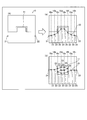
ここで、冷却回路20を設けずに順解析した場合の温度分布は、図6の例のようになる。また、この順解析と、設計目標とに基づいて逆解析を行って取得した体積発熱感度分布は、図7の例のようになる。図7に示す体積発熱感度分布を用いて冷却回路初期位置を決定することにより、熱溜まり以外の部分についても、容易に冷却回路の位置を決定することが可能である。
(冷却回路更新処理)
図8を参照して、図2のステップS2における冷却回路更新処理について説明する。冷却回路更新処理では、設計パラメータの感度分布に基づいて、冷却回路案を生成する。また、冷却回路更新処理は、冷却回路設定不可領域を決定するステップと、設計パラメータの感度に基づいて、冷却回路設定不可領域を避けて冷却回路20の配置を決定するステップとを含む。また、冷却回路更新処理は、冷却回路20を複数の冷却回路要素23に分割するステップと、設計パラメータの感度に基づいて、各冷却回路要素23の配置を決定するステップとを含む。また、冷却回路更新処理は、冷却回路要素23の位置の感度である位置感度に基づいて、各冷却回路要素23の位置を移動させるステップを含む。また、冷却回路更新処理は、位置感度に所定の係数を乗じて、各冷却回路要素23の移動量を決定するステップを含む。
図8を参照して、図2のステップS2における冷却回路更新処理について説明する。冷却回路更新処理では、設計パラメータの感度分布に基づいて、冷却回路案を生成する。また、冷却回路更新処理は、冷却回路設定不可領域を決定するステップと、設計パラメータの感度に基づいて、冷却回路設定不可領域を避けて冷却回路20の配置を決定するステップとを含む。また、冷却回路更新処理は、冷却回路20を複数の冷却回路要素23に分割するステップと、設計パラメータの感度に基づいて、各冷却回路要素23の配置を決定するステップとを含む。また、冷却回路更新処理は、冷却回路要素23の位置の感度である位置感度に基づいて、各冷却回路要素23の位置を移動させるステップを含む。また、冷却回路更新処理は、位置感度に所定の係数を乗じて、各冷却回路要素23の移動量を決定するステップを含む。
具体的には、図8のステップS31において、冷却回路20を複数の冷却回路要素23に分割する。この際に、各冷却回路要素23の連続性を維持するために、各冷却回路要素23の隣り合う要素番号を記憶しておく。
ステップS32において、冷却回路設定不可領域を決定する。冷却回路設定不可領域は、図3に示すように、金型10の外、成形品外形部11、ランナー12、突出しピン13を通す部分、各表面(金型10、成形品外形部11、ランナー12、突出しピン13を通す部分)から所定の距離以内の部分、分割された金型10aおよび10bにおいて各金型10aおよび10bの移動を伴う部分などが設定される。また、冷却回路設定不可領域は、機械的強度のために必要な部分が設定される。
ステップS33において、順解析を実行する。具体的には、冷却回路初期位置決定処理により決定された金型10のモデルに対して順解析を行い、金型10の状態が解析される。ステップS34において、設計目標を定義する。設計目標は、たとえば、成形品外形部11の表面温度を均一(所定の範囲内)にするなどの目標が設定される。
ステップS35において、逆解析に基づいて感度を取得する。具体的には、設定された設計目標と順解析の結果とに基づいて、差を0にするための各設計パラメータの方向性(感度)が求められる。なお、冷却回路更新処理では、複数の感度のうち、冷却回路要素23に対する位置感度を用いる。位置感度は、金型10内における移動方向の指標を示すベクトルとして表される。
ステップS36において、取得した感度(位置感度)に基づいて、各冷却回路要素23の移動量を決定する。移動量は、たとえば、位置感度(x,y,z)×係数αとして求められる。そして、各冷却回路要素23の元の座標位置に移動量が加算されて、新たな座標位置が求められる。なお、係数αは、変更可能である。ステップS37において、移動させた冷却回路要素23と、冷却回路設定不可領域とが接触(干渉)するか否かが判断される。接触すれば、ステップS38に進み、接触しなければ、ステップS39に進む。
ステップS38において、冷却回路設定不可領域と接触する冷却回路要素23の移動量を変更する。具体的には、係数αの値を変更して、移動量を変更する。つまり、移動によって、冷却回路要素23と、冷却回路設定不可領域との接触が生じる場合、該当する冷却回路要素23の係数αを小さくして、移動量を小さくする。その後、ステップS37に戻る。
ステップS39において、冷却回路要素23間の距離が所定値よりも大きいか否かを判断する。つまり、各冷却回路要素23の移動により、隣接する(接続される)冷却回路要素23間の距離が開きすぎたか否かが判断される。距離が大きい場合、ステップS40に進み、距離が大きくない場合、ステップS41に進む。ステップS40において、開きすぎた冷却回路要素23間に新たな冷却回路要素23を追加生成する。この際に、冷却回路要素23の数が更新される。また、各冷却回路要素23の隣接する連結情報が更新される。
ステップS41において、各冷却回路要素23の位置を更新する。ステップS42において、更新された冷却回路要素23の位置に基づいて、金型10の順解析用モデルを更新する。
(金型強度評価処理)
図8を参照して、図2のステップS4における金型強度評価処理について説明する。金型強度評価処理では、設計された冷却回路20が設けられた状態の金型10の機械的強度の評価を行う。つまり、冷却回路20が最適化された金型10において、必要な機械的強度が満たされていることを確認する。
図8を参照して、図2のステップS4における金型強度評価処理について説明する。金型強度評価処理では、設計された冷却回路20が設けられた状態の金型10の機械的強度の評価を行う。つまり、冷却回路20が最適化された金型10において、必要な機械的強度が満たされていることを確認する。
ステップS51において、金型部の有限要素モデルを作成する。この場合に、冷却回路部分は、空洞部として、強度を有さない空間とする。ステップS52において、成形品の材料の流動解析を行い成形中の材料圧力を取得する。たとえば、樹脂を成形する場合は、成形品(製品)の樹脂流動解析を行い、成形中の樹脂圧力を求める。
ステップS53において、材料圧力に基づいて金型部の構造解析を実行する。たとえば、樹脂を成形する場合は、成形品の樹脂圧力を金型10と製品表面とが接する面に荷重として付与して、金型部の構造解析を行う。ステップS54において、金型部の応力・歪・強度・安全率を評価する。そして、機械的強度が、設計目標を満足しない場合、冷却回路20の位置を変更して強度を高める検討を行うため、機械的強度が弱い箇所、および、応力が集中している箇所を、冷却回路設定不可領域として設定する。これにより、機械的強度を高めるために必要な位置に冷却回路20が配置されるのを回避することが可能である。
(本実施形態の効果)
次に、本実施形態の効果について説明する。
次に、本実施形態の効果について説明する。
本実施形態では、上記のように、設計パラメータの改善の方向性を示す指標となる感度に基づいて、冷却回路20を設計するステップを設ける。これにより、設計パラメータを感度に基づいて改善して冷却回路20を設計することができるので、単に熱溜まりをなくすように設計パラメータを変更する場合と異なり、より適した冷却回路20を設計することができる。つまり、設計パラメータの感度に基づいて熱溜まり以外の部分も考慮することができる。その結果、冷却効果が得られる冷却回路20を容易かつ精度よく設計することができる。
また、本実施形態では、上記のように、冷却回路20を設計するステップにおいて、設計パラメータの感度分布に基づいて、冷却回路案を生成する。これにより、設計パラメータの改善の方向性を示す指標となる感度分布に基づいて、金型10全体において適した状態の冷却回路20を容易に設計することができる。
また、本実施形態では、上記のように、冷却回路20を設計するステップは、冷却回路設定不可領域を決定するステップと、設計パラメータの感度に基づいて、冷却回路設定不可領域を避けて冷却回路20の配置を決定するステップとを含む。これにより、成形品外形部11や、型から成形品を抜くための突出しピン13や、機械的強度のために必要な部分などが配置され、冷却回路20を配置することができない冷却回路設定不可領域を避けながら冷却回路20を配置することができるので、確実に作成することが可能な金型10の冷却回路20を設計することができる。
また、本実施形態では、上記のように、冷却回路20を設計するステップは、冷却回路20を複数の冷却回路要素23に分割するステップと、設計パラメータの感度に基づいて、各冷却回路要素23の配置を決定するステップとを含む。これにより、感度に基づいて、冷却効果が高い部分に個別に冷却回路要素23を配置することができるので、配置した個々の冷却回路要素23を接続することにより、容易に冷却効果の高い冷却回路20を設計することができる。
また、本実施形態では、上記のように、冷却回路20を設計するステップは、金型領域内の体積あたりの発熱の感度である体積発熱感度に基づいて、各冷却回路要素23の初期位置を決定するステップを含む。これにより、体積発熱感度に基づいて、冷却要求が大きい位置に冷却回路要素23を配置することができるので、冷却回路20の初期位置を容易に決定することができる。また、体積発熱感度に基づいて冷却効果の高い位置に冷却回路20の初期位置が設定されるので、感度に基づいて冷却回路20の設計パラメータを変更する場合に、より迅速に収束させることができる。これにより、冷却回路20の設計処理を迅速に行うことができる。
また、本実施形態では、上記のように、各冷却回路要素23の初期位置を決定するステップは、金型領域内を複数の配置領域16a~16hに分割するステップと、体積発熱感度に基づいて、各配置領域16a~16hに冷却回路要素23を配置するステップと、配置された冷却回路要素23間を接続するステップとを有する。これにより、金型領域内の分割された複数の配置領域16a~16hにバランスよく冷却回路要素23を配置することができるので、配置された冷却回路要素23を接続することにより金型10をバランスよく冷却することが可能な冷却回路20を容易に設計することができる。
また、本実施形態では、上記のように、各冷却回路要素23の初期位置を決定するステップは、体積発熱感度に基づいて、冷却要求が大きい配置領域16c~16fに配置する冷却回路要素23の数が、冷却要求が小さい配置領域16a、16b、16g、16hに配置する冷却回路要素23の数よりも多くなるように、配置領域16a~16hに配置する冷却回路要素23の数を決定するステップを有する。これにより、冷却要求が大きい位置により多くの冷却回路要素23を配置することができるので、冷却要求が大きい位置を効果的に冷却することが可能な冷却回路20を容易に設計することができる。
また、本実施形態では、上記のように、冷却回路20を設計するステップは、冷却回路要素23の位置の感度である位置感度に基づいて、各冷却回路要素23の位置を移動させるステップを含む。これにより、位置感度に基づいて、冷却回路要素23をより冷却効果の高い位置に移動させることができるので、冷却効果が得られる冷却回路20を容易に精度よく設計することができる。
また、本実施形態では、上記のように、冷却回路20を設計するステップは、位置感度に所定の係数を乗じて、各冷却回路要素23の移動量を決定するステップを含む。これにより、冷却回路要素23を移動させる場合の移動量を位置感度と所定の係数とに基づいて容易に決定することができる。
また、本実施形態では、上記のように、冷却回路20を設計するステップにおいて、複数の感度に基づいて、冷却回路20を設計する。これにより、複数の設計パラメータの各々に適した感度を用いて冷却回路20を設計することができるので、冷却効果が得られる冷却回路20を容易に設計することができる。
(変形例)
なお、今回開示された実施形態は、すべての点で例示であって制限的なものではないと考えられるべきである。本発明の範囲は、上記した実施形態の説明ではなく請求の範囲によって示され、さらに請求の範囲と均等の意味および範囲内でのすべての変更(変形例)が含まれる。
なお、今回開示された実施形態は、すべての点で例示であって制限的なものではないと考えられるべきである。本発明の範囲は、上記した実施形態の説明ではなく請求の範囲によって示され、さらに請求の範囲と均等の意味および範囲内でのすべての変更(変形例)が含まれる。
たとえば、上記実施形態では、体積発熱感度に基づいて冷却回路の初期位置を決定する構成の例を示したが、本発明はこれに限られない。本発明では、体積発熱感度以外の感度に基づいて、冷却回路の初期位置を決定してもよい。
また、上記実施形態では、冷却回路の初期位置をプログラムにより自動で決定する構成の例を示したが、本発明はこれに限られない。本発明では、ユーザが任意の初期位置の冷却回路を設定してもよい。
また、上記実施形態では、位置感度に基づいて冷却回路を移動させる構成の例を示したが、本発明はこれに限られない。本発明では、位置感度以外の感度に基づいて、冷却回路を移動させてもよい。
また、上記実施形態では、冷却回路要素を配置する配置領域を面状(二次元的)に設定する構成の例を示したが、本発明はこれに限られない。本発明では、配置領域を立体形状(三次元的)に設定してもよいし、線状(一次元的)に設定してもよい。
また、上記実施形態では、設計目標として金型の型部分の表面温度が均一な状態となることを設定する例を示したが、本発明はこれに限られない。本発明では、たとえば、設計目標として、金型の温度が所定の温度以下(所定の温度以上)となるように設定してもよい。
また、上記実施形態では、金型に1つの冷却回路が設けられる例を示したが、本発明はこれに限られない。本発明では、金型に複数の冷却回路を設けてもよい。この場合、複数の冷却回路の互いの影響を考慮して、複数の冷却回路を並行して設計することが好ましい。
また、上記実施形態では、金型の機械的強度を評価する処理を行う構成の例を示したが、本発明はこれに限られない。本発明では、金型の機械的強度を評価する処理を行わなくてもよい。
また、上記実施形態では、説明の便宜上、コンピュータの処理動作を処理フローに沿って順番に処理を行うフロー駆動型のフローチャートを用いて説明したが、本発明はこれに限られない。本発明では、コンピュータの処理動作を、イベント単位で処理を実行するイベント駆動型(イベントドリブン型)の処理により行ってもよい。この場合、完全なイベント駆動型で行ってもよいし、イベント駆動およびフロー駆動を組み合わせて行ってもよい。
1 コンピュータ
3a プログラム
7 記録媒体
10 金型
16a~16h 配置領域
20 冷却回路
21 冷却回路入口(冷却回路要素)
22 冷却回路出口(冷却回路要素)
23 冷却回路要素
3a プログラム
7 記録媒体
10 金型
16a~16h 配置領域
20 冷却回路
21 冷却回路入口(冷却回路要素)
22 冷却回路出口(冷却回路要素)
23 冷却回路要素
Claims (12)
- 金型に設ける冷却回路の設計方法であって、
設計目標値に基づく目的関数の値を所定の値にする冷却回路の設計パラメータの改善の方向性を示す指標となる感度を取得するステップと、
取得した前記設計パラメータの感度に基づいて、冷却回路を設計するステップと、を備える、冷却回路の設計方法。 - 前記冷却回路を設計するステップにおいて、前記設計パラメータの感度分布に基づいて、冷却回路案を生成する、請求項1に記載の冷却回路の設計方法。
- 前記冷却回路を設計するステップは、冷却回路設定不可領域を決定するステップと、前記設計パラメータの感度に基づいて、前記冷却回路設定不可領域を避けて冷却回路の配置を決定するステップとを含む、請求項1または2に記載の冷却回路の設計方法。
- 前記冷却回路を設計するステップは、冷却回路を複数の冷却回路要素に分割するステップと、前記設計パラメータの感度に基づいて、各冷却回路要素の配置を決定するステップとを含む、請求項1~3のいずれか1項に記載の冷却回路の設計方法。
- 前記冷却回路を設計するステップは、金型領域内の体積あたりの発熱の感度である体積発熱感度に基づいて、各冷却回路要素の初期位置を決定するステップを含む、請求項4に記載の冷却回路の設計方法。
- 前記各冷却回路要素の初期位置を決定するステップは、金型領域内を複数の配置領域に分割するステップと、前記体積発熱感度に基づいて、各配置領域に冷却回路要素を配置するステップと、配置された冷却回路要素間を接続するステップとを有する、請求項5に記載の冷却回路の設計方法。
- 前記各冷却回路要素の初期位置を決定するステップは、前記体積発熱感度に基づいて、冷却要求が大きい配置領域に配置する冷却回路要素の数が、冷却要求が小さい配置領域に配置する冷却回路要素の数よりも多くなるように、配置領域に配置する冷却回路要素の数を決定するステップを有する、請求項6に記載の冷却回路の設計方法。
- 前記冷却回路を設計するステップは、冷却回路要素の位置の感度である位置感度に基づいて、各冷却回路要素の位置を移動させるステップを含む、請求項4~7のいずれか1項に記載の冷却回路の設計方法。
- 前記冷却回路を設計するステップは、前記位置感度に所定の係数を乗じて、各冷却回路要素の移動量を決定するステップを含む、請求項8に記載の冷却回路の設計方法。
- 前記冷却回路を設計するステップにおいて、複数の感度に基づいて、冷却回路を設計する、請求項1~9のいずれか1項に記載の冷却回路の設計方法。
- 請求項1~10のいずれか1項に記載された冷却回路の設計方法をコンピュータに実行させる、プログラム。
- 請求項11に記載のプログラムを記録した、コンピュータ読み取り可能な記録媒体。
Applications Claiming Priority (2)
| Application Number | Priority Date | Filing Date | Title |
|---|---|---|---|
| JP2017217242A JP2019087197A (ja) | 2017-11-10 | 2017-11-10 | 冷却回路の設計方法、プログラムおよびコンピュータ読み取り可能な記録媒体 |
| JP2017-217242 | 2017-11-10 |
Publications (1)
| Publication Number | Publication Date |
|---|---|
| WO2019093247A1 true WO2019093247A1 (ja) | 2019-05-16 |
Family
ID=66437868
Family Applications (1)
| Application Number | Title | Priority Date | Filing Date |
|---|---|---|---|
| PCT/JP2018/040893 Ceased WO2019093247A1 (ja) | 2017-11-10 | 2018-11-02 | 冷却回路の設計方法、プログラムおよびコンピュータ読み取り可能な記録媒体 |
Country Status (2)
| Country | Link |
|---|---|
| JP (1) | JP2019087197A (ja) |
| WO (1) | WO2019093247A1 (ja) |
Citations (2)
| Publication number | Priority date | Publication date | Assignee | Title |
|---|---|---|---|---|
| JPH0999472A (ja) * | 1995-10-09 | 1997-04-15 | Toray Ind Inc | 製品の設計支援装置、設計方法および製造方法 |
| JP2007164393A (ja) * | 2005-12-13 | 2007-06-28 | Hitachi Ltd | 設計支援方法および設計支援システム |
-
2017
- 2017-11-10 JP JP2017217242A patent/JP2019087197A/ja active Pending
-
2018
- 2018-11-02 WO PCT/JP2018/040893 patent/WO2019093247A1/ja not_active Ceased
Patent Citations (2)
| Publication number | Priority date | Publication date | Assignee | Title |
|---|---|---|---|---|
| JPH0999472A (ja) * | 1995-10-09 | 1997-04-15 | Toray Ind Inc | 製品の設計支援装置、設計方法および製造方法 |
| JP2007164393A (ja) * | 2005-12-13 | 2007-06-28 | Hitachi Ltd | 設計支援方法および設計支援システム |
Non-Patent Citations (1)
| Title |
|---|
| KORESAWA, HIROSHI ET AL.: "Automatic design for cooling channels in injection molding under steady-state heat conduction analysis", TRANSACTIONS OF THE JAPAN SOCIETY OF MECHANICAL ENGINEERS (C), vol. 65, no. 633, 1 January 1999 (1999-01-01), pages 353 - 359, Retrieved from the Internet <URL:https://www.istage.ist.go.jp/articte/kikaicl979/65/633/65_633_2087/_article/-char/ja> [retrieved on 20190115] * |
Also Published As
| Publication number | Publication date |
|---|---|
| JP2019087197A (ja) | 2019-06-06 |
Similar Documents
| Publication | Publication Date | Title |
|---|---|---|
| JP7118941B2 (ja) | 樹脂成形解析方法、プログラムおよび記録媒体 | |
| CN118797914A (zh) | 一种用于金属增材制造残余应力与变形预测的动态固有应变方法 | |
| CN119203680B (zh) | 金属塑料复合制品加工中热变形预测与优化方法和系统 | |
| JP4853145B2 (ja) | 成形プロセスシミュレーション装置、成形プロセスシミュレーションプログラム及び成形品の変形解析方法 | |
| JP4378011B2 (ja) | 金型設計装置と金型形状の設計方法 | |
| WO2024111172A1 (ja) | 成形品品質ばらつき推定装置、成形品品質ばらつき推定方法、及び射出成形システム | |
| Tschopp et al. | Evaluating local primary dendrite arm spacing characterization techniques using synthetic directionally solidified dendritic microstructures | |
| WO2020100726A1 (ja) | 樹脂成形解析方法、プログラムおよび記録媒体 | |
| Silva | A review of the design optimization of conformal cooling channels in injection molds | |
| JP5241310B2 (ja) | 成形品の変形形状の予測方法とその装置、変形形状の予測プログラムとその記憶媒体 | |
| Shinde et al. | Optimization of mold yield in multicavity sand castings | |
| WO2019093247A1 (ja) | 冷却回路の設計方法、プログラムおよびコンピュータ読み取り可能な記録媒体 | |
| JP6527006B2 (ja) | コンピュータ支援の樹脂挙動解析装置 | |
| JP2013050805A (ja) | 誘導加熱コイルの設計支援用シミュレーション方法および設計支援用シミュレーション装置 | |
| US11651124B2 (en) | Anti-warping design method for resin molded article, recording medium, and anti-warping design device for resin molded article | |
| CN119283322A (zh) | 汽车配件注塑模具的控制方法、装置、设备及介质 | |
| JP5899004B2 (ja) | 成形品そり変形予測装置、成形品そり変形予測方法及び成形品そり変形予測プログラム | |
| Rosli et al. | Optimization of process parameters in metal injection molding for turbine blade using response surface methodology | |
| El-Fotouh et al. | Semi-automated gating system design with optimum gate and overflow positions for aluminum HPDC | |
| Ben Slama et al. | Novel method for shape complexity evaluation: a threshold from machining to additive manufacturing in the early design phase | |
| JP2003271678A (ja) | 数値解析方法および装置 | |
| JP4032755B2 (ja) | 成型シミュレーション方法、成型シミュレーション装置及び成型シミュレーションプログラム並びに当該成型シミュレーションプログラムを記録したコンピュータ読みとり可能な記録媒体 | |
| JP6900184B2 (ja) | 樹脂流動解析方法、樹脂流動解析装置、プログラムおよびコンピュータ読み取り可能な記録媒体 | |
| JP7579117B2 (ja) | 樹脂成形品解析方法、プログラム、記録媒体および樹脂成形品解析装置 | |
| JP4018712B2 (ja) | 射出成形品の変形量算出方法、プログラム、記憶媒体、情報処理装置 |
Legal Events
| Date | Code | Title | Description |
|---|---|---|---|
| 121 | Ep: the epo has been informed by wipo that ep was designated in this application |
Ref document number: 18875335 Country of ref document: EP Kind code of ref document: A1 |
|
| NENP | Non-entry into the national phase |
Ref country code: DE |
|
| 122 | Ep: pct application non-entry in european phase |
Ref document number: 18875335 Country of ref document: EP Kind code of ref document: A1 |