WO2019088518A1 - Dispositif électronique et procédé de commande permettant de fournir une notification de sécurité - Google Patents
Dispositif électronique et procédé de commande permettant de fournir une notification de sécurité Download PDFInfo
- Publication number
- WO2019088518A1 WO2019088518A1 PCT/KR2018/012269 KR2018012269W WO2019088518A1 WO 2019088518 A1 WO2019088518 A1 WO 2019088518A1 KR 2018012269 W KR2018012269 W KR 2018012269W WO 2019088518 A1 WO2019088518 A1 WO 2019088518A1
- Authority
- WO
- WIPO (PCT)
- Prior art keywords
- electronic device
- display
- various embodiments
- present document
- event
- Prior art date
Links
Images


Classifications
-
- H—ELECTRICITY
- H04—ELECTRIC COMMUNICATION TECHNIQUE
- H04M—TELEPHONIC COMMUNICATION
- H04M1/00—Substation equipment, e.g. for use by subscribers
- H04M1/72—Mobile telephones; Cordless telephones, i.e. devices for establishing wireless links to base stations without route selection
- H04M1/724—User interfaces specially adapted for cordless or mobile telephones
- H04M1/72403—User interfaces specially adapted for cordless or mobile telephones with means for local support of applications that increase the functionality
- H04M1/7243—User interfaces specially adapted for cordless or mobile telephones with means for local support of applications that increase the functionality with interactive means for internal management of messages
- H04M1/72436—User interfaces specially adapted for cordless or mobile telephones with means for local support of applications that increase the functionality with interactive means for internal management of messages for text messaging, e.g. SMS or e-mail
-
- G—PHYSICS
- G06—COMPUTING; CALCULATING OR COUNTING
- G06F—ELECTRIC DIGITAL DATA PROCESSING
- G06F21/00—Security arrangements for protecting computers, components thereof, programs or data against unauthorised activity
- G06F21/70—Protecting specific internal or peripheral components, in which the protection of a component leads to protection of the entire computer
- G06F21/82—Protecting input, output or interconnection devices
- G06F21/84—Protecting input, output or interconnection devices output devices, e.g. displays or monitors
-
- G—PHYSICS
- G06—COMPUTING; CALCULATING OR COUNTING
- G06F—ELECTRIC DIGITAL DATA PROCESSING
- G06F3/00—Input arrangements for transferring data to be processed into a form capable of being handled by the computer; Output arrangements for transferring data from processing unit to output unit, e.g. interface arrangements
- G06F3/14—Digital output to display device ; Cooperation and interconnection of the display device with other functional units
- G06F3/1423—Digital output to display device ; Cooperation and interconnection of the display device with other functional units controlling a plurality of local displays, e.g. CRT and flat panel display
-
- G—PHYSICS
- G06—COMPUTING; CALCULATING OR COUNTING
- G06F—ELECTRIC DIGITAL DATA PROCESSING
- G06F11/00—Error detection; Error correction; Monitoring
- G06F11/30—Monitoring
- G06F11/32—Monitoring with visual or acoustical indication of the functioning of the machine
-
- G—PHYSICS
- G06—COMPUTING; CALCULATING OR COUNTING
- G06F—ELECTRIC DIGITAL DATA PROCESSING
- G06F11/00—Error detection; Error correction; Monitoring
- G06F11/30—Monitoring
- G06F11/32—Monitoring with visual or acoustical indication of the functioning of the machine
- G06F11/324—Display of status information
- G06F11/328—Computer systems status display
-
- G—PHYSICS
- G06—COMPUTING; CALCULATING OR COUNTING
- G06F—ELECTRIC DIGITAL DATA PROCESSING
- G06F21/00—Security arrangements for protecting computers, components thereof, programs or data against unauthorised activity
- G06F21/60—Protecting data
- G06F21/62—Protecting access to data via a platform, e.g. using keys or access control rules
- G06F21/6218—Protecting access to data via a platform, e.g. using keys or access control rules to a system of files or objects, e.g. local or distributed file system or database
- G06F21/6245—Protecting personal data, e.g. for financial or medical purposes
-
- G—PHYSICS
- G06—COMPUTING; CALCULATING OR COUNTING
- G06F—ELECTRIC DIGITAL DATA PROCESSING
- G06F3/00—Input arrangements for transferring data to be processed into a form capable of being handled by the computer; Output arrangements for transferring data from processing unit to output unit, e.g. interface arrangements
- G06F3/01—Input arrangements or combined input and output arrangements for interaction between user and computer
- G06F3/03—Arrangements for converting the position or the displacement of a member into a coded form
- G06F3/041—Digitisers, e.g. for touch screens or touch pads, characterised by the transducing means
-
- G—PHYSICS
- G06—COMPUTING; CALCULATING OR COUNTING
- G06F—ELECTRIC DIGITAL DATA PROCESSING
- G06F3/00—Input arrangements for transferring data to be processed into a form capable of being handled by the computer; Output arrangements for transferring data from processing unit to output unit, e.g. interface arrangements
- G06F3/01—Input arrangements or combined input and output arrangements for interaction between user and computer
- G06F3/048—Interaction techniques based on graphical user interfaces [GUI]
- G06F3/0481—Interaction techniques based on graphical user interfaces [GUI] based on specific properties of the displayed interaction object or a metaphor-based environment, e.g. interaction with desktop elements like windows or icons, or assisted by a cursor's changing behaviour or appearance
- G06F3/04817—Interaction techniques based on graphical user interfaces [GUI] based on specific properties of the displayed interaction object or a metaphor-based environment, e.g. interaction with desktop elements like windows or icons, or assisted by a cursor's changing behaviour or appearance using icons
-
- G—PHYSICS
- G06—COMPUTING; CALCULATING OR COUNTING
- G06F—ELECTRIC DIGITAL DATA PROCESSING
- G06F3/00—Input arrangements for transferring data to be processed into a form capable of being handled by the computer; Output arrangements for transferring data from processing unit to output unit, e.g. interface arrangements
- G06F3/01—Input arrangements or combined input and output arrangements for interaction between user and computer
- G06F3/048—Interaction techniques based on graphical user interfaces [GUI]
- G06F3/0484—Interaction techniques based on graphical user interfaces [GUI] for the control of specific functions or operations, e.g. selecting or manipulating an object, an image or a displayed text element, setting a parameter value or selecting a range
-
- G—PHYSICS
- G06—COMPUTING; CALCULATING OR COUNTING
- G06F—ELECTRIC DIGITAL DATA PROCESSING
- G06F3/00—Input arrangements for transferring data to be processed into a form capable of being handled by the computer; Output arrangements for transferring data from processing unit to output unit, e.g. interface arrangements
- G06F3/01—Input arrangements or combined input and output arrangements for interaction between user and computer
- G06F3/048—Interaction techniques based on graphical user interfaces [GUI]
- G06F3/0487—Interaction techniques based on graphical user interfaces [GUI] using specific features provided by the input device, e.g. functions controlled by the rotation of a mouse with dual sensing arrangements, or of the nature of the input device, e.g. tap gestures based on pressure sensed by a digitiser
- G06F3/0488—Interaction techniques based on graphical user interfaces [GUI] using specific features provided by the input device, e.g. functions controlled by the rotation of a mouse with dual sensing arrangements, or of the nature of the input device, e.g. tap gestures based on pressure sensed by a digitiser using a touch-screen or digitiser, e.g. input of commands through traced gestures
-
- G—PHYSICS
- G08—SIGNALLING
- G08B—SIGNALLING OR CALLING SYSTEMS; ORDER TELEGRAPHS; ALARM SYSTEMS
- G08B21/00—Alarms responsive to a single specified undesired or abnormal condition and not otherwise provided for
- G08B21/18—Status alarms
-
- H—ELECTRICITY
- H04—ELECTRIC COMMUNICATION TECHNIQUE
- H04M—TELEPHONIC COMMUNICATION
- H04M1/00—Substation equipment, e.g. for use by subscribers
- H04M1/72—Mobile telephones; Cordless telephones, i.e. devices for establishing wireless links to base stations without route selection
- H04M1/724—User interfaces specially adapted for cordless or mobile telephones
- H04M1/72403—User interfaces specially adapted for cordless or mobile telephones with means for local support of applications that increase the functionality
- H04M1/72409—User interfaces specially adapted for cordless or mobile telephones with means for local support of applications that increase the functionality by interfacing with external accessories
-
- H—ELECTRICITY
- H04—ELECTRIC COMMUNICATION TECHNIQUE
- H04M—TELEPHONIC COMMUNICATION
- H04M1/00—Substation equipment, e.g. for use by subscribers
- H04M1/72—Mobile telephones; Cordless telephones, i.e. devices for establishing wireless links to base stations without route selection
- H04M1/724—User interfaces specially adapted for cordless or mobile telephones
- H04M1/72448—User interfaces specially adapted for cordless or mobile telephones with means for adapting the functionality of the device according to specific conditions
- H04M1/72451—User interfaces specially adapted for cordless or mobile telephones with means for adapting the functionality of the device according to specific conditions according to schedules, e.g. using calendar applications
-
- G—PHYSICS
- G09—EDUCATION; CRYPTOGRAPHY; DISPLAY; ADVERTISING; SEALS
- G09G—ARRANGEMENTS OR CIRCUITS FOR CONTROL OF INDICATING DEVICES USING STATIC MEANS TO PRESENT VARIABLE INFORMATION
- G09G2358/00—Arrangements for display data security
-
- H—ELECTRICITY
- H04—ELECTRIC COMMUNICATION TECHNIQUE
- H04M—TELEPHONIC COMMUNICATION
- H04M1/00—Substation equipment, e.g. for use by subscribers
- H04M1/72—Mobile telephones; Cordless telephones, i.e. devices for establishing wireless links to base stations without route selection
- H04M1/724—User interfaces specially adapted for cordless or mobile telephones
- H04M1/72403—User interfaces specially adapted for cordless or mobile telephones with means for local support of applications that increase the functionality
- H04M1/72409—User interfaces specially adapted for cordless or mobile telephones with means for local support of applications that increase the functionality by interfacing with external accessories
- H04M1/724094—Interfacing with a device worn on the user's body to provide access to telephonic functionalities, e.g. accepting a call, reading or composing a message
- H04M1/724095—Worn on the wrist, hand or arm
-
- H—ELECTRICITY
- H04—ELECTRIC COMMUNICATION TECHNIQUE
- H04M—TELEPHONIC COMMUNICATION
- H04M1/00—Substation equipment, e.g. for use by subscribers
- H04M1/72—Mobile telephones; Cordless telephones, i.e. devices for establishing wireless links to base stations without route selection
- H04M1/724—User interfaces specially adapted for cordless or mobile telephones
- H04M1/72403—User interfaces specially adapted for cordless or mobile telephones with means for local support of applications that increase the functionality
- H04M1/72409—User interfaces specially adapted for cordless or mobile telephones with means for local support of applications that increase the functionality by interfacing with external accessories
- H04M1/72412—User interfaces specially adapted for cordless or mobile telephones with means for local support of applications that increase the functionality by interfacing with external accessories using two-way short-range wireless interfaces
-
- H—ELECTRICITY
- H04—ELECTRIC COMMUNICATION TECHNIQUE
- H04M—TELEPHONIC COMMUNICATION
- H04M2250/00—Details of telephonic subscriber devices
- H04M2250/16—Details of telephonic subscriber devices including more than one display unit
Definitions
- This document relates to an electronic device and a control method for providing a security screen.
- Electronic devices such as smart phones have rapidly increased in use and the frequency of use thereof has increased compared with electronic devices such as a desktop computer, a notebook PC, a desktop computer, and the like. Accordingly, a user of a smart phone stores various files on a smart phone rather than a desktop. However, if necessary, the user may have to run or modify various files stored on the smartphone on the desktop. Depending on the needs of such users, various technologies are being developed to connect the smartphone to the desk top (or monitor) and use the smartphone as a desktop environment.
- An electronic device e.g., a smartphone
- an external electronic device e.g., a monitor
- an electronic device may be connected to an external electronic device via a sub-electronic device (e.g., a docking station).
- the electronic device can provide various functions to the user through an external electronic device connected to the electronic device.
- a user can provide various information to other users via a monitor having a relatively larger display device than a display device of a smart phone.
- information associated with the event e.g., time of call, caller information (caller's name, , Various graphical user interfaces (GUI), etc.
- GUI graphical user interfaces
- privacy information e.g., sender information
- an event associated with a specific application occurs in an electronic device while the electronic device is connected to the external electronic device
- a notification other than the privacy information among the information associated with the event is provided through the external electronic device
- An electronic device is provided.
- the information associated with the event can be provided to the user through the electronic device as well as the external electronic device Is provided.
- a notification other than the privacy information among the information associated with the event is provided through the external electronic device.
- a computer-readable recording medium on which instructions are recorded.
- an electronic device when an electronic device is connected to an external electronic device via a sub-electronic device, it is possible to display various screens through the electronic device as well as external electronic devices, A recording medium is provided.
- An electronic device includes a housing including a first surface and a second surface facing the first surface, a touch screen display exposed through a portion of the first surface, At least one wireless and / or wired communication circuit disposed within the housing, at least one processor electrically connected to the communication circuit and the display, the processor being disposed within the housing, and electrically coupled to the housing,
- the memory is configured to store a plurality of application programs including a first application program, wherein the memory, when executed, causes the processor to cause the processor While the device is not electrically connected, the touch screen display Displaying on the touch screen display an event associated with the first application program and displaying a first plurality of icons representing a plurality of application programs without displaying a bar; And to cause the external display to display the first plurality of icons and bars while the electronic device is electrically connected to the external display device via the communication circuit, Wherein in the first operation, the external display at least partially causes the external display to display a second notification when the associated event is present, the second notification being suitable
- a computer readable recording medium may be configured such that at least one operation may be stored and at least one operation may be performed while the electronic device is not electrically connected to the external display device, Displaying on the touch screen display a first plurality of icons representing a plurality of application programs and displaying the first plurality of icons on the touch screen display when there is an event associated with the first application program, Display the first notification, cause the external display device to display the first plurality of icons and the bar while the electronic device is electrically connected to the external display device, and wherein the event associated with the first application program
- the second notification is adapted to the external display device and includes text based on the event, in a first operation, causing the external display device to display a second notification at least partially outside of the bar, And in a second operation, displaying the third notification to the external display device indicating the event but not including text based on the event.
- An electronic device includes a housing including a first surface and a second surface facing the first surface, a touch screen display exposed through a portion of the first surface, At least one wireless and / or wired communication circuit disposed within the housing, at least one processor electrically connected to the communication circuit and the display, the processor being disposed within the housing, and electrically coupled to the housing,
- the memory is configured to store a plurality of application programs including a first application program, wherein the memory, upon execution, causes the processor to communicate with the external While the electronic device is electrically connected to the display device, To cause the external display device to display my icon and bar and to cause the external display device to instruct the external display device when there is an event associated with the first application program, To display a first notification, and to display a second notification on the touch screen display that includes text based on the event.
- various screens can be provided to a user through an electronic device as well as an external electronic device when the electronic device is connected to the external electronic device through the sub electronic device, thereby enhancing user convenience.
- FIG. 1 is a block diagram of an electronic device in a network environment, in accordance with various embodiments.
- 2A is a diagram for explaining a state in which an electronic device is connected to an external electronic device via a sub electronic device, according to various embodiments.
- 2B is an exemplary view for explaining a sub electronic device according to various embodiments.
- 2C is an exemplary diagram for describing a connector of a sub-electronic device, in accordance with various embodiments.
- FIG. 3 is an exemplary diagram for explaining a method of operating an electronic device according to various embodiments.
- 4A-4D are exemplary diagrams illustrating an operation in which an electronic device is associated with a sub-electronic device and an external electronic device, in accordance with various embodiments.
- 5A to 5C are views for explaining an expansion mode according to connection of an external electronic device, according to various embodiments.
- 6A-6F are exemplary diagrams for describing an operation to enter the privacy mode, according to various embodiments.
- 7A to 7C are exemplary diagrams for explaining operation in a normal mode when an event occurs, according to various embodiments.
- 8A to 8E are exemplary diagrams for explaining operation in the privacy mode when an event occurs, according to various embodiments.
- 9A and 9B are exemplary diagrams illustrating an operation in which privacy information is displayed according to user input in a privacy mode, according to various embodiments.
- FIG. 10 is an exemplary diagram illustrating an operation in which a security notification is displayed in a privacy mode when a plurality of events have occurred, according to various embodiments.
- Figs. 11A and 11B are exemplary diagrams illustrating an operation in which privacy information is displayed according to a specified condition in a privacy mode, according to various embodiments.
- Fig. 11A and 11B are exemplary diagrams illustrating an operation in which privacy information is displayed according to a specified condition in a privacy mode, according to various embodiments.
- 12A to 12C are exemplary diagrams for explaining a case where an application specified in an external electronic device is executed and a home screen is displayed on an electronic device, according to various embodiments.
- 13A and 13B are exemplary diagrams for explaining operations when an event occurs in a state where the electronic device and the second external electronic device are connected, according to various embodiments.
- FIG. 14 is an exemplary diagram illustrating a method of operating an electronic device, in accordance with various embodiments.
- Figs. 15A to 15F are exemplary diagrams for explaining operations when an event including privacy information occurs while the electronic device is operating as a pad, according to various embodiments.
- Fig. 15A to 15F are exemplary diagrams for explaining operations when an event including privacy information occurs while the electronic device is operating as a pad, according to various embodiments.
- first, second, etc. terms including ordinal numbers such as first, second, etc. may be used to describe various elements, but the elements are not limited by the terms. The terms are used only for the purpose of distinguishing one component from another.
- first component may be referred to as a second component, and similarly, the second component may also be referred to as a first component.
- FIG. 1 is a block diagram of an electronic device 101 in a network environment 100, in accordance with various embodiments.
- an electronic device 101 in a network environment 100 communicates with an electronic device 102 via a first network 198 (e.g., a short-range wireless communication network) (E. G., A < / RTI > remote wireless communication network).
- a first network 198 e.g., a short-range wireless communication network
- the electronic device 101 is capable of communicating with the electronic device 104 through the server 108.
- the electronic device 101 includes a processor 120, a memory 130, an input device 150, an audio output device 155, a display device 160, an audio module 170, a sensor module 176, an interface 177, a haptic module 179, a camera module 180, a power management module 188, a battery 189, a communication module 190, a subscriber identity module 196, ).
- at least one (e.g., display 160 or camera module 180) of these components may be omitted from the electronic device 101, or one or more other components may be added.
- some of these components may be implemented as a single integrated circuit.
- a sensor module 176 e.g., a fingerprint sensor, an iris sensor, or a light sensor
- the display device 160 e.g., a display
- Processor 120 executes at least one other component (e.g., hardware or software component) of electronic device 101 connected to processor 120 by executing software (e.g., program 140) And can perform various data processing or arithmetic operations.
- the processor 120 may provide instructions or data received from other components (e.g., sensor module 176 or communication module 190) Process the instructions or data stored in the volatile memory 132, and store the resulting data in the non-volatile memory 134.
- the processor 120 includes a main processor 121 (e.g., a central processing unit or application processor), and a secondary processor 123 (e.g., a graphics processing unit, an image signal processor , A sensor hub processor, or a communications processor). Additionally or alternatively, the coprocessor 123 may use less power than the main processor 121, or it may be set to be specific to the specified function. The coprocessor 123 may be implemented separately from, or as part of, the main processor 121.
- a main processor 121 e.g., a central processing unit or application processor
- a secondary processor 123 e.g., a graphics processing unit, an image signal processor , A sensor hub processor, or a communications processor.
- the coprocessor 123 may use less power than the main processor 121, or it may be set to be specific to the specified function.
- the coprocessor 123 may be implemented separately from, or as part of, the main processor 121.
- a functionally related other component e.g., camera module 180 or communication module 190
- Memory 130 may store various data used by at least one component (e.g., processor 120 or sensor module 176) of electronic device 101.
- the data may include, for example, input data or output data for software (e.g., program 140) and instructions related thereto.
- the memory 130 may include a volatile memory 132 or a non-volatile memory 134.
- the program 140 may be stored as software in the memory 130 and may include, for example, an operating system 142, middleware 144,
- the input device 150 may receive instructions or data from an external (e.g., user) electronic device 101 for use in a component (e.g., processor 120) of the electronic device 101.
- the input device 150 may include, for example, a microphone, a mouse, a keyboard, or a pen input device (e.g., a stylus pen).
- the sound output device 155 can output the sound signal to the outside of the electronic device 101.
- the sound output device 155 may include, for example, a speaker or a receiver. Speakers can be used for general purposes, such as multimedia playback or record playback, and receivers can be used to receive incoming calls. According to one embodiment, the receiver may be implemented separately from the speaker, or as part thereof.
- Display device 160 may visually provide information to an external (e.g., user) of electronic device 101.
- Display device 160 may include, for example, a display, a hologram device, or a projector and control circuitry for controlling the device.
- the display device 160 may comprise a touch circuitry configured to sense a touch, or a sensor circuit (e.g., a pressure sensor) configured to measure the force generated by the touch have.
- the audio module 170 may convert the sound into an electrical signal or vice versa. According to one embodiment, the audio module 170 is configured to acquire sound through the input device 150, or to output audio to the audio output device 155, or to an external electronic device (e.g., Electronic device 102) (e.g., a speaker or headphone)).
- an external electronic device e.g., Electronic device 102
- a speaker or headphone e.g., a speaker or headphone
- the sensor module 176 senses the operating state (e.g., power or temperature) of the electronic device 101 or an external environmental condition (e.g., a user state) and generates an electrical signal or data value corresponding to the sensed condition can do.
- the sensor module 176 may be, for example, a gesture sensor, a gyro sensor, an air pressure sensor, a magnetic sensor, an acceleration sensor, a grip sensor, a proximity sensor, a color sensor, A temperature sensor, a humidity sensor, or an illuminance sensor.
- the interface 177 may support one or more designated protocols that may be used for the electronic device 101 to be connected directly or wirelessly with an external electronic device (e.g., the electronic device 102).
- the interface 177 may include, for example, a high definition multimedia interface (HDMI), a universal serial bus (USB) interface, an SD card interface, or an audio interface.
- HDMI high definition multimedia interface
- USB universal serial bus
- SD card interface Secure Digital Card
- connection terminal 178 may include a connector through which the electronic device 101 may be physically connected to an external electronic device (e.g., the electronic device 102).
- connection terminal 178 may include, for example, an HDMI connector, a USB connector, an SD card connector, or an audio connector (e.g., a headphone connector).
- the haptic module 179 may convert electrical signals into mechanical stimuli (e.g., vibrations or movements) or electrical stimuli that the user may perceive through tactile or kinesthetic sensations.
- the haptic module 179 may include, for example, a motor, a piezoelectric element, or an electrical stimulation device.
- the camera module 180 can capture a still image and a moving image.
- the camera module 180 may include one or more lenses, image sensors, image signal processors, or flashes.
- the power management module 188 can manage the power supplied to the electronic device 101.
- the power management module 388 may be implemented as at least a portion of, for example, a power management integrated circuit (PMIC).
- PMIC power management integrated circuit
- the battery 189 may supply power to at least one component of the electronic device 101.
- the battery 189 may include, for example, a non-rechargeable primary battery, a rechargeable secondary battery, or a fuel cell.
- Communication module 190 may be a direct (e.g., wired) communication channel or a wireless communication channel between electronic device 101 and an external electronic device (e.g., electronic device 102), electronic device 104, And to perform communication through the established communication channel.
- Communication module 190 may include one or more communication processors that operate independently of processor 120 (e.g., an application processor) and that support direct (e.g., wired) or wireless communication.
- the communication module 190 may include a wireless communication module 192 (e.g., a cellular communication module, a short range wireless communication module, or a global navigation satellite system (GNSS) communication module) or a wired communication module 194 : A local area network (LAN) communication module, or a power line communication module).
- GNSS global navigation satellite system
- a corresponding one of these communication modules may be a first network 198 (e.g., a short range communication network such as Bluetooth, WiFi direct or IrDA (infrared data association)) or a second network 199 (e.g. a cellular network, (E.g., a telecommunications network, such as a computer network (e.g., a LAN or WAN)).
- a first network 198 e.g., a short range communication network such as Bluetooth, WiFi direct or IrDA (infrared data association)
- a second network 199 e.g. a cellular network, (E.g., a telecommunications network, such as a computer network (e.g., a LAN or WAN)
- These various types of communication modules may be integrated into one component (e.g., a single chip) or a plurality of components (e.g., a plurality of chips) that are separate from each other.
- the wireless communication module 192 may be configured to communicate with the subscriber identity module 196 in a communication network such as the first network 198 or the second network 199 using subscriber information (e.g., International Mobile Subscriber Identity (IMSI)
- subscriber information e.g., International Mobile Subscriber Identity (IMSI)
- IMSI International Mobile Subscriber Identity
- the antenna module 197 can transmit signals or power to the outside (e.g., an external electronic device) or receive it from the outside.
- the antenna module 197 may include one or more antennas including a conductor formed on a substrate (e.g., a PCB) or a radiator in a conductive pattern.
- the antenna module 197 may comprise a plurality of antennas. In this case, at least one antenna suitable for a communication scheme used in a communication network, such as the first network 198 or the second network 199, is communicated from the plurality of antennas, for example, Can be selected.
- a signal or power may be transmitted or received between the communication module 190 and the external electronic device via the selected at least one antenna.
- other components e.g., RFICs in addition to the radiator may be further formed as part of the antenna module 197.
- At least some of the components are connected to each other via a communication method (e.g., bus, general purpose input and output, SPI, or mobile industry processor interface (MIPI) For example, commands or data).
- a communication method e.g., bus, general purpose input and output, SPI, or mobile industry processor interface (MIPI)
- MIPI mobile industry processor interface
- Instructions or data may be transmitted or received between the electronic device 101 and the external electronic device 104 via the server 108 connected to the second network 199.
- Each of the electronic devices 102 and 104 may be the same or a different kind of device as the electronic device 101.
- all or a portion of the operations performed on the electronic device 101 may be performed on one or more external devices of the external electronic devices 102, 104, or 108.
- the electronic device 101 may, instead of executing the function or service itself Or in addition, to one or more external electronic devices to perform the function or at least part of the service.
- One or more external electronic devices that have received the request may execute at least a portion of the requested function or service, or an additional function or service associated with the request, and deliver the result of the execution to the electronic device 101.
- the electronic device 101 may process the result as it is or in addition to provide it as at least part of the response to the request.
- cloud computing distributed computing, or client-server computing technology may be used.
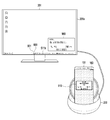
- 2A is a diagram for explaining a state in which an electronic device is connected to an external electronic device via a sub electronic device, according to various embodiments.
- an electronic device 101 may be electrically connected to a sub electronic device 200.
- FIG. The electronic device 101 in accordance with various embodiments of the present document may include a display device 160 (e.g., a display).
- a display device 160 e.g., a display
- the sub electronic device 200 is a docking station (for example, Samsung ⁇ Dex ⁇ ) is illustrated by way of example.
- the electronic device 101 and the sub electronic device 200 can be electrically connected to each other through a connector.
- the external electronic device 201 e.g., a monitor
- the external electronic device 201 is connected to the sub electronic device 200 and the electronic device 200 via the connector of the sub electronic device 200, with the electronic device 101 being connected to the sub electronic device 200.
- the external electronic device 201 according to various embodiments of the present document may include a display device 201a (e.g., a display).
- 2B is an exemplary view for explaining a sub electronic device according to various embodiments.
- a sub-electronic device 200 includes a type C connector 205, a display port (DP) 210, a universal serial bus (USB) 2.0 hub A USB 2.0 type A socket 240, a LAN socket 245, and a type C socket 250 (not shown), a billboard 220, a PD (power delivery) IC 225, a memory 230, an Ethernet controller 235, ).
- the Type C connector 205 may include a USB Type C connector.
- the Type C socket 250 may refer to a USB Type C socket.
- a USB 2.0 hub 215 is shown as an example of a USB hub, but this is exemplary.
- the USB 2.0 hub 215 according to various embodiments of this document may be used interchangeably with various types of USB hubs (e.g., USB 3.0 hubs), or may include various types of USB Hubs (such as USB 3.0 hubs) can be used additionally.
- the Type C connector 205 includes a USB type and may be coupled to the electronic device 101.
- the display port 210 according to various embodiments of the present document may be connected to the type C connector 205. And may be connected to an external electronic device 201 (e.g., a monitor) through the display port 210.
- the USB 2.0 hub 215 may be connected to the type C connector 205.
- the USB 2.0 hub 215 may be connected to the USB type A socket 240 and the LAN socket 245.
- the billboard 220 according to various embodiments of the present document may be coupled to a USB 2.0 hub 215.
- the billboard 220 may receive identification information from an external electronic device for identifying an external electronic device (e.g., a monitor) connected to the sub electronic device 200. [ The billboard 220 can transmit the identification information of the received external electronic device to the electronic device 101.
- the PD IC 225 according to various embodiments of the present document may be connected to the Type C socket 250. The PD IC 225 can receive power from the external power supply 290 and supply power to various components of the sub electronic device 200 when the PD IC 225 is connected to the external power supply 290 through the Type C socket 250 have.
- the memory 230 according to various embodiments of the present document may store various information associated with the operation of the sub electronic device 200, such as identification information of the sub electronic device 200 of the sub electronic device 200 .
- the Ethernet controller 235 in accordance with various embodiments of the present document can support establishment of a communication channel and communication through the established communication channel when the communication cable 265 is connected through the LAN socket 245 .
- the type of socket, the type of connector, and the type of port according to various embodiments of the present document shown in FIG. 2B are exemplary and may be modified in various types or ways. According to various embodiments of the present document, the ports or sockets may be used alternatively / interchangeably with the term connector.
- 2C is an exemplary view for describing a connector of a sub electronic device, according to various embodiments.
- the connector shown in FIG. 2C may include, for example, the Type C connector 205 shown in FIG. 2B. According to various embodiments of the present document, the connector shown in FIG. 2C may also be configured as a Type C socket 250. 2C, it is assumed that the connector (for example, the USB type C connector) of the electronic device 101 and the type C connector 205 of the sub electronic device 200 are connected to each other .
- the connector for example, the USB type C connector
- the Type C connector 250 may include a plurality of pins. 2C, the type C connector of the electronic device 101 includes a ground (GND) A1, pins TX1 + (A2), TX1- (A3) for data transmission, VBUS (A4) , D + (A6), D- (A7) for data transmission and reception (eg, high-speed communication), SBU1 (A8) for using side band, VBUS A9, RX2- (A10), RX2 + (A11), and ground (GND) A12 for data reception.
- GDD ground
- the type C connector 205 of the sub electronic device 200 includes a ground (GND) B12 as pins, RX1 + (B11), RX1- (B10) D-B7, D + B6 for data transmission and reception (for example, high-speed communication), CC2 (B5) for channel configuration, VBUS (B9) for power supply, SBU2 (B8) VBUS (B4) for power supply, TX2- (B3), TX2 + (B2), and ground (GND) B1 for data transmission.
- GND ground
- the ground A1 of the type C connector of the electronic device 101 may be connected to the ground B12 of the type C connector 205 of the sub electronic device 200.
- the ground A12 of the type C connector of the electronic device 101 may be connected to the ground B1 of the type C connector 205 of the sub electronic device 200.
- the TX + (A2) of the type C connector of the electronic device 101 may be connected to the RX + (B11) of the type C connector 205 of the sub electronic device 200.
- the TX- (A3) of the type C connector of the electronic device 101 can be connected to the RX- (B10) of the type C connector 205 of the sub electronic device 200.
- VBUS (A4) and VBUS (A9) of the electronic device can be connected to VBUS (B9) and VBUS (B4) of the sub electronic device 200, respectively.
- the sub electronic device 603 can receive power from the electronic device 101.
- the sub electronic device 200 may be powered from an external power source.
- CC1 (A5) of the type C connector of the electronic device 101 can be connected to SBU2 (B8) of the type C connector of the sub electronic device 200.
- SBU1 (A8) of the electronic device 101 type C connector can be connected to CC2 (B5) of the type C connector 205 of the sub electronic device 200.
- a communication channel between the electronic device 101 and the sub electronic device 200 can be formed.
- D + (A6) of the electronic device 101 type C connector is connected to D- (B7) of the type C connector 205 of the sub electronic device 200 and D + (A6) of the type C connector of the electronic device 101 is connected to D- A7 may be connected to D + of the type C connector 205 of the sub electronic device 200.
- FIG. 3 is an exemplary diagram for explaining a method of operating an electronic device according to various embodiments.
- an electronic device in accordance with various embodiments of the present document may be implemented in operation 300 using a connector (e.g., connection terminal 178 of FIG. 1) , And the sub electronic device 200.
- a connector e.g., connection terminal 178 of FIG. 1
- an electronic device e.g., electronic device 101 of FIG. 1 is coupled to a subelectronic device (e.g., subelectronic device 200 of FIG. ) And a USB Type C connector.
- An electronic device in accordance with various embodiments of the present document may be capable of detecting the connection of an external electronic device (e.g., external electronic device 201 of FIG. 2a) have.
- an external electronic device may be connected through a port of the sub-electronic device (e.g., DP 210 of FIG. 2B). Operations 310 are described below with respect to Figures 4A-4D.
- An electronic device e.g., processor 120 of FIG. 1 in accordance with various embodiments of the present document may switch to an extended mode at operation 320. Operations 320 are described below with respect to Figures 5A-5C.
- An electronic device in accordance with various embodiments of the present document may, at operation 330, detect the occurrence of an event.
- Events in accordance with various embodiments of this document include various events that may occur in the use of electronic devices, such as telephone calls, telephone calls, message reception, message origination, or user-designated notifications. can do.
- An electronic device in accordance with various embodiments of the present document may, at operation 340, determine whether the current mode is a privacy mode.
- the privacy mode according to the various embodiments of this document is a mode in which, for the generated event, a mode set to display a notice excluding privacy information on a display device (e.g., display device 201a in Fig. 2A) It can mean.
- the term privacy information excluded notification may be referred to generically / interchangeably with the term security notification.
- the privacy information may be stored in an electronic device (e.g., memory 130 of FIG. 1) according to a designated application.
- privacy information according to various embodiments of this document may be stored as a mapping table as shown in Table 1 below.
- SMS application Privacy Information Phone Application Caller's name, caller's contact information, images related to the caller, etc.
- only privacy information may be stored in an electronic device (e.g., memory 130 of FIG. 1).
- the electronic device 101 e.g., the processor 120 of FIG. 1
- An electronic device e.g., processor 120 of FIG. 1 in accordance with various embodiments of the present document includes at least one of an electronic device (e.g., electronic device 101 of FIG. 1) At least one device can display an alert for an event that has occurred.
- an electronic device e.g., electronic device 101 of FIG.
- Electronic device 101 in accordance with various embodiments of the present document may, at operation 360, determine whether the event generated is an event associated with a specified application.
- the designated application according to various embodiments of this document can be designated by the user.
- Designated applications according to various embodiments of this document can be specified by MDM policy.
- the designated application according to various embodiments of this document can be designated by the manufacturer of the application.
- Information for a designated application in accordance with various embodiments of the present document may be stored in an electronic device (e.g., memory 130 in FIG. 1).
- an electronic device may determine whether an event generated based on a mapping table such as Table 1 is an event associated with a specified application .
- An electronic device e.g., processor 120 of FIG. 1 in accordance with various embodiments of the present document, when not in the privacy mode (referred to herein as the normal mode for convenience of description herein) ,
- An electronic device e.g., display device 160 of FIG. 1
- an external electronic device e.g., display device 201a of FIG. 2a. Operation in the normal mode according to various embodiments of the present document is described below with reference to Figures 7A-7C.
- An electronic device in accordance with various embodiments of the present document may determine at operation 370 whether privacy information is included in the generated event. For example, in order to display a notification of a call event (e.g., a telephone call) on an electronic device (e.g., the display device 160 of FIG. 1), privacy information such as a sender name, have. Thus, an electronic device (e.g., processor 120 of FIG. 1) in accordance with various embodiments of the present document may determine that the call event includes privacy information. According to various embodiments of the present document, an electronic device (e.g., processor 120 of FIG. 1) may determine whether privacy information is included in an event that is generated based on a mapping table such as Table 1.
- a mapping table such as Table 1.
- Electronic device in accordance with various embodiments of the present document may, at operation 350, display the electronic device (e.g., the display of FIG. 1 Device 160) and an external electronic device (display device 201a of Fig. 2a).
- Operation 370 can be understood as an operation to determine whether or not privacy information is included in the notification or screen to provide information associated with the generated event, or whether the data associated with the generated event includes data associated with the privacy information .
- Electronic device e.g., processor 120 of FIG. 1
- an external electronic device e.g., Display (E.g., the device 201a)
- an alert including the privacy information in an electronic device (e.g., the display device 160 of FIG. 1).
- Security announcements in accordance with various embodiments of this document are described below with respect to Figures 8A-8E.
- a method of operating an electronic device in accordance with various embodiments of the present document may be performed with operation 360 omitted.
- an electronic device e. G., Electronic device 101
- the security notification may be displayed on at least one of the electronic device (e.g., display 160 of FIG. 1) and an external electronic device (e.g., display 201a of FIG. 2a).
- an electronic device e.g., electronic device 101
- an electronic device e. G., Electronic device 101
- the security notification can be displayed on at least one of the electronic device (e.g., the display device 101 of FIG. 1) and the external electronic device (e.g., the display device 201a of FIG.
- a method of operating an electronic device includes, at operation 380, only the external electronic device (e. G. Can be performed in place of the operation of displaying the excluded notification.
- an electronic device e.g., processor 120
- a standby screen e.g., a black screen
- the electronic device e.g., the display device 160 in Fig. 1.
- mode ", " set to a specific mode ", or " switch to a specific mode " referred to in this document refers to various functions / operations performed in accordance with various embodiments of the present document It is a term mentioned. That is, the term “mode " in this document refers to the state in which a particular function / function or operation / actions are performed.
- set to a specific mode means to change (in other words, set to environment) a state in which a function / function or operation / Does not imply that there must be an input (e.g., user input) to " set " or " switch to a particular mode "
- 4A-4D are exemplary diagrams illustrating an operation in which an electronic device is associated with a sub-electronic device and an external electronic device, in accordance with various embodiments.
- a sub-electronic device 200 and an external electronic device 201 are connected to each other through a display port 210 of a sub-electronic device 200 and a display port (not shown) of the external electronic device 201 Can be connected.
- a display port 210 of a sub-electronic device 200 and a display port (not shown) of the external electronic device 201 Can be connected.
- the HDMI port is shown in FIG. 2A as an example of the display port 210, various embodiments of the present document are not limited thereto.
- the connector 205 of the sub electronic device 200 and the connector of the electronic device 101 can be connected to each other.
- the connector of the electronic device 101 and the connector 205 of the sub-electronic device 200 may include USB Type C, whereby various embodiments of this document are limited It is not.
- the electronic device 101 e.g., the processor 120 of FIG. 1
- the order of FIGS. 4A and 4B may be changed from each other.
- sub-electronic device 200 according to various embodiments of this document, where sub-electronic device 200 according to various embodiments of this document is a dongle 400 Respectively.
- the electronic device 101 can detect the connection of the external electronic device 201 in a state of being connected to the dongle 400.
- the external electronic device 201 may be connected to the HDMI port 401 of the dongle 400.
- the electronic device 101 may be connected to the USB port 402 of the dongle 400.
- the electronic device 101 according to various embodiments of the present document can detect an external electronic device 201 connected through the dongle 400.
- FIG. 4D shows an embodiment in which an electronic device 101 according to various embodiments of the present document is connected to an external electronic device 201 via a wireless communication.
- An electronic device 201 may be configured to communicate with an external electronic device 201 and a communication module (e.g., Communication module 190).
- the electronic device 101 may be connected to the external electronic device 201 using the communication module of the sub electronic device 200 in a state where the electronic device 101 is connected to the sub electronic device 200.
- the sub electronic device 200 can transmit information indicating that it is connected to the external electronic device 201 and information for connecting with the external electronic device 201 to the electronic device 101.
- the electronic device 101 may detect the connection of the external electronic device 201, according to the various embodiments described with respect to Fig. 4d.
- Figs. 5A-5C are diagrams for explaining an expansion mode according to the connection of an external electronic device (e.g., the external electronic device 201 of Fig. 2A), according to various embodiments.
- an external electronic device e.g., the external electronic device 201 of Fig. 2A
- the electronic device 101 may be configured to communicate with an external electronic device (e. G., An external electronic device 201 of FIG. 2a) with the sub- ) Is detected, it is possible to enter the extended mode (in other words, switch from the normal mode to the extended mode).
- the expansion mode according to various embodiments of this document may be implemented in an external electronic device (e.g., display 201a of external electronic device 201 of FIG. 2a) or in electronic device 101 and external electronic device (A state in which a screen is displayed in other words, a screen) on the display device 201a of the external electronic device 201 in Fig. 2A).
- the screen displayed on display device 160 e.g., a touch screen display
- an external electronic device e.g., display 201a of external electronic device 201 of FIG. 2a
- Display attributes may be different from each other.
- the display attributes according to various embodiments of the present document may include resolution, number of screens, orientation of the screen, position of the displayed object on the screen, brightness of the screen, color of the object, shape of the object, The size of the image.
- the display device 160 of the electronic device 101 has a relatively low resolution (for example, 1920 x 1080) than the external device (for example, the display device 201a of the external electronic device 201 of Fig.
- the display device 201a of the external electronic device 201 in Fig. 2a can be displayed at a relatively higher resolution (for example, 3840 X 2160). ≪ / RTI >
- the memory (e.g., memory 130 of FIG. 1) of the electronic device 101 may include an external device (e.g., : External electronic device 201 in Fig. 2A).
- electronic device 101 may be configured to communicate with electronic device 101 (e. G., External electronic device 201) based on information about an external electronic device (For example, the display 201a of the external electronic device 201 in Fig.
- an electronic device 101 is connected to an external electronic device (e.g., the external electronic device 201 of FIG. 2A) via a sub-electronic device (e.g., sub- The electronic device 101 may be connected to a manufacturer server (not shown) of an external electronic device (e.g., the external electronic device 201 of Figure 2a) using a communication module (e.g., the communication module 190 of Figure 1) (E.g., the external electronic device 201 of FIG. 2A) from the external device (not shown).
- a communication module e.g., the communication module 190 of Figure 1
- electronic device 101 may be configured to display electronic device 101 based on display attribute information provided from a manufacturer server of an external electronic device (e.g., external electronic device 201 of FIG. 2A) (E.g., the display device 201a of Fig. 2A) having a different display attribute from the screen displayed on the display device 160 of Fig. 2A.
- the memory e.g., memory 130 of FIG. 1
- the electronic device 101 may be configured to receive information from the external electronic device (e.
- the display 130) based on the display attribute information obtained in accordance with various embodiments of the present document and information about the various user interfaces stored in a memory (E.g., a display device 201a of the external electronic device 201 in Fig. 2a) is displayed on an external electronic device (e.g., the display device 201a of the external electronic device 201 in Fig. 2a) .
- the general mode according to various embodiments of this document may mean a mode in which a screen is displayed only on the display device 160 of the electronic device 101.
- the general mode according to various embodiments of the present document may be implemented in electronic devices 101 (e.g., external electronic device 201 of FIG. 2A) May be displayed only on the display device 160 of the display device.
- electronic device 101 may display various screens and / or user interfaces on an external electronic device (e.g., display device 201a of external electronic device 201 of Figure 2a) To the external electronic device (e.g., the external electronic device 201 in FIG. 2A).
- an external electronic device e.g., display device 201a of external electronic device 201 of Figure 2a
- the external electronic device e.g., the external electronic device 201 in FIG. 2A.
- an electronic device 101 may be configured to switch to an extended mode when detecting a connection of an external electronic device (e.g., the external electronic device 201 of FIG. 2A)
- a confirmation message 500 for receiving an input can be displayed on the display device 160).
- the user may switch to the enhanced mode according to the user's input to the confirmation message (500).
- the electronic device 101 may switch to the extended mode when a connection of an external electronic device (e.g., the external electronic device 201 of FIG. 2A) is detected, have.
- the electronic device 101 may display the first screen 510 on the external electronic device 201.
- the electronic device 101 according to various embodiments of the present document may be in connection with the sub electronic device 200.
- the electronic device 101 can control the display device 160 of the electronic device 101 to display an idle screen (e.g., a black screen).
- the term " display of the idle screen " can also be understood to mean switching to the idle screen.
- the term idle screen display is also understood to mean that the display device 160 of the electronic device 101 is turned off.
- the idle screen is a screen state in which the brightness of the screen of the display device 160 becomes dark to be viewed as an idle screen and a black screen is displayed on the upper layer of the screen displayed on the display device 160 A state in which the idle screen is displayed and a state in which the screen of the display device 160 is turned off, or a state in which the screen is displayed).
- a bar 511a may be displayed.
- the electronic device 101 in the extended mode, is capable of displaying a first screen 510 on the display 201a of the external electronic device 201 have.
- the electronic device 101 according to various embodiments of the present document may be in connection with the sub electronic device 200.
- the electronic device 101 can display a second screen 520 (e.g., a home screen) on the display device 160.
- the status information of the electronic device 101 or the external electronic device 201 is stored in a form of a user interface (or graphical user interface (GUI)
- GUI graphical user interface
- 6A-6F are exemplary diagrams for describing an operation to enter the privacy mode, according to various embodiments.
- an electronic device e.g., processor 120 of FIG. 1 in accordance with various embodiments of the present document includes, at operation 601, a sub-electronic device (e.g., sub- Can be detected.
- a sub-electronic device e.g., sub- Can be detected.
- An electronic device in accordance with various embodiments of the present document is capable of detecting a connection of an external electronic device (e.g., external electronic device 201 of FIG. 2) have. According to various embodiments of the present document, it is possible to enter the extended mode according to operation 603.
- An electronic device in accordance with various embodiments of the present document may verify the identity of the subelectronic device (e.g., subelectronic device 200 of FIG. 2a) at operation 605 have.
- the identification information may be stored in a memory (e.g., memory 230 of FIG. 2B) of the subelectronic device (e.g., subelectronic device 200 of FIG. 2A).
- the electronic device e.g., processor 120 of FIG. 1 is coupled to a subelectronic device (e.g., subelectronic device 200 of FIG. 2A) (E.g., the sub-electronic device 200 in Fig. 2A) from the sub-electronic device.
- An electronic device in accordance with various embodiments of the present document may switch to a privacy mode based on the identified identification information, at operation 607.
- the memory e.g., memory 130 of FIG. 1 of an electronic device (e.g., electronic device 101 of FIG. 1) according to various embodiments of the present document includes a sub- (200), and a mapping table storing information on whether or not to switch to the privacy mode according to the identification information.
- the electronic device e.g., the processor 120 of FIG. 1 according to various embodiments of the present document may be configured such that when identification information of a subelectronic device (e.g., the subelectronic device 200 of FIG. 2A) (E. G., The electronic device 101 of FIG.
- an electronic device e.g., processor 120 of FIG. 1 may be configured to determine whether a sub-electronic device (e. G. (E.g., sub-electronic device 200 in FIG. 2A) is a B2B (Business to Business) device or a B2C (Business to Consumer) device.
- An electronic device e.g., processor 120 of FIG. 1 in accordance with various embodiments of the present document may be implemented as an electronic device (e. G. : The electronic device 101 in Fig. 1) can be set to the privacy mode.
- An electronic device (e.g., processor 120 of FIG. 1) in accordance with various embodiments of the present document may be implemented in electronic devices (e. G. : The electronic device 101 in Fig. 1) can be set to the normal mode.
- an electronic device in accordance with various embodiments of the present document includes at least one sub-electronic device (e.g., sub-electronic device 200 of FIG. Lt; / RTI >
- An electronic device in accordance with various embodiments of the present document may be operable to detect a connection of an external electronic device (e.g., external electronic device 201 of FIG. 2a) have.
- an electronic device e.g., electronic device 101 of FIG. 1 may enter an extended mode, according to act 613.
- processor 120 of FIG. 1 in accordance with various embodiments of the present document may include at least one of a sensor module (e.g., sensor module 176 of FIG. 1) or a communication module
- the communication module 190 of the electronic device 101 can be used to verify the current location of the electronic device (e.g., electronic device 101 of FIG. 1).
- an electronic device e.g., electronic device 101 of FIG. 1 may be coupled to an electronic device (e. G., The electronic device 101 of FIG. 1) using a Wi-Fi positioning system The device 101).
- An electronic device in accordance with various embodiments of the present document may switch to the privacy mode based on the identified location, at operation 617.
- the current location of an electronic device e.g., electronic device 101 of FIG. 1
- the electronic device 101 can be switched to the privacy mode.
- the designated location may be preset by the manufacturer of the electronic device (e.g., electronic device 101 of FIG. 1), or may be set by the user.
- an electronic device 101 e.g., processor 120 of FIG. 1 in accordance with various embodiments of the present document includes, at operation 621, a sub-electronic device (e.g., 200) can be detected.
- a sub-electronic device e.g., 200
- the electronic device 101 (e.g., processor 120 of FIG. 1) according to various embodiments of the present document may be operatively coupled to an external electronic device (e.g., external electronic device 201 of FIG. Can be detected. According to various embodiments of the present document, an electronic device (e.g., electronic device 101 of FIG. 1) may enter an extended mode, according to act 613.
- Electronic device 101 in accordance with various embodiments of the present document may be operable at operation 625 to communicate with external electronic devices (e. G., Display device 160 of FIG. 1)
- a user interface for switching to the privacy mode can be displayed on the device (e.g., the external electronic device 201).
- the user interface for switching to the privacy mode may include a visual user interface, such as a confirmation message or icon.
- the user interface for switching to the privacy mode may include various types of user interfaces, such as an audible, tactile interface, and the like.
- the operation 625 can be performed in place of the operation of outputting the user interface for switching to the privacy mode.
- Electronic device 101 in accordance with various embodiments of the present document may, at act 627, detect a selection input for a user interface for switching to a privacy mode.
- the electronic device 101 (e.g., the processor 120 of FIG. 1) according to various embodiments of the present document may be configured to operate at an operation 629 to change the operating mode of the electronic device (e.g., electronic device 101) The user can switch to the privacy mode.
- an electronic device 101 may be coupled to the sub electronic device 200.
- the identification information of the sub electronic device 200 according to various embodiments of the present document may be provided from a vendor 600 of the sub electronic device 200.
- the identification information of the sub electronic device 200 may be provided through a mobile device management (MDM) policy.
- An MDM in accordance with various embodiments of the present document may be provided from the MDM server 602 of the vendor 600 through the MDM client 604 of the electronic device 101.
- the electronic device 101 according to various embodiments of the present document may store identification information of the sub electronic device 200 obtained from the vendor 600 in the MDM framework 610.
- identification information of the sub-electronic device 200 provided from the vendor 600 may be stored in a memory (e.g., memory 230 of FIG. 2B) of the sub- .
- the electronic device 101 may be configured such that an external electronic device (e.g., the external electronic device 201 of FIG. 2A) is connected to the sub- electronic device 200 in accordance with the MDM policy provided by the vendor 600 It is possible to control the electronic device 101 to operate in the privacy mode.
- the MDM policy may include, in the privacy mode according to various embodiments of this document, for an application specified by the administrator (e.g., an application for accessing a company's server, etc.)
- An idle screen is displayed on the device (for example, the display device 201a of the external electronic device 201 in Fig. 2a), and the application specified only on the display device (e.g., the display device 160 in Fig. 2a) May be included to control the electronic device 101 so that a screen associated with the electronic device 101 is displayed.
- bars 511a, 511b displayed in an external electronic device may have various forms . ≪ / RTI > Bars 511a and 511b in accordance with various embodiments of the present document may include a first type bar 511a in a collapsed state and a second type bar 511b in an uncollapsed (in other words, expanded) And a second type bar 511b.
- the first type bar 511a may include a folded notification area 630a, a folded system status area 610a, and a folded quick panel area 650a.
- the folded notification area 630a and the notification area 630b in accordance with various embodiments of the present document, user interfaces related to notification information associated with various applications can be displayed.
- the folded system status area 640a and the system status area 640b in accordance with various embodiments of the present document include the system status of the electronic device 101 such as the battery status (in other words, the remaining battery amount) (Wifi) signal sensitivity, and the like can be displayed.
- a graphical user interface (GUI) 660 for switching to the privacy mode may be displayed in the system status area 640b.
- GUI graphical user interface
- the electronic device 101 may change the operation mode of the electronic device 101 to a privacy mode . ≪ / RTI >
- the graphical user interface 660 may include, in addition to the system status area 640b, at least one of the notification area 630b, the collapsed notification area 630a and the collapsed system status area 640a Area. ≪ / RTI >
- the electronic device 101 is configured to display on the display device 201a of the external electronic device 201, upon switching to the privacy mode (e.g., when the second type bar 511b ), A notification message 670 indicating that specific information (e.g., privacy information) is not displayed in the privacy mode is displayed on the display device 201 of the external electronic device 201 ).
- the privacy mode e.g., when the second type bar 511b
- a notification message 670 indicating that specific information (e.g., privacy information) is not displayed in the privacy mode is displayed on the display device 201 of the external electronic device 201 ).
- 7A to 7C are exemplary diagrams for explaining operations in a normal mode when an event occurs, according to various embodiments.
- an electronic device 101 may be connected to a sub electronic device 200.
- FIG. The electronic device 101 according to various embodiments of the present document may be connected to the external electronic device 201 via the sub electronic device 200.
- the electronic device 101 according to various embodiments of the present document can display the first type bar 511a on the display 201a of the external electronic device 201.
- the electronic device 101 in accordance with various embodiments of the present document may include an event associated with an application (e.g., a phone application) stored in a memory (e.g., memory 130 of FIG. 1) Reception) can be detected.
- an application e.g., a phone application
- a memory e.g., memory 130 of FIG. 1 Reception
- the electronic device 101 may display the notification 700 associated with the generated event on the display 201a of the external electronic device 201.
- the notification 700 according to various embodiments of the present document may include privacy information (e.g., the telephone number of the caller).
- the electronic device 101 according to various embodiments of the present document can display a standby screen (e.g., a black screen) on the display device 160, as shown in Fig. 7A.
- an electronic device 101 may be coupled to the sub-electronic device 200.
- FIG. The electronic device 101 according to various embodiments of the present document may be connected to the external electronic device 201 via the sub electronic device 200.
- the electronic device 101 according to various embodiments of the present document can display the first type bar 511a on the display 201a of the external electronic device 201.
- Electronic device 101 in accordance with various embodiments of the present document may include an event associated with an application (e.g., an SMS application) stored in memory (e.g., memory 130 of FIG. 1) Message reception) can be detected.
- an application e.g., an SMS application
- memory e.g., memory 130 of FIG. 1
- the electronic device 101 may display a notification 710 associated with the generated event on the display 201a of the external electronic device 201.
- the notification 700 according to various embodiments of this document may include privacy information (e.g., the telephone number of the SMS sender, the content of the SMS).
- the electronic device 101 according to various embodiments of the present document can display a standby screen (e.g., a black screen) on the display device 160, as shown in Fig. 7B.
- the electronic device 101 may be connected to the sub electronic device 200.
- FIG. The electronic device 101 according to various embodiments of the present document may be connected to the external electronic device 201 via the sub electronic device 200.
- the electronic device 101 according to various embodiments of the present document can display the first type bar 511a on the display 201a of the external electronic device 201.
- the electronic device 101 in accordance with various embodiments of the present document may include an event associated with an application (e.g., a phone application) stored in a memory (e.g., memory 130 in FIG. 1) Message reception) can be detected.
- the electronic device 101 according to various embodiments of the present document may display the notification 720 associated with the generated event on the external electronic device 201.
- the alert 720 associated with the generated event may include a mirroring screen for the screen displayed (or displayed) on the display device 160 of the electronic device 101 .
- Alert 700 may include privacy information (e.g., telephone number of telephone caller).
- the electronic device 101 can display the same screen as a standby screen (e.g., a black screen) or a mirrored screen.
- a standby screen e.g., a black screen
- a mirrored screen e.g., a case where an idle screen is displayed on the display device 160 is shown.
- 8A to 8E are exemplary diagrams for explaining operation in the privacy mode when an event occurs, according to various embodiments.
- an electronic device in accordance with various embodiments of the present document may detect occurrence of an event (e.g., telephone call) in a privacy mode.
- An electronic device e.g., electronic device 101 of FIG. 1 in accordance with various embodiments of the present document may include an icon 800 associated with the generated event to provide security notification in privacy mode (in other words, (In other words, may be included) in accordance with various embodiments of the present document (e.g., second type bar 511b).
- 8A shows an embodiment in which a phone icon is displayed, which does not include privacy information, as an example of a security notification.
- the icon 800 may be displayed in the quick panel area 650b, i.e., the notification area 630b or the system status area 640b.
- a graphical user interface 660 for switching to the privacy mode may be displayed in the system status area 640b.
- an icon 800 associated with an event generated in an electronic device e.g., electronic device 101 of FIG. 1 is displayed in a bar (e.g., second type bar 511b)
- the graphical user interface 660 for switching to the privacy mode may not be displayed in the bar (e.g., second type bar 511b).
- an icon 800 displayed in a bar in accordance with various embodiments of the present document may be controlled by the electronic device 101 to blink .
- the electronic device 101 may control the icon 800 to blink until an event occurs after an event occurring in the electronic device 101 occurs.
- the electronic device 101 may control the icon 800 to flash for a designated time after an event occurring in the electronic device 101 occurs.
- the icon 800 blinks and displays various auditory effects associated with the generated event (e.g., the electronic device 101 of FIG. 1 and / or the external electronic device 201 of FIG.
- a tactile effect (e.g., the electronic device 101 of FIG. 1 and / or the vibration output of the external electronic device 201 of FIG. 2a) may be output together.
- the blinking period of the icon 800 may become faster or slower as time elapses. Or may be displayed according to the same blinking period regardless of the passage of time.
- the icon 800 may include other interfaces displayed in the quick panel area 650b of a bar (e.g., second type bar 511b) according to various embodiments of the present document Can be displayed according to different display attributes.
- the icon 800 may be displayed according to a higher resolution than the other interfaces displayed in the notification area 630b or the system status area 640b.
- the icon 800 may be displayed with an enlarged size according to a specified rate over other interfaces.
- the graphical user interface 660 for switching to the privacy mode may display a bar (e.g., second type bar 511b) Lt; / RTI >
- the icon 800 may be displayed in the first type bar 511a.
- an electronic device 101 in accordance with various embodiments of the present document may be coupled to the sub electronic device 200. As shown in FIG. The electronic device 101 according to various embodiments of the present document may be connected to the external electronic device 201 via the sub electronic device 200. [ The electronic device 101 according to various embodiments of this document can display the second type bar 511b on the display 201a of the external electronic device 201. [ The electronic device 101 in accordance with various embodiments of the present document may include an event associated with an application (e.g., a phone application) stored in a memory (e.g., memory 130 of FIG. 1) Reception) can be detected.
- an application e.g., a phone application
- a memory e.g., memory 130 of FIG. 1 Reception
- the electronic device 101 may display the icon 800 associated with the generated event on the display 201a of the external electronic device 201.
- the display device 160 of the electronic device 101 may be configured to display an icon 800 associated with the generated event on the display device 201a of the external electronic device 201, (E.g., a phone application screen when a call is generated) 810 related to the event.
- a user of the electronic device 101 can control (e.g., touch) the screen displayed on the electronic device 101 to identify (e.g., receive a telephone) an event that has occurred.
- an electronic device 101 may be configured to display an icon 800 on a bar (e.g., second type bar 511b)
- the notification message 820 associated with the event can be displayed on the display 201a of the external electronic device 201.
- Information may not be included.
- a notification message 830 associated with an event may be displayed on the display 160 of the electronic device 101.
- the user of the electronic device 101 can control (e.g., touch) the screen displayed on the display device 160 of the electronic device 101 to confirm (e.g., receive) the generated event.
- An idle screen e.g., a black screen
- an electronic device 101 in accordance with various embodiments of the present document may display an icon 800 in a bar (e.g., second type bar 511b).
- the electronic device 101 according to various embodiments of the present document includes a display 840 that includes history information associated with an event generated in the electronic device 101 to the display device 160 of the electronic device 101 Can be displayed. For example, when the generated event is a call event, the display device 160 of the electronic device 101 displays a screen including history information such as " last call " or " 840 < / RTI >
- 9A and 9B are exemplary diagrams illustrating an operation in which privacy information is displayed according to user input in a privacy mode, according to various embodiments.
- an electronic device 101 may be connected to a sub-electronic device 200.
- FIG. The electronic device 101 according to various embodiments of the present document may be connected to the external electronic device 201 via the sub electronic device 200.
- the electronic device 101 according to various embodiments of this document can display the second type bar 511b on the display 201a of the external electronic device 201.
- the electronic device 101 in accordance with various embodiments of the present document may include an event associated with an application (e.g., a phone application) stored in a memory (e.g., memory 130 of FIG. 1) Reception) can be detected.
- an application e.g., a phone application
- a memory e.g., memory 130 of FIG. 1 Reception
- the electronic device 101 may display the icon 800 associated with the generated event on the display 201a of the external electronic device 201.
- the electronic device 101 may display an alert message 900 associated with the generated event that does not include privacy information on the display 201a of the external electronic device 201 have.
- the electronic device 101 may display on the display device 160 of the electronic device 101 a screen 910 that includes privacy information associated with the generated event have.
- a selection input e.g., a mouse pointer 901 for the icon 800 through an input device (e.g., a mouse) connected to the electronic device 101 or the external electronic device 201, Can be received.
- the selection input may be performed in various ways.
- an electronic device 101 upon receiving a selection input for an icon 800, displays on the display device 201a of the external electronic device 201, privacy information
- the notification message 920 can be displayed.
- the icon 800 is displayed in a bar (e.g., Bar 511b).
- the icon 800 may be displayed in a bar (e.g., 2 type bar 511b).
- the electronic device 101 may display a screen 910 containing privacy information associated with an event generated in the electronic device 101 on the display device 160 of the electronic device 101, As shown in FIG.
- FIG. 10 is an exemplary diagram illustrating an operation in which a security notification is displayed in a privacy mode when a plurality of events have occurred, according to various embodiments.
- an electronic device 101 when detecting a plurality of events, transmits a corresponding plurality of events 800a, 800b, 800c, respectively, Can be displayed on the display device 201a of the display device 201.
- an event e.g., a telephone call
- an event associated with an SMS application e.g., receiving an SMS message
- an SNS application e.g., receiving an SNS message
- the electronic device 101 may display on the display device 160 of the electronic device 101 a screen 1000 that includes privacy information associated with a plurality of events .
- the icons 800a, 800b, 800c may be controlled by the electronic device 101 to blink until the end of the event after the occurrence of the event.
- the icons 800a, 800b, 800c may be controlled by the electronic device 101 to flash for a designated time after the occurrence of the event.
- Figs. 11A and 11B are exemplary diagrams illustrating an operation in which privacy information is displayed according to a specified condition in a privacy mode, according to various embodiments.
- Fig. 11A and 11B are exemplary diagrams illustrating an operation in which privacy information is displayed according to a specified condition in a privacy mode, according to various embodiments.
- an electronic device e.g., processor 120 of FIG. 1 in accordance with various embodiments of the present document may detect an event occurrence at operation 1105.
- An electronic device in accordance with various embodiments of the present document may, at act 1115, determine whether the generated event includes privacy information.
- Operation 1115 can be understood as an operation to determine whether or not privacy information is included in the notification or information to be associated with the generated event, or whether the data associated with the generated event includes data associated with the privacy information .
- Electronic device e.g., processor 120 of FIG. 1
- an electronic device e.g., display device 160 of FIG. 1
- an external electronic device e.g., display device 201a of Fig. 2a
- notifications including privacy information in privacy mode may be sent to external electronic device 201 .
- a notification that includes privacy information in privacy mode by the user is sent to an external electronic device (The display device 201a in Fig.
- an electronic device e.g., processor 120 of FIG. 1
- a call originator in a designated contact group (e.g., a corporate group), for example, It is possible to judge whether or not the destination is the originating destination. Whether or not they are included in the designated group can be judged based on the group set in the phone book application.
- an electronic device e.g., processor 120 of FIG. 1
- the electronic device e.g., the display device 160 of FIG. 1
- the external electronic device E.g., as shown in FIGS. 7A-7C
- Electronic device 101 in accordance with various embodiments of the present document, at operation 1145, if there is no information contained in the group specified in the privacy information as a result of the determination according to act 1135 A notification that privacy information is excluded is displayed on an external electronic device (e.g., the display device 201a of Fig. 2A), and a notification containing the privacy information is displayed on the electronic device (e.g., the display device 160 of Fig. 1) Can be displayed.
- an external electronic device e.g., the display device 201a of Fig. 2A
- a notification containing the privacy information is displayed on the electronic device (e.g., the display device 160 of Fig. 1) Can be displayed.
- an electronic device 101 in accordance with various embodiments of the present document may be coupled to the sub-electronic device 200.
- the electronic device 101 according to various embodiments of the present document may be connected to the external electronic device 201 via the sub electronic device 200.
- the electronic device 101 according to various embodiments of the present document can display the first type bar 511a on the display 201a of the external electronic device 201.
- the electronic device 101 can detect a call event in the privacy mode.
- Electronic device 101 in accordance with various embodiments of the present document may determine whether a caller of a call event is included in a specified group (e.g., a company).
- the electronic device 101 can be displayed on the display device (not shown) of the external electronic device 201 even when the caller of the call event is included in the designated group 201a to display the notification message 1100 including the privacy information.
- an icon for security notification e.g., Icon 800
- the bar e.g., first type bar 511a
- a notification message 1110 including privacy information may be displayed.
- Figs. 11A and 11B can be equally applied when the occurrence of an event occurs through a specified application (e.g., an in-house messenger).
- a specified application e.g., an in-house messenger
- 12A to 12C are exemplary diagrams for explaining a case where an application specified in the external electronic device 201 is executed and a home screen is displayed on the electronic device 101, according to various embodiments.
- an electronic device 101 in accordance with various embodiments of the present document may be coupled to a sub-electronic device 200.
- the electronic device 101 according to various embodiments of the present document may be connected to the external electronic device 201 via the sub electronic device 200.
- the electronic device 101 according to various embodiments of the present document can receive an execution request for a specified application (e.g., application for presentation).
- the electronic device 101 according to various embodiments of the present document can display the first screen 1200 on the display device 160 of the electronic device 101.
- the first screen 1200 may include a home screen.
- the electronic device 101 can perform various functions / operations according to the input of the user in a state where the first screen is displayed.
- the electronic device 101 displays a second screen 1210 (e.g., a presentation execution screen) that is an execution screen of a designated application on the display device 201a of the external electronic device 201 can do.
- a second screen 1210 e.g., a presentation execution screen
- an external electronic device 201 displays a main screen, It can operate as a device for displaying a screen.
- an apparatus for displaying an electronic device 101 as a main screen includes an external electronic device 201 May operate as a device for displaying a sub-screen.
- an electronic device 101 may be coupled to the sub-electronic device 200.
- the electronic device 101 may be connected to the external electronic device 201 via the sub electronic device 200.
- the electronic device 101 in accordance with various embodiments of the present document may detect events (e.g., call events) that have occurred to the electronic device 101.
- the electronic device 101 according to various embodiments of the present document is configured to display a bar (e.g., second type bar 511b) in the display device 201a of the external electronic device 201 and a bar An icon 800 for notification can be displayed.
- the electronic device 101 may display on the display device 160 of the electronic device 101 a screen 1220 associated with the generated event.
- an electronic device 101 may be coupled to the sub-electronic device 200.
- the electronic device 101 according to various embodiments of the present document may be connected to the external electronic device 201 via the sub electronic device 200.
- the electronic device 101 in accordance with various embodiments of the present document may detect events (e.g., call events) that have occurred to the electronic device 101.
- Electronic device 101 in accordance with various embodiments of the present document may determine, in the privacy mode, whether some of the information associated with the generated event is included in a designated group of Phonebook applications .
- the electronic device 101 may be configured to send a notification message 1230 containing privacy information to an external electronic device (e.g., On the second screen 1210 displayed on the display 201a of the display device 201. [ The electronic device 101 according to various embodiments of the present document may display on the display device 160 of the electronic device 101 a screen 1220 associated with the generated event.
- an external electronic device e.g., On the second screen 1210 displayed on the display 201a of the display device 201.
- the electronic device 101 may display on the display device 160 of the electronic device 101 a screen 1220 associated with the generated event.
- FIG. 13A and 13B illustrate an operation when an event occurs in a state where an electronic device (e.g., the electronic device 101 of FIG. 1) and a second external electronic device (e.g., a wearable device) are connected in accordance with various embodiments Fig.
- an electronic device e.g., the electronic device 101 of FIG. 1
- a second external electronic device e.g., a wearable device
- an electronic device e.g., processor 120 of Figure 1 in accordance with various embodiments of the present document utilizes a connector (e.g., type c connector 205 of Figure 2B) And may be connected to the sub electronic device 200.
- a connector e.g., type c connector 205 of Figure 2B
- An electronic device e.g., processor 120 of FIG. 1 in accordance with various embodiments of the present document detects at operation 1315 the connection of a first external electronic device (e.g., external electronic device 201 of FIG. can do.
- a first external electronic device e.g., external electronic device 201 of FIG. can do.
- An electronic device e.g., processor 120 of FIG. 1 in accordance with various embodiments of the present document may switch to an extended mode at operation 1325.
- An electronic device e.g., processor 120 of FIG. 1 in accordance with various embodiments of the present document may, at operation 1335, detect the occurrence of an event.
- An electronic device e.g., processor 120 of FIG. 1 in accordance with various embodiments of the present document may, at operation 1345, determine whether the current mode of the electronic device is a privacy mode.
- processor 120 of FIG. 1 may be implemented in an electronic device (e.g., display 160 of FIG. 1) and a first external device : Display device 201a in Fig. 2A), it is possible to display a notification of the generated event.
- An electronic device e.g., processor 120 of FIG. 1 in accordance with various embodiments of the present document may, at act 1365, determine whether the generated event is an event associated with the specified application.
- An electronic device e.g., processor 120 of FIG. 1 in accordance with various embodiments of the present document may determine at operation 1375 whether the generated event includes privacy information.
- processor 120 of FIG. 1 in accordance with various embodiments of the present document may be coupled to an electronic device (e.g., electronic device 101 of FIG. 1) : Wearable device) is connected.
- the second external electronic device may be connected to the electronic device (e.g., electronic device 101 of FIG. 1) via wired or wireless communication.
- the second external electronic device may be coupled to the sub electronic device (e.g., sub-electronic device 200 of FIG. 2A).
- the information about the second external electronic device may be provided to the electronic device (e. G., The electronic device 101 of FIG. 1) via the sub-electronic device (e.g. sub-electronic device 200 of FIG. 2A).
- An electronic device in accordance with various embodiments of the present document may be implemented in a first external electronic device (e.g., display device 201a of external electronic device 201 of FIG. ) Of the second external electronic device (e.g., a wearable device), and display the notification containing the privacy information in the second external electronic device (e.g., wearable device).
- the operation of displaying a notification containing privacy information in a second external electronic device may be performed by a processor provided in a second external electronic device (e.g., a wearable device) .
- the electronic device 101 according to various embodiments of the present document is associated with a second external electronic device 1300 (e.g., a smart watch worn by a user 1320).
- the electronic device 101 according to various embodiments of the present document may be connected to the sub electronic device 200.
- the electronic device 101 according to various embodiments of the present document may be connected to the external electronic device 201 via the sub electronic device 200.
- the electronic device 101 in accordance with various embodiments of the present document may detect events (e.g., call events) that have occurred to the electronic device 101.
- the electronic device 101 is configured such that in the privacy mode a bar (e.g., second type bar 511b) and a generated event
- the user can display the icon 800 for notification of the user.
- the electronic device 101 according to various embodiments of the present document may display a screen 1310 that includes privacy information on the display device 1305 of the second external electronic device 1300.
- the electronic device 101 according to various embodiments of the present document can display a standby screen (e.g., a black screen) on the display device 160 of the electronic device 101.
- the electronic device 101 according to various embodiments of the present document may be configured such that the second external electronic device 1300 does not output sound (e.g., silent or oscillated) in the privacy mode, ) Can be changed.
- the electronic device 101 when changing from the privacy mode to the normal mode, may be configured such that the second external electronic device 1300 can output sound State or sound output mode of the first external electronic device 1300.
- the electronic device 101 may be configured to communicate with the second external electronic device 1300 using a communication module (e.g., the communication module 190 of FIG. 1) Information can be transmitted.
- the electronic device 101 may transmit information regarding the occurrence of an event using a communication module (e.g., the communication module 190 of FIG. 1).
- a change in the mode of operation of the second external electronic device 1300 may be controlled by a processor of the second external electronic device 1300.
- at least some of the descriptions relating to the operation of the second external electronic device 1300 e.g., the second external electronic device 1300 with the operation mode , An operation to display screen 1310 including privacy information, etc.
- FIG. 14 is an exemplary diagram for illustrating a method of operating an electronic device (e.g., electronic device 101 of FIG. 1), in accordance with various embodiments.
- An electronic device in accordance with various embodiments of the present document may be coupled to an external display device (e.g., While the electronic device 101 is not connected to the external device (e.g., the external electronic device 201 in FIG. 2A), a first plurality of icons representing a plurality of application programs may be displayed.
- electronic device 101 e.g., processor 120 of FIG. 1 may display a first plurality of icons while not displaying bar.
- Electronic device 101 in accordance with various embodiments of the present document may use the display (e.g., display 160 of FIG. 1)
- a first notification containing text based on the event can be displayed.
- An electronic device in accordance with various embodiments of the present document may be coupled to an external display device (e.g., processor 120 of FIG. 1) , A first plurality of icons and bars on an external display device (e.g., display device 201a of the external electronic device 201 of Fig. 2a).
- An electronic device in accordance with various embodiments of the present document may be configured such that, at operation 1430, in a first operation, when there is an event associated with a first application program, The second notification can be displayed on the external display device (e.g., the display device 201a of the external electronic device 201 in Fig. 2A).
- the external display device e.g., the display device 201a of the external electronic device 201 in Fig. 2A.
- An electronic device in accordance with various embodiments of the present document may send a third notification at operation 1440, in a second action, that directs the event but does not include event- And display it on a display device (e.g., the display device 201a of the external electronic device 201 in Fig. 2A).
- a display device e.g., the display device 201a of the external electronic device 201 in Fig. 2A.
- Figs. 15A to 15F are exemplary diagrams for explaining operations when an event including privacy information occurs while the electronic device 101 is operating as a pad, according to various embodiments.
- Fig. 15A to 15F are exemplary diagrams for explaining operations when an event including privacy information occurs while the electronic device 101 is operating as a pad, according to various embodiments.
- an electronic device e.g., processor 120 of FIG. 1 in accordance with various embodiments of the present document includes, at operation 1505, an external electronic device (e.g., external electronic device 201 of FIG. Can be detected.
- an external electronic device e.g., external electronic device 201 of FIG. Can be detected.
- An electronic device e.g., processor 120 of FIG. 1 in accordance with various embodiments of the present document may switch from normal mode to extended mode, at operation 1515, upon detection of operation 1505.
- processor 120 of FIG. 1 in accordance with various embodiments of the present document, at operation 1525, converts the input mode of the electronic device (e.g., electronic device 101 of FIG. 1) .
- An electronic device in accordance with various embodiments of the present document may be configured to detect the occurrence of an event for an electronic device (e.g., electronic device 101 of FIG. 1) .
- An electronic device e.g., processor 120 of FIG. 1 in accordance with various embodiments of the present document may determine whether the current mode of the electronic device (e.g., electronic device 101 of FIG. 1) Can be determined.
- An electronic device in accordance with various embodiments of the present document may be configured such that at operation 1555, if the current mode of the electronic device (e.g., electronic device 101 of FIG. 1) , And determine whether an event generated for an electronic device (e.g., electronic device 101 of FIG. 1) is an event associated with a designated application.
- processor 120 of FIG. 1 determines that the current mode of the electronic device (e.g., electronic device 101 of FIG. 1) At least one of the electronic devices (e.g., the display device 160 of the electronic device 101 of Fig. 1) and the external electronic device (e.g., the display device 201a of the external electronic device 201 of Fig. A notification about the generated event can be displayed.
- the electronic device e.g., electronic device 101 of FIG. 1
- the external electronic device e.g., the display device 201a of the external electronic device 201 of Fig.
- the event generated for an electronic device e.g., electronic device 101 of FIG. 1
- the event generated in the electronic device for example, the electronic device 101 in Fig. 1
- At event 1585 the event generated for an electronic device (e.g., electronic device 101 of FIG. 1) (E.g., the display 160 of the electronic device 101 of Figure 1) and the external electronics (e.g., the display 201a of the external electronic device 201 of Figure 2a) At least one of the devices can display a notification of the generated event.
- an electronic device e.g., electronic device 101 of FIG. 1
- the external electronics e.g., the display 201a of the external electronic device 201 of Figure 2a
- At least one of the devices can display a notification of the generated event.
- processor 120 of FIG. 1 in accordance with various embodiments of the present document may be configured such that at operation 1575 privacy information is associated with an event generated in an electronic device (e.g., electronic device 101 of FIG. 1) (E. G., The display 201a of the external electronic device 201 of Fig. 2a) and displays the notification that the privacy information is excluded, The notification including the privacy information can be displayed in a part of the area of the display device 160 of the display device 160.
- processor 120 of FIG. 1 in accordance with various embodiments of the present document may be configured such that at operation 1585, privacy information is added to an event generated in an electronic device (e.g., electronic device 101 of FIG. 1) If not included, at least one of the electronic device (e.g., the display device 160 of the electronic device 101 of FIG. 1) and the external electronic device (e.g., the display device 201a of the external electronic device 201 of FIG. In one device, a notification of the generated event can be displayed.
- an electronic device e.g., electronic device 101 of FIG. 1
- the external electronic device e.g., the display device 201a of the external electronic device 201 of FIG.
- a notification of the generated event can be displayed.
- an electronic device 101 in accordance with various embodiments of the present document may be configured to provide a selection input for using the electronic device 101 as a touch pad in a user mode (e.g., 1320).
- a user mode e.g. 1320
- the case where the electronic device 101 operates as a touch pad according to a selection input for using the electronic device 101 as a touch pad can be briefly referred to as a "touch pad input mode".
- the electronic device 101 when the electronic device 101 is operating in a touchpad input mode, the electronic device 101 may be connected to an auxiliary input device associated with the electronic device 101, such as a Samsung Galaxy S (E.g., a display device 201a of the external electronic device 201) using an input device (not shown) and a pen (not shown).
- the electronic device 101 may display on the display device 160 an input mode setting screen 1500 for receiving a selection input from a user for operating in a touchpad input mode have.
- the electronic device 101 may operate in a touchpad input mode have.
- an electronic device 101 may be operated in a touchpad input mode from a user 1320 via an auxiliary input device 1510 to a display device (not shown) of an external electronic device 201 (E.g., a touch input using an auxiliary input device 1510) to control various objects or screens displayed on the touchscreen 201a.
- the electronic device 101 can display the pointer 1522 displayed on the display device 201a of the external electronic device 201 to correspond to the movement of the auxiliary input device 1510 have.
- the display device 160 can operate as an area in which the touch input is received.
- a screen designated in the display device 160 can be displayed.
- the designated screen may be a screen including a standby screen (e.g., a black screen), a specified color (e.g., gray)
- a screen displaying a designated object e.g., a dotted line or a solid line
- the term that the designated screen is displayed can also be referred to as a term in which the display device 160 is turned off.
- the cross-shaped solid line shown on the display device 160 in Fig. 15C is illustratively shown to illustrate that the electronic device 101 is currently operating in the touchpad mode.
- the electronic device 101 can detect the occurrence of an event (e.g., a telephone call) associated with an application (e.g., a phone application) designated in the privacy mode.
- an application e.g., a phone application
- the electronic device 101 displays the screen 1540 including the privacy information on the display device 160, As shown in FIG. That is, according to various embodiments of the present document, the display device 160 includes an area 1530 (in other words, a first area) in which a screen 1540 including privacy information is displayed, (In other words, the second region).
- the electronic device 101 may display an icon 800 associated with an event generated in the electronic device 101 on the display device 201a of the external electronic device 201, The second type bar 511b). According to various embodiments of this document, the electronic device 101 may blinkly control the icon 800.
- the sizes of the first and second regions (in other words, the area) according to various embodiments of the present document may be specified in the manufacturing process of the electronic device 101, or may be designated by the user.
- the orientation of the electronic device 101 according to various embodiments of the present document when the orientation of the electronic device 101 according to various embodiments of the present document is changed (e.g., in the transverse direction to the longitudinal direction), the orientation of the first and second regions Can also be changed.
- the screen 1540 including the privacy information may be updated and displayed in the first area corresponding to the first area and the second area changed in direction.
- An electronic device includes a housing including a first surface and a second surface facing the first surface, a touch screen display exposed through a portion of the first surface, At least one wireless and / or wired communication circuit disposed within the housing, at least one processor electrically connected to the communication circuit and the display, the processor being disposed within the housing, and electrically coupled to the housing,
- the memory is configured to store a plurality of application programs including a first application program, wherein the memory, when executed, causes the processor to cause the processor While the device is not electrically connected, the touch screen display Displays on the touch screen display a first plurality of icons representing a plurality of application programs that are not bar, and when there is an event associated with the first application program, Display the first notification and cause the external display to display the first plurality of icons and bars while the electronic device is electrically connected to the external display device via the communication circuit; Wherein when the event is present, in a first operation, causes the external display to at least partially display a second notification on the outside of the
- the third notification may include an icon in the bar.
- the instructions may cause the processor to blink the icon.
- the first application program is at least one of an email application program, a phone application program, a calendar application program, a reminder application program, a messenger application program, an SNS application program, One can be included.
- the instructions when the electronic device is electrically connected to the external display through the wired communication circuit, the instructions can cause the processor to perform only the second operation.
- the instructions when the electronic device is electrically connected to the external display via a dock, the instructions may cause the processor to perform only the second operation.
- the instructions may cause the processor to display the first notification on the touch screen display.
- the instructions cause the processor to display a fourth notification on the touch screen display, the fourth notification including text based on the event, One display attribute may be different.
- the instructions cause the processor to display the fourth notification in a first area and serve as a touch input device in a second area of the touch screen display can do.
- the first notification and the second notification have at least one display attribute different from each other, and the at least one display attribute includes at least one of a resolution, a number of screens, The position of the object on the screen, the brightness of the screen, the color of the object, the shape of the object, the contrast, or the size of the screen.
- the instructions may cause the processor to display text based on the event on the external display device.
- a computer-readable medium may include at least one operation, and at least one operation may be performed while the electronic device is not electrically connected to an external display device, Displaying on the touch screen display a first plurality of icons representing a plurality of application programs, but not a bar, wherein when there is an event associated with the first application program, Displaying the first plurality of icons and the bar to the external display device while the electronic device is electrically connected to the external display device;
- the external display device may include displaying a third notification indicating the event but not including text based on the event.
- An electronic device includes a housing including a first surface and a second surface facing the first surface, a touch screen display exposed through a portion of the first surface, At least one wireless and / or wired communication circuit disposed within the housing, at least one processor electrically connected to the communication circuit and the display, the processor being disposed within the housing, and electrically coupled to the housing,
- the memory is configured to store a plurality of application programs including a first application program, wherein the memory, upon execution, causes the processor to communicate with the external While the electronic device is electrically connected to the display device, To cause the external display device to display my icon and bar and to cause the external display device to instruct the external display device when there is an event associated with the first application program, To display a first notification, and to display a second notification on the touch screen display that includes text based on the event.
- the electronic device can be various types of devices.
- An electronic device may include, for example, a portable communication device (e.g., a smart phone), a computer device, a portable multimedia device, a portable medical device, a camera, a wearable device, or a home appliance.
- a portable communication device e.g., a smart phone
- a computer device e.g., a laptop, a desktop, a tablet, or a portable multimedia device
- portable medical device e.g., a portable medical device
- camera e.g., a camera
- a wearable device e.g., a smart watch
- a home appliance e.g., a smart bracelet
- any (e.g., first) component may be referred to as being “coupled” or “connected” to another (eg, second) component, with or without the term “functionally”
- any (e.g., first) component may be referred to as being “coupled” or “connected” to another (eg, second) component, with or without the term “functionally”
- module may include units implemented in hardware, software, or firmware, and may be used interchangeably with terms such as, for example, logic, logic blocks, components, or circuits.
- a module may be an integrally constructed component or a minimum unit of the component or part thereof that performs one or more functions.
- the module may be implemented in the form of an application-specific integrated circuit (ASIC).
- ASIC application-specific integrated circuit
- the various embodiments of the present document may include one or more instructions stored in a storage medium (e.g., internal memory 136 or external memory 138) readable by a machine (e.g., electronic device 101) (E. G., Program 140). ≪ / RTI >
- a processor e.g., processor 120
- the one or more instructions may include code generated by the compiler or code that may be executed by the interpreter.
- a device-readable storage medium may be provided in the form of a non-transitory storage medium.
- " non-transient " means that the storage medium is a tangible device and does not include a signal (e.g., electromagnetic waves), which means that data is permanently stored on the storage medium Do not distinguish between cases where they are temporarily stored.
- a method according to various embodiments disclosed herein may be provided in a computer program product.
- a computer program product can be traded between a seller and a buyer as a product.
- the computer program product may be distributed in the form of a machine readable storage medium (e.g., compact disc read only memory (CD-ROM)), or via an application store (e.g. PlayStore TM ) For example, smartphones), directly or online (e.g., downloaded or uploaded).
- an application store e.g. PlayStore TM
- smartphones e.g., smartphones
- online e.g., downloaded or uploaded.
- at least a portion of the computer program product may be temporarily stored, or temporarily created, on a storage medium readable by a machine, such as a manufacturer's server, a server of an application store, or a memory of a relay server.
- each component e.g., a module or program of the components described above may include one or more entities.
- one or more of the above-described components or operations may be omitted, or one or more other components or operations may be added.
- a plurality of components e.g., modules or programs
- the integrated component may perform one or more functions of each component of each of the plurality of components in a manner similar or similar to that performed by the corresponding one of the plurality of components prior to the integration .
- operations performed by a module, program, or other component may be performed sequentially, in parallel, repetitively, or heuristically, or one or more of the operations may be performed in a different order, Or one or more other operations may be added.
Abstract
L'invention concerne un dispositif électronique et un procédé de commande permettant de fournir un écran de sécurité. Dans un dispositif électronique selon divers modes de réalisation de la présente invention, lorsqu'un évènement associé à une application spécifique se produit dans le dispositif électronique pendant que le dispositif électronique est connecté à un dispositif électronique externe, une notification d'informations associées à l'évènement, excepté des informations privées, est fournie par l'intermédiaire du dispositif électronique externe, de façon à éviter une situation dans laquelle les informations privées stockées dans le dispositif électronique sont exposées à un autre utilisateur.
Priority Applications (1)
| Application Number | Priority Date | Filing Date | Title |
|---|---|---|---|
| US15/733,055 US11201959B2 (en) | 2017-11-01 | 2018-10-17 | Electronic device and control method for providing security notification |
Applications Claiming Priority (2)
| Application Number | Priority Date | Filing Date | Title |
|---|---|---|---|
| KR10-2017-0144863 | 2017-11-01 | ||
| KR1020170144863A KR102418297B1 (ko) | 2017-11-01 | 2017-11-01 | 보안 알림을 제공하는 전자 장치 및 제어 방법 |
Publications (1)
| Publication Number | Publication Date |
|---|---|
| WO2019088518A1 true WO2019088518A1 (fr) | 2019-05-09 |
Family
ID=66333232
Family Applications (1)
| Application Number | Title | Priority Date | Filing Date |
|---|---|---|---|
| PCT/KR2018/012269 WO2019088518A1 (fr) | 2017-11-01 | 2018-10-17 | Dispositif électronique et procédé de commande permettant de fournir une notification de sécurité |
Country Status (3)
| Country | Link |
|---|---|
| US (1) | US11201959B2 (fr) |
| KR (1) | KR102418297B1 (fr) |
| WO (1) | WO2019088518A1 (fr) |
Families Citing this family (5)
| Publication number | Priority date | Publication date | Assignee | Title |
|---|---|---|---|---|
| KR102495643B1 (ko) | 2018-03-26 | 2023-02-06 | 삼성전자주식회사 | 입력 수단에 따른 어플리케이션으로 사용자 입력을 전달하는 모바일 전자 장치 및 방법 |
| KR102403790B1 (ko) * | 2020-09-25 | 2022-05-30 | 단국대학교 산학협력단 | Usb 보안 커넥터 및 이를 활용한 보안 시스템 |
| USD1006037S1 (en) * | 2021-05-28 | 2023-11-28 | Teletracking Technologies, Inc. | Display screen with graphical user interface icon |
| USD986261S1 (en) * | 2021-05-28 | 2023-05-16 | Teletracking Technologies, Inc. | Display screen with graphical user interface icon |
| WO2024020980A1 (fr) * | 2022-07-29 | 2024-02-01 | 广州视源电子科技股份有限公司 | Procédé et appareil de transmission de données, et système de conférence, émetteur d'écran sans fil et support de stockage |
Citations (5)
| Publication number | Priority date | Publication date | Assignee | Title |
|---|---|---|---|---|
| KR101418286B1 (ko) * | 2007-12-26 | 2014-07-10 | 엘지전자 주식회사 | 이동단말기 및 그 개인정보 보호방법 |
| KR101520686B1 (ko) * | 2008-10-15 | 2015-05-15 | 엘지전자 주식회사 | 이동 통신 단말기 및 이를 이용한 표시정보 제어방법 |
| KR20160092363A (ko) * | 2015-01-27 | 2016-08-04 | 엘지전자 주식회사 | 이동단말기 및 그 제어방법 |
| KR20170004481A (ko) * | 2015-07-02 | 2017-01-11 | 엘지전자 주식회사 | 영상표시장치 |
| KR20170007980A (ko) * | 2015-07-13 | 2017-01-23 | 엘지전자 주식회사 | 이동 단말기 및 그 제어방법 |
Family Cites Families (15)
| Publication number | Priority date | Publication date | Assignee | Title |
|---|---|---|---|---|
| KR100474724B1 (ko) * | 2001-08-04 | 2005-03-08 | 삼성전자주식회사 | 터치스크린을 가지는 장치 및 그 장치에 외부디스플레이기기를 연결하여 사용하는 방법 |
| US7962854B2 (en) * | 2004-10-19 | 2011-06-14 | Sony Ericsson Mobile Communications Ab | Systems, methods and computer program products for displaying content on multiple display screens using handheld wireless communicators |
| US7685238B2 (en) | 2005-12-12 | 2010-03-23 | Nokia Corporation | Privacy protection on application sharing and data projector connectivity |
| US10091345B2 (en) * | 2007-09-04 | 2018-10-02 | Apple Inc. | Media out interface |
| WO2009143294A2 (fr) * | 2008-05-20 | 2009-11-26 | Citrix Systems, Inc. | Procédés et systèmes pour utiliser des dispositifs d'affichage externes avec un dispositif informatique mobile |
| US9241062B2 (en) * | 2009-05-20 | 2016-01-19 | Citrix Systems, Inc. | Methods and systems for using external display devices with a mobile computing device |
| KR101657565B1 (ko) * | 2010-04-21 | 2016-09-19 | 엘지전자 주식회사 | 증강 원격제어장치 및 그 동작 방법 |
| EP2605611B1 (fr) * | 2010-08-13 | 2020-12-23 | LG Electronics Inc. | Dispositif d'affichage pour terminal mobile/portable et son procédé de commande |
| KR101718091B1 (ko) * | 2011-02-01 | 2017-04-04 | 삼성전자주식회사 | 기기 간 양방향 페어링 장치 및 방법 |
| KR20130023415A (ko) | 2011-08-29 | 2013-03-08 | 조동혁 | 스마트폰과 연결하여 스마트폰에서 실행되는 프로그램을 표시하는 외부 모니터 장치와 외부 모니터 연결기능을 갖는 스마트폰 및 운영체계 혹은 프로그램 |
| US8558790B2 (en) * | 2012-03-04 | 2013-10-15 | Lg Electronics Inc. | Portable device and control method thereof |
| US20140171132A1 (en) | 2012-12-14 | 2014-06-19 | Apple Inc. | Method and Apparatus for Automatically Repeating Alarms and Notifications in Response to Device Motion |
| US9100694B1 (en) | 2013-03-14 | 2015-08-04 | Google Inc. | TV mode change in accordance with number of viewers present |
| KR20160031724A (ko) | 2014-09-15 | 2016-03-23 | 엘지전자 주식회사 | 스크린 미러링 방법 및 이를 위한 디바이스 |
| KR102391487B1 (ko) * | 2015-12-15 | 2022-04-28 | 삼성전자주식회사 | 충전 및 데이터 통신 경로 제어 방법 및 이를 구현한 전자 장치 |
-
2017
- 2017-11-01 KR KR1020170144863A patent/KR102418297B1/ko active IP Right Grant
-
2018
- 2018-10-17 US US15/733,055 patent/US11201959B2/en active Active
- 2018-10-17 WO PCT/KR2018/012269 patent/WO2019088518A1/fr active Application Filing
Patent Citations (5)
| Publication number | Priority date | Publication date | Assignee | Title |
|---|---|---|---|---|
| KR101418286B1 (ko) * | 2007-12-26 | 2014-07-10 | 엘지전자 주식회사 | 이동단말기 및 그 개인정보 보호방법 |
| KR101520686B1 (ko) * | 2008-10-15 | 2015-05-15 | 엘지전자 주식회사 | 이동 통신 단말기 및 이를 이용한 표시정보 제어방법 |
| KR20160092363A (ko) * | 2015-01-27 | 2016-08-04 | 엘지전자 주식회사 | 이동단말기 및 그 제어방법 |
| KR20170004481A (ko) * | 2015-07-02 | 2017-01-11 | 엘지전자 주식회사 | 영상표시장치 |
| KR20170007980A (ko) * | 2015-07-13 | 2017-01-23 | 엘지전자 주식회사 | 이동 단말기 및 그 제어방법 |
Also Published As
| Publication number | Publication date |
|---|---|
| KR20190049235A (ko) | 2019-05-09 |
| US11201959B2 (en) | 2021-12-14 |
| KR102418297B1 (ko) | 2022-07-08 |
| US20210099564A1 (en) | 2021-04-01 |
Similar Documents
| Publication | Publication Date | Title |
|---|---|---|
| WO2019088518A1 (fr) | Dispositif électronique et procédé de commande permettant de fournir une notification de sécurité | |
| WO2020116758A1 (fr) | Dispositif électronique pour réaliser une opération sur la base d'informations d'état de celui-ci et son procédé de fonctionnement | |
| WO2020218742A1 (fr) | Dispositif électronique pliable et son procédé de fonctionnement | |
| EP3335097A1 (fr) | Procédé de mesure d'angles entre des afficheurs et dispositif électronique faisant appel à celui-ci | |
| WO2018143624A1 (fr) | Procédé de commande d'affichage, support de mémoire et dispositif électronique | |
| WO2021118061A1 (fr) | Dispositif électronique et procédé de configuration d'agencement utilisant ledit dispositif | |
| WO2019117566A1 (fr) | Dispositif électronique et procédé de commande d'entrée associé | |
| WO2021066293A1 (fr) | Dispositif électronique pour synchroniser une modification entre des écrans et procédé de fonctionnement de celui-ci | |
| WO2021085902A1 (fr) | Dispositif électronique pour délivrer des données audio d'une pluralité d'applications, et son procédé d'utilisation | |
| WO2019098670A1 (fr) | Dispositif électronique permettant de faire fonctionner des applications | |
| WO2021025497A1 (fr) | Dispositif électronique et son procédé de partage de données | |
| WO2020251311A1 (fr) | Dispositif électronique et procédé de fourniture d'informations de notification par ce dernier | |
| WO2019190024A1 (fr) | Dispositif électronique mobile et procédé de transfert de saisie d'utilisateur à une application en fonction de moyens de saisie | |
| WO2021133123A1 (fr) | Dispositif électronique comprenant un écran flexible et son procédé de fonctionnement | |
| WO2021261949A1 (fr) | Procédé d'utilisation selon l'état de pliage d'un afficheur et appareil électronique l'utilisant | |
| WO2021071222A1 (fr) | Dispositif électronique permettant de transmettre des données audio à une pluralité de dispositifs électroniques externes, et son procédé de commande | |
| WO2020222523A1 (fr) | Dispositif électronique comprenant un actionneur configuré pour délivrer un son et son procédé de fonctionnement | |
| WO2019117561A1 (fr) | Dispositif électronique permettant de fournir des différents services en fonction du dispositif externe | |
| WO2019164204A1 (fr) | Dispositif électronique et son procédé de fonctionnement | |
| WO2019147005A1 (fr) | Procédé et appareil de réception de diffusion pour dispositif électronique | |
| WO2021145614A1 (fr) | Dispositif électronique pour commander un dispositif électronique externe et procédé associé | |
| WO2021054662A1 (fr) | Dispositif électronique et procédé de fourniture d'informations sur un dispositif électronique | |
| WO2021158068A1 (fr) | Dispositif électronique et procédé de commande de presse-papiers de dispositif électronique | |
| WO2021235861A1 (fr) | Dispositif électronique conçu pour fournir un écran d'exécution de fonction et procédé de fonctionnement dudit dispositif | |
| WO2020022829A1 (fr) | Dispositif électronique de support d'entrée utilisateur et procédé de commande de dispositif électronique |
Legal Events
| Date | Code | Title | Description |
|---|---|---|---|
| 121 | Ep: the epo has been informed by wipo that ep was designated in this application |
Ref document number: 18873094 Country of ref document: EP Kind code of ref document: A1 |
|
| NENP | Non-entry into the national phase |
Ref country code: DE |
|
| 122 | Ep: pct application non-entry in european phase |
Ref document number: 18873094 Country of ref document: EP Kind code of ref document: A1 |