WO2019087709A1 - Nonaqueous electrolyte secondary battery and method for producing same - Google Patents
Nonaqueous electrolyte secondary battery and method for producing same Download PDFInfo
- Publication number
- WO2019087709A1 WO2019087709A1 PCT/JP2018/037638 JP2018037638W WO2019087709A1 WO 2019087709 A1 WO2019087709 A1 WO 2019087709A1 JP 2018037638 W JP2018037638 W JP 2018037638W WO 2019087709 A1 WO2019087709 A1 WO 2019087709A1
- Authority
- WO
- WIPO (PCT)
- Prior art keywords
- negative electrode
- positive electrode
- electrode
- lithium
- secondary battery
- Prior art date
Links
Images

Classifications
-
- H—ELECTRICITY
- H01—ELECTRIC ELEMENTS
- H01M—PROCESSES OR MEANS, e.g. BATTERIES, FOR THE DIRECT CONVERSION OF CHEMICAL ENERGY INTO ELECTRICAL ENERGY
- H01M4/00—Electrodes
- H01M4/02—Electrodes composed of, or comprising, active material
- H01M4/64—Carriers or collectors
- H01M4/66—Selection of materials
- H01M4/661—Metal or alloys, e.g. alloy coatings
-
- H—ELECTRICITY
- H01—ELECTRIC ELEMENTS
- H01M—PROCESSES OR MEANS, e.g. BATTERIES, FOR THE DIRECT CONVERSION OF CHEMICAL ENERGY INTO ELECTRICAL ENERGY
- H01M10/00—Secondary cells; Manufacture thereof
- H01M10/05—Accumulators with non-aqueous electrolyte
- H01M10/052—Li-accumulators
-
- H—ELECTRICITY
- H01—ELECTRIC ELEMENTS
- H01M—PROCESSES OR MEANS, e.g. BATTERIES, FOR THE DIRECT CONVERSION OF CHEMICAL ENERGY INTO ELECTRICAL ENERGY
- H01M10/00—Secondary cells; Manufacture thereof
- H01M10/05—Accumulators with non-aqueous electrolyte
- H01M10/056—Accumulators with non-aqueous electrolyte characterised by the materials used as electrolytes, e.g. mixed inorganic/organic electrolytes
- H01M10/0564—Accumulators with non-aqueous electrolyte characterised by the materials used as electrolytes, e.g. mixed inorganic/organic electrolytes the electrolyte being constituted of organic materials only
- H01M10/0566—Liquid materials
- H01M10/0569—Liquid materials characterised by the solvents
-
- H—ELECTRICITY
- H01—ELECTRIC ELEMENTS
- H01M—PROCESSES OR MEANS, e.g. BATTERIES, FOR THE DIRECT CONVERSION OF CHEMICAL ENERGY INTO ELECTRICAL ENERGY
- H01M10/00—Secondary cells; Manufacture thereof
- H01M10/05—Accumulators with non-aqueous electrolyte
- H01M10/058—Construction or manufacture
- H01M10/0587—Construction or manufacture of accumulators having only wound construction elements, i.e. wound positive electrodes, wound negative electrodes and wound separators
-
- H—ELECTRICITY
- H01—ELECTRIC ELEMENTS
- H01M—PROCESSES OR MEANS, e.g. BATTERIES, FOR THE DIRECT CONVERSION OF CHEMICAL ENERGY INTO ELECTRICAL ENERGY
- H01M4/00—Electrodes
- H01M4/02—Electrodes composed of, or comprising, active material
- H01M4/04—Processes of manufacture in general
- H01M4/0402—Methods of deposition of the material
- H01M4/0404—Methods of deposition of the material by coating on electrode collectors
-
- H—ELECTRICITY
- H01—ELECTRIC ELEMENTS
- H01M—PROCESSES OR MEANS, e.g. BATTERIES, FOR THE DIRECT CONVERSION OF CHEMICAL ENERGY INTO ELECTRICAL ENERGY
- H01M4/00—Electrodes
- H01M4/02—Electrodes composed of, or comprising, active material
- H01M4/13—Electrodes for accumulators with non-aqueous electrolyte, e.g. for lithium-accumulators; Processes of manufacture thereof
- H01M4/134—Electrodes based on metals, Si or alloys
-
- H—ELECTRICITY
- H01—ELECTRIC ELEMENTS
- H01M—PROCESSES OR MEANS, e.g. BATTERIES, FOR THE DIRECT CONVERSION OF CHEMICAL ENERGY INTO ELECTRICAL ENERGY
- H01M4/00—Electrodes
- H01M4/02—Electrodes composed of, or comprising, active material
- H01M4/36—Selection of substances as active materials, active masses, active liquids
- H01M4/38—Selection of substances as active materials, active masses, active liquids of elements or alloys
- H01M4/381—Alkaline or alkaline earth metals elements
- H01M4/382—Lithium
-
- H—ELECTRICITY
- H01—ELECTRIC ELEMENTS
- H01M—PROCESSES OR MEANS, e.g. BATTERIES, FOR THE DIRECT CONVERSION OF CHEMICAL ENERGY INTO ELECTRICAL ENERGY
- H01M4/00—Electrodes
- H01M4/02—Electrodes composed of, or comprising, active material
- H01M4/36—Selection of substances as active materials, active masses, active liquids
- H01M4/48—Selection of substances as active materials, active masses, active liquids of inorganic oxides or hydroxides
- H01M4/485—Selection of substances as active materials, active masses, active liquids of inorganic oxides or hydroxides of mixed oxides or hydroxides for inserting or intercalating light metals, e.g. LiTi2O4 or LiTi2OxFy
-
- H—ELECTRICITY
- H01—ELECTRIC ELEMENTS
- H01M—PROCESSES OR MEANS, e.g. BATTERIES, FOR THE DIRECT CONVERSION OF CHEMICAL ENERGY INTO ELECTRICAL ENERGY
- H01M4/00—Electrodes
- H01M4/02—Electrodes composed of, or comprising, active material
- H01M4/36—Selection of substances as active materials, active masses, active liquids
- H01M4/48—Selection of substances as active materials, active masses, active liquids of inorganic oxides or hydroxides
- H01M4/52—Selection of substances as active materials, active masses, active liquids of inorganic oxides or hydroxides of nickel, cobalt or iron
- H01M4/525—Selection of substances as active materials, active masses, active liquids of inorganic oxides or hydroxides of nickel, cobalt or iron of mixed oxides or hydroxides containing iron, cobalt or nickel for inserting or intercalating light metals, e.g. LiNiO2, LiCoO2 or LiCoOxFy
-
- H—ELECTRICITY
- H01—ELECTRIC ELEMENTS
- H01M—PROCESSES OR MEANS, e.g. BATTERIES, FOR THE DIRECT CONVERSION OF CHEMICAL ENERGY INTO ELECTRICAL ENERGY
- H01M4/00—Electrodes
- H01M4/02—Electrodes composed of, or comprising, active material
- H01M4/64—Carriers or collectors
- H01M4/66—Selection of materials
- H01M4/665—Composites
- H01M4/667—Composites in the form of layers, e.g. coatings
-
- H—ELECTRICITY
- H01—ELECTRIC ELEMENTS
- H01M—PROCESSES OR MEANS, e.g. BATTERIES, FOR THE DIRECT CONVERSION OF CHEMICAL ENERGY INTO ELECTRICAL ENERGY
- H01M4/00—Electrodes
- H01M4/02—Electrodes composed of, or comprising, active material
- H01M2004/021—Physical characteristics, e.g. porosity, surface area
-
- H—ELECTRICITY
- H01—ELECTRIC ELEMENTS
- H01M—PROCESSES OR MEANS, e.g. BATTERIES, FOR THE DIRECT CONVERSION OF CHEMICAL ENERGY INTO ELECTRICAL ENERGY
- H01M2300/00—Electrolytes
- H01M2300/0017—Non-aqueous electrolytes
- H01M2300/0025—Organic electrolyte
-
- Y—GENERAL TAGGING OF NEW TECHNOLOGICAL DEVELOPMENTS; GENERAL TAGGING OF CROSS-SECTIONAL TECHNOLOGIES SPANNING OVER SEVERAL SECTIONS OF THE IPC; TECHNICAL SUBJECTS COVERED BY FORMER USPC CROSS-REFERENCE ART COLLECTIONS [XRACs] AND DIGESTS
- Y02—TECHNOLOGIES OR APPLICATIONS FOR MITIGATION OR ADAPTATION AGAINST CLIMATE CHANGE
- Y02E—REDUCTION OF GREENHOUSE GAS [GHG] EMISSIONS, RELATED TO ENERGY GENERATION, TRANSMISSION OR DISTRIBUTION
- Y02E60/00—Enabling technologies; Technologies with a potential or indirect contribution to GHG emissions mitigation
- Y02E60/10—Energy storage using batteries
-
- Y—GENERAL TAGGING OF NEW TECHNOLOGICAL DEVELOPMENTS; GENERAL TAGGING OF CROSS-SECTIONAL TECHNOLOGIES SPANNING OVER SEVERAL SECTIONS OF THE IPC; TECHNICAL SUBJECTS COVERED BY FORMER USPC CROSS-REFERENCE ART COLLECTIONS [XRACs] AND DIGESTS
- Y02—TECHNOLOGIES OR APPLICATIONS FOR MITIGATION OR ADAPTATION AGAINST CLIMATE CHANGE
- Y02P—CLIMATE CHANGE MITIGATION TECHNOLOGIES IN THE PRODUCTION OR PROCESSING OF GOODS
- Y02P70/00—Climate change mitigation technologies in the production process for final industrial or consumer products
- Y02P70/50—Manufacturing or production processes characterised by the final manufactured product
Definitions
- the present disclosure relates to a non-aqueous electrolyte secondary battery and a method of manufacturing the same, and more particularly to a lithium secondary battery and a method of manufacturing the same.
- Lithium ion batteries are exclusively used as high-capacity non-aqueous electrolyte secondary batteries.
- a lithium ion battery for example, a configuration in which a lithium-containing transition metal oxide is used for a positive electrode and a negative electrode active material composed of graphite and a silicon compound is used for a negative electrode is known. The point is reaching its limits.
- Patent Document 1 discloses a lithium battery in which a part of the positive electrode is composed of a lithium transition metal oxide having an inverse spinel structure and the negative electrode is selected from the group consisting of lithium metal, lithium alloy and lithium insertion compound ing.
- Patent Document 2 describes a rechargeable battery in which a part of a positive electrode is made of a specific lithium manganese oxide insertion compound, a negative electrode is made of a lithium manganese oxide insertion compound, and an electrolyte is made of a lithium salt dissolved in a non-aqueous solvent. It is disclosed.
- a non-aqueous electrolyte secondary battery includes a positive electrode having a positive electrode active material composed of a lithium-containing transition metal oxide and a negative electrode current collector, and lithium metal is on the negative electrode current collector during charging.
- the positive electrode capacity ⁇ (mAh / cm 2 ) per unit area of the positive electrode and the average value X ( ⁇ m) of the thickness of the space layer And are characterized by satisfying 0.05 ⁇ ⁇ / X ⁇ 0.2.
- a method of manufacturing a non-aqueous electrolyte secondary battery includes a positive electrode having a positive electrode active material composed of a lithium-containing transition metal oxide and a negative electrode current collector, and on a negative electrode current collector during charging. And a separator disposed between the positive electrode and the negative electrode, and a non-aqueous electrolyte.
- the method of manufacturing a non-aqueous electrolyte secondary battery comprising: Coating the surface, and producing a negative electrode having a coating layer of ethylene carbonate on the surface, laminating the negative electrode having the coating layer and the positive electrode via a separator, and winding to produce an electrode body,
- the method comprises the steps of: housing the electrode body in a battery case; and injecting a non-aqueous electrolyte containing a non-aqueous solvent other than ethylene carbonate into the battery case containing the electrode body.
- non-aqueous electrolyte secondary battery capable of suppressing breakage of an electrode that may occur when charge and discharge cycles are repeated while achieving high capacity of the battery.
- non-aqueous electrolyte secondary batteries lithium secondary batteries
- lithium metal is deposited on the negative electrode during charging and the lithium metal dissolves in the non-aqueous electrolyte during discharging
- the lithium metal deposited on the negative electrode swells and the generated stress causes the electrode to break.
- the present inventors have found that, in an electrode assembly comprising a positive electrode, a negative electrode and a separator, precipitation of lithium metal during charge is achieved by forming a space layer between the negative electrode and the separator. It has been found that a space for receiving the expansion of the negative electrode is secured, and breakage of the electrode after repetition of charge and discharge cycles can be suppressed.
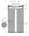
- FIG. 1 is a longitudinal cross-sectional view of a non-aqueous electrolyte secondary battery 10 which is an example of the embodiment, and shows a cross-section including a direction along a winding axis of an electrode assembly 14.
- FIG. 2 is a cross-sectional view in a plane perpendicular to the winding axis of the electrode body 14 constituting the non-aqueous electrolyte secondary battery 10 which is an example of the embodiment, and the positive electrode 11 and the negative electrode 12 constituting the electrode body 14
- the arrangement of the separators 13 is schematically shown.
- nonaqueous electrolyte secondary battery 10 illustrated as an embodiment is a cylindrical battery provided with a cylindrical metal case
- the nonaqueous electrolyte secondary battery of the present disclosure is not limited thereto.
- the non-aqueous electrolyte secondary battery of the present disclosure may be, for example, a prismatic battery provided with a prismatic metal case, or a laminate battery provided with an exterior body made of an aluminum laminate sheet or the like.
- the wound-type electrode body 14 in which the positive electrode and the negative electrode were wound via a separator is illustrated as an electrode body which comprises a nonaqueous electrolyte secondary battery, an electrode body is not limited to this.
- the electrode assembly may be, for example, a laminated electrode assembly in which a plurality of positive electrodes and a plurality of negative electrodes are alternately stacked via a separator.
- the non-aqueous electrolyte secondary battery 10 includes an electrode assembly 14 having a wound structure, and a non-aqueous electrolyte (not shown).
- the electrode assembly 14 is composed of a positive electrode 11, a negative electrode 12, and a separator 13, and the positive electrode 11 and the negative electrode 12 are spirally wound with the separator 13 interposed therebetween.
- the non-aqueous electrolyte secondary battery 10 is a lithium secondary battery in which lithium metal is deposited on the negative electrode 12 at the time of charge, and the lithium metal is dissolved in the non-aqueous electrolyte at the time of discharge.
- the positive electrode 11, the negative electrode 12, and the separator 13 which constitute the electrode body 14 are all formed in a strip shape, and are spirally wound to be in a state of being alternately stacked in the radial direction of the electrode body 14.
- the longitudinal direction of each electrode is the winding direction
- the width direction of each electrode is the axial direction.
- a space layer 50 is formed between the negative electrode 12 and the separator 13. The space layer 50 will be described in detail later.
- a positive electrode lead 19 for electrically connecting the positive electrode 11 and the positive electrode terminal is connected to, for example, the central portion in the longitudinal direction of the positive electrode 11 and extends from one end of the electrode body 14.
- a negative electrode lead 20 for electrically connecting the negative electrode 12 and the negative electrode terminal is connected to, for example, a longitudinal end of the negative electrode 12 and extends from the other end of the electrode body 14.
- the negative electrode lead 20 when the negative electrode lead 20 is connected to the end portion of the negative electrode 12 located radially outward, when stress is generated in the negative electrode 12, the negative electrode 12 extends in the winding direction so that the stress can be released. Is preferable because it spreads.
- the case main body 15 and the sealing body 16 constitute a metal battery case that accommodates the electrode assembly 14 and the non-aqueous electrolyte.
- Insulating plates 17 and 18 are respectively provided above and below the electrode body 14.
- the positive electrode lead 19 extends to the side of the sealing body 16 through the through hole of the insulating plate 17 and is welded to the lower surface of the filter 22 which is the bottom plate of the sealing body 16.
- the cap 26 of the sealing body 16 electrically connected to the filter 22 serves as a positive electrode terminal.
- the negative electrode lead 20 extends to the bottom side of the case body 15 and is welded to the inner surface of the bottom of the case body 15.
- the case main body 15 is a negative electrode terminal.
- the case main body 15 is a metal container with a bottomed cylindrical shape.
- a gasket 27 is provided between the case main body 15 and the sealing body 16 to ensure the airtightness in the battery case.
- the case main body 15 has an overhanging portion 21 for supporting the sealing body 16 which is formed, for example, by pressing the side surface portion from the outside.
- the projecting portion 21 is preferably formed in an annular shape along the circumferential direction of the case main body 15, and the sealing member 16 is supported on the upper surface thereof.
- the sealing body 16 has a structure in which the filter 22, the lower valve body 23, the insulating member 24, the upper valve body 25, and the cap 26 are sequentially stacked from the electrode body 14 side.
- Each member which comprises the sealing body 16 has disk shape or ring shape, for example, and each member except the insulation member 24 is electrically connected mutually.
- the lower valve body 23 and the upper valve body 25 are connected to each other at their central portions, and an insulating member 24 is interposed between the respective peripheral edge portions. Since the lower valve body 23 is provided with a vent, if the internal pressure of the battery rises due to abnormal heat generation, the upper valve body 25 bulges to the cap 26 side and separates from the lower valve body 23 so that the electrical connection between them is achieved. It is cut off. When the internal pressure further increases, the upper valve body 25 is broken, and the gas is discharged from the opening of the cap 26.
- a space layer 50 having a specific thickness is formed between the negative electrode 12 and the separator 13.
- the negative electrode 12 having no negative electrode mixture layer is used on the negative electrode current collector 40, lithium ions dissolved in the electrolytic solution at the time of charge are deposited as lithium metal on the surface of the negative electrode 12
- the entire thickness of the negative electrode 12 increases (swelling) according to the amount of lithium metal deposited.
- the positive electrode 11 and the negative electrode 12 that can be generated by expansion of the negative electrode 12 during charging (in the present specification, the positive electrode 11 and the negative electrode 12 are not distinguished. In this case, it is possible to suppress the breakage of both) (collectively referred to as "electrodes").
- the principle is considered to be as follows.
- the space layer 50 having a specific thickness is formed between the negative electrode 12 and the separator 13, that is, adjacent to the negative electrode 12.
- the formation of the space layer 50 in the lithium secondary battery can be said to be disadvantageous in terms of improving the capacity of the battery.
- the space for the provision of the negative electrode mixture layer is smaller than that of the conventional lithium secondary battery in which the negative electrode mixture layer is provided on both sides of the negative electrode current collector. It can be used for the expansion of the area of the positive electrode 11 and the negative electrode 12 per battery, and the increase in content per battery of lithium containing transition metal oxide which is a positive electrode active material. Therefore, the total amount of the positive electrode capacity per battery increases beyond the capacity reduction due to the formation of the space layer 50, and it becomes possible to realize the high capacity of the battery.
- the space layer 50 when the non-aqueous electrolyte secondary battery 10 is in a discharged state, the space layer 50 has a positive electrode capacity ⁇ (mAh / cm 2 ) per unit area of the positive electrode 11 and the space layer 50. Is formed such that the thickness X ( ⁇ m) of Y satisfies 0.05 ⁇ ⁇ / X ⁇ 0.2.
- the positive electrode capacity ⁇ per unit area of the positive electrode 11 is the positive electrode capacity ⁇ (mAh) per battery
- the positive electrode capacity ⁇ per battery is determined, for example, by the product of the theoretical capacity of lithium metal (3860 mAh / g) and the total mass of lithium contained in the positive electrode 11, more specifically, in the positive electrode mixture layer 31.
- the total mass of lithium contained in the positive electrode mixture layer 31 may be calculated based on, for example, the composition and thickness of the positive electrode mixture layer 31, and the total area of the wound positive electrode mixture layer 31.
- the thickness X of the space layer 50 is an average value of the thickness in the stacking direction of the space layer 50 provided between the negative electrode 12 and the separator 13. In other words, the thickness X is an average value of the distance between the surface of the negative electrode 12 facing the separator 13 and the surface of the separator 13 facing the negative electrode 12. For example, when the positive electrode capacity ⁇ per unit area of the positive electrode 11 is 5.4 mAh / cm 2 , the thickness X of the space layer 50 is 28 ⁇ m or more and 112 ⁇ m or less.
- the ratio of the positive electrode capacity ⁇ to the thickness X of the space layer 50 per unit area of the positive electrode 11 can also be said to represent the relationship between the amount of lithium metal deposited on the negative electrode 12 during charging and the volume occupying the space layer 50. If the ratio ⁇ / X is too large, a space for receiving expansion of the negative electrode due to deposition of lithium metal can not be secured, and the effect of preventing electrode breakage can not be obtained sufficiently. If the ratio ⁇ / X is too small, the positive electrode capacity ⁇ per battery decreases, and the significance of using a lithium metal precipitation type secondary battery is lost.
- the positive electrode capacity ⁇ per unit area of the positive electrode 11 and the thickness X of the space layer 50 preferably satisfy 0.05 ⁇ ⁇ / X ⁇ 0.2, and 0.07 ⁇ ⁇ / X. It is more preferable to satisfy ⁇ 0.15.
- the thickness X of the space layer 50 and the total area and thickness of the positive electrode mixture layer 31 in the non-aqueous electrolyte secondary battery 10 are, for example, X-ray CT devices (for example, Micro Focus X manufactured by Shimadzu Corporation) The measurement may be performed using a fluoroscope SMX-2000 ").
- the positive electrode capacity ⁇ per unit area of the positive electrode 11 is, as described above, the product of the theoretical capacity of lithium metal (3860 mAh / g) and the total mass of lithium contained in the positive electrode mixture layer 31 as the positive electrode mixture layer 31 It is calculated by dividing the total area (cm 2) of the total mass of the lithium contained in the positive electrode mixture layer 31, for example, the composition of the positive electrode mixture layer 31, is calculated based on the thickness and the total area .
- the composition of the lithium-containing transition metal oxide contained in the positive electrode mixture layer 31 is characterized and quantified using a known analyzer such as an ICP emission spectrometer (for example, “CIROS-120” manufactured by Spectro).
- the thickness X of the space layer 50 is a value measured at the beginning of the cycle, and is measured using, for example, a battery of 10 cycles or less.
- the specific formation method is not limited as long as the space layer 50 can form a space whose thickness average is included in the above-described range between the negative electrode 12 and the separator 13.
- the method of manufacturing the non-aqueous electrolyte secondary battery 10 having the space layer 50 applies ethylene carbonate (EC) to the surface of the negative electrode current collector 40 and applies EC to the surface.
- a step of producing a negative electrode 12 having a layer (negative electrode production step), a step of laminating the negative electrode 12 having an EC coating layer and the positive electrode 11 with the separator 13 interposed therebetween, and winding them to produce an electrode assembly 14
- Electrode body preparation step a step of housing the electrode body 14 in the case main body 15, and a step of injecting a non-aqueous electrolyte containing a non-aqueous solvent other than EC into the case main body 15 containing the electrode body 14 Have.
- Ethylene carbonate (EC) is a non-aqueous solvent used as a non-aqueous electrolyte for lithium secondary batteries and has a melting point of 34 ° C. to 37 ° C. Therefore, EC is a solid at room temperature (25 ° C.), but is easily dissolved in other nonaqueous solvents similarly used as a non-aqueous electrolyte to become a mixed solvent which is liquid at room temperature. In this embodiment, this property of EC is used to manufacture the non-aqueous electrolyte secondary battery 10 having the space layer 50. That is, in the negative electrode preparation step, liquid EC obtained by heating to the melting point or higher is applied to the surface of the negative electrode current collector 40 to form an EC coated layer.
- the EC coated layer solidifies as the temperature decreases.
- the positive electrode 11 and the negative electrode 12 are laminated and wound with the negative electrode 12 having the solidified EC coating layer on both surfaces and the positive electrode 11 via the separator 13.
- the electrode body 14 provided with the separator 13 in the side and the EC coating layer in the side of the negative electrode 12 is produced.
- a non-aqueous electrolyte containing a non-aqueous solvent other than EC is injected into the case main body 15.
- the EC coating layer is dissolved by the non-aqueous electrolyte injected into the case main body 15, the space in which the EC coating layer is provided is filled with the non-aqueous electrolyte, and the space layer 50 is formed.
- the method of manufacturing the non-aqueous electrolyte secondary battery 10 having the negative electrode preparation step of forming an EC coating layer on the surface of the above-described negative electrode 12 uses the conventionally known EC as the non-aqueous electrolyte of lithium secondary battery
- the adaptability is also high for the electrode assembly 14 having a different configuration such as a positive electrode active material.
- the surface layer of the negative electrode 12 is compared to the case where a member for forming the space layer 50 is provided.
- the energy density of the non-aqueous electrolyte secondary battery 10 can be improved by effectively utilizing it.
- the EC coating layer is provided on the surface of the negative electrode current collector 40.
- the way to do this is not limited to this.
- the secondary battery 10 may be manufactured.
- a coating layer composed of another non-aqueous solvent which is solid at room temperature other than EC and can be dissolved in the non-aqueous electrolyte is provided on the surface of the negative electrode current collector 40 or the surface of the separator 13 opposite to the negative electrode 12 It is also good.
- a resin or the like that is dissolved in the non-aqueous electrolyte electrolyte may be provided on the surface of the negative electrode current collector, and after injecting the non-aqueous electrolyte electrolyte, the resin may be dissolved to form a space.
- the negative electrode in the electrode body 14 may be formed by separating 12 and the separator 13.
- the molar ratio of the total amount of lithium contained in the positive electrode 11 and the negative electrode 12 to the amount of transition metal contained in the positive electrode 11 is 1.1 or less. If the lithium and the transition metal contained in the positive electrode and the negative electrode of the non-aqueous electrolyte secondary battery 10 are present in excess of the above ranges, side reactions easily occur. For example, when stored in a discharged state, it becomes easy to generate gas. In addition, when charge and discharge are repeated under the condition of overdischarge, gas generation tends to occur, and the deterioration of capacity becomes remarkable.
- the total amount (total content) of lithium contained in the positive electrode 11 and the negative electrode 12 constitutes a lithium-containing transition metal oxide contained as a positive electrode active material in the positive electrode mixture layer 31 of the positive electrode 11 in the non-aqueous electrolyte secondary battery 10 It is the total amount of lithium and the said lithium in case the negative electrode collector 40 of the negative electrode 12 has lithium metal.
- the positive electrode 11 includes a positive electrode current collector 30 and a positive electrode mixture layer 31 formed on the current collector.
- a foil of a metal stable in the potential range of the positive electrode 11 such as aluminum, a film in which the metal is disposed on the surface, or the like can be used.
- the positive electrode mixture layer 31 is composed of a positive electrode active material, a conductive material, and a binder. The positive electrode mixture layer 31 is generally formed on both sides of the positive electrode current collector 30.
- the positive electrode 11 is obtained by, for example, applying a positive electrode mixture slurry containing a positive electrode active material, a conductive material, a binder and the like on a positive electrode current collector 30, drying the coating, and rolling to form a positive electrode mixture layer 31. Can be produced by forming on both sides of the current collector.
- the positive electrode active material contained in the positive electrode mixture layer 31 is made of a lithium-containing transition metal oxide.
- Metal elements other than lithium that constitute the lithium-containing transition metal oxide are, for example, magnesium (Mg), aluminum (Al), calcium (Ca), scandium (Sc), titanium (Ti), vanadium (V), chromium (Cr) ), Manganese (Mn), iron (Fe), cobalt (Co), nickel (Ni), copper (Cu), zinc (Zn), gallium (Ga), germanium (Ge), yttrium (Y), zirconium (Zr) And at least one selected from tin (Sn), antimony (Sb), tungsten (W), lead (Pb), and bismuth (Bi).
- transition metals that constitute lithium-containing transition metal oxides metal elements other than lithium that constitute these lithium-containing transition metal oxides are regarded as “transition metals that constitute lithium-containing transition metal oxides”.
- the lithium-containing transition metal oxide contained in the positive electrode mixture layer 31 preferably contains at least one selected from Co, Ni, Mn, and Al as the transition metal. Moreover, it is preferable that the molar ratio of lithium which comprises a lithium containing transition metal and a transition metal is 1.1: 1 or less.
- the lithium-containing transition metal oxide contained in the positive electrode mixture layer 31 preferably has a crystal structure belonging to the space group R-3m.
- the crystal structure belonging to the space group R-3m is a structure in which a lithium-oxygen octahedral layer and a transition metal-oxygen octahedral layer are stacked, and examples thereof include lithium nickelate (LiNiO 2 ) and lithium cobaltate It is a crystal structure which LiCoO 2 ) has.
- the positive electrode active material has a crystal structure belonging to the space group R-3m, high charge / discharge capacity can be obtained in the secondary battery.
- the fact that the positive electrode active material has a crystal structure belonging to the space group R-3m can be confirmed, for example, by analyzing the positive electrode active material based on powder X-ray diffraction and obtaining an X-ray diffraction pattern.
- Examples of the conductive material constituting the positive electrode mixture layer 31 include carbon materials such as carbon black (CB), acetylene black (AB), ketjen black, and graphite.
- carbon materials such as carbon black (CB), acetylene black (AB), ketjen black, and graphite.
- fluorine resin such as polytetrafluoroethylene (PTFE) and polyvinylidene fluoride (PVdF), polyacrylonitrile (PAN), polyimide resin, acrylic resin Resin, polyolefin resin, etc. are mentioned. These may be used alone or in combination of two or more.
- the negative electrode 12 is an electrode for depositing lithium metal at the time of charge, and has a negative electrode current collector 40.
- the lithium metal deposited on the negative electrode 12 by charging is derived from lithium ions in the non-aqueous electrolyte, and the deposited lithium metal is dissolved in the electrolytic solution by discharge.
- the negative electrode current collector 40 is made of, for example, a metal foil such as copper, nickel, iron, stainless steel alloy (SUS) or the like, and among them, a copper foil having high conductivity is preferable.
- the copper foil is a metal foil containing copper as a main component, and may be composed substantially only of copper.
- the thickness of the copper foil is preferably 5 ⁇ m or more and 20 ⁇ m or less.
- the negative electrode 12 is made of, for example, only a copper foil having a thickness of 5 ⁇ m to 20 ⁇ m before charge and discharge of the battery, and lithium metal is deposited on both sides of the copper foil by charge to form a lithium metal layer.
- the negative electrode current collector 40 may contain a lithium metal layer, and may be, for example, a lithium metal foil, or a lithium metal layer formed on the surface by vapor deposition or the like (in this case, lithium). Is an active material). It is preferable that the negative electrode current collector 40 does not have a negative electrode active material in the initial state.
- the negative electrode 12 be configured of only the negative electrode current collector 40 in the initial state. This can increase the volumetric energy density of the battery.
- a lithium metal foil, a current collector having a lithium metal layer, or the like is used as the negative electrode current collector 40, the volume energy density of the battery is reduced by the thickness of the lithium layer.
- the surface of the negative electrode current collector 40 after the EC coating film is dissolved in the non-aqueous electrolyte is In many cases, it will have a specific surface roughness.
- the arithmetic average roughness Ra of the surface of the negative electrode current collector 40 is 1.0 ⁇ m or more and 10.0 ⁇ m or less.
- the surface roughness formed on the surface of the negative electrode current collector 40 is such that the thickness of the EC coating film becomes uneven when the EC coating film is solidified, and then the negative electrode 12 having the EC coating film is positive electrode It is considered that the solidified EC coating film pattern is transferred to the negative electrode current collector 40 by winding together with the electrode 11 and the separator 13.
- Arithmetic mean roughness Ra is a value calculated based on JIS B0601: 2001, and any method on the surface of the negative electrode current collector 40 may be a known method, for example, a shape measuring laser microscope device (stock It is calculated by averaging the absolute value of the roughness curve per reference length using "VK-X200" manufactured by Keyence Corporation.
- the negative electrode current collector 40 may have a layer (protective layer) containing a solid electrolyte, an organic substance, or an inorganic substance on the surface.
- the protective layer has an effect of making the electrode surface reaction uniform, lithium metal is uniformly deposited on the negative electrode, and expansion of the negative electrode 12 can be suppressed.
- a solid electrolyte a sulfide type solid electrolyte, a phosphoric acid type solid electrolyte, a perovskite type solid electrolyte, a garnet type solid electrolyte etc. can be mentioned, for example.
- the sulfide-based solid electrolyte is not particularly limited as long as it contains a sulfur component and has lithium ion conductivity.
- a raw material of a sulfide type solid electrolyte what has Li, S, and the 3rd component A etc. can be mentioned specifically ,.
- the third component A can include at least one selected from the group consisting of P, Ge, B, Si, I, Al, Ga, and As.
- the sulfide-based solid electrolyte specifically, Li 2 S-P 2 S 5, 70Li 2 S-30P 2 S 5, 80Li 2 S-20P 2 S 5, Li 2 S-SiS 2, LiGe 0. 25 P 0.75 S 4 etc. can be mentioned.
- the phosphoric acid-based solid electrolyte is not particularly limited as long as it contains a phosphoric acid component and has lithium ion conductivity.
- Examples of phosphoric acid-based solid electrolytes include Li 1 + n Al n Ti 2-n (PO 4 ) 3 (0 ⁇ n ⁇ 2, and particularly 0, such as Li 1.5 Al 0.5 Ti 1.5 (PO 4 ) 3. ⁇ N ⁇ 1 is preferable), and Li 1 + n Al n Ge 2-n (PO 4 ) 3 (0 ⁇ n ⁇ 2, among them, 0 ⁇ n ⁇ 1 is preferable) and the like.
- the organic substance layer is preferably a lithium conductive material such as polyethylene oxide or polymethyl methacrylate.
- a porous sheet having ion permeability and insulation is used.
- the porous sheet include a microporous thin film, a woven fabric, a non-woven fabric and the like.
- the material of the separator 13 is preferably an olefin resin such as polyethylene, polypropylene, a copolymer containing at least one of ethylene and propylene, and cellulose.
- the separator 13 may be a laminate having a cellulose fiber layer and a thermoplastic resin fiber layer such as an olefin resin.
- it may be a multilayer separator including a polyethylene layer and a polypropylene layer, and a separator in which an aramid-based resin or the like is applied to the surface of the separator 13 may be used.
- a heat-resistant layer containing a filler of an inorganic compound may be formed at the interface between the separator 13 and at least one of the positive electrode 11 and the negative electrode 12.
- the non-aqueous electrolyte comprises a non-aqueous solvent and an electrolyte salt dissolved in the non-aqueous solvent.
- the non-aqueous solvent for example, esters, ethers, nitriles such as acetonitrile, amides such as dimethylformamide, mixed solvents of two or more of these, and the like can be used.
- the non-aqueous solvent may contain a halogen substitute wherein at least a part of hydrogen of these solvents is substituted with a halogen atom such as fluorine.
- the non-aqueous electrolyte is not limited to a liquid electrolyte (non-aqueous electrolyte), and may be a solid electrolyte using a gel-like polymer or the like.
- the non-aqueous electrolyte secondary battery 10 is used as a non-aqueous electrolyte And ethylene carbonate (EC) and a non-aqueous solvent other than EC.
- nonaqueous solvents other than EC include esters other than EC, ethers, nitriles such as acetonitrile, amides such as dimethylformamide, and mixed solvents of two or more of them.
- the EC which is present as a coating layer on the surface of the negative electrode current collector 40, and the electrode body 14 housed in the case main body 15
- the total with the water electrolyte becomes the nonaqueous electrolyte contained in the nonaqueous electrolyte secondary battery 10 in the initial state. Therefore, in consideration of the EC coating layer on the surface of the negative electrode current collector 40, the composition of the non-aqueous solvent in the non-aqueous electrolyte to be added in the case main body 15, and the content of the electrolyte salt may be determined.
- esters examples include ethylene carbonate (EC), propylene carbonate (PC), butylene carbonate, cyclic carbonates such as fluoroethylene carbonate (FEC), dimethyl carbonate (DMC), ethyl methyl carbonate (EMC), Linear carbonates such as diethyl carbonate (DEC), methyl propyl carbonate, ethyl propyl carbonate, methyl isopropyl carbonate, cyclic carboxylic acid esters such as ⁇ -butyrolactone, ⁇ -valerolactone, methyl acetate, ethyl acetate, propyl acetate, propionic acid And chain carboxylic acid esters such as methyl (MP), ethyl propionate, ⁇ -butyrolactone, methyl fluoropropionate (FMP) and the like.
- EC ethylene carbonate
- PC propylene carbonate
- FEC fluoroethylene carbonate
- DMC dimethyl carbonate
- EMC ethy
- ethers examples include 1,3-dioxolane, 4-methyl-1,3-dioxolane, tetrahydrofuran, 2-methyltetrahydrofuran, propylene oxide, 1,2-butylene oxide, 1,3-dioxane, 1,4 -Dioxane, 1,3,5-trioxane, furan, 2-methyl furan, 1,8-cineole, cyclic ether such as crown ether, 1,2-dimethoxyethane, diethyl ether, dipropyl ether, diisopropyl ether, dibutyl ether , Dihexyl ether, ethyl vinyl ether, butyl vinyl ether, methyl phenyl ether, ethyl phenyl ether, butyl phenyl ether, pentyl phenyl ether, methoxytoluene, benzyl ethyl ether, diphenyl ether, dipheny
- Examples of the electrolyte salt contained in the nonaqueous electrolyte LiBF 4, LiClO 4, LiPF 6, LiAsF 6, LiSbF 6, LiAlCl 4, LiSCN, LiCF 3 SO 3, LiCF 3 CO 2, LiN (SO 2 CF 3) 2, LiN (C l F 2l + 1 SO 2) (C m F 2m + 1 SO 2) ⁇ l, m is an integer of at least 1 ⁇ , and the like imide salts such as. Among them, it is preferable to use LiPF 6.
- ethylene carbonate (EC) As a method of coating ethylene carbonate (EC) on the surface of the negative electrode current collector 40, a known method such as roll coating, bar coating, gravure coating, gravure reverse coating, die coating, slide coating, and curtain coating may be used. Can.
- the non-aqueous electrolyte preferably contains an additive that decomposes at the negative electrode 12.
- the non-aqueous electrolyte contains, for example, at least one selected from vinylene carbonate (VC), fluoroethylene carbonate (FEC), and vinylethyl carbonate (VEC).
- VC vinylene carbonate
- FEC fluoroethylene carbonate
- VEC vinylethyl carbonate
- Example 1 [Production of positive electrode] A lithium-containing transition metal oxide containing aluminum, nickel and cobalt as a positive electrode active material, acetylene black (AB) and polyvinylidene fluoride (PVdF) in a mass ratio of 95: 2.5: 2.5 Then, an appropriate amount of N-methyl-2-pyrrolidone (NMP) was added and stirred to prepare a positive electrode mixture slurry. Next, the positive electrode mixture slurry was applied to both sides of a positive electrode current collector made of aluminum foil, and the coating was dried. After the coated film was rolled using a roller, it was cut into a predetermined electrode size, and a positive electrode in which a positive electrode mixture layer was sequentially formed on both sides of the positive electrode current collector was produced. The molar ratio of lithium to the total of the transition metals in the lithium-containing transition metal oxide used as the positive electrode active material was 1.0.
- a mixed solvent was prepared by mixing EC and dimethyl carbonate (DMC). Next, LiPF 6 and LiBF 2 (C 2 O 4 ) were dissolved in the mixed solvent to prepare a non-aqueous electrolyte.
- the mixing ratio of EC and DMC in the mixed solvent so that the content of EC and DMC after dissolution of the coated film formed on the surface of the negative electrode in the mixed solvent is 3: 7 Adjusted.
- LiPF 6 and LiBF 2 (C 2 O 4)
- the amount of the mixed solvent, LiPF 6 and LiBF 2 after EC constituting the coating film is dissolved in the mixed solvent (C 2 O
- An amount was added such that the concentration of 4 ) became a concentration of 1.0 M (mol / L) and 0.1 M (mol / L), respectively.
- the positive electrode attached with an aluminum tab and the negative electrode attached with a nickel tab were spirally wound via a polyethylene separator to produce an electrode body.
- a space extending in the winding axial direction including the axial center of the winding axis was formed.
- the electrode assembly was housed in an outer package made of an aluminum laminate, the non-aqueous electrolyte was injected, and the opening of the outer package was sealed to fabricate a cylindrical battery T1.
- the positive electrode capacity ⁇ per area of the positive electrode constituting the battery T1 was 5.4 mAh / cm 2 . Further, the molar ratio of the total amount of lithium contained in the battery T1 to the amount of transition metal contained in the positive electrode was 1.0.
- Example 2 In the battery preparation, a cylindrical battery T2 was prepared in the same manner as in Example 1 except that the film thickness per surface of EC coated on both sides of the negative electrode current collector was changed to 75 ⁇ m.
- Example 1 in preparation of a battery, Example 1 was used except that the film thickness per surface of EC coated on both sides of the negative electrode current collector was changed to 0.0 ⁇ m (without EC coating), 15 ⁇ m and 120 ⁇ m, respectively. Cylindrical batteries T3 to T5 were produced in the same manner as in the above.
- a reference battery T6 for comparison of discharge capacity was produced.
- the reference battery T6 is provided with a negative electrode having a negative electrode mixture layer on both sides of a copper foil.
- the negative electrode comprises a negative electrode mixture slurry containing a graphite as a negative electrode active material and a binder (styrene-butadiene rubber) in a mass ratio of 97.5: 2.5, both sides of a copper foil as a negative electrode current collector. After coating was applied and the coating was dried, the coating was prepared by rolling with a rolling roller.
- the positive electrode capacity ⁇ per unit area is the theoretical capacity of Li metal (3860 mAh / g), the composition and layer thickness of the positive electrode mixture layer, and the positive electrode mixture layer formed on the surface of the positive electrode current collector for each battery. It is a theoretical value calculated based on the area. Each calculation result is shown in Table 1.
- the discharge capacity of each battery of the example and the comparative example was evaluated by comparison with the discharge capacity of the battery T6 for reference.
- the battery T6 is a conventional non-aqueous electrolyte secondary battery including a negative electrode having a negative electrode mixture layer on both surfaces, and almost no space formed between the negative electrode and the separator.
- the composition and layer thickness of the positive electrode mixture layer, and the formation area of the positive electrode mixture layer A battery having a discharge capacity equal to or less than the battery T6 was evaluated as "x", and a battery having a discharge capacity higher than that of the battery T6 was evaluated as "o".
- the measured value of the initial stage discharge capacity measured by the said test was in agreement with the calculated value of discharge capacity well.
- the evaluation results of the discharge capacity of each battery are shown in Table 1.
- the negative electrode current collector 40 is not provided with the negative electrode mixture layer
- the electrode assembly 14 including the positive electrode 11, the negative electrode 12 and the separator 13, specific between the negative electrode 12 and the separator 13 By forming the space layer 50 having the following thickness and securing the space for receiving the expansion of the negative electrode 12 due to the deposition of lithium metal at the time of charge, it is considered that the breakage of the electrode is suppressed even after repeated charge and discharge cycles.
- the lithium secondary battery is a lithium secondary battery in which lithium metal is deposited on the surface of the negative electrode 12
- the space layer 50 only filled with the non-aqueous electrolyte
- the energy density per battery is improved, and high capacity of the battery is realized.
Abstract
The nonaqueous electrolyte secondary battery comprises the following: a positive electrode having a positive electrode active material that includes a lithium-containing transition metal oxide, a negative electrode having a negative electrode current collector wherein lithium metal deposits on the negative electrode current collector during charging, a separator disposed between the positive electrode and the negative electrode, and a nonaqueous electrolyte. The molar ratio of the total amount of lithium held by the positive electrode and the negative electrode to the amount of transition metal in the positive electrode is not more than 1.1. In addition, in the discharged state, a space layer is present between the negative electrode and the separator, and the positive electrode capacity per unit area, α (mAh/cm2), of the positive electrode and the average in thickness, X (μm), of the space layer 50 satisfy 0.05 ≤ α/X ≤ 0.2.
Description
本開示は、非水電解質二次電池及びその製造方法に関し、より詳しくはリチウム二次電池及びその製造方法に関する。
The present disclosure relates to a non-aqueous electrolyte secondary battery and a method of manufacturing the same, and more particularly to a lithium secondary battery and a method of manufacturing the same.
パソコン、スマートフォン等のICT分野に加え、車載分野、蓄電分野等においても非水電解質二次電池の更なる高容量化が求められている。高容量の非水電解質二次電池としては、もっぱらリチウムイオン電池が使用されている。リチウムイオン電池としては、例えば、リチウム含有遷移金属酸化物を正極に使用し、黒鉛とシリコン化合物等からなる負極活物質を負極に使用した構成が知られているが、この構成は高容量化の点に関しては限界に達しつつある。
In addition to the field of ICT such as personal computers and smartphones, further increase in capacity of non-aqueous electrolyte secondary batteries is required also in the field of vehicles, storage of electricity and the like. Lithium ion batteries are exclusively used as high-capacity non-aqueous electrolyte secondary batteries. As a lithium ion battery, for example, a configuration in which a lithium-containing transition metal oxide is used for a positive electrode and a negative electrode active material composed of graphite and a silicon compound is used for a negative electrode is known. The point is reaching its limits.
特許文献1には、正極の一部が逆スピネル型構造を有するリチウム遷移金属酸化物で構成され、負極がリチウム金属、リチウム合金、リチウム挿入化合物とから成る群から選択されるリチウム電池が開示されている。
Patent Document 1 discloses a lithium battery in which a part of the positive electrode is composed of a lithium transition metal oxide having an inverse spinel structure and the negative electrode is selected from the group consisting of lithium metal, lithium alloy and lithium insertion compound ing.
特許文献2には、正極の一部が特定のリチウムマンガン酸化物挿入化合物からなり、負極がリチウムマンガン酸化物挿入化合物からなり、電解質が非水系溶剤に溶解したリチウム塩からなる再充電可能電池が開示されている。
Patent Document 2 describes a rechargeable battery in which a part of a positive electrode is made of a specific lithium manganese oxide insertion compound, a negative electrode is made of a lithium manganese oxide insertion compound, and an electrolyte is made of a lithium salt dissolved in a non-aqueous solvent. It is disclosed.
特許文献1に開示された技術のように、正極にリチウム含有遷移金属酸化物を使用し、負極にもリチウム金属を使用している電池系では、系内のリチウム金属量が増加するものの、系内の遷移金属量に対するリチウム金属量が過剰になるため、容量向上効果の点で十分とは言えなかった。また、高容量化の点で有望な非水電解質二次電池として、充電時にリチウム金属を負極上に析出させ、放電時に当該リチウム金属を非水電解質中に溶解させるリチウム二次電池がある。しかしながら、このようなリチウム二次電池では、リチウム金属析出による負極の膨張、及び、負極表面におけるリチウム金属の不均一な析出によって、電極内に応力が生じ、充放電サイクル毎に電極内での応力の発生が繰り返されることで、やがて電極が破断するという問題があった。
In a battery system in which a lithium-containing transition metal oxide is used for the positive electrode and lithium metal is also used for the negative electrode as in the technique disclosed in Patent Document 1, the amount of lithium metal in the system is increased. Since the amount of lithium metal is excessive with respect to the amount of transition metal contained therein, it can not be said that it is sufficient in terms of the capacity improvement effect. Further, as a promising non-aqueous electrolyte secondary battery in view of high capacity, there is a lithium secondary battery in which lithium metal is deposited on a negative electrode at the time of charge, and the lithium metal is dissolved in the non-aqueous electrolyte at the time of discharge. However, in such a lithium secondary battery, stress is generated in the electrode due to expansion of the negative electrode due to lithium metal deposition and uneven deposition of lithium metal on the surface of the negative electrode, and stress in the electrode every charge and discharge cycle. There is a problem that the electrode is eventually broken due to the repeated occurrence of
そこで、電池の高容量化を実現しながら、充放電サイクルを繰り返した場合に起こり得る電極の破断を抑制することができる非水電解質二次電池が求められている。
Therefore, there is a need for a non-aqueous electrolyte secondary battery that can suppress breakage of an electrode that may occur when charge and discharge cycles are repeated while achieving high battery capacity.
本開示の一態様である非水電解質二次電池は、リチウム含有遷移金属酸化物からなる正極活物質を有する正極と、負極集電体を有し、充電時に負極集電体上にリチウム金属が析出する負極と、正極及び負極の間に配置されたセパレータと、非水電解質とを備え、正極及び負極が有するリチウムの総量の、正極に含まれる遷移金属量に対するモル比が1.1以下であり、放電状態において、負極とセパレータとの間に空間層を有し、且つ、正極の単位面積当たりの正極容量α(mAh/cm2)と、空間層の厚さの平均値X(μm)とが、0.05≦α/X≦0.2を満たすことを特徴とする。
A non-aqueous electrolyte secondary battery according to one embodiment of the present disclosure includes a positive electrode having a positive electrode active material composed of a lithium-containing transition metal oxide and a negative electrode current collector, and lithium metal is on the negative electrode current collector during charging. A negative electrode to be deposited, a separator disposed between the positive electrode and the negative electrode, and a non-aqueous electrolyte, wherein the molar ratio of the total of lithium contained in the positive electrode and the negative electrode to the amount of transition metal contained in the positive electrode is 1.1 or less In the discharge state, there is a space layer between the negative electrode and the separator, and the positive electrode capacity α (mAh / cm 2 ) per unit area of the positive electrode and the average value X (μm) of the thickness of the space layer And are characterized by satisfying 0.05 ≦ α / X ≦ 0.2.
本開示の別の態様である非水電解質二次電池の製造方法は、リチウム含有遷移金属酸化物からなる正極活物質を有する正極と、負極集電体を有し、充電時に負極集電体上にリチウム金属が析出する負極と、正極及び負極の間に配置されたセパレータと、非水電解質と、を備える非水電解質二次電池の製造方法であって、負極集電体の表面にエチレンカーボネートを塗工し、表面にエチレンカーボネートの塗工層を有する負極を作製する工程と、塗工層を有する負極と正極とをセパレータを介して積層し、巻回して電極体を作製する工程と、電極体を電池ケースに収容する工程と、電極体が収容された電池ケースに、エチレンカーボネート以外の非水溶媒を含有する非水電解質を注入する工程と、を有することを特徴とする。
A method of manufacturing a non-aqueous electrolyte secondary battery according to another embodiment of the present disclosure includes a positive electrode having a positive electrode active material composed of a lithium-containing transition metal oxide and a negative electrode current collector, and on a negative electrode current collector during charging. And a separator disposed between the positive electrode and the negative electrode, and a non-aqueous electrolyte. The method of manufacturing a non-aqueous electrolyte secondary battery, comprising: Coating the surface, and producing a negative electrode having a coating layer of ethylene carbonate on the surface, laminating the negative electrode having the coating layer and the positive electrode via a separator, and winding to produce an electrode body, The method comprises the steps of: housing the electrode body in a battery case; and injecting a non-aqueous electrolyte containing a non-aqueous solvent other than ethylene carbonate into the battery case containing the electrode body.
本開示によれば、電池の高容量化を実現しながら、充放電サイクルを繰り返した場合に起こり得る電極の破断を抑制することができる非水電解質二次電池を提供することができる。
According to the present disclosure, it is possible to provide a non-aqueous electrolyte secondary battery capable of suppressing breakage of an electrode that may occur when charge and discharge cycles are repeated while achieving high capacity of the battery.
上述のように、充電時にリチウム金属が負極上に析出し、放電時に当該リチウム金属が非水電解質中に溶解する非水電解質二次電池(リチウム二次電池)は、高容量化が期待できるものの、負極上に析出するリチウム金属によって膨化するとともに、発生する応力により電極が破断するという課題がある。本発明者らは、かかる課題を解決すべく鋭意検討した結果、正極、負極及びセパレータからなる電極体において、負極とセパレータとの間に空間層を形成することにより、充電時のリチウム金属の析出による負極の膨化を受容する空間が確保され、充放電サイクルを繰り返した後の電極の破断を抑制できることを見出した。
As described above, in non-aqueous electrolyte secondary batteries (lithium secondary batteries) in which lithium metal is deposited on the negative electrode during charging and the lithium metal dissolves in the non-aqueous electrolyte during discharging, higher capacity can be expected. There is a problem that the lithium metal deposited on the negative electrode swells and the generated stress causes the electrode to break. As a result of intensive studies to solve the problems, the present inventors have found that, in an electrode assembly comprising a positive electrode, a negative electrode and a separator, precipitation of lithium metal during charge is achieved by forming a space layer between the negative electrode and the separator. It has been found that a space for receiving the expansion of the negative electrode is secured, and breakage of the electrode after repetition of charge and discharge cycles can be suppressed.
以下、本開示に係る非水電解質二次電池の実施形態の一例について詳細に説明する。図1は、実施形態の一例である非水電解質二次電池10の縦断面図であり、電極体14の巻回軸に沿った方向を含む断面を示す。図2は、実施形態の一例である非水電解質二次電池10を構成する電極体14の巻回軸に垂直な面での横断面図であり、電極体14を構成する正極11、負極12及びセパレータ13の配置を模式的に示す。
Hereinafter, an example of the embodiment of the nonaqueous electrolyte secondary battery according to the present disclosure will be described in detail. FIG. 1 is a longitudinal cross-sectional view of a non-aqueous electrolyte secondary battery 10 which is an example of the embodiment, and shows a cross-section including a direction along a winding axis of an electrode assembly 14. FIG. 2 is a cross-sectional view in a plane perpendicular to the winding axis of the electrode body 14 constituting the non-aqueous electrolyte secondary battery 10 which is an example of the embodiment, and the positive electrode 11 and the negative electrode 12 constituting the electrode body 14 The arrangement of the separators 13 is schematically shown.
実施形態として例示する非水電解質二次電池10は、円筒形の金属製ケースを備えた円筒形電池であるが、本開示の非水電解質二次電池はこれに限定されない。本開示の非水電解質二次電池は、例えば角形の金属製ケースを備えた角形電池、アルミニウムラミネートシート等からなる外装体を備えたラミネート電池などであってもよい。また、非水電解質二次電池を構成する電極体として、正極及び負極がセパレータを介して巻回された巻回型の電極体14を例示するが、電極体はこれに限定されない。電極体は、例えば複数の正極と複数の負極がセパレータを介して交互に積層されてなる積層型の電極体であってもよい。
Although the nonaqueous electrolyte secondary battery 10 illustrated as an embodiment is a cylindrical battery provided with a cylindrical metal case, the nonaqueous electrolyte secondary battery of the present disclosure is not limited thereto. The non-aqueous electrolyte secondary battery of the present disclosure may be, for example, a prismatic battery provided with a prismatic metal case, or a laminate battery provided with an exterior body made of an aluminum laminate sheet or the like. Moreover, although the wound-type electrode body 14 in which the positive electrode and the negative electrode were wound via a separator is illustrated as an electrode body which comprises a nonaqueous electrolyte secondary battery, an electrode body is not limited to this. The electrode assembly may be, for example, a laminated electrode assembly in which a plurality of positive electrodes and a plurality of negative electrodes are alternately stacked via a separator.
図1に例示するように、非水電解質二次電池10は、巻回構造を有する電極体14と、非水電解質(図示せず)とを備える。図1及び図2に示すように、電極体14は、正極11と、負極12と、セパレータ13とで構成され、正極11及び負極12がセパレータ13を介して渦巻状に巻回されてなる。非水電解質二次電池10は、充電時に負極12上にリチウム金属が析出し、放電時に当該リチウム金属が非水電解質中に溶解するリチウム二次電池である。
As illustrated in FIG. 1, the non-aqueous electrolyte secondary battery 10 includes an electrode assembly 14 having a wound structure, and a non-aqueous electrolyte (not shown). As shown in FIGS. 1 and 2, the electrode assembly 14 is composed of a positive electrode 11, a negative electrode 12, and a separator 13, and the positive electrode 11 and the negative electrode 12 are spirally wound with the separator 13 interposed therebetween. The non-aqueous electrolyte secondary battery 10 is a lithium secondary battery in which lithium metal is deposited on the negative electrode 12 at the time of charge, and the lithium metal is dissolved in the non-aqueous electrolyte at the time of discharge.
電極体14を構成する正極11、負極12、及びセパレータ13は、いずれも帯状に形成され、渦巻状に巻回されることで電極体14の径方向に交互に積層された状態となる。電極体14において、各電極の長手方向が巻回方向となり、各電極の幅方向が軸方向となる。また、電極体14には、負極12とセパレータ13との間に空間層50が形成されている。空間層50については後で詳述する。
The positive electrode 11, the negative electrode 12, and the separator 13 which constitute the electrode body 14 are all formed in a strip shape, and are spirally wound to be in a state of being alternately stacked in the radial direction of the electrode body 14. In the electrode body 14, the longitudinal direction of each electrode is the winding direction, and the width direction of each electrode is the axial direction. In the electrode body 14, a space layer 50 is formed between the negative electrode 12 and the separator 13. The space layer 50 will be described in detail later.
正極11と正極端子とを電気的に接続する正極リード19は、例えば正極11の長手方向中央部に接続され、電極体14の一端から延出している。負極12と負極端子とを電気的に接続する負極リード20は、例えば負極12の長手方向端部に接続され、電極体14の他端から延出している。電極体14において、負極リード20が負極12の径方向外側に位置する端部に接続すると、負極12に応力が発生したときに負極12が巻回方向に延びることで応力を逃がすことができる範囲が広がるため、好ましい。
A positive electrode lead 19 for electrically connecting the positive electrode 11 and the positive electrode terminal is connected to, for example, the central portion in the longitudinal direction of the positive electrode 11 and extends from one end of the electrode body 14. A negative electrode lead 20 for electrically connecting the negative electrode 12 and the negative electrode terminal is connected to, for example, a longitudinal end of the negative electrode 12 and extends from the other end of the electrode body 14. In the electrode body 14, when the negative electrode lead 20 is connected to the end portion of the negative electrode 12 located radially outward, when stress is generated in the negative electrode 12, the negative electrode 12 extends in the winding direction so that the stress can be released. Is preferable because it spreads.
図1に示す例では、ケース本体15と封口体16によって、電極体14及び非水電解質を収容する金属製の電池ケースが構成されている。電極体14の上下には、絶縁板17,18がそれぞれ設けられる。正極リード19は絶縁板17の貫通孔を通って封口体16側に延び、封口体16の底板であるフィルタ22の下面に溶接される。非水電解質二次電池10では、フィルタ22と電気的に接続された封口体16のキャップ26が正極端子となる。他方、負極リード20はケース本体15の底部側に延び、ケース本体15の底部内面に溶接される。非水電解質二次電池10では、ケース本体15が負極端子となる。
In the example shown in FIG. 1, the case main body 15 and the sealing body 16 constitute a metal battery case that accommodates the electrode assembly 14 and the non-aqueous electrolyte. Insulating plates 17 and 18 are respectively provided above and below the electrode body 14. The positive electrode lead 19 extends to the side of the sealing body 16 through the through hole of the insulating plate 17 and is welded to the lower surface of the filter 22 which is the bottom plate of the sealing body 16. In the non-aqueous electrolyte secondary battery 10, the cap 26 of the sealing body 16 electrically connected to the filter 22 serves as a positive electrode terminal. On the other hand, the negative electrode lead 20 extends to the bottom side of the case body 15 and is welded to the inner surface of the bottom of the case body 15. In the non-aqueous electrolyte secondary battery 10, the case main body 15 is a negative electrode terminal.
ケース本体15は、有底円筒形状の金属製容器である。ケース本体15と封口体16の間にはガスケット27が設けられ、電池ケース内の密閉性が確保されている。ケース本体15は、例えば側面部を外側からプレスして形成された、封口体16を支持する張り出し部21を有する。張り出し部21は、ケース本体15の周方向に沿って環状に形成されることが好ましく、その上面で封口体16を支持する。
The case main body 15 is a metal container with a bottomed cylindrical shape. A gasket 27 is provided between the case main body 15 and the sealing body 16 to ensure the airtightness in the battery case. The case main body 15 has an overhanging portion 21 for supporting the sealing body 16 which is formed, for example, by pressing the side surface portion from the outside. The projecting portion 21 is preferably formed in an annular shape along the circumferential direction of the case main body 15, and the sealing member 16 is supported on the upper surface thereof.
封口体16は、電極体14側から順に、フィルタ22、下弁体23、絶縁部材24、上弁体25、及びキャップ26が積層された構造を有する。封口体16を構成する各部材は、例えば円板形状又はリング形状を有し、絶縁部材24を除く各部材は互いに電気的に接続されている。下弁体23と上弁体25は各々の中央部で互いに接続され、各々の周縁部の間には絶縁部材24が介在している。下弁体23には通気孔が設けられているため、異常発熱で電池の内圧が上昇すると、上弁体25がキャップ26側に膨れて下弁体23から離れることにより両者の電気的接続が遮断される。さらに内圧が上昇すると、上弁体25が破断し、キャップ26の開口部からガスが排出される。
The sealing body 16 has a structure in which the filter 22, the lower valve body 23, the insulating member 24, the upper valve body 25, and the cap 26 are sequentially stacked from the electrode body 14 side. Each member which comprises the sealing body 16 has disk shape or ring shape, for example, and each member except the insulation member 24 is electrically connected mutually. The lower valve body 23 and the upper valve body 25 are connected to each other at their central portions, and an insulating member 24 is interposed between the respective peripheral edge portions. Since the lower valve body 23 is provided with a vent, if the internal pressure of the battery rises due to abnormal heat generation, the upper valve body 25 bulges to the cap 26 side and separates from the lower valve body 23 so that the electrical connection between them is achieved. It is cut off. When the internal pressure further increases, the upper valve body 25 is broken, and the gas is discharged from the opening of the cap 26.
[空間層]
本開示に係る電極体14には、負極12とセパレータ13との間に特定の厚さを有する空間層50が形成されている。リチウム二次電池において、負極集電体40上に負極合剤層を有さない負極12を用いた場合、充電時に電解液に溶解していたリチウムイオンが負極12の表面にリチウム金属として析出するが、そのリチウム金属の析出量に応じて負極12全体の厚さが増加する(膨化)。本開示の非水電解質二次電池10では、空間層50を形成することにより、充電時の負極12の膨化により生じ得る正極11及び負極12(本明細書では、正極11及び負極12を区別しない場合に両者を「電極」と総称する)の破断を抑制することができる。その原理は以下の通りであると考えられる。 [Spatial layer]
In theelectrode body 14 according to the present disclosure, a space layer 50 having a specific thickness is formed between the negative electrode 12 and the separator 13. In the lithium secondary battery, when the negative electrode 12 having no negative electrode mixture layer is used on the negative electrode current collector 40, lithium ions dissolved in the electrolytic solution at the time of charge are deposited as lithium metal on the surface of the negative electrode 12 However, the entire thickness of the negative electrode 12 increases (swelling) according to the amount of lithium metal deposited. In the non-aqueous electrolyte secondary battery 10 of the present disclosure, by forming the space layer 50, the positive electrode 11 and the negative electrode 12 that can be generated by expansion of the negative electrode 12 during charging (in the present specification, the positive electrode 11 and the negative electrode 12 are not distinguished. In this case, it is possible to suppress the breakage of both) (collectively referred to as "electrodes"). The principle is considered to be as follows.
本開示に係る電極体14には、負極12とセパレータ13との間に特定の厚さを有する空間層50が形成されている。リチウム二次電池において、負極集電体40上に負極合剤層を有さない負極12を用いた場合、充電時に電解液に溶解していたリチウムイオンが負極12の表面にリチウム金属として析出するが、そのリチウム金属の析出量に応じて負極12全体の厚さが増加する(膨化)。本開示の非水電解質二次電池10では、空間層50を形成することにより、充電時の負極12の膨化により生じ得る正極11及び負極12(本明細書では、正極11及び負極12を区別しない場合に両者を「電極」と総称する)の破断を抑制することができる。その原理は以下の通りであると考えられる。 [Spatial layer]
In the
従来のリチウム金属析出型の二次電池では、容量向上の観点から、ケース本体15内において、なるべく電極及びセパレータを密に積層し、非水電解質のみが占有する空間の排除を図っている。一方、当該析出型二次電池では、充電が進むほどリチウム金属の析出量が増加し、負極が膨化する。ここで、充電時にリチウム金属の析出は、負極の表面において不均一に発生するため、電極及びセパレータの積層構造に局所的な歪みが発生し、負極の膨化と相まって、電極に応力が発生することになる。上述の通り、従来の析出型二次電池では電極及びセパレータを密に積層しているため、電極に発生した応力が解放されない。このようにして、充放電サイクル毎に電極に応力が生じ、それが繰り返されることにより電極内に疲労が蓄積し、やがて電極の破断に至るものと考えられる。
In the conventional lithium metal deposition type secondary battery, from the viewpoint of capacity improvement, electrodes and separators are stacked as closely as possible in the case main body 15, and the space occupied only by the non-aqueous electrolyte is excluded. On the other hand, in the precipitation-type secondary battery, as the charge proceeds, the amount of lithium metal deposited increases, and the negative electrode swells. Here, since precipitation of lithium metal occurs unevenly on the surface of the negative electrode during charging, local distortion occurs in the laminated structure of the electrode and the separator, and stress is generated in the electrode in combination with expansion of the negative electrode. become. As described above, in the conventional precipitation type secondary battery, since the electrode and the separator are closely stacked, the stress generated in the electrode is not released. Thus, it is considered that stress is generated in the electrode every charge and discharge cycle, and fatigue is accumulated in the electrode by repeating the stress, and eventually the electrode is broken.
それに対して、本開示の非水電解質二次電池10では、負極12とセパレータ13との間、即ち、負極12に隣接して、特定の厚さを有する空間層50が形成されている。これにより、充電時のリチウム金属の析出による負極12の膨化を受容する空間が確保されているため、極板における応力の発生を抑制することができる。また、リチウム金属の不均一な析出により局所的な応力が発生したとしても、空間層50によりこれを緩和することができる。そのため、非水電解質二次電池10に対して充放電サイクルが繰り返されても、各電極内に応力の発生による疲労が蓄積せず、結果として、充電時のリチウムの析出に起因する電極の破断を抑制することができると考えられる。
In contrast, in the non-aqueous electrolyte secondary battery 10 of the present disclosure, the space layer 50 having a specific thickness is formed between the negative electrode 12 and the separator 13, that is, adjacent to the negative electrode 12. Thereby, since the space which receives expansion of the negative electrode 12 by precipitation of lithium metal at the time of charge is ensured, generation | occurrence | production of the stress in an electrode plate can be suppressed. In addition, even if local stress is generated due to uneven precipitation of lithium metal, this can be relaxed by the space layer 50. Therefore, even if charge and discharge cycles are repeated with respect to non-aqueous electrolyte secondary battery 10, fatigue due to the occurrence of stress does not accumulate in each electrode, and as a result, breakage of the electrode due to precipitation of lithium during charge It is thought that it can control.
リチウム二次電池における空間層50の形成は、電池の容量向上の点では不利であると言える。しかしながら、本開示の非水電解質二次電池10では、負極集電体の両面に負極合剤層を設ける従来のリチウム二次電池と比較して、負極合剤層を設けない分のスペースを、電池当たりの正極11及び負極12の面積の拡大、及び、正極活物質であるリチウム含有遷移金属酸化物の電池当たり含有量の増加に使用することができる。そのため、空間層50の形成による容量低下分を超えて、電池当たりの正極容量の総量が増加し、電池の高容量化を実現することが可能となる。
The formation of the space layer 50 in the lithium secondary battery can be said to be disadvantageous in terms of improving the capacity of the battery. However, in the non-aqueous electrolyte secondary battery 10 of the present disclosure, the space for the provision of the negative electrode mixture layer is smaller than that of the conventional lithium secondary battery in which the negative electrode mixture layer is provided on both sides of the negative electrode current collector. It can be used for the expansion of the area of the positive electrode 11 and the negative electrode 12 per battery, and the increase in content per battery of lithium containing transition metal oxide which is a positive electrode active material. Therefore, the total amount of the positive electrode capacity per battery increases beyond the capacity reduction due to the formation of the space layer 50, and it becomes possible to realize the high capacity of the battery.
本開示の一態様によれば、空間層50は、非水電解質二次電池10が放電状態にあるときに、正極11の単位面積当たりの正極容量α(mAh/cm2)と、空間層50の厚さX(μm)とが、0.05≦α/X≦0.2を満たすように、形成される。ここで、非水電解質二次電池10の放電時における、正極11の単位面積当たりの正極容量αは、電池当たりの正極容量Σα(mAh)を、正極集電体30の表面に形成された正極合剤層31の総面積(cm2)で除した値である。電池当たりの正極容量Σαは、例えば、リチウム金属の理論容量(3860mAh/g)と、正極11、より具体的には正極合剤層31に含まれるリチウムの総質量との積により求められる。正極合剤層31に含まれるリチウムの総質量は、例えば、正極合剤層31の組成及び厚さ、並びに巻回された正極合剤層31の総面積に基づいて算出すればよい。一方、空間層50の厚さXは、負極12とセパレータ13との間に設けられた空間層50の積層方向の厚さの平均値である。換言すれば、当該厚さXは、負極12のセパレータ13に対向する面とセパレータ13の負極12に対向する面との間の距離の平均値である。例えば、正極11の単位面積当たりの正極容量αが5.4mAh/cm2であるとき、空間層50の厚さXは28μm以上112μm以下である。
According to one embodiment of the present disclosure, when the non-aqueous electrolyte secondary battery 10 is in a discharged state, the space layer 50 has a positive electrode capacity α (mAh / cm 2 ) per unit area of the positive electrode 11 and the space layer 50. Is formed such that the thickness X (μm) of Y satisfies 0.05 ≦ α / X ≦ 0.2. Here, when discharging the non-aqueous electrolyte secondary battery 10, the positive electrode capacity α per unit area of the positive electrode 11 is the positive electrode capacity αα (mAh) per battery, the positive electrode formed on the surface of the positive electrode current collector 30 It is a value divided by the total area (cm 2 ) of the mixture layer 31. The positive electrode capacity αα per battery is determined, for example, by the product of the theoretical capacity of lithium metal (3860 mAh / g) and the total mass of lithium contained in the positive electrode 11, more specifically, in the positive electrode mixture layer 31. The total mass of lithium contained in the positive electrode mixture layer 31 may be calculated based on, for example, the composition and thickness of the positive electrode mixture layer 31, and the total area of the wound positive electrode mixture layer 31. On the other hand, the thickness X of the space layer 50 is an average value of the thickness in the stacking direction of the space layer 50 provided between the negative electrode 12 and the separator 13. In other words, the thickness X is an average value of the distance between the surface of the negative electrode 12 facing the separator 13 and the surface of the separator 13 facing the negative electrode 12. For example, when the positive electrode capacity α per unit area of the positive electrode 11 is 5.4 mAh / cm 2 , the thickness X of the space layer 50 is 28 μm or more and 112 μm or less.
正極11の単位面積当たりの正極容量αの空間層50の厚さXに対する比率は、充電時に負極12に析出されるリチウム金属の析出量と空間層50を占める体積との関係を表すとも言える。比率α/Xが大きすぎると、リチウム金属の析出による負極の膨化を受容するスペースを確保できず、電極破断を防止する効果が十分得られない。また、比率α/Xが小さすぎると、電池当たりの正極容量Σαが低下し、リチウム金属析出型の二次電池を使用する意義が損なわれてしまう。正極11の単位面積当たりの正極容量αと空間層50の厚さXとは、上記の観点から、0.05≦α/X≦0.2を満たすことが好ましく、0.07≦α/X≦0.15を満たすことがより好ましい。
The ratio of the positive electrode capacity α to the thickness X of the space layer 50 per unit area of the positive electrode 11 can also be said to represent the relationship between the amount of lithium metal deposited on the negative electrode 12 during charging and the volume occupying the space layer 50. If the ratio α / X is too large, a space for receiving expansion of the negative electrode due to deposition of lithium metal can not be secured, and the effect of preventing electrode breakage can not be obtained sufficiently. If the ratio α / X is too small, the positive electrode capacity αα per battery decreases, and the significance of using a lithium metal precipitation type secondary battery is lost. From the above viewpoint, the positive electrode capacity α per unit area of the positive electrode 11 and the thickness X of the space layer 50 preferably satisfy 0.05 ≦ α / X ≦ 0.2, and 0.07 ≦ α / X. It is more preferable to satisfy ≦ 0.15.
非水電解質二次電池10における空間層50の厚さX、及び、正極合剤層31の総面積及び厚さ等は、例えば、X線CT装置(例えば株式会社島津製作所社製「マイクロフォーカスX線透視装置SMX-2000」)を用いて、測定すればよい。また、正極11の単位面積当たりの正極容量αは、上述の通り、リチウム金属の理論容量(3860mAh/g)と正極合剤層31に含まれるリチウムの総質量との積を正極合剤層31の総面積(cm2)で除することにより算出され、正極合剤層31に含まれるリチウムの総質量は、例えば、正極合剤層31の組成、厚さ及び総面積に基づいて算出される。正極合剤層31に含まれるリチウム含有遷移金属酸化物の組成は、ICP発光分光分析装置(例えばSpectro社製「CIROS-120」)等の公知の分析装置を用いて定性及び定量される。なお、空間層50の厚さXはサイクル初期時に測定される値であり、例えば10サイクル以下の電池を用いて測定される。
The thickness X of the space layer 50 and the total area and thickness of the positive electrode mixture layer 31 in the non-aqueous electrolyte secondary battery 10 are, for example, X-ray CT devices (for example, Micro Focus X manufactured by Shimadzu Corporation) The measurement may be performed using a fluoroscope SMX-2000 "). The positive electrode capacity α per unit area of the positive electrode 11 is, as described above, the product of the theoretical capacity of lithium metal (3860 mAh / g) and the total mass of lithium contained in the positive electrode mixture layer 31 as the positive electrode mixture layer 31 It is calculated by dividing the total area (cm 2) of the total mass of the lithium contained in the positive electrode mixture layer 31, for example, the composition of the positive electrode mixture layer 31, is calculated based on the thickness and the total area . The composition of the lithium-containing transition metal oxide contained in the positive electrode mixture layer 31 is characterized and quantified using a known analyzer such as an ICP emission spectrometer (for example, “CIROS-120” manufactured by Spectro). The thickness X of the space layer 50 is a value measured at the beginning of the cycle, and is measured using, for example, a battery of 10 cycles or less.
[空間層の形成方法]
空間層50は、負極12とセパレータ13との間に、厚さ平均が上述の範囲に含まれる空間を形成できるものである限り、その具体的な形成方法は限定されない。 [Method of forming a space layer]
The specific formation method is not limited as long as thespace layer 50 can form a space whose thickness average is included in the above-described range between the negative electrode 12 and the separator 13.
空間層50は、負極12とセパレータ13との間に、厚さ平均が上述の範囲に含まれる空間を形成できるものである限り、その具体的な形成方法は限定されない。 [Method of forming a space layer]
The specific formation method is not limited as long as the
本開示の一態様によれば、空間層50を有する非水電解質二次電池10の製造方法は、負極集電体40の表面にエチレンカーボネート(EC)を塗工して、表面にEC塗工層を有する負極12を作製する工程(負極作製工程)と、EC塗工層を有する負極12と正極11とをセパレータ13を介して積層し、これらを巻回して電極体14を作製する工程(電極体作製工程)と、電極体14をケース本体15に収容する工程と、電極体14が収容されたケース本体15に、EC以外の非水溶媒を含有する非水電解質を注入する工程とを有する。
According to one aspect of the present disclosure, the method of manufacturing the non-aqueous electrolyte secondary battery 10 having the space layer 50 applies ethylene carbonate (EC) to the surface of the negative electrode current collector 40 and applies EC to the surface. A step of producing a negative electrode 12 having a layer (negative electrode production step), a step of laminating the negative electrode 12 having an EC coating layer and the positive electrode 11 with the separator 13 interposed therebetween, and winding them to produce an electrode assembly 14 Electrode body preparation step), a step of housing the electrode body 14 in the case main body 15, and a step of injecting a non-aqueous electrolyte containing a non-aqueous solvent other than EC into the case main body 15 containing the electrode body 14 Have.
エチレンカーボネート(EC)は、リチウム二次電池の非水電解質として利用される非水溶媒であり、34℃~37℃の融点を有する。そのため、ECは室温(25℃)では固体であるが、同様に非水電解質として利用される他の非水溶媒に対して容易に溶解して室温で液体である混合溶媒となる。本態様では、ECのこの性質を利用して、空間層50を有する非水電解質二次電池10を製造する。即ち、負極作製工程において、融点以上に加熱して得られた液体状のECを負極集電体40の表面に塗布してEC塗工層を形成する。EC塗工層はやがて温度の低下により固化する。次いで、電極体作製工程において、固化したEC塗工層を両表面に有する負極12と正極11とをセパレータ13を介して積層及び巻回することにより、正極11及び負極12の間に、正極11側にあるセパレータ13と負極12側にあるEC塗工層とを設けた電極体14を作製する。得られた電極体14をケース本体15に収容した後、当該ケース本体15内に、EC以外の非水溶媒を含有する非水電解質を注入する。ケース本体15内に注入された非水電解質により、EC塗工層が溶解し、EC塗工層が設けられていた空間が非水電解質により満たされ、空間層50が形成される。
Ethylene carbonate (EC) is a non-aqueous solvent used as a non-aqueous electrolyte for lithium secondary batteries and has a melting point of 34 ° C. to 37 ° C. Therefore, EC is a solid at room temperature (25 ° C.), but is easily dissolved in other nonaqueous solvents similarly used as a non-aqueous electrolyte to become a mixed solvent which is liquid at room temperature. In this embodiment, this property of EC is used to manufacture the non-aqueous electrolyte secondary battery 10 having the space layer 50. That is, in the negative electrode preparation step, liquid EC obtained by heating to the melting point or higher is applied to the surface of the negative electrode current collector 40 to form an EC coated layer. The EC coated layer solidifies as the temperature decreases. Next, in the electrode body preparation step, the positive electrode 11 and the negative electrode 12 are laminated and wound with the negative electrode 12 having the solidified EC coating layer on both surfaces and the positive electrode 11 via the separator 13. The electrode body 14 provided with the separator 13 in the side and the EC coating layer in the side of the negative electrode 12 is produced. After the obtained electrode assembly 14 is accommodated in the case main body 15, a non-aqueous electrolyte containing a non-aqueous solvent other than EC is injected into the case main body 15. The EC coating layer is dissolved by the non-aqueous electrolyte injected into the case main body 15, the space in which the EC coating layer is provided is filled with the non-aqueous electrolyte, and the space layer 50 is formed.
上述の負極12の表面にEC塗工層を形成する負極作製工程を有する非水電解質二次電池10の製造方法は、リチウム二次電池の非水電解質として従来より公知のECを使用することから正極活物質等の構成が異なる電極体14に対しても適合性が高い。また、負極12の表面に形成されたEC塗工層は、電池製造後の初期状態では全てなくなるため、空間層50の形成のための部材を設ける場合と比較して、負極12の表面層を有効に活用し、非水電解質二次電池10のエネルギー密度を向上させることができる。
The method of manufacturing the non-aqueous electrolyte secondary battery 10 having the negative electrode preparation step of forming an EC coating layer on the surface of the above-described negative electrode 12 uses the conventionally known EC as the non-aqueous electrolyte of lithium secondary battery The adaptability is also high for the electrode assembly 14 having a different configuration such as a positive electrode active material. In addition, since the EC coating layer formed on the surface of the negative electrode 12 disappears completely in the initial state after battery manufacture, the surface layer of the negative electrode 12 is compared to the case where a member for forming the space layer 50 is provided. The energy density of the non-aqueous electrolyte secondary battery 10 can be improved by effectively utilizing it.
なお、上記の説明では、負極12とセパレータ13との間に空間層50を形成する方法として、負極集電体40の表面にEC塗工層を設ける例を示したが、空間層50を形成する方法はこれに限定されない。例えば、当該EC塗工層を、負極集電体40の表面ではなく、セパレータ13の負極12に対向する面に設けること以外は、上記の説明と同様にして、空間層50を有する非水電解質二次電池10を作製してもよい。EC以外の室温で固体であり、非水電解質に溶解し得る他の非水溶媒で構成される塗工層を、負極集電体40の表面又はセパレータ13の負極12に対向する面に設けてもよい。また、非水電解質電解液に溶解する樹脂等を負極集電体表面に設け、非水電解質電解液を注液後に樹脂が溶解させて、空間を形成してもよい。さらに、負極集電体40の表面及びセパレータ13の負極12に対向する面の一方又は両方に、所定の高さを有する突起部を所定の間隔をおいて配置することで、電極体14において負極12とセパレータ13とを離間させ、空間層50を形成してもよい。
In the above description, as a method of forming the space layer 50 between the negative electrode 12 and the separator 13, an example is described in which the EC coating layer is provided on the surface of the negative electrode current collector 40. The way to do this is not limited to this. For example, a non-aqueous electrolyte having a space layer 50 in the same manner as described above except that the EC coating layer is provided not on the surface of the negative electrode current collector 40 but on the surface of the separator 13 facing the negative electrode 12. The secondary battery 10 may be manufactured. A coating layer composed of another non-aqueous solvent which is solid at room temperature other than EC and can be dissolved in the non-aqueous electrolyte is provided on the surface of the negative electrode current collector 40 or the surface of the separator 13 opposite to the negative electrode 12 It is also good. Alternatively, a resin or the like that is dissolved in the non-aqueous electrolyte electrolyte may be provided on the surface of the negative electrode current collector, and after injecting the non-aqueous electrolyte electrolyte, the resin may be dissolved to form a space. Further, by arranging a projection having a predetermined height at a predetermined distance on one or both of the surface of the negative electrode current collector 40 and the surface of the separator 13 facing the negative electrode 12, the negative electrode in the electrode body 14 The space layer 50 may be formed by separating 12 and the separator 13.
本開示の非水電解質二次電池10では、正極11及び負極12が有するリチウムの総量の、正極11に含まれる遷移金属量に対するモル比が1.1以下である。非水電解質二次電池10の正極と負極に含まれるリチウム及び遷移金属が上記の範囲を超えて過剰に存在すると副反応が起こりやすい。例えば放電状態で保存したときにガスを発生しやすくなる。また、過放電の条件で充放電を繰り返した際にガス発生が起こりやすく、容量の劣化が顕著になる。正極11と負極12が有するリチウムの総量(総含有量)は、非水電解質二次電池10において、正極11の正極合剤層31に正極活物質として含まれるリチウム含有遷移金属酸化物を構成するリチウムと、負極12の負極集電体40がリチウム金属を有する場合の当該リチウムとの合計量である。
In the non-aqueous electrolyte secondary battery 10 of the present disclosure, the molar ratio of the total amount of lithium contained in the positive electrode 11 and the negative electrode 12 to the amount of transition metal contained in the positive electrode 11 is 1.1 or less. If the lithium and the transition metal contained in the positive electrode and the negative electrode of the non-aqueous electrolyte secondary battery 10 are present in excess of the above ranges, side reactions easily occur. For example, when stored in a discharged state, it becomes easy to generate gas. In addition, when charge and discharge are repeated under the condition of overdischarge, gas generation tends to occur, and the deterioration of capacity becomes remarkable. The total amount (total content) of lithium contained in the positive electrode 11 and the negative electrode 12 constitutes a lithium-containing transition metal oxide contained as a positive electrode active material in the positive electrode mixture layer 31 of the positive electrode 11 in the non-aqueous electrolyte secondary battery 10 It is the total amount of lithium and the said lithium in case the negative electrode collector 40 of the negative electrode 12 has lithium metal.
以下、電極体14の各構成要素(正極11、負極12、セパレータ13)及び非水電解質について詳説する。
Hereinafter, each component (the positive electrode 11, the negative electrode 12, and the separator 13) of the electrode body 14 and the non-aqueous electrolyte will be described in detail.
[正極]
正極11は、正極集電体30と、当該集電体上に形成された正極合剤層31とを備える。正極集電体30には、アルミニウムなどの正極11の電位範囲で安定な金属の箔、当該金属を表層に配置したフィルム等を用いることができる。正極合剤層31は、正極活物質と、導電材と、結着材とで構成される。正極合剤層31は、一般的に正極集電体30の両面に形成される。正極11は、例えば正極集電体30上に正極活物質、導電材、及び結着材等を含む正極合剤スラリーを塗布し、塗膜を乾燥させた後、圧延して正極合剤層31を集電体の両面に形成することにより作製できる。 [Positive electrode]
Thepositive electrode 11 includes a positive electrode current collector 30 and a positive electrode mixture layer 31 formed on the current collector. For the positive electrode current collector 30, a foil of a metal stable in the potential range of the positive electrode 11 such as aluminum, a film in which the metal is disposed on the surface, or the like can be used. The positive electrode mixture layer 31 is composed of a positive electrode active material, a conductive material, and a binder. The positive electrode mixture layer 31 is generally formed on both sides of the positive electrode current collector 30. The positive electrode 11 is obtained by, for example, applying a positive electrode mixture slurry containing a positive electrode active material, a conductive material, a binder and the like on a positive electrode current collector 30, drying the coating, and rolling to form a positive electrode mixture layer 31. Can be produced by forming on both sides of the current collector.
正極11は、正極集電体30と、当該集電体上に形成された正極合剤層31とを備える。正極集電体30には、アルミニウムなどの正極11の電位範囲で安定な金属の箔、当該金属を表層に配置したフィルム等を用いることができる。正極合剤層31は、正極活物質と、導電材と、結着材とで構成される。正極合剤層31は、一般的に正極集電体30の両面に形成される。正極11は、例えば正極集電体30上に正極活物質、導電材、及び結着材等を含む正極合剤スラリーを塗布し、塗膜を乾燥させた後、圧延して正極合剤層31を集電体の両面に形成することにより作製できる。 [Positive electrode]
The
正極合剤層31に含まれる正極活物質は、リチウム含有遷移金属酸化物からなる。リチウム含有遷移金属酸化物を構成するリチウム以外の金属元素は、例えばマグネシウム(Mg)、アルミニウム(Al)、カルシウム(Ca)、スカンジウム(Sc)、チタン(Ti)、バナジウム(V)、クロム(Cr)、マンガン(Mn)、鉄(Fe)、コバルト(Co)、ニッケル(Ni)、銅(Cu)、亜鉛(Zn)、ガリウム(Ga)、ゲルマニウム(Ge)、イットリウム(Y)、ジルコニウム(Zr)、錫(Sn)、アンチモン(Sb)、タングステン(W)、鉛(Pb)、及びビスマス(Bi)から選択される少なくとも1種である。本開示では、便宜上、これらリチウム含有遷移金属酸化物を構成するリチウム以外の金属元素を「リチウム含有遷移金属酸化物を構成する遷移金属」とみなすことにする。正極合剤層31に含まれるリチウム含有遷移金属酸化物は、当該遷移金属として、Co、Ni、Mn及びAlから選択される少なくとも1種を含むことが好ましい。また、リチウム含有遷移金属を構成するリチウムと遷移金属とのモル比が1.1:1以下であることが好ましい。
The positive electrode active material contained in the positive electrode mixture layer 31 is made of a lithium-containing transition metal oxide. Metal elements other than lithium that constitute the lithium-containing transition metal oxide are, for example, magnesium (Mg), aluminum (Al), calcium (Ca), scandium (Sc), titanium (Ti), vanadium (V), chromium (Cr) ), Manganese (Mn), iron (Fe), cobalt (Co), nickel (Ni), copper (Cu), zinc (Zn), gallium (Ga), germanium (Ge), yttrium (Y), zirconium (Zr) And at least one selected from tin (Sn), antimony (Sb), tungsten (W), lead (Pb), and bismuth (Bi). In the present disclosure, for convenience, metal elements other than lithium that constitute these lithium-containing transition metal oxides are regarded as “transition metals that constitute lithium-containing transition metal oxides”. The lithium-containing transition metal oxide contained in the positive electrode mixture layer 31 preferably contains at least one selected from Co, Ni, Mn, and Al as the transition metal. Moreover, it is preferable that the molar ratio of lithium which comprises a lithium containing transition metal and a transition metal is 1.1: 1 or less.
正極合剤層31に含まれるリチウム含有遷移金属酸化物は、空間群R-3mに属する結晶構造を有することが好ましい。空間群R-3mに属する結晶構造は、リチウム-酸素八面体層と遷移金属-酸素八面体層とが積層してなる構造であり、例えば、ニッケル酸リチウム(LiNiO2)、及びコバルト酸リチウム(LiCoO2)が有する結晶構造である。正極活物質が空間群R-3mに属する結晶構造を有する場合、二次電池において高い充放電容量が得られるためである。正極活物質が空間群R-3mに属する結晶構造を有することは、例えば、正極活物質について粉末X線回折法に基づく解析を行い、X線回折パターンを得ることにより、確認することができる。
The lithium-containing transition metal oxide contained in the positive electrode mixture layer 31 preferably has a crystal structure belonging to the space group R-3m. The crystal structure belonging to the space group R-3m is a structure in which a lithium-oxygen octahedral layer and a transition metal-oxygen octahedral layer are stacked, and examples thereof include lithium nickelate (LiNiO 2 ) and lithium cobaltate It is a crystal structure which LiCoO 2 ) has. When the positive electrode active material has a crystal structure belonging to the space group R-3m, high charge / discharge capacity can be obtained in the secondary battery. The fact that the positive electrode active material has a crystal structure belonging to the space group R-3m can be confirmed, for example, by analyzing the positive electrode active material based on powder X-ray diffraction and obtaining an X-ray diffraction pattern.
正極合剤層31を構成する導電材の例としては、カーボンブラック(CB)、アセチレンブラック(AB)、ケッチェンブラック、黒鉛等の炭素材料などが挙げられる。また、正極合剤層31を構成する結着材の例としては、ポリテトラフルオロエチレン(PTFE)、ポリフッ化ビニリデン(PVdF)等のフッ素系樹脂、ポリアクリロニトリル(PAN)、ポリイミド系樹脂、アクリル系樹脂、ポリオレフィン系樹脂などが挙げられる。これらは、単独で用いてもよく、2種類以上を組み合わせて用いてもよい。
Examples of the conductive material constituting the positive electrode mixture layer 31 include carbon materials such as carbon black (CB), acetylene black (AB), ketjen black, and graphite. Moreover, as an example of the binding material which comprises the positive mix layer 31, fluorine resin, such as polytetrafluoroethylene (PTFE) and polyvinylidene fluoride (PVdF), polyacrylonitrile (PAN), polyimide resin, acrylic resin Resin, polyolefin resin, etc. are mentioned. These may be used alone or in combination of two or more.
[負極]
負極12は、充電時にリチウム金属を析出させる電極であって、負極集電体40を有する。充電により負極12上に析出するリチウム金属は、非水電解質中のリチウムイオンに由来するものであり、析出したリチウム金属は放電により電解液中に溶解する。 [Negative electrode]
Thenegative electrode 12 is an electrode for depositing lithium metal at the time of charge, and has a negative electrode current collector 40. The lithium metal deposited on the negative electrode 12 by charging is derived from lithium ions in the non-aqueous electrolyte, and the deposited lithium metal is dissolved in the electrolytic solution by discharge.
負極12は、充電時にリチウム金属を析出させる電極であって、負極集電体40を有する。充電により負極12上に析出するリチウム金属は、非水電解質中のリチウムイオンに由来するものであり、析出したリチウム金属は放電により電解液中に溶解する。 [Negative electrode]
The
負極集電体40は、例えば銅、ニッケル、鉄、ステンレス合金(SUS)等の金属箔で構成され、中でも導電性の高い銅箔が好ましい。銅箔は、銅を主成分とする金属箔であって、実質的に銅のみで構成されてもよい。銅箔の厚さは、5μm以上20μm以下が好ましい。負極12は、例えば電池の充放電前において、厚さが5μm以上20μm以下の銅箔のみで構成され、充電により銅箔の両面にリチウム金属が析出してリチウム金属層が形成される。また、負極集電体40は、リチウム金属層を含有してもよく、例えばリチウム金属箔であるか、或いは蒸着等により表面にリチウム金属層を形成したものであってもよい(この場合、リチウムは活物質となる)。負極集電体40は、初期状態において負極活物質を有さないことが好ましい。
The negative electrode current collector 40 is made of, for example, a metal foil such as copper, nickel, iron, stainless steel alloy (SUS) or the like, and among them, a copper foil having high conductivity is preferable. The copper foil is a metal foil containing copper as a main component, and may be composed substantially only of copper. The thickness of the copper foil is preferably 5 μm or more and 20 μm or less. The negative electrode 12 is made of, for example, only a copper foil having a thickness of 5 μm to 20 μm before charge and discharge of the battery, and lithium metal is deposited on both sides of the copper foil by charge to form a lithium metal layer. In addition, the negative electrode current collector 40 may contain a lithium metal layer, and may be, for example, a lithium metal foil, or a lithium metal layer formed on the surface by vapor deposition or the like (in this case, lithium). Is an active material). It is preferable that the negative electrode current collector 40 does not have a negative electrode active material in the initial state.
負極12は、初期状態において負極集電体40のみで構成されることが好ましい。これにより、電池の体積エネルギー密度を高めることができる。なお、負極集電体40として、リチウム金属箔、リチウム金属層を有する集電体等を用いた場合は、リチウム層の厚さ分だけ電池の体積エネルギー密度が低下することになる。
It is preferable that the negative electrode 12 be configured of only the negative electrode current collector 40 in the initial state. This can increase the volumetric energy density of the battery. When a lithium metal foil, a current collector having a lithium metal layer, or the like is used as the negative electrode current collector 40, the volume energy density of the battery is reduced by the thickness of the lithium layer.
負極集電体40の表面にEC塗工膜を形成して非水電解質二次電池10を製造する場合、EC塗工膜が非水電解質に溶解した後の負極集電体40の表面は、多くの場合、特定の表面粗さを有するものとなる。本開示の一態様に係る非水電解質二次電池10では、例えば、負極集電体40の表面の算術平均粗さRaは1.0μm以上10.0μm以下である。負極集電体40の表面に形成される表面粗さは、EC塗工膜が固化する際に当該EC塗工膜の厚さが不均一となり、その後、EC塗工膜を有する負極12を正極11及びセパレータ13とともに巻回することにより、固化したEC塗工膜のパターンが負極集電体40に転写されることで、形成されると考えられる。なお、算術平均粗さRaは、JIS B0601:2001に基づいて算出される値であり、負極集電体40の表面の任意の箇所について、公知の方法、例えば、形状測定レーザマイクロスコープ装置(株式会社キーエンス社製「VK-X200」)を用いて、基準長さ当たりの粗さ曲線の絶対値を平均することにより、算出される。
When an EC coating film is formed on the surface of the negative electrode current collector 40 to produce the non-aqueous electrolyte secondary battery 10, the surface of the negative electrode current collector 40 after the EC coating film is dissolved in the non-aqueous electrolyte is In many cases, it will have a specific surface roughness. In the non-aqueous electrolyte secondary battery 10 according to an aspect of the present disclosure, for example, the arithmetic average roughness Ra of the surface of the negative electrode current collector 40 is 1.0 μm or more and 10.0 μm or less. The surface roughness formed on the surface of the negative electrode current collector 40 is such that the thickness of the EC coating film becomes uneven when the EC coating film is solidified, and then the negative electrode 12 having the EC coating film is positive electrode It is considered that the solidified EC coating film pattern is transferred to the negative electrode current collector 40 by winding together with the electrode 11 and the separator 13. Arithmetic mean roughness Ra is a value calculated based on JIS B0601: 2001, and any method on the surface of the negative electrode current collector 40 may be a known method, for example, a shape measuring laser microscope device (stock It is calculated by averaging the absolute value of the roughness curve per reference length using "VK-X200" manufactured by Keyence Corporation.
負極集電体40は、表面に固体電解質、有機物や無機物を含む層(保護層)を有していてもよい。保護層は、電極表面反応を均一にする効果があり、負極上にリチウム金属が均一に析出し、負極12の膨化を抑制することができる。固体電解質としては、例えば硫化物系固体電解質、リン酸系固体電解質、ペロブスカイト系固体電解質、ガーネット系固体電解質等を挙げることができる。
The negative electrode current collector 40 may have a layer (protective layer) containing a solid electrolyte, an organic substance, or an inorganic substance on the surface. The protective layer has an effect of making the electrode surface reaction uniform, lithium metal is uniformly deposited on the negative electrode, and expansion of the negative electrode 12 can be suppressed. As a solid electrolyte, a sulfide type solid electrolyte, a phosphoric acid type solid electrolyte, a perovskite type solid electrolyte, a garnet type solid electrolyte etc. can be mentioned, for example.
上記硫化物系固体電解質としては、硫黄成分を含有し、リチウムイオン伝導性を有するものであれば特に限定されない。硫化物系固体電解質の原料としては、具体的には、Li、S、及び第三成分Aを有するもの等を挙げることができる。第三成分Aとしては、例えばP、Ge、B、Si、I、Al、Ga、及びAsからなる群より選択される少なくとも一種を挙げることができる。硫化物系固体電解質としては、具体的には、Li2S-P2S5、70Li2S-30P2S5、80Li2S-20P2S5、Li2S-SiS2、LiGe0.25P0.75S4等を挙げることができる。
The sulfide-based solid electrolyte is not particularly limited as long as it contains a sulfur component and has lithium ion conductivity. As a raw material of a sulfide type solid electrolyte, what has Li, S, and the 3rd component A etc. can be mentioned specifically ,. Examples of the third component A can include at least one selected from the group consisting of P, Ge, B, Si, I, Al, Ga, and As. The sulfide-based solid electrolyte, specifically, Li 2 S-P 2 S 5, 70Li 2 S-30P 2 S 5, 80Li 2 S-20P 2 S 5, Li 2 S-SiS 2, LiGe 0. 25 P 0.75 S 4 etc. can be mentioned.
上記リン酸系固体電解質としては、リン酸成分を含有し、リチウムイオン伝導性を有するものであれば特に限定されるものではない。リン酸系固体電解質としては、例えばLi1.5Al0.5Ti1.5(PO4)3等のLi1+nAlnTi2-n(PO4)3(0<n<2、中でも0<n≦1が好ましい。)、及びLi1+nAlnGe2-n(PO4)3(0<n<2、中でも0<n≦1が好ましい。)等を挙げることができる。
The phosphoric acid-based solid electrolyte is not particularly limited as long as it contains a phosphoric acid component and has lithium ion conductivity. Examples of phosphoric acid-based solid electrolytes include Li 1 + n Al n Ti 2-n (PO 4 ) 3 (0 <n <2, and particularly 0, such as Li 1.5 Al 0.5 Ti 1.5 (PO 4 ) 3. <N ≦ 1 is preferable), and Li 1 + n Al n Ge 2-n (PO 4 ) 3 (0 <n <2, among them, 0 <n ≦ 1 is preferable) and the like.
上記有機物層としては、ポリエチレンオキサイドやポリメタクリル酸メチル等のリチウム導電性物質が好ましい。無機物層としては、SiO2やAl2O3、MgOなどのセラミック材が好ましい。
The organic substance layer is preferably a lithium conductive material such as polyethylene oxide or polymethyl methacrylate. The inorganic material layer, SiO 2 and Al 2 O 3, a ceramic material such as MgO is preferred.
[セパレータ]
セパレータ13には、イオン透過性及び絶縁性を有する多孔性シートが用いられる。多孔性シートの具体例としては、微多孔薄膜、織布、不織布等が挙げられる。セパレータ13の材質としては、ポリエチレン、ポリプロピレン、エチレン及びプロピレンの少なくとも一方を含む共重合体等のオレフィン系樹脂、セルロースなどが好適である。セパレータ13は、セルロース繊維層及びオレフィン系樹脂等の熱可塑性樹脂繊維層を有する積層体であってもよい。また、ポリエチレン層及びポリプロピレン層を含む多層セパレータであってもよく、セパレータ13の表面にアラミド系樹脂等が塗布されたものを用いてもよい。また、セパレータ13と正極11及び負極12の少なくとも一方との界面には、無機化合物のフィラーを含む耐熱層が形成されていてもよい。 [Separator]
For theseparator 13, a porous sheet having ion permeability and insulation is used. Specific examples of the porous sheet include a microporous thin film, a woven fabric, a non-woven fabric and the like. The material of the separator 13 is preferably an olefin resin such as polyethylene, polypropylene, a copolymer containing at least one of ethylene and propylene, and cellulose. The separator 13 may be a laminate having a cellulose fiber layer and a thermoplastic resin fiber layer such as an olefin resin. In addition, it may be a multilayer separator including a polyethylene layer and a polypropylene layer, and a separator in which an aramid-based resin or the like is applied to the surface of the separator 13 may be used. In addition, at the interface between the separator 13 and at least one of the positive electrode 11 and the negative electrode 12, a heat-resistant layer containing a filler of an inorganic compound may be formed.
セパレータ13には、イオン透過性及び絶縁性を有する多孔性シートが用いられる。多孔性シートの具体例としては、微多孔薄膜、織布、不織布等が挙げられる。セパレータ13の材質としては、ポリエチレン、ポリプロピレン、エチレン及びプロピレンの少なくとも一方を含む共重合体等のオレフィン系樹脂、セルロースなどが好適である。セパレータ13は、セルロース繊維層及びオレフィン系樹脂等の熱可塑性樹脂繊維層を有する積層体であってもよい。また、ポリエチレン層及びポリプロピレン層を含む多層セパレータであってもよく、セパレータ13の表面にアラミド系樹脂等が塗布されたものを用いてもよい。また、セパレータ13と正極11及び負極12の少なくとも一方との界面には、無機化合物のフィラーを含む耐熱層が形成されていてもよい。 [Separator]
For the
[非水電解質]
非水電解質は、非水溶媒と、非水溶媒に溶解した電解質塩とを含む。非水溶媒には、例えばエステル類、エーテル類、アセトニトリル等のニトリル類、ジメチルホルムアミド等のアミド類、及びこれらの2種以上の混合溶媒等を用いることができる。非水溶媒は、これら溶媒の水素の少なくとも一部をフッ素等のハロゲン原子で置換したハロゲン置換体を含有していてもよい。非水電解質は、液体電解質(非水電解液)に限定されず、ゲル状ポリマー等を用いた固体電解質であってもよい。 [Non-aqueous electrolyte]
The non-aqueous electrolyte comprises a non-aqueous solvent and an electrolyte salt dissolved in the non-aqueous solvent. As the non-aqueous solvent, for example, esters, ethers, nitriles such as acetonitrile, amides such as dimethylformamide, mixed solvents of two or more of these, and the like can be used. The non-aqueous solvent may contain a halogen substitute wherein at least a part of hydrogen of these solvents is substituted with a halogen atom such as fluorine. The non-aqueous electrolyte is not limited to a liquid electrolyte (non-aqueous electrolyte), and may be a solid electrolyte using a gel-like polymer or the like.
上述の通り、負極集電体40の表面にエチレンカーボネート(EC)の塗工層を設けることにより、負極12に隣接する空間層50を設ける場合、非水電解質二次電池10は非水電解質として、エチレンカーボネート(EC)とEC以外の非水溶媒とを含有する。EC以外の非水溶媒としては、例えば、EC以外のエステル類、エーテル類、アセトニトリル等のニトリル類、ジメチルホルムアミド等のアミド類、及びこれらの2種以上の混合溶媒等が挙げられる。上述の方法で空間層50を設ける場合、負極集電体40の表面に塗工層として存在するECと、ケース本体15内に電極体14を収容した後に、ケース本体15内に添加される非水電解質との合計が、初期状態の非水電解質二次電池10に含有される非水電解質となる。そのため、負極集電体40の表面のEC塗工層を考慮して、ケース本体15内に添加する非水電解質における非水溶媒の組成、及び、電解質塩の含有量等を決定すればよい。
As described above, when the space layer 50 adjacent to the negative electrode 12 is provided by providing the coated layer of ethylene carbonate (EC) on the surface of the negative electrode current collector 40, the non-aqueous electrolyte secondary battery 10 is used as a non-aqueous electrolyte And ethylene carbonate (EC) and a non-aqueous solvent other than EC. Examples of nonaqueous solvents other than EC include esters other than EC, ethers, nitriles such as acetonitrile, amides such as dimethylformamide, and mixed solvents of two or more of them. When the space layer 50 is provided by the above-described method, the EC, which is present as a coating layer on the surface of the negative electrode current collector 40, and the electrode body 14 housed in the case main body 15 The total with the water electrolyte becomes the nonaqueous electrolyte contained in the nonaqueous electrolyte secondary battery 10 in the initial state. Therefore, in consideration of the EC coating layer on the surface of the negative electrode current collector 40, the composition of the non-aqueous solvent in the non-aqueous electrolyte to be added in the case main body 15, and the content of the electrolyte salt may be determined.
上記エステル類の例としては、エチレンカーボネート(EC)の他、プロピレンカーボネート(PC)、ブチレンカーボネート、フルオロエチレンカーボネート(FEC)等の環状炭酸エステル、ジメチルカーボネート(DMC)、エチルメチルカーボネート(EMC)、ジエチルカーボネート(DEC)、メチルプロピルカーボネート、エチルプロピルカーボネート、メチルイソプロピルカーボネート等の鎖状炭酸エステル、γ-ブチロラクトン、γ-バレロラクトン等の環状カルボン酸エステル、酢酸メチル、酢酸エチル、酢酸プロピル、プロピオン酸メチル(MP)、プロピオン酸エチル、γ-ブチロラクトン、フルオロプロピオン酸メチル(FMP)等の鎖状カルボン酸エステルなどが挙げられる。
Examples of the esters include ethylene carbonate (EC), propylene carbonate (PC), butylene carbonate, cyclic carbonates such as fluoroethylene carbonate (FEC), dimethyl carbonate (DMC), ethyl methyl carbonate (EMC), Linear carbonates such as diethyl carbonate (DEC), methyl propyl carbonate, ethyl propyl carbonate, methyl isopropyl carbonate, cyclic carboxylic acid esters such as γ-butyrolactone, γ-valerolactone, methyl acetate, ethyl acetate, propyl acetate, propionic acid And chain carboxylic acid esters such as methyl (MP), ethyl propionate, γ-butyrolactone, methyl fluoropropionate (FMP) and the like.
上記エーテル類の例としては、1,3-ジオキソラン、4-メチル-1,3-ジオキソラン、テトラヒドロフラン、2-メチルテトラヒドロフラン、プロピレンオキシド、1,2-ブチレンオキシド、1,3-ジオキサン、1,4-ジオキサン、1,3,5-トリオキサン、フラン、2-メチルフラン、1,8-シネオール、クラウンエーテル等の環状エーテル、1,2-ジメトキシエタン、ジエチルエーテル、ジプロピルエーテル、ジイソプロピルエーテル、ジブチルエーテル、ジヘキシルエーテル、エチルビニルエーテル、ブチルビニルエーテル、メチルフェニルエーテル、エチルフェニルエーテル、ブチルフェニルエーテル、ペンチルフェニルエーテル、メトキシトルエン、ベンジルエチルエーテル、ジフェニルエーテル、ジベンジルエーテル、o-ジメトキシベンゼン、1,2-ジエトキシエタン、1,2-ジブトキシエタン、ジエチレングリコールジメチルエーテル、ジエチレングリコールジエチルエーテル、ジエチレングリコールジブチルエーテル、1,1-ジメトキシメタン、1,1-ジエトキシエタン、トリエチレングリコールジメチルエーテル、テトラエチレングリコールジメチル等の鎖状エーテル類などが挙げられる。
Examples of the above ethers include 1,3-dioxolane, 4-methyl-1,3-dioxolane, tetrahydrofuran, 2-methyltetrahydrofuran, propylene oxide, 1,2-butylene oxide, 1,3-dioxane, 1,4 -Dioxane, 1,3,5-trioxane, furan, 2-methyl furan, 1,8-cineole, cyclic ether such as crown ether, 1,2-dimethoxyethane, diethyl ether, dipropyl ether, diisopropyl ether, dibutyl ether , Dihexyl ether, ethyl vinyl ether, butyl vinyl ether, methyl phenyl ether, ethyl phenyl ether, butyl phenyl ether, pentyl phenyl ether, methoxytoluene, benzyl ethyl ether, diphenyl ether, dibenzyl ether Ether, o-dimethoxybenzene, 1,2-diethoxyethane, 1,2-dibutoxyethane, diethylene glycol dimethyl ether, diethylene glycol diethyl ether, diethylene glycol dibutyl ether, 1,1-dimethoxymethane, 1,1-diethoxyethane, tri Examples thereof include linear ethers such as ethylene glycol dimethyl ether and tetraethylene glycol dimethyl.
非水電解質に含まれる電解質塩の例としては、LiBF4、LiClO4、LiPF6、LiAsF6、LiSbF6、LiAlCl4、LiSCN、LiCF3SO3、LiCF3CO2、LiN(SO2CF3)2、LiN(ClF2l+1SO2)(CmF2m+1SO2){l,mは1以上の整数}等のイミド塩類などが挙げられる。中でも、LiPF6を用いることが好ましい。
Examples of the electrolyte salt contained in the nonaqueous electrolyte, LiBF 4, LiClO 4, LiPF 6, LiAsF 6, LiSbF 6, LiAlCl 4, LiSCN, LiCF 3 SO 3, LiCF 3 CO 2, LiN (SO 2 CF 3) 2, LiN (C l F 2l + 1 SO 2) (C m F 2m + 1 SO 2) {l, m is an integer of at least 1}, and the like imide salts such as. Among them, it is preferable to use LiPF 6.
負極集電体40の表面にエチレンカーボネート(EC)の塗工する方法としては、ロールコート、バーコート、グラビアコート、グラビアリバースコート、ダイコート、スライドコート、及びカーテンコート等の公知の方法を用いることができる。
As a method of coating ethylene carbonate (EC) on the surface of the negative electrode current collector 40, a known method such as roll coating, bar coating, gravure coating, gravure reverse coating, die coating, slide coating, and curtain coating may be used. Can.
非水電解質は、負極12で分解する添加剤を含むことが好ましい。非水電解質は、例えばビニレンカーボネート(VC)、フルオロエチレンカーボネート(FEC)、及びビニルエチルカーボネート(VEC)から選択される少なくとも1種を含む。VC等を添加することで、負極の膨化がさらに抑制され、サイクル特性がより良好になる。
The non-aqueous electrolyte preferably contains an additive that decomposes at the negative electrode 12. The non-aqueous electrolyte contains, for example, at least one selected from vinylene carbonate (VC), fluoroethylene carbonate (FEC), and vinylethyl carbonate (VEC). By adding VC or the like, the expansion of the negative electrode is further suppressed, and the cycle characteristics become better.
以下、実施例により本開示をさらに詳説するが、本開示はこれらの実施例に限定されるものではない。
Hereinafter, the present disclosure will be described in more detail by way of examples, but the present disclosure is not limited to these examples.
<実施例1>
[正極の作製]
正極活物質としてアルミニウム、ニッケル、コバルトを含有するリチウム含有遷移金属酸化物と、アセチレンブラック(AB)と、ポリフッ化ビニリデン(PVdF)とを、95:2.5:2.5の質量比で混合し、さらにN-メチル-2-ピロリドン(NMP)を適量加えて撹拌することで正極合剤スラリーを調製した。次に、当該正極合剤スラリーをアルミニウム箔からなる正極集電体の両面に塗布し、塗膜を乾燥させた。ローラを用いて塗膜を圧延した後、所定の電極サイズに切断し、正極集電体の両面に正極合剤層が順に形成された正極を作製した。正極活物質として使用したリチウム含有遷移金属酸化物における遷移金属の合計に対するリチウムのモル比は、1.0であった。 Example 1
[Production of positive electrode]
A lithium-containing transition metal oxide containing aluminum, nickel and cobalt as a positive electrode active material, acetylene black (AB) and polyvinylidene fluoride (PVdF) in a mass ratio of 95: 2.5: 2.5 Then, an appropriate amount of N-methyl-2-pyrrolidone (NMP) was added and stirred to prepare a positive electrode mixture slurry. Next, the positive electrode mixture slurry was applied to both sides of a positive electrode current collector made of aluminum foil, and the coating was dried. After the coated film was rolled using a roller, it was cut into a predetermined electrode size, and a positive electrode in which a positive electrode mixture layer was sequentially formed on both sides of the positive electrode current collector was produced. The molar ratio of lithium to the total of the transition metals in the lithium-containing transition metal oxide used as the positive electrode active material was 1.0.
[負極の作製]
電解銅箔(厚さ10μm)を所定の電極サイズに切断して負極集電体とした。60℃に加熱して液状となったエチレンカーボネート(EC)を負極集電体の両面に塗工した。塗工したECの片面の膜厚は40μmであった。銅箔上にはEC以外の負極合剤等の塗工は行わなかった。 [Fabrication of negative electrode]
The electrodeposited copper foil (10 μm in thickness) was cut into a predetermined electrode size to obtain a negative electrode current collector. Ethylene carbonate (EC) which became a liquid by heating to 60 ° C. was coated on both sides of the negative electrode current collector. The film thickness of one side of the coated EC was 40 μm. Coating of negative mix other than EC was not performed on copper foil.
[非水電解液の調製]
ECとジメチルカーボネート(DMC)とを混合して混合溶媒を調製した。次いで、当該混合溶媒に、LiPF6及びLiBF2(C2O4)を溶解させて非水電解液を調製した。負極の表面に形成した塗工膜を構成するECが当該混合溶媒に溶解した後のECとDMCとの含有量が3:7の容積比になるように、混合溶媒におけるEC及びDMCの混合比を調整した。また、LiPF6及びLiBF2(C2O4)の混合溶媒への添加量についても同様に、塗工膜を構成するECが当該混合溶媒に溶解した後のLiPF6及びLiBF2(C2O4)の濃度がそれぞれ1.0M(mol/L)及び0.1M(mol/L)の濃度となる量を、それぞれ添加した。 [Preparation of Nonaqueous Electrolyte]
A mixed solvent was prepared by mixing EC and dimethyl carbonate (DMC). Next, LiPF 6 and LiBF 2 (C 2 O 4 ) were dissolved in the mixed solvent to prepare a non-aqueous electrolyte. The mixing ratio of EC and DMC in the mixed solvent so that the content of EC and DMC after dissolution of the coated film formed on the surface of the negative electrode in the mixed solvent is 3: 7 Adjusted. Also, LiPF 6 and LiBF 2 (C 2 O 4) Similarly, the amount of the mixed solvent, LiPF 6 and LiBF 2 after EC constituting the coating film is dissolved in the mixed solvent (C 2 O An amount was added such that the concentration of 4 ) became a concentration of 1.0 M (mol / L) and 0.1 M (mol / L), respectively.
[電池の作製]
不活性ガス雰囲気中で、アルミニウム製のタブを取り付けた上記正極、及びニッケル製のタブを取り付けた上記負極をポリエチレン製のセパレータを介して渦巻状に巻回し、電極体を作製した。実施例1の電極体には、巻回軸の軸中心を含み、巻回軸方向に延びる空間が形成されていた。当該電極体をアルミニウムラミネートで構成される外装体内に収容し、上記非水電解液を注入後、外装体の開口部を封止して、円筒型の電池T1を作製した。電池T1を構成する正極の面積当たりの正極容量αは5.4mAh/cm2であった。また、電池T1に含まれるリチウムの総量の、正極に含まれる遷移金属量に対するモル比は1.0であった。 [Production of battery]
In an inert gas atmosphere, the positive electrode attached with an aluminum tab and the negative electrode attached with a nickel tab were spirally wound via a polyethylene separator to produce an electrode body. In the electrode body of Example 1, a space extending in the winding axial direction including the axial center of the winding axis was formed. The electrode assembly was housed in an outer package made of an aluminum laminate, the non-aqueous electrolyte was injected, and the opening of the outer package was sealed to fabricate a cylindrical battery T1. The positive electrode capacity α per area of the positive electrode constituting the battery T1 was 5.4 mAh / cm 2 . Further, the molar ratio of the total amount of lithium contained in the battery T1 to the amount of transition metal contained in the positive electrode was 1.0.
<実施例2>
電池の作製において、負極集電体の両面に塗工したECの片面当たりの膜厚を75μmに変えたこと以外は実施例1と同様にして、円筒型の電池T2を作製した。 Example 2
In the battery preparation, a cylindrical battery T2 was prepared in the same manner as in Example 1 except that the film thickness per surface of EC coated on both sides of the negative electrode current collector was changed to 75 μm.
<比較例1~3>
同様に、電池の作製において、負極集電体の両面に塗工したECの片面当たりの膜厚をそれぞれ0.0μm(ECの塗工無し)、15μm及び120μmに変えたこと以外は実施例1と同様にして、円筒型の電池T3~T5を作製した。 Comparative Examples 1 to 3
Similarly, in preparation of a battery, Example 1 was used except that the film thickness per surface of EC coated on both sides of the negative electrode current collector was changed to 0.0 μm (without EC coating), 15 μm and 120 μm, respectively. Cylindrical batteries T3 to T5 were produced in the same manner as in the above.
<参考例>
放電容量の対比のための参照用電池T6を作製した。参照用電池T6は、銅箔の両面に負極合剤層を有する負極を備える。当該負極は、負極活物質としてのグラファイト及び結着材(スチレン-ブタジエンゴム)を97.5:2.5の質量比で含有する負極合剤スラリーを、負極集電体である銅箔の両面に塗布し、塗膜を乾燥させた後、塗膜を圧延ローラにより圧延することにより、調製した。負極として上記の方法で得られた負極合剤層を有する負極を使用すること、及び、中央に空間が殆ど形成されないように、帯状の正極、負極及びセパレータのそれぞれの長さを調整すること以外は、実施例1と同様にして、正極容量Σαが3500mAhである参照用電池T6を作製した。 <Reference example>
A reference battery T6 for comparison of discharge capacity was produced. The reference battery T6 is provided with a negative electrode having a negative electrode mixture layer on both sides of a copper foil. The negative electrode comprises a negative electrode mixture slurry containing a graphite as a negative electrode active material and a binder (styrene-butadiene rubber) in a mass ratio of 97.5: 2.5, both sides of a copper foil as a negative electrode current collector. After coating was applied and the coating was dried, the coating was prepared by rolling with a rolling roller. Using the negative electrode having the negative electrode mixture layer obtained by the above method as the negative electrode, and adjusting the length of each of the strip-like positive electrode, the negative electrode and the separator so that almost no space is formed at the center In the same manner as in Example 1, a reference battery T6 having a positive electrode capacity αα of 3500 mAh was produced.
[評価試験]
実施例及び比較例の各電池について、充放電サイクル試験を実施した。各電池を用いて、25℃の電池温度条件下、0.1Itの電流で電圧値が4.3Vになるまで定電流充電を行い、続いて、4.3Vの定電圧で電流値が0.01Itになるまで定電圧充電を行った。その後、0.1Itの電流で電圧値が2.5Vになるまで定電流放電を行い、この定電流放電を行ったときの放電容量を、各電池の初期放電容量とした。 [Evaluation test]
The charge and discharge cycle test was implemented about each battery of an Example and a comparative example. Using each battery, constant current charging is performed at a current of 0.1 It at a battery temperature condition of 25 ° C. until the voltage value reaches 4.3 V, and then, at a constant voltage of 4.3 V, the current value is 0.1. Constant voltage charging was performed until it became 01It. Thereafter, constant current discharge was performed at a current of 0.1 It until the voltage value reached 2.5 V, and the discharge capacity when this constant current discharge was performed was taken as the initial discharge capacity of each battery.
次に、各電池につき、60℃の温度条件下において、0.1Itの電流で4.3Vになるまでの定電流充電、15分間の休止期間、0.1Itの電流で2.5Vになるまでの定電流放電、及び、15分間の休止期間からなる充放電サイクルを、5回繰り返した。その後、電圧値が3.5V以上3.6V以下の放電状態にあるときに各電池を取り出した。取り出した各電池について、X線CT装置(例えば株式会社島津製作所社製「マイクロフォーカスX線透視装置 SMX-2000」)を用いて、空間層50の平均厚さXを測定した。得られた測定結果から、「単位面積当たり正極容量α(mAh/cm2)/空間層厚さX(μm)」を算出した。単位面積当たり正極容量αは、各電池について、Li金属の理論容量(3860mAh/g)、正極合剤層の組成及び層厚、並びに正極集電体の表面のうち正極合剤層が形成された面積に基づいて算出した理論値である。各算出結果を表1に示す。
Next, for each battery, constant current charge to 4.3 V with 0.1 It current under 60 ° C. temperature condition, rest period for 15 minutes to 2.5 V with 0.1 It current Charge-discharge cycles consisting of a constant current discharge of and a rest period of 15 minutes were repeated five times. After that, each battery was taken out when the voltage value was in the discharge state of 3.5 V or more and 3.6 V or less. The average thickness X of the space layer 50 was measured for each battery taken out using an X-ray CT apparatus (for example, “Microfocus X-ray fluoroscope SMX-2000” manufactured by Shimadzu Corporation). From the obtained measurement results, “positive electrode capacity α (mAh / cm 2 ) / space layer thickness X (μm) per unit area” was calculated. The positive electrode capacity α per unit area is the theoretical capacity of Li metal (3860 mAh / g), the composition and layer thickness of the positive electrode mixture layer, and the positive electrode mixture layer formed on the surface of the positive electrode current collector for each battery. It is a theoretical value calculated based on the area. Each calculation result is shown in Table 1.
続いて、各電池の電極破断抑制性能を評価するため、上記の充放電サイクルを1500回繰り返す充放電サイクル試験を行った。各電池について、上記で規定した電圧値及び電流値で1500回の充放電サイクルを完遂した場合、電極に破断が発生しなかったと判断し、当該電池の電極破断抑制性能を「○」と評価した。他方、充放電サイクル試験において、1500回の充放電サイクルを行う途中で規定の電圧値又は電流値が得られなくなった場合、電極に破断が発生したと判断し、当該電池の電極破断抑制性能を「×」と評価した。また、各電池について、上記X線CT装置を用いて電極体の断面を観察することにより、電極の破断の有無を確認したところ、電極破断抑制性能を「○」と評価した電池には電極の破断が観察されず、電極破断抑制性能を「×」と評価した電池には電極の破断が観察された。各評価結果を表1に示す。
Subsequently, in order to evaluate the electrode breakage suppressing performance of each battery, a charge and discharge cycle test in which the above charge and discharge cycle is repeated 1,500 times was performed. For each battery, when 1500 charge and discharge cycles were completed at the voltage value and current value specified above, it was judged that breakage did not occur in the electrode, and the electrode breakage suppression performance of the battery was evaluated as "○" . On the other hand, in the charge / discharge cycle test, when it is not possible to obtain a specified voltage value or current value in the course of performing 1,500 charge / discharge cycles, it is judged that breakage occurs in the electrode, and the electrode breakage suppression performance of the battery is It evaluated as "x". Further, for each battery, the presence or absence of breakage of the electrode was confirmed by observing the cross section of the electrode body using the above-mentioned X-ray CT apparatus. No breakage was observed, and breakage of the electrode was observed in the battery in which the electrode breakage suppression performance was evaluated as “x”. Each evaluation result is shown in Table 1.
実施例及び比較例の各電池の放電容量を、参照用の電池T6の放電容量との対比により評価した。電池T6は、両面に負極合剤層を有する負極を備え、負極とセパレータとの間に空間が殆ど形成されていない、従来型の非水電解質二次電池である。各電池について、各電池のLi金属の理論容量(3860mAh/g)、正極合剤層の組成及び層厚、並びに正極合剤層の形成面積に基づいて算出された放電容量の算出値に基づいて、電池T6以下の放電容量を有するものを「×」と評価し、電池T6より高い放電容量を有するものを「〇」と評価した。なお、各電池について、上記試験で測定された初期放電容量の測定値は、放電容量の算出値とよく一致していた。各電池の放電容量の評価結果を表1に示す。
The discharge capacity of each battery of the example and the comparative example was evaluated by comparison with the discharge capacity of the battery T6 for reference. The battery T6 is a conventional non-aqueous electrolyte secondary battery including a negative electrode having a negative electrode mixture layer on both surfaces, and almost no space formed between the negative electrode and the separator. For each battery, based on the calculated value of the discharge capacity calculated based on the theoretical capacity (3860 mAh / g) of Li metal of each battery, the composition and layer thickness of the positive electrode mixture layer, and the formation area of the positive electrode mixture layer A battery having a discharge capacity equal to or less than the battery T6 was evaluated as "x", and a battery having a discharge capacity higher than that of the battery T6 was evaluated as "o". In addition, about each battery, the measured value of the initial stage discharge capacity measured by the said test was in agreement with the calculated value of discharge capacity well. The evaluation results of the discharge capacity of each battery are shown in Table 1.

表1に示すように、比較例1及び2の電池T3及びT4では充放電サイクル試験後に電極が破断し、比較例3の電池T5では高容量化が実現できなかったのに対して、実施例の電池T1及びT2はいずれも、充放電サイクル試験後においても電極の破断を起こさず、且つ、負極集電体に負極合剤層を設けた従来の電池T6に対する高容量化を実現したことが確認された。つまり、負極集電体40に負極合剤層を設けないリチウム析出型のリチウム二次電池において、正極11、負極12及びセパレータ13からなる電極体14において、負極12とセパレータ13との間に特定の厚さを有する空間層50を形成し、充電時のリチウム金属の析出による負極12の膨化を受容する空間を確保したことにより、充放電サイクルを繰り返した後でも電極の破断が抑制されたと考えられる。また、本開示に係る非水電解質二次電池10では、負極12の表面上にリチウム金属が析出するリチウム二次電池であるため、非水電解質が満たしているだけの空間層50をケース本体15内部に有するにも関わらず、表面に負極合剤層を形成した負極を備える電池に対して、電池当たりのエネルギー密度が向上し、電池の高容量化を実現している。
As shown in Table 1, in the batteries T3 and T4 of Comparative Examples 1 and 2, the electrode is broken after the charge and discharge cycle test, and in the battery T5 of Comparative Example 3, high capacity can not be realized, but Examples Both of the batteries T1 and T2 did not cause breakage of the electrode even after the charge and discharge cycle test, and achieved high capacity to the conventional battery T6 in which the negative electrode current collector was provided with the negative electrode mixture layer. confirmed. That is, in the lithium deposition-type lithium secondary battery in which the negative electrode current collector 40 is not provided with the negative electrode mixture layer, in the electrode assembly 14 including the positive electrode 11, the negative electrode 12 and the separator 13, specific between the negative electrode 12 and the separator 13 By forming the space layer 50 having the following thickness and securing the space for receiving the expansion of the negative electrode 12 due to the deposition of lithium metal at the time of charge, it is considered that the breakage of the electrode is suppressed even after repeated charge and discharge cycles. Be Further, in the non-aqueous electrolyte secondary battery 10 according to the present disclosure, since the lithium secondary battery is a lithium secondary battery in which lithium metal is deposited on the surface of the negative electrode 12, the space layer 50 only filled with the non-aqueous electrolyte With respect to a battery provided with a negative electrode in which a negative electrode mixture layer is formed on the surface despite having the inside, the energy density per battery is improved, and high capacity of the battery is realized.
10 非水電解質二次電池、
11 正極、
12 負極、
13 セパレータ、
14 電極体、
15 ケース本体(電池ケース)、
16 封口体、
17,18 絶縁板、
19 正極リード、
20 負極リード、
21 張り出し部、
22 フィルタ、
23 下弁体、
24 絶縁部材、
25 上弁体、
26 キャップ、
27 ガスケット、
30 正極集電体、
31 正極合剤層、
40 負極集電体、
50 空間層 10 non-aqueous electrolyte secondary battery,
11 positive electrode,
12 negative electrodes,
13 separators,
14 electrode body,
15 case body (battery case),
16 seals,
17, 18 insulating plate,
19 positive lead,
20 negative lead,
21 overhang,
22 filters,
23 Lower valve body,
24 insulation members,
25 upper valve body,
26 caps,
27 gaskets,
30 positive electrode current collector,
31 positive electrode mixture layer,
40 negative electrode current collector,
50 space layers
Claims (6)
- リチウム含有遷移金属酸化物からなる正極活物質を有する正極と、
負極集電体を有し、充電時に前記負極集電体上にリチウム金属が析出する負極と、
前記正極及び前記負極の間に配置されたセパレータと、
非水電解質と、
を備える非水電解質二次電池であって、
前記正極及び前記負極が有するリチウムの総量の、前記正極に含まれる遷移金属量に対するモル比が1.1以下であり、
放電状態において、前記負極と前記セパレータとの間に空間層を有し、且つ、前記正極の単位面積当たりの正極容量α(mAh/cm2)と、前記空間層の厚さの平均値X(μm)とが、0.05≦α/X≦0.2を満たす、
非水電解質二次電池。 A positive electrode having a positive electrode active material comprising a lithium-containing transition metal oxide,
An anode having an anode current collector and lithium metal is deposited on the anode current collector during charging;
A separator disposed between the positive electrode and the negative electrode;
Non-aqueous electrolyte,
A non-aqueous electrolyte secondary battery comprising
The molar ratio of the total amount of lithium contained in the positive electrode and the negative electrode to the amount of transition metal contained in the positive electrode is 1.1 or less,
In the discharged state, a space layer is provided between the negative electrode and the separator, and a positive electrode capacity α (mAh / cm 2 ) per unit area of the positive electrode and an average value X of the thickness of the space layer μm) satisfies 0.05 ≦ α / X ≦ 0.2,
Nonaqueous electrolyte secondary battery. - 前記リチウム含有遷移金属酸化物が、空間群R-3mに属する結晶構造を有する、請求項1に記載の非水電解質二次電池。 The nonaqueous electrolyte secondary battery according to claim 1, wherein the lithium-containing transition metal oxide has a crystal structure belonging to space group R-3m.
- 前記負極集電体の表面の算術平均粗さRaが1.0μm以上10.0μm以下である、請求項1又は2に記載の非水電解質二次電池。 The nonaqueous electrolyte secondary battery according to claim 1, wherein an arithmetic mean roughness Ra of the surface of the negative electrode current collector is 1.0 μm or more and 10.0 μm or less.
- 前記非水電解質がエチレンカーボネートとエチレンカーボネート以外の非水溶媒とを含有する、請求項1~3のいずれか一項に記載の非水電解質二次電池。 The nonaqueous electrolyte secondary battery according to any one of claims 1 to 3, wherein the nonaqueous electrolyte contains ethylene carbonate and a nonaqueous solvent other than ethylene carbonate.
- 前記負極集電体が銅箔である、請求項1~4のいずれか一項に記載の非水電解質二次電池。 The non-aqueous electrolyte secondary battery according to any one of claims 1 to 4, wherein the negative electrode current collector is a copper foil.
- リチウム含有遷移金属酸化物からなる正極活物質を有する正極と、
負極集電体を有し、充電時に前記負極集電体上にリチウム金属が析出する負極と、
前記正極及び前記負極の間に配置されたセパレータと、
非水電解質と、
を備える非水電解質二次電池の製造方法であって、
前記負極集電体の表面にエチレンカーボネートを塗工し、表面にエチレンカーボネートの塗工層を有する負極を作製する工程と、
前記塗工層を有する負極と前記正極とを前記セパレータを介して積層し、巻回して電極体を作製する工程と、
前記電極体を電池ケースに収容する工程と、
前記電極体が収容された電池ケースに、エチレンカーボネート以外の非水溶媒を含有する非水電解質を注入する工程と、を有する、
非水電解質二次電池の製造方法。 A positive electrode having a positive electrode active material comprising a lithium-containing transition metal oxide,
An anode having an anode current collector and lithium metal is deposited on the anode current collector during charging;
A separator disposed between the positive electrode and the negative electrode;
Non-aqueous electrolyte,
A method of manufacturing a non-aqueous electrolyte secondary battery comprising the
Coating the surface of the negative electrode current collector with ethylene carbonate to produce a negative electrode having a coated layer of ethylene carbonate on the surface;
Laminating the negative electrode having the coated layer and the positive electrode with the separator interposed therebetween, and winding to form an electrode body;
Housing the electrode body in a battery case;
Injecting a non-aqueous electrolyte containing a non-aqueous solvent other than ethylene carbonate into a battery case in which the electrode assembly is accommodated.
Method of manufacturing non-aqueous electrolyte secondary battery.
Priority Applications (4)
| Application Number | Priority Date | Filing Date | Title |
|---|---|---|---|
| US16/640,159 US11508987B2 (en) | 2017-10-30 | 2018-10-10 | Nonaqueous electrolyte secondary battery and method for producing same |
| CN201880067620.3A CN111226340B (en) | 2017-10-30 | 2018-10-10 | Nonaqueous electrolyte secondary battery and method for manufacturing same |
| EP18873064.2A EP3706224B1 (en) | 2017-10-30 | 2018-10-10 | Nonaqueous electrolyte secondary battery and method for producing same |
| JP2019550960A JP7236645B2 (en) | 2017-10-30 | 2018-10-10 | Nonaqueous electrolyte secondary battery and manufacturing method thereof |
Applications Claiming Priority (2)
| Application Number | Priority Date | Filing Date | Title |
|---|---|---|---|
| JP2017209839 | 2017-10-30 | ||
| JP2017-209839 | 2017-10-30 |
Publications (1)
| Publication Number | Publication Date |
|---|---|
| WO2019087709A1 true WO2019087709A1 (en) | 2019-05-09 |
Family
ID=66332004
Family Applications (1)
| Application Number | Title | Priority Date | Filing Date |
|---|---|---|---|
| PCT/JP2018/037638 WO2019087709A1 (en) | 2017-10-30 | 2018-10-10 | Nonaqueous electrolyte secondary battery and method for producing same |
Country Status (5)
| Country | Link |
|---|---|
| US (1) | US11508987B2 (en) |
| EP (1) | EP3706224B1 (en) |
| JP (1) | JP7236645B2 (en) |
| CN (1) | CN111226340B (en) |
| WO (1) | WO2019087709A1 (en) |
Cited By (6)
| Publication number | Priority date | Publication date | Assignee | Title |
|---|---|---|---|---|
| WO2021229680A1 (en) * | 2020-05-12 | 2021-11-18 | TeraWatt Technology株式会社 | Battery and method for producing same |
| WO2023276757A1 (en) | 2021-06-30 | 2023-01-05 | パナソニックIpマネジメント株式会社 | Lithium secondary battery |
| WO2023276756A1 (en) | 2021-06-30 | 2023-01-05 | パナソニックIpマネジメント株式会社 | Lithium secondary battery |
| WO2023189938A1 (en) * | 2022-03-31 | 2023-10-05 | パナソニックIpマネジメント株式会社 | Power storage device |
| WO2023190871A1 (en) * | 2022-03-31 | 2023-10-05 | パナソニックIpマネジメント株式会社 | Secondary battery |
| US11894561B2 (en) | 2019-05-30 | 2024-02-06 | Panasonic Intellectual Property Management Co., Ltd. | Secondary battery |
Families Citing this family (1)
| Publication number | Priority date | Publication date | Assignee | Title |
|---|---|---|---|---|
| CN117074437B (en) * | 2023-10-11 | 2024-01-12 | 青岛金诺德科技有限公司 | Nondestructive testing method and application thereof in recovery of lithium battery of new energy automobile |
Citations (5)
| Publication number | Priority date | Publication date | Assignee | Title |
|---|---|---|---|---|
| JPH07243957A (en) | 1994-03-02 | 1995-09-19 | Sumitomo Bakelite Co Ltd | Evaluating method for prepreg for paper-based material laminated sheet |
| JPH11185818A (en) * | 1997-12-18 | 1999-07-09 | Fujitsu Ltd | Manufacture of rolled lithium secondary battery, and rolled lithium secondary battery and rolled body manufactured by its method |
| JP2001243957A (en) * | 2000-02-29 | 2001-09-07 | Sanyo Electric Co Ltd | Lithium secondary battery |
| WO2015145288A1 (en) * | 2014-03-24 | 2015-10-01 | 株式会社半導体エネルギー研究所 | Lithium ion secondary battery |
| JP2018195576A (en) * | 2017-05-18 | 2018-12-06 | パナソニックIpマネジメント株式会社 | Lithium secondary battery |
Family Cites Families (5)
| Publication number | Priority date | Publication date | Assignee | Title |
|---|---|---|---|---|
| US20020081485A1 (en) * | 2000-11-01 | 2002-06-27 | Toshihiro Takekawa | Non-aqueous rechargeable battery for vehicles |
| JP5043338B2 (en) * | 2006-01-19 | 2012-10-10 | パナソニック株式会社 | Lithium secondary battery |
| JP2009081105A (en) | 2007-09-27 | 2009-04-16 | Sanyo Electric Co Ltd | Lithium secondary battery and its manufacturing method |
| CN102349186A (en) * | 2010-04-27 | 2012-02-08 | 松下电器产业株式会社 | Non-aqueous secondary battery and electrodes for use in same |
| CN106165180B (en) * | 2014-03-27 | 2019-11-22 | 三洋电机株式会社 | Non-aqueous electrolyte secondary battery |
-
2018
- 2018-10-10 US US16/640,159 patent/US11508987B2/en active Active
- 2018-10-10 JP JP2019550960A patent/JP7236645B2/en active Active
- 2018-10-10 CN CN201880067620.3A patent/CN111226340B/en active Active
- 2018-10-10 EP EP18873064.2A patent/EP3706224B1/en active Active
- 2018-10-10 WO PCT/JP2018/037638 patent/WO2019087709A1/en unknown
Patent Citations (5)
| Publication number | Priority date | Publication date | Assignee | Title |
|---|---|---|---|---|
| JPH07243957A (en) | 1994-03-02 | 1995-09-19 | Sumitomo Bakelite Co Ltd | Evaluating method for prepreg for paper-based material laminated sheet |
| JPH11185818A (en) * | 1997-12-18 | 1999-07-09 | Fujitsu Ltd | Manufacture of rolled lithium secondary battery, and rolled lithium secondary battery and rolled body manufactured by its method |
| JP2001243957A (en) * | 2000-02-29 | 2001-09-07 | Sanyo Electric Co Ltd | Lithium secondary battery |
| WO2015145288A1 (en) * | 2014-03-24 | 2015-10-01 | 株式会社半導体エネルギー研究所 | Lithium ion secondary battery |
| JP2018195576A (en) * | 2017-05-18 | 2018-12-06 | パナソニックIpマネジメント株式会社 | Lithium secondary battery |
Non-Patent Citations (1)
| Title |
|---|
| See also references of EP3706224A4 |
Cited By (7)
| Publication number | Priority date | Publication date | Assignee | Title |
|---|---|---|---|---|
| US11894561B2 (en) | 2019-05-30 | 2024-02-06 | Panasonic Intellectual Property Management Co., Ltd. | Secondary battery |
| WO2021229680A1 (en) * | 2020-05-12 | 2021-11-18 | TeraWatt Technology株式会社 | Battery and method for producing same |
| JPWO2021229680A1 (en) * | 2020-05-12 | 2021-11-18 | ||
| WO2023276757A1 (en) | 2021-06-30 | 2023-01-05 | パナソニックIpマネジメント株式会社 | Lithium secondary battery |
| WO2023276756A1 (en) | 2021-06-30 | 2023-01-05 | パナソニックIpマネジメント株式会社 | Lithium secondary battery |
| WO2023189938A1 (en) * | 2022-03-31 | 2023-10-05 | パナソニックIpマネジメント株式会社 | Power storage device |
| WO2023190871A1 (en) * | 2022-03-31 | 2023-10-05 | パナソニックIpマネジメント株式会社 | Secondary battery |
Also Published As
| Publication number | Publication date |
|---|---|
| US20210159536A1 (en) | 2021-05-27 |
| EP3706224B1 (en) | 2024-04-24 |
| CN111226340A (en) | 2020-06-02 |
| EP3706224A4 (en) | 2021-01-27 |
| CN111226340B (en) | 2023-06-30 |
| US11508987B2 (en) | 2022-11-22 |
| EP3706224A1 (en) | 2020-09-09 |
| JPWO2019087709A1 (en) | 2020-11-12 |
| JP7236645B2 (en) | 2023-03-10 |
Similar Documents
| Publication | Publication Date | Title |
|---|---|---|
| US11145938B2 (en) | Secondary battery | |
| WO2019087709A1 (en) | Nonaqueous electrolyte secondary battery and method for producing same | |
| JP7162281B2 (en) | Non-aqueous electrolyte secondary battery | |
| JPWO2019239652A1 (en) | Non-aqueous electrolyte secondary battery | |
| US11450852B2 (en) | Positive electrode for secondary battery, and secondary battery | |
| WO2020084986A1 (en) | Cylindrical secondary battery | |
| JP7322776B2 (en) | lithium ion secondary battery | |
| US20190006664A1 (en) | Lithium secondary battery including electrolyte containing lithium boron compound | |
| WO2021117480A1 (en) | Non-aqueous electrolyte secondary battery | |
| JP2018056066A (en) | Negative electrode for nonaqueous electrolyte secondary battery, and nonaqueous electrolyte secondary battery | |
| JP2021099939A (en) | Anode for non-aqueous electrolyte secondary battery and non-aqueous electrolyte secondary battery | |
| WO2021111931A1 (en) | Nonaqueous electrolyte secondary battery | |
| JP6656370B2 (en) | Lithium ion secondary battery and battery pack | |
| JP7245998B2 (en) | Non-aqueous electrolyte secondary battery | |
| WO2020110691A1 (en) | Negative electrode for nonaqueous electrolyte secondary battery, and nonaqueous electrolyte secondary battery | |
| JP7017108B2 (en) | Active materials, electrodes and lithium-ion secondary batteries | |
| WO2020110690A1 (en) | Negative electrode for nonaqueous electrolyte secondary battery, and nonaqueous electrolyte secondary battery | |
| CN111033820A (en) | Positive electrode for nonaqueous electrolyte secondary battery and nonaqueous electrolyte secondary battery | |
| WO2021111932A1 (en) | Nonaqueous electrolyte secondary battery | |
| WO2021111930A1 (en) | Non-aqueous electrolyte secondary cell |
Legal Events
| Date | Code | Title | Description |
|---|---|---|---|
| 121 | Ep: the epo has been informed by wipo that ep was designated in this application |
Ref document number: 18873064 Country of ref document: EP Kind code of ref document: A1 |
|
| ENP | Entry into the national phase |
Ref document number: 2019550960 Country of ref document: JP Kind code of ref document: A |
|
| NENP | Non-entry into the national phase |
Ref country code: DE |
|
| ENP | Entry into the national phase |
Ref document number: 2018873064 Country of ref document: EP Effective date: 20200602 |