WO2019087581A1 - Information processing device, information processing method, and program - Google Patents
Information processing device, information processing method, and program Download PDFInfo
- Publication number
- WO2019087581A1 WO2019087581A1 PCT/JP2018/033801 JP2018033801W WO2019087581A1 WO 2019087581 A1 WO2019087581 A1 WO 2019087581A1 JP 2018033801 W JP2018033801 W JP 2018033801W WO 2019087581 A1 WO2019087581 A1 WO 2019087581A1
- Authority
- WO
- WIPO (PCT)
- Prior art keywords
- information
- appearance
- target object
- unit
- object model
- Prior art date
Links
Images


Classifications
-
- G—PHYSICS
- G06—COMPUTING; CALCULATING OR COUNTING
- G06T—IMAGE DATA PROCESSING OR GENERATION, IN GENERAL
- G06T7/00—Image analysis
- G06T7/70—Determining position or orientation of objects or cameras
- G06T7/73—Determining position or orientation of objects or cameras using feature-based methods
- G06T7/74—Determining position or orientation of objects or cameras using feature-based methods involving reference images or patches
-
- G—PHYSICS
- G01—MEASURING; TESTING
- G01V—GEOPHYSICS; GRAVITATIONAL MEASUREMENTS; DETECTING MASSES OR OBJECTS; TAGS
- G01V8/00—Prospecting or detecting by optical means
- G01V8/10—Detecting, e.g. by using light barriers
-
- G—PHYSICS
- G06—COMPUTING; CALCULATING OR COUNTING
- G06T—IMAGE DATA PROCESSING OR GENERATION, IN GENERAL
- G06T2207/00—Indexing scheme for image analysis or image enhancement
- G06T2207/10—Image acquisition modality
- G06T2207/10032—Satellite or aerial image; Remote sensing
-
- G—PHYSICS
- G06—COMPUTING; CALCULATING OR COUNTING
- G06T—IMAGE DATA PROCESSING OR GENERATION, IN GENERAL
- G06T2207/00—Indexing scheme for image analysis or image enhancement
- G06T2207/30—Subject of image; Context of image processing
- G06T2207/30196—Human being; Person
- G06T2207/30201—Face
-
- G—PHYSICS
- G06—COMPUTING; CALCULATING OR COUNTING
- G06T—IMAGE DATA PROCESSING OR GENERATION, IN GENERAL
- G06T2207/00—Indexing scheme for image analysis or image enhancement
- G06T2207/30—Subject of image; Context of image processing
- G06T2207/30244—Camera pose
Definitions
- This technology relates to an information processing apparatus, an information processing method, and a program, and enables accurate identification of an object.
- the object identification unit 18 compares the appearance information of each object model generated by the appearance information generation unit 17 with the target object detected by the object detection unit 13 and corresponds to the appearance information that matches the detected target object. An object model is identified as a target object, and an object identification result is output.
- step ST11 the appearance information generation unit calculates the standing position of the imaging unit.
- the appearance information generation unit 17 sets the position where the coordinate value of the Z direction of the perpendicular line VLb passing the reference point of the imaging unit 11 and having a foot on the reference plane is “0” as the standing position PSb of the imaging unit 11 Proceed to step ST12.
- step ST13 the appearance information generation unit calculates an angle from the imaging unit to the target object.
- FIG. 10 is a flowchart showing an operation of calculating the angle.
- step ST31 the appearance information generation unit calculates a direction vector.
- the appearance information generation unit 17 calculates a direction vector indicating the difference between the standing position PSa of the object model OBm and the standing position PSb of the imaging unit 11, and proceeds to step ST32.
- the appearance information generation unit calculates the angle of the direction vector.
- the appearance information generation unit 17 calculates, in the direction vector calculated in step ST31, an angle between a reference plane and a straight line connecting the optical axis position of the imaging unit 11 and the imaging unit 11 in the target object. Specifically, the appearance information generation unit 17 uses the position (height) of the imaging unit 11 indicated by the template information at the standing position PSb, and the position and orientation of the imaging unit 11 at the target object at the standing position PSa. The difference of the height of the optical axis position of the imaging unit 11 calculated based on the above is calculated. In addition, the appearance information generation unit 17 sets the arctangent calculated using the calculated height difference and the norm of the direction vector calculated in step ST31 as the angle (inclination) ⁇ of the direction vector to step ST14 in FIG. move on.
- step ST7 the appearance information generation unit performs perspective projection conversion so that the extracted portion is perpendicular to the optical axis.
- the appearance information generation unit 17 performs perspective projection conversion perpendicular to the optical axis of the imaging unit 11 with respect to the object model extracted in step ST6, and information indicating the object model converted into the coordinate system of the imaging unit 11 is appearance information Then, the process proceeds to step ST8.
- step ST8 the appearance information generation unit outputs the appearance information.
- the appearance information generation unit 17 outputs the image of the overlapping area in the object model coordinates determined by the coordinate conversion in step ST6 to the object identification unit 18 as appearance information.
- steps ST2 and ST3 in FIG. 7 may be performed first, or may be performed in parallel. Further, the processes of step ST11 and step ST12 in FIG. 8 are the same.
- the appearance information generation unit 17 obtains a three-dimensional figure representing a view area of the imaging unit 11 in a three-dimensional space, for example, a view area of the imaging unit 11, based on the parameter information.
- the appearance information generation unit 17 obtains an anteroposterior relationship between the target object and the self-shaped portion.
- the appearance information generation unit 17 obtains an anteroposterior relationship between the object model overlapping the view area and the self-shaped portion, and excludes the region where the self-shaped portion closer to the imaging unit 11 than the target object is projected to the object model. It is assumed that the region MR.
- FIG. 13 (b) shows the case where the prior art is used, and the input image GD including the excluded region MR which is a self-shaped portion is compared with the object models OBma, OBmb, OBmc, and the region of the object model OBma. Since the area MQb of the object model OBmb and the area MQc of the object model OBmc do not include a self-shaped portion, it is determined that the detected object is different from the object models OBma, OBmb, and OBmc.
- the object identification unit 28 compares the appearance information of each object model generated by the appearance information generation unit 17 with the point cloud cluster representing the target object classified by the clustering unit 22.
- the object identification unit 28 identifies an object model corresponding to the appearance information that matches the point cloud cluster representing the target object as the target object, and outputs an object identification result.
- the detected object may be determined to be the object model OBma or the object model OBmc, and it is not possible to perform high-accuracy identification processing as in the present technology.
- the distance measuring unit 42 is a sensor for measuring the distance to the ground.
- a stereo camera a camera capable of acquiring a captured image and distance measurement information by using an image sensor having image plane phase difference pixels, a TOF (Time of Flight) sensor, LIDAR (Light Detection and Ranging, Laser) Imaging Detection and Ranging, RADAR (Radio Detection and Ranging), etc. are used.
- TOF Time of Flight
- LIDAR Light Detection and Ranging, Laser Imaging Detection and Ranging
- RADAR Radio Detection and Ranging
- the information storage unit 45 stores parameter information, object model information, and the like as described above. Further, as described later, when the position calculation unit 48 calculates the self position of the unmanned air vehicle 40, the object model information includes information (object model position information) indicating the position of the object model for each object model.
- the posture detection unit 46 is configured using a magnetic sensor, an IMU (Inertial Measurement Unit) sensor, or the like, and detects the posture of the imaging unit 41 with respect to a reference plane (ground) on which the object model is arranged. When the imaging unit 41 is fixed to the unmanned air vehicle 40, the attitude of the unmanned air vehicle 40 may be used to detect the attitude of the imaging unit 41.
- the appearance information generation unit 47 obtains a visual field area of the imaging unit 41 in a three-dimensional space based on the posture of the imaging unit 41 and the parameter information. Further, the appearance information generation unit 47 obtains the attitude of the imaging unit 41 with respect to the reference plane, and obtains the visual field area in the reference plane of the imaging unit 41. Since the object model is assumed to be on the reference plane, the field of view becomes a two-dimensional area at this point.
- FIG. 20 is a diagram illustrating a visual field area.
- the position calculation unit 48 compares the appearance information generated by the appearance information generation unit 47 with the target object detected by the object detection unit 43, and an object model of an object model corresponding to the appearance information that matches the detected target object.
- the self position of the unmanned air vehicle 40 is calculated using the model position information.
- the position calculation unit 48 is unmanned based on object model position information of an object model determined to be a target object, the distance between the posture detected by the posture detection unit 46 and the ground, and rotation information of appearance information that matches the input image GD.
- the self position of the flying object 40 is calculated.
- FIG. 23 is a diagram for explaining the calculation operation of the self position.
- the position calculating unit 48 determines the direction FP of the unmanned air vehicle 40 with respect to the object model based on the appearance information (for example, GVma2 shown in FIG. 22) that matches the input image GD. Further, based on the appearance information matched with the input image GD, the position difference from the center position PM of the object model to the center position PV of the appearance information is clear.
- the object model OBm is assumed to be two-dimensional information having a size, but the object model OBm may be three-dimensional information.
- the appearance information indicates the difference in the appearance of the three-dimensional shape portion. For this reason, for example, the state seen from the front is similar, but the state seen from the side makes it possible to correctly distinguish and distinguish objects having shapes with different irregularities. Therefore, as compared with the case where the object model OBm is two-dimensional information, identification of an object can be performed with higher accuracy. Note that when the object model OBm is two-dimensional information, generation of the appearance information is easier than in the case of three-dimensional information, and the processing cost necessary for performing object identification, discrimination of the self position, etc. is low. it can.
- the effect described in this specification is an illustration to the last, is not limited, and may have an additional effect which is not described.
- the present technology should not be construed as being limited to the embodiments of the above-described technology.
- the embodiments of this technology disclose the present technology in the form of exemplification, and it is obvious that those skilled in the art can modify or substitute the embodiments within the scope of the present technology. That is, in order to determine the gist of the present technology, the claims should be taken into consideration.
- the information processing apparatus determines the visual field area based on the position and orientation of the sensor unit indicated by the parameter information and sensor parameters.
- the appearance information generation unit excludes, from the appearance information, the area of the non-target object that is included in the overlapping area of the visual field area and the object model and is located in front of the target object.
- the information processing apparatus according to any one of (4) to (4).
- the position of the target object is detected based on the position of the target object in the captured image of the target object indicated by the object information, the distance from the acquisition position of the object information to the target object, and the parameter information
- An information processing apparatus according to any one of (1) to (5), further including an object position detection unit.
- the information processing apparatus further including: a position calculation unit that calculates the position of the sensor unit based on position information of the object model, appearance information that matches the target object, and an attitude of the sensor unit. .
- a position calculation unit that calculates the position of the sensor unit based on position information of the object model, appearance information that matches the target object, and an attitude of the sensor unit.
Abstract
An image capture part 11 acquires object information (for example, a captured image) representing an object of interest, and a range finder part 12 measures the distance to the object of interest. An object detection part 13 detects the object of interest from the captured image. An object position detection part 14 detects the position of the object of interest on the basis of the position of the object of interest in the captured image, the distance to the object of interest, and parameter information and the like stored in an information storage part 15. Using the position of the object of interest and the parameter information relating to the acquisition of the object information, an appearance information generation part 16 generates, from an information acquisition position at which the object information has been acquired and for each object model disposed at the position of the object of interest, appearance information representing the appearance of said object models, compares said appearance information with the detected object of interest, and identifies the object model associated with the appearance information matching the object of interest as the object of interest. Object identification may thereby be carried out with good precision by using appearance information.
Description
この技術は、情報処理装置と情報処理方法およびプログラムに関し、物体の識別を精度よく行えるようにする。
This technology relates to an information processing apparatus, an information processing method, and a program, and enables accurate identification of an object.
従来、物体の識別では入力データと出力ラベルの組み合わせを学習して、新規の入力データに対してラベルを予測することが行われている。例えば、特許文献1では、対象物体までの距離に応じて複数のテンプレートを用意しておき、画像内の位置に応じてテンプレートを切替えることで認識精度の向上が図られている。また、引用文献2では、対象物体が存在する位置や姿勢を、テンプレートの絞込みに用いることが示されている。
Conventionally, in identification of an object, a combination of input data and an output label is learned to predict a label for new input data. For example, in Patent Document 1, a plurality of templates are prepared in accordance with the distance to the target object, and the recognition accuracy is improved by switching the templates in accordance with the position in the image. Further, in the cited reference 2, it is indicated that the position and the posture at which the target object exists are used for narrowing down the template.
ところで、物体の識別では、学習時と似たデータほど予測精度が安定して、学習時と似ていないデータでは予測を誤る可能性が高い。例えば、画像から人を識別する場合に、全身写真で学習した識別器に接写写真を与えると、写っている人の予測を誤る可能性が高い。また、対象物体までの距離に応じて複数のテンプレートを用意する場合、移動体などのセンサの位置や姿勢が変化したことにより距離が誤って推定されると、テンプレートの切り替えを最適に行うことができない。また、対象物体が存在する位置や姿勢に基づいてテンプレートの絞込みを行う場合、見た目が異なると識別精度の低下を招く。例えば対象物体が見切れて全体像が写っていないなど、テンプレートと見た目が一致しない撮像画像では誤認識が増える。また、見た目に対してロバストとするためには様々な見た目のテンプレートを用意しなければならなくなってしまう。
By the way, in the identification of an object, as data similar to that at the time of learning is more stable in prediction accuracy, data that is not similar to that at the time of learning is more likely to be mispredicted. For example, when a person is identified from an image, if a close-up photograph is given to a classifier that has been learned as a whole-body photograph, there is a high possibility that the person being photographed may be mispredicted. In addition, when preparing a plurality of templates according to the distance to the target object, it is possible to optimally switch the template if the distance is erroneously estimated due to a change in the position or posture of a sensor such as a moving object. Can not. In addition, when narrowing down the template based on the position and orientation in which the target object is present, if the appearance is different, the identification accuracy may be degraded. For example, false recognition is increased in a captured image whose appearance does not match the template, such as when the target object is missing and the entire image is not captured. Also, in order to be robust to the appearance, it will be necessary to prepare various appearance templates.
そこで、この技術では物体の識別を精度よく行える情報処理装置と情報処理方法およびプログラムを提供することを目的とする。
Therefore, it is an object of the present technology to provide an information processing apparatus, an information processing method, and a program that can accurately identify an object.
この技術の第1の側面は、
対象物体の位置を示す位置情報と、前記対象物体を表す物体情報の取得に関するパラメータ情報に基づいて、前記物体情報を取得した情報取得位置からの前記対象物体の位置に設けた物体モデルの見えを表す見え情報を生成する見え情報生成部
を備える情報処理装置にある。 The first aspect of this technology is
The appearance of an object model provided at the position of the target object from the information acquisition position at which the object information is acquired based on position information indicating the position of the target object and parameter information on acquisition of object information representing the target object An information processing apparatus includes an appearance information generation unit that generates appearance information to be represented.
この技術において、見え情報生成部は、対象物体の位置を示す位置情報と、対象物体を表す物体情報の取得に関するパラメータ情報に基づいて、物体情報を取得した情報取得位置からの対象物体の位置に設けた物体モデルの見えを表す見え情報を生成する。例えば、見え情報生成部は、物体情報を取得するセンサ部の視野領域と物体モデルの重なる領域に対して透視投影変換を行い、物体モデルの見えを示す見え情報を生成する。視野領域は、見え情報生成部は、センサ部の位置と姿勢およびパラメータ情報に基づき判別する。また、見え情報生成部は、視野領域と物体モデルの重複領域に含まれており、対象物体よりも手前に位置する非対象物体の領域を、見え情報から除外する。対象物体の位置は、物体情報が示す対象物体の撮像画における対象物体の位置と、物体情報の情報取得位置から対象物体までの距離とパラメータ情報に基づいて検出する。また、対象物体の位置は、物体情報が示す対象物体までの測距値を示す点群データを測距値に応じてクラスタリングして検出したクラスタの位置として検出してもよい。さらに、物体識別部は、見え情報生成部で生成された物体モデル毎の見え情報を用いて対象物体の識別を行う。
In this technique, the appearance information generation unit determines the position of the target object from the information acquisition position at which the object information is acquired based on the position information indicating the position of the target object and the parameter information related to acquisition of object information representing the target object. Appearance information representing the appearance of the provided object model is generated. For example, the appearance information generation unit performs perspective projection conversion on the overlapping area of the object model and the view area of the sensor unit that acquires object information, and generates appearance information indicating the appearance of the object model. The visual field generation unit determines the visual field region based on the position and orientation of the sensor unit and parameter information. Further, the appearance information generation unit is included in the overlapping area of the view area and the object model, and excludes the area of the non-target object located in front of the target object from the appearance information. The position of the target object is detected based on the position of the target object in the captured image of the target object indicated by the object information, the distance from the information acquisition position of the object information to the target object, and the parameter information. Further, the position of the target object may be detected as a position of a cluster detected by clustering point cloud data indicating a distance measurement value up to the target object indicated by the object information according to the distance measurement value. Furthermore, the object identification unit identifies the target object using the appearance information of each object model generated by the appearance information generation unit.
また、物体情報を取得するセンサ部を飛行体に設けて、対象物体の位置を示す位置情報は、物体モデルを配置する例えば地面等の基準平面に対するセンサ部の姿勢を含める。さらに、位置算出部を設けて、位置算出部は、物体モデルの位置情報と対象物体に一致する見え情報およびセンサ部の姿勢に基づき、センサ部の位置を算出する。また、センサ部のロール方向の姿勢変化量を取得できない場合、物体モデルはロール方向に異なる姿勢毎に設ける。
Further, a sensor unit for acquiring object information is provided on the flying object, and the position information indicating the position of the target object includes the attitude of the sensor unit with respect to a reference plane such as the ground on which the object model is arranged. Furthermore, a position calculation unit is provided, and the position calculation unit calculates the position of the sensor unit based on the position information of the object model, the appearance information matching the target object, and the attitude of the sensor unit. Further, when the posture change amount in the roll direction of the sensor unit can not be acquired, the object model is provided for each posture different in the roll direction.
この技術の第2の側面は、
対象物体の位置を示す位置情報と、前記対象物体を表す物体情報の取得に関するパラメータ情報に基づいて、前記物体情報を取得した情報取得位置からの前記対象物体の位置に設けた物体モデルの見えを表す見え情報を生成すること
を含む情報処理方法にある。 The second aspect of this technology is
The appearance of an object model provided at the position of the target object from the information acquisition position at which the object information is acquired based on position information indicating the position of the target object and parameter information on acquisition of object information representing the target object An information processing method including generating appearance information to represent.
この技術の第3の側面は、
対象物体に関する情報処理をコンピュータで実行させるプログラムであって、
前記対象物体の位置を示す位置情報と、前記対象物体を表す物体情報の取得に関するパラメータ情報に基づいて、前記物体情報を取得した情報取得位置からの前記対象物体の位置に設けた物体モデルの見えを表す見え情報を生成する手順
を前記コンピュータで実行させるプログラムにある。 The third aspect of this technology is
A program that causes a computer to execute information processing related to a target object, and
The appearance of an object model provided at the position of the target object from the information acquisition position at which the object information is acquired based on position information indicating the position of the target object and parameter information on acquisition of object information representing the target object The program for causing the computer to execute a procedure for generating appearance information representing.
なお、本技術のプログラムは、例えば、様々なプログラム・コードを実行可能な汎用コンピュータに対して、コンピュータ可読な形式で提供する記憶媒体、通信媒体、例えば、光ディスクや磁気ディスク、半導体メモリなどの記憶媒体、あるいは、ネットワークなどの通信媒体によって提供可能なプログラムである。このようなプログラムをコンピュータ可読な形式で提供することにより、コンピュータ上でプログラムに応じた処理が実現される。
Note that the program of the present technology is, for example, a storage medium, communication medium such as an optical disc, a magnetic disc, a semiconductor memory, etc., provided in a computer readable format to a general-purpose computer capable of executing various program codes. It is a program that can be provided by a medium or a communication medium such as a network. By providing such a program in a computer readable form, processing according to the program is realized on the computer.
この技術によれば、対象物体の位置を示す位置情報と、前記対象物体を表す物体情報の取得に関するパラメータ情報に基づいて、物体情報を取得した情報取得位置からの対象物体の位置に設けた物体モデルの見えを表す見え情報が生成される、したがって、情報取得位置から取得した対象物体の情報と見え情報を比較することで、対象物体の識別精度を向上できる。なお、本明細書に記載された効果はあくまで例示であって限定されるものではなく、また付加的な効果があってもよい。
According to this technique, the object provided at the position of the target object from the information acquisition position at which the object information is acquired based on the position information indicating the position of the target object and the parameter information related to acquisition of the object information representing the target object Appearance information representing the appearance of the model is generated. Therefore, by comparing the information of the target object acquired from the information acquisition position with the appearance information, the identification accuracy of the target object can be improved. The effects described in the present specification are merely examples and are not limited, and additional effects may be present.
以下、本技術を実施するための形態について説明する。なお、説明は以下の順序で行う。
1.システムの第1の構成
2.第1の構成の第1の動作
3.第1の構成の第2の動作
4.システムの第2の構成
5.第2の構成の動作
6.システムの他の動作 Hereinafter, modes for carrying out the present technology will be described. The description will be made in the following order.
1. First configuration of system First operation of first configuration 3. Second operation of first configuration 4. Second configuration of system Operation of second configuration 6. Other actions of the system
<1.システムの第1の構成>
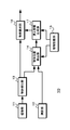
図1は、本技術の情報処理装置を用いたシステムの第1の構成を例示している。図1に示すシステムは、各種センサを搭載した移動体、例えば撮像部と測距部を備えるロボットである。システム10は、撮像部11、測距部12、物体検出部13、物体位置検出部14、情報記憶部15、見え情報生成部17、物体識別部18を有している。 <1. First Configuration of System>
FIG. 1 illustrates a first configuration of a system using an information processing device of the present technology. The system shown in FIG. 1 is a mobile body on which various sensors are mounted, for example, a robot including an imaging unit and a distance measuring unit. Thesystem 10 includes an imaging unit 11, a distance measuring unit 12, an object detection unit 13, an object position detection unit 14, an information storage unit 15, an appearance information generation unit 17, and an object identification unit 18.
図1は、本技術の情報処理装置を用いたシステムの第1の構成を例示している。図1に示すシステムは、各種センサを搭載した移動体、例えば撮像部と測距部を備えるロボットである。システム10は、撮像部11、測距部12、物体検出部13、物体位置検出部14、情報記憶部15、見え情報生成部17、物体識別部18を有している。 <1. First Configuration of System>
FIG. 1 illustrates a first configuration of a system using an information processing device of the present technology. The system shown in FIG. 1 is a mobile body on which various sensors are mounted, for example, a robot including an imaging unit and a distance measuring unit. The
撮像部11は、対象物体を表す物体情報を取得する。物体情報は対象物体を外から観測して取得できる外的特徴を示す情報であり、例えば対象物体の形状,輝度,色,温度等を示している。撮像部11としては、三原色の撮像画を得られるカラーカメラ、白黒の撮像画を得られる白黒カメラ、対象物体の温度を示す温度画像を得られる赤外線カメラ等が用いられる。なお、撮像部11で対象物体を表す物体情報の取得する際のパラメータ情報、物体情報を取得した情報取得位置である撮像部11の位置とその姿勢、撮像部11の視野角や焦点距離等のパラメータ(センサパラメータともいう)は、後述する情報記憶部15に記憶される。
The imaging unit 11 acquires object information representing a target object. Object information is information indicating external features that can be acquired by observing the target object from the outside, and indicates, for example, the shape, luminance, color, temperature, etc. of the target object. As the imaging unit 11, a color camera capable of obtaining captured images of three primary colors, a black and white camera capable of obtaining black and white captured images, an infrared camera capable of obtaining a temperature image indicating the temperature of a target object, etc. are used. The parameter information at the time of acquisition of object information representing a target object by the imaging unit 11, the position and posture of the imaging unit 11 which is the information acquisition position at which the object information is acquired, the viewing angle and focal length of the imaging unit 11, etc. The parameters (also referred to as sensor parameters) are stored in the information storage unit 15 described later.
測距部12は、対象物体までの距離を測定するためのセンサである。測距部12としては、ステレオカメラ、像面位相差画素を有するイメージセンサを用いることで撮像画と測距情報を取得できるカメラ、TOF(Time of Flight)センサ、LIDAR(Light Detection and Ranging、Laser Imaging Detection and Ranging)、RADAR(Radio Detection and Ranging)等が用いられる。
The distance measuring unit 12 is a sensor for measuring the distance to the target object. As the distance measuring unit 12, a stereo camera, a camera capable of acquiring a captured image and distance measurement information by using an image sensor having image plane phase difference pixels, a TOF (Time of Flight) sensor, LIDAR (Light Detection and Ranging, Laser) Imaging Detection and Ranging, RADAR (Radio Detection and Ranging), etc. are used.
物体検出部13は、撮像部11で取得された撮像画をもとに対象物体が存在することを検出して、検出した対象物体の画像内の位置を出力する。
The object detection unit 13 detects the presence of a target object based on the captured image acquired by the imaging unit 11, and outputs the position in the image of the detected target object.
物体位置検出部14は、物体検出部13で検出された対象物体の撮像画内における位置、測距部12で測定された対象物体までの距離、情報記憶部15に記憶されているパラメータ情報等に基づき、対象物体の三次元位置を検出する。物体位置検出部14は、検出した位置を示す位置情報を見え情報生成部17へ出力する。
The object position detection unit 14 detects the position of the target object detected by the object detection unit 13 in the captured image, the distance to the target object measured by the distance measurement unit 12, parameter information stored in the information storage unit 15, etc. To detect the three-dimensional position of the target object. The object position detection unit 14 outputs position information indicating the detected position to the appearance information generation unit 17.
情報記憶部15は、対象物体を表す物体情報の取得に関するパラメータ情報を記憶している。パラメータ情報には、撮像部11の位置と姿勢やセンサパラメータ等を記憶している。また、情報記憶部15は、学習された物体モデルを表す物体モデル情報を記憶している。
The information storage unit 15 stores parameter information related to acquisition of object information representing a target object. The parameter information stores the position and orientation of the imaging unit 11, sensor parameters, and the like. Further, the information storage unit 15 stores object model information representing a learned object model.
見え情報生成部17は、対象物体の位置を示す位置情報と、対象物体を表す物体情報の取得に関するパラメータ情報を用いて、物体情報を取得した情報取得位置から対象物体の位置に設けた物体モデルの見えを表す見え情報を物体モデル毎に生成する。見え情報生成部17は、物体情報を取得する撮像部11の視野領域と重なる物体モデルの部分を物体モデルの見えとする。また、見え情報生成部17は、撮像部11の位置と姿勢およびセンサパラメータに基づき、視野領域と重なる物体モデルの部分を判別する。
The appearance information generation unit 17 uses the position information indicating the position of the target object and the parameter information related to the acquisition of the object information representing the target object to obtain an object model provided at the position of the target object from the information acquisition position at which the object information Appearance information representing the appearance of is generated for each object model. The appearance information generation unit 17 sets the portion of the object model that overlaps the view area of the imaging unit 11 that acquires object information as the appearance of the object model. Further, the appearance information generation unit 17 determines a portion of the object model overlapping the view area based on the position and orientation of the imaging unit 11 and sensor parameters.
物体識別部18は、見え情報生成部17で生成された物体モデル毎の見え情報と物体検出部13で検出された対象物体を比較して、検出された対象物体と一致する見え情報に対応する物体モデルを対象物体と識別して物体識別結果を出力する。
The object identification unit 18 compares the appearance information of each object model generated by the appearance information generation unit 17 with the target object detected by the object detection unit 13 and corresponds to the appearance information that matches the detected target object. An object model is identified as a target object, and an object identification result is output.
<2.第1の構成の第1の動作>
次に、システムの第1の構成の第1の動作について説明する。なお、図2は物体モデルを例示しており、物体モデルOBmは「大きさを持った二次元の画像」と仮定している。また、撮像部11では、物体情報として対象物体の撮像画を取得している。 <2. First Operation of First Configuration>
Next, the first operation of the first configuration of the system will be described. Note that FIG. 2 exemplifies the object model, and the object model OBm is assumed to be a “two-dimensional image with a size”. Further, theimaging unit 11 acquires a captured image of a target object as the object information.
次に、システムの第1の構成の第1の動作について説明する。なお、図2は物体モデルを例示しており、物体モデルOBmは「大きさを持った二次元の画像」と仮定している。また、撮像部11では、物体情報として対象物体の撮像画を取得している。 <2. First Operation of First Configuration>
Next, the first operation of the first configuration of the system will be described. Note that FIG. 2 exemplifies the object model, and the object model OBm is assumed to be a “two-dimensional image with a size”. Further, the
見え情報生成部17は、検出された対象物体の位置情報と撮像部11の位置と姿勢に基づき、基準平面上に撮像部11と物体モデルを配置する。物体モデルは、例えば基準平面に垂直であって撮像部11に正対するように、対象物体の位置に配置する。この場合、座標系は統一されていればどのような座標系でもよい。
The appearance information generation unit 17 arranges the imaging unit 11 and the object model on the reference plane based on the detected position information of the target object and the position and orientation of the imaging unit 11. The object model is placed at the position of the target object, for example, so as to be perpendicular to the reference plane and face the imaging unit 11. In this case, any coordinate system may be used as long as the coordinate system is unified.
図3は、基準平面の座標系を基準として撮像部と物体モデルを配置した場合を例示している。見え情報生成部17は、物体モデルの三次元位置を示す点を通り、基準平面に足を持つ垂線VLaを求める。なお、垂線VLaと基準平面との交点を立ち位置PSaとする。次に、見え情報生成部17は、撮像部11の基準点を通り基準平面に足を持つ垂線VLbを求める。なお、垂線VLbと基準平面との交点を立ち位置PSbとする。さらに、立ち位置PSaと立ち位置PSbを結ぶ線分HLcを求める。垂線VLaを含み線分HLcに垂直な平面上に、物体モデルの下底が基準平面に乗るように物体モデルOBmを配置する。
FIG. 3 exemplifies the case where the imaging unit and the object model are arranged with reference to the coordinate system of the reference plane. The appearance information generation unit 17 passes through a point indicating the three-dimensional position of the object model, and obtains a perpendicular line VLa having a foot on the reference plane. In addition, let the intersection of perpendicular line VLa and a reference plane be the standing position PSa. Next, the appearance information generation unit 17 obtains a perpendicular line VLb passing the reference point of the imaging unit 11 and having a foot on the reference plane. In addition, let the intersection of perpendicular line VLb and a reference plane be standing position PSb. Further, a line segment HLc connecting the standing position PSa and the standing position PSb is obtained. The object model OBm is arranged on a plane including the perpendicular line VLa and perpendicular to the line segment HLc so that the lower base of the object model is on the reference plane.
また、見え情報生成部17は、撮像部11の位置と姿勢およびパラメータ情報に基づき三次元空間における撮像部11の視野領域、例えば撮像部11の視野領域を表す三次元図形を求める。一般的な撮像部において、視野領域はカメラ位置を頂点とした四角錐内の領域となる。図4は、基準平面の座標系を基準として求めた撮像部の視野領域を表す三次元図形を例示している。見え情報生成部17は、基準平面の座標系で撮像部11の位置と姿勢、および水平画角と垂直画角をもとに、視野領域ARvを表す三次元の四角錐を求める。
Further, the appearance information generation unit 17 obtains a three-dimensional figure representing a view area of the imaging unit 11 in a three-dimensional space, for example, a view area of the imaging unit 11 based on the position and orientation of the imaging unit 11 and parameter information. In a general imaging unit, a visual field area is an area in a quadrangular pyramid with the camera position at the top. FIG. 4 exemplifies a three-dimensional figure representing a visual field area of the imaging unit obtained based on the coordinate system of the reference plane. The appearance information generation unit 17 obtains a three-dimensional quadrangular pyramid representing the visual field area ARv based on the position and orientation of the imaging unit 11 and the horizontal angle of view and the vertical angle of view in the coordinate system of the reference plane.
次に、見え情報生成部17は、基準平面に配置した物体モデルOBmと、視野領域を示す四角錐との重なりに基づき、物体モデルから見え情報を生成する。図5は物体モデルの見えを説明するための図である。図5の(a)に示すように、撮像部11の光軸と物体モデルOBmの正面方向で傾きθを生じていると、撮像部11に対して物体モデルOBmは傾いた姿勢となっている。したがって、図5の(b)に示すように、撮像部11に対して傾きθを生じた物体モデルOBm、すなわち撮像部11と対象物体の位置関係に応じた姿勢の物体モデルOBmにおいて、撮像部11の視野領域を示す四角錐に含まれる領域が物体モデルの見えとなる。このため、見え情報は、図6に示すように、撮像部11に対して傾きθを生じた姿勢の物体モデルOBmにおいて、視野領域と重なる領域MPを透過投影変換して撮像部の座標系に変換したものとなり、画像GVを示すことになる。なお、撮像部11の光軸が物体モデルOBmの面に対して鉛直方向であれば重なり部分は矩形状となり、光軸が物体モデルOBmの面に対して鉛直方向でない場合は、矩形状とは異なる四角形となる。
Next, the appearance information generation unit 17 generates the appearance information from the object model based on the overlap between the object model OBm disposed on the reference plane and the quadrangular pyramid indicating the viewing area. FIG. 5 is a diagram for explaining the appearance of an object model. As shown in (a) of FIG. 5, when the optical axis of the imaging unit 11 and the front direction of the object model OBm generate an inclination θ, the object model OBm is inclined with respect to the imaging unit 11 . Therefore, as shown in (b) of FIG. 5, in the object model OBm in which the inclination θ is generated with respect to the imaging unit 11, that is, in the object model OBm of the posture according to the positional relationship between the imaging unit 11 and the target object The area included in the quadrangular pyramid indicating the 11 visual field areas is the appearance of the object model. For this reason, as shown in FIG. 6, in the object model OBm of the posture in which the tilt θ is generated with respect to the imaging unit 11, the appearance information overlaps and transmits the area MP overlapping the visual field to the coordinate system of the imaging unit. It becomes the converted one and shows the image GV. If the optical axis of the imaging unit 11 is in the vertical direction with respect to the surface of the object model OBm, the overlapping portion is rectangular, and if the optical axis is not perpendicular to the surface of the object model OBm, the rectangular shape is It will be a different square.
図7は、見え情報生成部の動作を例示したフローチャートである。ステップST1で見え情報生成部は対象物体の三次元位置が検出されているか判別する。見え情報生成部17は、物体位置検出部14で対象物体の三次元位置が検出されていない場合にステップST1に戻り、検出されている場合ステップST2に進む。
FIG. 7 is a flowchart illustrating the operation of the appearance information generation unit. In step ST1, the appearance information generation unit determines whether the three-dimensional position of the target object is detected. The appearance information generation unit 17 returns to step ST1 when the three-dimensional position of the target object is not detected by the object position detection unit 14, and proceeds to step ST2 when it is detected.
ステップST2で見え情報生成部は物体モデルの姿勢を算出する。見え情報生成部17は、物体モデルの基準平面上における姿勢を算出する。図8は、姿勢の算出動作を例示したフローチャートである。
In step ST2, the appearance information generation unit calculates the attitude of the object model. The appearance information generation unit 17 calculates the posture on the reference plane of the object model. FIG. 8 is a flowchart illustrating the operation of calculating the posture.
ステップST11で見え情報生成部は撮像部の立ち位置を算出する。見え情報生成部17は、上述のように、撮像部11の基準点を通り基準平面に足を持つ垂線VLbのZ方向の座標値が「0」となる位置を撮像部11の立ち位置PSbとしてステップST12に進む。
In step ST11, the appearance information generation unit calculates the standing position of the imaging unit. As described above, the appearance information generation unit 17 sets the position where the coordinate value of the Z direction of the perpendicular line VLb passing the reference point of the imaging unit 11 and having a foot on the reference plane is “0” as the standing position PSb of the imaging unit 11 Proceed to step ST12.
ステップST12で見え情報生成部は物体モデルの立ち位置を算出する。図9は物体モデルの立ち位置の算出動作を示すフローチャートである。ステップST21で見え情報生成部は基準平面への座標変換を行う。見え情報生成部17は、物体モデルを基準平面の座標に変換してステップST22に進む。
In step ST12, the appearance information generation unit calculates the standing position of the object model. FIG. 9 is a flowchart showing the calculation operation of the standing position of the object model. In step ST21, the appearance information generation unit performs coordinate conversion to the reference plane. The appearance information generation unit 17 converts the object model into the coordinates of the reference plane, and proceeds to step ST22.
ステップST22で見え情報生成部は立ち位置を算出する。見え情報生成部17は、物体位置検出部14で検出された対象物体の三次元位置を基準平面に座標変換したときにZ方向の座標値が「0」となる位置を、座標変換後の物体モデルOBmの立ち位置PSaとして、図8のステップST13に進む。
In step ST22, the appearance information generation unit calculates the standing position. The appearance information generation unit 17 coordinates the position at which the coordinate value in the Z direction is “0” when the three-dimensional position of the target object detected by the object position detection unit 14 is coordinate converted to the reference plane. The process proceeds to step ST13 of FIG. 8 as the standing position PSa of the model OBm.
ステップST13で見え情報生成部は撮像部から対象物体への角度を算出する。図10は角度の算出動作を示すフローチャートである。ステップST31で見え情報生成部は方向ベクトルを算出する。見え情報生成部17は、物体モデルOBmの立ち位置PSaと撮像部11の立ち位置PSbの差を示す方向ベクトルを算出してステップST32に進む。
In step ST13, the appearance information generation unit calculates an angle from the imaging unit to the target object. FIG. 10 is a flowchart showing an operation of calculating the angle. In step ST31, the appearance information generation unit calculates a direction vector. The appearance information generation unit 17 calculates a direction vector indicating the difference between the standing position PSa of the object model OBm and the standing position PSb of the imaging unit 11, and proceeds to step ST32.
ステップST32で見え情報生成部は方向ベクトルの角度を算出する。見え情報生成部17は、ステップST31で算出した方向ベクトルにおいて、撮像部11と対象物体における撮像部11の光軸位置を結ぶ直線と基準平面との角度を算出する。具体的には、見え情報生成部17は、立ち位置PSbにおいてテンプレート情報で示された撮像部11の位置(高さ)と、立ち位置PSaの対象物体において、撮像部11の位置や姿勢等に基づき算出した撮像部11の光軸位置の高さの差を算出する。また、見え情報生成部17は、算出した高さの差とステップST31で算出された方向ベクトルのノルムとを用いて算出した逆正接を方向ベクトルの角度(傾き)θとして図8のステップST14に進む。
In step ST32, the appearance information generation unit calculates the angle of the direction vector. The appearance information generation unit 17 calculates, in the direction vector calculated in step ST31, an angle between a reference plane and a straight line connecting the optical axis position of the imaging unit 11 and the imaging unit 11 in the target object. Specifically, the appearance information generation unit 17 uses the position (height) of the imaging unit 11 indicated by the template information at the standing position PSb, and the position and orientation of the imaging unit 11 at the target object at the standing position PSa. The difference of the height of the optical axis position of the imaging unit 11 calculated based on the above is calculated. In addition, the appearance information generation unit 17 sets the arctangent calculated using the calculated height difference and the norm of the direction vector calculated in step ST31 as the angle (inclination) θ of the direction vector to step ST14 in FIG. move on.
ステップST14で見え情報生成部は物体モデルの姿勢を設定する。見え情報生成部17は、物体モデルOBmを撮像部11に対してステップST13で算出した傾きθを生じた姿勢に設定して図7のステップST4に進む。なお、傾きθを生じた姿勢とは図5に示す状態である
ステップST4で見え情報生成部は視野領域と設定した姿勢の物体モデルとの重複領域を検出する。見え情報生成部17は、撮像部11に対する物体モデルOBmの姿勢および撮像部11の視野領域に基づき、物体モデルと視野領域が重複する重複領域を検出してステップST5に進む。 In step ST14, the appearance information generation unit sets the posture of the object model. The appearanceinformation generation unit 17 sets the object model OBm to the posture in which the inclination θ calculated in step ST13 is generated with respect to the imaging unit 11, and the process proceeds to step ST4 in FIG. The posture in which the inclination θ is generated is the state shown in FIG. 5 In step ST4, the appearance information generation unit detects an overlapping area of the visual field area and the object model of the set posture. The appearance information generation unit 17 detects an overlapping area where the object model and the visual field overlap with each other based on the posture of the object model OBm relative to the imaging unit 11 and the visual field area of the imaging unit 11, and proceeds to step ST5.
ステップST4で見え情報生成部は視野領域と設定した姿勢の物体モデルとの重複領域を検出する。見え情報生成部17は、撮像部11に対する物体モデルOBmの姿勢および撮像部11の視野領域に基づき、物体モデルと視野領域が重複する重複領域を検出してステップST5に進む。 In step ST14, the appearance information generation unit sets the posture of the object model. The appearance
ステップST5で見え情報生成部は重複領域があるか判別する。見え情報生成部17は、重複領域がある場合はステップST6に進み、重複領域がない場合はステップST1に戻る。
In step ST5, the appearance information generation unit determines whether there is an overlapping area. If there is an overlap area, the appearance information generation unit 17 proceeds to step ST6. If there is no overlap area, the appearance information generation unit 17 returns to step ST1.
ステップST6で見え情報生成部は重複領域の物体モデルを抽出する。見え情報生成部17は、ステップST4で検出された重複領域を物体モデルとして抽出してステップST7に進む。
In step ST6, the appearance information generation unit extracts an object model of the overlapping area. The appearance information generation unit 17 extracts the overlapping area detected in step ST4 as an object model, and proceeds to step ST7.
ステップST7で見え情報生成部は抽出した部分を光軸に対して垂直に透視投影変換を行う。見え情報生成部17は、ステップST6で抽出した物体モデルを撮像部11の光軸に対して垂直に透視投影変換を行い、撮像部11の座標系に変換された物体モデルを示す情報を見え情報としてステップST8に進む。
In step ST7, the appearance information generation unit performs perspective projection conversion so that the extracted portion is perpendicular to the optical axis. The appearance information generation unit 17 performs perspective projection conversion perpendicular to the optical axis of the imaging unit 11 with respect to the object model extracted in step ST6, and information indicating the object model converted into the coordinate system of the imaging unit 11 is appearance information Then, the process proceeds to step ST8.
ステップST8で見え情報生成部は見え情報を出力する。見え情報生成部17は、ステップST6の座標変換によって決定された物体モデル座標における重複領域の画像を見え情報として物体識別部18へ出力する。
In step ST8, the appearance information generation unit outputs the appearance information. The appearance information generation unit 17 outputs the image of the overlapping area in the object model coordinates determined by the coordinate conversion in step ST6 to the object identification unit 18 as appearance information.
なお、図7におけるステップST2とステップST3の処理は何れの処理を先に行ってもよく、並列して行ってもよい。また、図8におけるステップST11とステップST12の処理も同様である。
Note that any of the processes in steps ST2 and ST3 in FIG. 7 may be performed first, or may be performed in parallel. Further, the processes of step ST11 and step ST12 in FIG. 8 are the same.
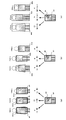
図11は、複数の物体モデルの見え情報を例示している。本技術の第1の動作によれば、図11の(a)に示すように、物体モデルOBmaについて例えば領域MPを示す画像が見え情報として生成される。同様に、物体モデルOBmb,OBmcについても領域MPを示す画像が見え情報として生成されて、見え情報は物体モデル毎に異なる。したがって、物体検出部13で検出された対象物体を表す入力画像GDと見え情報を比較することで、検出された対象物体が物体モデルOBmbであることを正しく識別できる。なお、図11の(b)は従来の技術を用いた場合であり、物体モデルOBma,OBmb,OBmcにおいて、破線で示す領域は検出された対象物体を表す入力画像GDと類似している。このため検出された物体は、物体モデルOBmaあるいは物体モデルOBmcと判定されてしまう場合が生じて、本技術のような精度の高い識別処理を行うことはできない。また、図11の(c)に示すように物体モデル全体を用いて識別処理を行った場合、入力画像GDと全体像が似ている物体モデルOBmaが選ばれやすく、本技術のような精度の高い識別処理を行うことはできない。
FIG. 11 illustrates the appearance information of a plurality of object models. According to the first operation of the present technology, as shown in (a) of FIG. 11, an image showing, for example, a region MP of the object model OBma is generated as the appearance information. Similarly, for the object models OBmb and OBmc, an image indicating the region MP is generated as appearance information, and the appearance information differs for each object model. Therefore, by comparing the appearance information with the input image GD representing the target object detected by the object detection unit 13, it is possible to correctly identify that the detected target object is the object model OBmb. FIG. 11B shows the case where the conventional technique is used, and in the object models OBma, OBmb, and OBmc, the region indicated by the broken line is similar to the input image GD representing the detected target object. For this reason, the detected object may be determined to be the object model OBma or the object model OBmc, and it is not possible to perform highly accurate identification processing as in the present technology. Further, as shown in (c) of FIG. 11, when identification processing is performed using the entire object model, an object model OBma having a similar overall image to the input image GD is easily selected, and accuracy as in the present technology is obtained. It is not possible to do a high identification process.
このような本技術の第1の動作によれば、物体モデルの見え情報は撮像部の位置や姿勢等に応じた見えが考慮されて生成されることから、取得された撮像画において対象物体の一部が見切れても、見切れに対してロバストであって、物体の識別精度を向上させることができる。また、物体モデルは撮像部による見えが考慮されることから、見た目が似ている物体を対象物体として誤識別してしまうことを防止できる。
According to the first operation of the present technology, the appearance information of the object model is generated in consideration of the appearance according to the position, orientation, and the like of the imaging unit. Even if a part is missed, it is robust against the missing and the identification accuracy of the object can be improved. In addition, since the appearance of the image capturing unit is considered in the object model, it is possible to prevent an object having a similar appearance from being erroneously identified as a target object.
また、見切れた物体の検出率を上げるために、見切れた物体の画像を学習データに加えると、見た目が似ている物体を対象物体として誤識別してしまう可能性が高くなる。例えば、頭が見えない人の画像を学習した場合に、ハンガーに掛けられた洋服の撮像画では、対象物体を人と誤識別する可能性がある。しかし、本技術によれば、全身が写るような撮像条件では、撮像条件に応じた見え情報を用いて物体の識別が行われる。したがって、全身が写るような撮像条件でハンガーに掛けられた洋服を撮像した場合、対象物体が人と誤識別されてしまう可能性を低くできる。
In addition, if the image of the missed object is added to the learning data in order to increase the detection rate of the missed object, there is a high possibility of misidentifying an object having a similar appearance as the target object. For example, in the case of learning an image of a person who can not see the head, there is a possibility that the target object may be misidentified as a person in the captured image of the clothes hung on the hanger. However, according to the present technology, under the imaging condition in which the whole body is captured, the identification of the object is performed using the appearance information according to the imaging condition. Therefore, when an image of clothes worn on a hanger is captured under an imaging condition in which the entire body is captured, the possibility that a target object is misidentified as a person can be reduced.
また、対象物体の全体を示す物体情報を学習しておけば、撮像部の位置や姿勢等に応じた見え情報を用いて物体の識別を行うことができるので、対象物体の一部が見切れた様々な物体モデルを学習しておく必要がなく、学習データのデータ量を削減できる。
In addition, by learning object information indicating the entire target object, it is possible to identify the object using appearance information according to the position, orientation, and the like of the imaging unit, so that part of the target object was missed. It is not necessary to learn various object models, and the amount of learning data can be reduced.
さらに、撮像部から対象物体までの距離を用いて見え情報が生成されるので、見え情報は物体モデルの大きさが考慮される。例えば撮像部から対象物体までの距離が等しい場合、物体モデルが大きければ見え情報には物体モデルの一部が含まれて、物体モデルが小さければ見え情報には物体モデルの全体が含まれる。したがって、見た目が同じサイズでも、撮像部から対象物体までの距離に応じた大きさを考慮して物体の識別を行うことができる。
Furthermore, since the appearance information is generated using the distance from the imaging unit to the target object, the size of the object model is considered in the appearance information. For example, when the distance from the imaging unit to the target object is equal, if the object model is large, the appearance information includes part of the object model, and if the object model is small, the appearance information includes the entire object model. Therefore, even if the size is the same, it is possible to identify the object in consideration of the size according to the distance from the imaging unit to the target object.
<3.第1の構成の第2の動作>
次に、システムの第1の構成の第2の動作について説明する。撮像部11で取得される撮像画には、対象物体だけでなく自己の一部が写り込む場合がある。例えば、アクセサリ等を撮像部11に取り付けるための取付器具や操作性等を向上させるために撮像部11に取り付けられるリグ等の付属器具が視野領域内に含まれると、付属機器の一部が撮像画に写り込んでしまう。また、システムが可動機構を有する機器、例えばロボット等に適用された場合、可動するアーム等が撮像画に写り込んでしまう場合もある。そこで、見え情報生成部17は、撮像部11の視野領域と対象物体の位置に設けた物体モデルの重複部分に含まれており、対象物体よりも手前に位置する非対象物体である自己形状部分(付属機器やアーム等の部分)が除外された見え情報を生成する。 <3. Second Operation of First Configuration>
Next, the second operation of the first configuration of the system will be described. Not only the target object but also a part of itself may be captured in the captured image acquired by theimaging unit 11. For example, when an attachment such as a rig attached to the imaging unit 11 for improving accessories or the like for attaching an accessory or the like to the imaging unit 11 is included in the visual field area, a part of the attached device is imaged It will be reflected in the picture. In addition, when the system is applied to an apparatus having a movable mechanism, for example, a robot or the like, a movable arm or the like may be reflected in a captured image. Therefore, the appearance information generation unit 17 is a self-shaped portion that is included in the overlapping portion of the field of view of the imaging unit 11 and the object model provided at the position of the target object and is a non-target object located in front of the target object. It generates appearance information that is excluded (parts such as accessories and arms).
次に、システムの第1の構成の第2の動作について説明する。撮像部11で取得される撮像画には、対象物体だけでなく自己の一部が写り込む場合がある。例えば、アクセサリ等を撮像部11に取り付けるための取付器具や操作性等を向上させるために撮像部11に取り付けられるリグ等の付属器具が視野領域内に含まれると、付属機器の一部が撮像画に写り込んでしまう。また、システムが可動機構を有する機器、例えばロボット等に適用された場合、可動するアーム等が撮像画に写り込んでしまう場合もある。そこで、見え情報生成部17は、撮像部11の視野領域と対象物体の位置に設けた物体モデルの重複部分に含まれており、対象物体よりも手前に位置する非対象物体である自己形状部分(付属機器やアーム等の部分)が除外された見え情報を生成する。 <3. Second Operation of First Configuration>
Next, the second operation of the first configuration of the system will be described. Not only the target object but also a part of itself may be captured in the captured image acquired by the
見え情報生成部17は、推定された三次元の物体位置、基準平面の位置と姿勢、撮像部11の位置と姿勢に基づき、三次元上に物体モデルを配置する。物体モデルは、例えば、三次元物体位置を含み、基準平面に垂直で、撮像部11に正対するように配置する。この場合、座標系は統一されていればどのような座標系でもよい。
The appearance information generation unit 17 arranges an object model in three dimensions based on the estimated three-dimensional object position, the position and attitude of the reference plane, and the position and attitude of the imaging unit 11. The object model includes, for example, a three-dimensional object position, and is disposed perpendicular to the reference plane so as to face the imaging unit 11. In this case, any coordinate system may be used as long as the coordinate system is unified.
次に、見え情報生成部17は、パラメータ情報に基づき三次元空間における撮像部11の視野領域、例えば撮像部11の視野領域を表す三次元図形を求める。
Next, the appearance information generation unit 17 obtains a three-dimensional figure representing a view area of the imaging unit 11 in a three-dimensional space, for example, a view area of the imaging unit 11, based on the parameter information.
見え情報生成部17は、第1の動作と同様にして撮像部11の視野領域と物体モデルの重なりを判別する。また、見え情報生成部17は、自己形状部分と視野領域の重なりを判別する。自己形状は、例えば三次元のメッシュや単純図形(例えば球・円柱・角柱・直方体・円錐・角錐)の組み合わせで示されている。見え情報生成部17は、撮像部11のパラメータ情報と自己形状および自己形状部分の位置に基づき、自己形状部分と視野領域との重なりを判別する。なお、撮像する被写体にかかわらず撮像画の固定した位置に写り込む被写体の領域を自己形状部分として、自己形状部分を示す自己形状領域情報を情報記憶部15に予め記憶させて、自己形状領域情報を用いて自己形状部分と視野領域との重なりを判別してもよい。
The appearance information generation unit 17 determines the overlap between the view area of the imaging unit 11 and the object model in the same manner as the first operation. Further, the appearance information generation unit 17 determines the overlap between the self-shaped portion and the visual field area. The self shape is indicated by, for example, a combination of a three-dimensional mesh or a simple figure (for example, a sphere, a cylinder, a prism, a rectangular parallelepiped, a cone, and a pyramid). The appearance information generation unit 17 determines the overlap between the self-shaped portion and the visual field region based on the parameter information of the imaging unit 11 and the position of the self-shape and the self-shaped portion. It should be noted that regardless of the subject to be imaged, the self-shaped area information indicating the self-shaped part is stored in advance in the information storage unit 15 with the area of the subject captured at the fixed position of the captured image as the self-shaped part. The overlap between the self-shaped portion and the visual field area may be determined using
さらに、見え情報生成部17は、対象物体と自己形状部分の前後関係を求める。見え情報生成部17は、視野領域と重なりを生じている物体モデルと自己形状部分との前後関係を求め、対象物体よりも撮像部11に近い自己形状の部分を物体モデルに投射した領域を除外領域MRとする。
Furthermore, the appearance information generation unit 17 obtains an anteroposterior relationship between the target object and the self-shaped portion. The appearance information generation unit 17 obtains an anteroposterior relationship between the object model overlapping the view area and the self-shaped portion, and excludes the region where the self-shaped portion closer to the imaging unit 11 than the target object is projected to the object model. It is assumed that the region MR.
また、撮像画に写り込む自己形状部分が可動する構成である場合、見え情報生成部17は、自己形状部分の可動状態に応じて、除外領域MRを設定する。例えば、見え情報生成部17は、情報記憶部15に記憶されている自己形状の情報と制御部(図示せず)から供給された可動制御信号に基づき、自己形状部分と視野領域との重なりを判別して、対象物体と自己形状部分の前後関係に基づき除外領域MRを設定する。また、自己形状算出部を設けて、自己形状部分の可動状態(位置・姿勢)と情報記憶部15に記憶されている自己形状の情報から、撮像部11に対する自己形状部分の全体の形状を算出してもよい。この場合、見え情報生成部17は、自己形状算出部で算出された形状と視野領域との重なりを判別して、対象物体と自己形状部分の前後関係に基づき除外領域MRを設定する。
When the self-shaped portion to be captured in the captured image is movable, the appearance information generation unit 17 sets the exclusion region MR according to the movable state of the self-shaped portion. For example, the appearance information generation unit 17 sets the overlap between the self shape portion and the visual field area based on the self shape information stored in the information storage unit 15 and the movable control signal supplied from the control unit (not shown). It discriminate | determines and sets exclusion area MR based on the context of a target object and a self-shaped part. In addition, a self shape calculation unit is provided to calculate the entire shape of the self shape portion with respect to the imaging unit 11 from the movable state (position and posture) of the self shape portion and the self shape information stored in the information storage unit 15 You may In this case, the appearance information generation unit 17 determines the overlap between the shape calculated by the self shape calculation unit and the visual field region, and sets the exclusion region MR based on the anteroposterior relationship between the target object and the self shape portion.
その後、見え情報生成部17は、視野領域と物体モデルとの重複領域の画像から自己形状部分に相当する除外領域MRの画像を除いて見え情報とする。
After that, the appearance information generation unit 17 excludes the image of the excluded area MR corresponding to the self-shaped part from the image of the overlapping area between the visual field area and the object model to obtain appearance information.
なお、第2の動作では、図7に示すステップST5の処理後に、自己形状部分と視野領域の重なりを求める処理と、物体モデルと自己形状部分の前後関係を求める処理を行い、物体モデルよりも手前の自己形状部分の領域を重複領域から除外したのちステップST6以降の処理を行えばよい。
In the second operation, after the process of step ST5 shown in FIG. 7, a process of obtaining an overlap between the self-shaped portion and the visual field and a process of obtaining an anteroposterior relationship between the object model and the self-shaped portion are performed. The processing of step ST6 and subsequent steps may be performed after excluding the region of the self-shaped portion at the front side from the overlapping region.
図12は、自己の一部が写り込む場合を例示している。例えば、視野領域内に付属器具31が含まれると、撮像画に付属機器が写り込んでしまう。このような場合、第2の動作によれば精度よく識別処理を行うことができる。
FIG. 12 exemplifies the case where a part of the user is captured. For example, when the accessory 31 is included in the visual field area, the accessory device is reflected in the captured image. In such a case, according to the second operation, the identification process can be performed with high accuracy.
図13は、複数の物体モデルの見え情報を例示している。本技術の第2の動作では、図13の(a)に示すように、物体モデルOBmaについて例えば領域MPから除外領域MRを除いた領域の画像GVmaが見え情報として生成される。同様に、物体モデルOBmb,OBmcについても領域MPから除外領域MRを除いた領域の画像GVmb,GVmcが見え情報として生成される。このため、見え情報は物体モデル毎に異なり、自己形状部分が比較対象から除外されている。したがって、物体検出部13で検出された物体を表す入力画像GDと見え情報を比較することで、検出された対象物体が物体モデルOBmbであることを正しく識別できる。なお、図13の(b)は従来の技術を用いた場合であり、自己形状部分である除外領域MRを含む入力画像GDと物体モデルOBma,OBmb,OBmcが比較されて、物体モデルOBmaの領域MQa,物体モデルOBmbの領域MQb,物体モデルOBmcの領域MQcには自己形状部分が含まれないことから、検出された物体は物体モデルOBma,OBmb,OBmcと異なると判定される。したがって、本技術のような精度の高い識別処理を行うことはできない。また、図13の(c)に示すように物体モデル全体を用いて識別処理を行った場合、入力画像GDと全体像が似ている物体モデルOBmaが選ばれやすく、本技術のような精度の高い識別処理を行うことはできない。
FIG. 13 illustrates the appearance information of a plurality of object models. In the second operation of the present technology, as shown in (a) of FIG. 13, for example, an image GVma of an area obtained by removing the exclusion area MR from the area MP is generated as appearance information for the object model OBma. Similarly, for the object models OBmb and OBmc, images GVmb and GVmc of the area excluding the exclusion area MR from the area MP are generated as appearance information. For this reason, the appearance information differs for each object model, and the self-shaped part is excluded from the comparison targets. Therefore, by comparing the appearance information with the input image GD representing the object detected by the object detection unit 13, it can be correctly identified that the detected target object is the object model OBmb. FIG. 13 (b) shows the case where the prior art is used, and the input image GD including the excluded region MR which is a self-shaped portion is compared with the object models OBma, OBmb, OBmc, and the region of the object model OBma. Since the area MQb of the object model OBmb and the area MQc of the object model OBmc do not include a self-shaped portion, it is determined that the detected object is different from the object models OBma, OBmb, and OBmc. Therefore, highly accurate identification processing as in the present technology can not be performed. Further, as shown in (c) of FIG. 13, when the identification process is performed using the entire object model, an object model OBma having a similar overall image to the input image GD is easily selected, and accuracy as in the present technique is obtained. It is not possible to do a high identification process.
このような本技術の第2の動作によれば、撮像画に自己形状部分が含まれても、自己形状部分を除外して見え情報が生成されるので、第1の動作と同様に、対象物体の一部の見切れに対してロバストであって、物体の識別を精度よく行うことができる。また、見え情報は撮像部からの見えが考慮されることから、見た目が似ている物体を対象物体として誤識別しまうことが少なくなる。また、学習データのデータ量の削減や大きさを考慮した物体の識別を行うことができる。
According to the second operation of the present technology, even if a self-shaped portion is included in the captured image, the appearance information is generated excluding the self-shaped portion, and therefore, as in the first operation, the target It is robust against missing part of an object, and object identification can be performed with high accuracy. Further, since the appearance information is considered in terms of the appearance from the imaging unit, it is less likely to misidentify an object having a similar appearance as a target object. In addition, it is possible to identify an object in consideration of reduction of data amount and size of learning data.
<4.システムの第2の構成>
次に、システムの第2の構成について説明する。第2の構成では、物体情報を取得するセンサ部として測距部を用いて、対象物体上の各位置までの距離を示す点群測距データを、対象物体を表す物体情報として取得する場合について説明する。 <4. Second configuration of system>
Next, a second configuration of the system will be described. In the second configuration, the point group ranging data indicating the distance to each position on the target object is acquired as the object information representing the target object using the distance measuring unit as a sensor unit for acquiring object information. explain.
図14は、本技術の情報処理装置を用いたシステムの第2の構成を例示している。システム20は、測距部21、クラスタリング部22、情報記憶部25、見え情報生成部27、物体識別部28を有している。
FIG. 14 illustrates a second configuration of a system using the information processing device of the present technology. The system 20 includes a distance measurement unit 21, a clustering unit 22, an information storage unit 25, an appearance information generation unit 27, and an object identification unit 28.
測距部21は、対象物体までの距離を測定するためのセンサである。測距部12としては、被写体上の各位置までの距離を測定して点群測距データを取得できる例えばLIDAR(Light Detection and Ranging、Laser Imaging Detection and Ranging)等が用いられる。測距部21は、取得した点群測距データをクラスタリング部22へ出力する。なお、測距部21として三次元LIDARを用いた場合の視野領域ARvは、図15に示すように2つの円錐に挟まれた領域となり、2つの円錐の領域は死角領域ARdとなる。
The distance measuring unit 21 is a sensor for measuring the distance to the target object. As the distance measuring unit 12, for example, LIDAR (Light Detection and Ranging, Laser Imaging Detection and Ranging) or the like, which can measure the distance to each position on the subject and acquire point group distance measurement data, is used. The ranging unit 21 outputs the acquired point group ranging data to the clustering unit 22. The field of view ARv in the case where a three-dimensional LIDAR is used as the distance measuring unit 21 is an area sandwiched between two cones as shown in FIG. 15, and the area of the two cones is a dead angle area ARd.
クラスタリング部22は、点群測距データのクラスタリングを行い、距離に基づいて点群測距データをクラスタに分類する。クラスタリング部22は、分類後の点群クラスタを物体識別部28へ出力する。また、クラスタリング部22は、対象物体を表す点群クラスタの位置情報を見え情報生成部27へ出力する。
The clustering unit 22 performs clustering of point group ranging data, and classifies the point group ranging data into clusters based on distances. The clustering unit 22 outputs the point cloud clusters after classification to the object identification unit 28. In addition, the clustering unit 22 outputs the position information of the point cloud cluster representing the target object to the appearance information generation unit 27.
情報記憶部25は、対象物体を表す物体情報の取得に関するパラメータ情報、例えば測距部21の位置と姿勢、測距部21の視野領域等を示すセンサパラメータを記憶している。また、情報記憶部25は、学習された物体モデルを表す物体モデル情報を記憶している。
The information storage unit 25 stores parameter information related to acquisition of object information representing a target object, for example, sensor parameters indicating the position and attitude of the distance measuring unit 21, the visual field area of the distance measuring unit 21, and the like. Further, the information storage unit 25 stores object model information representing a learned object model.
見え情報生成部27は、クラスタリング部22で推定された対象物体の三次元位置、情報記憶部25に記憶されているパラメータ情報および物体モデル情報に基づき、物体モデルが測距部21からどのように見えているかを示す見え情報を物体モデル毎に生成する。
The appearance information generation unit 27 determines how the object model is obtained from the distance measurement unit 21 based on the three-dimensional position of the target object estimated by the clustering unit 22, the parameter information and the object model information stored in the information storage unit 25. Appearance information indicating whether it is visible is generated for each object model.
見え情報生成部27は、クラスタリング部22で検出された対象物体を示す対象物体を示す点群クラスタの位置情報と、対象物体を表す物体情報の取得に関するパラメータ情報を用いて、物体情報を取得した情報取得位置から対象物体の位置に設けた物体モデルの見えを表す見え情報を物体モデル毎に生成する。見え情報生成部27は、物体情報を取得する測距部21の視野領域と重なる物体モデルの部分を物体モデルの見えとする。また、見え情報生成部27は、パラメータ情報に基づき視野領域と重なる物体モデルの部分を判別する。
The appearance information generation unit 27 acquires object information using position information of a point cloud cluster indicating a target object indicating a target object detected by the clustering unit 22 and parameter information on acquisition of object information indicating a target object. Appearance information representing the appearance of the object model provided at the position of the target object from the information acquisition position is generated for each object model. The appearance information generation unit 27 sets the portion of the object model that overlaps the view area of the distance measurement unit 21 that acquires object information as the appearance of the object model. In addition, the appearance information generation unit 27 determines a portion of the object model that overlaps the viewing area based on the parameter information.
物体識別部28は、見え情報生成部17で生成された物体モデル毎の見え情報とクラスタリング部22で分類された対象物体を表す点群クラスタを比較する。物体識別部28は、対象物体を表す点群クラスタと一致する見え情報に対応する物体モデルを対象物体と識別して物体識別結果を出力する。
The object identification unit 28 compares the appearance information of each object model generated by the appearance information generation unit 17 with the point cloud cluster representing the target object classified by the clustering unit 22. The object identification unit 28 identifies an object model corresponding to the appearance information that matches the point cloud cluster representing the target object as the target object, and outputs an object identification result.
<5.第2の構成の動作>
次に、システムの第2の構成の動作について説明する。見え情報生成部27は、検出された対象物体の位置情報と測距部21の位置と姿勢に基づき、基準平面上に測距部21と物体モデルを配置する。物体モデルは、例えば基準平面に垂直であって測距部21に正対するように、対象物体の位置に配置する。この場合、座標系は統一されていればどのような座標系でもよい。なお、基準平面の座標系を基準とした測距部21と物体モデルOBmの配置は、第1の構成の動作と同様に行えばよい。 <5. Operation of second configuration>
Next, the operation of the second configuration of the system will be described. The appearanceinformation generation unit 27 arranges the distance measurement unit 21 and the object model on the reference plane based on the detected position information of the target object and the position and attitude of the distance measurement unit 21. The object model is disposed at the position of the target object, for example, so as to be perpendicular to the reference plane and face the distance measuring unit 21. In this case, any coordinate system may be used as long as the coordinate system is unified. The arrangement of the distance measuring unit 21 and the object model OBm based on the coordinate system of the reference plane may be performed in the same manner as the operation of the first configuration.
次に、システムの第2の構成の動作について説明する。見え情報生成部27は、検出された対象物体の位置情報と測距部21の位置と姿勢に基づき、基準平面上に測距部21と物体モデルを配置する。物体モデルは、例えば基準平面に垂直であって測距部21に正対するように、対象物体の位置に配置する。この場合、座標系は統一されていればどのような座標系でもよい。なお、基準平面の座標系を基準とした測距部21と物体モデルOBmの配置は、第1の構成の動作と同様に行えばよい。 <5. Operation of second configuration>
Next, the operation of the second configuration of the system will be described. The appearance
また、見え情報生成部27は、測距部21の位置と姿勢および測距部21の視野領域を表す三次元図形を求めて、基準平面に配置した測距部21の視野領域と基準平面に配置して、測距部21と対象物体の位置関係に応じた姿勢の物体モデルと、測距部21の視野領域との重なりに基づき、物体モデルから見え情報を生成する。
Further, the appearance information generation unit 27 obtains a three-dimensional figure representing the position and attitude of the distance measurement unit 21 and the field of view region of the distance measurement unit 21 and sets the field of view of the distance measurement unit 21 arranged in the reference plane and the reference plane. Based on the overlap between the object model of the posture according to the positional relationship between the distance measuring unit 21 and the target object and the visual field area of the distance measuring unit 21, the appearance information is generated from the object model.
図16は、第2の構成の動作で得られる見え情報を例示している。本技術の第2の構成によれば、図16の(a)に示すように、物体モデルOBmaについて例えば領域MPに含まれる点群距離データが見え情報として生成される。同様に、物体モデルOBmb,OBmcについても領域MPに含まれる点群距離データが見え情報として生成される。このため、見え情報は物体モデル毎に異なっている。したがって、物体識別部28は、クラスタリング部22で検出された物体の点群クラスタと見え情報を比較することで、検出された物体が物体モデルOBmbであることを正しく認識できる。なお、図16の(b)は従来の技術を用いた場合であり、物体モデルOBma,OBmb,OBmcにおいて、破線で示す領域は検出された物体を示す点群クラスタと類似している。このため、検出された物体は物体モデルOBmaあるいは物体モデルOBmcと判定されてしまう場合が生じて、本技術のような精度の高い識別処理を行うことはできない。
FIG. 16 illustrates the appearance information obtained by the operation of the second configuration. According to the second configuration of the present technology, as illustrated in (a) of FIG. 16, point group distance data included in, for example, the area MP of the object model OBma is generated as the appearance information. Similarly, for the object models OBmb and OBmc, point group distance data included in the region MP is generated as the appearance information. For this reason, the appearance information is different for each object model. Therefore, the object identification unit 28 can correctly recognize that the detected object is the object model OBmb by comparing the point cloud cluster of the object detected by the clustering unit 22 and the appearance information. Note that FIG. 16B shows the case where the conventional technique is used, and in the object models OBma, OBmb, and OBmc, the region indicated by the broken line is similar to a point cloud cluster indicating the detected object. For this reason, the detected object may be determined to be the object model OBma or the object model OBmc, and it is not possible to perform high-accuracy identification processing as in the present technology.
このような本技術の第2の構成によれば、取得される情報が点群距離データであっても、撮像画を取得する場合と同様に、対象物体の一部の見切れに対してロバストであって、物体識別を精度よく行うことができる。また、物体モデルは測距部からの見えが考慮されることから、見た目が似ている物体を対象物体として誤識別しまうことを少なくできる。また、学習データのデータ量の削減や大きさを考慮した物体識別を行うことができる。さらに、点群距離データを用いることから、撮像画を用いる場合に比べてシステムの構成を簡易にできる。
According to the second configuration of the present technology, even when the acquired information is point cloud distance data, it is robust against the missing of a part of the target object, as in the case of acquiring a captured image. Therefore, object identification can be performed with high accuracy. Further, since the object model takes into consideration the appearance from the distance measuring unit, it is possible to reduce the possibility of misidentifying an object having a similar appearance as a target object. In addition, it is possible to perform object identification in consideration of reduction and size of data amount of learning data. Furthermore, since point cloud distance data is used, the system configuration can be simplified as compared to the case where a captured image is used.
<6.システムの他の構成と動作>
ところで、上述のシステムは、物体情報を取得するセンサ部の姿勢変化がピッチ方向とヨー方向である場合について例示したが、センサ部はロール方向の変化を生じる場合もある。そこで、システムの他の動作では、センサ部がロール方向の変化を生じる場合を含めて説明する。 <6. Other configuration and operation of system>
By the way, although the above-mentioned system illustrated about a case where posture change of a sensor part which acquires object information is a pitch direction and a yaw direction, a sensor part may produce change of a roll direction. Therefore, other operations of the system will be described including the case where the sensor unit causes a change in roll direction.
図17は、無人飛行体に対して下向きにセンサ部を設けた場合を例示している。無人飛行体40に設けたセンサ部(例えば撮像部41)で上空から地上面を撮像する場合、無人飛行体は上下方向の移動(スロットルともいう)や前後方向の移動(エレベータともいう)および左右方向の移動(エルロンともいう)だけでなく回転方向の移動(ラダーともいう)も可能である。したがって、無人飛行体で回転方向の移動が行われると、撮像部で取得される物体情報はロール方向の変化を生じる。このようなシステムの場合には、センサ部の回転方向の変化を考慮して見え情報を生成する。
FIG. 17 illustrates the case where the sensor unit is provided downward with respect to the unmanned air vehicle. When the ground surface is imaged from above with the sensor unit (for example, the imaging unit 41) provided on the unmanned air vehicle 40, the unmanned air vehicle moves vertically (also referred to as a throttle) or longitudinally (also referred to as an elevator) and horizontally Not only movement of direction (also referred to as aileron) but also movement of rotational direction (also referred to as ladder) is possible. Therefore, when movement in the rotational direction is performed with the unmanned aerial vehicle, the object information acquired by the imaging unit changes in the roll direction. In the case of such a system, the appearance information is generated in consideration of the change in the rotational direction of the sensor unit.
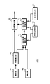
図18は、無人飛行体にシステムを適用した場合の構成を例示している。(地面の模様など)に基づいて自己位置推定を行う場合の概念図を示している。無人飛行体40には、撮像部41、測距部42、物体検出部43、物体位置検出部44、情報記憶部45、姿勢検出部46、見え情報生成部47、位置算出部48が設けられている。また、無人飛行体40には、無人飛行体の制御を行う飛行制御部等が設けられている。
FIG. 18 illustrates the configuration when the system is applied to an unmanned aerial vehicle. The conceptual diagram in the case of performing a self-position estimation based on (the ground pattern etc.) is shown. The unmanned air vehicle 40 is provided with an imaging unit 41, a distance measurement unit 42, an object detection unit 43, an object position detection unit 44, an information storage unit 45, an attitude detection unit 46, an appearance information generation unit 47, and a position calculation unit 48. ing. In addition, the unmanned air vehicle 40 is provided with a flight control unit or the like that controls the unmanned air vehicle.
撮像部41は、対象物体を表す物体情報を取得する。物体情報は、上述のように対象物体を外から観測して取得できる外的特徴を示す情報である。撮像部41としては、三原色の撮像画を得られるカラーカメラ、白黒の撮像画を得られる白黒カメラ、対象物体の温度を示す温度画像を得られる赤外線カメラ等が用いられる。なお、撮像部41で対象物体を表す物体情報の取得する際のパラメータ情報、例えば撮像部41の姿勢とセンサ視野角や焦点距離等のカメラパラメータは、情報記憶部45に記憶される。
The imaging unit 41 acquires object information representing a target object. Object information is information indicating an external feature that can be acquired by observing the target object from the outside as described above. As the imaging unit 41, a color camera capable of obtaining captured images of three primary colors, a black and white camera capable of obtaining black and white captured images, an infrared camera capable of obtaining a temperature image indicating the temperature of a target object, etc. are used. Note that parameter information at the time of acquisition of object information representing a target object by the imaging unit 41, for example, the posture of the imaging unit 41 and camera parameters such as sensor viewing angle and focal length are stored in the information storage unit 45.
測距部42は、地面までの距離を測定するためのセンサである。測距部42としては、ステレオカメラ、像面位相差画素を有するイメージセンサを用いることで撮像画と測距情報を取得できるカメラ、TOF(Time of Flight)センサ、LIDAR(Light Detection and Ranging、Laser Imaging Detection and Ranging)、RADAR(Radio Detection and Ranging)等が用いられる。
The distance measuring unit 42 is a sensor for measuring the distance to the ground. As the distance measuring unit 42, a stereo camera, a camera capable of acquiring a captured image and distance measurement information by using an image sensor having image plane phase difference pixels, a TOF (Time of Flight) sensor, LIDAR (Light Detection and Ranging, Laser) Imaging Detection and Ranging, RADAR (Radio Detection and Ranging), etc. are used.
物体検出部43は、撮像部41で取得された撮像画をもとに対象物体(地面の模様など)を検出して、検出した対象物体の画像内の位置を出力する。
The object detection unit 43 detects a target object (such as a pattern on the ground) based on the captured image acquired by the imaging unit 41, and outputs the position in the image of the detected target object.
物体位置検出部44は、物体検出部43で検出された対象物体の画像内位置、測距部42で測定された対象物体までの距離、情報記憶部45に記憶されているパラメータ情報と後述する姿勢検出部46で検出された姿勢に基づき、対象物体の三次元位置を推定する。
The object position detection unit 44 will be described later with the position in the image of the target object detected by the object detection unit 43, the distance to the target object measured by the distance measurement unit 42, and parameter information stored in the information storage unit 45. Based on the posture detected by the posture detection unit 46, the three-dimensional position of the target object is estimated.
情報記憶部45は、上述のようにパラメータ情報や物体モデル情報等を記憶している。また、後述するように、位置算出部48で無人飛行体40の自己位置を算出する場合、物体モデル情報には物体モデル毎に物体モデルの位置を示す情報(物体モデル位置情報)が含まれる、
姿勢検出部46は、磁気センサやIMU(Inertial Measurement Unit)センサ等を用いて構成されており、物体モデルを配置する基準面(地面)に対する撮像部41の姿勢を検出する。なお、撮像部41が無人飛行体40に固定されている場合、無人飛行体40の姿勢を利用して撮像部41の姿勢を検出してもよい。 Theinformation storage unit 45 stores parameter information, object model information, and the like as described above. Further, as described later, when the position calculation unit 48 calculates the self position of the unmanned air vehicle 40, the object model information includes information (object model position information) indicating the position of the object model for each object model.
Theposture detection unit 46 is configured using a magnetic sensor, an IMU (Inertial Measurement Unit) sensor, or the like, and detects the posture of the imaging unit 41 with respect to a reference plane (ground) on which the object model is arranged. When the imaging unit 41 is fixed to the unmanned air vehicle 40, the attitude of the unmanned air vehicle 40 may be used to detect the attitude of the imaging unit 41.
姿勢検出部46は、磁気センサやIMU(Inertial Measurement Unit)センサ等を用いて構成されており、物体モデルを配置する基準面(地面)に対する撮像部41の姿勢を検出する。なお、撮像部41が無人飛行体40に固定されている場合、無人飛行体40の姿勢を利用して撮像部41の姿勢を検出してもよい。 The
The
見え情報生成部47は、測距部42で測定された地面までの距離、情報記憶部45に記憶されているパラメータ情報と物体モデル情報、撮像部41の姿勢に基づき、物体モデルがどのように見えるか推定して見え情報を生成する。
The appearance information generation unit 47 determines how the object model is based on the distance to the ground measured by the distance measurement unit 42, the parameter information and the object model information stored in the information storage unit 45, and the attitude of the imaging unit 41. It is estimated whether it is visible or not to generate appearance information.
見え情報生成部47は、地面の位置を基準平面として、物体モデル(地面の模様)を基準平面上に重なるように配置する。撮像部41に対する姿勢については、姿勢検出部46の検出結果に基づき物体モデルの候補を選択して配置する。なお、姿勢検出部46が設けられていないため回転方向の姿勢がわからない場合、図19に示すように物体モデルの候補を複数の姿勢毎に設ける。例えば、図19の(a)に示すように無人飛行体40で物体モデルOBmを撮像する場合、図19の(b)に示す複数の回転方向の偏光モデルOBm1~OBm4を設ける。
The appearance information generation unit 47 arranges the object model (pattern of the ground) on the reference plane so that the position of the ground is a reference plane. As for the posture with respect to the imaging unit 41, candidates for the object model are selected and arranged based on the detection result of the posture detection unit 46. If the posture detection unit 46 is not provided and the posture in the rotation direction is not known, candidate object models are provided for each of a plurality of postures as shown in FIG. For example, as shown in FIG. 19A, when imaging an object model OBm with the unmanned air vehicle 40, polarization models OBm1 to OBm4 of a plurality of rotational directions shown in FIG. 19B are provided.
見え情報生成部47は、撮像部41の姿勢とパラメータ情報に基づき、三次元空間における撮像部41の視野領域を求める。さらに見え情報生成部47は、基準平面に対する撮像部41の姿勢を求め、撮像部41の基準平面における視野領域を求める。なお、物体モデルは基準平面上にあると仮定しているので視野領域はこの時点で二次元領域となる。図20は、視野領域を例示した図である。
The appearance information generation unit 47 obtains a visual field area of the imaging unit 41 in a three-dimensional space based on the posture of the imaging unit 41 and the parameter information. Further, the appearance information generation unit 47 obtains the attitude of the imaging unit 41 with respect to the reference plane, and obtains the visual field area in the reference plane of the imaging unit 41. Since the object model is assumed to be on the reference plane, the field of view becomes a two-dimensional area at this point. FIG. 20 is a diagram illustrating a visual field area.
見え情報生成部47は、物体モデルと視野領域の重なりから見え情報を生成する。見え情報生成部47は、複数配置した物体モデルと視野領域の重なり、すなわち二次元領域同士の重なりを求めて見え情報とする。図21は見え情報を例示している。例えば、図21の(a)に示すように撮像部41で上空から物体モデルを撮像した場合、例えば図21の(b)に示す見え情報GVm1~GVm5が生成される。
The appearance information generation unit 47 generates appearance information from the overlap of the object model and the visual field area. The appearance information generation unit 47 obtains an overlap of a plurality of arranged object models and a view area, that is, an overlap of two-dimensional areas, and sets the appearance information. FIG. 21 illustrates the appearance information. For example, as shown in (a) of FIG. 21, when an image of an object model is captured from above by the imaging unit 41, for example, appearance information GVm1 to GVm5 shown in (b) of FIG. 21 are generated.
位置算出部48は、見え情報生成部47で生成された見え情報と物体検出部43で検出された対象物体を比較して、検出された対象物体と一致する見え情報に対応する物体モデルの物体モデル位置情報を利用して、無人飛行体40の自己位置を算出する。
The position calculation unit 48 compares the appearance information generated by the appearance information generation unit 47 with the target object detected by the object detection unit 43, and an object model of an object model corresponding to the appearance information that matches the detected target object. The self position of the unmanned air vehicle 40 is calculated using the model position information.
図22は、複数の物体モデルの見え情報を例示している。本技術の他の動作では、図22の(a)に示すように、物体モデルOBmaについて例えば物体見え情報GVma1,GVma2が生成される。同様に、物体モデルOBmb,OBmcについても見え情報GVmb1,GVmb2,GVmc1,GVmc2が生成される。位置算出部48は、検出された対象物体を示す入力画像GDと見え情報を比較することで、検出された対象物体が物体モデルOBmaであることを正しく識別できる。なお、図22の(b)は従来の技術を用いた場合であり、物体モデルOBma,OBmb,OBmcの画像と検出された物体を示す入力画像GDとを比較しても、画像は相違することから、検出された物体が物体モデルOBmaであることを判別できない。
FIG. 22 illustrates the appearance information of a plurality of object models. In another operation of the present technology, for example, object appearance information GVma1 and GVma2 are generated for an object model OBma as shown in (a) of FIG. Similarly, appearance information GVmb1, GVmb2, GVmc1, and GVmc2 are generated for the object models OBmb and OBmc. The position calculation unit 48 can correctly identify that the detected target object is the object model OBma by comparing the appearance information with the input image GD indicating the detected target object. FIG. 22 (b) shows the case where the conventional technique is used, and the images are different even when the images of the object models OBma, OBmb, OBmc and the input image GD showing the detected object are compared. Therefore, it can not be determined that the detected object is the object model OBma.
位置算出部48は、対象物体と判別された物体モデルの物体モデル位置情報と、姿勢検出部46で検出した姿勢と地面までの距離、入力画像GDと一致した見え情報の回転情報に基づき、無人飛行体40の自己位置を算出する。図23は、自己位置の算出動作を説明するための図である。例えば、位置算出部48は、入力画像GDと一致した見え情報(例えば図22に示すGVma2)に基づき、物体モデルに対する無人飛行体40の方向FPが明らかである。また、入力画像GDと一致した見え情報に基づき、物体モデルの中心位置PMから見え情報の中心位置PVまでの位置差が明らかである。位置算出部48は、姿勢検出部46で検出した傾きθと物体までの距離LDに基づき、無人飛行体40からの垂線と地表面との交点PPから見え情報の中心位置PVまでの距離LMを算出する。さらに、位置算出部48は、物体モデルの中心位置PMに対する見え情報の中心位置PVの位置差情報と、中心位置PVから方向FPに距離LMだけ離れた位置を示す位置差情報に基づき、入力画像GDと一致した見え情報に対応する物体モデルの位置情報から交点PPの位置情報を算出して無人飛行体40の自己位置とする。
The position calculation unit 48 is unmanned based on object model position information of an object model determined to be a target object, the distance between the posture detected by the posture detection unit 46 and the ground, and rotation information of appearance information that matches the input image GD. The self position of the flying object 40 is calculated. FIG. 23 is a diagram for explaining the calculation operation of the self position. For example, the position calculating unit 48 determines the direction FP of the unmanned air vehicle 40 with respect to the object model based on the appearance information (for example, GVma2 shown in FIG. 22) that matches the input image GD. Further, based on the appearance information matched with the input image GD, the position difference from the center position PM of the object model to the center position PV of the appearance information is clear. Based on the inclination θ detected by the attitude detection unit 46 and the distance LD to the object, the position calculation unit 48 calculates the distance LM from the intersection point PP between the perpendicular from the unmanned air vehicle 40 and the ground surface to the center position PV of the visibility information. calculate. Furthermore, the position calculation unit 48 is an input image based on position difference information of the center position PV of the appearance information with respect to the center position PM of the object model and position difference information indicating a position away from the center position PV by the distance LM in the direction FP. The position information of the intersection point PP is calculated from the position information of the object model corresponding to the appearance information matched with the GD, and is made the self-position of the unmanned air vehicle 40.
このような処理を行えば、無人飛行体40に測位信号を受信する機能が設けられていない場合や、測位信号に基づき自己位置の算出に時間を要する場合であっても、地面の撮像画と測距情報および無人飛行体40の姿勢等に基づき、容易に自己位置を判別できるようになる。
If such processing is performed, even if the unmanned air vehicle 40 is not provided with the function of receiving the positioning signal, or even if it takes time to calculate its own position based on the positioning signal, Based on the distance measurement information and the attitude of the unmanned air vehicle 40, it is possible to easily determine the self position.
なお、上述の各動作の説明では、物体モデルOBmが大きさを持った二次元情報と仮定したが、物体モデルOBmは三次元情報であってもよい。この場合、見え情報は立体形状部分の見えの違いを示すことになる。このため、例えば正面から見た状態は類似しているが側面から見た状態は凹凸が異なる形状の物体を正しく区別して識別できるようになる。したがって、物体モデルOBmが二次元情報である場合に比べて、さらに精度よく物体の識別等を行うことができる。なお、物体モデルOBmを二次元情報とした場合は、三次元情報である場合に比べて見え情報の生成が容易であり、物体識別や自己位置の判別等を行うために必要な処理コストを低くできる。
In the above description of each operation, the object model OBm is assumed to be two-dimensional information having a size, but the object model OBm may be three-dimensional information. In this case, the appearance information indicates the difference in the appearance of the three-dimensional shape portion. For this reason, for example, the state seen from the front is similar, but the state seen from the side makes it possible to correctly distinguish and distinguish objects having shapes with different irregularities. Therefore, as compared with the case where the object model OBm is two-dimensional information, identification of an object can be performed with higher accuracy. Note that when the object model OBm is two-dimensional information, generation of the appearance information is easier than in the case of three-dimensional information, and the processing cost necessary for performing object identification, discrimination of the self position, etc. is low. it can.
また、本開示に係る技術によれば、上述したように対象物体の識別精度を向上できる。したがって、例えば、自動車、電気自動車、ハイブリッド電気自動車、自動二輪車、自転車、パーソナルモビリティ、飛行機、ドローン、船舶、ロボット、建設機械、農業機械(トラクター)などのいずれかの種類の移動体に本技術を用いれば、自律移動等を行う際に周辺状況の確認を精度よく行える。また、本技術を用いることで高精度の監視システム等を構築することも可能となる。
Further, according to the technology according to the present disclosure, as described above, the identification accuracy of the target object can be improved. Therefore, for example, this technology is applied to any type of mobile object such as a car, an electric car, a hybrid electric car, a motorcycle, a bicycle, personal mobility, an airplane, a drone, a ship, a robot, a construction machine, and an agricultural machine (tractor). If used, it is possible to accurately check the surrounding situation when performing autonomous movement and the like. In addition, by using the present technology, it is also possible to construct a highly accurate monitoring system or the like.
明細書中において説明した一連の処理はハードウェア、またはソフトウェア、あるいは両者の複合構成によって実行することが可能である。ソフトウェアによる処理を実行する場合は、処理シーケンスを記録したプログラムを、専用のハードウェアに組み込まれたコンピュータ内のメモリにインストールして実行させる。または、各種処理が実行可能な汎用コンピュータにプログラムをインストールして実行させることが可能である。
The series of processes described in the specification can be performed by hardware, software, or a combination of both. In the case of executing processing by software, a program recording the processing sequence is installed and executed in a memory in a computer incorporated in dedicated hardware. Alternatively, the program can be installed and executed on a general-purpose computer that can execute various processes.
例えば、プログラムは記録媒体としてのハードディスクやSSD(Solid State Drive)、ROM(Read Only Memory)に予め記録しておくことができる。あるいは、プログラムはフレキシブルディスク、CD-ROM(Compact Disc Read Only Memory),MO(Magneto optical)ディスク,DVD(Digital Versatile Disc)、BD(Blu-Ray Disc(登録商標))、磁気ディスク、半導体メモリカード等のリムーバブル記録媒体に、一時的または永続的に格納(記録)しておくことができる。このようなリムーバブル記録媒体は、いわゆるパッケージソフトウェアとして提供することができる。
For example, the program can be recorded in advance on a hard disk or a solid state drive (SSD) as a recording medium, or a read only memory (ROM). Alternatively, the program may be a flexible disk, a compact disc read only memory (CD-ROM), a magneto optical (MO) disc, a digital versatile disc (DVD), a BD (Blu-Ray Disc (registered trademark)), a magnetic disc, a semiconductor memory card Etc. can be stored (recorded) temporarily or permanently on a removable recording medium such as Such removable recording media can be provided as so-called package software.
また、プログラムは、リムーバブル記録媒体からコンピュータにインストールする他、ダウンロードサイトからLAN(Local Area Network)やインターネット等のネットワークを介して、コンピュータに無線または有線で転送してもよい。コンピュータでは、そのようにして転送されてくるプログラムを受信し、内蔵するハードディスク等の記録媒体にインストールすることができる。
The program may be installed from the removable recording medium to the computer, or may be transferred from the download site to the computer wirelessly or by wire via a network such as a LAN (Local Area Network) or the Internet. The computer can receive the program transferred in such a manner, and install the program on a recording medium such as a built-in hard disk.
なお、本明細書に記載した効果はあくまで例示であって限定されるものではなく、記載されていない付加的な効果があってもよい。また、本技術は、上述した技術の実施の形態に限定して解釈されるべきではない。この技術の実施の形態は、例示という形態で本技術を開示しており、本技術の要旨を逸脱しない範囲で当業者が実施の形態の修正や代用をなし得ることは自明である。すなわち、本技術の要旨を判断するためには、請求の範囲を参酌すべきである。
In addition, the effect described in this specification is an illustration to the last, is not limited, and may have an additional effect which is not described. In addition, the present technology should not be construed as being limited to the embodiments of the above-described technology. The embodiments of this technology disclose the present technology in the form of exemplification, and it is obvious that those skilled in the art can modify or substitute the embodiments within the scope of the present technology. That is, in order to determine the gist of the present technology, the claims should be taken into consideration.
また、本技術の情報処理装置は以下のような構成も取ることができる。
(1) 対象物体の位置を示す位置情報と、前記対象物体を表す物体情報の取得に関するパラメータ情報に基づいて、前記物体情報を取得した情報取得位置からの前記対象物体の位置に設けた物体モデルの見えを表す見え情報を生成する見え情報生成部
を備える情報処理装置。
(2) 前記見え情報生成部は、前記物体情報を取得するセンサ部の視野領域と前記物体モデルの重なりから前記物体モデルの見えを判別して、前記見え情報を生成する(1)に記載の情報処理装置。
(3) 前記見え情報生成部は、前記視野領域と前記物体モデルが重なる領域に対して透視投影変換を行い、前記見え情報を生成する(2)に記載の情報処理装置。
(4) 前記見え情報生成部は、前記パラメータ情報で示された前記センサ部の位置と姿勢およびセンサパラメータに基づき前記視野領域を判別する(2)または(3)に記載の情報処理装置。
(5) 前記見え情報生成部は、前記視野領域と前記物体モデルの重複領域に含まれており、前記対象物体よりも手前に位置する非対象物体の領域を、前記見え情報から除外する(2)乃至(4)の何れかに記載の情報処理装置。
(6) 前記物体情報が示す前記対象物体の撮像画における前記対象物体の位置と、前記物体情報の取得位置から前記対象物体までの距離と前記パラメータ情報に基づいて、前記対象物体の位置を検出する物体位置検出部をさらに備える(1)乃至(5)の何れかに記載の情報処理装置。
(7) 前記対象物体の位置を示す位置情報は、前記物体情報が示す前記対象物体までの測距値を示す点群データを前記測距値に応じてクラスタリングして検出したクラスタの位置を示す情報である(1)乃至(6)の何れかに記載の情報処理装置。
(8) 前記見え情報生成部で生成された物体モデル毎の見え情報を用いて前記対象物体の識別を行う物体識別部をさらに備える(1)乃至(7)の何れかに記載の情報処理装置。
(9) 前記見え情報生成部は、前記物体モデルを配置する基準面に対する前記センサ部の姿勢に基づき、前記見え情報を生成する(1)に記載の情報処理装置。
(10) 前記物体モデルの位置情報と前記対象物体に一致する見え情報および前記センサ部の姿勢に基づき、前記センサ部の位置を算出する位置算出部をさらに備える(9)に記載の情報処理装置。
(11) 前記センサ部のロール方向の姿勢変化量を取得できない場合、前記物体モデルを前記ロール方向に異なる姿勢毎に設ける(9)または(10)に記載の情報処理装置。
(12) 前記センサ部は飛行体に設けられている(9)乃至(11)の何れかに記載の情報処理装置。 In addition, the information processing device of the present technology can also have the following configuration.
(1) An object model provided at a position of the target object from an information acquisition position at which the object information is acquired based on position information indicating the position of the target object and parameter information on acquisition of object information representing the target object An information processing apparatus comprising: an appearance information generation unit configured to generate appearance information representing an appearance of
(2) The appearance information generation unit determines the appearance of the object model from the overlap of the visual field area of the sensor unit that acquires the object information and the object model, and generates the appearance information (1). Information processing device.
(3) The information processing apparatus according to (2), wherein the appearance information generation unit performs perspective projection conversion on an area where the visual field area and the object model overlap with each other to generate the appearance information.
(4) The information processing apparatus according to (2) or (3), wherein the appearance information generation unit determines the visual field area based on the position and orientation of the sensor unit indicated by the parameter information and sensor parameters.
(5) The appearance information generation unit excludes, from the appearance information, the area of the non-target object that is included in the overlapping area of the visual field area and the object model and is located in front of the target object. The information processing apparatus according to any one of (4) to (4).
(6) The position of the target object is detected based on the position of the target object in the captured image of the target object indicated by the object information, the distance from the acquisition position of the object information to the target object, and the parameter information An information processing apparatus according to any one of (1) to (5), further including an object position detection unit.
(7) The position information indicating the position of the target object indicates the position of a cluster detected by clustering point cloud data indicating the distance measurement value to the target object indicated by the object information according to the distance measurement value. The information processing apparatus according to any one of (1) to (6), which is information.
(8) The information processing apparatus according to any one of (1) to (7), further including: an object identification unit that identifies the target object using the appearance information of each object model generated by the appearance information generation unit. .
(9) The information processing apparatus according to (1), wherein the appearance information generation unit generates the appearance information based on an attitude of the sensor unit with respect to a reference plane on which the object model is arranged.
(10) The information processing apparatus according to (9), further including: a position calculation unit that calculates the position of the sensor unit based on position information of the object model, appearance information that matches the target object, and an attitude of the sensor unit. .
(11) The information processing apparatus according to (9) or (10), wherein the object model is provided for each posture different in the roll direction when the posture change amount in the roll direction of the sensor unit can not be acquired.
(12) The information processing apparatus according to any one of (9) to (11), wherein the sensor unit is provided on a flying object.
この技術の情報処理装置と情報処理方法およびプログラムによれば、対象物体の位置を示す位置情報と、前記対象物体を表す物体情報の取得に関するパラメータ情報に基づいて、物体情報を取得した情報取得位置からの対象物体の位置に設けた物体モデルの見えを表す見え情報が生成される、したがって、情報取得位置から取得した対象物体の情報と見え情報を比較することで、対象物体の識別精度を向上できるので、各種センサを搭載した移動体例えばロボットや車両,飛行体等に適用すれば、周辺状況や自己位置等を高精度に把握できるようになる。
According to the information processing apparatus, the information processing method, and the program of this technology, an information acquisition position at which object information is acquired based on position information indicating a position of a target object and parameter information related to acquisition of object information representing the target object The appearance information representing the appearance of the object model provided at the position of the target object from is generated. Therefore, the identification accuracy of the target object is improved by comparing the information of the target object acquired from the information acquisition position with the appearance information. Therefore, if applied to a mobile body equipped with various sensors, such as a robot, a vehicle, or an aircraft, it is possible to grasp the surrounding situation and the self position with high accuracy.
10,20・・・システム
11,41・・・撮像部
12,21,42・・・測距部
13,43・・・物体検出部
14,44・・・物体位置検出部
15,25,45・・・情報記憶部
17,27,47・・・見え情報生成部
18,28・・・物体識別部
22・・・クラスタリング部
31・・・付属器具
40・・・無人飛行体
46・・・姿勢検出部
48・・・位置算出部 10, 20:System 11, 41: Imaging unit 12, 21, 42: Ranging unit 13, 43: Object detection unit 14, 44: Object position detection unit 15, 25, 45 ... Information storage unit 17, 27, 47 ... Appearance information generation unit 18, 28 ... Object identification unit 22 ... Clustering unit 31 ... Accessories 40 ... Unmanned air vehicle 46 ... Posture detection unit 48 ··· Position calculation unit
11,41・・・撮像部
12,21,42・・・測距部
13,43・・・物体検出部
14,44・・・物体位置検出部
15,25,45・・・情報記憶部
17,27,47・・・見え情報生成部
18,28・・・物体識別部
22・・・クラスタリング部
31・・・付属器具
40・・・無人飛行体
46・・・姿勢検出部
48・・・位置算出部 10, 20:
Claims (14)
- 対象物体の位置を示す位置情報と、前記対象物体を表す物体情報の取得に関するパラメータ情報に基づいて、前記物体情報を取得した情報取得位置からの前記対象物体の位置に設けた物体モデルの見えを表す見え情報を生成する見え情報生成部
を備える情報処理装置。 The appearance of an object model provided at the position of the target object from the information acquisition position at which the object information is acquired based on position information indicating the position of the target object and parameter information on acquisition of object information representing the target object An information processing apparatus, comprising: an appearance information generation unit configured to generate appearance information to be represented. - 前記見え情報生成部は、前記物体情報を取得するセンサ部の視野領域と前記物体モデルの重なりから前記物体モデルの見えを判別して、前記見え情報を生成する
請求項1に記載の情報処理装置。 The information processing apparatus according to claim 1, wherein the appearance information generation unit generates the appearance information by determining the appearance of the object model from the overlapping of the visual field area of the sensor unit that acquires the object information and the object model. . - 前記見え情報生成部は、前記視野領域と前記物体モデルが重なる領域に対して透視投影変換を行い、前記見え情報を生成する
請求項2に記載の情報処理装置。 The information processing apparatus according to claim 2, wherein the appearance information generation unit performs perspective projection conversion on an area where the visual field area and the object model overlap to generate the appearance information. - 前記見え情報生成部は、前記パラメータ情報で示された前記センサ部の位置と姿勢およびセンサパラメータに基づき前記視野領域を判別する
請求項2に記載の情報処理装置。 The information processing apparatus according to claim 2, wherein the appearance information generation unit determines the visual field area based on a position and an attitude of the sensor unit indicated by the parameter information and a sensor parameter. - 前記見え情報生成部は、前記視野領域と前記物体モデルの重複領域に含まれており、前記対象物体よりも手前に位置する非対象物体の領域を、前記見え情報から除外する
請求項2に記載の情報処理装置。 The appearance information generation unit according to claim 2, wherein the area of the non-target object which is included in the overlapping area of the visual field area and the object model and which is located in front of the target object is excluded from the appearance information. Information processing equipment. - 前記物体情報が示す前記対象物体の撮像画における前記対象物体の位置と、前記物体情報の取得位置から前記対象物体までの距離と前記パラメータ情報に基づいて、前記対象物体の位置を検出する物体位置検出部をさらに備える
請求項1に記載の情報処理装置。 An object position for detecting the position of the target object based on the position of the target object in the captured image of the target object indicated by the object information, the distance from the acquisition position of the object information to the target object, and the parameter information The information processing apparatus according to claim 1, further comprising a detection unit. - 前記対象物体の位置を示す位置情報は、前記物体情報が示す前記対象物体までの測距値を示す点群データを前記測距値に応じてクラスタリングして検出したクラスタの位置を示す情報である
請求項1に記載の情報処理装置。 The position information indicating the position of the target object is information indicating the position of a cluster detected by clustering point cloud data indicating the distance measurement value to the target object indicated by the object information according to the distance measurement value. An information processing apparatus according to claim 1. - 前記見え情報生成部で生成された物体モデル毎の見え情報を用いて前記対象物体の識別を行う物体識別部をさらに備える
請求項1に記載の情報処理装置。 The information processing apparatus according to claim 1, further comprising an object identification unit that identifies the target object using the appearance information of each object model generated by the appearance information generation unit. - 前記見え情報生成部は、前記物体モデルを配置する基準面に対する前記センサ部の姿勢に基づき、前記見え情報を生成する
請求項1に記載の情報処理装置。 The information processing apparatus according to claim 1, wherein the appearance information generation unit generates the appearance information based on an attitude of the sensor unit with respect to a reference plane on which the object model is arranged. - 前記物体モデルの位置情報と前記対象物体に一致する見え情報および前記センサ部の姿勢に基づき、前記センサ部の位置を算出する位置算出部をさらに備える
請求項9に記載の情報処理装置。 10. The information processing apparatus according to claim 9, further comprising: a position calculation unit that calculates the position of the sensor unit based on position information of the object model, appearance information that matches the target object, and an attitude of the sensor unit. - 前記センサ部のロール方向の姿勢変化量を取得できない場合、前記物体モデルを前記ロール方向に異なる姿勢毎に設ける
請求項9に記載の情報処理装置。 The information processing apparatus according to claim 9, wherein the object model is provided for each posture that is different in the roll direction when the posture change amount in the roll direction of the sensor unit can not be acquired. - 前記センサ部は飛行体に設けられている
請求項9に記載の情報処理装置。 The information processing apparatus according to claim 9, wherein the sensor unit is provided to a flying object. - 対象物体の位置を示す位置情報と、前記対象物体を表す物体情報の取得に関するパラメータ情報に基づいて、前記物体情報を取得した情報取得位置からの前記対象物体の位置に設けた物体モデルの見えを表す見え情報を生成すること
を含む情報処理方法。 The appearance of an object model provided at the position of the target object from the information acquisition position at which the object information is acquired based on position information indicating the position of the target object and parameter information on acquisition of object information representing the target object An information processing method including generating appearance information to represent. - 対象物体に関する情報処理をコンピュータで実行させるプログラムであって、
前記対象物体の位置を示す位置情報と、前記対象物体を表す物体情報の取得に関するパラメータ情報に基づいて、前記物体情報を取得した情報取得位置からの前記対象物体の位置に設けた物体モデルの見えを表す見え情報を生成する手順
を前記コンピュータで実行させるプログラム。 A program that causes a computer to execute information processing related to a target object, and
The appearance of an object model provided at the position of the target object from the information acquisition position at which the object information is acquired based on position information indicating the position of the target object and parameter information on acquisition of object information representing the target object A program causing the computer to execute a procedure of generating appearance information representing.
Priority Applications (4)
| Application Number | Priority Date | Filing Date | Title |
|---|---|---|---|
| JP2019549925A JP7127651B2 (en) | 2017-11-06 | 2018-09-12 | Information processing device, information processing method and program |
| US16/760,122 US11282230B2 (en) | 2017-11-06 | 2018-09-12 | Information processing apparatus, information processing method, and program |
| CN201880070874.0A CN111295663A (en) | 2017-11-06 | 2018-09-12 | Information processing apparatus, information processing method, and program |
| EP18872303.5A EP3709261A4 (en) | 2017-11-06 | 2018-09-12 | Information processing device, information processing method, and program |
Applications Claiming Priority (2)
| Application Number | Priority Date | Filing Date | Title |
|---|---|---|---|
| JP2017213593 | 2017-11-06 | ||
| JP2017-213593 | 2017-11-06 |
Publications (1)
| Publication Number | Publication Date |
|---|---|
| WO2019087581A1 true WO2019087581A1 (en) | 2019-05-09 |
Family
ID=66331629
Family Applications (1)
| Application Number | Title | Priority Date | Filing Date |
|---|---|---|---|
| PCT/JP2018/033801 WO2019087581A1 (en) | 2017-11-06 | 2018-09-12 | Information processing device, information processing method, and program |
Country Status (5)
| Country | Link |
|---|---|
| US (1) | US11282230B2 (en) |
| EP (1) | EP3709261A4 (en) |
| JP (1) | JP7127651B2 (en) |
| CN (1) | CN111295663A (en) |
| WO (1) | WO2019087581A1 (en) |
Cited By (1)
| Publication number | Priority date | Publication date | Assignee | Title |
|---|---|---|---|---|
| WO2022176732A1 (en) * | 2021-02-22 | 2022-08-25 | パナソニックIpマネジメント株式会社 | Person-detecting system, detection method, and program |
Families Citing this family (1)
| Publication number | Priority date | Publication date | Assignee | Title |
|---|---|---|---|---|
| WO2016074169A1 (en) * | 2014-11-12 | 2016-05-19 | 深圳市大疆创新科技有限公司 | Target detecting method, detecting device, and robot |
Citations (4)
| Publication number | Priority date | Publication date | Assignee | Title |
|---|---|---|---|---|
| JP2005033319A (en) * | 2003-07-08 | 2005-02-03 | Canon Inc | Position and orientation measurement method and apparatus |
| JP2007072665A (en) | 2005-09-06 | 2007-03-22 | Fujitsu Ten Ltd | Object discrimination device, object discrimination method and object discrimination program |
| WO2013008584A1 (en) * | 2011-07-14 | 2013-01-17 | 株式会社エヌ・ティ・ティ・ドコモ | Object display device, object display method, and object display program |
| JP2016136320A (en) | 2015-01-23 | 2016-07-28 | トヨタ自動車株式会社 | robot |
Family Cites Families (5)
| Publication number | Priority date | Publication date | Assignee | Title |
|---|---|---|---|---|
| WO2014010004A1 (en) * | 2012-07-13 | 2014-01-16 | 株式会社ソニー・コンピュータエンタテインメント | Input device, information processing system, information processing device and information processing method |
| JP6314394B2 (en) * | 2013-09-13 | 2018-04-25 | 富士通株式会社 | Information processing apparatus, setting method, setting program, system, and management apparatus |
| IL232853A (en) * | 2014-05-28 | 2015-11-30 | Elbit Systems Land & C4I Ltd | Method and system for image georegistration |
| US10282861B2 (en) * | 2016-12-12 | 2019-05-07 | Here Global B.V. | Pose error estimation and localization using static features |
| US10410089B2 (en) * | 2018-01-19 | 2019-09-10 | Seiko Epson Corporation | Training assistance using synthetic images |
-
2018
- 2018-09-12 WO PCT/JP2018/033801 patent/WO2019087581A1/en unknown
- 2018-09-12 US US16/760,122 patent/US11282230B2/en active Active
- 2018-09-12 EP EP18872303.5A patent/EP3709261A4/en not_active Withdrawn
- 2018-09-12 JP JP2019549925A patent/JP7127651B2/en active Active
- 2018-09-12 CN CN201880070874.0A patent/CN111295663A/en active Pending
Patent Citations (4)
| Publication number | Priority date | Publication date | Assignee | Title |
|---|---|---|---|---|
| JP2005033319A (en) * | 2003-07-08 | 2005-02-03 | Canon Inc | Position and orientation measurement method and apparatus |
| JP2007072665A (en) | 2005-09-06 | 2007-03-22 | Fujitsu Ten Ltd | Object discrimination device, object discrimination method and object discrimination program |
| WO2013008584A1 (en) * | 2011-07-14 | 2013-01-17 | 株式会社エヌ・ティ・ティ・ドコモ | Object display device, object display method, and object display program |
| JP2016136320A (en) | 2015-01-23 | 2016-07-28 | トヨタ自動車株式会社 | robot |
Non-Patent Citations (1)
| Title |
|---|
| See also references of EP3709261A4 |
Cited By (3)
| Publication number | Priority date | Publication date | Assignee | Title |
|---|---|---|---|---|
| WO2022176732A1 (en) * | 2021-02-22 | 2022-08-25 | パナソニックIpマネジメント株式会社 | Person-detecting system, detection method, and program |
| JPWO2022176732A1 (en) * | 2021-02-22 | 2022-08-25 | ||
| JP7304603B2 (en) | 2021-02-22 | 2023-07-07 | パナソニックIpマネジメント株式会社 | Human detection system, human detection method and program |
Also Published As
| Publication number | Publication date |
|---|---|
| JPWO2019087581A1 (en) | 2020-11-12 |
| EP3709261A1 (en) | 2020-09-16 |
| US11282230B2 (en) | 2022-03-22 |
| JP7127651B2 (en) | 2022-08-30 |
| US20200258253A1 (en) | 2020-08-13 |
| EP3709261A4 (en) | 2020-12-09 |
| CN111295663A (en) | 2020-06-16 |
Similar Documents
| Publication | Publication Date | Title |
|---|---|---|
| KR101776622B1 (en) | Apparatus for recognizing location mobile robot using edge based refinement and method thereof | |
| JP4739004B2 (en) | Information processing apparatus and information processing method | |
| TWI827649B (en) | Apparatuses, systems and methods for vslam scale estimation | |
| KR101072876B1 (en) | Method and apparatus for estimating position in a mobile robot | |
| US9704248B2 (en) | Position and orientation measuring apparatus, information processing apparatus and information processing method | |
| TWI496108B (en) | AR image processing apparatus and method | |
| JP6658001B2 (en) | Position estimation device, program, position estimation method | |
| US20160238394A1 (en) | Device for Estimating Position of Moving Body and Method for Estimating Position of Moving Body | |
| JPWO2016181687A1 (en) | Image processing apparatus, image processing method, and program | |
| KR20110122022A (en) | Apparatus for building map and method thereof | |
| CN108603933A (en) | The system and method exported for merging the sensor with different resolution | |
| WO2019087581A1 (en) | Information processing device, information processing method, and program | |
| Bazin et al. | UAV attitude estimation by vanishing points in catadioptric images | |
| Shimizu et al. | LIDAR-based body orientation estimation by integrating shape and motion information | |
| WO2020105499A1 (en) | Image processing device, image processing method, and program | |
| JP5230354B2 (en) | POSITIONING DEVICE AND CHANGED BUILDING DETECTION DEVICE | |
| WO2019016879A1 (en) | Object detection device and object detection method | |
| JP2021047744A (en) | Information processing device, information processing method and information processing program | |
| JP2017182564A (en) | Positioning device, positioning method, and positioning computer program | |
| Zaslavskiy et al. | Method for automated data collection for 3d reconstruction | |
| CN117649619B (en) | Unmanned aerial vehicle visual navigation positioning recovery method, system, device and readable storage medium | |
| US20240083038A1 (en) | Assistance system, image processing device, assistance method and non-transitory computer-readable storage medium | |
| US20220291009A1 (en) | Information processing apparatus, information processing method, and storage medium | |
| JP7309097B2 (en) | POSITION DETECTION DEVICE, POSITION DETECTION METHOD, AND POSITION DETECTION PROGRAM | |
| JP2018195965A (en) | Flying object position detection apparatus, flying object position detection system, flying object position detection method, and program |
Legal Events
| Date | Code | Title | Description |
|---|---|---|---|
| 121 | Ep: the epo has been informed by wipo that ep was designated in this application |
Ref document number: 18872303 Country of ref document: EP Kind code of ref document: A1 |
|
| ENP | Entry into the national phase |
Ref document number: 2019549925 Country of ref document: JP Kind code of ref document: A |
|
| NENP | Non-entry into the national phase |
Ref country code: DE |
|
| ENP | Entry into the national phase |
Ref document number: 2018872303 Country of ref document: EP Effective date: 20200608 |