WO2019087513A1 - Information processing device, information processing method, and program - Google Patents
Information processing device, information processing method, and program Download PDFInfo
- Publication number
- WO2019087513A1 WO2019087513A1 PCT/JP2018/029985 JP2018029985W WO2019087513A1 WO 2019087513 A1 WO2019087513 A1 WO 2019087513A1 JP 2018029985 W JP2018029985 W JP 2018029985W WO 2019087513 A1 WO2019087513 A1 WO 2019087513A1
- Authority
- WO
- WIPO (PCT)
- Prior art keywords
- virtual object
- display
- information processing
- real
- processing apparatus
- Prior art date
Links
Images


Classifications
-
- G—PHYSICS
- G06—COMPUTING; CALCULATING OR COUNTING
- G06V—IMAGE OR VIDEO RECOGNITION OR UNDERSTANDING
- G06V40/00—Recognition of biometric, human-related or animal-related patterns in image or video data
- G06V40/10—Human or animal bodies, e.g. vehicle occupants or pedestrians; Body parts, e.g. hands
- G06V40/103—Static body considered as a whole, e.g. static pedestrian or occupant recognition
-
- G—PHYSICS
- G06—COMPUTING; CALCULATING OR COUNTING
- G06F—ELECTRIC DIGITAL DATA PROCESSING
- G06F3/00—Input arrangements for transferring data to be processed into a form capable of being handled by the computer; Output arrangements for transferring data from processing unit to output unit, e.g. interface arrangements
- G06F3/01—Input arrangements or combined input and output arrangements for interaction between user and computer
- G06F3/048—Interaction techniques based on graphical user interfaces [GUI]
- G06F3/0481—Interaction techniques based on graphical user interfaces [GUI] based on specific properties of the displayed interaction object or a metaphor-based environment, e.g. interaction with desktop elements like windows or icons, or assisted by a cursor's changing behaviour or appearance
-
- G—PHYSICS
- G06—COMPUTING; CALCULATING OR COUNTING
- G06F—ELECTRIC DIGITAL DATA PROCESSING
- G06F3/00—Input arrangements for transferring data to be processed into a form capable of being handled by the computer; Output arrangements for transferring data from processing unit to output unit, e.g. interface arrangements
- G06F3/01—Input arrangements or combined input and output arrangements for interaction between user and computer
- G06F3/048—Interaction techniques based on graphical user interfaces [GUI]
- G06F3/0484—Interaction techniques based on graphical user interfaces [GUI] for the control of specific functions or operations, e.g. selecting or manipulating an object, an image or a displayed text element, setting a parameter value or selecting a range
-
- G—PHYSICS
- G06—COMPUTING; CALCULATING OR COUNTING
- G06T—IMAGE DATA PROCESSING OR GENERATION, IN GENERAL
- G06T19/00—Manipulating 3D models or images for computer graphics
- G06T19/006—Mixed reality
-
- G—PHYSICS
- G06—COMPUTING; CALCULATING OR COUNTING
- G06T—IMAGE DATA PROCESSING OR GENERATION, IN GENERAL
- G06T7/00—Image analysis
- G06T7/20—Analysis of motion
-
- G—PHYSICS
- G06—COMPUTING; CALCULATING OR COUNTING
- G06T—IMAGE DATA PROCESSING OR GENERATION, IN GENERAL
- G06T7/00—Image analysis
- G06T7/90—Determination of colour characteristics
-
- G—PHYSICS
- G06—COMPUTING; CALCULATING OR COUNTING
- G06V—IMAGE OR VIDEO RECOGNITION OR UNDERSTANDING
- G06V10/00—Arrangements for image or video recognition or understanding
- G06V10/40—Extraction of image or video features
- G06V10/60—Extraction of image or video features relating to illumination properties, e.g. using a reflectance or lighting model
-
- G—PHYSICS
- G06—COMPUTING; CALCULATING OR COUNTING
- G06V—IMAGE OR VIDEO RECOGNITION OR UNDERSTANDING
- G06V20/00—Scenes; Scene-specific elements
- G06V20/20—Scenes; Scene-specific elements in augmented reality scenes
Definitions
- the present disclosure relates to an information processing device, an information processing method, and a program.
- a technique related to an image processing apparatus including a recognition unit that recognizes a position or a posture of an object shown in an image, and a display control unit that changes display of a virtual object related to the object according to the stability of recognition by the recognition unit (See, for example, Patent Document 1). According to such a technique, it is possible to prevent the user from being confused by the disturbance of the display of the virtual object.
- display delay of the virtual object may occur apart from the disturbance of the display of the virtual object. Furthermore, apart from the display delay, there is also a concept as to how easily the display delay of the virtual object is perceived by the user. Hereinafter, the user's perception of display delay is also referred to as “display delay feeling”.
- the sense of display delay of the virtual object becomes stronger, the sense of discomfort for the delay of display of the virtual object may be increased.
- the visibility of the virtual object may be reduced as the display of the virtual object is largely changed. Then, the technique which can reduce the discomfort with respect to the display of a virtual object is desired, suppressing the fall of the visibility of a virtual object.
- a position acquisition unit that acquires a position of a virtual object in the real space determined based on a recognition result of the real space according to an image captured by an imaging device, a position of the virtual object,
- An information processing apparatus comprising: a display control unit configured to control display of at least a boundary of the virtual object based on features of the real object existing in the real space and separated from the position of the virtual object; .
- An information processing method including controlling display of at least a boundary of the virtual objects based on the position of the virtual object and the features of the real object present in the real space.
- a position acquisition unit that acquires a position of a virtual object determined based on a position of a virtual camera calculated based on a recognition result of a real space according to an image captured by an imaging device according to the present disclosure
- a display control unit configured to control display of at least a boundary of the virtual object based on the position of the virtual object and the feature of the real object existing in the real space.
- a technology capable of reducing a sense of discomfort with respect to display of a virtual object while suppressing a decrease in the visibility of the virtual object.
- the above-mentioned effects are not necessarily limited, and, along with or in place of the above-mentioned effects, any of the effects shown in the present specification, or other effects that can be grasped from the present specification May be played.
- a plurality of components having substantially the same or similar functional configurations may be distinguished by attaching different numerals after the same reference numerals. However, when it is not necessary to distinguish each of a plurality of components having substantially the same or similar functional configuration, only the same reference numeral is given. Also, similar components in different embodiments may be distinguished by attaching different alphabets after the same reference numerals. However, when it is not necessary to distinguish each of similar components in particular, only the same reference numeral is attached.
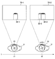
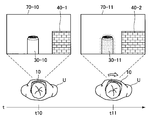
- FIG. 1 is a diagram for describing an overview of an embodiment of the present disclosure.
- a user U is present in the real space.
- the virtual object 30-1 is arranged in the field of view 70-1 of the user U.
- the virtual object 30-1 when the virtual object 30-1 is presented to the user U, it is for visual field analysis based on sensing data obtained by the visual field analysis imaging unit 111 (FIG. 5) (for example, a stereo camera etc.)
- the position and attitude (position of virtual camera) of the imaging unit 111 (FIG. 5) are recognized.
- the position of the virtual camera based on the position of the virtual camera, the position of the virtual object 30-1 in the field of view 70-1 is determined, and the virtual object 30-1 is displayed by the display based on the determined position of the virtual object 30-1. .
- the position of the virtual object is shifted between when the position of the virtual object is determined and when the virtual object is displayed by the display. That is, as shown in the field of view 70-2, the position of the virtual object 30-2 actually displayed by the display is the position 32-2 of the virtual object expected from the position of the virtual camera at the current time (time t2). There is a gap between them. Such a phenomenon is called display delay.
- the display delay feeling As an example, when there is no real object around the virtual object, it is assumed that the virtual object's sense of display delay is small because there is no real object around the virtual object that makes the display delay of the virtual object stand out Ru.
- FIG. 2 is a diagram for describing an overview of an embodiment of the present disclosure.
- a virtual object 30-14 is disposed in the field of view 70-14 of the user U.
- the user U moves his neck to the right from time t14 to time t15. Therefore, the field of view 70-14 is moved to the field of view 70-15.
- the position of the virtual object 30-15 actually displayed by the display is the position 32-15 of the virtual object expected from the position of the virtual camera at the present time (time t15).
- time t15 There is a gap between the Then, since the real object 40-2 exists near the virtual object 30-15, it is assumed that the sense of display delay is large.
- the real object when there is a real object whose luminance is not similar to the virtual object near the virtual object, the real object causes the display delay of the virtual object to be noticeable, so that the virtual object has a large sense of display delay. is assumed.
- the display delay of the virtual object is less noticeable when the virtual object has a movement as compared with the case where the virtual object has no movement, it is assumed that the display object of the virtual object has a smaller sense of display delay.
- FIG. 3 is a diagram for describing an overview of an embodiment of the present disclosure.
- a virtual object 30-16 is arranged in the field of view 70-16 of the user U.
- the user U moves his neck to the right from time t16 to time t17. Therefore, the field of view 70-16 is moved to the field of view 70-17.
- the position of the virtual object 30-17 actually displayed by the display is the position 32-13 of the virtual object expected from the position of the virtual camera at the present time (time t17).
- time t17 There is a gap between the Then, although the real object 40-2 exists near the virtual object 30-15, it is assumed that the sense of display delay is small because the definition of the virtual object 30-17 is lowered.
- a technique is proposed mainly capable of reducing the discomfort with respect to the display of the virtual object while suppressing the decrease in the visibility of the virtual object.
- the information processing apparatus 10 detects the distance between the user U and the real object as an example of the information on the real object.
- the information processing apparatus 10 includes a stereo camera, generates a depth map based on the left image and the right image captured by the stereo camera, and generates a depth map based on the depth map.
- the case of detecting the distance to a real object is mainly assumed.
- the distance between the user U and the real object may be detected in any way.
- the information processing apparatus 10 includes a distance sensor
- the distance sensor may detect the distance between the user U and the real object.
- the distance sensor may be a TOF (Time of Flight) sensor or the like.
- the type of the real object (for example, the shape, size, color, brightness, movement, etc. of the real object) is not particularly limited.
- the type of the virtual object 30 (for example, the shape, size, color, brightness, movement, etc. of the virtual object 30) is particularly limited I will not.
- the information processing apparatus 10 is configured by a goggle-type HMD (Head Mounted Display) mounted on the head of the user U is illustrated.
- the form of the HMD is not limited to the goggle type, and may be a glass type or the like.
- the information processing apparatus 10 is not limited to the HMD.
- the information processing apparatus 10 may be a smartphone, a tablet terminal, a mobile phone, or another mobile device.
- the information processing apparatus 10 has a transmissive display. At this time, the user U can visually recognize the virtual object 30 displayed by the display and can visually recognize the real object on the far side of the display. However, the information processing apparatus 10 may have a non-transmissive display. At this time, the user U can visually recognize the real object by the image captured by the virtual object 30 displayed by the display and the camera of the information processing apparatus 10 and displayed by the display.
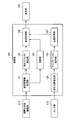
- FIG. 4 is a diagram showing an example of a functional configuration of the information processing apparatus 10 according to the embodiment of the present disclosure.
- the information processing apparatus 10 includes a visual field analysis imaging unit 111, a sensor unit 112, a control unit 120, a storage unit 130, and a display unit 150.
- the visual field analysis imaging unit 111 has a function of obtaining an image (visual field analysis image) by imaging the visual field of the user U.
- the visual field analysis imaging unit 111 includes a stereo camera, and obtains a left image and a right image captured by the stereo camera.
- the left image and the right image captured by the stereo camera are used for distance detection by the distance measuring unit 124 (FIG. 5).
- various distance sensors may be used instead of the stereo camera and the distance measuring unit 124.
- the visual field analysis imaging unit 111 may be integrated with the information processing apparatus 10 or may exist separately from the information processing apparatus 10.
- the sensor unit 112 includes a sensor, and has a function of detecting the movement of the user U's field of view.
- the sensor unit 112 may include an acceleration sensor, and may detect the movement of the field of view of the user U by the acceleration detected by the acceleration sensor.
- the sensor unit 112 may be configured to include a gyro sensor, and may detect the movement of the field of view of the user U by the angular velocity detected by the gyro sensor.
- the sensor unit 112 may not be provided.
- the storage unit 130 is configured to include a memory, and is a recording medium that stores a program executed by the control unit 120 or stores data necessary for the execution of the program. In addition, the storage unit 130 temporarily stores data for the calculation by the control unit 120.
- the storage unit 130 is configured of a magnetic storage unit device, a semiconductor storage device, an optical storage device, a magneto-optical storage device, or the like.
- the display unit 150 has a function of displaying various screens.
- the type of the display unit 150 is not limited.
- the display unit 150 may be a display (display device) capable of performing display visible to the user. More specifically, the display unit 150 may be a liquid crystal display or an organic EL (Electro-Luminescence) display.
- the control unit 120 executes control of each unit of the information processing apparatus 10.
- FIG. 5 is a diagram showing a detailed configuration example of the control unit 120.
- the control unit 120 includes a real space information acquisition unit 121, a real object detection unit 122, a distance measurement unit 124, a self position estimation unit 125, an application execution unit 126, a position acquisition unit 127, and a display control unit. 128 is provided. The details of each of these functional blocks will be described later.
- the control unit 120 may be configured of, for example, one or more CPUs (central processing units). When the control unit 120 is configured by a processing unit such as a CPU, the processing unit may be configured by an electronic circuit.
- the real space information acquisition unit 121 acquires information of a real object (hereinafter, also referred to as an “object”) disposed in the real space. More specifically, the real space information acquisition unit 121 acquires information of a real object by acquiring a left image and a right image in which the real object appears from the field-of-view analysis imaging unit 111.
- the distance measuring unit 124 generates a depth map based on the left image and the right image captured by the visual field analysis imaging unit 111, and outputs the generated depth map to the display control unit 128.
- the real object detection unit 122 determines whether a predetermined real object (for example, a plane or the like) is present in the field of view based on the left image and the right image captured by the field of view analysis imaging unit 111. When a predetermined real object exists in the field of view, the real object detection unit 122 detects a feature of the predetermined real object in the field of view (for example, the position of a plane in the real space), and the application execution unit 126 and the display control unit 128 Output to The real object detection unit 122 may detect the feature of a predetermined real object based on the depth map generated by the distance measurement unit 124.
- a predetermined real object for example, a plane or the like
- the self position estimation unit 125 estimates the position and orientation (the position of the virtual camera) in the real space of the visual field analysis imaging unit 111 as the self position based on the recognition result of the real space.
- the self position estimation unit 125 recognizes the real space based on a plurality of images continuously captured temporally by the visual field analysis imaging unit 111.
- the self position estimation unit 125 further takes into consideration sensing data (for example, an acceleration detected by an acceleration sensor, an angular velocity detected by a gyro sensor, etc.) obtained by the sensor unit 112 in order to improve recognition accuracy.
- the real space may be recognized.
- the application execution unit 126 determines a virtual object to be placed in the virtual space, and determines the position of the virtual object in the virtual space. At this time, the application execution unit 126 may determine the position of the virtual object based on the features of the real object detected by the real object detection unit 122. As an example, when the real object detection unit 122 detects the position of the plane, the application execution unit 126 determines the position of the plane detected by the real object detection unit 122 as the position at which the virtual object is arranged. May be
- the application execution unit 126 is for analyzing the position of the virtual object in the visual field and the visual field analysis based on the position of the virtual object in the virtual space and the position and orientation (the position of the virtual camera) in the real space of the imaging unit for visual field analysis 111.
- the distance between the imaging unit 111 and the virtual object is detected.
- the type of application is not particularly limited. As one example, the application may be a game application.
- the position acquisition unit 127 acquires the position of the virtual object acquired by the application execution unit 123.
- the position acquisition unit 127 acquires the position of the virtual object acquired by the application execution unit 123 in the virtual space. Further, the position acquisition unit 127 acquires the position in the field of view of the virtual object acquired by the application execution unit 123.
- the display control unit 128 acquires the features of the real object detected by the real object detection unit 122. Further, the display control unit 128 acquires the depth map generated by the distance measuring unit 124. Further, the display control unit 128 acquires the position of the virtual object acquired by the position acquisition unit 127.
- the display control unit 128 determines the position of the virtual object acquired by the position acquisition unit 127 and the feature of the real object present in the real space detected by the real object detection unit 122 and separated from the position of the virtual object. Based on the display of at least the boundaries of the virtual object. According to this configuration, it is possible to reduce the sense of discomfort with respect to the display of the virtual object while suppressing the decrease in the visibility of the virtual object. For example, when the virtual object and the real object have the first positional relationship, the display control unit 128 displays at least the boundary of the virtual object at a second position where the virtual object and the real object are different from the first positional relationship. Different from when it is in a relationship.
- the display control unit 128 The display of at least the boundaries of the object may be changed.
- the display control unit 128 calculates the predicted strength of the display delay feeling of the virtual object based on the features of the real object. Then, the display control unit 128 controls the display of at least the boundary of the virtual object based on the position of the virtual object and the predicted strength of the display delay. More specifically, the display control unit 128 may control at least one of the position, the shape, the motion, the color, the luminance, and the definition of the boundary of the virtual object.
- the characteristics of the real object are not particularly limited.
- the features of the real object may include at least one of the shape and motion of the real object.
- the display control unit 128 may increase the prediction strength of the sense of display delay as the proportion of the straight portion of the edge of the real object increases.
- the display control unit 128 may increase the prediction strength of the sense of display delay as the movement of the real object is larger.
- the display control unit 128 may calculate the predicted strength of the display delay based on the characteristics of the real object, or may calculate the predicted strength of the display delay based on the characteristics of the virtual object, or the real object The predicted strength of the display delay may be calculated based on both the feature of and the feature of the virtual object.
- the characteristics of the virtual object are not particularly limited.
- the features of the virtual object may include at least one of the shape and motion of the virtual object.
- the display control unit 128 may increase the prediction strength of the sense of display delay as the proportion of the straight portion of the edge of the virtual object increases.
- the display control unit 128 may increase the prediction strength of the sense of display delay as the movement of the virtual object is larger.
- the predicted strength of the display delay may be determined for each virtual object. Further, the predicted strength of the display delay feeling may be determined in advance for each feature of the virtual object. In the following, a case will be specifically described in which the predicted strength of display delay feeling of the virtual object is determined in advance for each of the virtual object and the feature of the virtual object.
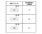
- 6 to 8 are diagrams showing examples of predicted strength of display delay feeling for each feature of the virtual object and the virtual object.
- a virtual object whose predicted intensity of display delay feeling corresponding to a virtual object 30-31 having a high proportion of straight portions of edges is indicated as “1.0” and the proportion of straight portions of edges is intermediate
- the predicted strength of display delay feeling corresponding to 30-32 is shown as "0.9”
- the predicted strength of display delay feeling corresponding to virtual object 30-33 with a low proportion of straight portions of edges is "0.7” It is shown as.
- the predicted strength of display delay feeling corresponding to the virtual object 30-34 without motion is shown as "0.4", corresponding to the virtual object 30-35 moving the eyes so that the user looks at the user.
- the predicted strength of the display delay feeling is shown as "0.35", and the predicted strength of the display delay feeling corresponding to the virtual object 30-36 with high motion is shown as "0.25".
- the virtual objects 30-35 for moving the eyes so that the user looks at them will be described later with reference to FIG.
- the predicted strength of the display delay feeling corresponding to the virtual object 30-37 moving with a small tail up and down is shown as “0.15”, and the virtual object moves with a large swing left and right
- the predicted strength of the display delay feeling corresponding to 30-38 is shown as "0.1".
- the predicted strength of display delay may be determined. Then, the display control unit 128 may change the display of at least the boundary of the virtual objects when the predicted strength of the display delay feeling exceeds the threshold. More specifically, when the display control unit 128 changes the position, shape, motion, color, brightness, and / or sharpness of the boundary of the virtual object when the predicted strength of the display delay feeling exceeds the threshold, Good.
- the predicted strength of the display delay feeling of the virtual object may be determined in advance for each of the virtual object and the feature of the virtual object in the application. Then, the virtual object after the change when the predicted strength of the display delay feeling exceeds the threshold may be determined in advance as an avoidance pattern in the application. The virtual object after the change may be determined as one, or the virtual object may be changed such that the reduction width of the prediction strength of display delay is larger as the prediction strength of the display delay is larger. The following describes an example of changing the display of a virtual object.
- FIG. 9 is a diagram showing an example of changing the color of a virtual object.
- the virtual object 30-3 is disposed in the field of view 70-3 of the user U.
- the user U moves his neck to the right, so at time t4, the field of view 70-3 of the user U is moved to the field of view 70-4.
- the display control unit 128 may thin the color of the virtual object 30-3 when the predicted strength of the display delay feeling exceeds the threshold. This is considered to reduce the feeling of display delay of the virtual object 30-4. For example, when the predicted strength of display delay feeling exceeds the threshold, the display control unit 128 sets the color of the virtual object 30-3 to the color of the real object 40-1 whose distance to the virtual object 30-3 is smaller than a predetermined distance. Should be close (virtual object 30-4). This is considered to reduce the feeling of display delay of the virtual object 30-4.
- the predicted strength of display delay may be calculated in any manner.
- the display control unit 128 determines the real object As the similarity between the color 40-1 and the color of the virtual object 30-3 is smaller, the predicted strength of the display delay may be calculated larger.
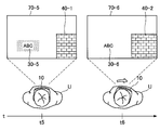
- FIG. 10 is a diagram showing an example of changing the luminance of the virtual object.
- the virtual object 30-5 is arranged in the field of view 70-5 of the user U.
- the user U moves his neck to the right, so at time t6, the visual field 70-5 of the user U moves to the visual field 70-6.
- the display control unit 128 may lower the luminance of the virtual object 30-5 if the predicted strength of the display delay feeling exceeds the threshold. This is considered to reduce the feeling of display delay of the virtual object 30-6. For example, when the predicted strength of display delay feeling exceeds the threshold, the display control unit 128 sets the brightness of the virtual object 30-5 to the brightness of the real object 40-1 whose distance to the virtual object 30-5 is smaller than a predetermined distance. Close to the virtual object 30-6).
- the predicted strength of display delay may be calculated in any manner.
- the display control unit 128 determines the real object As the difference between the brightness of 40-1 and the brightness of the virtual object 30-5 is larger, the predicted strength of the display delay may be calculated larger.
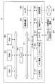
- FIG. 11 is a diagram illustrating an example of the relationship between the brightness of a real object, the brightness of a virtual object, and the predicted strength of display delay.
- the predicted strength of the sense of display delay corresponding to the luminance of the real object 40-3 and the luminance of each of the virtual objects 30-39 to 30-42 is shown.
- the predicted strength of the display delay feeling of the virtual object may be larger.
- the display control unit 128 may add motion to the virtual object or intensify the motion of the virtual object when the prediction strength of the display delay feeling exceeds the threshold.
- the display control unit 128 may change the movement of the virtual object from a no-motion state to a state in which the eyes are moved so that the user looks at the line when the predicted strength of display delay feeling exceeds the threshold. This is considered to reduce the display delay feeling of the virtual object.
- FIG. 12 is a diagram showing an example of a virtual object that moves the eyes so that the user looks at it.
- the visual field moves from the visual field 70-7 to the visual field 70-9.
- the virtual object 30-7 may move its eyes so that the user looks at it (virtual objects 30-8 and 30-9).
- FIG. 13 is a diagram showing an example of changing the luminance of the virtual object.
- virtual object 30-10 is arranged in the field of view 70-10 of user U.
- the user U moves his neck to the right, so at time t11, the field of view 70-10 of the user U is moved to the field of view 70-11.
- the display control unit 128 may lower the visibility (for example, the sharpness) of the boundary of the virtual object 30-10 when the predicted strength of the display delay feeling exceeds the threshold (for example, blur in the virtual object 30-10). (Virtual object 30-11). This is considered to reduce the feeling of display delay of the virtual object 30-10.
- the display control unit 128 may move the position of the virtual object away from the real object when the prediction strength of the display delay feeling exceeds the threshold. This is considered to reduce the display delay feeling of the virtual object. For example, the display control unit 128 may move the position of the virtual object away from the real object whose distance to the virtual object is smaller than a predetermined distance when the predicted strength of the display delay feeling exceeds the threshold.
- the display control unit 128 may change the shape of the virtual object when the predicted strength of the display delay feeling exceeds the threshold. This is considered to reduce the display delay feeling of the virtual object.
- the display control unit 128 may change the shape of the virtual object so that the proportion of the straight portion of the edge is lower when the predicted strength of the display delay feeling exceeds the threshold.
- the position of a straight line that constitutes a real object may be taken into consideration in calculating the prediction strength of the sense of display delay. That is, when the feature of the real object includes the position of a straight line that configures the real object, and the feature of the virtual object includes the position of the virtual object, the display control unit 128 determines the position of the virtual object and the straight line that configures the real object. As the distance to the position of is closer, the predicted strength of display delay may be calculated larger. Such an example will be described in detail with reference to FIG.
- FIG. 14 is a diagram for explaining an example of calculation of the predicted strength of the feeling of display delay based on the position of the straight line configuring the real object.
- the field of view 70-21 of the user U is shown.
- the virtual object 30-21 and the virtual object 30-22 are arranged in the field of view 70-21 of the user U.
- the display control unit 128 calculates the predicted strength of the sense of display delay more.
- the display control unit 128 may calculate the predicted strength of the display delay feeling corresponding to each of the perpendicular lines E11 to E14 as “0.2”, “0.18”, “0.15”, “0.05”.
- the display control unit 128 predicts the standard display delay feeling of the virtual object 30-21 “1.0”, assuming that the predicted strength of the standard display feeling of the virtual object 30-21 is “1.0”. Display the virtual object 30-21 by adding the predicted strengths “0.2”, “0.18”, “0.15” and “0.05” of the sense of display delay to the vertical lines E11 to E14 respectively. The predicted strength of the sense of delay may be calculated as “1.58”.
- the display control unit 128 may calculate the predicted strength of display delay feeling corresponding to each of the perpendiculars E21 to E23 as “0.03”, “0.018”, and “0.01”.
- the display control unit 128 predicts the standard display delay feeling of the virtual object 30-21 “1.0”, assuming that the predicted strength of the standard display feeling of the virtual object 30-21 is “1.0”. By adding the predicted strength “0.03” “0.018” “0.01” of the sense of display delay corresponding to each of the perpendiculars E21 to E23 to the estimated strength of the sense of display delay of the virtual object 30-22. May be calculated as "1.058".
- the predicted strength of display delay may be calculated based on the direction of the straight line forming the real object instead of the position of the straight line forming the real object. At this time, as the straight line forming the real object and the straight line forming the virtual object are closer to parallel, the predicted strength of the display delay may be calculated larger.
- the display control unit 128 configures the virtual object.
- the standard display delay feeling of the virtual object May be added to the predicted strength of
- the inner product of the direction vector of the straight line forming the virtual object and the direction vector of the straight line forming the real object May be used.
- the display control unit 128 controls the display of the virtual object based on at least one of the feature of the real object and the virtual object.
- the movement of the virtual camera may also change the feeling of display delay. Therefore, the display control unit 128 substitutes at least one of the features of the real object and the virtual object, or the display control unit 128 adds the feature to the real object and / or the virtual object, The display of at least the boundary of the virtual object may be controlled based on the movement of the camera.
- the display control unit 128 may change the display of at least the boundary of the virtual object when the motion of the virtual camera exceeds a predetermined motion. For example, when the movement of the virtual camera exceeds a predetermined movement, the display control unit 128 may increase the prediction strength of the display delay feeling of the virtual object. For example, the display control unit 128 may calculate the prediction strength of the display delay feeling of the virtual object to be larger as the movement of the virtual camera becomes larger. The display control of the virtual object based on the predicted strength of the display delay may be performed in the same manner as described above.
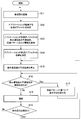
- FIG. 15 is a flowchart showing an operation example of the information processing apparatus 10 according to the present embodiment.
- the operation example illustrated in FIG. 15 merely illustrates an example of the operation of the information processing apparatus 10 according to the present embodiment. Therefore, the operation of the information processing apparatus 10 according to the present embodiment is not limited to the operation example shown in FIG.
- the self-position estimation unit 125 recognizes the real space based on a plurality of images continuously captured temporally by the visual field analysis imaging unit 111 (S11).
- the self position estimation unit 125 estimates the position and orientation (the position of the virtual camera) in the real space of the visual field analysis imaging unit 111 as the self position based on the recognition result of the real space.
- the application execution unit 126 determines a virtual object to be arranged in the virtual space (S12), and notifies the display control unit 128 of a combination of predicted intensity of display delay feeling of the virtual object, an avoidance pattern, and a threshold (S13).
- the application execution unit 126 determines the position of the virtual object in the virtual space (S14).
- the display control unit 128 calculates the predicted strength of the feeling of display delay based on at least one of the feature of the virtual object and the feature of the real object (S15).
- the display control unit 128 changes the display method of the virtual object based on the avoidance pattern (S17) when the predicted strength of the sense of display delay exceeds the threshold ("Yes" in S16), and shifts the operation to S16.
- the display method of the virtual object may be sequentially changed based on the avoidance pattern corresponding to each feature of the virtual object until the predicted strength of the display delay does not exceed the threshold.
- the display control unit 128 draws the virtual object (S18), and the characteristics of the virtual object and the characteristics of the real object. If it is necessary to make a redetermination ("Yes” in S19) because at least one of them is changed (S19), the operation is shifted to S15, but if the redetermination is not necessary (S19) The operation may be shifted to S11).
- FIG. 16 is a block diagram showing an example of the hardware configuration of the information processing apparatus 10 according to the embodiment of the present disclosure.
- the information processing apparatus 10 includes a central processing unit (CPU) 901, a read only memory (ROM) 903, and a random access memory (RAM) 905.
- the information processing apparatus 10 may also include a host bus 907, a bridge 909, an external bus 911, an interface 913, an input device 915, an output device 917, a storage device 919, a drive 921, a connection port 923, and a communication device 925.
- the information processing device 10 may include an imaging device 933 and a sensor 935 as necessary.
- the information processing apparatus 10 may have a processing circuit called a digital signal processor (DSP) or an application specific integrated circuit (ASIC) instead of or in addition to the CPU 901.
- DSP digital signal processor
- ASIC application specific integrated circuit
- the CPU 901 functions as an arithmetic processing unit and a control unit, and controls the entire operation or a part of the information processing apparatus 10 according to various programs recorded in the ROM 903, the RAM 905, the storage unit 919, or the removable recording medium 927.
- the ROM 903 stores programs used by the CPU 901, calculation parameters, and the like.
- the RAM 905 temporarily stores programs used in the execution of the CPU 901, parameters that appropriately change in the execution, and the like.
- the CPU 901, the ROM 903 and the RAM 905 are mutually connected by a host bus 907 configured by an internal bus such as a CPU bus. Furthermore, the host bus 907 is connected to an external bus 911 such as a peripheral component interconnect / interface (PCI) bus via the bridge 909.
- PCI peripheral component interconnect / interface
- the input device 915 is, for example, a device operated by the user, such as a mouse, a keyboard, a touch panel, a button, a switch, and a lever.
- the input device 915 may include a microphone that detects the user's voice.
- the input device 915 may be, for example, a remote control device using infrared rays or other radio waves, or may be an external connection device 929 such as a mobile phone corresponding to the operation of the information processing apparatus 10.
- the input device 915 includes an input control circuit that generates an input signal based on information input by the user and outputs the generated signal to the CPU 901.
- the user operates the input device 915 to input various data to the information processing apparatus 10 and instruct processing operations.
- an imaging device 933 described later can also function as an input device by imaging the movement of the user's hand, the finger of the user, and the like. At this time, the pointing position may be determined according to the movement of the hand or the direction of the finger.
- the output device 917 is configured of a device capable of visually or aurally notifying the user of the acquired information.
- the output device 917 is, for example, an LCD (Liquid Crystal Display), a PDP (Plasma Display Panel), an organic EL (Electro-Luminescence) display, a display such as a projector, a display of a hologram, an audio output such as a speaker and a headphone, And a printer device.
- the output device 917 outputs the result obtained by the processing of the information processing device 10 as a video such as text or an image, or outputs it as an audio such as audio or sound.
- the output device 917 may include a light or the like to brighten the surroundings.
- the storage device 919 is a device for data storage configured as an example of a storage unit of the information processing device 10.
- the storage device 919 is configured of, for example, a magnetic storage unit device such as a hard disk drive (HDD), a semiconductor storage device, an optical storage device, or a magneto-optical storage device.
- the storage device 919 stores programs executed by the CPU 901, various data, various data acquired from the outside, and the like.
- the drive 921 is a reader / writer for a removable recording medium 927 such as a magnetic disk, an optical disk, a magneto-optical disk, or a semiconductor memory, and is built in or externally attached to the information processing apparatus 10.
- the drive 921 reads out the information recorded in the mounted removable recording medium 927 and outputs it to the RAM 905.
- the drive 921 also writes a record on the attached removable recording medium 927.
- connection port 923 is a port for directly connecting a device to the information processing apparatus 10.
- the connection port 923 may be, for example, a Universal Serial Bus (USB) port, an IEEE 1394 port, a Small Computer System Interface (SCSI) port, or the like.
- the connection port 923 may be an RS-232C port, an optical audio terminal, a high-definition multimedia interface (HDMI (registered trademark)) port, or the like.
- HDMI registered trademark
- the communication device 925 is, for example, a communication interface configured of a communication device or the like for connecting to the communication network 931.
- the communication device 925 may be, for example, a communication card for a wired or wireless Local Area Network (LAN), Bluetooth (registered trademark), or WUSB (Wireless USB).
- the communication device 925 may be a router for optical communication, a router for Asymmetric Digital Subscriber Line (ADSL), or a modem for various types of communication.
- the communication device 925 transmits and receives signals and the like to and from the Internet or another communication device using a predetermined protocol such as TCP / IP.
- a communication network 931 connected to the communication device 925 is a network connected by wire or wireless, and is, for example, the Internet, a home LAN, infrared communication, radio wave communication, satellite communication, or the like.
- the imaging device 933 uses various members such as an imaging device such as a charge coupled device (CCD) or a complementary metal oxide semiconductor (CMOS), and a lens for controlling the formation of an object image on the imaging device. It is an apparatus which images real space and generates a captured image.
- the imaging device 933 may capture a still image, or may capture a moving image.
- the sensor 935 is, for example, various sensors such as a distance measuring sensor, an acceleration sensor, a gyro sensor, a geomagnetic sensor, an optical sensor, and a sound sensor.
- the sensor 935 acquires information on the environment of the information processing apparatus 10, such as information on the state of the information processing apparatus 10 itself, such as the attitude of the housing of the information processing apparatus 10, and brightness and noise around the information processing apparatus 10, for example. Do.
- the sensor 935 may also include a GPS sensor that receives a Global Positioning System (GPS) signal and measures the latitude, longitude and altitude of the device.
- GPS Global Positioning System
- the position of the virtual object determined based on the position of the virtual camera calculated based on the recognition result of the real space according to the image captured by the imaging device Information that includes: a position acquisition unit 127 that acquires the information; and a display control unit 128 that controls display of at least the boundary of the virtual object based on the position of the virtual object and the feature of the object present in the real space.
- a processing device 10 is provided.
- the position of each configuration is not particularly limited.
- a part of processing of each unit in the information processing apparatus 10 may be performed by a server device (not shown).
- a part or all of the blocks included in the control unit 120 in the information processing apparatus 10 may be present in a server apparatus (not shown) or the like.
- a server device not shown
- a position acquisition unit that acquires the position of a virtual object in the real space determined based on a recognition result of the real space according to an image captured by an imaging device;
- a display control unit configured to control display of at least a boundary of the virtual object based on the position of the virtual object and the features of the real object existing in the real space and separated from the position of the virtual object;
- An information processing apparatus comprising: (2) When the virtual object and the real object are in the first positional relationship, the display control unit is configured to display at least the boundary of the virtual object, and the virtual object and the real object are different from the first positional relationship. Different from the case of the second positional relationship, The information processing apparatus according to (1).
- the display control unit changes the positional relationship between the virtual object and the real object from the first positional relationship to the second positional relationship according to the movement of the field of view of the user who presents the virtual object , Changing the display of at least the boundaries of the virtual object, The information processing apparatus according to (2).
- the display control unit calculates the predicted strength of the display delay feeling of the virtual object based on the characteristics of the real object, and the virtual object based on the position of the virtual object and the predicted strength of the display delay feeling Control the display of at least the boundaries of The information processing apparatus according to (1).
- the display control unit moves the position of the virtual object away from the real object when the predicted strength of the display delay feeling exceeds a threshold.
- the information processing apparatus according to (4).
- the display control unit changes the shape of the virtual object when the predicted strength of the display delay feeling exceeds a threshold.
- the information processing apparatus according to (4). The display control unit imparts a motion to the virtual object or strengthens the motion of the virtual object when the prediction strength of the display delay feeling exceeds a threshold.
- the information processing apparatus according to (4). The display control unit brings at least one of the color or the luminance of the virtual object closer to at least one of the color or the luminance of the real object when the predicted strength of the display delay feeling exceeds a threshold.
- the information processing apparatus according to (4). (9) The display control unit reduces the visibility of the boundary of the virtual object when the predicted strength of the display delay feeling exceeds a threshold.
- the features of the real object include at least one of the shape and the motion of the real object, The information processing apparatus according to (1).
- the display control unit calculates the predicted strength of the display delay feeling based on the features of the real object and the features of the virtual object.
- the features of the real object include the positions of the straight lines that make up the real object,
- the features of the virtual object include the location of the virtual object
- the display control unit calculates the predicted strength of the display delay feeling to be larger as the distance between the position of the virtual object and the position of a straight line configuring the real object is shorter.
- the features of the real object include the direction of the straight lines that make up the real object
- the features of the virtual object include the direction of the straight lines that make up the virtual object
- the display control unit calculates the predicted strength of the sense of display delay more as the angle between the direction of the straight line forming the virtual object and the direction of the straight line forming the real object is smaller.
- the features of the virtual object include at least one of the shape and the motion of the virtual object.
- the features of the real object include the color of the real object
- the features of the virtual object include the color of the virtual object
- the display control unit calculates, as the similarity between the color of the real object and the color of the virtual object is smaller, the prediction strength of the display delay feeling larger.
- the features of the real object include the brightness of the real object
- the features of the virtual object include the intensity of the virtual object
- the display control unit calculates the predicted strength of the display delay feeling to be larger as the difference between the brightness of the real object and the brightness of the virtual object is larger.
- the display control unit controls display of at least a boundary of the virtual objects based on the movement of the virtual camera calculated based on the recognition result of the real space.
- the information processing apparatus changes display of at least a boundary of the virtual object when the motion of the virtual camera exceeds a predetermined motion.
- the information processing apparatus according to (17). (19) Acquiring a position of a virtual object determined based on a position of a virtual camera calculated based on a recognition result of real space according to an image captured by an imaging device; Controlling display of at least a boundary of the virtual object based on the position of the virtual object and the feature of the real object existing in the real space;
- Information processing methods including: (20) Computer, A position acquisition unit that acquires a position of a virtual object determined based on a position of a virtual camera calculated based on a recognition result of real space according to an image captured by an imaging device; A display control unit configured to control display of at least a boundary of the virtual object based on the position of the virtual object and the feature of the real object existing in the real space; Program for functioning as an information processing apparatus provided with
Landscapes
- Engineering & Computer Science (AREA)
- Theoretical Computer Science (AREA)
- Physics & Mathematics (AREA)
- General Physics & Mathematics (AREA)
- Multimedia (AREA)
- General Engineering & Computer Science (AREA)
- Human Computer Interaction (AREA)
- Software Systems (AREA)
- Computer Vision & Pattern Recognition (AREA)
- Computer Graphics (AREA)
- Computer Hardware Design (AREA)
- Processing Or Creating Images (AREA)
- User Interface Of Digital Computer (AREA)
Abstract
[Problem] A feature is desired that makes it possible to reduce a feeling of uneasiness about the display of a virtual object while suppressing a reduction in the visibility of the virtual object. [Solution] Provided is an information processing device provided with: a position acquisition unit for acquiring the position of a virtual object in a real space that corresponds to an image captured by an imaging device, the position being determined on the basis of the recognition result of the real space; and a display control unit for controlling the display of at least a boundary of the virtual object on the basis of the position of the virtual object and the features of a real object that is present in the real space and is set apart from the position of the virtual object.
Description
本開示は、情報処理装置、情報処理方法およびプログラムに関する。
The present disclosure relates to an information processing device, an information processing method, and a program.
近年、ユーザに対して仮想オブジェクトを提示する技術が開示されている。例えば、画像に映る物体の位置または姿勢を認識する認識部と、認識部による認識の安定度に応じて物体に関連する仮想オブジェクトの表示を変化させる表示制御部とを備える画像処理装置に関する技術が開示されている(例えば、特許文献1参照。)。かかる技術によれば、仮想オブジェクトの表示の乱れによってユーザに混乱を与えることが回避される。
In recent years, techniques for presenting virtual objects to users have been disclosed. For example, a technique related to an image processing apparatus including a recognition unit that recognizes a position or a posture of an object shown in an image, and a display control unit that changes display of a virtual object related to the object according to the stability of recognition by the recognition unit (See, for example, Patent Document 1). According to such a technique, it is possible to prevent the user from being confused by the disturbance of the display of the virtual object.
一方、仮想オブジェクトの表示の乱れとは別に、仮想オブジェクトの表示遅延が生じ得る。さらに、表示遅延とは別に、ユーザにとって仮想オブジェクトの表示遅延がどの程度知覚されやすいかといった概念も存在する。以下では、ユーザによる表示遅延の知覚のされやすさを「表示遅延感」とも言う。
On the other hand, display delay of the virtual object may occur apart from the disturbance of the display of the virtual object. Furthermore, apart from the display delay, there is also a concept as to how easily the display delay of the virtual object is perceived by the user. Hereinafter, the user's perception of display delay is also referred to as “display delay feeling”.
ここで、仮想オブジェクトの表示遅延感が強くなるほど、仮想オブジェクトの表示遅延に対する違和感も大きくなってしまう可能性がある。一方、仮想オブジェクトの表示を大きく変えるほど仮想オブジェクトの視認性が低下してしまう可能性がある。そこで、仮想オブジェクトの視認性の低下を抑制しつつ、仮想オブジェクトの表示に対する違和感を低減することが可能な技術が望まれる。
Here, as the sense of display delay of the virtual object becomes stronger, the sense of discomfort for the delay of display of the virtual object may be increased. On the other hand, the visibility of the virtual object may be reduced as the display of the virtual object is largely changed. Then, the technique which can reduce the discomfort with respect to the display of a virtual object is desired, suppressing the fall of the visibility of a virtual object.
本開示によれば、撮像装置によって撮像された画像に応じた実空間の認識結果に基づいて決定された前記実空間における仮想オブジェクトの位置を取得する位置取得部と、前記仮想オブジェクトの位置と、前記実空間に存在し前記仮想オブジェクトの位置から離れている実オブジェクトの特徴とに基づいて、前記仮想オブジェクトの少なくとも境界の表示を制御する表示制御部と、を備える、情報処理装置が提供される。
According to the present disclosure, a position acquisition unit that acquires a position of a virtual object in the real space determined based on a recognition result of the real space according to an image captured by an imaging device, a position of the virtual object, An information processing apparatus comprising: a display control unit configured to control display of at least a boundary of the virtual object based on features of the real object existing in the real space and separated from the position of the virtual object; .
本開示によれば、撮像装置によって撮像された画像に応じた実空間の認識結果に基づいて算出された仮想カメラの位置に基づいて決定された仮想オブジェクトの位置を取得することと、前記仮想オブジェクトの位置と実空間に存在する実オブジェクトの特徴とに基づいて、前記仮想オブジェクトのうち少なくとも境界の表示を制御することと、を含む、情報処理方法が提供される。
According to the present disclosure, acquiring a position of a virtual object determined based on a position of a virtual camera calculated based on a recognition result of a real space according to an image captured by an imaging device, and the virtual object An information processing method is provided, including controlling display of at least a boundary of the virtual objects based on the position of the virtual object and the features of the real object present in the real space.
本開示によれば、コンピュータを、撮像装置によって撮像された画像に応じた実空間の認識結果に基づいて算出された仮想カメラの位置に基づいて決定された仮想オブジェクトの位置を取得する位置取得部と、前記仮想オブジェクトの位置と実空間に存在する実オブジェクトの特徴とに基づいて、前記仮想オブジェクトのうち少なくとも境界の表示を制御する表示制御部と、を備える情報処理装置として機能させるためのプログラムが提供される。
According to the present disclosure, a position acquisition unit that acquires a position of a virtual object determined based on a position of a virtual camera calculated based on a recognition result of a real space according to an image captured by an imaging device according to the present disclosure And a display control unit configured to control display of at least a boundary of the virtual object based on the position of the virtual object and the feature of the real object existing in the real space. Is provided.
以上説明したように本開示によれば、仮想オブジェクトの視認性の低下を抑制しつつ、仮想オブジェクトの表示に対する違和感を低減することが可能な技術が提供される。なお、上記の効果は必ずしも限定的なものではなく、上記の効果とともに、または上記の効果に代えて、本明細書に示されたいずれかの効果、または本明細書から把握され得る他の効果が奏されてもよい。
As described above, according to the present disclosure, there is provided a technology capable of reducing a sense of discomfort with respect to display of a virtual object while suppressing a decrease in the visibility of the virtual object. Note that the above-mentioned effects are not necessarily limited, and, along with or in place of the above-mentioned effects, any of the effects shown in the present specification, or other effects that can be grasped from the present specification May be played.
以下に添付図面を参照しながら、本開示の好適な実施の形態について詳細に説明する。なお、本明細書及び図面において、実質的に同一の機能構成を有する構成要素については、同一の符号を付することにより重複説明を省略する。
Hereinafter, preferred embodiments of the present disclosure will be described in detail with reference to the accompanying drawings. In the present specification and the drawings, components having substantially the same functional configuration will be assigned the same reference numerals and redundant description will be omitted.
また、本明細書および図面において、実質的に同一または類似の機能構成を有する複数の構成要素を、同一の符号の後に異なる数字を付して区別する場合がある。ただし、実質的に同一または類似の機能構成を有する複数の構成要素の各々を特に区別する必要がない場合、同一符号のみを付する。また、異なる実施形態の類似する構成要素については、同一の符号の後に異なるアルファベットを付して区別する場合がある。ただし、類似する構成要素の各々を特に区別する必要がない場合、同一符号のみを付する。
In the present specification and the drawings, a plurality of components having substantially the same or similar functional configurations may be distinguished by attaching different numerals after the same reference numerals. However, when it is not necessary to distinguish each of a plurality of components having substantially the same or similar functional configuration, only the same reference numeral is given. Also, similar components in different embodiments may be distinguished by attaching different alphabets after the same reference numerals. However, when it is not necessary to distinguish each of similar components in particular, only the same reference numeral is attached.
なお、説明は以下の順序で行うものとする。
0.概要
1.実施形態の詳細
1.1.情報処理装置の機能構成例
1.2.情報処理装置の機能詳細
1.3.情報処理装置の動作例
2.ハードウェア構成例
3.むすび The description will be made in the following order.
0.Overview 1. Details of Embodiment 1.1. Functional configuration example of information processing apparatus 1.2. Details of Functions of Information Processing Device 1.3. Operation example of information processing apparatus Hardware configuration example 3. The end
0.概要
1.実施形態の詳細
1.1.情報処理装置の機能構成例
1.2.情報処理装置の機能詳細
1.3.情報処理装置の動作例
2.ハードウェア構成例
3.むすび The description will be made in the following order.
0.
<0.概要>
まず、図1を参照しながら、本開示の実施形態の概要を説明する。近年、ユーザに対して仮想オブジェクトを提示する技術が開示されている。例えば、画像に映る物体(実オブジェクト)の位置または姿勢を認識する認識部と、認識部による認識の安定度に応じて物体に関連する仮想オブジェクトの表示を変化させる表示制御部とを備える画像処理装置に関する技術が開示されている。かかる技術によれば、仮想オブジェクトの表示の乱れによってユーザに混乱を与えることが回避される。 <0. Overview>
First, an overview of an embodiment of the present disclosure will be described with reference to FIG. In recent years, techniques for presenting virtual objects to users have been disclosed. For example, image processing including a recognition unit that recognizes the position or orientation of an object (real object) shown in an image, and a display control unit that changes the display of a virtual object related to the object according to the degree of stability of recognition by the recognition unit Techniques related to the apparatus are disclosed. According to such a technique, it is possible to prevent the user from being confused by the disturbance of the display of the virtual object.
一方、仮想オブジェクトの表示の乱れとは別に、仮想オブジェクトの表示遅延が生じ得る。図1を参照しながら詳細に説明する。図1は、本開示の実施形態の概要を説明するための図である。図1を参照すると、実空間にユーザUが存在している。時刻t1において、ユーザUの視野70-1には、仮想オブジェクト30-1が配置されている。
On the other hand, display delay of the virtual object may occur apart from the disturbance of the display of the virtual object. This will be described in detail with reference to FIG. FIG. 1 is a diagram for describing an overview of an embodiment of the present disclosure. Referring to FIG. 1, a user U is present in the real space. At time t1, the virtual object 30-1 is arranged in the field of view 70-1 of the user U.
ここで、ユーザUに対して仮想オブジェクト30-1が提示されるに際しては、視野分析用撮像部111(図5)(例えば、ステレオカメラなど)によって得られたセンシングデータに基づいて、視野分析用撮像部111(図5)の位置および姿勢(仮想カメラの位置)が認識される。そして、仮想カメラの位置に基づいて、視野70-1における仮想オブジェクト30-1の位置が決定され、決定された仮想オブジェクト30-1の位置に基づいてディスプレイによって仮想オブジェクト30-1が表示される。
Here, when the virtual object 30-1 is presented to the user U, it is for visual field analysis based on sensing data obtained by the visual field analysis imaging unit 111 (FIG. 5) (for example, a stereo camera etc.) The position and attitude (position of virtual camera) of the imaging unit 111 (FIG. 5) are recognized. Then, based on the position of the virtual camera, the position of the virtual object 30-1 in the field of view 70-1 is determined, and the virtual object 30-1 is displayed by the display based on the determined position of the virtual object 30-1. .
このとき、仮想カメラの位置は更新され続けるため、仮想オブジェクの位置が決定された時点と仮想オブジェクトがディスプレイによって表示された時点との間においては、仮想オブジェクトの位置にずれが生じてしまう。すなわち、視野70-2に示すように、実際にディスプレイによって表示される仮想オブジェクト30-2の位置は、現在(時刻t2)の仮想カメラの位置から期待される仮想オブジェクトの位置32-2との間にずれが生じてしまう。かかる現象を表示遅延と呼ぶ。
At this time, since the position of the virtual camera continues to be updated, the position of the virtual object is shifted between when the position of the virtual object is determined and when the virtual object is displayed by the display. That is, as shown in the field of view 70-2, the position of the virtual object 30-2 actually displayed by the display is the position 32-2 of the virtual object expected from the position of the virtual camera at the current time (time t2). There is a gap between them. Such a phenomenon is called display delay.
さらに、表示遅延とは別に、ユーザUにとって仮想オブジェクトの表示遅延がどの程度知覚されやすいかといった概念も存在する。以下では、ユーザUによる表示遅延の知覚のされやすさを「表示遅延感」とも言う。一例として、仮想オブジェクトの周囲に実オブジェクトが存在しない場合には、仮想オブジェクトの表示遅延を目立たせる実オブジェクトが仮想オブジェクトの周囲に存在しないために、仮想オブジェクトの表示遅延感が小さいことが想定される。
Furthermore, apart from the display delay, there is also a concept as to how easily the display delay of the virtual object is perceived by the user U. Hereinafter, the ease with which the user U perceives the display delay is also referred to as “display delay feeling”. As an example, when there is no real object around the virtual object, it is assumed that the virtual object's sense of display delay is small because there is no real object around the virtual object that makes the display delay of the virtual object stand out Ru.
図2は、本開示の実施形態の概要を説明するための図である。図2を参照すると、時刻t14において、ユーザUの視野70-14には、仮想オブジェクト30-14が配置されている。そして、時刻t14から時刻t15までにユーザUが首を右に移動させている。そのため、視野70-14が視野70-15に移動されている。このとき、視野70-15に示すように、実際にディスプレイによって表示される仮想オブジェクト30-15の位置は、現在(時刻t15)の仮想カメラの位置から期待される仮想オブジェクトの位置32-15との間にずれが生じてしまう。そして、実オブジェクト40-2が仮想オブジェクト30-15の近くに存在するために、表示遅延感が大きいことが想定される。
FIG. 2 is a diagram for describing an overview of an embodiment of the present disclosure. Referring to FIG. 2, at time t14, a virtual object 30-14 is disposed in the field of view 70-14 of the user U. Then, the user U moves his neck to the right from time t14 to time t15. Therefore, the field of view 70-14 is moved to the field of view 70-15. At this time, as shown in the field of view 70-15, the position of the virtual object 30-15 actually displayed by the display is the position 32-15 of the virtual object expected from the position of the virtual camera at the present time (time t15). There is a gap between the Then, since the real object 40-2 exists near the virtual object 30-15, it is assumed that the sense of display delay is large.
一方、仮想オブジェクトの近くに仮想オブジェクトと輝度が類似しない実オブジェクトが存在する場合には、当該実オブジェクトが仮想オブジェクトの表示遅延を目立たせてしまうために、仮想オブジェクトの表示遅延感が大きいことが想定される。また、仮想オブジェクトに動きがない場合と比較して仮想オブジェクトに動きがある場合のほうが、仮想オブジェクトの表示遅延が目立ちにくいために、仮想オブジェクトの表示遅延感が小さいことが想定される。
On the other hand, when there is a real object whose luminance is not similar to the virtual object near the virtual object, the real object causes the display delay of the virtual object to be noticeable, so that the virtual object has a large sense of display delay. is assumed. In addition, since the display delay of the virtual object is less noticeable when the virtual object has a movement as compared with the case where the virtual object has no movement, it is assumed that the display object of the virtual object has a smaller sense of display delay.
図3は、本開示の実施形態の概要を説明するための図である。図3を参照すると、時刻t16において、ユーザUの視野70-16には、仮想オブジェクト30-16が配置されている。そして、時刻t16から時刻t17までにユーザUが首を右に移動させている。そのため、視野70-16が視野70-17に移動されている。このとき、視野70-17に示すように、実際にディスプレイによって表示される仮想オブジェクト30-17の位置は、現在(時刻t17)の仮想カメラの位置から期待される仮想オブジェクトの位置32-13との間にずれが生じてしまう。そして、実オブジェクト40-2が仮想オブジェクト30-15の近くに存在するが、仮想オブジェクト30-17の鮮明度が低下されているため、表示遅延感が小さいことが想定される。
FIG. 3 is a diagram for describing an overview of an embodiment of the present disclosure. Referring to FIG. 3, at time t16, a virtual object 30-16 is arranged in the field of view 70-16 of the user U. Then, the user U moves his neck to the right from time t16 to time t17. Therefore, the field of view 70-16 is moved to the field of view 70-17. At this time, as shown in the field of view 70-17, the position of the virtual object 30-17 actually displayed by the display is the position 32-13 of the virtual object expected from the position of the virtual camera at the present time (time t17). There is a gap between the Then, although the real object 40-2 exists near the virtual object 30-15, it is assumed that the sense of display delay is small because the definition of the virtual object 30-17 is lowered.
仮想オブジェクトの表示遅延感が強くなるほど、仮想オブジェクトの表示遅延に対する違和感も大きくなってしまう可能性がある。一方、仮想オブジェクトの表示を大きく変えるほど仮想オブジェクトの視認性が低下してしまう可能性がある。そこで、本明細書においては、仮想オブジェクトの視認性の低下を抑制しつつ、仮想オブジェクトの表示に対する違和感を低減することが可能な技術を主に提案する。
As the sense of display delay of the virtual object becomes stronger, the sense of discomfort for the delay of display of the virtual object may become greater. On the other hand, the visibility of the virtual object may be reduced as the display of the virtual object is largely changed. Therefore, in the present specification, a technique is proposed mainly capable of reducing the discomfort with respect to the display of the virtual object while suppressing the decrease in the visibility of the virtual object.
情報処理装置10は、ユーザUの視野に実オブジェクトが存在する場合、実オブジェクトの情報の例として、ユーザUと実オブジェクトとの距離を検出する。本開示の実施形態においては、情報処理装置10は、ステレオカメラを有しており、ステレオカメラによって撮像された左画像および右画像に基づいてデプスマップを生成し、デプスマップに基づいてユーザUと実オブジェクトとの距離を検出する場合を主に想定する。しかし、ユーザUと実オブジェクトとの距離はどのように検出されてもよい。例えば、情報処理装置10が距離センサを有する場合、距離センサによって、ユーザUと実オブジェクトとの距離が検出されてもよい。距離センサは、TOF(Time of Flight)センサなどであってもよい。
When a real object is present in the field of view of the user U, the information processing apparatus 10 detects the distance between the user U and the real object as an example of the information on the real object. In the embodiment of the present disclosure, the information processing apparatus 10 includes a stereo camera, generates a depth map based on the left image and the right image captured by the stereo camera, and generates a depth map based on the depth map. The case of detecting the distance to a real object is mainly assumed. However, the distance between the user U and the real object may be detected in any way. For example, when the information processing apparatus 10 includes a distance sensor, the distance sensor may detect the distance between the user U and the real object. The distance sensor may be a TOF (Time of Flight) sensor or the like.
なお、実オブジェクトの種類(例えば、実オブジェクトの形状、サイズ、色、輝度、動きなど)は特に限定されない。また、図1には、仮想オブジェクト30の例として円筒形状のオブジェクトが示されているが、仮想オブジェクト30の種類(例えば、仮想オブジェクト30の形状、サイズ、色、輝度、動きなど)は特に限定されない。
Note that the type of the real object (for example, the shape, size, color, brightness, movement, etc. of the real object) is not particularly limited. In addition, although a cylindrical object is shown as an example of the virtual object 30 in FIG. 1, the type of the virtual object 30 (for example, the shape, size, color, brightness, movement, etc. of the virtual object 30) is particularly limited I will not.
図1を参照すると、情報処理装置10がユーザUの頭部に装着されるゴーグル型のHMD(Head Mounted Display)によって構成される場合が例として示されている。しかし、HMDの形態は、ゴーグル型に限定されず、グラス型などであってもよい。また、情報処理装置10はHMDに限定されない。例えば、情報処理装置10は、スマートフォンであってもよいし、タブレット端末であってもよいし、携帯電話であってもよいし、他のモバイルデバイスであってもよい。
Referring to FIG. 1, an example in which the information processing apparatus 10 is configured by a goggle-type HMD (Head Mounted Display) mounted on the head of the user U is illustrated. However, the form of the HMD is not limited to the goggle type, and may be a glass type or the like. Also, the information processing apparatus 10 is not limited to the HMD. For example, the information processing apparatus 10 may be a smartphone, a tablet terminal, a mobile phone, or another mobile device.
また、本開示の実施形態においては、情報処理装置10が透過型のディスプレイを有する場合を主に想定する。このとき、ユーザUは、ディスプレイによって表示された仮想オブジェクト30を視認するとともにディスプレイの奥側に実オブジェクトを視認することが可能である。しかし、情報処理装置10は、非透過型のディスプレイを有してもよい。このとき、ユーザUは、ディスプレイによって表示された仮想オブジェクト30と情報処理装置10が有するカメラによって撮像されてディスプレイによって表示された画像によって実オブジェクトを視認することが可能である。
Moreover, in the embodiment of the present disclosure, it is mainly assumed that the information processing apparatus 10 has a transmissive display. At this time, the user U can visually recognize the virtual object 30 displayed by the display and can visually recognize the real object on the far side of the display. However, the information processing apparatus 10 may have a non-transmissive display. At this time, the user U can visually recognize the real object by the image captured by the virtual object 30 displayed by the display and the camera of the information processing apparatus 10 and displayed by the display.
以上において、本開示の実施形態の概要について説明した。
The outline of the embodiment of the present disclosure has been described above.
<1.実施形態の詳細>
続いて、本開示の実施形態の詳細について説明する。 <1. Details of the embodiment>
Subsequently, details of the embodiment of the present disclosure will be described.
続いて、本開示の実施形態の詳細について説明する。 <1. Details of the embodiment>
Subsequently, details of the embodiment of the present disclosure will be described.
[1.1.情報処理装置の機能構成例]
続いて、本開示の実施形態に係る情報処理装置10の機能構成例について説明する。図4は、本開示の実施形態に係る情報処理装置10の機能構成例を示す図である。図4に示したように、情報処理装置10は、視野分析用撮像部111、センサ部112、制御部120、記憶部130および表示部150を有している。 [1.1. Functional configuration example of information processing apparatus]
Subsequently, an example of a functional configuration of theinformation processing apparatus 10 according to an embodiment of the present disclosure will be described. FIG. 4 is a diagram showing an example of a functional configuration of the information processing apparatus 10 according to the embodiment of the present disclosure. As shown in FIG. 4, the information processing apparatus 10 includes a visual field analysis imaging unit 111, a sensor unit 112, a control unit 120, a storage unit 130, and a display unit 150.
続いて、本開示の実施形態に係る情報処理装置10の機能構成例について説明する。図4は、本開示の実施形態に係る情報処理装置10の機能構成例を示す図である。図4に示したように、情報処理装置10は、視野分析用撮像部111、センサ部112、制御部120、記憶部130および表示部150を有している。 [1.1. Functional configuration example of information processing apparatus]
Subsequently, an example of a functional configuration of the
視野分析用撮像部111は、ユーザUの視野を撮像することによって画像(視野分析用画像)を得る機能を有する。例えば、視野分析用撮像部111は、ステレオカメラを含んでおり、ステレオカメラによって撮像された左画像および右画像を得る。ステレオカメラによって撮像された左画像および右画像は、測距部124(図5)による距離の検出に利用される。なお、上記したように、ステレオカメラおよび測距部124の代わりに、各種の距離センサが利用されてもよい。また、視野分析用撮像部111は、情報処理装置10と一体化されていてもよいし、情報処理装置10とは別体として存在していてもよい。
The visual field analysis imaging unit 111 has a function of obtaining an image (visual field analysis image) by imaging the visual field of the user U. For example, the visual field analysis imaging unit 111 includes a stereo camera, and obtains a left image and a right image captured by the stereo camera. The left image and the right image captured by the stereo camera are used for distance detection by the distance measuring unit 124 (FIG. 5). As described above, various distance sensors may be used instead of the stereo camera and the distance measuring unit 124. Further, the visual field analysis imaging unit 111 may be integrated with the information processing apparatus 10 or may exist separately from the information processing apparatus 10.
センサ部112は、センサを含んで構成され、ユーザUの視野の動きを検出する機能を有する。例えば、センサ部112は、加速度センサを含んで構成され、加速度センサによって検出された加速度によってユーザUの視野の動きを検出してよい。あるいは、センサ部112は、ジャイロセンサを含んで構成され、ジャイロセンサによって検出された角速度によってユーザUの視野の動きを検出してよい。なお、視野分析用撮像部111によって撮像された視野分析用画像に基づいて、ユーザUの視野の動きが検出される場合には、センサ部112が設けられていなくてもよい。
The sensor unit 112 includes a sensor, and has a function of detecting the movement of the user U's field of view. For example, the sensor unit 112 may include an acceleration sensor, and may detect the movement of the field of view of the user U by the acceleration detected by the acceleration sensor. Alternatively, the sensor unit 112 may be configured to include a gyro sensor, and may detect the movement of the field of view of the user U by the angular velocity detected by the gyro sensor. When the movement of the visual field of the user U is detected based on the visual field analysis image captured by the visual field analysis imaging unit 111, the sensor unit 112 may not be provided.
記憶部130は、メモリを含んで構成され、制御部120によって実行されるプログラムを記憶したり、プログラムの実行に必要なデータを記憶したりする記録媒体である。また、記憶部130は、制御部120による演算のためにデータを一時的に記憶する。記憶部130は、磁気記憶部デバイス、半導体記憶デバイス、光記憶デバイス、または、光磁気記憶デバイスなどにより構成される。
The storage unit 130 is configured to include a memory, and is a recording medium that stores a program executed by the control unit 120 or stores data necessary for the execution of the program. In addition, the storage unit 130 temporarily stores data for the calculation by the control unit 120. The storage unit 130 is configured of a magnetic storage unit device, a semiconductor storage device, an optical storage device, a magneto-optical storage device, or the like.
表示部150は、各種の画面を表示する機能を有する。表示部150の種類は限定されない。例えば、表示部150は、ユーザに視認可能な表示を行うことが可能なディスプレイ(表示装置)であればよい。より具体的に、表示部150は、液晶ディスプレイであってもよいし、有機EL(Electro-Luminescence)ディスプレイであってもよい。
The display unit 150 has a function of displaying various screens. The type of the display unit 150 is not limited. For example, the display unit 150 may be a display (display device) capable of performing display visible to the user. More specifically, the display unit 150 may be a liquid crystal display or an organic EL (Electro-Luminescence) display.
制御部120は、情報処理装置10の各部の制御を実行する。図5は、制御部120の詳細構成例を示す図である。図5に示したように、制御部120は、実空間情報取得部121、実オブジェクト検出部122、測距部124、自己位置推定部125、アプリケーション実行部126、位置取得部127および表示制御部128を備える。これらの各機能ブロックについての詳細は、後に説明する。なお、制御部120は、例えば、1または複数のCPU(Central Processing Unit;中央演算処理装置)などで構成されていてよい。制御部120がCPUなどといった処理装置によって構成される場合、かかる処理装置は、電子回路によって構成されてよい。
The control unit 120 executes control of each unit of the information processing apparatus 10. FIG. 5 is a diagram showing a detailed configuration example of the control unit 120. As shown in FIG. As shown in FIG. 5, the control unit 120 includes a real space information acquisition unit 121, a real object detection unit 122, a distance measurement unit 124, a self position estimation unit 125, an application execution unit 126, a position acquisition unit 127, and a display control unit. 128 is provided. The details of each of these functional blocks will be described later. The control unit 120 may be configured of, for example, one or more CPUs (central processing units). When the control unit 120 is configured by a processing unit such as a CPU, the processing unit may be configured by an electronic circuit.
以上、本実施形態に係る情報処理装置10の機能構成例について説明した。
Heretofore, the functional configuration example of the information processing apparatus 10 according to the present embodiment has been described.
[1.2.情報処理装置の機能詳細]
続いて、本実施形態に係る情報処理装置10の機能詳細について説明する。本開示の実施形態に係る情報処理装置10において、実空間情報取得部121は、実空間に配置された実オブジェクト(以下、「物体」とも言う。)の情報を取得する。より具体的に、実空間情報取得部121は、実オブジェクトが写る左画像および右画像を視野分析用撮像部111から取得することによって、実オブジェクトの情報を取得する。 [1.2. Functional Details of Information Processing Device]
Subsequently, the function details of theinformation processing apparatus 10 according to the present embodiment will be described. In the information processing apparatus 10 according to the embodiment of the present disclosure, the real space information acquisition unit 121 acquires information of a real object (hereinafter, also referred to as an “object”) disposed in the real space. More specifically, the real space information acquisition unit 121 acquires information of a real object by acquiring a left image and a right image in which the real object appears from the field-of-view analysis imaging unit 111.
続いて、本実施形態に係る情報処理装置10の機能詳細について説明する。本開示の実施形態に係る情報処理装置10において、実空間情報取得部121は、実空間に配置された実オブジェクト(以下、「物体」とも言う。)の情報を取得する。より具体的に、実空間情報取得部121は、実オブジェクトが写る左画像および右画像を視野分析用撮像部111から取得することによって、実オブジェクトの情報を取得する。 [1.2. Functional Details of Information Processing Device]
Subsequently, the function details of the
測距部124は、視野分析用撮像部111によって撮像された左画像および右画像に基づいてデプスマップを生成し、生成したデプスマップを表示制御部128に出力する。
The distance measuring unit 124 generates a depth map based on the left image and the right image captured by the visual field analysis imaging unit 111, and outputs the generated depth map to the display control unit 128.
実オブジェクト検出部122は、視野分析用撮像部111によって撮像された左画像および右画像に基づいて視野に所定の実オブジェクト(例えば、平面など)が存在するか否かを判断する。実オブジェクト検出部122は、視野に所定の実オブジェクトが存在する場合、視野における所定の実オブジェクトの特徴(例えば、実空間における平面の位置など)を検出し、アプリケーション実行部126および表示制御部128に出力する。なお、実オブジェクト検出部122は、測距部124によって生成されたデプスマップに基づいて所定の実オブジェクトの特徴を検出してもよい。
The real object detection unit 122 determines whether a predetermined real object (for example, a plane or the like) is present in the field of view based on the left image and the right image captured by the field of view analysis imaging unit 111. When a predetermined real object exists in the field of view, the real object detection unit 122 detects a feature of the predetermined real object in the field of view (for example, the position of a plane in the real space), and the application execution unit 126 and the display control unit 128 Output to The real object detection unit 122 may detect the feature of a predetermined real object based on the depth map generated by the distance measurement unit 124.
自己位置推定部125は、実空間の認識結果に基づいて、視野分析用撮像部111の実空間における位置および姿勢(仮想カメラの位置)を自己位置として推定する。自己位置推定部125は、視野分析用撮像部111によって時間的に連続して撮像された複数の画像に基づいて実空間を認識する。このとき、自己位置推定部125は、認識精度を高めるために、センサ部112によって得られたセンシングデータ(例えば、加速度センサによって検出された加速度、ジャイロセンサによって検出された角速度など)をさらに加味して実空間を認識してもよい。
The self position estimation unit 125 estimates the position and orientation (the position of the virtual camera) in the real space of the visual field analysis imaging unit 111 as the self position based on the recognition result of the real space. The self position estimation unit 125 recognizes the real space based on a plurality of images continuously captured temporally by the visual field analysis imaging unit 111. At this time, the self position estimation unit 125 further takes into consideration sensing data (for example, an acceleration detected by an acceleration sensor, an angular velocity detected by a gyro sensor, etc.) obtained by the sensor unit 112 in order to improve recognition accuracy. The real space may be recognized.
アプリケーション実行部126は、仮想空間に配置する仮想オブジェクトを決定し、仮想空間における仮想オブジェクトの位置を決定する。このとき、アプリケーション実行部126は、実オブジェクト検出部122によって検出された実オブジェクトの特徴に基づいて仮想オブジェクトの位置を決定してもよい。一例として、アプリケーション実行部126は、実オブジェクト検出部122によって平面の位置が検出された場合には、実オブジェクト検出部122によって検出された平面の位置を、仮想オブジェクトが配置される位置として決定してもよい。
The application execution unit 126 determines a virtual object to be placed in the virtual space, and determines the position of the virtual object in the virtual space. At this time, the application execution unit 126 may determine the position of the virtual object based on the features of the real object detected by the real object detection unit 122. As an example, when the real object detection unit 122 detects the position of the plane, the application execution unit 126 determines the position of the plane detected by the real object detection unit 122 as the position at which the virtual object is arranged. May be
アプリケーション実行部126は、仮想オブジェクトの仮想空間における位置と視野分析用撮像部111の実空間における位置および姿勢(仮想カメラの位置)とに基づいて、仮想オブジェクトの視野における位置、および、視野分析用撮像部111と仮想オブジェクトとの距離を検出する。なお、アプリケーションの種類は特に限定されない。一例として、アプリケーションは、ゲームアプリケーションであってもよい。
The application execution unit 126 is for analyzing the position of the virtual object in the visual field and the visual field analysis based on the position of the virtual object in the virtual space and the position and orientation (the position of the virtual camera) in the real space of the imaging unit for visual field analysis 111. The distance between the imaging unit 111 and the virtual object is detected. The type of application is not particularly limited. As one example, the application may be a game application.
位置取得部127は、アプリケーション実行部123によって得られた仮想オブジェクトの位置を取得する。位置取得部127は、アプリケーション実行部123によって得られた仮想オブジェクトの仮想空間における位置を取得する。また、位置取得部127は、アプリケーション実行部123によって得られた仮想オブジェクトの視野における位置を取得する。
The position acquisition unit 127 acquires the position of the virtual object acquired by the application execution unit 123. The position acquisition unit 127 acquires the position of the virtual object acquired by the application execution unit 123 in the virtual space. Further, the position acquisition unit 127 acquires the position in the field of view of the virtual object acquired by the application execution unit 123.
表示制御部128は、実オブジェクト検出部122によって検出された実オブジェクトの特徴を取得する。また、表示制御部128は、測距部124によって生成されたデプスマップを取得する。また、表示制御部128は、位置取得部127によって取得された仮想オブジェクトの位置を取得する。
The display control unit 128 acquires the features of the real object detected by the real object detection unit 122. Further, the display control unit 128 acquires the depth map generated by the distance measuring unit 124. Further, the display control unit 128 acquires the position of the virtual object acquired by the position acquisition unit 127.
ここで、表示制御部128は、位置取得部127によって取得された仮想オブジェクトの位置と実オブジェクト検出部122によって検出された実空間に存在し仮想オブジェクトの位置から離れている実オブジェクトの特徴とに基づいて、仮想オブジェクトの少なくとも境界の表示を制御する。かかる構成によれば、仮想オブジェクトの視認性の低下を抑制しつつ、仮想オブジェクトの表示に対する違和感を低減することが可能となる。例えば、表示制御部128は、仮想オブジェクトと実オブジェクトが第1の位置関係にある場合、仮想オブジェクトの少なくとも境界の表示を、仮想オブジェクトと実オブジェクトが第1の位置関係とは異なる第2の位置関係にある場合とは異ならせる。このとき、表示制御部128は、仮想オブジェクトが提示されるユーザの視野の動きに応じて、仮想オブジェクトと実オブジェクトの位置関係が第1の位置関係から第2の位置関係に変化した場合、仮想オブジェクトの少なくとも境界の表示を変化させてもよい。
Here, the display control unit 128 determines the position of the virtual object acquired by the position acquisition unit 127 and the feature of the real object present in the real space detected by the real object detection unit 122 and separated from the position of the virtual object. Based on the display of at least the boundaries of the virtual object. According to this configuration, it is possible to reduce the sense of discomfort with respect to the display of the virtual object while suppressing the decrease in the visibility of the virtual object. For example, when the virtual object and the real object have the first positional relationship, the display control unit 128 displays at least the boundary of the virtual object at a second position where the virtual object and the real object are different from the first positional relationship. Different from when it is in a relationship. At this time, when the positional relationship between the virtual object and the real object changes from the first positional relationship to the second positional relationship according to the movement of the field of view of the user where the virtual object is presented, the display control unit 128 The display of at least the boundaries of the object may be changed.
より具体的には、表示制御部128は、実オブジェクトの特徴に基づいて、仮想オブジェクトの表示遅延感の予測強度を算出する。そして、表示制御部128は、仮想オブジェクトの位置と表示遅延感の予測強度とに基づいて、仮想オブジェクトのうち少なくとも境界の表示を制御する。より具体的には、表示制御部128は、仮想オブジェクトの位置、形状、動き、色、輝度、境界の鮮明度の少なくともいずれか一つを制御してよい。
More specifically, the display control unit 128 calculates the predicted strength of the display delay feeling of the virtual object based on the features of the real object. Then, the display control unit 128 controls the display of at least the boundary of the virtual object based on the position of the virtual object and the predicted strength of the display delay. More specifically, the display control unit 128 may control at least one of the position, the shape, the motion, the color, the luminance, and the definition of the boundary of the virtual object.
実オブジェクトの特徴は特に限定されない。例えば、実オブジェクトの特徴は、実オブジェクトの形状および動きの少なくともいずれか一つを含んでもよい。例えば、実オブジェクトのエッジの直線部分の割合が多いほど、仮想オブジェクトの表示遅延感が大きくなると考えられる。そこで、表示制御部128は、実オブジェクトのエッジの直線部分の割合が多いほど、表示遅延感の予測強度を大きくするとよい。
The characteristics of the real object are not particularly limited. For example, the features of the real object may include at least one of the shape and motion of the real object. For example, it is considered that the display delay feeling of the virtual object becomes larger as the proportion of the straight portion of the edge of the real object is larger. Therefore, the display control unit 128 may increase the prediction strength of the sense of display delay as the proportion of the straight portion of the edge of the real object increases.
また、実オブジェクトの動きが大きいほど、仮想オブジェクトの表示遅延感は小さくなると考えられる。そこで、表示制御部128は、実オブジェクトの動きが大きいほど、表示遅延感の予測強度を大きくするとよい。
In addition, it is considered that the display delay feeling of the virtual object decreases as the movement of the real object increases. Therefore, the display control unit 128 may increase the prediction strength of the sense of display delay as the movement of the real object is larger.
表示制御部128は、実オブジェクトの特徴に基づいて表示遅延感の予測強度を算出してもよいし、仮想オブジェクトの特徴に基づいて表示遅延感の予測強度を算出してもよいし、実オブジェクトの特徴および仮想オブジェクトの特徴の双方に基づいて表示遅延感の予測強度を算出してもよい。
The display control unit 128 may calculate the predicted strength of the display delay based on the characteristics of the real object, or may calculate the predicted strength of the display delay based on the characteristics of the virtual object, or the real object The predicted strength of the display delay may be calculated based on both the feature of and the feature of the virtual object.
仮想オブジェクトの特徴は特に限定されない。例えば、仮想オブジェクトの特徴は、仮想オブジェクトの形状および動きの少なくともいずれか一つを含んでもよい。例えば、仮想オブジェクトのエッジの直線部分の割合が多いほど、仮想オブジェクトの表示遅延感が大きくなると考えられる。そこで、表示制御部128は、仮想オブジェクトのエッジの直線部分の割合が多いほど、表示遅延感の予測強度を大きくするとよい。
The characteristics of the virtual object are not particularly limited. For example, the features of the virtual object may include at least one of the shape and motion of the virtual object. For example, it is considered that the display delay feeling of the virtual object becomes larger as the proportion of the straight portion of the edge of the virtual object increases. Therefore, the display control unit 128 may increase the prediction strength of the sense of display delay as the proportion of the straight portion of the edge of the virtual object increases.
また、仮想オブジェクトの動きが大きいほど、仮想オブジェクトの表示遅延感は小さくなると考えられる。そこで、表示制御部128は、仮想オブジェクトの動きが大きいほど、表示遅延感の予測強度を大きくするとよい。
In addition, it is considered that the display delay feeling of the virtual object decreases as the movement of the virtual object increases. Therefore, the display control unit 128 may increase the prediction strength of the sense of display delay as the movement of the virtual object is larger.
ここで、表示遅延感の予測強度は、仮想オブジェクトごとに決められていてよい。また、表示遅延感の予測強度は、仮想オブジェクトの特徴ごとにあらかじめ決められていてよい。以下では、仮想オブジェクトの表示遅延感の予測強度が仮想オブジェクトおよび仮想オブジェクトの特徴ごとにあらかじめ決められている場合について具体的に説明する。図6~図8は、仮想オブジェクトおよび仮想オブジェクトの特徴ごとの表示遅延感の予測強度の例を示す図である。
Here, the predicted strength of the display delay may be determined for each virtual object. Further, the predicted strength of the display delay feeling may be determined in advance for each feature of the virtual object. In the following, a case will be specifically described in which the predicted strength of display delay feeling of the virtual object is determined in advance for each of the virtual object and the feature of the virtual object. 6 to 8 are diagrams showing examples of predicted strength of display delay feeling for each feature of the virtual object and the virtual object.
図6を参照すると、エッジの直線部分の割合が高い仮想オブジェクト30-31に対応する表示遅延感の予測強度が「1.0」として示され、エッジの直線部分の割合が中程度の仮想オブジェクト30-32に対応する表示遅延感の予測強度が「0.9」として示され、エッジの直線部分の割合が低い仮想オブジェクト30-33に対応する表示遅延感の予測強度が「0.7」として示されている。
Referring to FIG. 6, a virtual object whose predicted intensity of display delay feeling corresponding to a virtual object 30-31 having a high proportion of straight portions of edges is indicated as “1.0” and the proportion of straight portions of edges is intermediate The predicted strength of display delay feeling corresponding to 30-32 is shown as "0.9", and the predicted strength of display delay feeling corresponding to virtual object 30-33 with a low proportion of straight portions of edges is "0.7" It is shown as.
図7を参照すると、動きのない仮想オブジェクト30-34に対応する表示遅延感の予測強度が「0.4」として示され、ユーザに視線が向くように目を動かす仮想オブジェクト30-35に対応する表示遅延感の予測強度が「0.35」として示され、動きの激しい仮想オブジェクト30-36に対応する表示遅延感の予測強度が「0.25」として示されている。ユーザに視線が向くように目を動かす仮想オブジェクト30-35については、図12を参照しながら後に説明する。
Referring to FIG. 7, the predicted strength of display delay feeling corresponding to the virtual object 30-34 without motion is shown as "0.4", corresponding to the virtual object 30-35 moving the eyes so that the user looks at the user. The predicted strength of the display delay feeling is shown as "0.35", and the predicted strength of the display delay feeling corresponding to the virtual object 30-36 with high motion is shown as "0.25". The virtual objects 30-35 for moving the eyes so that the user looks at them will be described later with reference to FIG.
図8を参照すると、尻尾を小さく上下に振る動きをする仮想オブジェクト30-37に対応する表示遅延感の予測強度が「0.15」として示され、首を左右に大きく振る動きをする仮想オブジェクト30-38に対応する表示遅延感の予測強度が「0.1」として示されている。
Referring to FIG. 8, the predicted strength of the display delay feeling corresponding to the virtual object 30-37 moving with a small tail up and down is shown as “0.15”, and the virtual object moves with a large swing left and right The predicted strength of the display delay feeling corresponding to 30-38 is shown as "0.1".
以上に示したようにして、表示遅延感の予測強度が決められていてよい。そして、表示制御部128は、表示遅延感の予測強度が閾値を超える場合、仮想オブジェクトのうち少なくとも境界の表示を変更するとよい。より具体的には、表示制御部128は、表示遅延感の予測強度が閾値を超える場合、仮想オブジェクトの位置、形状、動き、色、輝度、境界の鮮明度の少なくともいずれか一つを変更するとよい。
As described above, the predicted strength of display delay may be determined. Then, the display control unit 128 may change the display of at least the boundary of the virtual objects when the predicted strength of the display delay feeling exceeds the threshold. More specifically, when the display control unit 128 changes the position, shape, motion, color, brightness, and / or sharpness of the boundary of the virtual object when the predicted strength of the display delay feeling exceeds the threshold, Good.
なお、仮想オブジェクトの表示遅延感の予測強度は、アプリケーションにおいて仮想オブジェクトおよび仮想オブジェクトの特徴ごとにあらかじめ決められていてよい。そして、表示遅延感の予測強度が閾値を超える場合における変更後の仮想オブジェクトも、アプリケーションにおいて回避パターンとしてあらかじめ決められていてよい。変更後の仮想オブジェクトは、一つに決められてもよいし、表示遅延感の予測強度が大きいほど、表示遅延感の予測強度の低下幅が大きくなるように仮想オブジェクトが変更されてもよい。以下では、仮想オブジェクトの表示の変更の例について説明する。
The predicted strength of the display delay feeling of the virtual object may be determined in advance for each of the virtual object and the feature of the virtual object in the application. Then, the virtual object after the change when the predicted strength of the display delay feeling exceeds the threshold may be determined in advance as an avoidance pattern in the application. The virtual object after the change may be determined as one, or the virtual object may be changed such that the reduction width of the prediction strength of display delay is larger as the prediction strength of the display delay is larger. The following describes an example of changing the display of a virtual object.
図9は、仮想オブジェクトの色を変更する例を示す図である。図9を参照すると、時刻t3において、ユーザUの視野70-3に仮想オブジェクト30-3が配置されている。そして、時刻t3から時刻t4までに、ユーザUは首を右に動かしているため、時刻t4においては、ユーザUの視野70-3が視野70-4に移動している。
FIG. 9 is a diagram showing an example of changing the color of a virtual object. Referring to FIG. 9, at time t3, the virtual object 30-3 is disposed in the field of view 70-3 of the user U. Then, from time t3 to time t4, the user U moves his neck to the right, so at time t4, the field of view 70-3 of the user U is moved to the field of view 70-4.
このとき、表示制御部128は、表示遅延感の予測強度が閾値を超える場合、仮想オブジェクト30-3の色を薄くするとよい。これによって、仮想オブジェクト30-4の表示遅延感が小さくなると考えられる。例えば、表示制御部128は、表示遅延感の予測強度が閾値を超える場合、仮想オブジェクト30-3との距離が所定の距離よりも小さい実オブジェクト40-1の色に仮想オブジェクト30-3の色を近づけるとよい(仮想オブジェクト30-4)。これによって、仮想オブジェクト30-4の表示遅延感が小さくなると考えられる。
At this time, the display control unit 128 may thin the color of the virtual object 30-3 when the predicted strength of the display delay feeling exceeds the threshold. This is considered to reduce the feeling of display delay of the virtual object 30-4. For example, when the predicted strength of display delay feeling exceeds the threshold, the display control unit 128 sets the color of the virtual object 30-3 to the color of the real object 40-1 whose distance to the virtual object 30-3 is smaller than a predetermined distance. Should be close (virtual object 30-4). This is considered to reduce the feeling of display delay of the virtual object 30-4.
なお、図9に示した例において、表示遅延感の予測強度はどのように算出されてもよい。一例として、実オブジェクト40-1の特徴が、実オブジェクト40-1の色を含み、仮想オブジェクト30-3の特徴が、仮想オブジェクト30-3の色を含む場合、表示制御部128は、実オブジェクト40-1の色と仮想オブジェクト30-3の色との類似度が小さいほど、表示遅延感の予測強度を大きく算出してよい。
In the example shown in FIG. 9, the predicted strength of display delay may be calculated in any manner. As an example, when the feature of the real object 40-1 includes the color of the real object 40-1, and the feature of the virtual object 30-3 includes the color of the virtual object 30-3, the display control unit 128 determines the real object As the similarity between the color 40-1 and the color of the virtual object 30-3 is smaller, the predicted strength of the display delay may be calculated larger.
図10は、仮想オブジェクトの輝度を変更する例を示す図である。図10を参照すると、時刻t5において、ユーザUの視野70-5に仮想オブジェクト30-5が配置されている。そして、時刻t5から時刻t6までに、ユーザUは首を右に動かしているため、時刻t6においては、ユーザUの視野70-5が視野70-6に移動している。
FIG. 10 is a diagram showing an example of changing the luminance of the virtual object. Referring to FIG. 10, at time t5, the virtual object 30-5 is arranged in the field of view 70-5 of the user U. Then, from time t5 to time t6, the user U moves his neck to the right, so at time t6, the visual field 70-5 of the user U moves to the visual field 70-6.
このとき、表示制御部128は、表示遅延感の予測強度が閾値を超える場合、仮想オブジェクト30-5の輝度を低下させるとよい。これによって、仮想オブジェクト30-6の表示遅延感が小さくなると考えられる。例えば、表示制御部128は、表示遅延感の予測強度が閾値を超える場合、仮想オブジェクト30-5との距離が所定の距離よりも小さい実オブジェクト40-1の輝度に仮想オブジェクト30-5の輝度を近づけるとよい(仮想オブジェクト30-6)。
At this time, the display control unit 128 may lower the luminance of the virtual object 30-5 if the predicted strength of the display delay feeling exceeds the threshold. This is considered to reduce the feeling of display delay of the virtual object 30-6. For example, when the predicted strength of display delay feeling exceeds the threshold, the display control unit 128 sets the brightness of the virtual object 30-5 to the brightness of the real object 40-1 whose distance to the virtual object 30-5 is smaller than a predetermined distance. Close to the virtual object 30-6).
なお、図10に示した例において、表示遅延感の予測強度はどのように算出されてもよい。一例として、実オブジェクト40-1の特徴が、実オブジェクト40-1の輝度を含み、仮想オブジェクト30-5の特徴が、仮想オブジェクト30-5の輝度を含む場合、表示制御部128は、実オブジェクト40-1の輝度と仮想オブジェクト30-5の輝度との差が大きいほど、表示遅延感の予測強度を大きく算出してよい。
In the example shown in FIG. 10, the predicted strength of display delay may be calculated in any manner. As an example, when the feature of the real object 40-1 includes the brightness of the real object 40-1, and the feature of the virtual object 30-5 includes the brightness of the virtual object 30-5, the display control unit 128 determines the real object As the difference between the brightness of 40-1 and the brightness of the virtual object 30-5 is larger, the predicted strength of the display delay may be calculated larger.
図11は、実オブジェクトの輝度と仮想オブジェクトの輝度と表示遅延感の予測強度との関係の例を示す図である。図11を参照すると、実オブジェクト40-3の輝度と仮想オブジェクト30-39~30-42それぞれの輝度とに対応する表示遅延感の予測強度が示されている。図11に示したように、実オブジェクトの輝度と仮想オブジェクトの輝度との差が大きいほど、仮想オブジェクトの表示遅延感の予測強度が大きくてなっていてよい。
FIG. 11 is a diagram illustrating an example of the relationship between the brightness of a real object, the brightness of a virtual object, and the predicted strength of display delay. Referring to FIG. 11, the predicted strength of the sense of display delay corresponding to the luminance of the real object 40-3 and the luminance of each of the virtual objects 30-39 to 30-42 is shown. As shown in FIG. 11, as the difference between the luminance of the real object and the luminance of the virtual object is larger, the predicted strength of the display delay feeling of the virtual object may be larger.
また、表示制御部128は、表示遅延感の予測強度が閾値を超える場合、仮想オブジェクトに動きを付与し、または、仮想オブジェクトの動きを強めてもよい。例えば、表示制御部128は、表示遅延感の予測強度が閾値を超える場合、動きのない状態からユーザに視線が向くように目を動かす状態に仮想オブジェクトの動きを変更してよい。これによって、仮想オブジェクトの表示遅延感が小さくなると考えられる。
In addition, the display control unit 128 may add motion to the virtual object or intensify the motion of the virtual object when the prediction strength of the display delay feeling exceeds the threshold. For example, the display control unit 128 may change the movement of the virtual object from a no-motion state to a state in which the eyes are moved so that the user looks at the line when the predicted strength of display delay feeling exceeds the threshold. This is considered to reduce the display delay feeling of the virtual object.
図12は、ユーザに視線が向くように目を動かす仮想オブジェクトの例を示す図である。図12を参照すると、時刻t7から時刻t9までに、ユーザUが首を左から右に動かしているため、視野70-7から視野70-9に視野が移動している。このとき、仮想オブジェクト30-7は、ユーザに視線が向くように目を動かしてよい(仮想オブジェクト30-8、30-9)。
FIG. 12 is a diagram showing an example of a virtual object that moves the eyes so that the user looks at it. Referring to FIG. 12, since the user U moves his neck from left to right from time t7 to time t9, the visual field moves from the visual field 70-7 to the visual field 70-9. At this time, the virtual object 30-7 may move its eyes so that the user looks at it (virtual objects 30-8 and 30-9).
図13は、仮想オブジェクトの輝度を変更する例を示す図である。図13を参照すると、時刻t10において、ユーザUの視野70-10に仮想オブジェクト30-10が配置されている。そして、時刻t10から時刻t11までに、ユーザUは首を右に動かしているため、時刻t11においては、ユーザUの視野70-10が視野70-11に移動している。
FIG. 13 is a diagram showing an example of changing the luminance of the virtual object. Referring to FIG. 13, at time t10, virtual object 30-10 is arranged in the field of view 70-10 of user U. Then, from time t10 to time t11, the user U moves his neck to the right, so at time t11, the field of view 70-10 of the user U is moved to the field of view 70-11.
このとき、表示制御部128は、表示遅延感の予測強度が閾値を超える場合、仮想オブジェクト30-10の境界の視認性(例えば、鮮明度)を低下させるとよい(仮想オブジェクト30-10にブラーを施すとよい)(仮想オブジェクト30-11)。これによって、仮想オブジェクト30-10の表示遅延感が小さくなると考えられる。
At this time, the display control unit 128 may lower the visibility (for example, the sharpness) of the boundary of the virtual object 30-10 when the predicted strength of the display delay feeling exceeds the threshold (for example, blur in the virtual object 30-10). (Virtual object 30-11). This is considered to reduce the feeling of display delay of the virtual object 30-10.
あるいは、表示制御部128は、表示遅延感の予測強度が閾値を超える場合、仮想オブジェクトの位置を実オブジェクトから遠ざけるとよい。これによって、仮想オブジェクトの表示遅延感が小さくなると考えられる。例えば、表示制御部128は、表示遅延感の予測強度が閾値を超える場合、仮想オブジェクトの位置を仮想オブジェクトとの距離が所定の距離よりも小さい実オブジェクトから遠ざけるとよい。
Alternatively, the display control unit 128 may move the position of the virtual object away from the real object when the prediction strength of the display delay feeling exceeds the threshold. This is considered to reduce the display delay feeling of the virtual object. For example, the display control unit 128 may move the position of the virtual object away from the real object whose distance to the virtual object is smaller than a predetermined distance when the predicted strength of the display delay feeling exceeds the threshold.
あるいは、表示制御部128は、表示遅延感の予測強度が閾値を超える場合、仮想オブジェクトの形状を変更するとよい。これによって、仮想オブジェクトの表示遅延感が小さくなると考えられる。例えば、表示制御部128は、表示遅延感の予測強度が閾値を超える場合、エッジの直線部分の割合がより低くなるように仮想オブジェクトの形状を変更するとよい。
Alternatively, the display control unit 128 may change the shape of the virtual object when the predicted strength of the display delay feeling exceeds the threshold. This is considered to reduce the display delay feeling of the virtual object. For example, the display control unit 128 may change the shape of the virtual object so that the proportion of the straight portion of the edge is lower when the predicted strength of the display delay feeling exceeds the threshold.
また、表示遅延感の予測強度の算出には、実オブジェクトを構成する直線の位置が考慮されてもよい。すなわち、実オブジェクトの特徴が、実オブジェクトを構成する直線の位置を含み、仮想オブジェクトの特徴が、仮想オブジェクトの位置を含む場合、表示制御部128は、仮想オブジェクトの位置と実オブジェクトを構成する直線の位置との距離が近いほど、表示遅延感の予測強度を大きく算出してよい。かかる例について、図14を参照しながら詳細に説明する。
In addition, the position of a straight line that constitutes a real object may be taken into consideration in calculating the prediction strength of the sense of display delay. That is, when the feature of the real object includes the position of a straight line that configures the real object, and the feature of the virtual object includes the position of the virtual object, the display control unit 128 determines the position of the virtual object and the straight line that configures the real object. As the distance to the position of is closer, the predicted strength of display delay may be calculated larger. Such an example will be described in detail with reference to FIG.
図14は、実オブジェクトを構成する直線の位置に基づく表示遅延感の予測強度の算出例を説明するための図である。図14を参照すると、ユーザUの視野70-21が示されている。ユーザUの視野70-21には、仮想オブジェクト30-21および仮想オブジェクト30-22が配置されている。
FIG. 14 is a diagram for explaining an example of calculation of the predicted strength of the feeling of display delay based on the position of the straight line configuring the real object. Referring to FIG. 14, the field of view 70-21 of the user U is shown. The virtual object 30-21 and the virtual object 30-22 are arranged in the field of view 70-21 of the user U.
また、仮想オブジェクト30-21から所定の距離以内に、実オブジェクト40-4を構成する1本の直線、実オブジェクト40-5を構成する2本の直線、実オブジェクト40-6を構成する1本の直線が存在している。そして、仮想オブジェクト30-21から各直線までの垂線E11~E14が示されている。
Also, within a predetermined distance from the virtual object 30-21, one straight line configuring the real object 40-4, two straight lines configuring the real object 40-5, and one configuring the real object 40-6 There is a straight line of Further, perpendicular lines E11 to E14 from the virtual object 30-21 to the respective straight lines are shown.
ここで、表示制御部128が、仮想オブジェクトの位置と実オブジェクトを構成する直線の位置との距離が近いほど、表示遅延感の予測強度を大きく算出する場合を想定する。かかる場合、表示制御部128は、垂線E11~E14それぞれに対応する表示遅延感の予測強度を「0.2」「0.18」「0.15」「0.05」として算出してよい。
Here, it is assumed that, as the distance between the position of the virtual object and the position of the straight line constituting the real object is smaller, the display control unit 128 calculates the predicted strength of the sense of display delay more. In such a case, the display control unit 128 may calculate the predicted strength of the display delay feeling corresponding to each of the perpendicular lines E11 to E14 as “0.2”, “0.18”, “0.15”, “0.05”.
そして、表示制御部128は、仮想オブジェクト30-21の標準の表示遅延感の予測強度を「1.0」とした場合、仮想オブジェクト30-21の標準の表示遅延感の予測強度「1.0」に、垂線E11~E14それぞれに対応する表示遅延感の予測強度「0.2」「0.18」「0.15」「0.05」を加算することによって、仮想オブジェクト30-21の表示遅延感の予測強度を「1.58」と算出してよい。
The display control unit 128 predicts the standard display delay feeling of the virtual object 30-21 “1.0”, assuming that the predicted strength of the standard display feeling of the virtual object 30-21 is “1.0”. Display the virtual object 30-21 by adding the predicted strengths “0.2”, “0.18”, “0.15” and “0.05” of the sense of display delay to the vertical lines E11 to E14 respectively. The predicted strength of the sense of delay may be calculated as “1.58”.
また、仮想オブジェクト30-22から所定の距離以内に、実オブジェクト40-7を構成する3本の直線が存在している。そして、仮想オブジェクト30-22から各直線までの垂線E21~E23が示されている。同様にして、表示制御部128は、垂線E21~E23それぞれに対応する表示遅延感の予測強度を「0.03」「0.018」「0.01」として算出してよい。
Further, three straight lines constituting the real object 40-7 exist within a predetermined distance from the virtual object 30-22. Then, vertical lines E21 to E23 from the virtual object 30-22 to the respective straight lines are shown. Similarly, the display control unit 128 may calculate the predicted strength of display delay feeling corresponding to each of the perpendiculars E21 to E23 as “0.03”, “0.018”, and “0.01”.
そして、表示制御部128は、仮想オブジェクト30-21の標準の表示遅延感の予測強度を「1.0」とした場合、仮想オブジェクト30-21の標準の表示遅延感の予測強度「1.0」に、垂線E21~E23それぞれに対応する表示遅延感の予測強度「0.03」「0.018」「0.01」を加算することによって、仮想オブジェクト30-22の表示遅延感の予測強度を「1.058」と算出してよい。
The display control unit 128 predicts the standard display delay feeling of the virtual object 30-21 “1.0”, assuming that the predicted strength of the standard display feeling of the virtual object 30-21 is “1.0”. By adding the predicted strength “0.03” “0.018” “0.01” of the sense of display delay corresponding to each of the perpendiculars E21 to E23 to the estimated strength of the sense of display delay of the virtual object 30-22. May be calculated as "1.058".
図14を参照しながら、実オブジェクトを構成する直線の位置に基づく表示遅延感の予測強度の算出例を説明した。なお、実オブジェクトを構成する直線の位置の代わりに、実オブジェクトを構成する直線の方向に基づいて表示遅延感の予測強度が算出されてもよい。このとき、実オブジェクトを構成する直線と、仮想オブジェクトを構成する直線とが平行に近いほど、表示遅延感の予測強度は大きく算出されてよい。
The example of calculation of the prediction strength of the feeling of display delay based on the position of the straight line that configures the real object has been described with reference to FIG. The predicted strength of display delay may be calculated based on the direction of the straight line forming the real object instead of the position of the straight line forming the real object. At this time, as the straight line forming the real object and the straight line forming the virtual object are closer to parallel, the predicted strength of the display delay may be calculated larger.
より具体的に、実オブジェクトの特徴が、実オブジェクトを構成する直線の方向を含み、仮想オブジェクトの特徴が、仮想オブジェクトを構成する直線の方向を含む場合、表示制御部128は、仮想オブジェクトを構成する直線の方向と実オブジェクトを構成する直線の方向とのなす角度が小さいほど、表示遅延感の予測強度を大きく算出してよい。このとき、図14に示した場合と同様に、仮想オブジェクトと実オブジェクトを構成する直線との距離が所定の距離よりも小さい場合における表示遅延感の予測強度のみ、仮想オブジェクトの標準の表示遅延感の予測強度に加算されてよい。
More specifically, when the feature of the real object includes the direction of the straight line that configures the real object, and the feature of the virtual object includes the direction of the straight line that configures the virtual object, the display control unit 128 configures the virtual object. The smaller the angle between the direction of the straight line and the direction of the straight line that constitutes the real object, the larger the predicted strength of display delay may be calculated. At this time, as in the case shown in FIG. 14, only the predicted strength of display delay feeling when the distance between the virtual object and the straight line forming the real object is smaller than a predetermined distance, the standard display delay feeling of the virtual object May be added to the predicted strength of
なお、仮想オブジェクトを構成する直線の方向と実オブジェクトを構成する直線の方向とのなす角度の算出には、仮想オブジェクトを構成する直線の方向ベクトルと実オブジェクトを構成する直線の方向ベクトルとの内積が用いられてよい。
When calculating the angle formed by the direction of the straight line forming the virtual object and the direction of the straight line forming the real object, the inner product of the direction vector of the straight line forming the virtual object and the direction vector of the straight line forming the real object May be used.
以上においては、表示制御部128が、実オブジェクトの特徴および仮想オブジェクトの少なくともいずれか一方に基づいて仮想オブジェクトの表示を制御する例について説明した。しかし、仮想カメラの動きによっても、表示遅延感が変化する可能性がある。そこで、表示制御部128は、実オブジェクトの特徴および仮想オブジェクトの少なくともいずれか一方の代わりに、あるいは、表示制御部128は、実オブジェクトの特徴および仮想オブジェクトの少なくともいずれか一方に追加して、仮想カメラの動きに基づいて、仮想オブジェクトのうち少なくとも境界の表示を制御してもよい。
In the above, the example in which the display control unit 128 controls the display of the virtual object based on at least one of the feature of the real object and the virtual object has been described. However, the movement of the virtual camera may also change the feeling of display delay. Therefore, the display control unit 128 substitutes at least one of the features of the real object and the virtual object, or the display control unit 128 adds the feature to the real object and / or the virtual object, The display of at least the boundary of the virtual object may be controlled based on the movement of the camera.
表示制御部128は、仮想カメラの動きが所定の動きを超える場合、仮想オブジェクトのうち少なくとも境界の表示を変更してもよい。例えば、表示制御部128は、仮想カメラの動きが所定の動きを超える場合、仮想オブジェクトの表示遅延感の予測強度を大きくしてもよい。例えば、表示制御部128は、仮想カメラの動きが大きくなるほど、仮想オブジェクトの表示遅延感の予測強度を大きく算出してもよい。表示遅延感の予測強度に基づく仮想オブジェクトの表示制御は、上記と同様に実行されてよい。
The display control unit 128 may change the display of at least the boundary of the virtual object when the motion of the virtual camera exceeds a predetermined motion. For example, when the movement of the virtual camera exceeds a predetermined movement, the display control unit 128 may increase the prediction strength of the display delay feeling of the virtual object. For example, the display control unit 128 may calculate the prediction strength of the display delay feeling of the virtual object to be larger as the movement of the virtual camera becomes larger. The display control of the virtual object based on the predicted strength of the display delay may be performed in the same manner as described above.
以上、本実施形態に係る情報処理装置10の機能詳細について説明した。
The functional details of the information processing apparatus 10 according to the present embodiment have been described above.
[1.3.情報処理装置の動作例]
続いて、本実施形態に係る情報処理装置10の動作例について説明する。図15は、本実施形態に係る情報処理装置10の動作例を示すフローチャートである。なお、図15に示した動作例は、本実施形態に係る情報処理装置10の動作の一例を示したに過ぎない。したがって、本実施形態に係る情報処理装置10の動作は、図15に示した動作例に限定されない。 [1.3. Operation Example of Information Processing Device]
Subsequently, an operation example of theinformation processing apparatus 10 according to the present embodiment will be described. FIG. 15 is a flowchart showing an operation example of the information processing apparatus 10 according to the present embodiment. The operation example illustrated in FIG. 15 merely illustrates an example of the operation of the information processing apparatus 10 according to the present embodiment. Therefore, the operation of the information processing apparatus 10 according to the present embodiment is not limited to the operation example shown in FIG.
続いて、本実施形態に係る情報処理装置10の動作例について説明する。図15は、本実施形態に係る情報処理装置10の動作例を示すフローチャートである。なお、図15に示した動作例は、本実施形態に係る情報処理装置10の動作の一例を示したに過ぎない。したがって、本実施形態に係る情報処理装置10の動作は、図15に示した動作例に限定されない。 [1.3. Operation Example of Information Processing Device]
Subsequently, an operation example of the
図15に示すように、自己位置推定部125は、視野分析用撮像部111によって時間的に連続して撮像された複数の画像に基づいて実空間を認識する(S11)。自己位置推定部125は、実空間の認識結果に基づいて、視野分析用撮像部111の実空間における位置および姿勢(仮想カメラの位置)を自己位置として推定する。
As shown in FIG. 15, the self-position estimation unit 125 recognizes the real space based on a plurality of images continuously captured temporally by the visual field analysis imaging unit 111 (S11). The self position estimation unit 125 estimates the position and orientation (the position of the virtual camera) in the real space of the visual field analysis imaging unit 111 as the self position based on the recognition result of the real space.
アプリケーション実行部126は、仮想空間に配置する仮想オブジェクトを決定し(S12)、仮想オブジェクトの表示遅延感の予測強度、回避パターンおよび閾値の組み合わせを表示制御部128に通知する(S13)。アプリケーション実行部126は、仮想空間における仮想オブジェクトの位置を決定する(S14)。表示制御部128は、仮想オブジェクトの特徴および実オブジェクトの特徴の少なくともいずれか一方に基づいて、表示遅延感の予測強度を算出する(S15)。
The application execution unit 126 determines a virtual object to be arranged in the virtual space (S12), and notifies the display control unit 128 of a combination of predicted intensity of display delay feeling of the virtual object, an avoidance pattern, and a threshold (S13). The application execution unit 126 determines the position of the virtual object in the virtual space (S14). The display control unit 128 calculates the predicted strength of the feeling of display delay based on at least one of the feature of the virtual object and the feature of the real object (S15).
表示制御部128は、表示遅延感の予測強度が閾値を超える場合には(S16において「Yes」)、回避パターンに基づいて、仮想オブジェクトの表示方法を変更し(S17)、S16に動作を移行させる。このように表示遅延感の予測強度が閾値を超えなくなるまで、仮想オブジェクトの各特徴それぞれに対応する回避パターンに基づいて順次に仮想オブジェクトの表示方法が変更されてよい。
The display control unit 128 changes the display method of the virtual object based on the avoidance pattern (S17) when the predicted strength of the sense of display delay exceeds the threshold ("Yes" in S16), and shifts the operation to S16. Let As described above, the display method of the virtual object may be sequentially changed based on the avoidance pattern corresponding to each feature of the virtual object until the predicted strength of the display delay does not exceed the threshold.
一方、表示制御部128は、表示遅延感の予測強度が閾値を超えない場合には(S16において「No」)、仮想オブジェクトの描画を行って(S18)、仮想オブジェクトの特徴および実オブジェクトの特徴の少なくともいずれか一方が変更されたなどの理由により、再判定の必要がある場合には(S19において「Yes」)、動作をS15に移行させるが、再判定の必要がない場合には(S19において「No」)、S11に動作が移行されてよい。
On the other hand, when the predicted strength of display delay does not exceed the threshold ("No" in S16), the display control unit 128 draws the virtual object (S18), and the characteristics of the virtual object and the characteristics of the real object. If it is necessary to make a redetermination ("Yes" in S19) because at least one of them is changed (S19), the operation is shifted to S15, but if the redetermination is not necessary (S19) The operation may be shifted to S11).
以上において、本実施形態に係る情報処理装置10の動作例について説明した。
In the above, the operation example of the information processing apparatus 10 according to the present embodiment has been described.
<2.ハードウェア構成例>
次に、図16を参照して、本開示の実施形態に係る情報処理装置10のハードウェア構成例について説明する。図16は、本開示の実施形態に係る情報処理装置10のハードウェア構成例を示すブロック図である。 <2. Hardware configuration example>
Next, a hardware configuration example of theinformation processing device 10 according to the embodiment of the present disclosure will be described with reference to FIG. FIG. 16 is a block diagram showing an example of the hardware configuration of the information processing apparatus 10 according to the embodiment of the present disclosure.
次に、図16を参照して、本開示の実施形態に係る情報処理装置10のハードウェア構成例について説明する。図16は、本開示の実施形態に係る情報処理装置10のハードウェア構成例を示すブロック図である。 <2. Hardware configuration example>
Next, a hardware configuration example of the
図16に示すように、情報処理装置10は、CPU(Central Processing unit)901、ROM(Read Only Memory)903、およびRAM(Random Access Memory)905を含む。また、情報処理装置10は、ホストバス907、ブリッジ909、外部バス911、インターフェース913、入力装置915、出力装置917、ストレージ装置919、ドライブ921、接続ポート923、通信装置925を含んでもよい。さらに、情報処理装置10は、必要に応じて、撮像装置933、およびセンサ935を含んでもよい。情報処理装置10は、CPU901に代えて、またはこれとともに、DSP(Digital Signal Processor)またはASIC(Application Specific Integrated Circuit)と呼ばれるような処理回路を有してもよい。
As shown in FIG. 16, the information processing apparatus 10 includes a central processing unit (CPU) 901, a read only memory (ROM) 903, and a random access memory (RAM) 905. The information processing apparatus 10 may also include a host bus 907, a bridge 909, an external bus 911, an interface 913, an input device 915, an output device 917, a storage device 919, a drive 921, a connection port 923, and a communication device 925. Furthermore, the information processing device 10 may include an imaging device 933 and a sensor 935 as necessary. The information processing apparatus 10 may have a processing circuit called a digital signal processor (DSP) or an application specific integrated circuit (ASIC) instead of or in addition to the CPU 901.
CPU901は、演算処理装置および制御装置として機能し、ROM903、RAM905、ストレージ装置919、またはリムーバブル記録媒体927に記録された各種プログラムに従って、情報処理装置10内の動作全般またはその一部を制御する。ROM903は、CPU901が使用するプログラムや演算パラメータなどを記憶する。RAM905は、CPU901の実行において使用するプログラムや、その実行において適宜変化するパラメータなどを一時的に記憶する。CPU901、ROM903、およびRAM905は、CPUバスなどの内部バスにより構成されるホストバス907により相互に接続されている。さらに、ホストバス907は、ブリッジ909を介して、PCI(Peripheral Component Interconnect/Interface)バスなどの外部バス911に接続されている。
The CPU 901 functions as an arithmetic processing unit and a control unit, and controls the entire operation or a part of the information processing apparatus 10 according to various programs recorded in the ROM 903, the RAM 905, the storage unit 919, or the removable recording medium 927. The ROM 903 stores programs used by the CPU 901, calculation parameters, and the like. The RAM 905 temporarily stores programs used in the execution of the CPU 901, parameters that appropriately change in the execution, and the like. The CPU 901, the ROM 903 and the RAM 905 are mutually connected by a host bus 907 configured by an internal bus such as a CPU bus. Furthermore, the host bus 907 is connected to an external bus 911 such as a peripheral component interconnect / interface (PCI) bus via the bridge 909.
入力装置915は、例えば、マウス、キーボード、タッチパネル、ボタン、スイッチおよびレバーなど、ユーザによって操作される装置である。入力装置915は、ユーザの音声を検出するマイクロフォンを含んでもよい。入力装置915は、例えば、赤外線やその他の電波を利用したリモートコントロール装置であってもよいし、情報処理装置10の操作に対応した携帯電話などの外部接続機器929であってもよい。入力装置915は、ユーザが入力した情報に基づいて入力信号を生成してCPU901に出力する入力制御回路を含む。ユーザは、この入力装置915を操作することによって、情報処理装置10に対して各種のデータを入力したり処理動作を指示したりする。また、後述する撮像装置933も、ユーザの手の動き、ユーザの指などを撮像することによって、入力装置として機能し得る。このとき、手の動きや指の向きに応じてポインティング位置が決定されてよい。
The input device 915 is, for example, a device operated by the user, such as a mouse, a keyboard, a touch panel, a button, a switch, and a lever. The input device 915 may include a microphone that detects the user's voice. The input device 915 may be, for example, a remote control device using infrared rays or other radio waves, or may be an external connection device 929 such as a mobile phone corresponding to the operation of the information processing apparatus 10. The input device 915 includes an input control circuit that generates an input signal based on information input by the user and outputs the generated signal to the CPU 901. The user operates the input device 915 to input various data to the information processing apparatus 10 and instruct processing operations. In addition, an imaging device 933 described later can also function as an input device by imaging the movement of the user's hand, the finger of the user, and the like. At this time, the pointing position may be determined according to the movement of the hand or the direction of the finger.
出力装置917は、取得した情報をユーザに対して視覚的または聴覚的に通知することが可能な装置で構成される。出力装置917は、例えば、LCD(Liquid Crystal Display)、PDP(Plasma Display Panel)、有機EL(Electro-Luminescence)ディスプレイ、プロジェクタなどの表示装置、ホログラムの表示装置、スピーカおよびヘッドホンなどの音声出力装置、ならびにプリンタ装置などであり得る。出力装置917は、情報処理装置10の処理により得られた結果を、テキストまたは画像などの映像として出力したり、音声または音響などの音声として出力したりする。また、出力装置917は、周囲を明るくするためライトなどを含んでもよい。
The output device 917 is configured of a device capable of visually or aurally notifying the user of the acquired information. The output device 917 is, for example, an LCD (Liquid Crystal Display), a PDP (Plasma Display Panel), an organic EL (Electro-Luminescence) display, a display such as a projector, a display of a hologram, an audio output such as a speaker and a headphone, And a printer device. The output device 917 outputs the result obtained by the processing of the information processing device 10 as a video such as text or an image, or outputs it as an audio such as audio or sound. Also, the output device 917 may include a light or the like to brighten the surroundings.
ストレージ装置919は、情報処理装置10の記憶部の一例として構成されたデータ格納用の装置である。ストレージ装置919は、例えば、HDD(Hard Disk Drive)などの磁気記憶部デバイス、半導体記憶デバイス、光記憶デバイス、または光磁気記憶デバイスなどにより構成される。このストレージ装置919は、CPU901が実行するプログラムや各種データ、および外部から取得した各種のデータなどを格納する。
The storage device 919 is a device for data storage configured as an example of a storage unit of the information processing device 10. The storage device 919 is configured of, for example, a magnetic storage unit device such as a hard disk drive (HDD), a semiconductor storage device, an optical storage device, or a magneto-optical storage device. The storage device 919 stores programs executed by the CPU 901, various data, various data acquired from the outside, and the like.
ドライブ921は、磁気ディスク、光ディスク、光磁気ディスク、または半導体メモリなどのリムーバブル記録媒体927のためのリーダライタであり、情報処理装置10に内蔵、あるいは外付けされる。ドライブ921は、装着されているリムーバブル記録媒体927に記録されている情報を読み出して、RAM905に出力する。また、ドライブ921は、装着されているリムーバブル記録媒体927に記録を書き込む。
The drive 921 is a reader / writer for a removable recording medium 927 such as a magnetic disk, an optical disk, a magneto-optical disk, or a semiconductor memory, and is built in or externally attached to the information processing apparatus 10. The drive 921 reads out the information recorded in the mounted removable recording medium 927 and outputs it to the RAM 905. The drive 921 also writes a record on the attached removable recording medium 927.
接続ポート923は、機器を情報処理装置10に直接接続するためのポートである。接続ポート923は、例えば、USB(Universal Serial Bus)ポート、IEEE1394ポート、SCSI(Small Computer System Interface)ポートなどであり得る。また、接続ポート923は、RS-232Cポート、光オーディオ端子、HDMI(登録商標)(High-Definition Multimedia Interface)ポートなどであってもよい。接続ポート923に外部接続機器929を接続することで、情報処理装置10と外部接続機器929との間で各種のデータが交換され得る。
The connection port 923 is a port for directly connecting a device to the information processing apparatus 10. The connection port 923 may be, for example, a Universal Serial Bus (USB) port, an IEEE 1394 port, a Small Computer System Interface (SCSI) port, or the like. In addition, the connection port 923 may be an RS-232C port, an optical audio terminal, a high-definition multimedia interface (HDMI (registered trademark)) port, or the like. By connecting the external connection device 929 to the connection port 923, various data can be exchanged between the information processing device 10 and the external connection device 929.
通信装置925は、例えば、通信ネットワーク931に接続するための通信デバイスなどで構成された通信インターフェースである。通信装置925は、例えば、有線または無線LAN(Local Area Network)、Bluetooth(登録商標)、またはWUSB(Wireless USB)用の通信カードなどであり得る。また、通信装置925は、光通信用のルータ、ADSL(Asymmetric Digital Subscriber Line)用のルータ、または、各種通信用のモデムなどであってもよい。通信装置925は、例えば、インターネットや他の通信機器との間で、TCP/IPなどの所定のプロトコルを用いて信号などを送受信する。また、通信装置925に接続される通信ネットワーク931は、有線または無線によって接続されたネットワークであり、例えば、インターネット、家庭内LAN、赤外線通信、ラジオ波通信または衛星通信などである。
The communication device 925 is, for example, a communication interface configured of a communication device or the like for connecting to the communication network 931. The communication device 925 may be, for example, a communication card for a wired or wireless Local Area Network (LAN), Bluetooth (registered trademark), or WUSB (Wireless USB). The communication device 925 may be a router for optical communication, a router for Asymmetric Digital Subscriber Line (ADSL), or a modem for various types of communication. The communication device 925 transmits and receives signals and the like to and from the Internet or another communication device using a predetermined protocol such as TCP / IP. A communication network 931 connected to the communication device 925 is a network connected by wire or wireless, and is, for example, the Internet, a home LAN, infrared communication, radio wave communication, satellite communication, or the like.
撮像装置933は、例えば、CCD(Charge Coupled Device)またはCMOS(Complementary Metal Oxide Semiconductor)などの撮像素子、および撮像素子への被写体像の結像を制御するためのレンズなどの各種の部材を用いて実空間を撮像し、撮像画像を生成する装置である。撮像装置933は、静止画を撮像するものであってもよいし、また動画を撮像するものであってもよい。
The imaging device 933 uses various members such as an imaging device such as a charge coupled device (CCD) or a complementary metal oxide semiconductor (CMOS), and a lens for controlling the formation of an object image on the imaging device. It is an apparatus which images real space and generates a captured image. The imaging device 933 may capture a still image, or may capture a moving image.
センサ935は、例えば、測距センサ、加速度センサ、ジャイロセンサ、地磁気センサ、光センサ、音センサなどの各種のセンサである。センサ935は、例えば情報処理装置10の筐体の姿勢など、情報処理装置10自体の状態に関する情報や、情報処理装置10の周辺の明るさや騒音など、情報処理装置10の周辺環境に関する情報を取得する。また、センサ935は、GPS(Global Positioning System)信号を受信して装置の緯度、経度および高度を測定するGPSセンサを含んでもよい。
The sensor 935 is, for example, various sensors such as a distance measuring sensor, an acceleration sensor, a gyro sensor, a geomagnetic sensor, an optical sensor, and a sound sensor. The sensor 935 acquires information on the environment of the information processing apparatus 10, such as information on the state of the information processing apparatus 10 itself, such as the attitude of the housing of the information processing apparatus 10, and brightness and noise around the information processing apparatus 10, for example. Do. The sensor 935 may also include a GPS sensor that receives a Global Positioning System (GPS) signal and measures the latitude, longitude and altitude of the device.
<3.むすび>
以上説明したように、本開示の実施形態によれば、撮像装置によって撮像された画像に応じた実空間の認識結果に基づいて算出された仮想カメラの位置に基づいて決定された仮想オブジェクトの位置を取得する位置取得部127と、前記仮想オブジェクトの位置と実空間に存在する物体の特徴とに基づいて、前記仮想オブジェクトのうち少なくとも境界の表示を制御する表示制御部128と、を備える、情報処理装置10が提供される。 <3. End>
As described above, according to the embodiment of the present disclosure, the position of the virtual object determined based on the position of the virtual camera calculated based on the recognition result of the real space according to the image captured by the imaging device Information that includes: aposition acquisition unit 127 that acquires the information; and a display control unit 128 that controls display of at least the boundary of the virtual object based on the position of the virtual object and the feature of the object present in the real space. A processing device 10 is provided.
以上説明したように、本開示の実施形態によれば、撮像装置によって撮像された画像に応じた実空間の認識結果に基づいて算出された仮想カメラの位置に基づいて決定された仮想オブジェクトの位置を取得する位置取得部127と、前記仮想オブジェクトの位置と実空間に存在する物体の特徴とに基づいて、前記仮想オブジェクトのうち少なくとも境界の表示を制御する表示制御部128と、を備える、情報処理装置10が提供される。 <3. End>
As described above, according to the embodiment of the present disclosure, the position of the virtual object determined based on the position of the virtual camera calculated based on the recognition result of the real space according to the image captured by the imaging device Information that includes: a
かかる構成によれば、仮想オブジェクトの視認性の低下を抑制しつつ、仮想オブジェクトの表示に対する違和感を低減することが可能となる。
According to this configuration, it is possible to reduce the sense of discomfort with respect to the display of the virtual object while suppressing the decrease in the visibility of the virtual object.
以上、添付図面を参照しながら本開示の好適な実施形態について詳細に説明したが、本開示の技術的範囲はかかる例に限定されない。本開示の技術分野における通常の知識を有する者であれば、請求の範囲に記載された技術的思想の範疇内において、各種の変更例または修正例に想到し得ることは明らかであり、これらについても、当然に本開示の技術的範囲に属するものと了解される。
The preferred embodiments of the present disclosure have been described in detail with reference to the accompanying drawings, but the technical scope of the present disclosure is not limited to such examples. It will be apparent to those skilled in the art of the present disclosure that various modifications and alterations can be conceived within the scope of the technical idea described in the claims. It is naturally understood that the technical scope of the present disclosure is also included.
また、コンピュータに内蔵されるCPU、ROMおよびRAMなどのハードウェアを、上記した制御部120が有する機能と同等の機能を発揮させるためのプログラムも作成可能である。また、該プログラムを記録した、コンピュータに読み取り可能な記録媒体も提供され得る。
It is also possible to create a program for causing hardware such as a CPU, a ROM, and a RAM incorporated in the computer to exhibit the same function as the function of the control unit 120 described above. There may also be provided a computer readable recording medium having the program recorded thereon.
例えば、上記した情報処理装置10の動作が実現されれば、各構成の位置は特に限定されない。情報処理装置10における各部の処理の一部はサーバ装置(不図示)によって行われてもよい。具体的な一例として、情報処理装置10における制御部120が有する各ブロックの一部または全部は、サーバ装置(不図示)などに存在していてもよい。例えば、情報処理装置10における実オブジェクト検出部122、測距部124、自己位置推定部125およびアプリケーション実行部126の機能の一部または全部は、サーバ装置(不図示)などに存在していてもよい。
For example, as long as the operation of the information processing apparatus 10 described above is realized, the position of each configuration is not particularly limited. A part of processing of each unit in the information processing apparatus 10 may be performed by a server device (not shown). As a specific example, a part or all of the blocks included in the control unit 120 in the information processing apparatus 10 may be present in a server apparatus (not shown) or the like. For example, even if some or all of the functions of the real object detection unit 122, the distance measurement unit 124, the self position estimation unit 125, and the application execution unit 126 in the information processing apparatus 10 are present in a server device (not shown). Good.
また、本明細書に記載された効果は、あくまで説明的または例示的なものであって限定的ではない。つまり、本開示に係る技術は、上記の効果とともに、または上記の効果に代えて、本明細書の記載から当業者には明らかな他の効果を奏し得る。
In addition, the effects described in the present specification are merely illustrative or exemplary, and not limiting. That is, the technology according to the present disclosure can exhibit other effects apparent to those skilled in the art from the description of the present specification, in addition to or instead of the effects described above.
なお、以下のような構成も本開示の技術的範囲に属する。
(1)
撮像装置によって撮像された画像に応じた実空間の認識結果に基づいて決定された前記実空間における仮想オブジェクトの位置を取得する位置取得部と、
前記仮想オブジェクトの位置と、前記実空間に存在し前記仮想オブジェクトの位置から離れている実オブジェクトの特徴とに基づいて、前記仮想オブジェクトの少なくとも境界の表示を制御する表示制御部と、
を備える、情報処理装置。
(2)
前記表示制御部は、前記仮想オブジェクトと前記実オブジェクトが第1の位置関係にある場合、前記仮想オブジェクトの少なくとも境界の表示を、前記仮想オブジェクトと前記実オブジェクトが前記第1の位置関係とは異なる第2の位置関係にある場合とは異ならせる、
前記(1)に記載の情報処理装置。
(3)
前記表示制御部は、前記仮想オブジェクトが提示されるユーザの視野の動きに応じて、前記仮想オブジェクトと前記実オブジェクトの位置関係が前記第1の位置関係から前記第2の位置関係に変化した場合、前記仮想オブジェクトの少なくとも境界の表示を変化させる、
前記(2)に記載の情報処理装置。
(4)
前記表示制御部は、前記実オブジェクトの特徴に基づいて、前記仮想オブジェクトの表示遅延感の予測強度を算出し、前記仮想オブジェクトの位置と前記表示遅延感の予測強度とに基づいて、前記仮想オブジェクトのうち少なくとも境界の表示を制御する、
前記(1)に記載の情報処理装置。
(5)
前記表示制御部は、前記表示遅延感の予測強度が閾値を超える場合、前記仮想オブジェクトの位置を前記実オブジェクトから遠ざける、
前記(4)に記載の情報処理装置。
(6)
前記表示制御部は、前記表示遅延感の予測強度が閾値を超える場合、前記仮想オブジェクトの形状を変更する、
前記(4)に記載の情報処理装置。
(7)
前記表示制御部は、前記表示遅延感の予測強度が閾値を超える場合、前記仮想オブジェクトに動きを付与し、または、前記仮想オブジェクトの動きを強める、
前記(4)に記載の情報処理装置。
(8)
前記表示制御部は、前記表示遅延感の予測強度が閾値を超える場合、前記仮想オブジェクトの色または輝度の少なくとも一方を前記実オブジェクトの色または輝度の少なくとも一方に近づける、
前記(4)に記載の情報処理装置。
(9)
前記表示制御部は、前記表示遅延感の予測強度が閾値を超える場合、前記仮想オブジェクトの境界の視認性を低下させる、
前記(4)に記載の情報処理装置。
(10)
前記実オブジェクトの特徴は、前記実オブジェクトの形状および動きの少なくともいずれか一つを含む、
前記(1)に記載の情報処理装置。
(11)
前記表示制御部は、前記実オブジェクトの特徴と前記仮想オブジェクトの特徴とに基づいて、前記表示遅延感の予測強度を算出する、
前記(4)に記載の情報処理装置。
(12)
前記実オブジェクトの特徴は、前記実オブジェクトを構成する直線の位置を含み、
前記仮想オブジェクトの特徴は、前記仮想オブジェクトの位置を含み、
前記表示制御部は、前記仮想オブジェクトの位置と前記実オブジェクトを構成する直線の位置との距離が近いほど、前記表示遅延感の予測強度を大きく算出する、
前記(11)に記載の情報処理装置。
(13)
前記実オブジェクトの特徴は、前記実オブジェクトを構成する直線の方向を含み、
前記仮想オブジェクトの特徴は、前記仮想オブジェクトを構成する直線の方向を含み、
前記表示制御部は、前記仮想オブジェクトを構成する直線の方向と前記実オブジェクトを構成する直線の方向とのなす角度が小さいほど、前記表示遅延感の予測強度を大きく算出する、
前記(11)に記載の情報処理装置。
(14)
前記仮想オブジェクトの特徴は、前記仮想オブジェクトの形状および動きの少なくともいずれか一つを含む、
前記(11)に記載の情報処理装置。
(15)
前記実オブジェクトの特徴は、前記実オブジェクトの色を含み、
前記仮想オブジェクトの特徴は、前記仮想オブジェクトの色を含み、
前記表示制御部は、前記実オブジェクトの色と前記仮想オブジェクトの色との類似度が小さいほど、前記表示遅延感の予測強度を大きく算出する、
前記(11)に記載の情報処理装置。
(16)
前記実オブジェクトの特徴は、前記実オブジェクトの輝度を含み、
前記仮想オブジェクトの特徴は、前記仮想オブジェクトの輝度を含み、
前記表示制御部は、前記実オブジェクトの輝度と前記仮想オブジェクトの輝度との差が大きいほど、前記表示遅延感の予測強度を大きく算出する、
前記(11)に記載の情報処理装置。
(17)
前記表示制御部は、前記実空間の認識結果に基づいて算出された仮想カメラの動きに基づいて、前記仮想オブジェクトのうち少なくとも境界の表示を制御する、
前記(1)に記載の情報処理装置。
(18)
前記表示制御部は、前記仮想カメラの動きが所定の動きを超える場合、前記仮想オブジェクトのうち少なくとも境界の表示を変更する、
前記(17)に記載の情報処理装置。
(19)
撮像装置によって撮像された画像に応じた実空間の認識結果に基づいて算出された仮想カメラの位置に基づいて決定された仮想オブジェクトの位置を取得することと、
前記仮想オブジェクトの位置と実空間に存在する実オブジェクトの特徴とに基づいて、前記仮想オブジェクトのうち少なくとも境界の表示を制御することと、
を含む、情報処理方法。
(20)
コンピュータを、
撮像装置によって撮像された画像に応じた実空間の認識結果に基づいて算出された仮想カメラの位置に基づいて決定された仮想オブジェクトの位置を取得する位置取得部と、
前記仮想オブジェクトの位置と実空間に存在する実オブジェクトの特徴とに基づいて、前記仮想オブジェクトのうち少なくとも境界の表示を制御する表示制御部と、
を備える情報処理装置として機能させるためのプログラム。 The following configurations are also within the technical scope of the present disclosure.
(1)
A position acquisition unit that acquires the position of a virtual object in the real space determined based on a recognition result of the real space according to an image captured by an imaging device;
A display control unit configured to control display of at least a boundary of the virtual object based on the position of the virtual object and the features of the real object existing in the real space and separated from the position of the virtual object;
An information processing apparatus comprising:
(2)
When the virtual object and the real object are in the first positional relationship, the display control unit is configured to display at least the boundary of the virtual object, and the virtual object and the real object are different from the first positional relationship. Different from the case of the second positional relationship,
The information processing apparatus according to (1).
(3)
When the display control unit changes the positional relationship between the virtual object and the real object from the first positional relationship to the second positional relationship according to the movement of the field of view of the user who presents the virtual object , Changing the display of at least the boundaries of the virtual object,
The information processing apparatus according to (2).
(4)
The display control unit calculates the predicted strength of the display delay feeling of the virtual object based on the characteristics of the real object, and the virtual object based on the position of the virtual object and the predicted strength of the display delay feeling Control the display of at least the boundaries of
The information processing apparatus according to (1).
(5)
The display control unit moves the position of the virtual object away from the real object when the predicted strength of the display delay feeling exceeds a threshold.
The information processing apparatus according to (4).
(6)
The display control unit changes the shape of the virtual object when the predicted strength of the display delay feeling exceeds a threshold.
The information processing apparatus according to (4).
(7)
The display control unit imparts a motion to the virtual object or strengthens the motion of the virtual object when the prediction strength of the display delay feeling exceeds a threshold.
The information processing apparatus according to (4).
(8)
The display control unit brings at least one of the color or the luminance of the virtual object closer to at least one of the color or the luminance of the real object when the predicted strength of the display delay feeling exceeds a threshold.
The information processing apparatus according to (4).
(9)
The display control unit reduces the visibility of the boundary of the virtual object when the predicted strength of the display delay feeling exceeds a threshold.
The information processing apparatus according to (4).
(10)
The features of the real object include at least one of the shape and the motion of the real object,
The information processing apparatus according to (1).
(11)
The display control unit calculates the predicted strength of the display delay feeling based on the features of the real object and the features of the virtual object.
The information processing apparatus according to (4).
(12)
The features of the real object include the positions of the straight lines that make up the real object,
The features of the virtual object include the location of the virtual object
The display control unit calculates the predicted strength of the display delay feeling to be larger as the distance between the position of the virtual object and the position of a straight line configuring the real object is shorter.
The information processing apparatus according to (11).
(13)
The features of the real object include the direction of the straight lines that make up the real object,
The features of the virtual object include the direction of the straight lines that make up the virtual object,
The display control unit calculates the predicted strength of the sense of display delay more as the angle between the direction of the straight line forming the virtual object and the direction of the straight line forming the real object is smaller.
The information processing apparatus according to (11).
(14)
The features of the virtual object include at least one of the shape and the motion of the virtual object.
The information processing apparatus according to (11).
(15)
The features of the real object include the color of the real object,
The features of the virtual object include the color of the virtual object,
The display control unit calculates, as the similarity between the color of the real object and the color of the virtual object is smaller, the prediction strength of the display delay feeling larger.
The information processing apparatus according to (11).
(16)
The features of the real object include the brightness of the real object,
The features of the virtual object include the intensity of the virtual object,
The display control unit calculates the predicted strength of the display delay feeling to be larger as the difference between the brightness of the real object and the brightness of the virtual object is larger.
The information processing apparatus according to (11).
(17)
The display control unit controls display of at least a boundary of the virtual objects based on the movement of the virtual camera calculated based on the recognition result of the real space.
The information processing apparatus according to (1).
(18)
The display control unit changes display of at least a boundary of the virtual object when the motion of the virtual camera exceeds a predetermined motion.
The information processing apparatus according to (17).
(19)
Acquiring a position of a virtual object determined based on a position of a virtual camera calculated based on a recognition result of real space according to an image captured by an imaging device;
Controlling display of at least a boundary of the virtual object based on the position of the virtual object and the feature of the real object existing in the real space;
Information processing methods, including:
(20)
Computer,
A position acquisition unit that acquires a position of a virtual object determined based on a position of a virtual camera calculated based on a recognition result of real space according to an image captured by an imaging device;
A display control unit configured to control display of at least a boundary of the virtual object based on the position of the virtual object and the feature of the real object existing in the real space;
Program for functioning as an information processing apparatus provided with
(1)
撮像装置によって撮像された画像に応じた実空間の認識結果に基づいて決定された前記実空間における仮想オブジェクトの位置を取得する位置取得部と、
前記仮想オブジェクトの位置と、前記実空間に存在し前記仮想オブジェクトの位置から離れている実オブジェクトの特徴とに基づいて、前記仮想オブジェクトの少なくとも境界の表示を制御する表示制御部と、
を備える、情報処理装置。
(2)
前記表示制御部は、前記仮想オブジェクトと前記実オブジェクトが第1の位置関係にある場合、前記仮想オブジェクトの少なくとも境界の表示を、前記仮想オブジェクトと前記実オブジェクトが前記第1の位置関係とは異なる第2の位置関係にある場合とは異ならせる、
前記(1)に記載の情報処理装置。
(3)
前記表示制御部は、前記仮想オブジェクトが提示されるユーザの視野の動きに応じて、前記仮想オブジェクトと前記実オブジェクトの位置関係が前記第1の位置関係から前記第2の位置関係に変化した場合、前記仮想オブジェクトの少なくとも境界の表示を変化させる、
前記(2)に記載の情報処理装置。
(4)
前記表示制御部は、前記実オブジェクトの特徴に基づいて、前記仮想オブジェクトの表示遅延感の予測強度を算出し、前記仮想オブジェクトの位置と前記表示遅延感の予測強度とに基づいて、前記仮想オブジェクトのうち少なくとも境界の表示を制御する、
前記(1)に記載の情報処理装置。
(5)
前記表示制御部は、前記表示遅延感の予測強度が閾値を超える場合、前記仮想オブジェクトの位置を前記実オブジェクトから遠ざける、
前記(4)に記載の情報処理装置。
(6)
前記表示制御部は、前記表示遅延感の予測強度が閾値を超える場合、前記仮想オブジェクトの形状を変更する、
前記(4)に記載の情報処理装置。
(7)
前記表示制御部は、前記表示遅延感の予測強度が閾値を超える場合、前記仮想オブジェクトに動きを付与し、または、前記仮想オブジェクトの動きを強める、
前記(4)に記載の情報処理装置。
(8)
前記表示制御部は、前記表示遅延感の予測強度が閾値を超える場合、前記仮想オブジェクトの色または輝度の少なくとも一方を前記実オブジェクトの色または輝度の少なくとも一方に近づける、
前記(4)に記載の情報処理装置。
(9)
前記表示制御部は、前記表示遅延感の予測強度が閾値を超える場合、前記仮想オブジェクトの境界の視認性を低下させる、
前記(4)に記載の情報処理装置。
(10)
前記実オブジェクトの特徴は、前記実オブジェクトの形状および動きの少なくともいずれか一つを含む、
前記(1)に記載の情報処理装置。
(11)
前記表示制御部は、前記実オブジェクトの特徴と前記仮想オブジェクトの特徴とに基づいて、前記表示遅延感の予測強度を算出する、
前記(4)に記載の情報処理装置。
(12)
前記実オブジェクトの特徴は、前記実オブジェクトを構成する直線の位置を含み、
前記仮想オブジェクトの特徴は、前記仮想オブジェクトの位置を含み、
前記表示制御部は、前記仮想オブジェクトの位置と前記実オブジェクトを構成する直線の位置との距離が近いほど、前記表示遅延感の予測強度を大きく算出する、
前記(11)に記載の情報処理装置。
(13)
前記実オブジェクトの特徴は、前記実オブジェクトを構成する直線の方向を含み、
前記仮想オブジェクトの特徴は、前記仮想オブジェクトを構成する直線の方向を含み、
前記表示制御部は、前記仮想オブジェクトを構成する直線の方向と前記実オブジェクトを構成する直線の方向とのなす角度が小さいほど、前記表示遅延感の予測強度を大きく算出する、
前記(11)に記載の情報処理装置。
(14)
前記仮想オブジェクトの特徴は、前記仮想オブジェクトの形状および動きの少なくともいずれか一つを含む、
前記(11)に記載の情報処理装置。
(15)
前記実オブジェクトの特徴は、前記実オブジェクトの色を含み、
前記仮想オブジェクトの特徴は、前記仮想オブジェクトの色を含み、
前記表示制御部は、前記実オブジェクトの色と前記仮想オブジェクトの色との類似度が小さいほど、前記表示遅延感の予測強度を大きく算出する、
前記(11)に記載の情報処理装置。
(16)
前記実オブジェクトの特徴は、前記実オブジェクトの輝度を含み、
前記仮想オブジェクトの特徴は、前記仮想オブジェクトの輝度を含み、
前記表示制御部は、前記実オブジェクトの輝度と前記仮想オブジェクトの輝度との差が大きいほど、前記表示遅延感の予測強度を大きく算出する、
前記(11)に記載の情報処理装置。
(17)
前記表示制御部は、前記実空間の認識結果に基づいて算出された仮想カメラの動きに基づいて、前記仮想オブジェクトのうち少なくとも境界の表示を制御する、
前記(1)に記載の情報処理装置。
(18)
前記表示制御部は、前記仮想カメラの動きが所定の動きを超える場合、前記仮想オブジェクトのうち少なくとも境界の表示を変更する、
前記(17)に記載の情報処理装置。
(19)
撮像装置によって撮像された画像に応じた実空間の認識結果に基づいて算出された仮想カメラの位置に基づいて決定された仮想オブジェクトの位置を取得することと、
前記仮想オブジェクトの位置と実空間に存在する実オブジェクトの特徴とに基づいて、前記仮想オブジェクトのうち少なくとも境界の表示を制御することと、
を含む、情報処理方法。
(20)
コンピュータを、
撮像装置によって撮像された画像に応じた実空間の認識結果に基づいて算出された仮想カメラの位置に基づいて決定された仮想オブジェクトの位置を取得する位置取得部と、
前記仮想オブジェクトの位置と実空間に存在する実オブジェクトの特徴とに基づいて、前記仮想オブジェクトのうち少なくとも境界の表示を制御する表示制御部と、
を備える情報処理装置として機能させるためのプログラム。 The following configurations are also within the technical scope of the present disclosure.
(1)
A position acquisition unit that acquires the position of a virtual object in the real space determined based on a recognition result of the real space according to an image captured by an imaging device;
A display control unit configured to control display of at least a boundary of the virtual object based on the position of the virtual object and the features of the real object existing in the real space and separated from the position of the virtual object;
An information processing apparatus comprising:
(2)
When the virtual object and the real object are in the first positional relationship, the display control unit is configured to display at least the boundary of the virtual object, and the virtual object and the real object are different from the first positional relationship. Different from the case of the second positional relationship,
The information processing apparatus according to (1).
(3)
When the display control unit changes the positional relationship between the virtual object and the real object from the first positional relationship to the second positional relationship according to the movement of the field of view of the user who presents the virtual object , Changing the display of at least the boundaries of the virtual object,
The information processing apparatus according to (2).
(4)
The display control unit calculates the predicted strength of the display delay feeling of the virtual object based on the characteristics of the real object, and the virtual object based on the position of the virtual object and the predicted strength of the display delay feeling Control the display of at least the boundaries of
The information processing apparatus according to (1).
(5)
The display control unit moves the position of the virtual object away from the real object when the predicted strength of the display delay feeling exceeds a threshold.
The information processing apparatus according to (4).
(6)
The display control unit changes the shape of the virtual object when the predicted strength of the display delay feeling exceeds a threshold.
The information processing apparatus according to (4).
(7)
The display control unit imparts a motion to the virtual object or strengthens the motion of the virtual object when the prediction strength of the display delay feeling exceeds a threshold.
The information processing apparatus according to (4).
(8)
The display control unit brings at least one of the color or the luminance of the virtual object closer to at least one of the color or the luminance of the real object when the predicted strength of the display delay feeling exceeds a threshold.
The information processing apparatus according to (4).
(9)
The display control unit reduces the visibility of the boundary of the virtual object when the predicted strength of the display delay feeling exceeds a threshold.
The information processing apparatus according to (4).
(10)
The features of the real object include at least one of the shape and the motion of the real object,
The information processing apparatus according to (1).
(11)
The display control unit calculates the predicted strength of the display delay feeling based on the features of the real object and the features of the virtual object.
The information processing apparatus according to (4).
(12)
The features of the real object include the positions of the straight lines that make up the real object,
The features of the virtual object include the location of the virtual object
The display control unit calculates the predicted strength of the display delay feeling to be larger as the distance between the position of the virtual object and the position of a straight line configuring the real object is shorter.
The information processing apparatus according to (11).
(13)
The features of the real object include the direction of the straight lines that make up the real object,
The features of the virtual object include the direction of the straight lines that make up the virtual object,
The display control unit calculates the predicted strength of the sense of display delay more as the angle between the direction of the straight line forming the virtual object and the direction of the straight line forming the real object is smaller.
The information processing apparatus according to (11).
(14)
The features of the virtual object include at least one of the shape and the motion of the virtual object.
The information processing apparatus according to (11).
(15)
The features of the real object include the color of the real object,
The features of the virtual object include the color of the virtual object,
The display control unit calculates, as the similarity between the color of the real object and the color of the virtual object is smaller, the prediction strength of the display delay feeling larger.
The information processing apparatus according to (11).
(16)
The features of the real object include the brightness of the real object,
The features of the virtual object include the intensity of the virtual object,
The display control unit calculates the predicted strength of the display delay feeling to be larger as the difference between the brightness of the real object and the brightness of the virtual object is larger.
The information processing apparatus according to (11).
(17)
The display control unit controls display of at least a boundary of the virtual objects based on the movement of the virtual camera calculated based on the recognition result of the real space.
The information processing apparatus according to (1).
(18)
The display control unit changes display of at least a boundary of the virtual object when the motion of the virtual camera exceeds a predetermined motion.
The information processing apparatus according to (17).
(19)
Acquiring a position of a virtual object determined based on a position of a virtual camera calculated based on a recognition result of real space according to an image captured by an imaging device;
Controlling display of at least a boundary of the virtual object based on the position of the virtual object and the feature of the real object existing in the real space;
Information processing methods, including:
(20)
Computer,
A position acquisition unit that acquires a position of a virtual object determined based on a position of a virtual camera calculated based on a recognition result of real space according to an image captured by an imaging device;
A display control unit configured to control display of at least a boundary of the virtual object based on the position of the virtual object and the feature of the real object existing in the real space;
Program for functioning as an information processing apparatus provided with
10 情報処理装置
111 視野分析用撮像部
112 センサ部
120 制御部
121 実空間情報取得部
122 実オブジェクト検出部
123 アプリケーション実行部
124 測距部
125 自己位置推定部
126 アプリケーション実行部
127 位置取得部
128 表示制御部
130 記憶部
150 表示部 DESCRIPTION OFSYMBOLS 10 Information processing apparatus 111 Imaging part for visual field analysis 112 Sensor part 120 Control part 121 Real space information acquisition part 122 Real object detection part 123 Application execution part 124 Ranging part 125 Self-position estimation part 126 Application execution part 127 Position acquisition part 128 Display Control unit 130 Storage unit 150 Display unit
111 視野分析用撮像部
112 センサ部
120 制御部
121 実空間情報取得部
122 実オブジェクト検出部
123 アプリケーション実行部
124 測距部
125 自己位置推定部
126 アプリケーション実行部
127 位置取得部
128 表示制御部
130 記憶部
150 表示部 DESCRIPTION OF
Claims (20)
- 撮像装置によって撮像された画像に応じた実空間の認識結果に基づいて決定された前記実空間における仮想オブジェクトの位置を取得する位置取得部と、
前記仮想オブジェクトの位置と、前記実空間に存在し前記仮想オブジェクトの位置から離れている実オブジェクトの特徴とに基づいて、前記仮想オブジェクトの少なくとも境界の表示を制御する表示制御部と、
を備える、情報処理装置。 A position acquisition unit that acquires the position of a virtual object in the real space determined based on a recognition result of the real space according to an image captured by an imaging device;
A display control unit configured to control display of at least a boundary of the virtual object based on the position of the virtual object and the features of the real object existing in the real space and separated from the position of the virtual object;
An information processing apparatus comprising: - 前記表示制御部は、前記仮想オブジェクトと前記実オブジェクトが第1の位置関係にある場合、前記仮想オブジェクトの少なくとも境界の表示を、前記仮想オブジェクトと前記実オブジェクトが前記第1の位置関係とは異なる第2の位置関係にある場合とは異ならせる、
請求項1に記載の情報処理装置。 When the virtual object and the real object are in the first positional relationship, the display control unit is configured to display at least the boundary of the virtual object, and the virtual object and the real object are different from the first positional relationship. Different from the case of the second positional relationship,
An information processing apparatus according to claim 1. - 前記表示制御部は、前記仮想オブジェクトが提示されるユーザの視野の動きに応じて、前記仮想オブジェクトと前記実オブジェクトの位置関係が前記第1の位置関係から前記第2の位置関係に変化した場合、前記仮想オブジェクトの少なくとも境界の表示を変化させる、
請求項2に記載の情報処理装置。 When the display control unit changes the positional relationship between the virtual object and the real object from the first positional relationship to the second positional relationship according to the movement of the field of view of the user who presents the virtual object , Changing the display of at least the boundaries of the virtual object,
The information processing apparatus according to claim 2. - 前記表示制御部は、前記実オブジェクトの特徴に基づいて、前記仮想オブジェクトの表示遅延感の予測強度を算出し、前記仮想オブジェクトの位置と前記表示遅延感の予測強度とに基づいて、前記仮想オブジェクトのうち少なくとも境界の表示を制御する、
請求項1に記載の情報処理装置。 The display control unit calculates the predicted strength of the display delay feeling of the virtual object based on the characteristics of the real object, and the virtual object based on the position of the virtual object and the predicted strength of the display delay feeling Control the display of at least the boundaries of
An information processing apparatus according to claim 1. - 前記表示制御部は、前記表示遅延感の予測強度が閾値を超える場合、前記仮想オブジェクトの位置を前記実オブジェクトから遠ざける、
請求項4に記載の情報処理装置。 The display control unit moves the position of the virtual object away from the real object when the predicted strength of the display delay feeling exceeds a threshold.
The information processing apparatus according to claim 4. - 前記表示制御部は、前記表示遅延感の予測強度が閾値を超える場合、前記仮想オブジェクトの形状を変更する、
請求項4に記載の情報処理装置。 The display control unit changes the shape of the virtual object when the predicted strength of the display delay feeling exceeds a threshold.
The information processing apparatus according to claim 4. - 前記表示制御部は、前記表示遅延感の予測強度が閾値を超える場合、前記仮想オブジェクトに動きを付与し、または、前記仮想オブジェクトの動きを強める、
請求項4に記載の情報処理装置。 The display control unit imparts a motion to the virtual object or strengthens the motion of the virtual object when the prediction strength of the display delay feeling exceeds a threshold.
The information processing apparatus according to claim 4. - 前記表示制御部は、前記表示遅延感の予測強度が閾値を超える場合、前記仮想オブジェクトの色または輝度の少なくとも一方を前記実オブジェクトの色または輝度の少なくとも一方に近づける、
請求項4に記載の情報処理装置。 The display control unit brings at least one of the color or the luminance of the virtual object closer to at least one of the color or the luminance of the real object when the predicted strength of the display delay feeling exceeds a threshold.
The information processing apparatus according to claim 4. - 前記表示制御部は、前記表示遅延感の予測強度が閾値を超える場合、前記仮想オブジェクトの境界の視認性を低下させる、
請求項4に記載の情報処理装置。 The display control unit reduces the visibility of the boundary of the virtual object when the predicted strength of the display delay feeling exceeds a threshold.
The information processing apparatus according to claim 4. - 前記実オブジェクトの特徴は、前記実オブジェクトの形状および動きの少なくともいずれか一つを含む、
請求項1に記載の情報処理装置。 The features of the real object include at least one of the shape and the motion of the real object,
An information processing apparatus according to claim 1. - 前記表示制御部は、前記実オブジェクトの特徴と前記仮想オブジェクトの特徴とに基づいて、前記表示遅延感の予測強度を算出する、
請求項4に記載の情報処理装置。 The display control unit calculates the predicted strength of the display delay feeling based on the features of the real object and the features of the virtual object.
The information processing apparatus according to claim 4. - 前記実オブジェクトの特徴は、前記実オブジェクトを構成する直線の位置を含み、
前記仮想オブジェクトの特徴は、前記仮想オブジェクトの位置を含み、
前記表示制御部は、前記仮想オブジェクトの位置と前記実オブジェクトを構成する直線の位置との距離が近いほど、前記表示遅延感の予測強度を大きく算出する、
請求項11に記載の情報処理装置。 The features of the real object include the positions of the straight lines that make up the real object,
The features of the virtual object include the location of the virtual object
The display control unit calculates the predicted strength of the display delay feeling to be larger as the distance between the position of the virtual object and the position of a straight line configuring the real object is shorter.
The information processing apparatus according to claim 11. - 前記実オブジェクトの特徴は、前記実オブジェクトを構成する直線の方向を含み、
前記仮想オブジェクトの特徴は、前記仮想オブジェクトを構成する直線の方向を含み、
前記表示制御部は、前記仮想オブジェクトを構成する直線の方向と前記実オブジェクトを構成する直線の方向とのなす角度が小さいほど、前記表示遅延感の予測強度を大きく算出する、
請求項11に記載の情報処理装置。 The features of the real object include the direction of the straight lines that make up the real object,
The features of the virtual object include the direction of the straight lines that make up the virtual object,
The display control unit calculates the predicted strength of the sense of display delay more as the angle between the direction of the straight line forming the virtual object and the direction of the straight line forming the real object is smaller.
The information processing apparatus according to claim 11. - 前記仮想オブジェクトの特徴は、前記仮想オブジェクトの形状および動きの少なくともいずれか一つを含む、
請求項11に記載の情報処理装置。 The features of the virtual object include at least one of the shape and the motion of the virtual object.
The information processing apparatus according to claim 11. - 前記実オブジェクトの特徴は、前記実オブジェクトの色を含み、
前記仮想オブジェクトの特徴は、前記仮想オブジェクトの色を含み、
前記表示制御部は、前記実オブジェクトの色と前記仮想オブジェクトの色との類似度が小さいほど、前記表示遅延感の予測強度を大きく算出する、
請求項11に記載の情報処理装置。 The features of the real object include the color of the real object,
The features of the virtual object include the color of the virtual object,
The display control unit calculates, as the similarity between the color of the real object and the color of the virtual object is smaller, the prediction strength of the display delay feeling larger.
The information processing apparatus according to claim 11. - 前記実オブジェクトの特徴は、前記実オブジェクトの輝度を含み、
前記仮想オブジェクトの特徴は、前記仮想オブジェクトの輝度を含み、
前記表示制御部は、前記実オブジェクトの輝度と前記仮想オブジェクトの輝度との差が大きいほど、前記表示遅延感の予測強度を大きく算出する、
請求項11に記載の情報処理装置。 The features of the real object include the brightness of the real object,
The features of the virtual object include the intensity of the virtual object,
The display control unit calculates the predicted strength of the display delay feeling to be larger as the difference between the brightness of the real object and the brightness of the virtual object is larger.
The information processing apparatus according to claim 11. - 前記表示制御部は、前記実空間の認識結果に基づいて算出された仮想カメラの動きに基づいて、前記仮想オブジェクトのうち少なくとも境界の表示を制御する、
請求項1に記載の情報処理装置。 The display control unit controls display of at least a boundary of the virtual objects based on the movement of the virtual camera calculated based on the recognition result of the real space.
An information processing apparatus according to claim 1. - 前記表示制御部は、前記仮想カメラの動きが所定の動きを超える場合、前記仮想オブジェクトのうち少なくとも境界の表示を変更する、
請求項17に記載の情報処理装置。 The display control unit changes display of at least a boundary of the virtual object when the motion of the virtual camera exceeds a predetermined motion.
The information processing apparatus according to claim 17. - 撮像装置によって撮像された画像に応じた実空間の認識結果に基づいて算出された仮想カメラの位置に基づいて決定された仮想オブジェクトの位置を取得することと、
前記仮想オブジェクトの位置と実空間に存在する実オブジェクトの特徴とに基づいて、前記仮想オブジェクトのうち少なくとも境界の表示を制御することと、
を含む、情報処理方法。 Acquiring a position of a virtual object determined based on a position of a virtual camera calculated based on a recognition result of real space according to an image captured by an imaging device;
Controlling display of at least a boundary of the virtual object based on the position of the virtual object and the feature of the real object existing in the real space;
Information processing methods, including: - コンピュータを、
撮像装置によって撮像された画像に応じた実空間の認識結果に基づいて算出された仮想カメラの位置に基づいて決定された仮想オブジェクトの位置を取得する位置取得部と、
前記仮想オブジェクトの位置と実空間に存在する実オブジェクトの特徴とに基づいて、前記仮想オブジェクトのうち少なくとも境界の表示を制御する表示制御部と、
を備える情報処理装置として機能させるためのプログラム。 Computer,
A position acquisition unit that acquires a position of a virtual object determined based on a position of a virtual camera calculated based on a recognition result of real space according to an image captured by an imaging device;
A display control unit configured to control display of at least a boundary of the virtual object based on the position of the virtual object and the feature of the real object existing in the real space;
Program for functioning as an information processing apparatus provided with
Priority Applications (3)
| Application Number | Priority Date | Filing Date | Title |
|---|---|---|---|
| JP2019549871A JP7156301B2 (en) | 2017-10-31 | 2018-08-09 | Information processing device, information processing method and program |
| US16/757,974 US11263456B2 (en) | 2017-10-31 | 2018-08-09 | Virtual object repositioning versus motion of user and perceived or expected delay |
| CN201880069170.1A CN111263957B (en) | 2017-10-31 | 2018-08-09 | Information processing apparatus, information processing method, and program |
Applications Claiming Priority (2)
| Application Number | Priority Date | Filing Date | Title |
|---|---|---|---|
| JP2017-210820 | 2017-10-31 | ||
| JP2017210820 | 2017-10-31 |
Publications (1)
| Publication Number | Publication Date |
|---|---|
| WO2019087513A1 true WO2019087513A1 (en) | 2019-05-09 |
Family
ID=66333483
Family Applications (1)
| Application Number | Title | Priority Date | Filing Date |
|---|---|---|---|
| PCT/JP2018/029985 WO2019087513A1 (en) | 2017-10-31 | 2018-08-09 | Information processing device, information processing method, and program |
Country Status (4)
| Country | Link |
|---|---|
| US (1) | US11263456B2 (en) |
| JP (1) | JP7156301B2 (en) |
| CN (1) | CN111263957B (en) |
| WO (1) | WO2019087513A1 (en) |
Families Citing this family (2)
| Publication number | Priority date | Publication date | Assignee | Title |
|---|---|---|---|---|
| DE102009049073A1 (en) | 2009-10-12 | 2011-04-21 | Metaio Gmbh | Method for presenting virtual information in a view of a real environment |
| CN113465611B (en) * | 2021-06-29 | 2024-03-26 | 阿波罗智联(北京)科技有限公司 | Navigation method, navigation device, electronic equipment and readable storage medium |
Citations (5)
| Publication number | Priority date | Publication date | Assignee | Title |
|---|---|---|---|---|
| JP2009025918A (en) * | 2007-07-17 | 2009-02-05 | Canon Inc | Image processor and image processing method |
| JP2013105285A (en) * | 2011-11-11 | 2013-05-30 | Sony Corp | Information processing device, information processing method, and program |
| JP2014182719A (en) * | 2013-03-21 | 2014-09-29 | Yasuaki Iwai | Virtual reality presentation system, and virtual reality presentation method |
| WO2017047178A1 (en) * | 2015-09-16 | 2017-03-23 | ソニー株式会社 | Information processing device, information processing method, and program |
| WO2017183346A1 (en) * | 2016-04-18 | 2017-10-26 | ソニー株式会社 | Information processing device, information processing method, and program |
Family Cites Families (5)
| Publication number | Priority date | Publication date | Assignee | Title |
|---|---|---|---|---|
| JP5732988B2 (en) | 2011-04-08 | 2015-06-10 | ソニー株式会社 | Image processing apparatus, display control method, and program |
| WO2016153628A2 (en) * | 2015-02-25 | 2016-09-29 | Brian Mullins | Augmented reality content creation |
| CN106170082A (en) * | 2016-06-30 | 2016-11-30 | 深圳市虚拟现实科技有限公司 | The remotely real-time comprehensive transmission of panoramic picture and display packing |
| US10169919B2 (en) * | 2016-09-09 | 2019-01-01 | Oath Inc. | Headset visual displacement for motion correction |
| CN106909221B (en) * | 2017-02-21 | 2020-06-02 | 北京小米移动软件有限公司 | Image processing method and device based on VR system |
-
2018
- 2018-08-09 WO PCT/JP2018/029985 patent/WO2019087513A1/en active Application Filing
- 2018-08-09 US US16/757,974 patent/US11263456B2/en active Active
- 2018-08-09 CN CN201880069170.1A patent/CN111263957B/en active Active
- 2018-08-09 JP JP2019549871A patent/JP7156301B2/en active Active
Patent Citations (5)
| Publication number | Priority date | Publication date | Assignee | Title |
|---|---|---|---|---|
| JP2009025918A (en) * | 2007-07-17 | 2009-02-05 | Canon Inc | Image processor and image processing method |
| JP2013105285A (en) * | 2011-11-11 | 2013-05-30 | Sony Corp | Information processing device, information processing method, and program |
| JP2014182719A (en) * | 2013-03-21 | 2014-09-29 | Yasuaki Iwai | Virtual reality presentation system, and virtual reality presentation method |
| WO2017047178A1 (en) * | 2015-09-16 | 2017-03-23 | ソニー株式会社 | Information processing device, information processing method, and program |
| WO2017183346A1 (en) * | 2016-04-18 | 2017-10-26 | ソニー株式会社 | Information processing device, information processing method, and program |
Also Published As
| Publication number | Publication date |
|---|---|
| JPWO2019087513A1 (en) | 2020-11-19 |
| US11263456B2 (en) | 2022-03-01 |
| JP7156301B2 (en) | 2022-10-19 |
| CN111263957B (en) | 2023-11-07 |
| US20200342229A1 (en) | 2020-10-29 |
| CN111263957A (en) | 2020-06-09 |
Similar Documents
| Publication | Publication Date | Title |
|---|---|---|
| US10614605B2 (en) | Information processing apparatus, information processing method, and program for displaying a virtual object on a display | |
| US10832448B2 (en) | Display control device, display control method, and program | |
| EP2813922B1 (en) | Visibility improvement method based on eye tracking, machine-readable storage medium and electronic device | |
| WO2019087491A1 (en) | Information processing apparatus, information processing method, and program | |
| WO2016203792A1 (en) | Information processing device, information processing method, and program | |
| JP2015095802A (en) | Display control apparatus, display control method and program | |
| WO2015072195A1 (en) | Display control device, display control method and program | |
| US10771707B2 (en) | Information processing device and information processing method | |
| US11151804B2 (en) | Information processing device, information processing method, and program | |
| US10962738B2 (en) | Information processing apparatus and information processing method to calibrate line-of-sight of a user | |
| WO2019087513A1 (en) | Information processing device, information processing method, and program | |
| WO2016088410A1 (en) | Information processing device, information processing method, and program | |
| JP6065084B2 (en) | Information processing apparatus, information processing method, and program | |
| WO2020031795A1 (en) | Information processing device, information processing method, and program | |
| US11487355B2 (en) | Information processing apparatus and information processing method | |
| US11372473B2 (en) | Information processing apparatus and information processing method | |
| JP2015111371A (en) | Information processing apparatus, information processing method, and program |
Legal Events
| Date | Code | Title | Description |
|---|---|---|---|
| 121 | Ep: the epo has been informed by wipo that ep was designated in this application |
Ref document number: 18874102 Country of ref document: EP Kind code of ref document: A1 |
|
| ENP | Entry into the national phase |
Ref document number: 2019549871 Country of ref document: JP Kind code of ref document: A |
|
| NENP | Non-entry into the national phase |
Ref country code: DE |
|
| 122 | Ep: pct application non-entry in european phase |
Ref document number: 18874102 Country of ref document: EP Kind code of ref document: A1 |