WO2019080545A1 - 一种播种机监控系统和监控方法 - Google Patents
一种播种机监控系统和监控方法Info
- Publication number
- WO2019080545A1 WO2019080545A1 PCT/CN2018/095530 CN2018095530W WO2019080545A1 WO 2019080545 A1 WO2019080545 A1 WO 2019080545A1 CN 2018095530 W CN2018095530 W CN 2018095530W WO 2019080545 A1 WO2019080545 A1 WO 2019080545A1
- Authority
- WO
- WIPO (PCT)
- Prior art keywords
- speed
- sampling
- module
- uth
- seeding
- Prior art date
- Legal status (The legal status is an assumption and is not a legal conclusion. Google has not performed a legal analysis and makes no representation as to the accuracy of the status listed.)
- Ceased
Links
Images
Classifications
-
- H—ELECTRICITY
- H02—GENERATION; CONVERSION OR DISTRIBUTION OF ELECTRIC POWER
- H02P—CONTROL OR REGULATION OF ELECTRIC MOTORS, ELECTRIC GENERATORS OR DYNAMO-ELECTRIC CONVERTERS; CONTROLLING TRANSFORMERS, REACTORS OR CHOKE COILS
- H02P29/00—Arrangements for regulating or controlling electric motors, appropriate for both AC and DC motors
-
- G—PHYSICS
- G01—MEASURING; TESTING
- G01S—RADIO DIRECTION-FINDING; RADIO NAVIGATION; DETERMINING DISTANCE OR VELOCITY BY USE OF RADIO WAVES; LOCATING OR PRESENCE-DETECTING BY USE OF THE REFLECTION OR RERADIATION OF RADIO WAVES; ANALOGOUS ARRANGEMENTS USING OTHER WAVES
- G01S19/00—Satellite radio beacon positioning systems; Determining position, velocity or attitude using signals transmitted by such systems
- G01S19/01—Satellite radio beacon positioning systems transmitting time-stamped messages, e.g. GPS [Global Positioning System], GLONASS [Global Orbiting Navigation Satellite System] or GALILEO
- G01S19/13—Receivers
- G01S19/14—Receivers specially adapted for specific applications
-
- A—HUMAN NECESSITIES
- A01—AGRICULTURE; FORESTRY; ANIMAL HUSBANDRY; HUNTING; TRAPPING; FISHING
- A01B—SOIL WORKING IN AGRICULTURE OR FORESTRY; PARTS, DETAILS, OR ACCESSORIES OF AGRICULTURAL MACHINES OR IMPLEMENTS, IN GENERAL
- A01B79/00—Methods for working soil
- A01B79/005—Precision agriculture
-
- A—HUMAN NECESSITIES
- A01—AGRICULTURE; FORESTRY; ANIMAL HUSBANDRY; HUNTING; TRAPPING; FISHING
- A01C—PLANTING; SOWING; FERTILISING
- A01C21/00—Methods of fertilising, sowing or planting
- A01C21/002—Apparatus for sowing fertiliser; Fertiliser drill
-
- A—HUMAN NECESSITIES
- A01—AGRICULTURE; FORESTRY; ANIMAL HUSBANDRY; HUNTING; TRAPPING; FISHING
- A01C—PLANTING; SOWING; FERTILISING
- A01C7/00—Sowing
-
- A—HUMAN NECESSITIES
- A01—AGRICULTURE; FORESTRY; ANIMAL HUSBANDRY; HUNTING; TRAPPING; FISHING
- A01C—PLANTING; SOWING; FERTILISING
- A01C7/00—Sowing
- A01C7/08—Broadcast seeders; Seeders depositing seeds in rows
- A01C7/10—Devices for adjusting the seed-box ; Regulation of machines for depositing quantities at intervals
- A01C7/102—Regulating or controlling the seed rate
-
- A—HUMAN NECESSITIES
- A01—AGRICULTURE; FORESTRY; ANIMAL HUSBANDRY; HUNTING; TRAPPING; FISHING
- A01C—PLANTING; SOWING; FERTILISING
- A01C7/00—Sowing
- A01C7/08—Broadcast seeders; Seeders depositing seeds in rows
- A01C7/10—Devices for adjusting the seed-box ; Regulation of machines for depositing quantities at intervals
- A01C7/102—Regulating or controlling the seed rate
- A01C7/105—Seed sensors
-
- G—PHYSICS
- G06—COMPUTING OR CALCULATING; COUNTING
- G06F—ELECTRIC DIGITAL DATA PROCESSING
- G06F16/00—Information retrieval; Database structures therefor; File system structures therefor
- G06F16/90—Details of database functions independent of the retrieved data types
- G06F16/901—Indexing; Data structures therefor; Storage structures
- G06F16/9017—Indexing; Data structures therefor; Storage structures using directory or table look-up
-
- G—PHYSICS
- G06—COMPUTING OR CALCULATING; COUNTING
- G06F—ELECTRIC DIGITAL DATA PROCESSING
- G06F18/00—Pattern recognition
- G06F18/20—Analysing
- G06F18/25—Fusion techniques
-
- G—PHYSICS
- G06—COMPUTING OR CALCULATING; COUNTING
- G06N—COMPUTING ARRANGEMENTS BASED ON SPECIFIC COMPUTATIONAL MODELS
- G06N3/00—Computing arrangements based on biological models
- G06N3/02—Neural networks
- G06N3/04—Architecture, e.g. interconnection topology
- G06N3/043—Architecture, e.g. interconnection topology based on fuzzy logic, fuzzy membership or fuzzy inference, e.g. adaptive neuro-fuzzy inference systems [ANFIS]
-
- G—PHYSICS
- G06—COMPUTING OR CALCULATING; COUNTING
- G06N—COMPUTING ARRANGEMENTS BASED ON SPECIFIC COMPUTATIONAL MODELS
- G06N3/00—Computing arrangements based on biological models
- G06N3/02—Neural networks
- G06N3/04—Architecture, e.g. interconnection topology
- G06N3/0499—Feedforward networks
-
- G—PHYSICS
- G06—COMPUTING OR CALCULATING; COUNTING
- G06N—COMPUTING ARRANGEMENTS BASED ON SPECIFIC COMPUTATIONAL MODELS
- G06N3/00—Computing arrangements based on biological models
- G06N3/02—Neural networks
- G06N3/08—Learning methods
-
- H—ELECTRICITY
- H02—GENERATION; CONVERSION OR DISTRIBUTION OF ELECTRIC POWER
- H02P—CONTROL OR REGULATION OF ELECTRIC MOTORS, ELECTRIC GENERATORS OR DYNAMO-ELECTRIC CONVERTERS; CONTROLLING TRANSFORMERS, REACTORS OR CHOKE COILS
- H02P29/00—Arrangements for regulating or controlling electric motors, appropriate for both AC and DC motors
- H02P29/20—Arrangements for regulating or controlling electric motors, appropriate for both AC and DC motors for controlling one motor used for different sequential operations
-
- H—ELECTRICITY
- H04—ELECTRIC COMMUNICATION TECHNIQUE
- H04W—WIRELESS COMMUNICATION NETWORKS
- H04W4/00—Services specially adapted for wireless communication networks; Facilities therefor
- H04W4/02—Services making use of location information
-
- H—ELECTRICITY
- H04—ELECTRIC COMMUNICATION TECHNIQUE
- H04W—WIRELESS COMMUNICATION NETWORKS
- H04W4/00—Services specially adapted for wireless communication networks; Facilities therefor
- H04W4/02—Services making use of location information
- H04W4/029—Location-based management or tracking services
-
- G—PHYSICS
- G01—MEASURING; TESTING
- G01S—RADIO DIRECTION-FINDING; RADIO NAVIGATION; DETERMINING DISTANCE OR VELOCITY BY USE OF RADIO WAVES; LOCATING OR PRESENCE-DETECTING BY USE OF THE REFLECTION OR RERADIATION OF RADIO WAVES; ANALOGOUS ARRANGEMENTS USING OTHER WAVES
- G01S19/00—Satellite radio beacon positioning systems; Determining position, velocity or attitude using signals transmitted by such systems
- G01S19/38—Determining a navigation solution using signals transmitted by a satellite radio beacon positioning system
- G01S19/39—Determining a navigation solution using signals transmitted by a satellite radio beacon positioning system the satellite radio beacon positioning system transmitting time-stamped messages, e.g. GPS [Global Positioning System], GLONASS [Global Orbiting Navigation Satellite System] or GALILEO
- G01S19/42—Determining position
-
- G—PHYSICS
- G06—COMPUTING OR CALCULATING; COUNTING
- G06F—ELECTRIC DIGITAL DATA PROCESSING
- G06F17/00—Digital computing or data processing equipment or methods, specially adapted for specific functions
- G06F17/10—Complex mathematical operations
- G06F17/11—Complex mathematical operations for solving equations, e.g. nonlinear equations, general mathematical optimization problems
-
- H—ELECTRICITY
- H04—ELECTRIC COMMUNICATION TECHNIQUE
- H04W—WIRELESS COMMUNICATION NETWORKS
- H04W4/00—Services specially adapted for wireless communication networks; Facilities therefor
- H04W4/02—Services making use of location information
- H04W4/025—Services making use of location information using location based information parameters
- H04W4/027—Services making use of location information using location based information parameters using movement velocity, acceleration information
-
- H—ELECTRICITY
- H04—ELECTRIC COMMUNICATION TECHNIQUE
- H04W—WIRELESS COMMUNICATION NETWORKS
- H04W4/00—Services specially adapted for wireless communication networks; Facilities therefor
- H04W4/80—Services using short range communication, e.g. near-field communication [NFC], radio-frequency identification [RFID] or low energy communication
Definitions
- the invention relates to the field of agricultural machinery automation, in particular to a planter monitoring system and a monitoring method.
- Patent CN201210144176.5 provides an intelligent monitoring method for the seeding machine. The method lacks the speed monitoring means, and the main control system directly controls the speed regulating motor, which is susceptible to signal interference during the operation process, and cannot eliminate the deviation of the broadcast quantity in time, thereby causing actual The error between the broadcast volume and the theoretical broadcast volume.
- the actual rotation speed of the seeding axis is still based on the fixed parameter adjustment algorithm, and does not involve the online optimization function of the control parameters.
- the present invention provides a planter monitoring system and a monitoring method, which solves the problem of unit operating state parameter monitoring and precise regulation of the amount of broadcast.
- the present invention achieves the above technical objects by the following technical means.
- the planter monitoring system comprises an industrial computer and a driving motor;
- the industrial computer comprises a unit speed fusion module, a seed flow monitoring module, a driving motor theoretical speed decision module, a rotational speed deviation inference module, a control parameter setting module, a seeding axis Speed adjustment module and seed shaft speed control module;
- the positioning signal receiver is fixed on the top of the cab for receiving the geographical position signal; the positioning signal receiver is connected with the driving motor theoretical speed decision module, and the driving motor theoretical speed decision module converts the geographical location signal into the region by the look-up table method.
- the theoretical broadcast quantity Q, ie; Q f(N,E), where: N is the north latitude coordinate of the planter, and E is the east longitude coordinate of the planter;
- the speed sensor is mounted on the seeding machine driving wheel for measuring the driving speed of the seeding machine; the speed sensor is connected with the unit speed fusion module, and is used for the unit speed sampling module of the u-sampling machine driving wheel speed n u input; an acceleration sensor mounted on the planter frame beam, for measuring acceleration planter; line speed and the acceleration sensor fusion module is connected, for the u-th sample a planter speed increase as the line speed u fusion Input to the module;
- the unit speed fusion module converts the input u-sampled seeder drive wheel speed n u and the u-th sampled planter rotation speed a u into a u-sampled planter speed v u by a speed fusion algorithm, Specifically:
- n u is the seeding drive wheel speed of the uth sampling, turning /min;
- D is the diameter of the drive wheel of the planter, m
- a u is the speed of the seeding machine of the uth sampling, m/s 2 ;
- u is the current sampling number, 1 ⁇ u ⁇ m, m is the total number of sampling times;
- the sampling period T is the time interval between the uth sampling number and the u-1th sampling number, and T is a constant;
- a plurality of flow sensors are installed on each seeding port of the seeding machine for measuring the flow rate of each seeding port of the seeding machine; a plurality of the flow sensors are connected with the seeding flow monitoring module, and are used for arranging the flow of each seeding port of the seeding machine as a row
- the input of the flow monitoring module; the output of the flow monitoring module is the total broadcast quantity, and the seed flow monitoring module is connected with the theoretical motor speed decision module of the driving motor for using the total seeding amount of the seeding machine as the theoretical speed of the driving motor Decision module input;
- the driving motor theoretical speed decision module inputs the total broadcast quantity, the theoretical broadcast quantity Q of the area, and the seed speed v u of the u-th sampling, and outputs the theoretical motor speed by driving the motor speed algorithm.
- q u is the total amount of the first u sample, kg
- v u is the seed speed of the uth sampling, m/s
- A is the width of the planter operation, m;
- q is the theoretical broadcast amount per revolution of single row row axis, kg
- N is the number of rows of planters, OK;
- r is the transmission ratio between the seeding shaft driving motor and the seeding shaft
- u is the current sampling number
- m is the total sampling number, 1 ⁇ u ⁇ m
- the sampling period T is the time interval between the uth sampling number and the u-1th sampling number, and T is a constant
- An encoder is mounted on the drive motor for measuring the actual speed of the drive motor
- the encoder and the driving motor theoretical speed decision module are respectively connected with the speed deviation inference module, and the speed deviation inference module inputs the input driving motor actual speed And the theoretical speed of the seed shaft
- the speed deviation e u is obtained by the difference gate operation, that is,
- the control parameter setting module is connected with the rotation speed deviation inference module, and the rotation speed deviation e u is input into the control parameter setting module, and is calculated by the fuzzy neural network to obtain the proportional coefficient of the uth sampling.
- the integral coefficient of the uth sample And the differential coefficient of the uth sample Specifically,
- e u is the rotational speed deviation of the uth sampling
- m j is the mean value of the jth fuzzy subset corresponding to the rotational speed deviation e u ; j is the number of fuzzy subsets corresponding to the rotational speed deviation e u , and the preferred value interval is ⁇ j ⁇ N
- m 'k is the mean rotational speed deviation change amount ⁇ e u corresponding to the k-th fuzzy subset;
- fuzzy k is the deviation of the rotational change amount ⁇ e u corresponding to the set number, preferably ranging interval ⁇ k ⁇ N
- ⁇ j is the j-th fuzzy subset standard deviation corresponding to the rotational speed deviation e u ;
- ⁇ ' k is the k-th fuzzy subset standard deviation corresponding to the rotational speed deviation change amount ⁇ e u ;
- the control parameter setting module is connected to the seeding axis rotation speed adjustment module, and is used for proportional coefficient of the uth sampling The integral coefficient of the uth sample And the differential coefficient of the uth sample
- the input shaft rotation speed adjusting module is connected to the seeding shaft speed adjusting module, and is configured to input the speed deviation e u as the seeding shaft speed adjusting module; the seeding shaft speed adjusting module inputs Proportional coefficient of the uth sample The integral coefficient of the uth sample Differential coefficient of the uth sample And the speed deviation e u of the u-th sampling, converted to the adjusted speed by the incremental PID algorithm Output, specifically:
- the seed shaft speed adjusting module is connected with the seed shaft speed control module, and the input speed is controlled by the seed shaft speed control module. It is converted into a pulse frequency P u output; the drive motor controller is connected with the seed shaft speed control module for controlling the rotational speed of the drive motor by a pulse signal having a frequency of P u .
- the positioning signal receiver is a GPS locator.
- the positioning signal receiver, the plurality of flow sensors, the speed sensor, the acceleration sensor, and the transmission mode of the encoder and the industrial computer are wireless transmissions.
- the wireless transmission is a Zigbee wireless network transmission.
- sampling period T is 0.02 seconds.
- a seeder monitoring method comprising the steps of:
- the unit speed fusion module converts the input u-sampled seeder drive wheel speed n u and the u-th sampled planter rotation speed a u into a u-sampled planter speed v by a speed fusion algorithm u , specifically:
- n u is the seeding drive wheel speed of the uth sampling, turning /min;
- D is the diameter of the drive wheel of the planter, m
- a u is the speed of the seeding machine of the uth sampling, m/s 2 ;
- u is the current sampling number, 1 ⁇ u ⁇ m, m is the total number of sampling times;
- the sampling period T is the time interval between the uth sampling number and the u-1th sampling number, and T is a constant;
- S03 a plurality of the flow sensors are used to measure the flow rate of each seeding port of the seeding machine at the time of the uth sampling, and input to the seeding flow monitoring module (12), and converted into the uth sampling time by the seeding flow monitoring module.
- q u is the total amount of the first u sample, kg
- v u is the seed speed of the uth sampling, m/s
- A is the width of the planter operation, m;
- q is the theoretical broadcast amount per revolution of single row row axis, kg
- N is the number of rows of planters, OK;
- r is the transmission ratio between the seeding shaft driving motor and the seeding shaft
- u is the current sampling number
- m is the total sampling number, 1 ⁇ u ⁇ m
- the sampling period T is the time interval between the uth sampling number and the u-1th sampling number, and T is a constant
- e u is the rotational speed deviation of the uth sampling
- m j is the mean value of the jth fuzzy subset corresponding to the rotational speed deviation e u ; j is the number of fuzzy subsets corresponding to the rotational speed deviation e u , and the preferred value interval is ⁇ j ⁇ N
- m 'k is the mean rotational speed deviation change amount ⁇ e u corresponding to the k-th fuzzy subset;
- fuzzy k is the deviation of the rotational change amount ⁇ e u corresponding to the set number, preferably ranging interval ⁇ k ⁇ N
- ⁇ j is the j-th fuzzy subset standard deviation corresponding to the rotational speed deviation e u ;
- ⁇ ' k is the k-th fuzzy subset standard deviation corresponding to the rotational speed deviation change amount ⁇ e u ;
- S08 The input speed is adjusted by the seed shaft speed control module Converted to a pulse frequency P u output; the drive motor controller controls the speed of the drive motor through a pulse signal of frequency P u ; the encoder will actual speed Feedback output to the speed deviation inference module;
- the planter monitoring system and monitoring method according to the present invention by using a fuzzy neural network algorithm by setting a control parameter setting module, performing online optimization, enhancing the adaptability of the PID algorithm in variable seeding application, and reducing the seeding shaft driving motor The adjustment time and overshoot of the actual speed to the theoretical speed.
- the planter monitoring system and monitoring method according to the present invention by setting a unit speed fusion module using a speed fusion algorithm to eliminate the speed measurement error brought by a single sensor, and obtaining an optimum speed of the unit forward speed.
- the planter monitoring system and monitoring method according to the present invention solves the problem that the connection between the vehicle terminal and each terminal module is complicated and interferes with each other by setting Zigbee wireless communication technology instead of the existing CAN bus for information communication. It can effectively improve the monitoring accuracy of the planter operating parameters, and effectively reduce the power consumption, which can make the battery life longer.
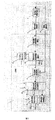
- Figure 1 is a control diagram of the planter monitoring system of the present invention.
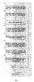
- FIG. 2 is a flow chart of a seeding machine monitoring method according to the present invention.
- a planter monitoring system includes an industrial computer 1 and a driving motor 3;
- the industrial computer 1 includes a unit speed fusion module 11 , a seed flow monitoring module 12 , a driving motor theoretical speed decision module 13 , and a rotating speed Deviation inference module 14, control parameter setting module 15, seeding axis speed adjustment module 16 and seed shaft speed control module 17;
- the positioning signal receiver is fixed on the top of the cab for receiving the geographical position signal; the positioning signal receiver is connected to the driving motor theoretical speed decision module 13, and the driving motor theoretical speed decision module 13 converts the geographical position signal into a table by the look-up table method.
- the theoretical broadcast quantity Q of the area, ie; Q f(N, E), where: N is the north latitude coordinate of the planter, E is the east longitude coordinate of the planter; the positioning signal receiver is a GPS locator.
- Planter speed sensor mounted on wheels, driving wheel rotational speed for measuring a planter; planter drive wheel and the speed sensor fusion module 11 is connected to line speed, for the u-th sampling speed as line speed u n-fusion the input module 11; an acceleration sensor mounted on the planter frame beam, for measuring acceleration planter; line speed and the acceleration sensor fusion module 11 is connected, for the u-th sample of the speed increase a planter as u The input of the unit speed fusion module 11;
- the unit speed fusion module 11 converts the input u-sampled seeder drive wheel speed n u and the u-th sampled planter rotation speed a u into a u-sampled planter speed v u by a speed fusion algorithm , Specifically:
- n u is the seeding drive wheel speed of the uth sampling, turning /min;
- D is the diameter of the drive wheel of the planter, m
- a u is the speed of the seeding machine of the uth sampling, m/s 2 ;
- u is the current sampling number
- m is the total sampling number, 1 ⁇ u ⁇ m
- the sampling period T is the time interval between the uth sampling number and the u-1th sampling number, and T is a constant
- a plurality of flow sensors are installed on each seeding port of the seeding machine for measuring the flow rate of each seeding port of the seeding machine; a plurality of the flow sensors are connected with the seeding flow monitoring module 12 for using the flow rate of each seeding port of the seeding machine as The input of the flow monitoring module 12 is output; the seeding flow monitoring module 12 outputs the total amount, and the seeding flow monitoring module 12 is connected to the driving motor theoretical speed decision module 13 for the total seeding amount of the seeding machine. Input as a driving motor theoretical speed decision module 13;
- the driving motor theoretical rotational speed decision module 13 outputs the total broadcast quantity, the theoretical broadcast quantity Q of the region, and the seeder speed v u of the u-th sampling, by driving the motor speed algorithm to output the theoretical speed of the driving motor.
- q u is the total amount of the first u sample, kg
- v u is the seed speed of the uth sampling, m/s
- A is the width of the planter operation, m;
- q is the theoretical broadcast amount per revolution of single row row axis, kg
- N is the number of rows of planters, OK;
- r is the transmission ratio between the seeding shaft driving motor and the seeding shaft
- u is the current sampling number
- m is the total sampling number, 1 ⁇ u ⁇ m
- the sampling period T is the time interval between the uth sampling number and the u-1th sampling number, and T is a constant
- An encoder 4 is mounted on the drive motor 3 for measuring the actual speed of the drive motor 3
- the encoder 4 and the driving motor theoretical rotational speed decision module 13 are respectively connected to the rotational speed deviation inference module 14, and the rotational speed deviation inference module 14 inputs the actual rotational speed of the input drive motor 3.
- the speed deviation e u is obtained by the difference gate operation, that is,
- the control parameter setting module 15 is connected to the rotational speed deviation inference module 14, and the rotational speed deviation e u is input to the control parameter setting module 15 to be estimated by the fuzzy neural network to obtain the proportional coefficient of the uth sampling.
- the integral coefficient of the uth sample And the differential coefficient of the uth sample Specifically,
- e u is the rotational speed deviation of the uth sampling
- m j is the mean value of the jth fuzzy subset corresponding to the rotational speed deviation e u ; j is the number of fuzzy subsets corresponding to the rotational speed deviation e u , and the preferred value interval is ⁇ j ⁇ N
- m 'k is the mean rotational speed deviation change amount ⁇ e u corresponding to the k-th fuzzy subset;
- fuzzy k is the deviation of the rotational change amount ⁇ e u corresponding to the set number, preferably ranging interval ⁇ k ⁇ N
- ⁇ j is the j-th fuzzy subset standard deviation corresponding to the rotational speed deviation e u ;
- ⁇ ' k is the k-th fuzzy subset standard deviation corresponding to the rotational speed deviation change amount ⁇ e u ;
- the control parameter setting module 15 is connected to the seeding axis rotation speed adjustment module 16 for using the proportional coefficient of the uth sampling The integral coefficient of the uth sample And the differential coefficient of the uth sample
- the input shaft rotation speed adjustment module 16 is connected to the seed shaft speed adjustment module 16 for inputting the rotation speed deviation e u as the seed shaft speed adjustment module 16;
- the adjustment module 16 will input the scale factor of the uth sample The integral coefficient of the uth sample Differential coefficient of the uth sample And the speed deviation e u of the u-th sampling, converted to the adjusted speed by the incremental PID algorithm Output, specifically:
- the seed shaft speed adjustment module 16 is connected to the seed shaft speed control module 17, and the input speed is adjusted by the seed shaft speed control module 17. Convert to pulse frequency P u output; the specific formula is: among them, For the seed shaft drive motor to adjust the speed, turn /min; ag is the rowing axis drive motor step angle, degree; d is the seeding axis drive motor subdivision number; drive motor controller 2 and seed shaft speed control module 17 The connection is for controlling the rotational speed of the drive motor 3 by a pulse signal having a frequency of P u .
- the transmission mode of the positioning signal receiver, the plurality of flow sensors, the speed sensor, the acceleration sensor, and the encoder 4 and the industrial computer 1 is wireless transmission.
- the wireless transmission is a Zigbee wireless network transmission.
- the sampling period T is 0.02 seconds.
- the industrial computer 1 is equipped with a user software program, which can perform human-computer interaction, including a unit parameter setting interface and a unit status monitoring interface; the unit parameter setting interface is used to set a working interval, a seeding area selection, and a tractor front wheel diameter. And whether to open the abnormal alarm of the seed box and the seeding amount; the unit status monitoring interface is used for real-time updating the current geographical position information of the machine, the advance speed of the machine, the residual value of the seed box storage, the working time of the storage allowance and each The seeding single multicast quantity is planted, and the operation interval over-border alarm, the broadcast quantity abnormal alarm and the reserve remaining quantity insufficient alarm indicator are provided.
- a user software program which can perform human-computer interaction, including a unit parameter setting interface and a unit status monitoring interface; the unit parameter setting interface is used to set a working interval, a seeding area selection, and a tractor front wheel diameter. And whether to open the abnormal alarm of the seed box and the seeding amount; the unit status monitoring interface is used for real-time updating the current
- the seeder monitoring method of the present invention comprises the following steps:
- the unit speed fusion module 11 converts the input u-sampled seeder drive wheel speed n u and the u-th sampled planter rotation speed a u into a u-sampled planter speed by a speed fusion algorithm.
- v u specifically:
- n u is the seeding drive wheel speed of the uth sampling, turning /min;
- D is the diameter of the drive wheel of the planter, m
- a u is the speed of the seeding machine of the uth sampling, m/s 2 ;
- u is the current sampling number
- m is the total sampling number, 1 ⁇ u ⁇ m
- the sampling period T is the time interval between the uth sampling number and the u-1th sampling number, and T is a constant
- S03 a plurality of the flow sensors are used to measure the flow rate of each seeding port of the seeder at the time of the uth sampling, and input to the seeding flow monitoring module 12, and converted to the total of the uth sampling time by the seeding flow monitoring module 12. Sowing amount q u ;
- q u is the total amount of the first u sample, kg
- v u is the seed speed of the uth sampling, m/s
- A is the width of the planter operation, m;
- q is the theoretical broadcast amount per revolution of single row row axis, kg
- N is the number of rows of planters, OK;
- r is the transmission ratio between the seeding shaft driving motor and the seeding shaft
- u is the current sampling number
- m is the total sampling number, 1 ⁇ u ⁇ m
- the sampling period T is the time interval between the uth sampling number and the u-1th sampling number, and T is a constant
- e u is the rotational speed deviation of the uth sampling
- m j is the mean value of the jth fuzzy subset corresponding to the rotational speed deviation e u ; j is the number of fuzzy subsets corresponding to the rotational speed deviation e u , and the preferred value interval is ⁇ j ⁇ N
- m 'k is the mean rotational speed deviation change amount ⁇ e u corresponding to the k-th fuzzy subset;
- fuzzy k is the deviation of the rotational change amount ⁇ e u corresponding to the set number, preferably ranging interval ⁇ k ⁇ N
- ⁇ j is the j-th fuzzy subset standard deviation corresponding to the rotational speed deviation e u ;
- ⁇ ' k is the k-th fuzzy subset standard deviation corresponding to the rotational speed deviation change amount ⁇ e u ;
- the input adjustment speed is input through the seed shaft speed control module 17 Converted to a pulse frequency P u output; the drive motor controller 2 controls the rotational speed of the drive motor 3 by a pulse signal having a frequency P u ; the encoder 4 will rotate the actual speed Feedback output to the speed deviation inference module 14;
Landscapes
- Engineering & Computer Science (AREA)
- Life Sciences & Earth Sciences (AREA)
- Physics & Mathematics (AREA)
- Theoretical Computer Science (AREA)
- Soil Sciences (AREA)
- General Physics & Mathematics (AREA)
- Data Mining & Analysis (AREA)
- General Engineering & Computer Science (AREA)
- Environmental Sciences (AREA)
- Software Systems (AREA)
- Computer Networks & Wireless Communication (AREA)
- Remote Sensing (AREA)
- Radar, Positioning & Navigation (AREA)
- Evolutionary Computation (AREA)
- Artificial Intelligence (AREA)
- Biomedical Technology (AREA)
- Health & Medical Sciences (AREA)
- Mathematical Physics (AREA)
- Biophysics (AREA)
- Computational Linguistics (AREA)
- Power Engineering (AREA)
- General Health & Medical Sciences (AREA)
- Molecular Biology (AREA)
- Computing Systems (AREA)
- Databases & Information Systems (AREA)
- Signal Processing (AREA)
- Mechanical Engineering (AREA)
- Computational Mathematics (AREA)
- Pure & Applied Mathematics (AREA)
- Bioinformatics & Cheminformatics (AREA)
- Bioinformatics & Computational Biology (AREA)
- Computer Vision & Pattern Recognition (AREA)
- Evolutionary Biology (AREA)
- Mathematical Optimization (AREA)
- Mathematical Analysis (AREA)
- Fuzzy Systems (AREA)
- Automation & Control Theory (AREA)
- Sowing (AREA)
- Feedback Control In General (AREA)
- Other Investigation Or Analysis Of Materials By Electrical Means (AREA)
Abstract
本发明提供了一种播种机监控系统和监控方法,一种播种机监控系统,包括工控机和驱动电机;所述工控机包括机组速度融合模块、排种流量监测模块、驱动电机理论转速决策模块、转速偏差推理模块、控制参数整定模块、排种轴转速调整模块和排种轴转速控制模块;定位信号接收器固定在驾驶室顶部,用于接收地理位置信号;所述定位信号接收器与驱动电机理论转速决策模块连接;速度传感器安装在播种机驱动轮上,用于测量播种机驱动轮转速;所述速度传感器与机组速度融合模块连接,加速度传感器安装在播种机机架横梁上,用于测量播种机加速度;所述加速度传感器与机组速度融合模块连接。本发明可以解决的是机组作业状态参数监测以及播量精准调控的问题。
Description
本发明涉及农业机械自动化领域,特别涉及一种播种机监控系统和监控方法。
播种过程智能化已成为农业工程领域的一大热点研究问题,播种机自适应监控系统由此应运而生。通过设定或导入播种处方图,实现智能播种。传统由链传动驱动排种器的播种机械,在潮湿、泥泞的土壤环境中,易受驱动轮空转及打滑的影响造成重播或漏播等问题,为降低播种机具作业过程中驱动轮滑移对播种质量的影响,采用电力拖动系统代替以地轮为动力源的链条传动系统已成为播种机发展的新趋势,专利CN201110398048.9以步进电机代替地轮链条系统驱动排种器,简化了机械结构,但其仍以地轮转速作为获取机具前进速度的单一因素,没有消除由于地轮空转、滑移导致的机具前进速度测量偏差,从而造成播种机漏播、重播现象。
为加快播种机智能化进程,降低人工劳动力,实现信息化播种作业,为后续田间管理、收获等工作提供数据支撑,需在机组关键位置安装传感器,除反馈机具前进速度外,还要求能够实时反馈机具空间位置、单位距离内种子流量,作为调整排种器转速的重要依据。专利CN201210144176.5提供一种播种机的智能监控方法,该方法缺乏转速监控手段,由主控制系统直接控制调速电机,易在作业过程中受到信号干扰,无法及时消除播量偏差,从而造成实际播量与理论播量的误差。
目前,虽然国内外播种机监控系统不断推陈出新,但实际应用中排种轴转速仍以固定参数的调节算法为主,不涉及控制参数的在线优化功能。
发明内容
针对现有技术中存在不足,本发明提供了一种播种机监控系统和监控方法,解决的是机组作业状态参数监测以及播量精准调控的问题。
本发明是通过以下技术手段实现上述技术目的的。
一种播种机监控系统,包括工控机和驱动电机;所述工控机包括机组速度融合模块、排种流量监测模块、驱动电机理论转速决策模块、转速偏差推理模块、控制参数整定模块、排种轴转速调整模块和排种轴转速控制模块;
定位信号接收器固定在驾驶室顶部,用于接收地理位置信号;所述定位信号接收器与驱动电机理论转速决策模块连接,驱动电机理论转速决策模块通过查表法将地理位置信号转换 为所在区域的理论播量Q,即;Q=f(N,E),式中:N为播种机的北纬坐标,E为播种机东经坐标;
速度传感器安装在播种机驱动轮上,用于测量播种机驱动轮转速;所述速度传感器与机组速度融合模块连接,用于将第u次采样的播种机驱动轮转速n
u作为机组速度融合模块的输入;加速度传感器安装在播种机机架横梁上,用于测量播种机加速度;所述加速度传感器与机组速度融合模块连接,用于将第u次采样的播种机加转速a
u作为机组速度融合模块的输入;
所述机组速度融合模块将输入的第u次采样的播种机驱动轮转速n
u和第u次采样的播种机加转速a
u通过速度融合算法转换为第u次采样的播种机速度v
u,具体为:

式中:
n
u为第u次采样的播种机驱动轮转速,转/min;
n
u-1为第u-1次采样的播种机驱动轮转速,转/min;当u=1时,n
0=0;
D为播种机驱动轮直径,m;
a
u为第u次采样的播种机加转速,m/s
2;
v
u-1为第u-1次采样的播种机速度,m/s;当u=1时,v
0=0;
u为当前采样次数,1≤u≤m,m为总采样次数;采样周期T为第u次采样次数和第u-1次采样次数的时间间隔,且T为常数;
若干流量传感器安装在播种机各个排种口上,用于测量播种机各个排种口的流量;若干所述流量传感器与排种流量监测模块连接,用于将播种机各个排种口的流量作为排种流量监测模块的输入;所述排种流量监测模块输出为总播量,且所述排种流量监测模块与驱动电机理论转速决策模块连接,用于将播种机总播量作为驱动电机理论转速决策模块输入;
所述驱动电机理论转速决策模块将输入的总播量、所在区域的理论播量Q和第u次采样的播种机速度v
u,通过驱动电机转速算法输出驱动电机理论转速
 即:
即:

式中:
Q为所在区域的理论播量,kg;
q
u为第u次采样的总播量,kg;
v
u为第u次采样的播种机速度,m/s;
A为播种机作业幅宽,m;
q为单行排种轴每转理论播量,kg;
N为播种机行数,行;
r为排种轴驱动电机与排种轴之间的传动比;
u为当前采样次数,m为总采样次数,1≤u≤m;采样周期T为第u次采样次数和第u-1次采样次数的时间间隔,且T为常数;
所述驱动电机上安装编码器,用于测量驱动电机实际转速
 所述编码器和驱动电机理论转速决策模块分别与转速偏差推理模块连接,所述转速偏差推理模块将输入的驱动电机实际转速
 和排种轴理论转速
 通过差门运算得出转速偏差e
u,即
通过差门运算得出转速偏差e
u,即

所述控制参数整定模块与转速偏差推理模块连接,将转速偏差e
u输入控制参数整定模块,通过模糊神经网络推算,得到第u次采样的比例系数
 第u次采样的积分系数
 和第u次采样的微分系数
 具体为,
具体为,


其中,式中:
e
u为第u次采样的转速偏差;
Δe
u为相邻两采样周期的转速偏差变化量,即Δe
u=e
u-e
u-1,且e
0为初始值,e
0=0;
m
j为转速偏差e
u对应的第j个模糊子集的均值;j为转速偏差e
u对应的模糊子集个数,优选取值区间为{j∈N|5≤j≤11};
m'
k为转速偏差变化量Δe
u对应的第k个模糊子集的均值;k为转速偏差变化量Δe
u对应的模糊子集的个数,优选取值区间为{k∈N|5≤k≤11};
δ
j为转速偏差e
u对应的第j个模糊子集标准差;
δ'
k为转速偏差变化量Δe
u对应的第k个模糊子集标准差;


所述控制参数整定模块与排种轴转速调整模块连接,用于将第u次采样的比例系数
 第u次采样的积分系数
 和第u次采样的微分系数
 作为排种轴转速调整模块输入;所述转速偏差推理模块与排种轴转速调整模块连接,用于将转速偏差e
u作为排种轴转速调整模块输入;所述排种轴转速调整模块将输入的第u次采样的比例系数
作为排种轴转速调整模块输入;所述转速偏差推理模块与排种轴转速调整模块连接,用于将转速偏差e
u作为排种轴转速调整模块输入;所述排种轴转速调整模块将输入的第u次采样的比例系数
 第u次采样的积分系数
 第u次采样的微分系数
 和第u次采样的转速偏差e
u,通过增量式PID算法转换为调节转速
和第u次采样的转速偏差e
u,通过增量式PID算法转换为调节转速
 输出,具体为:

所述排种轴转速调整模块与排种轴转速控制模块连接,通过排种轴转速控制模块将输入的调节转速
 转换为脉冲频率P
u输出;驱动电机控制器与排种轴转速控制模块连接,用于通过频率为P
u的脉冲信号控制驱动电机的转速。
转换为脉冲频率P
u输出;驱动电机控制器与排种轴转速控制模块连接,用于通过频率为P
u的脉冲信号控制驱动电机的转速。
进一步,所述定位信号接收器为GPS定位器。
进一步,所述定位信号接收器、若干流量传感器、速度传感器、加速度传感器和编码器与工控机的传输方式为无线传输。
进一步,所述无线传输为Zigbee无线网络传输。
进一步,所述采样周期T为0.02秒。
一种播种机监控方法,其特征在于,包括如下步骤:
S01:驱动电机理论转速决策模块将第u次采样时刻定位信号接收器输入的地理位置信号通过查表法转换为第u次采样时刻所在区域的理论播量Q,即;Q=f(N
u,E
u),式中:N
u为第u次采样时刻播种机的北纬坐标,E
u为第u次采样时刻播种机东经坐标;
S02:所述机组速度融合模块将输入的第u次采样的播种机驱动轮转速n
u和第u次采样的播种机加转速a
u通过速度融合算法转换为第u次采样的播种机速度v
u,具体为:

式中:
n
u为第u次采样的播种机驱动轮转速,转/min;
n
u-1为第u-1次采样的播种机驱动轮转速,转/min;当u=1时,n
0=0;
D为播种机驱动轮直径,m;
a
u为第u次采样的播种机加转速,m/s
2;
v
u-1为第u-1次采样的播种机速度,m/s;当u=1时,v
0=0;
u为当前采样次数,1≤u≤m,m为总采样次数;采样周期T为第u次采样次数和第u-1次采样次数的时间间隔,且T为常数;
S03:若干所述流量传感器用于测量第u次采样时刻播种机各个排种口的流量,并且输入到排种流量监测模块(12),通过排种流量监测模块转换为第u次采样时刻的总播量q
u;
S04:将第u次采样时刻所在区域的理论播量Q、第u次采样时刻的总播量q
u和第u次采样的播种机速度v
u作为驱动电机理论转速决策模块的输入,通过驱动电机转速算法输出驱动电机理论转速
 即:
即:

式中:
Q为所在区域的理论播量,kg;
q
u为第u次采样的总播量,kg;
v
u为第u次采样的播种机速度,m/s;
A为播种机作业幅宽,m;
q为单行排种轴每转理论播量,kg;
N为播种机行数,行;
r为排种轴驱动电机与排种轴之间的传动比;
u为当前采样次数,m为总采样次数,1≤u≤m;采样周期T为第u次采样次数和第u-1次采样次数的时间间隔,且T为常数;
S05:将驱动电机理论转速
 和编码器反馈的实际转速
 输入转速偏差推理模块,通过差门运算得出转速偏差e
u,即
输入转速偏差推理模块,通过差门运算得出转速偏差e
u,即

S06:将转速偏差e
u输入控制参数整定模块,通过模糊神经网络推算,输出第u次采样的比例系数
 第u次采样的积分系数
 和第u次采样的微分系数
 具体为,
具体为,


其中,式中:
e
u为第u次采样的转速偏差;
Δe
u为相邻两采样周期的转速偏差变化量,即Δe
u=e
u-e
u-1,且e
0为初始值,e
0=0;
m
j为转速偏差e
u对应的第j个模糊子集的均值;j为转速偏差e
u对应的模糊子集个数,优选取值区间为{j∈N|5≤j≤11};
m'
k为转速偏差变化量Δe
u对应的第k个模糊子集的均值;k为转速偏差变化量Δe
u对应的模糊子集的个数,优选取值区间为{k∈N|5≤k≤11};
δ
j为转速偏差e
u对应的第j个模糊子集标准差;
δ'
k为转速偏差变化量Δe
u对应的第k个模糊子集标准差;


S07:将第u次采样的比例系数
 第u次采样的积分系数
 第u次采样的微分系数
 和第u次采样的转速偏差e
u输入所述排种轴转速调整模块,通过增量式PID算法转换为调节转速
和第u次采样的转速偏差e
u输入所述排种轴转速调整模块,通过增量式PID算法转换为调节转速
 输出,具体为:

S08:通过排种轴转速控制模块将输入的调节转速
 转换为脉冲频率P
u输出;驱动电机控制器通过频率为P
u的脉冲信号控制驱动电机的转速;所述编码器将实际转速
转换为脉冲频率P
u输出;驱动电机控制器通过频率为P
u的脉冲信号控制驱动电机的转速;所述编码器将实际转速
 反馈输出到转速偏差推理模块;
S09:若u<m时,则进入下一采样周期u=u+1,循环执行S1至S8步骤;若u=m时或工控机接收到停止命令,播种机停止播种作业。
本发明的有益效果在于:
1.本发明所述的播种机监控系统和监控方法,通过设置控制参数整定模块利用模糊神经网络算法,进行在线优化,加强PID算法在变量播种应用中的适应性,减小排种轴驱动电机实际转速至理论转速的调整时间与超调量。
2.本发明所述的播种机监控系统和监控方法,通过设置机组速度融合模块利用速度融合算法以消除单一传感器带来的测速误差,得到机组前进速度最优值。
3.本发明所述的播种机监控系统和监控方法,通过设置Zigbee无线通信技术代替现有CAN总线进行信息通信,解决了所述车载终端与各终端模块之间连线复杂且互相干扰的问题,可有效提升播种机作业参数的监测准确性,并且有效降低功耗,可使蓄电池续航时间更加持久。
图1为本发明所述的播种机监控系统控制图。
图2为本发明所述的播种机监控方法流程图。
图中:
1-工控机;11-机组速度融合模块;12-排种流量监测模块;13-驱动电机理论转速决策模块;14-转速偏差推理模块;15-控制参数整定模块;16-排种轴转速调整模块;17-排种轴转速控制模块;2-驱动电机控制器;3-驱动电机;4-编码器。
下面结合附图以及具体实施例对本发明作进一步的说明,但本发明的保护范围并不限于此。
如图1所示,一种播种机监控系统,包括工控机1和驱动电机3;所述工控机1包括机组速度融合模块11、排种流量监测模块12、驱动电机理论转速决策模块13、转速偏差推理模块14、控制参数整定模块15、排种轴转速调整模块16和排种轴转速控制模块17;
定位信号接收器固定在驾驶室顶部,用于接收地理位置信号;所述定位信号接收器与驱动电机理论转速决策模块13连接,驱动电机理论转速决策模块13通过查表法将地理位置信号转换为所在区域的理论播量Q,即;Q=f(N,E),式中:N为播种机的北纬坐标,E为播种机东经坐标;所述定位信号接收器为GPS定位器。
速度传感器安装在播种机驱动轮上,用于测量播种机驱动轮转速;所述速度传感器与机组速度融合模块11连接,用于将第u次采样的播种机驱动轮转速n
u作为机组速度融合模块11的输入;加速度传感器安装在播种机机架横梁上,用于测量播种机加速度;所述加速度传感器与机组速度融合模块11连接,用于将第u次采样的播种机加转速a
u作为机组速度融合模块11的输入;
所述机组速度融合模块11将输入的第u次采样的播种机驱动轮转速n
u和第u次采样的播种机加转速a
u通过速度融合算法转换为第u次采样的播种机速度v
u,具体为:

式中:
n
u为第u次采样的播种机驱动轮转速,转/min;
n
u-1为第u-1次采样的播种机驱动轮转速,转/min;当u=1时,n
0=0;
D为播种机驱动轮直径,m;
a
u为第u次采样的播种机加转速,m/s
2;
v
u-1为第u-1次采样的播种机速度,m/s;当u=1时,v
0=0;
u为当前采样次数,m为总采样次数,1≤u≤m;采样周期T为第u次采样次数和第u-1次采样次数的时间间隔,且T为常数;
若干流量传感器安装在播种机各个排种口上,用于测量播种机各个排种口的流量;若干所述流量传感器与排种流量监测模块12连接,用于将播种机各个排种口的流量作为排种流量监测模块12的输入;所述排种流量监测模块12输出为总播量,且所述排种流量监测模块12与驱动电机理论转速决策模块13连接,用于将播种机总播量作为驱动电机理论转速决策模块13输入;
所述驱动电机理论转速决策模块13将输入的总播量、所在区域的理论播量Q和第u次采样的播种机速度v
u,通过驱动电机转速算法输出驱动电机理论转速
 即:
即:

式中:
Q为所在区域的理论播量,kg;
q
u为第u次采样的总播量,kg;
v
u为第u次采样的播种机速度,m/s;
A为播种机作业幅宽,m;
q为单行排种轴每转理论播量,kg;
N为播种机行数,行;
r为排种轴驱动电机与排种轴之间的传动比;
u为当前采样次数,m为总采样次数,1≤u≤m;采样周期T为第u次采样次数和第u-1次采样次数的时间间隔,且T为常数;
所述驱动电机3上安装编码器4,用于测量驱动电机3实际转速
 所述编码器4和驱动电机理论转速决策模块13分别与转速偏差推理模块14连接,所述转速偏差推理模块14将输入的驱动电机3实际转速
 和排种轴理论转速
 通过差门运算得出转速偏差e
u,即
通过差门运算得出转速偏差e
u,即

所述控制参数整定模块15与转速偏差推理模块14连接,将转速偏差e
u输入控制参数整定模块15,通过模糊神经网络推算,得到第u次采样的比例系数
 第u次采样的积分系数
 和第u次采样的微分系数
 具体为,
具体为,


其中,式中:
e
u为第u次采样的转速偏差;
Δe
u为相邻两采样周期的转速偏差变化量,即Δe
u=e
u-e
u-1,且e
0为初始值,e
0=0;
m
j为转速偏差e
u对应的第j个模糊子集的均值;j为转速偏差e
u对应的模糊子集个数,优选取值区间为{j∈N|5≤j≤11};
m'
k为转速偏差变化量Δe
u对应的第k个模糊子集的均值;k为转速偏差变化量Δe
u对应的模糊子集的个数,优选取值区间为{k∈N|5≤k≤11};
δ
j为转速偏差e
u对应的第j个模糊子集标准差;
δ'
k为转速偏差变化量Δe
u对应的第k个模糊子集标准差;


所述控制参数整定模块15与排种轴转速调整模块16连接,用于将第u次采样的比例系数
 第u次采样的积分系数
 和第u次采样的微分系数
 作为排种轴转速调整模块16 输入;所述转速偏差推理模块14与排种轴转速调整模块16连接,用于将转速偏差e
u作为排种轴转速调整模块16输入;所述排种轴转速调整模块16将输入的第u次采样的比例系数
作为排种轴转速调整模块16 输入;所述转速偏差推理模块14与排种轴转速调整模块16连接,用于将转速偏差e
u作为排种轴转速调整模块16输入;所述排种轴转速调整模块16将输入的第u次采样的比例系数
 第u次采样的积分系数
 第u次采样的微分系数
 和第u次采样的转速偏差e
u,通过增量式PID算法转换为调节转速
和第u次采样的转速偏差e
u,通过增量式PID算法转换为调节转速
 输出,具体为:

所述排种轴转速调整模块16与排种轴转速控制模块17连接,通过排种轴转速控制模块17将输入的调节转速
 转换为脉冲频率P
u输出;具体公式为:
转换为脉冲频率P
u输出;具体公式为:
 其中,
其中,
 为排种轴驱动电机调节转速,转/min;ag为排种轴驱动电机步进角,度;d为排种轴驱动电机细分数;驱动电机控制器2与排种轴转速控制模块17连接,用于通过频率为P
u的脉冲信号控制驱动电机3的转速。
为排种轴驱动电机调节转速,转/min;ag为排种轴驱动电机步进角,度;d为排种轴驱动电机细分数;驱动电机控制器2与排种轴转速控制模块17连接,用于通过频率为P
u的脉冲信号控制驱动电机3的转速。
所述定位信号接收器、若干流量传感器、速度传感器、加速度传感器和编码器4与工控机1的传输方式为无线传输。所述无线传输为Zigbee无线网络传输。
所述采样周期T为0.02秒。
所述工控机1安装有用户软件程序,可进行人机交互,包括机组参数设置界面和机组状态监视界面;所述机组参数设置界面,用于设定作业区间、播种区域选择、拖拉机前轮直径以及是否打开种箱余量及播种量异常报警;所述机组状态监视界面,用于实时更新机具当前地理位置信息、机具前进速度、种箱储种余量值、储种余量作业时间与各播种单组播量,并且设有作业区间越界报警、播量异常报警与储种余量不足报警指示灯。
如图2所示,本发明所述的播种机监控方法,包括如下步骤:
S01:驱动电机理论转速决策模块13将第u次采样时刻定位信号接收器输入的地理位置信号通过查表法转换为第u次采样时刻所在区域的理论播量Q,即;Q=f(N
u,E
u),式中:N
u为第u次采样时刻播种机的北纬坐标,E
u为第u次采样时刻播种机东经坐标;
S02:所述机组速度融合模块11将输入的第u次采样的播种机驱动轮转速n
u和第u次采样的播种机加转速a
u通过速度融合算法转换为第u次采样的播种机速度v
u,具体为:

式中:
n
u为第u次采样的播种机驱动轮转速,转/min;
n
u-1为第u-1次采样的播种机驱动轮转速,转/min;当u=1时,n
0=0;
D为播种机驱动轮直径,m;
a
u为第u次采样的播种机加转速,m/s
2;
v
u-1为第u-1次采样的播种机速度,m/s;当u=1时,v
0=0;
u为当前采样次数,m为总采样次数,1≤u≤m;采样周期T为第u次采样次数和第u-1次采样次数的时间间隔,且T为常数;
S03:若干所述流量传感器用于测量第u次采样时刻播种机各个排种口的流量,并且输入到排种流量监测模块12,通过排种流量监测模块12转换为第u次采样时刻的总播量q
u;
S04:将第u次采样时刻所在区域的理论播量Q、第u次采样时刻的总播量q
u和第u次采样的播种机速度v
u作为驱动电机理论转速决策模块13的输入,通过驱动电机转速算法输出驱动电机理论转速
 即:
即:

式中:
Q为所在区域的理论播量,kg;
q
u为第u次采样的总播量,kg;
v
u为第u次采样的播种机速度,m/s;
A为播种机作业幅宽,m;
q为单行排种轴每转理论播量,kg;
N为播种机行数,行;
r为排种轴驱动电机与排种轴之间的传动比;
u为当前采样次数,m为总采样次数,1≤u≤m;采样周期T为第u次采样次数和 第u-1次采样次数的时间间隔,且T为常数;
S05:将驱动电机理论转速
 和编码器4反馈的实际转速
 输入转速偏差推理模块14,通过差门运算得出转速偏差e
u,即
输入转速偏差推理模块14,通过差门运算得出转速偏差e
u,即

S06:将转速偏差e
u输入控制参数整定模块15,通过模糊神经网络推算,输出第u次采样的比例系数
 第u次采样的积分系数
 和第u次采样的微分系数
 具体为,
具体为,


其中,式中:
e
u为第u次采样的转速偏差;
Δe
u为相邻两采样周期的转速偏差变化量,即Δe
u=e
u-e
u-1,且e
0为初始值,e
0=0;
m
j为转速偏差e
u对应的第j个模糊子集的均值;j为转速偏差e
u对应的模糊子集个数,优选取值区间为{j∈N|5≤j≤11};
m'
k为转速偏差变化量Δe
u对应的第k个模糊子集的均值;k为转速偏差变化量Δe
u对应的模糊子集的个数,优选取值区间为{k∈N|5≤k≤11};
δ
j为转速偏差e
u对应的第j个模糊子集标准差;
δ'
k为转速偏差变化量Δe
u对应的第k个模糊子集标准差;


S07:将第u次采样的比例系数
 第u次采样的积分系数
 第u次采样的微分系数
 和第u次采样的转速偏差e
u输入所述排种轴转速调整模块16,通过增量式PID算法转换为调节转速
和第u次采样的转速偏差e
u输入所述排种轴转速调整模块16,通过增量式PID算法转换为调节转速
 输出,具体为:

S08:通过排种轴转速控制模块17将输入的调节转速
 转换为脉冲频率P
u输出;驱动电机控制器2通过频率为P
u的脉冲信号控制驱动电机3的转速;所述编码器4将实际转速
转换为脉冲频率P
u输出;驱动电机控制器2通过频率为P
u的脉冲信号控制驱动电机3的转速;所述编码器4将实际转速
 反馈输出到转速偏差推理模块14;
S09:若u<m时,则进入下一采样周期u=u+1,循环执行S1至S8步骤;若u=m时或工控机1接收到停止命令,播种机停止播种作业。
所述实施例为本发明的优选的实施方式,但本发明并不限于上述实施方式,在不背离本发明的实质内容的情况下,本领域技术人员能够做出的任何显而易见的改进、替换或变型均属于本发明的保护范围。
Claims (6)
- 一种播种机监控系统,其特征在于,包括工控机(1)和驱动电机(3);所述工控机(1)包括机组速度融合模块(11)、排种流量监测模块(12)、驱动电机理论转速决策模块(13)、转速偏差推理模块(14)、控制参数整定模块(15)、排种轴转速调整模块(16)和排种轴转速控制模块(17);定位信号接收器固定在驾驶室顶部,用于接收地理位置信号;所述定位信号接收器与驱动电机理论转速决策模块(13)连接,驱动电机理论转速决策模块(13)通过查表法将地理位置信号转换为所在区域的理论播量Q,即;Q=f(N,E),式中:N为播种机的北纬坐标,E为播种机东经坐标;速度传感器安装在播种机驱动轮上,用于测量播种机驱动轮转速;所述速度传感器与机组速度融合模块(11)连接,用于将第u次采样的播种机驱动轮转速n u作为机组速度融合模块(11)的输入;加速度传感器安装在播种机机架横梁上,用于测量播种机加速度;所述加速度传感器与机组速度融合模块(11)连接,用于将第u次采样的播种机加转速a u作为机组速度融合模块(11)的输入;所述机组速度融合模块(11)将输入的第u次采样的播种机驱动轮转速n u和第u次采样的播种机加转速a u通过速度融合算法转换为第u次采样的播种机速度v u,具体为:
 式中:n u为第u次采样的播种机驱动轮转速,转/min;n u-1为第u-1次采样的播种机驱动轮转速,转/min;当u=1时,n 0=0;D为播种机驱动轮直径,m;a u为第u次采样的播种机加转速,m/s 2;v u-1为第u-1次采样的播种机速度,m/s;当u=1时,v 0=0;u为当前采样次数,1≤u≤m,m为总采样次数;采样周期T为第u次采样次数和第u-1次采样次数的时间间隔,且T为常数;若干流量传感器安装在播种机各个排种口上,用于测量播种机各个排种口的流量;若干所述流量传感器与排种流量监测模块(12)连接,用于将播种机各个排种口的流量作为排种流量监测模块(12)的输入;所述排种流量监测模块(12)输出为总播量,且所述排种流量 监测模块(12)与驱动电机理论转速决策模块(13)连接,用于将播种机总播量作为驱动电机理论转速决策模块(13)输入;所述驱动电机理论转速决策模块(13)将输入的总播量、所在区域的理论播量Q和第u次采样的播种机速度v u,通过驱动电机转速算法输出驱动电机理论转速即:
 式中:Q为所在区域的理论播量,kg;q u为第u次采样的总播量,kg;v u为第u次采样的播种机速度,m/s;A为播种机作业幅宽,m;q为单行排种轴每转理论播量,kg;N为播种机行数,行;r为排种轴驱动电机与排种轴之间的传动比;所述驱动电机(3)上安装编码器(4),用于测量驱动电机(3)实际转速所述编码器(4)和驱动电机理论转速决策模块(13)分别与转速偏差推理模块(14)连接,所述转速偏差推理模块(14)将输入的驱动电机(3)实际转速
 和排种轴理论转速
 通过差门运算得出转速偏差e u,即
 所述控制参数整定模块(15)与转速偏差推理模块(14)连接,将转速偏差e u输入控制参数整定模块(15),通过模糊神经网络推算,得到第u次采样的比例系数第u次采样的积分系数
 和第u次采样的微分系数
 具体为,
具体为,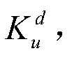


 其中,式中:e u为第u次采样的转速偏差;Δe u为相邻两采样周期的转速偏差变化量,即Δe u=e u-e u-1,且e 0为初始值,e 0=0;m j为转速偏差e u对应的第j个模糊子集的均值;j为转速偏差e u对应的模糊子集个数,优选取值区间为{j∈N|5≤j≤11};m' k为转速偏差变化量Δe u对应的第k个模糊子集的均值;k为转速偏差变化量Δe u对应的模糊子集的个数,优选取值区间为{k∈N|5≤k≤11};δ j为转速偏差e u对应的第j个模糊子集标准差;δ' k为转速偏差变化量Δe u对应的第k个模糊子集标准差;为修正比例参数的权值系数;
 为修正积分参数的权值系数;
 为修正微分参数的权值系数;
 所述控制参数整定模块(15)与排种轴转速调整模块(16)连接,用于将第u次采样的比例系数第u次采样的积分系数
 和第u次采样的微分系数
 作为排种轴转速调整模块(16)输入;所述转速偏差推理模块(14)与排种轴转速调整模块(16)连接,用于将转速偏差e u作为排种轴转速调整模块(16)输入;所述排种轴转速调整模块(16)将输入的第u次采样的比例系数
 第u次采样的积分系数
 第u次采样的微分系数
 和第u次采样的转速偏差e u,通过增量式PID算法转换为调节转速
 输出,具体为:
 所述排种轴转速调整模块(16)与排种轴转速控制模块(17)连接,通过排种轴转速控 制模块(17)将输入的调节转速转换为脉冲频率P u输出;驱动电机控制器(2)与排种轴转速控制模块(17)连接,用于通过频率为P u的脉冲信号控制驱动电机(3)的转速。
- 根据权利要求1所述的播种机监控系统,其特征在于,所述定位信号接收器为GPS定位器。
- 根据权利要求1所述的播种机监控系统,其特征在于,所述定位信号接收器、若干流量传感器、速度传感器、加速度传感器和编码器(4)与工控机(1)的传输方式为无线传输。
- 根据权利要求1所述的播种机监控系统,其特征在于,所述无线传输为Zigbee无线网络传输。
- 根据权利要求1所述的播种机监控系统,其特征在于,所述采样周期T为0.02秒。
- 一种播种机监控方法,其特征在于,包括如下步骤:S01:驱动电机理论转速决策模块(13)将第u次采样时刻定位信号接收器输入的地理位置信号通过查表法转换为第u次采样时刻所在区域的理论播量Q,即;Q=f(N u,E u),式中:N u为第u次采样时刻播种机的北纬坐标,E u为第u次采样时刻播种机东经坐标;S02:所述机组速度融合模块(11)将输入的第u次采样的播种机驱动轮转速n u和第u次采样的播种机加转速a u通过速度融合算法转换为第u次采样的播种机速度v u,具体为:
 式中:n u为第u次采样的播种机驱动轮转速,转/min;n u-1为第u-1次采样的播种机驱动轮转速,转/min;当u=1时,n 0=0;D为播种机驱动轮直径,m;a u为第u次采样的播种机加转速,m/s 2;v u-1为第u-1次采样的播种机速度,m/s;当u=1时,v 0=0;u为当前采样次数,1≤u≤m,m为总采样次数;采样周期T为第u次采样次数和第u-1次采样次数的时间间隔,且T为常数;S03:若干所述流量传感器用于测量第u次采样时刻播种机各个排种口的流量,并且输入到排种流量监测模块(12),通过排种流量监测模块(12)转换为第u次采样时刻的总播量 q u;S04:将第u次采样时刻所在区域的理论播量Q、第u次采样时刻的总播量q u和第u次采样的播种机速度v u作为驱动电机理论转速决策模块(13)的输入,通过驱动电机转速算法输出驱动电机理论转速即:
 式中:Q为所在区域的理论播量,kg;q u为第u次采样的总播量,kg;v u为第u次采样的播种机速度,m/s;A为播种机作业幅宽,m;q为单行排种轴每转理论播量,kg;N为播种机行数,行;r为排种轴驱动电机与排种轴之间的传动比;S05:将驱动电机理论转速和编码器(4)反馈的实际转速
 输入转速偏差推理模块(14),通过差门运算得出转速偏差e u,即
 S06:将转速偏差e u输入控制参数整定模块(15),通过模糊神经网络推算,输出第u次采样的比例系数第u次采样的积分系数
 和第u次采样的微分系数
 具体为,
具体为,


 其中,式中:e u为第u次采样的转速偏差;Δe u为相邻两采样周期的转速偏差变化量,即Δe u=e u-e u-1,且e 0为初始值,e 0=0;m j为转速偏差e u对应的第j个模糊子集的均值;j为转速偏差e u对应的模糊子集个数,优选取值区间为{j∈N|5≤j≤11};m' k为转速偏差变化量Δe u对应的第k个模糊子集的均值;k为转速偏差变化量Δe u对应的模糊子集的个数,优选取值区间为{k∈N|5≤k≤11};δ j为转速偏差e u对应的第j个模糊子集标准差;δ' k为转速偏差变化量Δe u对应的第k个模糊子集标准差;为修正比例参数的权值系数;
 为修正积分参数的权值系数;
 为修正微分参数的权值系数;
 S07:将第u次采样的比例系数第u次采样的积分系数
 第u次采样的微分系数
 和第u次采样的转速偏差e u输入所述排种轴转速调整模块(16),通过增量式PID算法转换为调节转速
 输出,具体为:
 S08:通过排种轴转速控制模块(17)将输入的调节转速转换为脉冲频率P u输出;驱动电机控制器(2)通过频率为P u的脉冲信号控制驱动电机(3)的转速;所述编码器(4)将实际转速
 反馈输出到转速偏差推理模块(14);
 S09:若u<m时,则进入下一采样周期u=u+1,循环执行S1至S8步骤;若u=m时或工控机(1)接收到停止命令,播种机停止播种作业。
Priority Applications (1)
| Application Number | Priority Date | Filing Date | Title |
|---|---|---|---|
| US16/474,514 US11464156B2 (en) | 2017-10-26 | 2018-07-13 | Monitoring system and monitoring method for seeder |
Applications Claiming Priority (2)
| Application Number | Priority Date | Filing Date | Title |
|---|---|---|---|
| CN201711012908.4A CN107733321B (zh) | 2017-10-26 | 2017-10-26 | 一种播种机监控系统和监控方法 |
| CN201711012908.4 | 2017-10-26 |
Publications (1)
| Publication Number | Publication Date |
|---|---|
| WO2019080545A1 true WO2019080545A1 (zh) | 2019-05-02 |
Family
ID=61213695
Family Applications (1)
| Application Number | Title | Priority Date | Filing Date |
|---|---|---|---|
| PCT/CN2018/095530 Ceased WO2019080545A1 (zh) | 2017-10-26 | 2018-07-13 | 一种播种机监控系统和监控方法 |
Country Status (3)
| Country | Link |
|---|---|
| US (1) | US11464156B2 (zh) |
| CN (1) | CN107733321B (zh) |
| WO (1) | WO2019080545A1 (zh) |
Families Citing this family (17)
| Publication number | Priority date | Publication date | Assignee | Title |
|---|---|---|---|---|
| CN107733321B (zh) * | 2017-10-26 | 2020-09-25 | 江苏大学 | 一种播种机监控系统和监控方法 |
| CN109197047B (zh) * | 2018-08-02 | 2020-10-23 | 山东省计算中心(国家超级计算济南中心) | 一种适用于小区育种播种机的编码器自动控制方法 |
| BR112021010533A2 (pt) * | 2018-12-24 | 2021-08-24 | The Climate Corporation | Geração de script preditivo para grãos de soja |
| CN110651569B (zh) * | 2019-10-15 | 2021-07-27 | 吉林农业大学 | 一种精密播种机地轮驱动力监控系统 |
| CN112072961A (zh) * | 2020-08-27 | 2020-12-11 | 吉林大学 | 一种基于anfis的无刷直流电机调速系统 |
| CN112666823B (zh) * | 2020-12-21 | 2023-04-07 | 潍柴雷沃智慧农业科技股份有限公司 | 一种作业方法、系统及农业机械设备 |
| CN112930794B (zh) * | 2021-03-16 | 2023-01-31 | 北京农业智能装备技术研究中心 | 一种精密播种机播量分布监测系统及方法 |
| CN113484516A (zh) * | 2021-07-01 | 2021-10-08 | 山东和生菌业科技有限公司 | 一种用于羊肚菌菌丝的定量检测方法 |
| CN114342605B (zh) * | 2021-12-14 | 2023-03-21 | 江苏大学 | 一种多信息融合的稻麦播种机播种量估计方法及监测系统 |
| US12201051B2 (en) * | 2021-12-17 | 2025-01-21 | Eden Concepts, Llc | Apparatus and method for seed germination and planting |
| CN115316084B (zh) * | 2022-08-01 | 2023-08-18 | 中国农业机械化科学研究院集团有限公司 | 一种气流输送式小麦播种机测控装置及其控制方法 |
| CN115686087B (zh) * | 2022-10-31 | 2024-09-13 | 安徽省农业科学院作物研究所 | 一种精量调节排种机排种芝麻种距解决方法及系统 |
| CN118058036B (zh) * | 2024-04-24 | 2024-06-18 | 江苏省农业机械技术推广站 | 一种大豆玉米带状种植播种机漏播控制系统及方法 |
| CN118786804A (zh) * | 2024-06-17 | 2024-10-18 | 安徽科技学院 | 一种基于速度监测的主动式电控精量排种装置及方法 |
| CN118537781B (zh) * | 2024-07-26 | 2024-11-26 | 南京农业大学 | 排种检测方法、装置、电子设备及存储介质 |
| CN120122537A (zh) * | 2025-03-10 | 2025-06-10 | 哈尔滨工业大学 | 一种播种施肥一体化播种机控制系统及方法 |
| CN120215382B (zh) * | 2025-03-26 | 2026-04-21 | 中国农业大学 | 一种少耕玉米播种智能化监测控制方法 |
Citations (4)
| Publication number | Priority date | Publication date | Assignee | Title |
|---|---|---|---|---|
| US5956255A (en) * | 1997-09-23 | 1999-09-21 | Case Corporation | Seed planter performance monitor |
| CN102096378A (zh) * | 2010-11-02 | 2011-06-15 | 湖南农业大学 | 油菜自动变量播种控制系统 |
| CN106444507A (zh) * | 2016-10-18 | 2017-02-22 | 合肥工业大学 | 一种基于可编程的免耕旋播机控制系统及其方法 |
| CN107733321A (zh) * | 2017-10-26 | 2018-02-23 | 江苏大学 | 一种播种机监控系统和监控方法 |
Family Cites Families (36)
| Publication number | Priority date | Publication date | Assignee | Title |
|---|---|---|---|---|
| US5684691A (en) * | 1995-04-17 | 1997-11-04 | Case Corporation | Method and apparatus for controlling draft of an agricultural implement |
| US7703266B2 (en) * | 2004-04-12 | 2010-04-27 | Cnh America Llc | Method for managing the electrical control system of a windrower header flotation and lift system |
| US7725234B2 (en) * | 2006-07-31 | 2010-05-25 | Caterpillar Inc. | System for controlling implement position |
| DE102006038865A1 (de) * | 2006-08-18 | 2008-02-21 | Alois Pöttinger Maschinenfabrik Gmbh | Sämaschine sowie Verfahren zur Regelung des Austrags einer Sämaschine |
| US8726543B2 (en) * | 2006-11-30 | 2014-05-20 | Deere & Company | Automated blade with load management control |
| US8078367B2 (en) * | 2007-01-08 | 2011-12-13 | Precision Planting, Inc. | Planter monitor system and method |
| US8498796B2 (en) * | 2007-02-12 | 2013-07-30 | Deere & Company | Perception model for trajectory following autonomous and human augmented speed control |
| US8195364B2 (en) * | 2007-02-12 | 2012-06-05 | Deere & Company | Perception model for trajectory following autonomous and human augmented steering control |
| US7895135B2 (en) * | 2007-02-12 | 2011-02-22 | Deere & Company | Human perception model for speed control performance |
| US7769512B2 (en) * | 2007-02-12 | 2010-08-03 | Deere & Company | Vehicle steering control method and performance |
| US8083004B2 (en) * | 2007-03-29 | 2011-12-27 | Caterpillar Inc. | Ripper autodig system implementing machine acceleration control |
| CN100504694C (zh) * | 2007-07-04 | 2009-06-24 | 华南农业大学 | 一种农业机械的导航控制方法 |
| US8515626B2 (en) * | 2008-07-22 | 2013-08-20 | Trimble Navigation Limited | System and method for machine guidance control |
| US8401744B2 (en) * | 2008-07-22 | 2013-03-19 | Trimble Navigation Limited | System and method for configuring a guidance controller |
| US8359139B2 (en) * | 2008-09-15 | 2013-01-22 | Cnh America Llc | Method and system for vehicle orientation measurement |
| CN102385318B (zh) * | 2010-08-31 | 2013-11-20 | 中国农业机械化科学研究院 | 一种免耕播种机播种量的控制方法及装置 |
| US8850997B2 (en) * | 2011-04-25 | 2014-10-07 | Deere & Company | Planter and method of operating a planter with individual meter control |
| JP5684691B2 (ja) * | 2011-11-14 | 2015-03-18 | 東芝テック株式会社 | コンテンツ配信装置およびプログラム |
| CN102550169B (zh) | 2011-12-05 | 2016-09-28 | 山东农业大学 | 步进电机驱动智能控制播种装置 |
| CN102630407B (zh) | 2012-05-11 | 2014-07-16 | 吉林大学 | 一种播种机工作状态实时监控系统和方法 |
| US9709969B2 (en) * | 2013-03-15 | 2017-07-18 | Deere & Company | Methods and apparatus to control machine configurations |
| GB201322859D0 (en) * | 2013-12-23 | 2014-02-12 | Agco Int Gmbh | Vehicle control system |
| GB201413547D0 (en) * | 2014-07-31 | 2014-09-17 | Agco Int Gmbh | Vehicle control system |
| US9826677B2 (en) * | 2014-12-16 | 2017-11-28 | Cnh Industrial Canada, Ltd. | Seed implement incorporating a down pressure sensing and adjustment system |
| CN106134579B (zh) * | 2015-04-03 | 2018-08-31 | 中国农业机械化科学研究院 | 气力式精密播种机播种监测装置及监测方法 |
| US10512203B2 (en) * | 2015-07-31 | 2019-12-24 | Agco International Gmbh | Vehicle control system |
| US9845008B2 (en) * | 2015-09-03 | 2017-12-19 | Deere & Company | System and method of detecting load forces on a traction vehicle to predict wheel slip |
| US9994104B2 (en) * | 2015-09-03 | 2018-06-12 | Deere & Company | System and method of reacting to wheel slip in a traction vehicle |
| US10112615B2 (en) * | 2015-09-03 | 2018-10-30 | Deere & Company | System and method of reacting to wheel slip in a traction vehicle |
| US10407072B2 (en) * | 2015-09-03 | 2019-09-10 | Deere & Company | System and method of regulating wheel slip in a traction vehicle |
| CN106856739A (zh) * | 2015-12-11 | 2017-06-20 | 魏莹 | 一种小麦双线精播智能控制系统 |
| US20220108262A1 (en) * | 2020-10-04 | 2022-04-07 | Strong Force Iot Portfolio 2016, Llc | Industrial digital twin systems and methods with echelons of executive, advisory and operations messaging and visualization |
| US10754334B2 (en) * | 2016-05-09 | 2020-08-25 | Strong Force Iot Portfolio 2016, Llc | Methods and systems for industrial internet of things data collection for process adjustment in an upstream oil and gas environment |
| CN108293715A (zh) * | 2017-07-28 | 2018-07-20 | 中国科学院西北高原生物研究所 | 高寒牧区禾本科牧草的有机栽培方法 |
| CN113418725A (zh) * | 2021-03-11 | 2021-09-21 | 东北林业大学 | 一种精量穴播种器排种性能自动检测装置 |
| CN114303854B (zh) * | 2022-02-10 | 2023-03-24 | 内蒙古大学 | 一种高降水量地区紫花苜蓿种子的繁育方法 |
-
2017
- 2017-10-26 CN CN201711012908.4A patent/CN107733321B/zh active Active
-
2018
- 2018-07-13 WO PCT/CN2018/095530 patent/WO2019080545A1/zh not_active Ceased
- 2018-07-13 US US16/474,514 patent/US11464156B2/en active Active
Patent Citations (4)
| Publication number | Priority date | Publication date | Assignee | Title |
|---|---|---|---|---|
| US5956255A (en) * | 1997-09-23 | 1999-09-21 | Case Corporation | Seed planter performance monitor |
| CN102096378A (zh) * | 2010-11-02 | 2011-06-15 | 湖南农业大学 | 油菜自动变量播种控制系统 |
| CN106444507A (zh) * | 2016-10-18 | 2017-02-22 | 合肥工业大学 | 一种基于可编程的免耕旋播机控制系统及其方法 |
| CN107733321A (zh) * | 2017-10-26 | 2018-02-23 | 江苏大学 | 一种播种机监控系统和监控方法 |
Also Published As
| Publication number | Publication date |
|---|---|
| US20200245531A1 (en) | 2020-08-06 |
| CN107733321B (zh) | 2020-09-25 |
| CN107733321A (zh) | 2018-02-23 |
| US11464156B2 (en) | 2022-10-11 |
Similar Documents
| Publication | Publication Date | Title |
|---|---|---|
| WO2019080545A1 (zh) | 一种播种机监控系统和监控方法 | |
| US10390478B2 (en) | Application control and monitoring apparatus, systems, and methods | |
| CN103270837B (zh) | 一种基于压力传感器的变量排种控制系统及方法 | |
| CN116671323B (zh) | 智能施肥装置及其控制方法 | |
| CN105302013B (zh) | 一种多作物条播机自适应播种控制方法 | |
| US12075721B2 (en) | Systems and methods for downforce control for an implement | |
| WO2022174561A1 (zh) | 一种变量播种施肥方法和施肥系统及装置 | |
| US20220000006A1 (en) | Tractor and method for operating a tractor | |
| CN115316084B (zh) | 一种气流输送式小麦播种机测控装置及其控制方法 | |
| CN120215382B (zh) | 一种少耕玉米播种智能化监测控制方法 | |
| Yu et al. | Design of motor-driven precision seed-metering device with improved fuzzy PID controller for small peanut planters | |
| CN111813032A (zh) | 一种精量播种机电驱播种控制系统 | |
| CN119452834A (zh) | 一种花生精量播种机播深播量在线检测与精准调控装置及方法 | |
| CN117369350B (zh) | 高速播种机控制系统、方法、电子设备及存储介质 | |
| Wang et al. | Development of automatic wheat seeding quantity control system based on Doppler radar speed measurement | |
| CN117148879A (zh) | 一种基于联动施肥机的精量控制系统和控制方法 | |
| CN120021467B (zh) | 一种水稻精量穴播机作业信息的监控系统及监测方法与水稻精量穴播机 | |
| JP7428163B2 (ja) | 作業車両 | |
| CN117652244B (zh) | 一种面向坡耕地的牵引式播种机主动纠偏方法及装置 | |
| CN117158161B (zh) | 宽苗带小麦播种机及其播种深度实时测控装置及方法 | |
| CN116616018A (zh) | 播种控制方法及播种机 | |
| KR101842358B1 (ko) | 모터 구동형 이식기 | |
| CN222465298U (zh) | 数控精量种肥一体播种机 | |
| Su et al. | Development of a variable rate fertilization control system based on DC motor for use on granular fertilizer applicator | |
| CN211671291U (zh) | 一种电动播种装置 |
Legal Events
| Date | Code | Title | Description |
|---|---|---|---|
| 121 | Ep: the epo has been informed by wipo that ep was designated in this application |
Ref document number: 18870650 Country of ref document: EP Kind code of ref document: A1 |
|
| NENP | Non-entry into the national phase |
Ref country code: DE |
|
| 122 | Ep: pct application non-entry in european phase |
Ref document number: 18870650 Country of ref document: EP Kind code of ref document: A1 |