WO2019073971A1 - Mounting structure and mounting method for cryogenic refrigerator - Google Patents
Mounting structure and mounting method for cryogenic refrigerator Download PDFInfo
- Publication number
- WO2019073971A1 WO2019073971A1 PCT/JP2018/037606 JP2018037606W WO2019073971A1 WO 2019073971 A1 WO2019073971 A1 WO 2019073971A1 JP 2018037606 W JP2018037606 W JP 2018037606W WO 2019073971 A1 WO2019073971 A1 WO 2019073971A1
- Authority
- WO
- WIPO (PCT)
- Prior art keywords
- cold head
- sleeve
- cooling stage
- flange
- stage
- Prior art date
Links
- 238000000034 method Methods 0.000 title claims description 16
- 238000001816 cooling Methods 0.000 claims abstract description 328
- 230000007246 mechanism Effects 0.000 claims abstract description 83
- 238000003825 pressing Methods 0.000 claims abstract description 32
- 238000012546 transfer Methods 0.000 claims description 108
- 239000004020 conductor Substances 0.000 claims description 9
- 238000002955 isolation Methods 0.000 claims description 9
- 238000000926 separation method Methods 0.000 claims description 2
- 238000010276 construction Methods 0.000 claims 1
- 238000012423 maintenance Methods 0.000 description 27
- 229910052738 indium Inorganic materials 0.000 description 23
- APFVFJFRJDLVQX-UHFFFAOYSA-N indium atom Chemical compound [In] APFVFJFRJDLVQX-UHFFFAOYSA-N 0.000 description 23
- 239000000463 material Substances 0.000 description 14
- RYGMFSIKBFXOCR-UHFFFAOYSA-N Copper Chemical compound [Cu] RYGMFSIKBFXOCR-UHFFFAOYSA-N 0.000 description 11
- 229910052802 copper Inorganic materials 0.000 description 11
- 239000010949 copper Substances 0.000 description 11
- 239000002184 metal Substances 0.000 description 11
- 229910052751 metal Inorganic materials 0.000 description 11
- 239000007789 gas Substances 0.000 description 8
- 238000005259 measurement Methods 0.000 description 6
- 230000007704 transition Effects 0.000 description 6
- 230000002093 peripheral effect Effects 0.000 description 5
- 230000000052 comparative effect Effects 0.000 description 4
- 229910001220 stainless steel Inorganic materials 0.000 description 4
- 239000010935 stainless steel Substances 0.000 description 4
- 230000008859 change Effects 0.000 description 3
- 230000008602 contraction Effects 0.000 description 3
- 230000008878 coupling Effects 0.000 description 3
- 238000010168 coupling process Methods 0.000 description 3
- 238000005859 coupling reaction Methods 0.000 description 3
- 230000015556 catabolic process Effects 0.000 description 2
- 239000000470 constituent Substances 0.000 description 2
- 230000007423 decrease Effects 0.000 description 2
- 238000006731 degradation reaction Methods 0.000 description 2
- 230000006866 deterioration Effects 0.000 description 2
- 230000005489 elastic deformation Effects 0.000 description 2
- 238000002474 experimental method Methods 0.000 description 2
- 239000001307 helium Substances 0.000 description 2
- 229910052734 helium Inorganic materials 0.000 description 2
- SWQJXJOGLNCZEY-UHFFFAOYSA-N helium atom Chemical compound [He] SWQJXJOGLNCZEY-UHFFFAOYSA-N 0.000 description 2
- 239000012535 impurity Substances 0.000 description 2
- 238000012986 modification Methods 0.000 description 2
- 230000004048 modification Effects 0.000 description 2
- 238000013459 approach Methods 0.000 description 1
- 238000013461 design Methods 0.000 description 1
- 238000010586 diagram Methods 0.000 description 1
- 230000014509 gene expression Effects 0.000 description 1
- 239000011261 inert gas Substances 0.000 description 1
- 230000007774 longterm Effects 0.000 description 1
- 239000012528 membrane Substances 0.000 description 1
- 239000007769 metal material Substances 0.000 description 1
- 239000000203 mixture Substances 0.000 description 1
- 238000012544 monitoring process Methods 0.000 description 1
- 230000008569 process Effects 0.000 description 1
- 238000011084 recovery Methods 0.000 description 1
- 238000007789 sealing Methods 0.000 description 1
Images


Classifications
-
- F—MECHANICAL ENGINEERING; LIGHTING; HEATING; WEAPONS; BLASTING
- F25—REFRIGERATION OR COOLING; COMBINED HEATING AND REFRIGERATION SYSTEMS; HEAT PUMP SYSTEMS; MANUFACTURE OR STORAGE OF ICE; LIQUEFACTION SOLIDIFICATION OF GASES
- F25D—REFRIGERATORS; COLD ROOMS; ICE-BOXES; COOLING OR FREEZING APPARATUS NOT OTHERWISE PROVIDED FOR
- F25D23/00—General constructional features
- F25D23/006—General constructional features for mounting refrigerating machinery components
-
- F—MECHANICAL ENGINEERING; LIGHTING; HEATING; WEAPONS; BLASTING
- F25—REFRIGERATION OR COOLING; COMBINED HEATING AND REFRIGERATION SYSTEMS; HEAT PUMP SYSTEMS; MANUFACTURE OR STORAGE OF ICE; LIQUEFACTION SOLIDIFICATION OF GASES
- F25B—REFRIGERATION MACHINES, PLANTS OR SYSTEMS; COMBINED HEATING AND REFRIGERATION SYSTEMS; HEAT PUMP SYSTEMS
- F25B9/00—Compression machines, plants or systems, in which the refrigerant is air or other gas of low boiling point
- F25B9/14—Compression machines, plants or systems, in which the refrigerant is air or other gas of low boiling point characterised by the cycle used, e.g. Stirling cycle
- F25B9/145—Compression machines, plants or systems, in which the refrigerant is air or other gas of low boiling point characterised by the cycle used, e.g. Stirling cycle pulse-tube cycle
-
- F—MECHANICAL ENGINEERING; LIGHTING; HEATING; WEAPONS; BLASTING
- F25—REFRIGERATION OR COOLING; COMBINED HEATING AND REFRIGERATION SYSTEMS; HEAT PUMP SYSTEMS; MANUFACTURE OR STORAGE OF ICE; LIQUEFACTION SOLIDIFICATION OF GASES
- F25B—REFRIGERATION MACHINES, PLANTS OR SYSTEMS; COMBINED HEATING AND REFRIGERATION SYSTEMS; HEAT PUMP SYSTEMS
- F25B49/00—Arrangement or mounting of control or safety devices
-
- F—MECHANICAL ENGINEERING; LIGHTING; HEATING; WEAPONS; BLASTING
- F25—REFRIGERATION OR COOLING; COMBINED HEATING AND REFRIGERATION SYSTEMS; HEAT PUMP SYSTEMS; MANUFACTURE OR STORAGE OF ICE; LIQUEFACTION SOLIDIFICATION OF GASES
- F25B—REFRIGERATION MACHINES, PLANTS OR SYSTEMS; COMBINED HEATING AND REFRIGERATION SYSTEMS; HEAT PUMP SYSTEMS
- F25B9/00—Compression machines, plants or systems, in which the refrigerant is air or other gas of low boiling point
- F25B9/14—Compression machines, plants or systems, in which the refrigerant is air or other gas of low boiling point characterised by the cycle used, e.g. Stirling cycle
-
- F—MECHANICAL ENGINEERING; LIGHTING; HEATING; WEAPONS; BLASTING
- F25—REFRIGERATION OR COOLING; COMBINED HEATING AND REFRIGERATION SYSTEMS; HEAT PUMP SYSTEMS; MANUFACTURE OR STORAGE OF ICE; LIQUEFACTION SOLIDIFICATION OF GASES
- F25D—REFRIGERATORS; COLD ROOMS; ICE-BOXES; COOLING OR FREEZING APPARATUS NOT OTHERWISE PROVIDED FOR
- F25D19/00—Arrangement or mounting of refrigeration units with respect to devices or objects to be refrigerated, e.g. infrared detectors
-
- F—MECHANICAL ENGINEERING; LIGHTING; HEATING; WEAPONS; BLASTING
- F25—REFRIGERATION OR COOLING; COMBINED HEATING AND REFRIGERATION SYSTEMS; HEAT PUMP SYSTEMS; MANUFACTURE OR STORAGE OF ICE; LIQUEFACTION SOLIDIFICATION OF GASES
- F25B—REFRIGERATION MACHINES, PLANTS OR SYSTEMS; COMBINED HEATING AND REFRIGERATION SYSTEMS; HEAT PUMP SYSTEMS
- F25B2309/00—Gas cycle refrigeration machines
- F25B2309/14—Compression machines, plants or systems characterised by the cycle used
- F25B2309/1414—Pulse-tube cycles characterised by pulse tube details
-
- F—MECHANICAL ENGINEERING; LIGHTING; HEATING; WEAPONS; BLASTING
- F25—REFRIGERATION OR COOLING; COMBINED HEATING AND REFRIGERATION SYSTEMS; HEAT PUMP SYSTEMS; MANUFACTURE OR STORAGE OF ICE; LIQUEFACTION SOLIDIFICATION OF GASES
- F25D—REFRIGERATORS; COLD ROOMS; ICE-BOXES; COOLING OR FREEZING APPARATUS NOT OTHERWISE PROVIDED FOR
- F25D2700/00—Means for sensing or measuring; Sensors therefor
- F25D2700/12—Sensors measuring the inside temperature
- F25D2700/121—Sensors measuring the inside temperature of particular compartments
Definitions
- the present invention relates to a mounting structure and a mounting method of a cryogenic refrigerator to a vacuum vessel.
- a cold head of a cryogenic refrigerator through a sleeve to a cryogenic vacuum vessel such as a cryostat.
- a cryogenic vacuum vessel such as a cryostat.
- An object to be cooled such as a superconducting coil, is accommodated in the cryogenic vacuum vessel, and the object to be cooled is attached to and in thermal contact with the end of the sleeve.
- the thermal contact between the cold head and the sleeve allows the cryogenic refrigerator to cool the object via the sleeve.
- cryogenic refrigerator During long term operation of the cryogenic refrigerator, maintenance of the cryogenic refrigerator may be required periodically.
- the operator can operate the mounting structure using the sleeve to release the thermal contact between the cold head and the sleeve to perform maintenance on the cryogenic refrigerator.
- the cryogenic refrigerator is heated to a temperature convenient for maintenance work, such as room temperature, and recooled after the work is completed. By releasing the thermal contact, the object to be cooled can be kept at a low temperature. Therefore, it is possible to shorten the recooling time of the object to be cooled as compared with the case where the object to be cooled is raised to room temperature and maintenance is performed together with the cryogenic refrigerator, and the required time for maintenance is shortened. be able to.
- Patent No. 3524460 gazette Patent No. 3992276
- the present inventors have come to recognize the following problems.
- the inventor of the present invention has found that the new phenomenon that the thermal contact state between the cryogenic refrigerator and the sleeve is likely to deteriorate when the maintenance of the cryogenic refrigerator mounted by this kind of mounting structure is repeated several times discovered.
- an indium sheet is sandwiched between the cryogenic refrigerator and the thermal contact portion of the sleeve to improve thermal contact.
- the deterioration phenomenon of the thermal contact state is considered to be due to the inclusion of the indium sheet. Degradation of the thermal contact is undesirable because it can lead to an increase in the cooling temperature of the object to be cooled or a decrease in the cooling efficiency.
- One of the exemplary objects of an embodiment of the present invention is an cryogenic refrigerator and a sleeve for a long period of time even if maintenance of the cryogenic refrigerator is repeated for the cryogenic refrigerator attached to the vacuum vessel via the sleeve.
- An object of the present invention is to provide a technique for maintaining a good thermal contact.
- a mounting structure for mounting a cold head of a cryogenic refrigerator on a vacuum vessel, the cold head comprising a cold head side cooling stage and a cold head side flange.
- the mounting structure is a cold head receiving sleeve installed in the vacuum vessel so as to form an airtight area isolated from an ambient environment between the cold head and the cold head, wherein the mounting structure is physically connected to the cold head side cooling stage.
- a cold head receiving sleeve comprising a sleeve side cooling stage in thermal contact with the cold head side cooling stage by contact, and a sleeve side flange coupled to the cold head side flange; isolation of the hermetic zone from the surrounding environment
- the cold head side cooling stage and the sleeve side cooling Flange spacing adjusting mechanism configured to adjust the distance between the sleeve side flange and the cold head side flange so as to bring the cages into physical contact or non-contact, the cold head side cooling stage, and the cold head side cooling stage
- the cold head side flange is configured to press the cold head side cooling stage against the sleeve side cooling stage with a pressing surface pressure specified to be in thermal contact with the sleeve side cooling stage with thermal resistance below a threshold value.
- a flange fastening mechanism configured to fasten the sleeve with the sleeve side flange.
- the cold head receiving sleeve is a sleeve side cooling stage in thermal contact with the cold head side cooling stage by physical contact with the cold head side cooling stage, and a sleeve side coupled to the cold head side flange A flange, and the vacuum vessel is disposed to form an airtight area isolated from the surrounding environment between the flange and the cold head, and the mounting method comprises isolating the airtight area from the surrounding environment While holding the cold head side cooling stage as the sleeve side cooling stay Adjusting the distance between the sleeve-side flange and the cold head-side flange so that the cold head-side cooling stage and the sleeve-side cooling stage are in thermal contact with each other by a threshold value or less. Fastening the cold head side flange with the sleeve side flange so as to press the cold head side cooling stage against the sleeve side cooling stage with a pressing surface pressure designated to be in thermal contact.
- FIG.6 (a) and FIG.6 (b) are schematic which shows an example of the cooling stage structure which may be used for the cryogenic refrigerator which concerns on embodiment. It is a schematic perspective view showing an exemplary composition of a cold head side heat transfer block concerning an embodiment.
- FIG. 1 and FIG. 2 are schematic diagrams for explaining the mounting structure according to the embodiment.
- FIG. 1 shows a state in which the cryogenic refrigerator 10 is thermally coupled to the object 12 to be cooled, such as a superconducting coil
- FIG. 2 shows a state in which the thermal coupling of the two is released. It is shown.
- the mounting structure is a device for mounting the cryogenic refrigerator 10 on a vacuum vessel 14, for example, a cryogenic vacuum vessel such as a cryostat.
- the mounting structure includes a cold head housing sleeve (hereinafter simply referred to as a sleeve) 16, a flange spacing adjustment mechanism 18, and a flange fastening mechanism 20.
- the cryogenic refrigerator 10 comprises a cold head 22 and a compressor 24.
- the sleeve 16 is mounted to the vacuum vessel 14 so as to form an air tight area 28 isolated from the surrounding environment 26 with the cold head 22.
- the ambient environment 26 is, for example, an atmospheric pressure environment at room temperature.
- the hermetic zone 28 may be evacuated to vacuum or may be filled with a cryogenic non-liquefiable inert gas such as helium gas.
- the sleeve 16 is mounted on the vacuum vessel 14 so as to combine with the vacuum vessel 14 to define the vacuum region 30 in the vacuum vessel 14.
- the upper end of the sleeve 16 is attached to an opening formed in the top plate of the vacuum vessel 14, and the sleeve 16 extends into the vacuum vessel 14 from this opening.
- the lower end of the sleeve 16 is attached to the object 12 directly or via an optional heat transfer member.
- the object to be cooled 12 is disposed in the vacuum region 30.
- the cryogenic refrigerator 10 is, for example, a single-stage Gifford McMahon refrigerator (hereinafter also referred to as a GM refrigerator). Therefore, the mounting structure is configured to mount the single-stage GM refrigerator on the vacuum vessel 14.
- the cryogenic refrigerator 10 is not limited to this, and may be a two-stage GM refrigerator, in which case, the mounting structure is configured to mount the two-stage GM refrigerator on the vacuum vessel 14 It can be done.
- the cryogenic refrigerator 10 may be another cryogenic refrigerator such as a Stirling refrigerator or a pulse tube refrigerator.
- the cryogenic refrigerator 10 may be provided to the customer by the manufacturer of the cryogenic refrigerator 10 along with the mounting structure described above. It can be said that the cooling device for cooling the object to be cooled 12 is composed of the cryogenic refrigerator 10 and the mounting structure. Therefore, the cooling device according to the embodiment includes the cryogenic refrigerator 10, the sleeve 16, the flange interval adjustment mechanism 18, and the flange fastening mechanism 20.
- the cold head 22 of the cryogenic refrigerator 10 includes a cold head side cooling stage 32, a cold head side flange 34, and a cylinder 36.
- the cylinder 36 extends along the central axis 38 and connects the cold head side flange 34 with the cold head side cooling stage 32.
- the cold head side flange 34 and the cold head side cooling stage 32 are arranged coaxially with the cylinder 36.
- the cold head side flange 34 is provided at the upper end of the cylinder 36, and the cold head side cooling stage 32 is provided at the lower end of the cylinder 36.
- the cylinder 36 is a hollow cylindrical member
- the cold head side flange 34 is an annular member extending radially outward from the upper end opening periphery of the cylinder 36 perpendicularly to the central axis 38.
- the cold head side cooling stage 32 is a disk-like or short cylindrical member fixed to the cylinder 36 so as to close the lower end opening of the cylinder 36.
- the cold head side cooling stage 32 is formed of, for example, a high thermal conductivity metal such as copper (for example, pure copper), or other thermal conductivity material.
- the cold head side flange 34 and the cylinder 36 are formed of, for example, a metal such as stainless steel.
- the thermal conductivity of the thermally conductive material forming the cold head side cooling stage 32 is higher than the thermal conductivity of the material forming the cylinder 36 (or the cold head side flange 34).
- the compressor 24 of the cryogenic refrigerator 10 is provided to circulate a working gas (for example, helium gas) to the cryogenic refrigerator 10.
- the compressor 24 is configured to supply high pressure working gas to the cold head 22 and recover from the cold head 22 low pressure working gas decompressed by adiabatic expansion in the expansion space in the cold head 22 and pressurize again. ing.
- the cold head 22 includes a displacer 40 and a drive unit 42 connected to the displacer 40 for driving the displacer 40.
- Displacer 40 is disposed in cylinder 36 coaxially with cylinder 36 and is capable of reciprocating along cylinder 36 in the direction of central axis 38.
- An expansion space for working gas is formed between the displacer 40 and the cold head side cooling stage 32.
- the drive unit 42 incorporates a valve for controlling the pressure in the expansion space.
- the pressure control valve is configured to alternate between high pressure working gas supply from the compressor 24 to the expansion space and low pressure working gas recovery from the expansion space to the compressor 24.
- the drive unit 42 is configured to appropriately synchronize the volume change of the expansion space due to the axial reciprocation of the displacer 40 and the pressure change of the expansion space by the pressure control valve. Thereby, the cold head 22 can cool the cold head side cooling stage 32.
- the drive unit 42 is fixed to the cold head side flange 34 by a fastening member (not shown) such as a bolt, for example. By releasing the fastening, the drive unit 42 can be removed together with the displacer 40 from the cold head 22 integrally.
- a fastening member such as a bolt
- the cold head flange 34 is a combination of two flanges. That is, the cold head side flange 34 includes a cylinder flange 44 integrally formed with the cylinder 36 at the upper end opening periphery of the cylinder 36 and a transition flange 46 attached to the lower surface of the cylinder flange 44.
- the drive portion 42 is removably fixed to the cylinder flange 44. When the drive unit 42 is removed, the displacer 40 is pulled out of the upper end opening of the cylinder 36, and when the drive unit 42 is attached, the displacer 40 is inserted into the cylinder 36 from the upper end opening of the cylinder 36.
- the transition flange 46 is also one component of the mounting structure, and includes an annular plate portion 46a and a tubular portion 46b.
- the annular plate 46a is fixed to the lower surface of the cylinder flange 44 by a fastening member (not shown) such as a bolt.
- the cylindrical portion 46 b extends downward from the annular plate portion 46 a in the direction of the central axis 38.
- the cylindrical portion 46 b is a short cylinder and surrounds the upper end of the cylinder 36.
- the diameter of the cylindrical portion 46b is slightly larger than the diameter of the cylinder 36, and there is a gap between the inner peripheral surface of the cylindrical portion 46b and the outer peripheral surface of the cylinder 36 so that they do not contact each other.
- the compressor 24, the coldhead flange 34 and the drive 42 are arranged in the ambient environment 26.
- the sleeve 16 is disposed coaxially with the cylinder 36 so as to surround the cylinder 36.
- the sleeve 16 includes a sleeve side cooling stage 48, a sleeve side flange 50, and a sleeve body 52.
- the sleeve side cooling stage 48 makes thermal contact with the cold head side cooling stage 32 by physical contact with the cold head side cooling stage 32.
- the contact surface of the sleeve side cooling stage 48 and the cold head side cooling stage 32 is flat, it is not restricted to this shape.
- the cold head side cooling stage 32 may have a non-flat surface such as a tapered surface, an inclined surface, or an uneven surface, and the inner surface of the sleeve side cooling stage 48 exposed to the airtight region 28 is It may have a non-flat surface corresponding to this non-flat surface.
- the object to be cooled 12 is attached to the outer surface of the sleeve side cooling stage 48 exposed to the vacuum region 30.
- the cold head side cooling stage 32 when the cold head side cooling stage 32 physically contacts the sleeve side cooling stage 48, the cold head side cooling stage 32 is thermally coupled to the object to be cooled 12 via the sleeve side cooling stage 48. Therefore, the object to be cooled 12 can be cooled by the cold head side cooling stage 32 being cooled.
- the cryogenic refrigerator 10 can cool the object to be cooled 12 to a cryogenic temperature below the critical temperature of the superconducting material.
- the cold head side cooling stage 32 and the sleeve side cooling stage 48 be in direct contact with each other without heat transfer inclusions such as an indium sheet.
- the present invention does not require the absence of inclusions. If permitted, the cold head side cooling stage 32 and the sleeve side cooling stage 48 may be in thermal contact with heat transfer inclusions such as an indium sheet.
- the sleeve side flange 50 is coupled to the cold head side flange 34 and is disposed in the ambient environment 26.
- the sleeve side flange 50 includes an annular first plate portion 50a, a cylindrical portion 50b, and an annular second plate portion 50c.
- the annular first plate portion 50a and the annular second plate portion 50c are connected by a cylindrical portion 50b.
- the annular first plate portion 50a is fixed to the upper surface of the vacuum vessel 14 by a fastening member (not shown) such as a bolt, for example.
- the cylindrical portion 50 b is a short cylinder and extends upward from the first plate portion 50 a in the direction of the central axis 38.
- the second plate portion 50c is opposed to the annular plate portion 46a of the transition flange 46 at an interval of, for example, several mm.
- the cylindrical portion 50b of the sleeve side flange 50 is disposed adjacent to and immediately outside the cylindrical portion 46b of the transition flange 46, and both are in contact with each other.
- a seal member 54 for maintaining the airtightness of the airtight region 28 is disposed between the cylindrical portion 50 b of the sleeve side flange 50 and the cylindrical portion 46 b of the transition flange 46.
- the seal member 54 is, for example, a seal member such as an O-ring disposed in a circumferential groove formed in the cylindrical portion 50 b of the sleeve side flange 50.
- the sleeve body 52 is a hollow cylindrical member and extends coaxially with the cylinder 36 along the central axis 38 and connects the sleeve side flange 50 with the sleeve side cooling stage 48.
- the sleeve side flange 50 is provided at the upper end of the sleeve body 52, and the sleeve side cooling stage 48 is provided at the lower end of the sleeve body 52.
- the sleeve side flange 50 is an annular member extending radially outward from the peripheral edge of the upper end opening of the sleeve body 52 in a direction perpendicular to the central axis 38.
- the sleeve side cooling stage 48 is a disc or short cylindrical member fixed to the sleeve 52 so as to close the lower end opening of the sleeve 52.
- the sleeve side cooling stage 48 is formed of, for example, a high thermal conductivity metal such as copper (for example, pure copper), or other thermal conductivity material.
- the sleeve side flange 50 and the sleeve body 52 are formed of metal such as stainless steel, for example.
- the thermal conductivity of the thermally conductive material forming the sleeve side cooling stage 48 is higher than the thermal conductivity of the material forming the sleeve body 52 (or the sleeve side flange 50).
- the cold head flange 34 is axially slidable with respect to the sleeve flange 50 so that the cold head 22 is axially movable with respect to the sleeve 16.
- the movable range is about several mm, for example, about 2 to 3 mm. Because of the sealing member 54, the tight area 28 is isolated from the surrounding environment 26 even if the cold head 22 moves.
- FIG. 1 shows that the cold head 22 is positioned at the lower end of the movable range and the cold head side cooling stage 32 and the sleeve side cooling stage 48 are in thermal contact.
- the cold head 22 is positioned at the upper end of the movable range, the cold head side cooling stage 32 is separated from the sleeve side cooling stage 48, and the thermal contact between the two is released.
- the flange spacing adjustment mechanism 18 keeps the cold head side cooling stage 32 and the sleeve side cooling stage 48 in physical contact or non-contact while maintaining isolation of the airtight region 28 from the surrounding environment 26.
- the gap between the flange 50 and the cold head side flange 34 is adjusted.
- the cold head 22 can be raised and lowered in the above-described movable range.
- An exemplary configuration of the flange spacing adjustment mechanism 18 will be described later.
- the flange fastening mechanism 20 is configured to fasten the cold head side flange 34 with the sleeve side flange 50 so as to press the cold head side cooling stage 32 against the sleeve side cooling stage 48.
- the flange fastening mechanism 20 sets the cold head side cooling stage 32 with a pressing surface pressure specified such that the cold head side cooling stage 32 and the sleeve side cooling stage 48 are in thermal contact with each other with a thermal resistance less than a threshold value.
- This threshold is also referred to as a thermal resistance threshold.
- the flange fastening mechanism 20 can adjust the pressing surface pressure acting between the cold head side cooling stage 32 and the sleeve side cooling stage 48.
- An exemplary configuration of the flange fastening mechanism 20 will be described later.
- the cold head 22 also includes a cold head temperature sensor 56 that measures the temperature of the cold head side cooling stage 32.
- the cold head side temperature sensor 56 is disposed on the cold head side cooling stage 32.
- the sleeve 16 is provided with a sleeve side temperature sensor 58 that measures the temperature of the sleeve side cooling stage 48.
- the sleeve side temperature sensor 58 is disposed on the sleeve side cooling stage 48.
- the cold head side temperature sensor 56 is configured to output a signal S1 representing a cold head measurement temperature to the outside
- the sleeve side temperature sensor 58 is configured to output a signal S2 representing a sleeve measurement temperature to the outside.
- An output unit 60 may be provided to display or output the measured temperature (and / or the temperature difference).
- the cold head side by the flange fastening mechanism 20 so that the temperature difference ⁇ T between the measured temperature of the cold head side cooling stage 32 and the measured temperature of the sleeve side cooling stage 48 falls within a predetermined temperature difference corresponding to the thermal resistance threshold value.
- the flange 34 is fastened to the sleeve side flange 50.
- the operator operates the flange fastening mechanism 20 to fasten the cold head side flange 34 with the sleeve side flange 50 so that the temperature difference ⁇ T falls within a predetermined temperature difference corresponding to the thermal resistance threshold value. it can.
- FIG. 3 is a flowchart for explaining the mounting method according to the embodiment.
- the operator operates the flange interval adjustment mechanism 18 and the flange fastening mechanism 20 to release the thermal connection between the cryogenic refrigerator 10 and the object 12 (S12). Therefore, first, the fastening between the cold head side flange 34 and the sleeve side flange 50 by the flange fastening mechanism 20 is released (S14). Next, the sleeve side flange 50 and the cold head side flange are arranged so that the cold head side cooling stage 32 physically comes out of contact with the sleeve side cooling stage 48 while maintaining the isolation of the airtight area 28 from the surrounding environment 26. The interval with 34 is adjusted.
- a seal 54 is provided between the coldhead flange 34 and the sleeve flange 50 so that the isolation of the hermetic zone 28 from the surrounding environment 26 is maintained.
- the cold head 22 is pulled up by the flange interval adjustment mechanism 18 (S16).
- the cold head side cooling stage 32 is separated from the sleeve side cooling stage 48 and the thermal contact between the two is released.
- the temperature of the cold head 22 can be raised while maintaining the object to be cooled 12 at a low temperature.
- the drive unit 42 and the displacer 40 are removed from the cold head 22.
- the cylinder 36 and the cold head side cooling stage 32 are mounted on the sleeve 16 as it is. Then, the maintenance (or new) drive unit 42 and the displacer 40 are attached to the cold head 22. Then, the cooling operation of the cryogenic refrigerator 10 is resumed (S20).
- the distance between the sleeve side flange 50 and the cold head side flange 34 is such that the cold head side cooling stage 32 physically contacts the sleeve side cooling stage 48 while maintaining the isolation of the airtight area 28 from the surrounding environment 26. Adjusted.
- the cold head 22 is lowered by the flange interval adjustment mechanism 18 (S24).
- the cold head side cooling stage 32 makes physical contact with the sleeve side cooling stage 48 again. At this time, the cold head side cooling stage 32 is pressed against the sleeve side cooling stage 48 by the weight of the cold head 22 and the pressure difference between the surrounding environment 26 and the airtight region 28.
- the cold head side flange 34 and the sleeve side flange 50 are again fastened by the flange fastening mechanism 20 (S26).
- S26 flange fastening mechanism 20
- the cold head side cooling stage 32 is pressed against the sleeve side cooling stage 48 by the pressing surface pressure.
- the pressing surface pressure between the cold head side cooling stage 32 and the sleeve side cooling stage 48 can be adjusted. Therefore, the designated pressing surface pressure or the fastening force or fastening torque by the flange fastening mechanism 20 corresponding to this may be described in related documents such as the instruction manual of the cryogenic refrigerator 10.
- the temperature of the cold head side cooling stage 32 is measured by the cold head side temperature sensor 56, and the temperature of the sleeve side cooling stage 48 is measured by the sleeve side temperature sensor 58.
- the cold head side flange 34 is sleeve side so that the temperature difference ⁇ T between the measurement temperature of the cold head side cooling stage 32 and the measurement temperature of the sleeve side cooling stage 48 falls within a predetermined temperature difference corresponding to the thermal resistance threshold. It is fastened with the flange 50. If the measured temperature difference ⁇ T exceeds the predetermined temperature difference, the operator increases the fastening force by the flange fastening mechanism 20 to press the pressing surface between the cold head side cooling stage 32 and the sleeve side cooling stage 48. The pressure may be increased.
- the thermal resistance is monitored such that the cold head side cooling stage 32 and the sleeve side cooling stage 48 are in thermal contact with each other with a thermal resistance equal to or less than the threshold (S28).
- the thermal contact between the cold head 22 and the sleeve 16 (S22) and the thermal resistance monitoring (S28) indicate that the cold head side cooling stage 32 and the sleeve side cooling stage 48 are sufficiently cooled by restarting the cooling operation of the cryogenic refrigerator 10. It is desirable to do after being done. In this way, separation between the cold head side cooling stage 32 and the sleeve side cooling stage 48 due to heat contraction during cooling can be avoided.
- the cold head side cooling stage 32 and the sleeve side cooling stage 48 are adjusted by adjusting the fastening force by the flange fastening mechanism 20. It can be re-contacted.
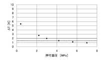
- FIG. 4 is a graph showing the relationship between the temperature difference ⁇ T and the pressing surface pressure, which is obtained by the experiments of the present inventors. It is easy to evaluate the thermal resistance between the cold head side cooling stage 32 and the sleeve side cooling stage 48 by the temperature difference ⁇ T between the measured temperature of the cold head side cooling stage 32 and the measured temperature of the sleeve side cooling stage 48 is there. As the pressing surface pressure between the cold head side cooling stage 32 and the sleeve side cooling stage 48 increases, the temperature difference ⁇ T between the measurement temperature of the cold head side cooling stage 32 and the measurement temperature of the sleeve side cooling stage 48 decreases. There is. Therefore, the temperature difference ⁇ T, that is, the thermal resistance can be managed by appropriately specifying the pressing surface pressure. The specified pressing surface pressure can be realized by adjusting the fastening force by the flange fastening mechanism 20 as described above.
- the predetermined temperature difference corresponding to the thermal resistance threshold can be, for example, 1.5 K or 1 K.
- the pressing surface pressure is specified as about 4 MPa or more, the temperature difference ⁇ T is within the predetermined temperature difference 1.5 K. Further, if the pressing surface pressure is specified to be about 7 MPa or more, the temperature difference ⁇ T becomes within the predetermined temperature difference 1 K.
- the cold head side cooling stage 32 and the sleeve side cooling stage 48 are in thermal contact with each other at a thermal resistance equal to or lower than the thermal resistance threshold value.
- FIG. 5 is a graph showing the relationship between the temperature difference ⁇ T and the number of times of maintenance, which is obtained by the experiments of the present inventors. Examples and comparative examples are shown in FIG. As mentioned above, no indium sheet is used between the cold head side cooling stage 32 and the sleeve side cooling stage 48 in the embodiment. Also, in the embodiment, the thermal resistance between the cold head side cooling stage 32 and the sleeve side cooling stage 48 is managed according to the method described above. In the comparative example, an indium sheet is interposed on the heat transfer surface of the cold head and the sleeve. In the comparative example, the thermal resistance on the heat transfer surface is not controlled.
- the thermal resistance (that is, the temperature difference ⁇ T) is maintained substantially constant until the fourth maintenance, but the thermal resistance is significantly degraded after the fifth maintenance (that is, the temperature difference ⁇ T increases significantly) ing).
- the inventor has found a phenomenon that the thermal contact state between the cryogenic refrigerator and the sleeve is likely to deteriorate when the maintenance of the cryogenic refrigerator is repeated several times. This thermal contact degradation phenomenon has not been known so far.
- the indium sheet When the cryogenic refrigerator leaves the sleeve to start maintenance, the indium sheet also moves with the refrigerator and is removed from the sleeve. When maintenance is complete and the cryogenic refrigerator again contacts the sleeve, the indium sheet also contacts the sleeve again. Peeling and re-contacting of the indium sheet is repeated with each maintenance of the cryogenic refrigerator, and the shape of the indium sheet may change from an initial flat sheet shape to a shape different from the initial shape, including some asperities.
- the sleeve is kept at cryogenic temperature with the object to be cooled, while the cryogenic refrigerator is returned to room temperature for maintenance.
- the indium sheet is also at room temperature with the cryogenic refrigerator.
- the indium sheet can be quenched and hardened by the sleeve.
- the indium sheet whose shape is changed is sandwiched between the cryogenic refrigerator and the sleeve, so that the heat transfer area between the cryogenic refrigerator and the sleeve by the indium sheet is the indium sheet of the initial shape Can be reduced compared to Thus, the thermal contact between the cryogenic refrigerator and the sleeve may be degraded.
- the thermal resistance is maintained substantially constant, and the reproducibility is good. This is considered to be due to the proper management of the pressing surface pressure.
- the absence of inclusions such as an indium sheet also contributes to the reproducibility of the thermal resistance.
- the cold head side flange 34 and the sleeve side flange are arranged to press the cold head side cooling stage 32 against the sleeve side cooling stage 48 with the specified pressing surface pressure. And 50 are mutually concluded.
- the pressing surface pressure is specified so that the cold head side cooling stage 32 and the sleeve side cooling stage 48 are in thermal contact with each other at a thermal resistance equal to or lower than the thermal resistance threshold.
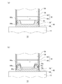
- FIGS. 6A and 6B are schematic views showing an example of a cooling stage structure that can be used for the cryogenic refrigerator 10 according to the embodiment.
- FIG. 6 (a) shows a state in which the cold head side cooling stage 32 and the sleeve side cooling stage 48 are in thermal contact
- FIG. 6 (b) shows the cold head side cooling stage 32 from the sleeve side cooling stage 48. It is shown separated and the thermal contact between the two is released.
- the cold head side cooling stage 32 includes a cold head side heat load flange 62 and a cold head side heat transfer block 64.
- the cold head side heat transfer block 64 has a non-sheet shape. The side surfaces and the lower surface of the cold head side heat transfer block 64 are exposed to the hermetic area 28.
- the cold head side heat load flange 62 is a disk-like member fixed to the cylinder 36 so as to close the lower end opening of the cylinder 36.
- the cold head side heat transfer block 64 is a disk-like member attached to the cold head side heat load flange 62.
- the cold head side heat transfer block 64 is an attachment removably attached to the cold head side heat load flange 62, and is attached to the cold head side heat load flange 62 by a fastening member (not shown) such as a bolt, for example. .
- the cold head side heat load flange 62 and the cold head side heat transfer block 64 are formed of, for example, a high thermal conductivity metal such as copper or other thermal conductivity material.
- the cold head side heat load flange 62 and the cold head side heat transfer block 64 are made of non-indium, that is, do not contain indium (except for inevitable impurities).
- the cold head side heat load flange 62 and the cold head side heat transfer block 64 are formed of the same heat conduction material, it is not essential, and both may be formed of different heat conduction materials.
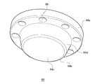
- FIG. 7 is a schematic perspective view showing an exemplary configuration of the cold head side heat transfer block 64 according to the embodiment.
- the cold head-side heat transfer block 64 includes a block base 64 a and a block center convex portion 64 b.
- the block base 64a and the block center convex portion 64b are integrally formed.
- the block base 64 a is formed with a plurality of bolt holes 66 for attaching the cold head side heat transfer block 64 to the cold head side heat load flange 62. These bolt holes are circumferentially arranged at equal angular intervals.
- the block center convex portion 64b protrudes axially downward from the center portion of the block base 64a.
- the block center convex portion 64b is a truncated cone-shaped convex portion, and has a flat block end face 64c and a tapered surface 64d.
- the block end face 64c is a circular region perpendicular to the central axis of the cryogenic refrigerator 10, and the tapered surface 64d is an inclined surface corresponding to the side surface of the truncated cone.
- the taper angle is, for example, 15 degrees, that is, the angle between the block end surface 64c and the taper surface 64d is 105 degrees.
- the surface area of the cold head side heat transfer block 64 in contact with the sleeve side cooling stage 48 can be increased, so heat exchange between the cold head side cooling stage 32 and the sleeve side cooling stage 48 is performed. Efficiency can be increased.
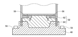
- FIG. 8 is a schematic cross-sectional view showing an exemplary configuration of the cold head side heat transfer block 64 according to the embodiment and the peripheral structure thereof.
- the cold head side temperature sensor 56 is disposed between the cold head side heat load flange 62 and the cold head side heat transfer block 64.
- the cold head side temperature sensor 56 is attached to the cold head side heat transfer block 64.
- two cold head temperature sensors 56 are provided for redundancy.
- two sleeve side temperature sensors 58 are provided on the sleeve side cooling stage 48 for redundancy.
- the sleeve side cooling stage 48 includes a sleeve side heat load flange 68 and a sleeve side heat transfer block 70.
- the sleeve side heat load flange 68 is a disk-like member fixed to the sleeve body 52 so as to close the lower end opening of the sleeve body 52.
- the object to be cooled 12 is attached to the sleeve side heat load flange 68.
- the sleeve side heat transfer block 70 has a non-sheet shape. The upper surface of the sleeve side heat transfer block 70 is exposed to the hermetic area 28.
- the sleeve side heat load flange 68 and the sleeve side heat transfer block 70 are integrally formed.
- the sleeve side heat transfer block 70 has a central recess corresponding to the block central convex portion 64 b of the cold head side heat transfer block 64.
- the sleeve side heat transfer block 70 has a block base 64a of the cold head side heat transfer block 64, a block end surface 64c, and a block upper surface 70a, a block lower surface 70b, and an inclined surface 70c corresponding to the tapered surface 64d.
- the block base 64a, the block end face 64c, and the tapered surface 64d separate from the block upper surface 70a, the block lower surface 70b, and the inclined surface 70c, respectively.
- the sleeve side heat loading flange 68 and the sleeve side heat transfer block 70 are formed of, for example, a high thermal conductivity metal such as copper or other thermal conductivity material.
- the sleeve side heat loading flange 68 and the sleeve side heat transfer block 70 are made of non-indium, that is, they do not contain indium (except for unavoidable impurities).
- the sleeve side heat load flange 68 and the sleeve side heat transfer block 70 are formed of the same heat conductive material, but this is not essential, and both may be formed of different heat conductive materials.
- the direct physical contact between the cold head side heat transfer block 64 and the sleeve side heat transfer block 70 causes the cold head side cooling stage 32 and the sleeve side cooling stage 48 to be in thermal contact. Since the cold head side heat transfer block 64 and the sleeve side heat transfer block 70 are in direct physical contact, there is no heat transfer inclusion such as an indium sheet between them. In this manner, good thermal contact can be realized between the cold head side cooling stage 32 and the sleeve side cooling stage 48 without heat transfer inclusions such as an indium sheet.
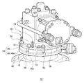
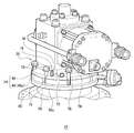
- FIG. 9 and 10 are schematic perspective views showing an example of the flange interval adjustment mechanism 18 and the flange fastening mechanism 20 that can be used in the cryogenic refrigerator 10 according to the embodiment.
- 9 shows a state in which the cryogenic refrigerator 10 is thermally coupled to the object 12 as in FIG. 1, and in FIG. 10, the thermal coupling between the two is released as in FIG. Is shown.
- the flange interval adjustment mechanism 18 includes lift-up bolt holes 72 formed in the cold head side flange 34 and lift-up bolts 74 screwed with the lift-up bolt holes 72.
- the flange interval adjustment mechanism 18 is configured to raise and lower the cold head side flange 34 relative to the sleeve side flange 50 by rotating the lift up bolt 74 in a state where the lift up bolt 74 is in contact with the sleeve side flange 50. ing.
- the lift-up bolt holes 72 are arranged at equal angular intervals circumferentially in the cold head side flange 34.
- the cold head flange 34 is provided with four lift-up bolt holes 72.
- the lift-up bolt holes 72 pass through the cylinder flange 44 and the annular plate portion 46 a of the transition flange 46.
- the portion of the sleeve side flange 50 located immediately below the lift up bolt hole 72 has no hole, and therefore, the tip of the lift up bolt 74 may abut against the annular second plate portion 50 c of the sleeve side flange 50. it can.
- the lift-up bolt 74 is screwed into the lift-up bolt hole 72. Therefore, the cold head side flange 34 is a sleeve by rotating the lift-up bolt 74 in a tightening direction (for example, clockwise) while the tip of the lift-up bolt 74 abuts on the annular second plate portion 50c. The cold head flange 34 can be moved upward away from the side flange 50.
- the flange distance adjustment mechanism 18 can increase the distance between the sleeve side flange 50 and the cold head side flange 34, and the cold head 22 is pulled up from the sleeve 16.
- the cold head side cooling stage 32 is separated from the sleeve side cooling stage 48, and their thermal contact is released.
- the cold head side flange 34 can move the cold head side flange 34 downward so that it approaches the sleeve side flange 50.
- the flange distance adjustment mechanism 18 can narrow the distance between the sleeve side flange 50 and the cold head side flange 34, and the cold head 22 is lowered.
- the cold head side cooling stage 32 physically contacts the sleeve side cooling stage 48, and these thermal contacts are realized.
- the distance between the cold head side flange 34 and the sleeve side cooling stage 48 can be adjusted with a relatively simple structure of the combination of the lift up bolt holes 72 and the lift up bolts 74.
- the flange fastening mechanism 20 includes a fastening bolt hole 76 formed in the sleeve side flange 50, and a fastening bolt 78 screwed with the fastening bolt hole 76.
- the flange fastening mechanism 20 is configured to adjust the pressing surface pressure of the cold head side cooling stage 32 and the sleeve side cooling stage 48 by the rotation of the fastening bolt 78.
- the fastening bolt holes 76 are circumferentially equiangularly spaced on the sleeve side flange 50.
- the sleeve side flange 50 is provided with eight bolt holes 76 for fastening.
- the fastening bolt 78 passes through both the cold head side flange 34 and the sleeve side flange 50.
- the fastening bolt 78 is loosely fitted to the cold head side flange 34, and thus is not screwed with the cold head side flange 34.
- the fastening bolt 78 is accommodated in a notch 80 formed in the cold head side flange 34.
- the notched portion 80 is, for example, a U-shaped groove formed on the outer peripheral edge of the cold head side flange 34 and extending in the axial direction.
- the head of the clamping bolt 78 may contact the upper surface of the cold head flange 34, that is, the cylinder flange 44.
- the tightening force between the cold head side flange 34 and the sleeve side flange 50 is increased by rotating the tightening bolt 78 in the tightening direction while the cold head side cooling stage 32 is in physical contact with the sleeve side cooling stage 48.
- the pressing surface pressure of the cold head side cooling stage 32 and the sleeve side cooling stage 48 is also increased.
- the fastening bolt 78 in the loosening direction the fastening force between the cold head side flange 34 and the sleeve side flange 50 is reduced, and the pressing surface pressure of the cold head side cooling stage 32 and the sleeve side cooling stage 48 Is also reduced.
- the pressing surface pressure of the cold head side flange 34 and the sleeve side cooling stage 48 can be adjusted with a relatively simple structure of a combination of the fastening bolt holes 76 and the fastening bolts 78.
- the cryogenic refrigerator 10 comprises a two-stage cold head 22 and a compressor 24. Therefore, the mounting structure includes the two-stage sleeve 16, the flange interval adjustment mechanism 18, and the flange fastening mechanism 20.
- the cryogenic refrigerator 10 is, for example, a two-stage GM refrigerator. However, the cryogenic refrigerator 10 may be another two-stage cryogenic refrigerator.
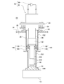
- FIG. 11 shows the cold head 22 and the sleeve 16 in thermal contact in both one and two stages.
- FIG. 12 the thermal contact is maintained for one stage and the thermal contact is released for the two stages.
- FIG. 13 shows the state in which the thermal contact is released in both the first and second stages.
- the cold head 22 includes a cold head-side one-stage cooling stage 132, a single-stage cylinder 136, a cold head-side two-stage cooling stage 232, and a two-stage cylinder 236.
- the single stage cylinder 136 connects the cold head side flange 34 to the cold head side single stage cooling stage 132
- the two stage cylinder 236 connects the cold head side single stage cooling stage 132 to the cold head side two stage cooling stage 232.
- the first stage cylinder 136 and the second stage cylinder 236 are coaxially arranged.
- the cold head-side one-stage cooling stage 132 and the cold head-side two-stage cooling stage 232 are formed of, for example, a high thermal conductivity metal such as copper (eg, pure copper), or other thermal conductivity material.
- the first cylinder 136 and the second cylinder 236 are formed of, for example, a metal such as stainless steel.
- the thermal conductivity of the thermally conductive material forming the cooling stage is higher than the thermal conductivity of the material forming the cylinder.
- the sleeve 16 includes a sleeve-side single-stage cooling stage 148, a single-stage sleeve body 152, a sleeve-side two-stage cooling stage 248, and a two-stage sleeve body 252.
- the single stage sleeve body 152 connects the sleeve side flange 50 to the sleeve side single stage cooling stage 148
- the two stage sleeve body 252 connects the sleeve side single stage cooling stage 148 to the sleeve side two stage cooling stage 248.
- the first stage sleeve body 152 and the second stage sleeve body 252 are arranged coaxially with the first stage cylinder 136 and the second stage cylinder 236 so as to surround the first stage cylinder 136 and the second stage cylinder 236, respectively.
- the sleeve side single stage cooling stage 148 makes thermal contact with the cold head side single stage cooling stage 132 by physical contact with the cold head side single stage cooling stage 132.
- the sleeve side two stage cooling stage 248 is in thermal contact with the cold head side two stage cooling stage 232 by physical contact with the cold head side two stage cooling stage 232.
- the shape of the contact surface of the cooling stage on the sleeve side and the cooling stage on the cold head side is non-flat such as a tapered surface, an inclined surface, or an uneven surface. It may be a plane or a flat surface.
- the sleeve side one-stage cooling stage 148 and the sleeve side two-stage cooling stage 248 are formed of, for example, a high thermal conductivity metal such as copper (eg, pure copper) or other thermal conductivity material.
- the first stage sleeve body 152 and the second stage sleeve body 252 are formed of, for example, a metal such as stainless steel.
- the thermal conductivity of the thermally conductive material forming the cooling stage is higher than the thermal conductivity of the material forming the sleeve body.
- the object to be cooled 12 is attached to the outer surface of the sleeve side two-stage cooling stage 248 exposed to the vacuum region 30.
- An object to be cooled other than the object to be cooled 12 may be attached to the outer surface of the sleeve side single-stage cooling stage 148 exposed to the vacuum region 30.
- an opening for connecting the internal space of the single-stage sleeve body 152 to the internal space of the two-stage sleeve body 252 is provided.
- the two-stage cylinder 236 and the cold head-side two-stage cooling stage 232 are inserted into the internal space of the two-stage sleeve body 252 from this opening.
- the sleeve side one-stage cooling stage 148 includes a sleeve side one-stage heat load flange 168, a sleeve side one-stage heat transfer block 170, and a heat transfer spring mechanism 180.
- the sleeve side single-stage heat load flange 168 is fixed to the lower end of the single-stage sleeve body 152.
- the sleeve side single-stage heat transfer block 170 is accommodated in the airtight region 28 and attached to the sleeve side single-stage heat load flange 168 via the heat transfer spring mechanism 180.
- the sleeve side single-stage heat transfer block 170 is axially displaceable with respect to the sleeve side single-stage heat load flange 168 by the expansion and contraction of the heat transfer spring mechanism 180.
- the sleeve-side single-stage heat load flange 168 and the sleeve-side single-stage heat transfer block 170 are concentrically disposed annular members, and as described above, the two-stage cylinder 236 and the cold head-side two-stage cooling stage 232 is inserted into the internal space of the two-step sleeve body 252.
- the heat transfer spring mechanism 180 includes a heat transfer spring portion 182 and a support spring portion 184.
- the heat transfer spring portion 182 and the support spring portion 184 are provided in parallel between the sleeve side one-step heat load flange 168 and the sleeve side one-step heat transfer block 170. That is, the heat transfer spring portion 182 connects the sleeve side single-stage heat transfer block 170 to the sleeve side single-stage heat load flange 168.
- the support spring portion 184 connects the sleeve side single-stage heat transfer block 170 to the sleeve side single-stage heat load flange 168.
- the sleeve side one-step heat transfer block 170 is elastically supported by the heat transfer spring portion 182 and the support spring portion 184 on the sleeve side one-step heat load flange 168.
- the heat transfer spring portion 182 functions as a heat transfer path from the sleeve side single-stage heat transfer block 170 to the sleeve side single-stage heat load flange 168.
- the heat transfer spring portion 182 is a spring formed of, for example, a high heat conductive metal such as copper or other heat conductive material.
- the heat transfer spring portion 182 may have, for example, a coil spring or any other shape.
- the heat transfer spring portion 182 may have a spring constant smaller than that of the support spring portion 184.
- the supporting spring portion 184 allows the cold head side single-stage cooling stage 132 and the sleeve side single-stage heat transfer block 170 to sink axially when the cold head side single-stage cooling stage 132 is pressed against the sleeve side single-stage heat transfer block 170. Do.
- the support spring portion 184 also has a function of suppressing excessive sinking of the cold head side one-stage cooling stage 132 and the sleeve side one-stage heat transfer block 170.
- the main heat transfer path is the heat transfer spring portion 182, but the support spring portion 184 may also receive a heat transfer function to some extent.
- the support spring portion 184 is, for example, a spring formed of a metal material or other suitable material.
- the support spring portion 184 may have, for example, a coil spring, a disc spring, or any other shape.
- the physical contact between the cold head-side single-stage cooling stage 132 and the sleeve-side single-stage heat transfer block 170 causes the cold head-side single-stage cooling stage 132 and the sleeve-side single-stage heat transfer block 170 to thermally contact.
- the sleeve side single-stage heat transfer block 170 is in thermal contact with the sleeve side single-stage heat load flange 168 via the heat transfer spring mechanism 180.
- the cold head side single stage cooling stage 132 is in thermal contact with the sleeve side single stage cooling stage 148.
- the sleeve side single-stage heat transfer block 170 can be displaced in the axial direction with respect to the sleeve side single-stage heat load flange 168 due to elastic deformation of the heat transfer spring portion 182 and the support spring portion 184.
- the cold head side single stage cooling stage 132 When the cold head side single stage cooling stage 132 is pressed against the sleeve side single stage heat transfer block 170, the cold head side single stage cooling stage 132 can be elastically displaced in the axial direction together with the sleeve side single stage heat transfer block 170.
- the heat transfer spring mechanism 180 may include a heat transfer member having flexibility, such as a bellows, a mesh, or a membrane, instead of the heat transfer spring portion 182.
- the heat transfer spring mechanism 180 may have the heat transfer spring portion 182 and the support spring portion 184 as separate springs.
- the heat transfer spring mechanism 180 may have a single spring member having both heat transfer and support functions.
- the heat transfer spring mechanism 180 may be incorporated into the cold head side one-stage cooling stage 132.
- the cold head side one-stage cooling stage 132 may include a cold head side heat load flange, a cold head side heat transfer block, and a heat transfer spring mechanism 180.
- the cold head side heat load flange may be fixed to the lower end of the single-stage cylinder 136, and the cold head side heat transfer block may be attached to the cold head side heat load flange via the heat transfer spring mechanism 180.
- the cold head-side heat transfer block may be in thermal contact with the sleeve-side single-stage cooling stage 148, and the cold head-side heat load flange may be axially displaceable by elastic deformation of the heat transfer spring mechanism 180.
- the cold head side temperature sensor 56 is disposed on the cold head side two-stage cooling stage 232 in order to measure the temperature of the cold head side two-stage cooling stage 232.
- the sleeve side temperature sensor 58 is disposed on the sleeve side two stage cooling stage 248 in order to measure the temperature of the sleeve side two stage cooling stage 248.
- the cold head side two stage cooling stage 232 and the sleeve side two stage cooling stage 248 have the same configuration as the cold head side cooling stage 32 and the sleeve side cooling stage 48 in the embodiment described with reference to FIGS. 1 to 10. Have. Therefore, when the cold head-side two-stage cooling stage 232 physically contacts the sleeve-side two-stage cooling stage 248, the cold head-side two-stage cooling stage 232 communicates with the object 12 via the sleeve-side two-stage cooling stage 248. Thermally coupled. Therefore, the object to be cooled 12 can be cooled by cooling the cold head side two-stage cooling stage 232.
- the cooling operation of the cryogenic refrigerator 10 is stopped.
- the cold head side single stage cooling stage 132 physically and thermally contacts the sleeve side single stage cooling stage 148
- the cold head side two stage cooling stage 232 is the sleeve side two stage cooling stage Physical and thermal contact with H.248.
- the fastening between the cold head side flange 34 and the sleeve side flange 50 is released.
- the elastic force of the heat transfer spring mechanism 180 lifts the cold head 22 somewhat, and the physical contact between the cold head side two-stage cooling stage 232 and the sleeve side two-stage cooling stage 248 is released.
- the thermal coupling between the refrigerator 10 and the object 12 is released.
- the cold head side single stage cooling stage 132 is in contact with the sleeve side single stage cooling stage 148.
- the cold head 22 is further pulled up by the operator operating the flange interval adjustment mechanism 18. As shown in FIG. 13, the sleeve side is maintained so that the cold head side single stage cooling stage 132 is physically out of contact with the sleeve side single stage cooling stage 148 while maintaining isolation of the hermetic region 28 from the surrounding environment 26. The distance between the flange 50 and the cold head side flange 34 is adjusted. A seal 54 is provided between the coldhead flange 34 and the sleeve flange 50 so that the isolation of the hermetic zone 28 from the surrounding environment 26 is maintained.
- the cold head-side one-stage cooling stage 132 and the cold head-side two-stage cooling stage 232 are thermally out of contact from the sleeve-side one-stage cooling stage 148 and the sleeve-side two-stage cooling stage 248, respectively.
- the temperature of the cold head 22 can be raised while maintaining the object to be cooled 12 at a low temperature.
- the drive and displacer of the cold head 22 are removed from the cold head 22.
- the cold head-side one-stage cooling stage 132, the single-stage cylinder 136, the cold head-side two-stage cooling stage 232, and the two-stage cylinder 236 are installed on the sleeve 16 as they are. Then, the maintenance (or new) drive unit and displacer are attached to the cold head 22. Then, the cooling operation of the cryogenic refrigerator 10 is resumed.
- the operator operates the flange spacing adjustment mechanism 18 and the flange fastening mechanism 20 again to thermally couple the cryogenic refrigerator 10 and the object 12 again.
- the distance between the sleeve side flange 50 and the cold head side flange 34 is adjusted by the flange distance adjustment mechanism 18, and the cold head 22 is lowered.
- the cold head side single stage cooling stage 132 again comes into physical and thermal contact with the sleeve side single stage cooling stage 148 while the isolation of the hermetic area 28 from the surrounding environment 26 is maintained. .
- the cold head side two-stage cooling stage 232 and the sleeve side two-stage cooling stage 248 are not in contact with each other.
- the cold head side flange 34 and the sleeve side flange 50 are again fastened by the flange fastening mechanism 20.
- the heat transfer spring mechanism 180 is compressed by the fastening between the cold head side flange 34 and the sleeve side flange 50 by the flange fastening mechanism 20, and the cold head side single stage cooling stage 132 and the sleeve side single stage heat transfer block 170 are sleeve side single stage heat load Sink towards the flange 168.
- the cold head side two-stage cooling stage 232 and the sleeve side two-stage cooling stage 248 physically contact.
- the cold head side two-stage cooling stage 232 and the sleeve side two-stage cooling stage 248 are thermally fastened with a pressing surface pressure specified so as to be in thermal contact with a thermal resistance below a threshold value by being fastened.
- the side two-stage cooling stage 232 is pressed against the sleeve-side two-stage cooling stage 248.
- the pressing surface pressure between the cold head side two-stage cooling stage 232 and the sleeve side two-stage cooling stage 248 can be adjusted by adjusting the fastening force by the flange fastening mechanism 20.
- the temperature of the cold head side two-stage cooling stage 232 is measured by the cold head side temperature sensor 56, and the temperature of the sleeve side two stage cooling stage 248 is measured by the sleeve side temperature sensor 58.
- the cold head side flange so that the temperature difference ⁇ T between the measured temperature of the cold head side two stage cooling stage 232 and the measured temperature of the sleeve side two stage cooling stage 248 falls within a predetermined temperature difference corresponding to the thermal resistance threshold value. 34 are fastened to the sleeve side flange 50.
- the operator increases the fastening force by the flange fastening mechanism 20 to thereby connect the cold head side two stage cooling stage 232 and the sleeve side two stage cooling stage 248.
- the pressing surface pressure may be increased.
- the thermal resistance is monitored such that the cold head-side two-stage cooling stage 232 and the sleeve-side two-stage cooling stage 248 thermally contact with a thermal resistance less than or equal to a threshold.
- the cold head side two-stage cooling stage 232 is a sleeve side two-stage cooling stage with the specified pressing surface pressure
- the cold head side flange 34 and the sleeve side flange 50 are fastened to each other so as to press against the H.248.
- the pressing surface pressure is specified such that the cold head side two-stage cooling stage 232 and the sleeve side two-stage cooling stage 248 are in thermal contact with each other at a thermal resistance equal to or lower than the thermal resistance threshold.
- the heat transfer spring mechanism 180 is incorporated in the sleeve side one-stage cooling stage 148 (or the cold head side one-stage cooling stage 132), the cold head side one-stage cooling stage 132 and the sleeve side one-stage cooling stage 148 Thermal contact via mechanism 180. Therefore, the pressing surface pressure between the cold head side two stage cooling stage 232 and the sleeve side two stage cooling stage 248 is adjusted while maintaining the thermal contact between the cold head side one stage cooling stage 132 and the sleeve side one stage cooling stage 148 be able to.
- the present invention can be used in the field of the mounting structure and mounting method of a cryogenic refrigerator on a vacuum vessel.
Landscapes
- Engineering & Computer Science (AREA)
- Physics & Mathematics (AREA)
- Mechanical Engineering (AREA)
- Thermal Sciences (AREA)
- General Engineering & Computer Science (AREA)
- Chemical & Material Sciences (AREA)
- Combustion & Propulsion (AREA)
- Containers, Films, And Cooling For Superconductive Devices (AREA)
- Compressors, Vaccum Pumps And Other Relevant Systems (AREA)
Abstract
A mounting structure for a cryogenic refrigerator 10, said mounting structure comprising: a sleeve 16; a flange interval adjustment mechanism 18 for adjusting an interval between a sleeve-side flange 50 and a cold-head-side flange 34 so as to physically bring into contact or separate a cold-head-side cooling stage 32 and a sleeve-side cooling stage 48, while keeping an airtight region 28 isolated from the surrounding environment 26; and a flange fastening mechanism 20 for fastening the cold-head-side flange 34 to the sleeve-side flange 50 so as to press the cold-head-side cooling stage 32 against the sleeve-side cooling stage 48 with a prescribed pressing surface pressure such that the cold-head-side cooling stage 32 and the sleeve-side cooling stage 48 are in thermal contact with a thermal resistance of a value equal to or less than a threshold value.
Description
本発明は、真空容器への極低温冷凍機の装着構造および装着方法に関する。
The present invention relates to a mounting structure and a mounting method of a cryogenic refrigerator to a vacuum vessel.
従来から、極低温冷凍機のコールドヘッドをスリーブを介してクライオスタットなどの極低温真空容器に装着することが知られている。極低温真空容器内には例えば超伝導コイルなどの被冷却物が収容され、この被冷却物はスリーブ末端に取り付けられ、熱接触している。コールドヘッドとスリーブとの熱接触により、極低温冷凍機は、スリーブを介して被冷却物を冷却することができる。
It is conventionally known to mount a cold head of a cryogenic refrigerator through a sleeve to a cryogenic vacuum vessel such as a cryostat. An object to be cooled, such as a superconducting coil, is accommodated in the cryogenic vacuum vessel, and the object to be cooled is attached to and in thermal contact with the end of the sleeve. The thermal contact between the cold head and the sleeve allows the cryogenic refrigerator to cool the object via the sleeve.
極低温冷凍機を長期的に運転するなかで、極低温冷凍機のメンテナンスが定期的に必要とされうる。作業者は、スリーブを用いた装着構造を操作し、コールドヘッドとスリーブの熱接触を解除して極低温冷凍機にメンテナンスを施すことができる。極低温冷凍機は例えば室温などメンテナンス作業に都合のよい温度に昇温され、作業完了後に再冷却される。熱接触の解除により、被冷却物は低温に保つことができる。したがって、極低温冷凍機とともに被冷却物を室温に昇温して極低温冷凍機にメンテナンスを施す場合に比べて被冷却物の再冷却時間を短縮することができ、メンテナンスの所要時間を短くすることができる。
During long term operation of the cryogenic refrigerator, maintenance of the cryogenic refrigerator may be required periodically. The operator can operate the mounting structure using the sleeve to release the thermal contact between the cold head and the sleeve to perform maintenance on the cryogenic refrigerator. The cryogenic refrigerator is heated to a temperature convenient for maintenance work, such as room temperature, and recooled after the work is completed. By releasing the thermal contact, the object to be cooled can be kept at a low temperature. Therefore, it is possible to shorten the recooling time of the object to be cooled as compared with the case where the object to be cooled is raised to room temperature and maintenance is performed together with the cryogenic refrigerator, and the required time for maintenance is shortened. be able to.
本発明者は、スリーブを介した真空容器への極低温冷凍機の装着構造について鋭意研究を重ねた結果、以下の課題を認識するに至った。本発明者は、この種の装着構造により装着された極低温冷凍機のメンテナンスを何回か繰り返したとき、極低温冷凍機とスリーブとの間の熱接触状態が劣化しやすいという新たな現象を発見した。通例、極低温冷凍機とスリーブの熱接触部には、熱接触をよくするためにインジウムシートが挟み込まれている。本発明者の考察によれば、熱接触状態の劣化現象は、インジウムシートの介在に起因すると考えられる。熱接触の劣化は、被冷却物の冷却温度の上昇、あるいは冷却効率の低下を招きうるので、望ましくない。
As a result of intensive studies on the mounting structure of the cryogenic refrigerator on a vacuum vessel via a sleeve, the present inventors have come to recognize the following problems. The inventor of the present invention has found that the new phenomenon that the thermal contact state between the cryogenic refrigerator and the sleeve is likely to deteriorate when the maintenance of the cryogenic refrigerator mounted by this kind of mounting structure is repeated several times discovered. Typically, an indium sheet is sandwiched between the cryogenic refrigerator and the thermal contact portion of the sleeve to improve thermal contact. According to the inventor's consideration, the deterioration phenomenon of the thermal contact state is considered to be due to the inclusion of the indium sheet. Degradation of the thermal contact is undesirable because it can lead to an increase in the cooling temperature of the object to be cooled or a decrease in the cooling efficiency.
本発明のある態様の例示的な目的のひとつは、スリーブを介して真空容器に装着される極低温冷凍機に関して、極低温冷凍機のメンテナンスが反復されても長期にわたり極低温冷凍機とスリーブの熱接触を良好に維持する技術を提供することにある。
One of the exemplary objects of an embodiment of the present invention is an cryogenic refrigerator and a sleeve for a long period of time even if maintenance of the cryogenic refrigerator is repeated for the cryogenic refrigerator attached to the vacuum vessel via the sleeve. An object of the present invention is to provide a technique for maintaining a good thermal contact.
本発明のある態様によると、極低温冷凍機のコールドヘッドを真空容器に装着するための装着構造であって、前記コールドヘッドは、コールドヘッド側冷却ステージと、コールドヘッド側フランジとを備えており、前記装着構造は、周囲環境から隔離された気密領域を前記コールドヘッドとの間に形成するよう前記真空容器に設置されたコールドヘッド収容スリーブであって、前記コールドヘッド側冷却ステージとの物理的接触により前記コールドヘッド側冷却ステージと熱接触するスリーブ側冷却ステージと、前記コールドヘッド側フランジに結合されるスリーブ側フランジと、を備えるコールドヘッド収容スリーブと、前記周囲環境からの前記気密領域の隔離を保持しつつ、前記コールドヘッド側冷却ステージと前記スリーブ側冷却ステージを物理的に接触させ又は非接触とするように、前記スリーブ側フランジと前記コールドヘッド側フランジとの間隔を調整するよう構成されたフランジ間隔調整機構と、前記コールドヘッド側冷却ステージと前記スリーブ側冷却ステージとがしきい値以下の熱抵抗で熱的に接触するように指定された押付面圧で前記コールドヘッド側冷却ステージを前記スリーブ側冷却ステージに押し付けるように、前記コールドヘッド側フランジを前記スリーブ側フランジと締結するよう構成されたフランジ締結機構と、を備える。
According to an aspect of the present invention, there is provided a mounting structure for mounting a cold head of a cryogenic refrigerator on a vacuum vessel, the cold head comprising a cold head side cooling stage and a cold head side flange. The mounting structure is a cold head receiving sleeve installed in the vacuum vessel so as to form an airtight area isolated from an ambient environment between the cold head and the cold head, wherein the mounting structure is physically connected to the cold head side cooling stage. A cold head receiving sleeve comprising a sleeve side cooling stage in thermal contact with the cold head side cooling stage by contact, and a sleeve side flange coupled to the cold head side flange; isolation of the hermetic zone from the surrounding environment The cold head side cooling stage and the sleeve side cooling Flange spacing adjusting mechanism configured to adjust the distance between the sleeve side flange and the cold head side flange so as to bring the cages into physical contact or non-contact, the cold head side cooling stage, and the cold head side cooling stage The cold head side flange is configured to press the cold head side cooling stage against the sleeve side cooling stage with a pressing surface pressure specified to be in thermal contact with the sleeve side cooling stage with thermal resistance below a threshold value. And a flange fastening mechanism configured to fasten the sleeve with the sleeve side flange.
本発明のある態様によると、極低温冷凍機のコールドヘッドをコールドヘッド収容スリーブを介して真空容器に装着する装着方法であって、前記コールドヘッドは、コールドヘッド側冷却ステージと、コールドヘッド側フランジとを備え、前記コールドヘッド収容スリーブは、前記コールドヘッド側冷却ステージとの物理的接触により前記コールドヘッド側冷却ステージと熱接触するスリーブ側冷却ステージと、前記コールドヘッド側フランジに結合されるスリーブ側フランジと、を備え、周囲環境から隔離された気密領域を前記コールドヘッドとの間に形成するよう前記真空容器に設置されており、前記装着方法は、前記周囲環境からの前記気密領域の隔離を保持しつつ、前記コールドヘッド側冷却ステージを前記スリーブ側冷却ステージに物理的に接触させるように、前記スリーブ側フランジと前記コールドヘッド側フランジとの間隔を調整することと、前記コールドヘッド側冷却ステージと前記スリーブ側冷却ステージとがしきい値以下の熱抵抗で熱的に接触するように指定された押付面圧で前記コールドヘッド側冷却ステージを前記スリーブ側冷却ステージに押し付けるように、前記コールドヘッド側フランジを前記スリーブ側フランジと締結することと、を備える。
According to an aspect of the present invention, there is provided a mounting method for mounting a cold head of a cryogenic refrigerator to a vacuum vessel via a cold head storage sleeve, the cold head comprising a cold head side cooling stage, and a cold head side flange. And the cold head receiving sleeve is a sleeve side cooling stage in thermal contact with the cold head side cooling stage by physical contact with the cold head side cooling stage, and a sleeve side coupled to the cold head side flange A flange, and the vacuum vessel is disposed to form an airtight area isolated from the surrounding environment between the flange and the cold head, and the mounting method comprises isolating the airtight area from the surrounding environment While holding the cold head side cooling stage as the sleeve side cooling stay Adjusting the distance between the sleeve-side flange and the cold head-side flange so that the cold head-side cooling stage and the sleeve-side cooling stage are in thermal contact with each other by a threshold value or less. Fastening the cold head side flange with the sleeve side flange so as to press the cold head side cooling stage against the sleeve side cooling stage with a pressing surface pressure designated to be in thermal contact.
なお、以上の構成要素の任意の組み合わせや本発明の構成要素や表現を、方法、装置、システムなどの間で相互に置換したものもまた、本発明の態様として有効である。
It is to be noted that any combination of the above-described constituent elements, or one in which the constituent elements and expressions of the present invention are mutually replaced among methods, apparatuses, systems, etc. is also effective as an aspect of the present invention.
本発明によれば、スリーブを介して真空容器に装着される極低温冷凍機に関して、極低温冷凍機のメンテナンスが反復されても長期にわたり極低温冷凍機とスリーブの熱接触を良好に維持することができる。
According to the present invention, with respect to a cryogenic refrigerator attached to a vacuum vessel via a sleeve, good thermal contact between the cryogenic refrigerator and the sleeve is maintained over a long period even if the maintenance of the cryogenic refrigerator is repeated. Can.
以下、図面を参照しながら、本発明を実施するための形態について詳細に説明する。説明および図面において同一または同等の構成要素、部材、処理には同一の符号を付し、重複する説明は適宜省略する。図示される各部の縮尺や形状は、説明を容易にするために便宜的に設定されており、特に言及がない限り限定的に解釈されるものではない。実施の形態は例示であり、本発明の範囲を何ら限定するものではない。実施の形態に記述されるすべての特徴やその組み合わせは、必ずしも発明の本質的なものであるとは限らない。
Hereinafter, embodiments of the present invention will be described in detail with reference to the drawings. In the description and the drawings, the same or equivalent components, members, and processes are denoted by the same reference numerals, and overlapping descriptions will be appropriately omitted. The scales and shapes of the illustrated parts are set conveniently for ease of explanation, and are not to be interpreted as being limited unless otherwise noted. The embodiments are illustrative and do not limit the scope of the present invention. All features or combinations thereof described in the embodiments are not necessarily essential to the invention.
図1および図2は、実施の形態に係る装着構造を説明するための概略図である。図1には、極低温冷凍機10が例えば超伝導コイルなどの被冷却物12と熱的に結合された状態が示され、図2には、両者の熱的な結合が解除された状態が示されている。
FIG. 1 and FIG. 2 are schematic diagrams for explaining the mounting structure according to the embodiment. FIG. 1 shows a state in which the cryogenic refrigerator 10 is thermally coupled to the object 12 to be cooled, such as a superconducting coil, and FIG. 2 shows a state in which the thermal coupling of the two is released. It is shown.
実施の形態に係る装着構造は、真空容器14、例えばクライオスタットなどの極低温真空容器に極低温冷凍機10を装着するための器具である。装着構造は、コールドヘッド収容スリーブ(以下では単に、スリーブともいう)16と、フランジ間隔調整機構18と、フランジ締結機構20とを備える。極低温冷凍機10は、コールドヘッド22と圧縮機24とを備える。
The mounting structure according to the embodiment is a device for mounting the cryogenic refrigerator 10 on a vacuum vessel 14, for example, a cryogenic vacuum vessel such as a cryostat. The mounting structure includes a cold head housing sleeve (hereinafter simply referred to as a sleeve) 16, a flange spacing adjustment mechanism 18, and a flange fastening mechanism 20. The cryogenic refrigerator 10 comprises a cold head 22 and a compressor 24.
スリーブ16は、周囲環境26から隔離された気密領域28をコールドヘッド22との間に形成するよう真空容器14に設置される。周囲環境26は例えば室温の大気圧環境である。気密領域28は、真空に排気されてもよいし、あるいは、ヘリウムガスのような極低温で液化しない不活性ガスで充填されてもよい。
The sleeve 16 is mounted to the vacuum vessel 14 so as to form an air tight area 28 isolated from the surrounding environment 26 with the cold head 22. The ambient environment 26 is, for example, an atmospheric pressure environment at room temperature. The hermetic zone 28 may be evacuated to vacuum or may be filled with a cryogenic non-liquefiable inert gas such as helium gas.
また、スリーブ16は、真空容器14と組み合わされて真空容器14内に真空領域30を区画するように真空容器14に設置される。一例として、真空容器14の天板に形成された開口部にスリーブ16の上端部が取り付けられ、スリーブ16はこの開口部から真空容器14内に延びている。スリーブ16の下端が被冷却物12に直接に又は任意の伝熱部材を介して取り付けられている。被冷却物12は、真空領域30に配置されている。
In addition, the sleeve 16 is mounted on the vacuum vessel 14 so as to combine with the vacuum vessel 14 to define the vacuum region 30 in the vacuum vessel 14. As one example, the upper end of the sleeve 16 is attached to an opening formed in the top plate of the vacuum vessel 14, and the sleeve 16 extends into the vacuum vessel 14 from this opening. The lower end of the sleeve 16 is attached to the object 12 directly or via an optional heat transfer member. The object to be cooled 12 is disposed in the vacuum region 30.
極低温冷凍機10は、一例として、単段式のギフォード・マクマホン冷凍機(以下、GM冷凍機ともいう)である。よって、装着構造は、単段式のGM冷凍機を真空容器14に装着するよう構成されている。ただし、極低温冷凍機10は、これに限られず、二段式のGM冷凍機であってもよく、その場合、装着構造は、二段式のGM冷凍機を真空容器14に装着するよう構成されうる。極低温冷凍機10は、スターリング冷凍機、パルス管冷凍機などその他の極低温冷凍機であってもよい。
The cryogenic refrigerator 10 is, for example, a single-stage Gifford McMahon refrigerator (hereinafter also referred to as a GM refrigerator). Therefore, the mounting structure is configured to mount the single-stage GM refrigerator on the vacuum vessel 14. However, the cryogenic refrigerator 10 is not limited to this, and may be a two-stage GM refrigerator, in which case, the mounting structure is configured to mount the two-stage GM refrigerator on the vacuum vessel 14 It can be done. The cryogenic refrigerator 10 may be another cryogenic refrigerator such as a Stirling refrigerator or a pulse tube refrigerator.
極低温冷凍機10は、上記の装着構造とともに、極低温冷凍機10の製造業者により顧客に提供されてもよい。被冷却物12を冷却する冷却装置が、極低温冷凍機10および装着構造から構成されるとも言える。よって、実施の形態に係る冷却装置は、極低温冷凍機10と、スリーブ16と、フランジ間隔調整機構18と、フランジ締結機構20とを備える。
The cryogenic refrigerator 10 may be provided to the customer by the manufacturer of the cryogenic refrigerator 10 along with the mounting structure described above. It can be said that the cooling device for cooling the object to be cooled 12 is composed of the cryogenic refrigerator 10 and the mounting structure. Therefore, the cooling device according to the embodiment includes the cryogenic refrigerator 10, the sleeve 16, the flange interval adjustment mechanism 18, and the flange fastening mechanism 20.
極低温冷凍機10のコールドヘッド22は、コールドヘッド側冷却ステージ32、コールドヘッド側フランジ34、シリンダ36を備える。シリンダ36は、中心軸38に沿って延在し、コールドヘッド側フランジ34をコールドヘッド側冷却ステージ32と連結している。コールドヘッド側フランジ34およびコールドヘッド側冷却ステージ32はシリンダ36と同軸に配置されている。コールドヘッド側フランジ34はシリンダ36の上端に設けられ、コールドヘッド側冷却ステージ32はシリンダ36の下端に設けられている。
The cold head 22 of the cryogenic refrigerator 10 includes a cold head side cooling stage 32, a cold head side flange 34, and a cylinder 36. The cylinder 36 extends along the central axis 38 and connects the cold head side flange 34 with the cold head side cooling stage 32. The cold head side flange 34 and the cold head side cooling stage 32 are arranged coaxially with the cylinder 36. The cold head side flange 34 is provided at the upper end of the cylinder 36, and the cold head side cooling stage 32 is provided at the lower end of the cylinder 36.
一例として、シリンダ36は、中空の円筒状部材であり、コールドヘッド側フランジ34は、シリンダ36の上端開口周縁から中心軸38と垂直な径方向外側に広がる円環状部材である。コールドヘッド側冷却ステージ32は、シリンダ36の下端開口を閉じるようシリンダ36に固着された円板状または短い円柱状の部材である。コールドヘッド側冷却ステージ32は、例えば銅(例えば純銅)などの高熱伝導金属、またはその他の熱伝導材料で形成されている。コールドヘッド側フランジ34およびシリンダ36は、例えばステンレスなどの金属で形成されている。コールドヘッド側冷却ステージ32を形成する熱伝導材料の熱伝導率は、シリンダ36(またはコールドヘッド側フランジ34)を形成する材料の熱伝導率より高い。
As one example, the cylinder 36 is a hollow cylindrical member, and the cold head side flange 34 is an annular member extending radially outward from the upper end opening periphery of the cylinder 36 perpendicularly to the central axis 38. The cold head side cooling stage 32 is a disk-like or short cylindrical member fixed to the cylinder 36 so as to close the lower end opening of the cylinder 36. The cold head side cooling stage 32 is formed of, for example, a high thermal conductivity metal such as copper (for example, pure copper), or other thermal conductivity material. The cold head side flange 34 and the cylinder 36 are formed of, for example, a metal such as stainless steel. The thermal conductivity of the thermally conductive material forming the cold head side cooling stage 32 is higher than the thermal conductivity of the material forming the cylinder 36 (or the cold head side flange 34).
極低温冷凍機10の圧縮機24は、極低温冷凍機10に作動ガス(例えばヘリウムガス)を循環させるために設けられている。圧縮機24は、高圧の作動ガスをコールドヘッド22に供給し、コールドヘッド22内の膨張空間での断熱膨張により減圧された低圧の作動ガスをコールドヘッド22から回収して再び昇圧するよう構成されている。
The compressor 24 of the cryogenic refrigerator 10 is provided to circulate a working gas (for example, helium gas) to the cryogenic refrigerator 10. The compressor 24 is configured to supply high pressure working gas to the cold head 22 and recover from the cold head 22 low pressure working gas decompressed by adiabatic expansion in the expansion space in the cold head 22 and pressurize again. ing.
さらに、コールドヘッド22は、ディスプレーサ40と、ディスプレーサ40を駆動するディスプレーサ40と連結された駆動部42とを備える。ディスプレーサ40は、シリンダ36と同軸にシリンダ36内に配置され、シリンダ36に沿って中心軸38の方向に往復動可能である。ディスプレーサ40とコールドヘッド側冷却ステージ32との間に作動ガスの膨張空間が形成される。また駆動部42には、膨張空間の圧力を制御するバルブが内蔵されている。この圧力制御バルブは、圧縮機24から膨張空間への高圧作動ガス供給と膨張空間から圧縮機24への低圧作動ガス回収とを交互に切り替えるよう構成されている。駆動部42は、ディスプレーサ40の軸方向往復動による膨張空間の容積変化と、圧力制御バルブによる膨張空間の圧力変化とを適切に同期させるよう構成されている。それにより、コールドヘッド22は、コールドヘッド側冷却ステージ32を冷却することができる。
Furthermore, the cold head 22 includes a displacer 40 and a drive unit 42 connected to the displacer 40 for driving the displacer 40. Displacer 40 is disposed in cylinder 36 coaxially with cylinder 36 and is capable of reciprocating along cylinder 36 in the direction of central axis 38. An expansion space for working gas is formed between the displacer 40 and the cold head side cooling stage 32. The drive unit 42 incorporates a valve for controlling the pressure in the expansion space. The pressure control valve is configured to alternate between high pressure working gas supply from the compressor 24 to the expansion space and low pressure working gas recovery from the expansion space to the compressor 24. The drive unit 42 is configured to appropriately synchronize the volume change of the expansion space due to the axial reciprocation of the displacer 40 and the pressure change of the expansion space by the pressure control valve. Thereby, the cold head 22 can cool the cold head side cooling stage 32.
駆動部42は、例えばボルト等の締結部材(図示せず)によってコールドヘッド側フランジ34に固定される。締結を解除することによって、駆動部42は、ディスプレーサ40とともに一体的にコールドヘッド22から取り外し可能である。
The drive unit 42 is fixed to the cold head side flange 34 by a fastening member (not shown) such as a bolt, for example. By releasing the fastening, the drive unit 42 can be removed together with the displacer 40 from the cold head 22 integrally.
コールドヘッド側フランジ34は、2つのフランジの結合体である。すなわち、コールドヘッド側フランジ34は、シリンダ36の上端開口周縁にシリンダ36と一体形成されたシリンダフランジ44と、シリンダフランジ44の下面に取り付けられたトランジションフランジ46とを備える。駆動部42はシリンダフランジ44に取り外し可能に固定されている。駆動部42が取り外されるとき、シリンダ36の上端開口からディスプレーサ40が引き抜かれ、駆動部42が取り付けられるとき、シリンダ36の上端開口からディスプレーサ40がシリンダ36内に挿入される。
The cold head flange 34 is a combination of two flanges. That is, the cold head side flange 34 includes a cylinder flange 44 integrally formed with the cylinder 36 at the upper end opening periphery of the cylinder 36 and a transition flange 46 attached to the lower surface of the cylinder flange 44. The drive portion 42 is removably fixed to the cylinder flange 44. When the drive unit 42 is removed, the displacer 40 is pulled out of the upper end opening of the cylinder 36, and when the drive unit 42 is attached, the displacer 40 is inserted into the cylinder 36 from the upper end opening of the cylinder 36.
トランジションフランジ46は、装着構造のひとつの構成要素でもあり、環状の板部46aおよび筒部46bを備える。環状の板部46aが例えばボルト等の締結部材(図示せず)によってシリンダフランジ44の下面に固定される。筒部46bは、環状の板部46aから中心軸38の方向に下方に延びている。筒部46bは、短い円筒であり、シリンダ36の上端を囲んでいる。筒部46bの径はシリンダ36の径より若干大きく、筒部46bの内周面とシリンダ36の外周面との間には隙間があり互いに接触していない。
The transition flange 46 is also one component of the mounting structure, and includes an annular plate portion 46a and a tubular portion 46b. The annular plate 46a is fixed to the lower surface of the cylinder flange 44 by a fastening member (not shown) such as a bolt. The cylindrical portion 46 b extends downward from the annular plate portion 46 a in the direction of the central axis 38. The cylindrical portion 46 b is a short cylinder and surrounds the upper end of the cylinder 36. The diameter of the cylindrical portion 46b is slightly larger than the diameter of the cylinder 36, and there is a gap between the inner peripheral surface of the cylindrical portion 46b and the outer peripheral surface of the cylinder 36 so that they do not contact each other.
圧縮機24、コールドヘッド側フランジ34、および駆動部42は、周囲環境26に配置されている。
The compressor 24, the coldhead flange 34 and the drive 42 are arranged in the ambient environment 26.
スリーブ16は、シリンダ36を囲むようにシリンダ36と同軸に配置されている。スリーブ16は、スリーブ側冷却ステージ48と、スリーブ側フランジ50と、スリーブ体52とを備える。
The sleeve 16 is disposed coaxially with the cylinder 36 so as to surround the cylinder 36. The sleeve 16 includes a sleeve side cooling stage 48, a sleeve side flange 50, and a sleeve body 52.
スリーブ側冷却ステージ48は、コールドヘッド側冷却ステージ32との物理的接触によりコールドヘッド側冷却ステージ32と熱接触する。一例として、スリーブ側冷却ステージ48とコールドヘッド側冷却ステージ32の接触面は平坦であるが、この形状には限られない。後述のように、コールドヘッド側冷却ステージ32は、テーパ面、傾斜面、または凹凸面などの非平坦面を有してもよく、気密領域28に露出されるスリーブ側冷却ステージ48の内面は、この非平坦面に対応する非平坦面を有してもよい。真空領域30に露出されるスリーブ側冷却ステージ48の外面には被冷却物12が取り付けられている。
The sleeve side cooling stage 48 makes thermal contact with the cold head side cooling stage 32 by physical contact with the cold head side cooling stage 32. As an example, although the contact surface of the sleeve side cooling stage 48 and the cold head side cooling stage 32 is flat, it is not restricted to this shape. As described later, the cold head side cooling stage 32 may have a non-flat surface such as a tapered surface, an inclined surface, or an uneven surface, and the inner surface of the sleeve side cooling stage 48 exposed to the airtight region 28 is It may have a non-flat surface corresponding to this non-flat surface. The object to be cooled 12 is attached to the outer surface of the sleeve side cooling stage 48 exposed to the vacuum region 30.
したがって、コールドヘッド側冷却ステージ32がスリーブ側冷却ステージ48と物理的に接触するとき、コールドヘッド側冷却ステージ32がスリーブ側冷却ステージ48を介して被冷却物12と熱的に結合される。よって、コールドヘッド側冷却ステージ32が冷却されることによって、被冷却物12を冷却することができる。例えば、被冷却物12が超伝導コイルのような超伝導機器である場合、極低温冷凍機10は、超伝導材料の臨界温度以下の極低温に被冷却物12を冷却することができる。
Therefore, when the cold head side cooling stage 32 physically contacts the sleeve side cooling stage 48, the cold head side cooling stage 32 is thermally coupled to the object to be cooled 12 via the sleeve side cooling stage 48. Therefore, the object to be cooled 12 can be cooled by the cold head side cooling stage 32 being cooled. For example, if the object to be cooled 12 is a superconducting device such as a superconducting coil, the cryogenic refrigerator 10 can cool the object to be cooled 12 to a cryogenic temperature below the critical temperature of the superconducting material.
なお、後述する理由により、コールドヘッド側冷却ステージ32とスリーブ側冷却ステージ48とはインジウムシートのような伝熱用の介在物無く、直接に接触することが望ましい。しかし、本発明は、介在物の不存在を必須とはしない。許容される場合には、コールドヘッド側冷却ステージ32とスリーブ側冷却ステージ48とがインジウムシートのような伝熱用の介在物を挟んで熱接触してもよい。
For the reason described later, it is desirable that the cold head side cooling stage 32 and the sleeve side cooling stage 48 be in direct contact with each other without heat transfer inclusions such as an indium sheet. However, the present invention does not require the absence of inclusions. If permitted, the cold head side cooling stage 32 and the sleeve side cooling stage 48 may be in thermal contact with heat transfer inclusions such as an indium sheet.
スリーブ側フランジ50は、コールドヘッド側フランジ34に結合され、周囲環境26に配置されている。一例として、スリーブ側フランジ50は、環状の第1板部50a、筒部50b、および環状の第2板部50cを備える。環状の第1板部50aと環状の第2板部50cは筒部50bによって連結されている。環状の第1板部50aは例えばボルト等の締結部材(図示せず)によって真空容器14の上面に固定される。筒部50bは、短い円筒であり、第1板部50aから中心軸38の方向に上方に延びている。第2板部50cは、例えば数mm程度の間隔を隔ててトランジションフランジ46の環状の板部46aと対向している。
The sleeve side flange 50 is coupled to the cold head side flange 34 and is disposed in the ambient environment 26. As an example, the sleeve side flange 50 includes an annular first plate portion 50a, a cylindrical portion 50b, and an annular second plate portion 50c. The annular first plate portion 50a and the annular second plate portion 50c are connected by a cylindrical portion 50b. The annular first plate portion 50a is fixed to the upper surface of the vacuum vessel 14 by a fastening member (not shown) such as a bolt, for example. The cylindrical portion 50 b is a short cylinder and extends upward from the first plate portion 50 a in the direction of the central axis 38. The second plate portion 50c is opposed to the annular plate portion 46a of the transition flange 46 at an interval of, for example, several mm.
スリーブ側フランジ50の筒部50bはトランジションフランジ46の筒部46bのすぐ外側に隣接配置され、両者は互いに接触している。気密領域28の気密性を保持するためのシール部材54が、スリーブ側フランジ50の筒部50bとトランジションフランジ46の筒部46bの間に配置されている。シール部材54は、例えば、スリーブ側フランジ50の筒部50bに形成された周溝に配置されたOリングなどのシール部材である。
The cylindrical portion 50b of the sleeve side flange 50 is disposed adjacent to and immediately outside the cylindrical portion 46b of the transition flange 46, and both are in contact with each other. A seal member 54 for maintaining the airtightness of the airtight region 28 is disposed between the cylindrical portion 50 b of the sleeve side flange 50 and the cylindrical portion 46 b of the transition flange 46. The seal member 54 is, for example, a seal member such as an O-ring disposed in a circumferential groove formed in the cylindrical portion 50 b of the sleeve side flange 50.
スリーブ体52は、中空の円筒状部材であり、シリンダ36と同軸に中心軸38に沿って延在し、スリーブ側フランジ50をスリーブ側冷却ステージ48と連結している。スリーブ側フランジ50はスリーブ体52の上端に設けられ、スリーブ側冷却ステージ48はスリーブ体52の下端に設けられている。スリーブ側フランジ50は、スリーブ体52の上端開口周縁から中心軸38と垂直な径方向外側に広がる円環状部材である。スリーブ側冷却ステージ48は、スリーブ体52の下端開口を閉じるようスリーブ体52に固着された円板状または短い円柱状の部材である。
The sleeve body 52 is a hollow cylindrical member and extends coaxially with the cylinder 36 along the central axis 38 and connects the sleeve side flange 50 with the sleeve side cooling stage 48. The sleeve side flange 50 is provided at the upper end of the sleeve body 52, and the sleeve side cooling stage 48 is provided at the lower end of the sleeve body 52. The sleeve side flange 50 is an annular member extending radially outward from the peripheral edge of the upper end opening of the sleeve body 52 in a direction perpendicular to the central axis 38. The sleeve side cooling stage 48 is a disc or short cylindrical member fixed to the sleeve 52 so as to close the lower end opening of the sleeve 52.
スリーブ側冷却ステージ48は、例えば銅(例えば純銅)などの高熱伝導金属、またはその他の熱伝導材料で形成されている。スリーブ側フランジ50およびスリーブ体52は、例えばステンレスなどの金属で形成されている。スリーブ側冷却ステージ48を形成する熱伝導材料の熱伝導率は、スリーブ体52(またはスリーブ側フランジ50)を形成する材料の熱伝導率より高い。
The sleeve side cooling stage 48 is formed of, for example, a high thermal conductivity metal such as copper (for example, pure copper), or other thermal conductivity material. The sleeve side flange 50 and the sleeve body 52 are formed of metal such as stainless steel, for example. The thermal conductivity of the thermally conductive material forming the sleeve side cooling stage 48 is higher than the thermal conductivity of the material forming the sleeve body 52 (or the sleeve side flange 50).
コールドヘッド側フランジ34はスリーブ側フランジ50に対して軸方向に摺動可能であり、それにより、コールドヘッド22は、スリーブ16に対し軸方向に移動可能である。この可動範囲は数mm程度、例えば2~3mm程度である。シール部材54があるので、コールドヘッド22が移動しても気密領域28は周囲環境26から隔離されている。
The cold head flange 34 is axially slidable with respect to the sleeve flange 50 so that the cold head 22 is axially movable with respect to the sleeve 16. The movable range is about several mm, for example, about 2 to 3 mm. Because of the sealing member 54, the tight area 28 is isolated from the surrounding environment 26 even if the cold head 22 moves.
図1には、コールドヘッド22が可動範囲の下端に位置してコールドヘッド側冷却ステージ32とスリーブ側冷却ステージ48が熱接触している状態が示されている。図2には、コールドヘッド22が可動範囲の上端に位置してコールドヘッド側冷却ステージ32がスリーブ側冷却ステージ48から離れ、両者の熱接触が解除された状態が示されている。
FIG. 1 shows that the cold head 22 is positioned at the lower end of the movable range and the cold head side cooling stage 32 and the sleeve side cooling stage 48 are in thermal contact. In FIG. 2, the cold head 22 is positioned at the upper end of the movable range, the cold head side cooling stage 32 is separated from the sleeve side cooling stage 48, and the thermal contact between the two is released.
フランジ間隔調整機構18は、周囲環境26からの気密領域28の隔離を保持しつつ、コールドヘッド側冷却ステージ32とスリーブ側冷却ステージ48を物理的に接触させ又は非接触とするように、スリーブ側フランジ50とコールドヘッド側フランジ34との間隔を調整するよう構成されている。作業者がフランジ間隔調整機構18を操作することによって、上記の可動範囲においてコールドヘッド22を昇降させることができる。フランジ間隔調整機構18の例示的な構成は、後述する。
The flange spacing adjustment mechanism 18 keeps the cold head side cooling stage 32 and the sleeve side cooling stage 48 in physical contact or non-contact while maintaining isolation of the airtight region 28 from the surrounding environment 26. The gap between the flange 50 and the cold head side flange 34 is adjusted. When the operator operates the flange interval adjustment mechanism 18, the cold head 22 can be raised and lowered in the above-described movable range. An exemplary configuration of the flange spacing adjustment mechanism 18 will be described later.
フランジ締結機構20は、コールドヘッド側冷却ステージ32をスリーブ側冷却ステージ48に押し付けるように、コールドヘッド側フランジ34をスリーブ側フランジ50と締結するよう構成されている。フランジ締結機構20は、コールドヘッド側冷却ステージ32とスリーブ側冷却ステージ48とがしきい値以下の熱抵抗で熱的に接触するように指定された押付面圧で、コールドヘッド側冷却ステージ32をスリーブ側冷却ステージ48に押し付ける。このしきい値を以下では、熱抵抗しきい値ともいう。作業者がフランジ締結機構20を操作することによって、フランジ締結機構20は、コールドヘッド側冷却ステージ32とスリーブ側冷却ステージ48の間に働く押付面圧を調整することができる。フランジ締結機構20の例示的な構成は、後述する。
The flange fastening mechanism 20 is configured to fasten the cold head side flange 34 with the sleeve side flange 50 so as to press the cold head side cooling stage 32 against the sleeve side cooling stage 48. The flange fastening mechanism 20 sets the cold head side cooling stage 32 with a pressing surface pressure specified such that the cold head side cooling stage 32 and the sleeve side cooling stage 48 are in thermal contact with each other with a thermal resistance less than a threshold value. The sleeve side cooling stage 48 is pressed. Hereinafter, this threshold is also referred to as a thermal resistance threshold. By the operator operating the flange fastening mechanism 20, the flange fastening mechanism 20 can adjust the pressing surface pressure acting between the cold head side cooling stage 32 and the sleeve side cooling stage 48. An exemplary configuration of the flange fastening mechanism 20 will be described later.
また、コールドヘッド22は、コールドヘッド側冷却ステージ32の温度を測定するコールドヘッド側温度センサ56を備える。コールドヘッド側温度センサ56は、コールドヘッド側冷却ステージ32に配置されている。スリーブ16は、スリーブ側冷却ステージ48の温度を測定するスリーブ側温度センサ58を備える。スリーブ側温度センサ58は、スリーブ側冷却ステージ48に配置されている。コールドヘッド側温度センサ56は、コールドヘッド測定温度を表す信号S1を外部に出力するよう構成され、スリーブ側温度センサ58は、スリーブ測定温度を表す信号S2を外部に出力するよう構成されている。したがって、作業者は、コールドヘッド側冷却ステージ32の測定温度とスリーブ側冷却ステージ48の測定温度を取得し、それらの温度差ΔTを取得することができる。測定温度(及び/または温度差)を表示または出力する出力部60が設けられていてもよい。
The cold head 22 also includes a cold head temperature sensor 56 that measures the temperature of the cold head side cooling stage 32. The cold head side temperature sensor 56 is disposed on the cold head side cooling stage 32. The sleeve 16 is provided with a sleeve side temperature sensor 58 that measures the temperature of the sleeve side cooling stage 48. The sleeve side temperature sensor 58 is disposed on the sleeve side cooling stage 48. The cold head side temperature sensor 56 is configured to output a signal S1 representing a cold head measurement temperature to the outside, and the sleeve side temperature sensor 58 is configured to output a signal S2 representing a sleeve measurement temperature to the outside. Therefore, the operator can obtain the measured temperature of the cold head side cooling stage 32 and the measured temperature of the sleeve side cooling stage 48, and obtain the temperature difference ΔT thereof. An output unit 60 may be provided to display or output the measured temperature (and / or the temperature difference).
コールドヘッド側冷却ステージ32の測定温度とスリーブ側冷却ステージ48の測定温度との温度差ΔTが熱抵抗しきい値に相当する所定の温度差以内に収まるように、フランジ締結機構20によってコールドヘッド側フランジ34がスリーブ側フランジ50と締結される。作業者は、フランジ締結機構20を操作することによって、温度差ΔTが熱抵抗しきい値に相当する所定の温度差以内に収まるようにコールドヘッド側フランジ34をスリーブ側フランジ50と締結することができる。
The cold head side by the flange fastening mechanism 20 so that the temperature difference ΔT between the measured temperature of the cold head side cooling stage 32 and the measured temperature of the sleeve side cooling stage 48 falls within a predetermined temperature difference corresponding to the thermal resistance threshold value. The flange 34 is fastened to the sleeve side flange 50. The operator operates the flange fastening mechanism 20 to fasten the cold head side flange 34 with the sleeve side flange 50 so that the temperature difference ΔT falls within a predetermined temperature difference corresponding to the thermal resistance threshold value. it can.
図3は、実施の形態に係る装着方法を説明するためのフローチャートである。極低温冷凍機10のメンテナンスが許容されるタイミングが到来すると、極低温冷凍機10の冷却運転が停止される(S10)。
FIG. 3 is a flowchart for explaining the mounting method according to the embodiment. When the timing at which the maintenance of the cryogenic refrigerator 10 is permitted comes, the cooling operation of the cryogenic refrigerator 10 is stopped (S10).
作業者がフランジ間隔調整機構18およびフランジ締結機構20を操作することによって、極低温冷凍機10と被冷却物12との熱的な結合が解除される(S12)。そのために、まず、フランジ締結機構20によるコールドヘッド側フランジ34とスリーブ側フランジ50との締結が解除される(S14)。次に、周囲環境26からの気密領域28の隔離を保持しつつ、コールドヘッド側冷却ステージ32をスリーブ側冷却ステージ48から物理的に非接触とするように、スリーブ側フランジ50とコールドヘッド側フランジ34との間隔が調整される。コールドヘッド側フランジ34とスリーブ側フランジ50の間にはシール部材54が設けられているので、周囲環境26からの気密領域28の隔離は保持される。こうして、フランジ間隔調整機構18によりコールドヘッド22が引き上げられる(S16)。コールドヘッド22の引き上げにより、コールドヘッド側冷却ステージ32がスリーブ側冷却ステージ48から離れ、両者の熱接触が解除される。被冷却物12を低温に保ちつつ、コールドヘッド22を昇温することができる。
The operator operates the flange interval adjustment mechanism 18 and the flange fastening mechanism 20 to release the thermal connection between the cryogenic refrigerator 10 and the object 12 (S12). Therefore, first, the fastening between the cold head side flange 34 and the sleeve side flange 50 by the flange fastening mechanism 20 is released (S14). Next, the sleeve side flange 50 and the cold head side flange are arranged so that the cold head side cooling stage 32 physically comes out of contact with the sleeve side cooling stage 48 while maintaining the isolation of the airtight area 28 from the surrounding environment 26. The interval with 34 is adjusted. A seal 54 is provided between the coldhead flange 34 and the sleeve flange 50 so that the isolation of the hermetic zone 28 from the surrounding environment 26 is maintained. Thus, the cold head 22 is pulled up by the flange interval adjustment mechanism 18 (S16). As the cold head 22 is pulled up, the cold head side cooling stage 32 is separated from the sleeve side cooling stage 48 and the thermal contact between the two is released. The temperature of the cold head 22 can be raised while maintaining the object to be cooled 12 at a low temperature.
極低温冷凍機10のメンテナンスが行われる(S18)。駆動部42およびディスプレーサ40がコールドヘッド22から取り外される。シリンダ36およびコールドヘッド側冷却ステージ32はそのままスリーブ16に設置されている。そして、メンテナンスが施された(または新品の)駆動部42およびディスプレーサ40がコールドヘッド22に取り付けられる。そして、極低温冷凍機10の冷却運転が再開される(S20)。
Maintenance of the cryogenic refrigerator 10 is performed (S18). The drive unit 42 and the displacer 40 are removed from the cold head 22. The cylinder 36 and the cold head side cooling stage 32 are mounted on the sleeve 16 as it is. Then, the maintenance (or new) drive unit 42 and the displacer 40 are attached to the cold head 22. Then, the cooling operation of the cryogenic refrigerator 10 is resumed (S20).
作業者がフランジ間隔調整機構18およびフランジ締結機構20を再び操作することによって、極低温冷凍機10と被冷却物12とが再び熱的に結合される(S22)。周囲環境26からの気密領域28の隔離を保持しつつ、コールドヘッド側冷却ステージ32をスリーブ側冷却ステージ48に物理的に接触させるように、スリーブ側フランジ50とコールドヘッド側フランジ34との間隔が調整される。こうして、フランジ間隔調整機構18によりコールドヘッド22が降下される(S24)。コールドヘッド側冷却ステージ32は、スリーブ側冷却ステージ48と再び物理的に接触する。このとき、コールドヘッド側冷却ステージ32は、コールドヘッド22の自重、および周囲環境26と気密領域28との圧力差によって、スリーブ側冷却ステージ48に押し付けられる。
The operator again operates the flange interval adjustment mechanism 18 and the flange fastening mechanism 20 to thermally couple the cryogenic refrigerator 10 and the object 12 again (S22). The distance between the sleeve side flange 50 and the cold head side flange 34 is such that the cold head side cooling stage 32 physically contacts the sleeve side cooling stage 48 while maintaining the isolation of the airtight area 28 from the surrounding environment 26. Adjusted. Thus, the cold head 22 is lowered by the flange interval adjustment mechanism 18 (S24). The cold head side cooling stage 32 makes physical contact with the sleeve side cooling stage 48 again. At this time, the cold head side cooling stage 32 is pressed against the sleeve side cooling stage 48 by the weight of the cold head 22 and the pressure difference between the surrounding environment 26 and the airtight region 28.
フランジ締結機構20によりコールドヘッド側フランジ34とスリーブ側フランジ50とが再び締結される(S26)。フランジ締結機構20によるコールドヘッド側フランジ34とスリーブ側フランジ50との締結によって、コールドヘッド側冷却ステージ32とスリーブ側冷却ステージ48とがしきい値以下の熱抵抗で熱的に接触するように指定された押付面圧で、コールドヘッド側冷却ステージ32が、スリーブ側冷却ステージ48に押し付けられる。フランジ締結機構20による締結力を調整することにより、コールドヘッド側冷却ステージ32とスリーブ側冷却ステージ48との間の押付面圧を調整することができる。そこで、この指定された押付面圧、またはこれに相当するフランジ締結機構20による締結力または締結トルクは、極低温冷凍機10の取扱説明書など関連資料に記載されていてもよい。
The cold head side flange 34 and the sleeve side flange 50 are again fastened by the flange fastening mechanism 20 (S26). Designated so that the cold head side cooling stage 32 and the sleeve side cooling stage 48 are in thermal contact with a thermal resistance less than the threshold value by fastening the cold head side flange 34 and the sleeve side flange 50 by the flange fastening mechanism 20 The cold head side cooling stage 32 is pressed against the sleeve side cooling stage 48 by the pressing surface pressure. By adjusting the fastening force by the flange fastening mechanism 20, the pressing surface pressure between the cold head side cooling stage 32 and the sleeve side cooling stage 48 can be adjusted. Therefore, the designated pressing surface pressure or the fastening force or fastening torque by the flange fastening mechanism 20 corresponding to this may be described in related documents such as the instruction manual of the cryogenic refrigerator 10.
コールドヘッド側温度センサ56によりコールドヘッド側冷却ステージ32の温度が測定され、スリーブ側温度センサ58によりスリーブ側冷却ステージ48の温度が測定される。コールドヘッド側冷却ステージ32の測定温度とスリーブ側冷却ステージ48の測定温度との温度差ΔTが熱抵抗しきい値に相当する所定の温度差以内に収まるように、コールドヘッド側フランジ34がスリーブ側フランジ50と締結される。測定された温度差ΔTが所定の温度差を超える場合には、作業者は、フランジ締結機構20による締結力を増すことによりコールドヘッド側冷却ステージ32とスリーブ側冷却ステージ48との間の押付面圧を増加させてもよい。こうして、コールドヘッド側冷却ステージ32とスリーブ側冷却ステージ48とがしきい値以下の熱抵抗で熱的に接触するように、熱抵抗が監視される(S28)。
The temperature of the cold head side cooling stage 32 is measured by the cold head side temperature sensor 56, and the temperature of the sleeve side cooling stage 48 is measured by the sleeve side temperature sensor 58. The cold head side flange 34 is sleeve side so that the temperature difference ΔT between the measurement temperature of the cold head side cooling stage 32 and the measurement temperature of the sleeve side cooling stage 48 falls within a predetermined temperature difference corresponding to the thermal resistance threshold. It is fastened with the flange 50. If the measured temperature difference ΔT exceeds the predetermined temperature difference, the operator increases the fastening force by the flange fastening mechanism 20 to press the pressing surface between the cold head side cooling stage 32 and the sleeve side cooling stage 48. The pressure may be increased. Thus, the thermal resistance is monitored such that the cold head side cooling stage 32 and the sleeve side cooling stage 48 are in thermal contact with each other with a thermal resistance equal to or less than the threshold (S28).
コールドヘッド22とスリーブ16の再度の熱接触(S22)および熱抵抗の監視(S28)は、極低温冷凍機10の冷却運転再開によりコールドヘッド側冷却ステージ32およびスリーブ側冷却ステージ48が十分に冷却されてから行うことが望ましい。そのようにすれば、冷却中の熱収縮によるコールドヘッド側冷却ステージ32とスリーブ側冷却ステージ48の離間を避けることができる。なお、熱収縮によりコールドヘッド側冷却ステージ32がスリーブ側冷却ステージ48から離間した場合には、フランジ締結機構20による締結力を調整することにより、コールドヘッド側冷却ステージ32をスリーブ側冷却ステージ48と再接触させることができる。
The thermal contact between the cold head 22 and the sleeve 16 (S22) and the thermal resistance monitoring (S28) indicate that the cold head side cooling stage 32 and the sleeve side cooling stage 48 are sufficiently cooled by restarting the cooling operation of the cryogenic refrigerator 10. It is desirable to do after being done. In this way, separation between the cold head side cooling stage 32 and the sleeve side cooling stage 48 due to heat contraction during cooling can be avoided. When the cold head side cooling stage 32 is separated from the sleeve side cooling stage 48 due to heat contraction, the cold head side cooling stage 32 and the sleeve side cooling stage 48 are adjusted by adjusting the fastening force by the flange fastening mechanism 20. It can be re-contacted.
図4は、温度差ΔTと押付面圧との関係を示すグラフであり、本発明者らの実験により得られたものである。コールドヘッド側冷却ステージ32とスリーブ側冷却ステージ48との間の熱抵抗は、コールドヘッド側冷却ステージ32の測定温度とスリーブ側冷却ステージ48の測定温度との温度差ΔTで評価することが簡便である。コールドヘッド側冷却ステージ32とスリーブ側冷却ステージ48との間の押付面圧が大きいほど、コールドヘッド側冷却ステージ32の測定温度とスリーブ側冷却ステージ48の測定温度との温度差ΔTが小さくなっている。したがって、押付面圧を適切に指定することにより、温度差ΔTすなわち熱抵抗を管理することができる。指定された押付面圧は、上述のように、フランジ締結機構20による締結力を調整することにより、実現することができる。
FIG. 4 is a graph showing the relationship between the temperature difference ΔT and the pressing surface pressure, which is obtained by the experiments of the present inventors. It is easy to evaluate the thermal resistance between the cold head side cooling stage 32 and the sleeve side cooling stage 48 by the temperature difference ΔT between the measured temperature of the cold head side cooling stage 32 and the measured temperature of the sleeve side cooling stage 48 is there. As the pressing surface pressure between the cold head side cooling stage 32 and the sleeve side cooling stage 48 increases, the temperature difference ΔT between the measurement temperature of the cold head side cooling stage 32 and the measurement temperature of the sleeve side cooling stage 48 decreases. There is. Therefore, the temperature difference ΔT, that is, the thermal resistance can be managed by appropriately specifying the pressing surface pressure. The specified pressing surface pressure can be realized by adjusting the fastening force by the flange fastening mechanism 20 as described above.
一例として、温度差ΔTが1.5Kまたは1K以内であれば、コールドヘッド側冷却ステージ32とスリーブ側冷却ステージ48とが十分に小さい熱抵抗で良好に熱接触していると言える。よって、熱抵抗しきい値に相当する所定の温度差は、例えば1.5Kまたは1Kとすることができる。図示される例では、押付面圧を約4MPa以上と指定すれば、温度差ΔTが所定の温度差1.5K以内となる。また、押付面圧を約7MPa以上と指定すれば、温度差ΔTが所定の温度差1K以内となる。よって、指定された押付面圧(例えば、約4MPa以上または約7MPa以上)となるようにフランジ締結機構20による締結力を調整することにより、コールドヘッド側冷却ステージ32とスリーブ側冷却ステージ48との温度差ΔTが1.5Kまたは1K以内となり、熱抵抗が十分に小さくなる。すなわち、コールドヘッド側冷却ステージ32とスリーブ側冷却ステージ48とが熱抵抗しきい値以下の熱抵抗で熱的に接触していると評価することができる。
As one example, if the temperature difference ΔT is within 1.5 K or 1 K, it can be said that the cold head side cooling stage 32 and the sleeve side cooling stage 48 are in good thermal contact with sufficiently small thermal resistance. Thus, the predetermined temperature difference corresponding to the thermal resistance threshold can be, for example, 1.5 K or 1 K. In the illustrated example, if the pressing surface pressure is specified as about 4 MPa or more, the temperature difference ΔT is within the predetermined temperature difference 1.5 K. Further, if the pressing surface pressure is specified to be about 7 MPa or more, the temperature difference ΔT becomes within the predetermined temperature difference 1 K. Therefore, by adjusting the fastening force by the flange fastening mechanism 20 so as to obtain the designated pressing surface pressure (for example, about 4 MPa or more or about 7 MPa or more), the cold head side cooling stage 32 and the sleeve side cooling stage 48 The temperature difference ΔT is within 1.5 K or 1 K, and the thermal resistance is sufficiently reduced. That is, it can be evaluated that the cold head side cooling stage 32 and the sleeve side cooling stage 48 are in thermal contact with each other at a thermal resistance equal to or lower than the thermal resistance threshold value.
図5は、温度差ΔTとメンテナンス回数との関係を示すグラフであり、本発明者らの実験により得られたものである。図5には、実施例と比較例とが示されている。上述のように、実施例においてはコールドヘッド側冷却ステージ32とスリーブ側冷却ステージ48の間にインジウムシートは使用されない。また実施例においては、上述の方法に従ってコールドヘッド側冷却ステージ32とスリーブ側冷却ステージ48との間の熱抵抗が管理されている。比較例においては、コールドヘッドとスリーブとの伝熱面にインジウムシートが介在している。また比較例においては伝熱面での熱抵抗は管理されていない。
FIG. 5 is a graph showing the relationship between the temperature difference ΔT and the number of times of maintenance, which is obtained by the experiments of the present inventors. Examples and comparative examples are shown in FIG. As mentioned above, no indium sheet is used between the cold head side cooling stage 32 and the sleeve side cooling stage 48 in the embodiment. Also, in the embodiment, the thermal resistance between the cold head side cooling stage 32 and the sleeve side cooling stage 48 is managed according to the method described above. In the comparative example, an indium sheet is interposed on the heat transfer surface of the cold head and the sleeve. In the comparative example, the thermal resistance on the heat transfer surface is not controlled.
比較例では、4回目のメンテナンスまでは熱抵抗(すなわち温度差ΔT)がほぼ一定に維持されているが、5回目のメンテナンス後に熱抵抗が顕著に劣化している(すなわち温度差ΔTが大きく増えている)。このように、極低温冷凍機のメンテナンスを何回か繰り返したとき、極低温冷凍機とスリーブとの間の熱接触状態が劣化しやすいという現象を本発明者は見出した。この熱接触の劣化現象は、これまで知られていない。
In the comparative example, the thermal resistance (that is, the temperature difference ΔT) is maintained substantially constant until the fourth maintenance, but the thermal resistance is significantly degraded after the fifth maintenance (that is, the temperature difference ΔT increases significantly) ing). As described above, the inventor has found a phenomenon that the thermal contact state between the cryogenic refrigerator and the sleeve is likely to deteriorate when the maintenance of the cryogenic refrigerator is repeated several times. This thermal contact degradation phenomenon has not been known so far.
こうした熱接触の劣化現象が起こるメカニズムは、本発明者の考察によれば、以下の通りである。
The mechanism of occurrence of such a thermal contact deterioration phenomenon is as follows according to the inventor's consideration.
メンテナンス開始のために極低温冷凍機がスリーブから離れるときインジウムシートも冷凍機とともに移動しスリーブから剥がされる。メンテナンスが完了し極低温冷凍機がスリーブに再び接触するときインジウムシートも再びスリーブに接触する。インジウムシートの剥離と再接触が極低温冷凍機のメンテナンスのたびに繰り返され、インジウムシートの形状が、初期の平坦なシート形状から、いくらか凹凸を含む等の初期形状と異なる形状に変わりうる。メンテナンスの間、スリーブは被冷却物とともに極低温に保たれる一方、極低温冷凍機はメンテナンスを施すために室温に戻されている。インジウムシートも極低温冷凍機とともに室温となっている。そのため、インジウムシートがスリーブに再接触する瞬間に、インジウムシートはスリーブによって急冷され、硬化されうる。このようにして、形状が変化したインジウムシートが極低温冷凍機とスリーブの間に挟まれ、その結果、インジウムシートによる極低温冷凍機とスリーブとの間の伝熱面積は、初期形状のインジウムシートに比べて、低減されうる。よって、極低温冷凍機とスリーブとの間の熱接触状態が劣化しうる。
When the cryogenic refrigerator leaves the sleeve to start maintenance, the indium sheet also moves with the refrigerator and is removed from the sleeve. When maintenance is complete and the cryogenic refrigerator again contacts the sleeve, the indium sheet also contacts the sleeve again. Peeling and re-contacting of the indium sheet is repeated with each maintenance of the cryogenic refrigerator, and the shape of the indium sheet may change from an initial flat sheet shape to a shape different from the initial shape, including some asperities. During maintenance, the sleeve is kept at cryogenic temperature with the object to be cooled, while the cryogenic refrigerator is returned to room temperature for maintenance. The indium sheet is also at room temperature with the cryogenic refrigerator. Thus, at the moment the indium sheet re-contacts the sleeve, the indium sheet can be quenched and hardened by the sleeve. In this way, the indium sheet whose shape is changed is sandwiched between the cryogenic refrigerator and the sleeve, so that the heat transfer area between the cryogenic refrigerator and the sleeve by the indium sheet is the indium sheet of the initial shape Can be reduced compared to Thus, the thermal contact between the cryogenic refrigerator and the sleeve may be degraded.
これに対して、実施例では、メンテナンスを10回繰り返した後でも、熱抵抗がほぼ一定に維持され、再現性が良好である。これは、押付面圧の適正な管理によるものと考えられる。また、インジウムシートのような介在物の不存在も熱抵抗の再現性に寄与している。
On the other hand, in the example, even after maintenance is repeated ten times, the thermal resistance is maintained substantially constant, and the reproducibility is good. This is considered to be due to the proper management of the pressing surface pressure. In addition, the absence of inclusions such as an indium sheet also contributes to the reproducibility of the thermal resistance.
実施の形態に係る極低温冷凍機10の装着構造によれば、指定された押付面圧でコールドヘッド側冷却ステージ32をスリーブ側冷却ステージ48に押し付けるように、コールドヘッド側フランジ34とスリーブ側フランジ50とが相互に締結される。押付面圧は、コールドヘッド側冷却ステージ32とスリーブ側冷却ステージ48とが熱抵抗しきい値以下の熱抵抗で熱的に接触するように指定されている。このようにして、スリーブ16を介して真空容器14に装着される極低温冷凍機10に関して、極低温冷凍機10のメンテナンスが反復されても長期にわたり極低温冷凍機10とスリーブ16の熱接触を良好に維持することができる。
According to the mounting structure of the cryogenic refrigerator 10 according to the embodiment, the cold head side flange 34 and the sleeve side flange are arranged to press the cold head side cooling stage 32 against the sleeve side cooling stage 48 with the specified pressing surface pressure. And 50 are mutually concluded. The pressing surface pressure is specified so that the cold head side cooling stage 32 and the sleeve side cooling stage 48 are in thermal contact with each other at a thermal resistance equal to or lower than the thermal resistance threshold. Thus, with respect to the cryogenic refrigerator 10 attached to the vacuum vessel 14 via the sleeve 16, even if maintenance of the cryogenic refrigerator 10 is repeated, the thermal contact between the cryogenic refrigerator 10 and the sleeve 16 over a long period of time It can be maintained well.
図6(a)および図6(b)は、実施の形態に係る極低温冷凍機10に使用されうる冷却ステージ構造の一例を示す概略図である。図6(a)にはコールドヘッド側冷却ステージ32とスリーブ側冷却ステージ48が熱接触している状態が示され、図6(b)にはコールドヘッド側冷却ステージ32がスリーブ側冷却ステージ48から離れ、両者の熱接触が解除された状態が示されている。
FIGS. 6A and 6B are schematic views showing an example of a cooling stage structure that can be used for the cryogenic refrigerator 10 according to the embodiment. FIG. 6 (a) shows a state in which the cold head side cooling stage 32 and the sleeve side cooling stage 48 are in thermal contact, and FIG. 6 (b) shows the cold head side cooling stage 32 from the sleeve side cooling stage 48. It is shown separated and the thermal contact between the two is released.
コールドヘッド側冷却ステージ32は、コールドヘッド側熱負荷フランジ62とコールドヘッド側伝熱ブロック64とを備える。コールドヘッド側伝熱ブロック64は、非シート形状を有する。コールドヘッド側伝熱ブロック64の側面および下面が気密領域28に露出されている。一例として、コールドヘッド側熱負荷フランジ62は、シリンダ36の下端開口を閉じるようシリンダ36に固着された円板状部材である。コールドヘッド側伝熱ブロック64は、コールドヘッド側熱負荷フランジ62に取り付けられた円板状部材である。コールドヘッド側伝熱ブロック64は、コールドヘッド側熱負荷フランジ62に取り外し可能に取り付けられるアタッチメントであり、例えばボルト等の締結部材(図示せず)によりコールドヘッド側熱負荷フランジ62に取り付けられている。
The cold head side cooling stage 32 includes a cold head side heat load flange 62 and a cold head side heat transfer block 64. The cold head side heat transfer block 64 has a non-sheet shape. The side surfaces and the lower surface of the cold head side heat transfer block 64 are exposed to the hermetic area 28. As one example, the cold head side heat load flange 62 is a disk-like member fixed to the cylinder 36 so as to close the lower end opening of the cylinder 36. The cold head side heat transfer block 64 is a disk-like member attached to the cold head side heat load flange 62. The cold head side heat transfer block 64 is an attachment removably attached to the cold head side heat load flange 62, and is attached to the cold head side heat load flange 62 by a fastening member (not shown) such as a bolt, for example. .
コールドヘッド側熱負荷フランジ62およびコールドヘッド側伝熱ブロック64は、例えば銅などの高熱伝導金属、またはその他の熱伝導材料で形成されている。コールドヘッド側熱負荷フランジ62およびコールドヘッド側伝熱ブロック64は、非インジウム製であり、すなわちインジウムを含有しない(ただし不可避不純物を除く)。ここで、コールドヘッド側熱負荷フランジ62とコールドヘッド側伝熱ブロック64は同じ熱伝導材料で形成されているが、それは必須ではなく、両者が異なる熱伝導材料で形成されていてもよい。
The cold head side heat load flange 62 and the cold head side heat transfer block 64 are formed of, for example, a high thermal conductivity metal such as copper or other thermal conductivity material. The cold head side heat load flange 62 and the cold head side heat transfer block 64 are made of non-indium, that is, do not contain indium (except for inevitable impurities). Here, although the cold head side heat load flange 62 and the cold head side heat transfer block 64 are formed of the same heat conduction material, it is not essential, and both may be formed of different heat conduction materials.
図7は、実施の形態に係るコールドヘッド側伝熱ブロック64の例示的構成を示す概略斜視図である。コールドヘッド側伝熱ブロック64は、ブロック基部64aとブロック中心凸部64bとを備える。ブロック基部64aおよびブロック中心凸部64bは一体形成されている。ブロック基部64aには、コールドヘッド側伝熱ブロック64をコールドヘッド側熱負荷フランジ62に取り付けるための複数のボルト孔66が形成されている。これらボルト孔は円周状に等角度間隔に配置されている。
FIG. 7 is a schematic perspective view showing an exemplary configuration of the cold head side heat transfer block 64 according to the embodiment. The cold head-side heat transfer block 64 includes a block base 64 a and a block center convex portion 64 b. The block base 64a and the block center convex portion 64b are integrally formed. The block base 64 a is formed with a plurality of bolt holes 66 for attaching the cold head side heat transfer block 64 to the cold head side heat load flange 62. These bolt holes are circumferentially arranged at equal angular intervals.
ブロック中心凸部64bはブロック基部64aの中心部から軸方向下方に突出している。一例として、ブロック中心凸部64bは、円錐台状の凸部であり、平坦なブロック端面64cとテーパ面64dとを有する。ブロック端面64cは極低温冷凍機10の中心軸に垂直な円形状領域であり、テーパ面64dは円錐台の側面にあたる傾斜面である。テーパ角度は例えば15度であり、すなわちブロック端面64cとテーパ面64dのなす角度は105度である。こうしたテーパ面64dを設けることにより、コールドヘッド側伝熱ブロック64がスリーブ側冷却ステージ48と接触する表面積を大きくすることができるので、コールドヘッド側冷却ステージ32とスリーブ側冷却ステージ48との熱交換効率を高くすることができる。
The block center convex portion 64b protrudes axially downward from the center portion of the block base 64a. As an example, the block center convex portion 64b is a truncated cone-shaped convex portion, and has a flat block end face 64c and a tapered surface 64d. The block end face 64c is a circular region perpendicular to the central axis of the cryogenic refrigerator 10, and the tapered surface 64d is an inclined surface corresponding to the side surface of the truncated cone. The taper angle is, for example, 15 degrees, that is, the angle between the block end surface 64c and the taper surface 64d is 105 degrees. By providing such a tapered surface 64 d, the surface area of the cold head side heat transfer block 64 in contact with the sleeve side cooling stage 48 can be increased, so heat exchange between the cold head side cooling stage 32 and the sleeve side cooling stage 48 is performed. Efficiency can be increased.
図8は、実施の形態に係るコールドヘッド側伝熱ブロック64およびその周辺構造の例示的構成を示す概略断面図である。図8に示されるように、コールドヘッド側温度センサ56は、コールドヘッド側熱負荷フランジ62とコールドヘッド側伝熱ブロック64の間に配置されている。例えば、コールドヘッド側温度センサ56は、コールドヘッド側伝熱ブロック64に取り付けられている。一例として、冗長性のために、2つのコールドヘッド側温度センサ56が設けられている。同様に、冗長性のために、2つのスリーブ側温度センサ58がスリーブ側冷却ステージ48に設けられている。
FIG. 8 is a schematic cross-sectional view showing an exemplary configuration of the cold head side heat transfer block 64 according to the embodiment and the peripheral structure thereof. As shown in FIG. 8, the cold head side temperature sensor 56 is disposed between the cold head side heat load flange 62 and the cold head side heat transfer block 64. For example, the cold head side temperature sensor 56 is attached to the cold head side heat transfer block 64. As an example, two cold head temperature sensors 56 are provided for redundancy. Similarly, two sleeve side temperature sensors 58 are provided on the sleeve side cooling stage 48 for redundancy.
図6(a)および図6(b)を再び参照すると、スリーブ側冷却ステージ48は、スリーブ側熱負荷フランジ68とスリーブ側伝熱ブロック70とを備える。スリーブ側熱負荷フランジ68は、スリーブ体52の下端開口を閉じるようスリーブ体52に固着された円板状部材である。スリーブ側熱負荷フランジ68に被冷却物12が取り付けられる。スリーブ側伝熱ブロック70は、非シート形状を有する。スリーブ側伝熱ブロック70の上面が気密領域28に露出されている。スリーブ側熱負荷フランジ68とスリーブ側伝熱ブロック70は一体形成されている。
Referring again to FIGS. 6A and 6B, the sleeve side cooling stage 48 includes a sleeve side heat load flange 68 and a sleeve side heat transfer block 70. The sleeve side heat load flange 68 is a disk-like member fixed to the sleeve body 52 so as to close the lower end opening of the sleeve body 52. The object to be cooled 12 is attached to the sleeve side heat load flange 68. The sleeve side heat transfer block 70 has a non-sheet shape. The upper surface of the sleeve side heat transfer block 70 is exposed to the hermetic area 28. The sleeve side heat load flange 68 and the sleeve side heat transfer block 70 are integrally formed.
スリーブ側伝熱ブロック70は、コールドヘッド側伝熱ブロック64のブロック中心凸部64bに対応する中心凹部を有する。スリーブ側伝熱ブロック70は、コールドヘッド側伝熱ブロック64のブロック基部64a、ブロック端面64c、およびテーパ面64dに対応するブロック上面70a、ブロック下面70b、および傾斜面70cを有する。コールドヘッド側伝熱ブロック64がスリーブ側伝熱ブロック70と接触するとき、ブロック基部64a、ブロック端面64c、およびテーパ面64dがそれぞれ、ブロック上面70a、ブロック下面70b、および傾斜面70cと接触する。コールドヘッド側伝熱ブロック64がスリーブ側伝熱ブロック70から離れるとき、ブロック基部64a、ブロック端面64c、およびテーパ面64dがそれぞれ、ブロック上面70a、ブロック下面70b、および傾斜面70cから離れる。
The sleeve side heat transfer block 70 has a central recess corresponding to the block central convex portion 64 b of the cold head side heat transfer block 64. The sleeve side heat transfer block 70 has a block base 64a of the cold head side heat transfer block 64, a block end surface 64c, and a block upper surface 70a, a block lower surface 70b, and an inclined surface 70c corresponding to the tapered surface 64d. When the cold head heat transfer block 64 contacts the sleeve heat transfer block 70, the block base 64a, the block end surface 64c, and the tapered surface 64d contact the block upper surface 70a, the block lower surface 70b, and the inclined surface 70c, respectively. When the cold head heat transfer block 64 separates from the sleeve heat transfer block 70, the block base 64a, the block end face 64c, and the tapered surface 64d separate from the block upper surface 70a, the block lower surface 70b, and the inclined surface 70c, respectively.
スリーブ側熱負荷フランジ68およびスリーブ側伝熱ブロック70は、例えば銅などの高熱伝導金属、またはその他の熱伝導材料で形成されている。スリーブ側熱負荷フランジ68およびスリーブ側伝熱ブロック70は、非インジウム製であり、すなわちインジウムを含有しない(ただし不可避不純物を除く)。ここで、スリーブ側熱負荷フランジ68とスリーブ側伝熱ブロック70は同じ熱伝導材料で形成されているが、それは必須ではなく、両者が異なる熱伝導材料で形成されていてもよい。
The sleeve side heat loading flange 68 and the sleeve side heat transfer block 70 are formed of, for example, a high thermal conductivity metal such as copper or other thermal conductivity material. The sleeve side heat loading flange 68 and the sleeve side heat transfer block 70 are made of non-indium, that is, they do not contain indium (except for unavoidable impurities). Here, the sleeve side heat load flange 68 and the sleeve side heat transfer block 70 are formed of the same heat conductive material, but this is not essential, and both may be formed of different heat conductive materials.
コールドヘッド側伝熱ブロック64とスリーブ側伝熱ブロック70との直接の物理的接触により、コールドヘッド側冷却ステージ32とスリーブ側冷却ステージ48とが熱的に接触する。コールドヘッド側伝熱ブロック64とスリーブ側伝熱ブロック70とは直接に物理的に接触するから、両者の間にインジウムシートのような伝熱用の介在物は存在しない。このようにして、インジウムシートのような伝熱用の介在物無く、コールドヘッド側冷却ステージ32とスリーブ側冷却ステージ48との間に良好な熱接触を実現することができる。
The direct physical contact between the cold head side heat transfer block 64 and the sleeve side heat transfer block 70 causes the cold head side cooling stage 32 and the sleeve side cooling stage 48 to be in thermal contact. Since the cold head side heat transfer block 64 and the sleeve side heat transfer block 70 are in direct physical contact, there is no heat transfer inclusion such as an indium sheet between them. In this manner, good thermal contact can be realized between the cold head side cooling stage 32 and the sleeve side cooling stage 48 without heat transfer inclusions such as an indium sheet.
図9および図10は、実施の形態に係る極低温冷凍機10に使用されうるフランジ間隔調整機構18およびフランジ締結機構20の一例を示す概略斜視図である。図9には、図1と同様に極低温冷凍機10が被冷却物12と熱的に結合された状態が示され、図10には、図2と同様に両者の熱的な結合が解除された状態が示されている。
9 and 10 are schematic perspective views showing an example of the flange interval adjustment mechanism 18 and the flange fastening mechanism 20 that can be used in the cryogenic refrigerator 10 according to the embodiment. 9 shows a state in which the cryogenic refrigerator 10 is thermally coupled to the object 12 as in FIG. 1, and in FIG. 10, the thermal coupling between the two is released as in FIG. Is shown.
フランジ間隔調整機構18は、コールドヘッド側フランジ34に形成されたリフトアップ用ボルト孔72と、リフトアップ用ボルト孔72と螺合するリフトアップ用ボルト74と、を備える。フランジ間隔調整機構18は、リフトアップ用ボルト74をスリーブ側フランジ50に突き当てた状態でリフトアップ用ボルト74を回転させることによりスリーブ側フランジ50に対しコールドヘッド側フランジ34を昇降させるよう構成されている。
The flange interval adjustment mechanism 18 includes lift-up bolt holes 72 formed in the cold head side flange 34 and lift-up bolts 74 screwed with the lift-up bolt holes 72. The flange interval adjustment mechanism 18 is configured to raise and lower the cold head side flange 34 relative to the sleeve side flange 50 by rotating the lift up bolt 74 in a state where the lift up bolt 74 is in contact with the sleeve side flange 50. ing.
リフトアップ用ボルト孔72は、コールドヘッド側フランジ34において円周状に等角度間隔に配置されている。一例として、コールドヘッド側フランジ34には4つのリフトアップ用ボルト孔72が設けられている。リフトアップ用ボルト孔72は、シリンダフランジ44とトランジションフランジ46の環状の板部46aとを貫通している。
The lift-up bolt holes 72 are arranged at equal angular intervals circumferentially in the cold head side flange 34. As an example, the cold head flange 34 is provided with four lift-up bolt holes 72. The lift-up bolt holes 72 pass through the cylinder flange 44 and the annular plate portion 46 a of the transition flange 46.
スリーブ側フランジ50においてリフトアップ用ボルト孔72の直下に位置する部位には穴が無く、したがって、リフトアップ用ボルト74の先端をスリーブ側フランジ50の環状の第2板部50cに突き当てることができる。上述のように、リフトアップ用ボルト74はリフトアップ用ボルト孔72と螺合している。そのため、リフトアップ用ボルト74の先端が環状の第2板部50cに突き当てられた状態でリフトアップ用ボルト74を締め方向(例えば時計回り)に回転させることにより、コールドヘッド側フランジ34がスリーブ側フランジ50から離れるようにコールドヘッド側フランジ34を上方に移動させることができる。こうして、フランジ間隔調整機構18は、スリーブ側フランジ50とコールドヘッド側フランジ34との間隔を広げることができ、コールドヘッド22がスリーブ16から引き上げられる。その結果、図2に示されるように、コールドヘッド側冷却ステージ32がスリーブ側冷却ステージ48から離れ、これらの熱接触が解除される。
The portion of the sleeve side flange 50 located immediately below the lift up bolt hole 72 has no hole, and therefore, the tip of the lift up bolt 74 may abut against the annular second plate portion 50 c of the sleeve side flange 50. it can. As described above, the lift-up bolt 74 is screwed into the lift-up bolt hole 72. Therefore, the cold head side flange 34 is a sleeve by rotating the lift-up bolt 74 in a tightening direction (for example, clockwise) while the tip of the lift-up bolt 74 abuts on the annular second plate portion 50c. The cold head flange 34 can be moved upward away from the side flange 50. Thus, the flange distance adjustment mechanism 18 can increase the distance between the sleeve side flange 50 and the cold head side flange 34, and the cold head 22 is pulled up from the sleeve 16. As a result, as shown in FIG. 2, the cold head side cooling stage 32 is separated from the sleeve side cooling stage 48, and their thermal contact is released.
逆に、リフトアップ用ボルト74の先端が環状の第2板部50cに突き当てられた状態でリフトアップ用ボルト74を緩め方向(例えば反時計回り)に回転させることにより、コールドヘッド側フランジ34がスリーブ側フランジ50に近づくようにコールドヘッド側フランジ34を下方に移動させることができる。こうして、フランジ間隔調整機構18は、スリーブ側フランジ50とコールドヘッド側フランジ34との間隔を狭めることができ、コールドヘッド22が降下される。その結果、図1に示されるように、コールドヘッド側冷却ステージ32がスリーブ側冷却ステージ48と物理的に接触し、これらの熱接触が実現される。リフトアップ用ボルト74を緩め方向(例えば反時計回り)にさらに回転させると、リフトアップ用ボルト74の先端はスリーブ側フランジ50から離れる。
Conversely, by rotating the lift-up bolt 74 in the loosening direction (for example, counterclockwise) while the tip of the lift-up bolt 74 abuts on the annular second plate portion 50 c, the cold head side flange 34 Can move the cold head side flange 34 downward so that it approaches the sleeve side flange 50. Thus, the flange distance adjustment mechanism 18 can narrow the distance between the sleeve side flange 50 and the cold head side flange 34, and the cold head 22 is lowered. As a result, as shown in FIG. 1, the cold head side cooling stage 32 physically contacts the sleeve side cooling stage 48, and these thermal contacts are realized. When the lift-up bolt 74 is further rotated in the loosening direction (for example, counterclockwise), the tip of the lift-up bolt 74 separates from the sleeve side flange 50.
このようにして、リフトアップ用ボルト孔72とリフトアップ用ボルト74の組み合わせという比較的簡単な構造で、コールドヘッド側フランジ34とスリーブ側冷却ステージ48との間隔を調整することができる。
Thus, the distance between the cold head side flange 34 and the sleeve side cooling stage 48 can be adjusted with a relatively simple structure of the combination of the lift up bolt holes 72 and the lift up bolts 74.
フランジ締結機構20は、スリーブ側フランジ50に形成された締め付け用ボルト孔76と、締め付け用ボルト孔76と螺合する締め付け用ボルト78と、を備える。フランジ締結機構20は、締め付け用ボルト78の回転によりコールドヘッド側冷却ステージ32とスリーブ側冷却ステージ48の押付面圧を調整するよう構成されている。
The flange fastening mechanism 20 includes a fastening bolt hole 76 formed in the sleeve side flange 50, and a fastening bolt 78 screwed with the fastening bolt hole 76. The flange fastening mechanism 20 is configured to adjust the pressing surface pressure of the cold head side cooling stage 32 and the sleeve side cooling stage 48 by the rotation of the fastening bolt 78.
締め付け用ボルト孔76は、スリーブ側フランジ50において円周状に等角度間隔に配置されている。一例として、スリーブ側フランジ50には8つの締め付け用ボルト孔76が設けられている。締め付け用ボルト78は、コールドヘッド側フランジ34とスリーブ側フランジ50の両方を貫通している。ただし、締め付け用ボルト78は、コールドヘッド側フランジ34に遊嵌し、従って、コールドヘッド側フランジ34とは螺合していない。締め付け用ボルト78は、コールドヘッド側フランジ34に形成された切り欠き部80に収容されている。切り欠き部80は、例えば、コールドヘッド側フランジ34の外周縁に形成され軸方向に延びるU字溝である。締め付け用ボルト78の頭部は、コールドヘッド側フランジ34の上面、すなわちシリンダフランジ44に接触しうる。
The fastening bolt holes 76 are circumferentially equiangularly spaced on the sleeve side flange 50. As an example, the sleeve side flange 50 is provided with eight bolt holes 76 for fastening. The fastening bolt 78 passes through both the cold head side flange 34 and the sleeve side flange 50. However, the fastening bolt 78 is loosely fitted to the cold head side flange 34, and thus is not screwed with the cold head side flange 34. The fastening bolt 78 is accommodated in a notch 80 formed in the cold head side flange 34. The notched portion 80 is, for example, a U-shaped groove formed on the outer peripheral edge of the cold head side flange 34 and extending in the axial direction. The head of the clamping bolt 78 may contact the upper surface of the cold head flange 34, that is, the cylinder flange 44.
コールドヘッド側冷却ステージ32がスリーブ側冷却ステージ48と物理的に接触した状態で、締め付け用ボルト78を締め方向に回転させることにより、コールドヘッド側フランジ34とスリーブ側フランジ50との締結力が増加され、コールドヘッド側冷却ステージ32とスリーブ側冷却ステージ48の押付面圧も増加される。逆に、締め付け用ボルト78を緩め方向に回転させることにより、コールドヘッド側フランジ34とスリーブ側フランジ50との締結力が減少され、コールドヘッド側冷却ステージ32とスリーブ側冷却ステージ48の押付面圧も減少される。
The tightening force between the cold head side flange 34 and the sleeve side flange 50 is increased by rotating the tightening bolt 78 in the tightening direction while the cold head side cooling stage 32 is in physical contact with the sleeve side cooling stage 48. The pressing surface pressure of the cold head side cooling stage 32 and the sleeve side cooling stage 48 is also increased. Conversely, by rotating the fastening bolt 78 in the loosening direction, the fastening force between the cold head side flange 34 and the sleeve side flange 50 is reduced, and the pressing surface pressure of the cold head side cooling stage 32 and the sleeve side cooling stage 48 Is also reduced.
このようにして、締め付け用ボルト孔76と締め付け用ボルト78の組み合わせという比較的簡単な構造で、コールドヘッド側フランジ34とスリーブ側冷却ステージ48との押付面圧を調整することができる。
Thus, the pressing surface pressure of the cold head side flange 34 and the sleeve side cooling stage 48 can be adjusted with a relatively simple structure of a combination of the fastening bolt holes 76 and the fastening bolts 78.
図11から図13は、他の実施の形態に係る装着構造を説明するための概略図である。この実施の形態においては、極低温冷凍機10は、二段式のコールドヘッド22と圧縮機24とを備える。よって、装着構造は、二段式のスリーブ16と、フランジ間隔調整機構18と、フランジ締結機構20とを備える。極低温冷凍機10は、例えば、二段GM冷凍機である。ただし、極低温冷凍機10は、他の二段式の極低温冷凍機であってもよい。
11 to 13 are schematic views for explaining a mounting structure according to another embodiment. In this embodiment, the cryogenic refrigerator 10 comprises a two-stage cold head 22 and a compressor 24. Therefore, the mounting structure includes the two-stage sleeve 16, the flange interval adjustment mechanism 18, and the flange fastening mechanism 20. The cryogenic refrigerator 10 is, for example, a two-stage GM refrigerator. However, the cryogenic refrigerator 10 may be another two-stage cryogenic refrigerator.
図11には、コールドヘッド22とスリーブ16が一段と二段の両方で熱接触している状態が示されている。図12には、一段については熱接触が保持され、二段については熱接触が解除された状態が示されている。図13には、一段と二段の両方について熱接触が解除された状態が示されている。
FIG. 11 shows the cold head 22 and the sleeve 16 in thermal contact in both one and two stages. In FIG. 12, the thermal contact is maintained for one stage and the thermal contact is released for the two stages. FIG. 13 shows the state in which the thermal contact is released in both the first and second stages.
コールドヘッド22は、コールドヘッド側一段冷却ステージ132、一段シリンダ136、コールドヘッド側二段冷却ステージ232、二段シリンダ236を備える。一段シリンダ136は、コールドヘッド側フランジ34をコールドヘッド側一段冷却ステージ132と連結し、二段シリンダ236は、コールドヘッド側一段冷却ステージ132をコールドヘッド側二段冷却ステージ232と連結する。一段シリンダ136および二段シリンダ236は同軸に配置されている。
The cold head 22 includes a cold head-side one-stage cooling stage 132, a single-stage cylinder 136, a cold head-side two-stage cooling stage 232, and a two-stage cylinder 236. The single stage cylinder 136 connects the cold head side flange 34 to the cold head side single stage cooling stage 132, and the two stage cylinder 236 connects the cold head side single stage cooling stage 132 to the cold head side two stage cooling stage 232. The first stage cylinder 136 and the second stage cylinder 236 are coaxially arranged.
コールドヘッド側一段冷却ステージ132およびコールドヘッド側二段冷却ステージ232は、例えば銅(例えば純銅)などの高熱伝導金属、またはその他の熱伝導材料で形成されている。一段シリンダ136および二段シリンダ236は、例えばステンレスなどの金属で形成されている。冷却ステージを形成する熱伝導材料の熱伝導率は、シリンダを形成する材料の熱伝導率より高い。
The cold head-side one-stage cooling stage 132 and the cold head-side two-stage cooling stage 232 are formed of, for example, a high thermal conductivity metal such as copper (eg, pure copper), or other thermal conductivity material. The first cylinder 136 and the second cylinder 236 are formed of, for example, a metal such as stainless steel. The thermal conductivity of the thermally conductive material forming the cooling stage is higher than the thermal conductivity of the material forming the cylinder.
スリーブ16は、スリーブ側一段冷却ステージ148、一段スリーブ体152、スリーブ側二段冷却ステージ248、二段スリーブ体252を備える。一段スリーブ体152は、スリーブ側フランジ50をスリーブ側一段冷却ステージ148と連結し、二段スリーブ体252は、スリーブ側一段冷却ステージ148をスリーブ側二段冷却ステージ248と連結する。一段スリーブ体152および二段スリーブ体252はそれぞれ、一段シリンダ136および二段シリンダ236を囲むように一段シリンダ136および二段シリンダ236と同軸に配置されている。
The sleeve 16 includes a sleeve-side single-stage cooling stage 148, a single-stage sleeve body 152, a sleeve-side two-stage cooling stage 248, and a two-stage sleeve body 252. The single stage sleeve body 152 connects the sleeve side flange 50 to the sleeve side single stage cooling stage 148, and the two stage sleeve body 252 connects the sleeve side single stage cooling stage 148 to the sleeve side two stage cooling stage 248. The first stage sleeve body 152 and the second stage sleeve body 252 are arranged coaxially with the first stage cylinder 136 and the second stage cylinder 236 so as to surround the first stage cylinder 136 and the second stage cylinder 236, respectively.
スリーブ側一段冷却ステージ148は、コールドヘッド側一段冷却ステージ132との物理的接触によりコールドヘッド側一段冷却ステージ132と熱接触する。スリーブ側二段冷却ステージ248は、コールドヘッド側二段冷却ステージ232との物理的接触によりコールドヘッド側二段冷却ステージ232と熱接触する。図1~図10を参照して説明した実施の形態と同様に、スリーブ側の冷却ステージとコールドヘッド側の冷却ステージの接触面の形状は、テーパ面、傾斜面、または凹凸面などの非平坦面であってもよいし、または、平坦面であってもよい。
The sleeve side single stage cooling stage 148 makes thermal contact with the cold head side single stage cooling stage 132 by physical contact with the cold head side single stage cooling stage 132. The sleeve side two stage cooling stage 248 is in thermal contact with the cold head side two stage cooling stage 232 by physical contact with the cold head side two stage cooling stage 232. Similar to the embodiment described with reference to FIGS. 1 to 10, the shape of the contact surface of the cooling stage on the sleeve side and the cooling stage on the cold head side is non-flat such as a tapered surface, an inclined surface, or an uneven surface. It may be a plane or a flat surface.
スリーブ側一段冷却ステージ148およびスリーブ側二段冷却ステージ248は、例えば銅(例えば純銅)などの高熱伝導金属、またはその他の熱伝導材料で形成されている。一段スリーブ体152および二段スリーブ体252は、例えばステンレスなどの金属で形成されている。冷却ステージを形成する熱伝導材料の熱伝導率は、スリーブ体を形成する材料の熱伝導率より高い。
The sleeve side one-stage cooling stage 148 and the sleeve side two-stage cooling stage 248 are formed of, for example, a high thermal conductivity metal such as copper (eg, pure copper) or other thermal conductivity material. The first stage sleeve body 152 and the second stage sleeve body 252 are formed of, for example, a metal such as stainless steel. The thermal conductivity of the thermally conductive material forming the cooling stage is higher than the thermal conductivity of the material forming the sleeve body.
真空領域30に露出されるスリーブ側二段冷却ステージ248の外面には被冷却物12が取り付けられている。真空領域30に露出されるスリーブ側一段冷却ステージ148の外面には、被冷却物12とは別の被冷却物(例えば、被冷却物12を囲む熱シールド)が取り付けられていてもよい。
The object to be cooled 12 is attached to the outer surface of the sleeve side two-stage cooling stage 248 exposed to the vacuum region 30. An object to be cooled other than the object to be cooled 12 (for example, a heat shield surrounding the object to be cooled 12) may be attached to the outer surface of the sleeve side single-stage cooling stage 148 exposed to the vacuum region 30.
スリーブ側一段冷却ステージ148の中心部には、一段スリーブ体152の内部空間を二段スリーブ体252の内部空間に接続する開口部が設けられている。二段シリンダ236およびコールドヘッド側二段冷却ステージ232はこの開口部から二段スリーブ体252の内部空間へと挿入される。
At the central portion of the sleeve side one-stage cooling stage 148, an opening for connecting the internal space of the single-stage sleeve body 152 to the internal space of the two-stage sleeve body 252 is provided. The two-stage cylinder 236 and the cold head-side two-stage cooling stage 232 are inserted into the internal space of the two-stage sleeve body 252 from this opening.
スリーブ側一段冷却ステージ148は、スリーブ側一段熱負荷フランジ168とスリーブ側一段伝熱ブロック170と、伝熱バネ機構180とを備える。スリーブ側一段熱負荷フランジ168は、一段スリーブ体152の下端に固着されている。スリーブ側一段伝熱ブロック170は、気密領域28に収容され、伝熱バネ機構180を介してスリーブ側一段熱負荷フランジ168に取り付けられている。スリーブ側一段伝熱ブロック170は、伝熱バネ機構180の伸縮によりスリーブ側一段熱負荷フランジ168に対して軸方向に変位可能である。スリーブ側一段熱負荷フランジ168およびスリーブ側一段伝熱ブロック170は、同軸に配置された円環状部材であり、上述のように、その中心開口部を通じて二段シリンダ236およびコールドヘッド側二段冷却ステージ232が二段スリーブ体252の内部空間へと挿入される。
The sleeve side one-stage cooling stage 148 includes a sleeve side one-stage heat load flange 168, a sleeve side one-stage heat transfer block 170, and a heat transfer spring mechanism 180. The sleeve side single-stage heat load flange 168 is fixed to the lower end of the single-stage sleeve body 152. The sleeve side single-stage heat transfer block 170 is accommodated in the airtight region 28 and attached to the sleeve side single-stage heat load flange 168 via the heat transfer spring mechanism 180. The sleeve side single-stage heat transfer block 170 is axially displaceable with respect to the sleeve side single-stage heat load flange 168 by the expansion and contraction of the heat transfer spring mechanism 180. The sleeve-side single-stage heat load flange 168 and the sleeve-side single-stage heat transfer block 170 are concentrically disposed annular members, and as described above, the two-stage cylinder 236 and the cold head-side two-stage cooling stage 232 is inserted into the internal space of the two-step sleeve body 252.
伝熱バネ機構180は、伝熱バネ部182と、支持バネ部184とを備える。伝熱バネ部182および支持バネ部184は、スリーブ側一段熱負荷フランジ168とスリーブ側一段伝熱ブロック170との間に並列に設けられている。すなわち、伝熱バネ部182は、スリーブ側一段伝熱ブロック170をスリーブ側一段熱負荷フランジ168に接続する。同様に、支持バネ部184は、スリーブ側一段伝熱ブロック170をスリーブ側一段熱負荷フランジ168に接続する。スリーブ側一段伝熱ブロック170は、伝熱バネ部182および支持バネ部184によってスリーブ側一段熱負荷フランジ168に弾性的に支持される。
The heat transfer spring mechanism 180 includes a heat transfer spring portion 182 and a support spring portion 184. The heat transfer spring portion 182 and the support spring portion 184 are provided in parallel between the sleeve side one-step heat load flange 168 and the sleeve side one-step heat transfer block 170. That is, the heat transfer spring portion 182 connects the sleeve side single-stage heat transfer block 170 to the sleeve side single-stage heat load flange 168. Similarly, the support spring portion 184 connects the sleeve side single-stage heat transfer block 170 to the sleeve side single-stage heat load flange 168. The sleeve side one-step heat transfer block 170 is elastically supported by the heat transfer spring portion 182 and the support spring portion 184 on the sleeve side one-step heat load flange 168.
伝熱バネ部182は、スリーブ側一段伝熱ブロック170からスリーブ側一段熱負荷フランジ168への伝熱経路として機能する。伝熱バネ部182は、例えば銅などの高熱伝導金属、またはその他の熱伝導材料で形成されたバネである。伝熱バネ部182は、例えばコイルバネ、またはその他の任意の形状を有してもよい。伝熱バネ部182は、支持バネ部184に比べて小さいバネ定数を有してもよい。
The heat transfer spring portion 182 functions as a heat transfer path from the sleeve side single-stage heat transfer block 170 to the sleeve side single-stage heat load flange 168. The heat transfer spring portion 182 is a spring formed of, for example, a high heat conductive metal such as copper or other heat conductive material. The heat transfer spring portion 182 may have, for example, a coil spring or any other shape. The heat transfer spring portion 182 may have a spring constant smaller than that of the support spring portion 184.
支持バネ部184は、コールドヘッド側一段冷却ステージ132がスリーブ側一段伝熱ブロック170に押し付けられるとき、コールドヘッド側一段冷却ステージ132とスリーブ側一段伝熱ブロック170が軸方向に沈み込むことを許容する。また、支持バネ部184は、コールドヘッド側一段冷却ステージ132とスリーブ側一段伝熱ブロック170の過剰な沈み込みを抑える機能も有する。上述のように、主な伝熱経路は伝熱バネ部182であるが、支持バネ部184も伝熱機能をある程度受け持ってもよい。支持バネ部184は、例えば金属材料、またはその他の適する材料で形成されたバネである。支持バネ部184は、例えばコイルバネ、皿バネ、またはその他の任意の形状を有してもよい。
The supporting spring portion 184 allows the cold head side single-stage cooling stage 132 and the sleeve side single-stage heat transfer block 170 to sink axially when the cold head side single-stage cooling stage 132 is pressed against the sleeve side single-stage heat transfer block 170. Do. In addition, the support spring portion 184 also has a function of suppressing excessive sinking of the cold head side one-stage cooling stage 132 and the sleeve side one-stage heat transfer block 170. As described above, the main heat transfer path is the heat transfer spring portion 182, but the support spring portion 184 may also receive a heat transfer function to some extent. The support spring portion 184 is, for example, a spring formed of a metal material or other suitable material. The support spring portion 184 may have, for example, a coil spring, a disc spring, or any other shape.
コールドヘッド側一段冷却ステージ132とスリーブ側一段伝熱ブロック170との物理的接触により、コールドヘッド側一段冷却ステージ132とスリーブ側一段伝熱ブロック170が熱的に接触する。スリーブ側一段伝熱ブロック170は、伝熱バネ機構180を介してスリーブ側一段熱負荷フランジ168と熱的に接触する。こうして、コールドヘッド側一段冷却ステージ132は、スリーブ側一段冷却ステージ148と熱的に接触する。
The physical contact between the cold head-side single-stage cooling stage 132 and the sleeve-side single-stage heat transfer block 170 causes the cold head-side single-stage cooling stage 132 and the sleeve-side single-stage heat transfer block 170 to thermally contact. The sleeve side single-stage heat transfer block 170 is in thermal contact with the sleeve side single-stage heat load flange 168 via the heat transfer spring mechanism 180. Thus, the cold head side single stage cooling stage 132 is in thermal contact with the sleeve side single stage cooling stage 148.
また、スリーブ側一段伝熱ブロック170は、伝熱バネ部182および支持バネ部184の弾性変形によりスリーブ側一段熱負荷フランジ168に対して軸方向に変位することができる。コールドヘッド側一段冷却ステージ132がスリーブ側一段伝熱ブロック170に押し付けられるとき、コールドヘッド側一段冷却ステージ132はスリーブ側一段伝熱ブロック170とともに軸方向に弾性的に変位することができる。
Further, the sleeve side single-stage heat transfer block 170 can be displaced in the axial direction with respect to the sleeve side single-stage heat load flange 168 due to elastic deformation of the heat transfer spring portion 182 and the support spring portion 184. When the cold head side single stage cooling stage 132 is pressed against the sleeve side single stage heat transfer block 170, the cold head side single stage cooling stage 132 can be elastically displaced in the axial direction together with the sleeve side single stage heat transfer block 170.
なお、伝熱バネ機構180が伝熱バネ部182を有することは必須ではない。伝熱バネ機構180は、伝熱バネ部182に代えて、ベローズ、網状物、膜などの柔軟性を有する伝熱部材を有してもよい。
It is not essential for the heat transfer spring mechanism 180 to have the heat transfer spring portion 182. The heat transfer spring mechanism 180 may include a heat transfer member having flexibility, such as a bellows, a mesh, or a membrane, instead of the heat transfer spring portion 182.
伝熱バネ機構180は、伝熱バネ部182および支持バネ部184を個別のバネとして有することは必須ではない。伝熱バネ機構180は、伝熱機能と支持機能の両方を有する単一のバネ部材を有してもよい。
It is not essential for the heat transfer spring mechanism 180 to have the heat transfer spring portion 182 and the support spring portion 184 as separate springs. The heat transfer spring mechanism 180 may have a single spring member having both heat transfer and support functions.
伝熱バネ機構180は、スリーブ側一段冷却ステージ148に組み込まれることは必須ではない。伝熱バネ機構180は、コールドヘッド側一段冷却ステージ132に組み込まれていてもよい。例えば、コールドヘッド側一段冷却ステージ132は、コールドヘッド側熱負荷フランジと、コールドヘッド側伝熱ブロックと、伝熱バネ機構180とを備えてもよい。コールドヘッド側熱負荷フランジが一段シリンダ136の下端に固着され、コールドヘッド側伝熱ブロックが伝熱バネ機構180を介してコールドヘッド側熱負荷フランジに取り付けられていてもよい。コールドヘッド側伝熱ブロックがスリーブ側一段冷却ステージ148と熱接触するとともに、コールドヘッド側熱負荷フランジが伝熱バネ機構180の弾性変形により軸方向に変位可能であってもよい。
It is not essential that the heat transfer spring mechanism 180 be incorporated into the sleeve side one-stage cooling stage 148. The heat transfer spring mechanism 180 may be incorporated into the cold head side one-stage cooling stage 132. For example, the cold head side one-stage cooling stage 132 may include a cold head side heat load flange, a cold head side heat transfer block, and a heat transfer spring mechanism 180. The cold head side heat load flange may be fixed to the lower end of the single-stage cylinder 136, and the cold head side heat transfer block may be attached to the cold head side heat load flange via the heat transfer spring mechanism 180. The cold head-side heat transfer block may be in thermal contact with the sleeve-side single-stage cooling stage 148, and the cold head-side heat load flange may be axially displaceable by elastic deformation of the heat transfer spring mechanism 180.
また、コールドヘッド側温度センサ56は、コールドヘッド側二段冷却ステージ232の温度を測定するためにコールドヘッド側二段冷却ステージ232に配置されている。スリーブ側温度センサ58は、スリーブ側二段冷却ステージ248の温度を測定するためにスリーブ側二段冷却ステージ248に配置されている。
The cold head side temperature sensor 56 is disposed on the cold head side two-stage cooling stage 232 in order to measure the temperature of the cold head side two-stage cooling stage 232. The sleeve side temperature sensor 58 is disposed on the sleeve side two stage cooling stage 248 in order to measure the temperature of the sleeve side two stage cooling stage 248.
コールドヘッド側二段冷却ステージ232およびスリーブ側二段冷却ステージ248は、図1~図10を参照して説明した実施の形態におけるコールドヘッド側冷却ステージ32およびスリーブ側冷却ステージ48と同様の構成を有する。よって、コールドヘッド側二段冷却ステージ232がスリーブ側二段冷却ステージ248と物理的に接触するとき、コールドヘッド側二段冷却ステージ232がスリーブ側二段冷却ステージ248を介して被冷却物12と熱的に結合される。よって、コールドヘッド側二段冷却ステージ232が冷却されることによって、被冷却物12を冷却することができる。
The cold head side two stage cooling stage 232 and the sleeve side two stage cooling stage 248 have the same configuration as the cold head side cooling stage 32 and the sleeve side cooling stage 48 in the embodiment described with reference to FIGS. 1 to 10. Have. Therefore, when the cold head-side two-stage cooling stage 232 physically contacts the sleeve-side two-stage cooling stage 248, the cold head-side two-stage cooling stage 232 communicates with the object 12 via the sleeve-side two-stage cooling stage 248. Thermally coupled. Therefore, the object to be cooled 12 can be cooled by cooling the cold head side two-stage cooling stage 232.
図11から図13を参照して、実施の形態に係る装着方法を説明する。この方法は基本的に図3に示される方法と同様である。
The mounting method according to the embodiment will be described with reference to FIGS. 11 to 13. This method is basically similar to the method shown in FIG.
極低温冷凍機10のメンテナンスが許容されるタイミングが到来すると、極低温冷凍機10の冷却運転が停止される。このとき、図11に示されるように、コールドヘッド側一段冷却ステージ132はスリーブ側一段冷却ステージ148と物理的かつ熱的に接触し、コールドヘッド側二段冷却ステージ232はスリーブ側二段冷却ステージ248と物理的かつ熱的に接触している。
When the timing at which the maintenance of the cryogenic refrigerator 10 is permitted comes, the cooling operation of the cryogenic refrigerator 10 is stopped. At this time, as shown in FIG. 11, the cold head side single stage cooling stage 132 physically and thermally contacts the sleeve side single stage cooling stage 148, and the cold head side two stage cooling stage 232 is the sleeve side two stage cooling stage Physical and thermal contact with H.248.
まず、作業者がフランジ締結機構20を操作することによって、コールドヘッド側フランジ34とスリーブ側フランジ50との締結が解除される。図12に示されるように、伝熱バネ機構180の弾性力によってコールドヘッド22はいくらか持ち上がり、コールドヘッド側二段冷却ステージ232とスリーブ側二段冷却ステージ248の物理的接触は解除され、極低温冷凍機10と被冷却物12との熱的な結合が解除される。コールドヘッド側一段冷却ステージ132はスリーブ側一段冷却ステージ148と接触している。
First, when the operator operates the flange fastening mechanism 20, the fastening between the cold head side flange 34 and the sleeve side flange 50 is released. As shown in FIG. 12, the elastic force of the heat transfer spring mechanism 180 lifts the cold head 22 somewhat, and the physical contact between the cold head side two-stage cooling stage 232 and the sleeve side two-stage cooling stage 248 is released. The thermal coupling between the refrigerator 10 and the object 12 is released. The cold head side single stage cooling stage 132 is in contact with the sleeve side single stage cooling stage 148.
作業者がフランジ間隔調整機構18を操作することによって、コールドヘッド22がさらに引き上げられる。図13に示されるように、周囲環境26からの気密領域28の隔離を保持しつつ、コールドヘッド側一段冷却ステージ132をスリーブ側一段冷却ステージ148から物理的に非接触とするように、スリーブ側フランジ50とコールドヘッド側フランジ34との間隔が調整される。コールドヘッド側フランジ34とスリーブ側フランジ50の間にはシール部材54が設けられているので、周囲環境26からの気密領域28の隔離は保持される。
The cold head 22 is further pulled up by the operator operating the flange interval adjustment mechanism 18. As shown in FIG. 13, the sleeve side is maintained so that the cold head side single stage cooling stage 132 is physically out of contact with the sleeve side single stage cooling stage 148 while maintaining isolation of the hermetic region 28 from the surrounding environment 26. The distance between the flange 50 and the cold head side flange 34 is adjusted. A seal 54 is provided between the coldhead flange 34 and the sleeve flange 50 so that the isolation of the hermetic zone 28 from the surrounding environment 26 is maintained.
こうして、コールドヘッド側一段冷却ステージ132およびコールドヘッド側二段冷却ステージ232はそれぞれ、スリーブ側一段冷却ステージ148およびスリーブ側二段冷却ステージ248から熱的に非接触となる。被冷却物12を低温に保ちつつ、コールドヘッド22を昇温することができる。
Thus, the cold head-side one-stage cooling stage 132 and the cold head-side two-stage cooling stage 232 are thermally out of contact from the sleeve-side one-stage cooling stage 148 and the sleeve-side two-stage cooling stage 248, respectively. The temperature of the cold head 22 can be raised while maintaining the object to be cooled 12 at a low temperature.
極低温冷凍機10のメンテナンスが行われる。コールドヘッド22の駆動部およびディスプレーサがコールドヘッド22から取り外される。コールドヘッド側一段冷却ステージ132、一段シリンダ136、コールドヘッド側二段冷却ステージ232、および二段シリンダ236はそのままスリーブ16に設置されている。そして、メンテナンスが施された(または新品の)駆動部およびディスプレーサがコールドヘッド22に取り付けられる。そして、極低温冷凍機10の冷却運転が再開される。
Maintenance of the cryogenic refrigerator 10 is performed. The drive and displacer of the cold head 22 are removed from the cold head 22. The cold head-side one-stage cooling stage 132, the single-stage cylinder 136, the cold head-side two-stage cooling stage 232, and the two-stage cylinder 236 are installed on the sleeve 16 as they are. Then, the maintenance (or new) drive unit and displacer are attached to the cold head 22. Then, the cooling operation of the cryogenic refrigerator 10 is resumed.
作業者がフランジ間隔調整機構18およびフランジ締結機構20を再び操作することによって、極低温冷凍機10と被冷却物12とが再び熱的に結合される。フランジ間隔調整機構18によりスリーブ側フランジ50とコールドヘッド側フランジ34との間隔が調整され、コールドヘッド22が降下される。図12に示されるように、周囲環境26からの気密領域28の隔離は保持された状態で、コールドヘッド側一段冷却ステージ132は、スリーブ側一段冷却ステージ148と再び物理的かつ熱的に接触する。このとき、コールドヘッド側二段冷却ステージ232とスリーブ側二段冷却ステージ248は接触していない。
The operator operates the flange spacing adjustment mechanism 18 and the flange fastening mechanism 20 again to thermally couple the cryogenic refrigerator 10 and the object 12 again. The distance between the sleeve side flange 50 and the cold head side flange 34 is adjusted by the flange distance adjustment mechanism 18, and the cold head 22 is lowered. As shown in FIG. 12, the cold head side single stage cooling stage 132 again comes into physical and thermal contact with the sleeve side single stage cooling stage 148 while the isolation of the hermetic area 28 from the surrounding environment 26 is maintained. . At this time, the cold head side two-stage cooling stage 232 and the sleeve side two-stage cooling stage 248 are not in contact with each other.
フランジ締結機構20によりコールドヘッド側フランジ34とスリーブ側フランジ50とが再び締結される。フランジ締結機構20によるコールドヘッド側フランジ34とスリーブ側フランジ50との締結によって、伝熱バネ機構180が圧縮され、コールドヘッド側一段冷却ステージ132およびスリーブ側一段伝熱ブロック170がスリーブ側一段熱負荷フランジ168に向かって沈み込む。それにより、図11に示されるように、コールドヘッド側二段冷却ステージ232とスリーブ側二段冷却ステージ248が物理的に接触する。
The cold head side flange 34 and the sleeve side flange 50 are again fastened by the flange fastening mechanism 20. The heat transfer spring mechanism 180 is compressed by the fastening between the cold head side flange 34 and the sleeve side flange 50 by the flange fastening mechanism 20, and the cold head side single stage cooling stage 132 and the sleeve side single stage heat transfer block 170 are sleeve side single stage heat load Sink towards the flange 168. As a result, as shown in FIG. 11, the cold head side two-stage cooling stage 232 and the sleeve side two-stage cooling stage 248 physically contact.
さらに締結されることによって、コールドヘッド側二段冷却ステージ232とスリーブ側二段冷却ステージ248とがしきい値以下の熱抵抗で熱的に接触するように指定された押付面圧で、コールドヘッド側二段冷却ステージ232が、スリーブ側二段冷却ステージ248に押し付けられる。フランジ締結機構20による締結力を調整することにより、コールドヘッド側二段冷却ステージ232とスリーブ側二段冷却ステージ248との間の押付面圧を調整することができる。
Further, the cold head side two-stage cooling stage 232 and the sleeve side two-stage cooling stage 248 are thermally fastened with a pressing surface pressure specified so as to be in thermal contact with a thermal resistance below a threshold value by being fastened. The side two-stage cooling stage 232 is pressed against the sleeve-side two-stage cooling stage 248. The pressing surface pressure between the cold head side two-stage cooling stage 232 and the sleeve side two-stage cooling stage 248 can be adjusted by adjusting the fastening force by the flange fastening mechanism 20.
コールドヘッド側温度センサ56によりコールドヘッド側二段冷却ステージ232の温度が測定され、スリーブ側温度センサ58によりスリーブ側二段冷却ステージ248の温度が測定される。コールドヘッド側二段冷却ステージ232の測定温度とスリーブ側二段冷却ステージ248の測定温度との温度差ΔTが熱抵抗しきい値に相当する所定の温度差以内に収まるように、コールドヘッド側フランジ34がスリーブ側フランジ50と締結される。測定された温度差ΔTが所定の温度差を超える場合には、作業者は、フランジ締結機構20による締結力を増すことによりコールドヘッド側二段冷却ステージ232とスリーブ側二段冷却ステージ248との間の押付面圧を増加させてもよい。こうして、コールドヘッド側二段冷却ステージ232とスリーブ側二段冷却ステージ248とがしきい値以下の熱抵抗で熱的に接触するように、熱抵抗が監視される。
The temperature of the cold head side two-stage cooling stage 232 is measured by the cold head side temperature sensor 56, and the temperature of the sleeve side two stage cooling stage 248 is measured by the sleeve side temperature sensor 58. The cold head side flange so that the temperature difference ΔT between the measured temperature of the cold head side two stage cooling stage 232 and the measured temperature of the sleeve side two stage cooling stage 248 falls within a predetermined temperature difference corresponding to the thermal resistance threshold value. 34 are fastened to the sleeve side flange 50. If the measured temperature difference ΔT exceeds the predetermined temperature difference, the operator increases the fastening force by the flange fastening mechanism 20 to thereby connect the cold head side two stage cooling stage 232 and the sleeve side two stage cooling stage 248. The pressing surface pressure may be increased. Thus, the thermal resistance is monitored such that the cold head-side two-stage cooling stage 232 and the sleeve-side two-stage cooling stage 248 thermally contact with a thermal resistance less than or equal to a threshold.
図11から図13を参照して説明した実施の形態に係る極低温冷凍機10の装着構造によれば、指定された押付面圧でコールドヘッド側二段冷却ステージ232をスリーブ側二段冷却ステージ248に押し付けるように、コールドヘッド側フランジ34とスリーブ側フランジ50とが相互に締結される。押付面圧は、コールドヘッド側二段冷却ステージ232とスリーブ側二段冷却ステージ248とが熱抵抗しきい値以下の熱抵抗で熱的に接触するように指定されている。このようにして、スリーブ16を介して真空容器14に装着される極低温冷凍機10に関して、極低温冷凍機10のメンテナンスが反復されても長期にわたり極低温冷凍機10とスリーブ16の熱接触を良好に維持することができる。
According to the mounting structure of the cryogenic refrigerator 10 according to the embodiment described with reference to FIG. 11 to FIG. 13, the cold head side two-stage cooling stage 232 is a sleeve side two-stage cooling stage with the specified pressing surface pressure The cold head side flange 34 and the sleeve side flange 50 are fastened to each other so as to press against the H.248. The pressing surface pressure is specified such that the cold head side two-stage cooling stage 232 and the sleeve side two-stage cooling stage 248 are in thermal contact with each other at a thermal resistance equal to or lower than the thermal resistance threshold. Thus, with respect to the cryogenic refrigerator 10 attached to the vacuum vessel 14 via the sleeve 16, even if maintenance of the cryogenic refrigerator 10 is repeated, the thermal contact between the cryogenic refrigerator 10 and the sleeve 16 over a long period of time It can be maintained well.
また、伝熱バネ機構180がスリーブ側一段冷却ステージ148(またはコールドヘッド側一段冷却ステージ132)に組み込まれているため、コールドヘッド側一段冷却ステージ132とスリーブ側一段冷却ステージ148は、伝熱バネ機構180を介して熱接触する。したがって、コールドヘッド側一段冷却ステージ132とスリーブ側一段冷却ステージ148の熱接触を保持しつつ、コールドヘッド側二段冷却ステージ232とスリーブ側二段冷却ステージ248との間の押付面圧を調整することができる。
Further, since the heat transfer spring mechanism 180 is incorporated in the sleeve side one-stage cooling stage 148 (or the cold head side one-stage cooling stage 132), the cold head side one-stage cooling stage 132 and the sleeve side one-stage cooling stage 148 Thermal contact via mechanism 180. Therefore, the pressing surface pressure between the cold head side two stage cooling stage 232 and the sleeve side two stage cooling stage 248 is adjusted while maintaining the thermal contact between the cold head side one stage cooling stage 132 and the sleeve side one stage cooling stage 148 be able to.
以上、本発明を実施例にもとづいて説明した。本発明は上記実施形態に限定されず、種々の設計変更が可能であり、様々な変形例が可能であること、またそうした変形例も本発明の範囲にあることは、当業者に理解されるところである。
The present invention has been described above based on the embodiments. It is understood by those skilled in the art that the present invention is not limited to the above embodiment, and various design changes are possible, and various modifications are possible, and such modifications are also within the scope of the present invention. It is a place.
10 極低温冷凍機、 14 真空容器、 16 スリーブ、 18 フランジ間隔調整機構、 20 フランジ締結機構、 22 コールドヘッド、 26 周囲環境、 28 気密領域、 32 コールドヘッド側冷却ステージ、 34 コールドヘッド側フランジ、 48 スリーブ側冷却ステージ、 50 スリーブ側フランジ、 56 コールドヘッド側温度センサ、 58 スリーブ側温度センサ、 64 コールドヘッド側伝熱ブロック、 66 ボルト孔、 70 スリーブ側伝熱ブロック、 72 リフトアップ用ボルト孔、 74 リフトアップ用ボルト、 132 コールドヘッド側一段冷却ステージ、 148 スリーブ側一段冷却ステージ、 232 コールドヘッド側二段冷却ステージ、 248 スリーブ側二段冷却ステージ。
Reference Signs List 10 cryogenic refrigerator, 14 vacuum containers, 16 sleeves, 18 flange spacing adjustment mechanism, 20 flange fastening mechanism, 22 cold heads, 26 ambient environment, 28 airtight regions, 32 cold head side cooling stages, 34 cold head side flanges, 48 Sleeve side cooling stage, 50 sleeve side flange, 56 cold head side temperature sensor, 58 sleeve side temperature sensor, 64 cold head side heat transfer block, 66 bolt hole, 70 sleeve side heat transfer block, 72 lift up bolt hole, 74 Lift-up bolt, 132 cold head side one stage cooling stage, 148 sleeve side one stage cooling stage, 232 cold head side two stage cooling stage, 248 sleeve Two-stage cooling stage.
本発明は、真空容器への極低温冷凍機の装着構造および装着方法の分野における利用が可能である。
The present invention can be used in the field of the mounting structure and mounting method of a cryogenic refrigerator on a vacuum vessel.
Claims (8)
- 極低温冷凍機のコールドヘッドを真空容器に装着するための装着構造であって、前記コールドヘッドは、コールドヘッド側冷却ステージと、コールドヘッド側フランジとを備えており、前記装着構造は、
周囲環境から隔離された気密領域を前記コールドヘッドとの間に形成するよう前記真空容器に設置されたコールドヘッド収容スリーブであって、前記コールドヘッド側冷却ステージとの物理的接触により前記コールドヘッド側冷却ステージと熱接触するスリーブ側冷却ステージと、前記コールドヘッド側フランジに結合されるスリーブ側フランジと、を備えるコールドヘッド収容スリーブと、
前記周囲環境からの前記気密領域の隔離を保持しつつ、前記コールドヘッド側冷却ステージと前記スリーブ側冷却ステージを物理的に接触させ又は非接触とするように、前記スリーブ側フランジと前記コールドヘッド側フランジとの間隔を調整するよう構成されたフランジ間隔調整機構と、
前記コールドヘッド側冷却ステージと前記スリーブ側冷却ステージとがしきい値以下の熱抵抗で熱的に接触するように指定された押付面圧で前記コールドヘッド側冷却ステージを前記スリーブ側冷却ステージに押し付けるように、前記コールドヘッド側フランジを前記スリーブ側フランジと締結するよう構成されたフランジ締結機構と、を備えることを特徴とする装着構造。 A mounting structure for mounting a cold head of a cryogenic refrigerator to a vacuum vessel, wherein the cold head includes a cold head side cooling stage and a cold head side flange, and the mounting structure is
A cold head receiving sleeve installed in the vacuum vessel to form an airtight area isolated from an ambient environment between the cold head and the cold head, wherein the cold head side sleeve is in physical contact with the cold head side cooling stage. A cold head storage sleeve comprising a sleeve side cooling stage in thermal contact with the cooling stage, and a sleeve side flange coupled to the cold head side flange;
The sleeve side flange and the cold head side so as to bring the cold head side cooling stage and the sleeve side cooling stage into physical contact or non-contact while maintaining isolation of the airtight area from the surrounding environment A flange spacing adjustment mechanism configured to adjust the spacing with the flange;
The cold head side cooling stage is pressed against the sleeve side cooling stage with a pressing surface pressure specified such that the cold head side cooling stage and the sleeve side cooling stage are in thermal contact with each other with a thermal resistance below a threshold value And a flange fastening mechanism configured to fasten the cold head side flange with the sleeve side flange. - 前記コールドヘッド側冷却ステージの温度を測定するコールドヘッド側温度センサと、
前記スリーブ側冷却ステージの温度を測定するスリーブ側温度センサと、をさらに備え、
前記コールドヘッド側冷却ステージの測定温度と前記スリーブ側冷却ステージの測定温度との温度差が前記しきい値に相当する所定の温度差以内に収まるように、前記フランジ締結機構によって前記コールドヘッド側フランジが前記スリーブ側フランジと締結されることを特徴とする請求項1に記載の装着構造。 A cold head side temperature sensor that measures the temperature of the cold head side cooling stage;
And a sleeve-side temperature sensor that measures the temperature of the sleeve-side cooling stage,
The cold head side flange by the flange fastening mechanism so that the temperature difference between the measured temperature of the cold head side cooling stage and the measured temperature of the sleeve side cooling stage falls within a predetermined temperature difference corresponding to the threshold value The mounting structure according to claim 1, wherein the sleeve is fastened to the sleeve side flange. - 前記フランジ間隔調整機構は、前記コールドヘッド側フランジに形成されたリフトアップ用ボルト孔と、前記リフトアップ用ボルト孔と螺合するリフトアップ用ボルトと、を備え、前記リフトアップ用ボルトを前記スリーブ側フランジに突き当てた状態で前記リフトアップ用ボルトを回転させることにより前記スリーブ側フランジに対し前記コールドヘッド側フランジを昇降させるよう構成されていることを特徴とする請求項1または2に記載の装着構造。 The flange interval adjustment mechanism includes a lift-up bolt hole formed in the cold head side flange and a lift-up bolt screwed with the lift-up bolt hole, and the lift-up bolt is a sleeve 3. The apparatus according to claim 1, wherein the cold head flange is raised and lowered with respect to the sleeve flange by rotating the lift-up bolt in a state of abutting against the side flange. Mounting structure.
- 前記コールドヘッド側冷却ステージは、熱伝導材料からなるコールドヘッド側伝熱ブロックを備え、
前記スリーブ側冷却ステージは、熱伝導材料からなるスリーブ側伝熱ブロックを備え、
前記コールドヘッド側伝熱ブロックと前記スリーブ側伝熱ブロックとの直接の物理的接触により、前記コールドヘッド側冷却ステージと前記スリーブ側冷却ステージとが熱的に接触することを特徴とする請求項1から3のいずれかに記載の装着構造。 The cold head side cooling stage includes a cold head side heat transfer block made of a heat conductive material,
The sleeve side cooling stage includes a sleeve side heat transfer block made of a heat conductive material,
The cold head side cooling stage and the sleeve side cooling stage are in thermal contact with each other by direct physical contact between the cold head side heat transfer block and the sleeve side heat transfer block. The mounting structure according to any one of to 3. - 前記コールドヘッドは、二段式のコールドヘッドであり、前記コールドヘッド収容スリーブは、二段式のスリーブであり、
前記フランジ締結機構は、コールドヘッド側二段冷却ステージとスリーブ側二段冷却ステージとがしきい値以下の熱抵抗で熱的に接触するように指定された押付面圧で前記コールドヘッド側二段冷却ステージを前記スリーブ側二段冷却ステージに押し付けるように、前記コールドヘッド側フランジを前記スリーブ側フランジと締結するよう構成されていることを特徴とする請求項1から4のいずれかに記載の装着構造。 The cold head is a two-stage cold head, and the cold head receiving sleeve is a two-stage sleeve,
The flange fastening mechanism is configured such that the cold head-side two-stage cooling stage is designed to thermally contact the sleeve-side two-stage cooling stage and the sleeve-side two-stage cooling stage with a thermal resistance less than a threshold. 5. A mounting according to any of the preceding claims, characterized in that the cold head flange is fastened with the sleeve flange so as to press the cooling stage against the sleeve two stage cooling stage. Construction. - コールドヘッド側一段冷却ステージとスリーブ側一段冷却ステージは、伝熱バネ機構を介して熱接触することを特徴とする請求項5に記載の装着構造。 The mounting structure according to claim 5, wherein the cold head side one-stage cooling stage and the sleeve side one-stage cooling stage are in thermal contact via a heat transfer spring mechanism.
- 極低温冷凍機のコールドヘッドをコールドヘッド収容スリーブを介して真空容器に装着する装着方法であって、
前記コールドヘッドは、コールドヘッド側冷却ステージと、コールドヘッド側フランジとを備え、
前記コールドヘッド収容スリーブは、前記コールドヘッド側冷却ステージとの物理的接触により前記コールドヘッド側冷却ステージと熱接触するスリーブ側冷却ステージと、前記コールドヘッド側フランジに結合されるスリーブ側フランジと、を備え、周囲環境から隔離された気密領域を前記コールドヘッドとの間に形成するよう前記真空容器に設置されており、前記装着方法は、
前記周囲環境からの前記気密領域の隔離を保持しつつ、前記コールドヘッド側冷却ステージを前記スリーブ側冷却ステージに物理的に接触させるように、前記スリーブ側フランジと前記コールドヘッド側フランジとの間隔を調整することと、
前記コールドヘッド側冷却ステージと前記スリーブ側冷却ステージとがしきい値以下の熱抵抗で熱的に接触するように指定された押付面圧で前記コールドヘッド側冷却ステージを前記スリーブ側冷却ステージに押し付けるように、前記コールドヘッド側フランジを前記スリーブ側フランジと締結することと、を備えることを特徴とする装着方法。 A method of mounting a cold head of a cryogenic refrigerator on a vacuum vessel via a cold head receiving sleeve,
The cold head comprises a cold head side cooling stage and a cold head side flange,
The cold head housing sleeve includes a sleeve side cooling stage in thermal contact with the cold head side cooling stage by physical contact with the cold head side cooling stage, and a sleeve side flange coupled to the cold head side flange. The vacuum vessel is provided so as to form an airtight area isolated from the surrounding environment between the vacuum head and the cold head;
The distance between the sleeve side flange and the cold head side flange is set so as to bring the cold head side cooling stage into physical contact with the sleeve side cooling stage while maintaining the separation of the airtight area from the surrounding environment. To adjust and
The cold head side cooling stage is pressed against the sleeve side cooling stage with a pressing surface pressure specified such that the cold head side cooling stage and the sleeve side cooling stage are in thermal contact with each other with a thermal resistance below a threshold value And fastening the cold head side flange with the sleeve side flange. - 前記コールドヘッド側冷却ステージの温度を測定することと、
前記スリーブ側冷却ステージの温度を測定することと、をさらに備え、
前記コールドヘッド側冷却ステージの測定温度と前記スリーブ側冷却ステージの測定温度との温度差が前記しきい値に相当する所定の温度差以内に収まるように、前記コールドヘッド側フランジが前記スリーブ側フランジと締結されることを特徴とする請求項7に記載の装着方法。 Measuring the temperature of the cold head side cooling stage;
And measuring the temperature of the sleeve side cooling stage.
The cold head side flange is the sleeve side flange so that the temperature difference between the measured temperature of the cold head side cooling stage and the measured temperature of the sleeve side cooling stage falls within a predetermined temperature difference corresponding to the threshold value. A method according to claim 7, characterized in that it is fastened.
Priority Applications (4)
| Application Number | Priority Date | Filing Date | Title |
|---|---|---|---|
| EP18866798.4A EP3696477B1 (en) | 2017-10-12 | 2018-10-09 | Mounting structure and mounting method for cryogenic refrigerator |
| CN201880004588.4A CN111183326B (en) | 2017-10-12 | 2018-10-09 | Mounting structure and mounting method for cryogenic refrigerator |
| JP2019506209A JP6509473B1 (en) | 2017-10-12 | 2018-10-09 | Mounting structure and mounting method of cryogenic refrigerator |
| US16/845,087 US11262119B2 (en) | 2017-10-12 | 2020-04-10 | Mounting structure and mounting method of cryocooler |
Applications Claiming Priority (2)
| Application Number | Priority Date | Filing Date | Title |
|---|---|---|---|
| JP2017-198369 | 2017-10-12 | ||
| JP2017198369 | 2017-10-12 |
Related Child Applications (1)
| Application Number | Title | Priority Date | Filing Date |
|---|---|---|---|
| US16/845,087 Continuation US11262119B2 (en) | 2017-10-12 | 2020-04-10 | Mounting structure and mounting method of cryocooler |
Publications (1)
| Publication Number | Publication Date |
|---|---|
| WO2019073971A1 true WO2019073971A1 (en) | 2019-04-18 |
Family
ID=66100926
Family Applications (1)
| Application Number | Title | Priority Date | Filing Date |
|---|---|---|---|
| PCT/JP2018/037606 WO2019073971A1 (en) | 2017-10-12 | 2018-10-09 | Mounting structure and mounting method for cryogenic refrigerator |
Country Status (5)
| Country | Link |
|---|---|
| US (1) | US11262119B2 (en) |
| EP (1) | EP3696477B1 (en) |
| JP (1) | JP6509473B1 (en) |
| CN (1) | CN111183326B (en) |
| WO (1) | WO2019073971A1 (en) |
Cited By (3)
| Publication number | Priority date | Publication date | Assignee | Title |
|---|---|---|---|---|
| WO2022138033A1 (en) * | 2020-12-23 | 2022-06-30 | 住友重機械工業株式会社 | Cryogenic freezer and heat switch |
| KR102631379B1 (en) * | 2022-12-09 | 2024-02-01 | 크라이오에이치앤아이(주) | Cryogenic cooling device |
| JP7496229B2 (en) | 2020-04-14 | 2024-06-06 | 住友重機械工業株式会社 | Cryogenic refrigerator mounting structure and cryogenic refrigerator |
Families Citing this family (4)
| Publication number | Priority date | Publication date | Assignee | Title |
|---|---|---|---|---|
| JP2021134951A (en) * | 2020-02-25 | 2021-09-13 | 住友重機械工業株式会社 | Cryogenic freezer and cryogenic system |
| CN112413918B (en) * | 2020-11-09 | 2023-07-25 | 深圳供电局有限公司 | Low-temperature refrigerator |
| FR3129199B1 (en) * | 2021-11-17 | 2023-11-24 | Air Liquide | Cryogenic refrigeration device |
| US20230392551A1 (en) * | 2022-06-01 | 2023-12-07 | General Electric Company | Hydrogen aircraft with cryo-compressed storage |
Citations (8)
| Publication number | Priority date | Publication date | Assignee | Title |
|---|---|---|---|---|
| JPS524460B2 (en) | 1972-09-04 | 1977-02-04 | ||
| JPH024172A (en) * | 1988-06-22 | 1990-01-09 | Toshiba Corp | Cryogenic cooling device |
| JPH09287838A (en) * | 1996-04-24 | 1997-11-04 | Kobe Steel Ltd | Connecting structure of cryogenic refrigerating machine in cryostat |
| JP2001230459A (en) * | 2000-02-17 | 2001-08-24 | Sumitomo Heavy Ind Ltd | Cooling cylinder for refrigerating machine and vacuum partitioning structure for cryostat |
| JP2004053068A (en) * | 2002-07-17 | 2004-02-19 | Sumitomo Heavy Ind Ltd | Mounting structure for freezer and maintenance method therefor |
| JP2004294041A (en) * | 2003-03-28 | 2004-10-21 | Aisin Seiki Co Ltd | Cryogenic refrigerator |
| JP2005210015A (en) * | 2004-01-26 | 2005-08-04 | Kobe Steel Ltd | Cryogenic apparatus |
| JP2013160393A (en) * | 2012-02-01 | 2013-08-19 | Sumitomo Heavy Ind Ltd | Refrigerator installing structure |
Family Cites Families (7)
| Publication number | Priority date | Publication date | Assignee | Title |
|---|---|---|---|---|
| JP2006275477A (en) * | 2005-03-30 | 2006-10-12 | Sumitomo Heavy Ind Ltd | Pulse tube refrigerator |
| JP6276033B2 (en) * | 2013-01-15 | 2018-02-07 | 株式会社神戸製鋼所 | Cryogenic apparatus and method for connecting and disconnecting refrigerator from object to be cooled |
| JP2014156952A (en) * | 2013-02-15 | 2014-08-28 | High Energy Accelerator Research Organization | Device for materializing extreme low temperature with continuous rotation system |
| CN103851818A (en) * | 2014-02-24 | 2014-06-11 | 浙江海洋学院 | Novel vortex refrigerating tube device |
| CN204102660U (en) * | 2014-09-19 | 2015-01-14 | 西安聚能超导磁体科技有限公司 | A kind of conduction cooling superconducting magnet refrigeration machine structure |
| JP6602717B2 (en) * | 2016-03-30 | 2019-11-06 | ジャパンスーパーコンダクタテクノロジー株式会社 | Maintenance method of refrigeration unit |
| CN106524554B (en) * | 2016-12-14 | 2022-10-11 | 费勉仪器科技(上海)有限公司 | Compact liquid-free helium 1K low-temperature refrigerating device suitable for ultrahigh vacuum environment |
-
2018
- 2018-10-09 WO PCT/JP2018/037606 patent/WO2019073971A1/en unknown
- 2018-10-09 EP EP18866798.4A patent/EP3696477B1/en active Active
- 2018-10-09 JP JP2019506209A patent/JP6509473B1/en active Active
- 2018-10-09 CN CN201880004588.4A patent/CN111183326B/en active Active
-
2020
- 2020-04-10 US US16/845,087 patent/US11262119B2/en active Active
Patent Citations (9)
| Publication number | Priority date | Publication date | Assignee | Title |
|---|---|---|---|---|
| JPS524460B2 (en) | 1972-09-04 | 1977-02-04 | ||
| JPH024172A (en) * | 1988-06-22 | 1990-01-09 | Toshiba Corp | Cryogenic cooling device |
| JPH09287838A (en) * | 1996-04-24 | 1997-11-04 | Kobe Steel Ltd | Connecting structure of cryogenic refrigerating machine in cryostat |
| JP2001230459A (en) * | 2000-02-17 | 2001-08-24 | Sumitomo Heavy Ind Ltd | Cooling cylinder for refrigerating machine and vacuum partitioning structure for cryostat |
| JP2004053068A (en) * | 2002-07-17 | 2004-02-19 | Sumitomo Heavy Ind Ltd | Mounting structure for freezer and maintenance method therefor |
| JP3992276B2 (en) | 2002-07-17 | 2007-10-17 | 住友重機械工業株式会社 | Refrigerator mounting structure and maintenance method |
| JP2004294041A (en) * | 2003-03-28 | 2004-10-21 | Aisin Seiki Co Ltd | Cryogenic refrigerator |
| JP2005210015A (en) * | 2004-01-26 | 2005-08-04 | Kobe Steel Ltd | Cryogenic apparatus |
| JP2013160393A (en) * | 2012-02-01 | 2013-08-19 | Sumitomo Heavy Ind Ltd | Refrigerator installing structure |
Non-Patent Citations (1)
| Title |
|---|
| See also references of EP3696477A4 |
Cited By (3)
| Publication number | Priority date | Publication date | Assignee | Title |
|---|---|---|---|---|
| JP7496229B2 (en) | 2020-04-14 | 2024-06-06 | 住友重機械工業株式会社 | Cryogenic refrigerator mounting structure and cryogenic refrigerator |
| WO2022138033A1 (en) * | 2020-12-23 | 2022-06-30 | 住友重機械工業株式会社 | Cryogenic freezer and heat switch |
| KR102631379B1 (en) * | 2022-12-09 | 2024-02-01 | 크라이오에이치앤아이(주) | Cryogenic cooling device |
Also Published As
| Publication number | Publication date |
|---|---|
| EP3696477A4 (en) | 2020-11-25 |
| JPWO2019073971A1 (en) | 2019-11-14 |
| EP3696477B1 (en) | 2022-11-23 |
| CN111183326B (en) | 2021-08-06 |
| CN111183326A (en) | 2020-05-19 |
| US20200240702A1 (en) | 2020-07-30 |
| JP6509473B1 (en) | 2019-05-08 |
| EP3696477A1 (en) | 2020-08-19 |
| US11262119B2 (en) | 2022-03-01 |
Similar Documents
| Publication | Publication Date | Title |
|---|---|---|
| JP6509473B1 (en) | Mounting structure and mounting method of cryogenic refrigerator | |
| US4770004A (en) | Cryogenic thermal switch | |
| JPH0586058B2 (en) | ||
| GB2532322A (en) | Automatic thermal decoupling of a cold head | |
| US4858442A (en) | Miniature integral stirling cryocooler | |
| JP2010506134A (en) | Cryogenic vacuum cutoff thermal coupler | |
| JP6838993B2 (en) | Semiconductor bonding equipment and related technologies | |
| GB2575161A (en) | Cryogenic cooling apparatus | |
| JP7311275B2 (en) | Cold head disassembly method and jig set | |
| US9234693B2 (en) | Cryogenic cooling apparatuses and systems | |
| US4509342A (en) | Infrared receiver having a cooled radiation detector | |
| JP3524460B2 (en) | Refrigerator cooling cylinder and cryostat vacuum bulkhead structure | |
| JP2021173475A (en) | Cryogenic cooling apparatus, cryogenic refrigerator, and handling method for cryogenic refrigerator | |
| JP7496229B2 (en) | Cryogenic refrigerator mounting structure and cryogenic refrigerator | |
| US11732930B2 (en) | Cooling container to which refrigerator is attachable | |
| JPH109696A (en) | Superconducting magnet apparatus using refrigerator | |
| JP7277169B2 (en) | Linear compressor for cryogenic refrigerator | |
| CN114086146B (en) | Semiconductor process equipment and bearing device thereof | |
| JP2024056390A (en) | Cold head mounting structure, cryogenic device, cold head, and cold head maintenance method | |
| JP2021169874A (en) | Fitting structure for cryogenic refrigeration machine and cryogenic refrigeration machine | |
| JP7450406B2 (en) | Cryogenic equipment and thermal switches | |
| JP2023034893A (en) | Cryogenic device | |
| JPH0438215Y2 (en) | ||
| JPH024172A (en) | Cryogenic cooling device | |
| JP2023006063A (en) | Cold head mounting structure and cryogenic device |
Legal Events
| Date | Code | Title | Description |
|---|---|---|---|
| ENP | Entry into the national phase |
Ref document number: 2019506209 Country of ref document: JP Kind code of ref document: A |
|
| 121 | Ep: the epo has been informed by wipo that ep was designated in this application |
Ref document number: 18866798 Country of ref document: EP Kind code of ref document: A1 |
|
| NENP | Non-entry into the national phase |
Ref country code: DE |
|
| ENP | Entry into the national phase |
Ref document number: 2018866798 Country of ref document: EP Effective date: 20200512 |