WO2019069968A1 - Dispositif de codage, dispositif de décodage, procédé de codage et procédé de décodage - Google Patents
Dispositif de codage, dispositif de décodage, procédé de codage et procédé de décodage Download PDFInfo
- Publication number
- WO2019069968A1 WO2019069968A1 PCT/JP2018/036979 JP2018036979W WO2019069968A1 WO 2019069968 A1 WO2019069968 A1 WO 2019069968A1 JP 2018036979 W JP2018036979 W JP 2018036979W WO 2019069968 A1 WO2019069968 A1 WO 2019069968A1
- Authority
- WO
- WIPO (PCT)
- Prior art keywords
- picture
- decoding
- pictures
- temporal
- encoding
- Prior art date
Links
- 238000000034 method Methods 0.000 title claims description 265
- 230000015654 memory Effects 0.000 claims abstract description 120
- 230000002123 temporal effect Effects 0.000 claims description 617
- 238000012545 processing Methods 0.000 description 174
- 230000008569 process Effects 0.000 description 165
- 230000003044 adaptive effect Effects 0.000 description 138
- 230000033001 locomotion Effects 0.000 description 108
- 230000000875 corresponding effect Effects 0.000 description 86
- 238000010586 diagram Methods 0.000 description 61
- 238000013139 quantization Methods 0.000 description 58
- 101100464932 Bacillus subtilis (strain 168) ppsC gene Proteins 0.000 description 53
- 239000013598 vector Substances 0.000 description 53
- 101100464927 Bacillus subtilis (strain 168) ppsB gene Proteins 0.000 description 44
- 101100137463 Bacillus subtilis (strain 168) ppsA gene Proteins 0.000 description 36
- 101100342406 Saccharomyces cerevisiae (strain ATCC 204508 / S288c) PRS1 gene Proteins 0.000 description 36
- 101150056693 pps1 gene Proteins 0.000 description 36
- 238000006243 chemical reaction Methods 0.000 description 29
- 229920000069 polyphenylene sulfide Polymers 0.000 description 23
- 230000004048 modification Effects 0.000 description 13
- 238000012986 modification Methods 0.000 description 13
- 238000004891 communication Methods 0.000 description 12
- 238000012937 correction Methods 0.000 description 12
- 230000006870 function Effects 0.000 description 12
- 230000005236 sound signal Effects 0.000 description 12
- 238000011156 evaluation Methods 0.000 description 11
- 230000011664 signaling Effects 0.000 description 9
- 230000009466 transformation Effects 0.000 description 9
- 238000009795 derivation Methods 0.000 description 8
- 230000010365 information processing Effects 0.000 description 7
- PXFBZOLANLWPMH-UHFFFAOYSA-N 16-Epiaffinine Natural products C1C(C2=CC=CC=C2N2)=C2C(=O)CC2C(=CC)CN(C)C1C2CO PXFBZOLANLWPMH-UHFFFAOYSA-N 0.000 description 6
- 230000008859 change Effects 0.000 description 6
- 230000003287 optical effect Effects 0.000 description 6
- 238000012217 deletion Methods 0.000 description 5
- 230000037430 deletion Effects 0.000 description 5
- 238000003672 processing method Methods 0.000 description 5
- 230000002146 bilateral effect Effects 0.000 description 4
- 230000005540 biological transmission Effects 0.000 description 4
- 238000004590 computer program Methods 0.000 description 4
- 230000000694 effects Effects 0.000 description 4
- 238000003702 image correction Methods 0.000 description 4
- 238000007726 management method Methods 0.000 description 4
- 230000002093 peripheral effect Effects 0.000 description 4
- 238000004458 analytical method Methods 0.000 description 3
- 229910003460 diamond Inorganic materials 0.000 description 3
- 239000010432 diamond Substances 0.000 description 3
- 239000011159 matrix material Substances 0.000 description 3
- 238000005192 partition Methods 0.000 description 3
- 101100537098 Mus musculus Alyref gene Proteins 0.000 description 2
- 101150095908 apex1 gene Proteins 0.000 description 2
- 230000006835 compression Effects 0.000 description 2
- 238000007906 compression Methods 0.000 description 2
- 239000000470 constituent Substances 0.000 description 2
- 238000001914 filtration Methods 0.000 description 2
- 239000000047 product Substances 0.000 description 2
- 239000004065 semiconductor Substances 0.000 description 2
- 238000001228 spectrum Methods 0.000 description 2
- 230000001360 synchronised effect Effects 0.000 description 2
- 230000001131 transforming effect Effects 0.000 description 2
- 230000007704 transition Effects 0.000 description 2
- 238000012935 Averaging Methods 0.000 description 1
- 241000023320 Luma <angiosperm> Species 0.000 description 1
- 238000009825 accumulation Methods 0.000 description 1
- 230000009471 action Effects 0.000 description 1
- 230000004913 activation Effects 0.000 description 1
- 238000013459 approach Methods 0.000 description 1
- 230000001174 ascending effect Effects 0.000 description 1
- 230000003190 augmentative effect Effects 0.000 description 1
- 238000004364 calculation method Methods 0.000 description 1
- 238000010276 construction Methods 0.000 description 1
- 230000001276 controlling effect Effects 0.000 description 1
- 230000002596 correlated effect Effects 0.000 description 1
- 238000013500 data storage Methods 0.000 description 1
- 230000001419 dependent effect Effects 0.000 description 1
- 238000001514 detection method Methods 0.000 description 1
- 239000000284 extract Substances 0.000 description 1
- 239000000446 fuel Substances 0.000 description 1
- 238000009499 grossing Methods 0.000 description 1
- 238000003384 imaging method Methods 0.000 description 1
- 230000006872 improvement Effects 0.000 description 1
- 238000010801 machine learning Methods 0.000 description 1
- 239000000463 material Substances 0.000 description 1
- OSWPMRLSEDHDFF-UHFFFAOYSA-N methyl salicylate Chemical group COC(=O)C1=CC=CC=C1O OSWPMRLSEDHDFF-UHFFFAOYSA-N 0.000 description 1
- 238000010295 mobile communication Methods 0.000 description 1
- 238000005457 optimization Methods 0.000 description 1
- 238000012805 post-processing Methods 0.000 description 1
- 238000007781 pre-processing Methods 0.000 description 1
- 239000007787 solid Substances 0.000 description 1
- 239000013589 supplement Substances 0.000 description 1
Images


Classifications
-
- H—ELECTRICITY
- H04—ELECTRIC COMMUNICATION TECHNIQUE
- H04N—PICTORIAL COMMUNICATION, e.g. TELEVISION
- H04N19/00—Methods or arrangements for coding, decoding, compressing or decompressing digital video signals
- H04N19/70—Methods or arrangements for coding, decoding, compressing or decompressing digital video signals characterised by syntax aspects related to video coding, e.g. related to compression standards
-
- H—ELECTRICITY
- H04—ELECTRIC COMMUNICATION TECHNIQUE
- H04N—PICTORIAL COMMUNICATION, e.g. TELEVISION
- H04N19/00—Methods or arrangements for coding, decoding, compressing or decompressing digital video signals
- H04N19/10—Methods or arrangements for coding, decoding, compressing or decompressing digital video signals using adaptive coding
- H04N19/102—Methods or arrangements for coding, decoding, compressing or decompressing digital video signals using adaptive coding characterised by the element, parameter or selection affected or controlled by the adaptive coding
- H04N19/117—Filters, e.g. for pre-processing or post-processing
-
- H—ELECTRICITY
- H04—ELECTRIC COMMUNICATION TECHNIQUE
- H04N—PICTORIAL COMMUNICATION, e.g. TELEVISION
- H04N19/00—Methods or arrangements for coding, decoding, compressing or decompressing digital video signals
- H04N19/10—Methods or arrangements for coding, decoding, compressing or decompressing digital video signals using adaptive coding
- H04N19/169—Methods or arrangements for coding, decoding, compressing or decompressing digital video signals using adaptive coding characterised by the coding unit, i.e. the structural portion or semantic portion of the video signal being the object or the subject of the adaptive coding
- H04N19/17—Methods or arrangements for coding, decoding, compressing or decompressing digital video signals using adaptive coding characterised by the coding unit, i.e. the structural portion or semantic portion of the video signal being the object or the subject of the adaptive coding the unit being an image region, e.g. an object
- H04N19/172—Methods or arrangements for coding, decoding, compressing or decompressing digital video signals using adaptive coding characterised by the coding unit, i.e. the structural portion or semantic portion of the video signal being the object or the subject of the adaptive coding the unit being an image region, e.g. an object the region being a picture, frame or field
-
- H—ELECTRICITY
- H04—ELECTRIC COMMUNICATION TECHNIQUE
- H04N—PICTORIAL COMMUNICATION, e.g. TELEVISION
- H04N19/00—Methods or arrangements for coding, decoding, compressing or decompressing digital video signals
- H04N19/30—Methods or arrangements for coding, decoding, compressing or decompressing digital video signals using hierarchical techniques, e.g. scalability
- H04N19/31—Methods or arrangements for coding, decoding, compressing or decompressing digital video signals using hierarchical techniques, e.g. scalability in the temporal domain
-
- H—ELECTRICITY
- H04—ELECTRIC COMMUNICATION TECHNIQUE
- H04N—PICTORIAL COMMUNICATION, e.g. TELEVISION
- H04N19/00—Methods or arrangements for coding, decoding, compressing or decompressing digital video signals
- H04N19/46—Embedding additional information in the video signal during the compression process
Definitions
- the present disclosure relates to an encoding apparatus and the like that encode a moving image including a plurality of pictures.
- H.264 also called High Efficiency Video Coding (HEVC)
- HEVC High Efficiency Video Coding
- the encoding of the moving image can not be properly performed.
- the present disclosure provides an encoding apparatus and the like that can appropriately set information related to encoding of a moving image.
- An encoding apparatus is an encoding apparatus that encodes a moving image including a plurality of pictures, and includes a circuit and a memory, the circuit using the memory, and Encoding a first picture of the pictures; (i) parameters for a second picture after the first picture in encoding order among the plurality of pictures after the encoding of the first picture A first operation of encoding a set and encoding of the second picture after encoding of the parameter set, or (ii) after encoding of the first picture, without encoding the parameter set Performing a second operation of encoding a second picture, wherein the circuit performs the first operation or the second operation when the second picture is a predetermined picture Performing the first operation.
- An encoding apparatus and the like can appropriately set information related to encoding of a moving image.
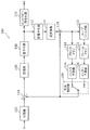
- FIG. 1 is a block diagram showing a functional configuration of the coding apparatus according to the first embodiment.
- FIG. 2 is a diagram showing an example of block division in the first embodiment.
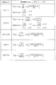
- FIG. 3 is a table showing transform basis functions corresponding to each transform type.
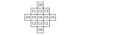
- FIG. 4A is a view showing an example of the shape of a filter used in ALF.
- FIG. 4B is a view showing another example of the shape of a filter used in ALF.
- FIG. 4C is a view showing another example of the shape of a filter used in ALF.
- FIG. 5A is a diagram illustrating 67 intra prediction modes in intra prediction.
- FIG. 5B is a flowchart for describing an outline of predicted image correction processing by OBMC processing.
- FIG. 5A is a diagram illustrating 67 intra prediction modes in intra prediction.
- FIG. 5B is a flowchart for describing an outline of predicted image correction processing by OBMC processing.
- FIG. 5C is a conceptual diagram for describing an outline of predicted image correction processing by OBMC processing.
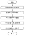
- FIG. 5D is a diagram illustrating an example of FRUC.
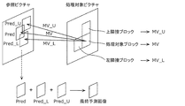
- FIG. 6 is a diagram for describing pattern matching (bilateral matching) between two blocks along a motion trajectory.
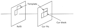
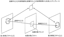
- FIG. 7 is a diagram for describing pattern matching (template matching) between a template in a current picture and a block in a reference picture.
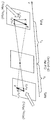
- FIG. 8 is a diagram for explaining a model assuming uniform linear motion.
- FIG. 9A is a diagram for describing derivation of a motion vector in units of sub blocks based on motion vectors of a plurality of adjacent blocks.
- FIG. 9B is a diagram for describing an overview of motion vector derivation processing in the merge mode.
- FIG. 9A is a diagram for describing derivation of a motion vector in units of sub blocks based on motion vectors of a plurality of adjacent blocks.
- FIG. 9B is a diagram for describing an
- FIG. 9C is a conceptual diagram for describing an overview of DMVR processing.
- FIG. 9D is a diagram for describing an outline of a predicted image generation method using luminance correction processing by LIC processing.
- FIG. 10 is a block diagram showing a functional configuration of the decoding apparatus according to the first embodiment.
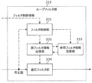
- FIG. 11 is a block diagram showing a configuration of a loop filter unit of the coding apparatus in the first embodiment.
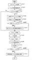
- FIG. 12A is a flow chart showing a first specific example of a management procedure of filter information in the first embodiment.
- FIG. 12B is a flowchart showing a first specific example of a setting procedure of filter information in the first embodiment.
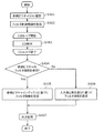
- FIG. 13A is a flowchart illustrating a second specific example of the management procedure of filter information in the first embodiment.
- FIG. 13B is a flowchart illustrating a second specific example of the setting procedure of the filter information in the first embodiment.
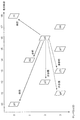
- FIG. 14A is a conceptual diagram showing a first specific example of reference restriction of filter information in the first embodiment.
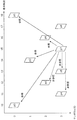
- FIG. 14B is a conceptual diagram showing a second specific example of the reference restriction of the filter information in the first embodiment.
- FIG. 15 is a block diagram showing a configuration of a loop filter unit of the decoding apparatus in the first embodiment.
- FIG. 16 is a flowchart showing a first specific example of the processing procedure of the filter information in the modification.
- FIG. 17 is a flowchart illustrating a second specific example of the processing procedure of the filter information in the modification.
- FIG. 18 is a conceptual diagram showing a first specific example of the PPS notification in the modification.
- FIG. 19 is a conceptual diagram showing a second specific example of the PPS notification in the modified embodiment.
- FIG. 20A is a conceptual diagram showing a third specific example of the PPS notification in the modified embodiment.
- FIG. 20B is a conceptual diagram showing a fourth specific example of the PPS notification in the modified embodiment.
- FIG. 21A is a conceptual diagram showing a fifth example of the PPS notification in the modified embodiment.
- FIG. 21B is a conceptual diagram showing a sixth specific example of the PPS notification in the modified embodiment.
- FIG. 22 is a block diagram showing an implementation example of a coding apparatus.
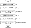
- FIG. 23 is a flow chart showing a first operation example of the coding apparatus.
- FIG. 24 is a flowchart showing a second operation example of the coding apparatus.
- FIG. 25 is a flowchart showing a third operation example of the coding apparatus.
- FIG. 26 is a flow chart showing a fourth operation example of the coding apparatus.
- FIG. 27 is a block diagram showing an implementation example of a decoding device.
- FIG. 28 is a flow chart showing a first operation example of the decoding device.
- FIG. 29 is a flow chart showing a second operation example of the decoding device.
- FIG. 30 is a flowchart showing a third operation example of the decoding device.
- FIG. 31 is a flowchart showing a fourth operation example of the decoding device.
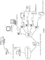
- FIG. 32 is an overall configuration diagram of a content supply system for realizing content distribution service.
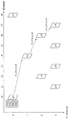
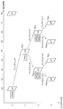
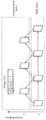
- FIG. 33 is a diagram illustrating an example of a coding structure at the time of scalable coding.
- FIG. 33 is a diagram illustrating an example of a coding structure at the time of scalable coding.
- FIG. 33 is a diagram illustrating an example of a coding structure at the
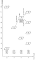
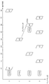
- FIG. 34 is a diagram illustrating an example of a coding structure at the time of scalable coding.
- FIG. 35 is a view showing an example of a display screen of a web page.
- FIG. 36 is a diagram showing an example of a display screen of a web page.
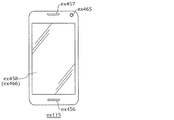
- FIG. 37 is a diagram illustrating an example of a smartphone.
- FIG. 38 is a block diagram illustrating a configuration example of a smartphone.
- the encoding apparatus that encodes a moving image including a plurality of pictures may encode the coding target picture of the plurality of pictures with reference to the encoded picture of the plurality of pictures.
- a decoding apparatus that decodes a moving image including a plurality of pictures may decode a decoding target picture among the plurality of pictures with reference to a decoded picture among the plurality of pictures.
- Each of the plurality of pictures may be assigned a temporal ID indicating a hierarchy related to temporal scalability.
- the temporal ID corresponds to an integer value of 0 or more. For example, it is prohibited to refer to a coded picture having a temporal ID larger than that of the current picture in coding of the current picture. As a result, the encoded picture referred to in the encoding of the encoding target picture is appropriately limited, and the processing complexity in encoding of the encoding target picture is suppressed.
- the decoding apparatus can perform thinning-out in decoding of a moving image by decoding only a part of pictures of which temporal IDs are equal to or less than a predetermined value among all pictures, thereby reducing the amount of processing. .
- a picture included in a plurality of pictures may be used as a temporal sub-layer access (TSA) picture.
- TSA temporal sub-layer access
- a transition may be made from a state in which each picture with a temporal ID smaller than that in the TSA picture is decoded to a state in which each picture with a temporal ID the same as or larger than a TSA picture is decoded. It is possible.
- the transition to a state in which a picture with a larger temporal ID is decoded is called an up switch.
- a picture with a large temporal ID may not be decoded by decimation. Then, when the up switch is performed without using a restriction such as a TSA picture, a picture which has not been decoded may be referred to. Therefore, it is difficult to perform an appropriate up switch if no restriction such as a TSA picture is used.
- a picture included in a plurality of pictures may be used as a step-wise temporal sub-layer access (STSA) picture.
- STSA step-wise temporal sub-layer access
- the up switch for transitioning to the state in which the temporal ID is the same as or larger than the TSA picture is guaranteed from the state in which each picture with the temporal ID smaller than the TSA picture is decoded Ru.
- the up switch is transitioned to the state where each picture with the same temporal ID as the STSA picture is decoded.
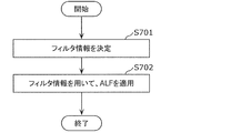
- the filter information of the adaptive loop filter is an example of information used in coding and decoding of a moving image.
- the adaptive loop filter is a filter for bringing a reconstructed image generated in coding or decoding of a moving image closer to the original image, and for performing image processing such as smoothing or sharpening on the reconstructed image. It is a filter.
- the adaptive loop filter is appropriately applied to the reconstructed image using the filter information, and moving image encoding and decoding are appropriately performed.
- filter information is not set appropriately, encoding and decoding of a moving picture are not properly performed. That is, if the information used in encoding and decoding of a moving image is not appropriately set, encoding and decoding of the moving image can not be appropriately performed.
- an encoding apparatus is an encoding apparatus that applies an adaptive loop filter in encoding of a moving image including a plurality of pictures to which temporal IDs indicating layers related to temporal scalability are respectively assigned.
- a plurality of first filter information for applying an adaptive loop filter to a first picture of the plurality of pictures using the memory Using the determined first filter information to determine by referring to second filter information associated with a second picture preceding the first picture among the pictures in coding order; Applying an adaptive loop filter to one picture, and the circuit
- the NAL (Network Abstraction Layer) unit type of the first picture is a predetermined NAL unit type, the picture is a picture preceding the first picture among the plurality of pictures in coding order and It may be prohibited to refer to the third filter information associated with the third picture whose temporal ID is the same as the first picture as the second filter information.
- the encoding apparatus can determine the first filter information of the first picture with reference to the second filter information of the second picture. At this time, the encoding apparatus can prohibit reference to the third filter information of the third picture in the same layer as the first picture of the predetermined NAL unit type as the second filter information.
- the encoding apparatus can perform filtering on filter information of a picture of the same layer as the first picture of the predetermined NAL unit type in the same manner as a reference restriction that can be performed on a picture of the same layer as the first picture of the predetermined NAL unit type Referential restrictions can be made. Therefore, the encoding apparatus can associate filter information with a picture and appropriately manage it, and can appropriately limit and set referenced filter information. Thus, the encoding apparatus can appropriately set information related to encoding of a moving image.
- the circuit is a picture preceding the first picture among the plurality of pictures in coding order and the temporal ID is higher than the first picture. It may be prohibited to refer to the fourth filter information associated with the fourth picture which is a large picture as the second filter information.
- the encoding apparatus can perform reference restriction on filter information associated with the picture in temporal scalability, as with the reference restriction imposed on the picture. Therefore, the encoding apparatus can appropriately limit and set the filter information to be referred to.
- the circuit may further include a plurality of fifth filter information for applying an adaptive loop filter to a fifth picture after the first picture in coding order among the plurality of pictures.
- the circuit may determine that the NAL unit type of the first picture is the predetermined NAL unit type. It is prohibited to refer to the third filter information associated with a picture as the sixth filter information. It may be.
- the encoding apparatus can determine the fifth filter information of the fifth picture after the first picture in the encoding order with reference to the sixth filter information of the sixth picture. At this time, the encoding apparatus can prohibit reference to the third filter information of the third picture of the same layer as the first picture of the predetermined NAL unit type as the sixth filter information.
- the coding apparatus may filter the picture of the same layer as the first picture in the same manner as the reference restriction that may be performed on the picture of the same layer as the first picture after the first picture of the predetermined NAL unit type.
- Referential restriction can be performed on information. Therefore, the encoding apparatus can associate filter information with a picture and appropriately manage it, and can appropriately limit and set referenced filter information. Thus, the encoding apparatus can appropriately set information related to encoding of a moving image.
- the circuit encodes more than the first picture among the plurality of pictures. It may be prohibited to refer to the fourth filter information associated with the fourth picture, which is the previous picture in order and whose temporal ID is larger than the first picture, as the sixth filter information.
- the fourth filter information of the fourth picture having a temporal ID larger than that of the first picture is the fifth filter information. It is forbidden to refer as.
- the encoding device performs the reference restriction on the filter information in the same manner as the reference restriction that may be performed on the picture having the temporal ID larger than the first picture after the first picture of the predetermined NAL unit type. It can be carried out. Therefore, the encoding apparatus can associate filter information with a picture and appropriately manage it, and can appropriately limit and set referenced filter information. Thus, the encoding apparatus can appropriately set information related to encoding of a moving image.
- the circuit is a picture preceding the first picture in the coding order among the first picture and the plurality of pictures, and the temporal ID is 0.
- the seventh picture which is a larger picture
- the NAL unit type of the eighth picture is the above
- reference to the seventh filter information associated with the seventh picture as the second filter information may be prohibited.
- the encoding apparatus refers to the seventh filter information of the seventh picture having the same or a larger temporal ID as the eighth filter than the eighth picture of the predetermined NAL unit type as the second filter information. It can be prohibited.
- the coding apparatus performs the reference restriction on the seventh filter information of the seventh picture in the same manner as the reference restriction that can be performed on the seventh picture after the eighth picture of the predetermined NAL unit type. be able to. Therefore, the encoding apparatus can associate filter information with a picture and appropriately manage it, and can appropriately limit and set referenced filter information. Thus, the encoding apparatus can appropriately set information related to encoding of a moving image.
- the predetermined NAL unit type may be a NAL unit type of a TSA (Temporal Sub-layer Access) picture.
- the encoding apparatus can perform reference restriction on the filter information of the picture in the same layer as that of the TSA picture, similarly to the reference restriction that can be performed on the picture in the same hierarchy as that of the TSA picture. Therefore, the encoding apparatus can associate filter information with a picture and appropriately manage it, and can appropriately limit and set referenced filter information. Thus, the encoding apparatus can appropriately set information related to encoding of a moving image.
- the circuit may further include a plurality of fifth filter information for applying an adaptive loop filter to a fifth picture after the first picture in coding order among the plurality of pictures.
- a plurality of fifth filter information for applying an adaptive loop filter to a fifth picture after the first picture in coding order among the plurality of pictures.
- the determined fifth filter information to determine by referring to the sixth filter information associated with the sixth picture preceding the fifth picture among the pictures in coding order; Applying an adaptive loop filter to five pictures, and in the circuit determining the fifth filter information, the NAL unit type of the first picture is the predetermined NAL unit type, and the fifth picture
- the third picture if the temporal ID of the second picture is the same as the temporal ID of the first picture It may be prohibited to refer to the third filter information associated as the sixth filter information.
- the encoding apparatus determines fifth filter information of the fifth picture of the same layer as the first picture after the first picture in coding order with reference to the sixth filter information of the sixth picture. be able to. At this time, the encoding apparatus can prohibit reference to the third filter information of the third picture of the same layer as the first picture of the predetermined NAL unit type as the sixth filter information.
- the encoding apparatus may filter the same as the reference restriction that may be applied to the picture before the first picture in the same layer as the first picture after the first picture of the predetermined NAL unit type.
- Referential restriction can be performed on information. Therefore, the encoding apparatus can associate filter information with a picture and appropriately manage it, and can appropriately limit and set referenced filter information. Thus, the encoding apparatus can appropriately set information related to encoding of a moving image.
- the predetermined NAL unit type may be a NAL unit type of a STSA (Step-wise Temporal Sub-layer Access) picture.
- STSA Step-wise Temporal Sub-layer Access
- the encoding apparatus can perform reference restriction on the filter information of the picture in the same hierarchy as that of the STSA picture, as in the case of the reference restriction that can be performed on a picture in the same hierarchy as that of the STSA picture. Therefore, the encoding apparatus can associate filter information with a picture and appropriately manage it, and can appropriately limit and set referenced filter information. Thus, the encoding apparatus can appropriately set information related to encoding of a moving image.
- a decoding device is a decoding device that applies an adaptive loop filter in decoding of a moving image including a plurality of pictures to which temporal IDs indicating layers related to temporal scalability are assigned.
- a circuit, and a memory wherein the circuit uses first memory to apply first filter information for applying an adaptive loop filter to a first picture of the plurality of pictures using the memory; Determining with reference to second filter information associated with a second picture preceding the first picture in decoding order, and using the determined first filter information for the first picture Applying an adaptive loop filter, the circuit comprising: In the determining step, when the NAL (Network Abstraction Layer) unit type of the first picture is a predetermined NAL unit type, the temporal ID is the picture preceding the first picture in the decoding order among the plurality of pictures. It may be prohibited to refer to the third filter information associated with the third picture which is the same picture as the first picture as the second filter information.
- NAL Network Abstraction Layer
- the decoding apparatus can determine the first filter information of the first picture with reference to the second filter information of the second picture. At this time, the decoding apparatus can prohibit reference to the third filter information of the third picture of the same layer as the first picture of the predetermined NAL unit type as the second filter information.
- the decoding device references the filter information of the picture of the same layer as the first picture of the predetermined NAL unit type, as in the case of the reference restriction that can be performed on the picture of the same layer as the first picture of the predetermined NAL unit type. You can do restrictions. Therefore, the decoding apparatus can associate filter information with a picture and appropriately manage it, and can appropriately limit and set referenced filter information. Therefore, the decoding device can appropriately set the information related to the decoding of the moving image.
- the circuit is a picture preceding the first picture in decoding order among the plurality of pictures, and the temporal ID is larger than the first picture.
- Reference to the fourth filter information associated with the fourth picture, which is a picture, as the second filter information may be prohibited.
- the decoding device can perform the reference restriction on the filter information associated with the picture in the time scalability, in the same manner as the reference restriction imposed on the picture. Therefore, the decoding apparatus can appropriately limit and set the filter information to be referred to.
- the circuit may further include fifth filter information for applying an adaptive loop filter to a fifth picture of the plurality of pictures after the first picture in decoding order, The step of determining with reference to sixth filter information associated with the sixth picture preceding the fifth picture among the pictures in decoding order, and using the determined fifth filter information, the fifth picture And applying the adaptive loop filter to the image, and the circuit determines the fifth filter information, if the NAL unit type of the first picture is the predetermined NAL unit type; Prohibiting reference to the associated third filter information as the sixth filter information It may be.
- the decoding apparatus can determine the fifth filter information of the fifth picture after the first picture in decoding order with reference to the sixth filter information of the sixth picture. At this time, the decoding apparatus can prohibit reference to the third filter information of the third picture of the same layer as the first picture of the predetermined NAL unit type as the sixth filter information.
- the decoding apparatus is configured to filter information of a picture in the same hierarchy as the first picture, similarly to a reference restriction that may be performed on a picture in the same hierarchy as the first picture after the first picture of the predetermined NAL unit type. Can be restricted to Therefore, the decoding apparatus can associate filter information with a picture and appropriately manage it, and can appropriately limit and set referenced filter information. Therefore, the decoding device can appropriately set the information related to the decoding of the moving image.
- the circuit determines the decoding order of the plurality of pictures in the decoding order than the first picture. It may be prohibited to refer to the fourth filter information associated with the fourth picture which is the previous picture and whose temporal ID is larger than the first picture as the sixth filter information.
- the fourth filter information of the fourth picture having a temporal ID larger than that of the first picture is the fifth filter information. It is forbidden to refer as.
- the decoding device performs the reference restriction on the filter information in the same manner as the reference restriction that may be performed on the picture having the temporal ID larger than that of the first picture after the first picture of the predetermined NAL unit type. be able to. Therefore, the decoding apparatus can associate filter information with a picture and appropriately manage it, and can appropriately limit and set referenced filter information. Therefore, the decoding device can appropriately set the information related to the decoding of the moving image.
- the circuit is a picture preceding the first picture in the decoding order among the first picture and the plurality of pictures, and the temporal ID is less than 0.
- the seventh picture which is also a large picture
- reference to the seventh filter information associated with the seventh picture as the second filter information may be prohibited.
- the decoding device is prohibited to refer to the seventh filter information of the seventh picture of the same or larger temporal ID as the second filter information as compared to the eighth picture after the eighth picture of the predetermined NAL unit type. can do.
- the decoding device performs the reference restriction on the seventh filter information of the seventh picture in the same manner as the reference restriction that may be performed on the seventh picture after the eighth picture of the predetermined NAL unit type. Can. Therefore, the decoding apparatus can associate filter information with a picture and appropriately manage it, and can appropriately limit and set referenced filter information. Therefore, the decoding device can appropriately set the information related to the decoding of the moving image.
- the predetermined NAL unit type may be a NAL unit type of a TSA (Temporal Sub-layer Access) picture.
- the decoding apparatus can perform reference restriction on filter information of pictures in the same hierarchy as that of the TSA picture, as in the case of reference restrictions that can be performed on pictures in the same hierarchy as that of the TSA picture. Therefore, the decoding apparatus can associate filter information with a picture and appropriately manage it, and can appropriately limit and set referenced filter information. Therefore, the decoding device can appropriately set the information related to the decoding of the moving image.
- the circuit may further include fifth filter information for applying an adaptive loop filter to a fifth picture of the plurality of pictures after the first picture in decoding order, The step of determining with reference to sixth filter information associated with the sixth picture preceding the fifth picture among the pictures in decoding order, and using the determined fifth filter information, the fifth picture Applying an adaptive loop filter to the circuit, and the circuit determines the fifth filter information, wherein the NAL unit type of the first picture is the predetermined NAL unit type, and the temporal of the fifth picture is If the ID is the same as the temporal ID of the first picture, It may be prohibited to refer to the third filter information attached as the sixth filter information.
- the decoding device may determine the fifth filter information of the fifth picture of the same layer as the first picture after the first picture in decoding order with reference to the sixth filter information of the sixth picture. it can. At this time, the decoding apparatus can prohibit reference to the third filter information of the third picture of the same layer as the first picture of the predetermined NAL unit type as the sixth filter information.
- the decoding apparatus performs filter information in the same manner as the reference restriction that can be performed on the picture before the first picture. Can be restricted to Therefore, the decoding apparatus can associate filter information with a picture and appropriately manage it, and can appropriately limit and set referenced filter information. Therefore, the decoding device can appropriately set the information related to the decoding of the moving image.
- the predetermined NAL unit type may be a NAL unit type of a STSA (Step-wise Temporal Sub-layer Access) picture.
- STSA Step-wise Temporal Sub-layer Access
- the decoding apparatus can perform reference restriction on filter information of pictures in the same hierarchy as that of the STSA picture, as in the case of reference restrictions that can be performed on pictures in the same hierarchy as that of the STSA picture. Therefore, the decoding apparatus can associate filter information with a picture and appropriately manage it, and can appropriately limit and set referenced filter information. Therefore, the decoding device can appropriately set the information related to the decoding of the moving image.
- an encoding method is an encoding method that applies an adaptive loop filter in encoding of a moving image including a plurality of pictures to which temporal IDs indicating layers related to temporal scalability are assigned.
- a first filter information for applying an adaptive loop filter to a first picture of the plurality of pictures, and a second filter information preceding the first picture of the plurality of pictures in coding order Determining with reference to second filter information associated with a picture, and applying an adaptive loop filter to the first picture using the determined first filter information,
- the NAL Netwo (k Abstraction Layer)
- the unit type is a predetermined NAL unit type
- the reference restriction is applied to the filter information of the picture in the same layer as the first picture of the predetermined NAL unit type, in the same manner as the reference restriction that can be performed on the picture in the same layer as the first picture of the predetermined NAL unit type. Is possible. Therefore, it is possible to appropriately manage filter information in association with a picture, and it is possible to appropriately limit and set reference filter information. Therefore, it is possible to appropriately set information related to the coding of a moving image.
- a decoding method is a decoding method that applies an adaptive loop filter in decoding of a moving image including a plurality of pictures to which temporal IDs indicating layers related to temporal scalability are assigned.
- First filter information for applying an adaptive loop filter to a first picture of the plurality of pictures is associated with a second picture preceding the first picture in the decoding order among the plurality of pictures.
- the NAL Network A of the first picture
- the unit type is a predetermined NAL unit type, it is associated with a third picture among the plurality of pictures which is a picture before the first picture in decoding order and whose temporal ID is the same as the first picture It may be prohibited to refer the generated third filter information as the second filter information.
- the reference restriction is applied to the filter information of the picture in the same layer as the first picture of the predetermined NAL unit type, in the same manner as the reference restriction that can be performed on the picture in the same layer as the first picture of the predetermined NAL unit type. Is possible. Therefore, it is possible to appropriately manage filter information in association with a picture, and it is possible to appropriately limit and set reference filter information. Therefore, it is possible to appropriately set information related to decoding of a moving image.
- the encoding apparatus is an encoding apparatus that encodes a moving image including a plurality of pictures to which temporal IDs indicating layers related to temporal scalability are assigned, respectively;
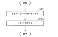
- a memory the circuit using the memory to encode a plurality of parameter sets, each of which is assigned 0 as a temporal ID indicating a hierarchy related to the time scalability; and encoding the plurality of parameter sets
- the step of encoding the first picture in the coding order among the plurality of pictures, and the plurality of parameter sets are respectively assigned to the plurality of layers indicated by the plurality of temporal IDs assigned to the plurality of pictures.
- each of the plurality of parameter sets It may be a parameter set for one or more pictures to which the parameter set of the number of pictures are assigned a temporal ID indicating the corresponding hierarchy.
- the encoding apparatus can collectively encode a plurality of parameter sets corresponding to each of the plurality of layers first. Further, 0 is assigned as a temporal ID to each of the plurality of parameter sets. Thus, multiple parameter sets can be properly processed without being discarded. Thus, the encoding apparatus can appropriately set information related to encoding of a moving image.
- the plurality of pictures constitute a first picture group
- the plurality of parameter sets constitute a first parameter set group
- the moving picture further constitutes a plurality of second picture groups.
- a plurality of parameter sets each including a picture, and the circuit is further assigned 0 as a temporal ID indicating a hierarchy relating to the temporal scalability after coding of the pictures making up the first picture group; Encoding a plurality of parameter sets that constitute a parameter set group; and, after encoding the plurality of parameter sets that constitute the second parameter set group, of the plurality of pictures that constitute the second picture group Code the first picture in coding order
- the plurality of parameter sets constituting the second parameter set group correspond respectively to a plurality of layers indicated by a plurality of temporal IDs assigned to the plurality of pictures constituting the second picture group.
- each of the plurality of parameter sets constituting the second parameter set group corresponds to a hierarchy corresponding to the parameter set constituting the second parameter set group among the plurality of pictures constituting the second picture group It may be a parameter set for one or more pictures to which a temporal ID indicating.
- the encoding apparatus can collectively encode a plurality of parameter sets corresponding to each of the plurality of layers for each picture group. Therefore, the encoding apparatus can appropriately set information related to encoding of a moving image for each picture group.
- a decoding device that decodes a moving image including a plurality of pictures to which temporal IDs indicating layers related to temporal scalability are assigned, and includes a circuit and a memory.
- the circuit may use the memory to decode a plurality of parameter sets, each of which is assigned 0 as a temporal ID indicating a hierarchy related to the time scalability, and after decoding the plurality of parameter sets, the plurality of parameter sets.
- the plurality of parameter sets respectively corresponding to a plurality of layers indicated by a plurality of temporal IDs assigned to the plurality of pictures, and the plurality of parameters
- Each of the sets comprises the plurality of pictures Out it may be a parameter set the parameter set for one or more pictures are assigned temporal ID indicating the corresponding hierarchy.
- the decoding apparatus can collectively decode a plurality of parameter sets corresponding to each of the plurality of layers at first. Further, 0 is assigned as a temporal ID to each of the plurality of parameter sets. Thus, multiple parameter sets can be properly processed without being discarded. Therefore, the decoding device can appropriately set the information related to the decoding of the moving image.
- the plurality of pictures constitute a first picture group
- the plurality of parameter sets constitute a first parameter set group
- the moving picture further constitutes a plurality of second picture groups.
- the plurality of parameter sets constituting the second parameter set group respectively correspond to a plurality of layers indicated by a plurality of temporal IDs assigned to the plurality of pictures constituting the second picture group
- Each of the plurality of parameter sets constituting the 2 parameter set group is a temporal ID indicating a layer to which the parameter set constituting the second parameter set group corresponds among the plurality of
- the decoding device can collectively decode a plurality of parameter sets corresponding to each of the plurality of layers for each picture group. Therefore, the decoding device can appropriately set information related to decoding of a moving image for each picture group.
- an encoding method for encoding a moving image including a plurality of pictures to which temporal IDs indicating layers related to temporal scalability are respectively assigned, the temporal scalability Encoding a plurality of parameter sets, each of which is assigned 0 as a temporal ID indicating a hierarchy related to H. After encoding the plurality of parameter sets, encoding the first picture in the encoding order among the plurality of pictures. And the plurality of parameter sets correspond respectively to a plurality of layers indicated by a plurality of temporal IDs assigned to the plurality of pictures, and each of the plurality of parameter sets is one of the plurality of pictures.
- the hierarchy corresponding to the parameter set It may be a parameter set for one or more pictures to temporal ID is assigned.
- a decoding method for decoding a moving image including a plurality of pictures to which temporal IDs indicating layers related to temporal scalability are assigned, respectively.
- Decoding the plurality of parameter sets to which 0 is respectively assigned as the temporal ID, and decoding the first picture in the decoding order among the plurality of pictures after decoding the plurality of parameter sets A plurality of parameter sets respectively correspond to a plurality of layers indicated by a plurality of temporal IDs assigned to the plurality of pictures, and each of the plurality of parameter sets corresponds to a layer corresponding to the parameter set among the plurality of pictures.
- Temporal indicating D may be a parameter set for one or more pictures are assigned.
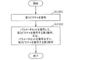
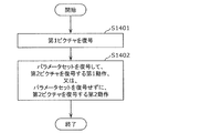
- an encoding apparatus that encodes a moving image including a plurality of pictures, and includes a circuit and a memory, and the circuit uses the memory. Coding the first picture of the plurality of pictures, and (i) coding the first picture, and then coding the first picture after the first picture in coding order of the plurality of pictures. Encoding a parameter set for two pictures, and encoding the second picture after encoding the parameter set, or (ii) encoding the parameter set after encoding the first picture And performing the second operation of encoding the second picture, and the circuit is configured to perform the second operation by performing the first operation or the second operation. If a turbocharger, it may perform the first operation.
- the coding apparatus can code the parameter set for a predetermined picture before the predetermined picture. Therefore, the parameter set for the predetermined picture can be properly processed at the up switch or the like for the predetermined picture. Thus, the encoding apparatus can appropriately set information related to encoding of a moving image.
- the predetermined picture may be a TSA (Temporal Sub-layer Access) picture.
- the coding apparatus can code the parameter set for the TSA picture before the TSA picture. Therefore, the parameter set for the TSA picture can be properly processed, such as at the up switch for the TSA picture.
- the encoding apparatus can appropriately set information related to encoding of a moving image.
- each of the plurality of pictures is a picture to which a temporal ID indicating a hierarchy related to temporal scalability is assigned, and in the first operation, the circuit generates the second picture after encoding the first picture.
- Each of the plurality of related parameter sets indicates a layer to which the related parameter set corresponds among the plurality of pictures, each corresponding to a plurality of layers indicated by a plurality of temporal IDs equal to or greater than the temporal ID assigned to 2 pictures.
- Temporal ID assigned It may be a parameter set for one or more pictures.
- the encoding apparatus can encode a plurality of parameter sets for a plurality of pictures having the same temporal ID as the predetermined picture or a temporal ID larger than the predetermined picture before the predetermined picture. Therefore, the parameter set can be properly processed at an up switch or the like for a picture having a temporal ID larger than that of the predetermined picture. Thus, the encoding apparatus can appropriately set information related to encoding of a moving image.
- the predetermined picture may be a step-wise temporal sub-layer access (STSA) picture.
- STSA step-wise temporal sub-layer access
- the coding apparatus can code the parameter set for the STSA picture before the STSA picture. Therefore, the parameter set for the STSA picture can be properly processed, such as in the up switch for the STSA picture.
- the encoding apparatus can appropriately set information related to encoding of a moving image.
- the second picture may be a picture to be encoded next to the first picture among the plurality of pictures.
- the encoding apparatus can appropriately encode the parameter set for the predetermined picture immediately before encoding the predetermined picture.
- parameter sets for a given picture may be properly processed.
- the encoding apparatus can appropriately set information related to encoding of a moving image.
- each of the plurality of pictures is a picture to which a temporal ID indicating a hierarchy related to temporal scalability is assigned, and the circuit further encodes the first picture among the plurality of pictures in coding order.
- a plurality of global parameter sets which are a plurality of parameter sets including the parameter set for the second picture, are encoded, wherein the plurality of global parameter sets are indicated by a plurality of temporal IDs assigned to the plurality of pictures
- Each of the plurality of inclusive parameter sets corresponds to a plurality of layers, and each of the plurality of inclusive parameter sets is a parameter set for one or more pictures to which temporal IDs indicating the layers to which the inclusive parameter set corresponds are assigned. It is also good.
- the encoding apparatus may re-encode the parameter set for the predetermined picture before the predetermined picture even when the plurality of parameter sets including the parameter set for the predetermined picture are encoded first. it can.
- parameter sets for a given picture may be properly processed.
- the encoding apparatus can appropriately set information related to encoding of a moving image.
- a decoding device that decodes a moving image including a plurality of pictures, and includes a circuit and a memory, and the circuit uses the memory to execute the process.
- the decoding apparatus can decode the parameter set for the predetermined picture before the predetermined picture. Therefore, the parameter set for the predetermined picture can be properly processed at the up switch or the like for the predetermined picture. Therefore, the decoding device can appropriately set the information related to the decoding of the moving image.
- the predetermined picture may be a TSA (Temporal Sub-layer Access) picture.
- the decoding apparatus can decode the parameter set for the TSA picture before the TSA picture. Therefore, the parameter set for the TSA picture can be properly processed, such as at the up switch for the TSA picture. Therefore, the decoding device can appropriately set the information related to the decoding of the moving image.
- each of the plurality of pictures is a picture to which a temporal ID indicating a hierarchy relating to temporal scalability is assigned, and the circuit performs, for the second picture, the decoding of the first picture in the first operation.
- Decoding a plurality of related parameter sets that are a plurality of parameter sets including the parameter set, and decoding the second picture after decoding the plurality of related parameter sets, and the plurality of related parameter sets are the second picture
- the decoding apparatus can decode a plurality of parameter sets for a plurality of pictures having the same temporal ID as the predetermined picture or a larger temporal ID than the predetermined picture, before the predetermined picture. Therefore, the parameter set can be properly processed at an up switch or the like for a picture having a temporal ID larger than that of the predetermined picture. Therefore, the decoding device can appropriately set the information related to the decoding of the moving image.
- the predetermined picture may be a step-wise temporal sub-layer access (STSA) picture.
- STSA step-wise temporal sub-layer access
- the decoding apparatus can decode the parameter set for the STSA picture before the STSA picture. Therefore, the parameter set for the STSA picture can be properly processed, such as in the up switch for the STSA picture. Therefore, the decoding device can appropriately set the information related to the decoding of the moving image.
- the second picture may be a picture decoded next to the first picture among the plurality of pictures.
- the decoding apparatus can appropriately decode the parameter set for the predetermined picture immediately before decoding the predetermined picture.
- parameter sets for a given picture may be properly processed. Therefore, the decoding device can appropriately set the information related to the decoding of the moving image.
- each of the plurality of pictures is a picture to which a temporal ID indicating a layer related to temporal scalability is assigned, and the circuit further decodes the first picture in decoding order among the plurality of pictures.
- Decoding a plurality of inclusive parameter sets that are a plurality of parameter sets including the parameter set for the second picture, wherein the plurality of inclusive parameter sets are indicated by a plurality of temporal IDs assigned to the plurality of pictures
- Each of the plurality of inclusive parameter sets may correspond to a layer, and each of the plurality of inclusive parameter sets may be a parameter set for one or more pictures to which a temporal ID indicating a layer corresponding to the inclusive parameter set is assigned. .
- the decoding apparatus can decode the parameter set for the predetermined picture again before the predetermined picture even when the plurality of parameter sets including the parameter set for the predetermined picture are decoded first.
- parameter sets for a given picture may be properly processed. Therefore, the decoding device can appropriately set the information related to the decoding of the moving image.
- an encoding method for encoding a moving image including a plurality of pictures, and encoding the first picture of the plurality of pictures; (I) After encoding the first picture, encoding a parameter set for a second picture after the first picture in encoding order among the plurality of pictures, and encoding the parameter set, A first operation of encoding a second picture, or (ii) performing a second operation of encoding the second picture without encoding the parameter set after the encoding of the first picture; In the step of performing the first operation or the second operation, the first operation may be performed if the second picture is a predetermined picture.
- the parameter set for the predetermined picture before the predetermined picture. Therefore, the parameter set for the predetermined picture can be properly processed at the up switch or the like for the predetermined picture. Therefore, it is possible to appropriately set information related to the coding of a moving image.
- a decoding method for decoding a moving image including a plurality of pictures, and decoding the first picture of the plurality of pictures; (i) After decoding the first picture, decoding a parameter set for a second picture after the first picture among the plurality of pictures in decoding order, and decoding the second picture after decoding the parameter set And (ii) performing a second operation of decoding the second picture without decoding the parameter set after decoding of the first picture, the first operation or the second operation.
- the first operation may be performed if the second picture is a predetermined picture.
- the encoding apparatus is an encoding apparatus that encodes a moving image including a plurality of pictures to which temporal IDs indicating layers related to temporal scalability are assigned, respectively;
- a memory the circuit using the memory to encode a first picture of the plurality of pictures; (i) after the coding of the first picture, of the plurality of pictures A first operation of encoding a parameter set for a second picture after the first picture in encoding order and encoding the second picture after encoding of the parameter set, or (ii) the first operation Performing a second operation of encoding the second picture without encoding the parameter set after encoding the picture;
- the temporal IDs assigned to the second picture are larger than the smallest temporal ID of the plurality of temporal IDs assigned to the plurality of pictures, and the plurality of temporal IDs are If the temporal ID is smaller than the largest temporal ID, the first operation may be performed.
- the encoding apparatus can appropriately set information related to encoding of a moving image.
- the circuit performs the first operation even when the temporal ID assigned to the second picture is the maximum temporal ID. Good.
- the encoding apparatus can appropriately set information related to encoding of a moving image.
- the circuit may encode the first picture. After that, the parameter set and the top parameter set are encoded, and after the parameter set and the top parameter set are encoded, the second picture is encoded, and the top parameter set is assigned the largest temporal ID. It may be a parameter set for one or more pictures to be performed.
- the circuit may perform the second operation when the temporal ID assigned to the second picture is the maximum temporal ID. .
- the circuit performs the second picture under a condition that a predetermined flag included in a sequence parameter set for the plurality of pictures has a predetermined value.
- the first operation may be performed if the temporal ID to be assigned is larger than the minimum temporal ID and smaller than the maximum temporal ID.
- each of the plurality of pictures is TSA (Temporal Sub-layer Access) when the temporal ID assigned to the picture is not the minimum temporal ID. It may be a picture.
- the encoding apparatus can appropriately encode the parameter set for the picture in the middle layer before the picture in the middle layer in the predetermined sequence composed of the TSA pictures excluding the lowest layer.
- a decoding device that decodes a moving image including a plurality of pictures to which temporal IDs indicating layers related to temporal scalability are assigned, and includes a circuit and a memory.
- the circuit may decode the first picture of the plurality of pictures using the memory; and (i) after decoding the first picture, the circuit in the decoding order of the plurality of pictures.
- the temporal ID assigned to the second picture is larger than the smallest temporal ID of the plurality of temporal IDs assigned to the plurality of pictures, and the largest temporal of the plurality of temporal IDs. If the ID is smaller than the ID, the first operation may be performed.
- the decoding device can decode the parameter set for the picture in the middle layer before the picture in the middle layer. Therefore, the parameter set for the picture in the middle layer can be properly processed, such as in the up switch for the picture in the middle layer. Therefore, the decoding device can appropriately set the information related to the decoding of the moving image.
- the circuit performs the first operation even when the temporal ID assigned to the second picture is the maximum temporal ID. Good.
- the decoding device can decode the parameter set for the top layer picture before the top layer picture. Therefore, the parameter set for the top layer picture can be properly processed, such as in the up switch for the top layer picture. Therefore, the decoding device can appropriately set the information related to the decoding of the moving image.
- the circuit performs the decoding after the first picture.
- Decoding the parameter set and the top parameter set, and decoding the second picture after decoding the parameter set and the top parameter set, wherein the top parameter set is assigned the largest temporal ID 1 It may be a parameter set for one or more pictures.
- the circuit may perform the second operation when the temporal ID assigned to the second picture is the maximum temporal ID. .
- the decoding apparatus can omit decoding the parameter set for the picture of the top layer before the picture of the top layer.
- the circuit performs the second picture under a condition that a predetermined flag included in a sequence parameter set for the plurality of pictures has a predetermined value.
- the first operation may be performed if the temporal ID to be assigned is larger than the minimum temporal ID and smaller than the maximum temporal ID.
- the decoding device can appropriately decode the parameter set for the picture in the middle layer before the picture in the middle layer in the predetermined sequence.
- each of the plurality of pictures is TSA (Temporal Sub-layer Access) when the temporal ID assigned to the picture is not the minimum temporal ID. It may be a picture.
- the decoding apparatus can appropriately decode the parameter set for the picture in the middle layer before the picture in the middle layer in the predetermined sequence configured by the TSA pictures except for the lowest layer.
- an encoding method for encoding a moving image including a plurality of pictures to which temporal IDs indicating layers related to temporal scalability are respectively assigned.
- the first operation is performed. You may go.
- a decoding method for decoding a moving image including a plurality of pictures to which temporal IDs indicating layers related to temporal scalability are respectively assigned, and among the plurality of pictures Decoding the first picture of (i) decoding the parameter set for the second picture after the first picture in decoding order among the plurality of pictures after the decoding of the first picture; A first operation of decoding the second picture after decoding of the set, or (ii) a second operation of decoding the second picture without decoding the parameter set after decoding of the first picture And performing the first operation or the second operation, the temporal I being assigned to the second picture.
- the first operation may be performed if the value is larger than the smallest temporal ID of the plurality of temporal IDs allocated to the plurality of pictures and smaller than the largest temporal ID of the plurality of temporal IDs. .
- the encoding apparatus includes a division unit, an intra prediction unit, an inter prediction unit, a conversion unit, a quantization unit, an entropy coding unit, and a filter unit. May be
- the division unit may divide a picture into a plurality of blocks.
- the intra prediction unit may perform intra prediction on blocks included in the plurality of blocks.
- the inter prediction unit may perform inter prediction on the block.
- the conversion unit may generate a conversion coefficient by converting a prediction error between a predicted image obtained by the intra prediction or the inter prediction and an original image.
- the quantization unit may quantize the transform coefficient to generate a quantization coefficient.
- the entropy coding unit may code the quantization coefficient to generate a coded bit stream.
- the filter unit may apply a filter to a reconstructed image generated using the predicted image.
- the encoding apparatus may be an encoding apparatus that applies an adaptive loop filter in encoding of a moving image including a plurality of pictures to which temporal IDs indicating layers related to temporal scalability are assigned.
- the filter unit is configured to apply first filter information for applying an adaptive loop filter to a first picture of the plurality of pictures in coding order relative to the first picture of the plurality of pictures. Determining with reference to second filter information associated with a previous second picture; and applying an adaptive loop filter to the first picture using the determined first filter information. You may go.
- the filter unit is in coding order than the first picture among the plurality of pictures. It may be prohibited to refer to the third filter information associated with the third picture that is the previous picture and has the same temporal ID as the first picture as the second filter information.
- the encoding apparatus may be an encoding apparatus that encodes a moving image including a plurality of pictures to which temporal IDs indicating layers related to temporal scalability are respectively assigned.
- the entropy encoding unit encodes a plurality of parameter sets each of which is assigned 0 as a temporal ID indicating a hierarchy related to the temporal scalability, and after encoding the plurality of parameter sets, the plurality of pictures And encoding the first picture in the encoding order.
- the plurality of parameter sets respectively correspond to a plurality of layers indicated by a plurality of temporal IDs assigned to the plurality of pictures, and each of the plurality of parameter sets corresponds to the parameter set of the plurality of pictures. It may be a parameter set for one or more pictures to which a temporal ID indicating a corresponding hierarchy is assigned.
- the encoding apparatus may be an encoding apparatus that encodes a moving image including a plurality of pictures.
- the entropy coding unit encodes the first picture of the plurality of pictures, and (i) after coding the first picture, the coding of the first picture in the coding order A first operation of encoding a parameter set for a second picture after one picture and encoding the second picture after encoding the parameter set, or (ii) after encoding the first picture A second operation of encoding the second picture may be performed without encoding the parameter set.
- the entropy coding unit may perform the first operation when the second picture is a predetermined picture.
- the encoding apparatus may be an encoding apparatus that encodes a moving image including a plurality of pictures to which temporal IDs indicating layers related to temporal scalability are respectively assigned.
- the entropy coding unit encodes the first picture of the plurality of pictures, and (i) after coding the first picture, the coding of the first picture in the coding order A first operation of encoding a parameter set for a second picture after one picture and encoding the second picture after encoding the parameter set, or (ii) after encoding the first picture A second operation of encoding the second picture may be performed without encoding the parameter set.
- the entropy coding unit is the smallest of temporal IDs assigned to the second picture among the plurality of temporal IDs assigned to the plurality of pictures.
- the first operation may be performed when it is larger than the temporal ID and smaller than the largest temporal ID of the plurality of temporal IDs.
- the decoding device may include an entropy decoding unit, an inverse quantization unit, an inverse transform unit, an intra prediction unit, an inter prediction unit, and a filter unit.
- the entropy decoding unit may decode quantization coefficients of blocks in a picture from a coded bit stream.
- the dequantization unit may dequantize the quantization coefficient to obtain a transform coefficient.
- the inverse transform unit may inverse transform the transform coefficient to obtain a prediction error.
- the intra prediction unit may perform intra prediction on the block.
- the inter prediction unit may perform inter prediction on the block.
- the filter unit may apply a filter to a reconstructed image generated using the prediction image obtained by the intra prediction or the inter prediction and the prediction error.
- the decoding device may be a decoding device that applies an adaptive loop filter in the decoding of a moving image including a plurality of pictures to which temporal IDs indicating layers related to temporal scalability are respectively assigned.
- the filter unit may perform first filter information for applying an adaptive loop filter to a first picture of the plurality of pictures before the first picture of the plurality of pictures in decoding order. Determining with reference to second filter information associated with the second picture of the second picture, and applying an adaptive loop filter to the first picture using the determined first filter information.
- the filter unit precedes, in decoding order, the first picture among the plurality of pictures. It may be prohibited to refer, as the second filter information, third filter information associated with a third picture which is a picture of the first picture and the temporal ID of which is the same picture.
- the decoding device may be a decoding device that decodes a moving image including a plurality of pictures to which temporal IDs indicating layers related to temporal scalability are respectively assigned.
- the entropy decoding unit decodes a plurality of parameter sets each of which is assigned 0 as a temporal ID indicating a hierarchy related to the temporal scalability, and after decoding the plurality of parameter sets, decodes the plurality of pictures. Decoding the first picture in order may be performed.
- the plurality of parameter sets respectively correspond to a plurality of layers indicated by a plurality of temporal IDs assigned to the plurality of pictures, and each of the plurality of parameter sets corresponds to the parameter set of the plurality of pictures. It may be a parameter set for one or more pictures to which a temporal ID indicating a corresponding hierarchy is assigned.
- the decoding device may be a decoding device that decodes a moving image including a plurality of pictures.
- the entropy decoding unit decodes the first picture of the plurality of pictures, and (i) after decoding the first picture, the first picture in decoding order among the plurality of pictures.
- a first operation of decoding a parameter set for a subsequent second picture and decoding of the second picture after decoding of the parameter set, or (ii) without decoding the parameter set after decoding of the first picture Performing a second operation of decoding the second picture.
- the entropy decoding unit may perform the first operation if the second picture is a predetermined picture.
- the decoding device may be a decoding device that decodes a moving image including a plurality of pictures to which temporal IDs indicating layers related to temporal scalability are respectively assigned.
- the entropy decoding unit decodes the first picture of the plurality of pictures, and (i) after decoding the first picture, the first picture in decoding order among the plurality of pictures.
- a first operation of decoding a parameter set for a subsequent second picture and decoding of the second picture after decoding of the parameter set, or (ii) without decoding the parameter set after decoding of the first picture Performing a second operation of decoding the second picture.
- the entropy decoding unit in the step of performing the first operation or the second operation, the temporal ID assigned to the second picture is the minimum temporal of the plurality of temporal IDs assigned to the plurality of pictures. If the ID is larger than the ID and smaller than the largest temporal ID of the plurality of temporal IDs, the first operation may be performed.
- these general or specific aspects may be realized by a system, an apparatus, a method, an integrated circuit, a computer program, or a non-transitory recording medium such as a computer readable CD-ROM, and the system
- the present invention may be realized as any combination of an apparatus, a method, an integrated circuit, a computer program, and a storage medium.
- Embodiment 1 First, an outline of the first embodiment will be described as an example of an encoding apparatus and a decoding apparatus to which the process and / or the configuration described in each aspect of the present disclosure described later can be applied.
- Embodiment 1 is merely an example of an encoding apparatus and a decoding apparatus to which the process and / or the configuration described in each aspect of the present disclosure can be applied, and the processing and / or the process described in each aspect of the present disclosure
- the configuration can also be implemented in a coding apparatus and a decoding apparatus that are different from the first embodiment.
- the encoding apparatus or the decoding apparatus according to the first embodiment corresponds to the constituent elements described in each aspect of the present disclosure among a plurality of constituent elements that configure the encoding apparatus or the decoding apparatus.
- Replacing a component with a component described in each aspect of the present disclosure (2) A plurality of configurations constituting the encoding device or the decoding device with respect to the encoding device or the decoding device of the first embodiment
- Addition of processing to the method performed by the encoding apparatus or the decoding apparatus of the first embodiment, and / or a plurality of processes included in the method home Replacing a process corresponding to the process described in each aspect of the present disclosure with the process described in each aspect of the present disclosure after replacing some of the processes and arbitrary changes such as deletion.
- the component described in each aspect of the present disclosure is a component of a part of the plurality of components constituting the encoding apparatus or the decoding apparatus of the first aspect Implementing in combination with a component having a part of the functions to be provided or a component performing a part of the process performed by the component described in each aspect of the present disclosure (5)
- the encoding apparatus according to the first embodiment Or a component having a part of functions provided by a part of a plurality of components constituting the decoding apparatus, or a plurality of components constituting the coding apparatus or the decoding apparatus of the first embodiment
- Part of A component performing a part of the process performed by the component is a component described in each aspect of the present disclosure, a component provided with a part of the function of the component described in each aspect of the present disclosure, or the present Implementing in combination with a component that performs part of the processing performed by the components described in each aspect of the disclosure (6)
- the manner of implementation of the processing and / or configuration described in each aspect of the present disclosure is not limited to the above example.
- it may be implemented in an apparatus used for a purpose different from the moving picture / image coding apparatus or the moving picture / image decoding apparatus disclosed in the first embodiment, or the process and / or the process described in each aspect.
- the configuration may be implemented alone.
- the processes and / or configurations described in the different embodiments may be implemented in combination.
- FIG. 1 is a block diagram showing a functional configuration of coding apparatus 100 according to the first embodiment.
- the encoding device 100 is a moving image / image coding device that encodes a moving image / image in units of blocks.
- the encoding apparatus 100 is an apparatus for encoding an image in units of blocks, and includes a dividing unit 102, a subtracting unit 104, a converting unit 106, a quantizing unit 108, and entropy coding.
- Unit 110 inverse quantization unit 112, inverse transformation unit 114, addition unit 116, block memory 118, loop filter unit 120, frame memory 122, intra prediction unit 124, inter prediction unit 126, And a prediction control unit 128.
- the encoding device 100 is realized by, for example, a general-purpose processor and a memory.
- the processor controls the division unit 102, the subtraction unit 104, the conversion unit 106, the quantization unit 108, the entropy coding unit 110, and the dequantization unit 112.
- the inverse transform unit 114, the addition unit 116, the loop filter unit 120, the intra prediction unit 124, the inter prediction unit 126, and the prediction control unit 128 function.
- coding apparatus 100 includes division section 102, subtraction section 104, conversion section 106, quantization section 108, entropy coding section 110, inverse quantization section 112, inverse conversion section 114, addition section 116, and loop filter section 120. , And may be realized as one or more dedicated electronic circuits corresponding to the intra prediction unit 124, the inter prediction unit 126, and the prediction control unit 128.
- the dividing unit 102 divides each picture included in the input moving image into a plurality of blocks, and outputs each block to the subtracting unit 104.
- the division unit 102 first divides a picture into blocks of a fixed size (for example, 128 ⁇ 128).
- This fixed size block may be referred to as a coding tree unit (CTU).
- the dividing unit 102 divides each of fixed size blocks into blocks of variable size (for example, 64 ⁇ 64 or less) based on recursive quadtree and / or binary tree block division.
- This variable sized block may be referred to as a coding unit (CU), a prediction unit (PU) or a transform unit (TU).
- CUs, PUs, and TUs need not be distinguished, and some or all of the blocks in a picture may be processing units of CUs, PUs, and TUs.
- FIG. 2 is a diagram showing an example of block division in the first embodiment.
- solid lines represent block boundaries by quadtree block division
- broken lines represent block boundaries by binary tree block division.
- the block 10 is a square block (128 ⁇ 128 block) of 128 ⁇ 128 pixels.
- the 128x128 block 10 is first divided into four square 64x64 blocks (quadtree block division).
- the upper left 64x64 block is further vertically divided into two rectangular 32x64 blocks, and the left 32x64 block is further vertically divided into two rectangular 16x64 blocks (binary block division). As a result, the upper left 64x64 block is divided into two 16x64 blocks 11, 12 and a 32x64 block 13.
- the upper right 64x64 block is divided horizontally into two rectangular 64x32 blocks 14 and 15 (binary block division).
- the lower left 64x64 block is divided into four square 32x32 blocks (quadtree block division). Of the four 32x32 blocks, the upper left block and the lower right block are further divided.
- the upper left 32x32 block is vertically divided into two rectangular 16x32 blocks, and the right 16x32 block is further horizontally split into two 16x16 blocks (binary block division).
- the lower right 32x32 block is divided horizontally into two 32x16 blocks (binary block division).
- the lower left 64x64 block is divided into a 16x32 block 16, two 16x16 blocks 17, 18, two 32x32 blocks 19, 20, and two 32x16 blocks 21, 22.
- the lower right 64x64 block 23 is not divided.
- the block 10 is divided into thirteen variable sized blocks 11 to 23 based on recursive quadtree and binary tree block division. Such division is sometimes called quad-tree plus binary tree (QTBT) division.
- QTBT quad-tree plus binary tree
- one block is divided into four or two blocks (quadtree or binary tree block division) in FIG. 2, the division is not limited to this.
- one block may be divided into three blocks (tri-tree block division).
- a partition including such a ternary tree block partition may be referred to as a multi type tree (MBT) partition.
- MBT multi type tree
- the subtracting unit 104 subtracts a prediction signal (prediction sample) from an original signal (original sample) in block units divided by the dividing unit 102. That is, the subtraction unit 104 calculates a prediction error (also referred to as a residual) of the encoding target block (hereinafter, referred to as a current block). Then, the subtracting unit 104 outputs the calculated prediction error to the converting unit 106.
- the original signal is an input signal of the coding apparatus 100, and is a signal (for example, a luminance (luma) signal and two color difference (chroma) signals) representing an image of each picture constituting a moving image.
- a signal representing an image may also be referred to as a sample.
- Transform section 106 transforms the prediction error in the spatial domain into a transform coefficient in the frequency domain, and outputs the transform coefficient to quantization section 108.
- the transform unit 106 performs, for example, discrete cosine transform (DCT) or discrete sine transform (DST) determined in advance on the prediction error in the spatial domain.
- DCT discrete cosine transform
- DST discrete sine transform
- Transform section 106 adaptively selects a transform type from among a plurality of transform types, and transforms the prediction error into transform coefficients using a transform basis function corresponding to the selected transform type. You may Such transformation may be referred to as explicit multiple core transform (EMT) or adaptive multiple transform (AMT).
- EMT explicit multiple core transform
- AMT adaptive multiple transform
- the plurality of transformation types include, for example, DCT-II, DCT-V, DCT-VIII, DST-I and DST-VII.
- FIG. 3 is a table showing transform basis functions corresponding to each transform type. In FIG. 3, N indicates the number of input pixels. The choice of transform type from among these multiple transform types may depend, for example, on the type of prediction (intra-prediction and inter-prediction) or depending on the intra-prediction mode.
- Information indicating whether to apply such EMT or AMT (for example, called an AMT flag) and information indicating the selected conversion type are signaled at CU level. Note that the signaling of these pieces of information need not be limited to the CU level, but may be at other levels (eg, sequence level, picture level, slice level, tile level or CTU level).
- the conversion unit 106 may re-convert the conversion coefficient (conversion result). Such reconversion may be referred to as adaptive secondary transform (AST) or non-separable secondary transform (NSST). For example, the conversion unit 106 performs reconversion for each sub block (for example, 4 ⁇ 4 sub blocks) included in the block of transform coefficients corresponding to the intra prediction error.
- the information indicating whether to apply the NSST and the information on the transformation matrix used for the NSST are signaled at the CU level. Note that the signaling of these pieces of information need not be limited to the CU level, but may be at other levels (eg, sequence level, picture level, slice level, tile level or CTU level).
- Separable conversion is a method in which conversion is performed multiple times by separating in each direction as many as the number of dimensions of the input, and Non-Separable conversion is two or more when the input is multidimensional. This is a method of collectively converting the dimensions of 1 and 2 into one dimension.
- Non-Separable conversion if the input is a 4 ⁇ 4 block, it is regarded as one array having 16 elements, and 16 ⁇ 16 conversion is performed on the array There is one that performs transformation processing with a matrix.
- the quantization unit 108 quantizes the transform coefficient output from the transform unit 106. Specifically, the quantization unit 108 scans the transform coefficient of the current block in a predetermined scan order, and quantizes the transform coefficient based on the quantization parameter (QP) corresponding to the scanned transform coefficient. Then, the quantization unit 108 outputs the quantized transform coefficient of the current block (hereinafter, referred to as a quantization coefficient) to the entropy coding unit 110 and the inverse quantization unit 112.
- QP quantization parameter
- the predetermined order is an order for quantization / inverse quantization of transform coefficients.
- the predetermined scan order is defined in ascending order (low frequency to high frequency) or descending order (high frequency to low frequency) of the frequency.
- the quantization parameter is a parameter that defines a quantization step (quantization width). For example, if the value of the quantization parameter increases, the quantization step also increases. That is, as the value of the quantization parameter increases, the quantization error increases.
- the entropy coding unit 110 generates a coded signal (coded bit stream) by subjecting the quantization coefficient input from the quantization unit 108 to variable-length coding. Specifically, for example, the entropy coding unit 110 binarizes the quantization coefficient and performs arithmetic coding on the binary signal.
- the inverse quantization unit 112 inversely quantizes the quantization coefficient which is the input from the quantization unit 108. Specifically, the inverse quantization unit 112 inversely quantizes the quantization coefficient of the current block in a predetermined scan order. Then, the inverse quantization unit 112 outputs the inverse quantized transform coefficient of the current block to the inverse transform unit 114.
- the inverse transform unit 114 restores the prediction error by inversely transforming the transform coefficient which is the input from the inverse quantization unit 112. Specifically, the inverse transform unit 114 restores the prediction error of the current block by performing inverse transform corresponding to the transform by the transform unit 106 on the transform coefficient. Then, the inverse conversion unit 114 outputs the restored prediction error to the addition unit 116.
- the restored prediction error does not match the prediction error calculated by the subtracting unit 104 because the information is lost due to quantization. That is, the restored prediction error includes the quantization error.
- the addition unit 116 reconstructs the current block by adding the prediction error, which is the input from the inverse conversion unit 114, and the prediction sample, which is the input from the prediction control unit 128. Then, the addition unit 116 outputs the reconstructed block to the block memory 118 and the loop filter unit 120. Reconstruction blocks may also be referred to as local decoding blocks.
- the block memory 118 is a storage unit for storing a block in an encoding target picture (hereinafter referred to as a current picture) which is a block referred to in intra prediction. Specifically, the block memory 118 stores the reconstructed block output from the adding unit 116.
- the loop filter unit 120 applies a loop filter to the block reconstructed by the adding unit 116, and outputs the filtered reconstructed block to the frame memory 122.
- the loop filter is a filter (in-loop filter) used in the coding loop, and includes, for example, a deblocking filter (DF), a sample adaptive offset (SAO), an adaptive loop filter (ALF) and the like.
- a least squares error filter is applied to remove coding distortion, for example, multiple 2x2 subblocks in the current block, based on local gradient direction and activity.
- One filter selected from the filters is applied.
- subblocks for example, 2x2 subblocks
- a plurality of classes for example, 15 or 25 classes.
- the direction value D of the gradient is derived, for example, by comparing gradients in a plurality of directions (for example, horizontal, vertical and two diagonal directions).
- the gradient activation value A is derived, for example, by adding gradients in a plurality of directions and quantizing the addition result.
- a filter for the subblock is determined among the plurality of filters.
- FIGS. 4A to 4C are diagrams showing a plurality of examples of filter shapes used in ALF.
- FIG. 4A shows a 5 ⁇ 5 diamond shaped filter
- FIG. 4B shows a 7 ⁇ 7 diamond shaped filter
- FIG. 4C shows a 9 ⁇ 9 diamond shaped filter.
- Information indicating the shape of the filter is signaled at the picture level. Note that the signaling of the information indicating the shape of the filter does not have to be limited to the picture level, and may be another level (for example, sequence level, slice level, tile level, CTU level or CU level).
- the on / off of the ALF is determined, for example, at the picture level or the CU level. For example, as to luminance, it is determined whether to apply ALF at the CU level, and as to color difference, it is determined whether to apply ALF at the picture level.
- Information indicating on / off of ALF is signaled at picture level or CU level. Note that the signaling of the information indicating ALF on / off need not be limited to the picture level or CU level, and may be other levels (eg, sequence level, slice level, tile level or CTU level) Good.
- the set of coefficients of the plurality of selectable filters (eg, up to 15 or 25 filters) is signaled at the picture level.
- the signaling of the coefficient set need not be limited to the picture level, but may be other levels (eg, sequence level, slice level, tile level, CTU level, CU level or sub-block level).
- the frame memory 122 is a storage unit for storing a reference picture used for inter prediction, and may be referred to as a frame buffer. Specifically, the frame memory 122 stores the reconstructed block filtered by the loop filter unit 120.
- the intra prediction unit 124 generates a prediction signal (intra prediction signal) by performing intra prediction (also referred to as in-screen prediction) of the current block with reference to a block in the current picture stored in the block memory 118. Specifically, the intra prediction unit 124 generates an intra prediction signal by performing intra prediction with reference to samples (for example, luminance value, color difference value) of a block adjacent to the current block, and performs prediction control on the intra prediction signal. Output to the part 128.
- intra prediction signal intra prediction signal
- intra prediction also referred to as in-screen prediction
- the intra prediction unit 124 performs intra prediction using one of a plurality of predefined intra prediction modes.
- the plurality of intra prediction modes include one or more non-directional prediction modes and a plurality of directional prediction modes.
- Non-Patent Document 1 One or more non-directional prediction modes are described, for example, in It includes Planar prediction mode and DC prediction mode defined in H.265 / High-Efficiency Video Coding (HEVC) standard (Non-Patent Document 1).
- Planar prediction mode and DC prediction mode defined in H.265 / High-Efficiency Video Coding (HEVC) standard (Non-Patent Document 1).
- HEVC High-Efficiency Video Coding
- the plurality of directionality prediction modes are, for example, H. It includes 33 directional prediction modes defined by the H.265 / HEVC standard. In addition to the 33 directions, the plurality of directionality prediction modes may further include 32 direction prediction modes (a total of 65 directionality prediction modes).
- FIG. 5A is a diagram showing 67 intra prediction modes (2 non-directional prediction modes and 65 directional prediction modes) in intra prediction. Solid arrows indicate H. A broken line arrow represents the added 32 directions, which represents the 33 directions defined in the H.265 / HEVC standard.
- a luminance block may be referred to in intra prediction of a chrominance block. That is, the chrominance component of the current block may be predicted based on the luminance component of the current block.
- Such intra prediction may be referred to as cross-component linear model (CCLM) prediction.
- the intra prediction mode (for example, referred to as a CCLM mode) of a chrominance block referencing such a luminance block may be added as one of the intra prediction modes of the chrominance block.
- the intra prediction unit 124 may correct the pixel value after intra prediction based on the gradient of the reference pixel in the horizontal / vertical directions. Intra prediction with such correction is sometimes called position dependent intra prediction combination (PDPC). Information indicating the presence or absence of application of PDPC (for example, called a PDPC flag) is signaled, for example, at CU level. Note that the signaling of this information need not be limited to the CU level, but may be at other levels (eg, sequence level, picture level, slice level, tile level or CTU level).
- the inter prediction unit 126 performs inter prediction (also referred to as inter-frame prediction) of a current block with reference to a reference picture that is a reference picture stored in the frame memory 122 and that is different from the current picture. Generate a prediction signal). Inter prediction is performed in units of a current block or sub blocks (for example, 4 ⁇ 4 blocks) in the current block. For example, the inter prediction unit 126 performs motion estimation on the current block or sub block in the reference picture. Then, the inter prediction unit 126 generates an inter prediction signal of the current block or sub block by performing motion compensation using motion information (for example, a motion vector) obtained by the motion search. Then, the inter prediction unit 126 outputs the generated inter prediction signal to the prediction control unit 128.
- inter prediction also referred to as inter-frame prediction
- a motion vector predictor may be used to signal the motion vector. That is, the difference between the motion vector and the predicted motion vector may be signaled.
- the inter prediction signal may be generated using not only the motion information of the current block obtained by the motion search but also the motion information of the adjacent block. Specifically, the inter prediction signal is generated in units of sub blocks in the current block by weighting and adding a prediction signal based on motion information obtained by motion search and a prediction signal based on motion information of an adjacent block. It may be done.
- Such inter prediction (motion compensation) may be called OBMC (overlapped block motion compensation).
- OBMC block size information indicating the size of the sub-block for the OBMC
- OBMC flag information indicating whether or not to apply the OBMC mode
- the level of signaling of these pieces of information need not be limited to the sequence level and the CU level, and may be other levels (eg, picture level, slice level, tile level, CTU level or subblock level) Good.
- FIG. 5B and FIG. 5C are a flowchart and a conceptual diagram for explaining an outline of predicted image correction processing by OBMC processing.
- a predicted image (Pred) by normal motion compensation is acquired using the motion vector (MV) assigned to the encoding target block.
- the motion vector (MV_L) of the encoded left adjacent block is applied to the current block to obtain a predicted image (Pred_L), and the predicted image and Pred_L are weighted and superimposed. Perform the first correction of the image.
- the motion vector (MV_U) of the encoded upper adjacent block is applied to the coding target block to obtain a predicted image (Pred_U), and the predicted image subjected to the first correction and the Pred_U are weighted.
- a second correction of the predicted image is performed by adding and superposing, and this is made a final predicted image.
- the right adjacent block and the lower adjacent block may be used to perform correction more than two steps. It is possible.
- the area to be superimposed may not be the pixel area of the entire block, but only a partial area near the block boundary.
- the processing target block may be a prediction block unit or a sub block unit obtained by further dividing the prediction block.
- obmc_flag is a signal indicating whether to apply the OBMC process.
- the encoding apparatus it is determined whether the encoding target block belongs to a complex area of motion, and if it belongs to a complex area of motion, the value 1 is set as obmc_flag. The encoding is performed by applying the OBMC processing, and when not belonging to the complex region of motion, the value 0 is set as the obmc_flag and the encoding is performed without applying the OBMC processing.
- the decoding apparatus decodes the obmc_flag described in the stream, and switches whether to apply the OBMC process according to the value to perform decoding.
- the motion information may be derived on the decoding device side without being signalized.
- the merge mode defined in the H.265 / HEVC standard may be used.
- motion information may be derived by performing motion search on the decoding device side. In this case, motion search is performed without using the pixel value of the current block.
- the mode in which motion estimation is performed on the side of the decoding apparatus may be referred to as a pattern matched motion vector derivation (PMMVD) mode or a frame rate up-conversion (FRUC) mode.
- PMMVD pattern matched motion vector derivation
- FRUC frame rate up-conversion
- FIG. 5D An example of the FRUC process is shown in FIG. 5D.
- a plurality of candidate lists (which may be common to the merge list) each having a predicted motion vector are generated Be done.
- the best candidate MV is selected from among the plurality of candidate MVs registered in the candidate list. For example, an evaluation value of each candidate included in the candidate list is calculated, and one candidate is selected based on the evaluation value.
- a motion vector for the current block is derived based on the selected candidate motion vector.
- the selected candidate motion vector (best candidate MV) is derived as it is as the motion vector for the current block.
- a motion vector for the current block may be derived by performing pattern matching in a peripheral region of a position in the reference picture corresponding to the selected candidate motion vector. That is, the search is performed on the area around the best candidate MV by the same method, and if there is an MV for which the evaluation value is good, the best candidate MV is updated to the MV and the current block is updated. It may be used as the final MV. In addition, it is also possible to set it as the structure which does not implement the said process.
- the evaluation value is calculated by calculating the difference value of the reconstructed image by pattern matching between the area in the reference picture corresponding to the motion vector and the predetermined area. Note that the evaluation value may be calculated using information other than the difference value.
- first pattern matching or second pattern matching is used as pattern matching.
- the first pattern matching and the second pattern matching may be referred to as bilateral matching and template matching, respectively.
- pattern matching is performed between two blocks in two different reference pictures, which are along the motion trajectory of the current block. Therefore, in the first pattern matching, a region in another reference picture along the motion trajectory of the current block is used as the predetermined region for calculation of the evaluation value of the candidate described above.
- FIG. 6 is a diagram for explaining an example of pattern matching (bilateral matching) between two blocks along a motion trajectory.
- First pattern matching among pairs of two blocks in two reference pictures (Ref0, Ref1) which are two blocks along the motion trajectory of the current block (Cur block), Two motion vectors (MV0, MV1) are derived by searching for the most matching pair. Specifically, for the current block, a reconstructed image at a designated position in the first encoded reference picture (Ref 0) designated by the candidate MV, and a symmetric MV obtained by scaling the candidate MV at a display time interval.
- the difference with the reconstructed image at the specified position in the second coded reference picture (Ref 1) specified in step is derived, and the evaluation value is calculated using the obtained difference value.
- the candidate MV with the best evaluation value among the plurality of candidate MVs may be selected as the final MV.
- motion vectors (MV0, MV1) pointing to two reference blocks are the temporal distance between the current picture (Cur Pic) and the two reference pictures (Ref0, Ref1) It is proportional to (TD0, TD1).
- the mirror symmetric bi-directional motion vector Is derived when the current picture is temporally located between two reference pictures, and the temporal distances from the current picture to the two reference pictures are equal, in the first pattern matching, the mirror symmetric bi-directional motion vector Is derived.
- pattern matching is performed between a template in the current picture (a block adjacent to the current block in the current picture (eg, upper and / or left adjacent blocks)) and a block in the reference picture. Therefore, in the second pattern matching, a block adjacent to the current block in the current picture is used as the predetermined area for calculating the evaluation value of the candidate described above.
- FIG. 7 is a diagram for explaining an example of pattern matching (template matching) between a template in a current picture and a block in a reference picture.
- the current block (Cur Pic) is searched for in the reference picture (Ref 0) for a block that most closely matches a block adjacent to the current block (Cur block).
- Motion vectors are derived.
- the reconstructed image of the left adjacent region and / or the upper adjacent encoded region and the encoded reference picture (Ref 0) specified by the candidate MV are equivalent to each other.
- the evaluation value is calculated using the obtained difference value, and the candidate MV having the best evaluation value among the plurality of candidate MVs is selected as the best candidate MV Good.
- a FRUC flag Information indicating whether to apply such a FRUC mode (for example, called a FRUC flag) is signaled at the CU level.
- a signal for example, called a FRUC mode flag
- a method of pattern matching for example, first pattern matching or second pattern matching
- the signaling of these pieces of information need not be limited to the CU level, but may be at other levels (eg, sequence level, picture level, slice level, tile level, CTU level or subblock level) .
- This mode is sometimes referred to as a bi-directional optical flow (BIO) mode.
- BIO bi-directional optical flow
- FIG. 8 is a diagram for explaining a model assuming uniform linear motion.
- (v x , v y ) indicate velocity vectors
- ⁇ 0 and ⁇ 1 indicate the time between the current picture (Cur Pic) and two reference pictures (Ref 0 and Ref 1 ), respectively.
- (MVx 0 , MVy 0 ) indicates a motion vector corresponding to the reference picture Ref 0
- (MVx 1 , MVy 1 ) indicates a motion vector corresponding to the reference picture Ref 1 .
- the optical flow equation is: (i) the time derivative of the luminance value, (ii) the product of the horizontal velocity and the horizontal component of the spatial gradient of the reference image, and (iii) the vertical velocity and the spatial gradient of the reference image The product of the vertical components of and the sum of is equal to zero.
- a motion vector in units of blocks obtained from a merge list or the like is corrected in units of pixels.
- the motion vector may be derived on the decoding device side by a method different from the derivation of the motion vector based on a model assuming uniform linear motion.
- motion vectors may be derived on a subblock basis based on motion vectors of a plurality of adjacent blocks.
- This mode is sometimes referred to as affine motion compensation prediction mode.
- FIG. 9A is a diagram for describing derivation of a motion vector in units of sub blocks based on motion vectors of a plurality of adjacent blocks.
- the current block includes sixteen 4 ⁇ 4 subblocks.
- the motion vector v 0 of the upper left corner control point of the current block is derived based on the motion vector of the adjacent block
- the motion vector v 1 of the upper right corner control point of the current block is derived based on the motion vector of the adjacent subblock Be done.
- the motion vector (v x , v y ) of each sub block in the current block is derived according to the following equation (2).
- x and y indicate the horizontal position and the vertical position of the sub block, respectively, and w indicates a predetermined weighting factor.
- the derivation method of the motion vector of the upper left and upper right control points may include several different modes.
- Information indicating such an affine motion compensation prediction mode (for example, called an affine flag) is signaled at the CU level. Note that the signaling of the information indicating this affine motion compensation prediction mode need not be limited to the CU level, and other levels (eg, sequence level, picture level, slice level, tile level, CTU level or subblock level) ) May be.
- the prediction control unit 128 selects one of the intra prediction signal and the inter prediction signal, and outputs the selected signal as a prediction signal to the subtraction unit 104 and the addition unit 116.
- FIG. 9B is a diagram for describing an overview of motion vector derivation processing in the merge mode.
- a predicted MV list in which candidates for predicted MV are registered is generated.
- the prediction MV candidate the position of the coding target block in the coded reference picture, which is the MV of the plurality of coded blocks located in the spatial periphery of the coding target block, is projected
- Temporally adjacent prediction MV which is an MV possessed by a nearby block
- joint prediction MV which is an MV generated by combining spatially adjacent prediction MV and MVs of temporally adjacent prediction MV, and zero prediction MV whose value is MV, etc.
- one prediction MV is selected from among the plurality of prediction MVs registered in the prediction MV list, and it is determined as the MV of the current block.
- merge_idx which is a signal indicating which prediction MV has been selected, is described in the stream and encoded.
- the prediction MVs registered in the prediction MV list described in FIG. 9B are an example, and the number is different from the number in the drawing, or the configuration does not include some types of the prediction MV in the drawing, It may have a configuration in which prediction MVs other than the type of prediction MV in the drawing are added.
- the final MV may be determined by performing the DMVR process described later using the MV of the coding target block derived in the merge mode.
- FIG. 9C is a conceptual diagram for describing an overview of DMVR processing.
- a first reference picture which is a processed picture in the L0 direction and a second reference picture which is a processed picture in the L1 direction To generate a template by averaging each reference pixel.
- the regions around candidate MVs of the first reference picture and the second reference picture are respectively searched, and the MV with the lowest cost is determined as the final MV.
- the cost value is calculated using the difference value between each pixel value of the template and each pixel value of the search area, the MV value, and the like.
- the outline of the process described here is basically common to the encoding apparatus and the decoding apparatus.
- FIG. 9D is a diagram for describing an outline of a predicted image generation method using luminance correction processing by LIC processing.
- an MV for obtaining a reference image corresponding to a current block to be coded is derived from a reference picture which is a coded picture.
- a predicted image for a block to be encoded is generated.
- the shape of the peripheral reference area in FIG. 9D is an example, and other shapes may be used.
- a predicted image is generated from a plurality of reference pictures, and is similar to the reference image acquired from each reference picture. After performing luminance correction processing by a method, a predicted image is generated.
- lic_flag is a signal indicating whether to apply the LIC process.
- the encoding apparatus it is determined whether or not the encoding target block belongs to the area in which the luminance change occurs, and when it belongs to the area in which the luminance change occurs, as lic_flag A value of 1 is set and encoding is performed by applying LIC processing, and when not belonging to an area where a luminance change occurs, a value of 0 is set as lic_flag and encoding is performed without applying the LIC processing.
- the decoding apparatus decodes lic_flag described in the stream to switch whether to apply the LIC processing according to the value and performs decoding.
- determining whether to apply the LIC process for example, there is also a method of determining according to whether or not the LIC process is applied to the peripheral block.
- a method of determining according to whether or not the LIC process is applied to the peripheral block For example, when the encoding target block is in merge mode, whether or not the surrounding encoded blocks selected in the derivation of the MV in merge mode processing are encoded by applying LIC processing According to the result, whether to apply the LIC process is switched to perform encoding. In the case of this example, the processing in the decoding is completely the same.
- FIG. 10 is a block diagram showing a functional configuration of decoding apparatus 200 according to Embodiment 1.
- the decoding device 200 is a moving image / image decoding device that decodes a moving image / image in units of blocks.
- the decoding apparatus 200 includes an entropy decoding unit 202, an inverse quantization unit 204, an inverse conversion unit 206, an addition unit 208, a block memory 210, a loop filter unit 212, and a frame memory 214. , An intra prediction unit 216, an inter prediction unit 218, and a prediction control unit 220.
- the decoding device 200 is realized by, for example, a general-purpose processor and a memory. In this case, when the processor executes the software program stored in the memory, the processor determines whether the entropy decoding unit 202, the inverse quantization unit 204, the inverse conversion unit 206, the addition unit 208, the loop filter unit 212, the intra prediction unit 216 functions as an inter prediction unit 218 and a prediction control unit 220.
- the decoding apparatus 200 is a dedicated unit corresponding to the entropy decoding unit 202, the inverse quantization unit 204, the inverse conversion unit 206, the addition unit 208, the loop filter unit 212, the intra prediction unit 216, the inter prediction unit 218, and the prediction control unit 220. And one or more electronic circuits.
- the entropy decoding unit 202 entropy decodes the coded bit stream. Specifically, the entropy decoding unit 202 performs arithmetic decoding, for example, from a coded bit stream to a binary signal. Then, the entropy decoding unit 202 debinarizes the binary signal. Thereby, the entropy decoding unit 202 outputs the quantization coefficient to the dequantization unit 204 in block units.
- the inverse quantization unit 204 inversely quantizes the quantization coefficient of the block to be decoded (hereinafter referred to as a current block), which is an input from the entropy decoding unit 202. Specifically, the dequantization part 204 dequantizes the said quantization coefficient about each of the quantization coefficient of a current block based on the quantization parameter corresponding to the said quantization coefficient. Then, the dequantization unit 204 outputs the dequantized quantization coefficient (that is, transform coefficient) of the current block to the inverse transformation unit 206.
- a current block which is an input from the entropy decoding unit 202.
- the dequantization part 204 dequantizes the said quantization coefficient about each of the quantization coefficient of a current block based on the quantization parameter corresponding to the said quantization coefficient. Then, the dequantization unit 204 outputs the dequantized quantization coefficient (that is, transform coefficient) of the current block to the inverse transformation unit 206.
- the inverse transform unit 206 restores the prediction error by inversely transforming the transform coefficient that is the input from the inverse quantization unit 204.
- the inverse transform unit 206 determines the current block based on the deciphered transformation type information. Inverse transform coefficients of
- the inverse transform unit 206 applies inverse retransformation to the transform coefficients.
- the addition unit 208 adds the prediction error, which is the input from the inverse conversion unit 206, and the prediction sample, which is the input from the prediction control unit 220, to reconstruct the current block. Then, the adding unit 208 outputs the reconstructed block to the block memory 210 and the loop filter unit 212.
- the block memory 210 is a storage unit for storing a block within a picture to be decoded (hereinafter referred to as a current picture) which is a block referred to in intra prediction. Specifically, the block memory 210 stores the reconstructed block output from the adding unit 208.
- the loop filter unit 212 applies a loop filter to the block reconstructed by the adding unit 208, and outputs the filtered reconstructed block to the frame memory 214 and a display device or the like.
- one filter is selected from the plurality of filters based on the local gradient direction and activity, The selected filter is applied to the reconstruction block.
- the frame memory 214 is a storage unit for storing a reference picture used for inter prediction, and may be referred to as a frame buffer. Specifically, the frame memory 214 stores the reconstructed block filtered by the loop filter unit 212.
- the intra prediction unit 216 refers to a block in the current picture stored in the block memory 210 to perform intra prediction based on the intra prediction mode read from the coded bit stream, thereby generating a prediction signal (intra prediction Signal). Specifically, the intra prediction unit 216 generates an intra prediction signal by performing intra prediction with reference to samples (for example, luminance value, color difference value) of a block adjacent to the current block, and performs prediction control on the intra prediction signal. Output to unit 220.
- the intra prediction unit 216 may predict the chrominance component of the current block based on the luminance component of the current block. .
- the intra prediction unit 216 corrects the pixel value after intra prediction based on the gradient of reference pixels in the horizontal / vertical directions.
- the inter prediction unit 218 predicts the current block with reference to the reference picture stored in the frame memory 214.
- the prediction is performed in units of the current block or subblocks (for example, 4 ⁇ 4 blocks) in the current block.
- the inter prediction unit 218 generates an inter prediction signal of the current block or sub block by performing motion compensation using motion information (for example, a motion vector) read from the coded bit stream, and generates an inter prediction signal. It is output to the prediction control unit 220.
- the inter prediction unit 218 determines not only the motion information of the current block obtained by the motion search but also the motion information of the adjacent block. Use to generate an inter prediction signal.
- the inter prediction unit 218 is configured to follow the method of pattern matching deciphered from the coded stream (bilateral matching or template matching). Motion information is derived by performing motion search. Then, the inter prediction unit 218 performs motion compensation using the derived motion information.
- the inter prediction unit 218 derives a motion vector based on a model assuming uniform linear motion. Also, in the case where the information deciphered from the coded bit stream indicates that the affine motion compensation prediction mode is applied, the inter prediction unit 218 performs motion vectors in units of sub blocks based on motion vectors of a plurality of adjacent blocks. Derive
- the prediction control unit 220 selects one of the intra prediction signal and the inter prediction signal, and outputs the selected signal to the addition unit 208 as a prediction signal.
- FIG. 11 is a block diagram showing a configuration of loop filter section 120 of coding apparatus 100 in the first embodiment.
- the loop filter unit 120 includes a filter control unit 131, a current filter information storage unit 132, a reference filter information storage unit 133, and an adaptive filter unit 134.
- the filter control unit 131 is a circuit for processing filter information.
- the current filter information storage unit 132 is a memory for storing filter information used for the adaptive loop filter.
- the reference filter information storage unit 133 is a memory for storing filter information used for the adaptive loop filter.
- the adaptive filter unit 134 is a circuit for applying an adaptive loop filter to each block using the filter information stored in the current filter information storage unit 132.
- Filter information may also be expressed as a filter information set.
- the filter control unit 131 sets the filter information set in the current filter information storage unit 132 with reference to the filter information set stored in the reference filter information storage unit 133 at the beginning of the slice.
- the adaptive filter unit 134 applies an adaptive loop filter to each block using the filter information set set in the current filter information storage unit 132. For example, the adaptive filter unit 134 reproduces, for each block, a filter coefficient for bringing the reproduced image (reconstructed image) closer to the input image (original image) among the plurality of types of filter coefficients included in the filter information set. Select according to the characteristics of Then, the adaptive filter unit 134 applies an adaptive loop filter using the selected filter coefficient for each block.
- the Network Abstraction Layer (NAL) unit type of the current slice may correspond to a picture that is permitted to be used as a reference picture for inter prediction.
- the filter control unit 131 stores, in the reference filter information storage unit 133, the filter information set used in the adaptive loop filter for the picture including the current slice.
- the filter control unit 131 stores the plurality of filter information sets used in the adaptive loop filter for a plurality of pictures in the reference filter information storage unit 133.
- the filter control unit 131 manages a plurality of filter information sets stored in the reference filter information storage unit 133 in association with a plurality of reference pictures stored in the reference picture buffer, that is, the frame memory 122. At this time, the filter control unit 131 manages each of the plurality of filter information sets in association with the reference picture to which the adaptive loop filter is applied, using the filter information set.
- a reference picture may be marked as "unused for reference”.
- the filter control unit 131 marks the filter information set associated with the reference picture marked as "unused for reference (non-reference)" as "unused for reference (non-reference)”. That is, when the reference picture is deleted, the filter control unit 131 deletes the filter information set associated with the reference picture.
- data such as a reference picture or a filter information set is marked as "unused for reference” means that the data is not referred to later.
- the filter control unit 131 may output filter control information related to a setting method for setting filter information in the current filter information storage unit 132. Then, the filter control information on the setting method for setting the filter information in the current filter information storage unit 132 may be notified from the encoding apparatus 100 to the decoding apparatus 200.
- filter control information is information for specifying a filter information set used for an adaptive loop filter applied to a picture.
- the filter control information may indicate the value of the reference picture index of the reference picture associated with the filter information set used in the adaptive loop filter applied to the picture.
- the filter information set may be designated from among the plurality of filter information sets of the reference filter information storage unit 133 using the value of the reference picture index of the reference picture.
- the filter control information indicates not the filter information set of the reference filter information storage unit 133 but the filter coefficients of the filter information set generated based on the input image (original image) and the reproduced image (reconstructed image). It is also good.
- a filter information set to be used for an adaptive loop filter applied to a picture may be designated.
- the filter control unit 131 may restrict the reference so as to refer only to the filter information set associated with the reference picture that satisfies the predetermined condition. Specifically, the filter control unit 131 may allow the reference only to the filter information set associated with the picture that satisfies the constraint condition regarding the TSA picture.
- the picture satisfying the constraint on the TSA picture may be a picture whose temporal ID is smaller than that of the TSA picture.
- a picture which is a picture before the TSA picture in coding order and has the same temporal ID as the TSA picture or a temporal ID larger than the TSA picture Reference to is prohibited.
- Reference to the filter information set associated with such a picture may be prohibited.
- a picture that satisfies the constraint condition regarding a TSA picture may be a reference picture whose temporal ID is smaller than any TSA picture between the current picture and the reference picture in coding order.
- the hierarchy indicated by the temporal ID is a higher hierarchy as the temporal ID is larger. For example, reference to a picture included in a relatively higher hierarchy is prohibited in the encoding of another picture included in a relatively lower hierarchy.
- the temporal ID is represented by an integer of 0 or more. If the temporal ID is 0, the hierarchy indicated by the temporal ID is the lowest hierarchy. Basically, reference to a picture included in the lowest layer is not prohibited in the coding of other pictures included in the lowest layer or other layers.
- FIG. 12A is a flow chart showing a first specific example of a management procedure of filter information in the first embodiment.
- the coding apparatus 100 shown in FIG. 1 performs, for example, the operation shown in FIG. 12A.
- the encoding apparatus 100 processes a slice header (S101).
- the entropy coding unit 110 generates and codes a slice header of the current slice to be coded.
- the encoding apparatus 100 processes the filter control information (S102). For example, the filter control unit 131 generates and outputs filter control information. Also, the entropy coding unit 110 codes the filter control information output from the filter control unit 131. Filter control information may be included in the slice header. Therefore, the process of filter control information (S102) may be included in the process of slice header (S101).
- the encoding apparatus 100 determines whether the current slice is the first slice of a picture (S103). For example, the division unit 102 determines whether the current slice is the first slice of a picture. Other components may make this determination, or each of a plurality of components may make this determination.
- a loop of processing for CU (Coding Unit) is performed (S109). That is, encoding apparatus 100 performs an encoding process for each CU. At this time, the coding apparatus 100 applies an adaptive loop filter.
- the encoding apparatus 100 updates the reference picture buffer (S104). Specifically, the inter prediction unit 126 updates the information of the reference picture stored in the frame memory 122. For example, the inter prediction unit 126 marks unnecessary reference pictures that are not referred to as “unused for reference (unreferenced)”. Thereby, unnecessary reference pictures which are not referred to are substantially erased.
- the encoding apparatus 100 deletes unnecessary filter information (S105).
- the filter control unit 131 marks the filter information set associated with the reference picture marked as "unused for reference (non-reference)" as “unused for reference (non-reference)”. As a result, unnecessary filter information sets that are not referred to are substantially erased.
- the filter information set associated with the reference picture is also deleted.
- the encoding apparatus 100 determines whether the NAL unit type of the current slice corresponds to the reference or the non-reference (S106).
- the picture corresponding to the reference is the picture to be referred to, that is, the picture that is permitted to be referred to, and the picture corresponding to the non-reference is not to be referred to, that is, to be referred to
- the picture is
- the filter control unit 131 determines whether the NAL unit type of the current slice is a type corresponding to a picture to be referred to or a type corresponding to a picture not to be referred to.
- a loop of processing for CU is performed (S109). That is, encoding apparatus 100 performs an encoding process for each CU. At this time, the coding apparatus 100 applies an adaptive loop filter.
- the encoding device 100 associates the storage area with the current picture (S107).
- the filter control unit 131 associates the storage area in which the filter information set is stored in the reference filter information storage unit 133 with the current picture including the current slice.
- the encoding apparatus 100 stores the filter information in the storage area (S108). Specifically, the filter control unit 131 stores the filter information set used for the adaptive loop filter for the current picture in the storage area associated with the current picture.
- a loop of processing for the CU is performed (S109). That is, encoding apparatus 100 performs an encoding process for each CU. At this time, the coding apparatus 100 applies an adaptive loop filter.
- the encoding apparatus 100 can update the filter information in the reference filter information storage unit 133 according to the state of the reference picture buffer at the beginning of the picture by performing the above-described operation. In addition, the encoding device 100 can save the filter information of the current picture in the reference filter information storage unit 133.
- the encoding device 100 can manage the reference picture and the filter information set in the frame memory 122 and the reference filter information storage unit 133 by associating the reference picture with the filter information set by performing the above-described operation.
- the filter information set associated with the reference picture may be managed using a reference picture index for specifying the reference picture.
- FIG. 12B is a flowchart showing a first specific example of a setting procedure of filter information in the first embodiment.
- the encoding apparatus 100 shown in FIG. 1 performs the operation shown in FIG. 12B.
- the encoding apparatus 100 constructs a reference picture list (S201). Specifically, the inter prediction unit 126 constructs a reference picture list. For example, when the process (S104) of updating the reference picture buffer in FIG. 12A is performed, the process of constructing a reference picture list may be performed.
- the encoding apparatus 100 acquires filter control information (S202).
- the filter control unit 131 acquires filter control information processed in the filter control information processing (S102) in FIG. 12A.
- the filter control information may include a reference picture index for specifying the filter information set in the reference filter information storage unit 133.
- the filter control information may include the filter information set used for the adaptive loop filter instead of the reference picture index. That is, in this case, the filter control information may include the filter coefficients constituting the filter information set.
- the encoding apparatus 100 determines whether to refer to the filter information of the reference picture (S203). Specifically, the filter control unit 131 determines whether to refer to the filter information set associated with the reference picture in setting of the filter information set for the current picture.
- the encoding apparatus 100 sets the filter information based on the reference picture index (S204). For example, the filter control unit 131 specifies, from the plurality of filter information sets in the reference filter information storage unit 133, the filter information set associated with the reference picture specified by the reference picture index included in the filter control information. Then, the filter control unit 131 stores the designated filter information set in the current filter information storage unit 132.
- the encoding apparatus 100 sets filter information based on the input image and the reproduction image (S205). That is, the encoding apparatus 100 stores the filter information set generated based on the input image and the reproduced image in the current filter information storage unit 132.
- the filter control information includes a filter information set generated based on the input image and the reproduced image
- the filter control unit 131 stores the filter information set included in the filter control information in the current filter information storage unit 132.
- a loop of processing for the CU is performed (S206). That is, encoding apparatus 100 performs an encoding process for each CU. At this time, the coding apparatus 100 applies an adaptive loop filter. Specifically, the adaptive filter unit 134 applies an adaptive loop filter using the set filter information.
- encoding apparatus 100 can store filter information for the current picture in current filter information storage unit 132 according to the filter control information.
- the encoding apparatus 100 may partially perform the encoding process of each CU to generate a reproduced image before generating the filter control information. Thereby, the encoding apparatus 100 can appropriately generate the filter information set based on the input image and the reproduced image, and appropriately generates the filter control information including the filter information set based on the input image and the reproduced image. can do.
- FIG. 13A is a flowchart illustrating a second specific example of the management procedure of filter information in the first embodiment.
- the coding apparatus 100 shown in FIG. 1 may perform the operation shown in FIG. 13A.
- the encoding apparatus 100 processes the slice header and the filter control information (S301 and S302) as in the processes (S101 and S102) shown in FIG. 12A. Then, the coding apparatus 100 determines whether the current slice is the top slice of the picture (S303), as in the process (S103) shown in FIG. 12A.
- the encoding apparatus 100 updates the reference picture buffer (S304), as in the process (S104) shown in FIG. 12A. After the reference picture buffer is updated, the encoding apparatus 100 deletes unnecessary filter information (S305) as in the process (S105) shown in FIG. 12A.
- the encoding apparatus 100 determines whether the NAL unit type of the current slice corresponds to reference or not, as in the process (S106) illustrated in FIG. 12A. (S306).
- the encoding apparatus 100 associates the storage area with the current picture (S307), as in the process (S107) shown in FIG. 12A.
- the process from the process of updating the reference picture buffer (S304) to the process of associating the storage area with the current picture (S307) is skipped.
- the NAL unit type of the current slice corresponds to non-reference (not referenced in S306)
- the process of associating the storage area with the current picture (S307) is skipped.
- a loop of processing for CU is performed (S308). That is, encoding apparatus 100 performs an encoding process for each CU.
- the encoding apparatus 100 sets filter information to be used for the adaptive loop filter (S309).
- the filter control unit 131 stores the filter information set used for the adaptive loop filter in the current filter information storage unit 132.
- the coding apparatus 100 applies an adaptive loop filter (S310).
- the adaptive filter unit 134 uses the filter information set stored in the current filter information storage unit 132 to apply an adaptive loop filter to the current slice.
- the encoding apparatus 100 determines whether the NAL unit type of the current slice corresponds to a reference or a non-reference (S311). For example, the filter control unit 131 determines whether the NAL unit type of the current slice is a type corresponding to a picture to be referred to or a type corresponding to a picture not to be referred to.
- the encoding apparatus 100 stores the filter information in the storage area (S312). Specifically, the filter control unit 131 stores the filter information set used for the adaptive loop filter for the current picture in the storage area associated with the current picture. In the case of non-reference (not in S311), the storage process (S312) is skipped.
- the coding apparatus 100 can set filter information and apply an adaptive loop filter after processing the CU. Thereby, the encoding apparatus 100 can appropriately generate a reproduced image before setting the filter information. Therefore, the encoding apparatus 100 can set filter information based on the input image and the reproduced image.
- the entropy coding unit 110 may add filter information set based on the input image and the reproduced image to slice data instead of the slice header and may encode the filter information. Then, the entropy coding unit 110 may code a slice header including filter control information indicating that the filter information added to the slice data is used.
- FIG. 13B is a flowchart illustrating a second specific example of the setting procedure of the filter information in the first embodiment.
- the coding apparatus 100 shown in FIG. 1 may perform the operation shown in FIG. 13B.
- the encoding apparatus 100 first constructs a reference picture list (S401), as in the process (S201) shown in FIG. 12B. Then, the encoding apparatus 100 acquires filter control information (S402) as in the process (S202) shown in FIG. 12B.
- encoding apparatus 100 performs an encoding process for each CU.
- the encoding apparatus 100 determines whether to refer to the filter information of the reference picture (S404), as in the process (S203) shown in FIG. 12B.
- the encoding apparatus 100 sets filter information based on the reference picture index (S405), as in the process (S204) shown in FIG. 12B. If the encoding apparatus 100 does not refer to the filter information of the reference picture (No in S404), the filter apparatus 100 sets filter information based on the input image and the reproduced image (S406) as in the process (S205) shown in FIG. ).
- the coding apparatus 100 applies an adaptive loop filter (S407).
- the adaptive filter unit 134 applies an adaptive loop filter using the set filter information.
- FIG. 14A is a conceptual diagram showing a first specific example of reference restriction of filter information in the first embodiment.
- “reference” corresponds to reference permission
- “non-reference” corresponds to reference prohibition.
- the pictures p0 to p8 shown in FIG. 14A are encoded in the order of p0, p1, p2, p3, p4, p5, p6, p7 and p8.
- temporal IDs indicating a hierarchy of temporal scalability are assigned to each of the pictures p0 to p8. Specifically, 0 is assigned to the pictures p0 and p1 as temporal IDs. Further, 1 is assigned to the picture p2 as a temporal ID. Further, 2 is assigned as temporal ID to the pictures p3 and p6. In addition, 3 is assigned as temporal ID to the pictures p4, p5, p7 and p8.
- FIG. 14A shows an example where the picture p6 is the current picture to be encoded. Then, in the setting of the filter information for each slice of the picture p6, the filter information for which the reference is permitted and the filter information for which the reference is prohibited are shown.
- the pictures p0 to p5 are coded pictures.
- the temporal IDs of the pictures p4 and p5 are larger than the temporal ID of the picture p6. Therefore, reference to pictures p4 and p5 is prohibited in the coding of picture p6. Accordingly, in the setting of the filter information of the picture p6, reference to the filter information of each of the pictures p4 and p5 may be prohibited.
- the picture p6 is a TSA picture
- reference to the picture p3 having the same temporal ID as the picture p6 is prohibited in the coding of the picture p6. According to this, in the setting of the filter information of the picture p6, the reference of the filter information of the picture p3 may be prohibited.
- FIG. 14B is a conceptual diagram showing a second specific example of the reference restriction of the filter information in the first embodiment.
- “reference” corresponds to reference permission
- “non-reference” corresponds to reference prohibition.
- pictures p0 to p8 are shown in FIG. 14B.
- the encoding order of the pictures p0 to p8 and the temporal ID assigned to each of the pictures p0 to p8 in the example of FIG. 14B are the same as the example of FIG. 14A.
- FIG. 14B shows an example where the picture p7 is the current picture to be encoded. Then, in the setting of the filter information for each slice of the picture p7, the filter information for which the reference is permitted and the filter information for which the reference is prohibited are shown.
- the pictures p0 to p6 are coded pictures. Among the pictures p0 to p6, reference to a specific picture whose temporal ID is smaller than any picture from the picture following the specific picture to the picture p7 in coding order, or a picture whose temporal ID is 0 may be permitted .
- the temporal ID of each of the pictures p0 and p1 is 0.
- the temporal ID of the picture p2 is smaller than any of the pictures p3 to p7.
- the temporal ID of the picture p6 is smaller than that of the picture p7. Therefore, in the setting of the filter information of the picture p7, reference to the filter information of the pictures p0 to p2 and p6 may be permitted.
- the temporal ID of the picture p3 is the same as the temporal ID of the picture p6 among the pictures p4 to p7.
- the temporal ID of the picture p4 is larger than the temporal ID of the picture p6 among the pictures p5 to p7.
- the temporal ID of the picture p5 is larger than the temporal ID of the picture p6 among the pictures p6 and p7. Therefore, in the setting of the filter information of the picture p7, reference to the filter information of the pictures p3 to p5 may be prohibited.
- the reference restriction as described above corresponds to the reference restriction when each picture having a temporal ID different from 0 is a TSA picture. That is, the reference restriction as described above corresponds to the reference restriction when each picture of the pictures p2 to p8 is a TSA picture.
- the reference restriction shown in FIG. 14B also corresponds to the reference restriction when the picture p6 is a TSA picture. For example, if there is a TSA picture having the same or smaller temporal ID as compared to the encoded picture between the encoded picture of which temporal ID is greater than 0 and the current picture, the filter of the encoded picture Information reference may be prohibited. FIG. 14B also shows such a reference restriction.
- FIG. 15 is a block diagram showing a configuration of loop filter section 212 of decoding apparatus 200 in the first embodiment.
- the configuration of the loop filter unit 212 of the decoding device 200 corresponds to the configuration of the loop filter unit 120 of the coding device 100.
- the loop filter unit 212 includes a filter control unit 231, a current filter information storage unit 232, a reference filter information storage unit 233, and an adaptive filter unit 234.
- the filter control unit 231 is a circuit for processing filter information.
- the current filter information storage unit 232 is a memory for storing filter information used for the adaptive loop filter.
- the reference filter information storage unit 233 is a memory for storing filter information used for the adaptive loop filter.
- the adaptive filter unit 234 is a circuit for applying an adaptive loop filter to each block using the filter information stored in the current filter information storage unit 232.
- the operation of the loop filter unit 212 of the decoding device 200 corresponds to the operation of the loop filter unit 120 of the coding device 100.
- the filter control unit 231 sets the filter information set in the current filter information storage unit 232 with reference to the filter information set stored in the reference filter information storage unit 233 at the beginning of the slice.
- the adaptive filter unit 234 applies an adaptive loop filter to each block using the filter information set set in the current filter information storage unit 232. For example, the adaptive filter unit 234 reproduces, for each block, a filter coefficient for bringing the reproduced image (reconstructed image) closer to the input image (original image) among the plurality of types of filter coefficients included in the filter information set. Select according to the characteristics of Then, the adaptive filter unit 234 applies an adaptive loop filter using the selected filter coefficient for each block.
- the NAL unit type of the current slice may correspond to a picture that is permitted to be used as a reference picture for inter prediction.
- the filter control unit 231 stores, in the reference filter information storage unit 233, the filter information set used for the adaptive loop filter for the picture including the current slice.
- the filter control unit 231 stores, in the reference filter information storage unit 233, a plurality of filter information sets used in the adaptive loop filter for a plurality of pictures.
- the filter control unit 231 manages a plurality of filter information sets stored in the reference filter information storage unit 233 in association with a plurality of reference pictures stored in the reference picture buffer, that is, the frame memory 214. At that time, the filter control unit 231 manages each of the plurality of filter information sets in association with the reference picture to which the adaptive loop filter is applied, using the filter information set.
- a reference picture may be marked as "unused for reference”.
- the filter control unit 231 marks the filter information set associated with the reference picture marked as "unused for reference (non-reference)" as “unused for reference (non-reference)”. That is, when the reference picture is deleted, the filter control unit 231 deletes the filter information set associated with the reference picture.
- the filter control information on the setting method for setting the filter information in the current filter information storage unit 232 may be notified from the encoding apparatus 100 to the decoding apparatus 200. Then, filter control information on a setting method for setting the filter information in the current filter information storage unit 232 may be input to the filter control unit 231.
- filter control information is information for specifying a filter information set used for an adaptive loop filter applied to a picture.
- the filter control information may indicate the value of the reference picture index of the reference picture associated with the filter information set used in the adaptive loop filter applied to the picture.
- the filter information set may be designated from among the plurality of filter information sets of the reference filter information storage unit 233 using the value of the reference picture index of the reference picture.
- the filter control information indicates not the filter information set of the reference filter information storage unit 233 but the filter coefficients of the filter information set generated based on the input image (original image) and the reproduced image (reconstructed image). It is also good.
- a filter information set to be used for an adaptive loop filter applied to a picture may be designated.
- the filter control unit 231 may restrict the reference so as to refer only to the filter information set associated with the reference picture that satisfies the predetermined condition. Specifically, the filter control unit 231 may permit reference only to the filter information set associated with the picture that satisfies the constraint condition regarding the TSA picture.
- the picture satisfying the constraint on the TSA picture may be a picture whose temporal ID is smaller than that of the TSA picture.
- a picture that satisfies the constraint condition regarding a TSA picture may be a reference picture whose temporal ID is smaller than any TSA picture between the current picture and the reference picture in decoding order.
- part 1 Reference to one reference picture is prohibited. Therefore, reference to the filter information set associated with the reference picture may be prohibited.
- the operations described with reference to FIG. 12A to FIG. 14B regarding the encoding device 100 may be described as operations for the decoding device 200 by replacing encoding with decoding.
- the decoding apparatus 200 performs an operation corresponding to the operation shown in FIG. 12A.
- the operations performed by the decoding device 200 corresponding to the operations shown in FIG. 12A may be described based on FIG. 12A.
- the decoding device 200 processes a slice header (S101).
- the entropy decoding unit 202 analyzes and decodes the slice header of the current slice to be decoded.
- the decoding device 200 processes the filter control information (S102).
- the entropy decoding unit 202 analyzes and decodes filter control information.
- the filter control unit 231 acquires the decoded filter control information.
- Filter control information may be included in the slice header. Therefore, the process of filter control information (S102) may be included in the process of slice header (S101).
- the decoding apparatus 200 determines whether the current slice is the first slice of the picture (S103). For example, the entropy decoding unit 202 determines whether the current slice is the first slice of a picture. Other components may make this determination, or each of a plurality of components may make this determination.
- a loop of processing for CU (Coding Unit) is performed (S109). That is, the decoding device 200 performs the decoding process for each CU. At that time, the decoding device 200 applies an adaptive loop filter.
- the decoding apparatus 200 updates the reference picture buffer (S104). Specifically, the inter prediction unit 218 updates the information of the reference picture stored in the frame memory 214. For example, the inter prediction unit 218 marks unnecessary reference pictures that are not referred to as “unused for reference (unreferenced)”. Thereby, unnecessary reference pictures which are not referred to are substantially erased.
- the decoding device 200 deletes unnecessary filter information (S105).
- the filter control unit 231 marks the filter information set associated with the reference picture marked as "unused for reference (non-reference)" as “unused for reference (non-reference)”. As a result, unnecessary filter information sets that are not referred to are substantially erased.
- the filter information set associated with the reference picture is also deleted.
- the decoding apparatus 200 determines whether the NAL unit type of the current slice corresponds to the reference or the non-reference (S106). For example, the filter control unit 231 determines whether the NAL unit type of the current slice is a type corresponding to a referenced picture or a type corresponding to a non-referenced picture.
- a loop of processing for CU is performed (S109). That is, the decoding apparatus 200 performs the encoding process for each CU. At that time, the decoding device 200 applies an adaptive loop filter.
- the decoding device 200 associates the storage area with the current picture (S107).
- the filter control unit 231 associates the storage area in which the filter information set is stored in the reference filter information storage unit 233 with the current picture including the current slice.
- the decoding apparatus 200 stores the filter information in the storage area (S108). Specifically, the filter control unit 231 stores the filter information set used for the adaptive loop filter for the current picture in the storage area associated with the current picture.
- a loop of processing for the CU is performed (S109). That is, the decoding apparatus 200 performs the encoding process for each CU. At that time, the decoding device 200 applies an adaptive loop filter.
- the decoding apparatus 200 can update the filter information in the reference filter information storage unit 233 according to the state of the reference picture buffer at the beginning of the picture.
- the decoding device 200 can save the filter information of the current picture in the reference filter information storage unit 233.
- the decoding device 200 can manage the reference picture and the filter information set in the frame memory 214 and the reference filter information storage unit 233 in association with each other by performing the above-described operation.
- the filter information set associated with the reference picture may be managed using a reference picture index for specifying the reference picture.
- the decoding device 200 performs an operation corresponding to the operation illustrated in FIG. 12B.
- the operations performed by the decoding device 200 corresponding to the operations shown in FIG. 12B may be described based on FIG. 12B.
- the decoding device 200 constructs a reference picture list (S201). Specifically, the inter prediction unit 218 constructs a reference picture list. For example, when the process (S104) of updating the reference picture buffer in FIG. 12A is performed, the process of constructing a reference picture list may be performed.
- the decoding device 200 acquires filter control information (S202).
- the filter control unit 231 acquires filter control information processed in the filter control information processing (S102) in FIG. 12A.
- the filter control information may include a reference picture index for specifying the filter information set in the reference filter information storage unit 233.
- the filter control information may include the filter information set used for the adaptive loop filter instead of the reference picture index. That is, in this case, the filter control information may include the filter coefficients constituting the filter information set.
- the decoding apparatus 200 determines whether to reference the filter information of the reference picture (S203). Specifically, the filter control unit 231 determines whether or not to reference the filter information set associated with the reference picture in setting of the filter information set for the current picture.
- the decoding apparatus 200 sets the filter information based on the reference picture index (S204). For example, the filter control unit 231 specifies, from among the plurality of filter information sets in the reference filter information storage unit 233, the filter information set associated with the reference picture specified by the reference picture index included in the filter control information. Then, the filter control unit 231 stores the designated filter information set in the current filter information storage unit 232.
- the decoding apparatus 200 sets filter information based on the input image and the reproduced image (S205). That is, the decoding device 200 stores the filter information set generated based on the input image and the reproduction image in the current filter information storage unit 232.
- the filter control information includes a filter information set generated based on the input image and the reproduced image
- the filter control unit 231 stores the filter information set included in the filter control information in the current filter information storage unit 232. .
- a loop of processing for the CU is performed (S206). That is, the decoding device 200 performs the decoding process for each CU. At that time, the decoding device 200 applies an adaptive loop filter. Specifically, the adaptive filter unit 234 applies an adaptive loop filter using the set filter information.
- the decoding apparatus 200 can store the filter information for the current picture in the current filter information storage unit 232 according to the filter control information.
- Decoding apparatus 200 may also perform an operation corresponding to the operation shown in FIG. 13A. Operations that may be performed by the decoding device 200 corresponding to the operations shown in FIG. 13A may be described based on FIG. 13A.
- the decoding apparatus 200 processes the slice header and the filter control information (S301 and S302) as in the processes (S101 and S102) shown in FIG. 12A. Then, the decoding apparatus 200 determines whether the current slice is the top slice of the picture (S303), as in the process (S103) shown in FIG. 12A.
- the decoding apparatus 200 updates the reference picture buffer (S304), as in the process (S104) shown in FIG. 12A. After the reference picture buffer is updated, the decoding device 200 deletes unnecessary filter information (S305) as in the process (S105) shown in FIG. 12A.
- the decoding apparatus 200 determines whether the NAL unit type of the current slice corresponds to reference or not, as in the process (S106) illustrated in FIG. 12A. (S306).
- the decoding apparatus 200 associates the storage area with the current picture (S307) as in the process (S107) shown in FIG. 12A.
- the process from the process of updating the reference picture buffer (S304) to the process of associating the storage area with the current picture (S307) is skipped.
- the NAL unit type of the current slice corresponds to non-reference (not referenced in S306)
- the process of associating the storage area with the current picture (S307) is skipped.
- a loop of processing for CU is performed (S308). That is, the decoding device 200 performs the decoding process for each CU.
- the decoding apparatus 200 sets filter information to be used for the adaptive loop filter (S309).
- the filter control unit 231 stores the filter information set used for the adaptive loop filter in the current filter information storage unit 232.
- the decoding device 200 applies an adaptive loop filter (S310). Specifically, the adaptive filter unit 234 applies an adaptive loop filter to the current slice using the filter information set stored in the current filter information storage unit 232.
- the decoding apparatus 200 determines whether the NAL unit type of the current slice corresponds to the reference or the non-reference (S311). For example, the filter control unit 231 determines whether the NAL unit type of the current slice is a type corresponding to a referenced picture or a type corresponding to a non-referenced picture.
- the decoding apparatus 200 stores the filter information in the storage area (S312). Specifically, the filter control unit 231 stores the filter information set used for the adaptive loop filter for the current picture in the storage area associated with the current picture. In the case of non-reference (not in S311), the storage process (S312) is skipped.
- the filter information set based on the input image and the reproduced image may be added not to the slice header but to the slice data.
- the filter control information may indicate that the filter information added to the slice data is used.
- the entropy decoding unit 202 may decode such filter information and filter control information.
- the decoding device 200 may perform an operation corresponding to the operation illustrated in FIG. 13B. Operations that may be performed by the decoding device 200 corresponding to the operations shown in FIG. 13B may be described based on FIG. 13B.
- the decoding apparatus 200 constructs a reference picture list (S401) as in the process (S201) shown in FIG. 12B. Then, the decoding apparatus 200 acquires filter control information (S402) as in the process (S202) shown in FIG. 12B.
- a loop of processing for CU is performed (S403). That is, the decoding device 200 performs the decoding process for each CU.
- the decoding apparatus 200 determines whether to refer to the filter information of the reference picture (S404), as in the process (S203) shown in FIG. 12B.
- the decoding apparatus 200 sets the filter information based on the reference picture index (S405) as in the process (S204) shown in FIG. 12B.
- the filter 200 sets filter information based on the input image and the reproduced image (S406) as in the process (S205) shown in FIG. 12B. .
- the decoding apparatus 200 applies an adaptive loop filter (S407).
- the adaptive filter unit 234 applies an adaptive loop filter using the set filter information.
- FIGS. 14A and 14B can also be applied as descriptions regarding the decoding device 200 by replacing encoding with decoding.
- the filter control information is notified from the encoding apparatus 100 to the decoding apparatus 200 by the parameter set associated with the slice header.
- the filter control information is included in the parameter set notified from the encoding device 100 to the decoding device 200.
- the parameter set may be PPS (picture parameter set).
- FIG. 16 is a flowchart showing a first specific example of the processing procedure of the filter information in the modification.
- the encoding apparatus 100 shown in FIG. 1 performs, for example, the operation shown in FIG.
- the encoding apparatus 100 determines whether to perform PPS processing (S501).
- the PPS process may correspond to the process of notifying the PPS from the encoding apparatus 100 to the decoding apparatus 200.
- the entropy coding unit 110 determines whether to code PPS.
- the entropy coding unit 110 may determine whether to code the PPS according to the coding order, the display order, the type, or the like of the picture to be coded. Specifically, the entropy encoding unit 110 may determine to encode the PPS when the encoding target picture is an IDR (Instantaneous Decoder Refresh) picture.
- IDR Intelligent Decoder Refresh
- the encoding apparatus 100 When it is determined that the PPS processing is to be performed (Yes in S501), the encoding apparatus 100 performs the PPS processing (S502). For example, when it is determined that the PPS is to be encoded, the entropy encoding unit 110 encodes the PPS.
- the PPS also includes, for example, filter control information. Also, the filter control information includes, for example, a filter information set.
- the encoding apparatus 100 skips the PPS process.
- the encoding apparatus 100 acquires the NAL unit type (S503).
- the entropy coding unit 110 obtains the NAL unit type of the picture to be coded. More specifically, the entropy coding unit 110 obtains the NAL unit type of the coding target slice in the coding target picture.
- the NAL unit type of the coding target slice in the coding target picture corresponds to the type of the coding target picture.
- the encoding apparatus 100 determines whether the encoding target picture is an IDR picture (S504).
- the filter control unit 131 determines whether the encoding target picture is an IDR picture according to the NAL unit type of the encoding target picture.
- the encoding apparatus 100 deletes the stored filter information (S505).
- the filter control unit 131 deletes a plurality of filter information sets stored in the reference filter information storage unit 133.
- the encoding apparatus 100 determines whether PPS processing (S502) has been performed (S506). For example, the filter control unit 131 determines whether the PPS has been encoded according to the encoding order, the display order, the type, or the like of the encoding target picture.
- the encoding apparatus 100 stores filter information based on the PPS in the PPS process (S502) (S507). On the other hand, when it is determined that the PPS process (S502) is not performed (No in S506), the encoding apparatus 100 skips the process of storing the filter information (S507).
- the encoding apparatus 100 stores the filter information based on the PPS in the PPS processing (S502) without determining whether the PPS processing has been performed.
- the filter control unit 131 identifies the filter information set based on the filter control information included in the PPS encoded in the PPS processing (S 502), and stores the identified filter information set in the reference filter information storage unit 133. Do. Also, the filter control unit 131 manages the filter information set specified based on the filter control information included in the PPS in association with the picture parameter set ID (PPS ID) of the PPS. That is, the filter information set is stored in association with the picture parameter set ID.
- PPS ID picture parameter set ID
- a filter information set corresponding to that PPS is specified and stored based on the filter control information of that PPS.
- a plurality of filter information sets respectively corresponding to a plurality of continuously inserted PPSs are specified and stored.
- the encoding device 100 acquires the picture parameter set ID of the slice header (S508). That is, the filter control unit 131 acquires the picture parameter set ID included in the slice header of the encoding target slice.
- the encoding apparatus 100 sets filter information based on the picture parameter set ID (S509). For example, the filter control unit 131 selects, from among the plurality of filter information sets stored in the reference filter information storage unit 133, the filter information set associated with the picture parameter set ID of the slice header. Then, the filter control unit 131 sets the filter information set by storing the selected filter information set in the current filter information storage unit 132.
- a loop of processing for the CU is performed (S510). That is, encoding apparatus 100 performs an encoding process for each CU. At this time, the coding apparatus 100 applies an adaptive loop filter.
- the encoding apparatus 100 can store the filter information set based on the filter control information of the PPS in the reference filter information storage unit 133 by performing the above-described operation. Also, the encoding device 100 can specify a filter information set based on the picture parameter set ID of the slice header from among the plurality of filter information sets in the reference filter information storage unit 133. Then, the encoding apparatus 100 can set the identified filter information set in the current filter information storage unit 132.
- FIG. 17 is a flowchart illustrating a second specific example of the processing procedure of the filter information in the modification.
- the coding apparatus 100 shown in FIG. 1 may perform the operation shown in FIG.
- the encoding apparatus 100 determines whether to perform PPS processing (S601), as in the processing (S501) shown in FIG. When it is determined that the PPS processing is to be performed (Yes in S601), the encoding apparatus 100 performs the PPS processing in the same manner as the processing (S502) illustrated in FIG. 16 (S602). On the other hand, when it is determined that the PPS processing is not performed (No in S601), the encoding apparatus 100 skips the PPS processing.
- the encoding device 100 performs processing of a slice header (S603).
- the entropy coding unit 110 generates and codes a slice header of the current slice to be coded.
- the encoding apparatus 100 processes the filter control information (S604).
- the filter control unit 131 generates and outputs filter control information.
- the entropy coding unit 110 codes the filter control information output from the filter control unit 131.
- Filter control information may be included in the PPS. Therefore, the process of filter control information (S604) may be included in the PPS process (S602). In slice header processing (S603), a slice header including a picture parameter set ID of PPS including filter control information corresponding to the current slice may be generated and encoded.
- a loop of processing for CU is performed (S605). That is, encoding apparatus 100 performs an encoding process for each CU.
- the encoding apparatus 100 acquires the NAL unit type (S606), as in the process (S503) shown in FIG. Next, the encoding apparatus 100 determines whether the picture to be encoded is an IDR picture (S607), as in the process (S504) shown in FIG.
- the encoding apparatus 100 deletes the stored filter information as in the process (S505) illustrated in FIG. S608).
- the encoding apparatus 100 may perform PPS processing (S602) as in the processing (S506) illustrated in FIG. Is determined (S609).
- the encoding apparatus 100 sets and stores filter information based on the PPS in the PPS process (S602) (S610).
- the encoding apparatus 100 sets and stores the filter information based on the PPS in the PPS processing (S602) without determining whether the PPS processing has been performed after the deletion of the filter information. S610).
- the filter control unit 131 specifies the filter information set based on the filter control information included in the PPS encoded in the PPS processing (S602). Then, the filter control unit 131 stores the specified filter information set in each of the current filter information storage unit 132 and the reference filter information storage unit 133.
- the filter control unit 131 manages, in the reference filter information storage unit 133, the filter information set specified based on the filter control information included in the PPS in association with the picture parameter set ID of the PPS. That is, the filter information set is stored in association with the picture parameter set ID.
- a filter information set corresponding to that PPS is specified and stored based on the filter control information of that PPS.
- a plurality of filter information sets respectively corresponding to a plurality of continuously inserted PPSs are specified and stored.
- the encoding apparatus 100 determines the picture parameter set ID of the slice header as in the process (S508) shown in FIG. Acquire (S611). Next, the encoding apparatus 100 sets filter information based on the picture parameter set ID (S612), as in the process (S509) shown in FIG.
- the coding apparatus 100 applies an adaptive loop filter (S613).
- the adaptive filter unit 134 uses the filter information set stored in the current filter information storage unit 132 to apply an adaptive loop filter to the current slice.
- the coding apparatus 100 can set filter information and apply an adaptive loop filter after processing the CU. Thereby, the encoding apparatus 100 can appropriately generate a reproduced image before setting the filter information. Therefore, the encoding apparatus 100 can set filter information based on the input image and the reproduced image.
- the entropy coding unit 110 may add filter information set based on the input image and the reproduction image to slice data instead of PPS, and may encode it. Then, the entropy coding unit 110 may code PPS including filter control information indicating that the filter information added to the slice data is used.
- the operations described with reference to FIG. 16 and FIG. 17 regarding the encoding device 100 can be described as operations regarding the decoding device 200 by replacing encoding with decoding.
- the decoding device 200 performs an operation corresponding to the operation shown in FIG.
- the operation performed by the decoding device 200 corresponding to the operation shown in FIG. 16 can be described based on FIG.
- the decryption apparatus 200 determines whether to perform PPS processing (S501). For example, the entropy decoding unit 202 determines whether to decode the PPS. The entropy decoding unit 202 may determine whether to decode the PPS according to the encoded stream. Specifically, when the PPS is encoded in the encoded stream, the entropy decoding unit 202 may determine to decode the PPS.
- the decryption apparatus 200 When it is determined that the PPS process is to be performed (Yes in S501), the decryption apparatus 200 performs the PPS process (S502). For example, when it is determined that the PPS is to be decoded, the entropy decoding unit 202 decodes the PPS. On the other hand, when it is determined that the PPS processing is not to be performed (No in S501), the decoding apparatus 200 skips the PPS processing.
- the decoding apparatus 200 acquires the NAL unit type (S503).
- the entropy decoding unit 202 acquires the NAL unit type of the picture to be decoded. More specifically, the entropy decoding unit 202 acquires the NAL unit type of the decoding target slice in the decoding target picture.
- the NAL unit type of the decoding target slice in the decoding target picture corresponds to the type of the decoding target picture.
- the decoding apparatus 200 determines whether the decoding target picture is an IDR picture (S504).
- the filter control unit 231 determines whether the decoding target picture is an IDR picture according to the NAL unit type of the decoding target picture.
- the decoding apparatus 200 deletes the stored filter information (S505).
- the filter control unit 231 deletes the plurality of filter information sets stored in the reference filter information storage unit 233.
- the decoding apparatus 200 determines whether PPS processing (S502) has been performed (S506). For example, the filter control unit 231 determines whether the PPS has been decoded.
- the decoding apparatus 200 stores the filter information based on the PPS in the PPS process (S502) (S507).
- the decoding device 200 skips the process of storing the filter information (S507).
- the decoding device 200 saves the filter information based on the PPS in the PPS process (S502) without determining whether the PPS process has been performed after the deletion of the filter information.
- the filter control unit 231 identifies the filter information set based on the filter control information included in the PPS decoded in the PPS processing (S 502), and stores the identified filter information set in the reference filter information storage unit 233. . Also, the filter control unit 231 manages the filter information set specified based on the filter control information included in the PPS in association with the picture parameter set ID of the PPS. That is, the filter information set is stored in association with the picture parameter set ID.
- a filter information set corresponding to that PPS is specified and stored based on the filter control information of that PPS.
- a plurality of filter information sets respectively corresponding to a plurality of continuously inserted PPSs are specified and stored.
- the decoding device 200 acquires the picture parameter set ID of the slice header (S508). That is, the filter control unit 231 acquires the picture parameter set ID included in the slice header of the slice to be decoded.
- the decoding apparatus 200 sets filter information based on the picture parameter set ID (S509). For example, the filter control unit 231 selects, from among the plurality of filter information sets stored in the reference filter information storage unit 233, the filter information set associated with the picture parameter set ID of the slice header. Then, the filter control unit 231 sets the filter information set by storing the selected filter information set in the current filter information storage unit 232.
- a loop of processing for the CU is performed (S510). That is, the decoding device 200 performs the decoding process for each CU. At that time, the decoding device 200 applies an adaptive loop filter.
- the decoding device 200 can store the filter information set based on the filter control information of the PPS in the reference filter information storage unit 233 by performing the above-described operation. Further, the decoding device 200 can specify a filter information set based on the picture parameter set ID of the slice header from among the plurality of filter information sets in the reference filter information storage unit 233. Then, the decoding device 200 can set the identified filter information set in the current filter information storage unit 232.
- the decoding device 200 may perform an operation corresponding to the operation illustrated in FIG. Operations that may be performed by the decoding device 200 corresponding to the operations shown in FIG. 17 may be described based on FIG.
- the decoding apparatus 200 determines whether to perform PPS processing (S601), as in the processing (S501) shown in FIG. When it is determined that the PPS process is to be performed (Yes in S601), the decryption apparatus 200 performs the PPS process (S602) as in the process (S502) illustrated in FIG. On the other hand, when it is determined that the PPS processing is not performed (No in S601), the decoding apparatus 200 skips the PPS processing.
- the decoding device 200 performs processing of a slice header (S603).
- the entropy decoding unit 202 analyzes and decodes the slice header of the current slice to be decoded.
- the decoding device 200 processes the filter control information (S604).
- the entropy decoding unit 202 decodes the filter control information
- the filter control unit 231 acquires the decoded filter control information.
- Filter control information may be included in the PPS. Therefore, the process of filter control information (S604) may be included in the PPS process (S602). Also, in the process of slice header (S603), the slice header including the picture parameter set ID of PPS including filter control information corresponding to the current slice may be decoded.
- a loop of processing for CU is performed (S605). That is, the decoding device 200 performs the decoding process for each CU.
- the decoding apparatus 200 acquires the NAL unit type (S606), as in the process (S503) shown in FIG.
- the decoding apparatus 200 determines whether the picture to be decoded is an IDR picture (S607), as in the process (S504) shown in FIG.
- the decoding apparatus 200 deletes the stored filter information (S608) as in the process (S505) shown in FIG. .
- the decoding apparatus 200 determines whether the PPS process (S602) has been performed as in the process (S506) illustrated in FIG. (S609).
- the decoding apparatus 200 sets and stores filter information based on the PPS in the PPS process (S602) (S610).
- the decoding apparatus 200 sets and saves the filter information based on the PPS in the PPS process (S602) without determining whether the PPS process has been performed after the deletion of the filter information (S610). ).
- the filter control unit 231 specifies the filter information set based on the filter control information included in the PPS decoded in the PPS processing (S602). Then, the filter control unit 231 stores the specified filter information set in each of the current filter information storage unit 232 and the reference filter information storage unit 233.
- the filter control unit 231 manages, in the reference filter information storage unit 233, the filter information set specified based on the filter control information included in the PPS in association with the picture parameter set ID of the PPS. That is, the filter information set is stored in association with the picture parameter set ID.
- a filter information set corresponding to that PPS is specified and stored based on the filter control information of that PPS.
- a plurality of filter information sets respectively corresponding to a plurality of continuously inserted PPSs are specified and stored.
- the decoding apparatus 200 acquires the picture parameter set ID of the slice header as in the process (S508) shown in FIG. (S611). Next, the decoding apparatus 200 sets filter information based on the picture parameter set ID (S612), as in the process (S509) shown in FIG.
- the decoding apparatus 200 applies an adaptive loop filter (S613).
- the adaptive filter unit 234 applies an adaptive loop filter to the current slice using the filter information set stored in the current filter information storage unit 232.
- the decoding apparatus 200 can set filter information and apply an adaptive loop filter after processing a CU.
- the decoding apparatus 200 can appropriately generate a reproduced image before setting the filter information. Therefore, the decoding device 200 can set the filter information based on the input image and the reproduced image.
- the filter information set based on the input image and the reproduced image may be added to slice data instead of PPS.
- the filter control information may indicate that the filter information added to the slice data is used.
- the entropy decoding unit 202 may decode such filter information and filter control information.
- the PPS including filter control information is notified from the encoding device 100 to the decoding device 200. That is, the entropy coding unit 110 of the coding device 100 codes PPS including filter control information, and the entropy decoding unit 202 of the decoding device 200 decodes PPS including filter control information. Thereby, filter control information is shared between the encoding device 100 and the decoding device 200.
- a temporal ID may be assigned to each of a plurality of pictures included in a moving image, which indicates a hierarchy related to temporal scalability.
- the PPS may also be assigned a temporal ID indicating a hierarchy related to temporal scalability.
- a plurality of PPSs may respectively correspond to a plurality of layers regarding temporal scalability, and each of the plurality of PPSs may be a PPS for one or more pictures belonging to a layer corresponding to the PPS.
- the plurality of PPSs may be configured of the PPS for one or more pictures to which the temporal ID is assigned.
- PPS for one or more pictures means a common PPS applied to one or more pictures.
- PPS corresponding to a layer means PPS for one or more pictures belonging to the layer, that is, PPS for one or more pictures to which a temporal ID indicating the layer is assigned. That is, here, the PPS corresponding to a hierarchy means that the PPS is a common PPS applied to one or more pictures to which a temporal ID indicating the hierarchy is assigned.
- the layer corresponding to the PPS may be different from the layer indicated by the temporal ID assigned to the PPS.
- These hierarchies can be defined independently of one another and independently.
- the hierarchy to which PPS corresponds may be expressed as a hierarchy to which PPS relates.
- the PPS and the layer to which the PPS corresponds are associated by the picture parameter set ID included in the slice header of the slice in the picture belonging to the layer.
- the slice header of the slice in the picture includes the picture parameter set ID of PPS corresponding to the layer to which the picture belongs.
- FIG. 18 is a conceptual diagram showing a first specific example of the PPS notification in the modification. Similar to FIG. 14A, the pictures p0 to p8 are shown in FIG. The encoding order of the pictures p0 to p8 and the temporal ID assigned to each of the pictures p0 to p8 in the example of FIG. 18 are the same as in the example of FIG. 14A.
- PPS x is PPS referenced in temporal layer x.
- x is a temporal ID
- the temporal layer x includes a picture to which x is assigned as a temporal ID.
- PPS 0 is a PPS referenced in temporal layer 0. That is, PPS0 is a PPS for a picture to which 0 is assigned as a temporal ID.
- PPS 1 is PPS referred to in temporal layer 1. That is, PPS1 is a PPS for a picture to which 1 is assigned as a temporal ID.
- PPS 2 is PPS referred to in temporal layer 2. That is, PPS2 is a PPS for a picture to which 2 is assigned as temporal ID.
- PPS 3 is PPS referred to in temporal layer 3. That is, PPS3 is a PPS for a picture to which 3 is assigned as temporal ID.
- x is assigned as a temporal ID to PPS x. Specifically, 0 is assigned to PPS 0 as a temporal ID. Similarly, 1 is assigned to PPS 1 as a temporal ID, 2 to PPS 2 as a temporal ID, and 3 to PPS 3 as a temporal ID.
- the encoding apparatus 100 encodes PPS0 to PPS3 before encoding the pictures p0 to p8. Then, encoding apparatus 100 encodes pictures p0 and p1 in accordance with PPS0. Also, the encoding device 100 encodes the picture p2 in accordance with PPS1. Also, encoding apparatus 100 encodes pictures p3 and p6 according to PPS2. Also, the encoding device 100 encodes the pictures p4, p5, p7 and p8 according to PPS3.
- the decoding device 200 decodes PPS0 to PPS3 before decoding the pictures p0 to p8. Then, the decoding device 200 decodes the pictures p0 and p1 according to PPS0. Also, the decoding device 200 decodes the picture p2 in accordance with the PPS1. Decoding apparatus 200 also decodes pictures p3 and p6 according to PPS2. Also, the decoding device 200 decodes the pictures p4, p5, p7 and p8 according to the PPS3.
- the decoding device 200 may decode only some of the pictures p0 to p8 whose temporal IDs are equal to or less than a predetermined value. For example, when the predetermined value is 1, the decoding device 200 decodes the pictures p0 and p1 according to PPS0, and decodes the picture p2 according to PPS1.
- the decoding device 200 does not decode a picture whose temporal ID is larger than the predetermined value among the pictures p0 to p8. Discard to In this case, the decoding apparatus 200 may discard the PPS whose temporal ID is larger than a predetermined value without decoding. Since there is a possibility that the PPS with a large temporal ID is thus not decoded but discarded, it is difficult to perform an appropriate up switch.
- the decoding device 200 may decode PPS0 and PPS1 and discard PP2 and PPS3 without decoding. .
- FIG. 19 is a conceptual diagram showing a second specific example of the PPS notification in the modified embodiment.
- Pictures p0 to p8 are shown in FIG. 19 as in FIG.
- the encoding order of the pictures p0 to p8 in the example of FIG. 19 and the temporal IDs assigned to the pictures p0 to p8 are the same as in the example of FIG.
- PPS0 to PPS3 are shown in FIG.
- PPS x is PPS referred to by the temporal layer x, as in the example of FIG.
- 0 is assigned as a temporal ID to each of PPS0 to PPS3.
- the encoding apparatus 100 encodes PPS0 to PPS3 before encoding the pictures p0 to p8 as in the example of FIG. Then, encoding apparatus 100 encodes pictures p0 and p1 according to PPS0, encodes picture p2 according to PPS1, encodes pictures p3 and p6 according to PPS2, and encodes pictures p4, p5, p7 and p8 according to PPS3. .
- the decoding device 200 decodes PPS0 to PPS3 before decoding the pictures p0 to p8.
- Decoding apparatus 200 decodes pictures p0 and p1 according to PPS0, decodes picture p2 according to PPS1, decodes pictures p3 and p6 according to PPS2, and decodes pictures p4, p5, p7 and p8 according to PPS3.
- the decoding device 200 may decode only some of the pictures p0 to p8 whose temporal IDs are equal to or less than a predetermined value. For example, when the predetermined value is 1, the decoding device 200 decodes the pictures p0 and p1 according to PPS0, and decodes the picture p2 according to PPS1.
- the decoding device 200 decodes pictures of which the temporal ID is larger than the predetermined value. Discard without. Even in this case, the decoding device 200 decodes PPS0 to PPS3 whose temporal ID is 0. Thus, an appropriate up switch is possible.
- the decoding device 200 decodes PPS0 to PPS3 even when decoding only the pictures p0 to p2 having temporal IDs of 1 or less among the pictures p0 to p8. Therefore, it is possible to decode the picture p6 according to the PPS2 after the decoding of the picture p2. That is, in the example of FIG. 19, an appropriate up switch is possible.
- FIG. 20A is a conceptual diagram showing a third specific example of the PPS notification in the modified embodiment.
- pictures p0 to p8 are shown as in FIG.
- the encoding order of the pictures p0 to p8 in the example of FIG. 20A and the temporal IDs assigned to the pictures p0 to p8 are the same as in the example of FIG.
- PPS0 to PPS3 are shown in FIG. 20A.
- PPS x is PPS referred to by the temporal layer x, as in the example of FIG.
- the encoding apparatus 100 encodes PPS0 to PPS3 before encoding the pictures p0 to p8.
- PPS x encoded at this time x is assigned as a temporal ID. Specifically, 0 is assigned to PPS 0 as a temporal ID. Similarly, 1 is assigned to PPS 1 as a temporal ID, 2 to PPS 2 as a temporal ID, and 3 to PPS 3 as a temporal ID.
- encoding apparatus 100 encodes pictures p0 and p1 according to PPS0, encodes picture p2 according to PPS1, encodes pictures p3 and p6 according to PPS2, and encodes pictures p4, p5, p7 and p8 according to PPS3. .
- the encoding apparatus 100 encodes one or more PPSs referred to in one or more temporal layers equal to or higher than the temporal ID assigned to the TSA picture before encoding the TSA picture. .
- One or more PPSs encoded at this time may be assigned the same temporal ID as the temporal ID assigned to the TSA picture.
- the picture p6 to which 2 is assigned as the temporal ID is a TSA picture.
- the encoding apparatus 100 encodes PPS2 and PPS3 which are respectively referred to by the temporal layer 2 and the temporal layer 3 before encoding the picture p6.
- PPS2 and PPS3 encoded at this time may be assigned 2 as temporal IDs.
- the decoding device 200 decodes PPS0 to PPS3 before decoding the pictures p0 to p8.
- x is assigned as a temporal ID.
- Decoding apparatus 200 decodes pictures p0 and p1 according to PPS0, decodes picture p2 according to PPS1, decodes pictures p3 and p6 according to PPS2, and decodes pictures p4, p5, p7 and p8 according to PPS3.
- the decoding apparatus 200 decodes one or more PPSs that are referred to in one or more temporal layers equal to or higher than the temporal ID assigned to the TSA picture before decoding the TSA picture.
- the same temporal ID as the temporal ID assigned to the TSA picture may be assigned to one or more PPSs decoded at this time.
- the picture p6 to which 2 is assigned as the temporal ID is a TSA picture. Therefore, the decoding apparatus 200 decodes PPS2 and PPS3 which are respectively referred to by temporal layer 2 and temporal layer 3 before decoding of picture p6. PPS2 and PPS3 decoded at this time may be assigned 2 as a temporal ID.
- the decoding apparatus 200 decodes only the PPS0 and PPS1 out of PPS0 to PPS3 before decoding the picture p0 in order to decode only the pictures p0 to p2 having temporal IDs of 1 or less among the pictures p0 to p8. It is also good. Then, the decoding apparatus 200 may discard PPS2 and PPS3 out of PPS0 to PPS3 without decoding before decoding the picture p0.
- the decoding apparatus 200 decodes PPS2 referenced in temporal layer 2 in order to decode picture p6 that is a TSA picture of temporal layer 2. Furthermore, the decoding device 200 decodes the PPS 3 referenced in the temporal layer 3.
- the decoding apparatus 200 can decode the picture p6 according to PPS2 after the picture p2, and can decode pictures p7 and p8 having temporal IDs of 3 according to PP3.
- the decoding device 200 can appropriately perform the up switch permitted according to the TSA picture.
- the temporal ID of the temporal layer to which the PPS is referred to may be assigned to the PPS processed before the TSA picture.
- PPS2 may be assigned 2 as a temporal ID and PPS3 may be assigned 3 as a temporal ID for PPS2 and PP3 processed before picture p6.
- FIG. 20B is a conceptual diagram showing a fourth specific example of the PPS notification in the modified embodiment.
- pictures p0 to p8 are shown in FIG. 20B.
- the encoding order of the pictures p0 to p8 and the temporal ID assigned to each of the pictures p0 to p8 in the example of FIG. 20B are the same as the example of FIG. 20A.
- PPS 0 to PPS 3 are shown in FIG. 20B.
- PPS x is PPS referred to by the temporal layer x, as in the example of FIG. 20A.
- the encoding device 100 encodes PPS0 to PPS3 before encoding the pictures p0 to p8.
- PPS x encoded at this time x is assigned as a temporal ID.
- encoding apparatus 100 encodes pictures p0 and p1 according to PPS0, encodes picture p2 according to PPS1, encodes pictures p3 and p6 according to PPS2, and encodes pictures p4, p5, p7 and p8 according to PPS3. .
- the encoding apparatus 100 encodes PPS referenced in the temporal layer of the temporal ID assigned to the STSA picture before encoding the STSA picture.
- the same temporal ID as the temporal ID assigned to the STSA picture is also assigned to the PPS encoded at this time.
- the picture p6 to which 2 is assigned as the temporal ID is the STSA picture.
- the encoding apparatus 100 encodes PPS2 referred to in the temporal layer 2 before encoding the picture p6.
- the temporal ID of 2 is also assigned to PPS 2 encoded at this time.
- the decoding device 200 decodes PPS0 to PPS3 before decoding the pictures p0 to p8.
- x is assigned as a temporal ID.
- Decoding apparatus 200 decodes pictures p0 and p1 according to PPS0, decodes picture p2 according to PPS1, decodes pictures p3 and p6 according to PPS2, and decodes pictures p4, p5, p7 and p8 according to PPS3.
- the decoding device 200 decodes the PPS referenced in the temporal layer of the temporal ID assigned to the STSA picture before decoding the STSA picture.
- the same temporal ID as the temporal ID assigned to the STSA picture is also assigned to the PPS decoded at this time.
- the picture p6 to which 2 is assigned as the temporal ID is the STSA picture. Therefore, the decoding apparatus 200 decodes PPS2 referenced in temporal layer 2 before decoding of picture p6.
- the temporal ID of 2 is also assigned to PPS 2 encoded at this time.
- the decoding apparatus 200 decodes only the PPS0 and PPS1 out of PPS0 to PPS3 before decoding the picture p0 in order to decode only the pictures p0 to p2 having temporal IDs of 1 or less among the pictures p0 to p8. It is also good. Then, the decoding apparatus 200 may discard PPS2 and PPS3 out of PPS0 to PPS3 without decoding before decoding the picture p0.
- the decoding apparatus 200 decodes PPS2 referenced in temporal layer 2 in order to decode picture p6 that is an STSA picture whose temporal ID is 2.
- the decoding apparatus 200 can decode the picture p6 according to PPS2 after the picture p2.
- the decoding apparatus 200 can appropriately perform the up switch permitted according to the STSA picture.
- FIG. 21A is a conceptual diagram showing a fifth example of the PPS notification in the modified embodiment.
- pictures p0 to p8 are shown as in FIG.
- the encoding order of the pictures p0 to p8 and the temporal ID assigned to each of the pictures p0 to p8 in the example of FIG. 21A are the same as in the example of FIG. PPS 0 to PPS 3 are shown in FIG. 21A.
- PPS x is PPS referred to by the temporal layer x, as in the example of FIG.
- each of the pictures p2 to p8 whose temporal ID is larger than 0 is a TSA picture.
- each of the pictures p2 to p8 whose temporal ID is larger than 0 may be defined as a TSA picture.
- sps_temporal_id_nesting_flag is 1 in HEVC
- each of the pictures p2 to p8 whose temporal ID is larger than 0 is defined as a TSA picture.
- the encoding apparatus 100 encodes PPS0 referenced in the temporal layer 0 before encoding the pictures p0 to p8.
- PPS0 encoded at this time 0 is assigned as a temporal ID.
- encoding apparatus 100 encodes pictures p0 and p1 according to PPS0.
- the encoding apparatus 100 encodes the PPS for the TSA picture before encoding the TSA picture.
- the same temporal ID as the temporal ID assigned to the TSA picture is assigned to the PPS for the TSA picture.
- the coding apparatus 100 codes the TSA picture according to the PPS for the TSA picture.
- the encoding apparatus 100 encodes PPS1 for the picture p2 before encoding the picture p2.
- the same 1 as the temporal ID assigned to the picture p2 is assigned to the PPS1 for the picture p2 as the temporal ID.
- encoding apparatus 100 encodes picture p2 according to PPS1 for picture p2.
- the processing for the other pictures p3 to p8 is similar to the processing for the picture p2.
- the decoding device 200 decodes PPS0 referenced in temporal layer 0 before decoding the pictures p0 to p8. At PPS0 decoded at this time, 0 is assigned as a temporal ID. Then, the decoding device 200 decodes the pictures p0 and p1 according to PPS0.
- the decoding device 200 decodes the PPS for the TSA picture before decoding the TSA picture.
- the same temporal ID as the temporal ID assigned to the TSA picture is assigned to the PPS for the TSA picture. Then, after decoding the PPS for the TSA picture, the decoding device 200 decodes the TSA picture according to the PPS for the TSA picture.
- the decoding apparatus 200 decodes PPS1 for the picture p2 before decoding the picture p2.
- the same 1 as the temporal ID assigned to the picture p2 is assigned to the PPS1 for the picture p2 as the temporal ID.
- the decoding apparatus 200 decodes the picture p2 according to the PPS1 for the picture p2 after the decoding of the PPS1 for the picture p2.
- the processing for the other pictures p3 to p8 is similar to the processing for the picture p2.
- the decoding device 200 may decode only some of the pictures p0 to p8 whose temporal IDs are equal to or less than a predetermined value. Then, the decoding apparatus 200 may discard a picture having a temporal ID greater than a predetermined value among the pictures p0 to p8 without decoding. In addition, the decoding apparatus 200 may decode only some of the PPSs 0 to 3 having temporal IDs equal to or less than a predetermined value. Then, the decoding apparatus 200 may discard the PPS of which the temporal ID is larger than the predetermined value among the PPS 0 to PPS 3 without decoding.
- the decoding device 200 decodes PPS0 and decodes pictures p0 and p1 according to PPS0. Also, the decoding device 200 decodes PPS1 for the picture p2 before decoding the picture p2. Then, the decoding apparatus 200 decodes the picture p2 according to the PPS1 for the picture p2 after the decoding of the PPS1 for the picture p2. Then, the decoding device 200 discards other pictures and PPSs whose temporal IDs are larger than 1 without decoding.
- an up switch may be performed.
- the predetermined value may be changed to a value larger than one.
- an up switch may be performed so that the picture p6 is decoded. Even if such an up switch is performed, the decoding device 200 can decode PPS2 for the picture p6 before decoding the picture p6. Therefore, the decoding device 200 can appropriately decode the picture p6 according to the PPS2 for the picture p6. Therefore, the decoding device 200 can perform such an up switch.
- the decoding apparatus 200 can decode the PPS for the TSA picture before decoding each TSA picture. Therefore, decoding apparatus 200 can appropriately decode the TSA picture in accordance with the PPS for that TSA picture. Therefore, the decoding device 200 can appropriately perform the up switch.
- FIG. 21B is a conceptual diagram showing a sixth specific example of the PPS notification in the modified embodiment.
- pictures p0 to p8 are shown in FIG. 21B.
- the encoding order of the pictures p0 to p8 in the example of FIG. 21B and the temporal IDs assigned to the pictures p0 to p8 are the same as in the example of FIG. 21A.
- PPS 0 to PPS 3 are shown in FIG. 21B.
- PPS x is PPS referred to by the temporal layer x, as in the example of FIG. 21A.
- each of the pictures p2 to p8 whose temporal ID is larger than 0 is a TSA picture.
- the encoding device 100 encodes PPS0 referenced by temporal layer 0 before encoding the pictures p0 to p8.
- PPS0 encoded at this time 0 is assigned as a temporal ID.
- encoding apparatus 100 encodes pictures p0 and p1 according to PPS0.
- the encoding apparatus 100 encodes the PPS for the intermediate layer picture before encoding the intermediate layer picture.
- the same temporal ID as the temporal ID assigned to the middle layer picture is assigned to the PPS for the middle layer picture. Then, after encoding the PPS for the intermediate layer picture, the encoding apparatus 100 encodes the intermediate layer picture according to the PPS for the intermediate layer picture.
- the middle layer picture is a picture to which a temporal ID greater than the smallest temporal ID and smaller than the largest temporal ID is assigned.
- the encoding apparatus 100 encodes the PPS for the top layer picture before encoding the specific middle layer picture.
- the top layer picture is a picture to which the largest temporal ID is assigned.
- the specific middle layer picture is a middle layer picture to which a temporal ID next to the largest temporal ID is assigned.
- the encoding apparatus 100 encodes the PPS for the specific intermediate layer picture and the PPS for the uppermost layer picture before encoding the specific intermediate layer picture.
- the same temporal ID as the temporal ID assigned to the specific intermediate layer picture may be assigned to each of the PPS for the specific intermediate layer picture and the PPS for the uppermost layer picture.
- the encoding apparatus 100 encodes the specific intermediate layer picture according to the PPS for the specific intermediate layer picture. Also, the encoding apparatus 100 encodes the top layer picture according to the PPS for the top layer picture after coding the PPS for the top layer picture.
- each of the pictures p2, p3 and p6 is an intermediate layer picture. Also, of the pictures p2, p3 and p6, each of the pictures p3 and p6 is a specific intermediate layer picture. Further, of the pictures p0 to p8, each of the pictures p4, p5, p7 and p8 is the uppermost layer picture.
- the encoding apparatus 100 encodes PPS1 before encoding the picture p2.
- the same 1 as the temporal ID assigned to the picture p2 is assigned to the PPS1 as the temporal ID.
- the encoding apparatus 100 encodes the picture p2 according to PPS1.
- the encoding apparatus 100 encodes PPS2 and PPS3 before encoding the picture p3.
- the same 2 as the temporal ID assigned to the picture p3 is assigned to each of PPS2 and PPS3 as the temporal ID.
- the encoding device 100 encodes the picture p3 according to PPS2 after encoding PPS2.
- encoding apparatus 100 encodes pictures p4 and p5 in accordance with PPS3.
- the encoding device 100 encodes PPS2 and PPS3 before encoding the picture p6.
- the same 2 as the temporal ID assigned to the picture p6 is assigned to each of PPS2 and PPS3 as the temporal ID.
- encoding apparatus 100 encodes picture p6 according to PPS2.
- encoding apparatus 100 encodes pictures p7 and p8 in accordance with PPS3.
- the decoding device 200 decodes PPS0 referenced in temporal layer 0 before decoding the pictures p0 to p8. At PPS0 decoded at this time, 0 is assigned as a temporal ID. Then, the decoding device 200 decodes the pictures p0 and p1 according to PPS0.
- the decoding device 200 decodes the PPS for the intermediate layer picture before decoding the intermediate layer picture.
- the same temporal ID as the temporal ID assigned to the middle layer picture is assigned to the PPS for the middle layer picture. Then, the decoding device 200 decodes the middle layer picture according to the PPS for the middle layer picture after decoding the PPS for the middle layer picture.
- the middle layer picture is a picture to which a temporal ID greater than the smallest temporal ID and smaller than the largest temporal ID is assigned.
- the decoding apparatus 200 decodes the PPS for the top layer picture before decoding the specific middle layer picture.
- the top layer picture is a picture to which the largest temporal ID is assigned.
- the specific middle layer picture is a middle layer picture to which a temporal ID next to the largest temporal ID is assigned.
- the decoding apparatus 200 decodes the PPS for the specific intermediate layer picture and the PPS for the highest layer picture before decoding the specific intermediate layer picture.
- the same temporal ID as the temporal ID assigned to the specific intermediate layer picture may be assigned to each of the PPS for the specific intermediate layer picture and the PPS for the uppermost layer picture.
- the decoding device 200 decodes the specific intermediate layer picture according to the PPS for the specific intermediate layer picture. Also, the decoding device 200 decodes the top layer picture according to the PPS for the top layer picture after decoding the PPS for the top layer picture.
- each of the pictures p2, p3 and p6 is an intermediate layer picture. Also, of the pictures p2, p3 and p6, each of the pictures p3 and p6 is a specific intermediate layer picture. Further, of the pictures p0 to p8, each of the pictures p4, p5, p7 and p8 is the uppermost layer picture.
- the decoding apparatus 200 decodes PPS1 before decoding the picture p2.
- the same 1 as the temporal ID assigned to the picture p2 is assigned to the PPS1 as the temporal ID.
- the decoding device 200 decodes the picture p2 in accordance with PPS1 after the decoding of PPS1.
- the decoding apparatus 200 decodes PPS2 and PPS3 before decoding the picture p3.
- the same 2 as the temporal ID assigned to the picture p3 is assigned to each of PPS2 and PPS3 as the temporal ID.
- the decoding device 200 decodes the picture p3 in accordance with PPS2 after decoding the PPS2.
- the decoding device 200 decodes the pictures p4 and p5 according to PPS3 after decoding the PPS3.
- the decoding apparatus 200 decodes PPS2 and PPS3 before decoding the picture p6.
- the same 2 as the temporal ID assigned to the picture p6 is assigned to each of PPS2 and PPS3 as the temporal ID.
- the decoding device 200 decodes the picture p6 according to PPS2 after decoding the PPS2.
- the decoding device 200 decodes the pictures p7 and p8 according to PPS3 after decoding the PPS3.
- the decoding device 200 may decode only some of the pictures p0 to p8 whose temporal IDs are equal to or less than a predetermined value. Then, the decoding apparatus 200 may discard a picture having a temporal ID greater than a predetermined value among the pictures p0 to p8 without decoding. In addition, the decoding apparatus 200 may decode only some of the PPSs 0 to 3 having temporal IDs equal to or less than a predetermined value. Then, the decoding apparatus 200 may discard the PPS of which the temporal ID is larger than the predetermined value among the PPS 0 to PPS 3 without decoding.
- the decoding device 200 decodes PPS0 and decodes pictures p0 and p1 according to PPS0. Also, the decoding device 200 decodes PPS1 for the picture p2 before decoding the picture p2. Then, the decoding apparatus 200 decodes the picture p2 according to the PPS1 for the picture p2 after the decoding of the PPS1 for the picture p2. Then, the decoding device 200 discards other pictures and PPSs whose temporal IDs are larger than 1 without decoding.
- an up switch may be performed.
- the predetermined value may be changed to a value larger than one.
- an up switch may be performed so that the picture p6 is decoded. Even if such an up switch is performed, the decoding device 200 can decode PPS2 for the picture p6 before decoding the picture p6. Therefore, the decoding device 200 can appropriately decode the picture p6 according to the PPS2 for the picture p6. Therefore, the decoding device 200 can perform such an up switch.
- the decoding apparatus 200 can decode PPS3 for the picture p7 before decoding the picture p6. Therefore, the decoding device 200 can appropriately decode the picture p7 according to the PPS3 for the picture p7. Therefore, the decoding device 200 can also perform such an up switch.
- the decoding apparatus 200 can appropriately decode a picture according to the PPS even when the up switch is performed. Therefore, the decoding device 200 can appropriately perform the up switch.
- the PPS notification described with reference to FIGS. 18 to 21B is not limited to the PPS notification in the modification of the method of processing filter information.
- the PPS may not include filter control information or may not be associated with an adaptive loop filter.
- the PPS may include other information used for coding or decoding of a picture without including information related to the adaptive loop filter.
- PPS may include information of a reference picture list or information of a quantization matrix.
- the operation related to FIGS. 18 to 21B is not limited to the PPS notification, and is also applicable to the notification of another parameter set such as a sequence parameter set or an adaptive parameter set. That is, PPS in the description related to FIGS. 18 to 21B can be read as a parameter set.
- temporal IDs related to FIGS. 14A, 14B and 18 to 21 B may be performed according to coding order, decoding order, display order, data type, and the like.
- the encoding device 100 may encode temporal IDs
- the decoding device 200 may decode temporal IDs.
- the temporal ID may be omitted by performing temporal ID assignment between the encoding device 100 and the decoding device 200 on the same basis.
- the entropy encoding unit 110 may assign temporal IDs, or another component may assign temporal IDs. Further, in the decoding device 200, the entropy decoding unit 202 may assign temporal IDs, or another component may assign temporal IDs.
- FIG. 22 is a block diagram showing an implementation example of the coding apparatus 100.
- the coding apparatus 100 includes a circuit 160 and a memory 162.
- the components of the coding apparatus 100 shown in FIG. 1 are implemented by the circuit 160 and the memory 162 shown in FIG.
- the circuit 160 is an electronic circuit that can access the memory 162 and performs information processing.
- the circuit 160 is a dedicated or general-purpose electronic circuit that encodes a moving image using the memory 162.
- the circuit 160 may be a processor such as a CPU.
- the circuit 160 may also be an assembly of a plurality of electronic circuits.
- circuit 160 may play a role of a plurality of components excluding the component for storing information among the plurality of components of the encoding device 100 illustrated in FIG. 1. That is, circuit 160 may perform the operations described above as the operation of these components.
- the memory 162 is a dedicated or general-purpose memory in which information for the circuit 160 to encode moving pictures is stored.
- the memory 162 may be an electronic circuit, may be connected to the circuit 160, or may be included in the circuit 160.
- the memory 162 may be an assembly of a plurality of electronic circuits or may be configured of a plurality of sub memories.
- the memory 162 may be a magnetic disk or an optical disk, or may be expressed as a storage or a recording medium.
- the memory 162 may be a non-volatile memory or a volatile memory.
- the memory 162 may play a role of a component for storing information among the plurality of components of the encoding device 100 illustrated in FIG. 1. Specifically, the memory 162 may play a role of the block memory 118, the frame memory 122, the current filter information storage unit 132, and the reference filter information storage unit 133 shown in FIG.
- the memory 162 may store a moving image to be encoded, or may store a bit string corresponding to the encoded moving image.
- the memory 162 may also store a program for the circuit 160 to encode a moving image.
- all of the plurality of components shown in FIG. 1 may not be mounted, or all of the plurality of processes described above may not be performed. Some of the components shown in FIG. 1 may be included in other devices, and some of the above-described processes may be performed by other devices. Then, in the encoding apparatus 100, part of the plurality of components shown in FIG. 1 is implemented, and part of the plurality of processes described above is performed to relate to encoding of a moving image. Information can be set appropriately.
- FIG. 23 is a flow chart showing a first operation example of the coding apparatus 100 shown in FIG.
- the coding apparatus 100 shown in FIG. Perform the indicated action.
- the circuit 160 performs the following operation using the memory 162.
- the circuit 160 determines first filter information for applying the adaptive loop filter to the first picture of the plurality of pictures with reference to the second filter information associated with the second picture (S701). ).
- the second picture is a picture preceding the first picture among the plurality of pictures in coding order.
- the circuit 160 prohibits the reference to the third filter information associated with the third picture as the second filter information.
- the third picture is a picture preceding the first picture in coding order among the plurality of pictures, and the first picture and the temporal ID are the same picture. Then, the circuit 160 applies an adaptive loop filter to the first picture using the determined first filter information (S702).
- the encoding apparatus 100 can determine the first filter information of the first picture with reference to the second filter information of the second picture. At this time, the encoding apparatus 100 can prohibit reference to the third filter information of the third picture in the same layer as the first picture of the predetermined NAL unit type as the second filter information.
- the encoding apparatus 100 performs filter information on a picture of the same layer as the first picture of the predetermined NAL unit type in the same manner as a reference restriction that can be performed on a picture of the same layer as the first picture of the predetermined NAL unit type Can perform reference restrictions. Therefore, the encoding apparatus 100 can associate filter information with a picture and appropriately manage it, and can appropriately limit and set referenced filter information. Therefore, the encoding apparatus 100 can appropriately set information related to encoding of a moving image.
- the circuit 160 may prohibit reference to the fourth filter information associated with the fourth picture as the second filter information.
- the fourth picture is a picture preceding the first picture in coding order among the plurality of pictures, and the temporal ID of which is larger than the first picture.
- the fourth filter information of the fourth picture having the temporal ID larger than that of the first picture is the second filter information. It is forbidden to refer as.
- the coding apparatus 100 can perform reference restriction on filter information associated with a picture, as in the case of temporal restriction, on the picture. Therefore, the encoding apparatus 100 can appropriately limit and set the filter information to be referred to.
- the circuit 160 may associate, with the sixth picture, fifth filter information for applying an adaptive loop filter to a fifth picture after the first picture in coding order among the plurality of pictures. You may determine with reference to 6th filter information.
- the sixth picture is a picture preceding the fifth picture in coding order among the plurality of pictures.
- the circuit 160 may prohibit reference to the third filter information associated with the third picture as the sixth filter information. Then, the circuit 160 may apply an adaptive loop filter to the fifth picture using the determined fifth filter information.
- the encoding apparatus 100 can determine the fifth filter information of the fifth picture after the first picture in the coding order with reference to the sixth filter information of the sixth picture. At this time, the encoding apparatus 100 can prohibit reference to the third filter information of the third picture in the same layer as the first picture of the predetermined NAL unit type as the sixth filter information.
- the encoding device 100 can set the picture of the same hierarchy as the first picture in the same manner as the reference restriction that may be performed on the picture of the same hierarchy as the first picture after the first picture of the predetermined NAL unit type. Referential restriction can be performed on filter information. Therefore, the encoding apparatus 100 can associate filter information with a picture and appropriately manage it, and can appropriately limit and set referenced filter information. Therefore, the encoding apparatus 100 can appropriately set information related to encoding of a moving image.
- the circuit 160 refers to the fourth filter information associated with the fourth picture as the sixth filter information. May be prohibited.
- the fourth picture is a picture preceding the first picture in coding order among the plurality of pictures, and the temporal ID of which is larger than the first picture.
- the fourth filter information of the fourth picture having a temporal ID larger than that of the first picture is the fifth filter information. It is forbidden to refer as.
- the encoding apparatus 100 restricts the reference to the filter information in the same manner as the reference restriction that may be performed on the picture having the temporal ID larger than the first picture after the first picture of the predetermined NAL unit type. It can be performed. Therefore, the encoding apparatus 100 can associate filter information with a picture and appropriately manage it, and can appropriately limit and set referenced filter information. Therefore, the encoding apparatus 100 can appropriately set information related to encoding of a moving image.
- the circuit 160 may prohibit reference to the seventh filter information associated with the seventh picture as the second filter information, in a predetermined case.
- the eighth picture is present between the first picture and the seventh picture, and the NAL unit type of the eighth picture is the predetermined NAL unit type.
- the seventh picture is a picture preceding the first picture among the plurality of pictures in coding order and has a temporal ID greater than zero.
- the eighth picture is a picture having the same temporal ID as the seventh picture or a smaller temporal ID than the seventh picture.
- the encoding device 100 refers to the seventh filter information of the seventh picture having the same temporal ID as or larger than that of the eighth picture as the second filter information after the eighth picture of the predetermined NAL unit type. Can be banned.
- the encoding device 100 performs the reference restriction on the seventh filter information of the seventh picture in the same manner as the reference restriction that may be performed on the seventh picture after the eighth picture of the predetermined NAL unit type. It can be carried out. Therefore, the encoding apparatus 100 can associate filter information with a picture and appropriately manage it, and can appropriately limit and set referenced filter information. Therefore, the encoding apparatus 100 can appropriately set information related to encoding of a moving image.
- the predetermined NAL unit type may be a NAL unit type of a TSA picture.
- the encoding apparatus 100 can perform reference restriction on filter information of pictures in the same layer as the TSA picture, as in the case of reference restrictions that can be performed on pictures in the same layer as the TSA picture. Therefore, the encoding apparatus 100 can associate filter information with a picture and appropriately manage it, and can appropriately limit and set referenced filter information. Therefore, the encoding apparatus 100 can appropriately set information related to encoding of a moving image.
- the circuit 160 may associate, with the sixth picture, fifth filter information for applying an adaptive loop filter to a fifth picture after the first picture in coding order among the plurality of pictures. You may determine with reference to 6th filter information.
- the sixth picture is a picture preceding the fifth picture in coding order among the plurality of pictures.
- the circuit 160 may prohibit reference to the third filter information associated with the third picture as the sixth filter information.
- the NAL unit type of the first picture is the predetermined NAL unit type
- the temporal ID of the fifth picture is the same as the temporal ID of the first picture. Then, the circuit 160 may apply an adaptive loop filter to the fifth picture using the determined fifth filter information.
- the encoding apparatus 100 refers to the sixth filter information of the sixth picture, and determines the fifth filter information of the fifth picture of the same layer as the first picture after the first picture in coding order. can do. At this time, the encoding apparatus 100 can prohibit reference to the third filter information of the third picture in the same layer as the first picture of the predetermined NAL unit type as the sixth filter information.
- the encoding device 100 performs the same reference restriction as may be performed on a picture before the first picture in the same layer as the first picture after the first picture of the predetermined NAL unit type, Referential restriction can be performed on filter information. Therefore, the encoding apparatus 100 can associate filter information with a picture and appropriately manage it, and can appropriately limit and set referenced filter information. Therefore, the encoding apparatus 100 can appropriately set information related to encoding of a moving image.
- the predetermined NAL unit type may be a NAL unit type of an STSA picture.
- the encoding apparatus 100 can perform reference restriction on filter information of pictures in the same hierarchy as that of the STSA picture, as in the case of reference restrictions that may be performed on pictures in the same hierarchy as the STSA picture. Therefore, the encoding apparatus 100 can associate filter information with a picture and appropriately manage it, and can appropriately limit and set referenced filter information. Therefore, the encoding apparatus 100 can appropriately set information related to encoding of a moving image.
- FIG. 24 is a flow chart showing a second operation example of the coding apparatus 100 shown in FIG.
- the encoding apparatus 100 illustrated in FIG. 22 performs the operation illustrated in FIG. 24 when encoding a moving image including a plurality of pictures to which temporal IDs indicating hierarchies relating to temporal scalability are respectively assigned.
- the circuit 160 performs the following operation using the memory 162.
- the circuit 160 encodes a plurality of parameter sets, each of which is assigned 0 as a temporal ID indicating a hierarchy related to temporal scalability (S801). Then, after encoding the plurality of parameter sets, the circuit 160 encodes the first picture in the encoding order among the plurality of pictures (S802).
- the plurality of parameter sets respectively correspond to a plurality of layers indicated by a plurality of temporal IDs assigned to a plurality of pictures. Further, each of the plurality of parameter sets is a parameter set for one or more pictures to which a temporal ID indicating the layer to which the parameter set corresponds is assigned among the plurality of pictures.
- encoding apparatus 100 can collectively encode a plurality of parameter sets corresponding to each of a plurality of layers first. Further, 0 is assigned as a temporal ID to each of the plurality of parameter sets. Thus, multiple parameter sets can be properly processed without being discarded. Therefore, the encoding apparatus 100 can appropriately set information related to encoding of a moving image.
- a plurality of pictures may constitute a first picture group.
- the plurality of parameter sets may constitute a first parameter set group.
- the moving image may include a plurality of pictures that constitute the second picture group. Then, the circuit 160 may encode a plurality of parameter sets configuring the second parameter set group after encoding a picture configuring the first picture group.
- the plurality of parameter sets constituting the second parameter set group may be a plurality of parameter sets to which 0 is respectively assigned as a temporal ID indicating a hierarchy regarding temporal scalability. Further, the plurality of parameter sets constituting the second parameter set group may respectively correspond to the plurality of layers indicated by the plurality of temporal IDs assigned to the plurality of pictures constituting the second picture group.
- each parameter set constituting the second parameter set group is a parameter set for one or more pictures to which a temporal ID indicating a layer corresponding to the parameter set is assigned among a plurality of pictures of the second picture group. May be
- the circuit 160 may encode the first picture in the coding order among the plurality of pictures configuring the second picture group after encoding the plurality of parameter sets configuring the second parameter set group.
- the encoding device 100 can collectively encode a plurality of parameter sets corresponding to each of the plurality of layers, for each picture group. Therefore, the encoding apparatus 100 can appropriately set information related to encoding of a moving image for each picture group.
- FIG. 25 is a flow chart showing a third operation example of the coding apparatus 100 shown in FIG.
- the encoding apparatus 100 illustrated in FIG. 22 performs the operation illustrated in FIG. 25 when encoding a moving image including a plurality of pictures.
- the circuit 160 performs the following operation using the memory 162.
- the circuit 160 encodes the first picture of the plurality of pictures (S901). Then, the circuit 160 performs the first operation or the second operation (S902). At this time, the circuit 160 performs the first operation when the second picture is a predetermined picture.
- the first operation is an operation of encoding the parameter set for the second picture after encoding the first picture
- encoding the second picture after encoding the parameter set for the second picture is an operation of coding the second picture without coding the parameter set for the second picture after the coding of the first picture.
- the second picture is a picture after the first picture in coding order among the plurality of pictures.
- the encoding apparatus 100 can encode the parameter set for the predetermined picture before the predetermined picture. Therefore, the parameter set for the predetermined picture can be properly processed at the up switch or the like for the predetermined picture. Therefore, the encoding apparatus 100 can appropriately set information related to encoding of a moving image.
- the predetermined picture may be a TSA picture.
- the encoding apparatus 100 can encode the parameter set for the TSA picture before the TSA picture. Therefore, the parameter set for the TSA picture can be properly processed, such as at the up switch for the TSA picture. Therefore, the encoding apparatus 100 can appropriately set information related to encoding of a moving image.
- each of the plurality of pictures may be a picture to which a temporal ID indicating a hierarchy related to temporal scalability is assigned.
- the circuit 160 encodes, after encoding of the first picture, a plurality of related parameter sets that are a plurality of parameter sets including a parameter set for the second picture, and encodes the plurality of related parameter sets Later, the second picture may be encoded.
- the plurality of related parameter sets respectively correspond to a plurality of layers indicated by a plurality of temporal IDs equal to or higher than the temporal ID assigned to the second picture.
- each of the plurality of related parameter sets is a parameter set for one or more pictures to which a temporal ID indicating a layer to which the related parameter set corresponds is assigned among the plurality of pictures.
- the encoding apparatus 100 can encode a plurality of parameter sets for a plurality of pictures having the same temporal ID as the predetermined picture or a temporal ID larger than the predetermined picture, respectively, before the predetermined picture. Therefore, the parameter set can be properly processed at an up switch or the like for a picture having a temporal ID larger than that of the predetermined picture. Therefore, the encoding apparatus 100 can appropriately set information related to encoding of a moving image.
- the predetermined picture may be an STSA picture.
- the coding apparatus 100 can code the parameter set for the STSA picture before the STSA picture. Therefore, the parameter set for the STSA picture can be properly processed, such as in the up switch for the STSA picture. Therefore, the encoding apparatus 100 can appropriately set information related to encoding of a moving image.
- the second picture may be a picture to be encoded next to the first picture among a plurality of pictures.
- the encoding apparatus 100 can appropriately encode the parameter set for the predetermined picture immediately before encoding the predetermined picture.
- parameter sets for a given picture may be properly processed. Therefore, the encoding apparatus 100 can appropriately set information related to encoding of a moving image.
- each of the plurality of pictures may be a picture to which a temporal ID indicating a hierarchy related to temporal scalability is assigned.
- the circuit 160 may encode a plurality of global parameter sets, which is a plurality of parameter sets including a parameter set for the second picture, before coding the first picture in the coding order among the plurality of pictures. .
- the plurality of inclusive parameter sets respectively correspond to the plurality of hierarchies indicated by the plurality of temporal IDs assigned to the plurality of pictures. Further, each of the plurality of inclusive parameter sets is a parameter set for one or more pictures to which a temporal ID indicating the layer to which the inclusive parameter set corresponds is assigned among the plurality of pictures.
- the encoding apparatus 100 re-encodes the parameter set for the predetermined picture before the predetermined picture even when the plurality of parameter sets including the parameter set for the predetermined picture are first encoded. Can. Thus, parameter sets for a given picture may be properly processed. Therefore, the encoding apparatus 100 can appropriately set information related to encoding of a moving image.
- the predetermined picture may be a TSA picture or an STSA picture.
- the circuit 160 may prohibit the second operation.
- FIG. 26 is a flow chart showing a fourth operation example of the coding apparatus 100 shown in FIG.
- the encoding apparatus 100 illustrated in FIG. 22 performs the operation illustrated in FIG. 26 when encoding a moving image including a plurality of pictures to which temporal IDs indicating hierarchies relating to temporal scalability are respectively assigned.
- the circuit 160 performs the following operation using the memory 162.
- the circuit 160 encodes the first picture of the plurality of pictures (S1001). Then, the circuit 160 performs the first operation or the second operation (S1002). At this time, the circuit 160 performs the first operation when the temporal ID assigned to the second picture is larger than the smallest temporal ID and smaller than the largest temporal ID.
- the first operation is an operation of encoding the parameter set for the second picture after encoding the first picture
- encoding the second picture after encoding the parameter set for the second picture is an operation of coding the second picture without coding the parameter set for the second picture after the coding of the first picture.
- the second picture is a picture after the first picture in coding order among the plurality of pictures.
- the minimum temporal ID is the minimum temporal ID among a plurality of temporal IDs assigned to a plurality of pictures.
- the largest temporal ID is the largest temporal ID among a plurality of temporal IDs assigned to a plurality of pictures.
- the encoding apparatus 100 can encode the parameter set for the picture in the middle layer before the picture in the middle layer. Therefore, the parameter set for the picture in the middle layer can be properly processed, such as in the up switch for the picture in the middle layer. Therefore, the encoding apparatus 100 can appropriately set information related to encoding of a moving image.
- the circuit 160 may perform the first operation also when the temporal ID assigned to the second picture is the largest temporal ID.
- the encoding apparatus 100 can encode the parameter set for the picture of the top layer before the picture of the top layer. Therefore, the parameter set for the top layer picture can be properly processed, such as in the up switch for the top layer picture. Therefore, the encoding apparatus 100 can appropriately set information related to encoding of a moving image.
- the circuit 160 may encode the parameter set for the second picture and the uppermost parameter set after the encoding of the first picture in the first operation performed in a predetermined case. The circuit 160 may then encode the second picture after encoding the parameter set for the second picture and the top parameter set.
- the temporal ID assigned to the second picture is the second largest temporal ID among the plurality of temporal IDs.
- the top parameter set is a parameter set for one or more pictures to which the largest temporal ID is assigned.
- encoding apparatus 100 can efficiently encode two parameter sets including the parameter set for the top layer picture.
- the circuit 160 may perform the second operation when the temporal ID assigned to the second picture is the largest temporal ID.
- encoding apparatus 100 can omit encoding the parameter set for the picture of the top layer before the picture of the top layer.
- the circuit 160 may perform the first operation when the temporal ID assigned to the second picture is larger than the smallest temporal ID and smaller than the largest temporal ID.
- the predetermined condition is a condition that a predetermined flag included in a sequence parameter set for a plurality of pictures has a predetermined value.
- each of the plurality of pictures may be a TSA picture when the temporal ID assigned to the picture is not the smallest temporal ID.
- the encoding apparatus 100 can appropriately encode the parameter set for the picture in the middle layer before the picture in the middle layer in the predetermined sequence configured by the TSA pictures except for the lowest layer.
- the circuit 160 may prohibit the second operation when the temporal ID assigned to the second picture is larger than the smallest temporal ID and smaller than the largest temporal ID. Also, for example, the circuit 160 may prohibit the second operation even when the temporal ID assigned to the second picture is the largest temporal ID. Also, for example, the circuit 160 may prohibit the second operation according to the temporal ID assigned to the second picture under a predetermined condition.
- FIG. 27 is a block diagram showing an implementation example of the decoding device 200.
- the decoding device 200 includes a circuit 260 and a memory 262.
- the plurality of components of the decoding apparatus 200 shown in FIG. 10 are implemented by the circuit 260 and the memory 262 shown in FIG.
- the circuit 260 is an electronic circuit that can access the memory 262 and performs information processing.
- the circuit 260 is a dedicated or general-purpose electronic circuit that decodes a moving image using the memory 262.
- the circuit 260 may be a processor such as a CPU.
- the circuit 260 may be a collection of a plurality of electronic circuits.
- circuit 260 may play a role of a plurality of components excluding the component for storing information among the plurality of components of the decoding device 200 illustrated in FIG. That is, circuit 260 may perform the operations described above as the operation of these components.
- the memory 262 is a dedicated or general-purpose memory in which information for the circuit 260 to decode a moving image is stored.
- the memory 262 may be an electronic circuit, may be connected to the circuit 260, or may be included in the circuit 260.
- the memory 262 may be an assembly of a plurality of electronic circuits, or may be configured of a plurality of sub memories. Also, the memory 262 may be a magnetic disk or an optical disk, or may be expressed as a storage or a recording medium. The memory 262 may be either a non-volatile memory or a volatile memory.
- the memory 262 may play a role of a component for storing information among the plurality of components of the decoding device 200 illustrated in FIG. Specifically, the memory 262 may play the role of the block memory 210, the frame memory 214, the current filter information storage unit 232, and the reference filter information storage unit 233 shown in FIG.
- a bit string corresponding to the encoded moving image may be stored, or a decoded moving image may be stored.
- the memory 262 may store a program for the circuit 260 to decode a moving image.
- all of the plurality of components shown in FIG. 10 may not be mounted, or all of the plurality of processes described above may not be performed. Some of the components shown in FIG. 10 may be included in other devices, or some of the above-described processes may be performed by other devices. Then, in the decoding apparatus 200, a part of the plurality of components shown in FIG. 10 is implemented, and a part of the plurality of processes described above is performed, whereby the information related to the decoding of the moving image becomes It can be set appropriately.
- FIG. 28 is a flow chart showing a first operation example of the decoding device 200 shown in FIG.
- the decoding apparatus 200 shown in FIG. 27 is shown in FIG. 28 when applying an adaptive loop filter in decoding of a moving image including a plurality of pictures to which temporal IDs indicating layers related to temporal scalability are respectively assigned.
- the circuit 260 performs the following operation using the memory 262.
- the circuit 260 determines first filter information for applying the adaptive loop filter to the first picture of the plurality of pictures with reference to the second filter information associated with the second picture (S1101) ).
- the second picture is a picture prior to the first picture in decoding order among the plurality of pictures.
- the circuit 260 prohibits reference to the third filter information associated with the third picture as the second filter information.
- the third picture is a picture preceding the first picture in decoding order among the plurality of pictures, and the first picture and the temporal ID are the same picture.
- the circuit 260 applies an adaptive loop filter to the first picture using the determined first filter information (S1102).
- the decoding apparatus 200 can determine the first filter information of the first picture with reference to the second filter information of the second picture. At this time, the decoding apparatus 200 can prohibit reference to the third filter information of the third picture in the same layer as the first picture of the predetermined NAL unit type as the second filter information.
- the decoding apparatus 200 performs filter information on pictures in the same hierarchy as the first picture in the predetermined NAL unit type, as in the case of reference restrictions that can be performed on pictures in the same hierarchy as the first picture of the predetermined NAL unit type. Referential restrictions can be made. Therefore, the decoding device 200 can associate filter information with a picture and appropriately manage it, and can appropriately limit and set the filter information to be referred to. Therefore, the decoding device 200 can appropriately set the information related to the decoding of the moving image.
- the circuit 260 may prohibit reference to the fourth filter information associated with the fourth picture as the second filter information.
- the fourth picture is a picture of the plurality of pictures preceding the first picture in decoding order and having a temporal ID larger than that of the first picture.
- the fourth filter information of the fourth picture having the temporal ID larger than that of the first picture is the second filter information. It is forbidden to refer as.
- decoding apparatus 200 can perform reference restriction on filter information associated with a picture in the same way as the reference restriction imposed on a picture in temporal scalability. Therefore, the decoding device 200 can appropriately limit and set the filter information to be referred to.
- the circuit 260 may be configured to associate, with the sixth picture, fifth filter information for applying the adaptive loop filter to the fifth picture after the first picture in decoding order among the plurality of pictures. It may be determined with reference to 6 filter information.
- the sixth picture is a picture preceding the fifth picture in decoding order among the plurality of pictures.
- the circuit 260 may prohibit reference to the third filter information associated with the third picture as the sixth filter information. Then, the circuit 260 may apply an adaptive loop filter to the fifth picture using the determined fifth filter information.
- the decoding apparatus 200 can determine the fifth filter information of the fifth picture after the first picture in the decoding order with reference to the sixth filter information of the sixth picture. At this time, the decoding apparatus 200 can prohibit reference to the third filter information of the third picture of the same layer as the first picture of the predetermined NAL unit type as the sixth filter information.
- the decoding device 200 may filter the picture of the same layer as the first picture in the same manner as the reference restriction that may be performed on the picture of the same layer as the first picture after the first picture of the predetermined NAL unit type. Referential restriction can be performed on information. Therefore, the decoding device 200 can associate filter information with a picture and appropriately manage it, and can appropriately limit and set the filter information to be referred to. Therefore, the decoding device 200 can appropriately set the information related to the decoding of the moving image.
- the circuit 260 refers to the fourth filter information associated with the fourth picture as the sixth filter information. May be prohibited.
- the fourth picture is a picture of the plurality of pictures preceding the first picture in decoding order and having a temporal ID larger than that of the first picture.
- the fourth filter information of the fourth picture having a temporal ID larger than that of the first picture is the fifth filter information. It is forbidden to refer as.
- the decoding apparatus 200 performs the reference restriction on the filter information in the same manner as the reference restriction that may be performed on the picture having the temporal ID larger than the first picture after the first picture of the predetermined NAL unit type. It can be carried out. Therefore, the decoding device 200 can associate filter information with a picture and appropriately manage it, and can appropriately limit and set the filter information to be referred to. Therefore, the decoding device 200 can appropriately set the information related to the decoding of the moving image.
- the circuit 260 may prohibit reference to the seventh filter information associated with the seventh picture as the second filter information in a predetermined case.
- the eighth picture is present between the first picture and the seventh picture, and the NAL unit type of the eighth picture is the predetermined NAL unit type.
- the seventh picture is a picture preceding the first picture in decoding order among the plurality of pictures, and the temporal ID is larger than zero.
- the eighth picture is a picture having the same temporal ID as the seventh picture or a smaller temporal ID than the seventh picture.
- the decoding apparatus 200 refers to the seventh filter information of the seventh picture with the same temporal ID as or larger than that of the eighth picture after the eighth picture of the predetermined NAL unit type as the second filter information. It can be prohibited.
- the decoding apparatus 200 performs the reference restriction on the seventh filter information of the seventh picture in the same manner as the reference restriction that may be performed on the seventh picture after the eighth picture of the predetermined NAL unit type. be able to. Therefore, the decoding device 200 can associate filter information with a picture and appropriately manage it, and can appropriately limit and set the filter information to be referred to. Therefore, the decoding device 200 can appropriately set the information related to the decoding of the moving image.
- the predetermined NAL unit type may be a NAL unit type of a TSA picture.
- the decoding apparatus 200 can perform the reference restriction on the filter information of the picture in the same layer as the TSA picture, similarly to the reference restriction that can be performed on the picture in the same layer as the TSA picture. Therefore, the decoding device 200 can associate filter information with a picture and appropriately manage it, and can appropriately limit and set the filter information to be referred to. Therefore, the decoding device 200 can appropriately set the information related to the decoding of the moving image.
- the circuit 260 may be configured to associate, with the sixth picture, fifth filter information for applying the adaptive loop filter to the fifth picture after the first picture in decoding order among the plurality of pictures. It may be determined with reference to 6 filter information.
- the sixth picture is a picture preceding the fifth picture in decoding order among the plurality of pictures.
- the circuit 260 may prohibit reference to the third filter information associated with the third picture as the sixth filter information.
- the NAL unit type of the first picture is the predetermined NAL unit type
- the temporal ID of the fifth picture is the same as the temporal ID of the first picture. Then, the circuit 260 may apply an adaptive loop filter to the fifth picture using the determined fifth filter information.
- the decoding device 200 determines the fifth filter information of the fifth picture of the same layer as the first picture after the first picture in decoding order with reference to the sixth filter information of the sixth picture. Can. At this time, the decoding apparatus 200 can prohibit reference to the third filter information of the third picture of the same layer as the first picture of the predetermined NAL unit type as the sixth filter information.
- the decoding apparatus 200 performs filtering in the same manner as the reference restriction that may be performed on a picture before the first picture in the same layer as the first picture after the first picture of the predetermined NAL unit type.
- Referential restriction can be performed on information. Therefore, the decoding device 200 can associate filter information with a picture and appropriately manage it, and can appropriately limit and set the filter information to be referred to. Therefore, the decoding device 200 can appropriately set the information related to the decoding of the moving image.
- the predetermined NAL unit type may be a NAL unit type of an STSA picture.
- the decoding apparatus 200 can perform the reference restriction on the filter information of the picture in the same layer as the STSA picture, similarly to the reference restriction that can be performed on the picture in the same layer as the STSA picture. Therefore, the decoding device 200 can associate filter information with a picture and appropriately manage it, and can appropriately limit and set the filter information to be referred to. Therefore, the decoding device 200 can appropriately set the information related to the decoding of the moving image.
- FIG. 29 is a flow chart showing a second operation example of the decoding apparatus 200 shown in FIG.
- the decoding apparatus 200 shown in FIG. 27 performs the operation shown in FIG. 29 when decoding a moving image including a plurality of pictures to which temporal IDs indicating layers related to temporal scalability are respectively assigned.
- the circuit 260 performs the following operation using the memory 262.
- the circuit 260 decodes a plurality of parameter sets, each of which is assigned 0 as a temporal ID indicating a hierarchy related to temporal scalability (S1201). Then, after decoding the plurality of parameter sets, the circuit 260 decodes the first picture among the plurality of pictures in the decoding order (S1202).
- the plurality of parameter sets respectively correspond to a plurality of layers indicated by a plurality of temporal IDs assigned to a plurality of pictures. Further, each of the plurality of parameter sets is a parameter set for one or more pictures to which a temporal ID indicating the layer to which the parameter set corresponds is assigned among the plurality of pictures.
- the decoding apparatus 200 can first collectively decode a plurality of parameter sets corresponding to each of a plurality of layers. Further, 0 is assigned as a temporal ID to each of the plurality of parameter sets. Thus, multiple parameter sets can be properly processed without being discarded. Therefore, the decoding device 200 can appropriately set the information related to the decoding of the moving image.
- a plurality of pictures may constitute a first picture group.
- the plurality of parameter sets may constitute a first parameter set group.
- the moving image may include a plurality of pictures that constitute the second picture group. Then, the circuit 260 may decode a plurality of parameter sets constituting the second parameter set group after decoding the pictures constituting the first picture group.
- the plurality of parameter sets constituting the second parameter set group may be a plurality of parameter sets to which 0 is respectively assigned as a temporal ID indicating a hierarchy regarding temporal scalability. Further, the plurality of parameter sets constituting the second parameter set group may respectively correspond to the plurality of layers indicated by the plurality of temporal IDs assigned to the plurality of pictures constituting the second picture group.
- each parameter set constituting the second parameter set group is a parameter set for one or more pictures to which a temporal ID indicating a layer corresponding to the parameter set is assigned among a plurality of pictures of the second picture group. May be
- the circuit 260 may decode the first picture in the decoding order among the plurality of pictures constituting the second picture group after the decoding of the plurality of parameter sets constituting the second parameter set group.
- the decoding device 200 can first collectively decode a plurality of parameter sets respectively corresponding to a plurality of layers for each picture group. Therefore, the decoding device 200 can appropriately set information related to decoding of a moving image for each picture group.
- FIG. 30 is a flow chart showing a third operation example of the decoding device 200 shown in FIG.
- the decoding apparatus 200 shown in FIG. 27 performs the operation shown in FIG.
- the circuit 260 performs the following operation using the memory 262.
- the circuit 260 decodes the first picture of the plurality of pictures (S1301). Then, the circuit 260 performs the first operation or the second operation (S1302). At this time, the circuit 260 performs the first operation when the second picture is a predetermined picture.
- the first operation is an operation of decoding the parameter set for the second picture after decoding the first picture
- decoding the second picture after decoding the parameter set for the second picture is an operation of decoding the second picture without decoding the parameter set for the second picture after the decoding of the first picture.
- the second picture is a picture after the first picture in decoding order among the plurality of pictures.
- the decoding apparatus 200 can decode the parameter set for the predetermined picture before the predetermined picture. Therefore, the parameter set for the predetermined picture can be properly processed at the up switch or the like for the predetermined picture. Therefore, the decoding device 200 can appropriately set the information related to the decoding of the moving image.
- the predetermined picture may be a TSA picture.
- the decoding apparatus 200 can decode the parameter set for the TSA picture before the TSA picture. Therefore, the parameter set for the TSA picture can be properly processed, such as at the up switch for the TSA picture. Therefore, the decoding device 200 can appropriately set the information related to the decoding of the moving image.
- each of the plurality of pictures may be a picture to which a temporal ID indicating a hierarchy related to temporal scalability is assigned. Then, in the first operation, the circuit 260 decodes, after decoding of the first picture, a plurality of related parameter sets that are a plurality of parameter sets including a parameter set for the second picture, and after decoding the plurality of related parameter sets, The second picture may be decoded.
- the plurality of related parameter sets respectively correspond to a plurality of layers indicated by a plurality of temporal IDs equal to or higher than the temporal ID assigned to the second picture.
- each of the plurality of related parameter sets is a parameter set for one or more pictures to which a temporal ID indicating a layer to which the related parameter set corresponds is assigned among the plurality of pictures.
- the decoding apparatus 200 can decode a plurality of parameter sets for a plurality of pictures having the same temporal ID as the predetermined picture or a temporal ID greater than the predetermined picture, respectively, before the predetermined picture. Therefore, the parameter set can be properly processed at an up switch or the like for a picture having a temporal ID larger than that of the predetermined picture. Therefore, the decoding device 200 can appropriately set the information related to the decoding of the moving image.
- the predetermined picture may be an STSA picture.
- the decoding device 200 can decode the parameter set for the STSA picture before the STSA picture. Therefore, the parameter set for the STSA picture can be properly processed, such as in the up switch for the STSA picture. Therefore, the decoding device 200 can appropriately set the information related to the decoding of the moving image.
- the second picture may be a picture decoded next to the first picture among a plurality of pictures.
- the decoding apparatus 200 can appropriately decode the parameter set for the predetermined picture immediately before decoding the predetermined picture.
- parameter sets for a given picture may be properly processed. Therefore, the decoding device 200 can appropriately set the information related to the decoding of the moving image.
- each of the plurality of pictures may be a picture to which a temporal ID indicating a hierarchy related to temporal scalability is assigned.
- the circuit 260 may decode a plurality of inclusive parameter sets, which are a plurality of parameter sets including a parameter set for the second picture, before decoding the first picture in decoding order among the plurality of pictures.
- the plurality of inclusive parameter sets respectively correspond to the plurality of hierarchies indicated by the plurality of temporal IDs assigned to the plurality of pictures. Further, each of the plurality of inclusive parameter sets is a parameter set for one or more pictures to which a temporal ID indicating the layer to which the inclusive parameter set corresponds is assigned among the plurality of pictures.
- the decoding apparatus 200 can decode the parameter set for the predetermined picture again before the predetermined picture even when the plurality of parameter sets including the parameter set for the predetermined picture are decoded first.
- parameter sets for a given picture may be properly processed. Therefore, the decoding device 200 can appropriately set the information related to the decoding of the moving image.
- the predetermined picture may be a TSA picture or an STSA picture.
- the circuit 260 may prohibit the second operation.
- FIG. 31 is a flow chart showing a fourth operation example of the decoding device 200 shown in FIG.
- the decoding apparatus 200 illustrated in FIG. 27 performs the operation illustrated in FIG. 31 when decoding a moving image including a plurality of pictures to which temporal IDs indicating layers related to temporal scalability are respectively assigned.
- the circuit 260 performs the following operation using the memory 262.
- the circuit 260 decodes the first picture of the plurality of pictures (S1401). Then, the circuit 260 performs the first operation or the second operation (S1402). At this time, the circuit 260 performs the first operation when the temporal ID assigned to the second picture is larger than the smallest temporal ID and smaller than the largest temporal ID.
- the first operation is an operation of decoding the parameter set for the second picture after decoding the first picture
- decoding the second picture after decoding the parameter set for the second picture is an operation of decoding the second picture without decoding the parameter set for the second picture after the decoding of the first picture.
- the second picture is a picture after the first picture in decoding order among the plurality of pictures.
- the minimum temporal ID is the minimum temporal ID among a plurality of temporal IDs assigned to a plurality of pictures.
- the largest temporal ID is the largest temporal ID among a plurality of temporal IDs assigned to a plurality of pictures.
- the decoding apparatus 200 can decode the parameter set for the picture in the middle layer before the picture in the middle layer. Therefore, the parameter set for the picture in the middle layer can be properly processed, such as in the up switch for the picture in the middle layer. Therefore, the decoding device 200 can appropriately set the information related to the decoding of the moving image.
- the circuit 260 may perform the first operation also when the temporal ID assigned to the second picture is the largest temporal ID.
- the decoding apparatus 200 can decode the parameter set for the picture of the top layer before the picture of the top layer. Therefore, the parameter set for the top layer picture can be properly processed, such as in the up switch for the top layer picture. Therefore, the decoding device 200 can appropriately set the information related to the decoding of the moving image.
- the circuit 260 may decode the parameter set for the second picture and the uppermost parameter set after decoding the first picture. The circuit 260 may then decode the second picture after decoding the parameter set for the second picture and the top parameter set.
- the temporal ID assigned to the second picture is the second largest temporal ID among the plurality of temporal IDs.
- the top parameter set is a parameter set for one or more pictures to which the largest temporal ID is assigned.
- the decoding apparatus 200 can efficiently decode two parameter sets including the parameter set for the picture of the highest layer.
- the circuit 260 may perform the second operation when the temporal ID assigned to the second picture is the largest temporal ID.
- the decoding apparatus 200 can omit decoding of the parameter set for the picture of the top layer before the picture of the top layer.
- the circuit 260 may perform the first operation when the temporal ID assigned to the second picture is larger than the smallest temporal ID and smaller than the largest temporal ID under a predetermined condition.
- the predetermined condition is a condition that a predetermined flag included in a sequence parameter set for a plurality of pictures has a predetermined value.
- the decoding apparatus 200 can appropriately decode the parameter set for the picture of the middle layer before the picture of the middle layer in the predetermined sequence.
- each of the plurality of pictures may be a TSA picture when the temporal ID assigned to the picture is not the smallest temporal ID. Accordingly, the decoding apparatus 200 can appropriately decode the parameter set for the picture in the middle layer before the picture in the middle layer in the predetermined sequence configured by the TSA pictures except for the lowest layer.
- the circuit 260 may prohibit the second operation when the temporal ID assigned to the second picture is larger than the smallest temporal ID and smaller than the largest temporal ID. Also, for example, the circuit 260 may prohibit the second operation even when the temporal ID assigned to the second picture is the largest temporal ID. Also, for example, under a predetermined condition, the circuit 260 may prohibit the second operation according to the temporal ID assigned to the second picture.
- Coding apparatus 100 and decoding apparatus 200 in the present embodiment may be used as an image coding apparatus and an image decoding apparatus, respectively, or may be used as a moving image coding apparatus and a moving image decoding apparatus.
- the encoding device 100 and the decoding device 200 may be used as a parameter encoding device and a parameter decoding device, respectively. That is, the encoding device 100 and the decoding device 200 may correspond to only the entropy encoding unit 110 and the entropy decoding unit 202, respectively. And other components such as the inter prediction unit 126 or 218 may be included in other devices.
- the encoding device 100 and the decoding device 200 may each be used as a filter device. That is, encoding apparatus 100 and decoding apparatus 200 may correspond to only loop filter section 120 and loop filter section 212, respectively. And other components such as the inter prediction unit 126 or 218 may be included in other devices.
- the coding apparatus 100 may correspond to only the entropy coding unit 110 and the loop filter unit 120.
- the decoding device 200 may correspond to only the entropy decoding unit 202 and the loop filter unit 212.
- At least a part of the present embodiment may be used as a coding method, may be used as a decoding method, may be used as a parameter setting method, and is used as another method. May be
- each component may be configured by dedicated hardware or implemented by executing a software program suitable for each component.
- Each component may be realized by a program execution unit such as a CPU or a processor reading and executing a software program recorded on a recording medium such as a hard disk or a semiconductor memory.
- each of the encoding device 100 and the decoding device 200 includes a processing circuit (Processing Circuitry) and a storage device (Storage) electrically connected to the processing circuit and accessible to the processing circuit. You may have.
- processing circuitry may correspond to circuitry 160 or 260 and storage may correspond to memory 162 or 262.
- the processing circuit includes at least one of dedicated hardware and a program execution unit, and executes processing using a storage device.
- the storage device stores a software program executed by the program execution unit.
- software for realizing the encoding apparatus 100 or the decoding apparatus 200 of the present embodiment is a program as follows.
- this program is an encoding method for applying an adaptive loop filter in encoding of a moving image including a plurality of pictures to which a temporal ID indicating a hierarchy related to temporal scalability is assigned to a computer, the plurality of pictures First filter information for applying an adaptive loop filter to a first picture of the first picture, a second picture information associated with a second picture preceding the first picture among the plurality of pictures in coding order, Determining the first filter information, comprising: determining with reference to filter information; and applying an adaptive loop filter to the first picture using the determined first filter information.
- the unit type is a predetermined NAL unit type
- An encoding method may be performed that prohibits reference to the associated third filter information as the second filter information.
- this program is a decoding method for applying an adaptive loop filter in decoding of a moving image including a plurality of pictures to which a temporal ID indicating a hierarchy related to temporal scalability is assigned to a computer, First filter information for applying an adaptive loop filter to the first picture of the first picture, and second filter information associated with a second picture preceding the first picture among the plurality of pictures in decoding order; Determining by referring to, and applying an adaptive loop filter to the first picture using the determined first filter information, wherein the first filter information is determined by: NAL of the first picture (Network Ab When the unit type is a predetermined NAL unit type, it is associated with a third picture of the plurality of pictures which is a picture before the first picture in decoding order and whose temporal ID is the same as the first picture A decoding method may be performed which prohibits referring to the third filter information obtained as the second filter information.
- the program is a coding method for encoding a moving image including a plurality of pictures to which a temporal ID indicating a hierarchy related to temporal scalability is assigned to a computer, and the temporal ID indicates a hierarchy related to temporal scalability Coding a plurality of parameter sets to which 0 is respectively assigned, and coding the first picture in coding order among the plurality of pictures after coding the plurality of parameter sets,
- a plurality of parameter sets respectively correspond to a plurality of layers indicated by a plurality of temporal IDs assigned to the plurality of pictures, and each of the plurality of parameter sets corresponds to a layer corresponding to the parameter set among the plurality of pictures.
- Indicate It may be executed the encoding method is a parameter set for one or more pictures Nporaru ID is assigned.
- this program is a decoding method for decoding a moving image including a plurality of pictures to which a temporal ID indicating a hierarchy related to temporal scalability is assigned to a computer, and 0 is given as the temporal ID indicating a hierarchy related to the temporal scalability.
- Decoding method is a parameter set for one or more pictures are assigned may be run.
- the program is a coding method for coding a moving image including a plurality of pictures in a computer, the step of coding a first picture of the plurality of pictures; (i) the first method After coding a picture, coding a parameter set for a second picture after the first picture in coding order among the plurality of pictures, and coding the second picture after coding the parameter set A first operation, or (ii) performing a second operation of encoding the second picture without encoding the parameter set after the encoding of the first picture, the first operation
- an encoding method may be performed to perform the first operation.
- the program is a decoding method for decoding a moving image including a plurality of pictures in a computer, the step of decoding a first picture of the plurality of pictures, and (i) decoding the first picture A first operation of decoding a parameter set for a second picture after the first picture in decoding order among the plurality of pictures, and decoding the second picture after decoding the parameter set, or ii) performing a second operation of decoding the second picture without decoding the parameter set after decoding the first picture, in the step of performing the first operation or the second operation,
- the decoding method may be performed to perform the first operation.
- the program is a coding method for coding a moving image including a plurality of pictures to which a temporal ID indicating a hierarchy related to temporal scalability is assigned to a computer, the first picture of the plurality of pictures being coded.
- the program is a decoding method for decoding a moving image including a plurality of pictures to which a temporal ID indicating a hierarchy related to temporal scalability is assigned to the computer, and the first picture of the plurality of pictures is decoded.
- the decoding method for performing the first operation is executed when the temporal ID is larger than the smallest temporal ID of the plural temporal IDs allocated to the plural pictures and smaller than the largest temporal ID of the plural temporal IDs. You may
- each component may be a circuit as described above. These circuits may constitute one circuit as a whole or may be separate circuits. Each component may be realized by a general purpose processor or a dedicated processor.
- another component may execute the processing that a particular component performs. Further, the order of executing the processing may be changed, or a plurality of processing may be executed in parallel. Further, the coding and decoding apparatus may include the coding apparatus 100 and the decoding apparatus 200.
- first and second ordinal numbers used in the description may be replaced as appropriate.
- ordinal numbers may be newly given or removed for components and the like.
- the aspect of the encoding apparatus 100 and the decoding apparatus 200 was demonstrated based on embodiment, the aspect of the encoding apparatus 100 and the decoding apparatus 200 is not limited to this embodiment.
- the encoding apparatus 100 and the decoding apparatus 200 may be configured by combining various modifications in the present embodiment that may occur to those skilled in the art without departing from the spirit of the present disclosure, or by combining components in different embodiments. It may be included within the scope of the aspect of.
- This aspect may be practiced in combination with at least some of the other aspects in the present disclosure.
- part of the processing described in the flowchart of this aspect part of the configuration of the apparatus, part of the syntax, and the like may be implemented in combination with other aspects.
- each of the functional blocks can usually be realized by an MPU, a memory, and the like. Further, the processing by each of the functional blocks is usually realized by a program execution unit such as a processor reading and executing software (program) recorded in a recording medium such as a ROM.
- the software may be distributed by downloading or the like, or may be distributed by being recorded in a recording medium such as a semiconductor memory.
- each embodiment may be realized by centralized processing using a single device (system), or may be realized by distributed processing using a plurality of devices. Good.
- the processor that executes the program may be singular or plural. That is, centralized processing may be performed, or distributed processing may be performed.
- the system is characterized by having an image coding apparatus using an image coding method, an image decoding apparatus using an image decoding method, and an image coding / decoding apparatus provided with both.
- Other configurations in the system can be suitably modified as the case may be.
- FIG. 32 is a diagram showing an overall configuration of a content supply system ex100 for realizing content distribution service.
- the area for providing communication service is divided into desired sizes, and base stations ex106, ex107, ex108, ex109 and ex110, which are fixed wireless stations, are installed in each cell.
- each device such as a computer ex111, a game machine ex112, a camera ex113, a home appliance ex114, and a smartphone ex115 via the Internet service provider ex102 or the communication network ex104 and the base stations ex106 to ex110 on the Internet ex101 Is connected.
- the content supply system ex100 may connect any of the above-described elements in combination.
- the respective devices may be connected to each other directly or indirectly via a telephone network, near-field radio, etc., not via the base stations ex106 to ex110 which are fixed wireless stations.
- the streaming server ex103 is connected to each device such as the computer ex111, the game machine ex112, the camera ex113, the home appliance ex114, and the smartphone ex115 via the Internet ex101 or the like.
- the streaming server ex103 is connected to a terminal or the like in a hotspot in the aircraft ex117 via the satellite ex116.
- a radio access point or a hotspot may be used instead of base stations ex106 to ex110.
- the streaming server ex103 may be directly connected to the communication network ex104 without the internet ex101 or the internet service provider ex102, or may be directly connected with the airplane ex117 without the satellite ex116.
- the camera ex113 is a device capable of shooting a still image such as a digital camera and shooting a moving image.
- the smartphone ex115 is a smartphone, a mobile phone, a PHS (Personal Handyphone System), or the like compatible with a mobile communication system generally called 2G, 3G, 3.9G, 4G, and 5G in the future.
- the home appliance ex118 is a refrigerator or a device included in a home fuel cell cogeneration system.
- a terminal having a photographing function when a terminal having a photographing function is connected to the streaming server ex103 through the base station ex106 or the like, live distribution and the like become possible.
- a terminal (a computer ex111, a game machine ex112, a camera ex113, a home appliance ex114, a smartphone ex115, a terminal in an airplane ex117, etc.) transmits the still image or moving image content captured by the user using the terminal.
- the encoding process described in each embodiment is performed, and video data obtained by the encoding and sound data obtained by encoding a sound corresponding to the video are multiplexed, and the obtained data is transmitted to the streaming server ex103. That is, each terminal functions as an image coding apparatus according to an aspect of the present disclosure.
- the streaming server ex 103 streams the content data transmitted to the requested client.
- the client is a computer ex111, a game machine ex112, a camera ex113, a home appliance ex114, a smartphone ex115, a terminal in the airplane ex117, or the like capable of decoding the above-described encoded data.
- Each device that receives the distributed data decrypts and reproduces the received data. That is, each device functions as an image decoding device according to an aspect of the present disclosure.
- the streaming server ex103 may be a plurality of servers or a plurality of computers, and may process, record, or distribute data in a distributed manner.
- the streaming server ex103 may be realized by a CDN (Contents Delivery Network), and content delivery may be realized by a network connecting a large number of edge servers distributed around the world and the edge servers.
- CDN Content Delivery Network
- content delivery may be realized by a network connecting a large number of edge servers distributed around the world and the edge servers.
- physically close edge servers are dynamically assigned according to clients. The delay can be reduced by caching and distributing the content to the edge server.
- processing is distributed among multiple edge servers, or the distribution subject is switched to another edge server, or a portion of the network where a failure has occurred. Since the delivery can be continued bypassing, high-speed and stable delivery can be realized.
- each terminal may perform encoding processing of captured data, or may perform processing on the server side, or may share processing with each other.
- a processing loop is performed twice.
- the first loop the complexity or code amount of the image in frame or scene units is detected.
- the second loop processing is performed to maintain the image quality and improve the coding efficiency.
- the terminal performs a first encoding process
- the server receiving the content performs a second encoding process, thereby improving the quality and efficiency of the content while reducing the processing load on each terminal. it can.
- the first encoded data made by the terminal can also be received and reproduced by another terminal, enabling more flexible real time delivery Become.
- the camera ex 113 or the like extracts a feature amount from an image, compresses data relating to the feature amount as metadata, and transmits the data to the server.
- the server performs compression according to the meaning of the image, for example, determining the importance of the object from the feature amount and switching the quantization accuracy.
- Feature amount data is particularly effective in improving the accuracy and efficiency of motion vector prediction at the time of second compression in the server.
- the terminal may perform simple coding such as VLC (variable length coding) and the server may perform coding with a large processing load such as CABAC (context adaptive binary arithmetic coding method).
- a plurality of video data in which substantially the same scenes are shot by a plurality of terminals.
- a unit of GOP Group of Picture
- a unit of picture or a tile into which a picture is divided, using a plurality of terminals for which photographing was performed and other terminals and servers which are not photographing as necessary.
- the encoding process is allocated in units, etc., and distributed processing is performed. This reduces delay and can realize more real time performance.
- the server may manage and / or instruct the video data captured by each terminal to be mutually referred to.
- the server may receive the encoded data from each terminal and change the reference relationship among a plurality of data, or may correct or replace the picture itself and re-encode it. This makes it possible to generate streams with enhanced quality and efficiency of each piece of data.
- the server may deliver the video data after performing transcoding for changing the coding method of the video data.
- the server may convert the encoding system of the MPEG system into the VP system, or the H.264 system. H.264. It may be converted to 265.
- the encoding process can be performed by the terminal or one or more servers. Therefore, in the following, although the description such as “server” or “terminal” is used as the subject of processing, part or all of the processing performed by the server may be performed by the terminal, or the processing performed by the terminal Some or all may be performed on the server. In addition, with regard to these, the same applies to the decoding process.
- the server not only encodes a two-dimensional moving image, but also automatically encodes a still image based on scene analysis of the moving image or at a time designated by the user and transmits it to the receiving terminal. It is also good. Furthermore, if the server can acquire relative positional relationship between the imaging terminals, the three-dimensional shape of the scene is not only determined based on the two-dimensional moving image but also the video of the same scene captured from different angles. Can be generated. Note that the server may separately encode three-dimensional data generated by a point cloud or the like, or an image to be transmitted to the receiving terminal based on a result of recognizing or tracking a person or an object using the three-dimensional data. Alternatively, it may be generated by selecting or reconfiguring from videos taken by a plurality of terminals.
- the user can enjoy the scene by arbitrarily selecting each video corresponding to each photographing terminal, or from the three-dimensional data reconstructed using a plurality of images or videos, the video of the arbitrary viewpoint You can also enjoy the extracted content.
- the sound may be picked up from a plurality of different angles as well as the video, and the server may multiplex the sound from a specific angle or space with the video and transmit it according to the video.
- the server may create viewpoint images for the right eye and for the left eye, respectively, and may perform coding to allow reference between each viewpoint video using Multi-View Coding (MVC) or the like. It may be encoded as another stream without reference. At the time of decoding of another stream, reproduction may be performed in synchronization with each other so that a virtual three-dimensional space is reproduced according to the viewpoint of the user.
- MVC Multi-View Coding
- the server superimposes virtual object information in the virtual space on camera information in the real space based on the three-dimensional position or the movement of the user's viewpoint.
- the decoding apparatus may acquire or hold virtual object information and three-dimensional data, generate a two-dimensional image according to the movement of the user's viewpoint, and create superimposed data by smoothly connecting.
- the decoding device transmits the motion of the user's viewpoint to the server in addition to the request for virtual object information, and the server creates superimposed data in accordance with the motion of the viewpoint received from the three-dimensional data held in the server.
- the superimposed data may be encoded and distributed to the decoding device.
- the superimposed data has an ⁇ value indicating transparency as well as RGB
- the server sets the ⁇ value of a portion other than the object created from the three-dimensional data to 0 etc., and the portion is transparent , May be encoded.
- the server may set RGB values of predetermined values as a background, such as chroma key, and generate data in which the portion other than the object has a background color.
- the decryption processing of the distributed data may be performed by each terminal which is a client, may be performed by the server side, or may be performed sharing each other.
- one terminal may send a reception request to the server once, the content corresponding to the request may be received by another terminal and decoded, and the decoded signal may be transmitted to a device having a display. Data of high image quality can be reproduced by distributing processing and selecting appropriate content regardless of the performance of the communicable terminal itself.
- a viewer's personal terminal may decode and display a partial area such as a tile in which a picture is divided. Thereby, it is possible to confirm at hand the area in which the user is in charge or the area to be checked in more detail while sharing the whole image.
- encoded data over the network such as encoded data being cached on a server that can be accessed in a short time from a receiving terminal, or copied to an edge server in a content delivery service, etc. It is also possible to switch the bit rate of the received data based on ease.
- the server may have a plurality of streams with the same content but different qualities as individual streams, but is temporally / spatial scalable which is realized by coding into layers as shown in the figure.
- the configuration may be such that the content is switched using the feature of the stream. That is, the decoding side determines low-resolution content and high-resolution content by determining which layer to decode depending on the internal factor of performance and external factors such as the state of the communication band. It can be switched freely and decoded. For example, when it is desired to view the continuation of the video being watched by the smartphone ex115 while moving on a device such as the Internet TV after returning home, the device only has to decode the same stream to different layers, so the burden on the server side Can be reduced.
- the picture is encoded for each layer, and the enhancement layer includes meta information based on statistical information of the image, etc., in addition to the configuration for realizing the scalability in which the enhancement layer exists above the base layer.
- the decoding side may generate high-quality content by super-resolving a picture of the base layer based on the meta information.
- the super resolution may be either an improvement in the SN ratio at the same resolution or an expansion of the resolution.
- Meta information includes information for identifying linear or non-linear filter coefficients used for super-resolution processing, or information for identifying parameter values in filter processing used for super-resolution processing, machine learning or least squares operation, etc. .
- the picture may be divided into tiles or the like according to the meaning of an object or the like in the image, and the decoding side may be configured to decode only a part of the area by selecting the tile to be decoded.
- the decoding side can position the desired object based on the meta information And determine the tile that contains the object. For example, as shown in FIG. 34, meta information is stored using a data storage structure different from pixel data, such as an SEI message in HEVC. This meta information indicates, for example, the position, size, or color of the main object.
- meta information may be stored in units of a plurality of pictures, such as streams, sequences, or random access units.
- the decoding side can acquire the time when a specific person appears in the video and the like, and can identify the picture in which the object exists and the position of the object in the picture by combining the information with the picture unit.
- FIG. 35 is a diagram showing an example of a display screen of a web page in the computer ex111 and the like.
- FIG. 36 is a diagram showing an example of a display screen of a web page in the smartphone ex115 and the like.
- a web page may include a plurality of link images which are links to image content, and the appearance differs depending on the viewing device.
- the display device When multiple link images are visible on the screen, the display device until the user explicitly selects the link image, or until the link image approaches near the center of the screen or the entire link image falls within the screen
- the (decoding device) displays still images or I pictures of each content as link images, displays images such as gif animation with a plurality of still images or I pictures, etc., receives only the base layer Decode and display.
- the display device decodes the base layer with the highest priority.
- the display device may decode up to the enhancement layer if there is information indicating that the content is scalable in the HTML configuring the web page.
- the display device decodes only forward referenced pictures (I picture, P picture, forward referenced only B picture) before the selection or when the communication band is very strict. And, by displaying, it is possible to reduce the delay between the decoding time of the leading picture and the display time (delay from the start of decoding of content to the start of display).
- the display device may roughly ignore the reference relationship of pictures and roughly decode all B pictures and P pictures with forward reference, and may perform normal decoding as time passes and the number of received pictures increases.
- the receiving terminal when transmitting or receiving still image or video data such as two-dimensional or three-dimensional map information for automatic traveling or driving assistance of a car, the receiving terminal is added as image information belonging to one or more layers as meta information Information on weather or construction may also be received, and these may be correlated and decoded.
- the meta information may belong to the layer or may be simply multiplexed with the image data.
- the receiving terminal since a car including a receiving terminal, a drone or an airplane moves, the receiving terminal transmits the position information of the receiving terminal at the time of reception request to seamlessly receive and decode while switching the base stations ex106 to ex110. Can be realized.
- the receiving terminal can dynamically switch how much meta information is received or how much map information is updated according to the user's selection, the user's situation or the state of the communication band. become.
- the client can receive, decode, and reproduce the encoded information transmitted by the user in real time.
- the server may perform the encoding process after performing the editing process. This can be realized, for example, with the following configuration.
- the server performs recognition processing such as shooting error, scene search, meaning analysis, and object detection from the original image or encoded data after shooting in real time or by accumulation. Then, the server manually or automatically corrects out-of-focus or camera shake, etc. based on the recognition result, or a scene with low importance such as a scene whose brightness is low or out of focus compared with other pictures. Make edits such as deleting, emphasizing the edge of an object, or changing the color. The server encodes the edited data based on the edited result. It is also known that the audience rating drops when the shooting time is too long, and the server works not only with scenes with low importance as described above, but also moves as content becomes within a specific time range according to the shooting time. Scenes with a small amount of motion may be clipped automatically based on the image processing result. Alternatively, the server may generate and encode a digest based on the result of semantic analysis of the scene.
- recognition processing such as shooting error, scene search, meaning analysis, and object detection from the original image or encoded data after shooting in real
- the server may change and encode the face of a person at the periphery of the screen, or the inside of a house, etc. into an image out of focus.
- the server recognizes whether or not the face of a person different from the person registered in advance appears in the image to be encoded, and if so, performs processing such as mosaicing the face portion. May be Alternatively, the user designates a person or background area desired to process an image from the viewpoint of copyright etc.
- preprocessing or post-processing of encoding replaces the designated area with another video or blurs the focus. It is also possible to perform such processing. If it is a person, it is possible to replace the image of the face part while tracking the person in the moving image.
- the decoding apparatus first receives the base layer with the highest priority, and performs decoding and reproduction, although it depends on the bandwidth.
- the decoding device may receive the enhancement layer during this period, and may play back high-quality video including the enhancement layer if it is played back more than once, such as when playback is looped.
- scalable coding it is possible to provide an experience in which the stream gradually becomes smart and the image becomes better although it is a rough moving image when it is not selected or when it starts watching.
- the same experience can be provided even if the coarse stream played back first and the second stream coded with reference to the first moving image are configured as one stream .
- these encoding or decoding processes are generally processed in an LSI ex 500 that each terminal has.
- the LSI ex 500 may be a single chip or a plurality of chips.
- Software for moving image encoding or decoding is incorporated in any recording medium (CD-ROM, flexible disk, hard disk, etc.) readable by computer ex111 or the like, and encoding or decoding is performed using the software. It is also good.
- moving image data acquired by the camera may be transmitted. The moving image data at this time is data encoded by the LSI ex 500 included in the smartphone ex 115.
- the LSI ex 500 may be configured to download and activate application software.
- the terminal first determines whether the terminal corresponds to the content coding scheme or has the ability to execute a specific service. If the terminal does not support the content encoding method or does not have the ability to execute a specific service, the terminal downloads the codec or application software, and then acquires and reproduces the content.
- the present invention is not limited to the content supply system ex100 via the Internet ex101, but also to a system for digital broadcasting at least a moving picture coding apparatus (image coding apparatus) or a moving picture decoding apparatus (image decoding apparatus) of the above embodiments. Can be incorporated. There is a difference in that it is multicast-oriented with respect to the configuration in which the content supply system ex100 can be easily unicasted, since multiplexed data in which video and sound are multiplexed is transmitted on broadcast radio waves using satellites etc. Similar applications are possible for the encoding process and the decoding process.
- FIG. 37 is a diagram showing the smartphone ex115.
- FIG. 38 is a diagram showing an example configuration of the smartphone ex115.
- the smartphone ex115 receives an antenna ex450 for transmitting and receiving radio waves to and from the base station ex110, a camera unit ex465 capable of taking video and still images, a video taken by the camera unit ex465, and the antenna ex450 And a display unit ex ⁇ b> 458 for displaying data obtained by decoding an image or the like.
- the smartphone ex115 further includes an operation unit ex466 that is a touch panel or the like, a voice output unit ex457 that is a speaker or the like for outputting voice or sound, a voice input unit ex456 that is a microphone or the like for inputting voice, Identify the user, the memory unit ex 467 capable of storing encoded video or still image, recorded voice, received video or still image, encoded data such as mail, or decoded data, and specify a network, etc. And a slot unit ex464 that is an interface unit with the SIM ex 468 for authenticating access to various data. Note that an external memory may be used instead of the memory unit ex467.
- a main control unit ex460 that integrally controls the display unit ex458 and the operation unit ex466, a power supply circuit unit ex461, an operation input control unit ex462, a video signal processing unit ex455, a camera interface unit ex463, a display control unit ex459, / Demodulation unit ex452, multiplexing / demultiplexing unit ex453, audio signal processing unit ex454, slot unit ex464, and memory unit ex467 are connected via a bus ex470.
- the power supply circuit unit ex461 activates the smartphone ex115 to an operable state by supplying power from the battery pack to each unit.
- the smartphone ex115 performs processing such as call and data communication based on control of the main control unit ex460 having a CPU, a ROM, a RAM, and the like.
- the audio signal collected by the audio input unit ex456 is converted to a digital audio signal by the audio signal processing unit ex454, spread spectrum processing is performed by the modulation / demodulation unit ex452, and digital analog conversion is performed by the transmission / reception unit ex451.
- transmission is performed via the antenna ex450.
- the received data is amplified and subjected to frequency conversion processing and analog-to-digital conversion processing, subjected to spectrum despreading processing by modulation / demodulation unit ex452, and converted to an analog sound signal by sound signal processing unit ex454.
- Output from In the data communication mode text, still images, or video data are sent to the main control unit ex460 via the operation input control unit ex462 by the operation of the operation unit ex466 or the like of the main unit, and transmission and reception processing is similarly performed.
- the video signal processing unit ex 455 executes the video signal stored in the memory unit ex 467 or the video signal input from the camera unit ex 465 as described above.
- the video data is compressed and encoded by the moving picture encoding method shown in the form, and the encoded video data is sent to the multiplexing / demultiplexing unit ex453.
- the audio signal processing unit ex454 encodes an audio signal collected by the audio input unit ex456 while capturing a video or a still image with the camera unit ex465, and sends the encoded audio data to the multiplexing / demultiplexing unit ex453.
- the multiplexing / demultiplexing unit ex453 multiplexes the encoded video data and the encoded audio data according to a predetermined method, and performs modulation processing and conversion by the modulation / demodulation unit (modulation / demodulation circuit unit) ex452 and the transmission / reception unit ex451. It processes and transmits via antenna ex450.
- the multiplexing / demultiplexing unit ex453 multiplexes in order to decode multiplexed data received via the antenna ex450.
- the multiplexed data is divided into a bit stream of video data and a bit stream of audio data, and the encoded video data is supplied to the video signal processing unit ex455 via the synchronization bus ex470, and The converted audio data is supplied to the audio signal processing unit ex 454.
- the video signal processing unit ex 455 decodes the video signal by the moving picture decoding method corresponding to the moving picture coding method described in each of the above embodiments, and is linked from the display unit ex 458 via the display control unit ex 459. An image or a still image included in the moving image file is displayed.
- the audio signal processing unit ex 454 decodes the audio signal, and the audio output unit ex 457 outputs the audio. Furthermore, since real-time streaming is widespread, depending on the user's situation, it may happen that sound reproduction is not socially appropriate. Therefore, as an initial value, it is preferable to be configured to reproduce only the video data without reproducing the audio signal. Audio may be synchronized and played back only when the user performs an operation such as clicking on video data.
- the smartphone ex115 has been described as an example, in addition to a transceiving terminal having both an encoder and a decoder as a terminal, a transmitting terminal having only the encoder and a receiver having only the decoder There are three possible implementation forms: terminals. Furthermore, in the digital broadcasting system, it has been described that multiplexed data in which audio data is multiplexed with video data is received or transmitted, but in multiplexed data, character data related to video other than audio data is also described. It may be multiplexed, or video data itself may be received or transmitted, not multiplexed data.
- the terminal often includes a GPU. Therefore, a configuration in which a large area is collectively processed using the performance of the GPU may be performed using a memory shared by the CPU and the GPU, or a memory whose address is managed so as to be commonly used. As a result, coding time can be shortened, real time property can be secured, and low delay can be realized. In particular, it is efficient to perform processing of motion search, deblock filter, sample adaptive offset (SAO), and transform / quantization collectively in units of pictures or the like on the GPU instead of the CPU.
- SAO sample adaptive offset
- the present disclosure is applicable to, for example, a television receiver, a digital video recorder, a car navigation system, a mobile phone, a digital camera, a digital video camera, a video conference system, an electronic mirror, and the like.
Landscapes
- Engineering & Computer Science (AREA)
- Multimedia (AREA)
- Signal Processing (AREA)
- Compression Or Coding Systems Of Tv Signals (AREA)
Abstract
L'invention concerne un dispositif de codage (100) qui est pourvu d'un circuit (160) et d'une mémoire (162). Le circuit (160) utilise la mémoire (162) pour effectuer une étape de codage d'une première image parmi une pluralité d'images et une étape dans laquelle une des opérations suivantes est effectuée : (i) une première opération dans laquelle un ensemble de paramètres pour une seconde image après la première image dans l'ordre de codage parmi la pluralité d'images est codé après le codage de la première image et la seconde image est codée après le codage de l'ensemble de paramètres ; ou (ii) une seconde opération dans laquelle la seconde image est codée sans codage de l'ensemble de paramètres après le codage de la première image. Lorsque la seconde image est une image prédéterminée dans l'étape dans laquelle la première opération ou la seconde opération est effectuée, le circuit (160) effectue la première opération.
Priority Applications (11)
| Application Number | Priority Date | Filing Date | Title |
|---|---|---|---|
| CN202311478761.3A CN117336495A (zh) | 2017-10-06 | 2018-10-03 | 编码方法和解码方法 |
| CN202311481424.XA CN117336496A (zh) | 2017-10-06 | 2018-10-03 | 编码装置、解码装置以及非暂时性计算机可读介质 |
| CN202311482437.9A CN117336497A (zh) | 2017-10-06 | 2018-10-03 | 编码方法和解码方法 |
| JP2019546751A JPWO2019069968A1 (ja) | 2017-10-06 | 2018-10-03 | 符号化装置、復号装置、符号化方法および復号方法 |
| CN202311484395.2A CN117336498A (zh) | 2017-10-06 | 2018-10-03 | 编码装置、解码装置以及非暂时性计算机可读介质 |
| CN201880064750.1A CN111183643B (zh) | 2017-10-06 | 2018-10-03 | 编码装置、解码装置、编码方法和解码方法 |
| EP18864764.8A EP3694211A4 (fr) | 2017-10-06 | 2018-10-03 | Dispositif de codage, dispositif de décodage, procédé de codage et procédé de décodage |
| US16/839,850 US11245913B2 (en) | 2017-10-06 | 2020-04-03 | Encoder, decoder, encoding method, and decoding method with parameter sets for pictures |
| US17/509,360 US11575920B2 (en) | 2017-10-06 | 2021-10-25 | Encoder, decoder, encoding method, and decoding method |
| US18/090,621 US11871016B2 (en) | 2017-10-06 | 2022-12-29 | Encoder, decoder, encoding method, and decoding method |
| US18/515,944 US20240098287A1 (en) | 2017-10-06 | 2023-11-21 | Encoder, decoder, encoding method, and decoding method |
Applications Claiming Priority (2)
| Application Number | Priority Date | Filing Date | Title |
|---|---|---|---|
| US201762569196P | 2017-10-06 | 2017-10-06 | |
| US62/569,196 | 2017-10-06 |
Related Child Applications (1)
| Application Number | Title | Priority Date | Filing Date |
|---|---|---|---|
| US16/839,850 Continuation US11245913B2 (en) | 2017-10-06 | 2020-04-03 | Encoder, decoder, encoding method, and decoding method with parameter sets for pictures |
Publications (1)
| Publication Number | Publication Date |
|---|---|
| WO2019069968A1 true WO2019069968A1 (fr) | 2019-04-11 |
Family
ID=65994961
Family Applications (1)
| Application Number | Title | Priority Date | Filing Date |
|---|---|---|---|
| PCT/JP2018/036979 WO2019069968A1 (fr) | 2017-10-06 | 2018-10-03 | Dispositif de codage, dispositif de décodage, procédé de codage et procédé de décodage |
Country Status (5)
| Country | Link |
|---|---|
| US (4) | US11245913B2 (fr) |
| EP (1) | EP3694211A4 (fr) |
| JP (1) | JPWO2019069968A1 (fr) |
| CN (5) | CN111183643B (fr) |
| WO (1) | WO2019069968A1 (fr) |
Cited By (2)
| Publication number | Priority date | Publication date | Assignee | Title |
|---|---|---|---|---|
| WO2021136322A1 (fr) * | 2019-12-31 | 2021-07-08 | Huawei Technologies Co., Ltd. | Codeur, décodeur et procédés correspondants |
| JP2022538551A (ja) * | 2019-06-21 | 2022-09-05 | テレフオンアクチーボラゲット エルエム エリクソン(パブル) | ビデオコーディングレイヤアップスイッチング指示 |
Families Citing this family (3)
| Publication number | Priority date | Publication date | Assignee | Title |
|---|---|---|---|---|
| US11451773B2 (en) * | 2018-06-01 | 2022-09-20 | Qualcomm Incorporated | Block-based adaptive loop filter (ALF) design and signaling |
| US11582463B2 (en) * | 2019-12-30 | 2023-02-14 | Tencent America LLC | Method for alignment across layers in coded video stream |
| CN111654668B (zh) * | 2020-05-26 | 2021-08-13 | 山东摄云信息技术有限公司 | 监控设备同步方法、装置及计算机终端 |
Citations (4)
| Publication number | Priority date | Publication date | Assignee | Title |
|---|---|---|---|---|
| JP2015119402A (ja) * | 2013-12-19 | 2015-06-25 | シャープ株式会社 | 画像復号装置、画像符号化装置、及び符号化データ |
| JP2015529439A (ja) * | 2012-09-24 | 2015-10-05 | クゥアルコム・インコーポレイテッドQualcomm Incorporated | 映像コーディングにおけるビットストリームプロパティ |
| US20160269740A1 (en) * | 2013-10-12 | 2016-09-15 | Samsung Electronics Co., Ltd. | Method and apparatus for encoding multilayer video, and method and apparatus for decoding multilayer video |
| JP2016226035A (ja) * | 2012-04-13 | 2016-12-28 | 三菱電機株式会社 | 画像符号化装置、画像復号装置、画像符号化方法、画像復号方法及び符号化ビットストリームを記録した記録媒体 |
Family Cites Families (9)
| Publication number | Priority date | Publication date | Assignee | Title |
|---|---|---|---|---|
| JP4002878B2 (ja) * | 2003-01-17 | 2007-11-07 | 松下電器産業株式会社 | 画像符号化方法 |
| JP2006203661A (ja) * | 2005-01-21 | 2006-08-03 | Toshiba Corp | 動画像符号化装置、動画像復号装置及び符号化ストリーム生成方法 |
| JP2006203662A (ja) * | 2005-01-21 | 2006-08-03 | Toshiba Corp | 動画像符号化装置・復号化装置及び符号化ストリーム生成方法 |
| CN107566838B (zh) * | 2012-06-25 | 2020-03-31 | 华为技术有限公司 | 用于发信号通知渐进式时间层访问图片的方法 |
| US9686542B2 (en) * | 2012-09-05 | 2017-06-20 | Qualcomm Incorporated | Network abstraction layer header design |
| US20140092953A1 (en) * | 2012-10-02 | 2014-04-03 | Sharp Laboratories Of America, Inc. | Method for signaling a step-wise temporal sub-layer access sample |
| KR102270788B1 (ko) * | 2013-01-10 | 2021-06-29 | 삼성전자주식회사 | 멀티 레이어 비디오 부호화 방법 및 장치, 멀티 레이어 비디오 복호화 방법 및 장치 |
| KR20140122200A (ko) * | 2013-04-05 | 2014-10-17 | 삼성전자주식회사 | 멀티 레이어 비디오의 복호화 방법 및 장치, 멀티 레이어 비디오의 부호화 방법 및 장치 |
| WO2014163467A1 (fr) * | 2013-04-05 | 2014-10-09 | 삼성전자 주식회사 | Procédé de codage de vidéo à multiples couches pour un accès aléatoire et dispositif associé, ainsi que procédé de décodage de vidéo à multiples couches pour un accès aléatoire et dispositif associé |
-
2018
- 2018-10-03 CN CN201880064750.1A patent/CN111183643B/zh active Active
- 2018-10-03 CN CN202311484395.2A patent/CN117336498A/zh active Pending
- 2018-10-03 CN CN202311478761.3A patent/CN117336495A/zh active Pending
- 2018-10-03 CN CN202311481424.XA patent/CN117336496A/zh active Pending
- 2018-10-03 CN CN202311482437.9A patent/CN117336497A/zh active Pending
- 2018-10-03 WO PCT/JP2018/036979 patent/WO2019069968A1/fr unknown
- 2018-10-03 JP JP2019546751A patent/JPWO2019069968A1/ja active Pending
- 2018-10-03 EP EP18864764.8A patent/EP3694211A4/fr active Pending
-
2020
- 2020-04-03 US US16/839,850 patent/US11245913B2/en active Active
-
2021
- 2021-10-25 US US17/509,360 patent/US11575920B2/en active Active
-
2022
- 2022-12-29 US US18/090,621 patent/US11871016B2/en active Active
-
2023
- 2023-11-21 US US18/515,944 patent/US20240098287A1/en active Pending
Patent Citations (4)
| Publication number | Priority date | Publication date | Assignee | Title |
|---|---|---|---|---|
| JP2016226035A (ja) * | 2012-04-13 | 2016-12-28 | 三菱電機株式会社 | 画像符号化装置、画像復号装置、画像符号化方法、画像復号方法及び符号化ビットストリームを記録した記録媒体 |
| JP2015529439A (ja) * | 2012-09-24 | 2015-10-05 | クゥアルコム・インコーポレイテッドQualcomm Incorporated | 映像コーディングにおけるビットストリームプロパティ |
| US20160269740A1 (en) * | 2013-10-12 | 2016-09-15 | Samsung Electronics Co., Ltd. | Method and apparatus for encoding multilayer video, and method and apparatus for decoding multilayer video |
| JP2015119402A (ja) * | 2013-12-19 | 2015-06-25 | シャープ株式会社 | 画像復号装置、画像符号化装置、及び符号化データ |
Non-Patent Citations (3)
| Title |
|---|
| HE, Y. ET AL.: "MV-HEVC/SHVC HLS: on picture parameter set", 7. JCT-3V MEETING; 11-1-2014 - 17-1-2014; SAN JOSE; (THE JOINT COLLABORATIVE TEAM ON 3D VIDEO CODING EXTENSION DEVELOPMENT OF ISO/IEC JTC1/SC29/WG11 AND ITU-T SG.16 ), no. JCT3V-G0159, 4 January 2014 (2014-01-04), pages 1 - 3, XP030131942 * |
| OKUBO, SAKAE ET AL.: "Passage, H.264/AVC Textbook", H.264/AVC TEXTBOOK, 1 January 2009 (2009-01-01), pages 101, XP009519861, ISBN: 978-4-8443-2664-9 * |
| See also references of EP3694211A4 * |
Cited By (7)
| Publication number | Priority date | Publication date | Assignee | Title |
|---|---|---|---|---|
| JP2022538551A (ja) * | 2019-06-21 | 2022-09-05 | テレフオンアクチーボラゲット エルエム エリクソン(パブル) | ビデオコーディングレイヤアップスイッチング指示 |
| EP3987792A4 (fr) * | 2019-06-21 | 2022-09-28 | Telefonaktiebolaget Lm Ericsson (Publ) | Indication d'accroissement de débit de couche de codage vidéo |
| JP7414856B2 (ja) | 2019-06-21 | 2024-01-16 | テレフオンアクチーボラゲット エルエム エリクソン(パブル) | ビデオコーディングレイヤアップスイッチング指示 |
| WO2021136322A1 (fr) * | 2019-12-31 | 2021-07-08 | Huawei Technologies Co., Ltd. | Codeur, décodeur et procédés correspondants |
| TWI782382B (zh) * | 2019-12-31 | 2022-11-01 | 大陸商華為技術有限公司 | 編解碼器及編解碼方法、電腦程式產品、非暫態性存儲介質 |
| CN116489389A (zh) * | 2019-12-31 | 2023-07-25 | 华为技术有限公司 | 编码器、解码器及对应方法 |
| CN116489389B (zh) * | 2019-12-31 | 2024-02-13 | 华为技术有限公司 | 编码器、解码器及对应方法 |
Also Published As
| Publication number | Publication date |
|---|---|
| US11871016B2 (en) | 2024-01-09 |
| US20200236371A1 (en) | 2020-07-23 |
| US11245913B2 (en) | 2022-02-08 |
| CN117336495A (zh) | 2024-01-02 |
| JPWO2019069968A1 (ja) | 2020-11-05 |
| US20240098287A1 (en) | 2024-03-21 |
| CN117336498A (zh) | 2024-01-02 |
| US20230138357A1 (en) | 2023-05-04 |
| US20220046256A1 (en) | 2022-02-10 |
| EP3694211A4 (fr) | 2020-12-16 |
| CN117336496A (zh) | 2024-01-02 |
| US11575920B2 (en) | 2023-02-07 |
| CN111183643A (zh) | 2020-05-19 |
| CN117336497A (zh) | 2024-01-02 |
| CN111183643B (zh) | 2023-11-21 |
| EP3694211A1 (fr) | 2020-08-12 |
Similar Documents
| Publication | Publication Date | Title |
|---|---|---|
| JP6946419B2 (ja) | 復号装置、復号方法及びプログラム | |
| JP7087030B2 (ja) | 符号化装置、復号装置、符号化方法及び復号方法 | |
| JP2022008413A (ja) | 復号装置、符号化装置及び記録媒体 | |
| JP7432653B2 (ja) | 符号化装置、復号装置、符号化方法、及び復号方法 | |
| WO2019065444A1 (fr) | Dispositif de codage, dispositif de décodage, procédé de codage et procédé de décodage | |
| WO2019069968A1 (fr) | Dispositif de codage, dispositif de décodage, procédé de codage et procédé de décodage | |
| WO2019013235A1 (fr) | Dispositif de codage, procédé de codage, dispositif de décodage et procédé de décodage | |
| JP7389282B2 (ja) | 復号装置、及び、復号方法 | |
| WO2019013236A1 (fr) | Dispositif de codage, procédé de codage, dispositif de décodage et procédé de décodage | |
| JP2022051735A (ja) | 符号化装置及び符号化方法 | |
| WO2019098152A1 (fr) | Dispositif et procédé de codage, et dispositif et procédé de décodage | |
| JP2023126387A (ja) | 符号化装置及び符号化方法 | |
| JP2022069458A (ja) | 符号化装置及び符号化方法 | |
| JP2023174874A (ja) | 符号化装置、復号装置、符号化方法及び復号方法 | |
| WO2019009314A1 (fr) | Dispositif de codage, dispositif de décodage, procédé de codage, et procédé de décodage | |
| WO2019069902A1 (fr) | Dispositif de codage, dispositif de décodage, procédé de codage et procédé de décodage | |
| WO2019059107A1 (fr) | Dispositif d'encodage, dispositif de décodage, procédé d'encodage et procédé de décodage | |
| WO2019021803A1 (fr) | Dispositif de codage, dispositif de décodage, procédé de codage, et procédé de décodage | |
| WO2019151408A1 (fr) | Dispositif de codage, dispositif de décodage, procédé de codage et procédé de décodage | |
| WO2019163795A1 (fr) | Dispositif de codage, et procédé de codage | |
| WO2019098092A1 (fr) | Dispositif de codage, dispositif de décodage, procédé de codage et procédé de décodage | |
| WO2019049912A1 (fr) | Dispositif de codage, dispositif de décodage, procédé de codage et procédé de décodage | |
| WO2019031417A1 (fr) | Dispositif de codage, dispositif de décodage, procédé de codage et procédé de décodage | |
| WO2019138981A1 (fr) | Dispositif de codage, dispositif de décodage, procédé de codage, et procédé de décodage | |
| WO2019124205A1 (fr) | Dispositif et procédé de codage, et dispositif et procédé de décodage |
Legal Events
| Date | Code | Title | Description |
|---|---|---|---|
| 121 | Ep: the epo has been informed by wipo that ep was designated in this application |
Ref document number: 18864764 Country of ref document: EP Kind code of ref document: A1 |
|
| ENP | Entry into the national phase |
Ref document number: 2019546751 Country of ref document: JP Kind code of ref document: A |
|
| NENP | Non-entry into the national phase |
Ref country code: DE |
|
| ENP | Entry into the national phase |
Ref document number: 2018864764 Country of ref document: EP Effective date: 20200506 |