WO2019065756A1 - 呼吸計測方法、及び、呼吸計測装置 - Google Patents
呼吸計測方法、及び、呼吸計測装置 Download PDFInfo
- Publication number
- WO2019065756A1 WO2019065756A1 PCT/JP2018/035736 JP2018035736W WO2019065756A1 WO 2019065756 A1 WO2019065756 A1 WO 2019065756A1 JP 2018035736 W JP2018035736 W JP 2018035736W WO 2019065756 A1 WO2019065756 A1 WO 2019065756A1
- Authority
- WO
- WIPO (PCT)
- Prior art keywords
- subject
- respiration
- probe
- electrode layer
- dielectric layer
- Prior art date
- Legal status (The legal status is an assumption and is not a legal conclusion. Google has not performed a legal analysis and makes no representation as to the accuracy of the status listed.)
- Ceased
Links
Images








Classifications
-
- A—HUMAN NECESSITIES
- A61—MEDICAL OR VETERINARY SCIENCE; HYGIENE
- A61B—DIAGNOSIS; SURGERY; IDENTIFICATION
- A61B5/00—Measuring for diagnostic purposes; Identification of persons
- A61B5/08—Measuring devices for evaluating the respiratory organs
-
- A—HUMAN NECESSITIES
- A61—MEDICAL OR VETERINARY SCIENCE; HYGIENE
- A61B—DIAGNOSIS; SURGERY; IDENTIFICATION
- A61B5/00—Measuring for diagnostic purposes; Identification of persons
- A61B5/103—Measuring devices for testing the shape, pattern, colour, size or movement of the body or parts thereof, for diagnostic purposes
- A61B5/11—Measuring movement of the entire body or parts thereof, e.g. head or hand tremor or mobility of a limb
- A61B5/113—Measuring movement of the entire body or parts thereof, e.g. head or hand tremor or mobility of a limb occurring during breathing
Definitions
- the present invention relates to a respiration measurement method and a respiration measurement apparatus.
- respiratory rate is one of the vital vital signs.
- the respiratory rate of a human being is controlled autonomously according to the size of exercise load. Therefore, the respiratory rate may be measured, for example, when evaluating exercise tolerance and the like of a patient with respiratory disease or cardiovascular disease.
- a measurement method using a spirometer is known as a method of measuring a respiration rate with high accuracy.
- this measurement method is a highly reliable measurement method, it requires a large-sized device and requires the attachment of a mask at the time of measurement, so the restriction at the time of measurement is large and it is difficult to measure the respiration rate easily. there were.
- the measurement method using a spirometer (flow sensor) can not be applied to patients who always need to wear a mask, a cannula or the like for treatment or the like.
- Patent Document 1 discloses a capacitive type in which a pair of conductive cloths having stretchability is provided on both sides of a sheet-like dielectric which can be elastically deformed in all directions.
- the method of Patent Document 1 is a method of monitoring the respiratory rate by placing a capacitive pressure sensor under the subject in the state of lying down, and it is difficult to measure when the subject is moving the body, such as during rehabilitation training. Met.
- Patent Document 2 describes a method of measuring a subject's respiration rate by attaching a capacitive sensor element to the skin surface of a chest part and continuing to measure the capacitance for a predetermined time.
- the measurement method described in Patent Document 2 is a measurement method using the fact that the skin of the chest stretches in accordance with the expansion and contraction of the thorax caused by breathing, and the number of times of the stretching matches the respiration rate. According to this method, the respiration rate of the subject can be easily measured. Moreover, the measurement method described in Patent Document 2 can measure the respiration rate even in the state in which the subject is moving the body. On the other hand, in the method of measuring the respiration rate of a subject who is moving the body, improvement in accuracy is desired.
- the present inventors repeated studies and completed a respiration measurement method capable of accurately measuring information on respiration such as the respiration rate of the subject even when the subject is moving the body.
- the present inventors have also completed a respiration measurement apparatus suitable for performing the above respiration measurement method.
- the respiratory measurement method of the present invention detects deformation of the skin surface of the human body that occurs during breathing of the subject with a respiratory measurement probe attached to the deformed area of the skin surface, and based on the acquired detection value, breathes the subject. It is a respiration measurement method to measure, The respiratory measurement probe is attached to the right and left sides of the subject's midline, A composite value of the detection value of the respiration measurement probe mounted on the right side of the subject and the detection value of the respiration measurement probe mounted on the left side of the subject is calculated.
- the respiration measurement method of the present invention even when the subject is moving the body, the respiration of the subject can be accurately measured.
- the deformation of the skin surface of the subject that occurs in accordance with the expansion and contraction of the thorax, it is possible to measure the breathing of the subject.
- the movement of the subject also causes deformation of the skin surface of the subject. Therefore, when breathing is measured while the subject is moving the body, deformation of the skin surface due to body movement of the subject becomes noise for the respiration measurement, and when trying to measure the respiration of the subject with one respiration measurement probe, In some cases, it was not possible to accurately measure the subject's breathing.
- the respiration measurement probe is attached to the right side and the left side with respect to the midline of the subject, and the detection value of the respiration measurement probe attached to the right side of the subject
- the compound value with the detection value of the probe for respiration measurement mounted on the left side of is calculated to measure the respiration of the subject. Therefore, in the respiration measurement method of the present invention, it is possible to cancel the noise due to the motion of the subject mentioned above and measure the respiration of the subject with high accuracy.
- the respiration measurement probe includes a capacitive sensor element
- the capacitive sensor element comprises a sheet-like first dielectric layer made of an elastomer composition and a conductive composition containing a conductive material, and is provided on each of the front and back surfaces of the first dielectric layer.
- a first electrode layer and a second electrode layer formed so as to at least partially face each other with the first dielectric layer interposed therebetween, and a portion where the first electrode layer and the second electrode layer face each other is used as a detection portion
- the sensor element is reversibly deformed so as to change the area of the front and back surfaces of the dielectric layer.
- the capacitive sensor element having the above-described configuration is suitable as a sensor element for measuring the deformation of the skin surface of the human body.
- the deformation of the skin surface in the horizontal direction be detected by the respiratory measurement probe.
- the detection of horizontal deformation on the skin surface of the subject tends to be more suitable for measuring the respiration rate of the subject than the detection of vertical deformation.
- detecting deformation in the horizontal direction makes it easier to measure deformation of the skin surface due to respiration.
- respiration measurement probes two identical respiration measurement probes are used as the respiration measurement probes, and the two respiration measurement probes are mounted so as to be line symmetrical with respect to the subject's midline. Is preferred. In this case, it is possible to measure the information on the subject's respiration with high accuracy.
- the respiration measurement apparatus of the present invention is A respiration measurement apparatus that detects a deformation of a skin surface of a human body that occurs during respiration of a subject with a respiration measurement probe, and measures respiration of the subject based on the acquired detection value, And an appliance worn on a human body for attaching a respiratory measurement probe to a deformed area of the skin surface, and a measuring instrument,
- the device has a belt-like main body which is held around the trunk of a subject when worn, and a belt-like auxiliary part which is connected to the main body and which hangs on the subject's shoulder when worn.
- the body portion includes two respiration measuring probes attached to the right side and the left side with respect to the subject's midline when the brace is worn,
- the measuring device calculates a composite value of the detection value of the respiration measurement probe mounted on the right side of the subject and the detection value of the respiration measurement probe mounted on the left side of the subject. It is characterized by
- the respiration of the subject can be measured, and even if the subject is moving the body, the respiration of the subject can be accurately measured. Further, since the respiration measuring apparatus includes the device having the above-described configuration, the respiration measurement probe can be easily attached to the subject, and the attachment position of the respiration measurement probe does not easily shift. for that reason.
- the above-described respiration measurement method of the present invention can be performed easily and accurately. Moreover, by using the said respiration measurement apparatus. The above respiration measurement method can be performed without putting a heavy burden on the subject.
- the respiration measurement probe includes a capacitive sensor element
- the capacitive sensor element comprises a sheet-like first dielectric layer made of an elastomer composition and a conductive composition containing a conductive material, and is provided on each of the front and back surfaces of the first dielectric layer.
- a first electrode layer and a second electrode layer formed so as to at least partially face each other with the first dielectric layer interposed therebetween, and a portion where the first electrode layer and the second electrode layer face each other is used as a detection portion
- the sensor element is reversibly deformed so as to change the area of the front and back surfaces of the dielectric layer.
- the capacitive sensor element having the above-described configuration is suitable as a sensor element for measuring the deformation of the skin surface of the human body.
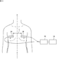
- FIG. 1 is a schematic diagram illustrating an embodiment of a respiration measurement device. It is a perspective view which shows typically an example of the capacitance-type sensor element which comprises the probe for respiration measurement used by embodiment of this invention. It is the sectional view on the AA line of FIG. 2A. It is a top view which shows typically an example of the probe for respiration measurement used by the embodiment of the present invention.
- FIG. 3B is a back view of the respiration measurement probe shown in FIG. 3A. It is the BB sectional drawing of FIG. 3B. It is a figure for demonstrating an example of the respiration measurement method which concerns on embodiment of this invention.
- FIG. 7B is a partial cross-sectional view taken along line DD of the first main body shown in FIG. 7A.
- FIG. 7B is a partial cross-sectional view taken along line DD of the first main body shown in FIG. 7A.
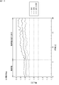
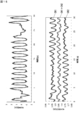
- FIG. 7 is a graph showing the measurement results of Evaluation 1-1 in Example 1.
- 15 is a graph showing the measurement results of Evaluation 1-2 in Example 1.
- 15 is a graph showing the measurement results of Evaluations 1-3 in Example 1.
- It is a graph which shows the measurement result of evaluation 2 in Example 1.
- It is a graph which shows the measurement result of evaluation 3 in Example 1.
- FIG. 1 is a schematic view showing a respiration measurement apparatus used in the present embodiment.
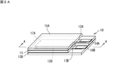
- FIG. 2A is a perspective view schematically showing an example of a capacitive sensor element constituting a respiration measurement probe included in the respiration measurement apparatus shown in FIG. 1, and
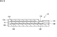
- FIG. 2B is a sectional view taken along line AA of FIG. 2A.
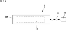
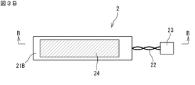
- FIG. 3A to 3C are views schematically showing an example of a respiration measurement probe used in the present embodiment, wherein FIG.
- FIG. 3A is a plan view
- FIG. 3B is a back view
- FIG. 3C is a BB line of FIG. 3B.
- the respiration measurement apparatus 1 includes a respiration measurement probe (hereinafter, also simply referred to as a probe) 2, a measurement device 3 electrically connected to the probe 2, and a measurement device 3. And a display 4 for displaying the measurement result of As shown in FIGS. 3A to 3C, the probe 2 is provided on a capacitive sensor element (hereinafter, also simply referred to as a sensor element) 10 and both surfaces (front and back surfaces) of the capacitive sensor element 10. And a covering member 21 made of a laminated insulating material.
- the respiration measurement apparatus 1 includes two probes 2.
- the sensor element 10 includes a sheet-like dielectric layer 11 made of an elastomer composition, a front side electrode layer 12A formed on the front surface of the dielectric layer 11, and the dielectric layer 11.
- Back side electrode layer 12B formed on the back side, front side wiring 13A connected to front side electrode layer 12A, back side wiring 13B connected to back side electrode layer 12B, end of front side wiring 13A opposite to front side electrode layer 12A
- a layer 15A and a back side protective layer 15B are provided.
- Lead wires 22 are connected to the front side connection portion 14A and the rear side connection portion 14B, respectively, and the sensor element 10 is connected to the measuring instrument 3 via the lead wires 22.
- a connection terminal 23 is provided at the end of the lead 22 opposite to the sensor element 10.
- the front side electrode layer 12A and the back side electrode layer 12B have the same shape in plan view, and the whole of the front side electrode layer 12A and the back side electrode layer 12B are opposed to each other with the dielectric layer 11 interposed therebetween.
- the opposing portion of the front side electrode layer 12A and the back side electrode layer 12B serves as a detection unit.
- the front side electrode layer 12A and the back side electrode layer 12B included in the capacitive sensor element do not necessarily have to be opposed to each other across the dielectric layer, and at least a part of them oppose each other. It is good if it is done.
- the front side electrode layer 12A corresponds to a first electrode layer
- the back side electrode layer 12B corresponds to a second electrode layer.
- the dielectric layer 11 is made of an elastomer composition. Therefore, the sensor element 10 can be deformed (stretched) in the surface direction.
- the areas of the front and back surfaces of the dielectric layer 11 change, and the deformation of the dielectric layer 11 is further followed to follow the front electrode layer 12A and the back electrode layer 12B, and the front protective layer.
- 15A and back side protection layer 15B (Hereafter, both are put together and it is also only called a protection layer.) Deform
- the capacitance of the detection unit changes in correlation with the amount of deformation of the dielectric layer 11 (change in area of the electrode layer).
- the amount of deformation of the sensor element 10 can be measured by detecting a change in capacitance of the detection unit.
- the sensor element 10 deforms according to the deformation of the skin surface of the subject. Therefore, the deformation of the skin surface of the subject can be detected by detecting the change in the capacitance of the detection unit.
- covering members 21 (21 ⁇ / b> A, 21 ⁇ / b> B) made of a cloth having stretchability are provided on both surfaces of the sensor element 10.
- Each of the two covering members 21A and 21B has a size slightly larger than that of the sensor element 10 in plan view in a non-elongated state.
- the two covering members 21A and 21B are made of a stretchable cloth.
- the sensor element 10 is sandwiched between the two cloths.
- the covering member 21 can protect the sensor element 10.
- the covering member 21 preferably has stretching anisotropy.
- the sensor element 10 When the probe 2 includes the covering member 21 with expansion and contraction anisotropy, the sensor element 10 is easily expanded and contracted in the longitudinal direction (left and right direction in the drawing), and is hardly expanded and contracted in the direction perpendicular to the longitudinal direction (width direction) can do. In this case, the amount of deformation in the longitudinal direction of the sensor element 10 can be measured more accurately.
- an adhesive layer 24 is provided on the back surface of the covering member 21 ⁇ / b> B.
- the adhesive layer 24 is a member for attaching the probe 2 to a subject.
- the probe 2 can be attached to a predetermined position on the skin surface of the subject by the adhesive layer 24.
- the measuring instrument 3 includes a circuit for measuring the capacitance of the detection unit in the sensor element 10.
- the circuit includes, for example, a Schmitt trigger oscillation circuit 3a for converting the capacitance C into the frequency signal F, an F / V conversion circuit 3b for converting the frequency signal F into the voltage signal V, and a power supply circuit (not shown). ).
- the above circuit converts the capacitance detected by the detection unit of the probe 2 into a frequency signal, further converts it into a voltage signal, and transmits the voltage signal to the display 4.
- the configuration of the circuit for measuring the capacitance in the measuring instrument 3 is not limited to such a configuration.
- the display 4 includes a monitor 4a, an arithmetic circuit 4b, and a storage unit 4c.
- the monitor 4a displays the respiration rate of the subject.
- the arithmetic circuit 4 b calculates the respiration rate of the subject based on the voltage signal related to the capacitance of the detection unit received from the measuring device 3.
- the storage unit 4c stores the change in the capacitance as recording data.
- FIG. 4 is a diagram for explaining a respiration measurement method according to the present embodiment.
- two probes 2A and 2B are attached to the skin surface of the chest of the subject.
- the probes 2A and 2B are the probes shown in FIGS. 3A to 3C, and are the same probe.
- the two probes 2A and 2B are both stuck in the direction in which the longitudinal direction of the capacitive sensor element is horizontal. Sticking the probes 2A and 2B in this direction is suitable for accurately measuring the respiration rate.
- the two probes 2A and 2B are mounted on the chest of the subject so as to be line symmetrical with each other with respect to the midline X of the subject. This makes it possible to perform particularly accurate measurement.
- the probes 2A and 2B are connected to the measuring instrument 33, and the measuring instrument 33 is connected to the display.
- two probes being mounted so as to be line symmetrical with respect to the subject's median line X means that part or all of the detection part of one probe and the detection part of the other probe It means that a part or all of are in line symmetrical position.
- all of the detection parts of one probe and all of the detection parts of the other probe are in line symmetry positions Is particularly preferred.
- the skin surface of the chest stretches (deforms) in accordance with the stretch of the chest of the subject.
- the cycle of stretching and contracting of the skin surface at this time corresponds to the cycle of breathing of the subject. Therefore, the respiration rate of the subject can be measured by measuring the cycle of expansion and contraction of the skin surface with the probes 2A and 2B.
- the skin surface of the subject's chest may be deformed due to the movement of the subject. Therefore, when the subject is moving the body, the deformation of the skin surface of the subject's chest may not match the stretching of the subject's thorax, and it is possible to accurately measure the subject's respiration rate with one probe. Have difficulty.
- the composite value is calculated from the detection values of each of the probe 2A and the probe 2B, and the respiratory rate is measured using the obtained composite value as an index. Therefore, it is possible to accurately measure the respiration rate of the subject excluding the influence of the subject's body movement.
- the calculation of the combined value is performed by dividing the sum of the detected value of the probe 2A and the detected value of the probe 2B by two.
- a walk etc. are mentioned, for example. Walking is because the body surface of the human body is a body movement that is likely to be deformed symmetrically across the midline. Therefore, the above-mentioned respiration measurement method can be suitably used as a method of measuring a subject's respiration, for example, at the time of a gait test carried out in rehabilitation.
- the subject's exercise suitable for performing the above respiration measurement method is not limited to walking. For example, standing and sitting movements, action using a spoon or fork at mealtimes, hair setting using a comb
- the subject may perform an action (exercise) using one hand, such as an action to be performed.
- the measurement results by the flow meter and the composite value calculated in the embodiment of the present invention are signals that fluctuate in accordance with the subject's respiration (expiration and inspiration). It is acquired as There are various methods for measuring the respiration rate of the subject from such signals. As one of the above methods, for example, a threshold is provided between the maximum value and the minimum value of the signal to pulse the signal, and the number of pulses within a fixed time is measured to calculate the respiration rate of the subject, or A method may be employed that measures the time between pulses to calculate the subject's respiration rate.
- the peaks and valleys of the above signal are detected, the number of peaks and valleys within a fixed time is measured to calculate the respiration rate of the subject, or the time between peaks and valleys is measured. It is also possible to adopt a method of calculating the subject's breathing rate. In the embodiment of the present invention, the method of measuring the respiration rate from the above composite value is not limited to these methods.
- the distance between the probe 2A and the probe 2B is not particularly limited, but it is preferably 100 to 200 mm on the front side of the subject.
- the distance between the probes is less than 100 mm, when the combined value of the two probes is calculated, the effect of eliminating the influence of the motion of the subject is poor.
- the probe and the arm of the subject easily come into contact, and the contact between the probe and the arm of the subject may cause an error (noise) in measurement.
- the distance between the probes for respiration measurement refers to the shortest distance between the detection units provided in the above-mentioned probes.
- the probe 2A and the probe 2B be mounted at the same height.
- the mounting position in the height direction of each probe is not particularly limited, it is preferably around the chest. Specifically, the range from the fourth rib to the tenth rib is preferable.
- the mounting position of the above-mentioned probe is lower than the 10th rib, the movement of the foot when the subject walks greatly affects the detection value of the probe 2, or the visceral position which occurs when the subject stands or sits down Changes in the circumference of the trunk due to changes in the degree of movement of the fat and the skin may significantly affect the detection value of the probe 2. As a result, it may be difficult to accurately measure the subject's respiration.
- the mounting position is particularly preferably in the range of the seventh rib to the tenth rib.
- the information on respiration measured by the respiration measurement method of the present embodiment is not limited to the respiration rate, and, for example, the respiration depth of the subject, the duration of respiration, the time of inspiration and expiration, etc. should also be measured. Can.
- the sensor element included in the probe 2 is not limited to the sensor element 10 described above, and in addition to the dielectric layer (first dielectric layer) and the first electrode layer and the second electrode layer formed on both surfaces thereof, The sensor element may be provided with the second dielectric layer and the third electrode layer.
- FIG. 5A is a perspective view schematically showing another example of the capacitive sensor element constituting the respiration measurement probe used in the present embodiment
- FIG. 5B is a cross-sectional view taken along the line CC of FIG. 5A. is there.
- the capacitive sensor element 40 shown in FIGS. 5A and 5B includes a sheet-shaped first dielectric layer 41A made of an elastomer composition, and a first electrode layer 42A formed on the front surface of the first dielectric layer 41A. , A second electrode layer 42B formed on the back surface of the first dielectric layer 41A, a second dielectric layer 41B laminated to cover the first electrode layer 42A on the front side of the first dielectric layer 41A, and a second dielectric layer And a third electrode layer 42C formed on the front surface of the layer 41B.
- the sensor element 40 includes a first wire 43A connected to the first electrode layer 42A, a second wire 43B connected to the second electrode layer 42B, and a third wire 43C connected to the third electrode layer 42C.
- a first connection portion 44A attached to an end of the first wire 43A opposite to the first electrode layer 42A, and a second connection 43B attached to an end of the second wire 43B opposite to the second electrode layer 42B.
- a second connection portion 44B and a third connection portion 44C attached to an end of the third wiring 43C opposite to the third electrode layer 42C.
- a back side protective layer 45B and a front side protective layer 45A are provided on the back side of the first dielectric layer 41A and the front side of the second dielectric layer 41B.
- the first electrode layer 42A to the third electrode layer 42C have the same shape in plan view.
- the first electrode layer 42A and the second electrode layer 42B are opposed to each other with the first dielectric layer 41A interposed therebetween, and the first electrode layer 42A and the third electrode layer 42C are opposed to each other with the second dielectric layer 41B interposed therebetween.
- a portion where the first electrode layer 42A and the second electrode layer 42B face each other, and a portion where the first electrode layer 42A and the third electrode layer 42C face each other serve as a detection portion.
- the sum of the capacitance of the facing portion of the second electrode layer 42B and the capacitance of the facing portion of the first electrode layer 42A and the third electrode layer 42C is the capacitance of the detection unit.
- the probe provided with such a sensor element 40 eliminates a drop in measurement accuracy which may occur when it is attached to the skin surface of the subject and which is close to a living body as a conductor as a noise source, It is suitable for measuring changes in capacitance more accurately.
- the probe 2 is directly attached to the skin surface of the subject by the adhesive layer 24.
- the probe 2 is not necessarily directly affixed to the skin surface of the subject It does not have to be attached.
- the probe 2 may be indirectly attached to the skin surface of the subject via clothing such as compression wear, a supporter, a bandage or the like.
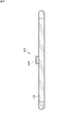
- FIG. 6 is a perspective view schematically showing an example of a device provided with two respiration measuring probes used in the present embodiment.
- 7A is a plan view showing a first main body constituting the main body of the appliance shown in FIG. 6, and
- FIG. 7B is a partial cross-sectional view of the first main body shown in FIG. 7A taken along line DD.
- FIG. 8 is a plan view showing a second main body that constitutes the main body of the appliance shown in FIG.
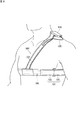
- FIG. 9 is a view for explaining a state in which the device shown in FIG. 6 is worn on a subject.
- the subject wears the device 100 including the probe member, and the respiration rate of the subject is measured.
- the orthosis 100 has a belt-like main body 101 held around the trunk of the subject when worn, and a belt-like auxiliary part 107 connected to the main body 101 at both ends and hanging on the subject's shoulder when worn. ing.
- the main body portion 101 is configured of a first main body portion 102 and a second main body portion 103.
- the first main body portion 102 is a member positioned on the front side of the subject when the subject wears the device 100.
- the first main body portion 102 includes a nylon cloth substrate 104 and a probe member 106 fixed to the back surface side (subject side) of the cloth substrate 104 and having two respiratory measurement probes 110A and 110B.
- Probes for measuring respiration (hereinafter, also simply referred to as probes) 110A and 110B are members similar to the probe 2 in the first embodiment except that the adhesive layer 24 is not formed (see FIGS. 3A to 3C).
- the respiration measurement probes 110 ⁇ / b> A and 110 ⁇ / b> B each include a sensor element 10 and covering members 21 provided on both sides of the sensor element 10.
- the two probes 110A and 110B are disposed apart from each other (the distance between the detection portions is 100 mm), and each of the two probes 110A and 110B A pair of core members 111A and 111B are provided so as to sandwich the end portion on the adjacent side.
- the core members 111A and 111B are plate-like members made of a non-stretchable material, at positions not overlapping the detection portions of the probes 110A and 110B in the thickness direction while sandwiching the respective end portions of the probes 110A and 110B. It is provided.
- each of the probes 110A and 110B includes leads 112A and 112B, and each lead 112A and 112B is connected to a circuit board 113 provided between the probes 110A and 110B.
- the lead wires 112A and 112B and the circuit board 113 are also protected by the pair of core members 111A and 111B.
- non-stretchable cloth fabrics 114A and 114B are provided on the outer layer side of each of the core materials 111A and 111B.
- the core materials 111A and 111B are entirely sandwiched between the two cloth fabrics 114A and 114B.
- the cloth fabrics 114A and 114B are members serving as sewing allowances for the cloth substrate 104.
- the cloth fabrics 114A and 114B are sewn onto the cloth substrate 104 at two places above and below the core members 111A and 111B, with the longitudinal direction (the left and right direction in FIG. 7A) of the cloth substrate 104 as the seam direction. ing.
- the end portions on the side (circuit board 113 side) and the opposite side of the respective probes 110A and 110B are also sandwiched between the two non-stretchable cloth fabrics 115A and 115B.
- the two cloth fabrics 115A and 115B are also members serving as sewing allowances for the cloth substrate 104.
- the cloth fabrics 115A and 115B are sewn to the cloth substrate 104 with the longitudinal direction of the cloth substrate 104 as the seam direction, as in the case of the cloth fabrics 114A and 114B.
- the cloth substrate 104 has the probe member 106 sewn to a portion 104 A (which exists at three locations in the longitudinal direction of the cloth substrate 104) of the cloth substrate 104, and
- the other pinched portion 104 ⁇ / b> B (which is provided in the longitudinal direction of the cloth substrate 104) is configured not to interfere with the probe member 106.
- the other portion 104B of the cloth substrate 104 is provided at a position where the detection portions of the probes 110A and 110B included in the probe member 106 overlap the thickness direction of the cloth substrate 104.
- the other portion 104B is provided so as to be loose relative to the probe member 106 (probes 110A and 110B).
- the expansion and contraction of the detection portions of the probes 110A and 110B can be avoided from being inhibited by the cloth base material 104. Furthermore, excessive extension of the detection portion of the probes 110A and 110B can be avoided. Further, D-rings 105A for connecting the second main body portion 103 are attached to both end portions of the first main body portion 102.
- the second main body portion 103 is a belt-like member, and has a nylon cloth base.
- the second main body portion 103 is provided with a hook-and-loop fastener 131 substantially over the entire surface of the cloth substrate.
- a D ring 105 B for connecting the auxiliary portion 107 is attached to a substantially central portion in the longitudinal direction of the second main body portion 103.
- the second main body portion 103 is integrated with the first main body portion 102 to form a belt-like annular main body portion 101 held around the trunk of the subject.
- the main body portion 101 is configured such that the first main body portion 102 and the second main body portion 103 can be separated, and the circumferential length can be adjusted by the surface fasteners 131 of the second main body portion 103. Therefore, when the brace 100 is worn by the subject, the brace 100 can bring the main body portion 101 into close contact with the skin surface around the trunk of the subject. Moreover, since the brace 100 can adjust the circumferential length at both ends of the first main body portion 102, the alignment of the probe members 106 (probes 110A and 110B) can be performed easily and accurately.
- the auxiliary portion 107 is a belt-like member that hangs on the subject's shoulder when worn, and has a nylon cloth substrate.
- the auxiliary portion 107 is connected to the main body portion 101 at both end sides. Specifically, one end of the auxiliary portion 107 is sewn to a substantially central portion in the longitudinal direction of the first main body portion 102. At the other end of the auxiliary portion 107, a hook and loop fastener (not shown) is provided. After the other end of the auxiliary portion 107 is passed through the D ring 105B of the second main body portion 103, it is folded back and the surface fasteners are fixed to each other. Thus, both ends of the auxiliary portion 107 are fixed to the main body portion 101.
- the brace 100 is worn on the subject as shown in FIG. That is, in the device 100, the main body 101 is held at a predetermined position around the trunk of the subject's chest (the position where the probes 110A and 110B are symmetrical with respect to the subject's midline), and the auxiliary part 107 is the subject's To be worn on the shoulders. In this case, the brace 100 can adjust the mounting height of the probes 110A and 110B by adjusting the length of the auxiliary portion 107. Further, in the device 100 worn by the subject, the attachment height of the main body portion 101 is less likely to be deviated because the auxiliary portion 107 is hung on the shoulder of the subject.
- the brace 100 may be worn on the subject with the detection portions of the probes 110A and 110B slightly extended (pretensioned state). It is because it is more suitable for detection of deformation in which the skin surface of the subject contracts.
- the respiratory rate of the subject and the like can be measured as in the first embodiment by performing the above-described respiration measurement method in a state where the subject wears the device 100.
- the measuring instrument 108 is mounted on a portion of the brace 100 hanging on the shoulder of the auxiliary portion 107.
- the measuring instrument 108 is connected to the circuit board 113 of the probe member 106 through the lead wire 109.
- the respiration measurement device in which the measurement instrument 108 is mounted at such a position of the brace 100 is a small-sized, portable respiration measurement device.
- the measuring instrument 108 since the measuring instrument 108 is mounted on the shoulder of the auxiliary unit 107, the subject is unlikely to feel heavy on the measuring instrument 108, and the burden on the subject is reduced. Furthermore, in the above-described respiration measurement apparatus, it is difficult for vibration due to the weight of the measuring instrument 108 to be transmitted to the sensor element provided in the probe member 106.
- the measuring instrument 108 is connected to a display (not shown) via a wireless connection.
- the material of the cloth substrate constituting the device is not limited to nylon, and cloth substrates of various materials can be used.
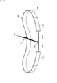
- FIG. 10 is a perspective view schematically showing another example of a device provided with two respiration measurement probes used in the present embodiment.
- the device 200 used in this embodiment is a probe 202A, 202B having the same configuration as the probes 2A, 2B employed in the first embodiment except that the adhesive layer 24 is not provided as two respiration measurement probes.
- a belt-like rubber member 204 is included in the probes 202A and 202B.
- the probes 202A and 202B include the sensor element 10 and the covering members 21 provided on both sides of the sensor element 10.
- the end of the probe 202A, 202B opposite to the side from which the lead wire 212A, 212B is pulled out is fixed to each end of the rubber member 204. Furthermore, in the brace 200, the lead wire 212A drawn from the probe 202A and the lead wire 212B drawn from the probe 202B are bundled by a cable tie (banding band) 205 in the middle of each other, and a bundle of lead wires 212 It has become. A connection terminal 213 for connecting to a measuring instrument (not shown) is provided at the end of the bundle of lead wires 212.
- the brace 200 can adjust the distance between the probes 202A and 202B by adjusting the position of the cable tie 205. Further, by bundling the lead wires 212A and 212B with the cable tie 205, the distance between the probes 202A and 202B can be maintained.
- the brace 200 is worn so as to be held at a predetermined position around the trunk of the subject (a position where the probes 202A and 202B are in line symmetry with respect to the midline of the subject).
- the probes 202A and 202B are connected by the rubber member 204, the probes 202A and 202B can be brought into close contact with the skin surface of the subject even if the probes 202A and 202B are not provided with the adhesive layer.
- the detection portions of the probes 202A and 202B can be brought into close contact with the skin surface of the subject in a state in which the detection portions are slightly extended (pretension state).
- the material of the rubber member 204 is not particularly limited, and examples thereof include urethane elastomer and the like.
- the number of respiratory measurement probes used in the embodiment of the present invention is not limited to two, and at least one may be used on the left and right sides of the subject's midline.
- calculation of the combined value is performed, for example, on the skin surface of the subject on each of the right side and the left side.
- the average value of the deformation may be calculated, and the combined value may be calculated based on the obtained average value on the right side and the average value on the left side.
- the probe for measuring respiration used in the embodiment of the present invention is not limited to the one provided with the above-mentioned capacitance type sensor element, as long as it can detect deformation (stretching) of the skin of the subject. . Therefore, for example, it may be a sensor element (resistance sensor element) or the like of a type in which the resistance value changes due to the expansion and contraction of the element.
- the respiration measurement method and the respiration measurement apparatus adopted in the embodiment of the present invention can be applied to other than humans. Specifically, like human beings, it can be applied to animals whose surface is deformed by respiration.
- the capacitive sensor element comprises an elastomeric dielectric layer.
- the capacitive sensor element includes the first dielectric layer and the second dielectric layer, both may be formed using the same elastomer composition, or may be formed using different elastostatic compositions. May be Preferably, both are formed using the same elastomeric composition. The reason is that the same behavior is exhibited at the time of deformation.
- the dielectric layer is a sheet-like material formed using an elastomer composition.
- the dielectric layer can be reversibly deformed so as to change the area of its front and back surfaces. Therefore, the dielectric layer can be deformed in the surface direction.
- the front and back surfaces of the dielectric layer mean the front and back surfaces of the dielectric layer.
- Examples of the elastomer composition include those containing an elastomer and, if necessary, other optional components.
- the elastomer include natural rubber, isoprene rubber, nitrile rubber (NBR), ethylene propylene rubber (EPDM), styrene butadiene rubber (SBR), butadiene rubber (BR), chloroprene rubber (CR), silicone rubber, fluorine Rubber, acrylic rubber, hydrogenated nitrile rubber, urethane rubber and the like can be mentioned. These may be used alone or in combination of two or more. Among these, urethane rubber and silicone rubber are preferred in view of low permanent set (or permanent elongation).
- the elastomer composition may contain, for example, additives such as a plasticizer, an antioxidant, an antiaging agent, a coloring agent, a dielectric filler, and the like.
- the average thickness of the dielectric layer is preferably 10 to 1000 ⁇ m, and more preferably 30 to 200 ⁇ m from the viewpoint of increasing the capacitance to improve the detection sensitivity.
- the dielectric layer is preferably deformable so that the area (the area of the front surface and the area of the back surface of the dielectric layer) increases by 30% or more from the non-stretched state when deformed.
- the dielectric layer is suitable for deformation following the deformation of the skin surface. Being able to deform so as to increase the area by 30% or more does not break even if the load is applied to increase the area by 30%, and when the load is released, it is restored to its original state (that is, elastic) Means in the deformation range).
- the deformable range of the area of the dielectric layer is preferably deformable to increase by 50% or more, more preferably 100% or more, and further preferably by 200% or more. It is particularly preferred to be deformable.
- the deformable range of the area of the dielectric layer can be controlled by the design (material, shape, etc.) of the dielectric layer.
- the capacitive sensor element includes the electrode layer made of a conductive composition containing a conductive material.
- Each electrode layer provided in the above-mentioned capacitive sensor element may be composed of conductive compositions of the same composition, or may be composed of conductive compositions of different compositions.
- the conductive material examples include carbon nanotubes, graphene, carbon nanohorns, carbon fibers, conductive carbon black, graphite, metal nanowires, metal nanoparticles, conductive polymers, and the like. These may be used alone or in combination of two or more.
- the conductive material is preferably a carbon nanotube. The reason for this is that it is suitable for the formation of an electrode layer that deforms following the deformation of the dielectric layer.
- a well-known carbon nanotube can be used as said carbon nanotube.
- the carbon nanotube may be a single-walled carbon nanotube (SWNT), or may be a double-walled carbon nanotube (DWNT) or a multi-walled carbon nanotube (MWNT) having three or more layers (herein, Together they are simply called multi-walled carbon nanotubes).
- SWNT single-walled carbon nanotube
- DWNT double-walled carbon nanotube
- MWNT multi-walled carbon nanotube having three or more layers (herein, Together they are simply called multi-walled carbon nanotubes).
- the shape (average length, fiber diameter, aspect ratio) of each carbon nanotube is also not particularly limited.
- the shape of the carbon nanotube may be appropriately selected by comprehensively judging the conductivity and durability required for the capacitive sensor element, and further the processing and cost for forming the electrode layer.
- the said conductive composition may contain the binder component which functions as a connection material of a conductive material, various additives, etc. other than the said conductive material, for example.
- the additive include a dispersant for a conductive material, a crosslinking agent for a binder component, a vulcanization accelerator, a vulcanization assistant, an antiaging agent, a plasticizer, a softener, and a colorant. It can be mentioned.
- the said protective layer front side protective layer and back side protective layer
- the electrode layer and the like can be electrically insulated from the outside.
- the protective layer the strength and durability of the capacitive sensor element can be enhanced.
- the elastomer composition similar to the material of the said dielectric layer etc. are mentioned, for example.
- the following covering member may also serve as the above-mentioned protective layer.
- the above-mentioned capacitive sensor element usually includes each wire connected to each electrode layer.
- Each wiring may be any wiring as long as it does not inhibit the deformation of the dielectric layer and the conductivity is maintained even if the dielectric layer is deformed.
- As said wiring what consists of an electroconductive composition similar to the said electrode layer is mentioned, for example.
- connection portion for connecting to an external wiring is generally formed at the end of each of the above-described wirings on the opposite side to the electrode layer.
- connection parts what was formed, for example using copper foil etc. is mentioned.
- the respiratory measurement probe preferably has an insulating covering member provided around the capacitance sensor element.
- the covering member include cloths having stretchability (anisotropy and isotropy do not matter), and members made of an elastomer composition.
- the stretchable fabric may be a woven fabric, a knitted fabric, or a non-woven fabric as long as it has stretchability.
- the fabric is integrated with the capacitance type sensor element using a pressure sensitive adhesive such as an acrylic pressure sensitive adhesive, a urethane pressure sensitive adhesive, a rubber pressure sensitive adhesive, or a silicone pressure sensitive adhesive.
- the pressure-sensitive adhesive needs to have flexibility not to inhibit the deformation of the dielectric layer.
- the covering member may be provided on both sides of the capacitive sensor element, or may be provided on only one side of the capacitive sensor element.
- the adhesive layer may be further formed on the outermost layer on the back side of the probe for measuring respiration.
- the probe for measuring respiration can be attached to the skin surface or the like of the subject via the adhesive layer.
- said adhesive layer For example, the layer which consists of an acrylic adhesive, a urethane adhesive, a rubber adhesive, a silicone adhesive etc. is mentioned.
- each adhesive may be a solvent type, an emulsion type, or a hot melt type.
- the pressure-sensitive adhesive may be appropriately selected and used according to the use mode of the sensor device and the like.
- the adhesive layer needs to be flexible so as not to inhibit the deformation of the dielectric layer.
- the respiratory measurement probe (the probe 2 shown in FIGS. 3A to 3C) can be manufactured, for example, by the following method.
- the sensor element 10 can be manufactured, for example, by the same method as the method of manufacturing a sensor sheet described in Japanese Patent Laid-Open No. 2016-90487.
- the adhesive layer 24 is formed on the outermost layer on the back surface side.
- the formation of the adhesive layer 24 may be performed by a known method according to the type of adhesive. Through these steps, the probe 2 shown in FIGS. 3A to 3C can be manufactured.
- the measuring device is connected to the respiration measuring probe.
- the measuring device has a function of measuring the capacitance of the detection unit in the respiration measurement probe.
- a conventionally known method can be used as a method of measuring the above-mentioned electrostatic capacity, and the above-mentioned measuring instrument is provided with an electrostatic capacity measurement circuit, an arithmetic circuit, an amplification circuit, a power supply circuit, etc.
- a method of measuring the above-mentioned electrostatic capacity for example, a method of measuring with a measuring instrument such as an LCR meter, a method of measuring using a CV conversion circuit using an automatic balance bridge circuit, a CV conversion circuit using an inverting amplification circuit Of measurement using a CV, a method of measurement using a CV conversion circuit using a half wave voltage doubler rectifier circuit, a method of measurement using a CF oscillation circuit using a Schmitt trigger oscillation circuit, a Schmitt trigger oscillation circuit and an F /
- a method of measuring the capacitance with a measuring instrument such as a voltage measuring instrument or a frequency counter after converting the capacitance into a voltage or a frequency with a V conversion circuit or the like can be mentioned.
- connection method When connecting the said measuring instrument and the said electrostatic capacitance type sensor element, the following connection method is preferable as a connection method of both.
- the sensor element 10 shown in FIG. 2A and FIG. 2B When the sensor element 10 shown in FIG. 2A and FIG. 2B is connected to the above measuring instrument, the back side protective layer 15B side of the sensor element 10 is the side to be attached to the skin surface, and the front side connection portion 14A is signal line, back side connection It is preferable to connect the portion 14B to the measuring instrument as a ground line.
- the capacitive sensor element 40 shown in FIGS. 5A and 5B is connected to the measuring instrument, the first connection portion 44A is used as a signal line, and the second connection portion 44B and the third connection portion 44C are used as an earth line. It is preferable to connect to the said measuring device.
- the back side protective layer 45B may be attached to the skin surface or the front side protective layer 45A may be attached to the skin surface.
- a computer provided with a storage unit such as a CPU, a RAM, a ROM, an HDD, a monitor, various input / output interfaces, and the like can be used.
- terminal devices such as a personal computer, a smartphone, and a tablet can be used as the display.
- the connection of the measuring device 3 and the indicator 4 is performed by the wire communication, both may be connected by radio
- Example 1 ⁇ Fabrication of capacitive sensor element>
- the sensor element 10 shown in FIGS. 2A and 2B was manufactured.
- .62 parts by weight were added and mixed by stirring with an agitator for 90 seconds to prepare a raw material composition for a dielectric layer.
- the raw material composition was heated in a heating apparatus (crosslinking furnace) while being conveyed in a state of being sandwiched between two protective films.
- a heating apparatus crosslinking furnace
- crosslinking was performed under the conditions of an oven temperature of 70 ° C. and an oven time of 30 minutes to obtain a roll wound sheet with a protective film and a predetermined thickness. Thereafter, post-crosslinking was carried out for 12 hours in a furnace adjusted to 70 ° C. to prepare a sheet made of a polyether urethane elastomer. The obtained urethane sheet was cut into a size of 8 mm ⁇ 70 mm ⁇ 100 ⁇ m thick, and then cut at a corner of 4 mm ⁇ 4 mm ⁇ 100 ⁇ m thick to prepare a dielectric layer.
- the elongation at break (%) and relative dielectric constant of the produced dielectric layer were measured.
- the elongation at break (%) was 505%, and the relative dielectric constant was 5.8.
- the elongation at break was measured in accordance with JIS K 6251.
- the relative dielectric constant is measured by measuring the capacitance at a measurement frequency of 1 kHz using an LCR high tester (3522-50 manufactured by Hioki Electric Co., Ltd.) with an electrode of 20 mm in diameter, and from the electrode area and the thickness of the measurement sample Calculated.
- Electrode layer material Highly-oriented carbon nanotubes (layer number 4 to 12 layers, fiber diameter 10 to 20 nm, fiber length 150 to 45), which are multi-walled carbon nanotubes manufactured by a substrate growth method and manufactured by Taiyo Nippon Oil Co. Add 30 mg of 300 ⁇ m, 99.5% carbon purity) to 30 g of isopropyl alcohol (IPA), apply a wet dispersion process using a jet mill (Nanojet Pal JN10-SP003, manufactured by Haruka Co., Ltd.), and dilute by 2 times A carbon nanotube dispersion having a concentration of 0.05% by weight was obtained.
- IPA isopropyl alcohol
- Pasted the formed mask (not shown).
- the mask is provided with an opening corresponding to the back side electrode layer and the back side wiring, and the size of the opening is such that a portion corresponding to the back side electrode layer is 5 mm wide ⁇ 54 mm long and a portion corresponding to the back side wiring It is 1.5 mm wide x 6 mm long.
- the carbon nanotube dispersion prepared in the step (2) was applied using an air brush so that the amount of application per unit area (cm 2 ) was 0.223 g. Subsequently, the resultant was dried at 100 ° C. for 10 minutes to form a back side electrode layer 12B and a back side wiring 13B. After that, the mask was peeled off.
- the dielectric layer 11 produced in the above step (1) was laminated on the back side protective layer 15B so as to cover the whole of the back side electrode layer 12B and a part of the back side wiring 13B. Furthermore, on the front side of the dielectric layer 11, the front electrode layer 12A and the front wiring 13A were formed. Formation of front side electrode layer 12A and front side wiring 13A was performed using a method similar to formation of back side electrode layer 12B and back side wiring 13B.
- the front side manufactured in the above step (3) so as to cover the whole front side electrode layer 12A and a part of the front side wiring 13A.
- Protective layer 15A was laminated.
- copper foil was attached to each end of front side wiring 13A and back side wiring 13B, and it was set as front side connection part 14A and back side connection part 14B.
- the lead wires 22 serving as external wiring are fixed to the front side connection portion 14A and the rear side connection portion 14B by soldering, and the sensor element 10 is obtained.
- ⁇ Preparation of adhesive layer A 50 parts by weight of methyl ethyl ketone (MEK) and 2 parts by weight of a curing agent (L-45, manufactured by Soken Chemical Co., Ltd.) are added to 50 parts by weight of a pressure sensitive adhesive (Sukken Chemical Co., Ltd., SK dyne 1720).
- MEK methyl ethyl ketone
- L-45 a curing agent
- SK dyne 1720 SK dyne 1720.
- the mixture was obtained by mixing (2000 rpm, 120 seconds) and defoaming (2000 rpm, 120 seconds) according to the company, model number: ARE-310).
- the obtained mixture is formed into a film with a wet film thickness of 100 ⁇ m on a PET film (50E-0010KF, manufactured by Fujimori Kogyo Co., Ltd.) whose surface has been subjected to a release treatment, and then a blasting oven is used.
- the composition was cured under conditions of 100 ° C. for 30 minutes to prepare a pressure-sensitive adhesive layer A having a thickness of 30 ⁇ m after curing.
- the brace 200 (see FIG. 10) was manufactured by the following method. (1) The pressure-sensitive adhesive layer A prepared by the above-described method was transferred to one side of the stretch anisotropic fabric. Thereafter, the stretch anisotropic fabric was cut into a size of 115 mm wide ⁇ 14 mm long. At this time, it cut
- connection terminal 213 of the brace 200 was connected to PowerLab 16/35, PL 3516 (manufactured by AD INSTRUMENTS) as a measuring instrument 203 to make a respiration measurement apparatus.
- each of the lead wires of the probes 202A and 202B uses the lead wire connected to the front side connection part 14A as a signal line and the lead wire connected to the back side connection part 14B as an earth line.
- FIG. 11 is a view for explaining a state in which the device shown in FIG. 10 is worn on a subject.
- the subject was equipped with a device provided with a probe for measuring respiration.
- the subject wears the brace 200 such that the mounting positions of the two probes 202A and 202B are symmetrical with respect to the subject's midline X, as shown in FIG.
- the probes 202A and 202B are mounted on the surface of the shirt 230 worn by the subject such that the direction (horizontal direction) in which easy extension and contraction is easy is horizontal.
- the mounting heights of the two probes 202A and 202B were the heights of the seventh rib. Furthermore, the detector 203 was attached to the shoulder of the shirt worn by the subject using a clip (not shown). In this evaluation 1-1, the distance (L in FIG. 11) between the probes 202A and 202B on the front side of the subject is 100 mm.
- the change in the capacitance of the probes 202A and 202B was detected as a change in voltage when the subject wearing the appliance 200 performed the following action.
- Subject's behavior Wait for 5 seconds in an apnea condition and then walk while keeping the apnea condition.
- a combined value (CH1 + CH2) was calculated based on the obtained detection value.
- the synthesis value was calculated by dividing the sum of the detection values of CH1 and CH2 by 2. The results are shown in FIG. FIG. 12 is a graph showing the evaluation results.
- FIGS. 13 and 14 are both graphs showing the evaluation results.
- FIG. 13 shows the results of Evaluation 1-2
- FIG. 14 shows the results of Evaluation 1-3.
- Evaluation 2 Similarly to the evaluation 1-1, when the subject wearing the appliance 200 performed the following action, a change in capacitance of the probes 202A and 202B was detected as a change in voltage. Subject's behavior: I walked on a treadmill at a constant speed with natural breathing.
- the combined value (CH1 + CH2) is evaluated based on the obtained detection value 1-1 It calculated with the same method as.
- measurement of respiration of a subject was also performed using a spirometer (manufactured by ADInstruments, ML311 Spirometer pod) connected to a face mask. The results are shown in FIG.
- the graph of FIG. 15 is a graph showing the result of the evaluation 2.
- the upper graph shows the measurement results of the flow meter
- the lower graph shows the detection values of CH1 and CH2 and a composite value based on the above detection values.
- the result of the respiration rate measured by the flow meter and the result of the respiration rate measured by the method according to the embodiment of the present invention were very consistent. From this, it became clear that, according to the respiration measurement method according to the embodiment of the present invention, when the subject walks while breathing, the respiration rate of the subject can be accurately measured.
- FIG. 16 is a graph showing the results of evaluation 3. Four graphs are shown side by side in FIG. Each graph shows, in order from the top, the measurement result of the flow meter, the detected value of CH1, the detected value of CH2, and the combined value based on the detected value.
- the respiration measurement method according to the embodiment of the present invention it is possible to accurately measure the respiration of the subject even in a state in which the subject is moving the body by an operation using one hand. It became clear that it was possible.
Landscapes
- Health & Medical Sciences (AREA)
- Life Sciences & Earth Sciences (AREA)
- Heart & Thoracic Surgery (AREA)
- Medical Informatics (AREA)
- Physics & Mathematics (AREA)
- Veterinary Medicine (AREA)
- Biophysics (AREA)
- Pathology (AREA)
- Engineering & Computer Science (AREA)
- Biomedical Technology (AREA)
- Physiology (AREA)
- Public Health (AREA)
- Molecular Biology (AREA)
- Surgery (AREA)
- Animal Behavior & Ethology (AREA)
- General Health & Medical Sciences (AREA)
- Oral & Maxillofacial Surgery (AREA)
- Dentistry (AREA)
- Pulmonology (AREA)
- Measurement Of The Respiration, Hearing Ability, Form, And Blood Characteristics Of Living Organisms (AREA)
Abstract
被験者の呼吸時に生じる人体の皮膚表面の変形を、当該皮膚表面の変形領域に装着した呼吸計測用プローブによって検出し、取得された検出値に基づいて被験者の呼吸を計測する呼吸計測方法であって、前記呼吸計測用プローブは、被験者の正中線に対して右側及び左側のそれぞれに装着し、被験者の右側に装着した呼吸計測用プローブの検出値と、被験者の左側に装着した呼吸計測用プローブの検出値との合成値を算出する、呼吸計測方法。
Description
本発明は、呼吸計測方法、及び、呼吸計測装置に関する。
医療分野やリハビリテーション分野等において、呼吸数は重要なバイタルサインの一つである。ヒトの呼吸数は、運動負荷の大きさに応じて自律的に制御される。そのため、呼吸数は、例えば、呼吸器疾患や循環器疾患の患者の運動耐容能等を評価する際に計測されることがある。
従来、呼吸数を精度良く計測する方法としては、スパイロメータ(フローセンサ)を使用した計測方法が知られている。この計測方法は信頼性の高い計測方法であるものの、大型の装置を必要とし、計測時にマスクの装着を必要とするため、計測時の制限が大きく、簡便に呼吸数を計測することは困難であった。また、スパイロメータ(フローセンサ)を使用した計測方法は、治療等のために、常時マスクやカニューレ等の装着を必要としている患者には適用できなかった。
従来、呼吸数を精度良く計測する方法としては、スパイロメータ(フローセンサ)を使用した計測方法が知られている。この計測方法は信頼性の高い計測方法であるものの、大型の装置を必要とし、計測時にマスクの装着を必要とするため、計測時の制限が大きく、簡便に呼吸数を計測することは困難であった。また、スパイロメータ(フローセンサ)を使用した計測方法は、治療等のために、常時マスクやカニューレ等の装着を必要としている患者には適用できなかった。
呼吸数を計測する他の方法として、例えば、特許文献1は、全方向に弾性変形可能なシート状誘電体の両面に伸縮性を有する一対の導電布を配備して構成される静電容量型圧力センサを用いる方法を提案している。
特許文献1の方法は、寝た状態の被験者の下に静電容量型圧力センサを敷いて呼吸数をモニタリングする方法であり、リハビリテーションのトレーニング中など被験者が身体を動かしている状態では計測が困難であった。
特許文献1の方法は、寝た状態の被験者の下に静電容量型圧力センサを敷いて呼吸数をモニタリングする方法であり、リハビリテーションのトレーニング中など被験者が身体を動かしている状態では計測が困難であった。
特許文献2は、静電容量型のセンサ素子を胸の部分の皮膚表面に貼り付け、所定の時間、静電容量を計測し続けることで被験者の呼吸数を計測する方法を記載している。
特許文献2に記載の計測方法は、呼吸で生じる胸郭の伸縮に合わせて胸部の皮膚が伸縮し、その伸縮回数が呼吸数と一致することを利用した計測方法である。この方法によれば、被験者の呼吸数を簡便に計測することができる。また、特許文献2に記載の計測方法は、被験者が身体を動かしている状態であっても呼吸数を計測することができる。
一方、身体を動かしている状態の被験者の呼吸数を計測する方法は、精度の向上が望まれている。
一方、身体を動かしている状態の被験者の呼吸数を計測する方法は、精度の向上が望まれている。
本発明者らは、検討を重ね、被験者が身体を動かしている状態であっても、被験者の呼吸数等の呼吸に関する情報を精度良く計測することができる呼吸計測方法を完成した。
本発明者らは、上記呼吸計測方法を行うのに適した呼吸計測装置も完成した。
本発明者らは、上記呼吸計測方法を行うのに適した呼吸計測装置も完成した。
本発明の呼吸計測方法は、被験者の呼吸時に生じる人体の皮膚表面の変形を、当該皮膚表面の変形領域に装着した呼吸計測用プローブによって検出し、取得された検出値に基づいて被験者の呼吸を計測する呼吸計測方法であって、
上記呼吸計測用プローブは、被験者の正中線に対して右側及び左側のそれぞれに装着し、
被験者の右側に装着した呼吸計測用プローブの検出値と、被験者の左側に装着した呼吸計測用プローブの検出値との合成値を算出する、ことを特徴とする。
上記呼吸計測用プローブは、被験者の正中線に対して右側及び左側のそれぞれに装着し、
被験者の右側に装着した呼吸計測用プローブの検出値と、被験者の左側に装着した呼吸計測用プローブの検出値との合成値を算出する、ことを特徴とする。
本発明の呼吸計測方法によれば、被験者が身体を動かしている状態であっても、被験者の呼吸を精度良く計測することができる。
上述したように、胸郭の伸縮に合わせて生じる被験者の皮膚表面の変形を計測すれば、被験者の呼吸を計測することができる。一方、被験者が身体を動かした場合には、その被験者の体動によっても被験者の皮膚表面の変形が生じることになる。そのため、被験者が身体を動かしている状態で呼吸を計測する場合、被験者の体動による皮膚表面の変形が呼吸計測に対するノイズとなり、1個の呼吸計測用プローブで被験者の呼吸を計測しようとすると、正確に被験者の呼吸を計測することができないことがあった。
これに対して、本発明の呼吸計測方法では、呼吸計測用プローブを被験者の正中線に対して右側及び左側のそれぞれに装着し、被験者の右側に装着した呼吸計測用プローブの検出値と、被験者の左側に装着した呼吸計測用プローブの検出値との合成値を算出して、被験者の呼吸を計測する。そのため、本発明の呼吸計測方法では、上述した被験者の体動によるノイズをキャンセルして、被験者の呼吸を精度良く計測することができる。
上述したように、胸郭の伸縮に合わせて生じる被験者の皮膚表面の変形を計測すれば、被験者の呼吸を計測することができる。一方、被験者が身体を動かした場合には、その被験者の体動によっても被験者の皮膚表面の変形が生じることになる。そのため、被験者が身体を動かしている状態で呼吸を計測する場合、被験者の体動による皮膚表面の変形が呼吸計測に対するノイズとなり、1個の呼吸計測用プローブで被験者の呼吸を計測しようとすると、正確に被験者の呼吸を計測することができないことがあった。
これに対して、本発明の呼吸計測方法では、呼吸計測用プローブを被験者の正中線に対して右側及び左側のそれぞれに装着し、被験者の右側に装着した呼吸計測用プローブの検出値と、被験者の左側に装着した呼吸計測用プローブの検出値との合成値を算出して、被験者の呼吸を計測する。そのため、本発明の呼吸計測方法では、上述した被験者の体動によるノイズをキャンセルして、被験者の呼吸を精度良く計測することができる。
上記呼吸計測方法において、上記呼吸計測用プローブは静電容量型センサ素子を含み、
上記静電容量型センサ素子は、エラストマー組成物からなるシート状の第1誘電層と、導電材料を含有する導電性組成物からなり、上記第1誘電層のおもて面及び裏面のそれぞれに上記第1誘電層を挟んで少なくとも一部が対向するよう形成された第1電極層及び第2電極層とを含み、上記第1電極層及び上記第2電極層の対向する部分を検出部とし、上記誘電層の表裏面の面積が変化するように可逆的に変形する、センサ素子である、ことが好ましい。
上述した構成を有する上記静電容量型センサ素子は、人体の皮膚表面の変形を計測するためのセンサ素子として適している。
上記静電容量型センサ素子は、エラストマー組成物からなるシート状の第1誘電層と、導電材料を含有する導電性組成物からなり、上記第1誘電層のおもて面及び裏面のそれぞれに上記第1誘電層を挟んで少なくとも一部が対向するよう形成された第1電極層及び第2電極層とを含み、上記第1電極層及び上記第2電極層の対向する部分を検出部とし、上記誘電層の表裏面の面積が変化するように可逆的に変形する、センサ素子である、ことが好ましい。
上述した構成を有する上記静電容量型センサ素子は、人体の皮膚表面の変形を計測するためのセンサ素子として適している。
上記呼吸計測方法では、上記呼吸計測用プローブによって、上記皮膚表面の水平方向の変形を検出することが好ましい。
被験者の皮膚表面における水平方向の変形を検出する方が、垂直方向の変形を検出する場合に比べて、被験者の呼吸数を計測するのに適している傾向にある。
特に、被験者の第4肋骨~腹部の高さに上記呼吸計測用プローブを装着する場合は、水平方向の変形を検出する方が、呼吸による皮膚表面の変形を計測しやすい。
被験者の皮膚表面における水平方向の変形を検出する方が、垂直方向の変形を検出する場合に比べて、被験者の呼吸数を計測するのに適している傾向にある。
特に、被験者の第4肋骨~腹部の高さに上記呼吸計測用プローブを装着する場合は、水平方向の変形を検出する方が、呼吸による皮膚表面の変形を計測しやすい。
上記呼吸計測方法では、上記呼吸計測用プローブとして、2個の同一の呼吸計測用プローブを使用し、2個の呼吸計測用プローブが被験者の正中線を基準に線対称となるように装着することが好ましい。
この場合、被験者の呼吸を関する情報を特に精度良く計測することができる。
この場合、被験者の呼吸を関する情報を特に精度良く計測することができる。
本発明の呼吸計測装置は、
被験者の呼吸時に生じる人体の皮膚表面の変形を呼吸計測用プローブによって検出し、取得された検出値に基づいて被験者の呼吸を計測する呼吸計測装置であって、
呼吸計測用プローブを当該皮膚表面の変形領域に装着するために人体に着用される装具と、計測器と、を備え、
上記装具は、着用時に被験者の体幹周りに保持されるベルト状の本体部と、上記本体部に連結され、着用時に被験者の肩に掛かるベルト状の補助部とを有し、
上記本体部は、上記装具の着用時に被験者の正中線に対して右側及び左側のそれぞれに装着される2個の呼吸計測用プローブを備え、
計測器は、被験者の右側に装着される呼吸計測用プローブの検出値と、被験者の左側に装着される呼吸計測用プローブの検出値との合成値を算出する、
ことを特徴とする。
被験者の呼吸時に生じる人体の皮膚表面の変形を呼吸計測用プローブによって検出し、取得された検出値に基づいて被験者の呼吸を計測する呼吸計測装置であって、
呼吸計測用プローブを当該皮膚表面の変形領域に装着するために人体に着用される装具と、計測器と、を備え、
上記装具は、着用時に被験者の体幹周りに保持されるベルト状の本体部と、上記本体部に連結され、着用時に被験者の肩に掛かるベルト状の補助部とを有し、
上記本体部は、上記装具の着用時に被験者の正中線に対して右側及び左側のそれぞれに装着される2個の呼吸計測用プローブを備え、
計測器は、被験者の右側に装着される呼吸計測用プローブの検出値と、被験者の左側に装着される呼吸計測用プローブの検出値との合成値を算出する、
ことを特徴とする。
本発明の呼吸計測装置によれば、被験者の呼吸を計測することができ、被験者が身体を動かしている状態であっても被験者の呼吸を精度良く計測することができる。
また、上記呼吸計測装置は、上述した構成の装具を備えているため、呼吸計測用プローブを簡便に被験者に装着することができ、かつ呼吸計測用プローブの装着位置がズレにくい。そのため。上述した本発明の呼吸計測方法を容易にかつ精度良く行うことができる。
また、上記呼吸計測装置を用いることにより。被験者に大きな負担を掛けることなく、上記呼吸計測方法を行うことができる。
また、上記呼吸計測装置は、上述した構成の装具を備えているため、呼吸計測用プローブを簡便に被験者に装着することができ、かつ呼吸計測用プローブの装着位置がズレにくい。そのため。上述した本発明の呼吸計測方法を容易にかつ精度良く行うことができる。
また、上記呼吸計測装置を用いることにより。被験者に大きな負担を掛けることなく、上記呼吸計測方法を行うことができる。
上記呼吸計測装置において、上記呼吸計測用プローブは静電容量型センサ素子を含み、
上記静電容量型センサ素子は、エラストマー組成物からなるシート状の第1誘電層と、導電材料を含有する導電性組成物からなり、上記第1誘電層のおもて面及び裏面のそれぞれに上記第1誘電層を挟んで少なくとも一部が対向するよう形成された第1電極層及び第2電極層とを含み、上記第1電極層及び上記第2電極層の対向する部分を検出部とし、上記誘電層の表裏面の面積が変化するように可逆的に変形する、センサ素子であることが好ましい。
上述した構成を有する上記静電容量型センサ素子は、人体の皮膚表面の変形を計測するためのセンサ素子として適している。
上記静電容量型センサ素子は、エラストマー組成物からなるシート状の第1誘電層と、導電材料を含有する導電性組成物からなり、上記第1誘電層のおもて面及び裏面のそれぞれに上記第1誘電層を挟んで少なくとも一部が対向するよう形成された第1電極層及び第2電極層とを含み、上記第1電極層及び上記第2電極層の対向する部分を検出部とし、上記誘電層の表裏面の面積が変化するように可逆的に変形する、センサ素子であることが好ましい。
上述した構成を有する上記静電容量型センサ素子は、人体の皮膚表面の変形を計測するためのセンサ素子として適している。
本発明によれば、被験者が身体を動かしている状態であっても、被験者の呼吸に関する情報を精度良く計測することができる。
以下、本発明の実施形態について、図面を参照しながら説明する。
(第1実施形態)
まず、本実施形態で使用する呼吸計測装置について説明し、その後、この呼吸計測装置を用いて被験者の呼吸数を計測する方法について説明する。
図1は、本実施形態で使用する呼吸計測装置を示す概略図である。
図2Aは、図1に示した呼吸計測装置が備える呼吸計測用プローブを構成する静電容量型センサ素子の一例を模式的に示す斜視図であり、図2Bは図2AのA-A線断面図である。
図3A~図3Cは、本実施形態で使用する呼吸計測用プローブの一例を模式的に示す図であり、図3Aは平面図、図3Bは裏面図、図3Cは図3BのB-B線断面図である。上記呼吸計測用プローブにおいては、粘着層を設けた側を裏側といい、その厚さ方向反対側を表側という。
(第1実施形態)
まず、本実施形態で使用する呼吸計測装置について説明し、その後、この呼吸計測装置を用いて被験者の呼吸数を計測する方法について説明する。
図1は、本実施形態で使用する呼吸計測装置を示す概略図である。
図2Aは、図1に示した呼吸計測装置が備える呼吸計測用プローブを構成する静電容量型センサ素子の一例を模式的に示す斜視図であり、図2Bは図2AのA-A線断面図である。
図3A~図3Cは、本実施形態で使用する呼吸計測用プローブの一例を模式的に示す図であり、図3Aは平面図、図3Bは裏面図、図3Cは図3BのB-B線断面図である。上記呼吸計測用プローブにおいては、粘着層を設けた側を裏側といい、その厚さ方向反対側を表側という。
本実施形態に係る呼吸計測装置1は、図1に示すように、呼吸計測用プローブ(以下、単にプローブともいう)2と、プローブ2と電気的に接続された計測器3と、計測器3での計測結果を表示するための表示器4とを備える。
プローブ2は、図3A~図3Cに示すように、静電容量型センサ素子(以下、単にセンサ素子ともいう)10と、静電容量型センサ素子10の両面(おもて面及び裏面)に積層された絶縁素材からなる被覆部材21とを有する。
呼吸計測装置1は、2個のプローブ2を備える。
プローブ2は、図3A~図3Cに示すように、静電容量型センサ素子(以下、単にセンサ素子ともいう)10と、静電容量型センサ素子10の両面(おもて面及び裏面)に積層された絶縁素材からなる被覆部材21とを有する。
呼吸計測装置1は、2個のプローブ2を備える。
センサ素子10は、図2A及び図2Bに示すように、エラストマー組成物からなるシート状の誘電層11と、誘電層11のおもて面に形成された表側電極層12Aと、誘電層11の裏面に形成された裏側電極層12Bと、表側電極層12Aに連結された表側配線13Aと、裏側電極層12Bに連結された裏側配線13Bと、表側配線13Aの表側電極層12Aと反対側の端部に取り付けられた表側接続部14Aと、裏側配線13Bの裏側電極層12Bと反対側の端部に取り付けられた裏側接続部14Bと、誘電層11の表側及び裏側のそれぞれに積層された表側保護層15A及び裏側保護層15Bと、を備えている。
表側接続部14A及び裏側接続部14Bは、それぞれリード線22(図3C参照)が接続され、このリード線22を介してセンサ素子10は計測器3に接続される。リード線22のセンサ素子10と反対側の端部には、計測器3と接続するための接続用端子23(図3C参照)が設けられている。
表側接続部14A及び裏側接続部14Bは、それぞれリード線22(図3C参照)が接続され、このリード線22を介してセンサ素子10は計測器3に接続される。リード線22のセンサ素子10と反対側の端部には、計測器3と接続するための接続用端子23(図3C参照)が設けられている。
表側電極層12Aと裏側電極層12Bとは、同一の平面視形状を有しており、誘電層11を挟んで表側電極層12Aと裏側電極層12Bとは全体が対向している。センサ素子10では、表側電極層12Aと裏側電極層12Bとの対向した部分が検出部となる。
本発明の実施形態において、静電容量型センサ素子が備える表側電極層12Aと裏側電極層12Bとは、必ずしも誘電層を挟んでその全体が対向している必要はなく、少なくともその一部が対向していれば良い。
センサ素子10では、表側電極層12Aが第1電極層に相当し、裏側電極層12Bが第2電極層に相当する。
本発明の実施形態において、静電容量型センサ素子が備える表側電極層12Aと裏側電極層12Bとは、必ずしも誘電層を挟んでその全体が対向している必要はなく、少なくともその一部が対向していれば良い。
センサ素子10では、表側電極層12Aが第1電極層に相当し、裏側電極層12Bが第2電極層に相当する。
センサ素子10は、誘電層11がエラストマー組成物からなる。そのため、センサ素子10は、面方向に変形(伸縮)可能である。誘電層11が面方向に変形した際には、誘電層11の表裏面の面積が変化し、更に誘電層11の変形に追従して表側電極層12A及び裏側電極層12B、並びに、表側保護層15A及び裏側保護層15B(以下、両者を合わせて単に保護層ともいう)が変形する。
センサ素子10の変形に伴い、上記検出部の静電容量は誘電層11の変形量(電極層の面積変化)と相関をもって変化する。そのため、センサ素子10の変形量は、上記検出部の静電容量の変化を検出することによって計測することができる。
プローブ2を被験者の皮膚表面に装着した場合、センサ素子10は、被験者の皮膚表面の変形に応じて変形する。そのため、上記検出部の静電容量の変化を検出することによって、被験者の皮膚表面の変形を検出することができる。
センサ素子10の変形に伴い、上記検出部の静電容量は誘電層11の変形量(電極層の面積変化)と相関をもって変化する。そのため、センサ素子10の変形量は、上記検出部の静電容量の変化を検出することによって計測することができる。
プローブ2を被験者の皮膚表面に装着した場合、センサ素子10は、被験者の皮膚表面の変形に応じて変形する。そのため、上記検出部の静電容量の変化を検出することによって、被験者の皮膚表面の変形を検出することができる。
プローブ2では、センサ素子10の両面に伸縮性を有する布生地からなる被覆部材21(21A、21B)が設けられている。2枚の被覆部材21A、21Bのそれぞれは、無伸長状態で平面視した際にセンサ素子10よりも少し大きいサイズを有する。2枚の被覆部材21A、21Bは、伸縮性布生地からなる。センサ素子10は、この2枚の布生地の間に挟み込まれている。
被覆部材21は、センサ素子10を保護することができる。
被覆部材21は、伸縮異方性を有するものが好ましい。プローブ2が伸縮異方性の被覆部材21を備える場合、センサ素子10は、その長手方向(図中、左右方向)に伸縮しやすく、上記長手方向に垂直な方向(幅方向)に伸縮しにくくすることができる。この場合、センサ素子10の長手方向の変形量をより精度良く計測することができる。
被覆部材21は、センサ素子10を保護することができる。
被覆部材21は、伸縮異方性を有するものが好ましい。プローブ2が伸縮異方性の被覆部材21を備える場合、センサ素子10は、その長手方向(図中、左右方向)に伸縮しやすく、上記長手方向に垂直な方向(幅方向)に伸縮しにくくすることができる。この場合、センサ素子10の長手方向の変形量をより精度良く計測することができる。
プローブ2において、被覆部材21Bの裏面には粘着層24が設けられている。粘着層24は、プローブ2を被験者に貼り付けるための部材である。
プローブ2は、粘着層24によって被験者の皮膚表面の所定の位置に装着することができる。
プローブ2は、粘着層24によって被験者の皮膚表面の所定の位置に装着することができる。
計測器3は、センサ素子10における検出部の静電容量を計測するための回路を備えている。
上記回路は、例えば、静電容量Cを周波数信号Fに変換するためのシュミットトリガ発振回路3a、周波数信号Fを電圧信号Vに変換するF/V変換回路3b、及び、電源回路(図示せず)を備える。
上記回路は、プローブ2の検出部で検出された静電容量を周波数信号に変換した後、更に電圧信号に変換し、表示器4に送信する。
後述するように、計測器3における静電容量を計測するための回路の構成はこのような構成に限定されるわけではない。
上記回路は、例えば、静電容量Cを周波数信号Fに変換するためのシュミットトリガ発振回路3a、周波数信号Fを電圧信号Vに変換するF/V変換回路3b、及び、電源回路(図示せず)を備える。
上記回路は、プローブ2の検出部で検出された静電容量を周波数信号に変換した後、更に電圧信号に変換し、表示器4に送信する。
後述するように、計測器3における静電容量を計測するための回路の構成はこのような構成に限定されるわけではない。
表示器4は、モニター4a、演算回路4b、記憶部4cを備えている。
表示器4において、モニター4aは被験者の呼吸数を表示する。この被験者の呼吸数は、計測器3から受信した検出部の静電容量に関する電圧信号に基づいて演算回路4bが算出する。記憶部4cは、上記静電容量の変化を記録データとして記憶する。
表示器4において、モニター4aは被験者の呼吸数を表示する。この被験者の呼吸数は、計測器3から受信した検出部の静電容量に関する電圧信号に基づいて演算回路4bが算出する。記憶部4cは、上記静電容量の変化を記録データとして記憶する。
本実施形態では、呼吸計測装置1を用いて被験者の呼吸数を計測する。
図4は、本実施形態に係る呼吸計測方法を説明するための図である。
本実施形態では、図4に示すように、2つのプローブ2A、2Bを被験者の胸部の皮膚表面に貼り付ける。ここで、プローブ2A、2Bは、図3A~図3Cに示したプローブであり、同一のプローブである。
このとき、2つのプローブ2A、2Bは、いずれも上記静電容量型センサ素子の長手方向が水平方向となる向きに貼り付ける。この向きにプローブ2A、2Bを貼り付けるのが呼吸数を正確に計測するのに適している。
また、2つのプローブ2A、2Bは、互いに被験者の正中線Xを基準に線対称となるように、被験者の胸部に装着する。これにより特に精度の良い計測を行うことができる。
なお、プローブ2A、2Bはそれぞれ計測器33に接続され、計測器33は表示器34に接続されている。
本発明の実施形態において、2つのプローブが被験者の正中線Xを基準に線対称となるように装着されているとは、一方のプローブの検出部の一部又は全部と他方のプローブの検出部の一部又は全部とが線対称の位置にあることをいう。2つのプローブが被験者の正中線Xを基準に線対称となるように装着されている場合、一方のプローブの検出部の全部と他方のプローブの検出部の全部とが線対称の位置にあることが特に好ましい。
図4は、本実施形態に係る呼吸計測方法を説明するための図である。
本実施形態では、図4に示すように、2つのプローブ2A、2Bを被験者の胸部の皮膚表面に貼り付ける。ここで、プローブ2A、2Bは、図3A~図3Cに示したプローブであり、同一のプローブである。
このとき、2つのプローブ2A、2Bは、いずれも上記静電容量型センサ素子の長手方向が水平方向となる向きに貼り付ける。この向きにプローブ2A、2Bを貼り付けるのが呼吸数を正確に計測するのに適している。
また、2つのプローブ2A、2Bは、互いに被験者の正中線Xを基準に線対称となるように、被験者の胸部に装着する。これにより特に精度の良い計測を行うことができる。
なお、プローブ2A、2Bはそれぞれ計測器33に接続され、計測器33は表示器34に接続されている。
本発明の実施形態において、2つのプローブが被験者の正中線Xを基準に線対称となるように装着されているとは、一方のプローブの検出部の一部又は全部と他方のプローブの検出部の一部又は全部とが線対称の位置にあることをいう。2つのプローブが被験者の正中線Xを基準に線対称となるように装着されている場合、一方のプローブの検出部の全部と他方のプローブの検出部の全部とが線対称の位置にあることが特に好ましい。
このように2つのプローブ2A、2Bを装着した被験者が呼吸すると、被験者の胸郭の伸縮に合わせて胸部の皮膚表面が伸縮(変形)する。このときの上記皮膚表面の伸縮の周期は、被験者の呼吸の周期と一致している。従って、上記皮膚表面の伸縮の周期をプローブ2A、2Bで計測することにより、被験者の呼吸数を計測することができる。
上記被験者の胸郭の伸縮と上記被験者の胸部の皮膚表面の変形とは、被験者が安静にしている状態では一致している。そのため、被験者が安静にしている場合には、上記プローブの数が1つであったとしても被験者の呼吸数を計測することができる。
しかしながら、被験者が身体を動かしている状態では、被験者の胸部の皮膚表面は被験者の体動によっても変形することがある。そのため、被験者が身体を動かしている状態では、上記被験者の胸部の皮膚表面の変形が上記被験者の胸郭の伸縮と一致しないことがあり、1つのプローブで被験者の呼吸数を精度良く計測することは困難である。
一方、本実施形態の計測方法では、プローブ2A及びプローブ2Bのそれぞれの検出値から合成値を算出して、得られた合成値を指標に呼吸数を計測する。そのため、被験者の体動による影響を排除して、被験者の呼吸数を精度良く計測することができる。
しかしながら、被験者が身体を動かしている状態では、被験者の胸部の皮膚表面は被験者の体動によっても変形することがある。そのため、被験者が身体を動かしている状態では、上記被験者の胸部の皮膚表面の変形が上記被験者の胸郭の伸縮と一致しないことがあり、1つのプローブで被験者の呼吸数を精度良く計測することは困難である。
一方、本実施形態の計測方法では、プローブ2A及びプローブ2Bのそれぞれの検出値から合成値を算出して、得られた合成値を指標に呼吸数を計測する。そのため、被験者の体動による影響を排除して、被験者の呼吸数を精度良く計測することができる。
上記合成値の算出は、プローブ2Aの検出値とプローブ2Bの検出値との和を2で除することにより行う。このような手法で合成値を算出することにより、被験者の体動の影響を排除した計測結果を取得することができる。そのため、被験者の呼吸数を精度良く計測することができる。
本実施形態の呼吸計測方法を適用するのに適した被験者の運動としては、例えば、歩行等が挙げられる。歩行は、人体の皮膚表面が正中線を挟んで対称に変形しやすい体動だからである。
そのため、上記呼吸計測方法は、例えば、リハビリテーションで実施される歩行試験の際に被験者の呼吸を計測する方法として好適に用いることができる。
本実施形態の呼吸計測方法を適用するのに適した被験者の運動としては、例えば、歩行等が挙げられる。歩行は、人体の皮膚表面が正中線を挟んで対称に変形しやすい体動だからである。
そのため、上記呼吸計測方法は、例えば、リハビリテーションで実施される歩行試験の際に被験者の呼吸を計測する方法として好適に用いることができる。
上記呼吸計測方法を行うのに適した被験者の運動は、歩行に限定されるわけではなく、例えば、立ったり・座ったりする動作や、食事時のスプーンやフォークを使う動作、櫛を使って整髪する動作などの被験者が片手を使って行う動作(運動)等であっても良い。
本発明の実施形態で算出される合成値と被験者の呼吸数との関係について、もう少し説明する。
後述する実施例の結果(図15)にも示すように、フローメータによる計測結果や本発明の実施形態で算出される合成値は、被験者の呼吸(呼気や吸気)に対応して変動する信号として取得される。このような信号から被験者の呼吸数を計測する方法としては、色々な方法がある。
上記方法の一つとして、例えば、信号の最大値と最小値の間にしきい値を設けて上記信号をパルス化し、一定時間内のパルス数を計測して被験者の呼吸数を算出する、又は、パルス間の時間を計測して被験者の呼吸数を算出する、方法を採用することができる。
また、他の方法として、例えば、上記信号の山や谷を検出し、一定時間内の山や谷の数を計測して被験者の呼吸数を算出する、又は、山間や谷間の時間を計測して被験者の呼吸数を算出する、方法を採用することもできる。
本発明の実施形態において、上記合成値から呼吸数を計測する方法はこれらの方法に限定されない。
後述する実施例の結果(図15)にも示すように、フローメータによる計測結果や本発明の実施形態で算出される合成値は、被験者の呼吸(呼気や吸気)に対応して変動する信号として取得される。このような信号から被験者の呼吸数を計測する方法としては、色々な方法がある。
上記方法の一つとして、例えば、信号の最大値と最小値の間にしきい値を設けて上記信号をパルス化し、一定時間内のパルス数を計測して被験者の呼吸数を算出する、又は、パルス間の時間を計測して被験者の呼吸数を算出する、方法を採用することができる。
また、他の方法として、例えば、上記信号の山や谷を検出し、一定時間内の山や谷の数を計測して被験者の呼吸数を算出する、又は、山間や谷間の時間を計測して被験者の呼吸数を算出する、方法を採用することもできる。
本発明の実施形態において、上記合成値から呼吸数を計測する方法はこれらの方法に限定されない。
本実施形態の呼吸計測方法において、プローブ2Aとプローブ2Bとの距離は特に限定されないが、被験者の正面側において、100~200mmが好ましい。
上記プローブ間の距離が100mm未満では、2つのプローブの合成値を算出した際に、被験者の体動の影響を排除する効果が乏しくなる。一方、200mmを超えると、プローブと被験者の腕とが接触しやすくなり、プローブと被験者の腕とが接触したことが計測時の誤差(ノイズ)の原因となることがある。
本発明において呼吸計測用プローブ間の距離とは、上記プローブが備える検出部間の最短距離をいう。
上記プローブ間の距離が100mm未満では、2つのプローブの合成値を算出した際に、被験者の体動の影響を排除する効果が乏しくなる。一方、200mmを超えると、プローブと被験者の腕とが接触しやすくなり、プローブと被験者の腕とが接触したことが計測時の誤差(ノイズ)の原因となることがある。
本発明において呼吸計測用プローブ間の距離とは、上記プローブが備える検出部間の最短距離をいう。
本実施形態の呼吸計測方法において、プローブ2A及びプローブ2Bは同じ高さに装着されていることが好ましい。
各プローブの高さ方向の装着位置は特に限定されないが、胸部周りが好ましい。具体的には、第4肋骨~第10肋骨の範囲が好ましい。上記プローブの装着位置が第10肋骨よりも低い場合には、被験者が歩行した際の足の動きがプローブ2の検出値に大きく影響したり、被験者が立ったり・座ったりした際に生じる内臓位置の移動や、脂肪及び皮膚の伸縮度合いの変化による体幹の周径変化が、プローブ2の検出値に大きく影響することがある。その結果、被験者の呼吸を精度良く計測することが困難になることがある。上記装着位置は、第7肋骨~第10肋骨の範囲が特に好ましい。
各プローブの高さ方向の装着位置は特に限定されないが、胸部周りが好ましい。具体的には、第4肋骨~第10肋骨の範囲が好ましい。上記プローブの装着位置が第10肋骨よりも低い場合には、被験者が歩行した際の足の動きがプローブ2の検出値に大きく影響したり、被験者が立ったり・座ったりした際に生じる内臓位置の移動や、脂肪及び皮膚の伸縮度合いの変化による体幹の周径変化が、プローブ2の検出値に大きく影響することがある。その結果、被験者の呼吸を精度良く計測することが困難になることがある。上記装着位置は、第7肋骨~第10肋骨の範囲が特に好ましい。
本実施形態の呼吸計測方法で計測する呼吸に関する情報は、呼吸数に限定されるわけではなく、例えば、被験者の呼吸深さ、呼吸の持続時間、吸気及び呼気の時間等も計測対象とすることができる。
本実施形態において、プローブ2が備えるセンサ素子は上述したセンサ素子10に限定されず、誘電層(第1誘電層)及びその両面に形成された第1電極層及び第2電極層に加えて、第2誘電層及び第3電極層を備えるセンサ素子であっても良い。
図5Aは、本実施形態で使用する呼吸計測用プローブを構成する静電容量型センサ素子の別の一例を模式的に示す斜視図であり、図5Bは図5AのC-C線断面図である。
図5Aは、本実施形態で使用する呼吸計測用プローブを構成する静電容量型センサ素子の別の一例を模式的に示す斜視図であり、図5Bは図5AのC-C線断面図である。
図5A及び図5Bに示す静電容量型センサ素子40は、エラストマー組成物からなるシート状の第1誘電層41Aと、第1誘電層41Aのおもて面に形成された第1電極層42Aと、第1誘電層41Aの裏面に形成された第2電極層42Bと、第1誘電層41Aの表側に第1電極層42Aを覆うように積層された第2誘電層41Bと、第2誘電層41Bのおもて面に形成された第3電極層42Cとを備える。
更に、センサ素子40は、第1電極層42Aに連結された第1配線43Aと、第2電極層42Bに連結された第2配線43Bと、第3電極層42Cに連結された第3配線43Cと、第1配線43Aの第1電極層42Aと反対側の端部に取り付けられた第1接続部44Aと、第2配線43Bの第2電極層42Bと反対側の端部に取り付けられた第2接続部44Bと、第3配線43Cの第3電極層42Cと反対側の端部に取り付けられた第3接続部44Cとを備える。
また、センサ素子40は、第1誘電層41Aの裏側及び第2誘電層41Bの表側のそれぞれに裏側保護層45B及び表側保護層45Aが設けられている。
更に、センサ素子40は、第1電極層42Aに連結された第1配線43Aと、第2電極層42Bに連結された第2配線43Bと、第3電極層42Cに連結された第3配線43Cと、第1配線43Aの第1電極層42Aと反対側の端部に取り付けられた第1接続部44Aと、第2配線43Bの第2電極層42Bと反対側の端部に取り付けられた第2接続部44Bと、第3配線43Cの第3電極層42Cと反対側の端部に取り付けられた第3接続部44Cとを備える。
また、センサ素子40は、第1誘電層41Aの裏側及び第2誘電層41Bの表側のそれぞれに裏側保護層45B及び表側保護層45Aが設けられている。
ここで、第1電極層42A~第3電極層42Cは、同一の平面視形状を有している。第1電極層42Aと第2電極層42Bとは第1誘電層41Aを挟んで全体が対向しており、第1電極層42Aと第3電極層42Cとは第2誘電層41Bを挟んで全体が対向している。
センサ素子40では、第1電極層42Aと第2電極層42Bとの対向した部分、及び、第1電極層42Aと第3電極層42Cとの対向した部分が検出部となり、第1電極層42Aと第2電極層42Bとの対向した部分の静電容量と第1電極層42Aと第3電極層42Cとの対向した部分の静電容量との和が検出部の静電容量となる。
このようなセンサ素子40を備えたプローブは、被験者の皮膚表面に貼り付けた際に発生しうる、導体である生体と近接していること等をノイズ源とする計測精度の低下を排除し、より正確に静電容量の変化を計測するのに適している。
センサ素子40では、第1電極層42Aと第2電極層42Bとの対向した部分、及び、第1電極層42Aと第3電極層42Cとの対向した部分が検出部となり、第1電極層42Aと第2電極層42Bとの対向した部分の静電容量と第1電極層42Aと第3電極層42Cとの対向した部分の静電容量との和が検出部の静電容量となる。
このようなセンサ素子40を備えたプローブは、被験者の皮膚表面に貼り付けた際に発生しうる、導体である生体と近接していること等をノイズ源とする計測精度の低下を排除し、より正確に静電容量の変化を計測するのに適している。
(第2実施形態)
第1実施形態では、プローブ2が粘着層24によって、被験者の皮膚表面に直接貼り付けられていたが、本発明の実施形態に係る呼吸計測方法において、プローブ2は必ずしも被験者の皮膚表面に直接貼り付けられている必要はない。
本発明の実施形態に係る呼吸計測方法において、プローブ2は、コンプレッションウエア等の衣類、サポーター、包帯等を介して被験者の皮膚表面に間接的に貼り付けられていても良い。
第1実施形態では、プローブ2が粘着層24によって、被験者の皮膚表面に直接貼り付けられていたが、本発明の実施形態に係る呼吸計測方法において、プローブ2は必ずしも被験者の皮膚表面に直接貼り付けられている必要はない。
本発明の実施形態に係る呼吸計測方法において、プローブ2は、コンプレッションウエア等の衣類、サポーター、包帯等を介して被験者の皮膚表面に間接的に貼り付けられていても良い。
(第3実施形態)
本実施形態では、特定の装具を備えた呼吸計測装置を用いて、本発明の実施形態に係る呼吸計測方法を行う。
図6は、本実施形態で使用する2個の呼吸計測用プローブを備えた装具の一例を模式的に示す斜視図である。
図7Aは、図6に示した装具の本体部を構成する第1本体部を示す平面図であり、図7Bは図7Aに示した第1本体部のD-D線部分断面図である。
図8は、図6に示した装具の本体部を構成する第2本体部を示す平面図である。
図9は、図6に示した装具を被験者に着用した状態を説明するための図である。
本実施形態では、特定の装具を備えた呼吸計測装置を用いて、本発明の実施形態に係る呼吸計測方法を行う。
図6は、本実施形態で使用する2個の呼吸計測用プローブを備えた装具の一例を模式的に示す斜視図である。
図7Aは、図6に示した装具の本体部を構成する第1本体部を示す平面図であり、図7Bは図7Aに示した第1本体部のD-D線部分断面図である。
図8は、図6に示した装具の本体部を構成する第2本体部を示す平面図である。
図9は、図6に示した装具を被験者に着用した状態を説明するための図である。
本実施形態では、プローブ部材を備えた装具100を被験者に着用させ、被験者の呼吸数の計測を行う。
装具100は、着用時に被験者の体幹周りに保持されるベルト状の本体部101と、両端側で本体部101に連結され、着用時に被験者の肩に掛かるベルト状の補助部107とを有している。
本体部101は、第1本体部102と、第2本体部103とで構成されている。
第1本体部102は、装具100を被験者が着用した際に被験者の正面側に位置する部材である。第1本体部102は、ナイロン製の布基材104と、布基材104の裏面側(被験者側)に固定された、2つの呼吸計測用プローブ110A、110Bを有するプローブ部材106とを備えている。
呼吸計測用プローブ(以下、単にプローブともいう)110A、110Bは、粘着層24が形成されていない以外は、第1実施形態におけるプローブ2と同様の部材である(図3A~図3C参照)。
呼吸計測用プローブ110A、110Bは、センサ素子10と、センサ素子10の両面に設けられた被覆部材21とを備えている。
装具100は、着用時に被験者の体幹周りに保持されるベルト状の本体部101と、両端側で本体部101に連結され、着用時に被験者の肩に掛かるベルト状の補助部107とを有している。
本体部101は、第1本体部102と、第2本体部103とで構成されている。
第1本体部102は、装具100を被験者が着用した際に被験者の正面側に位置する部材である。第1本体部102は、ナイロン製の布基材104と、布基材104の裏面側(被験者側)に固定された、2つの呼吸計測用プローブ110A、110Bを有するプローブ部材106とを備えている。
呼吸計測用プローブ(以下、単にプローブともいう)110A、110Bは、粘着層24が形成されていない以外は、第1実施形態におけるプローブ2と同様の部材である(図3A~図3C参照)。
呼吸計測用プローブ110A、110Bは、センサ素子10と、センサ素子10の両面に設けられた被覆部材21とを備えている。
図7Bに示したように、第1本体部102を構成するプローブ部材106は、2つのプローブ110A、110Bが離間して(検出部間の距離100mm)配置され、2つのプローブ110A、110Bのそれぞれの近接する側の端部を挟み込むように一対の芯材111A、111Bが設けられている。
芯材111A、111Bは、非伸縮性の素材からなる板状の部材であり、プローブ110A、110Bのそれぞれの端部を挟み込みつつ、厚さ方向においてプローブ110A、110Bの検出部と重ならない位置に設けられている。芯材111A、111Bを設けることにより、プローブ110A、110B間の距離(プローブ110A、110Bが有するセンサ素子の検出部間の距離)が一定に維持される。
プローブ110A、110Bのそれぞれはリード線112A、112Bを備え、各リード線112A、112Bは、プローブ110A、110B間に設けられた回路基板113に接続されている。第1本体部102では、これらのリード線112A、112B及び回路基板113も一対の芯材111A、111Bによって保護されている。
さらに、各芯材111A、111Bのそれぞれの外層側には、非伸縮性の布生地114A、114Bが設けられている。芯材111A、111Bは2枚の布生地114A、114B同士の間に全体が挟み込まれている。布生地114A、114Bは、布基材104に対する縫い付け代となる部材である。布生地114A、114Bは、芯材111A、111Bを挟んだ上下の2か所で、布基材104の長手方向(図7A中、左右方向)を縫い目方向として、布基材104に縫い付けられている。
また、プローブ部材106では、プローブ110A、110Bのそれぞれの近接する側(回路基板113側)と反対側の端部も非伸縮性の2枚の布生地115A、115Bの間に挟み込まれている。2枚の布生地115A、115Bも布基材104に対する縫い付け代となる部材である。布生地115A、115Bは、布生地114A、114Bと同様、布基材104の長手方向を縫い目方向として、布基材104に縫い付けられている。
芯材111A、111Bは、非伸縮性の素材からなる板状の部材であり、プローブ110A、110Bのそれぞれの端部を挟み込みつつ、厚さ方向においてプローブ110A、110Bの検出部と重ならない位置に設けられている。芯材111A、111Bを設けることにより、プローブ110A、110B間の距離(プローブ110A、110Bが有するセンサ素子の検出部間の距離)が一定に維持される。
プローブ110A、110Bのそれぞれはリード線112A、112Bを備え、各リード線112A、112Bは、プローブ110A、110B間に設けられた回路基板113に接続されている。第1本体部102では、これらのリード線112A、112B及び回路基板113も一対の芯材111A、111Bによって保護されている。
さらに、各芯材111A、111Bのそれぞれの外層側には、非伸縮性の布生地114A、114Bが設けられている。芯材111A、111Bは2枚の布生地114A、114B同士の間に全体が挟み込まれている。布生地114A、114Bは、布基材104に対する縫い付け代となる部材である。布生地114A、114Bは、芯材111A、111Bを挟んだ上下の2か所で、布基材104の長手方向(図7A中、左右方向)を縫い目方向として、布基材104に縫い付けられている。
また、プローブ部材106では、プローブ110A、110Bのそれぞれの近接する側(回路基板113側)と反対側の端部も非伸縮性の2枚の布生地115A、115Bの間に挟み込まれている。2枚の布生地115A、115Bも布基材104に対する縫い付け代となる部材である。布生地115A、115Bは、布生地114A、114Bと同様、布基材104の長手方向を縫い目方向として、布基材104に縫い付けられている。
布基材104は、布基材104のうちの一部分104A(布基材104の長手方向に3か所存在する)にプローブ部材106が縫い付けられており、布基材104の一部分104A同士に挟まれた他の一部分104B(布基材104の長手方向に2か所存在する)はプローブ部材106と干渉しないように構成されている。
ここで、布基材104の他の一部分104Bは、プローブ部材106が備えるプローブ110A、110Bの検出部と布基材104の厚さ方向で重なる位置に設けられている。また、他の一部分104Bは、プローブ部材106(プローブ110A、110B)に対して弛むように設けられている。これによって、第1本体部102では、プローブ110A、110Bの検出部の伸縮が布基材104によって阻害されることを回避することができる。更に、プローブ110A、110Bの検出部が伸長しすぎることも回避することができる。
また、第1本体部102の両端部には、第2本体部103を連結するためのDリング105Aが取り付けられている。
ここで、布基材104の他の一部分104Bは、プローブ部材106が備えるプローブ110A、110Bの検出部と布基材104の厚さ方向で重なる位置に設けられている。また、他の一部分104Bは、プローブ部材106(プローブ110A、110B)に対して弛むように設けられている。これによって、第1本体部102では、プローブ110A、110Bの検出部の伸縮が布基材104によって阻害されることを回避することができる。更に、プローブ110A、110Bの検出部が伸長しすぎることも回避することができる。
また、第1本体部102の両端部には、第2本体部103を連結するためのDリング105Aが取り付けられている。
第2本体部103は、図6及び図8に示したように、ベルト状の部材であり、ナイロン製の布基材を有する。第2本体部103は、布基材の片面に、ほぼ全体にわたって面ファスナ131が設けられている。また、第2本体部103の長手方向ほぼ中央部には、補助部107を連結するためのDリング105Bが取り付けられている。
第2本体部103は、両端部のそれぞれが第1本体部102のDリング105Aに通された後、折り返され、面ファスナ131同士が固定される。
これによって、第2本体部103は、第1本体部102と一体化され、被験者の体幹周りに保持されるベルト状で環状の本体部101となる。
本体部101は、第1本体部102と第2本体部103とが分離可能に構成されており、第2本体部103の面ファスナ131によって周長を調整することができる。そのため、装具100は、装具100を被験者に着用させた際に、本体部101を被験者の体幹周りの皮膚表面に密着させることができる。また、装具100は、第1本体部102の両端部で周囲長を調整することができるため、プローブ部材106(プローブ110A、110B)の位置合わせを容易にかつ正確に行うことができる。
第2本体部103は、両端部のそれぞれが第1本体部102のDリング105Aに通された後、折り返され、面ファスナ131同士が固定される。
これによって、第2本体部103は、第1本体部102と一体化され、被験者の体幹周りに保持されるベルト状で環状の本体部101となる。
本体部101は、第1本体部102と第2本体部103とが分離可能に構成されており、第2本体部103の面ファスナ131によって周長を調整することができる。そのため、装具100は、装具100を被験者に着用させた際に、本体部101を被験者の体幹周りの皮膚表面に密着させることができる。また、装具100は、第1本体部102の両端部で周囲長を調整することができるため、プローブ部材106(プローブ110A、110B)の位置合わせを容易にかつ正確に行うことができる。
補助部107は、着用時に被験者の肩に掛かるベルト状の部材であり、ナイロン製の布基材を有する。補助部107は、両端側のそれぞれが本体部101に連結されている。
具体的には、補助部107の一端が第1本体部102の長手方向ほぼ中央部に縫い付けられている。補助部107の他端側には、面ファスナ(図示せず)が設けられている。補助部107の他端は、第2本体部103のDリング105Bに通された後、折り返され、面ファスナ同士が固定される。これにより、補助部107は、その両端側が本体部101に固定される。
具体的には、補助部107の一端が第1本体部102の長手方向ほぼ中央部に縫い付けられている。補助部107の他端側には、面ファスナ(図示せず)が設けられている。補助部107の他端は、第2本体部103のDリング105Bに通された後、折り返され、面ファスナ同士が固定される。これにより、補助部107は、その両端側が本体部101に固定される。
装具100は、図9に示したように被験者に着用される。即ち、装具100は、本体部101が被験者の胸部の体幹周りで所定の位置(被験者の正中線を基準にプローブ110A、110Bが線対称となる位置)に保持され、補助部107が被験者の肩に掛かるように着用される。この場合、装具100は、補助部107の長さを調節することによりプローブ110A、110Bの取付け高さを調節することができる。また、被験者に着用された装具100は、補助部107が被験者の肩に掛かっているため本体部101の取付け高さがズレにくくなっている。
装具100は、プローブ110A、110Bの検出部が少し伸長した状態(プリテンション状態)で被験者に着用されても良い。被験者の皮膚表面が収縮する変形の検出により適しているからである。
装具100は、プローブ110A、110Bの検出部が少し伸長した状態(プリテンション状態)で被験者に着用されても良い。被験者の皮膚表面が収縮する変形の検出により適しているからである。
本実施形態では、装具100を被験者に着用させた状態で上記呼吸計測方法を実施することにより、第1実施形態と同様、被験者の呼吸数等を計測することができる。
このとき、装具100には、補助部107の肩に掛かる部分に計測器108が搭載されている。計測器108はリード線109を介して、プローブ部材106が有する回路基板113と接続されている。
装具100のこのような位置に計測器108を搭載した呼吸計測装置は、小型で携帯に適した呼吸計測装置である。上記呼吸計測装置において、計測器108は、補助部107の肩に掛かる部分に搭載されているため、被験者は計測器108を重く感じにくく、被験者の負担が軽減されている。更に、上記呼吸計測装置は、計測器108の重さによる振動が、プローブ部材106が備えるセンサ素子に伝わりにくくなっている。
計測器108は、無線接続によって図示しない表示器と接続されている。
本実施形態において、装具を構成する布基材の素材はナイロンに限定されるわけではなく、種々の素材の布基材を用いることができる。
このとき、装具100には、補助部107の肩に掛かる部分に計測器108が搭載されている。計測器108はリード線109を介して、プローブ部材106が有する回路基板113と接続されている。
装具100のこのような位置に計測器108を搭載した呼吸計測装置は、小型で携帯に適した呼吸計測装置である。上記呼吸計測装置において、計測器108は、補助部107の肩に掛かる部分に搭載されているため、被験者は計測器108を重く感じにくく、被験者の負担が軽減されている。更に、上記呼吸計測装置は、計測器108の重さによる振動が、プローブ部材106が備えるセンサ素子に伝わりにくくなっている。
計測器108は、無線接続によって図示しない表示器と接続されている。
本実施形態において、装具を構成する布基材の素材はナイロンに限定されるわけではなく、種々の素材の布基材を用いることができる。
(第4実施形態)
本発明の実施形態に係る呼吸計測方法で使用することができる2個の呼吸計測用プローブを備えた装具は、第3実施形態で使用した装具100に限られない。
図10は、本実施形態で使用する2個の呼吸計測用プローブを備えた装具の別の一例の模式的に示す斜視図である。
本実施形態で使用する装具200は、2個の呼吸計測用プローブとして、粘着層24が設けられていない以外は第1実施形態で採用したプローブ2A、2Bと同様の構成のプローブ202A、202Bと、ベルト状のゴム部材204とを備えている。プローブ202A、202Bは、センサ素子10と、センサ素子10の両面に設けられた被覆部材21とを備えている。
本発明の実施形態に係る呼吸計測方法で使用することができる2個の呼吸計測用プローブを備えた装具は、第3実施形態で使用した装具100に限られない。
図10は、本実施形態で使用する2個の呼吸計測用プローブを備えた装具の別の一例の模式的に示す斜視図である。
本実施形態で使用する装具200は、2個の呼吸計測用プローブとして、粘着層24が設けられていない以外は第1実施形態で採用したプローブ2A、2Bと同様の構成のプローブ202A、202Bと、ベルト状のゴム部材204とを備えている。プローブ202A、202Bは、センサ素子10と、センサ素子10の両面に設けられた被覆部材21とを備えている。
装具200は、ゴム部材204の両端部のそれぞれに、プローブ202A、202Bのリード線212A、212Bが引き出された側と反対側の端部が固定されている。更に、装具200では、プローブ202Aから引き出されたリード線212Aと、プローブ202Bから引き出されたリード線212Bとが、それぞれの途中でケーブルタイ(結束バンド)205によって束ねられ、一束のリード線212となっている。一束のリード線212の端部には、計測器(図示せず)と接続するための接続端子213が設けられている。
装具200は、ケーブルタイ205の位置を調節することによって、プローブ202A、202B間の距離を調節することができる。また、ケーブルタイ205でリード線212A、212Bを束ねることによって、プローブ202A、202B間の距離を維持することができる。
装具200は、ケーブルタイ205の位置を調節することによって、プローブ202A、202B間の距離を調節することができる。また、ケーブルタイ205でリード線212A、212Bを束ねることによって、プローブ202A、202B間の距離を維持することができる。
装具200は、被験者の体幹周りで所定の位置(被験者の正中線を基準にプローブ202A、202Bが線対称となる位置)に保持されるように着用される。装具200は、プローブ202A、202Bがゴム部材204で連結されているため、プローブ202A、202Bに粘着層が設けられていなくても、プローブ202A、202Bを被験者の皮膚表面に密着させることができる。このとき、プローブ202A、202Bの検出部を少し伸長させた状態(プリテンション状態)で被験者の皮膚表面に密着させることもできる。
本実施形態では、装具200を着用させた被験者に上記呼吸計測方法を実施することにより、第1実施形態と同様、被験者の呼吸数等を計測することができる。
本実施形態において、ゴム部材204の素材は特に限定されないが、例えば、ウレタンエラストマー等が挙げられる。
本実施形態では、装具200を着用させた被験者に上記呼吸計測方法を実施することにより、第1実施形態と同様、被験者の呼吸数等を計測することができる。
本実施形態において、ゴム部材204の素材は特に限定されないが、例えば、ウレタンエラストマー等が挙げられる。
(他の実施形態)
本発明の実施形態で使用する呼吸計測用プローブの個数は2個に限定されず、被験者の正中線を挟んで左右に少なくとも1つずつ使用されれば良い。
被験者の正中線を挟んで右側及び左側の一方又は両方に2個以上の呼吸計測用プローブを装着する場合、上記合成値の算出は、例えば、上記右側と上記左側のそれぞれで被験者の皮膚表面の変形の平均値を算出し、得られた上記右側の平均値及び上記左側の平均値に基づいて合成値を算出すれば良い。
本発明の実施形態で使用する呼吸計測用プローブの個数は2個に限定されず、被験者の正中線を挟んで左右に少なくとも1つずつ使用されれば良い。
被験者の正中線を挟んで右側及び左側の一方又は両方に2個以上の呼吸計測用プローブを装着する場合、上記合成値の算出は、例えば、上記右側と上記左側のそれぞれで被験者の皮膚表面の変形の平均値を算出し、得られた上記右側の平均値及び上記左側の平均値に基づいて合成値を算出すれば良い。
本発明の実施形態において、2個の呼吸計測用プローブを使用する場合、2個の呼吸計測用プローブは、同じような特性等を有するものが好ましく、同一のものがより好ましい。
本発明の実施形態で使用する呼吸計測用プローブは、上述した静電容量型センサ素子を備えたものに限定されず、被験者の皮膚の変形(伸縮)を検出することができるものであれば良い。従って、例えば、素子の伸縮により抵抗値が変動するタイプのセンサ素子(抵抗型センサ素子)等であっても良い。
(その他)
上述した本発明の実施形態では、ヒトの呼吸を計測する手法について説明したが、本発明の実施形態で採用した呼吸計測方法や呼吸計測装置は、ヒト以外にも適用することができる。具体的には、ヒトと同じように、呼吸により生体表面が変形する動物にも適用することができる。
上述した本発明の実施形態では、ヒトの呼吸を計測する手法について説明したが、本発明の実施形態で採用した呼吸計測方法や呼吸計測装置は、ヒト以外にも適用することができる。具体的には、ヒトと同じように、呼吸により生体表面が変形する動物にも適用することができる。
次に、第1実施形態で使用した呼吸計測用プローブの構成部材について説明する。
[呼吸計測用プローブ]
<静電容量型センサ素子>
<<誘電層>>
上記静電容量型センサ素子は、エラストマー製の誘電層を備える。
上記静電容量型センサ素子が第1誘電層と第2誘電層とを備える場合、両者は、同一のエラストマー組成物を用いて形成されていても良いし、異なるエラストー組成物を用いて形成されていても良い。両者は、同一のエラストマー組成物を用いて形成されていることが好ましい。この理由は、変形時に同様の挙動を示すからである。
[呼吸計測用プローブ]
<静電容量型センサ素子>
<<誘電層>>
上記静電容量型センサ素子は、エラストマー製の誘電層を備える。
上記静電容量型センサ素子が第1誘電層と第2誘電層とを備える場合、両者は、同一のエラストマー組成物を用いて形成されていても良いし、異なるエラストー組成物を用いて形成されていても良い。両者は、同一のエラストマー組成物を用いて形成されていることが好ましい。この理由は、変形時に同様の挙動を示すからである。
上記誘電層は、エラストマー組成物を用いて形成されたシート状物である。上記誘電層は、その表裏面の面積が変化するように可逆的に変形することができる。従って、上記誘電層は面方向に変形することができる。
本発明において、誘電層の表裏面とは、誘電層のおもて面及び裏面を意味する。
本発明において、誘電層の表裏面とは、誘電層のおもて面及び裏面を意味する。
上記エラストマー組成物としては、例えば、エラストマーと、必要に応じて他の任意成分とを含有するものが挙げられる。
上記エラストマーとしては、例えば、天然ゴム、イソプレンゴム、ニトリルゴム(NBR)、エチレンプロピレンゴム(EPDM)、スチレン・ブタジエンゴム(SBR)、ブタジエンゴム(BR)、クロロプレンゴム(CR)、シリコーンゴム、フッ素ゴム、アクリルゴム、水素添加ニトリルゴム、ウレタンゴム等が挙げられる。これらは単独で用いても良いし、2種以上併用しても良い。
これらのなかでは、永久歪み(または永久伸び)が小さい点で、ウレタンゴム、シリコーンゴムが好ましい。また、カーボンナノチューブとの密着性に優れる点では、ウレタンゴムが好ましい。
また、上記エラストマー組成物は、エラストマー以外に、例えば、可塑剤、酸化防止剤、老化防止剤、着色剤等の添加剤、誘電性フィラー等を含有しても良い。
上記エラストマーとしては、例えば、天然ゴム、イソプレンゴム、ニトリルゴム(NBR)、エチレンプロピレンゴム(EPDM)、スチレン・ブタジエンゴム(SBR)、ブタジエンゴム(BR)、クロロプレンゴム(CR)、シリコーンゴム、フッ素ゴム、アクリルゴム、水素添加ニトリルゴム、ウレタンゴム等が挙げられる。これらは単独で用いても良いし、2種以上併用しても良い。
これらのなかでは、永久歪み(または永久伸び)が小さい点で、ウレタンゴム、シリコーンゴムが好ましい。また、カーボンナノチューブとの密着性に優れる点では、ウレタンゴムが好ましい。
また、上記エラストマー組成物は、エラストマー以外に、例えば、可塑剤、酸化防止剤、老化防止剤、着色剤等の添加剤、誘電性フィラー等を含有しても良い。
上記誘電層の平均厚さは、静電容量を大きくして検出感度の向上を図る観点から、10~1000μmが好ましく、30~200μmがより好ましい。
上記誘電層は、変形時に面積(誘電層のおもて面の面積及び裏面の面積)が無伸長状態から30%以上増大するように変形可能であることが好ましい。この場合、上記誘電層は、皮膚表面の変形に追従して変形するのに適している。
面積が30%以上増大するように変形可能であるとは、荷重を掛けて面積を30%増大させても破断することがなく、かつ、荷重を解放すると元の状態に復元する(即ち、弾性変形範囲にある)ことを意味する。
上記誘電層の面積の変形可能な範囲は、50%以上増大するように変形可能であることがより好ましく、100%以上増大するように変形可能であることが更に好ましく、200%以上増大するように変形可能であることが特に好ましい。
上記誘電層の面積の変形可能な範囲は、誘電層の設計(材質や形状等)により制御することができる。
上記誘電層は、変形時に面積(誘電層のおもて面の面積及び裏面の面積)が無伸長状態から30%以上増大するように変形可能であることが好ましい。この場合、上記誘電層は、皮膚表面の変形に追従して変形するのに適している。
面積が30%以上増大するように変形可能であるとは、荷重を掛けて面積を30%増大させても破断することがなく、かつ、荷重を解放すると元の状態に復元する(即ち、弾性変形範囲にある)ことを意味する。
上記誘電層の面積の変形可能な範囲は、50%以上増大するように変形可能であることがより好ましく、100%以上増大するように変形可能であることが更に好ましく、200%以上増大するように変形可能であることが特に好ましい。
上記誘電層の面積の変形可能な範囲は、誘電層の設計(材質や形状等)により制御することができる。
<<電極層>>
上記静電容量型センサ素子は、導電材料を含有する導電性組成物からなる上記電極層を備える。
上記静電容量型センサ素子が備える各電極層は、それぞれ同一組成の導電性組成物から構成されていても良いし、異なる組成の導電性組成物から構成されていても良い。
上記静電容量型センサ素子は、導電材料を含有する導電性組成物からなる上記電極層を備える。
上記静電容量型センサ素子が備える各電極層は、それぞれ同一組成の導電性組成物から構成されていても良いし、異なる組成の導電性組成物から構成されていても良い。
上記導電材料としては、例えば、カーボンナノチューブ、グラフェン、カーボンナノホーン、カーボンファイバー、導電性カーボンブラック、グラファイト、金属ナノワイヤー、金属ナノ粒子、導電性高分子等が挙げられる。これらは単独で用いても良いし、2種以上併用しても良い。
上記導電材料は、カーボンナノチューブが好ましい。この理由は、誘電層の変形に追従して変形する電極層の形成に適しているからである。
上記導電材料は、カーボンナノチューブが好ましい。この理由は、誘電層の変形に追従して変形する電極層の形成に適しているからである。
上記カーボンナノチューブとしては公知のカーボンナノチューブを使用することができる。上記カーボンナノチューブは、単層カーボンナノチューブ(SWNT)であっても良いし、また、2層カーボンナノチューブ(DWNT)又は3層以上の多層カーボンナノチューブ(MWNT)であっても良い(本明細書では、両者を合わせて単に多層カーボンナノチューブと称する)。上記カーボンナノチューブとしては、層数の異なるカーボンナノチューブを2種以上併用しても良い。
各カーボンナノチューブの形状(平均長さや繊維径、アスペクト比)も特には限定されない。上記カーボンナノチューブの形状は、静電容量型センサ素子に要求される導電性や耐久性、更には電極層を形成するための処理や費用を総合的に判断して適宜選択すれば良い。
各カーボンナノチューブの形状(平均長さや繊維径、アスペクト比)も特には限定されない。上記カーボンナノチューブの形状は、静電容量型センサ素子に要求される導電性や耐久性、更には電極層を形成するための処理や費用を総合的に判断して適宜選択すれば良い。
上記導電性組成物は、上記導電材料以外に、例えば、導電材料のつなぎ材料として機能するバインダー成分や各種添加剤等を含有しても良い。
上記添加剤としては、例えば、導電材料のための分散剤、バインダー成分のための架橋剤、加硫促進剤、加硫助剤、老化防止剤、可塑剤、軟化剤、更には着色剤等が挙げられる。
上記添加剤としては、例えば、導電材料のための分散剤、バインダー成分のための架橋剤、加硫促進剤、加硫助剤、老化防止剤、可塑剤、軟化剤、更には着色剤等が挙げられる。
<<保護層>>
上記静電容量型センサ素子は、上記保護層(表側保護層及び裏側保護層)が積層されていることが好ましい。上記保護層を設けることにより、電極層等を外部から電気的に絶縁することができる。また、上記保護層を設けることにより、静電容量型センサ素子の強度や耐久性を高めることができる。
上記保護層の材質としては、例えば、上記誘電層の材質と同様のエラストマー組成物等が挙げられる。
なお、上記静電容量型センサ素子においては、下記被覆部材が上記保護層の役割を兼ねていても良い。
上記静電容量型センサ素子は、上記保護層(表側保護層及び裏側保護層)が積層されていることが好ましい。上記保護層を設けることにより、電極層等を外部から電気的に絶縁することができる。また、上記保護層を設けることにより、静電容量型センサ素子の強度や耐久性を高めることができる。
上記保護層の材質としては、例えば、上記誘電層の材質と同様のエラストマー組成物等が挙げられる。
なお、上記静電容量型センサ素子においては、下記被覆部材が上記保護層の役割を兼ねていても良い。
<<その他>>
上記静電容量型センサ素子は、図2A等に示したように、通常、各電極層と接続された各配線を備えている。
各配線は、誘電層の変形を阻害せず、かつ、誘電層が変形しても導電性が維持されるものであれば良い。上記配線としては、例えば、上記電極層と同様の導電性組成物からなるものが挙げられる。
上記静電容量型センサ素子は、図2A等に示したように、通常、各電極層と接続された各配線を備えている。
各配線は、誘電層の変形を阻害せず、かつ、誘電層が変形しても導電性が維持されるものであれば良い。上記配線としては、例えば、上記電極層と同様の導電性組成物からなるものが挙げられる。
上述した各配線それぞれの電極層と反対側の端部には、図2A等に示したように、通常、外部配線と接続するための接続部が形成されている。これらの各接続部としては、例えば、銅箔等を用いて形成されたものが挙げられる。
<被覆部材>
上記呼吸計測用プローブは、上記静電容量型センサ素子の周囲に絶縁性の被覆部材が設けられていることが好ましい。
上記被覆部材としては、例えば、伸縮性(異方性、等方性は問わない)を有する布生地や、エラストマー組成物からなる部材等が挙げられる。
上記伸縮性を有する布生地は、伸縮性を有していれば、織物であっても良いし、編物であっても良く、更には不織布であっても良い。
上記布生地は、アクリル系粘着剤、ウレタン系粘着剤、ゴム系粘着剤、シリコーン系粘着剤等の粘着剤を用いて上記静電容量型センサ素子と一体化されている。上記粘着剤は、上記誘電層の変形を阻害しない柔軟性が必要である。
また、上記被覆部材は、静電容量型センサ素子の両面に設けられていても良いし、静電容量型センサ素子の片面にのみ設けられていても良い。
上記呼吸計測用プローブは、上記静電容量型センサ素子の周囲に絶縁性の被覆部材が設けられていることが好ましい。
上記被覆部材としては、例えば、伸縮性(異方性、等方性は問わない)を有する布生地や、エラストマー組成物からなる部材等が挙げられる。
上記伸縮性を有する布生地は、伸縮性を有していれば、織物であっても良いし、編物であっても良く、更には不織布であっても良い。
上記布生地は、アクリル系粘着剤、ウレタン系粘着剤、ゴム系粘着剤、シリコーン系粘着剤等の粘着剤を用いて上記静電容量型センサ素子と一体化されている。上記粘着剤は、上記誘電層の変形を阻害しない柔軟性が必要である。
また、上記被覆部材は、静電容量型センサ素子の両面に設けられていても良いし、静電容量型センサ素子の片面にのみ設けられていても良い。
<粘着層>
上記呼吸計測用プローブは、更に裏側の最外層に粘着層が形成されていても良い。この場合、粘着層を介して上記呼吸計測用プローブを被験者の皮膚表面等に貼り付けることができる。
上記粘着層としては特に限定されず、例えば、アクリル系粘着剤、ウレタン系粘着剤、ゴム系粘着剤、シリコーン系粘着剤等からなる層が挙げられる。
ここで、各粘着剤は、溶剤型であっても良いし、エマルジョン型であっても良いし、ホットメルト型でも良い。
上記粘着剤は、センサ装置の使用態様等に応じて適宜選択して用いれば良い。上記粘着層は、上記誘電層の変形を阻害しない柔軟性が必要である。
上記呼吸計測用プローブは、更に裏側の最外層に粘着層が形成されていても良い。この場合、粘着層を介して上記呼吸計測用プローブを被験者の皮膚表面等に貼り付けることができる。
上記粘着層としては特に限定されず、例えば、アクリル系粘着剤、ウレタン系粘着剤、ゴム系粘着剤、シリコーン系粘着剤等からなる層が挙げられる。
ここで、各粘着剤は、溶剤型であっても良いし、エマルジョン型であっても良いし、ホットメルト型でも良い。
上記粘着剤は、センサ装置の使用態様等に応じて適宜選択して用いれば良い。上記粘着層は、上記誘電層の変形を阻害しない柔軟性が必要である。
上記呼吸計測用プローブ(図3A~図3Cに示したプローブ2)は、例えば、下記の方法によって製造することができる。
(1)まずは、センサ素子10を製造する。
センサ素子10は、例えば、特開2016-90487号公報に記載されたセンサシートの作製方法と同様の方法により製造することができる。
(2)次に、工程(1)で作製されたセンサ素子10の両面に被覆部材21A、21Bを貼り付ける。
(3)その後、裏面側の最外層に粘着層24を形成する。粘着層24の形成は、粘着剤の種類に応じた公知の手法より行えば良い。
このような工程を経ることにより、図3A~図3Cに示したプローブ2を製造することができる。
なお、図6に示した装具100が備える呼吸計測用プローブ110A、110Bや、図10に示した装具200が備える呼吸計測用プローブ202A、202Bは、粘着層24を設ける必要がないため、上記(1)及び上記(2)を経ることにより製造することができる。
(1)まずは、センサ素子10を製造する。
センサ素子10は、例えば、特開2016-90487号公報に記載されたセンサシートの作製方法と同様の方法により製造することができる。
(2)次に、工程(1)で作製されたセンサ素子10の両面に被覆部材21A、21Bを貼り付ける。
(3)その後、裏面側の最外層に粘着層24を形成する。粘着層24の形成は、粘着剤の種類に応じた公知の手法より行えば良い。
このような工程を経ることにより、図3A~図3Cに示したプローブ2を製造することができる。
なお、図6に示した装具100が備える呼吸計測用プローブ110A、110Bや、図10に示した装具200が備える呼吸計測用プローブ202A、202Bは、粘着層24を設ける必要がないため、上記(1)及び上記(2)を経ることにより製造することができる。
[計測器]
上記計測器は、上記呼吸計測用プローブと接続されている。上記計測器は、上記呼吸計測用プローブにおける検出部の静電容量を計測する機能を有する。
上記静電容量を計測する方法としては従来公知の方法を用いることができ、上記計測器は、そのために必要となる静電容量測定回路、演算回路、増幅回路、電源回路等を備えている。
上記静電容量を計測する方法としては、例えば、LCRメータなどの計測器で計測する方法、自動平衡ブリッジ回路を利用したCV変換回路を用いて計測する方法、反転増幅回路を利用したCV変換回路を用いて計測する方法、半波倍電圧整流回路を利用したCV変換回路を用いて計測する方法、シュミットトリガ発振回路を用いたCF発振回路を用いて計測する方法、シュミットトリガ発振回路とF/V変換回路などにより静電容量を電圧や周波数に変換した後に、電圧測定器や周波数カウンター等の計測器で計測する方法、等が挙げられる。
上記計測器は、上記呼吸計測用プローブと接続されている。上記計測器は、上記呼吸計測用プローブにおける検出部の静電容量を計測する機能を有する。
上記静電容量を計測する方法としては従来公知の方法を用いることができ、上記計測器は、そのために必要となる静電容量測定回路、演算回路、増幅回路、電源回路等を備えている。
上記静電容量を計測する方法としては、例えば、LCRメータなどの計測器で計測する方法、自動平衡ブリッジ回路を利用したCV変換回路を用いて計測する方法、反転増幅回路を利用したCV変換回路を用いて計測する方法、半波倍電圧整流回路を利用したCV変換回路を用いて計測する方法、シュミットトリガ発振回路を用いたCF発振回路を用いて計測する方法、シュミットトリガ発振回路とF/V変換回路などにより静電容量を電圧や周波数に変換した後に、電圧測定器や周波数カウンター等の計測器で計測する方法、等が挙げられる。
上記計測器と上記静電容量型センサ素子とを接続する場合、両者の接続方法は、下記の接続方法が好ましい。
図2A及び図2Bに示したセンサ素子10を上記計測器に接続する場合には、センサ素子10の裏側保護層15B側を皮膚表面に貼り付ける側とし、表側接続部14Aをシグナルライン、裏側接続部14Bをアースラインとして上記計測器に接続することが好ましい。
図5A及び図5Bに示した静電容量型センサ素子40を上記計測器に接続する場合には、第1接続部44Aをシグナルライン、第2接続部44B及び第3接続部44Cをアースラインとして上記計測器に接続することが好ましい。この場合、静電容量型センサ素子40は、裏側保護層45B側を皮膚表面に貼り付ける側としても良いし、表側保護層45A側を皮膚表面に貼り付ける側としても良い。
図2A及び図2Bに示したセンサ素子10を上記計測器に接続する場合には、センサ素子10の裏側保護層15B側を皮膚表面に貼り付ける側とし、表側接続部14Aをシグナルライン、裏側接続部14Bをアースラインとして上記計測器に接続することが好ましい。
図5A及び図5Bに示した静電容量型センサ素子40を上記計測器に接続する場合には、第1接続部44Aをシグナルライン、第2接続部44B及び第3接続部44Cをアースラインとして上記計測器に接続することが好ましい。この場合、静電容量型センサ素子40は、裏側保護層45B側を皮膚表面に貼り付ける側としても良いし、表側保護層45A側を皮膚表面に貼り付ける側としても良い。
[表示器]
上記表示器としては、CPU、RAM、ROM、HDD等の記憶部、モニター、各種入出力インターフェイス等を備えたコンピュータを用いることができる。
例えば、パソコン、スマートフォン、タブレット等の端末機器を上記表示器として利用することができる。
また、図1に示した呼吸計測装置1において、計測器3と表示器4との接続は有線で行われているが、両者は無線で接続されていても良い。
上記表示器としては、CPU、RAM、ROM、HDD等の記憶部、モニター、各種入出力インターフェイス等を備えたコンピュータを用いることができる。
例えば、パソコン、スマートフォン、タブレット等の端末機器を上記表示器として利用することができる。
また、図1に示した呼吸計測装置1において、計測器3と表示器4との接続は有線で行われているが、両者は無線で接続されていても良い。
以下、実施例によって本発明をさらに具体的に説明するが、本発明は以下の実施例に限定されるものではない。
(実施例1)
<静電容量型センサ素子の作製>
図2A及び図2Bに示したセンサ素子10を作製した。
(1)誘電層の作製
ポリオール(パンデックスGCB-41、DIC社製)100重量部に対して、可塑剤(ジオクチルスルホネート)40重量部と、イソシアネート(パンデックスGCA-11、DIC社製)17.62重量部とを添加し、アジターで90秒間撹拌混合し、誘電層用の原料組成物を調製した。
次に、原料組成物を2枚の保護フィルムの間に挟み込んだ状態で搬送しつつ、加熱装置(架橋炉)内で加熱した。ここでは、炉内温度70℃、炉内時間30分間の条件で架橋させ、保護フィルム付きの所定厚みのロール巻シートを得た。その後、70℃に調節した炉で12時間後架橋させ、ポリエーテル系ウレタンエラストマーからなるシートを作製した。得られたウレタンシートを8mm×70mm×厚さ100μmに裁断し、更に、角部の一か所を4mm×4mm×厚さ100μmのサイズで切り落とし、誘電層を作製した。
<静電容量型センサ素子の作製>
図2A及び図2Bに示したセンサ素子10を作製した。
(1)誘電層の作製
ポリオール(パンデックスGCB-41、DIC社製)100重量部に対して、可塑剤(ジオクチルスルホネート)40重量部と、イソシアネート(パンデックスGCA-11、DIC社製)17.62重量部とを添加し、アジターで90秒間撹拌混合し、誘電層用の原料組成物を調製した。
次に、原料組成物を2枚の保護フィルムの間に挟み込んだ状態で搬送しつつ、加熱装置(架橋炉)内で加熱した。ここでは、炉内温度70℃、炉内時間30分間の条件で架橋させ、保護フィルム付きの所定厚みのロール巻シートを得た。その後、70℃に調節した炉で12時間後架橋させ、ポリエーテル系ウレタンエラストマーからなるシートを作製した。得られたウレタンシートを8mm×70mm×厚さ100μmに裁断し、更に、角部の一か所を4mm×4mm×厚さ100μmのサイズで切り落とし、誘電層を作製した。
作製した誘電層の切断時伸び(%)及び比誘電率を測定した。切断時伸び(%)は505%、比誘電率は5.8であった。
上記切断時伸びは、JIS K 6251に準拠して測定した。
上記比誘電率は、20mmΦの電極で誘電層を挟み、LCRハイテスタ(日置電機社製、3522-50)を用いて計測周波数1kHzで静電容量を測定し、電極面積と測定試料の厚さから算出した。
上記切断時伸びは、JIS K 6251に準拠して測定した。
上記比誘電率は、20mmΦの電極で誘電層を挟み、LCRハイテスタ(日置電機社製、3522-50)を用いて計測周波数1kHzで静電容量を測定し、電極面積と測定試料の厚さから算出した。
(2)電極層材料の調製
基板成長法により製造した多層カーボンナノチューブである、大陽日酸社製の高配向カーボンナノチューブ(層数4~12層、繊維径10~20nm、繊維長さ150~300μm、炭素純度99.5%)30mgをイソプロピルアルコール(IPA)30gに添加し、ジェットミル(ナノジェットパル JN10-SP003、常光社製)を用いて湿式分散処理を施し、2倍に希釈して濃度0.05重量%のカーボンナノチューブ分散液を得た。
基板成長法により製造した多層カーボンナノチューブである、大陽日酸社製の高配向カーボンナノチューブ(層数4~12層、繊維径10~20nm、繊維長さ150~300μm、炭素純度99.5%)30mgをイソプロピルアルコール(IPA)30gに添加し、ジェットミル(ナノジェットパル JN10-SP003、常光社製)を用いて湿式分散処理を施し、2倍に希釈して濃度0.05重量%のカーボンナノチューブ分散液を得た。
(3)保護層の作製
上述した(1)誘電層の作製と同様の方法を用いて、ポリエーテル系ウレタンエラストマー製で、8mm×70mm×厚さ50μmの裏側保護層と、8mm×63mm×厚さ50μmの表側保護層とを作製した。
上述した(1)誘電層の作製と同様の方法を用いて、ポリエーテル系ウレタンエラストマー製で、8mm×70mm×厚さ50μmの裏側保護層と、8mm×63mm×厚さ50μmの表側保護層とを作製した。
(4)静電容量型センサ素子の作製
まず、上記(3)の工程で作製した裏側保護層15Bの片面(おもて面)に、離型処理されたPETフィルムに所定の形状の開口部が形成されたマスク(図示せず)を貼り付けた。
上記マスクには、裏側電極層及び裏側配線に相当する開口部が設けられており、開口部のサイズは、裏側電極層に相当する部分が幅5mm×長さ54mm、裏側配線に相当する部分が幅1.5mm×長さ6mmである。
まず、上記(3)の工程で作製した裏側保護層15Bの片面(おもて面)に、離型処理されたPETフィルムに所定の形状の開口部が形成されたマスク(図示せず)を貼り付けた。
上記マスクには、裏側電極層及び裏側配線に相当する開口部が設けられており、開口部のサイズは、裏側電極層に相当する部分が幅5mm×長さ54mm、裏側配線に相当する部分が幅1.5mm×長さ6mmである。
次に、上記(2)の工程で調製したカーボンナノチューブ分散液を単位面積(cm2)あたりの塗布量が0.223gとなるようにエアブラシを用いて塗布した。続いて、100℃で10分間乾燥させ、裏側電極層12B及び裏側配線13Bを形成した。その後、マスクを剥離した。
次に、裏側電極層12Bの全体及び裏側配線13Bの一部を被覆するように、上記(1)の工程で作製した誘電層11を裏側保護層15B上に積層した。
更に、誘電層11の表側に表側電極層12A及び表側配線13Aを形成した。表側電極層12A及び表側配線13Aを形成は、裏側電極層12B及び裏側配線13Bの形成と同様の方法を用いて行った。
更に、誘電層11の表側に表側電極層12A及び表側配線13Aを形成した。表側電極層12A及び表側配線13Aを形成は、裏側電極層12B及び裏側配線13Bの形成と同様の方法を用いて行った。
次に、表側電極層12A及び表側配線13Aを形成した誘電層11の表側に、表側電極層12Aの全体及び表側配線13Aの一部を被覆するように、上記(3)の工程で作製した表側保護層15Aを積層した。
更に、表側配線13A及び裏側配線13Bのそれぞれの端部に銅箔を取り付けて、表側接続部14A及び裏側接続部14Bとした。その後、表側接続部14A及び裏側接続部14Bに外部配線となるリード線22を半田で固定し、センサ素子10とした。
更に、表側配線13A及び裏側配線13Bのそれぞれの端部に銅箔を取り付けて、表側接続部14A及び裏側接続部14Bとした。その後、表側接続部14A及び裏側接続部14Bに外部配線となるリード線22を半田で固定し、センサ素子10とした。
<布生地の準備>
布生地として、下記の布生地を用意した。
伸縮異方性生地:ニット KK5550(東工コーセン株式会社より購入)
布生地として、下記の布生地を用意した。
伸縮異方性生地:ニット KK5550(東工コーセン株式会社より購入)
<粘着層Aの準備>
粘着剤(綜研化学社製、SKダイン1720)50重量部に、メチルエチルケトン(MEK)50重量部及び硬化剤(綜研化学社製、L-45)2質量部を添加し、あわとり練太郎(Thinky社製、型番:ARE-310)で混合(2000rpm、120秒)、脱泡(2000rpm、120秒)して混合物を得た。次に、得られた混合物を、表面が離型処理されたPETフィルム(藤森工業社製、50E-0010KF)にアプリケーターを用いて100μmのウエット膜厚で成膜した後、送風式のオーブンを用いて100℃、30分間の条件で硬化させ、硬化後の厚さが30μmの粘着層Aを作製した。
粘着剤(綜研化学社製、SKダイン1720)50重量部に、メチルエチルケトン(MEK)50重量部及び硬化剤(綜研化学社製、L-45)2質量部を添加し、あわとり練太郎(Thinky社製、型番:ARE-310)で混合(2000rpm、120秒)、脱泡(2000rpm、120秒)して混合物を得た。次に、得られた混合物を、表面が離型処理されたPETフィルム(藤森工業社製、50E-0010KF)にアプリケーターを用いて100μmのウエット膜厚で成膜した後、送風式のオーブンを用いて100℃、30分間の条件で硬化させ、硬化後の厚さが30μmの粘着層Aを作製した。
<ゴム部材の準備>
幅15mmのライクラゴム(発売元:ユザワヤ商事株式会社)を用意した。これを長さ400mmに裁断し、ゴム部材とした。
幅15mmのライクラゴム(発売元:ユザワヤ商事株式会社)を用意した。これを長さ400mmに裁断し、ゴム部材とした。
<装具の作製>
本実施例では、下記の方法によって装具200(図10参照)を作製した。
(1)上記伸縮異方性生地の片面に、上述した方法で作製した粘着層Aを転写した。
その後、上記伸縮異方性生地をヨコ115mm×タテ14mmのサイズで裁断した。このとき、ヨコが伸縮しやすい方向、タテが伸縮しにくい方向となるように裁断した。
本実施例では、下記の方法によって装具200(図10参照)を作製した。
(1)上記伸縮異方性生地の片面に、上述した方法で作製した粘着層Aを転写した。
その後、上記伸縮異方性生地をヨコ115mm×タテ14mmのサイズで裁断した。このとき、ヨコが伸縮しやすい方向、タテが伸縮しにくい方向となるように裁断した。
(2)上述した方法で作製したセンサ素子10の裏面側に裁断した伸縮異方性生地(被覆部材)21Bを貼り付けた。このとき、伸縮異方性生地21Bの長手方向(ヨコ方向)の一端から15mmの位置に、センサ素子10の配線(表側配線13A及び裏側配線13B)を形成した側と反対側の端部が位置するように伸縮異方性生地21Bを貼り付けた。
その後、静電容量型センサ素子のおもて面側にも上記(1)で裁断した伸縮異方性生地(被覆部材)21Aを貼り付け、2枚の布生地間に静電容量型センサ素子を挟み込んだ。
工程(1)及び(2)を経て、2つのプローブ202A、202Bを作製した。
その後、静電容量型センサ素子のおもて面側にも上記(1)で裁断した伸縮異方性生地(被覆部材)21Aを貼り付け、2枚の布生地間に静電容量型センサ素子を挟み込んだ。
工程(1)及び(2)を経て、2つのプローブ202A、202Bを作製した。
(3)プローブ202A、202Bのリード線212A、212Bを設けた側と反対側の端部と、ゴム部材204の端部とをクリップで固定した。
次に、プローブ202A、202B間の距離が100mmとなるようにリード線212A、212Bをそれぞれの途中で、ケーブルタイ205によって結束した。
このような工程を経て、装具200を作製した。
次に、プローブ202A、202B間の距離が100mmとなるようにリード線212A、212Bをそれぞれの途中で、ケーブルタイ205によって結束した。
このような工程を経て、装具200を作製した。
<呼吸計測装置の組立>
装具200の接続端子213を計測器203としてのPowerLab 16/35,PL3516(AD INSTRUMENTS社製)に接続して呼吸計測装置とした。
このとき、プローブ202A、202Bの各リード線は、表側接続部14Aに接続されたリード線をシグナルラインとし、裏側接続部14Bに接続されたリード線をアースラインとした。
装具200の接続端子213を計測器203としてのPowerLab 16/35,PL3516(AD INSTRUMENTS社製)に接続して呼吸計測装置とした。
このとき、プローブ202A、202Bの各リード線は、表側接続部14Aに接続されたリード線をシグナルラインとし、裏側接続部14Bに接続されたリード線をアースラインとした。
(評価1-1)
上記呼吸計測装置を用いて、被験者(成人男性:健常者)の呼吸を計測した。
図11は、図10に示した装具を被験者に着用した状態を説明するための図である。本評価では、図11に示したように呼吸計測用プローブを備えた装具を被験者に着用させた。
被験者は、図11に示したように、2つのプローブ202A、202Bの装着位置が被験者の正中線Xを基準に線対称となるように装具200を着用した。プローブ202A、202Bは、伸縮しやすい方向(ヨコ方向)が水平方向を向くように被験者が着ているシャツ230の表面に装着されている。また、2つのプローブ202A、202Bの装着高さは、第7肋骨の高さとした。更に、検出器203は、被験者が着るシャツの肩の部分にクリップ(図示せず)を用いて取り付けた。なお、本評価1-1では、被験者の正面側におけるプローブ202Aと202B間の距離(図11中、L)は100mmである。
上記呼吸計測装置を用いて、被験者(成人男性:健常者)の呼吸を計測した。
図11は、図10に示した装具を被験者に着用した状態を説明するための図である。本評価では、図11に示したように呼吸計測用プローブを備えた装具を被験者に着用させた。
被験者は、図11に示したように、2つのプローブ202A、202Bの装着位置が被験者の正中線Xを基準に線対称となるように装具200を着用した。プローブ202A、202Bは、伸縮しやすい方向(ヨコ方向)が水平方向を向くように被験者が着ているシャツ230の表面に装着されている。また、2つのプローブ202A、202Bの装着高さは、第7肋骨の高さとした。更に、検出器203は、被験者が着るシャツの肩の部分にクリップ(図示せず)を用いて取り付けた。なお、本評価1-1では、被験者の正面側におけるプローブ202Aと202B間の距離(図11中、L)は100mmである。
本評価では、装具200を着用した被験者が下記の行動をした際における、プローブ202A、202Bの静電容量の変化を電圧の変化として検出した。
被験者の行動:無呼吸状態で5秒間待機し、その後、無呼吸状態をキープしたまま歩行した。
本評価では、呼吸計測用プローブ202A(CH1)及び呼吸計測用プローブ202B(CH2)のそれぞれで独立して計測を行った後、得られた検出値に基づく合成値(CH1+CH2)を算出した。上記合成値の算出は、CH1及びCH2の検出値の和を2で除することにより行った。
結果を図12に示した。図12は評価結果を示すグラフである。
被験者の行動:無呼吸状態で5秒間待機し、その後、無呼吸状態をキープしたまま歩行した。
本評価では、呼吸計測用プローブ202A(CH1)及び呼吸計測用プローブ202B(CH2)のそれぞれで独立して計測を行った後、得られた検出値に基づく合成値(CH1+CH2)を算出した。上記合成値の算出は、CH1及びCH2の検出値の和を2で除することにより行った。
結果を図12に示した。図12は評価結果を示すグラフである。
(評価1-2及び評価1-3)
ケーブルタイ205による結束位置を変更して、プローブ202Aと202B間の距離を150mm(評価1-2)又は200mm(評価1-3)に変更した以外は、評価1-1と同様にして被験者(成人男性:健常者)の呼吸を計測した。
結果を図13及び14に示した。
図13及び14はいずれも評価結果を示すグラフである。図13には評価1-2の結果を示し、図14には評価1-3の結果を示した。
ケーブルタイ205による結束位置を変更して、プローブ202Aと202B間の距離を150mm(評価1-2)又は200mm(評価1-3)に変更した以外は、評価1-1と同様にして被験者(成人男性:健常者)の呼吸を計測した。
結果を図13及び14に示した。
図13及び14はいずれも評価結果を示すグラフである。図13には評価1-2の結果を示し、図14には評価1-3の結果を示した。
図12~14に示したように、本発明の実施形態に係る呼吸計測方法によれば、被験者が身体を動かしている状態であっても、被験者の呼吸を精度良く計測することができることが明らかとなった。
(評価2)
評価1-1と同様にして、装具200を着用した被験者が下記の行動をした際における、プローブ202A、202Bの静電容量の変化を電圧の変化として検出した。
被験者の行動:自然な呼吸をしながらトレッドミル上を一定速度で歩行した。
評価1-1と同様にして、装具200を着用した被験者が下記の行動をした際における、プローブ202A、202Bの静電容量の変化を電圧の変化として検出した。
被験者の行動:自然な呼吸をしながらトレッドミル上を一定速度で歩行した。
本評価では、呼吸計測用プローブ202A(CH1)及び呼吸計測用プローブ202B(CH2)のそれぞれで独立して計測を行った後、得られた検出値に基づく合成値(CH1+CH2)を評価1-1と同様の手法で算出した。
また、本評価では、プローブ202A、202Bを用いた呼吸の計測と同時に、フェイスマスクへ接続したスパイロメーター(ADInstruments社製、ML311 Spirometer pod)を使用して被験者の呼吸の計測も行った。
これらの結果を図15に示した。図15のグラフは、評価2の結果を示すグラフである。ここで、上段のグラフにはフローメータの計測結果を示し、下段のグラフにはCH1及びCH2の検出値、並びに上記検出値に基づく合成値を示した。
図15に示したように、フローメータで計測した呼吸数の結果と、本発明の実施形態に係る方法で計測した呼吸数の結果とは、非常に一致していた。このことから、本発明の実施形態に係る呼吸計測方法によれば、被験者が呼吸しながら歩行した際に、被験者の呼吸数を精度良く計測することができることが明らかとなった。
また、本評価では、プローブ202A、202Bを用いた呼吸の計測と同時に、フェイスマスクへ接続したスパイロメーター(ADInstruments社製、ML311 Spirometer pod)を使用して被験者の呼吸の計測も行った。
これらの結果を図15に示した。図15のグラフは、評価2の結果を示すグラフである。ここで、上段のグラフにはフローメータの計測結果を示し、下段のグラフにはCH1及びCH2の検出値、並びに上記検出値に基づく合成値を示した。
図15に示したように、フローメータで計測した呼吸数の結果と、本発明の実施形態に係る方法で計測した呼吸数の結果とは、非常に一致していた。このことから、本発明の実施形態に係る呼吸計測方法によれば、被験者が呼吸しながら歩行した際に、被験者の呼吸数を精度良く計測することができることが明らかとなった。
(評価3)
評価1-1と同様にして、2つの呼吸計測用プローブ202A、202Bを被験者に貼り付け、被験者が下記の行動をした際における、プローブ202A、202Bの静電容量の変化を電圧の変化として検出した。
被験者の行動:安静状態で待機した後、任意のタイミングから無呼吸状態を維持した状態で髪を櫛で整える動作を実施した。
評価1-1と同様にして、2つの呼吸計測用プローブ202A、202Bを被験者に貼り付け、被験者が下記の行動をした際における、プローブ202A、202Bの静電容量の変化を電圧の変化として検出した。
被験者の行動:安静状態で待機した後、任意のタイミングから無呼吸状態を維持した状態で髪を櫛で整える動作を実施した。
本評価では、呼吸計測用プローブ202A(CH1)及び呼吸計測用プローブ202B(CH2)のそれぞれで独立して計測を行った後、得られた検出値に基づく合成値(CH1+CH2)を評価1-1と同様の手法で算出した。
また、本評価でも、評価2と同様、プローブ202A、202Bを用いた呼吸の計測と同時にフローメータを使用して被験者の呼吸の計測を行った。
これらの結果を図16に示した。図16は、評価3の結果を示すグラフである。図16では4つのグラフを並べて示した。各グラフは、上から順に、フローメータの計測結果、CH1の検出値、CH2の検出値、上記検出値に基づく合成値を示したものである。
図16に示したように、本発明の実施形態に係る呼吸計測方法によれば、被験者が片手を使う動作で身体を動かしている状態であっても、被験者の呼吸を精度良く計測することができることが明らかとなった。
また、本評価でも、評価2と同様、プローブ202A、202Bを用いた呼吸の計測と同時にフローメータを使用して被験者の呼吸の計測を行った。
これらの結果を図16に示した。図16は、評価3の結果を示すグラフである。図16では4つのグラフを並べて示した。各グラフは、上から順に、フローメータの計測結果、CH1の検出値、CH2の検出値、上記検出値に基づく合成値を示したものである。
図16に示したように、本発明の実施形態に係る呼吸計測方法によれば、被験者が片手を使う動作で身体を動かしている状態であっても、被験者の呼吸を精度良く計測することができることが明らかとなった。
1 呼吸計測装置
2、2A、2B、110A、110B、202A、202B 呼吸計測用プローブ
3、33、108、203 計測器
3a シュミットトリガ発振回路
3b F/V変換回路
4、34 表示器
4a モニター
4b 演算回路
4c 記憶部
10、40 静電容量型センサ素子
11 誘電層(第1誘電層)
12A 表側電極層(第1電極層)
12B 裏側電極層(第2電極層)
13A 表側配線
13B 裏側配線
14A 表側接続部
14B 裏側接続部
15A、45A 表側保護層
15B、45B 裏側保護層
21 被覆部材
22、109、112A、112B、212、212A、212B リード線
23 電気端子
24 粘着層
41A 第1誘電層
41B 第2誘電層
42A 第1電極層
42B 第2電極層
42C 第3電極層
43A 第1配線
43B 第2配線
43C 第3配線
44A 第1接続部
44B 第2接続部
44C 第3接続部
100、200 装具
101 本体部
102 第1本体部
103 第2本体部
104 布基材
105A、105B Dリング
106 プローブ部材
107 補助部
111A、111B 芯材
113 回路基板
114A、114B 布生地
131 面ファスナ
204 ゴム部材
205 ケーブルタイ
2、2A、2B、110A、110B、202A、202B 呼吸計測用プローブ
3、33、108、203 計測器
3a シュミットトリガ発振回路
3b F/V変換回路
4、34 表示器
4a モニター
4b 演算回路
4c 記憶部
10、40 静電容量型センサ素子
11 誘電層(第1誘電層)
12A 表側電極層(第1電極層)
12B 裏側電極層(第2電極層)
13A 表側配線
13B 裏側配線
14A 表側接続部
14B 裏側接続部
15A、45A 表側保護層
15B、45B 裏側保護層
21 被覆部材
22、109、112A、112B、212、212A、212B リード線
23 電気端子
24 粘着層
41A 第1誘電層
41B 第2誘電層
42A 第1電極層
42B 第2電極層
42C 第3電極層
43A 第1配線
43B 第2配線
43C 第3配線
44A 第1接続部
44B 第2接続部
44C 第3接続部
100、200 装具
101 本体部
102 第1本体部
103 第2本体部
104 布基材
105A、105B Dリング
106 プローブ部材
107 補助部
111A、111B 芯材
113 回路基板
114A、114B 布生地
131 面ファスナ
204 ゴム部材
205 ケーブルタイ
Claims (6)
- 被験者の呼吸時に生じる人体の皮膚表面の変形を、当該皮膚表面の変形領域に装着した呼吸計測用プローブによって検出し、取得された検出値に基づいて被験者の呼吸を計測する呼吸計測方法であって、
前記呼吸計測用プローブは、被験者の正中線に対して右側及び左側のそれぞれに装着し、
被験者の右側に装着した呼吸計測用プローブの検出値と、被験者の左側に装着した呼吸計測用プローブの検出値との合成値を算出する、ことを特徴とする呼吸計測方法。 - 前記呼吸計測用プローブは、静電容量型センサ素子を含み、
前記静電容量型センサ素子は、エラストマー組成物からなるシート状の第1誘電層と、導電材料を含有する導電性組成物からなり、前記第1誘電層のおもて面及び裏面のそれぞれに前記第1誘電層を挟んで少なくとも一部が対向するよう形成された第1電極層及び第2電極層とを含み、前記第1電極層及び前記第2電極層の対向する部分を検出部とし、前記誘電層の表裏面の面積が変化するように可逆的に変形する、請求項1に記載の呼吸計測方法。 - 前記呼吸計測用プローブによって、前記皮膚表面の水平方向の変形を検出する請求項1又は2に記載に呼吸計測方法。
- 前記呼吸計測用プローブとして、2個の同一の呼吸計測用プローブを使用し、
2個の呼吸計測用プローブが被験者の正中線を基準に線対称となるように装着する請求項1~3の何れかに記載の呼吸計測方法。 - 被験者の呼吸時に生じる人体の皮膚表面の変形を呼吸計測用プローブによって検出し、取得された検出値に基づいて被験者の呼吸を計測する呼吸計測装置であって、
呼吸計測用プローブを当該皮膚表面の変形領域に装着するために人体に着用される装具と、計測器と、を備え、
前記装具は、着用時に被験者の体幹周りに保持されるベルト状の本体部と、前記本体部に連結され、着用時に被験者の肩に掛かるベルト状の補助部とを有し、
前記本体部は、前記装具の着用時に被験者の正中線に対して右側及び左側のそれぞれに装着される2個の呼吸計測用プローブを備え、
計測器は、被験者の右側に装着される呼吸計測用プローブの検出値と、被験者の左側に装着される呼吸計測用プローブの検出値との合成値を算出する、
ことを特徴とする呼吸計測装置。 - 前記呼吸計測用プローブは、静電容量型センサ素子を含み、
前記静電容量型センサ素子は、エラストマー組成物からなるシート状の第1誘電層と、導電材料を含有する導電性組成物からなり、前記第1誘電層のおもて面及び裏面のそれぞれに前記第1誘電層を挟んで少なくとも一部が対向するよう形成された第1電極層及び第2電極層とを含み、前記第1電極層及び前記第2電極層の対向する部分を検出部とし、前記誘電層の表裏面の面積が変化するように可逆的に変形する、請求項5に記載の呼吸計測装置。
Applications Claiming Priority (2)
| Application Number | Priority Date | Filing Date | Title |
|---|---|---|---|
| JP2017185330A JP2019058348A (ja) | 2017-09-26 | 2017-09-26 | 呼吸計測方法、及び、呼吸計測装置 |
| JP2017-185330 | 2017-09-26 |
Publications (1)
| Publication Number | Publication Date |
|---|---|
| WO2019065756A1 true WO2019065756A1 (ja) | 2019-04-04 |
Family
ID=65901908
Family Applications (1)
| Application Number | Title | Priority Date | Filing Date |
|---|---|---|---|
| PCT/JP2018/035736 Ceased WO2019065756A1 (ja) | 2017-09-26 | 2018-09-26 | 呼吸計測方法、及び、呼吸計測装置 |
Country Status (2)
| Country | Link |
|---|---|
| JP (1) | JP2019058348A (ja) |
| WO (1) | WO2019065756A1 (ja) |
Families Citing this family (1)
| Publication number | Priority date | Publication date | Assignee | Title |
|---|---|---|---|---|
| KR102416723B1 (ko) | 2020-10-20 | 2022-07-06 | (주)지에이치이노텍 | 호흡근 강화기기 |
Citations (6)
| Publication number | Priority date | Publication date | Assignee | Title |
|---|---|---|---|---|
| US3831586A (en) * | 1972-11-16 | 1974-08-27 | P Petit | Respiration monitor |
| JP2008229084A (ja) * | 2007-03-22 | 2008-10-02 | Tokai Rubber Ind Ltd | 呼吸センサ |
| JP2009518057A (ja) * | 2005-10-26 | 2009-05-07 | ヴィヴォメトリクス・インク | 生理機能モニタのためのバンド状衣服 |
| JP2009125567A (ja) * | 2007-11-22 | 2009-06-11 | Metoran:Kk | 生体内情報モニタ装置およびモニタ方法 |
| JP2009195600A (ja) * | 2008-02-25 | 2009-09-03 | Tokai Rubber Ind Ltd | 体動センサおよび体動検出装置 |
| WO2015156174A1 (ja) * | 2014-04-09 | 2015-10-15 | バンドー化学株式会社 | センサ装置 |
Family Cites Families (1)
| Publication number | Priority date | Publication date | Assignee | Title |
|---|---|---|---|---|
| CN103976737B (zh) * | 2014-05-28 | 2015-11-18 | 中山大学 | 一种左右肺呼吸阻抗相关性分析方法及系统 |
-
2017
- 2017-09-26 JP JP2017185330A patent/JP2019058348A/ja active Pending
-
2018
- 2018-09-26 WO PCT/JP2018/035736 patent/WO2019065756A1/ja not_active Ceased
Patent Citations (6)
| Publication number | Priority date | Publication date | Assignee | Title |
|---|---|---|---|---|
| US3831586A (en) * | 1972-11-16 | 1974-08-27 | P Petit | Respiration monitor |
| JP2009518057A (ja) * | 2005-10-26 | 2009-05-07 | ヴィヴォメトリクス・インク | 生理機能モニタのためのバンド状衣服 |
| JP2008229084A (ja) * | 2007-03-22 | 2008-10-02 | Tokai Rubber Ind Ltd | 呼吸センサ |
| JP2009125567A (ja) * | 2007-11-22 | 2009-06-11 | Metoran:Kk | 生体内情報モニタ装置およびモニタ方法 |
| JP2009195600A (ja) * | 2008-02-25 | 2009-09-03 | Tokai Rubber Ind Ltd | 体動センサおよび体動検出装置 |
| WO2015156174A1 (ja) * | 2014-04-09 | 2015-10-15 | バンドー化学株式会社 | センサ装置 |
Also Published As
| Publication number | Publication date |
|---|---|
| JP2019058348A (ja) | 2019-04-18 |
Similar Documents
| Publication | Publication Date | Title |
|---|---|---|
| CN110031145B (zh) | 传感装置 | |
| US20180116559A1 (en) | Capacitive sensor sheet and sensor device | |
| JP6335891B2 (ja) | 電子テキスタイル組立体 | |
| Trung et al. | Flexible and stretchable physical sensor integrated platforms for wearable human‐activity monitoringand personal healthcare | |
| Atalay et al. | Weft-knitted strain sensor for monitoring respiratory rate and its electro-mechanical modeling | |
| WO2018047842A1 (ja) | 生体情報計測用プローブ、及び、生体情報計測装置 | |
| JP7060847B2 (ja) | 伸縮性コンデンサ、変形センサ、変位センサ、呼吸状態のセンシング方法およびセンシングウェア | |
| WO2017111058A1 (ja) | 嚥下運動計測装置及び嚥下運動計測方法 | |
| JP2017198621A (ja) | 回転角度計測装置、及び、静電容量型センサシート | |
| JP2018096870A (ja) | 動作計測装置、及び、動作計測用部材 | |
| JP4045344B2 (ja) | 体動検知センサーおよびそれを用いた体動モニタリングシステム | |
| JP2016211997A (ja) | 静電容量型センサシート及びセンサ装置 | |
| WO2019065756A1 (ja) | 呼吸計測方法、及び、呼吸計測装置 | |
| JP2018096797A (ja) | 伸縮構造体、伸縮構造体の製造方法及びセンサ部品 | |
| JP6505164B2 (ja) | 静電容量型センサシート及びセンサ装置 | |
| JP2018094084A (ja) | 体幹の運動状態を取得する方法、及び、腰用運動状態測定装置 | |
| CN120051241A (zh) | 用于将传感器贴片定位在用户上的系统和方法 | |
| JPS63229302A (ja) | 体動検知型センサ−素子 |
Legal Events
| Date | Code | Title | Description |
|---|---|---|---|
| 121 | Ep: the epo has been informed by wipo that ep was designated in this application |
Ref document number: 18863077 Country of ref document: EP Kind code of ref document: A1 |
|
| NENP | Non-entry into the national phase |
Ref country code: DE |
|
| 122 | Ep: pct application non-entry in european phase |
Ref document number: 18863077 Country of ref document: EP Kind code of ref document: A1 |