WO2019065580A1 - Endoscope - Google Patents
Endoscope Download PDFInfo
- Publication number
- WO2019065580A1 WO2019065580A1 PCT/JP2018/035324 JP2018035324W WO2019065580A1 WO 2019065580 A1 WO2019065580 A1 WO 2019065580A1 JP 2018035324 W JP2018035324 W JP 2018035324W WO 2019065580 A1 WO2019065580 A1 WO 2019065580A1
- Authority
- WO
- WIPO (PCT)
- Prior art keywords
- slider
- wire
- engaged
- engagement
- proximal end
- Prior art date
Links
Images


Classifications
-
- A—HUMAN NECESSITIES
- A61—MEDICAL OR VETERINARY SCIENCE; HYGIENE
- A61B—DIAGNOSIS; SURGERY; IDENTIFICATION
- A61B1/00—Instruments for performing medical examinations of the interior of cavities or tubes of the body by visual or photographical inspection, e.g. endoscopes; Illuminating arrangements therefor
- A61B1/00064—Constructional details of the endoscope body
- A61B1/00071—Insertion part of the endoscope body
- A61B1/0008—Insertion part of the endoscope body characterised by distal tip features
- A61B1/00098—Deflecting means for inserted tools
-
- A—HUMAN NECESSITIES
- A61—MEDICAL OR VETERINARY SCIENCE; HYGIENE
- A61B—DIAGNOSIS; SURGERY; IDENTIFICATION
- A61B1/00—Instruments for performing medical examinations of the interior of cavities or tubes of the body by visual or photographical inspection, e.g. endoscopes; Illuminating arrangements therefor
- A61B1/00002—Operational features of endoscopes
- A61B1/00039—Operational features of endoscopes provided with input arrangements for the user
- A61B1/00042—Operational features of endoscopes provided with input arrangements for the user for mechanical operation
-
- A—HUMAN NECESSITIES
- A61—MEDICAL OR VETERINARY SCIENCE; HYGIENE
- A61B—DIAGNOSIS; SURGERY; IDENTIFICATION
- A61B1/00—Instruments for performing medical examinations of the interior of cavities or tubes of the body by visual or photographical inspection, e.g. endoscopes; Illuminating arrangements therefor
- A61B1/00064—Constructional details of the endoscope body
- A61B1/00066—Proximal part of endoscope body, e.g. handles
-
- A—HUMAN NECESSITIES
- A61—MEDICAL OR VETERINARY SCIENCE; HYGIENE
- A61B—DIAGNOSIS; SURGERY; IDENTIFICATION
- A61B1/00—Instruments for performing medical examinations of the interior of cavities or tubes of the body by visual or photographical inspection, e.g. endoscopes; Illuminating arrangements therefor
- A61B1/00064—Constructional details of the endoscope body
- A61B1/00071—Insertion part of the endoscope body
- A61B1/0008—Insertion part of the endoscope body characterised by distal tip features
- A61B1/00101—Insertion part of the endoscope body characterised by distal tip features the distal tip features being detachable
-
- A—HUMAN NECESSITIES
- A61—MEDICAL OR VETERINARY SCIENCE; HYGIENE
- A61B—DIAGNOSIS; SURGERY; IDENTIFICATION
- A61B1/00—Instruments for performing medical examinations of the interior of cavities or tubes of the body by visual or photographical inspection, e.g. endoscopes; Illuminating arrangements therefor
- A61B1/00064—Constructional details of the endoscope body
- A61B1/00105—Constructional details of the endoscope body characterised by modular construction
-
- A—HUMAN NECESSITIES
- A61—MEDICAL OR VETERINARY SCIENCE; HYGIENE
- A61B—DIAGNOSIS; SURGERY; IDENTIFICATION
- A61B1/00—Instruments for performing medical examinations of the interior of cavities or tubes of the body by visual or photographical inspection, e.g. endoscopes; Illuminating arrangements therefor
- A61B1/00064—Constructional details of the endoscope body
- A61B1/0011—Manufacturing of endoscope parts
-
- A—HUMAN NECESSITIES
- A61—MEDICAL OR VETERINARY SCIENCE; HYGIENE
- A61B—DIAGNOSIS; SURGERY; IDENTIFICATION
- A61B1/00—Instruments for performing medical examinations of the interior of cavities or tubes of the body by visual or photographical inspection, e.g. endoscopes; Illuminating arrangements therefor
- A61B1/00112—Connection or coupling means
- A61B1/00121—Connectors, fasteners and adapters, e.g. on the endoscope handle
- A61B1/00128—Connectors, fasteners and adapters, e.g. on the endoscope handle mechanical, e.g. for tubes or pipes
-
- A—HUMAN NECESSITIES
- A61—MEDICAL OR VETERINARY SCIENCE; HYGIENE
- A61B—DIAGNOSIS; SURGERY; IDENTIFICATION
- A61B1/00—Instruments for performing medical examinations of the interior of cavities or tubes of the body by visual or photographical inspection, e.g. endoscopes; Illuminating arrangements therefor
- A61B1/012—Instruments for performing medical examinations of the interior of cavities or tubes of the body by visual or photographical inspection, e.g. endoscopes; Illuminating arrangements therefor characterised by internal passages or accessories therefor
- A61B1/018—Instruments for performing medical examinations of the interior of cavities or tubes of the body by visual or photographical inspection, e.g. endoscopes; Illuminating arrangements therefor characterised by internal passages or accessories therefor for receiving instruments
-
- G—PHYSICS
- G02—OPTICS
- G02B—OPTICAL ELEMENTS, SYSTEMS OR APPARATUS
- G02B23/00—Telescopes, e.g. binoculars; Periscopes; Instruments for viewing the inside of hollow bodies; Viewfinders; Optical aiming or sighting devices
- G02B23/24—Instruments or systems for viewing the inside of hollow bodies, e.g. fibrescopes
-
- A—HUMAN NECESSITIES
- A61—MEDICAL OR VETERINARY SCIENCE; HYGIENE
- A61B—DIAGNOSIS; SURGERY; IDENTIFICATION
- A61B1/00—Instruments for performing medical examinations of the interior of cavities or tubes of the body by visual or photographical inspection, e.g. endoscopes; Illuminating arrangements therefor
- A61B1/00131—Accessories for endoscopes
- A61B1/00137—End pieces at either end of the endoscope, e.g. caps, seals or forceps plugs
-
- A—HUMAN NECESSITIES
- A61—MEDICAL OR VETERINARY SCIENCE; HYGIENE
- A61B—DIAGNOSIS; SURGERY; IDENTIFICATION
- A61B1/00—Instruments for performing medical examinations of the interior of cavities or tubes of the body by visual or photographical inspection, e.g. endoscopes; Illuminating arrangements therefor
- A61B1/005—Flexible endoscopes
- A61B1/0051—Flexible endoscopes with controlled bending of insertion part
- A61B1/0052—Constructional details of control elements, e.g. handles
-
- A—HUMAN NECESSITIES
- A61—MEDICAL OR VETERINARY SCIENCE; HYGIENE
- A61B—DIAGNOSIS; SURGERY; IDENTIFICATION
- A61B1/00—Instruments for performing medical examinations of the interior of cavities or tubes of the body by visual or photographical inspection, e.g. endoscopes; Illuminating arrangements therefor
- A61B1/005—Flexible endoscopes
- A61B1/0051—Flexible endoscopes with controlled bending of insertion part
- A61B1/0057—Constructional details of force transmission elements, e.g. control wires
Definitions
- the present invention relates to an endoscope, and more particularly to an endoscope provided with a treatment instrument stand for changing the lead-out direction of a treatment instrument at the distal end of an insertion portion.
- various treatment tools are introduced from a treatment tool introduction port provided in the hand operation unit (hereinafter referred to as "operation unit"), and the treatment tool is opened at the distal end member of the insertion unit It is derived from the tool outlet and used for treatment.
- a treatment instrument such as a forceps or an imaging tube is used in a duodenoscope, and a treatment instrument such as a puncture needle is used in an ultrasonic endoscope.
- a treatment tool needs to change the delivery direction of the treatment tool delivered from the treatment tool outlet in order to treat a desired position in the subject.
- a treatment tool stand (hereinafter referred to as a "stand”) is provided on the tip member, and a treatment tool stand that changes the posture of the stand between the standing position and the lying position on the operation unit.
- a mechanism is provided.
- a wire pulling type mechanism in which the tip of a wire (also referred to as a forceps raising wire) is directly attached to a stand is known (see Patent Document 1).
- the proximal end side of the wire is connected to a standup operation lever (also referred to as a forceps raising lever) provided in the operation unit, and the stand is rotated by pushing and pulling the wire with the standup operation lever. It is rotated around an axis to change its posture between the upright position and the fallen position.
- the grip part for holding an operation part by hand, and an angle knob are provided in the operation part of patent document 1.
- a wire opening is provided below the grip and a drive shaft opening is provided in the grip, and the proximal end of the wire is led out from the wire opening, and from the drive shaft opening, The tip of the drive shaft moved by the forceps raising lever is derived.
- the distal end of the drive shaft and the proximal end of the wire are releasably connected to a fitting having a set screw.
- the cover covering the distal end member of the insertion portion, the stand and the wire are detachably provided, and the cover, the upright and the wire are removed to guide the distal end member of the insertion portion and the wire I am cleaning the tube.
- Patent Document 2 discloses an endoscope in which a proximal end of a cable cord is led out from a proximal end of a control handle, and a collet is connected to the proximal end of the cable cord. The collet is fastened to the nut and moved in the front-rear direction by the operating lever.
- a connector (hereinafter referred to as a "slider") for connecting the proximal end side of the wire to the erecting operation lever side is accommodated in the narrow inside of the operation portion, and moreover a stop screw Since the proximal end side of the wire is connected to the slider by rotating the connector, there is a problem that the attachment and detachment operation of the proximal end side of the wire with respect to the slider becomes complicated.
- the present invention has been made in view of such circumstances, and it is an object of the present invention to provide an endoscope capable of easily performing attaching and detaching operations on the proximal end side of a wire with respect to a slider.
- an endoscope comprises an operation unit provided with an operation member, an insertion unit provided on the distal end side of the operation unit and inserted into a subject, and an insertion unit A treatment tool stand provided at the tip of the tip, and a stand-up operation wire which is movably inserted in a wire insertion path formed from the operation section to the insertion section and is detachably connected to the treatment tool stand And a base member provided in the operation unit and forming a slider accommodation space independent of the internal space of the operation unit, and provided at the proximal end of the wire insertion path, and leading the proximal end side of the erecting operation wire to the slider accommodation space And a slider which is disposed in the slider accommodation space and which is movable back and forth in the longitudinal direction of the operation unit according to the operation of the operation member, and is provided on the slider and is directed to the side orthogonal to the movement direction of the slider Concave or convex It includes an engaging portion, provided
- a slider which is movable back and forth in the longitudinal direction includes not only a form in which the slider moves back and forth in a direction parallel to the longitudinal direction but also a form in which the slider moves back and forth in a direction inclined to the longitudinal direction. . That is, it includes a form in which the slider moves back and forth in the direction having the longitudinal component.
- the engaged portion is provided on an engagement receiving portion linearly extending in the moving direction of the slider, and on the engagement receiving portion, and a positioning receiving member for positioning the engaging member on the engaged portion.
- the engaging member has an engaging main body portion engaged with the engagement receiving portion, and a positioning portion engaged with the positioning receiving portion.
- the engaging member preferably includes a cylindrical portion that constitutes the engaging main body portion, and a head that is larger in diameter than the cylindrical portion and that constitutes the positioning portion.
- the slider preferably has a guide surface for guiding the positioning portion to the positioning receiving portion.
- the engaging member preferably has a slit-like holding portion which is inserted and held from the outer surface side of the engaging member at the proximal end side of the erecting operation wire.
- the engaging member is a sphere that engages with the engaged portion, and the clamping portion is constituted by a semicircular slit formed inward from the outer surface of the sphere. preferable.
- the bottom of the slit preferably reaches the center of the sphere.
- a lock position that prevents release of an engagement state between an engagement member and an engaged portion
- a lock release position that allows release of an engagement state between an engagement member and an engaged portion. It is preferable to provide a lock mechanism switchable between them.
- the locking mechanism includes a locking member provided on either the engaging member or the slider, and a locking recess provided on the other of the engaging member and the slider and engaged with the locking member.
- the lock member is in the lock position when the lock member and the lock recess are engaged, and is in the lock release position when the engagement between the lock member and the lock recess is released.
- an endoscope comprises an operation unit provided with an operation member, an insertion unit provided on the distal end side of the operation unit and inserted into a subject, and an insertion unit A treatment tool stand provided at the tip of the tip, and a standup operation wire which is movably inserted in a wire insertion path formed from the working portion to the insertion portion, and the tip end is detachably connected to the treatment tool stand And a base member provided in the operation unit and forming a slider accommodation space independent of the internal space of the operation unit, and provided at the proximal end of the wire insertion path, and leading the proximal end side of the erecting operation wire to the slider accommodation space And a slider which is disposed in the slider accommodation space and which is movable back and forth in the longitudinal direction of the operation unit according to the operation of the operation member, and is provided on the slider and is directed to the side orthogonal to the movement direction of the slider Concave or convex object
- a lock position that prevents release of an engagement state between an engagement member and an engaged portion
- a lock release position that allows release of an engagement state between an engagement member and an engaged portion. It is preferable to provide a lock mechanism switchable between them.
- the lock mechanism is provided on a cam engaging portion provided on any one of the engaging member and the engaged portion, and on the other of the engaging member and the engaged portion. And the cam engaging portion is pushed while being guided by the cam groove so that the engaging member and the engaged portion are engaged to be in the locked position. preferable.
- attachment and detachment of the proximal end side of the wire to the slider can be easily performed.
- the block diagram of the endoscope system provided with the endoscope which concerns on embodiment
- the perspective view of the tip member in which the stand is located at the collapsed position The perspective view of the tip member in which the stand is located in the standing position
- Enlarged perspective view of the stand Principal part sectional view showing the mounting structure of the stand to the tip member
- FIG. 16A Sectional view of the engagement member taken along line 16-16 of FIG.
- FIG. 1 is a block diagram of an endoscope system 12 provided with an endoscope 10 according to an embodiment of the present invention.
- the endoscope system 12 includes an endoscope 10, a processor device 14, a light source device 16 and a display 18.
- the treatment tool 56 used in the endoscope system 12 is also shown in FIG.
- the endoscope 10 includes an operation unit 22 provided with a standup operation lever 20, and an insertion unit 24 provided on the distal end side of the operation unit 22 and inserted into a subject.
- the rising control lever 20 corresponds to the operation unit of the present invention.
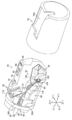
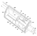
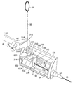
- FIG. 2 is a perspective view of the tip end member 28 in which the stand 30 is in the collapsed position
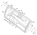
- FIG. 3 is a perspective view of the tip end member 28 in which the stand 30 is in the upright position.
- the upper direction refers to the Z (+) direction in FIGS. 1 and 2
- the lower direction refers to the Z ( ⁇ ) direction in FIGS. 1 and 2.
- the right direction refers to the X (+) direction of FIG. 2
- the left direction refers to the X (-) direction of FIG.
- the Y (+) direction in FIGS. 1 and 2 points to the distal side of the tip member 28, and the Y ( ⁇ ) direction in FIGS. 1 and 2 points to the proximal side of the tip member 28.
- the operation unit 22 includes an operation unit main body 32 provided with the erecting operation lever 20 and a grip unit 34 connected to the operation unit main body 32.
- the insertion portion 24 is provided at the tip end of the grip portion 34 via a bending tube 38.
- the holding part 34 is a part which an operator grasps at the time of operation of the endoscope 10.
- a universal cord 46 is provided on the operation unit main body 32 of the operation unit 22.
- a light source connector 50 is provided on the distal end side of the universal cord 46.
- An electrical connector 48 is branched from the light source connector 50. The electrical connector 48 is connected to the processor unit 14, and the light source connector 50 is connected to the light source unit 16.
- the insertion portion 24 is configured by connecting the distal end portion 26, the bending portion 52, and the flexible portion 54 from the distal end side toward the proximal end side.
- the following contents are provided inside the insertion portion 24. That is, the operation for changing the lead-out direction of the treatment instrument channel 58 for guiding the distal end portion 56A of the treatment instrument 56 of FIG. 1 to the distal end member 28 of FIG.
- the light source device shown in FIG. 1 is a standing operation wire 60 (hereinafter referred to as a wire 60) to be performed, a standing operation wire channel 62 (hereinafter referred to as a wire channel 62) for guiding the tip of the wire 60 to the tip member 28.
- a light guide (not shown) for guiding illumination light supplied from 16 to the tip member 28 of FIG. 2, an air / water feeding tube (not shown), an angle wire (not shown), a signal cable (not shown), etc.
- the wire channel 62 is an example of the wire insertion path of the present invention formed from the operation unit 22 to the insertion unit 24, and the wire 60 is inserted and disposed in the wire channel 62 so as to be movable back and forth.
- the operation unit 22 is generally formed in a substantially cylindrical shape, and has a longitudinal axis A along the Y (+)-Y (-) direction. Further, a pair of angle knobs 64, 64 for bending the bending portion 52 are disposed in the operation portion 22. The pair of angle knobs 64, 64 are coaxially rotatably provided.
- the bending portion 52 has a structure in which a plurality of angle rings (not shown) are rotatably connected to each other.
- the curved portion 52 is configured by covering the outer periphery of this structure with a tubular mesh woven with metal wires, and covering the outer circumferential surface of the mesh with a cylindrical outer shell made of rubber.
- four angle wires (not shown) are disposed from the curved portion 52 configured as described above to the angle knobs 64, 64, and these angle wires are set by turning the angle knobs 64, 64.
- the bending portion 52 is bent vertically and horizontally.
- An air supply / water supply button 66 and a suction button 68 are juxtaposed on the operation unit main body 32 of the operation unit 22.
- air supply / water supply button 66 By operating the air supply / water supply button 66, air and water can be ejected from the air supply / water supply nozzle 70 provided in the tip end member 28 of FIG.
- suction button 68 of FIG. 1 By operating the suction button 68 of FIG. 1, it is possible to suction body fluid such as blood from the suction port which also serves as the treatment instrument outlet 72 provided in the tip end member 28 of FIG.
- the grip portion 34 of the operation portion 22 of FIG. 1 is provided with a treatment tool introduction port 42 for introducing the treatment tool 56.
- the treatment instrument 56 introduced from the treatment instrument inlet 42 with the tip 56A at the top is inserted into the treatment instrument channel 58 of FIG. It is derived from the outlet 72 to the outside.
- the standing up operation lever 20 is rotatably provided coaxially with the angle knobs 64, 64.
- the erecting control lever 20 is rotationally operated by the operator's hand holding the grip 34.
- the wire 60 of FIG. 2 is formed by the rising operation mechanism 120 (see FIG. 9) and the slider 96 (see FIG. 9) that operate in conjunction with the rotation operation of the rising operation lever 20. It is pushed and pulled.
- the posture of the stand 30 connected to the tip of the wire 60 is changed between the standing position of FIG. 3 and the reclining position of FIG.
- the rising operation mechanism 120 and the slider 96 shown in FIG. 9 will be described later.
- the flexible portion 54 has a helical tube (not shown) formed by spirally winding a thin thin metal plate having elasticity.
- the flexible portion 54 is configured by covering the outside of the spiral tube with a tubular mesh woven with metal wires, and covering the outer circumferential surface of the mesh with a tubular outer shell made of resin.
- the endoscope 10 of the embodiment configured as described above is a side-view endoscope used as a duodenoscope, and the insertion portion 24 is inserted into a subject through an oral cavity.
- the insertion portion 24 is inserted from the esophagus through the stomach to the duodenum, and a treatment such as a predetermined examination or treatment is performed.
- a biopsy forceps having a cup capable of collecting a living tissue at the tip end portion 56A is exemplified, but the invention is not limited thereto.
- a treatment tool such as a contrast tube or a knife for EST (Endoscopic Sphincterotomy) is used.
- the distal end portion 26 of the insertion portion 24 is composed of a distal end member 28 and a cap 76 detachably mounted on the distal end member 28.
- the cap 76 is formed in a substantially cylindrical shape whose front end side is sealed, and a substantially rectangular opening window 76A is formed in a part of the outer peripheral surface thereof.
- the opening window 76 A of the cap 76 is in communication with the treatment instrument outlet 72 of the distal end member 28.
- the distal end portion 56A of the treatment instrument 56 derived from the treatment instrument outlet 72 is derived from the opening window 76A to the outside.
- the cap 76 is made of an elastic material, for example, a rubber material such as fluororubber or silicone rubber, or a resin material such as polysulfone.
- the proximal end side of the cap 76 has an engaging portion (not shown) engaged with a groove (not shown) formed in the distal end member 28, and the engaging portion is engaged with the groove in the distal end member 28.
- the tip member 28 is mounted.
- the cap 76 is removed from the tip member 28 and cleaned or disinfected or discarded as disposable.
- the tip member 28 is made of a metal material having corrosion resistance. Further, the distal end member 28 is integrally provided with a partition wall 78 projecting toward the tip end and a partition wall 80 opposed to the partition wall 78. Between the partition wall 78 and the partition wall 80, a stand storage chamber 82 for storing the stand 30 is formed. A treatment instrument outlet 72 for guiding the treatment instrument 56 to the outside is formed on the proximal end side of the stand storage chamber 82, and the distal end of the treatment instrument channel 58 is connected to the treatment instrument outlet 72.
- the treatment instrument channel 58 is inserted into the inside of the insertion portion 24 of FIG.
- the proximal end of the treatment instrument channel 58 is connected to a distal end tube 302 of a branch tube 300 (see FIG. 9) provided inside the operation unit 22.
- the branch pipe 300 has a well-known structure, and the proximal end is branched into two pipes 304 and 306, and the treatment instrument inlet 42 is formed at the proximal end of one pipe 304. Therefore, the distal end portion 56A of the treatment tool 56 introduced from the treatment tool introduction port 42 is inserted into the treatment tool channel 58 through the conduit 304, and from the treatment tool outlet 72 of FIG. It is derived. Then, the leading end 56A of the treatment tool 56 led to the stand storage chamber 82 changes the lead-out direction according to the posture between the upright position and the fall position of the stand 30 disposed in the stand storage chamber 82. Be done. Further, the distal end of a suction pipe (not shown) for suctioning a body fluid such as blood is connected to the proximal end of the other pipe line 306 of the branch pipe 300 shown in FIG.
- FIG. 4 is an enlarged perspective view of the stand 30.
- the upper surface of the stand 30 is provided with a guide surface 30A.
- the tip 56A of the treatment instrument 56 of FIG. 1 is led out of the opening window 76A of the cap 76 of FIG.
- the stand 30 is provided with pivots 84 and 86 on both sides of its base 30B.
- the axial direction of the pivot shafts 84 and 86 is set in the X (+)-X (-) direction of FIG. 2 when the stand 30 is attached to the tip end member 28.
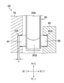
- FIG. 5 is a sectional view of an essential part showing a mounting structure of the stand 30 to the tip end member 28.
- the axes of the pivoting shafts 84 and 86 are coaxially disposed via the base 30B of the stand 30, and the pivoting shaft 84 is pivotable to the concave bearing portion 78A of the partition wall 78.
- the rotary shaft 86 is rotatably fitted on the concave bearing portion 80A of the partition 80.
- the pivot shafts 84 and 86 are mounted to the bearings 78A and 80A in the axial direction of the pivot shafts 84 and 86 with a predetermined amount of play x.
- an optical system storage chamber 88 is provided inside the partition wall 78.
- An illumination window 90 and an observation window 92 are disposed adjacent to each other at the top of the optical system storage chamber 88, and an air / water feed nozzle 70 directed to the observation window 92 is provided on the tip member 28.
- the air / water feed nozzle 70 is connected to an air / water feed device (not shown) via an air / water feed tube (not shown) inserted into the insertion portion 24, and the air / water feed button 66 of the operation unit 22 shown in FIG.
- the air or water is jetted from the air / water feed nozzle 70 toward the observation window 92 by operating the. Thereby, the observation window 92 is cleaned.
- the illumination unit includes an illumination lens (not shown) disposed inside the illumination window 90, and a light guide (not shown) disposed so that the tip surface faces the illumination lens.
- the light guide is disposed from the insertion portion 24 of the endoscope 10 to the universal cord 46 via the operation portion 22, and the proximal end thereof is connected to the light source device 16 via the light source connector 50. Thereby, the irradiation light from the light source device 16 is transmitted through the light guide and is irradiated from the illumination window 90 to the outside.
- the imaging unit described above includes an imaging optical system (not shown) disposed inside the observation window 92, and a complementary metal oxide semiconductor (CMOS) type or CCD (charge coupled device) type imaging device (not shown). Is equipped.
- the imaging device is connected to the processor device 14 via a signal cable (not shown) inserted into the insertion portion 24 of FIG.
- the imaging signal of the subject image obtained by the imaging unit is output to the processor unit 14 through the signal cable and subjected to image processing, and then displayed on the display 18 as the subject image.
- FIG. 6 is a perspective view of the operation unit 22 of FIG. 1 as viewed from below from above.
- the wire 60 is provided with an engagement member 100 at its tip.
- the stand 30 is provided with the accommodation groove 102 engaged with the engagement member 100 so as to be detachably engaged, and the accommodation groove 102 having the opening 104 formed on the X (+) direction side.
- the distal end of the wire 60 is connected to the stand 30 by accommodating the engagement member 100 provided at the distal end of the wire 60 in the accommodation groove 102 through the opening 104.
- the engagement member 100 is a sphere
- the accommodation groove 102 is a spherical recess for accommodating the engagement member 100 of a sphere.
- the shapes of the engagement member 100 and the accommodation groove 102 are not limited to the above-described shapes, but the engagement member 100 may be a sphere and the accommodation groove 102 may be a spherical recess to push and pull the wire 60.
- the sliding resistance between the engagement member 100 and the accommodation groove 102 caused by the operation can be reduced. Therefore, the push and pull operation of the wire 60 can be performed smoothly.
- leading end member 28 is provided with an engagement guiding portion 106 which is continuously provided in the accommodation groove 102 in the upright position of FIG. 3.
- the engagement guiding portion 106 has a function of guiding the engagement member 100 led out from the outlet 74 to the opening 104 of the housing groove 102.
- the outlet 74 is provided in the distal end member 28 and is in communication with the opening 94 (see FIG. 6) at the proximal end of the wire channel 62 via the wire channel 62.
- the engagement member 100 when the wire 60 is introduced from the opening 94 of the wire channel 62 to the head of the engagement member 100, the engagement member 100 is a wire channel It passes through 62 (see FIG. 2) and is led out from the outlet 74. Then, the engaging member 100 is guided toward the opening 104 of the accommodation groove 102 of the stand 30 by the engagement guiding portion 106 by the continuous introduction operation of the wire 60, and is engaged with the accommodation groove 102 from the opening 104 Be done.
- the engagement member 100 of the wire 60 can be engaged with the accommodation groove 102 of the stand 30 only by the introduction operation of the wire 60.
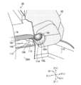
- FIG. 7 is an enlarged perspective view in which the engagement member 100 is engaged with the accommodation groove 102 via the engagement guiding portion 106.
- FIG. FIG. 8 is an explanatory view sequentially showing an operation until the engagement member 100 is guided by the engagement guiding portion 106 and engaged with the accommodation groove 102. As shown in FIG.
- the engagement guiding portion 106 guides the engagement member 100 led from the outlet 74 up to the opening 104 of the housing groove 102, and the engagement guide path 108.
- a deformation generation unit 110 connected to the opening 104 of the accommodation groove 102 in the space 108.
- the deformation generating portion 110 contacts the engaging member 100 advancing in the engagement guide path 108 toward the opening 104 in the Y (+) direction, and guides the engaging member 100 in the Y (+) direction while X (( Guide in the +) direction.
- the distal end of the wire 60 elastically deforms in a direction (X (+) direction) gradually away from the opening 104 as the engagement member 100 approaches the opening 104 along the engagement guide path 108.
- the engagement member 100 advancing in the engagement guide path 108 is moved in the X (-) direction by the restoring force of the wire 60 and engaged with the accommodation groove 102 from the opening 104.
- the engagement guide path 108 is formed by notching a part of the circumferential surface 28A of the tip member 28 in a concave shape, and is gradually inclined in the X (+) direction from the outlet 74 toward the Y (+) direction It is a face.
- a deformation generating portion 110 is formed on the tip end side of the engagement guide path 108.
- the engagement guiding portion 106 is formed with a groove 112 for retracting the tip of the wire 60 when the engagement member 100 is engaged with the accommodation groove 102.
- a groove 114 is formed which allows the tip of the wire 60 to be retracted and released when the engagement member 100 is engaged with the accommodation groove 102.
- the width dimension of the groove 112 in the direction orthogonal to the paper surface of FIG. 8 is larger than the diameter of the wire 60, and the engaging member 100 passing through the deformation generating portion 110 does not get into the groove 112. Less than diameter.
- the width dimension of the groove 114 in the direction orthogonal to the paper surface of FIG. 8 is larger than the diameter of the wire 60, and the engaging member 100 engaged with the accommodation groove 102 does not come off in the Y (-) direction. , Smaller than the diameter of the engagement member 100.
- the guiding part 106 for engagement is a form suitable for engaging the engaging member 100 with the accommodation groove 102 in a state where the stand 30 is in the upright position. That is, as shown in FIG. 7, the housing groove 102 is disposed at a position opposed to the outlet port 74 with the stand 30 positioned at the standing position. Therefore, by moving the engaging member 100 straight from the outlet 74, the engaging member 100 can be engaged with the housing groove 102 of the stand 30 located at the standing position via the guiding portion 106 for engagement.
- the distal end member 28 is provided with a guiding surface 116 for detachment, and the guiding surface 116 for detachment is provided on the upper surface of the partition wall 80.
- the separating guide surface 116 is a guide surface inclined in the Z ( ⁇ ) direction toward the X (+) direction.
- the proximal end side of the wire 60 is removed from the slider 96 of FIG. 6, and then the wire 60 is pushed in through the opening 94 of the wire channel 62 to operate the stand 30. From the upright position of FIG. 3 to the collapsed position of FIG. Thereafter, when the wire 60 is further pushed in, the wire 60 is guided by the detachment guiding surface 116 of the tip member 28 in the X (+) direction in which the engaging member 100 is detached from the inside of the accommodation groove 102 to the outside of the opening 104. Ru. As a result, the restoring force of the wire 60 easily disengages the engagement member 100 from the inside of the accommodation groove 102 to the outside of the opening 104.
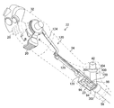
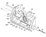
- FIG. 9 is a perspective view showing the configuration of the standing operation mechanism 120. As shown in FIG. In addition, in FIG. 9, the exterior case (not shown) of the operation part 22 is abbreviate
- components of each unit constituting the rising operation mechanism 120 are continuously provided from the operation unit main body 32 to the gripping unit 34 inside the operation unit 22.
- the standing operation mechanism 120 is a power transmission mechanism that connects the standing operation lever 20 and the slider 96 and transmits the rotation operation of the standing operation lever 20 to the slider 96.
- the erecting operation mechanism 120 includes an arm 124 for converting the rotational motion of the erecting operation lever 20 into a linear motion, a drive shaft 126 coupled to the arm 124 for linear motion with the arm 124, and a drive shaft 126 coupled to the drive shaft 126. And a first lever 130 (see FIG. 10) connected to the drive arm 128 to convert the linear motion of the drive arm 128 into rotational movement, and a first lever connected to the first lever 130. And a second lever 132 (see FIG. 10) for converting the rotational movement of 130 into linear movement and transmitting the linear movement to the slider 96.
- FIG. 10 is an explanatory view showing a structure in which the drive arm 128 and the slider 96 are connected via the first lever 130 and the second lever 132.
- the base member 98 is shown by a two-dot chain line. .
- a cam pin 134 is provided in a protruding manner at the tip of the drive arm 128, and the cam pin 134 is slidably engaged with the cam groove 136 of the first lever 130.
- the first lever 130 has one end 130A and the other end 130B, and a linear cam groove 136 is formed from the one end 130A to the other end 130B.
- the first lever 130 is provided with a rotation shaft 138 at one end 130A.
- the rotary shaft 138 is disposed through a through hole (not shown) formed in the base member 98 and is rotatably attached to the base member 98 through an O-ring 140 provided on the rotary shaft 138. .
- the O-ring 140 seals the internal space of the operation unit 22 from the slider accommodation space 150 shown in FIG.
- the second lever 132 of FIG. 10 is disposed in the slider accommodation space 150 (see FIG. 6).
- the second lever 132 is formed in the same shape as the first lever 130, and is disposed opposite to the first lever 130 via the base member 98.
- the second lever 132 has one end 132A and the other end 132B, and a linear cam groove 142 is formed from the one end 132A to the other end 132B.
- the second lever 132 is provided with a rotation shaft 144 at one end 132A.
- the rotation shaft 144 is connected to a rotation shaft 138 of the first lever 130 which is projected from a through hole (not shown) of the base member 98.
- a cam pin 146 protruding from the slider 96 is slidably engaged with the cam groove 142 of the second lever 132.
- the arm 124 When the elevation control lever 20 is rotated in the direction of arrow B from the position shown by the two-dot chain line to the position shown by the solid line, the arm 124 is directed along the longitudinal axis A of the operation portion 22 toward the proximal end of the operation portion 22 It moves in a straight line. Then, in conjunction with the operation of the arm 124, the drive shaft 126 and the drive arm 128 similarly linearly move toward the proximal end side.
- FIG. 11 shows the position of the drive arm 128 when the rising operation lever 20 is at the position shown by the two-dot chain line in FIG. 9, that is, when the rising stand 30 is positioned at the collapsed position (see FIG. 2).
- FIG. FIG. 12 is an explanatory view showing the position of the drive arm 128 when the rising operation lever 20 is at the position shown by the solid line in FIG. 9, that is, when the rising stand 30 is positioned at the rising position (see FIG. 3). is there.
- the drive arm 128 linearly moves from the position shown in FIG. 12 to the position shown in FIG. Rotate towards the side.
- the second lever 132 rotates toward the tip end side of the operation unit 22 about the rotation shaft 144.
- the slider 96 slides from the position of FIG. 12 to the position of FIG. 11 by the action of the cam pin 146 and the cam groove 142.
- the wire 60 is pushed to move the stand 30 to the collapsed position shown in FIG.
- the rising operation mechanism 120 allows the slider 96 to move back and forth in the longitudinal direction of the operation portion 22 along the longitudinal axis A of the operation portion 22 in response to the operation of the rising operation lever 20.
- the base member 98 is provided in the opening 23 formed in the operation unit 22.
- the base member 98 has a plate-like main portion 98A disposed along the longitudinal axis A of the operation portion 22 and a side portion of the main portion 98A with respect to the main portion 98A.
- Wall 98B provided in the direction orthogonal to each other, a fan-shaped base end wall 98C connecting the base ends of the main body 98A and the wall 98B, and tip ends of the main body 98A and the wall 98B
- An opening (not shown) is formed in the tip wall 98D, which is composed of a connecting fan-shaped tip wall 98D, and the opening 94 (see FIG. 6) of the wire channel 62 is disposed in the opening.
- the base member 98 configured in this manner is provided at the opening 23 of the operation unit 22. Thereby, the slider accommodation space 150 independent of the internal space of the operation unit 22 is formed in the operation unit 22.
- the slider accommodation space 150 is a space surrounded by the main body portion 98A of the base member 98, the wall portion 98B, the base end wall 98C and the tip end wall 98D, and as an example, a space having a fan-shaped cross section in the direction orthogonal to the longitudinal axis A. It is.
- the slider accommodation space 150 may be exposed to the outside of the operation unit 22 as shown in FIG. 6, and a cap (not shown) for closing the slider accommodation space 150 may be attached to the opening 23 of the operation unit 22. It may be formed on the inner side of the cap.
- the cross-sectional shape in the direction orthogonal to the longitudinal axis A of the slider accommodation space 150 is not limited to a fan shape, and may be, for example, a rectangular or circular space.
- the slider 96 is disposed in the slider accommodation space 150, and moves back and forth in the longitudinal direction of the operation unit 22 in response to the operation of the rising operation lever 20. That is, when the rising operation lever 20 is operated, the slider 96 is moved via the rising operation mechanism 120. As a result, the wire 60 (see FIG. 2) connected to the slider 96 is pushed and pulled.
- a ridge portion 97 along the longitudinal axis A is formed on the lower surface of the slider 96. Further, as shown in FIGS. 11 and 12, a concave portion 99 along the longitudinal axis A is formed on the upper surface of the main body portion 98A of the base member 98.
- the slider 96 smoothly moves along the longitudinal axis A by the convex streaks 97 being slidably engaged with the concave streaks 99.
- connection structure for connecting the proximal end side of the wire 60 to the slider 96 will be described.
- FIG. 13 is an assembled perspective view showing the connection structure of the first embodiment for connecting the proximal end side of the wire 60 to the slider 96. As shown in FIG.
- the slider 96 is formed in a substantially cubic shape, and in FIG. 13, an engaged portion 152 is provided on the upper surface thereof.
- the engaged portion 152 is recessed on the upper surface of the slider 96 such that the opening 152A of the engaged portion 152 is directed to the side (the direction of the arrow D) orthogonal to the moving direction of the slider 96.
- the direction of movement of the slider and the direction of the longitudinal axis A are the same.
- an engagement member 154 is provided on the proximal end side of the wire 60.
- the engagement member 154 is configured to be engageable with the engaged portion 152 by being pushed into the engaged portion 152 from the side orthogonal to the moving direction of the slider 96.
- the pushing direction of the engaging member 154 with respect to the engaged portion 152 is indicated by the arrow E.
- the engaged portion 152 is provided on the proximal end side of the engagement receiving portion 156 linearly extending in the moving direction of the slider 96 and the engagement receiving portion 156, and positions the engaging member 154 in the engaged portion 152.
- a positioning receiving portion 158 a positioning receiving portion 158.
- the engagement receiving portion 156 and the positioning receiving portion 158 each have a semicircular cross-sectional shape in the direction orthogonal to the moving direction of the slider 96, but the positioning receiving portion 158 has a semicircular shape larger in diameter than the engagement receiving portion 156. Is formed.
- the engagement member 154 has an engagement main body portion 160 engaged with the engagement receiving portion 156 and a positioning portion 162 engaged with the positioning receiving portion 158.
- the engagement main body portion 160 is formed of a cylindrical portion
- the positioning portion 162 is formed of a disk-shaped head formed to have a diameter larger than that of the cylindrical portion. That is, the engagement member 154 has a cylindrical portion which constitutes the engagement main portion 160, and a head which is formed larger in diameter than the cylindrical portion and which constitutes the positioning portion 162.
- the slider 96 and the engagement member 154 are made of, for example, elastically deformable rubber or plastic, and by pressing the engagement main body portion 160 into the engagement receiving portion 156 while elastically deforming, the engagement main body portion 160 The engagement receiving portion 156 is resiliently engaged.
- the slider 96 has a guide surface 164 for guiding the positioning portion 162 to the positioning receiving portion 158.
- the guide surface 164 is connected to the positioning receiving portion 158.
- the positioning portion 162 is guided by the positioning receiving portion 158 by bringing the proximal end surface 163 of the positioning portion 162 into contact with the guide surface 164.
- a connecting operation is performed to connect the tip of the wire 60 to the stand 30.
- the wire 60 is introduced from the opening 94 in FIG. 6 and the engaging member 100 is introduced to the head, with the stand 30 positioned at the standing position (see FIG. 3).
- the engagement member 100 is led out from the outlet 74 via the wire channel 62 (see FIG. 2).
- the engaging member 100 is guided toward the opening 104 of the accommodation groove 102 of the stand 30 by the engagement guiding portion 106 of FIG. 3 by the continuous introduction operation of the wire 60, and from the opening 104 to the accommodation groove 102. Is engaged.
- tip of the wire 60 to the stand 30 is complete
- connection operation of connecting the proximal end side of the wire 60 to the slider 96 is performed.
- the proximal end face 163 of the engagement member 154 shown in FIG. 13 is brought into contact with the guide surface 164 of the slider 96, and the positioning portion 162 and the positioning receiving portion 158 are pushed in (arrow E Position relative to each other.
- the positioning portion 162 can be easily guided to the positioning receiving portion 158.
- the engaging member 154 is pushed into the engaged portion 152 in the arrow E direction from the side orthogonal to the moving direction of the slider 96.
- the engagement main body portion 160 is resiliently engaged with the engagement receiving portion 156.
- the above-mentioned connection work is completed.
- connection operation of connecting the proximal end side of the wire 60 to the slider 96 can be performed only by the operation of pushing the engaging member 154 into the engaged portion 152.
- the proximal end side of the wire 60 can be easily connected to the slider 96.
- the endoscope 10 is used for various examinations or treatments. Thereafter, when the endoscope 10 is cleaned, the following operation is performed.
- the cap 76 shown in FIG. 2 is removed from the tip member 28.
- the proximal end of the wire 60 is removed from the slider 96 of FIG. The removal operation will be described later.
- the wire 60 is pushed in through the opening 94 shown in FIG. 6 to position the stand 30 from the upright position of FIG. 3 to the collapsed position of FIG. Thereafter, the wire 60 is further pushed to separate the engagement member 100 from the inside of the accommodation groove 102 to the outside of the opening 104.
- the tip of the wire 60 is removed from the stand 30 by this operation.
- the wire 60 is pulled out of the opening 94 to empty the wire channel 62. Thereafter, cleaning of the tip member 28, the stand 30, and the wire channel 62 is performed.
- connection structure of the first embodiment is opposite to the pressing direction (direction of arrow E) of the engagement member 154 with respect to the engaged portion 152 performed at the connection operation.
- the engaging member 154 is pulled out from the engaged portion 152 in the direction (the direction of the arrow D).
- the removal operation is completed only by the removal operation. Therefore, according to the connection structure of the first embodiment, the proximal end side of the wire 60 can be easily removed from the slider 96.
- connection operation of connecting the proximal end side of the wire 60 to the slider 96 is performed only by the operation of pushing the engagement member 154 into the engaged portion 152.
- removal operation of removing the proximal end side of the wire 60 from the slider 96 can be performed only by the operation of pulling out the engagement member 154 from the engaged portion 152.
- the endoscope of Patent Document 1 which performs attaching and detaching operations of the proximal end of the wire to the slider using the fixing screw and the tip of the cable cord can be detachably attached to the collet and the nut
- the proximal end attachment / detachment operation of the wire 60 to the slider 96 can be easily performed.
- connection structure of the first embodiment includes the positioning receiving portion 158 and the positioning portion 162
- the engaged portion 152 and the engaging member 154 can be engaged by engaging the positioning portion 162 with the positioning receiving portion 158. It becomes easy to engage with the Further, by engaging the positioning portion 162 with the positioning receiving portion 158, it is possible to prevent the engagement member 154 from coming off the engaged portion 152 in the axial direction of the wire 60.
- the cross-sectional shapes of the engagement receiving portion 156 and the positioning receiving portion 158 are not limited to a semicircular shape, and may be rectangular.
- the engagement main body portion 160 is not limited to a cylindrical shape, and may be configured in a prismatic shape
- the positioning portion 162 is not limited to a disk shape, and is configured in a rectangular shape It may be
- the positioning portion 162 can be easily guided to the positioning receiving portion 158 simply by pressing the base end side end surface 163 of the positioning portion 162 against the guide surface 164. .
- the form in which the slider 96 is recessed is illustrated as the engaged portion 152, but the engaged portion 152 may be formed in the slider 96 so as to be convex.
- the engagement member 154 which can engage with the engaged portion 152 has a concave portion that is engaged with the convex portion of the engaged portion 152.
- the positioning receiving portion 158 may be provided on the distal end side of the engagement receiving portion 156. That is, the positioning receiving portion 158 may be provided in the engagement receiving portion 156.
- the slider 96 moves back and forth in the direction parallel to the longitudinal axis A, but the movement direction of the slider of the present invention is limited to the direction parallel to the longitudinal direction. is not. That is, the moving direction of the slider of the present invention also includes a mode in which the slider moves back and forth in a direction inclined with respect to the longitudinal direction. That is, it includes a form in which the slider moves back and forth in the direction having the longitudinal component. This form is described in each of the following embodiments.
- connection structure of the second embodiment in which the proximal end side of the wire 60 is connected to the slider will be described.
- connection structure of the second embodiment the same or similar members as or to those of the connection structure of the first embodiment described with reference to FIG.
- FIG. 14 is an assembled perspective view showing constituent members of the connection structure of the second embodiment.
- FIG. 14 the state before the proximal end side of the wire 60 is connected to the slider 170 is shown.
- FIG. 15 shows a state in which the proximal end side of the wire 60 is connected to the slider 170.
- the slider 170 is provided with a cam pin 146 engaged with the cam groove 142 of the second lever 132 and a convex streak portion 97 engaged with the concave streak portion 99 of the base member 98.
- the slider 170 is also disposed in the slider accommodation space 150 in the same manner as the slider 96 shown in FIGS. 11 and 12, and is elongated along the longitudinal axis A of the operation portion 22 in response to the operation of the erecting operation lever 20 (see FIG. 9). Move forward and backward in the direction.
- an engaged portion 172 is formed on the surface 170 A of the slider 170.
- the engaged portion 172 is recessed on the surface 170 A of the slider 170 so that the opening 172 A of the engaged portion 172 faces in the side (the direction of the arrow F) orthogonal to the moving direction of the slider 170.
- the engaged portion 172 is formed in a hemispherical shape.
- a wire insertion path 174 is formed in the slider 170.
- the wire insertion path 174 is, as shown in FIG. 15, an opening 176 disposed at a position opposed to the opening 94 of the wire channel 62, and an opening 178 formed in the engaged portion 172 (see FIG. 14). And a channel that communicates with the inside of the slider 170.
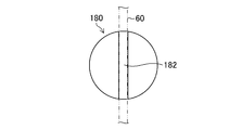
- the engagement member 180 engageable with the engaged portion 172 is formed in a spherical shape.
- the engaging member 180 is pushed into the engaged portion 172 in the direction of arrow G in FIG. 14 from the side perpendicular to the moving direction of the slider 170. Thereby, the engagement member 180 is resiliently engaged with the engaged portion 172.
- the engagement member 180 has a slit-like holding portion 182 inserted and held from the outer surface side of the engagement member 180 at the proximal end side of the wire 60.
- the holding portion 182 is constituted by a semicircular slit formed inward from the outer surface of the engagement member 180.
- FIG. 16A is a front view of the engagement member 180 showing a state in which the proximal end side of the wire 60 is inserted into the sandwiching portion 182 of the engagement member 180.
- FIG. 16B is a top view of FIG. 16A.
- 16C is a cross-sectional view of the engagement member 180 taken along line 16-16 of FIG. 16A.
- FIG. 16D is an explanatory view showing a state of the holding portion 182 when the engaging member 180 is engaged with the engaged portion 172.
- the proximal end side of the wire 60 is inserted into the sandwiching portion 182 of the engaging member 180.
- the bottom surface 182A of the slit which is the holding portion 182 reaches the center 180A of the engaging member 180.
- the proximal end side of the wire 60 is nipped by the center 180A of the engagement member 180.
- the proximal end side of the wire 60 is inserted into the holding portion 182 of the engaging member 180, and in this state, the tip of the wire 60 is inserted from the opening 178 of the slider 170 through the wire insertion passage 174, the opening 176 and the opening 94. Through the wire channel 62. Then, the tip of the wire 60 is connected to the stand 30 (see FIG. 3).
- the standup operation lever 20 (see FIG. 9) is operated to position the slider 170 in the standup position of FIG.
- connection operation of connecting the proximal end side of the wire 60 to the slider 170 can be performed only by the operation of pushing the engagement member 180 into the engaged portion 172 .
- the proximal end side of the wire 60 can be easily connected to the slider 170.
- the removal work for removing the proximal end side of the wire 60 from the slider 170 is in the direction (arrow F direction) opposite to the pushing direction (arrow G direction) of the engaging member 180 with respect to the engaged portion 172
- the engaging member 180 is pulled out of the engaged portion 172.
- the removal operation is completed only by the removal operation. Therefore, according to the connection structure of the second embodiment, the proximal end side of the wire 60 can be easily removed from the slider 170.
- connection operation of connecting the proximal end side of the wire 60 to the slider 170 is performed only by the operation of pushing the engaging member 180 into the engaged portion 172.
- removal operation of removing the proximal end side of the wire 60 from the slider 170 can be performed only by the operation of pulling out the engagement member 180 from the engaged portion 172.
- connection structure of the second embodiment the attachment / detachment operation of the proximal end side of the wire 60 to the slider 170 can be easily performed as in the connection structure of the first embodiment described above.
- the bottom surface 182A of the sandwiching portion 182 reaches the center 180A of the engaging member 180.
- the holding force of the wire 60 by the holding part 182 can be obtained at maximum while holding the strength of the engaging member 180.
- the bottom surface 182A of the sandwiching portion 182 may reach the center 180A, and thus the bottom surface 182A may reach a deep position from the center 180A.
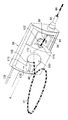
- FIG. 17 is an explanatory view showing a state in which the engaging member 180 is removed from the engaged portion 172 using the jig 190. As shown in FIG.
- the pointed portion 192 of the tip of the jig 190 is inserted into the boundary between the engaging member 180 and the engaged portion 172, and the engaging member 180 is removed from the engaged portion 172 according to the principle of leverage. .
- the engagement member 180 can be easily removed from the engaged portion 172.
- a concave guide surface 173 for guiding the pointed portion 192 of the jig 190 to the boundary may be connected to the engaged portion 172.
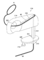
- the jig 190 may be attached to the proximal end side of the wire 60 as shown in FIG.
- FIG. 18 is an explanatory view in which a jig 190 is attached to the proximal end side of the wire 60.
- a projection 194 for holding the jig 190 may be provided in the operation unit 22.
- the jig 190 is held by the operation unit 22 by engaging the recess 196 formed in the jig 190 with the projection 194.
- connection structure of the third embodiment in which the proximal end side of the wire 60 is connected to the slider will be described.
- connection structure of the third embodiment the same or similar members as or to those of the connection structure of the second embodiment described with reference to FIGS. 14 to 18 will be described with the same reference numerals.
- FIG. 19 is an assembled perspective view showing constituent members of the connection structure of the third embodiment.
- the state before the proximal end side of the wire 60 is connected to the slider 200 is shown.
- FIG. 20 shows the state of the unlocking position in the connection structure of the third embodiment.
- FIG. 21 shows the state of the lock position in the connection structure of the third embodiment.
- the slider 200 is provided with a cam pin 146 engaged with the cam groove 142 of the second lever 132 and a convex portion 97 engaged with the concave portion 99 of the base member 98. .
- the slider 200 is also disposed in the slider accommodation space 150 in the same manner as the slider 170 shown in FIG. 14, and advances and retracts in the longitudinal direction along the longitudinal axis A of the operation portion 22 in response to the operation of the erecting operation lever 20 (see FIG. 9). Moving.
- an engaged portion 202 is formed on the surface 200 ⁇ / b> A of the slider 200.
- the engaged portion 202 is concavely provided on the surface 200A of the slider 200 so that the opening 202A of the engaged portion 202 is directed to the side (the direction of the arrow J) orthogonal to the moving direction of the slider 200.
- the engaged portion 202 is formed in a hemispherical shape.
- a wire insertion path 204 is formed in the slider 200.
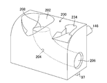
- FIG. 22 is an enlarged perspective view showing the structure of the slider 200. As shown in FIG.
- the wire insertion path 204 is a passage for communicating the opening 206 disposed at a position opposed to the opening 94 (see FIG. 19) of the wire channel 62 with the opening 208 formed in the engaged portion 202. , And the inside of the slider 200.
- the engagement member 210 engageable with the engaged portion 202 is formed in a hemispherical body.
- the engaging member 210 is pushed into the engaged portion 202 in the arrow K direction in FIG. 19 from the side orthogonal to the moving direction of the slider 200.
- the engagement member 210 is resiliently engaged with the engaged portion 202.
- the engagement member 210 is provided on a lock operation member 216 having a rotary shaft 212 and a knob 214. According to this lock operation member 216, in FIG. 19, the engagement member 210 is connected to the lower end portion of the rotation shaft 212, and the knob 214 is connected to the upper end portion of the rotation shaft 212. Further, the engagement member 210 and the rotation shaft 212 are coupled such that their central axes are coaxially located.
- the lock operation member 216 has a lock member 218 described later, and the lock member 218 is connected to the rotation shaft 212 via a bracket 220. That is, the lock member 218 is provided at a position offset with respect to the central axis of the rotation shaft 212.
- FIG. 23 is an enlarged perspective view showing the structure of the lock operation member 216.
- FIG. 24 is an enlarged perspective view in which the proximal end side of the wire 60 is locked to the lock operation member 216.
- FIG. 25 is a bottom view of the lock operating member 216 shown in FIG.
- the engagement member 210 has a slit-like holding portion 222 which is inserted and held from the outer surface side of the engagement member 210 at the proximal end side of the wire 60. Further, a slit 224 for guiding the wire 60 to the holding portion 222 is formed in the bracket 220, and slits 226 and 228 are also formed in the rotation shaft 212 and the knob 214 in the same manner. The proximal end side of the wire 60 is inserted into the holding portion 222 of the engagement member 210 via the slits 224, 226, 228. Further, as shown in FIG.
- the proximal end side of the wire 60 is disposed along the groove 230 formed in the knob 214, and the loop portion 61 of the wire 60 is inserted into the opening 232 of the knob 214.
- the proximal end side of the wire 60 is locked to the inner circumferential portion of the opening 232.
- connection structure of the third embodiment includes a lock mechanism.
- the lock mechanism has a lock position (see FIG. 21) for preventing release of the engagement state between the engagement member 210 and the engaged portion 202, and an engagement state between the engagement member 210 and the engaged portion 202. It is switchable between an unlocking position (see FIG. 20) which permits unlocking.
- the lock mechanism includes a lock member 218 provided adjacent to the engagement member 210, and a lock recess 234 (see FIG. 22) provided on the slider 200 and engaged with the lock member 218. According to the lock mechanism, when the lock member 218 and the lock recess 234 are engaged, the lock position (see FIG. 21) is obtained, and when the engagement between the lock member 218 and the lock recess 234 is released, the lock is performed. The release position (see FIG. 20) is obtained.
- the proximal end side of the wire 60 is inserted into the holding portion 222 of the engaging member 210, and in this state, the tip of the wire 60 is inserted from the opening 208 (see FIG. 22) of the slider 200 to the wire insertion path 204, the opening 206 and The wire channel 62 is inserted through the opening 94 (see FIG. 19). Then, the tip of the wire 60 is connected to the stand 30 (see FIG. 3).
- the rising operation lever 20 (see FIG. 9) is operated to position the slider 200 at the rising position shown in FIG.
- the engaging member 210 is pushed in the direction of the arrow K into the engaged portion 202 from the side perpendicular to the moving direction of the slider 200.
- the engaging member 210 is elastically engaged with the engaged portion 202.
- the engaging member 210 receives a force in the arrow L direction from the engaged portion 202. It is elastically deformed in the direction in which the gap of the sandwiching portion 222 becomes narrow. As a result, the proximal end side of the wire 60 is firmly held by the holding portion 222 and fixed to the engagement member 210.
- connection work of connecting the proximal end side of the wire 60 to the slider 200 is performed by pushing the engagement member 210 into the engaged portion 202 and the lock recess 234. It can be performed only by the operation of engaging the lock member 218.
- the proximal end side of the wire 60 can be easily connected to the slider 200.
- the lock operating member 216 in the locked position shown in FIG. 21 is rotated 90 degrees in the arrow N direction using the knob 214.
- the lock member 218 is disengaged from the lock recess 234 of the slider 200 and becomes the lock release position.
- the engaging member 210 is engaged in the opposite direction (direction of arrow J: see FIG. 19) to the pushing direction of the engaging member 210 with respect to the engaged portion 202 (direction of arrow K: see FIG. 19). Pull it out. Removal work is completed only with this work. Therefore, according to the connection structure of the third embodiment, the proximal end side of the wire 60 can be easily removed from the slider 200.
- connection operation of connecting the proximal end side of the wire 60 to the slider 200 is performed by pushing the engaging member 210 into the engaged portion 202, and the lock recess This can be performed only by engaging the lock member 218 with the H.234.
- the removal operation of removing the proximal end side of the wire 60 from the slider 200 can be performed only by the operation of removing the lock member 218 from the lock recess 234 and the operation of pulling out the engagement member 210 from the engaged portion 202.
- the proximal end side of the wire 60 can also be connected to the slider 200 only by pushing the engaging member 210 into the engaged portion 202.
- the proximal end side of the wire 60 can be removed from the slider 200 only by the operation of pulling out the engaging member 210 from the engaged portion 202.
- connection structure of the third embodiment the attachment / detachment operation of the proximal end side of the wire 60 with respect to the slider 200 can be easily performed as in the connection structures of the above-described embodiments.
- the slider 200 is provided with the lock recess 234, and the lock member 218 is provided on the engagement member 210 side.
- the slider 200 is provided with the lock member 218, and the engagement member 210 side is provided.
- the lock recess 234 may be provided on the
- the bracket 220 may interfere with the base member 98 when pushing the engaging member 210 in the arrow K direction.
- the engaging member 210 can engage with the engaged portion 202 only when the slider 200 is at the position shown in FIG. 19, that is, when the slider 200 is at the upright position.
- the engaging member 210 is engaged with the engaged portion 202 at a position other than the position shown in FIG. In this case, the slider 200 may become inoperable.
- the engaging member 210 can engage with the engaged portion 202 only at the position shown in FIG. 19, thus eliminating the problem that the slider 200 becomes inoperable. be able to.
- the position corresponds to the inclined position of the slider 200.
- the relief portion 236 may be formed at the position.
- connection structure of the fourth embodiment in which the proximal end side of the wire 60 is connected to the slider will be described.
- connection structure of the fourth embodiment the same or similar members as or to those of the connection structure of the third embodiment described with reference to FIGS. 19 to 25 are denoted by the same reference numerals.
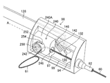
- FIG. 26 is an assembled perspective view showing constituent members of the connection structure of the fourth embodiment.
- the state before the proximal end side of the wire 60 is connected to the slider 240 is shown.
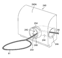
- FIG. 27 shows the state of the lock release position in the connection structure of the fourth embodiment.
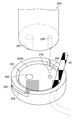
- FIG. 28 shows the state of the lock position in the connection structure of the fourth embodiment.
- the slider 240 is provided with a cam pin 146 engaged with the cam groove 142 of the second lever 132 and a convex portion 97 engaged with the concave portion 99 of the base member 98. .
- the slider 240 is also disposed in the slider accommodation space 150 in the same manner as the slider 200 shown in FIG. 19, and advances and retracts in the longitudinal direction along the longitudinal axis A of the operation portion 22 in response to the operation of the erecting operation lever 20 (see FIG. 9). Moving.
- an engaged portion 242 is formed on the surface 240 ⁇ / b> A of the slider 240.
- the engaged portion 242 is concavely provided on the surface 240 A of the slider 240 so that the opening 242 A of the engaged portion 242 faces in the side (the arrow P direction) orthogonal to the moving direction of the slider 240.
- a wire insertion path 244 is formed in the slider 240.
- FIG. 29 is an enlarged perspective view showing the structure of the slider 240. As shown in FIG.
- the wire insertion path 244 is a passage for communicating the opening 246 disposed at a position facing the opening 94 (see FIG. 26) of the wire channel 62 with the opening 248 formed in the engaged portion 242. ,
- the slider 240 is formed.
- the engagement member 250 engageable with the engaged portion 242 is formed in a semi-spherical body as shown in FIG.
- the engaging member 250 is pushed into the engaged portion 242 in the direction of arrow Q in FIG. 26 from the side orthogonal to the moving direction of the slider 240. Thereby, the engagement member 250 is elastically engaged with the engaged portion 242.
- connection structure of the fourth embodiment includes a lock mechanism.
- the lock mechanism has a lock position (see FIG. 28) for preventing release of the engagement between the engagement member 250 and the engaged portion 242, and the engagement between the engagement member 250 and the engaged portion 242. It is switchable between an unlocking position (see FIG. 27) which permits unlocking.
- the lock mechanism includes a pair of cam pins 252 which are cam engaging portions provided on the outer peripheral surface of the engaging member 250, and a pair of cam grooves 254 provided on the engaged portion 242 and engaged with the cam pins 252. Is configured.
- the cam groove 254 is spirally formed in the arrow Q direction.
- the tip of the wire 60 is inserted into the wire channel 62 from the opening 248 (see FIG. 29) of the slider 240 through the wire insertion path 244, the opening 246 and the opening 94 (see FIG. 26). Then, the tip of the wire 60 is connected to the stand 30 (see FIG. 3).
- the standup operation lever 20 (see FIG. 9) is operated to position the slider 240 in the standup position shown in FIG.
- connection work of connecting the proximal end side of the wire 60 to the slider 240, the work of pushing the engaging member 250 into the engaged portion 242, and the cam pin 252 It can be performed only by the operation of engaging the groove 254.
- the proximal end side of the wire 60 can be easily connected to the slider 240.
- the engaging member 250 in the locked position shown in FIG. 28 is rotated in the reverse direction along the cam groove 254. Thereby, the engagement member 250 can be positioned at the unlocking position shown in FIG.
- the engaging member 250 is engaged in the opposite direction (direction of arrow P: see FIG. 26) to the pushing direction of the engaging member 250 with respect to the engaged portion 242 (arrow Q direction: see FIG. 26). Pull it out. Removal work is completed only with this work. Therefore, according to the connection structure of the fourth embodiment, the proximal end side of the wire 60 can be easily removed from the slider 240.
- the connecting operation of connecting the proximal end side of the wire 60 to the slider 240 is an operation of pushing the engaging member 250 into the engaged portion 242; Can be performed only by the operation of engaging the cam groove 254.
- the removal operation of removing the proximal end side of the wire 60 from the slider 240 can be performed only by the operation of removing the cam pin 252 from the cam groove 254 and the operation of pulling out the engagement member 250 from the engaged portion 242.
- the proximal end side of the wire 60 can be connected to the slider 240 only by pushing the engaging member 250 into the engaged portion 242.
- the proximal end side of the wire 60 can be removed from the slider 240 only by the operation of pulling out the engagement member 250 from the engaged portion 242.
- connection structure of the fourth embodiment the attachment / detachment operation of the proximal end side of the wire 60 to the slider 240 can be easily performed as in the connection structures of the above-described embodiments.
- the cam pin 252 is provided on the engaging member 250, and the cam groove 254 is provided on the engaged portion 242.
- the cam groove 254 is provided on the engaging member 250.
- the cam pin 252 may be provided at the joint portion 242.
- connection structure of the fourth embodiment the following operations can be easily performed by using a jig.
- the above operation includes pushing the engaging member 250 into the engaged portion 242, locking operation for rotating the engaging member 250 from the unlocked position to the locked position, rotating the engaging member 250 from the locked position to the unlocked position.
- the lock release operation is performed, and the operation for pulling out the engagement member 250 from the engaged portion 242.
- FIG. 30 is an explanatory view of an operation of pushing the engaging member 250 into the engaged portion 242 using the jig 260.
- FIG. 31 is an enlarged perspective view of an essential part showing an engagement relationship between the jig 260 and the engagement member 250. As shown in FIG.
- the jig 260 includes a knob 262, and two pins 264 and 266 projecting from the end of the knob 262. Further, the flat end face 250A of the engagement member 250 is provided with a hole 268 into which the pin 264 is inserted and a hole 270 into which the pin 266 is inserted.
- the engaging member 250 is detachably attached to the jig 260 by inserting the pin 264 into the hole 268 and inserting the pin 266 into the hole 270 (see FIG. 30).
- an operation of pushing the engagement member 250 into the engaged portion 242 is performed.
- a finger is hooked on the loop portion 61 of the wire 60, the wire 60 is pulled in the pulling direction, and the wire 60 is loosened.
- the engaging member 250 is pushed in the arrow Q direction into the engaged portion 242 in the state of FIG. 30 attached to the jig 260.
- FIG. 32 is an explanatory view showing a state in which the engaging member 250 is pushed into the engaged portion 242 using the jig 260.
- FIG. 33 is an enlarged perspective view of an essential part showing a state in which the engagement member 250 is pushed into the engaged portion 242.
- the position of the engagement member 250 with respect to the engaged portion 242 in FIGS. 32 and 33 is the unlocking position.
- FIG. 34 is an enlarged perspective view of an essential part in which the cam pin 252 is engaged with the cam groove 254 by the rotation of the jig 260. As shown in FIG.
- a lock release operation is performed.
- the jig 260 is rotated in the direction of arrow S in FIG. Thereby, the engagement between the cam pin 252 and the cam groove 254 is released, and the lock release position (see FIG. 33) is obtained.
- the engaging member 250 is pulled out.
- the jig 260 is pulled out in the pulling direction (arrow P direction: see FIG. 26). Thereby, the engaging member 250 can be easily pulled out from the engaged portion 242.
- the jig 260 shown in FIGS. 30 to 34 may be removed from the engagement member 250 or may be attached to the engagement member 250.
- a duodenoscope was illustrated as an example of the endoscope 10, but in the case of an endoscope provided with a stand for adjusting the lead-out direction of the treatment tool at the distal end of the insertion portion, ultrasound endoscopy
- the present invention can be applied to various endoscopes such as mirrors.
Abstract
Provided is an endoscope with which work related to the attachment/detachment of a proximal end side of a wire to a slider can be easily performed. The present invention is provided with: a base member (98) which forms a slider accommodation space (150) which is independent from an internal space of an operation part (22); an opening (94) which is provided to the proximal end of a wire channel (62), and through which the proximal end side of the wire (60) is lead out to the slider accommodation space (150); a slider (96) which is provided in the slider accommodation space (150), and which moves so as to be capable of advancing and retracting in the longitudinal direction of the operation part (22) in accordance with operation of a standing operation lever (20); a part (152) to be engaged which is provided to the slider (96), and which is recessed towards a side orthogonal to the movement direction of the slider (96); and an engagement member (154) which is provided to the proximal end of the wire (60), and which is capable of engaging with the part (152) to be engaged by being pushed down from the side.
Description
本発明は内視鏡に係り、特に挿入部の先端部に処置具の導出方向を変更する処置具起立台を備えた内視鏡に関する。
The present invention relates to an endoscope, and more particularly to an endoscope provided with a treatment instrument stand for changing the lead-out direction of a treatment instrument at the distal end of an insertion portion.
内視鏡では、手元操作部(以下、「操作部」と言う。)に設けられた処置具導入口から各種の処置具を導入し、この処置具を、挿入部の先端部材に開口した処置具導出口から外部に導出して処置に用いている。例えば十二指腸鏡では、鉗子又は造影チューブ等の処置具が使用され、超音波内視鏡では穿刺針等の処置具が使用される。このような処置具は、被検体内の所望の位置を処置するために、処置具導出口から導出される処置具の導出方向を変更する必要がある。このため先端部材には処置具起立台(以下、「起立台」と言う。)が設けられ、また操作部には、起立台の姿勢を起立位置と倒伏位置との間で変更させる処置具起立機構が設けられている。
In the endoscope, various treatment tools are introduced from a treatment tool introduction port provided in the hand operation unit (hereinafter referred to as "operation unit"), and the treatment tool is opened at the distal end member of the insertion unit It is derived from the tool outlet and used for treatment. For example, a treatment instrument such as a forceps or an imaging tube is used in a duodenoscope, and a treatment instrument such as a puncture needle is used in an ultrasonic endoscope. Such a treatment tool needs to change the delivery direction of the treatment tool delivered from the treatment tool outlet in order to treat a desired position in the subject. For this purpose, a treatment tool stand (hereinafter referred to as a "stand") is provided on the tip member, and a treatment tool stand that changes the posture of the stand between the standing position and the lying position on the operation unit. A mechanism is provided.
処置具起立機構としては、起立台にワイヤ(鉗子起上ワイヤとも言う。)の先端部を直接取り付けたワイヤ牽引式の機構が知られている(特許文献1参照)。この機構は、操作部に備えられた起立操作レバー(鉗子起上レバーとも言う。)に、ワイヤの基端側を連結し、起立操作レバーによってワイヤを押し引き操作することで起立台を回動軸回りに回転させて、起立位置と倒伏位置との間でその姿勢を変更させるものである。
As a treatment instrument rising mechanism, a wire pulling type mechanism in which the tip of a wire (also referred to as a forceps raising wire) is directly attached to a stand is known (see Patent Document 1). In this mechanism, the proximal end side of the wire is connected to a standup operation lever (also referred to as a forceps raising lever) provided in the operation unit, and the stand is rotated by pushing and pulling the wire with the standup operation lever. It is rotated around an axis to change its posture between the upright position and the fallen position.
具体的に説明すると、特許文献1の操作部には、操作部を手で保持するためのグリップ部と、アングルノブとが設けられている。この操作部には、ワイヤ開口部がグリップ部の下方に、また駆動軸開口部がグリップ部に設けられており、ワイヤ開口部からはワイヤの基端が導出され、駆動軸開口部からは、鉗子起上レバーにより移動される駆動軸の先端が導出される。駆動軸の先端とワイヤの基端とは、止めビスを有する接続具に取り外し可能に連結されている。
If it demonstrates concretely, the grip part for holding an operation part by hand, and an angle knob are provided in the operation part of patent document 1. As shown in FIG. In this operation part, a wire opening is provided below the grip and a drive shaft opening is provided in the grip, and the proximal end of the wire is led out from the wire opening, and from the drive shaft opening, The tip of the drive shaft moved by the forceps raising lever is derived. The distal end of the drive shaft and the proximal end of the wire are releasably connected to a fitting having a set screw.
ところで、特許文献1、2で示される内視鏡は、各種の検査又は処置に使用されると、起立台を含む挿入部の先端部材、及びワイヤが挿通される案内管に体液が付着するので、使用後には洗浄液及び消毒液を用いて内視鏡が洗浄消毒処理される。その際に、案内管の直径は小さく、内部にワイヤが挿通されているため、十分な洗浄効果を得るためには、洗浄に手間がかかる。
By the way, when the endoscope shown by patent documents 1 and 2 is used for various examinations or procedures, since bodily fluid adheres on a tip part member of an insertion part including a stand, and a guide tube in which a wire is penetrated. After use, the endoscope is cleaned and disinfected using a cleaning solution and a disinfecting solution. At that time, since the diameter of the guide tube is small and the wire is inserted inside, it takes time for cleaning in order to obtain a sufficient cleaning effect.
そこで、特許文献1の内視鏡は、挿入部の先端部材を覆うカバーと起立台とワイヤとを着脱自在に設け、カバー、起立台及びワイヤを取り外して挿入部の先端部材、及びワイヤの案内管を洗浄している。
Therefore, in the endoscope of Patent Document 1, the cover covering the distal end member of the insertion portion, the stand and the wire are detachably provided, and the cover, the upright and the wire are removed to guide the distal end member of the insertion portion and the wire I am cleaning the tube.
一方、特許文献2には、制御ハンドルの基端からケーブルコードの基端を導出させて、ケーブルコードの基端にコレットを接続した内視鏡が開示されている。コレットは、ナットに締結され、且つ操作レバーによって前後方向に移動する。
On the other hand, Patent Document 2 discloses an endoscope in which a proximal end of a cable cord is led out from a proximal end of a control handle, and a collet is connected to the proximal end of the cable cord. The collet is fastened to the nut and moved in the front-rear direction by the operating lever.
しかしながら、特許文献1の内視鏡は、ワイヤの基端側を起立操作レバー側に接続する接続具(以下、「スライダ」と言う。)が操作部の狭隘な内部に収容され、しかも止めビスを回転させてワイヤの基端側をスライダに接続する構成なので、スライダに対するワイヤの基端側の着脱作業が煩雑になるという問題があった。
However, in the endoscope disclosed in Patent Document 1, a connector (hereinafter referred to as a "slider") for connecting the proximal end side of the wire to the erecting operation lever side is accommodated in the narrow inside of the operation portion, and moreover a stop screw Since the proximal end side of the wire is connected to the slider by rotating the connector, there is a problem that the attachment and detachment operation of the proximal end side of the wire with respect to the slider becomes complicated.
一方、特許文献2の内視鏡は、ケーブルコードを制御ハンドルの外部に導出させて、ケーブルコードの先端をコレット及びナットに着脱自在に装着しているが、その着脱作業が煩雑であった。
On the other hand, in the endoscope of Patent Document 2, the cable cord is led out of the control handle, and the tip of the cable cord is detachably attached to the collet and the nut, but the attaching and detaching work is complicated.
本発明はこのような事情に鑑みてなされたもので、スライダに対するワイヤの基端側の着脱作業を容易に行うことができる内視鏡を提供することを目的とする。
The present invention has been made in view of such circumstances, and it is an object of the present invention to provide an endoscope capable of easily performing attaching and detaching operations on the proximal end side of a wire with respect to a slider.
本発明の目的を達成するために、本発明の内視鏡は、操作部材が設けられた操作部と、操作部の先端側に設けられ、被検体内に挿入される挿入部と、挿入部の先端部に設けられた処置具起立台と、操作部から挿入部にかけて形成されたワイヤ挿通路内に進退可能に挿通配置され、先端側が処置具起立台に着脱自在に連結された起立操作ワイヤと、操作部に設けられ、操作部の内部空間とは独立したスライダ収容空間を形成するベース部材と、ワイヤ挿通路の基端に設けられ、起立操作ワイヤの基端側をスライダ収容空間に導出する開口部と、スライダ収容空間に配置され、操作部材の操作に応じて操作部の長手方向に進退自在に移動するスライダと、スライダに設けられ、スライダの移動方向に直交する側方に向かって凹設又は凸設された被係合部と、起立操作ワイヤの基端に設けられ、側方側から被係合部に押し込み係合可能な係合部材と、を備える。
In order to achieve the object of the present invention, an endoscope according to the present invention comprises an operation unit provided with an operation member, an insertion unit provided on the distal end side of the operation unit and inserted into a subject, and an insertion unit A treatment tool stand provided at the tip of the tip, and a stand-up operation wire which is movably inserted in a wire insertion path formed from the operation section to the insertion section and is detachably connected to the treatment tool stand And a base member provided in the operation unit and forming a slider accommodation space independent of the internal space of the operation unit, and provided at the proximal end of the wire insertion path, and leading the proximal end side of the erecting operation wire to the slider accommodation space And a slider which is disposed in the slider accommodation space and which is movable back and forth in the longitudinal direction of the operation unit according to the operation of the operation member, and is provided on the slider and is directed to the side orthogonal to the movement direction of the slider Concave or convex It includes an engaging portion, provided at the base end of the rising operation wire, engageable with the engaging member pushing laterally side engaged portion.
本発明において、長手方向に進退自在に移動するスライダとは、長手方向と平行な方向にスライダが進退移動する形態の他、長手方向に対して傾斜した方向にスライダが進退移動する形態も含むものである。すなわち、長手方向の成分を有する方向にスライダが進退移動する形態を含むものである。
In the present invention, a slider which is movable back and forth in the longitudinal direction includes not only a form in which the slider moves back and forth in a direction parallel to the longitudinal direction but also a form in which the slider moves back and forth in a direction inclined to the longitudinal direction. . That is, it includes a form in which the slider moves back and forth in the direction having the longitudinal component.
本発明の一形態は、被係合部は、スライダの移動方向に直線状に延びた係合受け部と、係合受け部に設けられ、被係合部に係合部材を位置決めする位置決め受け部とを有し、係合部材は、係合受け部に係合する係合本体部と、位置決め受け部に係合する位置決め部とを有することが好ましい。
In one aspect of the present invention, the engaged portion is provided on an engagement receiving portion linearly extending in the moving direction of the slider, and on the engagement receiving portion, and a positioning receiving member for positioning the engaging member on the engaged portion. Preferably, the engaging member has an engaging main body portion engaged with the engagement receiving portion, and a positioning portion engaged with the positioning receiving portion.
本発明の一形態は、係合部材は、係合本体部を構成する円柱部と、円柱部よりも大径に形成され、位置決め部を構成する頭部とを有することが好ましい。
In one aspect of the present invention, the engaging member preferably includes a cylindrical portion that constitutes the engaging main body portion, and a head that is larger in diameter than the cylindrical portion and that constitutes the positioning portion.
本発明の一形態は、スライダは、位置決め部を位置決め受け部に案内するガイド面を有することが好ましい。
In one aspect of the present invention, the slider preferably has a guide surface for guiding the positioning portion to the positioning receiving portion.
本発明の一形態は、係合部材は、起立操作ワイヤの基端側が係合部材の外面側から差し込まれて挟持するスリット状の挟持部を有することが好ましい。
In one aspect of the present invention, the engaging member preferably has a slit-like holding portion which is inserted and held from the outer surface side of the engaging member at the proximal end side of the erecting operation wire.
本発明の一形態は、係合部材は、被係合部に係合する球体であり、挟持部は、球体の外面から内側に向けて形成された半円状のスリットによって構成されることが好ましい。
In one aspect of the present invention, the engaging member is a sphere that engages with the engaged portion, and the clamping portion is constituted by a semicircular slit formed inward from the outer surface of the sphere. preferable.
本発明の一形態は、スリットの底面は球体の中心に達していることが好ましい。
In one aspect of the present invention, the bottom of the slit preferably reaches the center of the sphere.
本発明の一形態は、係合部材と被係合部との係合状態の解除を阻止するロック位置と、係合部材と被係合部との係合状態の解除を許容するロック解除位置との間で切り替え可能なロック機構を備えることが好ましい。
According to one aspect of the present invention, there is provided a lock position that prevents release of an engagement state between an engagement member and an engaged portion, and a lock release position that allows release of an engagement state between an engagement member and an engaged portion. It is preferable to provide a lock mechanism switchable between them.
本発明の一形態は、ロック機構は、係合部材及びスライダのいずれか一方に設けられたロック部材と、係合部材及びスライダの他方に設けられ、ロック部材が係合するロック凹部とを備えて構成され、ロック部材とロック凹部とが係合している場合にロック位置となり、ロック部材とロック凹部との係合が解除されている場合にロック解除位置となることが好ましい。
In one aspect of the present invention, the locking mechanism includes a locking member provided on either the engaging member or the slider, and a locking recess provided on the other of the engaging member and the slider and engaged with the locking member. Preferably, the lock member is in the lock position when the lock member and the lock recess are engaged, and is in the lock release position when the engagement between the lock member and the lock recess is released.
本発明の目的を達成するために、本発明の内視鏡は、操作部材が設けられた操作部と、操作部の先端側に設けられ、被検体内に挿入される挿入部と、挿入部の先端部に設けられた処置具起立台と、作部から挿入部にかけて形成されたワイヤ挿通路内に進退可能に挿通配置され、先端側が処置具起立台に着脱自在に連結された起立操作ワイヤと、操作部に設けられ、操作部の内部空間とは独立したスライダ収容空間を形成するベース部材と、ワイヤ挿通路の基端に設けられ、起立操作ワイヤの基端側をスライダ収容空間に導出する開口部と、スライダ収容空間に配置され、操作部材の操作に応じて操作部の長手方向に進退自在に移動するスライダと、スライダに設けられ、スライダの移動方向に直交する側方に向かって凹設又は凸設された被係合部と、側方側から被係合部に押し込み係合可能な係合部材であって、被係合部との間に起立操作ワイヤの基端側を挟持固定する係合部材と、を備える。
In order to achieve the object of the present invention, an endoscope according to the present invention comprises an operation unit provided with an operation member, an insertion unit provided on the distal end side of the operation unit and inserted into a subject, and an insertion unit A treatment tool stand provided at the tip of the tip, and a standup operation wire which is movably inserted in a wire insertion path formed from the working portion to the insertion portion, and the tip end is detachably connected to the treatment tool stand And a base member provided in the operation unit and forming a slider accommodation space independent of the internal space of the operation unit, and provided at the proximal end of the wire insertion path, and leading the proximal end side of the erecting operation wire to the slider accommodation space And a slider which is disposed in the slider accommodation space and which is movable back and forth in the longitudinal direction of the operation unit according to the operation of the operation member, and is provided on the slider and is directed to the side orthogonal to the movement direction of the slider Concave or convex object An engaging member which can be pressed into and engaged with the engaged portion from the side, and which holds the proximal end side of the erecting operation wire between the engaged portion and the engaged portion; Prepare.
本発明の一形態は、係合部材と被係合部との係合状態の解除を阻止するロック位置と、係合部材と被係合部との係合状態の解除を許容するロック解除位置との間で切り替え可能なロック機構を備えることが好ましい。
According to one aspect of the present invention, there is provided a lock position that prevents release of an engagement state between an engagement member and an engaged portion, and a lock release position that allows release of an engagement state between an engagement member and an engaged portion. It is preferable to provide a lock mechanism switchable between them.
本発明の一形態は、ロック機構は、係合部材及び被係合部のいずれか一方に設けられたカム係合部と、係合部材及び被係合部の他方に設けられ、カム係合部が係合するカム溝とを備えて構成され、カム係合部はカム溝に案内されながら押し込まれることにより、係合部材と被係合部とが係合してロック位置となることが好ましい。
In one aspect of the present invention, the lock mechanism is provided on a cam engaging portion provided on any one of the engaging member and the engaged portion, and on the other of the engaging member and the engaged portion. And the cam engaging portion is pushed while being guided by the cam groove so that the engaging member and the engaged portion are engaged to be in the locked position. preferable.
本発明によれば、スライダに対するワイヤの基端側の着脱作業を容易に行うことができる。
According to the present invention, attachment and detachment of the proximal end side of the wire to the slider can be easily performed.
以下、添付図面に従って本発明に係る内視鏡の好ましい実施形態について詳説する。
Hereinafter, a preferred embodiment of the endoscope according to the present invention will be described in detail according to the attached drawings.
図1は、本発明の実施形態に係る内視鏡10を備えた内視鏡システム12の構成図である。内視鏡システム12は、内視鏡10、プロセッサ装置14、光源装置16及びディスプレイ18を備える。なお、図1には、内視鏡システム12にて使用される処置具56も図示されている。
FIG. 1 is a block diagram of an endoscope system 12 provided with an endoscope 10 according to an embodiment of the present invention. The endoscope system 12 includes an endoscope 10, a processor device 14, a light source device 16 and a display 18. The treatment tool 56 used in the endoscope system 12 is also shown in FIG.
内視鏡10は、起立操作レバー20が設けられた操作部22と、操作部22の先端側に設けられ、被検体内に挿入される挿入部24と、を備える。起立操作レバー20が、本発明の操作部に相当する。
The endoscope 10 includes an operation unit 22 provided with a standup operation lever 20, and an insertion unit 24 provided on the distal end side of the operation unit 22 and inserted into a subject. The rising control lever 20 corresponds to the operation unit of the present invention.
また、挿入部24の先端部26の構成を示した図2及び図3の斜視図に示すように、挿入部24の先端部26には、先端部材28が設けられ、先端部材28には後述する起立台30が設けられている。図2は、起立台30が倒伏位置に位置された先端部材28の斜視図であり、図3は、起立台30が起立位置に位置された先端部材28の斜視図である。
Further, as shown in the perspective views of FIG. 2 and FIG. 3 showing the configuration of the distal end portion 26 of the insertion portion 24, a distal end member 28 is provided at the distal end portion 26 of the insertion portion 24. A stand 30 is provided. FIG. 2 is a perspective view of the tip end member 28 in which the stand 30 is in the collapsed position, and FIG. 3 is a perspective view of the tip end member 28 in which the stand 30 is in the upright position.
なお、以下の説明において、上方向とは図1及び図2のZ(+)方向を指し、下方向とは図1及び図2のZ(-)方向を指す。また、右方向とは図2のX(+)方向を指し、左方向とは図2のX(-)方向を指す。さらに、図1及び図2のY(+)方向は、先端部材28の先端側方向を指し、図1及び図2のY(-)方向は、先端部材28の基端側方向を指す。
In the following description, the upper direction refers to the Z (+) direction in FIGS. 1 and 2, and the lower direction refers to the Z (−) direction in FIGS. 1 and 2. Further, the right direction refers to the X (+) direction of FIG. 2, and the left direction refers to the X (-) direction of FIG. Furthermore, the Y (+) direction in FIGS. 1 and 2 points to the distal side of the tip member 28, and the Y (−) direction in FIGS. 1 and 2 points to the proximal side of the tip member 28.
図1に示すように、操作部22は、起立操作レバー20が設けられた操作部本体32と、操作部本体32に連接された把持部34とを有する。挿入部24は、把持部34の先端部に折れ止め管38を介して設けられている。なお、把持部34は、内視鏡10の操作時に術者が把持する部分である。
As shown in FIG. 1, the operation unit 22 includes an operation unit main body 32 provided with the erecting operation lever 20 and a grip unit 34 connected to the operation unit main body 32. The insertion portion 24 is provided at the tip end of the grip portion 34 via a bending tube 38. In addition, the holding part 34 is a part which an operator grasps at the time of operation of the endoscope 10.
操作部22の操作部本体32には、ユニバーサルコード46が備えられる。ユニバーサルコード46の先端側には、光源コネクタ50が設けられる。光源コネクタ50には、電気コネクタ48が分岐して設けられている。電気コネクタ48はプロセッサ装置14に接続され、光源コネクタ50は光源装置16に接続される。
A universal cord 46 is provided on the operation unit main body 32 of the operation unit 22. A light source connector 50 is provided on the distal end side of the universal cord 46. An electrical connector 48 is branched from the light source connector 50. The electrical connector 48 is connected to the processor unit 14, and the light source connector 50 is connected to the light source unit 16.
挿入部24は、先端側から基端側に向かって先端部26、湾曲部52及び軟性部54が連結されて構成される。
The insertion portion 24 is configured by connecting the distal end portion 26, the bending portion 52, and the flexible portion 54 from the distal end side toward the proximal end side.
挿入部24の内部には、以下の内容物が設けられる。すなわち、図1の処置具56の先端部56Aを、図2の先端部材28に導く処置具チャンネル58と、先端部材28から導出される処置具56の先端部56Aの導出方向を変更する操作を行うための起立操作ワイヤ60(以下、ワイヤ60と称する。)と、ワイヤ60の先端を先端部材28に導く起立操作ワイヤチャンネル62(以下、ワイヤチャンネル62と称する。)と、図1の光源装置16から供給される照明光を、図2の先端部材28に導くライトガイド(不図示)と、送気送水チューブ(不図示)と、アングルワイヤ(不図示)と、信号ケーブル(不図示)等の内容物が設けられている。ワイヤチャンネル62は、操作部22から挿入部24にかけて形成された本発明のワイヤ挿通路の一例であり、このワイヤチャンネル62内にワイヤ60が進退可能に挿通配置される。
The following contents are provided inside the insertion portion 24. That is, the operation for changing the lead-out direction of the treatment instrument channel 58 for guiding the distal end portion 56A of the treatment instrument 56 of FIG. 1 to the distal end member 28 of FIG. The light source device shown in FIG. 1 is a standing operation wire 60 (hereinafter referred to as a wire 60) to be performed, a standing operation wire channel 62 (hereinafter referred to as a wire channel 62) for guiding the tip of the wire 60 to the tip member 28. A light guide (not shown) for guiding illumination light supplied from 16 to the tip member 28 of FIG. 2, an air / water feeding tube (not shown), an angle wire (not shown), a signal cable (not shown), etc. The contents of are provided. The wire channel 62 is an example of the wire insertion path of the present invention formed from the operation unit 22 to the insertion unit 24, and the wire 60 is inserted and disposed in the wire channel 62 so as to be movable back and forth.
図1に戻り、操作部22は、全体として略円筒状に構成されており、Y(+)-Y(-)方向に沿った長手軸Aを有している。また、操作部22には、湾曲部52を湾曲操作する一対のアングルノブ64、64が配置される。一対のアングルノブ64、64は、同軸上で回動自在に設けられる。
Returning to FIG. 1, the operation unit 22 is generally formed in a substantially cylindrical shape, and has a longitudinal axis A along the Y (+)-Y (-) direction. Further, a pair of angle knobs 64, 64 for bending the bending portion 52 are disposed in the operation portion 22. The pair of angle knobs 64, 64 are coaxially rotatably provided.
湾曲部52は、複数のアングルリング(不図示)が相互に回動可能に連結されてなる構造体を有する。湾曲部52は、この構造体の外周に金属線で編んだ筒状の網体を被覆し、この網体の外周面にゴム製の筒状の外皮を被覆することによって構成される。このように構成された湾曲部52からアングルノブ64、64にかけて、例えば4本のアングルワイヤ(不図示)が配設されており、アングルノブ64、64の回動操作によって、これらのアングルワイヤを押し引き操作することにより湾曲部52が上下左右に湾曲される。
The bending portion 52 has a structure in which a plurality of angle rings (not shown) are rotatably connected to each other. The curved portion 52 is configured by covering the outer periphery of this structure with a tubular mesh woven with metal wires, and covering the outer circumferential surface of the mesh with a cylindrical outer shell made of rubber. For example, four angle wires (not shown) are disposed from the curved portion 52 configured as described above to the angle knobs 64, 64, and these angle wires are set by turning the angle knobs 64, 64. By performing the push and pull operation, the bending portion 52 is bent vertically and horizontally.
操作部22の操作部本体32には、送気送水ボタン66と吸引ボタン68とが並設されている。送気送水ボタン66を操作することによって、図2の先端部材28に設けられた送気送水ノズル70からエアと水を噴出することができる。また、図1の吸引ボタン68を操作することによって、図2の先端部材28に設けられた処置具導出口72を兼ねる吸引口から血液等の体液を吸引することができる。
An air supply / water supply button 66 and a suction button 68 are juxtaposed on the operation unit main body 32 of the operation unit 22. By operating the air supply / water supply button 66, air and water can be ejected from the air supply / water supply nozzle 70 provided in the tip end member 28 of FIG. In addition, by operating the suction button 68 of FIG. 1, it is possible to suction body fluid such as blood from the suction port which also serves as the treatment instrument outlet 72 provided in the tip end member 28 of FIG.
さらに、図1の操作部22の把持部34には、処置具56を導入する処置具導入口42が設けられる。処置具導入口42から先端部56Aを先頭にして導入された処置具56は、挿入部24に挿通された図2の処置具チャンネル58に挿通されて、先端部材28に設けられた処置具導出口72から外部に導出される。
Furthermore, the grip portion 34 of the operation portion 22 of FIG. 1 is provided with a treatment tool introduction port 42 for introducing the treatment tool 56. The treatment instrument 56 introduced from the treatment instrument inlet 42 with the tip 56A at the top is inserted into the treatment instrument channel 58 of FIG. It is derived from the outlet 72 to the outside.
さらにまた、図1の操作部22には、アングルノブ64、64と同軸上に起立操作レバー20が回転自在に設けられる。起立操作レバー20は、把持部34を把持する術者の手によって回転操作される。起立操作レバー20が回転操作されると、起立操作レバー20の回転操作に連動して動作する起立操作機構120(図9参照)とスライダ96(図9参照)とによって、図2のワイヤ60が押し引きされる。ワイヤ60が押し引きされることにより、ワイヤ60の先端に連結された起立台30の姿勢が、図3の起立位置と図2の倒伏位置との間で変更される。なお、図9に示した起立操作機構120及びスライダ96については後述する。
Furthermore, in the operation unit 22 of FIG. 1, the standing up operation lever 20 is rotatably provided coaxially with the angle knobs 64, 64. The erecting control lever 20 is rotationally operated by the operator's hand holding the grip 34. When the rising operation lever 20 is rotated, the wire 60 of FIG. 2 is formed by the rising operation mechanism 120 (see FIG. 9) and the slider 96 (see FIG. 9) that operate in conjunction with the rotation operation of the rising operation lever 20. It is pushed and pulled. By pushing and pulling the wire 60, the posture of the stand 30 connected to the tip of the wire 60 is changed between the standing position of FIG. 3 and the reclining position of FIG. The rising operation mechanism 120 and the slider 96 shown in FIG. 9 will be described later.
図1に戻り、軟性部54は、弾性を有する薄い金属製の帯状板を螺旋状に巻回してなる螺旋管(不図示)を有する。軟性部54は、この螺旋管の外部に、金属線で編んだ筒状の網体を被覆し、この網体の外周面に樹脂からなる筒状の外皮を被覆することによって構成される。
Returning to FIG. 1, the flexible portion 54 has a helical tube (not shown) formed by spirally winding a thin thin metal plate having elasticity. The flexible portion 54 is configured by covering the outside of the spiral tube with a tubular mesh woven with metal wires, and covering the outer circumferential surface of the mesh with a tubular outer shell made of resin.
上記の如く構成された実施形態の内視鏡10は、十二指腸鏡として用いられる側視内視鏡であり、挿入部24が口腔を介して被検体内に挿入される。挿入部24は、食道から胃を経て十二指腸まで挿入されて、所定の検査又は治療等の処置が行われる。
The endoscope 10 of the embodiment configured as described above is a side-view endoscope used as a duodenoscope, and the insertion portion 24 is inserted into a subject through an oral cavity. The insertion portion 24 is inserted from the esophagus through the stomach to the duodenum, and a treatment such as a predetermined examination or treatment is performed.
なお、実施形態では、処置具56として、先端部56Aに生体組織を採取可能なカップを有する生検鉗子を例示したが、これに限定されるものではない。例えば、他の処置具として、造影チューブ又はEST(Endoscopic Sphincterotomy:内視鏡的乳頭切開術)用ナイフ等の処置具が使用される。
In the embodiment, as the treatment tool 56, a biopsy forceps having a cup capable of collecting a living tissue at the tip end portion 56A is exemplified, but the invention is not limited thereto. For example, as another treatment tool, a treatment tool such as a contrast tube or a knife for EST (Endoscopic Sphincterotomy) is used.
次に、挿入部24の先端部26の構造について説明する。
Next, the structure of the distal end portion 26 of the insertion portion 24 will be described.
図2に示すように、挿入部24の先端部26は、先端部材28と、先端部材28に着脱自在に装着されるキャップ76と、から構成される。キャップ76は、先端側が封止された略筒状に構成され、その外周面の一部には、略矩形状の開口窓76Aが形成されている。キャップ76が先端部材28に装着されると、キャップ76の開口窓76Aが先端部材28の処置具導出口72に連通される。これにより、処置具導出口72から導出された処置具56の先端部56Aが、開口窓76Aから外部に導出される。
As shown in FIG. 2, the distal end portion 26 of the insertion portion 24 is composed of a distal end member 28 and a cap 76 detachably mounted on the distal end member 28. The cap 76 is formed in a substantially cylindrical shape whose front end side is sealed, and a substantially rectangular opening window 76A is formed in a part of the outer peripheral surface thereof. When the cap 76 is attached to the distal end member 28, the opening window 76 A of the cap 76 is in communication with the treatment instrument outlet 72 of the distal end member 28. Thus, the distal end portion 56A of the treatment instrument 56 derived from the treatment instrument outlet 72 is derived from the opening window 76A to the outside.
キャップ76は、弾性力のある材質、例えばフッ素ゴム又はシリコンゴム等のゴム材料、又はポリサルフォン等の樹脂材料から構成されている。キャップ76の基端側には、先端部材28に形成された溝(不図示)に係合する係合部(不図示)を有し、この係合部を先端部材28の溝に係合することにより先端部材28に装着される。また、キャップ76は、内視鏡10の処置が終了すると、先端部材28から取り外されて洗浄消毒されるか、もしくはディスポーザブルとして廃棄される。
The cap 76 is made of an elastic material, for example, a rubber material such as fluororubber or silicone rubber, or a resin material such as polysulfone. The proximal end side of the cap 76 has an engaging portion (not shown) engaged with a groove (not shown) formed in the distal end member 28, and the engaging portion is engaged with the groove in the distal end member 28. Thus, the tip member 28 is mounted. In addition, when the treatment of the endoscope 10 is completed, the cap 76 is removed from the tip member 28 and cleaned or disinfected or discarded as disposable.
先端部材28は、耐食性を有する金属材料で構成される。また、先端部材28には、先端側に向けて突設された隔壁78と、隔壁78に対向する隔壁80とが一体に設けられている。隔壁78と隔壁80との間には、起立台30を収容する起立台収容室82が形成される。この起立台収容室82の基端側に、処置具56を外部に導出させる処置具導出口72が形成され、この処置具導出口72に処置具チャンネル58の先端部が接続されている。
The tip member 28 is made of a metal material having corrosion resistance. Further, the distal end member 28 is integrally provided with a partition wall 78 projecting toward the tip end and a partition wall 80 opposed to the partition wall 78. Between the partition wall 78 and the partition wall 80, a stand storage chamber 82 for storing the stand 30 is formed. A treatment instrument outlet 72 for guiding the treatment instrument 56 to the outside is formed on the proximal end side of the stand storage chamber 82, and the distal end of the treatment instrument channel 58 is connected to the treatment instrument outlet 72.
処置具チャンネル58は、図1の挿入部24の内部に挿通される。処置具チャンネル58の基端部は、操作部22の内部に設けられた分岐管300(図9参照)の先端管302に接続される。
The treatment instrument channel 58 is inserted into the inside of the insertion portion 24 of FIG. The proximal end of the treatment instrument channel 58 is connected to a distal end tube 302 of a branch tube 300 (see FIG. 9) provided inside the operation unit 22.
分岐管300は、周知な構造であり、基端部が二つの管路304、306に分岐され、一方の管路304の基端に処置具導入口42が形成される。よって、処置具導入口42から導入された処置具56の先端部56Aは、管路304を介して処置具チャンネル58に挿通されて、図2の処置具導出口72から起立台収容室82に導出される。そして、起立台収容室82に導出された処置具56の先端部56Aは、起立台収容室82に配置された起立台30の起立位置と倒伏位置との間の姿勢に応じて導出方向が変更される。また、図9に示した分岐管300の他方の管路306の基端には、血液等の体液を吸引する吸引管(不図示)の先端が接続される。
The branch pipe 300 has a well-known structure, and the proximal end is branched into two pipes 304 and 306, and the treatment instrument inlet 42 is formed at the proximal end of one pipe 304. Therefore, the distal end portion 56A of the treatment tool 56 introduced from the treatment tool introduction port 42 is inserted into the treatment tool channel 58 through the conduit 304, and from the treatment tool outlet 72 of FIG. It is derived. Then, the leading end 56A of the treatment tool 56 led to the stand storage chamber 82 changes the lead-out direction according to the posture between the upright position and the fall position of the stand 30 disposed in the stand storage chamber 82. Be done. Further, the distal end of a suction pipe (not shown) for suctioning a body fluid such as blood is connected to the proximal end of the other pipe line 306 of the branch pipe 300 shown in FIG.
図4は、起立台30の拡大斜視図である。図4に示すように、起立台30の上面にはガイド面30Aが備えられる。このガイド面30Aに沿って、図1の処置具56の先端部56Aが、図2のキャップ76の開口窓76Aから外部に導出される。
FIG. 4 is an enlarged perspective view of the stand 30. As shown in FIG. 4, the upper surface of the stand 30 is provided with a guide surface 30A. Along the guide surface 30A, the tip 56A of the treatment instrument 56 of FIG. 1 is led out of the opening window 76A of the cap 76 of FIG.
図4に示すように、起立台30は、その基部30Bの両側面に回動軸84、86が備えられる。この回動軸84、86の軸方向は、起立台30が先端部材28に取り付けられた場合に、図2のX(+)-X(-)方向に設定される。
As shown in FIG. 4, the stand 30 is provided with pivots 84 and 86 on both sides of its base 30B. The axial direction of the pivot shafts 84 and 86 is set in the X (+)-X (-) direction of FIG. 2 when the stand 30 is attached to the tip end member 28.
図5は、先端部材28に対する起立台30の取り付け構造を示した要部断面図である。図5に示すように、回動軸84、86の軸は、起立台30の基部30Bを介して同軸上に配置され、回動軸84が隔壁78の凹状の軸受部78Aに回動自在に嵌合され、回動軸86が隔壁80の凹状の軸受部80Aに回動自在に嵌合されている。また、回動軸84、86は、それぞれ軸受部78A、80Aに対して回動軸84、86の軸方向に所定のガタ量xをもって装着されている。このガタ量xを利用して回動軸84、86を一方側に片寄せしたときに、軸受部78A、80Aのうち一方の軸受部の一部が露出され、その露出部にブラシを容易に挿入することができるので、軸受部78A、80Aの洗浄性が向上されている。
FIG. 5 is a sectional view of an essential part showing a mounting structure of the stand 30 to the tip end member 28. As shown in FIG. As shown in FIG. 5, the axes of the pivoting shafts 84 and 86 are coaxially disposed via the base 30B of the stand 30, and the pivoting shaft 84 is pivotable to the concave bearing portion 78A of the partition wall 78. The rotary shaft 86 is rotatably fitted on the concave bearing portion 80A of the partition 80. The pivot shafts 84 and 86 are mounted to the bearings 78A and 80A in the axial direction of the pivot shafts 84 and 86 with a predetermined amount of play x. When the rotational shafts 84 and 86 are offset to one side by utilizing the play amount x, a part of one of the bearing portions 78A and 80A is exposed, and the brush can be easily exposed to the exposed portion. Since it can be inserted, the washability of the bearing portions 78A, 80A is improved.
一方、図2及び図3に示すように、隔壁78の内部には、光学系収容室88が備えられる。光学系収容室88の上部には、照明窓90と観察窓92とが隣接して配設され、また、観察窓92に向けられた送気送水ノズル70が先端部材28に設けられる。送気送水ノズル70は、挿入部24に挿通された送気送水チューブ(不図示)を介して不図示の送気送水装置に接続され、図1に示した操作部22の送気送水ボタン66を操作することによって、エア又は水が送気送水ノズル70から観察窓92に向けて噴射される。これにより、観察窓92が洗浄される。
On the other hand, as shown in FIGS. 2 and 3, an optical system storage chamber 88 is provided inside the partition wall 78. An illumination window 90 and an observation window 92 are disposed adjacent to each other at the top of the optical system storage chamber 88, and an air / water feed nozzle 70 directed to the observation window 92 is provided on the tip member 28. The air / water feed nozzle 70 is connected to an air / water feed device (not shown) via an air / water feed tube (not shown) inserted into the insertion portion 24, and the air / water feed button 66 of the operation unit 22 shown in FIG. The air or water is jetted from the air / water feed nozzle 70 toward the observation window 92 by operating the. Thereby, the observation window 92 is cleaned.
光学系収容室88の内部には、照明部(不図示)と撮影部(不図示)とが収容される。照明部は、照明窓90の内部に設置された照明レンズ(不図示)と、この照明レンズに先端面が臨むように配置されたライトガイド(不図示)とを備えている。ライトガイドは、内視鏡10の挿入部24から操作部22を介してユニバーサルコード46に配設され、その基端が光源コネクタ50を介して光源装置16に接続される。これにより、光源装置16からの照射光がライトガイドを介して伝達され、照明窓90から外部に照射される。
A lighting unit (not shown) and a photographing unit (not shown) are housed inside the optical system housing chamber 88. The illumination unit includes an illumination lens (not shown) disposed inside the illumination window 90, and a light guide (not shown) disposed so that the tip surface faces the illumination lens. The light guide is disposed from the insertion portion 24 of the endoscope 10 to the universal cord 46 via the operation portion 22, and the proximal end thereof is connected to the light source device 16 via the light source connector 50. Thereby, the irradiation light from the light source device 16 is transmitted through the light guide and is irradiated from the illumination window 90 to the outside.
前述の撮影部は、観察窓92の内部に配設された撮影光学系(不図示)と、CMOS(complementary metal oxide semiconductor)型又はCCD(charge coupled device)型の撮像素子(不図示)と、を備えている。撮像素子は、図1の挿入部24に挿通された信号ケーブル(不図示)を介してプロセッサ装置14に接続される。この撮影部によって得られた被写体像の撮像信号は、信号ケーブルを介してプロセッサ装置14に出力されて画像処理された後、ディスプレイ18に被写体像として表示される。
The imaging unit described above includes an imaging optical system (not shown) disposed inside the observation window 92, and a complementary metal oxide semiconductor (CMOS) type or CCD (charge coupled device) type imaging device (not shown). Is equipped. The imaging device is connected to the processor device 14 via a signal cable (not shown) inserted into the insertion portion 24 of FIG. The imaging signal of the subject image obtained by the imaging unit is output to the processor unit 14 through the signal cable and subjected to image processing, and then displayed on the display 18 as the subject image.
先の説明と重複するが、図2及び図3に示したワイヤ60は、ワイヤ60の先端が導出口74の外部に配置されて起立台30に係脱自在に連結される。また、ワイヤ60の基端側は、図6に示すように操作部22に設けられた開口部94からスライダ収容空間150に導出され、スライダ96に連結される。開口部94は、ワイヤチャンネル62の基端に設けられている。また、スライダ96は、スライダ収容空間150に配置されている。スライダ収容空間150は、操作部22の内部空間とは独立した空間であり、操作部22に設けられたベース部材98によって形成される。ベース部材98及びスライダ収容空間150については後述する。図6は、図1の操作部22を下方から上方に向けて見た斜視図である。
As for the wire 60 shown in FIG. 2 and FIG. 3, the tip of the wire 60 is disposed outside the outlet port 74 and is connected to the stand 30 so as to be able to be disengaged. Further, as shown in FIG. 6, the proximal end side of the wire 60 is led out from the opening 94 provided in the operation unit 22 to the slider accommodation space 150, and is connected to the slider 96. An opening 94 is provided at the proximal end of the wire channel 62. In addition, the slider 96 is disposed in the slider accommodation space 150. The slider accommodation space 150 is a space independent of the internal space of the operation unit 22, and is formed by the base member 98 provided in the operation unit 22. The base member 98 and the slider accommodation space 150 will be described later. FIG. 6 is a perspective view of the operation unit 22 of FIG. 1 as viewed from below from above.
次に、ワイヤ60の先端を起立台30に係脱自在に係合する係合構造について説明する。
Next, an engagement structure for detachably engaging the tip of the wire 60 with the stand 30 will be described.
図2及び図3に示すように、ワイヤ60は、先端に係合部材100が設けられる。また、起立台30には、係合部材100と係脱自在に係合される収容溝102であって、X(+)方向側に開口104が形成された収容溝102が設けられる。これにより、ワイヤ60の先端に設けられた係合部材100を、開口104を介して収容溝102に収容させることによって、ワイヤ60の先端が起立台30に連結される。
As shown in FIGS. 2 and 3, the wire 60 is provided with an engagement member 100 at its tip. Further, the stand 30 is provided with the accommodation groove 102 engaged with the engagement member 100 so as to be detachably engaged, and the accommodation groove 102 having the opening 104 formed on the X (+) direction side. Thus, the distal end of the wire 60 is connected to the stand 30 by accommodating the engagement member 100 provided at the distal end of the wire 60 in the accommodation groove 102 through the opening 104.
実施形態では、係合部材100は球体であり、収容溝102は球体の係合部材100を収容する球面状凹部である。なお、係合部材100及び収容溝102の形状は上記の形状に限定されるものではないが、係合部材100を球体とし、収容溝102を球面状凹部とすることにより、ワイヤ60の押し引き操作によって生じる係合部材100と収容溝102との間の摺動抵抗を低減することができる。よって、ワイヤ60の押し引き操作を円滑に行うことができる。
In the embodiment, the engagement member 100 is a sphere, and the accommodation groove 102 is a spherical recess for accommodating the engagement member 100 of a sphere. The shapes of the engagement member 100 and the accommodation groove 102 are not limited to the above-described shapes, but the engagement member 100 may be a sphere and the accommodation groove 102 may be a spherical recess to push and pull the wire 60. The sliding resistance between the engagement member 100 and the accommodation groove 102 caused by the operation can be reduced. Therefore, the push and pull operation of the wire 60 can be performed smoothly.
また、先端部材28には、図3の起立位置において収容溝102に連設される係合用誘導部106が備えられる。係合用誘導部106は、導出口74から導出された係合部材100を、収容溝102の開口104に誘導する機能を備えている。導出口74は、先端部材28に設けられており、ワイヤチャンネル62の基端の開口部94(図6参照)にワイヤチャンネル62を介して連通されている。
In addition, the leading end member 28 is provided with an engagement guiding portion 106 which is continuously provided in the accommodation groove 102 in the upright position of FIG. 3. The engagement guiding portion 106 has a function of guiding the engagement member 100 led out from the outlet 74 to the opening 104 of the housing groove 102. The outlet 74 is provided in the distal end member 28 and is in communication with the opening 94 (see FIG. 6) at the proximal end of the wire channel 62 via the wire channel 62.
このような係合用誘導部106を有する内視鏡10によれば、ワイヤチャンネル62の開口部94からワイヤ60を、係合部材100を先頭に導入していくと、係合部材100はワイヤチャンネル62(図2参照)に挿通されて、導出口74から外部に導出される。そして、係合部材100は、継続するワイヤ60の導入操作によって、係合用誘導部106により起立台30の収容溝102の開口104に向けて誘導されていき、開口104から収容溝102に係合される。これにより、実施形態の内視鏡10によれば、ワイヤ60の導入操作のみで、ワイヤ60の係合部材100を起立台30の収容溝102に係合させることができる。
According to the endoscope 10 having such an engagement guiding portion 106, when the wire 60 is introduced from the opening 94 of the wire channel 62 to the head of the engagement member 100, the engagement member 100 is a wire channel It passes through 62 (see FIG. 2) and is led out from the outlet 74. Then, the engaging member 100 is guided toward the opening 104 of the accommodation groove 102 of the stand 30 by the engagement guiding portion 106 by the continuous introduction operation of the wire 60, and is engaged with the accommodation groove 102 from the opening 104 Be done. Thus, according to the endoscope 10 of the embodiment, the engagement member 100 of the wire 60 can be engaged with the accommodation groove 102 of the stand 30 only by the introduction operation of the wire 60.
図7は、係合用誘導部106を介して係合部材100が収容溝102に係合された拡大斜視図である。図8は、係合部材100が係合用誘導部106に誘導されて収容溝102に係合されるまでの動作を継時的に示した説明図である。
FIG. 7 is an enlarged perspective view in which the engagement member 100 is engaged with the accommodation groove 102 via the engagement guiding portion 106. FIG. FIG. 8 is an explanatory view sequentially showing an operation until the engagement member 100 is guided by the engagement guiding portion 106 and engaged with the accommodation groove 102. As shown in FIG.
図7及び図8に示すように、係合用誘導部106は、導出口74から導出された係合部材100を、収容溝102の開口104まで誘導する係合用誘導路108と、係合用誘導路108内で収容溝102の開口104に連設された変形発生部110と、を備える。変形発生部110は、係合用誘導路108内を開口104に向けてY(+)方向に進む係合部材100に接触して、係合部材100をY(+)方向に誘導しつつX(+)方向に誘導する。
As shown in FIGS. 7 and 8, the engagement guiding portion 106 guides the engagement member 100 led from the outlet 74 up to the opening 104 of the housing groove 102, and the engagement guide path 108. And a deformation generation unit 110 connected to the opening 104 of the accommodation groove 102 in the space 108. The deformation generating portion 110 contacts the engaging member 100 advancing in the engagement guide path 108 toward the opening 104 in the Y (+) direction, and guides the engaging member 100 in the Y (+) direction while X (( Guide in the +) direction.
これにより、ワイヤ60の先端は、係合部材100が係合用誘導路108に沿って開口104に近づくのに従って、開口104からしだいに遠ざかる方向(X(+)方向)に弾性変形する。係合用誘導路108内を進む係合部材100は、変形発生部110を通過した場合に、ワイヤ60の復元力によりX(-)方向に移動して、開口104から収容溝102に係合される。
As a result, the distal end of the wire 60 elastically deforms in a direction (X (+) direction) gradually away from the opening 104 as the engagement member 100 approaches the opening 104 along the engagement guide path 108. When passing through the deformation generation portion 110, the engagement member 100 advancing in the engagement guide path 108 is moved in the X (-) direction by the restoring force of the wire 60 and engaged with the accommodation groove 102 from the opening 104. Ru.
係合用誘導路108は、先端部材28の周面28Aの一部を凹状に切り欠くことにより形成されており、導出口74からY(+)方向に向けてX(+)方向に漸次傾斜した面である。この係合用誘導路108の先端側に変形発生部110が形成されている。
The engagement guide path 108 is formed by notching a part of the circumferential surface 28A of the tip member 28 in a concave shape, and is gradually inclined in the X (+) direction from the outlet 74 toward the Y (+) direction It is a face. A deformation generating portion 110 is formed on the tip end side of the engagement guide path 108.
また、係合用誘導部106には、係合部材100が収容溝102に係合された場合に、ワイヤ60の先端を没入させて逃がす溝112が形成されている。また、起立台30の収容溝102の基端側にも、係合部材100が収容溝102に係合された場合に、ワイヤ60の先端を没入させて逃がす溝114が形成されている。図8の紙面に直交する方向の溝112の幅寸法は、ワイヤ60の直径よりも大きく、且つ変形発生部110を通過する係合部材100が溝112に没入しないように、係合部材100の直径よりも小さい。また、図8の紙面に直交する方向の溝114の幅寸法は、ワイヤ60の直径よりも大きく、且つ収容溝102に係合された係合部材100がY(-)方向に抜けないように、係合部材100の直径よりも小さい。
Further, the engagement guiding portion 106 is formed with a groove 112 for retracting the tip of the wire 60 when the engagement member 100 is engaged with the accommodation groove 102. Further, also on the base end side of the accommodation groove 102 of the stand 30, a groove 114 is formed which allows the tip of the wire 60 to be retracted and released when the engagement member 100 is engaged with the accommodation groove 102. The width dimension of the groove 112 in the direction orthogonal to the paper surface of FIG. 8 is larger than the diameter of the wire 60, and the engaging member 100 passing through the deformation generating portion 110 does not get into the groove 112. Less than diameter. Further, the width dimension of the groove 114 in the direction orthogonal to the paper surface of FIG. 8 is larger than the diameter of the wire 60, and the engaging member 100 engaged with the accommodation groove 102 does not come off in the Y (-) direction. , Smaller than the diameter of the engagement member 100.
係合用誘導部106は、起立台30を起立位置に位置させた状態で係合部材100を収容溝102に係合させる場合に適した形態である。つまり、収容溝102は、図7に示すように、起立台30が起立位置に位置した状態で、導出口74に対向した位置に配置されている。よって、導出口74から係合部材100を直進させることにより、起立位置に位置した起立台30の収容溝102に係合部材100を、係合用誘導部106を介して係合させることができる。
The guiding part 106 for engagement is a form suitable for engaging the engaging member 100 with the accommodation groove 102 in a state where the stand 30 is in the upright position. That is, as shown in FIG. 7, the housing groove 102 is disposed at a position opposed to the outlet port 74 with the stand 30 positioned at the standing position. Therefore, by moving the engaging member 100 straight from the outlet 74, the engaging member 100 can be engaged with the housing groove 102 of the stand 30 located at the standing position via the guiding portion 106 for engagement.
次に、起立台30の収容溝102に係合されたワイヤ60の係合部材100を、収容溝102から離脱させるための離脱構造について説明する。
Next, a separation structure for separating the engagement member 100 of the wire 60 engaged with the accommodation groove 102 of the stand 30 from the accommodation groove 102 will be described.
図2及び図3に示すように、先端部材28には、離脱用誘導面116が備えられており、この離脱用誘導面116は、隔壁80の上面に備えられている。この離脱用誘導面116は、X(+)方向に向けてZ(-)方向に傾斜したガイド面である。また、図2に示すように、離脱用誘導面116は、収容溝102に係合部材100が係合されて起立台30が倒伏位置に位置した状態で、ワイヤ60がさらに押し込み操作された場合に、収容溝102内から開口104の外へ係合部材100が離脱する方向にワイヤ60を誘導する面として機能する。
As shown in FIGS. 2 and 3, the distal end member 28 is provided with a guiding surface 116 for detachment, and the guiding surface 116 for detachment is provided on the upper surface of the partition wall 80. The separating guide surface 116 is a guide surface inclined in the Z (−) direction toward the X (+) direction. Further, as shown in FIG. 2, when the wire 60 is further pushed in a state where the engaging member 100 is engaged with the housing groove 102 and the stand 30 is at the reclining position, as shown in FIG. In addition, it functions as a surface for guiding the wire 60 in the direction in which the engaging member 100 separates from inside the accommodation groove 102 to the outside of the opening 104.
このように構成された離脱構造によれば、図6のスライダ96から、ワイヤ60の基端側を取り外し、その後、ワイヤチャンネル62の開口部94からワイヤ60を押し込み操作して、起立台30を図3の起立位置から図2の倒伏位置に位置させる。この後、ワイヤ60をさらに押し込み操作すると、先端部材28の離脱用誘導面116によって、収容溝102内から開口104の外へ係合部材100が離脱するX(+)方向にワイヤ60が誘導される。これにより、ワイヤ60の復元力によって係合部材100が、収容溝102内から開口104の外へ容易に離脱する。
According to the release structure configured in this manner, the proximal end side of the wire 60 is removed from the slider 96 of FIG. 6, and then the wire 60 is pushed in through the opening 94 of the wire channel 62 to operate the stand 30. From the upright position of FIG. 3 to the collapsed position of FIG. Thereafter, when the wire 60 is further pushed in, the wire 60 is guided by the detachment guiding surface 116 of the tip member 28 in the X (+) direction in which the engaging member 100 is detached from the inside of the accommodation groove 102 to the outside of the opening 104. Ru. As a result, the restoring force of the wire 60 easily disengages the engagement member 100 from the inside of the accommodation groove 102 to the outside of the opening 104.
次に、図9に示す起立操作機構120について説明する。
Next, the rising operation mechanism 120 shown in FIG. 9 will be described.
図9は、起立操作機構120の構成を示した斜視図である。なお、図9では、操作部22の外装ケース(不図示)を省略し、操作部22の内部を簡略して示している。
FIG. 9 is a perspective view showing the configuration of the standing operation mechanism 120. As shown in FIG. In addition, in FIG. 9, the exterior case (not shown) of the operation part 22 is abbreviate | omitted, and the inside of the operation part 22 is simplified and shown.
図9に示す起立操作機構120は、操作部22の内部において、操作部本体32から把持部34にかけて、起立操作機構120を構成する各部の構成要素が連設されている。
In the rising operation mechanism 120 shown in FIG. 9, components of each unit constituting the rising operation mechanism 120 are continuously provided from the operation unit main body 32 to the gripping unit 34 inside the operation unit 22.
起立操作機構120は、起立操作レバー20とスライダ96とを連結し、起立操作レバー20の回転動作をスライダ96に伝達する動力伝達機構である。
The standing operation mechanism 120 is a power transmission mechanism that connects the standing operation lever 20 and the slider 96 and transmits the rotation operation of the standing operation lever 20 to the slider 96.
起立操作機構120は、起立操作レバー20の回転運動を直線運動に変換するアーム124と、アーム124に連結されてアーム124とともに直線運動する駆動軸126と、駆動軸126に連結されて駆動軸126とともに直線運動する駆動アーム128と、駆動アーム128に連結されて駆動アーム128の直線運動を回転運動に変換する第1レバー130(図10参照)と、第1レバー130に連結されて第1レバー130の回転運動を直線運動に変換してスライダ96に伝達する第2レバー132(図10参照)と、を備える。
The erecting operation mechanism 120 includes an arm 124 for converting the rotational motion of the erecting operation lever 20 into a linear motion, a drive shaft 126 coupled to the arm 124 for linear motion with the arm 124, and a drive shaft 126 coupled to the drive shaft 126. And a first lever 130 (see FIG. 10) connected to the drive arm 128 to convert the linear motion of the drive arm 128 into rotational movement, and a first lever connected to the first lever 130. And a second lever 132 (see FIG. 10) for converting the rotational movement of 130 into linear movement and transmitting the linear movement to the slider 96.
図10は、駆動アーム128とスライダ96とを、第1レバー130及び第2レバー132を介して接続した構造を示す説明図であり、図10では、ベース部材98を二点鎖線で示している。
FIG. 10 is an explanatory view showing a structure in which the drive arm 128 and the slider 96 are connected via the first lever 130 and the second lever 132. In FIG. 10, the base member 98 is shown by a two-dot chain line. .
図10に示すように、駆動アーム128の先端部には、カムピン134が突設され、このカムピン134は、第1レバー130のカム溝136に摺動自在に係合されている。
As shown in FIG. 10, a cam pin 134 is provided in a protruding manner at the tip of the drive arm 128, and the cam pin 134 is slidably engaged with the cam groove 136 of the first lever 130.
第1レバー130は、一端部130Aと他端部130Bとを有し、一端部130Aから他端部130Bにかけて直線状のカム溝136が形成されている。また、第1レバー130は、一端部130Aに回転軸138が設けられている。この回転軸138は、ベース部材98に形成された貫通孔(不図示)に貫通配置されるとともに、回転軸138に設けられたOリング140を介してベース部材98に回転自在に取り付けられている。Oリング140によって操作部22の内部空間が、図6に示したスライダ収容空間150から封止されている。
The first lever 130 has one end 130A and the other end 130B, and a linear cam groove 136 is formed from the one end 130A to the other end 130B. In addition, the first lever 130 is provided with a rotation shaft 138 at one end 130A. The rotary shaft 138 is disposed through a through hole (not shown) formed in the base member 98 and is rotatably attached to the base member 98 through an O-ring 140 provided on the rotary shaft 138. . The O-ring 140 seals the internal space of the operation unit 22 from the slider accommodation space 150 shown in FIG.
図10の第2レバー132は、スライダ収容空間150(図6参照)に配置されている。この第2レバー132は、第1レバー130と同形状に構成され、かつベース部材98を介して第1レバー130に対向配置されている。
The second lever 132 of FIG. 10 is disposed in the slider accommodation space 150 (see FIG. 6). The second lever 132 is formed in the same shape as the first lever 130, and is disposed opposite to the first lever 130 via the base member 98.
第2レバー132は、一端部132Aと他端部132Bとを有し、一端部132Aから他端部132Bにかけて直線状のカム溝142が形成されている。また、第2レバー132は、一端部132Aに回転軸144が設けられている。この回転軸144はベース部材98の貫通孔(不図示)から突出された第1レバー130の回転軸138に連結されている。第2レバー132のカム溝142には、スライダ96に突設されたカムピン146が摺動自在に係合されている。
The second lever 132 has one end 132A and the other end 132B, and a linear cam groove 142 is formed from the one end 132A to the other end 132B. In addition, the second lever 132 is provided with a rotation shaft 144 at one end 132A. The rotation shaft 144 is connected to a rotation shaft 138 of the first lever 130 which is projected from a through hole (not shown) of the base member 98. A cam pin 146 protruding from the slider 96 is slidably engaged with the cam groove 142 of the second lever 132.
次に、図9に示した起立操作機構120の作用について説明する。
Next, the operation of the rising operation mechanism 120 shown in FIG. 9 will be described.
起立操作レバー20が二点鎖線で示す位置から実線で示す位置に矢印B方向に回転操作されると、アーム124は、操作部22の長手軸Aに沿って操作部22の基端側に向けて直線運動する。そして、アーム124の動作に連動して駆動軸126及び駆動アーム128も同様に基端側に向けて直線運動する。
When the elevation control lever 20 is rotated in the direction of arrow B from the position shown by the two-dot chain line to the position shown by the solid line, the arm 124 is directed along the longitudinal axis A of the operation portion 22 toward the proximal end of the operation portion 22 It moves in a straight line. Then, in conjunction with the operation of the arm 124, the drive shaft 126 and the drive arm 128 similarly linearly move toward the proximal end side.
ここで、図11は、起立操作レバー20が図9の二点鎖線で示す位置、つまり、起立台30を倒伏位置(図2参照)に位置させているときの駆動アーム128の位置を示した説明図である。また、図12は、起立操作レバー20が図9の実線で示す位置、つまり、起立台30を起立位置(図3参照)に位置させているときの駆動アーム128の位置を示した説明図である。
Here, FIG. 11 shows the position of the drive arm 128 when the rising operation lever 20 is at the position shown by the two-dot chain line in FIG. 9, that is, when the rising stand 30 is positioned at the collapsed position (see FIG. 2). FIG. FIG. 12 is an explanatory view showing the position of the drive arm 128 when the rising operation lever 20 is at the position shown by the solid line in FIG. 9, that is, when the rising stand 30 is positioned at the rising position (see FIG. 3). is there.
起立操作レバー20の操作により、駆動アーム128が図11の位置から図12の位置に向けて直線運動を行うと、図10のカムピン134とカム溝136の作用により第1レバー130が回転軸138を中心に操作部22の基端側に向けて回転する。そして、第1レバー130の回転に連動して、第2レバー132が回転軸144を中心に操作部22の基端側に向けて回転する。これにより、カムピン146(図10参照)とカム溝142の作用によってスライダ96が、長手軸Aに沿って図11の位置から図12の位置に向けてスライド移動する。スライダ96には、後述するようにワイヤ60の基端側が連結されている。したがって、スライダ96が図11の位置から図12の位置に向けてスライド移動すると、ワイヤ60が引き操作され、起立台30が図3の起立位置に移動する。
When the drive arm 128 linearly moves from the position of FIG. 11 to the position of FIG. 12 by the operation of the rising operation lever 20, the first lever 130 is rotated by the action of the cam pin 134 and the cam groove 136 of FIG. , And rotates toward the proximal end side of the operation unit 22. Then, in conjunction with the rotation of the first lever 130, the second lever 132 rotates toward the base end side of the operation unit 22 about the rotation shaft 144. Thus, the slider 96 slides along the longitudinal axis A from the position of FIG. 11 to the position of FIG. 12 by the action of the cam pin 146 (see FIG. 10) and the cam groove 142. The proximal end side of the wire 60 is connected to the slider 96 as described later. Therefore, when the slider 96 slides from the position of FIG. 11 to the position of FIG. 12, the wire 60 is pulled, and the stand 30 moves to the upright position of FIG.
一方、この操作とは逆に、起立操作レバー20が図9の実線で示す位置から二点鎖線で示す位置に矢印C方向に回転操作されると、アーム124は、操作部22の長手軸Aに沿って操作部22の先端側に向けて直線運動する。そして、アーム124の動作に連動して駆動軸126及び駆動アーム128も同様に先端側に向けて直線運動する。
On the other hand, contrary to this operation, when the rising control lever 20 is rotated in the direction of the arrow C from the position shown by the solid line in FIG. Linear movement toward the tip of the operation unit 22 along the Then, in conjunction with the operation of the arm 124, the drive shaft 126 and the drive arm 128 similarly linearly move toward the distal end side.
これにより、駆動アーム128が図12の位置から図11の位置に向けて直線運動を行うので、カムピン134とカム溝136の作用によって第1レバー130が回転軸138を中心に操作部22の先端側に向けて回転する。そして、第1レバー130の回転に連動して、第2レバー132が回転軸144を中心に操作部22の先端側に向けて回転する。これにより、カムピン146とカム溝142の作用によってスライダ96が、図12の位置から図11の位置に向けてスライド移動する。このスライダ96の移動によって、ワイヤ60が押し操作され、起立台30が図2の倒伏位置に移動する。
Thus, the drive arm 128 linearly moves from the position shown in FIG. 12 to the position shown in FIG. Rotate towards the side. Then, in conjunction with the rotation of the first lever 130, the second lever 132 rotates toward the tip end side of the operation unit 22 about the rotation shaft 144. Thus, the slider 96 slides from the position of FIG. 12 to the position of FIG. 11 by the action of the cam pin 146 and the cam groove 142. By the movement of the slider 96, the wire 60 is pushed to move the stand 30 to the collapsed position shown in FIG.
以上が、起立操作機構120の作用である。この起立操作機構120によってスライダ96は、起立操作レバー20の操作に応じて操作部22の長手軸Aに沿った操作部22の長手方向に進退自在に移動する。
The above is the operation of the rising operation mechanism 120. The rising operation mechanism 120 allows the slider 96 to move back and forth in the longitudinal direction of the operation portion 22 along the longitudinal axis A of the operation portion 22 in response to the operation of the rising operation lever 20.
次に、ベース部材98について図6、図11及び図12を参照して説明する。
Next, the base member 98 will be described with reference to FIG. 6, FIG. 11 and FIG.
図6に示すように、ベース部材98は、操作部22に形成された開口部23に設けられる。
As shown in FIG. 6, the base member 98 is provided in the opening 23 formed in the operation unit 22.
また、図11及び図12に示すように、ベース部材98は、操作部22の長手軸Aに沿って配置された板状の本体部98Aと、本体部98Aの側部に本体部98Aに対して直交する方向に設けられた壁部98Bと、本体部98Aと壁部98Bのそれぞれの基端部を連結する扇状の基端壁98Cと、本体部98Aと壁部98Bのそれぞれの先端部を連結する扇状の先端壁98Dとから構成される、この先端壁98Dに開口(不図示)が形成されて、この開口にワイヤチャンネル62の開口部94(図6参照)が配置されている。このように構成されたベース部材98は、操作部22の開口部23に設けられる。これにより、操作部22の内部空間とは独立したスライダ収容空間150が操作部22に形成される。
Further, as shown in FIGS. 11 and 12, the base member 98 has a plate-like main portion 98A disposed along the longitudinal axis A of the operation portion 22 and a side portion of the main portion 98A with respect to the main portion 98A. Wall 98B provided in the direction orthogonal to each other, a fan-shaped base end wall 98C connecting the base ends of the main body 98A and the wall 98B, and tip ends of the main body 98A and the wall 98B An opening (not shown) is formed in the tip wall 98D, which is composed of a connecting fan-shaped tip wall 98D, and the opening 94 (see FIG. 6) of the wire channel 62 is disposed in the opening. The base member 98 configured in this manner is provided at the opening 23 of the operation unit 22. Thereby, the slider accommodation space 150 independent of the internal space of the operation unit 22 is formed in the operation unit 22.
スライダ収容空間150は、ベース部材98の本体部98A、壁部98B、基端壁98C及び先端壁98Dによって囲まれた空間であり、一例として長手軸Aに直交する方向の断面形状が扇状の空間である。スライダ収容空間150は、図6に示すように、操作部22の外部に露出された形態でもよく、スライダ収容空間150を閉塞するキャップ(不図示)を操作部22の開口部23に装着することにより、キャップの内側に形成される形態でもよい。また、スライダ収容空間150の長手軸Aに直交する方向の断面形状は、扇状に限定されるものではなく、例えば、矩形状又は円形等の空間であってもよい。
The slider accommodation space 150 is a space surrounded by the main body portion 98A of the base member 98, the wall portion 98B, the base end wall 98C and the tip end wall 98D, and as an example, a space having a fan-shaped cross section in the direction orthogonal to the longitudinal axis A. It is. The slider accommodation space 150 may be exposed to the outside of the operation unit 22 as shown in FIG. 6, and a cap (not shown) for closing the slider accommodation space 150 may be attached to the opening 23 of the operation unit 22. It may be formed on the inner side of the cap. Further, the cross-sectional shape in the direction orthogonal to the longitudinal axis A of the slider accommodation space 150 is not limited to a fan shape, and may be, for example, a rectangular or circular space.
次に、スライダ96について説明する。
Next, the slider 96 will be described.
スライダ96は、スライダ収容空間150に配置され、起立操作レバー20の操作に応じて操作部22の長手方向に進退自在に移動する。すなわち、起立操作レバー20が操作されると、起立操作機構120を介してスライダ96が移動する。これによって、スライダ96に連結されているワイヤ60(図2参照)が押し引き操作される。
The slider 96 is disposed in the slider accommodation space 150, and moves back and forth in the longitudinal direction of the operation unit 22 in response to the operation of the rising operation lever 20. That is, when the rising operation lever 20 is operated, the slider 96 is moved via the rising operation mechanism 120. As a result, the wire 60 (see FIG. 2) connected to the slider 96 is pushed and pulled.
図10に示すように、スライダ96の下面には、長手軸Aに沿った凸条部97が形成されている。また、図11及び図12に示すように、ベース部材98の本体部98Aの上面には、長手軸Aに沿った凹条部99が形成されている。スライダ96は、凹条部99に凸条部97が摺動自在に係合されることにより、長手軸Aに沿って円滑に移動する。
As shown in FIG. 10, on the lower surface of the slider 96, a ridge portion 97 along the longitudinal axis A is formed. Further, as shown in FIGS. 11 and 12, a concave portion 99 along the longitudinal axis A is formed on the upper surface of the main body portion 98A of the base member 98. The slider 96 smoothly moves along the longitudinal axis A by the convex streaks 97 being slidably engaged with the concave streaks 99.
次に、ワイヤ60の基端側をスライダ96に接続する接続構造の実施形態について説明する。
Next, an embodiment of a connection structure for connecting the proximal end side of the wire 60 to the slider 96 will be described.
図13は、ワイヤ60の基端側をスライダ96に接続する第1実施形態の接続構造を示した組立斜視図である。
FIG. 13 is an assembled perspective view showing the connection structure of the first embodiment for connecting the proximal end side of the wire 60 to the slider 96. As shown in FIG.
図13に示すように、スライダ96は、略立方体形状に構成されており、図13においてその上面には被係合部152が設けられている。この被係合部152は、被係合部152の開口部152Aが、スライダ96の移動方向に直交する側方(矢印D方向)に向くようにスライダ96の上面に凹設されている。なお、スライダの移動方向と長手軸Aの方向は同方向である。
As shown in FIG. 13, the slider 96 is formed in a substantially cubic shape, and in FIG. 13, an engaged portion 152 is provided on the upper surface thereof. The engaged portion 152 is recessed on the upper surface of the slider 96 such that the opening 152A of the engaged portion 152 is directed to the side (the direction of the arrow D) orthogonal to the moving direction of the slider 96. The direction of movement of the slider and the direction of the longitudinal axis A are the same.
一方、ワイヤ60の基端側には、係合部材154が設けられている。この係合部材154は、スライダ96の移動方向に直交する側方側から被係合部152に押し込まれることにより被係合部152に係合可能に構成される。なお、図13では、被係合部152に対する係合部材154の押し込み方向を矢印Eで示している。
On the other hand, on the proximal end side of the wire 60, an engagement member 154 is provided. The engagement member 154 is configured to be engageable with the engaged portion 152 by being pushed into the engaged portion 152 from the side orthogonal to the moving direction of the slider 96. In FIG. 13, the pushing direction of the engaging member 154 with respect to the engaged portion 152 is indicated by the arrow E.
被係合部152は、スライダ96の移動方向に直線状に延びた係合受け部156と、係合受け部156の基端側に設けられ、被係合部152に係合部材154を位置決めする位置決め受け部158と、を有する。係合受け部156及び位置決め受け部158は、スライダ96の移動方向に直交する方向の断面形状がそれぞれ半円形であるが、位置決め受け部158は、係合受け部156よりも大径の半円形に形成されている。
The engaged portion 152 is provided on the proximal end side of the engagement receiving portion 156 linearly extending in the moving direction of the slider 96 and the engagement receiving portion 156, and positions the engaging member 154 in the engaged portion 152. And a positioning receiving portion 158. The engagement receiving portion 156 and the positioning receiving portion 158 each have a semicircular cross-sectional shape in the direction orthogonal to the moving direction of the slider 96, but the positioning receiving portion 158 has a semicircular shape larger in diameter than the engagement receiving portion 156. Is formed.
係合部材154は、係合受け部156に係合する係合本体部160と、位置決め受け部158に係合する位置決め部162と、を有している。係合本体部160は、円柱部によって構成され、位置決め部162は、円柱部よりも大径に形成された円盤状の頭部によって構成されている。すなわち、係合部材154は、係合本体部160を構成する円柱部と、円柱部よりも大径に形成され、位置決め部162を構成する頭部と、を有している。
The engagement member 154 has an engagement main body portion 160 engaged with the engagement receiving portion 156 and a positioning portion 162 engaged with the positioning receiving portion 158. The engagement main body portion 160 is formed of a cylindrical portion, and the positioning portion 162 is formed of a disk-shaped head formed to have a diameter larger than that of the cylindrical portion. That is, the engagement member 154 has a cylindrical portion which constitutes the engagement main portion 160, and a head which is formed larger in diameter than the cylindrical portion and which constitutes the positioning portion 162.
スライダ96及び係合部材154は、一例として弾性変形可能なゴム又はプラスチックで構成されており、係合本体部160を係合受け部156に弾性変形させながら押し込むことにより、係合本体部160が係合受け部156に弾性をもって係合される。
The slider 96 and the engagement member 154 are made of, for example, elastically deformable rubber or plastic, and by pressing the engagement main body portion 160 into the engagement receiving portion 156 while elastically deforming, the engagement main body portion 160 The engagement receiving portion 156 is resiliently engaged.
また、スライダ96は、位置決め部162を位置決め受け部158に案内するガイド面164を有している。このガイド面164は、位置決め受け部158に連設されている。このガイド面164に、位置決め部162の基端側端面163を当接させることにより、位置決め部162が位置決め受け部158に案内される。
Further, the slider 96 has a guide surface 164 for guiding the positioning portion 162 to the positioning receiving portion 158. The guide surface 164 is connected to the positioning receiving portion 158. The positioning portion 162 is guided by the positioning receiving portion 158 by bringing the proximal end surface 163 of the positioning portion 162 into contact with the guide surface 164.
次に、第1実施形態の接続構造によって、ワイヤ60の基端側をスライダ96に接続する接続作業について説明する。
Next, a connection operation of connecting the proximal end side of the wire 60 to the slider 96 according to the connection structure of the first embodiment will be described.
ワイヤ60の基端側をスライダ96に接続する前に、ワイヤ60の先端を起立台30に連結する連結作業を行う。この連結作業は、まず、起立台30を起立位置に位置させた状態(図3参照)で、図6の開口部94からワイヤ60を、係合部材100を先頭に導入していく。これにより、係合部材100が、ワイヤチャンネル62(図2参照)を介して導出口74から外部に導出される。そして、係合部材100は、継続するワイヤ60の導入操作によって、図3の係合用誘導部106により起立台30の収容溝102の開口104に向けて誘導されていき、開口104から収容溝102に係合される。以上でワイヤ60の先端を、起立台30に連結する連結作業が終了する。
Before connecting the proximal end side of the wire 60 to the slider 96, a connecting operation is performed to connect the tip of the wire 60 to the stand 30. In this connection operation, first, the wire 60 is introduced from the opening 94 in FIG. 6 and the engaging member 100 is introduced to the head, with the stand 30 positioned at the standing position (see FIG. 3). Thereby, the engagement member 100 is led out from the outlet 74 via the wire channel 62 (see FIG. 2). Then, the engaging member 100 is guided toward the opening 104 of the accommodation groove 102 of the stand 30 by the engagement guiding portion 106 of FIG. 3 by the continuous introduction operation of the wire 60, and from the opening 104 to the accommodation groove 102. Is engaged. Above, the connection operation which connects the front-end | tip of the wire 60 to the stand 30 is complete | finished.
次に、ワイヤ60の基端側をスライダ96に接続する接続作業を行う。この接続作業は、まず、図13に示した係合部材154の基端側端面163を、スライダ96のガイド面164に当接して、位置決め部162と位置決め受け部158とを押し込み方向(矢印E方向)において相対的に位置決めする。このように、スライダ96にガイド面164を設けることにより、位置決め部162を位置決め受け部158に容易に案内することができる。
Next, a connection operation of connecting the proximal end side of the wire 60 to the slider 96 is performed. In this connection operation, first, the proximal end face 163 of the engagement member 154 shown in FIG. 13 is brought into contact with the guide surface 164 of the slider 96, and the positioning portion 162 and the positioning receiving portion 158 are pushed in (arrow E Position relative to each other. Thus, by providing the guide surface 164 on the slider 96, the positioning portion 162 can be easily guided to the positioning receiving portion 158.
次に、スライダ96の移動方向に直交する側方側から係合部材154を被係合部152に矢印E方向に押し込む。この押し込み作業よって、係合本体部160が係合受け部156に弾性をもって係合される。以上で、上記の接続作業が終了する。
Next, the engaging member 154 is pushed into the engaged portion 152 in the arrow E direction from the side orthogonal to the moving direction of the slider 96. By this pressing operation, the engagement main body portion 160 is resiliently engaged with the engagement receiving portion 156. Above, the above-mentioned connection work is completed.
このように、第1実施形態の接続構造によれば、ワイヤ60の基端側をスライダ96に接続する接続作業を、被係合部152に係合部材154を押し込む作業だけで行うことができる。これにより、第1実施形態の接続構造によれば、ワイヤ60の基端側をスライダ96に容易に接続することができる。
Thus, according to the connection structure of the first embodiment, the connection operation of connecting the proximal end side of the wire 60 to the slider 96 can be performed only by the operation of pushing the engaging member 154 into the engaged portion 152. . Thus, according to the connection structure of the first embodiment, the proximal end side of the wire 60 can be easily connected to the slider 96.
ところで、内視鏡10は、各種の検査又は処置に使用される。その後において、内視鏡10を洗浄する場合には、以下の作業を実施する。
The endoscope 10 is used for various examinations or treatments. Thereafter, when the endoscope 10 is cleaned, the following operation is performed.
まず、図2に示したキャップ76を先端部材28から取り外す。次に、図6のスライダ96からワイヤ60の基端側を取り外す。この取り外し作業については後述する。
First, the cap 76 shown in FIG. 2 is removed from the tip member 28. Next, the proximal end of the wire 60 is removed from the slider 96 of FIG. The removal operation will be described later.
次に、図6に示した開口部94からワイヤ60を押し込み操作して、起立台30を図3の起立位置から図2の倒伏位置に位置させる。この後、ワイヤ60をさらに押し込み操作して、係合部材100を、収容溝102内から開口104の外へ離脱させる。この作業により、ワイヤ60の先端が起立台30から取り外される。次に、ワイヤ60を開口部94から外部に引き出してワイヤチャンネル62を空にする。その後、先端部材28、起立台30、及びワイヤチャンネル62の洗浄を実施する。
Next, the wire 60 is pushed in through the opening 94 shown in FIG. 6 to position the stand 30 from the upright position of FIG. 3 to the collapsed position of FIG. Thereafter, the wire 60 is further pushed to separate the engagement member 100 from the inside of the accommodation groove 102 to the outside of the opening 104. The tip of the wire 60 is removed from the stand 30 by this operation. Next, the wire 60 is pulled out of the opening 94 to empty the wire channel 62. Thereafter, cleaning of the tip member 28, the stand 30, and the wire channel 62 is performed.
スライダ96からワイヤ60の基端側を取り外す取り外し作業において、第1実施形態の接続構造は、接続作業時に実施した被係合部152に対する係合部材154の押し込み方向(矢印E方向)とは逆方向(矢印D方向)に、係合部材154を被係合部152から引き抜く。この引き抜き作業だけで取り外し作業が終了する。よって、第1実施形態の接続構造によれば、スライダ96からワイヤ60の基端側を容易に取り外すことができる。
In the removal operation for removing the proximal end side of the wire 60 from the slider 96, the connection structure of the first embodiment is opposite to the pressing direction (direction of arrow E) of the engagement member 154 with respect to the engaged portion 152 performed at the connection operation. The engaging member 154 is pulled out from the engaged portion 152 in the direction (the direction of the arrow D). The removal operation is completed only by the removal operation. Therefore, according to the connection structure of the first embodiment, the proximal end side of the wire 60 can be easily removed from the slider 96.
以上説明したように、第1実施形態の接続構造によれば、ワイヤ60の基端側をスライダ96に接続する接続作業を、被係合部152に係合部材154を押し込む作業だけで行うことができる。また、スライダ96からワイヤ60の基端側を取り外す取り外し作業を、被係合部152から係合部材154を引き抜く作業だけで行うことができる。
As described above, according to the connection structure of the first embodiment, the connection operation of connecting the proximal end side of the wire 60 to the slider 96 is performed only by the operation of pushing the engagement member 154 into the engaged portion 152. Can. Further, the removal operation of removing the proximal end side of the wire 60 from the slider 96 can be performed only by the operation of pulling out the engagement member 154 from the engaged portion 152.
したがって、第1実施形態の接続構造によれば、スライダに対するワイヤの基端の着脱作業を止めビスを用いて行う特許文献1の内視鏡、及びケーブルコードの先端をコレット及びナットに着脱自在に装着した特許文献2の内視鏡と比較して、スライダ96に対するワイヤ60の基端側の着脱作業を容易に行うことができる。
Therefore, according to the connection structure of the first embodiment, the endoscope of Patent Document 1 which performs attaching and detaching operations of the proximal end of the wire to the slider using the fixing screw and the tip of the cable cord can be detachably attached to the collet and the nut As compared with the attached endoscope of Patent Document 2, the proximal end attachment / detachment operation of the wire 60 to the slider 96 can be easily performed.
また、第1実施形態の接続構造は、位置決め受け部158と位置決め部162を備えているので、位置決め受け部158に位置決め部162を係合させることで、被係合部152と係合部材154との係合が容易になる。また、位置決め受け部158に位置決め部162を係合させることで、ワイヤ60の軸線方向に係合部材154が、被係合部152から抜けるのを防止することができる。
Further, since the connection structure of the first embodiment includes the positioning receiving portion 158 and the positioning portion 162, the engaged portion 152 and the engaging member 154 can be engaged by engaging the positioning portion 162 with the positioning receiving portion 158. It becomes easy to engage with the Further, by engaging the positioning portion 162 with the positioning receiving portion 158, it is possible to prevent the engagement member 154 from coming off the engaged portion 152 in the axial direction of the wire 60.
また、係合受け部156と位置決め受け部158の断面形状は半円形に限定されるものではなく、矩形状であってもよい。同様に係合本体部160は円柱状に限定されるものではなく、角柱状に構成されたものであってもよく、位置決め部162も円盤状に限定されるものではなく、矩形状に構成されたものであってもよい。
Moreover, the cross-sectional shapes of the engagement receiving portion 156 and the positioning receiving portion 158 are not limited to a semicircular shape, and may be rectangular. Similarly, the engagement main body portion 160 is not limited to a cylindrical shape, and may be configured in a prismatic shape, and the positioning portion 162 is not limited to a disk shape, and is configured in a rectangular shape It may be
また、スライダ96は、ガイド面164を有しているので、位置決め部162の基端側端面163をガイド面164に押し付けるだけで、位置決め部162を位置決め受け部158に容易に案内することができる。
Further, since the slider 96 has the guide surface 164, the positioning portion 162 can be easily guided to the positioning receiving portion 158 simply by pressing the base end side end surface 163 of the positioning portion 162 against the guide surface 164. .
また、第1実施形態の接続構造では、被係合部152としてスライダ96に凹設した形態を例示したが、スライダ96に凸設した形態の被係合部152であってもよい。この場合、被係合部152に係合可能な係合部材154は、被係合部152の凸部に係合される凹部を備える形態となる。
Further, in the connection structure of the first embodiment, the form in which the slider 96 is recessed is illustrated as the engaged portion 152, but the engaged portion 152 may be formed in the slider 96 so as to be convex. In this case, the engagement member 154 which can engage with the engaged portion 152 has a concave portion that is engaged with the convex portion of the engaged portion 152.
また、第1実施形態の接続構造では、係合受け部156の基端側に位置決め受け部158を設けた例を説明したが、これに限定されるものではない。すなわち、位置決め受け部158は、係合受け部156の先端側に設けられていてもよい。つまり、位置決め受け部158は、係合受け部156に設けられていればよい。
Moreover, although the example which provided the positioning receiving part 158 in the proximal end side of the engagement receiving part 156 was demonstrated in the connection structure of 1st Embodiment, it is not limited to this. That is, the positioning receiving portion 158 may be provided on the distal end side of the engagement receiving portion 156. That is, the positioning receiving portion 158 may be provided in the engagement receiving portion 156.
また、第1実施形態の接続構造では、長手軸Aと平行な方向にスライダ96が進退移動する形態であるが、本発明のスライダの移動方向は、長手方向と平行な方向に限定されるものではない。すなわち、本発明のスライダの移動方向は、長手方向に対して傾斜した方向にスライダが進退移動する形態も含む。つまり、長手方向の成分を有する方向にスライダが進退移動する形態を含むものである。この形態が以下の各実施形態に記載されている。
Further, in the connection structure of the first embodiment, the slider 96 moves back and forth in the direction parallel to the longitudinal axis A, but the movement direction of the slider of the present invention is limited to the direction parallel to the longitudinal direction. is not. That is, the moving direction of the slider of the present invention also includes a mode in which the slider moves back and forth in a direction inclined with respect to the longitudinal direction. That is, it includes a form in which the slider moves back and forth in the direction having the longitudinal component. This form is described in each of the following embodiments.
次に、ワイヤ60の基端側をスライダに接続する第2実施形態の接続構造について説明する。
Next, the connection structure of the second embodiment in which the proximal end side of the wire 60 is connected to the slider will be described.
なお、第2実施形態の接続構造を説明するに当たり、図13にて説明した第1実施形態の接続構造と同一又は類似の部材については同一の符号を付して説明する。
In the connection structure of the second embodiment, the same or similar members as or to those of the connection structure of the first embodiment described with reference to FIG.
図14は、第2実施形態の接続構造の構成部材を示した組立斜視図である。図14では、ワイヤ60の基端側がスライダ170に接続される前の状態が示されている。また、図15は、ワイヤ60の基端側がスライダ170に接続された状態が示されている。
FIG. 14 is an assembled perspective view showing constituent members of the connection structure of the second embodiment. In FIG. 14, the state before the proximal end side of the wire 60 is connected to the slider 170 is shown. Further, FIG. 15 shows a state in which the proximal end side of the wire 60 is connected to the slider 170.
図14に示すように、スライダ170は、第2レバー132のカム溝142に係合するカムピン146と、ベース部材98の凹条部99に係合する凸条部97を備えている。このスライダ170も図11及び図12で示したスライダ96と同様にスライダ収容空間150に配置され、起立操作レバー20(図9参照)の操作に応じて操作部22の長手軸Aに沿った長手方向に進退移動する。
As shown in FIG. 14, the slider 170 is provided with a cam pin 146 engaged with the cam groove 142 of the second lever 132 and a convex streak portion 97 engaged with the concave streak portion 99 of the base member 98. The slider 170 is also disposed in the slider accommodation space 150 in the same manner as the slider 96 shown in FIGS. 11 and 12, and is elongated along the longitudinal axis A of the operation portion 22 in response to the operation of the erecting operation lever 20 (see FIG. 9). Move forward and backward in the direction.
図14に示すように、スライダ170の表面170Aには、被係合部172が形成される。この被係合部172は、被係合部172の開口部172Aが、スライダ170の移動方向に直交する側方(矢印F方向)に向くようにスライダ170の表面170Aに凹設されている。被係合部172は、半球面状に構成されている。また、スライダ170には、ワイヤ挿通路174が形成される。ワイヤ挿通路174は、図15に示すように、ワイヤチャンネル62の開口部94に対向した位置に配置された開口部176と、被係合部172に形成された開口部178(図14参照)とを連通させる通路であり、スライダ170の内部に形成されている。ワイヤ60の先端を起立台30(図3参照)に連結する際には、ワイヤ60は、開口部178からワイヤ挿通路174に挿入され、開口部176から開口部94に挿入される。
As shown in FIG. 14, an engaged portion 172 is formed on the surface 170 A of the slider 170. The engaged portion 172 is recessed on the surface 170 A of the slider 170 so that the opening 172 A of the engaged portion 172 faces in the side (the direction of the arrow F) orthogonal to the moving direction of the slider 170. The engaged portion 172 is formed in a hemispherical shape. Further, a wire insertion path 174 is formed in the slider 170. The wire insertion path 174 is, as shown in FIG. 15, an opening 176 disposed at a position opposed to the opening 94 of the wire channel 62, and an opening 178 formed in the engaged portion 172 (see FIG. 14). And a channel that communicates with the inside of the slider 170. When connecting the tip of the wire 60 to the stand 30 (see FIG. 3), the wire 60 is inserted into the wire insertion path 174 from the opening 178 and is inserted into the opening 94 from the opening 176.
被係合部172に係合可能な係合部材180は、球体に構成されている。この係合部材180は、スライダ170の移動方向に直交する側方側から図14の矢印G方向に被係合部172に押し込まれる。これにより、係合部材180は、被係合部172に弾性をもって係合される。
The engagement member 180 engageable with the engaged portion 172 is formed in a spherical shape. The engaging member 180 is pushed into the engaged portion 172 in the direction of arrow G in FIG. 14 from the side perpendicular to the moving direction of the slider 170. Thereby, the engagement member 180 is resiliently engaged with the engaged portion 172.
係合部材180は、ワイヤ60の基端側が係合部材180の外面側から差し込まれて挟持するスリット状の挟持部182を有する。挟持部182は、係合部材180の外面から内側に向けて形成された半円状のスリットによって構成されている。
The engagement member 180 has a slit-like holding portion 182 inserted and held from the outer surface side of the engagement member 180 at the proximal end side of the wire 60. The holding portion 182 is constituted by a semicircular slit formed inward from the outer surface of the engagement member 180.
図16Aは、係合部材180の挟持部182にワイヤ60の基端側を差し込んだ状態を示す係合部材180の正面図である。図16Bは、図16Aの上面図である。図16Cは、図16Aの16-16線に沿う係合部材180の断面図である。また、図16Dは、係合部材180が被係合部172に係合されたときの挟持部182の状態を示した説明図である。
FIG. 16A is a front view of the engagement member 180 showing a state in which the proximal end side of the wire 60 is inserted into the sandwiching portion 182 of the engagement member 180. FIG. FIG. 16B is a top view of FIG. 16A. 16C is a cross-sectional view of the engagement member 180 taken along line 16-16 of FIG. 16A. FIG. 16D is an explanatory view showing a state of the holding portion 182 when the engaging member 180 is engaged with the engaged portion 172.
図16Aで示すように、ワイヤ60の基端側が係合部材180の挟持部182に差し込まれる。図16Cで示すように、挟持部182であるスリットの底面182Aは係合部材180の中心180Aに達している。これにより、ワイヤ60の基端側は、係合部材180の中心180Aで挟持される。
As shown in FIG. 16A, the proximal end side of the wire 60 is inserted into the sandwiching portion 182 of the engaging member 180. As shown in FIG. 16C, the bottom surface 182A of the slit which is the holding portion 182 reaches the center 180A of the engaging member 180. Thus, the proximal end side of the wire 60 is nipped by the center 180A of the engagement member 180.
次に、第2実施形態の接続構造によって、ワイヤ60の基端側をスライダ96に接続する接続作業について説明する。
Next, a connection operation of connecting the proximal end side of the wire 60 to the slider 96 according to the connection structure of the second embodiment will be described.
まず、ワイヤ60の基端側を係合部材180の挟持部182に差し込み、この状態で、ワイヤ60の先端をスライダ170の開口部178からワイヤ挿通路174、開口部176及び開口部94を介してワイヤチャンネル62に挿通する。そして、ワイヤ60の先端を起立台30(図3参照)に連結する。
First, the proximal end side of the wire 60 is inserted into the holding portion 182 of the engaging member 180, and in this state, the tip of the wire 60 is inserted from the opening 178 of the slider 170 through the wire insertion passage 174, the opening 176 and the opening 94. Through the wire channel 62. Then, the tip of the wire 60 is connected to the stand 30 (see FIG. 3).
次に、起立操作レバー20(図9参照)を操作してスライダ170を図15の起立位置に位置させる。
Next, the standup operation lever 20 (see FIG. 9) is operated to position the slider 170 in the standup position of FIG.
この後、ワイヤ60の基端側に形成したループ部61に指を引っ掛けて、ワイヤ60を引き方向に引っ張り、ワイヤ60の弛みを取る。この状態で係合部材180を、スライダ170の移動方向に直交する側方側から被係合部172に矢印G方向(図14参照)に押し込む。この押し込み作業よって、係合部材180が被係合部172に弾性をもって係合される。係合部材180が被係合部172に係合されると、図16Dに示すように、係合部材180は、被係合部172から矢印H方向の力を受けて挟持部182の隙間が狭くなる方向に弾性変形される。これにより、ワイヤ60の基端側が挟持部182に強固に挟持されて係合部材180に固定される。以上で、上記の接続作業が終了する。
Thereafter, a finger is hooked on the loop portion 61 formed on the proximal end side of the wire 60, and the wire 60 is pulled in the pulling direction to remove the slack of the wire 60. In this state, the engaging member 180 is pushed in the direction of arrow G (see FIG. 14) into the engaged portion 172 from the side orthogonal to the moving direction of the slider 170. By this pressing operation, the engagement member 180 is elastically engaged with the engaged portion 172. When the engaging member 180 is engaged with the engaged portion 172, as shown in FIG. 16D, the engaging member 180 receives a force in the arrow H direction from the engaged portion 172, and the gap of the holding portion 182 It is elastically deformed in the narrowing direction. Thus, the proximal end side of the wire 60 is firmly held by the holding portion 182 and fixed to the engagement member 180. Above, the above-mentioned connection work is completed.
このように、第2実施形態の接続構造によれば、ワイヤ60の基端側をスライダ170に接続する接続作業を、被係合部172に係合部材180を押し込む作業だけで行うことができる。これにより、第2実施形態の接続構造によれば、ワイヤ60の基端側をスライダ170に容易に接続することができる。
Thus, according to the connection structure of the second embodiment, the connection operation of connecting the proximal end side of the wire 60 to the slider 170 can be performed only by the operation of pushing the engagement member 180 into the engaged portion 172 . Thus, according to the connection structure of the second embodiment, the proximal end side of the wire 60 can be easily connected to the slider 170.
一方、スライダ170からワイヤ60の基端側を取り外す取り外し作業は、接続作業時に実施した被係合部172に対する係合部材180の押し込み方向(矢印G方向)とは逆方向(矢印F方向)に、係合部材180を被係合部172から引き抜く。この引き抜き作業だけで取り外し作業が終了する。よって、第2実施形態の接続構造によれば、スライダ170からワイヤ60の基端側を容易に取り外すことができる。
On the other hand, the removal work for removing the proximal end side of the wire 60 from the slider 170 is in the direction (arrow F direction) opposite to the pushing direction (arrow G direction) of the engaging member 180 with respect to the engaged portion 172 The engaging member 180 is pulled out of the engaged portion 172. The removal operation is completed only by the removal operation. Therefore, according to the connection structure of the second embodiment, the proximal end side of the wire 60 can be easily removed from the slider 170.
以上説明したように、第2実施形態の接続構造によれば、ワイヤ60の基端側をスライダ170に接続する接続作業を、被係合部172に係合部材180を押し込む作業だけで行うことができる。また、スライダ170からワイヤ60の基端側を取り外す取り外し作業を、被係合部172から係合部材180を引き抜く作業だけで行うことができる。
As described above, according to the connection structure of the second embodiment, the connection operation of connecting the proximal end side of the wire 60 to the slider 170 is performed only by the operation of pushing the engaging member 180 into the engaged portion 172. Can. Further, the removal operation of removing the proximal end side of the wire 60 from the slider 170 can be performed only by the operation of pulling out the engagement member 180 from the engaged portion 172.
したがって、第2実施形態の接続構造によれば、上述した第1実施形態の接続構造と同様に、スライダ170に対するワイヤ60の基端側の着脱作業を容易に行うことができる。
Therefore, according to the connection structure of the second embodiment, the attachment / detachment operation of the proximal end side of the wire 60 to the slider 170 can be easily performed as in the connection structure of the first embodiment described above.
また、第2実施形態の接続構造において、図16Cに示すように、挟持部182の底面182Aを係合部材180の中心180Aまで到達させている。これにより、係合部材180によれば、係合部材180の強度を保持しつつ、挟持部182によるワイヤ60の挟持力を最大限に得ることができる。なお、挟持部182の底面182Aは、中心180Aまで到達していればよく、よって、底面182Aは、中心180Aから深い位置に到達していてもよい。
Further, in the connection structure of the second embodiment, as shown in FIG. 16C, the bottom surface 182A of the sandwiching portion 182 reaches the center 180A of the engaging member 180. Thereby, according to the engaging member 180, the holding force of the wire 60 by the holding part 182 can be obtained at maximum while holding the strength of the engaging member 180. The bottom surface 182A of the sandwiching portion 182 may reach the center 180A, and thus the bottom surface 182A may reach a deep position from the center 180A.
なお、取り外し作業時には、ワイヤ60のループ部61に指を引っ掛けて、ワイヤ60を引っ張ることで被係合部172から係合部材180を引き抜く。これにより、ワイヤ60の引っ張りを容易に行うことができる。
In the removal operation, a finger is hooked on the loop portion 61 of the wire 60, and by pulling the wire 60, the engagement member 180 is pulled out from the engaged portion 172. Thereby, the wire 60 can be easily pulled.
また、治具を使用して、被係合部172から係合部材180を取り外すこともできる。図17は、治具190を使用して係合部材180を被係合部172から取り外している状態を示す説明図である。
Also, the engaging member 180 can be removed from the engaged portion 172 using a jig. FIG. 17 is an explanatory view showing a state in which the engaging member 180 is removed from the engaged portion 172 using the jig 190. As shown in FIG.
図17によれば、治具190の先端の先鋭部192を係合部材180と被係合部172との境界部に差し込んで、テコの原理により係合部材180を被係合部172から取り外す。このように、治具190を使用すれば、係合部材180を被係合部172から容易に取り外すことができる。この場合、治具190の先鋭部192を上記の境界部に案内するための凹状のガイド面173を、被係合部172に連設しておいてもよい。
According to FIG. 17, the pointed portion 192 of the tip of the jig 190 is inserted into the boundary between the engaging member 180 and the engaged portion 172, and the engaging member 180 is removed from the engaged portion 172 according to the principle of leverage. . As described above, when the jig 190 is used, the engagement member 180 can be easily removed from the engaged portion 172. In this case, a concave guide surface 173 for guiding the pointed portion 192 of the jig 190 to the boundary may be connected to the engaged portion 172.
また、治具190は、図18に示すように、ワイヤ60の基端側に取り付けておいてもよい。図18は、ワイヤ60の基端側に治具190が取り付けられた説明図である。また、図18に示すように、治具190を保持する突起部194を操作部22に設けておいてもよい。治具190は、治具190に形成された凹部196を突起部194に係合させることにより、操作部22に保持される。これにより、治具190の垂れ下がりを防止することができるので、内視鏡10(図1参照)の操作中に治具190が邪魔になることを防止することができる。
The jig 190 may be attached to the proximal end side of the wire 60 as shown in FIG. FIG. 18 is an explanatory view in which a jig 190 is attached to the proximal end side of the wire 60. Further, as shown in FIG. 18, a projection 194 for holding the jig 190 may be provided in the operation unit 22. The jig 190 is held by the operation unit 22 by engaging the recess 196 formed in the jig 190 with the projection 194. As a result, since drooping of the jig 190 can be prevented, it is possible to prevent the jig 190 from disturbing the operation of the endoscope 10 (see FIG. 1).
次に、ワイヤ60の基端側をスライダに接続する第3実施形態の接続構造について説明する。
Next, the connection structure of the third embodiment in which the proximal end side of the wire 60 is connected to the slider will be described.
なお、第3実施形態の接続構造を説明するに当たり、図14から図18にて説明した第2実施形態の接続構造と同一又は類似の部材については同一の符号を付して説明する。
In the connection structure of the third embodiment, the same or similar members as or to those of the connection structure of the second embodiment described with reference to FIGS. 14 to 18 will be described with the same reference numerals.
図19は、第3実施形態の接続構造の構成部材を示した組立斜視図である。図19では、ワイヤ60の基端側がスライダ200に接続される前の状態が示されている。また、図20は、第3実施形態の接続構造におけるロック解除位置の状態が示されている。さらに、図21は、第3実施形態の接続構造におけるロック位置の状態が示されている。
FIG. 19 is an assembled perspective view showing constituent members of the connection structure of the third embodiment. In FIG. 19, the state before the proximal end side of the wire 60 is connected to the slider 200 is shown. Moreover, FIG. 20 shows the state of the unlocking position in the connection structure of the third embodiment. Furthermore, FIG. 21 shows the state of the lock position in the connection structure of the third embodiment.
図19から図21に示すように、スライダ200は、第2レバー132のカム溝142に係合するカムピン146と、ベース部材98の凹条部99に係合する凸条部97を備えている。このスライダ200も図14で示したスライダ170と同様にスライダ収容空間150に配置され、起立操作レバー20(図9参照)の操作に応じて操作部22の長手軸Aに沿った長手方向に進退移動する。
As shown in FIGS. 19 to 21, the slider 200 is provided with a cam pin 146 engaged with the cam groove 142 of the second lever 132 and a convex portion 97 engaged with the concave portion 99 of the base member 98. . The slider 200 is also disposed in the slider accommodation space 150 in the same manner as the slider 170 shown in FIG. 14, and advances and retracts in the longitudinal direction along the longitudinal axis A of the operation portion 22 in response to the operation of the erecting operation lever 20 (see FIG. 9). Moving.
図19に示すように、スライダ200の表面200Aには、被係合部202が形成される。この被係合部202は、被係合部202の開口部202Aが、スライダ200の移動方向に直交する側方(矢印J方向)に向くようにスライダ200の表面200Aに凹設されている。この被係合部202は、半球面状に構成されている。また、スライダ200には、図22に示すように、ワイヤ挿通路204が形成される。図22は、スライダ200の構造を示した拡大斜視図である。
As shown in FIG. 19, an engaged portion 202 is formed on the surface 200 </ b> A of the slider 200. The engaged portion 202 is concavely provided on the surface 200A of the slider 200 so that the opening 202A of the engaged portion 202 is directed to the side (the direction of the arrow J) orthogonal to the moving direction of the slider 200. The engaged portion 202 is formed in a hemispherical shape. Further, as shown in FIG. 22, a wire insertion path 204 is formed in the slider 200. FIG. 22 is an enlarged perspective view showing the structure of the slider 200. As shown in FIG.
ワイヤ挿通路204は、ワイヤチャンネル62の開口部94(図19参照)に対向した位置に配置された開口部206と、被係合部202に形成された開口部208とを連通させる通路であり、スライダ200の内部に形成されている。ワイヤ60の先端を起立台30(図3参照)に連結する際には、ワイヤ60は、開口部208からワイヤ挿通路204に挿入され、開口部206から開口部94(図19参照)に挿入される。
The wire insertion path 204 is a passage for communicating the opening 206 disposed at a position opposed to the opening 94 (see FIG. 19) of the wire channel 62 with the opening 208 formed in the engaged portion 202. , And the inside of the slider 200. When connecting the tip of the wire 60 to the stand 30 (see FIG. 3), the wire 60 is inserted into the wire insertion path 204 from the opening 208 and is inserted into the opening 94 (see FIG. 19) from the opening 206. Be done.
図19に示すように、被係合部202に係合可能な係合部材210は、半球体に構成されている。この係合部材210は、スライダ200の移動方向に直交する側方側から図19の矢印K方向に被係合部202に押し込まれる。これにより、係合部材210は、被係合部202に弾性をもって係合される。
As shown in FIG. 19, the engagement member 210 engageable with the engaged portion 202 is formed in a hemispherical body. The engaging member 210 is pushed into the engaged portion 202 in the arrow K direction in FIG. 19 from the side orthogonal to the moving direction of the slider 200. Thus, the engagement member 210 is resiliently engaged with the engaged portion 202.
係合部材210は、回転軸212とツマミ214とを有するロック操作部材216に備えられている。このロック操作部材216によれば、図19において、回転軸212の下端部に係合部材210が連結され、回転軸212の上端部にツマミ214が連結されている。また、係合部材210と回転軸212とは、各々の中心軸が同軸上に位置するように連結されている。
The engagement member 210 is provided on a lock operation member 216 having a rotary shaft 212 and a knob 214. According to this lock operation member 216, in FIG. 19, the engagement member 210 is connected to the lower end portion of the rotation shaft 212, and the knob 214 is connected to the upper end portion of the rotation shaft 212. Further, the engagement member 210 and the rotation shaft 212 are coupled such that their central axes are coaxially located.
また、ロック操作部材216は、後述するロック部材218を有し、このロック部材218は回転軸212にブラケット220を介して連結されている。すなわち、ロック部材218は、回転軸212の中心軸に対してオフセットした位置に設けられている。
Further, the lock operation member 216 has a lock member 218 described later, and the lock member 218 is connected to the rotation shaft 212 via a bracket 220. That is, the lock member 218 is provided at a position offset with respect to the central axis of the rotation shaft 212.
図23は、ロック操作部材216の構造を示した拡大斜視図である。図24は、ロック操作部材216にワイヤ60の基端側が係止された拡大斜視図である。図25は、図24に示したロック操作部材216の底面図である。
FIG. 23 is an enlarged perspective view showing the structure of the lock operation member 216. As shown in FIG. FIG. 24 is an enlarged perspective view in which the proximal end side of the wire 60 is locked to the lock operation member 216. FIG. 25 is a bottom view of the lock operating member 216 shown in FIG.
図23及び図25に示すように、係合部材210は、ワイヤ60の基端側が係合部材210の外面側から差し込まれて挟持するスリット状の挟持部222を有する。また、ブラケット220には、挟持部222にワイヤ60を案内するためのスリット224が形成され、同様に回転軸212及びツマミ214にもスリット226、228が形成されている。ワイヤ60の基端側は、これらのスリット224、226、228を介して係合部材210の挟持部222に差し込まれる。また、ワイヤ60の基端側は、図24に示すように、ツマミ214に形成された溝230に沿って配置され、ワイヤ60のループ部61がツマミ214の開口部232に挿入される。これにより、ワイヤ60の基端側が開口部232の内周部に係止される。
As shown in FIGS. 23 and 25, the engagement member 210 has a slit-like holding portion 222 which is inserted and held from the outer surface side of the engagement member 210 at the proximal end side of the wire 60. Further, a slit 224 for guiding the wire 60 to the holding portion 222 is formed in the bracket 220, and slits 226 and 228 are also formed in the rotation shaft 212 and the knob 214 in the same manner. The proximal end side of the wire 60 is inserted into the holding portion 222 of the engagement member 210 via the slits 224, 226, 228. Further, as shown in FIG. 24, the proximal end side of the wire 60 is disposed along the groove 230 formed in the knob 214, and the loop portion 61 of the wire 60 is inserted into the opening 232 of the knob 214. Thus, the proximal end side of the wire 60 is locked to the inner circumferential portion of the opening 232.
また、第3実施形態の接続構造は、ロック機構を備えている。このロック機構は、係合部材210と被係合部202との係合状態の解除を阻止するロック位置(図21参照)と、係合部材210と被係合部202との係合状態の解除を許容するロック解除位置(図20参照)との間で切り替え可能である。
Further, the connection structure of the third embodiment includes a lock mechanism. The lock mechanism has a lock position (see FIG. 21) for preventing release of the engagement state between the engagement member 210 and the engaged portion 202, and an engagement state between the engagement member 210 and the engaged portion 202. It is switchable between an unlocking position (see FIG. 20) which permits unlocking.
ロック機構は、係合部材210に隣設されたロック部材218と、スライダ200に設けられ、ロック部材218が係合するロック凹部234(図22参照)と、を備えて構成される。ロック機構によれば、ロック部材218とロック凹部234とが係合している場合にロック位置(図21参照)となり、ロック部材218とロック凹部234との係合が解除されている場合にロック解除位置(図20参照)となる。
The lock mechanism includes a lock member 218 provided adjacent to the engagement member 210, and a lock recess 234 (see FIG. 22) provided on the slider 200 and engaged with the lock member 218. According to the lock mechanism, when the lock member 218 and the lock recess 234 are engaged, the lock position (see FIG. 21) is obtained, and when the engagement between the lock member 218 and the lock recess 234 is released, the lock is performed. The release position (see FIG. 20) is obtained.
次に、第3実施形態の接続構造によって、ワイヤ60の基端側をスライダ200に接続する接続作業について説明する。
Next, a connection operation of connecting the proximal end side of the wire 60 to the slider 200 according to the connection structure of the third embodiment will be described.
まず、ワイヤ60の基端側を係合部材210の挟持部222に差し込み、この状態で、ワイヤ60の先端をスライダ200の開口部208(図22参照)からワイヤ挿通路204、開口部206及び開口部94(図19参照)を介してワイヤチャンネル62に挿通する。そして、ワイヤ60の先端を起立台30(図3参照)に連結する。
First, the proximal end side of the wire 60 is inserted into the holding portion 222 of the engaging member 210, and in this state, the tip of the wire 60 is inserted from the opening 208 (see FIG. 22) of the slider 200 to the wire insertion path 204, the opening 206 and The wire channel 62 is inserted through the opening 94 (see FIG. 19). Then, the tip of the wire 60 is connected to the stand 30 (see FIG. 3).
次に、起立操作レバー20(図9参照)を操作してスライダ200を図19の起立位置に位置させる。
Next, the rising operation lever 20 (see FIG. 9) is operated to position the slider 200 at the rising position shown in FIG.
この後、ワイヤ60のループ部61に指を引っ掛けて、ワイヤ60を引き方向に引っ張り、ワイヤ60の弛みを取る。この状態で係合部材210を、スライダ200の移動方向に直交する側方側から被係合部202に矢印K方向に押し込む。この押し込み作業によって、係合部材210が被係合部202に弾性をもって係合される。図20に示すように、係合部材210が被係合部202に係合されると、図25に示すように、係合部材210は被係合部202から矢印L方向の力を受けて挟持部222の隙間が狭くなる方向に弾性変形される。これにより、ワイヤ60の基端側が挟持部222に強固に挟持されて係合部材210に固定される。
Thereafter, a finger is hooked on the loop portion 61 of the wire 60, and the wire 60 is pulled in the pulling direction to remove the slack of the wire 60. In this state, the engaging member 210 is pushed in the direction of the arrow K into the engaged portion 202 from the side perpendicular to the moving direction of the slider 200. By this pressing operation, the engaging member 210 is elastically engaged with the engaged portion 202. As shown in FIG. 20, when the engaging member 210 is engaged with the engaged portion 202, as shown in FIG. 25, the engaging member 210 receives a force in the arrow L direction from the engaged portion 202. It is elastically deformed in the direction in which the gap of the sandwiching portion 222 becomes narrow. As a result, the proximal end side of the wire 60 is firmly held by the holding portion 222 and fixed to the engagement member 210.
次に、図20のロック解除位置の状態のロック操作部材216を、ツマミ214を利用して矢印M方向に90度回転させると、図21に示すように、スライダ200のロック凹部234にロック部材218が係合してロック位置となる。これにより、被係合部202に対する係合部材210の矢印J方向の抜けを阻止することができる。そして、図21に示すように、ワイヤ60のループ部61を開口部232に挿入し、ワイヤ60の基端側を開口部232の内周部に係止させて、手技に影響が出ないようにする。以上で、上記の接続作業が終了する。
Next, when the lock operating member 216 in the unlocking position shown in FIG. 20 is rotated 90 degrees in the arrow M direction using the knob 214, as shown in FIG. 218 is engaged and in the locked position. Thus, it is possible to prevent the engagement member 210 from coming off in the direction of the arrow J with respect to the engaged portion 202. Then, as shown in FIG. 21, the loop portion 61 of the wire 60 is inserted into the opening 232, and the proximal end side of the wire 60 is locked to the inner peripheral portion of the opening 232 so that the procedure is not affected. Make it Above, the above-mentioned connection work is completed.
このように、第3実施形態の接続構造によれば、ワイヤ60の基端側をスライダ200に接続する接続作業を、被係合部202に係合部材210を押し込む作業と、ロック凹部234にロック部材218を係合させる作業だけで行うことができる。これにより、第3実施形態の接続構造によれば、ワイヤ60の基端側をスライダ200に容易に接続することができる。
As described above, according to the connection structure of the third embodiment, the connection work of connecting the proximal end side of the wire 60 to the slider 200 is performed by pushing the engagement member 210 into the engaged portion 202 and the lock recess 234. It can be performed only by the operation of engaging the lock member 218. Thus, according to the connection structure of the third embodiment, the proximal end side of the wire 60 can be easily connected to the slider 200.
一方、スライダ200からワイヤ60の基端側を取り外す場合には、まず、図21のロック位置の状態のロック操作部材216を、ツマミ214を利用して矢印N方向に90度回転させる。これにより、図20に示すように、スライダ200のロック凹部234からロック部材218が外れてロック解除位置となる。次に、被係合部202に対する係合部材210の押し込み方向(矢印K方向:図19参照)とは逆方向(矢印J方向:図19参照)に、係合部材210を被係合部202から引き抜く。この作業だけで取り外し作業が終了する。よって、第3実施形態の接続構造によれば、スライダ200からワイヤ60の基端側を容易に取り外すことができる。
On the other hand, when removing the proximal end side of the wire 60 from the slider 200, first, the lock operating member 216 in the locked position shown in FIG. 21 is rotated 90 degrees in the arrow N direction using the knob 214. As a result, as shown in FIG. 20, the lock member 218 is disengaged from the lock recess 234 of the slider 200 and becomes the lock release position. Next, the engaging member 210 is engaged in the opposite direction (direction of arrow J: see FIG. 19) to the pushing direction of the engaging member 210 with respect to the engaged portion 202 (direction of arrow K: see FIG. 19). Pull it out. Removal work is completed only with this work. Therefore, according to the connection structure of the third embodiment, the proximal end side of the wire 60 can be easily removed from the slider 200.
以上説明したように、第3実施形態の接続構造によれば、ワイヤ60の基端側をスライダ200に接続する接続作業を、被係合部202に係合部材210を押し込む作業と、ロック凹部234にロック部材218を係合させる作業だけで行うことができる。また、スライダ200からワイヤ60の基端側を取り外す取り外し作業を、ロック凹部234からロック部材218を外す作業と、被係合部202から係合部材210を引き抜く作業だけで行うことができる。また、第3実施形態の接続構造によれば、被係合部202に係合部材210を押し込む作業だけで、ワイヤ60の基端側をスライダ200に接続することもできる。また、第3実施形態の接続構造によれば、被係合部202から係合部材210を引き抜く作業だけで、スライダ200からワイヤ60の基端側を取り外すこともできる。
As described above, according to the connection structure of the third embodiment, the connection operation of connecting the proximal end side of the wire 60 to the slider 200 is performed by pushing the engaging member 210 into the engaged portion 202, and the lock recess This can be performed only by engaging the lock member 218 with the H.234. Further, the removal operation of removing the proximal end side of the wire 60 from the slider 200 can be performed only by the operation of removing the lock member 218 from the lock recess 234 and the operation of pulling out the engagement member 210 from the engaged portion 202. Further, according to the connection structure of the third embodiment, the proximal end side of the wire 60 can also be connected to the slider 200 only by pushing the engaging member 210 into the engaged portion 202. Further, according to the connection structure of the third embodiment, the proximal end side of the wire 60 can be removed from the slider 200 only by the operation of pulling out the engaging member 210 from the engaged portion 202.
したがって、第3実施形態の接続構造によれば、上述した各実施形態の接続構造と同様に、スライダ200に対するワイヤ60の基端側の着脱作業を容易に行うことができる。
Therefore, according to the connection structure of the third embodiment, the attachment / detachment operation of the proximal end side of the wire 60 with respect to the slider 200 can be easily performed as in the connection structures of the above-described embodiments.
なお、第3実施形態の接続構造によれば、スライダ200にロック凹部234を設け、係合部材210側にロック部材218を設けたが、スライダ200にロック部材218を設け、係合部材210側にロック凹部234を設けてもよい。
According to the connection structure of the third embodiment, the slider 200 is provided with the lock recess 234, and the lock member 218 is provided on the engagement member 210 side. However, the slider 200 is provided with the lock member 218, and the engagement member 210 side is provided. The lock recess 234 may be provided on the
また、図19に示すように、係合部材210を矢印K方向に押し込む際に、ブラケット220がベース部材98に干渉する場合がある。この場合には、ベース部材98にブラケット220の押し込み移動を許容する凹状の逃げ部236を形成しておくことが好ましい。これにより、ベース部材98にブラケット220の押し込み移動する際における、ベース部材98に対するブラケット220の干渉を防止できる。
Further, as shown in FIG. 19, the bracket 220 may interfere with the base member 98 when pushing the engaging member 210 in the arrow K direction. In this case, it is preferable to form in the base member 98 a concave relief 236 which permits the push-in movement of the bracket 220. Thereby, when the bracket 220 is pushed and moved to the base member 98, the interference of the bracket 220 with the base member 98 can be prevented.
また、逃げ部236を設けることにより、以下の利点がある。すなわち、係合部材210は、スライダ200が図19の位置、つまり、スライダ200が起立位置に位置している場合でしか、被係合部202に係合することができない。これに対して、起立台30が起立状態(図3参照)でワイヤ60に接続されている状態において、図19の位置以外の位置で係合部材210を被係合部202に係合させた場合には、スライダ200が動作不能になる恐れがある。このように、逃げ部236を設けることにより、係合部材210は、図19の位置でしか被係合部202に係合することができないので、スライダ200が動作不能になるという問題を解消することができる。
Further, providing the relief portion 236 has the following advantages. That is, the engaging member 210 can engage with the engaged portion 202 only when the slider 200 is at the position shown in FIG. 19, that is, when the slider 200 is at the upright position. On the other hand, when the stand 30 is connected to the wire 60 in the standing state (see FIG. 3), the engaging member 210 is engaged with the engaged portion 202 at a position other than the position shown in FIG. In this case, the slider 200 may become inoperable. Thus, by providing the relief portion 236, the engaging member 210 can engage with the engaged portion 202 only at the position shown in FIG. 19, thus eliminating the problem that the slider 200 becomes inoperable. be able to.
なお、起立台30が倒伏状態(図2参照)でワイヤ60に接続されている状態において、係合部材210を被係合部202に係合させる場合には、スライダ200の倒伏位置に対応する位置に、逃げ部236を形成すればよい。
When the engaging member 210 is engaged with the engaged portion 202 in a state in which the stand 30 is connected to the wire 60 in the collapsed state (see FIG. 2), the position corresponds to the inclined position of the slider 200. The relief portion 236 may be formed at the position.
次に、ワイヤ60の基端側をスライダに接続する第4実施形態の接続構造について説明する。
Next, the connection structure of the fourth embodiment in which the proximal end side of the wire 60 is connected to the slider will be described.
なお、第4実施形態の接続構造を説明するに当たり、図19から図25にて説明した第3実施形態の接続構造と同一又は類似の部材については同一の符号を付して説明する。
In the connection structure of the fourth embodiment, the same or similar members as or to those of the connection structure of the third embodiment described with reference to FIGS. 19 to 25 are denoted by the same reference numerals.
図26は、第4実施形態の接続構造の構成部材を示した組立斜視図である。図26では、ワイヤ60の基端側がスライダ240に接続される前の状態が示されている。また、図27は、第4実施形態の接続構造におけるロック解除位置の状態が示されている。さらに、図28は、第4実施形態の接続構造におけるロック位置の状態が示されている。
FIG. 26 is an assembled perspective view showing constituent members of the connection structure of the fourth embodiment. In FIG. 26, the state before the proximal end side of the wire 60 is connected to the slider 240 is shown. Further, FIG. 27 shows the state of the lock release position in the connection structure of the fourth embodiment. Further, FIG. 28 shows the state of the lock position in the connection structure of the fourth embodiment.
図26から図28に示すように、スライダ240は、第2レバー132のカム溝142に係合するカムピン146と、ベース部材98の凹条部99に係合する凸条部97を備えている。このスライダ240も図19で示したスライダ200と同様にスライダ収容空間150に配置され、起立操作レバー20(図9参照)の操作に応じて操作部22の長手軸Aに沿った長手方向に進退移動する。
As shown in FIG. 26 to FIG. 28, the slider 240 is provided with a cam pin 146 engaged with the cam groove 142 of the second lever 132 and a convex portion 97 engaged with the concave portion 99 of the base member 98. . The slider 240 is also disposed in the slider accommodation space 150 in the same manner as the slider 200 shown in FIG. 19, and advances and retracts in the longitudinal direction along the longitudinal axis A of the operation portion 22 in response to the operation of the erecting operation lever 20 (see FIG. 9). Moving.
図26に示すように、スライダ240の表面240Aには、被係合部242が形成される。この被係合部242は、被係合部242の開口部242Aが、スライダ240の移動方向に直交する側方(矢印P方向)に向くようにスライダ240の表面240Aに凹設されている。また、スライダ240には、図29に示すように、ワイヤ挿通路244が形成される。図29は、スライダ240の構造を示した拡大斜視図である。
As shown in FIG. 26, an engaged portion 242 is formed on the surface 240 </ b> A of the slider 240. The engaged portion 242 is concavely provided on the surface 240 A of the slider 240 so that the opening 242 A of the engaged portion 242 faces in the side (the arrow P direction) orthogonal to the moving direction of the slider 240. Further, as shown in FIG. 29, a wire insertion path 244 is formed in the slider 240. FIG. 29 is an enlarged perspective view showing the structure of the slider 240. As shown in FIG.
ワイヤ挿通路244は、ワイヤチャンネル62の開口部94(図26参照)に対向した位置に配置された開口部246と、被係合部242に形成された開口部248とを連通させる通路であり、スライダ240の内部に形成されている。ワイヤ60の先端を起立台30(図3参照)に連結する際には、ワイヤ60は、開口部248からワイヤ挿通路244に挿入され、開口部246から開口部94(図19参照)に挿入される。
The wire insertion path 244 is a passage for communicating the opening 246 disposed at a position facing the opening 94 (see FIG. 26) of the wire channel 62 with the opening 248 formed in the engaged portion 242. , The slider 240 is formed. When connecting the tip of the wire 60 to the stand 30 (see FIG. 3), the wire 60 is inserted into the wire insertion path 244 from the opening 248 and is inserted into the opening 94 (see FIG. 19) from the opening 246 Be done.
被係合部242に係合可能な係合部材250は、図26に示すように半球体に構成されている。この係合部材250は、スライダ240の移動方向に直交する側方側から図26の矢印Q方向に被係合部242に押し込まれる。これにより、係合部材250は、被係合部242に弾性をもって係合される。
The engagement member 250 engageable with the engaged portion 242 is formed in a semi-spherical body as shown in FIG. The engaging member 250 is pushed into the engaged portion 242 in the direction of arrow Q in FIG. 26 from the side orthogonal to the moving direction of the slider 240. Thereby, the engagement member 250 is elastically engaged with the engaged portion 242.
また、第4実施形態の接続構造は、ロック機構を備えている。このロック機構は、係合部材250と被係合部242との係合状態の解除を阻止するロック位置(図28参照)と、係合部材250と被係合部242との係合状態の解除を許容するロック解除位置(図27参照)との間で切り替え可能である。
Further, the connection structure of the fourth embodiment includes a lock mechanism. The lock mechanism has a lock position (see FIG. 28) for preventing release of the engagement between the engagement member 250 and the engaged portion 242, and the engagement between the engagement member 250 and the engaged portion 242. It is switchable between an unlocking position (see FIG. 27) which permits unlocking.
ロック機構は、係合部材250の外周面に設けられたカム係合部である一対のカムピン252と、被係合部242に設けられ、カムピン252が係合する一対のカム溝254とを備えて構成される。カム溝254は、矢印Q方向に向けて螺旋状に形成されている。このカム溝254にカムピン252が案内されながら、矢印Q方向に押し込まれることにより、係合部材250と被係合部242とが係合してロック位置(図28参照)となる。
The lock mechanism includes a pair of cam pins 252 which are cam engaging portions provided on the outer peripheral surface of the engaging member 250, and a pair of cam grooves 254 provided on the engaged portion 242 and engaged with the cam pins 252. Is configured. The cam groove 254 is spirally formed in the arrow Q direction. When the cam pin 252 is guided in the cam groove 254 and pushed in the direction of the arrow Q, the engagement member 250 and the engaged portion 242 are engaged to be in the lock position (see FIG. 28).
次に、第4実施形態の接続構造によって、ワイヤ60の基端側をスライダ240に接続する接続作業について説明する。
Next, a connection operation of connecting the proximal end side of the wire 60 to the slider 240 according to the connection structure of the fourth embodiment will be described.
まず、ワイヤ60の先端をスライダ240の開口部248(図29参照)からワイヤ挿通路244、開口部246及び開口部94(図26参照)を介してワイヤチャンネル62に挿通する。そして、ワイヤ60の先端を起立台30(図3参照)に連結する。
First, the tip of the wire 60 is inserted into the wire channel 62 from the opening 248 (see FIG. 29) of the slider 240 through the wire insertion path 244, the opening 246 and the opening 94 (see FIG. 26). Then, the tip of the wire 60 is connected to the stand 30 (see FIG. 3).
次に、起立操作レバー20(図9参照)を操作してスライダ240を図26の起立位置に位置させる。
Next, the standup operation lever 20 (see FIG. 9) is operated to position the slider 240 in the standup position shown in FIG.
この後、ワイヤ60のループ部61に指を引っ掛けて、ワイヤ60を引き方向に引っ張り、ワイヤ60の弛みを取る。この状態で係合部材250を、スライダ240の移動方向に直交する側方側から被係合部242に矢印Q方向に押し込む。この押し込み作業よって、係合部材250が被係合部202に弾性をもって係合される。図27に示すように、係合部材250が被係合部242に係合されると、開口部248から外側に突出されていたワイヤ60の基端側が、被係合部242と係合部材250との間で挟持される。これにより、ワイヤ60の基端側がスライダ240に固定される。
Thereafter, a finger is hooked on the loop portion 61 of the wire 60, and the wire 60 is pulled in the pulling direction to remove the slack of the wire 60. In this state, the engaging member 250 is pushed in the direction of arrow Q from the side orthogonal to the moving direction of the slider 240 into the engaged portion 242. By this pressing operation, the engaging member 250 is elastically engaged with the engaged portion 202. As shown in FIG. 27, when the engaging member 250 is engaged with the engaged portion 242, the proximal end side of the wire 60 that has been projected outward from the opening 248 is the engaged portion 242 and the engaging member It is held between 250 and. Thus, the proximal end side of the wire 60 is fixed to the slider 240.
次に、図27のロック解除位置の状態の係合部材250を、カム溝254に沿って回転させると、図28に示すように、係合部材250のカムピン252が被係合部242のカム溝254に係合してロック位置となる。これにより、被係合部242に対する係合部材250の矢印P方向の抜けを阻止することができる。以上で、上記の接続作業が終了する。
Next, when the engagement member 250 in the unlocked position shown in FIG. 27 is rotated along the cam groove 254, the cam pin 252 of the engagement member 250 cams the engaged portion 242, as shown in FIG. It engages with the groove 254 to be in the locked position. Thereby, it is possible to prevent the disengagement of the engaging member 250 with respect to the engaged portion 242 in the arrow P direction. Above, the above-mentioned connection work is completed.
このように、第4実施形態の接続構造によれば、ワイヤ60の基端側をスライダ240に接続する接続作業を、被係合部242に係合部材250を押し込む作業と、カムピン252をカム溝254に係合させる作業だけで行うことができる。これにより、第4実施形態の接続構造によれば、ワイヤ60の基端側をスライダ240に容易に接続することができる。
As described above, according to the connection structure of the fourth embodiment, the connection work of connecting the proximal end side of the wire 60 to the slider 240, the work of pushing the engaging member 250 into the engaged portion 242, and the cam pin 252 It can be performed only by the operation of engaging the groove 254. Thus, according to the connection structure of the fourth embodiment, the proximal end side of the wire 60 can be easily connected to the slider 240.
一方、スライダ240からワイヤ60の基端側を取り外す場合には、まず、図28のロック位置の状態の係合部材250を、カム溝254に沿って逆方向に回転させる。これにより、図27に示したロック解除位置に係合部材250を位置させることができる。次に、被係合部242に対する係合部材250の押し込み方向(矢印Q方向:図26参照)とは逆方向(矢印P方向:図26参照)に、係合部材250を被係合部242から引き抜く。この作業だけで取り外し作業が終了する。よって、第4実施形態の接続構造によれば、スライダ240からワイヤ60の基端側を容易に取り外すことができる。
On the other hand, when removing the proximal end side of the wire 60 from the slider 240, first, the engaging member 250 in the locked position shown in FIG. 28 is rotated in the reverse direction along the cam groove 254. Thereby, the engagement member 250 can be positioned at the unlocking position shown in FIG. Next, the engaging member 250 is engaged in the opposite direction (direction of arrow P: see FIG. 26) to the pushing direction of the engaging member 250 with respect to the engaged portion 242 (arrow Q direction: see FIG. 26). Pull it out. Removal work is completed only with this work. Therefore, according to the connection structure of the fourth embodiment, the proximal end side of the wire 60 can be easily removed from the slider 240.
以上説明したように、第4実施形態の接続構造によれば、ワイヤ60の基端側をスライダ240に接続する接続作業を、被係合部242に係合部材250を押し込む作業と、カムピン252をカム溝254に係合させる作業だけで行うことができる。また、スライダ240からワイヤ60の基端側を取り外す取り外し作業を、カム溝254からカムピン252を外す作業と、被係合部242から係合部材250を引き抜く作業だけで行うことができる。また、第4実施形態の接続構造によれば、被係合部242に係合部材250を押し込む作業だけで、ワイヤ60の基端側をスライダ240に接続することもできる。また、第4実施形態の接続構造によれば、被係合部242から係合部材250を引き抜く作業だけで、スライダ240からワイヤ60の基端側を取り外すこともできる。
As described above, according to the connection structure of the fourth embodiment, the connecting operation of connecting the proximal end side of the wire 60 to the slider 240 is an operation of pushing the engaging member 250 into the engaged portion 242; Can be performed only by the operation of engaging the cam groove 254. Further, the removal operation of removing the proximal end side of the wire 60 from the slider 240 can be performed only by the operation of removing the cam pin 252 from the cam groove 254 and the operation of pulling out the engagement member 250 from the engaged portion 242. Further, according to the connection structure of the fourth embodiment, the proximal end side of the wire 60 can be connected to the slider 240 only by pushing the engaging member 250 into the engaged portion 242. Further, according to the connection structure of the fourth embodiment, the proximal end side of the wire 60 can be removed from the slider 240 only by the operation of pulling out the engagement member 250 from the engaged portion 242.
したがって、第4実施形態の接続構造によれば、上述した各実施形態の接続構造と同様に、スライダ240に対するワイヤ60の基端側の着脱作業を容易に行うことができる。
Therefore, according to the connection structure of the fourth embodiment, the attachment / detachment operation of the proximal end side of the wire 60 to the slider 240 can be easily performed as in the connection structures of the above-described embodiments.
なお、第4実施形態の接続構造によれば、係合部材250にカムピン252を設け、被係合部242にカム溝254を設けたが、係合部材250にカム溝254を設け、被係合部242にカムピン252を設けてもよい。
According to the connection structure of the fourth embodiment, the cam pin 252 is provided on the engaging member 250, and the cam groove 254 is provided on the engaged portion 242. However, the cam groove 254 is provided on the engaging member 250. The cam pin 252 may be provided at the joint portion 242.
また、第4実施形態の接続構造では、治具を用いることにより以下の作業を容易に行うことできる。上記の作業とは、被係合部242に係合部材250を押し込む作業、ロック解除位置からロック位置に係合部材250を回転させるロック作業、ロック位置からロック解除位置に係合部材250を回転させるロック解除作業、及び被係合部242から係合部材250を引き抜く作業である。
In the connection structure of the fourth embodiment, the following operations can be easily performed by using a jig. The above operation includes pushing the engaging member 250 into the engaged portion 242, locking operation for rotating the engaging member 250 from the unlocked position to the locked position, rotating the engaging member 250 from the locked position to the unlocked position. The lock release operation is performed, and the operation for pulling out the engagement member 250 from the engaged portion 242.
図30は、治具260を用いて係合部材250を、被係合部242に押し込む作業の説明図である。また、図31は、治具260と係合部材250との係合関係を示した要部拡大斜視図である。
FIG. 30 is an explanatory view of an operation of pushing the engaging member 250 into the engaged portion 242 using the jig 260. As shown in FIG. FIG. 31 is an enlarged perspective view of an essential part showing an engagement relationship between the jig 260 and the engagement member 250. As shown in FIG.
図30及び図31に示すように、治具260は、ツマミ262と、ツマミ262の端部に突設された2本のピン264、266とを備えている。また、係合部材250の平坦な端面250Aには、ピン264が嵌入される孔268と、ピン266が嵌入される孔270とが設けられている。係合部材250は、孔268にピン264が嵌入され、孔270にピン266が嵌入されることにより、治具260に着脱自在に取り付けられる(図30参照)。
As shown in FIGS. 30 and 31, the jig 260 includes a knob 262, and two pins 264 and 266 projecting from the end of the knob 262. Further, the flat end face 250A of the engagement member 250 is provided with a hole 268 into which the pin 264 is inserted and a hole 270 into which the pin 266 is inserted. The engaging member 250 is detachably attached to the jig 260 by inserting the pin 264 into the hole 268 and inserting the pin 266 into the hole 270 (see FIG. 30).
次に、係合部材250を被係合部242に押し込む作業を行う。この作業では、まず、ワイヤ60のループ部61に指を引っ掛けて、ワイヤ60を引き方向に引っ張り、ワイヤ60の弛みを取る。この状態で係合部材250は、治具260に取り付けられた図30の状態で被係合部242に矢印Q方向に押し込まれる。
Next, an operation of pushing the engagement member 250 into the engaged portion 242 is performed. In this operation, first, a finger is hooked on the loop portion 61 of the wire 60, the wire 60 is pulled in the pulling direction, and the wire 60 is loosened. In this state, the engaging member 250 is pushed in the arrow Q direction into the engaged portion 242 in the state of FIG. 30 attached to the jig 260.
図32は、治具260を用いて係合部材250を被係合部242に押し込んだ状態を示した説明図である。図33は、係合部材250が被係合部242に押し込まれた状態を示した要部拡大斜視図である。図32及び図33における、被係合部242に対する係合部材250の位置は、ロック解除位置である。
FIG. 32 is an explanatory view showing a state in which the engaging member 250 is pushed into the engaged portion 242 using the jig 260. As shown in FIG. FIG. 33 is an enlarged perspective view of an essential part showing a state in which the engagement member 250 is pushed into the engaged portion 242. As shown in FIG. The position of the engagement member 250 with respect to the engaged portion 242 in FIGS. 32 and 33 is the unlocking position.
次に、ロック作業を行う。この作業では、図32の矢印R方向に治具260を回転させる。これにより、カムピン252がカム溝254に沿って押し込まれていき、カムピン252がカム溝254に係合されてロック位置となる(図34参照)。図34は、治具260の回転によってカムピン252がカム溝254に係合された要部拡大斜視図である。
Next, do the lock work. In this operation, the jig 260 is rotated in the direction of arrow R in FIG. Thereby, the cam pin 252 is pushed along the cam groove 254, and the cam pin 252 is engaged with the cam groove 254 to be in the lock position (see FIG. 34). FIG. 34 is an enlarged perspective view of an essential part in which the cam pin 252 is engaged with the cam groove 254 by the rotation of the jig 260. As shown in FIG.
被係合部242から係合部材250を取り外す場合には、まず、ロック解除作業を行う。この作業では、図32の矢印S方向に治具260を回転させる。これにより、カムピン252とカム溝254との係合が解除されてロック解除位置(図33参照)となる。
When removing the engagement member 250 from the engaged portion 242, first, a lock release operation is performed. In this operation, the jig 260 is rotated in the direction of arrow S in FIG. Thereby, the engagement between the cam pin 252 and the cam groove 254 is released, and the lock release position (see FIG. 33) is obtained.
次に、係合部材250の引き抜き作業を行う。この作業では、治具260を引き抜き方向(矢印P方向:図26参照)に引き抜く。これにより、係合部材250を被係合部242から容易に引き抜くことができる。
Next, the engaging member 250 is pulled out. In this operation, the jig 260 is pulled out in the pulling direction (arrow P direction: see FIG. 26). Thereby, the engaging member 250 can be easily pulled out from the engaged portion 242.
図30から図34に示した治具260は、内視鏡10の使用時において、係合部材250から取り外してもよいし、係合部材250に装着したままであってもよい。
During use of the endoscope 10, the jig 260 shown in FIGS. 30 to 34 may be removed from the engagement member 250 or may be attached to the engagement member 250.
上記の実施形態では、内視鏡10として十二指腸鏡を例示して説明したが、挿入部の先端部に処置具の導出方向を調整する起立台を備える内視鏡であれば、超音波内視鏡等の各種内視鏡に本発明を適用することができる。
In the above embodiment, a duodenoscope was illustrated as an example of the endoscope 10, but in the case of an endoscope provided with a stand for adjusting the lead-out direction of the treatment tool at the distal end of the insertion portion, ultrasound endoscopy The present invention can be applied to various endoscopes such as mirrors.
10 内視鏡
12 内視鏡システム
14 プロセッサ装置
16 光源装置
18 ディスプレイ
20 起立操作レバー
22 操作部
23 開口部
24 挿入部
26 先端部
28 先端部材
28A 周面
30 起立台
30A ガイド面
30B 基部
32 操作部本体
34 把持部
38 折れ止め管
38A 基端部
42 処置具導入口
46 ユニバーサルコード
48 電気コネクタ
50 光源コネクタ
52 湾曲部
54 軟性部
56 処置具
56A 先端部
58 処置具チャンネル
60 ワイヤ
61 ループ部
62 ワイヤチャンネル
64 アングルノブ
66 送気送水ボタン
68 吸引ボタン
70 送気送水ノズル
72 処置具導出口
74 導出口
76 キャップ
76A 開口窓
78 隔壁
78A 軸受部
80 隔壁
80A 軸受部
82 起立台収容室
84 回動軸
86 回動軸
88 光学系収容室
90 照明窓
92 観察窓
94 開口部
96 スライダ
97 凸条部
98 ベース部材
99 凹条部
98A 本体部
98B 壁部
98C 基端壁
98D 先端壁
100 係合部材
102 収容溝
104 開口
106 係合用誘導部
108 係合用誘導路
110 変形発生部
112 溝
114 溝
116 離脱用誘導面
120 起立操作機構
124 アーム
126 駆動軸
128 駆動アーム
130 第1レバー
130A 一端部
130B 他端部
132 第2レバー
132A 一端部
132B 他端部
134 カムピン
136 カム溝
138 回転軸
140 Oリング
142 カム溝
144 回転軸
146 カムピン
150 スライダ収容空間
152 被係合部
152A 開口部
154 係合部材
156 係合受け部
158 位置決め受け部
160 係合本体部
162 位置決め部
163 基端側端面
164 ガイド面
170 スライダ
170A 表面
172 被係合部
172A 開口部
173 ガイド面
174 ワイヤ挿通路
176 開口部
178 開口部
180 係合部材
180A 中心
182 挟持部
182A 底面
190 治具
192 先鋭部
194 突起部
196 凹部
200 スライダ
200A 表面
202 被係合部
202A 開口部
204 ワイヤ挿通路
206 開口部
208 開口部
210 係合部材
212 回転軸
214 ツマミ
216 ロック操作部材
218 ロック部材
220 ブラケット
222 挟持部
224 スリット
226 スリット
228 スリット
230 溝
232 開口部
234 ロック凹部
236 逃げ部
240 スライダ
240A 表面
242 被係合部
242A 開口部
244 ワイヤ挿通路
246 開口部
248 開口部
250 係合部材
250A 端面
252 カムピン
254 カム溝
260 治具
262 ツマミ
264 ピン
266 ピン
268 孔
270 孔
300 分岐管
302 先端管
304 管路
306 管路 DESCRIPTION OF SYMBOLS 10 Endoscope 12 Endoscope system 14 Processor apparatus 16 Light source device 18 Display 20 Lifting operation lever 22 Operation part 23 Opening part 24 Insertion part 26 Tip part 28 Tip member 28A Peripheral surface 30 Rising stand 30A Guide surface 30B Base part 32 Operation part Body 34 Gripping portion 38 Anti-folding tube 38A Base end portion 42 Treatment tool introduction port 46 Universal cord 48 Electrical connector 50 Light source connector 52 Curved portion 54 Soft portion 56 Treatment tool 56A Tip portion 58 Treatment tool channel 60 Wire 61 Loop portion 62 Wire channel 64 angle knob 66 air supply / water supply button 68 suction button 70 air / water supply nozzle 72 treatment tool outlet 74 outlet 76 cap 76A opening window 78 partition 78A bearing 80 partition 80A bearing 82 raising stand storage chamber 84 rotation shaft 86 times Motion axis 88 Optical system storage room 90 Illumination window 92 Observation window 94 Opening 96 Slider 97 Convex part 98 Base member 99 Concave part 98A Main body part 98B Wall 98C Base end wall 98D Tip wall 100 Engaging member 102 Accommodating groove 104 Opening 106 Engaging guiding part 108 Guideway for engaging DESCRIPTION OF SYMBOLS 110 deformation generation part 112 groove 114 groove 116 guiding surface 120 for detachment | lifting operation mechanism 124 arm 126 drive shaft 128 drive arm 130 1st lever 130A one end 130B other end 132 2nd lever 132A one end 132B other end 134 cam pin 136 Cam groove 138 Rotation shaft 140 O ring 142 Cam groove 144 Rotation shaft 146 Cam pin 150 Slider accommodation space 152 Engaged portion 152A Opening 154 Engagement member 156 Engagement receiving portion 158 Positioning receiving portion 160 Engagement main portion 162 Positioning portion 163 Base end side end face 164 Guide face 170 Lidar 170A Surface 172 Engaged portion 172A Opening 173 Guide surface 174 Wire insertion path 176 Opening 178 Opening 180 Opening 180 Engaging member 180A Center 182 Clamping portion 182A Bottom surface 190 Jig 192 Sharpened portion 194 Projection 196 Recess 200 Slider 200A Surface 202 Engaged part 202A Opening 204 Wire insertion path 206 Opening 208 Opening 210 Engaging member 212 Rotating shaft 214 Knob 216 Locking member 218 Locking member 220 Bracket 222 Holding part 224 Slit 226 Slit 228 Slit 230 Groove 232 Opening 234 lock recess 236 relief portion 240 slider 240A surface 242 engaged portion 242A opening 244 wire insertion path 246 opening 248 opening 250 opening 250 engagement member 250A end surface 252 cam pin 254 cam groove 2 0 jig 262 Knob 264 pin 266 pin 268 hole 270 hole 300 branch pipe 302 distal tube 304 conduit 306 conduit
Claims (12)
- 操作部材が設けられた操作部と、
前記操作部の先端側に設けられ、被検体内に挿入される挿入部と、
前記挿入部の先端部に設けられた処置具起立台と、
前記操作部から前記挿入部にかけて形成されたワイヤ挿通路内に進退可能に挿通配置され、先端側が前記処置具起立台に着脱自在に連結された起立操作ワイヤと、
前記操作部に設けられ、前記操作部の内部空間とは独立したスライダ収容空間を形成するベース部材と、
前記ワイヤ挿通路の基端に設けられ、前記起立操作ワイヤの基端側を前記スライダ収容空間に導出する開口部と、
前記スライダ収容空間に配置され、前記操作部材の操作に応じて前記操作部の長手方向に進退自在に移動するスライダと、
前記スライダに設けられ、前記スライダの移動方向に直交する側方に向かって凹設又は凸設された被係合部と、
前記起立操作ワイヤの基端に設けられ、前記側方側から前記被係合部に押し込み係合可能な係合部材と、
を備える、内視鏡。 An operation unit provided with an operation member;
An insertion unit provided on the distal end side of the operation unit and inserted into the subject;
A treatment instrument stand provided at the tip of the insertion section;
An erecting operation wire which is movably inserted in the wire insertion path formed from the operation portion to the insertion portion and is detachably connected to the treatment instrument stand at a distal end side thereof;
A base member provided in the operation unit and forming a slider accommodation space independent of the internal space of the operation unit;
An opening portion provided at a proximal end of the wire insertion path, for leading the proximal end side of the rising operation wire to the slider accommodation space;
A slider, which is disposed in the slider accommodation space, and is capable of advancing and retracting in the longitudinal direction of the operation unit according to the operation of the operation member;
An engaged portion provided on the slider and recessed or convex toward a side orthogonal to the moving direction of the slider;
An engagement member which is provided at a proximal end of the erecting operation wire and which can be pushed into and engaged with the engaged portion from the lateral side;
, An endoscope. - 前記被係合部は、前記スライダの移動方向に直線状に延びた係合受け部と、前記係合受け部に設けられ、前記被係合部に前記係合部材を位置決めする位置決め受け部とを有し、
前記係合部材は、前記係合受け部に係合する係合本体部と、前記位置決め受け部に係合する位置決め部とを有する、
請求項1に記載の内視鏡。 The engaged portion is an engagement receiving portion linearly extending in the moving direction of the slider, and a positioning receiving portion provided on the engagement receiving portion for positioning the engaging member in the engaged portion. Have
The engagement member has an engagement main body that engages with the engagement receiving portion, and a positioning portion that engages with the positioning receiving portion.
The endoscope according to claim 1. - 前記係合部材は、前記係合本体部を構成する円柱部と、前記円柱部よりも大径に形成され、前記位置決め部を構成する頭部とを有する、
請求項2に記載の内視鏡。 The engagement member has a cylindrical portion that constitutes the engagement main body, and a head that is larger in diameter than the cylindrical portion and that constitutes the positioning portion.
The endoscope according to claim 2. - 前記スライダは、前記位置決め部を前記位置決め受け部に案内するガイド面を有する、
請求項2又は3に記載の内視鏡。 The slider has a guide surface for guiding the positioning portion to the positioning receiving portion.
The endoscope according to claim 2 or 3. - 前記係合部材は、前記起立操作ワイヤの基端側が前記係合部材の外面側から差し込まれて挟持するスリット状の挟持部を有する、
請求項1に記載の内視鏡。 The engagement member has a slit-like holding portion which is inserted and held from the outer surface side of the engagement member at the proximal end side of the rising operation wire.
The endoscope according to claim 1. - 前記係合部材は、前記被係合部に係合する球体であり、
前記挟持部は、前記球体の外面から内側に向けて形成された半円状のスリットによって構成される、
請求項5に記載の内視鏡。 The engagement member is a sphere that engages with the engaged portion,
The holding portion is constituted by a semicircular slit formed inward from the outer surface of the sphere.
The endoscope according to claim 5. - 前記スリットの底面は前記球体の中心に達している、
請求項6に記載の内視鏡。 The bottom of the slit reaches the center of the sphere,
The endoscope according to claim 6. - 前記係合部材と前記被係合部との係合状態の解除を阻止するロック位置と、前記係合部材と前記被係合部との係合状態の解除を許容するロック解除位置との間で切り替え可能なロック機構を備える、
請求項1に記載の内視鏡。 Between a lock position that prevents release of the engagement state between the engagement member and the engaged portion, and a lock release position that allows release of the engagement state between the engagement member and the engaged portion With switchable lock mechanism,
The endoscope according to claim 1. - 前記ロック機構は、前記係合部材及び前記スライダのいずれか一方に設けられたロック部材と、前記係合部材及び前記スライダの他方に設けられ、前記ロック部材が係合するロック凹部とを備えて構成され、前記ロック部材と前記ロック凹部とが係合している場合に前記ロック位置となり、前記ロック部材と前記ロック凹部との係合が解除されている場合に前記ロック解除位置となる、
請求項8に記載の内視鏡。 The lock mechanism includes a lock member provided on one of the engagement member and the slider, and a lock recess provided on the other of the engagement member and the slider and engaged with the lock member. The lock position is obtained when the lock member and the lock recess are engaged, and the lock release position is obtained when the lock member and the lock recess are disengaged.
The endoscope according to claim 8. - 操作部材が設けられた操作部と、
前記操作部の先端側に設けられ、被検体内に挿入される挿入部と、
前記挿入部の先端部に設けられた処置具起立台と、
前記操作部から前記挿入部にかけて形成されたワイヤ挿通路内に進退可能に挿通配置され、先端側が前記処置具起立台に着脱自在に連結された起立操作ワイヤと、
前記操作部に設けられ、前記操作部の内部空間とは独立したスライダ収容空間を形成するベース部材と、
前記ワイヤ挿通路の基端に設けられ、前記起立操作ワイヤの基端側を前記スライダ収容空間に導出する開口部と、
前記スライダ収容空間に配置され、前記操作部材の操作に応じて前記操作部の長手方向に進退自在に移動するスライダと、
前記スライダに設けられ、前記スライダの移動方向に直交する側方に向かって凹設又は凸設された被係合部と、
前記側方側から前記被係合部に押し込み係合可能な係合部材であって、前記被係合部との間に前記起立操作ワイヤの基端側を挟持固定する係合部材と、
を備える、内視鏡。 An operation unit provided with an operation member;
An insertion unit provided on the distal end side of the operation unit and inserted into the subject;
A treatment instrument stand provided at the tip of the insertion section;
An erecting operation wire which is movably inserted in the wire insertion path formed from the operation portion to the insertion portion and is detachably connected to the treatment instrument stand at a distal end side thereof;
A base member provided in the operation unit and forming a slider accommodation space independent of the internal space of the operation unit;
An opening portion provided at a proximal end of the wire insertion path, for leading the proximal end side of the rising operation wire to the slider accommodation space;
A slider, which is disposed in the slider accommodation space, and is capable of advancing and retracting in the longitudinal direction of the operation unit according to the operation of the operation member;
An engaged portion provided on the slider and recessed or convex toward a side orthogonal to the moving direction of the slider;
An engagement member which can be pushed into and engaged with the engaged portion from the side, and holds the proximal end side of the rising operation wire between the engaged portion and the engaged portion;
, An endoscope. - 前記係合部材と前記被係合部との係合状態の解除を阻止するロック位置と、前記係合部材と前記被係合部との係合状態の解除を許容するロック解除位置との間で切り替え可能なロック機構を備える、
請求項10に記載の内視鏡。 Between a lock position that prevents release of the engagement state between the engagement member and the engaged portion, and a lock release position that allows release of the engagement state between the engagement member and the engaged portion With switchable lock mechanism,
The endoscope according to claim 10. - 前記ロック機構は、前記係合部材及び前記被係合部のいずれか一方に設けられたカム係合部と、前記係合部材及び前記被係合部の他方に設けられ、前記カム係合部が係合するカム溝とを備えて構成され、前記カム係合部は前記カム溝に案内されながら押し込まれることにより、前記係合部材と前記被係合部とが係合して前記ロック位置となる、
請求項11に記載の内視鏡。 The lock mechanism is provided on a cam engaging portion provided on any one of the engaging member and the engaged portion, and on the other of the engaging member and the engaged portion, the cam engaging portion And the cam engaging portion is pushed in while being guided by the cam groove, whereby the engaging member and the engaged portion are engaged and the lock position is formed. Become
The endoscope according to claim 11.
Priority Applications (4)
| Application Number | Priority Date | Filing Date | Title |
|---|---|---|---|
| CN201880058736.0A CN111093464B (en) | 2017-09-27 | 2018-09-25 | Endoscope with a detachable handle |
| EP18861762.5A EP3689221A4 (en) | 2017-09-27 | 2018-09-25 | Endoscope |
| JP2019545105A JP7114617B2 (en) | 2017-09-27 | 2018-09-25 | Endoscope |
| US16/826,300 US11925316B2 (en) | 2017-09-27 | 2020-03-23 | Endoscope |
Applications Claiming Priority (2)
| Application Number | Priority Date | Filing Date | Title |
|---|---|---|---|
| JP2017186561 | 2017-09-27 | ||
| JP2017-186561 | 2017-09-27 |
Related Child Applications (1)
| Application Number | Title | Priority Date | Filing Date |
|---|---|---|---|
| US16/826,300 Continuation US11925316B2 (en) | 2017-09-27 | 2020-03-23 | Endoscope |
Publications (1)
| Publication Number | Publication Date |
|---|---|
| WO2019065580A1 true WO2019065580A1 (en) | 2019-04-04 |
Family
ID=65902921
Family Applications (1)
| Application Number | Title | Priority Date | Filing Date |
|---|---|---|---|
| PCT/JP2018/035324 WO2019065580A1 (en) | 2017-09-27 | 2018-09-25 | Endoscope |
Country Status (5)
| Country | Link |
|---|---|
| US (1) | US11925316B2 (en) |
| EP (1) | EP3689221A4 (en) |
| JP (1) | JP7114617B2 (en) |
| CN (1) | CN111093464B (en) |
| WO (1) | WO2019065580A1 (en) |
Cited By (3)
| Publication number | Priority date | Publication date | Assignee | Title |
|---|---|---|---|---|
| WO2021187298A1 (en) * | 2020-03-18 | 2021-09-23 | 富士フイルム株式会社 | Endoscope |
| US20220061631A1 (en) * | 2020-08-26 | 2022-03-03 | Fujifilm Corporation | Endoscope and mounting component |
| WO2022071566A1 (en) * | 2020-10-02 | 2022-04-07 | 富士フイルム株式会社 | Endoscope |
Families Citing this family (6)
| Publication number | Priority date | Publication date | Assignee | Title |
|---|---|---|---|---|
| US20110067641A1 (en) * | 2008-05-16 | 2011-03-24 | Atmocean, Inc. | Methods and Apparatus For Increasing Upper-Level Fish Populations |
| KR101469955B1 (en) * | 2013-12-31 | 2014-12-09 | 대운이앤씨(주) | Water circulation structure of sea farms using wave energy |
| CN111065313A (en) * | 2017-09-28 | 2020-04-24 | 富士胶片株式会社 | Endoscope with a detachable handle |
| JP7033188B2 (en) * | 2018-02-23 | 2022-03-09 | 富士フイルム株式会社 | Endoscope |
| CN113208545B (en) * | 2021-03-25 | 2022-04-01 | 北京大学 | Endoscope device |
| US20230248224A1 (en) * | 2022-02-07 | 2023-08-10 | Boston Scientific Scimed, Inc. | Endoscope elevator actuators |
Citations (5)
| Publication number | Priority date | Publication date | Assignee | Title |
|---|---|---|---|---|
| JPS62227312A (en) * | 1986-03-27 | 1987-10-06 | 旭光学工業株式会社 | Mount structure of curving operation wire of endoscope |
| JPH045802U (en) * | 1990-05-08 | 1992-01-20 | ||
| JPH06315458A (en) | 1993-05-07 | 1994-11-15 | Olympus Optical Co Ltd | Endoscope |
| EP1759626B1 (en) | 2005-08-31 | 2013-05-22 | Karl Storz GmbH & Co. KG | Endoscope |
| JP2015104424A (en) * | 2013-11-28 | 2015-06-08 | 富士フイルム株式会社 | Wire push/pull device and endoscope |
Family Cites Families (16)
| Publication number | Priority date | Publication date | Assignee | Title |
|---|---|---|---|---|
| JPS607743B2 (en) | 1979-06-30 | 1985-02-26 | 日本マイヤ−株式会社 | Jacquard lace fabric and its knitting method |
| JPH045802A (en) | 1990-04-23 | 1992-01-09 | Tdk Corp | Manufacture of oxide permanent magnet |
| US5569157A (en) * | 1993-05-07 | 1996-10-29 | Olympus Optical Co., Ltd. | Endoscope |
| JPH06315460A (en) * | 1993-05-10 | 1994-11-15 | Olympus Optical Co Ltd | Endoscope |
| JP3272134B2 (en) * | 1993-12-28 | 2002-04-08 | オリンパス光学工業株式会社 | Endoscope |
| JP3607743B2 (en) | 1995-04-20 | 2005-01-05 | オリンパス株式会社 | Endoscope |
| JP4589520B2 (en) * | 2000-11-22 | 2010-12-01 | Hoya株式会社 | Endoscope tip manufacturing method and endoscope tip portion |
| JP3772107B2 (en) * | 2001-10-12 | 2006-05-10 | オリンパス株式会社 | Endoscope system |
| JP4163438B2 (en) * | 2002-04-17 | 2008-10-08 | オリンパス株式会社 | Endoscope |
| JP4323210B2 (en) * | 2003-04-28 | 2009-09-02 | オリンパス株式会社 | Endoscope |
| JP4689962B2 (en) * | 2004-01-23 | 2011-06-01 | オリンパス株式会社 | Endoscope |
| JP4468721B2 (en) * | 2004-03-16 | 2010-05-26 | オリンパス株式会社 | Endoscopic treatment instrument system |
| JP2011177383A (en) * | 2010-03-02 | 2011-09-15 | Fujifilm Corp | Operation wire connecting device of endoscope, and endoscope |
| JP5362142B1 (en) * | 2012-01-31 | 2013-12-11 | オリンパスメディカルシステムズ株式会社 | Endoscope |
| JP2015107226A (en) | 2013-12-04 | 2015-06-11 | オリンパス株式会社 | Coil pipe position fixing member, manipulator, and coil pipe position fixing method |
| WO2016042843A1 (en) * | 2014-09-16 | 2016-03-24 | オリンパス株式会社 | Endoscope |
-
2018
- 2018-09-25 JP JP2019545105A patent/JP7114617B2/en active Active
- 2018-09-25 EP EP18861762.5A patent/EP3689221A4/en active Pending
- 2018-09-25 CN CN201880058736.0A patent/CN111093464B/en active Active
- 2018-09-25 WO PCT/JP2018/035324 patent/WO2019065580A1/en unknown
-
2020
- 2020-03-23 US US16/826,300 patent/US11925316B2/en active Active
Patent Citations (5)
| Publication number | Priority date | Publication date | Assignee | Title |
|---|---|---|---|---|
| JPS62227312A (en) * | 1986-03-27 | 1987-10-06 | 旭光学工業株式会社 | Mount structure of curving operation wire of endoscope |
| JPH045802U (en) * | 1990-05-08 | 1992-01-20 | ||
| JPH06315458A (en) | 1993-05-07 | 1994-11-15 | Olympus Optical Co Ltd | Endoscope |
| EP1759626B1 (en) | 2005-08-31 | 2013-05-22 | Karl Storz GmbH & Co. KG | Endoscope |
| JP2015104424A (en) * | 2013-11-28 | 2015-06-08 | 富士フイルム株式会社 | Wire push/pull device and endoscope |
Non-Patent Citations (1)
| Title |
|---|
| See also references of EP3689221A4 |
Cited By (4)
| Publication number | Priority date | Publication date | Assignee | Title |
|---|---|---|---|---|
| WO2021187298A1 (en) * | 2020-03-18 | 2021-09-23 | 富士フイルム株式会社 | Endoscope |
| US20220061631A1 (en) * | 2020-08-26 | 2022-03-03 | Fujifilm Corporation | Endoscope and mounting component |
| JP7463233B2 (en) | 2020-08-26 | 2024-04-08 | 富士フイルム株式会社 | Endoscope and attached parts |
| WO2022071566A1 (en) * | 2020-10-02 | 2022-04-07 | 富士フイルム株式会社 | Endoscope |
Also Published As
| Publication number | Publication date |
|---|---|
| EP3689221A1 (en) | 2020-08-05 |
| JPWO2019065580A1 (en) | 2020-12-24 |
| US20200214544A1 (en) | 2020-07-09 |
| EP3689221A4 (en) | 2020-10-07 |
| CN111093464B (en) | 2023-01-06 |
| CN111093464A (en) | 2020-05-01 |
| US11925316B2 (en) | 2024-03-12 |
| JP7114617B2 (en) | 2022-08-08 |
Similar Documents
| Publication | Publication Date | Title |
|---|---|---|
| JP7114617B2 (en) | Endoscope | |
| WO2019146329A1 (en) | Endoscope | |
| JP7114618B2 (en) | Endoscope | |
| WO2019163401A1 (en) | Endoscope | |
| US11889980B2 (en) | Endoscope | |
| WO2019155795A1 (en) | Endoscope | |
| WO2019017117A1 (en) | Endoscope | |
| WO2019017115A1 (en) | Endoscope | |
| JP7090190B2 (en) | Endoscope | |
| CN110831484B (en) | Endoscope with a detachable handle | |
| JP7142062B2 (en) | Endoscope |
Legal Events
| Date | Code | Title | Description |
|---|---|---|---|
| 121 | Ep: the epo has been informed by wipo that ep was designated in this application |
Ref document number: 18861762 Country of ref document: EP Kind code of ref document: A1 |
|
| ENP | Entry into the national phase |
Ref document number: 2019545105 Country of ref document: JP Kind code of ref document: A |
|
| NENP | Non-entry into the national phase |
Ref country code: DE |
|
| ENP | Entry into the national phase |
Ref document number: 2018861762 Country of ref document: EP Effective date: 20200428 |