WO2019064909A1 - Automotive frame part - Google Patents
Automotive frame part Download PDFInfo
- Publication number
- WO2019064909A1 WO2019064909A1 PCT/JP2018/028796 JP2018028796W WO2019064909A1 WO 2019064909 A1 WO2019064909 A1 WO 2019064909A1 JP 2018028796 W JP2018028796 W JP 2018028796W WO 2019064909 A1 WO2019064909 A1 WO 2019064909A1
- Authority
- WO
- WIPO (PCT)
- Prior art keywords
- shape
- outer panel
- stiffening member
- inner panel
- panel
- Prior art date
Links
Images


Classifications
-
- B—PERFORMING OPERATIONS; TRANSPORTING
- B62—LAND VEHICLES FOR TRAVELLING OTHERWISE THAN ON RAILS
- B62D—MOTOR VEHICLES; TRAILERS
- B62D29/00—Superstructures, understructures, or sub-units thereof, characterised by the material thereof
- B62D29/001—Superstructures, understructures, or sub-units thereof, characterised by the material thereof characterised by combining metal and synthetic material
- B62D29/005—Superstructures, understructures, or sub-units thereof, characterised by the material thereof characterised by combining metal and synthetic material preformed metal and synthetic material elements being joined together, e.g. by adhesives
-
- B—PERFORMING OPERATIONS; TRANSPORTING
- B62—LAND VEHICLES FOR TRAVELLING OTHERWISE THAN ON RAILS
- B62D—MOTOR VEHICLES; TRAILERS
- B62D25/00—Superstructure or monocoque structure sub-units; Parts or details thereof not otherwise provided for
- B62D25/04—Door pillars ; windshield pillars
-
- B—PERFORMING OPERATIONS; TRANSPORTING
- B62—LAND VEHICLES FOR TRAVELLING OTHERWISE THAN ON RAILS
- B62D—MOTOR VEHICLES; TRAILERS
- B62D25/00—Superstructure or monocoque structure sub-units; Parts or details thereof not otherwise provided for
- B62D25/08—Front or rear portions
-
- B—PERFORMING OPERATIONS; TRANSPORTING
- B62—LAND VEHICLES FOR TRAVELLING OTHERWISE THAN ON RAILS
- B62D—MOTOR VEHICLES; TRAILERS
- B62D27/00—Connections between superstructure or understructure sub-units
- B62D27/02—Connections between superstructure or understructure sub-units rigid
- B62D27/023—Assembly of structural joints
-
- B—PERFORMING OPERATIONS; TRANSPORTING
- B62—LAND VEHICLES FOR TRAVELLING OTHERWISE THAN ON RAILS
- B62D—MOTOR VEHICLES; TRAILERS
- B62D65/00—Designing, manufacturing, e.g. assembling, facilitating disassembly, or structurally modifying motor vehicles or trailers, not otherwise provided for
-
- B—PERFORMING OPERATIONS; TRANSPORTING
- B60—VEHICLES IN GENERAL
- B60Y—INDEXING SCHEME RELATING TO ASPECTS CROSS-CUTTING VEHICLE TECHNOLOGY
- B60Y2304/00—Optimising design; Manufacturing; Testing
- B60Y2304/03—Reducing weight
-
- B—PERFORMING OPERATIONS; TRANSPORTING
- B60—VEHICLES IN GENERAL
- B60Y—INDEXING SCHEME RELATING TO ASPECTS CROSS-CUTTING VEHICLE TECHNOLOGY
- B60Y2306/00—Other features of vehicle sub-units
- B60Y2306/01—Reducing damages in case of crash, e.g. by improving battery protection
Definitions
- the present invention relates to automotive frame parts made of metal, and in particular, a resin stiffening member is formed in a space formed by an outer panel and an inner panel.
- the invention relates to an automotive frame part which is an A-pillar-lower part provided.
- Patent Document 1 discloses a C-pillar made of aluminum die-cast for which a rib having a specific shape is provided as a technique for manufacturing a framework part of an automobile by an aluminum die-casting method.
- the A-pillar lower part is an important part for the recent attention to frontal crash in the crash worthiness of automobiles. Therefore, there has been a demand for an A-pillar lower component which satisfies both of securing of rigidity and weight reduction.
- the present invention has been made to solve the problems as described above, and it is an object of the present invention to provide an automotive frame component that can be reduced in weight while securing rigidity.
- the frame part for an automobile is substantially T-shaped in a plan view, and a cross section intersecting respective portions corresponding to the horizontal side and the vertical side of the substantially T-shape is in the vertical direction with the top portion. It has an outer panel having a hat-shaped cross section consisting of a side wall portion and a flange portion, and an inner panel joined to the flange portion of the outer panel to form a closed cross section between the outer panel and the outer panel.
- the inner panel and the outer panel are frame parts for automobiles that are A-pillar lower parts made of metal, and one end is on the inner surface of the outer panel in the space formed between the outer panel and the inner panel.
- the stiffening member has a plurality of resin stiffening members whose ends are respectively joined to the inner surface of the inner panel, and the shape and arrangement of the stiffening members are analyzed by a shape optimization analysis method. Is set based on the result, the shape of the stiffening member is characterized in that columnar (Columnar,) or both ends and has a columnar shape bulging (bulging).
- the shape optimization analysis method uses the solid isotropic material with penalization method of topology optimization, and the rigidity is improved. It is characterized in that analysis is performed under a constraint function in which a maximum objective condition (objective function) is set and a volume constraint rate is set from a range of 3 to 40%. is there.
- the automotive frame part which is the A-pillar lower part has a locker connection portion to which a tip end portion of a locker is connected, and the stiffening member is The locker connection portion in the space and the upper portion of the A-pillar lower part in the height direction are disposed.
- the shape optimization analysis method sets a target condition which minimizes the volume and maximizes the rigidity by using the density method of topology optimization, It is characterized in that analysis is performed under the constraint conditions for setting the displacement amount.
- the cross section which crosses each portion corresponding to the horizontal side and the vertical side of the substantially T shape in plan view is a cross section including the top plate portion, the vertical wall portion, and the flange portion.
- a frame component wherein a plurality of auxiliary members made of resin are respectively joined at one end to the inner surface of the outer panel and at the other end to the inner surface of the inner panel in a space formed between the outer panel and the inner panel.
- the stiffening member has a rigid member, and the shape and arrangement of the stiffening member are set based on the analysis result by the shape optimization analysis method, and the shape of the stiffening member is a column or both ends
- the shape of the stiffening member is a column or both ends
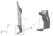
- FIG. 1 is a perspective view of a framework for an automobile according to an embodiment of the present invention.
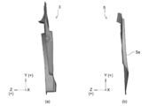
- FIG. 2 is a side view of the automotive frame according to the embodiment of the present invention.
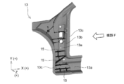
- FIG. 3 is a perspective view of an outer panel and an inner panel used in the automotive frame according to the present embodiment.
- FIG. 4 is a side view of an outer panel and an inner panel used for the automotive frame according to the present embodiment.
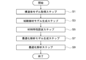
- FIG. 5 is a view showing a flowchart showing a process flow of shape optimization analysis of a stiffening member in the automobile frame part according to the present embodiment.
- FIG. 6 is a view showing an example of analysis conditions in shape optimization analysis of a stiffening member in the automobile frame part according to the present embodiment.
- FIG. 1 is a perspective view of a framework for an automobile according to an embodiment of the present invention.
- FIG. 2 is a side view of the automotive frame according to the embodiment of the present invention.
- FIG. 3 is a perspective view of an outer panel and an inner panel used in the
- FIG. 7 is a perspective view showing an example of an analysis result of shape optimization analysis of a stiffening member in the automobile frame part according to the present embodiment.
- FIG. 8 is a side view showing an example of an analysis result of shape optimization analysis of a stiffening member in the automobile frame part according to the present embodiment.
- FIG. 9 is a perspective view of the automotive frame component of Comparative Example 1 and Comparative Example 3 to be compared in Example 1.
- FIG. 10 is a side view of an automotive frame part according to Comparative Example 1 and Comparative Example 3 to be compared in Example 1.
- FIG. 11 is a view for explaining an automotive frame part according to Comparative Example 1 and Comparative Example 3 to be compared in Example 1.
- FIG. 12 is a perspective view of an outer panel used for a framework part of a vehicle according to Comparative Example 2 to be compared in Example 1.
- FIG. 13 is a side view of the automotive frame component according to Comparative Example 2 to be compared in Example 1.
- FIG. 14 is a view for explaining an automotive frame part according to Comparative Example 2 to be compared in Example 1.
- FIG. 15 is a side view of the automotive frame according to another aspect of the embodiment of the present invention.
- FIG. 16 is a perspective view of the automotive frame according to another aspect of the embodiment of the present invention.
- FIG. 17 is a perspective view showing an example of an analysis result of shape optimization analysis of a stiffening member in a vehicle frame part according to another aspect of the present embodiment.
- FIG. 18 is a view for explaining a load and constraint condition (a) in shape optimization analysis of a stiffening member and a displacement measurement point (b) in stiffness evaluation in Example 2; is there.
- FIG. 19 is a perspective view of a framework part of a vehicle according to Inventive Example 1 and Inventive Example 2 in the second embodiment.
- FIG. 20 is a side view of the automotive frame according to the invention example 13 in the second embodiment.
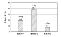
- FIG. 21 is a graph showing the results of weight change and improvement in stiffness with respect to a conventional automobile frame part in Example 2.
- FIG. 22 is a graph showing the results of the rigidity improvement rate per weight based on the conventional automobile frame component in Example 2.
- the A pillar lower 1 (view F in FIG. 1 (view seen from the rear side of the A pillar lower 1) shown in FIG. 1 and FIG. 2 according to the present embodiment has an outer panel 3 and an outer panel
- An automotive frame component having an inner panel 5 joined to the flange portion 3c of 3 and forming a closed cross section with the outer panel 3, and as shown in FIG. 2, between the outer panel 3 and the inner panel 5
- a plurality of stiffening members 7 one end of which is joined to the inner surface 3 d of the outer panel 3 and the other end to the inner surface 5 a of the inner panel 5.
- the shape is set based on the analysis result by the shape optimization analysis method, and the shape of the stiffening member 7 has a columnar shape in which both ends bulge.
- the coordinate axes shown in the figure show the arrangement when the A-pillar lower 1 is attached to a car, and the X-axis is the longitudinal direction of the car (automobile), the Y-axis is the vertical direction of the car, the Z-axis Indicates the width direction of the car.
- the outer panel 3 made of metal is substantially T-shaped in plan view, and has portions (portion P and portion Q in FIG. 1) corresponding to the horizontal sides of the substantially T-shape It has a part (part R in FIG. 1) corresponding to a side.
- the portion P extends to the front (X-axis minus direction in the figure) of the vehicle at the upper part of the outer panel 3 and is connected to other automotive frame components provided at the front of the vehicle.
- the portion Q extends to the upper rear of the outer panel 3 in the upper rear of the vehicle (X-axis plus direction and Y-axis plus direction in the figure), and is connected to the A pillar upper (not shown).
- the portion R extends from the horizontal side of the substantially T-shape to the lower side of the vehicle (in the negative direction of the Y axis in the figure). Furthermore, the lower end portion of the portion R is curved in an L shape toward the rear of the automobile (X-axis plus direction), and is connected to a rocker (not shown).
- part R is cross-sectional hat shape which consists of the top plate part 3a, the vertical wall part 3b, and the flange part 3c in all.
- the outer panel 3 having a hat-shaped cross section can be manufactured, for example, by press-forming a steel plate or an aluminum plate. Alternatively, it can be manufactured by casting such as aluminum die casting.
- the metal inner panel 5 is joined to the flange portion 3c of the outer panel 3 (see FIGS. 3 and 4) to form a closed cross section with the outer panel 3.
- the closed cross section is formed by being surrounded by the top plate portion 3 a and the vertical wall portion 3 b of the outer panel 3 and the inner surface 5 a of the inner panel 5, whereby a space is formed between the outer panel 3 and the inner panel 5. It is formed.
- the inner panel 5 can be manufactured by press-forming, for example, a steel plate or an aluminum plate similarly to the outer panel 3. Alternatively, it can be manufactured by casting such as aluminum die casting.
- the stiffening member 7 has one end on the inner surface 3 d of the outer panel 3 and the other end on the inner surface 5 a of the inner panel 5.
- a plurality of stiffening members 7 are provided.
- the shape of the stiffening member 7 has a columnar shape in which both ends bulge, and one end of the bulge is joined to the inner surface 3 d of the outer panel 3 and the other end is joined to the inner surface 5 a of the inner panel 5.
- the shape and arrangement of the stiffening member 7 are set based on the analysis result of shape optimization analysis described later, and by setting the shape and arrangement of the stiffening member 7 in this manner, the outer panel 3 and A bridge structure is formed in the space formed by the inner panel 5.
- the column having the shape of the stiffening member 7 is a cylindrical shape (FIG. 2 (c)) or a cylindrical shape having a flat cross section (FIG. 2). And (d)) a femur-shaped narrow in the longitudinal central portion and expanding from the central portion toward both ends.
- the shape of the stiffening member 7 is not limited to the shape shown in FIG. 2 (b), and may be only a column, and as shown in FIG. 2 (e), one end side of the elongated column is Or the like, or a stiffening member 7a having a larger bulging shape, or a stiffening member 7b having a short central narrow portion and a narrow neck.
- the cross section of the central portion of the column is not limited to a circular shape or a flat circular shape as shown in FIGS. 2C and 2D, and may be a polygon such as a triangle or a square. .
- the material of the stiffening member 7 is made of resin (hard plastic, fiber-reinforced plastic, etc.) from the viewpoint of weight in addition to the ease of processing into various shapes, and in particular CFRP (Carbon Fiber Reinforced Plastics) and GFRP (Glass Fiber Reinforced Plastics), which are reinforced resins, are more preferable in terms of rigidity improvement.
- resin hard plastic, fiber-reinforced plastic, etc.
- CFRP Carbon Fiber Reinforced Plastics
- GFRP Glass Fiber Reinforced Plastics
- the resin-made stiffening member 7 can be manufactured, for example by injection molding (injection molding) based on the analysis result obtained by shape optimization analysis, the manufacturing method of the stiffening member 7 is injection molding It is not limited to
- stiffening member 7 and the outer panel 3 and the inner panel 5 can be joined by adhesive or mechanical fastening.
- a predetermined shape is assumed in advance, and an optimum shape is not determined on the premise of the predetermined shape, and an optimum condition satisfying a given analysis condition is assumed without assuming the predetermined shape.
- the shape is determined by topology optimization or the like.
- topology optimization is to provide a design space of a certain size, incorporate a three-dimensional element in the design space, and leave a minimum of three-dimensional elements while satisfying given analysis conditions.
- the method is to obtain an optimal shape that satisfies the analysis condition.
- a method of directly constraining and applying a direct load to a three-dimensional element forming a design space is used.
- the outer panel 3 and Shape optimization analysis is performed on the analysis target with the space between the inner panel 5 and the stiffening member filled as the analysis target, and the optimum shape is stiffened based on the analysis result in which unnecessary portions are removed by the optimization analysis.
- the member 7 is set.
- Steps S1 to S9 can be executed on a computer.
- the structure model acquisition step S1 is a step of acquiring a structural model in which a framework part for an automobile is modeled using planar elements and / or three-dimensional elements.
- the structure model is intended for the A-pillar lower 1 (see FIGS. 1 and 2), which is an automotive frame component to be stiffened by setting the stiffening member 7.
- the stiffening member model generation step S3 is a step of generating a stiffening member model (not shown) composed of a three-dimensional element and coupled to the structure model.
- the stiffening member model generates a plurality of three-dimensional elements so as to fill the space formed by the outer panel 3 and the inner panel 5 as shown in FIG.
- the stiffening member model generated in this way is a target of optimization analysis in the optimization analysis model generation step S7 described later, and in the process of optimization analysis, a three-dimensional object located at a portion unnecessary for stiffening The elements are eliminated, leaving a three-dimensional element located at the site required for stiffening.
- the material property setting step S5 is a step of setting the material property of the stiffening member model generated in the stiffening member model generation step S3.
- stiffening member is a resin such as FRP (Fiber Reinforced Plastics) having in-plane anisotropy in its material properties
- anisotropy is taken into consideration.
- Material properties of the stiffening member model may be set.
- the optimization analysis model generation step S7 combines the stiffening member model generated in the stiffening member model generation step S3 with the structure model to generate an optimization analysis model (not shown).
- connection between the structure model and the stiffening member model is a node (node) of a solid element constituting the stiffening member model This can be done by sharing the node) and the node of the planar element of the structure model.
- connection between the structure model and the stiffening member model is not limited to the above-described sharing of nodes, and the structure model and the complement are connected via a rigid element, a beam element, a plane element, etc. It may be coupled to a rigid member model, and in any case, it may be coupled to transfer loads between the structural body model and the stiffening member model in shape optimization analysis. Just do it.
- the optimization analysis step S9 gives analysis conditions to the optimization analysis model generated in the optimization analysis model generation step S7, performs optimization analysis on the stiffening member model, and determines the optimum shape of the stiffening member model. It is a step to be sought.
- FIG. 6 shows the position where the load (1000 N) is applied and the position where it is restrained, displayed on the outer panel 3.
- the optimization analysis step S9 a structure obtained by modeling the outer panel 3 and the inner panel 5 of the A pillar lower Perform optimization analysis by applying load and constraint conditions to the optimization analysis model in which the stiffening member model is connected to the body model.
- a load of 1000 N is applied vertically downward to the end of the front end (corresponding to the portion P of the outer panel 3 in FIG. 6) of the A pillar lower, and the A pillar lower and the locker (not shown) It was decided to provide a load / restraint condition that completely constrains the bottom surface of the connection portion to be connected (corresponding to the portion enclosed by an ellipse in FIG. 6).
- the stiffness at the evaluation position is maximized as the objective condition of the optimization analysis, and the volume constraint rate of the stiffening member model is given as the constraint condition.
- the volume restriction rate may be selected from the range of 3 to 40%.
- the optimum shape 9 of the stiffening member model as shown in FIGS. 7 and 8 is obtained as the analysis result.
- FIG. 8 is displayed from the direction of the field of view F shown in FIG. 7, and the rear side (the front side of the paper surface of FIG. 8) of the outer panel 3 in the longitudinal direction (X axis) of the vehicle
- the rear portion of the outer panel 3 is displayed in a state of being inclined (in the positive direction of the Z axis) (see the X axis direction in FIG. 8).
- the stiffening member 7 shown in FIGS. 1 and 2 is set based on the optimum shape 9 of the stiffening member model which is the analysis result of the shape optimization analysis, and the optimum shape 9 is the outer panel It consists of a three-dimensional element remaining in the form of a column in the space formed between the and the inner panel. Then, a bridging structure is formed in the space between the outer panel 3 and the inner panel 5 by the stiffening member 7 whose shape and position are set based on the optimum shape 9, and the outer panel 3 and the inner panel 5 have a narrow central portion.
- the rigidity of the A-pillar lower 1 is improved by forming a cylindrical shape that bulges toward both ends to be joined with each other or a thigh-like shape that is a cylindrical shape whose cross section is flat.
- topology optimization can be applied to the optimization analysis in the optimization analysis step S9. Furthermore, when applying the density method in topology optimization, it is preferable to set the penalty coefficient of the element to 2 or more to perform discretization.
- analysis processing of optimization can be applied to optimization analysis in the optimization analysis step S9 by another calculation method.
- analysis software using a finite element method (commercially available finite element method) can be used, for example.
- the space made between the outer panel and the inner panel is made of resin whose shape and arrangement are set based on the analysis result by shape optimization analysis.
- the stiffening member is provided in the space formed between the outer panel and the inner panel, and the plate thickness of the outer panel and the inner panel is reduced. The weight can be reduced while maintaining the This point is demonstrated in Example 1 described later.
- the A pillar lower 1 sets a target condition that maximizes the rigidity at the evaluation position, and based on the result of performing the shape optimization analysis under the constraint that sets the volume constraint rate.
- the stiffening member 7 having the shape and arrangement shown in FIGS. 1 and 2 is set, as another aspect of the automotive frame component which is the A pillar lower according to the present embodiment, FIGS. It may be an A-pillar lower 31 in which a stiffening member 33 having a shape and arrangement shown as an example at 16 is set.
- the stiffening member 33 shown in FIGS. 15 and 16 uses the density method of topology optimization as a shape optimization analysis method, and sets a target condition that minimizes stiffness and maximizes rigidity of the stiffening member model, The shape and the arrangement are set based on the optimum shape 41 (FIG. 17) of the stiffening member model obtained by giving a constraint condition for setting a predetermined displacement amount at the evaluation position.
- 17 (a) is a plan view of the outer panel 3 on which the stiffening member 33 is disposed
- FIG. 17 (b) is a view from the direction of the visual field G in FIG. 17 (b). And the inside of the space formed by
- the optimum shape 41 of the stiffening member model shown in FIG. 17 joins the columnar portion 43 remaining in a columnar shape in the space formed between the outer panel 3 and the inner panel 5, the outer panel 3 and the inner panel 5 It has the flange residual part 45 (point-like part of a figure) which remained to the flange part. Furthermore, the columnar portion 43 has a columnar portion 43 a at the locker connection portion in the space, and a columnar portion 43 b above the central portion in the height direction of the A pillar lower 31.
- the stiffening member 33 a is disposed at the rocker connection portion based on the columnar portion 43 a of the optimum shape 41, and the height direction of the A-pillar lower 31 based on the columnar portion 43 b A stiffening member 33b is disposed at the top of the central portion.
- the stiffening member 33 since the columnar portion 43 in the optimum shape 41 is not a shape in which both ends are expanded as shown in FIG. 17B, the stiffening member 33 has the installability and its own durability. As shown in FIG. 16, it is in the shape of a dumbbell (like a dumbbell-like) in which both ends are expanded (bulged) in a columnar shape.
- the upper portion of the central portion in the height direction of the A-pillar lower 31 is considered to be the portion where the outer panel 3 and the inner panel 5 are most easily expanded in the vehicle width direction when a load is input and deformed. Therefore, it is assumed that the result of the columnar portion 43b remaining on the upper part of the central portion in the height direction of the A-pillar lower 31 is obtained by shape optimization analysis.
- the dumbbell-shaped stiffening member 33 As described above, by arranging the dumbbell-shaped stiffening member 33 at the most important place for deformation when a load is input, the rigidity is improved without causing an increase in weight due to the placement of the stiffening member. Furthermore, high rigidity can be achieved even when the outer panel 3 and the inner panel 5 are reduced in thickness by reducing the thickness thereof.
- the rigidity and weight reduction of the A-pillar lower 1 were evaluated.
- the A-pillar lower 1 according to the invention example 1 is formed by joining the outer panel 3 and the inner panel 5, and the outer panel 3 and the inner panel 5 are alloys of tensile strength 440MPa class and plate thickness 1.0 mm. It was manufactured by press-forming a hot-dip galvannealed steel sheet.
- the stiffening member 7 (FIG. 2) has a shape and a shape based on the analysis result (optimum shape 9, FIG. 7, FIG. 8) obtained by the shape optimization analysis method (see FIG. 5) described in the above embodiment.
- the position is set and manufactured by injection molding, and the material is glass fiber reinforced plastic (glass fiber reinforced nylon, glass fiber content 25%, elastic modulus 7 GPa).
- the topology remaining rate was 5%.
- the outer panel 3 is made of an aluminum die cast of 2.0 mm
- the inner panel 5 is an alloyed galvanized steel sheet having a tensile strength of 440 MPa class and a thickness of 1.0 mm.
- Inventive Example 2 is a press-formed product.
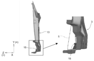
- the outer panel 13 and the inner panel 5 are manufactured by aluminum die casting, and the outer panel 13 is provided with a rib 15 as a stiffening member.
- the A-pillar lower 11 comprising the outer panel 3 and the inner panel 5 manufactured by press-forming a steel plate of tensile strength 440 MPa class in the same manner as the invention example
- the A-pillar lower 21 not provided is referred to as Comparative Example 2.
- the rib 15 of the comparative example 1 is a rib height less than the depth of the outer panel 3 in the longitudinal direction of the vehicle (automotive body), the height direction, and the vehicle width direction.
- Comparative Example 3 a resin member having the same shape as the aluminum rib 15 provided on the outer panel 13 of the comparative example 1 is adhered to the outer panel 3, which is formed of the outer panel 3 and the inner panel 5 formed by press forming a steel plate in the same manner as the comparative example 2
- a lower A-pillar (see FIGS. 9 to 11) is referred to as Comparative Example 3
- Comparative Example 4 is referred to as Comparative Example 4 except that the rib 15 is not provided.
- the outer panel 13 according to Comparative Example 1 and Comparative Example 3 has a hat shape in cross section including the top plate 13a, the vertical wall 13b and the flange 13c, and the inner panel 5 is joined to the flange 13c of the outer panel 13. Do.
- FIG. 11 shows the A-pillar lower 11 viewed from the direction of the field of view F shown in FIG. 9, and the rear side of the A-pillar lower 11 in the longitudinal direction (X axis) of the vehicle The rear portion of the A-pillar lower 11 is displayed in the state of being inclined in the plus direction of
- the A-pillar lower 21 is displayed in a state of being inclined in the Z-axis direction from the direction of the field of view F shown in FIG. 12.
- Table 1 shows materials of the outer panel, the inner panel and the stiffening member used in the invention examples 1 and 2 and the comparative examples 1 to 4.
- the ⁇ marks in the shape optimization column indicate that the stiffening member 7 set based on the analysis result by the shape optimization analysis is used, and the x marks indicate that the stiffening member is a rib 15 (see FIG. It shows that it is the same shape as 9).
- injection molding means that a resin-made stiffening member is formed by injection molding, and the molded stiffening member is adhered to the outer panel with an adhesive, and die casting is a rib
- the outer panel 13 (refer FIG. 9) which integrally molded 15 is represented.
- Example 1 the rigidity of the automotive frame component was evaluated as follows.
- an analysis model was generated for each of the A pillar lowers according to the invention example and the comparative example, and the load / restraint conditions shown in FIG. 6 were applied to the analysis model to perform CAE analysis.
- the load / restraint condition shown in FIG. 6 makes the bottom surface of the connection portion between the A-pillar lower and the locker completely constrained as in the load / restraint condition in the shape optimization analysis described in the above-described embodiment.
- a load of 1000 N is applied to the tip of the front end of the front end vertically downward (in the negative direction of the Y axis in FIG. 6).
- weight reduction of automotive frame parts based on the weight of the A pillar lower 11 according to Comparative Example 1 (hereinafter referred to as "reference weight"), the weight and reference weight of the A pillar lower according to the invention example and the comparison example The weight reduction rate was calculated by dividing the difference of by the reference weight.
- Table 1 shows the displacement at the evaluation position, and the weight and weight reduction ratio of the A-pillar lower.
- both the outer panel 13 and the inner panel 5 are manufactured by an aluminum die-cast having a thickness of 3.0 mm, and the rib 15 (thickness 1.5 mm) is integrally formed on the outer panel 13.
- the amount of displacement at the evaluation position was 0.5 mm, and the total weight of the entire A-pillar lower 11 was 4.71 kg.
- the displacement amount is smaller than that of the comparative example 1, and the rigidity is improved. Furthermore, by using a steel plate with a thickness of 1.0 mm for the outer panel 3 and the inner panel 5, their weight becomes 3.37 kg, which is better than the weight (3.74 kg) of the outer panel 13 and the inner panel 5 of Comparative Example 1. It became lightweight. Furthermore, in the invention example 1, since the resin-made stiffening member 7 (thickness 2.0 mm) is used, the weight of the stiffening member 7 is reduced as compared to the comparative example 1 (0.97 kg ⁇ 0.11 kg) . As a result, the total weight of the A-pillar lower 1 is 3.48 kg, and the weight reduction ratio is 26%, and the weight reduction is achieved without lowering the rigidity (without increasing the displacement amount) as compared with the comparative example 1. It became.
- Comparative Example 2 uses the outer panel 3 and the inner panel 5 obtained by press-forming a steel plate having a thickness of 1.2 mm, the weight is increased compared to the aluminum die-cast outer panel 13 and the inner panel 5 of Comparative Example 1. Since the stiffening member is not provided, the weight reduction ratio of 14% of the A-pillar lower 21 is achieved as compared with Comparative Example 1. However, the displacement at the evaluation position significantly increased to 8.6 mm, resulting in a significant decrease in rigidity.
- Comparative Example 3 an outer panel and an inner panel obtained by press-forming a steel plate having a thickness of 1.0 mm in the same manner as in Inventive Example 1 and further bonding GFRP ribs having the same shape as the rib shape of Comparative Example 1 to the outer panel
- the total weight of the A-pillar lower was 3.94 kg, and a weight reduction ratio of 16% was achieved as compared to Comparative Example 1.
- the amount of displacement at the evaluation position although the rigidity improvement is recognized to be reduced from 8.6 mm to 1.5 mm as compared with Comparative Example 2, the amount of displacement is compared with 0.5 mm of Comparative Example 1. The result is a large reduction in rigidity.
- the comparative example 4 is an evaluation result of only the housing of the comparative example 1 (without the rib 15), and although significant weight reduction is possible by using aluminum, the displacement amount is significantly increased because the Young's modulus of aluminum is low. , The rigidity decreased.
- the resin-made stiffening member whose shape and position are set based on the analysis result of the shape optimization analysis method is in the space formed by the outer panel and the inner panel. It has been proved that both the rigidity improvement and the weight reduction can be achieved by providing the
- the automotive frame component according to the present invention uses a steel plate, it is superior in terms of assembly property and cost as compared to an aluminum die-cast automotive frame component.
- the shape and arrangement of the stiffening member 33 shown in FIGS. 15 and 16 are set based on the analysis result of shape optimization analysis, and the rigidity and weight reduction of the A pillar lower 31 in which the stiffening member 33 is set. was evaluated.
- FIG. 18 shows an optimization analysis model 51 in shape optimization analysis.
- the optimization analysis model 51 sets a design space in a space formed by the outer panel 3 and the inner panel 5 and sets a stiffening member model in which the design space is modeled by a three-dimensional element. Then, they are connected by sharing the nodes of the three-dimensional element of the stiffening member model and the nodes of the planar elements of the outer panel 3 and the inner panel 5 so that the load is transmitted from the outer panel 3 and the inner panel 5 to the stiffening member model. ing.
- the material of the outer panel 3 and the inner panel 5 was a steel plate having a tensile strength of 440 MPa and a plate thickness of 0.8 mm
- the material of the stiffening member model was a resin having material properties shown in Table 2.
- a jig (jig) 57 is used as shown in FIG. 18 (a) in order to target rigidity by bending input from a suspension part of the vehicle. Constrain the lower part of the optimization analysis model 51, and give load and restraint conditions to input a load of 2000 N downward in the height direction (Y-axis minus direction) to the load input part provided on the top of the optimization analysis model 51.
- Shape optimization analysis was performed under the load / restraint condition and the target condition and constraint condition set as described above, and the optimum shape 41 of the stiffening member model shown in FIG. 17 described above was determined.
- the optimum shape 41 has a columnar portion 43 remaining in a columnar shape in a space formed between the outer panel 3 and the inner panel 5 and a flange remaining portion 45 remaining in a flange portion joining the outer panel 3 and the inner panel 5 .
- the columnar portion 43 remains above the central portion in the height direction of the A-pillar lower 31 and the columnar portion 43 a remaining in the locker connection portion (the portion to which the side sill is coupled) in the space. It has a columnar portion 43b.
- Invention example 11 CAD-models the both ends of the optimum shape 41 for the columnar portion 43a of the locker connection (see FIG. 15) and the columnar portion 43b above the center in the height direction as shown in FIG. Dumbbell-like stiffening members 33a and 33b are set in a disk shape.
- the remaining portions remain in the flange portion joining the outer panel 3 and the inner panel 5 in shape optimization analysis.
- the outer panel 3 and the inner panel 5 are further joined with an adhesive to the position of the remaining flange portion 45.
- Example 2 the A pillar lower in which the optimum shape 41 of the stiffening member model shown in FIG. 17 was set was Inventive Example 13, and the rigidity and weight reduction were evaluated in the same manner as Inventive Example 11 and Inventive Example 12.
- FIG. 20 does not display the inner panel 5 configuring the A-pillar lower, but displays the columnar portions 43 a and 43 b and the flange remaining portion 45 on the outer panel 3.
- Example 2 the rigidity of the automotive frame component was evaluated as follows.
- an analytical model for evaluating the rigidity of each of Inventive Example 11, Inventive Example 12 and Inventive Example 13 is generated, and the load / restraint condition shown in FIG. 18 is given to the analytical model to perform CAE analysis.
- the amount of displacement in the vertical direction downward (Y-axis minus direction in FIG. 18) at the displacement measurement point (FIG. 18B) provided at the tip of the end was determined.
- the load / restraint condition shown in FIG. 18 is provided at the tip end of the front end of the A pillar lower, with the locker connection portion to which the locker is connected being completely restrained, as in the load / restraint condition in the shape optimization analysis described above.
- a load of 2000 N was input to the load input unit.
- a value obtained by dividing the displacement amount at the displacement measurement point by the input load was calculated as a stiffness value.
- the rigidity value was calculated in the same manner as described above, assuming that the outer panel made of an aluminum plate having a plate thickness of 3.3 mm and the A pillar lower of the inner panel were the conventional example 1.
- the rigidity of the invention examples 11 and 12 and the invention example 13 is the rigidity improvement rate (%) based on the rigidity value of the prior art example 1, and the rigidity improvement rate by the weight of the stiffening member or stiffening member model.
- the rigidity improvement rate (%) per standardized weight was calculated.
- FIG. 21 The result of the rigidity improvement rate is shown in FIG. 21, and the result of the rigidity improvement rate per weight, in which the rigidity improvement rate is standardized by the weight of the stiffening member or the stiffening member model, is shown in FIG. Further, FIG. 21 also shows numerical values of weight change under each condition.
- the weight change of the entire A-pillar lower is -1.9 g to -1.8 kg, and the rigidity improvement rate per weight is also 844.2% / kg to 494.7% / although it decreased to kg, the rigidity improvement rate increased from 7.7% to 19.2%.
- the stiffening member 33 is provided based on the columnar portion 43 in the optimum shape 41, and the flange portion of the outer panel 3 and the inner panel 5 is further joined with an adhesive based on the flange remaining portion 45.
- the stiffening member 33 By making the stiffening member 33 into a dumbbell shape, the weight change of the entire A-pillar lower is -1.9 g to -1.8 kg, and the rigidity improvement rate per weight is 2770.2% / kg to 965.4% / Although it decreased to kg, the rigidity improvement rate increased from 29.1% to 38.7%.
- the present invention it is possible to reduce the deformation when a load acts on the automotive frame component, and to improve the rigidity of the automotive frame component. Furthermore, according to the present invention, it is possible to reduce the weight of the automotive frame component while maintaining the rigidity.
Landscapes
- Engineering & Computer Science (AREA)
- Chemical & Material Sciences (AREA)
- Combustion & Propulsion (AREA)
- Transportation (AREA)
- Mechanical Engineering (AREA)
- Manufacturing & Machinery (AREA)
- Architecture (AREA)
- Structural Engineering (AREA)
- Body Structure For Vehicles (AREA)
Abstract
An A-pillar lower part 1 which is an automotive frame part related to the present invention has: an outer panel 3 which is substantially T-shaped in plan view with a hat-shaped cross section intersecting with portions corresponding to the transverse and longitudinal sides of the substantial T shape and which comprises a top plate portion 3a, a vertical wall portion 3b, and a flange portion 3c; and an inner panel 5 which is joined to the flange portion 3c of the outer panel 3 to form a closed cross section with respect to the outer panel 3. The inner panel 5 and the outer panel 3 comprise metal and have within a space formed therebetween a plurality of resin stiffening members 7, each having one end joined to the inner surface 3d of the outer panel 3 and the other end joined to the inner surface 5a of the inner panel 5. The shape and arrangement of the plurality of stiffening members 7 are determined on the basis of the result of an analysis using a shape optimization analysis method, and each of the plurality of stiffening members 7 has a columnar shape or a columnar shape bulging at both ends.
Description
本発明は、金属からなる自動車用骨格部品(automotive frame parts)に関し、特に、アウタパネル(outer panel)とインナパネル(inner panel)により形成された空間内に樹脂製の補剛部材(stiffening member)が設けられているAピラーロア(pillar-lower)部品(parts)である自動車用骨格部品に関する。
The present invention relates to automotive frame parts made of metal, and in particular, a resin stiffening member is formed in a space formed by an outer panel and an inner panel. The invention relates to an automotive frame part which is an A-pillar-lower part provided.
自動車の金属からなる骨格部品の軽量化(weight reduction)方法に関して、多くの技術が存在する。例えば、超高張力鋼板(ultra high-tensile steel sheet)を適用した薄肉化、鋼板からアルミニウム板への素材置換などがある。鋼板からアルミニウム化されるプレス部品(press formed part)は年々増加する傾向にあるものの、素材(base metal sheet)コストの上昇は避けられないことから、最近では周辺の複数部品を取り込んだ形状部品をアルミダイカスト(aluminum die cast)法で製造し、金型(tool for press forming)費用等の削減によりコスト低減をはかる方法が適用されている。
There are many techniques relating to the method of weight reduction of automobile metal frame parts. For example, there are thinning using an ultra high-tensile steel sheet, material replacement from a steel plate to an aluminum plate, and the like. Although there is a tendency for the press formed parts to be aluminized from steel plates to increase year by year, the increase in base metal sheet costs can not be avoided. A method of manufacturing by aluminum die cast method and reducing cost by reducing tool for press forming cost is applied.
アルミダイカスト法で自動車の骨格部品を製造する技術として、例えば特許文献1には、特定形状を有するリブ(rib)が設けられているアルミダイカスト製の車両用Cピラーが開示されている。
For example, Patent Document 1 discloses a C-pillar made of aluminum die-cast for which a rib having a specific shape is provided as a technique for manufacturing a framework part of an automobile by an aluminum die-casting method.
アルミニウムの比重(specific gravity)は鋼のおよそ3分の1であるため軽量である一方、ヤング率(Young's modulus)も鋼と比較しておよそ3分の1であることから、従来と同等の部品の剛性(stiffness)を確保するために、アルミニウム製部品は鋼板製部品以上の板厚確保やリブ構造の付与といった重量増加の要因となる対応を取る必要がある。そのため、部品の生産性の低下やコスト増加など、軽量化効果を阻害するという問題があった。また、アルミダイカスト製の部品は一般にスポット溶接(spot welding)が困難であるため機械的締結(mechanical fastening)が必須となり、従来の自動車組立ラインでの組立が困難となる課題があった。
While the specific gravity of aluminum is about one third of that of steel and light in weight, the Young's modulus is also about one third of that of steel, so it is an equivalent part to the conventional one In order to secure the stiffness of the aluminum part, it is necessary to take measures to increase the weight, such as securing the plate thickness of the steel part or providing a rib structure. Therefore, there is a problem that the weight reduction effect is hindered, such as a decrease in productivity of parts and an increase in cost. In addition, since aluminum die cast parts are generally difficult to spot weld, mechanical fastening is essential, and there is a problem that assembly in a conventional automobile assembly line becomes difficult.
このように、アルミニウム製の自動車用骨格部品はそのヤング率の低さから、アルミニウムが低比重であることの有効性を充分に活用しきれておらず、十分に軽量化を達成することができない。
Thus, due to the low Young's modulus of aluminum frame parts made of aluminum, the effectiveness of the low specific gravity of aluminum can not be fully utilized, and weight reduction can not be achieved sufficiently. .
また、Aピラーロア部品は自動車の耐衝突特性(crash worthiness)において、最近注目されている前方斜め衝突(crash)にとって重要部品である。そのため、剛性の確保と軽量化の双方を満たすAピラーロア部品が望まれていた。
Also, the A-pillar lower part is an important part for the recent attention to frontal crash in the crash worthiness of automobiles. Therefore, there has been a demand for an A-pillar lower component which satisfies both of securing of rigidity and weight reduction.
さらに、アウタパネルとインナパネルからなる自動車用骨格部品を補剛する場合、一般に、アウタパネルとインナパネルを繋ぐことを目的として金属製のバルクヘッド(bulkhead)などの隔壁部品を入れることが多いが、これらは大きい部品となるため重量がかさみ、軽量とは言えない。また、アウタパネルとインナパネルから形成される空間内に発泡樹脂(foaming resin)などを全体に注入する方法もあるが、発泡樹脂自体の剛性が低いため充填するのみでは大きな剛性向上は期待できなくて、発泡樹脂を骨格部品内の全体に注入する必要があって、充填状態の確認が難しいため補修性に問題があった。
Furthermore, when stiffening automotive frame parts consisting of an outer panel and an inner panel, in general, bulkhead parts such as metal bulkheads are often inserted for the purpose of connecting the outer panel and the inner panel. Because it is a large part, it is heavy and can not be said to be lightweight. Although there is also a method of injecting a foamed resin or the like into the entire space formed by the outer panel and the inner panel, the rigidity of the foamed resin itself is low, and a large improvement in rigidity can not be expected by filling alone. Since the foamed resin needs to be injected into the whole of the frame part, it is difficult to check the filling state, and there is a problem in the repairability.
本発明は上記のような課題を解決するためになされたものであり、剛性を確保しつつ軽量化することができる自動車用骨格部品を提供することを目的とする。
The present invention has been made to solve the problems as described above, and it is an object of the present invention to provide an automotive frame component that can be reduced in weight while securing rigidity.
本発明に係る自動車用骨格部品は、平面視において略T字形状で、該略T字形状の横辺および縦辺に相当するそれぞれの部位に交差する断面が天板部(top portion)と縦壁部(side wall portion)とフランジ部(flange portion)とからなる断面ハット形状のアウタパネルと、該アウタパネルのフランジ部に接合されて該アウタパネルとの間に閉断面を形成するインナパネルとを有し、該インナパネルと前記アウタパネルは金属からなるAピラーロア部品である自動車用骨格部品であって、前記アウタパネルと前記インナパネルとの間に形成される空間内に、一端が前記アウタパネルの内面に、他端が前記インナパネルの内面にそれぞれ接合された樹脂製の複数の補剛部材を有し、該補剛部材の形状および配置は、形状最適化解析方法による解析結果に基づいて設定され、前記補剛部材の形状は、柱状(columnar)または両端部が膨隆(bulging)する柱状を有するものであることを特徴とするものである。
The frame part for an automobile according to the present invention is substantially T-shaped in a plan view, and a cross section intersecting respective portions corresponding to the horizontal side and the vertical side of the substantially T-shape is in the vertical direction with the top portion. It has an outer panel having a hat-shaped cross section consisting of a side wall portion and a flange portion, and an inner panel joined to the flange portion of the outer panel to form a closed cross section between the outer panel and the outer panel. The inner panel and the outer panel are frame parts for automobiles that are A-pillar lower parts made of metal, and one end is on the inner surface of the outer panel in the space formed between the outer panel and the inner panel. It has a plurality of resin stiffening members whose ends are respectively joined to the inner surface of the inner panel, and the shape and arrangement of the stiffening members are analyzed by a shape optimization analysis method. Is set based on the result, the shape of the stiffening member is characterized in that columnar (Columnar,) or both ends and has a columnar shape bulging (bulging).
本発明に係る自動車用骨格部品は、上記発明において、前記形状最適化(shape optimization)解析方法は、トポロジー最適化(topology optimization)の密度法(solid isotropic material with penalization method)を用いて、剛性が最大となる目的条件(objective function)を設定し、体積制約率(volume constraints rate)を3~40%の範囲から設定する制約条件(constraint function)のもとに解析することを特徴とするものである。
In the automotive frame component according to the present invention, in the above-mentioned invention, the shape optimization analysis method uses the solid isotropic material with penalization method of topology optimization, and the rigidity is improved. It is characterized in that analysis is performed under a constraint function in which a maximum objective condition (objective function) is set and a volume constraint rate is set from a range of 3 to 40%. is there.
本発明に係る自動車用骨格部品は、上記発明において、前記Aピラーロア部品である自動車用骨格部品は、ロッカー(locker)の先端部が接続されるロッカー接続部を有し、前記補剛部材は、前記空間内における前記ロッカー接続部と、前記Aピラーロア部品の高さ方向中央部よりも上部とに配置されていることを特徴とするものである。
In the automotive frame part according to the present invention, in the above invention, the automotive frame part which is the A-pillar lower part has a locker connection portion to which a tip end portion of a locker is connected, and the stiffening member is The locker connection portion in the space and the upper portion of the A-pillar lower part in the height direction are disposed.
本発明に係る自動車用骨格部品は、上記発明において、前記形状最適化解析方法は、トポロジー最適化の密度法を用いて、体積を最小にして剛性が最大となる目的条件を設定し、所定の変位量を設定する制約条件のもとに解析することを特徴とするものである。
In the automobile frame part according to the present invention, in the above-mentioned invention, the shape optimization analysis method sets a target condition which minimizes the volume and maximizes the rigidity by using the density method of topology optimization, It is characterized in that analysis is performed under the constraint conditions for setting the displacement amount.
本発明においては、平面視において略T字形状で、該略T字形状の横辺および縦辺に相当するそれぞれの部位に交差する断面が天板部と縦壁部とフランジ部とからなる断面ハット形状のアウタパネルと、該アウタパネルのフランジ部に接合されて該アウタパネルとの間に閉断面を形成するインナパネルとを有し、該インナパネルと前記アウタパネルは金属からなるAピラーロア部品である自動車用骨格部品であって、前記アウタパネルと前記インナパネルとの間に形成される空間内に、一端が前記アウタパネルの内面に、他端が前記インナパネルの内面にそれぞれ接合された樹脂製の複数の補剛部材を有し、該補剛部材の形状及び配置は、形状最適化解析方法による解析結果に基づいて設定され、前記補剛部材の形状は、柱状または両端部が膨隆する柱状を有することにより、該自動車用骨格部品に荷重が作用したときの変形を低減させ、該自動車用骨格部品の剛性を向上させることができる。さらに、本発明によれば、剛性を維持したまま自動車用骨格部品を軽量化することができる。
In the present invention, the cross section which crosses each portion corresponding to the horizontal side and the vertical side of the substantially T shape in plan view is a cross section including the top plate portion, the vertical wall portion, and the flange portion. A hat-shaped outer panel, and an inner panel joined to a flange portion of the outer panel to form a closed cross section between the outer panel and the inner panel, the inner panel and the outer panel being an A-pillar lower part made of metal A frame component, wherein a plurality of auxiliary members made of resin are respectively joined at one end to the inner surface of the outer panel and at the other end to the inner surface of the inner panel in a space formed between the outer panel and the inner panel. It has a rigid member, and the shape and arrangement of the stiffening member are set based on the analysis result by the shape optimization analysis method, and the shape of the stiffening member is a column or both ends By having the columnar to bulge, reducing the deformation when the load on the backbone parts for automobiles is applied, it is possible to improve the rigidity of the automobile frame components. Furthermore, according to the present invention, it is possible to reduce the weight of the automotive frame component while maintaining the rigidity.
本発明の実施の形態に係るAピラーロア部品について、図1および図2に基づいて以下に説明する。
The A-pillar lower part according to the embodiment of the present invention will be described below based on FIGS. 1 and 2.
本実施の形態に係る図1および図2に示すAピラーロア1(図1の視野F(Aピラーロア1の後部側から見た視野))は、平面視において略T字形状のアウタパネル3と、アウタパネル3のフランジ部3cに接合されてアウタパネル3との間に閉断面を形成するインナパネル5とを有する自動車用骨格部品であって、図2に示すとおり、アウタパネル3とインナパネル5との間に形成される空間内に、一端がアウタパネル3の内面3dに、他端がインナパネル5の内面5aにそれぞれ接合された複数の補剛部材7を有し、補剛部材7の形状及び配置は、形状最適化解析方法による解析結果に基づいて設定され、補剛部材7の形状は、両端部が膨隆する柱状を有するものである。
The A pillar lower 1 (view F in FIG. 1 (view seen from the rear side of the A pillar lower 1) shown in FIG. 1 and FIG. 2 according to the present embodiment has an outer panel 3 and an outer panel An automotive frame component having an inner panel 5 joined to the flange portion 3c of 3 and forming a closed cross section with the outer panel 3, and as shown in FIG. 2, between the outer panel 3 and the inner panel 5 In the space to be formed, there are provided a plurality of stiffening members 7 one end of which is joined to the inner surface 3 d of the outer panel 3 and the other end to the inner surface 5 a of the inner panel 5. The shape is set based on the analysis result by the shape optimization analysis method, and the shape of the stiffening member 7 has a columnar shape in which both ends bulge.
以下、各構成について説明する。なお、図中に示されている座標軸は、Aピラーロア1を自動車に取り付けたときの配置を示すものであり、X軸は自動車(automobile)の前後方向、Y軸は自動車の上下方向、Z軸は自動車の幅方向を示す。
Each component will be described below. The coordinate axes shown in the figure show the arrangement when the A-pillar lower 1 is attached to a car, and the X-axis is the longitudinal direction of the car (automobile), the Y-axis is the vertical direction of the car, the Z-axis Indicates the width direction of the car.
<アウタパネル>
金属からなるアウタパネル3は、図1に示すように、平面視において略T字形状であり、該略T字形状の横辺に相当する部位(図1中の部位Pおよび部位Q)と、縦辺に相当する部位(図1中の部位R)を有するものである。 <Outer panel>
As shown in FIG. 1, theouter panel 3 made of metal is substantially T-shaped in plan view, and has portions (portion P and portion Q in FIG. 1) corresponding to the horizontal sides of the substantially T-shape It has a part (part R in FIG. 1) corresponding to a side.
金属からなるアウタパネル3は、図1に示すように、平面視において略T字形状であり、該略T字形状の横辺に相当する部位(図1中の部位Pおよび部位Q)と、縦辺に相当する部位(図1中の部位R)を有するものである。 <Outer panel>
As shown in FIG. 1, the
部位Pは、アウタパネル3の上部において自動車の前方(図中のX軸マイナス方向)に延出し、該自動車の前部に設けられる他の自動車用骨格部品に接続する。
The portion P extends to the front (X-axis minus direction in the figure) of the vehicle at the upper part of the outer panel 3 and is connected to other automotive frame components provided at the front of the vehicle.
部位Qは、アウタパネル3の上部において自動車の後上方(図中のX軸プラス方向およびY軸プラス方向)に延出し、Aピラーアッパ(図示なし)に接続する。
The portion Q extends to the upper rear of the outer panel 3 in the upper rear of the vehicle (X-axis plus direction and Y-axis plus direction in the figure), and is connected to the A pillar upper (not shown).
部位Rは、前記略T字形状の横辺から自動車の下方(図中のY軸マイナス方向)に延出している。さらに、部位Rの下端部は、自動車の後方(X軸プラス方向)に向かってL字形状に湾曲し、ロッカ-(図示なし)に接続する。
The portion R extends from the horizontal side of the substantially T-shape to the lower side of the vehicle (in the negative direction of the Y axis in the figure). Furthermore, the lower end portion of the portion R is curved in an L shape toward the rear of the automobile (X-axis plus direction), and is connected to a rocker (not shown).
そして、部位P、部位Qおよび部位Rに交差する断面は、いずれも天板部3aと縦壁部3bとフランジ部3cとからなる断面ハット形状である。なお、断面ハット形状のアウタパネル3は、例えば、鋼板やアルミニウム板をプレス成形することにより製造することができる。あるいはアルミダイカストのような鋳造(casting)により製造可能である。
And the cross section which cross | intersects the site | part P, the site | part Q, and the site | part R is cross-sectional hat shape which consists of the top plate part 3a, the vertical wall part 3b, and the flange part 3c in all. The outer panel 3 having a hat-shaped cross section can be manufactured, for example, by press-forming a steel plate or an aluminum plate. Alternatively, it can be manufactured by casting such as aluminum die casting.
<インナパネル>
金属からなるインナパネル5は、アウタパネル3のフランジ部3cに接合され(図3および図4参照)、アウタパネル3との間に閉断面を形成する。 <Inner panel>
The metalinner panel 5 is joined to the flange portion 3c of the outer panel 3 (see FIGS. 3 and 4) to form a closed cross section with the outer panel 3.
金属からなるインナパネル5は、アウタパネル3のフランジ部3cに接合され(図3および図4参照)、アウタパネル3との間に閉断面を形成する。 <Inner panel>
The metal
閉断面は、アウタパネル3の天板部3aおよび縦壁部3bとインナパネル5の内面5aとで囲まれて形成されたものであり、これにより、アウタパネル3とインナパネル5との間に空間が形成される。
The closed cross section is formed by being surrounded by the top plate portion 3 a and the vertical wall portion 3 b of the outer panel 3 and the inner surface 5 a of the inner panel 5, whereby a space is formed between the outer panel 3 and the inner panel 5. It is formed.
なお、アウタパネル3と同様に、インナパネル5は、例えば鋼板やアルミニウム板をプレス成形することにより製造することができる。あるいはアルミダイカストのような鋳造により製造可能である。
In addition, the inner panel 5 can be manufactured by press-forming, for example, a steel plate or an aluminum plate similarly to the outer panel 3. Alternatively, it can be manufactured by casting such as aluminum die casting.
<補剛部材>
補剛部材7は、図2に示すように、アウタパネル3とインナパネル5との間に形成された空間内において、一端がアウタパネル3の内面3dに、他端がインナパネル5の内面5aにそれぞれ接合されたものであり、複数の補剛部材7が設けられている。 <Stiffening member>
As shown in FIG. 2, in the space formed between theouter panel 3 and the inner panel 5, the stiffening member 7 has one end on the inner surface 3 d of the outer panel 3 and the other end on the inner surface 5 a of the inner panel 5. A plurality of stiffening members 7 are provided.
補剛部材7は、図2に示すように、アウタパネル3とインナパネル5との間に形成された空間内において、一端がアウタパネル3の内面3dに、他端がインナパネル5の内面5aにそれぞれ接合されたものであり、複数の補剛部材7が設けられている。 <Stiffening member>
As shown in FIG. 2, in the space formed between the
補剛部材7の形状は、両端部が膨隆する柱状を有するものであり、該膨隆した一端がアウタパネル3の内面3dに、他端がインナパネル5の内面5aに接合されている。
The shape of the stiffening member 7 has a columnar shape in which both ends bulge, and one end of the bulge is joined to the inner surface 3 d of the outer panel 3 and the other end is joined to the inner surface 5 a of the inner panel 5.
補剛部材7の形状および配置は、後述する形状最適化解析の解析結果に基づいて設定されたものであり、補剛部材7の形状および配置がこのように設定されることで、アウタパネル3とインナパネル5とで形成される空間内に橋渡し構造(bridge structure)が形成される。
The shape and arrangement of the stiffening member 7 are set based on the analysis result of shape optimization analysis described later, and by setting the shape and arrangement of the stiffening member 7 in this manner, the outer panel 3 and A bridge structure is formed in the space formed by the inner panel 5.
なお、補剛部材7の形状である両端部が膨隆する柱状としては、例えば、図2(b)に示すように、円柱状(図2(c))又は断面が扁平した円柱状(図2(d))であって、長手方向の中央部が細く、該中央部から両端に向かって膨隆する大腿骨状(femur-shaped)が挙げられる。
For example, as shown in FIG. 2 (b), the column having the shape of the stiffening member 7 is a cylindrical shape (FIG. 2 (c)) or a cylindrical shape having a flat cross section (FIG. 2). And (d)) a femur-shaped narrow in the longitudinal central portion and expanding from the central portion toward both ends.
もっとも、補剛部材7の形状は、図2(b)に示す形状に限られるものではなく、柱状のみであってもよく、図2(e)に示すように、細長い柱状の一端側の方がより大きく膨隆している補剛部材7aや、中央部が短かく細くくびれている補剛部材7bのようなものであってもよい。さらに、柱状の中央部の断面は、図2(c)、(d)に示すように円形状や扁平円形状などに限られるものではなく、三角形や四角形のような多角形であってもよい。
However, the shape of the stiffening member 7 is not limited to the shape shown in FIG. 2 (b), and may be only a column, and as shown in FIG. 2 (e), one end side of the elongated column is Or the like, or a stiffening member 7a having a larger bulging shape, or a stiffening member 7b having a short central narrow portion and a narrow neck. Furthermore, the cross section of the central portion of the column is not limited to a circular shape or a flat circular shape as shown in FIGS. 2C and 2D, and may be a polygon such as a triangle or a square. .
さらに、補剛部材7の材質に関しては、様々な形状に加工することの容易さに加えて重量の観点から、樹脂(硬質プラスチック、繊維強化樹脂(fiber-reinforced plastic)など)とし、特に、繊維強化樹脂であるCFRP(Carbon Fiber Reinforced Plastics;炭素繊維強化樹脂)やGFRP(Glass Fiber Reinforced Plastics;ガラス繊維強化樹脂)は、剛性向上の面からより好ましい。
Furthermore, the material of the stiffening member 7 is made of resin (hard plastic, fiber-reinforced plastic, etc.) from the viewpoint of weight in addition to the ease of processing into various shapes, and in particular CFRP (Carbon Fiber Reinforced Plastics) and GFRP (Glass Fiber Reinforced Plastics), which are reinforced resins, are more preferable in terms of rigidity improvement.
そして、樹脂製の補剛部材7は、形状最適化解析で得られた解析結果に基づいて、例えば射出成形(injection molding)により製造することができるが、補剛部材7の製造方法は射出成形に限定するものではない。
And although the resin-made stiffening member 7 can be manufactured, for example by injection molding (injection molding) based on the analysis result obtained by shape optimization analysis, the manufacturing method of the stiffening member 7 is injection molding It is not limited to
また、補剛部材7とアウタパネル3およびインナパネル5とは、接着(adhesive)または機械的締結により接合することができる。
Further, the stiffening member 7 and the outer panel 3 and the inner panel 5 can be joined by adhesive or mechanical fastening.
<形状最適化解析方法>
次に、補剛部材7の形状および位置を設定する形状最適化解析方法について説明する。 <Shape optimization analysis method>
Next, a shape optimization analysis method for setting the shape and position of the stiffeningmember 7 will be described.
次に、補剛部材7の形状および位置を設定する形状最適化解析方法について説明する。 <Shape optimization analysis method>
Next, a shape optimization analysis method for setting the shape and position of the stiffening
形状最適化解析方法とは、予め所定の形状を想定し、該所定の形状を前提として最適な形状を求めるものではなく、所定の形状を想定することなく、与えられた解析条件を満たす最適な形状をトポロジー最適化等により求めるものである。
With the shape optimization analysis method, a predetermined shape is assumed in advance, and an optimum shape is not determined on the premise of the predetermined shape, and an optimum condition satisfying a given analysis condition is assumed without assuming the predetermined shape. The shape is determined by topology optimization or the like.
また、トポロジー最適化とは、ある程度の大きさの設計空間を設け、当該設計空間に立体要素を組み込み、与えられた解析条件を満たしつつ必要最小限の立体要素(three-dimensional element)を残すことで当該解析条件を満たす最適形状を得るという方法である。トポロジー最適化においては、設計空間をなす立体要素に直接拘束を行い、直接荷重を加えるという方法が用いられる。
Moreover, topology optimization is to provide a design space of a certain size, incorporate a three-dimensional element in the design space, and leave a minimum of three-dimensional elements while satisfying given analysis conditions. The method is to obtain an optimal shape that satisfies the analysis condition. In topology optimization, a method of directly constraining and applying a direct load to a three-dimensional element forming a design space is used.
本発明の実施の形態においては、アウタパネル3とインナパネル5との間に形成される空間内に樹脂製の補剛部材を設定することによりAピラーロア1の剛性を向上させるため、前記アウタパネル3とインナパネル5との間の空間を前記補剛部材で埋めたものを解析対象として形状最適化解析を行い、その最適化解析により不要な部分を取り除いた解析結果に基づいて最適な形状の補剛部材7を設定する。
In the embodiment of the present invention, in order to improve the rigidity of the A pillar lower 1 by setting a resin-made stiffening member in the space formed between the outer panel 3 and the inner panel 5, the outer panel 3 and Shape optimization analysis is performed on the analysis target with the space between the inner panel 5 and the stiffening member filled as the analysis target, and the optimum shape is stiffened based on the analysis result in which unnecessary portions are removed by the optimization analysis. The member 7 is set.
ここで、形状最適化解析は、図5に示すステップS1からステップS9を実行することにより行うことができる。以下、図5に示す各ステップにおける処理について説明する。なお、ステップS1からステップS9は、コンピュータ上で実行することができる。
Here, shape optimization analysis can be performed by executing steps S1 to S9 shown in FIG. The process in each step shown in FIG. 5 will be described below. Steps S1 to S9 can be executed on a computer.
≪構造体モデル取得ステップ≫
構造体モデル取得ステップS1は、平面要素及び/又は立体要素を用いて自動車用骨格部品をモデル化した構造体モデル(structural model)を取得するステップである。 «Structure model acquisition step»
The structure model acquisition step S1 is a step of acquiring a structural model in which a framework part for an automobile is modeled using planar elements and / or three-dimensional elements.
本実施の形態において、構造体モデルは、補剛部材7を設定することにより補剛する自動車用骨格部品であるAピラーロア1(図1および図2参照)を対象としたものである。
In the present embodiment, the structure model is intended for the A-pillar lower 1 (see FIGS. 1 and 2), which is an automotive frame component to be stiffened by setting the stiffening member 7.
≪補剛部材モデル生成ステップ≫
補剛部材モデル生成ステップS3は、立体要素からなり前記構造体モデルと結合する補剛部材モデル(図示なし)を生成するステップである。 «Step for generating stiffening member model»
The stiffening member model generation step S3 is a step of generating a stiffening member model (not shown) composed of a three-dimensional element and coupled to the structure model.
補剛部材モデル生成ステップS3は、立体要素からなり前記構造体モデルと結合する補剛部材モデル(図示なし)を生成するステップである。 «Step for generating stiffening member model»
The stiffening member model generation step S3 is a step of generating a stiffening member model (not shown) composed of a three-dimensional element and coupled to the structure model.
本実施の形態において、前記補剛部材モデルは、図2に示すようなアウタパネル3とインナパネル5とで形成される空間を埋めるように複数の立体要素を生成する。
In the present embodiment, the stiffening member model generates a plurality of three-dimensional elements so as to fill the space formed by the outer panel 3 and the inner panel 5 as shown in FIG.
このように生成された補剛部材モデルは、後述する最適化解析モデル生成ステップS7における最適化解析の対象となるものであり、最適化解析の過程において、補剛に不要な部位に位置する立体要素は消去され、補剛に必要となる部位に位置する立体要素が残存する。
The stiffening member model generated in this way is a target of optimization analysis in the optimization analysis model generation step S7 described later, and in the process of optimization analysis, a three-dimensional object located at a portion unnecessary for stiffening The elements are eliminated, leaving a three-dimensional element located at the site required for stiffening.
≪材料特性(material property)設定ステップ≫
材料特性設定ステップS5は、補剛部材モデル生成ステップS3において生成した補剛部材モデルの材料特性を設定するステップである。 << material property (material property) setting step >>
The material property setting step S5 is a step of setting the material property of the stiffening member model generated in the stiffening member model generation step S3.
材料特性設定ステップS5は、補剛部材モデル生成ステップS3において生成した補剛部材モデルの材料特性を設定するステップである。 << material property (material property) setting step >>
The material property setting step S5 is a step of setting the material property of the stiffening member model generated in the stiffening member model generation step S3.
本発明では、樹脂製の補剛部材を対象としているため、材料特性設定ステップS5において前記補剛部材モデルに設定する材料特性としては、樹脂のヤング率、ポアソン比(Poisson's ratio)および比重などが挙げられる。
In the present invention, since a resin-made stiffening member is targeted, as a material property to be set to the stiffening member model in the material property setting step S5, Young's modulus, Poisson's ratio, specific gravity and the like of the resin It can be mentioned.
さらに、前記補剛部材が、例えばFRP(Fiber Reinforced Plastics;繊維強化樹脂)のようにその材料特性が面内異方性(in‐plane anisotropy)を有する樹脂の場合は、異方性を考慮して補剛部材モデルの材料特性を設定すればよい。
Furthermore, in the case where the stiffening member is a resin such as FRP (Fiber Reinforced Plastics) having in-plane anisotropy in its material properties, anisotropy is taken into consideration. Material properties of the stiffening member model may be set.
≪最適化解析モデル生成ステップ≫
最適化解析モデル生成ステップS7は、補剛部材モデル生成ステップS3において生成した補剛部材モデルを前記構造体モデルに結合して最適化解析モデル(図示なし)を生成するものである。 «Optimization analysis model generation step»
The optimization analysis model generation step S7 combines the stiffening member model generated in the stiffening member model generation step S3 with the structure model to generate an optimization analysis model (not shown).
構造体モデルと補剛部材モデルとの結合は、例えば、構造体モデルが平面要素(two-dimensional element)でモデル化されている場合、補剛部材モデルを構成する立体要素のノード(節点)(node)と構造体モデルの平面要素のノードとを共有することにより行うことができる。
For example, when the structure model is modeled by a two-dimensional element, the connection between the structure model and the stiffening member model is a node (node) of a solid element constituting the stiffening member model This can be done by sharing the node) and the node of the planar element of the structure model.
もっとも、構造体モデルと補剛部材モデルとの結合は、上記のノード共有に限るものではなく、剛体要素(rigid element)、梁要素(beam element)、平面要素などを介して構造体モデルと補剛部材モデルとを結合するものであってもよく、いずれにおいても、形状最適化解析において構造体モデルと補剛部材モデルとの間で荷重(load)が伝達されるように結合するものであればよい。
However, the connection between the structure model and the stiffening member model is not limited to the above-described sharing of nodes, and the structure model and the complement are connected via a rigid element, a beam element, a plane element, etc. It may be coupled to a rigid member model, and in any case, it may be coupled to transfer loads between the structural body model and the stiffening member model in shape optimization analysis. Just do it.
≪最適化解析ステップ≫
最適化解析ステップS9は、最適化解析モデル生成ステップS7において生成した最適化解析モデルに解析条件を与え、前記補剛部材モデルを対象として最適化解析を行い、該補剛部材モデルの最適形状を求めるステップである。 «Optimization analysis step»
The optimization analysis step S9 gives analysis conditions to the optimization analysis model generated in the optimization analysis model generation step S7, performs optimization analysis on the stiffening member model, and determines the optimum shape of the stiffening member model. It is a step to be sought.
最適化解析モデルに与える解析条件としては、荷重を付加する位置や拘束位置を与える荷重・拘束条件と、最適化解析の目的に応じて設定する目的条件および制約条件がある。
As analysis conditions given to the optimization analysis model, there are load / restraint conditions giving a position to which a load is applied and a constraint position, and objective conditions and constraints set according to the purpose of optimization analysis.
目的条件である自動車用骨格部品の剛性を評価するためには、いくつも荷重の入力条件が考えられるが、自動車用骨格部品を設置する自動車の剛性を種々評価した結果、最適化解析ステップS9においては、予め求めておいた実際の走行時に変位が最も大きくなる荷重を入力条件として与え、該荷重入力条件のもとで補剛部材モデルの最適な形状および位置を求めるものとした。
In order to evaluate the rigidity of automotive frame parts, which is the target condition, there are several possible input conditions of load, but various evaluations of the rigidity of the automobile on which the automotive frame parts are installed result in optimization analysis step S9. In the above, a load which gives the largest displacement during actual traveling, which is obtained in advance, is given as an input condition, and the optimum shape and position of the stiffening member model are obtained under the load input condition.
最適化解析モデルに与える荷重・拘束条件の一例を、図6に示す。図6は、荷重(1000N)を負荷する位置と拘束する位置を、アウタパネル3上に表示したものであるが、最適化解析ステップS9では、Aピラーロアのアウタパネル3およびインナパネル5をモデル化した構造体モデルに補剛部材モデルを結合した最適化解析モデルに荷重・拘束条件を与えて最適化解析を行う。
An example of the load / restraint condition given to the optimization analysis model is shown in FIG. FIG. 6 shows the position where the load (1000 N) is applied and the position where it is restrained, displayed on the outer panel 3. In the optimization analysis step S9, a structure obtained by modeling the outer panel 3 and the inner panel 5 of the A pillar lower Perform optimization analysis by applying load and constraint conditions to the optimization analysis model in which the stiffening member model is connected to the body model.
本実施の形態では、Aピラーロアのフロントエンド部(図6中におけるアウタパネル3の部位Pに相当)の先端部に鉛直方向下向きに1000Nの荷重を負荷し、Aピラーロアとロッカー(図示なし)とが接続する接続部の底面(図6において楕円で囲んだ部位に相当)を完全拘束する荷重・拘束条件を与えることとした。
In the present embodiment, a load of 1000 N is applied vertically downward to the end of the front end (corresponding to the portion P of the outer panel 3 in FIG. 6) of the A pillar lower, and the A pillar lower and the locker (not shown) It was decided to provide a load / restraint condition that completely constrains the bottom surface of the connection portion to be connected (corresponding to the portion enclosed by an ellipse in FIG. 6).
さらに本実施の形態では、最適化解析の目的条件として評価位置における剛性を最大、制約条件として補剛部材モデルの体積制約率を与えた。なお、補剛部材7による重量増とAピラーロア1の薄肉化(thinning)による軽量化を考慮して、体積制約率は3~40%の範囲から選択するとよい。
Furthermore, in the present embodiment, the stiffness at the evaluation position is maximized as the objective condition of the optimization analysis, and the volume constraint rate of the stiffening member model is given as the constraint condition. In view of the weight increase by the stiffening member 7 and the weight reduction by thinning of the A-pillar lower 1, the volume restriction rate may be selected from the range of 3 to 40%.
このように、解析条件として荷重・拘束条件と目的条件および制約条件を与えて最適化解析を行うことにより、図7および図8に示すような補剛部材モデルの最適形状9が解析結果として得られる。
As described above, by performing the optimization analysis with the load / restraint condition, the target condition and the constraint condition as analysis conditions, the optimum shape 9 of the stiffening member model as shown in FIGS. 7 and 8 is obtained as the analysis result. Be
ここで、図8は、図7に示す視野Fの方向から表示したものであり、自動車の前後方向(X軸)におけるアウタパネル3の後部側(図8の紙面手前)を自動車の幅方向室内側(Z軸のプラス方向)に傾けた状態で(図8のX軸方向を参照)、アウタパネル3の後部が表示されている。
Here, FIG. 8 is displayed from the direction of the field of view F shown in FIG. 7, and the rear side (the front side of the paper surface of FIG. 8) of the outer panel 3 in the longitudinal direction (X axis) of the vehicle The rear portion of the outer panel 3 is displayed in a state of being inclined (in the positive direction of the Z axis) (see the X axis direction in FIG. 8).
前述のとおり、図1および図2に示す補剛部材7は、形状最適化解析の解析結果である補剛部材モデルの最適形状9に基づいて設定されたものであり、最適形状9は、アウタパネルとインナパネルとの間に形成された空間内に柱状に残存した立体要素からなる。そして、最適形状9に基づいて形状と位置が設定された補剛部材7によりアウタパネル3とインナパネル5との間の空間内に橋渡し構造が形成され、中央部が細く、アウタパネル3およびインナパネル5と接合する両端に向かって膨隆する円柱状またはその断面が扁平した円柱である大腿骨状の形状を成してAピラーロア1の剛性が向上する。
As described above, the stiffening member 7 shown in FIGS. 1 and 2 is set based on the optimum shape 9 of the stiffening member model which is the analysis result of the shape optimization analysis, and the optimum shape 9 is the outer panel It consists of a three-dimensional element remaining in the form of a column in the space formed between the and the inner panel. Then, a bridging structure is formed in the space between the outer panel 3 and the inner panel 5 by the stiffening member 7 whose shape and position are set based on the optimum shape 9, and the outer panel 3 and the inner panel 5 have a narrow central portion. The rigidity of the A-pillar lower 1 is improved by forming a cylindrical shape that bulges toward both ends to be joined with each other or a thigh-like shape that is a cylindrical shape whose cross section is flat.
なお、最適化解析ステップS9における最適化解析には、トポロジー最適化を適用することができる。さらに、トポロジー最適化において密度法を適用する場合、要素のペナルティ係数(penalty coefficient)を2以上に設定して離散化(discretization)を行うようにすることが好ましい。
Note that topology optimization can be applied to the optimization analysis in the optimization analysis step S9. Furthermore, when applying the density method in topology optimization, it is preferable to set the penalty coefficient of the element to 2 or more to perform discretization.
もっとも、最適化解析ステップS9における最適化解析には、他の計算方式により最適化の解析処理を適用することができる。最適化の解析処理を行うものとしては、例えば、市販されている有限要素法(finite element method)を用いた解析ソフトを使用することができる。
However, analysis processing of optimization can be applied to optimization analysis in the optimization analysis step S9 by another calculation method. As what performs analysis processing of optimization, analysis software using a finite element method (commercially available finite element method) can be used, for example.
以上、本実施の形態に係る自動車用骨格部品によれば、アウタパネルとインナパネルとの間に形成された空間に、形状最適化解析による解析結果に基づいて形状と配置が設定された樹脂製の補剛部材を設けることで、該自動車用骨格部品に荷重が作用したときの変形を低減させ、該自動車用骨格部品の剛性を向上させることができる。
As described above, according to the automotive frame component according to the present embodiment, the space made between the outer panel and the inner panel is made of resin whose shape and arrangement are set based on the analysis result by shape optimization analysis. By providing the stiffening member, it is possible to reduce the deformation when a load acts on the automotive frame component, and to improve the rigidity of the automotive frame component.
さらに、本実施の形態に係る自動車用骨格部品によれば、アウタパネルとインナパネルとの間に形成された空間に補剛部材を設けるとともに、前記アウタパネルとインナパネルの板厚を減じることにより、剛性を維持したまま軽量化することができる。この点については後述の実施例1にて実証する。
Furthermore, according to the automotive frame component according to the present embodiment, the stiffening member is provided in the space formed between the outer panel and the inner panel, and the plate thickness of the outer panel and the inner panel is reduced. The weight can be reduced while maintaining the This point is demonstrated in Example 1 described later.
また、本実施の形態に係るAピラーロア1は、評価位置における剛性を最大にする目的条件を設定し、体積制約率を設定する制約条件のもとに形状最適化解析を行った結果に基づいて、図1および図2に示す形状および配置の補剛部材7を設定したものであったが、本実施の形態に係るAピラーロアである自動車用骨格部品の他の態様としては、図15および図16に一例として示す形状と配置の補剛部材33を設定したAピラーロア31であってもよい。
In addition, the A pillar lower 1 according to the present embodiment sets a target condition that maximizes the rigidity at the evaluation position, and based on the result of performing the shape optimization analysis under the constraint that sets the volume constraint rate. Although the stiffening member 7 having the shape and arrangement shown in FIGS. 1 and 2 is set, as another aspect of the automotive frame component which is the A pillar lower according to the present embodiment, FIGS. It may be an A-pillar lower 31 in which a stiffening member 33 having a shape and arrangement shown as an example at 16 is set.
図15および図16に示す補剛部材33は、形状最適化解析方法としてトポロジー最適化の密度法を用いて、補剛部材モデルの体積を最小にして剛性が最大となる目的条件を設定し、評価位置における所定の変位量を設定する制約条件を与えて求めた補剛部材モデルの最適形状41(図17)に基づいて形状と配置を設定したものである。なお、図17(a)は、補剛部材33を配置したアウタパネル3を平面視したものであり、図17(b)は、図17(b)の視野Gの方向からアウタパネル3とインナパネル5とで形成される空間内を表示したものである。
The stiffening member 33 shown in FIGS. 15 and 16 uses the density method of topology optimization as a shape optimization analysis method, and sets a target condition that minimizes stiffness and maximizes rigidity of the stiffening member model, The shape and the arrangement are set based on the optimum shape 41 (FIG. 17) of the stiffening member model obtained by giving a constraint condition for setting a predetermined displacement amount at the evaluation position. 17 (a) is a plan view of the outer panel 3 on which the stiffening member 33 is disposed, and FIG. 17 (b) is a view from the direction of the visual field G in FIG. 17 (b). And the inside of the space formed by
また、図17に示す補剛部材モデルの最適形状41は、アウタパネル3とインナパネル5の間に形成された空間内に柱状に残存した柱状部43と、アウタパネル3とインナパネル5とを接合するフランジ部に残存したフランジ残存部45(図の点状部分)を有する。さらに、柱状部43は、前記空間内における前記ロッカー接続部にある柱状部43aと、Aピラーロア31の高さ方向中央部よりも上部にある柱状部43bとを有する。
Further, the optimum shape 41 of the stiffening member model shown in FIG. 17 joins the columnar portion 43 remaining in a columnar shape in the space formed between the outer panel 3 and the inner panel 5, the outer panel 3 and the inner panel 5 It has the flange residual part 45 (point-like part of a figure) which remained to the flange part. Furthermore, the columnar portion 43 has a columnar portion 43 a at the locker connection portion in the space, and a columnar portion 43 b above the central portion in the height direction of the A pillar lower 31.
そこで、Aピラーロア31は、最適形状41の柱状部43aに基づいて、図15に示すように、ロッカー接続部に補剛部材33aが配置され、柱状部43bに基づいてAピラーロア31の高さ方向中央部の上部に補剛部材33bが配置されている。さらに、最適形状41における柱状部43は、図17(b)に示すように両端部が膨隆した形状ではないので、補剛部材33は、設置性およびそれ自身の耐久性を持たせるために、図16に示すように両端部を広げた(膨隆した)柱状であるダンベル状(dumbbell-like)としている。
Therefore, in the A-pillar lower 31, as shown in FIG. 15, the stiffening member 33 a is disposed at the rocker connection portion based on the columnar portion 43 a of the optimum shape 41, and the height direction of the A-pillar lower 31 based on the columnar portion 43 b A stiffening member 33b is disposed at the top of the central portion. Further, since the columnar portion 43 in the optimum shape 41 is not a shape in which both ends are expanded as shown in FIG. 17B, the stiffening member 33 has the installability and its own durability. As shown in FIG. 16, it is in the shape of a dumbbell (like a dumbbell-like) in which both ends are expanded (bulged) in a columnar shape.
前述のとおり、自動車用骨格部品を補剛するに際し、やみくもに補剛部品として隔壁構造を設けることは重量増につながり好ましくない。自動車用骨格部品に荷重が入力する場合、該自動車用骨格部品の変形には変形しやすいポイントとなる箇所があり、当該箇所に補剛部材を配置して押さえることで、自動車用骨格部品全体の重量増を押さえて剛性を上げることが可能になる。特に、Aピラーロア31の高さ方向中央部の上部は、荷重を入力して変形させたときにアウタパネル3とインナパネル5とが車体幅方向に最も膨らみやすい箇所であると考えられる。そのため、形状最適化解析により、Aピラーロア31の高さ方向中央部の上部に柱状部43bが残存する結果が得られたものと推察される。
As described above, when stiffening an automotive frame component, it is not preferable to provide a partition structure as a stiffening component in a blind manner. When a load is input to an automotive frame component, there is a point where deformation of the automotive frame component is likely to be deformed, and a stiffening member is disposed at this location and held down. It is possible to suppress the weight increase and to increase the rigidity. In particular, the upper portion of the central portion in the height direction of the A-pillar lower 31 is considered to be the portion where the outer panel 3 and the inner panel 5 are most easily expanded in the vehicle width direction when a load is input and deformed. Therefore, it is assumed that the result of the columnar portion 43b remaining on the upper part of the central portion in the height direction of the A-pillar lower 31 is obtained by shape optimization analysis.
以上のように、荷重が入力したときの変形に最も重要な箇所にダンベル状の補剛部材33を配置することで、補剛部材を配置することによる重量増を招くことなく剛性を向上することができ、さらに、アウタパネル3とインナパネル5を薄肉化(板厚を減少)して軽量化する場合であっても高剛性を達成することができる。なお、図15および図16に示す補剛部材33の形状と配置の設定に係る形状最適化解析方法と、アウタパネル3とインナパネル5の板厚を減少した場合における補剛部材33による剛性向上と軽量化については、後述する実施例2にて説明する。
As described above, by arranging the dumbbell-shaped stiffening member 33 at the most important place for deformation when a load is input, the rigidity is improved without causing an increase in weight due to the placement of the stiffening member. Furthermore, high rigidity can be achieved even when the outer panel 3 and the inner panel 5 are reduced in thickness by reducing the thickness thereof. The shape optimization analysis method according to the setting of the shape and arrangement of the stiffening member 33 shown in FIGS. 15 and 16 and the rigidity improvement by the stiffening member 33 when the plate thickness of the outer panel 3 and the inner panel 5 is reduced. The weight reduction will be described in a second embodiment described later.
本発明に係る自動車用骨格部品により、剛性の向上および軽量化の効果を検証する実験を行ったので、以下、これについて説明する。
An experiment was conducted to verify the effect of the improvement in rigidity and the reduction in weight by the automotive frame part according to the present invention, which will be described below.
本実施例1では、自動車用骨格部品として、図7および図8に示す補剛部材モデルの最適形状9に基づいて図1および図2に示す補剛部材7を設定したAピラーロア1を発明例とし、Aピラーロア1の剛性と軽量化を評価した。
In the first embodiment, the A pillar lower 1 in which the stiffening member 7 shown in FIGS. 1 and 2 is set based on the optimum shape 9 of the stiffening member model shown in FIGS. The rigidity and weight reduction of the A-pillar lower 1 were evaluated.
発明例1に係るAピラーロア1は、アウタパネル3とインナパネル5とを接合してなるものであり、アウタパネル3およびインナパネル5は、引張強度(tensile strength)440MPa級、板厚1.0mmの合金化溶融亜鉛めっき鋼板(hot-dip galvannealed steel sheet)をプレス成形することにより製造した。
The A-pillar lower 1 according to the invention example 1 is formed by joining the outer panel 3 and the inner panel 5, and the outer panel 3 and the inner panel 5 are alloys of tensile strength 440MPa class and plate thickness 1.0 mm. It was manufactured by press-forming a hot-dip galvannealed steel sheet.
補剛部材7(図2)は、前述の実施の形態で述べた形状最適化解析方法(図5参照)により得られた解析結果(最適形状9、図7、図8)に基づいて形状および位置が設定されたものであり、射出成形により製造し、材質は、ガラス繊維強化樹脂(glass fiber reinforced plastic)とした(ガラスファイバー強化ナイロン、ガラスファイバー含有率25%、弾性率7GPa)。
The stiffening member 7 (FIG. 2) has a shape and a shape based on the analysis result (optimum shape 9, FIG. 7, FIG. 8) obtained by the shape optimization analysis method (see FIG. 5) described in the above embodiment. The position is set and manufactured by injection molding, and the material is glass fiber reinforced plastic (glass fiber reinforced nylon, glass fiber content 25%, elastic modulus 7 GPa).
なお、形状最適化解析における制約条件として、トポロジー残存率(体積制約率)は5%とした。
In addition, as a constraint condition in the shape optimization analysis, the topology remaining rate (volume restriction rate) was 5%.
また、発明例1と同様の補剛部材7を用いて、アウタパネル3を2.0mmのアルミダイカスト製として、インナパネル5を引張強度440MPa級、板厚1.0mmの合金化溶融亜鉛めっき鋼板のプレス成形品としたものを発明例2とした。
Further, using the same stiffening member 7 as in Inventive Example 1, the outer panel 3 is made of an aluminum die cast of 2.0 mm, and the inner panel 5 is an alloyed galvanized steel sheet having a tensile strength of 440 MPa class and a thickness of 1.0 mm. Inventive Example 2 is a press-formed product.
また、本実施例1では、比較対象として、図9~図11に示すように、アルミダイカストで製造したアウタパネル13とインナパネル5とからなり、アウタパネル13に補剛部材としてリブ15が設けられているAピラーロア11を比較例1、図12~図14に示すように、発明例と同様に引張強度440MPa級の鋼板をプレス成形して製造したアウタパネル3とインナパネル5とからなり補剛部材を設けていないAピラーロア21を比較例2とした。なお、比較例1のリブ15は、車両(automotive body)長手方向、高さ方向、車幅方向へアウタパネル3の深さ未満のリブ高さとし、リブ15の配置位置は市販の実車を参照した。
In the first embodiment, for comparison, as shown in FIGS. 9 to 11, the outer panel 13 and the inner panel 5 are manufactured by aluminum die casting, and the outer panel 13 is provided with a rib 15 as a stiffening member. As shown in Comparative Example 1 and FIGS. 12 to 14, the A-pillar lower 11 comprising the outer panel 3 and the inner panel 5 manufactured by press-forming a steel plate of tensile strength 440 MPa class in the same manner as the invention example The A-pillar lower 21 not provided is referred to as Comparative Example 2. The rib 15 of the comparative example 1 is a rib height less than the depth of the outer panel 3 in the longitudinal direction of the vehicle (automotive body), the height direction, and the vehicle width direction.
さらに、比較例2と同様に鋼板をプレス成形したアウタパネル3とインナパネル5からなり、比較例1のアウタパネル13に設けられているアルミニウムのリブ15と同形状の樹脂部材がアウタパネル3に接着されているAピラーロア(図9~図11参照)を比較例3とし、比較例1に対して上記リブ15がない場合を比較例4とした。
Furthermore, a resin member having the same shape as the aluminum rib 15 provided on the outer panel 13 of the comparative example 1 is adhered to the outer panel 3, which is formed of the outer panel 3 and the inner panel 5 formed by press forming a steel plate in the same manner as the comparative example 2 A lower A-pillar (see FIGS. 9 to 11) is referred to as Comparative Example 3, and Comparative Example 4 is referred to as Comparative Example 4 except that the rib 15 is not provided.
ここで、比較例1および比較例3に係るアウタパネル13は、天板部13aと縦壁部13bとフランジ部13cとを有する断面ハット形状であり、アウタパネル13のフランジ部13cにインナパネル5が接合する。
Here, the outer panel 13 according to Comparative Example 1 and Comparative Example 3 has a hat shape in cross section including the top plate 13a, the vertical wall 13b and the flange 13c, and the inner panel 5 is joined to the flange 13c of the outer panel 13. Do.
なお、図11は、Aピラーロア11を図9に示す視野Fの方向から表示したものであり、自動車の前後方向(X軸)におけるAピラーロア11の後部側を自動車の幅方向室内側(Z軸のプラス方向)に傾けた状態で、Aピラーロア11の後部が表示されている。
11 shows the A-pillar lower 11 viewed from the direction of the field of view F shown in FIG. 9, and the rear side of the A-pillar lower 11 in the longitudinal direction (X axis) of the vehicle The rear portion of the A-pillar lower 11 is displayed in the state of being inclined in the plus direction of
また、図14も、図11と同様に、Aピラーロア21を図12に示す視野Fの方向からZ軸方向に傾けた状態で表示したものである。
Also in FIG. 14, as in FIG. 11, the A-pillar lower 21 is displayed in a state of being inclined in the Z-axis direction from the direction of the field of view F shown in FIG. 12.
表1に、発明例1、2および比較例1~4に用いたアウタパネル、インナパネルおよび補剛部材の材質を示す。
Table 1 shows materials of the outer panel, the inner panel and the stiffening member used in the invention examples 1 and 2 and the comparative examples 1 to 4.

表1において、形状最適化の欄の○印は、形状最適化解析による解析結果に基づいて設定された補剛部材7を用いていることを示し、×印は補剛部材がリブ15(図9参照)と同一形状であることを示す。
In Table 1, the 印 marks in the shape optimization column indicate that the stiffening member 7 set based on the analysis result by the shape optimization analysis is used, and the x marks indicate that the stiffening member is a rib 15 (see FIG. It shows that it is the same shape as 9).
また、表1の成形方法の欄において、射出成形は、樹脂製の補剛部材を射出成形により成形し、該成形した補剛部材をアウタパネルに接着剤で接着したことを表し、ダイカストは、リブ15を一体成形したアウタパネル13(図9参照)を表している。
Further, in the column of molding method in Table 1, injection molding means that a resin-made stiffening member is formed by injection molding, and the molded stiffening member is adhered to the outer panel with an adhesive, and die casting is a rib The outer panel 13 (refer FIG. 9) which integrally molded 15 is represented.
本実施例1において、自動車用骨格部品の剛性は、以下のように評価した。
In Example 1, the rigidity of the automotive frame component was evaluated as follows.
まず、発明例および比較例に係るAピラーロアのそれぞれについて解析モデルを生成し、該解析モデルに図6に示す荷重・拘束条件を与えてCAE解析を行った。ここで、図6に示す荷重・拘束条件は、前述の実施の形態で説明した形状最適化解析における荷重・拘束条件と同様、Aピラーロアとロッカーとの接続部の底面を完全拘束とし、Aピラーロアのフロントエンドの先端部に鉛直方向下向き(図6中のY軸マイナス方向)に1000Nの荷重を負荷するものとした。
First, an analysis model was generated for each of the A pillar lowers according to the invention example and the comparative example, and the load / restraint conditions shown in FIG. 6 were applied to the analysis model to perform CAE analysis. Here, the load / restraint condition shown in FIG. 6 makes the bottom surface of the connection portion between the A-pillar lower and the locker completely constrained as in the load / restraint condition in the shape optimization analysis described in the above-described embodiment. A load of 1000 N is applied to the tip of the front end of the front end vertically downward (in the negative direction of the Y axis in FIG. 6).
そして、上記荷重・拘束条件を与えたときの評価位置(図6参照)におけるY軸方向の変位量を取得し、該変位量の大小を比較することで剛性を評価した。
Then, the amount of displacement in the Y-axis direction at the evaluation position (see FIG. 6) when the load / restraint condition was given was acquired, and the rigidity was evaluated by comparing the magnitude of the amount of displacement.
また、自動車用骨格部品の軽量化に関しては、比較例1に係るAピラーロア11の重量(以下、「基準重量」という)を基準とし、発明例、比較例それぞれに係るAピラーロアの重量と基準重量の差を該基準重量で除することにより、軽量化率を算出した。
Further, with regard to weight reduction of automotive frame parts, based on the weight of the A pillar lower 11 according to Comparative Example 1 (hereinafter referred to as "reference weight"), the weight and reference weight of the A pillar lower according to the invention example and the comparison example The weight reduction rate was calculated by dividing the difference of by the reference weight.
前掲の表1に、評価位置における変位量と、Aピラーロアの重量および軽量化率を示す。
Table 1 shows the displacement at the evaluation position, and the weight and weight reduction ratio of the A-pillar lower.
比較例1は、アウタパネル13およびインナパネル5ともに肉厚3.0mmのアルミダイカストで製造されており、リブ15(肉厚1.5mm)がアウタパネル13に一体成形されている。
In Comparative Example 1, both the outer panel 13 and the inner panel 5 are manufactured by an aluminum die-cast having a thickness of 3.0 mm, and the rib 15 (thickness 1.5 mm) is integrally formed on the outer panel 13.
そして、評価位置における変位量は0.5mm、Aピラーロア11全体の合計重量は4.71kgであった。
The amount of displacement at the evaluation position was 0.5 mm, and the total weight of the entire A-pillar lower 11 was 4.71 kg.
発明例1においては、変位量が比較例1よりも減少し、剛性が向上していることを示している。さらに、アウタパネル3とインナパネル5に板厚1.0mmの鋼板を用いたことにより、これらの重量が3.37kgとなり、比較例1のアウタパネル13とインナパネル5の重量(3.74kg)よりも軽量となった。さらに、発明例1では樹脂製の補剛部材7(肉厚2.0mm)を用いているため、比較例1に比べて補剛部材7の重量が低減した(0.97kg→0.11kg)。その結果、Aピラーロア1の合計重量は3.48kg、軽量化率は26%であり、比較例1と比べて剛性を低下させず(変位量を増加させず)に軽量化が達成される結果となった。
In the invention example 1, it is shown that the displacement amount is smaller than that of the comparative example 1, and the rigidity is improved. Furthermore, by using a steel plate with a thickness of 1.0 mm for the outer panel 3 and the inner panel 5, their weight becomes 3.37 kg, which is better than the weight (3.74 kg) of the outer panel 13 and the inner panel 5 of Comparative Example 1. It became lightweight. Furthermore, in the invention example 1, since the resin-made stiffening member 7 (thickness 2.0 mm) is used, the weight of the stiffening member 7 is reduced as compared to the comparative example 1 (0.97 kg → 0.11 kg) . As a result, the total weight of the A-pillar lower 1 is 3.48 kg, and the weight reduction ratio is 26%, and the weight reduction is achieved without lowering the rigidity (without increasing the displacement amount) as compared with the comparative example 1. It became.
また、発明例2も、剛性を低下させることなく、アルミニウムを適用した結果、さらに軽量化できた。
Moreover, as a result of applying aluminum also to the invention example 2 as a result of reducing rigidity, it was able to further reduce the weight.
比較例2は、板厚1.2mmの鋼板をプレス成形したアウタパネル3とインナパネル5を用いているため、比較例1のアルミダイカスト製のアウタパネル13とインナパネル5よりも重量が増しているものの、補剛部材が設けられていないため、比較例1に比べてAピラーロア21は14%の軽量化率が達成されている。しかしながら、評価位置における変位量は8.6mmと著しく増加し、剛性が大幅に低下する結果となった。
Although Comparative Example 2 uses the outer panel 3 and the inner panel 5 obtained by press-forming a steel plate having a thickness of 1.2 mm, the weight is increased compared to the aluminum die-cast outer panel 13 and the inner panel 5 of Comparative Example 1. Since the stiffening member is not provided, the weight reduction ratio of 14% of the A-pillar lower 21 is achieved as compared with Comparative Example 1. However, the displacement at the evaluation position significantly increased to 8.6 mm, resulting in a significant decrease in rigidity.
比較例3は、発明例1と同様に板厚1.0mmの鋼板をプレス成形したアウタパネルとインナパネルを用い、さらに、比較例1のリブ形状と同一形状のGFRP製リブをアウタパネルに接着したものであり、Aピラーロアの合計重量は3.94kgとなり、比較例1に比べて16%の軽量化率が達成された。しかしながら、また、評価位置における変位量に関しては、比較例2に比べて8.6mmから1.5mmまで低下して剛性向上が認められたものの、比較例1の0.5mmに比べると変位量は大きく、剛性が低下する結果となった。
In Comparative Example 3, an outer panel and an inner panel obtained by press-forming a steel plate having a thickness of 1.0 mm in the same manner as in Inventive Example 1 and further bonding GFRP ribs having the same shape as the rib shape of Comparative Example 1 to the outer panel The total weight of the A-pillar lower was 3.94 kg, and a weight reduction ratio of 16% was achieved as compared to Comparative Example 1. However, regarding the amount of displacement at the evaluation position, although the rigidity improvement is recognized to be reduced from 8.6 mm to 1.5 mm as compared with Comparative Example 2, the amount of displacement is compared with 0.5 mm of Comparative Example 1. The result is a large reduction in rigidity.
比較例4は、比較例1の筐体のみ(リブ15なし)の評価結果であり、アルミニウムの使用により大幅な軽量化が可能であるが、アルミニウムのヤング率が低いため変位量が著しく増加し、剛性が低下した。
The comparative example 4 is an evaluation result of only the housing of the comparative example 1 (without the rib 15), and although significant weight reduction is possible by using aluminum, the displacement amount is significantly increased because the Young's modulus of aluminum is low. , The rigidity decreased.
以上、本発明に係る自動車用骨格部品によれば、形状最適化解析方法の解析結果に基づいて形状および位置が設定された樹脂製の補剛部材をアウタパネルとインナパネルとで形成される空間内に設けることにより、剛性向上と軽量化の双方を達成できることが実証された。
As described above, according to the automotive frame component of the present invention, the resin-made stiffening member whose shape and position are set based on the analysis result of the shape optimization analysis method is in the space formed by the outer panel and the inner panel. It has been proved that both the rigidity improvement and the weight reduction can be achieved by providing the
さらに、本発明に係る自動車用骨格部品は、鋼板を使用していることから、アルミダイカスト製の自動車用骨格部品に比べて組立性(assembling property)およびコストの面でも優れている。
Furthermore, since the automotive frame component according to the present invention uses a steel plate, it is superior in terms of assembly property and cost as compared to an aluminum die-cast automotive frame component.
前述の実施例1と同様に、本発明に係る自動車用骨格部品により、剛性の向上および軽量化の効果を検証する実験を行ったので、以下、これについて説明する。
As in the above-described first embodiment, an experiment was conducted to verify the effect of the improvement of the rigidity and the reduction of the weight by the automobile frame part according to the present invention. This will be described below.
本実施例2では、形状最適化解析の解析結果に基づいて図15および図16に示す補剛部材33の形状と配置を設定し、補剛部材33を設定したAピラーロア31の剛性と軽量化を評価した。
In the second embodiment, the shape and arrangement of the stiffening member 33 shown in FIGS. 15 and 16 are set based on the analysis result of shape optimization analysis, and the rigidity and weight reduction of the A pillar lower 31 in which the stiffening member 33 is set. Was evaluated.
まず、形状最適化解析方法による補剛部材33の形状と配置の設定について説明する。
First, setting of the shape and arrangement of the stiffening member 33 by the shape optimization analysis method will be described.
図18に、形状最適化解析における最適化解析モデル51を示す。最適化解析モデル51は、アウタパネル3とインナパネル5とで形成される空間内に設計空間を設定し、設計空間を立体要素でモデル化した補剛部材モデルを設定する。そして、補剛部材モデルの立体要素のノードとアウタパネル3およびインナパネル5の平面要素のノードとを共有させることにより連結し、アウタパネル3およびインナパネル5から補剛部材モデルへと荷重が伝わるようにしている。
FIG. 18 shows an optimization analysis model 51 in shape optimization analysis. The optimization analysis model 51 sets a design space in a space formed by the outer panel 3 and the inner panel 5 and sets a stiffening member model in which the design space is modeled by a three-dimensional element. Then, they are connected by sharing the nodes of the three-dimensional element of the stiffening member model and the nodes of the planar elements of the outer panel 3 and the inner panel 5 so that the load is transmitted from the outer panel 3 and the inner panel 5 to the stiffening member model. ing.
また、アウタパネル3とインナパネル5の材質は、いずれも引張強度440MPa級、板厚0.8mmの鋼板とし、補剛部材モデルの材質は、表2に示す材料特性の樹脂とした。
Further, the material of the outer panel 3 and the inner panel 5 was a steel plate having a tensile strength of 440 MPa and a plate thickness of 0.8 mm, and the material of the stiffening member model was a resin having material properties shown in Table 2.

最適化解析モデル51を用いた形状最適化解析では、自動車のサス部(suspension part)からの曲げ入力による剛性をターゲットとするため、図18(a)に示すように、治具(jig)57により最適化解析モデル51の下部を拘束し、最適化解析モデル51の上部に設けられた荷重入力部に高さ方向下向き(Y軸マイナス方向)に2000Nの荷重を入力する荷重・拘束条件を与えた。
In shape optimization analysis using the optimization analysis model 51, a jig (jig) 57 is used as shown in FIG. 18 (a) in order to target rigidity by bending input from a suspension part of the vehicle. Constrain the lower part of the optimization analysis model 51, and give load and restraint conditions to input a load of 2000 N downward in the height direction (Y-axis minus direction) to the load input part provided on the top of the optimization analysis model 51 The
そして、形状最適化解析方法としてトポロジー最適化の密度法を用いて、補剛部材モデルの体積を最小にして剛性が最大となる目的条件を設定し、図18(b)に示す変位測定点においてY軸マイナス方向の変位量0.5mmを設定する制約条件を与えた。なお、変位測定点は、荷重・拘束条件として設定した荷重入力部(図18(a))と同位置とした。
Then, using the density method of topology optimization as the shape optimization analysis method, set the objective condition in which the rigidity is maximized by minimizing the volume of the stiffening member model, and at the displacement measurement point shown in FIG. A constraint condition was set to set a displacement of 0.5 mm in the negative direction of the Y axis. The displacement measurement point is at the same position as the load input unit (FIG. 18A) set as a load / restraint condition.
上記のとおり設定した荷重・拘束条件と目的条件および制約条件のもとで形状最適化解析を行い、前述の図17に示す補剛部材モデルの最適形状41を求めた。
Shape optimization analysis was performed under the load / restraint condition and the target condition and constraint condition set as described above, and the optimum shape 41 of the stiffening member model shown in FIG. 17 described above was determined.
最適形状41は、アウタパネル3とインナパネル5の間に形成された空間内において柱状に残存した柱状部43と、アウタパネル3とインナパネル5とを接合するフランジ部に残存したフランジ残存部45を有する。そして、柱状部43は、前記空間内における前記ロッカー接続部(サイドシル(side sill)が結合される部位)に残存した柱状部43aと、Aピラーロア31の高さ方向中央部よりも上部に残存した柱状部43bを有する。
The optimum shape 41 has a columnar portion 43 remaining in a columnar shape in a space formed between the outer panel 3 and the inner panel 5 and a flange remaining portion 45 remaining in a flange portion joining the outer panel 3 and the inner panel 5 . The columnar portion 43 remains above the central portion in the height direction of the A-pillar lower 31 and the columnar portion 43 a remaining in the locker connection portion (the portion to which the side sill is coupled) in the space. It has a columnar portion 43b.
次に、形状最適化解析の結果に基づいて形状と配置を設定した補剛部材と、該補剛部材を設けたAピラーロアの剛性と軽量化の評価について説明する。
Next, evaluation of the rigidity and weight reduction of the stiffening member whose shape and arrangement are set based on the result of the shape optimization analysis and the A pillar lower provided with the stiffening member will be described.
本実施例2では、図17に示す補剛部材モデルの最適形状41に基づいて、補剛部材33の形状および配置を設定したAピラーロア31を発明例11および発明例12とした。
In the second embodiment, the A-pillar lower 31 in which the shape and the arrangement of the stiffening member 33 are set based on the optimum shape 41 of the stiffening member model shown in FIG.
発明例11は、最適形状41のうちロッカー接続部(図15参照)の柱状部43aと高さ方向中央部よりも上部の柱状部43bについて、図19に示すようにCADモデル化して両端部が円板状に膨隆したダンベル状の補剛部材33a、33bを設定したものである。
Invention example 11 CAD-models the both ends of the optimum shape 41 for the columnar portion 43a of the locker connection (see FIG. 15) and the columnar portion 43b above the center in the height direction as shown in FIG. Dumbbell- like stiffening members 33a and 33b are set in a disk shape.
一方、発明例12は、発明例11と同一形状および配置の補剛部材33a、33bに加え、図17に示すように形状最適化解析においてアウタパネル3とインナパネル5とを接合するフランジ部に残存したフランジ残存部45の位置に対して、アウタパネル3とインナパネル5とを接着剤によりさらに接合したものである。
On the other hand, in the invention example 12, in addition to the stiffening members 33a and 33b having the same shape and arrangement as the invention example 11, as shown in FIG. 17, the remaining portions remain in the flange portion joining the outer panel 3 and the inner panel 5 in shape optimization analysis. The outer panel 3 and the inner panel 5 are further joined with an adhesive to the position of the remaining flange portion 45.
さらに、本実施例2では、図17に示す補剛部材モデルの最適形状41を設定したAピラーロアを発明例13とし、発明例11および発明例12と同様に剛性と軽量化を評価した。
Further, in Example 2, the A pillar lower in which the optimum shape 41 of the stiffening member model shown in FIG. 17 was set was Inventive Example 13, and the rigidity and weight reduction were evaluated in the same manner as Inventive Example 11 and Inventive Example 12.
発明例13は、図20に示すように、最適形状41のうち柱状に残存した4本の柱状部43a、43bの補剛部材モデルを設定したものである。なお、図20は、Aピラーロアを構成するインナパネル5を表示せず、アウタパネル3上に柱状部43a、43bとフランジ残存部45を表示したものである。
In the invention example 13, as shown in FIG. 20, a stiffening member model of four columnar portions 43a and 43b remaining in the columnar shape among the optimum shape 41 is set. Note that FIG. 20 does not display the inner panel 5 configuring the A-pillar lower, but displays the columnar portions 43 a and 43 b and the flange remaining portion 45 on the outer panel 3.
本実施例2において、自動車用骨格部品の剛性は、以下のように評価した。
In Example 2, the rigidity of the automotive frame component was evaluated as follows.
まず、発明例11、発明例12と発明例13のそれぞれについて剛性を評価する解析モデルを生成し、該解析モデルに図18に示す荷重・拘束条件を与えてCAE解析を行い、Aピラーロアのフロントエンドの先端部に設けた変位測定点(図18(b))における鉛直方向下向き(図18中Y軸マイナス方向)の変位量を求めた。ここで、図18に示す荷重・拘束条件は、前述の形状最適化解析における荷重・拘束条件と同様、ロッカーが接続されるロッカー接続部を完全拘束とし、Aピラーロアのフロントエンドの先端部に設けた荷重入力部に2000Nの荷重を入力した。そして、変位測定点における変位量を入力荷重で除した値を剛性値として算出した。
First, an analytical model for evaluating the rigidity of each of Inventive Example 11, Inventive Example 12 and Inventive Example 13 is generated, and the load / restraint condition shown in FIG. 18 is given to the analytical model to perform CAE analysis. The amount of displacement in the vertical direction downward (Y-axis minus direction in FIG. 18) at the displacement measurement point (FIG. 18B) provided at the tip of the end was determined. Here, the load / restraint condition shown in FIG. 18 is provided at the tip end of the front end of the A pillar lower, with the locker connection portion to which the locker is connected being completely restrained, as in the load / restraint condition in the shape optimization analysis described above. A load of 2000 N was input to the load input unit. Then, a value obtained by dividing the displacement amount at the displacement measurement point by the input load was calculated as a stiffness value.
また、本実施例2では、板厚3.3mmのアルミニウム板製のアウタパネルとインナパネルのAピラーロアを従来例1とし、上記と同様に剛性値を算出した。そして、発明例11および発明例12と発明例13の剛性は、従来例1の剛性値を基準とする剛性向上率(%)と、剛性向上率を補剛部材または補剛部材モデルの重量で規格化した重量あたりの剛性向上率(%)を算出した。
Further, in the second embodiment, the rigidity value was calculated in the same manner as described above, assuming that the outer panel made of an aluminum plate having a plate thickness of 3.3 mm and the A pillar lower of the inner panel were the conventional example 1. The rigidity of the invention examples 11 and 12 and the invention example 13 is the rigidity improvement rate (%) based on the rigidity value of the prior art example 1, and the rigidity improvement rate by the weight of the stiffening member or stiffening member model. The rigidity improvement rate (%) per standardized weight was calculated.
さらに、発明例11および発明例12と発明例13のそれぞれについて、従来例1のAピラーロアの重量を基準とする重量変化を算出した。
Furthermore, for each of Inventive Example 11, Inventive Example 12 and Inventive Example 13, the change in weight based on the weight of the A pillar lower of Conventional Example 1 was calculated.
剛性向上率の結果を図21に、補剛部材または補剛部材モデルの重量で剛性向上率を規格化した重量あたりの剛性向上率の結果を図22に示す。また、図21に、各条件における重量変化の数値も併せて示す。
The result of the rigidity improvement rate is shown in FIG. 21, and the result of the rigidity improvement rate per weight, in which the rigidity improvement rate is standardized by the weight of the stiffening member or the stiffening member model, is shown in FIG. Further, FIG. 21 also shows numerical values of weight change under each condition.
図21より、発明例11および発明例12は、いずれも剛性向上率が正の値であり、かつ重量変化が-1.8kgであることから、アウタパネル3とインナパネル5に鋼板を用い、かつダンベル状の補剛部材33を設けたAピラーロア31は、アルミニウム板製である従来例1のAピラーロアに比べて剛性の向上と軽量化の双方を達成できることが示された。
From FIG. 21, in each of the invention examples 11 and 12, since the rigidity improvement rate is a positive value and the weight change is -1.8 kg, steel plates are used for the outer panel 3 and the inner panel 5, and It has been shown that the A-pillar lower 31 provided with the dumbbell-shaped stiffening member 33 can achieve both improvement in rigidity and weight reduction as compared with the A-pillar lower of Conventional Example 1 made of an aluminum plate.
次に、発明例11および発明例12と発明例13の結果を比較する。
Next, the results of the invention examples 11 and 12 and the invention example 13 are compared.
まず、最適形状41のうち柱状部43a、43bを設定した発明例13と、柱状部43a、43bに基づいて補剛部材33a、33bを設けた発明例11とを比較すると、発明例11においては補剛部材33a、33bをダンベル状にすることでAピラーロア全体の重量変化は-1.9gから-1.8kgとなり、重量あたりの剛性向上率も844.2%/kgから494.7%/kgに低下したものの、剛性向上率は7.7%から19.2%に増加した。
First, in comparison with the invention example 13 in which the columnar portions 43a and 43b are set out of the optimum shape 41 and the invention example 11 in which the stiffening members 33a and 33b are provided based on the pillar portions 43a and 43b, in the invention example 11 By making the stiffening members 33a and 33b dumbbell-shaped, the weight change of the entire A-pillar lower is -1.9 g to -1.8 kg, and the rigidity improvement rate per weight is also 844.2% / kg to 494.7% / Although it decreased to kg, the rigidity improvement rate increased from 7.7% to 19.2%.
また、最適形状41における柱状部43に基づいて補剛部材33を設けるとともに、フランジ残存部45に基づいてアウタパネル3とインナパネル5のフランジ部を接着剤によりさらに接合するものとした発明例12は、補剛部材33をダンベル状にすることで、Aピラーロア全体の重量変化は-1.9gから-1.8kgとなり、重量あたりの剛性向上率は2770.2%/kgから965.4%/kgに低下したものの、剛性向上率は29.1%から38.7%に増加した。
In the invention example 12 in which the stiffening member 33 is provided based on the columnar portion 43 in the optimum shape 41, and the flange portion of the outer panel 3 and the inner panel 5 is further joined with an adhesive based on the flange remaining portion 45. By making the stiffening member 33 into a dumbbell shape, the weight change of the entire A-pillar lower is -1.9 g to -1.8 kg, and the rigidity improvement rate per weight is 2770.2% / kg to 965.4% / Although it decreased to kg, the rigidity improvement rate increased from 29.1% to 38.7%.
さらに、発明例11と発明例12の結果を比較すると、最適形状41のフランジ残存部45に基づいてフランジ部をさらに接合した発明例12は、発明例11よりも剛性向上率が増加する結果(19.2%→38.7%)となった。
Further, comparing the results of Inventive Example 11 and Inventive Example 12, in the inventive example 12 in which the flange portion is further joined based on the flange remaining portion 45 of the optimum shape 41, the rigidity improvement rate is increased more than the inventive example 11 ( It became 19.2% → 38.7%).
以上、形状最適化解析の結果に基づいて、アウタパネルとインナパネルで形成される空間内におけるロッカー接続部と高さ方向中央部よりも上部にダンベル状の補剛部材を設けることで、Aピラーロアの剛性の向上と軽量化の双方を達成できることが示された。さらに、形状最適化解析においてアウタパネルとインナパネルとを接合するフランジ部に補剛部材モデルが残存した部位に対して、アウタパネルとインナパネルとを接着剤でさらに接合することで、重量を増加させずに剛性向上率をさらに増加できることが示された。
As mentioned above, based on the result of shape optimization analysis, by providing a dumbbell-shaped stiffening member above the rocker connection portion and the height direction central portion in the space formed by the outer panel and the inner panel, It has been shown that both improvement in rigidity and weight reduction can be achieved. Furthermore, the weight is not increased by further bonding the outer panel and the inner panel with an adhesive to a portion where the stiffening member model remains in the flange portion joining the outer panel and the inner panel in shape optimization analysis. It is shown that the rigidity improvement rate can be further increased.
本発明によれば、自動車用骨格部品に荷重が作用したときの変形を低減させ、自動車用骨格部品の剛性を向上させることができる。さらに、本発明によれば、剛性を維持したまま自動車用骨格部品を軽量化することができる。
According to the present invention, it is possible to reduce the deformation when a load acts on the automotive frame component, and to improve the rigidity of the automotive frame component. Furthermore, according to the present invention, it is possible to reduce the weight of the automotive frame component while maintaining the rigidity.
1 Aピラーロア
3 アウタパネル
3a 天板部
3b 縦壁部
3c フランジ部
3d 内面
5 インナパネル
5a 内面
7 補剛部材
9 最適形状
11 Aピラーロア(比較例1)
13 アウタパネル
13a 天板部
13b 縦壁部
13c フランジ部
15 リブ
21 Aピラーロア(比較例2)
31 Aピラーロア
33 補剛部材
41 最適形状
43 柱状部
45 フランジ残存部
51 最適化解析モデル
57 治具 DESCRIPTION OF SYMBOLS 1 A pillar lower 3outer panel 3a top plate part 3b vertical wall part 3c flange part 3d inner surface 5 inner panel 5a inner surface 7 stiffening member 9 optimum shape 11 A pillar lower (comparative example 1)
13outer panel 13a top plate portion 13b vertical wall portion 13c flange portion 15 rib 21 A pillar lower (comparative example 2)
31 A pillar lower 33 stiffeningmember 41 optimum shape 43 columnar portion 45 flange remaining portion 51 optimization analysis model 57 jig
3 アウタパネル
3a 天板部
3b 縦壁部
3c フランジ部
3d 内面
5 インナパネル
5a 内面
7 補剛部材
9 最適形状
11 Aピラーロア(比較例1)
13 アウタパネル
13a 天板部
13b 縦壁部
13c フランジ部
15 リブ
21 Aピラーロア(比較例2)
31 Aピラーロア
33 補剛部材
41 最適形状
43 柱状部
45 フランジ残存部
51 最適化解析モデル
57 治具 DESCRIPTION OF SYMBOLS 1 A pillar lower 3
13
31 A pillar lower 33 stiffening
Claims (4)
- 平面視において略T字形状で、該略T字形状の横辺および縦辺に相当するそれぞれの部位に交差する断面が天板部と縦壁部とフランジ部とからなる断面ハット形状のアウタパネルと、該アウタパネルのフランジ部に接合されて該アウタパネルとの間に閉断面を形成するインナパネルとを有し、該インナパネルと前記アウタパネルは金属からなるAピラーロア部品である自動車用骨格部品であって、
前記アウタパネルと前記インナパネルとの間に形成される空間内に、一端が前記アウタパネルの内面に、他端が前記インナパネルの内面にそれぞれ接合された樹脂製の複数の補剛部材を有し、
該補剛部材の形状および配置は、形状最適化解析方法による解析結果に基づいて設定され、前記補剛部材の形状は、柱状または両端部が膨隆する柱状を有するものであることを特徴とする自動車用骨格部品。 And an outer panel having a hat-shaped cross section in which the cross section intersecting the respective portions corresponding to the horizontal side and the vertical side of the substantially T shape in plan view is a cross section including the top plate portion, the vertical wall portion and the flange portion. And an inner panel joined to a flange portion of the outer panel to form a closed cross section between the outer panel and the inner panel, wherein the inner panel and the outer panel are frame members for an automobile, which are A-pillar lower parts made of metal. ,
In the space formed between the outer panel and the inner panel, there are provided a plurality of resin-made stiffening members, one end of which is bonded to the inner surface of the outer panel and the other end to the inner surface of the inner panel.
The shape and arrangement of the stiffening member are set based on the analysis result by the shape optimization analysis method, and the shape of the stiffening member is characterized by having a columnar shape or a columnar shape in which both ends are expanded. Automotive frame parts. - 前記形状最適化解析方法は、トポロジー最適化の密度法を用いて、剛性が最大となる目的条件を設定し、体積制約率を3~40%の範囲から設定する制約条件のもとに解析することを特徴とする請求項1記載の自動車用骨格部品。 In the shape optimization analysis method, using the density method of topology optimization, an objective condition that maximizes rigidity is set, and analysis is performed based on a constraint that sets a volume restriction rate from a range of 3 to 40%. An automobile frame part according to claim 1, characterized in that:
- 前記Aピラーロア部品である自動車用骨格部品は、ロッカーの先端部が接続されるロッカー接続部を有し、前記補剛部材は、前記空間内における前記ロッカー接続部と、前記Aピラーロア部品の高さ方向中央部よりも上部とに配置されていることを特徴とする請求項1に記載の自動車用骨格部品。 The automotive frame component which is the A-pillar lower component has a locker connection portion to which the tip end portion of the locker is connected, and the stiffening member is the height of the locker connection portion in the space and the A-pillar lower component The automotive frame component according to claim 1, wherein the automotive frame component is disposed above the central portion in the direction.
- 前記形状最適化解析方法は、トポロジー最適化の密度法を用いて、体積を最小にして剛性が最大となる目的条件を設定し、所定の変位量を設定する制約条件のもとに解析することを特徴とする請求項1又は3に記載の自動車用骨格部品。 The shape optimization analysis method uses a density method of topology optimization to set an objective condition that minimizes the volume and maximizes the rigidity, and analyzes under a constraint condition that sets a predetermined displacement amount. An automobile frame part according to claim 1 or 3, characterized in that
Priority Applications (5)
| Application Number | Priority Date | Filing Date | Title |
|---|---|---|---|
| US16/648,037 US11235812B2 (en) | 2017-09-29 | 2018-08-01 | Automotive frame part |
| EP18863152.7A EP3689716B1 (en) | 2017-09-29 | 2018-08-01 | Automotive frame part |
| MX2020003652A MX2020003652A (en) | 2017-09-29 | 2018-08-01 | Automotive frame part. |
| CN201880061706.5A CN111132892B (en) | 2017-09-29 | 2018-08-01 | Automobile framework component |
| KR1020207007522A KR102383816B1 (en) | 2017-09-29 | 2018-08-01 | skeletal parts for automobiles |
Applications Claiming Priority (4)
| Application Number | Priority Date | Filing Date | Title |
|---|---|---|---|
| JP2017-189571 | 2017-09-29 | ||
| JP2017189571 | 2017-09-29 | ||
| JP2018004609A JP6485560B1 (en) | 2017-09-29 | 2018-01-16 | Automotive frame parts |
| JP2018-004609 | 2018-01-16 |
Publications (1)
| Publication Number | Publication Date |
|---|---|
| WO2019064909A1 true WO2019064909A1 (en) | 2019-04-04 |
Family
ID=65802356
Family Applications (1)
| Application Number | Title | Priority Date | Filing Date |
|---|---|---|---|
| PCT/JP2018/028796 WO2019064909A1 (en) | 2017-09-29 | 2018-08-01 | Automotive frame part |
Country Status (7)
| Country | Link |
|---|---|
| US (1) | US11235812B2 (en) |
| EP (1) | EP3689716B1 (en) |
| JP (1) | JP6485560B1 (en) |
| KR (1) | KR102383816B1 (en) |
| CN (1) | CN111132892B (en) |
| MX (1) | MX2020003652A (en) |
| WO (1) | WO2019064909A1 (en) |
Cited By (3)
| Publication number | Priority date | Publication date | Assignee | Title |
|---|---|---|---|---|
| JP6733850B1 (en) * | 2019-10-01 | 2020-08-05 | 日本製鉄株式会社 | Panel structure |
| JP6760549B1 (en) * | 2019-10-01 | 2020-09-23 | 日本製鉄株式会社 | Curved panel member |
| JP2022110025A (en) * | 2018-06-08 | 2022-07-28 | 日本製鉄株式会社 | curved panel member |
Families Citing this family (3)
| Publication number | Priority date | Publication date | Assignee | Title |
|---|---|---|---|---|
| JP7344029B2 (en) * | 2019-07-19 | 2023-09-13 | 株式会社Subaru | Mobile body structure and method for manufacturing the mobile body structure |
| JP7535387B2 (en) * | 2020-04-02 | 2024-08-16 | 株式会社豊田中央研究所 | Connecting material |
| EP4137389A1 (en) * | 2021-08-17 | 2023-02-22 | Henkel AG & Co. KGaA | Repair kit and method for exchanging partitioning elements of cavities in vehicle bodies |
Citations (7)
| Publication number | Priority date | Publication date | Assignee | Title |
|---|---|---|---|---|
| JP2002337734A (en) * | 2001-05-16 | 2002-11-27 | Nissan Motor Co Ltd | Front pillar structure of automobile |
| JP2007001515A (en) * | 2005-06-27 | 2007-01-11 | Toyota Motor Corp | Side body structure for vehicle |
| JP2008247347A (en) | 2007-03-30 | 2008-10-16 | Mitsubishi Motors Corp | Pillar structure of vehicle |
| JP2014080182A (en) * | 2012-09-26 | 2014-05-08 | Fuji Heavy Ind Ltd | Vehicle |
| JP2014166767A (en) * | 2013-02-28 | 2014-09-11 | Honda Motor Co Ltd | Mounting structure of steering hanger beam |
| JP2015202761A (en) * | 2014-04-14 | 2015-11-16 | トヨタ車体株式会社 | Vehicle front pillar structure |
| JP2016159812A (en) * | 2015-03-03 | 2016-09-05 | トヨタ自動車株式会社 | Side structure of vehicle |
Family Cites Families (16)
| Publication number | Priority date | Publication date | Assignee | Title |
|---|---|---|---|---|
| DE4335029C2 (en) * | 1993-10-14 | 1995-08-31 | Vaw Ver Aluminium Werke Ag | A-pillar connector and process for its manufacture |
| JP3139984B2 (en) | 1997-06-06 | 2001-03-05 | 株式会社協豊製作所 | Tubular structural member, tubular structural member of vehicle body, and reinforcement thereof |
| DE60007774T2 (en) * | 1999-10-28 | 2004-10-21 | Toyota Motor Co Ltd | STRUCTURE OF A PILLAR FOR MOTOR VEHICLES |
| JP3446712B2 (en) | 2000-03-10 | 2003-09-16 | 日産自動車株式会社 | Car front body structure |
| US6428087B1 (en) * | 2001-01-05 | 2002-08-06 | Ford Global Technologies, Inc. | A-pillar structure for a vehicle |
| DE10357927B4 (en) * | 2003-12-11 | 2007-07-26 | Daimlerchrysler Ag | A-pillar for a motor vehicle |
| EP2154052A1 (en) | 2008-08-12 | 2010-02-17 | Sika Technology AG | Structural reinforcement system |
| US8755923B2 (en) * | 2009-12-07 | 2014-06-17 | Engineering Technology Associates, Inc. | Optimization system |
| JP5556306B2 (en) * | 2010-03-30 | 2014-07-23 | マツダ株式会社 | Frame structure with built-in resin body |
| US8398157B2 (en) * | 2010-08-26 | 2013-03-19 | Honda Motor Co., Ltd. | Pillar reduction by outer panel cut |
| JP6064447B2 (en) | 2012-08-31 | 2017-01-25 | Jfeスチール株式会社 | Springback suppression part manufacturing method |
| JP6007132B2 (en) * | 2013-03-01 | 2016-10-12 | 本田技研工業株式会社 | Side panel |
| JP5924321B2 (en) * | 2013-08-27 | 2016-05-25 | トヨタ自動車株式会社 | Vehicle skeleton structure |
| US9227673B2 (en) * | 2013-12-03 | 2016-01-05 | GM Global Technology Operations LLC | Vehicle pillar |
| FR3030356B1 (en) * | 2014-12-23 | 2019-04-05 | Renault S.A.S | METHOD FOR MANUFACTURING A HYBRID STRUCTURE PIECE OF A MOTOR VEHICLE AND CORRESPONDING HYBRID STRUCTURE PART |
| JP6563832B2 (en) * | 2016-03-04 | 2019-08-21 | トヨタ自動車株式会社 | Pillar structure for vehicles |
-
2018
- 2018-01-16 JP JP2018004609A patent/JP6485560B1/en active Active
- 2018-08-01 EP EP18863152.7A patent/EP3689716B1/en active Active
- 2018-08-01 MX MX2020003652A patent/MX2020003652A/en unknown
- 2018-08-01 US US16/648,037 patent/US11235812B2/en active Active
- 2018-08-01 CN CN201880061706.5A patent/CN111132892B/en active Active
- 2018-08-01 WO PCT/JP2018/028796 patent/WO2019064909A1/en unknown
- 2018-08-01 KR KR1020207007522A patent/KR102383816B1/en active IP Right Grant
Patent Citations (7)
| Publication number | Priority date | Publication date | Assignee | Title |
|---|---|---|---|---|
| JP2002337734A (en) * | 2001-05-16 | 2002-11-27 | Nissan Motor Co Ltd | Front pillar structure of automobile |
| JP2007001515A (en) * | 2005-06-27 | 2007-01-11 | Toyota Motor Corp | Side body structure for vehicle |
| JP2008247347A (en) | 2007-03-30 | 2008-10-16 | Mitsubishi Motors Corp | Pillar structure of vehicle |
| JP2014080182A (en) * | 2012-09-26 | 2014-05-08 | Fuji Heavy Ind Ltd | Vehicle |
| JP2014166767A (en) * | 2013-02-28 | 2014-09-11 | Honda Motor Co Ltd | Mounting structure of steering hanger beam |
| JP2015202761A (en) * | 2014-04-14 | 2015-11-16 | トヨタ車体株式会社 | Vehicle front pillar structure |
| JP2016159812A (en) * | 2015-03-03 | 2016-09-05 | トヨタ自動車株式会社 | Side structure of vehicle |
Non-Patent Citations (1)
| Title |
|---|
| See also references of EP3689716A4 |
Cited By (10)
| Publication number | Priority date | Publication date | Assignee | Title |
|---|---|---|---|---|
| JP2022110025A (en) * | 2018-06-08 | 2022-07-28 | 日本製鉄株式会社 | curved panel member |
| JP7248936B2 (en) | 2018-06-08 | 2023-03-30 | 日本製鉄株式会社 | curved panel member |
| JP6733850B1 (en) * | 2019-10-01 | 2020-08-05 | 日本製鉄株式会社 | Panel structure |
| JP6760549B1 (en) * | 2019-10-01 | 2020-09-23 | 日本製鉄株式会社 | Curved panel member |
| WO2021064870A1 (en) * | 2019-10-01 | 2021-04-08 | 日本製鉄株式会社 | Curved panel member |
| WO2021064872A1 (en) * | 2019-10-01 | 2021-04-08 | 日本製鉄株式会社 | Panel structure |
| CN114340890A (en) * | 2019-10-01 | 2022-04-12 | 日本制铁株式会社 | Curved plate member |
| EP4023434A4 (en) * | 2019-10-01 | 2022-09-14 | Nippon Steel Corporation | Curved panel member |
| US11731392B2 (en) | 2019-10-01 | 2023-08-22 | Nippon Steel Corporation | Panel structure |
| US11945205B2 (en) | 2019-10-01 | 2024-04-02 | Nippon Steel Corporation | Curved panel part |
Also Published As
| Publication number | Publication date |
|---|---|
| KR102383816B1 (en) | 2022-04-08 |
| EP3689716B1 (en) | 2022-07-20 |
| JP6485560B1 (en) | 2019-03-20 |
| JP2019064569A (en) | 2019-04-25 |
| KR20200037400A (en) | 2020-04-08 |
| EP3689716A1 (en) | 2020-08-05 |
| MX2020003652A (en) | 2020-08-03 |
| CN111132892B (en) | 2022-05-13 |
| US20200239081A1 (en) | 2020-07-30 |
| EP3689716A4 (en) | 2020-11-25 |
| US11235812B2 (en) | 2022-02-01 |
| CN111132892A (en) | 2020-05-08 |
Similar Documents
| Publication | Publication Date | Title |
|---|---|---|
| JP6485560B1 (en) | Automotive frame parts | |
| CN102414049B (en) | Bumper structure | |
| EP2860086A1 (en) | Fibre-reinforced plastic cabin for vehicle | |
| WO2013105398A1 (en) | Vehicle body frame structure of motor vehicle | |
| JP6705579B1 (en) | Car hood | |
| JPWO2014069108A1 (en) | Fiber-reinforced resin impact receiving member and method of manufacturing impact receiving member | |
| CN111263705B (en) | Reinforcing structure and reinforcing method for automobile door panel part | |
| JP2017159895A (en) | Structural member for vehicle | |
| CN111469932B (en) | Vehicle body structural member | |
| EP3300993A1 (en) | Vehicular structure | |
| JP2019128868A (en) | Shape optimization analysis method for stiffening member of car body component and device therefor | |
| JP2014124956A (en) | Vehicular body structure | |
| US9580029B2 (en) | Bumper assemblies including a bumper cover reinforcement and vehicles incorporating the same | |
| JP2013141850A (en) | Body frame structure of vehicle | |
| JP4904334B2 (en) | Energy absorption member for automobile | |
| CN217533012U (en) | Instrument board crossbeam and car | |
| JP6922877B2 (en) | Automobile subframe structure | |
| CN221273209U (en) | Frame for automobile | |
| CN219707120U (en) | Top cap front beam assembly additional strengthening and vehicle | |
| CN220785921U (en) | Automobile body rear side wall structure and vehicle | |
| JP7522342B2 (en) | Structural parts | |
| JP6206302B2 (en) | Vehicle frame structure | |
| JP6206303B2 (en) | Vehicle frame structure | |
| WO2024116578A1 (en) | Automotive sub-frame structure and stiffening component for same | |
| CN218907385U (en) | Vehicle body structure and vehicle |
Legal Events
| Date | Code | Title | Description |
|---|---|---|---|
| 121 | Ep: the epo has been informed by wipo that ep was designated in this application |
Ref document number: 18863152 Country of ref document: EP Kind code of ref document: A1 |
|
| ENP | Entry into the national phase |
Ref document number: 20207007522 Country of ref document: KR Kind code of ref document: A |
|
| NENP | Non-entry into the national phase |
Ref country code: DE |
|
| ENP | Entry into the national phase |
Ref document number: 2018863152 Country of ref document: EP Effective date: 20200429 |