WO2019064832A1 - シミュレーション方法 - Google Patents
シミュレーション方法 Download PDFInfo
- Publication number
- WO2019064832A1 WO2019064832A1 PCT/JP2018/026643 JP2018026643W WO2019064832A1 WO 2019064832 A1 WO2019064832 A1 WO 2019064832A1 JP 2018026643 W JP2018026643 W JP 2018026643W WO 2019064832 A1 WO2019064832 A1 WO 2019064832A1
- Authority
- WO
- WIPO (PCT)
- Prior art keywords
- model
- parameter
- mode
- input
- intermediate model
- Prior art date
- Legal status (The legal status is an assumption and is not a legal conclusion. Google has not performed a legal analysis and makes no representation as to the accuracy of the status listed.)
- Ceased
Links
Images






Classifications
-
- B—PERFORMING OPERATIONS; TRANSPORTING
- B60—VEHICLES IN GENERAL
- B60L—PROPULSION OF ELECTRICALLY-PROPELLED VEHICLES; SUPPLYING ELECTRIC POWER FOR AUXILIARY EQUIPMENT OF ELECTRICALLY-PROPELLED VEHICLES; ELECTRODYNAMIC BRAKE SYSTEMS FOR VEHICLES IN GENERAL; MAGNETIC SUSPENSION OR LEVITATION FOR VEHICLES; MONITORING OPERATING VARIABLES OF ELECTRICALLY-PROPELLED VEHICLES; ELECTRIC SAFETY DEVICES FOR ELECTRICALLY-PROPELLED VEHICLES
- B60L15/00—Methods, circuits, or devices for controlling the traction-motor speed of electrically-propelled vehicles
- B60L15/20—Methods, circuits, or devices for controlling the traction-motor speed of electrically-propelled vehicles for control of the vehicle or its driving motor to achieve a desired performance, e.g. speed, torque, programmed variation of speed
-
- Y—GENERAL TAGGING OF NEW TECHNOLOGICAL DEVELOPMENTS; GENERAL TAGGING OF CROSS-SECTIONAL TECHNOLOGIES SPANNING OVER SEVERAL SECTIONS OF THE IPC; TECHNICAL SUBJECTS COVERED BY FORMER USPC CROSS-REFERENCE ART COLLECTIONS [XRACs] AND DIGESTS
- Y02—TECHNOLOGIES OR APPLICATIONS FOR MITIGATION OR ADAPTATION AGAINST CLIMATE CHANGE
- Y02T—CLIMATE CHANGE MITIGATION TECHNOLOGIES RELATED TO TRANSPORTATION
- Y02T10/00—Road transport of goods or passengers
- Y02T10/60—Other road transportation technologies with climate change mitigation effect
- Y02T10/72—Electric energy management in electromobility
Definitions
- the present invention relates to a simulation method using a computer.
- Patent Document 1 is known as a background art of the present technical field.
- the model selection unit selects a simulation model based on the selection condition set from the condition input unit, and reads out the simulation model from the model database.
- the simulation calculation unit performs simulation calculation based on the initial state and simulation conditions set in the condition input unit, using the read simulation model.
- simulation calculation is performed by switching the simulation models having different levels of detail based on model selection conditions. For example, important parts use high-detail models to simulate with high accuracy, and less important parts use low-detail models for simulation in a short time.
- Patent Document 1 describes a method for switching a simulation model during calculation.
- the simulation method performs calculation on a simulation target using a computer, and the simulation target intervenes between the first element and the second element, the first element, and the second element.
- the first parameter output from the first model is input to the first intermediate model, and the second parameter output from the first intermediate model is output according to the first parameter input.
- a second parameter is input to the second model, and a third parameter output from the second model is input to the first intermediate model, and a fourth parameter output from the first intermediate model according to the input third parameter
- the computer is operated to input the first parameter to the first model, and in the second mode, the first parameter output from the first model is input to the second intermediate model, and the first parameter is input.
- a second parameter output from the second intermediate model according to a parameter is input to the second model, and an output from the second model is output.
- a third parameter to be input to the second intermediate model, and the fourth parameter to be output from the second intermediate model according to the input third parameter is input to the first model.
- the first parameter or the third parameter is input to the first intermediate model and the second intermediate model, and the input first parameter Or the output from the first intermediate model according to the second parameter or the fourth parameter output from the second intermediate model according to the third parameter and the first parameter or the third parameter input Comparison with the second parameter or the fourth parameter, and the comparison Connecting the first model and the second model with the second intermediate model, and the first model, the second model and the first intermediate model
- the disconnection causes the computer to operate to switch from the first mode to the second mode.
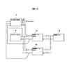
- FIG. 6 is a flow diagram showing an example of a control procedure when switching the mode in the simulator according to the first embodiment of the present invention. It is a figure which shows the example of a change of rotor rotational speed V, Vb when switching from a 1st mode to a 2nd mode is performed.
- FIG. 1 is a view showing a configuration example of a simulator according to a first embodiment of the present invention.
- the simulator shown in FIG. 1 is a system simulator for simulating a drive device of an electric vehicle, and is realized using, for example, a computer.
- the simulator converts the electromagnetic torque 21 generated by the motor model 1 into an axle torque 23 through the high speed gear model 3 and transmits it to the vehicle model 2. Further, the axle rotation speed 24 corresponding to the motion state of the vehicle model 2 is converted into the rotor rotation speed 22 through the high speed gear model 3 and is input to the motor model 1.
- the motion of the drive device of the electric vehicle is simulated.
- each element (motor, gear, vehicle) constituting the drive device of the electric vehicle to be simulated is modeled as a motor model 1, a high speed gear model 3 and a vehicle model 2 respectively.
- a simulator is realized that performs calculations related to the drive device of the electric vehicle to be simulated.
- a high precision gear model 3 b is further arranged in parallel with the high speed gear model 3.
- the high-precision gear model 3b is a model of a gear which is one of the elements constituting the drive device of the electric vehicle to be simulated.
- the high-speed gear model 3 is a model in which calculation contents for solving the conversion of torque and rotational speed by the reduction ratio of gears are modeled, and the calculation load is light but a model which can not solve the phenomenon of shaft vibration and the like.
- the high-precision gear model 3b is a modeling of the calculation content for solving the conversion of torque and rotational speed by the reduction ratio taking into consideration the shaft twist in the gear, and in addition to the calculation content of the high-speed gear model 3, the internal gear Calculation of the behavior of the drive shaft and the twist of the drive shaft. That is, the high precision gear model 3b is a model that is heavy in calculation load but can solve the phenomenon of shaft vibration and the like.
- the case where the calculation is performed using the high speed gear model 3 will be referred to as a “first mode”.
- the state of each switch is exchanged and the motor model 1 and the vehicle model 2 are connected via the high precision gear model 3b, the calculation using the high precision gear model 3b is performed.
- the case where the calculation is performed using the high-precision gear model 3b is referred to as a "second mode”.
- Control of each of the switches is implemented by the switching controller 4.
- the switching controller 4 and each switch are connected by a wire (not shown) so that each switch can be operated from the switching controller 4.
- the wiring between the switching controller 4 and each switch is virtually realized on a computer, not a physical wire.
- the switching controller 4 receives the rotor rotation speed 22 output from the high-speed gear model 3 and the rotor rotation speed 22 b output from the high-precision gear model 3 b. Further, the electromagnetic torques 21 and 21 b output from the motor model 1 are also input to the switching controller 4. The switching controller 4 determines the operation timing of each switch based on these parameters. A specific method of determining the operation timing of each switch will be described later.
- each configuration as described above is realized on a computer. That is, in the simulator according to the present embodiment, a computer is a motor model 1 that models a motor, a vehicle model 2 that models a vehicle, and a high-speed gear model 3 that models gears interposed between the motor and the vehicle.
- the high-precision gear model 3b is made to function as each.
- the first mode in which the motor model 1 and the vehicle model 2 transmit and receive information via the high speed gear model 3 and the second mode in which the motor model 1 and the vehicle model 2 transmit and receive information via the high precision gear model 3b Either make the computer perform the calculation.
- the electromagnetic torque 21 output from the motor model 1 is input to the high speed gear model 3, and the axle torque 23 output from the high speed gear model 3 according to the input electromagnetic torque 21 is a vehicle model 2, the axle rotation speed 24 output from the vehicle model 2 is input to the high speed gear model 3, and the rotor rotation speed 22 output from the high speed gear model 3 according to the input axle rotation speed 24 is the motor model 1 Operate the computer as you would enter it.
- the electromagnetic torque 21b output from the motor model 1 is input to the high precision gear model 3b, and the axle torque 23b output from the high precision gear model 3b according to the input electromagnetic torque 21b is transmitted to the vehicle model 2
- the axle rotation speed 24b output from the vehicle model 2 is input to the high precision gear model 3b, and the rotor rotation speed 22b output from the high precision gear model 3b is output according to the input axle rotation speed 24b. Operate the computer as you enter 1.
- FIG. 2 is a diagram showing a configuration example of a conventional simulator according to the first embodiment of the present invention.
- the motor model 1 and the vehicle model 2 are connected only via the high speed gear model 3, and the high precision gear model 3b of FIG. 1 does not exist. Therefore, the switches for switching between the high-speed gear model 3 and the high-precision gear model 3b shown in FIG. 1 are not provided in FIG.
- electromagnetic torque 21 and rotor rotational speed 22 input / output between motor model 1 and high speed gear model 3 and axle torque 23 and axle rotation input / output between high speed gear model 3 and vehicle model 2
- the speed 24 corresponds to the parameters passed between the models.
- the direction of the arrow of FIG. 2 has shown the transmission direction of the information by each parameter.
- information transfer between the models is realized by passing parameters. This point is the same as in the simulator of the present embodiment shown in FIG.
- FIG. 3 is a diagram showing an example of parameters in each physical domain used for the simulator.
- the various parameters used in the simulator are classified into two types: cross variables and through variables.
- the through variable is a variable that satisfies the Kirchhoff's first law when the physical domain is electricity, or the same rule that holds for other physical domains, that is, the law in which the sum of the quantities flowing into one point is zero.
- the Across variable means Kirchhoff's second law when the physical domain is electrical, or the same law that holds for other physical domains, ie, the integrated value of elements forming a loop in the model is zero It is a variable that satisfies the law.
- the angular velocity (rotational speed) which is an across variable, and the torque which is a through variable are used as a pair of parameters in the simulator. Be done.
- the physical domain is machine translation
- the velocity which is an across variable and the force which is a through variable are used as paired parameters in the simulator.
- the physical domain is electricity
- the voltage which is an across variable and the current which is a through variable are used as parameters to be paired in the simulator
- the physical domain is oil or air pressure
- the across variable is used.
- the through flow variable are used as paired parameters in the simulator.
- the models set in the simulator according to the physical domain are connected to each other, and calculation of coupled motion of each element constituting the simulation target can be performed.
- the physical domain shown in FIG. 3 and the corresponding cross variables and through variables are merely examples, and the parameters used in the simulator of this embodiment are not limited thereto.
- the consumption amount of electric power and the shaft vibration generated at the time of deceleration are calculated for the traveling pattern in which the electric vehicle is accelerated from the stopped state and decelerated by braking and stopped when reaching a predetermined speed.
- An operation example of the simulator according to the present embodiment will be described.
- FIG. 4 shows an example of the rotor rotational speed calculated using the simulator according to the first embodiment of the present invention.
- Graph 41 in FIG. 4 is calculated in the first mode using high-speed gear model 3 after the acceleration of the electric vehicle starts and immediately after the start of braking, and the electric vehicle starts to decelerate by the brake.
- the figure shows how the rotor rotational speed changes with time when calculation is performed in the second mode using the high-precision gear model 3b in the second half before stopping.
- the time lapse when switching from the first mode to the second mode is 0, in fact, as described later, the state quantity of the high-precision gear model 3b can be switched. It takes some time to change. Therefore, the time change of the rotor rotational speed may be determined in consideration of this time.
- a desired result can be obtained even if calculation is performed using the high-precision gear model 3b in the entire section including the first half.
- the calculation using the high accuracy gear model 3b takes time, it is not preferable to perform the calculation using the high accuracy gear model 3b in all sections, considering the calculation cost. Therefore, as in the simulator of the present embodiment, efficient simulation can be realized by switching from the first mode to the second mode in the middle of the calculation and performing the calculation.
- variable value is converted before and after the switching, and then the high speed gear model 3 is converted to the high precision gear model 3b. It needs to be replaced.
- variable values representing each state quantity in the high speed gear model 3 for example, the rotational speed of the rotor, the rotational speed of the drive shaft, the internal transmission torque, etc. It converts into a variable value representing each state quantity in the high precision gear model 3b. Then, these converted variable values may be set in the high-precision gear model 3b, and the calculation in the second mode of the second half may be continued.
- the conversion program when the contents of the high-speed gear model 3 and the high-precision gear model 3b are changed, the conversion program also needs to be recreated accordingly. Due to these causes, it takes time to create a conversion program, and as a result, the system development efficiency using simulation may be reduced.
- the high-precision gear model 3b is disposed in parallel with the high-speed gear model 3 as shown in FIG. 1, and switches disposed between the models are switched at appropriate operation timing. Thereby, mode switching in the middle of calculation is realized without requiring conversion of variable values.
- FIG. 5 is a flowchart showing an example of a control procedure when switching the mode in the simulator according to the first embodiment of the present invention.
- the switching controller 4 starts the process shown in the flowchart of FIG. 5 when the preset mode switching timing is reached.
- step S51 the switching controller 4 switches the switch 34b from the disconnected state to the connected state, and connects the input of the axle rotation speed 24b to the high precision gear model 3b. That is, the axle rotation speed 24 from the vehicle model 2 which has been input only to the high speed gear model 3 until then is input to the high speed gear model 3 and the high precision gear model 3 b as axle rotation speeds 24 and 24 b. Thereby, using the calculation result of the high speed gear model 3, the fluctuation of the internal state quantity in the high precision gear model 3b is started.
- the axle rotation speeds 24, 24b correspond to the crossing variables when the physical domain is machine rotation. That is, in step S51, the axle rotational speed 24, 24b which is the cross variable is set as a parameter to be first connected to the high speed gear model 3 and the high precision gear model 3b when switching the mode. Across variables inside the precision gear model 3b are made to match.
- the across variables are, as described above, angular velocity, velocity, voltage, pressure and the like, which have a close relationship with internal energy. That is, as described above, matching the internal Across variables of the high-speed gear model 3 and the high-precision gear model 3b in step S51 is an approximation of matching the internal energy of these models. Therefore, the state quantity inside the high precision gear model 3b can be rapidly changed to the switchable state.
- the parameter to be connected first when switching the mode is not necessarily limited to the cross variable. That is, when switching the mode, the parameter to be connected first may be a through variable instead of an across variable, or both the across variable and the through variable may be mixed.
- step S52 the switching controller 4 controls the rotor rotational speed 22 output from the high speed gear model 3 according to the input axle rotational speed 24 and the high precision gear model 3b according to the input axle rotational speed 24b.
- the rotor rotational speed 22b to be output is detected.
- the detected value of the rotor rotational speed 22 from the high speed gear model 3 is referred to as a rotor rotational speed V
- the detected value of the rotor rotational speed 22b from the high precision gear model 3b is referred to as a rotor rotational speed Vb.
- step S53 the switching controller 4 compares the rotor rotational speed V detected in step S52 with the rotor rotational speed Vb.
- these differences are compared by calculating the difference ⁇ v between the rotor rotational speed Vb and the rotor rotational speed V.
- step S54 the switching controller 4 calculates the control amount Ta for the high precision gear model 3b based on the difference ⁇ v calculated in step S53.
- the value of the electromagnetic torque 21 output from the motor model 1 is detected, and the control amount Ta is determined according to the value of the electromagnetic torque 21 so that the absolute value of the difference ⁇ v is reduced.
- the control amount Ta may be calculated using general PID control, or the control amount Ta may be determined using preset map information or the like.
- the control amount Ta may be determined by any method as long as the absolute value of at least the difference ⁇ v can be reduced.
- step S55 the switching controller 4 supplies the control amount Ta calculated in step S54 to the electromagnetic torque input of the high precision gear model 3b. That is, the electromagnetic torque 21b corresponding to the control amount Ta is input from the switching controller 4 to the high precision gear model 3b via the switch 31b.
- the switch 31 b is in the disconnected state between the motor model 1 and the high precision gear model 3 b
- the switching controller 4 and the high precision gear model 3 b are in the connected state.
- the electromagnetic torque 21b adjusted according to the difference ⁇ v is further input to the high precision gear model 3b, and the high precision gear model 3b is operated so that the absolute value of the difference ⁇ v becomes smaller.
- step S56 the switching controller 4 determines whether or not the rotor rotational speed V and the rotor rotational speed Vb detected in step S52 are approximately equal.
- the absolute value of difference ⁇ v calculated in step S53 is less than or equal to a predetermined reference value.
- the absolute value of the difference ⁇ v is equal to or less than the reference value, it is determined that the rotor rotational speed V and the rotor rotational speed Vb are approximately equal, and the process proceeds to step S57.
- step S52 when the absolute value of the difference ⁇ v exceeds the reference value, it is determined that the rotor rotational speed V and the rotor rotational speed Vb are not approximately equal, and the process returns to step S52 and the processes after step S52 are performed again.
- step S57 the switching controller 4 switches all terminals of the high speed gear model 3, ie, the switches 31, 32, 33, 34 from the connected state to the disconnected state, and all terminals of the high precision gear model 3b, ie, connected in step S51.
- the switch 31b, 32b, 33b other than the switch 34b is switched from the disconnected state to the connected state.
- FIG. 6 is a view showing a change example of the rotor rotational speeds V and Vb when switching from the first mode to the second mode is performed according to the flow chart of FIG.
- the graph 61 shows the change of the rotor rotational speed V
- the graph 62 shows the change of the rotor rotational speed Vb.
- step S56 in FIG. 5 is positively determined, and from the first mode Switching to the 2 mode is completed.
- Switching from the first mode to the second mode is implemented by the switching controller 4 performing the processing shown in the flowchart of FIG. 5 described above.
- the electromagnetic torque 21 b from the motor model 1 is input to the high-precision gear model 3 b, converted to the axle torque 23 b, and transmitted to the vehicle model 2.
- the axle rotation speed 24 b from the vehicle model 2 is input to the high-precision gear model 3 b, converted to the rotor rotation speed 22 b, and transmitted to the motor model 1. Therefore, mode switching in the middle of calculation can be realized without conversion of variable values as described above.
- the simulator according to the present embodiment uses a computer to perform calculations regarding the drive device of the electric vehicle to be simulated.
- the simulation targets include a motor and a vehicle, and a gear interposed between the motor and the vehicle.
- the computer functions as a motor model 1 that models a motor, a vehicle model 2 that models a vehicle, and a high-speed gear model 3 and a high-precision gear model 3b that models gears. .
- the first mode in which the motor model 1 and the vehicle model 2 transmit and receive information via the high speed gear model 3 and the second mode in which the motor model 1 and the vehicle model 2 transmit and receive information via the high precision gear model 3b Either make the computer perform the calculation.
- the electromagnetic torque 21 output from the motor model 1 is input to the high speed gear model 3, and the axle torque 23 output from the high speed gear model 3 according to the input electromagnetic torque 21 is input to the vehicle model 2.
- the axle rotation speed 24 output from the vehicle model 2 is input to the high speed gear model 3, and the rotor rotation speed 22 output from the high speed gear model 3 is input to the motor model 1 according to the input axle rotation speed 24.
- Operate the computer Operate the computer.
- the electromagnetic torque 21b output from the motor model 1 is input to the high precision gear model 3b, and the axle torque 23b output from the high precision gear model 3b is input to the vehicle model 2 according to the input electromagnetic torque 21b.
- the axle rotation speed 24b output from the vehicle model 2 is input to the high precision gear model 3b, and the rotor rotation speed 22b output from the high precision gear model 3b according to the input axle rotation speed 24b is converted to the motor model 1 Operate the computer as you enter. Furthermore, when switching from the first mode to the second mode, the axle rotational speeds 24 and 24b are respectively input to the high speed gear model 3 and the high precision gear model 3b (step S51), and high according to the input axle rotational speed 24b.
- the rotor rotation speed 22b output from the precision gear model 3b is compared with the rotor rotation speed 22 output from the high speed gear model 3 according to the input axle rotation speed 24 (step S53), and the comparison result is By connecting the motor model 1 and the vehicle model 2 with the high-precision gear model 3b and separating the motor model 1 and the vehicle model 2 from the high-speed gear model 3 when the predetermined criteria are satisfied (step S56: Yes), The switching from the first mode to the second mode is carried out (step S57). To operate the Yuta. Since this is done, mode switching in the middle of calculation can be realized without conversion of variable values, and as a result, a simulation method with high system development efficiency can be provided.
- step S53 the difference ⁇ v between the value Vb of the rotor rotational speed 22b output from the high precision gear model 3b and the value V of the rotor rotational speed 22 output from the high speed gear model 3 is calculated. Then, when the calculated absolute value of the difference ⁇ v becomes equal to or less than the predetermined reference value, step S56 is positively determined, and step S57 is executed to connect the motor model 1 and the vehicle model 2 with the high precision gear model 3b. In addition, by separating the motor model 1 and the vehicle model 2 from the high-speed gear model 3, the computer is operated to perform switching from the first mode to the second mode. Since this is done, switching from the first mode to the second mode can be performed at an appropriate timing.
- the simulator adjusts the value of the electromagnetic torque 21b input to the high precision gear model 3b when switching from the first mode to the second mode (steps S54 and S55). Operate the computer so that Specifically, in step S54, the control amount Ta adjusted according to the difference .delta.v between the value Vb of the rotor rotational speed 22b output from the high precision gear model 3b and the value V of the rotor rotational speed 22 output from the high speed gear model 3 is determined.
- the electromagnetic torque 21b corresponding to the control amount Ta is further input to the high-precision gear model 3b in step S55, and the computer is operated so as to reduce the difference ⁇ v. Since this is done, switching from the first mode to the second mode can be performed smoothly.
- the axle rotation speeds 24 and 24b input to the high speed gear model 3 and the high precision gear model 3b in step S51 are cross variables. Therefore, the internal energy of the high-speed gear model 3 and the high-precision gear model 3b can be matched, and the amount of state inside the high-precision gear model 3b can be rapidly changed to a switchable state.
- the value may be gradually changed. Specifically, the value of the electromagnetic torque 21b input to the high-precision gear model 3b is not changed rapidly by limiting the amount of change in input per operation cycle per unit time of the electromagnetic torque 21b to, for example, a predetermined value or less. Make it In this way, it is possible to prevent the state quantity inside the high precision gear model 3b from changing suddenly, and to switch from the first mode to the second mode more appropriately.
- Modification 2 In the present embodiment, by performing the processing of steps S53 to S55 of FIG. 5 before switching from the first mode to the second mode, the value Vb of the rotor rotational speed 22b output from the high-precision gear model 3b and Although the value V of the rotor rotational speed 22 output from the high speed gear model 3 is made to approach quickly, it is not limited thereto. For example, the processes of steps S53 to S55 may not be performed.
- Modification 3 it is possible to switch from the first mode to the second mode by determining whether or not the rotor rotational speed V and the rotor rotational speed Vb are approximately equal in step S56 of FIG. 5.
- the determination method is not limited to this. For example, determination may be performed when a predetermined calculation time has elapsed, or determination may be performed using a plurality of methods in combination.
- the procedure for switching from the first mode to the second mode has been described, but the high-speed gear model 3 and the high-precision gear model 3b are also used for switching from the second mode to the first mode. It is possible to carry out by the same procedure by replacing. That is, the method of mode switching described in the present embodiment is applicable to both the switching from the first mode to the second mode and the switching from the second mode to the first mode.
- FIG. 7 is a view showing a configuration example of a simulator according to the second embodiment of the present invention.
- the simulator shown in FIG. 7 is a system simulator in which a drive device of an electric vehicle is simulated, as in the simulator of FIG. 1 described in the first embodiment, and is realized using, for example, a computer.
- the simulator of this embodiment is different from the simulator of the first embodiment in the types of parameters input to and output from the switching controller 4.
- the rotor rotational speed 22 output from the high-speed gear model 3, the rotor rotational speed 22b output from the high-precision gear model 3b, and the electromagnetic torque 21 output from the motor model 1 Is input to the switching controller 4, and the electromagnetic torques 21 and 21b are respectively output from the switching controller 4 to the high speed gear model 3 and the high precision gear model 3b.
- the axle rotation speeds 24 and 24b are output from the switching controller 4 to the high speed gear model 3 and the high precision gear model 3b, respectively.
- the simulator of this embodiment is the same as the simulator of the first embodiment.
- FIG. 8 is a flow chart showing an example of a control procedure when switching the mode in the simulator according to the second embodiment of the present invention.
- the switching controller 4 starts the process shown in the flowchart of FIG. 8 when the preset mode switching timing is reached.
- step S71 the switching controller 4 switches the switch 31b from the disconnection state to the connection state, and connects the input of the motor torque, that is, the electromagnetic torque 21b to the high precision gear model 3b. That is, the electromagnetic torque 21 from the motor model 1 which has been input only to the high speed gear model 3 until then is input to the high speed gear model 3 and the high precision gear model 3b as the electromagnetic torque 21 and 21b, respectively. Thereby, using the calculation result of the high speed gear model 3, the fluctuation of the internal state quantity in the high precision gear model 3b is started.
- step S72 the switching controller 4 is outputted from the high precision gear model 3b according to the axle torque 23 outputted from the high speed gear model 3 according to the inputted electromagnetic torque 21 and the inputted electromagnetic torque 21b.
- the axle torque 23b is detected.
- the detected value of the axle torque 23 from the high speed gear model 3 is referred to as an axle torque T
- the detected value of the axle torque 23b from the high precision gear model 3b is referred to as an axle torque Tb.
- step S73 the switching controller 4 compares the axle torque T detected in step S72 with the axle torque Tb.
- these differences are compared by calculating the difference ⁇ t between the axle torque Tb and the axle torque T.
- step S74 the switching controller 4 calculates the control amount Va for the high-precision gear model 3b based on the difference ⁇ t calculated in step S73.
- the value of the axle rotational speed 24 output from the vehicle model 2 is detected, and the control amount Va is determined according to the value of the axle rotational speed 24 so that the absolute value of the difference ⁇ t is reduced.
- the control amount Va may be calculated using general PID control, or the control amount Va may be determined using preset map information or the like.
- the control amount Va may be determined by any method as long as at least the absolute value of the difference ⁇ t can be reduced.
- step S75 the switching controller 4 supplies the control amount Va calculated in step S74 to the axle rotational speed input of the high precision gear model 3b. That is, the axle rotation speed 24b corresponding to the control amount Va is input from the switching controller 4 to the high precision gear model 3b via the switch 34b.
- the switch 34 b is in the disconnected state between the vehicle model 2 and the high precision gear model 3 b, the switching controller 4 and the high precision gear model 3 b are in the connected state.
- the axle rotational speed 24b adjusted according to the difference ⁇ t is further input to the high accuracy gear model 3b, and the high accuracy gear model 3b is operated so that the absolute value of the difference ⁇ t becomes smaller.
- step S76 the switching controller 4 determines whether the axle torque T and the axle torque Tb detected in step S72 are approximately equal.
- the absolute value of difference ⁇ t calculated in step S73 is equal to or less than a predetermined reference value.
- the absolute value of the difference ⁇ t is equal to or less than the reference value, it is determined that the axle torque T and the axle torque Tb are approximately equal, and the process proceeds to step S77.
- the absolute value of the difference ⁇ t exceeds the reference value, it is determined that the axle torque T and the axle torque Tb are not approximately equal, and the process returns to step S72 to execute the processing from step S72 again.
- step S77 the switching controller 4 switches all terminals of the high-speed gear model 3, ie, the switches 31, 32, 33, 34 from the connected state to the disconnected state, and all terminals of the high precision gear model 3b, ie, connected in step S71.
- the switch 32b, 33b, 34b other than the switch 31b is switched from the disconnected state to the connected state.
- the computer performs the same operation as that of the first embodiment in each of the first mode and the second mode. Furthermore, when switching from the first mode to the second mode, the electromagnetic torques 21 and 21b are respectively input to the high speed gear model 3 and the high precision gear model 3b (step S71), and the high precision gear model is selected according to the input electromagnetic torque 21b. The axle torque 23b output from 3b is compared with the axle torque 23 output from the high speed gear model 3 according to the input electromagnetic torque 21 (step S73), and the result of the comparison satisfies the predetermined standard.
- Step S76 Yes
- the computer is operated to perform switching to the 2 mode (step S77). That. Since this is done, it is possible to realize mode switching in the middle of calculation without performing conversion of variable values as described in the first embodiment, and as a result, it is possible to provide a simulation method with high system development efficiency. .
- step S73 the difference ⁇ t between the value Tb of the axle torque 23b output from the high precision gear model 3b and the value T of the axle torque 23 output from the high speed gear model 3 is calculated. Then, when the calculated absolute value of the difference ⁇ t becomes equal to or less than the predetermined reference value, step S76 is affirmed and step S77 is executed to connect the motor model 1 and the vehicle model 2 with the high precision gear model 3b. In addition, by separating the motor model 1 and the vehicle model 2 from the high-speed gear model 3, the computer is operated to perform switching from the first mode to the second mode. Since this is done, switching from the first mode to the second mode can be performed at an appropriate timing, as described in the first embodiment.
- step S74 and S75 when switching from the first mode to the second mode, the value of the axle rotation speed 24b input to the high precision gear model 3b is adjusted (steps S74 and S75).
- the computer is operated to reduce ⁇ t.
- the control amount Va adjusted in accordance with the difference ⁇ t between the value Tb of the axle torque 23b output from the high precision gear model 3b and the value T of the axle torque 23 output from the high speed gear model 3 is calculated in step S74.
- the computer is operated to reduce the difference ⁇ t. Since this is done, switching from the first mode to the second mode can be smoothly performed as described in the first embodiment.
- FIG. 9 is a view showing a configuration example of a simulator according to a third embodiment of the present invention.
- the main communication I / F 83 is disposed in the portion where the high-speed gear model 3 and the high-precision gear model 3b are disposed in the simulator shown in FIG.
- the main communication I / F 83, the motor model 1, the vehicle model 2 and the switching controller 4 are realized on the main computer 81. Further, the high speed gear model 3 and the high precision gear model 3b are realized on separate sub computers 82 and 82b, respectively.
- the high speed gear model 3 is connected to the sub communication I / F 84, and in the sub computer 82 b, the high precision gear model 3 b is connected to the sub communication I / F 84 b.
- the main communication I / F 83, the sub communication I / F 84, and the sub communication I / F 84b are mutually connected via a network (not shown), etc., and are configured to communicate with each other to carry out passing of each parameter. ing.
- calculation results similar to those of the first embodiment can be obtained using a plurality of computers. Also, by distributing the calculation load to a plurality of computers, calculation results can be obtained at high speed even with few hardware resources. Furthermore, since there is no restriction on the installation location of each computer, it is also possible to disperse the physical occupation area and the power consumption. Therefore, the simulation execution efficiency can be further improved.
- the simulator described in the first embodiment is distributed to a plurality of computers
- the simulator described in the second embodiment can also be distributed to a plurality of computers.
- each modification described in the first embodiment is possible.
- FIG. 10 is a view showing a configuration example of a conventional simulator according to the fourth embodiment of the present invention.
- the battery model 5 and the mechanism model 6 are connected via the high precision motor model 1b.
- the battery model 5, the high precision motor model 1b, and the mechanism model 6 are obtained by modeling the respective elements (a battery, a motor, and a drive mechanism) constituting the motorized device to be simulated.
- the motor is an AC motor, it is preferable to model the high precision motor model 1b including an inverter.
- an electromagnetic torque 21, a rotor rotational speed 22, a DC voltage 25 and a DC current 26 are used as parameters for information transmission between the models.
- the direction of the arrow in FIG. 10 indicates the transmission direction of information by each parameter. That is, the simulator of FIG. 10 converts the DC voltage 25 generated by the battery model 5 into the electromagnetic torque 21 through the high precision motor model 1 b and transmits it to the mechanical model 6. Further, the rotor rotational speed 22 corresponding to the state of the mechanism model 6 is converted into a direct current 26 through the high precision motor model 1 b, and is input to the battery model 5. By calculating the states of the battery model 5, the high precision motor model 1b, and the mechanism model 6 at this time, the movement of the motorized device is simulated.
- FIG. 11 is a view showing a configuration example of a simulator according to a fourth embodiment of the present invention.
- the simulator shown in FIG. 11 further has a high-speed motor model 1c arranged in parallel with the high-precision motor model 1b.
- the high-speed motor model 1c is, like the high-precision motor model 1b, a model of a motor which is one of the elements constituting the motorized device to be simulated.
- the simulator of FIG. 11 includes the switching controller 4 in the same manner as the simulator of FIG. 1 described in the first embodiment. Under the control of the switching controller 4, switching between the mode of performing calculation using the high-precision motor model 1b and the mode of performing calculation using the high-speed motor model 1c in the same manner as in the first embodiment it can.
- the same effect as that described in the first embodiment can be obtained even in a system simulator in which a motor-driven device using an electric motor is simulated. .
- a simulator of an electrically powered device that performs mode switching in the same manner as in the first embodiment has been described.
- mode switching is performed in the same manner as in the second embodiment.
- the invention is also applicable to a simulator of a motorized device.
- each modification described in the first embodiment is possible.
- it may be a simulator realized on a single computer, or it may be a simulator distributed to a plurality of computers as described in the third embodiment.
- the present invention is not limited to the above-described embodiments and various modifications, and various modifications are possible other than that.
- the above-described embodiments are described in detail in order to explain the present invention in an easy-to-understand manner, and are not necessarily limited to those having all the described configurations.
- part of the configuration of one embodiment can be replaced with the configuration of another embodiment, or the configuration of another embodiment can be added to the configuration of one embodiment. That is, it is possible to add, delete, and replace other configurations for part of the configurations of the respective embodiments.
- control lines and the information lines indicate what is considered necessary for the description, and not all the control lines and the information lines in the product are necessarily shown. In practice, almost all configurations may be considered to be mutually connected.
Landscapes
- Engineering & Computer Science (AREA)
- Power Engineering (AREA)
- Transportation (AREA)
- Mechanical Engineering (AREA)
- Management, Administration, Business Operations System, And Electronic Commerce (AREA)
- Electric Propulsion And Braking For Vehicles (AREA)
- Testing Of Devices, Machine Parts, Or Other Structures Thereof (AREA)
Abstract
システム開発効率の高いシミュレーション方法を提供する。 シミュレーターでは、コンピューターを、モーターをモデル化したモーターモデル1と、車両をモデル化した車両モデル2と、ギヤをそれぞれモデル化した高速ギヤモデル3および高精度ギヤモデル3bと、としてそれぞれ機能させる。切り替え制御器4は、車軸回転速度24、24bを、高速ギヤモデル3および高精度ギヤモデル3bにそれぞれ入力し、高精度ギヤモデル3bから出力されるローター回転速度22bと、高速ギヤモデル3から出力されるローター回転速度22との比較を行い、その比較の結果が所定の基準を満たしたときに、モーターモデル1および車両モデル2と高精度ギヤモデル3bとを接続すると共に、モーターモデル1および車両モデル2と高速ギヤモデル3とを切り離すことで、第1モードから第2モードへの切り替えを実施する。
Description
本発明は、コンピューターを用いたシミュレーション方法に関する。
本技術分野の背景技術として、下記特許文献1が知られている。特許文献1に記載の技術では、モデル選択部が、条件入力部から設定された選択条件に基づいて、シミュレーションモデルを選択し、当該シミュレーションモデルをモデルデータベースから読み出す。シミュレーション計算部が、この読み出されたシミュレーションモデルを用い、条件入力部に設定された初期状態及びシミュレーション条件に基づいて、シミュレーション計算を行う。これにより、モデルの選択条件に基づいて、詳細度の異なる各シミュレーションモデルを切り替えてシミュレーション計算を行う。例えば、重要な部分は詳細度の高いモデルを使って高い精度のシミュレーションを行い、あまり重要でない部分は詳細度の低いモデルを使って短時間でシミュレーションを行う。
特許文献1には、計算途中にシミュレーションモデルを切り替える際の手法が記載されている。しかしながら、特許文献1の切り替え手法では、シミュレーションに用いられる変数値を切り替えの前後で変換するためのプログラムを別途作成する必要がある。このプログラムの作成には、未知の変数値を推定する必要があるなどの理由から、時間がかかることがある。そのため、シミュレーター作成から計算結果の評価までのシミュレーション全体の時間を長大化させてしまい、結果として、シミュレーションを利用したシステム開発効率が低下する場合がある。
本発明によるシミュレーション方法は、コンピューターを用いてシミュレーション対象に関する計算を行うものであって、前記シミュレーション対象は、第1要素および第2要素と、前記第1要素と前記第2要素の間に介在する中間要素と、を含み、前記コンピューターを、前記第1要素をモデル化した第1モデルと、前記第2要素をモデル化した第2モデルと、前記中間要素をそれぞれモデル化した第1中間モデルおよび第2中間モデルと、としてそれぞれ機能させ、前記第1モデルと前記第2モデルが前記第1中間モデルを介して情報を送受信する第1モードと、前記第1モデルと前記第2モデルが前記第2中間モデルを介して情報を送受信する第2モードと、のいずれかにより、前記コンピューターに前記計算を実行させ、前記第1モードでは、前記第1モデルから出力される第1パラメーターを前記第1中間モデルに入力し、入力された前記第1パラメーターに応じて前記第1中間モデルから出力される第2パラメーターを前記第2モデルに入力すると共に、前記第2モデルから出力される第3パラメーターを前記第1中間モデルに入力し、入力された前記第3パラメーターに応じて前記第1中間モデルから出力される第4パラメーターを前記第1モデルに入力するように、前記コンピューターを動作させ、前記第2モードでは、前記第1モデルから出力される第1パラメーターを前記第2中間モデルに入力し、入力された前記第1パラメーターに応じて前記第2中間モデルから出力される第2パラメーターを前記第2モデルに入力すると共に、前記第2モデルから出力される第3パラメーターを前記第2中間モデルに入力し、入力された前記第3パラメーターに応じて前記第2中間モデルから出力される第4パラメーターを前記第1モデルに入力するように、前記コンピューターを動作させ、前記第1モードから前記第2モードに切り替える際に、前記第1パラメーターまたは前記第3パラメーターを、前記第1中間モデルおよび前記第2中間モデルに入力し、入力された前記第1パラメーターまたは前記第3パラメーターに応じて前記第2中間モデルから出力される前記第2パラメーターまたは前記第4パラメーターと、入力された前記第1パラメーターまたは前記第3パラメーターに応じて前記第1中間モデルから出力される前記第2パラメーターまたは前記第4パラメーターと、の比較を行い、前記比較の結果が所定の基準を満たしたときに、前記第1モデルおよび前記第2モデルと前記第2中間モデルとを接続すると共に、前記第1モデルおよび前記第2モデルと前記第1中間モデルとを切り離すことで、前記第1モードから前記第2モードへの切り替えを実施するように、前記コンピューターを動作させる。
本発明によれば、システム開発効率の高いシミュレーション方法を提供できる。
(第1の実施形態)
本実施形態では、電気自動車の駆動装置のシステムシミュレーターへの適用例を説明する。
本実施形態では、電気自動車の駆動装置のシステムシミュレーターへの適用例を説明する。
図1は、本発明の第1の実施形態に係るシミュレーターの構成例を示す図である。図1に示すシミュレーターは、電気自動車の駆動装置をシミュレーション対象としたシステムシミュレーターであり、たとえばコンピューターを用いて実現される。このシミュレーターは、モーターモデル1の発生する電磁トルク21を高速ギヤモデル3を通して車軸トルク23に変換し、車両モデル2に伝達する。また、車両モデル2の運動状態に応じた車軸回転速度24を高速ギヤモデル3を通してローター回転速度22に変換し、モーターモデル1に入力する。このときのモーターモデル1、高速ギヤモデル3および車両モデル2の運動をそれぞれ計算することで、電気自動車の駆動装置の動きをシミュレーションする。すなわち、本実施形態のシミュレーターでは、シミュレーション対象である電気自動車の駆動装置を構成する各要素(モーター、ギヤ、車両)を、モーターモデル1、高速ギヤモデル3、車両モデル2としてそれぞれモデル化し、これらのモデル間で相互に影響するパラメーターを互いに受け渡すことで、各要素の連成運動を計算することを可能としている。これにより、シミュレーション対象である電気自動車の駆動装置に関する計算を行うシミュレーターを実現している。
ここで図1に示すように、本実施形態のシミュレーターでは、さらに高精度ギヤモデル3bが高速ギヤモデル3と並列に配置されている。高精度ギヤモデル3bは、高速ギヤモデル3と同様に、シミュレーション対象である電気自動車の駆動装置を構成する要素の一つであるギヤをモデル化したものである。なお、高速ギヤモデル3は、ギヤの減速比によるトルクと回転速度の変換を解く計算内容をモデル化したものであり、計算負荷は軽いが軸振動の現象などを解くことが出来ないモデルである。一方、高精度ギヤモデル3bは、ギヤ内部の軸ねじれを考慮した減速比によるトルクと回転速度の変換を解く計算内容をモデル化したものであり、高速ギヤモデル3の計算内容に加えて、内部のギヤの挙動やドライブシャフトの捩れなどの計算も含んでいる。すなわち高精度ギヤモデル3bは、計算負荷は重いが軸振動の現象などを解くことができるモデルである。
なお、図1では、高速ギヤモデル3に入出力される各パラメーターと区別するため、高精度ギヤモデル3bに入出力される各パラメーターの符号の末尾に「b」を付している。すなわち、高精度ギヤモデル3bは、モーターモデル1から入力された電磁トルク21bを車軸トルク23bに変換し、車両モデル2に伝達する。また、車両モデル2から入力された車軸回転速度24bをローター回転速度22bに変換し、モーターモデル1に伝達する。
本実施形態のシミュレーターにおいて、高速ギヤモデル3と高精度ギヤモデル3bのどちらを計算に用いるかは、各モデル間に配置されたスイッチ31,32,33,34,31b,32b,33b,34bをそれぞれ切り替えることで決定される。図1では、モーターモデル1および車両モデル2と高速ギヤモデル3の間にそれぞれ配置されたスイッチ31,32,33,34が接続状態である一方で、モーターモデル1および車両モデル2と高精度ギヤモデル3bの間にそれぞれ配置されたスイッチ31b,32b,33b,34bが切断状態である。すなわち、図1では、モーターモデル1と車両モデル2が高速ギヤモデル3を介して接続されており、高速ギヤモデル3を用いた計算が実施される状態となっている。以下では、高速ギヤモデル3を用いて計算を行う場合を「第1モード」と称する。一方、各スイッチの状態を入れ換え、モーターモデル1と車両モデル2が高精度ギヤモデル3bを介して接続されるようにすると、高精度ギヤモデル3bを用いた計算が実施される状態となる。以下では、高精度ギヤモデル3bを用いて計算を行う場合を「第2モード」と称する。
上記各スイッチの制御は、切り替え制御器4で実施される。切り替え制御器4と各スイッチとは不図示の配線により接続されており、切り替え制御器4から各スイッチを操作できるようになっている。なお、切り替え制御器4と各スイッチ間の配線は、物理的な電線ではなく、コンピューター上で仮想的に実現されるものである。
切り替え制御器4には、高速ギヤモデル3から出力されるローター回転速度22と、高精度ギヤモデル3bから出力されるローター回転速度22bとが入力される。また、モーターモデル1から出力される電磁トルク21、21bも切り替え制御器4に入力される。切り替え制御器4は、これらのパラメーターに基づいて、各スイッチの操作タイミングを決定する。なお、各スイッチの操作タイミングの具体的な決定方法については、後で説明する。
本実施形態のシミュレーターでは、以上説明したような各構成がコンピューター上で実現されている。すなわち、本実施形態のシミュレーターでは、コンピューターを、モーターをモデル化したモーターモデル1と、車両をモデル化した車両モデル2と、モーターと車両の間に介在するギヤをそれぞれモデル化した高速ギヤモデル3および高精度ギヤモデル3bと、としてそれぞれ機能させている。そして、モーターモデル1と車両モデル2が高速ギヤモデル3を介して情報を送受信する第1モードと、モーターモデル1と車両モデル2が高精度ギヤモデル3bを介して情報を送受信する第2モードと、のいずれかにより、コンピューターに計算を実行させる。具体的には、第1モードでは、モーターモデル1から出力される電磁トルク21を高速ギヤモデル3に入力し、入力された電磁トルク21に応じて高速ギヤモデル3から出力される車軸トルク23を車両モデル2に入力すると共に、車両モデル2から出力される車軸回転速度24を高速ギヤモデル3に入力し、入力された車軸回転速度24に応じて高速ギヤモデル3から出力されるローター回転速度22をモーターモデル1に入力するように、コンピューターを動作させる。また、第2モードでは、モーターモデル1から出力される電磁トルク21bを高精度ギヤモデル3bに入力し、入力された電磁トルク21bに応じて高精度ギヤモデル3bから出力される車軸トルク23bを車両モデル2に入力すると共に、車両モデル2から出力される車軸回転速度24bを高精度ギヤモデル3bに入力し、入力された車軸回転速度24bに応じて高精度ギヤモデル3bから出力されるローター回転速度22bをモーターモデル1に入力するように、コンピューターを動作させる。
次に、本実施形態のシミュレーターにおいて各モデル間で受け渡されるパラメーターについて説明する。なお、以下では理解を簡単にするため、図2に示す従来のシミュレーターを用いて、各パラメーターについて解説する。
図2は、本発明の第1の実施形態に関する従来のシミュレーターの構成例を示す図である。図2に示す従来のシミュレーターでは、モーターモデル1と車両モデル2が高速ギヤモデル3のみを介して接続されており、図1の高精度ギヤモデル3bが存在していない。そのため、図1で示した高速ギヤモデル3と高精度ギヤモデル3bとを切り替えるための各スイッチは、図2には設けられていない。
図2のシミュレーターでは、モーターモデル1と高速ギヤモデル3の間で入出力される電磁トルク21およびローター回転速度22と、高速ギヤモデル3と車両モデル2の間で入出力される車軸トルク23および車軸回転速度24とが、各モデル間で受け渡されるパラメーターに該当する。なお、図2の矢印の向きは、各パラメーターによる情報の伝達方向を示している。このように、従来のシミュレーターでは、各モデル間での情報伝達をパラメーターの受け渡しによって実現している。この点は、図1に示した本実施形態のシミュレーターについても同様である。
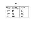
図3は、シミュレーターに用いられる各物理ドメインでのパラメーターの例を示した図である。シミュレーターで用いられる各種パラメーターは、アクロス変数とスルー変数の2種類に分類される。スルー変数とは、物理ドメインが電気である場合のキルヒホッフの第一法則や、他の物理ドメインに対して成り立つ同様の法則、すなわち一点に流れ込む量の和がゼロとなる法則を満たす変数である。一方、アクロス変数とは,物理ドメインが電気である場合のキルヒホッフの第二法則や、他の物理ドメインに対して成り立つ同様の法則、すなわちモデル内でループを形成する要素の積算値がゼロとなる法則を満たす変数である。これらの変数は、同一の物理ドメインでそれぞれ対応関係にあるものが対にして用いられる。
具体的には、図3に示すように、たとえば物理ドメインが機械回転の場合には、アクロス変数である角速度(回転速度)と、スルー変数であるトルクとが、シミュレーターにおいて対になるパラメーターとして利用される。同様に、物理ドメインが機械並進の場合には、アクロス変数である速度と、スルー変数である力とが、シミュレーターにおいて対になるパラメーターとして利用される。また、物理ドメインが電気の場合には、アクロス変数である電圧と、スルー変数である電流とが、シミュレーターにおいて対になるパラメーターとして利用され、物理ドメインが油や空圧の場合には、アクロス変数である圧力と、スルー変数である流量とが、シミュレーターにおいて対になるパラメーターとして利用される。これにより、物理ドメインに応じてシミュレーター内に設定された各モデル同士を連結し、シミュレーション対象を構成する各要素の連成運動の計算を行うことができるようにしている。なお、図3に示した物理ドメインと対応するアクロス変数およびスルー変数とは一例であり、本実施形態のシミュレーターで利用されるパラメーターはこれに限定されない。
次に、本実施形態のシミュレーターにおいて計算途中にモードを切り替える場合の動作について解説する。以下の説明では、電気自動車を停止している状態から加速させ、所定の速度に達したらブレーキをかけて減速し停止する走行パターンについて、電力の消費量と減速時に発生する軸振動とを計算する場合での、本実施形態のシミュレーターの動作例を説明する。
図4は、本発明の第1の実施形態に係るシミュレーターを用いて計算されたローター回転速度の例を示している。図4のグラフ41は、電気自動車の加速を開始してからブレーキ開始直後までの前半部分を、高速ギヤモデル3を用いた第1モードにより計算を行い、ブレーキによる減速を開始してから電気自動車が停止するまでの後半部分を、高精度ギヤモデル3bを用いた第2モードにより計算を行った場合での、ローター回転速度の時間変化の様子を示している。なお、図4のグラフ41では、第1モードから第2モードに切り替える際の時間経過を0としているが、実際には後述するように、高精度ギヤモデル3bの状態量が切り替え可能な状態へと変化するまでにある程度の時間を要する。したがって、この時間を加味してローター回転速度の時間変化を求めてもよい。
上記の走行パターンにおけるローター回転速度を計算する場合、前半の加速部分では、モーターの発生する電磁トルクがどれだけ車両を加速させるかを解くことが課題である。そのため、高速ギヤモデル3を用いた計算で十分である。一方、後半の減速部分では、軸振動が発生するため、この挙動を算出することも課題となる。そのため、高速ギヤモデル3を用いた計算では不十分であり、高精度ギヤモデル3bを用いた計算を行うことが必須となる。
なお、前半部分を含めた全区間で高精度ギヤモデル3bを用いた計算を行っても、所望の結果を得ることができる。しかし、高精度ギヤモデル3bを用いた計算は時間がかかるため、計算コストを含めて考えた場合、全区間で高精度ギヤモデル3bを用いた計算を行うのはあまり好ましくない。そこで、本実施形態のシミュレーターのように、計算途中で第1モードから第2モードに切り替えて計算を行うことにより、効率的なシミュレーションを実現できる。
図2に示した従来のシミュレーターにおいて、第1モードから第2モードへの切り替えを実現する場合には、切り替え前後での変数値の変換を行った上で、高速ギヤモデル3を高精度ギヤモデル3bに置き換える必要がある。具体的には、前半の第1モードでの計算が終了した後に、高速ギヤモデル3内の各状態量を表す変数値、たとえばローターの回転速度、ドライブシャフトの回転速度、内部の伝達トルクなどを、高精度ギヤモデル3b内の各状態量を表す変数値に変換する。そして、変換されたこれらの変数値を高精度ギヤモデル3bに設定して、後半の第2モードでの計算を継続すればよい。
しかし、上記のような変数値の変換計算を実現するためには、高速ギヤモデル3と高精度ギヤモデル3bそれぞれの物理特性や拘束条件を加味した変換プログラムを、シミュレーターとは別に作成する必要がある。また、高速ギヤモデル3から高精度ギヤモデル3bへの切り替えでは、内部の状態量の数が増加するため、単純な変換式では高精度ギヤモデル3b内の各状態量を表す変数値を求めることができない。そのため、過去の計算履歴を参照して状態量を推定したり、最小二乗法等の手法によりカーブフィッティングを行って状態量を推定したりする作業が必要となる。さらに、高速ギヤモデル3や高精度ギヤモデル3bの内容が変更された場合には、それに応じて変換プログラムも作り直す必要が生じる。これらの原因から、変換プログラムの作成に時間がかかってしまい、その結果、シミュレーションを利用したシステム開発効率が低下する場合がある。
一方、本実施形態のシミュレーターでは、図1のように高精度ギヤモデル3bを高速ギヤモデル3と並列に配置して、各モデル間に配置されたスイッチを適切な操作タイミングで切り替える。これにより、変数値の変換を必要とせずに、計算途中でのモード切り替えを実現している。
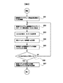
図5は、本発明の第1の実施形態に係るシミュレーターにおいてモードを切り替える際の制御手順例を示したフロー図である。以下では、図5のフロー図に従って、本実施形態のシミュレーターの動作を説明する。なお、図1のシミュレーターにおいて、切り替え制御器4は、予め設定されたモード切り替えのタイミングになると、図5のフロー図に示す処理を開始する。
まずステップS51において、切り替え制御器4は、スイッチ34bを切断状態から接続状態に切り替えて、高精度ギヤモデル3bへ車軸回転速度24bの入力を接続する。すなわち、それまでは高速ギヤモデル3のみに入力されていた車両モデル2からの車軸回転速度24を、高速ギヤモデル3と高精度ギヤモデル3bに車軸回転速度24、24bとしてそれぞれ入力されるようにする。これにより、高速ギヤモデル3での計算結果を用いて、高精度ギヤモデル3bにおける内部の状態量の変動が開始される。
前述の図3を参照すると、車軸回転速度24、24bは、物理ドメインが機械回転の場合におけるアクロス変数に相当する。すなわちステップS51では、アクロス変数である車軸回転速度24、24bを、モードを切り替える際に最初に高速ギヤモデル3と高精度ギヤモデル3bに接続するパラメーターとすることで、高速ギヤモデル3内部のアクロス変数と高精度ギヤモデル3b内部のアクロス変数とを合致させるようにしている。ここで、アクロス変数とは、前述のように角速度、速度、電圧、圧力などであり、これらは内部エネルギーと密接な関係がある。すなわち、上記のようにステップS51で高速ギヤモデル3と高精度ギヤモデル3bの内部のアクロス変数を合致させることは、これらのモデルの内部エネルギーを合致させることと近似である。したがって、高精度ギヤモデル3b内部の状態量を切り替え可能な状態へと迅速に変化させることができる。
なお、モードを切り替える際に最初に接続するパラメーターは、必ずしもアクロス変数に限定されるものではない。すなわち、モードを切り替える際に最初に接続するパラメーターをアクロス変数ではなくスルー変数としてもよいし、アクロス変数とスルー変数とを混在させてもよい。
次にステップS52において、切り替え制御器4は、入力された車軸回転速度24に応じて高速ギヤモデル3から出力されるローター回転速度22と、入力された車軸回転速度24bに応じて高精度ギヤモデル3bから出力されるローター回転速度22bとを検出する。なお、以下の説明では、高速ギヤモデル3からのローター回転速度22の検出値をローター回転速度Vとし、高精度ギヤモデル3bからのローター回転速度22bの検出値をローター回転速度Vbとする。
次にステップS53において、切り替え制御器4は、ステップS52で検出したローター回転速度Vとローター回転速度Vbとを比較する。ここでは、ローター回転速度Vbとローター回転速度Vとの差分δvを計算することで、これらの比較を行う。
次にステップS54において、切り替え制御器4は、ステップS53で算出した差分δvに基づいて、高精度ギヤモデル3bに対する制御量Taを計算する。ここでは、モーターモデル1から出力された電磁トルク21の値を検出し、その電磁トルク21の値に応じて、差分δvの絶対値が縮小するように制御量Taを決定する。このとき、たとえば一般的なPID制御を用いて制御量Taを演算してもよいし、予め設定されたマップ情報などを用いて制御量Taを決定してもよい。少なくとも差分δvの絶対値を縮小できるものであれば、どのような方法で制御量Taを決定してもよい。
次にステップS55において、切り替え制御器4は、ステップS54で計算した制御量Taを、高精度ギヤモデル3bの電磁トルク入力へ供給する。すなわち、制御量Taに応じた電磁トルク21bを、切り替え制御器4からスイッチ31bを介して高精度ギヤモデル3bに入力する。なお、スイッチ31bは、モーターモデル1と高精度ギヤモデル3bとの間が切断状態であるときには、切り替え制御器4と高精度ギヤモデル3bとの間が接続状態になっている。これにより、車軸回転速度24bに加えて、差分δvに応じて調整した電磁トルク21bをさらに高精度ギヤモデル3bに入力して、差分δvの絶対値が小さくなるように高精度ギヤモデル3bを動作させる。
次にステップS56において、切り替え制御器4は、ステップS52で検出したローター回転速度Vとローター回転速度Vbとがおおよそ等しいか否かを判定する。ここでは、たとえばステップS53で計算した差分δvの絶対値が所定の基準値以下であるか否かを判断する。その結果、差分δvの絶対値が基準値以下であれば、ローター回転速度Vとローター回転速度Vbとがおおよそ等しいと判定し、ステップS57に進む。一方、差分δvの絶対値が基準値を超えている場合は、ローター回転速度Vとローター回転速度Vbとがおおよそ等しくないと判定し、ステップS52に戻ってステップS52以降の処理を再度実行する。
ステップS57において、切り替え制御器4は、高速ギヤモデル3の全端子、すなわちスイッチ31,32,33,34を接続状態から切断状態に切り替えると共に、高精度ギヤモデル3bの全端子、すなわちステップS51で接続済みのスイッチ34bを除いた残りのスイッチ31b,32b,33bを切断状態から接続状態に切り替える。これにより、モーターモデル1および車両モデル2と高精度ギヤモデル3bとを接続すると共に、モーターモデル1および車両モデル2と高速ギヤモデル3とを切り離して、第1モードから第2モードへの切り替えが実施されるようにする。ステップS57の処理を実行したら、切り替え制御器4は図5のフロー図を終了する。
図6は、図5のフロー図に従って第1モードから第2モードへの切り替えを行ったときのローター回転速度V、Vbの変化例を示す図である。図6において、グラフ61はローター回転速度Vの変化の様子を示し、グラフ62はローター回転速度Vbの変化の様子を示している。符号63に示すタイミングで図5のフロー図によりモード切り替えを開始すると、グラフ62に示すローター回転速度Vbの値が、次第にグラフ61に示すローター回転速度Vの値に近づいていく。そして、ある一定の計算時間が経過した符号64に示すタイミングで、ローター回転速度Vとローター回転速度Vbとがほぼ同一の値になると、図5のステップS56が肯定判定され、第1モードから第2モードへの切り替えが終了する。
以上説明した図5のフロー図に示す処理を切り替え制御器4が行うことで、第1モードから第2モードへの切り替えが実施される。第2モードへの切り替え後は、モーターモデル1からの電磁トルク21bが高精度ギヤモデル3bに入力されて車軸トルク23bに変換され、車両モデル2に伝達される。また、車両モデル2からの車軸回転速度24bが高精度ギヤモデル3bに入力されてローター回転速度22bに変換され、モーターモデル1に伝達される。したがって、前述のような変数値の変換を行わずに、計算途中でのモード切り替えを実現できる。
以上説明した本発明の第1の実施形態によれば、以下の作用効果を奏する。
(1)本実施形態のシミュレーターは、コンピューターを用いて、シミュレーション対象である電気自動車の駆動装置に関する計算を行う。このシミュレーション対象は、モーターおよび車両と、モーターと車両の間に介在するギヤとを含む。本実施形態のシミュレーターでは、コンピューターを、モーターをモデル化したモーターモデル1と、車両をモデル化した車両モデル2と、ギヤをそれぞれモデル化した高速ギヤモデル3および高精度ギヤモデル3bと、としてそれぞれ機能させる。そして、モーターモデル1と車両モデル2が高速ギヤモデル3を介して情報を送受信する第1モードと、モーターモデル1と車両モデル2が高精度ギヤモデル3bを介して情報を送受信する第2モードと、のいずれかにより、コンピューターに計算を実行させる。第1モードでは、モーターモデル1から出力される電磁トルク21を高速ギヤモデル3に入力し、入力された電磁トルク21に応じて高速ギヤモデル3から出力される車軸トルク23を車両モデル2に入力すると共に、車両モデル2から出力される車軸回転速度24を高速ギヤモデル3に入力し、入力された車軸回転速度24に応じて高速ギヤモデル3から出力されるローター回転速度22をモーターモデル1に入力するように、コンピューターを動作させる。第2モードでは、モーターモデル1から出力される電磁トルク21bを高精度ギヤモデル3bに入力し、入力された電磁トルク21bに応じて高精度ギヤモデル3bから出力される車軸トルク23bを車両モデル2に入力すると共に、車両モデル2から出力される車軸回転速度24bを高精度ギヤモデル3bに入力し、入力された車軸回転速度24bに応じて高精度ギヤモデル3bから出力されるローター回転速度22bをモーターモデル1に入力するように、コンピューターを動作させる。さらに、第1モードから第2モードに切り替える際に、車軸回転速度24、24bを、高速ギヤモデル3および高精度ギヤモデル3bにそれぞれ入力し(ステップS51)、入力された車軸回転速度24bに応じて高精度ギヤモデル3bから出力されるローター回転速度22bと、入力された車軸回転速度24に応じて高速ギヤモデル3から出力されるローター回転速度22と、の比較を行い(ステップS53)、その比較の結果が所定の基準を満たしたときに(ステップS56:Yes)、モーターモデル1および車両モデル2と高精度ギヤモデル3bとを接続すると共に、モーターモデル1および車両モデル2と高速ギヤモデル3とを切り離すことで、第1モードから第2モードへの切り替えを実施する(ステップS57)ように、コンピューターを動作させる。このようにしたので、変数値の変換を行わずに計算途中でのモード切り替えを実現でき、その結果、システム開発効率の高いシミュレーション方法を提供できる。
(2)ステップS53の比較では、高精度ギヤモデル3bから出力されるローター回転速度22bの値Vbと、高速ギヤモデル3から出力されるローター回転速度22の値Vとの差分δvを算出する。そして、算出した差分δvの絶対値が所定の基準値以下となったときに、ステップS56を肯定判定してステップS57を実行し、モーターモデル1および車両モデル2と高精度ギヤモデル3bとを接続すると共に、モーターモデル1および車両モデル2と高速ギヤモデル3とを切り離すことで、第1モードから第2モードへの切り替えを実施するように、コンピューターを動作させる。このようにしたので、適切なタイミングで第1モードから第2モードへの切り替えを行うことができる。
(3)本実施形態のシミュレーターでは、第1モードから第2モードへの切り替えの際に、高精度ギヤモデル3bに入力される電磁トルク21bの値を調整する(ステップS54、S55)ことで差分δvが小さくなるように、コンピューターを動作させる。具体的には、高精度ギヤモデル3bから出力されるローター回転速度22bの値Vbと高速ギヤモデル3から出力されるローター回転速度22の値Vとの差分δvに応じて調整した制御量TaをステップS54で計算し、この制御量Taに応じた電磁トルク21bをステップS55でさらに高精度ギヤモデル3bに入力することで、差分δvが小さくなるようにコンピューターを動作させる。このようにしたので、第1モードから第2モードへの切り替えをスムーズに行うことができる。
(4)なお、第1モードから第2モードに切り替える際に、ステップS51で高速ギヤモデル3および高精度ギヤモデル3bにそれぞれ入力される車軸回転速度24、24bは、アクロス変数である。したがって、高速ギヤモデル3と高精度ギヤモデル3bとの内部エネルギーを合致させ、高精度ギヤモデル3b内部の状態量を切り替え可能な状態へと迅速に変化させることができる。
なお、本実施形態では、以下の変形例も可能である。
(変形例1)
図5のステップS55で制御量Taに応じた電磁トルク21bを高精度ギヤモデル3bに入力する際に、その値を徐々に変化させてもよい。具体的には、電磁トルク21bの単位時間当たり、たとえば演算周期当たりの入力変化量を所定値以下に制限することで、高精度ギヤモデル3bに入力される電磁トルク21bの値が急激に変化しないようにする。このようにすれば、高精度ギヤモデル3b内部の状態量が急変するのを防いで、第1モードから第2モードへの切り替えをより適切に行うことができる。
図5のステップS55で制御量Taに応じた電磁トルク21bを高精度ギヤモデル3bに入力する際に、その値を徐々に変化させてもよい。具体的には、電磁トルク21bの単位時間当たり、たとえば演算周期当たりの入力変化量を所定値以下に制限することで、高精度ギヤモデル3bに入力される電磁トルク21bの値が急激に変化しないようにする。このようにすれば、高精度ギヤモデル3b内部の状態量が急変するのを防いで、第1モードから第2モードへの切り替えをより適切に行うことができる。
(変形例2)
本実施形態では、第1モードから第2モードへの切り替えを行う前に、図5のステップS53~S55の処理を行うことで、高精度ギヤモデル3bから出力されるローター回転速度22bの値Vbと、高速ギヤモデル3から出力されるローター回転速度22の値Vとが迅速に近づくようにしたが、これに限定するものではない。たとえば、ステップS53~S55の処理を実施しなくてもよい。
本実施形態では、第1モードから第2モードへの切り替えを行う前に、図5のステップS53~S55の処理を行うことで、高精度ギヤモデル3bから出力されるローター回転速度22bの値Vbと、高速ギヤモデル3から出力されるローター回転速度22の値Vとが迅速に近づくようにしたが、これに限定するものではない。たとえば、ステップS53~S55の処理を実施しなくてもよい。
(変形例3)
本実施形態では、図5のステップS56において、ローター回転速度Vとローター回転速度Vbとがおおよそ等しいか否かを判定することで、第1モードから第2モードへの切り替えが可能であるか否かを判定したが、判定方法はこれに限定するものではない。たとえば、所定の計算時間が経過することで判定を行ってもよいし、複数の方法を併用して判定を行ってもよい。
本実施形態では、図5のステップS56において、ローター回転速度Vとローター回転速度Vbとがおおよそ等しいか否かを判定することで、第1モードから第2モードへの切り替えが可能であるか否かを判定したが、判定方法はこれに限定するものではない。たとえば、所定の計算時間が経過することで判定を行ってもよいし、複数の方法を併用して判定を行ってもよい。
なお、本実施形態では、第1モードから第2モードへの切り替えを行う際の手順を説明したが、第2モードから第1モードへの切り替えについても、高速ギヤモデル3と高精度ギヤモデル3bとを入れ替えることで、同様の手順により行うことが可能である。すなわち、本実施形態で説明したモード切り替えの手法は、第1モードから第2モードへの切り替え、第2モードから第1モードへの切り替えのどちらにも適用可能である。
(第2の実施形態)
次に本発明の第2の実施形態について説明する。本実施形態では、アクロス変数である車軸回転速度24、24bではなく、スルー変数である電磁トルク21、21bを最初に高速ギヤモデル3と高精度ギヤモデル3bに接続して、モード切り替えを行う例を説明する。
次に本発明の第2の実施形態について説明する。本実施形態では、アクロス変数である車軸回転速度24、24bではなく、スルー変数である電磁トルク21、21bを最初に高速ギヤモデル3と高精度ギヤモデル3bに接続して、モード切り替えを行う例を説明する。
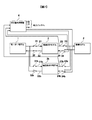
図7は、本発明の第2の実施形態に係るシミュレーターの構成例を示す図である。図7に示すシミュレーターは、第1の実施形態で説明した図1のシミュレーターと同様に、電気自動車の駆動装置をシミュレーション対象としたシステムシミュレーターであり、たとえばコンピューターを用いて実現される。本実施形態のシミュレーターは、第1の実施形態のシミュレーターと比較して、切り替え制御器4に入出力されるパラメーターの種類が異なっている。具体的には、第1の実施形態では、高速ギヤモデル3から出力されるローター回転速度22と、高精度ギヤモデル3bから出力されるローター回転速度22bと、モーターモデル1から出力される電磁トルク21とが、切り替え制御器4に入力され、切り替え制御器4から高速ギヤモデル3と高精度ギヤモデル3bに対して電磁トルク21、21bがそれぞれ出力されていた。一方、本実施形態では、高速ギヤモデル3から出力される車軸トルク23と、高精度ギヤモデル3bから出力される車軸トルク23bと、車両モデル2から出力される車軸回転速度24とが、切り替え制御器4に入力され、切り替え制御器4から高速ギヤモデル3と高精度ギヤモデル3bに対して車軸回転速度24、24bがそれぞれ出力されている。これ以外の点では、本実施形態のシミュレーターは、第1の実施形態のシミュレーターと同様である。
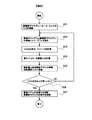
図8は、本発明の第2の実施形態に係るシミュレーターにおいてモードを切り替える際の制御手順例を示したフロー図である。以下では、図8のフロー図に従って、本実施形態のシミュレーターの動作を説明する。なお、図7のシミュレーターにおいて、切り替え制御器4は、予め設定されたモード切り替えのタイミングになると、図8のフロー図に示す処理を開始する。
まずステップS71において、切り替え制御器4は、スイッチ31bを切断状態から接続状態に切り替えて、高精度ギヤモデル3bへモータートルク、すなわち電磁トルク21bの入力を接続する。すなわち、それまでは高速ギヤモデル3のみに入力されていたモーターモデル1からの電磁トルク21を、高速ギヤモデル3と高精度ギヤモデル3bに電磁トルク21、21bとしてそれぞれ入力されるようにする。これにより、高速ギヤモデル3での計算結果を用いて、高精度ギヤモデル3bにおける内部の状態量の変動が開始される。
次にステップS72において、切り替え制御器4は、入力された電磁トルク21に応じて高速ギヤモデル3から出力される車軸トルク23と、入力された電磁トルク21bに応じて高精度ギヤモデル3bから出力される車軸トルク23bとを検出する。なお、以下の説明では、高速ギヤモデル3からの車軸トルク23の検出値を車軸トルクTとし、高精度ギヤモデル3bからの車軸トルク23bの検出値を車軸トルクTbとする。
次にステップS73において、切り替え制御器4は、ステップS72で検出した車軸トルクTと車軸トルクTbとを比較する。ここでは、車軸トルクTbと車軸トルクTとの差分δtを計算することで、これらの比較を行う。
次にステップS74において、切り替え制御器4は、ステップS73で算出した差分δtに基づいて、高精度ギヤモデル3bに対する制御量Vaを計算する。ここでは、車両モデル2から出力された車軸回転速度24の値を検出し、その車軸回転速度24の値に応じて、差分δtの絶対値が縮小するように制御量Vaを決定する。このとき、たとえば一般的なPID制御を用いて制御量Vaを演算してもよいし、予め設定されたマップ情報などを用いて制御量Vaを決定してもよい。少なくとも差分δtの絶対値を縮小できるものであれば、どのような方法で制御量Vaを決定してもよい。
次にステップS75において、切り替え制御器4は、ステップS74で計算した制御量Vaを、高精度ギヤモデル3bの車軸回転速度入力へ供給する。すなわち、制御量Vaに応じた車軸回転速度24bを、切り替え制御器4からスイッチ34bを介して高精度ギヤモデル3bに入力する。なお、スイッチ34bは、車両モデル2と高精度ギヤモデル3bとの間が切断状態であるときには、切り替え制御器4と高精度ギヤモデル3bとの間が接続状態になっている。これにより、電磁トルク21bに加えて、差分δtに応じて調整した車軸回転速度24bをさらに高精度ギヤモデル3bに入力して、差分δtの絶対値が小さくなるように高精度ギヤモデル3bを動作させる。
次にステップS76において、切り替え制御器4は、ステップS72で検出した車軸トルクTと車軸トルクTbとがおおよそ等しいか否かを判定する。ここでは、たとえばステップS73で計算した差分δtの絶対値が所定の基準値以下であるか否かを判断する。その結果、差分δtの絶対値が基準値以下であれば、車軸トルクTと車軸トルクTbとがおおよそ等しいと判定し、ステップS77に進む。一方、差分δtの絶対値が基準値を超えている場合は、車軸トルクTと車軸トルクTbとがおおよそ等しくないと判定し、ステップS72に戻ってステップS72以降の処理を再度実行する。
ステップS77において、切り替え制御器4は、高速ギヤモデル3の全端子、すなわちスイッチ31,32,33,34を接続状態から切断状態に切り替えると共に、高精度ギヤモデル3bの全端子、すなわちステップS71で接続済みのスイッチ31bを除いた残りのスイッチ32b,33b,34bを切断状態から接続状態に切り替える。これにより、モーターモデル1および車両モデル2と高精度ギヤモデル3bとを接続すると共に、モーターモデル1および車両モデル2と高速ギヤモデル3とを切り離して、第1モードから第2モードへの切り替えが実施されるようにする。ステップS77の処理を実行したら、切り替え制御器4は図8のフロー図を終了する。
以上説明した本発明の第2の実施形態によれば、以下の作用効果を奏する。
(1)本実施形態のシミュレーターでは、第1モードと第2モードのそれぞれにおいて、第1の実施形態と同様の動作をコンピューターに行わせる。さらに、第1モードから第2モードに切り替える際に、電磁トルク21、21bを、高速ギヤモデル3および高精度ギヤモデル3bにそれぞれ入力し(ステップS71)、入力された電磁トルク21bに応じて高精度ギヤモデル3bから出力される車軸トルク23bと、入力された電磁トルク21に応じて高速ギヤモデル3から出力される車軸トルク23と、の比較を行い(ステップS73)、その比較の結果が所定の基準を満たしたときに(ステップS76:Yes)、モーターモデル1および車両モデル2と高精度ギヤモデル3bとを接続すると共に、モーターモデル1および車両モデル2と高速ギヤモデル3とを切り離すことで、第1モードから第2モードへの切り替えを実施する(ステップS77)ように、コンピューターを動作させる。このようにしたので、第1の実施形態で説明したのと同様に、変数値の変換を行わずに計算途中でのモード切り替えを実現でき、その結果、システム開発効率の高いシミュレーション方法を提供できる。
(2)ステップS73の比較では、高精度ギヤモデル3bから出力される車軸トルク23bの値Tbと、高速ギヤモデル3から出力される車軸トルク23の値Tとの差分δtを算出する。そして、算出した差分δtの絶対値が所定の基準値以下となったときに、ステップS76を肯定判定してステップS77を実行し、モーターモデル1および車両モデル2と高精度ギヤモデル3bとを接続すると共に、モーターモデル1および車両モデル2と高速ギヤモデル3とを切り離すことで、第1モードから第2モードへの切り替えを実施するように、コンピューターを動作させる。このようにしたので、第1の実施形態で説明したのと同様に、適切なタイミングで第1モードから第2モードへの切り替えを行うことができる。
(3)本実施形態のシミュレーターでは、第1モードから第2モードへの切り替えの際に、高精度ギヤモデル3bに入力される車軸回転速度24bの値を調整する(ステップS74、S75)ことで差分δtが小さくなるように、コンピューターを動作させる。具体的には、高精度ギヤモデル3bから出力される車軸トルク23bの値Tbと高速ギヤモデル3から出力される車軸トルク23の値Tとの差分δtに応じて調整した制御量VaをステップS74で計算し、この制御量Vaに応じた車軸回転速度24bをステップS75でさらに高精度ギヤモデル3bに入力することで、差分δtが小さくなるようにコンピューターを動作させる。このようにしたので、第1の実施形態で説明したのと同様に、第1モードから第2モードへの切り替えをスムーズに行うことができる。
なお、本実施形態においても、第1の実施形態で説明した各変形例が可能である。また、第2モードから第1モードへの切り替えについても、高速ギヤモデル3と高精度ギヤモデル3bとを入れ替えることで、同様の手順により行うことが可能である。
(第3の実施形態)
以上説明した第1および第2の実施形態では、単独のコンピューター上で実行されるシミュレーターの例を説明したが、本発明はこれに限定されず、複数のコンピューターに分散させてシミュレーターを実現してもよい。本実施形態では、それぞれ部分的に計算を実行する複数のコンピューターを用いたシミュレーターの例を説明する。
以上説明した第1および第2の実施形態では、単独のコンピューター上で実行されるシミュレーターの例を説明したが、本発明はこれに限定されず、複数のコンピューターに分散させてシミュレーターを実現してもよい。本実施形態では、それぞれ部分的に計算を実行する複数のコンピューターを用いたシミュレーターの例を説明する。
図9は、本発明の第3の実施形態に係るシミュレーターの構成例を示す図である。図9に示すシミュレーターは、第1の実施形態で説明した図1のシミュレーターと比較して、高速ギヤモデル3と高精度ギヤモデル3bが配置されていた部分にメイン通信I/F83が配置されており、このメイン通信I/F83と、モーターモデル1、車両モデル2および切り替え制御器4とが、メインコンピューター81上で実現されている。また、高速ギヤモデル3と高精度ギヤモデル3bとは、それぞれ別個のサブコンピューター82、82b上で実現されている。サブコンピューター82では、高速ギヤモデル3がサブ通信I/F84に接続されており、サブコンピューター82bでは、高精度ギヤモデル3bがサブ通信I/F84bに接続されている。メイン通信I/F83、サブ通信I/F84およびサブ通信I/F84bは、不図示のネットワーク等を介して相互に接続されており、互いに通信を行って各パラメーターの受け渡しを実施できるように構成されている。
以上説明した本発明の第3の実施形態によれば、複数のコンピューターを用いて、第1の実施形態と同様の計算結果を得ることができる。また、複数のコンピューターに計算負荷を分散させることにより、少ないハードウェア資源でも高速に計算結果を得ることができる。さらに、各コンピューターの設置場所には制約がないため、物理的な専有面積や電力消費を分散させることも可能である。そのため、シミュレーション実行効率のさらなる向上を図ることができる。
なお、本実施形態では、第1の実施形態で説明したシミュレーターを複数のコンピューターに分散させた例を説明したが、第2の実施形態で説明したシミュレーターを複数のコンピューターに分散させることも可能である。また、本実施形態においても、第1の実施形態で説明した各変形例が可能である。
(第4の実施形態)
以上説明した第1~第3の実施形態では、電気自動車の駆動装置をシミュレーション対象としたシステムシミュレーターの例を説明したが、本発明はこれに限定されず、様々な種類のシミュレーターに適用可能である。本実施形態では、電気モーターを用いた電動装置をシミュレーション対象としたシステムシミュレーターの例を説明する。
以上説明した第1~第3の実施形態では、電気自動車の駆動装置をシミュレーション対象としたシステムシミュレーターの例を説明したが、本発明はこれに限定されず、様々な種類のシミュレーターに適用可能である。本実施形態では、電気モーターを用いた電動装置をシミュレーション対象としたシステムシミュレーターの例を説明する。
図10は、本発明の第4の実施形態に関する従来のシミュレーターの構成例を示す図である。図10に示す従来のシミュレーターでは、バッテリーモデル5と機構モデル6が高精度モーターモデル1bを介して接続されている。バッテリーモデル5、高精度モーターモデル1bおよび機構モデル6は、シミュレーション対象である電動装置を構成する各要素(バッテリー、モーター、駆動機構)をそれぞれモデル化したものである。なお、モーターが交流モーターである場合、高精度モーターモデル1bはインバーターを含んでモデル化することが好ましい。
図10のシミュレーターでは、各モデル間の情報伝達用のパラメーターとして、電磁トルク21、ローター回転速度22、直流電圧25、直流電流26が用いられる。図10の矢印の向きは、各パラメーターによる情報の伝達方向を示している。すなわち、図10のシミュレーターは、バッテリーモデル5の発生する直流電圧25を高精度モーターモデル1bを通して電磁トルク21に変換し、機構モデル6に伝達する。また、機構モデル6の状態に応じたローター回転速度22を高精度モーターモデル1bを通して直流電流26に変換し、バッテリーモデル5に入力する。このときのバッテリーモデル5、高精度モーターモデル1bおよび機構モデル6の状態をそれぞれ計算することで、電動装置の動きをシミュレーションする。
図11は、本発明の第4の実施形態に係るシミュレーターの構成例を示す図である。図11に示すシミュレーターは、図10に示した従来のシミュレーターと比較して、さらに高速モーターモデル1cが高精度モーターモデル1bと並列に配置されている。高速モーターモデル1cは、高精度モーターモデル1bと同様に、シミュレーション対象である電動装置を構成する要素の一つであるモーターをモデル化したものである。
図11のシミュレーターは、第1の実施形態で説明した図1のシミュレーターと同様に、切り替え制御器4を有している。この切り替え制御器4の制御により、高精度モーターモデル1bを用いて計算を行うモードと、高速モーターモデル1cを用いて計算を行うモードとを、第1の実施形態と同様の手法で切り替えることができる。
以上説明した本発明の第4の実施形態によれば、電気モーターを用いた電動装置をシミュレーション対象としたシステムシミュレーターにおいても、第1の実施形態で説明したのと同様の効果を得ることができる。
なお、本実施形態では、第1の実施形態と同様の手法でモード切り替えを行う電動装置のシミュレーターの例を説明したが、第2の実施形態で説明したのと同様の手法でモード切り替えを行う電動装置のシミュレーターにも適用可能である。また、本実施形態においても、第1の実施形態で説明した各変形例が可能である。さらに、単独のコンピューター上で実現されるシミュレーターとしてもよいし、あるいは第3の実施形態で説明したように、複数のコンピューターに分散されたシミュレーターとしてもよい。
なお、本発明は上記した各実施形態や各種変形例に限定されるものではなく、それ以外にも様々な変形が可能である。たとえば、上記の各実施形態は本発明を分かりやすく説明するために詳細に説明したものであり、必ずしも説明した全ての構成を備えるものに限定されない。また、ある実施形態の構成の一部を他の実施形態の構成に置き換えたり、ある実施形態の構成に他の実施形態の構成を加えたりすることも可能である。すなわち、各実施形態の構成の一部について、他の構成の追加・削除・置換をすることが可能である。
また、上記の各構成、機能、処理部、処理手段等は、それらの一部又は全部を、例えば集積回路のハードウェアで実現してもよい。あるいは、上記の各構成、機能等をソフトウェアで実現し、プロセッサがそれぞれの機能を実現するプログラムを解釈して実行することとしてもよい。また、上記の各実施形態において、制御線や情報線は説明上必要と考えられるものを示しており、製品上必ずしも全ての制御線や情報線を示しているとは限らない。実際には殆ど全ての構成が相互に接続されていると考えてもよい。
以上説明した各実施形態や各種変形例はあくまで一例であり、発明の特徴が損なわれない限り、本発明はこれらの内容に限定されるものではない。また、上記では種々の実施形態や変形例を説明したが、本発明はこれらの内容に限定されるものではない。本発明の技術的思想の範囲内で考えられるその他の態様も本発明の範囲内に含まれる。
1 モーターモデル
1b 高精度モーターモデル
1c 高速モーターモデル
2 車両モデル
3 高速ギヤモデル
3b 高精度ギヤモデル
4 切り替え制御器
5 バッテリーモデル
6 機構モデル
21,21b 電磁トルク
22,22b ローター回転速度
23,23b 車軸トルク
24,24b 車軸回転速度
31,32,33,34,31b,32b,33b,34b スイッチ
1b 高精度モーターモデル
1c 高速モーターモデル
2 車両モデル
3 高速ギヤモデル
3b 高精度ギヤモデル
4 切り替え制御器
5 バッテリーモデル
6 機構モデル
21,21b 電磁トルク
22,22b ローター回転速度
23,23b 車軸トルク
24,24b 車軸回転速度
31,32,33,34,31b,32b,33b,34b スイッチ
Claims (6)
- コンピューターを用いてシミュレーション対象に関する計算を行うシミュレーション方法であって、
前記シミュレーション対象は、第1要素および第2要素と、前記第1要素と前記第2要素の間に介在する中間要素と、を含み、
前記コンピューターを、前記第1要素をモデル化した第1モデルと、前記第2要素をモデル化した第2モデルと、前記中間要素をそれぞれモデル化した第1中間モデルおよび第2中間モデルと、としてそれぞれ機能させ、
前記第1モデルと前記第2モデルが前記第1中間モデルを介して情報を送受信する第1モードと、前記第1モデルと前記第2モデルが前記第2中間モデルを介して情報を送受信する第2モードと、のいずれかにより、前記コンピューターに前記計算を実行させ、
前記第1モードでは、前記第1モデルから出力される第1パラメーターを前記第1中間モデルに入力し、入力された前記第1パラメーターに応じて前記第1中間モデルから出力される第2パラメーターを前記第2モデルに入力すると共に、前記第2モデルから出力される第3パラメーターを前記第1中間モデルに入力し、入力された前記第3パラメーターに応じて前記第1中間モデルから出力される第4パラメーターを前記第1モデルに入力するように、前記コンピューターを動作させ、
前記第2モードでは、前記第1モデルから出力される第1パラメーターを前記第2中間モデルに入力し、入力された前記第1パラメーターに応じて前記第2中間モデルから出力される第2パラメーターを前記第2モデルに入力すると共に、前記第2モデルから出力される第3パラメーターを前記第2中間モデルに入力し、入力された前記第3パラメーターに応じて前記第2中間モデルから出力される第4パラメーターを前記第1モデルに入力するように、前記コンピューターを動作させ、
前記第1モードから前記第2モードに切り替える際に、
前記第1パラメーターまたは前記第3パラメーターを、前記第1中間モデルおよび前記第2中間モデルに入力し、
入力された前記第1パラメーターまたは前記第3パラメーターに応じて前記第2中間モデルから出力される前記第2パラメーターまたは前記第4パラメーターと、入力された前記第1パラメーターまたは前記第3パラメーターに応じて前記第1中間モデルから出力される前記第2パラメーターまたは前記第4パラメーターと、の比較を行い、
前記比較の結果が所定の基準を満たしたときに、前記第1モデルおよび前記第2モデルと前記第2中間モデルとを接続すると共に、前記第1モデルおよび前記第2モデルと前記第1中間モデルとを切り離すことで、前記第1モードから前記第2モードへの切り替えを実施するように、前記コンピューターを動作させるシミュレーション方法。 - 請求項1に記載のシミュレーション方法において、
前記比較では、前記第2中間モデルから出力される前記第2パラメーターまたは前記第4パラメーターと、前記第1中間モデルから出力される前記第2パラメーターまたは前記第4パラメーターとの差分を算出し、
算出した前記差分の絶対値が所定の基準値以下となったときに、前記第1モデルおよび前記第2モデルと前記第2中間モデルとを接続すると共に、前記第1モデルおよび前記第2モデルと前記第1中間モデルとを切り離すことで、前記第1モードから前記第2モードへの切り替えを実施するように、前記コンピューターを動作させるシミュレーション方法。 - 請求項2に記載のシミュレーション方法において、
前記第2中間モデルに入力される前記第1パラメーターおよび前記第3パラメーターの少なくとも一方の値を調整することで前記差分が小さくなるように、前記コンピューターを動作させるシミュレーション方法。 - 請求項3に記載のシミュレーション方法において、
前記第1モードから前記第2モードに切り替える際に、前記第3パラメーターを前記第1中間モデルおよび前記第2中間モデルに入力する場合には、前記第2中間モデルから出力される前記第4パラメーターと前記第1中間モデルから出力される前記第4パラメーターとの差分に応じて調整した前記第1パラメーターをさらに前記第2中間モデルに入力することで、前記差分が小さくなるように前記コンピューターを動作させ、
前記第1モードから前記第2モードに切り替える際に、前記第1パラメーターを前記第1中間モデルおよび前記第2中間モデルに入力する場合には、前記第2中間モデルから出力される前記第2パラメーターと前記第1中間モデルから出力される前記第2パラメーターとの差分に応じて調整した前記第3パラメーターをさらに前記第2中間モデルに入力することで、前記差分が小さくなるように前記コンピューターを動作させるシミュレーション方法。 - 請求項4に記載のシミュレーション方法において、
調整した前記第1パラメーターまたは前記第3パラメーターをさらに前記第2中間モデルに入力する際には、単位時間当たりの入力変化量を所定値以下に制限するシミュレーション方法。 - 請求項1から請求項5までのいずれか一項に記載のシミュレーション方法において、
前記第1モードから前記第2モードに切り替える際に前記第1中間モデルおよび前記第2中間モデルに入力される前記第1パラメーターまたは前記第3パラメーターは、アクロス変数であるシミュレーション方法。
Applications Claiming Priority (2)
| Application Number | Priority Date | Filing Date | Title |
|---|---|---|---|
| JP2017-191939 | 2017-09-29 | ||
| JP2017191939A JP6868530B2 (ja) | 2017-09-29 | 2017-09-29 | シミュレーション方法 |
Publications (1)
| Publication Number | Publication Date |
|---|---|
| WO2019064832A1 true WO2019064832A1 (ja) | 2019-04-04 |
Family
ID=65901247
Family Applications (1)
| Application Number | Title | Priority Date | Filing Date |
|---|---|---|---|
| PCT/JP2018/026643 Ceased WO2019064832A1 (ja) | 2017-09-29 | 2018-07-17 | シミュレーション方法 |
Country Status (2)
| Country | Link |
|---|---|
| JP (1) | JP6868530B2 (ja) |
| WO (1) | WO2019064832A1 (ja) |
Citations (2)
| Publication number | Priority date | Publication date | Assignee | Title |
|---|---|---|---|---|
| JP2006209491A (ja) * | 2005-01-28 | 2006-08-10 | Matsushita Electric Ind Co Ltd | 回路シミュレーション方法および回路シミュレーション装置 |
| JP2014115520A (ja) * | 2012-12-11 | 2014-06-26 | Toshiba Corp | シミュレーションモデル切替プログラム、シミュレーションモデル切替方法、およびシミュレーションモデル切替装置 |
-
2017
- 2017-09-29 JP JP2017191939A patent/JP6868530B2/ja active Active
-
2018
- 2018-07-17 WO PCT/JP2018/026643 patent/WO2019064832A1/ja not_active Ceased
Patent Citations (2)
| Publication number | Priority date | Publication date | Assignee | Title |
|---|---|---|---|---|
| JP2006209491A (ja) * | 2005-01-28 | 2006-08-10 | Matsushita Electric Ind Co Ltd | 回路シミュレーション方法および回路シミュレーション装置 |
| JP2014115520A (ja) * | 2012-12-11 | 2014-06-26 | Toshiba Corp | シミュレーションモデル切替プログラム、シミュレーションモデル切替方法、およびシミュレーションモデル切替装置 |
Also Published As
| Publication number | Publication date |
|---|---|
| JP2019068621A (ja) | 2019-04-25 |
| JP6868530B2 (ja) | 2021-05-12 |
Similar Documents
| Publication | Publication Date | Title |
|---|---|---|
| CN101278242B (zh) | 用于仿真电气/电子负载的方法和装置 | |
| Zhang et al. | Optimal Control Strategy Design Based on Dynamic Programming for a Dual‐Motor Coupling‐Propulsion System | |
| CN113569476B (zh) | 一种利用动态参数混合实现混合维联合仿真的方法 | |
| CN103939597A (zh) | 模拟装置 | |
| CN109495050A (zh) | 基于二次型价值函数的双电机转矩同步模型预测控制方法 | |
| Padilla-García et al. | Selection/control concurrent optimization of BLDC motors for industrial robots | |
| CN110162007A (zh) | 一种车辆故障的检测系统和检测方法 | |
| CN105910815A (zh) | 一种变速器换挡性能测试系统及测试方法 | |
| Filippa et al. | Modeling of a hybrid electric vehicle powertrain test cell using bond graphs | |
| CN115891677A (zh) | 一种电动车辆动力系统的控制装置及其相关设备 | |
| Li et al. | Compensation control of PMSMs based on a high-order sliding mode observer with inertia identification | |
| CN102750422A (zh) | 一种电动车驱动系统的设计方法 | |
| US11222150B2 (en) | Simulation program | |
| Kandhasamy | Machine learning based SRM control using FPGAs for torque ripple minimization | |
| Khan et al. | Machine learning applied to the design and analysis of low frequency electromagnetic devices | |
| Gökbulut et al. | A virtual electrical drive control laboratory: Neuro‐fuzzy control of induction motors | |
| JP2019068621A (ja) | シミュレーション方法 | |
| Ciornei et al. | Real-Time simulation of a complete electric vehicle based on NI VeriStand integration platform | |
| Girovský et al. | Shaft sensor-less FOC control of an induction motor using neural estimators | |
| CN102064752A (zh) | 能量互馈式双直线感应电机操动机构控制装置及控制方法 | |
| Chen | Model reference adaptive minimum‐energy control for a mechatronic elevator system | |
| Marzi | Fuzzy control of an inverted pendulum using AC induction motor actuator | |
| Han et al. | Torque distribution strategy for modular cascade machines used in EVs | |
| Rodic et al. | Use of dynamic emulation of mechanical loads in the testing of electrical vehicle driveline control algorithms | |
| Ismail et al. | Master Slave Technique for Speed Synchronization of a Multi-Motor System with a Dynamic Master Motor. |
Legal Events
| Date | Code | Title | Description |
|---|---|---|---|
| 121 | Ep: the epo has been informed by wipo that ep was designated in this application |
Ref document number: 18861601 Country of ref document: EP Kind code of ref document: A1 |
|
| NENP | Non-entry into the national phase |
Ref country code: DE |
|
| 122 | Ep: pct application non-entry in european phase |
Ref document number: 18861601 Country of ref document: EP Kind code of ref document: A1 |