WO2019059304A1 - Heating cooker - Google Patents
Heating cooker Download PDFInfo
- Publication number
- WO2019059304A1 WO2019059304A1 PCT/JP2018/034893 JP2018034893W WO2019059304A1 WO 2019059304 A1 WO2019059304 A1 WO 2019059304A1 JP 2018034893 W JP2018034893 W JP 2018034893W WO 2019059304 A1 WO2019059304 A1 WO 2019059304A1
- Authority
- WO
- WIPO (PCT)
- Prior art keywords
- image
- heating
- unit
- camera
- color
- Prior art date
Links
Images


Classifications
-
- H—ELECTRICITY
- H05—ELECTRIC TECHNIQUES NOT OTHERWISE PROVIDED FOR
- H05B—ELECTRIC HEATING; ELECTRIC LIGHT SOURCES NOT OTHERWISE PROVIDED FOR; CIRCUIT ARRANGEMENTS FOR ELECTRIC LIGHT SOURCES, IN GENERAL
- H05B6/00—Heating by electric, magnetic or electromagnetic fields
- H05B6/02—Induction heating
- H05B6/10—Induction heating apparatus, other than furnaces, for specific applications
- H05B6/12—Cooking devices
Definitions
- the present invention relates to a heating cooker for heating an object to be cooked.
- a heating cooker which shoots a cooking object with a camera and controls heating of the cooking object based on an image of the cooking object shown in the photographed image (see, for example, Patent Document 1).
- the color tone of the image of the object to be cooked that is captured in the captured image of the camera changes.
- the entire photographed image, that is, the image to be cooked may become reddish (the hue changes).
- the entire photographed image, that is, the image to be cooked may be whitened (color saturation may be reduced) by the light of the light.
- the color tone of the image of the cooking object shown to a picked-up image will also differ.
- the heating of the cooking target is appropriately performed without being affected by changes or differences in the light environment. Make it a task.
- a main body including a top surface including a container placement unit on which a container containing a cooking target is placed;
- a heating unit configured to heat the container placed on the container placement unit from below;
- a marker provided on the main body and photographed by the camera;
- the color tone of the image of the marker in the photographed image of the camera is measured, and based on the measurement result, the photographed image is color corrected so that the image of the marker is photographed in the actual color of the marker itself in the photographed image.
- the image processing unit to A cooking target state estimation unit that estimates the state of the cooking target based on the image of the cooking target captured in the captured image that has been color-corrected by the image processing unit; And a heating control unit configured to control the heating unit based on the state of the cooking target estimated by the cooking target state estimation unit.
- a container containing the object to be cooked A main body including a top surface including a container placement unit on which the container is placed; A heating unit configured to heat the container placed on the container placement unit from below; A camera for photographing the cooking object; A marker provided in the container and photographed by the camera; The color tone of the image of the marker in the photographed image of the camera is measured, and based on the measurement result, the photographed image is color corrected so that the image of the marker is photographed in the actual color of the marker itself in the photographed image.
- the image processing unit to A cooking target state estimation unit that estimates the state of the cooking target image based on the cooking target image captured in the captured image that has been color-corrected by the image processing unit; And a heating control unit configured to control the heating unit based on the state of the cooking target estimated by the cooking target state estimation unit.
- the heating cooker which controls the heating of the cooking object based on the image of the cooking object shown in the photographed image of the camera, the heating of the cooking object is appropriately performed without being influenced by the change or difference of the light environment. It can be carried out.
- FIG. 1 Schematic perspective view of the heating cooker according to Embodiment 1 of the present invention
- FIG. 2 Top view of the top plate of the cooker A diagram schematically showing the configuration of a heating cooker Block diagram showing the control system of the heating cooker
- a diagram showing a photographed image of an example of a camera Flowchart diagram showing the flow of geometric correction of a photographed image
- a diagram showing a photographed image with keystone correction A diagram showing a size-corrected photographed image
- FIG. position-corrected and rotation-corrected captured image Flow chart showing the flow of color correction of a photographed image
- FIG. 2 Top view of the top plate of the cooker A diagram schematically showing the configuration of a heating cooker Block diagram showing the control system of the heating cooker Flow chart showing the flow of color correction of a photographed image
- a diagram showing a photographed image of an example of a camera A diagram showing an example of a reference chart for adjustment Diagram showing standard RGB values and detected RGB values
- the heating cooker includes, from below, a main body including a top surface including a container placement unit on which a container containing a cooking object is placed, and the container placed on the container placement unit from below
- An image processing unit that performs color correction on the captured image so that the image of the marker is captured in the actual color of the marker itself in the captured image; and cooking that is captured in the captured image color-corrected by the image processing unit
- a cooking target state estimation unit that estimates the state of the cooking target based on an image of the target, and a heating control unit that controls the heating unit based on the cooking target state estimated by the cooking target state estimation unit It has a.
- a heating cooker for controlling heating of a cooking target based on an image of the cooking target shown in a captured image of a camera, wherein the heating of the cooking target is not affected by changes or differences in the light environment. You can do it properly.
- the hue may be at least one of hue, saturation, and lightness.
- hue, saturation, and lightness By using these as parameters of color tone, color correction can be appropriately performed.
- the marker is provided on the top surface of the main body.
- the image of the object to be cooked that is, the image of the liquid surface is appropriately color corrected under the color correction condition calculated based on the color of the image of the marker provided on the horizontal top surface it can.
- the marker may be provided on a portion of the top surface other than the container placement unit. This prevents the container from being placed on the marker.
- each of the plurality of markers is associated with the plurality of heating units, and in the vicinity of the container placement unit facing the corresponding heating unit.
- the image processing unit calculates a color correction condition for each of the images of the plurality of markers, and the plurality of cooking objects corresponding to the container placement unit in the photographed image are calculated according to the calculated color correction conditions. Color correct the area. Thereby, the image of the cooking object heated by each of the plurality of heating units can be color-corrected separately.
- each of the plurality of markers is provided at the center of each heating unit as viewed from above the top surface of the main body.
- the marker can indicate the position of the heating unit, and can also function as a mark indicating the container mounting position.
- the image processing unit includes a reference chart display unit that displays a reference chart for color correction as the marker, the camera is installed at a position away from the top surface, and images the container and the cooking target
- the image processing apparatus further includes a color correction unit that performs color correction of an image captured by the camera using a pixel value of a reference chart included in the image captured by the camera.
- the cooking target state estimation unit recognizes that the cooking target in the image captured by the camera has reached a predetermined color, and the cooking target state estimation unit determines the cooking target in the image. Upon recognizing that the color has been reached, the heating control unit performs control to increase or decrease the heating output.
- an illumination state detection unit for detecting an illumination state around the top surface of the top plate is provided during heating output from the heating unit, and the color is detected when a change in the illumination state is detected by the illumination state detection unit.
- the correction unit performs color correction again using the pixel values of the reference chart included in the image captured by the camera.
- the illumination state detection unit when the illumination state detection unit does not detect an illumination state greater than a predetermined brightness, a warning is notified to the user.
- the display unit displays a heating condition of the heating unit, and when the image processing unit does not recognize the reference chart, a warning is notified from the display unit to the user.
- the heating unit has a heating coil that generates an induction magnetic field to heat the container, and the heating control unit supplies a high frequency current to the heating coil to heat the container.
- the distance from the camera to the top surface of the top plate is 600 mm or more and 2000 mm or less. With this distance, the entire top surface within the field of view of the camera can be photographed properly.
- a heating cooker is a container containing a cooking object, a main body including a top surface provided with a container mounting unit on which the container is mounted, and the container mounted on the container mounting unit.
- the color of the image of the marker which is provided in the heating unit which heats the container from below, the camera which shoots the cooking object, the container and which is provided in the container and which is photographed by the camera and which is photographed in the photographed image of the camera
- An image processing unit that performs color correction on the photographed image so that the image of the marker is captured in the actual color of the marker itself in the photographed image based on the measurement result; and photographing that is color-corrected by the image processing unit
- a cooking target state estimation unit for estimating the state of the cooking target image based on the image of the cooking target in the image, and the heating unit based on the cooking target state estimated by the cooking target state estimation unit It has a heating control unit that, the.
- a heating cooker that controls heating of a cooking target based on an image of the cooking target shown in a captured image of a camera, wherein the heating of the cooking target is not affected by changes or differences in the light environment. You can do it properly.
- Embodiment 1 Hereinafter, Embodiment 1 of the present invention will be described with reference to the drawings.
- FIG. 1 is a schematic perspective view of a heating cooker according to a first embodiment of the present invention.
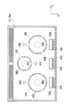
- FIG. 2 is a top view of the top plate of a heating cooker.
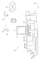
- FIG. 3 is a diagram schematically showing the configuration of the heating cooker.
- FIG. 4 is a block diagram showing a control system of the heating cooker.
- the X-axis direction indicates the width direction (longitudinal direction) of the heating cooker
- the Y-axis direction indicates the depth direction
- the Z-axis direction indicates the height direction.
- the heating cooker 10 has a main body 12 and, as an upper portion of the main body 12, a top plate 14 on which a container C containing a cooking target T such as a stew is placed. Have.
- the top surface 14 a of the top plate 14 is provided with a container placement unit on which the container C is placed.
- the main body 12 includes the top surface 14 a including the container placement unit on which the container C containing the cooking target T is placed.
- the heating cooker 10 is an induction heating cooker, and as shown in FIG. 1 and FIG. 3, it is placed on the container mounting portion (container mounting area described later) in the top plate 14. Below the placed container C, that is, in the main body 12, heating coils 16A to 16C are disposed as heating parts of the heating cooker 10. The heating coils 16A to 16C inductively heat the container C placed on the container placement part on the top plate 14 from below. The heating coils 16A to 16C generate an induction magnetic field to heat the container C.
- a plurality of touch keys 18A to 18C are provided on a portion of the top plate 14 on the front surface 10a side of the heating cooker 10, as operation units for the user to operate the heating coils 16A to 16C, respectively. For example, heating of the corresponding heating coil 16A is started or stopped by the touch key 18A. In addition, the heating level (for example, four stages) is adjusted.
- a plurality of output display units 20A to 20C for displaying the output state (heating level) of the heating coils 16A to 16C are also provided on the top plate 14 on the front surface 10a side of the heating cooker 10.
- a setting unit 22 is provided on the front surface 10a side of the heating cooker 10.
- the setting unit 22 can be inserted into and taken out of the main body 12, and the setting key 22a for setting the heating by the heating coils 16A to 16C in detail, the setting contents thereof, the detailed state of the heating coils 16A to 16C, etc.
- a setting display unit 22b for displaying.
- the setting portion 22 sets the heating temperature, the heating time, the timer, etc. of the heating coils 16A to 16C.
- the heating cooker 10 equips the front surface 10a side of the heating cooker 10 with alerting
- the heating cooker 10 has a plurality of temperature sensors 26A to 26C for detecting the temperature of the container C placed on the top plate 14 and a weight for detecting the weight of the container C placed on the top plate 14 And a sensor 28.
- the plurality of temperature sensors 26A to 26C are disposed below the top plate 14 and at the centers of the heating coils 16A to 16C. That is, for example, the temperature sensor 26A is disposed above the heating coil 16A and detects the temperature on the bottom side of the container C inductively heated by the heating coil 16A through the top plate 14.
- the weight sensor 28 determines the weight of the object on the top plate 14, that is, when there are a plurality of containers C, the weights of the plurality of containers C and the cooking contained in each container C. Detect the sum of the subject's weight.
- the heating cooker 10 has the camera 30 which image
- the camera 30 is, for example, a camera capable of capturing still images, moving images, infrared images, etc., and captures the entire top surface 14 a of the top plate 14 (i.e., the top surface of the main body 12) which is the upper portion of the main body 12.
- the camera 30 is attached to a ceiling or a range hood (not shown) located above the heating cooker 10 or the like.
- the camera 30 is attached to the range hood via a magnet. Therefore, the camera 30 can be installed freely with respect to the main body 12 of the heating cooker 10 (that is, the installation freedom is high). As a result, the camera can be mounted at a position preferred by the user without impairing the design of the kitchen.
- the camera 30 that can be disposed at a position preferred by the user is configured to wirelessly communicate with the control unit 50 of the heating cooker 10.
- the camera 30 is provided with the antenna 32, and the antenna 34 is provided in the main body 12 of the heating cooker 10.
- the camera 30 and the control unit 50 are connected via the router device 36. That is, the camera 30 and the control unit 50 are connected in a wirelessly communicable manner to a local area network 38 centering on the router device 36.
- the router device 36 is connected to the Internet 40.
- the router device 36 is connected to the portable terminal 42 of the user in a wirelessly communicable manner.
- the control unit 50 of the heating cooker 10 is, for example, a processing device such as a CPU, and performs various functions by executing a program stored in the storage unit 60 such as a ROM, a RAM, a hard disk (for example, , And is configured to function as an image processing unit described later. As shown in FIG. 4, the control unit 50 is configured to receive from these signals corresponding to the user's operation on the touch keys 18A to 18C and the setting key 22a of the setting unit 22. The control unit 50 is also configured to receive from them signals corresponding to the temperatures detected by the temperature sensors 26A to 26C, respectively. Control unit 50 is further configured to receive a signal corresponding to the weight detected by weight sensor 28. The control unit 50 is configured to receive from the camera 30 a captured image (data) captured by the camera 30.
- control unit 50 of the heating cooker 10 is configured to control the heating coils 16A to 16C, the output display units 20A to 20C, the setting display unit 22b, and the notification unit 24.
- control unit 50 controls the outputs of the heating coils 16A to 16C so that the temperature sensors 26A to 26C continue to detect the heating temperature set by the user via the setting key 22a of the setting unit 22. Thereby, for example, when frying, the oil accommodated in the container C can be maintained at a constant temperature.
- control unit 50 heats when the temperature sensors 26A to 26C detect the boiling temperature.
- the coils 16A to 16C are stopped, and the user is notified via the notification unit 24 that the water heating is completed.
- control unit 50 is configured to perform various controls based on a captured image of the camera 30, specifically, an image of the cooking object T shown in the captured image.
- the control unit 50 of the heating cooker 10 sets the image acquisition unit 52 that acquires a photographed image from the camera 30, the image processing unit 54 that processes (corrects) the acquired image, and the corrected photographed image.
- a cooking object state estimation unit 56 that estimates the state of the cooking object T based on the image of the cooking object T in the container C, and heating as a heating control unit that controls the heating coils 16A to 16C based on the estimation result It has (functions as) a coil control unit 58.
- the heating coil control unit 58 supplies a high frequency current to the heating coils 16A to 16C to heat the container C.
- the heating coil control unit 58 controls the heating of the container C by controlling the amount of high frequency current supplied.
- the image acquiring unit 52 of the control unit 50 of the heating cooker 10 is a photographed image photographed by the camera 30, for example, a photographing in which the top plate 14 in a state in which the container C accommodating the cooking target T being cooked is placed Acquire an image (data).
- the camera 30 performs shooting at predetermined time intervals.
- FIG. 5 illustrates an example of a photographed image (original image) of the camera 30 acquired by the image acquiring unit 52.
- an image 14 a ′ of the top surface 14 a of the top plate 14 is captured in a captured image P ⁇ b> 0 of the camera 30.
- image T 'of cooking object T is shown by the cross hatching.
- the image processing unit 54 performs image processing on the captured image P0 of the camera 30 acquired by the image acquisition unit 52. Specifically, the image processing unit 54 estimates the state of the cooking target T in a short time with high accuracy based on the image T ′ of the cooking target T captured in the photographed image P0 of the camera 30 by the cooking target state estimation unit 56 As the pre-processing, the photographed image P0 is corrected so that it can be performed. In the case of the first embodiment, geometrical correction and color correction are performed on the captured image P0. First, geometric correction will be described with reference to the flowchart shown in FIG.
- a plurality of markers 44A to 44C provided on the main body 12 of the heating cooker 10 are used.
- the markers 44 A to 44 C are provided on the main body 12 and captured by the camera 30.
- the markers 44A to 44C are alignment markers photographed by the camera 30 in order to facilitate identification of the image T 'of the cooking target T in the photographed image, that is, to specify in a short time with high accuracy.
- the plurality of markers 44A to 44C are provided on the top surface 14a of the top plate 14 (that is, the top surface of the main body 12).
- the markers 44A to 44C are marks drawn on the top surface 14a of the top plate 14 or stickers attached to the top surface 14a.
- the markers 44A to 44C have shapes and colors that can be recognized with high accuracy (it is easy to specify in a captured image of a camera), and in the case of the first embodiment, they are equilateral triangles.
- the plurality of markers 44A to 44C are associated with the heating coils 16A to 16C.
- one vertex of the equilateral triangle-shaped marker is matched by being directed to the heating coil.
- the plurality of markers 44A to 44C correspond to the top plate 14 other than the container placement areas 46A to 46C (container placement portions on which the containers C heated by the heating coils are placed) facing the heating coils 16A to 16C. It is provided in the portion of the top surface 14a. This prevents the container C from being placed on the markers 44A to 44C.
- the marker 44A is associated with the heating coil 16A, and is provided in the vicinity (rear side) of the container placement area 46A facing the heating coil 16A.
- the marker 44B is matched with the heating coil 16B, and is provided in the vicinity (back side) of the container mounting area 46B which opposes the heating coil 16B.
- the marker 44C is matched with the heating coil 16C, and is provided in the vicinity (front side) of the container mounting area 46C which opposes the heating coil 16C.
- the container placement areas 46A to 46C are defined by substantially annular marks 48A to 48C provided on the top surface 14a of the top plate 14, and are presented to the user.
- the images of the markers 44A to 44C can be specified in the photographed image of the camera 30, the area of the photographed image corresponding to the container placement areas 46A to 46C, that is, the cooking target T can be determined based on the positions of the specified markers. Areas in which an image may be present (areas to be cooked RA to RC, see FIG. 9) can be identified with high accuracy in a short time.
- the camera 30 is not at a fixed position with respect to the main body 12 of the heating cooker 10, but can be freely installed. Therefore, the image of the cooking object T is not necessarily captured at a fixed position of the captured image. In the absence of the markers 44A to 44C, since it is necessary to confirm the entire photographed image in order to specify the image of the cooking object T, it takes time to specify the image and a specific error may occur. In addition, since the cooking target T has various shapes and is not a fixed shape or color, the specific time of the image and the probability of a specific error vary depending on the cooking target T.
- the image of the markers 44A to 44C having a certain feature (shape and color) in the photographed image is specified, and the area of the photographed image corresponding to the container mounting area 46A to 46C based on the position of the image of the specified marker.
- the cooking target presence areas RA to RC are identified, and the image of the cooking target T is specified from within the cooking target presence areas RA to RC.
- the image processing unit 54 performs geometrical correction on the photographed image P0 of the camera 30 by using such markers 44A to 44C.
- step S100 the image processing unit 54 forms an image 44A 'to 44C' of a plurality of markers 44A to 44C in the photographed image P0 of the camera 30 shown in FIG. Identify.
- step S110 the image processing unit 54 measures the shapes of the images 44A 'to 44C' of the markers 44A to 44C.
- the shapes of the images 44A 'to 44C' of the markers 44A to 44C in the photographed image P are , And the actual shapes of the markers 44A to 44C themselves. That is, in the case of the first embodiment, since the actual shape is an equilateral triangle, the shapes of the images 44A 'to 44C' should also be equilateral triangles.
- the camera 30 can be freely installed with respect to the main body 12 of the heating cooker 10, the camera 30 is installed with the optical axis 30a not orthogonal to the top surface 14a of the top plate 14 There is a case. In that case, as shown in FIG. 5, the shape of the image 14 'of the top plate 14 is distorted, and the shapes of the images 44A' to 44C 'of the markers 44A to 44C are also distorted so that they are not regular triangles.
- step S120 the image processing unit 54 geometrically corrects the photographed image P0 of the camera 30 based on the shapes of the images 44A 'to 44C' of the markers 44A to 44C measured in step S110. Specifically, the image processing unit 54 compares the shapes of the measured images 44A 'to 44C' with the actual shapes of the markers 44A to 44C themselves, and calculates the correction condition of the keystone correction based on the comparison result. .
- the correction condition is a condition for trapezoidal correction of the shape of the photographed image P0 so that the images 44A 'to 44C' are captured in a shape similar to the actual shapes of the markers 44A to 44C themselves.
- the photographed image P0 is substantially the same as the photographed image obtained when the optical axis 30a of the camera 30 is photographed orthogonal to the top surface 14a of the top plate 14. Are corrected to the same photographed image P1.
- step S130 the image processing unit 54 measures the size of the images 44A 'to 44C' of the markers 44A to 44C in the captured image P1. Then, in the subsequent step S140, the image processing unit 54 corrects the size of the photographed image P1 of the camera 30 based on the size measured in step S130. Specifically, the photographed image is subjected to enlargement correction or reduction correction so that the images 44A 'to 44C' appear in the photographed image in a predetermined size determined in advance. By this size correction, as shown in FIG. 8, the photographed image P1 is substantially the same as the photographed image obtained when photographed with the distance between the camera 30 and the top surface 14a of the top plate 14 being a predetermined distance. Is corrected to the same photographed image P2.
- step S150 the image processing unit 54 measures the positions and orientations of the images 44A 'to 44C' of the markers 44A to 44C in the captured image P2. Then, in the subsequent step S160, the image processing unit 54 performs position correction and rotation correction on the captured image P2 of the camera 30 based on the position and orientation measured in step S150. Specifically, the photographed image is subjected to position correction and rotational correction so that the images 44A 'to 44C' are captured at predetermined positions and postures determined in advance. As a result of these corrections, as shown in FIG. 9, the photographed image P2 is obtained when the camera 30 is photographed at a predetermined position relative to the main body 12 of the heating cooker 10 in a predetermined posture.
- the captured image P3 is corrected to be substantially the same as the image.
- the predetermined position is, for example, the position of the camera 30 such that the optical axis 30 a of the camera 30 passes the center of the top plate 14.
- the predetermined posture is, for example, a rotation posture of the camera 30 centered on the optical axis 30 a such that the longitudinal direction (X-axis direction) of the top plate 14 coincides with the longitudinal direction of the photographed image.
- step S160 When the position correction and the rotation correction in step S160 are completed, the geometrical correction on the captured image P0 of the camera 30 by the image processing unit 54 is completed.
- Such geometrical correction makes it possible to obtain a photographed image photographed under substantially the same geometrical condition no matter where the camera 30 is installed with respect to the main body 12 of the heating cooker 10 Can.
- the cooking target state estimation unit 56 estimates the state of the cooking target T with substantially constant accuracy based on the image T 'of the cooking target T shown in the photographed image. Can.
- images 44A 'to 44C' of the markers 44A to 44C are captured at predetermined positions and predetermined postures in the photographed image P3 corrected by the image processing unit 54. Therefore, although the details will be described later, the cooking target state estimation unit 56 can specify the images 44A 'to 44C' of the markers 44A to 44C in a short time with high accuracy in the photographed image.
- steps S130 and S140 shown in FIG. 6 can be omitted. Specifically, based on the size of the images 44A 'to 44C' of the markers 44A to 44C that appear in the captured image initially captured by the installed camera 30, the images 44A 'to 44C' are captured in a predetermined size The camera 30 is zoomed. By maintaining the zoom state, it is not necessary to correct the size of the photographed image photographed thereafter.
- the image processing unit 54 performs color correction on the geometrically corrected captured image P3.
- the reason for performing the color correction is to remove the influence of the light environment around the heating cooker 10 from the photographed image.
- the color tone of the image T 'of the cooking target T captured in the captured image of the camera 30 changes.
- the light may cause the entire photographed image, that is, the image T 'of the cooking object T to become reddish (change in hue).
- the image T 'of the object to be cooked T may be whitened (the saturation may be reduced) by the light of the light.
- the color tone of image T 'of cooking object T reflected to a picked-up image will also differ.
- the cooking target state estimation unit 56 when a change or difference occurs in the color of the cooking target in the captured image due to a change or difference in the light environment around the heating cooker 10, the cooking target state estimation unit 56 generates an image T of the cooking target T in the captured image. There is a possibility that the estimation of the state of the cooking target T based on 'can not be performed with high accuracy. As a result, there is a possibility that heating control can not be appropriately performed on the cooking target T based on the estimation result of the state of the cooking target T.
- the image processing unit 54 performs color correction on the geometrically corrected captured image P3.
- the markers 44A to 44C used in the geometric correction are again used for the color correction.
- the image processing unit 54 measures the color tone of the images of the markers 44A to 44C in the photographed image of the camera 30, and based on the measurement result, the images of the markers 44A to 44C in the photographed image P3 are actually markers 44A to 44C themselves.
- the color of the captured image P3 is corrected so that the color tone of the image is taken.
- the flow of color correction using the markers 44A to 44C will be described with reference to the flowchart shown in FIG.
- step S200 the image processing unit 54 performs the image 44A 'of the plurality of markers 44A to 44C in the photographed image P3 geometrically corrected as shown in FIG. Identify 44C '.
- step S210 the image processing unit 54 measures the color tone for each of the images 44A 'to 44C' of the plurality of markers 44A to 44C that appear in the captured image of the camera 30.
- the hue, saturation, and lightness are measured as parameters indicating the hue. Note that at least one of hue, saturation, and lightness may be measured as the hue.
- step S220 the image processing unit 54 in the case of the first embodiment based on the measurement result obtained by measuring the color tone in step 210 for the images 44A 'to 44C' of the respective markers 44A to 44C.
- a color correction condition based on hue, saturation, and lightness.
- color correction conditions for correcting the photographed image P3 are calculated for each of the images 44A 'to 44C' so that the images 44A 'to 44C' are captured by the actual color tone of the markers 44A to 44C themselves. This is because the images 44A'-44C 'of all the markers 44A-44C are not necessarily equally affected by the light environment.
- only the marker 44A may be exposed to sunset light, whereby only the image 44A 'of the marker 44A may be reddish. Assuming such a case, color correction conditions are calculated for each of the images 44A 'to 44C'. Therefore, a plurality of different color correction conditions may be calculated.
- step S230 following step S220 the image processing unit 54 performs color correction on the cooking target existing areas RA to RC in the photographed image P3 shown in FIG. 9 according to the color correction conditions calculated in step S220.
- These cooking target existing areas RA to RC are areas corresponding to the container mounting areas 46A to 46C as described above and as shown in FIG. 9, that is, the image T 'of the cooking target T exists. It is an area that
- the cooking target existing area RA in the captured image P3 is color-corrected under the color correction condition calculated for the image 44A 'of the corresponding marker 44A. Further, the cooking target existing area RB is color-corrected under the color correction condition calculated for the image 44B 'of the corresponding marker 44B. Then, the cooking target existing area RC is color-corrected under the color correction condition calculated for the image 44C 'of the corresponding marker 44C.
- the image T 'of the cooking object T in the container C placed in different container placement areas 46A to 46C is color corrected under different color correction conditions.
- the image T 'of the cooking object T in each of the container placement areas 46A to 46C is appropriately color corrected.
- a color correction condition is calculated to make the image 44A 'of the marker 44A a color tone when the light of the setting sun is not illuminated.
- the image T 'of the cooking object T in the container C placed in the container placement area 46A is color-corrected using the color correction condition. That is, the image T 'of the cooking object T is color-corrected to a color which is not exposed to the light of the setting sun.
- this color correction is not applied to the image T 'of the cooking target T in the container placement areas 46B to 46C which are not exposed to the light of the setting sun.
- the cooking target state estimation unit 56 estimates the state of the cooking target T with substantially constant accuracy based on the image T 'of the cooking target T in the photographed image regardless of the change or difference in the light environment. can do.
- the cooking target state estimation unit 56 specifies the image T 'of the cooking target T in the photographed image based on the positions of the images 44A' to 44C 'of the markers 44A to 44C shown in the photographed image.
- the image T 'of the cooking target T is specified in the photographed image which has been geometrically corrected and color corrected by the image processing unit 54.
- the cooking target state estimation unit 56 first specifies the images 44A 'to 44C' of the markers 44A to 44C that appear in the captured image of the camera 30. Next, based on the positions of the identified images 44A 'to 44C', the cooking object presence areas RA to RC corresponding to the container placement areas 46A to 46C of the top surface 14a of the top plate 14 in the photographed image are identified. Then, the image T 'of the cooking object T is specified from within the cooking object presence areas RA to RC. Thus, the image T 'of the cooking object T can be identified in a short time with high accuracy, as compared to the case where the entire photographed image is checked and the image T' of the cooking object T is identified.
- the positional relationship between the markers 44A to 44C and the container placement areas 46A to 46C (the cooking object presence areas RA to RC) needs to be known.
- the heating and cooking indicating the positional relationship between the markers and the container placement areas Layout data is used.
- the layout data is stored in the storage unit 60.
- the cooking object state estimation unit 56 extracts the image T' of the specified cooking object T from the photographed image. For example, the extracted image T 'is stored in the storage unit 60 as image data.
- the cooking target state estimation unit 56 estimates the state of the cooking target T. For example, based on a plurality of images T 'of the cooking target T extracted from a plurality of continuous captured images, a change in the image T' of the cooking target T is detected, and the state of the cooking target T is estimated based on the changes Do. For example, when the cooking target T is a liquid and the change in the image of the liquid level is large, it is estimated that the cooking target T is in a boiling state. Further, for example, when the cooking target T is grilled meat such as meat, it is estimated that baking has occurred when the change in color of the image of the cooking target is almost eliminated.
- the cooking target state estimation unit 56 may estimate the state of the cooking target T taking into consideration also the detected temperatures of the temperature sensors 26A to 26C and the detected weight of the weight sensor 28. For example, when the cooking target T is a liquid, the change in the image of the liquid level is large, and the weight detected by the weight sensor 28 starts to decrease, the cooking target state estimation unit 56 evaporates the cooking target T Estimate that
- the heating coil control unit 58 controls the outputs of the heating coils 16A to 16C based on the state of the cooking target T estimated by the cooking target state estimation unit 56. For example, when the cooking target state estimation unit 56 estimates that the cooking target T is being evaporated, the heating coil control unit 58 reduces the output level of the heating coil or stops the heating coil.
- the heating cooker 10 that controls the heating of the cooking target T based on the image T ′ of the cooking target T shown in the captured image of the camera 30, the change of the light environment or It is possible to appropriately heat the cooking target T without being affected by the difference.
- the heating cooker 10 which concerns on Embodiment 2 of this indication is demonstrated.
- the markers 44A to 44C used for color correction are marks drawn on the top surface 14a of the top plate 14 or stickers attached thereto.
- the marker used in the heating cooker 10A according to the second embodiment is a reference chart displayed on the output display portions 20A to 20C provided on the top surface 14a.
- the heating cooker 10A according to the second embodiment is the same as the heating cooker 10 according to the first embodiment except for the matters described below.
- heating cooking device 10A concerning Embodiment 2 aims at being able to confirm the color of cooking object to which the influence of lighting environment was reduced.
- FIG. 11 is a schematic perspective view of the heating cooker 10 according to Embodiment 2 of the present disclosure.
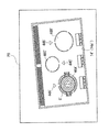
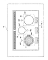
- FIG. 12 is a top view of the top plate 14 of the heating cooker 10.
- FIG. 13 schematically shows the structure of the heating cooker 10.
- FIG. 14 is a block diagram showing a control system of the heating cooker 10. As shown in FIG.
- the output display unit 20 has output display units 20A to 20C.
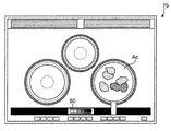
- Output display units 20A to 20C are arranged in predetermined areas of each of the output display units 20. Note that in FIG. 11, the output display units 20A to 20C are extinguished, and in FIG. 12, the output display units 20A and 20B are extinguished, so the output display unit 20 is shown in black.
- the output display unit 20C is a color liquid crystal panel, and can display the reference chart 80.
- the output display unit 20C doubles as a reference chart display unit that displays the reference chart 80 in addition to the display of the heating condition of the heating coil 16C.
- the output display units 20A and 20B are monochrome or color liquid crystal panels.
- the container placement areas 46A, 46B, 46C facing the heating coils 16A, 16B, 16C, respectively, are presented to the user by annular marks 48A, 48B, 48C printed on the top surface 14a of the top plate 14 There is.
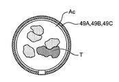
- light emitting portions 49 A, 49 B, 49 C emitting in a ring shape are disposed on the top plate 14 outside of the heating coils 16 A, 16 B, 16 C respectively.
- the light emitting units 49A, 49B, 49C emit light, for example, when current flows through the corresponding heating coils 16A, 16B, 16C.
- the light emitting units 49A to 49C have, for example, LED light emitting substrates.
- the heating cooker 10 is provided with the cooking condition recognition part 31 which has the camera 30.
- FIG. The distance from the camera 30 to the top surface 14 a of the top plate 14 is 600 mm or more and 2000 mm or less. With this distance, the entire top surface of the top plate 14 can be appropriately photographed within the field of view of the camera 30.
- the camera 30 according to the second embodiment is, for example, a visible light camera capable of capturing still images, moving images, and the like, and is, for example, a CCD camera or a CMOS camera.
- the camera 30 is mounted on the heating cooker 10, for example, attached to a ceiling or a range hood 70 or the like.
- the camera 30 is installed at a position away from the top surface 14 a of the top plate 14 which is the upper portion of the main body 12, and captures the entire top surface 14 a of the main body 12, that is, the container C and the cooking target T.
- the cooking condition recognition unit 31 is attached to the range hood 70, for example, via a magnet.
- the camera 30 can be freely installed on the main body 12 of the heating cooker 10.
- the camera can be mounted at a position preferred by the user without impairing the design of the kitchen.
- the cooking condition recognition unit 31 that can be disposed at a position preferred by the user is configured to wirelessly communicate with the control unit 50A of the heating cooker 10.
- the cooking condition recognition unit 31 includes an antenna 32.
- an antenna 34 is provided in the main body 12 of the heating cooker 10.
- the cooking condition recognition unit 31 and the control unit 50A are connected via the router device 36. That is, the cooking condition recognition unit 31 and the control unit 50A are connected to the local area network 38 centering on the router device 36 in a wirelessly communicable manner.
- the router device 36 is connected to the Internet 40. Furthermore, the router device 36 is connected to the portable terminal 42 of the user in a wirelessly communicable manner.
- the control unit 50A of the heating cooker 10 includes one or more microprocessors, a memory, and a circuit board.
- the control unit 50A is, for example, a processing device such as a CPU, and performs various functions by executing a program stored in the storage unit 60 such as a ROM, a RAM, a hard disk, or an SSD (for example, It is configured to function as an image processing unit described later.
- the control unit 50A of the heating cooker 10A outputs an imaging instruction to the camera 30 of the cooking condition recognition unit 31 to acquire a captured image; Has a section 54A, a cooking target state estimation section 56, a heating coil control section 58, and a guidance information output section 59 for presenting various information to the user from the output display sections 20A to 20C and the notification section 24 To do).
- the control unit 50A when heating of the heating coils 16A to 16C is started, the control unit 50A outputs a photographing instruction to the camera 30. Thereby, the camera 30 acquires images on the top plate 14 at a predetermined cycle, and these images are sent to the control unit 50A.
- the image processing unit 54A performs color correction on the captured image.
- the reason for performing the color correction is to remove the influence of the light environment around the heating cooker 10 from the photographed image.
- the image processing unit 54A in the second embodiment includes an area extraction unit 72, an illumination state detection unit 73, a correction parameter calculation unit 74, a color correction unit 76, and a lightness calculation unit 78.
- the region extraction unit 72 extracts the reference chart 80 from the image captured by the camera 30, for example, by template matching. In addition, the region extraction unit 72 extracts the regions of the container C and the cooking target T placed in the container placement areas 46A to 46C.
- the illumination state detection unit 73 detects the illumination state around the top surface 14a of the top plate 14 during heating output from the heating coils 16A to 16C.
- the correction parameter calculation unit 74 calculates a correction parameter for correcting the pixel value of each of the RGB areas in the region of the cooking target T based on the pixel values of the reference chart 80.
- the color correction unit 76 corrects the RGB values of the pixels of the region of the cooking target T using the correction parameters.
- the lightness calculation unit 78 calculates the lightness of each pixel based on the pixel values of the standard RGB values of the corrected image.
- heating coil control unit 58 performs heating output to corresponding heating coils 16A to 16C.
- the heating coil control unit 58 supplies a high frequency current to the heating coils 16A to 16C.
- the heating coils 16A to 16C generate an induction magnetic field when a high frequency current is supplied.
- an induced current flows and is heated by the induced magnetic field generated.
- the heating coil control unit 58 controls the amount of current supplied to the heating coils 16A to 16C to control the amount of heating from the heating coils 16A to 16C.
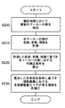
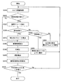
- control unit 50A When control unit 50A outputs a heating instruction from heating coil control unit 58 to any of heating coils 16A to 16C, control unit 50A instructs image acquisition unit 52 to take an image in camera 30 of cooking condition recognition unit 31. Do. At the same time as this instruction, the guidance information output unit 59 displays a reference chart 80 for color correction shown in FIG. 7 on the output display unit 20C as a reference chart display unit. The reference chart 80 is displayed as markers 44A to 44C used for color correction in the first embodiment. In response to a photographing instruction from the control unit 50A, the camera 30 photographs an image 79 of the top plate 14 as shown in FIG. 6, for example, and transmits the photographed image 79 to the control unit 50A.
- step S310 the image processing unit 54A acquires the image 79 transmitted from the camera 30.
- the image 79 also includes an image of a reference chart 80 for color correction.
- Image 79 has RGB values for each pixel.
- step S320 the region extraction unit 72 extracts the image of the reference chart 80 from the image 79 by image processing such as template matching.
- step S330 when the region extraction unit 72 does not successfully extract the reference chart 80 from the image 79, that is, when the image processing unit 54A does not recognize the reference chart 80, an output display unit as a display unit A warning is notified to the user from 20A or 20B.
- the reference chart 80 As a case where the reference chart 80 is not recognized, there are cases where the illumination state around the top plate 14 is not appropriate and when a dirt or obstacle is placed on the output display section 20C that displays the reference chart 80. is there. Then, a warning is notified according to each case.
- the illumination state detection unit 73 of the image processing unit 54A detects the illumination state that illuminates the top plate 14, and determines whether the detected illumination state is dark.
- the illumination state detection unit 73 detects the illumination state using, for example, the histogram of the image 79.
- the illumination state detection unit 73 can determine whether blackening occurs in the histogram or whether the illumination state is dark based on the peak position of the histogram.
- a warning is notified to the user.
- the guidance information output unit 59 notifies the user of a warning indicating that the illumination state illuminating the top plate 14 is to be brightened from the output display unit 20A or 20B.
- the user illuminates the illumination that illuminates the top plate 14, so that the image processing unit 54A can recognize the reference chart 80.
- the process is performed again from step S310 after a predetermined time has elapsed.
- step S340 when a lighting condition equal to or greater than a predetermined brightness is detected, there is a possibility that a dirt or an obstacle is placed on the upper part of the output display unit 20C.
- the guidance information output unit 59 notifies the output display unit 20C to expose the output display unit 20C from the output display unit 20A or 20B. Further, the guidance information output unit 59 may notify the output display unit 20A or 20B to remove dirt or an obstacle. Also, notification may be performed from the notification unit 24 by voice guidance. Thus, the user exposes the output display unit 20C, so that the image processing unit 54A can recognize the reference chart 80. After notification, the process is performed again from step S310 after a predetermined time has elapsed.
- the reference chart 80 is constituted by charts 80a to 80f so that the brightness indicating the degree of white to black is substantially equal, in order to use the index indicating the dynamic range of white to black.
- the chart 80a has both R and G values of 243, a B value of 242, and a lightness of about 96.5.
- the chart 80b has R, G and B values of 200 and a lightness of about 81.3.
- the chart 80c has R, G and B values of 160 together and a lightness of about 66.8.
- the chart 80d has R and G values of 122, a B value of 121, and a lightness of about 50.9.
- the chart 80e has R, G and B values of 85 and a lightness of about 35.7.
- the chart 80 f has R, G and B values of 52 and a lightness of about 20.5.
- the RGB values of these charts 80a to 80f are taken as standard RGB values.
- the RGB values of the respective charts 80a to 80f of the reference chart 80 displayed on the output display unit 20C are as described above. However, the RGB values of the respective charts 80a to 80f of the reference chart 80 captured in the image 79 captured by the camera 30 differ due to the influence of the illumination environment.
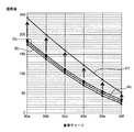
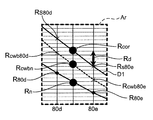
- FIG. 18 is a graph showing the standard RGB values D1 of the reference chart 80 displayed on the output display unit 20C and the RGB values of the reference chart 80 in the image captured by the camera 30.
- the standard RGB values D1 are indicated by one because the R, G and B values are the same or almost the same in each of the charts 80a to 80f.
- the RGB values of the reference chart 80 displayed on the output display unit 20C are standard RGB values, they are affected by the illumination environment at the time of shooting, and thus the R of each chart 80a to 80f obtained from the shot image
- the value Rc, the G value Gc, and the B value Bc are different from the standard RGB value D1.
- the correction parameter calculation unit 74 calculates correction parameters for correcting the RGB values of each of the charts 80a to 80f to standard RGB values.
- the chart 80a is a chart showing white, and white correction can be performed by correcting this to standard RGB values.
- the R value in the image of the chart 80a is 180, since the standard R value is 243, 1.35 which is a value obtained by dividing the R value in the image from the standard R value is a parameter for white correction.
- Parameters for white correction are calculated for G value and B value, respectively.
- the parameters of the white correction of the calculated RGB values are stored in the storage unit 60.
- the parameters of the white correction are respectively multiplied by the R values of the images of all the charts 80a to 80f.
- a value white-corrected to Rc which is an R value acquired from the image 79 is Rcwb.
- the curve indicated by the broken line in FIG. 19 is a graph of the R value Rcwb obtained by the white correction.
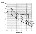
- FIG. 20 is a view showing an example of the color correction, and is an enlarged view of the rectangular broken line area Ar of FIG.
- Rd (Rcwbn-Rcwb 80e) ⁇ (Rs80d-Rs80e) / (Rcwb80d-Rcwb 80e) (1)
- the correction parameter Rd for gray scale correction can be obtained, and the range of pixel values 52 to 243 useful for confirming the cooking state of the food can be corrected at the standard R value. Further, the same linear interpolation operation can be performed for the range of pixel values 255-243 and 52-0 as well.
- the correction parameter calculation unit 74 calculates a conversion table to standard RGB values from all possible RGB values of the captured image, and stores this in the storage unit 60.
- step S380 the area extraction unit 72 extracts the cooking area Ac including the cooking target T.
- the area in the luminous ring-like light emitting portions 49A to 49C may be extracted as the cooking area Ac by image processing, or may be extracted using another marker.
- the user may input the cooking area Ac in the image 79 to the control unit 50A using the portable terminal 42.
- step S390 the color correction unit 76 corrects the RGB values of all the pixels of the extracted cooking area Ac to standard RGB values using the calculated conversion table.
- the calculated conversion table is calculated using the pixel values of the reference chart 80 included in the image captured by the camera 30. Accordingly, the color correction unit 76 performs color correction of the image captured by the camera 30 using the pixel values of the reference chart 80 included in the image captured by the camera 30.
- step S400 the lightness calculation unit 78 calculates the lightness of the cooking area Ac.
- the brightness for example, to calculate the CIE-L * a * b * color system of the lightness L *. Therefore, RGB values are converted to the CIE-XYZ color system, and further converted to the CIE-L * a * b * color system. A more specific conversion procedure will be described below.
- the R′′G′′B ′ ′ value is converted to the CIE-XYZ color system. Note that since only the Y value is used, the lightness calculation unit 78 may calculate only the Y value.
- step S410 the guide information output unit 59 notifies the tint of the IEC standard corresponding to the calculated lightness L * from the output display unit 20C.
- This notification may notify the color corresponding to the most detected lightness L * in the cooking object T as the color of the cooking object, or corresponds to the histogram of the lightness L * detected in the cooking object T Then, it may be notified of the tint.
- step S420 the cooking target state estimation unit 56 determines whether the detected color of the cooking target T has reached a predetermined color. This determination is performed, for example, by determining whether the calculated lightness L * has reached a predetermined lightness.
- the detected color is a predetermined color, for example, the lightness L * of the cooking object T in the image photographed by the cooking object state estimation unit 56 is predetermined.
- the heating coil control unit 58 reduces or stops the heating output of the heating coils 16A to 16C. Further, the guidance information output unit 59 notifies the output display units 20A to 20C that the cooking of the cooking target T is completed.
- step S420 If the detected color is not a predetermined color in step S420, for example, if the calculated lightness L * has not reached the predetermined color, the color to be cooked is still predetermined. Since the color has not been reached, the process is repeated again from step S310.
- the heating cooker 10 is mounted on the top plate 14 provided with the container mounting areas 46A to 46C on which the container C accommodating the cooking target T is mounted, and the container mounting areas 46A to 46C.
- the heating coil 16A-16C which heats the placed container C from below
- the heating coil control unit 58 which controls the heating output of the heating coil 16A-16C
- the container C and cooking which are installed at a position away from the top plate 14 Photographed by the camera 30 using the camera 30 for photographing the target T
- the output display unit 20C for displaying the reference chart 80 for color correction and the pixel values of the reference chart 80 included in the image 79 photographed by the camera 30
- a color correction unit 76 that performs color correction of the image 79
- a cooking target state estimation unit that estimates the cooking status based on the cooking target of the color-corrected image.
- the image of the reference chart 80 is also acquired at the same time, so that image correction based on the color reference can be performed. Since the standard RGB values of the reference chart 80 are known in advance, the color correction of the image taken by the camera 30 may be performed using the pixel values of the reference chart 80 affected by the lighting environment around the heating cooker 10. it can. Thereby, the lighting environment around the heating cooker 10 is, for example, various lighting environments from cold to warm depending on the user's preference, but the influence of the lighting environment around the heating cooker 10 is reduced, It becomes possible to correctly recognize the state of the cooking object T using, for example, the color information of the baking color of the cooking object T.
- white correction and gray scale correction are performed using six points (80a to 80f) as the reference chart 80, but only white correction is performed using only the reference charts 80a and 80f. You may implement. Even if only white correction is performed as color correction, color is significantly improved as shown in Rcwb shown in FIG. In addition, if three points 80a, 80d, and 80f are used, gray scale correction can also be performed for white correction, so that color accuracy can be enhanced.
- the heating cooker 10 has one camera 30, but the camera of the heating cooker according to the embodiment of the present invention is limited to one. Absent.
- a camera may be disposed above each of the plurality of heating coils.
- the cooking condition recognition part 31 has one camera 30 as shown in FIG. 13, embodiment of this indication is not restricted to this.
- the number of cameras may be two or more, and for example, the cameras may be disposed above each of the plurality of heating coils.
- the camera 30 and the control part 50 of the heating cooker 10 are wirelessly connected via the local area network 38, it does not restrict to this. At least one of the camera 30 and the control unit 50 may be connected to the local area network 38 by wire. In the first and second embodiments, the camera 30 may be directly wirelessly connected or wired to the control units 50 and 50A of the heating cooker 10. Furthermore, the photographed image of the camera 30 may be transmitted to the portable terminal 42, or may be transmitted to the outside via the Internet 40. Thus, the user can confirm the photographed image actually photographed by the camera 30.
- the cooking condition recognition unit 31 and the control unit 50A of the heating cooker 10A are wirelessly connected via the local area network 38.
- the embodiment is not limited to this.
- At least one of the cooking condition recognition unit 31 and the control unit 50A may be connected to the local area network 38 by wire.
- the cooking condition recognition unit 31 may be directly wirelessly connected or wired to the control unit 50A of the heating cooker 10.
- the heating cooker 10 is provided with three heating coils 16A-16C, the heating coil of the heating cooker 10 which concerns on embodiment of this invention
- the number of is not limited to this.
- the number of heating coils may be one, or three or more.
- the markers 44A to 44C are marks or seals drawn on the top surface 14a of the top plate 14.
- the embodiment of the present invention is not limited to this.
- the marker may be a light emitter that emits light, such as an LED.
- it is preferable to emit light such as red or blue instead of white light.
- the markers 44A to 44C are provided on the top surface 14a of the top plate 14, but the embodiment of the present invention is not limited to this.
- the markers 44A to 44C may be in the main body of the heating cooker, that is, in the shooting range of the camera. However, it is preferable that the marker be provided on the top surface of the top plate if color correction of the photographed image, that is, the image of the object to be cooked is more appropriately performed. In most cases, the cooker is installed with the top of the top plate horizontal. Moreover, when the cooking target is a liquid, the liquid level is also horizontal. Therefore, both the marker and the liquid level are equally affected by the light environment. Therefore, in order to color correct the image of the horizontal liquid surface, the image of the object to be cooked is color corrected under the color correction condition calculated based on the color of the image of the marker provided on the top surface of the horizontal top plate. It is preferable to do.
- the markers 44A to 44C correspond to the top surface 14a of the top plate 14 other than the container mounting areas 46A to 46C facing the heating coils 16A to 16C.
- the marker may be provided to be located at the center of each of the heating coils as viewed from above the top plate. Thereby, the marker can indicate the position of the heating coil, that is, it can also function as a mark indicating the mounting position of the container heated by the heating coil.
- the markers 44A to 44C are provided to facilitate identification of the image T 'of the cooking target T in the photographed image of the camera 30, but the geometrical It is also used for correction and color correction.
- the embodiment of the present invention is not limited to this.
- a marker dedicated to color correction that is used only for color correction may be provided on the main body of the heating cooker, for example, the top surface of the top plate. This allows the use of markers that vary greatly in shade due to slight differences in the light environment, such as markers that reflect light.
- the markers 44A to 44C are marks or stickers drawn on the top surface 14a of the top plate 14, but the embodiment of the present invention is limited thereto. Absent.
- the marker may be present on the body of the cooker and within the imaging range of the camera. Thus, the marker may be all or part of the component in the body of the cooker.
- at least one of the touch keys 18A to 18C and the output display units 20A to 20C shown in FIG. 2 may be used as a marker.
- the entire top surface 14a of the top plate 14 may be used as a marker.
- a marker should just exist on the main body of a heating cooker, exist in a fixed position with respect to a container mounting area (heating part), and that the image can be specified in a picked-up image. In this case, it is not necessary to draw a marker or attach a marker seal, and it is possible to suppress a decrease in the design of the heating cooker.
- the markers 44A to 44C are provided on the main body 12 of the heating cooker 10, specifically, on the top surface 14a of the top plate 14.
- the embodiment of the present invention is not limited to this. As long as it is used only for the color correction of the photographed image, a marker for the color correction may be provided in the container in which the cooking target is accommodated. Thereby, a marker for color correction can be provided near the cooking target, and the color of the image of the cooking target can be corrected more appropriately.
- the reference chart 80 in the image is extracted to calculate the correction parameter each time the camera 30 captures an image, but the embodiment of the present disclosure is not limited thereto. .
- the cooking area extraction in step S380 may be performed by omitting steps S320 to S370.
- the process shown in FIG. 22 may be performed. That is, after step S310, in step S500, the illumination state detection unit 73 of the image processing unit 54 determines a change in the illumination state around the top plate 14. If there is no change in the illumination state, steps S320 to S370. May be omitted.
- the case where there is no change in the illumination state means that the change in the illumination state is included in a predetermined range.
- the illumination state detection unit 73 detects 30 or more changes in any of the RGB values of the image captured by the camera 30 as compared to the sampling image at the time of calculation of the previous sampling image or the correction parameter, It may be determined that there is a change in state, and the process from step S320 may be performed.
- the illumination state detection unit 73 changes the illumination state, for example, when any of the RGB values of the image captured by the camera 30 is less than 30 compared to the sampling image at the time of calculation of the correction parameter.
- step S320 to step S370 may be omitted and the process may be performed from step S380.
- the color correction unit 76 performs color correction again using the reference chart 80 included in the image captured by the camera 30.
- steps S320 to S370 are omitted, so that the color correction can be speeded up.
- color correction is performed using the pixel values of the reference chart 80. Therefore, the condition of the cooking object T should be correctly recognized using, for example, the color information of the baking color. Is possible.
- the illumination state detection unit 73 of the image processing unit 54 detects the illumination state around the top plate 14 by image processing, but the embodiment of the present disclosure is limited thereto. Absent. Instead of the illumination state detection unit 73 detecting the illumination state from the photographed image, the cooking state recognition unit 31 may directly detect the illumination state around the top plate 14 by providing a light intensity meter.
- Embodiment 2 although the reference
- heating coil control unit 58 reduces or stops the heating output of heating coils 16A to 16C.
- the embodiment of is not limited to this.
- the heating coil control unit 58 may increase the heating output of the heating coils 16A to 16C after, for example, the lightness L * reaches the predetermined lightness after the detected coloration has reached the predetermined color. .
- a brown color as finish cooking.
- a plurality of predetermined colors may be stored, and the heating output may be adjusted each time each color is reached.
- the cooking target state estimation unit 56 recognizes that the cooking target T in the image captured by the camera 30 has reached a predetermined color, and the cooking target state estimation unit 56 captures the image captured by the camera 30. Upon recognizing that the cooking target T has reached a predetermined color, the heating coil control unit 58 performs control to increase or decrease the heating output.
- the output display part 20C was sharing the output display of the heating coil 16C and the display of the reference
- the reference chart 80 may be displayed from the output unit display unit corresponding to the heating coil which is not heated.
- a dedicated display unit for displaying the reference chart 80 may be disposed on the top plate 14.
- the present invention is not limited to the induction heating cooker, and is applicable to any heating cooker that heats a container containing a cooking target.
Abstract
According to the present invention, heat-cooking is suitably performed on the basis of an image of an object to be cooked on a captured image without being influenced by an optical environment. The heating cooker includes: a main body having a top surface provided with a container mounting part on which a container, in which an object to be cooked is contained, is mounted; a heating part which heats the container mounted on the container mounting part from below; a camera which captures an image of the object to be cooked; a marker which is provided in the main body and captured with the camera; an image processing unit which measures the color tone of an image of the marker on the captured image, and corrects colors of the captured image so that the captured image of the marker has an actual color tone of the marker itself on the basis of the measurement result; an object-to-be-cooked state estimation unit which estimates the state of the object to be cooked, on the basis of the image of the object to be cooked on the color-corrected captured image; and a heating control unit which controls the heating part on the basis of the estimated state of the object to be cooked.
Description
本発明は、調理対象を加熱する加熱調理器に関する。
TECHNICAL FIELD The present invention relates to a heating cooker for heating an object to be cooked.
従来より、調理対象をカメラで撮影し、その撮影画像に写る調理対象の像に基づいて、調理対象に対する加熱を制御する加熱調理器が知られている(例えば、特許文献1参照)。
2. Description of the Related Art Conventionally, a heating cooker is known which shoots a cooking object with a camera and controls heating of the cooking object based on an image of the cooking object shown in the photographed image (see, for example, Patent Document 1).
しかしながら、特許文献1に記載された加熱調理器の場合、加熱調理器周りの光環境が変化すると、カメラの撮影画像に写る調理対象の像の色合いが変化する。例えば、加熱調理中にカーテンが開けられてキッチンに夕日の光が入り、その光が調理対象に当たると、撮影画像全体、すなわち調理対象の像が赤みを帯びる(色相が変化する)場合がある。また例えば、加熱調理中に照明が灯されると、その照明の光によって撮影画像全体、すなわち調理対象の像が白みを帯びる(彩度が低下する)場合がある。さらに、同じ調理対象であっても、光環境が異なれば、撮影画像に写る調理対象の像の色合いも異なる。このように光環境の変化や違いによって撮影画像に写る調理対象の色合いに変化や違いが生じると、撮影画像に写る調理対象の像に基づく該調理対象に対する加熱調理を適切に行えない可能性がある。
However, in the case of the heating cooker described in Patent Document 1, when the light environment around the heating cooker changes, the color tone of the image of the object to be cooked that is captured in the captured image of the camera changes. For example, when the curtain is opened during cooking and the light of the sunset enters the kitchen and the light strikes the object to be cooked, the entire photographed image, that is, the image to be cooked may become reddish (the hue changes). Also, for example, when a light is turned on during cooking, the entire photographed image, that is, the image to be cooked may be whitened (color saturation may be reduced) by the light of the light. Furthermore, even if it is the same cooking object, if light environment is different, the color tone of the image of the cooking object shown to a picked-up image will also differ. As described above, if a change or difference occurs in the color of the cooking object in the photographed image due to a change or difference in the light environment, there is a possibility that the cooking object can not be appropriately cooked based on the image of the cooking object in the photographed image. is there.
そこで、本発明は、カメラの撮影画像に写る調理対象の像に基づいて該調理対象に対する加熱を制御する加熱調理器において、光環境の変化や違いに影響されずに調理対象に対する加熱を適切に行うことを課題とする。
Therefore, according to the present invention, in a heating cooker that controls heating of a cooking target based on an image of the cooking target shown in a captured image of a camera, the heating of the cooking target is appropriately performed without being affected by changes or differences in the light environment. Make it a task.
上述の課題を解決するために、本発明の一態様によれば、
調理対象を収容した容器が載置される容器載置部を備える天面を含む本体と、
前記容器載置部に載置された容器を下方から加熱する加熱部と、
前記調理対象を撮影するカメラと、
前記本体に設けられ、前記カメラに撮影されるマーカーと、
前記カメラの撮影画像に写る前記マーカーの像の色合いを計測し、その計測結果に基づいて、前記撮影画像において前記マーカーの像が前記マーカー自体の実際の色合いで写るように前記撮影画像を色補正する画像処理部と、
前記画像処理部によって色補正された撮影画像に写る調理対象の像に基づいて、調理対象の状態を推定する調理対象状態推定部と、
前記調理対象状態推定部によって推定された調理対象の状態に基づいて、前記加熱部を制御する加熱制御部と、を有する、加熱調理器が提供される。 According to one aspect of the present invention, in order to solve the above-mentioned problems,
A main body including a top surface including a container placement unit on which a container containing a cooking target is placed;
A heating unit configured to heat the container placed on the container placement unit from below;
A camera for photographing the cooking object;
A marker provided on the main body and photographed by the camera;
The color tone of the image of the marker in the photographed image of the camera is measured, and based on the measurement result, the photographed image is color corrected so that the image of the marker is photographed in the actual color of the marker itself in the photographed image. The image processing unit to
A cooking target state estimation unit that estimates the state of the cooking target based on the image of the cooking target captured in the captured image that has been color-corrected by the image processing unit;
And a heating control unit configured to control the heating unit based on the state of the cooking target estimated by the cooking target state estimation unit.
また、本発明の別態様によれば、
調理対象を収容した容器と、
前記容器が載置される容器載置部を備える天面を含む本体と、
前記容器載置部に載置された前記容器を下方から加熱する加熱部と、
前記調理対象を撮影するカメラと、
前記容器に設けられ、前記カメラに撮影されるマーカーと、
前記カメラの撮影画像に写る前記マーカーの像の色合いを計測し、その計測結果に基づいて、前記撮影画像において前記マーカーの像が前記マーカー自体の実際の色合いで写るように前記撮影画像を色補正する画像処理部と、
前記画像処理部によって色補正された撮影画像に写る調理対象の像に基づいて、調理対象の像の状態を推定する調理対象状態推定部と、
前記調理対象状態推定部によって推定された調理対象の状態に基づいて、前記加熱部を制御する加熱制御部と、を有する、加熱調理器が提供される。 Also, according to another aspect of the present invention,
A container containing the object to be cooked;
A main body including a top surface including a container placement unit on which the container is placed;
A heating unit configured to heat the container placed on the container placement unit from below;
A camera for photographing the cooking object;
A marker provided in the container and photographed by the camera;
The color tone of the image of the marker in the photographed image of the camera is measured, and based on the measurement result, the photographed image is color corrected so that the image of the marker is photographed in the actual color of the marker itself in the photographed image. The image processing unit to
A cooking target state estimation unit that estimates the state of the cooking target image based on the cooking target image captured in the captured image that has been color-corrected by the image processing unit;
And a heating control unit configured to control the heating unit based on the state of the cooking target estimated by the cooking target state estimation unit.
本発明によれば、カメラの撮影画像に写る調理対象の像に基づいて該調理対象に対する加熱を制御する加熱調理器において、光環境の変化や違いに影響されずに調理対象に対する加熱を適切に行うことができる。
According to the present invention, in the heating cooker which controls the heating of the cooking object based on the image of the cooking object shown in the photographed image of the camera, the heating of the cooking object is appropriately performed without being influenced by the change or difference of the light environment. It can be carried out.
本発明の一態様の加熱調理器は、調理対象を収容した容器が載置される容器載置部を備える天面を含む本体と、前記容器載置部に載置された前記容器を下方から加熱する加熱部と、前記調理対象を撮影するカメラと、前記本体に設けられ、前記カメラに撮影されるマーカーと、前記カメラの撮影画像に写る前記マーカーの像の色合いを計測し、その計測結果に基づいて、前記撮影画像において前記マーカーの像が前記マーカー自体の実際の色合いで写るように前記撮影画像を色補正する画像処理部と、前記画像処理部によって色補正された撮影画像に写る調理対象の像に基づいて、調理対象の状態を推定する調理対象状態推定部と、前記調理対象状態推定部によって推定された調理対象の状態に基づいて、前記加熱部を制御する加熱制御部と、を有する。
The heating cooker according to one aspect of the present invention includes, from below, a main body including a top surface including a container placement unit on which a container containing a cooking object is placed, and the container placed on the container placement unit from below A color of a heating unit to be heated, a camera for photographing the cooking object, a marker provided on the main body and photographed by the camera, and an image of the marker shown in the photographed image of the camera is measured, and the measurement result An image processing unit that performs color correction on the captured image so that the image of the marker is captured in the actual color of the marker itself in the captured image; and cooking that is captured in the captured image color-corrected by the image processing unit A cooking target state estimation unit that estimates the state of the cooking target based on an image of the target, and a heating control unit that controls the heating unit based on the cooking target state estimated by the cooking target state estimation unit It has a.
本発明の一態様によれば、カメラの撮影画像に写る調理対象の像に基づいて該調理対象に対する加熱を制御する加熱調理器において、光環境の変化や違いに影響されずに調理対象に対する加熱を適切に行うことができる。
According to one aspect of the present invention, there is provided a heating cooker for controlling heating of a cooking target based on an image of the cooking target shown in a captured image of a camera, wherein the heating of the cooking target is not affected by changes or differences in the light environment. You can do it properly.
例えば、前記色合いが、色相、彩度、および明度の少なくとも1つであってもよい。これらを色合いのパラメータとして用いることにより、適切に色補正を行うことができる。
For example, the hue may be at least one of hue, saturation, and lightness. By using these as parameters of color tone, color correction can be appropriately performed.
例えば、前記マーカーが、前記本体の天面に設けられている。調理対象が液体である場合、水平な天面に設けられたマーカーの像の色合いに基づいて算出された色補正条件で、調理対象の像、すなわち液面の像を適切に色補正することができる。
For example, the marker is provided on the top surface of the main body. When the object to be cooked is a liquid, the image of the object to be cooked, that is, the image of the liquid surface is appropriately color corrected under the color correction condition calculated based on the color of the image of the marker provided on the horizontal top surface it can.
例えば、前記マーカーが、前記容器載置部以外の前記天面の部分に設けられてもよい。これにより、マーカー上に容器が載置されることが抑制される。
For example, the marker may be provided on a portion of the top surface other than the container placement unit. This prevents the container from being placed on the marker.
例えば、前記加熱部が複数あって、前記マーカーが複数あって、前記複数のマーカーそれぞれが、前記複数の加熱部に対応付けされ、且つ、対応する加熱部に対向する前記容器載置部近傍に設けられ、前記画像処理部が、前記複数のマーカーの像それぞれについて色補正条件を算出し、算出した色補正条件それぞれにしたがって、前記撮影画像における前記容器載置部に対応する複数の調理対象存在領域を色補正する。これにより、複数の加熱部それぞれに加熱されている調理対象の像を、別々に色補正することができる。
For example, there are a plurality of heating units, a plurality of markers, each of the plurality of markers is associated with the plurality of heating units, and in the vicinity of the container placement unit facing the corresponding heating unit. The image processing unit calculates a color correction condition for each of the images of the plurality of markers, and the plurality of cooking objects corresponding to the container placement unit in the photographed image are calculated according to the calculated color correction conditions. Color correct the area. Thereby, the image of the cooking object heated by each of the plurality of heating units can be color-corrected separately.
例えば、前記加熱部が複数あって、前記マーカーが複数あって、前記複数のマーカーそれぞれが、前記本体の天面の上方から見て前記加熱部それぞれの中央に位置するように設けられている。これにより、マーカーによって加熱部の位置を示すことができ、容器載置位置を示す目印としても機能することができる。
For example, there are a plurality of heating units, a plurality of markers, and each of the plurality of markers is provided at the center of each heating unit as viewed from above the top surface of the main body. Thus, the marker can indicate the position of the heating unit, and can also function as a mark indicating the container mounting position.
例えば、前記マーカーとしての色補正用の基準チャートを表示する基準チャート表示部を備え、前記カメラは、前記天面から離れた位置に設置されて前記容器および調理対象を撮影し、前記画像処理部は、前記カメラで撮影した画像に含まれる基準チャートの画素値を用いて、前記カメラで撮影した画像の色補正を行う色補正部を有する。これにより、照明環境の影響を低減した調理対象の色を確認することができる加熱調理器を提供することができる。
For example, the image processing unit includes a reference chart display unit that displays a reference chart for color correction as the marker, the camera is installed at a position away from the top surface, and images the container and the cooking target The image processing apparatus further includes a color correction unit that performs color correction of an image captured by the camera using a pixel value of a reference chart included in the image captured by the camera. Thereby, the heating cooker which can confirm the color of cooking object which reduced the influence of lighting environment can be provided.
例えば、前記調理対象状態推定部は、前記カメラで撮影した画像における調理対象の予め定められた色への到達を認識し、前記調理対象状態推定部が前記画像において前記調理対象が予め定められた色へ到達したことを認識すると、前記加熱制御部は、加熱出力を加減または停止する制御を行う。
For example, the cooking target state estimation unit recognizes that the cooking target in the image captured by the camera has reached a predetermined color, and the cooking target state estimation unit determines the cooking target in the image. Upon recognizing that the color has been reached, the heating control unit performs control to increase or decrease the heating output.
例えば、前記加熱部から加熱出力中において、前記トッププレートの天面周囲の照明状態を検出する照明状態検出部を備え、前記照明状態検出部により前記照明状態の変化が検出されると、前記色補正部は前記カメラで撮影した画像に含まれる前記基準チャートの画素値を用いて色補正を再び行う。
For example, an illumination state detection unit for detecting an illumination state around the top surface of the top plate is provided during heating output from the heating unit, and the color is detected when a change in the illumination state is detected by the illumination state detection unit. The correction unit performs color correction again using the pixel values of the reference chart included in the image captured by the camera.
例えば、前記照明状態検出部により予め定められた明るさ以上の照明状態が検出されない場合に、ユーザに警告が報知される。
For example, when the illumination state detection unit does not detect an illumination state greater than a predetermined brightness, a warning is notified to the user.
例えば、前記加熱部の加熱状況を表示する表示部を備え、前記画像処理部により前記基準チャートが認識されない場合に、前記表示部からユーザに警告が報知される。
For example, the display unit displays a heating condition of the heating unit, and when the image processing unit does not recognize the reference chart, a warning is notified from the display unit to the user.
例えば、前記加熱部は、前記容器を加熱するために誘導磁界を発生させる加熱コイルを有し、前記加熱制御部は、前記加熱コイルに高周波電流を供給して前記容器の加熱を行う。
For example, the heating unit has a heating coil that generates an induction magnetic field to heat the container, and the heating control unit supplies a high frequency current to the heating coil to heat the container.
例えば、前記カメラから前記トッププレートの天面までの距離は600mm以上、2000mm以内である。この距離であれば、カメラの視野内での天面の全面を適切に撮影することができる。
For example, the distance from the camera to the top surface of the top plate is 600 mm or more and 2000 mm or less. With this distance, the entire top surface within the field of view of the camera can be photographed properly.
本発明の別態様の加熱調理器は、調理対象を収容した容器と、前記容器が載置される容器載置部を備える天面を含む本体と、前記容器載置部に載置された前記容器を下方から加熱する加熱部と、前記調理対象を撮影するカメラと、前記容器に設けられ、前記カメラに撮影されるマーカーと、前記カメラの撮影画像に写る前記マーカーの像の色合いを計測し、その計測結果に基づいて、前記撮影画像において前記マーカーの像が前記マーカー自体の実際の色合いで写るように前記撮影画像を色補正する画像処理部と、前記画像処理部によって色補正された撮影画像に写る調理対象の像に基づいて、調理対象の像の状態を推定する調理対象状態推定部と、前記調理対象状態推定部によって推定された調理対象の状態に基づいて、前記加熱部を制御する加熱制御部と、を有する。
A heating cooker according to another aspect of the present invention is a container containing a cooking object, a main body including a top surface provided with a container mounting unit on which the container is mounted, and the container mounted on the container mounting unit. The color of the image of the marker which is provided in the heating unit which heats the container from below, the camera which shoots the cooking object, the container and which is provided in the container and which is photographed by the camera and which is photographed in the photographed image of the camera An image processing unit that performs color correction on the photographed image so that the image of the marker is captured in the actual color of the marker itself in the photographed image based on the measurement result; and photographing that is color-corrected by the image processing unit A cooking target state estimation unit for estimating the state of the cooking target image based on the image of the cooking target in the image, and the heating unit based on the cooking target state estimated by the cooking target state estimation unit It has a heating control unit that, the.
本発明の別態様によれば、カメラの撮影画像に写る調理対象の像に基づいて該調理対象に対する加熱を制御する加熱調理器において、光環境の変化や違いに影響されずに調理対象に対する加熱を適切に行うことができる。
According to another aspect of the present invention, there is provided a heating cooker that controls heating of a cooking target based on an image of the cooking target shown in a captured image of a camera, wherein the heating of the cooking target is not affected by changes or differences in the light environment. You can do it properly.
(実施の形態1)
以下、本発明の実施の形態1について、図面を参照しながら説明する。Embodiment 1
Hereinafter,Embodiment 1 of the present invention will be described with reference to the drawings.
以下、本発明の実施の形態1について、図面を参照しながら説明する。
Hereinafter,
図1は、本発明の実施の形態1に係る加熱調理器の概略的斜視図である。また、図2は、加熱調理器のトッププレートの上面図である。さらに、図3は、加熱調理器の構成を概略的に示す図である。さらにまた、図4は、加熱調理器の制御系を示すブロック図である。なお、図において、X軸方向は加熱調理器の幅方向(長手方向)を示し、Y軸方向は奥行き方向を示し、Z軸方向は高さ方向を示す。
FIG. 1 is a schematic perspective view of a heating cooker according to a first embodiment of the present invention. Moreover, FIG. 2 is a top view of the top plate of a heating cooker. Furthermore, FIG. 3 is a diagram schematically showing the configuration of the heating cooker. Furthermore, FIG. 4 is a block diagram showing a control system of the heating cooker. In the drawing, the X-axis direction indicates the width direction (longitudinal direction) of the heating cooker, the Y-axis direction indicates the depth direction, and the Z-axis direction indicates the height direction.
図1に示すように、加熱調理器10は、本体12を有し、また、その本体12の上側部分として、例えばシチューなどの調理対象Tを収容した容器Cが載置されるトッププレート14を有する。トッププレート14の天面14aには、容器Cが載置される容器載置部が設けられている。このように、本体12は、調理対象Tを収容した容器Cが載置される容器載置部を備える天面14aを含む。
As shown in FIG. 1, the heating cooker 10 has a main body 12 and, as an upper portion of the main body 12, a top plate 14 on which a container C containing a cooking target T such as a stew is placed. Have. The top surface 14 a of the top plate 14 is provided with a container placement unit on which the container C is placed. As described above, the main body 12 includes the top surface 14 a including the container placement unit on which the container C containing the cooking target T is placed.
また、実施の形態1の場合、加熱調理器10は誘導加熱調理器であって、図1および図3に示すように、トッププレート14における容器載置部(後述する容器載置エリア)に載置された容器Cの下方には、すなわち本体12内には、加熱調理器10の加熱部として加熱コイル16A~16Cが配置されている。加熱コイル16A~16Cは、トッププレート14上の容器載置部に載置された容器Cを下方から誘導加熱する。加熱コイル16A~16Cは、容器Cを加熱するために誘導磁界を発生させる。
Moreover, in the case of Embodiment 1, the heating cooker 10 is an induction heating cooker, and as shown in FIG. 1 and FIG. 3, it is placed on the container mounting portion (container mounting area described later) in the top plate 14. Below the placed container C, that is, in the main body 12, heating coils 16A to 16C are disposed as heating parts of the heating cooker 10. The heating coils 16A to 16C inductively heat the container C placed on the container placement part on the top plate 14 from below. The heating coils 16A to 16C generate an induction magnetic field to heat the container C.
この加熱コイル16A~16Cそれぞれをユーザが操作するための操作部として、複数のタッチキー18A~18Cが、加熱調理器10の正面10a側のトッププレート14の部分に設けられている。例えば、タッチキー18Aにより、対応する加熱コイル16Aの加熱が開始されるまたは停止される。また、その加熱レベル(例えば4段階)が調節される。
A plurality of touch keys 18A to 18C are provided on a portion of the top plate 14 on the front surface 10a side of the heating cooker 10, as operation units for the user to operate the heating coils 16A to 16C, respectively. For example, heating of the corresponding heating coil 16A is started or stopped by the touch key 18A. In addition, the heating level (for example, four stages) is adjusted.
また、加熱コイル16A~16Cの出力状態(加熱レベル)を表示する複数の出力表示部20A~20Cも、加熱調理器10の正面10a側のトッププレート14の部分に設けられている。
Further, a plurality of output display units 20A to 20C for displaying the output state (heating level) of the heating coils 16A to 16C are also provided on the top plate 14 on the front surface 10a side of the heating cooker 10.
なお、加熱コイル16A~16Cによる加熱を詳細に設定するために、設定部22が加熱調理器10の正面10a側に設けられている。設定部22は、本体12に対して出し入れ可能であって、加熱コイル16A~16Cによる加熱を詳細に設定するための設定キー22aと、その設定内容や加熱コイル16A~16Cの詳細な状態などを表示する設定表示部22bとを備える。この設定部22により、加熱コイル16A~16Cの加熱温度、加熱時間、タイマーなどが設定される。
Note that, in order to set heating by the heating coils 16A to 16C in detail, a setting unit 22 is provided on the front surface 10a side of the heating cooker 10. The setting unit 22 can be inserted into and taken out of the main body 12, and the setting key 22a for setting the heating by the heating coils 16A to 16C in detail, the setting contents thereof, the detailed state of the heating coils 16A to 16C, etc. And a setting display unit 22b for displaying. The setting portion 22 sets the heating temperature, the heating time, the timer, etc. of the heating coils 16A to 16C.
また、加熱調理器10は、ユーザに対して報知するスピーカーなどの報知部24を、加熱調理器10の正面10a側に備える。
Moreover, the heating cooker 10 equips the front surface 10a side of the heating cooker 10 with alerting | reporting parts 24, such as a speaker alerting | reporting with respect to a user.
さらに、加熱調理器10は、トッププレート14上に載置された容器Cの温度を検出する複数の温度センサ26A~26Cと、トッププレート14上に載置された容器Cの重量を検出する重量センサ28とを有する。
Furthermore, the heating cooker 10 has a plurality of temperature sensors 26A to 26C for detecting the temperature of the container C placed on the top plate 14 and a weight for detecting the weight of the container C placed on the top plate 14 And a sensor 28.
実施の形態1の場合、複数の温度センサ26A~26Cは、トッププレート14の下方に配置されるとともに、加熱コイル16A~16Cそれぞれの中央に配置されている。すなわち、例えば温度センサ26Aは、加熱コイル16Aの上方に配置されて該加熱コイル16Aによって誘導加熱されている容器Cの底側の温度をトッププレート14を介して検出している。
In the case of the first embodiment, the plurality of temperature sensors 26A to 26C are disposed below the top plate 14 and at the centers of the heating coils 16A to 16C. That is, for example, the temperature sensor 26A is disposed above the heating coil 16A and detects the temperature on the bottom side of the container C inductively heated by the heating coil 16A through the top plate 14.
実施の形態1の場合、重量センサ28は、トッププレート14上の載置物の重量、すなわち容器Cが複数ある場合には、その複数の容器Cの重量とそれぞれの容器Cに収容されている調理対象の重量との合計を検出する。
In the case of the first embodiment, the weight sensor 28 determines the weight of the object on the top plate 14, that is, when there are a plurality of containers C, the weights of the plurality of containers C and the cooking contained in each container C. Detect the sum of the subject's weight.
さらに、加熱調理器10は、トッププレート14上の調理対象Tを上方から撮影するカメラ30を有する。
Furthermore, the heating cooker 10 has the camera 30 which image | photographs cooking object T on the top plate 14 from upper direction.
カメラ30は、例えば、静止画、動画、赤外線画像などを撮影可能なカメラであって、本体12の上側部分であるトッププレート14の天面14a(すなわち本体12の天面)全体を撮影する。カメラ30は、加熱調理器10の上方に位置する天井またはレンジフード(図示せず)などに取り付けられる。実施の形態1の場合、カメラ30は、マグネットを介してレンジフードに取り付けられる。そのため、加熱調理器10の本体12に対してカメラ30を自由に設置することができる(すなわち設置の自由度が高い)。その結果、キッチンの意匠性を損なうことがない、ユーザの好む位置にカメラを取り付けることができる。
The camera 30 is, for example, a camera capable of capturing still images, moving images, infrared images, etc., and captures the entire top surface 14 a of the top plate 14 (i.e., the top surface of the main body 12) which is the upper portion of the main body 12. The camera 30 is attached to a ceiling or a range hood (not shown) located above the heating cooker 10 or the like. In the case of the first embodiment, the camera 30 is attached to the range hood via a magnet. Therefore, the camera 30 can be installed freely with respect to the main body 12 of the heating cooker 10 (that is, the installation freedom is high). As a result, the camera can be mounted at a position preferred by the user without impairing the design of the kitchen.
実施の形態1の場合、ユーザの好む位置に配置可能なカメラ30は、加熱調理器10の制御部50と無線通信するように構成されている。そのために、図3に示すように、カメラ30がアンテナ32を備えるとともに、加熱調理器10の本体12内にアンテナ34が設けられている。なお、実施の形態1の場合、カメラ30と制御部50は、ルーター装置36を介して接続されている。すなわち、カメラ30と制御部50は、ルーター装置36を中心とするローカルエリアネットワーク38に無線通信可能に接続されている。また、ルーター装置36は、インターネット40に接続されている。さらに、ルーター装置36は、ユーザの携帯端末42に無線通信可能に接続されている。
In the case of the first embodiment, the camera 30 that can be disposed at a position preferred by the user is configured to wirelessly communicate with the control unit 50 of the heating cooker 10. For that purpose, as shown in FIG. 3, the camera 30 is provided with the antenna 32, and the antenna 34 is provided in the main body 12 of the heating cooker 10. In the first embodiment, the camera 30 and the control unit 50 are connected via the router device 36. That is, the camera 30 and the control unit 50 are connected in a wirelessly communicable manner to a local area network 38 centering on the router device 36. Also, the router device 36 is connected to the Internet 40. Furthermore, the router device 36 is connected to the portable terminal 42 of the user in a wirelessly communicable manner.
ここからは、加熱調理器10の動作、すなわちその制御部50が行う制御について図4を参照しながら説明する。
From here, the operation of the heating cooker 10, that is, the control performed by the control unit 50 will be described with reference to FIG.
加熱調理器10の制御部50は、例えばCPUなどの処理装置であって、ROM、RAM、ハードディスクなどの記憶部60に記憶されているプログラムを実行することによって種々の機能を果たすように(例えば、後述する画像処理部として機能するように)構成されている。図4に示すように、制御部50は、タッチキー18A~18Cおよび設定部22の設定キー22aに対するユーザの操作に対応する信号をこれらから受け取るように構成されている。制御部50はまた、温度センサ26A~26Cそれぞれによって検出された温度に対応する信号をこれらから受け取るように構成されている。制御部50はさらに、重量センサ28によって検出された重量に対応する信号を受け取るように構成されている。そして、制御部50は、カメラ30によって撮影された撮影画像(データ)を該カメラ30から受け取るように構成されている。
The control unit 50 of the heating cooker 10 is, for example, a processing device such as a CPU, and performs various functions by executing a program stored in the storage unit 60 such as a ROM, a RAM, a hard disk (for example, , And is configured to function as an image processing unit described later. As shown in FIG. 4, the control unit 50 is configured to receive from these signals corresponding to the user's operation on the touch keys 18A to 18C and the setting key 22a of the setting unit 22. The control unit 50 is also configured to receive from them signals corresponding to the temperatures detected by the temperature sensors 26A to 26C, respectively. Control unit 50 is further configured to receive a signal corresponding to the weight detected by weight sensor 28. The control unit 50 is configured to receive from the camera 30 a captured image (data) captured by the camera 30.
加えて、加熱調理器10の制御部50は、加熱コイル16A~16C、出力表示部20A~20C、設定表示部22b、および報知部24を制御するように構成されている。
In addition, the control unit 50 of the heating cooker 10 is configured to control the heating coils 16A to 16C, the output display units 20A to 20C, the setting display unit 22b, and the notification unit 24.
例えば、制御部50は、設定部22の設定キー22aを介してユーザによって設定された加熱温度を温度センサ26A~26Cが検出し続けるように、加熱コイル16A~16Cの出力を制御する。これにより、例えば、揚げ物をする場合、容器Cに収容された油を一定の温度に維持することができる。
For example, the control unit 50 controls the outputs of the heating coils 16A to 16C so that the temperature sensors 26A to 26C continue to detect the heating temperature set by the user via the setting key 22a of the setting unit 22. Thereby, for example, when frying, the oil accommodated in the container C can be maintained at a constant temperature.
また例えば、制御部50は、容器C内に水が収容されている場合(ユーザが自動湯沸しモードを設定部22を介して設定した場合)、温度センサ26A~26Cが沸騰温度を検出すると、加熱コイル16A~16Cを停止させるとともに、報知部24を介してユーザに湯沸しが完了したことを報知する。
Further, for example, when water is stored in the container C (when the user sets the automatic boiling mode through the setting unit 22), the control unit 50 heats when the temperature sensors 26A to 26C detect the boiling temperature. The coils 16A to 16C are stopped, and the user is notified via the notification unit 24 that the water heating is completed.
さらに、制御部50は、カメラ30の撮影画像、具体的にはその撮影画像に写る調理対象Tの像に基づいて様々な制御を行うように構成されている。
Furthermore, the control unit 50 is configured to perform various controls based on a captured image of the camera 30, specifically, an image of the cooking object T shown in the captured image.
そのために、加熱調理器10の制御部50は、カメラ30から撮影画像を取得する画像取得部52と、その取得した画像を処理(補正)する画像処理部54と、その補正された撮影画像に写る容器C内の調理対象Tの像に基づいて該調理対象Tの状態を推定する調理対象状態推定部56と、その推定結果に基づいて加熱コイル16A~16Cを制御する加熱制御部としての加熱コイル制御部58とを有する(として機能する)。加熱コイル制御部58は、加熱コイル16A~16Cに高周波電流を供給して容器Cの加熱を行う。加熱コイル制御部58は、供給する高周波電流量を制御することで容器Cの加熱を制御する。
For that purpose, the control unit 50 of the heating cooker 10 sets the image acquisition unit 52 that acquires a photographed image from the camera 30, the image processing unit 54 that processes (corrects) the acquired image, and the corrected photographed image. A cooking object state estimation unit 56 that estimates the state of the cooking object T based on the image of the cooking object T in the container C, and heating as a heating control unit that controls the heating coils 16A to 16C based on the estimation result It has (functions as) a coil control unit 58. The heating coil control unit 58 supplies a high frequency current to the heating coils 16A to 16C to heat the container C. The heating coil control unit 58 controls the heating of the container C by controlling the amount of high frequency current supplied.
加熱調理器10の制御部50の画像取得部52は、カメラ30が撮影した撮影画像、例えば加熱調理中の調理対象Tを収容する容器Cが載置されている状態のトッププレート14が写る撮影画像(データ)を取得する。実施の形態1の場合、カメラ30は所定の時間間隔で撮影を行う。
The image acquiring unit 52 of the control unit 50 of the heating cooker 10 is a photographed image photographed by the camera 30, for example, a photographing in which the top plate 14 in a state in which the container C accommodating the cooking target T being cooked is placed Acquire an image (data). In the case of the first embodiment, the camera 30 performs shooting at predetermined time intervals.
図5は、画像取得部52が取得するカメラ30の撮影画像(オリジナル画像)の一例を示している。図5に示すように、カメラ30の撮影画像P0には、トッププレート14の天面14aの像14a’が写っている。なお、図5において、調理対象Tの像T’は、クロスハッチングで示されている。
FIG. 5 illustrates an example of a photographed image (original image) of the camera 30 acquired by the image acquiring unit 52. As shown in FIG. 5, an image 14 a ′ of the top surface 14 a of the top plate 14 is captured in a captured image P <b> 0 of the camera 30. In addition, in FIG. 5, image T 'of cooking object T is shown by the cross hatching.
画像処理部54は、画像取得部52によって取得されたカメラ30の撮影画像P0に対して画像処理を行う。具体的には、画像処理部54は、調理対象状態推定部56がカメラ30の撮影画像P0に写る調理対象Tの像T’に基づいて該調理対象Tの状態を短時間で高精度に推定できるように、その前処理として、撮影画像P0を補正する。実施の形態1の場合、撮影画像P0に対して幾何学的補正と色補正とを行う。まず、幾何学的補正について、図6に示すフローチャートを参照しながら説明する。
The image processing unit 54 performs image processing on the captured image P0 of the camera 30 acquired by the image acquisition unit 52. Specifically, the image processing unit 54 estimates the state of the cooking target T in a short time with high accuracy based on the image T ′ of the cooking target T captured in the photographed image P0 of the camera 30 by the cooking target state estimation unit 56 As the pre-processing, the photographed image P0 is corrected so that it can be performed. In the case of the first embodiment, geometrical correction and color correction are performed on the captured image P0. First, geometric correction will be described with reference to the flowchart shown in FIG.
まず、図6に示す幾何学的補正を適切に行うために、図2に示すように、加熱調理器10の本体12に設けられた複数のマーカー44A~44Cを利用する。マーカー44A~44Cは、本体12に設けられ、カメラ30に撮影される。
First, in order to appropriately perform the geometric correction shown in FIG. 6, as shown in FIG. 2, a plurality of markers 44A to 44C provided on the main body 12 of the heating cooker 10 are used. The markers 44 A to 44 C are provided on the main body 12 and captured by the camera 30.
具体的には、マーカー44A~44Cは、撮影画像において調理対象Tの像T’を特定しやすくするため、すなわち短時間で高精度に特定するために、カメラ30に撮影されるアライメントマーカーである。図2に示すように、実施の形態1の場合、複数のマーカー44A~44Cは、トッププレート14の天面14a(すなわち本体12の天面)に設けられている。例えば、マーカー44A~44Cは、トッププレート14の天面14aに描かれたマークまたは天面14aに貼り付けられたシールである。特に、マーカー44A~44Cは、高精度に画像認識できる(カメラの撮影画像において特定しやすい)形状および色を備えたものであって、実施の形態1の場合、正三角形状である。
Specifically, the markers 44A to 44C are alignment markers photographed by the camera 30 in order to facilitate identification of the image T 'of the cooking target T in the photographed image, that is, to specify in a short time with high accuracy. . As shown in FIG. 2, in the case of the first embodiment, the plurality of markers 44A to 44C are provided on the top surface 14a of the top plate 14 (that is, the top surface of the main body 12). For example, the markers 44A to 44C are marks drawn on the top surface 14a of the top plate 14 or stickers attached to the top surface 14a. In particular, the markers 44A to 44C have shapes and colors that can be recognized with high accuracy (it is easy to specify in a captured image of a camera), and in the case of the first embodiment, they are equilateral triangles.
また、理由は後述するが、複数のマーカー44A~44Cは、加熱コイル16A~16Cに対応付けされている。実施の形態1の場合、正三角形状のマーカーにおける1つの頂点が加熱コイルに向くことにより、対応付けされている。また、複数のマーカー44A~44Cは、加熱コイル16A~16Cに対向する容器載置エリア46A~46C(加熱コイルによって加熱される容器Cが載置される容器載置部)以外のトッププレート14の天面14aの部分に設けられている。これにより、マーカー44A~44C上に容器Cが載置されることが抑制されている。
Further, although the reason will be described later, the plurality of markers 44A to 44C are associated with the heating coils 16A to 16C. In the case of the first embodiment, one vertex of the equilateral triangle-shaped marker is matched by being directed to the heating coil. Further, the plurality of markers 44A to 44C correspond to the top plate 14 other than the container placement areas 46A to 46C (container placement portions on which the containers C heated by the heating coils are placed) facing the heating coils 16A to 16C. It is provided in the portion of the top surface 14a. This prevents the container C from being placed on the markers 44A to 44C.
具体的には、マーカー44Aは、加熱コイル16Aに対応付けされ、加熱コイル16Aに対向する容器載置エリア46Aの近傍(奥側)に設けられている。また、マーカー44Bは、加熱コイル16Bに対応付けされ、加熱コイル16Bに対向する容器載置エリア46Bの近傍(奥側)に設けられている。そして、マーカー44Cは、加熱コイル16Cに対応付けされ、加熱コイル16Cに対向する容器載置エリア46Cの近傍(手前側)に設けられている。なお、容器載置エリア46A~46Cは、トッププレート14の天面14aに設けられた略円環状のマーク48A~48Cによって画定されているとともに、ユーザに提示されている。
Specifically, the marker 44A is associated with the heating coil 16A, and is provided in the vicinity (rear side) of the container placement area 46A facing the heating coil 16A. Moreover, the marker 44B is matched with the heating coil 16B, and is provided in the vicinity (back side) of the container mounting area 46B which opposes the heating coil 16B. And the marker 44C is matched with the heating coil 16C, and is provided in the vicinity (front side) of the container mounting area 46C which opposes the heating coil 16C. The container placement areas 46A to 46C are defined by substantially annular marks 48A to 48C provided on the top surface 14a of the top plate 14, and are presented to the user.
したがって、カメラ30の撮影画像においてマーカー44A~44Cの像を特定できれば、その特定したマーカーの像の位置に基づいて、容器載置エリア46A~46Cに対応する撮影画像の領域、すなわち調理対象Tの像が存在しうる領域(調理対象存在領域RA~RC、図9参照)を短時間で高精度に特定することができる。
Therefore, if the images of the markers 44A to 44C can be specified in the photographed image of the camera 30, the area of the photographed image corresponding to the container placement areas 46A to 46C, that is, the cooking target T can be determined based on the positions of the specified markers. Areas in which an image may be present (areas to be cooked RA to RC, see FIG. 9) can be identified with high accuracy in a short time.
説明すると、上述したように、カメラ30は加熱調理器10の本体12に対して一定の位置ではなく、自由に設置可能である。そのため、撮影画像の一定の位置に調理対象Tの像が写るとは限らない。マーカー44A~44Cがない場合、調理対象Tの像を特定するために撮影画像全体を確認する必要があるため、その像の特定に時間がかかり、また特定エラーが起こり得る。また、調理対象Tは種々あって一定の形状や色ではないため、調理対象Tによってその像の特定時間や特定エラーの起こりやすさが異なる。
To explain, as described above, the camera 30 is not at a fixed position with respect to the main body 12 of the heating cooker 10, but can be freely installed. Therefore, the image of the cooking object T is not necessarily captured at a fixed position of the captured image. In the absence of the markers 44A to 44C, since it is necessary to confirm the entire photographed image in order to specify the image of the cooking object T, it takes time to specify the image and a specific error may occur. In addition, since the cooking target T has various shapes and is not a fixed shape or color, the specific time of the image and the probability of a specific error vary depending on the cooking target T.
したがって、撮影画像において一定の特徴(形状や色)を備えるマーカー44A~44Cの像を特定し、その特定したマーカーの像の位置に基づいて容器載置エリア46A~46Cに対応する撮影画像の領域(調理対象存在領域RA~RC)を特定し、その調理対象存在領域RA~RC内から調理対象Tの像を特定する。その結果、マーカーを用いずに撮影画像全体を確認して調理対象の像を特定する場合に比べて、調理対象の像を短時間で高精度に特定することができる。
Therefore, the image of the markers 44A to 44C having a certain feature (shape and color) in the photographed image is specified, and the area of the photographed image corresponding to the container mounting area 46A to 46C based on the position of the image of the specified marker. (The cooking target presence areas RA to RC) are identified, and the image of the cooking target T is specified from within the cooking target presence areas RA to RC. As a result, it is possible to identify the image of the cooking object in a short time with high accuracy, as compared to the case where the entire photographed image is confirmed and the image of the cooking object is identified without using the marker.
実施の形態1の場合、このようなマーカー44A~44Cを利用することにより、画像処理部54がカメラ30の撮影画像P0に対して幾何学的補正を行う。
In the case of the first embodiment, the image processing unit 54 performs geometrical correction on the photographed image P0 of the camera 30 by using such markers 44A to 44C.
まず、図6に示すように、ステップS100において、画像処理部54は、画像認識技術により、図5に示すカメラ30の撮影画像P0において、複数のマーカー44A~44Cの像44A’~44C’を特定する。
First, as shown in FIG. 6, in step S100, the image processing unit 54 forms an image 44A 'to 44C' of a plurality of markers 44A to 44C in the photographed image P0 of the camera 30 shown in FIG. Identify.
ステップS110において、画像処理部54は、マーカー44A~44Cの像44A’~44C’の形状を計測する。
In step S110, the image processing unit 54 measures the shapes of the images 44A 'to 44C' of the markers 44A to 44C.
補足すると、図1に示すように、カメラ30の光軸30aがトッププレート14の天面14aに直交している場合、撮影画像Pに写るマーカー44A~44Cの像44A’~44C’の形状は、マーカー44A~44C自体の実際形状と相似する。すなわち、実施の形態1の場合、実際形状が正三角形であるため、像44A’~44C’の形状も正三角形のはずである。
Supplementally, as shown in FIG. 1, when the optical axis 30a of the camera 30 is orthogonal to the top surface 14a of the top plate 14, the shapes of the images 44A 'to 44C' of the markers 44A to 44C in the photographed image P are , And the actual shapes of the markers 44A to 44C themselves. That is, in the case of the first embodiment, since the actual shape is an equilateral triangle, the shapes of the images 44A 'to 44C' should also be equilateral triangles.
しかしながら、加熱調理器10の本体12に対してカメラ30が自由に設置可能であるために、トッププレート14の天面14aに対して光軸30aが非直交の状態で、カメラ30が設置される場合がある。その場合、図5に示すように、トッププレート14の像14’の形状は歪み、マーカー44A~44Cの像44A’~44C’の形状も歪んで正三角形ではなくなる。
However, since the camera 30 can be freely installed with respect to the main body 12 of the heating cooker 10, the camera 30 is installed with the optical axis 30a not orthogonal to the top surface 14a of the top plate 14 There is a case. In that case, as shown in FIG. 5, the shape of the image 14 'of the top plate 14 is distorted, and the shapes of the images 44A' to 44C 'of the markers 44A to 44C are also distorted so that they are not regular triangles.
ステップS110に続くステップS120において、画像処理部54は、ステップS110で計測されたマーカー44A~44Cの像44A’~44C’の形状に基づいて、カメラ30の撮影画像P0を幾何学的補正する。具体的には、画像処理部54は、計測した像44A’~44C’の形状とマーカー44A~44C自体の実際形状とを比較し、その比較結果に基づいて、台形補正の補正条件を算出する。補正条件は、像44A’~44C’がマーカー44A~44C自体の実際形状に相似な形状で写るように、撮影画像P0の形状を台形補正するための条件である。なお、そのために、マーカー44A~44C自体の実際形状のデータが記憶部60に記憶されている。この台形補正を行うことにより、撮影画像P0は、図7に示すように、カメラ30の光軸30aがトッププレート14の天面14aに直交した状態で撮影したときに得られる撮影画像と実質的に同一の撮影画像P1に補正される。
In step S120 following step S110, the image processing unit 54 geometrically corrects the photographed image P0 of the camera 30 based on the shapes of the images 44A 'to 44C' of the markers 44A to 44C measured in step S110. Specifically, the image processing unit 54 compares the shapes of the measured images 44A 'to 44C' with the actual shapes of the markers 44A to 44C themselves, and calculates the correction condition of the keystone correction based on the comparison result. . The correction condition is a condition for trapezoidal correction of the shape of the photographed image P0 so that the images 44A 'to 44C' are captured in a shape similar to the actual shapes of the markers 44A to 44C themselves. For that purpose, data of the actual shape of the markers 44A to 44C themselves are stored in the storage unit 60. By performing this keystone correction, as shown in FIG. 7, the photographed image P0 is substantially the same as the photographed image obtained when the optical axis 30a of the camera 30 is photographed orthogonal to the top surface 14a of the top plate 14. Are corrected to the same photographed image P1.
ステップS130において、画像処理部54は、撮影画像P1におけるマーカー44A~44Cの像44A’~44C’のサイズを計測する。そして、続くステップS140において、画像処理部54は、ステップS130で計測したサイズに基づいて、カメラ30の撮影画像P1をサイズ補正する。具体的には、像44A’~44C’が予め決められた所定のサイズで撮影画像に写るように、撮影画像を拡大補正または縮小補正する。このサイズ補正により、撮影画像P1は、図8に示すように、カメラ30とトッププレート14の天面14aとの間の距離が所定の距離である状態で撮影したときに得られる撮影画像と実質的に同一の撮影画像P2に補正される。
In step S130, the image processing unit 54 measures the size of the images 44A 'to 44C' of the markers 44A to 44C in the captured image P1. Then, in the subsequent step S140, the image processing unit 54 corrects the size of the photographed image P1 of the camera 30 based on the size measured in step S130. Specifically, the photographed image is subjected to enlargement correction or reduction correction so that the images 44A 'to 44C' appear in the photographed image in a predetermined size determined in advance. By this size correction, as shown in FIG. 8, the photographed image P1 is substantially the same as the photographed image obtained when photographed with the distance between the camera 30 and the top surface 14a of the top plate 14 being a predetermined distance. Is corrected to the same photographed image P2.
ステップS150において、画像処理部54は、撮影画像P2におけるマーカー44A~44Cの像44A’~44C’の位置と姿勢とを計測する。そして、続くステップS160において、画像処理部54は、ステップS150で計測した位置と姿勢とに基づいて、カメラ30の撮影画像P2を位置補正および回転補正する。具体的には、像44A’~44C’が予め決められた所定の位置および姿勢で写るように、撮影画像を位置補正および回転補正する。これらの補正により、撮影画像P2は、図9に示すように、カメラ30が加熱調理器10の本体12に対して所定の位置に所定の姿勢で配置された状態で撮影したときに得られる撮影画像と実質的に同一の撮影画像P3に補正される。なお、所定の位置は、例えば、カメラ30の光軸30aがトッププレート14の中心を通過するようなカメラ30の位置である。また、所定の姿勢は、例えば、トッププレート14の長手方向(X軸方向)が撮影画像の長手方向と一致するような光軸30aを中心とするカメラ30の回転姿勢である。
In step S150, the image processing unit 54 measures the positions and orientations of the images 44A 'to 44C' of the markers 44A to 44C in the captured image P2. Then, in the subsequent step S160, the image processing unit 54 performs position correction and rotation correction on the captured image P2 of the camera 30 based on the position and orientation measured in step S150. Specifically, the photographed image is subjected to position correction and rotational correction so that the images 44A 'to 44C' are captured at predetermined positions and postures determined in advance. As a result of these corrections, as shown in FIG. 9, the photographed image P2 is obtained when the camera 30 is photographed at a predetermined position relative to the main body 12 of the heating cooker 10 in a predetermined posture. The captured image P3 is corrected to be substantially the same as the image. The predetermined position is, for example, the position of the camera 30 such that the optical axis 30 a of the camera 30 passes the center of the top plate 14. Further, the predetermined posture is, for example, a rotation posture of the camera 30 centered on the optical axis 30 a such that the longitudinal direction (X-axis direction) of the top plate 14 coincides with the longitudinal direction of the photographed image.
ステップS160での位置補正および回転補正が終了すると、画像処理部54によるカメラ30の撮影画像P0に対する幾何学的補正が完了する。
When the position correction and the rotation correction in step S160 are completed, the geometrical correction on the captured image P0 of the camera 30 by the image processing unit 54 is completed.
このような幾何学的補正により、加熱調理器10の本体12に対してカメラ30がどのような位置に設置されても、実質的に同一の幾何学的条件で撮影された撮影画像を得ることができる。その結果、カメラ30の位置によらず、調理対象状態推定部56は、撮影画像に写る調理対象Tの像T’に基づいて該調理対象Tの状態を実質的に一定の精度で推定することができる。
Such geometrical correction makes it possible to obtain a photographed image photographed under substantially the same geometrical condition no matter where the camera 30 is installed with respect to the main body 12 of the heating cooker 10 Can. As a result, regardless of the position of the camera 30, the cooking target state estimation unit 56 estimates the state of the cooking target T with substantially constant accuracy based on the image T 'of the cooking target T shown in the photographed image. Can.
また、図9に示すように、マーカー44A~44Cの像44A’~44C’が、画像処理部54によって補正された撮影画像P3において所定の位置および所定の姿勢で写っている。したがって、詳細は後述するが、調理対象状態推定部56は、撮影画像において、マーカー44A~44Cの像44A’~44C’を、短時間に高い精度で特定することができる。
Further, as shown in FIG. 9, images 44A 'to 44C' of the markers 44A to 44C are captured at predetermined positions and predetermined postures in the photographed image P3 corrected by the image processing unit 54. Therefore, although the details will be described later, the cooking target state estimation unit 56 can specify the images 44A 'to 44C' of the markers 44A to 44C in a short time with high accuracy in the photographed image.
なお、カメラ30がズーム機能を備える場合、図6に示すステップS130およびS140の処理を省略することができる。具体的には、設置されたカメラ30が最初に撮影した撮影画像に写るマーカー44A~44Cの像44A’~44C’のサイズに基づいて、像44A’~44C’が所定のサイズで写るようにカメラ30をズームさせる。そのズーム状態を維持することにより、以後に撮影された撮影画像についてはサイズ補正をする必要がなくなる。
When the camera 30 has a zoom function, the processes of steps S130 and S140 shown in FIG. 6 can be omitted. Specifically, based on the size of the images 44A 'to 44C' of the markers 44A to 44C that appear in the captured image initially captured by the installed camera 30, the images 44A 'to 44C' are captured in a predetermined size The camera 30 is zoomed. By maintaining the zoom state, it is not necessary to correct the size of the photographed image photographed thereafter.
幾何学的補正が完了すると、画像処理部54は、幾何学的補正された撮影画像P3に対して色補正を行う。色補正を行う理由は、加熱調理器10周りの光環境の影響を撮影画像から取り除くためである。
When the geometric correction is completed, the image processing unit 54 performs color correction on the geometrically corrected captured image P3. The reason for performing the color correction is to remove the influence of the light environment around the heating cooker 10 from the photographed image.
具体的に説明すると、加熱調理器10周りの光環境が変化すると、カメラ30の撮影画像に写る調理対象Tの像T’の色合いが変化する。例えば、加熱調理中にカーテンが開けられてキッチンに夕日の光が入ると、その光によって撮影画像全体、すなわち調理対象Tの像T’が赤みを帯びる(色相が変化する)場合がある。また例えば、加熱調理中に照明が灯されると、その照明の光によって調理対象Tの像T’が白みを帯びる(彩度が低下する)場合がある。また、同じ調理対象であっても、加熱調理器10周りの光環境が異なれば、撮影画像に写る調理対象Tの像T’の色合いも異なる。
Specifically, when the light environment around the heating cooker 10 changes, the color tone of the image T 'of the cooking target T captured in the captured image of the camera 30 changes. For example, when the curtain is opened during cooking and the light of the setting sun enters the kitchen, the light may cause the entire photographed image, that is, the image T 'of the cooking object T to become reddish (change in hue). Also, for example, when a light is turned on during cooking, the image T 'of the object to be cooked T may be whitened (the saturation may be reduced) by the light of the light. Moreover, even if it is the same cooking object, if the light environment around heating cooker 10 differs, the color tone of image T 'of cooking object T reflected to a picked-up image will also differ.
このように加熱調理器10周りの光環境の変化や違いによって撮影画像に写る調理対象の色合いに変化や違いが生じると、調理対象状態推定部56は、撮影画像に写る調理対象Tの像T’に基づく該調理対象Tの状態の推定を高精度に行えない可能性がある。その結果として、調理対象Tの状態の推定結果に基づく該調理対象Tに対する加熱制御を適切に行えない可能性がある。
As described above, when a change or difference occurs in the color of the cooking target in the captured image due to a change or difference in the light environment around the heating cooker 10, the cooking target state estimation unit 56 generates an image T of the cooking target T in the captured image. There is a possibility that the estimation of the state of the cooking target T based on 'can not be performed with high accuracy. As a result, there is a possibility that heating control can not be appropriately performed on the cooking target T based on the estimation result of the state of the cooking target T.
そのために、画像処理部54は、幾何学的補正された撮影画像P3に対して色補正を行う。その色補正のために、実施の形態1の場合、幾何学的補正において利用したマーカー44A~44Cが再び利用される。画像処理部54は、カメラ30の撮影画像に写るマーカー44A~44Cの像の色合いを計測し、その計測結果に基づいて、撮影画像P3においてマーカー44A~44Cの像がマーカー44A~44C自体の実際の色合いで写るように撮影画像P3を色補正する。このマーカー44A~44Cを利用した色補正の流れについて、図10に示すフローチャートを参照しながら説明する。
Therefore, the image processing unit 54 performs color correction on the geometrically corrected captured image P3. In the case of the first embodiment, the markers 44A to 44C used in the geometric correction are again used for the color correction. The image processing unit 54 measures the color tone of the images of the markers 44A to 44C in the photographed image of the camera 30, and based on the measurement result, the images of the markers 44A to 44C in the photographed image P3 are actually markers 44A to 44C themselves. The color of the captured image P3 is corrected so that the color tone of the image is taken. The flow of color correction using the markers 44A to 44C will be described with reference to the flowchart shown in FIG.
図10に示すように、まず、ステップS200において、画像処理部54は、画像認識技術により、図7に示す幾何学的補正された撮影画像P3において、複数のマーカー44A~44Cの像44A’~44C’を特定する。
As shown in FIG. 10, first, in step S200, the image processing unit 54 performs the image 44A 'of the plurality of markers 44A to 44C in the photographed image P3 geometrically corrected as shown in FIG. Identify 44C '.
次に、ステップS210において、画像処理部54は、カメラ30の撮影画像に写る複数のマーカー44A~44Cの像44A’~44C’それぞれについて色合いを計測する。実施の形態1の場合、色合いを示すパラメータとして、色相、彩度、および明度を計測する。なお、色合いとして、色相、彩度、および明度の少なくとも1つを計測してもよい。
Next, in step S210, the image processing unit 54 measures the color tone for each of the images 44A 'to 44C' of the plurality of markers 44A to 44C that appear in the captured image of the camera 30. In the case of the first embodiment, the hue, saturation, and lightness are measured as parameters indicating the hue. Note that at least one of hue, saturation, and lightness may be measured as the hue.
続いて、ステップS220において、画像処理部54は、各マーカー44A~44Cの像44A’~44C’について、ステップ210で色合いを計測して得た計測結果に基づいて、実施の形態1の場合には色相、彩度、および明度に基づいて、色補正条件を算出する。具体的には、像44A’~44C’がマーカー44A~44C自体の実際の色合いで写るように撮影画像P3を補正するための色補正条件を、像44A’~44C’それぞれについて算出する。これは、全てのマーカー44A~44Cの像44A’~44C’が、同等に光環境の影響を受けているとは限らないからである。例えば、マーカー44Aのみに夕日の光があたり、それによりマーカー44Aの像44A’のみが赤みを帯びている場合がある。このような場合を想定し、像44A’~44C’それぞれについて色補正条件が算出される。したがって、複数の異なる色補正条件が算出される場合がある。
Subsequently, in step S220, the image processing unit 54 in the case of the first embodiment based on the measurement result obtained by measuring the color tone in step 210 for the images 44A 'to 44C' of the respective markers 44A to 44C. Calculates a color correction condition based on hue, saturation, and lightness. Specifically, color correction conditions for correcting the photographed image P3 are calculated for each of the images 44A 'to 44C' so that the images 44A 'to 44C' are captured by the actual color tone of the markers 44A to 44C themselves. This is because the images 44A'-44C 'of all the markers 44A-44C are not necessarily equally affected by the light environment. For example, only the marker 44A may be exposed to sunset light, whereby only the image 44A 'of the marker 44A may be reddish. Assuming such a case, color correction conditions are calculated for each of the images 44A 'to 44C'. Therefore, a plurality of different color correction conditions may be calculated.
ステップS220に続くステップS230において、画像処理部54は、ステップS220で算出した色補正条件それぞれにしたがって、図9に示す撮影画像P3における調理対象存在領域RA~RCを色補正する。
In step S230 following step S220, the image processing unit 54 performs color correction on the cooking target existing areas RA to RC in the photographed image P3 shown in FIG. 9 according to the color correction conditions calculated in step S220.
これらの調理対象存在領域RA~RCは、上述したように、また図9に示すように、容器載置エリア46A~46Cに対応する領域であって、すなわち調理対象Tの像T’が存在しうる領域である。
These cooking target existing areas RA to RC are areas corresponding to the container mounting areas 46A to 46C as described above and as shown in FIG. 9, that is, the image T 'of the cooking target T exists. It is an area that
撮影画像P3における調理対象存在領域RAは、対応するマーカー44Aの像44A’について算出された色補正条件で色補正される。また、調理対象存在領域RBは、対応するマーカー44Bの像44B’について算出された色補正条件で色補正される。そして、調理対象存在領域RCは、対応するマーカー44Cの像44C’について算出された色補正条件で色補正される。
The cooking target existing area RA in the captured image P3 is color-corrected under the color correction condition calculated for the image 44A 'of the corresponding marker 44A. Further, the cooking target existing area RB is color-corrected under the color correction condition calculated for the image 44B 'of the corresponding marker 44B. Then, the cooking target existing area RC is color-corrected under the color correction condition calculated for the image 44C 'of the corresponding marker 44C.
それにより、異なる容器載置エリア46A~46Cに載置されている容器C内の調理対象Tの像T’は、異なる色補正条件で色補正される。その結果、容器載置エリア46A~46Cそれぞれの調理対象Tの像T’は、適切に色補正される。
Thus, the image T 'of the cooking object T in the container C placed in different container placement areas 46A to 46C is color corrected under different color correction conditions. As a result, the image T 'of the cooking object T in each of the container placement areas 46A to 46C is appropriately color corrected.
一例を挙げて説明する。容器載置エリア46Aに載置された容器C内の調理対象Tと対応するマーカー44Aとには、夕日の光が当たっている。それに対して、他の容器載置エリア46B、46Cとそれに対応するマーカー44B,44Cとには夕日の光が当たっていない。
An example is given and demonstrated. The light of the setting sun is applied to the cooking target T in the container C placed in the container placement area 46A and the corresponding marker 44A. On the other hand, the other container placement areas 46B and 46C and the corresponding markers 44B and 44C are not exposed to the light of the setting sun.
マーカー44Aの像44A’を夕日の光が当たっていないときの色合いにするための色補正条件が算出される。その色補正条件を用いて、容器載置エリア46Aに載置された容器C内の調理対象Tの像T’が色補正される。すなわち、その調理対象Tの像T’は、夕日の光が当たっていない色合いに色補正される。これに対して、夕日の光が当たっていない容器載置エリア46B~46Cの調理対象Tの像T’には、この色補正が適用されない。
A color correction condition is calculated to make the image 44A 'of the marker 44A a color tone when the light of the setting sun is not illuminated. The image T 'of the cooking object T in the container C placed in the container placement area 46A is color-corrected using the color correction condition. That is, the image T 'of the cooking object T is color-corrected to a color which is not exposed to the light of the setting sun. On the other hand, this color correction is not applied to the image T 'of the cooking target T in the container placement areas 46B to 46C which are not exposed to the light of the setting sun.
このような色補正により、加熱調理器10周りの光環境が変化したり違いが生じても、実質的に同一の光環境下で撮影された撮影画像を得ることができる。その結果、光環境の変化や違いによらず、調理対象状態推定部56は、撮影画像に写る調理対象Tの像T’に基づいて該調理対象Tの状態を実質的に一定の精度で推定することができる。
By such color correction, even if the light environment around the heating cooker 10 changes or changes, it is possible to obtain a photographed image photographed under substantially the same light environment. As a result, the cooking target state estimation unit 56 estimates the state of the cooking target T with substantially constant accuracy based on the image T 'of the cooking target T in the photographed image regardless of the change or difference in the light environment. can do.
調理対象状態推定部56は、撮影画像に写るマーカー44A~44Cの像44A’~44C’の位置に基づいて、撮影画像において調理対象Tの像T’を特定する。実施の形態1の場合、画像処理部54によって幾何学的補正および色補正された撮影画像において調理対象Tの像T’を特定する。
The cooking target state estimation unit 56 specifies the image T 'of the cooking target T in the photographed image based on the positions of the images 44A' to 44C 'of the markers 44A to 44C shown in the photographed image. In the case of the first embodiment, the image T 'of the cooking target T is specified in the photographed image which has been geometrically corrected and color corrected by the image processing unit 54.
具体的には、図9に示すように、調理対象状態推定部56は、まず、カメラ30の撮影画像に写るマーカー44A~44Cの像44A’~44C’を特定する。次に、その特定した像44A’~44C’の位置に基づいて、撮影画像におけるトッププレート14の天面14aの容器載置エリア46A~46Cに対応する調理対象存在領域RA~RCを特定する。そして、その調理対象存在領域RA~RC内から調理対象Tの像T’を特定する。これにより、撮影画像全体を確認して調理対象Tの像T’を特定する場合に比べて、短時間で高精度に調理対象Tの像T’の特定を実行することができる。
Specifically, as shown in FIG. 9, the cooking target state estimation unit 56 first specifies the images 44A 'to 44C' of the markers 44A to 44C that appear in the captured image of the camera 30. Next, based on the positions of the identified images 44A 'to 44C', the cooking object presence areas RA to RC corresponding to the container placement areas 46A to 46C of the top surface 14a of the top plate 14 in the photographed image are identified. Then, the image T 'of the cooking object T is specified from within the cooking object presence areas RA to RC. Thus, the image T 'of the cooking object T can be identified in a short time with high accuracy, as compared to the case where the entire photographed image is checked and the image T' of the cooking object T is identified.
なお、そのためには、マーカー44A~44Cと容器載置エリア46A~46C(調理対象存在領域RA~RC)との間の位置関係が既知である必要がある。マーカー44A~44Cの像の位置に基づいて容器載置エリア46A~46Cに対応する調理対象存在領域RA~RCを特定するために、マーカーと容器載置エリアとの間の位置関係を示す加熱調理器のレイアウトデータが使用される。このレイアウトデータは、記憶部60に記憶されている。
In order to do so, the positional relationship between the markers 44A to 44C and the container placement areas 46A to 46C (the cooking object presence areas RA to RC) needs to be known. In order to identify the cooking object presence areas RA to RC corresponding to the container placement areas 46A to 46C based on the positions of the images of the markers 44A to 44C, the heating and cooking indicating the positional relationship between the markers and the container placement areas Layout data is used. The layout data is stored in the storage unit 60.
撮影画像において調理対象Tの像T’を特定すると、調理対象状態推定部56は、その特定した調理対象Tの像T’を撮影画像から抽出する。例えば、抽出した像T’を画像データとして記憶部60に記憶する。
When the image T 'of the cooking object T is specified in the photographed image, the cooking object state estimation unit 56 extracts the image T' of the specified cooking object T from the photographed image. For example, the extracted image T 'is stored in the storage unit 60 as image data.
抽出した調理対象Tの像T’に基づいて、調理対象状態推定部56は、その調理対象Tの状態を推定する。例えば、連続する複数の撮影画像から抽出された調理対象Tの複数の像T’に基づいて、調理対象Tの像T’の変化を検出し、その変化に基づいて調理対象Tの状態を推定する。例えば、調理対象Tが液体であって、その液面の像の変化が大きい場合、調理対象Tが沸騰状態であると推定する。また例えば、調理対象Tが肉などの焼き物である場合、調理対象の像の色の変化がほぼなくなると、焼き上がりと推定する。
Based on the image T ′ of the extracted cooking target T, the cooking target state estimation unit 56 estimates the state of the cooking target T. For example, based on a plurality of images T 'of the cooking target T extracted from a plurality of continuous captured images, a change in the image T' of the cooking target T is detected, and the state of the cooking target T is estimated based on the changes Do. For example, when the cooking target T is a liquid and the change in the image of the liquid level is large, it is estimated that the cooking target T is in a boiling state. Further, for example, when the cooking target T is grilled meat such as meat, it is estimated that baking has occurred when the change in color of the image of the cooking target is almost eliminated.
なお、調理対象状態推定部56は、温度センサ26A~26Cの検出温度や重量センサ28の検出重量をも考慮に入れて、調理対象Tの状態を推定してもよい。例えば、調理対象Tが液体であって、その液面の像の変化が大きく、且つ、重量センサ28の検出重量が減少し始めた場合、調理対象状態推定部56は、調理対象Tが蒸発していると推定する。
The cooking target state estimation unit 56 may estimate the state of the cooking target T taking into consideration also the detected temperatures of the temperature sensors 26A to 26C and the detected weight of the weight sensor 28. For example, when the cooking target T is a liquid, the change in the image of the liquid level is large, and the weight detected by the weight sensor 28 starts to decrease, the cooking target state estimation unit 56 evaporates the cooking target T Estimate that
加熱コイル制御部58は、調理対象状態推定部56によって推定された調理対象Tの状態に基づいて、加熱コイル16A~16Cの出力を制御する。例えば、調理対象状態推定部56によって調理対象Tが蒸発中であると推定された場合、加熱コイル制御部58は加熱コイルの出力レベルを下げるまたは加熱コイルを停止させる。
The heating coil control unit 58 controls the outputs of the heating coils 16A to 16C based on the state of the cooking target T estimated by the cooking target state estimation unit 56. For example, when the cooking target state estimation unit 56 estimates that the cooking target T is being evaporated, the heating coil control unit 58 reduces the output level of the heating coil or stops the heating coil.
以上、このような実施の形態1によれば、カメラ30の撮影画像に写る調理対象Tの像T’に基づいて該調理対象Tに対する加熱を制御する加熱調理器10において、光環境の変化や違いに影響されずに調理対象Tに対する加熱を適切に行うことができる。
As described above, according to the first embodiment, in the heating cooker 10 that controls the heating of the cooking target T based on the image T ′ of the cooking target T shown in the captured image of the camera 30, the change of the light environment or It is possible to appropriately heat the cooking target T without being affected by the difference.
(実施の形態2)
以下に、本開示の実施の形態2に係る加熱調理器について説明する。実施の形態1の加熱調理器10において、色補正に用いられるマーカー44A~44Cは、トップレート14の天面14aに描かれたマーク、または、貼り付けられたシールである。これに対して、実施の形態2に係る加熱調理器10Aに用いられるマーカーは、天面14aに設けられた出力表示部20A~20Cに表示される基準チャートである。なお、実施の形態2における加熱調理器10Aは、以下に記載した事項以外の構成は、実施の形態1の加熱調理器10と共通である。 Second Embodiment
Below, the heating cooker which concerns on Embodiment 2 of this indication is demonstrated. In theheating cooker 10 according to the first embodiment, the markers 44A to 44C used for color correction are marks drawn on the top surface 14a of the top plate 14 or stickers attached thereto. On the other hand, the marker used in the heating cooker 10A according to the second embodiment is a reference chart displayed on the output display portions 20A to 20C provided on the top surface 14a. The heating cooker 10A according to the second embodiment is the same as the heating cooker 10 according to the first embodiment except for the matters described below.
以下に、本開示の実施の形態2に係る加熱調理器について説明する。実施の形態1の加熱調理器10において、色補正に用いられるマーカー44A~44Cは、トップレート14の天面14aに描かれたマーク、または、貼り付けられたシールである。これに対して、実施の形態2に係る加熱調理器10Aに用いられるマーカーは、天面14aに設けられた出力表示部20A~20Cに表示される基準チャートである。なお、実施の形態2における加熱調理器10Aは、以下に記載した事項以外の構成は、実施の形態1の加熱調理器10と共通である。 Second Embodiment
Below, the heating cooker which concerns on Embodiment 2 of this indication is demonstrated. In the
従来の加熱調理器において、調理状況をカメラでどのように確認するかは記載されていない。そこで、カメラを用いて調理対象の色、例えば、焼き色を確認する場合、加熱調理器周囲の照明環境によって、カメラを通して得られる色合いが影響を受ける。その結果、調理対象の正しい色の認識を行うことができない場合がある。したがって、実施の形態2に係る加熱調理器10Aは、この課題を解決するために、照明環境の影響を低減した調理対象の色を確認することができることを目的とする。
In the conventional heating cooker, how to confirm a cooking condition with a camera is not described. Therefore, when using a camera to confirm the color of the object to be cooked, for example, the color of the food, the color environment obtained through the camera affects the lighting environment around the cooking device. As a result, it may not be possible to recognize the correct color of the food to be cooked. Therefore, in order to solve this subject, heating cooking device 10A concerning Embodiment 2 aims at being able to confirm the color of cooking object to which the influence of lighting environment was reduced.
図11は、本開示の実施の形態2に係る加熱調理器10の概略斜視図である。図12は、加熱調理器10のトッププレート14の上面図である。図13は、加熱調理器10の構成を概略的に示す図である。図14は、加熱調理器10の制御系を示すブロック図である。
FIG. 11 is a schematic perspective view of the heating cooker 10 according to Embodiment 2 of the present disclosure. FIG. 12 is a top view of the top plate 14 of the heating cooker 10. FIG. 13 schematically shows the structure of the heating cooker 10. As shown in FIG. FIG. 14 is a block diagram showing a control system of the heating cooker 10. As shown in FIG.
実施の形態2において、出力表示部20は、出力表示部20A~20Cを有する。出力表示部20のそれぞれの予め定められた領域に、出力表示部20A~20Cが配置されている。なお、図11においては出力表示部20A~20Cが消灯され、図12においては出力表示部20Aおよび20Bが消灯されているので、出力表示部20が黒色で示されている。出力表示部20Cは、カラーの液晶パネルであり、基準チャート80を表示することができる。出力表示部20Cは、加熱コイル16Cの加熱状況の表示に加えて、基準チャート80を表示する基準チャート表示部として兼用している。出力表示部20Aおよび20Bは、モノクロ又はカラーの液晶パネルである。
In the second embodiment, the output display unit 20 has output display units 20A to 20C. Output display units 20A to 20C are arranged in predetermined areas of each of the output display units 20. Note that in FIG. 11, the output display units 20A to 20C are extinguished, and in FIG. 12, the output display units 20A and 20B are extinguished, so the output display unit 20 is shown in black. The output display unit 20C is a color liquid crystal panel, and can display the reference chart 80. The output display unit 20C doubles as a reference chart display unit that displays the reference chart 80 in addition to the display of the heating condition of the heating coil 16C. The output display units 20A and 20B are monochrome or color liquid crystal panels.
また、加熱コイル16A、16B、16Cにそれぞれ対向する容器載置エリア46A、46B、46Cは、トッププレート14の天面14aに印刷された円環状のマーク48A、48B、48Cによりユーザに提示されている。
The container placement areas 46A, 46B, 46C facing the heating coils 16A, 16B, 16C, respectively, are presented to the user by annular marks 48A, 48B, 48C printed on the top surface 14a of the top plate 14 There is.
また、トッププレート14の上面視において、加熱コイル16A、16B、16Cのそれぞれの外側には、リング状に光る発光部49A、49B、49Cがトッププレ-ト14に配置されている。発光部49A、49B、49Cは、例えば、対応するそれぞれの加熱コイル16A、16B、16Cに電流が流れているときに発光する。発光部49A~49Cは、例えば、LED発光基板を有する。
Further, in the top view of the top plate 14, light emitting portions 49 A, 49 B, 49 C emitting in a ring shape are disposed on the top plate 14 outside of the heating coils 16 A, 16 B, 16 C respectively. The light emitting units 49A, 49B, 49C emit light, for example, when current flows through the corresponding heating coils 16A, 16B, 16C. The light emitting units 49A to 49C have, for example, LED light emitting substrates.
さらに、加熱調理器10は、カメラ30を有する調理状況認識部31を備える。カメラ30からトッププレート14の天面14aまでの距離は600mm以上、2000mm以内である。この距離であれば、カメラ30の視野内でトッププレート14の天面の全面を適切に撮影することができる。
Furthermore, the heating cooker 10 is provided with the cooking condition recognition part 31 which has the camera 30. FIG. The distance from the camera 30 to the top surface 14 a of the top plate 14 is 600 mm or more and 2000 mm or less. With this distance, the entire top surface of the top plate 14 can be appropriately photographed within the field of view of the camera 30.
実施の形態2のカメラ30は、例えば、静止画、動画などを撮影可能な可視光カメラであって、例えば、CCDカメラまたはCMOSカメラである。カメラ30は、加熱調理器10の上方に位置する、例えば、天井またはレンジフード70などに取り付けられている。このようにカメラ30は、本体12の上側部分であるトッププレート14の天面14aから離れた位置に設置されて、本体12の天面14a全体、すなわち、容器Cおよび調理対象Tを撮影する。実施の形態2の場合、調理状況認識部31は、例えば、マグネットを介してレンジフード70に取り付けられる。これにより、加熱調理器10の本体12に対して、カメラ30を自由に設置することができる。その結果、キッチンの意匠性を損なうことのない、ユーザの好む位置にカメラを取り付けることができる。
The camera 30 according to the second embodiment is, for example, a visible light camera capable of capturing still images, moving images, and the like, and is, for example, a CCD camera or a CMOS camera. The camera 30 is mounted on the heating cooker 10, for example, attached to a ceiling or a range hood 70 or the like. Thus, the camera 30 is installed at a position away from the top surface 14 a of the top plate 14 which is the upper portion of the main body 12, and captures the entire top surface 14 a of the main body 12, that is, the container C and the cooking target T. In the case of the second embodiment, the cooking condition recognition unit 31 is attached to the range hood 70, for example, via a magnet. Thereby, the camera 30 can be freely installed on the main body 12 of the heating cooker 10. As a result, the camera can be mounted at a position preferred by the user without impairing the design of the kitchen.
実施の形態2の場合、ユーザの好む位置に配置可能な調理状況認識部31は、加熱調理器10の制御部50Aと無線通信するように構成されている。そのために、図13に示すように、調理状況認識部31はアンテナ32を備える。また、加熱調理器10の本体12内にアンテナ34が設けられている。なお、実施の形態2の場合、調理状況認識部31と、制御部50Aは、ルーター装置36を介して接続されている。すなわち、調理状況認識部31と制御部50Aは、ルーター装置36を中心とするローカルエリアネットワーク38に無線通信可能に接続されている。また、ルーター装置36は、インターネット40に接続されている。さらに、ルーター装置36は、ユーザの携帯端末42に無線通信可能に接続されている。
In the case of the second embodiment, the cooking condition recognition unit 31 that can be disposed at a position preferred by the user is configured to wirelessly communicate with the control unit 50A of the heating cooker 10. For that purpose, as shown in FIG. 13, the cooking condition recognition unit 31 includes an antenna 32. In addition, an antenna 34 is provided in the main body 12 of the heating cooker 10. In the case of the second embodiment, the cooking condition recognition unit 31 and the control unit 50A are connected via the router device 36. That is, the cooking condition recognition unit 31 and the control unit 50A are connected to the local area network 38 centering on the router device 36 in a wirelessly communicable manner. Also, the router device 36 is connected to the Internet 40. Furthermore, the router device 36 is connected to the portable terminal 42 of the user in a wirelessly communicable manner.
次に、加熱調理器10の動作、すなわちその制御部50Aが行う制御について図14を参照しながら説明する。
Next, the operation of the heating cooker 10, that is, the control performed by the control unit 50A will be described with reference to FIG.
加熱調理器10の制御部50Aは、1つ又は複数のマイクロプロセッサ、メモリおよび回路基板から構成されている。制御部50Aは、例えばCPUなどの処理装置であって、ROM、RAM、ハードディスク、または、SSDなどの記憶部60に記憶されているプログラムを実行することによって種々の機能を果たすように(例えば、後述する画像処理部として機能するように)構成されている。
The control unit 50A of the heating cooker 10 includes one or more microprocessors, a memory, and a circuit board. The control unit 50A is, for example, a processing device such as a CPU, and performs various functions by executing a program stored in the storage unit 60 such as a ROM, a RAM, a hard disk, or an SSD (for example, It is configured to function as an image processing unit described later.
図14に示すように、実施の形態2における加熱調理器10Aの制御部50Aは、調理状況認識部31のカメラ30に撮影指示を出力して撮影画像を取得する画像取得部52と、画像処理部54Aと、調理対象状態推定部56と、加熱コイル制御部58と、種々の情報を、出力表示部20A~20Cおよび報知部24からユーザに提示する案内情報出力部59とを有する(として機能する)。
As shown in FIG. 14, the control unit 50A of the heating cooker 10A according to the second embodiment outputs an imaging instruction to the camera 30 of the cooking condition recognition unit 31 to acquire a captured image; Has a section 54A, a cooking target state estimation section 56, a heating coil control section 58, and a guidance information output section 59 for presenting various information to the user from the output display sections 20A to 20C and the notification section 24 To do).
実施の形態2の場合、加熱コイル16A~16Cの加熱が開始されると、制御部50Aは、カメラ30に撮影指示を出力する。これにより、カメラ30は、予め定められた周期でトッププレート14上の画像を取得し、これらの画像は制御部50Aに送られる。
In the case of the second embodiment, when heating of the heating coils 16A to 16C is started, the control unit 50A outputs a photographing instruction to the camera 30. Thereby, the camera 30 acquires images on the top plate 14 at a predetermined cycle, and these images are sent to the control unit 50A.
画像処理部54Aは、撮影画像に対して色補正を行う。色補正を行う理由は、加熱調理器10周りの光環境の影響を撮影画像から取り除くためである。
The image processing unit 54A performs color correction on the captured image. The reason for performing the color correction is to remove the influence of the light environment around the heating cooker 10 from the photographed image.
実施の形態2における画像処理部54Aは、領域抽出部72と、照明状態検出部73と、補正用パラメータ算出部74と、色補正部76と、明度算出部78とを備える。領域抽出部72は、カメラ30が撮影した画像中から基準チャート80を、例えば、テンプレートマッチングにより抽出する。また、領域抽出部72は、容器載置エリア46A~46Cに載置されている容器Cおよび調理対象Tの領域を抽出する。照明状態検出部73は、加熱コイル16A~16Cから加熱出力中において、トッププレート14の天面14a周囲の照明状態を検出する。
The image processing unit 54A in the second embodiment includes an area extraction unit 72, an illumination state detection unit 73, a correction parameter calculation unit 74, a color correction unit 76, and a lightness calculation unit 78. The region extraction unit 72 extracts the reference chart 80 from the image captured by the camera 30, for example, by template matching. In addition, the region extraction unit 72 extracts the regions of the container C and the cooking target T placed in the container placement areas 46A to 46C. The illumination state detection unit 73 detects the illumination state around the top surface 14a of the top plate 14 during heating output from the heating coils 16A to 16C.
補正用パラメータ算出部74は、基準チャート80の画素値を基に調理対象Tの領域のRGBごとの画素値を補正する補正用パラメータを算出する。色補正部76は、補正用パラメータを用いて調理対象Tの領域の画素のRGB値をそれぞれ補正する。明度算出部78は、補正された画像の標準RGB値の画素値を基に、それぞれの画素の明度を算出する。
The correction parameter calculation unit 74 calculates a correction parameter for correcting the pixel value of each of the RGB areas in the region of the cooking target T based on the pixel values of the reference chart 80. The color correction unit 76 corrects the RGB values of the pixels of the region of the cooking target T using the correction parameters. The lightness calculation unit 78 calculates the lightness of each pixel based on the pixel values of the standard RGB values of the corrected image.
予め、標準RGB値の基準となる基準チャート80を含めて画像を撮影することで、撮影画像中の基準チャート80の基準画素値からのズレを補正する補正パラメータを算出することができる。基準チャート80を利用した色補正の流れについて、図5に示すフローチャートを参照しながら説明する。
By photographing the image including the reference chart 80 which is a reference of standard RGB values in advance, it is possible to calculate a correction parameter for correcting the deviation from the reference pixel value of the reference chart 80 in the photographed image. The flow of color correction using the reference chart 80 will be described with reference to the flowchart shown in FIG.
ステップS300において、ユーザによりタッチキー18A~18Cのいずれかから加熱指示が入力されると、加熱コイル制御部58は、対応する加熱コイル16A~16Cに加熱出力する。加熱コイル制御部58は、加熱コイル16A~16Cに高周波電流を供給する。加熱コイル16A~16Cは、高周波電流が供給されると誘導磁界を発生させる。容器Crの底には、発生した誘導磁界により誘導電流が流れ、加熱される。このようにして、加熱指示された加熱コイル16A~16Cの加熱が開始される。加熱コイル制御部58は、加熱コイル16A~16Cに流す電流量を制御することで、加熱コイル16A~16Cからの加熱量を制御する。制御部50Aは、加熱コイル制御部58から加熱コイル16A~16Cのいずれかに加熱指示の出力がされると、画像取得部52が調理状況認識部31のカメラ30に画像を撮影するように指示する。また、この指示と同時に、案内情報出力部59は、基準チャート表示部としての出力表示部20Cに、図7に示す色補正用の基準チャート80を表示する。基準チャート80は、実施の形態1において色補正に用いられるマーカー44A~44Cとして表示される。制御部50Aからの撮影指示により、カメラ30は、例えば、図6に示すようなトッププレート14の画像79を撮影し、撮影した画像79を制御部50Aへ送信する。
In step S300, when the user inputs a heating instruction from any of touch keys 18A to 18C, heating coil control unit 58 performs heating output to corresponding heating coils 16A to 16C. The heating coil control unit 58 supplies a high frequency current to the heating coils 16A to 16C. The heating coils 16A to 16C generate an induction magnetic field when a high frequency current is supplied. At the bottom of the container Cr, an induced current flows and is heated by the induced magnetic field generated. Thus, heating of the heating coils 16A to 16C instructed to be heated is started. The heating coil control unit 58 controls the amount of current supplied to the heating coils 16A to 16C to control the amount of heating from the heating coils 16A to 16C. When control unit 50A outputs a heating instruction from heating coil control unit 58 to any of heating coils 16A to 16C, control unit 50A instructs image acquisition unit 52 to take an image in camera 30 of cooking condition recognition unit 31. Do. At the same time as this instruction, the guidance information output unit 59 displays a reference chart 80 for color correction shown in FIG. 7 on the output display unit 20C as a reference chart display unit. The reference chart 80 is displayed as markers 44A to 44C used for color correction in the first embodiment. In response to a photographing instruction from the control unit 50A, the camera 30 photographs an image 79 of the top plate 14 as shown in FIG. 6, for example, and transmits the photographed image 79 to the control unit 50A.
ステップS310において、画像処理部54Aはカメラ30から送信された画像79を取得する。画像79の一部に色補正用の基準チャート80の像も含まれる。画像79は、画素ごとにRGB値を有する。ステップS320において、領域抽出部72は、画像79から基準チャート80の像をテンプレートマッチング等の画像処理により抽出する。
In step S310, the image processing unit 54A acquires the image 79 transmitted from the camera 30. The image 79 also includes an image of a reference chart 80 for color correction. Image 79 has RGB values for each pixel. In step S320, the region extraction unit 72 extracts the image of the reference chart 80 from the image 79 by image processing such as template matching.
ステップS330のNoのように、領域抽出部72が画像79から基準チャート80の抽出に成功しなかった場合、すなわち、画像処理部54Aにより基準チャート80が認識されない場合、表示部としての出力表示部20Aまたは20Bからユーザに警告が報知される。なお、基準チャート80が認識されない場合として、トッププレート14の周囲の照明状態が適切でない場合と、基準チャート80を表示する出力表示部20C上に汚れまたは障害物が載置されている場合とがある。そこで、それぞれの場合に応じて警告が報知される。具体的には、ステップS340において、画像処理部54Aの照明状態検出部73は、トッププレート14を照らす照明状態を検出し、検出された照明状態が暗いか否かを判定する。照明状態検出部73は、例えば、画像79のヒストグラムにより照明状態を検出する。照明状態検出部73は、ヒストグラムに黒つぶれが発生しているか、又は、ヒストグラムのピーク位置により照明状態が暗いか否かを判定することができる。ステップS340のYesのように、照明状態が暗い場合、すなわち、照明状態検出部73により予め定められた明るさ以上の照明状態が検出されない場合、ユーザに警告が報知される。具体的には、ステップS350において、案内情報出力部59は、出力表示部20Aまたは20Bから、トッププレート14を照らす照明状態を明るくすることを示す警告をユーザに報知する。これにより、ユーザがトッププレート14を照らす照明を明るくするので、画像処理部54Aが基準チャート80を認識することができる。報知した後は、予め定められた時間経過後に、再びステップS310から処理が実施される。
As in the case of No in step S330, when the region extraction unit 72 does not successfully extract the reference chart 80 from the image 79, that is, when the image processing unit 54A does not recognize the reference chart 80, an output display unit as a display unit A warning is notified to the user from 20A or 20B. As a case where the reference chart 80 is not recognized, there are cases where the illumination state around the top plate 14 is not appropriate and when a dirt or obstacle is placed on the output display section 20C that displays the reference chart 80. is there. Then, a warning is notified according to each case. Specifically, in step S340, the illumination state detection unit 73 of the image processing unit 54A detects the illumination state that illuminates the top plate 14, and determines whether the detected illumination state is dark. The illumination state detection unit 73 detects the illumination state using, for example, the histogram of the image 79. The illumination state detection unit 73 can determine whether blackening occurs in the histogram or whether the illumination state is dark based on the peak position of the histogram. As in the case of Yes in step S340, when the illumination state is dark, that is, when the illumination state detection unit 73 does not detect the illumination state higher than the predetermined brightness, a warning is notified to the user. Specifically, in step S350, the guidance information output unit 59 notifies the user of a warning indicating that the illumination state illuminating the top plate 14 is to be brightened from the output display unit 20A or 20B. As a result, the user illuminates the illumination that illuminates the top plate 14, so that the image processing unit 54A can recognize the reference chart 80. After notification, the process is performed again from step S310 after a predetermined time has elapsed.
ステップS340のNoのように、予め定められた明るさ以上の照明状態が検出された場合、出力表示部20Cの上部に、汚れまたは障害物が載置されている可能性があるので、ステップS360において、案内情報出力部59は、出力表示部20Aまたは20Bから、出力表示部20Cを露出するように報知する。また、案内情報出力部59は、出力表示部20Aまたは20Bから、汚れまたは障害物を除去するように報知してもよい。また、報知部24から音声案内により報知してもよい。これにより、ユーザが出力表示部20Cを露出させるので、画像処理部54Aが基準チャート80を認識することができる。報知した後は、予め定められた時間経過後に、再びステップS310から処理が実施される。
As in the case of No in step S340, when a lighting condition equal to or greater than a predetermined brightness is detected, there is a possibility that a dirt or an obstacle is placed on the upper part of the output display unit 20C. The guidance information output unit 59 notifies the output display unit 20C to expose the output display unit 20C from the output display unit 20A or 20B. Further, the guidance information output unit 59 may notify the output display unit 20A or 20B to remove dirt or an obstacle. Also, notification may be performed from the notification unit 24 by voice guidance. Thus, the user exposes the output display unit 20C, so that the image processing unit 54A can recognize the reference chart 80. After notification, the process is performed again from step S310 after a predetermined time has elapsed.
ステップS330のYesのように、領域抽出部72が、画像79から基準チャート80の抽出に成功すると、補正用パラメータ算出部74が補正用パラメータを算出する。まず、図7を参照して、基準チャート80を説明する。基準チャート80は、白から黒のダイナミックレンジを表す指標とするために、白から黒の度合いを示す明度が略等間隔となるようにチャート80a~80fにより構成されている。具体的には、例えば、チャート80aは、R、G値が共に243で、B値が242であり、明度が約96.5となっている。チャート80bは、R、G及びB値が共に200であり、明度が約81.3となっている。チャート80cは、R、G及びB値が共に160であり、明度は約66.8となっている。チャート80dは、R、G値が共に122で、B値が121であり、明度は約50.9となっている。チャート80eは、R、G及びB値が共に85であり、明度は約35.7となっている。チャート80fは、R、G及びB値が共に52であり、明度は約20.5となっている。これらチャート80a~80fのRGB値を標準RGB値とする。
When the area extraction unit 72 succeeds in extracting the reference chart 80 from the image 79 as in the case of Yes in step S330, the correction parameter calculation unit 74 calculates the correction parameter. First, the reference chart 80 will be described with reference to FIG. The reference chart 80 is constituted by charts 80a to 80f so that the brightness indicating the degree of white to black is substantially equal, in order to use the index indicating the dynamic range of white to black. Specifically, for example, the chart 80a has both R and G values of 243, a B value of 242, and a lightness of about 96.5. The chart 80b has R, G and B values of 200 and a lightness of about 81.3. The chart 80c has R, G and B values of 160 together and a lightness of about 66.8. The chart 80d has R and G values of 122, a B value of 121, and a lightness of about 50.9. The chart 80e has R, G and B values of 85 and a lightness of about 35.7. The chart 80 f has R, G and B values of 52 and a lightness of about 20.5. The RGB values of these charts 80a to 80f are taken as standard RGB values.
出力表示部20Cに表示される基準チャート80の各チャート80a~80fのそれぞれのRGB値は上述した通りである。しかしながら、カメラ30で撮影した画像79に写された基準チャート80の各チャート80a~80fのそれぞれのRGB値は、照明環境の影響により異なっている。
The RGB values of the respective charts 80a to 80f of the reference chart 80 displayed on the output display unit 20C are as described above. However, the RGB values of the respective charts 80a to 80f of the reference chart 80 captured in the image 79 captured by the camera 30 differ due to the influence of the illumination environment.
図18は、出力表示部20Cに表示される基準チャート80の標準RGB値D1と、カメラ30により撮影された画像における基準チャート80のRGB値を示すグラフである。なお、標準RGB値D1はR、G、B値それぞれの値が各チャート80a~80fのそれぞれで同じ値又はほとんど同じ値であるので、1本で示している。ここで、出力表示部20Cに表示される基準チャート80のRGB値は標準RGB値であるが、撮影時の照明環境に影響されるため、撮影された画像から得た各チャート80a~80fのR値Rc、G値Gc、及びB値Bcは標準RGB値D1と異なっている。
FIG. 18 is a graph showing the standard RGB values D1 of the reference chart 80 displayed on the output display unit 20C and the RGB values of the reference chart 80 in the image captured by the camera 30. The standard RGB values D1 are indicated by one because the R, G and B values are the same or almost the same in each of the charts 80a to 80f. Here, although the RGB values of the reference chart 80 displayed on the output display unit 20C are standard RGB values, they are affected by the illumination environment at the time of shooting, and thus the R of each chart 80a to 80f obtained from the shot image The value Rc, the G value Gc, and the B value Bc are different from the standard RGB value D1.
そこで、撮影時の照明環境による影響を補正するために、ステップS370において、補正用パラメータ算出部74は、各チャート80a~80fのRGB値を標準RGB値に補正するための補正用パラメータを算出する。例えば、R値を例に説明すると、チャート80aは、白色を示すチャートであり、これを標準RGB値に補正することで、ホワイト補正をすることができる。例えば、チャート80aの画像におけるR値が180の場合、標準R値が243なので、標準R値から画像におけるR値を除した値である1.35がホワイト補正のパラメータとなる。G値およびB値についても、それぞれホワイト補正のパラメータを算出する。算出されたこれらRGB値のそれぞれのホワイト補正のパラメータは記憶部60に記憶される。
Therefore, in order to correct the influence of the lighting environment at the time of shooting, in step S370, the correction parameter calculation unit 74 calculates correction parameters for correcting the RGB values of each of the charts 80a to 80f to standard RGB values. . For example, when the R value is described as an example, the chart 80a is a chart showing white, and white correction can be performed by correcting this to standard RGB values. For example, when the R value in the image of the chart 80a is 180, since the standard R value is 243, 1.35 which is a value obtained by dividing the R value in the image from the standard R value is a parameter for white correction. Parameters for white correction are calculated for G value and B value, respectively. The parameters of the white correction of the calculated RGB values are stored in the storage unit 60.
次に、ホワイト補正のパラメータを全てのチャート80a~80fの画像のR値にそれぞれ乗算する。画像79から取得されたR値であるRcにホワイト補正した値をRcwbとする。図19の破線で示す曲線は、ホワイト補正により得られたR値Rcwbのグラフを示す。
Next, the parameters of the white correction are respectively multiplied by the R values of the images of all the charts 80a to 80f. A value white-corrected to Rc which is an R value acquired from the image 79 is Rcwb. The curve indicated by the broken line in FIG. 19 is a graph of the R value Rcwb obtained by the white correction.
図19において、チャート80aでは色ズレが補正されているが、白以外のチャート80b~80fでは、ホワイト補正されたR値Rcwbと標準R値とでは色ズレが生じている。そこで、ホワイト補正では補正しきれなかった色ズレについてグレースケールの補正を実施する。図20を参照して、グレースケール補正について説明する。図20は、色補正の一例を示す図であり、図19の矩形の破線領域Arを拡大した図である。
In FIG. 19, the color shift is corrected in the chart 80a, but in the charts 80b to 80f other than white, the color shift occurs between the white value corrected R value Rcwb and the standard R value. Therefore, gray scale correction is performed on color misregistration that could not be corrected by white correction. Gray scale correction will be described with reference to FIG. FIG. 20 is a view showing an example of the color correction, and is an enlarged view of the rectangular broken line area Ar of FIG.
例えば、図20において、チャート80dと80eとの間のRcwbnを補正する場合、Rcwbnの両端のチャート80d、80eのそれぞれのホワイト補正したRcwb80dと、Rcwb80eとを取得する。Rcwbnと対応する標準RCB値のRcorとの差であるRdは以下の(1)式により算出される。
For example, in FIG. 20, when correcting Rcwbn between the charts 80d and 80e, the white corrected Rcwb 80d and Rcwb 80e of the charts 80d and 80e at both ends of the Rcwbn are acquired. Rd which is a difference between Rcwbn and Rcor of the corresponding standard RCB value is calculated by the following equation (1).
Rd=(Rcwbn-Rcwb80e)×(Rs80d-Rs80e)/(Rcwb80d-Rcwb80e) ・・・(1)式
Rd = (Rcwbn-Rcwb 80e) × (Rs80d-Rs80e) / (Rcwb80d-Rcwb 80e) (1)
したがって、Rnが標準RGB値に補正されたRcorは、以下の(2)式により算出される。
Therefore, Rcor obtained by correcting Rn to standard RGB values is calculated by the following equation (2).
Rcor=Rd+Rs80e ・・・(2)式
Rcor = Rd + Rs80e (2)
以上のようにして、グレースケール補正用の補正パラメータRdを取得することができ、標準R値において食品の調理状態を確認するために有用な画素値52-243の範囲について補正することができる。また、画素値255-243,52-0の範囲についても同様の線形補間演算を行うことで補正が可能である。補正用パラメータ算出部74は、撮影画像の全ての取り得るRGBそれぞれの値から標準RGB値への変換テーブルを算出し、これを記憶部60に記憶させる。
As described above, the correction parameter Rd for gray scale correction can be obtained, and the range of pixel values 52 to 243 useful for confirming the cooking state of the food can be corrected at the standard R value. Further, the same linear interpolation operation can be performed for the range of pixel values 255-243 and 52-0 as well. The correction parameter calculation unit 74 calculates a conversion table to standard RGB values from all possible RGB values of the captured image, and stores this in the storage unit 60.
ステップS380において、領域抽出部72は、調理対象Tを含む調理領域Acを抽出する。図11に示すように、例えば、光るリング状の発光部49A~49C内の領域を画像処理により調理領域Acとして抽出してもよいし、他のマーカを利用して抽出してもよい。また、画像79における調理領域Acをユーザが携帯端末42を利用して制御部50Aへ入力してもよい。
In step S380, the area extraction unit 72 extracts the cooking area Ac including the cooking target T. As shown in FIG. 11, for example, the area in the luminous ring-like light emitting portions 49A to 49C may be extracted as the cooking area Ac by image processing, or may be extracted using another marker. Alternatively, the user may input the cooking area Ac in the image 79 to the control unit 50A using the portable terminal 42.
ステップS390において、色補正部76は、抽出された調理領域Acの全ての画素のRGB値について、算出した変換テーブルを用いてそれぞれ標準RGB値に補正する。算出した変換テーブルは、カメラ30で撮影した画像に含まれる基準チャート80の画素値を用いて算出されている。したがって、色補正部76は、カメラ30で撮影した画像に含まれる基準チャート80の画素値を用いて、カメラ30で撮影した画像の色補正を行っている。
In step S390, the color correction unit 76 corrects the RGB values of all the pixels of the extracted cooking area Ac to standard RGB values using the calculated conversion table. The calculated conversion table is calculated using the pixel values of the reference chart 80 included in the image captured by the camera 30. Accordingly, the color correction unit 76 performs color correction of the image captured by the camera 30 using the pixel values of the reference chart 80 included in the image captured by the camera 30.
ステップS400において、明度算出部78は、調理領域Acの明度を算出する。明度として、例えば、CIE-L*a*b*表色系の明度L*を算出する。したがって、RGB値からCIE-XYZ表色系に変換し、さらに、CIE-L*a*b*表色系に変換する。より、具体的な変換手順を以下に説明する。
In step S400, the lightness calculation unit 78 calculates the lightness of the cooking area Ac. As the brightness, for example, to calculate the CIE-L * a * b * color system of the lightness L *. Therefore, RGB values are converted to the CIE-XYZ color system, and further converted to the CIE-L * a * b * color system. A more specific conversion procedure will be described below.
カメラ30の画像において取得されたRGB値を、R'G'B'値へ変換する。
R’=R/255 ・・・(3)式
G’=G/255 ・・・(4)式
B’=B/255 ・・・(5)式 The RGB values acquired in the image of thecamera 30 are converted to R'G'B 'values.
R '= R / 255 (3) Formula G' = G / 255 (4) Formula B '= B / 255 (5)
R’=R/255 ・・・(3)式
G’=G/255 ・・・(4)式
B’=B/255 ・・・(5)式 The RGB values acquired in the image of the
R '= R / 255 (3) Formula G' = G / 255 (4) Formula B '= B / 255 (5)
次に、R'G'B'値からR''G''B''値に変換する。


Next, the R'G'B 'values are converted to R''G''B''values.
次に、R''G''B''値からCIE-XYZ表色系に変換する。なお、用いるのはY値だけであるので、明度算出部78は、Y値だけを算出してもよい。

Next, the R′′G′′B ′ ′ value is converted to the CIE-XYZ color system. Note that since only the Y value is used, the lightness calculation unit 78 may calculate only the Y value.
(9)式よりY値は以下の式で算出される。
Y=100×(0.2126×R”+0.7152×G”+0.0722×R”) ・・・ (10)式 From the equation (9), the Y value is calculated by the following equation.
Y = 100 × (0.2126 × R ′ ′ + 0.7152 × G ′ ′ + 0.0722 × R ′ ′) (10)
Y=100×(0.2126×R”+0.7152×G”+0.0722×R”) ・・・ (10)式 From the equation (9), the Y value is calculated by the following equation.
Y = 100 × (0.2126 × R ′ ′ + 0.7152 × G ′ ′ + 0.0722 × R ′ ′) (10)
次に、算出されたY値から、以下の式により、CIE-L*a*b*表色系の明度L*を算出する。
L*=116(Y/Yn)1/3-16 ・・・ (11)式
但し、 Yn=1.00 Next, the lightness L * of the CIE-L * a * b * color system is calculated from the calculated Y value according to the following equation.
L * = 116 (Y / Yn) 1/3 -16 ... (11) However, Yn = 1.00
L*=116(Y/Yn)1/3-16 ・・・ (11)式
但し、 Yn=1.00 Next, the lightness L * of the CIE-L * a * b * color system is calculated from the calculated Y value according to the following equation.
L * = 116 (Y / Yn) 1/3 -16 ... (11) However, Yn = 1.00
ステップS410において、案内情報出力部59は、算出された明度L*に対応するIEC規格の焼き色を出力表示部20Cから報知する。この報知は、調理対象T内で最も検出された明度L*に対応する焼き色を調理対象物の色として報知してもよいし、調理対象T内で検出された明度L*のヒストグラムに対応して、焼き色を報知してもよい。
In step S410, the guide information output unit 59 notifies the tint of the IEC standard corresponding to the calculated lightness L * from the output display unit 20C. This notification may notify the color corresponding to the most detected lightness L * in the cooking object T as the color of the cooking object, or corresponds to the histogram of the lightness L * detected in the cooking object T Then, it may be notified of the tint.
なお、(10)式および(11)式においては、食品の焼き色を判断する際には必要のない状態での変換は省略している。
In the equations (10) and (11), conversion in a state not necessary when determining the coloration of food is omitted.
ステップS420では、調理対象状態推定部56が、調理対象Tの検出した焼き色が予め定められた色に到達したか否かを判定する。この判定は、例えば、算出された明度L*が予め定められた明度に到達したか否かを判定することで実施される。ステップS420のYesにおいて、検出した焼き色が予め定められた色である場合、例えば、調理対象状態推定部56が、カメラ30で撮影した画像における調理対象Tの明度L*が予め定められた明度に到達したことを認識した場合、加熱コイル制御部58は、加熱コイル16A~16Cの加熱出力を低減または停止する。また、案内情報出力部59は、出力表示部20A~20Cから、調理対象Tの調理が終了したことを報知する。
In step S420, the cooking target state estimation unit 56 determines whether the detected color of the cooking target T has reached a predetermined color. This determination is performed, for example, by determining whether the calculated lightness L * has reached a predetermined lightness. In Yes of step S420, when the detected color is a predetermined color, for example, the lightness L * of the cooking object T in the image photographed by the cooking object state estimation unit 56 is predetermined. When it is recognized that the temperature has reached, the heating coil control unit 58 reduces or stops the heating output of the heating coils 16A to 16C. Further, the guidance information output unit 59 notifies the output display units 20A to 20C that the cooking of the cooking target T is completed.
ステップS420のNoにおいて、検出した焼き色が予め定められた色でない場合、例えば、算出された明度L*が予め定められた明度に到達していない場合、調理対象の焼き色はまだ予め定められた色に到達していないので、ステップS310から再び処理が繰り返される。
If the detected color is not a predetermined color in step S420, for example, if the calculated lightness L * has not reached the predetermined color, the color to be cooked is still predetermined. Since the color has not been reached, the process is repeated again from step S310.
以上より、実施の形態2による加熱調理器10は、調理対象Tを収容した容器Cが載置される容器載置エリア46A~46Cを備えるトッププレート14と、容器載置エリア46A~46Cに載置された容器Cを下方から加熱する加熱コイル16A~16Cと、加熱コイル16A~16Cの加熱出力を制御する加熱コイル制御部58と、トッププレート14から離れた位置に設置して容器Cおよび調理対象Tを撮影するカメラ30と、色補正用の基準チャート80を表示する出力表示部20Cと、カメラ30で撮影した画像79に含まれる基準チャート80の画素値を用いて、カメラ30で撮影した画像79の色補正を行う色補正部76と、色補正された画像の調理対象を基に調理状況を推定する調理対象状態推定部と、を備える。これらの構成により、カメラを用いて調理対象Tの画像を取得する際に、基準チャート80の画像も同時に取得するので、色基準に基づいた画像補正を行うことができる。基準チャート80の標準RGB値は予め知っているので、加熱調理器10の周囲の照明環境の影響を受けた基準チャート80の画素値を用いてカメラ30で撮影した画像の色補正を行うことができる。これにより、加熱調理器10の周囲の照明環境は、ユーザの好みにより、例えば、寒色系から暖色系の様々な照明環境であるが、加熱調理器10の周囲の照明環境の影響を低減し、調理対象Tの、例えば、焼き色の色情報を用いて、調理対象Tの状態を正しく認識することが可能となる。
From the above, the heating cooker 10 according to the second embodiment is mounted on the top plate 14 provided with the container mounting areas 46A to 46C on which the container C accommodating the cooking target T is mounted, and the container mounting areas 46A to 46C. The heating coil 16A-16C which heats the placed container C from below, the heating coil control unit 58 which controls the heating output of the heating coil 16A-16C, and the container C and cooking which are installed at a position away from the top plate 14 Photographed by the camera 30 using the camera 30 for photographing the target T, the output display unit 20C for displaying the reference chart 80 for color correction, and the pixel values of the reference chart 80 included in the image 79 photographed by the camera 30 A color correction unit 76 that performs color correction of the image 79, and a cooking target state estimation unit that estimates the cooking status based on the cooking target of the color-corrected image. With these configurations, when acquiring the image of the cooking target T using a camera, the image of the reference chart 80 is also acquired at the same time, so that image correction based on the color reference can be performed. Since the standard RGB values of the reference chart 80 are known in advance, the color correction of the image taken by the camera 30 may be performed using the pixel values of the reference chart 80 affected by the lighting environment around the heating cooker 10. it can. Thereby, the lighting environment around the heating cooker 10 is, for example, various lighting environments from cold to warm depending on the user's preference, but the influence of the lighting environment around the heating cooker 10 is reduced, It becomes possible to correctly recognize the state of the cooking object T using, for example, the color information of the baking color of the cooking object T.
なお、上述した実施の形態2では、基準チャート80として6点(80a~80f)を用いてホワイト補正およびグレースケール補正を実施したが、基準チャート80aと80fとだけを用いて、ホワイト補正だけを実施してもよい。色補正としてホワイト補正だけを実施しても、図9に示すRcwbのように、大幅に色が改善される。また、80a、80d、80fの3点を用いると、ホワイト補正にさらにグレースケール補正もすることができるので、色の正確性を高めることができる。
In the second embodiment described above, white correction and gray scale correction are performed using six points (80a to 80f) as the reference chart 80, but only white correction is performed using only the reference charts 80a and 80f. You may implement. Even if only white correction is performed as color correction, color is significantly improved as shown in Rcwb shown in FIG. In addition, if three points 80a, 80d, and 80f are used, gray scale correction can also be performed for white correction, so that color accuracy can be enhanced.
以上、上述の実施の形態を挙げて本発明を説明したが、本発明は上述の実施の形態に限定されない。
As mentioned above, although the present invention was described with the above-mentioned embodiment, the present invention is not limited to the above-mentioned embodiment.
例えば、上述の実施の形態1の場合、図1に示すように、加熱調理器10は1台のカメラ30を有するが、本発明の実施の形態に係る加熱調理器のカメラは1台に限らない。例えば、複数の加熱コイルそれぞれの上方にカメラが配置されてもよい。
For example, in the case of the first embodiment described above, as shown in FIG. 1, the heating cooker 10 has one camera 30, but the camera of the heating cooker according to the embodiment of the present invention is limited to one. Absent. For example, a camera may be disposed above each of the plurality of heating coils.
また、上述の実施の形態2において、図13に示すように、調理状況認識部31は1台のカメラ30を有するが、本開示の実施の形態はこれに限らない。カメラの台数は2台以上でもよく、例えば、複数の加熱コイルのそれぞれの上方にカメラが配置されてもよい。
Moreover, in the above-mentioned Embodiment 2, although the cooking condition recognition part 31 has one camera 30 as shown in FIG. 13, embodiment of this indication is not restricted to this. The number of cameras may be two or more, and for example, the cameras may be disposed above each of the plurality of heating coils.
また、上述の実施の形態1の場合、図3に示すように、カメラ30と加熱調理器10の制御部50は、ローカルエリアネットワーク38を介して無線接続されているが、これに限らない。カメラ30と制御部50の少なくとも一方が、ローカルエリアネットワーク38に対して有線接続されてもよい。また、実施の形態1および2において、カメラ30が、加熱調理器10の制御部50、50Aに対して直接的に無線接続または有線接続されてもよい。さらに、カメラ30の撮影画像を携帯端末42に送信してもよく、またインターネット40を介して外部に送信してもよい。これにより、カメラ30が実際に撮影した撮影画像を、ユーザは確認することができる。
Moreover, in the case of the above-mentioned Embodiment 1, as shown in FIG. 3, although the camera 30 and the control part 50 of the heating cooker 10 are wirelessly connected via the local area network 38, it does not restrict to this. At least one of the camera 30 and the control unit 50 may be connected to the local area network 38 by wire. In the first and second embodiments, the camera 30 may be directly wirelessly connected or wired to the control units 50 and 50A of the heating cooker 10. Furthermore, the photographed image of the camera 30 may be transmitted to the portable terminal 42, or may be transmitted to the outside via the Internet 40. Thus, the user can confirm the photographed image actually photographed by the camera 30.
また、上述の実施の形態2において、図13に示すように、調理状況認識部31と加熱調理器10Aの制御部50Aは、ローカルエリアネットワーク38を介して無線接続されているが、本開示の実施の形態はこれに限らない。調理状況認識部31と制御部50Aの少なくとも一方が、ローカルエリアネットワーク38に対して有線接続されてもよい。また、調理状況認識部31が、加熱調理器10の制御部50Aに対して直接的に無線接続または有線接続されてもよい。
Further, in the above-described second embodiment, as shown in FIG. 13, the cooking condition recognition unit 31 and the control unit 50A of the heating cooker 10A are wirelessly connected via the local area network 38. The embodiment is not limited to this. At least one of the cooking condition recognition unit 31 and the control unit 50A may be connected to the local area network 38 by wire. Moreover, the cooking condition recognition unit 31 may be directly wirelessly connected or wired to the control unit 50A of the heating cooker 10.
さらに、上述の各実施の形態の場合、図1に示すように、加熱調理器10は三基の加熱コイル16A~16Cを備えるが、本発明の実施の形態に係る加熱調理器10の加熱コイルの数はこれに限らない。加熱コイルは1つであってもよく、また3基以上あってもよい。
Furthermore, in the case of each above-mentioned embodiment, as shown in FIG. 1, although the heating cooker 10 is provided with three heating coils 16A-16C, the heating coil of the heating cooker 10 which concerns on embodiment of this invention The number of is not limited to this. The number of heating coils may be one, or three or more.
さらにまた、上述の実施の形態1の場合、図2に示すように、マーカー44A~44Cは、トッププレート14の天面14aに描かれたマークまたはシールである。しかしながら、本発明の実施の形態は、これに限定されない。例えば、マーカーは、発光する発光体、例えばLEDなどであってもよい。ただし、自然光と区別するために、白色光でなく、赤色や青色などの光を発光するものが好ましい。
Furthermore, in the case of Embodiment 1 described above, as shown in FIG. 2, the markers 44A to 44C are marks or seals drawn on the top surface 14a of the top plate 14. However, the embodiment of the present invention is not limited to this. For example, the marker may be a light emitter that emits light, such as an LED. However, in order to distinguish from natural light, it is preferable to emit light such as red or blue instead of white light.
加えて、上述の実施の形態1の場合、マーカー44A~44Cはトッププレート14の天面14aに設けられているが、本発明の実施の形態はこれに限らない。マーカー44A~44Cは、加熱調理器の本体、すなわちカメラの撮影範囲にあればよい。ただし、撮影画像、すなわち調理対象の像の色補正をより適切に行うのであれば、マーカーはトッププレートの天面に設けられているのが好ましい。大抵の場合、トッププレートの天面が水平な状態で加熱調理器は設置される。また、調理対象が液体の場合、その液面も水平である。したがって、マーカーおよび液面がともに水平であるために、同程度に光環境の影響を受ける。そのため、水平な液面の像を色補正するためには、水平なトッププレートの天面に設けられたマーカーの像の色合いに基づいて算出された色補正条件で、調理対象の像を色補正するのが好ましい。
In addition, in the case of Embodiment 1 described above, the markers 44A to 44C are provided on the top surface 14a of the top plate 14, but the embodiment of the present invention is not limited to this. The markers 44A to 44C may be in the main body of the heating cooker, that is, in the shooting range of the camera. However, it is preferable that the marker be provided on the top surface of the top plate if color correction of the photographed image, that is, the image of the object to be cooked is more appropriately performed. In most cases, the cooker is installed with the top of the top plate horizontal. Moreover, when the cooking target is a liquid, the liquid level is also horizontal. Therefore, both the marker and the liquid level are equally affected by the light environment. Therefore, in order to color correct the image of the horizontal liquid surface, the image of the object to be cooked is color corrected under the color correction condition calculated based on the color of the image of the marker provided on the top surface of the horizontal top plate. It is preferable to do.
加えてまた、上述の実施の形態1の場合、図2に示すように、マーカー44A~44Cは、加熱コイル16A~16Cに対向する容器載置エリア46A~46C以外のトッププレート14の天面14aの部分に設けられている。しかしながら、本発明の実施の形態は、これに限らない。マーカーは、トッププレートの上方から見て加熱コイルそれぞれの中央に位置するように設けられてもよい。これにより、マーカーは、加熱コイルの位置を示すことができ、すなわち加熱コイルによって加熱される容器の載置位置を示す目印としても機能することができる。
In addition, in the case of the first embodiment described above, as shown in FIG. 2, the markers 44A to 44C correspond to the top surface 14a of the top plate 14 other than the container mounting areas 46A to 46C facing the heating coils 16A to 16C. Provided in the part of However, the embodiment of the present invention is not limited to this. The marker may be provided to be located at the center of each of the heating coils as viewed from above the top plate. Thereby, the marker can indicate the position of the heating coil, that is, it can also function as a mark indicating the mounting position of the container heated by the heating coil.
さらに加えて、上述の実施の形態1の場合、マーカー44A~44Cは、カメラ30の撮影画像において調理対象Tの像T’を特定しやすくするためのものであるが、撮影画像の幾何学的補正や色補正にも利用されている。しかしながら、本発明の実施の形態はこれに限らない。例えば、色補正のみに利用される色補正専用のマーカーが、加熱調理器の本体、例えばトッププレートの天面に設けられてもよい。これにより、光環境のわずかの違いによって大きく色合いが変化するマーカー、例えば光を反射するマーカーを使用することができる。
Furthermore, in the case of the above-described embodiment 1, the markers 44A to 44C are provided to facilitate identification of the image T 'of the cooking target T in the photographed image of the camera 30, but the geometrical It is also used for correction and color correction. However, the embodiment of the present invention is not limited to this. For example, a marker dedicated to color correction that is used only for color correction may be provided on the main body of the heating cooker, for example, the top surface of the top plate. This allows the use of markers that vary greatly in shade due to slight differences in the light environment, such as markers that reflect light.
さらに加えて、上述の実施の形態1の場合、マーカー44A~44Cはトッププレート14の天面14aに描かれたマークまたは貼り付けられたシールであるが、本発明の実施の形態はこれに限らない。マーカーは、加熱調理器の本体上に存在し、且つ、カメラの撮影範囲に存在するものであればよい。したがって、マーカーは、加熱調理器の本体における構成要素全体または一部分であってもよい。例えば、図2に示すタッチキー18A~18Cおよび出力表示部20A~20Cの少なくとも一方が、マーカーとして使用されてもよい。また例えば、トッププレート14の天面14a全体が、マーカーとして使用されてもよい。すなわち、マーカーは、加熱調理器の本体上に存在し、容器載置エリア(加熱部)に対して一定の位置に存在し、且つ、その像が撮影画像において特定できるものであればよい。この場合、マーカーを描くまたはマーカーシールを貼り付ける必要がなくなり、加熱調理器の意匠性の低下を抑制することができる。
Furthermore, in the case of Embodiment 1 described above, the markers 44A to 44C are marks or stickers drawn on the top surface 14a of the top plate 14, but the embodiment of the present invention is limited thereto. Absent. The marker may be present on the body of the cooker and within the imaging range of the camera. Thus, the marker may be all or part of the component in the body of the cooker. For example, at least one of the touch keys 18A to 18C and the output display units 20A to 20C shown in FIG. 2 may be used as a marker. Also, for example, the entire top surface 14a of the top plate 14 may be used as a marker. That is, a marker should just exist on the main body of a heating cooker, exist in a fixed position with respect to a container mounting area (heating part), and that the image can be specified in a picked-up image. In this case, it is not necessary to draw a marker or attach a marker seal, and it is possible to suppress a decrease in the design of the heating cooker.
さらに加えて、上述の実施の形態1の場合、マーカー44A~44Cは、加熱調理器10の本体12、具体的にはトッププレート14の天面14aに設けられている。しかしながら、本発明の実施の形態はこれに限らない。撮影画像の色補正にのみ使用するのであれば、その色補正用のマーカーを、調理対象が収容される容器に設けてもよい。これにより、色補正用のマーカーを調理対象の近くに設けることができ、より適切に調理対象の像を色補正することができる。
Furthermore, in the case of Embodiment 1 described above, the markers 44A to 44C are provided on the main body 12 of the heating cooker 10, specifically, on the top surface 14a of the top plate 14. However, the embodiment of the present invention is not limited to this. As long as it is used only for the color correction of the photographed image, a marker for the color correction may be provided in the container in which the cooking target is accommodated. Thereby, a marker for color correction can be provided near the cooking target, and the color of the image of the cooking target can be corrected more appropriately.
また、上述の実施の形態2において、カメラ30が画像を撮影するごとに画像中の基準チャート80を抽出して補正用パラメータを算出していたが、本開示の実施の形態はこれに限らない。一度、基準チャート80を抽出して補正用パラメータを算出した後は、ステップS310でカメラ画像を取得すると、ステップS320~ステップS370を省略して、ステップS380の調理領域抽出をしてもよい。また、同様に、一度補正用パラメータを算出して色補正を実施した後は、図22に示す処理を実施してもよい。すなわち、ステップS310の後に、ステップS500において、画像処理部54の照明状態検出部73が、トッププレート14の周囲の照明状態の変化を判別し、照明状態の変化が無い場合にはステップS320~S370を省略してもよい。ここで、照明状態の変化が無い場合とは、照明状態の変化が予め定められた範囲内に含まれる場合である。照明状態検出部73は、例えば、カメラ30が撮影した画像のRGB値のいずれかにおいて前回のサンプリング画像又は補正用パラメータの算出時のサンプリング画像に比べて30以上の変化を検出した場合に、照明状態の変化が有ると判断し、ステップS320からの処理を実施してもよい。また、照明状態検出部73は、例えば、カメラ30が撮影した画像のRGB値のいずれかにおいて補正用パラメータの算出時のサンプリング画像に比べて30未満の変化であった場合に、照明状態の変化は無いと判断し、ステップS320からステップS370の処理を省略して、ステップS380から実施してもよい。このように、照明状態検出部73により照明状態の変化が検出されると、色補正部76はカメラ30で撮影した画像に含まれる基準チャート80を用いた色補正を再び行う。照明状態が変化しない場合は、ステップS320~ステップS370を省略するので、色補正を高速化することができる。また、照明状態が変化した場合は、基準チャート80の画素値を用いて色補正するので、調理対象Tの、例えば、焼き色の色情報を用いて、調理対象Tの状態を正しく認識することが可能となる。
Further, in the above-described second embodiment, the reference chart 80 in the image is extracted to calculate the correction parameter each time the camera 30 captures an image, but the embodiment of the present disclosure is not limited thereto. . Once the reference chart 80 is extracted and the correction parameters are calculated, when the camera image is acquired in step S310, the cooking area extraction in step S380 may be performed by omitting steps S320 to S370. Similarly, after color correction is performed by calculating correction parameters once, the process shown in FIG. 22 may be performed. That is, after step S310, in step S500, the illumination state detection unit 73 of the image processing unit 54 determines a change in the illumination state around the top plate 14. If there is no change in the illumination state, steps S320 to S370. May be omitted. Here, the case where there is no change in the illumination state means that the change in the illumination state is included in a predetermined range. For example, when the illumination state detection unit 73 detects 30 or more changes in any of the RGB values of the image captured by the camera 30 as compared to the sampling image at the time of calculation of the previous sampling image or the correction parameter, It may be determined that there is a change in state, and the process from step S320 may be performed. In addition, the illumination state detection unit 73 changes the illumination state, for example, when any of the RGB values of the image captured by the camera 30 is less than 30 compared to the sampling image at the time of calculation of the correction parameter. It may be determined that there is not, and the process from step S320 to step S370 may be omitted and the process may be performed from step S380. As described above, when a change in the illumination state is detected by the illumination state detection unit 73, the color correction unit 76 performs color correction again using the reference chart 80 included in the image captured by the camera 30. When the illumination state does not change, steps S320 to S370 are omitted, so that the color correction can be speeded up. In addition, when the illumination state changes, color correction is performed using the pixel values of the reference chart 80. Therefore, the condition of the cooking object T should be correctly recognized using, for example, the color information of the baking color. Is possible.
また、上述の実施の形態2において、画像処理部54の照明状態検出部73が、画像処理によりトッププレート14の周囲の照明状態を検出していたが、本開示の実施の形態はこれに限らない。照明状態検出部73が撮影画像から照明状態を検出する替わりに、調理状況認識部31が光量計を備えることで、トッププレート14の周囲の照明状態を直接的に検出してもよい。
Furthermore, in the above-described second embodiment, the illumination state detection unit 73 of the image processing unit 54 detects the illumination state around the top plate 14 by image processing, but the embodiment of the present disclosure is limited thereto. Absent. Instead of the illumination state detection unit 73 detecting the illumination state from the photographed image, the cooking state recognition unit 31 may directly detect the illumination state around the top plate 14 by providing a light intensity meter.
また、上述の実施の形態2において、基準チャート80は、出力表示部20Cから表示されていたが、本開示の実施の形態はこれに限らない。トッププレート14上に直接印刷されていてもよい。
Moreover, in the above-mentioned Embodiment 2, although the reference | standard chart 80 was displayed from 20 C of output display parts, embodiment of this indication is not restricted to this. It may be printed directly on the top plate 14.
また、上述の実施の形態2において、検出した焼き色が予め定められた色である場合、加熱コイル制御部58は、加熱コイル16A~16Cの加熱出力を低減または停止していたが、本開示の実施の形態はこれに限らない。検出した焼き色が予め定められた色に到達した後に、例えば明度L*が予め定められた明度に到達した後に、加熱コイル制御部58は、加熱コイル16A~16Cの加熱出力を増やしてもよい。これにより、例えば、仕上がり調理として焼き色を付けることができる。また、予め定められた焼き色を複数色記憶しておいて、各焼き色に到達するごとに加熱出力を加減してもよい。このように、調理対象状態推定部56が、カメラ30で撮影した画像における調理対象Tの予め定められた色への到達を認識し、調理対象状態推定部56が、カメラ30で撮影した画像において調理対象Tが予め定められた色へ到達したことを認識すると、加熱コイル制御部58は、加熱出力を加減または停止する制御を行う。
In the above-mentioned second embodiment, when the detected coloration is a predetermined color, heating coil control unit 58 reduces or stops the heating output of heating coils 16A to 16C. The embodiment of is not limited to this. The heating coil control unit 58 may increase the heating output of the heating coils 16A to 16C after, for example, the lightness L * reaches the predetermined lightness after the detected coloration has reached the predetermined color. . Thereby, for example, it is possible to add a brown color as finish cooking. Further, a plurality of predetermined colors may be stored, and the heating output may be adjusted each time each color is reached. As described above, the cooking target state estimation unit 56 recognizes that the cooking target T in the image captured by the camera 30 has reached a predetermined color, and the cooking target state estimation unit 56 captures the image captured by the camera 30. Upon recognizing that the cooking target T has reached a predetermined color, the heating coil control unit 58 performs control to increase or decrease the heating output.
また、上述の実施の形態2において、出力表示部20Cは、加熱コイル16Cの出力表示と、基準チャート80の表示とを兼用していたが、これに限られない。出力表示部20A~20Cの中で、加熱されていない加熱コイルに対応する出力部表示部から基準チャート80を表示してもよい。また、出力表示部20A~20Cとは別に、基準チャート80を表示するための専用の表示部をトッププレート14上に配置してもよい。
Moreover, in the above-mentioned Embodiment 2, although the output display part 20C was sharing the output display of the heating coil 16C and the display of the reference | standard chart 80, it is not restricted to this. In the output display units 20A to 20C, the reference chart 80 may be displayed from the output unit display unit corresponding to the heating coil which is not heated. In addition to the output display units 20A to 20C, a dedicated display unit for displaying the reference chart 80 may be disposed on the top plate 14.
なお、上記様々な実施の形態および変形例のうちの任意の実施の形態を適宜組み合わせることにより、それぞれの有する効果を奏するようにすることができる。
In addition, the effect which each has can be exhibited by combining suitably the arbitrary embodiment of the said various embodiment and modification.
本開示は、添付図面を参照しながら好ましい実施の形態に関連して充分に記載されているが、この技術の熟練した人々にとっては種々の変形や修正は明白である。そのような変形や修正は、添付した特許請求の範囲による本開示の範囲から外れない限りにおいて、その中に含まれると理解されるべきである。また、各実施の形態における要素の組合せや順序の変化は、本開示の範囲及び思想を逸脱することなく実現し得るものである。
While the present disclosure has been fully described in connection with the preferred embodiments with reference to the accompanying drawings, various changes and modifications will be apparent to those skilled in the art. Such variations and modifications are to be understood as included within the scope of the present disclosure as set forth in the appended claims unless they depart therefrom. In addition, changes in combination or order of elements in each embodiment can be realized without departing from the scope and spirit of the present disclosure.
本発明は、誘導加熱調理器に限らず、調理対象を収容した容器を加熱する加熱調理器であれば適用可能である。
The present invention is not limited to the induction heating cooker, and is applicable to any heating cooker that heats a container containing a cooking target.
10、10A 加熱調理器
10a 正面
12 本体
14 トッププレート
14a 天面
14a’ 像
16A 加熱部(加熱コイル)
16B 加熱部(加熱コイル)
16C 加熱部(加熱コイル)
18A タッチキー
18B タッチキー
18C タッチキー
20 表示部
20A 出力表示部
20B 出力表示部
20C 出力表示部
22b 設定表示部
24 報知部
30 カメラ
31 調理状況認識部
32 アンテナ
34 アンテナ
36 ルーター装置
38 ローカルエリアネットワーク
40 インターネット
42 携帯端末
44A マーカー
44B マーカー
44C マーカー
46A 容器載置エリア
46B 容器載置エリア
46C 容器載置エリア
48A マーク
48B マーク
48C マーク
49A 発光部
49B 発光部
49C 発光部
50、50A 制御部
52 画像取得部
54、54A 画像処理部
56 調理対象状態推定部
58 加熱コイル制御部
59 案内情報出力部
60 記憶部
70 レンジフード
72 領域抽出部
74 補正用パラメータ算出部
76 色補正部
78 明度算出部
79 画像
80 基準チャート
80a、80b、80c、80d、80e、80f チャート
C 容器
T 調理対象 10,10A heating cooker 10a front 12 main body 14 top plate 14a top surface 14a 'image 16A heating unit (heating coil)
16B heating unit (heating coil)
16C heating unit (heating coil)
18A touch key 18B touch key18C touch key 20 display unit 20A output display unit 20B output display unit 20C output display unit 22b setting display unit 24 notification unit 30 camera 31 cooking status recognition unit 32 antenna 34 antenna 36 router 38 local area network 40 Internet 42 Mobile terminal 44A marker 44B marker 44C marker 46A container mounting area 46B container mounting area 48C container mounting area 48A mark 48B mark 48C mark 49C light emitting unit 49B light emitting unit 49C light emitting unit 50, 50A control unit 52 image acquisition unit 54 , 54A image processing unit 56 cooking condition estimation unit 58 heating coil control unit 59 guidance information output unit 60 storage unit 70 range hood 72 area Area extraction unit 74 Correction parameter calculation unit 76 Color correction unit 78 Lightness calculation unit 79 Image 80 Reference chart 80a, 80b, 80c, 80d, 80e, 80f Chart C Container T Cooking target
10a 正面
12 本体
14 トッププレート
14a 天面
14a’ 像
16A 加熱部(加熱コイル)
16B 加熱部(加熱コイル)
16C 加熱部(加熱コイル)
18A タッチキー
18B タッチキー
18C タッチキー
20 表示部
20A 出力表示部
20B 出力表示部
20C 出力表示部
22b 設定表示部
24 報知部
30 カメラ
31 調理状況認識部
32 アンテナ
34 アンテナ
36 ルーター装置
38 ローカルエリアネットワーク
40 インターネット
42 携帯端末
44A マーカー
44B マーカー
44C マーカー
46A 容器載置エリア
46B 容器載置エリア
46C 容器載置エリア
48A マーク
48B マーク
48C マーク
49A 発光部
49B 発光部
49C 発光部
50、50A 制御部
52 画像取得部
54、54A 画像処理部
56 調理対象状態推定部
58 加熱コイル制御部
59 案内情報出力部
60 記憶部
70 レンジフード
72 領域抽出部
74 補正用パラメータ算出部
76 色補正部
78 明度算出部
79 画像
80 基準チャート
80a、80b、80c、80d、80e、80f チャート
C 容器
T 調理対象 10,
16B heating unit (heating coil)
16C heating unit (heating coil)
18A touch key 18B touch key
Claims (14)
- 調理対象を収容した容器が載置される容器載置部を備える天面を含む本体と、
前記容器載置部に載置された前記容器を下方から加熱する加熱部と、
前記調理対象を撮影するカメラと、
前記本体に設けられ、前記カメラに撮影されるマーカーと、
前記カメラの撮影画像に写る前記マーカーの像の色合いを計測し、その計測結果に基づいて、前記撮影画像において前記マーカーの像が前記マーカー自体の実際の色合いで写るように前記撮影画像を色補正する画像処理部と、
前記画像処理部によって色補正された撮影画像に写る調理対象の像に基づいて、調理対象の状態を推定する調理対象状態推定部と、
前記調理対象状態推定部によって推定された調理対象の状態に基づいて、前記加熱部を制御する加熱制御部と、を有する、加熱調理器。 A main body including a top surface including a container placement unit on which a container containing a cooking target is placed;
A heating unit configured to heat the container placed on the container placement unit from below;
A camera for photographing the cooking object;
A marker provided on the main body and photographed by the camera;
The color tone of the image of the marker in the photographed image of the camera is measured, and based on the measurement result, the photographed image is color corrected so that the image of the marker is photographed in the actual color of the marker itself in the photographed image. The image processing unit to
A cooking target state estimation unit that estimates the state of the cooking target based on the image of the cooking target captured in the captured image that has been color-corrected by the image processing unit;
And a heating control unit configured to control the heating unit based on the state of the cooking target estimated by the cooking target state estimation unit. - 前記色合いが、色相、彩度、および明度の少なくとも1つである、
請求項1に記載の加熱調理器。 The tint is at least one of hue, saturation, and lightness.
The heating cooker according to claim 1. - 前記マーカーが、前記本体の天面に設けられている、
請求項1または2に記載の加熱調理器。 The marker is provided on the top surface of the main body,
The heating cooker according to claim 1 or 2. - 前記マーカーが、前記容器載置部以外の前記天面の部分に設けられている、
請求項3に記載の加熱調理器。 The marker is provided on a portion of the top surface other than the container mounting portion,
The heating cooker according to claim 3. - 前記加熱部が複数あって、
前記マーカーが複数あって、
前記複数のマーカーそれぞれが、前記複数の加熱部に対応付けされ、且つ、対応する加熱部に対向する前記容器載置部近傍に設けられ、
前記画像処理部が、前記複数のマーカーの像それぞれについて色補正条件を算出し、算出した色補正条件それぞれにしたがって、前記撮影画像における前記容器載置部に対応する複数の調理対象存在領域を色補正する、
請求項4に記載の加熱調理器。 There are multiple heating units,
There are multiple markers,
Each of the plurality of markers is provided in the vicinity of the container placement unit that corresponds to the plurality of heating units and faces the corresponding heating unit,
The image processing unit calculates a color correction condition for each of the images of the plurality of markers, and colors the plurality of cooking target existing areas corresponding to the container placement unit in the photographed image according to each of the calculated color correction conditions. to correct,
The heating cooker according to claim 4. - 前記加熱部が複数あって、
前記マーカーが複数あって、
前記複数のマーカーそれぞれが、前記本体の天面の上方から見て前記加熱部それぞれの中央に位置するように設けられている、
請求項1から3のいずれか一項に記載の加熱調理器。 There are multiple heating units,
There are multiple markers,
Each of the plurality of markers is provided so as to be located at the center of each of the heating units as viewed from above the top surface of the main body.
The heating cooker according to any one of claims 1 to 3. - 前記マーカーとしての色補正用の基準チャートを表示する基準チャート表示部を備え、
前記カメラは、前記天面から離れた位置に設置されて前記容器および調理対象を撮影し、
前記画像処理部は、前記カメラで撮影した画像に含まれる基準チャートの画素値を用いて、前記カメラで撮影した画像の色補正を行う色補正部を有する、
請求項1に記載の加熱調理器。 A reference chart display unit for displaying a reference chart for color correction as the marker;
The camera is installed at a position away from the top surface and photographs the container and the cooking target.
The image processing unit has a color correction unit that performs color correction of an image captured by the camera using a pixel value of a reference chart included in the image captured by the camera.
The heating cooker according to claim 1. - 前記調理対象状態推定部は、前記カメラで撮影した画像における調理対象の予め定められた色への到達を認識し、
前記調理対象状態推定部が前記画像において前記調理対象が予め定められた色へ到達したことを認識すると、前記加熱制御部は、加熱出力を加減または停止する制御を行う、
請求項7に記載の加熱調理器。 The cooking target state estimation unit recognizes the arrival of a predetermined color of the cooking target in the image captured by the camera,
When the cooking target state estimation unit recognizes that the cooking target has reached a predetermined color in the image, the heating control unit performs control to increase or decrease the heating output.
The heating cooker according to claim 7. - 前記加熱部から加熱出力中において、前記天面周囲の照明状態を検出する照明状態検出部を備え、
前記照明状態検出部により前記照明状態の変化が検出されると、前記色補正部は前記カメラで撮影した画像に含まれる前記基準チャートの画素値を用いて色補正を再び行う、
請求項7または8に記載の加熱調理器。 And an illumination state detection unit configured to detect an illumination state around the top surface during heating output from the heating unit.
When the change in the illumination state is detected by the illumination state detection unit, the color correction unit performs color correction again using the pixel values of the reference chart included in the image captured by the camera.
The heating cooker according to claim 7 or 8. - 前記照明状態検出部により予め定められた明るさ以上の照明状態が検出されない場合に、ユーザに警告が報知される
請求項9に記載の加熱調理器。 The heating cooker according to claim 9, wherein a warning is notified to the user when the illumination state greater than a predetermined brightness is not detected by the illumination state detection unit. - 前記加熱部の加熱状況を表示する表示部を備え、
前記画像処理部により前記基準チャートが認識されない場合に、前記表示部からユーザに警告が報知される
請求項7から10のいずれか1つに記載の加熱調理器。 A display unit for displaying a heating condition of the heating unit;
The heating cooker according to any one of claims 7 to 10, wherein a warning is notified from the display unit to the user when the reference chart is not recognized by the image processing unit. - 前記加熱部は、前記容器を加熱するために誘導磁界を発生させる加熱コイルを有し、
前記加熱制御部は、前記加熱コイルに高周波電流を供給して前記容器の加熱を行う、
請求項7から11のいずれか1つに記載の加熱調理器。 The heating unit has a heating coil that generates an induction magnetic field to heat the container.
The heating control unit supplies a high frequency current to the heating coil to heat the container.
The heating cooker as described in any one of Claims 7-11. - 前記カメラから前記天面までの距離は600mm以上、2000mm以内である、
請求項7から12のいずれか1つに記載の加熱調理器。 The distance from the camera to the top surface is 600 mm or more and 2000 mm or less.
The heating cooker according to any one of claims 7 to 12. - 調理対象を収容した容器と、
前記容器が載置される容器載置部を備える天面を含む本体と、
前記容器載置部に載置された前記容器を下方から加熱する加熱部と、
前記調理対象を撮影するカメラと、
前記容器に設けられ、前記カメラに撮影されるマーカーと、
前記カメラの撮影画像に写る前記マーカーの像の色合いを計測し、その計測結果に基づいて、前記撮影画像において前記マーカーの像が前記マーカー自体の実際の色合いで写るように前記撮影画像を色補正する画像処理部と、
前記画像処理部によって色補正された撮影画像に写る調理対象の像に基づいて、調理対象の像の状態を推定する調理対象状態推定部と、
前記調理対象状態推定部によって推定された調理対象の状態に基づいて、前記加熱部を制御する加熱制御部と、を有する、加熱調理器。 A container containing the object to be cooked;
A main body including a top surface including a container placement unit on which the container is placed;
A heating unit configured to heat the container placed on the container placement unit from below;
A camera for photographing the cooking object;
A marker provided in the container and photographed by the camera;
The color tone of the image of the marker in the photographed image of the camera is measured, and based on the measurement result, the photographed image is color corrected so that the image of the marker is photographed in the actual color of the marker itself in the photographed image. The image processing unit to
A cooking target state estimation unit that estimates the state of the cooking target image based on the cooking target image captured in the captured image that has been color-corrected by the image processing unit;
And a heating control unit configured to control the heating unit based on the state of the cooking target estimated by the cooking target state estimation unit.
Applications Claiming Priority (4)
| Application Number | Priority Date | Filing Date | Title |
|---|---|---|---|
| JP2017183991A JP6906192B2 (en) | 2017-09-25 | 2017-09-25 | Cooker |
| JP2017-183991 | 2017-09-25 | ||
| JP2018-096532 | 2018-05-18 | ||
| JP2018096532A JP7178622B2 (en) | 2018-05-18 | 2018-05-18 | heating cooker |
Publications (1)
| Publication Number | Publication Date |
|---|---|
| WO2019059304A1 true WO2019059304A1 (en) | 2019-03-28 |
Family
ID=65810822
Family Applications (1)
| Application Number | Title | Priority Date | Filing Date |
|---|---|---|---|
| PCT/JP2018/034893 WO2019059304A1 (en) | 2017-09-25 | 2018-09-20 | Heating cooker |
Country Status (1)
| Country | Link |
|---|---|
| WO (1) | WO2019059304A1 (en) |
Cited By (1)
| Publication number | Priority date | Publication date | Assignee | Title |
|---|---|---|---|---|
| JP2021081149A (en) * | 2019-11-21 | 2021-05-27 | 株式会社パロマ | Gas cooking stove system |
Citations (3)
| Publication number | Priority date | Publication date | Assignee | Title |
|---|---|---|---|---|
| JP2004363814A (en) * | 2003-06-03 | 2004-12-24 | Toshiba Plant Systems & Services Corp | References unit, and device and method for information processing |
| JP2017040430A (en) * | 2015-08-19 | 2017-02-23 | 東京瓦斯株式会社 | Range hood |
| WO2017033406A1 (en) * | 2015-08-27 | 2017-03-02 | パナソニックIpマネジメント株式会社 | Heat-cooking device |
-
2018
- 2018-09-20 WO PCT/JP2018/034893 patent/WO2019059304A1/en active Application Filing
Patent Citations (3)
| Publication number | Priority date | Publication date | Assignee | Title |
|---|---|---|---|---|
| JP2004363814A (en) * | 2003-06-03 | 2004-12-24 | Toshiba Plant Systems & Services Corp | References unit, and device and method for information processing |
| JP2017040430A (en) * | 2015-08-19 | 2017-02-23 | 東京瓦斯株式会社 | Range hood |
| WO2017033406A1 (en) * | 2015-08-27 | 2017-03-02 | パナソニックIpマネジメント株式会社 | Heat-cooking device |
Cited By (2)
| Publication number | Priority date | Publication date | Assignee | Title |
|---|---|---|---|---|
| JP2021081149A (en) * | 2019-11-21 | 2021-05-27 | 株式会社パロマ | Gas cooking stove system |
| JP7350308B2 (en) | 2019-11-21 | 2023-09-26 | 株式会社パロマ | gas stove system |
Similar Documents
| Publication | Publication Date | Title |
|---|---|---|
| CN104272717B (en) | For performing projected image to the method and system of the alignment of infrared ray (IR) radiation information detected | |
| US7924312B2 (en) | Infrared and visible-light image registration | |
| US20200178651A1 (en) | Foot measuring and sizing application | |
| JP5845834B2 (en) | Multiple image frame alignment method, scanning device, and computer-readable medium | |
| KR101998639B1 (en) | Intelligent system for ignition point surveillance using composite image of thermal camera and color camera | |
| JP2007303804A (en) | Boil-over detector, boil-over detecting method and boil-over detection program | |
| WO2013127946A1 (en) | A method and system for projecting a visible representation of infrared radiation | |
| CN105122943A (en) | A method of characterizing a light source and a mobile device | |
| US9100595B2 (en) | Image processing method and thermal imaging camera | |
| JP6861345B2 (en) | Character figure recognition device, character figure recognition method, and character figure recognition program | |
| JP6945620B2 (en) | System operating method and program | |
| JP7149466B2 (en) | heating cooker | |
| US20160134854A1 (en) | Automated white balancing in digital photography | |
| JP2018066712A (en) | Measuring device | |
| JP5768673B2 (en) | Image processing apparatus and fusion image generation method | |
| JP2012156984A (en) | Method for registration of image frames, scanning devices, and computer readable media | |
| JP7065305B2 (en) | Cooker | |
| WO2019059304A1 (en) | Heating cooker | |
| JP7178622B2 (en) | heating cooker | |
| JP2019061793A (en) | Heating cooker | |
| KR101678557B1 (en) | Device for display a roasting state of meat | |
| WO2006076397A2 (en) | Image methods for determining contour of terrain | |
| WO2013104313A1 (en) | Method and system for use in detecting three-dimensional position information of input device | |
| CN110300291A (en) | Determine device and method, digital camera, application and the computer equipment of color-values | |
| JP6565513B2 (en) | Color correction device, color correction method, and computer program for color correction |
Legal Events
| Date | Code | Title | Description |
|---|---|---|---|
| 121 | Ep: the epo has been informed by wipo that ep was designated in this application |
Ref document number: 18859818 Country of ref document: EP Kind code of ref document: A1 |
|
| NENP | Non-entry into the national phase |
Ref country code: DE |
|
| 122 | Ep: pct application non-entry in european phase |
Ref document number: 18859818 Country of ref document: EP Kind code of ref document: A1 |