이하, 첨부된 도면을 참조하여 본 발명에 따른 실시 예들에 대하여 본 발명이 속하는 기술 분야에서 통상의 지식을 가진 자가 용이하게 실시할 수 있도록 상세히 설명한다.Hereinafter, embodiments of the present invention will be described in detail with reference to the accompanying drawings so that those skilled in the art can easily carry out the present invention.
본 발명이 여러 가지 수정 및 변형을 허용하면서도, 그 특정 실시 예들이 도면들로 예시되어 나타내어지며, 이하에서 상세히 설명될 것이다. 그러나 본 발명을 개시된 특별한 형태로 한정하려는 의도는 아니며, 오히려 본 발명은 청구항들에 의해 정의된 본 발명의 사상과 합치되는 모든 수정, 균등 및 대용을 포함한다. While the invention is susceptible to various modifications and alternative forms, specific embodiments thereof are shown by way of example in the drawings and will herein be described in detail. Rather, the intention is not to limit the invention to the particular forms disclosed, but rather, the invention includes all modifications, equivalents and substitutions that are consistent with the spirit of the invention as defined by the claims.
또한, 첨부 도면에서, 두께 및 크기는 명세서의 명확성을 위해 과장되어진 것이며, 따라서 본 발명은 첨부도면에 도시된 상대적인 크기나 두께에 의해 제한되지 않는다. Also, in the accompanying drawings, thickness and size are exaggerated for the sake of clarity of the description, and thus the present invention is not limited by the relative size or thickness shown in the accompanying drawings.
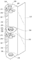
도 1은 본 발명의 일실시 예에 따른 맥주 제조장치를 나타내는 사시도이고, 도 2는 도 1에 따른 맥주 제조장치의 개략적인 수직단면도이고, 도 3은 도 1에 따른 맥주 제조장치의 개략적인 수평단면도이다. FIG. 1 is a perspective view showing a beer manufacturing apparatus according to an embodiment of the present invention, FIG. 2 is a schematic vertical sectional view of a beer manufacturing apparatus according to FIG. 1, and FIG. 3 is a schematic horizontal Sectional view.
도 1 내지 도 3을 참조하면, 본 발명의 일실시 예에 따른 맥주 제조장치(10)는, 냉기를 발생시키는 냉각장치(110)가 구비되는 기계실(100)과, 맥즙이 담긴 케그(KEG)(202)가 장착되는 독립된 공간을 가지는 챔버(210)가 복수개 구비되는 발효실(200)과, 기계실(100)과 발효실(200)을 지지하는 지지부(15)를 포함할 수 있다. 1 to 3, a beer manufacturing apparatus 10 according to an embodiment of the present invention includes a machine room 100 having a cooling device 110 for generating cool air, a keg containing a wort, A fermentation chamber 200 having a plurality of chambers 210 having an independent space for mounting the chamber 202 and a support unit 15 for supporting the chamber 100 and the fermentation chamber 200.
상기 기계실(100)에는 냉각장치(110)에서 발생하는 냉기를 보관하는 냉기보관부(120)가 구비될 수 있으며, 상기 발효실(200)에는 냉기보관부(120)에 보관된 냉기를 챔버(210) 내부로 공급하는 냉기공급장치(220)가 구비될 수 있다. The machine room 100 may be provided with a cold storage unit 120 for storing cold air generated by the cooling unit 110. In the fermentation chamber 200, cool air stored in the cold storage unit 120 may be supplied to the chamber 210 (Not shown).
또한, 상기 발효실(200)에는 챔버(210) 내에 장착된 케그(202)에 담긴 맥즙을 발효시키기 위한 발효장치(300)가 구비될 수 있다. The fermentation chamber 200 may be provided with a fermentation device 300 for fermenting the wort contained in the keg 202 installed in the chamber 210.
상기 챔버(210)는 맥즙이 담긴 케그(202)가 장착되는 독립된 공간으로써, 상기 각각의 챔버(210)에는 내부를 밀폐시키는 도어(212)가 구비될 수 있으며, 상기 챔버(210) 내부는 냉기공급장치(220)에 의해 독립적인 온도 조절이 가능하며, 상기 챔버(210) 내부에 장착된 케그(202)에 담긴 맥즙은 발효장치(300)에 의해 독립적인 발효를 통한 맥주 제조가 가능하다. The chamber 210 is an independent space in which the poured keg 202 is mounted and each of the chambers 210 may be provided with a door 212 for sealing the inside of the chamber 210. Inside the chamber 210, The wafers contained in the keg 202 mounted in the chamber 210 can be independently fermented by the fermentation apparatus 300 to produce beer.
일반적으로, 맥주는 맥즙과 효모의 종류에 따라 발효시간, 발효온도 등의 조건을 달리하여 제조하여야 하며, 그에 따라 제조된 맥주의 맛이 달라지게 되는데, 본 발명의 일실시 예에 따른 맥주 제조장치(10)는 독립적인 온도조절과 발효가 가능한 챔버(210)를 복수개 구비하기 때문에, 한 번에 다양한 종류의 맥주를 제조할 수 있다.Generally, the beer must be manufactured under different conditions such as fermentation time, fermentation temperature, etc. depending on the kinds of the wort and yeast, and the taste of the beer thus produced is changed. In the beer manufacturing apparatus according to the embodiment of the present invention, (10) has a plurality of chambers (210) capable of independent temperature control and fermentation, so that various kinds of beer can be produced at one time.
본 발명의 일실시 예에 따른 맥주 제조장치(10)는 효모(yeast)가 살아있는 상태의 맥주를 판매하기 위한 호프집 등과 같은 장소에 설치될 수 있으며, 상기 맥즙이 담긴 케그(202)는 공장으로부터 제조되어 제공될 수 있다. The beer manufacturing apparatus 10 according to an embodiment of the present invention may be installed in a place such as a hob house for selling beer in a state where yeast is live, Can be manufactured and supplied.
예를 들어, 공장에서는 맥즙을 제조하고, 상기 제조된 맥즙을 유통 및 보관을 위한 살균처리를 하고, 상기 살균처리된 맥즙을 케그(202)에 담아 케그캡으로 밀봉하고, 상기 밀봉된 케그를 본 발명에 따른 맥주 제조장치(10)가 설치된 판매장소로 유통시킴으로써, 상기 맥즙이 담긴 케그(202)를 제공할 수 있다. For example, in a factory, a wort is manufactured, a sterilization treatment is performed for distributing and storing the wort, and the sterilized wort is placed in a keg 202 and sealed with a keel cap. The beer manufacturing apparatus 10 according to the present invention can be provided with the poured keg 202 by distributing it to a sale place where the beer manufacturing apparatus 10 according to the present invention is installed.
그리고 본 발명에 따른 맥주 제조장치(10)가 설치된 판매장소에서는, 상기 맥즙이 담긴 밀봉된 케그(202)를 챔버(210)에 장착시키기만 하면, 발효장치(300)에 의해 밀봉된 상태로 즉, 외부와 접촉되어 오염될 여지 없이 자동으로 발효된 후 숙성되는 과정을 통해 전문지식 없이도 효모가 살아있는 맥주를 쉽게 제조하여 판매할 수 있다.In the sales place where the beer manufacturing apparatus 10 according to the present invention is installed, if the sealed peg 202 containing the wort is placed in the chamber 210, , It is possible to easily produce and sell live beer without yeast expertise through the process of being fermented automatically after being in contact with the outside and becoming uncontaminated and aged.
본 실시 예에서는 하나의 챔버(210)에 2개의 케그(202)가 장착되도록 구비된 것이 도시되지만, 하나의 챔버(210)에 1개의 케그(202)가 장착되도록 구비될 수도 있으며, 본 발명은 하나의 챔버(210)에 장착되는 케그(202)의 개수에 의해 한정되지 않는다.Although it is shown in the present embodiment that two pegs 202 are mounted on one chamber 210, one peg 202 may be mounted on one chamber 210, But is not limited by the number of pegs 202 mounted in one chamber 210.
다만, 본 실시 예에서와 같이, 하나의 챔버(210)에 2개의 케그(202)가 장착되는 경우에도, 각각의 케그(202)에 담겨진 맥즙을 발효시키기 위한 발효장치(300)는 각각 독립적으로 이루어질 수 있도록 구비될 수 있다. However, as in the present embodiment, even when two kegs 202 are mounted in one chamber 210, the fermentation apparatus 300 for fermenting the wort contained in each keg 202 can be independently And the like.
한편, 상기 발효실(200)은 회전 가능하게 구비될 수 있다. Meanwhile, the fermentation chamber 200 may be rotatably installed.
예를 들어, 본 실시 예에서와 같이, 지지부(15) 상부에 발효실(200)이 위치하고, 발효실(200) 상부에 기계실(100)이 위치하는 경우에는, 상기 발효실(200)은 지지부(15)와 기계실(100) 사이에서 회전 가능하게 구비될 수 있으며, 이를 위해 발효실(200)과 지지부(15) 사이, 발효실(200)과 기계실(100) 사이에는 상기 발효실(200)의 회전을 위한 로테이팅 베어링, 로터리 댐퍼 등의 구성이 구비될 수 있다.For example, as in the present embodiment, when the fermentation chamber 200 is positioned above the support portion 15 and the machine room 100 is positioned above the fermentation chamber 200, the fermentation chamber 200 is supported by the support portion 15, Between the fermentation chamber 200 and the support portion 15 and between the fermentation chamber 200 and the machine chamber 100 for rotatable rotation between the fermentation chamber 200 and the machine chamber 100, A bearing, a rotary damper, and the like may be provided.
다만, 본 발명은 이에 한정하는 것은 아니며, 지지부(15) 상부에 기계실(100)이 위치하고, 기계실(100) 상부에 발효실(200)이 위치할 수도 있으며, 이 경우 상기 발효실(200)은 기계실(100) 상부에 위치한 상태로 회전 가능하게 구비될 수 있다.However, the present invention is not limited thereto, and the machine room 100 may be located above the support unit 15, and the fermentation chamber 200 may be located above the machine room 100. In this case, 100, respectively.
이와 같이, 상기 발효실(200)이 회전 가능하게 구비되면, 사용자가 발효실(200)을 회전시키면서 복수의 챔버(210) 각각에 케그(202)를 장착시키거나 복수의 챔버(210) 각각에 장착된 케그(202)를 탈착시키기가 편리하다.When the fermentation chamber 200 is rotatably installed, the user may rotate the fermentation chamber 200 to install the keg 202 in each of the plurality of chambers 210, or to install the keg 202 in each of the plurality of chambers 210 It is convenient to detach the keg 202.
또한, 도 3에서 보이는 바와 같이, 상기 복수의 챔버(210)는 원주방향으로 구획될 수 있다. 그러면, 사용자는 발효실(200)을 회전시키면서 더욱 쉽게 케그(202)를 장착시키고 탈착시킬 수 있다.Further, as shown in FIG. 3, the plurality of chambers 210 may be partitioned in the circumferential direction. Then, the user can mount and detach the peg 202 more easily while rotating the fermentation chamber 200.
본 발명의 일실시 예에 따른 맥주 제조장치(10)는 상부 대략 기계실(100) 전면에 구비되어 복수의 챔버(210) 각각에 장착된 케그(202)에 담겨진 맥즙의 발효 진행상황, 상기 각각의 챔버(210) 내부 온도 등을 표시하는 디스플레이부(17)를 더 포함할 수 있다. The beer manufacturing apparatus 10 according to an embodiment of the present invention includes a plurality of chambers 210 provided in the front of a machine room 100 to process the fermentation progress of the wort contained in the keg 202, And a display unit 17 for displaying an internal temperature of the chamber 210 and the like.
상기 냉각장치(110)는 냉매를 이용하여 냉기를 발생시키도록 구성될 수 있는데, 예를 들어 압축기, 응축기, 증발기, 열교환기 등의 구성을 포함하여 이루어질 수 있다.The cooling device 110 may be configured to generate cold air using a refrigerant, for example, a compressor, a condenser, an evaporator, a heat exchanger, or the like.
상기 냉기보관부(120)는 냉각장치(110)에서 발생하는 냉기를 보관하는 공간(121)을 형성하는 제1 케이스(122)와 제2 케이스(125)를 포함할 수 있다. The cold storage unit 120 may include a first case 122 and a second case 125 that form a space 121 for storing cold air generated in the cooling device 110. [
상기 제1 케이스(122)는 냉각장치(110)에서 발생하는 냉기를 공급받을 수 있도록 기계실(100)에 위치하여 고정되며, 상기 제2 케이스(125)는 제1 케이스(122)에 회전 가능하게 구비되어 발효실(200) 회전시 함께 회전할 수 있다.The first case 122 is positioned and fixed in the machine room 100 to receive the cool air generated by the cooling device 110 and the second case 125 is rotatably mounted on the first case 122 And can rotate together when the fermentation chamber 200 is rotated.
또한, 제1 케이스(122)와 제2 케이스(125) 사이에는 제2 케이스(125)가 회전함에 따라 냉기보관부(120)에 보관된 냉기가 누출되는 것을 방지하는 가스켓(127)이 구비될 수 있으며, 제1 케이스(122) 상부에는 냉각장치(110)에서 발생한 냉기를 제2 케이스(125)로 원활하게 공급하는 팬(129)이 구비될 수 있다.A gasket 127 is provided between the first case 122 and the second case 125 to prevent the cool air stored in the cold storage unit 120 from leaking as the second case 125 rotates And a fan 129 for smoothly supplying cool air generated by the cooling device 110 to the second case 125 may be provided on the upper portion of the first case 122.
한편, 상기 제2 케이스(125)에는 냉기공급장치(220)가 연결될 수 있다.Meanwhile, the second case 125 may be connected to a cooler supply device 220.
도 4는 본 발명의 일실시 예에 따른 냉기공급장치를 설명하기 위한 도면이다.4 is a view for explaining a cool air supply device according to an embodiment of the present invention.
도 4에서 보이는 바와 같이, 본 발명의 일 실시 예에 따른 냉기공급장치(220)는 냉기보관부(120)에 보관된 냉기를 복수의 챔버(210) 각각으로 공급하기 위한 구성으로, 발효실(200)에는 냉기공급장치(220)가 적어도 상기 복수의 챔버(210) 수만큼 구비될 수 있다.4, the cool air supply device 220 according to the embodiment of the present invention is configured to supply cool air stored in the cool air storage unit 120 to each of the plurality of chambers 210. The cool air supply device 220 includes a fermentation chamber 200 The number of the plurality of chambers 210 can be increased.
상기 냉기공급장치(220)는 제2 케이스(125)에 연결되어 냉기보관부(120)와 챔버(210)를 연결하는 덕트(222)와, 냉기보관부(120)에 보관된 냉기를 덕트(222)를 통해 챔버(210)로 공급하는 냉기공급팬(225)과, 덕트(222)를 개폐하는 덕트개폐부(227)를 포함할 수 있다.The cool air supply device 220 includes a duct 222 connected to the second case 125 to connect the cool storage unit 120 to the chamber 210 and a cool air supply unit And a duct opening and closing part 227 for opening and closing the duct 222. The duct opening /
또한, 상기 각각의 챔버(210) 상단에는 덕트(222)에 연결되는 냉기공급구(211)가 형성될 수 있으며, 상기 각각의 챔버(210) 내부에는 히터(219)와 온도센서(미도시)가 구비될 수 있다.A cool air supply port 211 connected to the duct 222 may be formed at the upper end of each of the chambers 210. A heater 219 and a temperature sensor (not shown) May be provided.
따라서, 상기 각각의 챔버(210) 내부는 온도센서, 냉기공급장치(220) 및 히터(219)에 의해 독립적인 온도 조절이 가능해질 수 있다. 즉, 상기 복수의 챔버(210) 각각에 장착된 케그(202)에 담긴 맥즙의 발효진행 정도에 따라 챔버(210) 내부의 온도를 독립적으로 조절할 수 있다.Therefore, the temperature inside each of the chambers 210 can be controlled independently by the temperature sensor, the cold supply device 220, and the heater 219. That is, the temperature inside the chamber 210 can be independently controlled according to the degree of progress of the fermentation of the wort contained in the keg 202 mounted in each of the plurality of chambers 210.
도 5는 본 발명의 일실시 예에 따른 발효장치를 설명하기 위한 도면이고, 도 6은 본 발명의 일실시 예에 따른 발효장치의 구성도이다.FIG. 5 is a view for explaining a fermentation apparatus according to an embodiment of the present invention, and FIG. 6 is a configuration diagram of a fermentation apparatus according to an embodiment of the present invention.
도 5에서 보이는 바와 같이, 본 발명의 일실시 예에 따른 발효장치(300)는 복수의 챔버(210) 각각에 장착된 케그(202)에 담긴 맥즙을 독립적으로 발효시키기 위한 구성으로, 발효실(200)에는 발효장치(300)가 적어도 상기 복수의 챔버(210) 수만큼 구비될 수 있다.5, the fermentation apparatus 300 according to an embodiment of the present invention is configured to independently ferment the wort contained in the keg 202 mounted on each of the plurality of chambers 210, and includes a fermentation chamber 200 The fermenter 300 may be provided at least as many as the number of the chambers 210.
상기 발효장치(300)는 케그(202)의 케그캡(205)이 결합하는 커플러(230), 커플러(230)에 연결되어 독립된 유로를 형성하는 유로부(304), 유로부(304)에 연결되는 필터부(270), 유로부(304)에 연결되는 펌프(260)를 포함할 수 있다.The fermentation apparatus 300 includes a coupler 230 to which the cage cap 205 of the keg 202 is coupled, a flow path portion 304 connected to the coupler 230 to form an independent flow path, And a pump 260 connected to the flow path portion 304. The flow path portion 304 may be formed of a metal plate.
전술한 바와 같이, 본 실시 예에서는 하나의 챔버(210)에 2개의 케그(202)가 장착되는 것이 도시되는데, 이 경우에도 각각의 케그(202)에 담겨진 맥즙을 발효시키기 위한 발효장치(300)는 펌프(260)만을 공유할 뿐 각각 독립적으로 이루어질 수 있다.As described above, in this embodiment, two chambers 202 are mounted on one chamber 210. In this case, the fermenter 300 for fermenting the juice contained in each of the kags 202, Only the pump 260 can be shared independently.
즉, 하나의 챔버(210)에 장착된 2개의 케그(202)에 담겨진 맥즙을 각각 독립적으로 발효시키기 위하여, 상기 발효장치(300)는 2개의 케플러(230), 2개의 유로부(304), 2개의 필터부(270)를 포함할 수 있다.That is, in order to independently ferment the wafers contained in the two kegs 202 mounted on one chamber 210, the fermentor 300 includes two keplers 230, two flow channels 304, Two filter units 270 may be included.
물론, 펌프(260)도 2개가 구비될 수 있지만, 본 실시 예에서와 같이 하나의 펌프(260)를 공용으로 사용하면, 상기 발효장치(300)의 구성을 간단히 할 수 있다. Of course, two pumps 260 may be provided. However, if one pump 260 is commonly used as in the present embodiment, the configuration of the fermentation apparatus 300 can be simplified.
상기 커플러(230)에는 가스유로(air line)(232)와 맥즙유로(wort line)(234)가 구비될 수 있다.The coupler 230 may include an air line 232 and a wort line 234.
상기 유로부(304)는 커플러(230)의 가스유로(232)와 맥즙유로(234)를 연결하여 독립된 유로를 형성할 수 있다. The flow path portion 304 connects the gas flow path 232 and the wick flow path 234 of the coupler 230 to form an independent flow path.
상세히, 상기 유로부(304)는 커플러(230)의 가스유로(232)와 펌프(260)를 연결하는 제1 유로(310)와, 커플러(230)의 맥즙유로(234)와 펌프(260)를 연결하는 제2 유로(320)를 포함할 수 있다.The flow path portion 304 includes a first flow path 310 connecting the gas flow path 232 of the coupler 230 and the pump 260 and a second flow path 310 connecting the wax flow path 234 and the pump 260 of the coupler 230. [ And a second flow path 320 connecting the first and second flow paths.
또한, 상기 유로부(304)는 제1 유로(310)에 구비되어 케그(202)에 담긴 맥즙 발효시 발생하는 가스를 외부로 배출시키는 가스배출부(312)와, 가스배출부(312)를 개폐시키는 제1 밸브(314)와, 가스배출부(312)와 펌프(260) 사이에 구비되어 제1 유로(310)를 개폐시키는 제2 밸브(315)를 포함할 수 있다.The channel portion 304 includes a gas discharge portion 312 provided in the first flow path 310 to discharge the gas generated during fermentation of the wort contained in the keg 202 to the outside, And a second valve 315 provided between the gas discharging unit 312 and the pump 260 for opening and closing the first flow path 310. The first valve 314 may be a valve that opens and closes the first flow path 310,
또한, 상기 제1 유로(310)에는 케그(202) 내부의 압력을 감지하기 위한 압력센서(317)가 구비될 수 있다. 제1 유로(310)는 커플러(230)의 가스유로(232)를 통해 케그(202)의 내부와 연결되기 때문에, 압력센서(317)가 제1 유로(310)에 위치하더라도 케그(202)의 내부 압력 감지가 가능하다.The first channel 310 may include a pressure sensor 317 for sensing pressure inside the keg 202. The first flow path 310 is connected to the inside of the peg 202 through the gas flow path 232 of the coupler 230 so that even if the pressure sensor 317 is located in the first flow path 310, Internal pressure sensing is possible.
도면에는 도시되지 않지만, 상기 가스배출부(312)에는 외부 공기가 제1 유로(310)로 유입되어 오염되는 것을 방지하는 공기필터가 구비될 수 있으며, 압력센서(317) 및 제1 밸브(314)의 오작동시 압력을 배출할 수 있는 기계식 릴리프밸브가 구비될 수 있다. Although not shown in the drawing, the gas discharge unit 312 may include an air filter for preventing external air from entering the first flow path 310 and contaminating it. The pressure sensor 317 and the first valve 314 A mechanical relief valve capable of discharging the pressure at the time of malfunction.
상기 필터부(270)는 필터용기(filter bottle)(274)와, 필터용기(274)를 막아 밀폐시키는 필터캡(filter cap)(275)과, 유로부(304)에 연결되되 필터캡(275)이 결합하는 경우에 필터용기(274) 내부와 유로부(304)를 연결하는 필터헤드(filter head)(271)를 포함할 수 있다.The filter unit 270 includes a filter bottle 274, a filter cap 275 for closing and sealing the filter container 274, a filter cap 275 connected to the flow path unit 304, And a filter head 271 connecting the inside of the filter vessel 274 and the flow path portion 304 in the case where the filter portion 274 is coupled.
상기 필터용기(274)는 유로부(304) 살균세척을 위한 살균세척수가 담긴 살균세척용 필터용기일 수 있으며, 또는 맥주에 홉(hop)이나 자연재료 그대로의 맛(flavor)과 향(aroma)을 가미하기 위한 재료가 담긴 스마트 인퓨징(smart infusing)용 필터용기일 수 있으며, 또는 케그(202)에 담긴 맥즙에 공급할 효모(yeast)가 담긴 효모공급용 필터용기일 수 있다. The filter container 274 may be a sterilizing filter container for sterilizing washing water for sterilizing the flow path 304 or may be provided with hop or natural flavor and aroma, Or a yeast feed filter container containing a yeast to be fed to the wort contained in the keg 202. The yeast feed filter container may be a smart infusing filter container containing a material for adding the yeast to the yeast,
상기 필터부(270)는 제2 유로(320)에 구비되어 커플러(230)의 맥즙유로(234)에 연결될 수 있다.The filter unit 270 may be provided in the second flow path 320 and may be connected to the wick channel 234 of the coupler 230.
상기 유로부(304)는 제2 유로(320)에 구비되어 상기 제2 유로(320)를 개폐하는 제3 밸브(325)를 더 포함할 수 있으며, 상기 제3 밸브(325)는 커플러(230)의 맥즙유로(234)와 필터부(270) 사이에 구비될 수 있다.The flow path unit 304 may further include a third valve 325 provided in the second flow path 320 to open and close the second flow path 320. The third valve 325 may include a coupler 230 And the filter unit 270. In this case,
도 7은 도 1에 따른 맥주 제조장치의 챔버 내부를 나타내는 도면이고, 도 8은 도 7의 챔버에 케그가 장착된 상태를 나타내는 도면이고, 도 9는 도 7의 챔버에 케그가 장착되어 형성된 독립된 유로부를 개략적으로 나타내는 도면이다.7 is a view showing the inside of the chamber of the beer manufacturing apparatus shown in Fig. 1, Fig. 8 is a view showing a state in which the cage is mounted in the chamber of Fig. 7, Fig.
먼저, 도 7 및 도 8에서 보이는 바와 같이, 상기 챔버(210)에는 2개의 케그(202)가 장착되도록 지지플레이트(214)가 구비될 수 있으며, 상기 지지플레이트(214)에는 챔버(210) 내로 공급된 냉기가 지지플레이트(214)를 기준으로 아래위로 원활하게 순환될 수 있도록 홀(213)과 틈(216) 등이 형성될 수 있으며, 지지플레이트(214)와 챔버(210)의 하부에는 케그(202)가 안착되는 케그안착부(215)가 구비될 수 있다.7 and 8, the chamber 210 may include a support plate 214 to which two pegs 202 may be mounted, and the support plate 214 may be provided with a chamber 210, A hole 213 and a gap 216 may be formed in the lower portion of the support plate 214 and the chamber 210 to smoothly circulate the supplied cool air upward and downward with respect to the support plate 214, And a cage seating part 215 on which the cage 202 is mounted.
또한, 챔버(210) 내부에는 커플러(230)가 챔버(210) 상단과 지지플레이트(214) 상단에 고정설치될 수 있는데, 커플러(230)의 가스유로(232)는 제1 유로(310)에 연결되고, 커플러(230)의 맥즙유로(234)는 제2 유로(320)에 연결된 상태로 고정설치될 수 있다.A coupler 230 may be fixed to the upper end of the chamber 210 and the upper end of the support plate 214 in the chamber 210. The gas channel 232 of the coupler 230 is connected to the first channel 310 And the wick channel 234 of the coupler 230 may be fixedly connected to the second channel 320.
도면에는 도시되지 않지만, 커플러(230)는 챔버(210) 상단 또는 지지플레이트(214) 상단에 소정의 높이 조절이 가능한 상태로 고정되도록 코일스프링과 같은 탄성부재에 의해 지지될 수 있다. 그러면, 커플러(230)의 높이를 케그(202)의 크기에 맞게 쉽게 조절 가능하게 됨에 따라, 케그(202)를 케그안착부(215)에 안착시킨 상태에서 케그캡(205)을 커플러(230)에 쉽게 결합시킬 수 있어서 편리하다.Although not shown in the drawings, the coupler 230 may be supported by an elastic member such as a coil spring so as to be fixed at the top of the chamber 210 or at the upper end of the support plate 214 in a predetermined height-adjustable state. The height of the coupler 230 can be easily adjusted to the size of the keg 202 so that the keb cap 205 is coupled to the coupler 230 in a state in which the keg 202 is seated on the keg mount 215. [ So that it is possible to easily combine them with each other.
도 9에서 보이는 바와 같이, 케그캡(205)에는 케그(202)에 담긴 맥즙을 케그(202) 외부로 배출시키기 위한 맥즙호스(206)가 케그(202)의 대략 바닥면까지 길게 형성될 수 있으며, 상기 맥즙호스(206)는 케그캡(205)이 커플러(230)에 결합한 경우에 커플러(230)의 맥즙유로(234)에 연결될 수 있다.9, the wick hose 206 for discharging the wort contained in the keg 202 to the outside of the keg 202 may be formed to be long to the substantially bottom surface of the keg 202, The wick hose 206 may be connected to the wick channel 234 of the coupler 230 when the cap cap 205 is coupled to the coupler 230.
또한, 상기 케그캡(205)에는 케그(202) 내부 공간과 연결되어 맥즙 발효시 발생하는 가스를 케그(202) 외부로 배출시키기 위한 가스배출유로(207)가 형성될 수 있으며, 상기 가스배출유로(207)는 케그캡(205)이 커플러(230)에 결합한 경우에 커플러(230)의 가스유로(232)에 연결될 수 있다.A gas discharge passage 207 may be formed in the cage cap 205 to discharge a gas generated during fermentation of the wort to the outside of the keg 202 by being connected to an inner space of the keg 202, The coupler 230 may be connected to the gas passage 232 of the coupler 230 when the coupler cap 205 is coupled to the coupler 230.
그러면, 상기 유로부(304)는 케그캡(205)과 커플러(230)가 결합하게 됨에 따라, 제1 유로(310), 제2 유로(320), 커플러(230) 및 케그(202)로 연결되는 폐유로를 형성할 수 있다.As the coupler 230 is coupled to the coupler 230, the flow path portion 304 is connected to the first flow path 310, the second flow path 320, the coupler 230, and the peg 202, Can be formed.
따라서, 상기 맥즙이 담긴 케그(202)를 챔버(210) 내에 구비된 케그안착부(215)에 안착시킨 상태에서 케그캡(205)을 커플러(230)에 결합함으로써 상기 맥즙이 담긴 케그(202)를 챔버(210) 내에 장착시킬 수 있으며, 이와 같이 상기 맥즙이 담긴 케그(202)를 챔버(210) 내에 장착시키면, 상기 케그(202)에 담긴 맥즙은 맥즙호스(206)와 맥즙유로(234)를 통해 제2 유로(320)에 연결되고, 상기 맥즙이 담긴 케그(202)의 공간은 가스배출유로(207)와 가스유로(232)를 통해 제1 유로(310)에 연결됨에 따라, 상기 유로부(304)는 폐유로를 형성할 수 있다. Therefore, by coupling the cake cap 205 to the coupler 230 in a state where the poured cake 202 is placed on the pouched part 215 provided in the chamber 210, The wastes contained in the keg 202 may be introduced into the chamber 210 through the wick hose 206 and the wick channel 234 when the keg 202 containing the wort is mounted in the chamber 210. [ And the space of the peg 202 containing the wort is connected to the first flow path 310 through the gas discharge flow path 207 and the gas flow path 232, The portion 304 can form an oil path.
그러면, 상기 케그(202)에 담긴 맥즙은 펌프(260)에 의해 외부와 접촉되어 오염될 여지 없이 제2 유로(320)로 펌핑될 수 있으며, 상기 케그(202)에 담긴 맥즙 발효시 발생하는 가스는 외부와 접촉되어 오염될 여지 없이 제1 유로(310)와 가스배출부(312)를 통해 외부로 배출될 수 있다.The wastes contained in the keg 202 may be pumped to the second flow path 320 without being contaminated by contact with the outside by the pump 260. The wastes contained in the keg 202 Can be discharged to the outside through the first flow path 310 and the gas discharging portion 312 without any possibility of being contaminated by contact with the outside.
또한, 챔버(210) 내부 일측에는 필터부(270)의 필터용기(274)가 안착되는 필터안착부(217)가 구비될 수 있으며, 상기 필터안착부(217) 상부에는 필터헤드(271)가 유로부(304)에 연결된 상태로 고정설치될 수 있다.A filter seat 277 may be provided on one side of the chamber 210 and a filter seat 277 on which the filter 274 of the filter 270 may be mounted. And may be fixedly installed in a state connected to the flow path portion 304.
다만, 본 발명은 이에 한정하는 것은 아니며, 챔버(210) 내부에 별도의 필터안착부(217)가 구비됨이 없이, 필터용기(274)가 챔버(210) 상부에 고정설치된 필터헤드(271)에 결합됨으로써 챔버(210)에 장착될 수도 있다.However, the present invention is not limited to this. The filter container 274 may be provided with a filter head 271 fixed to the upper part of the chamber 210 without a separate filter seating part 217 inside the chamber 210, Or may be mounted to the chamber 210 by being coupled to the chamber 210.
도 9에서 보이는 바와 같이, 상기 필터헤드(271)에는 커플러(230)의 맥즙유로(234)에 연결되는 제1 필터유로(272)와, 펌프(260)에 연결되는 제2 필터유로(273)가 형성될 수 있으며, 상기 필터헤드(271)는 제1 필터유로(272)가 커플러(230)의 맥즙유로(234)에 연결되고, 제2 필터유로(273)가 펌프(260)에 연결된 상태로 필터안착부(217) 상부에 고정설치될 수 있다.9, the filter head 271 is provided with a first filter channel 272 connected to the wick channel 234 of the coupler 230, a second filter channel 273 connected to the pump 260, The first filter passage 272 is connected to the wick channel 234 of the coupler 230 and the second filter channel 273 is connected to the pump 260 And may be fixed to the upper portion of the filter seat 217.
또한, 상기 필터캡(275)에는 대략 필터용기(274) 바닥면까지 길게 형성된 제1 필터호스(276)와, 제1 필터호스(276)보다 짧게 형성된 제2 필터호스(277) 형성될 수 있으며, 제1 필터호스(276)와 제2 필터호스(277) 각각은 상기 필터캡(275)이 필터헤드(271)에 결합한 경우에 제1 필터유로(272)와 제2 필터유로(273)에 연결될 수 있다.The first filter hose 276 and the second filter hose 277 may be formed in the filter cap 275 so as to extend to the bottom surface of the filter container 274 and the second filter hose 277 may be formed shorter than the first filter hose 276. The first filter hose 276 and the second filter hose 277 are connected to the first filter passage 272 and the second filter passage 273 when the filter cap 275 is coupled to the filter head 271 Can be connected.
따라서, 상기 필터용기(274)의 필터캡(275)을 필터헤드(271)에 결합함으로써 상기 필터용기(274)를 챔버(210) 내에 장착시킬 수 있으며, 이와 같이 상기 필터용기(274)를 챔버(210) 내에 장착시키면, 상기 필터용기(274) 내부는 제1 필터호스(276)와 제1 필터유로(272)를 통해 커플러(230)의 맥즙유로(234)에 연결될 수 있으며, 제2 필터호스(277)와 제2 필터유로(273)를 통해 펌프(260)에 연결될 수 있다. The filter vessel 274 can be mounted in the chamber 210 by coupling the filter cap 275 of the filter vessel 274 to the filter head 271, The inside of the filter container 274 can be connected to the wick channel 234 of the coupler 230 through the first filter hose 276 and the first filter channel 272, And may be connected to the pump 260 through the hose 277 and the second filter channel 273.
그러면, 상기 필터부(270)의 용도에 따라 적절한 필터용기(274)를 챔버(210) 내에 장착시킴으로써, 외부와 접촉되어 오염될 여지없이 자동으로 쉽게 케그(202)에 담긴 맥즙으로부터 효모가 살아있는 맥주를 제조할 수 있다.By mounting the appropriate filter vessel 274 in the chamber 210 according to the use of the filter unit 270, the beer can be automatically and easily contaminated by contact with the outside, Can be produced.
예를 들어, 상기 필터용기(274)로서 내부에 살균세척수가 담긴 살균세척용 필터용기를 사용하면, 펌프(260)에 의해 상기 필터용기(274)에 담긴 살균세척수를 유로부(304)로 순환시킴으로써, 외부와 접촉되어 오염될 여지없이 자동으로 유로부(304)를 살균세척할 수 있다.For example, when the filter container 274 is used for sterilizing cleaning filter container in which the sterilizing wash water is contained, the sterilizing wash water contained in the filter container 274 is circulated by the pump 260 to the flow path portion 304 It is possible to sterilize and clean the flow path portion 304 automatically without contact with the outside to be contaminated.
또한, 상기 필터용기(274)로서 내부에 홉이나 자연재료 그대로의 맛과 향을 우려내기 위한 재료가 담긴 스마트 인퓨징용 필터용기를 사용하면, 펌프(260)에 의해 케그(202)에 담긴 맥즙을 상기 필터용기(274) 내부로 순환시킴으로써, 외부와 접촉되어 오염될 여지없이 자동으로 맥주에 맛과 향을 우려낼 수 있다.When the filter container 274 is used for a smart infusion filter container containing a material for avoiding taste and odor intact in the interior of the filter container 274, By circulating the inside of the filter container 274, it is possible to automatically taste the taste and the aroma in the beer without touching the outside and being polluted.
또한, 상기 필터용기(274)로서 내부에 맥즙을 발효시키기 위한 효모가 담긴 효모공급용 필터용기를 사용하면, 펌프(260)에 의해 케그(202)에 담긴 맥즙을 상기 필터용기(274) 내부로 순환시킴으로써, 외부와 접촉되어 오염될 여지없이 자동으로 맥즙에 효모를 공급할 수 있다. When the filter container 274 is filled with a yeast-containing filter container for containing the yeast for fermenting the wort, the wastes contained in the keg 202 are pumped into the filter container 274 by the pump 260 By circulating, the yeast can be automatically supplied to the juice by contact with the outside and free from contamination.
한편, 도 9에서 보이는 바와 같이, 상기 케그(202)가 안착되는 케그안착부(215)에는 무게센서(40)가 구비될 수 있다. Meanwhile, as shown in FIG. 9, the weight sensor 40 may be provided on the keg seating unit 215 on which the keg 202 is mounted.
상기 무게센서(40)는 케그(202)에 담긴 맥즙의 발효진행 정도에 따른 상기 케그(202)의 무게 변화를 측정하기 위한 것으로서, 케그안착부(215) 하단에 부착 가능한 로드셀(load cell)이 사용될 수 있다. The weight sensor 40 measures a change in the weight of the keg 202 according to the degree of progress of the fermentation of the wort contained in the keg 202. The weight sensor 40 has a load cell attachable to the lower end of the keg seating unit 215 Can be used.
또한, 케그안착부(215) 상부와 케그(202)의 하부에는 케그(202)가 케그안착부(215)의 정확한 위치에 안착되도록 가이드하는 가이드부(208,218)가 형성될 수 있다. 예를 들어, 상기 케그(202)의 하부에는 소정형상의 돌기(208)가 형성되고, 상기 케그안착부(215)의 상부에는 상기 돌기(208)가 끼움되도록 상기 돌기(208) 형상에 상응하는 형상을 갖는 돌기홈(218)이 형성될 수 있다. Guide portions 208 and 218 may be formed on the upper portion of the keg seating portion 215 and the lower portion of the keg 202 to guide the keg 202 to be seated at the correct position of the keg seating portion 215. For example, a protrusion 208 of a predetermined shape is formed on the lower part of the keg 202, and a protrusion 208 corresponding to the shape of the protrusion 208 is inserted into the upper part of the keg seating part 215 A protrusion groove 218 having a shape can be formed.
그러면, 상기 케그(202)는 케그안착부(215)의 정확한 위치에 안착될 수 있게 됨에 따라 케그안착부(215)에 구비된 무게센서(40)의 센터에 해당하는 정확한 위치에 상기 케그(202)를 안착시킬 수 있으며, 그에 따라 케그(202)가 무게센서(40)와 틀어져 안착되는 경우에 발생하는 무게 변화의 측정오차를 최소화시킬 수 있어서 상기 케그(202) 내에 담긴 맥즙의 발효진행에 따른 무게변화를 보다 정확하게 측정할 수 있다.As the keg 202 can be seated at the correct position of the keg seat 215, the keg 202 can be positioned at a precise position corresponding to the center of the weight sensor 40 provided in the keg seat 215 So that it is possible to minimize a measurement error of a change in weight caused when the keg 202 is seated with the weight sensor 40. Thus, Weight change can be measured more accurately.
도 10은 본 발명의 일실시 예에 따른 맥주 제조장치의 구성도이다.10 is a configuration diagram of a beer manufacturing apparatus according to an embodiment of the present invention.
도 10을 참조하면, 본 발명의 일실시 예에 따른 맥주 제조장치(10)는 냉기공급장치(220)를 제어하여 복수의 챔버(210) 각각의 내부 온도를 조절하며, 발효장치(300)를 제어하여 복수의 챔버(210) 각각에 장착된 케그(202)에 담겨진 맥즙을 독립적으로 발효시키는 제어부(20)를 포함할 수 있다.10, a beer manufacturing apparatus 10 according to an embodiment of the present invention controls a cool air supply device 220 to adjust an internal temperature of each of a plurality of chambers 210, and a fermenter 300 And a control unit 20 for independently fermenting the juice contained in the keg 202 mounted on each of the plurality of chambers 210 by controlling the control unit 20.
또한, 본 발명의 일실시 예에 따른 맥주 제조장치(10)는 케그(202)에 담긴 맥즙의 발효시간, 발효온도 등의 구체적인 발효조건 등이 입력되는 입력부(60)를 포함할 수 있다.The beer manufacturing apparatus 10 according to an embodiment of the present invention may include an input unit 60 for inputting specific fermentation conditions such as a fermentation time of the wort contained in the keg 202 and a fermentation temperature.
상기 입력부(60)는 사용자가 직접 입력 가능하도록 구비될 수도 있으나, 바코드나 QR(Quick Response)코드 형태로 저장된 정보를 읽을 수 있는 스캐너 등으로 구비됨이 바람직하다.The input unit 60 may be directly input by a user, but may be a scanner or the like capable of reading information stored in a form of a bar code or a QR (Quick Response) code.
예를 들어, 케그캡(205) 상단에는 케그(202)에 담긴 맥즙의 종류, 사용할 효모의 종류, 발효조건, 홉(hop)이나 자연재료 그대로의 맛(flavor)과 향(aroma)을 가미할 것인지 가미한다면 어떠한 재료를 쓸 것인지 등에 대한 정보가 저장된 바코드 또는 QR코드가 형성될 수 있으며, 상기 입력부(60)는 케그캡(205) 상단에 형성된 바코드 또는 QR코드를 인식할 수 있는 스캐너 형태로 구비될 수 있다.For example, at the top of the keel cap 205, the kind of wort contained in the keg 202, the type of yeast to be used, the fermentation conditions, hop, natural flavor and aroma A barcode or a QR code storing information on what kind of material to use or the like can be formed, and the input unit 60 is provided in the form of a scanner capable of recognizing a barcode or a QR code formed on the top of the keycap 205 .
따라서, 상기 제어부(20)는 입력부(60)를 통해 입력된 정보, 챔버(210) 내에 구비된 온도센서(30)에서 감지된 온도 및 무게센서(40)에서 감지된 케그(202)의 무게변화 측정값 등을 기초로 냉기공급장치(200)의 냉기공급팬(225), 덕트개폐부(227) 및 챔버(210) 내에 구비된 히터(219)를 제어함으로써, 상기 복수의 챔버(210) 각각의 내부 온도를 상기 케그(202) 내에 담긴 맥즙의 발효진행 정도에 따라 독립적으로 조절할 수 있다. The control unit 20 controls the operation of the control unit 20 based on the information input through the input unit 60 and the temperature sensed by the temperature sensor 30 provided in the chamber 210 and the weight change of the keg 202 sensed by the weight sensor 40. [ By controlling the cold air supply fan 225, the duct opening and closing part 227 of the cold supply device 200 and the heater 219 provided in the chamber 210 on the basis of measured values and the like, The internal temperature can be independently controlled according to the degree of fermentation progression of the wort contained in the keg 202.
또한, 상기 제어부(20)는 입력부(60)를 통해 입력된 정보, 압력센서(317)에서 감지된 압력 및 무게센서(40)에서 감지된 케그(202)의 무게변화 측정값 등을 기초로 발효장치(300)의 펌프(260), 제1 밸브(314), 제2 밸브(315) 및 제3 밸브(325)를 제어함으로써, 상기 복수의 챔버(210) 각각에 장착된 케그(202)에 담겨진 맥즙을 독립적으로 발효시킬 수 있다.The control unit 20 may also be configured to perform a fermentation based on the information input through the input unit 60, the pressure sensed by the pressure sensor 317, and the weight change measured value of the kerg 202 sensed by the weight sensor 40, By controlling the pump 260 of the apparatus 300, the first valve 314, the second valve 315 and the third valve 325, the purging of the keg 202 mounted on each of the plurality of chambers 210 The contained juice can be fermented independently.
상술한 바와 같은 구성을 가지는 본 발명의 일실시 예에 따른 맥주 제조장치에 의하면, 공장에서 제조되어 제공된 맥즙이 담겨 밀봉된 케그(202)를 챔버(210)에 장착하기만 하면 전문지식 없이도 외부와 접촉되어 오염될 여지 없이 자동으로 쉽게 효모가 살아있는 상태의 맥주를 제조할 수 있으며, 독립적으로 온도조절이 가능하고 독립적인 발효가 가능한 챔버를 복수개 구비하기 때문에 한 번에 다양한 종류의 맥주를 제조할 수 있다.According to the beer manufacturing apparatus of the present invention having the above-described structure, when the beer 202, which is manufactured and sealed in a factory, is installed in the chamber 210, It is possible to manufacture beer in a state where the yeast can live easily and automatically without any possibility of contamination by contact, and it is possible to manufacture various kinds of beer at one time because it has independent chamber temperature controllable and independent fermentation have.
이하, 본 발명에 따른 맥주 제조장치를 이용한 맥주 제조방법에 대하여 상세히 설명한다.Hereinafter, a method for manufacturing beer using the beer manufacturing apparatus according to the present invention will be described in detail.
도 11은 본 발명의 일실시 예에 따른 맥주 제조장치를 이용한 맥주 제조방법을 나타내는 흐름도이다.11 is a flowchart illustrating a method of manufacturing beer using a beer manufacturing apparatus according to an embodiment of the present invention.
도 11을 참조하면, 본 발명의 일실시 예에 따른 맥주 제조장치(10)를 이용한 맥주 제조방법은, 유로부(304) 살균세척 단계(S10), 케그(202) 장착 단계(S20), 효모 공급 단계(S30), 1차 발효 단계(S40), 스마트 인퓨징(smart infusing) 단계(S50), 2차 발효 단계(S60), 콜드 브레이킹(cold breaking) 단계(S70) 및 숙성 단계(S80)를 포함할 수 있다. 11, a beer manufacturing method using a beer manufacturing apparatus 10 according to an embodiment of the present invention includes a sterilizing cleaning step S10 of a flow path 304, a mounting step S20 of a keg 202, The fermentation step S30, the smart infusing step S50, the secondary fermentation step S60, the cold breaking step S70 and the aging step S80, . ≪ / RTI >
상기 유로부(304) 살균세척 단계(S10)는 맥즙이 담긴 케그(202)를 챔버(210) 내에 장착시키기 전에 챔버(210) 내에 고정설치된 커플러(230)의 맥즙유로(234)와 가스유로(232)를 연결하는 유로부(304)를 살균세척하기 위한 단계로서, 필터부(270)의 필터용기(274)를 내부에 살균세척수가 담겨진 살균세척용 필터용기로 사용함으로써 수행될 수 있다. The sterilizing cleaning step S10 of the flow path 304 is carried out in such a manner that the wick channel 234 and the gas channel 234 of the coupler 230 fixed in the chamber 210 before the pod 202 containing the wort is mounted in the chamber 210, 232 by connecting the filter container 274 of the filter part 270 to the sterilizing cleaning filter container in which the sterilizing wash water is contained.
상기 케그(202) 장착 단계(S20)는, 맥즙이 담긴 케그(202)의 케그캡(205)을 커플러(230)에 결합하여 상기 맥즙이 담긴 케그(202)의 내부를 상기 살균세척된 유로부(304)에 연결하는 단계로서, 상기 맥즙이 담긴 케그(202)를 챔버(210) 내에 구비된 케그안착부(215)에 안착시킨 상태에서 케그캡(205)을 커플러(230)에 결합시킴으로써, 케그(202) 내부 공간을 가스배출유로(207)와 가스유로(232)를 통해 제1 유로(310)에 연결하고, 케그(202)에 담겨진 맥즙을 맥즙호스(206)와 맥즙유로(234)를 통해 제2 유로(320)에 연결할 수 있다. The mounting step S20 of the keg 202 may be performed by coupling the cap cap 205 of the poured keg 202 to the coupler 230 so that the inside of the pouched keg 202 is inserted into the sterilized- And connecting the cage cap 205 to the coupler 230 in a state where the poured keg 202 is seated in the cage seating part 215 provided in the chamber 210, The inner space of the keg 202 is connected to the first flow path 310 through the gas discharge flow path 207 and the gas flow path 232 and the wastes contained in the keg 202 are supplied to the wastewater hose 206 and the wastewater flow path 234, To the second flow path (320).
상기 효모 공급 단계(S30)는, 상기 챔버(210) 내에 장착된 케그(202)에 담긴 맥즙을 발효시키기 위한 효모를 공급하는 단계로서, 필터부(270)의 필터용기(274)를 내부에 맥즙을 발효시키기 위한 효모가 담긴 효모공급용 필터용기를 사용함으로써 수행될 수 있다.The yeast supplying step S30 is a step of supplying yeast for fermenting the wort contained in the keg 202 mounted in the chamber 210. The yeast supplying step S30 is a step of supplying yeast to the filter container 274 of the filter unit 270, For example, by using a yeast feed filter container containing yeast for fermenting yeast.
상기 1차 발효 단계(S40)는, 유로부(304)에 구비된 가스배출부(312)를 열어 상기 케그(202)에 담긴 맥즙 발효시 발생하는 가스를 외부로 배출시키는 단계이다.The primary fermentation step S40 is a step of opening the gas discharging part 312 provided in the flow path part 304 to discharge the gas generated during fermentation of the wort contained in the keg 202 to the outside.
상기 케그(202)에 담긴 맥즙에 효모가 공급되면 바로 발효가 시작되고, 발효가 시작되면 케그(202) 내부로 공급된 효모가 활성화되고 알코올 생성이 활발히 이루어지게 되면서 가스가 발생하게 되는데, 상기 1차 발효 단계(S40)는 발효 시작 후 소정시간 동안 발생하는 가스를 외부로 배출시키기 위한 단계로서, 이때 제어부(20)는 제2 밸브(315)와 제3 밸브(325)를 닫고, 제1 밸브(314)를 오픈함으로써, 발효시작 후 소정시간 동안 케그(202) 내부에서 발생하는 가스를 가스배출부(312)를 통해 외부로 배출시킬 수 있다.When yeast is supplied to the bees contained in the keg 202, the fermentation starts immediately. When the fermentation is started, the yeast supplied into the keg 202 is activated and alcohol is actively generated, and gas is generated. The control unit 20 closes the second valve 315 and the third valve 325, and the first valve 315 and the third valve 325 are closed. At this time, The gas generated inside the keg 202 can be discharged to the outside through the gas discharging part 312 for a predetermined time after the start of fermentation.
상기 스마트 인퓨징 단계(S50)는, 맥주에 홉이나 자연재료 그대로의 맛과 향을 우려내기 위한 단계로서, 필터부(270)의 필터용기(274)를 내부에 맛과 향을 우려내기 위한 재료가 담긴 스마트 인퓨징용 필터용기를 사용함으로써 수행될 수 있다.The smart infusing step S50 is a step for raising the taste and flavor of the beer as it is as a hop or a natural material. The smart infusing step S50 includes a step of forming a filter container 274 of the filter unit 270, By using a smart infusion filter container.
상기 2차 발효 단계(S60)는, 상기 가스배출부(312)를 닫아 상기 케그(202)에 담긴 맥즙 발효시 발생하는 가스를 이용하여 상기 1차 발효된 맥즙을 자연 탄산화시키는 단계로서, 이때 제어부(20)는 제1 밸브(325)를 닫아 케그(202) 내부에 발생된 가스가 가스배출부(312)를 통해 외부로 배출되지 못하도록 할 수 있다.The secondary fermentation step (S60) is a step of carbonating the primary fermented wort using the gas generated when the wort fermented in the keg (202) is closed by closing the gas discharging part (312) The first valve 325 may be closed to prevent the gas generated in the peg 202 from being discharged to the outside through the gas discharging unit 312. [
상기 콜드 브레이킹 단계(S70)는, 챔버(210) 내부 온도를 대략 2℃ 이하로 낮춤으로써, 2차 발효된 맥주에 섞여져 있는 단미, 단백질, 효모 등의 침전물을 케그(202) 바닥으로 가라앉게 하는 단계이다.In the cold breaking step S70, the internal temperature of the chamber 210 is lowered to approximately 2 DEG C or lower, so that precipitates such as starch, protein, yeast, etc. mixed in the secondary fermented beer are submerged to the bottom of the keg 202 .
상기 숙성 단계(S80)는, 상기 콜드 브레이킹 단계(S70)까지 완료된 맥주를 숙성시키는 단계로서, 챔버(210) 내부 온도를 기 설정된 소정온도로 유지한 상태로 기 설정된 소정시간 동안 유지시키는 단계이다.The aging step S80 is a step of aging the beer completed until the cold breaking step S70 and maintaining the internal temperature of the chamber 210 at a predetermined temperature for a predetermined period of time.
이하, 본 발명의 일실시 예에 따른 맥주 제조장치를 이용한 유로부 살균세척 방법에 대하여 도면을 참조하여 상세히 설명한다.Hereinafter, a method of cleaning a path portion disinfection using a beer manufacturing apparatus according to an embodiment of the present invention will be described in detail with reference to the drawings.
상기 유로부 살균세척 단계(S10)는 챔버(210)에 맥즙이 담긴 케그(202)를 장착하여 발효시키기 전에 미리 유로부(304)를 살균세척하기 위한 것이다.The sterilizing and washing step S 10 is for sterilizing and washing the channel portion 304 before the fermentation of the chamber 210 with the poured keg 202 is carried out.
도 12 내지 도 14는 본 발명의 일실시 예에 따른 맥주 제조장치를 이용한 유로부 살균세척 단계를 설명하기 위한 도면으로서, 도 12는 커플러에 살균세척용 마개를 결합한 상태를 개략적으로 나타내는 도면이고, 도 13은 살균세척수가 유로부를 순환하는 상태를 개략적으로 나타내는 도면이고, 도 14는 본 발명의 일실시 예에 따른 유로부의 살균세척 단계를 나타내는 흐름도이다.FIGS. 12 to 14 are views for explaining the steps of cleaning a path portion disinfection using a beer manufacturing apparatus according to an embodiment of the present invention, FIG. 12 is a view schematically showing a state in which a sterilizing cleaning stopper is coupled to a coupler, FIG. 13 is a view schematically showing a state in which sterilizing washing water circulates through the flow path portion, and FIG. 14 is a flowchart showing a sterilizing washing step of the flow path portion according to an embodiment of the present invention.
도 12 및 도 13을 참조하면, 챔버(210) 내에 케그(202)를 장착하기 전에 자동으로 유로부(304)를 살균세척하기 위한, 본 발명의 일실시 예에 따른 맥주 제조장치(10)는, 커플러(230)에 결합하여 유로부(304)를 폐유로가 되도록 하는 살균세척용 마개(280)를 더 포함할 수 있다. 12 and 13, a beer manufacturing apparatus 10 according to an embodiment of the present invention for sterilizing and cleaning the flow path portion 304 automatically before mounting the keg 202 in the chamber 210 And a sterilizing cleaning stopper 280 coupled to the coupler 230 to make the flow path portion 304 a waste oil path.
즉, 자동으로 유로부(304) 살균세척을 위한 본 발명의 일실시 예에 따른 맥주 제조장치(10)는, 챔버(210), 챔버(210) 내에 고정설치되며 맥즙유로(234)와 가스유로(232)가 구비되는 커플러(230), 커플러(230)의 맥즙유로(234)와 가스유로(232)를 연결하는 유로부(304), 커플러(230)에 결합하여 유로부(304)가 폐유로가 되도록 하는 살균세척용 마개(280), 유로부(304)에 연결되며 내부에 살균세척수가 담긴 살균세척용 필터용기(285), 유로부(304)에 연결되는 펌프(260), 살균세척용 필터용기(285)에 담긴 살균세척수가 상기 폐유로가 된 유로부(304)를 순환하도록 펌프(260)의 작동을 제어하는 제어부(20)를 포함할 수 있다.That is, the beer manufacturing apparatus 10 according to an embodiment of the present invention for sterilizing and cleaning the flow path 304 automatically includes a chamber 210, a fixed chamber 210, a wick channel 234, A flow path portion 304 connecting the wick channel flow path 234 of the coupler 230 and the gas flow path 232 and a coupler 230 coupled to the coupler 230 so that the flow path portion 304 is connected to the waste oil A sterilizing cleaning plug 280 connected to the flow path portion 304 and containing a sterilizing and washing water therein, a pump 260 connected to the flow path portion 304, And a control unit 20 for controlling the operation of the pump 260 so that sterilizing washing water contained in the filter container 285 for circulating the circulating flow path 304 is circulated.
상기 살균세척용 마개(280)에는 커플러(230)에 결합한 경우에 맥즙유로(234)와 가스유로(232)를 연결하는 공간(283)이 구비될 수 있다.The sterilizing cleaning stopper 280 may be provided with a space 283 for connecting the wick channel 234 and the gas channel 232 when coupled to the coupler 230.
그러면, 맥즙유로(234)와 가스유로(232)가 관통 형성된 커플러(230)의 어느 한 일측의 맥즙유로(234)와 가스유로(232)는 유로부(304)에 의해 연결되고, 다른 일측의 맥즙유로(234)와 가스유로(232)는 상기 살균세척용 마개(280)에 의해 연결됨에 따라, 상기 유로부(304)는 폐유로를 형성할 수 있게 된다.The wick channel 234 and the gas channel 232 on either side of the coupler 230 in which the wick channel 234 and the gas channel 232 are formed are connected by the channel portion 304, As the wick channel 234 and the gas channel 232 are connected by the sterilizing cleaning stopper 280, the channel portion 304 can form a waste oil path.
상기 유로부(304)는 커플러(230)의 가스유로(232)와 펌프(260)를 연결하는 제1 유로(310), 커플러(230)의 맥즙유로(234)와 펌프(260)를 연결하는 제2 유로(320), 제1 유로(310)에 구비되는 가스배출부(312), 가스배출부(312)를 개폐시키는 제1 밸브(314), 가스배출부(312)와 펌프(260) 사이에 구비되어 제1 유로(310)를 개폐시키는 제2 밸브(315)를 포함할 수 있다. The flow path portion 304 connects the first flow path 310 connecting the gas flow path 232 of the coupler 230 and the pump 260 and the pump flow path 234 of the coupler 230 to the pump 260 A first valve 314 for opening and closing the gas discharging portion 312, a gas discharging portion 312 and a pump 260, which are provided in the second flow path 320, the first flow path 310, And a second valve 315 provided between the first and second flow paths 310 and 320 to open and close the first flow path 310.
상기 살균세척용 필터용기(285)는 제2 유로(320)에 연결될 수 있다. The sterilizing cleaning filter container 285 may be connected to the second flow path 320.
상기 유로부(304)는 커플러(230)의 맥즙유로(234)와 살균세척용 필터용기(285) 사이에 구비되어 제2 유로(320)를 개폐시키는 제3 밸브(325)를 더 포함할 수 있다. The flow path portion 304 may further include a third valve 325 provided between the wick channel 234 of the coupler 230 and the sterilizing cleaning filter container 285 to open and close the second flow path 320 have.
상기 챔버(210)에는 제2 유로(320)에 연결된 상태로 고정설치되되 살균세척용 필터용기(285)의 필터캡(275)이 결합하는 경우에 살균세척용 필터용기(285) 내부와 제2 유로(320)를 연결하는 필터헤드(271)가 구비될 수 있다.The chamber 210 is fixedly connected to the second flow path 320. When the filter cap 275 of the sterilizing cleaning filter vessel 285 is coupled to the inside of the sterilizing cleaning filter vessel 285, And a filter head 271 connecting the flow path 320 may be provided.
상기 필터헤드(271)에는 커플러(230)의 맥즙유로(234)에 연결되는 제1 필터유로(272)와, 펌프(260)에 연결되는 제2 필터유로(273)가 형성될 수 있다.The filter head 271 may have a first filter channel 272 connected to the wick channel 234 of the coupler 230 and a second filter channel 273 connected to the pump 260.
상기 필터캡(275)에는 살균세척용 필터용기(285)에 담긴 거의 모든 살균세척수가 외부로 배출될 수 있도록 상기 살균세척용 필터용기(285) 내부 바닥면까지 길게 형성되는 제1 필터호스(276)와, 상기 살균세척용 필터용기(285)에 담겨진 살균세척수의 수면에 닿지 않도록 상기 살균세척용 필터용기(285) 내부 공간에 연결되는 제2 필터호스(277)가 구비될 수 있다.The filter cap 275 is provided with a first filter hose 276 formed to be long from the inner bottom surface of the sterilizing cleaning filter container 285 so that almost all the sterilizing wash water contained in the sterilizing cleaning filter container 285 can be discharged to the outside. And a second filter hose 277 connected to the inner space of the sterilizing cleaning filter container 285 so as not to touch the surface of the sterilizing washing water contained in the sterilizing cleaning filter container 285.
또한, 필터캡(275)이 필터헤드(271)에 결합한 경우에, 상기 필터캡(275)의 제1 필터호스(276)는 상기 필터헤드(271)의 제1 필터유로(272)에 연결되고, 상기 필터캡(275)의 제2 필터호스(277)는 상기 필터헤드(271)의 제2 필터유로(273)에 연결될 수 있다. The first filter hose 276 of the filter cap 275 is connected to the first filter channel 272 of the filter head 271 when the filter cap 275 is coupled to the filter head 271 The second filter hose 277 of the filter cap 275 may be connected to the second filter channel 273 of the filter head 271.
상기 펌프(260)는 양방향 구동 예를 들어, 시계방향 구동과 반시계방향 구동이 가능한 펌프가 사용될 수 있다.The pump 260 may be a bi-directional pump, for example, a pump capable of clockwise driving and counterclockwise driving.
그러면, 제어부(20)는 펌프(260)의 작동 방향을 제어함으로써 살균세척용 필터용기(285)에 담긴 살균세척수를 상기 폐유로가 된 유로부(304)로 순환시킨 후 다시 살균세척용 필터용기(285)로 회수할 수 있다.The control unit 20 controls the operation direction of the pump 260 to circulate sterilizing wash water contained in the filter container 285 for sterilization to the flow path unit 304 as the waste oil, (285).
도 14를 참조하면, 본 발명의 일실시 예에 따른 유로부 살균세척 방법(S10)은, 유로부(304)가 폐유로가 되도록 커플러(230)에 살균세척용 마개(280)를 결합하고 상기 유로부(304)에 살균세척용 필터용기(285)를 연결하는 살균세척용 마개 결합 및 살균세척용 필터용기 장착 단계(S12), 상기 유로부(304)에 연결된 펌프(260)를 작동시켜 상기 살균세척용 필터용기(285)에 담긴 살균세척수를 소정시간 동안 상기 폐유로가 된 유로부(304)로 순환시키는 살균세척수 순환 단계(S14), 상기 펌프(260)를 반대방향으로 작동시켜 상기 순환하는 살균세척수를 상기 살균세척용 필터용기(285)로 회수하는 살균세척수 회수 단계(S15), 상기 커플러(230)에 결합된 살균세척용 마개(280)를 분리하고 상기 유로부(304)에 연결된 살균세척용 필터용기(285)를 분리하는 살균세척용 마개 분리 및 살균세척용 필터용기 탈착 단계(S17)를 포함할 수 있다. 14, the method (S10) for sterilizing a passage portion according to an embodiment of the present invention includes coupling the sterilizing cleaning plug 280 to the coupler 230 so that the flow path portion 304 becomes a waste oil path, (S12) for sterilizing cleaning plug connection and sterilizing cleaning (S12) for connecting sterilizing cleaning filter container (285) to flow path portion (304), operating pump (260) connected to said flow path portion (304) A sterilizing washing water circulating step (S14) of circulating the sterilizing washing water contained in the sterilizing washing filter vessel (285) to the flow path portion (304) serving as the waste oil for a predetermined time, A sterilizing wash water recovery step S15 for recovering the sterilizing wash water to the sterilizing wash filter container 285 and a sterilizing cleaning stopper 280 coupled to the coupler 230 are separated and connected to the flow path 304 Disinfection plug for disinfection Cleaning filter cap (285) Separation and sterilization It may include a chuck filter vessel desorption step (S17).
예를 들어, 상기 살균세척수 순환 단계(S14)는 제어부(20)에 의한 펌프(260) 작동이 반시계방향으로 이루어지도록 함으로써 수행될 수 있다.For example, the sterilizing wash water circulation step (S14) may be performed by causing the controller (20) to operate the pump (260) counterclockwise.
도 13에서 보이는 바와 같이, 펌프(260)가 반시계방향으로 작동하면, 살균세척용 필터용기(285) 내부 바닥면까지 길게 형성된 제1 필터호스(276)에 의해 상기 살균세척용 필터용기(285)에 담긴 살균세척수는 유로부(304)로 펌핑되어 시계방향으로 순환한 후 다시 제2 필터호스(277)를 통해 상기 살균세척용 필터용기(285)로 회수됨에 따라, 상기 살균세척용 필터용기(285)에 담긴 살균세척수는 펌프(260)의 반시계방향 작동에 의해 계속해서 유로부(304)를 시계방향으로 순환할 수 있다.13, when the pump 260 is operated in the counterclockwise direction, the sterilizing cleaning filter container 285 is opened by the first filter hose 276 formed elongated to the inner bottom surface of the sterilizing cleaning filter container 285 Is circulated in the clockwise direction and is then returned to the sterilizing cleaning filter container 285 through the second filter hose 277. The sterilizing cleaning water in the sterilizing cleaning filter container 285 The sterilizing washing water contained in the circulating pump 285 can circulate the flow path portion 304 in the clockwise direction by the counterclockwise operation of the pump 260. [
이때, 상기 살균세척수 회수 단계(S15)는 제어부(20)에 의한 펌프(260) 작동이 상기 살균세척수 순환 단계(S14)에서의 작동방향과 반대 방향 즉, 시계방향으로 이루어지도록 함으로써 수행될 수 있다.At this time, the sterilizing wash water recovery step S15 may be performed by causing the control unit 20 to operate the pump 260 in a direction opposite to the operation direction of the sterilizing wash water circulation step S14, that is, clockwise .
이와 같이, 펌프(260)가 시계방향으로 작동하면, 살균세척수는 유로부(304)를 반시계방향으로 순환하게 되는데, 이때 제2 필터호스(277)는 살균세척수의 표면에 닿지 않는 상태이기 때문에, 살균세척용 필터용기(285) 내의 살균세척수는 더이상 유로부(304)로 펌핑되지 않는 상태에서, 유로부(304)에 잔존하는 살균세척수만 살균세척용 필터용기(285)로 회수될 수 있게 된다.When the pump 260 is operated in the clockwise direction, the circulation passage 304 is circulated in the counterclockwise direction. At this time, since the second filter hose 277 does not touch the surface of the sterilizing washing water , The sterilizing wash water in the sterilizing wash filter container 285 is not pumped to the flow passage 304 but only the sterilizing wash water remaining in the flow passage 304 can be recovered to the sterilizing wash filter container 285 do.
상술한 바와 같이, 자동으로 유로부(304) 살균세척을 위한 본 발명의 일실시 예에 따른 맥주 제조장치(10) 및 이를 이용한 유로부(304) 살균세척 방법(S10)은, 커플러(230)에 맥즙이 담긴 케그(202)를 결합하기 전에 살균세척용 마개(280)를 먼저 결합시켜 상기 유로부(304)를 폐유로로 만들고, 살균세척수가 담긴 살균세척용 필터용기(285)를 상기 유로부(304)에 연결한 후, 펌프(260) 작동에 의해 살균세척수가 상기 폐유로가 된 유로부(304)를 순환하도록 함으로써, 케그(202) 장착 전에 유로부(304)를 외부와 접촉되어 오염될 여지없이 자동으로 유로부(304) 살균세척이 이루어질 수 있도록 한 것이다. As described above, the beer manufacturing apparatus 10 according to an embodiment of the present invention for sterilizing and cleaning the flow path 304 automatically, and the flow path 304 sterilizing cleaning method S10 using the same, The sterilizing cleaning stopper 280 is first joined to the channel portion 304 to make the channel portion 304 a waste oil before the sterilization cleaning filter container 285 containing the sterilizing wash water is connected to the channel The flow path 304 is connected to the outside of the flow path 304 before the keg 202 is attached by allowing the sterilizing water to circulate through the flow path portion 304 that has become the waste oil by the operation of the pump 260 So that the flow path 304 can be automatically sterilized and cleaned without being contaminated.
이하에서는 본 발명의 일실시 예에 따른 맥주 제조장치를 이용한 스마트 인퓨징 방법에 대하여 도면을 참조하여 상세히 설명한다.Hereinafter, a smart infusion method using a beer manufacturing apparatus according to an embodiment of the present invention will be described in detail with reference to the drawings.
상기 스마트 인퓨징 단계(S50)는 맥즙에 홉이나 자연재료 그대로의 맛과 향을 우려내기 위한 것으로서, 본 발명에 따른 맥주 제조장치(10)를 이용한 맥주 제조시, 제조하고자 하는 맥주의 레시피에 따라 선택적으로 진행될 수 있다. The smart infusing step (S50) is for raising the taste and aroma of the bean jam as it is as a hop or natural material. In the beer manufacturing process using the beer manufacturing apparatus 10 according to the present invention, depending on the recipe of the beer to be manufactured Can be selectively performed.
여기서, 스마트 인퓨징(smart infusing)은 자동으로 맥즙에 홉이나 자연재료 그대로의 맛과 향을 우려내는 것을 의미하는 것으로서, 맥주의 풍미를 더욱 풍성하게 더해주기 위해 홉을 추가하는 드라이 호핑(dry hopping)을 포함한다.Here, smart infusing automatically refers to the taste and aroma of hops and natural ingredients in the juice, and it is a method of adding dry hopping to add more flavor of beer ).
도 15 내지 도 18은 본 발명의 일실시 예에 따른 맥주 제조장치를 이용한 스마트 인퓨징 방법을 설명하기 위한 도면으로서, 도 15는 커플러에 맥즙이 담긴 케그를 결합한 상태를 개략적으로 나타내는 도면이고, 도 16은 케그에 담긴 맥즙이 유로부를 순환하는 상태를 개략적으로 나타내는 도면이고, 도 17은 본 발명의 일실시 예에 따른 스마트 인퓨징 방법을 나타내는 흐름도이고, 도 18은 본 발명의 다른 실시 예에 따른 스마트 인퓨징 방법을 나타내는 흐름도이다.15 to 18 are diagrams for explaining a smart infusing method using a beer making apparatus according to an embodiment of the present invention, wherein FIG. 15 is a view schematically showing a state in which a coupler is coupled with a cake containing wort, FIG. 17 is a flowchart showing a smart infusing method according to an embodiment of the present invention, and FIG. 18 is a flowchart illustrating a smart infusing method according to another embodiment of the present invention Figure 6 is a flow chart illustrating a smart in fusing method.
도 15 및 도 16을 참조하면, 스마트 인퓨징(smart infusing)을 위한 본 발명의 일실시 예에 따른 맥주 제조장치(10)는, 챔버(210), 챔버(210) 내에 고정설치되며 맥즙유로(234)와 가스유로(232)가 구비되는 커플러(230), 커플러(230)의 맥즙유로(234)와 가스유로(232)를 연결하는 유로부(304), 커플러(230)에 결합하여 유로부(304)에 연결된 상태로 챔버(210) 내에 장착된 맥즙이 담긴 케그(202), 유로부(304)에 연결되며 내부에 상기 케그(202)에 담긴 맥즙에 맛과 향을 우려내기 위한 재료가 담긴 스마트 인퓨징용 필터용기(287), 유로부(304)에 연결되는 펌프(260), 상기 스마트 인퓨징용 필터용기(287)에 담긴 재료가 상기 케그(202)에 담긴 맥즙에 우려지도록 펌프(260)의 작동을 제어하는 제어부(20)를 포함할 수 있다.15 and 16, a beer manufacturing apparatus 10 for smart infusing according to an embodiment of the present invention includes a chamber 210, a chamber 210 fixedly installed in the chamber 210, A flow path portion 304 connecting the wax flow path 234 and the gas flow path 232 of the coupler 230 and a coupler 230 coupled to the flow path portion 232, The purger 202 is connected to the channel portion 304 and the material for attracting flavor and aroma to the wort contained in the keg 202 is connected to the channel portion 304, A pump 260 connected to the flow path 304 and a filter 260 for supplying the material contained in the smart infusion filter container 287 to the pump 260 (Not shown).
여기서, 상기 스마트 인퓨징용 필터용기(287) 내부에 담긴 재료는, 상기 케그(202)에 담긴 맥즙에 맛과 향을 우려내기 위한 재료 예를 들어, 홉이나 오렌지 peel, Oak 나무 조각, 바닐라 등의 자연재료일 수 있다. The material contained in the smart infusion filter container 287 may be a material such as a hop or orange peel, a piece of Oak wood, a vanilla or the like It can be natural material.
또한, 상기 맥즙이 담긴 케그(202)가 커플러(230)에 결합하여 유로부(304)에 연결되면, 맥즙유로(234)와 가스유로(232)가 관통 형성된 커플러(230)의 어느 한 일측의 맥즙유로(234)와 가스유로(232)는 유로부(304)에 의해 연결되고, 다른 일측의 맥즙유로(234)와 가스유로(232)는 상기 맥즙이 담긴 케그(202)에 의해 연결됨에 따라, 상기 유로부(304)는 폐유로를 형성할 수 있다.When the purged keg 202 is coupled to the coupler 230 and connected to the flow path portion 304, the coupler 230 having the wick flow path 234 and the gas flow path 232 formed therein Since the wick channel 234 and the gas channel 232 are connected by the channel portion 304 and the wick channel 234 and the gas channel 232 on the other side are connected by the peg 202 containing the wort , The flow path portion 304 can form an oil path.
상기 유로부(304)는 커플러(230)의 가스유로(232)와 펌프(260)를 연결하는 제1 유로(310), 커플러(230)의 맥즙유로(234)와 펌프(260)를 연결하는 제2 유로(320), 제1 유로(310)에 구비되는 가스배출부(312), 가스배출부(312)를 개폐시키는 제1 밸브(314), 가스배출부(312)와 펌프(260) 사이에 구비되어 제1 유로(310)를 개폐시키는 제2 밸브(315)를 포함할 수 있다. The flow path portion 304 connects the first flow path 310 connecting the gas flow path 232 of the coupler 230 and the pump 260 and the pump flow path 234 of the coupler 230 to the pump 260 A first valve 314 for opening and closing the gas discharging portion 312, a gas discharging portion 312 and a pump 260, which are provided in the second flow path 320, the first flow path 310, And a second valve 315 provided between the first and second flow paths 310 and 320 to open and close the first flow path 310.
상기 스마트 인퓨징용 필터용기(287)는 제2 유로(320)에 연결될 수 있다. The smart infusion filter container 287 may be connected to the second flow path 320.
상기 유로부(304)는 커플러(230)의 맥즙유로(234)와 스마트 인퓨징용 필터용기(287) 사이에 구비되어 제2 유로(320)를 개폐시키는 제3 밸브(325)를 더 포함할 수 있다. The flow path portion 304 may further include a third valve 325 provided between the wick channel 234 of the coupler 230 and the filter container 287 for smart infusion to open and close the second flow path 320 have.
상기 케그(202)에는 내부를 밀폐시키며, 커플러(230)에 결합하여 상기 케그(202) 내부를 유로부(304)에 연결시키는 케그캡(205)이 구비될 수 있다. The keg 202 may be provided with a cap cap 205 for sealing the inside of the keg 202 and coupling the inside of the keg 202 to the flow path portion 304 by coupling with the coupler 230.
상기 케그캡(205)에는 케그(202)에 담긴 거의 모든 맥즙을 외부로 배출시킬 수 있도록 상기 케그(202) 내부 바닥면까지 길게 형성되는 맥즙호스(206)와, 상기 케그(202)에 담긴 맥즙 발효시 발생하는 가스가 외부로 배출될 수 있도록 상기 케그(202) 내부 공간과 연결되는 가스배출유로(207)가 구비될 수 있다. The cage cap 205 is formed with a squirrel hose 206 extending to the inner bottom surface of the keg 202 so as to discharge almost all the juice contained in the keg 202 to the outside, And a gas discharge passage 207 connected to the inner space of the keg 202 so that gas generated during fermentation may be discharged to the outside.
또한, 케그캡(205)이 커플러(230)에 결합한 경우에, 상기 케그캡(205)의 맥즙호스(206)는 상기 커플러(230)의 맥즙유로(234)에 연결되고, 상기 케그캡(205)의 가스배출유로(207)는 상기 커플러(230)의 가스유로(232)에 연결될 수 있다. When the cap cap 205 is coupled to the coupler 230, the vial hose 206 of the cap cap 205 is connected to the wick channel 234 of the coupler 230, and the cap cap 205 May be connected to the gas flow path 232 of the coupler 230. [
상기 챔버(210)에는 제2 유로(320)에 연결된 상태로 고정설치되되 스마트 인퓨징용 필터용기(287)의 필터캡(275)이 결합하는 경우에 스마트 인퓨징용 필터용기(287) 내부와 제2 유로(320)를 연결하는 필터헤드(271)가 구비될 수 있다.In the case where the filter cap 275 of the smart infusion filter container 287 is coupled to the chamber 210 while being fixedly connected to the second flow path 320, the inside of the smart infusion filter container 287 and the second And a filter head 271 connecting the flow path 320 may be provided.
상기 필터헤드(271)에는 커플러(230)의 맥즙유로(234)에 연결되는 제1 필터유로(272)와, 펌프(260)에 연결되는 제2 필터유로(273)가 형성될 수 있다.The filter head 271 may have a first filter channel 272 connected to the wick channel 234 of the coupler 230 and a second filter channel 273 connected to the pump 260.
상기 필터캡(275)에는 상기 스마트 인퓨징용 필터용기(287)로 유입된 거의 모든 맥즙을 다시 케그(202)로 회수할 수 있도록 상기 스마트 인퓨징용 필터용기(287) 내부 바닥면까지 길게 형성되는 제1 필터호스(276)와, 상기 스마트 인퓨징용 필터용기(287)로 유입된 맥즙이 상기 스마트 인퓨징용 필터용기(287)에 담겨진 재료를 채울 수 있도록 상기 스마트 인퓨징용 필터용기(287) 내부 공간에 연결되는 제2 필터호스(277)가 구비될 수 있다.The filter cap 275 is provided with a filter cap 287 which is extended to the inner bottom surface of the smart infusion filter container 287 so that almost all the wort that has flowed into the smart infusion filter container 287 can be collected again by the peg 202. 1 filter hose 276 and the smart infusion filter container 287 so as to fill the material contained in the smart infusion filter container 287 into the inner space of the smart infusion filter container 287 A second filter hose 277 may be provided.
또한, 필터캡(275)이 필터헤드(271)에 결합한 경우에, 상기 필터캡(275)의 제1 필터호스(276)는 상기 필터헤드(271)의 제1 필터유로(272)에 연결되고, 상기 필터캡(275)의 제2 필터호스(277)는 상기 필터헤드(271)의 제2 필터유로(273)에 연결될 수 있다. The first filter hose 276 of the filter cap 275 is connected to the first filter channel 272 of the filter head 271 when the filter cap 275 is coupled to the filter head 271 The second filter hose 277 of the filter cap 275 may be connected to the second filter channel 273 of the filter head 271.
상기 펌프(260)는 양방향 구동 예를 들어, 시계방향 구동과 반시계방향 구동이 가능한 펌프가 사용될 수 있다.The pump 260 may be a bi-directional pump, for example, a pump capable of clockwise driving and counterclockwise driving.
그러면, 제어부(20)는 펌프(260)의 작동 방향을 제어함으로써 상기 케그(202)에 담긴 맥즙을 스마트 인퓨징용 필터용기(287)로 유입시킨 후 다시 케그(202)로 회수할 수 있다. Then, the controller 20 controls the operation direction of the pump 260 so that the wort contained in the keg 202 may be introduced into the smart infusion filter container 287 and then returned to the pug 202.
상기 제어부(20)는 상기 케그(202)에 담긴 맥즙이 상기 스마트 인퓨징용 필터용기(287) 내부로 유입되도록 상기 펌프(20)의 작동을 제어함으로써, 상기 스마트 인퓨징용 필터용기(287)에 담긴 재료의 맛과 향을 상기 케그(202)에 담긴 맥즙에 우려낼 수 있다. The control unit 20 controls the operation of the pump 20 so that the wort contained in the keg 202 flows into the smart infusion filter container 287, The taste and flavor of the material can be worried about the juice contained in the keg 202.
예를 들어, 상기 제어부(20)는 상기 케그(202)에 담긴 맥즙이 유로부(304)를 순환하도록 펌프(260)의 작동을 제어할 수도 있으며, 상기 케그(202)에 담긴 맥즙이 상기 스마트 인퓨징용 필터용기(287) 내부에 소정시간 동안 침지되었다가 다시 상기 케그(202)로 회수되는 과정이 반복적으로 일어나도록 펌프(260)의 작동을 제어할 수도 있다. For example, the control unit 20 may control the operation of the pump 260 so that the beverage contained in the keg 202 circulates the flow path 304, The operation of the pump 260 may be controlled such that the process of immersing in the infusion filter container 287 for a predetermined time and then returning to the peg 202 is repeatedly performed.
또한, 스마트 인퓨징용 필터용기(287)와 펌프(260) 사이에는 수위센서(level sensor)(327)가 구비될 수 있다. A level sensor 327 may be provided between the smart infusion filter container 287 and the pump 260.
그러면, 상기 제어부(20)가 수위센서(327)가 맥즙을 감지한 경우에 펌프(260)의 작동을 정지하면, 상기 스마트 인퓨징용 필터용기(287) 내부로 유입된 맥즙은 상기 스마트 인퓨징용 필터용기(287)에 담겨진 재료에 침지된 상태를 유지할 수 있으며, 그에 따라 상기 스마트 인퓨징용 필터용기(287)에 담긴 재료가 상기 스마트 인퓨징용 필터용기(287)로 유입된 맥즙에 우려질 수 있게 된다.If the control unit 20 stops the operation of the pump 260 when the water level sensor 327 senses the wort, the wastewater flowing into the filter container 287 for smart infusion may flow through the smart infusion filter The material immersed in the material contained in the container 287 can be maintained so that the material contained in the smart infusion filter container 287 can be worried about the infusion of wastewater into the smart infusion filter container 287 .
도 17을 참조하면, 본 발명의 일실시 예에 따른 스마트 인퓨징 방법(S50)은, 상기 유로부(304)에 스마트 인퓨징용 필터용기(287)를 연결하는 스마트 인퓨징용 필터용기 장착 단계(S51)와, 상기 유로부(304)에 연결된 펌프(260)를 작동시켜 상기 케그(202)에 담긴 맥즙에 상기 스마트 인퓨징용 필터용기(287)에 담긴 재료를 우려내는 인퓨징(infusing) 단계(S52)를 포함할 수 있다.17, a smart infusing method S50 according to an embodiment of the present invention includes a smart infusion filter container mounting step S51 for connecting a smart infusion filter container 287 to the flow path portion 304 And an infusing step S52 in which the pump 260 connected to the flow path portion 304 is actuated to disturb the material contained in the smart infusion filter container 287 into the wort contained in the keg 202 ).
여기서, 상기 필터용기 장착 단계(S51)는 상기 유로부 살균세척 단계(S10) 이후 또는 상기 효모 공급 단계(S30) 이후에 이루어질 수 있다.Here, the filter container mounting step (S51) may be performed after the sterilizing cleaning step (S10) or after the yeast supplying step (S30).
예를 들어, 상기 효모 공급 단계(S30)가 필터부(270)의 필터용기(274)를 효모 공급용 필터용기를 사용하여 이루어지는 경우에는, 상기 필터용기 장착 단계(S51)는 상기 효모 공급 단계(S30) 이후 즉, 상기 효모 공급용 필터용기가 탈착된 이후에 이루어질 수 있다.For example, when the yeast supply step S30 is performed using the filter container 274 of the filter unit 270 using the yeast supply filter container, the filter container mounting step S51 may be performed in the yeast supply step S30), that is, after the yeast supplying filter container is detached.
또는, 상기 효모 공급 단계(S30)가 필터부(270)의 필터용기(274)를 효모 공급용 필터용기를 사용하여 이루어지는 경우가 아닌 경우에는, 상기 필터용기 장착 단계(S51)는 상기 유로부 살균세척 단계(S10) 이후 즉, 살균세척용 필터용기(285)가 탈착된 이후에 이루어질 수 있다. Alternatively, if the yeast supply step S30 is not the case where the filter container 274 of the filter part 270 is made of a filter container for yeast supply, the filter container mounting step S51 is a step After the cleaning step S10, that is, after the sterilizing cleaning filter container 285 is detached.
상기 인퓨징 단계(S52)는 펌프(260)를 작동시켜 소정시간 동안 케그(202)에 담긴 맥즙을 유로부(304)로 순환시키는 맥즙 순환 단계(S53)와, 상기 펌프(260)를 반대방향으로 작동시켜 상기 순환하는 맥즙을 상기 케그(202) 내부로 회수하는 맥즙 회수 단계(S54)를 포함할 수 있다. The infusing step S52 includes a wax circulation step S53 for circulating the wort contained in the keg 202 to the flow path portion 304 for a predetermined time by operating the pump 260, And returning the circulating wort to the inside of the keg 202 by operating the wastewater recovery unit (step S54).
예를 들어, 상기 맥즙 순환 단계(S53)는 제어부(20)에 의한 펌프(260) 작동이 시계방향으로 이루어지도록 함으로써 수행될 수 있다.For example, the wort circulation step S53 may be performed by causing the control unit 20 to operate the pump 260 in a clockwise direction.
도 16에서 보이는 바와 같이, 펌프(260)가 시계방향으로 작동하면, 케그(202) 내부 바닥면까지 길게 형성된 맥즙호스(206)에 의해 상기 케그(202)에 담긴 맥즙은 유로부(304)로 펌핑되어 반시계방향으로 순환한 후 다시 가스배출유로(207)를 통해 케그(202)로 회수됨에 따라, 상기 케그(202)에 담긴 맥즙은 펌프(260)의 시계방향 작동에 의해 계속해서 유로부(304)를 반시계방향으로 순환할 수 있다.16, when the pump 260 is operated in the clockwise direction, the wedges contained in the keg 202 by the squirrel hose 206 extending to the inner bottom surface of the keg 202 flow into the channel portion 304 The wastewater contained in the keg 202 continues to flow through the flow path 207 by the clockwise operation of the pump 260. As a result, (304) in a counterclockwise direction.
그러면, 유로부(304)를 순환하는 맥즙 중 일정량은 항상 스마트 인퓨징용 필터용기(287)에 침지된 상태를 유지할 수 있기 때문에, 상기 유로부(304)를 순환하는 맥즙에는 상기 스마트 인퓨징용 필터용기(287)에 담긴 재료의 맛과 향이 우려내 질 수 있다.Since a certain amount of the wort circulating through the flow path portion 304 can be always kept in the state of being immersed in the smart infusion filter container 287, The taste and flavor of the material contained in the container 287 can be worried.
이때, 상기 맥즙 회수 단계(S54)는 제어부(20)에 의한 펌프(260) 작동이 상기 맥즙 순환 단계(S53)에서의 작동방향과 반대 방향 즉, 반시계방향으로 이루어지도록 함으로써 수행될 수 있다.At this time, the wort collection step S54 may be performed by causing the control unit 20 to operate the pump 260 in the opposite direction to the operation direction in the wax circulation step S53, that is, counterclockwise.
이와 같이, 펌프(260)가 반시계방향으로 작동하면, 맥즙은 유로부(304)를 시계방향으로 순환하게 되는데, 이때 상기 필터캡(275)의 제1 필터호스(276)는 스마트 인퓨징용 필터용기(287) 바닥면에 거의 닿은 상태이기 때문에 상기 스마트 인퓨징용 필터용기(287)로 유입된 맥즙은 케그(202)로 회수될 수 있는 반면, 상기 케그캡(205)의 가스배출유로(207)는 케그(202)에 담긴 맥즙에 닿지 않는 상태이기 때문에 상기 케그(202)로 회수된 맥즙은 더이상 유로부(304)로 펌핑되지 않게 됨에 따라, 상기 스마트 인퓨징용 필터용기(287)로 유입된 맥즙과 상기 유로부(304)에 잔존하는 맥즙만 케그(202)로 회수될 수 있게 된다.When the pump 260 is operated in the counterclockwise direction, the wastewater circulates through the flow path portion 304 in a clockwise direction. At this time, the first filter hose 276 of the filter cap 275 is connected to the smart infusion filter The wastewater flowing into the smart infusion filter container 287 can be recovered by the keg 202 while the gas discharge passage 207 of the kebab cap 205 is in contact with the bottom of the container 287, The wastewater recovered by the keg 202 is no longer pumped into the flow path portion 304 because the wastewater is not in contact with the wastewater contained in the keg 202. Therefore, And the wastes remaining in the channel portion 304 can be recovered by the keg 202.
도 18은 본 발명의 다른 실시 예에 따른 스마트 인퓨징 방법을 나타내는 흐름도이다.18 is a flow chart illustrating a smart infusing method in accordance with another embodiment of the present invention.
도 18을 참조하면, 본 실시 예에 따른 스마트 인퓨징 방법(S50)은 상기 실시 예와 비교하여 상기 인퓨징 단계(S52)만이 상이하므로, 이하에서는 이에 대해서만 설명한다.Referring to FIG. 18, the smart infusing method S50 according to the present embodiment differs from the above embodiment only in the infusing step S52, and only the smart infusing method S50 will be described below.
본 실시 예에 따른 인퓨징 단계(S55)는 펌프(260)를 작동시켜 케그(202)에 담긴 맥즙을 스마트 인퓨징용 필터용기(287)로 유입시키는 맥즙 유입 단계(S56)와, 상기 스마트 인퓨징용 필터용기(287) 내부에 맥즙이 채워지면 상기 펌프(260)의 작동을 정지시켜 상기 맥즙이 상기 스마트 인퓨징용 필터용기(287)에 담긴 재료에 침지된 상태를 소정시간 동안 유지시키는 맥즙 침지 단계(S57)와, 상기 펌프(260)를 반대방향으로 작동시켜 상기 스마트 인퓨징용 필터용기(287)에 담긴 재료에 침지된 맥즙을 상기 케그(202)로 회수하는 맥즙 회수 단계(S58)를 포함할 수 있다. The infusing step S55 according to the present embodiment includes a wick inflow step S56 for operating the pump 260 to introduce the wort contained in the keg 202 into the smart infusion filter container 287, A step of stopping the operation of the pump 260 to keep the wax immersed in the material contained in the smart infusion filter container 287 for a predetermined time when the wort is filled in the filter container 287 And a wastewater collection step (S58) of operating the pump (260) in the opposite direction to recover the wort immersed in the material contained in the smart infusion filter container (287) to the keg (202) have.
또한, 상기 인퓨징 단계(S55)는 상기 맥즙 유입 단계(S56), 상기 맥즙 침지 단계(S57) 및 상기 맥즙 회수 단계(S58)가 순서대로 반복적으로 이루어질 수 있다. In addition, the infusion step S55 may be repeatedly performed in order of the wick introduction step S56, the wax immersion step S57, and the wort collection step S58.
또한, 상기 맥즙 침지 단계(S57)에서 스마트 인퓨징용 필터용기(287) 내부에 맥즙이 채워졌는지 여부에 대한 판단은, 스마트 인퓨징용 필터용기(287)와 펌프(260) 사이에 구비된 수위센서(327)에 의한 맥즙 감지에 의해 수행될 수 있다. The determination as to whether or not the wort is filled in the smart infusion filter container 287 in the wax immersion step S57 may be performed by a water level sensor provided between the smart infusion filter container 287 and the pump 260 327). ≪ / RTI >
예를 들어, 제어부(20)는 수위센서(327)에 의해 맥즙이 감지된 경우에 상기 스마트 인퓨징용 필터용기(287) 내부에 맥즙이 채워진 것으로 판단하여 상기 펌프(260)의 작동을 정지할 수 있다. For example, when the wort is detected by the water level sensor 327, the control unit 20 determines that the wort is filled in the smart infusion filter container 287 and stops the operation of the pump 260 have.
한편, 상기 인퓨징 단계(S52,S55)는 1차 발효 단계(S40) 중에 이루어지되, 2차 발효 단계(S60) 시작 소정시간 전부터 상기 2차 발효 단계(S60) 시작 직전까지 이루어질 수 있다. The infusing steps S52 and S55 may be performed during the first fermentation step S40 and may be performed from a predetermined time before the second fermentation step S60 to just before the second fermentation step S60.
상기 1차 발효 단계(S40)는 가스배출부(312)가 열려진 상태이고, 상기 2차 발효 단계(S60)는 가스배출부(312)가 닫혀진 상태이기 때문에, 상기 인퓨징 단계(S52,S55)는 상기 2차 발효 단계(S60) 직전에 이루어지도록 하는 것이, 상기 인퓨징 단계(S52,S55)에서 맥즙에 우려진 맛과 향이 가스배출부(312)를 통해 외부로 날아가는 것을 최소화시킬 수 있다.In the primary fermentation step S40, the gas discharging part 312 is opened. Since the gas discharging part 312 is closed in the secondary fermentation step S60, the infusing step S52, Is performed immediately before the secondary fermentation step (S60), it is possible to minimize the taste and flavor of the juice in the infusing step (S52, S55) through the gas discharging part (312) to the outside.
상술한 바와 같이, 스마트 인퓨징을 위한 본 발명의 일실시 예에 따른 맥주 제조장치(10) 및 이를 이용한 스마트 인퓨징 방법(S50)에 의하면, 외부와 접촉되어 오염될 여지없이 자동으로 쉽게 맥주에 맛과 향을 우려낼 수 있다. As described above, according to the beer manufacturing apparatus 10 and the smart infusing method (S50) for smart infusing according to an embodiment of the present invention, it is possible to automatically and easily contact the beer Taste and fragrance can be worried.
이상에서 살펴본 바와 같이, 본 발명은 효모가 살아있는 상태의 맥주를 현장에서 전문지식 없이도 직접 생산하여 판매할 수 있으며, 한 번에 다양한 종류의 맥주를 외부와 접촉되어 오염될 여지 없이 자동으로 저비용으로 쉽게 제조 가능한 맥주 제조장치에 관한 것으로서, 그 실시 형태는 다양한 형태로 변경가능하다 할 것이다. 따라서 본 발명은 본 명세서에서 개시된 실시 예에 의해 한정되지 않으며, 본 발명이 속하는 기술분야에서 통상의 지식을 가진 자가 변경 가능한 모든 형태도 본 발명의 권리범위에 속한다 할 것이다.As described above, according to the present invention, it is possible to directly produce and sell beer in a state where yeast is alive without expert knowledge in the field, and it is possible to automatically and inexpensively The present invention relates to a manufacturable beer manufacturing apparatus, and its embodiments can be modified in various forms. Accordingly, the present invention is not limited to the embodiments disclosed herein, and all changes which can be made by those skilled in the art are also within the scope of the present invention.